US10080666B2 - Expandable spinal implant - Google Patents
Expandable spinal implantDownload PDFInfo
- Publication number
- US10080666B2 US10080666B2US15/417,699US201715417699AUS10080666B2US 10080666 B2US10080666 B2US 10080666B2US 201715417699 AUS201715417699 AUS 201715417699AUS 10080666 B2US10080666 B2US 10080666B2
- Authority
- US
- United States
- Prior art keywords
- spinal implant
- bodies
- relative
- ratchet mechanism
- movement
- Prior art date
- Legal status (The legal status is an assumption and is not a legal conclusion. Google has not performed a legal analysis and makes no representation as to the accuracy of the status listed.)
- Active
Links
Images


Classifications
- A—HUMAN NECESSITIES
- A61—MEDICAL OR VETERINARY SCIENCE; HYGIENE
- A61F—FILTERS IMPLANTABLE INTO BLOOD VESSELS; PROSTHESES; DEVICES PROVIDING PATENCY TO, OR PREVENTING COLLAPSING OF, TUBULAR STRUCTURES OF THE BODY, e.g. STENTS; ORTHOPAEDIC, NURSING OR CONTRACEPTIVE DEVICES; FOMENTATION; TREATMENT OR PROTECTION OF EYES OR EARS; BANDAGES, DRESSINGS OR ABSORBENT PADS; FIRST-AID KITS
- A61F2/00—Filters implantable into blood vessels; Prostheses, i.e. artificial substitutes or replacements for parts of the body; Appliances for connecting them with the body; Devices providing patency to, or preventing collapsing of, tubular structures of the body, e.g. stents
- A61F2/02—Prostheses implantable into the body
- A61F2/30—Joints
- A61F2/44—Joints for the spine, e.g. vertebrae, spinal discs
- A61F2/442—Intervertebral or spinal discs, e.g. resilient
- A61F2/4425—Intervertebral or spinal discs, e.g. resilient made of articulated components
- A—HUMAN NECESSITIES
- A61—MEDICAL OR VETERINARY SCIENCE; HYGIENE
- A61F—FILTERS IMPLANTABLE INTO BLOOD VESSELS; PROSTHESES; DEVICES PROVIDING PATENCY TO, OR PREVENTING COLLAPSING OF, TUBULAR STRUCTURES OF THE BODY, e.g. STENTS; ORTHOPAEDIC, NURSING OR CONTRACEPTIVE DEVICES; FOMENTATION; TREATMENT OR PROTECTION OF EYES OR EARS; BANDAGES, DRESSINGS OR ABSORBENT PADS; FIRST-AID KITS
- A61F2/00—Filters implantable into blood vessels; Prostheses, i.e. artificial substitutes or replacements for parts of the body; Appliances for connecting them with the body; Devices providing patency to, or preventing collapsing of, tubular structures of the body, e.g. stents
- A61F2/02—Prostheses implantable into the body
- A61F2/30—Joints
- A61F2/44—Joints for the spine, e.g. vertebrae, spinal discs
- A61F2/442—Intervertebral or spinal discs, e.g. resilient
- A—HUMAN NECESSITIES
- A61—MEDICAL OR VETERINARY SCIENCE; HYGIENE
- A61F—FILTERS IMPLANTABLE INTO BLOOD VESSELS; PROSTHESES; DEVICES PROVIDING PATENCY TO, OR PREVENTING COLLAPSING OF, TUBULAR STRUCTURES OF THE BODY, e.g. STENTS; ORTHOPAEDIC, NURSING OR CONTRACEPTIVE DEVICES; FOMENTATION; TREATMENT OR PROTECTION OF EYES OR EARS; BANDAGES, DRESSINGS OR ABSORBENT PADS; FIRST-AID KITS
- A61F2/00—Filters implantable into blood vessels; Prostheses, i.e. artificial substitutes or replacements for parts of the body; Appliances for connecting them with the body; Devices providing patency to, or preventing collapsing of, tubular structures of the body, e.g. stents
- A61F2/02—Prostheses implantable into the body
- A61F2/30—Joints
- A61F2/44—Joints for the spine, e.g. vertebrae, spinal discs
- A61F2/4455—Joints for the spine, e.g. vertebrae, spinal discs for the fusion of spinal bodies, e.g. intervertebral fusion of adjacent spinal bodies, e.g. fusion cages
- A61F2/447—Joints for the spine, e.g. vertebrae, spinal discs for the fusion of spinal bodies, e.g. intervertebral fusion of adjacent spinal bodies, e.g. fusion cages substantially parallelepipedal, e.g. having a rectangular or trapezoidal cross-section
- A—HUMAN NECESSITIES
- A61—MEDICAL OR VETERINARY SCIENCE; HYGIENE
- A61F—FILTERS IMPLANTABLE INTO BLOOD VESSELS; PROSTHESES; DEVICES PROVIDING PATENCY TO, OR PREVENTING COLLAPSING OF, TUBULAR STRUCTURES OF THE BODY, e.g. STENTS; ORTHOPAEDIC, NURSING OR CONTRACEPTIVE DEVICES; FOMENTATION; TREATMENT OR PROTECTION OF EYES OR EARS; BANDAGES, DRESSINGS OR ABSORBENT PADS; FIRST-AID KITS
- A61F2/00—Filters implantable into blood vessels; Prostheses, i.e. artificial substitutes or replacements for parts of the body; Appliances for connecting them with the body; Devices providing patency to, or preventing collapsing of, tubular structures of the body, e.g. stents
- A61F2/02—Prostheses implantable into the body
- A61F2/30—Joints
- A61F2/46—Special tools for implanting artificial joints
- A61F2/4603—Special tools for implanting artificial joints for insertion or extraction of endoprosthetic joints or of accessories thereof
- A61F2/4611—Special tools for implanting artificial joints for insertion or extraction of endoprosthetic joints or of accessories thereof of spinal prostheses
- A—HUMAN NECESSITIES
- A61—MEDICAL OR VETERINARY SCIENCE; HYGIENE
- A61F—FILTERS IMPLANTABLE INTO BLOOD VESSELS; PROSTHESES; DEVICES PROVIDING PATENCY TO, OR PREVENTING COLLAPSING OF, TUBULAR STRUCTURES OF THE BODY, e.g. STENTS; ORTHOPAEDIC, NURSING OR CONTRACEPTIVE DEVICES; FOMENTATION; TREATMENT OR PROTECTION OF EYES OR EARS; BANDAGES, DRESSINGS OR ABSORBENT PADS; FIRST-AID KITS
- A61F2/00—Filters implantable into blood vessels; Prostheses, i.e. artificial substitutes or replacements for parts of the body; Appliances for connecting them with the body; Devices providing patency to, or preventing collapsing of, tubular structures of the body, e.g. stents
- A61F2/02—Prostheses implantable into the body
- A61F2/30—Joints
- A61F2/46—Special tools for implanting artificial joints
- A61F2/4603—Special tools for implanting artificial joints for insertion or extraction of endoprosthetic joints or of accessories thereof
- A—HUMAN NECESSITIES
- A61—MEDICAL OR VETERINARY SCIENCE; HYGIENE
- A61F—FILTERS IMPLANTABLE INTO BLOOD VESSELS; PROSTHESES; DEVICES PROVIDING PATENCY TO, OR PREVENTING COLLAPSING OF, TUBULAR STRUCTURES OF THE BODY, e.g. STENTS; ORTHOPAEDIC, NURSING OR CONTRACEPTIVE DEVICES; FOMENTATION; TREATMENT OR PROTECTION OF EYES OR EARS; BANDAGES, DRESSINGS OR ABSORBENT PADS; FIRST-AID KITS
- A61F2/00—Filters implantable into blood vessels; Prostheses, i.e. artificial substitutes or replacements for parts of the body; Appliances for connecting them with the body; Devices providing patency to, or preventing collapsing of, tubular structures of the body, e.g. stents
- A61F2/02—Prostheses implantable into the body
- A61F2/30—Joints
- A61F2002/30001—Additional features of subject-matter classified in A61F2/28, A61F2/30 and subgroups thereof
- A61F2002/30108—Shapes
- A61F2002/30199—Three-dimensional shapes
- A61F2002/30261—Three-dimensional shapes parallelepipedal
- A61F2002/30266—Three-dimensional shapes parallelepipedal wedge-shaped parallelepipeds
- A—HUMAN NECESSITIES
- A61—MEDICAL OR VETERINARY SCIENCE; HYGIENE
- A61F—FILTERS IMPLANTABLE INTO BLOOD VESSELS; PROSTHESES; DEVICES PROVIDING PATENCY TO, OR PREVENTING COLLAPSING OF, TUBULAR STRUCTURES OF THE BODY, e.g. STENTS; ORTHOPAEDIC, NURSING OR CONTRACEPTIVE DEVICES; FOMENTATION; TREATMENT OR PROTECTION OF EYES OR EARS; BANDAGES, DRESSINGS OR ABSORBENT PADS; FIRST-AID KITS
- A61F2/00—Filters implantable into blood vessels; Prostheses, i.e. artificial substitutes or replacements for parts of the body; Appliances for connecting them with the body; Devices providing patency to, or preventing collapsing of, tubular structures of the body, e.g. stents
- A61F2/02—Prostheses implantable into the body
- A61F2/30—Joints
- A61F2002/30001—Additional features of subject-matter classified in A61F2/28, A61F2/30 and subgroups thereof
- A61F2002/30108—Shapes
- A61F2002/30199—Three-dimensional shapes
- A61F2002/3028—Three-dimensional shapes polyhedral different from parallelepipedal and pyramidal
- A61F2002/30281—Three-dimensional shapes polyhedral different from parallelepipedal and pyramidal wedge-shaped
- A—HUMAN NECESSITIES
- A61—MEDICAL OR VETERINARY SCIENCE; HYGIENE
- A61F—FILTERS IMPLANTABLE INTO BLOOD VESSELS; PROSTHESES; DEVICES PROVIDING PATENCY TO, OR PREVENTING COLLAPSING OF, TUBULAR STRUCTURES OF THE BODY, e.g. STENTS; ORTHOPAEDIC, NURSING OR CONTRACEPTIVE DEVICES; FOMENTATION; TREATMENT OR PROTECTION OF EYES OR EARS; BANDAGES, DRESSINGS OR ABSORBENT PADS; FIRST-AID KITS
- A61F2/00—Filters implantable into blood vessels; Prostheses, i.e. artificial substitutes or replacements for parts of the body; Appliances for connecting them with the body; Devices providing patency to, or preventing collapsing of, tubular structures of the body, e.g. stents
- A61F2/02—Prostheses implantable into the body
- A61F2/30—Joints
- A61F2002/30001—Additional features of subject-matter classified in A61F2/28, A61F2/30 and subgroups thereof
- A61F2002/30316—The prosthesis having different structural features at different locations within the same prosthesis; Connections between prosthetic parts; Special structural features of bone or joint prostheses not otherwise provided for
- A61F2002/30329—Connections or couplings between prosthetic parts, e.g. between modular parts; Connecting elements
- A61F2002/30476—Connections or couplings between prosthetic parts, e.g. between modular parts; Connecting elements locked by an additional locking mechanism
- A61F2002/30484—Mechanically expandable devices located on the first prosthetic part for locking into or onto the second prosthetic part
- A—HUMAN NECESSITIES
- A61—MEDICAL OR VETERINARY SCIENCE; HYGIENE
- A61F—FILTERS IMPLANTABLE INTO BLOOD VESSELS; PROSTHESES; DEVICES PROVIDING PATENCY TO, OR PREVENTING COLLAPSING OF, TUBULAR STRUCTURES OF THE BODY, e.g. STENTS; ORTHOPAEDIC, NURSING OR CONTRACEPTIVE DEVICES; FOMENTATION; TREATMENT OR PROTECTION OF EYES OR EARS; BANDAGES, DRESSINGS OR ABSORBENT PADS; FIRST-AID KITS
- A61F2/00—Filters implantable into blood vessels; Prostheses, i.e. artificial substitutes or replacements for parts of the body; Appliances for connecting them with the body; Devices providing patency to, or preventing collapsing of, tubular structures of the body, e.g. stents
- A61F2/02—Prostheses implantable into the body
- A61F2/30—Joints
- A61F2002/30001—Additional features of subject-matter classified in A61F2/28, A61F2/30 and subgroups thereof
- A61F2002/30316—The prosthesis having different structural features at different locations within the same prosthesis; Connections between prosthetic parts; Special structural features of bone or joint prostheses not otherwise provided for
- A61F2002/30329—Connections or couplings between prosthetic parts, e.g. between modular parts; Connecting elements
- A61F2002/30518—Connections or couplings between prosthetic parts, e.g. between modular parts; Connecting elements with possibility of relative movement between the prosthetic parts
- A61F2002/3052—Connections or couplings between prosthetic parts, e.g. between modular parts; Connecting elements with possibility of relative movement between the prosthetic parts unrestrained in only one direction, e.g. moving unidirectionally
- A61F2002/30522—Connections or couplings between prosthetic parts, e.g. between modular parts; Connecting elements with possibility of relative movement between the prosthetic parts unrestrained in only one direction, e.g. moving unidirectionally releasable, e.g. using a releasable ratchet
- A—HUMAN NECESSITIES
- A61—MEDICAL OR VETERINARY SCIENCE; HYGIENE
- A61F—FILTERS IMPLANTABLE INTO BLOOD VESSELS; PROSTHESES; DEVICES PROVIDING PATENCY TO, OR PREVENTING COLLAPSING OF, TUBULAR STRUCTURES OF THE BODY, e.g. STENTS; ORTHOPAEDIC, NURSING OR CONTRACEPTIVE DEVICES; FOMENTATION; TREATMENT OR PROTECTION OF EYES OR EARS; BANDAGES, DRESSINGS OR ABSORBENT PADS; FIRST-AID KITS
- A61F2/00—Filters implantable into blood vessels; Prostheses, i.e. artificial substitutes or replacements for parts of the body; Appliances for connecting them with the body; Devices providing patency to, or preventing collapsing of, tubular structures of the body, e.g. stents
- A61F2/02—Prostheses implantable into the body
- A61F2/30—Joints
- A61F2002/30001—Additional features of subject-matter classified in A61F2/28, A61F2/30 and subgroups thereof
- A61F2002/30316—The prosthesis having different structural features at different locations within the same prosthesis; Connections between prosthetic parts; Special structural features of bone or joint prostheses not otherwise provided for
- A61F2002/30535—Special structural features of bone or joint prostheses not otherwise provided for
- A61F2002/30537—Special structural features of bone or joint prostheses not otherwise provided for adjustable
- A61F2002/30538—Special structural features of bone or joint prostheses not otherwise provided for adjustable for adjusting angular orientation
- A61F2002/3054—Special structural features of bone or joint prostheses not otherwise provided for adjustable for adjusting angular orientation about a connection axis or implantation axis for selecting any one of a plurality of radial orientations between two modular parts, e.g. Morse taper connections, at discrete positions, angular positions or continuous positions
- A—HUMAN NECESSITIES
- A61—MEDICAL OR VETERINARY SCIENCE; HYGIENE
- A61F—FILTERS IMPLANTABLE INTO BLOOD VESSELS; PROSTHESES; DEVICES PROVIDING PATENCY TO, OR PREVENTING COLLAPSING OF, TUBULAR STRUCTURES OF THE BODY, e.g. STENTS; ORTHOPAEDIC, NURSING OR CONTRACEPTIVE DEVICES; FOMENTATION; TREATMENT OR PROTECTION OF EYES OR EARS; BANDAGES, DRESSINGS OR ABSORBENT PADS; FIRST-AID KITS
- A61F2/00—Filters implantable into blood vessels; Prostheses, i.e. artificial substitutes or replacements for parts of the body; Appliances for connecting them with the body; Devices providing patency to, or preventing collapsing of, tubular structures of the body, e.g. stents
- A61F2/02—Prostheses implantable into the body
- A61F2/30—Joints
- A61F2002/30001—Additional features of subject-matter classified in A61F2/28, A61F2/30 and subgroups thereof
- A61F2002/30316—The prosthesis having different structural features at different locations within the same prosthesis; Connections between prosthetic parts; Special structural features of bone or joint prostheses not otherwise provided for
- A61F2002/30535—Special structural features of bone or joint prostheses not otherwise provided for
- A61F2002/30537—Special structural features of bone or joint prostheses not otherwise provided for adjustable
- A61F2002/30556—Special structural features of bone or joint prostheses not otherwise provided for adjustable for adjusting thickness
- A—HUMAN NECESSITIES
- A61—MEDICAL OR VETERINARY SCIENCE; HYGIENE
- A61F—FILTERS IMPLANTABLE INTO BLOOD VESSELS; PROSTHESES; DEVICES PROVIDING PATENCY TO, OR PREVENTING COLLAPSING OF, TUBULAR STRUCTURES OF THE BODY, e.g. STENTS; ORTHOPAEDIC, NURSING OR CONTRACEPTIVE DEVICES; FOMENTATION; TREATMENT OR PROTECTION OF EYES OR EARS; BANDAGES, DRESSINGS OR ABSORBENT PADS; FIRST-AID KITS
- A61F2/00—Filters implantable into blood vessels; Prostheses, i.e. artificial substitutes or replacements for parts of the body; Appliances for connecting them with the body; Devices providing patency to, or preventing collapsing of, tubular structures of the body, e.g. stents
- A61F2/02—Prostheses implantable into the body
- A61F2/30—Joints
- A61F2002/30001—Additional features of subject-matter classified in A61F2/28, A61F2/30 and subgroups thereof
- A61F2002/30316—The prosthesis having different structural features at different locations within the same prosthesis; Connections between prosthetic parts; Special structural features of bone or joint prostheses not otherwise provided for
- A61F2002/30535—Special structural features of bone or joint prostheses not otherwise provided for
- A61F2002/30565—Special structural features of bone or joint prostheses not otherwise provided for having spring elements
- A61F2002/30566—Helical springs
- A61F2002/30568—Multiple spring systems including two or more helical springs
- A—HUMAN NECESSITIES
- A61—MEDICAL OR VETERINARY SCIENCE; HYGIENE
- A61F—FILTERS IMPLANTABLE INTO BLOOD VESSELS; PROSTHESES; DEVICES PROVIDING PATENCY TO, OR PREVENTING COLLAPSING OF, TUBULAR STRUCTURES OF THE BODY, e.g. STENTS; ORTHOPAEDIC, NURSING OR CONTRACEPTIVE DEVICES; FOMENTATION; TREATMENT OR PROTECTION OF EYES OR EARS; BANDAGES, DRESSINGS OR ABSORBENT PADS; FIRST-AID KITS
- A61F2/00—Filters implantable into blood vessels; Prostheses, i.e. artificial substitutes or replacements for parts of the body; Appliances for connecting them with the body; Devices providing patency to, or preventing collapsing of, tubular structures of the body, e.g. stents
- A61F2/02—Prostheses implantable into the body
- A61F2/30—Joints
- A61F2002/30001—Additional features of subject-matter classified in A61F2/28, A61F2/30 and subgroups thereof
- A61F2002/30316—The prosthesis having different structural features at different locations within the same prosthesis; Connections between prosthetic parts; Special structural features of bone or joint prostheses not otherwise provided for
- A61F2002/30535—Special structural features of bone or joint prostheses not otherwise provided for
- A61F2002/30593—Special structural features of bone or joint prostheses not otherwise provided for hollow
- A—HUMAN NECESSITIES
- A61—MEDICAL OR VETERINARY SCIENCE; HYGIENE
- A61F—FILTERS IMPLANTABLE INTO BLOOD VESSELS; PROSTHESES; DEVICES PROVIDING PATENCY TO, OR PREVENTING COLLAPSING OF, TUBULAR STRUCTURES OF THE BODY, e.g. STENTS; ORTHOPAEDIC, NURSING OR CONTRACEPTIVE DEVICES; FOMENTATION; TREATMENT OR PROTECTION OF EYES OR EARS; BANDAGES, DRESSINGS OR ABSORBENT PADS; FIRST-AID KITS
- A61F2/00—Filters implantable into blood vessels; Prostheses, i.e. artificial substitutes or replacements for parts of the body; Appliances for connecting them with the body; Devices providing patency to, or preventing collapsing of, tubular structures of the body, e.g. stents
- A61F2/02—Prostheses implantable into the body
- A61F2/30—Joints
- A61F2002/30001—Additional features of subject-matter classified in A61F2/28, A61F2/30 and subgroups thereof
- A61F2002/30316—The prosthesis having different structural features at different locations within the same prosthesis; Connections between prosthetic parts; Special structural features of bone or joint prostheses not otherwise provided for
- A61F2002/30535—Special structural features of bone or joint prostheses not otherwise provided for
- A61F2002/30594—Special structural features of bone or joint prostheses not otherwise provided for slotted, e.g. radial or meridian slot ending in a polar aperture, non-polar slots, horizontal or arcuate slots
- A—HUMAN NECESSITIES
- A61—MEDICAL OR VETERINARY SCIENCE; HYGIENE
- A61F—FILTERS IMPLANTABLE INTO BLOOD VESSELS; PROSTHESES; DEVICES PROVIDING PATENCY TO, OR PREVENTING COLLAPSING OF, TUBULAR STRUCTURES OF THE BODY, e.g. STENTS; ORTHOPAEDIC, NURSING OR CONTRACEPTIVE DEVICES; FOMENTATION; TREATMENT OR PROTECTION OF EYES OR EARS; BANDAGES, DRESSINGS OR ABSORBENT PADS; FIRST-AID KITS
- A61F2/00—Filters implantable into blood vessels; Prostheses, i.e. artificial substitutes or replacements for parts of the body; Appliances for connecting them with the body; Devices providing patency to, or preventing collapsing of, tubular structures of the body, e.g. stents
- A61F2/02—Prostheses implantable into the body
- A61F2/30—Joints
- A61F2002/30001—Additional features of subject-matter classified in A61F2/28, A61F2/30 and subgroups thereof
- A61F2002/30621—Features concerning the anatomical functioning or articulation of the prosthetic joint
- A61F2002/30624—Hinged joint, e.g. with transverse axle restricting the movement
- A61F2002/30626—
- A61F2002/30629—
- A—HUMAN NECESSITIES
- A61—MEDICAL OR VETERINARY SCIENCE; HYGIENE
- A61F—FILTERS IMPLANTABLE INTO BLOOD VESSELS; PROSTHESES; DEVICES PROVIDING PATENCY TO, OR PREVENTING COLLAPSING OF, TUBULAR STRUCTURES OF THE BODY, e.g. STENTS; ORTHOPAEDIC, NURSING OR CONTRACEPTIVE DEVICES; FOMENTATION; TREATMENT OR PROTECTION OF EYES OR EARS; BANDAGES, DRESSINGS OR ABSORBENT PADS; FIRST-AID KITS
- A61F2/00—Filters implantable into blood vessels; Prostheses, i.e. artificial substitutes or replacements for parts of the body; Appliances for connecting them with the body; Devices providing patency to, or preventing collapsing of, tubular structures of the body, e.g. stents
- A61F2/02—Prostheses implantable into the body
- A61F2/30—Joints
- A61F2/30767—Special external or bone-contacting surface, e.g. coating for improving bone ingrowth
- A61F2/30771—Special external or bone-contacting surface, e.g. coating for improving bone ingrowth applied in original prostheses, e.g. holes or grooves
- A61F2002/3082—Grooves
- A61F2002/30827—Plurality of grooves
- A61F2002/30828—Plurality of grooves parallel
- A—HUMAN NECESSITIES
- A61—MEDICAL OR VETERINARY SCIENCE; HYGIENE
- A61F—FILTERS IMPLANTABLE INTO BLOOD VESSELS; PROSTHESES; DEVICES PROVIDING PATENCY TO, OR PREVENTING COLLAPSING OF, TUBULAR STRUCTURES OF THE BODY, e.g. STENTS; ORTHOPAEDIC, NURSING OR CONTRACEPTIVE DEVICES; FOMENTATION; TREATMENT OR PROTECTION OF EYES OR EARS; BANDAGES, DRESSINGS OR ABSORBENT PADS; FIRST-AID KITS
- A61F2/00—Filters implantable into blood vessels; Prostheses, i.e. artificial substitutes or replacements for parts of the body; Appliances for connecting them with the body; Devices providing patency to, or preventing collapsing of, tubular structures of the body, e.g. stents
- A61F2/02—Prostheses implantable into the body
- A61F2/30—Joints
- A61F2/30767—Special external or bone-contacting surface, e.g. coating for improving bone ingrowth
- A61F2/30771—Special external or bone-contacting surface, e.g. coating for improving bone ingrowth applied in original prostheses, e.g. holes or grooves
- A61F2002/3082—Grooves
- A61F2002/30827—Plurality of grooves
- A61F2002/30831—Plurality of grooves perpendicular with respect to each other
- A61F2002/4475—
- A—HUMAN NECESSITIES
- A61—MEDICAL OR VETERINARY SCIENCE; HYGIENE
- A61F—FILTERS IMPLANTABLE INTO BLOOD VESSELS; PROSTHESES; DEVICES PROVIDING PATENCY TO, OR PREVENTING COLLAPSING OF, TUBULAR STRUCTURES OF THE BODY, e.g. STENTS; ORTHOPAEDIC, NURSING OR CONTRACEPTIVE DEVICES; FOMENTATION; TREATMENT OR PROTECTION OF EYES OR EARS; BANDAGES, DRESSINGS OR ABSORBENT PADS; FIRST-AID KITS
- A61F2/00—Filters implantable into blood vessels; Prostheses, i.e. artificial substitutes or replacements for parts of the body; Appliances for connecting them with the body; Devices providing patency to, or preventing collapsing of, tubular structures of the body, e.g. stents
- A61F2/02—Prostheses implantable into the body
- A61F2/30—Joints
- A61F2/44—Joints for the spine, e.g. vertebrae, spinal discs
- A61F2002/448—Joints for the spine, e.g. vertebrae, spinal discs comprising multiple adjacent spinal implants within the same intervertebral space or within the same vertebra, e.g. comprising two adjacent spinal implants
- A—HUMAN NECESSITIES
- A61—MEDICAL OR VETERINARY SCIENCE; HYGIENE
- A61F—FILTERS IMPLANTABLE INTO BLOOD VESSELS; PROSTHESES; DEVICES PROVIDING PATENCY TO, OR PREVENTING COLLAPSING OF, TUBULAR STRUCTURES OF THE BODY, e.g. STENTS; ORTHOPAEDIC, NURSING OR CONTRACEPTIVE DEVICES; FOMENTATION; TREATMENT OR PROTECTION OF EYES OR EARS; BANDAGES, DRESSINGS OR ABSORBENT PADS; FIRST-AID KITS
- A61F2250/00—Special features of prostheses classified in groups A61F2/00 - A61F2/26 or A61F2/82 or A61F9/00 or A61F11/00 or subgroups thereof
- A61F2250/0004—Special features of prostheses classified in groups A61F2/00 - A61F2/26 or A61F2/82 or A61F9/00 or A61F11/00 or subgroups thereof adjustable
- A61F2250/0006—Special features of prostheses classified in groups A61F2/00 - A61F2/26 or A61F2/82 or A61F9/00 or A61F11/00 or subgroups thereof adjustable for adjusting angular orientation
- A—HUMAN NECESSITIES
- A61—MEDICAL OR VETERINARY SCIENCE; HYGIENE
- A61F—FILTERS IMPLANTABLE INTO BLOOD VESSELS; PROSTHESES; DEVICES PROVIDING PATENCY TO, OR PREVENTING COLLAPSING OF, TUBULAR STRUCTURES OF THE BODY, e.g. STENTS; ORTHOPAEDIC, NURSING OR CONTRACEPTIVE DEVICES; FOMENTATION; TREATMENT OR PROTECTION OF EYES OR EARS; BANDAGES, DRESSINGS OR ABSORBENT PADS; FIRST-AID KITS
- A61F2310/00—Prostheses classified in A61F2/28 or A61F2/30 - A61F2/44 being constructed from or coated with a particular material
- A61F2310/00005—The prosthesis being constructed from a particular material
- A61F2310/00011—Metals or alloys
- A61F2310/00023—Titanium or titanium-based alloys, e.g. Ti-Ni alloys
- A—HUMAN NECESSITIES
- A61—MEDICAL OR VETERINARY SCIENCE; HYGIENE
- A61F—FILTERS IMPLANTABLE INTO BLOOD VESSELS; PROSTHESES; DEVICES PROVIDING PATENCY TO, OR PREVENTING COLLAPSING OF, TUBULAR STRUCTURES OF THE BODY, e.g. STENTS; ORTHOPAEDIC, NURSING OR CONTRACEPTIVE DEVICES; FOMENTATION; TREATMENT OR PROTECTION OF EYES OR EARS; BANDAGES, DRESSINGS OR ABSORBENT PADS; FIRST-AID KITS
- A61F2310/00—Prostheses classified in A61F2/28 or A61F2/30 - A61F2/44 being constructed from or coated with a particular material
- A61F2310/00005—The prosthesis being constructed from a particular material
- A61F2310/00011—Metals or alloys
- A61F2310/00029—Cobalt-based alloys, e.g. Co-Cr alloys or Vitallium
Definitions
- the present disclosurerelates generally to devices and methods for treating spinal conditions, and in particular, to expandable spinal implants configured for positioning within an intervertebral space.
- the human spineincludes thirty-three vertebrae.
- the vertebraeinterlock with one another to form a spinal column.
- Each vertebrahas a cylindrical bony body (vertebral body), two pedicles extending from the vertebral body, a lamina extending from the pedicles, two wing-like projections extending from the pedicles, a spinous process extending from the lamina, a pars interarticularis, two superior facets extending from the pedicles, and two inferior facets extending from the lamina.
- the vertebraeare separated and cushioned by thin pads of tough, resilient fiber known as intervertebral discs. Intervertebral discs provide flexibility to the spine and act as shock absorbers during activity.
- a small opening (foramen) located between each vertebraallows passage of nerves.
- the nervespass through without a problem.
- the nervesget compressed and may cause back pain, leg pain, or other neurological disorders.
- disorders of the spinethat may cause misalignment of the vertebrae or constriction of the spinal canal include spinal injuries, infections, tumor formation, herniation of the intervertebral discs (i.e., slippage or protrusion), arthritic disorders, and scoliosis.
- surgerymay be tried to either decompress the neural elements and/or fuse adjacent vertebral segments. Decompression may involve laminectomy, discectomy, or corpectomy.
- Laminectomyinvolves the removal of part of the lamina, i.e., the bony roof of the spinal canal.
- Discectomyinvolves removal of the intervertebral discs.
- Corpectomyinvolves removal of the vertebral body as well as the adjacent intervertebral discs.
- intervertebral implantshave one or more fixed dimensions that may create challenges and/or lead to compromises when selecting a suitable implant for a surgical procedure.
- an expandable spinal implantthat can be inserted in a collapsed state in order to prevent over retraction of the anatomy, a reduction in surgical morbidity, and/or substandard implant sizing. Once the expandable spinal implant is in place, it can then be expanded to fill the anatomical space appropriately.
- a spinal implantincluding a first body, a second body, and a ratchet mechanism.
- the first and second bodiesare pivotably affixed to each other at respective first ends thereof and are capable of movement relative to each other.
- the first and second bodiesare dimensioned to be installed between two vertebral bodies and the outer surfaces of each of the first and second bodies are adapted to engage the vertebral bodies.
- the movement of the first and second bodiesis in a medial-lateral direction relative to the two vertebral bodies.
- a ratchet mechanismis pivotably supported within a slot defined in a recess of the first body. The ratchet mechanism is capable of engaging a portion of the second body thereby permitting movement of the first and second bodies relative to each other in a first direction, and inhibiting movement in a second direction different than the first direction.
- outer surfaces of the first body and the second bodyinclude ridges adapted to engage the first and second vertebral bodies.
- At least one biasing elementis disposed within a counterbore defined in the recess of the first body.
- the at least one biasing elementis adapted to bias the ratchet mechanism into engagement with the second body.
- the ratchet mechanismincludes a first plurality of teeth disposed thereon.
- the second bodyincludes a second plurality of teeth disposed on an interior surface thereon opposite the ratchet mechanism.
- the second plurality of teethis configured to engage the first plurality of teeth of the ratchet mechanism.
- the first and second pluralities of teethare oriented such that the first and second pluralities of teeth are slidably engaged in a first direction, and are prohibited from movement relative each other in a second direction different from the first direction, thereby defining a predetermined size of the spinal implant.
- the spinal implantfurther includes a locking mechanism disposed within an orifice defined in a side surface of the ratchet mechanism and a keyhole defined in an end face of the second body.
- the locking mechanismincludes first and second ends, wherein the second end is capable of advancing axially within the keyhole in a first, unlocked position.
- the second endis also capable of locking the ratchet mechanism into a selected position when in a second, locked, position.
- the spinal implantis capable of being inserted between two vertebral bodies using a tool.
- the first and second bodiesare capable of being manipulated relative to each other using a tool.
- the first end of the locking mechanismis attachable to a tool.
- a method of performing surgeryincludes providing a spinal implant comprising a first body, a second body, and a ratchet mechanism.
- the first and second bodiesare pivotably affixed to each other at respective first ends thereof and are capable of movement relative to each other.
- the first and second bodiesare dimensioned to be installed between two vertebral bodies and the outer surfaces of each of the first and second bodies are adapted to engage the vertebral bodies.
- the movement of the first and second bodiesmay be in a medial-lateral direction relative to the two vertebral bodies.
- a ratchet mechanismis pivotably supported within a slot defined in a recess of the first body.
- the ratchet mechanismis capable of engaging a portion of the second body thereby permitting movement of the first and second bodies relative to each other in a first direction, and inhibiting movement in a second direction different than the first direction.
- the methodfurther includes positioning the first body and the second body in a first, approximated position relative each other, preparing an intervertebral space between first and second vertebral bodies to receive the spinal implant, inserting the spinal implant into the prepared intervertebral space, articulating the first body and the second body relative to each other to obtain a desired medial-lateral footprint within the intervertebral space, and locking the ratchet mechanism to define a predetermined size of the spinal implant.
- inserting the spinal implantincludes first securing the spinal implant to an insertion device.
- locking the ratchet mechanismincludes rotating a locking mechanism disposed within an orifice defined within a side surface of the ratchet mechanism and a keyhole defined in an end face of the second body.
- the locking mechanismincludes first and second ends, and is capable of advancing axially within the keyhole. Rotating the tool causes the locking mechanism to rotate to a locked position.
- positioning the first body and second body in a first, approximated, positionincludes engaging a first plurality of teeth disposed on a surface of the ratchet mechanism with a second plurality of teeth disposed on an opposing surface of other one of the first body and second body, thereby permitting articulation of the first body relative to the second body in a first direction, but not in a second direction.
- inserting the spinal implantincludes attaching an insertion instrument to the spinal implant.
- articulating the first body relative to the second bodyincludes manipulating an insertion instrument, thereby causing the first body and the second body to articulate relative to each other.
- locking the ratchet mechanismfurther includes attaching a tool to a first end of the locking mechanism.
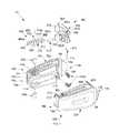
- FIG. 1is an exploded view, with parts separated, of an expandable spinal implant provided in accordance with the present disclosure
- FIG. 2is a top view of the expandable spinal implant of FIG. 1 , shown in a closed position;
- FIG. 3is an end view of the expandable spinal implant of FIG. 1 , shown in the closed position;
- FIG. 4is a side view of the expandable spinal implant of FIG. 1 , shown in the closed position;
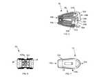
- FIG. 5is a top view of the expandable spinal implant of FIG. 1 , shown in an expanded position;
- FIG. 6is an end view of the expandable spinal implant of FIG. 1 , shown in an expanded position;
- FIG. 7is a side view of the expandable spinal implant of FIG. 1 , shown in an expanded position;
- FIG. 8is an enlarged view of a locking mechanism of the expandable spinal implant of FIG. 1 , shown in an unlocked position;
- FIG. 9is an enlarged view of the locking mechanism of FIG. 8 , shown in a locked position
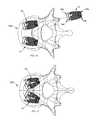
- FIG. 10is a plan view of an intervertebral space shown with two expandable spinal implants of FIG. 1 in a closed position;
- FIG. 11is a plan view of the intervertebral space of FIG. 10 , shown with two expandable spinal implants of FIG. 1 in an expanded position.
- FIG. 1illustrates an embodiment of expandable spinal implant 10 provided in accordance with the present disclosure.
- Expandable spinal implant 10includes a first body 100 , a second body 200 , a ratchet mechanism 300 , a locking mechanism 400 , biasing elements 500 , and hinge pins 600 .
- First and second bodies 100 , 200cooperate to define a two part expandable spinal implant configured for positioning between adjacent vertebral bodies.
- Ratchet mechanism 300 and locking mechanism 400cooperate to provide a locking mechanism to lock first and second bodies 100 , 200 in an expanded position relative to each other, thereby expanding the medial-lateral footprint of expandable spinal implant 10 .
- Each of these componentsalong with the assembly and insertion of expandable spinal implant 10 into the intervertebral space, as well as the expansion/contraction of expandable spinal implant 10 within the intervertebral space will be described in turn hereinbelow.
- first and second bodies 100 , 200may be formed from a metallic material (e.g., titanium, titanium alloy, or cobalt chrome (CoCr)) or a non-metallic material (e.g., polymeric materials such as polyetheretherketone (PEEK), non-absorbable polymers, nylon absorbable polymers such as polyglycolides, polylactides, polycaprolactone, etc., or organic materials such as bone) and ceramic materials.
- Ratchet mechanism 300 , locking mechanism 400 , biasing elements 500 , and hinge pins 600may be formed from titanium, titanium alloy, CoCr or other suitable metal or polymeric material compatible with first and second bodies 100 , 200 .
- Expandable spinal implant 10is formed by first and second bodies 100 , 200 , which are operable to be positioned in an expanded state ( FIG. 5 ), or a closed state ( FIG. 2 ).
- Expandable spinal implant 10includes substantially contoured first end surfaces 12 a , 12 b at a distal or leading end 14 a , 14 b of first and second bodies 100 , 200 , respectively, and second end surfaces 16 a , 16 b opposite thereto at a proximal or trailing end 18 a , 18 b , of first and second bodies 100 , 200 , respectively.
- Expandable spinal implant 10extends between the first and second end surfaces 12 a , 12 b and 16 a , 16 b to define respective top and bottom surfaces 20 a , 20 b , 22 a , and 22 b , as well as opposed side surfaces 24 , 26 .
- the top and bottom surfaces 20 a , 20 b and 22 a , 22 bengage side surfaces 24 , 26 , respectively, to provide a substantially rectangular cross-sectional profile, with rounded corners 27 a , 27 b .
- first end surfaces 12 a , 12 bform a substantially atraumatic blunt nose profile
- second end surfaces 16 a , 16 bform a substantially flat or planar profile.
- top surfaces 20 a , 20 bare generally shown as being angled with respect to bottom surfaces 22 a , 22 b in a direction from leading end 14 to trailing end 18 thereby defining a lordotic taper capable of effectuating lordosis of the spine when expandable spinal implant 10 is advanced within the intervertebral space.
- top surfaces 20 a , 20 b and bottom surfaces 22 a , 22 bmay be angled with respect to each other such that leading end 14 has a height that is less than a height of the trailing end 18 . It is also contemplated that top surface 20 may be parallel to bottom surface 22 .
- top and bottom surfaces 20 a , 20 b , 22 a , and 22 bdefine a first plurality of ridges 30 a and a second plurality of ridges 30 b arranged thereon.
- the first plurality of ridges 30 aare disposed proximate to leading ends 14 a , 14 b and the second plurality of ridges 30 b are disposed proximate to trailing ends 18 a , 18 b , each of which are configured to frictionally engage an adjacent surface of a vertebral body VB (i.e., a vertebral endplate) to prevent expandable spinal implant 10 from backing out of the intervertebral space since the ridges 30 a and 30 b will bite into the adjacent vertebral plate.
- a vertebral body VBi.e., a vertebral endplate
- First and second pluralities of ridges 30 a , 30 binclude distinct profiles (i.e., first plurality of ridges 30 a may have an elongate triangular profile, while second plurality of ridges 30 b may have a pyramidal profile); however, it is contemplated that first and second pluralities of ridges 30 a , 30 b may have similar profiles.
- first and second pluralities of ridges 30 a , 30 bmay have similar profiles.
- Channel 102is defined through first and second end surfaces 12 a , 16 a and is substantially parallel to side surface 24 ; however, it is contemplated that channel 102 may approximate side surface 24 in a direction from trailing end 18 a towards leading end 14 a and vice versa. Although generally shown as having a substantially U-shaped configuration, it is contemplated that channel 102 may have other suitable cross sections, such as v-shaped, circular, or oval.
- Relief 104( FIG. 5 ) is illustrated as being defined through top and bottom surfaces 20 a , 22 a adjacent to leading end 14 a , and defines faces 106 , 108 , extending substantially perpendicular to top and bottom surfaces 20 a , 22 a .
- Counterbores 110are defined in face 106 and are configured and/or dimensioned to receive biasing elements 500 , such that biasing elements 500 bias ratchet mechanism 300 into engagement with teeth 208 of second body 200 , thereby permitting motion in a first direction, and inhibiting motion in a second, opposite direction.
- Pivot slot 112is defined in face 108 and is open at the top and bottom surfaces 20 a , 22 a . Pivot slot 112 includes a circular cross section with less than half of the circumference open such that pivot 304 of ratchet mechanism 300 is rotatably secured therein.
- Counterbores 114are defined within each of the upper and lower inner surfaces of channel 102 , adjacent to trailing end 18 a and side surface 24 .
- Through-holes 116are defined through upper surface 20 a and lower surface 22 a and are concentric with counterbore 114 .
- Through-holes 116are configured to frictionally retain hinge pins 600 therein.
- slot 118is defined through side surface 24 and includes an elongate shape complimentary to that of side surface 24 of first body 100 ; however, it is contemplated that slot 118 may include other suitable shapes such as circular, rectangular, or the like. It is further contemplated that slot 118 may include a plurality of individual apertures.
- second body 200is shown generally as having a shape complimentary to that of first body 100 (i.e., mirrored) and thus, in the interest of brevity, only the differences between first body 100 and second body 200 will be detailed herein.
- Extension 204extends from inner face 202 (adjacent to leading end 14 b ) and terminates in end face 206 ( FIG. 5 ).
- Teeth 208are disposed on an opposing face to that of first end surface 12 b and are configured to engage teeth 306 of ratchet mechanism 300 such that when in an unlocked position, first body 100 and second body 200 may pivot or rotate relative to each other in a first direction causing expandable spinal implant 10 to expand, but not in a second direction allowing expandable spinal implant 10 to contract (i.e., a direction causing first and second bodies 100 , 200 to approximate each other).
- Teeth 208are generally shown as being arranged in an arcuate profile (when viewed looking towards top surface 20 b ); however, it is contemplated that teeth 208 may have other suitable profiles, such as planar.
- Keyhole 210( FIG. 8 ) is defined through end face 206 and includes a circular cross section and an intersecting rectangular cross section such that keyhole 210 is defined through teeth 208 . Keyhole 210 is configured to receive leading end 414 of locking mechanism 400 .
- Counterbores 212are disposed within top and bottom surfaces 20 b , 22 b of second body 200 adjacent to trailing end 18 b and are complimentary to counterbores 114 of first body 100 such that counterbores 114 and 212 interlock (i.e., counterbores 212 pass within counterbores 114 ).
- Through-bore 214is defined through top and bottom surfaces 20 b , 22 b and is concentric with counterbores 212 .
- Through-bore 214is configured and/or dimensioned to rotatably receive hinge pins 600 therein, such that hinge pins may be pressed into through-hole 116 (held in frictional engagement) and pass through through-bore 214 such that first and second bodies 100 , 200 are pivotably/rotatably retained thereabout.
- Hinge pins 600may be any suitable pin, such as a dowel pin, a roll pin, or the like.
- Aperture 216( FIG. 5 ) is defined through top and bottom surfaces 20 b , 22 b at a location where first end surface 14 b and side surface 26 intersect.
- Ratchet mechanism 300includes first and second ends defining elongate body 302 therebetween.
- Pivot 304is disposed on the first end of elongate body 302 and includes a substantially circular cross section extending from upper surface 302 a to lower surface 302 b .
- Pivot 304is configured and/or adapted to be received within pivot slot 112 of first body 100 such that ratchet mechanism 300 is pivotably secured therein.
- Boss 316extends from a side surface 302 c adjacent to pivot 304 and is configured to engage biasing elements 500 , thereby biasing ratchet mechanism 300 into engagement with teeth 208 of second body 200 , thereby permitting motion in a first direction, and inhibiting motion in a second, opposite direction.
- Teeth 306are disposed on a second, opposing side surface and are configured to engage teeth 208 of second body 200 .
- Teeth 306are arranged in a profile complimentary to that of teeth 208 of second body 200 , such as arcuate; however, it is contemplated that teeth 306 may be arranged in any suitable profile that is complimentary to that of the profile of teeth 208 .
- Orifice 308is defined through side surface 302 c and teeth 306 , and is configured to receive locking mechanism 400 such that locking mechanism 400 is rotatably secured therein.
- Bore 310is defined through side surface 302 c proximate to orifice 308 and is configured to frictionally retain limiting pin 312 therein.
- Limiting pin 312may be any suitable pin, such as a dowel, a roll pin, or the like, and is disposed within bore 310 , thereby limiting the rotational motion of locking mechanism 400 .
- Retaining bore 314is defined through upper surface 302 a and intersects a portion of orifice 308 , such that when retaining pin 318 is frictionally retained therein, locking mechanism 400 is prevented from advancing axially in orifice 308 .
- Retaining pin 318may be any suitable pin, such as a dowel, a roll pin, or the like.
- Locking mechanism 400includes an elongate body 402 including first and second ends.
- the first end of elongate body 402includes a hexagonal cross section 404 .
- Hexagonal cross section 404includes annular groove 404 a defined therein capable of engaging a suitable tool (not shown).
- Hexagonal cross section 404transitions to a flange 406 having a circular cross section extending in a direction towards the second end.
- Flange 406includes a larger diameter than that of hexagonal cross section 404 and is configured to abut side surface 302 c of ratchet mechanism 300 , thereby inhibiting locking mechanism from passing entirely through orifice 308 .
- Flange 406includes a notch 406 a ( FIG. 6 ).
- Notch 406 ais configured to act as a limiter to enable locking mechanism 400 to rotate from a first, unlocked position, to a second, locked position by engaging limiting pin 312 .
- Flange 406transitions to first shank portion 408 having a circular cross section and a diameter less than that of flange 406 and is configured and/or dimensioned to be received within orifice 308 such that locking mechanism is rotatably supported therein.
- Recess 410is disposed within first shank portion 408 and includes a circular cross section having a diameter less than that of first shank portion 408 .
- Recess 410is configured and/or dimensioned to receive a portion of retaining pin 312 when locking mechanism 400 is fully advanced within orifice 308 , thereby inhibiting locking mechanism 400 from translating axially within orifice 308 .
- First shank portion 408transitions to second shank portion 412 having a circular cross section and a diameter less than that of first shank section 408 such that second shank portion 412 may be advanced within keyhole 210 .
- Second shank portion 412transitions to leading end 414 having a spherical cross section having a diameter complimentary to that of the circular cross section portion of keyhole 210 .
- Leading end 414includes opposing planar sides 414 a , 414 b disposed thereon.
- Opposing planar sides 414 a , 414 breduce the diameter of leading end 414 to that of second shank portion 412 such that leading end 414 and second shank portion 412 may be advanced within keyhole 210 when locking mechanism is in an unlocked position (i.e., opposing planar sides 414 a , 414 b are parallel to upper surface 302 a of ratchet mechanism 300 ), locking mechanism may advance axially within keyhole 210 as teeth 306 and teeth 208 slide past each other as first body 100 and second body 200 rotate in a first direction allowing expandable spinal implant 10 to expand ( FIG. 8 ). Rotation of locking mechanism 400 may be effectuated using any suitable tool capable of transmitting rotational motion to locking mechanism 400 .
- Rotation of locking mechanism 400 to a second, locked positionorients opposing planar sides 414 a , 414 b normal to upper surface 302 a of ratchet mechanism 300 ( FIG. 9 ) such that the diameter of leading end 414 abuts the interior of keyhole 210 thereby prohibiting axial translation of locking mechanism 300 within keyhole 210 .
- teeth 208 , 306remain engaged with one another thereby fixing a size of expandable spinal implant 10 .
- expandable spinal implant 10is prohibited from expanding or contracting with locking mechanism 400 in the locked position.
- the toolwhen advanced over hexagonal cross section 404 and retained within annular groove 404 a , may be used to retract ratchet mechanism 300 such that teeth 208 , 306 become disengaged, thereby allowing expandable spinal implant 10 to rotate in the second direction and contract.
- first body 100is manipulated relative to second body 200 such that first and second bodies 100 , 200 are in a first, approximated, position ( FIG. 2 ) (e.g., closed).
- first and second bodies 100 , 200are not already in an approximated position.
- expandable spinal implant 10is affixed to a suitable insertion instrument (not shown). It is contemplated that the insertion tool may also be capable of engaging the hexagonal cross section 404 of locking mechanism 400 . At this point, expandable spinal implant 10 may be advanced within an incision within the patient and thereafter, into a previously prepared intervertebral space of the patient's spine ( FIG. 10 ). The insertion instrument (not shown) is then manipulated to expand expandable spinal implant 10 in a medial-lateral direction to a desired location ( FIG. 11 ) using the insertion instrument (not shown).
- Expandable spinal implant 10Medial-lateral expansion of expandable spinal implant 10 is effectuated by manipulating first and second bodies 100 , 200 about hinge pins 600 , such that teeth 208 , 306 cam, permitting rotation in the first direction, but not in a second, opposite direction. Expansion of expandable spinal implant adjusts the medial-lateral footprint within the intervertebral space.
- the desired location of first body 100 relative to second body 200is selected based on the desired medial-lateral footprint of expandable spinal implant 10 .
- locking mechanism 400is rotated in the second, opposite direction to lock teeth 208 of second body 200 into engagement with teeth 306 of ratchet mechanism 300 thereby locking the position of first body 100 relative to second body 200 .
- expandable spinal implant 10has been expanded too far, the clinician may use a suitable tool (not shown) to retract ratchet mechanism 300 such that teeth 208 , 306 become disengaged, thereby allowing expandable spinal implant 10 to rotate or pivot in the second direction and contract.
- This processmay be repeated as many times as the procedure requires, whether it be for the same expandable spinal implant 10 or for a plurality of expandable spinal implants 10 as required by the procedure being performed.
- Expandable spinal implant 10may be inserted using a variety of surgical techniques including, but not limited to, an anterior approach, an anteriolateral approach, a lateral approach, a retro-peritoneal approach, or a posterior approach. Expandable implant 10 is usable in a number of procedures including, but not limited to, Anterior Lumbar Interbody Fusion (ALIF), Posterior Lumbar Interbody Fusion (PLIF), and Transforaminal Lumbar Interbody Fusion (TLIF).
- ALIFAnterior Lumbar Interbody Fusion
- PLIFPosterior Lumbar Interbody Fusion
- TLIFTransforaminal Lumbar Interbody Fusion
Landscapes
- Health & Medical Sciences (AREA)
- Engineering & Computer Science (AREA)
- Biomedical Technology (AREA)
- Orthopedic Medicine & Surgery (AREA)
- Neurology (AREA)
- Transplantation (AREA)
- Heart & Thoracic Surgery (AREA)
- Oral & Maxillofacial Surgery (AREA)
- Cardiology (AREA)
- Vascular Medicine (AREA)
- Life Sciences & Earth Sciences (AREA)
- Animal Behavior & Ethology (AREA)
- General Health & Medical Sciences (AREA)
- Public Health (AREA)
- Veterinary Medicine (AREA)
- Physical Education & Sports Medicine (AREA)
- Prostheses (AREA)
Abstract
Description
Claims (18)
Priority Applications (1)
| Application Number | Priority Date | Filing Date | Title |
|---|---|---|---|
| US15/417,699US10080666B2 (en) | 2013-08-21 | 2017-01-27 | Expandable spinal implant |
Applications Claiming Priority (3)
| Application Number | Priority Date | Filing Date | Title |
|---|---|---|---|
| US201361868499P | 2013-08-21 | 2013-08-21 | |
| US14/464,892US9566163B2 (en) | 2013-08-21 | 2014-08-21 | Expandable spinal implant |
| US15/417,699US10080666B2 (en) | 2013-08-21 | 2017-01-27 | Expandable spinal implant |
Related Parent Applications (1)
| Application Number | Title | Priority Date | Filing Date |
|---|---|---|---|
| US14/464,892ContinuationUS9566163B2 (en) | 2013-08-21 | 2014-08-21 | Expandable spinal implant |
Publications (2)
| Publication Number | Publication Date |
|---|---|
| US20170135824A1 US20170135824A1 (en) | 2017-05-18 |
| US10080666B2true US10080666B2 (en) | 2018-09-25 |
Family
ID=52481055
Family Applications (2)
| Application Number | Title | Priority Date | Filing Date |
|---|---|---|---|
| US14/464,892Active2035-07-09US9566163B2 (en) | 2013-08-21 | 2014-08-21 | Expandable spinal implant |
| US15/417,699ActiveUS10080666B2 (en) | 2013-08-21 | 2017-01-27 | Expandable spinal implant |
Family Applications Before (1)
| Application Number | Title | Priority Date | Filing Date |
|---|---|---|---|
| US14/464,892Active2035-07-09US9566163B2 (en) | 2013-08-21 | 2014-08-21 | Expandable spinal implant |
Country Status (1)
| Country | Link |
|---|---|
| US (2) | US9566163B2 (en) |
Cited By (24)
| Publication number | Priority date | Publication date | Assignee | Title |
|---|---|---|---|---|
| US11013616B2 (en)* | 2018-10-10 | 2021-05-25 | K2M, Inc. | Sagittal balance systems and methods of use thereof |
| US11285014B1 (en) | 2020-11-05 | 2022-03-29 | Warsaw Orthopedic, Inc. | Expandable inter-body device, system, and method |
| US11291554B1 (en) | 2021-05-03 | 2022-04-05 | Medtronic, Inc. | Unibody dual expanding interbody implant |
| US11376134B1 (en) | 2020-11-05 | 2022-07-05 | Warsaw Orthopedic, Inc. | Dual expanding spinal implant, system, and method of use |
| US11395743B1 (en) | 2021-05-04 | 2022-07-26 | Warsaw Orthopedic, Inc. | Externally driven expandable interbody and related methods |
| US11517443B2 (en) | 2020-11-05 | 2022-12-06 | Warsaw Orthopedic, Inc. | Dual wedge expandable implant, system and method of use |
| US11564724B2 (en) | 2020-11-05 | 2023-01-31 | Warsaw Orthopedic, Inc. | Expandable inter-body device, system and method |
| US11612499B2 (en) | 2021-06-24 | 2023-03-28 | Warsaw Orthopedic, Inc. | Expandable interbody implant |
| US11638653B2 (en) | 2020-11-05 | 2023-05-02 | Warsaw Orthopedic, Inc. | Surgery instruments with a movable handle |
| US11701240B2 (en) | 2021-02-19 | 2023-07-18 | Loubert S. Suddaby | Expandable intervertebral fusion implant |
| US11730608B2 (en) | 2021-07-13 | 2023-08-22 | Warsaw Orthopedic, Inc. | Monoblock expandable interbody implant |
| US11806250B2 (en) | 2018-02-22 | 2023-11-07 | Warsaw Orthopedic, Inc. | Expandable spinal implant system and method of using same |
| US11833059B2 (en) | 2020-11-05 | 2023-12-05 | Warsaw Orthopedic, Inc. | Expandable inter-body device, expandable plate system, and associated methods |
| US11850163B2 (en) | 2022-02-01 | 2023-12-26 | Warsaw Orthopedic, Inc. | Interbody implant with adjusting shims |
| US11963881B2 (en) | 2020-11-05 | 2024-04-23 | Warsaw Orthopedic, Inc. | Expandable inter-body device, system, and method |
| US12121453B2 (en) | 2020-11-05 | 2024-10-22 | Warsaw Orthopedic, Inc. | Dual wedge expandable implant with eyelets, system, and method of use |
| US12171439B2 (en) | 2020-11-05 | 2024-12-24 | Warsaw Orthopedic, Inc. | Protected drill |
| US12239544B2 (en) | 2020-11-05 | 2025-03-04 | Warsaw Orthopedic, Inc. | Rhomboid shaped implants |
| US12268614B2 (en) | 2021-06-24 | 2025-04-08 | Warsaw Orthopedic, Inc. | Interbody implant with adjusting shims |
| US12295865B2 (en) | 2021-06-24 | 2025-05-13 | Warsaw Orthopedic, Inc. | Expandable interbody implant and corresponding inserter |
| US12318308B2 (en) | 2020-11-05 | 2025-06-03 | Warsaw Orthopedic, Inc. | Dual expandable inter-body device |
| US12318307B2 (en) | 2021-07-16 | 2025-06-03 | Blue Ocean Spine Gmbh | Adjustable spinal implants, associated instruments and methods |
| US12414863B2 (en) | 2021-06-24 | 2025-09-16 | Warsaw Orthopedic, Inc. | Expandable interbody implant and corresponding surgical tool |
| US12440349B2 (en) | 2022-02-04 | 2025-10-14 | Warsaw Orthopedic, Inc. | Expandable interbody implant and breakoff screw |
Families Citing this family (72)
| Publication number | Priority date | Publication date | Assignee | Title |
|---|---|---|---|---|
| WO2006058221A2 (en) | 2004-11-24 | 2006-06-01 | Abdou Samy M | Devices and methods for inter-vertebral orthopedic device placement |
| WO2008070863A2 (en) | 2006-12-07 | 2008-06-12 | Interventional Spine, Inc. | Intervertebral implant |
| US8900307B2 (en) | 2007-06-26 | 2014-12-02 | DePuy Synthes Products, LLC | Highly lordosed fusion cage |
| US8936641B2 (en) | 2008-04-05 | 2015-01-20 | DePuy Synthes Products, LLC | Expandable intervertebral implant |
| US8764806B2 (en) | 2009-12-07 | 2014-07-01 | Samy Abdou | Devices and methods for minimally invasive spinal stabilization and instrumentation |
| US10085849B2 (en) | 2010-09-03 | 2018-10-02 | Globus Medical, Inc. | Expandable fusion device and method of installation thereof |
| US10869768B2 (en) | 2010-09-03 | 2020-12-22 | Globus Medical Inc. | Expandable fusion device and method of installation thereof |
| US10835387B2 (en) | 2010-09-03 | 2020-11-17 | Globus Medical Inc. | Expandable fusion device and method of installation thereof |
| US10779957B2 (en) | 2010-09-03 | 2020-09-22 | Globus Medical, Inc. | Expandable fusion device and method of installation thereof |
| US10842644B2 (en) | 2010-09-03 | 2020-11-24 | Globus Medical, Inc. | Expandable fusion device and method of installation thereof |
| US10709573B2 (en) | 2010-09-03 | 2020-07-14 | Globus Medical Inc. | Expandable fusion device and method of installation thereof |
| US10512550B2 (en) | 2010-09-03 | 2019-12-24 | Globus Medical, Inc. | Expandable interspinous process fixation device |
| US11446162B2 (en) | 2010-09-03 | 2022-09-20 | Globus Medical, Inc. | Expandable fusion device and method of installation thereof |
| US10945858B2 (en) | 2010-09-03 | 2021-03-16 | Globus Medical, Inc. | Expandable interspinous process fixation device |
| US11793654B2 (en) | 2010-09-03 | 2023-10-24 | Globus Medical, Inc. | Expandable fusion device and method of installation thereof |
| US10758367B2 (en) | 2010-09-03 | 2020-09-01 | Globus Medical Inc. | Expandable fusion device and method of installation thereof |
| DE102010047901B4 (en)* | 2010-10-11 | 2019-01-10 | Heinrich Böhm | Implant for the spine and operating instrument |
| US8845728B1 (en) | 2011-09-23 | 2014-09-30 | Samy Abdou | Spinal fixation devices and methods of use |
| US20130226240A1 (en) | 2012-02-22 | 2013-08-29 | Samy Abdou | Spinous process fixation devices and methods of use |
| US9198767B2 (en) | 2012-08-28 | 2015-12-01 | Samy Abdou | Devices and methods for spinal stabilization and instrumentation |
| US9987142B2 (en) | 2012-08-31 | 2018-06-05 | Institute for Musculoskeletal Science and Education, Ltd. | Fixation devices for anterior lumbar or cervical interbody fusion |
| US9320617B2 (en) | 2012-10-22 | 2016-04-26 | Cogent Spine, LLC | Devices and methods for spinal stabilization and instrumentation |
| US9717601B2 (en) | 2013-02-28 | 2017-08-01 | DePuy Synthes Products, Inc. | Expandable intervertebral implant, system, kit and method |
| US9522070B2 (en) | 2013-03-07 | 2016-12-20 | Interventional Spine, Inc. | Intervertebral implant |
| WO2014143894A1 (en)* | 2013-03-15 | 2014-09-18 | NuTech Spine, Inc. | Anterior lumbar fusion method and device |
| AU2014268740B2 (en)* | 2013-05-20 | 2018-04-26 | K2M, Inc. | Adjustable implant and insertion tool |
| US9566163B2 (en)* | 2013-08-21 | 2017-02-14 | K2M, Inc. | Expandable spinal implant |
| US9585762B2 (en)* | 2014-10-09 | 2017-03-07 | K2M, Inc. | Expandable spinal interbody spacer and method of use |
| US10363142B2 (en) | 2014-12-11 | 2019-07-30 | K2M, Inc. | Expandable spinal implants |
| US11426290B2 (en) | 2015-03-06 | 2022-08-30 | DePuy Synthes Products, Inc. | Expandable intervertebral implant, system, kit and method |
| US10500061B2 (en)* | 2015-08-13 | 2019-12-10 | K2M, Inc. | Adjustable spinal implant |
| US10857003B1 (en) | 2015-10-14 | 2020-12-08 | Samy Abdou | Devices and methods for vertebral stabilization |
| EP3393404A4 (en) | 2015-12-21 | 2019-08-07 | Southern Spine, LLC | Expandable interbody devices and related instruments and methods for spinal fusion surgery |
| US10004608B2 (en) | 2016-02-26 | 2018-06-26 | K2M, Inc. | Insertion instrument for expandable spinal implants |
| US20200000595A1 (en) | 2016-06-07 | 2020-01-02 | HD LifeSciences LLC | High X-Ray Lucency Lattice Structures |
| US11510788B2 (en) | 2016-06-28 | 2022-11-29 | Eit Emerging Implant Technologies Gmbh | Expandable, angularly adjustable intervertebral cages |
| EP3474784A2 (en) | 2016-06-28 | 2019-05-01 | Eit Emerging Implant Technologies GmbH | Expandable and angularly adjustable intervertebral cages with articulating joint |
| US10052215B2 (en)* | 2016-06-29 | 2018-08-21 | Globus Medical, Inc. | Expandable fusion device and method of installation thereof |
| US9974662B2 (en)* | 2016-06-29 | 2018-05-22 | Globus Medical, Inc. | Expandable fusion device and method of installation thereof |
| US10786367B2 (en)* | 2016-07-21 | 2020-09-29 | Seaspine, Inc. | Expandable implant |
| US11154404B2 (en) | 2016-09-08 | 2021-10-26 | Mayo Foundation For Medical Education And Research | Spinal fixation system |
| US10307265B2 (en) | 2016-10-18 | 2019-06-04 | Institute for Musculoskeletal Science and Education, Ltd. | Implant with deployable blades |
| US10973648B1 (en) | 2016-10-25 | 2021-04-13 | Samy Abdou | Devices and methods for vertebral bone realignment |
| US10744000B1 (en) | 2016-10-25 | 2020-08-18 | Samy Abdou | Devices and methods for vertebral bone realignment |
| US10405992B2 (en) | 2016-10-25 | 2019-09-10 | Institute for Musculoskeletal Science and Education, Ltd. | Spinal fusion implant |
| US10449060B2 (en) | 2016-10-25 | 2019-10-22 | Institute for Musculoskeletal Science and Education, Ltd. | Spinal fusion implant |
| CA3061043A1 (en) | 2017-02-14 | 2018-08-23 | HD LifeSciences LLC | High x-ray lucency lattice structures and variably x-ray lucent markers |
| CA3058365A1 (en) | 2017-04-01 | 2018-10-04 | HD LifeSciences LLC | Three-dimensional lattice structures for implants |
| US10398563B2 (en) | 2017-05-08 | 2019-09-03 | Medos International Sarl | Expandable cage |
| US11344424B2 (en) | 2017-06-14 | 2022-05-31 | Medos International Sarl | Expandable intervertebral implant and related methods |
| US11006981B2 (en) | 2017-07-07 | 2021-05-18 | K2M, Inc. | Surgical implant and methods of additive manufacturing |
| WO2019014452A1 (en) | 2017-07-12 | 2019-01-17 | K2M, Inc. | Systems and methods for modeling spines and treating spines based on spine models |
| US11207135B2 (en) | 2017-07-12 | 2021-12-28 | K2M, Inc. | Systems and methods for modeling spines and treating spines based on spine models |
| US11000334B1 (en) | 2017-07-12 | 2021-05-11 | K2M, Inc. | Systems and methods for modeling spines and treating spines based on spine models |
| US10441430B2 (en) | 2017-07-24 | 2019-10-15 | K2M, Inc. | Expandable spinal implants |
| US10874460B2 (en) | 2017-09-29 | 2020-12-29 | K2M, Inc. | Systems and methods for modeling spines and treating spines based on spine models |
| US10892058B2 (en) | 2017-09-29 | 2021-01-12 | K2M, Inc. | Systems and methods for simulating spine and skeletal system pathologies |
| EP3826582A4 (en) | 2018-07-26 | 2022-05-25 | Nanohive Medical LLC | DYNAMIC IMPLANT FIXATION PLATE |
| US10893951B2 (en)* | 2018-08-07 | 2021-01-19 | Minimally Invasive Spinal Technology, LLC | Device and method for correcting spinal deformities in patients |
| US10849758B2 (en) | 2018-08-22 | 2020-12-01 | Institute for Musculoskeletal Science and Education, Ltd. | Spinal fusion implant |
| US11636650B2 (en) | 2018-09-24 | 2023-04-25 | K2M, Inc. | System and method for isolating anatomical features in computerized tomography data |
| US11179248B2 (en) | 2018-10-02 | 2021-11-23 | Samy Abdou | Devices and methods for spinal implantation |
| US11446156B2 (en) | 2018-10-25 | 2022-09-20 | Medos International Sarl | Expandable intervertebral implant, inserter instrument, and related methods |
| US11497617B2 (en) | 2019-01-16 | 2022-11-15 | Nanohive Medical Llc | Variable depth implants |
| CN110464516B (en)* | 2019-09-04 | 2020-05-22 | 北京积水潭医院 | an intervertebral fusion device |
| US11534307B2 (en) | 2019-09-16 | 2022-12-27 | K2M, Inc. | 3D printed cervical standalone implant |
| US11426286B2 (en) | 2020-03-06 | 2022-08-30 | Eit Emerging Implant Technologies Gmbh | Expandable intervertebral implant |
| US11850160B2 (en) | 2021-03-26 | 2023-12-26 | Medos International Sarl | Expandable lordotic intervertebral fusion cage |
| EP4312890A1 (en) | 2021-04-02 | 2024-02-07 | Nuvasive, Inc. | Expansion driver |
| JP2024514536A (en) | 2021-04-04 | 2024-04-02 | ニューヴェイジヴ,インコーポレイテッド | expandable implant |
| US11752009B2 (en) | 2021-04-06 | 2023-09-12 | Medos International Sarl | Expandable intervertebral fusion cage |
| US12090064B2 (en) | 2022-03-01 | 2024-09-17 | Medos International Sarl | Stabilization members for expandable intervertebral implants, and related systems and methods |
Citations (27)
| Publication number | Priority date | Publication date | Assignee | Title |
|---|---|---|---|---|
| US5554191A (en) | 1994-01-26 | 1996-09-10 | Biomat | Intersomatic vertebral cage |
| US6159244A (en) | 1999-07-30 | 2000-12-12 | Suddaby; Loubert | Expandable variable angle intervertebral fusion implant |
| US6176882B1 (en) | 1998-02-20 | 2001-01-23 | Biedermann Motech Gmbh | Intervertebral implant |
| US6190414B1 (en) | 1996-10-31 | 2001-02-20 | Surgical Dynamics Inc. | Apparatus for fusion of adjacent bone structures |
| US6193757B1 (en)* | 1998-10-29 | 2001-02-27 | Sdgi Holdings, Inc. | Expandable intervertebral spacers |
| US6443989B1 (en) | 2000-12-04 | 2002-09-03 | Roger P. Jackson | Posterior expandable fusion cage |
| US6454807B1 (en)* | 2000-11-30 | 2002-09-24 | Roger P. Jackson | Articulated expandable spinal fusion cage system |
| US6576016B1 (en) | 1997-05-01 | 2003-06-10 | Spinal Concepts, Inc. | Adjustable height fusion device |
| US6685742B1 (en) | 2002-11-12 | 2004-02-03 | Roger P. Jackson | Articulated anterior expandable spinal fusion cage system |
| US20040087947A1 (en) | 2002-08-28 | 2004-05-06 | Roy Lim | Minimally invasive expanding spacer and method |
| US6743255B2 (en)* | 1999-08-13 | 2004-06-01 | Bret Ferree | Spinal fusion cage with lordosis correction |
| US6808537B2 (en) | 2000-07-07 | 2004-10-26 | Gary Karlin Michelson | Expandable implant with interlocking walls |
| US6814756B1 (en) | 2000-02-04 | 2004-11-09 | Gary K. Michelson | Expandable threaded arcuate interbody spinal fusion implant with lordotic configuration during insertion |
| US7044971B2 (en) | 2002-08-30 | 2006-05-16 | Loubert Suddaby | Lordotic fusion implant |
| US20060122701A1 (en) | 2004-11-23 | 2006-06-08 | Kiester P D | Posterior lumbar interbody fusion expandable cage with lordosis and method of deploying the same |
| US7118579B2 (en) | 2001-02-04 | 2006-10-10 | Sdgi Holdings, Inc. | Instrumentation for inserting an expandable interbody spinal fusion implant |
| US7217293B2 (en) | 2003-11-21 | 2007-05-15 | Warsaw Orthopedic, Inc. | Expandable spinal implant |
| US7217291B2 (en) | 2003-12-08 | 2007-05-15 | St. Francis Medical Technologies, Inc. | System and method for replacing degenerated spinal disks |
| US7678148B2 (en) | 2004-07-23 | 2010-03-16 | Warsaw Orthopedic, Inc. | Expandable spinal implant having interlocking geometry for structural support |
| US7799081B2 (en) | 2004-09-14 | 2010-09-21 | Aeolin, Llc | System and method for spinal fusion |
| US8398713B2 (en) | 2010-09-03 | 2013-03-19 | Globus Medical, Inc. | Expandable fusion device and method of installation thereof |
| US8496706B2 (en) | 2010-08-02 | 2013-07-30 | Ashraf A. Ragab | Bone cage with components for controlled expansion |
| US8518114B2 (en) | 2011-04-21 | 2013-08-27 | Warsaw Orthopedic, Inc. | Expandable implant system and methods of use |
| US8628578B2 (en) | 2011-12-19 | 2014-01-14 | Warsaw Orthopedic, Inc. | Expandable interbody implant and methods of use |
| US8679183B2 (en) | 2010-06-25 | 2014-03-25 | Globus Medical | Expandable fusion device and method of installation thereof |
| US8795366B2 (en) | 2010-01-11 | 2014-08-05 | Innova Spinal Technologies, Llc | Expandable intervertebral implant and associated surgical method |
| US9566163B2 (en)* | 2013-08-21 | 2017-02-14 | K2M, Inc. | Expandable spinal implant |
- 2014
- 2014-08-21USUS14/464,892patent/US9566163B2/enactiveActive
- 2017
- 2017-01-27USUS15/417,699patent/US10080666B2/enactiveActive
Patent Citations (27)
| Publication number | Priority date | Publication date | Assignee | Title |
|---|---|---|---|---|
| US5554191A (en) | 1994-01-26 | 1996-09-10 | Biomat | Intersomatic vertebral cage |
| US6190414B1 (en) | 1996-10-31 | 2001-02-20 | Surgical Dynamics Inc. | Apparatus for fusion of adjacent bone structures |
| US6576016B1 (en) | 1997-05-01 | 2003-06-10 | Spinal Concepts, Inc. | Adjustable height fusion device |
| US6176882B1 (en) | 1998-02-20 | 2001-01-23 | Biedermann Motech Gmbh | Intervertebral implant |
| US6193757B1 (en)* | 1998-10-29 | 2001-02-27 | Sdgi Holdings, Inc. | Expandable intervertebral spacers |
| US6159244A (en) | 1999-07-30 | 2000-12-12 | Suddaby; Loubert | Expandable variable angle intervertebral fusion implant |
| US6743255B2 (en)* | 1999-08-13 | 2004-06-01 | Bret Ferree | Spinal fusion cage with lordosis correction |
| US6814756B1 (en) | 2000-02-04 | 2004-11-09 | Gary K. Michelson | Expandable threaded arcuate interbody spinal fusion implant with lordotic configuration during insertion |
| US6808537B2 (en) | 2000-07-07 | 2004-10-26 | Gary Karlin Michelson | Expandable implant with interlocking walls |
| US6454807B1 (en)* | 2000-11-30 | 2002-09-24 | Roger P. Jackson | Articulated expandable spinal fusion cage system |
| US6443989B1 (en) | 2000-12-04 | 2002-09-03 | Roger P. Jackson | Posterior expandable fusion cage |
| US7118579B2 (en) | 2001-02-04 | 2006-10-10 | Sdgi Holdings, Inc. | Instrumentation for inserting an expandable interbody spinal fusion implant |
| US20040087947A1 (en) | 2002-08-28 | 2004-05-06 | Roy Lim | Minimally invasive expanding spacer and method |
| US7044971B2 (en) | 2002-08-30 | 2006-05-16 | Loubert Suddaby | Lordotic fusion implant |
| US6685742B1 (en) | 2002-11-12 | 2004-02-03 | Roger P. Jackson | Articulated anterior expandable spinal fusion cage system |
| US7217293B2 (en) | 2003-11-21 | 2007-05-15 | Warsaw Orthopedic, Inc. | Expandable spinal implant |
| US7217291B2 (en) | 2003-12-08 | 2007-05-15 | St. Francis Medical Technologies, Inc. | System and method for replacing degenerated spinal disks |
| US7678148B2 (en) | 2004-07-23 | 2010-03-16 | Warsaw Orthopedic, Inc. | Expandable spinal implant having interlocking geometry for structural support |
| US7799081B2 (en) | 2004-09-14 | 2010-09-21 | Aeolin, Llc | System and method for spinal fusion |
| US20060122701A1 (en) | 2004-11-23 | 2006-06-08 | Kiester P D | Posterior lumbar interbody fusion expandable cage with lordosis and method of deploying the same |
| US8795366B2 (en) | 2010-01-11 | 2014-08-05 | Innova Spinal Technologies, Llc | Expandable intervertebral implant and associated surgical method |
| US8679183B2 (en) | 2010-06-25 | 2014-03-25 | Globus Medical | Expandable fusion device and method of installation thereof |
| US8496706B2 (en) | 2010-08-02 | 2013-07-30 | Ashraf A. Ragab | Bone cage with components for controlled expansion |
| US8398713B2 (en) | 2010-09-03 | 2013-03-19 | Globus Medical, Inc. | Expandable fusion device and method of installation thereof |
| US8518114B2 (en) | 2011-04-21 | 2013-08-27 | Warsaw Orthopedic, Inc. | Expandable implant system and methods of use |
| US8628578B2 (en) | 2011-12-19 | 2014-01-14 | Warsaw Orthopedic, Inc. | Expandable interbody implant and methods of use |
| US9566163B2 (en)* | 2013-08-21 | 2017-02-14 | K2M, Inc. | Expandable spinal implant |
Cited By (33)
| Publication number | Priority date | Publication date | Assignee | Title |
|---|---|---|---|---|
| US12036132B2 (en) | 2018-02-22 | 2024-07-16 | Warsaw Orthopedic, Inc. | Expandable spinal implant system and method of using same |
| US11806250B2 (en) | 2018-02-22 | 2023-11-07 | Warsaw Orthopedic, Inc. | Expandable spinal implant system and method of using same |
| US11679004B2 (en)* | 2018-10-10 | 2023-06-20 | K2M, Inc. | Sagittal balance systems and methods of use thereof |
| US20210236301A1 (en)* | 2018-10-10 | 2021-08-05 | K2M, Inc. | Sagittal Balance Systems And Methods Of Use Thereof |
| US12239551B2 (en)* | 2018-10-10 | 2025-03-04 | K2M, Inc. | Sagittal balance systems and methods of use thereof |
| US11013616B2 (en)* | 2018-10-10 | 2021-05-25 | K2M, Inc. | Sagittal balance systems and methods of use thereof |
| US20230255793A1 (en)* | 2018-10-10 | 2023-08-17 | K2M, Inc. | Sagittal Balance Systems And Methods Of Use Thereof |
| US11833059B2 (en) | 2020-11-05 | 2023-12-05 | Warsaw Orthopedic, Inc. | Expandable inter-body device, expandable plate system, and associated methods |
| US12364529B2 (en) | 2020-11-05 | 2025-07-22 | Warsaw Orthopedic, Inc. | Expandable inter-body device, system, and method |
| US11617658B2 (en) | 2020-11-05 | 2023-04-04 | Warsaw Orthopedic, Inc. | Expandable inter-body device, system and method |
| US11638653B2 (en) | 2020-11-05 | 2023-05-02 | Warsaw Orthopedic, Inc. | Surgery instruments with a movable handle |
| US11564724B2 (en) | 2020-11-05 | 2023-01-31 | Warsaw Orthopedic, Inc. | Expandable inter-body device, system and method |
| US12239544B2 (en) | 2020-11-05 | 2025-03-04 | Warsaw Orthopedic, Inc. | Rhomboid shaped implants |
| US11517443B2 (en) | 2020-11-05 | 2022-12-06 | Warsaw Orthopedic, Inc. | Dual wedge expandable implant, system and method of use |
| US12121453B2 (en) | 2020-11-05 | 2024-10-22 | Warsaw Orthopedic, Inc. | Dual wedge expandable implant with eyelets, system, and method of use |
| US11285014B1 (en) | 2020-11-05 | 2022-03-29 | Warsaw Orthopedic, Inc. | Expandable inter-body device, system, and method |
| US11376134B1 (en) | 2020-11-05 | 2022-07-05 | Warsaw Orthopedic, Inc. | Dual expanding spinal implant, system, and method of use |
| US12318308B2 (en) | 2020-11-05 | 2025-06-03 | Warsaw Orthopedic, Inc. | Dual expandable inter-body device |
| US11963881B2 (en) | 2020-11-05 | 2024-04-23 | Warsaw Orthopedic, Inc. | Expandable inter-body device, system, and method |
| US11969196B2 (en) | 2020-11-05 | 2024-04-30 | Warsaw Orthopedic, Inc. | Expandable inter-body device, system, and method |
| US12171439B2 (en) | 2020-11-05 | 2024-12-24 | Warsaw Orthopedic, Inc. | Protected drill |
| US12053392B2 (en) | 2020-11-05 | 2024-08-06 | Warsaw Orthopedic, Inc. | Expandable inter-body device, expandable plate system, and associated methods |
| US11701240B2 (en) | 2021-02-19 | 2023-07-18 | Loubert S. Suddaby | Expandable intervertebral fusion implant |
| US11291554B1 (en) | 2021-05-03 | 2022-04-05 | Medtronic, Inc. | Unibody dual expanding interbody implant |
| US11395743B1 (en) | 2021-05-04 | 2022-07-26 | Warsaw Orthopedic, Inc. | Externally driven expandable interbody and related methods |
| US12268614B2 (en) | 2021-06-24 | 2025-04-08 | Warsaw Orthopedic, Inc. | Interbody implant with adjusting shims |
| US11612499B2 (en) | 2021-06-24 | 2023-03-28 | Warsaw Orthopedic, Inc. | Expandable interbody implant |
| US12295865B2 (en) | 2021-06-24 | 2025-05-13 | Warsaw Orthopedic, Inc. | Expandable interbody implant and corresponding inserter |
| US12414863B2 (en) | 2021-06-24 | 2025-09-16 | Warsaw Orthopedic, Inc. | Expandable interbody implant and corresponding surgical tool |
| US11730608B2 (en) | 2021-07-13 | 2023-08-22 | Warsaw Orthopedic, Inc. | Monoblock expandable interbody implant |
| US12318307B2 (en) | 2021-07-16 | 2025-06-03 | Blue Ocean Spine Gmbh | Adjustable spinal implants, associated instruments and methods |
| US11850163B2 (en) | 2022-02-01 | 2023-12-26 | Warsaw Orthopedic, Inc. | Interbody implant with adjusting shims |
| US12440349B2 (en) | 2022-02-04 | 2025-10-14 | Warsaw Orthopedic, Inc. | Expandable interbody implant and breakoff screw |
Also Published As
| Publication number | Publication date |
|---|---|
| US20150057755A1 (en) | 2015-02-26 |
| US20170135824A1 (en) | 2017-05-18 |
| US9566163B2 (en) | 2017-02-14 |
Similar Documents
| Publication | Publication Date | Title |
|---|---|---|
| US10080666B2 (en) | Expandable spinal implant | |
| US20210322182A1 (en) | Expandable intervertebral spacer | |
| US9566167B2 (en) | Expandable spinal implant | |
| US11759331B2 (en) | Stabilized expandable intervertebral spacer | |
| US12390343B2 (en) | Expandable, angularly adjustable intervertebral cages | |
| US11701236B2 (en) | Articulating expandable intervertebral implant | |
| US11766340B2 (en) | Articulating expandable intervertebral implant | |
| US20250262064A1 (en) | Intervertebral spacer and plate | |
| US20210361443A1 (en) | Expandable intervertebral fusion devices and methods of installation thereof | |
| US12029659B2 (en) | Stabilized intervertebral spacer | |
| US20170165082A1 (en) | Stabilized expandable intervertebral spacer | |
| US9138328B2 (en) | Radially expandable spinal interbody device and implantation tool | |
| US7887589B2 (en) | Minimally invasive spinal disc stabilizer and insertion tool | |
| US20150223950A1 (en) | Spinal implant | |
| CN115381606B (en) | An intervertebral fusion cage capable of being expanded at an angle and a spinal implant system thereof |
Legal Events
| Date | Code | Title | Description |
|---|---|---|---|
| AS | Assignment | Owner name:K2M, INC., VIRGINIA Free format text:ASSIGNMENT OF ASSIGNORS INTEREST;ASSIGNORS:SUDDABY, LOUBERT;MCCLINTOCK, LARRY;REEL/FRAME:041108/0293 Effective date:20140826 | |
| STCF | Information on status: patent grant | Free format text:PATENTED CASE | |
| MAFP | Maintenance fee payment | Free format text:PAYMENT OF MAINTENANCE FEE, 4TH YEAR, LARGE ENTITY (ORIGINAL EVENT CODE: M1551); ENTITY STATUS OF PATENT OWNER: LARGE ENTITY Year of fee payment:4 | |
| AS | Assignment | Owner name:STRYKER CORPORATION, MICHIGAN Free format text:ASSIGNMENT OF ASSIGNORS INTEREST;ASSIGNOR:K2M, INC.;REEL/FRAME:071271/0170 Effective date:20250328 | |
| AS | Assignment | Owner name:VB SPINE US OPCO LLC, DELAWARE Free format text:ASSIGNMENT OF ASSIGNORS INTEREST;ASSIGNOR:STRYKER CORPORATION;REEL/FRAME:071312/0356 Effective date:20250505 | |
| AS | Assignment | Owner name:ANKURA TRUST COMPANY, LLC, AS COLLATERAL AGENT, CONNECTICUT Free format text:PATENT SECURITY AGREEMENT;ASSIGNORS:K2M, INC.;VB SPINE US OPCO LLC;VB SPINE LLC;REEL/FRAME:071682/0116 Effective date:20250616 |