US10080592B2 - Access assembly for anterior and lateral spinal procedures - Google Patents
Access assembly for anterior and lateral spinal proceduresDownload PDFInfo
- Publication number
- US10080592B2 US10080592B2US15/289,322US201615289322AUS10080592B2US 10080592 B2US10080592 B2US 10080592B2US 201615289322 AUS201615289322 AUS 201615289322AUS 10080592 B2US10080592 B2US 10080592B2
- Authority
- US
- United States
- Prior art keywords
- distractor
- disc space
- lock member
- spinal procedures
- tube assembly
- Prior art date
- Legal status (The legal status is an assumption and is not a legal conclusion. Google has not performed a legal analysis and makes no representation as to the accuracy of the status listed.)
- Active
Links
- 238000000034methodMethods0.000titleclaimsabstractdescription39
- 210000000988bone and boneAnatomy0.000claimsdescription17
- 238000003780insertionMethods0.000claimsdescription15
- 230000037431insertionEffects0.000claimsdescription15
- 239000000463materialSubstances0.000claimsdescription5
- 210000001519tissueAnatomy0.000claimsdescription4
- 238000013459approachMethods0.000abstractdescription23
- 210000000115thoracic cavityAnatomy0.000abstractdescription18
- 238000001356surgical procedureMethods0.000abstractdescription15
- 210000004705lumbosacral regionAnatomy0.000abstractdescription9
- 230000004927fusionEffects0.000description22
- 239000007943implantSubstances0.000description9
- 230000006641stabilisationEffects0.000description5
- 238000011105stabilizationMethods0.000description5
- 208000003618Intervertebral Disc DisplacementDiseases0.000description3
- 239000012634fragmentSubstances0.000description3
- 206010041899Stab woundDiseases0.000description2
- 210000003815abdominal wallAnatomy0.000description2
- 230000008901benefitEffects0.000description2
- 230000006378damageEffects0.000description2
- 201000010099diseaseDiseases0.000description2
- 208000037265diseases, disorders, signs and symptomsDiseases0.000description2
- 238000000605extractionMethods0.000description2
- 230000035876healingEffects0.000description2
- 238000012986modificationMethods0.000description2
- 230000004048modificationEffects0.000description2
- 210000005036nerveAnatomy0.000description2
- 230000001537neural effectEffects0.000description2
- 210000003200peritoneal cavityAnatomy0.000description2
- 125000006850spacer groupChemical group0.000description2
- 210000000278spinal cordAnatomy0.000description2
- 208000028389Nerve injuryDiseases0.000description1
- 208000002193PainDiseases0.000description1
- 206010033799ParalysisDiseases0.000description1
- 208000004550Postoperative PainDiseases0.000description1
- 241000283984RodentiaSpecies0.000description1
- 206010058907Spinal deformityDiseases0.000description1
- 208000027418Wounds and injuryDiseases0.000description1
- 210000001015abdomenAnatomy0.000description1
- 230000002159abnormal effectEffects0.000description1
- 210000003484anatomyAnatomy0.000description1
- 208000037873arthrodesisDiseases0.000description1
- 210000000038chestAnatomy0.000description1
- 210000000078clawAnatomy0.000description1
- 230000006835compressionEffects0.000description1
- 238000007906compressionMethods0.000description1
- 238000012937correctionMethods0.000description1
- 230000006837decompressionEffects0.000description1
- 230000000991decompressive effectEffects0.000description1
- 238000005553drillingMethods0.000description1
- 239000000835fiberSubstances0.000description1
- 238000003384imaging methodMethods0.000description1
- 238000002513implantationMethods0.000description1
- 208000014674injuryDiseases0.000description1
- 210000000936intestineAnatomy0.000description1
- 210000002414legAnatomy0.000description1
- 210000004072lungAnatomy0.000description1
- 239000007769metal materialSubstances0.000description1
- 210000003205muscleAnatomy0.000description1
- 230000008764nerve damageEffects0.000description1
- HLXZNVUGXRDIFK-UHFFFAOYSA-Nnickel titaniumChemical compound[Ti].[Ti].[Ti].[Ti].[Ti].[Ti].[Ti].[Ti].[Ti].[Ti].[Ti].[Ni].[Ni].[Ni].[Ni].[Ni].[Ni].[Ni].[Ni].[Ni].[Ni].[Ni].[Ni].[Ni].[Ni]HLXZNVUGXRDIFK-UHFFFAOYSA-N0.000description1
- 229910001000nickel titaniumInorganic materials0.000description1
- 210000000056organAnatomy0.000description1
- 210000000273spinal nerve rootAnatomy0.000description1
- 229910001220stainless steelInorganic materials0.000description1
- 239000010935stainless steelSubstances0.000description1
- 239000000126substanceSubstances0.000description1
- 238000011477surgical interventionMethods0.000description1
- 230000002889sympathetic effectEffects0.000description1
- 210000000779thoracic wallAnatomy0.000description1
- 230000007704transitionEffects0.000description1
- 210000000689upper legAnatomy0.000description1
- 210000001631vena cava inferiorAnatomy0.000description1
- 238000012800visualizationMethods0.000description1
- 230000003313weakening effectEffects0.000description1
Images


Classifications
- A—HUMAN NECESSITIES
- A61—MEDICAL OR VETERINARY SCIENCE; HYGIENE
- A61B—DIAGNOSIS; SURGERY; IDENTIFICATION
- A61B17/00—Surgical instruments, devices or methods
- A61B17/16—Instruments for performing osteoclasis; Drills or chisels for bones; Trepans
- A61B17/17—Guides or aligning means for drills, mills, pins or wires
- A61B17/1739—Guides or aligning means for drills, mills, pins or wires specially adapted for particular parts of the body
- A61B17/1757—Guides or aligning means for drills, mills, pins or wires specially adapted for particular parts of the body for the spine
- A—HUMAN NECESSITIES
- A61—MEDICAL OR VETERINARY SCIENCE; HYGIENE
- A61B—DIAGNOSIS; SURGERY; IDENTIFICATION
- A61B17/00—Surgical instruments, devices or methods
- A61B17/56—Surgical instruments or methods for treatment of bones or joints; Devices specially adapted therefor
- A61B17/58—Surgical instruments or methods for treatment of bones or joints; Devices specially adapted therefor for osteosynthesis, e.g. bone plates, screws or setting implements
- A61B17/68—Internal fixation devices, including fasteners and spinal fixators, even if a part thereof projects from the skin
- A61B17/70—Spinal positioners or stabilisers, e.g. stabilisers comprising fluid filler in an implant
- A61B17/7074—Tools specially adapted for spinal fixation operations other than for bone removal or filler handling
- A61B17/7076—Tools specially adapted for spinal fixation operations other than for bone removal or filler handling for driving, positioning or assembling spinal clamps or bone anchors specially adapted for spinal fixation
- A61B17/7077—Tools specially adapted for spinal fixation operations other than for bone removal or filler handling for driving, positioning or assembling spinal clamps or bone anchors specially adapted for spinal fixation for moving bone anchors attached to vertebrae, thereby displacing the vertebrae
- A61B17/708—Tools specially adapted for spinal fixation operations other than for bone removal or filler handling for driving, positioning or assembling spinal clamps or bone anchors specially adapted for spinal fixation for moving bone anchors attached to vertebrae, thereby displacing the vertebrae with tubular extensions coaxially mounted on the bone anchors
- A—HUMAN NECESSITIES
- A61—MEDICAL OR VETERINARY SCIENCE; HYGIENE
- A61B—DIAGNOSIS; SURGERY; IDENTIFICATION
- A61B17/00—Surgical instruments, devices or methods
- A61B17/56—Surgical instruments or methods for treatment of bones or joints; Devices specially adapted therefor
- A61B17/58—Surgical instruments or methods for treatment of bones or joints; Devices specially adapted therefor for osteosynthesis, e.g. bone plates, screws or setting implements
- A61B17/88—Osteosynthesis instruments; Methods or means for implanting or extracting internal or external fixation devices
- A61B17/8897—Guide wires or guide pins
- A—HUMAN NECESSITIES
- A61—MEDICAL OR VETERINARY SCIENCE; HYGIENE
- A61B—DIAGNOSIS; SURGERY; IDENTIFICATION
- A61B17/00—Surgical instruments, devices or methods
- A61B17/02—Surgical instruments, devices or methods for holding wounds open, e.g. retractors; Tractors
- A61B17/025—Joint distractors
- A61B2017/0256—Joint distractors for the spine
Definitions
- the present inventionrelates generally to stabilization of adjacent bony structures of the spine and more particularly to an assembly and method for providing anterior and/or lateral access to the disc space of the vertebrae for providing stabilization to the bony structures thereof.
- an abnormal spinecan be stabilized using a substantially rigid or semi-rigid interconnecting means (rod or plate) and fastening means (screws, clamps, hooks, claws, anchors, or bolts).
- fastening meansscrews, clamps, hooks, claws, anchors, or bolts.
- Multiple fastenersare placed into the spinal pedicle of each vertebra and linked by at least one interconnecting means. Once in place, these systems substantially immobilize the spine and promote bony fusion (arthrodesis).
- the thoracic spineWith respect to the thoracic spine, it may be afflicted with a variety of ailments, some so severe as to require surgical intervention.
- a disc herniationmay compress the spinal cord and/or nerve roots and cause pain, loss of function, and even complete paralysis of the legs with loss of bowel and bladder control.
- the correct treatment for such conditionsis the removal of the offending discal tissue.
- thishas proven both difficult and quite dangerous.
- the spinal cordis in the way.
- To approach the same herniation anteriorly (from the front)requires the very daunting procedure of thoracotomy (cutting open the chest) and moving the heart and lungs out of the way.
- the thoracic spinemay become unstable (too much motion) at any given level. Historically, this has been treated by fusion, the joining together permanently of the unstable vertebrae via a bridge of bone so as to eliminate all motion at that location. Fusions about the thoracic spine have been performed either anteriorly or posteriorly, either procedure being a serious surgical undertaking.
- Stability of the spineis required for fusion to occur. For this reason, and for the purpose of correcting spinal deformity, it is often necessary to use hardware to rigidly internally fixate (stabilize) the spine. To date, the only benefit the use of the thorascope has provided in this regard is to allow the previous thoracotomy incision to be somewhat smaller.
- the prior artincludes numerous drawbacks which have not been entirely addressed.
- the surgical techniques for stabilization of bonerequired large incisions (upwards of 6 cm in length) and a considerable amount of muscle be cut and stripped away (retracted) from the bone for an “open” visualization of the bone and access thereto for the placement of the fasteners and instrument implantation.
- this so-called “open” surgical techniquehas successfully treated non-unions, instability, injuries and disease of the spine, it is not without disadvantages. Given the invasive nature of this technique, a lengthy healing time and considerable post-operative pain for the patient is common.
- Interbody fusionis generally induced with the application of bone or bone like substances between bones to induce bony bridging; such procedures have been performed outside the vertebral bodies and/or between the vertebral bodies, the latter being known as an interbody fusion.
- Such interbody fusionshave been performed from posterior, posterolateral and anterior.
- Interbody fusion from the posterior approachwhile still in use, has been associated with significant complications generally related to the fact that the delicate dural sac and the spine nerves cover the back of the disc space and are thus clearly at risk for damage with such an approach.
- the posterolateral approachhas generally been utilized as a compliment to percutaneous discectomy and has consisted of pushing tiny fragments of morsalized bone down through a tube and into the disc space.
- anterior interbody spinal fusionthe path of entry of the fusion material into the intervertebral space is performed from a straight anterior position.
- Such an anterior positionis achieved in one of two ways. First, by a straight anterior approach which requires that the peritoneal cavity, which contains the intestines and other organs, be punctured twice, once through the front and once through the back on the way to the front of the spine; or secondly, by starting on the front of the abdomen off to one side and dissecting behind the peritoneal cavity on the way to the front of the spine.
- anterior interbody fusion angle of implant insertionthere are at least two major problems specific to the anterior interbody fusion angle of implant insertion itself.
- the great iliac vesselsbifurcate from the inferior vena cava and lie in close apposition to and covering that disc space, making fusion from the front both difficult and dangerous.
- anterior fusionshave generally been done by filling the disc space with bone or by drilling across the disc space and then filling those holes with shaped implants.
- the preferred method of filling the disc spaceconsists of placing a ring of allograft (bone not from the patient) femur into that disc space.
- An attempt to get good fill of the disc spaceplaces the sympathetic nerves along the sides of the disc at great risk.
- the dowel techniquebecause of the short path from the front of the vertebrae to the back and because of the height of the disc as compared to the width of the spine, only a portion of the cylindrical implant or implants actually engage the vertebrae; thus compromising the support provided to the vertebrae and the area of contact provided for the fusion to occur.
- the present inventionis directed to methods and instrumentation for performing surgery on the spine along its lateral aspect (side), and generally by a lateral, anterior or an anterolateral surgical approach, such that the instruments enter the body from an approach that is other than posterior and make contact with the spine along its lateral aspect.
- the present inventionprovides for the entire surgical procedure to be performed through a relatively small incision and may be performed in either the thoracic or lumbar spine.
- the access assembly of the present inventioncomprises a guide wire, a distractor, and a dynamic tube assembly that includes a manually operable locking member for securing the dynamic tube assembly to the bony structure.
- the locking feature of the dynamic tube assemblymay also be utilized for providing additional controlled distraction of the bony structures.
- the guide wireis provided for initial insertion into the disc space through a small incision in the patient with the assistance of x-rays, thorascope, image intensifier, direct vision or the like. For example, for surgery in the thoracic spine, a small incision in the chest cavity of the patient is made from a lateral approach to the thoracic spine.
- the distractoris generally an elongated member having a small central aperture sized for cooperation with the guide wire.
- a first end of the distractorincludes a tapered end and a pair of generally flat opposing side surfaces extending along a portion of the length thereof. The opposing side surfaces are spaced a predetermined distance apart to provide a desired distraction (spacing) and alignment of the vertebrae.
- the second end of the distractoris provided with a surface suitable for striking with a mallet or the like.
- the outer surface of the distractoris preferably round to act as a guide surface for the dynamic tube assembly.
- the dynamic tube assemblyincludes an outer tube member and an inner lock member.
- the inner lock memberincludes an inner bore sized for cooperation with the outer surface of the distractor member. In this manner, the distractor acts as a guideway for the dynamic tube assembly.
- the dynamic tube assemblyis constructed and arranged so that a portion of the lock member and outer tube member extend a short distance into the disc space adjacent the side surfaces of the distractor and between the two opposed surfaces.
- the lock memberis then rotatable to engage the opposing bony surfaces of the disc space. In this manner, the lock member secures the first end of the dynamic tube assembly into place and releases the distractor member for extraction from the patient through the bore of the dynamic tube assembly.
- the lock membermay include a shaped cam surface that provides additional controlled distraction of the disc space during rotation thereof.
- the locking functionprevents the first end of the dynamic tube assembly from being inadvertently moved from its intended position once placed, while maintaining the adjacent vertebrae in a distracted position and aligned position.
- the distractor and guide wiremay be removed, providing an access tunnel to the disc space.
- the tunnelis provided with sufficient diameter for disc modification or removal as well as the placement of spacers, bone fragments, implants and the like to be passed therethrough to the disc space.
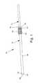
- FIG. 1is a perspective view of one embodiment of the present invention
- FIG. 2is a partial perspective view of the embodiment shown in FIG. 1 illustrating the first end thereof;
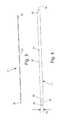
- FIG. 3is a perspective view of one embodiment of the guide wire of the present invention.
- FIG. 4is a perspective view of one embodiment of the distractor member of the present invention.
- FIG. 5is a partial perspective view of the first end of the distractor member illustrated in FIG. 4 ;
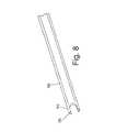
- FIG. 6is a partial perspective view of one embodiment of the dynamic tube assembly of the present invention.
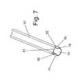
- FIG. 7is a partial perspective view of the dynamic tube assembly shown in FIG. 6 illustrating the locking member positioned in the locking position;
- FIG. 8is a partial perspective view of the dynamic tube assembly shown in FIG. 6 illustrating the locking member positioned in the unlocked position;
- FIG. 9is a partial perspective view of the dynamic tube assembly shown in FIG. 6 illustrating the locking member positioned in the unlocked position
- FIG. 10is a perspective view of a segment of the thoractic spine and of the guide wire of the present invention being inserted from a lateral approach into the disc space between two adjacent vertebrae;
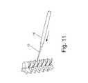
- FIG. 11is a perspective view of the distractor member being inserted over the guide wire of FIG. 10 ;
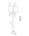
- FIG. 12is a perspective view of the dynamic tube assembly being inserted over the distractor member of FIG. 11 ;
- FIG. 13is a front view of a portion of the segment of thoractic spine shown in FIG. 1 illustrating the dynamic tube assembly fully seated into the disc space over the distractor member with the locking member in the unlocked position;
- FIG. 14is a front view of the segment of the thoractic spine shown in FIG. 13 illustrating the locking member in the locked position with the distractor member removed;
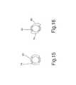
- FIG. 15is an end view of one embodiment of the locking dynamic tube assembly
- FIG. 16is an end view of one embodiment of the dynamic tube assembly.
- an access assembly 10constructed and arranged for anterior, lateral anterolateral spinal procedures is illustrated.
- the present inventionprovides for the entire surgical procedure to be performed through a relatively small incision, and may be performed in either the thoracic or lumbar spine.
- the access assembly 10comprises a guide wire 12 , a distractor 14 , and a dynamic tube assembly 16 that includes a manually operable locking member 18 for securing the dynamic tube assembly to a bony structure.
- the guide wire 12is provided for initial insertion into the disc space through a small incision in the patient with the assistance of x-rays, thorascope, image intensifier, direct vision or the like, see FIG. 10 .
- a small incision in the chest cavity of the patientis made from a lateral approach to the thoracic spine.
- a small incisionmay be made in the abdominal wall of the patient.
- the first end 22 of the guide wire 12may be inserted with the assistance of a jam shidi needle or other suitable cannula.
- the guide wiremay have sufficient rigidity for direct insertion.
- the first end 22 of the guide wire 12may include a particular shape that aids in the insertion such as, but not limited to, a conical point, trocar, spherical or blunt.
- the central shaft 24 of the guide wire 12extends between the disc space to outside of the patient to provide a guideway for the distractor member.
- the second end 26 of the guide wire 12generally includes a blunt square cut.
- the guide wire 12is preferably constructed from a biocompatible metal material such as spring temper stainless steel or nitinol. However, it should be noted that any material having sufficient rigidity to act as a guideway for the distractor member may be utilized without departing from the scope of the invention.
- the distractor 14is generally an elongated member having a first end 28 , a central portion 30 and a second end 32 . Extending through a central portion of the distractor is a small central aperture 34 sized for cooperation with the outer surface of the center portion of the guide wire 12 .
- the first end of the distractorpreferably includes a tapered end 36 for ease of insertion into the disc space.
- the tapered endincludes a frustoconical shape.
- other shapesmay be utilized for the tapered end so long as they provide a smooth transition from the outer diameter of the guide wire to the outer diameter of the distractor. Such shapes may include, but should not be limited to, spherical, bullet, pyramid or suitable combinations thereof.
- a pair of generally flat opposing side surfaces 38extend along a portion of the length of the center portion 30 .
- the opposing side surfacesare spaced a predetermined distance apart 40 , which may include a taper, to provide a desired distraction (spacing) and alignment of the vertebrae.
- the second end 32 of the distractor 14is provided with a surface 42 suitable for striking with a mallet or the like.
- the outer surface 44 of the distractoris preferably round to act as a guide surface for the dynamic tube assembly. It should be noted that while the inner and outer surfaces of the distractor member are illustrated as being round, other matched shapes may be utilized without departing from the scope of the invention.
- the dynamic tube assembly 16includes an outer tube member 50 and an inner lock member 52 .
- the dynamic tube assembly 16includes a first end 56 , a center portion 58 , a second end 60 , an outer surface 59 and an inner surface 61 .
- the first end 56includes a pair of tab members 62 integrally formed thereto and sized so that they extend a short distance into the disc space adjacent the distractor and between the two opposed surfaces. In this manner, the dynamic tube assembly may be easily traversed to its desired functional position.
- the second end 60 of the dynamic tube assembly 16includes a gripping portion 64 for providing counter-rotation force to the dynamic tube assembly during actuation of the lock member 52 .
- the inner surface of the outer tube memberis sized to cooperate with the outer surface of the locking member so as to function as a bearing surface for rotation of the lock member.
- the inner lock member 52extends through the inner bore 54 of the outer tube member 50 and includes a first end 66 , a center portion (not shown), a second end 70 , an inner bore 54 , and an outer surface 72 .
- the first end of the lock memberpreferably includes at least two locks 74 extending beyond and having approximately the same width as the tabs 62 , whereby the lock member may be rotated to align substantially therewith for insertion alongside the distractor.
- the distal ends of the lockseach include at least one barb portion 76 which may include a ramp portion 78 , a rear surface 80 and a pair of side surfaces 82 .
- the ramp portion 78provides easy entry through tissue and the like, while the side surfaces 82 may be constructed and arranged to bite and/or cut into the bone during rotation to create a secure engagement.
- the center portion 68 of the lock memberis sized and shaped to cooperate with the inner surface 61 of the outer tube member 50 to allow free rotation therebetween.
- the second end 70 of the lock member 52extends through the outer tube member terminating in a second gripping portion 84 which may include a hex 86 of shape constructed and arranged for providing rotational torque to the lock member for engagement or disengagement thereof.
- the inner bore 54is sized for cooperation with the outer surface 44 of the distractor member 14 . In this manner, the distractor acts as a guideway for the dynamic tube assembly.
- the lock memberis then rotatable to engage the opposing bony surfaces of the disc space. In this manner, the lock member secures the first end of the dynamic tube assembly into place and releases the distractor member for extraction from the patient while maintaining the adjacent vertebrae in a distracted and aligned position.
- the lock membermay include a shaped cam surface 88 that provides additional controlled distraction of the disc space during rotation thereof.
Landscapes
- Health & Medical Sciences (AREA)
- Orthopedic Medicine & Surgery (AREA)
- Surgery (AREA)
- Life Sciences & Earth Sciences (AREA)
- Neurology (AREA)
- Medical Informatics (AREA)
- Public Health (AREA)
- Heart & Thoracic Surgery (AREA)
- Engineering & Computer Science (AREA)
- Molecular Biology (AREA)
- Animal Behavior & Ethology (AREA)
- General Health & Medical Sciences (AREA)
- Biomedical Technology (AREA)
- Veterinary Medicine (AREA)
- Nuclear Medicine, Radiotherapy & Molecular Imaging (AREA)
- Dentistry (AREA)
- Oral & Maxillofacial Surgery (AREA)
- Surgical Instruments (AREA)
- Prostheses (AREA)
Abstract
Description
Claims (18)
Priority Applications (1)
| Application Number | Priority Date | Filing Date | Title |
|---|---|---|---|
| US15/289,322US10080592B2 (en) | 2012-01-12 | 2016-10-10 | Access assembly for anterior and lateral spinal procedures |
Applications Claiming Priority (3)
| Application Number | Priority Date | Filing Date | Title |
|---|---|---|---|
| US201261585724P | 2012-01-12 | 2012-01-12 | |
| US13/739,805US9463052B2 (en) | 2012-01-12 | 2013-01-11 | Access assembly for anterior and lateral spinal procedures |
| US15/289,322US10080592B2 (en) | 2012-01-12 | 2016-10-10 | Access assembly for anterior and lateral spinal procedures |
Related Parent Applications (1)
| Application Number | Title | Priority Date | Filing Date |
|---|---|---|---|
| US13/739,805ContinuationUS9463052B2 (en) | 2012-01-12 | 2013-01-11 | Access assembly for anterior and lateral spinal procedures |
Publications (2)
| Publication Number | Publication Date |
|---|---|
| US20170095276A1 US20170095276A1 (en) | 2017-04-06 |
| US10080592B2true US10080592B2 (en) | 2018-09-25 |
Family
ID=47891894
Family Applications (2)
| Application Number | Title | Priority Date | Filing Date |
|---|---|---|---|
| US13/739,805Expired - Fee RelatedUS9463052B2 (en) | 2012-01-12 | 2013-01-11 | Access assembly for anterior and lateral spinal procedures |
| US15/289,322ActiveUS10080592B2 (en) | 2012-01-12 | 2016-10-10 | Access assembly for anterior and lateral spinal procedures |
Family Applications Before (1)
| Application Number | Title | Priority Date | Filing Date |
|---|---|---|---|
| US13/739,805Expired - Fee RelatedUS9463052B2 (en) | 2012-01-12 | 2013-01-11 | Access assembly for anterior and lateral spinal procedures |
Country Status (2)
| Country | Link |
|---|---|
| US (2) | US9463052B2 (en) |
| WO (1) | WO2013106726A1 (en) |
Cited By (9)
| Publication number | Priority date | Publication date | Assignee | Title |
|---|---|---|---|---|
| US10322014B2 (en) | 2013-09-09 | 2019-06-18 | Integrity Implants Inc. | Expandable trial with telescopic stabilizers |
| US10383743B2 (en) | 2016-09-21 | 2019-08-20 | Integrity Implants Inc. | Laterovertically-expanding fusion cage systems |
| US10507116B2 (en) | 2017-01-10 | 2019-12-17 | Integrity Implants Inc. | Expandable intervertebral fusion device |
| US10709578B2 (en) | 2017-08-25 | 2020-07-14 | Integrity Implants Inc. | Surgical biologics delivery system and related methods |
| US10758368B2 (en) | 2015-01-20 | 2020-09-01 | Integrity Implants Inc. | Stabilized, 4 beam intervertebral scaffolding system |
| US10786366B2 (en) | 2012-12-13 | 2020-09-29 | Integrity Implants Inc. | Angled, rigid intervertebral scaffolding |
| US11224522B2 (en) | 2017-07-24 | 2022-01-18 | Integrity Implants Inc. | Surgical implant and related methods |
| US11285018B2 (en) | 2018-03-01 | 2022-03-29 | Integrity Implants Inc. | Expandable fusion device with independent expansion systems |
| US12329652B2 (en) | 2020-07-20 | 2025-06-17 | Integrity Implants Inc. | Expandable fusion device with independent expansion systems |
Families Citing this family (2)
| Publication number | Priority date | Publication date | Assignee | Title |
|---|---|---|---|---|
| US9463052B2 (en) | 2012-01-12 | 2016-10-11 | Integrity Implants Inc. | Access assembly for anterior and lateral spinal procedures |
| US10058350B2 (en) | 2015-09-24 | 2018-08-28 | Integrity Implants, Inc. | Access assembly for anterior and lateral spinal procedures |
Citations (86)
| Publication number | Priority date | Publication date | Assignee | Title |
|---|---|---|---|---|
| US3750667A (en) | 1972-01-31 | 1973-08-07 | N Pshenichny | Device for intraosseous injection of liquid substances |
| US4580563A (en) | 1983-10-24 | 1986-04-08 | Gross R Michael | Arthroscopic surgical instrument and method |
| US5013318A (en) | 1990-07-31 | 1991-05-07 | Special Devices Incorporated | Medical instrument for measuring depth of fastener hold in bone |
| US5484437A (en) | 1988-06-13 | 1996-01-16 | Michelson; Gary K. | Apparatus and method of inserting spinal implants |
| US5741253A (en) | 1988-06-13 | 1998-04-21 | Michelson; Gary Karlin | Method for inserting spinal implants |
| US6063088A (en) | 1997-03-24 | 2000-05-16 | United States Surgical Corporation | Method and instrumentation for implant insertion |
| US6228022B1 (en) | 1998-10-28 | 2001-05-08 | Sdgi Holdings, Inc. | Methods and instruments for spinal surgery |
| US6283966B1 (en) | 1999-07-07 | 2001-09-04 | Sulzer Spine-Tech Inc. | Spinal surgery tools and positioning method |
| WO2002017206A1 (en) | 2000-08-24 | 2002-02-28 | Barker, Daniel, T. | System for establishing legal representation for waivable traffic violations via a web site |
| US20020032447A1 (en) | 2000-09-01 | 2002-03-14 | Stuart Weikel | Tools and methods for creating cavities in bone |
| US20020077641A1 (en) | 1988-06-13 | 2002-06-20 | Michelson Gary Karlin | Apparatus and method of inserting spinal implants |
| US6506151B2 (en) | 1998-04-09 | 2003-01-14 | Sdgi Holdings, Inc. | Method and instrumentation for posterior interbody fusion |
| US6589247B2 (en) | 1999-10-15 | 2003-07-08 | Sdgi Holdings, Inc. | Distraction instrument with fins for maintaining insertion location |
| US20030233094A1 (en) | 2002-06-18 | 2003-12-18 | Squires Craig M. | System and method of mating implants and vertebral bodies |
| US20040024408A1 (en) | 1999-02-04 | 2004-02-05 | Burkus J. Kenneth | Methods and instrumentation for vertebral interbody fusion |
| US20040068264A1 (en) | 2002-10-03 | 2004-04-08 | Treace John T. | Bendable needle for delivering bone graft material and method of use |
| US6740091B2 (en) | 1997-03-06 | 2004-05-25 | Sulzer Spine-Tech Inc. | Lordotic spinal implant |
| US20050143825A1 (en) | 2002-07-09 | 2005-06-30 | Albert Enayati | Intervertebral prosthesis |
| US6916323B2 (en) | 2001-08-21 | 2005-07-12 | Depuy Products, Inc. | Method and apparatus for percutaneously securing a bone screw and a bone plate to a bone of a patient |
| US20050261681A9 (en) | 1998-08-27 | 2005-11-24 | Branch Charles L | Interbody fusion grafts and instrumentation |
| US20050261684A1 (en) | 2002-11-08 | 2005-11-24 | Shaolian Samuel M | Transpedicular intervertebral disk access methods and devices |
| US20060084992A1 (en) | 1988-06-13 | 2006-04-20 | Michelson Gary K | Tubular member having a passage and opposed bone contacting extensions |
| US20060200238A1 (en)* | 2000-08-02 | 2006-09-07 | Zimmer Spine, Inc. | Posterior oblique lumbar arthrodesis |
| US20070055379A1 (en) | 2005-08-03 | 2007-03-08 | Stone Corbett W | Annular access devices |
| US20070233252A1 (en) | 2006-02-23 | 2007-10-04 | Kim Daniel H | Devices, systems and methods for treating intervertebral discs |
| US20070270875A1 (en) | 2006-04-13 | 2007-11-22 | Uwe Bacher | Medical Instrument For Spreading Vertebral Bodies Apart |
| US20080071279A1 (en) | 2006-06-07 | 2008-03-20 | Stryker Spine | Collet-activated distraction wedge inserter |
| US20080108875A1 (en) | 2003-04-30 | 2008-05-08 | Kunkel Sanford S | Portal Device |
| US20080255667A1 (en) | 2007-04-13 | 2008-10-16 | Horton Kenneth L | Allograft spinal facet fusion system |
| US20090125030A1 (en) | 2006-10-18 | 2009-05-14 | Shawn Tebbe | Dilator |
| US20090131986A1 (en) | 2007-11-19 | 2009-05-21 | David Lee | Method and apparatus for spinal facet joint fusion using irregularly shaped cortical bone implants |
| US20090138053A1 (en) | 2007-09-25 | 2009-05-28 | Zyga Technology, Inc. | Method and apparatus for facet joint stabilization |
| US20090143863A1 (en) | 2006-09-22 | 2009-06-04 | Mi4Spine, Llc | Method for disc regeneration using stem cell derived chondroprogenitors |
| US20090164020A1 (en)* | 2007-11-28 | 2009-06-25 | Pioneer Surgical Technology, Inc. | Device for Securing an Implant to Tissue |
| US20090171389A1 (en) | 2007-12-31 | 2009-07-02 | Meera Sankaran | Bone fusion device and methods |
| US20090216238A1 (en) | 2008-02-27 | 2009-08-27 | Stark John G | Tools for performing less invasive orthopedic joint procedures |
| US20090265007A1 (en) | 2007-11-12 | 2009-10-22 | Dennis Colleran | Vertebral interbody compression implant |
| US20090306671A1 (en)* | 2008-06-06 | 2009-12-10 | Providence Medical Technology, Inc. | Facet joint implants and delivery tools |
| US7686807B2 (en) | 2001-03-22 | 2010-03-30 | Interventional Spine, Inc. | Tool for bone fixation device |
| US7717917B2 (en) | 2004-09-06 | 2010-05-18 | Newdeal | Ancillary device for positioning a bone graft in a joint in order to ensure arthrodesis of the joint |
| US20100160984A1 (en)* | 2008-12-19 | 2010-06-24 | Amicus, Llc | Insertion tool for Inter-body Vertebral Prosthetic Device With Self-Deploying Screws |
| US20100174148A1 (en) | 2003-01-16 | 2010-07-08 | Nuvasive, Inc. | Surgical access system and related methods |
| US20100191241A1 (en) | 2008-06-06 | 2010-07-29 | Mccormack Bruce M | Vertebral joint implants and delivery tools |
| US20100191296A1 (en) | 2006-08-07 | 2010-07-29 | Lyon Thomas R | Bone Tamp Apparatus and Method |
| US20100217088A1 (en) | 2009-02-26 | 2010-08-26 | Heiges Bradley A | Surgical dilator, retractor and mounting pad |
| US20100241124A1 (en) | 2009-03-18 | 2010-09-23 | Smith & Nephew, Inc. | Soft Tissue Manipulator Assembly |
| US20100331845A1 (en) | 2000-10-20 | 2010-12-30 | Foley Kevin T | Methods and instruments for interbody surgical techniques |
| US20110028791A1 (en) | 2009-07-28 | 2011-02-03 | Marino James F | Arcuate surgical guidance system and methods |
| US20110032078A1 (en) | 2009-08-05 | 2011-02-10 | Paul Francis Guiziel | Mobile CAT |
| US20110040154A1 (en) | 2009-08-14 | 2011-02-17 | Reznik Alan M | Customizable, self holding, space retracting arthroscopic/endoscopic cannula system |
| US20110054537A1 (en) | 2009-08-28 | 2011-03-03 | Zimmer Spine Austin, Inc. | Fusion method and pedicle access tool |
| US7905884B2 (en) | 2006-04-27 | 2011-03-15 | Warsaw Orthopedic, Inc. | Method for use of dilating stylet and cannula |
| US7909832B2 (en) | 2001-03-01 | 2011-03-22 | Warsaw Orthopedic, Inc. | Retractor for percutaneous surgery in a patient and method for use thereof |
| US20110106186A1 (en) | 2009-11-02 | 2011-05-05 | Nikolaj Wolfson | Bone fragment extraction |
| US20110152866A1 (en) | 2009-12-19 | 2011-06-23 | Knutson Eric J | Intraosseous injection system |
| US20110196494A1 (en) | 2009-12-04 | 2011-08-11 | Osteo Innovations Llc | Percutaneous interbody spine fusion devices, nuclear support device, spine fracture support device, delivery tools, percutaneous off-angle bone stapling/nailing fixation device and methods of use |
| US20110213432A1 (en) | 2009-06-26 | 2011-09-01 | Wyatt Drake Geist | Guidewire And Method For Surgical Procedures |
| US20110224742A1 (en)* | 2009-12-04 | 2011-09-15 | Thomas Weisel | Methods and devices for accessing and retracting a capsule of a joint |
| US20110238184A1 (en) | 1995-03-27 | 2011-09-29 | Thomas Zdeblick | Methods and instruments for interbody fusion |
| US20110251461A1 (en) | 2008-08-01 | 2011-10-13 | Universidad De Sevilla | Progressive surgical distraction device for atraumatic access |
| US20120071984A1 (en) | 1988-06-13 | 2012-03-22 | Michelson Gary K | Method for inserting an artificial implant between two adjacent vertebrae along a coronal plane |
| US20120172670A1 (en) | 2002-10-25 | 2012-07-05 | K2M, Inc. | Minimal incision maximal access mis spine instrumentation and method |
| US20120203071A1 (en) | 2009-10-05 | 2012-08-09 | Osman Said G | Endoscopic Soft Tissue Working Space Creation |
| US20120232552A1 (en) | 2011-03-10 | 2012-09-13 | Interventional Spine, Inc. | Method and apparatus for minimally invasive insertion of intervertebral implants |
| US20120232658A1 (en) | 2011-03-10 | 2012-09-13 | Interventional Spine, Inc. | Method and apparatus for minimally invasive insertion of intervertebral implants |
| US20120296171A1 (en) | 2011-05-10 | 2012-11-22 | Nathan Lovell | Method and Apparatus for Performing Spinal Fusion Surgery |
| US8328716B2 (en) | 2002-05-23 | 2012-12-11 | Arthrex, Inc. | Retracting cannula |
| US20130013000A1 (en) | 2002-12-03 | 2013-01-10 | Trans1 Inc. | Therapy to adjacent motion segments |
| US20130103103A1 (en) | 2011-10-24 | 2013-04-25 | Warsaw Orthopedic, Inc | Surgical system methods for spinal access |
| US8449463B2 (en) | 2010-10-08 | 2013-05-28 | K2M, Inc. | Lateral access system and method of use |
| US20130150678A1 (en) | 2002-06-26 | 2013-06-13 | Nuvasive, Inc. | Surgical access system and related methods |
| US20130184771A1 (en) | 2012-01-12 | 2013-07-18 | Wyatt Drake Geist | Access assembly for anterior and lateral spinal procedures |
| US8496709B2 (en) | 2010-03-22 | 2013-07-30 | Amendia, Inc | Spinal Implant |
| US8535322B1 (en) | 2012-11-07 | 2013-09-17 | Roy Y. Powlan | Hip nail and inertial insertion tooling |
| US20130310943A1 (en) | 2008-06-06 | 2013-11-21 | Providence Medical Technology, Inc. | Cervical distraction/implant delivery device |
| US20130345712A1 (en) | 2009-06-26 | 2013-12-26 | Wyatt Drake Geist | K-wire and method for surgical procedures |
| US20140014360A1 (en) | 2012-07-13 | 2014-01-16 | Timothy L. Wilson | Multi-cycle circulating tool |
| US20140031874A1 (en) | 2012-07-27 | 2014-01-30 | Spinal Usa, Inc. | Minimally invasive devices, systems and methods for treating the spine |
| US8641719B2 (en) | 2005-02-23 | 2014-02-04 | Pioneer Surgical Technology, Inc. | Minimally invasive surgical system |
| US20140067069A1 (en) | 2012-08-30 | 2014-03-06 | Interventional Spine, Inc. | Artificial disc |
| US20140074170A1 (en) | 2012-02-10 | 2014-03-13 | Herbert H. Mertens | Delivery Device With Interior Dilation Element Channel |
| US20140100657A1 (en) | 2008-06-06 | 2014-04-10 | Providence Medical Technology, Inc. | Spinal facet cage implant |
| US20140121467A1 (en) | 2012-10-31 | 2014-05-01 | Invuity, Inc. | Methods and apparatus for simultaneous retraction and distraction of bone and soft tissue |
| US20140180418A1 (en) | 2007-11-28 | 2014-06-26 | Brian P. Janowski | Device For Securing An Implant To Tissue |
| US20140214165A1 (en) | 2010-03-22 | 2014-07-31 | Amendia, Inc. | Percutaneous arthrodesis method and system |
| US8795167B2 (en) | 2011-11-15 | 2014-08-05 | Baxano Surgical, Inc. | Spinal therapy lateral approach access instruments |
Family Cites Families (7)
| Publication number | Priority date | Publication date | Assignee | Title |
|---|---|---|---|---|
| US5772661A (en) | 1988-06-13 | 1998-06-30 | Michelson; Gary Karlin | Methods and instrumentation for the surgical correction of human thoracic and lumbar spinal disease from the antero-lateral aspect of the spine |
| ATE263511T1 (en) | 1993-06-10 | 2004-04-15 | Karlin Technology Inc | PROTECTIVE DEVICE WITH TWO PASSAGES FOR SURGERY OF THE INTERVERBEL SPACE |
| US6159214A (en) | 1996-07-31 | 2000-12-12 | Michelson; Gary K. | Milling instrumentation and method for preparing a space between adjacent vertebral bodies |
| EP1681021A3 (en) | 1998-06-09 | 2009-04-15 | Warsaw Orthopedic, Inc. | Abrading element for preparing a space between adjacent vertebral bodies |
| US6692501B2 (en) | 2000-12-14 | 2004-02-17 | Gary K. Michelson | Spinal interspace shaper |
| AU2002247230B9 (en) | 2001-03-01 | 2007-05-10 | Warsaw Orthopedic, Inc. | Dynamic lordotic guard with movable extensions for creating an implantation space posteriorly in the lumbar spine and method for use thereof |
| US6923830B2 (en) | 2002-02-02 | 2005-08-02 | Gary K. Michelson | Spinal fusion implant having deployable bone engaging projections |
- 2013
- 2013-01-11USUS13/739,805patent/US9463052B2/ennot_activeExpired - Fee Related
- 2013-01-11WOPCT/US2013/021256patent/WO2013106726A1/enactiveApplication Filing
- 2016
- 2016-10-10USUS15/289,322patent/US10080592B2/enactiveActive
Patent Citations (112)
| Publication number | Priority date | Publication date | Assignee | Title |
|---|---|---|---|---|
| US3750667A (en) | 1972-01-31 | 1973-08-07 | N Pshenichny | Device for intraosseous injection of liquid substances |
| US4580563A (en) | 1983-10-24 | 1986-04-08 | Gross R Michael | Arthroscopic surgical instrument and method |
| US20120071984A1 (en) | 1988-06-13 | 2012-03-22 | Michelson Gary K | Method for inserting an artificial implant between two adjacent vertebrae along a coronal plane |
| US5484437A (en) | 1988-06-13 | 1996-01-16 | Michelson; Gary K. | Apparatus and method of inserting spinal implants |
| US5741253A (en) | 1988-06-13 | 1998-04-21 | Michelson; Gary Karlin | Method for inserting spinal implants |
| US20060084992A1 (en) | 1988-06-13 | 2006-04-20 | Michelson Gary K | Tubular member having a passage and opposed bone contacting extensions |
| US20120323331A1 (en) | 1988-06-13 | 2012-12-20 | Michelson Gary K | Spinal implant and instruments |
| US20020077641A1 (en) | 1988-06-13 | 2002-06-20 | Michelson Gary Karlin | Apparatus and method of inserting spinal implants |
| US5013318A (en) | 1990-07-31 | 1991-05-07 | Special Devices Incorporated | Medical instrument for measuring depth of fastener hold in bone |
| US20110238184A1 (en) | 1995-03-27 | 2011-09-29 | Thomas Zdeblick | Methods and instruments for interbody fusion |
| US6740091B2 (en) | 1997-03-06 | 2004-05-25 | Sulzer Spine-Tech Inc. | Lordotic spinal implant |
| US6063088A (en) | 1997-03-24 | 2000-05-16 | United States Surgical Corporation | Method and instrumentation for implant insertion |
| US20030032865A1 (en) | 1998-04-09 | 2003-02-13 | Estes Bradley T. | Method and instrumentation for posterior interbody fusion |
| US6506151B2 (en) | 1998-04-09 | 2003-01-14 | Sdgi Holdings, Inc. | Method and instrumentation for posterior interbody fusion |
| US8066710B2 (en) | 1998-04-09 | 2011-11-29 | Warsaw Orthopedic, Inc. | Distractor for posterior interbody fusion |
| US20100198226A1 (en) | 1998-04-09 | 2010-08-05 | Estes Bradley T | Method and instrumentation for posterior interbody fusion |
| US20050261681A9 (en) | 1998-08-27 | 2005-11-24 | Branch Charles L | Interbody fusion grafts and instrumentation |
| US6228022B1 (en) | 1998-10-28 | 2001-05-08 | Sdgi Holdings, Inc. | Methods and instruments for spinal surgery |
| US7244258B2 (en) | 1999-02-04 | 2007-07-17 | Warsaw Orthopedic, Inc. | Methods and instrumentation for vertebral interbody fusion |
| US20040024408A1 (en) | 1999-02-04 | 2004-02-05 | Burkus J. Kenneth | Methods and instrumentation for vertebral interbody fusion |
| US6283966B1 (en) | 1999-07-07 | 2001-09-04 | Sulzer Spine-Tech Inc. | Spinal surgery tools and positioning method |
| US6589247B2 (en) | 1999-10-15 | 2003-07-08 | Sdgi Holdings, Inc. | Distraction instrument with fins for maintaining insertion location |
| US20060200238A1 (en)* | 2000-08-02 | 2006-09-07 | Zimmer Spine, Inc. | Posterior oblique lumbar arthrodesis |
| US7597695B2 (en) | 2000-08-02 | 2009-10-06 | Zimmer Spine, Inc. | Posterior oblique lumbar arthrodesis |
| WO2002017206A1 (en) | 2000-08-24 | 2002-02-28 | Barker, Daniel, T. | System for establishing legal representation for waivable traffic violations via a web site |
| US20020032447A1 (en) | 2000-09-01 | 2002-03-14 | Stuart Weikel | Tools and methods for creating cavities in bone |
| US20100331845A1 (en) | 2000-10-20 | 2010-12-30 | Foley Kevin T | Methods and instruments for interbody surgical techniques |
| US7909832B2 (en) | 2001-03-01 | 2011-03-22 | Warsaw Orthopedic, Inc. | Retractor for percutaneous surgery in a patient and method for use thereof |
| US7686807B2 (en) | 2001-03-22 | 2010-03-30 | Interventional Spine, Inc. | Tool for bone fixation device |
| US6916323B2 (en) | 2001-08-21 | 2005-07-12 | Depuy Products, Inc. | Method and apparatus for percutaneously securing a bone screw and a bone plate to a bone of a patient |
| US8328716B2 (en) | 2002-05-23 | 2012-12-11 | Arthrex, Inc. | Retracting cannula |
| US20030233094A1 (en) | 2002-06-18 | 2003-12-18 | Squires Craig M. | System and method of mating implants and vertebral bodies |
| US20130150678A1 (en) | 2002-06-26 | 2013-06-13 | Nuvasive, Inc. | Surgical access system and related methods |
| US20050143825A1 (en) | 2002-07-09 | 2005-06-30 | Albert Enayati | Intervertebral prosthesis |
| US20040068264A1 (en) | 2002-10-03 | 2004-04-08 | Treace John T. | Bendable needle for delivering bone graft material and method of use |
| US20120172670A1 (en) | 2002-10-25 | 2012-07-05 | K2M, Inc. | Minimal incision maximal access mis spine instrumentation and method |
| US20050261684A1 (en) | 2002-11-08 | 2005-11-24 | Shaolian Samuel M | Transpedicular intervertebral disk access methods and devices |
| US20130013000A1 (en) | 2002-12-03 | 2013-01-10 | Trans1 Inc. | Therapy to adjacent motion segments |
| US8403841B2 (en) | 2003-01-16 | 2013-03-26 | Nuvasive, Inc. | Surgical access system and related methods |
| US20100174147A1 (en) | 2003-01-16 | 2010-07-08 | Patrick Miles | Surgical access system and related methods |
| US20100174148A1 (en) | 2003-01-16 | 2010-07-08 | Nuvasive, Inc. | Surgical access system and related methods |
| US20080140013A1 (en) | 2003-04-30 | 2008-06-12 | Kunkel Sanford S | Portal Device |
| US20080108875A1 (en) | 2003-04-30 | 2008-05-08 | Kunkel Sanford S | Portal Device |
| US7717917B2 (en) | 2004-09-06 | 2010-05-18 | Newdeal | Ancillary device for positioning a bone graft in a joint in order to ensure arthrodesis of the joint |
| US8641719B2 (en) | 2005-02-23 | 2014-02-04 | Pioneer Surgical Technology, Inc. | Minimally invasive surgical system |
| US20070055379A1 (en) | 2005-08-03 | 2007-03-08 | Stone Corbett W | Annular access devices |
| US20070233252A1 (en) | 2006-02-23 | 2007-10-04 | Kim Daniel H | Devices, systems and methods for treating intervertebral discs |
| US20070270875A1 (en) | 2006-04-13 | 2007-11-22 | Uwe Bacher | Medical Instrument For Spreading Vertebral Bodies Apart |
| US8372076B2 (en) | 2006-04-27 | 2013-02-12 | Warsaw Orthopedic, Inc. | Method for use of dilating stylet and cannula |
| US7905884B2 (en) | 2006-04-27 | 2011-03-15 | Warsaw Orthopedic, Inc. | Method for use of dilating stylet and cannula |
| US20080071279A1 (en) | 2006-06-07 | 2008-03-20 | Stryker Spine | Collet-activated distraction wedge inserter |
| US20130345667A1 (en) | 2006-08-07 | 2013-12-26 | Thomas R. Lyon | Bone tamp apparatus and method |
| US20100191296A1 (en) | 2006-08-07 | 2010-07-29 | Lyon Thomas R | Bone Tamp Apparatus and Method |
| US8480676B2 (en) | 2006-08-07 | 2013-07-09 | Thomas R. Lyon | Bone tamp apparatus and method |
| US20090143863A1 (en) | 2006-09-22 | 2009-06-04 | Mi4Spine, Llc | Method for disc regeneration using stem cell derived chondroprogenitors |
| US20090125030A1 (en) | 2006-10-18 | 2009-05-14 | Shawn Tebbe | Dilator |
| US20080255667A1 (en) | 2007-04-13 | 2008-10-16 | Horton Kenneth L | Allograft spinal facet fusion system |
| US8343189B2 (en) | 2007-09-25 | 2013-01-01 | Zyga Technology, Inc. | Method and apparatus for facet joint stabilization |
| US20090138053A1 (en) | 2007-09-25 | 2009-05-28 | Zyga Technology, Inc. | Method and apparatus for facet joint stabilization |
| US20090265007A1 (en) | 2007-11-12 | 2009-10-22 | Dennis Colleran | Vertebral interbody compression implant |
| US20090131986A1 (en) | 2007-11-19 | 2009-05-21 | David Lee | Method and apparatus for spinal facet joint fusion using irregularly shaped cortical bone implants |
| US20140180418A1 (en) | 2007-11-28 | 2014-06-26 | Brian P. Janowski | Device For Securing An Implant To Tissue |
| US20090164020A1 (en)* | 2007-11-28 | 2009-06-25 | Pioneer Surgical Technology, Inc. | Device for Securing an Implant to Tissue |
| US20090171389A1 (en) | 2007-12-31 | 2009-07-02 | Meera Sankaran | Bone fusion device and methods |
| US20090216238A1 (en) | 2008-02-27 | 2009-08-27 | Stark John G | Tools for performing less invasive orthopedic joint procedures |
| US20090306671A1 (en)* | 2008-06-06 | 2009-12-10 | Providence Medical Technology, Inc. | Facet joint implants and delivery tools |
| US20140100657A1 (en) | 2008-06-06 | 2014-04-10 | Providence Medical Technology, Inc. | Spinal facet cage implant |
| US20130310943A1 (en) | 2008-06-06 | 2013-11-21 | Providence Medical Technology, Inc. | Cervical distraction/implant delivery device |
| US20130006364A1 (en) | 2008-06-06 | 2013-01-03 | Providence Medical Technology, Inc. | Facet joint implants and delivery tools |
| US20130023995A1 (en) | 2008-06-06 | 2013-01-24 | Providence Medical Technology, Inc. | Vertebral joint implants and delivery tools |
| US20130018474A1 (en) | 2008-06-06 | 2013-01-17 | Providence Medical Technology, Inc. | Vertebral joint implants and delivery tools |
| US20130013070A1 (en) | 2008-06-06 | 2013-01-10 | Providence Medical Technology, Inc. | Vertebral joint implants and delivery tools |
| US20100191241A1 (en) | 2008-06-06 | 2010-07-29 | Mccormack Bruce M | Vertebral joint implants and delivery tools |
| US20130023996A1 (en) | 2008-06-06 | 2013-01-24 | Providence Medical Technology, Inc. | Vertebral joint implants and delivery tools |
| US8753345B2 (en) | 2008-06-06 | 2014-06-17 | Providence Medical Technology, Inc. | Vertebral joint implants and delivery tools |
| US20130030532A1 (en) | 2008-06-06 | 2013-01-31 | Providence Medical Technology, Inc. | Vertebral joint implants and delivery tools |
| US20110251461A1 (en) | 2008-08-01 | 2011-10-13 | Universidad De Sevilla | Progressive surgical distraction device for atraumatic access |
| US20100160984A1 (en)* | 2008-12-19 | 2010-06-24 | Amicus, Llc | Insertion tool for Inter-body Vertebral Prosthetic Device With Self-Deploying Screws |
| US20100217088A1 (en) | 2009-02-26 | 2010-08-26 | Heiges Bradley A | Surgical dilator, retractor and mounting pad |
| US20100241124A1 (en) | 2009-03-18 | 2010-09-23 | Smith & Nephew, Inc. | Soft Tissue Manipulator Assembly |
| US20130338674A1 (en) | 2009-06-26 | 2013-12-19 | Wyatt Drake Geist | Guidewire and method for surgical procedures |
| US20130345712A1 (en) | 2009-06-26 | 2013-12-26 | Wyatt Drake Geist | K-wire and method for surgical procedures |
| US20110213432A1 (en) | 2009-06-26 | 2011-09-01 | Wyatt Drake Geist | Guidewire And Method For Surgical Procedures |
| US20110028791A1 (en) | 2009-07-28 | 2011-02-03 | Marino James F | Arcuate surgical guidance system and methods |
| US8721536B2 (en) | 2009-07-28 | 2014-05-13 | Trinity Orthopedics, Llc | Arcuate surgical guidance system and methods |
| US20110032078A1 (en) | 2009-08-05 | 2011-02-10 | Paul Francis Guiziel | Mobile CAT |
| US20110040154A1 (en) | 2009-08-14 | 2011-02-17 | Reznik Alan M | Customizable, self holding, space retracting arthroscopic/endoscopic cannula system |
| US20110054537A1 (en) | 2009-08-28 | 2011-03-03 | Zimmer Spine Austin, Inc. | Fusion method and pedicle access tool |
| US20120203071A1 (en) | 2009-10-05 | 2012-08-09 | Osman Said G | Endoscopic Soft Tissue Working Space Creation |
| US20110106186A1 (en) | 2009-11-02 | 2011-05-05 | Nikolaj Wolfson | Bone fragment extraction |
| US20110196494A1 (en) | 2009-12-04 | 2011-08-11 | Osteo Innovations Llc | Percutaneous interbody spine fusion devices, nuclear support device, spine fracture support device, delivery tools, percutaneous off-angle bone stapling/nailing fixation device and methods of use |
| US8617167B2 (en) | 2009-12-04 | 2013-12-31 | Pivot Medical, Inc. | Methods and devices for accessing and retracting a capsule of a joint |
| US20110224742A1 (en)* | 2009-12-04 | 2011-09-15 | Thomas Weisel | Methods and devices for accessing and retracting a capsule of a joint |
| US20110152866A1 (en) | 2009-12-19 | 2011-06-23 | Knutson Eric J | Intraosseous injection system |
| US8496709B2 (en) | 2010-03-22 | 2013-07-30 | Amendia, Inc | Spinal Implant |
| US20140214165A1 (en) | 2010-03-22 | 2014-07-31 | Amendia, Inc. | Percutaneous arthrodesis method and system |
| US8449463B2 (en) | 2010-10-08 | 2013-05-28 | K2M, Inc. | Lateral access system and method of use |
| US20130190769A1 (en) | 2011-03-10 | 2013-07-25 | Interventional Spine, Inc. | Method and apparatus for minimally invasive insertion of intervertebral implants |
| US20120232552A1 (en) | 2011-03-10 | 2012-09-13 | Interventional Spine, Inc. | Method and apparatus for minimally invasive insertion of intervertebral implants |
| US20120232658A1 (en) | 2011-03-10 | 2012-09-13 | Interventional Spine, Inc. | Method and apparatus for minimally invasive insertion of intervertebral implants |
| US20140100660A1 (en) | 2011-03-10 | 2014-04-10 | Interventional Spine, Inc. | Method and apparatus for minimally invasive insertion of intervertebral implants |
| US20120296171A1 (en) | 2011-05-10 | 2012-11-22 | Nathan Lovell | Method and Apparatus for Performing Spinal Fusion Surgery |
| US20130103103A1 (en) | 2011-10-24 | 2013-04-25 | Warsaw Orthopedic, Inc | Surgical system methods for spinal access |
| US8795167B2 (en) | 2011-11-15 | 2014-08-05 | Baxano Surgical, Inc. | Spinal therapy lateral approach access instruments |
| US20130184771A1 (en) | 2012-01-12 | 2013-07-18 | Wyatt Drake Geist | Access assembly for anterior and lateral spinal procedures |
| US9463052B2 (en) | 2012-01-12 | 2016-10-11 | Integrity Implants Inc. | Access assembly for anterior and lateral spinal procedures |
| US20140074170A1 (en) | 2012-02-10 | 2014-03-13 | Herbert H. Mertens | Delivery Device With Interior Dilation Element Channel |
| US20140014360A1 (en) | 2012-07-13 | 2014-01-16 | Timothy L. Wilson | Multi-cycle circulating tool |
| US20140031874A1 (en) | 2012-07-27 | 2014-01-30 | Spinal Usa, Inc. | Minimally invasive devices, systems and methods for treating the spine |
| US20140067069A1 (en) | 2012-08-30 | 2014-03-06 | Interventional Spine, Inc. | Artificial disc |
| US20140121467A1 (en) | 2012-10-31 | 2014-05-01 | Invuity, Inc. | Methods and apparatus for simultaneous retraction and distraction of bone and soft tissue |
| US8535322B1 (en) | 2012-11-07 | 2013-09-17 | Roy Y. Powlan | Hip nail and inertial insertion tooling |
Non-Patent Citations (19)
| Title |
|---|
| Anonymous, "Backseat lawyer", Internet article: http://udm4.com/iPhone/Backseat_Lawyer-3621608, (retrieved Mar. 18, 2013). |
| Anonymous, "Don't pay that speeding ticket. How to fight a traffic ticket or moving radar violation", Internet article: http://www.appszoom.com/iphone-apps/lifestyle/dont-pay-that-speeding-ticket-how-to-fight-a-traffic-ticket-or-moving-radar-violation-in-court-a_dvcmp.html?nav=related. (retrieved Mar. 18, 2013). |
| Anonymous, "Mr. Ticket traffic ticket attorney mobile app", Internet article: http://www.mrtickettrafficattorney.com/mrticketmobileapp, (retrieved Mar. 18, 2013). |
| Anonymous, "No traffic tickets. How to get out of a traffic ticket! 2.1.7 App for iPad, iPhone . . .", Internet article: http://appfinder.lisisoft.com/app/no-traffic-tickets-how-to.html, (retrieved Mar. 18, 2013). |
| Anonymous, "Pocket attorney app. a lawyer in your pocket", Internet article: http://pocketattorneyapp.com, (retrieved Mar. 18, 2013). |
| Anonymous, "TicketVoid tight your ticket", Internet article: http://appfinder.lisisoft.com/app/ticket-void-traffic-ticket.html, (retrieved Mar. 18, 2013). |
| Bensen & Bingham, "24 Hour ticket power traffic ticket attorney", Las Vegas, Nevada, Internet Article: http://24hourticketpower.com, (retrieved Mar. 18, 2013). |
| Bharath, M., "Fight your ticket 1.1 App for iPad, iPhone, Medical", Internet article: http://appfinder.lisisoft.com/app/fight-your-ticket.html, (retrieved Mar. 18, 2013). |
| Hanna, A., "The Alex Hanna mobile app", Internet article: http://www.appszoom.com/iphone-apps/reference/alex-hanna-pa_evltp.html, (retrieved Mar. 18, 2013). |
| JDG, "Fight that ticket-SlideMe v.2.8", Internet article: http://slideme.org/application/fight-ticket, (retrieved Mar. 18, 2013). |
| JDG, "Fight that ticket—SlideMe v.2.8", Internet article: http://slideme.org/application/fight-ticket, (retrieved Mar. 18, 2013). |
| Nextgenmobile, "File my tickets-Android", Internet article: http://pt.appszoom.com/android_applications/transportation/file-my-tickets_cbhwe.html, (retrieved Mar. 18, 2013). |
| Nextgenmobile, "File my tickets—Android", Internet article: http://pt.appszoom.com/android_applications/transportation/file-my-tickets_cbhwe.html, (retrieved Mar. 18, 2013). |
| Rand, "Babkes law iPhone", Internet article: http://www.appszoom.com/iphone-apps/business/babkes-law_eumjc.html, (retrieved Mar. 19, 2013). |
| ticketbust.com, "iTicketBust for iPhone, iPod touch, and iPad on the iTunes app store", Internet article: https://itunes.apple.com/app/iticketbust/id425364397, (retrieved Mar. 18, 2013). |
| Ticketdefender LLC, "TicketDefender iPhone", Internet article: http://www.appszoom.com/iphone-apps/navigation/ticketdefender_efjcs.html, (retrieved Mar. 18, 2013). |
| Unger and Kowitt, "Fight back-iPhone application to fight florida traffic ticket.", Internet article: http://udm4.com/iPhone/Fight_Back_Florida_T-3957004, (retrieved Mar. 18, 2013). |
| Unger and Kowitt, "Fight back—iPhone application to fight florida traffic ticket.", Internet article: http://udm4.com/iPhone/Fight_Back_Florida_T-3957004, (retrieved Mar. 18, 2013). |
| Ziu, I., "Parking ticket pundit NYC iPhone", Internet article: http://www.appszoom.com/iphone-apps/utilities/parking-ticket-pundit-nyc_dlhtb.html, (retrieved Mar. 19, 2013). |
Cited By (21)
| Publication number | Priority date | Publication date | Assignee | Title |
|---|---|---|---|---|
| US11234837B2 (en) | 2012-12-13 | 2022-02-01 | Integrity Implants Inc | Staged laterovertical expansion |
| US11076968B2 (en) | 2012-12-13 | 2021-08-03 | Integrity Implants Inc. | Expandable scaffolding with a rigid, central beam |
| US12390344B2 (en) | 2012-12-13 | 2025-08-19 | Integrity Implants Inc. | Distributing graft material from an expandable cage |
| US10786366B2 (en) | 2012-12-13 | 2020-09-29 | Integrity Implants Inc. | Angled, rigid intervertebral scaffolding |
| US10322014B2 (en) | 2013-09-09 | 2019-06-18 | Integrity Implants Inc. | Expandable trial with telescopic stabilizers |
| US11253376B2 (en) | 2013-09-09 | 2022-02-22 | Integrity Implants Inc. | System for distracting and measuring an intervertebral space |
| US11918484B2 (en) | 2015-01-20 | 2024-03-05 | Integrity Implants Inc. | Methods of stabilizing an inter vertebral scaffolding |
| US10758368B2 (en) | 2015-01-20 | 2020-09-01 | Integrity Implants Inc. | Stabilized, 4 beam intervertebral scaffolding system |
| US10912653B2 (en) | 2016-09-21 | 2021-02-09 | Integrity Implants Inc. | Stabilized laterovertically-expanding fusion cage systems with tensioner |
| US10383743B2 (en) | 2016-09-21 | 2019-08-20 | Integrity Implants Inc. | Laterovertically-expanding fusion cage systems |
| US11717415B2 (en) | 2016-09-21 | 2023-08-08 | Integrity Implants Inc. | Scaffolding with locking expansion member |
| US11033401B2 (en) | 2017-01-10 | 2021-06-15 | Integrity Implants Inc. | Expandable intervertebral fusion device |
| US11331197B2 (en) | 2017-01-10 | 2022-05-17 | Integrity Implants Inc. | Spinal fusion device with staged expansion |
| US11951016B2 (en) | 2017-01-10 | 2024-04-09 | Integrity Implants Inc. | Spinal fusion device with staged expansion |
| US10507116B2 (en) | 2017-01-10 | 2019-12-17 | Integrity Implants Inc. | Expandable intervertebral fusion device |
| US11224522B2 (en) | 2017-07-24 | 2022-01-18 | Integrity Implants Inc. | Surgical implant and related methods |
| US11850165B2 (en) | 2017-07-24 | 2023-12-26 | Integrity Implants Inc. | Asymmetrically expandable cage |
| US10709578B2 (en) | 2017-08-25 | 2020-07-14 | Integrity Implants Inc. | Surgical biologics delivery system and related methods |
| US11285018B2 (en) | 2018-03-01 | 2022-03-29 | Integrity Implants Inc. | Expandable fusion device with independent expansion systems |
| US11684484B2 (en) | 2018-03-01 | 2023-06-27 | Integrity Implants Inc. | Expandable fusion device with interdigitating fingers |
| US12329652B2 (en) | 2020-07-20 | 2025-06-17 | Integrity Implants Inc. | Expandable fusion device with independent expansion systems |
Also Published As
| Publication number | Publication date |
|---|---|
| WO2013106726A1 (en) | 2013-07-18 |
| US9463052B2 (en) | 2016-10-11 |
| US20170095276A1 (en) | 2017-04-06 |
| US20130184771A1 (en) | 2013-07-18 |
Similar Documents
| Publication | Publication Date | Title |
|---|---|---|
| US10653443B2 (en) | Access assembly for anterior and lateral spinal procedures | |
| US10080592B2 (en) | Access assembly for anterior and lateral spinal procedures | |
| US11850156B2 (en) | Systems, devices, and methods for joint fusion | |
| US8632550B2 (en) | System and method for providing surgical access to a spine | |
| US11559336B2 (en) | Spinal fixation devices and methods of use | |
| US9814598B2 (en) | Spinal implants and implantation system | |
| US9265622B2 (en) | Percutaneous arthrodesis method and system | |
| US20140276851A1 (en) | Systems and methods for removing an implant | |
| EP1488755A1 (en) | Translateral spinal distractor | |
| US9675384B2 (en) | Spinal stabilization system | |
| US20050143819A1 (en) | Percutaneous posterior lateral in-situ cage | |
| US20110270396A1 (en) | Expandable implants for stabilizing adjacent anatomical structures | |
| EP3434211A1 (en) | Spinal stabilization device | |
| US20090112261A1 (en) | Minimally invasive spine internal fixation system | |
| US20110245880A1 (en) | Spinal fixator and method of use thereof | |
| US10537437B2 (en) | Spinal construct and method | |
| US20240148414A1 (en) | Methods for single incision anterior and posterior spinal fusion procedure | |
| CN108135625B (en) | Access Components for Anterior and Lateral Spine Surgery | |
| US20240382317A1 (en) | Modular lateral plating system and related methods | |
| US20250275791A1 (en) | Pedicle based retractor with screw gate | |
| US9827015B1 (en) | Wireless pedicle screw system and methods of use | |
| Kim et al. | Minimal Invasive Posterior Lumbar Interbody Fusion (MIS PLIF) | |
| Cheng et al. | T horacolumbar S pinal D eformity |
Legal Events
| Date | Code | Title | Description |
|---|---|---|---|
| AS | Assignment | Owner name:INTEGRITY IMPLANTS, INC., FLORIDA Free format text:ASSIGNMENT OF ASSIGNORS INTEREST;ASSIGNOR:GEIST, WYATT DRAKE;REEL/FRAME:042255/0337 Effective date:20170418 | |
| STCF | Information on status: patent grant | Free format text:PATENTED CASE | |
| AS | Assignment | Owner name:HERITAGE BANK OF COMMERCE, CALIFORNIA Free format text:SECURITY INTEREST;ASSIGNOR:INTEGRITY IMPLANTS, INC.;REEL/FRAME:051393/0643 Effective date:20191231 | |
| AS | Assignment | Owner name:INTEGRITY IMPLANTS INC., FLORIDA Free format text:RELEASE BY SECURED PARTY;ASSIGNOR:HERITAGE BANK OF COMMERCE;REEL/FRAME:056500/0116 Effective date:20210607 | |
| AS | Assignment | Owner name:EASTWARD FUND MANAGEMENT, LLC, MASSACHUSETTS Free format text:SECURITY INTEREST;ASSIGNOR:INTEGRITY IMPLANTS INC.;REEL/FRAME:057079/0965 Effective date:20210528 | |
| FEPP | Fee payment procedure | Free format text:MAINTENANCE FEE REMINDER MAILED (ORIGINAL EVENT CODE: REM.); ENTITY STATUS OF PATENT OWNER: SMALL ENTITY | |
| FEPP | Fee payment procedure | Free format text:SURCHARGE FOR LATE PAYMENT, SMALL ENTITY (ORIGINAL EVENT CODE: M2554); ENTITY STATUS OF PATENT OWNER: SMALL ENTITY | |
| MAFP | Maintenance fee payment | Free format text:PAYMENT OF MAINTENANCE FEE, 4TH YR, SMALL ENTITY (ORIGINAL EVENT CODE: M2551); ENTITY STATUS OF PATENT OWNER: SMALL ENTITY Year of fee payment:4 | |
| AS | Assignment | Owner name:INTEGRITY IMPLANTS INC., FLORIDA Free format text:RELEASE BY SECURED PARTY;ASSIGNOR:EASTWARD FUND MANAGEMENT, LLC;REEL/FRAME:065536/0632 Effective date:20231107 | |
| AS | Assignment | Owner name:SYMBIOTIC CAPITAL AGENCY LLC, AS ADMINISTRATIVE AGENT, CALIFORNIA Free format text:PATENT SECURITY AGREEMENT;ASSIGNOR:INTEGRITY IMPLANTS INC.;REEL/FRAME:066090/0832 Effective date:20231221 |