US10080574B2 - Coplana X-ray guided aiming arm for locking of intramedullary nails - Google Patents
Coplana X-ray guided aiming arm for locking of intramedullary nailsDownload PDFInfo
- Publication number
- US10080574B2 US10080574B2US12/984,974US98497411AUS10080574B2US 10080574 B2US10080574 B2US 10080574B2US 98497411 AUS98497411 AUS 98497411AUS 10080574 B2US10080574 B2US 10080574B2
- Authority
- US
- United States
- Prior art keywords
- aiming
- aiming arm
- intramedullary nail
- arm
- holes
- Prior art date
- Legal status (The legal status is an assumption and is not a legal conclusion. Google has not performed a legal analysis and makes no representation as to the accuracy of the status listed.)
- Active, expires
Links
Images


Classifications
- A—HUMAN NECESSITIES
- A61—MEDICAL OR VETERINARY SCIENCE; HYGIENE
- A61B—DIAGNOSIS; SURGERY; IDENTIFICATION
- A61B17/00—Surgical instruments, devices or methods
- A61B17/56—Surgical instruments or methods for treatment of bones or joints; Devices specially adapted therefor
- A—HUMAN NECESSITIES
- A61—MEDICAL OR VETERINARY SCIENCE; HYGIENE
- A61B—DIAGNOSIS; SURGERY; IDENTIFICATION
- A61B17/00—Surgical instruments, devices or methods
- A61B17/16—Instruments for performing osteoclasis; Drills or chisels for bones; Trepans
- A61B17/17—Guides or aligning means for drills, mills, pins or wires
- A61B17/1725—Guides or aligning means for drills, mills, pins or wires for applying transverse screws or pins through intramedullary nails or pins
- A—HUMAN NECESSITIES
- A61—MEDICAL OR VETERINARY SCIENCE; HYGIENE
- A61B—DIAGNOSIS; SURGERY; IDENTIFICATION
- A61B17/00—Surgical instruments, devices or methods
- A61B17/16—Instruments for performing osteoclasis; Drills or chisels for bones; Trepans
- A61B17/17—Guides or aligning means for drills, mills, pins or wires
- A61B17/1703—Guides or aligning means for drills, mills, pins or wires using imaging means, e.g. by X-rays
- A—HUMAN NECESSITIES
- A61—MEDICAL OR VETERINARY SCIENCE; HYGIENE
- A61B—DIAGNOSIS; SURGERY; IDENTIFICATION
- A61B17/00—Surgical instruments, devices or methods
- A61B17/56—Surgical instruments or methods for treatment of bones or joints; Devices specially adapted therefor
- A61B17/58—Surgical instruments or methods for treatment of bones or joints; Devices specially adapted therefor for osteosynthesis, e.g. bone plates, screws or setting implements
- A61B17/60—Surgical instruments or methods for treatment of bones or joints; Devices specially adapted therefor for osteosynthesis, e.g. bone plates, screws or setting implements for external osteosynthesis, e.g. distractors, contractors
- A—HUMAN NECESSITIES
- A61—MEDICAL OR VETERINARY SCIENCE; HYGIENE
- A61B—DIAGNOSIS; SURGERY; IDENTIFICATION
- A61B17/00—Surgical instruments, devices or methods
- A61B2017/00831—Material properties
- A—HUMAN NECESSITIES
- A61—MEDICAL OR VETERINARY SCIENCE; HYGIENE
- A61B—DIAGNOSIS; SURGERY; IDENTIFICATION
- A61B17/00—Surgical instruments, devices or methods
- A61B2017/00831—Material properties
- A61B2017/00902—Material properties transparent or translucent
- A61B2017/00915—Material properties transparent or translucent for radioactive radiation
- A—HUMAN NECESSITIES
- A61—MEDICAL OR VETERINARY SCIENCE; HYGIENE
- A61B—DIAGNOSIS; SURGERY; IDENTIFICATION
- A61B90/00—Instruments, implements or accessories specially adapted for surgery or diagnosis and not covered by any of the groups A61B1/00 - A61B50/00, e.g. for luxation treatment or for protecting wound edges
- A61B90/39—Markers, e.g. radio-opaque or breast lesions markers
Definitions
- the present inventionis directed to aiming arm locking of intramedullary nails, and in particular to X-ray guided aiming arm locking of intramedullary nails.
- a nailis implanted in the medullary canal of the bone across the fracture site in order to retain the bone fragments on the bone nail and to secure the bone fragments from being displaced.
- the nailhas transverse holes and is fixed to the bone by a number of locking screws or fixation bolts which must pass through holes in the nail and into the surrounding bone material. After the nail is inserted into the medullary canal, the distal end of the nail is invisible to the naked eye. Numerous methods and apparatus have been developed to successfully place locking screws across both a fractured bone and an implanted intramedullary nail.
- nailsare locked at both ends, close to the entry point and far away from the entry point.
- the region of the bone where the nail is implantedis identified as proximal and the opposite end of the intramedullary nail is distal.
- Nail lockingis currently made using either mechanical aiming arms or X-ray guidance.
- Mechanical aiming instrumentswhich are fixedly attached to the proximal end of the implanted bone nail, may provide concentric alignment with the proximal screw holes in order to enable reliable drilling such as those disclosed in U.S. Pat. Nos. 5,334,192, 5,766,179, and 6,514,253.
- An advantage of this mechanical aiming armis that neither the patient nor the surgeon will be exposed to the X-ray source.
- distal screw holesmay not perform satisfactorily due to distortion of the intramedullary nail while being driven into the bone and/or mechanical stress on the aiming arm.
- Aiming-arm-guided-lockingis usually successful for proximal locking since the distortion of the nail when inserted into the bone is negligible for a short length of nail.
- Distortion in the implanted intramedullary nailhappens in the 3D space and can be analyzed into its main components:
- X-ray guidanceis what is presently most used for distal locking except for very short nails.
- the procedurestarts by exactly positioning the X-ray beam in the axis of the nail holes, something that is not always straightforward for the X-ray technician.
- the intramedullary nailwill cast a dark, elongate image on the X-ray monitor, while the nail holes will appear as light circles or ovals.
- the nail holewill appear as a circle when the X-ray source is positioned such that the X-ray beam is parallel to the axis of the nail hole, something that is a complex 3D procedure.
- a drillis used to drill through the bone for insertion of the locking screw. This procedure may be accomplished either with or without the use of an aiming arm guide, wherein said aiming arm guide can be fastened to the bone nail or not.
- All these X-ray guided proceduresrequire the X-ray source positioned such that the X-ray beam is parallel to the axis of the nail hole. This is not always simple, and sometimes not even possible. It may also increase undesirable X-ray exposure to the surgeon, patient and operating room staff, and lengthen the surgical procedure.
- the present inventionrelates to a novel apparatus and method of distal locking that allows the surgeon to target and install bone screws into an intramedullary nail in an accurate, fast and reliable manner.
- Another object of the present inventionis to provide a radiolucent aiming arm for distal locking of an intramedullary nail having radiopaque target markers for use in determining when the position of an X ray source is such that an X ray beam is coplanar with the aiming arm holes axis.
- the present inventionprovides an easy and straightforward procedure for the X-ray technician and the surgeon and makes distal bone fixation of intramedullary nails simple and fast, thereby addressing one of the most important issues in actual surgery—time shortening.
- the aiming arm of the present inventionovercomes the disadvantages of conventional aiming arms by providing an easily obtainable X-ray guidance for distal locking without requiring that the X-ray beam be coaxial with the nail hole, thus reducing undesirable X-ray exposure to the surgeon, patient and operating room staff.
- the novel feature of the present inventionis an aiming arm capable of being adjusted to compensate for the nail deformation after its insertion into bone, making use of the information given by a few snap shots of the X-ray image intensifier.
- the present inventionis extremely helpful to the medical care area.
- the preferred embodiment of the present inventionprovides an adjustable aiming arm fastened to a bone nail.
- the aiming armis constructed of a radiolucent material and has coplanar transverse holes or apertures.
- the aiming armhas a number of radiopaque target markers to enable the X-ray technician to assess when the position of an X-ray source is such that an X-ray beam is coplanar with the transverse holes of aiming arm.
- the image shown by a single X-ray snapshot in this positiongives the surgeon precise information on the amount of nail distortion after nail insertion into the bone, thereby allowing the surgeon to determine the aiming arm adjustment needed to compensate for the distortion of the intramedullary nail.
- the surrounding bone materialcan be drilled. After the bone is drilled, locking bone screws are screwed through the protective sleeves previously inserted into the aiming arm transverse holes.
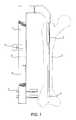
- FIG. 1shows a plan view of an aiming arm according to a preferred embodiment of the present invention wherein the protective sleeves and a fastened intramedullary nail are shown;
- FIG. 2is a side view illustrating the aiming arm transverse holes precisely aligned with the intramedullary nail holes
- FIG. 3shows a perspective view of the aligned aiming am according to a preferred embodiment of the present invention, wherein the protective sleeves and the intramedullary nail fastened to the aiming arm are shown;
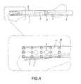
- FIG. 4shows a side view of an aiming arm according to a preferred embodiment of the present invention, wherein the fastened intramedullary nail is distorted after bone insertion, and wherein aiming arm holes and intramedullary nail transverse holes are not aligned thereof;
- FIG. 5shows a side view of an aiming arm according to a preferred embodiment of the present invention after compensation for the nail deformation was made, so that aiming arm holes and intramedullary nail transverse holes are aligned;
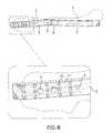
- FIG. 6is a perspective view in the plane of the aiming arm holes, illustrating how the alignment of intramedullary nail cross holes and aiming arm holes can be confirmed despite the fact that the X-ray beam is not aligned with the axis of the intramedullary nail holes;
- FIG. 7shows a perspective view of FIG. 5 ;
- FIG. 8shows a perspective view of an aiming arm according to a preferred embodiment of the present invention wherein a fastened short intramedullary nail implanted into the bone is shown;
- FIG. 9is a side view illustrating the aiming arm holes precisely aligned with the short intramedullary nail
- FIG. 10shows a perspective view of FIG. 9 , wherein the protective sleeves, the short intramedullary nail fastened to the aiming arm, and the front and rear radiopaque markers are shown;
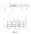
- FIG. 11shows a side view of the aiming arm according to a preferred embodiment of the present invention, wherein the fastened intramedullary nail is distorted after bone insertion, and wherein the aiming arm holes and intramedullary nail transverse holes are not aligned;
- FIG. 12is a perspective view in the plane of the aiming arm holes, illustrating how a single X-ray snapshot in this plane enables one to assess the exact distortion of the intramedullary nail after insertion into the bone;
- FIG. 13shows a perspective view of the aiming arm according to a preferred embodiment of the present invention wherein the distorted intramedullary nail, and an insert with offset holes to compensate for the distortion of the intramedullary nail are shown;
- FIG. 14shows a side view of FIG. 13 ;
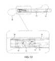
- FIG. 15is a side view of an aiming arm according to another preferred embodiment of the present invention, wherein the aiming arm is connected to an intramedullary nail;
- FIG. 16is a top view of the aiming arm shown in FIG. 15 ;
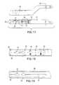
- FIG. 17includes both top and side views of the lower portion of the aiming arm of FIG. 15 ;
- FIG. 18is a partial view of a top surface of the distal portion of the aiming arm of FIG. 15 showing the radiopaque markers;
- FIG. 19is a partial view of the bottom surface of the aiming arm of FIG. 15 , opposite the surface shown in FIG. 18 ;
- FIG. 20is a partial view of the properly aligned radiopaque markers of the aiming arm shown in FIG. 15 .
- FIGS. 1-7a method of bone fixation according to the preferred embodiment of the present invention will be explained with reference to FIGS. 1-7 .
- FIG. 1there is shown an aiming device 4 , on which is mounted a mobile aiming arm portion 6 .
- An intramedullary nail 2with two coplanar transverse holes 3 is fastened to the aiming arm 4 .
- Protective sleeves 7slide through holes 5 located in the mobile part of the aiming arm 6 , guiding drills and bone screws through the nail transverse holes 3 for distal locking of the intramedullary nail 2 .
- Mobile aiming arm portion 6rotates about the axis 9 with respect to aiming arm 4 .
- the aiming arm 4is fastened to the intramedullary nail 2 , and before the nail 2 is inserted into the bone 1 , aiming arm holes 5 and intramedullary nail holes 3 are precisely aligned as shown in FIGS. 2 and 3 .
- the distortion of the intramedullary nailcauses the intramedullary nail holes 3 to move out of alignment with aiming arm holes 5 as shown in FIG. 4 .
- the aiming arm 4is formed, at least partially, of a relatively radiolucent material and is provided with radiopaque target markers 10 , 11 , which enable one to assess when the position of the X ray source and ensure that the X-ray beam is coplanar with the plane of the aiming arm holes, eliminating the need for the X-ray beam to be coaxial with the intramedullary nail holes 3 .
- a single snapshot from an X-ray source positioned such that an X-ray beam is coplanar with the aiming arm holes 5is enough to determine the exact distortion of the intramedullary nail 2 , as shown in FIG. 6 .
- the mobile part of the aiming arm 6can be positioned to compensate for the distortion of the intramedullary nail 2 , so that aiming arm holes 5 and nail holes 3 are re-aligned as shown in FIGS. 5 and 7 .
- aiming arm holes 5 and intramedullary nail holes 3are aligned it is easy to slide in the protective sleeves 7 through the aiming arm holes 5 .
- a drill bitis aligned with the nail hole 3 and drilled through the nail hole 3 and the surrounding bone material.
- the second drill bitis drilled accurately through the second nail hole 3 and the surrounding bone material, the second drill bit is removed, and a locking screw is inserted through the protection sleeve and screwed through the bone and second nail hole 3 to secure the nail to the bone.
- the first drill bitis removed, and a second locking screw is inserted through the sleeve 7 and screwed through the bone 1 and first nail hole 3 to secure the intramedullary nail 2 to the bone 1 .
- FIG. 8there is shown an aiming device 14 , fastened to a short intramedullary nail 12 .
- the intramedullary nail 12is provided with two coplanar transverse holes 13 .
- Protective sleeves 17can slide through holes 15 , existing in the insert 16 situated in the aiming arm 14 in order to guide drills and bone screws through the nail cross holes 13 , for distal locking of the intrameudullary nail 12 .
- Insert holes 15 , and nail holes 13have the same axis 19 .
- aiming arm holes 15 and nail holes 13are perfectly aligned as it can be seen in FIGS. 9 and 10 .
- the intramedullary nail 12After insertion into the bone, the intramedullary nail 12 commonly distorts such that aiming arm holes 15 and nail holes 13 are not aligned anymore as shown in FIG. 11 .
- a single snapshot of an X-ray source positioned such that an X ray beam is coplanar with the aiming arm holes 15is sufficient to determine the amount of nail distortion, as shown in FIG. 12 .
- an insert 16provided with offset holes, aiming arm holes 15 and intramedullary nail holes 13 can be aligned again as shown in FIGS. 13 and 14 .
- aiming arm holes 15 and intramedullary nail holes 13are aligned it is easy to slide in the protective sleeves 17 through the aiming arm holes 15 and slide a drill through the protective sleeves 17 to bore the bone 1 . One may then slide bone screws through the protective sleeves 17 and through the aligned nail holes 13 in order to lock the intramedullary nail 12 .
- the present inventionsrelates to a radiolucent aiming device 30 for targeting transverse bores in an intramedullary nail 32 in order to distally lock nail 32 in place within a patient's bone.
- Aiming device 30includes an aiming arm 34 , which is removably and adjustably connected to an upper handle 36 and includes at least one transverse hole 33 for receiving and guiding drilling and fixation elements.
- Aiming arm 34is configured to be both rotated with respect to handle 36 about axis 50 and translated with respect to handle 36 along axis 53 in the direction 52 .
- Aiming arm 34may also be removed from and re-connected to handle 36 for use with either left-hand or right-hand intramedullary nails.
- Handle 36is attached to intramedullary nail 32 via nail insertion handle 38 , which is releasably mounted to aiming arm handle 36 via a bolt, screw or other connection element having a knurled nut 39 .
- Aiming arm 34includes a radiolucent lower portion 35 and an upper portion 37 , where lower portion 35 is pivotally attached to upper portion 37 via a pin 40 and includes an adjustment knob 42 that actuates a screw mechanism to rotate arm portion 34 about axis 50 in order to adjust the angle of lower aiming arm portion 35 with respect to upper aiming arm portion 37 and handle 36 .
- axis 50is parallel to the axis of the transverse holes in the intramedullary nail.
- Handle 36also includes a plurality of elongated slots 44 along which the upper portion 37 of aiming arm 34 may be adjustably mounted. A particular rail is selected based upon the orientation of the nail, i.e., right or left, and the size/length of the nail 32 . Once mounted along a slot 44 by one or more pins 46 , aiming arm 34 may be releasably locked against further translation along the direction 52 by knurled nut 48 .
- lower portion 35 of aiming arm 34includes a set of radiopaque markers on both its top and bottom surfaces, 56 , 58 , respectively.
- Top surface 56includes a plurality of peripheral circles 60 aligned along the two longitudinal edges of top surface 56 and a series of dots 62 along the centerline of top surface 56 .
- a series of scale markers 64aid in determining the degree of angular adjustment necessary when the aiming arm 34 is not correctly aligned with the X-ray source.
- Top surface 56may also include radiopaque markers 66 indicating the correct orientation of the device for the given installation, i.e., the letters “L” and “R.”
- circles 60may have a diameter on the order 5.0 mm and scale markers 64 may have a length on the order of 5.0 mm.
- bottom surfaceincludes its own set of radiopaque markers in the form of two peripheral lines 68 and one median line 70 , all of which run parallel to one another.
- Peripheral lines 68extend along both longitudinal edges of the bottom surface 58
- median line 70runs along the centerline of bottom surface 58 .
- Lines 68 , 70may a have a thickness on the order of 1.0-2.0 mm.
- lower portion 35 of aiming arm 34may include one or more recessed sections 72 between the top and bottom surfaces 56 , 58 , and their respective sets of radiopaque markers, such that less solid material lies between the radiopaque markers. This will aid in visualization and alignment of the radiopaque markers under image intensification.
- aiming arm 34is connected to an appropriate slot 44 , which is selected based upon the nail length/size and the side of the patient requiring implantation, i.e., left or right.
- Knurled nut 48is loosely coupled to handle 36 and calibration trocars 41 are used to align the aiming arm holes 33 with the transverse holes in the intramedullary nail and determine the appropriate length of aiming arm 34 .
- aiming arm holes 33are properly aligned with the nail holes, knurled nut 48 is tightened securely and the calibration trocars are removed from device 30 .
- aiming device 30is removed from insertion handle 38 , and the nail is inserted into the medullary canal of the patient. After insertion, the nail is typically locked proximally using known techniques.
- aiming device 30is re-attached to the nail insertion handle 38 , with care taken not to adjust the knurled nut 48 , which locks the aiming arm 34 against translational movement along slot 44 .
- the image intensification equipmentC-ARM
- the surgeonverifies that the image of the radiopaque markers of aiming arm 34 is configured for the appropriate side (left or right). If so, the “L” or “R” symbol, shown as 66 in FIG. 17 .
- the imagemay be transposed.
- the surgeonthen identifies the various radiopaque markers, e.g., peripheral circles 60 , dots 62 , scale markers 64 , and lines 68 , 70 .
- the C-ARM beamis then adjusted in order to align the dots 62 so that they overlay the median line 70 and/or so that the relationship between the peripheral circles 60 and peripheral lines 68 is symmetrical (as shown in FIGS. 5 & 20 ). Therefore, if the dots 62 and circles 60 are above lines 68 and 70 , the C-ARM should be rotated down, and if the dots 62 and circles 60 are below the lines 68 , 70 , then the C-ARM should be rotated up.
- scale markers 64are configured such that each graduation of the scale represents 2° of rotation. Therefore, the surgeon can use the scale markers 64 to determine the amount the C-ARM needs to be rotated in order to properly align the beam with the plane of the aiming arm holes 33 . As shown in FIG. 20 , when the center dots 62 overlay the median line 70 , and the peripheral circles 60 lie symmetrically with respect to the peripheral lines 68 , aiming arm 34 has been properly aligned with the C-ARM. If circles 60 are not symmetrically positioned with respect to the peripheral lines 68 , the C-ARM still requires adjustment.
- aiming arm 34is properly aligned with the C-ARM, the surgeon can visualize the nail and determine if any deflection in the anterior-posterior plane, i.e., in a direction perpendicular to the axis of the nail holes, has occurred. If so, the lower portion 35 of aiming arm 34 can be adjusted to re-align the aiming arm holes 33 with the nail holes. As discussed above, turning of adjustment knob 42 rotates the lower portion 35 of aiming arm 34 with respect to the handle 36 to accomplish this alignment and compensate for the anterior-posterior nail deflection. After adjusting the angle of the aiming arm 34 , a final check should be made to ensure that the radiopaque markers are still in proper alignment. If not, the alignment steps described above should be repeated. Once aligned, a sleeve/trocar assembly is inserted through the aiming arm holes 33 , and the radiopaque markers are checked once again to confirm alignment prior to drilling and insertion of locking elements.
Landscapes
- Health & Medical Sciences (AREA)
- Surgery (AREA)
- Life Sciences & Earth Sciences (AREA)
- Orthopedic Medicine & Surgery (AREA)
- Nuclear Medicine, Radiotherapy & Molecular Imaging (AREA)
- Medical Informatics (AREA)
- Public Health (AREA)
- Heart & Thoracic Surgery (AREA)
- Engineering & Computer Science (AREA)
- Molecular Biology (AREA)
- Animal Behavior & Ethology (AREA)
- General Health & Medical Sciences (AREA)
- Biomedical Technology (AREA)
- Veterinary Medicine (AREA)
- Dentistry (AREA)
- Oral & Maxillofacial Surgery (AREA)
- Pathology (AREA)
- Radiology & Medical Imaging (AREA)
- Surgical Instruments (AREA)
Abstract
Description
- Length variation in the axis of the intramedullary nail.
- Rotational distortion in the axis of the intramedullary nail.
- Flexion distortion in the plane of the intramedullary nail distal holes
- Flexion distortion perpendicular to the plane of the distal holes of the intramedullary nail.
Claims (14)
Priority Applications (2)
| Application Number | Priority Date | Filing Date | Title |
|---|---|---|---|
| US12/984,974US10080574B2 (en) | 2004-09-23 | 2011-01-05 | Coplana X-ray guided aiming arm for locking of intramedullary nails |
| US16/128,173US10820916B2 (en) | 2004-09-23 | 2018-09-11 | Coplanar X-ray guided aiming arm for locking of intramedullary nails |
Applications Claiming Priority (3)
| Application Number | Priority Date | Filing Date | Title |
|---|---|---|---|
| US10/947,155US7481815B2 (en) | 2004-09-23 | 2004-09-23 | Coplanar X-ray guided aiming arm for locking of intramedullary nails |
| US11/240,785US7887545B2 (en) | 2004-09-23 | 2005-09-23 | Coplanar X-ray guided aiming arm for intramedullary nails |
| US12/984,974US10080574B2 (en) | 2004-09-23 | 2011-01-05 | Coplana X-ray guided aiming arm for locking of intramedullary nails |
Related Parent Applications (1)
| Application Number | Title | Priority Date | Filing Date |
|---|---|---|---|
| US11/240,785ContinuationUS7887545B2 (en) | 2004-09-23 | 2005-09-23 | Coplanar X-ray guided aiming arm for intramedullary nails |
Related Child Applications (1)
| Application Number | Title | Priority Date | Filing Date |
|---|---|---|---|
| US16/128,173ContinuationUS10820916B2 (en) | 2004-09-23 | 2018-09-11 | Coplanar X-ray guided aiming arm for locking of intramedullary nails |
Publications (2)
| Publication Number | Publication Date |
|---|---|
| US20110130765A1 US20110130765A1 (en) | 2011-06-02 |
| US10080574B2true US10080574B2 (en) | 2018-09-25 |
Family
ID=35500916
Family Applications (6)
| Application Number | Title | Priority Date | Filing Date |
|---|---|---|---|
| US10/947,155Expired - LifetimeUS7481815B2 (en) | 2004-09-23 | 2004-09-23 | Coplanar X-ray guided aiming arm for locking of intramedullary nails |
| US11/240,785Active2028-12-16US7887545B2 (en) | 2004-09-23 | 2005-09-23 | Coplanar X-ray guided aiming arm for intramedullary nails |
| US12/357,011Active2026-07-18US8202276B2 (en) | 2004-09-23 | 2009-01-21 | Coplanar X-ray guided aiming arm for locking of intramedullary nails |
| US12/984,974Active2030-04-15US10080574B2 (en) | 2004-09-23 | 2011-01-05 | Coplana X-ray guided aiming arm for locking of intramedullary nails |
| US13/471,669Expired - Fee RelatedUS8500746B2 (en) | 2004-09-23 | 2012-05-15 | Coplanar X-ray guided aiming arm for locking of intramedullary nails |
| US16/128,173Expired - LifetimeUS10820916B2 (en) | 2004-09-23 | 2018-09-11 | Coplanar X-ray guided aiming arm for locking of intramedullary nails |
Family Applications Before (3)
| Application Number | Title | Priority Date | Filing Date |
|---|---|---|---|
| US10/947,155Expired - LifetimeUS7481815B2 (en) | 2004-09-23 | 2004-09-23 | Coplanar X-ray guided aiming arm for locking of intramedullary nails |
| US11/240,785Active2028-12-16US7887545B2 (en) | 2004-09-23 | 2005-09-23 | Coplanar X-ray guided aiming arm for intramedullary nails |
| US12/357,011Active2026-07-18US8202276B2 (en) | 2004-09-23 | 2009-01-21 | Coplanar X-ray guided aiming arm for locking of intramedullary nails |
Family Applications After (2)
| Application Number | Title | Priority Date | Filing Date |
|---|---|---|---|
| US13/471,669Expired - Fee RelatedUS8500746B2 (en) | 2004-09-23 | 2012-05-15 | Coplanar X-ray guided aiming arm for locking of intramedullary nails |
| US16/128,173Expired - LifetimeUS10820916B2 (en) | 2004-09-23 | 2018-09-11 | Coplanar X-ray guided aiming arm for locking of intramedullary nails |
Country Status (11)
| Country | Link |
|---|---|
| US (6) | US7481815B2 (en) |
| EP (2) | EP1799127B1 (en) |
| JP (1) | JP4955561B2 (en) |
| KR (1) | KR101205933B1 (en) |
| CN (2) | CN101584598B (en) |
| AU (1) | AU2005286622A1 (en) |
| BR (1) | BRPI0515574B8 (en) |
| CA (1) | CA2580928C (en) |
| NZ (1) | NZ554233A (en) |
| WO (1) | WO2006034503A1 (en) |
| ZA (1) | ZA200702531B (en) |
Families Citing this family (96)
| Publication number | Priority date | Publication date | Assignee | Title |
|---|---|---|---|---|
| JP2007504845A (en)* | 2003-07-14 | 2007-03-08 | ジンテーズ アクチエンゲゼルシャフト クール | Sighting device |
| US7406775B2 (en)* | 2004-04-22 | 2008-08-05 | Archus Orthopedics, Inc. | Implantable orthopedic device component selection instrument and methods |
| US20070276404A1 (en)* | 2004-09-16 | 2007-11-29 | Alfa Plastics S.R.L. | Aligning Device for Correctly Inserting Screws Into Holes of Endomedullary Prostheses, and Relative Alignment Method |
| US20060173458A1 (en)* | 2004-10-07 | 2006-08-03 | Micah Forstein | Bone fracture fixation system |
| JP2008532707A (en)* | 2005-03-17 | 2008-08-21 | スミス アンド ネフュー インコーポレーテッド | Medical fixing member placement system |
| WO2006105673A1 (en)* | 2005-04-06 | 2006-10-12 | Synthes Ag Chur | Aiming device |
| WO2008001386A2 (en)* | 2006-06-29 | 2008-01-03 | L.R.S. Ortho Ltd. | System and method for locating of distal holes of an intramedullary nail |
| US8685034B2 (en)* | 2006-08-10 | 2014-04-01 | Stryker Trauma Gmbh | Distal targeting device |
| EP2051647B1 (en)* | 2006-08-15 | 2010-12-01 | AO Technology AG | Method and device for computer assisted distal locking of intramedullary nails |
| US20080125782A1 (en)* | 2006-11-29 | 2008-05-29 | Disc Dynamics, Inc. | Method and apparatus for removing an extension from a prosthesis |
| US8795287B2 (en)* | 2007-02-08 | 2014-08-05 | Zimmer, Inc. | Targeting device |
| US8784425B2 (en)* | 2007-02-28 | 2014-07-22 | Smith & Nephew, Inc. | Systems and methods for identifying landmarks on orthopedic implants |
| US8814868B2 (en) | 2007-02-28 | 2014-08-26 | Smith & Nephew, Inc. | Instrumented orthopaedic implant for identifying a landmark |
| US20100030219A1 (en)* | 2007-07-01 | 2010-02-04 | L.R.S. Ortho Ltd. | Orthopedic navigation system and method |
| US20110184477A1 (en)* | 2007-09-13 | 2011-07-28 | Synthes Usa Llc | Aiming Arm for Locking of Bone Nails |
| US8273091B2 (en)* | 2007-10-04 | 2012-09-25 | Ebi, Llc | Alignment device for locking nail |
| US8771283B2 (en) | 2007-12-17 | 2014-07-08 | Wright Medical Technology, Inc. | Guide assembly for intramedullary fixation and method of using the same |
| ES2595366T3 (en) | 2008-01-09 | 2016-12-29 | Stryker European Holdings I, Llc | Computer-assisted stereotactic surgery system based on a three-dimensional visualization |
| CA2781407A1 (en) | 2008-01-14 | 2009-07-23 | Michael P. Brenzel | Apparatus and methods for fracture repair |
| US9220514B2 (en) | 2008-02-28 | 2015-12-29 | Smith & Nephew, Inc. | System and method for identifying a landmark |
| BRPI0920250A2 (en)* | 2008-10-15 | 2016-11-22 | Smith & Nephew Inc | composite internal fasteners |
| CA2749684C (en)* | 2009-01-16 | 2016-04-26 | Carbofix Orthopedics Ltd. | Composite material bone implant |
| US9031637B2 (en)* | 2009-04-27 | 2015-05-12 | Smith & Nephew, Inc. | Targeting an orthopaedic implant landmark |
| US8945147B2 (en) | 2009-04-27 | 2015-02-03 | Smith & Nephew, Inc. | System and method for identifying a landmark |
| US8932301B2 (en)* | 2009-08-26 | 2015-01-13 | Biomet C.V. | Targeting jig for hip fracture nail system |
| USD674093S1 (en) | 2009-08-26 | 2013-01-08 | Smith & Nephew, Inc. | Landmark identifier for targeting a landmark of an orthopaedic implant |
| US8086734B2 (en) | 2009-08-26 | 2011-12-27 | International Business Machines Corporation | Method of autonomic representative selection in local area networks |
| US20110178520A1 (en) | 2010-01-15 | 2011-07-21 | Kyle Taylor | Rotary-rigid orthopaedic rod |
| WO2011091052A1 (en) | 2010-01-20 | 2011-07-28 | Kyle Taylor | Apparatus and methods for bone access and cavity preparation |
| US10588647B2 (en)* | 2010-03-01 | 2020-03-17 | Stryker European Holdings I, Llc | Computer assisted surgery system |
| US8333807B2 (en)* | 2010-03-05 | 2012-12-18 | Biomet Manufacturing Corp. | Method and apparatus for trialing and implanting a modular femoral hip |
| WO2011112615A1 (en) | 2010-03-08 | 2011-09-15 | Krinke Todd A | Apparatus and methods for securing a bone implant |
| CA2829196A1 (en)* | 2010-03-08 | 2011-09-15 | Conventus Orthopaedics, Inc. | Apparatus and methods for bone repair |
| US8535337B2 (en) | 2010-04-26 | 2013-09-17 | David Chang | Pedicle screw insertion system and method |
| RU2012157125A (en) | 2010-06-03 | 2014-07-20 | Смит Энд Нефью, Инк. | ORTHOPEDIC IMPLANT |
| CN105877829B (en) | 2010-06-07 | 2018-06-22 | 卡波菲克斯整形有限公司 | Composite material bone implant |
| US10154867B2 (en) | 2010-06-07 | 2018-12-18 | Carbofix In Orthopedics Llc | Multi-layer composite material bone screw |
| US9517107B2 (en) | 2010-07-16 | 2016-12-13 | Stryker European Holdings I, Llc | Surgical targeting system and method |
| KR101244901B1 (en)* | 2010-12-06 | 2013-03-18 | 김정재 | aiming arm for locking feumr medullary nail |
| WO2012103169A2 (en) | 2011-01-25 | 2012-08-02 | Smith & Nephew, Inc. | Targeting operation sites |
| CN102670296B (en)* | 2011-03-18 | 2014-10-22 | 创生医疗器械(中国)有限公司 | Intramedullary nail aiming device |
| RU2013153116A (en)* | 2011-05-06 | 2015-06-20 | Смит Энд Нефью, Инк. | TARGETING FOR SIGNIFICANT POINTS OF ORTHOPEDIC DEVICES |
| CA2837205A1 (en)* | 2011-05-25 | 2012-11-29 | DePuy Synthes Products, LLC | Aiming device having radio-opaque markers |
| WO2012173890A2 (en) | 2011-06-16 | 2012-12-20 | Smith & Nephew, Inc. | Surgical alignment using references |
| US8551106B2 (en)* | 2011-09-30 | 2013-10-08 | Arthrocare Corporation | Method and apparatus for installation of intramedullary medical device |
| US8968324B2 (en) | 2011-10-27 | 2015-03-03 | Kettering University | Adjustable jig and method for targeting interlocking holes of an intramedullary nail |
| US9687308B2 (en) | 2011-12-15 | 2017-06-27 | AO Technolgoy AG | Method and a device for computer assisted surgery |
| CN107184248B (en)* | 2012-02-08 | 2020-02-21 | Epix整形外科股份有限公司 | Implant Insertion Device |
| US8382758B1 (en) | 2012-03-08 | 2013-02-26 | Mark Sommers | Method for aligning upper extremity bones and inserting guide device |
| US10039606B2 (en) | 2012-09-27 | 2018-08-07 | Stryker European Holdings I, Llc | Rotational position determination |
| US10105151B2 (en) | 2012-12-12 | 2018-10-23 | Wright Medical Technology, Inc. | Instrument for intra-operative implant templating using fluoroscopy |
| US9155582B2 (en)* | 2013-01-30 | 2015-10-13 | DePuy Synthes Products, Inc. | Aiming instrument |
| US8721644B1 (en)* | 2013-03-08 | 2014-05-13 | Ta-Lun Tan | Intramedullary apparatus and methods of treating bone fracture using the same |
| WO2014140808A1 (en)* | 2013-03-15 | 2014-09-18 | Materialise Nv | Adaptive surface surgical guiding apparatus and systems and methods of manufacturing adaptive surface surgical guiding apparatus |
| DE102013210185A1 (en)* | 2013-05-31 | 2014-12-04 | Siemens Aktiengesellschaft | Method of visual assistance in fixing an implant |
| EP3003174B1 (en)* | 2013-06-07 | 2019-03-27 | Stryker European Holdings I, LLC | Targeting adjustment |
| WO2014194965A1 (en) | 2013-06-07 | 2014-12-11 | Stryker Trauma Gmbh | Targeting adjustment system for an intramedullary nail |
| CN105939677A (en) | 2013-12-12 | 2016-09-14 | 康文图斯整形外科公司 | Tissue displacement tools and methods |
| CN103654932A (en)* | 2013-12-17 | 2014-03-26 | 周玉梅 | Orthopaedics department steel plate implanting device |
| US9386995B1 (en) | 2015-06-11 | 2016-07-12 | Jake Doroshow | Apparatus and method for guiding a surgical drill during orthopedic surgery |
| GB2544501B (en)* | 2015-11-18 | 2017-12-13 | Grampian Health Board | Variable curve jig for an intramedullary nail |
| US10918412B2 (en)* | 2015-12-18 | 2021-02-16 | Boston Scientific Scimed, Inc. | Surgical guidance devices, methods, and systems |
| US10617458B2 (en) | 2015-12-23 | 2020-04-14 | Carbofix In Orthopedics Llc | Multi-layer composite material bone screw |
| US11045242B2 (en) | 2016-09-22 | 2021-06-29 | Globus Medical, Inc. | Systems and methods for intramedullary nail implantation |
| US10751096B2 (en) | 2016-09-22 | 2020-08-25 | Bala Sundararajan | Systems and methods for intramedullary nail implantation |
| US11083503B2 (en) | 2016-09-22 | 2021-08-10 | Globus Medical, Inc. | Systems and methods for intramedullary nail implantation |
| US10299847B2 (en) | 2016-09-22 | 2019-05-28 | Globus Medical, Inc. | Systems and methods for intramedullary nail implantation |
| US10695135B2 (en)* | 2016-11-08 | 2020-06-30 | Kaohsiung Medical University | Non-invasive positioning system and method for screwing and fixing a bone |
| CN108210038A (en)* | 2016-12-14 | 2018-06-29 | 创生医疗器械(中国)有限公司 | Intramedullary nail pinning mechanism |
| US10631881B2 (en) | 2017-03-09 | 2020-04-28 | Flower Orthopedics Corporation | Plating depth gauge and countersink instrument |
| US11364077B2 (en)* | 2017-03-24 | 2022-06-21 | The Spectranetics Corporation | Laser energy delivery devices including distal tip orientation indicators |
| WO2019010252A2 (en) | 2017-07-04 | 2019-01-10 | Conventus Orthopaedics, Inc. | APPARATUS AND METHODS FOR TREATING BONES |
| US10517612B2 (en) | 2017-09-19 | 2019-12-31 | Biosense Webster (Israel) Ltd. | Nail hole guiding system |
| MX2020003481A (en) | 2017-10-11 | 2020-12-07 | Howmedica Osteonics Corp | Humeral fixation plate guides. |
| CN107802277B (en)* | 2017-11-13 | 2021-04-23 | 冯启鲁 | Device for determining placement of bone nail in hip joint surgery |
| US10939945B2 (en)* | 2017-11-16 | 2021-03-09 | Metal Industries Research & Development Centre | Minimally invasive bone fracture positioning device |
| KR102293985B1 (en)* | 2018-05-23 | 2021-08-27 | 전남대학교산학협력단 | Surgical operation apparatus for fracture reduction |
| CN110788371B (en)* | 2018-08-01 | 2020-10-16 | 航天特种材料及工艺技术研究所 | A accurate positioning drilling equipment for narrow and small space of high degree of depth |
| JP6983204B2 (en)* | 2018-10-08 | 2021-12-17 | グローバス メディカル インコーポレイティッド | Systems and methods for intramedullary nail implantation |
| EP4003198B1 (en) | 2019-07-26 | 2025-01-08 | GLW, Inc. | Intramedullary rod with intrabody outrigger interface |
| CN111184568A (en)* | 2020-01-21 | 2020-05-22 | 杨彬奎 | Intramedullary nail distal locking hole aiming and positioning device |
| WO2021154794A1 (en) | 2020-01-28 | 2021-08-05 | Mason Bettenga | Systems and methods for aligning surgical devices |
| CN111671509B (en)* | 2020-04-20 | 2022-08-23 | 杭州市萧山区第一人民医院 | Intra-articular fracture minimally invasive surgery sighting device with resetting function |
| CN114052875B (en)* | 2020-08-07 | 2025-04-22 | 北京蒙太因医疗器械有限公司 | Intramedullary nail aiming device and bone treatment system including the same |
| CN111904577B (en)* | 2020-08-17 | 2025-10-03 | 天津正天医疗器械有限公司 | Intramedullary nail aiming device and surgical instrument box containing the same |
| CN112244977B (en)* | 2020-10-22 | 2022-03-15 | 刘磊 | Auxiliary device for aiming of intramedullary ultrasonic locking nail for orthopedics department |
| CN112155706B (en)* | 2020-10-29 | 2024-10-29 | 河南省洛阳正骨医院(河南省骨科医院) | Distal locking nail fine tuning aiming device for femoral intramedullary nail |
| CN112515730B (en)* | 2020-12-17 | 2024-10-22 | 郝晓艳 | Drilling guide for intramedullary nail |
| WO2022204002A1 (en)* | 2021-03-22 | 2022-09-29 | Acumed Llc | Targeting device for screw insertion in distal end of bone |
| CN113558743A (en)* | 2021-08-09 | 2021-10-29 | 北京市春立正达医疗器械股份有限公司 | Adjustable aiming arm for intramedullary nail |
| CN113855208B (en)* | 2021-10-08 | 2024-04-16 | 四川省骨科医院 | Handle for installing femoral intramedullary nail |
| US11806061B2 (en) | 2021-11-05 | 2023-11-07 | Jordan Andre BAUER | And method for proximal and distal screw fixation in intramedullary tibial nails |
| KR102676159B1 (en)* | 2021-11-10 | 2024-06-19 | 주식회사 엔가든 | Insertion guidance system for locking screw and locking screw guidance method using the same, and a computer-readable storage medium |
| CN116807591B (en)* | 2023-08-29 | 2023-11-10 | 核工业四一六医院 | Auxiliary positioning instrument for fracture hollow nails |
| CN118845143B (en)* | 2024-09-25 | 2025-02-07 | 浙江德康医疗器械有限公司 | Aiming module, intramedullary nail aiming arm and intramedullary nail aiming device |
| CN118845181B (en)* | 2024-09-25 | 2025-02-14 | 浙江德康医疗器械有限公司 | Intramedullary nail aiming system |
Citations (101)
| Publication number | Priority date | Publication date | Assignee | Title |
|---|---|---|---|---|
| US2531734A (en) | 1945-07-27 | 1950-11-28 | Heywood H Hopkins | Hip nail aiming device |
| US3613684A (en) | 1969-09-19 | 1971-10-19 | David S Sheridan | Trocar catheters |
| US3704707A (en) | 1971-04-06 | 1972-12-05 | William X Halloran | Orthopedic drill guide apparatus |
| US4037592A (en) | 1976-05-04 | 1977-07-26 | Kronner Richard F | Guide pin locating tool and method |
| US4418422A (en) | 1978-02-22 | 1983-11-29 | Howmedica International, Inc. | Aiming device for setting nails in bones |
| US4541424A (en)* | 1982-03-30 | 1985-09-17 | Howmedica International, Inc. | Distal aiming device for a locking nail |
| US4621628A (en) | 1983-09-09 | 1986-11-11 | Ortopedia Gmbh | Apparatus for locating transverse holes of intramedullary implantates |
| US4622959A (en) | 1985-03-05 | 1986-11-18 | Marcus Randall E | Multi-use femoral intramedullary nail |
| US4625718A (en) | 1984-06-08 | 1986-12-02 | Howmedica International, Inc. | Aiming apparatus |
| US4667664A (en) | 1985-01-18 | 1987-05-26 | Richards Medical Company | Blind hole targeting device for orthopedic surgery |
| US4722336A (en) | 1985-01-25 | 1988-02-02 | Michael Kim | Placement guide |
| CH664725A5 (en) | 1985-05-07 | 1988-03-31 | Synthes Ag | Eyepiece instrument for surgical alignment |
| CH668692A5 (en) | 1984-11-30 | 1989-01-31 | Synthes Ag | Bone pin alignment instrument - has lockable head pivoting in all directions |
| US4803976A (en) | 1985-10-03 | 1989-02-14 | Synthes | Sighting instrument |
| US4848327A (en) | 1988-05-23 | 1989-07-18 | Perdue Kevin D | Apparatus and procedure for blind alignment of fasteners extended through transverse holes in an orthopedic locking nail |
| US4865025A (en) | 1984-12-26 | 1989-09-12 | Carlo Buzzi | Drill guide aiming device for medullary rods |
| US4877019A (en) | 1986-12-02 | 1989-10-31 | Pierre Vives | Intramedullary nail and apparatus for its insertion |
| US4881535A (en) | 1988-09-06 | 1989-11-21 | Sohngen Gary W | Intramedullary rod targeting device |
| US4917111A (en) | 1987-10-15 | 1990-04-17 | Dietmar Pennig | Instrument for aiming and hole forming for implantation of locking nails of the like |
| US4969889A (en) | 1986-12-22 | 1990-11-13 | Zimmer, Inc. | Instrument for locating a hole |
| US4976713A (en) | 1988-07-28 | 1990-12-11 | Icp France | Aiming device to position at least one fixing component of the centromedullar nail type, through an implant |
| US5013317A (en) | 1990-02-07 | 1991-05-07 | Smith & Nephew Richards Inc. | Medical drill assembly transparent to X-rays and targeting drill bit |
| US5031203A (en) | 1990-02-09 | 1991-07-09 | Trecha Randal R | Coaxial laser targeting device for use with x-ray equipment and surgical drill equipment during surgical procedures |
| US5030222A (en) | 1990-05-09 | 1991-07-09 | James Calandruccio | Radiolucent orthopedic chuck |
| US5070861A (en) | 1989-06-10 | 1991-12-10 | Dornier Medizintechnik Gmbh | X-ray sighting for aiming lithotripter |
| WO1992001422A1 (en) | 1990-07-24 | 1992-02-06 | British Technology Group Plc | Interlocking intramedullary nails |
| US5112336A (en) | 1991-05-14 | 1992-05-12 | Intermedics Orthopedics, Inc. | Drill guide and template for prosthetic devices |
| US5127913A (en) | 1991-04-22 | 1992-07-07 | Thomas Jr Charles B | Apparatus and method for implanting an intramedullary rod |
| US5234434A (en) | 1992-08-17 | 1993-08-10 | Marlowe Goble E | Mutliple guide sleeve drill guide |
| US5261915A (en) | 1992-04-16 | 1993-11-16 | Scott M. Durlacher | Femur bone rasp with adjustable handle |
| US5283808A (en) | 1992-07-01 | 1994-02-01 | Diasonics, Inc. | X-ray device having a co-axial laser aiming system in an opposed configuration |
| US5295991A (en) | 1991-05-24 | 1994-03-22 | Synthes (U.S.A.) | Surgical instrument for positioning osteosynthetic elements |
| EP0589592A2 (en) | 1992-09-22 | 1994-03-30 | ORTHOFIX S.r.l. | Centering means for holes of intramedullary nails |
| US5306278A (en) | 1992-09-11 | 1994-04-26 | Ace Medical Company | Corticotomy drill guide |
| US5308350A (en) | 1990-04-11 | 1994-05-03 | Mikhail Michael W E | Femoral distractor for use in knee surgery |
| US5312412A (en) | 1993-02-03 | 1994-05-17 | Whipple Terry L | Fixation alignment guide for surgical use |
| US5334203A (en) | 1992-09-30 | 1994-08-02 | Amei Technologies Inc. | Spinal fixation system and methods |
| US5334192A (en) | 1991-01-30 | 1994-08-02 | Homwedica Gmbh | Targeting device for an implant |
| US5346496A (en) | 1991-12-13 | 1994-09-13 | Dietmar Pennig | Drill-device for alignment of a bone screw driven into the neck of a femur |
| US5352228A (en) | 1993-05-10 | 1994-10-04 | Kummer Frederick J | Apparatus and method to provide compression for a locked intramedullary nail |
| US5403321A (en) | 1993-12-15 | 1995-04-04 | Smith & Nephew Richards Inc. | Radiolucent drill guide |
| US5403322A (en) | 1993-07-08 | 1995-04-04 | Smith & Nephew Richards Inc. | Drill guide and method for avoiding intramedullary nails in the placement of bone pins |
| US5403320A (en) | 1993-01-07 | 1995-04-04 | Venus Corporation | Bone milling guide apparatus and method |
| US5411503A (en) | 1993-06-18 | 1995-05-02 | Hollstien; Steven B. | Instrumentation for distal targeting of locking screws in intramedullary nails |
| US5417688A (en) | 1993-12-22 | 1995-05-23 | Elstrom; John A. | Optical distal targeting system for an intramedullary nail |
| US5426687A (en) | 1992-07-07 | 1995-06-20 | Innovative Care Ltd. | Laser targeting device for use with image intensifiers in surgery |
| US5429641A (en) | 1993-03-28 | 1995-07-04 | Gotfried; Yechiel | Surgical device for connection of fractured bones |
| US5433720A (en) | 1992-09-22 | 1995-07-18 | Orthofix S.R.L. | Centering means for holes of intramedullary nails |
| US5458600A (en) | 1991-12-07 | 1995-10-17 | Howmedica Gmbh | Locking nail for hollow bone fractures |
| WO1995030378A1 (en) | 1994-05-06 | 1995-11-16 | Ternamian Artin M | Laparoscopic instrument for penetrating body tissue |
| US5470335A (en) | 1992-05-03 | 1995-11-28 | Technology Finance Corporation (Proprietary) Limited | Method for carrying out an osteotomy procedure |
| US5474561A (en) | 1994-02-01 | 1995-12-12 | Yao; Meei-Huei | All positional and universal guiding device for interlocking intramedullary nail |
| US5478343A (en) | 1991-06-13 | 1995-12-26 | Howmedica International, Inc. | Targeting device for bone nails |
| US5489284A (en) | 1994-07-15 | 1996-02-06 | Smith & Nephew Richards Inc. | Cannulated modular intramedullary nail |
| US5498265A (en) | 1991-03-05 | 1996-03-12 | Howmedica Inc. | Screw and driver |
| US5499986A (en) | 1994-01-07 | 1996-03-19 | Smith & Nephew Richards Inc. | Quick release handle apparatus for removing and inserting intramedullary nails |
| US5513240A (en) | 1993-05-18 | 1996-04-30 | The Research Foundation Of Suny | Intraoral radiograph alignment device |
| US5514145A (en) | 1994-05-04 | 1996-05-07 | Durham; Alfred A. | Magnetic positioner arrangement for locking screws for orthopedic hardware |
| US5569262A (en) | 1995-05-19 | 1996-10-29 | Carney; William P. | Guide tool for surgical devices |
| US5576194A (en) | 1986-07-11 | 1996-11-19 | Bayer Corporation | Recombinant protein production |
| US5584838A (en) | 1991-07-09 | 1996-12-17 | Stryker Corporation | Distal targeting system |
| US5613971A (en) | 1995-08-11 | 1997-03-25 | Depuy Inc. | Ratcheting tibial and femoral guide |
| US5620449A (en) | 1994-07-28 | 1997-04-15 | Orthofix, S.R.L. | Mechanical system for blind nail-hole alignment of bone screws |
| US5624447A (en) | 1995-03-20 | 1997-04-29 | Othy, Inc. | Surgical tool guide and entry hole positioner |
| US5665086A (en) | 1994-05-20 | 1997-09-09 | Asahi Kogaku Kogyo Kabushiki Kaisha | Instrument for inserting an intramedullary nail in a bone |
| US5681318A (en) | 1992-02-13 | 1997-10-28 | Orthofix S.R.L. | Medullary cavity template |
| US5722978A (en) | 1996-03-13 | 1998-03-03 | Jenkins, Jr.; Joseph Robert | Osteotomy system |
| US5728128A (en) | 1997-02-11 | 1998-03-17 | Wright Medical Technology, Inc. | Femoral neck anteversion guide |
| US5766179A (en) | 1997-03-05 | 1998-06-16 | Orthofix S.R.L. | Mechanical system for blind nail-hole alignment of bone screws |
| US5772594A (en) | 1995-10-17 | 1998-06-30 | Barrick; Earl F. | Fluoroscopic image guided orthopaedic surgery system with intraoperative registration |
| US5855579A (en) | 1994-07-15 | 1999-01-05 | Smith & Nephew, Inc. | Cannulated modular intramedullary nail |
| US5891158A (en) | 1997-10-23 | 1999-04-06 | Manwaring; Kim H. | Method and system for directing an instrument to a target |
| US5899908A (en) | 1993-02-10 | 1999-05-04 | Sulzer Spine-Tech Inc. | Spinal drill tube guide |
| US5904685A (en) | 1997-04-11 | 1999-05-18 | Stryker Corporation | Screw sheath |
| US5913860A (en) | 1998-02-27 | 1999-06-22 | Synthes (Usa) | Surgical nail inserter |
| EP0923906A2 (en) | 1997-12-19 | 1999-06-23 | Howmedica Inc. | Implant device targetting instrument and method for use |
| US5951561A (en) | 1998-06-30 | 1999-09-14 | Smith & Nephew, Inc. | Minimally invasive intramedullary nail insertion instruments and method |
| US5989260A (en) | 1994-08-22 | 1999-11-23 | Yao; Meei-Huei | Intramedullary nail guide rod with measure scale marked thereon |
| US6015408A (en) | 1997-07-02 | 2000-01-18 | Howmedica International Inc. | Apparatus for impacting bone chips in a bone canal |
| US6024746A (en) | 1995-05-31 | 2000-02-15 | Lawrence Katz | Method and apparatus for locating bone cuts at the distal condylar femur region to receive a femoral prothesis and to coordinate tibial and patellar resection and replacement with femoral resection and replacement |
| US6027507A (en) | 1998-04-30 | 2000-02-22 | Innomed, Inc. | Leg length gauge for total hip surgery |
| US6033407A (en) | 1998-01-27 | 2000-03-07 | Behrens; Alfred F. | Apparatus and method for intramedullary nailing and intramedullary nail therefor |
| US6036657A (en) | 1995-09-08 | 2000-03-14 | United States Surgical Corporation | Apparatus for removing tissue |
| US6080159A (en) | 1996-07-16 | 2000-06-27 | Sulzer Orthopedics Ltd. | Ascending centromedullary thigh bone pin with mechanical clamping of its two ends |
| US6126659A (en) | 1998-09-30 | 2000-10-03 | Depuy Orthopaedics, Inc. | Impaction instruments |
| US6126661A (en) | 1997-01-20 | 2000-10-03 | Orthofix S.R.L. | Intramedullary cavity nail and kit for the treatment of fractures of the hip |
| US6129729A (en) | 1998-11-11 | 2000-10-10 | Snyder; Samuel J. | Apparatus and method for targeting and/or installing fasteners into an intramedullary nail |
| US6168595B1 (en) | 1997-02-11 | 2001-01-02 | Orthomatrix, Inc. | Modular intramedullary fixation system and insertion instrumentation |
| US6174335B1 (en) | 1996-12-23 | 2001-01-16 | Johnson & Johnson Professional, Inc. | Alignment guide for slotted prosthetic stem |
| US6183477B1 (en) | 1998-09-04 | 2001-02-06 | Smith & Nephew, Inc. | Attachment tool for drill guide |
| US6371959B1 (en) | 2000-04-05 | 2002-04-16 | Michael E. Trice | Radiolucent position locating device and drill guide |
| US6514253B1 (en)* | 2000-11-22 | 2003-02-04 | Meei-Huei Yao | Apparatus for locating interlocking intramedullary nails |
| WO2003092515A2 (en) | 2002-04-27 | 2003-11-13 | Grampian University Hospitals Nhs Trust | Apparatus and method for aligning and positioning implants in a body |
| US6656189B1 (en) | 2000-05-25 | 2003-12-02 | Synthes (Usa) | Radiolucent aiming guide |
| US6702823B2 (en)* | 2002-01-14 | 2004-03-09 | Hit Medica S.R.L. | Device for identifying the position of intramedullary nail securement screw holes |
| US20060098851A1 (en) | 2002-06-17 | 2006-05-11 | Moshe Shoham | Robot for use with orthopaedic inserts |
| US7056322B2 (en)* | 2002-03-28 | 2006-06-06 | Depuy Orthopaedics, Inc. | Bone fastener targeting and compression/distraction device for an intramedullary nail and method of use |
| US7175633B2 (en) | 2001-10-17 | 2007-02-13 | Synthes (Usa) | Orthopedic implant insertion instruments |
| US8591517B2 (en)* | 2008-06-30 | 2013-11-26 | Biomet C.V. | Targeting apparatus for use in a medical procedure |
| US8675930B2 (en)* | 2004-04-22 | 2014-03-18 | Gmedelaware 2 Llc | Implantable orthopedic device component selection instrument and methods |
| US8685034B2 (en)* | 2006-08-10 | 2014-04-01 | Stryker Trauma Gmbh | Distal targeting device |
Family Cites Families (5)
| Publication number | Priority date | Publication date | Assignee | Title |
|---|---|---|---|---|
| US2200120A (en)* | 1938-04-30 | 1940-05-07 | Walter W Nauth | Fracture nail guide |
| JP3123332B2 (en)* | 1994-02-25 | 2001-01-09 | 富士電機株式会社 | Switching power supply |
| US5649930A (en)* | 1996-01-26 | 1997-07-22 | Kertzner; Richard I. | Orthopedic centering tool |
| DE69819748T2 (en)* | 1997-09-12 | 2004-09-30 | Columbia Laboratories (Bermuda) Ltd. | MEDICINES FOR TREATING DYSMENORRHEA AND PREVIOUS BLIES |
| US7720575B2 (en)* | 2004-07-02 | 2010-05-18 | Dominion Transmission, Inc. | Pipeline flow control optimization software methods |
- 2004
- 2004-09-23USUS10/947,155patent/US7481815B2/ennot_activeExpired - Lifetime
- 2005
- 2005-09-23CNCN2009102037423Apatent/CN101584598B/ennot_activeExpired - Lifetime
- 2005-09-23BRBRPI0515574Apatent/BRPI0515574B8/enactiveIP Right Grant
- 2005-09-23CACA2580928Apatent/CA2580928C/ennot_activeExpired - Lifetime
- 2005-09-23ZAZA200702531Apatent/ZA200702531B/enunknown
- 2005-09-23EPEP05799921.1Apatent/EP1799127B1/ennot_activeExpired - Lifetime
- 2005-09-23USUS11/240,785patent/US7887545B2/enactiveActive
- 2005-09-23AUAU2005286622Apatent/AU2005286622A1/ennot_activeAbandoned
- 2005-09-23CNCNB200580040167XApatent/CN100522082C/ennot_activeExpired - Lifetime
- 2005-09-23JPJP2007533715Apatent/JP4955561B2/ennot_activeExpired - Lifetime
- 2005-09-23EPEP12164119.5Apatent/EP2481363B1/ennot_activeExpired - Lifetime
- 2005-09-23NZNZ554233Apatent/NZ554233A/ennot_activeIP Right Cessation
- 2005-09-23WOPCT/US2005/034457patent/WO2006034503A1/enactiveApplication Filing
- 2005-09-23KRKR1020077006496Apatent/KR101205933B1/ennot_activeExpired - Lifetime
- 2009
- 2009-01-21USUS12/357,011patent/US8202276B2/enactiveActive
- 2011
- 2011-01-05USUS12/984,974patent/US10080574B2/enactiveActive
- 2012
- 2012-05-15USUS13/471,669patent/US8500746B2/ennot_activeExpired - Fee Related
- 2018
- 2018-09-11USUS16/128,173patent/US10820916B2/ennot_activeExpired - Lifetime
Patent Citations (111)
| Publication number | Priority date | Publication date | Assignee | Title |
|---|---|---|---|---|
| US2531734A (en) | 1945-07-27 | 1950-11-28 | Heywood H Hopkins | Hip nail aiming device |
| US3613684A (en) | 1969-09-19 | 1971-10-19 | David S Sheridan | Trocar catheters |
| US3704707A (en) | 1971-04-06 | 1972-12-05 | William X Halloran | Orthopedic drill guide apparatus |
| US4037592A (en) | 1976-05-04 | 1977-07-26 | Kronner Richard F | Guide pin locating tool and method |
| US4418422A (en) | 1978-02-22 | 1983-11-29 | Howmedica International, Inc. | Aiming device for setting nails in bones |
| US4541424A (en)* | 1982-03-30 | 1985-09-17 | Howmedica International, Inc. | Distal aiming device for a locking nail |
| US4621628A (en) | 1983-09-09 | 1986-11-11 | Ortopedia Gmbh | Apparatus for locating transverse holes of intramedullary implantates |
| US4625718A (en) | 1984-06-08 | 1986-12-02 | Howmedica International, Inc. | Aiming apparatus |
| US4850344A (en) | 1984-06-08 | 1989-07-25 | Howmedica International, Inc. | Aiming apparatus |
| CH668692A5 (en) | 1984-11-30 | 1989-01-31 | Synthes Ag | Bone pin alignment instrument - has lockable head pivoting in all directions |
| US4865025A (en) | 1984-12-26 | 1989-09-12 | Carlo Buzzi | Drill guide aiming device for medullary rods |
| US4667664A (en) | 1985-01-18 | 1987-05-26 | Richards Medical Company | Blind hole targeting device for orthopedic surgery |
| US4722336A (en) | 1985-01-25 | 1988-02-02 | Michael Kim | Placement guide |
| US4622959A (en) | 1985-03-05 | 1986-11-18 | Marcus Randall E | Multi-use femoral intramedullary nail |
| CH664725A5 (en) | 1985-05-07 | 1988-03-31 | Synthes Ag | Eyepiece instrument for surgical alignment |
| US4803976A (en) | 1985-10-03 | 1989-02-14 | Synthes | Sighting instrument |
| US5576194A (en) | 1986-07-11 | 1996-11-19 | Bayer Corporation | Recombinant protein production |
| US4877019A (en) | 1986-12-02 | 1989-10-31 | Pierre Vives | Intramedullary nail and apparatus for its insertion |
| US4969889A (en) | 1986-12-22 | 1990-11-13 | Zimmer, Inc. | Instrument for locating a hole |
| US4917111A (en) | 1987-10-15 | 1990-04-17 | Dietmar Pennig | Instrument for aiming and hole forming for implantation of locking nails of the like |
| US4848327A (en) | 1988-05-23 | 1989-07-18 | Perdue Kevin D | Apparatus and procedure for blind alignment of fasteners extended through transverse holes in an orthopedic locking nail |
| US4976713A (en) | 1988-07-28 | 1990-12-11 | Icp France | Aiming device to position at least one fixing component of the centromedullar nail type, through an implant |
| US4881535A (en) | 1988-09-06 | 1989-11-21 | Sohngen Gary W | Intramedullary rod targeting device |
| US5070861A (en) | 1989-06-10 | 1991-12-10 | Dornier Medizintechnik Gmbh | X-ray sighting for aiming lithotripter |
| US5013317A (en) | 1990-02-07 | 1991-05-07 | Smith & Nephew Richards Inc. | Medical drill assembly transparent to X-rays and targeting drill bit |
| US5031203A (en) | 1990-02-09 | 1991-07-09 | Trecha Randal R | Coaxial laser targeting device for use with x-ray equipment and surgical drill equipment during surgical procedures |
| US5308350A (en) | 1990-04-11 | 1994-05-03 | Mikhail Michael W E | Femoral distractor for use in knee surgery |
| US5030222A (en) | 1990-05-09 | 1991-07-09 | James Calandruccio | Radiolucent orthopedic chuck |
| WO1992001422A1 (en) | 1990-07-24 | 1992-02-06 | British Technology Group Plc | Interlocking intramedullary nails |
| US5334192A (en) | 1991-01-30 | 1994-08-02 | Homwedica Gmbh | Targeting device for an implant |
| US5498265A (en) | 1991-03-05 | 1996-03-12 | Howmedica Inc. | Screw and driver |
| US5127913A (en) | 1991-04-22 | 1992-07-07 | Thomas Jr Charles B | Apparatus and method for implanting an intramedullary rod |
| US5112336A (en) | 1991-05-14 | 1992-05-12 | Intermedics Orthopedics, Inc. | Drill guide and template for prosthetic devices |
| US5295991A (en) | 1991-05-24 | 1994-03-22 | Synthes (U.S.A.) | Surgical instrument for positioning osteosynthetic elements |
| US5478343A (en) | 1991-06-13 | 1995-12-26 | Howmedica International, Inc. | Targeting device for bone nails |
| US5584838A (en) | 1991-07-09 | 1996-12-17 | Stryker Corporation | Distal targeting system |
| US5458600A (en) | 1991-12-07 | 1995-10-17 | Howmedica Gmbh | Locking nail for hollow bone fractures |
| US5346496A (en) | 1991-12-13 | 1994-09-13 | Dietmar Pennig | Drill-device for alignment of a bone screw driven into the neck of a femur |
| US5681318A (en) | 1992-02-13 | 1997-10-28 | Orthofix S.R.L. | Medullary cavity template |
| US5261915A (en) | 1992-04-16 | 1993-11-16 | Scott M. Durlacher | Femur bone rasp with adjustable handle |
| US5470335A (en) | 1992-05-03 | 1995-11-28 | Technology Finance Corporation (Proprietary) Limited | Method for carrying out an osteotomy procedure |
| US5283808A (en) | 1992-07-01 | 1994-02-01 | Diasonics, Inc. | X-ray device having a co-axial laser aiming system in an opposed configuration |
| US5426687A (en) | 1992-07-07 | 1995-06-20 | Innovative Care Ltd. | Laser targeting device for use with image intensifiers in surgery |
| US5234434A (en) | 1992-08-17 | 1993-08-10 | Marlowe Goble E | Mutliple guide sleeve drill guide |
| US5306278A (en) | 1992-09-11 | 1994-04-26 | Ace Medical Company | Corticotomy drill guide |
| EP0589592A2 (en) | 1992-09-22 | 1994-03-30 | ORTHOFIX S.r.l. | Centering means for holes of intramedullary nails |
| CN1084382A (en) | 1992-09-22 | 1994-03-30 | 奥叟菲克斯公司 | The centering device in the hole of intramedullary nail |
| US5433720A (en) | 1992-09-22 | 1995-07-18 | Orthofix S.R.L. | Centering means for holes of intramedullary nails |
| US5334203A (en) | 1992-09-30 | 1994-08-02 | Amei Technologies Inc. | Spinal fixation system and methods |
| US5403320A (en) | 1993-01-07 | 1995-04-04 | Venus Corporation | Bone milling guide apparatus and method |
| US5312412A (en) | 1993-02-03 | 1994-05-17 | Whipple Terry L | Fixation alignment guide for surgical use |
| US5899908A (en) | 1993-02-10 | 1999-05-04 | Sulzer Spine-Tech Inc. | Spinal drill tube guide |
| US5429641A (en) | 1993-03-28 | 1995-07-04 | Gotfried; Yechiel | Surgical device for connection of fractured bones |
| US5352228A (en) | 1993-05-10 | 1994-10-04 | Kummer Frederick J | Apparatus and method to provide compression for a locked intramedullary nail |
| US5513240A (en) | 1993-05-18 | 1996-04-30 | The Research Foundation Of Suny | Intraoral radiograph alignment device |
| US5411503A (en) | 1993-06-18 | 1995-05-02 | Hollstien; Steven B. | Instrumentation for distal targeting of locking screws in intramedullary nails |
| US5403322A (en) | 1993-07-08 | 1995-04-04 | Smith & Nephew Richards Inc. | Drill guide and method for avoiding intramedullary nails in the placement of bone pins |
| US5403321A (en) | 1993-12-15 | 1995-04-04 | Smith & Nephew Richards Inc. | Radiolucent drill guide |
| US5417688A (en) | 1993-12-22 | 1995-05-23 | Elstrom; John A. | Optical distal targeting system for an intramedullary nail |
| US5540691A (en) | 1993-12-22 | 1996-07-30 | Elstrom; John A. | Optical distal targeting method for an intramedullary nail |
| US5499986A (en) | 1994-01-07 | 1996-03-19 | Smith & Nephew Richards Inc. | Quick release handle apparatus for removing and inserting intramedullary nails |
| US5474561A (en) | 1994-02-01 | 1995-12-12 | Yao; Meei-Huei | All positional and universal guiding device for interlocking intramedullary nail |
| US5514145A (en) | 1994-05-04 | 1996-05-07 | Durham; Alfred A. | Magnetic positioner arrangement for locking screws for orthopedic hardware |
| US5707375A (en) | 1994-05-04 | 1998-01-13 | Wright Medical Technology, Inc. | Magnetic positioner arrangement for locking screws for orthopedic hardware |
| US5630805A (en) | 1994-05-06 | 1997-05-20 | Ternamian; Artin M. | Method for accessing the peritoneal cavity |
| US5478329A (en) | 1994-05-06 | 1995-12-26 | Ternamian; Artin M. | Trocarless rotational entry cannula |
| WO1995030378A1 (en) | 1994-05-06 | 1995-11-16 | Ternamian Artin M | Laparoscopic instrument for penetrating body tissue |
| US5665086A (en) | 1994-05-20 | 1997-09-09 | Asahi Kogaku Kogyo Kabushiki Kaisha | Instrument for inserting an intramedullary nail in a bone |
| US5855579A (en) | 1994-07-15 | 1999-01-05 | Smith & Nephew, Inc. | Cannulated modular intramedullary nail |
| US5489284A (en) | 1994-07-15 | 1996-02-06 | Smith & Nephew Richards Inc. | Cannulated modular intramedullary nail |
| US5620449A (en) | 1994-07-28 | 1997-04-15 | Orthofix, S.R.L. | Mechanical system for blind nail-hole alignment of bone screws |
| US5989260A (en) | 1994-08-22 | 1999-11-23 | Yao; Meei-Huei | Intramedullary nail guide rod with measure scale marked thereon |
| US5624447A (en) | 1995-03-20 | 1997-04-29 | Othy, Inc. | Surgical tool guide and entry hole positioner |
| US5569262A (en) | 1995-05-19 | 1996-10-29 | Carney; William P. | Guide tool for surgical devices |
| US6024746A (en) | 1995-05-31 | 2000-02-15 | Lawrence Katz | Method and apparatus for locating bone cuts at the distal condylar femur region to receive a femoral prothesis and to coordinate tibial and patellar resection and replacement with femoral resection and replacement |
| US5613971A (en) | 1995-08-11 | 1997-03-25 | Depuy Inc. | Ratcheting tibial and femoral guide |
| US6036657A (en) | 1995-09-08 | 2000-03-14 | United States Surgical Corporation | Apparatus for removing tissue |
| US5772594A (en) | 1995-10-17 | 1998-06-30 | Barrick; Earl F. | Fluoroscopic image guided orthopaedic surgery system with intraoperative registration |
| US5722978A (en) | 1996-03-13 | 1998-03-03 | Jenkins, Jr.; Joseph Robert | Osteotomy system |
| US6080159A (en) | 1996-07-16 | 2000-06-27 | Sulzer Orthopedics Ltd. | Ascending centromedullary thigh bone pin with mechanical clamping of its two ends |
| US6174335B1 (en) | 1996-12-23 | 2001-01-16 | Johnson & Johnson Professional, Inc. | Alignment guide for slotted prosthetic stem |
| US6126661A (en) | 1997-01-20 | 2000-10-03 | Orthofix S.R.L. | Intramedullary cavity nail and kit for the treatment of fractures of the hip |
| US6168595B1 (en) | 1997-02-11 | 2001-01-02 | Orthomatrix, Inc. | Modular intramedullary fixation system and insertion instrumentation |
| US5728128A (en) | 1997-02-11 | 1998-03-17 | Wright Medical Technology, Inc. | Femoral neck anteversion guide |
| US5766179A (en) | 1997-03-05 | 1998-06-16 | Orthofix S.R.L. | Mechanical system for blind nail-hole alignment of bone screws |
| US6027506A (en) | 1997-03-05 | 2000-02-22 | Orthofix, S.R.L. | Mechanical system for blind nail-hole alignment of bone screws |
| US5904685A (en) | 1997-04-11 | 1999-05-18 | Stryker Corporation | Screw sheath |
| US6015408A (en) | 1997-07-02 | 2000-01-18 | Howmedica International Inc. | Apparatus for impacting bone chips in a bone canal |
| US5891158A (en) | 1997-10-23 | 1999-04-06 | Manwaring; Kim H. | Method and system for directing an instrument to a target |
| US6214013B1 (en) | 1997-12-19 | 2001-04-10 | Stryker Technologies Corporation | Method of using a guide-pin placement device |
| EP0923906A2 (en) | 1997-12-19 | 1999-06-23 | Howmedica Inc. | Implant device targetting instrument and method for use |
| US6036696A (en) | 1997-12-19 | 2000-03-14 | Stryker Technologies Corporation | Guide-pin placement device and method of use |
| US6033407A (en) | 1998-01-27 | 2000-03-07 | Behrens; Alfred F. | Apparatus and method for intramedullary nailing and intramedullary nail therefor |
| US5913860A (en) | 1998-02-27 | 1999-06-22 | Synthes (Usa) | Surgical nail inserter |
| US6027507A (en) | 1998-04-30 | 2000-02-22 | Innomed, Inc. | Leg length gauge for total hip surgery |
| US5951561A (en) | 1998-06-30 | 1999-09-14 | Smith & Nephew, Inc. | Minimally invasive intramedullary nail insertion instruments and method |
| US6183477B1 (en) | 1998-09-04 | 2001-02-06 | Smith & Nephew, Inc. | Attachment tool for drill guide |
| US6126659A (en) | 1998-09-30 | 2000-10-03 | Depuy Orthopaedics, Inc. | Impaction instruments |
| US6129729A (en) | 1998-11-11 | 2000-10-10 | Snyder; Samuel J. | Apparatus and method for targeting and/or installing fasteners into an intramedullary nail |
| US6635061B1 (en) | 1998-11-11 | 2003-10-21 | Samuel J. Snyder | Apparatus and method for targeting and/or installing fastners into an intramedullary nails |
| US6371959B1 (en) | 2000-04-05 | 2002-04-16 | Michael E. Trice | Radiolucent position locating device and drill guide |
| US6656189B1 (en) | 2000-05-25 | 2003-12-02 | Synthes (Usa) | Radiolucent aiming guide |
| US6514253B1 (en)* | 2000-11-22 | 2003-02-04 | Meei-Huei Yao | Apparatus for locating interlocking intramedullary nails |
| US7175633B2 (en) | 2001-10-17 | 2007-02-13 | Synthes (Usa) | Orthopedic implant insertion instruments |
| US6702823B2 (en)* | 2002-01-14 | 2004-03-09 | Hit Medica S.R.L. | Device for identifying the position of intramedullary nail securement screw holes |
| US7056322B2 (en)* | 2002-03-28 | 2006-06-06 | Depuy Orthopaedics, Inc. | Bone fastener targeting and compression/distraction device for an intramedullary nail and method of use |
| WO2003092515A2 (en) | 2002-04-27 | 2003-11-13 | Grampian University Hospitals Nhs Trust | Apparatus and method for aligning and positioning implants in a body |
| US20060098851A1 (en) | 2002-06-17 | 2006-05-11 | Moshe Shoham | Robot for use with orthopaedic inserts |
| US8675930B2 (en)* | 2004-04-22 | 2014-03-18 | Gmedelaware 2 Llc | Implantable orthopedic device component selection instrument and methods |
| US8685034B2 (en)* | 2006-08-10 | 2014-04-01 | Stryker Trauma Gmbh | Distal targeting device |
| US8591517B2 (en)* | 2008-06-30 | 2013-11-26 | Biomet C.V. | Targeting apparatus for use in a medical procedure |
Also Published As
| Publication number | Publication date |
|---|---|
| US7887545B2 (en) | 2011-02-15 |
| CN101068501A (en) | 2007-11-07 |
| US8202276B2 (en) | 2012-06-19 |
| US8500746B2 (en) | 2013-08-06 |
| CN101584598B (en) | 2012-10-10 |
| US20120232561A1 (en) | 2012-09-13 |
| CA2580928A1 (en) | 2006-03-30 |
| EP1799127A1 (en) | 2007-06-27 |
| AU2005286622A1 (en) | 2006-03-30 |
| US20190015114A1 (en) | 2019-01-17 |
| EP2481363B1 (en) | 2019-07-10 |
| US20060106400A1 (en) | 2006-05-18 |
| BRPI0515574B8 (en) | 2021-06-22 |
| CN100522082C (en) | 2009-08-05 |
| US20090131951A1 (en) | 2009-05-21 |
| JP2008514296A (en) | 2008-05-08 |
| CN101584598A (en) | 2009-11-25 |
| KR101205933B1 (en) | 2012-11-28 |
| KR20070067688A (en) | 2007-06-28 |
| EP2481363A1 (en) | 2012-08-01 |
| US10820916B2 (en) | 2020-11-03 |
| ZA200702531B (en) | 2008-07-30 |
| JP4955561B2 (en) | 2012-06-20 |
| EP1799127B1 (en) | 2018-12-19 |
| NZ554233A (en) | 2010-06-25 |
| BRPI0515574A (en) | 2008-07-29 |
| US7481815B2 (en) | 2009-01-27 |
| US20060064106A1 (en) | 2006-03-23 |
| US20110130765A1 (en) | 2011-06-02 |
| BRPI0515574B1 (en) | 2017-10-17 |
| WO2006034503A1 (en) | 2006-03-30 |
| CA2580928C (en) | 2014-03-04 |
Similar Documents
| Publication | Publication Date | Title |
|---|---|---|
| US10820916B2 (en) | Coplanar X-ray guided aiming arm for locking of intramedullary nails | |
| US20110184477A1 (en) | Aiming Arm for Locking of Bone Nails | |
| KR101363848B1 (en) | Aiming device | |
| JP4920749B2 (en) | Distal targeting device | |
| KR20160146957A (en) | Aiming device for distal locking of intramedullary nails and methods of use | |
| US20140249536A1 (en) | Distal locking targeting device | |
| US20210015500A1 (en) | System and method for placing fasteners into intramedullary nails | |
| EP1499249A2 (en) | Apparatus and method for aligning and positioning implants in a body | |
| EP1796558B1 (en) | Aligning device for correctly inserting screws into holes of endomedullary prostheses | |
| US20220296284A1 (en) | Targeting device for screw insertion in distal end of bone |
Legal Events
| Date | Code | Title | Description |
|---|---|---|---|
| AS | Assignment | Owner name:SYNTHES GMBH, SWITZERLAND Free format text:ASSIGNMENT OF ASSIGNORS INTEREST;ASSIGNORS:BUETTLER, MARKUS;WAELCHLI, ANDREAS;REEL/FRAME:025612/0721 Effective date:20051207 Owner name:SYNTHES USA, LLC, PENNSYLVANIA Free format text:CHANGE OF NAME;ASSIGNOR:SYNTHES (U.S.A.);REEL/FRAME:025612/0731 Effective date:20081231 Owner name:SYNTHES (U.S.A.), PENNSYLVANIA Free format text:ASSIGNMENT OF ASSIGNORS INTEREST;ASSIGNOR:SYNTHES GMBH;REEL/FRAME:025612/0723 Effective date:20070507 | |
| AS | Assignment | Owner name:SYNTHES (U.S.A.), PENNSYLVANIA Free format text:ASSIGNMENT OF ASSIGNORS INTEREST;ASSIGNOR:FERNANDEZ, ALBERTO;REEL/FRAME:025993/0602 Effective date:20060116 Owner name:SYNTHES (U.S.A.), PENNSYLVANIA Free format text:ASSIGNMENT OF ASSIGNORS INTEREST;ASSIGNOR:FERNANDEZ, ALBERTO;REEL/FRAME:025993/0714 Effective date:20060116 | |
| AS | Assignment | Owner name:HAND INNOVATIONS LLC, FLORIDA Free format text:ASSIGNMENT OF ASSIGNORS INTEREST;ASSIGNOR:DEPUY SPINE, LLC;REEL/FRAME:030359/0001 Effective date:20121230 Owner name:DEPUY SPINE, LLC, MASSACHUSETTS Free format text:ASSIGNMENT OF ASSIGNORS INTEREST;ASSIGNOR:SYNTHES USA, LLC;REEL/FRAME:030358/0945 Effective date:20121230 Owner name:DEPUY SYNTHES PRODUCTS, LLC, MASSACHUSETTS Free format text:CHANGE OF NAME;ASSIGNOR:HAND INNOVATIONS LLC;REEL/FRAME:030359/0036 Effective date:20121231 | |
| AS | Assignment | Owner name:HAND INNOVATIONS LLC, FLORIDA Free format text:CORRECTIVE ASSIGNMENT TO CORRECT THE INCORRECT APPL. NO. 13/486,591 PREVIOUSLY RECORDED AT REEL: 030359 FRAME: 0001. ASSIGNOR(S) HEREBY CONFIRMS THE ASSIGNMENT;ASSIGNOR:DEPUY SPINE, LLC;REEL/FRAME:042621/0565 Effective date:20121230 | |
| AS | Assignment | Owner name:DEPUY SPINE, LLC, MASSACHUSETTS Free format text:CORRECTIVE ASSIGNMENT TO CORRECT THE INCORRECT APPLICATION NO. US 13/486,591 PREVIOUSLY RECORDED ON REEL 030358 FRAME 0945. ASSIGNOR(S) HEREBY CONFIRMS THE ASSIGNMENT;ASSIGNOR:SYNTHES USA, LLC;REEL/FRAME:042687/0849 Effective date:20121230 | |
| AS | Assignment | Owner name:DEPUY SYNTHES PRODUCTS, INC., MASSACHUSETTS Free format text:CHANGE OF NAME;ASSIGNOR:DEPUY SYNTHES PRODUCTS, LLC;REEL/FRAME:046775/0865 Effective date:20141219 | |
| STCF | Information on status: patent grant | Free format text:PATENTED CASE | |
| CC | Certificate of correction | ||
| MAFP | Maintenance fee payment | Free format text:PAYMENT OF MAINTENANCE FEE, 4TH YEAR, LARGE ENTITY (ORIGINAL EVENT CODE: M1551); ENTITY STATUS OF PATENT OWNER: LARGE ENTITY Year of fee payment:4 |