US10075019B2 - Voltage source isolation in wireless power transfer systems - Google Patents
Voltage source isolation in wireless power transfer systemsDownload PDFInfo
- Publication number
- US10075019B2 US10075019B2US15/356,798US201615356798AUS10075019B2US 10075019 B2US10075019 B2US 10075019B2US 201615356798 AUS201615356798 AUS 201615356798AUS 10075019 B2US10075019 B2US 10075019B2
- Authority
- US
- United States
- Prior art keywords
- coil
- voltage
- wireless power
- source
- magnetic field
- Prior art date
- Legal status (The legal status is an assumption and is not a legal conclusion. Google has not performed a legal analysis and makes no representation as to the accuracy of the status listed.)
- Active, expires
Links
Images


Classifications
- H—ELECTRICITY
- H02—GENERATION; CONVERSION OR DISTRIBUTION OF ELECTRIC POWER
- H02J—CIRCUIT ARRANGEMENTS OR SYSTEMS FOR SUPPLYING OR DISTRIBUTING ELECTRIC POWER; SYSTEMS FOR STORING ELECTRIC ENERGY
- H02J50/00—Circuit arrangements or systems for wireless supply or distribution of electric power
- H02J50/10—Circuit arrangements or systems for wireless supply or distribution of electric power using inductive coupling
- H02J50/12—Circuit arrangements or systems for wireless supply or distribution of electric power using inductive coupling of the resonant type
- H—ELECTRICITY
- H02—GENERATION; CONVERSION OR DISTRIBUTION OF ELECTRIC POWER
- H02J—CIRCUIT ARRANGEMENTS OR SYSTEMS FOR SUPPLYING OR DISTRIBUTING ELECTRIC POWER; SYSTEMS FOR STORING ELECTRIC ENERGY
- H02J50/00—Circuit arrangements or systems for wireless supply or distribution of electric power
- H02J50/10—Circuit arrangements or systems for wireless supply or distribution of electric power using inductive coupling
- H—ELECTRICITY
- H02—GENERATION; CONVERSION OR DISTRIBUTION OF ELECTRIC POWER
- H02J—CIRCUIT ARRANGEMENTS OR SYSTEMS FOR SUPPLYING OR DISTRIBUTING ELECTRIC POWER; SYSTEMS FOR STORING ELECTRIC ENERGY
- H02J50/00—Circuit arrangements or systems for wireless supply or distribution of electric power
- H02J50/40—Circuit arrangements or systems for wireless supply or distribution of electric power using two or more transmitting or receiving devices
- H—ELECTRICITY
- H02—GENERATION; CONVERSION OR DISTRIBUTION OF ELECTRIC POWER
- H02J—CIRCUIT ARRANGEMENTS OR SYSTEMS FOR SUPPLYING OR DISTRIBUTING ELECTRIC POWER; SYSTEMS FOR STORING ELECTRIC ENERGY
- H02J50/00—Circuit arrangements or systems for wireless supply or distribution of electric power
- H02J50/60—Circuit arrangements or systems for wireless supply or distribution of electric power responsive to the presence of foreign objects, e.g. detection of living beings
- H—ELECTRICITY
- H02—GENERATION; CONVERSION OR DISTRIBUTION OF ELECTRIC POWER
- H02J—CIRCUIT ARRANGEMENTS OR SYSTEMS FOR SUPPLYING OR DISTRIBUTING ELECTRIC POWER; SYSTEMS FOR STORING ELECTRIC ENERGY
- H02J50/00—Circuit arrangements or systems for wireless supply or distribution of electric power
- H02J50/80—Circuit arrangements or systems for wireless supply or distribution of electric power involving the exchange of data, concerning supply or distribution of electric power, between transmitting devices and receiving devices
- H—ELECTRICITY
- H02—GENERATION; CONVERSION OR DISTRIBUTION OF ELECTRIC POWER
- H02J—CIRCUIT ARRANGEMENTS OR SYSTEMS FOR SUPPLYING OR DISTRIBUTING ELECTRIC POWER; SYSTEMS FOR STORING ELECTRIC ENERGY
- H02J50/00—Circuit arrangements or systems for wireless supply or distribution of electric power
- H02J50/90—Circuit arrangements or systems for wireless supply or distribution of electric power involving detection or optimisation of position, e.g. alignment
- H02J7/025—
- H—ELECTRICITY
- H02—GENERATION; CONVERSION OR DISTRIBUTION OF ELECTRIC POWER
- H02J—CIRCUIT ARRANGEMENTS OR SYSTEMS FOR SUPPLYING OR DISTRIBUTING ELECTRIC POWER; SYSTEMS FOR STORING ELECTRIC ENERGY
- H02J50/00—Circuit arrangements or systems for wireless supply or distribution of electric power
- H02J50/70—Circuit arrangements or systems for wireless supply or distribution of electric power involving the reduction of electric, magnetic or electromagnetic leakage fields
Definitions
- This disclosurerelates to wireless power transfer systems, and in particular, to isolating voltage sources from reference ground in such systems.
- Energycan be transferred from a power source to a receiving device using a variety of known techniques such as radiative (far-field) techniques.
- radiative techniques using low-directionality antennascan transfer a small portion of the supplied radiated power, namely, that portion in the direction of, and overlapping with, the receiving device used for pick up. In such methods, much—even most—of the energy is radiated away in directions other than the direction of the receiving device, and typically the transferred energy is insufficient to power or charge the receiving device.
- directional antennasare used to confine and preferentially direct the radiated energy towards the receiving device. In this case, an uninterruptible line-of-sight and potentially complicated tracking and steering mechanisms are used.
- non-radiative (near-field) techniquesFor example, techniques known as traditional induction schemes do not (intentionally) radiate power, but use an oscillating current passing through a primary coil, to generate an oscillating magnetic near-field that induces currents in a nearby receiving or secondary coil.
- Traditional induction schemescan transfer modest to large amounts of power over very short distances. In these schemes, the offset tolerances between the power source and the receiving device are very small.
- Electric transformers and proximity chargerstypically use traditional induction schemes.
- Wireless power transfer systemscan be used to transfer significant quantities of power between a source resonator and a receiving resonator.
- a source resonatorTo generate a large amplitude magnetic field using a magnetic source resonator, one or more source resonator coils are typically driven with a large amplitude AC voltage that is referenced to a common ground in the source.
- the components in the sourceeach should be capable of withstanding the large AC voltage that is applied to the resonator coil(s).
- switches that are used in capacitor banks as part of impedance matching networks, components that are used for communication, and other circuit elements that are used to generate low power driving voltages, to detect low power signals, and/or to switch or adjust other elementsshould all be capable of withstanding the large AC driving voltages.
- Components that can withstand such voltagesare expensive and can therefore significantly increase the cost of wireless power transfer systems.
- auxiliary coilsthat transmit and/or receive small quantities of power, which can then be conditioned and used for a variety of applications.
- the auxiliary coilscan be used to construct one or more floating “batteries” within a wireless power source.
- the floating batteriesare then available for a wide variety of uses within the source.
- the disclosurefeatures wireless power transmitters that include a power source, a first coil connected to the power source, a second coil connected in series to the first coil, and a third coil positioned in proximity to the second coil, where during operation of the wireless power transmitter: the power source applies a driving voltage to the first and second coils; the first coil generates a first magnetic field that transfers power to a receiver resonator; the second coil generates a second magnetic field that induces a voltage across the third coil; and the induced voltage across the third coil is applied to a component of the wireless power transmitter.
- Embodiments of the transmitterscan include any one or more of the following features.
- Each of the first, second, and third coilscan include one or more loops of conductive material.
- the sourcescan include a housing that encloses the power source and the first, second, and third coils.
- the componentcan include at least one of a resistive element, a capacitive element, and an inductive element of the wireless power transmitters.
- the componentcan include a switch of the wireless power transmitters.
- the componentcan include a component of an impedance matching network of the wireless power transmitters, e.g., an adjustable capacitor of the impedance matching network.
- the componentcan include a transceiver or transmitter configured to generate an information carrying signal.
- the componentcan include a fourth coil configured to generate an information carrying magnetic field that, during operation, is received by a fifth coil connected to the receiver resonator.
- the sourcescan include a modulator configured to modulate the induced voltage to generate the information carrying magnetic field.
- the induced voltagecan correspond to an oscillating voltage signal, and the modulator can be configured to modulate at least one of an amplitude and a frequency of the oscillating voltage signal to generate the information carrying magnetic field.
- the sourcescan include a conditioning circuit connected to the third coil, where during operation, the conditioning circuit can be configured to at least one of rectify the induced voltage, adjust an amplitude of the induced voltage, and adjust a frequency of the induced voltage.
- a magnitude of the induced voltagecan be 1% or less (e.g., 0.01% or less) of a magnitude of a voltage induced in the receiver resonator.
- the induced voltagemay not be referenced to a ground voltage of the wireless power transmitter.
- the transmitterscan include a fourth coil connected in series to the first and second coils, and a fifth coil positioned in proximity to the fourth coil, where during operation of the wireless power transmitters: the power source applies the driving voltage to the first, second, and fourth coils; the fourth coil generates a third magnetic field that induces a voltage across the fifth coil; and the induced voltage across the fifth coil is applied to a second component of the wireless power transmitters.
- the second componentcan include at least one of a resistive element, a capacitive element, an inductive element, a switch, and a component of an impedance matching network.
- the second componentcan include a transceiver configured to generate an information carrying signal.
- the second componentcan include a sixth coil configured to generate an information carrying magnetic field that, during operation, is received by a seventh coil connected to the receiver resonator.
- Embodiments of the transmitterscan also include any of the other features disclosed herein, including combinations of features disclosed in connection with different embodiments, except as expressly stated otherwise.
- the disclosurefeatures wireless power transmitters that include a power source, a first coil connected to the power source, and a second coil positioned in proximity to the first coil, where during operation of the wireless power transmitters: the power source applies a driving voltage to the first coil; the first coil generates a magnetic field that transfers power to a receiver resonator; the magnetic field induces a voltage across the second coil; and the induced voltage across the second coil is applied to a component of the wireless power transmitters.
- Embodiments of the transmitterscan include any one or more of the following features.
- Each of the first and second coilscan include one or more loops of conductive material.
- the transmitterscan include a housing that encloses the power source and the first and second coils.
- the componentcan include at least one of a resistive element, a capacitive element, and an inductive element of the wireless power transmitters.
- the componentcan include a switch of the wireless power transmitters.
- the componentcan include a component of an impedance matching network of the wireless power transmitters.
- the componentcan include an adjustable capacitor of the impedance matching network.
- the componentcan include a transceiver or transmitter configured to generate an information carrying signal.
- the componentcan include a third coil configured to generate an information carrying magnetic field that, during operation, is received by a fourth coil connected to the receiver resonator.
- the sourcescan include a modulator configured to modulate the induced voltage to generate the information carrying magnetic field.
- the induced voltagecan correspond to an oscillating voltage signal, and the modulator can be configured to modulate at least one of an amplitude and a frequency of the oscillating voltage signal to generate the information carrying magnetic field.
- the sourcescan include a conditioning circuit connected to the second coil, where during operation, the conditioning circuit is configured to at least one of rectify the induced voltage, adjust an amplitude of the induced voltage, and adjust a frequency of the induced voltage.
- a magnitude of the induced voltagecan be 1% or less (e.g., 0.01% or less) of a magnitude of a voltage induced in the receiver resonator.
- the induced voltagemay not be referenced to a ground voltage of the wireless power transmitters.
- the sourcescan include a third coil positioned in proximity to the first coil, where during operation of the wireless power transmitters, the magnetic field induces a voltage across the third coil, and the induced voltage across the third coil is applied to a second component of the wireless power transmitters.
- the second componentcan include at least one of a resistive element, a capacitive element, an inductive element, a switch, and a component of an impedance matching network.
- the second componentcan include a transceiver or transmitter configured to generate an information carrying signal.
- the second componentcan include a fourth coil configured to generate an information carrying magnetic field that, during operation, is received by a fifth coil connected to the receiver resonator.
- Embodiments of the transmitterscan also include any of the other features disclosed herein, including combinations of features disclosed in connection with different embodiments, except as expressly stated otherwise.
- the disclosurefeatures wireless power systems that include a power source, a first coil connected to the power source, a second coil connected in series to the first coil, a third coil positioned in proximity to the second coil, a controller connected to the third coil and configured to selectively modulate coupling between the second and third coils, a power receiving device, a receiver resonator connected to the power receiving device, and a fourth coil connected to the power receiving device and positioned in proximity to the second coil, where during operation of the wireless power transfer systems: the power source applies a driving voltage to the first and second coils; the first coil generates a first magnetic field that transfers power to the receiver resonator; the second coil generates a second magnetic field that induces voltages across the third and fourth coils; and the controller modulates the coupling between the second and third coils to adjust a magnitude of the induced voltage across the fourth coil.
- Embodiments of the systemscan include any one or more of the features disclosed herein, including combinations of features disclosed in connection with different embodiments, except as expressly stated otherwise.
- the disclosurefeatures methods that include applying a driving voltage across first and second coils connected in series in a wireless power transmitter to generate a first magnetic field and a second magnetic field, where the first magnetic field transfers power wirelessly to a receiver resonator, and where the second magnetic field induces a voltage across a third coil positioned in proximity to the second coil in the wireless power transmitter, and applying the induced voltage to a component of the wireless power transmitter.
- Embodiments of the methodscan include any one or more of the features disclosed herein, including combinations of features disclosed in connection with different embodiments, except as expressly stated otherwise.
- the disclosurefeatures methods that include applying a driving voltage across a source coil in a wireless power transmitter to generate a magnetic field to transfer power wirelessly to a receiver resonator, inducing a voltage in an auxiliary coil positioned in proximity to the source coil in the wireless power transmitter, and applying the induced voltage to a component of the wireless power transmitter.
- Embodiments of the methodscan include any one or more of the features disclosed herein, including combinations of features disclosed in connection with different embodiments, except as expressly stated otherwise.
- FIG. 1is a schematic diagram of a wireless power system.
- FIG. 2is a perspective view of a wireless power transmitting apparatus.
- FIG. 3is a schematic diagram of a wireless power source.
- FIG. 4is a schematic diagram of a flyback transformer.
- FIG. 5is a schematic diagram of an opto-coupler.
- FIG. 6is a schematic diagram of a wireless power transfer system that includes one or more auxiliary coils.
- FIG. 7is a schematic diagram of a wireless power transfer system that includes two auxiliary coils.
- FIG. 8is a schematic diagram of a wireless power transfer system that includes multiple floating auxiliary power sources.
- FIG. 9is a schematic diagram of a portion of a wireless power transfer system that uses an auxiliary coil to adjust a variable capacitance.
- FIG. 10is a schematic diagram of a portion of a wireless power transfer system that uses an auxiliary coil for wireless communication.
- FIG. 11is a schematic diagram of a portion of a wireless power transfer system that uses an auxiliary coil to modulate an analog communication signal.
- FIG. 12is a schematic diagram of a portion of a wireless power transfer system that uses an auxiliary coil to generate a digital signal.
- FIGS. 13A-13Care schematic diagrams showing a portion of a source resonator coil in proximity to a portion of an auxiliary coil.
- a wireless power transfer systemcan include a power transmitting apparatus which is configured to wirelessly transmit power to a power receiving apparatus.
- the power transmitting apparatuscan include a source coil which generates oscillating fields (e.g., electric fields, magnetic fields) due to currents oscillating within the source coil.
- the generated oscillating fieldscan couple to the power receiving apparatus and provide power to the power receiving apparatus through the coupling.
- the power receiving apparatustypically includes a receiver coil.
- the oscillating fields generated by the source coilcan induce oscillating currents within the receiver coil.
- either or both of the source and receiver coilscan be resonant.
- either or both of the source and receiver coilscan be non-resonant so that power transfer is achieved through non-resonant coupling.
- a wireless power transfer systemcan utilize a source resonator to wirelessly transmit power to a receiver resonator.
- a power transmitting apparatus of the systemcan include the source resonator, which has a source coil
- a power receiving apparatus of the systemcan include the receiver resonator, which has a receiver coil.
- Powercan be wirelessly transferred between the source resonator and the receiver resonator.
- the wireless power transfercan be extended by multiple source resonators and/or multiple device resonators and/or multiple intermediate (also referred as “repeater” or “repeating”) resonators.
- FIG. 1is a schematic diagram of a wireless power transfer system 100 .
- System 100includes a power transmitting apparatus 102 and a power receiving apparatus 104 .
- Power transmitting apparatus 102is coupled to power source 106 through a coupling 105 .
- coupling 105is a direct electrical connection.
- coupling 105is a non-contact inductive coupling.
- coupling 105can include an impedance matching network (not shown in FIG. 1 ). Impedance matching networks and methods for impedance matching are disclosed, for example, in commonly owned U.S. patent application Ser. No. 13/283,822, published as US Patent Application Publication No. 2012/0242225, the entire contents of which are incorporated herein by reference.
- Coupling 107can be a direct electrical connection or a non-contact inductive coupling.
- coupling 107can include an impedance matching network, as described above.
- device 108receives power from power receiving apparatus 104 .
- Device 108then uses the power to do useful work.
- device 108is a battery charger that charges depleted batteries (e.g., car batteries).
- device 108is a lighting device and uses the power to illuminate one or more light sources.
- device 108is an electronic device such as a communication device (e.g., a mobile telephone) or a display.
- device 108is a medical device which can be implanted in a patient.
- power transmitting apparatus 102is configured to wirelessly transmit power to power receiving apparatus 104 .
- power transmitting apparatus 102can include a source coil, which can generate oscillating fields (e.g., electric, magnetic fields) when electrical currents oscillate within the source resonator.
- the generated oscillating fieldscan couple to power receiving apparatus 104 and provide power to the power receiving apparatus through the coupling.
- the power receiving apparatuscan include a receiver resonator.
- the oscillating fieldscan induce oscillating currents within the receiver resonator.
- the system 100can include a power repeating apparatus (not shown in FIG. 1 ).
- the power repeating apparatuscan be configured to wirelessly receive power from the power transmitting apparatus 102 and wirelessly transmit the power to the power receiving apparatus 104 .
- the power repeating apparatuscan include similar elements described in relation to the power transmitting apparatus 102 and the power receiving apparatus 104 above.
- System 100can include an electronic controller 103 configured to control the power transfer in the system 100 , for example, by directing electrical currents through coils of the system 100 .
- the electronic controller 103can tune resonant frequencies of resonators included in the system 100 , through coupling 109 .
- the electronic controller 103can tune impedance matching elements in either impedance matching network.
- the electronic controller 103can be coupled to one or more elements of the system 100 in various configurations. For example, the electronic controller 103 can be only coupled to power source 106 .
- the electronic controller 103can be coupled to power source 106 and power transmitting apparatus 102 .
- the electronic controller 103can be only coupled to power transmitting apparatus 102 .
- coupling 109is a direct connection.
- coupling 109is a wireless communication (e.g., radio-frequency, Bluetooth communication).
- the coupling 109 between the electronic controller 103 and the various components of system 100can depend, respectively, on the components.
- the electronic controller 103can be directly connected to power source 106 while wirelessly communicating with power receiving apparatus 104 .
- the electronic controller 103can configure the power source 106 to provide power to the power transmitting apparatus 102 .
- the electronic controller 103can increase the power output of the power source 106 by sending a higher drive current to a coil in the power transmitting apparatus 102 .
- the power outputcan be at an operating frequency, which is used to generate oscillating fields by the power transmitting apparatus 102 .
- the electronic controller 103can tune a resonant frequency of a resonator in the power transmitting apparatus 102 and/or a resonant frequency of a resonator in the power receiving apparatus 104 .
- the efficiency of power transfer from the power source 106 to the device 108can be controlled.
- the electronic controller 103can tune the resonant frequencies to be substantially the same (e.g., within 0.5%, within 1%, within 2%) to the operating frequency to increase the efficiency of power transfer.
- the electronic controller 103can tune the resonant frequencies by adjusting capacitance values of respective resonators.
- the electronic controller 103can adjust a capacitance of a capacitor connected to a coil in a resonator. The adjustment can be based on the electronic controller 103 's measurement of the resonant frequency or based on wireless communication signal from the apparatuses 102 and 104 .
- the electronic controller 103can tune the operating frequency to be substantially the same (e.g., within 0.5%, within 1%, within 2%) to the resonant frequencies of the resonators. In some embodiments, the electronic controller 103 can tune the operating frequency.
- the electronic controller 103can control an impedance matching network in the system 100 to optimize or de-tune impedance matching conditions in the system 100 , and thereby control the efficiency of power transfer.
- the electronic controller 103can tune capacitance of capacitors or networks of capacitors included in the impedance matching network connected between power transmitting apparatus 102 and power source 106 .
- the optimum impedance conditionscan be calculated internally by the electronic controller 103 or can be received from an external device.
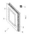
- FIG. 2is a schematic diagram of a power transmitting apparatus 200 that includes a resonator coil 202 having a plurality of loops.
- the resonator coil 202can be printed on substrate 204 in the form of, for example, a printed circuit board.
- a layer of magnetic material 206can guide the magnetic field from one side of the resonator coil 210 .
- the power transmitting apparatus 200can include a shield 208 (e.g., a sheet of conductive material) positioned between coil 202 and a lossy object 210 .
- Shield 208which is typically formed of a conductive material (such as copper, aluminum, and/or other metallic materials), shields magnetic fields generated by coil 202 from lossy object 210 (e.g., lossy steel object).
- the shield 208can reduce aberrant coupling of magnetic fields to lossy object 210 by guiding magnetic field lines away from the lossy object 210 .
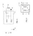
- FIG. 3is a schematic diagram of a portion of a wireless power transmitter 300 .
- Source 300includes a resonator coil 302 used to generate an oscillating magnetic field for wireless power transfer.
- Coil 302is coupled through an impedance matching network (IMN) 304 to a power source represented by terminals A and B.
- Impedance matching network 304includes a fixed capacitance C 1 and a variable capacitance C 2 , although an impedance matching network 304 can be implemented in a wide variety of ways.
- Impedance matching network 304includes a fixed capacitance C 1 and a variable capacitance C 2 , although an impedance matching network 304 can be implemented in a wide variety of ways.
- Various aspects of impedance matching networksare disclosed, for example, in U.S. Patent Application Publication No. 2015/0270719, the entire contents of which are incorporated herein by reference.
- the power sourceapplies a driving voltage between terminals A and B to drive coil 302 to generate the magnetic field.
- the power sourceis referenced to common ground 308 , as are the other components of source 300 .
- the voltage at each of the terminals A and Bcan range from 0 (i.e., the ground voltage) to a maximum voltage V max , which can be 1 V to 50 V or more.
- V A ⁇ V BA voltage difference V A ⁇ V B is applied across coil 302 to drive the coil and generate the magnetic field used for wireless power transfer to a receiving coil.
- V A and V Bcan each range in magnitude from V max to 0 (the common ground voltage)
- each of the other components in source 300including the capacitors, inductors, switches, and other components of IMN 304 —should be capable of withstanding any voltage up to V max to ensure that failure does not occur during operation of source 300 .
- source 300is tapped at point 306 , for example, to apply a voltage to a switch, a resistive element, a capacitive element, an inductive element, or any other circuit component, that component should also be capable of withstanding any voltage up to V max to ensure failure does not occur, since that component will also be referenced to ground 308 .
- V max in wireless power transfer systemscan be high, implementing such systems with hundreds or thousands of elements, all of which are capable of withstanding high voltages, adds significant expense to the systems. Moreover, for certain components designed to operate only at low voltages, designing high voltage-capable counterparts may be quite difficult.
- Decoupling certain components of source 300 from common ground 308creates “floating” components, i.e., components that are not ground referenced.
- components that are not ground referencedneed only be capable of withstanding the voltage difference that is applied across their terminals, not the difference between the voltage at one terminal and a ground reference, as discussed above. Such components are said to be “isolated” from other components in the system.
- FIG. 4is a schematic diagram of a flyback transformer 400 that includes a primary winding 402 and a secondary winding 404 .
- a voltage V Cis applied across primary winding 402 , which is spaced from secondary winding 404 .
- the current flowing in primary winding 402generates a magnetic field which in turn induces a voltage V D across the terminals of secondary winding 404 .
- V D across the terminals of secondary winding 404is only induced when the magnetic field generated by primary winding 402 is time-varying.
- V Cis typically a DC voltage. Accordingly, to produce a time-varying magnetic field from primary winding 402 (which approximates the field that would be produced from an AC driving voltage), V C can be “chopped” using switch 408 , which alternately opens and closes to replicate a time-varying driving voltage.
- the voltage that is thus induced across secondary coil 404is a time-varying voltage also.
- flyback transformersare used for DC-DC voltage conversion.
- the induced voltagecan be conditioned by voltage conditioner 406 (which can be, for example, a rectifier) to produce a DC output voltage V D , which differs from the input DC voltage V C .
- FIG. 5is a schematic diagram of an opto-coupler 500 that includes a radiation source 502 and a radiation receiver 504 enclosed in a housing 508 .
- a voltage V Eis applied across the terminals of source 502 , causing source 502 to emit radiation 506 .
- the emitted radiationis detected by receiver 504 , which generates a voltage V F across its terminals.
- V Fis less than V E .
- conventional sources 502are not capable of generating sufficient quantities of radiation 506 such that large quantities of power can be transferred between source 502 and receiver 504 .
- opto-couplersare best suited for isolation in circumstances where only weak signals are involved, such as in communication.
- circuit elementsthat are isolated from large potentials relative to ground, the elements need only be capable of withstanding smaller voltages. As low-voltage circuit components are typically much cheaper than corresponding high-voltage components, portions of wireless power sources can be implemented at significant cost savings.
- isolation among componentsare typically safer, as portions of such systems are not exposed to high voltages. Isolation is important in medical applications, for example, where a wireless power source may be located in close proximity to a human or animal patient. Isolating certain components of the source ensures that the human or animal is not exposed to potentially lethal voltages that are generated within the source.
- isolationhelps to eliminate electromagnetic interference (EMI) that can arise when energy couples back into the common ground, giving rise to ground loops.
- EMIelectromagnetic interference
- electrical noise from the ground-coupled energycan propagate into other components of the system that are also connected to the common ground, and can particularly disrupt low power signals such as those used for communication and low amplitude measurements.
- auxiliary coilsi.e., coils that are different from one or more source resonator coils that are used to transfer power wirelessly to a receiver resonator by generating magnetic fields.
- the systems and methodsexploit the AC driving voltage that is generated within a source resonator and used to drive one or more source resonator coils, using the driving voltage to generate auxiliary magnetic fields (or capturing a small portion of the magnetic field that is generated by the source resonator coil(s)) to transfer small quantities of power wirelessly to additional components within the source.
- the additional componentsare not connected through conductors to the electronics that generate the AC driving voltage, the additional components are isolated from the source's common ground. The additional components therefore are effectively driven by floating batteries or power sources, and are not subject to, or expected to withstand, the large ground-referenced voltages that are generated in the source.
- FIG. 6is a schematic diagram showing one embodiment of a wireless power transfer system 600 that includes one or more auxiliary coils for ground-isolation of components.
- a housing 602encloses the components of a source, which include a power source 604 , switching and impedance matching circuitry 606 , a source resonator coil 608 , an auxiliary coil 610 , and conditioning circuit 612 .
- power source 604generates an AC driving voltage that is conveyed to coil 608 through switching and impedance matching circuitry 606 .
- Coil 608generates a magnetic field (represented by field lines 614 ), a portion of which is captured by receiver resonator coil 616 , inducing a current within the coil.
- Switching and impedance matching circuitry 618(along with switching and impedance matching circuitry 606 ) is configured to ensure that power is transferred efficiently between source coil 608 and receiver coil 616 .
- the current induced in receiver coil 616is delivered to device 620 , where it performs useful work.
- auxiliary coil 610which can be positioned outside of a principal region of power transfer between source and receiver coils 608 and 616 —captures a small fraction of the magnetic field generated by source coil 608 , inducing a small voltage across auxiliary coil 610 .
- the induced voltageis optionally conditioned by conditioning circuit 612 , before being used to drive one or more elements in switching and impedance matching circuitry 606 and/or power source 604 .
- Conditioningcan include, but is not limited to, rectification of the AC voltage induced in auxiliary coil 610 to generate a DC voltage, attenuation of the voltage induced in auxiliary coil 610 , and changing the frequency of the voltage induced in auxiliary coil 610 .
- auxiliary coil 610captures only a very small portion of the magnetic field that is generated by source coil 608 , and therefore the voltage generated across the terminals of auxiliary coil 610 is small relative to the driving voltage applied to source coil 608 .
- the voltage across auxiliary coil 610 , V auxcan be 1% or less of the driving voltage V src applied across source coil 608 (e.g., 0.5% or less, 0.1% or less, 0.05% or less, 0.01% or less, 0.001% or less, 0.0001% or less).
- a single auxiliary coilis used in system 600 to function effectively as a floating voltage source. More generally, however, system 600 can include more than one auxiliary coil configured in the same manner, each of which functions as an independent, floating voltage source. In some embodiments, for example, system 600 can include 2 or more auxiliary coils (e.g., 3 or more auxiliary coils, 4 or more auxiliary coils, 5 or more auxiliary coils, 7 or more auxiliary coils, or even more).
- auxiliary coilse.g., 3 or more auxiliary coils, 4 or more auxiliary coils, 5 or more auxiliary coils, 7 or more auxiliary coils, or even more.
- auxiliary coil 610can be positioned on or near the source resonator coil 608 , and the spatial location and orientation of auxiliary coil 610 relative to source resonator coil 608 can be adjusted to control the amount of flux captured by auxiliary coil 610 from source coil 608 , and the coupling between the coils.
- auxiliary coil 610 and source coil 608overlap in the x-y (i.e., coil) plane, but are relatively displaced in a direction perpendicular to the plane.
- FIG. 13Ais a schematic diagram showing an embodiment of a wireless power transfer system in which auxiliary coil 610 overlaps with, and is displaced vertically from, source resonator coil 608 . To indicate that coil 610 is in a different plane from coil 608 , coil 610 is shown in dashed lines.
- FIG. 13Bis a schematic diagram showing an embodiment of a wireless power transfer system in which individual loops of source coil 608 are interleaved with loops of auxiliary coil 610 .
- Insulating material 1302is positioned between adjacent interleaved loops.
- auxiliary coil 610can be positioned within source resonator coil 608 .
- FIG. 13Cis a schematic diagram of a wireless power transfer system in which auxiliary coil 610 , which is coplanar with source resonator coil 608 , is positioned within a central region of source coil 608 , surrounded by the loops of source coil 608 .
- conditioning circuit 612is controlled by controller 622 , which is connected to conditioning circuit 612 , power source 604 , and switching and matching circuitry 606 via one or more communication lines (shown as dashed lines in FIG. 6 ).
- controller 622In addition to regulating modulation (amplitude and/or frequency) and rectification by conditioning circuit 612 , controller 622 also adjusts the driving voltage and frequency generated by power source 604 , impedance adjustment by circuitry 606 , and also regulates other functions such as communication between components of the source, and between the source and device 620 .
- auxiliary coil 610is positioned inside housing 602 .
- Housing 602can be formed from or lined with a material (e.g., a conductive material) that effectively prevents stray fields other than those used for wireless power transfer from escaping.
- a materiale.g., a conductive material
- auxiliary coil 610can be positioned either inside housing 602 or external to housing 602 .
- auxiliary coil 610By positioning auxiliary coil 610 external to housing 602 , the auxiliary coil may be able to capture a larger fraction of the field generated by source coil 608 . Such a configuration can be useful for certain applications, particularly where shielding and/or containment of the magnetic field is not as significant a concern.
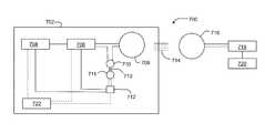
- FIG. 7is a schematic diagram of a wireless power transfer system 700 that includes a power source 704 , switching and matching circuitry 706 , source resonator coil 708 , and a controller 722 enclosed within a housing 702 .
- source resonator coil 708generates a magnetic field (represented by field lines 714 ) that is captured by receiver resonator coil 716 , which is coupled to switching and matching circuitry 718 .
- the current induced in receiver resonator coil 716is coupled to load 720 and provides electrical power for the load.
- the foregoing components of system 700function in a manner similar to their counterparts in system 600 .
- System 700includes two auxiliary coils 710 and 711 .
- Coil 710is connected in series with source resonator coil 708 , such that the driving voltage applied to source resonator coil 708 is also applied across auxiliary coil 710 .
- Coil 711is coupled to conditioning circuit 712 .
- auxiliary coil 710when the driving voltage is applied across source resonator coil 708 and auxiliary coil 710 , auxiliary coil 710 generates a magnetic field (represented by field lines 713 ).
- Auxiliary coil 711captures the field generated by coil 710 , which induces a voltage across the terminals of coil 711 .
- Conditioning circuit 712is configured to perform functions similar to the functions of conditioning circuit 612 , i.e., rectifying the induced voltage across coil 711 and/or modulating the amplitude and/or frequency of the induced voltage, for example.
- the conditioned voltagethen functions as an auxiliary floating power source, which is coupled to one or more elements of power source 704 and/or switching and matching circuitry 706 within the wireless power source.
- auxiliary coils 710 and 711can be fully enclosed within housing 702 to ensure that magnetic fields used to creating floating power sources do not perturb other components of the system (i.e., components that are not part of the wireless power source). More generally, auxiliary coils 710 and/or 711 can be positioned either interior to housing 702 or exterior to housing 702 , depending upon the particular wireless power transfer application.
- auxiliary coilsone of which is connected in series with source resonator coil 708 —to realize a floating power source internal to the wireless power source that is isolated from the wireless power source's common ground reference has certain advantages relative to one-auxiliary-coil implementations, as shown in FIG. 6 .
- a first auxiliary coili.e., coil 710
- a second auxiliary coili.e., coil 711
- the auxiliary coil that receives the fielddoes not have to be positioned anywhere near the magnetic field that is generated by source coil 708 for wireless power transfer.
- auxiliary coilsdoes not perturb the spatial field distribution (represented by magnetic field lines 714 ) used for wireless power transfer, and the auxiliary coil that receives the magnetic field does not capture too large a fraction (or even any fraction) of the wireless power transfer field.
- the use of two auxiliary coilsallows for greater flexibility in the layout and design of wireless power transfer systems; pairs of auxiliary coils can be positioned at nearly any desired location within the wireless power source to realize a floating auxiliary power source.
- auxiliary coil 710can be positioned in series with source coil 708 on either side of source coil 708 (i.e., in terms of current flow, either upstream or downstream relative to source coil 708 ). Further, while a single pair of auxiliary coils are used to implement a single auxiliary floating power source in FIG. 7 , more generally a wireless power source can include multiple pairs of auxiliary coils, each of which is used to implement an independent auxiliary floating power source.
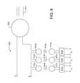
- FIG. 8is a schematic diagram showing a portion of a wireless power system 800 that is similar to system 700 of FIG. 7 , but includes multiple floating auxiliary power sources. More specifically, in system 800 , a source resonator coil 808 is connected at points A and B to switching and matching circuitry and a power source (not shown in FIG. 8 ), and during operation, generates a magnetic field 814 for wireless power transfer to a receiving resonator. Connected in series with source coil 808 are three auxiliary coils 810 a , 810 b , and 810 c , which generate magnetic fields 813 a , 813 b , and 813 c , respectively, when the driving voltage is applied across terminals A and B.
- auxiliary coils 810 a , 810 b , and 810 cConnected in series with source coil 808 are three auxiliary coils 810 a , 810 b , and 810 c , which generate magnetic fields 813 a , 813
- Fields 813 a - care captured by auxiliary coils 811 a , 811 b , and 811 c , respectively, inducing voltages across each of coils 811 a - c .
- the induced voltagesare conditioned, respectively, by conditioning circuits 812 a , 812 b , and 812 c .
- auxiliary coils 810 a - c and 811 a - cyield three floating, independent auxiliary voltage sources V a , V b , and V c , each of which can be connected to one or more components within the wireless power source to drive the components and/or perform other useful work.
- auxiliary floating power sourcescan be included in a wireless power source.
- a wireless power sourcecan include two or more auxiliary floating power sources (e.g., three or more sources, four or more sources, five or more sources, or even more sources).
- Each of the multiple sourcescan be implemented using a single auxiliary coil, as discussed above in connection with FIG. 6 , or using two auxiliary coils, as discussed in connection with FIGS. 7 and 8 .
- these implementationscan be mixed: one or more auxiliary floating power sources can be implemented using a single auxiliary coil, and one or more auxiliary floating power sources can be implemented using pairs of auxiliary coils.
- the area and strength of the magnetic field generated by source resonator 808are considerations in determining the number of auxiliary power sources that are implemented.
- auxiliary floating power sourcesare implemented using a single auxiliary coil or a pair of auxiliary coils
- the sizes of the coilsdetermine the magnitudes of the voltages of each auxiliary source.
- the sizes of the coilsare chosen such that perturbations of the wireless power transfer process between the source coil and the receiver resonator are relatively insignificant, and so that the voltage of each floating source is nonetheless sufficient for its intended purpose.
- the sourcesare independent and therefore can have the same or different output voltages.
- V a , V b , and V ccan be the same, any two of these can be the same, or they can each be different voltages.
- each of the auxiliary sourcesis coupled to one or more low voltage components within the wireless power source and is used to drive the coupled components. Because the auxiliary sources are decoupled from the wireless power source's common ground, the components to which they are coupled are not subjected to the large, ground-referenced voltages that are generated by the wireless power source's electronics. To the contrary, the components to which the auxiliary sources are coupled are subjected only to the much lower floating voltages (i.e., V a , V b , and V c in system 800 ), and are therefore significantly cheaper to implement than their corresponding high voltage counterparts would be.
- V a , V b , and V c in system 800the much lower floating voltages
- Floating auxiliary power sourcescan generally be used for functions that fall within one of two categories in a wireless power source: power-related functions and communication-related functions.
- Power-related functionsinclude driving adjustable components such as inductors, capacitors, resistors, switches, detectors, and other electronic devices.
- FIG. 9illustrates an example of such an application.
- the output voltage V a from a floating auxiliary source(such as the corresponding source shown in FIG. 8 ) is connected across switch S 1 , which is connected in series with capacitance C 2 of an adjustable capacitor.
- the adjustable capacitoralso includes a fixed capacitance C 1 . When voltage V a is applied across switch S 1 , the switch closes, coupling C 2 into the circuit.
- the auxiliary floating sourcecan be used to implement an adjustable capacitor (e.g., in an impedance matching circuit) by selectively closing or opening S 1 to switch C 2 in or out of the total capacitance.
- auxiliary floating power sourcesare also well suited for communications-related applications. Such applications can include communications between components internal to the wireless power source, and communications between the wireless power source and the wireless power receiver that receives wirelessly transmitted power.
- communications-related applicationscan include communications between components internal to the wireless power source, and communications between the wireless power source and the wireless power receiver that receives wirelessly transmitted power.
- a variety of different types of communications systemscan be implemented.
- an auxiliary floating power sourcecan be used to drive a transmitter located in a wireless power source to generate a communications signal that is received by the receiver connected to the receiving resonator.
- FIG. 10is a schematic diagram showing a portion of a wireless power transfer system 1000 , including a controller 1022 connected to a transceiver 1030 in a wireless power source, and a transceiver 1040 connected to a load 1020 that receives power from the wireless power source.
- a voltage V ais applied to transceiver 1030 , which also receives an information signal from controller 1022 .
- Transceiver 1030energized by voltage V a , generates a communications signal 1035 that carries the information from controller 1022 .
- the communications signalis received by transceiver 1040 and delivered to device 1020 , and the information encoded in the signal is extracted.
- Communications signalsthat correspond to a wide variety of different protocols and implementations can be transmitted in the foregoing manner, including Bluetooth® signals, wireless 802.11a/b/g/n signals, IrDA signals, and signals corresponding to other open and/or proprietary specifications.
- wireless power transfer system 1000includes transceivers 1030 and 1040 .
- transceiversare devices that both transmit and receive communication signals.
- the system shown in FIG. 10as well as the other systems disclosed herein, are not limited to the use of transceivers and/or two-way communication.
- any of the transceivers disclosed in connection with embodiments hereincan be replaced with a transmitter or a receiver alone, or separate transmitters and receivers, for purposes of one-way communication.
- the term “transceiver”should be understood to include functional devices that can transmit only, receive only, or both transmit and receive communication signals.
- FIG. 11is a schematic diagram showing a portion of a wireless power transfer system 1100 that includes a source resonator coil 1102 in a wireless power source and a receiving resonator coil 1104 connected to a load 1120 that receives power wirelessly from the wireless power source.
- voltage V a generated by a floating auxiliary sourceis applied to a modulator 1106 .
- Voltage V atypically corresponds to an oscillating AC voltage signal at a frequency corresponding approximately to the frequency of the voltage applied to the source resonator coil in the wireless power source to generate the power transmitting magnetic field.
- Modulator 1106modulates voltage signal V a to encode information into the voltage signal.
- modulator 1106generates an amplitude modulated voltage signal, where the information is encoded as variations in an amplitude envelope function that modulates the underlying sinusoidal AC voltage signal V a .
- modulator 1106generates a frequency modulated voltage signal, where the information is encoded as variations in the nominal frequency of the oscillating AC voltage signal V a .
- Modulator 1106can also implement other modulation or encoding schemes as well.
- the modulated voltage signalis then delivered to source resonator coil 1102 , where it generates a magnetic field that is modulated in a manner that corresponds to the modulation of the voltage signal.
- the modulated magnetic fieldis captured by receiving resonator coil 1104 , and induces a voltage signal across the receiving resonator coil that is modulated in the same manner as V a .
- Load 1120(or circuits connected to load 1120 ) demodulates the induced voltage signal to extract the information encoded in it.
- FIG. 12is a schematic diagram showing a portion of a wireless power transfer system 1200 .
- a source resonator coil 1208 and an auxiliary coil 1210are connected in series.
- source resonator coil 1208When a driving voltage is applied across terminal points A and B, source resonator coil 1208 generates a magnetic field that transfers power to a receiver resonator (not shown in FIG. 12 ), and auxiliary coil 1210 generates an auxiliary magnetic field 1215 .
- System 1200includes two additional auxiliary coils 1211 and 1221 .
- Auxiliary coil 1211is a component of the wireless power source, and auxiliary coil 1221 is connected to a device 1220 that receives power from the wireless power source.
- Auxiliary coil 1211is connected in series with a switch S v , which is controlled by controller 1222 .
- Auxiliary coils 1211 and 1221are positioned so that each coil captures a portion of magnetic field 1215 . Accordingly, voltages are induced across each of coils 1211 and 1221 when coil 1210 generates field 1215 .
- both auxiliary coils 1211 and 1221couple to coil 1210 through the same magnetic field 1215 , a change in the coupling between coils 1211 and 1210 changes the coupling between coils 1221 and 1210 , and vice versa.
- the coupling between auxiliary coils 1210 and 1221and therefore the voltage induced across auxiliary coil 1221 —can be changed by adjusting the coupling between coils 1210 and 1211 .
- System 1200exploits this property by using switch S v to adjust the coupling between coils 1210 and 1211 .
- controller 1222closes switch S v , coil 1211 is connected or shorted within the wireless power source.
- Poweris transferred from coil 1210 to coil 1211 , and power transfer between coils 1210 and 1221 is therefore reduced or otherwise modulated.
- controller 1222opens switch S v thereby decoupling or open-circuiting coil 1211 within the wireless power source, power transfer between coils 1210 and 1211 is reduced, and power transfer between coils 1210 and 1221 is increased or otherwise modulated.
- Device 1220 connected to auxiliary coil 1221senses the changes in induced voltage across coil 1221 as switch S v is opened and closed.
- controller 1222can implement a digital (or bitwise) communication protocol that transmits information to device 1220 by opening and closing switch S v to alternately switch coil 1221 between high and low voltage states.
- controller 1222does not directly generate a communication signal that is broadcast. Instead, controller 1222 —through auxiliary coil 1211 —effectively functions as a digital modulator that perturbs power transfer between two different coils (i.e., coils 1210 and 1221 ).
- This method for generating an “on/off” signalcan also be used to switch devices such as power supplies on and off.
- signals corresponding to high and low voltage statescan be used to activate and de-activate, respectively, device 1220 .
- Device 1220can correspond to a power supply or to any one or more of various switchable electronic devices.
- FIG. 12shows communication of information from a wireless power source to a receiving device by modulating power transfer between an auxiliary coil connected in series with a source resonator coil and an auxiliary coil connected to the receiving device. Similar methods can be used to generate a digital communication signal that is received by auxiliary coil 1211 and controller 1222 , i.e., coil 1221 can be alternately connected and disconnected by closing and opening a switch connected in series with coil 1221 by device 1220 , thereby modulating coupling and the induced voltage across coil 1211 between high and low voltage states.
- coils 1211 and 1221can be used both to effectively “transmit” and “receive” signals by interleaving these functions in time. For example, for a first period of time, coil 1211 can be alternately coupled and decoupled by controller 1222 to induce voltage changes across coil 1221 , thereby communicating information to device 1220 . Then, for a second period of time, coil 1221 can be alternately coupled and decoupled by device 1220 to induce voltage changes across coil 1211 , thereby communicating information to the wireless power source. The alternating of functionalities defines a duty cycle for coils 1211 and 1221 that enables two-way communication.
- system 1200includes additional auxiliary coils to enable simultaneous two-way communication.
- system 1200can include a second auxiliary coil connected in series with source coil 1208 that generates a second auxiliary magnetic field, analogous to field 1215 .
- Two additional auxiliary coilsone implemented as part of the wireless power source and the other connected to device 1220 , are positioned so that each captures a portion of the second auxiliary magnetic field, analogous to auxiliary coils 1211 and 1221 .
- the generation of two magnetic fields by two different auxiliary coils connected in series with source resonator coil 1208allows the wireless power source to transmit information to, and receive information from, device 1220 at the same time.
- one of the auxiliary magnetic fieldscan be used to induce an information-carrying voltage signal that is received by device 1220
- the other auxiliary magnetic fieldcan be used to induce an information-carrying voltage signal that is received by the wireless power source, as disclosed above.
- digitally encoded informationcan be transmitted bi-directionally between the wireless power source and device 1220 .
- auxiliary coilscan be used to isolate sensitive analog circuitry from noisy power ground connections, thereby ensuring that such circuitry operates at high sensitivity.
- Auxiliary coilscan also be used to implement feedback systems in which power from one or more auxiliary coils is used to adjust coupling to provide a regulated source (i.e., perform auxiliary coil-mediated voltage regulation).
Landscapes
- Engineering & Computer Science (AREA)
- Computer Networks & Wireless Communication (AREA)
- Power Engineering (AREA)
- Charge And Discharge Circuits For Batteries Or The Like (AREA)
Abstract
Description
This application claims priority to U.S. Provisional Patent Application No. 62/258,144, filed on Nov. 20, 2015, the entire contents of which are incorporated herein by reference.
This disclosure relates to wireless power transfer systems, and in particular, to isolating voltage sources from reference ground in such systems.
Energy can be transferred from a power source to a receiving device using a variety of known techniques such as radiative (far-field) techniques. For example, radiative techniques using low-directionality antennas can transfer a small portion of the supplied radiated power, namely, that portion in the direction of, and overlapping with, the receiving device used for pick up. In such methods, much—even most—of the energy is radiated away in directions other than the direction of the receiving device, and typically the transferred energy is insufficient to power or charge the receiving device. In another example of radiative techniques, directional antennas are used to confine and preferentially direct the radiated energy towards the receiving device. In this case, an uninterruptible line-of-sight and potentially complicated tracking and steering mechanisms are used.
Another approach to energy transfer is to use non-radiative (near-field) techniques. For example, techniques known as traditional induction schemes do not (intentionally) radiate power, but use an oscillating current passing through a primary coil, to generate an oscillating magnetic near-field that induces currents in a nearby receiving or secondary coil. Traditional induction schemes can transfer modest to large amounts of power over very short distances. In these schemes, the offset tolerances between the power source and the receiving device are very small. Electric transformers and proximity chargers, for example, typically use traditional induction schemes.
Wireless power transfer systems can be used to transfer significant quantities of power between a source resonator and a receiving resonator. To generate a large amplitude magnetic field using a magnetic source resonator, one or more source resonator coils are typically driven with a large amplitude AC voltage that is referenced to a common ground in the source.
With components referenced in a common ground in a wireless power transmitter, the components in the source each should be capable of withstanding the large AC voltage that is applied to the resonator coil(s). For example, switches that are used in capacitor banks as part of impedance matching networks, components that are used for communication, and other circuit elements that are used to generate low power driving voltages, to detect low power signals, and/or to switch or adjust other elements, should all be capable of withstanding the large AC driving voltages. Components that can withstand such voltages are expensive and can therefore significantly increase the cost of wireless power transfer systems.
An alternative to common ground-referenced components would be to implement floating sources, switches, and other elements that are not referenced to the common wireless source ground. However, transformers that are typically used to implement floating elements are themselves expensive and bulky, and therefore also increase the cost and size of wireless power transfer systems.
Disclosed herein are systems and methods for wireless power transfer that implement floating components (e.g., voltage sources, switches, detectors, communication transmitters and receivers) by taking advantage of the large AC voltages that are used to drive source resonator coils. The systems include one or more auxiliary coils that transmit and/or receive small quantities of power, which can then be conditioned and used for a variety of applications. In effect, the auxiliary coils can be used to construct one or more floating “batteries” within a wireless power source. The floating batteries are then available for a wide variety of uses within the source.
In general, in a first aspect, the disclosure features wireless power transmitters that include a power source, a first coil connected to the power source, a second coil connected in series to the first coil, and a third coil positioned in proximity to the second coil, where during operation of the wireless power transmitter: the power source applies a driving voltage to the first and second coils; the first coil generates a first magnetic field that transfers power to a receiver resonator; the second coil generates a second magnetic field that induces a voltage across the third coil; and the induced voltage across the third coil is applied to a component of the wireless power transmitter.
Embodiments of the transmitters can include any one or more of the following features.
Each of the first, second, and third coils can include one or more loops of conductive material. The sources can include a housing that encloses the power source and the first, second, and third coils.
The component can include at least one of a resistive element, a capacitive element, and an inductive element of the wireless power transmitters. The component can include a switch of the wireless power transmitters. The component can include a component of an impedance matching network of the wireless power transmitters, e.g., an adjustable capacitor of the impedance matching network. The component can include a transceiver or transmitter configured to generate an information carrying signal.
The component can include a fourth coil configured to generate an information carrying magnetic field that, during operation, is received by a fifth coil connected to the receiver resonator. The sources can include a modulator configured to modulate the induced voltage to generate the information carrying magnetic field. The induced voltage can correspond to an oscillating voltage signal, and the modulator can be configured to modulate at least one of an amplitude and a frequency of the oscillating voltage signal to generate the information carrying magnetic field.
The sources can include a conditioning circuit connected to the third coil, where during operation, the conditioning circuit can be configured to at least one of rectify the induced voltage, adjust an amplitude of the induced voltage, and adjust a frequency of the induced voltage.
A magnitude of the induced voltage can be 1% or less (e.g., 0.01% or less) of a magnitude of a voltage induced in the receiver resonator. The induced voltage may not be referenced to a ground voltage of the wireless power transmitter.
The transmitters can include a fourth coil connected in series to the first and second coils, and a fifth coil positioned in proximity to the fourth coil, where during operation of the wireless power transmitters: the power source applies the driving voltage to the first, second, and fourth coils; the fourth coil generates a third magnetic field that induces a voltage across the fifth coil; and the induced voltage across the fifth coil is applied to a second component of the wireless power transmitters. The second component can include at least one of a resistive element, a capacitive element, an inductive element, a switch, and a component of an impedance matching network. The second component can include a transceiver configured to generate an information carrying signal. The second component can include a sixth coil configured to generate an information carrying magnetic field that, during operation, is received by a seventh coil connected to the receiver resonator.
Embodiments of the transmitters can also include any of the other features disclosed herein, including combinations of features disclosed in connection with different embodiments, except as expressly stated otherwise.
In another aspect, the disclosure features wireless power transmitters that include a power source, a first coil connected to the power source, and a second coil positioned in proximity to the first coil, where during operation of the wireless power transmitters: the power source applies a driving voltage to the first coil; the first coil generates a magnetic field that transfers power to a receiver resonator; the magnetic field induces a voltage across the second coil; and the induced voltage across the second coil is applied to a component of the wireless power transmitters.
Embodiments of the transmitters can include any one or more of the following features.
Each of the first and second coils can include one or more loops of conductive material. The transmitters can include a housing that encloses the power source and the first and second coils.
The component can include at least one of a resistive element, a capacitive element, and an inductive element of the wireless power transmitters. The component can include a switch of the wireless power transmitters. The component can include a component of an impedance matching network of the wireless power transmitters. The component can include an adjustable capacitor of the impedance matching network. The component can include a transceiver or transmitter configured to generate an information carrying signal.
The component can include a third coil configured to generate an information carrying magnetic field that, during operation, is received by a fourth coil connected to the receiver resonator. The sources can include a modulator configured to modulate the induced voltage to generate the information carrying magnetic field. The induced voltage can correspond to an oscillating voltage signal, and the modulator can be configured to modulate at least one of an amplitude and a frequency of the oscillating voltage signal to generate the information carrying magnetic field.
The sources can include a conditioning circuit connected to the second coil, where during operation, the conditioning circuit is configured to at least one of rectify the induced voltage, adjust an amplitude of the induced voltage, and adjust a frequency of the induced voltage.
A magnitude of the induced voltage can be 1% or less (e.g., 0.01% or less) of a magnitude of a voltage induced in the receiver resonator. The induced voltage may not be referenced to a ground voltage of the wireless power transmitters.
The sources can include a third coil positioned in proximity to the first coil, where during operation of the wireless power transmitters, the magnetic field induces a voltage across the third coil, and the induced voltage across the third coil is applied to a second component of the wireless power transmitters. The second component can include at least one of a resistive element, a capacitive element, an inductive element, a switch, and a component of an impedance matching network. The second component can include a transceiver or transmitter configured to generate an information carrying signal. The second component can include a fourth coil configured to generate an information carrying magnetic field that, during operation, is received by a fifth coil connected to the receiver resonator.
Embodiments of the transmitters can also include any of the other features disclosed herein, including combinations of features disclosed in connection with different embodiments, except as expressly stated otherwise.
In a further aspect, the disclosure features wireless power systems that include a power source, a first coil connected to the power source, a second coil connected in series to the first coil, a third coil positioned in proximity to the second coil, a controller connected to the third coil and configured to selectively modulate coupling between the second and third coils, a power receiving device, a receiver resonator connected to the power receiving device, and a fourth coil connected to the power receiving device and positioned in proximity to the second coil, where during operation of the wireless power transfer systems: the power source applies a driving voltage to the first and second coils; the first coil generates a first magnetic field that transfers power to the receiver resonator; the second coil generates a second magnetic field that induces voltages across the third and fourth coils; and the controller modulates the coupling between the second and third coils to adjust a magnitude of the induced voltage across the fourth coil.
Embodiments of the systems can include any one or more of the features disclosed herein, including combinations of features disclosed in connection with different embodiments, except as expressly stated otherwise.
In another aspect, the disclosure features methods that include applying a driving voltage across first and second coils connected in series in a wireless power transmitter to generate a first magnetic field and a second magnetic field, where the first magnetic field transfers power wirelessly to a receiver resonator, and where the second magnetic field induces a voltage across a third coil positioned in proximity to the second coil in the wireless power transmitter, and applying the induced voltage to a component of the wireless power transmitter.
Embodiments of the methods can include any one or more of the features disclosed herein, including combinations of features disclosed in connection with different embodiments, except as expressly stated otherwise.
In a further aspect, the disclosure features methods that include applying a driving voltage across a source coil in a wireless power transmitter to generate a magnetic field to transfer power wirelessly to a receiver resonator, inducing a voltage in an auxiliary coil positioned in proximity to the source coil in the wireless power transmitter, and applying the induced voltage to a component of the wireless power transmitter.
Embodiments of the methods can include any one or more of the features disclosed herein, including combinations of features disclosed in connection with different embodiments, except as expressly stated otherwise.
Unless otherwise defined, all technical and scientific terms used herein have the same meaning as commonly understood by one of ordinary skill in the art to which this disclosure belongs. Although methods and materials similar or equivalent to those described herein can be used in the practice or testing of the subject matter herein, suitable methods and materials are described below. All publications, patent applications, patents, and other references mentioned herein are incorporated by reference in their entirety. In case of conflict, the present specification, including definitions, will control. In addition, the materials, methods, and examples are illustrative only and not intended to be limiting.
The details of one or more embodiments are set forth in the accompanying drawings and the description below. Other features and advantages will be apparent from the description, drawings, and claims.
Like reference symbols in the various drawings indicate like elements.
Introduction
A wireless power transfer system can include a power transmitting apparatus which is configured to wirelessly transmit power to a power receiving apparatus. In some embodiments, the power transmitting apparatus can include a source coil which generates oscillating fields (e.g., electric fields, magnetic fields) due to currents oscillating within the source coil. The generated oscillating fields can couple to the power receiving apparatus and provide power to the power receiving apparatus through the coupling. To achieve coupling, the power receiving apparatus typically includes a receiver coil. The oscillating fields generated by the source coil can induce oscillating currents within the receiver coil. In some embodiments, either or both of the source and receiver coils can be resonant. In some other embodiments, either or both of the source and receiver coils can be non-resonant so that power transfer is achieved through non-resonant coupling.
In some embodiments, a wireless power transfer system can utilize a source resonator to wirelessly transmit power to a receiver resonator. For example, a power transmitting apparatus of the system can include the source resonator, which has a source coil, and a power receiving apparatus of the system can include the receiver resonator, which has a receiver coil. Power can be wirelessly transferred between the source resonator and the receiver resonator. In certain embodiments, the wireless power transfer can be extended by multiple source resonators and/or multiple device resonators and/or multiple intermediate (also referred as “repeater” or “repeating”) resonators.
In similar fashion,power receiving apparatus 104 is coupled to adevice 108 through acoupling 107. Coupling107 can be a direct electrical connection or a non-contact inductive coupling. In some embodiments, coupling107 can include an impedance matching network, as described above.
In general,device 108 receives power frompower receiving apparatus 104.Device 108 then uses the power to do useful work. In some embodiments, for example,device 108 is a battery charger that charges depleted batteries (e.g., car batteries). In certain embodiments,device 108 is a lighting device and uses the power to illuminate one or more light sources. In some embodiments,device 108 is an electronic device such as a communication device (e.g., a mobile telephone) or a display. In some embodiments,device 108 is a medical device which can be implanted in a patient.
During operation,power transmitting apparatus 102 is configured to wirelessly transmit power to power receivingapparatus 104. In some embodiments,power transmitting apparatus 102 can include a source coil, which can generate oscillating fields (e.g., electric, magnetic fields) when electrical currents oscillate within the source resonator. The generated oscillating fields can couple topower receiving apparatus 104 and provide power to the power receiving apparatus through the coupling. To achieve coupling betweenpower transmitting apparatus 102 andpower receiving apparatus 104, the power receiving apparatus can include a receiver resonator. The oscillating fields can induce oscillating currents within the receiver resonator.
In certain embodiments, thesystem 100 can include a power repeating apparatus (not shown inFIG. 1 ). The power repeating apparatus can be configured to wirelessly receive power from thepower transmitting apparatus 102 and wirelessly transmit the power to thepower receiving apparatus 104. The power repeating apparatus can include similar elements described in relation to thepower transmitting apparatus 102 and thepower receiving apparatus 104 above.
In some embodiments, theelectronic controller 103 can configure thepower source 106 to provide power to thepower transmitting apparatus 102. For example, theelectronic controller 103 can increase the power output of thepower source 106 by sending a higher drive current to a coil in thepower transmitting apparatus 102. The power output can be at an operating frequency, which is used to generate oscillating fields by thepower transmitting apparatus 102.
In certain embodiments, theelectronic controller 103 can tune a resonant frequency of a resonator in thepower transmitting apparatus 102 and/or a resonant frequency of a resonator in thepower receiving apparatus 104. By tuning resonant frequencies of resonators relative to the operating frequency of the power output of thepower source 106, the efficiency of power transfer from thepower source 106 to thedevice 108 can be controlled. For example, theelectronic controller 103 can tune the resonant frequencies to be substantially the same (e.g., within 0.5%, within 1%, within 2%) to the operating frequency to increase the efficiency of power transfer. Theelectronic controller 103 can tune the resonant frequencies by adjusting capacitance values of respective resonators. To achieve this, for example, theelectronic controller 103 can adjust a capacitance of a capacitor connected to a coil in a resonator. The adjustment can be based on theelectronic controller 103's measurement of the resonant frequency or based on wireless communication signal from theapparatuses electronic controller 103 can tune the operating frequency to be substantially the same (e.g., within 0.5%, within 1%, within 2%) to the resonant frequencies of the resonators. In some embodiments, theelectronic controller 103 can tune the operating frequency.
In some embodiments, theelectronic controller 103 can control an impedance matching network in thesystem 100 to optimize or de-tune impedance matching conditions in thesystem 100, and thereby control the efficiency of power transfer. For example, theelectronic controller 103 can tune capacitance of capacitors or networks of capacitors included in the impedance matching network connected betweenpower transmitting apparatus 102 andpower source 106. The optimum impedance conditions can be calculated internally by theelectronic controller 103 or can be received from an external device.
The power source applies a driving voltage between terminals A and B to drivecoil 302 to generate the magnetic field. The power source is referenced tocommon ground 308, as are the other components ofsource 300. During operation, the voltage at each of the terminals A and B can range from 0 (i.e., the ground voltage) to a maximum voltage Vmax, which can be 1 V to 50 V or more.
A voltage difference VA−VBis applied acrosscoil 302 to drive the coil and generate the magnetic field used for wireless power transfer to a receiving coil. However, because VAand VBcan each range in magnitude from Vmaxto 0 (the common ground voltage), each of the other components insource 300—including the capacitors, inductors, switches, and other components ofIMN 304—should be capable of withstanding any voltage up to Vmaxto ensure that failure does not occur during operation ofsource 300. Ifsource 300 is tapped atpoint 306, for example, to apply a voltage to a switch, a resistive element, a capacitive element, an inductive element, or any other circuit component, that component should also be capable of withstanding any voltage up to Vmaxto ensure failure does not occur, since that component will also be referenced toground 308.
Since Vmaxin wireless power transfer systems can be high, implementing such systems with hundreds or thousands of elements, all of which are capable of withstanding high voltages, adds significant expense to the systems. Moreover, for certain components designed to operate only at low voltages, designing high voltage-capable counterparts may be quite difficult.
Decoupling certain components ofsource 300 fromcommon ground 308 creates “floating” components, i.e., components that are not ground referenced. During operation, components that are not ground referenced need only be capable of withstanding the voltage difference that is applied across their terminals, not the difference between the voltage at one terminal and a ground reference, as discussed above. Such components are said to be “isolated” from other components in the system.
In general electrical circuits, isolation can conventionally be performed using DC-DC flyback transformers.FIG. 4 is a schematic diagram of aflyback transformer 400 that includes a primary winding402 and a secondary winding404. During operation, a voltage VCis applied across primary winding402, which is spaced from secondary winding404. The current flowing in primary winding402 generates a magnetic field which in turn induces a voltage VDacross the terminals of secondary winding404.
In general, voltage VDacross the terminals of secondary winding404 is only induced when the magnetic field generated by primary winding402 is time-varying. However, VCis typically a DC voltage. Accordingly, to produce a time-varying magnetic field from primary winding402 (which approximates the field that would be produced from an AC driving voltage), VCcan be “chopped” usingswitch 408, which alternately opens and closes to replicate a time-varying driving voltage.
The voltage that is thus induced acrosssecondary coil 404 is a time-varying voltage also. Typically, however, flyback transformers are used for DC-DC voltage conversion. Accordingly, the induced voltage can be conditioned by voltage conditioner406 (which can be, for example, a rectifier) to produce a DC output voltage VD, which differs from the input DC voltage VC.
Isolation can also be achieved using opto-couplers, particularly for low power signals such as those used for communication.FIG. 5 is a schematic diagram of an opto-coupler 500 that includes aradiation source 502 and aradiation receiver 504 enclosed in ahousing 508. During operation, a voltage VEis applied across the terminals ofsource 502, causingsource 502 to emitradiation 506. The emitted radiation is detected byreceiver 504, which generates a voltage VFacross its terminals. As the conversions from electrical energy to radiation and then from radiation back to electrical energy are lossy processes, VFis less than VE. Moreover,conventional sources 502 are not capable of generating sufficient quantities ofradiation 506 such that large quantities of power can be transferred betweensource 502 andreceiver 504. As a result, opto-couplers are best suited for isolation in circumstances where only weak signals are involved, such as in communication.
Isolation with Auxiliary Coils
The benefits of achieving isolation of circuit elements are significant. For circuit elements that are isolated from large potentials relative to ground, the elements need only be capable of withstanding smaller voltages. As low-voltage circuit components are typically much cheaper than corresponding high-voltage components, portions of wireless power sources can be implemented at significant cost savings.
In addition, systems that implement isolation among components are typically safer, as portions of such systems are not exposed to high voltages. Isolation is important in medical applications, for example, where a wireless power source may be located in close proximity to a human or animal patient. Isolating certain components of the source ensures that the human or animal is not exposed to potentially lethal voltages that are generated within the source.
Further, isolation helps to eliminate electromagnetic interference (EMI) that can arise when energy couples back into the common ground, giving rise to ground loops. When this occurs, electrical noise from the ground-coupled energy can propagate into other components of the system that are also connected to the common ground, and can particularly disrupt low power signals such as those used for communication and low amplitude measurements.
But while these advantages of isolation in wireless power transfer systems are significant, the use of conventional isolation technologies in such systems is difficult, and obviates some of the advantages. Transformers that operate at high voltages are large and expensive, and inclusion of such devices in wireless power source can both increase the physical size of the source and increase the cost of the source. If multiple groups of isolated components are desired, multiple transformers may be required, further emphasizing these drawbacks. Opto-couplers are generally also expensive and only suitable for isolation of components that handle very low-power signals such as communication signals.
The systems and methods disclosed herein implement isolation in a different manner, using one or more auxiliary coils (i.e., coils that are different from one or more source resonator coils that are used to transfer power wirelessly to a receiver resonator by generating magnetic fields). In particular, the systems and methods exploit the AC driving voltage that is generated within a source resonator and used to drive one or more source resonator coils, using the driving voltage to generate auxiliary magnetic fields (or capturing a small portion of the magnetic field that is generated by the source resonator coil(s)) to transfer small quantities of power wirelessly to additional components within the source. As the additional components are not connected through conductors to the electronics that generate the AC driving voltage, the additional components are isolated from the source's common ground. The additional components therefore are effectively driven by floating batteries or power sources, and are not subject to, or expected to withstand, the large ground-referenced voltages that are generated in the source.
During operation ofsystem 600,auxiliary coil 610—which can be positioned outside of a principal region of power transfer between source andreceiver coils source coil 608, inducing a small voltage acrossauxiliary coil 610. The induced voltage is optionally conditioned byconditioning circuit 612, before being used to drive one or more elements in switching andimpedance matching circuitry 606 and/orpower source 604. Conditioning can include, but is not limited to, rectification of the AC voltage induced inauxiliary coil 610 to generate a DC voltage, attenuation of the voltage induced inauxiliary coil 610, and changing the frequency of the voltage induced inauxiliary coil 610.
Typically,auxiliary coil 610 captures only a very small portion of the magnetic field that is generated bysource coil 608, and therefore the voltage generated across the terminals ofauxiliary coil 610 is small relative to the driving voltage applied tosource coil 608. By capturing only a small fraction of the field that is generated, the perturbing effect of the auxiliary coil on the transfer of power betweensource coil 608 andreceiver coil 616 is relatively insignificant. In some embodiments, for example, the voltage acrossauxiliary coil 610, Vauxcan be 1% or less of the driving voltage Vsrcapplied across source coil608 (e.g., 0.5% or less, 0.1% or less, 0.05% or less, 0.01% or less, 0.001% or less, 0.0001% or less).
InFIG. 6 , a single auxiliary coil is used insystem 600 to function effectively as a floating voltage source. More generally, however,system 600 can include more than one auxiliary coil configured in the same manner, each of which functions as an independent, floating voltage source. In some embodiments, for example,system 600 can include 2 or more auxiliary coils (e.g., 3 or more auxiliary coils, 4 or more auxiliary coils, 5 or more auxiliary coils, 7 or more auxiliary coils, or even more).
In general, theauxiliary coil 610 can be positioned on or near thesource resonator coil 608, and the spatial location and orientation ofauxiliary coil 610 relative to sourceresonator coil 608 can be adjusted to control the amount of flux captured byauxiliary coil 610 fromsource coil 608, and the coupling between the coils. In some embodiments, for example,auxiliary coil 610 andsource coil 608 overlap in the x-y (i.e., coil) plane, but are relatively displaced in a direction perpendicular to the plane.FIG. 13A is a schematic diagram showing an embodiment of a wireless power transfer system in whichauxiliary coil 610 overlaps with, and is displaced vertically from,source resonator coil 608. To indicate thatcoil 610 is in a different plane fromcoil 608,coil 610 is shown in dashed lines.
In certain embodiments,auxiliary coil 610 andsource resonator coil 608 can be interleaved.FIG. 13B is a schematic diagram showing an embodiment of a wireless power transfer system in which individual loops ofsource coil 608 are interleaved with loops ofauxiliary coil 610. Insulatingmaterial 1302 is positioned between adjacent interleaved loops.
In some embodiments,auxiliary coil 610 can be positioned withinsource resonator coil 608.FIG. 13C is a schematic diagram of a wireless power transfer system in whichauxiliary coil 610, which is coplanar withsource resonator coil 608, is positioned within a central region ofsource coil 608, surrounded by the loops ofsource coil 608.
In general, the action ofconditioning circuit 612, as well aspower source 604 and switching and matchingcircuitry 606, is controlled bycontroller 622, which is connected toconditioning circuit 612,power source 604, and switching and matchingcircuitry 606 via one or more communication lines (shown as dashed lines inFIG. 6 ). In addition to regulating modulation (amplitude and/or frequency) and rectification byconditioning circuit 612,controller 622 also adjusts the driving voltage and frequency generated bypower source 604, impedance adjustment bycircuitry 606, and also regulates other functions such as communication between components of the source, and between the source anddevice 620.
InFIG. 6 ,auxiliary coil 610 is positioned insidehousing 602. Housing602 can be formed from or lined with a material (e.g., a conductive material) that effectively prevents stray fields other than those used for wireless power transfer from escaping. By positioningauxiliary coil 610 insidehousing 602, the portion of the magnetic field that is captured byauxiliary coil 610 does not affect other field-sensitive devices or elements that may be positioned outsidehousing 602, which reduces electrical interference and noise that might otherwise occur during operation of the system. More generally, however, in certain embodiments,auxiliary coil 610 can be positioned either insidehousing 602 or external tohousing 602. By positioningauxiliary coil 610 external tohousing 602, the auxiliary coil may be able to capture a larger fraction of the field generated bysource coil 608. Such a configuration can be useful for certain applications, particularly where shielding and/or containment of the magnetic field is not as significant a concern.
In certain embodiments, multiple auxiliary coils can be used to create an isolated, floating voltage source.FIG. 7 is a schematic diagram of a wirelesspower transfer system 700 that includes apower source 704, switching and matchingcircuitry 706,source resonator coil 708, and acontroller 722 enclosed within ahousing 702. During operation,source resonator coil 708 generates a magnetic field (represented by field lines714) that is captured byreceiver resonator coil 716, which is coupled to switching and matchingcircuitry 718. The current induced inreceiver resonator coil 716 is coupled to load720 and provides electrical power for the load. The foregoing components ofsystem 700 function in a manner similar to their counterparts insystem 600.
As shown inFIG. 7 ,auxiliary coils housing 702 to ensure that magnetic fields used to creating floating power sources do not perturb other components of the system (i.e., components that are not part of the wireless power source). More generally,auxiliary coils 710 and/or711 can be positioned either interior tohousing 702 or exterior tohousing 702, depending upon the particular wireless power transfer application.
The use of two auxiliary coils—one of which is connected in series withsource resonator coil 708—to realize a floating power source internal to the wireless power source that is isolated from the wireless power source's common ground reference has certain advantages relative to one-auxiliary-coil implementations, as shown inFIG. 6 . By using a first auxiliary coil (i.e., coil710) to generate a small amplitude magnetic field, and a second auxiliary coil (i.e., coil711) to capture the small amplitude field, the auxiliary coil that receives the field does not have to be positioned anywhere near the magnetic field that is generated bysource coil 708 for wireless power transfer. As such, the use of auxiliary coils does not perturb the spatial field distribution (represented by magnetic field lines714) used for wireless power transfer, and the auxiliary coil that receives the magnetic field does not capture too large a fraction (or even any fraction) of the wireless power transfer field. Furthermore, the use of two auxiliary coils allows for greater flexibility in the layout and design of wireless power transfer systems; pairs of auxiliary coils can be positioned at nearly any desired location within the wireless power source to realize a floating auxiliary power source.
In general,auxiliary coil 710 can be positioned in series withsource coil 708 on either side of source coil708 (i.e., in terms of current flow, either upstream or downstream relative to source coil708). Further, while a single pair of auxiliary coils are used to implement a single auxiliary floating power source inFIG. 7 , more generally a wireless power source can include multiple pairs of auxiliary coils, each of which is used to implement an independent auxiliary floating power source.
Whilesystem 800 includes three auxiliary floating power sources, in general any number of auxiliary power sources can be included in a wireless power source. For example, a wireless power source can include two or more auxiliary floating power sources (e.g., three or more sources, four or more sources, five or more sources, or even more sources). Each of the multiple sources can be implemented using a single auxiliary coil, as discussed above in connection withFIG. 6 , or using two auxiliary coils, as discussed in connection withFIGS. 7 and 8 . In some embodiments, these implementations can be mixed: one or more auxiliary floating power sources can be implemented using a single auxiliary coil, and one or more auxiliary floating power sources can be implemented using pairs of auxiliary coils. Typically, the area and strength of the magnetic field generated bysource resonator 808 are considerations in determining the number of auxiliary power sources that are implemented.
Whether auxiliary floating power sources are implemented using a single auxiliary coil or a pair of auxiliary coils, the sizes of the coils (e.g., the number of turns, the diameter of the turns, the size and composition of the core material) determine the magnitudes of the voltages of each auxiliary source. In general, the sizes of the coils are chosen such that perturbations of the wireless power transfer process between the source coil and the receiver resonator are relatively insignificant, and so that the voltage of each floating source is nonetheless sufficient for its intended purpose. Where a wireless power source includes multiple auxiliary floating sources, the sources are independent and therefore can have the same or different output voltages. For example, insystem 800, Va, Vb, and Vccan be the same, any two of these can be the same, or they can each be different voltages.
Applications
The floating (i.e., ground isolated) auxiliary sources disclosed herein can be used for a variety of applications in wireless power transfer systems. In general, each of the auxiliary sources is coupled to one or more low voltage components within the wireless power source and is used to drive the coupled components. Because the auxiliary sources are decoupled from the wireless power source's common ground, the components to which they are coupled are not subjected to the large, ground-referenced voltages that are generated by the wireless power source's electronics. To the contrary, the components to which the auxiliary sources are coupled are subjected only to the much lower floating voltages (i.e., Va, Vb, and Vcin system800), and are therefore significantly cheaper to implement than their corresponding high voltage counterparts would be.
Floating auxiliary power sources can generally be used for functions that fall within one of two categories in a wireless power source: power-related functions and communication-related functions. Power-related functions include driving adjustable components such as inductors, capacitors, resistors, switches, detectors, and other electronic devices.FIG. 9 illustrates an example of such an application. InFIG. 9 , the output voltage Vafrom a floating auxiliary source (such as the corresponding source shown inFIG. 8 ) is connected across switch S1, which is connected in series with capacitance C2of an adjustable capacitor. The adjustable capacitor also includes a fixed capacitance C1. When voltage Vais applied across switch S1, the switch closes, coupling C2into the circuit. When the voltage is not applied across S1, C2is decoupled from the circuit. Thus, the auxiliary floating source can be used to implement an adjustable capacitor (e.g., in an impedance matching circuit) by selectively closing or opening S1to switch C2in or out of the total capacitance.
As mentioned above, auxiliary floating power sources are also well suited for communications-related applications. Such applications can include communications between components internal to the wireless power source, and communications between the wireless power source and the wireless power receiver that receives wirelessly transmitted power. A variety of different types of communications systems can be implemented. In some embodiments, for example, an auxiliary floating power source can be used to drive a transmitter located in a wireless power source to generate a communications signal that is received by the receiver connected to the receiving resonator.
In the above discussion, wirelesspower transfer system 1000 includestransceivers FIG. 10 , as well as the other systems disclosed herein, are not limited to the use of transceivers and/or two-way communication. It should be understood that any of the transceivers disclosed in connection with embodiments herein can be replaced with a transmitter or a receiver alone, or separate transmitters and receivers, for purposes of one-way communication. Thus, the term “transceiver” should be understood to include functional devices that can transmit only, receive only, or both transmit and receive communication signals.
In some embodiments, floating auxiliary voltage sources can be used to drive magnetic resonators that generate communications signals.FIG. 11 is a schematic diagram showing a portion of a wirelesspower transfer system 1100 that includes asource resonator coil 1102 in a wireless power source and a receivingresonator coil 1104 connected to aload 1120 that receives power wirelessly from the wireless power source. To generate a communications signal, voltage Vagenerated by a floating auxiliary source is applied to amodulator 1106. Voltage Vatypically corresponds to an oscillating AC voltage signal at a frequency corresponding approximately to the frequency of the voltage applied to the source resonator coil in the wireless power source to generate the power transmitting magnetic field.
The modulated voltage signal is then delivered to sourceresonator coil 1102, where it generates a magnetic field that is modulated in a manner that corresponds to the modulation of the voltage signal. The modulated magnetic field is captured by receivingresonator coil 1104, and induces a voltage signal across the receiving resonator coil that is modulated in the same manner as Va. Load1120 (or circuits connected to load1120) demodulates the induced voltage signal to extract the information encoded in it.
Amplitude and frequency modulation of a sinusoidal or other oscillating/periodic carrier wave signal are methods for implementing analog communication between a wireless power source and receiver. However, floating auxiliary voltage sources can also be used to implement digital communication between a source and receiver.FIG. 12 is a schematic diagram showing a portion of a wirelesspower transfer system 1200. Insystem 1200, asource resonator coil 1208 and anauxiliary coil 1210 are connected in series. When a driving voltage is applied across terminal points A and B,source resonator coil 1208 generates a magnetic field that transfers power to a receiver resonator (not shown inFIG. 12 ), andauxiliary coil 1210 generates an auxiliarymagnetic field 1215.
Because bothauxiliary coils coil 1210 through the samemagnetic field 1215, a change in the coupling betweencoils coils auxiliary coils auxiliary coil 1221—can be changed by adjusting the coupling betweencoils System 1200 exploits this property by using switch Svto adjust the coupling betweencoils controller 1222 closes switch Sv,coil 1211 is connected or shorted within the wireless power source. Power is transferred fromcoil 1210 tocoil 1211, and power transfer betweencoils controller 1222 opens switch Svthereby decoupling or open-circuiting coil 1211 within the wireless power source, power transfer betweencoils coils
This method for generating an “on/off” signal can also be used to switch devices such as power supplies on and off. Using a method similar to the one described above, signals corresponding to high and low voltage states can be used to activate and de-activate, respectively,device 1220.Device 1220 can correspond to a power supply or to any one or more of various switchable electronic devices.
Two-way communication between the wireless power source anddevice 1220 can be implemented in various ways. In some embodiments, for example, coils1211 and1221 can be used both to effectively “transmit” and “receive” signals by interleaving these functions in time. For example, for a first period of time,coil 1211 can be alternately coupled and decoupled bycontroller 1222 to induce voltage changes acrosscoil 1221, thereby communicating information todevice 1220. Then, for a second period of time,coil 1221 can be alternately coupled and decoupled bydevice 1220 to induce voltage changes acrosscoil 1211, thereby communicating information to the wireless power source. The alternating of functionalities defines a duty cycle forcoils
In certain embodiments,system 1200 includes additional auxiliary coils to enable simultaneous two-way communication. For example,system 1200 can include a second auxiliary coil connected in series withsource coil 1208 that generates a second auxiliary magnetic field, analogous tofield 1215. Two additional auxiliary coils, one implemented as part of the wireless power source and the other connected todevice 1220, are positioned so that each captures a portion of the second auxiliary magnetic field, analogous toauxiliary coils
The generation of two magnetic fields by two different auxiliary coils connected in series withsource resonator coil 1208 allows the wireless power source to transmit information to, and receive information from,device 1220 at the same time. In particular, one of the auxiliary magnetic fields can be used to induce an information-carrying voltage signal that is received bydevice 1220, while the other auxiliary magnetic field can be used to induce an information-carrying voltage signal that is received by the wireless power source, as disclosed above. In this manner, digitally encoded information can be transmitted bi-directionally between the wireless power source anddevice 1220.
Other applications can also take advantage of the auxiliary coils disclosed herein. For example, auxiliary coils can be used to isolate sensitive analog circuitry from noisy power ground connections, thereby ensuring that such circuitry operates at high sensitivity. Auxiliary coils can also be used to implement feedback systems in which power from one or more auxiliary coils is used to adjust coupling to provide a regulated source (i.e., perform auxiliary coil-mediated voltage regulation).
A number of embodiments have been described. Nevertheless, it will be understood that various modifications may be made without departing from the spirit and scope of the disclosure. Accordingly, other embodiments are within the scope of the following claims.
Claims (9)
1. A wireless power transmitter, comprising:
a power source;
a first coil connected to the power source;
a second coil connected in series to the first coil; and
a third coil positioned in proximity to the second coil,
wherein during operation of the wireless power transmitter:
the power source applies a driving voltage to the first and second coils;
the first coil generates a first magnetic field that transfers power to a receiver resonator;
the second coil generates a second magnetic field that induces a voltage across the third coil; and
the induced voltage across the third coil is applied to a component of the wireless power transmitter.
2. The transmitter ofclaim 1 , wherein each one of the first, second, and third coils comprises one or more loops of conductive material.
3. The transmitter ofclaim 1 , wherein the component comprises at least one of a resistive element, a capacitive element, an inductive element, and a switch of the wireless power transmitter.
4. The transmitter ofclaim 1 , wherein the component comprises a component of an impedance matching network of the wireless power transmitter.
5. The transmitter ofclaim 1 , wherein the component comprises a transceiver configured to generate an information carrying signal.
6. The transmitter ofclaim 1 , wherein the component comprises a fourth coil configured to generate an information carrying magnetic field that, during operation, is received by a fifth coil connected to the receiver resonator, the transmitter further comprising a modulator configured to modulate the induced voltage to generate the information carrying magnetic field, wherein the induced voltage corresponds to an oscillating voltage signal, and wherein the modulator is configured to modulate at least one of an amplitude and a frequency of the oscillating voltage signal to generate the information carrying magnetic field.
7. The transmitter ofclaim 1 , wherein a magnitude of the induced voltage is 1% or less of a magnitude of a voltage induced in the receiver resonator.
8. The transmitter ofclaim 1 , wherein the induced voltage is not referenced to a ground voltage of the wireless power transmitter.
9. A method, comprising:
applying a driving voltage across first and second coils connected in series in a wireless power transmitter to generate a first magnetic field and a second magnetic field, wherein the first magnetic field transfers power wirelessly to a receiver resonator, and wherein the second magnetic field induces a voltage across a third coil positioned in proximity to the second coil in the wireless power transmitter; and
applying the induced voltage to a component of the wireless power transmitter.
Priority Applications (2)
| Application Number | Priority Date | Filing Date | Title |
|---|---|---|---|
| US15/356,798US10075019B2 (en) | 2015-11-20 | 2016-11-21 | Voltage source isolation in wireless power transfer systems |
| US16/120,746US20180375379A1 (en) | 2015-11-20 | 2018-09-04 | Voltage source isolation in wireless power transfer systems |
Applications Claiming Priority (2)
| Application Number | Priority Date | Filing Date | Title |
|---|---|---|---|
| US201562258144P | 2015-11-20 | 2015-11-20 | |
| US15/356,798US10075019B2 (en) | 2015-11-20 | 2016-11-21 | Voltage source isolation in wireless power transfer systems |
Related Child Applications (1)
| Application Number | Title | Priority Date | Filing Date |
|---|---|---|---|
| US16/120,746DivisionUS20180375379A1 (en) | 2015-11-20 | 2018-09-04 | Voltage source isolation in wireless power transfer systems |
Publications (2)
| Publication Number | Publication Date |
|---|---|
| US20170149280A1 US20170149280A1 (en) | 2017-05-25 |
| US10075019B2true US10075019B2 (en) | 2018-09-11 |
Family
ID=58721221
Family Applications (2)
| Application Number | Title | Priority Date | Filing Date |
|---|---|---|---|
| US15/356,798Active2037-01-28US10075019B2 (en) | 2015-11-20 | 2016-11-21 | Voltage source isolation in wireless power transfer systems |
| US16/120,746AbandonedUS20180375379A1 (en) | 2015-11-20 | 2018-09-04 | Voltage source isolation in wireless power transfer systems |
Family Applications After (1)
| Application Number | Title | Priority Date | Filing Date |
|---|---|---|---|
| US16/120,746AbandonedUS20180375379A1 (en) | 2015-11-20 | 2018-09-04 | Voltage source isolation in wireless power transfer systems |
Country Status (1)
| Country | Link |
|---|---|
| US (2) | US10075019B2 (en) |
Cited By (3)
| Publication number | Priority date | Publication date | Assignee | Title |
|---|---|---|---|---|
| US20190284827A1 (en)* | 2018-03-16 | 2019-09-19 | Maytronics Ltd. | Pool cleaning system |
| US12193169B2 (en)* | 2022-03-02 | 2025-01-07 | Radwave Technologies Inc. | Fluoroscopic imaging-compatible and X-ray dose reducing electromagnetic field generator for electromagnetic tracking |
| US12374929B2 (en)* | 2020-09-09 | 2025-07-29 | Samsung Electronics Co., Ltd. | Electronic device for wirelessly transmitting power and operation method thereof |
Families Citing this family (3)
| Publication number | Priority date | Publication date | Assignee | Title |
|---|---|---|---|---|
| TWI605664B (en)* | 2016-06-29 | 2017-11-11 | 立錡科技股份有限公司 | Resonant Wireless Power Transmitter Circuit and Control Method thereof |
| EP3767658B1 (en)* | 2019-07-18 | 2022-06-08 | ABB Schweiz AG | Switch for mv or hv traction line test device |
| GB202110295D0 (en)* | 2021-07-16 | 2021-09-01 | Imperial College Innovations Ltd | Induced electromotive force measurement system for inductive power transfer |
Citations (581)
| Publication number | Priority date | Publication date | Assignee | Title |
|---|---|---|---|---|
| US645576A (en) | 1897-09-02 | 1900-03-20 | Nikola Tesla | System of transmission of electrical energy. |
| US787412A (en) | 1900-05-16 | 1905-04-18 | Nikola Tesla | Art of transmitting electrical energy through the natural mediums. |
| CA142352A (en) | 1905-04-17 | 1912-08-13 | Nikola Tesla | Electrical energy transmission |
| US1119732A (en) | 1907-05-04 | 1914-12-01 | Nikola Tesla | Apparatus for transmitting electrical energy. |
| US2133494A (en) | 1936-10-24 | 1938-10-18 | Harry F Waters | Wirelessly energized electrical appliance |
| US3517350A (en) | 1969-07-07 | 1970-06-23 | Bell Telephone Labor Inc | Energy translating device |
| US3535543A (en) | 1969-05-01 | 1970-10-20 | Nasa | Microwave power receiving antenna |
| US3780425A (en) | 1970-01-30 | 1973-12-25 | Atomic Energy Authority Uk | Thermoelectric units |
| US3871176A (en) | 1973-03-08 | 1975-03-18 | Combustion Eng | Large sodium valve actuator |
| US4088999A (en) | 1976-05-21 | 1978-05-09 | Nasa | RF beam center location method and apparatus for power transmission system |
| US4095998A (en) | 1976-09-30 | 1978-06-20 | The United States Of America As Represented By The Secretary Of The Army | Thermoelectric voltage generator |
| US4180795A (en) | 1976-12-14 | 1979-12-25 | Bridgestone Tire Company, Limited | Alarm device for informing reduction of pneumatic pressure of tire |
| US4280129A (en) | 1978-09-09 | 1981-07-21 | Wells Donald H | Variable mutual transductance tuned antenna |
| US4450431A (en) | 1981-05-26 | 1984-05-22 | Hochstein Peter A | Condition monitoring system (tire pressure) |
| US4588978A (en) | 1984-06-21 | 1986-05-13 | Transensory Devices, Inc. | Remote switch-sensing system |
| DE3824972A1 (en) | 1988-07-22 | 1989-01-12 | Roland Hiering | Illumination of christmas trees, decorations and artwork |
| JPH0297005A (en) | 1988-10-03 | 1990-04-09 | Tokyo Cosmos Electric Co Ltd | variable inductance |
| US5027709A (en) | 1990-04-26 | 1991-07-02 | Slagle Glenn B | Magnetic induction mine arming, disarming and simulation system |
| US5033295A (en) | 1988-05-04 | 1991-07-23 | Robert Bosch Gmbh | Device for transmission and evaluation of measurement signals for the tire pressure of motor vehicles |
| US5034658A (en) | 1990-01-12 | 1991-07-23 | Roland Hierig | Christmas-tree, decorative, artistic and ornamental object illumination apparatus |
| US5053774A (en) | 1987-07-31 | 1991-10-01 | Texas Instruments Deutschland Gmbh | Transponder arrangement |
| US5070293A (en) | 1989-03-02 | 1991-12-03 | Nippon Soken, Inc. | Electric power transmitting device with inductive coupling |
| US5118997A (en) | 1991-08-16 | 1992-06-02 | General Electric Company | Dual feedback control for a high-efficiency class-d power amplifier circuit |
| JPH04265875A (en) | 1991-02-21 | 1992-09-22 | Seiko Instr Inc | Plane type gradiometer |
| WO1992017929A1 (en) | 1991-03-26 | 1992-10-15 | Piper, James, William | Inductive power distribution system |
| US5216402A (en) | 1992-01-22 | 1993-06-01 | Hughes Aircraft Company | Separable inductive coupler |
| US5229652A (en) | 1992-04-20 | 1993-07-20 | Hough Wayne E | Non-contact data and power connector for computer based modules |
| WO1993023908A1 (en) | 1992-05-10 | 1993-11-25 | Auckland Uniservices Limited | A non-contact power distribution system |
| US5287112A (en) | 1993-04-14 | 1994-02-15 | Texas Instruments Incorporated | High speed read/write AVI system |
| US5341083A (en) | 1991-09-27 | 1994-08-23 | Electric Power Research Institute, Inc. | Contactless battery charging system |
| US5367242A (en) | 1991-09-20 | 1994-11-22 | Ericsson Radio Systems B.V. | System for charging a rechargeable battery of a portable unit in a rack |
| WO1994028560A1 (en) | 1993-05-21 | 1994-12-08 | Era Patents Limited | Power coupling |
| JPH06341410A (en) | 1993-06-02 | 1994-12-13 | Yaskawa Electric Corp | Universal hydraulic device |
| US5408209A (en) | 1993-11-02 | 1995-04-18 | Hughes Aircraft Company | Cooled secondary coils of electric automobile charging transformer |
| WO1995011545A1 (en) | 1993-10-21 | 1995-04-27 | Auckland Uniservices Limited | Inductive power pick-up coils |
| US5437057A (en) | 1992-12-03 | 1995-07-25 | Xerox Corporation | Wireless communications using near field coupling |
| US5455467A (en) | 1991-12-18 | 1995-10-03 | Apple Computer, Inc. | Power connection scheme |
| WO1996002970A1 (en) | 1994-07-13 | 1996-02-01 | Auckland Uniservices Limited | Inductively powered lighting |
| US5493691A (en) | 1993-12-23 | 1996-02-20 | Barrett; Terence W. | Oscillator-shuttle-circuit (OSC) networks for conditioning energy in higher-order symmetry algebraic topological forms and RF phase conjugation |
| US5522856A (en) | 1994-09-20 | 1996-06-04 | Vitatron Medical, B.V. | Pacemaker with improved shelf storage capacity |
| US5541604A (en) | 1993-09-03 | 1996-07-30 | Texas Instruments Deutschland Gmbh | Transponders, Interrogators, systems and methods for elimination of interrogator synchronization requirement |
| US5550452A (en) | 1993-07-26 | 1996-08-27 | Nintendo Co., Ltd. | Induction charging apparatus |
| US5565763A (en) | 1993-11-19 | 1996-10-15 | Lockheed Martin Corporation | Thermoelectric method and apparatus for charging superconducting magnets |
| US5630835A (en) | 1995-07-24 | 1997-05-20 | Cardiac Control Systems, Inc. | Method and apparatus for the suppression of far-field interference signals for implantable device data transmission systems |
| JPH09182323A (en) | 1995-12-28 | 1997-07-11 | Rohm Co Ltd | Non-contact type electric power transmission device |
| JPH09298847A (en) | 1996-04-30 | 1997-11-18 | Sony Corp | Non-contact charger |
| US5697956A (en) | 1995-06-02 | 1997-12-16 | Pacesetter, Inc. | Implantable stimulation device having means for optimizing current drain |
| US5703461A (en) | 1995-06-28 | 1997-12-30 | Kabushiki Kaisha Toyoda Jidoshokki Seisakusho | Inductive coupler for electric vehicle charger |
| US5703573A (en) | 1995-01-11 | 1997-12-30 | Sony Chemicals Corp. | Transmitter-receiver for non-contact IC card system |
| US5710413A (en) | 1995-03-29 | 1998-01-20 | Minnesota Mining And Manufacturing Company | H-field electromagnetic heating system for fusion bonding |
| US5742471A (en) | 1996-11-25 | 1998-04-21 | The Regents Of The University Of California | Nanostructure multilayer dielectric materials for capacitors and insulators |
| JPH10164837A (en) | 1996-11-26 | 1998-06-19 | Sony Corp | Power supply |
| US5821731A (en) | 1996-01-30 | 1998-10-13 | Sumitomo Wiring Systems, Ltd. | Connection system and connection method for an electric automotive vehicle |
| US5821728A (en) | 1996-07-22 | 1998-10-13 | Schwind; John P. | Armature induction charging of moving electric vehicle batteries |
| WO1998050993A1 (en) | 1997-05-06 | 1998-11-12 | Auckland Uniservices Limited | Inductive power transfer across an extended gap |
| US5864323A (en) | 1995-12-22 | 1999-01-26 | Texas Instruments Incorporated | Ring antennas for resonant circuits |
| JPH1175329A (en) | 1997-08-29 | 1999-03-16 | Hitachi Ltd | Non-contact IC card system |
| US5903134A (en) | 1998-03-30 | 1999-05-11 | Nippon Electric Industry Co., Ltd. | Inductive battery charger |
| US5923544A (en) | 1996-07-26 | 1999-07-13 | Tdk Corporation | Noncontact power transmitting apparatus |
| JPH11188113A (en) | 1997-12-26 | 1999-07-13 | Nec Corp | POWER TRANSMISSION SYSTEM, POWER TRANSMISSION METHOD, AND ELECTRIC STIMULATION DEVICE HAVING THE POWER TRANSMISSION SYSTEM |
| US5940509A (en) | 1995-06-30 | 1999-08-17 | Intermec Ip Corp. | Method and apparatus for controlling country specific frequency allocation |
| US5959245A (en) | 1996-05-30 | 1999-09-28 | Commscope, Inc. Of North Carolina | Coaxial cable |
| US5957956A (en) | 1994-06-21 | 1999-09-28 | Angeion Corp | Implantable cardioverter defibrillator having a smaller mass |
| US5986895A (en) | 1998-06-05 | 1999-11-16 | Astec International Limited | Adaptive pulse width modulated resonant Class-D converter |
| US5993996A (en) | 1997-09-16 | 1999-11-30 | Inorganic Specialists, Inc. | Carbon supercapacitor electrode materials |
| US5999308A (en) | 1998-04-01 | 1999-12-07 | Massachusetts Institute Of Technology | Methods and systems for introducing electromagnetic radiation into photonic crystals |
| US6012659A (en) | 1995-06-16 | 2000-01-11 | Daicel Chemical Industries, Ltd. | Method for discriminating between used and unused gas generators for air bags during car scrapping process |
| US6047214A (en) | 1998-06-09 | 2000-04-04 | North Carolina State University | System and method for powering, controlling, and communicating with multiple inductively-powered devices |
| US6066163A (en) | 1996-02-02 | 2000-05-23 | John; Michael Sasha | Adaptive brain stimulation method and system |
| US6067473A (en) | 1998-04-29 | 2000-05-23 | Medtronic, Inc. | Implantable medical device using audible sound communication to provide warnings |
| US6108579A (en) | 1996-04-15 | 2000-08-22 | Pacesetter, Inc. | Battery monitoring apparatus and method for programmers of cardiac stimulating devices |
| US6127799A (en) | 1999-05-14 | 2000-10-03 | Gte Internetworking Incorporated | Method and apparatus for wireless powering and recharging |
| WO2000077910A1 (en) | 1999-06-11 | 2000-12-21 | Abb Research Ltd. | Method and assembly for the wireless supply of electric energy to a number of actuators, actuator and primary winding therefor and system for a machine with a number of actuators |
| US6176433B1 (en) | 1997-05-15 | 2001-01-23 | Hitachi, Ltd. | Reader/writer having coil arrangements to restrain electromagnetic field intensity at a distance |
| US6184651B1 (en) | 2000-03-20 | 2001-02-06 | Motorola, Inc. | Contactless battery charger with wireless control link |
| US6207887B1 (en) | 1999-07-07 | 2001-03-27 | Hi-2 Technology, Inc. | Miniature milliwatt electric power generator |
| US6232841B1 (en) | 1999-07-01 | 2001-05-15 | Rockwell Science Center, Llc | Integrated tunable high efficiency power amplifier |
| US6238387B1 (en) | 1996-08-23 | 2001-05-29 | Team Medical, L.L.C. | Electrosurgical generator |
| US6252762B1 (en) | 1999-04-21 | 2001-06-26 | Telcordia Technologies, Inc. | Rechargeable hybrid battery/supercapacitor system |
| JP2001309580A (en) | 2000-04-25 | 2001-11-02 | Matsushita Electric Works Ltd | Non-contact power transfer apparatus |
| DE10029147A1 (en) | 2000-06-14 | 2001-12-20 | Ulf Tiemens | Installation for supplying toys with electrical energy, preferably for production of light, comprises a sender of electromagnetic waves which is located at a small distance above a play area with the toys |
| JP2002010535A (en) | 2000-06-27 | 2002-01-11 | Matsushita Electric Works Ltd | Non-contact power transmission device |
| DE20016655U1 (en) | 2000-09-25 | 2002-02-14 | iC-Haus GmbH, 55294 Bodenheim | System for wireless energy and data transmission |
| US20020032471A1 (en) | 2000-09-06 | 2002-03-14 | Loftin Scott M. | Low-power, high-modulation-index amplifier for use in battery-powered device |
| US20020105343A1 (en) | 1999-06-11 | 2002-08-08 | Guntram Scheible | System for a machine having a large number of proximity sensors, as well as a proximity sensor, and a primary winding for this purpose |
| US6436299B1 (en) | 1999-06-21 | 2002-08-20 | Amway Corporation | Water treatment system with an inductively coupled ballast |
| US6450946B1 (en) | 2000-02-11 | 2002-09-17 | Obtech Medical Ag | Food intake restriction with wireless energy transfer |
| US6452465B1 (en) | 2000-06-27 | 2002-09-17 | M-Squared Filters, Llc | High quality-factor tunable resonator |
| US20020130642A1 (en) | 2001-03-02 | 2002-09-19 | Ettes Wilhelmus Gerardus Maria | Inductive coupling system with capacitive parallel compensation of the mutual self-inductance between the primary and the secondary windings |
| US6459218B2 (en) | 1994-07-13 | 2002-10-01 | Auckland Uniservices Limited | Inductively powered lamp unit |
| US6473028B1 (en) | 1999-04-07 | 2002-10-29 | Stmicroelectronics S.A. | Detection of the distance between an electromagnetic transponder and a terminal |
| US20020167294A1 (en) | 2001-05-08 | 2002-11-14 | International Business Machines Corporation | Rechargeable power supply system and method of protection against abnormal charging |
| US6483202B1 (en) | 1997-11-17 | 2002-11-19 | Auckland Uniservices Limited | Control of inductive power transfer pickups |
| US6515878B1 (en) | 1997-08-08 | 2003-02-04 | Meins Juergen G. | Method and apparatus for supplying contactless power |
| US20030038641A1 (en) | 2000-03-02 | 2003-02-27 | Guntram Scheible | Proximity sensor |
| US6535133B2 (en) | 2000-11-16 | 2003-03-18 | Yazaki Corporation | Vehicle slide door power supply apparatus and method of supplying power to vehicle slide door |
| US20030062980A1 (en) | 2000-03-09 | 2003-04-03 | Guntram Scheible | Configuration for producing electrical power from a magnetic field |
| US20030062794A1 (en) | 2001-09-15 | 2003-04-03 | Guntram Scheible | Magnetic field production system, and configuration for wire-free supply of a large number of sensors and/or actuators using a magnetic field production system |
| US20030071034A1 (en) | 1998-07-10 | 2003-04-17 | Thompson Leslie L. | Resonant frequency tracking system and method for use in a radio frequency (RF) power supply |
| US6563425B2 (en) | 2000-08-11 | 2003-05-13 | Escort Memory Systems | RFID passive repeater system and apparatus |
| US6561975B1 (en) | 2000-04-19 | 2003-05-13 | Medtronic, Inc. | Method and apparatus for communicating with medical device systems |
| JP2003179526A (en) | 2001-12-11 | 2003-06-27 | Sony Corp | Non-contact communication system, and auxiliary device and method for non-contact communication |
| US20030124050A1 (en) | 2002-01-03 | 2003-07-03 | Tapesh Yadav | Post-processed nanoscale powders and method for such post-processing |
| US20030126948A1 (en) | 2000-02-15 | 2003-07-10 | Tapesh Yadav | High purity fine metal powders and methods to produce such powders |
| US6609023B1 (en) | 2002-09-20 | 2003-08-19 | Angel Medical Systems, Inc. | System for the detection of cardiac events |
| US20030160590A1 (en) | 2002-02-26 | 2003-08-28 | Schaefer Martin A. | Method and apparatus for charging sterilizable rechargeable batteries |
| US6631072B1 (en) | 1998-12-05 | 2003-10-07 | Energy Storage Systems Pty Ltd | Charge storage device |
| US20030199778A1 (en) | 1998-12-22 | 2003-10-23 | Marlin Mickle | Apparatus for energizing a remote station and related method |
| WO2003092329A2 (en) | 2002-04-26 | 2003-11-06 | Access Business Group International Llc | Inductively powered lamp assembly |
| US6650227B1 (en) | 1999-12-08 | 2003-11-18 | Hid Corporation | Reader for a radio frequency identification system having automatic tuning capability |
| US20030214255A1 (en) | 1999-06-21 | 2003-11-20 | Baarman David W. | Inductively powered apparatus |
| WO2003096361A1 (en) | 2002-05-13 | 2003-11-20 | Splashpower Limited | Improvements relating to the transfer of electromagnetic power |
| DE10221484A1 (en) | 2002-05-15 | 2003-11-27 | Hans-Joachim Laue | Inductive coils are used to provide electrical energy for inductive coupling used to transmit data from identification tag on animal to processing unit |
| US6664770B1 (en) | 1999-12-05 | 2003-12-16 | Iq- Mobil Gmbh | Wireless power transmission system with increased output voltage |
| US20040000974A1 (en) | 2002-06-26 | 2004-01-01 | Koninklijke Philips Electronics N.V. | Planar resonator for wireless power transfer |
| US6673250B2 (en) | 1999-06-21 | 2004-01-06 | Access Business Group International Llc | Radio frequency identification system for a fluid treatment system |
| US6683256B2 (en) | 2002-03-27 | 2004-01-27 | Ta-San Kao | Structure of signal transmission line |
| US20040026998A1 (en) | 2002-07-24 | 2004-02-12 | Henriott Jay M. | Low voltage electrified furniture unit |
| WO2004015885A1 (en) | 2002-08-12 | 2004-02-19 | Mobilewise, Inc. | Wireless power supply system for small devices |
| US6696647B2 (en) | 2002-03-05 | 2004-02-24 | Hitachi Cable, Ltd. | Coaxial cable and coaxial multicore cable |
| US6703921B1 (en) | 1999-04-07 | 2004-03-09 | Stmicroelectronics S.A. | Operation in very close coupling of an electromagnetic transponder system |
| WO2004038888A2 (en) | 2002-10-28 | 2004-05-06 | Splashpower Limited | Unit and system for contactless power transfer |
| US20040100338A1 (en) | 2002-11-13 | 2004-05-27 | Clark Roger L. | Oscillator module incorporating looped-stub resonator |
| JP2004166459A (en) | 2002-11-15 | 2004-06-10 | Mitsui Eng & Shipbuild Co Ltd | Wireless power supply |
| US20040113847A1 (en) | 2002-12-12 | 2004-06-17 | Yihong Qi | Antenna with near-field radiation control |
| WO2004055654A2 (en) | 2002-12-16 | 2004-07-01 | Splashpower Limited | Adapting portable electrical devices to receive power wirelessly |
| US20040130915A1 (en) | 1999-06-21 | 2004-07-08 | Baarman David W. | Adaptive inductive power supply with communication |
| US20040130916A1 (en) | 1999-06-21 | 2004-07-08 | Baarman David W. | Adaptive inductive power supply |
| JP2004201458A (en) | 2002-12-20 | 2004-07-15 | Toko Inc | Multi-output power supply transformer |
| US20040142733A1 (en) | 1997-05-09 | 2004-07-22 | Parise Ronald J. | Remote power recharge for electronic equipment |
| US6772011B2 (en) | 2002-08-20 | 2004-08-03 | Thoratec Corporation | Transmission of information from an implanted medical device |
| US20040150934A1 (en) | 2003-02-04 | 2004-08-05 | Baarman David W. | Adapter |
| JP2004229144A (en) | 2003-01-24 | 2004-08-12 | Citizen Electronics Co Ltd | Surface mounting antenna |
| DE10304584A1 (en) | 2003-02-05 | 2004-08-19 | Abb Research Ltd. | Communication of power and data to sensors and actuators in a process uses field transmission and avoids wiring |
| US6798716B1 (en) | 2003-06-19 | 2004-09-28 | Bc Systems, Inc. | System and method for wireless electrical power transmission |
| US20040189246A1 (en) | 2002-12-23 | 2004-09-30 | Claudiu Bulai | System and method for inductive charging a wireless mouse |
| US6803744B1 (en) | 1999-11-01 | 2004-10-12 | Anthony Sabo | Alignment independent and self aligning inductive power transfer system |
| US20040201361A1 (en) | 2003-04-09 | 2004-10-14 | Samsung Electronics Co., Ltd. | Charging system for robot |
| US6806649B2 (en) | 2002-02-19 | 2004-10-19 | Access Business Group International Llc | Starter assembly for a gas discharge lamp |
| US20040227057A1 (en) | 2003-04-17 | 2004-11-18 | Ailocom Oy | Wireless power transmission |
| US20040233043A1 (en) | 2003-05-23 | 2004-11-25 | Hitachi, Ltd. | Communication system |
| US6825620B2 (en) | 1999-06-21 | 2004-11-30 | Access Business Group International Llc | Inductively coupled ballast circuit |
| WO2004112216A1 (en) | 2003-06-16 | 2004-12-23 | Abb Ab | Industrial robot |
| US20040267501A1 (en) | 2001-04-19 | 2004-12-30 | Freed Mason L. | Sensor apparatus management methods and apparatus |
| US6839035B1 (en) | 2003-10-07 | 2005-01-04 | A.C.C. Systems | Magnetically coupled antenna range extender |
| US20050007067A1 (en) | 1999-06-21 | 2005-01-13 | Baarman David W. | Vehicle interface |
| US6844702B2 (en) | 2002-05-16 | 2005-01-18 | Koninklijke Philips Electronics N.V. | System, method and apparatus for contact-less battery charging with dynamic control |
| US20050021134A1 (en) | 2003-06-30 | 2005-01-27 | Opie John C. | Method of rendering a mechanical heart valve non-thrombogenic with an electrical device |
| US20050027192A1 (en) | 2003-07-29 | 2005-02-03 | Assaf Govari | Energy transfer amplification for intrabody devices |
| US20050033382A1 (en) | 2003-08-04 | 2005-02-10 | Peter Single | Temperature regulated implant |
| US6856291B2 (en) | 2002-08-15 | 2005-02-15 | University Of Pittsburgh- Of The Commonwealth System Of Higher Education | Energy harvesting circuits and associated methods |
| US6858970B2 (en) | 2002-10-21 | 2005-02-22 | The Boeing Company | Multi-frequency piezoelectric energy harvester |
| JP2005057444A (en) | 2003-08-01 | 2005-03-03 | Mitsui Chemicals Inc | Small-sized high-sensitivity antenna |
| WO2005024865A2 (en) | 2003-09-08 | 2005-03-17 | Splashpower Limited | Inductive power transfer units having flux shields |
| EP1521206A2 (en) | 2003-10-01 | 2005-04-06 | Sony Corporation | Relaying apparatus and communication system |
| EP1524010A1 (en) | 2003-10-17 | 2005-04-20 | Alfred E. Mann Foundation for Scientific Research | Method and apparatus for efficient power/data transmission |
| US20050104064A1 (en) | 2002-03-01 | 2005-05-19 | John Hegarty | Semiconductor photodetector |
| US20050104453A1 (en) | 2003-10-17 | 2005-05-19 | Firefly Power Technologies, Inc. | Method and apparatus for a wireless power supply |
| US20050116683A1 (en) | 2002-05-13 | 2005-06-02 | Splashpower Limited | Contact-less power transfer |
| JP2005149238A (en) | 2003-11-17 | 2005-06-09 | Tdk Corp | Battery charger for ic card and passcase |
| US6906495B2 (en) | 2002-05-13 | 2005-06-14 | Splashpower Limited | Contact-less power transfer |
| US20050127866A1 (en) | 2003-12-11 | 2005-06-16 | Alistair Hamilton | Opportunistic power supply charge system for portable unit |
| US20050135122A1 (en) | 2002-05-13 | 2005-06-23 | Cheng Lily K. | Contact-less power transfer |
| US20050140482A1 (en) | 2002-05-13 | 2005-06-30 | Cheng Lily K. | Contact-less power transfer |
| WO2005060068A1 (en) | 2003-12-17 | 2005-06-30 | Abb Research Ltd | Tool for an industrial robot |
| US6917431B2 (en) | 2001-05-15 | 2005-07-12 | Massachusetts Institute Of Technology | Mach-Zehnder interferometer using photonic band gap crystals |
| US20050151511A1 (en) | 2004-01-14 | 2005-07-14 | Intel Corporation | Transferring power between devices in a personal area network |
| US20050156560A1 (en) | 2002-04-08 | 2005-07-21 | Motohiro Shimaoka | Charging apparatus by non-contact dielectric feeding |
| SG112842A1 (en) | 2002-06-28 | 2005-07-28 | Tunity Pte Ltd | Passive range extender/booster for rfid tag/reader |
| US20050189945A1 (en) | 2004-02-09 | 2005-09-01 | Arcady Reiderman | Method and apparatus of using magnetic material with residual magnetization in transient electromagnetic measurement |
| US20050194926A1 (en) | 2004-03-02 | 2005-09-08 | Di Stefano Michael V. | Wireless battery charger via carrier frequency signal |
| US6961619B2 (en) | 2000-08-29 | 2005-11-01 | Casey Don E | Subcutaneously implantable power supply |
| WO2005109597A1 (en) | 2004-05-11 | 2005-11-17 | Splashpower Limited | Controlling inductive power transfer systems |
| WO2005109598A1 (en) | 2004-05-11 | 2005-11-17 | Splashpower Limited | Controlling inductive power transfer systems |
| US20050253152A1 (en) | 2004-05-11 | 2005-11-17 | Klimov Victor I | Non-contact pumping of light emitters via non-radiative energy transfer |
| US6967462B1 (en) | 2003-06-05 | 2005-11-22 | Nasa Glenn Research Center | Charging of devices by microwave power beaming |
| US6975198B2 (en) | 2003-02-04 | 2005-12-13 | Access Business Group International Llc | Inductive coil assembly |
| US20050288740A1 (en) | 2004-06-24 | 2005-12-29 | Ethicon Endo-Surgery, Inc. | Low frequency transcutaneous telemetry to implanted medical device |
| US20050288741A1 (en) | 2004-06-24 | 2005-12-29 | Ethicon Endo-Surgery, Inc. | Low frequency transcutaneous energy transfer to implanted medical device |
| US20050288739A1 (en) | 2004-06-24 | 2005-12-29 | Ethicon, Inc. | Medical implant having closed loop transcutaneous energy transfer (TET) power transfer regulation circuitry |
| US20050288742A1 (en) | 2004-06-24 | 2005-12-29 | Ethicon Endo-Surgery, Inc. | Transcutaneous energy transfer primary coil with a high aspect ferrite core |
| US20060001509A1 (en) | 2004-06-30 | 2006-01-05 | Gibbs Phillip R | Systems and methods for automated resonant circuit tuning |
| US6988026B2 (en) | 1995-06-07 | 2006-01-17 | Automotive Technologies International Inc. | Wireless and powerless sensor and interrogator |
| US20060010902A1 (en) | 2003-06-06 | 2006-01-19 | Trinh David L | Thermal therapeutic method |
| WO2006011769A1 (en) | 2004-07-29 | 2006-02-02 | Jc Protek Co., Ltd. | An amplification relay device of electromagnetic wave and a radio electric power conversion apparatus using the above device |
| US20060022636A1 (en) | 2004-07-30 | 2006-02-02 | Kye Systems Corporation | Pulse frequency modulation for induction charge device |
| US20060053296A1 (en) | 2002-05-24 | 2006-03-09 | Axel Busboom | Method for authenticating a user to a service of a service provider |
| JP2006074848A (en) | 2004-08-31 | 2006-03-16 | Hokushin Denki Kk | Non-contact power transmission system |
| US20060066443A1 (en) | 2004-09-15 | 2006-03-30 | Tagsys Sa | Self-adjusting RF assembly |
| US7035076B1 (en) | 2005-08-15 | 2006-04-25 | Greatbatch-Sierra, Inc. | Feedthrough filter capacitor assembly with internally grounded hermetic insulator |
| US20060090956A1 (en) | 2004-11-04 | 2006-05-04 | Advanced Ultrasonic Solutions, Inc. | Ultrasonic rod waveguide-radiator |
| US20060132045A1 (en) | 2004-12-17 | 2006-06-22 | Baarman David W | Heating system and heater |
| US7069064B2 (en) | 2001-08-22 | 2006-06-27 | Telefonaktiebolaget Lm Ericsson (Publ) | Tunable ferroelectric resonator arrangement |
| US7084605B2 (en) | 2003-10-29 | 2006-08-01 | University Of Pittsburgh | Energy harvesting circuit |
| US20060184209A1 (en) | 2004-09-02 | 2006-08-17 | John Constance M | Device for brain stimulation using RF energy harvesting |
| US20060184210A1 (en) | 2003-05-16 | 2006-08-17 | Medtronic, Inc. | Explantation of implantable medical device |
| US20060185809A1 (en) | 2005-02-23 | 2006-08-24 | Abb. | Actuator system for use in control of a sheet or web forming process |
| US20060199620A1 (en) | 2005-02-24 | 2006-09-07 | Firefly Power Technologies, Inc. | Method, apparatus and system for power transmission |
| US20060202665A1 (en) | 2005-03-10 | 2006-09-14 | Microsoft Corporation | Inductive powering surface for powering portable devices |
| US20060214626A1 (en) | 2005-03-25 | 2006-09-28 | Nilson Lee A | Battery charging assembly for use on a locomotive |
| US20060219448A1 (en) | 2005-04-04 | 2006-10-05 | Grieve Malcolm J | Electric vehicle having multiple-use APU system |
| US7127293B2 (en) | 2002-03-15 | 2006-10-24 | Biomed Solutions, Llc | Biothermal power source for implantable devices |
| US20060238365A1 (en) | 2005-04-24 | 2006-10-26 | Elio Vecchione | Short-range wireless power transmission and reception |
| US20060270440A1 (en) | 2005-05-24 | 2006-11-30 | Firefly Power Technologies, Inc. | Power transmission network |
| US7147604B1 (en) | 2002-08-07 | 2006-12-12 | Cardiomems, Inc. | High Q factor sensor |
| US20060281435A1 (en) | 2005-06-08 | 2006-12-14 | Firefly Power Technologies, Inc. | Powering devices using RF energy harvesting |
| US20070010295A1 (en) | 2005-07-08 | 2007-01-11 | Firefly Power Technologies, Inc. | Power transmission system, apparatus and method with communication |
| US20070016089A1 (en) | 2005-07-15 | 2007-01-18 | Fischell David R | Implantable device for vital signs monitoring |
| US20070013483A1 (en) | 2005-07-15 | 2007-01-18 | Allflex U.S.A. Inc. | Passive dynamic antenna tuning circuit for a radio frequency identification reader |
| WO2007008646A2 (en) | 2005-07-12 | 2007-01-18 | Massachusetts Institute Of Technology | Wireless non-radiative energy transfer |
| US20070021140A1 (en) | 2005-07-22 | 2007-01-25 | Keyes Marion A Iv | Wireless power transmission systems and methods |
| US20070024246A1 (en) | 2005-07-27 | 2007-02-01 | Flaugher David J | Battery Chargers and Methods for Extended Battery Life |
| KR20070017804A (en) | 2005-08-08 | 2007-02-13 | (주)제이씨 프로텍 | Compact and lightweight wireless power transceiver |
| DE102005036290A1 (en) | 2005-08-02 | 2007-02-15 | Gebrüder Frei GmbH & Co. KG | Switching device for e.g. operator console, has switching unit that is designed as switch and is selected and operated by operating unit through wireless transmission of data between operating unit and switching unit |
| WO2007020583A2 (en) | 2005-08-16 | 2007-02-22 | Access Business Group International Llc | Inductive power supply, remote device powered by inductive power supply and method for operating same |
| US7191007B2 (en) | 2004-06-24 | 2007-03-13 | Ethicon Endo-Surgery, Inc | Spatially decoupled twin secondary coils for optimizing transcutaneous energy transfer (TET) power transfer characteristics |
| US7193418B2 (en) | 2004-07-23 | 2007-03-20 | Bruker Biospin Ag | Resonator system |
| US20070069687A1 (en) | 2005-09-29 | 2007-03-29 | Sony Ericsson Mobile Communications Japan, Inc. | Charging apparatus and charging system |
| WO2007042952A1 (en) | 2005-10-07 | 2007-04-19 | Koninklijke Philips Electronics, N.V. | Ear-thermometer with ear identification |
| USD541322S1 (en) | 2004-05-05 | 2007-04-24 | Russell Finex Limited | Resonator |
| US20070096875A1 (en) | 2005-10-02 | 2007-05-03 | Paul Waterhouse | Radio tag and system |
| US20070105429A1 (en) | 2005-11-04 | 2007-05-10 | Georgia Tech Research Corporation | High performance interconnect devices & structures |
| US20070117596A1 (en) | 2005-11-21 | 2007-05-24 | Powercast, Llc | Radio-frequency (RF) power portal |
| US20070126650A1 (en) | 2004-05-13 | 2007-06-07 | Wulf Guenther | Antenna Arrangement For Inductive Power Transmission And Use Of The Antenna Arrangement |
| US7233137B2 (en) | 2003-09-30 | 2007-06-19 | Sharp Kabushiki Kaisha | Power supply system |
| US20070145830A1 (en) | 2005-12-27 | 2007-06-28 | Mobilewise, Inc. | System and method for contact free transfer of power |
| US20070164839A1 (en) | 2004-06-14 | 2007-07-19 | Matsushita Electric Industrial Co., Ltd. | Electric machine signal selecting element |
| WO2007084716A2 (en) | 2006-01-18 | 2007-07-26 | Nigel Power Llc | Method and system for powering an electronic device via a wireless link |
| WO2007084717A2 (en) | 2006-01-18 | 2007-07-26 | Nigel Power Llc. | Method and apparatus for delivering energy to an electrical or electronic device via a wireless link |
| US7251527B2 (en) | 1997-09-15 | 2007-07-31 | Cardiac Pacemakers, Inc. | Method for monitoring end of life for battery |
| US20070176840A1 (en) | 2003-02-06 | 2007-08-02 | James Pristas | Multi-receiver communication system with distributed aperture antenna |
| US20070182367A1 (en) | 2006-01-31 | 2007-08-09 | Afshin Partovi | Inductive power source and charging system |
| US20070208263A1 (en) | 2006-03-01 | 2007-09-06 | Michael Sasha John | Systems and methods of medical monitoring according to patient state |
| JP2007266892A (en) | 2006-03-28 | 2007-10-11 | Sumida Corporation | Coil antenna |
| US20070257636A1 (en) | 2006-04-28 | 2007-11-08 | Medtronic, Inc. | Holster for charging pectorally implanted medical devices |
| US20070267918A1 (en) | 2004-04-30 | 2007-11-22 | Gyland Geir O | Device and Method of Non-Contact Energy Transmission |
| US20080014897A1 (en) | 2006-01-18 | 2008-01-17 | Cook Nigel P | Method and apparatus for delivering energy to an electrical or electronic device via a wireless link |
| US20080012569A1 (en) | 2005-05-21 | 2008-01-17 | Hall David R | Downhole Coils |
| KR20080007635A (en) | 2005-04-28 | 2008-01-22 | 마이크로튠 텍사스 엘. 피. | Dynamic Impedance Control System and Method for Minimizing Return Loss |
| US20080030415A1 (en) | 2006-08-02 | 2008-02-07 | Schlumberger Technology Corporation | Flexible Circuit for Downhole Antenna |
| US20080036588A1 (en) | 2006-06-23 | 2008-02-14 | Rod Iverson | Wireless electromagnetic parasitic power transfer |
| US20080047727A1 (en) | 2003-09-05 | 2008-02-28 | Newire, Inc. | Electrical wire and method of fabricating the electrical wire |
| US20080051854A1 (en) | 2005-11-04 | 2008-02-28 | Cherik Bulkes | Mri compatible implanted electronic medical device with power and data communication capability |
| US7340304B2 (en) | 2002-03-15 | 2008-03-04 | Biomed Soutions, Llc | Biothermal power source for implantable devices |
| US20080067874A1 (en) | 2006-09-14 | 2008-03-20 | Ryan Tseng | Method and apparatus for wireless power transmission |
| DE102006044057A1 (en) | 2006-09-20 | 2008-04-10 | Abb Patent Gmbh | Wireless power supply system for multiple electronic devices e.g. sensors, actuators has at least one field reinforcement or deflection unit that is brought into magnetic field such that resonance is adjusted |
| US7375493B2 (en) | 2003-12-12 | 2008-05-20 | Microsoft Corporation | Inductive battery charger |
| US7375492B2 (en) | 2003-12-12 | 2008-05-20 | Microsoft Corporation | Inductively charged battery pack |
| US7378817B2 (en) | 2003-12-12 | 2008-05-27 | Microsoft Corporation | Inductive power adapter |
| US7382636B2 (en) | 2005-10-14 | 2008-06-03 | Access Business Group International Llc | System and method for powering a load |
| US20080132909A1 (en) | 2006-12-01 | 2008-06-05 | Medtronic Navigation, Inc. | Portable electromagnetic navigation system |
| US7385357B2 (en) | 1999-06-21 | 2008-06-10 | Access Business Group International Llc | Inductively coupled ballast circuit |
| US20080154331A1 (en) | 2006-12-21 | 2008-06-26 | Varghese John | Device for multicentric brain modulation, repair and interface |
| US20080172109A1 (en)* | 2007-01-11 | 2008-07-17 | Advanced Bionics Corporation | Multiple Telemetry and/or Charging Coil Configurations for an Implantable Medical Device System |
| US20080176521A1 (en) | 2007-01-19 | 2008-07-24 | Samsung Electronics Co., Ltd. | Method and system for power saving in wireless communications |
| US20080197802A1 (en) | 2007-02-16 | 2008-08-21 | Seiko Epson Corporation | Power transmission control device, power reception control device, non-contact power transmission system, power transmission device, power reception device, and electronic instrument |
| US20080197710A1 (en) | 2004-11-30 | 2008-08-21 | Abb Research Ltd. | Transmission Of Power Supply For Robot Applications Between A First Member And A Second Member Arranged Rotatable Relative To One Another |
| US20080211320A1 (en) | 2007-03-02 | 2008-09-04 | Nigelpower, Llc | Wireless power apparatus and methods |
| JP2008206231A (en) | 2007-02-16 | 2008-09-04 | Seiko Epson Corp | Power reception control device, power transmission control device, non-contact power transmission system, power reception device, power transmission device, and electronic device |
| JP2008206327A (en) | 2007-02-21 | 2008-09-04 | Seiko Epson Corp | Power transmission control device, power reception control device, non-contact power transmission system, power transmission device, power reception device, and electronic equipment |
| WO2008118178A1 (en) | 2007-03-27 | 2008-10-02 | Massachusetts Institute Of Technology | Wireless energy transfer |
| US20080238364A1 (en) | 2007-04-02 | 2008-10-02 | Visteon Global Technologies, Inc. | System for inductive power transfer |
| US20080255901A1 (en) | 2007-03-26 | 2008-10-16 | John Stuart Carroll | Kiosk systems and methods |
| US7443135B2 (en) | 2005-03-21 | 2008-10-28 | Hanrim Postech Co., Ltd. | No point of contact charging system |
| US20080265684A1 (en) | 2006-10-25 | 2008-10-30 | Laszlo Farkas | High power wireless resonant energy transfer system |
| US20080273242A1 (en) | 2003-09-30 | 2008-11-06 | Graham John Woodgate | Directional Display Apparatus |
| US20080272860A1 (en) | 2007-05-01 | 2008-11-06 | M/A-Com, Inc. | Tunable Dielectric Resonator Circuit |
| US20080278264A1 (en) | 2005-07-12 | 2008-11-13 | Aristeidis Karalis | Wireless energy transfer |
| US20080291277A1 (en) | 2007-01-12 | 2008-11-27 | Jacobsen Jeffrey J | Monocular display device |
| US20080300660A1 (en) | 2007-06-01 | 2008-12-04 | Michael Sasha John | Power generation for implantable devices |
| US20080300657A1 (en) | 2007-05-31 | 2008-12-04 | Mark Raymond Stultz | Therapy system |
| US7462951B1 (en) | 2004-08-11 | 2008-12-09 | Access Business Group International Llc | Portable inductive power station |
| US7466213B2 (en) | 2003-10-06 | 2008-12-16 | Nxp B.V. | Resonator structure and method of producing it |
| US7471062B2 (en) | 2002-06-12 | 2008-12-30 | Koninklijke Philips Electronics N.V. | Wireless battery charging |
| WO2009009559A1 (en) | 2007-07-09 | 2009-01-15 | Nigelpower, Llc | Wireless energy transfer using coupled antennas |
| US20090033564A1 (en) | 2007-08-02 | 2009-02-05 | Nigel Power, Llc | Deployable Antennas for Wireless Power |
| US20090033280A1 (en) | 2006-01-31 | 2009-02-05 | Sung-Uk Choi | Contact-less power supply, contact-less charger systems and method for charging rechargeable battery cell |
| US20090038623A1 (en) | 2004-09-21 | 2009-02-12 | Pavad Medical, Inc. | Inductive power transfer system for palatal implant |
| US7492247B2 (en) | 2003-03-19 | 2009-02-17 | Sew-Eurodrive Gmbh & Co. Kg | Transmitter head and system for contactless energy transmission |
| WO2009023646A2 (en) | 2007-08-13 | 2009-02-19 | Nigelpower, Llc | Long range low frequency resonator and materials |
| WO2009023155A2 (en) | 2007-08-09 | 2009-02-19 | Nigelpower, Llc | Increasing the q factor of a resonator |
| US20090045772A1 (en) | 2007-06-11 | 2009-02-19 | Nigelpower, Llc | Wireless Power System and Proximity Effects |
| WO2009033043A2 (en) | 2007-09-05 | 2009-03-12 | University Of Florida Research Foundation, Inc. | Planar near-field wireless power charger and high-speed data communication platform |
| US20090067198A1 (en) | 2007-08-29 | 2009-03-12 | David Jeffrey Graham | Contactless power supply |
| US20090072629A1 (en) | 2007-09-17 | 2009-03-19 | Nigel Power, Llc | High Efficiency and Power Transfer in Wireless Power Magnetic Resonators |
| US20090072628A1 (en) | 2007-09-13 | 2009-03-19 | Nigel Power, Llc | Antennas for Wireless Power applications |
| US20090072627A1 (en) | 2007-03-02 | 2009-03-19 | Nigelpower, Llc | Maximizing Power Yield from Wireless Power Magnetic Resonators |
| US20090072782A1 (en) | 2002-12-10 | 2009-03-19 | Mitch Randall | Versatile apparatus and method for electronic devices |
| US20090079268A1 (en) | 2007-03-02 | 2009-03-26 | Nigel Power, Llc | Transmitters and receivers for wireless energy transfer |
| US20090079387A1 (en) | 2007-09-26 | 2009-03-26 | Seiko Epson Corporation | Power transmission control device, power transmitting device, power-transmitting-side device, and non-contact power transmission system |
| US20090085408A1 (en) | 2007-09-01 | 2009-04-02 | Maquet Gmbh & Co. Kg | Apparatus and method for wireless energy and/or data transmission between a source device and at least one target device |
| US20090085706A1 (en) | 2007-09-28 | 2009-04-02 | Access Business Group International Llc | Printed circuit board coil |
| US7514818B2 (en) | 2005-10-26 | 2009-04-07 | Matsushita Electric Works, Ltd. | Power supply system |
| US20090096413A1 (en) | 2006-01-31 | 2009-04-16 | Mojo Mobility, Inc. | System and method for inductive charging of portable devices |
| US20090102292A1 (en) | 2007-09-19 | 2009-04-23 | Nigel Power, Llc | Biological Effects of Magnetic Power Transfer |
| US20090108997A1 (en) | 2007-10-31 | 2009-04-30 | Intermec Ip Corp. | System, devices, and method for energizing passive wireless data communication devices |
| US20090108679A1 (en) | 2007-10-30 | 2009-04-30 | Ati Technologies Ulc | Wireless energy transfer |
| US20090115628A1 (en) | 2006-10-24 | 2009-05-07 | Kent Dicks | Systems and methods for wireless processing and adapter-based communication with a medical device |
| US20090127937A1 (en) | 2007-11-16 | 2009-05-21 | Nigelpower, Llc | Wireless Power Bridge |
| WO2009062438A1 (en) | 2007-11-09 | 2009-05-22 | City University Of Hong Kong | Planar battery charging system |
| US20090134712A1 (en) | 2007-11-28 | 2009-05-28 | Nigel Power Llc | Wireless Power Range Increase Using Parasitic Antennas |
| WO2009070730A2 (en) | 2007-11-27 | 2009-06-04 | University Of Florida Research Foundation, Inc. | Method and apparatus for high efficiency scalable near-field wireless power transfer |
| US20090146892A1 (en) | 2007-12-07 | 2009-06-11 | Sony Ericsson Mobile Communications Japan, Inc. | Non-contact wireless communication apparatus, method of adjusting resonance frequency of non-contact wireless communication antenna, and mobile terminal apparatus |
| US20090153273A1 (en) | 2007-12-14 | 2009-06-18 | Darfon Electronics Corp. | Energy transferring system and method thereof |
| US20090160261A1 (en) | 2007-12-19 | 2009-06-25 | Nokia Corporation | Wireless energy transfer |
| US20090161078A1 (en) | 2007-12-21 | 2009-06-25 | Oculon Optoelectronics, Inc. | Projector, and mobile device and computer device having the same |
| US20090167449A1 (en) | 2007-10-11 | 2009-07-02 | Nigel Power, Llc | Wireless Power Transfer using Magneto Mechanical Systems |
| US20090174263A1 (en) | 2008-01-07 | 2009-07-09 | Access Business Group International Llc | Inductive power supply with duty cycle control |
| US20090179502A1 (en) | 2008-01-14 | 2009-07-16 | Nigelpower, Llc | Wireless powering and charging station |
| US20090188396A1 (en) | 2007-08-06 | 2009-07-30 | Hofmann Matthias C | Oven with wireless temperature sensor for use in monitoring food temperature |
| US20090189458A1 (en) | 2008-01-23 | 2009-07-30 | Toyota Jidosha Kabushiki Kaisha | Vehicle power supply apparatus and vehicle window member |
| US20090212636A1 (en) | 2008-01-10 | 2009-08-27 | Nigel Power Llc | Wireless desktop IT environment |
| US20090213028A1 (en) | 2008-02-27 | 2009-08-27 | Nigel Power, Llc | Antennas and Their Coupling Characteristics for Wireless Power Transfer via Magnetic Coupling |
| US20090218884A1 (en) | 2005-06-28 | 2009-09-03 | Soar Roger J | Contactless Battery Charging Apparel |
| US20090224608A1 (en) | 2008-02-24 | 2009-09-10 | Nigel Power, Llc | Ferrite Antennas for Wireless Power Transfer |
| US20090224723A1 (en) | 2008-03-07 | 2009-09-10 | Canon Kabushiki Kaisha | Charging apparatus |
| US20090224609A1 (en) | 2008-03-10 | 2009-09-10 | Nigel Power, Llc | Packaging and Details of a Wireless Power device |
| US20090230777A1 (en) | 2008-03-13 | 2009-09-17 | Access Business Group International Llc | Inductive power supply system with multiple coil primary |
| US20090237194A1 (en) | 2006-09-18 | 2009-09-24 | Koninklijke Philips Electronics N. V. | Apparatus, a system and a method for enabling electromagnetic energy transfer |
| US20090243397A1 (en) | 2008-03-05 | 2009-10-01 | Nigel Power, Llc | Packaging and Details of a Wireless Power device |
| US20090243394A1 (en) | 2008-03-28 | 2009-10-01 | Nigelpower, Llc | Tuning and Gain Control in Electro-Magnetic power systems |
| US20090251008A1 (en) | 2008-04-04 | 2009-10-08 | Shigeru Sugaya | Power Exchange Device, Power Exchange Method, Program, and Power Exchange System |
| WO2009126963A2 (en) | 2008-04-11 | 2009-10-15 | University Of Florida Research Foundation, Inc. | Power control duty cycle throttling scheme for planar wireless power transmission system |
| US20090261778A1 (en) | 2006-10-24 | 2009-10-22 | Hanrim Postech Co., Ltd. | Non-Contact Charger Available Of Wireless Data and Power Transmission, Charging Battery-Pack and Mobile Device Using Non-Contact Charger |
| US20090271047A1 (en) | 2008-04-28 | 2009-10-29 | Masataka Wakamatsu | Power transmitting apparatus, power receiving apparatus, power transmission method, program, and power transmission system |
| US20090267558A1 (en) | 2008-04-28 | 2009-10-29 | Chun-Kil Jung | Wireless Power Charging System |
| US20090271048A1 (en) | 2008-04-28 | 2009-10-29 | Masataka Wakamatsu | Power Transmitting Apparatus, Power Transmission Method, Program, and Power Transmission System |
| US20090273318A1 (en) | 2008-04-30 | 2009-11-05 | Medtronic, Inc. | Time remaining to charge an implantable medical device, charger indicator, system and method therefore |
| US20090273242A1 (en) | 2008-05-05 | 2009-11-05 | Nigelpower, Llc | Wireless Delivery of power to a Fixed-Geometry power part |
| US20090281678A1 (en) | 2008-05-12 | 2009-11-12 | Masataka Wakamatsu | Power Transmission Device, Power Transmission Method, Program, Power Receiving Device and Power Transfer System |
| US20090284245A1 (en) | 2008-05-13 | 2009-11-19 | Qualcomm Incorporated | Wireless power transfer for appliances and equipments |
| US20090284083A1 (en) | 2008-05-14 | 2009-11-19 | Aristeidis Karalis | Wireless energy transfer, including interference enhancement |
| US20090289595A1 (en) | 2008-05-20 | 2009-11-26 | Darfon Electronics Corp. | Wireless charging module and electronic apparatus |
| KR20090122072A (en) | 2008-05-23 | 2009-11-26 | 고려대학교 산학협력단 | Wireless power supply control system |
| US20090299918A1 (en) | 2008-05-28 | 2009-12-03 | Nigelpower, Llc | Wireless delivery of power to a mobile powered device |
| WO2009149464A2 (en) | 2008-06-06 | 2009-12-10 | University Of Florida Research Foundation, Inc. | Method and apparatus for contactless power transfer |
| US20090308933A1 (en) | 2006-11-20 | 2009-12-17 | Semiconductor Energy Laboratory Co., Ltd. | Wireless power receiving device |
| WO2009155000A2 (en) | 2008-05-27 | 2009-12-23 | University Of Florida Research Foundation, Inc. | Method and apparatus for producing substantially uniform magnetic field |
| US20090322280A1 (en) | 2008-06-25 | 2009-12-31 | Seiko Epson Corporation | Power transmission control device, power transmission device, power receiving control device, power receiving device, and electronic apparatus |
| US20100017249A1 (en) | 2008-07-11 | 2010-01-21 | Fincham Carson C K | Systems and methods for electric vehicle charging and power management |
| US20100015918A1 (en) | 2008-07-18 | 2010-01-21 | Ferro Solutions, Inc. | Wireless transfer of information using magneto-electric devices |
| US20100036773A1 (en) | 2008-08-05 | 2010-02-11 | Broadcom Corporation | Integrated wireless resonant power charging and communication channel |
| US20100034238A1 (en) | 2008-08-05 | 2010-02-11 | Broadcom Corporation | Spread spectrum wireless resonant power delivery |
| US20100033021A1 (en) | 2008-08-05 | 2010-02-11 | Broadcom Corporation | Phased array wireless resonant power delivery system |
| US20100038970A1 (en) | 2008-04-21 | 2010-02-18 | Nigel Power, Llc | Short Range Efficient Wireless Power Transfer |
| US20100045114A1 (en) | 2008-08-20 | 2010-02-25 | Sample Alanson P | Adaptive wireless power transfer apparatus and method thereof |
| US20100052431A1 (en) | 2008-09-02 | 2010-03-04 | Sony Corporation | Non-contact power transmission device |
| US20100060077A1 (en) | 2006-11-15 | 2010-03-11 | Pilkington Automotive Deutschland Gmbh | Glazing |
| US20100066349A1 (en) | 2008-09-12 | 2010-03-18 | University Of Florida Research Foundation, Inc. | Method and Apparatus of Load Detection for a Planar Wireless Power System |
| US20100065352A1 (en) | 2008-09-18 | 2010-03-18 | Toyota Jidosha Kabushiki Kaisha | Noncontact electric power receiving device, noncontact electric power transmitting device, noncontact electric power feeding system, and electrically powered vehicle |
| US20100076524A1 (en) | 2003-10-02 | 2010-03-25 | Medtronic, Inc. | Inductively rechargeable external energy source, charger, system and method for a transcutaneous inductive charger for an implantable medical device |
| US20100081379A1 (en) | 2008-08-20 | 2010-04-01 | Intel Corporation | Wirelessly powered speaker |
| WO2010036980A1 (en) | 2008-09-27 | 2010-04-01 | Witricity Corporation | Wireless energy transfer systems |
| WO2010039967A1 (en) | 2008-10-01 | 2010-04-08 | Massachusetts Institute Of Technology | Efficient near-field wireless energy transfer using adiabatic system variations |
| US20100094381A1 (en) | 2008-10-13 | 2010-04-15 | Electronics And Telecommunications Research Institute | Apparatus for driving artificial retina using medium-range wireless power transmission technique |
| US20100104031A1 (en) | 2007-03-27 | 2010-04-29 | Delachaux S.A. | System for electrical power supply and for transmitting data without electrical contact |
| US20100109604A1 (en) | 2007-05-10 | 2010-05-06 | John Talbot Boys | Multi power sourced electric vehicle |
| US20100115474A1 (en) | 2008-11-04 | 2010-05-06 | Kabushiki Kaisha Toyota Jidoshokki | Non-contact power transmission apparatus and method for designing non-contact power transmission apparatus |
| US20100109443A1 (en) | 2008-07-28 | 2010-05-06 | Qualcomm Incorporated | Wireless power transmission for electronic devices |
| US20100117596A1 (en) | 2008-07-08 | 2010-05-13 | Qualcomm Incorporated | Wireless high power transfer under regulatory constraints |
| US20100117454A1 (en) | 2008-07-17 | 2010-05-13 | Qualcomm Incorporated | Adaptive matching and tuning of hf wireless power transmit antenna |
| US20100123530A1 (en) | 2008-11-17 | 2010-05-20 | Samsung Electronics Co., Ltd. | Apparatus for wireless power transmission using high Q low frequency near magnetic field resonator |
| US20100123452A1 (en) | 2008-11-17 | 2010-05-20 | Toyota Jidosha Kabushiki Kaisha | Power supply system and method of controlling power supply system |
| US20100127660A1 (en) | 2008-08-19 | 2010-05-27 | Qualcomm Incorporated | Wireless power transmission for portable wireless power charging |
| US20100148723A1 (en) | 2008-09-02 | 2010-06-17 | Qualcomm Incorporated | Bidirectional wireless power transmission |
| US20100151808A1 (en) | 2008-11-21 | 2010-06-17 | Qualcomm Incorporated | Reduced jamming between receivers and wireless power transmitters |
| US20100156346A1 (en) | 2008-12-24 | 2010-06-24 | Kabushiki Kaisha Toyota Jidoshokki | Resonance-type non-contact charging apparatus |
| US20100156355A1 (en) | 2008-12-19 | 2010-06-24 | Gm Global Technology Operations, Inc. | System and method for charging a plug-in electric vehicle |
| US20100156570A1 (en) | 2008-12-18 | 2010-06-24 | Samsung Electronics Co., Ltd. | Resonator for wireless power transmission |
| US20100164296A1 (en) | 2008-09-27 | 2010-07-01 | Kurs Andre B | Wireless energy transfer using variable size resonators and system monitoring |
| US20100164295A1 (en) | 2008-12-26 | 2010-07-01 | Katsuei Ichikawa | Wireless power transfer system and a load apparatus in the same wireless power transfer system |
| US20100164298A1 (en) | 2008-09-27 | 2010-07-01 | Aristeidis Karalis | Wireless energy transfer using magnetic materials to shape field and reduce loss |
| US20100164297A1 (en) | 2008-09-27 | 2010-07-01 | Kurs Andre B | Wireless energy transfer using conducting surfaces to shape fields and reduce loss |
| US20100171368A1 (en) | 2008-09-27 | 2010-07-08 | Schatz David A | Wireless energy transfer with frequency hopping |
| US20100179384A1 (en) | 2008-04-25 | 2010-07-15 | Hans David Hoeg | Wirelessly Powered Medical Devices And Instruments |
| US20100181961A1 (en) | 2009-01-22 | 2010-07-22 | Qualcomm Incorporated | Adaptive power control for wireless charging |
| US20100184371A1 (en) | 2008-09-17 | 2010-07-22 | Qualcomm Incorporated | Transmitters for wireless power transmission |
| US20100181964A1 (en) | 2009-01-22 | 2010-07-22 | Mark Huggins | Wireless power distribution system and method for power tools |
| US20100181845A1 (en) | 2008-09-27 | 2010-07-22 | Ron Fiorello | Temperature compensation in a wireless transfer system |
| US20100190435A1 (en) | 2008-08-25 | 2010-07-29 | Qualcomm Incorporated | Passive receivers for wireless power transmission |
| US20100188183A1 (en) | 2007-06-12 | 2010-07-29 | Advanced Magnetic Solutions Limited | Magnetic Induction Devices And Methods For Producing Them |
| US20100187913A1 (en) | 2008-08-20 | 2010-07-29 | Smith Joshua R | Wireless power transfer apparatus and method thereof |
| US20100190436A1 (en) | 2008-08-26 | 2010-07-29 | Qualcomm Incorporated | Concurrent wireless power transmission and near-field communication |
| US20100194207A1 (en) | 2009-02-04 | 2010-08-05 | Graham David S | Wireless power transfer with lighting |
| US20100194335A1 (en) | 2008-11-13 | 2010-08-05 | Qualcomm Incorporated | Wireless power and data transfer for electronic devices |
| US20100194206A1 (en) | 2009-02-05 | 2010-08-05 | Qualcomm Incorporated | Wireless power for charging devices |
| US20100194334A1 (en) | 2008-11-20 | 2010-08-05 | Qualcomm Incorporated | Retrofitting wireless power and near-field communication in electronic devices |
| US20100201513A1 (en) | 2009-02-06 | 2010-08-12 | Broadcom Corporation | Efficiency indicator for increasing efficiency of wireless power transfer |
| US20100201204A1 (en) | 2009-02-09 | 2010-08-12 | Kabushiki Kaisha Toyota Jidoshokki | Non-contact power transmission apparatus |
| US20100201312A1 (en) | 2009-02-10 | 2010-08-12 | Qualcomm Incorporated | Wireless power transfer for portable enclosures |
| US20100201316A1 (en) | 2009-02-09 | 2010-08-12 | Kabushiki Kaisha Toyota Jidoshokki | Non-contact power transmission apparatus |
| US20100201189A1 (en) | 2008-05-13 | 2010-08-12 | Qualcomm Incorporated | Wireless power transfer for vehicles |
| WO2010090539A1 (en) | 2009-02-05 | 2010-08-12 | Auckland Uniservices Limited | Inductive power transfer apparatus |
| WO2010090538A1 (en) | 2009-02-05 | 2010-08-12 | Auckland Uniservices Limited | Inductive power transfer apparatus |
| US20100201203A1 (en) | 2008-09-27 | 2010-08-12 | Schatz David A | Wireless energy transfer with feedback control for lighting applications |
| US20100201201A1 (en) | 2009-02-10 | 2010-08-12 | Qualcomm Incorporated | Wireless power transfer in public places |
| US20100201313A1 (en) | 2009-02-06 | 2010-08-12 | Broadcom Corporation | Increasing efficiency of wireless power transfer |
| US20100201310A1 (en) | 2009-02-06 | 2010-08-12 | Broadcom Corporation | Wireless power transfer system |
| WO2010093997A1 (en) | 2009-02-13 | 2010-08-19 | Witricity Corporation | Wireless energy transfer in lossy environments |
| US20100210233A1 (en) | 2008-09-08 | 2010-08-19 | Qualcomm Incorporated | Receive antenna arrangement for wireless power |
| US20100213895A1 (en) | 2009-02-24 | 2010-08-26 | Qualcomm Incorporated | Wireless power charging timing and charging control |
| US20100213770A1 (en) | 2007-09-17 | 2010-08-26 | Hideo Kikuchi | Induced power transmission circuit |
| US20100217553A1 (en) | 2009-01-22 | 2010-08-26 | Qualcomm Incorporated | Impedance change detection in wireless power transmission |
| US20100222010A1 (en) | 2009-02-13 | 2010-09-02 | Qualcomm Incorporated | Antenna sharing for wirelessly powered devices |
| US20100219694A1 (en) | 2008-09-27 | 2010-09-02 | Kurs Andre B | Wireless energy transfer in lossy environments |
| US20100219695A1 (en) | 2009-02-27 | 2010-09-02 | Sony Corporation | Electric power supplying apparatus and electric power transmitting system using the same |
| US20100219696A1 (en) | 2009-02-27 | 2010-09-02 | Toko, Inc. | Noncontact Electric Power Transmission System |
| US20100225271A1 (en) | 2007-10-25 | 2010-09-09 | Toyota Jidosha Kabushiki Kaisha | Electrical powered vehicle and power feeding device for vehicle |
| US20100225272A1 (en) | 2009-02-13 | 2010-09-09 | Qualcomm Incorporated | Wireless power for chargeable and charging devices |
| US20100225270A1 (en) | 2009-03-08 | 2010-09-09 | Qualcomm Incorporated | Wireless power transfer for chargeable devices |
| US7795708B2 (en) | 2006-06-02 | 2010-09-14 | Honeywell International Inc. | Multilayer structures for magnetic shielding |
| US20100234922A1 (en) | 2007-10-16 | 2010-09-16 | Peter Forsell | Method and apparatus for supplying energy to a medical device |
| WO2010104569A1 (en) | 2009-03-09 | 2010-09-16 | Neurds Inc. | System and method for wireless power transfer in implantable medical devices |
| US20100231340A1 (en) | 2008-09-27 | 2010-09-16 | Ron Fiorello | Wireless energy transfer resonator enclosures |
| US20100235006A1 (en) | 2009-03-12 | 2010-09-16 | Wendell Brown | Method and Apparatus for Automatic Charging of an Electrically Powered Vehicle |
| US20100231163A1 (en) | 2007-09-26 | 2010-09-16 | Governing Dynamics, Llc | Self-Charging Electric Vehicles and Aircraft, and Wireless Energy Distribution System |
| US20100237709A1 (en) | 2008-09-27 | 2010-09-23 | Hall Katherine L | Resonator arrays for wireless energy transfer |
| US20100244579A1 (en) | 2009-03-26 | 2010-09-30 | Seiko Epson Corporation | Coil unit, and power transmission device and power reception device using the coil unit |
| US20100244583A1 (en) | 2009-03-31 | 2010-09-30 | Fujitsu Limited | Wireless power apparatus and wireless power-receiving method |
| US20100244580A1 (en) | 2009-03-31 | 2010-09-30 | Fujitsu Limited | Wireless power supply apparatus |
| US20100244577A1 (en) | 2009-03-30 | 2010-09-30 | Fujitsu Limited | Wireless power supply system and wireless power supply method |
| US20100244576A1 (en) | 2009-03-25 | 2010-09-30 | Qualcomm Incorporated | Optimization of wireless power devices |
| US20100248622A1 (en) | 2009-03-28 | 2010-09-30 | Qualcomm Incorporated | Tracking receiver devices with wireless power systems, apparatuses, and methods |
| US20100244767A1 (en) | 2009-03-27 | 2010-09-30 | Microsoft Corporation | Magnetic inductive charging with low far fields |
| US20100244578A1 (en) | 2009-03-31 | 2010-09-30 | Fujitsu Limited | Power transmmission apparatus, power transmission/reception apparatus, and method of transmitting power |
| US20100244839A1 (en) | 2009-03-31 | 2010-09-30 | Fujitsu Limited | Power transmitting apparatus |
| US20100244581A1 (en) | 2009-03-31 | 2010-09-30 | Fujitsu Limited | Wireless electric power supply method and wireless electric power supply apparatus |
| US20100244582A1 (en) | 2009-03-31 | 2010-09-30 | Fujitsu Limited | Power Transfer Apparatus |
| US20100256481A1 (en) | 2007-09-27 | 2010-10-07 | Mareci Thomas H | Method and Apparatus for Providing a Wireless Multiple-Frequency MR Coil |
| US20100253281A1 (en) | 2009-04-07 | 2010-10-07 | Qualcomm Incorporated | Wireless power transmission scheduling |
| US20100256831A1 (en) | 2009-04-03 | 2010-10-07 | Keith Abramo | Wireless power infrastructure |
| US20100259108A1 (en) | 2008-09-27 | 2010-10-14 | Giler Eric R | Wireless energy transfer using repeater resonators |
| US20100259109A1 (en) | 2009-04-14 | 2010-10-14 | Sony Corporation | Power transmission device, power transmission method, power reception device, power reception method, and power transmission system |
| US20100259110A1 (en) | 2008-09-27 | 2010-10-14 | Kurs Andre B | Resonator optimizations for wireless energy transfer |
| US20100264746A1 (en) | 2009-03-31 | 2010-10-21 | Fujitsu Limited | Wireless power transmitting system, power receiving station, power transmitting station, and recording medium |
| US20100264747A1 (en) | 2008-09-27 | 2010-10-21 | Hall Katherine L | Wireless energy transfer converters |
| US7825544B2 (en) | 2005-12-02 | 2010-11-02 | Koninklijke Philips Electronics N.V. | Coupling system |
| US20100277120A1 (en) | 2009-04-28 | 2010-11-04 | Qualcomm Incorporated | Parasitic devices for wireless power transfer |
| US20100277121A1 (en) | 2008-09-27 | 2010-11-04 | Hall Katherine L | Wireless energy transfer between a source and a vehicle |
| US20100277003A1 (en) | 2009-03-20 | 2010-11-04 | Qualcomm Incorporated | Adaptive impedance tuning in wireless power transmission |
| US20100277004A1 (en) | 2007-12-25 | 2010-11-04 | Masayuki Suzuki | Planar coil and contactless electric power transmission device using the same |
| US20100276995A1 (en) | 2009-04-29 | 2010-11-04 | Thomas Louis Marzetta | Security for wireless transfer of electrical power |
| US7835417B2 (en) | 2008-07-15 | 2010-11-16 | Octrolix Bv | Narrow spectrum light source |
| US20100289341A1 (en) | 2009-02-10 | 2010-11-18 | Qualcomm Incorporated | Systems and methods relating to multi-dimensional wireless charging |
| US20100295506A1 (en) | 2008-09-19 | 2010-11-25 | Toyota Jidosha Kabushiki Kaisha | Noncontact power receiving apparatus and vehicle including the same |
| US20100295505A1 (en) | 2009-05-22 | 2010-11-25 | Chun-Kil Jung | Mobile terminals and battery packs for mobile terminals |
| US7843288B2 (en) | 2007-11-15 | 2010-11-30 | Samsung Electronics Co., Ltd. | Apparatus and system for transmitting power wirelessly |
| US20100308939A1 (en) | 2008-09-27 | 2010-12-09 | Kurs Andre B | Integrated resonator-shield structures |
| US20100314946A1 (en) | 2006-10-26 | 2010-12-16 | Koninklijke Philips Electronics N.V. | Floor covering and inductive power system |
| US20100328044A1 (en) | 2006-10-26 | 2010-12-30 | Koninklijke Philips Electronics N.V. | Inductive power system and method of operation |
| US20110004269A1 (en) | 2004-06-10 | 2011-01-06 | Medtronic Urinary Solutions, Inc. | Implantable pulse generator for providing functional and/or therapeutic stimulation of muscles and/or nerves and/or central nervous system tissue |
| US7884697B2 (en) | 2007-06-01 | 2011-02-08 | Industrial Technology Research Institute | Tunable embedded inductor devices |
| US20110031928A1 (en) | 2007-12-21 | 2011-02-10 | Soar Roger J | Soldier system wireless power and data transmission |
| US20110043047A1 (en) | 2008-09-27 | 2011-02-24 | Aristeidis Karalis | Wireless energy transfer using field shaping to reduce loss |
| US20110043048A1 (en) | 2008-09-27 | 2011-02-24 | Aristeidis Karalis | Wireless energy transfer using object positioning for low loss |
| US20110043049A1 (en) | 2008-09-27 | 2011-02-24 | Aristeidis Karalis | Wireless energy transfer with high-q resonators using field shaping to improve k |
| US20110049995A1 (en) | 2009-08-26 | 2011-03-03 | Sony Corporation | Noncontact electric power feeding apparatus, noncontact electric power receiving apparatus, noncontact electric power feeding method, noncontact electric power receiving method, and noncontact electric power feeding system |
| US20110074346A1 (en) | 2009-09-25 | 2011-03-31 | Hall Katherine L | Vehicle charger safety system and method |
| US7919886B2 (en) | 2007-08-31 | 2011-04-05 | Sony Corporation | Power receiving device and power transfer system |
| JP2011072074A (en) | 2009-09-24 | 2011-04-07 | Panasonic Electric Works Co Ltd | Noncontact charging system |
| US7923870B2 (en) | 2007-03-20 | 2011-04-12 | Seiko Epson Corporation | Noncontact power transmission system and power transmitting device |
| US7932798B2 (en) | 2005-03-14 | 2011-04-26 | Koninklijke Philips Electronics N.V. | System, an inductive power device, an energizable load and a method for enabling a wireless power transfer |
| US20110095618A1 (en) | 2008-09-27 | 2011-04-28 | Schatz David A | Wireless energy transfer using repeater resonators |
| KR20110050920A (en) | 2009-11-09 | 2011-05-17 | 삼성전자주식회사 | Load impedance determination device, wireless power transmission device and method |
| US20110115303A1 (en) | 2009-11-19 | 2011-05-19 | Access Business Group International Llc | Multiple use wireless power systems |
| US20110115431A1 (en) | 2009-11-17 | 2011-05-19 | Qualcomm Incorporated | Selective wireless power transfer |
| US7948209B2 (en) | 2007-07-13 | 2011-05-24 | Hanrim Postech Co., Ltd. | Wireless charger system for battery pack solution and controlling method thereof |
| WO2011061388A1 (en) | 2009-11-18 | 2011-05-26 | Nokia Corporation | Wireless energy repeater |
| WO2011061821A1 (en) | 2009-11-18 | 2011-05-26 | 株式会社 東芝 | Wireless power transmission device |
| WO2011062827A2 (en) | 2009-11-17 | 2011-05-26 | Apple Inc. | Wireless power utilization in a local computing environment |
| US20110121920A1 (en) | 2008-09-27 | 2011-05-26 | Kurs Andre B | Wireless energy transfer resonator thermal management |
| US20110128015A1 (en) | 2009-11-03 | 2011-06-02 | Robert Bosch Gmbh | Foreign Object Detection in Inductive Coupled Devices |
| US7963941B2 (en) | 2005-04-12 | 2011-06-21 | Wilk Peter J | Intra-abdominal medical method and associated device |
| US7969045B2 (en) | 2006-05-30 | 2011-06-28 | Sew-Eurodrive Gmbh & Co. Kg | Installation |
| US20110193416A1 (en) | 2008-09-27 | 2011-08-11 | Campanella Andrew J | Tunable wireless energy transfer systems |
| US7999506B1 (en) | 2008-04-09 | 2011-08-16 | SeventhDigit Corporation | System to automatically recharge vehicles with batteries |
| EP2357716A2 (en) | 2008-12-12 | 2011-08-17 | Hanrim Postech Co., Ltd. | Contactless power transmission device |
| US20110215086A1 (en) | 2010-03-02 | 2011-09-08 | Winharbor Technology Co., Ltd. | Wirelessly-chargeable stretch-resistant light-emitting or heat-emitting structure |
| WO2011112795A1 (en) | 2010-03-10 | 2011-09-15 | Witricity Corporation | Wireless energy transfer converters |
| US20110248573A1 (en) | 2010-04-07 | 2011-10-13 | Panasonic Corporation | Wireless power transmission system |
| US20110254503A1 (en) | 2010-04-08 | 2011-10-20 | Qualcomm Incorporated | Wireless power antenna alignment adjustment system for vehicles |
| US20110254377A1 (en) | 2010-04-08 | 2011-10-20 | Qualcomm Incorporated | Wireless power transmission in electric vehicles |
| US20110278943A1 (en) | 2010-05-11 | 2011-11-17 | Searete Llc, A Limited Liability Corporation Of The State Of Delaware | System including wearable power receiver and wearable power-output device |
| US20120001593A1 (en) | 2010-06-30 | 2012-01-05 | Stmicroelectronics S.R.L. | Apparatus for power wireless transfer between two devices and simultaneous data transfer |
| US20120007435A1 (en) | 2010-06-30 | 2012-01-12 | Panasonic Corporation | Power generator and power generation system |
| US20120032522A1 (en) | 2008-09-27 | 2012-02-09 | Schatz David A | Wireless energy transfer for implantable devices |
| US20120038525A1 (en) | 2008-09-12 | 2012-02-16 | Advanced Automotive Antennas S.L | Flush-mounted low-profile resonant hole antenna |
| US8131378B2 (en) | 1999-03-24 | 2012-03-06 | Second Sight Medical Products, Inc. | Inductive repeater coil for an implantable device |
| US20120062345A1 (en) | 2008-09-27 | 2012-03-15 | Kurs Andre B | Low resistance electrical conductor |
| WO2012037279A1 (en) | 2010-09-14 | 2012-03-22 | Witricity Corporation | Wireless energy distribution system |
| US20120086284A1 (en) | 2008-09-27 | 2012-04-12 | Capanella Andrew J | Wireless transmission of solar generated power |
| US20120086867A1 (en) | 2008-09-27 | 2012-04-12 | Kesler Morris P | Modular upgrades for wirelessly powered televisions |
| US20120091820A1 (en) | 2008-09-27 | 2012-04-19 | Campanella Andrew J | Wireless power transfer within a circuit breaker |
| US20120091950A1 (en) | 2008-09-27 | 2012-04-19 | Campanella Andrew J | Position insensitive wireless charging |
| US20120091819A1 (en) | 2008-09-27 | 2012-04-19 | Konrad Kulikowski | Computer that wirelessly powers accessories |
| US20120091949A1 (en) | 2008-09-27 | 2012-04-19 | Campanella Andrew J | Wireless energy transfer for energizing power tools |
| US20120091796A1 (en) | 2008-09-27 | 2012-04-19 | Kesler Morris P | Wireless powered projector |
| US20120091797A1 (en) | 2008-09-27 | 2012-04-19 | Kesler Morris P | Energized tabletop |
| US20120091795A1 (en) | 2008-09-27 | 2012-04-19 | Ron Fiorello | Wireless powered television |
| US20120091794A1 (en) | 2008-09-27 | 2012-04-19 | Campanella Andrew J | Wirelessly powered laptop and desktop environment |
| US20120098350A1 (en) | 2008-09-27 | 2012-04-26 | Campanella Andrew J | Wireless energy transfer for photovoltaic panels |
| US20120112535A1 (en) | 2008-09-27 | 2012-05-10 | Aristeidis Karalis | Wireless energy transfer for vehicles |
| US20120112534A1 (en) | 2008-09-27 | 2012-05-10 | Kesler Morris P | Wireless energy transfer with multi resonator arrays for vehicle applications |
| US20120112532A1 (en) | 2008-09-27 | 2012-05-10 | Kesler Morris P | Tunable wireless energy transfer for in-vehicle applications |
| US20120112536A1 (en) | 2008-09-27 | 2012-05-10 | Aristeidis Karalis | Wireless energy transfer for vehicles |
| US20120112691A1 (en) | 2008-09-27 | 2012-05-10 | Kurs Andre B | Wireless energy transfer for vehicles |
| US20120112531A1 (en) | 2008-09-27 | 2012-05-10 | Kesler Morris P | Secure wireless energy transfer for vehicle applications |
| US20120112538A1 (en) | 2008-09-27 | 2012-05-10 | Kesler Morris P | Wireless energy transfer for vehicle applications |
| US20120119576A1 (en) | 2008-09-27 | 2012-05-17 | Kesler Morris P | Safety systems for wireless energy transfer in vehicle applications |
| US20120119575A1 (en) | 2008-09-27 | 2012-05-17 | Kurs Andre B | Wireless energy transfer for vehicles |
| US20120119698A1 (en) | 2008-09-27 | 2012-05-17 | Aristeidis Karalis | Wireless energy transfer for vehicles |
| US20120119569A1 (en) | 2008-09-27 | 2012-05-17 | Aristeidis Karalis | Multi-resonator wireless energy transfer inside vehicles |
| US8193769B2 (en) | 2007-10-18 | 2012-06-05 | Powermat Technologies, Ltd | Inductively chargeable audio devices |
| US20120139355A1 (en) | 2008-09-27 | 2012-06-07 | Ganem Steven J | Wireless energy transfer for medical applications |
| US20120146575A1 (en) | 2010-12-10 | 2012-06-14 | EverHeart Systems LLC | Implantable wireless power system |
| US20120153893A1 (en) | 2008-09-27 | 2012-06-21 | Schatz David A | Wireless energy transfer for supplying power and heat to a device |
| US20120153735A1 (en) | 2008-09-27 | 2012-06-21 | Aristeidis Karalis | Wireless energy transfer with high-q resonators using field shaping to improve k |
| US20120153732A1 (en) | 2008-09-27 | 2012-06-21 | Kurs Andre B | Wireless energy transfer for computer peripheral applications |
| US20120153733A1 (en) | 2008-09-27 | 2012-06-21 | Schatz David A | Wireless energy transfer systems |
| US20120153736A1 (en) | 2008-09-27 | 2012-06-21 | Aristeidis Karalis | Wireless energy transfer using object positioning for improved k |
| US20120153738A1 (en) | 2008-09-27 | 2012-06-21 | Aristeidis Karalis | Wireless energy transfer across variable distances using field shaping with magnetic materials to improve the coupling factor |
| US20120153737A1 (en) | 2008-09-27 | 2012-06-21 | Aristeidis Karalis | Wireless energy transfer over distance using field shaping to improve the coupling factor |
| US20120153734A1 (en) | 2008-09-27 | 2012-06-21 | Kurs Andre B | Wireless energy transfer using conducting surfaces to shape field and improve k |
| US8212414B2 (en) | 2008-07-10 | 2012-07-03 | Lockheed Martin Corporation | Resonant, contactless radio frequency power coupling |
| US20120184338A1 (en) | 2008-09-27 | 2012-07-19 | Kesler Morris P | Integrated repeaters for cell phone applications |
| US20120223573A1 (en) | 2008-09-27 | 2012-09-06 | Schatz David A | Flexible resonator attachment |
| US20120228952A1 (en) | 2008-09-27 | 2012-09-13 | Hall Katherine L | Tunable wireless energy transfer for appliances |
| US20120228954A1 (en) | 2008-09-27 | 2012-09-13 | Kesler Morris P | Tunable wireless energy transfer for clothing applications |
| US20120228953A1 (en) | 2008-09-27 | 2012-09-13 | Kesler Morris P | Tunable wireless energy transfer for furniture applications |
| US20120239117A1 (en) | 2008-09-27 | 2012-09-20 | Kesler Morris P | Wireless energy transfer with resonator arrays for medical applications |
| US20120235501A1 (en) | 2008-09-27 | 2012-09-20 | Kesler Morris P | Multi-resonator wireless energy transfer for medical applications |
| US20120235633A1 (en) | 2008-09-27 | 2012-09-20 | Kesler Morris P | Wireless energy transfer with variable size resonators for implanted medical devices |
| US20120235567A1 (en) | 2008-09-27 | 2012-09-20 | Aristeidis Karalis | Tunable wireless energy transfer for outdoor lighting applications |
| US20120235500A1 (en) | 2008-09-27 | 2012-09-20 | Ganem Steven J | Wireless energy distribution system |
| US20120235504A1 (en) | 2008-09-27 | 2012-09-20 | Kesler Morris P | Tunable wireless energy transfer for sensors |
| US20120235634A1 (en) | 2008-09-27 | 2012-09-20 | Hall Katherine L | Wireless energy transfer with variable size resonators for medical applications |
| US20120235566A1 (en) | 2008-09-27 | 2012-09-20 | Aristeidis Karalis | Tunable wireless energy transfer for lighting applications |
| US20120235503A1 (en) | 2008-09-27 | 2012-09-20 | Kesler Morris P | Secure wireless energy transfer in medical applications |
| US20120235502A1 (en) | 2008-09-27 | 2012-09-20 | Kesler Morris P | Multi-resonator wireless energy transfer for implanted medical devices |
| US20120242225A1 (en) | 2008-09-27 | 2012-09-27 | Aristeidis Karalis | Multi-resonator wireless energy transfer for exterior lighting |
| US20120242159A1 (en) | 2008-09-27 | 2012-09-27 | Herbert Toby Lou | Multi-resonator wireless energy transfer for appliances |
| US20120248887A1 (en) | 2008-09-27 | 2012-10-04 | Kesler Morris P | Multi-resonator wireless energy transfer for sensors |
| US20120248888A1 (en) | 2008-09-27 | 2012-10-04 | Kesler Morris P | Wireless energy transfer with resonator arrays for medical applications |
| US20120248886A1 (en) | 2008-09-27 | 2012-10-04 | Kesler Morris P | Multi-resonator wireless energy transfer to mobile devices |
| US20120248981A1 (en) | 2008-09-27 | 2012-10-04 | Aristeidis Karalis | Multi-resonator wireless energy transfer for lighting |
| US20120256494A1 (en) | 2008-09-27 | 2012-10-11 | Kesler Morris P | Tunable wireless energy transfer for medical applications |
| US20120267960A1 (en) | 2011-04-19 | 2012-10-25 | Qualcomm Incorporated | Wireless power transmitter tuning |
| US20120280765A1 (en) | 2008-09-27 | 2012-11-08 | Kurs Andre B | Low AC resistance conductor designs |
| US20120313742A1 (en) | 2008-09-27 | 2012-12-13 | Witricity Corporation | Compact resonators for wireless energy transfer in vehicle applications |
| US20120313449A1 (en) | 2008-09-27 | 2012-12-13 | Witricity Corporation | Resonator optimizations for wireless energy transfer |
| WO2012170278A2 (en) | 2011-06-06 | 2012-12-13 | Witricity Corporation | Wireless energy transfer for implantable devices |
| US20130007949A1 (en) | 2011-07-08 | 2013-01-10 | Witricity Corporation | Wireless energy transfer for person worn peripherals |
| WO2013013235A2 (en) | 2011-07-21 | 2013-01-24 | Witricity Corporation | Wireless power component selection |
| WO2013020138A2 (en) | 2011-08-04 | 2013-02-07 | Witricity Corporation | Tunable wireless power architectures |
| US20130038402A1 (en) | 2011-07-21 | 2013-02-14 | Witricity Corporation | Wireless power component selection |
| US20130057364A1 (en) | 2008-09-27 | 2013-03-07 | Witricity Corporation | Resonator enclosure |
| US20130062966A1 (en) | 2011-09-12 | 2013-03-14 | Witricity Corporation | Reconfigurable control architectures and algorithms for electric vehicle wireless energy transfer systems |
| WO2013036947A2 (en) | 2011-09-09 | 2013-03-14 | Witricity Corporation | Foreign object detection in wireless energy transfer systems |
| US20130069753A1 (en) | 2011-09-16 | 2013-03-21 | Witricity Corporation | High frequency pcb coils |
| US20130099587A1 (en) | 2011-10-18 | 2013-04-25 | Witricity Corporation | Wireless energy transfer for packaging |
| WO2013059441A1 (en) | 2011-10-18 | 2013-04-25 | Witricity Corporation | Wireless energy transfer for photovoltaic panels |
| WO2013067484A1 (en) | 2011-11-04 | 2013-05-10 | Witricity Corporation | Wireless energy transfer modeling tool |
| US8457547B2 (en) | 2008-04-28 | 2013-06-04 | Cochlear Limited | Magnetic induction signal repeater |
| US8461817B2 (en) | 2007-09-11 | 2013-06-11 | Powercast Corporation | Method and apparatus for providing wireless power to a load device |
| US20130154383A1 (en) | 2011-12-16 | 2013-06-20 | Qualcomm Incorporated | System and method for low loss wireless power transmission |
| US20130175874A1 (en) | 2012-01-09 | 2013-07-11 | Witricity Corporation | Wireless energy transfer for promotional items |
| US20130175875A1 (en) | 2008-09-27 | 2013-07-11 | Witricity Corporation | Wireless energy transfer systems |
| US8487480B1 (en) | 2008-09-27 | 2013-07-16 | Witricity Corporation | Wireless energy transfer resonator kit |
| WO2013113017A1 (en) | 2012-01-26 | 2013-08-01 | Witricity Corporation | Wireless energy transfer with reduced fields |
| US20130221744A1 (en) | 2008-09-27 | 2013-08-29 | Witricity Corporation | Mechanically removable wireless power vehicle seat assembly |
| WO2013142840A1 (en) | 2012-03-23 | 2013-09-26 | Witricity Corporation | Integrated repeaters for cell phone applications |
| US20130334892A1 (en) | 2008-09-27 | 2013-12-19 | Witricity Corporation | Wireless energy transfer converters |
| US20140002012A1 (en) | 2012-06-27 | 2014-01-02 | Witricity Corporation | Wireless energy transfer for rechargeable batteries |
| WO2014004843A1 (en) | 2012-06-27 | 2014-01-03 | Witricity Corporation | Wireless energy transfer for rechargeable batteries |
| US20140070764A1 (en)* | 2012-09-11 | 2014-03-13 | Qualcomm Incorporated | Wireless power transfer system coil arrangements and method of operation |
| US20140125140A1 (en)* | 2012-11-02 | 2014-05-08 | Qualcomm Incorporated | Coil arrangements in wireless power transfer systems for low electromagnetic emissions |
| US20150311728A1 (en)* | 2014-04-25 | 2015-10-29 | Electronics And Telecommunications Research Institute | Wireless power trasmitting method and apparatus using dual-loop in-phase feeding |
| US20150333801A1 (en)* | 2013-02-15 | 2015-11-19 | Murata Manufacturing Co., Ltd. | Wireless power supply apparatus |
| US20160189848A1 (en)* | 2014-12-24 | 2016-06-30 | Samsung Electro-Mechanics Co., Ltd. | Coil structure and wireless power transmitter using the same |
| US20160243949A1 (en)* | 2013-10-24 | 2016-08-25 | Harald Merkel | Method and arrangement for wireless energy transfer |
| US20160285317A1 (en)* | 2015-03-29 | 2016-09-29 | Sanjaya Maniktala | Wireless Power Transfer Using Multiple Coil Arrays |
- 2016
- 2016-11-21USUS15/356,798patent/US10075019B2/enactiveActive
- 2018
- 2018-09-04USUS16/120,746patent/US20180375379A1/ennot_activeAbandoned
Patent Citations (804)
| Publication number | Priority date | Publication date | Assignee | Title |
|---|---|---|---|---|
| US645576A (en) | 1897-09-02 | 1900-03-20 | Nikola Tesla | System of transmission of electrical energy. |
| US649621A (en) | 1897-09-02 | 1900-05-15 | Nikola Tesla | Apparatus for transmission of electrical energy. |
| US787412A (en) | 1900-05-16 | 1905-04-18 | Nikola Tesla | Art of transmitting electrical energy through the natural mediums. |
| CA142352A (en) | 1905-04-17 | 1912-08-13 | Nikola Tesla | Electrical energy transmission |
| US1119732A (en) | 1907-05-04 | 1914-12-01 | Nikola Tesla | Apparatus for transmitting electrical energy. |
| US2133494A (en) | 1936-10-24 | 1938-10-18 | Harry F Waters | Wirelessly energized electrical appliance |
| US3535543A (en) | 1969-05-01 | 1970-10-20 | Nasa | Microwave power receiving antenna |
| US3517350A (en) | 1969-07-07 | 1970-06-23 | Bell Telephone Labor Inc | Energy translating device |
| US3780425A (en) | 1970-01-30 | 1973-12-25 | Atomic Energy Authority Uk | Thermoelectric units |
| US3871176A (en) | 1973-03-08 | 1975-03-18 | Combustion Eng | Large sodium valve actuator |
| US4088999A (en) | 1976-05-21 | 1978-05-09 | Nasa | RF beam center location method and apparatus for power transmission system |
| US4095998A (en) | 1976-09-30 | 1978-06-20 | The United States Of America As Represented By The Secretary Of The Army | Thermoelectric voltage generator |
| US4180795A (en) | 1976-12-14 | 1979-12-25 | Bridgestone Tire Company, Limited | Alarm device for informing reduction of pneumatic pressure of tire |
| US4280129A (en) | 1978-09-09 | 1981-07-21 | Wells Donald H | Variable mutual transductance tuned antenna |
| US4450431A (en) | 1981-05-26 | 1984-05-22 | Hochstein Peter A | Condition monitoring system (tire pressure) |
| US4588978A (en) | 1984-06-21 | 1986-05-13 | Transensory Devices, Inc. | Remote switch-sensing system |
| US5053774A (en) | 1987-07-31 | 1991-10-01 | Texas Instruments Deutschland Gmbh | Transponder arrangement |
| US5033295A (en) | 1988-05-04 | 1991-07-23 | Robert Bosch Gmbh | Device for transmission and evaluation of measurement signals for the tire pressure of motor vehicles |
| DE3824972A1 (en) | 1988-07-22 | 1989-01-12 | Roland Hiering | Illumination of christmas trees, decorations and artwork |
| JPH0297005A (en) | 1988-10-03 | 1990-04-09 | Tokyo Cosmos Electric Co Ltd | variable inductance |
| US5070293A (en) | 1989-03-02 | 1991-12-03 | Nippon Soken, Inc. | Electric power transmitting device with inductive coupling |
| US5034658A (en) | 1990-01-12 | 1991-07-23 | Roland Hierig | Christmas-tree, decorative, artistic and ornamental object illumination apparatus |
| US5027709A (en) | 1990-04-26 | 1991-07-02 | Slagle Glenn B | Magnetic induction mine arming, disarming and simulation system |
| JPH04265875A (en) | 1991-02-21 | 1992-09-22 | Seiko Instr Inc | Plane type gradiometer |
| WO1992017929A1 (en) | 1991-03-26 | 1992-10-15 | Piper, James, William | Inductive power distribution system |
| US5118997A (en) | 1991-08-16 | 1992-06-02 | General Electric Company | Dual feedback control for a high-efficiency class-d power amplifier circuit |
| US5367242A (en) | 1991-09-20 | 1994-11-22 | Ericsson Radio Systems B.V. | System for charging a rechargeable battery of a portable unit in a rack |
| US5341083A (en) | 1991-09-27 | 1994-08-23 | Electric Power Research Institute, Inc. | Contactless battery charging system |
| US5455467A (en) | 1991-12-18 | 1995-10-03 | Apple Computer, Inc. | Power connection scheme |
| US5216402A (en) | 1992-01-22 | 1993-06-01 | Hughes Aircraft Company | Separable inductive coupler |
| US5229652A (en) | 1992-04-20 | 1993-07-20 | Hough Wayne E | Non-contact data and power connector for computer based modules |
| WO1993023908A1 (en) | 1992-05-10 | 1993-11-25 | Auckland Uniservices Limited | A non-contact power distribution system |
| US5898579A (en) | 1992-05-10 | 1999-04-27 | Auckland Uniservices Limited | Non-contact power distribution system |
| US5437057A (en) | 1992-12-03 | 1995-07-25 | Xerox Corporation | Wireless communications using near field coupling |
| US5374930A (en) | 1993-04-14 | 1994-12-20 | Texas Instruments Deutschland Gmbh | High speed read/write AVI system |
| US5287112A (en) | 1993-04-14 | 1994-02-15 | Texas Instruments Incorporated | High speed read/write AVI system |
| WO1994028560A1 (en) | 1993-05-21 | 1994-12-08 | Era Patents Limited | Power coupling |
| JPH06341410A (en) | 1993-06-02 | 1994-12-13 | Yaskawa Electric Corp | Universal hydraulic device |
| US5550452A (en) | 1993-07-26 | 1996-08-27 | Nintendo Co., Ltd. | Induction charging apparatus |
| US5541604A (en) | 1993-09-03 | 1996-07-30 | Texas Instruments Deutschland Gmbh | Transponders, Interrogators, systems and methods for elimination of interrogator synchronization requirement |
| WO1995011545A1 (en) | 1993-10-21 | 1995-04-27 | Auckland Uniservices Limited | Inductive power pick-up coils |
| US5528113A (en) | 1993-10-21 | 1996-06-18 | Boys; John T. | Inductive power pick-up coils |
| US5408209A (en) | 1993-11-02 | 1995-04-18 | Hughes Aircraft Company | Cooled secondary coils of electric automobile charging transformer |
| US5565763A (en) | 1993-11-19 | 1996-10-15 | Lockheed Martin Corporation | Thermoelectric method and apparatus for charging superconducting magnets |
| US5493691A (en) | 1993-12-23 | 1996-02-20 | Barrett; Terence W. | Oscillator-shuttle-circuit (OSC) networks for conditioning energy in higher-order symmetry algebraic topological forms and RF phase conjugation |
| US5957956A (en) | 1994-06-21 | 1999-09-28 | Angeion Corp | Implantable cardioverter defibrillator having a smaller mass |
| EP1335477A2 (en) | 1994-07-13 | 2003-08-13 | Auckland Uniservices Limited | Inductively powered lighting |
| WO1996002970A1 (en) | 1994-07-13 | 1996-02-01 | Auckland Uniservices Limited | Inductively powered lighting |
| US6459218B2 (en) | 1994-07-13 | 2002-10-01 | Auckland Uniservices Limited | Inductively powered lamp unit |
| US5522856A (en) | 1994-09-20 | 1996-06-04 | Vitatron Medical, B.V. | Pacemaker with improved shelf storage capacity |
| US5703573A (en) | 1995-01-11 | 1997-12-30 | Sony Chemicals Corp. | Transmitter-receiver for non-contact IC card system |
| US5710413A (en) | 1995-03-29 | 1998-01-20 | Minnesota Mining And Manufacturing Company | H-field electromagnetic heating system for fusion bonding |
| US5697956A (en) | 1995-06-02 | 1997-12-16 | Pacesetter, Inc. | Implantable stimulation device having means for optimizing current drain |
| US6988026B2 (en) | 1995-06-07 | 2006-01-17 | Automotive Technologies International Inc. | Wireless and powerless sensor and interrogator |
| US6012659A (en) | 1995-06-16 | 2000-01-11 | Daicel Chemical Industries, Ltd. | Method for discriminating between used and unused gas generators for air bags during car scrapping process |
| US5703461A (en) | 1995-06-28 | 1997-12-30 | Kabushiki Kaisha Toyoda Jidoshokki Seisakusho | Inductive coupler for electric vehicle charger |
| US5940509A (en) | 1995-06-30 | 1999-08-17 | Intermec Ip Corp. | Method and apparatus for controlling country specific frequency allocation |
| US5630835A (en) | 1995-07-24 | 1997-05-20 | Cardiac Control Systems, Inc. | Method and apparatus for the suppression of far-field interference signals for implantable device data transmission systems |
| US5864323A (en) | 1995-12-22 | 1999-01-26 | Texas Instruments Incorporated | Ring antennas for resonant circuits |
| JPH09182323A (en) | 1995-12-28 | 1997-07-11 | Rohm Co Ltd | Non-contact type electric power transmission device |
| US5821731A (en) | 1996-01-30 | 1998-10-13 | Sumitomo Wiring Systems, Ltd. | Connection system and connection method for an electric automotive vehicle |
| US6066163A (en) | 1996-02-02 | 2000-05-23 | John; Michael Sasha | Adaptive brain stimulation method and system |
| US6108579A (en) | 1996-04-15 | 2000-08-22 | Pacesetter, Inc. | Battery monitoring apparatus and method for programmers of cardiac stimulating devices |
| JPH09298847A (en) | 1996-04-30 | 1997-11-18 | Sony Corp | Non-contact charger |
| US5959245A (en) | 1996-05-30 | 1999-09-28 | Commscope, Inc. Of North Carolina | Coaxial cable |
| US5821728A (en) | 1996-07-22 | 1998-10-13 | Schwind; John P. | Armature induction charging of moving electric vehicle batteries |
| US5923544A (en) | 1996-07-26 | 1999-07-13 | Tdk Corporation | Noncontact power transmitting apparatus |
| US6238387B1 (en) | 1996-08-23 | 2001-05-29 | Team Medical, L.L.C. | Electrosurgical generator |
| US5742471A (en) | 1996-11-25 | 1998-04-21 | The Regents Of The University Of California | Nanostructure multilayer dielectric materials for capacitors and insulators |
| JPH10164837A (en) | 1996-11-26 | 1998-06-19 | Sony Corp | Power supply |
| WO1998050993A1 (en) | 1997-05-06 | 1998-11-12 | Auckland Uniservices Limited | Inductive power transfer across an extended gap |
| US20040142733A1 (en) | 1997-05-09 | 2004-07-22 | Parise Ronald J. | Remote power recharge for electronic equipment |
| US6176433B1 (en) | 1997-05-15 | 2001-01-23 | Hitachi, Ltd. | Reader/writer having coil arrangements to restrain electromagnetic field intensity at a distance |
| US6515878B1 (en) | 1997-08-08 | 2003-02-04 | Meins Juergen G. | Method and apparatus for supplying contactless power |
| JPH1175329A (en) | 1997-08-29 | 1999-03-16 | Hitachi Ltd | Non-contact IC card system |
| US7251527B2 (en) | 1997-09-15 | 2007-07-31 | Cardiac Pacemakers, Inc. | Method for monitoring end of life for battery |
| US5993996A (en) | 1997-09-16 | 1999-11-30 | Inorganic Specialists, Inc. | Carbon supercapacitor electrode materials |
| US6483202B1 (en) | 1997-11-17 | 2002-11-19 | Auckland Uniservices Limited | Control of inductive power transfer pickups |
| JPH11188113A (en) | 1997-12-26 | 1999-07-13 | Nec Corp | POWER TRANSMISSION SYSTEM, POWER TRANSMISSION METHOD, AND ELECTRIC STIMULATION DEVICE HAVING THE POWER TRANSMISSION SYSTEM |
| US5903134A (en) | 1998-03-30 | 1999-05-11 | Nippon Electric Industry Co., Ltd. | Inductive battery charger |
| US5999308A (en) | 1998-04-01 | 1999-12-07 | Massachusetts Institute Of Technology | Methods and systems for introducing electromagnetic radiation into photonic crystals |
| US6067473A (en) | 1998-04-29 | 2000-05-23 | Medtronic, Inc. | Implantable medical device using audible sound communication to provide warnings |
| US5986895A (en) | 1998-06-05 | 1999-11-16 | Astec International Limited | Adaptive pulse width modulated resonant Class-D converter |
| US6047214A (en) | 1998-06-09 | 2000-04-04 | North Carolina State University | System and method for powering, controlling, and communicating with multiple inductively-powered devices |
| US20030071034A1 (en) | 1998-07-10 | 2003-04-17 | Thompson Leslie L. | Resonant frequency tracking system and method for use in a radio frequency (RF) power supply |
| US6631072B1 (en) | 1998-12-05 | 2003-10-07 | Energy Storage Systems Pty Ltd | Charge storage device |
| US20030199778A1 (en) | 1998-12-22 | 2003-10-23 | Marlin Mickle | Apparatus for energizing a remote station and related method |
| US8131378B2 (en) | 1999-03-24 | 2012-03-06 | Second Sight Medical Products, Inc. | Inductive repeater coil for an implantable device |
| US6473028B1 (en) | 1999-04-07 | 2002-10-29 | Stmicroelectronics S.A. | Detection of the distance between an electromagnetic transponder and a terminal |
| US6703921B1 (en) | 1999-04-07 | 2004-03-09 | Stmicroelectronics S.A. | Operation in very close coupling of an electromagnetic transponder system |
| US6252762B1 (en) | 1999-04-21 | 2001-06-26 | Telcordia Technologies, Inc. | Rechargeable hybrid battery/supercapacitor system |
| US6127799A (en) | 1999-05-14 | 2000-10-03 | Gte Internetworking Incorporated | Method and apparatus for wireless powering and recharging |
| US20020118004A1 (en) | 1999-06-11 | 2002-08-29 | Guntram Scheible | System for wirelessly supplying a large number of actuators of a machine with electrical power |
| US6749119B2 (en) | 1999-06-11 | 2004-06-15 | Abb Research Ltd. | System for a machine having a large number of proximity sensors, as well as a proximity sensor, and a primary winding for this purpose |
| US20020105343A1 (en) | 1999-06-11 | 2002-08-08 | Guntram Scheible | System for a machine having a large number of proximity sensors, as well as a proximity sensor, and a primary winding for this purpose |
| US6597076B2 (en) | 1999-06-11 | 2003-07-22 | Abb Patent Gmbh | System for wirelessly supplying a large number of actuators of a machine with electrical power |
| WO2000077910A1 (en) | 1999-06-11 | 2000-12-21 | Abb Research Ltd. | Method and assembly for the wireless supply of electric energy to a number of actuators, actuator and primary winding therefor and system for a machine with a number of actuators |
| US6825620B2 (en) | 1999-06-21 | 2004-11-30 | Access Business Group International Llc | Inductively coupled ballast circuit |
| US7180248B2 (en) | 1999-06-21 | 2007-02-20 | Access Business Group International, Llc | Inductively coupled ballast circuit |
| US7212414B2 (en) | 1999-06-21 | 2007-05-01 | Access Business Group International, Llc | Adaptive inductive power supply |
| US7639514B2 (en) | 1999-06-21 | 2009-12-29 | Access Business Group International Llc | Adaptive inductive power supply |
| US20040130915A1 (en) | 1999-06-21 | 2004-07-08 | Baarman David W. | Adaptive inductive power supply with communication |
| US20050116650A1 (en) | 1999-06-21 | 2005-06-02 | Baarman David W. | Method of manufacturing a lamp assembly |
| US20050122058A1 (en) | 1999-06-21 | 2005-06-09 | Baarman David W. | Inductively powered apparatus |
| US7615936B2 (en) | 1999-06-21 | 2009-11-10 | Access Business Group International Llc | Inductively powered apparatus |
| US20040130916A1 (en) | 1999-06-21 | 2004-07-08 | Baarman David W. | Adaptive inductive power supply |
| US6731071B2 (en) | 1999-06-21 | 2004-05-04 | Access Business Group International Llc | Inductively powered lamp assembly |
| US20050007067A1 (en) | 1999-06-21 | 2005-01-13 | Baarman David W. | Vehicle interface |
| US20050127850A1 (en) | 1999-06-21 | 2005-06-16 | Baarman David W. | Inductively powered apparatus |
| US20050122059A1 (en) | 1999-06-21 | 2005-06-09 | Baarman David W. | Inductively powered apparatus |
| US6831417B2 (en) | 1999-06-21 | 2004-12-14 | Access Business Group International Llc | Method of manufacturing a lamp assembly |
| US20070171681A1 (en) | 1999-06-21 | 2007-07-26 | Access Business Group International Llc | Adaptive inductive power supply |
| US6812645B2 (en) | 1999-06-21 | 2004-11-02 | Access Business Group International Llc | Inductively powered lamp assembly |
| US6436299B1 (en) | 1999-06-21 | 2002-08-20 | Amway Corporation | Water treatment system with an inductively coupled ballast |
| US20050127849A1 (en) | 1999-06-21 | 2005-06-16 | Baarman David W. | Inductively powered apparatus |
| US7474058B2 (en) | 1999-06-21 | 2009-01-06 | Access Business Group International Llc | Inductively powered secondary assembly |
| US20050093475A1 (en) | 1999-06-21 | 2005-05-05 | Kuennen Roy W. | Inductively coupled ballast circuit |
| US20030214255A1 (en) | 1999-06-21 | 2003-11-20 | Baarman David W. | Inductively powered apparatus |
| US7385357B2 (en) | 1999-06-21 | 2008-06-10 | Access Business Group International Llc | Inductively coupled ballast circuit |
| US20080191638A1 (en) | 1999-06-21 | 2008-08-14 | Access Business Group International Llc | Inductively coupled ballast circuit |
| US7118240B2 (en) | 1999-06-21 | 2006-10-10 | Access Business Group International Llc | Inductively powered apparatus |
| US6673250B2 (en) | 1999-06-21 | 2004-01-06 | Access Business Group International Llc | Radio frequency identification system for a fluid treatment system |
| US7126450B2 (en) | 1999-06-21 | 2006-10-24 | Access Business Group International Llc | Inductively powered apparatus |
| US6232841B1 (en) | 1999-07-01 | 2001-05-15 | Rockwell Science Center, Llc | Integrated tunable high efficiency power amplifier |
| US6207887B1 (en) | 1999-07-07 | 2001-03-27 | Hi-2 Technology, Inc. | Miniature milliwatt electric power generator |
| US6803744B1 (en) | 1999-11-01 | 2004-10-12 | Anthony Sabo | Alignment independent and self aligning inductive power transfer system |
| US6664770B1 (en) | 1999-12-05 | 2003-12-16 | Iq- Mobil Gmbh | Wireless power transmission system with increased output voltage |
| US6650227B1 (en) | 1999-12-08 | 2003-11-18 | Hid Corporation | Reader for a radio frequency identification system having automatic tuning capability |
| US6450946B1 (en) | 2000-02-11 | 2002-09-17 | Obtech Medical Ag | Food intake restriction with wireless energy transfer |
| US20030126948A1 (en) | 2000-02-15 | 2003-07-10 | Tapesh Yadav | High purity fine metal powders and methods to produce such powders |
| US20030038641A1 (en) | 2000-03-02 | 2003-02-27 | Guntram Scheible | Proximity sensor |
| US20030062980A1 (en) | 2000-03-09 | 2003-04-03 | Guntram Scheible | Configuration for producing electrical power from a magnetic field |
| US6184651B1 (en) | 2000-03-20 | 2001-02-06 | Motorola, Inc. | Contactless battery charger with wireless control link |
| US6561975B1 (en) | 2000-04-19 | 2003-05-13 | Medtronic, Inc. | Method and apparatus for communicating with medical device systems |
| JP2001309580A (en) | 2000-04-25 | 2001-11-02 | Matsushita Electric Works Ltd | Non-contact power transfer apparatus |
| US6917163B2 (en) | 2000-06-12 | 2005-07-12 | Access Business Group International Llc | Inductively powered lamp assembly |
| DE10029147A1 (en) | 2000-06-14 | 2001-12-20 | Ulf Tiemens | Installation for supplying toys with electrical energy, preferably for production of light, comprises a sender of electromagnetic waves which is located at a small distance above a play area with the toys |
| US6452465B1 (en) | 2000-06-27 | 2002-09-17 | M-Squared Filters, Llc | High quality-factor tunable resonator |
| JP2002010535A (en) | 2000-06-27 | 2002-01-11 | Matsushita Electric Works Ltd | Non-contact power transmission device |
| US6563425B2 (en) | 2000-08-11 | 2003-05-13 | Escort Memory Systems | RFID passive repeater system and apparatus |
| US6961619B2 (en) | 2000-08-29 | 2005-11-01 | Casey Don E | Subcutaneously implantable power supply |
| US20020032471A1 (en) | 2000-09-06 | 2002-03-14 | Loftin Scott M. | Low-power, high-modulation-index amplifier for use in battery-powered device |
| DE20016655U1 (en) | 2000-09-25 | 2002-02-14 | iC-Haus GmbH, 55294 Bodenheim | System for wireless energy and data transmission |
| US6535133B2 (en) | 2000-11-16 | 2003-03-18 | Yazaki Corporation | Vehicle slide door power supply apparatus and method of supplying power to vehicle slide door |
| US20020130642A1 (en) | 2001-03-02 | 2002-09-19 | Ettes Wilhelmus Gerardus Maria | Inductive coupling system with capacitive parallel compensation of the mutual self-inductance between the primary and the secondary windings |
| US20060181242A1 (en) | 2001-04-19 | 2006-08-17 | Freed Mason L | Sensor apparatus management methods and apparatus |
| US20040267501A1 (en) | 2001-04-19 | 2004-12-30 | Freed Mason L. | Sensor apparatus management methods and apparatus |
| US20020167294A1 (en) | 2001-05-08 | 2002-11-14 | International Business Machines Corporation | Rechargeable power supply system and method of protection against abnormal charging |
| US6917431B2 (en) | 2001-05-15 | 2005-07-12 | Massachusetts Institute Of Technology | Mach-Zehnder interferometer using photonic band gap crystals |
| US7069064B2 (en) | 2001-08-22 | 2006-06-27 | Telefonaktiebolaget Lm Ericsson (Publ) | Tunable ferroelectric resonator arrangement |
| US6937130B2 (en) | 2001-09-15 | 2005-08-30 | Abb Research Ltd. | Magnetic field production system, and configuration for wire-free supply of a large number of sensors and/or actuators using a magnetic field production system |
| US20030062794A1 (en) | 2001-09-15 | 2003-04-03 | Guntram Scheible | Magnetic field production system, and configuration for wire-free supply of a large number of sensors and/or actuators using a magnetic field production system |
| JP2003179526A (en) | 2001-12-11 | 2003-06-27 | Sony Corp | Non-contact communication system, and auxiliary device and method for non-contact communication |
| US20030124050A1 (en) | 2002-01-03 | 2003-07-03 | Tapesh Yadav | Post-processed nanoscale powders and method for such post-processing |
| US20040222751A1 (en) | 2002-02-19 | 2004-11-11 | Mollema Scott A. | Starter assembly for a gas discharge lamp |
| US6806649B2 (en) | 2002-02-19 | 2004-10-19 | Access Business Group International Llc | Starter assembly for a gas discharge lamp |
| US20030160590A1 (en) | 2002-02-26 | 2003-08-28 | Schaefer Martin A. | Method and apparatus for charging sterilizable rechargeable batteries |
| US20050104064A1 (en) | 2002-03-01 | 2005-05-19 | John Hegarty | Semiconductor photodetector |
| US6696647B2 (en) | 2002-03-05 | 2004-02-24 | Hitachi Cable, Ltd. | Coaxial cable and coaxial multicore cable |
| US7127293B2 (en) | 2002-03-15 | 2006-10-24 | Biomed Solutions, Llc | Biothermal power source for implantable devices |
| US7340304B2 (en) | 2002-03-15 | 2008-03-04 | Biomed Soutions, Llc | Biothermal power source for implantable devices |
| US6683256B2 (en) | 2002-03-27 | 2004-01-27 | Ta-San Kao | Structure of signal transmission line |
| US20050156560A1 (en) | 2002-04-08 | 2005-07-21 | Motohiro Shimaoka | Charging apparatus by non-contact dielectric feeding |
| WO2003092329A2 (en) | 2002-04-26 | 2003-11-06 | Access Business Group International Llc | Inductively powered lamp assembly |
| WO2003096361A1 (en) | 2002-05-13 | 2003-11-20 | Splashpower Limited | Improvements relating to the transfer of electromagnetic power |
| US20050116683A1 (en) | 2002-05-13 | 2005-06-02 | Splashpower Limited | Contact-less power transfer |
| US20050140482A1 (en) | 2002-05-13 | 2005-06-30 | Cheng Lily K. | Contact-less power transfer |
| WO2003096512A2 (en) | 2002-05-13 | 2003-11-20 | Splashpower Limited | Contact-less power transfer |
| US7042196B2 (en) | 2002-05-13 | 2006-05-09 | Splashpower Limited | Contact-less power transfer |
| US7239110B2 (en) | 2002-05-13 | 2007-07-03 | Splashpower Limited | Primary units, methods and systems for contact-less power transfer |
| US6906495B2 (en) | 2002-05-13 | 2005-06-14 | Splashpower Limited | Contact-less power transfer |
| US7525283B2 (en) | 2002-05-13 | 2009-04-28 | Access Business Group International Llc | Contact-less power transfer |
| US7248017B2 (en) | 2002-05-13 | 2007-07-24 | Spashpower Limited | Portable contact-less power transfer devices and rechargeable batteries |
| US20050135122A1 (en) | 2002-05-13 | 2005-06-23 | Cheng Lily K. | Contact-less power transfer |
| DE10221484A1 (en) | 2002-05-15 | 2003-11-27 | Hans-Joachim Laue | Inductive coils are used to provide electrical energy for inductive coupling used to transmit data from identification tag on animal to processing unit |
| US6844702B2 (en) | 2002-05-16 | 2005-01-18 | Koninklijke Philips Electronics N.V. | System, method and apparatus for contact-less battery charging with dynamic control |
| US20060053296A1 (en) | 2002-05-24 | 2006-03-09 | Axel Busboom | Method for authenticating a user to a service of a service provider |
| US7471062B2 (en) | 2002-06-12 | 2008-12-30 | Koninklijke Philips Electronics N.V. | Wireless battery charging |
| US20040000974A1 (en) | 2002-06-26 | 2004-01-01 | Koninklijke Philips Electronics N.V. | Planar resonator for wireless power transfer |
| US6960968B2 (en) | 2002-06-26 | 2005-11-01 | Koninklijke Philips Electronics N.V. | Planar resonator for wireless power transfer |
| SG112842A1 (en) | 2002-06-28 | 2005-07-28 | Tunity Pte Ltd | Passive range extender/booster for rfid tag/reader |
| US20040026998A1 (en) | 2002-07-24 | 2004-02-12 | Henriott Jay M. | Low voltage electrified furniture unit |
| US7147604B1 (en) | 2002-08-07 | 2006-12-12 | Cardiomems, Inc. | High Q factor sensor |
| WO2004015885A1 (en) | 2002-08-12 | 2004-02-19 | Mobilewise, Inc. | Wireless power supply system for small devices |
| US20040130425A1 (en) | 2002-08-12 | 2004-07-08 | Tal Dayan | Enhanced RF wireless adaptive power provisioning system for small devices |
| US6856291B2 (en) | 2002-08-15 | 2005-02-15 | University Of Pittsburgh- Of The Commonwealth System Of Higher Education | Energy harvesting circuits and associated methods |
| US6772011B2 (en) | 2002-08-20 | 2004-08-03 | Thoratec Corporation | Transmission of information from an implanted medical device |
| US6609023B1 (en) | 2002-09-20 | 2003-08-19 | Angel Medical Systems, Inc. | System for the detection of cardiac events |
| US6858970B2 (en) | 2002-10-21 | 2005-02-22 | The Boeing Company | Multi-frequency piezoelectric energy harvester |
| WO2004038888A2 (en) | 2002-10-28 | 2004-05-06 | Splashpower Limited | Unit and system for contactless power transfer |
| US20060061323A1 (en) | 2002-10-28 | 2006-03-23 | Cheng Lily K | Contact-less power transfer |
| US20040100338A1 (en) | 2002-11-13 | 2004-05-27 | Clark Roger L. | Oscillator module incorporating looped-stub resonator |
| JP2004166459A (en) | 2002-11-15 | 2004-06-10 | Mitsui Eng & Shipbuild Co Ltd | Wireless power supply |
| US20090072782A1 (en) | 2002-12-10 | 2009-03-19 | Mitch Randall | Versatile apparatus and method for electronic devices |
| US20040113847A1 (en) | 2002-12-12 | 2004-06-17 | Yihong Qi | Antenna with near-field radiation control |
| US20060205381A1 (en) | 2002-12-16 | 2006-09-14 | Beart Pilgrim G | Adapting portable electrical devices to receive power wirelessly |
| WO2004055654A2 (en) | 2002-12-16 | 2004-07-01 | Splashpower Limited | Adapting portable electrical devices to receive power wirelessly |
| JP2004201458A (en) | 2002-12-20 | 2004-07-15 | Toko Inc | Multi-output power supply transformer |
| US20040189246A1 (en) | 2002-12-23 | 2004-09-30 | Claudiu Bulai | System and method for inductive charging a wireless mouse |
| JP2004229144A (en) | 2003-01-24 | 2004-08-12 | Citizen Electronics Co Ltd | Surface mounting antenna |
| US7116200B2 (en) | 2003-02-04 | 2006-10-03 | Access Business Group International Llc | Inductive coil assembly |
| US7518267B2 (en) | 2003-02-04 | 2009-04-14 | Access Business Group International Llc | Power adapter for a remote device |
| US20040232845A1 (en) | 2003-02-04 | 2004-11-25 | Baarman David W. | Inductive coil assembly |
| US20040150934A1 (en) | 2003-02-04 | 2004-08-05 | Baarman David W. | Adapter |
| WO2004073166A2 (en) | 2003-02-04 | 2004-08-26 | Access Business Group International Llc | Adaptive inductive power supply with communication |
| WO2004073176A2 (en) | 2003-02-04 | 2004-08-26 | Access Business Group International Llc | Adapter |
| US6975198B2 (en) | 2003-02-04 | 2005-12-13 | Access Business Group International Llc | Inductive coil assembly |
| US7132918B2 (en) | 2003-02-04 | 2006-11-07 | Access Business Group International Llc | Inductive coil assembly |
| WO2004073150A1 (en) | 2003-02-04 | 2004-08-26 | Access Business Group International Llc | Adaptive inductive power supply |
| WO2004073177A2 (en) | 2003-02-04 | 2004-08-26 | Access Business Group International Llc | Inductively powered apparatus |
| DE10304584A1 (en) | 2003-02-05 | 2004-08-19 | Abb Research Ltd. | Communication of power and data to sensors and actuators in a process uses field transmission and avoids wiring |
| US20070176840A1 (en) | 2003-02-06 | 2007-08-02 | James Pristas | Multi-receiver communication system with distributed aperture antenna |
| US7492247B2 (en) | 2003-03-19 | 2009-02-17 | Sew-Eurodrive Gmbh & Co. Kg | Transmitter head and system for contactless energy transmission |
| US20040201361A1 (en) | 2003-04-09 | 2004-10-14 | Samsung Electronics Co., Ltd. | Charging system for robot |
| US20040227057A1 (en) | 2003-04-17 | 2004-11-18 | Ailocom Oy | Wireless power transmission |
| US20060184210A1 (en) | 2003-05-16 | 2006-08-17 | Medtronic, Inc. | Explantation of implantable medical device |
| US20040233043A1 (en) | 2003-05-23 | 2004-11-25 | Hitachi, Ltd. | Communication system |
| US6967462B1 (en) | 2003-06-05 | 2005-11-22 | Nasa Glenn Research Center | Charging of devices by microwave power beaming |
| US20060010902A1 (en) | 2003-06-06 | 2006-01-19 | Trinh David L | Thermal therapeutic method |
| WO2004112216A1 (en) | 2003-06-16 | 2004-12-23 | Abb Ab | Industrial robot |
| US6798716B1 (en) | 2003-06-19 | 2004-09-28 | Bc Systems, Inc. | System and method for wireless electrical power transmission |
| US20050021134A1 (en) | 2003-06-30 | 2005-01-27 | Opie John C. | Method of rendering a mechanical heart valve non-thrombogenic with an electrical device |
| US20050027192A1 (en) | 2003-07-29 | 2005-02-03 | Assaf Govari | Energy transfer amplification for intrabody devices |
| JP2005057444A (en) | 2003-08-01 | 2005-03-03 | Mitsui Chemicals Inc | Small-sized high-sensitivity antenna |
| US20050033382A1 (en) | 2003-08-04 | 2005-02-10 | Peter Single | Temperature regulated implant |
| US20080047727A1 (en) | 2003-09-05 | 2008-02-28 | Newire, Inc. | Electrical wire and method of fabricating the electrical wire |
| JP2007505480A (en) | 2003-09-08 | 2007-03-08 | スプラッシュパワー リミテッド | Inductive power transmission unit with magnetic flux shield |
| US20070064406A1 (en) | 2003-09-08 | 2007-03-22 | Beart Pilgrim G W | Inductive power transfer units having flux shields |
| WO2005024865A2 (en) | 2003-09-08 | 2005-03-17 | Splashpower Limited | Inductive power transfer units having flux shields |
| US20080273242A1 (en) | 2003-09-30 | 2008-11-06 | Graham John Woodgate | Directional Display Apparatus |
| US7233137B2 (en) | 2003-09-30 | 2007-06-19 | Sharp Kabushiki Kaisha | Power supply system |
| EP1521206A2 (en) | 2003-10-01 | 2005-04-06 | Sony Corporation | Relaying apparatus and communication system |
| US20050125093A1 (en) | 2003-10-01 | 2005-06-09 | Sony Corporation | Relaying apparatus and communication system |
| US20100076524A1 (en) | 2003-10-02 | 2010-03-25 | Medtronic, Inc. | Inductively rechargeable external energy source, charger, system and method for a transcutaneous inductive charger for an implantable medical device |
| US7466213B2 (en) | 2003-10-06 | 2008-12-16 | Nxp B.V. | Resonator structure and method of producing it |
| US6839035B1 (en) | 2003-10-07 | 2005-01-04 | A.C.C. Systems | Magnetically coupled antenna range extender |
| US20060164866A1 (en) | 2003-10-17 | 2006-07-27 | Vanderelli Timm A | Method and apparatus for a wireless power supply |
| US7027311B2 (en) | 2003-10-17 | 2006-04-11 | Firefly Power Technologies, Inc. | Method and apparatus for a wireless power supply |
| US20050104453A1 (en) | 2003-10-17 | 2005-05-19 | Firefly Power Technologies, Inc. | Method and apparatus for a wireless power supply |
| US20050085873A1 (en) | 2003-10-17 | 2005-04-21 | Gord John C. | Method and apparatus for efficient power/data transmission |
| EP1524010A1 (en) | 2003-10-17 | 2005-04-20 | Alfred E. Mann Foundation for Scientific Research | Method and apparatus for efficient power/data transmission |
| US7084605B2 (en) | 2003-10-29 | 2006-08-01 | University Of Pittsburgh | Energy harvesting circuit |
| JP2005149238A (en) | 2003-11-17 | 2005-06-09 | Tdk Corp | Battery charger for ic card and passcase |
| US20050127866A1 (en) | 2003-12-11 | 2005-06-16 | Alistair Hamilton | Opportunistic power supply charge system for portable unit |
| US7375492B2 (en) | 2003-12-12 | 2008-05-20 | Microsoft Corporation | Inductively charged battery pack |
| US7375493B2 (en) | 2003-12-12 | 2008-05-20 | Microsoft Corporation | Inductive battery charger |
| US7378817B2 (en) | 2003-12-12 | 2008-05-27 | Microsoft Corporation | Inductive power adapter |
| US20070276538A1 (en) | 2003-12-17 | 2007-11-29 | Abb Research Ltd. | Tool for an Industrial Robot |
| WO2005060068A1 (en) | 2003-12-17 | 2005-06-30 | Abb Research Ltd | Tool for an industrial robot |
| US20050151511A1 (en) | 2004-01-14 | 2005-07-14 | Intel Corporation | Transferring power between devices in a personal area network |
| US20050189945A1 (en) | 2004-02-09 | 2005-09-01 | Arcady Reiderman | Method and apparatus of using magnetic material with residual magnetization in transient electromagnetic measurement |
| US7288918B2 (en) | 2004-03-02 | 2007-10-30 | Distefano Michael Vincent | Wireless battery charger via carrier frequency signal |
| US20050194926A1 (en) | 2004-03-02 | 2005-09-08 | Di Stefano Michael V. | Wireless battery charger via carrier frequency signal |
| US20070267918A1 (en) | 2004-04-30 | 2007-11-22 | Gyland Geir O | Device and Method of Non-Contact Energy Transmission |
| USD545855S1 (en) | 2004-05-05 | 2007-07-03 | Russell Finex Limited | Resonator |
| USD541322S1 (en) | 2004-05-05 | 2007-04-24 | Russell Finex Limited | Resonator |
| US20090322158A1 (en) | 2004-05-11 | 2009-12-31 | Access Business Group International Llc | Controlling inductive power transfer systems |
| WO2005109597A1 (en) | 2004-05-11 | 2005-11-17 | Splashpower Limited | Controlling inductive power transfer systems |
| WO2005109598A1 (en) | 2004-05-11 | 2005-11-17 | Splashpower Limited | Controlling inductive power transfer systems |
| US20050253152A1 (en) | 2004-05-11 | 2005-11-17 | Klimov Victor I | Non-contact pumping of light emitters via non-radiative energy transfer |
| US7554316B2 (en) | 2004-05-11 | 2009-06-30 | Access Business Group International Llc | Controlling inductive power transfer systems |
| JP2007537637A (en) | 2004-05-13 | 2007-12-20 | バクームシュメルツェ ゲゼルシャフト ミット ベシュレンクテル ハフツング ウント コンパニ コマンディートゲゼルシャフト | Inductive energy transmission antenna device and method of using the antenna device |
| US20070126650A1 (en) | 2004-05-13 | 2007-06-07 | Wulf Guenther | Antenna Arrangement For Inductive Power Transmission And Use Of The Antenna Arrangement |
| US7545337B2 (en) | 2004-05-13 | 2009-06-09 | Vacuumscmelze Gmbh & Co. Kg | Antenna arrangement for inductive power transmission and use of the antenna arrangement |
| US20110004269A1 (en) | 2004-06-10 | 2011-01-06 | Medtronic Urinary Solutions, Inc. | Implantable pulse generator for providing functional and/or therapeutic stimulation of muscles and/or nerves and/or central nervous system tissue |
| US20070164839A1 (en) | 2004-06-14 | 2007-07-19 | Matsushita Electric Industrial Co., Ltd. | Electric machine signal selecting element |
| US7191007B2 (en) | 2004-06-24 | 2007-03-13 | Ethicon Endo-Surgery, Inc | Spatially decoupled twin secondary coils for optimizing transcutaneous energy transfer (TET) power transfer characteristics |
| US20050288740A1 (en) | 2004-06-24 | 2005-12-29 | Ethicon Endo-Surgery, Inc. | Low frequency transcutaneous telemetry to implanted medical device |
| US7599743B2 (en) | 2004-06-24 | 2009-10-06 | Ethicon Endo-Surgery, Inc. | Low frequency transcutaneous energy transfer to implanted medical device |
| US20050288741A1 (en) | 2004-06-24 | 2005-12-29 | Ethicon Endo-Surgery, Inc. | Low frequency transcutaneous energy transfer to implanted medical device |
| US20050288739A1 (en) | 2004-06-24 | 2005-12-29 | Ethicon, Inc. | Medical implant having closed loop transcutaneous energy transfer (TET) power transfer regulation circuitry |
| US20050288742A1 (en) | 2004-06-24 | 2005-12-29 | Ethicon Endo-Surgery, Inc. | Transcutaneous energy transfer primary coil with a high aspect ferrite core |
| US20060001509A1 (en) | 2004-06-30 | 2006-01-05 | Gibbs Phillip R | Systems and methods for automated resonant circuit tuning |
| US7193418B2 (en) | 2004-07-23 | 2007-03-20 | Bruker Biospin Ag | Resonator system |
| WO2006011769A1 (en) | 2004-07-29 | 2006-02-02 | Jc Protek Co., Ltd. | An amplification relay device of electromagnetic wave and a radio electric power conversion apparatus using the above device |
| JP2008508842A (en) | 2004-07-29 | 2008-03-21 | ジェーシー プロテク カンパニー リミテッド | Electromagnetic wave amplification repeater and wireless power conversion device using the same |
| US20080266748A1 (en) | 2004-07-29 | 2008-10-30 | Hyung-Joo Lee | Amplification Relay Device of Electromagnetic Wave and a Radio Electric Power Conversion Apparatus Using the Above Device |
| US7885050B2 (en) | 2004-07-29 | 2011-02-08 | Jc Protek Co., Ltd. | Amplification relay device of electromagnetic wave and a radio electric power conversion apparatus using the above device |
| US20060022636A1 (en) | 2004-07-30 | 2006-02-02 | Kye Systems Corporation | Pulse frequency modulation for induction charge device |
| US7462951B1 (en) | 2004-08-11 | 2008-12-09 | Access Business Group International Llc | Portable inductive power station |
| JP2006074848A (en) | 2004-08-31 | 2006-03-16 | Hokushin Denki Kk | Non-contact power transmission system |
| US20060184209A1 (en) | 2004-09-02 | 2006-08-17 | John Constance M | Device for brain stimulation using RF energy harvesting |
| US20060066443A1 (en) | 2004-09-15 | 2006-03-30 | Tagsys Sa | Self-adjusting RF assembly |
| US20090038623A1 (en) | 2004-09-21 | 2009-02-12 | Pavad Medical, Inc. | Inductive power transfer system for palatal implant |
| US20060090956A1 (en) | 2004-11-04 | 2006-05-04 | Advanced Ultrasonic Solutions, Inc. | Ultrasonic rod waveguide-radiator |
| US20080197710A1 (en) | 2004-11-30 | 2008-08-21 | Abb Research Ltd. | Transmission Of Power Supply For Robot Applications Between A First Member And A Second Member Arranged Rotatable Relative To One Another |
| US20060132045A1 (en) | 2004-12-17 | 2006-06-22 | Baarman David W | Heating system and heater |
| US20060185809A1 (en) | 2005-02-23 | 2006-08-24 | Abb. | Actuator system for use in control of a sheet or web forming process |
| US20060199620A1 (en) | 2005-02-24 | 2006-09-07 | Firefly Power Technologies, Inc. | Method, apparatus and system for power transmission |
| US20060202665A1 (en) | 2005-03-10 | 2006-09-14 | Microsoft Corporation | Inductive powering surface for powering portable devices |
| US7932798B2 (en) | 2005-03-14 | 2011-04-26 | Koninklijke Philips Electronics N.V. | System, an inductive power device, an energizable load and a method for enabling a wireless power transfer |
| US7443135B2 (en) | 2005-03-21 | 2008-10-28 | Hanrim Postech Co., Ltd. | No point of contact charging system |
| US20060214626A1 (en) | 2005-03-25 | 2006-09-28 | Nilson Lee A | Battery charging assembly for use on a locomotive |
| US20060219448A1 (en) | 2005-04-04 | 2006-10-05 | Grieve Malcolm J | Electric vehicle having multiple-use APU system |
| US7963941B2 (en) | 2005-04-12 | 2011-06-21 | Wilk Peter J | Intra-abdominal medical method and associated device |
| US20060238365A1 (en) | 2005-04-24 | 2006-10-26 | Elio Vecchione | Short-range wireless power transmission and reception |
| KR20080007635A (en) | 2005-04-28 | 2008-01-22 | 마이크로튠 텍사스 엘. 피. | Dynamic Impedance Control System and Method for Minimizing Return Loss |
| US20080012569A1 (en) | 2005-05-21 | 2008-01-17 | Hall David R | Downhole Coils |
| US7844306B2 (en) | 2005-05-24 | 2010-11-30 | Powercast Corporation | Power transmission network |
| US20060270440A1 (en) | 2005-05-24 | 2006-11-30 | Firefly Power Technologies, Inc. | Power transmission network |
| US20060281435A1 (en) | 2005-06-08 | 2006-12-14 | Firefly Power Technologies, Inc. | Powering devices using RF energy harvesting |
| US7863859B2 (en) | 2005-06-28 | 2011-01-04 | Cynetic Designs Ltd. | Contactless battery charging apparel |
| US20090218884A1 (en) | 2005-06-28 | 2009-09-03 | Soar Roger J | Contactless Battery Charging Apparel |
| US20070010295A1 (en) | 2005-07-08 | 2007-01-11 | Firefly Power Technologies, Inc. | Power transmission system, apparatus and method with communication |
| US20110148219A1 (en) | 2005-07-12 | 2011-06-23 | Aristeidis Karalis | Short range efficient wireless power transfer |
| US20100127573A1 (en) | 2005-07-12 | 2010-05-27 | Joannopoulos John D | Wireless energy transfer over a distance at high efficiency |
| US20100207458A1 (en) | 2005-07-12 | 2010-08-19 | Joannopoulos John D | Wireless energy transfer over a distance with devices at variable distances |
| US20100231053A1 (en) | 2005-07-12 | 2010-09-16 | Aristeidis Karalis | Wireless power range increase using parasitic resonators |
| US20100237706A1 (en) | 2005-07-12 | 2010-09-23 | Aristeidis Karalis | Wireless power system and proximity effects |
| US20100201205A1 (en) | 2005-07-12 | 2010-08-12 | Aristeidis Karalis | Biological effects of magnetic power transfer |
| US20100237708A1 (en) | 2005-07-12 | 2010-09-23 | Aristeidis Karalis | Transmitters and receivers for wireless energy transfer |
| US20100237707A1 (en) | 2005-07-12 | 2010-09-23 | Aristeidis Karalis | Increasing the q factor of a resonator |
| US20100253152A1 (en) | 2005-07-12 | 2010-10-07 | Aristeidis Karalis | Long range low frequency resonator |
| US20100264745A1 (en) | 2005-07-12 | 2010-10-21 | Aristeidis Karalis | Resonators for wireless power applications |
| US7825543B2 (en) | 2005-07-12 | 2010-11-02 | Massachusetts Institute Of Technology | Wireless energy transfer |
| US20100277005A1 (en) | 2005-07-12 | 2010-11-04 | Aristeidis Karalis | Wireless powering and charging station |
| US20100327661A1 (en) | 2005-07-12 | 2010-12-30 | Aristeidis Karalis | Packaging and details of a wireless power device |
| US20100187911A1 (en) | 2005-07-12 | 2010-07-29 | Joannopoulos John D | Wireless energy transfer over distances to a moving device |
| US20100327660A1 (en) | 2005-07-12 | 2010-12-30 | Aristeidis Karalis | Resonators and their coupling characteristics for wireless power transfer via magnetic coupling |
| US20110012431A1 (en) | 2005-07-12 | 2011-01-20 | Aristeidis Karalis | Resonators for wireless power transfer |
| US20110018361A1 (en) | 2005-07-12 | 2011-01-27 | Aristeidis Karalis | Tuning and gain control in electro-magnetic power systems |
| US20110025131A1 (en) | 2005-07-12 | 2011-02-03 | Aristeidis Karalis | Packaging and details of a wireless power device |
| US20100181844A1 (en) | 2005-07-12 | 2010-07-22 | Aristeidis Karalis | High efficiency and power transfer in wireless power magnetic resonators |
| US20100171370A1 (en) | 2005-07-12 | 2010-07-08 | Aristeidis Karalis | Maximizing power yield from wireless power magnetic resonators |
| US20080278264A1 (en) | 2005-07-12 | 2008-11-13 | Aristeidis Karalis | Wireless energy transfer |
| US20110043046A1 (en) | 2005-07-12 | 2011-02-24 | Joannopoulos John D | Wireless energy transfer with high-q capacitively loaded conducting loops |
| US20110049996A1 (en) | 2005-07-12 | 2011-03-03 | Aristeidis Karalis | Wireless desktop it environment |
| US20110049998A1 (en) | 2005-07-12 | 2011-03-03 | Aristeidis Karalis | Wireless delivery of power to a fixed-geometry power part |
| US20110074218A1 (en) | 2005-07-12 | 2011-03-31 | Aristedis Karalis | Wireless energy transfer |
| US20110074347A1 (en) | 2005-07-12 | 2011-03-31 | Aristeidis Karalis | Wireless energy transfer |
| US7741734B2 (en) | 2005-07-12 | 2010-06-22 | Massachusetts Institute Of Technology | Wireless non-radiative energy transfer |
| US20110089895A1 (en) | 2005-07-12 | 2011-04-21 | Aristeidis Karalis | Wireless energy transfer |
| US20100133919A1 (en) | 2005-07-12 | 2010-06-03 | Joannopoulos John D | Wireless energy transfer across variable distances with high-q capacitively-loaded conducting-wire loops |
| US20100133920A1 (en) | 2005-07-12 | 2010-06-03 | Joannopoulos John D | Wireless energy transfer across a distance to a moving device |
| US20100133918A1 (en) | 2005-07-12 | 2010-06-03 | Joannopoulos John D | Wireless energy transfer over variable distances between resonators of substantially similar resonant frequencies |
| US20100127574A1 (en) | 2005-07-12 | 2010-05-27 | Joannopoulos John D | Wireless energy transfer with high-q at high efficiency |
| US20100127575A1 (en) | 2005-07-12 | 2010-05-27 | Joannopoulos John D | Wireless energy transfer with high-q to more than one device |
| US20100123353A1 (en) | 2005-07-12 | 2010-05-20 | Joannopoulos John D | Wireless energy transfer with high-q from more than one source |
| WO2007008646A2 (en) | 2005-07-12 | 2007-01-18 | Massachusetts Institute Of Technology | Wireless non-radiative energy transfer |
| US20100123355A1 (en) | 2005-07-12 | 2010-05-20 | Joannopoulos John D | Wireless energy transfer with high-q sub-wavelength resonators |
| US20100123354A1 (en) | 2005-07-12 | 2010-05-20 | Joannopoulos John D | Wireless energy transfer with high-q devices at variable distances |
| US20110140544A1 (en) | 2005-07-12 | 2011-06-16 | Aristeidis Karalis | Adaptive wireless power transfer apparatus and method thereof |
| US20100117456A1 (en) | 2005-07-12 | 2010-05-13 | Aristeidis Karalis | Applications of wireless energy transfer using coupled antennas |
| US20100117455A1 (en) | 2005-07-12 | 2010-05-13 | Joannopoulos John D | Wireless energy transfer using coupled resonators |
| US20100225175A1 (en) | 2005-07-12 | 2010-09-09 | Aristeidis Karalis | Wireless power bridge |
| US20110162895A1 (en) | 2005-07-12 | 2011-07-07 | Aristeidis Karalis | Noncontact electric power receiving device, noncontact electric power transmitting device, noncontact electric power feeding system, and electrically powered vehicle |
| US20110169339A1 (en) | 2005-07-12 | 2011-07-14 | Aristeidis Karalis | Method and apparatus of load detection for a planar wireless power system |
| US20100102640A1 (en) | 2005-07-12 | 2010-04-29 | Joannopoulos John D | Wireless energy transfer to a moving device between high-q resonators |
| US20100102639A1 (en) | 2005-07-12 | 2010-04-29 | Joannopoulos John D | Wireless non-radiative energy transfer |
| US20100102641A1 (en) | 2005-07-12 | 2010-04-29 | Joannopoulos John D | Wireless energy transfer across variable distances |
| US20100096934A1 (en) | 2005-07-12 | 2010-04-22 | Joannopoulos John D | Wireless energy transfer with high-q similar resonant frequency resonators |
| US20110181122A1 (en) | 2005-07-12 | 2011-07-28 | Aristeidis Karalis | Wirelessly powered speaker |
| US20110193419A1 (en) | 2005-07-12 | 2011-08-11 | Aristeidis Karalis | Wireless energy transfer |
| US20110198939A1 (en) | 2005-07-12 | 2011-08-18 | Aristeidis Karalis | Flat, asymmetric, and e-field confined wireless power transfer apparatus and method thereof |
| US20110221278A1 (en) | 2005-07-12 | 2011-09-15 | Aristeidis Karalis | Power supply system and method of controlling power supply system |
| US8022576B2 (en) | 2005-07-12 | 2011-09-20 | Massachusetts Institute Of Technology | Wireless non-radiative energy transfer |
| US20110227530A1 (en) | 2005-07-12 | 2011-09-22 | Aristeidis Karalis | Wireless power transmission for portable wireless power charging |
| US20110227528A1 (en) | 2005-07-12 | 2011-09-22 | Aristeidis Karalis | Adaptive matching, tuning, and power transfer of wireless power |
| US20110241618A1 (en) | 2005-07-12 | 2011-10-06 | Aristeidis Karalis | Methods and systems for wireless power transmission |
| US8076800B2 (en) | 2005-07-12 | 2011-12-13 | Massachusetts Institute Of Technology | Wireless non-radiative energy transfer |
| US8084889B2 (en) | 2005-07-12 | 2011-12-27 | Massachusetts Institute Of Technology | Wireless non-radiative energy transfer |
| US8097983B2 (en) | 2005-07-12 | 2012-01-17 | Massachusetts Institute Of Technology | Wireless energy transfer |
| US20120248884A1 (en) | 2005-07-12 | 2012-10-04 | Aristeidis Karalis | Wireless power transmission apparatus |
| US8395282B2 (en) | 2005-07-12 | 2013-03-12 | Massachusetts Institute Of Technology | Wireless non-radiative energy transfer |
| US8395283B2 (en) | 2005-07-12 | 2013-03-12 | Massachusetts Institute Of Technology | Wireless energy transfer over a distance at high efficiency |
| US8400021B2 (en) | 2005-07-12 | 2013-03-19 | Massachusetts Institute Of Technology | Wireless energy transfer with high-Q sub-wavelength resonators |
| US8400022B2 (en) | 2005-07-12 | 2013-03-19 | Massachusetts Institute Of Technology | Wireless energy transfer with high-Q similar resonant frequency resonators |
| US8400020B2 (en) | 2005-07-12 | 2013-03-19 | Massachusetts Institute Of Technology | Wireless energy transfer with high-Q devices at variable distances |
| US8400019B2 (en) | 2005-07-12 | 2013-03-19 | Massachusetts Institute Of Technology | Wireless energy transfer with high-Q from more than one source |
| US8400024B2 (en) | 2005-07-12 | 2013-03-19 | Massachusetts Institute Of Technology | Wireless energy transfer across variable distances |
| US8400023B2 (en) | 2005-07-12 | 2013-03-19 | Massachusetts Institute Of Technology | Wireless energy transfer with high-Q capacitively loaded conducting loops |
| US8400018B2 (en) | 2005-07-12 | 2013-03-19 | Massachusetts Institute Of Technology | Wireless energy transfer with high-Q at high efficiency |
| US20090267710A1 (en) | 2005-07-12 | 2009-10-29 | Joannopoulos John D | Wireless non-radiative energy transfer |
| US20090267709A1 (en) | 2005-07-12 | 2009-10-29 | Joannopoulos John D | Wireless non-radiative energy transfer |
| US20090224856A1 (en) | 2005-07-12 | 2009-09-10 | Aristeidis Karalis | Wireless energy transfer |
| US20070222542A1 (en) | 2005-07-12 | 2007-09-27 | Joannopoulos John D | Wireless non-radiative energy transfer |
| US20090195333A1 (en) | 2005-07-12 | 2009-08-06 | John D Joannopoulos | Wireless non-radiative energy transfer |
| US20090195332A1 (en) | 2005-07-12 | 2009-08-06 | John D Joannopoulos | Wireless non-radiative energy transfer |
| US20070013483A1 (en) | 2005-07-15 | 2007-01-18 | Allflex U.S.A. Inc. | Passive dynamic antenna tuning circuit for a radio frequency identification reader |
| US20070016089A1 (en) | 2005-07-15 | 2007-01-18 | Fischell David R | Implantable device for vital signs monitoring |
| US20070021140A1 (en) | 2005-07-22 | 2007-01-25 | Keyes Marion A Iv | Wireless power transmission systems and methods |
| US20070024246A1 (en) | 2005-07-27 | 2007-02-01 | Flaugher David J | Battery Chargers and Methods for Extended Battery Life |
| DE102005036290A1 (en) | 2005-08-02 | 2007-02-15 | Gebrüder Frei GmbH & Co. KG | Switching device for e.g. operator console, has switching unit that is designed as switch and is selected and operated by operating unit through wireless transmission of data between operating unit and switching unit |
| KR20070017804A (en) | 2005-08-08 | 2007-02-13 | (주)제이씨 프로텍 | Compact and lightweight wireless power transceiver |
| US7035076B1 (en) | 2005-08-15 | 2006-04-25 | Greatbatch-Sierra, Inc. | Feedthrough filter capacitor assembly with internally grounded hermetic insulator |
| US20090010028A1 (en) | 2005-08-16 | 2009-01-08 | Access Business Group International Llc | Inductive power supply, remote device powered by inductive power supply and method for operating same |
| WO2007020583A2 (en) | 2005-08-16 | 2007-02-22 | Access Business Group International Llc | Inductive power supply, remote device powered by inductive power supply and method for operating same |
| US20070069687A1 (en) | 2005-09-29 | 2007-03-29 | Sony Ericsson Mobile Communications Japan, Inc. | Charging apparatus and charging system |
| US20070096875A1 (en) | 2005-10-02 | 2007-05-03 | Paul Waterhouse | Radio tag and system |
| WO2007042952A1 (en) | 2005-10-07 | 2007-04-19 | Koninklijke Philips Electronics, N.V. | Ear-thermometer with ear identification |
| US7382636B2 (en) | 2005-10-14 | 2008-06-03 | Access Business Group International Llc | System and method for powering a load |
| US7514818B2 (en) | 2005-10-26 | 2009-04-07 | Matsushita Electric Works, Ltd. | Power supply system |
| US20080051854A1 (en) | 2005-11-04 | 2008-02-28 | Cherik Bulkes | Mri compatible implanted electronic medical device with power and data communication capability |
| US20070105429A1 (en) | 2005-11-04 | 2007-05-10 | Georgia Tech Research Corporation | High performance interconnect devices & structures |
| US20070117596A1 (en) | 2005-11-21 | 2007-05-24 | Powercast, Llc | Radio-frequency (RF) power portal |
| US7825544B2 (en) | 2005-12-02 | 2010-11-02 | Koninklijke Philips Electronics N.V. | Coupling system |
| US7521890B2 (en) | 2005-12-27 | 2009-04-21 | Power Science Inc. | System and method for selective transfer of radio frequency power |
| US20070145830A1 (en) | 2005-12-27 | 2007-06-28 | Mobilewise, Inc. | System and method for contact free transfer of power |
| WO2007084716A2 (en) | 2006-01-18 | 2007-07-26 | Nigel Power Llc | Method and system for powering an electronic device via a wireless link |
| US20080014897A1 (en) | 2006-01-18 | 2008-01-17 | Cook Nigel P | Method and apparatus for delivering energy to an electrical or electronic device via a wireless link |
| WO2007084717A2 (en) | 2006-01-18 | 2007-07-26 | Nigel Power Llc. | Method and apparatus for delivering energy to an electrical or electronic device via a wireless link |
| US20070178945A1 (en) | 2006-01-18 | 2007-08-02 | Cook Nigel P | Method and system for powering an electronic device via a wireless link |
| US20070182367A1 (en) | 2006-01-31 | 2007-08-09 | Afshin Partovi | Inductive power source and charging system |
| US7952322B2 (en) | 2006-01-31 | 2011-05-31 | Mojo Mobility, Inc. | Inductive power source and charging system |
| US20090096413A1 (en) | 2006-01-31 | 2009-04-16 | Mojo Mobility, Inc. | System and method for inductive charging of portable devices |
| US20090033280A1 (en) | 2006-01-31 | 2009-02-05 | Sung-Uk Choi | Contact-less power supply, contact-less charger systems and method for charging rechargeable battery cell |
| US20070208263A1 (en) | 2006-03-01 | 2007-09-06 | Michael Sasha John | Systems and methods of medical monitoring according to patient state |
| JP2007266892A (en) | 2006-03-28 | 2007-10-11 | Sumida Corporation | Coil antenna |
| US20070257636A1 (en) | 2006-04-28 | 2007-11-08 | Medtronic, Inc. | Holster for charging pectorally implanted medical devices |
| US7969045B2 (en) | 2006-05-30 | 2011-06-28 | Sew-Eurodrive Gmbh & Co. Kg | Installation |
| US7795708B2 (en) | 2006-06-02 | 2010-09-14 | Honeywell International Inc. | Multilayer structures for magnetic shielding |
| US20080036588A1 (en) | 2006-06-23 | 2008-02-14 | Rod Iverson | Wireless electromagnetic parasitic power transfer |
| US20080030415A1 (en) | 2006-08-02 | 2008-02-07 | Schlumberger Technology Corporation | Flexible Circuit for Downhole Antenna |
| US20080067874A1 (en) | 2006-09-14 | 2008-03-20 | Ryan Tseng | Method and apparatus for wireless power transmission |
| US20090237194A1 (en) | 2006-09-18 | 2009-09-24 | Koninklijke Philips Electronics N. V. | Apparatus, a system and a method for enabling electromagnetic energy transfer |
| DE102006044057A1 (en) | 2006-09-20 | 2008-04-10 | Abb Patent Gmbh | Wireless power supply system for multiple electronic devices e.g. sensors, actuators has at least one field reinforcement or deflection unit that is brought into magnetic field such that resonance is adjusted |
| US20090115628A1 (en) | 2006-10-24 | 2009-05-07 | Kent Dicks | Systems and methods for wireless processing and adapter-based communication with a medical device |
| US20090261778A1 (en) | 2006-10-24 | 2009-10-22 | Hanrim Postech Co., Ltd. | Non-Contact Charger Available Of Wireless Data and Power Transmission, Charging Battery-Pack and Mobile Device Using Non-Contact Charger |
| US7880337B2 (en) | 2006-10-25 | 2011-02-01 | Laszlo Farkas | High power wireless resonant energy transfer system |
| US20080265684A1 (en) | 2006-10-25 | 2008-10-30 | Laszlo Farkas | High power wireless resonant energy transfer system |
| US20100328044A1 (en) | 2006-10-26 | 2010-12-30 | Koninklijke Philips Electronics N.V. | Inductive power system and method of operation |
| US20100314946A1 (en) | 2006-10-26 | 2010-12-16 | Koninklijke Philips Electronics N.V. | Floor covering and inductive power system |
| US20100060077A1 (en) | 2006-11-15 | 2010-03-11 | Pilkington Automotive Deutschland Gmbh | Glazing |
| US20090308933A1 (en) | 2006-11-20 | 2009-12-17 | Semiconductor Energy Laboratory Co., Ltd. | Wireless power receiving device |
| US20080132909A1 (en) | 2006-12-01 | 2008-06-05 | Medtronic Navigation, Inc. | Portable electromagnetic navigation system |
| US20080154331A1 (en) | 2006-12-21 | 2008-06-26 | Varghese John | Device for multicentric brain modulation, repair and interface |
| US20080172109A1 (en)* | 2007-01-11 | 2008-07-17 | Advanced Bionics Corporation | Multiple Telemetry and/or Charging Coil Configurations for an Implantable Medical Device System |
| US20080291277A1 (en) | 2007-01-12 | 2008-11-27 | Jacobsen Jeffrey J | Monocular display device |
| US20080176521A1 (en) | 2007-01-19 | 2008-07-24 | Samsung Electronics Co., Ltd. | Method and system for power saving in wireless communications |
| JP2008206231A (en) | 2007-02-16 | 2008-09-04 | Seiko Epson Corp | Power reception control device, power transmission control device, non-contact power transmission system, power reception device, power transmission device, and electronic device |
| US20080197802A1 (en) | 2007-02-16 | 2008-08-21 | Seiko Epson Corporation | Power transmission control device, power reception control device, non-contact power transmission system, power transmission device, power reception device, and electronic instrument |
| JP2008206327A (en) | 2007-02-21 | 2008-09-04 | Seiko Epson Corp | Power transmission control device, power reception control device, non-contact power transmission system, power transmission device, power reception device, and electronic equipment |
| US20080211320A1 (en) | 2007-03-02 | 2008-09-04 | Nigelpower, Llc | Wireless power apparatus and methods |
| US20090051224A1 (en) | 2007-03-02 | 2009-02-26 | Nigelpower, Llc | Increasing the q factor of a resonator |
| US20110266878A9 (en) | 2007-03-02 | 2011-11-03 | Nigel Power, Llc | Transmitters and receivers for wireless energy transfer |
| US8482157B2 (en) | 2007-03-02 | 2013-07-09 | Qualcomm Incorporated | Increasing the Q factor of a resonator |
| US20090079268A1 (en) | 2007-03-02 | 2009-03-26 | Nigel Power, Llc | Transmitters and receivers for wireless energy transfer |
| WO2008109489A2 (en) | 2007-03-02 | 2008-09-12 | Nigelpower, Llc | Wireless power apparatus and methods |
| US20120001492A9 (en) | 2007-03-02 | 2012-01-05 | Nigelpower, Llc | Increasing the q factor of a resonator |
| US20090072627A1 (en) | 2007-03-02 | 2009-03-19 | Nigelpower, Llc | Maximizing Power Yield from Wireless Power Magnetic Resonators |
| US7923870B2 (en) | 2007-03-20 | 2011-04-12 | Seiko Epson Corporation | Noncontact power transmission system and power transmitting device |
| US20080255901A1 (en) | 2007-03-26 | 2008-10-16 | John Stuart Carroll | Kiosk systems and methods |
| US20100104031A1 (en) | 2007-03-27 | 2010-04-29 | Delachaux S.A. | System for electrical power supply and for transmitting data without electrical contact |
| WO2008118178A1 (en) | 2007-03-27 | 2008-10-02 | Massachusetts Institute Of Technology | Wireless energy transfer |
| US20080238364A1 (en) | 2007-04-02 | 2008-10-02 | Visteon Global Technologies, Inc. | System for inductive power transfer |
| US20080272860A1 (en) | 2007-05-01 | 2008-11-06 | M/A-Com, Inc. | Tunable Dielectric Resonator Circuit |
| US20100109604A1 (en) | 2007-05-10 | 2010-05-06 | John Talbot Boys | Multi power sourced electric vehicle |
| US20080300657A1 (en) | 2007-05-31 | 2008-12-04 | Mark Raymond Stultz | Therapy system |
| US20090058361A1 (en) | 2007-06-01 | 2009-03-05 | Michael Sasha John | Systems and Methods for Wireless Power |
| US20080300660A1 (en) | 2007-06-01 | 2008-12-04 | Michael Sasha John | Power generation for implantable devices |
| US8115448B2 (en) | 2007-06-01 | 2012-02-14 | Michael Sasha John | Systems and methods for wireless power |
| US7884697B2 (en) | 2007-06-01 | 2011-02-08 | Industrial Technology Research Institute | Tunable embedded inductor devices |
| US20120206096A1 (en) | 2007-06-01 | 2012-08-16 | Witricity Corporation | Systems and methods for wireless power |
| US20120007441A1 (en) | 2007-06-01 | 2012-01-12 | Michael Sasha John | Wireless Power Harvesting and Transmission with Heterogeneous Signals. |
| US20090045772A1 (en) | 2007-06-11 | 2009-02-19 | Nigelpower, Llc | Wireless Power System and Proximity Effects |
| US20100188183A1 (en) | 2007-06-12 | 2010-07-29 | Advanced Magnetic Solutions Limited | Magnetic Induction Devices And Methods For Producing Them |
| WO2009009559A1 (en) | 2007-07-09 | 2009-01-15 | Nigelpower, Llc | Wireless energy transfer using coupled antennas |
| US20090015075A1 (en) | 2007-07-09 | 2009-01-15 | Nigel Power, Llc | Wireless Energy Transfer Using Coupled Antennas |
| US7948209B2 (en) | 2007-07-13 | 2011-05-24 | Hanrim Postech Co., Ltd. | Wireless charger system for battery pack solution and controlling method thereof |
| WO2009018568A2 (en) | 2007-08-02 | 2009-02-05 | Nigelpower, Llc | Deployable antennas for wireless power |
| US20090033564A1 (en) | 2007-08-02 | 2009-02-05 | Nigel Power, Llc | Deployable Antennas for Wireless Power |
| US20090188396A1 (en) | 2007-08-06 | 2009-07-30 | Hofmann Matthias C | Oven with wireless temperature sensor for use in monitoring food temperature |
| WO2009023155A2 (en) | 2007-08-09 | 2009-02-19 | Nigelpower, Llc | Increasing the q factor of a resonator |
| WO2009023646A2 (en) | 2007-08-13 | 2009-02-19 | Nigelpower, Llc | Long range low frequency resonator and materials |
| US20090058189A1 (en) | 2007-08-13 | 2009-03-05 | Nigelpower, Llc | Long range low frequency resonator and materials |
| US20090067198A1 (en) | 2007-08-29 | 2009-03-12 | David Jeffrey Graham | Contactless power supply |
| US7919886B2 (en) | 2007-08-31 | 2011-04-05 | Sony Corporation | Power receiving device and power transfer system |
| US20090085408A1 (en) | 2007-09-01 | 2009-04-02 | Maquet Gmbh & Co. Kg | Apparatus and method for wireless energy and/or data transmission between a source device and at least one target device |
| WO2009033043A2 (en) | 2007-09-05 | 2009-03-12 | University Of Florida Research Foundation, Inc. | Planar near-field wireless power charger and high-speed data communication platform |
| US8461817B2 (en) | 2007-09-11 | 2013-06-11 | Powercast Corporation | Method and apparatus for providing wireless power to a load device |
| US20090072628A1 (en) | 2007-09-13 | 2009-03-19 | Nigel Power, Llc | Antennas for Wireless Power applications |
| US20090072629A1 (en) | 2007-09-17 | 2009-03-19 | Nigel Power, Llc | High Efficiency and Power Transfer in Wireless Power Magnetic Resonators |
| US20100213770A1 (en) | 2007-09-17 | 2010-08-26 | Hideo Kikuchi | Induced power transmission circuit |
| US20090102292A1 (en) | 2007-09-19 | 2009-04-23 | Nigel Power, Llc | Biological Effects of Magnetic Power Transfer |
| US20090079387A1 (en) | 2007-09-26 | 2009-03-26 | Seiko Epson Corporation | Power transmission control device, power transmitting device, power-transmitting-side device, and non-contact power transmission system |
| US20100231163A1 (en) | 2007-09-26 | 2010-09-16 | Governing Dynamics, Llc | Self-Charging Electric Vehicles and Aircraft, and Wireless Energy Distribution System |
| US20100256481A1 (en) | 2007-09-27 | 2010-10-07 | Mareci Thomas H | Method and Apparatus for Providing a Wireless Multiple-Frequency MR Coil |
| US20090085706A1 (en) | 2007-09-28 | 2009-04-02 | Access Business Group International Llc | Printed circuit board coil |
| US20090167449A1 (en) | 2007-10-11 | 2009-07-02 | Nigel Power, Llc | Wireless Power Transfer using Magneto Mechanical Systems |
| US20100234922A1 (en) | 2007-10-16 | 2010-09-16 | Peter Forsell | Method and apparatus for supplying energy to a medical device |
| US8193769B2 (en) | 2007-10-18 | 2012-06-05 | Powermat Technologies, Ltd | Inductively chargeable audio devices |
| US20100225271A1 (en) | 2007-10-25 | 2010-09-09 | Toyota Jidosha Kabushiki Kaisha | Electrical powered vehicle and power feeding device for vehicle |
| US20090108679A1 (en) | 2007-10-30 | 2009-04-30 | Ati Technologies Ulc | Wireless energy transfer |
| US20090108997A1 (en) | 2007-10-31 | 2009-04-30 | Intermec Ip Corp. | System, devices, and method for energizing passive wireless data communication devices |
| WO2009062438A1 (en) | 2007-11-09 | 2009-05-22 | City University Of Hong Kong | Planar battery charging system |
| US7843288B2 (en) | 2007-11-15 | 2010-11-30 | Samsung Electronics Co., Ltd. | Apparatus and system for transmitting power wirelessly |
| US20090127937A1 (en) | 2007-11-16 | 2009-05-21 | Nigelpower, Llc | Wireless Power Bridge |
| WO2009070730A2 (en) | 2007-11-27 | 2009-06-04 | University Of Florida Research Foundation, Inc. | Method and apparatus for high efficiency scalable near-field wireless power transfer |
| US20090134712A1 (en) | 2007-11-28 | 2009-05-28 | Nigel Power Llc | Wireless Power Range Increase Using Parasitic Antennas |
| US20090146892A1 (en) | 2007-12-07 | 2009-06-11 | Sony Ericsson Mobile Communications Japan, Inc. | Non-contact wireless communication apparatus, method of adjusting resonance frequency of non-contact wireless communication antenna, and mobile terminal apparatus |
| US8260200B2 (en) | 2007-12-07 | 2012-09-04 | Sony Mobile Communications Japan, Inc. | Non-contact wireless communication apparatus, method of adjusting resonance frequency of non-contact wireless communication antenna, and mobile terminal apparatus |
| US20090153273A1 (en) | 2007-12-14 | 2009-06-18 | Darfon Electronics Corp. | Energy transferring system and method thereof |
| US7994880B2 (en) | 2007-12-14 | 2011-08-09 | Darfon Electronics Corp. | Energy transferring system and method thereof |
| US20090160261A1 (en) | 2007-12-19 | 2009-06-25 | Nokia Corporation | Wireless energy transfer |
| US20100289449A1 (en) | 2007-12-19 | 2010-11-18 | Harri Heikki Elo | Wireless energy transfer |
| US20110031928A1 (en) | 2007-12-21 | 2011-02-10 | Soar Roger J | Soldier system wireless power and data transmission |
| US20090161078A1 (en) | 2007-12-21 | 2009-06-25 | Oculon Optoelectronics, Inc. | Projector, and mobile device and computer device having the same |
| US20100277004A1 (en) | 2007-12-25 | 2010-11-04 | Masayuki Suzuki | Planar coil and contactless electric power transmission device using the same |
| US20090174263A1 (en) | 2008-01-07 | 2009-07-09 | Access Business Group International Llc | Inductive power supply with duty cycle control |
| US20090212636A1 (en) | 2008-01-10 | 2009-08-27 | Nigel Power Llc | Wireless desktop IT environment |
| US20090179502A1 (en) | 2008-01-14 | 2009-07-16 | Nigelpower, Llc | Wireless powering and charging station |
| US20090189458A1 (en) | 2008-01-23 | 2009-07-30 | Toyota Jidosha Kabushiki Kaisha | Vehicle power supply apparatus and vehicle window member |
| US20090224608A1 (en) | 2008-02-24 | 2009-09-10 | Nigel Power, Llc | Ferrite Antennas for Wireless Power Transfer |
| US20090213028A1 (en) | 2008-02-27 | 2009-08-27 | Nigel Power, Llc | Antennas and Their Coupling Characteristics for Wireless Power Transfer via Magnetic Coupling |
| US20090243397A1 (en) | 2008-03-05 | 2009-10-01 | Nigel Power, Llc | Packaging and Details of a Wireless Power device |
| US20090224723A1 (en) | 2008-03-07 | 2009-09-10 | Canon Kabushiki Kaisha | Charging apparatus |
| US20090224609A1 (en) | 2008-03-10 | 2009-09-10 | Nigel Power, Llc | Packaging and Details of a Wireless Power device |
| US20090230777A1 (en) | 2008-03-13 | 2009-09-17 | Access Business Group International Llc | Inductive power supply system with multiple coil primary |
| US20090243394A1 (en) | 2008-03-28 | 2009-10-01 | Nigelpower, Llc | Tuning and Gain Control in Electro-Magnetic power systems |
| US20090251008A1 (en) | 2008-04-04 | 2009-10-08 | Shigeru Sugaya | Power Exchange Device, Power Exchange Method, Program, and Power Exchange System |
| US7999506B1 (en) | 2008-04-09 | 2011-08-16 | SeventhDigit Corporation | System to automatically recharge vehicles with batteries |
| WO2009126963A2 (en) | 2008-04-11 | 2009-10-15 | University Of Florida Research Foundation, Inc. | Power control duty cycle throttling scheme for planar wireless power transmission system |
| US20100038970A1 (en) | 2008-04-21 | 2010-02-18 | Nigel Power, Llc | Short Range Efficient Wireless Power Transfer |
| US20100179384A1 (en) | 2008-04-25 | 2010-07-15 | Hans David Hoeg | Wirelessly Powered Medical Devices And Instruments |
| US20090271047A1 (en) | 2008-04-28 | 2009-10-29 | Masataka Wakamatsu | Power transmitting apparatus, power receiving apparatus, power transmission method, program, and power transmission system |
| US20090267558A1 (en) | 2008-04-28 | 2009-10-29 | Chun-Kil Jung | Wireless Power Charging System |
| US20090271048A1 (en) | 2008-04-28 | 2009-10-29 | Masataka Wakamatsu | Power Transmitting Apparatus, Power Transmission Method, Program, and Power Transmission System |
| US8457547B2 (en) | 2008-04-28 | 2013-06-04 | Cochlear Limited | Magnetic induction signal repeater |
| US20090273318A1 (en) | 2008-04-30 | 2009-11-05 | Medtronic, Inc. | Time remaining to charge an implantable medical device, charger indicator, system and method therefore |
| US20090273242A1 (en) | 2008-05-05 | 2009-11-05 | Nigelpower, Llc | Wireless Delivery of power to a Fixed-Geometry power part |
| US20090281678A1 (en) | 2008-05-12 | 2009-11-12 | Masataka Wakamatsu | Power Transmission Device, Power Transmission Method, Program, Power Receiving Device and Power Transfer System |
| US20090286470A1 (en) | 2008-05-13 | 2009-11-19 | Qualcomm Incorporated | Repeaters for enhancement of wireless power transfer |
| US20090284082A1 (en) | 2008-05-13 | 2009-11-19 | Qualcomm Incorporated | Method and apparatus with negative resistance in wireless power transfers |
| US20100201202A1 (en) | 2008-05-13 | 2010-08-12 | Qualcomm Incorporated | Wireless power transfer for furnishings and building elements |
| US20090284369A1 (en) | 2008-05-13 | 2009-11-19 | Qualcomm Incorporated | Transmit power control for a wireless charging system |
| US20090286475A1 (en) | 2008-05-13 | 2009-11-19 | Qualcomm Incorporated | Signaling charging in wireless power environment |
| US20090286476A1 (en) | 2008-05-13 | 2009-11-19 | Qualcomm Incorporated | Reverse link signaling via receive antenna impedance modulation |
| US20090284220A1 (en) | 2008-05-13 | 2009-11-19 | Qualcomm Incorporated | Method and apparatus for adaptive tuning of wireless power transfer |
| US20100201189A1 (en) | 2008-05-13 | 2010-08-12 | Qualcomm Incorporated | Wireless power transfer for vehicles |
| US20090284218A1 (en) | 2008-05-13 | 2009-11-19 | Qualcomm Incorporated | Method and apparatus for an enlarged wireless charging area |
| US20090284227A1 (en) | 2008-05-13 | 2009-11-19 | Qualcomm Incorporated | Receive antenna for wireless power transfer |
| US20090284245A1 (en) | 2008-05-13 | 2009-11-19 | Qualcomm Incorporated | Wireless power transfer for appliances and equipments |
| US8076801B2 (en) | 2008-05-14 | 2011-12-13 | Massachusetts Institute Of Technology | Wireless energy transfer, including interference enhancement |
| WO2009140506A1 (en) | 2008-05-14 | 2009-11-19 | Massachusetts Institute Of Technology | Wireless energy transfer, including interference enhancement |
| US20120068549A1 (en) | 2008-05-14 | 2012-03-22 | Aristeidis Karalis | Wireless energy transfer, including interference enhancement |
| US20090284083A1 (en) | 2008-05-14 | 2009-11-19 | Aristeidis Karalis | Wireless energy transfer, including interference enhancement |
| US20090289595A1 (en) | 2008-05-20 | 2009-11-26 | Darfon Electronics Corp. | Wireless charging module and electronic apparatus |
| KR20090122072A (en) | 2008-05-23 | 2009-11-26 | 고려대학교 산학협력단 | Wireless power supply control system |
| WO2009155000A2 (en) | 2008-05-27 | 2009-12-23 | University Of Florida Research Foundation, Inc. | Method and apparatus for producing substantially uniform magnetic field |
| US20090299918A1 (en) | 2008-05-28 | 2009-12-03 | Nigelpower, Llc | Wireless delivery of power to a mobile powered device |
| WO2009149464A2 (en) | 2008-06-06 | 2009-12-10 | University Of Florida Research Foundation, Inc. | Method and apparatus for contactless power transfer |
| US20090322280A1 (en) | 2008-06-25 | 2009-12-31 | Seiko Epson Corporation | Power transmission control device, power transmission device, power receiving control device, power receiving device, and electronic apparatus |
| US20100117596A1 (en) | 2008-07-08 | 2010-05-13 | Qualcomm Incorporated | Wireless high power transfer under regulatory constraints |
| US8212414B2 (en) | 2008-07-10 | 2012-07-03 | Lockheed Martin Corporation | Resonant, contactless radio frequency power coupling |
| US20100017249A1 (en) | 2008-07-11 | 2010-01-21 | Fincham Carson C K | Systems and methods for electric vehicle charging and power management |
| US7835417B2 (en) | 2008-07-15 | 2010-11-16 | Octrolix Bv | Narrow spectrum light source |
| US20100117454A1 (en) | 2008-07-17 | 2010-05-13 | Qualcomm Incorporated | Adaptive matching and tuning of hf wireless power transmit antenna |
| US20100015918A1 (en) | 2008-07-18 | 2010-01-21 | Ferro Solutions, Inc. | Wireless transfer of information using magneto-electric devices |
| US20100109443A1 (en) | 2008-07-28 | 2010-05-06 | Qualcomm Incorporated | Wireless power transmission for electronic devices |
| US20100034238A1 (en) | 2008-08-05 | 2010-02-11 | Broadcom Corporation | Spread spectrum wireless resonant power delivery |
| US20100033021A1 (en) | 2008-08-05 | 2010-02-11 | Broadcom Corporation | Phased array wireless resonant power delivery system |
| US20100036773A1 (en) | 2008-08-05 | 2010-02-11 | Broadcom Corporation | Integrated wireless resonant power charging and communication channel |
| US20100127660A1 (en) | 2008-08-19 | 2010-05-27 | Qualcomm Incorporated | Wireless power transmission for portable wireless power charging |
| US20100045114A1 (en) | 2008-08-20 | 2010-02-25 | Sample Alanson P | Adaptive wireless power transfer apparatus and method thereof |
| US20100081379A1 (en) | 2008-08-20 | 2010-04-01 | Intel Corporation | Wirelessly powered speaker |
| US20100187913A1 (en) | 2008-08-20 | 2010-07-29 | Smith Joshua R | Wireless power transfer apparatus and method thereof |
| US20100052811A1 (en) | 2008-08-20 | 2010-03-04 | Smith Joshua R | Flat, asymmetric, and e-field confined wireless power transfer apparatus and method thereof |
| US20100190435A1 (en) | 2008-08-25 | 2010-07-29 | Qualcomm Incorporated | Passive receivers for wireless power transmission |
| US20100190436A1 (en) | 2008-08-26 | 2010-07-29 | Qualcomm Incorporated | Concurrent wireless power transmission and near-field communication |
| US20100148723A1 (en) | 2008-09-02 | 2010-06-17 | Qualcomm Incorporated | Bidirectional wireless power transmission |
| US20100052431A1 (en) | 2008-09-02 | 2010-03-04 | Sony Corporation | Non-contact power transmission device |
| US20100210233A1 (en) | 2008-09-08 | 2010-08-19 | Qualcomm Incorporated | Receive antenna arrangement for wireless power |
| US20100066349A1 (en) | 2008-09-12 | 2010-03-18 | University Of Florida Research Foundation, Inc. | Method and Apparatus of Load Detection for a Planar Wireless Power System |
| US20120038525A1 (en) | 2008-09-12 | 2012-02-16 | Advanced Automotive Antennas S.L | Flush-mounted low-profile resonant hole antenna |
| WO2010030977A2 (en) | 2008-09-12 | 2010-03-18 | University Of Florida Research Foundation, Inc. | Method and apparatus for load detection for a planar wireless power system |
| US20100184371A1 (en) | 2008-09-17 | 2010-07-22 | Qualcomm Incorporated | Transmitters for wireless power transmission |
| US20100065352A1 (en) | 2008-09-18 | 2010-03-18 | Toyota Jidosha Kabushiki Kaisha | Noncontact electric power receiving device, noncontact electric power transmitting device, noncontact electric power feeding system, and electrically powered vehicle |
| US20100295506A1 (en) | 2008-09-19 | 2010-11-25 | Toyota Jidosha Kabushiki Kaisha | Noncontact power receiving apparatus and vehicle including the same |
| US20120091950A1 (en) | 2008-09-27 | 2012-04-19 | Campanella Andrew J | Position insensitive wireless charging |
| US8106539B2 (en) | 2008-09-27 | 2012-01-31 | Witricity Corporation | Wireless energy transfer for refrigerator application |
| US8643326B2 (en) | 2008-09-27 | 2014-02-04 | Witricity Corporation | Tunable wireless energy transfer systems |
| US20130057364A1 (en) | 2008-09-27 | 2013-03-07 | Witricity Corporation | Resonator enclosure |
| US20120313449A1 (en) | 2008-09-27 | 2012-12-13 | Witricity Corporation | Resonator optimizations for wireless energy transfer |
| US20100308939A1 (en) | 2008-09-27 | 2010-12-09 | Kurs Andre B | Integrated resonator-shield structures |
| US20120313742A1 (en) | 2008-09-27 | 2012-12-13 | Witricity Corporation | Compact resonators for wireless energy transfer in vehicle applications |
| US8324759B2 (en) | 2008-09-27 | 2012-12-04 | Witricity Corporation | Wireless energy transfer using magnetic materials to shape field and reduce loss |
| US20120280765A1 (en) | 2008-09-27 | 2012-11-08 | Kurs Andre B | Low AC resistance conductor designs |
| US8629578B2 (en) | 2008-09-27 | 2014-01-14 | Witricity Corporation | Wireless energy transfer systems |
| US8304935B2 (en) | 2008-09-27 | 2012-11-06 | Witricity Corporation | Wireless energy transfer using field shaping to reduce loss |
| US20100181845A1 (en) | 2008-09-27 | 2010-07-22 | Ron Fiorello | Temperature compensation in a wireless transfer system |
| US20100181843A1 (en) | 2008-09-27 | 2010-07-22 | Schatz David A | Wireless energy transfer for refrigerator application |
| US20120256494A1 (en) | 2008-09-27 | 2012-10-11 | Kesler Morris P | Tunable wireless energy transfer for medical applications |
| US8618696B2 (en) | 2008-09-27 | 2013-12-31 | Witricity Corporation | Wireless energy transfer systems |
| US20120248981A1 (en) | 2008-09-27 | 2012-10-04 | Aristeidis Karalis | Multi-resonator wireless energy transfer for lighting |
| US20100171368A1 (en) | 2008-09-27 | 2010-07-08 | Schatz David A | Wireless energy transfer with frequency hopping |
| US20100164297A1 (en) | 2008-09-27 | 2010-07-01 | Kurs Andre B | Wireless energy transfer using conducting surfaces to shape fields and reduce loss |
| US20100164298A1 (en) | 2008-09-27 | 2010-07-01 | Aristeidis Karalis | Wireless energy transfer using magnetic materials to shape field and reduce loss |
| US20120248886A1 (en) | 2008-09-27 | 2012-10-04 | Kesler Morris P | Multi-resonator wireless energy transfer to mobile devices |
| US20110043047A1 (en) | 2008-09-27 | 2011-02-24 | Aristeidis Karalis | Wireless energy transfer using field shaping to reduce loss |
| US20110043048A1 (en) | 2008-09-27 | 2011-02-24 | Aristeidis Karalis | Wireless energy transfer using object positioning for low loss |
| US20110043049A1 (en) | 2008-09-27 | 2011-02-24 | Aristeidis Karalis | Wireless energy transfer with high-q resonators using field shaping to improve k |
| US20130334892A1 (en) | 2008-09-27 | 2013-12-19 | Witricity Corporation | Wireless energy transfer converters |
| US20100164296A1 (en) | 2008-09-27 | 2010-07-01 | Kurs Andre B | Wireless energy transfer using variable size resonators and system monitoring |
| US20120248888A1 (en) | 2008-09-27 | 2012-10-04 | Kesler Morris P | Wireless energy transfer with resonator arrays for medical applications |
| US20120248887A1 (en) | 2008-09-27 | 2012-10-04 | Kesler Morris P | Multi-resonator wireless energy transfer for sensors |
| US20120242159A1 (en) | 2008-09-27 | 2012-09-27 | Herbert Toby Lou | Multi-resonator wireless energy transfer for appliances |
| US20130320773A1 (en) | 2008-09-27 | 2013-12-05 | Witricity Corporation | Wireless energy transfer for implantable devices |
| US20120242225A1 (en) | 2008-09-27 | 2012-09-27 | Aristeidis Karalis | Multi-resonator wireless energy transfer for exterior lighting |
| US8598743B2 (en) | 2008-09-27 | 2013-12-03 | Witricity Corporation | Resonator arrays for wireless energy transfer |
| US20120235502A1 (en) | 2008-09-27 | 2012-09-20 | Kesler Morris P | Multi-resonator wireless energy transfer for implanted medical devices |
| US20100277121A1 (en) | 2008-09-27 | 2010-11-04 | Hall Katherine L | Wireless energy transfer between a source and a vehicle |
| US20100141042A1 (en) | 2008-09-27 | 2010-06-10 | Kesler Morris P | Wireless energy transfer systems |
| US20110095618A1 (en) | 2008-09-27 | 2011-04-28 | Schatz David A | Wireless energy transfer using repeater resonators |
| US20130307349A1 (en) | 2008-09-27 | 2013-11-21 | Witricity Corporation | Wireless energy transfer converters |
| US8587155B2 (en) | 2008-09-27 | 2013-11-19 | Witricity Corporation | Wireless energy transfer using repeater resonators |
| US8587153B2 (en) | 2008-09-27 | 2013-11-19 | Witricity Corporation | Wireless energy transfer using high Q resonators for lighting applications |
| US20120235503A1 (en) | 2008-09-27 | 2012-09-20 | Kesler Morris P | Secure wireless energy transfer in medical applications |
| US20130300353A1 (en) | 2008-09-27 | 2013-11-14 | Witricity Corporation | Low ac resistance conductor designs |
| US8569914B2 (en) | 2008-09-27 | 2013-10-29 | Witricity Corporation | Wireless energy transfer using object positioning for improved k |
| US20130278073A1 (en) | 2008-09-27 | 2013-10-24 | Witricity Corporation | Wireless energy transfer using variable size resonators and system monitoring |
| US20110121920A1 (en) | 2008-09-27 | 2011-05-26 | Kurs Andre B | Wireless energy transfer resonator thermal management |
| US20120235566A1 (en) | 2008-09-27 | 2012-09-20 | Aristeidis Karalis | Tunable wireless energy transfer for lighting applications |
| US20130278075A1 (en) | 2008-09-27 | 2013-10-24 | Witricity Corporation | Wireless energy transfer using variable size resonators and system monitoring |
| US20120235505A1 (en) | 2008-09-27 | 2012-09-20 | Schatz David A | Wireless energy transfer using repeater resonators |
| US20130278074A1 (en) | 2008-09-27 | 2013-10-24 | WiTricity Corportion | Wireless energy transfer using variable size resonators and system monitoring |
| US20120235634A1 (en) | 2008-09-27 | 2012-09-20 | Hall Katherine L | Wireless energy transfer with variable size resonators for medical applications |
| US20100264747A1 (en) | 2008-09-27 | 2010-10-21 | Hall Katherine L | Wireless energy transfer converters |
| US20120235504A1 (en) | 2008-09-27 | 2012-09-20 | Kesler Morris P | Tunable wireless energy transfer for sensors |
| US20100109445A1 (en) | 2008-09-27 | 2010-05-06 | Kurs Andre B | Wireless energy transfer systems |
| US20120235500A1 (en) | 2008-09-27 | 2012-09-20 | Ganem Steven J | Wireless energy distribution system |
| US20120235567A1 (en) | 2008-09-27 | 2012-09-20 | Aristeidis Karalis | Tunable wireless energy transfer for outdoor lighting applications |
| US20110193416A1 (en) | 2008-09-27 | 2011-08-11 | Campanella Andrew J | Tunable wireless energy transfer systems |
| WO2010036980A1 (en) | 2008-09-27 | 2010-04-01 | Witricity Corporation | Wireless energy transfer systems |
| US20120235633A1 (en) | 2008-09-27 | 2012-09-20 | Kesler Morris P | Wireless energy transfer with variable size resonators for implanted medical devices |
| US20120235501A1 (en) | 2008-09-27 | 2012-09-20 | Kesler Morris P | Multi-resonator wireless energy transfer for medical applications |
| US8552592B2 (en) | 2008-09-27 | 2013-10-08 | Witricity Corporation | Wireless energy transfer with feedback control for lighting applications |
| US20130221744A1 (en) | 2008-09-27 | 2013-08-29 | Witricity Corporation | Mechanically removable wireless power vehicle seat assembly |
| US20130200716A1 (en) | 2008-09-27 | 2013-08-08 | Morris P. Kesler | Wireless energy transfer resonator kit |
| US20100259110A1 (en) | 2008-09-27 | 2010-10-14 | Kurs Andre B | Resonator optimizations for wireless energy transfer |
| US8497601B2 (en) | 2008-09-27 | 2013-07-30 | Witricity Corporation | Wireless energy transfer converters |
| US20100259108A1 (en) | 2008-09-27 | 2010-10-14 | Giler Eric R | Wireless energy transfer using repeater resonators |
| US8487480B1 (en) | 2008-09-27 | 2013-07-16 | Witricity Corporation | Wireless energy transfer resonator kit |
| US20120239117A1 (en) | 2008-09-27 | 2012-09-20 | Kesler Morris P | Wireless energy transfer with resonator arrays for medical applications |
| US8035255B2 (en) | 2008-09-27 | 2011-10-11 | Witricity Corporation | Wireless energy transfer using planar capacitively loaded conducting loop resonators |
| US20130175875A1 (en) | 2008-09-27 | 2013-07-11 | Witricity Corporation | Wireless energy transfer systems |
| US20100219694A1 (en) | 2008-09-27 | 2010-09-02 | Kurs Andre B | Wireless energy transfer in lossy environments |
| US8482158B2 (en) | 2008-09-27 | 2013-07-09 | Witricity Corporation | Wireless energy transfer using variable size resonators and system monitoring |
| US8476788B2 (en) | 2008-09-27 | 2013-07-02 | Witricity Corporation | Wireless energy transfer with high-Q resonators using field shaping to improve K |
| CN102239633A (en) | 2008-09-27 | 2011-11-09 | 韦特里西提公司 | Wireless Energy Transfer System |
| US8471410B2 (en) | 2008-09-27 | 2013-06-25 | Witricity Corporation | Wireless energy transfer over distance using field shaping to improve the coupling factor |
| US20130154389A1 (en) | 2008-09-27 | 2013-06-20 | Witricity Corporation | Wireless energy transfer systems |
| US8466583B2 (en) | 2008-09-27 | 2013-06-18 | Witricity Corporation | Tunable wireless energy transfer for outdoor lighting applications |
| US8461719B2 (en) | 2008-09-27 | 2013-06-11 | Witricity Corporation | Wireless energy transfer systems |
| US8461721B2 (en) | 2008-09-27 | 2013-06-11 | Witricity Corporation | Wireless energy transfer using object positioning for low loss |
| US8461722B2 (en) | 2008-09-27 | 2013-06-11 | Witricity Corporation | Wireless energy transfer using conducting surfaces to shape field and improve K |
| US20100231340A1 (en) | 2008-09-27 | 2010-09-16 | Ron Fiorello | Wireless energy transfer resonator enclosures |
| US8461720B2 (en) | 2008-09-27 | 2013-06-11 | Witricity Corporation | Wireless energy transfer using conducting surfaces to shape fields and reduce loss |
| US20120228953A1 (en) | 2008-09-27 | 2012-09-13 | Kesler Morris P | Tunable wireless energy transfer for furniture applications |
| US20120228954A1 (en) | 2008-09-27 | 2012-09-13 | Kesler Morris P | Tunable wireless energy transfer for clothing applications |
| US20120228952A1 (en) | 2008-09-27 | 2012-09-13 | Hall Katherine L | Tunable wireless energy transfer for appliances |
| US20120032522A1 (en) | 2008-09-27 | 2012-02-09 | Schatz David A | Wireless energy transfer for implantable devices |
| US8441154B2 (en) | 2008-09-27 | 2013-05-14 | Witricity Corporation | Multi-resonator wireless energy transfer for exterior lighting |
| JP2012504387A (en) | 2008-09-27 | 2012-02-16 | ウィトリシティ コーポレーション | Wireless energy transfer system |
| US8410636B2 (en) | 2008-09-27 | 2013-04-02 | Witricity Corporation | Low AC resistance conductor designs |
| US20120223573A1 (en) | 2008-09-27 | 2012-09-06 | Schatz David A | Flexible resonator attachment |
| US20120062345A1 (en) | 2008-09-27 | 2012-03-15 | Kurs Andre B | Low resistance electrical conductor |
| US20120184338A1 (en) | 2008-09-27 | 2012-07-19 | Kesler Morris P | Integrated repeaters for cell phone applications |
| US20100237709A1 (en) | 2008-09-27 | 2010-09-23 | Hall Katherine L | Resonator arrays for wireless energy transfer |
| US20120086284A1 (en) | 2008-09-27 | 2012-04-12 | Capanella Andrew J | Wireless transmission of solar generated power |
| US20120086867A1 (en) | 2008-09-27 | 2012-04-12 | Kesler Morris P | Modular upgrades for wirelessly powered televisions |
| US20120091820A1 (en) | 2008-09-27 | 2012-04-19 | Campanella Andrew J | Wireless power transfer within a circuit breaker |
| US20120153734A1 (en) | 2008-09-27 | 2012-06-21 | Kurs Andre B | Wireless energy transfer using conducting surfaces to shape field and improve k |
| US20120091819A1 (en) | 2008-09-27 | 2012-04-19 | Konrad Kulikowski | Computer that wirelessly powers accessories |
| US20120091949A1 (en) | 2008-09-27 | 2012-04-19 | Campanella Andrew J | Wireless energy transfer for energizing power tools |
| US20120091796A1 (en) | 2008-09-27 | 2012-04-19 | Kesler Morris P | Wireless powered projector |
| US20120091797A1 (en) | 2008-09-27 | 2012-04-19 | Kesler Morris P | Energized tabletop |
| US20120091795A1 (en) | 2008-09-27 | 2012-04-19 | Ron Fiorello | Wireless powered television |
| US20120091794A1 (en) | 2008-09-27 | 2012-04-19 | Campanella Andrew J | Wirelessly powered laptop and desktop environment |
| US20120098350A1 (en) | 2008-09-27 | 2012-04-26 | Campanella Andrew J | Wireless energy transfer for photovoltaic panels |
| US20120153737A1 (en) | 2008-09-27 | 2012-06-21 | Aristeidis Karalis | Wireless energy transfer over distance using field shaping to improve the coupling factor |
| US20120112535A1 (en) | 2008-09-27 | 2012-05-10 | Aristeidis Karalis | Wireless energy transfer for vehicles |
| US20120112534A1 (en) | 2008-09-27 | 2012-05-10 | Kesler Morris P | Wireless energy transfer with multi resonator arrays for vehicle applications |
| US20120112532A1 (en) | 2008-09-27 | 2012-05-10 | Kesler Morris P | Tunable wireless energy transfer for in-vehicle applications |
| US20120112536A1 (en) | 2008-09-27 | 2012-05-10 | Aristeidis Karalis | Wireless energy transfer for vehicles |
| US20120112691A1 (en) | 2008-09-27 | 2012-05-10 | Kurs Andre B | Wireless energy transfer for vehicles |
| US20120112531A1 (en) | 2008-09-27 | 2012-05-10 | Kesler Morris P | Secure wireless energy transfer for vehicle applications |
| US20120112538A1 (en) | 2008-09-27 | 2012-05-10 | Kesler Morris P | Wireless energy transfer for vehicle applications |
| US20120153738A1 (en) | 2008-09-27 | 2012-06-21 | Aristeidis Karalis | Wireless energy transfer across variable distances using field shaping with magnetic materials to improve the coupling factor |
| US20120119576A1 (en) | 2008-09-27 | 2012-05-17 | Kesler Morris P | Safety systems for wireless energy transfer in vehicle applications |
| US20120119575A1 (en) | 2008-09-27 | 2012-05-17 | Kurs Andre B | Wireless energy transfer for vehicles |
| US20120119698A1 (en) | 2008-09-27 | 2012-05-17 | Aristeidis Karalis | Wireless energy transfer for vehicles |
| US20120119569A1 (en) | 2008-09-27 | 2012-05-17 | Aristeidis Karalis | Multi-resonator wireless energy transfer inside vehicles |
| US20100201203A1 (en) | 2008-09-27 | 2010-08-12 | Schatz David A | Wireless energy transfer with feedback control for lighting applications |
| US20120139355A1 (en) | 2008-09-27 | 2012-06-07 | Ganem Steven J | Wireless energy transfer for medical applications |
| US8400017B2 (en) | 2008-09-27 | 2013-03-19 | Witricity Corporation | Wireless energy transfer for computer peripheral applications |
| US20120153893A1 (en) | 2008-09-27 | 2012-06-21 | Schatz David A | Wireless energy transfer for supplying power and heat to a device |
| US20120153735A1 (en) | 2008-09-27 | 2012-06-21 | Aristeidis Karalis | Wireless energy transfer with high-q resonators using field shaping to improve k |
| US20120153732A1 (en) | 2008-09-27 | 2012-06-21 | Kurs Andre B | Wireless energy transfer for computer peripheral applications |
| US20120153733A1 (en) | 2008-09-27 | 2012-06-21 | Schatz David A | Wireless energy transfer systems |
| US20120153736A1 (en) | 2008-09-27 | 2012-06-21 | Aristeidis Karalis | Wireless energy transfer using object positioning for improved k |
| US8362651B2 (en) | 2008-10-01 | 2013-01-29 | Massachusetts Institute Of Technology | Efficient near-field wireless energy transfer using adiabatic system variations |
| US20100148589A1 (en) | 2008-10-01 | 2010-06-17 | Hamam Rafif E | Efficient near-field wireless energy transfer using adiabatic system variations |
| WO2010039967A1 (en) | 2008-10-01 | 2010-04-08 | Massachusetts Institute Of Technology | Efficient near-field wireless energy transfer using adiabatic system variations |
| US20100094381A1 (en) | 2008-10-13 | 2010-04-15 | Electronics And Telecommunications Research Institute | Apparatus for driving artificial retina using medium-range wireless power transmission technique |
| US20100115474A1 (en) | 2008-11-04 | 2010-05-06 | Kabushiki Kaisha Toyota Jidoshokki | Non-contact power transmission apparatus and method for designing non-contact power transmission apparatus |
| US20100194335A1 (en) | 2008-11-13 | 2010-08-05 | Qualcomm Incorporated | Wireless power and data transfer for electronic devices |
| US20100123530A1 (en) | 2008-11-17 | 2010-05-20 | Samsung Electronics Co., Ltd. | Apparatus for wireless power transmission using high Q low frequency near magnetic field resonator |
| US20100123452A1 (en) | 2008-11-17 | 2010-05-20 | Toyota Jidosha Kabushiki Kaisha | Power supply system and method of controlling power supply system |
| US8178995B2 (en) | 2008-11-17 | 2012-05-15 | Toyota Jidosha Kabushiki Kaisha | Power supply system and method of controlling power supply system |
| US20100194334A1 (en) | 2008-11-20 | 2010-08-05 | Qualcomm Incorporated | Retrofitting wireless power and near-field communication in electronic devices |
| US20100151808A1 (en) | 2008-11-21 | 2010-06-17 | Qualcomm Incorporated | Reduced jamming between receivers and wireless power transmitters |
| EP2357716A2 (en) | 2008-12-12 | 2011-08-17 | Hanrim Postech Co., Ltd. | Contactless power transmission device |
| US20100156570A1 (en) | 2008-12-18 | 2010-06-24 | Samsung Electronics Co., Ltd. | Resonator for wireless power transmission |
| US20100156355A1 (en) | 2008-12-19 | 2010-06-24 | Gm Global Technology Operations, Inc. | System and method for charging a plug-in electric vehicle |
| US20100156346A1 (en) | 2008-12-24 | 2010-06-24 | Kabushiki Kaisha Toyota Jidoshokki | Resonance-type non-contact charging apparatus |
| US20100164295A1 (en) | 2008-12-26 | 2010-07-01 | Katsuei Ichikawa | Wireless power transfer system and a load apparatus in the same wireless power transfer system |
| US20100181961A1 (en) | 2009-01-22 | 2010-07-22 | Qualcomm Incorporated | Adaptive power control for wireless charging |
| US20100181964A1 (en) | 2009-01-22 | 2010-07-22 | Mark Huggins | Wireless power distribution system and method for power tools |
| US20100217553A1 (en) | 2009-01-22 | 2010-08-26 | Qualcomm Incorporated | Impedance change detection in wireless power transmission |
| US20100194207A1 (en) | 2009-02-04 | 2010-08-05 | Graham David S | Wireless power transfer with lighting |
| US20120025602A1 (en) | 2009-02-05 | 2012-02-02 | John Talbot Boys | Inductive power transfer apparatus |
| US20100194206A1 (en) | 2009-02-05 | 2010-08-05 | Qualcomm Incorporated | Wireless power for charging devices |
| WO2010090538A1 (en) | 2009-02-05 | 2010-08-12 | Auckland Uniservices Limited | Inductive power transfer apparatus |
| WO2010090539A1 (en) | 2009-02-05 | 2010-08-12 | Auckland Uniservices Limited | Inductive power transfer apparatus |
| US20100201513A1 (en) | 2009-02-06 | 2010-08-12 | Broadcom Corporation | Efficiency indicator for increasing efficiency of wireless power transfer |
| US20100201313A1 (en) | 2009-02-06 | 2010-08-12 | Broadcom Corporation | Increasing efficiency of wireless power transfer |
| US20100201310A1 (en) | 2009-02-06 | 2010-08-12 | Broadcom Corporation | Wireless power transfer system |
| US20100201204A1 (en) | 2009-02-09 | 2010-08-12 | Kabushiki Kaisha Toyota Jidoshokki | Non-contact power transmission apparatus |
| US20100201316A1 (en) | 2009-02-09 | 2010-08-12 | Kabushiki Kaisha Toyota Jidoshokki | Non-contact power transmission apparatus |
| US20100201201A1 (en) | 2009-02-10 | 2010-08-12 | Qualcomm Incorporated | Wireless power transfer in public places |
| US20100289341A1 (en) | 2009-02-10 | 2010-11-18 | Qualcomm Incorporated | Systems and methods relating to multi-dimensional wireless charging |
| US20100201312A1 (en) | 2009-02-10 | 2010-08-12 | Qualcomm Incorporated | Wireless power transfer for portable enclosures |
| WO2010093997A1 (en) | 2009-02-13 | 2010-08-19 | Witricity Corporation | Wireless energy transfer in lossy environments |
| CN102439669A (en) | 2009-02-13 | 2012-05-02 | 韦特里西提公司 | Wireless energy transfer in lossy environments |
| US20100225272A1 (en) | 2009-02-13 | 2010-09-09 | Qualcomm Incorporated | Wireless power for chargeable and charging devices |
| US20100222010A1 (en) | 2009-02-13 | 2010-09-02 | Qualcomm Incorporated | Antenna sharing for wirelessly powered devices |
| US20100213895A1 (en) | 2009-02-24 | 2010-08-26 | Qualcomm Incorporated | Wireless power charging timing and charging control |
| US20100219696A1 (en) | 2009-02-27 | 2010-09-02 | Toko, Inc. | Noncontact Electric Power Transmission System |
| US20100219695A1 (en) | 2009-02-27 | 2010-09-02 | Sony Corporation | Electric power supplying apparatus and electric power transmitting system using the same |
| US20100225270A1 (en) | 2009-03-08 | 2010-09-09 | Qualcomm Incorporated | Wireless power transfer for chargeable devices |
| WO2010104569A1 (en) | 2009-03-09 | 2010-09-16 | Neurds Inc. | System and method for wireless power transfer in implantable medical devices |
| US20100235006A1 (en) | 2009-03-12 | 2010-09-16 | Wendell Brown | Method and Apparatus for Automatic Charging of an Electrically Powered Vehicle |
| US20100277003A1 (en) | 2009-03-20 | 2010-11-04 | Qualcomm Incorporated | Adaptive impedance tuning in wireless power transmission |
| US20100244576A1 (en) | 2009-03-25 | 2010-09-30 | Qualcomm Incorporated | Optimization of wireless power devices |
| US20100244579A1 (en) | 2009-03-26 | 2010-09-30 | Seiko Epson Corporation | Coil unit, and power transmission device and power reception device using the coil unit |
| US20100244767A1 (en) | 2009-03-27 | 2010-09-30 | Microsoft Corporation | Magnetic inductive charging with low far fields |
| US20100248622A1 (en) | 2009-03-28 | 2010-09-30 | Qualcomm Incorporated | Tracking receiver devices with wireless power systems, apparatuses, and methods |
| US20100244577A1 (en) | 2009-03-30 | 2010-09-30 | Fujitsu Limited | Wireless power supply system and wireless power supply method |
| US20100244582A1 (en) | 2009-03-31 | 2010-09-30 | Fujitsu Limited | Power Transfer Apparatus |
| US20100244581A1 (en) | 2009-03-31 | 2010-09-30 | Fujitsu Limited | Wireless electric power supply method and wireless electric power supply apparatus |
| US20100244839A1 (en) | 2009-03-31 | 2010-09-30 | Fujitsu Limited | Power transmitting apparatus |
| US20100244578A1 (en) | 2009-03-31 | 2010-09-30 | Fujitsu Limited | Power transmmission apparatus, power transmission/reception apparatus, and method of transmitting power |
| US20100244583A1 (en) | 2009-03-31 | 2010-09-30 | Fujitsu Limited | Wireless power apparatus and wireless power-receiving method |
| US20100264746A1 (en) | 2009-03-31 | 2010-10-21 | Fujitsu Limited | Wireless power transmitting system, power receiving station, power transmitting station, and recording medium |
| US20100244580A1 (en) | 2009-03-31 | 2010-09-30 | Fujitsu Limited | Wireless power supply apparatus |
| US20100256831A1 (en) | 2009-04-03 | 2010-10-07 | Keith Abramo | Wireless power infrastructure |
| US20100253281A1 (en) | 2009-04-07 | 2010-10-07 | Qualcomm Incorporated | Wireless power transmission scheduling |
| US20100259109A1 (en) | 2009-04-14 | 2010-10-14 | Sony Corporation | Power transmission device, power transmission method, power reception device, power reception method, and power transmission system |
| US20100277120A1 (en) | 2009-04-28 | 2010-11-04 | Qualcomm Incorporated | Parasitic devices for wireless power transfer |
| US20100276995A1 (en) | 2009-04-29 | 2010-11-04 | Thomas Louis Marzetta | Security for wireless transfer of electrical power |
| US20100295505A1 (en) | 2009-05-22 | 2010-11-25 | Chun-Kil Jung | Mobile terminals and battery packs for mobile terminals |
| US20110049995A1 (en) | 2009-08-26 | 2011-03-03 | Sony Corporation | Noncontact electric power feeding apparatus, noncontact electric power receiving apparatus, noncontact electric power feeding method, noncontact electric power receiving method, and noncontact electric power feeding system |
| JP2011072074A (en) | 2009-09-24 | 2011-04-07 | Panasonic Electric Works Co Ltd | Noncontact charging system |
| US20110074346A1 (en) | 2009-09-25 | 2011-03-31 | Hall Katherine L | Vehicle charger safety system and method |
| US20110128015A1 (en) | 2009-11-03 | 2011-06-02 | Robert Bosch Gmbh | Foreign Object Detection in Inductive Coupled Devices |
| KR20110050920A (en) | 2009-11-09 | 2011-05-17 | 삼성전자주식회사 | Load impedance determination device, wireless power transmission device and method |
| US8334620B2 (en) | 2009-11-09 | 2012-12-18 | Samsung Electronics Co., Ltd. | Load impedance decision device, wireless power transmission device, and wireless power transmission method |
| US20110115431A1 (en) | 2009-11-17 | 2011-05-19 | Qualcomm Incorporated | Selective wireless power transfer |
| WO2011062827A2 (en) | 2009-11-17 | 2011-05-26 | Apple Inc. | Wireless power utilization in a local computing environment |
| WO2011061388A1 (en) | 2009-11-18 | 2011-05-26 | Nokia Corporation | Wireless energy repeater |
| WO2011061821A1 (en) | 2009-11-18 | 2011-05-26 | 株式会社 東芝 | Wireless power transmission device |
| US20110115303A1 (en) | 2009-11-19 | 2011-05-19 | Access Business Group International Llc | Multiple use wireless power systems |
| US20110215086A1 (en) | 2010-03-02 | 2011-09-08 | Winharbor Technology Co., Ltd. | Wirelessly-chargeable stretch-resistant light-emitting or heat-emitting structure |
| WO2011112795A1 (en) | 2010-03-10 | 2011-09-15 | Witricity Corporation | Wireless energy transfer converters |
| US20110248573A1 (en) | 2010-04-07 | 2011-10-13 | Panasonic Corporation | Wireless power transmission system |
| US20110254377A1 (en) | 2010-04-08 | 2011-10-20 | Qualcomm Incorporated | Wireless power transmission in electric vehicles |
| US20110254503A1 (en) | 2010-04-08 | 2011-10-20 | Qualcomm Incorporated | Wireless power antenna alignment adjustment system for vehicles |
| US20110278943A1 (en) | 2010-05-11 | 2011-11-17 | Searete Llc, A Limited Liability Corporation Of The State Of Delaware | System including wearable power receiver and wearable power-output device |
| US20120007435A1 (en) | 2010-06-30 | 2012-01-12 | Panasonic Corporation | Power generator and power generation system |
| US20120001593A1 (en) | 2010-06-30 | 2012-01-05 | Stmicroelectronics S.R.L. | Apparatus for power wireless transfer between two devices and simultaneous data transfer |
| JP2013543718A (en) | 2010-09-14 | 2013-12-05 | ウィットリシティ コーポレイション | Wireless energy distribution system |
| WO2012037279A1 (en) | 2010-09-14 | 2012-03-22 | Witricity Corporation | Wireless energy distribution system |
| CN103329397A (en) | 2010-09-14 | 2013-09-25 | 无线电力公司 | Wireless energy distribution system |
| US20120146575A1 (en) | 2010-12-10 | 2012-06-14 | EverHeart Systems LLC | Implantable wireless power system |
| US20120267960A1 (en) | 2011-04-19 | 2012-10-25 | Qualcomm Incorporated | Wireless power transmitter tuning |
| WO2012170278A2 (en) | 2011-06-06 | 2012-12-13 | Witricity Corporation | Wireless energy transfer for implantable devices |
| US20130007949A1 (en) | 2011-07-08 | 2013-01-10 | Witricity Corporation | Wireless energy transfer for person worn peripherals |
| US20130020878A1 (en) | 2011-07-21 | 2013-01-24 | Witricity Corporation | Wireless power component selection |
| WO2013013235A2 (en) | 2011-07-21 | 2013-01-24 | Witricity Corporation | Wireless power component selection |
| US20130038402A1 (en) | 2011-07-21 | 2013-02-14 | Witricity Corporation | Wireless power component selection |
| WO2013020138A2 (en) | 2011-08-04 | 2013-02-07 | Witricity Corporation | Tunable wireless power architectures |
| US20130033118A1 (en) | 2011-08-04 | 2013-02-07 | Witricity Corporation | Tunable wireless power architectures |
| US20130069441A1 (en) | 2011-09-09 | 2013-03-21 | Witricity Corporation | Foreign object detection in wireless energy transfer systems |
| WO2013036947A2 (en) | 2011-09-09 | 2013-03-14 | Witricity Corporation | Foreign object detection in wireless energy transfer systems |
| US20130062966A1 (en) | 2011-09-12 | 2013-03-14 | Witricity Corporation | Reconfigurable control architectures and algorithms for electric vehicle wireless energy transfer systems |
| US20130069753A1 (en) | 2011-09-16 | 2013-03-21 | Witricity Corporation | High frequency pcb coils |
| US20130099587A1 (en) | 2011-10-18 | 2013-04-25 | Witricity Corporation | Wireless energy transfer for packaging |
| WO2013059441A1 (en) | 2011-10-18 | 2013-04-25 | Witricity Corporation | Wireless energy transfer for photovoltaic panels |
| US20130159956A1 (en) | 2011-11-04 | 2013-06-20 | Witricity Corporation | Wireless energy transfer modeling tool |
| WO2013067484A1 (en) | 2011-11-04 | 2013-05-10 | Witricity Corporation | Wireless energy transfer modeling tool |
| US20130154383A1 (en) | 2011-12-16 | 2013-06-20 | Qualcomm Incorporated | System and method for low loss wireless power transmission |
| US20130175874A1 (en) | 2012-01-09 | 2013-07-11 | Witricity Corporation | Wireless energy transfer for promotional items |
| WO2013113017A1 (en) | 2012-01-26 | 2013-08-01 | Witricity Corporation | Wireless energy transfer with reduced fields |
| US20130200721A1 (en) | 2012-01-26 | 2013-08-08 | Witricity Corporation | Wireless energy transfer with reduced fields |
| WO2013142840A1 (en) | 2012-03-23 | 2013-09-26 | Witricity Corporation | Integrated repeaters for cell phone applications |
| US20140002012A1 (en) | 2012-06-27 | 2014-01-02 | Witricity Corporation | Wireless energy transfer for rechargeable batteries |
| WO2014004843A1 (en) | 2012-06-27 | 2014-01-03 | Witricity Corporation | Wireless energy transfer for rechargeable batteries |
| US20140070764A1 (en)* | 2012-09-11 | 2014-03-13 | Qualcomm Incorporated | Wireless power transfer system coil arrangements and method of operation |
| US20140125140A1 (en)* | 2012-11-02 | 2014-05-08 | Qualcomm Incorporated | Coil arrangements in wireless power transfer systems for low electromagnetic emissions |
| US20150333801A1 (en)* | 2013-02-15 | 2015-11-19 | Murata Manufacturing Co., Ltd. | Wireless power supply apparatus |
| US20160243949A1 (en)* | 2013-10-24 | 2016-08-25 | Harald Merkel | Method and arrangement for wireless energy transfer |
| US20150311728A1 (en)* | 2014-04-25 | 2015-10-29 | Electronics And Telecommunications Research Institute | Wireless power trasmitting method and apparatus using dual-loop in-phase feeding |
| US20160189848A1 (en)* | 2014-12-24 | 2016-06-30 | Samsung Electro-Mechanics Co., Ltd. | Coil structure and wireless power transmitter using the same |
| US20160285317A1 (en)* | 2015-03-29 | 2016-09-29 | Sanjaya Maniktala | Wireless Power Transfer Using Multiple Coil Arrays |
Non-Patent Citations (117)
| Title |
|---|
| "In pictures: A year in technology", BBC News, (Dec. 28, 2007). |
| "Intel CTO Says Gap between Humans, Machines Will Close by 2050", Intel News Release, (See intel.com/.../20080821comp.htm?iid=S . . . ) (Printed Nov. 6, 2009). |
| "Next Little Thing 2010 Electricity without wires", CNN Money (See money.cnn.com/galleries/2009/smallbusiness/0911/gallery.next_little_thing_2010.smb/) (dated Nov. 30, 2009). |
| "Physics Update, Unwired Energy", Physics Today, pp. 26, (Jan. 2007) (See http://arxiv.org/abs/physics/0611063.). |
| Abe et al. "A Noncontact Charger Using a Resonant Converter with Parallel Capacitor of the Secondary Coil". IEEE, 36(2):444-451, Mar./Apr. 2000. |
| Ahmadian, M. et al., "Miniature Transmitter for Implantable Micro Systems", Proceedings of the 25th Annual International Conference of the IEEE EMBS Cancun, Mexico, pp. 3028-3031 (Sep. 17-21, 2003). |
| Aoki, T. et al., "Observation of strong coupling between one atom and a monolithic microresonator", Nature, vol. 443:671-674 (2006). |
| Apneseth et al. "Introducing wireless proximity switches" ABB Review Apr. 2002. |
| Aristeidis Karalis et al., "Efficient Wireless non-radiative mid-range energy transfer", Annals of Physics, vol. 323, pp. 34-48 (2008). |
| Baker et al., "Feedback Analysis and Design of RF Power Links for Low-Power Bionic Systems," IEEE Transactions on Biomedical Circuits and Systems, vol. 1(1):28-38 (Mar. 2007). |
| Balanis, C.A., "Antenna Theory: Analysis and Design," 3rd Edition, Sections 4.2, 4.3, 5.2, 5.3 (Wiley, New Jersey, 2005). |
| Berardelli, P., "Outlets Are Out", ScienceNOW Daily News, Science Now, http://sciencenow.sciencemag.org/ cgi/content/full/2006/1114/2, (Nov. 14, 2006) 2 pages. |
| Biever, C., "Evanescent coupling could power gadgets wirelessly", NewScientistsTech.com, http://www. newscientisttech.com/article.ns?id=dnl 0575&print=true, (Nov. 15, 2006) 2 pages. |
| Borenstein, S., "Man tries wirelessly boosting batteries", (The Associated Press), USA Today, (Nov. 16, 2006) 1 page. |
| Borenstein, S., "Man tries wirelessly boosting batteries", AP Science Writer, Boston.com, (See http://www.boston.com/business/technology/articles/2006/11/15/man_tries_wirelessly_b . . . ) (Nov. 15, 2006). |
| Boyle, A., "Electro-nirvana? Not so fast", MSNBC, http:/lcosmiclog.msnbc.msn.com/_news/2007/06/08/4350760-electro-nirvana-not-so-fast, (Jun. 8, 2007) 1 page. |
| Budhia, M. et al., "A New IPT Magnetic Coupler for Electric Vehicle Charging Systems", IECON 2010—36th Annual Conference on IEEE Industrial Electronics Society, Glendale, AZ, pp. 2487-2492 (Nov. 7-10, 2010). |
| Budhia, M. et al., "Development and evaluation of single sided flux couplers for contactless electric vehicle charging", 2011 IEEE Energy Conversion Congress and Exposition (ECCE), Phoenix, AZ, pp. 614-621 (Sep. 17-22, 2011). |
| Budhia, M. et al.,"Development of a Single-Sided Flux Magnetic Coupler for Electric Vehicle IPT", IEEE Transactions on Industrial Electronics, vol. 60:318-328 (Jan. 2013). |
| Bulkeley, W. M., "MIT Scientists Pave the Way for Wireless Battery Charging", The Wall Street Journal (See http://online.wsj.com/articles/SB118123955549228045.html?mod=googlenews_wsj), (Jun. 8, 2007) 2 pages. |
| Burri et al., "Invention Description", (Feb. 5, 2008). |
| Cass, S., "Air Power—Wireless data connections are common—now scientists are working on wireless power", Sponsored by IEEE Spectrum, http://spectrum.ieee.org/computing/hardware/air-power, (Nov. 2006) 2 pages. |
| Castelvecchi, Davide, "The Power of Induction—Cutting the last cord could resonate with our increasingly gadget dependent lives", Science News Online, vol. 172, No. 3, Jul. 21, 2007, 6 pages. |
| Chang, A., "Recharging the Wireless Way—Even physicists forget to recharge their cell phones sometimes.", PC Magazine, ABC News Internet Ventures, (Dec. 12, 2006) 1 page. |
| Chinaview,, "Scientists light bulb with ‘wireless electricity’",www.Chinaview.cn, http://news.xinhuanet.com/english/2007-06/08/content_6215681.htm,Jun. 2007,1 page. |
| Cooks, G., "The vision of an MIT physicist: Getting rid of pesky rechargers", Boston.com, (Dec. 11, 2006) 1 page. |
| Derbyshire, D., "The end of the plug? Scientists invent wireless device that beams electricity through your home", Daily Mail, http://www.dailymail.co.uk/pages/live/articles/technology/technology.html?in_article_id=4 . . . ), (Jun. 7, 2007) 3 pages. |
| Eisenberg, Anne, "Automatic Recharging, From a Distance", The New York Times, (see www.nytimes.com/2012/03/11/business/built-in-wireless-chargeing-for-electronic-devices.html?_r=0) (published on Mar. 10, 2012). |
| Esser et al., "A New Approach to Power Supplies for Robots", IEEE, vol. 27(5):872-875, (Sep./Oct. 1991). |
| Fan, Shanhui et al., "Rate-Equation Analysis of Output Efficiency and Modulation Rate of Photomic-Crystal Light-Emitting Diodes", IEEE Journal of Quantum Electronics, vol. 36(10):1123-1130 (Oct. 2000). |
| Fenske et al., "Dielectric Materials at Microwave Frequencies", Applied Microwave & Wireless, pp. 92-100 (2000). |
| Fernandez, C. et al., "A simple dc-dc converter for the power supply of a cochlear implant", IEEE, pp. 1965-1970 (2003). |
| Ferris, David, "How Wireless Charging Will Make Life Simpler (and Greener)", Forbes (See forbes.com/sites/davidferris/2012/07/24/how-wireless-charging-will-make-life-simpler-and-greener/print/) (dated Jul. 24, 2012). |
| Fildes, J., "Physics Promises Wireless Power", (Science and Technology Reporter), BBC News, (Nov. 15, 2006) 3 pages. |
| Fildes, J., "The technology with impact 2007", BBC News, (Dec. 27, 2007) 3 pages. |
| Fildes, J., "Wireless energy promise powers up", BBC News, http://news.bbc.co.uk/2/hi/technology/6725955.stm, (Jun. 7, 2007) 3 pages. |
| Finkenzeller, Klaus, "RFID Handbook (2nd Edition)", The Nikkan Kogyo Shimbun, Ltd., pp. 19, 20, 38, 39, 43, 44, 62, 63, 67, 68, 87, 88, 291, 292 (Published on May 31, 2004). |
| Finkenzeller, Klaus, "RFID Handbook—Fundamentals and Applications in Contactless Smart Cards", Nikkan Kohgyo-sya, Kanno Taihei, first version, pp. 32-37, 253 (Aug. 21, 2001). |
| Freedman, D.H., "Power on a Chip", MIT Technology Review, (Nov. 2004). |
| Gary Peterson, "MIT WiTricity Not So Original After All", Feed Line No. 9, (See http://www.tfcbooks.com/articles/witricity.htm) printed Nov. 12, 2009. |
| Geyi, Wen, "A Method for the Evaluation of Small Antenna Q", IEEE Transactions on Antennas and Propagation, vol. 51(8):2124-2129 (Aug. 2003). |
| Hadley, F., "Goodbye Wires—MIT Team Experimentally Demonstrates Wireless Power Transfer, Potentially Useful for Power Laptops, Cell-Phones Without Cords", Massachusetts Institute of Technology, Institute for Soldier D Nanotechnologies, http://web.mit.edu/newsoffice/2007/wireless-0607.html, (Jun. 7, 2007) 3 pages. |
| Haus, H.A., "Waves and Fields in Optoelectronics," Chapter 7 "Coupling of Modes—Reasonators and Couplers" (Prentice-Hall, New Jersey, 1984). |
| Heikkinen et al., "Performance and Efficiency of Planar Rectennas for Short-Range Wireless Power Transfer at 2.45 GHz", Microwave and Optical Technology Letters, vol. 31(2):86-91, (Oct. 20, 2001). |
| Highfield, R., "Wireless revolution could spell end of plugs",(Science Editor), Telegraph.co.uk, http://www. telegraph.co.uk/news/main.jhtml?xml=/news/2007/06/07/nwirelessl 07.xml, (Jun. 7, 2007) 3 pages. |
| Hirai et al., "Integral Motor with Driver and Wireless Transmission of Power and Information for Autonomous Subspindle Drive", IEEE, vol. 15(1):13-20, (Jan. 2000). |
| Hirai et al., "Practical Study on Wireless Transmission of Power and Information for Autonomous Decentralized Manufacturing System", IEEE, vol. 46(2):349-359, Apr. 1999. |
| Hirai et al., "Study on Intelligent Battery Charging Using Inductive Transmission of Power and Information", IEEE, vol. 15(2):335-345, (Mar. 2000). |
| Hirai et al., "Wireless Transmission of Power and Information and Information for Cableless Linear Motor Drive", IEEE, vol. 15(1):21-27, (Jan. 2000). |
| Hirayama, M., "Splashpower—World Leaders in Wireless Power", PowerPoint presentation, Splashpower Japan, (Sep. 3, 2007) 30 pages. |
| Ho, S. L. et al., "A Comparative Study Between Novel Witricity and Traditional Inductive Magnetic Coupling in Wireless Charging", IEEE Transactions on Magnetics, vol. 47(5):1522-1525 (May 2011). |
| Infotech Online, "Recharging gadgets without cables", infotech.indiatimes.com, (Nov. 17, 2006) 1 page. |
| Jackson, J. D., "Classical Electrodynamics", 3rd Edition, Wiley, New York, 1999, pp. 201-203. |
| Jackson, J.D., "Classical Electrodynamics," 3rd Edition, Sections 1.11, 5.5, 5.17, 6.9, 8.1, 8.8, 9.2, 9.3 (Wiley, New York, 1999). |
| Jacob, M. V. et al., "Lithium Tantalate—A High Permittivity Dielectric Material for Microwave Communication Systems", Proceedings of IEEE Tencon—Poster Papers, pp. 1362-1366, 2003. |
| Karalis, Aristeidis, "Electricity Unplugged", Feature: Wireless Energy Physics World, physicsworld.com, pp. 23-25 (Feb. 2009). |
| Kawamura et al., "Wireless Transmission of Power and Information Through One High-Frequency Resonant AC Link Inverter for Robot Manipulator Applications", IEEE, vol. 32(3):503-508, (May/Jun. 1996). |
| Kurs, A. et al., "Simultaneous mid-range power transfer to multiple devices", Applied Physics Letters, vol. 96, No. 044102 (2010). |
| Kurs, A. et al., "Wireless Power Transfer via Strongly Coupled Magnetic Resonances", Science vol. 317, pp. 83-86 (Jul. 6, 2007) |
| Kurs, A. et al.,"Optimized design of a low-resistance electrical conductor for the multimegahertz range", Applied Physics Letters, vol. 98:172504-172504-3 (Apr. 2011). |
| Lamb, Gregory M. ,"Look Ma—no wires!—Electricity broadcast through the air may someday run your home",The Christian Science Monitor,http://www.csmonitor.com/2006/1116/p14s01-stct.html,Nov. 15, 2006,2 pages. |
| Lee, "Antenna Circuit Design for RFID Applications," Microchip Technology Inc., AN710, 50 pages (2003). |
| Lee, "RFID Coil Design," Microchip Technology Inc., AN678, 21 pages (1998). |
| Liang et al., "Silicon waveguide two-photon absorption detector at 1.5 μm wavelength for autocorrelation measurements," Applied Physics Letters, 81(7):1323-1325 (Aug. 12, 2002). |
| Markoff, J. ,"Intel Moves to Free Gadgets of Their Recharging Cords", The New York Times—nytimes.com, Aug. 21, 2008, 2 pages. |
| Mediano, A. et al. "Design of class E amplifier with nonlinear and linear shunt capacitances for any duty cycle", IEEE Trans. Microwave Theor. Tech., vol. 55, No. 3, pp. 484-492, (2007). |
| Microchip Technology Inc., "microID 13.56 MHz Design Guide—MCRF355/360 Reader Reference Design,"24 pages (2001). |
| Minkel, J R. ,"Wireless Energy Lights Bulb from Seven Feet Away—Physicists vow to cut the cord between your laptop battery and the wall socket—with just a simple loop of wire",Scientific American,http://www.scientificamerican.com/article.cfm?id=wireless-energy-lights-bulb-from-seven-feet-away,Jun. 7, 2007,1 page. |
| Minkel, J R. ,"Wireless Energy Transfer May Power Devices at a Distance",Scientific American,Nov. 14, 2006,1 page. |
| Morgan, J., "Lab report: Pull the plug for a positive charge", The Herald, Web Issue 2680, (Nov. 16, 2006) 3 pages. |
| Moskvitch, Katia, "Wireless charging—the future for electric cars?", BBC News Technology (See www.bbc.co.uk/news/technology-14183409) (dated Jul. 21, 2011). |
| O'Brien et al., "Analysis of Wireless Power Supplies for Industrial Automation Systems", IEEE, pp. 367-372 (Nov. 2-6, 2003). |
| O'Brien et al., "Design of Large Air-Gap Transformers for Wireless Power Supplies", IEEE, pp. 1557-1562 (Jun. 15-19, 2003). |
| Pendry, J. B., "A Chiral Route to Negative Refraction", Science, vol. 306:1353-1355 (2004). |
| Physics Today, "Unwired energy questions asked answered", Sep. 2007, pp. 16-17. |
| Powercast LLC. "White Paper" Powercast simply wire free, 2003. |
| PR News Wire, "The Big Story for CES 2007: The public debut of eCoupled Intelligent Wireless Power", Press Release, Fulton Innovation LLC, Las Vegas, NV, (Dec. 27, 2006) 3 pages. |
| Press Release, "The world's first sheet-type wireless power transmission system: Will a socket be replaced by e-wall?",Public Relations Office, School of Engineering, University of Tokyo, Japan,Dec. 12, 2006,4 pages. |
| Presstv, "Wireless power transfer possible", http://edition.presstv.ir/detail/12754.html, Jun. 11, 2007, 1 page. |
| Reidy, C. (Globe Staff), "MIT discovery could unplug your iPod forever", Boston.com, http://www.boston.com/ business/ticker/2007/06/mit_discoverry_c.html, (Jun. 7, 2007) 3 pages. |
| Risen, C., "Wireless Energy", The New York Times, (Dec. 9, 2007) 1 page. |
| Sakamoto et al., "A Novel Circuit for Non-Contact Charging Through Electro-Magnetic Coupling", IEEE, pp. 168-174 (1992). |
| Scheible, G. et al., "Novel Wireless Power Supply System for Wireless Communication Devices in Industrial Automation Systems", IEEE, pp. 1358-1363, (Nov. 5-8, 2002). |
| Schneider, D. "A Critical Look at Wireless Power", IEEE Spectrum, pp. 35-39 (May 2010). |
| Schneider, David, "Electrons Unplugged. Wireless power at a distance is still far away", IEEE Spectrum, pp. 35-39 (May 2010). |
| Schuder, J. C. et al., "An Inductively Coupled RF System for the Transmission of 1 kW of Power Through the Skin", IEEE Transactions on Bio-Medical Engineering, vol. BME-18, No. 4, pp. 265-273 (Jul. 1971). |
| Schuder, J. C., "Powering an Artificial Heart: Birth of the Inductively Coupled-Radio Frequency System in 1960", Artificial Organs, vol. 26:909-915 (2002). |
| Schuder, J.C. et al., "Energy Transport Into the Closed Chest From a Set of Very-Large Mutually Orthogonal Coils", Communication Electronics, vol. 64:527-534 (Jan. 1963). |
| Schutz, J. et al., "Load Adaptive Medium Frequency Resonant Power Supply", IEEE, pp. 282-287 (Nov. 2002). |
| Sekitani et al. "A large-area wireless power-transmission sheet using printed organic transistors and plastic MEMS switches" www.nature.com/naturematerials. Published online Apr. 29, 2007. |
| Sekitani et al., "A large-area flexible wireless power transmission sheet using printed plastic MEMS switches and organic field-effect transistors", IEDM '06, International Electron Devices Meeting, (Dec. 11-13, 2006) 4 pages. |
| Sekiya, H. et al., "FM/PWM control scheme in class DE inverter", IEEE Trans. Circuits Syst. I, vol. 51(7) (Jul. 2004). |
| Senge, M., "MIT's wireless electricity for mobile phones", Vanguard, http://www.vanguardngr.com/articles/2002/features/gsm/gsm211062007.htm, (Jun. 11, 2007) 1 page. |
| Sensiper, S., "Electromagnetic wave propogation on helical conductors", Technical Report No. 194 (based on PhD Thesis), Massachusetts Institute of Technology, (May 16, 1951) 126 pages. |
| Soljacic, M. , "Wireless Non-Radiative Energy Transfer—PowerPoint presentation". Massachusetts Institute of Technology, (Oct. 6, 2005). |
| Soljacic, M. et al., "Photonic-crystal slow-light enhancement of nonlinear phase sensitivity", J. Opt. Soc. Am B, vol. 19, No. 9, pp. 2052-2059 (Sep. 2002). |
| Soljacic, M. et al., "Wireless Energy Transfer Can Potentially Recharge Laptops Cell Phones Without Cords", (Nov. 14, 2006) 3 pages. |
| Soljacic, M., "Wireless nonradiative energy transfer", Visions of Discovery New Light on Physics, Cosmology, and Consciousness, Cambridge University Press, New York, NY pp. 530-542 (2011). |
| Someya, Takao. "The world's first sheet-type wireless power transmission system". University of Tokyo, (Dec. 12, 2006). |
| Staelin, David H. et al., Electromagnetic Waves, Chapters 2, 3, 4, and 8, pp. 46-176 and 336-405 (Prentice Hall Upper Saddle River, New Jersey 1998). |
| Stark III, Joseph C., "Wireless Power Transmission Utilizing a Phased Array of Tesla Coils", Master Thesis, Massachusetts Institute of Technology (2004). |
| Stewart, W., "The Power to Set you Free", Science, vol. 317:55-56 (Jul. 6, 2007). |
| Tang, S.C. et al., "Evaluation of the Shielding Effects on Printed-Circuit-Board Transformers Using Ferrite Plates and Copper Sheets", IEEE Transactions on Power Electronics, vol. 17:1080-1088 (Nov. 2002). |
| Tesla, Nikola, "High Frequency Oscillators for Electro-Therapeutic and Other Purposes", Proceedings of the IEEE, vol. 87:1282-1292 (Jul. 1999). |
| Tesla, Nikola, "High Frequency Oscillators for Electro-Therapeutic and Other Purposes", The Electrical Engineer, vol. XXVI, No. 50 (Nov. 17, 1898). |
| Texas Instruments, "HF Antenna Design Notes—Technical Application Report," Literature No. 11-08-26-003, 47 pages (Sep. 2003). |
| Thomsen et al., "Ultrahigh speed all-optical demultiplexing based on two-photon absorption in a laser diode," Electronics Letters, 34(19):1871-1872 (Sep. 17, 1998). |
| UPM Rafsec, "Tutorial overview of inductively coupled RFID Systems," 7 pages (May 2003). |
| Valtchev et al. "Efficient Resonant Inductive Coupling Energy Transfer Using New Magnetic and Design Criteria". IEEE, pp. 1293-1298, 2005. |
| Vandevoorde et al., "Wireless energy transfer for stand-alone systems: a comparison between low and high power applicability", Sensors and Actuators, vol. 92:305-311 (2001). |
| Vilkomerson, David et al., "Implantable Doppler System for Self-Monitoring Vascular Grafts", IEEE Ultrasonics Symposium, pp. 461-465 (2004). |
| Villeneuve, Pierre R. et al., "Microcavities in photonic crystals: Mode symmetry, tunability, and coupling efficiency", Physical Review B, vol. 54:7837-7842 (Sep. 15, 1996). |
| Yariv, Amnon et al., "Coupled-resonator optical waveguide: a proposal and analysis", Optics Letters, vol. 24(11):711-713 (Jun. 1, 1999). |
| Yates, David C. et al., "Optimal Transmission Frequency for Ultralow-Power Short-Range Radio Links", IEEE Transactions on Circuits and Systems—1, Regular Papers, vol. 51:1405-1413 (Jul. 2004). |
| Yoshihiro Konishi, Microwave Electronic Circuit Technology, Chapter 4, pp. 145-197 (Marcel Dekker, Inc., New York, NY 1998). |
| Ziaie, Babak et al., "A Low-Power Miniature Transmitter Using a Low-Loss Silicon Platform for Biotelemetry", Proceedings—19th International Conference IEEE/EMBS, pp. 2221-2224, (Oct. 30-Nov. 2, 1997) 4 pages. |
| Zierhofer, Clemens M. et al., "High-Efficiency Coupling-Insensitive Transcutaneous Power and Data Transmission via an Inductive Link", IEEE Transactions on Biomedical Engineering, vol. 37, No. 7, pp. 716-722 (Jul. 1990). |
Cited By (5)
| Publication number | Priority date | Publication date | Assignee | Title |
|---|---|---|---|---|
| US20190284827A1 (en)* | 2018-03-16 | 2019-09-19 | Maytronics Ltd. | Pool cleaning system |
| US10982456B2 (en)* | 2018-03-16 | 2021-04-20 | Maytronic Ltd. | Pool cleaning system |
| US11505960B2 (en) | 2018-03-16 | 2022-11-22 | Maytronics Ltd. | Pool cleaning system |
| US12374929B2 (en)* | 2020-09-09 | 2025-07-29 | Samsung Electronics Co., Ltd. | Electronic device for wirelessly transmitting power and operation method thereof |
| US12193169B2 (en)* | 2022-03-02 | 2025-01-07 | Radwave Technologies Inc. | Fluoroscopic imaging-compatible and X-ray dose reducing electromagnetic field generator for electromagnetic tracking |
Also Published As
| Publication number | Publication date |
|---|---|
| US20180375379A1 (en) | 2018-12-27 |
| US20170149280A1 (en) | 2017-05-25 |
Similar Documents
| Publication | Publication Date | Title |
|---|---|---|
| US10075019B2 (en) | Voltage source isolation in wireless power transfer systems | |
| KR101045585B1 (en) | Wireless power transmitter with reduced leakage of electromagnetic waves | |
| KR101436063B1 (en) | Wiress Power Transmission Apparatus | |
| US10141769B2 (en) | Wireless power transfer system | |
| CN101978746B (en) | Packaging and details of the wireless power device | |
| KR101947980B1 (en) | Method and apparatus for wireless power transmission and wireless power reception apparatus | |
| US9837829B2 (en) | Wireless power transmission system having wireless power transmitter | |
| EP2597782B1 (en) | Wireless power transmitter and method of transmitting power thereof | |
| US20160284465A1 (en) | Electromagnetic Interference Shield for Wireless Power Transfer | |
| CN103718417B (en) | Capacitive character contactless power supply system | |
| JP4258505B2 (en) | Power supply system | |
| CN110620408A (en) | Wireless charger with electromagnetic shielding function | |
| CN104604091A (en) | Contactless power supply system and contactless extension plug | |
| US10916971B2 (en) | Wireless power transfer ecosystem and coils operating on substantially different power levels | |
| EP2582064B1 (en) | Wireless power repeater | |
| EP3032701B1 (en) | Wireless power transmission device | |
| KR20140077801A (en) | Wireless power transmitter | |
| JP7319352B2 (en) | Apparatus and method for wireless power transfer | |
| JP2012049434A (en) | Electronic component, feeder device, power receiver, and wireless feeder system | |
| US20170047768A1 (en) | Transmission system, method for inductively charging an electrically driven vehicle, and vehicle assembly | |
| KR20130128130A (en) | Resonance coupling wireless energy transfer receiver and transmistter | |
| JP6535003B2 (en) | Wireless power receiver | |
| US8760009B2 (en) | Wireless power source | |
| KR20170058383A (en) | Resonance-type electrical power-transmitting device | |
| US20170070097A1 (en) | Assembly for inductive energy transfer |
Legal Events
| Date | Code | Title | Description |
|---|---|---|---|
| AS | Assignment | Owner name:WITRICITY CORPORATION, MASSACHUSETTS Free format text:ASSIGNMENT OF ASSIGNORS INTEREST;ASSIGNORS:BUENROSTRO, CHRISTOPHER;HLEBOWITSH, PAUL GERARDUS;SIGNING DATES FROM 20161121 TO 20170614;REEL/FRAME:042821/0694 | |
| STCF | Information on status: patent grant | Free format text:PATENTED CASE | |
| MAFP | Maintenance fee payment | Free format text:PAYMENT OF MAINTENANCE FEE, 4TH YEAR, LARGE ENTITY (ORIGINAL EVENT CODE: M1551); ENTITY STATUS OF PATENT OWNER: LARGE ENTITY Year of fee payment:4 |