US10073630B2 - Systems and methods for log coordination - Google Patents
Systems and methods for log coordinationDownload PDFInfo
- Publication number
- US10073630B2 US10073630B2US14/075,951US201314075951AUS10073630B2US 10073630 B2US10073630 B2US 10073630B2US 201314075951 AUS201314075951 AUS 201314075951AUS 10073630 B2US10073630 B2US 10073630B2
- Authority
- US
- United States
- Prior art keywords
- log
- storage
- data
- segments
- physical
- Prior art date
- Legal status (The legal status is an assumption and is not a legal conclusion. Google has not performed a legal analysis and makes no representation as to the accuracy of the status listed.)
- Expired - Fee Related, expires
Links
Images


Classifications
- G—PHYSICS
- G06—COMPUTING OR CALCULATING; COUNTING
- G06F—ELECTRIC DIGITAL DATA PROCESSING
- G06F3/00—Input arrangements for transferring data to be processed into a form capable of being handled by the computer; Output arrangements for transferring data from processing unit to output unit, e.g. interface arrangements
- G06F3/06—Digital input from, or digital output to, record carriers, e.g. RAID, emulated record carriers or networked record carriers
- G06F3/0601—Interfaces specially adapted for storage systems
- G06F3/0602—Interfaces specially adapted for storage systems specifically adapted to achieve a particular effect
- G06F3/061—Improving I/O performance
- G06F3/0611—Improving I/O performance in relation to response time
- G—PHYSICS
- G06—COMPUTING OR CALCULATING; COUNTING
- G06F—ELECTRIC DIGITAL DATA PROCESSING
- G06F17/00—Digital computing or data processing equipment or methods, specially adapted for specific functions
- G06F17/40—Data acquisition and logging
- G—PHYSICS
- G06—COMPUTING OR CALCULATING; COUNTING
- G06F—ELECTRIC DIGITAL DATA PROCESSING
- G06F3/00—Input arrangements for transferring data to be processed into a form capable of being handled by the computer; Output arrangements for transferring data from processing unit to output unit, e.g. interface arrangements
- G06F3/06—Digital input from, or digital output to, record carriers, e.g. RAID, emulated record carriers or networked record carriers
- G06F3/0601—Interfaces specially adapted for storage systems
- G06F3/0602—Interfaces specially adapted for storage systems specifically adapted to achieve a particular effect
- G06F3/062—Securing storage systems
- G06F3/0623—Securing storage systems in relation to content
- G—PHYSICS
- G06—COMPUTING OR CALCULATING; COUNTING
- G06F—ELECTRIC DIGITAL DATA PROCESSING
- G06F3/00—Input arrangements for transferring data to be processed into a form capable of being handled by the computer; Output arrangements for transferring data from processing unit to output unit, e.g. interface arrangements
- G06F3/06—Digital input from, or digital output to, record carriers, e.g. RAID, emulated record carriers or networked record carriers
- G06F3/0601—Interfaces specially adapted for storage systems
- G06F3/0628—Interfaces specially adapted for storage systems making use of a particular technique
- G06F3/0638—Organizing or formatting or addressing of data
- G06F3/064—Management of blocks
- G—PHYSICS
- G06—COMPUTING OR CALCULATING; COUNTING
- G06F—ELECTRIC DIGITAL DATA PROCESSING
- G06F3/00—Input arrangements for transferring data to be processed into a form capable of being handled by the computer; Output arrangements for transferring data from processing unit to output unit, e.g. interface arrangements
- G06F3/06—Digital input from, or digital output to, record carriers, e.g. RAID, emulated record carriers or networked record carriers
- G06F3/0601—Interfaces specially adapted for storage systems
- G06F3/0628—Interfaces specially adapted for storage systems making use of a particular technique
- G06F3/0646—Horizontal data movement in storage systems, i.e. moving data in between storage devices or systems
- G06F3/0652—Erasing, e.g. deleting, data cleaning, moving of data to a wastebasket
- G—PHYSICS
- G06—COMPUTING OR CALCULATING; COUNTING
- G06F—ELECTRIC DIGITAL DATA PROCESSING
- G06F3/00—Input arrangements for transferring data to be processed into a form capable of being handled by the computer; Output arrangements for transferring data from processing unit to output unit, e.g. interface arrangements
- G06F3/06—Digital input from, or digital output to, record carriers, e.g. RAID, emulated record carriers or networked record carriers
- G06F3/0601—Interfaces specially adapted for storage systems
- G06F3/0628—Interfaces specially adapted for storage systems making use of a particular technique
- G06F3/0662—Virtualisation aspects
- G06F3/0664—Virtualisation aspects at device level, e.g. emulation of a storage device or system
- G—PHYSICS
- G06—COMPUTING OR CALCULATING; COUNTING
- G06F—ELECTRIC DIGITAL DATA PROCESSING
- G06F3/00—Input arrangements for transferring data to be processed into a form capable of being handled by the computer; Output arrangements for transferring data from processing unit to output unit, e.g. interface arrangements
- G06F3/06—Digital input from, or digital output to, record carriers, e.g. RAID, emulated record carriers or networked record carriers
- G06F3/0601—Interfaces specially adapted for storage systems
- G06F3/0668—Interfaces specially adapted for storage systems adopting a particular infrastructure
- G06F3/0671—In-line storage system
- G06F3/0673—Single storage device
- G06F3/0679—Non-volatile semiconductor memory device, e.g. flash memory, one time programmable memory [OTP]
- G—PHYSICS
- G06—COMPUTING OR CALCULATING; COUNTING
- G06F—ELECTRIC DIGITAL DATA PROCESSING
- G06F3/00—Input arrangements for transferring data to be processed into a form capable of being handled by the computer; Output arrangements for transferring data from processing unit to output unit, e.g. interface arrangements
- G06F3/06—Digital input from, or digital output to, record carriers, e.g. RAID, emulated record carriers or networked record carriers
- G06F3/0601—Interfaces specially adapted for storage systems
- G06F3/0668—Interfaces specially adapted for storage systems adopting a particular infrastructure
- G06F3/0671—In-line storage system
- G06F3/0683—Plurality of storage devices
- G06F3/0688—Non-volatile semiconductor memory arrays
- G06F2003/0697—
Definitions
- This disclosurerelates to storage systems and, in particular, to systems and methods for coordinating log operations.
- the disclosed methodmay comprise writing data to a storage log on a non-volatile storage medium, the storage log comprising an ordered sequence of segments within a physical address space of the non volatile storage medium and/or coordinating log storage operations within the storage log with operations of a logical log maintained by a client. Coordinating the log storage operations may include receiving a deallocation message pertaining to the logical log maintained by the client.
- coordinating the log storage operationscomprises one or more of configuring a segment size of the logical log based on a segment size of the storage log, and configuring the segment size of the storage log based on the segment size of the logical log.
- the clientmay be configured to adapt a groomer of the logical log based on the size of the recovery segments of the storage log.
- coordinating the log storage operationsmay comprise configuring segments of the logical log to align boundaries of the segments of the logical log to boundaries of segments of the storage log, and determining an optimal size for segments of the logical log by use of a write amplification reduction criterion corresponding to grooming operations performed on segments of the storage log.
- Coordinating log storage operationsmay include coordinating storage recovery operations within the storage log and coordinating storage recovery operations within the logical log by, inter alia, adjusting a storage recovery operation schedule for recovery operations on segments of the storage log based on a state of the logical log.
- Coordinating storage recovery operationsmay include identifying data within a segment of the storage log that does not need to be retained on the non-volatile storage medium based on validity information pertaining to one or more segments of the logical log.
- Data of the logical logmay be interleaved with other data within one or more segments of the storage log.
- Coordinating log operationsmay comprise consolidating the interleaved data of the logical log within the storage log.
- Consolidating the interleaved data of the logical logmay include relocating the interleaved data of the logical log to one or more other segments of the storage log.
- the disclosed methodincludes, maintaining a plurality of append points within the storage log, each append point corresponding to a respective region of the logical address space, and selecting one of the plurality of append points to store data of a storage request based on logical identifiers pertaining to the storage request.
- the apparatusmay include a storage module configured to manage a logical address space made available to an application, a log storage module configured to append data to a log within a storage address space of a storage device in response to storage requests of the application, wherein the application is configured to maintain an application log within the logical address space, and/or a log coordination module configured to coordinate log operations of the application log with log storage operations of the log within the storage address space.
- the log storage modulemay be configured to append data within respective sections of the storage log, wherein the sections of the storage log correspond to erase blocks of a solid-state storage medium.
- the log coordination modulemay be configured to report a size of the sections of the storage log to the application, and the application may be configured to adapt a configuration of the application log in response to the reported size of the sections of the storage log.
- the apparatusmay further include a groomer module configured to reclaim sections of the storage log, wherein the log coordination module is configured to manage operations of the groomer module in response to log hints pertaining to the application log.
- the log coordination modulemay be configured to defer recovery of a section of the storage log in response to a log hint indicating that one or more sections of the application log are to be recovered and/or resume recovery of a section of the storage log in response to a log hint indicating that one or more sections of the application log have been recovered.
- the log hintsare configured to identify data stored within one or more sections of the storage log that does not need to be retained within the storage log.
- the log coordination moduleis configured to defragment data of the application log within the storage address space of the storage device.
- the log storage modulemay be configured to append data to one of a plurality of different append points within the storage address space of the storage device, and to select one of the append points for a storage operation based on logical identifiers corresponding to the storage operation.
- Disclosed herein are further embodiments of a method for log coordinationincluding, maintaining a logical address space corresponding to a non-volatile storage medium, appending data of an upper-level log corresponding to the logical address space to a media-level log on the non-volatile storage medium, wherein the media-level log comprises an ordered sequence of log divisions on the non-volatile storage medium, and/or attuning log management operations between the upper-level log of the logical address space and the media-level log on the non volatile storage medium.
- Attuning log management operationsmay comprise determining a log division size for the upper-level log based on a log division size of the media-level log, and the determined log division size may be at least as large the log division size of the media-level log.
- attuning log management operationsmay include managing compaction operations on divisions of the media-level log based on information pertaining to compaction operations on segments of the upper-level log.
- Attuning log management operationsmay comprise configuring an operation to re-initialize a division of the media-level log based on validity information of the upper-level log and/or grouping data of the upper-level log by relocating the data within the storage address space of the non-volatile medium.
- the disclosed methodmay include issuing storage requests pertaining to an application log to a storage module, wherein the storage module is configured to satisfy the storage requests, the storage module comprising a persistent storage log, and providing metadata pertaining to the application log to the storage module.
- Providing the metadata pertaining to the application logmay include one or more of calling an application programming interface of the storage module, accessing a storage interface corresponding to the storage module, transmitting a message comprising the metadata pertaining to the application log to the storage module, and/or broadcasting the metadata pertaining to the application log.
- the metadata pertaining to the application logmay be provided to the storage module in response to a request from the storage module.
- the metadata pertaining to the application logis configured to identify data of the application log that no longer needs to be retained by the storage module.
- the metadata pertaining to the application logmay be configured to identify a segment of the application log that has been reclaimed in the application log.
- the metadata pertaining to the application logmay include one or more of a deallocation message, a deallocation command, an erase message, an erase command, an invalidation message, and an invalidation command.
- the storage modulemay be configured to record that data corresponding to the segment of the application log in the persistent storage log does not need to be retained, in response to the metadata.
- the metadata pertaining to the application logmay indicate a size of segments comprising the application log.
- the metadatacomprises timing information pertaining to compaction operations within the application log.
- the timing informationmay indicate that compaction operations are being performed within the application log and/or compaction operations are to be performed within the application log within a time threshold.
- the storage modulemay be configured to defer compaction operations in the persistent storage log in response to the metadata.
- the timing informationmay indicate that compaction operations have been performed within the application log within a time threshold, and the storage module may be configured to resume compaction operations in the persistent storage log in response to the metadata.
- the metadata pertaining to the application logmay identify logical addresses allocated for use by the application log within a logical address space managed by the storage module.
- the storage modulemay be configured to defragment data of the application log within a storage address space of the storage log in response to the metadata.
- the metadatapertains to a segment boundary condition of the application log. In response, the storage module may advance an append point of the persistent storage log to a next storage log segment.
- an apparatus for log coordinationmay include a log storage module configured store data of an upper-level log within a lower-level log on a non-volatile storage medium, and a log coordination module configured to adapt storage operations within the lower-level log on the non-volatile storage medium in response to a log coordination message pertaining to the upper-level log.
- the log coordination messagemay be configured to identify data of the upper-level log stored in the lower-level log that no longer needs to be persisted.
- the log coordination modulemay be further configured to record that the identified data does not need to be retained on the non-volatile storage medium.
- the apparatusmay further include a garbage collection module configured to re-initialize segments of the lower-level log.
- Re-initializing a segmentmay include relocating valid data on the segment and initializing the segment.
- the garbage collection modulemay be configured to not relocate data stored within the segment that corresponds to the log coordination message.
- the log coordination messagemay correspond to a state of garbage collection operations within the upper-level log, and the log coordination module may be configured to adapt garbage collection operations to recover segments within the lower-level log based on the state of garbage collection operations within the upper-level log.
- the log coordination messagemay include timing for compaction operations in the upper-level log (e.g., compaction operations to reclaim segments of the upper-level log).
- the log coordination modulemay be configured to schedule compaction operations to reclaim segments of the lower-level log based on the timing for compaction operations in the upper-level log.
- the log coordination modulemay be configured to pause compaction operations in the lower-level log in response to one or more of determining that compaction operations are being performed in the upper-level log, and determining that compaction operations are to be performed in the upper-level log within a time threshold.
- the log coordination modulemay be configured to resume compaction operations in the lower-level log in response to one or more of determining that compaction operations are not currently being performed in the upper-level log, and determining that compaction operations were completed in the upper-level log within a time threshold.
- the log coordination messagemay comprise identifiers of a logical address space that are provisioned to the upper-level log, and the log coordination module may be configured to defragment data of the upper-level log within the lower-level log by use of the log coordination message.
- the log coordination messagemay correspond to filling an upper-level log segment, and, in response, the log coordination module may be configured to advance an append point of the lower-level log from a current lower-level log segment to a next lower-level log segment.
- the log coordination messageindicates a storage capacity for recoverable segments of the upper-level log
- the log coordination modulemay be configured to determine an optimal storage capacity for segments of the lower-level log in response to the log coordination message.
- a method for log coordinationmay include, accessing log coordination information pertaining to a storage log stored on a non-volatile storage device and managed by a storage module, and configuring an application log based on the log coordination information pertaining to the storage log.
- the log coordination information pertaining to the storage logmay indicate a size of segments of the storage log.
- Configuring the application logmay include configuring a size of segments of the application log based on the size of the segments of the storage log.
- configuring the application logmay include configuring the segments of the application log to have a size as least as large as the size of the segments of the storage log.
- the log coordination information pertaining to the storage logmay indicate a capacity of segments of the storage log.
- Configuring the application logmay comprise configuring a capacity of segments of the application log based on the capacity of the segments of the storage log.
- the segments of the application logmay be configured to have a capacity as least as large as the capacity of the segments of the storage log.
- FIG. 1Ais a schematic block diagram of one embodiment of a storage module
- FIG. 1Bdepicts embodiments of storage metadata
- FIG. 1Cdepicts one embodiment of a contextual data storage format
- FIG. 1Dis a schematic block diagram of one embodiment of a storage array
- FIG. 2Ais a schematic block diagram of another embodiment of a storage module
- FIG. 2Bdepicts one embodiment of a sequential, interleaved storage pattern within independent banks of solid-state storage arrays
- FIG. 2Cdepicts further embodiments of interleaved storage patterns
- FIG. 3Adepicts one embodiment of a storage log
- FIG. 3Bdepicts embodiments of log storage operations of a storage module
- FIG. 3Cdepicts one embodiment of a media management module
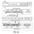
- FIG. 4Adepicts log management operations of a storage module
- FIG. 4Bdepicts embodiments of log coordination operations
- FIG. 4Cis a plot illustrating write amplification levels corresponding to different combinations of upper- and lower-level log segment sizes
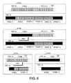
- FIG. 5Adepicts embodiments of log coordination operations pertaining to log segment boundary conditions
- FIG. 5Bdepicts further embodiments of log coordination operations pertaining to log segment boundary conditions
- FIG. 6depicts embodiments of log coordination operations pertaining to log grooming
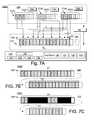
- FIG. 7Adepicts embodiments of log coordination operations pertaining to log fragmentation
- FIG. 7Bdepicts further embodiments of log coordination operations pertaining to log fragmentation
- FIG. 7Cdepicts further embodiments of log coordination operations pertaining to log fragmentation
- FIG. 8depicts embodiment of log coordination operations pertaining to multiple upper-level logs
- FIG. 9is a flow diagram depicting one embodiment of a method for log coordination
- FIG. 10is a flow diagram depicting another embodiment of a method for log coordination
- FIG. 11is a flow diagram depicting one embodiment of a method for log segment coordination
- FIG. 12is a flow diagram depicting one embodiment of a method for log coordination pertaining to grooming operations
- FIG. 13is a flow diagram depicting one embodiment of a method for log coordination operations pertaining to segment boundary conditions
- FIG. 14is a flow diagram depicting one embodiment of a method for log coordination operations pertaining to log defragmentation
- FIG. 15is a flow diagram depicting another embodiment of a method for log coordination operations pertaining to log defragmentation.
- FIG. 16is a flow diagram depicting another embodiment of a method for log coordination.
- FIG. 1Ais a block diagram of one embodiment of a computing system 100 comprising a storage module 130 configured to provide I/O and/or storage services to one or more I/O clients 106 .
- the computing system 100may comprise any computing device, including, but not limited to, a server, desktop, laptop, embedded system, mobile device, and/or the like. In some embodiments, the computing system 100 may include multiple computing devices, such as a cluster of server computing devices.
- the computing system 100may comprise processing resources 101 , volatile memory resources 102 (e.g., random access memory (RAM)), non-volatile storage resources 103 , and a communication interface 105 .
- volatile memory resources 102e.g., random access memory (RAM)
- the processing resources 101may include, but are not limited to, general purpose central processing units (CPUs), application-specific integrated circuits (ASICs), and programmable logic elements, such as field programmable gate arrays (FPGAs), programmable logic arrays (PLGs), and the like.
- the non-volatile storage resources 103may comprise a non-transitory machine-readable storage medium, such as a magnetic hard disk, solid-state storage medium, optical storage medium, and/or the like.
- the communication interface 105may be configured to communicatively couple the computing system 100 to a network 115 .
- the network 115may comprise any suitable communication network, including, but not limited to, a Transmission Control Protocol/Internet Protocol (TCP/IP) network, a Local Area Network (LAN), a Wide Area Network (WAN), a Virtual Private Network (VPN), a Storage Area Network (SAN), a Public Switched Telephone Network (PSTN), the Internet, and/or the like.
- TCP/IPTransmission Control Protocol/Internet Protocol
- LANLocal Area Network
- WANWide Area Network
- VPNVirtual Private Network
- SANStorage Area Network
- PSTNPublic Switched Telephone Network
- the Internetand/or the like.
- the I/O clients 106may include, but are not limited to, operating systems (including bare metal operating systems, guest operating systems, virtual machines, and the like), virtualization systems (virtualization kernels, hypervisors, virtual machines, and/or the like), file systems, database systems, remote I/O clients (e.g., I/O clients 106 communicatively coupled to the computing system 100 and/or storage module 130 through the network 115 ), and/or the like.
- operating systemsincluding bare metal operating systems, guest operating systems, virtual machines, and the like
- virtualization systemsvirtualization kernels, hypervisors, virtual machines, and/or the like
- file systemsdatabase systems
- remote I/O clientse.g., I/O clients 106 communicatively coupled to the computing system 100 and/or storage module 130 through the network 115 , and/or the like.
- the storage module 130may be implemented in software, hardware, or a combination thereof.
- portions of the storage module 130are embodied as executable instructions, such as computer program code, which may be stored on a persistent, non-transitory storage medium, such as the non-volatile storage resources 103 , storage medium 140 , firmware, and/or the like.
- the instructions and/or computer program codemay be configured for execution by the processing resources 101 of the computing system 100 and/or processing resources of other components and/or modules, such as the storage controller 139 .
- portions of the storage module 130 and/or other modules disclosed hereinmay be embodied as machine components, such as general and/or application-specific components, programmable hardware, FPGAs, ASICs, hardware controllers, storage controllers, and/or the like.
- the storage module 130may be configured to perform storage operations on the storage medium 140 .
- the storage medium 140may comprise any storage medium capable of storing data persistently.
- “persistent” data storagerefers to storing information on a persistent, non-volatile storage medium.
- the storage medium 140may include non-volatile storage media, such as solid-state storage media in one or more solid-state storage devices or drives (SSD), hard disk drives (e.g., Integrated Drive Electronics (IDE) drives, Small Computer System Interface (SCSI) drives, Serial Attached SCSI (SAS) drives, Serial AT Attachment (SATA) drives, etc.), tape drives, writeable optical drives (e.g., CD drives, DVD drives, Blu-ray drives, etc.), and/or the like.
- SSDsolid-state storage media in one or more solid-state storage devices or drives
- IDEIntegrated Drive Electronics
- SCSISmall Computer System Interface
- SASSerial Attached SCSI
- SASSerial AT Attachment
- SATASerial AT Attachment
- tape drives
- the storage medium 140comprises non-volatile, solid-state memory, which may include, but is not limited to, NAND flash memory, NOR flash memory, nano RAM (NRAM), magneto-resistive RAM (MRAM), phase change RAM (PRAM), Racetrack memory, Memristor memory, nanocrystal wire-based memory, silicon-oxide based sub-10 nanometer process memory, graphene memory, Silicon-Oxide-Nitride-Oxide-Silicon (SONOS) memory, resistive random-access memory (RRAM), programmable metallization cell (PMC) memory, conductive-bridging RAM (CBRAM), and/or the like.
- NAND flash memoryNOR flash memory
- NRAMnano RAM
- MRAMmagneto-resistive RAM
- PRAMphase change RAM
- Racetrack memoryMemristor memory
- nanocrystal wire-based memorysilicon-oxide based sub-10 nanometer process memory
- graphene memorySilicon-Oxide-Nitride-Oxide-Sili
- the teachings of this disclosurecould be applied to any suitable form of memory, including both non-volatile and volatile forms. Accordingly, although particular embodiments of the storage module 130 are disclosed in the context of non-volatile, solid-state storage devices, the storage module 130 may be used with other storage devices and/or storage media.
- the storage medium 140includes volatile memory, which may include, but is not limited to, RAM, dynamic RAM (DRAM), static RAM (SRAM), synchronous dynamic RAM (SDRAM), etc.
- the storage medium 140may correspond to the memory of the processing resources 101 , such as a CPU cache (e.g., L1, L2, L3 cache, etc.), graphics memory, and/or the like.
- the storage medium 140is communicatively coupled to the storage module 130 by use of an interconnect 127 .
- the interconnect 127may include, but is not limited to, peripheral component interconnect (PCI), PCI express (PCI-e), serial advanced technology attachment (serial ATA or SATA), parallel ATA (PATA), small computer system interface (SCSI), IEEE 1394 (FireWire), Fiber Channel, universal serial bus (USB), and/or the like.
- the storage medium 140may be a remote storage device that is communicatively coupled to the storage module 130 through the network 115 (and/or other communication interface, such as a Storage Area Network (SAN), a Virtual Storage Area Network (VSAN), and/or the like).
- SANStorage Area Network
- VSANVirtual Storage Area Network
- the interconnect 127may, therefore, comprise a remote bus, such as a PCE-e bus, a network connection (e.g., Infiniband), a storage network, Fibre Channel Protocol (FCP) network, HyperSCSI, and/or the like.
- a remote bussuch as a PCE-e bus, a network connection (e.g., Infiniband), a storage network, Fibre Channel Protocol (FCP) network, HyperSCSI, and/or the like.
- a network connectione.g., Infiniband
- FCPFibre Channel Protocol
- HyperSCSIHyperSCSI
- the storage module 130may be configured to manage storage operations on the storage medium 140 by use of the storage controller 139 .
- the storage module 130 and/or storage controller 139may comprise software and/or hardware components, including, but not limited to, one or more drivers and/or other software modules operating on the computing system 100 , such as storage drivers, I/O drivers, filter drivers, and/or the like.
- the storage module 130may comprise a driver and/or storage services layer of the computing device 100 .
- the storage module 130 (and/or modules thereof)may be embodied as computer-readable code stored on a non-volatile, computer-readable storage medium (e.g., non-volatile storage 103 of the computing device 100 ).
- the storage module 130may comprise and/or be tied to particular hardware components, such as hardware controllers, dedicated processing components, memory components, storage media, buffers, communication interfaces, and/or the like.
- the storage medium 140may be embodied on a storage device 141 . Portions of the storage module 130 and/or storage controller 139 may be implemented as hardware and/or software components (e.g., firmware) of the storage device 141 . The storage controller 139 may be configured to implement storage operations at particular storage units and/or storage locations of the storage medium 140 .
- a storage unit or storage locationsrefers to portion of a storage resource (e.g., a storage medium and/or device) that is capable of storing data persistently; storage units and/or storage locations may include, but are not limited to, pages, groups of pages (e.g., logical pages and/or offsets within a logical page), storage divisions (e.g., physical erase blocks, logical erase blocks, etc.), sectors, blocks, physical die, physical die plane(s), locations on a magnetic disk, battery-backed memory locations, and/or the like.
- Storage unitsmay be addressable within a storage address space 144 of the storage medium 140 .
- Storage addressesmay correspond to physical addresses, media addresses, back-end addresses, address offsets, and/or the like. Storage addresses may correspond to any suitable storage address space 144 , storage addressing scheme, and/or arrangement of storage units.
- the storage module 130may comprise an interface 131 through which I/O clients 106 may access storage services provided by the storage module 130 .
- the storage interface 131may include one or more of a block device interface, an object storage interface, a file storage interface, a key-value storage interface, a virtualized storage interface, one or more virtual storage units (VSUs), an object storage interface, a database storage interface, and/or other suitable interfaces and/or an Application Programming Interface (API), and the like.
- VSUsvirtual storage units
- APIApplication Programming Interface
- the storage module 130may provide for referencing storage resources through a front-end storage interface.
- a “front-end storage interface”refers to an interface and/or namespace through which I/O clients 106 may refer to storage resources of the storage module 130 .
- a storage interfacemay correspond to a logical address space 132 .
- the logical address space 132may comprise a group, set, collection, range, and/or extent of identifiers.
- an “identifier” or “logical identifier” (LID)refers to an identifier for referencing an I/O resource.
- LIDsmay include, but are not limited to, names (e.g., file names, distinguished names, and/or the like), data identifiers, references, links, front-end identifiers, logical addresses, logical block addresses (LBAs), storage unit addresses, virtual storage unit (VSU) addresses, logical unit number (LUN) addresses, virtual unit number (VUN) addresses, virtual logical unit number (VLUN) addresses, virtual storage addresses, storage addresses, physical addresses, media addresses, back-end addresses, unique identifiers, globally unique identifiers (GUIDs), and/or the like.
- namese.g., file names, distinguished names, and/or the like
- LBAslogical block addresses
- VSUvirtual storage unit
- LUNlogical unit number
- VUNvirtual unit number
- VLUNvirtual logical unit number
- GUIDsglobally unique identifiers
- the logical capacity of the logical address space 132may correspond to the number of LIDs in the logical address space 132 and/or the size and/or granularity of the storage resources referenced by the LIDs.
- the logical address space 132may be “thinly provisioned.”
- a thinly provisioned logical address space 132refers to a logical address space 132 having a logical capacity that exceeds the physical storage capacity of the underlying storage resources (e.g., exceeds the storage capacity of the storage medium 140 ).
- the storage module 130is configured to provide a 64-bit logical address space 132 (e.g., a logical address space comprising 2 ⁇ 26 unique LIDs), which may exceed the physical storage capacity of the storage medium 140 .
- the storage module 130may leverage the large, thinly provisioned logical address space 132 to efficiently allocate and/or reference contiguous ranges of LIDs for the I/O clients 106 , while reducing the chance of naming conflicts.
- the translation module 133 of the storage module 130may be configured to map LIDs of the logical address space 132 to storage resources (e.g., data stored within the storage address space 144 of the storage medium 140 ).
- the logical address space 132may be independent of the back-end storage resources (e.g., the storage medium 140 ); accordingly, there may be no set or pre-determined mappings between LIDs of the logical address space 132 and the storage addresses of the storage address space 144 .
- the logical address space 132is sparse, thinly provisioned, and/or over-provisioned, such that the size of the logical address space 132 differs from the storage address space 144 of the storage medium 140 .
- the storage module 130may be configured to maintain storage metadata 134 pertaining to storage operations performed on the storage medium 140 .
- the storage metadata 134may include, but is not limited to, a forward map comprising any-to-any mappings between LIDs of the logical address space 132 and storage addresses within the storage address space 144 , a reverse map pertaining to the contents of storage units of the storage medium 140 , validity bitmaps, reliability testing and/or status metadata, status information (e.g., error rate, retirement status, and so on), cache metadata, and/or the like.
- Portions of the storage metadata 134may be maintained within the volatile memory resources 102 of the computing system 100 .
- portions of the storage metadata 134may be stored on non-volatile storage resources 103 and/or the storage medium 140 .
- FIG. 1Bdepicts one embodiment of any-to-any mappings between LIDs of the logical address space 132 and back-end identifiers (e.g., storage addresses) within the storage address space 144 .
- the any-to-any mappingsmay be maintained in one or more data structures of the storage metadata 134 .
- the translation module 133may be configured to map any storage resource identifier (any LID of the logical address space 132 ) to any back-end storage unit.
- the logical address space 132may be sized differently than the underlying storage address space 144 .
- the logical address space 132may be thinly provisioned, and, as such, may comprise a larger range of LIDs than the range of storage addresses in the storage address space 144 .
- I/O clients 106may reference storage resources of the storage module 130 by use of, inter alia, LIDs of the logical address space 132 .
- the logical address space 132may correspond to a logical or front-end interface of the storage resources, and the mappings to particular storage addresses within the storage address space 144 may correspond to a back-end interface of the storage resources.
- the storage module 130may be configured to maintain the any-to-any mappings between the logical interface and back-end interface in a forward map 150 ( FIG. 1B ).
- the forward map 150may comprise any suitable data structure, including, but not limited to, an index, a map, a hash map, a hash table, a tree, a range-encoded tree, a b-tree, and/or the like.
- the forward map 150may comprise entries 152 corresponding to LIDs that have been allocated for use to reference data stored on the storage medium 140 .
- the entries 152 of the forward map 150may associate LIDs 154 A-D with respective storage addresses 156 A-D within the storage address space 144 .
- the forward map 150may be sparsely populated and, as such, may omit entries corresponding to LIDs that are not currently allocated to I/O clients 106 and/or are not currently in use to reference valid data stored on the storage medium 140 .
- the forward map 150comprises a range-encoded data structure, such that one or more of the entries 152 correspond to a plurality of LIDs (e.g., a range, extent, and/or set of LIDs).
- the forward map 150includes an entry 152 corresponding to a range of LIDs 154 A (LID range 34 of length 4, comprising LIDs 34-37) mapped to a corresponding range of storage addresses 156 A (16987-16990).
- the entries 152 of the forward map 150may be indexed by a LID in a tree data structure. The disclosure is not limited in this regard, however, and could be adapted to use any suitable data structure and/or indexing mechanism.
- the storage module 130may further comprise a log storage module 135 configured to store data on the storage medium 140 in a log structured storage configuration (e.g., in a storage log).
- a “storage log” or “log structure”refers to an ordered arrangement of data within the storage address space 144 of the storage medium 140 .
- Data in the storage logmay comprise and/or be associated with persistent metadata.
- the storage module 130may be configured to store data in a contextual, self-describing format.
- a contextual or self-describing formatrefers to a data format in which data is stored in association with persistent metadata.
- the persistent metadatamay be configured to identify the data and, as such, may comprise and/or reference the logical interface of the data (e.g., may comprise the LID(s) associated with the data).
- the persistent metadatamay include other information, including, but not limited to, information pertaining to the owner of the data, access controls, data type, relative position or offset of the data, information pertaining to storage operation(s) associated with the data (e.g., atomic storage operations, transactions, and/or the like), log sequence information, data storage parameters (e.g., compression algorithm, encryption, etc.), and/or the like.
- the storage module 130may further comprise a log management module 136 configured to manage portions of the log (log segments).
- the log management module 136may comprise a groomer 137 configured to reclaim and/or reinitialize log storage resources, such as log segments, media storage units, media storage divisions (e.g., erase blocks), virtual storage units, virtual storage divisions (e.g., groups of erase blocks), and the like.
- the log management module 136may further comprise a log coordination module 138 configured to coordinate log management operations with I/O clients 106 .
- FIG. 1Cillustrates one embodiment of a contextual data format.
- the data packet format 110 of FIG. 1Ccomprises a data segment 112 and persistent metadata 114 .
- the data segment 112may be of any arbitrary length and/or size.
- the persistent metadata 114may be embodied as one or more header fields of the data packet 110 .
- the persistent metadata 114may be configured to define the logical interface of the data segment 112 and, as such, may include and/or reference the LID(s) associated with the data segment 112 .
- the persistent metadata 114may be further configured to associate the data segment 112 with a particular application, user, I/O client 106 , upper-level log, and/or the like.
- 1Cdepicts a packet format 110 , the disclosure is not limited in this regard and could associate data (e.g., data segment 112 ) with persistent, contextual metadata in other ways, including, but not limited to, an index on the storage medium 140 , a separate metadata channel, and/or the like.
- datae.g., data segment 112
- persistent, contextual metadatain other ways, including, but not limited to, an index on the storage medium 140 , a separate metadata channel, and/or the like.
- the log storage module 135is further configured to associate data packets 110 with sequence information 113 .
- the sequence information 113may be used to determine the relative order of the data packets 110 stored on the storage medium 140 .
- the log storage module 135 and/or storage controller 139are configured to assign sequence information 113 to sections of the storage medium 140 .
- the sectionsmay correspond to storage divisions, erase blocks, logical erase blocks, and/or the like. Each section may be capable of storing a plurality of data packets 110 .
- the log storage module 135may be configured to append data packets 110 sequentially within the physical address space of the respective sections of the storage medium 140 (by use of the storage controller 139 ).
- the relative position of data packets 110 within a sectionmay determine the relative order of the data packets 110 within the section.
- the order of the sections of the storage medium 140may be determined by use of, inter alia, sequence information 113 of the sections.
- the sequence information 113may be assigned to respective sections of the storage medium 140 when the sections are initialized for use (e.g., erased), programmed, closed, and/or the like, such that the sequence information 113 defines an ordered sequence of sections within the storage address space 144 .
- the order of a data packet 110 within the storage logmay be determined by: a) the relative position of the data packet 110 within a particular storage division and b) the order of the storage division relative to other storage divisions in the storage address space 144 .
- the storage medium 140may comprise a solid-state storage array 145 .
- a solid-state storage array(or storage array 145 ) refers to a plurality of solid-state storage elements 146 A-Y managed in parallel.
- the solid-state storage elements 146 A-Ymay comprise solid-state storage resources embodied as a package, chip, die, plane, printed circuit board, and/or the like.
- the solid-state storage elements 146 A-Y comprising the array 145may be communicatively coupled to the storage module 130 in parallel by the interconnect 127 (through the storage controller 139 ).
- the interconnect 127may be capable of communicating data, address, and/or control information to each of the solid-state storage elements 146 A-Y.
- the storage module 130may be configured to leverage the parallel connection of the interconnect 127 to manage the solid-state storage elements 146 A-Y as a single, logical storage element (array 145 ).
- the interconnect 127comprises a separate, independent communication channel to/from each solid-state storage element 146 A-Y.
- signals on the interconnect 127such as command and/or addressing information, may be shared between a plurality of the solid-state storage elements 146 A-Y.
- the solid-state storage elements 146 A-Ymay comprise media storage units 160 .
- a media storage unit 160refers to any unit of storage on a solid-state storage element 146 A-Y including, but not limited to: a page, a sector, a block, and/or the like.
- the storage medium 140may be a “write-once” storage medium, comprising media storage units 160 that can only be reliably programmed once after initialization, such that the media storage units 160 must be reinitialized each time new data is written or programmed thereto.
- the media storage units 160may have a “writeable” or “initialized,” state in which the media storage units 160 are capable of having data programmed thereon, and a “written” state in which the media storage units 160 have been programmed with data and, as such, must be reinitialized before being used to store new data.
- the storage medium 140may be “asymmetric,” such that different storage operations have different time latencies.
- read operationsmay be faster than write/program operations
- write/program operationsmay be faster than initialization operations (e.g., reading the media may be hundreds of times faster than erasing, and tens of times faster than programming the storage medium).
- the solid-state storage elements 146 A-Ymay be partitioned into respective media storage divisions 162 .
- a media storage division 162refers to a section, sector, segment, block and/or division of a solid-state storage element 146 A-Y including, but not limited to: a block, an erase block, an erase sector, and/or the like.
- the media storage divisions 162may comprise a plurality of media storage units 160 .
- the media storage units 160 of a media storage division 162may be initialized as a group, such that a single erase operation on a media storage division 162 is configured to initialize a plurality of media storage units 160 .
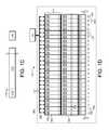
- the solid-state storage array 145may comprise columns 118 and rows 117 .
- the columns 118may correspond to respective solid-state storage elements 146 A-Y, and the rows may correspond to media storage units 160 and/or divisions 162 within the array 145 .
- FIG. 1Ddepicts one embodiment of a solid-state storage array 145 comprising solid-state storage elements 146 A-Y having a particular configuration, the disclosure is not limited in this regard and could be adapted to arrange solid-state storage elements 146 A-Y partitioned in any suitable manner, in any suitable configuration.
- the storage module 130may be configured to perform storage operations on groups of media storage units 160 and/or media storage divisions 162 . As disclosed above, it may take longer to program data onto the solid-state storage elements 146 A-Y than it takes to read data therefrom (e.g., ten times as long). Moreover, in some embodiments, data may only be programmed media storage units 160 that have been initialized (e.g., are in a writeable state). Initialization operations may take longer than program and/or read operations. Managing groups of solid-state storage elements 146 A-Y in the storage array 145 (and/or independent banks, as disclosed below), may allow the storage module 130 to address these asymmetric properties.
- the storage module 130is configured to perform data write and/or read operations within virtual storage units 164 (e.g., virtual pages) of the solid-state storage array 145 .
- virtual storage units 164e.g., virtual pages
- a virtual storage unit 164may comprise media storage units 160 within a particular row 117 of the array 145 (e.g., a media storage unit 160 on each of a plurality of solid-state storage elements 146 A-Y).
- the storage module 130may be further configured to manage storage recovery and/or initialization operations using virtual storage divisions 166 , which may comprise media storage divisions 162 within respective rows 117 of the array 145 (e.g., a media storage division 162 (physical erase block) on each of a plurality of the solid-state storage elements 146 A-Y).
- An operation to read or write data to a virtual storage unit 164may comprise programming data to each of 25 media storage units 160 (e.g., one media storage unit 160 per solid-state storage element 146 A-Y); an operation to initialize (e.g., erase) a virtual storage division 166 may comprise initializing 25 media storage divisions 162 (e.g., erase blocks); and so on.
- a read operation on the array 145may comprise reading data from media storage unit 160 at a first address of solid-state storage element 146 A and reading data from a media storage unit 160 at a different address within one or more other solid-state storage elements 146 B-N.
- portions of the solid-state storage array 145may be configured to store data, and other portions of the array 145 may be configured to store error detection and/or recovery information.
- a column 118 used for data storagemay be referred to as a “data column,” and a column 118 used to store error detection and/or recovery information may be referred to as a “parity column” or “recovery column.”
- the array 145may be configured in an operational mode in which the solid-state storage element 146 Y is used to store parity data, and the other solid-state storage elements 146 A-X are used to store data.
- the effective storage capacity of the virtual storage units 160may be reduced (e.g., reduced from 25 pages to 24 pages).
- the “effective storage capacity” of a storage unitrefers to the number of storage units or divisions that are available to store data and/or the total amount of data that can be stored within a particular virtual storage unit 164 .
- the operational mode described abovemay be referred to as a “24+1” configuration, denoting that 24 physical storage units 160 are available to store data, and 1 of the physical storage units 160 is used for parity information.
- the disclosed embodimentsare not limited to any particular operational mode and/or configuration, however, and could be adapted to use any number of the solid-state storage elements 146 A-Y to store error detection and/or recovery data.
- FIG. 2Adepicts one embodiment of a storage system 200 A comprising a storage module 130 configured to manage a storage medium 140 .
- the storage medium 140comprises a plurality of independent banks 149 A-N, each of which may comprise one or more storage arrays 145 A-N, as disclosed above.
- the storage controller 139may comprise a storage request module 231 configured to receive storage requests from the storage module 130 .
- the storage request module 231may be further configured to transfer data to/from the storage module 130 and/or I/O clients 106 .
- the storage request module 231may comprise one or more direct memory access (DMA) modules, remote DMA modules, bus controllers, bridges, buffers, and the like.
- DMAdirect memory access
- the storage controller 139may comprise a write module 240 configured to store data on the storage medium 140 in response to requests received via the request module 231 .
- the requestsmay comprise and/or reference a logical interface of the data to be written to the storage medium 140 .
- the write module 240may be configured to store the data in a self-describing storage log, which, as disclosed above, may comprise appending data packets 110 sequentially within the storage address space 144 of the storage medium 140 .
- the data packets 110may comprise and/or reference the logical interface of the data (e.g., may comprise the LID(s) associated with the data), as disclosed herein.
- the write module 240may comprise a write processing module 242 configured to process data for storage on the storage medium 140 , which may include, but is not limited to: a) compression processing, b) encryption processing, c) encapsulating data into respective data packets 110 (and/or other containers), d) performing error-correcting code (ECC) processing, and so on.
- the write module 240may further comprise a write buffer 244 configured to buffer data for storage on media storage units 160 of the storage medium 140 .
- the write buffer 244may comprise one or more synchronization buffers configured to synchronize a clock domain of the storage controller 139 with a clock domain of the storage medium 140 (and/or interconnect 127 A-N).
- the log storage module 135may be configured to select storage unit(s) for data storage operations and may provide addressing and/or control information to the storage arrays 145 A-N of the independent banks 149 A-N.
- the log storage module 135may be configured to append data sequentially in a log format within the storage address space 144 of the storage medium 140 , as disclosed herein.
- Storage operations to write data on the storage medium 140may comprise: a) appending one or more data packets to the storage log on the storage medium 140 and b) updating storage metadata 134 (forward map 150 ) to associate LID(s) of the data with the storage addresses of the one or more data packets on the storage medium 140 .
- the storage metadata 134may be maintained by use of memory resources of the storage controller 139 (e.g., volatile memory resources of the storage device 141 comprising the storage medium 140 ).
- portions of the storage metadata 134may be maintained within the storage module 130 (e.g., on a volatile memory 102 of the computing device 110 of FIG. 1A ).
- the storage metadata 134may be maintained in a volatile memory by the storage module 130 , and may be periodically stored on the storage medium 140 (or other persistent storage resource).
- the storage controller 139may further comprise a data read module 241 configured to read data from the storage log on the storage medium 140 in response to requests received via the request module 231 .
- the read requestsmay comprise LID(s) of the requested data, a storage address of the requested data, and/or the like.
- the read module 241may be configured to: a) determine the storage address(es) of the data packet(s) 110 comprising the requested data by use of, inter alia, the forward map 150 , b) read the data packet(s) 110 from the determined storage address(es) on the storage medium 140 , and c) process data for use by the requesting entity.
- Data read from the storage medium 140may stream into the read module 241 via a read buffer 245 .
- the read buffer 245may comprise one or more read synchronization buffers for clock domain synchronization, as described above.
- a read processing module 243may be configured to process data read from the storage medium 140 , which may include, but is not limited to, one or more of: a) decompression processing, b) decryption processing, c) extracting data from one or more data packet(s) 110 (and/or other containers), d) performing ECC processing, and so on.
- the storage controller 139may further comprise a bank controller 247 configured to selectively route data and/or commands of the write module 240 and/or read module 241 to/from particular independent banks 149 A-N. In some embodiments, the storage controller 139 is configured to interleave storage operations between the independent banks 149 A-N.
- the storage controller 139may, for example, read from a virtual storage unit 164 A of array 145 A in bank 149 A by use of the read module 241 while data from the write module 240 is being programmed to another virtual storage unit 164 B-N of another bank 149 B-N. Further embodiments of multi-bank storage operations are disclosed in U.S.
- the write processing module 242may be configured to encode data packets 110 into ECC codewords.
- an ECC codewordrefers to data and corresponding error detection and/or correction information.
- the write processing module 242may be configured to implement any suitable ECC algorithm and/or generate ECC codewords of any suitable type, which may include, but are not limited to, data segments and corresponding ECC syndromes, ECC symbols, ECC chunks, and/or other structured and/or unstructured ECC information.
- ECC codewordsmay comprise any suitable error-correcting encoding, including, but not limited to, block ECC encoding, convolutional ECC encoding, Low-Density Parity-Check (LDPC) encoding, Gallager encoding, Reed-Solomon encoding, Hamming codes, Multidimensional parity encoding, cyclic error-correcting codes, BCH codes, and/or the like.
- the write processing module 242may be configured to generate ECC codewords of a pre-determined size. Accordingly, a single packet may be encoded into a plurality of different ECC codewords and/or a single ECC codeword may comprise portions of two or more packets.
- the write processing module 242may be configured to generate arbitrarily sized ECC codewords. Further embodiments of error-correcting code processing are disclosed in U.S. patent application Ser. No. 13/830,652, entitled, “Systems and Methods for Adaptive Error-Correction Coding,” filed Mar. 14, 2013 for Jeremy Fillingim et al., which is hereby incorporated by reference in its entirety.
- the storage module 130is configured to interleave storage operations between independent banks 149 A-N of solid-state storage arrays 145 A-N, which may further ameliorate performance issues caused by asymmetry between erase, program, and read operations.
- the banks 149 A-Nmay comprise one or more solid-state storage arrays 145 A-N, which, as disclosed herein, may comprise a plurality of solid-state storage elements 146 A-Y coupled in parallel to the storage module 130 through respective interconnects 127 A-N.
- the banks 149 A-Nmay be capable of independent operation. Data may be read from virtual storage unit 164 A within the array 145 A of bank 149 A while data is being programmed to virtual storage unit 164 B of bank 149 B, and/or as virtual storage division 166 N is being initialized.
- the storage module 130may be further configured to manage groups of virtual storage divisions 166 A-N.
- a virtual storage division group (VSDG) 167may comprise virtual storage divisions 164 A-N of banks 149 A-N.
- the VSDG 167comprises a virtual storage division 166 within each array 145 A-N.
- the VSDG 167may comprise N virtual storage divisions 166 .
- the virtual storage divisions 164 A-N of the VSDG 167may be initialized together (e.g., erased in response to a single erase command and/or in response to a plurality of separate erase commands and/or signals on the interconnects 127 A-N).
- Performing storage recovery and/or initialization operations on groups of virtual storage divisions (e.g., VSDGs 167 ) that comprise a large number of media storage divisions 164may further mask the asymmetric properties of the solid-state storage medium 140 .
- the storage module 130is configured to perform storage operations within boundaries of the arrays 145 A-N and/or banks 149 A-N. As disclosed above, write and/or program operations may be performed within rows 117 of the solid-state storage arrays 145 A-N (e.g., on virtual storage units 164 A-N of respective banks 149 A-N). As depicted in FIG. 2A , the virtual storage units 164 A-N of the arrays 145 A-N may not extend beyond the respective boundaries of the arrays 145 A-N and/or banks 149 A-N.
- the log storage module 135 and/or bank controller 247may be configured to append data to the solid-state storage medium 140 by interleaving and/or scheduling storage operations sequentially between the arrays 145 A-N of the banks 149 A-N.
- FIG. 2Bdepicts one embodiment 200 B of storage operations that are interleaved between a plurality of independent banks 149 A-N.
- the bank interleave controller 247is configured to interleave programming operations on virtual storage units 164 A-N within respective arrays 145 A-N of banks 149 A-N.
- the write module 240may comprise a write buffer 250 , which may have sufficient capacity to fill write buffers of one or more virtual storage units 164 of an array 145 A-N.
- the storage controller 139may stream the contents of the write buffer 250 to program buffers of the solid-state storage elements 146 A-Y of one of the banks 149 A-N.
- the storage controller 139may issue a program signal to the corresponding solid-state storage array 145 A-N configured to write the contents of the program buffers to respective media storage units 160 A-N of the elements 146 A-Y.
- the log storage module 135 and/or bank interleave controller 247may be configured to provide control and addressing information to the solid-state storage elements 146 A-Y of the array 145 A-N by use of the interconnects 127 A-N, as disclosed herein.
- the bank controller 247may be configured to append data to a storage log on the storage medium 140 according to a sequential, bank interleave pattern.
- FIG. 2Cdepicts one embodiment 200 C of a sequential, bank interleave pattern configured to latency due to asymmetry between read and write operations.
- the bank interleave patternmay be configured to sequence operations between virtual storage units 164 within the banks 149 A-N.
- datamay be programmed to a first virtual storage unit 164 (VSU_ 0 ) of array 145 A in bank 149 A in a program operation 253 A.
- the storage controller 139may then stream data to a first virtual storage unit 164 (VSU_ 0 ) of the array 145 B in the next bank 149 B.
- Datamay then be programmed to VSU_ 0 of array 145 B of bank 149 B in a program operation 253 B.
- the program operation 253 Bmay be performed concurrently with the program operation 253 A on array 145 A of bank 149 A; the storage controller 139 may be configured to stream data to array 145 B and/or issue a command and/or signal for the program operation 253 B, while the program operation 253 A is being performed on the array 145 A.
- Datamay be streamed to and/or programmed on the first logical page (VSU_ 0 ) of the arrays 145 C-N of the other banks 149 C- 119 N following the same sequential interleave pattern (e.g., after data is streamed and/or programmed to VSU_ 0 of array 145 A of bank 149 B, data is streamed and/or programmed to VSU_ 0 of array 145 C of bank 149 C in program operation 253 C, and so on).
- VSU_ 0first logical page
- the storage controller 139may be configured to begin streaming and/or programming data to the next virtual storage unit 164 (VSU_ 1 ) of array 145 A within the first bank 149 A, and the interleave pattern may continue accordingly (e.g., program VSU_ 1 of array 145 B of bank 149 B, followed by VSU_ 1 of array 145 C of bank 149 C through VSU_ 1 of array 145 N of bank 149 N, followed by VSU_ 2 of array 145 A of bank 149 A, and so on).
- VSU_ 1virtual storage unit 164
- the interleave patternmay continue back at VSU_ 0 of array 145 A in bank 149 A (in accordance with the availability of writeable virtual storage divisions 166 , as disclosed herein).
- Sequentially interleaving programming operations between the independent banks 149 A-Nmay increase the time between concurrent programming operations on the same array 145 A-N and/or bank 149 A-N, which may reduce the likelihood that the storage operations will have to be delayed due to, inter alia, asymmetric media programming latency.
- programming operationsmay take significantly longer than other operations, such as read and/or data streaming operations (e.g., operations to stream the contents of the write buffer 250 to an array 145 A-N via the bus 127 A-N).
- read and/or data streaming operationse.g., operations to stream the contents of the write buffer 250 to an array 145 A-N via the bus 127 A-N.
- 2Cmay be configured to avoid consecutive program operations on the same array 145 A-N and/or bank 149 A-N; programming operations on a particular array 145 A-N may be separated by N ⁇ 1 programming operations on other banks (e.g., programming operations on array 145 A are separated by programming operations on arrays 145 A-N). As such, programming operations on array 149 A are likely to be complete before another programming operation needs to be performed on the array 149 A.
- the storage module 130may be configured to manage groups of virtual storage divisions, such as VSDGs 167 , which may comprise virtual storage divisions 166 A-N within respective banks 149 A-N.
- FIG. 2Cillustrates another embodiment 200 C of a sequential, bank interleave pattern with respect to VSDGs 167 A-N.
- the VSDGs 167 A-Nmay comprise virtual storage divisions 166 A-N within different banks 149 A-N (e.g., VSDG 167 A may comprise virtual storage division VSD_ 0 of each array 145 A-N, VSDG 167 B may comprise virtual storage division VSD_ 1 of each array 145 A-N, and so on).
- the storage controller 130may be configured to program data to virtual storage units 164 (VSU_ 0 -N) of a first virtual storage division group 167 A according to the sequential, bank interleave pattern of FIG. 2B . Subsequent to programming data to the last virtual storage unit 164 (VSU_N) of the first virtual storage division 166 (VSD_ 0 ) of bank 145 N, the storage module 130 may resume the sequential, bank interleave pattern within the next virtual storage division group 167 B.
- the storage module 130may resume the sequential, bank interleave pattern within the next virtual storage division group 167 C, and so on.
- the sequential, bank interleave patternmay continue until the last VSDG 167 N is filled, at which point the interleave pattern may continue at the first erase block group VSDG_ 0 (or next writeable VSDG 167 ).
- the storage module 130may be configured to perform media management operations on large numbers of media storage units 160 in parallel in order to address write-once, asymmetric properties of the storage medium 140 .
- a “write-once” storage mediumrefers to a storage medium that can only be reliably programmed once, and/or must be reinitialized (e.g., erased) each time new data is written or programmed thereon.
- a write-once storage mediummay, therefore, have a “writeable” or “initialized” state in which the storage medium is capable of having data programmed thereon, and a “written state” in which the storage medium has had data programmed thereon and, as such, must be initialized before being used to store new data.
- the storage module 130may be configured to initialize groups, sets, and/or collections of media storage units 160 and/or media storage divisions 162 in parallel.
- the sequential, bank interleave pattern disclosed hereinmay be configured to program data to VSDG 167 A-N in sequence (e.g., program data to VSDG 167 A before programming data to VSDG 167 B, and so on).
- the storage module 130may be configured to perform media management operations at a VSDG 167 A-N granularity (e.g., perform management operations on respective VSDGs 167 A-N).
- Initializing a VSDG 167 A-Nmay comprise initializing each of the virtual storage divisions 166 within the respective VSDG 167 A-N.
- Initializing VSDG 167 Amay, therefore, comprise initializing the first virtual storage division (VSD_ 0 ) within each array 145 A-N of banks 149 A-N, initializing the VSDG 167 B may comprise erasing the next virtual storage division (VSD_ 1 ) within each array 145 A-N of banks 119 A-N, initializing VSDG 167 C may comprise initializing a third virtual storage division (VSD_ 2 ) within each array 145 A-N of banks 149 A-N, initializing VSDG 167 N may comprise erasing a last virtual storage division (VSD_N) within each array 145 A-N of banks 149 A-N, and so on.
- Initializing a VSDG 167 A-Nmay further comprise relocating valid data stored on the VSDG 167 A-N (if any) and erasing the VSDG 167 A-N. Following erasure, the VSDG 167 A-N may be made available for write operations, which may comprise placing the VSDG 167 A-N in a write queue of the log storage module 135 , marking the VSDG 167 A-N as writeable (in the storage metadata 134 ), marking the VSDG 167 A-N with sequence information 113 , and/or the like.
- initializing a VSDG 167 A-Nmay comprise initializing 100 media storage divisions 162 in parallel (e.g., initializing 100 erase blocks in parallel).
- multi-bank embodimentsare disclosed herein, the disclosure is not limited in this regard and could be configured using any multi-bank architecture comprising any number of banks 149 A-N, comprising arrays 145 A-N having any number of solid-state storage elements 146 A-Y.
- Further embodiments of systems and methods for arranging data for storage within a solid-state storage arrayare disclosed in U.S. patent application Ser. No. 13/784,705, entitled “Systems and Methods for Adaptive Data Storage,” filed on Mar. 4, 2013 for David Flynn et al., which is hereby incorporated by reference in its entirety.
- modifying a data segment “in-place” on a particular media storage unit 160may require erasing the entire media storage division 162 comprising the data (and/or the corresponding virtual storage division 166 and/or VSDG 167 ) and rewriting the modified data along with the other data on the particular media storage division 162 , virtual storage division 166 and/or VSDG 167 , resulting in“write amplification,” which may reduce performance and excessively wear the storage medium 140 .
- the storage module 130may be configured to write data “out-of-place” on the storage medium 140 .
- writing data “out-of-place”refers to updating and/or overwriting data at different storage unit(s) rather than overwriting the data “in-place” (e.g., overwriting the original physical storage unit of the data). Updating and/or overwriting data out-of-place may avoid write amplification, since existing, valid data on the erase block with the data to be modified need not be erased and recopied. Moreover, writing data out-of-place may remove media initialization (erasure) from the latency path of many storage operations.
- the storage module 130may be configured to perform storage operations out-of-place by use of the log storage module 135 .
- the log storage module 135may be configured to append data at a current append point within the storage address space 144 in a manner that maintains the relative order of storage operations performed by the storage module 130 , forming a “storage log” on the storage medium 140 .
- a “storage log”refers to a data storage configuration configured to define a relative order of storage operations performed on the storage medium 140 .
- the storage logmay comprise a plurality of “storage log segments” or “log segments.”
- a “log segment”refers to a collection of storage units and/or storage units that are managed and/or initialized as a group (a set of log storage units).
- a log segmentmay include, but is not limited to: a media storage division 162 (e.g., an erase block), a virtual storage unit 164 , a virtual storage division 166 , a virtual storage division group 167 , and/or the like.
- a “log storage unit” of a log segmentcan include, but is not limited to: a media storage unit 160 (e.g., a page, sector, block and/or the like), a virtual media storage unit 164 , and/or the like.
- the size and/or storage capacity of a log segmentmay correspond to the number and/or configuration of log storage units included therein. For example, a log segment comprising 2,000 media storage units 160 each capable of storing 1 kb of data, may have a storage capacity of 2 MB.
- the log storage module 135may be configured to append data within respective log segments within storage address space 144 of the storage device 141 (e.g., according to the sequential, bank interleave patterns of FIGS. 2B and 2C ).
- the log management module 136 of the storage module 130may be configured to groom the log segments, which may comprise initializing log segments for use by the log storage module 135 by, inter alia: a) relocating valid data on the log segment (if any), and b) erasing the log segment.
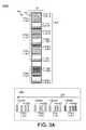
- FIG. 3Adepicts one embodiment 300 A of a storage log 350 comprising data stored sequentially within log segments 370 (e.g., log segments 370 [ 1 ]- 370 [N]) by the storage module 130 .
- a log segment 370refers to a collection, group, and/or set of commonly managed log storage units 371 .
- the log storage units 371 of the log segments 370may comprise a plurality of log storage units 371 A-N capable of storing data (e.g., data packets 110 ), as disclosed above.
- the log storage units 371may comprise storage units 160 (e.g., pages, sectors, blocks, and/or the like), virtual storage units (e.g., pages on a plurality of storage elements 146 A-N in a particular bank 149 A-N), and/or the like.
- a log segment 370may correspond to a collection of log storage units 371 that are reclaimed, recovered, and/or reinitialized as a group.
- the groomer 137may be configured to perform grooming operations within respective log segments 370 .
- the log segments 370may comprise virtual storage divisions 166 and/or virtual storage division groups 167 of a solid-state storage array 145 .
- log segments 370comprising any storage medium 140 including, but not limited to: a magnetic storage medium (e.g., a hard disk drive), persistent random access memory (e.g., battery-backed RAM), an optical storage medium, and/or the like.
- a magnetic storage mediume.g., a hard disk drive
- persistent random access memorye.g., battery-backed RAM
- an optical storage mediume.g., an optical storage medium, and/or the like.
- a grooming operation to reinitialize a log segment 370may comprise: a) relocating valid data stored within the log segment 370 (if any), and b) reinitializing the log segment 370 .
- reinitializing a log segment 370may comprise erasing the physical erase blocks 162 , virtual erase blocks 166 , and/or virtual erase block groups 167 comprising the log segment 370 .
- the groomer 137may be configured to erase the log segment 370 in a simultaneous operation and/or by use of a single and/or common erase command transmitted to a plurality of storage elements 146 and/or banks 149 , as disclosed herein.
- the log segments 370may comprise a different storage medium, such as a hard disk, battery-backed RAM, and/or the like.
- reinitializing the log segment 370may comprise marking the log segment 370 as available for storage operations, writing a pre-determined pattern to the log segment 370 (e.g., zeros), and/or the like.
- the storage log 350may comprise data stored with persistent metadata configured to determine a log order 352 of data stored within the respective log storage units 371 of the log segments 370 (e.g., log order 352 of data packets 110 [A][ 0 ]- 110 [N][P]).
- the log storage module 135may be configured to append data packets 110 sequentially within the storage address space 144 (e.g., within log segments 370 [ 1 ]- 370 [N]), by use of the log storage module 135 and/or storage controller 139 .
- the order in which data is appended within the respective log segments 370 [ 1 ]- 370 [N]may be determined according to the availability of erased and/or initialized log segments 370 [ 1 ]- 370 [N], as disclosed in further detail herein.
- the log storage module 135may be configured to fill the respective log segments 370 [ 1 ]- 370 [N] before appending data to other log segments 370 [ 1 ]- 370 [N].
- the log segments 370 [ 1 ]- 370 [N]may be filled according to a sequential, bank interleave storage pattern as disclosed above in conjunction with FIGS. 2A and 2B .
- the log storage module 135may have stored data packets 110 [ 1 ][A]- 110 [ 1 ][P] sequentially in the storage address space of log segment 370 [ 1 ] (e.g., within the log storage units 371 [ 1 ][A]- 371 [ 1 ][N]), such that data packet 110 [ 1 ][P] is later in the storage log (stored more recently) relative to data packet 110 [ 1 ][A].
- 3Afurther illustrates data packets 110 stored sequentially within the log storage units 371 of other log segments 370 [ 2 ]- 370 [N]: data packets 110 [ 2 ][A]- 110 [ 2 ][P] are stored sequentially within log storage units 371 [ 2 ][A]- 371 [ 2 ][N] of log segment 370 [ 2 ], data packets 110 [ 3 ][A]- 110 [ 3 ][P] are stored sequentially within log storage units 371 [ 3 ][A]- 371 [ 3 ][N] of log storage segment 370 [ 3 ], data packets 110 [N][A]- 110 [N][P] are stored sequentially within log storage units 371 [N][A]- 371 [N][N] of log segment 370 [N], and so on.
- the storage module 130may mark log segments 370 [ 1 ]- 370 [N] with respective sequence information 113 [ 1 ]- 113 [Y], configured to define the order in which the log segments 370 [ 1 ]- 370 [N] were programmed. Accordingly, the order in which the data packets 110 [ 1 ][A]- 110 [N][P] were stored within the respective log segments 370 [ 1 ]- 370 [N] may be defined by, inter alia, sequence information 113 [ 1 ]- 113 [Y] of the log segments 370 [ 1 ]- 370 [N].
- sequence information 113 [ 1 ]- 113 [Y]may be stored at predetermined locations within the log segments 370 [ 1 ]- 370 [N] (e.g., in a header, at a predetermined offset, and/or the like).
- the sequence information 113 [ 1 ]- 113 [Y]may be stored when the log segments 370 [ 1 ]- 370 [N] are initialized (e.g., erased) by the log management module 136 , placed in a write queue by the log management module 136 , selected for use by the log storage module 135 , when data is appended to the log segments 370 [ 1 ]- 370 [N], when the log segments 370 [ 1 ]- 370 [N] are closed (e.g., filled), and/or the like.
- the sequence information 113 [Y]may correspond to the most recently programmed (youngest) log segment 370 [ 1 ]- 370 [N] in the storage log 350 , and the sequence information 113 [ 1 ] may correspond to the earliest programmed (oldest) log segment 370 [ 1 ]- 370 [N]. Therefore, and as illustrated in FIG. 3A , the log order 352 of the log segments 370 [ 1 ]- 370 [N] may be 370 [N] (most recently programmed or youngest), 370 [ 1 ], 370 [ 3 ], to 370 [ 2 ] (least recently programmed or oldest).
- the order of the individual data packets 110 [ 1 ][A]- 110 [N][P] within the storage log 350may be determined based on the sequence information 113 [ 1 ]- 113 [Y] of the respective log segments 370 [ 1 ]- 370 [N] and the relative storage unit(s) of the data packets 110 [ 1 ][A]- 110 [N][P] within the log segments 370 [ 1 ]- 370 [N].
- sequence information 113 [ 1 ]- 113 [Y] of the respective log segments 370 [ 1 ]- 370 [N]and the relative storage unit(s) of the data packets 110 [ 1 ][A]- 110 [N][P] within the log segments 370 [ 1 ]- 370 [N].
- the log order 352 from most recent to oldestis: 110 [N][P]- 110 [N][A], 110 [ 1 ][P]- 110 [ 1 ][A], 110 [ 3 ][P]- 110 [ 3 ][A], and 110 [ 2 ][P]- 110 [ 2 ][A].
- FIG. 3Bdepicts one embodiment 300 B of storage operations, performed by the storage module 130 , configured to append data to an ordered storage log 350 .
- the storage module 130may be configured to manage the storage address space 144 as a plurality of log segments 370 [ 1 ]- 370 [N], which may comprise a set of commonly managed log storage units 371 (e.g., pages, sectors, blocks, virtual pages, and/or the like).
- the log storage units 371may correspond to respective storage addresses within the storage address space 144 (e.g., storage address 0 of storage division 370 [ 1 ] through storage address X of storage division 370 [N]).
- the log storage module 135may be configured to store data sequentially within respective storage divisions 370 [ 1 ]- 370 [N], by use of the storage controller 139 .
- the log storage module 135may be configured to sequentially append data packets 110 at a current append point 180 within the storage address space 144 .
- the current append point 180corresponds to storage unit 182 of log segment 370 [ 1 ].
- the log storage module 135may be configured to sequentially increment the append point 180 within the log segment 370 [ 1 ] until the storage division 370 [ 1 ] is fully programmed (and/or filled within a threshold or boundary condition).
- the append point 180may be incremented within the log segment 370 [ 1 ] according to the sequential, interleaved pattern disclosed above).
- an “available” log segment 371refers to a log segment 371 that is “writeable” and/or is in a “writeable state.”
- a “writeable” log segment 371refers to a log segment 371 comprising media storage units 160 that are writeable (e.g., have been initialized and have not yet been programmed).
- log segments 371 that have been programmed and/or are not initializedare “unavailable,” “un-writeable” and/or in an “un-writeable” state.
- Advancing 181 the append point 180may comprise selecting a writeable log segment 370 [ 2 ]- 370 [N]. As disclosed in further detail herein, in some embodiments, advancing 181 the append point 180 to the next available storage unit may comprise selecting a log segment 370 [ 1 ]- 370 [N] from a write queue.
- the log segment 370 [ 2 ]may be unavailable for use by the log storage module 135 (e.g., un-writeable) due to not being in an erased/initialized state, being out-of-service due to high error rates, and/or the like. Therefore, after filling the log storage segment 370 [ 1 ], the log storage module 135 may skip the unavailable storage division 370 [ 2 ] and advance 181 the append point 180 to the next available storage division 370 [ 3 ].
- the log storage module 135may be configured to continue appending data to log storage segments 183 - 185 , after which the append point 180 is advanced to a next available log storage segment 370 [ 1 ]- 370 [N], as disclosed herein.
- the log storage module 135may advance 181 the append point 180 by wrapping back to the first log storage segment 370 [ 1 ] (or the next available log segment 370 [ 2 ]- 370 [N], if the log segment 370 [ 1 ] is unavailable). Accordingly, the storage module 130 may be configured to manage the storage address space 144 as a loop or cycle (e.g., as illustrated in FIG. 3C ).
- the log storage format implemented by the storage module 130may be used to modify and/or overwrite data out-of-place. As disclosed above, performing storage operations out-of-place may avoid performance and/or endurance issues, such as erase latency and/or write amplification.
- a data segment D 0 corresponding to LID Amay be stored at log storage unit 191 of log segment 370 [ 3 ].
- the data segment D 0may be stored in association with persistent metadata (e.g., in the packet format 110 , disclosed above).
- the data segment 112 of the packet 110may comprise the data segment D 0
- the persistent metadata 114may comprise the LID(s) associated with the data segment (e.g., LID A).
- An I/O client 106may request an operation to modify and/or overwrite the data associated with the LID A, which may comprise replacing the data segment D 0 with data segment D 1 .
- the storage module 130may perform this operation out-of-place by appending a new packet 110 comprising the data segment D 1 at a different location on the storage medium 140 , rather than modifying the existing data in place, at storage unit 191 .
- the data segment D 1is stored in a data packet at log storage unit 193 of log segment 370 [N].
- the storage operationmay further comprise updating the storage metadata 134 to bind LID A to the log storage unit 193 and/or to invalidate the obsolete data D 0 at storage unit 191 . As illustrated in FIG.
- updating the storage metadata 134may comprise updating an entry of the forward map 150 to associate the LID A 154 E with the storage address of the modified data segment D 1 . Updating the storage metadata 134 may further comprise updating one or more reverse indexes and/or validity bitmaps, as disclosed in further detail herein.
- Performing storage operations out-of-placemay result in obsolete and/or invalid data remaining on the storage medium 140 and/or within the storage log 350 .
- invalid datarefers to data that has been overwritten, modified, erased, deleted, deallocated, and/or does not need to be retained on the storage medium 140 .
- modifying the data of LID A by appending the data segment D 1 to the storage log at log storage unit 193 rather than overwriting and/or replacing the data segment D 0 in place at log storage unit 191results in keeping the obsolete version of the data segment D 0 on the storage medium 140 .
- erasing the data segment D 0may involve reinitializing the log segment 370 [ 1 ], which may comprise a) relocating valid data stored on the log segment 370 [ 1 ], and b) erasing the log segment 370 [ 1 ].
- the log segments 370 [ 1 ]- 370 [N]may comprise a large number of media storage units 160 (e.g., a log segment 370 corresponding to a virtual storage division group 167 may comprise 100 erase blocks, each of which may comprise 256 pages, for a total of 2560 media storage units 160 ).
- the storage module 130may, therefore, defer removal of invalid data, which may result in accumulating a significant amount of invalid data on the storage medium 140 .
- the log management module 136 of the storage module 130may be configured to reclaim log segments 370 , so that the log storage segments 370 can be used to store new, valid data. As disclosed above reclaiming a log segment 370 may comprise copying valid data from the log storage units 371 of the log segment 370 (if any), and erasing the log segment 370 .
- the log management module 136may be configured to select log segments 370 to be reinitialized and/or identify valid data on the selected log segments 370 by use of the storage metadata 134 .
- the storage metadata 134 maintained by the storage module 130comprises a reverse index 158 .
- the reverse index 158may be configured to, inter alia, identify invalid data within the log segments 370 [ 1 ]- 370 [N] of the storage medium 140 .
- the reverse index 158comprises one or more validity bitmaps comprising entries 159 configured to identify log storage unit(s) comprising invalid data.
- the reverse index 158may be further configured to maintain information pertaining to the media storage units 160 and/or media storage divisions 162 comprising the log segments 370 [ 1 ]- 370 [N], which may include, but is not limited to: wear level, reliability characteristics (e.g., error rate), performance characteristics (e.g., read time, write time, erase time, and so on), data age (e.g., time since last program operation, refresh, or the like), read disturb count, write disturb count, and so on.
- wear levele.g., reliability characteristics (e.g., error rate), performance characteristics (e.g., read time, write time, erase time, and so on), data age (e.g., time since last program operation, refresh, or the like), read disturb count, write disturb count, and so on.
- reliability characteristicse.g., error rate
- performance characteristicse.g., read time, write time, erase time, and so on
- data agee.g., time since last program operation, refresh, or the like
- the storage module 130may be configured to mark the entry 159 associated with storage unit 191 as invalid to indicate that the storage unit 191 comprises data that does not need to be retained on the storage medium 140 .
- a reverse index 158 and/or validity bitmapsare described herein, the disclosure is not limited in this regard, and could be adapted to mark and/or identify invalid data using any suitable technique including, but not limited to: maintaining a separate validity index, storing validity information on the storage medium 140 (e.g., in the log segments 370 [ 1 ]- 370 [N]), and/or the like.
- the storage module 130is configured to reconstruct the storage metadata 134 , including the forward map 150 , by using the contents of the storage log 350 on the storage medium 140 .
- the current version of the data associated with LID Amay be determined based on the relative log order of the data packets 110 at log storage units 191 and 193 . Since the data packet at storage unit 193 is ordered after the data packet at storage unit 191 in the storage log 350 , the storage module 130 may determine that storage unit 193 comprises the most recent, up-to-date version of the data corresponding to LID A.
- the storage module 130may reconstruct the forward map 150 to associate the LID A with the data packet at log storage unit 193 (rather than the obsolete data at log storage unit 191 ).
- the storage module 130may be further configured to mark the storage unit 193 as comprising invalid data that does not need to be retained on the storage medium 140 .
- the storage module 130may comprise a log management module 136 configured to reclaim storage resources occupied by invalid data and/or prepare storage divisions 370 [ 1 ]- 370 [N] for use by the log storage module 135 .
- the log management module 136may be further configured to perform other media management operations including, but not limited to, refreshing data stored on the storage medium 140 (to prevent error conditions due to data degradation, write disturb, read disturb, and/or the like), monitoring media reliability conditions, and/or the like.
- the log management module 136is configured to operate as a background process, outside of the critical path for servicing storage requests of the I/O clients 106 .
- the log management module 136may identify log segments 370 [ 1 ]- 370 [N] to reclaim by use of the storage metadata 134 (e.g., the reverse index 158 ).
- reclaiming a log segment 370refers to erasing the media storage units 160 of the log segment 370 so that new data may be stored/programmed thereon.
- the storage module 130may identify log segments 370 [ 1 ]- 370 [N] to reclaim based on one or more factors, which may include, but are not limited to, the amount of invalid data stored on the log segment 370 [ 1 ]- 370 [N], the amount of valid data in the log segment 370 [ 1 ]- 370 [N], wear levels of the log segment 370 [ 1 ]- 370 [N] (e.g., number of program/erase cycles), time since the storage division 370 [ 1 ]- 370 [N] was programmed and/or refreshed, the relative order of the storage division 370 [ 1 ]- 370 [N] within the storage log 350 , and so on.
- factorsmay include, but are not limited to, the amount of invalid data stored on the log segment 370 [ 1 ]- 370 [N], the amount of valid data in the log segment 370 [ 1 ]- 370 [N], wear levels of the log segment 370 [ 1 ]- 370 [N] (e.g., number of program
- the log management module 136may identify invalid data on the storage medium 140 , such as the data segment D 0 at storage unit 191 , by use of the storage metadata 134 (e.g., the reverse index 158 and/or forward map 150 ). The log management module 136 may determine that storage units that are not associated with valid identifiers (LIDs) in the forward map 150 and/or are marked invalid in the reverse index 158 comprise invalid data that does not need to be retained on the storage medium 140 .
- LIDsvalid identifiers
- a storage recovery operation to reclaim a log segment 370may comprise: a) identifying valid data stored on the log segment (by use of the storage metadata 134 ), b) relocating the identified data to other log storage units (e.g., at the current append point 180 ), and c) initializing the log segment 370 (e.g., erasing the media storage units 160 and/or media storage divisions 162 comprising the log segment 370 ).
- Initializing a log segmentmay further comprise marking the log segment 370 with sequence information 113 configured to identify an order of the log segment 370 within the storage log 350 , as disclosed herein (by use of sequence information 113 ).
- sequence information 113configured to identify an order of the log segment 370 within the storage log 350
- Further embodiments of systems and methods for reclaiming storage resourcesare disclosed in U.S. Pat. No. 8,402,201, entitled “Apparatus, System, and Method for Storage Space Recovery in Solid-State Storage,” issued on Mar. 19, 2013 to David Flynn
- FIG. 3Cis a block diagram of one embodiment 300 C of a log management module 136 of the storage module 130 .
- the log management module 136may comprise a groomer 137 configured to manage grooming operations on the storage medium 140 , which may include reinitializing log segments 370 , as disclosed herein.
- the log management module 136may be further configured to manage a write queue 339 that identifies log segments 370 that are in a writeable state (e.g., log segments 370 comprising media storage units 160 that have been erased and/or initialized).
- the log management module 136may place log segments 370 into the write queue 339 in response to recovering and/or initializing the write segments 370 [ 1 ]- 370 [N], by use of the garbage collection module 337 of the groomer 137 .
- the log storage module 135may access the write queue 339 to advance the append point 180 within the storage log 350 , as disclosed herein.
- the write queue 339may be maintained in the storage metadata 134 and/or in separate metadata storage.
- the number of log segments 370 in the write queue 339may determine the amount of write capacity currently available to the storage module 130 .
- write capacityrefers to the amount of capacity that is currently available for storing data on the storage medium 140 (e.g., storage capacity that is in a writeable state). Accordingly, the write capacity may correspond to the number of log segments 370 that are currently in a writeable state.
- the write capacitymay differ from the amount of “free” physical storage capacity on the storage medium 140 .
- “free” physical storage capacityrefers to physical storage capacity that is not currently in use to store valid data.
- “Used” or “occupied” physical storage capacityrefers to physical storage capacity that is currently being used to store valid data.
- the storage module 130may be configured to write data out-of-place due to the asymmetric, write-once properties of the storage medium 140 . Accordingly, data that is invalid and/or obsolete may remain on the storage medium 140 until removed in a storage recovery operation.
- the media storage units 160 that are occupied by invalid data (and/or are in a non-writeable state)represent storage capacity that could be used to store other, valid data, but are not available to do so until they are reinitialized by the groomer 137 .
- the storage unit 193represents “used” physical storage capacity (e.g., storage resources occupied by valid data).
- the storage unit 191comprises invalid data and, as such, represents “free” physical storage capacity, which is not currently available for use.
- storage unit 191is “free,” it is not usable for write operations until the media storage units 160 of the log segment 370 [ 3 ] are recovered. Therefore, although the storage unit 191 represents “free” space, the storage unit 191 does not contribute to the available write capacity of the storage medium 140 until it is reinitialized.
- the groomer 137may be configured to identify and reclaim storage resources by use of the garbage collection module 337 .
- the garbage collection module 337may be configured to iterate over the log segments 370 comprising the storage log 350 and select log segments 370 for recovery.
- the garbage collection module 337may be configured to select log segments 370 for recovery based on the amount of invalid data within the log segments 370 , the last program time of the log segments 370 , reliability metrics of the media storage units 160 of the log segments 370 , and the like.
- the garbage collection module 337may be configured to evaluate log segments 370 at a recovery point 382 within the storage address space 144 .
- the recovery point 382may correspond to a “tail” region 353 of the storage log 350 .
- the tail region 353 of the storage log 350refers to a region of the log 350 comprising older log segments 370 (e.g., log segments 370 programmed earlier than other, more recent log segments 370 , such as the log segment 370 [ 2 ] of FIG. 3A ).
- the “head” region 355comprises log segments 370 that were programmed more recently to the storage log 350 .
- the garbage collection module 337may be configured to evaluate and/or reclaim log segments 370 within the tail region 353 before evaluating and/or reclaiming log segments 370 in the head region 355 .
- the garbage collection module 337may, therefore, be configured to traverse the storage log 350 in reverse log order 383 (e.g., from older log segments 370 to more recent log segments 370 ).
- the groomer 137may be configured to schedule storage recovery operations at a rate configured to ensure that the log storage module 135 has sufficient write capacity to efficiently satisfy write requests of the I/O clients 106 . Accordingly, the groomer 137 may be configured to schedule storage reclamation operations to occur at a similar rate to which the log storage module 135 is appending data to the storage medium 140 at the append point 180 . The groomer 137 may prioritize garbage collection operations to ensure that the log storage module 135 has sufficient writeable storage divisions 369 in the write queue 339 to satisfy write requests from the I/O clients 106 .
- I/O clients 106may access storage services of the storage module 130 through the storage interface 131 . Some I/O clients 106 may be configured for operation with solid-state storage systems. Some I/O clients 106 , for example, may be configured to provide deallocation hints and/or messages to the storage module 130 to identify LIDs and/or data that has been erased and/or no longer needs to be retained on the storage medium 140 . In response, the storage module 130 may be configured to invalidate the corresponding data on the storage medium 140 (and/or deallocate the corresponding LIDs), which may enable the groomer 137 to operate more efficiently by reducing the amount of data that is relocated when the log segment(s) 370 comprising the deallocated data are recovered.
- one or more I/O clients 106may be configured to perform log storage operations within the logical address space 132 (e.g., upper-level log storage operations).
- an “upper-level log”refers to a log storage paradigm within a particular namespace, such as the logical address space 132 . Accordingly, an upper-level log may be defined and/or implemented within an ordered sequence of LIDs, LID ranges, extents, and/or the like.
- an upper-level logmay include, but is not limited to: a logical log (e.g., a log comprising a set, range, and/or extent of LIDs within the logical address space 132 ), an application log, a database log, a file system log, an operating system log, a transaction log, and/or the like.
- Some storage systemsmay provide deterministic, one-to-one mappings between the logical address space 132 and the storage address space 144 , such that the structure and/or configuration of a upper-level log corresponds to the structure and/or configuration of data on the storage medium 140 .
- the storage module 130 disclosed hereinmay implement storage operations out-of-place within a storage log 350 , and without predetermined mappings between LIDs and the storage address space 144 (e.g., using the any-to-any mappings of the forward map 150 ). Accordingly, the structure and/or configuration of the upper-level log of the I/O client 106 may not correspond to the underlying storage log 350 of the storage module 130 . Accordingly, a upper-level log may be referred to as a “front-end” log and/or “upper-level” log.
- the storage module 130may be configured to coordinate log storage operations of an I/O client 106 in accordance with the storage log 350 .
- FIG. 4Adepicts one embodiment 400 A of a log client 406 configured to manage an upper-level log 450 within the logical address space 132 of the storage module 130 .
- the upper-level log 450may comprise a portion of the logical address space 132 presented by the storage module 130 . Accordingly, the upper-level log 450 may comprise a set, range, and/or extent of LIDs allocated to the log client 106 within the logical address space 132 .
- the log client 406may perform log storage operations within segments 470 of the upper-level log 450 .
- a segment 470 of the upper-level log 450 or “upper-level log segment”refers to a quantum of logical storage resources in which the log client 406 performs log operations. Accordingly, a segment 470 of the upper-level log 450 may comprise a set, group, collection range and/or extent of logical storage units 471 (e.g., LIDs) within the logical address space 132 .
- logical storage units 471e.g., LIDs
- the log client 406may comprise a client log management (CLM) module 436 configured to manage log storage operations within the upper-level log 450 .
- the CLM module 436may be configured to perform log management operations in accordance with the granularity of the segments 470 .
- the CLM module 436may be configured to append data sequentially within respective segments 470 (e.g., at the append point 480 within log segment 470 [ 4 ]) and/or using other log storage techniques.
- the CLM module 436may be further configured to reclaim segments 470 of the upper-level log 450 .
- Reclaiming a segment 470may comprise selecting an upper-level log segment 470 (e.g., segment 470 [ 1 ]) for recovery based on a suitable metric (e.g., the amount of invalid data in the segment 471 [ 1 ], age of the segment 471 [ 1 ], access metrics, and/or the like), relocating valid data stored within the segment 470 [ 1 ] (if any), and marking the segment 470 [ 1 ] as available to store log data.
- a suitable metrice.g., the amount of invalid data in the segment 471 [ 1 ], age of the segment 471 [ 1 ], access metrics, and/or the like
- the CLM module 436may be further configured to deallocate the segment 470 [ 1 ] by, inter alia, issuing deallocation hints and/or messages to the storage module 130 (e.g., TRIM messages) to indicate that data of the segment 470 [ 1 ] do not need to be retained on the storage medium 140 .
- a coordination agent 448may be configured to communicate configuration pertaining to the upper-level log 450 to the storage module 130 (and vice versa).
- the coordination agent 448may be configured to monitor operations within the upper-level log 450 and/to issue log coordination messages 490 to from the log client 406 and/or storage module 130 .
- the coordination agent 448may be adapted to configure the upper-level log 448 in accordance with the log coordination information (e.g., set the size, capacity, and/or configuration of the upper-level log segments 470 , as disclosed below).
- the log client 406may implement log storage operations by use of the storage module 130 , which may comprise issuing storage requests to the storage module 130 through the interface 131 .
- the storage module 130may implement the storage requests of the log client 406 by appending data of the requests to the storage log 350 , as disclosed herein (e.g., writing data within respective log storage units 371 at an append point 180 ).
- the upper-level log 450may be embodied on and/or within the storage log 350 on the storage medium 140 as a “log-on-a-log.”
- the log management module 138may comprise a log coordination module 138 configured to coordinate log configuration and/or log storage operations with I/O clients 106 in order to, inter alia, improve the performance and/or efficiency of log storage operations.
- the log coordination module 138is configured to provide log coordination information to I/O clients 106 , such as the log client 406 .
- the log coordination information provided by the log coordination module 138may include, but is not limited to: information pertaining to the state of the storage log 350 , information pertaining to the size and/or configuration of the segments 370 comprising the storage log 350 , information pertaining to grooming operations within storage log 350 (e.g., activity of the groomer 137 ), information pertaining to the storage capacity within the storage log 350 , and the like.
- the log coordination module 138may provide log coordination information in response to requests and/or queries received through the storage interface 131 .
- the storage module 130may, for example, be configured to provide information pertaining to the storage log 350 through one or more extensions to a block device interface, by use of I/O control parameters, and/or the like. Alternatively, or in addition, requests and/or queries for log coordination information of the storage module 130 may be received through separate APIs and/or interfaces.
- the log coordination module 138is configured to push log coordination information to the I/O clients 106 by transmitting and/or broadcasting log coordination messages and/or hints to the storage clients 106 .
- the log coordination module 138may be further configured to adapt the storage log 350 in response to information pertaining to other, upper-level logs (e.g., an application log and/or the like).
- the log coordination module 138may be configured to access log coordination information of one or more I/O clients 106 (e.g., the log client 406 ).
- the client log coordination informationmay include, but is not limited to: the state of the upper-level log 450 , the size and/or configuration of the segments 470 of the upper-level log 450 , information pertaining to grooming operations within the upper-level log 450 , validity information pertaining to upper-level log segments 470 , upper-level log segment boundaries, and so on.
- the log coordination module 138may be configured to acquire client log coordination information in response to requests and/or queries to the log client 406 (e.g., to the client log management module 436 ).
- the requests and/or queriesmay be issued through the storage interface 131 (e.g., as a callback parameter, or the like), through an API and/or interface of the log client 406 , and/or the like.
- the log coordination module 138is configured to exchange log coordination information with I/O clients 106 (e.g., log client 406 ).
- the log coordination module 138may be configured to exchange metadata pertaining to the storage log 350 (e.g., log coordination messages 490 ) with the I/O clients 106 and/or receive metadata pertaining to one or more upper-level logs.
- the log coordination module 138may exchange log coordination messages 490 using any suitable technique including, but not limited to: interfaces and/or APIs (e.g., receiving log coordination information through the storage interface 131 ), messaging protocols, storage interface(s) (e.g., through storage interface commands, parameters and/or the like), I/O control parameters and/or settings, through storage operations (e.g., data written to particular LIDs and/or addresses within the logical address space 132 ), and/or the like.
- the log coordination module 138may be configured to publish and/or broadcast information pertaining to the storage log 350 by use of the log coordination messages 490 .
- the log coordination module 138may be further configured to receive log coordination messages 490 pertaining to one or more upper-level logs 450 . Accordingly, the log coordination module 138 may be configured to receive client log coordination information pushed and/or broadcast by the log client 406 using log coordination messages and/or hints 490 .
- the log coordination module 138may be configured to indicate the size of the log segments 370 of the storage log 350 to the log client 406 (e.g., by providing log coordination information to the log client 406 , as disclosed herein).
- the size and/or configuration of the segments 470 of the upper-level log 450may be adapted in response to the size and/or configuration of the storage log segments 370 . Since the segments 470 of the upper-level log 450 are defined in the logical address space 132 , the log client 406 may be capable of utilizing log segments 470 or any arbitrary size.
- the storage module 130may be configured to adjust the size of the log segments 370 in accordance with the size of the segments 470 of the upper-level log 450 .
- Adjusting the size of the log segments 370may comprise modifying the number of media storage units 160 , media storage divisions 162 , and/or virtual storage divisions 166 included in each segment log segment 370 .
- adjusting the log segments 370may comprise modifying the number of virtual storage divisions 166 in the virtual storage division groups 167 comprising the log segments 370 .
- the disclosureis not limited in this regard, however, and could be adapted to modify the size and/or granularity of the segments 370 using any suitable technique and/or mechanism.
- the log coordination module 138may be configured to coordinate the size of the segments 370 and/or 470 to reduce write amplification in grooming operations, such as storage recovery. As illustrated in FIG. 4A , the log segments 370 of the storage log 350 are larger than the segments 470 , such that the log segments 470 cross the boundaries of the log segments 370 . Therefore, invalidating and/or reclaiming a log segment 470 may comprise invalidating data within two (or more) segments of 370 of the storage log 350 . Moreover, grooming a segment 370 of the storage log 350 may result in fragmenting the data of the one or more segments 470 of the upper-level log 450 within the storage address space 144 .
- FIG. 4Bdepicts one embodiment of log coordination operations of the storage module 130 .
- the log client 406has appended data to segments 470 [ 1 ]- 470 [ 3 ] within the upper-level log 450 .
- the log client 406may invalidate segment 470 [ 2 ], which may comprise invalidating the LIDs and/or data corresponding to the segment 470 [ 2 ] within the storage log 350 . Since the size of the segments 470 are not coordinated with the size of the segments 370 , invalidating the segment 470 [ 2 ] invalidates portions of a plurality of storage log segments 370 (segments 370 [ 1 ] and 370 [ 2 ]).
- Reclaiming the storage resources corresponding to the segment 470 [ 2 ] in the storage log 350may, therefore, comprise reclaiming storage resources corresponding to segments 370 [ 1 ] and 370 [ 2 ].
- the log client 406is configured to deallocate log segments 470 by reusing the LIDs corresponding to the segments 470 (e.g., overwriting the segments 470 ).
- the log client 406may be configured to deallocate log segments 470 by use of a log coordination message 490 A.
- the log coordination message 490 Amay comprise a deallocation hint configured to indicate that the LIDs of upper-level log segment 470 [ 2 ] have been deallocated by the log client 406 , such that data corresponding to the LIDs does not need to be retained on the storage medium 140 .
- the log coordination message 490 Amay, therefore, include, but is not limited to: a deallocation hint, a deallocation directive or command, a TRIM hint or message, a TRIM directive or command, an erase hint or message, an erase directive or command, and/or the like.
- the storage module 130may use the log coordination message 490 A to invalidate data corresponding to upper-level log segment 470 [ 2 ] within the storage log segments 370 [ 1 ] and 370 [ 2 ].
- the log coordination module 138may use the log coordination messages 490 A to, inter alia, improve the efficiency of grooming operations within the storage log 350 . As illustrated above, the log coordination messages 490 A may identify data that does not need to be retained on the storage medium.
- the log coordination module 138may record that data of the corresponding log storage units 371 does not need to be retained on the storage medium 140 (e.g., by updating the reverse index 158 , validity bitmap entries, and/or the like). In some embodiments, the log coordination module 138 stores persistent data on the storage medium 140 configured to identify the erased or invalid data (e.g., a persistent TRIM note). Further embodiments of systems and methods for recording validity information are disclosed in U.S. patent application Ser. No. 14/045,605 entitled, “Systems and Methods for Persistent Address Space Management,” filed Oct. 3, 2013 for David Atkisson et al., which is hereby incorporated by reference in its entirety.
- the groomer 137may erase the segments 370 without relocating data identified as invalid by the log coordination messages 490 A. Accordingly, synchronizing validity information between the upper-level log 450 and storage log 350 (e.g., by use of the log coordination messages 490 A) may improve grooming performance, reduce write amplification, and improve storage availability.
- State 415 Billustrates a recovery operation within segments 370 of the storage log 350 in response to deallocation of segment 470 [ 2 ] in the upper-level log 450 .
- invalidating the segment 470 [ 2 ]may affect portions of the log segments 370 [ 1 ] and 370 [ 2 ].
- the groomer 137may be configured to compact the corresponding storage log segments 370 [ 1 ] and 370 [ 2 ] by: a) relocating valid data stored within segments 370 [ 1 ] and 370 [ 2 ]; and b) erasing the log segments 370 [ 1 ] and 370 [ 2 ].
- erasing the log segments 370 [ 1 ] and/or 370 [ 2 ]may comprise erasing a plurality of storage divisions 162 (e.g., erase blocks) within a virtual erase block 166 and/or virtual erase block group 167 .
- the log management operations depicted in states 415 A and 415 Bmay result in write amplification.
- reinitializing the log segments 370 [ 1 ] and 370 [ 2 ]comprises rewriting the valid data 472 and 473 within the storage log, resulting in write amplification.
- the valid data 472 and 473may correspond to other segments 470 of the upper-level log 450 , such that relocating the valid data 472 and 473 fragments the corresponding log segments 470 within the storage log 350 (e.g., data of the corresponding log segments 470 are no longer stored contiguously within the storage address space 144 ).
- the log coordination module 138may be configured to reduce write amplification (and log fragmentation) by coordinating log storage operations between the upper-level log 450 and the storage log 350 .
- the log coordination module 138is configured to provide log coordination information to the log client 406 , which, as disclosed herein, may include information pertaining to the size and/or configuration of the log segments 370 .
- the log client 406may adapt the size and/or configuration of the segments 470 of the upper-level log 450 accordingly.
- the log coordination module 138may be further configured to determine an ideal and/or optimal configuration for the size and/or configuration of the segments 470 of the upper-level log 450 and/or the size and/or configuration of the segments 370 of the storage log 350 .
- the configuration and/or size of the segments 470 and/or 370may be optimized to reduce write amplification.
- FIG. 4Cdepicts one embodiment of a plot 400 C that depicts write amplification levels 401 corresponding to combinations of storage segment sizes 402 and upper-level log segment sizes 403 .
- lower write amplification levelsare achieved by configuring the log segments 470 to be as least as large as the underlying segments 370 of the lower-level storage log 350 .
- the log coordination module 138may be configured to indicate an optimal size and/or configuration for the segments 470 of the upper-level log 450 that is at least as large as the segments 370 of the storage log 350 .
- the log coordination module 138may be configured to provide log coordination hints and/or messages indicating the size of the storage log segments 370 and/or the optimal configuration for the upper-level log 450 .
- the log client 406may adapt the segments 470 of the upper-level log 450 , according to the determined optimal configuration.
- the log coordination module 138may be configured to modify the size and/or configuration of the segments 370 of the storage log 350 based on the size and/or configuration of the segments 470 of the upper-level log 450 .
- the log coordination module 138may configure the segments 370 to have a size that is less than (or equal to) the size of the segments 470 of the upper-level log 450 .
- the storage module 130may modify the size of the log segments 370 by modifying the size and/or extent of the virtual storage division groups 167 .
- the virtual storage division groups 167comprise N virtual storage divisions 164 A-N.
- the storage module 130may modify the size of the storage log segments 370 by managing virtual storage division groups 167 comprising different numbers of virtual storage divisions (e.g., splitting virtual storage division groups 167 comprising N virtual storage divisions 166 into M sub-groups, each comprising N/M virtual storage divisions 166 ).
- the bank controller 247may be configured to interleave programming operations within the sub-groups, and the groomer 137 may be configured to manage grooming operations within the respective sub-groups.
- the storage module 130may be configured to modify the size of the log segments 370 by modifying a compression ratio of the write module 240 ; the size of the storage log segments 370 may be increased by increasing the compression ratio of the write module 240 , and may be decreased by decreasing the compression ratio of the write module 240 .
- a coordination agent 448is adapted to configure one or more of the upper-level log 450 and/or lower-level, storage log 350 in response to the log coordination information disclosed herein.
- the coordination agent 448may be adapted to configure the size, capacity, and/or configuration of the segments 470 of the upper-level log 450 in accordance with an optimal size, capacity, and/or configuration, as disclosed herein. Configuring the size, capacity, and/or configuration of the segments 470 may comprise updating data of the log client 406 , such as configuration files, policy, settings, and/or the like.
- the coordination agent 448is configured to determine the optimal configuration for the upper-level log 450 (by use of the log coordination module 138 , log coordination messages 490 , and/or the like), and to reconfigure and/or restart the log client 406 in accordance with the determined optimal configuration.
- the disclosureis not limited in this regard, and could be adapted to modify the size and/or configuration of the storage log segments 370 using any suitable technique and/or mechanism.
- the log coordination module 138may be configured to modify the size and/or configuration of the segments 370 in response to information pertaining to the upper-level log 450 , as disclosed herein.
- the log coordination module 138may be further configured to provide information pertaining to log storage operations, such as information pertaining to segment boundaries.
- a “segment boundary”refers to a boundary between log segments 370 and/or 470 .
- FIG. 5Adepicts one embodiment 500 A of log coordination operations of the log coordination module 138 pertaining to segment boundary conditions.
- the log client 406may be configured to append data within a segment 470 [L] of the upper-level log 450 (at the current logical append point 480 ). Upon reaching the end of the segment 470 [L], the log client 406 may continue appending data within the next available segment 470 [L+1] (e.g., advance the logical append point 480 to the first LID within 470 [L+1]).
- the storage module 130may append data to the storage log 350 in response to the log storage operations of the upper-level log 450 .
- appending data to the storage log 350may comprise sequentially writing data packets 110 to log storage units 371 of a log segment 370 [P] (appending data packets 110 at the append point 180 ).
- the log storage module 135may advance the append point 180 to the next log segment 370 [P+1] in response to filling the log storage units 371 log segment 370 [P].
- a set of unoccupied log storage units 571remain within the storage log segment 370 [P].
- the set of unoccupied log storage units 571may remain due to mismatches between the size and/or configuration of the segments 370 and 470 of the logs 350 and 450 , storage operations of other storage clients 106 , and/or the like.
- the storage module 130may continue appending data of the next log storage segment 470 [L+1], which as depicted in state 515 B, may result in a small portion of the segment 470 [L+1] being stored within log segment 370 [P] (in log storage units 571 ), resulting in potential write amplification and/or fragmentation.
- the log coordination module 138may be configured to adapt storage operations in the storage log 350 in accordance with boundary conditions of the upper-level log 450 .
- the log coordination module 138may determine that the upper-level log 450 is about to cross a segment boundary and, in response, may advance the append point 180 of the storage log 350 to the segment 370 [P+1].
- the log coordination module 138determines the log boundary condition based on information pertaining to the size and/or configuration of the segments 470 of the upper-level log 450 .
- the log coordination module 137may infer the size of the upper-level log segments 470 based on the range and/or extent of deallocation hints from the log client 406 , as disclosed above in conjunction with FIG. 4B (e.g., log coordination message 490 A).
- the log coordination module 138may determine the log boundary condition in response to a log coordination hint 490 C from the log client 406 .
- the log coordination hint 490 Cmay indicate a location of the log segment boundaries within the logical address space 132 (e.g., size and/or extent of the segments 470 ), may indicate that the log client 406 has filled the current segment 470 [L], and/or indicate that the log client 406 is advancing to a new segment 470 [L+1].
- the log coordination module 138may determine whether to continue filling the current storage log segment 370 [P] or to advance the append point 180 to the next log segment 370 [P+1] to avoid the fragmentation of state 515 B.
- the determinationmay be based on the relative size and/or configuration of the segments 370 and 470 , the size of the set of unoccupied log storage units 571 within the current segment 370 [P], availability of storage resources, policy, configuration, and/or the like.
- the log coordination module 138is configured to increment the append point 180 to the next segment 370 [P+1] in response to the log coordination hint 490 C. Incrementing the append point 180 may comprise configuring the log storage module 135 to ignore or skip the log storage units 571 , program padding data to the log storage units 571 , and/or the like.
- FIG. 5Bdepicts further embodiments 500 B of log coordination operations of the log coordination module 138 .
- the log storage module 135may append data within a segment 370 [M] of storage log 350 in response to the log client 406 appending data to the segment 470 [K] of the upper-level log 450 .
- the log storage module 135may fill the segment 370 [M] and prepare to advance the append point 180 to a next available log segment 370 [M+1], as disclosed herein.
- the storage log segment 370 [M]may be filled, and a relatively small set of log storage units (LIDs 572 ) may remain unused within the segment 470 [K] of the upper-level log 450 .
- appending data to the LIDs 572may comprise appending data to a new segment 370 within the storage log 350 (e.g., segment 370 [M+1]).
- the log client 406may append data to the unused LIDs 572 of the upper-level log segment 470 [K], and continue performing log storage operations in the next upper-level log segment 470 [K+1].
- the operations in the upper-level log 450may be serviced by appending data to the storage log 350 (by use of the log storage module 135 , as disclosed herein).
- the operations in the storage log 350may comprise appending a relatively small portion of the data corresponding to LIDs 572 of the upper-level log segment 470 [K] (data 573 ) within the storage log segment 370 [M+1], with data of the next upper-level log segment 470 [K+1].
- interleaving relatively small portions of data of different upper-level log segments 470 in the storage log 350may create write amplification and/or fragmentation issues.
- invalidating the upper-level log segment 470 [K]may comprise invalidating data of storage log segments 370 [M] and 370 [M+1].
- Recovering log segment 370 [M+1]may comprise erasing the relatively small amount of data 573 corresponding to log segment 470 [K], and relocating the remaining data on the segment 370 [M+1], resulting in write amplification, increased wear, and further fragmentation.
- the log coordination module 138is configured to avoid such issues by coordinating log storage operations between the lower-level storage log 350 and the upper-level log 450 , as disclosed herein.
- the log coordination module 138may be configured to issue a log coordination hint 490 F to the log client 406 .
- the log coordination hint 490 Fmay be configured to indicate that the storage log 350 has reached a log segment boundary condition (or in nearing a segment boundary).
- the log client 406may advance the logical append point 480 to the next segment 470 [L+1] without using the remaining LIDs 572 in the current segment 470 [L]. Skipping the LIDs 572 may avoid the potential write amplification and/or fragmentation issues of state 515 E.
- the log client 406may determine whether to skip to the LIDs 572 based on the number of unused LIDs that remain in the segment 470 [K], availability of logical capacity (e.g., availability of other segments 470 in the upper-level log 450 ), policy, configuration, and/or the like. Skipping the LIDs 572 may comprise advancing the logical append point 480 to the next segment 470 [K+1] without appending data to the LIDs 572 . As illustrated in state 515 F, skipping the LIDs 572 may prevent data of the upper-level log segment 470 [K] from being appended within the next storage log segment 370 [M+1]. Accordingly, invalidating the log segment 470 [K] may not affect the validity of data stored within the storage log segment 370 [M+1].
- FIG. 6depicts further embodiments of log coordination operations of the storage module 130 .
- the groomer 137may determine that segments 370 [Q ⁇ 1] and 370 [Q+4] comprise data that does not need to be retained on the storage medium 140 (e.g., invalid data).
- the storage module 130determines that the segments 370 [Q ⁇ 1] and 370 [Q+4] comprise invalid data in response to log coordination information pertaining to the upper-level log 450 , such as a log coordination message 490 , a deallocation message, overwrite operations, and/or the like.
- the segments 370 [Q ⁇ 1] and 370 [Q+4]may be marked as invalid in storage metadata 134 of the storage module 130 (e.g., in a reverse index 158 ).
- the storage module 130may determine that segments 370 [Q]- 370 [Q+3] correspond to valid data (e.g., log segments 470 [J] and 470 [J+1]).
- the groomer 137 of the storage module 130may be configured to reclaim storage resources of the storage medium 140 , which may comprise compacting, reclaiming, recovering, and/or reinitializing storage log segments 370 (by use of the garage collection module 337 ).
- the groomer 137may be configured to operate as a low-priority, background process and, as such, may not impact the performance of storage requests being serviced by the storage module 130 .
- storage module 130may be configured to increase the priority of garbage collection operations to ensure that the log storage module 135 has sufficient write capacity to avoid write stall conditions.
- Further embodiments of systems and methods for managing grooming operations and/or write capacityare disclosed in U.S. Provisional Patent Application No. 61/893,024, entitled, “Systems and Methods for Adaptive Reserve Storage,” filed Oct. 18, 2013 for Michael Brown et al., which is hereby incorporated by reference in its entirety.
- Recovering a storage log segment 370may comprise a) relocating valid data from the storage log segment 370 (if any), b) erasing the log segment 370 , and c) making the erased log segment 370 available to the log storage module 135 (e.g., placing the log segment 370 in a write queue 339 and/or the like).
- the groomer 137may, therefore, be configured to identify segments 370 that are suitable for recovery based, inter alia, on the amount of valid and/or invalid data within the respective segments 370 and, as such, a grooming operation performed in state 615 A may comprise selecting log segments 370 [Q ⁇ 1] and 370 [Q+4] for recovery.
- the log client 406may be configured to manage segments 470 of the upper-level log 450 .
- the log client 406may periodically (or continuously) monitor segments 470 of the upper-level log 450 to identify and recover segments 470 of the upper-level log 450 (by use of the upper-level log groomer 437 , as disclosed above).
- Recovering a segment 470 of the upper-level log 450may comprise a) relocating valid data within the log segment 470 (if any), and b) preparing the segment 470 for use by deallocating, erasing, and/or overwriting the LID range corresponding to the log segment 470 .
- Recovering a segment 470may, therefore, comprise deallocating and/or invalidating data stored on the storage medium 140 .
- the log coordination module 138is configured to coordinate grooming operations between the storage log 350 and the upper-level log 450 .
- Coordinating grooming operationsmay comprise one or more of: a) pausing, delaying, and/or deferring grooming operations within the storage log 350 based on log coordination information pertaining to the upper-level log 450 (e.g., a state of the upper-level log 450 , activity of the upper-level log groomer 437 , and/or the like), b) un-pausing, resuming, and/or prioritizing grooming operations within the storage log 350 in response to the log coordination information, c) identifying data that does not need to be retained within the storage log 350 by use of the log coordination information, d) informing the upper-level log 450 of grooming operations being performed in the lower-level log 350 , e) informing the lower-level log 350 of grooming operations being performed in the upper-level log 450 , and so on.
- Coordinating storage recovery operationsmay enable the groomer 137 to operate more efficiently.
- the groomer 137may perform grooming operations within the storage log 350 which may comprise recovering segments 370 [Q ⁇ 1] and 370 [Q+4].
- the segments 370 [Q]- 370 [Q+3]may not be recovered because the segments 370 [Q]- 370 [Q+3] comprise data that is marked as valid in the storage metadata 134 .
- the log client 406may, however, perform grooming operations within the upper-level log 470 concurrently and/or subsequently with the lower-level grooming operations in the storage module 130 .
- the upper-level grooming operations within the upper-level log 450may comprise recovering segment 470 [J], which may result in invalidating data in storage log segments 370 [Q] and 370 [Q+1].
- the groomer 137Had the groomer 137 been aware of the activity in the upper-level log 450 , the groomer 137 could have identified additional segments 370 for recovery (and/or avoided relocating data that was being invalidated in the upper-level log 450 ).
- the log coordination module 138is configured to manage operation of the groomer 137 in response to log state information pertaining to the log client 406 (e.g., log coordination information provided through one or more log coordination messages 490 G).
- the log state information of the message 490 Gmay indicate that the log client 406 is performing grooming operations (and/or has scheduled an upcoming grooming operation) that may affect validity of data in the storage log 350 .
- the log coordination module 138may pause, delay and/or defer grooming operations until the upper-level log grooming operations are complete. Deferring the grooming operation of state 615 B until after grooming the upper-level log 450 may enable the groomer 137 to identify and recover segments 370 [Q] and 370 [Q+1].
- the log state information of the log coordination message 490 Gmay indicate that grooming operations are complete (and/or were recently completed).
- the log coordination module 138may un-pause, prioritize, and/or resume grooming operations within the storage log 350 .
- the log coordination module 138may be configured to use validity information pertaining to the upper-level log 450 in grooming operations.
- a segment 370 [R] of the storage log 350may comprise both invalid data, and data that is marked as valid in storage metadata 134 of the storage module 130 (e.g., data pertaining to upper-level log segment 470 [I]).
- Data of the upper-level log segment 470 [I]may be stored on other portions of the storage log 350 , including segment 370 [R+1].
- the groomer 137may select the segment 370 [R] for recovery. Recovering the segment 370 [R] may comprise relocating valid data stored on the segment 370 [R] (e.g., data 673 ), and erasing the segment 370 [R].
- the log coordination module 138may inform the upper-level log 450 (log client 406 and/or client log manager 436 ) of grooming operations being performed in the storage log 350 .
- the log coordination module 138may identify data that is being relocated within the storage log 350 in a garbage collection operation and/or may indicate a storage location of the relocated data within storage log 350 .
- the upper-level log 450may identify data that does not need to be retained (relocated) on the storage media and/or provide relocation hints for the data.
- the relocation hintsmay be configured to prevent fragmentation of the upper-level log segments 470 within the storage log 350 (as disclosed in further detail herein).
- the log coordination module 138may be configured to access log coordination information of the upper-level log 450 to improve the efficiency of the grooming operation (e.g., avoid relocating data that is no longer valid). In response to the grooming operation, the log coordination module 138 may be configured to determine validity information pertaining to data stored on the segment 370 [R] based on log coordination information of the upper-level log 450 (as conveyed in log coordination message(s) 490 H). The log coordination module 138 may request validity information pertaining to the segment 470 [I] from the log client 406 (e.g., whether the log segment 470 [I] is still valid) and/or validity information pertaining to particular LIDs (e.g., the LIDs bound to data within the segment 370 [R]).
- validity information pertaining to the segment 470 [I]from the log client 406 (e.g., whether the log segment 470 [I] is still valid) and/or validity information pertaining to particular LIDs (e.g., the LIDs bound
- the log coordination module 138may determine whether the log client 406 is currently performing log grooming operations pertaining to the segment 470 [I] (and/or has scheduled such grooming operations). The log coordination module 138 may be further configured to request a grooming operation on the upper-level log segment 470 [I] and/or may delay the grooming operation on the segment 370 [R] until grooming within the upper-level 450 is complete, as disclosed above.
- the log coordination message 490 Hmay indicate that the log segment 470 [I] is no longer valid.
- the log coordination module 138may invalidate the corresponding data (in the reverse index 158 ) and/or inform the groomer 137 .
- the groomer 137may, therefore, reclaim the segment 370 [R] without relocating the data 673 .
- the groomer 137may be further configured to reclaim other segment(s), such as segment 370 [R+1] comprising data corresponding to the deallocated segment 470 [I].
- the upper-level log 450may be configured to leverage the storage module 130 to improve the performance of log management operations.
- segments 470 of the upper-level logmay be reclaimed by a) relocating valid data within the segment 470 , and b) marking the segment 470 as available to store data of the log 450 .
- Relocating valid data within the segment 470may comprise copying the data to a new LID in the logical address space 132 (e.g., re-write the data).
- the storage module 130may expose logical move and/or clone operations configured to manage changes to the logical interface to the data, without rewriting the data on the storage medium 140 .
- the log client 406 and/or client log manager 437may leverage range move, clone, and/or merge operations to relocate data within the logical address space 132 (e.g., move data to another segment 470 ), without re-writing the data to the storage log 350 , which may further reduce write amplification.
- the log coordination module 138may be further configured to coordinate log storage operations pertaining to a plurality of upper-level logs 450 of different respective log clients 406 .
- FIG. 7Adepicts one embodiment of log coordination operations of the storage module 130 .
- the storage module 130is configured to service storage requests pertaining to a plurality of separate upper-level logs 450 A-N.
- Each upper-level log 450 A-Nmay be maintained by a respective I/O client 106 (e.g., respective log managers 706 A-N).
- the logs 450 A-Nmay comprise application logs 450 A-N.
- the application logs 405 A-Nmay be maintained within respective portions of the logical address space 132 .
- each log 405 A-Nis provisioned a respective set, range, and/or extent of LIDs within the logical address space 132 .
- the log coordination module 138may be configured to coordinate log storage and/or management operations of the application logs 450 A-N and the storage log 350 by coordinating log segment sizes, boundary conditions, grooming operations, and the like, as disclosed herein (e.g., by use of log coordination messages 490 ).
- the log managers 706 A-Nmay append application data blocks 773 A-N to the respective application logs 450 A-N.
- the application data blocks 773 A-Nmay comprise a fixed or variable amounts of data.
- the application data blocks 773 A-Nmay correspond to log storage units 471 and/or log segments 470 , as disclosed herein.
- Appending data to an application log 450 A-Nmay comprise issuing write requests to the storage module 130 .
- the storage module 130may service the write requests by appending data packets 110 corresponding to the application data blocks 773 A-N to the storage log 350 , as disclosed herein.
- the data packets 110 comprising data of the application data blocks 773 A-Nmay be appended at a single append point 180 in accordance with the order in which the requests were received at the storage module 130 . Due to, inter alia, different activity levels of the log managers 706 A-N, application concurrency, and/or the like, storage requests of the log managers 706 A-N may overlap and/or be interleaved with one another. Accordingly, application data blocks 773 A-N of the log managers 706 A-N may be fragmented within the storage address space 144 of the storage log (e.g., application data blocks 773 A-N of the logs 450 A-N are interleaved with application data blocks 773 A-N of other logs 450 A-N).
- Application log fragmentationmay increase write amplification and/or reduce the performance of the groomer 137 since validity of particular segments 370 within the storage log 350 may depend on validity information of different upper-level application logs 450 A-N.
- the log managers 706 A-Nmay perform log grooming and/or management operations at different rates and/or according to different criteria, which may further increase log fragmentation.
- the log coordination module 138is configured to reduce log fragmentation by gathering, coalescing, and/or consolidating upper-level log data within the storage log 350 by use of a log translation module 744 .
- the log translation module 744may be configured to associate LIDs of the logical address space 132 with respective log managers 706 A-N and/or logs 450 A-N.
- the log translation module 744may determine the associations based on allocation operations of the storage module 130 to allocate logical capacity to the log managers 706 A-N and/or logs 450 A-N (e.g., by use of the translation module 133 and/or storage metadata 134 ).
- the groomer 137may be configured to defragment the application data blocks 773 A-N by, inter alia, relocating the application data blocks 773 A-N within the storage log 350 in one or more background grooming processes. In some embodiments, the groomer 137 is configured to defragment the application data blocks 773 A-N during other grooming operations (e.g., storage recovery operations). Alternatively, the groomer 137 may be configured to defragment the application data blocks 773 A-N in a dedicated defragmentation operation.
- Defragmenting upper-level logs (application logs 450 A-N) within the storage log 350may comprise a) identifying storage log segment(s) 370 comprising data associated with different respective log managers 706 A-N, and b) relocating data of the identified storage log segment(s) 370 such that data associated with the respective log managers 706 A-N are stored contiguously within the storage log 350 .
- the groomer 137may determine that the region 770 is fragmented (e.g., comprises application data blocks 773 A-N corresponding to different log managers 706 and/or logs 450 A-N).
- the region 770may correspond to one or more segments 370 of the storage log 350 .
- the log coordination module 138may be configured to identify regions of the storage log 350 comprising fragmented data, and to mark the regions (e.g., region 700 ) for defragmentation. Marking a region 700 for defragmentation may comprise updating storage metadata 134 , to indicate that the region 700 comprises fragmented data.
- the log coordination module 138may be configured to identify fragmentation as data is being appended to the storage log 350 .
- the log coordination module 138is configured to monitor log storage operations on the storage log 350 and, by use of the log translation module 744 , identify regions of the storage log 350 (e.g., region 770 ) in which data of different logs 450 A-N and/or applications 106 A-N is being appended.
- the groomer 137may be configured to evaluate portions of the storage log 350 in background grooming operations to identify data fragmentation (e.g., traverse the storage log 350 to identify regions comprising fragmented data associated with different logs 450 A-N and/or applications 106 A-N), which may be marked for defragmentation, as disclosed above.
- the log translation module 744may associate LID regions with respective logs 450 A-N and/or log managers 706 A-N by use of log coordination information (e.g., log coordination messages 490 ).
- the application(s) 706 A-Nmay be configured to identify the LID regions and/or extents provisioned thereto by use of log coordination messages 490 .
- the log coordination module 138may request LID allocation information from the application(s) 706 A-N by use of log coordination messages 490 .
- datamay be associated with a particular log 450 A-N by use of persistent metadata 114 of the data packets 110 in the storage log 350 .
- the log storage module 134may be configured to associate data with persistent metadata 114 , which may include, inter alia, the LID(s) associated with the data segment 112 .
- the persistent metadata 114may be further configured to associate data segment 112 with a particular I/O client 106 , log client 406 , log 450 A-N, and/or the like.
- the groomer 137may be configured to use the persistent metadata 114 to associate data with respective logs 450 A-N and/or identify data fragmentation, as disclosed herein.
- the groomer 137may be configured to defragment the region 700 by relocating the data within the storage log 350 . Accordingly, defragmenting a region 700 may comprise a) accessing data corresponding to respective logs 450 A-N and/or log managers 706 A-N within an identified region 700 , and b) re-appending the data, such that the data is stored contiguously within the storage address space 144 of the storage log 350 .
- the groomer 137may be configured to defragment a region 700 in a storage recovery process, as disclosed herein. Alternatively, the groomer 137 may defragment the region 700 in a separate defragmentation process.
- the log coordination module 138may identify the region 700 as comprising fragmented data at the time the application data blocks 773 A-N are appended to the storage log 350 . In response, the log coordination module 138 may mark the region 700 for defragmentation in the storage metadata 134 (e.g., reverse index 158 ), as disclosed herein. Alternatively, the region 700 may be identified and marked for defragmentation subsequent to appending the application data blocks 773 A-N to the log, as disclosed herein.
- the storage metadata 134e.g., reverse index 158
- FIG. 7Bdepicts embodiments of log coordination operations to defragment the region 700 within the storage log 350 .
- the groomer 137may be configured to defragment the region 700 in a background grooming process, which may be implemented while the storage module 130 is idle and/or under low load conditions.
- the groomer 137may be configured to defragment the region during a storage recovery operation.
- the defragmentation operationmay comprise a) relocating valid data within the region 700 , such that the data associated with the same log 450 A-N and/or log manager 706 A-N is stored contiguously within the storage log 350 and b) reinitializing the region 700 (e.g., erasing the storage units 371 within the region 700 ).
- the groomer 137may be configured to identify data associated with the same log 450 A-N and/or log manager 706 A-N by use of the log translation module 744 , as disclosed herein. Defragmenting the data in region 700 may comprise reading the data out of log sequence, and appending the data at the append point 180 of the log 350 . In the FIG. 7B embodiment, reading the data out of log sequence may comprise reading and/or re-appending data of application log 450 A before reading and/or re-appending data of application log 450 B, and so on. In response to relocating the valid data in the region 700 , the groomer 137 may erase the region, as illustrated in FIG. 7B .
- FIG. 7Cdepicts further embodiments of log coordination operations to defragment upper-level logs in a lower-level storage log.
- the groomer 137may be configured to defragment the region in a separate defragmentation operation (independent of storage recovery operations of the groomer 137 ).
- the groomer 137may be configured to identify the region 700 for defragmentation and/or associate the data within the region 700 with respective logs 450 A-N and/or log managers 706 A-N by use of the log transaction module 744 and/or storage metadata 134 , as disclosed herein.
- the groomer 137may be configured to defragment the region 700 by selectively relocating data from the region 700 . As illustrated in FIG.
- the groomer 137may leave data associated with log 450 A on the region 700 .
- Data associated with other logs 450 B-N in region 700may be relocated by a) re-appending the data, such that the data is contiguous within the storage log 350 (as disclosed above) and b) invalidating the corresponding data in region 700 .
- the invalidated portions of region 700may be reclaimed in a subsequent storage recovery operation, as disclosed herein.
- FIG. 8depicts one embodiment of log coordination operations configured to prevent upper-level log fragmentation by appending data of different logs 450 A-N and/or log managers 706 A-N at different append points 180 A-N within the storage medium 140 .
- the append points 180 A-Nmay correspond to different storage addresses within the storage address space 144 of the storage medium 140 .
- log 450 Amay be associated with append point 180 A
- log 450 Bmay be associated with append point 180 B
- log 450 Nmay be associated with append point 180 N
- the storage module 130may be configured to associate storage requests with respective append points 180 A-N by use of the log translation module 744 , as disclosed above.
- the log storage module 135may, therefore, be configured to append data corresponding to storage requests from respective log managers 706 A-N at respective append points 180 A-N. Appending data at different respective append points 180 A-N may prevent data of the upper-level logs 450 A-N from being interleaved (fragmented) on the lower-level storage log 350 . As illustrated in FIG. 8 , data of the respective logs 450 A-N is stored contiguously within respective portions of the storage log 350 .
- the groomer 137may be configured to perform grooming operations at respective recovery points 382 A-N, as disclosed above.
- the storage module 130may exhaust the available append points 180 A-N.
- the log coordination module 138may be configured to append data of two or more logs to the same append point 180 A-N, as disclosed herein.
- the log coordination module 138may select logs 450 A-N to share an append point based on log coordination information of the upper-level logs 450 A-N (as conveyed using log coordination messages 490 ).
- the log coordination informationmay include, but is not limited to: activity level of the logs 450 A-N, log segment size and/or configuration, and so on.
- the log coordination module 138may use the log coordination information to select logs that admit to time domain multiplexing (e.g., can be separated in time), which may reduce log fragmentation due to concurrent and/or interleaved storage operations performed within the logs 450 A-N.
- FIG. 9is a flow diagram of one embodiment of a method 900 for log coordination.
- portions of the method 900may be embodied as computer-readable instructions stored on a computer-readable storage medium.
- the instructionsmay be configured for execution by a processor of a computing device to perform one or more steps and/or operations of the disclosed methods.
- portions of the methods disclosed hereinmay be implemented by use of hardware components, such as processing resources 101 , memory resources 102 , non-volatile storage 103 , communication interface(s) 105 , and/or the like.
- Step 910may comprise performing log storage operations on a storage medium 140 .
- step 910may comprise writing data to a storage log 350 within the storage address space 144 of a storage medium 140 .
- Step 910may, therefore, comprise appending data to respective segments 370 of the storage log 350 with, and/or in association with, contextual metadata (e.g., as respective data packets 110 ).
- the contextual, log-based storage format of step 910may define, inter alia, a log order 352 of data within the storage log 350 .
- the log order 352may be determined based on a) sequence information on respective segments 370 of the storage log (e.g., sequence information 113 ), and b) the relative storage addresses of data packets 110 within the respective segments 370 .
- Step 920may comprise coordinating log storage operations within the storage log with operations of an upper-level log 450 .
- the upper-level log 450may correspond to the logical address space 132 of the storage module 130 . Accordingly, the upper-level log 450 may correspond to a sets, range, and/or extent of LIDs within the logical address space 132 .
- the upper-level log 450may comprise an ordered sequence of upper-level log segments 370 within the logical address space 132 .
- Step 920may comprise providing and/or accessing log coordination information by one or more of: a) transmitting and/or broadcasting information pertaining to the storage log 350 to one or more I/O clients 106 (e.g., log client 406 and/or log managers 706 A-N), and b) receiving and/or accessing information pertaining to the upper-level log 450 by use of, inter alia, log coordination messages 490 .
- I/O clients 106e.g., log client 406 and/or log managers 706 A-N
- log coordination messages 490may comprise providing and/or accessing log coordination information by one or more of: a) transmitting and/or broadcasting information pertaining to the storage log 350 to one or more I/O clients 106 (e.g., log client 406 and/or log managers 706 A-N), and b) receiving and/or accessing information pertaining to the upper-level log 450 by use of, inter alia, log coordination messages 490 .
- the log coordination of step 920may include, but is not limited to: a) coordinating the size and/or configuration of storage log segments 370 and/or upper-level log segments 470 , b) coordinating grooming operations within the storage log 350 and/or the upper-level log 450 , c) identifying boundary conditions in the storage log 350 , d) identifying boundary conditions in the upper-level log 450 , e) defragmenting data of one or more upper-level logs 450 A-N within the storage log 350 , and/or f) preventing data of one or more upper-level logs 450 A-N from being fragmented within the storage log 350 , and/or the like.
- step 920comprises coordinating the size and/or configuration of log segments, which may include determining an optimal size and/or configuration for upper-level log segments 470 based, inter alia, on the size and/or configuration of the lower-level log segments 370 .
- Step 920may further comprise configuring the size and/or configuration of upper-level log segments 470 of the upper-level log 450 .
- Step 920may, therefore, comprise determining a configuration for the upper-level log 450 based on log coordination information pertaining to the lower-level, storage log 350 .
- the optimal configurationmay be adapted to reduce write amplification within the upper-level log 450 and/or lower-level storage log 350 , as illustrated in FIG. 4C .
- the optimal configurationmay, therefore, comprise configuring the segment size of the upper-level log segments 470 to be at least as large as the lower-level storage log segments 370 (e.g., a multiple and/or factor larger than lower-level storage log segments 370 ).
- the optimal configurationmay be based on information pertaining to the upper-level log 450 , such as optimal segment size for a groomer 437 of the upper-level log, usage of segments of the upper-level log (e.g., file sector size within a file system log), and the like.
- Step 920may further comprise configuring the upper-level log to perform log management operations on log segments 470 of the determined size and/or configuration (e.g., adapt a groomer 437 of the upper-level log 450 to manage segments 470 of the determined size and/or configuration).
- the size and/or configuration segments 370 and/or 470may be adapted to reduce boundary overlaps between the respective segments 370 and/or 470 .
- step 920may comprise determining an optimal size and/or configuration for the lower-level storage log segments 370 based on the size and/or configuration of one or more upper-level log segments 470 .
- the determination of the optimal size and/or configuration of the lower-level storage log segments 370may be configured to reduce write amplification (e.g., as shown in FIG. 4C ).
- Step 920may further comprise modifying the size and/or configuration of the storage log segments 370 , which may include, but is not limited to: modifying the size and/or configuration of the virtual storage units 162 managed by the groomer 137 and/or log storage module 134 , modifying the size and/or configuration of virtual storage division groups 167 managed by the groomer 137 and/or log storage module 134 , modifying the size and/or configuration of the banks 149 A-N of solid-state storage elements 146 A-N (e.g., modifying the sequential bank interleave pattern of FIGS. 2B and 2C ), modifying a compression ratio of the write module 240 (e.g., increasing and/or decreasing the compression ratio to increase or decrease the effective storage capacity of virtual storage units 160 within the storage log 350 ), and/or the like.
- modifying the size and/or configuration of the storage log segments 370may include, but is not limited to: modifying the size and/or configuration of the virtual storage units 162 managed by the groomer 137 and/or
- step 920comprises coordinating log boundary conditions.
- Coordinating log boundary conditionsmay comprise identifying segment boundary conditions within the upper-level log 450 and/or lower-level storage log 350 in order to, inter alia, prevent boundary segmentation, as disclosed above in conjunction with FIGS. 5A and 5B .
- the log coordination module 138is configured to adapt log storage operations within the storage log 350 in accordance with segment boundary conditions in the upper-level log 450 .
- an upper-level boundary conditionrefers to a log client 406 and/or log manager 706 A-N transitioning to a next upper-level log segment 470 (e.g., in response to filling a current segment 470 ).
- the log coordination module 138may identify an upper-level segment boundary condition based on information pertaining to the size and/or configuration of the upper-level log segments 470 (e.g., the size of LID ranges and/or extents of the segments 470 ).
- the log coordination module 138may identify the upper-level segment condition in response to log coordination information of the upper-level log 450 (e.g., in response to a log coordination message 490 configured to identify the boundary condition).
- the log coordination module 138may be configured to advance the append point 180 of the log storage module 134 to a next segment 370 of the storage log 350 .
- Advancing the append point 180may comprise skipping log storage units 371 of a current storage log segment 370 .
- the log coordination module 138may skip the log storage units 371 to prevent the current storage log segment 370 from storing data of two (or more) different segments 470 of the upper-level log 450 .
- the log coordination module 138may determine whether to advance the append point 180 to the next storage log segment 370 based on one or more factors, including, but not limited to: the number of log storage units 371 remaining in the current storage log segment 370 , the availability of storage capacity on the storage medium 140 , the availability of write capacity, the write load on the storage module 130 , and so on.
- coordinating log segment boundary conditions at step 920may comprise providing log coordination information pertaining to the storage log 350 to one or more log clients 406 and/or log managers 706 A-N.
- the log coordination module 138may be configured to indicate boundary conditions within the respective segments 370 of the storage log 350 by use of log coordination messages 490 .
- the log coordination messages 490may indicate when the log storage module 134 has filled a current segment 370 and is advancing the append point 180 to a next segment 370 .
- the upper-level log client 406 and/or log manager 706 A-Nmay be configured to advance the upper-level log append point 480 to a next segment 470 (skip remaining upper-level storage units 471 in a current segment 470 ) in order to, inter alia, avoid fragmentation of an upper-level log segment on two (or more) segments 370 of the storage log 350 .
- the log client 406 and/or log manager 706 A-Nmay determine whether to advance the append point 480 based on one or more factors, including, but not limited to: the number of unused upper-level log storage units 471 in the current segment 470 , the availability of capacity within the upper-level log 450 (e.g., availability of free LIDs), and/or the like.
- step 920comprises coordinating grooming operations.
- Coordinating grooming operationsmay comprise one or more of: adapting grooming operations in the storage log 350 based on information pertaining to one or more upper-level logs 450 , adapting grooming operations in one or more upper-level logs 450 based on information pertaining to the storage log 350 , and the like.
- Adapting grooming operations in the storage log 350may comprise one or more of: a) pausing, delaying, and/or deferring grooming operations in response to a state of an upper-level log 450 , b) un-pausing, resuming, and/or prioritizing grooming operations in the storage log 350 based on the state of the upper-level log 450 , c) performing grooming operations within the storage log 350 based on information pertaining to the upper-level log 450 (e.g., information pertaining to the validity of data stored within segments 370 of the storage log 350 ), and so on.
- information pertaining to the upper-level log 450e.g., information pertaining to the validity of data stored within segments 370 of the storage log 350
- the groomer 137may be configured to, inter alia, recover segments 370 of the storage log 350 for re-use (e.g., compress segments 370 of the log 350 ), which may comprise a) relocating valid data within the segments 370 (if any), and b) erasing the storage units 160 comprising the segment 370 (e.g., erasing the physical erase blocks 162 in the virtual storage division 166 and/or virtual storage division group 167 corresponding to the segment 370 ).
- Log clientssuch as the log client 406 and/or log managers 706 A-N, may be configured to implement recovery and/or compaction operations within respective upper-level logs 450 and/or 450 A-N.
- Recovering an upper-level log segment 470may comprise a) relocating valid data in the segment 470 within the upper-level log 450 (if any) and b) making the segment 470 available for re-use, which may comprise deallocating the segment 470 .
- Deallocating a segment 470 of an upper-level log 450may comprise informing the storage module 130 (and/or other entities), that data associated with the LIDs of the segment 470 do not need to be retained on the storage medium 140 (e.g., do not need to be retained in the storage log 350 ).
- the deallocation informationmay be conveyed by use of log coordination messages 490 , which may include, but are not limited to: a) deallocation messages, hints, commands and/or directives, b) TRIM messages, hints, commands, and/or directives, c) erase messages, hints, commands, and/or directives, d) invalidation message, hints, commands, and/or directives and/or the like.
- the storage module 130may invalidate the corresponding LIDs and/or log storage units 371 within the storage log 350 (e.g., by use of the storage metadata 134 , such as the reverse index 158 ).
- the groomer 137may use the invalidation information to a) select storage log segments 370 for recovery and/or compaction operations (e.g., identify segments 370 comprising invalid data), and b) identify data within the segments 370 that do not need to be retained on the storage medium 140 (e.g., do not need to be relocated). Accordingly, recovery and/or compaction operations in upper-level storage logs 450 may enable the groomer 137 of the storage log 350 to operate more efficiently.
- recovery and/or compaction operations in upper-level storage logs 450may enable the groomer 137 of the storage log 350 to operate more efficiently.
- the log coordination module 138may be configured to access log coordination information of the upper-level logs 450 and adapt operation of the groomer 137 accordingly. Accessing the log coordination information at step 920 may comprise determining a state of one or more upper-level logs 450 , which may include, but is not limited to: whether grooming operations have been recently performed within the upper-level log 450 , the last time grooming operations were performed, grooming scheduling information (e.g., when the next grooming operation(s are scheduled to occur), whether grooming operations are currently underway, and/or the like. Step 920 may further comprise adapting the groomer 137 in response to the state of the upper-level log 450 .
- Step 920may, for example, comprise pausing, delaying, and/or deferring grooming operations on the storage log 350 in response to determining that grooming operations are currently being performed within the upper-level log 450 (and/or about to be performed).
- step 920may comprise un-pausing, resuming, and/or prioritizing grooming operations on the storage log 350 in response to determining that grooming operations have recently been completed within the upper-level log 450 .
- the log coordination module 138may request a grooming operation in the upper-level log 450 (e.g., request that a log manager 706 a -N of the upper-level log 450 identify data that does not need to be retained), so that the groomer 137 can reclaim additional space.
- Step 920may, therefore, comprise issuing requests for validity information pertaining to portions of the logical address space 132 to one or more log clients 406 and/or log managers 706 A-N.
- the requests and/or queries of step 920may be conveyed by use of log coordination messages 490 , as disclosed herein.
- step 920comprises providing information pertaining to grooming operations within the storage log 350 to a log client 406 .
- the information provided at step 920may include, but is not limited to: a) an indication of the need for grooming operations within the storage log 350 (e.g., an indication of the availability of write capacity within the storage log 350 , such as the size of the write queue 339 ), b) information pertaining to grooming operations within the storage log 350 (e.g., indicate when grooming operations are scheduled to occur), requests for invalidity information, and the like.
- the log client 406may configure grooming operations in response to the information pertaining to the storage log 350 by one or more of: performing grooming/compaction operations in the upper-level log 450 , prioritizing grooming/compaction operations, providing invalidity information regarding particular logical segments 470 and/or LIDs, providing information pertaining to grooming/compaction information in the upper-level log 450 , and/or the like.
- coordinating log storage operations at step 920may comprise defragmenting data of one or more upper-level logs 450 A-N within the storage address space 144 of the storage medium 140 (e.g., within segments 370 of the storage log 350 ).
- Step 920may, therefore, comprise a) identifying fragmented data in the storage log 350 by use of the log translation module 744 , and b) gathering, coalescing, and/or consolidating fragmented data, such that data of respective logs 450 A-N is stored contiguously within the storage address space 144 .
- Step 920may comprise identifying data fragmentation at the time data is appended to the storage log 350 and/or subsequent to appending the data (e.g., by traversing the storage log 350 to identify data fragmentation).
- step 920may comprise marking storage log segment(s) 350 for defragmentation in storage metadata 134 (e.g., in a reverse index 158 ).
- Gathering the fragmented datamay comprise recovering storage log segment(s) 370 comprising the fragmented data, as disclosed above in conjunction with FIG. 7B .
- gathering the fragmented datamay comprise selectively relocated data within one or more storage log segment(s) 370 , as disclosed above in conjunction with FIG. 7C .
- step 920comprises coordinating log storage operations by, inter alia, appending data of respective upper-level logs 450 A-N at different respective append points 180 A-N, as disclosed above in conjunction with FIG. 8 .
- Step 920may comprise maintaining a plurality of append points 180 A-N within the storage address space 144 of the storage medium 140 .
- Step 920may further comprise associating each of the append points 180 A-N with a respective upper-level log 450 A-N (e.g., associating sets, ranges, and/or extents of LIDs in the logical address space 132 with respective logs 450 A-N and/or append points 180 A-N).
- Appending data to the storage log 350may comprise: a) selecting an append point 180 A-N for a storage request based on LIDs pertaining to the storage request (e.g., by associating LIDs of the storage request with a respective log 450 A-N), and b) appending data of the storage request at the selected append point 180 A-N.
- step 920comprises associating two or more upper-level logs 450 A-N with the same append point 180 A-N.
- Step 920may comprise selecting the two or more upper-level logs 450 A-N based on I/O characteristics of the logs 450 A-N, such as write characteristics, write scheduling, and/or the like, as disclosed herein.
- FIG. 10is a flow diagram of another embodiment of a method 1000 for log coordination.
- Step 1010comprises accessing log coordination information of one or more of the storage log 350 of the storage module 130 and/or an upper-level log 450 .
- the storage log 350may pertain to storage log segments 370 within a storage address space 144 of a storage medium 140
- the upper-level log 450may pertain to segments 370 within a logical address space 132 .
- Accessing the log coordination information at step 1010may comprise receiving log coordination messages 490 through a storage interface 131 .
- step 1010may comprise requesting the log coordination information (e.g., issuing one or more queries for log coordination information).
- the log coordination information of step 1010may include, but is not limited to: a) the size and/or configuration of the segments 370 of the storage log 350 , b) the size and/or configuration of the segments 470 of an upper-level log 450 , c) grooming operations within the storage log 350 , d) grooming operations within the upper-level log 450 , e) validity information pertaining to segments and/or LIDs of the upper-level log 450 (e.g., deallocation hints, messages, and/or directives), f) LID allocated to the upper-level log 450 , and the like.
- Step 1010may further comprise providing log coordination information to one or more log clients 406 and/or log managers 706 A-N.
- Providing log coordination informationmay comprise a) transmitting log coordination information, b) broadcasting log coordination information, c) providing access to stored log coordination information, and/or the like.
- Log coordination informationmay be transmitted and/or broadcast by use of log coordination messages 490 , as disclosed herein.
- Step 1020may comprise attuning log storage operations by use of the log coordination information accessed at step 1010 .
- Step 1020may include, but is not limited to: a) determining a size and/or configuration for the segments 370 of the storage log 350 , b) determining a size and/or configuration for the segments 470 of the upper-level log 450 , c) adapting grooming operations within the storage log 350 , d) adapting grooming operations within the upper-level log 450 , e) relocating data of the upper-level log 450 within the storage log 350 , f) selecting one of a plurality of append points 180 A-N of the storage log 350 , and/or the like, as disclosed herein.
- FIG. 11is a flow diagram of another embodiment of a method 1100 for log coordination.
- Step 1110may comprise determining a log segment size for one or more of a) the lower-level storage log 350 , and/or b) an upper-level log 450 .
- Step 1110may comprise determining the log segment size based, at least in part, on the configuration of another log.
- Step 1110may, therefore, comprise accessing log coordination information pertaining to the other log, such as the size and/or configuration of the segments of the other log (e.g., by use of log coordination messages 490 , as disclosed herein).
- step 1110comprises determining an optimal size for the segments 470 of an upper-level log 450 based on the size of the storage log segments 370 managed within the lower-level storage log 350 .
- the optimal size for the upper-level log segments 470may be based on an optimization criterion corresponding to a write amplification metric.
- the optimal upper-level log segment sizemay, therefore, be at least as large as segment size of the lower-level storage log 350 (e.g., as illustrated in FIG. 4C ).
- the optimization criterionmay further include application performance metrics, upper-level log efficiency metrics, and/or the like.
- step 1110may comprise determining an optimal segment size for the lower-level storage log 350 based on, inter alia, the size of the upper-level log segments 370 of the upper-level log 450 .
- the size of the storage log segments 370may be less than or equal to the size of the upper-level log segments 470 , as illustrated in FIG. 4C .
- Step 1120may comprise configuring one or more of a) the upper-level log 450 and/or b) lower-level storage log 350 in accordance with the segment size determined at step 1110 .
- Step 1120may comprise configuring the upper-level log 450 to manage upper-level log segments 470 comprising a particular number of LIDs within the logical address space 132 .
- the capacity represented by the upper-level log segments 470may be based on the segment size determined at step 1110 .
- step 1120may comprise configuring a size of storage log segments 370 by, inter alia, configuring the virtual storage units 166 and/or virtual storage unit groups 167 managed by the groomer 137 , in accordance with the determined segment size, as disclosed herein.
- FIG. 12is a flow diagram of another embodiment of a method 1200 for log coordination.
- Step 1210may comprise determining the state of an upper-level log 450 .
- Determining the state of the upper-level log 450may comprise determining a state of grooming operations within the upper-level log 450 by use of log coordination information (e.g., log coordination messages 490 ), as disclosed herein.
- log coordination informatione.g., log coordination messages 490
- Step 1220may comprise adapting grooming operations within the storage log 350 based on the state of the upper-level log 450 .
- Step 1220may include, but is not limited to: a) pausing, delaying, and/or deferring grooming operations in response to determining that grooming operations are being performed on one or more segments 470 of the upper-level log 450 (and/or are scheduled to be performed within a time threshold), b) un-pausing, resuming, and/or prioritizing grooming operations in response to determining that grooming operations have been completed on one or more segments 470 of the upper-level log 450 , c) requesting grooming operations within the upper-level log 450 , d) selecting a storage log segment 370 for recovery based on validity information pertaining to segments 470 of the upper-level log 450 (e.g., deallocation hints, messages, and/or directives), and/or e) identifying data that does not need to be relocated from a particular storage log segment 370 based on
- FIG. 13is a flow diagram of one embodiment of a method 1300 for log coordination pertaining to segment boundary conditions.
- Step 1310may comprise performing log storage operations in a storage log 350 in response to storage requests pertaining to an upper-level log 450 .
- Step 1310may comprise appending data to segments 370 of a storage log 350 within a storage address space 144 in response to storage requests pertaining to segments 470 of an upper-level log 450 comprising a set, range, and/or extent of LIDs of a logical address space 132 .
- Step 1320may comprise adapting storage operations within one or more of the storage log 350 and/or upper-level log 450 in response to a segment boundary condition.
- Step 1320may comprise advancing the append point 180 of the storage log 350 to a next segment 370 in response to a segment boundary condition in the upper-level log 450 (e.g., in response to determining that the upper-level log 450 is advancing to a next segment 470 ).
- Advancing the append point 180may comprise skipping one or more log storage units 371 in a current segment 370 .
- step 1320may comprise advancing the append point 480 of the upper-level log 450 in response to a boundary condition in the storage log 350 .
- Advancing the append point 480may comprise skipping one or more upper-level log storage units 471 in a current segment 470 .
- the boundary condition of step 1320may be identified in response to log coordination information pertaining to one or more of the upper-level log 450 and the storage log 350 , which may be communicated by use of log coordination messages 490 , as disclosed herein.
- FIG. 14is a flow diagram of another embodiment of a method 1400 for log coordination.
- Step 1410may comprise identifying fragmented data within the storage log 350 .
- Step 1410may comprise identifying data of an upper-level log 450 A-N that is stored with data of another upper-level log 450 A-N (and/or non-log data) within one or more storage log segments 370 .
- Step 1410may comprise identifying fragmentation at the time the data of the upper-level log 450 A-N is appended to the storage medium 140 .
- Step 1410may comprise a) associating a storage request with a particular log 450 A-N based on the LIDs corresponding to the storage request (e.g., using the log translation module 744 ), and b) determining that the data is to be appended to storage log segment 370 comprising data that does not correspond to the particular log 450 A-N.
- data fragmentation conditionsmay be identified after appending data to the storage log 350 .
- Step 1410may comprise analyzing segments 370 of the storage log 350 to identify segments 370 comprising fragmented data. Segments 370 comprising fragmented data may be marked for a background defragmentation process by use of the storage metadata 134 .
- Step 1420may comprise defragmenting data of the upper-level log 450 A-N within the storage address space 144 of the storage log 350 .
- Step 1420may comprise gathering, coalescing, and/or combining data of respective upper-level logs 450 within respective storage log segments 370 .
- relocating the data at step 1420may comprise storing data of the upper-level log 450 A-N, such that the data is stored contiguously within one or more storage log segments 370 (e.g., stored contiguously within the storage address space 144 of the storage device 141 ).
- Step 1420may comprise re-appending data of the upper-level log 450 A-N such that the data is not interleaved with unrelated data (e.g., data of other upper-level logs 450 A-N).
- the defragmentation of step 1420may be implemented in a background grooming process. Accordingly, relocating the data from a set of one or more storage log segments 370 may comprise reinitializing the storage log segments 370 , as disclosed herein. Alternatively, relocating the data may comprise selecting re-appending data of the upper-level log 450 A-N to the storage log 350 without recovering the identified segments 370 .
- FIG. 15is a flow diagram of another embodiment of a method 1500 for log coordination.
- Step 1510may comprise maintaining a plurality of append points 180 A-N within the storage address space 144 of a storage medium 140 .
- the append points 180 A-Nmay correspond to different segments 370 of the storage log 350 , as disclosed herein in conjunction with FIG. 8 .
- Step 1520comprises associating each of a plurality of upper-level logs 450 A-N with respective append points 180 A-N.
- Step 1520may further comprise allocating a logical resources to the plurality of upper-level logs 450 A-N.
- Allocating logical resourcesmay comprise assigning one or more sets, ranges, and/or extents of LIDs within the logical address space 132 to the upper-level logs 450 A-N. Accordingly LIDs of the logical address space 132 may be tied to respective upper-level logs 450 A-N.
- Step 1530may comprise selecting one of the plurality of append points in response to a storage request. The selection of step 1530 may be based on the LIDs associated with the storage request. Step 1530 may comprise identifying the upper-level log 450 A-N assigned the LIDs corresponding to the storage request, and selecting the append point 180 A-N that is associated with the identified upper-level log 450 A-N. Step 1530 may further comprise appending data of the storage request at the selected append point 180 A-N, as disclosed herein.
- FIG. 16is flow diagram of another embodiment of a method for log coordination.
- Step 1610may comprise maintaining an upper-level log 450 (application log 450 ).
- the application log 450may be maintained within a logical address space 132 of the storage module 130 , as disclosed herein.
- Maintaining the application logmay comprise issuing storage requests to the storage module 130 pertaining to the application log 450 , which may include, but are not limited to: requests to store data associated with particular LIDs within the logical address space 132 (e.g., append data to the application log 450 ), read data associated with particular LIDs (e.g., read data from the application log 450 ), and so on.
- the requestsmay be issued through the storage interface 131 of the storage module 130 (and/or another storage interface and/or API), as disclosed herein.
- Step 1620may comprise providing metadata pertaining to the application log to the storage module 130 .
- Step 1620may comprise providing log coordination information to a log coordination module 138 of the storage layer 130 through the storage interface 131 and/or other communication mechanism, which may include, but is not limited to: calling an application programming interface of the storage module 130 , accessing a storage interface corresponding to the storage module 130 , transmitting a message comprising the metadata pertaining to the application log 450 to the storage module 130 (e.g., transmitting a log coordination message 490 ), and broadcasting the metadata pertaining to the application log 450 (e.g., broadcasting a log coordination message 490 ), writing log coordination information to a predetermined LID range, and/or the like.
- the metadata pertaining to the application log 450 provided at step 1620may include, but is not limited to: information configured to identify segments 470 of the application log 450 that are no longer in use (e.g., segments 470 corresponding to data that does not need to be preserved and/or retained by the storage module 130 ), information indicating a size and/or configuration of the application log segments 470 , information pertaining to garbage collection operations within the application log 450 (e.g., timing and/or scheduling of garbage collection operations), information pertaining to LID allocations to the application log 450 , information pertaining to boundary conditions in the application log 450 , and/or the like.
- information configured to identify segments 470 of the application log 450 that are no longer in usee.g., segments 470 corresponding to data that does not need to be preserved and/or retained by the storage module 130
- information indicating a size and/or configuration of the application log segments 470e.g., information pertaining to garbage collection operations within the application log 450 (e.g., timing and
- the storage module 130may manage the storage log 350 in response to the metadata provided at step 1620 , as disclosed herein.
- the storage module 130may a) identify data corresponding to the segments 470 in the storage log 350 and b) record that the data does not need to be retained on the storage device.
- the storage module 130may determine an optimal size for the segments 370 of the storage log 350 (and/or configure the storage log 350 accordingly).
- the storage module 130may adapt garbage collection operations of the storage log in response to metadata pertaining to garbage collection operations within the application log 450 by, inter alia, pausing, deferring, and/or delaying garbage collection operations in response to determining that garbage collection is occurring (or about to occur) in the application log 450 , un-pausing, resuming, and/or prioritizing garbage collection operations in response to determining that garbage collection is complete (or as been recently completed) in the application log 450 , and so on.
- the storage layer 130may defragment data of the application log 450 within the storage log 350 , in response to metadata associating LIDs of the logical address space 132 with the application log 405 .
- the storage layer 130may be further configured to advance the append point in the storage log 350 (skip to a next segment 370 ) in response to metadata identifying a boundary condition in the application log 450 (e.g., in response to determining that an application log segment 470 has been filled, or is about to be filled).
- FIG. 17is a flow diagram of another embodiment of a method 1700 for log coordination.
- Step 1710may comprise accessing log coordination pertaining to a lower-level, storage log 350 .
- the log coordination informationmay include, but is not limited to information pertaining to: the size of the storage log segments 370 , the configuration of the storage log segments 370 , the capacity of the storage log segments 370 , and/or the like.
- Step 1710may comprise accessing the log coordination message in response to a query to the storage module 130 (through the interface 131 ), accessing settings, configuration, and profile information pertaining to the storage log 350 , receiving a log coordination message 490 , and/or the like.
- Step 1720may comprise configuring the size, configuration, and/or capacity of segments of an upper-level, application log 450 based on the log coordination information accessed at step 1710 .
- Step 1720may comprise updating a configuration, settings, and/or policy of the upper-level log 450 .
- Step 1720may include reconfiguring the upper-level log 450 (e.g., restarting the log client 406 ), and/or the like.
- the terms “comprises,” “comprising,” and any other variation thereofare intended to cover a non-exclusive inclusion, such that a process, a method, an article, or an apparatus that comprises a list of elements does not include only those elements but may include other elements not expressly listed or inherent to such process, method, system, article, or apparatus.
- the terms “coupled,” “coupling,” and any other variation thereofare intended to cover a physical connection, an electrical connection, a magnetic connection, an optical connection, a communicative connection, a functional connection, and/or any other connection.
- These computer program instructionsmay also be stored in a machine-readable memory that can direct a computer or other programmable data processing apparatus to function in a particular manner, such that the instructions stored in the machine-readable memory produce an article of manufacture, including implementing means that implement the function specified.
- the computer program instructionsmay also be loaded onto a computer or other programmable data processing apparatus to cause a series of operational steps to be performed on the computer or other programmable apparatus to produce a computer-implemented process, such that the instructions that execute on the computer or other programmable apparatus provide steps for implementing the functions specified.
Landscapes
- Engineering & Computer Science (AREA)
- Theoretical Computer Science (AREA)
- Physics & Mathematics (AREA)
- General Engineering & Computer Science (AREA)
- General Physics & Mathematics (AREA)
- Human Computer Interaction (AREA)
- Computer Hardware Design (AREA)
- Data Mining & Analysis (AREA)
- Databases & Information Systems (AREA)
- Mathematical Physics (AREA)
- Software Systems (AREA)
- Information Retrieval, Db Structures And Fs Structures Therefor (AREA)
- Debugging And Monitoring (AREA)
Abstract
Description
Claims (20)
Priority Applications (2)
| Application Number | Priority Date | Filing Date | Title |
|---|---|---|---|
| US14/075,951US10073630B2 (en) | 2013-11-08 | 2013-11-08 | Systems and methods for log coordination |
| PCT/US2014/064158WO2015069788A1 (en) | 2013-11-08 | 2014-11-05 | Systems and methods for log coordination |
Applications Claiming Priority (1)
| Application Number | Priority Date | Filing Date | Title |
|---|---|---|---|
| US14/075,951US10073630B2 (en) | 2013-11-08 | 2013-11-08 | Systems and methods for log coordination |
Publications (2)
| Publication Number | Publication Date |
|---|---|
| US20150134926A1 US20150134926A1 (en) | 2015-05-14 |
| US10073630B2true US10073630B2 (en) | 2018-09-11 |
Family
ID=52001065
Family Applications (1)
| Application Number | Title | Priority Date | Filing Date |
|---|---|---|---|
| US14/075,951Expired - Fee RelatedUS10073630B2 (en) | 2013-11-08 | 2013-11-08 | Systems and methods for log coordination |
Country Status (2)
| Country | Link |
|---|---|
| US (1) | US10073630B2 (en) |
| WO (1) | WO2015069788A1 (en) |
Cited By (3)
| Publication number | Priority date | Publication date | Assignee | Title |
|---|---|---|---|---|
| US10218576B1 (en)* | 2015-12-29 | 2019-02-26 | Amazon Technologies, Inc. | Controlled bandwidth expansion in compressed disaggregated storage systems |
| US11947839B2 (en) | 2021-05-10 | 2024-04-02 | Samsung Electronics Co., Ltd. | Storage device, system, and method for customizable metadata |
| US20250126096A1 (en)* | 2023-10-16 | 2025-04-17 | Advanced Micro Devices, Inc. | Distributed reverse indexing of network flow logs in a fabric composed of dpus |
Families Citing this family (42)
| Publication number | Priority date | Publication date | Assignee | Title |
|---|---|---|---|---|
| US8819208B2 (en) | 2010-03-05 | 2014-08-26 | Solidfire, Inc. | Data deletion in a distributed data storage system |
| US9838269B2 (en) | 2011-12-27 | 2017-12-05 | Netapp, Inc. | Proportional quality of service based on client usage and system metrics |
| US9054992B2 (en) | 2011-12-27 | 2015-06-09 | Solidfire, Inc. | Quality of service policy sets |
| US10073630B2 (en)* | 2013-11-08 | 2018-09-11 | Sandisk Technologies Llc | Systems and methods for log coordination |
| US9152330B2 (en) | 2014-01-09 | 2015-10-06 | Netapp, Inc. | NVRAM data organization using self-describing entities for predictable recovery after power-loss |
| US20150244795A1 (en) | 2014-02-21 | 2015-08-27 | Solidfire, Inc. | Data syncing in a distributed system |
| US9798728B2 (en) | 2014-07-24 | 2017-10-24 | Netapp, Inc. | System performing data deduplication using a dense tree data structure |
| US20160063607A1 (en)* | 2014-09-02 | 2016-03-03 | International Business Machines Corporation | Manufacturing adaptive order load for complex configure to order products |
| US9671960B2 (en) | 2014-09-12 | 2017-06-06 | Netapp, Inc. | Rate matching technique for balancing segment cleaning and I/O workload |
| US10133511B2 (en) | 2014-09-12 | 2018-11-20 | Netapp, Inc | Optimized segment cleaning technique |
| US9836229B2 (en) | 2014-11-18 | 2017-12-05 | Netapp, Inc. | N-way merge technique for updating volume metadata in a storage I/O stack |
| US9720601B2 (en) | 2015-02-11 | 2017-08-01 | Netapp, Inc. | Load balancing technique for a storage array |
| US9762460B2 (en) | 2015-03-24 | 2017-09-12 | Netapp, Inc. | Providing continuous context for operational information of a storage system |
| US9710317B2 (en) | 2015-03-30 | 2017-07-18 | Netapp, Inc. | Methods to identify, handle and recover from suspect SSDS in a clustered flash array |
| US9740566B2 (en) | 2015-07-31 | 2017-08-22 | Netapp, Inc. | Snapshot creation workflow |
| US20170097771A1 (en)* | 2015-10-01 | 2017-04-06 | Netapp, Inc. | Transaction log layout for efficient reclamation and recovery |
| CN106897281B (en)* | 2015-12-17 | 2020-08-14 | 阿里巴巴集团控股有限公司 | Log fragmentation method and device |
| US9846539B2 (en) | 2016-01-22 | 2017-12-19 | Netapp, Inc. | Recovery from low space condition of an extent store |
| US10592110B2 (en) | 2016-02-19 | 2020-03-17 | International Business Machines Corporation | Techniques for dynamically adjusting over-provisioning space of a flash controller based on workload characteristics |
| US10437521B2 (en)* | 2016-03-25 | 2019-10-08 | Netapp, Inc. | Consistent method of indexing file system information |
| US10929022B2 (en) | 2016-04-25 | 2021-02-23 | Netapp. Inc. | Space savings reporting for storage system supporting snapshot and clones |
| US20180024909A1 (en)* | 2016-07-25 | 2018-01-25 | International Business Machines Corporation | Monitoring growth of memory buffers in logging and dynamically adapting quantity and detail of logging |
| US10642763B2 (en) | 2016-09-20 | 2020-05-05 | Netapp, Inc. | Quality of service policy sets |
| US11163624B2 (en) | 2017-01-27 | 2021-11-02 | Pure Storage, Inc. | Dynamically adjusting an amount of log data generated for a storage system |
| US11099983B2 (en) | 2017-04-27 | 2021-08-24 | EMC IP Holding Company LLC | Consolidating temporally-related data within log-based storage |
| WO2018199794A1 (en) | 2017-04-27 | 2018-11-01 | EMC IP Holding Company LLC | Re-placing data within a mapped-raid environment |
| WO2018199795A1 (en) | 2017-04-27 | 2018-11-01 | EMC IP Holding Company LLC | Best-effort deduplication of data |
| CN110832473B (en)* | 2017-06-21 | 2023-01-13 | 华为技术有限公司 | Log structure management system and method |
| WO2019022631A1 (en) | 2017-07-27 | 2019-01-31 | EMC IP Holding Company LLC | Storing data in slices of different sizes within different storage tiers |
| US10990581B1 (en)* | 2017-09-27 | 2021-04-27 | Amazon Technologies, Inc. | Tracking a size of a database change log |
| WO2019083391A1 (en) | 2017-10-26 | 2019-05-02 | EMC IP Holding Company LLC | Tuning data storage equipment |
| WO2019083390A1 (en) | 2017-10-26 | 2019-05-02 | EMC IP Holding Company LLC | Using recurring write quotas to optimize utilization of solid state storage |
| WO2019083389A1 (en) | 2017-10-26 | 2019-05-02 | EMC IP Holding Company LLC | Managing a file system within multiple luns |
| US11132133B2 (en) | 2018-03-08 | 2021-09-28 | Toshiba Memory Corporation | Workload-adaptive overprovisioning in solid state storage drive arrays |
| CN112306372B (en) | 2019-07-31 | 2024-07-05 | 伊姆西Ip控股有限责任公司 | Method, apparatus and program product for processing data |
| CN115053214A (en) | 2020-02-03 | 2022-09-13 | 三星电子株式会社 | Data management system and control method thereof |
| US11494090B2 (en)* | 2020-09-25 | 2022-11-08 | Vmware, Inc. | Systems and methods of maintaining fault tolerance for new writes in degraded erasure coded distributed storage |
| CN112115097B (en) | 2020-09-28 | 2023-08-29 | 合肥沛睿微电子股份有限公司 | Access method and storage device for operation log information |
| TWI811573B (en)* | 2020-10-16 | 2023-08-11 | 大陸商合肥沛睿微電子股份有限公司 | Storage device and accessing method for operation log thereof |
| KR102835855B1 (en)* | 2021-11-30 | 2025-07-18 | 한국전자통신연구원 | Apparatus and Method for Fast Persistent Writing on Non-Volatile Memory |
| US12182396B2 (en)* | 2023-03-30 | 2024-12-31 | Advanced Micro Devices, Inc. | Performance and memory access tracking |
| US12393603B2 (en)* | 2023-09-08 | 2025-08-19 | Dell Products L.P. | Data storage system with efficient data change reporting for replication |
Citations (272)
| Publication number | Priority date | Publication date | Assignee | Title |
|---|---|---|---|---|
| GB123416A (en) | 1918-02-28 | 1919-02-27 | John Buchanan | Composite Valve for all Classes of Internal Combustion Engines. |
| US4571674A (en) | 1982-09-27 | 1986-02-18 | International Business Machines Corporation | Peripheral storage system having multiple data transfer rates |
| JPH04242848A (en) | 1990-12-29 | 1992-08-31 | Nec Corp | System for controlling cache memory by running mode |
| US5193184A (en) | 1990-06-18 | 1993-03-09 | Storage Technology Corporation | Deleted data file space release system for a dynamically mapped virtual data storage subsystem |
| US5261068A (en) | 1990-05-25 | 1993-11-09 | Dell Usa L.P. | Dual path memory retrieval system for an interleaved dynamic RAM memory unit |
| US5307497A (en) | 1990-06-25 | 1994-04-26 | International Business Machines Corp. | Disk operating system loadable from read only memory using installable file system interface |
| US5325509A (en) | 1991-03-05 | 1994-06-28 | Zitel Corporation | Method of operating a cache memory including determining desirability of cache ahead or cache behind based on a number of available I/O operations |
| WO1994019746A1 (en) | 1993-02-19 | 1994-09-01 | Conner Peripherals, Inc. | Flash solid state drive emulating a disk drive to processing elements |
| US5392427A (en) | 1989-10-31 | 1995-02-21 | Microsoft Corporation | System for updating data stored on a flash-erasable, programmable, read-only memory (FEPROM) based upon predetermined bit value of indicating pointers |
| US5404485A (en) | 1993-03-08 | 1995-04-04 | M-Systems Flash Disk Pioneers Ltd. | Flash file system |
| WO1995018407A1 (en) | 1993-12-24 | 1995-07-06 | Memory Corporation Plc | Solid state memory system |
| US5438671A (en) | 1991-07-19 | 1995-08-01 | Dell U.S.A., L.P. | Method and system for transferring compressed bytes of information between separate hard disk drive units |
| US5469555A (en) | 1991-12-19 | 1995-11-21 | Opti, Inc. | Adaptive write-back method and apparatus wherein the cache system operates in a combination of write-back and write-through modes for a cache-based microprocessor system |
| US5499354A (en) | 1993-05-19 | 1996-03-12 | International Business Machines Corporation | Method and means for dynamic cache management by variable space and time binding and rebinding of cache extents to DASD cylinders |
| US5504882A (en) | 1994-06-20 | 1996-04-02 | International Business Machines Corporation | Fault tolerant data storage subsystem employing hierarchically arranged controllers |
| WO1996012225A1 (en) | 1992-06-08 | 1996-04-25 | Framdrive | Non-volatile solid state random access storage device used in place of a rotating disk drive unit in a computer system |
| JPH08153014A (en) | 1994-11-30 | 1996-06-11 | Hitachi Ltd | Client server system |
| US5535399A (en) | 1993-09-30 | 1996-07-09 | Quantum Corporation | Solid state disk drive unit having on-board backup non-volatile memory |
| US5553261A (en) | 1994-04-01 | 1996-09-03 | Intel Corporation | Method of performing clean-up of a solid state disk while executing a read command |
| US5586291A (en) | 1994-12-23 | 1996-12-17 | Emc Corporation | Disk controller with volatile and non-volatile cache memories |
| US5594883A (en) | 1993-04-14 | 1997-01-14 | International Business Machines Corporation | Hierarchical data storage system employing contemporaneous transfer of designated data pages to long write and short read cycle memory |
| US5596736A (en) | 1992-07-22 | 1997-01-21 | Fujitsu Limited | Data transfers to a backing store of a dynamically mapped data storage system in which data has nonsequential logical addresses |
| US5598370A (en) | 1993-02-24 | 1997-01-28 | International Business Machines Corporation | Nonvolatile memory with cluster-erase flash capability and solid state file apparatus using the same |
| US5651133A (en) | 1995-02-01 | 1997-07-22 | Hewlett-Packard Company | Methods for avoiding over-commitment of virtual capacity in a redundant hierarchic data storage system |
| US5680579A (en) | 1994-11-10 | 1997-10-21 | Kaman Aerospace Corporation | Redundant array of solid state memory devices |
| US5682497A (en) | 1993-09-28 | 1997-10-28 | Intel Corporation | Managing file structures for a flash memory file system in a computer |
| US5682499A (en) | 1995-06-06 | 1997-10-28 | International Business Machines Corporation | Directory rebuild method and apparatus for maintaining and rebuilding directory information for compressed data on direct access storage device (DASD) |
| US5701434A (en) | 1995-03-16 | 1997-12-23 | Hitachi, Ltd. | Interleave memory controller with a common access queue |
| US5745792A (en) | 1993-04-29 | 1998-04-28 | Sbc Technology Resources, Inc. | System for automatically and continuously tuning tunable parameters by setting tuning mechanism to tune a next tunable parameter after maintaining means maintained paramenter change |
| US5754563A (en) | 1995-09-11 | 1998-05-19 | Ecc Technologies, Inc. | Byte-parallel system for implementing reed-solomon error-correcting codes |
| US5757567A (en) | 1996-02-08 | 1998-05-26 | International Business Machines Corporation | Method and apparatus for servo control with high efficiency gray code for servo track ID |
| US5787486A (en) | 1995-12-15 | 1998-07-28 | International Business Machines Corporation | Bus protocol for locked cycle cache hit |
| US5802602A (en) | 1997-01-17 | 1998-09-01 | Intel Corporation | Method and apparatus for performing reads of related data from a set-associative cache memory |
| US5809527A (en) | 1993-12-23 | 1998-09-15 | Unisys Corporation | Outboard file cache system |
| US5809543A (en) | 1993-12-23 | 1998-09-15 | Unisys Corporation | Fault tolerant extended processing complex for redundant nonvolatile file caching |
| US5845329A (en) | 1993-01-29 | 1998-12-01 | Sanyo Electric Co., Ltd. | Parallel computer |
| US5930815A (en) | 1995-07-31 | 1999-07-27 | Lexar Media, Inc. | Moving sequential sectors within a block of information in a flash memory mass storage architecture |
| US5960462A (en) | 1996-09-26 | 1999-09-28 | Intel Corporation | Method and apparatus for analyzing a main memory configuration to program a memory controller |
| US5957158A (en) | 1998-05-11 | 1999-09-28 | Automatic Switch Company | Visual position indicator |
| US6000019A (en) | 1995-06-06 | 1999-12-07 | Hewlett-Packard Company | SDRAM data allocation system and method utilizing dual bank storage and retrieval |
| US6014724A (en) | 1995-10-27 | 2000-01-11 | Scm Microsystems (U.S.) Inc. | Flash translation layer block indication map revision system and method |
| US6073232A (en) | 1997-02-25 | 2000-06-06 | International Business Machines Corporation | Method for minimizing a computer's initial program load time after a system reset or a power-on using non-volatile storage |
| US6101601A (en) | 1998-04-20 | 2000-08-08 | International Business Machines Corporation | Method and apparatus for hibernation within a distributed data processing system |
| JP2000259525A (en) | 1999-03-10 | 2000-09-22 | Nec Corp | Response returning method for communication protocol, and communication controller |
| US6170047B1 (en) | 1994-11-16 | 2001-01-02 | Interactive Silicon, Inc. | System and method for managing system memory and/or non-volatile memory using a memory controller with integrated compression and decompression capabilities |
| US6170039B1 (en) | 1997-05-16 | 2001-01-02 | Nec Corporation | Memory controller for interchanging memory against memory error in interleave memory system |
| US6173381B1 (en) | 1994-11-16 | 2001-01-09 | Interactive Silicon, Inc. | Memory controller including embedded data compression and decompression engines |
| US6185654B1 (en) | 1998-07-17 | 2001-02-06 | Compaq Computer Corporation | Phantom resource memory address mapping system |
| US6209088B1 (en) | 1998-09-21 | 2001-03-27 | Microsoft Corporation | Computer hibernation implemented by a computer operating system |
| US6236593B1 (en) | 1999-04-27 | 2001-05-22 | Samsung Electronics Co., Ltd. | Method for simultaneously programming plural flash memories having invalid blocks |
| US6256642B1 (en) | 1992-01-29 | 2001-07-03 | Microsoft Corporation | Method and system for file system management using a flash-erasable, programmable, read-only memory |
| US6279069B1 (en) | 1996-12-26 | 2001-08-21 | Intel Corporation | Interface for flash EEPROM memory arrays |
| US6289413B1 (en) | 1996-10-18 | 2001-09-11 | International Business Machines Corp. | Cached synchronous DRAM architecture having a mode register programmable cache policy |
| GB0123416D0 (en) | 2001-09-28 | 2001-11-21 | Memquest Ltd | Non-volatile memory control |
| US6330642B1 (en) | 2000-06-29 | 2001-12-11 | Bull Hn Informatin Systems Inc. | Three interconnected raid disk controller data processing system architecture |
| US6330688B1 (en) | 1995-10-31 | 2001-12-11 | Intel Corporation | On chip error correction for devices in a solid state drive |
| US6336174B1 (en) | 1999-08-09 | 2002-01-01 | Maxtor Corporation | Hardware assisted memory backup system and method |
| WO2002001365A2 (en) | 2000-06-23 | 2002-01-03 | Intel Corporation | Non-volatile cache |
| JP2002059525A (en) | 2000-08-17 | 2002-02-26 | Nippon Shokubai Co Ltd | Permeable waterproof coated structure and its building method |
| WO2002021273A2 (en) | 2000-09-08 | 2002-03-14 | Storage Technology Corporation | Self archiving log structured volume with intrinsic data protection |
| US6385710B1 (en) | 1996-02-23 | 2002-05-07 | Sun Microsystems, Inc. | Multiple-mode external cache subsystem |
| US20020069318A1 (en) | 2000-12-01 | 2002-06-06 | Chow Yan Chiew | Real time application accelerator and method of operating the same |
| US6404647B1 (en) | 2000-08-24 | 2002-06-11 | Hewlett-Packard Co. | Solid-state mass memory storage device |
| US6412080B1 (en) | 1999-02-23 | 2002-06-25 | Microsoft Corporation | Lightweight persistent storage system for flash memory devices |
| US6418478B1 (en) | 1997-10-30 | 2002-07-09 | Commvault Systems, Inc. | Pipelined high speed data transfer mechanism |
| US20020103819A1 (en) | 2000-12-12 | 2002-08-01 | Fresher Information Corporation | Technique for stabilizing data in a non-log based information storage and retrieval system |
| US20020161855A1 (en) | 2000-12-05 | 2002-10-31 | Olaf Manczak | Symmetric shared file storage system |
| US20020181134A1 (en) | 2001-06-04 | 2002-12-05 | Xerox Corporation | Secure data file erasure |
| US6507911B1 (en) | 1998-07-22 | 2003-01-14 | Entrust Technologies Limited | System and method for securely deleting plaintext data |
| US6523102B1 (en) | 2000-04-14 | 2003-02-18 | Interactive Silicon, Inc. | Parallel compression/decompression system and method for implementation of in-memory compressed cache improving storage density and access speed for industry standard memory subsystems and in-line memory modules |
| US20030061296A1 (en) | 2001-09-24 | 2003-03-27 | International Business Machines Corporation | Memory semantic storage I/O |
| US6564285B1 (en) | 1994-06-03 | 2003-05-13 | Intel Corporation | Synchronous interface for a nonvolatile memory |
| US6587915B1 (en) | 1999-09-29 | 2003-07-01 | Samsung Electronics Co., Ltd. | Flash memory having data blocks, spare blocks, a map block and a header block and a method for controlling the same |
| US20030140051A1 (en) | 2002-01-23 | 2003-07-24 | Hitachi, Ltd. | System and method for virtualizing a distributed network storage as a single-view file system |
| US6601211B1 (en) | 1996-10-15 | 2003-07-29 | Micron Technology, Inc. | Write reduction in flash memory systems through ECC usage |
| US20030145230A1 (en) | 2002-01-31 | 2003-07-31 | Huimin Chiu | System for exchanging data utilizing remote direct memory access |
| US20030149753A1 (en) | 2001-10-05 | 2003-08-07 | Lamb Michael Loren | Storage area network methods and apparatus for associating a logical identification with a physical identification |
| US6625685B1 (en) | 2000-09-20 | 2003-09-23 | Broadcom Corporation | Memory controller with programmable configuration |
| US6625684B1 (en) | 2000-07-08 | 2003-09-23 | 3Com Corporation | Application specific integrated circuit with dual-mode system for externally accessible data buses and visibility buses |
| US6629112B1 (en) | 1998-12-31 | 2003-09-30 | Nortel Networks Limited | Resource management for CORBA-based applications |
| US20030198084A1 (en) | 2002-04-18 | 2003-10-23 | Hitachi, Ltd. | Nonvolatile semiconductor memory |
| US6658438B1 (en) | 2000-08-14 | 2003-12-02 | Matrix Semiconductor, Inc. | Method for deleting stored digital data from write-once memory device |
| US6671757B1 (en) | 2000-01-26 | 2003-12-30 | Fusionone, Inc. | Data transfer and synchronization system |
| US20040003002A1 (en) | 2002-06-26 | 2004-01-01 | Adelmann Todd Christopher | Systems and methods for storing information to allow users to manage files |
| US6715027B2 (en) | 2000-12-27 | 2004-03-30 | Electronics And Telecommunications Research Institute | Ranked cleaning policy and error recovery method for file systems using flash memory |
| EP1418502A2 (en) | 2002-10-28 | 2004-05-12 | SanDisk Corporation | Unusable block management within a non-volatile memory system |
| US20040093463A1 (en) | 2002-11-06 | 2004-05-13 | Rung-Ji Shang | RAID-5 disk having cache memory implemented using non-volatile RAM |
| US20040117586A1 (en) | 1995-07-31 | 2004-06-17 | Petro Estakhri | Direct logical block addressing flash memory mass storage architecture |
| US6754774B2 (en) | 2001-07-06 | 2004-06-22 | Juniper Networks, Inc. | Streaming output engine facilitating data transfers between application engines and memory |
| US20040148360A1 (en) | 2003-01-24 | 2004-07-29 | Hewlett-Packard Development Company | Communication-link-attached persistent memory device |
| US6779088B1 (en) | 2000-10-24 | 2004-08-17 | International Business Machines Corporation | Virtual uncompressed cache size control in compressed memory systems |
| US6785776B2 (en) | 2001-07-26 | 2004-08-31 | International Business Machines Corporation | DMA exclusive cache state providing a fully pipelined input/output DMA write mechanism |
| US6785785B2 (en) | 2000-01-25 | 2004-08-31 | Hewlett-Packard Development Company, L.P. | Method for supporting multi-level stripping of non-homogeneous memory to maximize concurrency |
| US20040186946A1 (en) | 2003-03-19 | 2004-09-23 | Jinaeon Lee | Flash file system |
| WO2004099989A2 (en) | 2003-05-07 | 2004-11-18 | International Business Machines Corporation | Distributed file serving architecture system |
| US20040268359A1 (en) | 2003-06-27 | 2004-12-30 | Hanes David H. | Computer-readable medium, method and computer system for processing input/output requests |
| US20050002263A1 (en) | 2003-05-20 | 2005-01-06 | Yasuaki Iwase | Writing control method and writing control system of semiconductor storage device, and portable electronic apparatus |
| US20050015539A1 (en) | 2002-01-09 | 2005-01-20 | Takashi Horii | Memory system and memory card |
| US6883069B2 (en) | 2002-07-05 | 2005-04-19 | Fujitsu Limited | Cache control device and manufacturing method thereof |
| US6883079B1 (en) | 2000-09-01 | 2005-04-19 | Maxtor Corporation | Method and apparatus for using data compression as a means of increasing buffer bandwidth |
| US20050120177A1 (en) | 2000-06-27 | 2005-06-02 | Emc Corporation | Method and apparatus for identifying logical volumes in multiple element computer storage domains |
| US20050141313A1 (en) | 2003-12-30 | 2005-06-30 | Gorobets Sergey A. | Non-volatile memory and method with memory planes alignment |
| US20050177687A1 (en) | 2004-02-10 | 2005-08-11 | Sun Microsystems, Inc. | Storage system including hierarchical cache metadata |
| US6938133B2 (en) | 2001-09-28 | 2005-08-30 | Hewlett-Packard Development Company, L.P. | Memory latency and bandwidth optimizations |
| US20050216653A1 (en) | 2002-02-27 | 2005-09-29 | Microsoft Corporation | Transactional file system for flash memory |
| US6957158B1 (en) | 2002-12-23 | 2005-10-18 | Power Measurement Ltd. | High density random access memory in an intelligent electric device |
| US6959369B1 (en) | 2003-03-06 | 2005-10-25 | International Business Machines Corporation | Method, system, and program for data backup |
| US20050240713A1 (en) | 2004-04-22 | 2005-10-27 | V-Da Technology | Flash memory device with ATA/ATAPI/SCSI or proprietary programming interface on PCI express |
| WO2005103878A2 (en) | 2004-04-26 | 2005-11-03 | Storewiz, Inc. | Method and system for compression of files for storage and operation on compressed files |
| US20050246510A1 (en) | 2003-11-13 | 2005-11-03 | Retnamma Manoj V | System and method for combining data streams in pipelined storage operations in a storage network |
| US20050257017A1 (en) | 2004-05-14 | 2005-11-17 | Hideki Yagi | Method and apparatus to erase hidden memory in a memory card |
| US20050268359A1 (en) | 1997-06-03 | 2005-12-01 | University Of Chicago | Plant centromere compositions |
| US20050273476A1 (en) | 2004-05-18 | 2005-12-08 | Oracle International Corporation | Automated disk-oriented backups |
| US6981070B1 (en) | 2000-07-12 | 2005-12-27 | Shun Hang Luk | Network storage device having solid-state non-volatile memory |
| US20060004955A1 (en) | 2002-06-20 | 2006-01-05 | Rambus Inc. | Dynamic memory supporting simultaneous refresh and data-access transactions |
| US20060020744A1 (en) | 2004-07-21 | 2006-01-26 | Sandisk Corporation | Method and apparatus for maintaining data on non-volatile memory systems |
| US20060026339A1 (en) | 2004-07-30 | 2006-02-02 | Arad Rostampour | Providing block data access for an operating system using solid-state memory |
| US6996676B2 (en) | 2002-11-14 | 2006-02-07 | International Business Machines Corporation | System and method for implementing an adaptive replacement cache policy |
| US7010662B2 (en) | 2002-02-27 | 2006-03-07 | Microsoft Corporation | Dynamic data structures for tracking file system free space in a flash memory device |
| US7013376B2 (en) | 2000-12-20 | 2006-03-14 | Hewlett-Packard Development Company, L.P. | Method and system for data block sparing in a solid-state storage device |
| US7013379B1 (en) | 2001-12-10 | 2006-03-14 | Incipient, Inc. | I/O primitives |
| US20060059326A1 (en) | 2002-11-21 | 2006-03-16 | Microsoft Corporation | Dynamic data structures for tracking file system free space in a flash memory device |
| US20060075057A1 (en) | 2004-08-30 | 2006-04-06 | International Business Machines Corporation | Remote direct memory access system and method |
| US20060085626A1 (en) | 2004-10-20 | 2006-04-20 | Seagate Technology Llc | Updating system configuration information |
| US7047366B1 (en) | 2003-06-17 | 2006-05-16 | Emc Corporation | QOS feature knobs |
| US7058769B1 (en) | 2002-08-07 | 2006-06-06 | Nvidia Corporation | Method and system of improving disk access time by compression |
| WO2006062511A1 (en) | 2004-12-06 | 2006-06-15 | Teac Aerospace Technologies, Inc. | System and method of erasing non-volatile recording media |
| US20060129778A1 (en) | 2004-12-09 | 2006-06-15 | Clark Thomas K | Apparatus, system, and method for managing storage space allocation |
| WO2006065626A1 (en) | 2004-12-14 | 2006-06-22 | Network Appliance, Inc. | Rendering disk data unrecoverable using encryption |
| US20060136657A1 (en) | 2004-12-22 | 2006-06-22 | Intel Corporation | Embedding a filesystem into a non-volatile device |
| US20060143396A1 (en) | 2004-12-29 | 2006-06-29 | Mason Cabot | Method for programmer-controlled cache line eviction policy |
| US20060149893A1 (en) | 2004-12-30 | 2006-07-06 | Barfuss Dale C | Data storage management for flash memory devices |
| US7082495B2 (en) | 2002-06-27 | 2006-07-25 | Microsoft Corporation | Method and apparatus to reduce power consumption and improve read/write performance of hard disk drives using non-volatile memory |
| US7085879B2 (en) | 2002-02-27 | 2006-08-01 | Microsoft Corporation | Dynamic data structures for tracking data stored in a flash memory device |
| US7085512B2 (en) | 2004-11-04 | 2006-08-01 | Xerox Corporation | Compact contamination reducing multi-corona system and method for reducing contamination of surfaces being acted upon by corona generating devices |
| US7089391B2 (en) | 2000-04-14 | 2006-08-08 | Quickshift, Inc. | Managing a codec engine for memory compression/decompression operations using a data movement engine |
| US20060179263A1 (en) | 2005-02-04 | 2006-08-10 | Dong-Hyun Song | Flash memory device and associated data merge method |
| US20060184722A1 (en) | 2005-02-16 | 2006-08-17 | Sinclair Alan W | Direct data file storage implementation techniques in flash memories |
| US7096321B2 (en) | 2003-10-21 | 2006-08-22 | International Business Machines Corporation | Method and system for a cache replacement technique with adaptive skipping |
| US20060190552A1 (en) | 2005-02-24 | 2006-08-24 | Henze Richard H | Data retention system with a plurality of access protocols |
| US20060224849A1 (en) | 2005-03-31 | 2006-10-05 | Rezaul Islam Shah M | Storage of data in cache and non-volatile media |
| US20060236061A1 (en) | 2005-04-18 | 2006-10-19 | Creek Path Systems | Systems and methods for adaptively deriving storage policy and configuration rules |
| US7130957B2 (en) | 2004-02-10 | 2006-10-31 | Sun Microsystems, Inc. | Storage system structure for storing relational cache metadata |
| US20060248387A1 (en) | 2005-04-15 | 2006-11-02 | Microsoft Corporation | In-line non volatile memory disk read cache and write buffer |
| US20060265636A1 (en) | 2005-05-19 | 2006-11-23 | Klaus Hummler | Optimized testing of on-chip error correction circuit |
| US20070016699A1 (en) | 2005-07-14 | 2007-01-18 | Canon Kabushiki Kaisha | Memory control apparatus and method |
| US7173852B2 (en) | 2003-10-03 | 2007-02-06 | Sandisk Corporation | Corrected data storage and handling methods |
| US20070033325A1 (en) | 2005-08-03 | 2007-02-08 | Sinclair Alan W | Non-volatile memory with scheduled reclaim operations |
| US20070033362A1 (en) | 2005-02-04 | 2007-02-08 | Sinclair Alan W | Mass data storage system |
| US7181572B2 (en) | 2002-12-02 | 2007-02-20 | Silverbrook Research Pty Ltd | Cache updating method and apparatus |
| US20070043900A1 (en) | 2005-08-20 | 2007-02-22 | Samsung Electronics Co., Ltd. | Flash memory management method and flash memory system |
| US20070050571A1 (en) | 2005-09-01 | 2007-03-01 | Shuji Nakamura | Storage system, storage device, and control method thereof |
| US20070061508A1 (en) | 2005-09-13 | 2007-03-15 | Quantum Corporation | Data storage cartridge with built-in tamper-resistant clock |
| US7194740B1 (en) | 1999-05-28 | 2007-03-20 | Oracle International Corporation | System for extending an addressable range of memory |
| US20070069318A1 (en) | 2005-09-09 | 2007-03-29 | Denso Corporation | Physical quantity sensor having optical part and method for manufacturing the same |
| US7203815B2 (en) | 2004-07-30 | 2007-04-10 | International Business Machines Corporation | Multi-level page cache for enhanced file system performance via read ahead |
| US20070088666A1 (en) | 2003-11-18 | 2007-04-19 | Hiroshi Saito | File recording apparatus |
| US7219238B2 (en) | 2002-03-20 | 2007-05-15 | Seiko Epson Corporation | Data transfer control device, electronic instrument, and data transfer control method |
| US20070118676A1 (en) | 2005-11-23 | 2007-05-24 | Yoshiki Kano | System, method and apparatus for multiple-protocol-accessible OSD storage subsystem |
| US20070118713A1 (en) | 2005-11-22 | 2007-05-24 | Guterman Daniel C | Memory system for legacy hosts |
| US20070124540A1 (en) | 2005-11-30 | 2007-05-31 | Red. Hat, Inc. | Method for tuning a cache |
| US20070136555A1 (en) | 2005-12-13 | 2007-06-14 | Sinclair Alan W | Logically-addressed file storage methods |
| US20070143532A1 (en) | 2005-12-21 | 2007-06-21 | Gorobets Sergey A | Method and system for accessing non-volatile storage devices |
| US20070143567A1 (en) | 2005-12-21 | 2007-06-21 | Gorobets Sergey A | Methods for data alignment in non-volatile memories with a directly mapped file storage system |
| US20070143566A1 (en) | 2005-12-21 | 2007-06-21 | Gorobets Sergey A | Non-volatile memories with data alignment in a directly mapped file storage system |
| US20070143560A1 (en) | 2005-12-21 | 2007-06-21 | Gorobets Sergey A | Non-volatile memories with memory allocation for a directly mapped file storage system |
| US20070147356A1 (en) | 2005-12-22 | 2007-06-28 | Level 3 Communications, Inc. | Registration of multiple VoIP devices |
| US20070150689A1 (en) | 2005-12-22 | 2007-06-28 | Pandit Anil K | Effective wear-leveling and concurrent reclamation method for embedded linear flash file systems |
| US20070156998A1 (en) | 2005-12-21 | 2007-07-05 | Gorobets Sergey A | Methods for memory allocation in non-volatile memories with a directly mapped file storage system |
| US7243203B2 (en) | 2003-06-13 | 2007-07-10 | Sandisk 3D Llc | Pipeline circuit for low latency memory |
| US7246179B2 (en) | 2000-10-17 | 2007-07-17 | Microsoft Corporation | System and method for controlling mass storage class digital imaging devices |
| US20070168698A1 (en) | 2005-11-03 | 2007-07-19 | Coulson Richard L | Recovering from a non-volatile memory failure |
| EP1814039A2 (en) | 2005-12-27 | 2007-08-01 | Intel Corporation | Device, system and method of multistate cache coherence scheme |
| US20070204128A1 (en) | 2003-09-10 | 2007-08-30 | Super Talent Electronics Inc. | Two-Level RAM Lookup Table for Block and Page Allocation and Wear-Leveling in Limited-Write Flash-Memories |
| US20070208790A1 (en) | 2006-03-06 | 2007-09-06 | Reuter James M | Distributed data-storage system |
| US7275135B2 (en) | 2001-08-31 | 2007-09-25 | Intel Corporation | Hardware updated metadata for non-volatile mass storage cache |
| US20070233937A1 (en) | 2006-03-31 | 2007-10-04 | Coulson Richard L | Reliability of write operations to a non-volatile memory |
| US7280536B2 (en) | 2001-12-10 | 2007-10-09 | Incipient, Inc. | Fast path for performing data operations |
| US7293183B2 (en) | 2002-08-28 | 2007-11-06 | Samsung Electronics Co., Ltd. | System for storing working context in a non-volatile memory while in a power-off suspend mode and restoring the working context when the power-off suspend mode is released |
| US20070260608A1 (en) | 2006-05-02 | 2007-11-08 | Ben Hertzberg | System and method for allocating and deallocating memory within transactional code |
| US20070261030A1 (en) | 2006-05-04 | 2007-11-08 | Gaurav Wadhwa | Method and system for tracking and prioritizing applications |
| US20070266037A1 (en) | 2004-11-05 | 2007-11-15 | Data Robotics Incorporated | Filesystem-Aware Block Storage System, Apparatus, and Method |
| US20070263514A1 (en) | 2004-08-30 | 2007-11-15 | Yoshiaki Iwata | Recorder |
| US7305520B2 (en) | 2004-01-30 | 2007-12-04 | Hewlett-Packard Development Company, L.P. | Storage system with capability to allocate virtual storage segments among a plurality of controllers |
| US20070300008A1 (en) | 2006-06-23 | 2007-12-27 | Microsoft Corporation | Flash management techniques |
| US20080010395A1 (en) | 2006-07-06 | 2008-01-10 | Nokia Corporation | Performance optimization in solid-state media |
| US7328307B2 (en) | 2004-01-22 | 2008-02-05 | Tquist, Llc | Method and apparatus for improving update performance of non-uniform access time persistent storage media |
| US20080052377A1 (en) | 2006-07-11 | 2008-02-28 | Robert Light | Web-Based User-Dependent Customer Service Interaction with Co-Browsing |
| US20080052477A1 (en) | 2006-08-23 | 2008-02-28 | Lg Electronics, Inc. | Controlling access to non-volatile memory |
| US7340566B2 (en) | 2002-10-21 | 2008-03-04 | Microsoft Corporation | System and method for initializing a memory device from block oriented NAND flash |
| US7340558B2 (en) | 2000-11-22 | 2008-03-04 | Silicon Image, Inc. | Multisection memory bank system |
| US7356651B2 (en) | 2004-01-30 | 2008-04-08 | Piurata Technologies, Llc | Data-aware cache state machine |
| US7360015B2 (en) | 2004-05-04 | 2008-04-15 | Intel Corporation | Preventing storage of streaming accesses in a cache |
| US20080091876A1 (en) | 2006-10-11 | 2008-04-17 | Akira Fujibayashi | Storage apparatus and control method thereof |
| US20080109090A1 (en) | 2006-11-03 | 2008-05-08 | Air Products And Chemicals, Inc. | System And Method For Process Monitoring |
| US20080120469A1 (en) | 2006-11-22 | 2008-05-22 | International Business Machines Corporation | Systems and Arrangements for Cache Management |
| US20080126507A1 (en) | 2006-08-31 | 2008-05-29 | Keith Iain Wilkinson | Shared memory message switch and cache |
| US20080126700A1 (en) | 2006-11-27 | 2008-05-29 | Lsi Logic Corporation | System for optimizing the performance and reliability of a storage controller cache offload circuit |
| WO2008070173A1 (en) | 2006-12-06 | 2008-06-12 | Fusion Multisystems, Inc. (Dba Fusion-Io) | Apparatus, system, and method for solid-state storage as cache for high-capacity, non-volatile storage |
| US20080140737A1 (en) | 2006-12-08 | 2008-06-12 | Apple Computer, Inc. | Dynamic memory management |
| WO2008073421A2 (en) | 2006-12-11 | 2008-06-19 | Marvell World Trade Ltd. | Hybrid non-volatile solid state memory system |
| US7398348B2 (en) | 2004-08-24 | 2008-07-08 | Sandisk 3D Llc | Method and apparatus for using a one-time or few-time programmable memory with a host device designed for erasable/rewritable memory |
| US20080229045A1 (en) | 2007-03-16 | 2008-09-18 | Lsi Logic Corporation | Storage system provisioning architecture |
| US20080235443A1 (en) | 2000-01-06 | 2008-09-25 | Super Talent Electronics Inc. | Intelligent Solid-State Non-Volatile Memory Device (NVMD) System With Multi-Level Caching of Multiple Channels |
| US20080243966A1 (en) | 2007-04-02 | 2008-10-02 | Croisettier Ramanakumari M | System and method for managing temporary storage space of a database management system |
| US7437510B2 (en) | 2005-09-30 | 2008-10-14 | Intel Corporation | Instruction-assisted cache management for efficient use of cache and memory |
| US20080263305A1 (en) | 2007-04-19 | 2008-10-23 | Microsoft Corporation | Remove-on-delete technologies for solid state drive optimization |
| US20080263259A1 (en) | 2007-04-23 | 2008-10-23 | Microsoft Corporation | Hints model for optimization of storage devices connected to host and write optimization schema for storage devices |
| US20080263569A1 (en) | 2007-04-19 | 2008-10-23 | Microsoft Corporation | Composite solid state drive identification and optimization technologies |
| US7447847B2 (en) | 2004-07-19 | 2008-11-04 | Micron Technology, Inc. | Memory device trims |
| US20080276040A1 (en) | 2007-05-02 | 2008-11-06 | Naoki Moritoki | Storage apparatus and data management method in storage apparatus |
| US20080294847A1 (en) | 2006-02-27 | 2008-11-27 | Fujitsu Limited | Cache control device and computer-readable recording medium storing cache control program |
| US7487320B2 (en) | 2004-12-15 | 2009-02-03 | International Business Machines Corporation | Apparatus and system for dynamically allocating main memory among a plurality of applications |
| US7487235B2 (en) | 2003-09-24 | 2009-02-03 | Dell Products L.P. | Dynamically varying a raid cache policy in order to optimize throughput |
| US20090070526A1 (en) | 2007-09-12 | 2009-03-12 | Tetrick R Scott | Using explicit disk block cacheability attributes to enhance i/o caching efficiency |
| JP4242848B2 (en) | 2004-02-11 | 2009-03-25 | マイクロソフト コーポレーション | Method and apparatus for visually conspicuous numerical data contained in electronic document |
| US20090083485A1 (en) | 2007-09-25 | 2009-03-26 | Cheng Steven S | Nonvolatile memory with self recovery |
| US20090083478A1 (en) | 2007-03-28 | 2009-03-26 | Kabushiki Kaisha Toshiba | Integrated memory management and memory management method |
| US20090089485A1 (en) | 2007-09-27 | 2009-04-02 | Phison Electronics Corp. | Wear leveling method and controller using the same |
| US7529905B2 (en) | 2005-10-13 | 2009-05-05 | Sandisk Corporation | Method of storing transformed units of data in a memory system having fixed sized storage blocks |
| US20090125650A1 (en) | 2007-11-05 | 2009-05-14 | Nokia Siemens Networks Oy | Buffer status reporting apparatus, system, and method |
| US20090125700A1 (en) | 2007-09-11 | 2009-05-14 | Michael Kisel | Processing system having memory partitioning |
| JP2009122850A (en) | 2007-11-13 | 2009-06-04 | Toshiba Corp | Block device control apparatus and access range management method |
| US20090150641A1 (en) | 2007-12-06 | 2009-06-11 | David Flynn | Apparatus, system, and method for efficient mapping of virtual and physical addresses |
| US20090150599A1 (en) | 2005-04-21 | 2009-06-11 | Bennett Jon C R | Method and system for storage of data in non-volatile media |
| US20090150605A1 (en) | 2007-12-06 | 2009-06-11 | David Flynn | Apparatus, system, and method for converting a storage request into an append data storage command |
| US7552271B2 (en) | 2005-08-03 | 2009-06-23 | Sandisk Corporation | Nonvolatile memory with block management |
| US7580287B2 (en) | 2005-09-01 | 2009-08-25 | Micron Technology, Inc. | Program and read trim setting |
| US20090228637A1 (en) | 2008-03-10 | 2009-09-10 | Moon Yang Gi | High-speed solid state storage system having a hierarchy of different control units that process data in a corresponding memory area and method of controlling the same |
| US20090248763A1 (en) | 2004-10-15 | 2009-10-01 | Vijayan Rajan | System and method for reclaiming unused space from a thinly provisioned data container |
| US20090276588A1 (en) | 2008-04-30 | 2009-11-05 | Atsushi Murase | Free space utilization in tiered storage systems |
| US20090276654A1 (en) | 2008-05-02 | 2009-11-05 | International Business Machines Corporation | Systems and methods for implementing fault tolerant data processing services |
| US20090287887A1 (en) | 2008-05-14 | 2009-11-19 | Hitachi, Ltd. | Storage system and method of managing a storage system using a management apparatus |
| US20090292861A1 (en) | 2008-05-23 | 2009-11-26 | Netapp, Inc. | Use of rdma to access non-volatile solid-state memory in a network storage system |
| US20090294847A1 (en) | 2006-03-09 | 2009-12-03 | Mutsuhiro Mori | Plasma Display Apparatus |
| US20090300277A1 (en) | 2008-05-27 | 2009-12-03 | Micron Technology, Inc. | Devices and methods for operating a solid state drive |
| US20090307424A1 (en) | 2008-06-06 | 2009-12-10 | Pivot3 | Method and system for placement of data on a storage device |
| US20090313453A1 (en) | 2008-06-17 | 2009-12-17 | Seagate Technology Llc | Data conflict resolution for solid-state memory devices |
| US7640390B2 (en) | 2006-05-31 | 2009-12-29 | Hitachi, Ltd. | Flash memory storage system |
| US20090327804A1 (en) | 2008-06-25 | 2009-12-31 | Stec, Inc. | Wear leveling in flash storage devices |
| US20090327602A1 (en) | 2008-06-30 | 2009-12-31 | Sun Microsystems, Inc. | Method and system for managing wear-level aware file systems |
| US7644239B2 (en) | 2004-05-03 | 2010-01-05 | Microsoft Corporation | Non-volatile memory cache performance improvement |
| US20100005228A1 (en) | 2008-07-07 | 2010-01-07 | Kabushiki Kaisha Toshiba | Data control apparatus, storage system, and computer program product |
| US20100017556A1 (en) | 2008-07-19 | 2010-01-21 | Nanostar Corporationm U.S.A. | Non-volatile memory storage system with two-stage controller architecture |
| US20100023682A1 (en) | 2007-10-11 | 2010-01-28 | Super Talent Electronics Inc. | Flash-Memory System with Enhanced Smart-Storage Switch and Packed Meta-Data Cache for Mitigating Write Amplification by Delaying and Merging Writes until a Host Read |
| US20100023676A1 (en) | 2008-07-25 | 2010-01-28 | Moon Yang-Gi | Solid state storage system for data merging and method of controlling the same according to both in-place method and out-of-place method |
| US20100023674A1 (en) | 2008-07-28 | 2010-01-28 | Aviles Joaquin J | Flash DIMM in a Standalone Cache Appliance System and Methodology |
| US20100030946A1 (en) | 2008-07-30 | 2010-02-04 | Hitachi, Ltd. | Storage apparatus, memory area managing method thereof, and flash memory package |
| US7660911B2 (en) | 2006-12-20 | 2010-02-09 | Smart Modular Technologies, Inc. | Block-based data striping to flash memory |
| US7664239B2 (en) | 2004-08-09 | 2010-02-16 | Cox Communications, Inc. | Methods and computer-readable media for managing and configuring options for the real-time notification and disposition of voice services in a cable services network |
| US7676628B1 (en) | 2006-03-31 | 2010-03-09 | Emc Corporation | Methods, systems, and computer program products for providing access to shared storage by computing grids and clusters with large numbers of nodes |
| US20100076936A1 (en) | 2006-10-31 | 2010-03-25 | Vijayan Rajan | System and method for examining client generated content stored on a data container exported by a storage system |
| US7702873B2 (en) | 2005-04-25 | 2010-04-20 | Network Appliance, Inc. | Managing common storage by allowing delayed allocation of storage after reclaiming reclaimable space in a logical volume |
| US7725628B1 (en) | 2004-04-20 | 2010-05-25 | Lexar Media, Inc. | Direct secondary device interface by a host |
| US20100169542A1 (en) | 2008-12-30 | 2010-07-01 | Sinclair Alan W | Dynamic mapping of logical ranges to write blocks |
| US20100205231A1 (en) | 2004-05-13 | 2010-08-12 | Cousins Robert E | Transaction-based storage system and method that uses variable sized objects to store data |
| US20100211737A1 (en) | 2006-12-06 | 2010-08-19 | David Flynn | Apparatus, system, and method for data block usage information synchronization for a non-volatile storage volume |
| US20100235597A1 (en) | 2009-03-10 | 2010-09-16 | Hiroshi Arakawa | Method and apparatus for conversion between conventional volumes and thin provisioning with automated tier management |
| US20100262760A1 (en) | 2009-04-08 | 2010-10-14 | Google Inc. | Command processor for a data storage device |
| US20100262767A1 (en) | 2009-04-08 | 2010-10-14 | Google Inc. | Data storage device |
| US20100262979A1 (en) | 2009-04-08 | 2010-10-14 | Google Inc. | Circular command queues for communication between a host and a data storage device |
| US20100263894A1 (en) | 2009-04-19 | 2010-10-21 | Hilti Aktiengesellschaft | Pneumatic striking mechanism and hand-held power tool |
| US7853772B2 (en) | 2005-06-29 | 2010-12-14 | Sandisk Corporation | Method for managing partitions in a storage device |
| US20110022819A1 (en) | 2009-07-24 | 2011-01-27 | Daniel Jeffrey Post | Index cache tree |
| US7913051B1 (en) | 2006-12-22 | 2011-03-22 | Emc Corporation | Methods and apparatus for increasing the storage capacity of a zone of a storage system |
| US7984230B2 (en) | 2006-09-12 | 2011-07-19 | Hitachi, Ltd. | Allocation of logical volumes to flash memory drives |
| US20110295969A1 (en) | 2010-05-25 | 2011-12-01 | Microsoft Corporation | Totally ordered log on appendable storage |
| US20110296133A1 (en)* | 2010-05-13 | 2011-12-01 | Fusion-Io, Inc. | Apparatus, system, and method for conditional and atomic storage operations |
| US20120124294A1 (en)* | 2007-12-06 | 2012-05-17 | Fusion-Io, Inc. | Apparatus, system, and method for destaging cached data |
| US8214583B2 (en) | 2005-02-16 | 2012-07-03 | Sandisk Technologies Inc. | Direct file data programming and deletion in flash memories |
| US20130166855A1 (en)* | 2011-12-22 | 2013-06-27 | Fusion-Io, Inc. | Systems, methods, and interfaces for vector input/output operations |
| US20150134926A1 (en)* | 2013-11-08 | 2015-05-14 | Fusion-Io, Inc. | Systems and methods for log coordination |
- 2013
- 2013-11-08USUS14/075,951patent/US10073630B2/ennot_activeExpired - Fee Related
- 2014
- 2014-11-05WOPCT/US2014/064158patent/WO2015069788A1/enactiveApplication Filing
Patent Citations (340)
| Publication number | Priority date | Publication date | Assignee | Title |
|---|---|---|---|---|
| GB123416A (en) | 1918-02-28 | 1919-02-27 | John Buchanan | Composite Valve for all Classes of Internal Combustion Engines. |
| US4571674A (en) | 1982-09-27 | 1986-02-18 | International Business Machines Corporation | Peripheral storage system having multiple data transfer rates |
| US5392427A (en) | 1989-10-31 | 1995-02-21 | Microsoft Corporation | System for updating data stored on a flash-erasable, programmable, read-only memory (FEPROM) based upon predetermined bit value of indicating pointers |
| US5261068A (en) | 1990-05-25 | 1993-11-09 | Dell Usa L.P. | Dual path memory retrieval system for an interleaved dynamic RAM memory unit |
| US5193184A (en) | 1990-06-18 | 1993-03-09 | Storage Technology Corporation | Deleted data file space release system for a dynamically mapped virtual data storage subsystem |
| US5307497A (en) | 1990-06-25 | 1994-04-26 | International Business Machines Corp. | Disk operating system loadable from read only memory using installable file system interface |
| JPH04242848A (en) | 1990-12-29 | 1992-08-31 | Nec Corp | System for controlling cache memory by running mode |
| US5325509A (en) | 1991-03-05 | 1994-06-28 | Zitel Corporation | Method of operating a cache memory including determining desirability of cache ahead or cache behind based on a number of available I/O operations |
| US5438671A (en) | 1991-07-19 | 1995-08-01 | Dell U.S.A., L.P. | Method and system for transferring compressed bytes of information between separate hard disk drive units |
| US5469555A (en) | 1991-12-19 | 1995-11-21 | Opti, Inc. | Adaptive write-back method and apparatus wherein the cache system operates in a combination of write-back and write-through modes for a cache-based microprocessor system |
| US6256642B1 (en) | 1992-01-29 | 2001-07-03 | Microsoft Corporation | Method and system for file system management using a flash-erasable, programmable, read-only memory |
| WO1996012225A1 (en) | 1992-06-08 | 1996-04-25 | Framdrive | Non-volatile solid state random access storage device used in place of a rotating disk drive unit in a computer system |
| US5596736A (en) | 1992-07-22 | 1997-01-21 | Fujitsu Limited | Data transfers to a backing store of a dynamically mapped data storage system in which data has nonsequential logical addresses |
| US5845329A (en) | 1993-01-29 | 1998-12-01 | Sanyo Electric Co., Ltd. | Parallel computer |
| WO1994019746A1 (en) | 1993-02-19 | 1994-09-01 | Conner Peripherals, Inc. | Flash solid state drive emulating a disk drive to processing elements |
| US5598370A (en) | 1993-02-24 | 1997-01-28 | International Business Machines Corporation | Nonvolatile memory with cluster-erase flash capability and solid state file apparatus using the same |
| US5404485A (en) | 1993-03-08 | 1995-04-04 | M-Systems Flash Disk Pioneers Ltd. | Flash file system |
| US5594883A (en) | 1993-04-14 | 1997-01-14 | International Business Machines Corporation | Hierarchical data storage system employing contemporaneous transfer of designated data pages to long write and short read cycle memory |
| US5745792A (en) | 1993-04-29 | 1998-04-28 | Sbc Technology Resources, Inc. | System for automatically and continuously tuning tunable parameters by setting tuning mechanism to tune a next tunable parameter after maintaining means maintained paramenter change |
| US5499354A (en) | 1993-05-19 | 1996-03-12 | International Business Machines Corporation | Method and means for dynamic cache management by variable space and time binding and rebinding of cache extents to DASD cylinders |
| US5682497A (en) | 1993-09-28 | 1997-10-28 | Intel Corporation | Managing file structures for a flash memory file system in a computer |
| US5535399A (en) | 1993-09-30 | 1996-07-09 | Quantum Corporation | Solid state disk drive unit having on-board backup non-volatile memory |
| US5809543A (en) | 1993-12-23 | 1998-09-15 | Unisys Corporation | Fault tolerant extended processing complex for redundant nonvolatile file caching |
| US5809527A (en) | 1993-12-23 | 1998-09-15 | Unisys Corporation | Outboard file cache system |
| WO1995018407A1 (en) | 1993-12-24 | 1995-07-06 | Memory Corporation Plc | Solid state memory system |
| US5553261A (en) | 1994-04-01 | 1996-09-03 | Intel Corporation | Method of performing clean-up of a solid state disk while executing a read command |
| US6564285B1 (en) | 1994-06-03 | 2003-05-13 | Intel Corporation | Synchronous interface for a nonvolatile memory |
| US5504882A (en) | 1994-06-20 | 1996-04-02 | International Business Machines Corporation | Fault tolerant data storage subsystem employing hierarchically arranged controllers |
| US5680579A (en) | 1994-11-10 | 1997-10-21 | Kaman Aerospace Corporation | Redundant array of solid state memory devices |
| US6173381B1 (en) | 1994-11-16 | 2001-01-09 | Interactive Silicon, Inc. | Memory controller including embedded data compression and decompression engines |
| US6170047B1 (en) | 1994-11-16 | 2001-01-02 | Interactive Silicon, Inc. | System and method for managing system memory and/or non-volatile memory using a memory controller with integrated compression and decompression capabilities |
| US6370631B1 (en) | 1994-11-16 | 2002-04-09 | Interactive Silicon, Inc. | Memory controller including compression/decompression capabilities for improved data access |
| JPH08153014A (en) | 1994-11-30 | 1996-06-11 | Hitachi Ltd | Client server system |
| US5586291A (en) | 1994-12-23 | 1996-12-17 | Emc Corporation | Disk controller with volatile and non-volatile cache memories |
| US5651133A (en) | 1995-02-01 | 1997-07-22 | Hewlett-Packard Company | Methods for avoiding over-commitment of virtual capacity in a redundant hierarchic data storage system |
| US5701434A (en) | 1995-03-16 | 1997-12-23 | Hitachi, Ltd. | Interleave memory controller with a common access queue |
| US6000019A (en) | 1995-06-06 | 1999-12-07 | Hewlett-Packard Company | SDRAM data allocation system and method utilizing dual bank storage and retrieval |
| US5682499A (en) | 1995-06-06 | 1997-10-28 | International Business Machines Corporation | Directory rebuild method and apparatus for maintaining and rebuilding directory information for compressed data on direct access storage device (DASD) |
| US5930815A (en) | 1995-07-31 | 1999-07-27 | Lexar Media, Inc. | Moving sequential sectors within a block of information in a flash memory mass storage architecture |
| US20040117586A1 (en) | 1995-07-31 | 2004-06-17 | Petro Estakhri | Direct logical block addressing flash memory mass storage architecture |
| US5754563A (en) | 1995-09-11 | 1998-05-19 | Ecc Technologies, Inc. | Byte-parallel system for implementing reed-solomon error-correcting codes |
| US6014724A (en) | 1995-10-27 | 2000-01-11 | Scm Microsystems (U.S.) Inc. | Flash translation layer block indication map revision system and method |
| US6330688B1 (en) | 1995-10-31 | 2001-12-11 | Intel Corporation | On chip error correction for devices in a solid state drive |
| US5787486A (en) | 1995-12-15 | 1998-07-28 | International Business Machines Corporation | Bus protocol for locked cycle cache hit |
| US5757567A (en) | 1996-02-08 | 1998-05-26 | International Business Machines Corporation | Method and apparatus for servo control with high efficiency gray code for servo track ID |
| US6385710B1 (en) | 1996-02-23 | 2002-05-07 | Sun Microsystems, Inc. | Multiple-mode external cache subsystem |
| US5960462A (en) | 1996-09-26 | 1999-09-28 | Intel Corporation | Method and apparatus for analyzing a main memory configuration to program a memory controller |
| US6356986B1 (en) | 1996-09-26 | 2002-03-12 | Intel Corporation | Method and apparatus for analyzing a main memory configuration |
| US6601211B1 (en) | 1996-10-15 | 2003-07-29 | Micron Technology, Inc. | Write reduction in flash memory systems through ECC usage |
| US6289413B1 (en) | 1996-10-18 | 2001-09-11 | International Business Machines Corp. | Cached synchronous DRAM architecture having a mode register programmable cache policy |
| US6279069B1 (en) | 1996-12-26 | 2001-08-21 | Intel Corporation | Interface for flash EEPROM memory arrays |
| US5802602A (en) | 1997-01-17 | 1998-09-01 | Intel Corporation | Method and apparatus for performing reads of related data from a set-associative cache memory |
| US6073232A (en) | 1997-02-25 | 2000-06-06 | International Business Machines Corporation | Method for minimizing a computer's initial program load time after a system reset or a power-on using non-volatile storage |
| US6170039B1 (en) | 1997-05-16 | 2001-01-02 | Nec Corporation | Memory controller for interchanging memory against memory error in interleave memory system |
| US20050268359A1 (en) | 1997-06-03 | 2005-12-01 | University Of Chicago | Plant centromere compositions |
| US6418478B1 (en) | 1997-10-30 | 2002-07-09 | Commvault Systems, Inc. | Pipelined high speed data transfer mechanism |
| US6101601A (en) | 1998-04-20 | 2000-08-08 | International Business Machines Corporation | Method and apparatus for hibernation within a distributed data processing system |
| US5957158A (en) | 1998-05-11 | 1999-09-28 | Automatic Switch Company | Visual position indicator |
| US6185654B1 (en) | 1998-07-17 | 2001-02-06 | Compaq Computer Corporation | Phantom resource memory address mapping system |
| US6507911B1 (en) | 1998-07-22 | 2003-01-14 | Entrust Technologies Limited | System and method for securely deleting plaintext data |
| US6209088B1 (en) | 1998-09-21 | 2001-03-27 | Microsoft Corporation | Computer hibernation implemented by a computer operating system |
| US6629112B1 (en) | 1998-12-31 | 2003-09-30 | Nortel Networks Limited | Resource management for CORBA-based applications |
| US6412080B1 (en) | 1999-02-23 | 2002-06-25 | Microsoft Corporation | Lightweight persistent storage system for flash memory devices |
| JP2000259525A (en) | 1999-03-10 | 2000-09-22 | Nec Corp | Response returning method for communication protocol, and communication controller |
| US6236593B1 (en) | 1999-04-27 | 2001-05-22 | Samsung Electronics Co., Ltd. | Method for simultaneously programming plural flash memories having invalid blocks |
| US7194740B1 (en) | 1999-05-28 | 2007-03-20 | Oracle International Corporation | System for extending an addressable range of memory |
| US6336174B1 (en) | 1999-08-09 | 2002-01-01 | Maxtor Corporation | Hardware assisted memory backup system and method |
| US6587915B1 (en) | 1999-09-29 | 2003-07-01 | Samsung Electronics Co., Ltd. | Flash memory having data blocks, spare blocks, a map block and a header block and a method for controlling the same |
| US20080235443A1 (en) | 2000-01-06 | 2008-09-25 | Super Talent Electronics Inc. | Intelligent Solid-State Non-Volatile Memory Device (NVMD) System With Multi-Level Caching of Multiple Channels |
| US8171204B2 (en) | 2000-01-06 | 2012-05-01 | Super Talent Electronics, Inc. | Intelligent solid-state non-volatile memory device (NVMD) system with multi-level caching of multiple channels |
| US6785785B2 (en) | 2000-01-25 | 2004-08-31 | Hewlett-Packard Development Company, L.P. | Method for supporting multi-level stripping of non-homogeneous memory to maximize concurrency |
| US20050027951A1 (en) | 2000-01-25 | 2005-02-03 | Piccirillo Gary J. | Method for supporting multi-level striping of non-homogeneous memory to maximize concurrency |
| US7010652B2 (en) | 2000-01-25 | 2006-03-07 | Hewlett-Packard Development Company, L.P. | Method for supporting multi-level striping of non-homogeneous memory to maximize concurrency |
| US6671757B1 (en) | 2000-01-26 | 2003-12-30 | Fusionone, Inc. | Data transfer and synchronization system |
| US6523102B1 (en) | 2000-04-14 | 2003-02-18 | Interactive Silicon, Inc. | Parallel compression/decompression system and method for implementation of in-memory compressed cache improving storage density and access speed for industry standard memory subsystems and in-line memory modules |
| US7089391B2 (en) | 2000-04-14 | 2006-08-08 | Quickshift, Inc. | Managing a codec engine for memory compression/decompression operations using a data movement engine |
| WO2002001365A2 (en) | 2000-06-23 | 2002-01-03 | Intel Corporation | Non-volatile cache |
| US20050120177A1 (en) | 2000-06-27 | 2005-06-02 | Emc Corporation | Method and apparatus for identifying logical volumes in multiple element computer storage domains |
| US6330642B1 (en) | 2000-06-29 | 2001-12-11 | Bull Hn Informatin Systems Inc. | Three interconnected raid disk controller data processing system architecture |
| US6625684B1 (en) | 2000-07-08 | 2003-09-23 | 3Com Corporation | Application specific integrated circuit with dual-mode system for externally accessible data buses and visibility buses |
| US6981070B1 (en) | 2000-07-12 | 2005-12-27 | Shun Hang Luk | Network storage device having solid-state non-volatile memory |
| US6658438B1 (en) | 2000-08-14 | 2003-12-02 | Matrix Semiconductor, Inc. | Method for deleting stored digital data from write-once memory device |
| JP2002059525A (en) | 2000-08-17 | 2002-02-26 | Nippon Shokubai Co Ltd | Permeable waterproof coated structure and its building method |
| US6404647B1 (en) | 2000-08-24 | 2002-06-11 | Hewlett-Packard Co. | Solid-state mass memory storage device |
| US6883079B1 (en) | 2000-09-01 | 2005-04-19 | Maxtor Corporation | Method and apparatus for using data compression as a means of increasing buffer bandwidth |
| WO2002021273A2 (en) | 2000-09-08 | 2002-03-14 | Storage Technology Corporation | Self archiving log structured volume with intrinsic data protection |
| US6625685B1 (en) | 2000-09-20 | 2003-09-23 | Broadcom Corporation | Memory controller with programmable configuration |
| US6877076B1 (en) | 2000-09-20 | 2005-04-05 | Broadcom Corporation | Memory controller with programmable configuration |
| US7246179B2 (en) | 2000-10-17 | 2007-07-17 | Microsoft Corporation | System and method for controlling mass storage class digital imaging devices |
| US6779088B1 (en) | 2000-10-24 | 2004-08-17 | International Business Machines Corporation | Virtual uncompressed cache size control in compressed memory systems |
| US7340558B2 (en) | 2000-11-22 | 2008-03-04 | Silicon Image, Inc. | Multisection memory bank system |
| US20020069318A1 (en) | 2000-12-01 | 2002-06-06 | Chow Yan Chiew | Real time application accelerator and method of operating the same |
| US20020161855A1 (en) | 2000-12-05 | 2002-10-31 | Olaf Manczak | Symmetric shared file storage system |
| US20020103819A1 (en) | 2000-12-12 | 2002-08-01 | Fresher Information Corporation | Technique for stabilizing data in a non-log based information storage and retrieval system |
| US7013376B2 (en) | 2000-12-20 | 2006-03-14 | Hewlett-Packard Development Company, L.P. | Method and system for data block sparing in a solid-state storage device |
| US6715027B2 (en) | 2000-12-27 | 2004-03-30 | Electronics And Telecommunications Research Institute | Ranked cleaning policy and error recovery method for file systems using flash memory |
| US20020181134A1 (en) | 2001-06-04 | 2002-12-05 | Xerox Corporation | Secure data file erasure |
| US6754774B2 (en) | 2001-07-06 | 2004-06-22 | Juniper Networks, Inc. | Streaming output engine facilitating data transfers between application engines and memory |
| US6880049B2 (en) | 2001-07-06 | 2005-04-12 | Juniper Networks, Inc. | Sharing a second tier cache memory in a multi-processor |
| US6785776B2 (en) | 2001-07-26 | 2004-08-31 | International Business Machines Corporation | DMA exclusive cache state providing a fully pipelined input/output DMA write mechanism |
| US7275135B2 (en) | 2001-08-31 | 2007-09-25 | Intel Corporation | Hardware updated metadata for non-volatile mass storage cache |
| US20030061296A1 (en) | 2001-09-24 | 2003-03-27 | International Business Machines Corporation | Memory semantic storage I/O |
| US20070274150A1 (en) | 2001-09-28 | 2007-11-29 | Lexar Media, Inc. | Non-volatile memory control |
| US6751155B2 (en) | 2001-09-28 | 2004-06-15 | Lexar Media, Inc. | Non-volatile memory control |
| US7194577B2 (en) | 2001-09-28 | 2007-03-20 | Hewlett-Packard Development Company, L.P. | Memory latency and bandwidth optimizations |
| GB0123416D0 (en) | 2001-09-28 | 2001-11-21 | Memquest Ltd | Non-volatile memory control |
| US6938133B2 (en) | 2001-09-28 | 2005-08-30 | Hewlett-Packard Development Company, L.P. | Memory latency and bandwidth optimizations |
| US20050193166A1 (en) | 2001-09-28 | 2005-09-01 | Johnson Jerome J. | Memory latency and bandwidth optimizations |
| US7215580B2 (en) | 2001-09-28 | 2007-05-08 | Lexar Media, Inc. | Non-volatile memory control |
| US20030149753A1 (en) | 2001-10-05 | 2003-08-07 | Lamb Michael Loren | Storage area network methods and apparatus for associating a logical identification with a physical identification |
| US7013379B1 (en) | 2001-12-10 | 2006-03-14 | Incipient, Inc. | I/O primitives |
| US7280536B2 (en) | 2001-12-10 | 2007-10-09 | Incipient, Inc. | Fast path for performing data operations |
| US20050015539A1 (en) | 2002-01-09 | 2005-01-20 | Takashi Horii | Memory system and memory card |
| US20070198770A1 (en) | 2002-01-09 | 2007-08-23 | Takashi Horii | Memory system and memory card |
| US20030140051A1 (en) | 2002-01-23 | 2003-07-24 | Hitachi, Ltd. | System and method for virtualizing a distributed network storage as a single-view file system |
| US20030145230A1 (en) | 2002-01-31 | 2003-07-31 | Huimin Chiu | System for exchanging data utilizing remote direct memory access |
| US7085879B2 (en) | 2002-02-27 | 2006-08-01 | Microsoft Corporation | Dynamic data structures for tracking data stored in a flash memory device |
| US7010662B2 (en) | 2002-02-27 | 2006-03-07 | Microsoft Corporation | Dynamic data structures for tracking file system free space in a flash memory device |
| US7076599B2 (en) | 2002-02-27 | 2006-07-11 | Microsoft Corporation | Transactional file system for flash memory |
| US20050216653A1 (en) | 2002-02-27 | 2005-09-29 | Microsoft Corporation | Transactional file system for flash memory |
| US7219238B2 (en) | 2002-03-20 | 2007-05-15 | Seiko Epson Corporation | Data transfer control device, electronic instrument, and data transfer control method |
| US20030198084A1 (en) | 2002-04-18 | 2003-10-23 | Hitachi, Ltd. | Nonvolatile semiconductor memory |
| US6775185B2 (en) | 2002-04-18 | 2004-08-10 | Renesas Technology Corp. | Nonvolatile semiconductor memory |
| US20060004955A1 (en) | 2002-06-20 | 2006-01-05 | Rambus Inc. | Dynamic memory supporting simultaneous refresh and data-access transactions |
| US7043599B1 (en) | 2002-06-20 | 2006-05-09 | Rambus Inc. | Dynamic memory supporting simultaneous refresh and data-access transactions |
| US20040003002A1 (en) | 2002-06-26 | 2004-01-01 | Adelmann Todd Christopher | Systems and methods for storing information to allow users to manage files |
| US7082495B2 (en) | 2002-06-27 | 2006-07-25 | Microsoft Corporation | Method and apparatus to reduce power consumption and improve read/write performance of hard disk drives using non-volatile memory |
| US6883069B2 (en) | 2002-07-05 | 2005-04-19 | Fujitsu Limited | Cache control device and manufacturing method thereof |
| US7058769B1 (en) | 2002-08-07 | 2006-06-06 | Nvidia Corporation | Method and system of improving disk access time by compression |
| US7293183B2 (en) | 2002-08-28 | 2007-11-06 | Samsung Electronics Co., Ltd. | System for storing working context in a non-volatile memory while in a power-off suspend mode and restoring the working context when the power-off suspend mode is released |
| US7340566B2 (en) | 2002-10-21 | 2008-03-04 | Microsoft Corporation | System and method for initializing a memory device from block oriented NAND flash |
| EP1418502A2 (en) | 2002-10-28 | 2004-05-12 | SanDisk Corporation | Unusable block management within a non-volatile memory system |
| US7171536B2 (en) | 2002-10-28 | 2007-01-30 | Sandisk Corporation | Unusable block management within a non-volatile memory system |
| US20040093463A1 (en) | 2002-11-06 | 2004-05-13 | Rung-Ji Shang | RAID-5 disk having cache memory implemented using non-volatile RAM |
| US7035974B2 (en) | 2002-11-06 | 2006-04-25 | Synology Inc. | RAID-5 disk having cache memory implemented using non-volatile RAM |
| US7167953B2 (en) | 2002-11-14 | 2007-01-23 | International Business Machines Corporation | System and method for adaptively managing pages in a memory |
| US6996676B2 (en) | 2002-11-14 | 2006-02-07 | International Business Machines Corporation | System and method for implementing an adaptive replacement cache policy |
| US20060059326A1 (en) | 2002-11-21 | 2006-03-16 | Microsoft Corporation | Dynamic data structures for tracking file system free space in a flash memory device |
| US7093101B2 (en) | 2002-11-21 | 2006-08-15 | Microsoft Corporation | Dynamic data structures for tracking file system free space in a flash memory device |
| US7181572B2 (en) | 2002-12-02 | 2007-02-20 | Silverbrook Research Pty Ltd | Cache updating method and apparatus |
| US6957158B1 (en) | 2002-12-23 | 2005-10-18 | Power Measurement Ltd. | High density random access memory in an intelligent electric device |
| US20040148360A1 (en) | 2003-01-24 | 2004-07-29 | Hewlett-Packard Development Company | Communication-link-attached persistent memory device |
| US6959369B1 (en) | 2003-03-06 | 2005-10-25 | International Business Machines Corporation | Method, system, and program for data backup |
| US20040186946A1 (en) | 2003-03-19 | 2004-09-23 | Jinaeon Lee | Flash file system |
| CN1771495A (en) | 2003-05-07 | 2006-05-10 | 国际商业机器公司 | Distributed File Service Architecture System |
| US20100095059A1 (en) | 2003-05-07 | 2010-04-15 | International Business Machines Corporation | Distributed file serving architecture system with metadata storage virtualization and data access at the data server connection speed |
| US7610348B2 (en) | 2003-05-07 | 2009-10-27 | International Business Machines | Distributed file serving architecture system with metadata storage virtualization and data access at the data server connection speed |
| WO2004099989A2 (en) | 2003-05-07 | 2004-11-18 | International Business Machines Corporation | Distributed file serving architecture system |
| US7050337B2 (en) | 2003-05-20 | 2006-05-23 | Sharp Kabushiki Kaisha | Writing control method and writing control system of semiconductor storage device, and portable electronic apparatus |
| US20050002263A1 (en) | 2003-05-20 | 2005-01-06 | Yasuaki Iwase | Writing control method and writing control system of semiconductor storage device, and portable electronic apparatus |
| US7243203B2 (en) | 2003-06-13 | 2007-07-10 | Sandisk 3D Llc | Pipeline circuit for low latency memory |
| US7047366B1 (en) | 2003-06-17 | 2006-05-16 | Emc Corporation | QOS feature knobs |
| US20040268359A1 (en) | 2003-06-27 | 2004-12-30 | Hanes David H. | Computer-readable medium, method and computer system for processing input/output requests |
| US7660941B2 (en) | 2003-09-10 | 2010-02-09 | Super Talent Electronics, Inc. | Two-level RAM lookup table for block and page allocation and wear-leveling in limited-write flash-memories |
| US20070204128A1 (en) | 2003-09-10 | 2007-08-30 | Super Talent Electronics Inc. | Two-Level RAM Lookup Table for Block and Page Allocation and Wear-Leveling in Limited-Write Flash-Memories |
| US7487235B2 (en) | 2003-09-24 | 2009-02-03 | Dell Products L.P. | Dynamically varying a raid cache policy in order to optimize throughput |
| US7173852B2 (en) | 2003-10-03 | 2007-02-06 | Sandisk Corporation | Corrected data storage and handling methods |
| US7096321B2 (en) | 2003-10-21 | 2006-08-22 | International Business Machines Corporation | Method and system for a cache replacement technique with adaptive skipping |
| US20050246510A1 (en) | 2003-11-13 | 2005-11-03 | Retnamma Manoj V | System and method for combining data streams in pipelined storage operations in a storage network |
| US20070088666A1 (en) | 2003-11-18 | 2007-04-19 | Hiroshi Saito | File recording apparatus |
| US20050141313A1 (en) | 2003-12-30 | 2005-06-30 | Gorobets Sergey A. | Non-volatile memory and method with memory planes alignment |
| US7328307B2 (en) | 2004-01-22 | 2008-02-05 | Tquist, Llc | Method and apparatus for improving update performance of non-uniform access time persistent storage media |
| US7356651B2 (en) | 2004-01-30 | 2008-04-08 | Piurata Technologies, Llc | Data-aware cache state machine |
| US7305520B2 (en) | 2004-01-30 | 2007-12-04 | Hewlett-Packard Development Company, L.P. | Storage system with capability to allocate virtual storage segments among a plurality of controllers |
| US7130957B2 (en) | 2004-02-10 | 2006-10-31 | Sun Microsystems, Inc. | Storage system structure for storing relational cache metadata |
| US20050177687A1 (en) | 2004-02-10 | 2005-08-11 | Sun Microsystems, Inc. | Storage system including hierarchical cache metadata |
| US7130956B2 (en) | 2004-02-10 | 2006-10-31 | Sun Microsystems, Inc. | Storage system including hierarchical cache metadata |
| JP4242848B2 (en) | 2004-02-11 | 2009-03-25 | マイクロソフト コーポレーション | Method and apparatus for visually conspicuous numerical data contained in electronic document |
| US20100205335A1 (en) | 2004-04-20 | 2010-08-12 | Lexar Media Inc. | Direct secondary device interface by a host |
| US7725628B1 (en) | 2004-04-20 | 2010-05-25 | Lexar Media, Inc. | Direct secondary device interface by a host |
| US20050240713A1 (en) | 2004-04-22 | 2005-10-27 | V-Da Technology | Flash memory device with ATA/ATAPI/SCSI or proprietary programming interface on PCI express |
| WO2005103878A2 (en) | 2004-04-26 | 2005-11-03 | Storewiz, Inc. | Method and system for compression of files for storage and operation on compressed files |
| US7644239B2 (en) | 2004-05-03 | 2010-01-05 | Microsoft Corporation | Non-volatile memory cache performance improvement |
| US7360015B2 (en) | 2004-05-04 | 2008-04-15 | Intel Corporation | Preventing storage of streaming accesses in a cache |
| US20100205231A1 (en) | 2004-05-13 | 2010-08-12 | Cousins Robert E | Transaction-based storage system and method that uses variable sized objects to store data |
| US20050257017A1 (en) | 2004-05-14 | 2005-11-17 | Hideki Yagi | Method and apparatus to erase hidden memory in a memory card |
| US20050273476A1 (en) | 2004-05-18 | 2005-12-08 | Oracle International Corporation | Automated disk-oriented backups |
| US7447847B2 (en) | 2004-07-19 | 2008-11-04 | Micron Technology, Inc. | Memory device trims |
| US20060020744A1 (en) | 2004-07-21 | 2006-01-26 | Sandisk Corporation | Method and apparatus for maintaining data on non-volatile memory systems |
| US7395384B2 (en) | 2004-07-21 | 2008-07-01 | Sandisk Corproation | Method and apparatus for maintaining data on non-volatile memory systems |
| US7203815B2 (en) | 2004-07-30 | 2007-04-10 | International Business Machines Corporation | Multi-level page cache for enhanced file system performance via read ahead |
| US20060026339A1 (en) | 2004-07-30 | 2006-02-02 | Arad Rostampour | Providing block data access for an operating system using solid-state memory |
| US7664239B2 (en) | 2004-08-09 | 2010-02-16 | Cox Communications, Inc. | Methods and computer-readable media for managing and configuring options for the real-time notification and disposition of voice services in a cable services network |
| US7398348B2 (en) | 2004-08-24 | 2008-07-08 | Sandisk 3D Llc | Method and apparatus for using a one-time or few-time programmable memory with a host device designed for erasable/rewritable memory |
| US20070263514A1 (en) | 2004-08-30 | 2007-11-15 | Yoshiaki Iwata | Recorder |
| US20060075057A1 (en) | 2004-08-30 | 2006-04-06 | International Business Machines Corporation | Remote direct memory access system and method |
| US20090248763A1 (en) | 2004-10-15 | 2009-10-01 | Vijayan Rajan | System and method for reclaiming unused space from a thinly provisioned data container |
| US7603532B2 (en) | 2004-10-15 | 2009-10-13 | Netapp, Inc. | System and method for reclaiming unused space from a thinly provisioned data container |
| US20060085626A1 (en) | 2004-10-20 | 2006-04-20 | Seagate Technology Llc | Updating system configuration information |
| US7085512B2 (en) | 2004-11-04 | 2006-08-01 | Xerox Corporation | Compact contamination reducing multi-corona system and method for reducing contamination of surfaces being acted upon by corona generating devices |
| US7873782B2 (en) | 2004-11-05 | 2011-01-18 | Data Robotics, Inc. | Filesystem-aware block storage system, apparatus, and method |
| US20070266037A1 (en) | 2004-11-05 | 2007-11-15 | Data Robotics Incorporated | Filesystem-Aware Block Storage System, Apparatus, and Method |
| WO2006062511A1 (en) | 2004-12-06 | 2006-06-15 | Teac Aerospace Technologies, Inc. | System and method of erasing non-volatile recording media |
| US20060129778A1 (en) | 2004-12-09 | 2006-06-15 | Clark Thomas K | Apparatus, system, and method for managing storage space allocation |
| WO2006065626A1 (en) | 2004-12-14 | 2006-06-22 | Network Appliance, Inc. | Rendering disk data unrecoverable using encryption |
| US7487320B2 (en) | 2004-12-15 | 2009-02-03 | International Business Machines Corporation | Apparatus and system for dynamically allocating main memory among a plurality of applications |
| US20060136657A1 (en) | 2004-12-22 | 2006-06-22 | Intel Corporation | Embedding a filesystem into a non-volatile device |
| US20060143396A1 (en) | 2004-12-29 | 2006-06-29 | Mason Cabot | Method for programmer-controlled cache line eviction policy |
| US20060149893A1 (en) | 2004-12-30 | 2006-07-06 | Barfuss Dale C | Data storage management for flash memory devices |
| US20060179263A1 (en) | 2005-02-04 | 2006-08-10 | Dong-Hyun Song | Flash memory device and associated data merge method |
| US20070033362A1 (en) | 2005-02-04 | 2007-02-08 | Sinclair Alan W | Mass data storage system |
| US8214583B2 (en) | 2005-02-16 | 2012-07-03 | Sandisk Technologies Inc. | Direct file data programming and deletion in flash memories |
| US20060184722A1 (en) | 2005-02-16 | 2006-08-17 | Sinclair Alan W | Direct data file storage implementation techniques in flash memories |
| US20060190552A1 (en) | 2005-02-24 | 2006-08-24 | Henze Richard H | Data retention system with a plurality of access protocols |
| US20060224849A1 (en) | 2005-03-31 | 2006-10-05 | Rezaul Islam Shah M | Storage of data in cache and non-volatile media |
| US7254686B2 (en) | 2005-03-31 | 2007-08-07 | International Business Machines Corporation | Switching between mirrored and non-mirrored volumes |
| US7620773B2 (en) | 2005-04-15 | 2009-11-17 | Microsoft Corporation | In-line non volatile memory disk read cache and write buffer |
| US20060248387A1 (en) | 2005-04-15 | 2006-11-02 | Microsoft Corporation | In-line non volatile memory disk read cache and write buffer |
| US20060236061A1 (en) | 2005-04-18 | 2006-10-19 | Creek Path Systems | Systems and methods for adaptively deriving storage policy and configuration rules |
| US20090150599A1 (en) | 2005-04-21 | 2009-06-11 | Bennett Jon C R | Method and system for storage of data in non-volatile media |
| US7702873B2 (en) | 2005-04-25 | 2010-04-20 | Network Appliance, Inc. | Managing common storage by allowing delayed allocation of storage after reclaiming reclaimable space in a logical volume |
| US20060265636A1 (en) | 2005-05-19 | 2006-11-23 | Klaus Hummler | Optimized testing of on-chip error correction circuit |
| US7853772B2 (en) | 2005-06-29 | 2010-12-14 | Sandisk Corporation | Method for managing partitions in a storage device |
| US20070016699A1 (en) | 2005-07-14 | 2007-01-18 | Canon Kabushiki Kaisha | Memory control apparatus and method |
| US7450420B2 (en) | 2005-08-03 | 2008-11-11 | Sandisk Corporation | Reclaiming data storage capacity in flash memories |
| US7552271B2 (en) | 2005-08-03 | 2009-06-23 | Sandisk Corporation | Nonvolatile memory with block management |
| US20070033325A1 (en) | 2005-08-03 | 2007-02-08 | Sinclair Alan W | Non-volatile memory with scheduled reclaim operations |
| US20070033327A1 (en) | 2005-08-03 | 2007-02-08 | Sinclair Alan W | Enhanced host interface |
| US20070033326A1 (en) | 2005-08-03 | 2007-02-08 | Sinclair Alan W | Enhanced host interfacing methods |
| US20070043900A1 (en) | 2005-08-20 | 2007-02-22 | Samsung Electronics Co., Ltd. | Flash memory management method and flash memory system |
| US7464221B2 (en) | 2005-09-01 | 2008-12-09 | Hitachi, Ltd. | Storage system, storage device, and control method thereof |
| US20070050571A1 (en) | 2005-09-01 | 2007-03-01 | Shuji Nakamura | Storage system, storage device, and control method thereof |
| US7580287B2 (en) | 2005-09-01 | 2009-08-25 | Micron Technology, Inc. | Program and read trim setting |
| US20070069318A1 (en) | 2005-09-09 | 2007-03-29 | Denso Corporation | Physical quantity sensor having optical part and method for manufacturing the same |
| US20070061508A1 (en) | 2005-09-13 | 2007-03-15 | Quantum Corporation | Data storage cartridge with built-in tamper-resistant clock |
| US7437510B2 (en) | 2005-09-30 | 2008-10-14 | Intel Corporation | Instruction-assisted cache management for efficient use of cache and memory |
| US7529905B2 (en) | 2005-10-13 | 2009-05-05 | Sandisk Corporation | Method of storing transformed units of data in a memory system having fixed sized storage blocks |
| US20070168698A1 (en) | 2005-11-03 | 2007-07-19 | Coulson Richard L | Recovering from a non-volatile memory failure |
| US7516267B2 (en) | 2005-11-03 | 2009-04-07 | Intel Corporation | Recovering from a non-volatile memory failure |
| US20070118713A1 (en) | 2005-11-22 | 2007-05-24 | Guterman Daniel C | Memory system for legacy hosts |
| US7536491B2 (en) | 2005-11-23 | 2009-05-19 | Hitachi, Ltd. | System, method and apparatus for multiple-protocol-accessible OSD storage subsystem |
| US20080209090A1 (en) | 2005-11-23 | 2008-08-28 | Hitachi, Ltd. | System, method and apparatus for multiple-protocol-accessible OSD storage subsystem |
| US7366808B2 (en) | 2005-11-23 | 2008-04-29 | Hitachi, Ltd. | System, method and apparatus for multiple-protocol-accessible OSD storage subsystem |
| US20070118676A1 (en) | 2005-11-23 | 2007-05-24 | Yoshiki Kano | System, method and apparatus for multiple-protocol-accessible OSD storage subsystem |
| US20070124540A1 (en) | 2005-11-30 | 2007-05-31 | Red. Hat, Inc. | Method for tuning a cache |
| US7526614B2 (en) | 2005-11-30 | 2009-04-28 | Red Hat, Inc. | Method for tuning a cache |
| US20070136555A1 (en) | 2005-12-13 | 2007-06-14 | Sinclair Alan W | Logically-addressed file storage methods |
| US20070143566A1 (en) | 2005-12-21 | 2007-06-21 | Gorobets Sergey A | Non-volatile memories with data alignment in a directly mapped file storage system |
| US20070143532A1 (en) | 2005-12-21 | 2007-06-21 | Gorobets Sergey A | Method and system for accessing non-volatile storage devices |
| US20070156998A1 (en) | 2005-12-21 | 2007-07-05 | Gorobets Sergey A | Methods for memory allocation in non-volatile memories with a directly mapped file storage system |
| US20070143567A1 (en) | 2005-12-21 | 2007-06-21 | Gorobets Sergey A | Methods for data alignment in non-volatile memories with a directly mapped file storage system |
| US20070143560A1 (en) | 2005-12-21 | 2007-06-21 | Gorobets Sergey A | Non-volatile memories with memory allocation for a directly mapped file storage system |
| US7831783B2 (en) | 2005-12-22 | 2010-11-09 | Honeywell International Inc. | Effective wear-leveling and concurrent reclamation method for embedded linear flash file systems |
| US20070147356A1 (en) | 2005-12-22 | 2007-06-28 | Level 3 Communications, Inc. | Registration of multiple VoIP devices |
| US20070150689A1 (en) | 2005-12-22 | 2007-06-28 | Pandit Anil K | Effective wear-leveling and concurrent reclamation method for embedded linear flash file systems |
| EP1814039A2 (en) | 2005-12-27 | 2007-08-01 | Intel Corporation | Device, system and method of multistate cache coherence scheme |
| US20080294847A1 (en) | 2006-02-27 | 2008-11-27 | Fujitsu Limited | Cache control device and computer-readable recording medium storing cache control program |
| US20070208790A1 (en) | 2006-03-06 | 2007-09-06 | Reuter James M | Distributed data-storage system |
| US20090294847A1 (en) | 2006-03-09 | 2009-12-03 | Mutsuhiro Mori | Plasma Display Apparatus |
| US7676628B1 (en) | 2006-03-31 | 2010-03-09 | Emc Corporation | Methods, systems, and computer program products for providing access to shared storage by computing grids and clusters with large numbers of nodes |
| US20070233937A1 (en) | 2006-03-31 | 2007-10-04 | Coulson Richard L | Reliability of write operations to a non-volatile memory |
| US20070260608A1 (en) | 2006-05-02 | 2007-11-08 | Ben Hertzberg | System and method for allocating and deallocating memory within transactional code |
| US20070261030A1 (en) | 2006-05-04 | 2007-11-08 | Gaurav Wadhwa | Method and system for tracking and prioritizing applications |
| US7640390B2 (en) | 2006-05-31 | 2009-12-29 | Hitachi, Ltd. | Flash memory storage system |
| US20070300008A1 (en) | 2006-06-23 | 2007-12-27 | Microsoft Corporation | Flash management techniques |
| US7721059B2 (en) | 2006-07-06 | 2010-05-18 | Nokia Corporation | Performance optimization in solid-state media |
| US20080010395A1 (en) | 2006-07-06 | 2008-01-10 | Nokia Corporation | Performance optimization in solid-state media |
| US20080052377A1 (en) | 2006-07-11 | 2008-02-28 | Robert Light | Web-Based User-Dependent Customer Service Interaction with Co-Browsing |
| US20080052477A1 (en) | 2006-08-23 | 2008-02-28 | Lg Electronics, Inc. | Controlling access to non-volatile memory |
| US20080126507A1 (en) | 2006-08-31 | 2008-05-29 | Keith Iain Wilkinson | Shared memory message switch and cache |
| US7984230B2 (en) | 2006-09-12 | 2011-07-19 | Hitachi, Ltd. | Allocation of logical volumes to flash memory drives |
| US20080091876A1 (en) | 2006-10-11 | 2008-04-17 | Akira Fujibayashi | Storage apparatus and control method thereof |
| US7669019B2 (en) | 2006-10-11 | 2010-02-23 | Hitachi, Ltd. | Apparatus and method of mirroring data between nonvolatile memory and hard disk |
| US20100076936A1 (en) | 2006-10-31 | 2010-03-25 | Vijayan Rajan | System and method for examining client generated content stored on a data container exported by a storage system |
| US20080109090A1 (en) | 2006-11-03 | 2008-05-08 | Air Products And Chemicals, Inc. | System And Method For Process Monitoring |
| US20080120469A1 (en) | 2006-11-22 | 2008-05-22 | International Business Machines Corporation | Systems and Arrangements for Cache Management |
| US20080126700A1 (en) | 2006-11-27 | 2008-05-29 | Lsi Logic Corporation | System for optimizing the performance and reliability of a storage controller cache offload circuit |
| US7904647B2 (en) | 2006-11-27 | 2011-03-08 | Lsi Corporation | System for optimizing the performance and reliability of a storage controller cache offload circuit |
| US20100211737A1 (en) | 2006-12-06 | 2010-08-19 | David Flynn | Apparatus, system, and method for data block usage information synchronization for a non-volatile storage volume |
| WO2008070173A1 (en) | 2006-12-06 | 2008-06-12 | Fusion Multisystems, Inc. (Dba Fusion-Io) | Apparatus, system, and method for solid-state storage as cache for high-capacity, non-volatile storage |
| US20080140737A1 (en) | 2006-12-08 | 2008-06-12 | Apple Computer, Inc. | Dynamic memory management |
| WO2008073421A2 (en) | 2006-12-11 | 2008-06-19 | Marvell World Trade Ltd. | Hybrid non-volatile solid state memory system |
| US7660911B2 (en) | 2006-12-20 | 2010-02-09 | Smart Modular Technologies, Inc. | Block-based data striping to flash memory |
| US7913051B1 (en) | 2006-12-22 | 2011-03-22 | Emc Corporation | Methods and apparatus for increasing the storage capacity of a zone of a storage system |
| US20080229045A1 (en) | 2007-03-16 | 2008-09-18 | Lsi Logic Corporation | Storage system provisioning architecture |
| US20090083478A1 (en) | 2007-03-28 | 2009-03-26 | Kabushiki Kaisha Toshiba | Integrated memory management and memory management method |
| US8135900B2 (en) | 2007-03-28 | 2012-03-13 | Kabushiki Kaisha Toshiba | Integrated memory management and memory management method |
| US20080243966A1 (en) | 2007-04-02 | 2008-10-02 | Croisettier Ramanakumari M | System and method for managing temporary storage space of a database management system |
| US20080263305A1 (en) | 2007-04-19 | 2008-10-23 | Microsoft Corporation | Remove-on-delete technologies for solid state drive optimization |
| WO2008130799A1 (en) | 2007-04-19 | 2008-10-30 | Microsoft Corporation | Remove-on-delete technologies for solid state drive optimization |
| US20080263569A1 (en) | 2007-04-19 | 2008-10-23 | Microsoft Corporation | Composite solid state drive identification and optimization technologies |
| US20080263259A1 (en) | 2007-04-23 | 2008-10-23 | Microsoft Corporation | Hints model for optimization of storage devices connected to host and write optimization schema for storage devices |
| US7882305B2 (en) | 2007-05-02 | 2011-02-01 | Hitachi, Ltd. | Storage apparatus and data management method in storage apparatus |
| US20080276040A1 (en) | 2007-05-02 | 2008-11-06 | Naoki Moritoki | Storage apparatus and data management method in storage apparatus |
| US20090125700A1 (en) | 2007-09-11 | 2009-05-14 | Michael Kisel | Processing system having memory partitioning |
| US20090070526A1 (en) | 2007-09-12 | 2009-03-12 | Tetrick R Scott | Using explicit disk block cacheability attributes to enhance i/o caching efficiency |
| US7873803B2 (en) | 2007-09-25 | 2011-01-18 | Sandisk Corporation | Nonvolatile memory with self recovery |
| US20090083485A1 (en) | 2007-09-25 | 2009-03-26 | Cheng Steven S | Nonvolatile memory with self recovery |
| US8046526B2 (en) | 2007-09-27 | 2011-10-25 | Phison Electronics Corp. | Wear leveling method and controller using the same |
| US20090089485A1 (en) | 2007-09-27 | 2009-04-02 | Phison Electronics Corp. | Wear leveling method and controller using the same |
| US20100023682A1 (en) | 2007-10-11 | 2010-01-28 | Super Talent Electronics Inc. | Flash-Memory System with Enhanced Smart-Storage Switch and Packed Meta-Data Cache for Mitigating Write Amplification by Delaying and Merging Writes until a Host Read |
| US8055820B2 (en) | 2007-11-05 | 2011-11-08 | Nokia Siemens Networks Oy | Apparatus, system, and method for designating a buffer status reporting format based on detected pre-selected buffer conditions |
| US20090125650A1 (en) | 2007-11-05 | 2009-05-14 | Nokia Siemens Networks Oy | Buffer status reporting apparatus, system, and method |
| JP2009122850A (en) | 2007-11-13 | 2009-06-04 | Toshiba Corp | Block device control apparatus and access range management method |
| US8151082B2 (en) | 2007-12-06 | 2012-04-03 | Fusion-Io, Inc. | Apparatus, system, and method for converting a storage request into an append data storage command |
| US20130185532A1 (en)* | 2007-12-06 | 2013-07-18 | Fusion-Io, Inc. | Apparatus, system, and method for log storage |
| US20090150641A1 (en) | 2007-12-06 | 2009-06-11 | David Flynn | Apparatus, system, and method for efficient mapping of virtual and physical addresses |
| US20090150605A1 (en) | 2007-12-06 | 2009-06-11 | David Flynn | Apparatus, system, and method for converting a storage request into an append data storage command |
| US20120124294A1 (en)* | 2007-12-06 | 2012-05-17 | Fusion-Io, Inc. | Apparatus, system, and method for destaging cached data |
| US20090228637A1 (en) | 2008-03-10 | 2009-09-10 | Moon Yang Gi | High-speed solid state storage system having a hierarchy of different control units that process data in a corresponding memory area and method of controlling the same |
| US20090276588A1 (en) | 2008-04-30 | 2009-11-05 | Atsushi Murase | Free space utilization in tiered storage systems |
| US20090276654A1 (en) | 2008-05-02 | 2009-11-05 | International Business Machines Corporation | Systems and methods for implementing fault tolerant data processing services |
| US20090287887A1 (en) | 2008-05-14 | 2009-11-19 | Hitachi, Ltd. | Storage system and method of managing a storage system using a management apparatus |
| US20090292861A1 (en) | 2008-05-23 | 2009-11-26 | Netapp, Inc. | Use of rdma to access non-volatile solid-state memory in a network storage system |
| US20090300277A1 (en) | 2008-05-27 | 2009-12-03 | Micron Technology, Inc. | Devices and methods for operating a solid state drive |
| US20090307424A1 (en) | 2008-06-06 | 2009-12-10 | Pivot3 | Method and system for placement of data on a storage device |
| US7917803B2 (en) | 2008-06-17 | 2011-03-29 | Seagate Technology Llc | Data conflict resolution for solid-state memory devices |
| US20090313453A1 (en) | 2008-06-17 | 2009-12-17 | Seagate Technology Llc | Data conflict resolution for solid-state memory devices |
| US20090327804A1 (en) | 2008-06-25 | 2009-12-31 | Stec, Inc. | Wear leveling in flash storage devices |
| US8135907B2 (en) | 2008-06-30 | 2012-03-13 | Oracle America, Inc. | Method and system for managing wear-level aware file systems |
| US20090327602A1 (en) | 2008-06-30 | 2009-12-31 | Sun Microsystems, Inc. | Method and system for managing wear-level aware file systems |
| US20100005228A1 (en) | 2008-07-07 | 2010-01-07 | Kabushiki Kaisha Toshiba | Data control apparatus, storage system, and computer program product |
| US20100017556A1 (en) | 2008-07-19 | 2010-01-21 | Nanostar Corporationm U.S.A. | Non-volatile memory storage system with two-stage controller architecture |
| US20100023676A1 (en) | 2008-07-25 | 2010-01-28 | Moon Yang-Gi | Solid state storage system for data merging and method of controlling the same according to both in-place method and out-of-place method |
| US7941591B2 (en) | 2008-07-28 | 2011-05-10 | CacheIQ, Inc. | Flash DIMM in a standalone cache appliance system and methodology |
| US20100023674A1 (en) | 2008-07-28 | 2010-01-28 | Aviles Joaquin J | Flash DIMM in a Standalone Cache Appliance System and Methodology |
| US20100030946A1 (en) | 2008-07-30 | 2010-02-04 | Hitachi, Ltd. | Storage apparatus, memory area managing method thereof, and flash memory package |
| US8127103B2 (en) | 2008-07-30 | 2012-02-28 | Hitachi, Ltd. | Storage apparatus, memory area managing method thereof, and flash memory package |
| US20100169542A1 (en) | 2008-12-30 | 2010-07-01 | Sinclair Alan W | Dynamic mapping of logical ranges to write blocks |
| US20100235597A1 (en) | 2009-03-10 | 2010-09-16 | Hiroshi Arakawa | Method and apparatus for conversion between conventional volumes and thin provisioning with automated tier management |
| US20100262762A1 (en) | 2009-04-08 | 2010-10-14 | Google Inc. | Raid configuration in a flash memory data storage device |
| US20100262759A1 (en) | 2009-04-08 | 2010-10-14 | Google Inc. | Data storage device |
| US20100262767A1 (en) | 2009-04-08 | 2010-10-14 | Google Inc. | Data storage device |
| US20100262738A1 (en) | 2009-04-08 | 2010-10-14 | Google Inc. | Command and interrupt grouping for a data storage device |
| US20100262740A1 (en) | 2009-04-08 | 2010-10-14 | Google Inc. | Multiple command queues having separate interrupts |
| US20100262766A1 (en) | 2009-04-08 | 2010-10-14 | Google Inc. | Garbage collection for failure prediction and repartitioning |
| US20100262773A1 (en) | 2009-04-08 | 2010-10-14 | Google Inc. | Data striping in a flash memory data storage device |
| US20100262894A1 (en) | 2009-04-08 | 2010-10-14 | Google Inc. | Error correction for a data storage device |
| US20100262761A1 (en) | 2009-04-08 | 2010-10-14 | Google Inc. | Partitioning a flash memory data storage device |
| US20100262979A1 (en) | 2009-04-08 | 2010-10-14 | Google Inc. | Circular command queues for communication between a host and a data storage device |
| US20100262758A1 (en) | 2009-04-08 | 2010-10-14 | Google Inc. | Data storage device |
| US20100262760A1 (en) | 2009-04-08 | 2010-10-14 | Google Inc. | Command processor for a data storage device |
| US20100262757A1 (en) | 2009-04-08 | 2010-10-14 | Google Inc. | Data storage device |
| US20100263894A1 (en) | 2009-04-19 | 2010-10-21 | Hilti Aktiengesellschaft | Pneumatic striking mechanism and hand-held power tool |
| US20110022819A1 (en) | 2009-07-24 | 2011-01-27 | Daniel Jeffrey Post | Index cache tree |
| WO2011106394A2 (en) | 2010-02-23 | 2011-09-01 | Fusion-Io, Inc. | Apparatus, system, and method for data block usage information synchronization for a non-volatile storage volume |
| US20110296133A1 (en)* | 2010-05-13 | 2011-12-01 | Fusion-Io, Inc. | Apparatus, system, and method for conditional and atomic storage operations |
| US20110295969A1 (en) | 2010-05-25 | 2011-12-01 | Microsoft Corporation | Totally ordered log on appendable storage |
| US20130166855A1 (en)* | 2011-12-22 | 2013-06-27 | Fusion-Io, Inc. | Systems, methods, and interfaces for vector input/output operations |
| US20150134926A1 (en)* | 2013-11-08 | 2015-05-14 | Fusion-Io, Inc. | Systems and methods for log coordination |
Non-Patent Citations (100)
| Title |
|---|
| Actel, "Actel Fusion FPGAs Supporting Intelligent Peripheral Management Interface (IPMI) Applications," http://www.actel.com/documents/Fusion_IPMI_AN.pdf, Oct. 1, 2006, visited Mar. 11, 2010. |
| Agigatech, "Bulletproof Memory for RAID Servers, Part 1," http://agigatech.com/blog/bulletproof-memory-for-raid-servers-part-1/, last visited Feb. 16, 2010. |
| Anonymous, "Method for Fault Tolerance in Nonvolatile Storage", http://ip.com, IP.com No. IPCOM000042269D, 2005. |
| Ari, "Performance Boosting and Workload Isolation in Storage Area Networks with SanCache," Hewlett Packard Laboratories, Proceedings of the 23rd IEEE / 14th NASA Goddard Conference on Mass Storage Systems and Technologies (MSST 2006), May 2006, pp. 263-27. |
| Arpaci-Dusseau, "Nameless Writes," HotStorage '10, Boston, MA, Jun. 2010. |
| Asine, "ASPMC-660 Rugged IDE Flash Drive PMC Module", http://www.asinegroup.com/products/aspmc660.html, copyright 2002, visited Nov. 8, 2009. |
| Barrall et al., U.S. Appl. No. 60/625,495, "Dynamically Expandable and Contractible Fault-Tolerant Storage System Permitting Variously Sized Storage Devices and Method," filed Nov. 5, 2004. |
| Barrall et al., U.S. Appl. No. 60/718,768, "Dynamically Adaptable Fault-Tolerant Storage System," filed Sep. 20, 2005. |
| BiTMICRO, "BiTMICRO Introduces E-Disk PMC Flash Disk Module at Military & Aerospace Electronics East 2004," http://www.bitmicro.com/press.sub, published May 18, 2004, visited Mar. 8, 2011. |
| Bonnet et al., "Flash Device Support for Database Management," published at the 5th Biennial Conference on Innovative Data Systems Research (CIDR '11), held in Asilomar, California, on Jan. 9-12, 2011. |
| Brandon, Jr., "Sparse Matrices in CS Education," Journal of Computing Sciences in Colleges, vol. 24 Issue 5, May 2009, pp. 93-98. |
| Clustered Storage Solutions: "Products," http://www.clusteredstorage.com/clustered_storage_solutions.HTML, last visited Feb. 16, 2010. |
| Coburn, "NV-Heaps: Making Persistent Objects Fast and Safe with Next-Generation, Non-Volatile Memories", ACM 978-1-4503-0266-1/11/0, published Mar. 5, 2011. |
| Dan, "Implementing MLC NAND Flash for Cost-Effective, High-Capacity Memory," M-Systems, White Paper, 91-SR-014-02-8L, Rev 1.1, Sep. 2003. |
| EEEL-6892, Lecture 18, "Virtual Computers," Mar. 2010. |
| ELNEC "NAND Flash Memories and Programming NAND Flash Memories Using ELNEC Device Programmers, Application Note," published Mar. 1, 2007. |
| European Patent Office, Office Action, EP Application No. 07865345.8, dated Nov. 17, 2010. |
| Gal, "A Transactional Flash File System for Microcontrollers," 2005 USENIX Annual Technical Conference, published Apr. 10, 2009. |
| Garfinkel, "One Big File Is Not Enough: A Critical Evaluation of the Dominant Free-Space Sanitization Technique," 6th Workshop on Privacy Enhancing Technologies. Cambridge, United Kingdom, published Jun. 1, 2006. |
| Gutmann, "Secure Deletion of Data from Magnetic and Solid-State Memory", Usenix, 14 pages, San Jose, CA, published Jul. 1, 1996. |
| Hensbergen, IBM Research Report, "Dynamic Policy Disk Caching for Storage Networking," IBM Research Division, Computer Science, RC24123 (WO611-189), Nov. 28, 2006. |
| Huffman, "Non-Volatile Memory Host Controller Interface," Apr. 14, 2008, 65 pgs. |
| Hynix Semiconductor, Intel Corporation, Micron Technology, Inc. Phison Electronics Corp., Sony Corporation, Spansion, STMicroelectronics, "Open NAND Flash Interface Specification," Revision 2.0, Feb. 27, 2008. |
| Hystor: "Making SSDs the Survival of the Fittest in High-Performance Storage Systems," ics10-Paper 102, Feb. 2010. |
| IBM, "Method to Improve Reliability of SSD Arrays," Nov. 2009. |
| Information Technology, "SCSI Object-Based Storage Device Commands," 2 (OSD-2), Project T10/1729-D, Revision 4, published Jul. 30, 2004, printed Jul. 24, 2008. |
| Intel, "Non-Volatile Memory Host Controller Interface (NVMHCI) 1.0," Apr. 14, 2008. |
| Johnson, "An Introduction to Block Device Drivers," Jan. 1, 1995. |
| Kawaguchi, "A Flash-Memory Based File System," TCON'95 Proceedings of the USENIX 1995 Technical Conference Proceedings, p. 13. |
| Mesnier, "Object-Based Storage," IEEE Communications Magazine, Aug. 2003, pp. 84-90. |
| Micron Technology, Inc., "NAND Flash 101: An Introduction to NAND Flash and How to Design It in to Your Next Product (TN-29-19)," http://www.micron.com/˜/media/Documents/Products/Technical%20Note/NAND%20Flash/145tn2919_nand_101.pdf, 2006, visited May 10, 2010. |
| Micron, "TN-29-08: Technical Note, Hamming Codes for NAND Flash Memory Devices," Mar. 10, 2010. |
| Micron, "TN-29-17: NAND Flash Design and Use Considerations," Mar. 10, 2010. |
| Micron, "TN-29-42: Wear-Leveling Techniques in NAND Flash Devices," Mar. 10, 2010. |
| Microsoft, "How NTFS Works," Apr. 9, 2010. |
| Morgenstern, David, "Is There a Flash Memory RAID in your Future?", http://www.eweek.com-eWeek, Ziff Davis Enterprise Holdings Inc., Nov. 8, 2006, visited Mar. 18, 2010. |
| Novell, "File System Primer", http://wiki.novell.com/index.php/File_System_Primer, 2006, visited Oct. 18, 2006. |
| Plank, "A Tutorial on Reed-Solomon Coding for Fault Tolerance in RAID-like System," Department of Computer Science, University of Tennessee, pp. 995-1012, Sep. 1997. |
| Porter, "Operating System Transactions," ACM 978-1-60558-752-3/09/10, published Oct. 1, 2009. |
| Probert, "Windows Kernel Internals Cache Manager," Microsoft Corporation, http://www.i.u-tokyo.ac.jp/edu/training/ss/lecture/new-documents/Lectures/15-CacheManager/CacheManager.pdf, printed May 15, 2010. |
| Ranaweera, 05-270RO, SAT: Write Same (10) command (41h), T10/05, Jul. 7, 2005, www.t10.org/ftp/t10/document.05/05-270r0.pdf, last visited Apr. 11, 2013. |
| Rosenblum, "The Design and Implementation of a Log-Structured File System," ACM Transactions on Computer Systems, vol. 10 Issue 1, Feb. 1992. |
| Samsung Electronics, "Introduction to Samsung's Linux Flash File System-RFS Application Note", Version 1.0, Nov. 2006. |
| Samsung Electronics, "Introduction to Samsung's Linux Flash File System—RFS Application Note", Version 1.0, Nov. 2006. |
| Sears, "Stasis: Flexible Transactional Storage," OSDI '06: 7th USENIX Symposium on Operating Systems Design and Implementation, published Nov. 6, 2006. |
| Seltzer, "File System Performance and Transaction Support", University of California at Berkeley, published Jan. 1, 1992. |
| Seltzer, "Transaction Support in a Log-Structured File System", Harvard University Division of Applied Sciences, published Jan. 1, 1993 (Chapter 5, pp. 52-69). |
| Seltzer, "Transaction Support in Read Optimized and Write Optimized File Systems," Proceedings of the 16th VLDB Conference, Brisbane, Australia, published Jan. 1, 1990. |
| Shimpi, Anand, The SSD Anthology: Understanding SSDs and New Drives from OCZ, Mar. 18, 2009, 69 pgs. |
| Shu, "Data Set Management Commands Proposals for ATA8-ACS2," Dec. 12, 2007, http://www.t13.org.Documents/UploadedDocuments/docs2008/e07154r6-Data_Set_ Management_Proposal_for_ATA-ACS2.pdf, printed Apr. 5, 2010. |
| Singer, "Implementing MLC NAND Flash for Cost-Effective, High Capacity Memory," M-Systems, White Paper, 91-SR014-02-8L, Rev. 1.1, Sep. 2003. |
| Spansion, "Data Management Software (DMS) for AMD Simultaneous Read/Write Flash Memory Devices", published Jul. 7, 2003. |
| Spillane "Enabling Transactional File Access via Lightweight Kernel EXtensions", Stony Brook University, IBM T. J. Watson Research Center, published Feb. 25, 2009. |
| State Intellectual Property Office, Office Action, CN Application No. 200780050970.0, dated Jan. 5, 2012. |
| State Intellectual Property Office, Office Action, CN Application No. 200780050970.0, dated Oct. 28, 2010. |
| State Intellectual Property Office, Office Action, CN Application No. 200780050983.8, dated May 18, 2011. |
| State Intellectual Property Office, Office Action, CN Application No. 200780051020.X, dated Jul. 6, 2011. |
| State Intellectual Property Office, Office Action, CN Application No. 200780051020.X, dated Nov. 11, 2010. |
| State Intellectual Property Office, Office Action, CN Application No. 200780051020.X, dated Nov. 7, 2011. |
| Tal, "NAND vs. NOR Flash Technology," M-Systems, www2.electronicproducts.com/PrintArticle.aspx?ArticleURL=FEBMSY1.feb2002.html, visited Nov. 22, 2010. |
| Terry et al., U.S. Appl. No. 60/797,127, "Filesystem-aware Block Storage System, Apparatus, and Method," filed May 3, 2006. |
| United States Patent Office, Final Office Action, U.S. Appl. No. 11/952,109, dated Nov. 29, 2011. |
| United States Patent Office, Office Action, U.S. Appl. No. 11/952,109, dated May 1, 2012. |
| United States Patent Office, Office Action, U.S. Appl. No. 11/952,113, dated Dec. 15, 2010. |
| United States Patent Office, Office Action, U.S. Appl. No. 11/952,113, dated Mar. 6, 2012. |
| United States Patent Office, U.S. Appl. No. 60/912,728, published as U.S. Application Publication No. 20080263305 on Oct. 23, 2008. |
| USPTO, Notice of Allowance for U.S. Appl. No. 12/986,117 dated Jun. 5, 2013. |
| USPTO, Notice of Allowance for U.S. Appl. No. 12/986,117, dated Apr. 4, 2013. |
| USPTO, Office Action for U.S. Appl. No. 12/711,113, dated Jun. 6, 2012. |
| USPTO, Office Action for U.S. Appl. No. 12/711,113, dated Nov. 23, 2012. |
| USPTO, Office Action for U.S. Appl. No. 12/879,004 dated Feb. 25, 2013. |
| USPTO, Office Action for U.S. Appl. No. 13/118,237 dated Apr. 22, 2013. |
| USPTO, Office Action for U.S. Appl. No. 13/424,333 dated Mar. 17, 2014. |
| USPTO, Office Action for U.S. Appl. No. 13/607,486 dated Jan. 10, 2013. |
| USPTO, Office Action for U.S. Appl. No. 13/607,486 dated May 2, 2013. |
| USPTO, Office Action for U.S. Appl. No. 14/030,717 dated Apr. 11, 2014. |
| USPTO, Office Action, U.S. Appl. No. 11/952,109, dated Nov. 29, 2011. |
| Van Hensbergen, "Dynamic Policy Disk Caching for Storage Networking," IBM Research Division, RC24123, Nov. 2006. |
| Volos, "Mnemosyne: Lightweight Persistent Memory", ACM 978-1-4503-0266-1/11/03, published Mar. 5, 2011. |
| Wacha, "Improving RAID-Based Storage Systems with Flash Memory," First Annual ISSDM/SRL Research Symposium, Oct. 20-21, 2009. |
| Walp, "System Integrated Flash Storage," Microsoft Corporation, 2008, http://download.microsoft.com/download/5/E/6/5E66B27B-988B-4F50-AF3A-C2FF1E62180F/COR-T559_WHO8.pptx, Printed Apr. 6, 2010, 8 pgs. |
| Wikipedia, "Object Storage Device," http://en.wikipedia.org/wiki/Object-storage-device, last visited Apr. 29, 2010. |
| WIPO, International Preliminary Report of Patentability for PCT/US2007/086691, dated Feb. 16, 2009. |
| WIPO, International Preliminary Report on Patentability for PCT/US2007/025048, dated Jun. 10, 2009. |
| WIPO, International Preliminary Report on Patentability for PCT/US2007/059048, dated Oct. 20, 2009. |
| WIPO, International Preliminary Report on Patentability for PCT/US2007/086687, dated Mar. 18, 2009. |
| WIPO, International Preliminary Report on Patentability for PCT/US2007/086688, dated Mar. 16, 2009. |
| WIPO, International Preliminary Report on Patentability for PCT/US2007/086701, dated Mar. 16, 2009. |
| WIPO, International Preliminary Report on Patentability for PCT/US2010/048325, dated Mar. 13, 2012. |
| WIPO, International Search Report and Written Opinion for PCT/US11/65927, dated Aug. 28, 2012. |
| WIPO, International Search Report and Written Opinion for PCT/US2007/025048, dated May 27, 2008. |
| WIPO, International Search Report and Written Opinion for PCT/US2007/086687, dated Sep. 5, 2008. |
| WIPO, International Search Report and Written Opinion for PCT/US2007/086691, dated May 8, 2008. |
| WIPO, International Search Report and Written Opinion for PCT/US2007/086701, dated Jun. 5, 2008. |
| WIPO, International Search Report and Written Opinion for PCT/US2010/048325, dated Jun. 1, 2011. |
| WIPO, International Search Report and Written Opinion for PCT/US2011/025885, dated Sep. 28, 2011. |
| Wright, "Extending ACID Semantics to the File System", ACM Transactions on Storage, vol. 3, No. 2, published May 1, 2011, pp. 1-40. |
| Wu, "eNVy: A Non-Volatile, Main Memory Storage System," ACM 0-89791-660-3/94/0010, ASPLOS-VI Proceedings of the sixth international conference on Architectural support for programming languages and operating systems, pp. 86-97, 1994. |
| Yerrick, "Block Device," http://www.pineight.com/ds/block, last visited Mar. 1, 2010. |
| Zhang et al., "De-indirection for Flash-based SSDs with Nameless Writes," Usenix InFast 2012 (Feb. 14, 2012). |
Cited By (3)
| Publication number | Priority date | Publication date | Assignee | Title |
|---|---|---|---|---|
| US10218576B1 (en)* | 2015-12-29 | 2019-02-26 | Amazon Technologies, Inc. | Controlled bandwidth expansion in compressed disaggregated storage systems |
| US11947839B2 (en) | 2021-05-10 | 2024-04-02 | Samsung Electronics Co., Ltd. | Storage device, system, and method for customizable metadata |
| US20250126096A1 (en)* | 2023-10-16 | 2025-04-17 | Advanced Micro Devices, Inc. | Distributed reverse indexing of network flow logs in a fabric composed of dpus |
Also Published As
| Publication number | Publication date |
|---|---|
| US20150134926A1 (en) | 2015-05-14 |
| WO2015069788A1 (en) | 2015-05-14 |
Similar Documents
| Publication | Publication Date | Title |
|---|---|---|
| US10073630B2 (en) | Systems and methods for log coordination | |
| US10019352B2 (en) | Systems and methods for adaptive reserve storage | |
| US9875180B2 (en) | Systems and methods for managing storage compression operations | |
| US10268396B2 (en) | Systems and methods for managing storage endurance | |
| US11182212B2 (en) | Systems, methods, and interfaces for vector input/output operations | |
| US10558561B2 (en) | Systems and methods for storage metadata management | |
| US9767032B2 (en) | Systems and methods for cache endurance | |
| US10338817B2 (en) | Systems and methods for storage recovery | |
| US10102144B2 (en) | Systems, methods and interfaces for data virtualization | |
| US9251058B2 (en) | Servicing non-block storage requests | |
| US8898376B2 (en) | Apparatus, system, and method for grouping data stored on an array of solid-state storage elements | |
| US10019320B2 (en) | Systems and methods for distributed atomic storage operations | |
| US8725934B2 (en) | Methods and appratuses for atomic storage operations | |
| US8782344B2 (en) | Systems and methods for managing cache admission | |
| US9842128B2 (en) | Systems and methods for atomic storage operations | |
| US10127166B2 (en) | Data storage controller with multiple pipelines | |
| US9519647B2 (en) | Data expiry in a non-volatile device | |
| US11030156B2 (en) | Key-value store with partial data access | |
| US20150012689A1 (en) | Systems and methods for persistent address space management | |
| JP6290405B2 (en) | System and method for memory consistency | |
| WO2015112634A1 (en) | Systems, methods and interfaces for data virtualization |
Legal Events
| Date | Code | Title | Description |
|---|---|---|---|
| AS | Assignment | Owner name:FUSION-IO, INC., UTAH Free format text:ASSIGNMENT OF ASSIGNORS INTEREST;ASSIGNORS:YANG, JINGPEI;TALAGALA, NISHA;SUNDARARAMAN, SWAMINATHAN;AND OTHERS;SIGNING DATES FROM 20130820 TO 20131119;REEL/FRAME:032019/0337 | |
| AS | Assignment | Owner name:INTELLECTUAL PROPERTY HOLDINGS 2 LLC, DELAWARE Free format text:ASSIGNMENT OF ASSIGNORS INTEREST;ASSIGNOR:FUSION-IO, INC.;REEL/FRAME:033390/0566 Effective date:20140722 | |
| AS | Assignment | Owner name:FUSION-IO, INC., UTAH Free format text:SECURITY INTEREST;ASSIGNOR:INTELLIGENT INTELLECTUAL PROPERTY HOLDINGS 2 LLC;REEL/FRAME:033410/0158 Effective date:20140723 | |
| AS | Assignment | Owner name:INTELLIGENT INTELLECTUAL PROPERTY HOLDINGS 2 LLC, Free format text:ASSIGNMENT OF ASSIGNORS INTEREST;ASSIGNOR:FUSION-IO, INC.;REEL/FRAME:033419/0748 Effective date:20140722 | |
| AS | Assignment | Owner name:SANDISK TECHNOLOGIES, INC., TEXAS Free format text:ASSIGNMENT OF ASSIGNORS INTEREST;ASSIGNOR:LONGITUDE ENTERPRISE FLASH SARL;REEL/FRAME:038324/0628 Effective date:20160318 | |
| AS | Assignment | Owner name:PS12 LUXCO S.A.R.L., LUXEMBOURG Free format text:ASSIGNMENT OF ASSIGNORS INTEREST;ASSIGNOR:INTELLIGENT INTELLECTUAL PROPERTY HOLDINGS 2 LLC;REEL/FRAME:038362/0575 Effective date:20141107 Owner name:LONGITUDE ENTERPRISE FLASH S.A.R.L., LUXEMBOURG Free format text:ASSIGNMENT OF ASSIGNORS INTEREST;ASSIGNOR:PS12 LUXCO S.A.R.L.;REEL/FRAME:038362/0604 Effective date:20141107 | |
| AS | Assignment | Owner name:SANDISK CORPORATION, CALIFORNIA Free format text:RELEASE BY SECURED PARTY;ASSIGNOR:FUSION-IO, INC.;REEL/FRAME:038748/0880 Effective date:20160421 | |
| AS | Assignment | Owner name:SANDISK TECHNOLOGIES LLC, TEXAS Free format text:CHANGE OF NAME;ASSIGNOR:SANDISK TECHNOLOGIES INC;REEL/FRAME:038807/0807 Effective date:20160516 | |
| STCF | Information on status: patent grant | Free format text:PATENTED CASE | |
| FEPP | Fee payment procedure | Free format text:MAINTENANCE FEE REMINDER MAILED (ORIGINAL EVENT CODE: REM.); ENTITY STATUS OF PATENT OWNER: LARGE ENTITY | |
| LAPS | Lapse for failure to pay maintenance fees | Free format text:PATENT EXPIRED FOR FAILURE TO PAY MAINTENANCE FEES (ORIGINAL EVENT CODE: EXP.); ENTITY STATUS OF PATENT OWNER: LARGE ENTITY | |
| STCH | Information on status: patent discontinuation | Free format text:PATENT EXPIRED DUE TO NONPAYMENT OF MAINTENANCE FEES UNDER 37 CFR 1.362 | |
| FP | Lapsed due to failure to pay maintenance fee | Effective date:20220911 |