US10070969B2 - Annulus plug for intervertebral disc repair - Google Patents
Annulus plug for intervertebral disc repairDownload PDFInfo
- Publication number
- US10070969B2 US10070969B2US14/157,857US201414157857AUS10070969B2US 10070969 B2US10070969 B2US 10070969B2US 201414157857 AUS201414157857 AUS 201414157857AUS 10070969 B2US10070969 B2US 10070969B2
- Authority
- US
- United States
- Prior art keywords
- spacer
- plug
- screw
- aperture
- disc space
- Prior art date
- Legal status (The legal status is an assumption and is not a legal conclusion. Google has not performed a legal analysis and makes no representation as to the accuracy of the status listed.)
- Active, expires
Links
Images


Classifications
- A—HUMAN NECESSITIES
- A61—MEDICAL OR VETERINARY SCIENCE; HYGIENE
- A61F—FILTERS IMPLANTABLE INTO BLOOD VESSELS; PROSTHESES; DEVICES PROVIDING PATENCY TO, OR PREVENTING COLLAPSING OF, TUBULAR STRUCTURES OF THE BODY, e.g. STENTS; ORTHOPAEDIC, NURSING OR CONTRACEPTIVE DEVICES; FOMENTATION; TREATMENT OR PROTECTION OF EYES OR EARS; BANDAGES, DRESSINGS OR ABSORBENT PADS; FIRST-AID KITS
- A61F2/00—Filters implantable into blood vessels; Prostheses, i.e. artificial substitutes or replacements for parts of the body; Appliances for connecting them with the body; Devices providing patency to, or preventing collapsing of, tubular structures of the body, e.g. stents
- A61F2/02—Prostheses implantable into the body
- A61F2/30—Joints
- A61F2/44—Joints for the spine, e.g. vertebrae, spinal discs
- A61F2/4455—Joints for the spine, e.g. vertebrae, spinal discs for the fusion of spinal bodies, e.g. intervertebral fusion of adjacent spinal bodies, e.g. fusion cages
- A—HUMAN NECESSITIES
- A61—MEDICAL OR VETERINARY SCIENCE; HYGIENE
- A61F—FILTERS IMPLANTABLE INTO BLOOD VESSELS; PROSTHESES; DEVICES PROVIDING PATENCY TO, OR PREVENTING COLLAPSING OF, TUBULAR STRUCTURES OF THE BODY, e.g. STENTS; ORTHOPAEDIC, NURSING OR CONTRACEPTIVE DEVICES; FOMENTATION; TREATMENT OR PROTECTION OF EYES OR EARS; BANDAGES, DRESSINGS OR ABSORBENT PADS; FIRST-AID KITS
- A61F2/00—Filters implantable into blood vessels; Prostheses, i.e. artificial substitutes or replacements for parts of the body; Appliances for connecting them with the body; Devices providing patency to, or preventing collapsing of, tubular structures of the body, e.g. stents
- A61F2/02—Prostheses implantable into the body
- A61F2/30—Joints
- A61F2/44—Joints for the spine, e.g. vertebrae, spinal discs
- A61F2/442—Intervertebral or spinal discs, e.g. resilient
- A—HUMAN NECESSITIES
- A61—MEDICAL OR VETERINARY SCIENCE; HYGIENE
- A61F—FILTERS IMPLANTABLE INTO BLOOD VESSELS; PROSTHESES; DEVICES PROVIDING PATENCY TO, OR PREVENTING COLLAPSING OF, TUBULAR STRUCTURES OF THE BODY, e.g. STENTS; ORTHOPAEDIC, NURSING OR CONTRACEPTIVE DEVICES; FOMENTATION; TREATMENT OR PROTECTION OF EYES OR EARS; BANDAGES, DRESSINGS OR ABSORBENT PADS; FIRST-AID KITS
- A61F2/00—Filters implantable into blood vessels; Prostheses, i.e. artificial substitutes or replacements for parts of the body; Appliances for connecting them with the body; Devices providing patency to, or preventing collapsing of, tubular structures of the body, e.g. stents
- A61F2/02—Prostheses implantable into the body
- A61F2/28—Bones
- A61F2002/2835—Bone graft implants for filling a bony defect or an endoprosthesis cavity, e.g. by synthetic material or biological material
- A—HUMAN NECESSITIES
- A61—MEDICAL OR VETERINARY SCIENCE; HYGIENE
- A61F—FILTERS IMPLANTABLE INTO BLOOD VESSELS; PROSTHESES; DEVICES PROVIDING PATENCY TO, OR PREVENTING COLLAPSING OF, TUBULAR STRUCTURES OF THE BODY, e.g. STENTS; ORTHOPAEDIC, NURSING OR CONTRACEPTIVE DEVICES; FOMENTATION; TREATMENT OR PROTECTION OF EYES OR EARS; BANDAGES, DRESSINGS OR ABSORBENT PADS; FIRST-AID KITS
- A61F2/00—Filters implantable into blood vessels; Prostheses, i.e. artificial substitutes or replacements for parts of the body; Appliances for connecting them with the body; Devices providing patency to, or preventing collapsing of, tubular structures of the body, e.g. stents
- A61F2/02—Prostheses implantable into the body
- A61F2/30—Joints
- A61F2002/30001—Additional features of subject-matter classified in A61F2/28, A61F2/30 and subgroups thereof
- A61F2002/30316—The prosthesis having different structural features at different locations within the same prosthesis; Connections between prosthetic parts; Special structural features of bone or joint prostheses not otherwise provided for
- A61F2002/30329—Connections or couplings between prosthetic parts, e.g. between modular parts; Connecting elements
- A61F2002/30405—Connections or couplings between prosthetic parts, e.g. between modular parts; Connecting elements made by screwing complementary threads machined on the parts themselves
- A—HUMAN NECESSITIES
- A61—MEDICAL OR VETERINARY SCIENCE; HYGIENE
- A61F—FILTERS IMPLANTABLE INTO BLOOD VESSELS; PROSTHESES; DEVICES PROVIDING PATENCY TO, OR PREVENTING COLLAPSING OF, TUBULAR STRUCTURES OF THE BODY, e.g. STENTS; ORTHOPAEDIC, NURSING OR CONTRACEPTIVE DEVICES; FOMENTATION; TREATMENT OR PROTECTION OF EYES OR EARS; BANDAGES, DRESSINGS OR ABSORBENT PADS; FIRST-AID KITS
- A61F2/00—Filters implantable into blood vessels; Prostheses, i.e. artificial substitutes or replacements for parts of the body; Appliances for connecting them with the body; Devices providing patency to, or preventing collapsing of, tubular structures of the body, e.g. stents
- A61F2/02—Prostheses implantable into the body
- A61F2/30—Joints
- A61F2/44—Joints for the spine, e.g. vertebrae, spinal discs
- A61F2/442—Intervertebral or spinal discs, e.g. resilient
- A61F2002/4435—Support means or repair of the natural disc wall, i.e. annulus, e.g. using plates, membranes or meshes
- A—HUMAN NECESSITIES
- A61—MEDICAL OR VETERINARY SCIENCE; HYGIENE
- A61F—FILTERS IMPLANTABLE INTO BLOOD VESSELS; PROSTHESES; DEVICES PROVIDING PATENCY TO, OR PREVENTING COLLAPSING OF, TUBULAR STRUCTURES OF THE BODY, e.g. STENTS; ORTHOPAEDIC, NURSING OR CONTRACEPTIVE DEVICES; FOMENTATION; TREATMENT OR PROTECTION OF EYES OR EARS; BANDAGES, DRESSINGS OR ABSORBENT PADS; FIRST-AID KITS
- A61F2/00—Filters implantable into blood vessels; Prostheses, i.e. artificial substitutes or replacements for parts of the body; Appliances for connecting them with the body; Devices providing patency to, or preventing collapsing of, tubular structures of the body, e.g. stents
- A61F2/02—Prostheses implantable into the body
- A61F2/30—Joints
- A61F2/46—Special tools for implanting artificial joints
- A61F2002/4677—Special tools for implanting artificial joints using a guide wire
Definitions
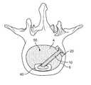
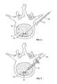
- an opening or holeis created in the annulus fibrosis surrounding the disc space to create an access portal into the disc space for introduction of one or more devices after the disc space is initially cleared. After the introduction of the device(s), it is a common procedure to fill the remaining open area of the disc space with bone graft material to provide additional structure to the disc space and to promote bone growth between the adjacent vertebral bodies.
- the screw 10 and plug 20 constructcan be inserted to a finally implanted location in which plug 20 is essentially flush with the outer portion of annulus 6 .
- the configuration of plug 20is such that it has an outer periphery sized to completely overlap the outer periphery of hole 8 .
- the outer periphery of plug 20may be configured to substantially match the size and shape of hole 8 , such that plug 20 fits within and fills hole 8 . Either configuration may require an irregularly shaped periphery of plug 20 according to the configuration of hole 8 in annulus 6 , and any such periphery is possible as dictated by the needs of a particular procedure and patient anatomy.
Landscapes
- Health & Medical Sciences (AREA)
- Engineering & Computer Science (AREA)
- Biomedical Technology (AREA)
- Neurology (AREA)
- Orthopedic Medicine & Surgery (AREA)
- Cardiology (AREA)
- Oral & Maxillofacial Surgery (AREA)
- Transplantation (AREA)
- Heart & Thoracic Surgery (AREA)
- Vascular Medicine (AREA)
- Life Sciences & Earth Sciences (AREA)
- Animal Behavior & Ethology (AREA)
- General Health & Medical Sciences (AREA)
- Public Health (AREA)
- Veterinary Medicine (AREA)
- Prostheses (AREA)
Abstract
Description
Claims (29)
Priority Applications (1)
| Application Number | Priority Date | Filing Date | Title |
|---|---|---|---|
| US14/157,857US10070969B2 (en) | 2013-01-17 | 2014-01-17 | Annulus plug for intervertebral disc repair |
Applications Claiming Priority (2)
| Application Number | Priority Date | Filing Date | Title |
|---|---|---|---|
| US201361753649P | 2013-01-17 | 2013-01-17 | |
| US14/157,857US10070969B2 (en) | 2013-01-17 | 2014-01-17 | Annulus plug for intervertebral disc repair |
Publications (2)
| Publication Number | Publication Date |
|---|---|
| US20140200672A1 US20140200672A1 (en) | 2014-07-17 |
| US10070969B2true US10070969B2 (en) | 2018-09-11 |
Family
ID=51165740
Family Applications (1)
| Application Number | Title | Priority Date | Filing Date |
|---|---|---|---|
| US14/157,857Active2034-05-31US10070969B2 (en) | 2013-01-17 | 2014-01-17 | Annulus plug for intervertebral disc repair |
Country Status (1)
| Country | Link |
|---|---|
| US (1) | US10070969B2 (en) |
Families Citing this family (1)
| Publication number | Priority date | Publication date | Assignee | Title |
|---|---|---|---|---|
| AU2012332447A1 (en)* | 2011-11-01 | 2014-05-15 | Amedica Corporation | Implants with a connectable insert and related systems and methods |
Citations (63)
| Publication number | Priority date | Publication date | Assignee | Title |
|---|---|---|---|---|
| US5098434A (en)* | 1990-11-28 | 1992-03-24 | Boehringer Mannheim Corporation | Porous coated bone screw |
| US5192283A (en)* | 1990-08-10 | 1993-03-09 | Ling Robin S M | System for performing hip prosthesis revision surgery |
| US6224630B1 (en) | 1998-05-29 | 2001-05-01 | Advanced Bio Surfaces, Inc. | Implantable tissue repair device |
| US20020029083A1 (en) | 1999-09-13 | 2002-03-07 | Zucherman James F. | Implantable prosthetic or tissue expanding device |
| US20020065518A1 (en)* | 2000-11-22 | 2002-05-30 | John Naybour | Tamp assembly |
| US6425919B1 (en) | 1999-08-18 | 2002-07-30 | Intrinsic Orthopedics, Inc. | Devices and methods of vertebral disc augmentation |
| US20020138146A1 (en)* | 2000-04-18 | 2002-09-26 | Jackson Roger P. | Anterior expandable spinal fusion cage system |
| US20020147497A1 (en) | 2001-04-06 | 2002-10-10 | Integrated Vascular Systems, Inc. | Methods for treating spinal discs |
| US20020147461A1 (en) | 2001-04-06 | 2002-10-10 | Aldrich William N. | Apparatus and methods for closing openings in spinal discs |
| US6508839B1 (en) | 1999-08-18 | 2003-01-21 | Intrinsic Orthopedics, Inc. | Devices and methods of vertebral disc augmentation |
| US20030114930A1 (en) | 2001-12-18 | 2003-06-19 | Lim Kit Yeng | Apparatus and method to stabilize and repair an intervertebral disc |
| US20040010317A1 (en) | 1999-08-18 | 2004-01-15 | Gregory Lambrecht | Devices and method for augmenting a vertebral disc |
| US20040044412A1 (en) | 1999-08-18 | 2004-03-04 | Gregory Lambrecht | Devices and method for augmenting a vertebral disc |
| US6719794B2 (en) | 2001-05-03 | 2004-04-13 | Synthes (U.S.A.) | Intervertebral implant for transforaminal posterior lumbar interbody fusion procedure |
| US6733531B1 (en) | 2000-10-20 | 2004-05-11 | Sdgi Holdings, Inc. | Anchoring devices and implants for intervertebral disc augmentation |
| US20040143334A1 (en) | 2003-01-08 | 2004-07-22 | Ferree Bret A. | Artificial disc replacements (ADRS) with features to enhance longevity and prevent extrusion |
| US20040210310A1 (en) | 2002-12-10 | 2004-10-21 | Trieu Hai H. | Implant system and method for intervertebral disc augmentation |
| US6821276B2 (en) | 1999-08-18 | 2004-11-23 | Intrinsic Therapeutics, Inc. | Intervertebral diagnostic and manipulation device |
| US20040260397A1 (en) | 1999-08-18 | 2004-12-23 | Lambrecht Greg H. | Method of defect closure in anulus fibrosus |
| US6878167B2 (en) | 2002-04-24 | 2005-04-12 | Bret A. Ferree | Methods and apparatus for placing intradiscal devices |
| US20050101960A1 (en)* | 2001-04-03 | 2005-05-12 | Vincent Fiere | Stabilised interbody fusion system for vertebrae |
| US6936072B2 (en) | 1999-08-18 | 2005-08-30 | Intrinsic Therapeutics, Inc. | Encapsulated intervertebral disc prosthesis and methods of manufacture |
| US6964674B1 (en) | 1999-09-20 | 2005-11-15 | Nuvasive, Inc. | Annulotomy closure device |
| US20050256582A1 (en) | 1999-10-08 | 2005-11-17 | Ferree Bret A | Spinal implants, including devices that reduce pressure on the annulus fibrosis |
| US6974480B2 (en) | 2001-05-03 | 2005-12-13 | Synthes (Usa) | Intervertebral implant for transforaminal posterior lumbar interbody fusion procedure |
| US7004970B2 (en) | 1999-10-20 | 2006-02-28 | Anulex Technologies, Inc. | Methods and devices for spinal disc annulus reconstruction and repair |
| US20060195193A1 (en) | 2003-08-26 | 2006-08-31 | Aesculap Ag & Co. Kg | Implant for closing an opening in the annulus fibrosus |
| US20070118133A1 (en) | 1999-08-18 | 2007-05-24 | Lambrecht Greg H | Intervertebral disc anulus repair |
| US7223227B2 (en) | 2002-05-13 | 2007-05-29 | Pflueger D Russell | Spinal disc therapy system |
| US20070135921A1 (en) | 2005-12-09 | 2007-06-14 | Park Kee B | Surgical implant |
| US20070150064A1 (en) | 2005-12-22 | 2007-06-28 | Depuy Spine, Inc. | Methods and devices for intervertebral augmentation |
| US20070282441A1 (en)* | 2006-05-19 | 2007-12-06 | Katie Stream | Spinal Stabilization Device and Methods |
| US7318840B2 (en) | 1999-12-06 | 2008-01-15 | Sdgi Holdings, Inc. | Intervertebral disc treatment devices and methods |
| US20080065218A1 (en) | 2006-09-13 | 2008-03-13 | O'neil Michael J | Annulus fibrosus repair devices and techniques |
| US20080249625A1 (en)* | 2007-04-03 | 2008-10-09 | Warsaw Orthopedic, Inc. | Composite Interbody Spacer |
| US7445634B2 (en) | 2000-10-27 | 2008-11-04 | Warsaw Orthopedic, Inc. | Annulus repair systems and methods |
| US7553329B2 (en) | 1999-08-18 | 2009-06-30 | Intrinsic Therapeutics, Inc. | Stabilized intervertebral disc barrier |
| US7618456B2 (en)* | 2002-02-19 | 2009-11-17 | Synthes Usa, Llc | Intervertebral implant |
| EP2140841A1 (en) | 2008-07-04 | 2010-01-06 | Arthro Kinetics AG | Device for closing spinal disc annulus |
| US20100004747A1 (en)* | 2008-07-07 | 2010-01-07 | Jin-Fu Lin | Trans-Vertebral and Intra-Vertebral Plate and Fusion Cage Device for Spinal Interbody Fusion and Method of Operation |
| US20100049259A1 (en) | 2007-09-07 | 2010-02-25 | Intrinsic Therapeutics, Inc. | Method for vertebral endplate reconstruction |
| US7682394B2 (en) | 2005-06-08 | 2010-03-23 | Co-Ligne Ag | Method for repair of a spine and intervertebral implant |
| US7717961B2 (en) | 1999-08-18 | 2010-05-18 | Intrinsic Therapeutics, Inc. | Apparatus delivery in an intervertebral disc |
| US20100145397A1 (en)* | 2008-12-05 | 2010-06-10 | Tom Overes | Anchor-in-anchor system for use in bone fixation |
| US7749273B2 (en) | 1999-10-20 | 2010-07-06 | Anulex Technologies, Inc. | Method and apparatus for the treatment of the intervertebral disc annulus |
| US7857855B2 (en) | 1999-10-08 | 2010-12-28 | Ferree Bret A | Devices used to treat disc herniation and attachment mechanisms therefore |
| US20110160866A1 (en)* | 2008-09-02 | 2011-06-30 | Synthes Usa, Llc | Intervertebral implant with blades for connecting to adjacent vertebral bodies |
| US7972337B2 (en) | 2005-12-28 | 2011-07-05 | Intrinsic Therapeutics, Inc. | Devices and methods for bone anchoring |
| US8025697B2 (en) | 2006-09-21 | 2011-09-27 | Custom Spine, Inc. | Articulating interbody spacer, vertebral body replacement |
| US20110245923A1 (en) | 2009-10-02 | 2011-10-06 | John Cobb | Intervertebral implant device for a posterior interbody fusion surgical procedure |
| US8034110B2 (en) | 2006-07-31 | 2011-10-11 | Depuy Spine, Inc. | Spinal fusion implant |
| US20110251689A1 (en)* | 2010-04-08 | 2011-10-13 | Seifert Jody L | Intervertebral Implant |
| US8114161B2 (en) | 2005-05-06 | 2012-02-14 | Kensey Nash Corporation | System and devices for the repair of a vertebral disc defect |
| US20120158144A1 (en)* | 2005-05-06 | 2012-06-21 | Ullrich Jr Peter F | Implant with critical ratio of load bearing surface area to central opening area |
| US8221460B2 (en) | 2001-07-30 | 2012-07-17 | Warsaw Orthopedic, Inc | Methods and devices for interbody spinal stabilization |
| US8231678B2 (en) | 1999-08-18 | 2012-07-31 | Intrinsic Therapeutics, Inc. | Method of treating a herniated disc |
| US20120232665A1 (en) | 2009-11-12 | 2012-09-13 | Anchor Orthopedics Xt Inc. | Devices and Methods for Treating Tissue Defects |
| US8273110B2 (en) | 2009-09-22 | 2012-09-25 | Globus Medical, Inc. | System and method for installing an annular repair rivet through a vertebral body port |
| US8308803B2 (en) | 1999-10-20 | 2012-11-13 | Warsaw Orthopedic, Inc. | Methods and instruments for endoscopic interbody surgical techniques |
| US8323341B2 (en) | 2007-09-07 | 2012-12-04 | Intrinsic Therapeutics, Inc. | Impaction grafting for vertebral fusion |
| US20120316648A1 (en) | 1999-08-18 | 2012-12-13 | Intrinsic Therapeutics, Inc. | Intervertebral disc reinforcement systems |
| US20130053964A1 (en)* | 2011-08-25 | 2013-02-28 | Vikram Talwar | Interbody fusion implant and screw guide |
| US20130150969A1 (en)* | 2005-06-03 | 2013-06-13 | Arthrodisc, L.L.C. | Spinner body |
- 2014
- 2014-01-17USUS14/157,857patent/US10070969B2/enactiveActive
Patent Citations (75)
| Publication number | Priority date | Publication date | Assignee | Title |
|---|---|---|---|---|
| US5192283A (en)* | 1990-08-10 | 1993-03-09 | Ling Robin S M | System for performing hip prosthesis revision surgery |
| US5098434A (en)* | 1990-11-28 | 1992-03-24 | Boehringer Mannheim Corporation | Porous coated bone screw |
| US6224630B1 (en) | 1998-05-29 | 2001-05-01 | Advanced Bio Surfaces, Inc. | Implantable tissue repair device |
| US20040260397A1 (en) | 1999-08-18 | 2004-12-23 | Lambrecht Greg H. | Method of defect closure in anulus fibrosus |
| US6821276B2 (en) | 1999-08-18 | 2004-11-23 | Intrinsic Therapeutics, Inc. | Intervertebral diagnostic and manipulation device |
| US6425919B1 (en) | 1999-08-18 | 2002-07-30 | Intrinsic Orthopedics, Inc. | Devices and methods of vertebral disc augmentation |
| US7879097B2 (en) | 1999-08-18 | 2011-02-01 | Intrinsic Therapeutics, Inc. | Method of performing a procedure within a disc |
| US8025698B2 (en) | 1999-08-18 | 2011-09-27 | Intrinsic Therapeutics, Inc. | Method of rehabilitating an anulus fibrosus |
| US7258700B2 (en) | 1999-08-18 | 2007-08-21 | Intrinsic Therapeutics, Inc. | Devices and method for nucleus pulposus augmentation and retention |
| US6482235B1 (en) | 1999-08-18 | 2002-11-19 | Intrinsic Orthopedics, Inc. | Devices and methods of vertebral disc augmentation |
| US6508839B1 (en) | 1999-08-18 | 2003-01-21 | Intrinsic Orthopedics, Inc. | Devices and methods of vertebral disc augmentation |
| US7658765B2 (en) | 1999-08-18 | 2010-02-09 | Intrinsic Therapeutics, Inc. | Resilient intervertebral disc implant |
| US20040010317A1 (en) | 1999-08-18 | 2004-01-15 | Gregory Lambrecht | Devices and method for augmenting a vertebral disc |
| US20040024465A1 (en) | 1999-08-18 | 2004-02-05 | Gregory Lambrecht | Devices and method for augmenting a vertebral disc |
| US20040044412A1 (en) | 1999-08-18 | 2004-03-04 | Gregory Lambrecht | Devices and method for augmenting a vertebral disc |
| US8231678B2 (en) | 1999-08-18 | 2012-07-31 | Intrinsic Therapeutics, Inc. | Method of treating a herniated disc |
| US7553329B2 (en) | 1999-08-18 | 2009-06-30 | Intrinsic Therapeutics, Inc. | Stabilized intervertebral disc barrier |
| US20120316648A1 (en) | 1999-08-18 | 2012-12-13 | Intrinsic Therapeutics, Inc. | Intervertebral disc reinforcement systems |
| US20070118133A1 (en) | 1999-08-18 | 2007-05-24 | Lambrecht Greg H | Intervertebral disc anulus repair |
| US7198047B2 (en) | 1999-08-18 | 2007-04-03 | Intrinsic Therapeutics, Inc. | Anchored anulus method |
| US7507243B2 (en) | 1999-08-18 | 2009-03-24 | Gregory Lambrecht | Devices and method for augmenting a vertebral disc |
| US20050206039A1 (en) | 1999-08-18 | 2005-09-22 | Gregory Lambrecht | Encapsulated intervertebral disc prosthesis and methods of manufacture |
| US7717961B2 (en) | 1999-08-18 | 2010-05-18 | Intrinsic Therapeutics, Inc. | Apparatus delivery in an intervertebral disc |
| US6936072B2 (en) | 1999-08-18 | 2005-08-30 | Intrinsic Therapeutics, Inc. | Encapsulated intervertebral disc prosthesis and methods of manufacture |
| US20020029083A1 (en) | 1999-09-13 | 2002-03-07 | Zucherman James F. | Implantable prosthetic or tissue expanding device |
| US6964674B1 (en) | 1999-09-20 | 2005-11-15 | Nuvasive, Inc. | Annulotomy closure device |
| US7857855B2 (en) | 1999-10-08 | 2010-12-28 | Ferree Bret A | Devices used to treat disc herniation and attachment mechanisms therefore |
| US20050256582A1 (en) | 1999-10-08 | 2005-11-17 | Ferree Bret A | Spinal implants, including devices that reduce pressure on the annulus fibrosis |
| US8308803B2 (en) | 1999-10-20 | 2012-11-13 | Warsaw Orthopedic, Inc. | Methods and instruments for endoscopic interbody surgical techniques |
| US7004970B2 (en) | 1999-10-20 | 2006-02-28 | Anulex Technologies, Inc. | Methods and devices for spinal disc annulus reconstruction and repair |
| US7749273B2 (en) | 1999-10-20 | 2010-07-06 | Anulex Technologies, Inc. | Method and apparatus for the treatment of the intervertebral disc annulus |
| US7318840B2 (en) | 1999-12-06 | 2008-01-15 | Sdgi Holdings, Inc. | Intervertebral disc treatment devices and methods |
| US20020138146A1 (en)* | 2000-04-18 | 2002-09-26 | Jackson Roger P. | Anterior expandable spinal fusion cage system |
| US6733531B1 (en) | 2000-10-20 | 2004-05-11 | Sdgi Holdings, Inc. | Anchoring devices and implants for intervertebral disc augmentation |
| US7445634B2 (en) | 2000-10-27 | 2008-11-04 | Warsaw Orthopedic, Inc. | Annulus repair systems and methods |
| US20020065518A1 (en)* | 2000-11-22 | 2002-05-30 | John Naybour | Tamp assembly |
| US20050101960A1 (en)* | 2001-04-03 | 2005-05-12 | Vincent Fiere | Stabilised interbody fusion system for vertebrae |
| US20020147461A1 (en) | 2001-04-06 | 2002-10-10 | Aldrich William N. | Apparatus and methods for closing openings in spinal discs |
| US20020147497A1 (en) | 2001-04-06 | 2002-10-10 | Integrated Vascular Systems, Inc. | Methods for treating spinal discs |
| US6719794B2 (en) | 2001-05-03 | 2004-04-13 | Synthes (U.S.A.) | Intervertebral implant for transforaminal posterior lumbar interbody fusion procedure |
| US6974480B2 (en) | 2001-05-03 | 2005-12-13 | Synthes (Usa) | Intervertebral implant for transforaminal posterior lumbar interbody fusion procedure |
| US8221460B2 (en) | 2001-07-30 | 2012-07-17 | Warsaw Orthopedic, Inc | Methods and devices for interbody spinal stabilization |
| US20030114930A1 (en) | 2001-12-18 | 2003-06-19 | Lim Kit Yeng | Apparatus and method to stabilize and repair an intervertebral disc |
| US7618456B2 (en)* | 2002-02-19 | 2009-11-17 | Synthes Usa, Llc | Intervertebral implant |
| US20050159817A1 (en) | 2002-04-24 | 2005-07-21 | Ferree Bret A. | Annulus preserving methods and apparatus for placement of intradiscal devices |
| US6878167B2 (en) | 2002-04-24 | 2005-04-12 | Bret A. Ferree | Methods and apparatus for placing intradiscal devices |
| US7223227B2 (en) | 2002-05-13 | 2007-05-29 | Pflueger D Russell | Spinal disc therapy system |
| US20040210310A1 (en) | 2002-12-10 | 2004-10-21 | Trieu Hai H. | Implant system and method for intervertebral disc augmentation |
| US20040143334A1 (en) | 2003-01-08 | 2004-07-22 | Ferree Bret A. | Artificial disc replacements (ADRS) with features to enhance longevity and prevent extrusion |
| US20060195193A1 (en) | 2003-08-26 | 2006-08-31 | Aesculap Ag & Co. Kg | Implant for closing an opening in the annulus fibrosus |
| US20120158144A1 (en)* | 2005-05-06 | 2012-06-21 | Ullrich Jr Peter F | Implant with critical ratio of load bearing surface area to central opening area |
| US8114161B2 (en) | 2005-05-06 | 2012-02-14 | Kensey Nash Corporation | System and devices for the repair of a vertebral disc defect |
| US20130150969A1 (en)* | 2005-06-03 | 2013-06-13 | Arthrodisc, L.L.C. | Spinner body |
| US7682394B2 (en) | 2005-06-08 | 2010-03-23 | Co-Ligne Ag | Method for repair of a spine and intervertebral implant |
| US20070135921A1 (en) | 2005-12-09 | 2007-06-14 | Park Kee B | Surgical implant |
| US20070150064A1 (en) | 2005-12-22 | 2007-06-28 | Depuy Spine, Inc. | Methods and devices for intervertebral augmentation |
| US7972337B2 (en) | 2005-12-28 | 2011-07-05 | Intrinsic Therapeutics, Inc. | Devices and methods for bone anchoring |
| US20070282441A1 (en)* | 2006-05-19 | 2007-12-06 | Katie Stream | Spinal Stabilization Device and Methods |
| US8034110B2 (en) | 2006-07-31 | 2011-10-11 | Depuy Spine, Inc. | Spinal fusion implant |
| US20080065218A1 (en) | 2006-09-13 | 2008-03-13 | O'neil Michael J | Annulus fibrosus repair devices and techniques |
| US8025697B2 (en) | 2006-09-21 | 2011-09-27 | Custom Spine, Inc. | Articulating interbody spacer, vertebral body replacement |
| US20080249625A1 (en)* | 2007-04-03 | 2008-10-09 | Warsaw Orthopedic, Inc. | Composite Interbody Spacer |
| US20110196492A1 (en) | 2007-09-07 | 2011-08-11 | Intrinsic Therapeutics, Inc. | Bone anchoring systems |
| US20100049259A1 (en) | 2007-09-07 | 2010-02-25 | Intrinsic Therapeutics, Inc. | Method for vertebral endplate reconstruction |
| US8323341B2 (en) | 2007-09-07 | 2012-12-04 | Intrinsic Therapeutics, Inc. | Impaction grafting for vertebral fusion |
| EP2140841A1 (en) | 2008-07-04 | 2010-01-06 | Arthro Kinetics AG | Device for closing spinal disc annulus |
| US20100004747A1 (en)* | 2008-07-07 | 2010-01-07 | Jin-Fu Lin | Trans-Vertebral and Intra-Vertebral Plate and Fusion Cage Device for Spinal Interbody Fusion and Method of Operation |
| US20110160866A1 (en)* | 2008-09-02 | 2011-06-30 | Synthes Usa, Llc | Intervertebral implant with blades for connecting to adjacent vertebral bodies |
| US20100145397A1 (en)* | 2008-12-05 | 2010-06-10 | Tom Overes | Anchor-in-anchor system for use in bone fixation |
| US8273110B2 (en) | 2009-09-22 | 2012-09-25 | Globus Medical, Inc. | System and method for installing an annular repair rivet through a vertebral body port |
| US20120316654A1 (en) | 2009-09-22 | 2012-12-13 | Seifert Jody L | System and Method for Installing an Annular Repair Rivet Through a Vertebral Body Port |
| US20110245923A1 (en) | 2009-10-02 | 2011-10-06 | John Cobb | Intervertebral implant device for a posterior interbody fusion surgical procedure |
| US20120232665A1 (en) | 2009-11-12 | 2012-09-13 | Anchor Orthopedics Xt Inc. | Devices and Methods for Treating Tissue Defects |
| US20110251689A1 (en)* | 2010-04-08 | 2011-10-13 | Seifert Jody L | Intervertebral Implant |
| US20130053964A1 (en)* | 2011-08-25 | 2013-02-28 | Vikram Talwar | Interbody fusion implant and screw guide |
Also Published As
| Publication number | Publication date |
|---|---|
| US20140200672A1 (en) | 2014-07-17 |
Similar Documents
| Publication | Publication Date | Title |
|---|---|---|
| US20210378835A1 (en) | Variable lordotic interbody spacer | |
| US10258481B2 (en) | Modular, customizable spine stabilization system | |
| US10779956B2 (en) | Systems and methods for inserting an expandable intervertebral device | |
| US8932358B1 (en) | Anterior intervertebral spacer and integrated plate assembly and methods of use | |
| AU715283B2 (en) | An expandable osteosynthesis cage | |
| US9913730B1 (en) | Spinal fixation system and related methods | |
| US7588599B2 (en) | Interbody cage system | |
| US8778027B2 (en) | Implant apparatus and method including tee and screw mechanism for spinal fusion | |
| US6863689B2 (en) | Intervertebral spacer having a flexible wire mesh vertebral body contact element | |
| US8496706B2 (en) | Bone cage with components for controlled expansion | |
| JP4291779B2 (en) | Fixation means for intervertebral implants | |
| US8273127B2 (en) | Interbody fusion device and associated methods | |
| US20090198339A1 (en) | Systems and methods for spinal fusion | |
| US9566167B2 (en) | Expandable spinal implant | |
| US20140194992A1 (en) | Expandable interbody (lateral, posterior, anterior) multi-access cage for spinal surgery | |
| US20140257486A1 (en) | Expandable implant | |
| US20140012384A1 (en) | Interbody fusion device and associated methods | |
| US20120041494A1 (en) | Vertebral implant | |
| US8821578B2 (en) | Intervertebral implant device for a posterior interbody fusion surgical procedure | |
| JP2004508888A (en) | Bone formation fusion device | |
| US9615934B2 (en) | Protective cover for interbody fusion devices | |
| US10070969B2 (en) | Annulus plug for intervertebral disc repair | |
| US12127950B2 (en) | Spinal interbody with compressive fusion features | |
| US20240252325A1 (en) | Vertebral decompression and fusion implant | |
| MXPA96001079A (en) | Intercorporal fusion device and method for the restoration of anatomy of the columnaverteb |
Legal Events
| Date | Code | Title | Description |
|---|---|---|---|
| AS | Assignment | Owner name:STRYKER SPINE, FRANCE Free format text:ASSIGNMENT OF ASSIGNORS INTEREST;ASSIGNOR:ALHEIDT, THOMAS A.;REEL/FRAME:032656/0276 Effective date:20140307 | |
| AS | Assignment | Owner name:STRYKER EUROPEAN HOLDINGS VI, LLC, MICHIGAN Free format text:NUNC PRO TUNC ASSIGNMENT;ASSIGNOR:STRYKER SPINE SAS;REEL/FRAME:037152/0825 Effective date:20151008 Owner name:STRYKER EUROPEAN HOLDINGS I, LLC, MICHIGAN Free format text:NUNC PRO TUNC ASSIGNMENT;ASSIGNOR:STRYKER EUROPEAN HOLDINGS VI, LLC;REEL/FRAME:037153/0391 Effective date:20151008 | |
| STCF | Information on status: patent grant | Free format text:PATENTED CASE | |
| AS | Assignment | Owner name:STRYKER EUROPEAN OPERATIONS HOLDINGS LLC, MICHIGAN Free format text:CHANGE OF NAME;ASSIGNOR:STRYKER EUROPEAN HOLDINGS III, LLC;REEL/FRAME:052860/0716 Effective date:20190226 Owner name:STRYKER EUROPEAN HOLDINGS III, LLC, DELAWARE Free format text:NUNC PRO TUNC ASSIGNMENT;ASSIGNOR:STRYKER EUROPEAN HOLDINGS I, LLC;REEL/FRAME:052861/0001 Effective date:20200519 | |
| MAFP | Maintenance fee payment | Free format text:PAYMENT OF MAINTENANCE FEE, 4TH YEAR, LARGE ENTITY (ORIGINAL EVENT CODE: M1551); ENTITY STATUS OF PATENT OWNER: LARGE ENTITY Year of fee payment:4 | |
| AS | Assignment | Owner name:STRYKER EUROPEAN OPERATIONS HOLDINGS LLC, MICHIGAN Free format text:CHANGE OF ADDRESS;ASSIGNOR:STRYKER EUROPEAN OPERATIONS HOLDINGS LLC;REEL/FRAME:069730/0754 Effective date:20241217 | |
| AS | Assignment | Owner name:VB SPINE US OPCO LLC, DELAWARE Free format text:ASSIGNMENT OF ASSIGNORS INTEREST;ASSIGNOR:STRYKER EUROPEAN OPERATIONS HOLDINGS LLC;REEL/FRAME:071267/0099 Effective date:20250401 | |
| AS | Assignment | Owner name:ANKURA TRUST COMPANY, LLC, AS COLLATERAL AGENT, CONNECTICUT Free format text:PATENT SECURITY AGREEMENT;ASSIGNORS:K2M, INC.;VB SPINE US OPCO LLC;VB SPINE LLC;REEL/FRAME:071682/0116 Effective date:20250616 | |
| AS | Assignment | Owner name:TEXAS CAPITAL BANK, AS COLLATERAL AGENT, TEXAS Free format text:SECURITY INTEREST;ASSIGNORS:K2M, INC.;VB SPINE US OPCO LLC;REEL/FRAME:072340/0397 Effective date:20250401 |