US10070955B2 - Prosthesis with bendable central region - Google Patents
Prosthesis with bendable central regionDownload PDFInfo
- Publication number
- US10070955B2 US10070955B2US12/272,093US27209308AUS10070955B2US 10070955 B2US10070955 B2US 10070955B2US 27209308 AUS27209308 AUS 27209308AUS 10070955 B2US10070955 B2US 10070955B2
- Authority
- US
- United States
- Prior art keywords
- end portion
- constant diameter
- column
- sheath
- prosthetic device
- Prior art date
- Legal status (The legal status is an assumption and is not a legal conclusion. Google has not performed a legal analysis and makes no representation as to the accuracy of the status listed.)
- Active, expires
Links
Images
Classifications
- A—HUMAN NECESSITIES
- A61—MEDICAL OR VETERINARY SCIENCE; HYGIENE
- A61F—FILTERS IMPLANTABLE INTO BLOOD VESSELS; PROSTHESES; DEVICES PROVIDING PATENCY TO, OR PREVENTING COLLAPSING OF, TUBULAR STRUCTURES OF THE BODY, e.g. STENTS; ORTHOPAEDIC, NURSING OR CONTRACEPTIVE DEVICES; FOMENTATION; TREATMENT OR PROTECTION OF EYES OR EARS; BANDAGES, DRESSINGS OR ABSORBENT PADS; FIRST-AID KITS
- A61F2/00—Filters implantable into blood vessels; Prostheses, i.e. artificial substitutes or replacements for parts of the body; Appliances for connecting them with the body; Devices providing patency to, or preventing collapsing of, tubular structures of the body, e.g. stents
- A61F2/02—Prostheses implantable into the body
- A61F2/26—Penis implants
Definitions
- the present inventionrelates to implantable prostheses.
- the present inventionrelates to implantable malleable (non-inflatable) penile prostheses.
- the prosthetic devicecomprises a column.
- the columncomprises resilient material.
- the columncomprises a central region between the proximal and distal ends.
- the central regionhas a reduced diameter relative to the proximal and distal ends. Discs protrude from the central region.
- FIG. 1illustrates a prosthetic device in a straight position
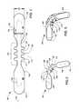
- FIG. 2illustrates a prosthetic device in a bent position.
- FIG. 3illustrates a prosthetic device that includes a sheath.
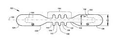
- FIG. 1illustrates a prosthetic device 100 .
- the prosthetic device 100comprises a column 102 formed of resilient material.
- the column 102comprises an annular shape that is generally symmetric about a lengthwise axis 103 .
- the column 102encloses an internal malleable core or other known type of penile prosthesis core.
- the column 102does not include a core.
- the column 102comprises a central region 104 between a proximal end 106 and a distal end 108 .
- the central region 104includes one or more annular groove regions 110 , 112 , 114 , 116 that have a diameter D 1 that is reduced relative to a diameter D 2 of the proximal and distal ends 106 , 108 .
- the reduced diameter annular groove regions 110 , 112 , 114 , 116are spaced apart from one another by intervening discs 118 , 120 , 122 that have a larger diameter than the reduced diameter D 1 .
- the column 102is formed as a single unitary, seamless component that is molded, cast, or machined to final shape. This unitary manufacturing method is economical.
- the column 102is formed of end caps (tip extenders) 124 , 126 that join a central body 128 along joint lines 130 , 132 .
- the joint lines 130 , 132are annular and form a snap attachment profile between the column and the end caps 124 , 126 .
- end caps 124 , 126 of different lengths and shapesallows the prosthetic device 100 to be conveniently sized by a physician to vary the cylinder length while maintaining a central body 128 that is common to the different sizes and shapes.
- the central body 128 and a first end cap 124can formed as a seamless unitary body, and a second end cap 126 can have different lengths and shapes.
- rear tip extendersRTEs
- RTEsrear tip extenders
- the prosthesis 100is in a generally straight alignment.
- the discs 118 , 120 , 122extend outwardly as illustrated to provide closely spaced annular protrusions that function to maintain girth along the central region 104 .
- FIG. 2illustrates the prosthesis 100 in a bent position.
- the prosthesisis bent through an angle as illustrated.
- the annular groove regions 110 , 112 , 114 , 116require less force to bend because of their small diameter D 1 .
- stresstends to concentrate at the smaller diameter zones. Bending takes place predominantly in the annular groove regions because of their smaller diameter D 1 .
- Springbackrefers to the amount of a return movement of a bent column after a bending force is removed. Springback causes a column that is bent into a position (either a straight or bent position) to lose part of the bend after the column is released. Springback is an undesirable property that adversely affects concealability. Springback requires the user to learn to bend the column past a desired position in order for it to have the desired position after springback, or requires the user to bend the column multiple times in order to obtain a concealed position. As illustrated, on the inside of the bend at locations 202 , 204 , annular grooves have eliminated material which would otherwise be compressed. The grooves at locations 202 , 204 reduce springback due to avoiding compression of material.
- Bendingtends to stretch (place in tension) resilient material on the outside of the bend, and the stretched material tends to exert a springback force.
- annular grooveshave eliminated material which would otherwise be stretched. The grooves at locations 206 , 208 reduce springback due to avoiding stretching of material.
- the material remaining inside the grooves(such as grooves 112 , 114 ), in other words the material within diameter D 1 is close to a main cylinder axis (along a bent central axis 103 ) for bending where both compression and stretching tends to be reduced. There is thus little contribution to springback from the material within diameter D 1 .
- the grooveshave a combination of width and depth (groove aspect ratio) that provides a desirable wide bending angle at each groove before adjacent disc edges bend far enough to contact one another.
- the prosthesis 100has overall desirable large girth characteristics associated with the larger diameter D 2 and the multiple discs 118 , 120 , 122 , in combination with the desirable small springback characteristics associated with the smaller diameter D 1 .
- the desired large girth characteristicsare maintained through the region 104 by the presence of the discs 118 , 120 , 122 .
- the internal core structurecan comprise wires and/or fabric and/or plastic components (interlocking rings.)
- the two endscan have profiles 130 that would accept snap attachment rear tip extenders, for finer length dimensioning to better fit the patient's anatomy.
- discshubs or rings
- the addition of discs (hubs or rings) along a smaller diameter center sectionallows the rod to maintain a more concealed position for the patient.
- the discs (hubs or rings), with or without an outer sheath,would give the rod an outward appearance and sensation of being an isodiametric rod.
- Existing internal rod componentsAMS 600, AMS 600M, AMS 650, DURA II
- rear tip extendersAMS 700 IPP or AMS Ambicor
- the prosthesiscan have a sheath or “skin” that would give the appearance of the rod being isodiametric.
- the ends of the rodscould have snap attachment profiles to accept the existing AMS 700 RTEs.
- Inside cores from the AMS 600, AMS 600M, AMS 650, DURA IIcan be adapted for use.
Landscapes
- Health & Medical Sciences (AREA)
- Reproductive Health (AREA)
- Cardiology (AREA)
- Oral & Maxillofacial Surgery (AREA)
- Transplantation (AREA)
- Engineering & Computer Science (AREA)
- Biomedical Technology (AREA)
- Heart & Thoracic Surgery (AREA)
- Vascular Medicine (AREA)
- Life Sciences & Earth Sciences (AREA)
- Animal Behavior & Ethology (AREA)
- General Health & Medical Sciences (AREA)
- Public Health (AREA)
- Veterinary Medicine (AREA)
- Prostheses (AREA)
Abstract
Description
Claims (16)
Priority Applications (1)
| Application Number | Priority Date | Filing Date | Title |
|---|---|---|---|
| US12/272,093US10070955B2 (en) | 2007-11-15 | 2008-11-17 | Prosthesis with bendable central region |
Applications Claiming Priority (2)
| Application Number | Priority Date | Filing Date | Title |
|---|---|---|---|
| US98829807P | 2007-11-15 | 2007-11-15 | |
| US12/272,093US10070955B2 (en) | 2007-11-15 | 2008-11-17 | Prosthesis with bendable central region |
Publications (2)
| Publication Number | Publication Date |
|---|---|
| US20090132044A1 US20090132044A1 (en) | 2009-05-21 |
| US10070955B2true US10070955B2 (en) | 2018-09-11 |
Family
ID=40642801
Family Applications (1)
| Application Number | Title | Priority Date | Filing Date |
|---|---|---|---|
| US12/272,093Active2030-07-12US10070955B2 (en) | 2007-11-15 | 2008-11-17 | Prosthesis with bendable central region |
Country Status (1)
| Country | Link |
|---|---|
| US (1) | US10070955B2 (en) |
Families Citing this family (6)
| Publication number | Priority date | Publication date | Assignee | Title |
|---|---|---|---|---|
| US8052594B2 (en)* | 2007-11-20 | 2011-11-08 | Ams Research Corporation | Prosthetic device with protrusions for girth |
| RU2543035C2 (en)* | 2009-08-27 | 2015-02-27 | Колопласт А/С | Penile prosthesis cap, implantation assembly and instrument |
| US9855144B2 (en) | 2015-09-09 | 2018-01-02 | Coloplast A/S | Penile prosthetic with an insertion tool contained inside an inflatable bladder |
| ES2892483T3 (en) | 2015-09-30 | 2022-02-04 | Coloplast As | A penile prosthesis with an insertion sleeve that can be attached to an inflatable bladder |
| US10729546B2 (en) | 2017-02-02 | 2020-08-04 | Coloplast A/S | Inflatable penile prosthetic system |
| US11266563B2 (en)* | 2018-10-15 | 2022-03-08 | Boston Scientific Scimed, Inc. | Extendable penile implant |
Citations (47)
| Publication number | Priority date | Publication date | Assignee | Title |
|---|---|---|---|---|
| US3832996A (en) | 1972-02-04 | 1974-09-03 | V Kalnberz | Endoprosthesis for the penis and a method of endoprosthetic repair |
| US3893456A (en) | 1974-08-07 | 1975-07-08 | Heyer Schulte Corp | Penile prosthesis |
| US3987789A (en) | 1975-10-28 | 1976-10-26 | American Medical Systems, Inc. | Malleable penile prosthesis |
| US3991752A (en) | 1975-12-04 | 1976-11-16 | Dow Corning Corporation | Penile implant |
| US4066073A (en) | 1976-10-04 | 1978-01-03 | Medical Engineering Corporation | Composite rod penile implant |
| US4151840A (en) | 1978-01-27 | 1979-05-01 | Abcor, Inc. | Implantable penile prosthesis |
| US4177805A (en) | 1977-08-12 | 1979-12-11 | Peter Falge | Penile implantation prosthesis |
| US4187839A (en) | 1978-06-05 | 1980-02-12 | Abcor, Inc. | Implantable penile prosthesis |
| US4204530A (en) | 1979-03-29 | 1980-05-27 | Medical Engineering Corp. | Sleeve implant |
| US4244370A (en) | 1978-11-20 | 1981-01-13 | American Medical Systems, Inc. | Tool for positioning implantable medical prosthetic device _and method of using same |
| US4345339A (en) | 1980-06-03 | 1982-08-24 | Sulzer Brothers Limited | Biologically implantable member for a tendon and/or ligament |
| US4353360A (en) | 1980-10-31 | 1982-10-12 | Medical Engineering Corporation | Penile erectile system |
| US4392562A (en)* | 1981-06-19 | 1983-07-12 | American Medical Systems, Inc. | Limited bend malleable penile prosthesis |
| US4411261A (en) | 1980-05-15 | 1983-10-25 | Medical Engineering Corporation | Semi-rigid penile implant |
| US4411260A (en) | 1980-11-24 | 1983-10-25 | Walter Koss | Penis prosthesis |
| US4483331A (en) | 1982-09-16 | 1984-11-20 | Medical Engineering Corporation | Rod-type penile implant |
| US4517967A (en) | 1983-04-18 | 1985-05-21 | Dacomed Corporation | Penile prosthesis |
| US4522198A (en) | 1983-04-18 | 1985-06-11 | Dacomed Corporation | Penile prosthesis |
| GB2151484A (en) | 1983-12-21 | 1985-07-24 | Stefano Mattioli | Semi-rigid penial prosthesis for the treatment of impotence in the erection |
| US4541420A (en) | 1984-04-26 | 1985-09-17 | Dacomed Corporation | Penile prosthesis utilizing patient controlled cam actuator apparatus |
| US4545081A (en) | 1981-06-29 | 1985-10-08 | Jack Nestor | Semi-rigid penile prosthesis with separable members and posture control |
| WO1986001398A1 (en) | 1984-08-31 | 1986-03-13 | Moreira De Azeredo F A | Penile rigidity prosthesis |
| US4594998A (en) | 1983-09-16 | 1986-06-17 | American Medical Systems, Inc. | Penile prosthesis of improved malleable construction |
| US4619251A (en) | 1984-04-26 | 1986-10-28 | Dacomed Corporation | Penile prosthesis having an actuator means interacting with a member and articulated column |
| US4666428A (en) | 1984-10-23 | 1987-05-19 | Stefano Mattioli | Semi-rigid penial prosthesis for the treatment of impotence in the erection |
| US4665902A (en) | 1985-12-04 | 1987-05-19 | C. R. Bard, Inc. | Flexible penile prosthesis |
| US4669456A (en) | 1983-05-04 | 1987-06-02 | Mentor Corporation | Positionable penile prosthesis |
| US4693719A (en) | 1985-02-14 | 1987-09-15 | C. R. Bard, Inc. | Mechanical penile prosthesis |
| US4699128A (en) | 1984-10-12 | 1987-10-13 | Hemmeter George T | Thermally activated penile prosthesis |
| US4807608A (en) | 1987-07-22 | 1989-02-28 | American Medical Systems | Mechanical penile prosthesis |
| US4881531A (en) | 1986-11-21 | 1989-11-21 | Dacomed Corporation | Position stable segmented column penile prosthesis |
| US4899737A (en) | 1988-09-14 | 1990-02-13 | Lazarian Vartan J | Splint for complete circumferential immobilization of an extremity or a terminal member of an extremity |
| US4988357A (en) | 1983-12-08 | 1991-01-29 | Industriestrasse | Penis prosthesis |
| US5050592A (en) | 1990-05-07 | 1991-09-24 | Raul Olmedo | Penile prosthesis |
| US5067485A (en)* | 1990-05-14 | 1991-11-26 | Mentor Corporation | Corpus cavernosum implant device |
| US5167611A (en)* | 1991-07-22 | 1992-12-01 | Mentor Corporation | Penile implant with lengthening cylinder |
| US5176708A (en) | 1990-03-12 | 1993-01-05 | Sulzer Brothers Limited | Prosthetic implant |
| US5283390A (en) | 1992-07-07 | 1994-02-01 | W. L. Gore & Associates, Inc. | Twisted pair data bus cable |
| US5445594A (en) | 1994-04-05 | 1995-08-29 | Elist; James J. | Implant for expanding penile girth and length |
| US5468213A (en)* | 1994-09-22 | 1995-11-21 | American Medical Systems, Inc. | Mechanical penile prosthesis |
| WO1996004865A1 (en) | 1994-08-08 | 1996-02-22 | American Medical Systems, Inc. | Malleable penile prosthesis |
| US5509891A (en) | 1994-12-19 | 1996-04-23 | Deridder; Paul A. | Prothesis for male dysfunction |
| US6579230B2 (en) | 2001-06-15 | 2003-06-17 | Impetus Ltd. | Penile prosthesis and method of implantation |
| US6600108B1 (en) | 2002-01-25 | 2003-07-29 | Schlumberger Technology Corporation | Electric cable |
| US20040193283A1 (en)* | 2003-03-26 | 2004-09-30 | Scimed Life Systems, Inc. | Longitudinally expanding medical device |
| US20050014993A1 (en) | 2003-06-06 | 2005-01-20 | Mische Hans A. | Inflatable penile prosthesis with volume displacement materials and devices |
| US20080103353A1 (en) | 2006-10-24 | 2008-05-01 | Jahns Scott E | Implantable Malleable Penile Prosthetic Device |
Family Cites Families (1)
| Publication number | Priority date | Publication date | Assignee | Title |
|---|---|---|---|---|
| US553379A (en)* | 1896-01-21 | Locking device for elevators and elevator-doors |
- 2008
- 2008-11-17USUS12/272,093patent/US10070955B2/enactiveActive
Patent Citations (51)
| Publication number | Priority date | Publication date | Assignee | Title |
|---|---|---|---|---|
| US3832996A (en) | 1972-02-04 | 1974-09-03 | V Kalnberz | Endoprosthesis for the penis and a method of endoprosthetic repair |
| US3893456A (en) | 1974-08-07 | 1975-07-08 | Heyer Schulte Corp | Penile prosthesis |
| US3987789A (en) | 1975-10-28 | 1976-10-26 | American Medical Systems, Inc. | Malleable penile prosthesis |
| US3991752A (en) | 1975-12-04 | 1976-11-16 | Dow Corning Corporation | Penile implant |
| US4066073A (en) | 1976-10-04 | 1978-01-03 | Medical Engineering Corporation | Composite rod penile implant |
| US4177805A (en) | 1977-08-12 | 1979-12-11 | Peter Falge | Penile implantation prosthesis |
| US4151840A (en) | 1978-01-27 | 1979-05-01 | Abcor, Inc. | Implantable penile prosthesis |
| US4187839A (en) | 1978-06-05 | 1980-02-12 | Abcor, Inc. | Implantable penile prosthesis |
| US4244370A (en) | 1978-11-20 | 1981-01-13 | American Medical Systems, Inc. | Tool for positioning implantable medical prosthetic device _and method of using same |
| US4204530A (en) | 1979-03-29 | 1980-05-27 | Medical Engineering Corp. | Sleeve implant |
| US4411261A (en) | 1980-05-15 | 1983-10-25 | Medical Engineering Corporation | Semi-rigid penile implant |
| US4345339A (en) | 1980-06-03 | 1982-08-24 | Sulzer Brothers Limited | Biologically implantable member for a tendon and/or ligament |
| US4353360A (en) | 1980-10-31 | 1982-10-12 | Medical Engineering Corporation | Penile erectile system |
| US4411260A (en) | 1980-11-24 | 1983-10-25 | Walter Koss | Penis prosthesis |
| US4392562A (en)* | 1981-06-19 | 1983-07-12 | American Medical Systems, Inc. | Limited bend malleable penile prosthesis |
| US4545081A (en) | 1981-06-29 | 1985-10-08 | Jack Nestor | Semi-rigid penile prosthesis with separable members and posture control |
| US4483331A (en) | 1982-09-16 | 1984-11-20 | Medical Engineering Corporation | Rod-type penile implant |
| US4522198A (en) | 1983-04-18 | 1985-06-11 | Dacomed Corporation | Penile prosthesis |
| US4517967A (en) | 1983-04-18 | 1985-05-21 | Dacomed Corporation | Penile prosthesis |
| US4669456A (en) | 1983-05-04 | 1987-06-02 | Mentor Corporation | Positionable penile prosthesis |
| US4594998A (en) | 1983-09-16 | 1986-06-17 | American Medical Systems, Inc. | Penile prosthesis of improved malleable construction |
| EP0137752B1 (en) | 1983-09-16 | 1989-08-16 | American Medical Systems, Inc. | Penile prosthesis of improved malleable construction |
| US4988357A (en) | 1983-12-08 | 1991-01-29 | Industriestrasse | Penis prosthesis |
| GB2151484A (en) | 1983-12-21 | 1985-07-24 | Stefano Mattioli | Semi-rigid penial prosthesis for the treatment of impotence in the erection |
| US4541420A (en) | 1984-04-26 | 1985-09-17 | Dacomed Corporation | Penile prosthesis utilizing patient controlled cam actuator apparatus |
| US4619251A (en) | 1984-04-26 | 1986-10-28 | Dacomed Corporation | Penile prosthesis having an actuator means interacting with a member and articulated column |
| WO1986001398A1 (en) | 1984-08-31 | 1986-03-13 | Moreira De Azeredo F A | Penile rigidity prosthesis |
| US4699128A (en) | 1984-10-12 | 1987-10-13 | Hemmeter George T | Thermally activated penile prosthesis |
| US4666428A (en) | 1984-10-23 | 1987-05-19 | Stefano Mattioli | Semi-rigid penial prosthesis for the treatment of impotence in the erection |
| US4693719A (en) | 1985-02-14 | 1987-09-15 | C. R. Bard, Inc. | Mechanical penile prosthesis |
| US4665902A (en) | 1985-12-04 | 1987-05-19 | C. R. Bard, Inc. | Flexible penile prosthesis |
| US4881531A (en) | 1986-11-21 | 1989-11-21 | Dacomed Corporation | Position stable segmented column penile prosthesis |
| US4807608A (en) | 1987-07-22 | 1989-02-28 | American Medical Systems | Mechanical penile prosthesis |
| US4899737A (en) | 1988-09-14 | 1990-02-13 | Lazarian Vartan J | Splint for complete circumferential immobilization of an extremity or a terminal member of an extremity |
| US5176708A (en) | 1990-03-12 | 1993-01-05 | Sulzer Brothers Limited | Prosthetic implant |
| US5050592A (en) | 1990-05-07 | 1991-09-24 | Raul Olmedo | Penile prosthesis |
| US5067485A (en)* | 1990-05-14 | 1991-11-26 | Mentor Corporation | Corpus cavernosum implant device |
| US5167611A (en)* | 1991-07-22 | 1992-12-01 | Mentor Corporation | Penile implant with lengthening cylinder |
| US5283390A (en) | 1992-07-07 | 1994-02-01 | W. L. Gore & Associates, Inc. | Twisted pair data bus cable |
| US5445594A (en) | 1994-04-05 | 1995-08-29 | Elist; James J. | Implant for expanding penile girth and length |
| WO1996004865A1 (en) | 1994-08-08 | 1996-02-22 | American Medical Systems, Inc. | Malleable penile prosthesis |
| US5512033A (en)* | 1994-08-08 | 1996-04-30 | American Medical Systems, Inc. | Malleable penile prosthesis |
| US5553379A (en) | 1994-08-08 | 1996-09-10 | American Medical Systems, Inc. | Malleable penile prosthesis |
| EP0774935B1 (en) | 1994-08-08 | 1999-11-03 | American Medical Systems, Inc. | Malleable penile prosthesis |
| US5468213A (en)* | 1994-09-22 | 1995-11-21 | American Medical Systems, Inc. | Mechanical penile prosthesis |
| US5509891A (en) | 1994-12-19 | 1996-04-23 | Deridder; Paul A. | Prothesis for male dysfunction |
| US6579230B2 (en) | 2001-06-15 | 2003-06-17 | Impetus Ltd. | Penile prosthesis and method of implantation |
| US6600108B1 (en) | 2002-01-25 | 2003-07-29 | Schlumberger Technology Corporation | Electric cable |
| US20040193283A1 (en)* | 2003-03-26 | 2004-09-30 | Scimed Life Systems, Inc. | Longitudinally expanding medical device |
| US20050014993A1 (en) | 2003-06-06 | 2005-01-20 | Mische Hans A. | Inflatable penile prosthesis with volume displacement materials and devices |
| US20080103353A1 (en) | 2006-10-24 | 2008-05-01 | Jahns Scott E | Implantable Malleable Penile Prosthetic Device |
Non-Patent Citations (50)
| Title |
|---|
| Acu-Form Penile Prosthesis, Mentor, 1 page Aug. 1997. |
| Agrawal, Wineet, et al., An Audit of Implanted Penile Prostheses in the UK, BJU International pp. 393-395 (2006). |
| Akand, Murat Mechanical Failure With Malleable Penile Prosthesis, J. Urol. 70: 1007.e11-1007.e12 (2007). |
| AMS Malleable 600.TM. American Medical Systems Publication 30915, 1983. |
| Anafarta, Kadri, Clinical Experience With Inflatable and Malleable Penile Implants in 104 Patients, Urol. Int. 56: 100-104 (1996). |
| Benson RC Jr, Patterson DE, Barrett DM. Long-term results with the Jonas malleable penile prosthesis. J Urol. Nov. 1985;134(5):899-901. |
| Burns-Cox, N., Fifteen Years Experience of Penile Prosthesis Insertion, International J. Impotence Res. (1997) 9, 211-216. |
| Chiang, Han-Sun, 10 Years of Experience With Penile Prosthesis Implantation in Taiwanese Patients, J. Urol. vol. 163: 476-480 (2000). |
| Choi, Hyung Ki, Ten Years of Experience With Various Penile Prosthesis in Korean, Yasel Medical J. Wol. 35, No. 2, (1994) 209-217. |
| Dorfinger T, Bruskewitz R. AMS malleable penile prosthesis. Urology. Dec. 1986;28(6):480-5. |
| Durazi, Mohammed et al., Penile Prosthesis Implantation for Treatment of Postpriapism Erectile Dysfunction, Urol. J. 2008:5:115-9. |
| Fathey, Ahmad, Experience With Tube (PROMEDON_ Malleable Penile Implant, Urol. Int. 2007; 79:244-247. |
| Ferguson, Kenneth, Prospective Long-Term Results and Quality-Of-Life- Assessment After Dura-II Penile Prosthesis Placement, Urol. 61(2) 437-441 (2003). |
| Fogarty, JD, Cutaneous Temperature Measurements in Men With Penile Prostheses: A Comparison Study, Int. J. of Impotence Res. (2005) 17, 506-509. |
| Henry, Gerard D., Advances in Penile Prosthesis Design, Curr Sex Health report 2007;4:15-19. |
| Jonas U. [Silicone-silver penis prosthesis (Jonas-Eska), long-term reconstruction. J Urol. Sep. 1998;160(3 Pt 2):1164-8. |
| Kardar, A.H., An Unusual Complication of Penile Prosthesis Following Urethroplasty, Scand. J. Urol. Nephrol. 36: 89-90, 2002. |
| Kaufman JJ, Raz S. Use of implantable prostheses for the treatment of urinary incontinence and impotence. Am J Surg. Aug. 1975;130(2):244-50. |
| Khoudary, Kevin, Design Considerations in Penile Prostheses: The American Medical Systems Product Line, J. Long-Term Effects of Medical Implants, 7(1):55-64 (1997). |
| Kimoto, Yasusuke et al., JSSM Guidleines for Erectile Dysfunction, Int. J. Urol (2008) 15, 564-76. |
| Krauss, Dennis J., Use of the Malleable Penile Prosthesis in the Treatment of Erectile Dysfunction: A Prospective Study of Postoperative Adjustment, J. Urol. vol. 142: 988-991 (1989). |
| Lazarou, Stephen, Technical Advances in Penile Prostheses, J. Long-Term effects of Medical Implants, 16(3):235-247 (2006J. |
| Leriche, Albert, et al., Long-Term Outcome of Forearm Flee-Flap Phalloplasy in the Treatment of Transexualism, BJU Int. (2008) 101, 1297-1300. |
| Maul Judd, Experience With the AMS 600 Malleable Penile Prosthesis, J Urol. 135:929-931 (1986). |
| Mentor Urology Products, 18 pages (May 1998). |
| Merino, G. Atienza, Penile Prosthesis for the Treatment of Erectile Dysfunction, Actas Urol. Esp. 2006: 30 (2): 159-169. |
| Minervini, Andrea, Outcome of Penile Prosthesis Implantation for Treating Erectile Dysfunction: Experience With 504 Procedures, BJU International 97:129-133, (2005). |
| Montague, Drogo, Clinical Guidelines Panel on Erectile Dysfunction: Summary Report on the Treatment of Organic Erectile Dysfunction, J. Urol. 156:2007-2011 (1996). |
| Montague, Drogo, Contemporary Aspects of Penile Prosthesis Implantation, urol Int. 2003: 70: 141-146. |
| Montague, Drogo, Current Status of Penile Prosthesis Implantation, Urology Reports 2000, 1: 291-296. |
| Montague, Drogo, Experience With Semirigid Rod and Inflatable Penile Prostheses, J. Urol. 129:967-968, 1983. |
| Montague, Drogo, Penile Prosthesis Implantation for End-Stage Erectile Dysfunction After Radical Prostatectomy, Reviews in Urol. vol. 7 Suppl. 2 S51-S57 2005. |
| Montague, Drogo, Penile Prosthesis Implantation, 712-719 1994. |
| Montague, Drogo, Surgical Approaches for Penile Prostheses Implantation: Penoscrotal Vs Infrapubic, International J. Impotence Res. (2003) 15, Suppl. 5 , S134-S135. |
| Morey, Allen, et al, Immediate Insertion of a Semirigid Penile Prosthesis For Refractory Ischemic Priapism, Military Medicine, 172, 11:1211, 2007. |
| Mulcahy, John, Another Look at the Role of Penile Prostheses in the Management of Impotence, Urology Annual 11, pp. 169-185 (1997). |
| Natali, Alessandro, et al., Penile Implantation in Europe: Successes and Complications With W53 Implants in Italy and Germany, J Sex. Med. 2008;5:1503-12. |
| Paula, B. G. Revision Surgery for Penile Implants, Int. J. Impotence res. (1994) 6, 17-23. |
| Pearman RO. Insertion of a silastic penile prosthesis for the treatment of organic sexual impotence. J Urol. May 1972;107(5):802-6. |
| Randrup, Eduardo, Penile Implant Surgery: Rear Tip Extender That Stays Behind, Urology 1992 34,1 p. 87. |
| Rhee, Eugene, Technique for Concomitant Implantation of the Penile Prosthesis With the Male Sling, J. Urol. 173: 925-927 (2006). |
| Salama, Nadar, Satisfaction With the Malleable Penile Prosthesis Among Couples From the Middle East: Is It Different From That Reported Elsewhere?, Int. J. Impotence Res. 16:175-180 (2004). |
| Simmons, M, et al., Penile Prosthesis Implantation: Past, Present and Future, Int. J. Impotence Res. (2008) 20, 437-44. |
| Small, Michael, Small-Carrion Penile Prosthesis: A Report on 160 Cases and Review of the Literature, J. Urol. vol. 167, 2357-2360, Jun. 2002. |
| Smith, Christopher, Management of Impending Penile Prosthesis Erosion With a Polytetrafluoroethylene Distal Wind Sock Graft, J. Urol. vol. 160: 2037-2040, (1998). |
| Stein, Avi et al., Malleable Penile Prosthesis Removal Leaving Behind the Rear Tip Extenders: A Clinical Presentation, Urol. Int. 50:119-120 (1993). |
| Surgical Protocol, Mentor 5 pages Sep. 1997. |
| The AMS Hydroflex Self-Contained Penile Prosthesis, American Medical Systems Publication 50513 (1985). |
| Yoo JJ, Lee I, Atala A. Cartilage rods as a potential material for penile reconstruction. J Urol. Sep. 1998;160(3 Pt 2):1164-8; discussion 1178. |
| Zerman, Dirk-Henrik, et al. Penile Prosthetic Surgery in Neurologically Impaired Patients: Long-Term Follow-Up, J Urol 175: 1041-1044. (2006). |
Also Published As
| Publication number | Publication date |
|---|---|
| US20090132044A1 (en) | 2009-05-21 |
Similar Documents
| Publication | Publication Date | Title |
|---|---|---|
| US10070955B2 (en) | Prosthesis with bendable central region | |
| US12357798B2 (en) | Cage for medical balloon | |
| EP0746269B1 (en) | Stent to be set inside a body vessel | |
| DE69513181T2 (en) | PRESTIGIBLE PENIS ENDOPROTHESIS | |
| KR100209073B1 (en) | Intervertebral stabilization device incorporating dampers | |
| US9089369B2 (en) | Rod assembly and modular rod system for spinal stabilization | |
| DE2744265C2 (en) | Penile implant | |
| US5306310A (en) | Vertebral prosthesis | |
| KR101288232B1 (en) | Implant with one-piece swivel joint | |
| EP0749290B1 (en) | Stent to be set inside a body vessel | |
| EP2204148B1 (en) | Implant for treatment of obstructive sleep apnea | |
| JP2005319303A (en) | Flexible space holder | |
| US8911350B2 (en) | Malleable prosthesis with enhanced concealability | |
| CN103919598B (en) | Spring wire type spine stabilizing device with deviation prevention | |
| WO2004096066A3 (en) | Spinal curvature correction device | |
| EP2944290B1 (en) | Prosthetic sheath | |
| US4411260A (en) | Penis prosthesis | |
| EP4233971B1 (en) | Guidewires for medical devices | |
| US8052594B2 (en) | Prosthetic device with protrusions for girth | |
| WO2013079159A1 (en) | Cosmetic cover for a prosthesis | |
| DE202018106495U1 (en) | orthosis | |
| CN202128534U (en) | Expansion type cervical interbody fusion cage with buckle | |
| DE69507703T2 (en) | MECHANICAL PENIS PROSTHESIS | |
| EP2676641A2 (en) | Insertion element and insertion device | |
| DE19524653A1 (en) | Placeholder for placement in a body tube |
Legal Events
| Date | Code | Title | Description |
|---|---|---|---|
| AS | Assignment | Owner name:AMS RESEARCH CORPORATION, MINNESOTA Free format text:ASSIGNMENT OF ASSIGNORS INTEREST;ASSIGNORS:GEORGE, STEPHANIE A.;NELSON, SARA ELIZABETH;ROWLAND, RANDALL P.;AND OTHERS;REEL/FRAME:022069/0817;SIGNING DATES FROM 20081118 TO 20081119 Owner name:AMS RESEARCH CORPORATION, MINNESOTA Free format text:ASSIGNMENT OF ASSIGNORS INTEREST;ASSIGNORS:GEORGE, STEPHANIE A.;NELSON, SARA ELIZABETH;ROWLAND, RANDALL P.;AND OTHERS;SIGNING DATES FROM 20081118 TO 20081119;REEL/FRAME:022069/0817 | |
| AS | Assignment | Owner name:MORGAN STANLEY SENIOR FUNDING, INC., AS ADMINISTRA Free format text:SECURITY AGREEMENT;ASSIGNOR:AMS RESEARCH CORPORATION;REEL/FRAME:026632/0535 Effective date:20110617 | |
| AS | Assignment | Owner name:AMS RESEARCH CORPORATION, MINNESOTA Free format text:RELEASE OF PATENT SECURITY INTEREST;ASSIGNOR:MORGAN STANLEY SENIOR FUNDING, INC., AS ADMINISTRATIVE AGENT;REEL/FRAME:032380/0053 Effective date:20140228 | |
| AS | Assignment | Owner name:DEUTSCHE BANK AG NEW YORK BRANCH, AS COLLATERAL AGENT, NEW YORK Free format text:GRANT OF SECURITY INTEREST IN PATENTS;ASSIGNORS:ENDO PHARMACEUTICALS SOLUTIONS, INC.;ENDO PHARMACEUTICALS, INC.;AMS RESEARCH CORPORATION;AND OTHERS;REEL/FRAME:032491/0440 Effective date:20140228 Owner name:DEUTSCHE BANK AG NEW YORK BRANCH, AS COLLATERAL AG Free format text:GRANT OF SECURITY INTEREST IN PATENTS;ASSIGNORS:ENDO PHARMACEUTICALS SOLUTIONS, INC.;ENDO PHARMACEUTICALS, INC.;AMS RESEARCH CORPORATION;AND OTHERS;REEL/FRAME:032491/0440 Effective date:20140228 | |
| AS | Assignment | Owner name:AMS RESEARCH, LLC, MINNESOTA Free format text:RELEASE BY SECURED PARTY;ASSIGNOR:DEUTSCHE BANK AG NEW YORK BRANCH;REEL/FRAME:036285/0146 Effective date:20150803 Owner name:AMERICAN MEDICAL SYSTEMS, LLC, MINNESOTA Free format text:RELEASE BY SECURED PARTY;ASSIGNOR:DEUTSCHE BANK AG NEW YORK BRANCH;REEL/FRAME:036285/0146 Effective date:20150803 Owner name:LASERSCOPE, CALIFORNIA Free format text:RELEASE BY SECURED PARTY;ASSIGNOR:DEUTSCHE BANK AG NEW YORK BRANCH;REEL/FRAME:036285/0146 Effective date:20150803 | |
| AS | Assignment | Owner name:BOSTON SCIENTIFIC SCIMED, INC., MINNESOTA Free format text:ASSIGNMENT OF ASSIGNORS INTEREST;ASSIGNOR:AMERICAN MEDICAL SYSTEMS, LLC;REEL/FRAME:037902/0200 Effective date:20151210 Owner name:BOSTON SCIENTIFIC SCIMED, INC., MINNESOTA Free format text:ASSIGNMENT OF ASSIGNORS INTEREST;ASSIGNOR:AMS RESEARCH, LLC;REEL/FRAME:037902/0162 Effective date:20151210 | |
| STCF | Information on status: patent grant | Free format text:PATENTED CASE | |
| MAFP | Maintenance fee payment | Free format text:PAYMENT OF MAINTENANCE FEE, 4TH YEAR, LARGE ENTITY (ORIGINAL EVENT CODE: M1551); ENTITY STATUS OF PATENT OWNER: LARGE ENTITY Year of fee payment:4 |