US10070850B2 - Vascular closure with multiple connections - Google Patents
Vascular closure with multiple connectionsDownload PDFInfo
- Publication number
- US10070850B2 US10070850B2US14/056,429US201314056429AUS10070850B2US 10070850 B2US10070850 B2US 10070850B2US 201314056429 AUS201314056429 AUS 201314056429AUS 10070850 B2US10070850 B2US 10070850B2
- Authority
- US
- United States
- Prior art keywords
- anchoring member
- opening
- tissue
- filament
- stem
- Prior art date
- Legal status (The legal status is an assumption and is not a legal conclusion. Google has not performed a legal analysis and makes no representation as to the accuracy of the status listed.)
- Active, expires
Links
- 230000002792vascularEffects0.000titledescription7
- 238000004873anchoringMethods0.000claimsabstractdescription106
- 238000000034methodMethods0.000claimsabstractdescription12
- 238000011282treatmentMethods0.000claimsdescription12
- 230000002439hemostatic effectEffects0.000claimsdescription6
- 230000017531blood circulationEffects0.000claimsdescription3
- 238000012544monitoring processMethods0.000claimsdescription2
- 238000007789sealingMethods0.000abstractdescription35
- 210000001519tissueAnatomy0.000description46
- 239000000872bufferSubstances0.000description20
- 239000000463materialSubstances0.000description10
- 210000004204blood vesselAnatomy0.000description6
- 208000008883Patent Foramen OvaleDiseases0.000description4
- 239000008280bloodSubstances0.000description4
- 210000004369bloodAnatomy0.000description4
- 230000007423decreaseEffects0.000description4
- 208000002223abdominal aortic aneurysmDiseases0.000description2
- 208000007474aortic aneurysmDiseases0.000description2
- 238000013459approachMethods0.000description2
- 238000003780insertionMethods0.000description2
- 230000037431insertionEffects0.000description2
- 238000012986modificationMethods0.000description2
- 230000004048modificationEffects0.000description2
- 210000000056organAnatomy0.000description2
- 230000008439repair processEffects0.000description2
- 239000007787solidSubstances0.000description2
- 210000004876tela submucosaAnatomy0.000description2
- JJTUDXZGHPGLLC-IMJSIDKUSA-N4511-42-6Chemical compoundC[C@@H]1OC(=O)[C@H](C)OC1=OJJTUDXZGHPGLLC-IMJSIDKUSA-N0.000description1
- 241001631457CannulaSpecies0.000description1
- 206010053567CoagulopathiesDiseases0.000description1
- 238000004026adhesive bondingMethods0.000description1
- 230000004075alterationEffects0.000description1
- 239000011324beadSubstances0.000description1
- 230000008901benefitEffects0.000description1
- 239000000560biocompatible materialSubstances0.000description1
- 230000000740bleeding effectEffects0.000description1
- 230000000903blocking effectEffects0.000description1
- 230000008859changeEffects0.000description1
- 230000035602clottingEffects0.000description1
- 239000002872contrast mediaSubstances0.000description1
- 230000010339dilationEffects0.000description1
- 239000003814drugSubstances0.000description1
- 239000000835fiberSubstances0.000description1
- 208000025339heart septal defectDiseases0.000description1
- 238000002513implantationMethods0.000description1
- 230000006872improvementEffects0.000description1
- 238000001802infusionMethods0.000description1
- 230000000968intestinal effectEffects0.000description1
- 239000012160loading bufferSubstances0.000description1
- 230000005012migrationEffects0.000description1
- 238000013508migrationMethods0.000description1
- 239000000203mixtureSubstances0.000description1
- 230000037361pathwayEffects0.000description1
- 230000035515penetrationEffects0.000description1
- 239000002985plastic filmSubstances0.000description1
- 229920006255plastic filmPolymers0.000description1
- 229920001610polycaprolactonePolymers0.000description1
- 239000004632polycaprolactoneSubstances0.000description1
- 210000000813small intestineAnatomy0.000description1
- 230000007480spreadingEffects0.000description1
- 238000012360testing methodMethods0.000description1
- 230000007704transitionEffects0.000description1
- 238000003466weldingMethods0.000description1
Images


Classifications
- A—HUMAN NECESSITIES
- A61—MEDICAL OR VETERINARY SCIENCE; HYGIENE
- A61B—DIAGNOSIS; SURGERY; IDENTIFICATION
- A61B17/00—Surgical instruments, devices or methods
- A61B17/0057—Implements for plugging an opening in the wall of a hollow or tubular organ, e.g. for sealing a vessel puncture or closing a cardiac septal defect
- A61B2017/00575—Implements for plugging an opening in the wall of a hollow or tubular organ, e.g. for sealing a vessel puncture or closing a cardiac septal defect for closure at remote site, e.g. closing atrial septum defects
- A61B2017/00615—Implements with an occluder on one side of the opening and holding means therefor on the other
- A—HUMAN NECESSITIES
- A61—MEDICAL OR VETERINARY SCIENCE; HYGIENE
- A61B—DIAGNOSIS; SURGERY; IDENTIFICATION
- A61B17/00—Surgical instruments, devices or methods
- A61B17/0057—Implements for plugging an opening in the wall of a hollow or tubular organ, e.g. for sealing a vessel puncture or closing a cardiac septal defect
- A61B2017/00575—Implements for plugging an opening in the wall of a hollow or tubular organ, e.g. for sealing a vessel puncture or closing a cardiac septal defect for closure at remote site, e.g. closing atrial septum defects
- A61B2017/00619—Locking means for locking the implement in expanded state
- A—HUMAN NECESSITIES
- A61—MEDICAL OR VETERINARY SCIENCE; HYGIENE
- A61B—DIAGNOSIS; SURGERY; IDENTIFICATION
- A61B17/00—Surgical instruments, devices or methods
- A61B17/0057—Implements for plugging an opening in the wall of a hollow or tubular organ, e.g. for sealing a vessel puncture or closing a cardiac septal defect
- A61B2017/00575—Implements for plugging an opening in the wall of a hollow or tubular organ, e.g. for sealing a vessel puncture or closing a cardiac septal defect for closure at remote site, e.g. closing atrial septum defects
- A61B2017/00623—Introducing or retrieving devices therefor
Definitions
- the present disclosureconcerns closures for openings in bodily tissue.
- the disclosureconcerns devices for closing relatively large holes in vessels, organs or other locations.
- Closures for holes in vascular wallshave been proposed that include plugs, seals or other blocking pieces placed in or over the hole.
- a number of structures and techniqueshave been proposed for placing and holding such closures, so that minimal amounts of blood escape the vessel. It has been found, however, that such closures can be less efficacious in sealing vascular or other tissue holes that are relatively large. While such closures may work well in closing holes made by small introducers, as for example those used to introduce small catheters for infusion of contrast agents or medicaments, they may not be able to be easily or efficiently placed to close larger openings, as for example those made by introducers for intra-aortic balloon (IAB) pump or abdominal aortic aneurysm (AAA) repair.
- IABintra-aortic balloon
- AAAabdominal aortic aneurysm
- medical treatment devicesfor a tissue opening in a patient.
- Particular embodiments of such devicesinclude an anchoring member adapted for engagement with tissue bordering the tissue opening, and at least first and second filaments connected to the anchoring member and adapted to extend from the anchoring member to a position outside of the patient, so that pulling one or more of the filaments tends to engage or press the anchoring member against the tissue.
- the anchoring memberhas a center point inside at least one edge, with the connection of the first filament and the anchoring member being offset laterally in a first direction from the center point, and the connection of the second filament and the anchoring member offset laterally in a second direction from the center point.
- the first and second directionsmay be substantially opposed to each other, and the distance between the first and second filaments may be less than or equal to a dimension of the tissue opening.
- the anchoring memberincludes at least first and second stems monolithic with the remainder of the anchoring member, with the first filament is attached to the first stem and the second filament is attached to the second stem.
- the anchoring membermay have a major axis through the center point and extending between first and second ends of the anchoring member, and the first and second stems are on that major axis.
- the first and second stemscan be equidistant from the center point.
- the anchoring memberincludes at least three, four or more stems, each having a respective filament, each displaced from the center point by approximately the same distance, and each separated from adjacent stems by approximately the same distance and/or angle are also contemplated.
- the anchoring memberinclude a hemostatic valve adapted to permit passage of a guide wire therethrough, the valve substantially preventing blood flow through the anchoring member.
- the valvemay be placed substantially at the center point of the anchoring member or its wall, and be offset from each of said first and second filaments.
- a guide wiremay be provided that extends through the valve.
- a system or apparatusmay include a pusher with a lumen.
- the pusheris configured to move over the stem with at least a portion of the stem within the lumen, and has a forward portion that is inwardly tapered.
- a pushercan be provided with a lumen and configured to move over the stem and filament with at least a portion of the stem and at least portion of the filament within the lumen.
- An indicatoris fixed with respect to at least one of the stem and filament and at least partially within the pusher, the indicator having at least a portion contrasting with the pusher.
- the indicatoris positioned to exit from the pusher as the pusher is moved along at least one of the stem and the filament so that the contrasting portion exits from the pusher at a point at which the pusher has moved a desired distance, such as a distance necessary to lock the anchoring or sealing member in place against tissue.
- an anchoring memberadapted for engagement with tissue bordering the tissue opening, the anchoring member including a wall, the wall having a valve portion allowing penetration through the wall and providing hemostatic control.
- a guide wireis inserted through the valve so that a portion of the guide wire is on either side of the wall, wherein when the anchoring member is engaged with tissue bordering the tissue opening, a portion of the guide wire extends through the opening.
- Such an anchoring membercan include at least one stem monolithic with the wall and offset from the valve, e.g. at least first and second stems joined to the wall and offset from the valve, wherein the first and second stems and the valve are along a line.
- a first distance between the first stem and the valve and a second distance between the second stem and the valvemay be substantially the same, and/or the distance between the first and second stems may be equal to or less than a dimension of the tissue opening.
- a first filamentcan be connected to the first stem and a second filament connected to the second stem, or at least one filament connected to the anchoring member and offset from the valve.
- Methods for treating an opening in tissueinclude inserting through the opening a medical treatment device having an anchoring member and at least first and second filaments connected to the anchoring member and adapted to extend from the anchoring member to a position outside of the patient.
- the anchoring memberhas a center point, with the connection of the first filament and the anchoring member offset laterally in a first direction from the center point, and the connection of the second filament and the anchoring member offset laterally in a second direction from the center point, with the first and second directions substantially opposed to each other, so that the first and second filament extend to a location outside the patient.
- Methodscan also include, with the anchoring member having first and second stems and the first filament is attached to the first stem and the second filament is attached to the second stem, an inserting step that includes placing the anchoring member so that the first and second stems both extend through the hole so that the stems limit movement of the anchoring member with respect to the hole.
- the anchoring memberhaving a hemostatic valve and a guide wire extending through the valve
- methodscan include monitoring the treatment of the tissue opening, and where an emergency is detected, applying a medical device over the guide wire to one or both of the tissue and the hole.
- Devices and methods as described hereinprovide solutions to problems existing with some types of vascular closure devices, including risks of improper placement of the device so that an opening is not closed or covered sufficiently, and of damage or eversion of a closure when tension is applied.
- the multiple connections of the disclosuredistribute pulling force through the connections, making it less likely for any particular connection to fail, or for too much force at one point to cause an eversion or pull-through of a closure device. Further, in cases where failure of the treatment occurs, emergency measures must be taken, and structure to facilitate such measures is also disclosed.
- FIG. 1is a perspective view of an embodiment of a device or part of a system for closing bodily openings.
- FIG. 1Ais a perspective view of an embodiment of a device or part of a system for closing bodily openings.
- FIG. 2is a side view of the embodiment of FIG. 1 .
- FIG. 3is a top view of the embodiment of FIG. 1 .
- FIG. 4is a side view of a portion of an embodiment similar to that of FIG. 1 showing an embodiment of an elongated member formed as a stem.
- FIG. 5is a perspective view of an embodiment of a device or part of a system for closing bodily openings.
- FIG. 6is a perspective view of an embodiment similar to that of FIG. 5 with a different example of buffer configuration.
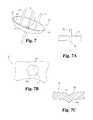
- FIG. 7is a perspective view of an embodiment as in FIG. 1 including additional features.
- FIG. 7Ais a side view of an embodiment of a valve or seal configuration usable in the disclosed embodiments.
- FIGS. 7B-Dare a top view ( FIG. 7B ) and part cross-sectional views perpendicular to a slit ( FIGS. 7C-D ) of an embodiment of a valve or seal configuration usable in the disclosed embodiments.
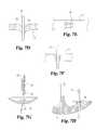
- FIGS. 7E-Fare side views of an embodiment of a valve or seal configuration usable in the disclosed embodiments.
- FIGS. 7G-7Hare part cross-sectional views of embodiments of valve or seal configurations and connections usable in the disclosed embodiments.
- FIG. 8is a top view of the embodiment of FIG. 7 .
- FIG. 9is a perspective view of an embodiment similar to that of FIG. 5 with features shown in FIG. 7 .
- FIG. 10is a perspective view of an embodiment as in FIG. 1 with additional features.
- FIG. 11is a perspective view of an embodiment of a device or part of a system for closing bodily openings.
- FIG. 12is a part-sectional view of the embodiment of FIG. 11 .
- FIGS. 13A-Bare side views of an embodiment of at least part of a closure system.
- FIG. 13Cis a part cross-sectional view of the embodiment of FIGS. 13 A-B.
- FIG. 1there is shown an embodiment of a closure device 20 for use itself or with a system for closing holes in tissue, such as those formed in the walls of blood vessels during catheterizations or other treatments, or septal defects (e.g. patent foramen ovale, or PFO).
- Embodiments of device 20can be used for closing holes of any size, whether relatively small or relatively large. However, device 20 is believed to be effective in closing large or elongated holes, where existing devices are not or present difficulties or uncertainties in closing such holes.
- Device 20includes an internal anchoring or sealing member 22 that is placed on one side of a hole to be closed (e.g. within a blood vessel) and at least two elongated members (e.g. members 24 , 26 in FIGS. 1-3 ) extending proximally from anchoring member 22 .
- elongated members 24 , 26may be stems that are part of or are fixed to anchoring member 22 , or may be threads or other types of filaments attached to anchoring member 22 .
- Anchoring or sealing member 22 in the illustrated embodimentis in the illustrated embodiment is a curved toggle or dome having a wall 30 .
- Wall 30can have a constant or varying thickness, for example in certain embodiments having a maximum thickness in the range of about 0.0050 inches to about 0.050 inches, and in a particular embodiment about 0.015 inches.
- the maximum thickness of member 22is at and/or between the connection(s) with elongated members 24 and 26 are, and the thickness decreases uniformly out to a rim 32 .
- Anchoring or sealing member 22is part-spheroidal in an unstressed state (e.g. FIGS. 1-3 ), having a substantially oval-shaped (e.g. elliptical) rim 32 .
- Rim 32is substantially in one plane in this embodiment, having little or no breadth.
- Member 22has an exterior convex surface 34 and an interior concave surface 36 which is open and unobstructed.
- surfaces 34 and 36may have substantially the same radii, so that the overall thickness of wall 30 is substantially constant, or may have differing radii, so that they intersect or approach each other at (and wall 32 thins toward) rim 32 .
- a center point 38may have a tangent plane that is parallel to the plane of rim 32 .
- An elongated toggle or dome member 22has respective ends or end portions 39 along a major axis MA, so that the distance between ends 39 is the largest dimension of member 22 .
- FIG. 1Ashows an example of an anchoring member 22 that is essentially the same as member 22 in FIGS. 1-3 , with the exception that the generally elliptical form of the embodiment in FIGS. 1-3 is truncated substantially along the major axis MA, leaving an anchoring member in the form of a toggle.
- Rim 32 around end portions 39may thus form part of an ellipse.
- Exterior convex surface 34 , interior concave surface 36 and center point 38 as described abovemay be seen in this example.
- anchoring member 22is flexible
- such flexibilitypermits an elastic or inelastic deformation or change in shape.
- internal anchoring or sealing member 22can be folded for placement in a delivery device, and during or after placement can open or flatten from the folded condition to move close or closer to tissue.
- Member 22can be constructed so as to completely flatten (e.g. surface 36 substantially conforming to surrounding tissue) under stress as experienced after implantation, or so as to not completely flatten under such stress (e.g. maintaining an at least slightly concave surface 36 or arch) in use, as discussed further below.
- anchoring or sealing member 22is made of a flexible material that is biocompatible and resorbable in particular embodiments.
- a flexible materialis used that is elastically foldable, i.e. that can be folded or compressed into a tube or other holder, and will resume the original dome-like shape once moved out of the holder.
- Specific examples of materials that have been found to be particularly usefulare mixtures of polycaprolactone and L-lactide as disclosed in Application Ser. No. 61/716,182, filed on Oct. 19, 2012, which is incorporated by reference herein in its entirety.
- examples of elongated members 24include filaments and/or stems attached to member 22 .
- an exemplary stem 40is shown in FIG. 4 , which is unitary (i.e. monolithic) with or joined to surface 36 or other part of member 22 .
- additional stemsmay be provided on member 22 in other embodiments.
- Each stem 40 in this embodimentis configured to attach to a suture, thread or other filament 41 , and in the example of FIG. 4 stems 40 each include an eyelet 42 through which such a filament 41 is threaded.
- Stems 40further include protrusions or beads 44 at particular intervals between eyelet 42 and surface 36 , and preferably between eyelet 42 and a plane in which rim 32 of member 22 is located.
- Stems 40have thickened bases 46 in particular embodiments.
- a base 46 of a stem 40is conical or outwardly flared from stem 40 toward surface 36 .
- the widened base 46provides a sturdier or more secure connection between stem 40 and the rest of member 22 , which may be needed with greater strains associated with larger vascular or other openings to be closed.
- a conical or flared base 46can also provide a non-edged and larger surface against which tissue surrounding the hole can abut. The bases 46 can be lodged against the tissue surrounding the hole, ensuring the positioning of member 22 across the hole while spreading out stress on the tissue.
- Elongated members 24 , 26are substantially identical to each other in the illustrated embodiments, e.g. each of elongated members 24 , 26 as a stem (e.g. stem 40 ) to which a suture or other type of filament or fiber is attached.
- Filament 41extends proximally from stem 40 (and/or from surface 36 of member 22 , e.g. if elongated members 24 , 26 are connected directly to surface 36 ) a distance that is at least sufficient to stretch from an implanted location of member 22 (e.g. within a vessel) to a location outside the patient's body.
- filament 41may be directly connected to stem 40 , as by threading or looping through eyelet 42 so that filament 41 doubles up on itself, or by fixing filament 41 directly to stem 40 as by welding, gluing, or the like.
- FIG. 1shows an elongated internal anchoring or sealing member 22 , substantially in an oval or elliptical shape when viewed from top or bottom (e.g. FIG. 3 ).
- Elongated members 24 , 26are on opposite sides of the center point 38 of sealing member 22 .
- elongated members 24are joined to sealing member 22 so that they intersect major axis MA.
- elongated members 24are located at or intersecting the foci of the ellipse.
- elongated members 24may each be located approximately halfway between the center 38 and a respective end 39 of sealing member 22 .
- sealing member 22is intended to be larger in size or outermost extent than an opening in a vessel or other body part to be closed.
- Particular embodiments of sealing member 22will have respective elongated members 24 , 26 separated by a distance that is less than or approximately equal to the diameter of an introducer used for access to a vessel, and thus less than or approximately equal to the diameter of the opening in the vessel to be closed by member 22 .
- FIGS. 5, 6, and 9show a sealing member 22 with four elongated members 24 attached to it, each offset from the center 38 and from the major axis MA. That embodiment shows the placement of elongated members 24 is such that an adjacent pair of elongated members 24 (e.g. toward the top or bottom in FIG. 9 ) is on a line substantially parallel to axis MA, an adjacent pair of elongated members 24 (e.g. to the right or left in FIG. 9 ) is on a line substantially perpendicular to axis MA.
- Opposing or diagonal pairs of elongated members 24are on lines through center 38 in the illustrated embodiment. Such embodiments space out the application of force through elongated members 24 to sealing member 22 , resulting in better attachment of the entirety of sealing member 22 to the inside of the vessel or to other tissue when tension is applied to elongated members 24 .
- buffer material 60is included in the embodiments shown in FIGS. 5-6 .
- Such buffers 60are made of biocompatible material, and preferably resorbable material.
- buffers 60are of small intestinal submucosa (SIS) material.
- SISsmall intestinal submucosa
- buffer 60is a single sheet or layer with multiple holes 62 positioned in locations compatible with loading buffer 60 onto elongated members 24 of an anchoring or sealing member 22 .
- One or more locking members 70 with central holes 72are provided to slide over elongated members 24 to lock buffer 60 into place with respect to anchoring or sealing member 22 , and member 22 with respect to the hole in tissue.
- a plurality of buffer pieces 60in the form of flat discs or plates in the illustrated embodiment, are provided.
- one buffer piece 60can be provided for each stem 40 , with a specific locking member 70 for each elongated member 24 .
- multiple buffer pieces 60may be provided to one or more elongated members 24 , and that no buffer piece 60 may be provided to one or more elongated members 24 .
- the width or diameter of buffer pieces 60may be chosen so that portions of two or more such pieces 60 overlap when they are placed along their respective elongated members 24 (see e.g. FIG. 6 ).
- Locking members 70are sized and/or configured so that they do not overlap when placed on respective elongated members 24 .
- the radius of an exemplary locking member 70may be half or less of that specific distance.
- a single locking member 70may be provided with multiple holes 72 positioned so that the single locking member 70 can be used with multiple elongated members 24 .
- Embodiments of anchoring or sealing member 22may also include an opening 80 for passage of a guide wire 82 .
- the illustrated embodimentshows opening 80 in the center 38 (unmarked in FIGS. 7-9 to maintain clarity) of member 22 .
- this embodiment of member 22is essentially the same as embodiments described above, with elongated members 24 (e.g. stems 40 ) offset from the center.
- Hole 80 in this embodimentis occupied by or includes a valve or seal 84 configured for hemostatic control both when guide wire 82 is inserted through it and when no guide wire is present.
- Exemplary valves or sealsmay include an opening through member 22 having at least a portion with a diameter less than the diameter of a guide wire to be extended through it, so that member 22 engages the wire with some force.
- a holemay be cylindrical (e.g. FIG. 7A ), a “duck-bill” configuration (e.g. FIGS. 7B-D ), conical (e.g. FIG. 7H , with the smallest diameter on the concave exterior of member 22 ), or otherwise configured.
- a “duck-bill” configurationincludes two leaves 81 a pressed against each other at a slit 81 b , with the leaves generally pointed or oriented toward an outer or exterior surface of member 22 .
- a guide wire 82 through slit 81 bis engaged by leaves 81 a , and when wire 82 is removed, the leaves press the slit closed to limit or eliminate leakage.
- a conical opening configuration as indicated in FIG. 7Epinches together as member 22 is pulled against the vascular wall, to limit or eliminate leakage through the opening.
- Another example of a suitable valve or sealwould be an opening with opposed interdigitating (i.e. overlapping) flanges or fingers (e.g. FIG. 7E-F ). Wire 82 inserted through the hole bends the flanges or fingers, with the flanges or fingers pressed against the wire to maintain a seal.
- a stem 24 and/or 26may have guides 85 attached to allow passage of wire 82 close to and along the stem (e.g. FIG. 7G ).
- a center opening for passage of wire 82 through member 22may be adjacent or under a stem (e.g. FIG. 7G ), whether the stem is at or offset from the center of member 22 , and that an opening for a wire 82 may be offset from the center of member 22 .
- the opening for wire 82may have a wall thicker than that of member 22 (e.g. FIG. 7H ).
- Guide wire 82is not used for placement of anchoring or sealing member 22 in some embodiments, but merely accompanies member 22 as it is placed, to provide a safety measure in maintaining vessel access in case of an emergency. That is, should there be a breakage or improper placement of member 22 or another part of device 20 or other emergency, guide wire 82 extends through member 22 and into the vessel, and permits insertion of an emergency sheath, valve, plug or other device to address the situation. While FIGS.
- FIGS. 7 and 8show an embodiment with two elongated members 24 , similar to the embodiment in FIGS. 1-3
- FIG. 9shows an embodiment with four elongated members 24 , similar to the embodiments shown in FIGS. 5-6 . It will be understood that wire and valve usage as noted above can be incorporated into members 22 with a single elongated member 24 placed in the center of member 22 .
- multiple elongated members 24In addition to a force-spreading characteristic of the multiple elongated members 24 , their use in connection with distance between them provides a better opportunity for ensuring proper placement or centering of anchoring or sealing member 22 with respect to a tissue hole.
- the multiple filament and/or stem embodimentsdo not permit member 22 to be placed in or to slide to a position in which the hole is not covered, or in which an end 39 of member 22 is in or positioned through the hole. Rather, the presence of spread-apart multiple stems or filaments that extend through the hole means that position or movement of member 22 relative to the hole is limited. The member 22 is less likely to be mispositioned, because of interference between the tissue surrounding the hole and the stems or filaments.
- Insertion of embodiments of sealing or anchoring member 22can be accomplished using devices (e.g. cannulas, catheters, or the like) known for providing access to bodily openings in blood vessels, organs or other tissues.
- Device 20is inserted through the opening to be closed, and is retracted so that at least a portion of rim 32 and perhaps at least a portion of inner surface 36 engages tissue.
- the multiple elongated members 24help to ensure proper positioning of device 20 , i.e. with a portion of member 22 on opposing sides of the hole or surrounding the hole, so that member 22 firmly engages tissue and does not slip back through the hole. That is, elongated members 24 prevent shifting of member 22 into an unacceptable position relative to the hole due to interference with the sides of the hole.
- buffer 60may be moved along elongated members 24 by or prior to locking members 70 .
- locking members 70engaging elongated members 24 and holding buffer 60 and member 22 over the hole and/or engaging tissue around the hole, the hole is closed.
- Filaments 41 extending from elongated members 24 (or elongated members 24 themselves if they are filaments)are cut and pulled out of the patient, and the pathway through the skin used to access the bodily opening is closed.
- FIG. 10depicts an example of an internal anchoring or sealing member 22 similar to that shown in FIGS. 1-3 , and common elements described above with respect to FIGS. 1-3 will not be repeated here.
- a respective base member 90is joined to or part of each elongated member 24 and joined to or part of inner surface 36 of member 22 . It will be understood that less than all of the elongated members 24 may have such a base member 90 in other embodiments.
- base members 90are solid parts that are curved substantially along the curvature of surface 36 , e.g. forming a part of an ellipse concentric with an elliptical rim 32 of member 22 .
- Such base memberscan not only reinforce the connection between elongated members 24 and wall 30 of member 22 , but can also help to better index the elongated members 24 within the bodily opening during deployment.
- the illustrated example of base members 90which are rounded or part elliptical, can help index with respect to the bodily opening by lying adjacent or engaging a rim of the opening. That is, a side surface of members 90 generally facing rim 32 of member 22 can engage or face the sides of the tissue opening. The sides of members 90 can provide a larger surface to help prevent migration of member 22 or provide some frictional securing of member 22 within the tissue opening.
- FIGS. 11 and 12show an example of an embodiment of device 20 in which elongated members 24 are not fixed with respect to anchoring or sealing member 22 .
- member 22is similar to that described with respect to FIGS. 1-3 , e.g. wall 30 and other parts excepting elongated members 24 and the presence of holes 94 .
- holes 94are placed at or near the foci of an elliptical or ellipsoidal member 22 .
- Elongated members 24 in the embodiment of FIGS. 11-12may be a stem or filament as described above, with a dome-like seal 96 at a distal end.
- Each seal 96is sized and configured to cover a respective hole 94 , and may be formed as a smaller and/or circular version of member 22 described above. Pulling on one or both of elongated members 24 move the respective seal(s) 96 to and/or over respective holes 94 , to prevent leakage through holes 94 and/or to move member 22 against tissue to cover all or part of a bodily opening.
- FIGS. 13A-Cshow an embodiment of at least part of a closure system having an internal or distal sealing or anchoring member 222 , from which a stem 224 with an eyelet 241 and a filament 226 through eyelet 241 extend proximally.
- stem 224 and/or filament 226are a holding disc 270 , a sheet or other mass of buffer material 260 (e.g. small intestine submucosa, or SIS), and a locking disc 271 .
- a pusher 230is provided to move along filament 226 and/or stem 224 to move at least disc 271 and buffer material 260 along stem 224 and/or filament 226 , to lock the system (e.g.
- This embodimentmay be or include features as disclosed above (e.g. multiple elongated stems, filaments or other members) or as disclosed in application Ser. No. 13/111,338 (filed on May 19, 2011) and Ser. No. 13/303,707 (filed on Nov. 23, 2011), incorporated herein by reference in their entireties.
- Embodiments of a pusher device having a substantially cylindrical outer form, with a central lumen to allow the pusher device to slide along and over at least a part of a filament and/or stem connected to a member 22have been tried. In testing, it was found that such a cylindrical pusher operated well so long as tissue planes intersecting the wound or channel through the skin were generally oriented so that the wound or channel was itself substantially cylindrical. In other cases, such a cylindrical pusher device could catch on or be impeded by the tissue planes.
- pusher device 230is substantially torpedo-shaped, having a rearward gripping or base portion 232 and a forward pushing portion 234 .
- Base portion 232has a substantially cylindrical outer surface 236 in this embodiment, with a rearward or proximal end 238 that is rounded.
- the illustrated embodiment of forward portion 234has an outer surface 240 that transitions smoothly with surface 236 of gripping portion 232 , and tapers inward toward forward end 242 .
- the tapering outer surface 240describes a portion of a regular circular cone (i.e. a plane tangent to surface 240 intersects surface 240 in a line) or a convex solid (e.g.
- Pusher 230has a linear lumen 246 extending between ends 238 and 242 .
- Lumen 246may have a substantially constant diameter between ends 238 and 242 , and in such cases the thickness of the wall of pusher 230 (i.e. the material between lumen 246 and outer surfaces 236 , 240 ) decreases in tapering forward portion 234 as one approaches end 242 .
- lumen 246may decrease in diameter in forward portion 234 , so that the wall has a smaller or no decrease in width.
- End 242may be rounded in particular embodiments.
- Pusher 230 or other parts of the system in particular embodimentscan also provide the user an indication as to when locking disc 271 and/or other items are in a desired placement and he or she can thus stop pushing.
- an indicator 250is placed within lumen 246 of pusher 230 .
- Indicator 250is fixed to one or both of filament 226 and stem 224 connected to anchor or closure member 22 , and in the illustrated embodiment is fixed to filament 226 .
- Pusher 230is movable with respect to filament 226 and stem 224 , and is thus also movable with respect to indicator 250 .
- Indicator 250 in the illustrated embodimentis a tube having a proximal portion 252 and a forward or distal portion 254 .
- indicator 250may be a sheet, wrap (e.g. a shrink-wrap plastic film), or other attachment.
- At least a portion of indicator 250has a contrasting surface or portion 256 differentiating it from proximal end 238 or more of base portion 232 of pusher 230 , as by contrasting coloration, lineation, writing, texture, or other observable features.
- the illustrated embodiment of indicator 250includes contrasting portion 256 at or toward distal portion 254 , so that use of pusher uncovers a substantial portion of indicator 250 before contrasting portion 256 is exposed from pusher 230 . It will be understood that in other embodiments all of indicator 250 , or at least a part of proximal portion 252 , may be included in contrasting portion 256 , so that the contrasting portion 256 is observable as soon as any part of indicator 250 exits from pusher 230 .
- the length and positioning of indicator 250are chosen so that when end 242 of pusher 230 is in a position as indicated in FIG. 13C , having pushed disc 271 and buffer 260 against disc 270 and/or tissue, so that the system is locked with respect to member 222 and its filament 226 and/or stem 224 , at least a portion of the contrasting part 256 is exposed from the proximal end 238 of pusher 230 , observable to the user.
- the usersees contrasting part 256 , or a specified amount of part 256 , he or she knows that the system is locked as intended.
- the useris accordingly not limited to relying on resistance felt through the pusher to determine when the locking disc and other items are fully deployed (e.g. snug against the vessel or other tissue against which the anchoring or sealing member 222 was engaged).
- anchoring or sealing member 222is engaged to the inside of a blood vessel or other tissue portion adjacent a hole to be closed.
- Stem 224 , filament 226 , and discs 270 , 271 and buffer 260 along stem 224 and/or filament 226extend proximally into or through an opening in the skin to the hole.
- Pusher 230is moved forward along filament 226 and stem 224 (in the illustrated embodiment) to force locking disc 271 , buffer material 260 , holding disc 279 (if needed), and/or other parts forward.
- pusher 230moves forward, its pushing end 242 engages disc 271 to push it and the noted parts along filament 226 and/or stem 224 .
- Indicator 250remains fixed to filament 226 and/or stem 224 , and so pusher 230 moves over indicator 250 as well, so that eventually proximal portion 252 of indicator 250 is exposed (or further exposed) from the proximal end 238 of pusher 230 as pusher 230 is moved forward.
- end 242 of pusher 230has pushed locking disc 271 , buffer 260 and any other items into a fully-deployed state, so that member 222 is locked in place and the hole is covered or sealed.
- end 212 and tapering outer surface 210lead within the opening in the skin.
- the taper of surface 210allows pusher 230 to move through the skin opening with less likelihood of catching or snagging on tissue plane(s) adjoining the opening. Rather, tapering outer surface 210 , to the extent necessary, provides a smooth adjustment of tissue plane(s) and/or dilation of the opening through them.
- elongated members 24may be placed in alternative configurations with respect to the rest of member 22 , such as having two elongated members 24 adjacent ends 39 and on major axis MA, and two elongated members 24 offset from major axis MA so that a line between them is through center 38 and substantially perpendicular to axis MA.
Landscapes
- Health & Medical Sciences (AREA)
- Surgery (AREA)
- Life Sciences & Earth Sciences (AREA)
- Biomedical Technology (AREA)
- Nuclear Medicine, Radiotherapy & Molecular Imaging (AREA)
- Engineering & Computer Science (AREA)
- Cardiology (AREA)
- Heart & Thoracic Surgery (AREA)
- Medical Informatics (AREA)
- Molecular Biology (AREA)
- Animal Behavior & Ethology (AREA)
- General Health & Medical Sciences (AREA)
- Public Health (AREA)
- Veterinary Medicine (AREA)
- Surgical Instruments (AREA)
Abstract
Description
Claims (12)
Priority Applications (2)
| Application Number | Priority Date | Filing Date | Title |
|---|---|---|---|
| US14/056,429US10070850B2 (en) | 2012-10-19 | 2013-10-17 | Vascular closure with multiple connections |
| US16/126,262US11317901B2 (en) | 2012-10-19 | 2018-09-10 | Vascular closure with multiple connections |
Applications Claiming Priority (2)
| Application Number | Priority Date | Filing Date | Title |
|---|---|---|---|
| US201261716155P | 2012-10-19 | 2012-10-19 | |
| US14/056,429US10070850B2 (en) | 2012-10-19 | 2013-10-17 | Vascular closure with multiple connections |
Related Child Applications (1)
| Application Number | Title | Priority Date | Filing Date |
|---|---|---|---|
| US16/126,262ContinuationUS11317901B2 (en) | 2012-10-19 | 2018-09-10 | Vascular closure with multiple connections |
Publications (2)
| Publication Number | Publication Date |
|---|---|
| US20140114347A1 US20140114347A1 (en) | 2014-04-24 |
| US10070850B2true US10070850B2 (en) | 2018-09-11 |
Family
ID=50486011
Family Applications (2)
| Application Number | Title | Priority Date | Filing Date |
|---|---|---|---|
| US14/056,429Active2035-07-23US10070850B2 (en) | 2012-10-19 | 2013-10-17 | Vascular closure with multiple connections |
| US16/126,262Active2033-12-16US11317901B2 (en) | 2012-10-19 | 2018-09-10 | Vascular closure with multiple connections |
Family Applications After (1)
| Application Number | Title | Priority Date | Filing Date |
|---|---|---|---|
| US16/126,262Active2033-12-16US11317901B2 (en) | 2012-10-19 | 2018-09-10 | Vascular closure with multiple connections |
Country Status (1)
| Country | Link |
|---|---|
| US (2) | US10070850B2 (en) |
Cited By (1)
| Publication number | Priority date | Publication date | Assignee | Title |
|---|---|---|---|---|
| US20190000432A1 (en)* | 2012-10-19 | 2019-01-03 | Cook Medical Technologies Llc | Vascular closure with multiple connections |
Families Citing this family (3)
| Publication number | Priority date | Publication date | Assignee | Title |
|---|---|---|---|---|
| EP4147649A1 (en)* | 2015-02-10 | 2023-03-15 | Teleflex Life Sciences Limited | Closure device for sealing percutaneous opening in a vessel |
| US12383246B2 (en) | 2020-10-12 | 2025-08-12 | Abbott Cardiovascular Systems, Inc. | Vessel closure device with improved safety and tract hemostasis |
| CN117694940A (en)* | 2022-09-06 | 2024-03-15 | 深圳市先健纬康科技有限公司 | Vascular closure device and vascular closure system |
Citations (72)
| Publication number | Priority date | Publication date | Assignee | Title |
|---|---|---|---|---|
| US4744364A (en)* | 1987-02-17 | 1988-05-17 | Intravascular Surgical Instruments, Inc. | Device for sealing percutaneous puncture in a vessel |
| EP0534696A1 (en) | 1991-09-23 | 1993-03-31 | Jay Erlebacher | A sealing device and an insertion tool therefor |
| US5269809A (en) | 1990-07-02 | 1993-12-14 | American Cyanamid Company | Locking mechanism for use with a slotted suture anchor |
| US5312435A (en) | 1993-05-17 | 1994-05-17 | Kensey Nash Corporation | Fail predictable, reinforced anchor for hemostatic puncture closure |
| US5342393A (en) | 1992-08-27 | 1994-08-30 | Duke University | Method and device for vascular repair |
| US5411520A (en) | 1991-11-08 | 1995-05-02 | Kensey Nash Corporation | Hemostatic vessel puncture closure system utilizing a plug located within the puncture tract spaced from the vessel, and method of use |
| US5531759A (en) | 1994-04-29 | 1996-07-02 | Kensey Nash Corporation | System for closing a percutaneous puncture formed by a trocar to prevent tissue at the puncture from herniating |
| US5545178A (en) | 1994-04-29 | 1996-08-13 | Kensey Nash Corporation | System for closing a percutaneous puncture formed by a trocar to prevent tissue at the puncture from herniating |
| US5620461A (en) | 1989-05-29 | 1997-04-15 | Muijs Van De Moer; Wouter M. | Sealing device |
| US5643320A (en)* | 1995-03-13 | 1997-07-01 | Depuy Inc. | Soft tissue anchor and method |
| US5662681A (en) | 1996-04-23 | 1997-09-02 | Kensey Nash Corporation | Self locking closure for sealing percutaneous punctures |
| US5700277A (en) | 1993-06-04 | 1997-12-23 | Kensey Nash Corporation | Hemostatic vessel puncture closure with filament lock |
| US5800436A (en)* | 1996-02-03 | 1998-09-01 | Lerch; Karl-Dieter | Device for postoperative fixation back into the cranium of a plug of bone removed therefrom during a surgical operation |
| US5916236A (en) | 1989-05-29 | 1999-06-29 | Kensey Nash Corporation | Occlusion assembly for sealing openings in blood vessels and a method for sealing openings in blood vessels |
| WO1999033402A1 (en) | 1997-12-29 | 1999-07-08 | Swanstrom Lee L | Method and apparatus for attaching or locking an implant to an anatomic vessel or hollow organ wall |
| US6071301A (en) | 1998-05-01 | 2000-06-06 | Sub Q., Inc. | Device and method for facilitating hemostasis of a biopsy tract |
| WO2000078226A1 (en) | 1999-06-18 | 2000-12-28 | Radi Medical Systems Ab | A tool, a sealing device, a system and a method for closing a wound |
| US6190400B1 (en) | 1991-10-22 | 2001-02-20 | Kensey Nash Corporation | Blood vessel sealing device and method of sealing an opening in a blood vessel |
| US6280474B1 (en)* | 1997-01-09 | 2001-08-28 | Neucoll, Inc. | Devices for tissue repair and methods for preparation and use thereof |
| EP1169968A1 (en) | 2000-11-03 | 2002-01-09 | Radi Medical Systems Ab | Sealing and wound closure device |
| US6425911B1 (en) | 2001-05-09 | 2002-07-30 | Radi Medical Systems Ab | Positioning device and incision closure device |
| US6491714B1 (en) | 1996-05-03 | 2002-12-10 | William F. Bennett | Surgical tissue repair and attachment apparatus and method |
| EP1266626A1 (en) | 2001-06-15 | 2002-12-18 | Radi Medical Systems Ab | Tamping mechanism |
| US6508828B1 (en) | 2000-11-03 | 2003-01-21 | Radi Medical Systems Ab | Sealing device and wound closure device |
| US6596013B2 (en) | 2001-09-20 | 2003-07-22 | Scimed Life Systems, Inc. | Method and apparatus for treating septal defects |
| US20030181988A1 (en) | 2002-03-22 | 2003-09-25 | Ethicon, Inc. | Hernia repair device |
| US6712837B2 (en)* | 2001-05-03 | 2004-03-30 | Radi Medical Systems Ab | Guiding tool for wound closure element |
| EP1413255A1 (en) | 2002-10-25 | 2004-04-28 | Radi Medical Systems Ab | Absorbable surgical sealing device |
| US6764500B1 (en) | 1989-05-29 | 2004-07-20 | Kensey Nash Corporation | Sealing device |
| EP1440661A1 (en) | 2003-01-14 | 2004-07-28 | Radi Medical Systems Ab | Closure device and method |
| US6780164B2 (en)* | 2000-04-14 | 2004-08-24 | Glaukos Corporation | L-shaped implant with bi-directional flow |
| US20050085855A1 (en) | 2003-10-17 | 2005-04-21 | Forsberg Andrew T. | Automatic suture locking device |
| US20050096696A1 (en)* | 2003-11-04 | 2005-05-05 | Forsberg Andrew T. | Arteriotomy closure device with anti-roll anchor |
| WO2005063133A1 (en) | 2003-12-26 | 2005-07-14 | Terumo Kabushiki Kaisha | Tissue closure and tissue closing device |
| US6921401B2 (en) | 1999-10-30 | 2005-07-26 | Aesculap Ag & Co. Kg | Surgical connecting element for fixing adjacently arranged bone plates |
| US20050169974A1 (en) | 2002-05-08 | 2005-08-04 | Radi Medical Systems Ab | Dissolvable medical sealing device |
| US6939363B2 (en) | 2002-06-12 | 2005-09-06 | Radi Medical Systems Ab | Closure device |
| US20050283193A1 (en)* | 2004-06-18 | 2005-12-22 | Radi Medical Systems Ab | Introducer guide |
| US20050283187A1 (en)* | 2004-06-22 | 2005-12-22 | Longson Matthew S | Vascular occlusion device |
| US7048710B1 (en) | 1998-05-01 | 2006-05-23 | Sub-Q, Inc. | System and method for facilitating hemostasis of blood vessel punctures with absorbable sponge |
| US20060142797A1 (en) | 2004-12-16 | 2006-06-29 | Radi Medical Systems Ab | Medical sealing device |
| WO2006075228A1 (en) | 2005-01-14 | 2006-07-20 | Radi Medical Systems Ab | Medical closure device |
| US20060206146A1 (en) | 2005-03-11 | 2006-09-14 | Radi Medical Systems Ab | Medical sealing device |
| WO2007059243A1 (en) | 2005-11-15 | 2007-05-24 | Aoi Medical, Inc. | Arterial closure button |
| US20070198059A1 (en) | 2006-01-31 | 2007-08-23 | Patel Umesh H | Fistula grafts and related methods and systems for treating fistulae |
| US20080033487A1 (en)* | 2006-08-07 | 2008-02-07 | Bioduct, Llc | Medical device for repair of tissue and method for implantation and fixation |
| US7338514B2 (en) | 2001-06-01 | 2008-03-04 | St. Jude Medical, Cardiology Division, Inc. | Closure devices, related delivery methods and tools, and related methods of use |
| US20080071310A1 (en) | 2006-09-12 | 2008-03-20 | Hoffman Grant T | Medical device and a method for sealing a puncture or an opening |
| US20080287986A1 (en) | 2007-05-18 | 2008-11-20 | Possis Medical, Inc. | Closure device |
| US20080312684A1 (en) | 2007-02-05 | 2008-12-18 | Boston Scientific Scimed, Inc | Apparatus and Method for Closing an Opening in a Blood Vessel Using a Permanent Implant |
| US20090018574A1 (en) | 2007-06-15 | 2009-01-15 | Zerusa Limited | Closure device |
| US20090054926A1 (en) | 2007-08-21 | 2009-02-26 | St. Jude Medical Puerto Rico B.V. | Extra-vascular sealing device and method |
| US20090088793A1 (en) | 2007-09-28 | 2009-04-02 | Accessclosure, Inc. | Apparatus and methods for sealing a vascular puncture |
| US20090112257A1 (en) | 2007-10-31 | 2009-04-30 | Radi Medical Systems Ab | Method and device for sealing a puncture hole in a bodily organ |
| EP2064999A2 (en) | 2007-11-30 | 2009-06-03 | Radi Medical Systems Ab | Insertion tool |
| US20090216267A1 (en) | 2008-02-26 | 2009-08-27 | Boston Scientific Scimed, Inc. | Closure device with rapidly dissolving anchor |
| US20090234377A1 (en) | 2008-03-14 | 2009-09-17 | Radi Medical Systems Ab | Medical closure device |
| US7597705B2 (en) | 2003-12-03 | 2009-10-06 | St. Jude Medical Puerto Rico Llc | Vascular puncture seal anchor nest |
| US7621937B2 (en) | 2003-12-03 | 2009-11-24 | St. Jude Medical Puerto Rico LC | Vascular sealing device with high surface area sealing plug |
| US7658748B2 (en) | 2003-09-23 | 2010-02-09 | Cardia, Inc. | Right retrieval mechanism |
| US20100042144A1 (en) | 2008-08-12 | 2010-02-18 | Steven Bennett | Medical Device for Wound Closure and Method of Use |
| US20100087854A1 (en) | 2008-08-12 | 2010-04-08 | Joshua Stopek | Medical device for wound closure and method of use |
| US7717929B2 (en) | 2003-12-19 | 2010-05-18 | Radi Medical Systems Ab | Technique for securing a suture |
| US20100217309A1 (en)* | 2009-02-20 | 2010-08-26 | Boston Scientific Scimed, Inc. | Plug for arteriotomy closure and method of use |
| US20100217308A1 (en) | 2009-02-20 | 2010-08-26 | Boston Scientific Scimed, Inc. | Locking element for vascular closure device |
| US7875052B2 (en) | 2004-12-17 | 2011-01-25 | Terumo Kabushiki Kaisha | Tissue closure and tissue closing device |
| US20110066181A1 (en) | 2009-02-20 | 2011-03-17 | Boston Scientific Scimed, Inc. | Tissue puncture closure device |
| US20110082427A1 (en)* | 2009-10-06 | 2011-04-07 | Regents Of The University Of Minnesota | Bioresorbable embolization microspheres |
| US20110213414A1 (en)* | 2008-02-15 | 2011-09-01 | Mcguckin Jr James F | Vascular hole closure device |
| US20110288581A1 (en)* | 2010-05-19 | 2011-11-24 | Paul Jr Ram H | Devices and methods useful for sealing bodily openings |
| US20120116447A1 (en) | 2010-05-19 | 2012-05-10 | Cleon Stanley | Devices and methods useful for sealing bodily openings |
| US8257389B2 (en) | 2004-05-07 | 2012-09-04 | W.L. Gore & Associates, Inc. | Catching mechanisms for tubular septal occluder |
Family Cites Families (18)
| Publication number | Priority date | Publication date | Assignee | Title |
|---|---|---|---|---|
| US4927421A (en)* | 1989-05-15 | 1990-05-22 | Marlowe Goble E | Process of endosteal fixation of a ligament |
| US6117162A (en)* | 1996-08-05 | 2000-09-12 | Arthrex, Inc. | Corkscrew suture anchor |
| US6994092B2 (en)* | 1999-11-08 | 2006-02-07 | Ev3 Sunnyvale, Inc. | Device for containing embolic material in the LAA having a plurality of tissue retention structures |
| US6767356B2 (en) | 2000-09-01 | 2004-07-27 | Angiolink Corporation | Advanced wound site management systems and methods |
| US6426911B1 (en) | 2000-10-19 | 2002-07-30 | Infineon Technologies Ag | Area efficient method for programming electrical fuses |
| US7270675B2 (en)* | 2002-05-10 | 2007-09-18 | Cordis Corporation | Method of forming a tubular membrane on a structural frame |
| US6860896B2 (en) | 2002-09-03 | 2005-03-01 | Jeffrey T. Samson | Therapeutic method and apparatus |
| US8398675B2 (en)* | 2002-10-25 | 2013-03-19 | Radi Medical Systems Ab | Absorbable medical sealing device with retaining assembly having at least two loops |
| WO2007079234A2 (en) | 2006-01-02 | 2007-07-12 | Excellims Corporation | Multi-dimensional ion mobility spectrometry apparatus and methods |
| US8500809B2 (en)* | 2011-01-10 | 2013-08-06 | Ceterix Orthopaedics, Inc. | Implant and method for repair of the anterior cruciate ligament |
| JP2010015019A (en) | 2008-07-04 | 2010-01-21 | Hitachi Displays Ltd | Liquid crystal display device and manufacturing method for the same |
| EP3300695B1 (en)* | 2009-12-08 | 2023-05-24 | Avalon Medical Ltd. | Device and system for transcatheter mitral valve replacement |
| US9579193B2 (en)* | 2010-09-23 | 2017-02-28 | Transmural Systems Llc | Methods and systems for delivering prostheses using rail techniques |
| US8900295B2 (en)* | 2011-09-26 | 2014-12-02 | Edwards Lifesciences Corporation | Prosthetic valve with ventricular tethers |
| US20130184811A1 (en)* | 2012-01-13 | 2013-07-18 | Tendyne Holdings, Inc. | Device and Method for Replacing Mitral Valve |
| US10070850B2 (en)* | 2012-10-19 | 2018-09-11 | Cook Medical Technologies Llc | Vascular closure with multiple connections |
| US9844435B2 (en)* | 2013-03-01 | 2017-12-19 | St. Jude Medical, Cardiology Division, Inc. | Transapical mitral valve replacement |
| US9517131B2 (en)* | 2014-12-12 | 2016-12-13 | Than Nguyen | Cardiac valve repair device |
- 2013
- 2013-10-17USUS14/056,429patent/US10070850B2/enactiveActive
- 2018
- 2018-09-10USUS16/126,262patent/US11317901B2/enactiveActive
Patent Citations (85)
| Publication number | Priority date | Publication date | Assignee | Title |
|---|---|---|---|---|
| US4744364A (en)* | 1987-02-17 | 1988-05-17 | Intravascular Surgical Instruments, Inc. | Device for sealing percutaneous puncture in a vessel |
| US5620461A (en) | 1989-05-29 | 1997-04-15 | Muijs Van De Moer; Wouter M. | Sealing device |
| US5916236A (en) | 1989-05-29 | 1999-06-29 | Kensey Nash Corporation | Occlusion assembly for sealing openings in blood vessels and a method for sealing openings in blood vessels |
| US6764500B1 (en) | 1989-05-29 | 2004-07-20 | Kensey Nash Corporation | Sealing device |
| US7169168B2 (en) | 1989-05-29 | 2007-01-30 | Kensey Nash Corporation | Sealing device |
| US5269809A (en) | 1990-07-02 | 1993-12-14 | American Cyanamid Company | Locking mechanism for use with a slotted suture anchor |
| EP0534696A1 (en) | 1991-09-23 | 1993-03-31 | Jay Erlebacher | A sealing device and an insertion tool therefor |
| US5350399A (en) | 1991-09-23 | 1994-09-27 | Jay Erlebacher | Percutaneous arterial puncture seal device and insertion tool therefore |
| US6190400B1 (en) | 1991-10-22 | 2001-02-20 | Kensey Nash Corporation | Blood vessel sealing device and method of sealing an opening in a blood vessel |
| US5411520A (en) | 1991-11-08 | 1995-05-02 | Kensey Nash Corporation | Hemostatic vessel puncture closure system utilizing a plug located within the puncture tract spaced from the vessel, and method of use |
| US5342393A (en) | 1992-08-27 | 1994-08-30 | Duke University | Method and device for vascular repair |
| US5312435A (en) | 1993-05-17 | 1994-05-17 | Kensey Nash Corporation | Fail predictable, reinforced anchor for hemostatic puncture closure |
| US5700277A (en) | 1993-06-04 | 1997-12-23 | Kensey Nash Corporation | Hemostatic vessel puncture closure with filament lock |
| US5545178A (en) | 1994-04-29 | 1996-08-13 | Kensey Nash Corporation | System for closing a percutaneous puncture formed by a trocar to prevent tissue at the puncture from herniating |
| US5531759A (en) | 1994-04-29 | 1996-07-02 | Kensey Nash Corporation | System for closing a percutaneous puncture formed by a trocar to prevent tissue at the puncture from herniating |
| US5643320A (en)* | 1995-03-13 | 1997-07-01 | Depuy Inc. | Soft tissue anchor and method |
| US5800436A (en)* | 1996-02-03 | 1998-09-01 | Lerch; Karl-Dieter | Device for postoperative fixation back into the cranium of a plug of bone removed therefrom during a surgical operation |
| US5662681A (en) | 1996-04-23 | 1997-09-02 | Kensey Nash Corporation | Self locking closure for sealing percutaneous punctures |
| US6491714B1 (en) | 1996-05-03 | 2002-12-10 | William F. Bennett | Surgical tissue repair and attachment apparatus and method |
| US6280474B1 (en)* | 1997-01-09 | 2001-08-28 | Neucoll, Inc. | Devices for tissue repair and methods for preparation and use thereof |
| WO1999033402A1 (en) | 1997-12-29 | 1999-07-08 | Swanstrom Lee L | Method and apparatus for attaching or locking an implant to an anatomic vessel or hollow organ wall |
| US6071301A (en) | 1998-05-01 | 2000-06-06 | Sub Q., Inc. | Device and method for facilitating hemostasis of a biopsy tract |
| US7048710B1 (en) | 1998-05-01 | 2006-05-23 | Sub-Q, Inc. | System and method for facilitating hemostasis of blood vessel punctures with absorbable sponge |
| WO2000078226A1 (en) | 1999-06-18 | 2000-12-28 | Radi Medical Systems Ab | A tool, a sealing device, a system and a method for closing a wound |
| US6860895B1 (en) | 1999-06-18 | 2005-03-01 | Radi Medical Systems Ab | Tool, a sealing device, a system and a method for closing a wound |
| US6921401B2 (en) | 1999-10-30 | 2005-07-26 | Aesculap Ag & Co. Kg | Surgical connecting element for fixing adjacently arranged bone plates |
| US6780164B2 (en)* | 2000-04-14 | 2004-08-24 | Glaukos Corporation | L-shaped implant with bi-directional flow |
| US6508828B1 (en) | 2000-11-03 | 2003-01-21 | Radi Medical Systems Ab | Sealing device and wound closure device |
| EP1169968A1 (en) | 2000-11-03 | 2002-01-09 | Radi Medical Systems Ab | Sealing and wound closure device |
| US6712837B2 (en)* | 2001-05-03 | 2004-03-30 | Radi Medical Systems Ab | Guiding tool for wound closure element |
| US6425911B1 (en) | 2001-05-09 | 2002-07-30 | Radi Medical Systems Ab | Positioning device and incision closure device |
| US7338514B2 (en) | 2001-06-01 | 2008-03-04 | St. Jude Medical, Cardiology Division, Inc. | Closure devices, related delivery methods and tools, and related methods of use |
| EP1266626A1 (en) | 2001-06-15 | 2002-12-18 | Radi Medical Systems Ab | Tamping mechanism |
| US6596013B2 (en) | 2001-09-20 | 2003-07-22 | Scimed Life Systems, Inc. | Method and apparatus for treating septal defects |
| US20030181988A1 (en) | 2002-03-22 | 2003-09-25 | Ethicon, Inc. | Hernia repair device |
| US6755868B2 (en) | 2002-03-22 | 2004-06-29 | Ethicon, Inc. | Hernia repair device |
| US20050169974A1 (en) | 2002-05-08 | 2005-08-04 | Radi Medical Systems Ab | Dissolvable medical sealing device |
| US6939363B2 (en) | 2002-06-12 | 2005-09-06 | Radi Medical Systems Ab | Closure device |
| EP1413255A1 (en) | 2002-10-25 | 2004-04-28 | Radi Medical Systems Ab | Absorbable surgical sealing device |
| EP1440661A1 (en) | 2003-01-14 | 2004-07-28 | Radi Medical Systems Ab | Closure device and method |
| US7658748B2 (en) | 2003-09-23 | 2010-02-09 | Cardia, Inc. | Right retrieval mechanism |
| US20050085855A1 (en) | 2003-10-17 | 2005-04-21 | Forsberg Andrew T. | Automatic suture locking device |
| US20050096696A1 (en)* | 2003-11-04 | 2005-05-05 | Forsberg Andrew T. | Arteriotomy closure device with anti-roll anchor |
| US7621937B2 (en) | 2003-12-03 | 2009-11-24 | St. Jude Medical Puerto Rico LC | Vascular sealing device with high surface area sealing plug |
| US7597705B2 (en) | 2003-12-03 | 2009-10-06 | St. Jude Medical Puerto Rico Llc | Vascular puncture seal anchor nest |
| US7717929B2 (en) | 2003-12-19 | 2010-05-18 | Radi Medical Systems Ab | Technique for securing a suture |
| WO2005063133A1 (en) | 2003-12-26 | 2005-07-14 | Terumo Kabushiki Kaisha | Tissue closure and tissue closing device |
| US8480709B2 (en) | 2004-05-07 | 2013-07-09 | W.L. Gore & Associates, Inc. | Catching mechanisms for tubular septal occluder |
| US8257389B2 (en) | 2004-05-07 | 2012-09-04 | W.L. Gore & Associates, Inc. | Catching mechanisms for tubular septal occluder |
| US20050283193A1 (en)* | 2004-06-18 | 2005-12-22 | Radi Medical Systems Ab | Introducer guide |
| US20050283187A1 (en)* | 2004-06-22 | 2005-12-22 | Longson Matthew S | Vascular occlusion device |
| US20060142797A1 (en) | 2004-12-16 | 2006-06-29 | Radi Medical Systems Ab | Medical sealing device |
| US8105352B2 (en) | 2004-12-16 | 2012-01-31 | Radi Medical Systems Ab | Medical sealing device |
| US7875052B2 (en) | 2004-12-17 | 2011-01-25 | Terumo Kabushiki Kaisha | Tissue closure and tissue closing device |
| US20080114395A1 (en) | 2005-01-14 | 2008-05-15 | Radi Medical Systems Ab | Closure Device |
| WO2006075228A1 (en) | 2005-01-14 | 2006-07-20 | Radi Medical Systems Ab | Medical closure device |
| US20060206146A1 (en) | 2005-03-11 | 2006-09-14 | Radi Medical Systems Ab | Medical sealing device |
| US7931671B2 (en)* | 2005-03-11 | 2011-04-26 | Radi Medical Systems Ab | Medical sealing device |
| WO2007059243A1 (en) | 2005-11-15 | 2007-05-24 | Aoi Medical, Inc. | Arterial closure button |
| US20070123936A1 (en)* | 2005-11-15 | 2007-05-31 | Aoi Medical, Inc. | Arterial Closure Button |
| US20070198059A1 (en) | 2006-01-31 | 2007-08-23 | Patel Umesh H | Fistula grafts and related methods and systems for treating fistulae |
| US20080033487A1 (en)* | 2006-08-07 | 2008-02-07 | Bioduct, Llc | Medical device for repair of tissue and method for implantation and fixation |
| US20080071310A1 (en) | 2006-09-12 | 2008-03-20 | Hoffman Grant T | Medical device and a method for sealing a puncture or an opening |
| US20080312684A1 (en) | 2007-02-05 | 2008-12-18 | Boston Scientific Scimed, Inc | Apparatus and Method for Closing an Opening in a Blood Vessel Using a Permanent Implant |
| US20080287986A1 (en) | 2007-05-18 | 2008-11-20 | Possis Medical, Inc. | Closure device |
| US20090018574A1 (en) | 2007-06-15 | 2009-01-15 | Zerusa Limited | Closure device |
| US20090054926A1 (en) | 2007-08-21 | 2009-02-26 | St. Jude Medical Puerto Rico B.V. | Extra-vascular sealing device and method |
| US7993367B2 (en) | 2007-09-28 | 2011-08-09 | Accessclosure, Inc. | Apparatus and methods for sealing a vascular puncture |
| US20090088793A1 (en) | 2007-09-28 | 2009-04-02 | Accessclosure, Inc. | Apparatus and methods for sealing a vascular puncture |
| US20090112257A1 (en) | 2007-10-31 | 2009-04-30 | Radi Medical Systems Ab | Method and device for sealing a puncture hole in a bodily organ |
| US8652166B2 (en) | 2007-11-30 | 2014-02-18 | Radi Medical Systems Ab | Insertion tool for a medical closure device |
| EP2064999A2 (en) | 2007-11-30 | 2009-06-03 | Radi Medical Systems Ab | Insertion tool |
| US20090143817A1 (en) | 2007-11-30 | 2009-06-04 | Radi Medical Systems Ab | Insertion tool for a medical closure device |
| US20110213414A1 (en)* | 2008-02-15 | 2011-09-01 | Mcguckin Jr James F | Vascular hole closure device |
| US20090216267A1 (en) | 2008-02-26 | 2009-08-27 | Boston Scientific Scimed, Inc. | Closure device with rapidly dissolving anchor |
| US20090234377A1 (en) | 2008-03-14 | 2009-09-17 | Radi Medical Systems Ab | Medical closure device |
| US20100087854A1 (en) | 2008-08-12 | 2010-04-08 | Joshua Stopek | Medical device for wound closure and method of use |
| US20100042144A1 (en) | 2008-08-12 | 2010-02-18 | Steven Bennett | Medical Device for Wound Closure and Method of Use |
| US20110066181A1 (en) | 2009-02-20 | 2011-03-17 | Boston Scientific Scimed, Inc. | Tissue puncture closure device |
| US20100217309A1 (en)* | 2009-02-20 | 2010-08-26 | Boston Scientific Scimed, Inc. | Plug for arteriotomy closure and method of use |
| US20100217308A1 (en) | 2009-02-20 | 2010-08-26 | Boston Scientific Scimed, Inc. | Locking element for vascular closure device |
| US20110082427A1 (en)* | 2009-10-06 | 2011-04-07 | Regents Of The University Of Minnesota | Bioresorbable embolization microspheres |
| WO2011146729A2 (en) | 2010-05-19 | 2011-11-24 | Cook Incorporated | Devices and methods useful for sealing bodily openings |
| US20110288581A1 (en)* | 2010-05-19 | 2011-11-24 | Paul Jr Ram H | Devices and methods useful for sealing bodily openings |
| US20120116447A1 (en) | 2010-05-19 | 2012-05-10 | Cleon Stanley | Devices and methods useful for sealing bodily openings |
Non-Patent Citations (2)
| Title |
|---|
| International Search Report and Written Opinion issued in PCT/US2011/037173, dated Nov. 17, 2011. |
| International Search Report and Written Opinion issued in PCT/US2012/066173, dated Mar. 8, 2013. |
Cited By (2)
| Publication number | Priority date | Publication date | Assignee | Title |
|---|---|---|---|---|
| US20190000432A1 (en)* | 2012-10-19 | 2019-01-03 | Cook Medical Technologies Llc | Vascular closure with multiple connections |
| US11317901B2 (en)* | 2012-10-19 | 2022-05-03 | Cook Medical Technologies Llc | Vascular closure with multiple connections |
Also Published As
| Publication number | Publication date |
|---|---|
| US20140114347A1 (en) | 2014-04-24 |
| US20190000432A1 (en) | 2019-01-03 |
| US11317901B2 (en) | 2022-05-03 |
Similar Documents
| Publication | Publication Date | Title |
|---|---|---|
| US11317901B2 (en) | Vascular closure with multiple connections | |
| CN106473791B (en) | Left auricle plugging device with adjustable distance | |
| US12349883B2 (en) | Vascular hole closure device | |
| US8083754B2 (en) | Vascular suturing device with needle capture | |
| US20070032801A1 (en) | Vascular suturing device | |
| JP6431534B2 (en) | Suture device and method for suturing anatomic tissue | |
| US20190374211A1 (en) | Vascular hole closure device | |
| CA2682685C (en) | Adapter for an introducer | |
| ES2738857T3 (en) | Holster adapter used for vascular closure device | |
| US8920462B2 (en) | Vascular hole closure device | |
| US20190247040A1 (en) | Sizing and positioning adapter for medical instruments | |
| BR112017009834B1 (en) | CLOSURE SYSTEM FOR USE WITH A PROCEDURAL SHEATH USED IN PERFORMING AN ARTERIOTOMY | |
| CN108143447A (en) | A kind of dissection of aorta distal end cut plugging device | |
| US20140200604A1 (en) | Fistula treatment devices and methods | |
| US20140172012A1 (en) | Vascular closure device suture tension mechanism | |
| US20230053963A1 (en) | Vascular hole closure device | |
| CN113116407B (en) | Plugging device | |
| CN113116409B (en) | Plugging device and plugging device conveying system | |
| JP2022179677A (en) | Closure device for tissue opening | |
| CN117427263A (en) | Expanding fistula blocking stent, implantation system and implantation method | |
| CN120381303A (en) | Left atrial appendage closure device and method of use thereof |
Legal Events
| Date | Code | Title | Description |
|---|---|---|---|
| AS | Assignment | Owner name:COOK MEDICAL TECHNOLOGIES LLC, INDIANA Free format text:ASSIGNMENT OF ASSIGNORS INTEREST;ASSIGNOR:COOK INCORPORATED;REEL/FRAME:031873/0751 Effective date:20121029 Owner name:WILLIAM COOK EUROPE APS, DENMARK Free format text:ASSIGNMENT OF ASSIGNORS INTEREST;ASSIGNOR:GRIFFIN, DENNIS;REEL/FRAME:031875/0851 Effective date:20121029 Owner name:COOK MEDICAL TECHNOLOGIES LLC, INDIANA Free format text:ASSIGNMENT OF ASSIGNORS INTEREST;ASSIGNOR:WILLIAM COOK EUROPE APS;REEL/FRAME:031875/0699 Effective date:20121108 Owner name:COOK INCORPORATED, INDIANA Free format text:ASSIGNMENT OF ASSIGNORS INTEREST;ASSIGNORS:STANLEY, CLEON;PAUL, RAM H., JR.;SIGNING DATES FROM 20121026 TO 20121029;REEL/FRAME:031875/0729 | |
| STCF | Information on status: patent grant | Free format text:PATENTED CASE | |
| MAFP | Maintenance fee payment | Free format text:PAYMENT OF MAINTENANCE FEE, 4TH YEAR, LARGE ENTITY (ORIGINAL EVENT CODE: M1551); ENTITY STATUS OF PATENT OWNER: LARGE ENTITY Year of fee payment:4 | |
| AS | Assignment | Owner name:WILMINGTON TRUST, NATIONAL ASSOCIATION, AS COLLATERAL AGENT, DELAWARE Free format text:SECURITY INTEREST;ASSIGNOR:COOK MEDICAL TECHNOLOGIES LLC;REEL/FRAME:066700/0277 Effective date:20240227 |