US10068728B2 - Touchpad with capacitive force sensing - Google Patents
Touchpad with capacitive force sensingDownload PDFInfo
- Publication number
- US10068728B2 US10068728B2US13/082,293US201113082293AUS10068728B2US 10068728 B2US10068728 B2US 10068728B2US 201113082293 AUS201113082293 AUS 201113082293AUS 10068728 B2US10068728 B2US 10068728B2
- Authority
- US
- United States
- Prior art keywords
- user
- force
- spring plate
- engagement surface
- sensing
- Prior art date
- Legal status (The legal status is an assumption and is not a legal conclusion. Google has not performed a legal analysis and makes no representation as to the accuracy of the status listed.)
- Active, expires
Links
Images


Classifications
- H—ELECTRICITY
- H01—ELECTRIC ELEMENTS
- H01H—ELECTRIC SWITCHES; RELAYS; SELECTORS; EMERGENCY PROTECTIVE DEVICES
- H01H13/00—Switches having rectilinearly-movable operating part or parts adapted for pushing or pulling in one direction only, e.g. push-button switch
- H01H13/70—Switches having rectilinearly-movable operating part or parts adapted for pushing or pulling in one direction only, e.g. push-button switch having a plurality of operating members associated with different sets of contacts, e.g. keyboard
- H01H13/84—Switches having rectilinearly-movable operating part or parts adapted for pushing or pulling in one direction only, e.g. push-button switch having a plurality of operating members associated with different sets of contacts, e.g. keyboard characterised by ergonomic functions, e.g. for miniature keyboards; characterised by operational sensory functions, e.g. sound feedback
- H01H13/85—Switches having rectilinearly-movable operating part or parts adapted for pushing or pulling in one direction only, e.g. push-button switch having a plurality of operating members associated with different sets of contacts, e.g. keyboard characterised by ergonomic functions, e.g. for miniature keyboards; characterised by operational sensory functions, e.g. sound feedback characterised by tactile feedback features
- G—PHYSICS
- G06—COMPUTING OR CALCULATING; COUNTING
- G06F—ELECTRIC DIGITAL DATA PROCESSING
- G06F3/00—Input arrangements for transferring data to be processed into a form capable of being handled by the computer; Output arrangements for transferring data from processing unit to output unit, e.g. interface arrangements
- G06F3/01—Input arrangements or combined input and output arrangements for interaction between user and computer
- G06F3/016—Input arrangements with force or tactile feedback as computer generated output to the user
- G—PHYSICS
- G06—COMPUTING OR CALCULATING; COUNTING
- G06F—ELECTRIC DIGITAL DATA PROCESSING
- G06F3/00—Input arrangements for transferring data to be processed into a form capable of being handled by the computer; Output arrangements for transferring data from processing unit to output unit, e.g. interface arrangements
- G06F3/01—Input arrangements or combined input and output arrangements for interaction between user and computer
- G06F3/03—Arrangements for converting the position or the displacement of a member into a coded form
- G06F3/041—Digitisers, e.g. for touch screens or touch pads, characterised by the transducing means
- G06F3/0414—Digitisers, e.g. for touch screens or touch pads, characterised by the transducing means using force sensing means to determine a position
- H—ELECTRICITY
- H01—ELECTRIC ELEMENTS
- H01H—ELECTRIC SWITCHES; RELAYS; SELECTORS; EMERGENCY PROTECTIVE DEVICES
- H01H3/00—Mechanisms for operating contacts
- H01H2003/008—Mechanisms for operating contacts with a haptic or a tactile feedback controlled by electrical means, e.g. a motor or magnetofriction
- H—ELECTRICITY
- H01—ELECTRIC ELEMENTS
- H01H—ELECTRIC SWITCHES; RELAYS; SELECTORS; EMERGENCY PROTECTIVE DEVICES
- H01H2215/00—Tactile feedback
- H01H2215/05—Tactile feedback electromechanical
Definitions
- Touchpadsseemingly are the de facto industry-standard pointing device built into portable computing devices (e.g., laptops, netbooks, notebooks, etc.).
- a touchpadi.e., trackpad
- touchpadswork by sensing the changes in an electrical field using, for example, capacitance or conductance (i.e., resistance).
- Capacitive touchpadse.g., projected or surface capacitive primarily detect location on the two-dimensional surface of the touchpad of the user's touch. This location may be called the “X/Y position” herein. Due to the nature of the technology, sensor designs, and environmental conditions, the “touch threshold” can vary quite widely.
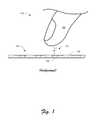
- FIG. 1illustrates a conventional touchpad scenario 100 , which shows a user's finger 102 hovering over a cross-section of a user-interactive portion 104 of a conventional touchpad.
- This portion 104includes a touchsurface 106 and a conventional capacitive touch sensor 108 .
- a region of varying capacitance (i.e., “circuit”) 110lies between the finger 102 and the capacitive touch sensor 108 .
- the finger 102is determined to have “touched” the touchsurface 106 when the capacitance of the circuit 110 exceeds a given threshold, as measured by the sensor 108 .
- the capacitive sensor 108is generally designed to detect the user touching the touchsurface 106 , but, depending on the size, skin humidity, and physiological factors of a user's finger and/or environmental conditions, the point at which the touch is detected can vary widely as the capacitance circuit 110 varies. Indeed, a projected-capacitance touchpad may “detect” a touch before a user has actually touched the touchpad.
- a touchpadis often used much like a mouse of a computer.
- a mousetypically has one or more buttons to indicate performance of a function (i.e., action) associated with a cursor position.
- functionsare called cursor-position associative functions and examples of such include (but are not limited to): menu pull down and selection, icon selection and use, program execution, properties access, and the like.
- cursor-position associative functionsinclude (but are not limited to): menu pull down and selection, icon selection and use, program execution, properties access, and the like.
- Most mouse usersare familiar with single-click, double-click, and right-click, and the corresponding action expected based upon the cursor location on the screen.
- buttonsare equipped with similar buttons to accomplish the same cursor-position associative functions. Instead of, or in addition to, buttons, some touchpads allow the user to indicate the performance of cursor-position associative functions based upon an action or gesture performed on the touchpad itself. For example, a user may indicate a “single-click” once the cursor has arrived at its desired spot by quickly tapping the touchpad. A “double-click” may be accomplished likewise with a double tap. Alternatively, a single or multi-finger gesture may accomplish a similar “mouse click.”
- the described techniquesmay determine the point or region of a user-engagement surface contacted by a user.
- the described techniquesmay also determine a force of the user's finger press on the user-engagement surface using one or more capacitive force-sensors.
- the described techniquesmay offer active tactile feedback (i.e., haptics) to the user's finger touching the user-engagement surface. Such feedback may be provided to enhance the illusion of pressing a displayed button on an on-screen user-interface (UI) of a computer display.
- UIon-screen user-interface
- FIG. 1is elevation view that illustrates a conventional touchpad scenario with a conventional capacitive touch sensor.
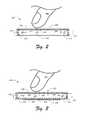
- FIG. 3is an elevation view that illustrates a second implementation of a capacitive force-sensing touchpad configured in accordance with the techniques described herein.
- FIG. 9is a top plan view of a spring plate of the fourth implementation of the capacitive force-sensing touchpad.
- FIG. 10is a cross-sectional side elevation view of the fourth implementation of the capacitive force-sensing touchpad.
- FIGS. 11 and 12are cross-sectional side elevation views of a cutaway of the fourth implementation of the capacitive force-sensing touchpad.
- FIGS. 14 and 15are flow diagrams of one or more exemplary processes, each of which implements the techniques described herein.
- FIG. 16illustrates an exemplary computing environment suitable for one or more implementations of the techniques described herein.
- Described hereinare techniques related to a touchpad with capacitive force sensing.
- one or more of the exemplary force-sensing touchpadsoffer new approaches in determining the X/Y position of a user's finger touching the touchsurface of the touchpad. These new approaches include a determination of the X/Y position of the user's finger touch on the touchsurface by using one or more capacitive force-sensors. In addition, these new approaches also determine the force of the user's finger press on the touchsurface using one or more capacitive force-sensors.
- the force of the finger pressmoves the touchsurface in a “Z” direction (e.g., down) and thus the determination of that force equates to a detection of the “Z position” of the user's finger. Therefore, collectively, the new approaches described herein determine the X/Y/Z position of user's finger on the touchsurface of the exemplary force-sensing touchpad.
- the described exemplary force-sensing touchpadmay offer active tactile feedback (i.e., haptics) to the user's finger touching the touchsurface of the touchpad.
- active tactile feedbacki.e., haptics
- Such feedbackmay be provided to enhance the illusion of pressing a displayed button on an on-screen user-interface (UI) of a computer display.
- UIon-screen user-interface
- the haptics of the touchpadmay provide feedback so that it feels, to the user, as if she can feel the edges of the on-screen button.
- the userpresses the surface a bit harder with the intention to select that on-screen button. She does this without lifting her finger from the touchsurface of the touchpad.
- the host computerthat the touchpad is attached thereto determines that the user has selected the on-screen selectable button. In response to that, the touchpad provides active tactile feedback to the user. In this way, the user gets a satisfying tactile feedback of button press via the touchsurface of the touchpad.
- the exemplary force-sensing touchpaddoes not need extra buttons for the user to perform a single-, double-, or right-click operations of a conventional mouse or touchpad. Similarly, the user does not need to perform some of the conventional awkward gestures or movements to perform such operations.
- touchpador “trackpad” as used herein refers to one or embodiments of the new force-sensing techniques described herein.
- the embodiments of such embodimentsmay be referred to as an “exemplary force-sensing touchpad” or just “exemplary touchpad.” While one or more example embodiments are described herein, the reader should understand that the claimed invention may be practiced using different details than the exemplary ones described herein.
- FIGS. 2-4illustrate three different exemplary force-sensing touchpads.
- Each exemplary touchpadis configured to implement the techniques described herein to detect X/Y/Z finger position and/or provide active tactile (“haptics”) user feedback to the finger.
- hapticsactive tactile
- capacitive force sensingcan be used alone and independent of any haptic actuator without departing from the spirit and scope of claimed subject matter.
- capacitive force sensingcan be used with a haptic actuators described herein or, indeed, any type of haptic actuator without departing from the spirit and scope of claimed subject matter.
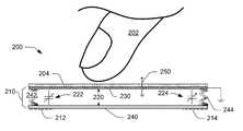
- FIG. 2shows a cross-section of a simplified exemplary force-sensing touchpad 200 that is configured to detect X/Y/Z finger position using the techniques described herein.
- the touchpad 200is configured to detect X/Y finger position using the new techniques described herein and not via conventional approaches.
- the touchpad 200is not configured to provide haptics.
- the exemplary force-sensing touchpad 200includes a touchsurface 204 , a resistance mechanism 210 , and multiple capacitive sensors (as represented by capacitive strips 212 , 214 in FIG. 2 ).
- FIG. 2shows the user's finger 202 hovering over the touchsurface 204 in anticipation of touching the touchsurface.
- the touchsurface 204may also be described as a user-engagement surface presented for contact by the user.
- the resistance mechanism 210holds at least a pair of resistance planes in a spaced-apart position relative to each other with a defined resistance gap 220 therebetween. As depicted, that pair includes an upper resistance plane 230 and a lower resistance plane 240 .
- the upper resistance plane 230is conductive and grounded.
- the resistance mechanism 210also includes a return mechanism (as represented by springs 242 and 244 in FIG. 2 ) that aids in holding the resistance planes apart and also returns the planes back to their original position after they are forced together by the user pressing down on the touchsurface 204 .
- One or more force-sensing capacitive “circuits”are located under the touchsurface 204 .
- traditional capacitive touch sensinginvolves detecting a change in capacitance between a capacitive touch sensor and a user's finger.
- the sensor 108(as shown in FIG. 1 ) detects the changes in the capacitive circuit 110 created by the user's finger 102 . Since the traditional circuit 110 is outside of the device and above the touchsurface 106 , the circuit is variable and unpredictable because of size, skin humidity, and physiological factors of a user's finger and/or environmental conditions. This variability makes detection of precise changes in touch difficult, because the circuit must discern what relative changes in capacitance constitute a touch rather than just environmental influences.
- the capacitive circuits 222 and 224 of the exemplary touchpad 200are located under the touchsurface 204 . This arrangement significantly ameliorates or eliminates variations due to unpredictable external factors. Unlike the conventional approaches (as shown in FIG. 1 ), the user does not act as the ground with the exemplary touchpad 200 .
- the exemplary touchpad 200has a conductive and grounded layer (i.e., “ground plane”) placed above the capacitive sensors to act as the other half of the capacitive circuit.
- the capacitive circuit 222is located between the upper resistance plane 230 and the capacitive strip 212 .
- the capacitive circuit 224is located between the upper resistance plane 230 and the capacitive strip 214 .
- the return mechanism of the resistance mechanism 210resists movement in at least one direction of Z (e.g., down) of the touchsurface 204 .
- the directions of Zare represented by vector arrow 250 .
- the user's finger 202 pressing down on the touchsurface 204typically causes such movement.
- the return mechanismalso urges the touchsurface 204 back to its original position after the user releases the press-down force.
- the capacitive sensorse.g., 212 , 214
- the ground planee.g., upper resistance plane 230
- the space therebetweencreate a capacitor as represented by the capacitive circuits (such as 222 , 224 ). Consequently, a capacitive sensor and at least a portion of the upper resistance plane 230 form a first and second plane (e.g., plate) of a capacitor and thus form a capacitive circuit (e.g., 222 ) therebetween.
- the force of the touchcauses the top layer to move down a distance determined by the overall resistance rate of the resistance mechanism.
- the spring rate of the springs 242 and 244is part of the overall resistance rate.
- the movement caused by the press-down forcechanges the size of the gap 220 between the sensors (e.g., 212 , 214 ) and the ground plane (e.g., 230 ), resulting in a changing capacitance (e.g., of circuits 222 and/or 224 ) that can be measured with a capacitive sensor.
- the exemplary touchpad 200has a sensor topology configured so one or more sensors can also be used to detect X/Y positions as well as Z-position.
- the capacitive sensorcan be a single sensor that is spatially distributed around the edges or corners.
- the capacitive sensorcan be broken up into one or more sensor regions, such as in each corner of a rectangular surface, and each sensor is read independently.
- the force of each sensorcan be combined in an algorithm that can determine the centroid of the force.
- Such an algorithmuses a form of interpolation to find the centroid of force. Using a minimum of three points, this interpolation may be a form of triangulation.
- the touchsurface of a touchpadis typically a rectangle
- at least one implementationemploys a form of interpolation that uses four data points (e.g., force-sensed input), which may be called “quadrangulation.”
- quadrangulationa form of interpolation that uses four data points (e.g., force-sensed input), which may be called “quadrangulation.”
- Those of ordinary skill in the artknow the specific equations used in such a calculation. In the fields of Statics in the mechanical engineering discipline, these equations may be those used for expressing or determining the equilibrium of a rigid body in two-dimensions.
- each force sensorwill have approximately the same reading, but if the user is closer to one corner, that corner will read higher force.
- Calibration of the touch positioncan be done to factor out sensor location variance from unit to unit. Summation of the force from all of the sensor locations results in a similar total force measurement as the basic implementation of this technology.
- the exemplary touchpad 200may determine the X/Y position of the user's finger based upon the change of capacitance of multiple capacitive circuits (like capacitive circuits 222 and 224 ) between each of the multiple capacitive sensors (like sensors 212 and 214 ).
- the capacitive sensorsare spatially distributed under the touchsurface 204 . Based upon the known locations of the sensors and the measured capacitance of the capacitive circuits (e.g., 222 and 224 ), the X/Y position of the finger may be determined by forms of interpolation (e.g., quadrangulation).
- the capacitive circuits 222 and 224change in a predictable manner every time the touchsurface 204 moves.
- the capacitance of the sensorswhen correlated to the known resistance rate, directly relates to the force that the user applies to the touchsurface 204 .
- the capacitive sensorsare equally distributed under the touchsurface (e.g., on the edge or in the corners of the lower resistance plane 240 )
- the forcecan be sensed accurately regardless of where the force is applied.
- the larger the sensor locations arethe higher the sensing accuracy can be, and more precise and balanced resistance rates can improve sensing, as well.
- multiple sensors or sensor regionscan be used to determine one or more force inputs at different locations of the touchsurface 204 .
- Automatic and/or manual calibration between the capacitance and the resistance to movement of the resistance mechanismcan be done to ensure the user has a consistent input experience regardless of orientation or manufacturing tolerances.
- automatic calibrationcan be basic, as in resetting the force sensors to zero on start up, or advanced, as in using an accelerometer to determine operating angle and compensating for the gravity effects of the touchsurface at that angle.
- FIG. 3shows a cross-section of a simplified exemplary force-sensing touchpad 300 that is configured to both detect X/Y/Z finger position and provide haptics using the techniques described herein.
- the exemplary force-sensing touchpad 300includes a touchsurface 304 , an actuation mechanism 310 , and multiple capacitive sensors (as represented by capacitive strips 312 , 314 in FIG. 3 ).
- FIG. 3shows the user's finger 202 hovering over the touchsurface 304 in anticipation of touching the touchsurface.
- the actuation mechanism 310 of the touchpad 300holds at least a pair of planes in a spaced-apart position relative to each other with a defined gap therebetween. That gap is called the defined actuation gap 320 herein.
- the pair of planesincludes an upper actuation plane 330 and a lower actuation plane 340 .
- a dielectric layer 332is located between the planes and a conductive layer 334 is attached to the underside of the lower actuation plane 340 .
- the upper actuation plane 330is conductive and grounded.
- the actuation mechanism 310includes a return mechanism (as represented by springs 342 and 344 in FIG. 3 ) that aids in holding the actuation planes apart and also returns the planes back to their original position after they are forced together by the user pressing down on the touchsurface 304 and after an actuation.
- a return mechanismas represented by springs 342 and 344 in FIG. 3
- One or more force-sensing capacitive “circuits”(such as 322 and 324 ) is located under the touchsurface 304 .
- one or more capacitorsare formed between the upper actuation plane 330 and each of the capacitive sensors (e.g., capacitive strips 312 , 314 ) below the lower actuation plane 340 .
- the upper actuation plane 330 and the capacitive sensorsform the capacitor planes (e.g., first and second planes) of one or more capacitors.
- the exemplary touchpad 300In addition to performing capacitive force-sensing touch detection like the exemplary touchpad 200 , the exemplary touchpad 300 also performs active tactile feedback to the user touching the touchsurface 304 . Many of the same components used to detect capacitive force-sensing touch may also be used to perform the actuation for the tactile feedback. Of course, in alternative implementations, different and separate components may perform each of the capacitive force-sensing touch detection and the actuation for the tactile feedback.
- the conductive layer 334can occupy the center of that lower plane and be utilized as a high voltage electrode of an electrostatic actuation subsystem.
- either conductive layermay be a film or layer of particles applied to a substrate, such as indium tin oxide (ITO).
- ITOindium tin oxide
- the ground layer of the upper surfacecan act as the ground in the electrostatic actuation.
- Force-measuring capacitive touch technologycan be implemented to provide tactile feedback to simulate any number of tactile responses.
- a capacitive force detection sensorcan be operably associated with a haptic actuator to provide haptic feedback.
- capacitive force detectioncan be implemented to trigger one or more tactile responses based on one or more force thresholds. For example, when typing on an on-screen keyboard, snap-over may be simulated by triggering a haptic response when a “press” force threshold (such as sixty grams) is exceeded. Alternately or additionally, in at least some embodiments, another haptic response may be triggered when a “release” force threshold (such as forty grams) is traversed.
- a “press” force thresholdsuch as sixty grams
- another haptic responsemay be triggered when a “release” force threshold (such as forty grams) is traversed.
- configuring a capacitive force sensor with a hysteresis of one or more thresholds for triggering haptic responsecan result in haptic feedback profiles suitable for key snap-over and button/switch position clicks.
- a haptic actuator operably coupled to a capacitive force sensormay be implemented to provide a tactile feedback profile similar to a traditional keyboard dome snap over (e.g., break force, return force).
- force measuring capacitive technologymay be implemented in part by a microcontroller capable of executing processor-executable instructions stored on processor-readable storage media.
- the microcontrolleris operably coupled to at least a capacitive sensor or a haptic actuation logic.
- the processor-executable instructionsmay be executable to provide a variety of functionality including, by way of example and not limitation, calibration functions, signal/input filtering, force threshold detection, and/or haptic feedback, to name a few.
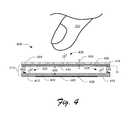
- FIG. 4shows a cross-section of a simplified exemplary force-sensing touchpad 400 that is configured to provide haptics using the techniques described herein. While the touchpad 400 is configured to detect the Z finger position using the new techniques described herein, it is configured to detect X/Y finger position using conventional approaches, such as conventional resistive, capacitive, and/or optical touch sensors. As depicted in FIG. 4 , the touchpad 400 uses a conventional capacitive touch sensor to detect X/Y finger position.
- the touchpad 400 of FIG. 4illustrates an example of incorporating the new-force sensing technology described herein with products and solutions that use existing touch-position detection technology.
- This approachallows for a much greater level of user interactivity than the conventional approach alone. With this approach, a casual and inadvertent slight touch can be ignored. Instead, only a purposeful touch applied with at least a measured force exceeding a defined amount will trigger a response from the host device (which the touchpad is attached thereto) with this approach incorporated therein.
- the exemplary force-sensing touchpad 400includes a touchsurface 404 , a capacitive touch sensor 406 , an actuation mechanism 410 , a sensor-actuator separator layer 416 and multiple capacitive sensors (as represented by capacitive strips 412 , 414 in FIG. 4 ).
- FIG. 4shows the user's finger 202 hovering over the touchsurface 404 in anticipation of touching the touchsurface.
- the actuation mechanism 410 of the touchpad 400is constructed like, and functions like, the actuation mechanism 310 of the touchpad 300 described above.
- the actuation mechanismincludes at least a pair of spaced-apart planes, which are an upper and a lower actuation plane 430 and 440 , respectively.
- the planesare held apart by a return mechanism, as represented in FIG. 4 as springs 442 and 444 .
- the return mechanismalso returns the planes back to their original position after an actuation and/or movement in the Z direction.
- a defined actuation gap 420 and in that gapare an air space and a dielectric 432 .
- a conductive layer 434is attached to the underside of the lower actuation plane 440 between the multiple capacitive sensors (e.g., capacitive strips 412 , 414 ).
- the force-measuring capacitive touch technology(which includes one or more capacitive sensors, such as strips 412 , 414 ) detects movement of the touchsurface 404 in the Z direction by a change in one or more capacitive circuits (such as circuits 422 and 424 ).
- the Z directionis represented by Z vector arrow 450 .
- one or more capacitorsare formed between the upper actuation plane 430 and each of the capacitive sensors (e.g., capacitive strips 412 , 414 ) below the lower actuation plane 440 .
- the upper actuation plane 430 and the capacitive sensorsform the capacitor planes (e.g., first and second planes) of one or more capacitors.
- the touchpad 400provides active tactile feedback via its actuation mechanism, namely mechanism 410 . Also, like the touchpad 300 , the touchpad 400 detects the Z position of the user's finger 202 pressing down on the touchsurface 404 using its force-measuring capacitive touch technology (which includes one or more capacitive sensors, such as strips 412 , 414 ).
- this touchpad 400detects the X/Y position of the user's finger 202 using some other touch sensing approach. That other approach may include conventional and future approaches. Examples of conventional approaches that may be used for X/Y detection include (but are not limited to): resistive, capacitive, and/or optical touch sensors. As depicted, the touchpad 400 uses the capacitive touch sensor 406 and, consequently, there is a capacitive circuit 408 between the sensor 406 and the user's finger 202 .
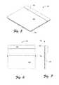
- FIGS. 5-7offer three different views of an exemplary force-sensing touchpad 500 that is configured to implement the techniques described herein to detect X/Y/Z finger position and/or provide active tactile user feedback to a user's finger touching the touchpad.
- FIG. 5is an isometric view of the exemplary force-sensing touchpad 500 .
- FIG. 6is top plan view of the touchpad 500 .
- FIG. 7is a side elevation view of the touchpad 500 .
- the exemplary force-sensing touchpad 500includes a top cap 502 , a touchsurface 504 , and a housing base 506 .
- the touchsurface 504may also be described as a user-engagement surface presented for contact by the user.
- the top cap 502 and the housing base 506form, at least in part, the housing or chassis of the touchpad 500 .
- the exemplary force-sensing touchpad 500includes an electro-mechanical movement-effecting mechanism designed to move an electronically conductive plane using electrostatic forces. This movement is designed to provide active tactile feedback to the user's finger touching the touchsurface 504 .
- the electronically conductive planeis moved in one or more directions that are towards and/or away from the touchsurface 504 .
- FIG. 8shows an exploded view of an exemplary assembly 800 of the touchpad 800 .
- the exemplary assembly 800includes the top cap 502 , the touchsurface 504 , a sensor board 802 , an actuation mechanism 804 , a spacer 806 , a controller board 808 , and the housing base 506 .
- the exemplary assembly 800 of the exemplary force-sensing touchpad 800is one example of how the touchpad described herein may be assembled within the scope of the claims appended hereto.
- the top cap 502is an ornamental and functional cover and bezel.
- the touchsurface 504is the touch-sensitive surface presented to the user for contact therewith.
- the sensor board 802includes one or more force-sensing capacitance sensors that are configured to measure a change in capacitance that is calibrated with defined forces applied to the touchsurface 504 .
- the touchpad 500may determine the X/Y position of the user's finger on the touchsurface 504 by calculating the centroid of force based upon the varying input from the sensors.
- the touchpad 500may also determine the Z position of the user's finger.
- the Z positionrelates to the displacement of the touchsurface 504 to and from its original position (before a user presses down on it). With that displacement calibrated to a defined force scale, the force that the user applies to the touchsurface 504 can be determined.
- the spacer 806is an inert material filling space between the actuation mechanism 804 and the housing base 506 .
- the controller board 808includes logic to handle and manage various aspects of the touchpad 500 functionality, such as the sensors of the sensor board 802 and driving the actuation mechanism 804 .
- the actuation mechanism 804provides the active tactile feedback (i.e., haptics) to the user.
- the actuation mechanism 804includes an upper actuation plane 810 , a return mechanism, a dielectric layer 818 , and a lower actuation plane 820 .
- the actuation mechanism 804holds at least a pair of electrically conductive planes (e.g., upper actuation plane 810 and lower actuation plane 820 ) in a spaced-apart position with a defined gap therebetween.
- the upper actuation plane 810is an electrically conductive plane of sheet metal.
- the lower actuation plane 820is an electrically conductive film adhered to the spacer 806 .
- the return mechanismis represented herein by leaf springs 812 , 813 , 814 , 815 , 816 that are built into the upper actuation plane 810 .
- the return mechanismis operably associated with (e.g., integrated with, connected to, or coupled to) at least one of the pair of actuation planes (e.g., upper actuation plane 810 and lower actuation plane 820 ).
- the return mechanismis designed to return the pair of planes, after a movement of the planes relative to each other, back to the spaced-apart position relative to each other and restore the defined gap therebetween. That is, the return mechanism restores the defined gap between the actuation planes.
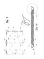
- FIG. 9shows the upper actuation plane 810 alone.
- leaf springs 812 , 813 , 814 , 815 , 816 , 902 , 903 , and 904Integrated into the perimeter of the upper actuation plane 810 are leaf springs 812 , 813 , 814 , 815 , 816 , 902 , 903 , and 904 .
- the upper actuation plane 810 with integrated leaf springsmay also be called a “spring plate.”
- Each of the leaf springs( 812 , 813 , 814 , 815 , 816 , 902 , 903 , and 904 ) has a hole with which the upper actuation plane 810 is rigidly mounted to the housing base 506 (directly or indirectly). In doing this, the interior of the upper actuation plane 810 may move up and down while the leaf springs remain affixed and unmoving.
- the spring plate 810includes air vents, such as vents 906 and 908 , and touchsurface-mounting spaces, such as spaces 910 and 912 .
- the air vents (such as vents 906 and 908 ) in the spring-plate/upper-actuation-plane 810allows for the rapid evacuation of air from an air gap between the pair of actuation planes during the actuation and for the rapid re-introduction of air during the return/reset of the actuation mechanism 804 .
- the touchsurface-mounting spaces, such as spaces 910 and 912are where the spring-plate/upper-actuation-plane 810 is rigidly mounted to the touchsurface 504 above. In this way, the spring-plate/upper-actuation-plane 810 will move (e.g., up and down) in response to the user pressing on the touchsurface 504 .
- the exemplary assembly 800also includes a return stop that is firmly attached to the housing/chassis of the touchpad and is designed to stop the upward movement of the upper actuation plane 810 on its return from actuation. That upward movement is typically caused by the return mechanism urging the upper actuation plane back to its original position after actuation is released.
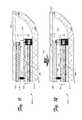
- FIG. 10is a cross-section of the exemplary assembly 800 of the exemplary force-sensing touchpad 500 along line A-A shown in FIG. 6 .
- the user's finger 202is shown in FIG. 10 hovering over the touchsurface 504 .
- FIG. 11shows an enlargement of a circled portion 1002 of the assembly 800 in FIG. 10 .
- the exemplary assembly 800includes the touchsurface 504 , the sensor board 802 , the actuation mechanism 804 , the spacer 806 , and the housing base 506 .
- a touchsurface-movement clearance 1102 between the touchsurface 504 and the housing base 506gives the touchsurface 504 room to move relative to the base in a Z direction (as indicated by Z-direction vector 1103 ).
- the sensor board 802includes at least one capacitance-sensing strip 1104 , but in other implementations, the board may include multiple strips, which are strategically deployed across the board.
- the actuation mechanism 804includes the upper actuation plane 810 , the dielectric layer 818 , and the lower actuation plane 820 .
- the upper actuation plane 810is grounded (as shown) while the lower actuation plane 820 is charged or electrically active when the actuation mechanism 804 is activated.
- the actuation mechanism 804is designed to permit at least one of the actuation planes to move relative to the other. This movement is effective to provide tactile feedback to the user when, for example, the user presses down on the touchsurface 504 . This movement may be in response to the performance of a defined on-screen action.
- Each of the planes 810 , 820has conductive properties. Each plane may be inherently conductive or have, support, include, or otherwise integrate a layer of conductive material.
- the upper actuation plane 810is mounted (either directly or indirectly) to both the touchsurface 504 and the housing base 506 .
- the upper actuation plane 810is rigidly mounted to the touchsurface 504 indirectly by being rigidly mounted to the sensor board 802 , which itself it rigidly connected to the touchsurface.
- the mounting bracket 1106 and other bracketsattach to the upper actuation plane 810 via mounting-bracket spaces, such as spaces 910 and 912 (as shown in FIG. 9 ).
- the built-in leaf springs(such as spring 813 ) are rigidly mounted to the housing base 506 via base-mounting brackets, such as base-mounting bracket 1108 .
- the interior of the upper actuation plane 810may move relative to the lower actuation plane 820 while the built-in leaf springs (such as spring 813 ) remains affixed to the base 506 via its base-mounting brackets (e.g., bracket 1108 ).
- the built-in leaf springs(which are the return mechanism) will return the upper actuation plane 810 back to its original position once force is no longer applied to the upper actuation plane 810 .
- Such forcemay be from the actuation and/or from the user pressing down on the touchsurface 504 .
- the actuation mechanism 804is configured to provide tactile feedback to a user responsive to a user performing an action, such as pressing down on the touchsurface 504 .
- the actuation mechanism 804includes at least two spaced-apart planes (e.g., upper actuation plane 810 and lower actuation plane 820 ).
- the actuation mechanismholds this pair of planes in a spaced-apart position relative to each other and with the defined actuation gap 1110 therebetween.
- the defined actuation gap 1110defines the distance that the planes 810 , 820 are spaced apart.
- the defined actuation gap 1110is substantially smaller than the width of the expanse of the planes.
- the defined actuation gap 1110is one micron to one centimeter. In other implementations, the defined actuation gap 1110 is two tenths of a millimeter to two millimeters.
- a defined capacitance-sensing gap 1114is located between the capacitance-sensing strip 1104 and the grounded mounted leaf spring 813 .
- a capacitive circuit 1116is formed in the capacitance-sensing gap 1114 between the strip 1104 and the grounded spring 813 .
- a capacitoris formed with the capacitive circuit 1116 therebetween. In this way, the capacitance-sensing strip 1104 and the grounded mounted leaf spring 813 form the capacitor planes (e.g., first and second planes) of one or more capacitors of the exemplary touchpad 500 .
- the capacitance-sensing gap 1104decreases and the capacitance circuit 1116 changes accordingly.
- the change in the capacitance circuit 1116corresponds with the force applied by the user's finger to the touchsurface 504 that causes displacement of the touchsurface 504 in the Z direction. Via programming and configuration, that displacement force is calibrated to the change in the capacitance circuit.
- the force-sensing logic of the controller board 808handles the data storage, programming, configuration, customization and management of the force sensing itself.
- FIG. 12shows that same circled portion 1002 and the same components of FIG. 11 .
- the components of FIG. 12are oriented in response to a downward force (as indicated by force vector 1202 ) applied to the touchsurface 504 by, for example, a user's finger.
- the key differences between FIGS. 11 and 12include a decrease in following cavities: the touchsurface-movement clearance 1102 , defined actuation gap 1110 , air space 1112 , and defined capacitance gap 1114 . These cavities all decreased in response to the downward force on the touchsurface 504 .
- the upper actuation plane 810is lower than it was illustrated in FIG. 11 and the built-in leaf spring 813 is flexed.
- the return mechanism(as represented by the built-in leaf springs here, such as spring 813 ) return the upper actuation plane 810 to its original position and restores all of the cavities ( 1102 , 1110 , 1112 , 1114 ) back to their original position (as shown in FIG. 11 ).
- FIG. 13illustrates some exemplary components in accordance with one or more embodiments of the force-sensing technology described herein, such as an exemplary force-sensing haptic touchpad 1300 .
- the exemplary touchpad 1300includes touchpad mechanics 1310 , a sensor module 1320 , an active-feedback actuation module 1330 , touchpad logic 1340 , a communication module 1350 , and a backlighting system 1360 .
- the touchpad mechanics 1310includes the mechanical components of the exemplary touchpad 1300 that are not part of the other components described as part of this exemplary touchpad.
- such componentsmay include (but are not limited to): a housing and a touchsurface.
- the sensor module 1320is configured to determine the X/Y/Z position of a user's finger on the touchsurface of the touchpad 1300 .
- the sensor module 1320includes force-sensing capacitive sensors 1322 and sensor logic 1324 .
- the sensor module 1320also includes circuitry operatively connecting the sensors 1320 to the sensor logic 1322 .
- the herein-described multiple force-sensing capacitive sensors(such as the capacitive strips shown in FIGS. 2, 3, 4, 11, and 12 ) are examples of the force-sensing capacitive sensors 1322 .
- the sensor module 1320may be described as a capacitive force-sensing module that is operably associated with the touchsurface. It may also be described as including at least one capacitor having at least two capacitor planes. Examples of such planes include capacitance-sensing strip 1104 and the grounded mounted leaf spring 813 as shown in FIGS. 11 and 12 . At least one of the planes (e.g., capacitance-sensing strip 1104 ) is operatively associated with the touchsurface (e.g., touchsurface 504 ). That is, movement in the Z-direction of the touchsurface moves one of the planes (e.g., capacitance-sensing strip 1104 ) in a corresponding manner.
- the touchsurfacee.g., touchsurface 504
- the sensor module 1320includes at least one capacitive sensor configured to sense a change in capacitance of the capacitor formed by the two planes.
- the change in capacitanceis caused at least in part by movement of at least one of the capacitor planes (e.g., capacitance-sensing strip 1104 ) relative to the other of the plane (e.g., leaf spring 813 ) effective enough to determine a force applied to the touchsurface.
- one or more capacitive sensorsinclude or are operatively coupled to at least one of the capacitor planes (e.g., capacitance-sensing strip 1104 ).
- the sensor module 1320may also include conventional touch sensing technology to detect the X/Y position of a user's finger on the touchsurface.
- the force-sensing capacitive sensors 1322may be used to detect the Z position of the user's finger on the touchsurface. That is, the force-sensing capacitive sensors 1322 may determine the force that the user applies to the touchsurface.
- the sensor modulemay be of the design where a capacitive sense matrix is underneath a flexible top surface such that X/Y position and Z force of a finger or multiple fingers can be determined from a user's interaction with the touchsurface.
- the sensor logic 1324receives the force-sensing signals from the force-sensing capacitive sensors 1322 (and perhaps other conventional touch sensors) and responds accordingly to send signals to the touchpad logic 1340 and/or actuation drive logic 1334 of the active-feedback actuation module 1330 .
- the active-feedback actuation module 1330includes an actuation mechanism 1332 and the actuation drive logic 1334 .
- the actuation drive mechanism 1332corresponds, in this example, to the actuation mechanisms depicted in FIGS. 3, 4, 8, 11, and 12 .
- the actuation drive logic 1334fires the actuation mechanism 1332 with the appropriate timing and characteristics.
- the actuation drive logic 1334is designed to drive the actuation planes, which have conductive properties, with an electrical signal to cause the permitted movement of at least one of the planes relative to the other of the planes effective to provide tactile feedback to the user.
- a combination of the actuation drive logic 1334 and at least a portion of the sensor logic 1324may be called a haptic logic 1370 .
- the haptic logic 1370may be a component that replaces some or all of the functionality of the actuation drive logic 1334 and the sensor logic 1324 .
- the touchpad logic 1340interprets the signals sent from the sensor logic 1324 to determine the X/Y/Z position of the user's finger on the touchsurface.
- the touchpad logic 1340sends that determination to the host computer via the communication module 1350 .
- the backlighting system 1360includes one or more lighting elements that are positioned so a user, through a transparent and/or translucent touchsurface, can see the light. In some implementations, the backlighting system 1360 may be designed to light specific areas of the touchsurface.
- any suitable hardware, software, and/or firmwarecan be used to implement the sensor logic 1324 , the actuation drive logic 1334 , the touchpad logic 1340 , the haptics logic 1370 , and the communication module 1350 .
- a usercan rollover or browse icons with a light-force, purposeful touch to enlarge icons for better visibility. Then, with the icon enlarged, a harder press by the user activates that icon. Alternately or additionally, interaction with icons can be force dependent. For example, pressing lightly may allow a user to drag and drop an icon, while pressing harder may open a menu of associated actions that can be performed in relation to the file or program linked to the icon.
- a haptic actuatorsuch as an electrostatic haptic actuator with integrated capacitive force sensor components like that shown in FIGS. 3-12
- a display screene.g., a liquid crystal display (LCD)
- LCDliquid crystal display
- a sheet metal backer of the LCDcan be used as a grounded conductive layer for capacitive force sensing and/or electrostatic haptic feedback.
- An existing sensor located proximate the surface of the device's display screencould be used to determine X/Y position.
- the electrostatic actuator with integrated capacitive force sensorcould be implemented to provide force detection and haptic feedback for user interaction, such as, by way of example and not limitation, on-screen typing, gaming, and internet browsing.
- the devicecould automatically adjust the activation pressure threshold based on the vibrations it detects, so when a user is jogging or driving on a rough road, the screen could increase the required force to activate, so that light, accidental bumps do not cause random presses.
- an inductive-proximity sensing drawing tablet or input devicesuch as that offered by WacomTM.
- the traditional capacitive-sensing technologycan be used for the X/Y location
- the new force-sensing technologycan be used for the Z-direction force (and possibly X/Y touch area)
- the inductive-proximity sensingcan be used to detect the angle of the pen to allow 4-dimensional data collection. This could be used in a digital image manipulation application to change the size, flow, and position of the brush tool at the same time.
- force measuring capacitive touch technologycan be implemented to provide redundant switch mechanisms to reduce accidental selections, interactions, and/or software triggers.
- a touch screen medical devicemay require an on-screen key to be pressed with a certain force before triggering a corresponding software event.
- an on-screen switch or knob of a touch screen control panelmay be configured with a force threshold for changing a position/selection.
- a screen lock on a mobile touch screen device enabled with force measuring capacitive touch technologymay be configured to require a user to press and hold an onscreen button/key with at least a certain amount of force before displaying an interactive gesture driven lock mechanism (e.g. slide, tap, or motion to unlock) to the user.
- an interactive gesture driven lock mechanisme.g. slide, tap, or motion to unlock
- capacitive force sensing technologycan be implemented in existing input devices, such as mice or track ball devices.
- capacitive force sensing technologymay be implemented in support structures associated with an input device, such as mouse pads.
- buttons or surfaces of a mousecould be configured to detect force, allowing a user to interact with UI elements or applications differently depending on force applied to various area and/or buttons of a mouse.
- changing mouse/pointer speedcould be a function based on force applied to a surface of a mouse.
- a button of a mouse or trackball devicecould be configured to provide a wide variety of functionality based on varying force applied to the button. In some instances this could lead to a reduction of buttons, as functions of buttons may be combined and utilized based on varying levels of force instead of requiring individual switches for each button.
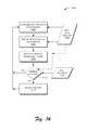
- FIGS. 14 and 15are flow diagrams illustrating exemplary processes 1400 and 1500 that implement the techniques described herein for the new capacitive force-sensing touchpad technology.
- FIG. 14illustrates the example process 1400 for detecting X/Y/Z position of a user's finger on the touchsurface of a touchpad and performing an active tactile feedback by that touchpad.
- the process 1400is performed, at least in part, by a touchpad, which includes, for example, the exemplary force-sensing touchpads shown in FIGS. 3-8 and 10-13 and described herein.
- the touchpadmay use the new techniques described herein for determining the X/Y position based upon triangulation and/or interpolation of force-sensing capacitance changes as measured by multiple capacitive sensors/springs strategically located across the landscape under the touchsurface.
- the touchpadmay employ conventional or some future touch sensing technology to locate the X/Y position of the user's finger on the touchsurface.
- the touchpaddetermines the Z position of the user's finger on the touchsurface of the touchpad. That is, the touchpad determines the amount of deflection of the touchsurface caused by the user pressing down thereon.
- the touchpadmakes this determination based upon input from one or more of its force-sensing sensors as indicated at 1404 .
- the deflection of the touchsurfacecauses the measured capacitance of the one or more force-sensing sensors to change accordingly.
- the forceis determined based upon a known, specified, predefined, previously determined, and/or calculated correspondence between capacitance, deflection, and resistance (i.e., spring bias) of the touchpad's resistance mechanism or actuation mechanism.
- the range of finger-press force (applied by the user's finger) on the touchsurfaceis typically between 10-150 grams of force.
- the touchpadsends the X/Y/Z position information to a host device (e.g., a connected computer).
- a host devicee.g., a connected computer
- the host deviceoften directs the navigation of an on-screen cursor for user interactivity with the host device.
- the Z-position informationmay be used for many purposes including (for the purpose of illustration only and not limitation): icon selection (like a single-click of a mouse), icon activation (like a double-click), icon interaction (like a right-click), or other actions (such as drag-and-drop).
- the touchpaddetermines whether to trigger the actuator. If not, then the process 1400 returns back to the X/Y determination operation 1402 . If so, then the process moves onto the operation 1414 .
- the touchpadobtains input from the host device (as indicted at 1412 ) and/or it alternatively obtains input from the touch-sensing and/or force-sensing sensors at 1404 (as indicated by a dashed line between 1404 and 1410 ).
- the touchpadmay simply follow the direction of the host and trigger the actuation mechanism when directed to do so.
- the touchpadmay trigger the actuation mechanism only when the host input permits it.
- the touchpadmay make a triggering decision without regard to input from the host. When the touchpad makes a triggering decision itself (with or without input from the host), it may do so at least in part based upon input from one or more of its touch-sensing or force-sensing sensors as indicated at 1404 .
- the touchpadmay decide to trigger the actuation mechanism if the host input indicates that the on-screen cursor is over a selectable icon based upon the X/Y position of the user's finger on the touchsurface and the input from the force-sensing sensors indicate an increase in the force with which the user is pressing down on the touchpad.
- the actuation mechanismmay be triggered at a force of 20 to 120 grams during the downward finger press. In other implementations, the actuation mechanism may be triggered at a force of 40 to 80 grams during the downward finger press. In some implementations, the actuation mechanism may be triggered at a force of 5 to 50 grams during the upward finger release. In other implementations, the actuation mechanism may be triggered at a force of 10 to 30 grams during the downward finger press.
- a determination to trigger the actuation mechanismis based, at least in part, upon the circumstances and conditions of the finger press.
- the circumstances and conditionsmay be part of a haptic profile.
- a determination to trigger the actuation mechanismmay be made during the downward motion of the finger press and at one or more specified forces.
- a determination to trigger the actuation mechanismmay be made during the upward motion of the finger press and at one or more specified forces.
- the actuation mechanismmay be triggered multiple times.
- the actuation mechanismmay be triggered once during the downward finger press and once during the upward finger press.
- the haptic profilemay indicate that a decision be made to repeatedly and/or periodically trigger the actuation mechanism until, of course, the user lifts his finger.
- the actuation mechanismmay be triggered once when the on-screen cursor (as directed by the user's X/Y position movements on the touchsurface) rolls over an icon. Once over that icon, the actuation mechanism may be triggered twice when the user selects that icon by pressing down harder at the point on the touchsurface.
- the actuation mechanismis triggered in response to a determination at operation 1412 to do so.
- factorsinclude (but are not limited to): amount of voltage, rate of application of that voltage, how long the actuation is held, when the actuation is released, the rate of the release of the actuation voltage, etc.
- factorsinclude (but are not limited to): amount of voltage, rate of application of that voltage, how long the actuation is held, when the actuation is released, the rate of the release of the actuation voltage, etc.
- different combination of the factorsmay be utilized in a given actuation.
- the process 1400continues as long as the touchpad is active and in use.
- a particular haptic profilemay be set at anytime without halting process 1400 .
- Process 1400could proceed directly from the force-determination operation at 1406 to the actuation-triggering operations 1410 in a “passive” mode where everything is handled at the controller level and the decision to trigger or not is based on a predefined threshold in memory.
- An alternative processcould feed all the X/Y/Z input data to the host and then have the host exclusively decide when to perform the operations of 1408 , 1412 , and/or 1414 .
- FIG. 15illustrates the example process 1500 for user interactivity utilizing a touchpad with the new force-sensing technology described herein.
- a computing deviceperforms the process 1500 , at least in part.
- the computing devicemoves an on-screen cursor in accordance with and corresponding to the X/Y position information of the received X/Y/Z input data 1504 .
- This actionis, at least in part, like the typical action of coordinating the input from a pointing device to cursor movements of an on-screen user interface.
- the computing devicedetermines whether the on-screen cursor is located over an active area of the user-interface.
- An active areaincludes (but is not limited to): icons, balloons, check boxes, command buttons, command links, drop-down lists and combo boxes, links, list boxes, list views, notifications, progress bars, progressive disclosure controls, radio buttons, search boxes, sliders, spin controls, status bars, tabs, text boxes, tooltips, infotips, tree views, window frames, menus, toolbars, ribbons, etc. If the on-screen cursor is not located over an active area, then the process returns back to the beginning, which is the operation 1502 .
- Audio feedbackmay include (by way of example and not limitation): a beep, sound effect, or musical tones.
- Visual feedbackmay include (by way of example and not limitation): changes of color, visual effects (e.g., blinking), shadowing, or other on-screen visual changes in the user interface.
- Tactile feedbackmay include (by way of example and not limitation): one or more triggerings of the haptic actuator of the touchpad.
- the computing devicemay direct the touchpad to deliver a single actuation when the cursor rolls over the icon and another when the user rolls off the icon. In this way, the user effectively “feels” an edge to the icon as she rolls on and off the icon. Therefore, the user gets additional confirmation when the cursor is over a selectable icon.
- the computing devicedetermines whether the Z position information of the received X/Y/Z input data 1504 exceeds one or more thresholds (e.g., 40 g, 60 g, 80 g, and 100 g). That is, does input data from the touchpad indicate that the user is pressing down on the touchsurface hard enough to trigger a response thereto? If not, then the process returns back to operation 1502 . If so, then the process proceeds to the next operation.
- one or more thresholdse.g. 40 g, 60 g, 80 g, and 100 g.
- the computing deviceperforms one or more associated actions (such as executing an application on the computing device).
- the specific associated action performedmay depend upon many factors (such as on-screen context and proximity of the cursor, amount much force applied by the user, and timing of the application of that force).
- Associated actionsmay include (by way of example only and not limitation): accessing a file, menu pull down, menu selection, icon selection, program execution, properties access, single-click type function, double-click type function, and right-click type function, viewing and/or selecting balloons, viewing and/or selecting check boxes, selecting a command button, selecting a command link, dropping down a drop-down list and/or combo boxes, opening a link, viewing and/or selecting list boxes, viewing and/or selecting list views, viewing and/or selecting notifications, viewing and/or selecting progress bars, viewing and/or selecting progressive disclosure controls, viewing and/or selecting radio buttons, viewing and/or selecting search boxes, viewing and/or selecting sliders, viewing and/or selecting spin controls, viewing and/or selecting status bars, viewing and/or selecting tabs, viewing and/or selecting text boxes, viewing and/or selecting tooltips, viewing and/or selecting infotips, viewing and/or selecting tree views, viewing and/or selecting windows, viewing and/or selecting menus, viewing and/or selecting toolbars, viewing and/or
- the computing deviceprovides additional user feedback.
- Such feedbackmay include audio, visual, and/or tactile aspects. Then the process returns to operation 1502 .
- the usermay simply press harder on the touchsurface to take further action based upon that icon.
- the userneed not lift her finger to click on a button. Rather the user may keep her finger on the touchsurface and indicate her desire to select the icon by pressing harder.
- how hard the user pressesmay indicate different choices. For example, pressing at least one low level (e.g., 40 grams) indicates a single-click, pressing a bit harder (e.g., 60 grams) indicates a double-click, and even harder (e.g., 80 grams) may mean a right-click.
- interaction with icons and other active areascan be force dependent. For example, pressing lightly may allow a user to drag and drop an icon, while pressing harder may open a menu of associated actions that can be performed in relation to the file or program linked to the icon.
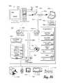
- FIG. 16illustrates an example of a suitable computing environment 1600 within which one or more implementations, as described herein, may be implemented (either fully or partially).
- the exemplary computing environment 1600is only one example of a computing environment and is not intended to suggest any limitation as to the scope of use or functionality of the computer and network architectures. Neither should the computing environment 1600 be interpreted as having any dependency or requirement relating to any one or combination of components illustrated in the exemplary computing environment 1600 .
- program modulesinclude routines, programs, objects, components, data structures, etc. that perform particular tasks or implement particular abstract data types.
- the computing environment 1600includes a general-purpose computing device in the form of a computer 1602 .
- the components of computer 1602may include, but are not limited to, one or more processors or processing units 1604 , a system memory 1606 , and a system bus 1608 that couples various system components, including the processor 1604 , to the system memory 1606 .
- the system bus 1608represents one or more of any of several types of bus structures, including a memory bus or memory controller, a peripheral bus, an accelerated graphics port, and a processor or local bus using any of a variety of bus architectures.
- Computer 1602typically includes a variety of processor-readable media. Such media may be any available media that is accessible by computer 1602 and includes both volatile and non-volatile media, removable and non-removable media.
- the system memory 1606includes processor-readable media in the form of volatile memory, such as random access memory (RAM) 1610 , and/or non-volatile memory, such as read only memory (ROM) 1612 .
- RAMrandom access memory
- ROMread only memory
- a basic input/output system (BIOS) 1614containing the basic routines that help to transfer information between elements within computer 1602 , such as during start-up, is stored in ROM 1612 .
- BIOSbasic input/output system
- RAM 1610typically contains data and/or program modules that are immediately accessible to and/or presently operated on by the processing unit 1604 .
- Computer 1602may also include other removable/non-removable, volatile/non-volatile computer storage media.
- FIG. 16illustrates a hard disk drive 1616 for reading from and writing to a non-removable, non-volatile magnetic media (not shown), a magnetic disk drive 1618 for reading from and writing to a removable, non-volatile flash memory data storage device 1620 (e.g., a “flash drive”), and an optical disk drive 1622 for reading from and/or writing to a removable, non-volatile optical disk 1624 such as a CD-ROM, DVD-ROM, or other optical media.
- a hard disk drive 1616for reading from and writing to a non-removable, non-volatile magnetic media (not shown)
- a magnetic disk drive 1618for reading from and writing to a removable, non-volatile flash memory data storage device 1620 (e.g., a “flash drive”)
- an optical disk drive 1622for reading from and/or writing to a removable, non
- the hard disk drive 1616 , flash drive 1618 , and optical disk drive 1622are each connected to the system bus 1608 by one or more data media interfaces 1626 .
- the hard disk drive 1616 , magnetic disk drive 1618 , and optical disk drive 1622may be connected to the system bus 1608 by one or more interfaces (not shown).
- the drives and their associated processor-readable mediaprovide non-volatile storage of processor-readable instructions, data structures, program modules, and other data for computer 1602 .
- a hard disk 1616a removable magnetic disk 1620 , and a removable optical disk 1624
- processor-readable mediawhich may store data that is accessible by a computer, such as magnetic cassettes or other magnetic storage devices, flash memory cards, floppy disks, compact disk-(CD-), digital versatile disks (DVD) or other optical storage, random access memories (RAM), read only memories (ROM), electrically erasable programmable read-only memory (EEPROM), and the like, may also be utilized to implement the exemplary computing system and environment.
- RAMrandom access memories
- ROMread only memories
- EEPROMelectrically erasable programmable read-only memory
- Any number of program modulesmay be stored on the hard disk 1616 , magnetic disk 1620 , optical disk 1624 , ROM 1612 , and/or RAM 1610 , including, by way of example, an operating system 1628 , one or more application programs 1630 , other program modules 1632 , and program data 1634 .
- a usermay enter commands and information into computer 1602 via input devices such as a keyboard 1636 and one or more pointing devices, such as mouse 1638 or touchpad 1640 .
- Other input devices 1638may include a microphone, joystick, game pad, satellite dish, serial port, scanner, and/or the like.
- input/output interfaces 1642are coupled to the system bus 1608 , but may be connected by other interfaces and bus structures, such as a parallel port, game port, or a universal serial bus (USB).
- a monitor 1644 or other type of display devicemay also be connected to the system bus 1608 via an interface, such as a video adapter 1646 .
- other output peripheral devicesmay include components, such as speakers (not shown) and a printer 1648 , which may be connected to computer 1602 via the input/output interfaces 1642 .
- Computer 1602may operate in a networked environment using logical connections to one or more remote computers, such as a remote computing device 1650 .
- the remote computing device 1650may be a personal computer, portable computer, a server, a router, a network computer, a peer device or other common network node, and the like.
- the remote computing device 1650is illustrated as a portable computer that may include many or all of the elements and features described herein, relative to computer 1602 .
- the remote computing device 1650may have remote application programs 1658 running thereon.
- Logical connections between computer 1602 and the remote computer 1650are depicted as a local area network (LAN) 1652 and a general wide area network (WAN) 1654 .
- LANlocal area network
- WANwide area network
- Such networking environmentsare commonplace in offices, enterprise-wide computer networks, intranets, and the Internet.
- the computer 1602When implemented in a LAN networking environment, the computer 1602 is connected to a wired or wireless local network 1652 via a network interface or adapter 1656 . When implemented in a WAN networking environment, the computer 1602 typically includes some means for establishing communications over the wide network 1654 . It is to be appreciated that the illustrated network connections are exemplary and that other means of establishing communication link(s) between the computers 1602 and 1650 may be employed.
- program modules depicted relative to the computer 1602may be stored in a remote memory storage device.
- touchsurfacerefers to the touch-sensitive surface that the exemplary touchpad presents to the user for physical contact therewith.
- the touchsurface of the exemplary touchpadmay be opaque. In other implementations, the touchsurface of the exemplary touchpad may be translucent or transparent.
- a force-sensing touchpadis stand-alone touchpads rather than integrated with a computer, like the touchpads of a laptop computer.
- alternative implementationsmay have a touchpad integrated within the housing or chassis of the computer or other device.
- the followingare examples of devices and systems that may use or include one or more implementations of a force-sensing touchpad, depicted herein, like the exemplary force-sensing touchpad 500 (by way of example only and not limitation): a mobile phone, electronic book, computer, laptop, tablet computer, netbook, stand-alone trackpad, input device, monitor, electronic kiosk, gaming device, automated teller machine (ATM), vehicle dashboard, control panel, medical workstation, and industrial workstation.
- ATMautomated teller machine
- the capacitive sensorsare the force-sensing components.
- the components of force sensingcan be provided via a substrate configured to support a layer of conductive material and/or sensor material such as ITO, silver, or copper to name a few.
- a substratemay support a layer of ITO, which may be etched to provide a sense pattern, and/or a conductive layer suitable for electrostatic haptic feedback.
- vapor depositionmay be used to coat a substrate with conductive material to provide a suitable sense pattern and/or conductive layer suitable for electrostatic haptic feedback.
- a substratemay include a printed circuit board configured to provide a sense pattern and/or a conductive layer suitable for providing electrostatic feedback.
- strips of conductive materialsuch as copper or metallic tape, may be utilized to provide either conductive layer or sensor elements.
- adhesive backed conductive materialmay be die cut into suitable patterns to provide a sense pattern.
- housingalso includes a chassis or other framework designed to hold or retain the components of the haptic keyboard described herein and possibly other computing components (e.g., a CPU, memory, graphics processor, hard drive, I/O subsystems, network communications subsystems, etc.).
- computing componentse.g., a CPU, memory, graphics processor, hard drive, I/O subsystems, network communications subsystems, etc.
- the useris described as touching or pressing the touchsurface of the exemplary force-sensing touchpad. While users typically touch a touchsurface with their fingers, it should be understood by those of ordinary skill in the art that user is not limited to touching the touchsurface with his finger. Alternatively, the user may use another body part or use a tool (e.g., a pencil, pen, or stylus) to touch the touchsurface.
- a toole.g., a pencil, pen, or stylus
- the actuation mechanism(such as actuation mechanisms 210 , 310 , 410 , and 804 ) is described herein as producing a movement to effect a tactile feedback to a user by using electrostatic forces to attract a pair of conductive planes.
- the movementmay be cause by other types of electro-mechanical actuators, which include (but are not limited to) those based upon: electroactive polymers (EAP), piezoelectric, solenoids, and the like.
- the actuation mechanism(such as actuation mechanisms 210 , 310 , 410 , and 804 ) is described herein as having a pair of actuation planes (such as 810 and 820 ).
- Alternative assemblies of the force-sensing touchpadmay include more than just the pair of planes. Those alternative assemblies may include a defined gap between each pair of stacked-up and spaced-apart planes. This effectively creates a layered stack of multiple actuation mechanisms.
- actuation planessuch as 810 and 820 depicted herein are shown as a single stratum of material. However, other embodiments may use multiple strata of material to form an actuation plane. For example, some embodiments may use two, three, four, or more layers of material. Regardless of the number of layers used for each plane, one or more layers have conductive properties for electrostatic actuation purposes.
- the actuation mechanism(such as actuation mechanisms 210 , 310 , 410 , and 804 ) moves at least one of the pair of the actuation planes (such as 810 and 820 ) down and the return mechanism moves the planes up when actuation is deactivated.
- This movementcan be described as being substantially normal to and/or from the touchsurface (such as touchsurface 504 ). Alternatively, this movement can be described as being parallel with the movement of the z direction of the touchsurface.
- the return mechanismmay be and/or may include a variety of functional components.
- the return mechanismis described in additional detail in U.S. patent application Ser. No. 12/975,733 and in U.S. Provisional Patent Application Ser. No. 61/410,891, both of which are incorporated herein by reference.
- actuation mechanismssuch as actuation mechanisms 210 , 310 , 410 , and 804 ) described herein include a return mechanism, which may also be called a resistance mechanism.
- the actuation mechanism(through its resistance mechanism) also resists a Z-direction (e.g., downward) force applied to the touchsurface by the user.
- resistance or return mechanismscan be utilized without departing from the spirit and scope of claimed subject matter.
- alternative resistance or return mechanismsmight resist the down force of the user's finger without biasing or spring forces. This resistance action may be accomplished via repulsion, attraction, or other magnetic or electromagnetic forces. Also, other mechanical actions may restore the gap between the planes.
- exemplaryis used herein to mean serving as an example, instance, or illustration. Any aspect or design described herein as “exemplary” is not necessarily to be construed as preferred or advantageous over other aspects or designs. Rather, use of the word exemplary is intended to present concepts and techniques in a concrete fashion.
- techniquesmay refer to one or more devices, apparatuses, systems, methods, articles of manufacture, and/or computer-readable instructions as indicated by the context described herein.
- the term “or”is intended to mean an inclusive “or” rather than an exclusive “or.” That is, unless specified otherwise or clear from context, “X employs A or B” is intended to mean any of the natural inclusive permutations. That is, if X employs A; X employs B; or X employs both A and B, then “X employs A or B” is satisfied under any of the foregoing instances.
- the articles “a” and “an” as used in this application and the appended claimsshould generally be construed to mean “one or more,” unless specified otherwise or clear from context to be directed to a singular form.
- processor-readable mediaincludes processor-storage media.
- processor-storage mediamay include, but are not limited to, magnetic storage devices (e.g., hard disk, floppy disk, and magnetic strips), optical disks (e.g., compact disk (CD) and digital versatile disk (DVD)), smart cards, flash memory devices (e.g., thumb drive, stick, key drive, and SD cards), and volatile and non-volatile memory (e.g., random access memory (RAM), read-only memory (ROM)).
- magnetic storage devicese.g., hard disk, floppy disk, and magnetic strips
- optical diskse.g., compact disk (CD) and digital versatile disk (DVD)
- smart cardse.g., compact disk (CD) and digital versatile disk (DVD)
- smart cardse.g., compact disk (CD) and digital versatile disk (DVD)
- flash memory devicese.g., thumb drive, stick, key drive, and SD cards
- volatile and non-volatile memorye.g.,
- logicused herein includes hardware, software, firmware, circuitry, logic circuitry, integrated circuitry, other electronic components and/or a combination thereof that is suitable to perform the functions described for that logic.
Landscapes
- Engineering & Computer Science (AREA)
- General Engineering & Computer Science (AREA)
- Theoretical Computer Science (AREA)
- Human Computer Interaction (AREA)
- Physics & Mathematics (AREA)
- General Physics & Mathematics (AREA)
- Position Input By Displaying (AREA)
Abstract
Description
- U.S. patent application Ser. No. 12/580,002, filed on Oct. 15, 2009;
- U.S. Provisional Patent Application Ser. No. 61/347,768, filed on May 24, 2010;
- U.S. Provisional Patent Application Ser. No. 61/410,891, filed on Nov. 6, 2010; and
- U.S. patent application Ser. No. 12/975,733, filed on Dec. 22, 2010.
Claims (16)
Priority Applications (2)
| Application Number | Priority Date | Filing Date | Title |
|---|---|---|---|
| US13/082,293US10068728B2 (en) | 2009-10-15 | 2011-04-07 | Touchpad with capacitive force sensing |
| US13/606,005US9349552B2 (en) | 2010-05-24 | 2012-09-06 | Touchpad with capacitive force sensing |
Applications Claiming Priority (3)
| Application Number | Priority Date | Filing Date | Title |
|---|---|---|---|
| US12/580,002US8760413B2 (en) | 2009-01-08 | 2009-10-15 | Tactile surface |
| US34776810P | 2010-05-24 | 2010-05-24 | |
| US13/082,293US10068728B2 (en) | 2009-10-15 | 2011-04-07 | Touchpad with capacitive force sensing |
Related Parent Applications (1)
| Application Number | Title | Priority Date | Filing Date |
|---|---|---|---|
| US12/580,002Continuation-In-PartUS8760413B2 (en) | 2009-01-08 | 2009-10-15 | Tactile surface |
Related Child Applications (1)
| Application Number | Title | Priority Date | Filing Date |
|---|---|---|---|
| US13/606,005ContinuationUS9349552B2 (en) | 2010-05-24 | 2012-09-06 | Touchpad with capacitive force sensing |
Publications (2)
| Publication Number | Publication Date |
|---|---|
| US20110227872A1 US20110227872A1 (en) | 2011-09-22 |
| US10068728B2true US10068728B2 (en) | 2018-09-04 |
Family
ID=44646837
Family Applications (2)
| Application Number | Title | Priority Date | Filing Date |
|---|---|---|---|
| US13/082,293Active2032-09-20US10068728B2 (en) | 2009-10-15 | 2011-04-07 | Touchpad with capacitive force sensing |
| US13/606,005ActiveUS9349552B2 (en) | 2010-05-24 | 2012-09-06 | Touchpad with capacitive force sensing |
Family Applications After (1)
| Application Number | Title | Priority Date | Filing Date |
|---|---|---|---|
| US13/606,005ActiveUS9349552B2 (en) | 2010-05-24 | 2012-09-06 | Touchpad with capacitive force sensing |
Country Status (1)
| Country | Link |
|---|---|
| US (2) | US10068728B2 (en) |
Cited By (16)
| Publication number | Priority date | Publication date | Assignee | Title |
|---|---|---|---|---|
| US20180373914A1 (en)* | 2015-09-30 | 2018-12-27 | Apple Inc. | Finger biometric sensor including capacitance change sensing pressure sensing circuit and related methods |
| US10379657B2 (en) | 2014-02-12 | 2019-08-13 | Apple Inc. | Force determination employing sheet sensor and capacitive array |
| US10706252B2 (en) | 2013-07-25 | 2020-07-07 | Apple Inc. | Electronic device with strain-based force sensor |
| US10739855B2 (en) | 2016-03-31 | 2020-08-11 | Apple Inc. | Electronic device configured to collect biometric and amount of force data when a user touches a displayed image |
| US10866683B2 (en) | 2018-08-27 | 2020-12-15 | Apple Inc. | Force or touch sensing on a mobile device using capacitive or pressure sensing |
| US10921943B2 (en) | 2019-04-30 | 2021-02-16 | Apple Inc. | Compliant material for protecting capacitive force sensors and increasing capacitive sensitivity |
| US11279496B2 (en)* | 2018-02-21 | 2022-03-22 | Sikorsky Aircraft Corporation | System for reliable landing gear contact with identification of the surface |
| US11372496B2 (en) | 2020-03-20 | 2022-06-28 | Samsung Display Co., Ltd. | Display device having dielectric constant control layer |
| US20220382397A1 (en)* | 2020-03-04 | 2022-12-01 | Alps Alpine Co., Ltd. | Input Device |
| US11592946B1 (en) | 2021-09-21 | 2023-02-28 | Apple Inc. | Capacitive gap force sensor with multi-layer fill |
| US11726597B1 (en) | 2022-05-27 | 2023-08-15 | Microsoft Technology Licensing, Llc | Differential capacitive force sensing |
| US11747950B2 (en) | 2013-02-08 | 2023-09-05 | Apple Inc. | Force determination based on capacitive sensing |
| US11921927B1 (en) | 2021-10-14 | 2024-03-05 | Rockwell Collins, Inc. | Dynamic and context aware cabin touch-screen control module |
| US12061748B2 (en) | 2021-10-26 | 2024-08-13 | Dell Products Lp | System and method for a single surface palmrest with localized haptics for touchpad and tactile feedback |
| US12099667B1 (en)* | 2023-05-19 | 2024-09-24 | Microsoft Technology Licensing, Llc | Force sensing touchpad |
| US12348669B2 (en) | 2020-11-09 | 2025-07-01 | Samsung Electronics Co., Ltd. | Electronic device and method for managing contacts thereof |
Families Citing this family (285)
| Publication number | Priority date | Publication date | Assignee | Title |
|---|---|---|---|---|
| US9329719B2 (en)* | 2007-03-15 | 2016-05-03 | Apple Inc. | Hybrid force sensitive touch devices |
| EP2137597A4 (en)* | 2007-03-15 | 2012-02-08 | Origin Inc F | Integrated feature for friction-less movement of force sensitive touch screen |
| US11126321B2 (en) | 2007-09-04 | 2021-09-21 | Apple Inc. | Application menu user interface |
| US20160187981A1 (en) | 2008-01-04 | 2016-06-30 | Tactus Technology, Inc. | Manual fluid actuator |
| US20150205355A1 (en)* | 2008-01-04 | 2015-07-23 | Tactus Technology, Inc. | Dynamic tactile interface |
| US9720501B2 (en) | 2008-01-04 | 2017-08-01 | Tactus Technology, Inc. | Dynamic tactile interface |
| US8760413B2 (en) | 2009-01-08 | 2014-06-24 | Synaptics Incorporated | Tactile surface |
| WO2011011025A1 (en)* | 2009-07-24 | 2011-01-27 | Research In Motion Limited | Method and apparatus for a touch-sensitive display |
| US10068728B2 (en) | 2009-10-15 | 2018-09-04 | Synaptics Incorporated | Touchpad with capacitive force sensing |
| US8624839B2 (en) | 2009-10-15 | 2014-01-07 | Synaptics Incorporated | Support-surface apparatus to impart tactile feedback |
| DE102011006448A1 (en) | 2010-03-31 | 2011-10-06 | Tk Holdings, Inc. | steering wheel sensors |
| US8587422B2 (en) | 2010-03-31 | 2013-11-19 | Tk Holdings, Inc. | Occupant sensing system |
| DE102011006649B4 (en) | 2010-04-02 | 2018-05-03 | Tk Holdings Inc. | Steering wheel with hand sensors |
| US20120120017A1 (en)* | 2010-11-17 | 2012-05-17 | Synaptics Incorporated | System and method for determining object information using an estimated deflection response |
| US20120120002A1 (en)* | 2010-11-17 | 2012-05-17 | Sony Corporation | System and method for display proximity based control of a touch screen user interface |
| US8912458B2 (en) | 2011-01-04 | 2014-12-16 | Synaptics Incorporated | Touchsurface with level and planar translational travel responsiveness |
| US8847890B2 (en) | 2011-01-04 | 2014-09-30 | Synaptics Incorporated | Leveled touchsurface with planar translational responsiveness to vertical travel |
| US20120169617A1 (en)* | 2011-01-04 | 2012-07-05 | Nokia Corporation | Controlling of user input device |
| US8309870B2 (en) | 2011-01-04 | 2012-11-13 | Cody George Peterson | Leveled touchsurface with planar translational responsiveness to vertical travel |
| US9389721B2 (en) | 2011-02-09 | 2016-07-12 | Apple Inc. | Snap domes as sensor protection |
| US8735755B2 (en) | 2011-03-07 | 2014-05-27 | Synaptics Incorporated | Capacitive keyswitch technologies |
| US8766936B2 (en) | 2011-03-25 | 2014-07-01 | Honeywell International Inc. | Touch screen and method for providing stable touches |
| US9408372B2 (en) | 2011-05-11 | 2016-08-09 | University Of Kansas | Modular force sensor system, device, and method for behavioral measurement |
| US20130018489A1 (en)* | 2011-07-14 | 2013-01-17 | Grunthaner Martin Paul | Combined force and proximity sensing |
| US9417754B2 (en) | 2011-08-05 | 2016-08-16 | P4tents1, LLC | User interface system, method, and computer program product |
| US20130074006A1 (en)* | 2011-09-21 | 2013-03-21 | International Business Machines Corporation | Command invocation during log-in user authentication to an operating system |
| US8872798B2 (en)* | 2011-09-30 | 2014-10-28 | Apple Inc. | Method and apparatus for receiving user inputs |
| JP6130844B2 (en)* | 2011-10-19 | 2017-05-17 | トムソン ライセンシングThomson Licensing | Remote control with feedback for blind navigation |
| US10112556B2 (en) | 2011-11-03 | 2018-10-30 | Ford Global Technologies, Llc | Proximity switch having wrong touch adaptive learning and method |
| JP2013101479A (en)* | 2011-11-08 | 2013-05-23 | Canon Inc | Information processing apparatus, and its control method and program |
| US20130120398A1 (en)* | 2011-11-10 | 2013-05-16 | Psion Inc. | Input device and method for an electronic apparatus |
| DE102011119746A1 (en)* | 2011-11-30 | 2013-06-06 | Audi Ag | Actuating device with a manually operated touch-sensitive surface |
| TWI447631B (en)* | 2011-12-07 | 2014-08-01 | Ind Tech Res Inst | Projective capacitance touch apparatus and touching control method thereof |
| US20130155017A1 (en)* | 2011-12-16 | 2013-06-20 | Synaptics Incorporated | System and method for a clickable input device |
| FR2985048B1 (en)* | 2011-12-21 | 2014-08-15 | Nanotec Solution | PRESSURE-SENSITIVE CAPACITIVE MEASUREMENT DEVICE AND METHOD FOR TOUCH-FREE CONTACT INTERFACES |
| WO2013099743A1 (en)* | 2011-12-27 | 2013-07-04 | 株式会社村田製作所 | Tactile presentation device |
| US9766704B2 (en)* | 2012-01-27 | 2017-09-19 | Visteon Global Technologies, Inc. | Touch surface and microprocessor assembly |
| JP2013167939A (en)* | 2012-02-14 | 2013-08-29 | Alps Electric Co Ltd | Capacitance type input device |
| US9733707B2 (en) | 2012-03-22 | 2017-08-15 | Honeywell International Inc. | Touch screen display user interface and method for improving touch interface utility on the same employing a rules-based masking system |
| US9831870B2 (en) | 2012-04-11 | 2017-11-28 | Ford Global Technologies, Llc | Proximity switch assembly and method of tuning same |
| US9559688B2 (en) | 2012-04-11 | 2017-01-31 | Ford Global Technologies, Llc | Proximity switch assembly having pliable surface and depression |
| US9660644B2 (en) | 2012-04-11 | 2017-05-23 | Ford Global Technologies, Llc | Proximity switch assembly and activation method |
| US9531379B2 (en) | 2012-04-11 | 2016-12-27 | Ford Global Technologies, Llc | Proximity switch assembly having groove between adjacent proximity sensors |
| US9944237B2 (en) | 2012-04-11 | 2018-04-17 | Ford Global Technologies, Llc | Proximity switch assembly with signal drift rejection and method |
| US9568527B2 (en) | 2012-04-11 | 2017-02-14 | Ford Global Technologies, Llc | Proximity switch assembly and activation method having virtual button mode |
| US9520875B2 (en)* | 2012-04-11 | 2016-12-13 | Ford Global Technologies, Llc | Pliable proximity switch assembly and activation method |
| WO2013154720A1 (en) | 2012-04-13 | 2013-10-17 | Tk Holdings Inc. | Pressure sensor including a pressure sensitive material for use with control systems and methods of using the same |
| US9218071B2 (en) | 2012-04-20 | 2015-12-22 | Microsoft Corporation | Interpolation of position of a stylus in a touch sensor |
| WO2013169875A2 (en) | 2012-05-09 | 2013-11-14 | Yknots Industries Llc | Device, method, and graphical user interface for displaying content associated with a corresponding affordance |
| WO2013169851A2 (en) | 2012-05-09 | 2013-11-14 | Yknots Industries Llc | Device, method, and graphical user interface for facilitating user interaction with controls in a user interface |
| WO2013169303A1 (en)* | 2012-05-09 | 2013-11-14 | Yknots Industries Llc | Adaptive haptic feedback for electronic devices |
| WO2013169865A2 (en) | 2012-05-09 | 2013-11-14 | Yknots Industries Llc | Device, method, and graphical user interface for moving a user interface object based on an intensity of a press input |
| WO2013169845A1 (en) | 2012-05-09 | 2013-11-14 | Yknots Industries Llc | Device, method, and graphical user interface for scrolling nested regions |
| JP6182207B2 (en) | 2012-05-09 | 2017-08-16 | アップル インコーポレイテッド | Device, method, and graphical user interface for providing feedback for changing an activation state of a user interface object |
| EP3264252B1 (en) | 2012-05-09 | 2019-11-27 | Apple Inc. | Device, method, and graphical user interface for performing an operation in accordance with a selected mode of operation |
| CN104487929B (en) | 2012-05-09 | 2018-08-17 | 苹果公司 | Apparatus, method and graphical user interface for displaying additional information in response to user contact |
| WO2013169849A2 (en) | 2012-05-09 | 2013-11-14 | Industries Llc Yknots | Device, method, and graphical user interface for displaying user interface objects corresponding to an application |
| JP6002836B2 (en) | 2012-05-09 | 2016-10-05 | アップル インコーポレイテッド | Device, method, and graphical user interface for transitioning between display states in response to a gesture |
| JP6082458B2 (en) | 2012-05-09 | 2017-02-15 | アップル インコーポレイテッド | Device, method, and graphical user interface for providing tactile feedback of actions performed within a user interface |
| EP2847660B1 (en) | 2012-05-09 | 2018-11-14 | Apple Inc. | Device, method, and graphical user interface for selecting user interface objects |
| WO2013170099A1 (en)* | 2012-05-09 | 2013-11-14 | Yknots Industries Llc | Calibration of haptic feedback systems for input devices |
| WO2013169843A1 (en) | 2012-05-09 | 2013-11-14 | Yknots Industries Llc | Device, method, and graphical user interface for manipulating framed graphical objects |
| WO2013169842A2 (en) | 2012-05-09 | 2013-11-14 | Yknots Industries Llc | Device, method, and graphical user interface for selecting object within a group of objects |
| CN105009048B (en) | 2012-05-22 | 2018-08-03 | 辛纳普蒂克斯公司 | force augmentation input device |
| WO2013188307A2 (en)* | 2012-06-12 | 2013-12-19 | Yknots Industries Llc | Haptic electromagnetic actuator |
| TWI470491B (en) | 2012-06-19 | 2015-01-21 | Ind Tech Res Inst | Feedback tactile sense apparatus |
| US9493342B2 (en) | 2012-06-21 | 2016-11-15 | Nextinput, Inc. | Wafer level MEMS force dies |
| US9176587B2 (en)* | 2012-06-29 | 2015-11-03 | Panasonic Intellectual Property Management Co., Ltd. | Tactile sense presentation device and tactile sense presentation method |
| US9032818B2 (en) | 2012-07-05 | 2015-05-19 | Nextinput, Inc. | Microelectromechanical load sensor and methods of manufacturing the same |
| US9886116B2 (en)* | 2012-07-26 | 2018-02-06 | Apple Inc. | Gesture and touch input detection through force sensing |
| US9218927B2 (en) | 2012-08-06 | 2015-12-22 | Synaptics Incorporated | Touchsurface assembly with level and planar translational responsiveness via a buckling elastic component |
| US9177733B2 (en) | 2012-08-06 | 2015-11-03 | Synaptics Incorporated | Touchsurface assemblies with linkages |
| WO2014025786A1 (en) | 2012-08-06 | 2014-02-13 | Synaptics Incorporated | Touchsurface assembly utilizing magnetically enabled hinge |
| US9240296B2 (en) | 2012-08-06 | 2016-01-19 | Synaptics Incorporated | Keyboard construction having a sensing layer below a chassis layer |
| US9040851B2 (en) | 2012-08-06 | 2015-05-26 | Synaptics Incorporated | Keycap assembly with an interactive spring mechanism |
| US9423871B2 (en) | 2012-08-07 | 2016-08-23 | Honeywell International Inc. | System and method for reducing the effects of inadvertent touch on a touch screen controller |
| US8922340B2 (en) | 2012-09-11 | 2014-12-30 | Ford Global Technologies, Llc | Proximity switch based door latch release |
| WO2014043664A1 (en) | 2012-09-17 | 2014-03-20 | Tk Holdings Inc. | Single layer force sensor |
| US20140085213A1 (en)* | 2012-09-21 | 2014-03-27 | Apple Inc. | Force Sensing Using Bottom-Side Force Map |
| US9851708B2 (en)* | 2012-11-06 | 2017-12-26 | Koninklijke Philips N.V. | Sensor for moving equipment |
| US9128580B2 (en) | 2012-12-07 | 2015-09-08 | Honeywell International Inc. | System and method for interacting with a touch screen interface utilizing an intelligent stencil mask |
| FR2999742B1 (en)* | 2012-12-13 | 2018-03-30 | Dav | TOUCH CONTROL INTERFACE |
| US10817096B2 (en) | 2014-02-06 | 2020-10-27 | Apple Inc. | Force sensor incorporated into display |
| WO2014092758A1 (en) | 2012-12-14 | 2014-06-19 | Changello Enterprise Llc | Force sensing through capacitance changes |
| EP2749996B1 (en)* | 2012-12-28 | 2018-05-30 | Sony Mobile Communications Inc. | Electronic device and method for improving accuracy of location determination of a user input on a touch panel |
| KR20170081744A (en) | 2012-12-29 | 2017-07-12 | 애플 인크. | Device, method, and graphical user interface for forgoing generation of tactile output for a multi-contact gesture |
| WO2014105279A1 (en) | 2012-12-29 | 2014-07-03 | Yknots Industries Llc | Device, method, and graphical user interface for switching between user interfaces |
| KR101905174B1 (en) | 2012-12-29 | 2018-10-08 | 애플 인크. | Device, method, and graphical user interface for navigating user interface hierachies |
| WO2014105277A2 (en) | 2012-12-29 | 2014-07-03 | Yknots Industries Llc | Device, method, and graphical user interface for moving a cursor according to a change in an appearance of a control icon with simulated three-dimensional characteristics |
| HK1215315A1 (en) | 2012-12-29 | 2016-09-30 | Apple Inc. | Device, method, and graphical user interface for determining whether to scroll or select contents |
| CN104903834B (en) | 2012-12-29 | 2019-07-05 | 苹果公司 | For equipment, method and the graphic user interface in touch input to transition between display output relation |
| US9235299B2 (en) | 2013-02-06 | 2016-01-12 | Google Technology Holdings LLC | Touch sensitive surface for an electronic device with false touch protection |
| US10578499B2 (en)* | 2013-02-17 | 2020-03-03 | Microsoft Technology Licensing, Llc | Piezo-actuated virtual buttons for touch surfaces |
| US9075095B2 (en)* | 2013-02-27 | 2015-07-07 | Synaptics Incorporated | Device and method for localized force sensing |
| US9715300B2 (en)* | 2013-03-04 | 2017-07-25 | Microsoft Technology Licensing, Llc | Touch screen interaction using dynamic haptic feedback |
| US20140253503A1 (en)* | 2013-03-05 | 2014-09-11 | Bang & Olufsen A/S | Touch system configured on metal surface with x-y and force detection |
| FR3003030B1 (en)* | 2013-03-11 | 2015-04-17 | Commissariat Energie Atomique | CAPACITIVE SENSOR MECHANICAL STRAIN DETECTION DEVICE, DETECTION DEVICE ASSEMBLY, AND CAPACITIVE SENSOR TOUCH LOCATION DEVICE |
| US20140253454A1 (en)* | 2013-03-11 | 2014-09-11 | Alsentis, Llc | Keyboard with integrated touch sensing |
| US9384919B2 (en) | 2013-03-14 | 2016-07-05 | Synaptics Incorporated | Touchsurface assembly having key guides formed in a sheet metal component |
| WO2014143066A1 (en) | 2013-03-15 | 2014-09-18 | Rinand Solutions Llc | Touch force deflection sensor |
| WO2014143776A2 (en) | 2013-03-15 | 2014-09-18 | Bodhi Technology Ventures Llc | Providing remote interactions with host device using a wireless device |
| US9213372B2 (en) | 2013-04-19 | 2015-12-15 | Synaptics Incorporated | Retractable keyboard keys |
| US20140320419A1 (en)* | 2013-04-25 | 2014-10-30 | Dexin Corporation | Touch input device |
| US9939900B2 (en)* | 2013-04-26 | 2018-04-10 | Immersion Corporation | System and method for a haptically-enabled deformable surface |
| WO2014190293A2 (en)* | 2013-05-24 | 2014-11-27 | New York University | Haptic force-feedback for computing interfaces |
| CN105452992B (en) | 2013-05-30 | 2019-03-08 | Tk控股公司 | Multi-dimensional trackpad |
| US9141225B2 (en) | 2013-05-31 | 2015-09-22 | Eastman Kodak Company | Capacitive touch screen with force detection |
| US9128558B2 (en) | 2013-05-31 | 2015-09-08 | Eastman Kodak Company | Force detecting method for capacitive touch screen |
| CN110109534A (en)* | 2013-06-11 | 2019-08-09 | 意美森公司 | System and method for the haptic effect based on pressure |
| US9201468B2 (en) | 2013-06-28 | 2015-12-01 | Synaptics Incorporated | Device and method for proximity sensing with force imaging |
| JP5904174B2 (en)* | 2013-08-22 | 2016-04-13 | Smk株式会社 | Touch panel support structure |
| US9652070B2 (en)* | 2013-09-25 | 2017-05-16 | Lenovo (Singapore) Pte. Ltd. | Integrating multiple different touch based inputs |
| US9619044B2 (en) | 2013-09-25 | 2017-04-11 | Google Inc. | Capacitive and resistive-pressure touch-sensitive touchpad |
| WO2015047357A1 (en)* | 2013-09-28 | 2015-04-02 | Rinand Solutions Llc | Compensation for nonlinear variation of gap capacitance with displacement |
| US10282014B2 (en) | 2013-09-30 | 2019-05-07 | Apple Inc. | Operating multiple functions in a display of an electronic device |
| US9921649B2 (en)* | 2013-10-07 | 2018-03-20 | Immersion Corporation | Electrostatic haptic based user input elements |
| WO2015054362A1 (en) | 2013-10-08 | 2015-04-16 | Tk Holdings Inc. | Force-based touch interface with ingrated multi-sensory feedback |
| WO2015063541A1 (en)* | 2013-10-29 | 2015-05-07 | Continental Automotive Gmbh | Apparatus and algorithm for the detection of capacitive button events |
| US9514902B2 (en)* | 2013-11-07 | 2016-12-06 | Microsoft Technology Licensing, Llc | Controller-less quick tactile feedback keyboard |
| US10270898B2 (en) | 2014-05-30 | 2019-04-23 | Apple Inc. | Wellness aggregator |
| US12080421B2 (en) | 2013-12-04 | 2024-09-03 | Apple Inc. | Wellness aggregator |
| US20160019360A1 (en) | 2013-12-04 | 2016-01-21 | Apple Inc. | Wellness aggregator |
| EP3077890B1 (en)* | 2013-12-06 | 2020-09-09 | Next System Vertriebsges.m.b.H. | Input element for electronic apparatuses |
| US9851896B2 (en) | 2013-12-17 | 2017-12-26 | Google Inc. | Edge swiping gesture for home navigation |
| US9726922B1 (en) | 2013-12-20 | 2017-08-08 | Apple Inc. | Reducing display noise in an electronic device |
| US9448631B2 (en) | 2013-12-31 | 2016-09-20 | Microsoft Technology Licensing, Llc | Input device haptics and pressure sensing |
| US20150242037A1 (en) | 2014-01-13 | 2015-08-27 | Apple Inc. | Transparent force sensor with strain relief |
| US9902611B2 (en) | 2014-01-13 | 2018-02-27 | Nextinput, Inc. | Miniaturized and ruggedized wafer level MEMs force sensors |
| JP6171998B2 (en)* | 2014-03-14 | 2017-08-02 | ソニー株式会社 | Information processing apparatus, input apparatus, information processing method, and program |
| WO2015163843A1 (en) | 2014-04-21 | 2015-10-29 | Rinand Solutions Llc | Mitigating noise in capacitive sensor |
| EP3161581A1 (en) | 2014-06-27 | 2017-05-03 | Apple Inc. | Electronic device with rotatable input mechanism for navigating calendar application |
| EP4439231A3 (en) | 2014-07-21 | 2024-12-11 | Apple Inc. | Remote user interface |
| WO2016022204A1 (en) | 2014-08-02 | 2016-02-11 | Apple Inc. | Context-specific user interfaces |
| US9690381B2 (en) | 2014-08-21 | 2017-06-27 | Immersion Corporation | Systems and methods for shape input and output for a haptically-enabled deformable surface |
| KR102384103B1 (en)* | 2014-08-26 | 2022-04-07 | 엘지디스플레이 주식회사 | Apparatus for driving of touch panel |
| CN106797415A (en) | 2014-09-02 | 2017-05-31 | 苹果公司 | phone user interface |
| CN117038007A (en) | 2014-09-02 | 2023-11-10 | 苹果公司 | Physical activity and fitness monitor |
| WO2016036552A1 (en) | 2014-09-02 | 2016-03-10 | Apple Inc. | User interactions for a mapping application |
| US10297119B1 (en) | 2014-09-02 | 2019-05-21 | Apple Inc. | Feedback device in an electronic device |
| US9632638B2 (en) | 2014-09-10 | 2017-04-25 | Synaptics Incorporated | Device and method for force and proximity sensing employing an intermediate shield electrode layer |
| US10185427B2 (en) | 2014-09-11 | 2019-01-22 | Synaptics Incorporated | Device and method for localized force sensing |
| US9939901B2 (en) | 2014-09-30 | 2018-04-10 | Apple Inc. | Haptic feedback assembly |
| US10466826B2 (en) | 2014-10-08 | 2019-11-05 | Joyson Safety Systems Acquisition Llc | Systems and methods for illuminating a track pad system |
| US10283282B2 (en)* | 2014-10-17 | 2019-05-07 | Shamus Patrick McNamara | Strain capacitor energy storage devices and assemblies |
| US10038443B2 (en) | 2014-10-20 | 2018-07-31 | Ford Global Technologies, Llc | Directional proximity switch assembly |
| US9535550B2 (en) | 2014-11-25 | 2017-01-03 | Immersion Corporation | Systems and methods for deformation-based haptic effects |
| DE102014117991B4 (en)* | 2014-12-05 | 2018-03-22 | Preh Gmbh | Capacitive force sensor |
| AT516662B1 (en)* | 2014-12-12 | 2018-06-15 | Next System Vertriebsges M B H | Haptic feedback element of an input element for electronic apparatus |
| AT516663B1 (en)* | 2014-12-12 | 2016-12-15 | Next System Vertriebsges M B H | Input element for electronic apparatus |
| EP3484134B1 (en) | 2015-02-02 | 2022-03-23 | Apple Inc. | Device, method, and graphical user interface for establishing a relationship and connection between two devices |
| US9600094B2 (en)* | 2015-03-04 | 2017-03-21 | Lenovo (Singapore) Pte. Ltd. | Apparatus, method, and program product for directing motion of a writing device |
| US9798409B1 (en) | 2015-03-04 | 2017-10-24 | Apple Inc. | Multi-force input device |
| US10296123B2 (en) | 2015-03-06 | 2019-05-21 | Apple Inc. | Reducing noise in a force signal in an electronic device |
| US10006937B2 (en) | 2015-03-06 | 2018-06-26 | Apple Inc. | Capacitive sensors for electronic devices and methods of forming the same |
| WO2016144385A1 (en) | 2015-03-08 | 2016-09-15 | Apple Inc. | Sharing user-configurable graphical constructs |
| US10185397B2 (en) | 2015-03-08 | 2019-01-22 | Apple Inc. | Gap sensor for haptic feedback assembly |
| US9990107B2 (en) | 2015-03-08 | 2018-06-05 | Apple Inc. | Devices, methods, and graphical user interfaces for displaying and using menus |
| US10048757B2 (en) | 2015-03-08 | 2018-08-14 | Apple Inc. | Devices and methods for controlling media presentation |
| US9632664B2 (en) | 2015-03-08 | 2017-04-25 | Apple Inc. | Devices, methods, and graphical user interfaces for manipulating user interface objects with visual and/or haptic feedback |
| US9645732B2 (en) | 2015-03-08 | 2017-05-09 | Apple Inc. | Devices, methods, and graphical user interfaces for displaying and using menus |
| US10095396B2 (en) | 2015-03-08 | 2018-10-09 | Apple Inc. | Devices, methods, and graphical user interfaces for interacting with a control object while dragging another object |
| US9654103B2 (en) | 2015-03-18 | 2017-05-16 | Ford Global Technologies, Llc | Proximity switch assembly having haptic feedback and method |
| US9785305B2 (en) | 2015-03-19 | 2017-10-10 | Apple Inc. | Touch input cursor manipulation |
| US9639184B2 (en) | 2015-03-19 | 2017-05-02 | Apple Inc. | Touch input cursor manipulation |
| KR102330585B1 (en)* | 2015-03-23 | 2021-11-24 | 엘지디스플레이 주식회사 | Touch screen device and method for driving thereof, and portable electronic device comprising the same |
| US9746952B2 (en) | 2015-03-31 | 2017-08-29 | Synaptics Incorporated | Force enhanced input device vibration compensation |
| US9785296B2 (en) | 2015-03-31 | 2017-10-10 | Synaptics Incorporated | Force enhanced input device with shielded electrodes |
| US10067653B2 (en) | 2015-04-01 | 2018-09-04 | Apple Inc. | Devices and methods for processing touch inputs based on their intensities |
| US20170045981A1 (en) | 2015-08-10 | 2017-02-16 | Apple Inc. | Devices and Methods for Processing Touch Inputs Based on Their Intensities |
| US9733756B2 (en) | 2015-05-12 | 2017-08-15 | Synaptics Incorporated | Integrated display device and sensing device with force sensing |
| US9965118B2 (en) | 2015-05-12 | 2018-05-08 | Synaptics Incorporated | Sensing force using transcapacitance with dedicated force receiver electrodes |
| US9548733B2 (en) | 2015-05-20 | 2017-01-17 | Ford Global Technologies, Llc | Proximity sensor assembly having interleaved electrode configuration |
| US9505140B1 (en) | 2015-06-02 | 2016-11-29 | Irobot Corporation | Contact sensors for a mobile robot |
| US10416799B2 (en)* | 2015-06-03 | 2019-09-17 | Microsoft Technology Licensing, Llc | Force sensing and inadvertent input control of an input device |
| US9830048B2 (en) | 2015-06-07 | 2017-11-28 | Apple Inc. | Devices and methods for processing touch inputs with instructions in a web page |
| US10200598B2 (en) | 2015-06-07 | 2019-02-05 | Apple Inc. | Devices and methods for capturing and interacting with enhanced digital images |
| US10275116B2 (en) | 2015-06-07 | 2019-04-30 | Apple Inc. | Browser with docked tabs |
| US9860451B2 (en) | 2015-06-07 | 2018-01-02 | Apple Inc. | Devices and methods for capturing and interacting with enhanced digital images |
| US10346030B2 (en) | 2015-06-07 | 2019-07-09 | Apple Inc. | Devices and methods for navigating between user interfaces |
| US9891811B2 (en) | 2015-06-07 | 2018-02-13 | Apple Inc. | Devices and methods for navigating between user interfaces |
| US10466119B2 (en) | 2015-06-10 | 2019-11-05 | Nextinput, Inc. | Ruggedized wafer level MEMS force sensor with a tolerance trench |
| US9715301B2 (en) | 2015-08-04 | 2017-07-25 | Apple Inc. | Proximity edge sensing |
| US10416800B2 (en) | 2015-08-10 | 2019-09-17 | Apple Inc. | Devices, methods, and graphical user interfaces for adjusting user interface objects |
| US10235035B2 (en) | 2015-08-10 | 2019-03-19 | Apple Inc. | Devices, methods, and graphical user interfaces for content navigation and manipulation |
| US10248308B2 (en) | 2015-08-10 | 2019-04-02 | Apple Inc. | Devices, methods, and graphical user interfaces for manipulating user interfaces with physical gestures |
| US9880735B2 (en) | 2015-08-10 | 2018-01-30 | Apple Inc. | Devices, methods, and graphical user interfaces for manipulating user interface objects with visual and/or haptic feedback |
| US9971441B2 (en) | 2015-08-17 | 2018-05-15 | Sony Mobile Communications Inc. | Touch sensitive system with haptic feedback |
| US9927905B2 (en) | 2015-08-19 | 2018-03-27 | Apple Inc. | Force touch button emulation |
| EP4327731A3 (en) | 2015-08-20 | 2024-05-15 | Apple Inc. | Exercise-based watch face |
| US10120449B2 (en) | 2015-08-25 | 2018-11-06 | Immersion Corporation | Parallel plate actuator |
| US9939458B2 (en)* | 2015-08-27 | 2018-04-10 | General Electric Company | Insulated accelerometer assembly for high voltage environment |
| KR102396000B1 (en)* | 2015-09-24 | 2022-05-10 | 삼성전자주식회사 | Memory module solid state drive having the same |
| US10019085B2 (en) | 2015-09-30 | 2018-07-10 | Apple Inc. | Sensor layer having a patterned compliant layer |
| US10394393B2 (en) | 2015-10-09 | 2019-08-27 | Synaptics Incorporated | Compensating force baseline artifacts in a capacitive sensor |
| WO2017083533A1 (en) | 2015-11-12 | 2017-05-18 | Synaptics Incorporated | Determining thickness profiles for dielectric layer within input device |
| US9927887B2 (en)* | 2015-12-31 | 2018-03-27 | Synaptics Incorporated | Localized haptics for two fingers |
| US10061385B2 (en) | 2016-01-22 | 2018-08-28 | Microsoft Technology Licensing, Llc | Haptic feedback for a touch input device |
| CN107145253B (en) | 2016-02-19 | 2020-06-09 | 苹果公司 | Force Sensing Architecture |
| US10372259B2 (en) | 2016-02-19 | 2019-08-06 | Synaptics Incorporated | Transcapacitive touch and force sensing in an input device |
| US10048801B2 (en) | 2016-02-29 | 2018-08-14 | Synaptics Incorporated | Adaptive mechanical change compensation for force detector |
| KR101811414B1 (en)* | 2016-03-16 | 2017-12-21 | 주식회사 하이딥 | Touch input depvice |
| US10198133B2 (en)* | 2016-03-28 | 2019-02-05 | Synaptics Incorporated | Inflection based calibration method for force detector |
| JP6682951B2 (en)* | 2016-03-29 | 2020-04-15 | ブラザー工業株式会社 | Program and information processing device |
| US10108303B2 (en) | 2016-03-31 | 2018-10-23 | Synaptics Incorporated | Combining trans-capacitance data with absolute-capacitance data for touch force estimates |
| US10088942B2 (en) | 2016-03-31 | 2018-10-02 | Synaptics Incorporated | Per-finger force detection using segmented sensor electrodes |
| KR101761361B1 (en)* | 2016-04-04 | 2017-07-25 | 엘지디스플레이 주식회사 | Touch display apparatus, back light unit |
| WO2017190052A1 (en) | 2016-04-29 | 2017-11-02 | Synaptics Incorporated | Differential force and touch sensing |
| TWI698773B (en)* | 2016-04-29 | 2020-07-11 | 姚秉洋 | Method for displaying an on-screen keyboard, computer program product thereof, and non-transitory computer-readable medium thereof |
| CN106055150B (en)* | 2016-05-26 | 2020-06-26 | 武汉华星光电技术有限公司 | Pressure touch display device |
| DK201770423A1 (en)* | 2016-06-11 | 2018-01-15 | Apple Inc | Activity and workout updates |
| US10873786B2 (en) | 2016-06-12 | 2020-12-22 | Apple Inc. | Recording and broadcasting application visual output |
| US11216119B2 (en) | 2016-06-12 | 2022-01-04 | Apple Inc. | Displaying a predetermined view of an application |
| US10095341B2 (en) | 2016-06-30 | 2018-10-09 | Synaptics Incorporated | Hybrid force measurement |
| US10061428B2 (en) | 2016-06-30 | 2018-08-28 | Synaptics Incorporated | Detecting applied forces on a display |
| JP6682398B2 (en)* | 2016-08-02 | 2020-04-15 | 株式会社ジャパンディスプレイ | Force detection device, display device, and organic electroluminescence display device |
| WO2018037426A2 (en)* | 2016-08-22 | 2018-03-01 | Altaf Shirpurwala Fazle Imdad | An input device |
| CN106354317B (en)* | 2016-08-30 | 2024-04-16 | 京东方科技集团股份有限公司 | Touch display panel and display device |
| US10061430B2 (en) | 2016-09-07 | 2018-08-28 | Synaptics Incorporated | Touch force estimation |
| US10444887B2 (en) | 2016-09-20 | 2019-10-15 | Cypress Semiconductor Corporation | Force sensing |
| US10736543B2 (en) | 2016-09-22 | 2020-08-11 | Apple Inc. | Workout monitor interface |
| EP3549001A4 (en)* | 2016-12-02 | 2020-05-27 | Methode Electronics, Inc. | Integrated control panel apparatus and use thereof |
| CN108153078A (en)* | 2016-12-05 | 2018-06-12 | 达意科技股份有限公司 | Electrophoresis type display panel |
| WO2018148510A1 (en) | 2017-02-09 | 2018-08-16 | Nextinput, Inc. | Integrated piezoresistive and piezoelectric fusion force sensor |
| CN110494724B (en) | 2017-02-09 | 2023-08-01 | 触控解决方案股份有限公司 | Integrated digital force sensor and related manufacturing method |
| FR3065092B1 (en)* | 2017-04-07 | 2019-06-14 | Peugeot Citroen Automobiles Sa | METHOD FOR CONTROLLING VEHICLE BY TOUCH DISPLAY |
| US10845955B2 (en) | 2017-05-15 | 2020-11-24 | Apple Inc. | Displaying a scrollable list of affordances associated with physical activities |
| EP3655740A4 (en) | 2017-07-19 | 2021-07-14 | Nextinput, Inc. | VOLTAGE TRANSFER STACKING IN A MEMS FORCE SENSOR |
| RU2663706C1 (en)* | 2017-07-20 | 2018-08-08 | Общество С Ограниченной Ответственностью "Центр Разработки И Внедрения Инновационных Технологий" | Self-adjusting interactive system, a method and computer-readable data medium of credibility content assessment |
| US11423686B2 (en) | 2017-07-25 | 2022-08-23 | Qorvo Us, Inc. | Integrated fingerprint and force sensor |
| WO2019023552A1 (en) | 2017-07-27 | 2019-01-31 | Nextinput, Inc. | A wafer bonded piezoresistive and piezoelectric force sensor and related methods of manufacture |
| US11579028B2 (en) | 2017-10-17 | 2023-02-14 | Nextinput, Inc. | Temperature coefficient of offset compensation for force sensor and strain gauge |
| WO2019090057A1 (en) | 2017-11-02 | 2019-05-09 | Nextinput, Inc. | Sealed force sensor with etch stop layer |
| US11874185B2 (en) | 2017-11-16 | 2024-01-16 | Nextinput, Inc. | Force attenuator for force sensor |
| US11136000B2 (en) | 2017-11-17 | 2021-10-05 | Magna Closures Inc. | Touch and gesture pad for swipe/tap entry verification system |
| DE102017223731A1 (en)* | 2017-12-22 | 2019-06-27 | Continental Automotive Gmbh | Electro-optical touchscreen with integrated pressure sensing |
| CN112136097B (en) | 2018-01-04 | 2024-12-31 | 乔伊森安全系统收购有限责任公司 | Display-based switch assembly and method of use |
| DK201870380A1 (en) | 2018-05-07 | 2020-01-29 | Apple Inc. | Displaying user interfaces associated with physical activities |
| US11317833B2 (en) | 2018-05-07 | 2022-05-03 | Apple Inc. | Displaying user interfaces associated with physical activities |
| DK180171B1 (en) | 2018-05-07 | 2020-07-14 | Apple Inc | USER INTERFACES FOR SHARING CONTEXTUALLY RELEVANT MEDIA CONTENT |
| CN112005202A (en)* | 2018-05-18 | 2020-11-27 | 阿尔卑斯阿尔派株式会社 | input device |
| US11298082B2 (en)* | 2018-05-22 | 2022-04-12 | Biosense Webster (Israel) Ltd. | Catheter with capacitive force sensor |
| US10459542B1 (en)* | 2018-06-01 | 2019-10-29 | Google Llc | Trackpad with capacitive force sensing and haptic feedback |
| US10534451B2 (en)* | 2018-06-01 | 2020-01-14 | Google Llc | Trackpad with capacitive force sensing |
| GB2574253B (en) | 2018-06-01 | 2020-06-03 | Touchnetix Ltd | Displacement sensing |
| CN110597402B (en)* | 2018-06-12 | 2023-03-28 | 宏碁股份有限公司 | Touch electronic device with detachable touch pad |
| TWI682316B (en)* | 2018-06-27 | 2020-01-11 | 精元電腦股份有限公司 | Impulse induction button system and method |
| US10661159B2 (en)* | 2018-09-11 | 2020-05-26 | SANE Products, Inc. | Mobile game control system |
| CN109381164B (en)* | 2018-09-11 | 2022-02-08 | 北京小米移动软件有限公司 | Skin humidity detection method and device |
| US10953307B2 (en) | 2018-09-28 | 2021-03-23 | Apple Inc. | Swim tracking and notifications for wearable devices |
| US11642539B2 (en) | 2018-12-21 | 2023-05-09 | Zoll Medical Corporation | Response mechanisms |
| US10962427B2 (en) | 2019-01-10 | 2021-03-30 | Nextinput, Inc. | Slotted MEMS force sensor |
| CN111516617A (en)* | 2019-02-01 | 2020-08-11 | 佛吉亚(中国)投资有限公司 | Touch module for vehicle interior, interior and vehicle comprising same |
| DE102019105285A1 (en)* | 2019-03-01 | 2020-09-03 | Motherson Innovations Company Limited | Operating component for a device with a hidden-to-lit pattern |
| US11863700B2 (en) | 2019-05-06 | 2024-01-02 | Apple Inc. | Providing user interfaces based on use contexts and managing playback of media |
| DK201970532A1 (en) | 2019-05-06 | 2021-05-03 | Apple Inc | Activity trends and workouts |
| US11169635B2 (en)* | 2019-05-13 | 2021-11-09 | Lenovo (Beijing) Co., Ltd. | Input device, electronic device and control method |
| EP3977232A1 (en) | 2019-06-01 | 2022-04-06 | Apple Inc. | Multi-modal activity tracking user interface |
| KR102038020B1 (en)* | 2019-09-19 | 2019-10-30 | 주식회사 서연이화 | A smart garnish for an automobile |
| US11422629B2 (en) | 2019-12-30 | 2022-08-23 | Joyson Safety Systems Acquisition Llc | Systems and methods for intelligent waveform interruption |
| DK202070616A1 (en) | 2020-02-14 | 2022-01-14 | Apple Inc | User interfaces for workout content |
| US11511186B2 (en) | 2020-02-14 | 2022-11-29 | Valve Corporation | Controller with sensor-rich controls |
| FR3107765B3 (en) | 2020-02-28 | 2022-03-11 | Nanomade Lab | Combined proximity detection and contact force measurement sensor |
| KR102542753B1 (en) | 2020-03-03 | 2023-06-14 | 센셀, 인크. | Systems and methods for detecting and characterizing touch input in human-computer interfaces |
| US11262853B2 (en)* | 2020-03-10 | 2022-03-01 | Cirque Corporation | Measuring capacitance |
| DE102020123436A1 (en)* | 2020-09-08 | 2022-03-10 | Next System Vertriebsges.M.B.H. | actuator unit |
| US11467669B2 (en) | 2020-10-08 | 2022-10-11 | Meta Platforms Technologies, Llc | Operational feedback using capacitive sensing |
| US11669167B2 (en)* | 2020-11-06 | 2023-06-06 | Synaptics Incorporated | Single-bracket support structure for force sensing and haptic feedback |
| KR20220100137A (en) | 2021-01-07 | 2022-07-15 | 삼성디스플레이 주식회사 | Electronic apparatus |
| FR3122516B1 (en) | 2021-04-28 | 2023-11-24 | Commissariat Energie Atomique | HAPTIC READING DEVICE IMPLEMENTING THE BRAILLE-PERKINS METHOD |
| US11687160B2 (en) | 2021-05-13 | 2023-06-27 | Microsoft Technology Licensing, Llc | Active control and calibration of haptic trackpad |
| EP4550349A3 (en) | 2021-05-15 | 2025-07-02 | Apple Inc. | User interfaces for group workouts |
| US11567575B2 (en)* | 2021-06-14 | 2023-01-31 | Microsoft Technology Licensing, Llc | Haptic response control |
| US11893156B2 (en) | 2021-10-25 | 2024-02-06 | Dell Products L.P. | Information handling system touchpad with mechanical uniform touch response |
| EP4457594A1 (en) | 2021-12-29 | 2024-11-06 | Bosch Car Multimedia Portugal, S.A. | Armrest keyboard with haptic and thermal feedback |
| US11977729B2 (en) | 2022-06-05 | 2024-05-07 | Apple Inc. | Physical activity information user interfaces |
| US11896871B2 (en) | 2022-06-05 | 2024-02-13 | Apple Inc. | User interfaces for physical activity information |
| TWI850937B (en)* | 2022-12-29 | 2024-08-01 | 致伸科技股份有限公司 | Touch pad module and computer using the same |
| DE202024101077U1 (en)* | 2023-03-09 | 2024-05-16 | Azoteq Holdings Limited | Trackpad with force sensing and haptic features |
| TWI856597B (en)* | 2023-03-31 | 2024-09-21 | 致伸科技股份有限公司 | Method of calibrating sensed force of touch pad module |
| US12229378B1 (en) | 2024-01-16 | 2025-02-18 | Microsoft Technology Licensing, Llc | Keyboard with force-sensing trackpad |
| US12379275B1 (en) | 2024-02-06 | 2025-08-05 | Microsoft Technology Licensing, Llc | Touchpad force determinations |
| WO2025176505A1 (en)* | 2024-02-19 | 2025-08-28 | BHTC GmbH | Operating unit for a vehicle, in particular for operating one or more vehicle components |
| US12429951B1 (en)* | 2024-03-29 | 2025-09-30 | Microsoft Technology Licensing, Llc | Touch surface force determination |
| US12333094B1 (en) | 2024-04-04 | 2025-06-17 | Microsoft Technology Licensing, Llc | Mechanical flexural parallel motion trackpad |
| CN119473054B (en)* | 2025-01-11 | 2025-04-18 | 深圳市深普科技开发有限公司 | Touch panel pressure measurement and touch vibration system and electronic equipment |
Citations (127)
| Publication number | Priority date | Publication date | Assignee | Title |
|---|---|---|---|---|
| US3886341A (en) | 1973-05-02 | 1975-05-27 | Bowman Ali Inc | Switch operating device for use with an over center diaphragm switch contact assembly with contact ramp camming surface |
| US4334280A (en) | 1980-06-09 | 1982-06-08 | Texas Instruments Incorporated | System and method for providing an audible sound and a tactile feedback in an electronic data processing system |
| US4403123A (en) | 1982-01-05 | 1983-09-06 | Ark-Les Corporation | Pedal mounted switching assembly |
| USD278239S (en) | 1982-10-08 | 1985-04-02 | Teletype Corporation | Stand-alone keyboard |
| USD284574S (en) | 1983-11-30 | 1986-07-08 | International Telephone & Telegraph Corp. | Keyboard or similar article |
| USD292801S (en) | 1985-03-18 | 1987-11-17 | International Business Machines Corporation | Keyboard for a computer |
| EP0278916A2 (en) | 1987-02-11 | 1988-08-17 | Dynalab Ag | Device for indicating the actuation of a key in electronic keyboards |
| US4786766A (en) | 1985-08-26 | 1988-11-22 | Canon Kabushiki Kaisha | Keyboard apparatus |
| US4885565A (en) | 1988-06-01 | 1989-12-05 | General Motors Corporation | Touchscreen CRT with tactile feedback |
| USD312623S (en) | 1988-10-14 | 1990-12-04 | Compaq Computer Corporation | Low-profile computer keyboard |
| US5121091A (en) | 1989-09-08 | 1992-06-09 | Matsushita Electric Industrial Co., Ltd. | Panel switch |
| US5189390A (en) | 1989-09-22 | 1993-02-23 | Sextant Avionique | Method for stimulating the finger of an operator acting on a static keyboard and a device for implementing this method |
| US5212473A (en) | 1991-02-21 | 1993-05-18 | Typeright Keyboard Corp. | Membrane keyboard and method of using same |
| US5239152A (en) | 1990-10-30 | 1993-08-24 | Donnelly Corporation | Touch sensor panel with hidden graphic mode |
| US5626223A (en) | 1996-07-01 | 1997-05-06 | Packard Hughes Interconnect Company | Cam-assisted switch |
| US5667061A (en) | 1996-07-01 | 1997-09-16 | Packard Hughes Interconnect Company | Linear cam-assisted plunger switch |
| DE19704253A1 (en) | 1997-02-05 | 1998-08-06 | Hella Kg Hueck & Co | Operating unit for motor vehicle component |
| US5921382A (en) | 1998-09-30 | 1999-07-13 | Datahand Systems, Inc | Magnetically enhanced membrane switch |
| US5973670A (en) | 1996-12-31 | 1999-10-26 | International Business Machines Corporation | Tactile feedback controller for computer cursor control device |
| US5977867A (en) | 1998-05-29 | 1999-11-02 | Nortel Networks Corporation | Touch pad panel with tactile feedback |
| US5977888A (en) | 1994-12-28 | 1999-11-02 | Idec Izumi Corporation | Switching device of thin type and display device with switch |
| US5982304A (en) | 1997-03-24 | 1999-11-09 | International Business Machines Corporation | Piezoelectric switch with tactile response |
| US6039258A (en) | 1996-07-18 | 2000-03-21 | Norand Corporation | Hand-held portable data collection terminal system |
| US6067081A (en) | 1996-09-18 | 2000-05-23 | Vdo Adolf Schindling Ag | Method for producing tactile markings on an input surface and system for carrying out of the method |
| US6118435A (en) | 1997-04-10 | 2000-09-12 | Idec Izumi Corporation | Display unit with touch panel |
| US6219034B1 (en) | 1998-02-23 | 2001-04-17 | Kristofer E. Elbing | Tactile computer interface |
| US6218966B1 (en) | 1998-11-05 | 2001-04-17 | International Business Machines Corporation | Tactile feedback keyboard |
| US20010002648A1 (en) | 1999-10-18 | 2001-06-07 | Van Zeeland Anthony J. | Island switch |
| US6262717B1 (en) | 1998-07-02 | 2001-07-17 | Cirque Corporation | Kiosk touch pad |
| WO2001091100A1 (en) | 2000-05-24 | 2001-11-29 | Immersion Corporation | Haptic devices using electroactive polymers |
| US6373463B1 (en) | 1998-10-14 | 2002-04-16 | Honeywell International Inc. | Cursor control system with tactile feedback |
| US6392515B1 (en) | 2000-12-27 | 2002-05-21 | Duraswitch Industries, Inc. | Magnetic switch with multi-wide actuator |
| US20020084721A1 (en) | 2001-01-03 | 2002-07-04 | Walczak Thomas J. | Piezo electric keypad assembly with tactile feedback |
| US6429846B2 (en) | 1998-06-23 | 2002-08-06 | Immersion Corporation | Haptic feedback for touchpads and other touch controls |
| WO2002073587A1 (en) | 2001-03-09 | 2002-09-19 | Immersion Corporation | Haptic interface for laptop computers and other portable devices |
| US6466118B1 (en) | 2002-04-17 | 2002-10-15 | Duraswitch Industries, Inc. | Overlay electrical conductor for a magnetically coupled pushbutton switch |
| US20020149561A1 (en) | 2000-08-08 | 2002-10-17 | Masaaki Fukumoto | Electronic apparatus vibration generator, vibratory informing method and method for controlling information |
| DE10126670A1 (en) | 2001-06-01 | 2002-12-05 | Bayerische Motoren Werke Ag | Electric circuit switch for a motor vehicle comprises vibration or audible signal from piezoelectric element used in touch-pad to generate operating signal |
| US20020180710A1 (en) | 2001-04-13 | 2002-12-05 | Roberts Jerry B. | Force sensors and touch panels using same |
| US6542058B2 (en) | 1999-10-18 | 2003-04-01 | Duraswitch Industries, Inc. | Island switch |
| US20030067449A1 (en) | 2001-10-10 | 2003-04-10 | Smk Corporation | Touch panel input device |
| US20030209131A1 (en) | 2002-05-08 | 2003-11-13 | Yamaha Corporation | Musical instrument |
| US6677843B1 (en) | 2003-06-06 | 2004-01-13 | Datahand Systems, Inc. | Magnetically coupled pushbutton plunger switch |
| US6693626B1 (en) | 1999-12-07 | 2004-02-17 | Immersion Corporation | Haptic feedback using a keyboard device |
| US6723937B2 (en) | 2001-04-10 | 2004-04-20 | Schott Glas | Touch switch with a keypad |
| US6819990B2 (en) | 2002-12-23 | 2004-11-16 | Matsushita Electric Industrial Co., Ltd. | Touch panel input for automotive devices |
| US20040252104A1 (en) | 2003-06-10 | 2004-12-16 | Fujitsu Component Limited | Inputting device stimulating tactile sense of operator thereof |
| US6861603B1 (en) | 2003-12-29 | 2005-03-01 | Paten Wireless Technology Inc. | Structure of button for electronic product |
| US6911901B2 (en) | 2000-12-20 | 2005-06-28 | New Transducers Limited | Multi-functional vibro-acoustic device |
| EP1548776A1 (en) | 2003-12-22 | 2005-06-29 | Siemens Aktiengesellschaft | A key, keypad, and portable electronic device |
| US20050157893A1 (en) | 2003-09-03 | 2005-07-21 | Sri International, A California Corporation | Surface deformation electroactive polymer transducers |
| DE102004005501A1 (en) | 2004-01-30 | 2005-08-18 | Aurenz Gmbh | Data input facility and corresponding control process has movable pins, which serve as input device and form a three-dimensional display |
| US6937124B1 (en) | 2004-02-13 | 2005-08-30 | Fujitsu Component Limited | Plane plate vibration device and switch employing the same |
| US20050204906A1 (en) | 2004-03-19 | 2005-09-22 | Gerhard Lengeling | Method and apparatus for simulating a mechanical keyboard action in an electronic keyboard |
| US20050237309A1 (en) | 2004-04-26 | 2005-10-27 | Manish Sharma | Input device including a layer of particles |
| US6982617B2 (en) | 2003-11-24 | 2006-01-03 | Duraswitch Industries, Inc. | Dual output magnetically coupled pushbutton switch |
| US20060109256A1 (en) | 2004-10-08 | 2006-05-25 | Immersion Corporation, A Delaware Corporation | Haptic feedback for button and scrolling action simulation in touch input devices |
| US20060113880A1 (en) | 1999-07-20 | 2006-06-01 | Sri International, A California Corporation | Electroactive polymers |
| DE102005002417A1 (en) | 2005-01-18 | 2006-07-27 | Behr Gmbh & Co. Kg | Heat exchangers, in particular intercoolers or coolant radiators for motor vehicles |
| USD527004S1 (en) | 2003-05-20 | 2006-08-22 | Chic Technology Corp. | Computer keyboard |
| US7113177B2 (en) | 2000-09-18 | 2006-09-26 | Siemens Aktiengesellschaft | Touch-sensitive display with tactile feedback |
| US7119798B2 (en) | 2002-06-18 | 2006-10-10 | Smk Corporation | Digitizing tablet |
| US20060256075A1 (en) | 2005-05-12 | 2006-11-16 | Immersion Corporation | Method and apparatus for providing haptic effects to a touch panel |
| US20060261983A1 (en) | 2005-05-16 | 2006-11-23 | Research In Motion Limited | Key system for a communication device |
| US7148789B2 (en) | 2004-09-09 | 2006-12-12 | Motorola, Inc. | Handheld device having multiple localized force feedback |
| US20070031097A1 (en) | 2003-12-08 | 2007-02-08 | University Of Cincinnati | Light Emissive Signage Devices Based on Lightwave Coupling |
| US7182691B1 (en) | 2000-09-28 | 2007-02-27 | Immersion Corporation | Directional inertial tactile feedback using rotating masses |
| US20070080951A1 (en) | 2002-08-29 | 2007-04-12 | Sony Corporation | Input device and electronic device using the input device |
| US20070091070A1 (en) | 2005-10-20 | 2007-04-26 | Microsoft Corporation | Keyboard with integrated key and touchpad |
| US7227537B2 (en) | 2002-09-30 | 2007-06-05 | Smk Corporation | Touch panel |
| US20070146334A1 (en) | 2003-11-17 | 2007-06-28 | Sony Corporation | Input device, information processing device, remote control device, and input device control method |
| US20070152974A1 (en) | 2006-01-03 | 2007-07-05 | Samsung Electronics Co., Ltd. | Haptic button and haptic device using the same |
| JP2007173087A (en) | 2005-12-22 | 2007-07-05 | Kyocera Corp | Switch device and portable terminal device |
| US20070193436A1 (en) | 2001-10-10 | 2007-08-23 | Immersion Corporation | System and method for manipulation of sound data using haptic feedback |
| US7269484B2 (en) | 2004-09-09 | 2007-09-11 | Lear Corporation | Vehicular touch switches with adaptive tactile and audible feedback |
| US20070229464A1 (en) | 2006-03-30 | 2007-10-04 | Apple Computer, Inc. | Force Imaging Input Device and System |
| US20070236449A1 (en) | 2006-04-06 | 2007-10-11 | Immersion Corporation | Systems and Methods for Enhanced Haptic Effects |
| US20070234890A1 (en) | 2006-03-24 | 2007-10-11 | Masayoshi Yamashita | Key driving apparatus and keyboard musical instrument |
| US20070236450A1 (en) | 2006-03-24 | 2007-10-11 | Northwestern University | Haptic device with indirect haptic feedback |
| US20070234887A1 (en) | 2006-03-24 | 2007-10-11 | Yamaha Corporation | Wind musical instrument with pitch changing mechanism and supporting system for pitch change |
| US7312791B2 (en) | 2002-08-28 | 2007-12-25 | Hitachi, Ltd. | Display unit with touch panel |
| US7324094B2 (en) | 2001-11-12 | 2008-01-29 | Myorigo, S.A.R.L. | Method and device for generating multi-functional feedback |
| US7336266B2 (en) | 2003-02-20 | 2008-02-26 | Immersion Corproation | Haptic pads for use with user-interface devices |
| US7342573B2 (en) | 2004-07-07 | 2008-03-11 | Nokia Corporation | Electrostrictive polymer as a combined haptic-seal actuator |
| US20080084384A1 (en) | 2006-10-05 | 2008-04-10 | Immersion Corporation | Multiple Mode Haptic Feedback System |
| US20080083314A1 (en) | 2006-09-06 | 2008-04-10 | Yoshinori Hayashi | Key actuating apparatus and key actuation control system |
| US20080092720A1 (en) | 2006-09-04 | 2008-04-24 | Masayoshi Yamashita | Key actuating system |
| US20080100568A1 (en) | 2006-10-30 | 2008-05-01 | Koch Paul B | Electronic device providing tactile feedback |
| US7385308B2 (en) | 2005-09-26 | 2008-06-10 | Visteon Global Technologies, Inc. | Advanced automotive control switches |
| US7400319B2 (en) | 2004-02-05 | 2008-07-15 | Smk Corporation | Tablet apparatus |
| US20080303782A1 (en) | 2007-06-05 | 2008-12-11 | Immersion Corporation | Method and apparatus for haptic enabled flexible touch sensitive surface |
| US20080303797A1 (en)* | 2007-06-11 | 2008-12-11 | Honeywell International, Inc. | Stimuli sensitive display screen with multiple detect modes |
| US20080302647A1 (en) | 2007-06-11 | 2008-12-11 | Coactive Technologies, Inc. | Device for controlling an electronic apparatus |
| US20090002205A1 (en) | 2007-06-28 | 2009-01-01 | Sony Ericsson Mobile Communications Ab | Data input device and portable electronic device |
| US20090046069A1 (en) | 2007-08-13 | 2009-02-19 | Research In Motion Limited | Portable electronic device and method of controlling same |
| US20090072662A1 (en) | 2007-09-17 | 2009-03-19 | Motorola, Inc. | Electronic device and circuit for providing tactile feedback |
| WO2009043605A1 (en) | 2007-10-01 | 2009-04-09 | Sony Ericsson Mobile Communications Ab | Cellular terminals and other electronic devices and methods using electroactive polymer transducer indicators |
| US7525415B2 (en) | 2004-09-06 | 2009-04-28 | Fujitsu Component Limited | Tactile presenting device |
| US20090128501A1 (en) | 2007-11-16 | 2009-05-21 | Research In Motion Limited | Tactile touch screen for electronic device |
| WO2009067708A1 (en) | 2007-11-21 | 2009-05-28 | Artificial Muscle, Inc. | Electroactive polymer transducers for tactile feedback devices |
| US20090178913A1 (en) | 2007-07-06 | 2009-07-16 | Cody George Peterson | Haptic Keyboard Systems and Methods |
| US7567232B2 (en) | 2001-03-09 | 2009-07-28 | Immersion Corporation | Method of using tactile feedback to deliver silent status information to a user of an electronic device |
| US20090189873A1 (en) | 2008-01-29 | 2009-07-30 | Cody George Peterson | Projected Field Haptic Actuation |
| US20090189790A1 (en) | 2007-07-06 | 2009-07-30 | Cody George Peterson | Haptic Keyboard Systems and Methods |
| US20090210568A1 (en) | 2008-02-15 | 2009-08-20 | Pacinian Corporation | Keyboard Adaptive Haptic Response |
| US7579758B2 (en) | 2006-11-15 | 2009-08-25 | Sony Corporation | Substrate supporting vibration structure, input device having haptic function, and electronic device |
| US7589607B2 (en) | 2003-09-17 | 2009-09-15 | Coactive Technologies, Inc | Thin contactor |
| WO2009114827A1 (en) | 2008-03-14 | 2009-09-17 | Pacinian Corporation | Vector-specific haptic feedback |
| US7592901B2 (en) | 2004-08-25 | 2009-09-22 | Alps Electric Co., Ltd. | Input device |
| US20090243817A1 (en)* | 2008-03-30 | 2009-10-01 | Pressure Profile Systems Corporation | Tactile Device with Force Sensitive Touch Input Surface |
| US20090255793A1 (en) | 2008-04-15 | 2009-10-15 | Andrew Cyril Krochmal | Thin laminate construction for the creation of tactile feedback |
| US7607087B2 (en) | 2004-02-02 | 2009-10-20 | Volkswagen Ag | Input device |
| US20100079379A1 (en)* | 2008-09-26 | 2010-04-01 | Sony Ericsson Mobile Communications Ab | Portable communication device having an electroluminescent driven haptic keypad |
| US20100109486A1 (en) | 2008-11-05 | 2010-05-06 | Artificial Muscle, Inc. | Surface deformation electroactive polymer transducers |
| US20100171715A1 (en) | 2009-01-08 | 2010-07-08 | Cody George Peterson | Tactile Surface |
| US20100231423A1 (en) | 2009-03-10 | 2010-09-16 | Hong Fu Jin Precision Industry (Shenzhen) Co., Ltd. | Keyboard |
| US20100253645A1 (en)* | 2009-04-03 | 2010-10-07 | Synaptics Incorporated | Input device with capacitive force sensor and method for constructing the same |
| US7855715B1 (en) | 2005-07-27 | 2010-12-21 | James Harrison Bowen | Switch with depth and lateral articulation detection using optical beam |
| US7969288B2 (en) | 1997-11-14 | 2011-06-28 | Immersion Corporation | Force feedback system including multi-tasking graphical host environment and interface device |
| US20110205165A1 (en)* | 2010-02-24 | 2011-08-25 | Douglas Allen Pfau | Tuned mass damper for improving nvh characteristics of a haptic touch panel |
| US20110227872A1 (en) | 2009-10-15 | 2011-09-22 | Huska Andrew P | Touchpad with Capacitive Force Sensing |
| US20110227763A1 (en) | 2007-07-06 | 2011-09-22 | James William Schlosser | Haptic Keyboard Assemblies, Systems and Methods |
| US20110234494A1 (en) | 2009-10-15 | 2011-09-29 | Cody Peterson | Support-Surface Apparatus to Impart Tactile Feedback |
| JP2011233406A (en) | 2010-04-28 | 2011-11-17 | Alps Electric Co Ltd | Pressing force type input device |
| US20120043191A1 (en) | 2010-08-20 | 2012-02-23 | Apple Inc. | Single support lever keyboard mechanism |
| US20120092263A1 (en) | 2009-10-15 | 2012-04-19 | Pacinian Corporation | Haptic keyboard featuring a satisfying tactile keypress experience |
| US20120169603A1 (en) | 2011-01-04 | 2012-07-05 | Pacinian Corporation | Leveled touchsurface with planar translational responsiveness to vertical travel |
Family Cites Families (1)
| Publication number | Priority date | Publication date | Assignee | Title |
|---|---|---|---|---|
| US6985058B2 (en)* | 2002-09-17 | 2006-01-10 | The Johns Hopkins University | Lorentz force assisted switch |
- 2011
- 2011-04-07USUS13/082,293patent/US10068728B2/enactiveActive
- 2012
- 2012-09-06USUS13/606,005patent/US9349552B2/enactiveActive
Patent Citations (154)
| Publication number | Priority date | Publication date | Assignee | Title |
|---|---|---|---|---|
| US3886341A (en) | 1973-05-02 | 1975-05-27 | Bowman Ali Inc | Switch operating device for use with an over center diaphragm switch contact assembly with contact ramp camming surface |
| US4334280A (en) | 1980-06-09 | 1982-06-08 | Texas Instruments Incorporated | System and method for providing an audible sound and a tactile feedback in an electronic data processing system |
| US4403123A (en) | 1982-01-05 | 1983-09-06 | Ark-Les Corporation | Pedal mounted switching assembly |
| USD278239S (en) | 1982-10-08 | 1985-04-02 | Teletype Corporation | Stand-alone keyboard |
| USD284574S (en) | 1983-11-30 | 1986-07-08 | International Telephone & Telegraph Corp. | Keyboard or similar article |
| USD292801S (en) | 1985-03-18 | 1987-11-17 | International Business Machines Corporation | Keyboard for a computer |
| US4786766A (en) | 1985-08-26 | 1988-11-22 | Canon Kabushiki Kaisha | Keyboard apparatus |
| EP0278916A2 (en) | 1987-02-11 | 1988-08-17 | Dynalab Ag | Device for indicating the actuation of a key in electronic keyboards |
| US4885565A (en) | 1988-06-01 | 1989-12-05 | General Motors Corporation | Touchscreen CRT with tactile feedback |
| USD312623S (en) | 1988-10-14 | 1990-12-04 | Compaq Computer Corporation | Low-profile computer keyboard |
| US5121091A (en) | 1989-09-08 | 1992-06-09 | Matsushita Electric Industrial Co., Ltd. | Panel switch |
| US5189390A (en) | 1989-09-22 | 1993-02-23 | Sextant Avionique | Method for stimulating the finger of an operator acting on a static keyboard and a device for implementing this method |
| US5239152A (en) | 1990-10-30 | 1993-08-24 | Donnelly Corporation | Touch sensor panel with hidden graphic mode |
| US5212473A (en) | 1991-02-21 | 1993-05-18 | Typeright Keyboard Corp. | Membrane keyboard and method of using same |
| US5977888A (en) | 1994-12-28 | 1999-11-02 | Idec Izumi Corporation | Switching device of thin type and display device with switch |
| US5626223A (en) | 1996-07-01 | 1997-05-06 | Packard Hughes Interconnect Company | Cam-assisted switch |
| US5667061A (en) | 1996-07-01 | 1997-09-16 | Packard Hughes Interconnect Company | Linear cam-assisted plunger switch |
| US6039258A (en) | 1996-07-18 | 2000-03-21 | Norand Corporation | Hand-held portable data collection terminal system |
| US6067081A (en) | 1996-09-18 | 2000-05-23 | Vdo Adolf Schindling Ag | Method for producing tactile markings on an input surface and system for carrying out of the method |
| US5973670A (en) | 1996-12-31 | 1999-10-26 | International Business Machines Corporation | Tactile feedback controller for computer cursor control device |
| DE19704253A1 (en) | 1997-02-05 | 1998-08-06 | Hella Kg Hueck & Co | Operating unit for motor vehicle component |
| US5982304A (en) | 1997-03-24 | 1999-11-09 | International Business Machines Corporation | Piezoelectric switch with tactile response |
| US6118435A (en) | 1997-04-10 | 2000-09-12 | Idec Izumi Corporation | Display unit with touch panel |
| US7969288B2 (en) | 1997-11-14 | 2011-06-28 | Immersion Corporation | Force feedback system including multi-tasking graphical host environment and interface device |
| US6219034B1 (en) | 1998-02-23 | 2001-04-17 | Kristofer E. Elbing | Tactile computer interface |
| US5977867A (en) | 1998-05-29 | 1999-11-02 | Nortel Networks Corporation | Touch pad panel with tactile feedback |
| US7602384B2 (en) | 1998-06-23 | 2009-10-13 | Immersion Corporation | Haptic feedback touchpad |
| US7592999B2 (en) | 1998-06-23 | 2009-09-22 | Immersion Corporation | Haptic feedback for touchpads and other touch controls |
| US6429846B2 (en) | 1998-06-23 | 2002-08-06 | Immersion Corporation | Haptic feedback for touchpads and other touch controls |
| US7982720B2 (en) | 1998-06-23 | 2011-07-19 | Immersion Corporation | Haptic feedback for touchpads and other touch controls |
| US8059105B2 (en) | 1998-06-23 | 2011-11-15 | Immersion Corporation | Haptic feedback for touchpads and other touch controls |
| US8031181B2 (en) | 1998-06-23 | 2011-10-04 | Immersion Corporation | Haptic feedback for touchpads and other touch controls |
| US6262717B1 (en) | 1998-07-02 | 2001-07-17 | Cirque Corporation | Kiosk touch pad |
| US5921382A (en) | 1998-09-30 | 1999-07-13 | Datahand Systems, Inc | Magnetically enhanced membrane switch |
| US6373463B1 (en) | 1998-10-14 | 2002-04-16 | Honeywell International Inc. | Cursor control system with tactile feedback |
| US6218966B1 (en) | 1998-11-05 | 2001-04-17 | International Business Machines Corporation | Tactile feedback keyboard |
| US20060113880A1 (en) | 1999-07-20 | 2006-06-01 | Sri International, A California Corporation | Electroactive polymers |
| US20010002648A1 (en) | 1999-10-18 | 2001-06-07 | Van Zeeland Anthony J. | Island switch |
| US6542058B2 (en) | 1999-10-18 | 2003-04-01 | Duraswitch Industries, Inc. | Island switch |
| US6693626B1 (en) | 1999-12-07 | 2004-02-17 | Immersion Corporation | Haptic feedback using a keyboard device |
| US7106305B2 (en) | 1999-12-07 | 2006-09-12 | Immersion Corporation | Haptic feedback using a keyboard device |
| US6822635B2 (en) | 2000-01-19 | 2004-11-23 | Immersion Corporation | Haptic interface for laptop computers and other portable devices |
| US7450110B2 (en) | 2000-01-19 | 2008-11-11 | Immersion Corporation | Haptic input devices |
| US7548232B2 (en) | 2000-01-19 | 2009-06-16 | Immersion Corporation | Haptic interface for laptop computers and other portable devices |
| US20050017947A1 (en) | 2000-01-19 | 2005-01-27 | Shahoian Erik J. | Haptic input devices |
| US20020054060A1 (en) | 2000-05-24 | 2002-05-09 | Schena Bruce M. | Haptic devices using electroactive polymers |
| WO2001091100A1 (en) | 2000-05-24 | 2001-11-29 | Immersion Corporation | Haptic devices using electroactive polymers |
| US7196688B2 (en) | 2000-05-24 | 2007-03-27 | Immersion Corporation | Haptic devices using electroactive polymers |
| US20070146317A1 (en) | 2000-05-24 | 2007-06-28 | Immersion Corporation | Haptic devices using electroactive polymers |
| US7339572B2 (en) | 2000-05-24 | 2008-03-04 | Immersion Corporation | Haptic devices using electroactive polymers |
| US7292227B2 (en) | 2000-08-08 | 2007-11-06 | Ntt Docomo, Inc. | Electronic device, vibration generator, vibration-type reporting method, and report control method |
| US20020149561A1 (en) | 2000-08-08 | 2002-10-17 | Masaaki Fukumoto | Electronic apparatus vibration generator, vibratory informing method and method for controlling information |
| EP1310860A1 (en) | 2000-08-08 | 2003-05-14 | NTT DoCoMo, Inc. | Electronic apparatus, vibration generator, vibratory informing method and method for controlling information |
| US7113177B2 (en) | 2000-09-18 | 2006-09-26 | Siemens Aktiengesellschaft | Touch-sensitive display with tactile feedback |
| US7182691B1 (en) | 2000-09-28 | 2007-02-27 | Immersion Corporation | Directional inertial tactile feedback using rotating masses |
| US6911901B2 (en) | 2000-12-20 | 2005-06-28 | New Transducers Limited | Multi-functional vibro-acoustic device |
| US6392515B1 (en) | 2000-12-27 | 2002-05-21 | Duraswitch Industries, Inc. | Magnetic switch with multi-wide actuator |
| US20020084721A1 (en) | 2001-01-03 | 2002-07-04 | Walczak Thomas J. | Piezo electric keypad assembly with tactile feedback |
| US7567232B2 (en) | 2001-03-09 | 2009-07-28 | Immersion Corporation | Method of using tactile feedback to deliver silent status information to a user of an electronic device |
| WO2002073587A1 (en) | 2001-03-09 | 2002-09-19 | Immersion Corporation | Haptic interface for laptop computers and other portable devices |
| US6723937B2 (en) | 2001-04-10 | 2004-04-20 | Schott Glas | Touch switch with a keypad |
| US20020180710A1 (en) | 2001-04-13 | 2002-12-05 | Roberts Jerry B. | Force sensors and touch panels using same |
| DE10126670A1 (en) | 2001-06-01 | 2002-12-05 | Bayerische Motoren Werke Ag | Electric circuit switch for a motor vehicle comprises vibration or audible signal from piezoelectric element used in touch-pad to generate operating signal |
| US20030067449A1 (en) | 2001-10-10 | 2003-04-10 | Smk Corporation | Touch panel input device |
| US20070193436A1 (en) | 2001-10-10 | 2007-08-23 | Immersion Corporation | System and method for manipulation of sound data using haptic feedback |
| US7215329B2 (en) | 2001-10-10 | 2007-05-08 | Smk Corporation | Touch panel input device |
| US7324094B2 (en) | 2001-11-12 | 2008-01-29 | Myorigo, S.A.R.L. | Method and device for generating multi-functional feedback |
| US6466118B1 (en) | 2002-04-17 | 2002-10-15 | Duraswitch Industries, Inc. | Overlay electrical conductor for a magnetically coupled pushbutton switch |
| US20030209131A1 (en) | 2002-05-08 | 2003-11-13 | Yamaha Corporation | Musical instrument |
| US7119798B2 (en) | 2002-06-18 | 2006-10-10 | Smk Corporation | Digitizing tablet |
| US7312791B2 (en) | 2002-08-28 | 2007-12-25 | Hitachi, Ltd. | Display unit with touch panel |
| US20070080951A1 (en) | 2002-08-29 | 2007-04-12 | Sony Corporation | Input device and electronic device using the input device |
| US7227537B2 (en) | 2002-09-30 | 2007-06-05 | Smk Corporation | Touch panel |
| US6819990B2 (en) | 2002-12-23 | 2004-11-16 | Matsushita Electric Industrial Co., Ltd. | Touch panel input for automotive devices |
| US7336266B2 (en) | 2003-02-20 | 2008-02-26 | Immersion Corproation | Haptic pads for use with user-interface devices |
| USD527004S1 (en) | 2003-05-20 | 2006-08-22 | Chic Technology Corp. | Computer keyboard |
| US6677843B1 (en) | 2003-06-06 | 2004-01-13 | Datahand Systems, Inc. | Magnetically coupled pushbutton plunger switch |
| US20040252104A1 (en) | 2003-06-10 | 2004-12-16 | Fujitsu Component Limited | Inputting device stimulating tactile sense of operator thereof |
| US20050157893A1 (en) | 2003-09-03 | 2005-07-21 | Sri International, A California Corporation | Surface deformation electroactive polymer transducers |
| US20080289952A1 (en) | 2003-09-03 | 2008-11-27 | Sri International | Surface deformation electroactive polymer transducers |
| US7589607B2 (en) | 2003-09-17 | 2009-09-15 | Coactive Technologies, Inc | Thin contactor |
| US20070146334A1 (en) | 2003-11-17 | 2007-06-28 | Sony Corporation | Input device, information processing device, remote control device, and input device control method |
| US6982617B2 (en) | 2003-11-24 | 2006-01-03 | Duraswitch Industries, Inc. | Dual output magnetically coupled pushbutton switch |
| US20070031097A1 (en) | 2003-12-08 | 2007-02-08 | University Of Cincinnati | Light Emissive Signage Devices Based on Lightwave Coupling |
| EP1548776A1 (en) | 2003-12-22 | 2005-06-29 | Siemens Aktiengesellschaft | A key, keypad, and portable electronic device |
| US6861603B1 (en) | 2003-12-29 | 2005-03-01 | Paten Wireless Technology Inc. | Structure of button for electronic product |
| DE102004005501A1 (en) | 2004-01-30 | 2005-08-18 | Aurenz Gmbh | Data input facility and corresponding control process has movable pins, which serve as input device and form a three-dimensional display |
| US7607087B2 (en) | 2004-02-02 | 2009-10-20 | Volkswagen Ag | Input device |
| US7400319B2 (en) | 2004-02-05 | 2008-07-15 | Smk Corporation | Tablet apparatus |
| US6937124B1 (en) | 2004-02-13 | 2005-08-30 | Fujitsu Component Limited | Plane plate vibration device and switch employing the same |
| US7166795B2 (en) | 2004-03-19 | 2007-01-23 | Apple Computer, Inc. | Method and apparatus for simulating a mechanical keyboard action in an electronic keyboard |
| US20050204906A1 (en) | 2004-03-19 | 2005-09-22 | Gerhard Lengeling | Method and apparatus for simulating a mechanical keyboard action in an electronic keyboard |
| US20050237309A1 (en) | 2004-04-26 | 2005-10-27 | Manish Sharma | Input device including a layer of particles |
| US7342573B2 (en) | 2004-07-07 | 2008-03-11 | Nokia Corporation | Electrostrictive polymer as a combined haptic-seal actuator |
| US7592901B2 (en) | 2004-08-25 | 2009-09-22 | Alps Electric Co., Ltd. | Input device |
| US7525415B2 (en) | 2004-09-06 | 2009-04-28 | Fujitsu Component Limited | Tactile presenting device |
| US7148789B2 (en) | 2004-09-09 | 2006-12-12 | Motorola, Inc. | Handheld device having multiple localized force feedback |
| US7269484B2 (en) | 2004-09-09 | 2007-09-11 | Lear Corporation | Vehicular touch switches with adaptive tactile and audible feedback |
| US20060109256A1 (en) | 2004-10-08 | 2006-05-25 | Immersion Corporation, A Delaware Corporation | Haptic feedback for button and scrolling action simulation in touch input devices |
| DE102005002417A1 (en) | 2005-01-18 | 2006-07-27 | Behr Gmbh & Co. Kg | Heat exchangers, in particular intercoolers or coolant radiators for motor vehicles |
| US20060256075A1 (en) | 2005-05-12 | 2006-11-16 | Immersion Corporation | Method and apparatus for providing haptic effects to a touch panel |
| US20060261983A1 (en) | 2005-05-16 | 2006-11-23 | Research In Motion Limited | Key system for a communication device |
| US7855715B1 (en) | 2005-07-27 | 2010-12-21 | James Harrison Bowen | Switch with depth and lateral articulation detection using optical beam |
| US7385308B2 (en) | 2005-09-26 | 2008-06-10 | Visteon Global Technologies, Inc. | Advanced automotive control switches |
| US20070091070A1 (en) | 2005-10-20 | 2007-04-26 | Microsoft Corporation | Keyboard with integrated key and touchpad |
| JP2007173087A (en) | 2005-12-22 | 2007-07-05 | Kyocera Corp | Switch device and portable terminal device |
| US20070152974A1 (en) | 2006-01-03 | 2007-07-05 | Samsung Electronics Co., Ltd. | Haptic button and haptic device using the same |
| US20070234887A1 (en) | 2006-03-24 | 2007-10-11 | Yamaha Corporation | Wind musical instrument with pitch changing mechanism and supporting system for pitch change |
| US20070236450A1 (en) | 2006-03-24 | 2007-10-11 | Northwestern University | Haptic device with indirect haptic feedback |
| US20070234890A1 (en) | 2006-03-24 | 2007-10-11 | Masayoshi Yamashita | Key driving apparatus and keyboard musical instrument |
| US20070229464A1 (en) | 2006-03-30 | 2007-10-04 | Apple Computer, Inc. | Force Imaging Input Device and System |
| US20090231305A1 (en)* | 2006-03-30 | 2009-09-17 | Hotelling Steven P | Force Imaging Input Device and System |
| US20070236449A1 (en) | 2006-04-06 | 2007-10-11 | Immersion Corporation | Systems and Methods for Enhanced Haptic Effects |
| US20080092720A1 (en) | 2006-09-04 | 2008-04-24 | Masayoshi Yamashita | Key actuating system |
| US20080083314A1 (en) | 2006-09-06 | 2008-04-10 | Yoshinori Hayashi | Key actuating apparatus and key actuation control system |
| US20080084384A1 (en) | 2006-10-05 | 2008-04-10 | Immersion Corporation | Multiple Mode Haptic Feedback System |
| US20080100568A1 (en) | 2006-10-30 | 2008-05-01 | Koch Paul B | Electronic device providing tactile feedback |
| US7579758B2 (en) | 2006-11-15 | 2009-08-25 | Sony Corporation | Substrate supporting vibration structure, input device having haptic function, and electronic device |
| US20080303782A1 (en) | 2007-06-05 | 2008-12-11 | Immersion Corporation | Method and apparatus for haptic enabled flexible touch sensitive surface |
| US20080303797A1 (en)* | 2007-06-11 | 2008-12-11 | Honeywell International, Inc. | Stimuli sensitive display screen with multiple detect modes |
| US20080302647A1 (en) | 2007-06-11 | 2008-12-11 | Coactive Technologies, Inc. | Device for controlling an electronic apparatus |
| US20090002205A1 (en) | 2007-06-28 | 2009-01-01 | Sony Ericsson Mobile Communications Ab | Data input device and portable electronic device |
| US20110227763A1 (en) | 2007-07-06 | 2011-09-22 | James William Schlosser | Haptic Keyboard Assemblies, Systems and Methods |
| US20090189790A1 (en) | 2007-07-06 | 2009-07-30 | Cody George Peterson | Haptic Keyboard Systems and Methods |
| US20090178913A1 (en) | 2007-07-06 | 2009-07-16 | Cody George Peterson | Haptic Keyboard Systems and Methods |
| US20090046069A1 (en) | 2007-08-13 | 2009-02-19 | Research In Motion Limited | Portable electronic device and method of controlling same |
| US20090072662A1 (en) | 2007-09-17 | 2009-03-19 | Motorola, Inc. | Electronic device and circuit for providing tactile feedback |
| WO2009043605A1 (en) | 2007-10-01 | 2009-04-09 | Sony Ericsson Mobile Communications Ab | Cellular terminals and other electronic devices and methods using electroactive polymer transducer indicators |
| US20090128501A1 (en) | 2007-11-16 | 2009-05-21 | Research In Motion Limited | Tactile touch screen for electronic device |
| WO2009067708A1 (en) | 2007-11-21 | 2009-05-28 | Artificial Muscle, Inc. | Electroactive polymer transducers for tactile feedback devices |
| US20110128239A1 (en) | 2007-11-21 | 2011-06-02 | Bayer Materialscience Ag | Electroactive polymer transducers for tactile feedback devices |
| WO2009097359A2 (en) | 2008-01-29 | 2009-08-06 | Pacinian Corporation | Haptic keyboard systems and methods |
| WO2009097358A1 (en) | 2008-01-29 | 2009-08-06 | Pacinian Corporation | Touch input device with haptic feedback |
| WO2009097361A2 (en) | 2008-01-29 | 2009-08-06 | Pacinian Corporation | Haptic keyboard systems and methods |
| US20090189873A1 (en) | 2008-01-29 | 2009-07-30 | Cody George Peterson | Projected Field Haptic Actuation |
| US20090210568A1 (en) | 2008-02-15 | 2009-08-20 | Pacinian Corporation | Keyboard Adaptive Haptic Response |
| WO2009114827A1 (en) | 2008-03-14 | 2009-09-17 | Pacinian Corporation | Vector-specific haptic feedback |
| US20090231277A1 (en) | 2008-03-14 | 2009-09-17 | Cody George Peterson | Vector-Specific Haptic Feedback |
| US20090243817A1 (en)* | 2008-03-30 | 2009-10-01 | Pressure Profile Systems Corporation | Tactile Device with Force Sensitive Touch Input Surface |
| US20090255793A1 (en) | 2008-04-15 | 2009-10-15 | Andrew Cyril Krochmal | Thin laminate construction for the creation of tactile feedback |
| US7868515B2 (en) | 2008-04-15 | 2011-01-11 | Visteon Global Technologies, Inc. | Thin laminate construction for the creation of tactile feedback |
| US20100079379A1 (en)* | 2008-09-26 | 2010-04-01 | Sony Ericsson Mobile Communications Ab | Portable communication device having an electroluminescent driven haptic keypad |
| US20100109486A1 (en) | 2008-11-05 | 2010-05-06 | Artificial Muscle, Inc. | Surface deformation electroactive polymer transducers |
| US20110096013A1 (en) | 2009-01-08 | 2011-04-28 | Krumpelman Douglas M | Techniques for tactile feedback technology |
| US20100171715A1 (en) | 2009-01-08 | 2010-07-08 | Cody George Peterson | Tactile Surface |
| US20100231423A1 (en) | 2009-03-10 | 2010-09-16 | Hong Fu Jin Precision Industry (Shenzhen) Co., Ltd. | Keyboard |
| US20100253645A1 (en)* | 2009-04-03 | 2010-10-07 | Synaptics Incorporated | Input device with capacitive force sensor and method for constructing the same |
| US20110227872A1 (en) | 2009-10-15 | 2011-09-22 | Huska Andrew P | Touchpad with Capacitive Force Sensing |
| US20110234494A1 (en) | 2009-10-15 | 2011-09-29 | Cody Peterson | Support-Surface Apparatus to Impart Tactile Feedback |
| US20120092263A1 (en) | 2009-10-15 | 2012-04-19 | Pacinian Corporation | Haptic keyboard featuring a satisfying tactile keypress experience |
| US20110205165A1 (en)* | 2010-02-24 | 2011-08-25 | Douglas Allen Pfau | Tuned mass damper for improving nvh characteristics of a haptic touch panel |
| JP2011233406A (en) | 2010-04-28 | 2011-11-17 | Alps Electric Co Ltd | Pressing force type input device |
| US20120043191A1 (en) | 2010-08-20 | 2012-02-23 | Apple Inc. | Single support lever keyboard mechanism |
| US20120169603A1 (en) | 2011-01-04 | 2012-07-05 | Pacinian Corporation | Leveled touchsurface with planar translational responsiveness to vertical travel |
Non-Patent Citations (73)
| Title |
|---|
| "Elastomers: Powerful Polymer", Retrieved from <http://appliancedesign.com/copyright/>, (Jun. 2006),5 pages. |
| "Final Office Action dated Aug. 1, 2012", U.S. Appl. No. 12/580,002, 23 pages. |
| "Haptic Touch Technology", Pacinian,(Nov. 2007),2 pages. |
| "Haptics: Learning Through Touch", Retrieved from <http://ced.ncsu.edu/nanoscale/haptics.htm>, (2004),5 pages. |
| "International Search Report and Written Opinion", Application No. PCT/US2010/020380, (dated Apr. 12, 2010),10 pages. |
| "Nanoactuators Based on Electrostatic Forces on Dielectrics", Retrieved from <http://www.nasatech.com/Briefs/Apr05/NPO30747.html>on Nov. 28, 2005, NASA's Jet Propulsion Laboratory, Pasadena, CA,4 pages. |
| "New SRI International sSpin-Off, Artificial Muscle, Inc., Secure Series a Funding from Leading VC Firms", Retrieved from <http://www.sri.com/news/releases/05-03-04.html> on Jan. 30, 2008, SRI International Spin Offs Artificial Muscle, Inc,(May 2004),2 pages. |
| "Non-Final Office Action dated Dec. 9, 2011", U.S. Appl. No. 12/580,002, 21 pages. |
| "Non-Final Office Action dated May 14, 2012", U.S. Appl. No. 13/323,292, 19 pages. |
| "Proposed Experiment Protocal and Details"; Retrieved from http://www.bdml.stanford.edu/twiki/bin/view/Haptics/ProposedExperimentProtocalandDetails, Feb. 2006 (5 pages). |
| "Tactile Perception and Design", Retrieved from http://www.tireesias.org/reports.tpd2.htm on Apr. 4, 2006, 10 pages. |
| "Touch and Haptics", 2004 IEEE/ RSJ International Conference on Intelligent Robots and Systems, (Sep. 28, 2004),32 pages. |
| "Towards a Touching Presence: TOUCH-HAPSYS High Definition Haptic Systems"; Retrieved from http://www.touch-hapsyss.org, Jun. 2006 (2 pages). |
| Ashley, Steven "Artificial Muscles", Scientific American, Available at <www.sciam.com>,(Oct. 2003),pp. 53-59. |
| Bar-Cohen, Y. "Electroactive Polymer (EAP) Actuators as Artificial Muscles—Reality, Potential and Challenges", SPIE Press, (Mar. 18, 2004),pp. 26 and 548-550. |
| Bar-Cohen, Y. et al., "Enabling Novel Planetary and Terrestrial Mechanisms Using Electroactive Materials at the JPL's NDEAA Lab"; 2004 International Conference on NEMS, NANO, and Smart Systems (ICMENS 2004) Banff, Canada, Aug. 2004; http://trs.jpl.nasa.gov (10 pages). |
| Bar-Cohen, Yoseph "Electric Flex", IEEE Spectrum Online, (Jun. 2004),6 pages. |
| Bar-Cohen, Yoseph "Electroactive Polymers as Artificial Muscles—Capabilities, Potentials and Challenges", Robotics 2000, Available at <www.spaceandrobotics>,(Feb. 28-Mar. 2, 2000),pp. 1-8. |
| Bar-Cohen, Yoseph "Electroactive Polymers", Retrieved from <http://electrochem.cwru.edu/ed/encycl/>, Electrochemistry Encyclopedia,(Dec. 2004),7 pages. |
| Bar-Cohen, Yoseph "Low Mass Muscle Actuators (LoMMAs)", Telerobotic Task Sponsored by NASA HQ, Code S, (Oct. 23, 1997),18 pages. |
| Bar-Cohen, Yoseph "Worldwide Electroactive Polymers", (Artificial Muscles) Newsletter, vol. 7, No. 2, Available at <http://eap.jpl.nasa.gov>,(Dec. 2005),pp. 1-16. |
| Bark, Karlin "Functional Prototype I", Retrieved from <http://bdml.stanford.edu/twiki/bin/view/Haptics/FunctionalPrototypel?—skin=print.pattern>, (Aug. 9, 2005),3 pages. |
| Beavers, Jr., A. N.; "Basic Concepts for Commercial Applications of Electroactive Polymer Artificial Muscle", Artificial Muscle Incorporated, Menlo Park, California 94025, USA, Jul. 2009 (10 pages). |
| Bicchi, A. et al., "Haptic Illusions Induced by Tactile Flow", EuroHaptics Conference, Jul. 2003 (12 pages). |
| Bifano, Thomas "Parallel Plate Electrostatic Actuation for High-Resolution Deformable Mirrors", Boston University, (Aug. 19, 2004),35 pages. |
| Bifano, Thomas, "Parallel Plate Electrostatic Actuation for High-Resolution Deformable Mirrors", Boston University, Boston, MA, Aug. 19, 2004. |
| Biggs, James "Some Useful Information for Tactile Display Design", IEEE Transactions on Man-Machine Systems, vol. 11, No. 1,(1970),pp. 19-24. |
| Carpi, Federico et al., "Dielectric Elastomers as Electromechanical Transducers: Fundamentals, Materials, Devices, Models and Applications of an Emerging Elecrotactive Polymer Technology", Elsevier Ltd., (2008),12 pages. |
| Fontaine, Ebraheem "A Laboratory Demonstration of a Parallel Robotic Mechanism", Massachusetts Institute of Technology,(Jun. 2002),pp. 1-14. |
| Fukumoto, Masaki, et al, "Active Click: Tactile Feedback for Touch Panels", NTT DoCoMo Multimedia Labs, Mar. 31, 2001, 2 pages. |
| Gorinevsky, Dimitry "Adaptive membrane for large lightweight space telescopes", SPIE Astronomical Telescopes and Instrumentation,(2002),pp. 1-9. |
| Ha, S. M. et al., "Interpenetrating Polymer Networks for High-Performance Electroelastomer Artificial Muscles", Published in Advanced Materials, vol. 18, Issue 7, Apr. 2006 (19 pages). |
| Hayward, Vincent et al., "Tactile Display Device Using Distributed Lateral Skin Stretch", Proceedings of the Haptic Interfaces for Virtual Environment and Teleoperator Systems Symposium, ASME International Mechanical Engineering Congress & Exposition,(2000),pp. 1309-1314. |
| Hollis, Ralph "Haptics", Berkshire Encyclopedia of Human-Computer Interaction, Berkshire Publishing Group,(2004), pp. 311-316. |
| Jager, Edwin et al., "Microfabricating Conjugated Polymer Actuators", Science Magazine, vol. 290, www.sciencemag.org,(Nov. 24, 2000),pp. 1540-1544. |
| Jones, Lynette, "Human Factors and Haptic Interfaces", Department of Mechanical Engineering, Massachusetts Institute of Technology, Jun. 2001 (40 pages). |
| Jones, M. G. et al., "A Comparison of Learning with Haptic and Visual Modalities", The electronic journal of haptics research, vol. 3, No. 6, May 3, 2005 (20 pages). |
| Jungmann, M., et al, Miniaturised Electrostatic Tactile Display with High Structural Compliance, 2002, 6 pages. |
| Kajimoto, H. et al., "Electro-Tactile Display with Tactile Primary Color Approach", Journal, Graduate School of Information Science and Technology, University of Tokyo, Tokyo Japan, Oct. 2004 (10 pages). |
| Mackenzie, Scott, et al, "The Tactile Touchpad", 1997, 5 pages. |
| Mackenzie, Scott, et al., "A Comparison of Three Selection Techniques for Touchpads", Proceedings of the CHI'98 Conference on Human Factors in Computing Systems, pp. 336-343 New York 1998. |
| Non-Final Office Action dated Feb. 13, 2009, U.S. Appl. No. 11/945,879. |
| Odell, D.L. et al., "MicroRobot Conveyance and Propulsion System Using Comb Drive and Parallel Plate Actuators: The ScuttleBot" May 2010 (4 pages). |
| O'Halloran, A et al., "Materials and Technologies for Artificial Muscle: A Review for the Mechatronic Muscle Project", Topics in Bio-Mechanical Engineering, Chapter 7, Department of Electronic Engineering, National University of Ireland Galway,(2004),pp. 184-215. |
| Oniszczak, Aleks, "VersaPad Driver Plus Pack", 1999, 3 pages. |
| Pasquero, J., "Stimulation of the Fingertip by Lateral Skin Stretch", Center for Intelligent Machines, McGill University, Canada, May 2005 (5 pages). |
| Pasquero, J., "Tactile Display Survey", Technical Report, Center for Intelligent Machines, McGill University, Canada, May 2010 (6 pages). |
| Pasquero, Jerome "Stress: A Tactile Display Using Lateral Skin Stretch", Department of Electrical and Computer Engineering McGill University, Montreal,(Oct. 2003),75 pages. |
| Pasquero, Jerome "Survey on Communication Through Touch", Technical Report: TR-CIM 06.04, Center for Intelligent Machines Department of Electrical and Computer Engineering,(Jul. 2006),pp. 1-27. |
| Pei, Qibing et al., "Multiple-Degrees-of-Freedom Electroelastomer Roll Actuators", SRI International Institute of Physics Publishing, (2004),pp. N86-N92. |
| Poupyrev, Ivan, et al., "Tactile Interfaces for Small Touch Screens", 2003, 4 pages. |
| Poupyrev, Ivan, et al., "TouchEngine: A Tactile Display for Handheld Devices", 2002, 2 pages. |
| Raisamo, Roope "Tactile User Interfaces", New Interaction Techniques,(Aug. 2, 2001),30 pages. |
| Seeger, Joseph et al., "Dynamics and Control of Parallel-Plate Actuators Beyond the Electrostatic Instability", Transducers ″99 The 10th International Conference on Solid State Sensors and Actuators, (Jun. 1999),pp. 474-477. |
| Sommer-Larsen, Peter, "Artificial Muscles", Riso National Laboratory, Condensed Matter Physics and Chemistry Department, Dec. 2001 (3 pages). |
| Spires, Shelby "Artificial Strongman", Smart Business: For The New Economy, (Nov. 2000),1 page. |
| Srinivasan, Mandayam A., et al, "Role of Skin Biomechanics in Mechanoreceptor Response", Retrieved from <http://touchlab.mit.edu/oldresearch/currentwork/humanhaptics/roleofsk- inbiomechanics/> on Dec. 20, 2007, MIT Touch Lab, (Dec. 20, 2007),pp. 1-13. |
| Supplemental Notice of Allowance dated May 20, 2010, U.S. Appl. No. 11/945,879, 5 pages. |
| United States Patent and Trademark Office, US Non-final Office Action for U.S. Appl. No. 12/975,733 dated Oct. 25, 2013. |
| USPTO, Final Office Action in U.S. Appl. No. 13/606,005, dated Apr. 1, 2013. |
| USPTO, Final Office Action in U.S. Appl. No. 13/606,005, dated Jun. 9, 2014. |
| USPTO, Non-Final Office Action in U.S. Appl. No. 13/606,005, dated Nov. 16, 2012. |
| USPTO, Non-Final Office Action in U.S. Appl. No. 13/606,005, dated Oct. 17, 2013. |
| USPTO, Response to Final Office Action in U.S. Appl. No. 13/606,005, dated May 22, 2013. |
| USPTO, Response to Non-Final Office Action in U.S. Appl. No. 13/606,005, dated Feb. 15, 2013. |
| USPTO, Response to Non-Final Office Action in U.S. Appl. No. 13/606,005, dated Jan. 7, 2014. |
| Wagner, C.R. et al., "Integrating Tactile and Force Feedback with Finite Element Models", Proceedings of the 2005 International Conference on Robotics and Automation, Barcelona, Spain, Apr. 2005 (6 pages). |
| Wagstaff, Jeremy, "A Passion for the Keys", The Wall Street Journal Online, Nov. 23, 2007, 3 pages, retrieved from the Internet at online.wsj.com/article_print/SB119578337324301744.html. |
| Wing, Alan et al., "Multidimensional Haptics Preliminary Report", Retrieved from <http://www.touch-hapsys.org>, (Sep. 21, 2003),pp. 1-125. |
| Wingert, A. et al., "On the Kinematics of Parallel Mechanisms with Bi-Stable Polymer Actuators"; Advances in Robot Kinematics pp. 303-310, Jan. 2002, (8 pages). |
| Wu, Xingtao et al., "A Generalized Capacitance-Based Model for Electrostatic Micro-Actuators", Department of Physics, New Jersey Institute of Technology, Newark, NJ, 07102-1982 Department of Mechanical Engineering, Columbia University, NY 10027, pp. 1-23. |
| Yang, Gi-Hun, "Novel Haptic Mouse System for Holistic Haptic Display and Potential of Vibrotactile Stimulation", Human-Robot Interaction Research Center, Korea Advanced Institute of Science and Technology, 2005, 17 pages. |
| Zou, Jun et al., "Design of a Wide Turning Range Micromachined Turnable Capacitor for Wireless Communications", First IEEE Electro/Information Technology Conference, Jun. 8-11, Chicago, IL, 2000, 6 pages. |
Cited By (21)
| Publication number | Priority date | Publication date | Assignee | Title |
|---|---|---|---|---|
| US11747950B2 (en) | 2013-02-08 | 2023-09-05 | Apple Inc. | Force determination based on capacitive sensing |
| US10706252B2 (en) | 2013-07-25 | 2020-07-07 | Apple Inc. | Electronic device with strain-based force sensor |
| US10379657B2 (en) | 2014-02-12 | 2019-08-13 | Apple Inc. | Force determination employing sheet sensor and capacitive array |
| US10739899B2 (en) | 2014-02-12 | 2020-08-11 | Apple Inc. | Force determination employing sheet sensor |
| US10474866B2 (en)* | 2015-09-30 | 2019-11-12 | Apple Inc. | Finger biometric sensor including capacitance change sensing pressure sensing circuit and related methods |
| US20180373914A1 (en)* | 2015-09-30 | 2018-12-27 | Apple Inc. | Finger biometric sensor including capacitance change sensing pressure sensing circuit and related methods |
| US10739855B2 (en) | 2016-03-31 | 2020-08-11 | Apple Inc. | Electronic device configured to collect biometric and amount of force data when a user touches a displayed image |
| US11279496B2 (en)* | 2018-02-21 | 2022-03-22 | Sikorsky Aircraft Corporation | System for reliable landing gear contact with identification of the surface |
| US10866683B2 (en) | 2018-08-27 | 2020-12-15 | Apple Inc. | Force or touch sensing on a mobile device using capacitive or pressure sensing |
| US11275475B2 (en) | 2019-04-30 | 2022-03-15 | Apple Inc. | Compliant material for protecting capacitive force sensors and increasing capacitive sensitivity |
| US10921943B2 (en) | 2019-04-30 | 2021-02-16 | Apple Inc. | Compliant material for protecting capacitive force sensors and increasing capacitive sensitivity |
| US20220382397A1 (en)* | 2020-03-04 | 2022-12-01 | Alps Alpine Co., Ltd. | Input Device |
| US11928293B2 (en)* | 2020-03-04 | 2024-03-12 | Alps Alpine Co., Ltd. | Input device |
| US11372496B2 (en) | 2020-03-20 | 2022-06-28 | Samsung Display Co., Ltd. | Display device having dielectric constant control layer |
| US12348669B2 (en) | 2020-11-09 | 2025-07-01 | Samsung Electronics Co., Ltd. | Electronic device and method for managing contacts thereof |
| US11592946B1 (en) | 2021-09-21 | 2023-02-28 | Apple Inc. | Capacitive gap force sensor with multi-layer fill |
| US11921927B1 (en) | 2021-10-14 | 2024-03-05 | Rockwell Collins, Inc. | Dynamic and context aware cabin touch-screen control module |
| US12126955B1 (en) | 2021-10-14 | 2024-10-22 | Rockwell Collins, Inc. | Dynamic cabin digital headphone jack |
| US12061748B2 (en) | 2021-10-26 | 2024-08-13 | Dell Products Lp | System and method for a single surface palmrest with localized haptics for touchpad and tactile feedback |
| US11726597B1 (en) | 2022-05-27 | 2023-08-15 | Microsoft Technology Licensing, Llc | Differential capacitive force sensing |
| US12099667B1 (en)* | 2023-05-19 | 2024-09-24 | Microsoft Technology Licensing, Llc | Force sensing touchpad |
Also Published As
| Publication number | Publication date |
|---|---|
| US20120327025A1 (en) | 2012-12-27 |
| US20110227872A1 (en) | 2011-09-22 |
| US9349552B2 (en) | 2016-05-24 |
Similar Documents
| Publication | Publication Date | Title |
|---|---|---|
| US10068728B2 (en) | Touchpad with capacitive force sensing | |
| US10817062B2 (en) | Touch pad with force sensors and actuator feedback | |
| CN104185831B (en) | Systems and methods for dynamically adjusting user interface parameters using input devices | |
| US20150169059A1 (en) | Display apparatus with haptic feedback | |
| US9335844B2 (en) | Combined touchpad and keypad using force input | |
| CN112346641A (en) | Touch type discriminating method and touch input device for executing the same | |
| AU2018201027B2 (en) | Touch pad with force sensors and actuator feedback | |
| US20140035866A1 (en) | Hinged input device | |
| KR101865300B1 (en) | Method for controlling behavior of character in touch input device | |
| US20140002339A1 (en) | Surface With Touch Sensors for Detecting Proximity | |
| AU2012101005A4 (en) | Touch pad with force sensors and actuator feedback | |
| HK1177028A (en) | Touch pad with force sensors and actuator feedback | |
| HK1177028B (en) | Touch pad with force sensors and actuator feedback |
Legal Events
| Date | Code | Title | Description |
|---|---|---|---|
| AS | Assignment | Owner name:PACINIAN CORPORATION, WASHINGTON Free format text:ASSIGNMENT OF ASSIGNORS INTEREST;ASSIGNORS:HUSKA, ANDREW P.;KRUMPELMAN, DOUGLAS M.;PETERSON, CODY G.;REEL/FRAME:027467/0035 Effective date:20111216 | |
| AS | Assignment | Owner name:PACINIAN CORPORATION, CALIFORNIA Free format text:ASSIGNMENT OF ASSIGNORS INTEREST;ASSIGNORS:HUSKA, ANDREW P.;KRUMPELMAN, DOUGLAS M.;PETERSON, CODY G.;REEL/FRAME:029803/0503 Effective date:20130123 | |
| AS | Assignment | Owner name:SYNAPTICS INCORPORATED, CALIFORNIA Free format text:ASSIGNMENT OF ASSIGNORS INTEREST;ASSIGNOR:PACINIAN CORPORATION;REEL/FRAME:030322/0239 Effective date:20130411 | |
| AS | Assignment | Owner name:WELLS FARGO BANK, NATIONAL ASSOCIATION, NORTH CARO Free format text:SECURITY INTEREST;ASSIGNOR:SYNAPTICS INCORPORATED;REEL/FRAME:033888/0851 Effective date:20140930 | |
| AS | Assignment | Owner name:WELLS FARGO BANK, NATIONAL ASSOCIATION, NORTH CAROLINA Free format text:SECURITY INTEREST;ASSIGNOR:SYNAPTICS INCORPORATED;REEL/FRAME:044037/0896 Effective date:20170927 Owner name:WELLS FARGO BANK, NATIONAL ASSOCIATION, NORTH CARO Free format text:SECURITY INTEREST;ASSIGNOR:SYNAPTICS INCORPORATED;REEL/FRAME:044037/0896 Effective date:20170927 | |
| FEPP | Fee payment procedure | Free format text:ENTITY STATUS SET TO UNDISCOUNTED (ORIGINAL EVENT CODE: BIG.); ENTITY STATUS OF PATENT OWNER: LARGE ENTITY | |
| STCF | Information on status: patent grant | Free format text:PATENTED CASE | |
| CC | Certificate of correction | ||
| MAFP | Maintenance fee payment | Free format text:PAYMENT OF MAINTENANCE FEE, 4TH YEAR, LARGE ENTITY (ORIGINAL EVENT CODE: M1551); ENTITY STATUS OF PATENT OWNER: LARGE ENTITY Year of fee payment:4 |