US10067312B2 - Vision system camera with mount for multiple lens types - Google Patents
Vision system camera with mount for multiple lens typesDownload PDFInfo
- Publication number
- US10067312B2 US10067312B2US14/611,401US201514611401AUS10067312B2US 10067312 B2US10067312 B2US 10067312B2US 201514611401 AUS201514611401 AUS 201514611401AUS 10067312 B2US10067312 B2US 10067312B2
- Authority
- US
- United States
- Prior art keywords
- lens
- vision system
- front plate
- housing
- mount
- Prior art date
- Legal status (The legal status is an assumption and is not a legal conclusion. Google has not performed a legal analysis and makes no representation as to the accuracy of the status listed.)
- Active
Links
- 239000007788liquidSubstances0.000claimsabstractdescription37
- 238000005286illuminationMethods0.000claimsdescription5
- 230000003287optical effectEffects0.000abstractdescription4
- 238000004891communicationMethods0.000abstractdescription2
- 238000000034methodMethods0.000description10
- 230000008859changeEffects0.000description8
- 230000008569processEffects0.000description5
- 230000004044responseEffects0.000description4
- 230000008901benefitEffects0.000description3
- 238000010276constructionMethods0.000description3
- 238000012545processingMethods0.000description3
- 230000000712assemblyEffects0.000description2
- 238000000429assemblyMethods0.000description2
- 238000007906compressionMethods0.000description2
- 239000004020conductorSubstances0.000description2
- 238000001764infiltrationMethods0.000description2
- 230000008595infiltrationEffects0.000description2
- 238000009434installationMethods0.000description2
- 239000012212insulatorSubstances0.000description2
- 238000012423maintenanceMethods0.000description2
- 239000000463materialSubstances0.000description2
- 230000007246mechanismEffects0.000description2
- 229910052751metalInorganic materials0.000description2
- 239000002184metalSubstances0.000description2
- 230000026676system processEffects0.000description2
- XLYOFNOQVPJJNP-UHFFFAOYSA-NwaterSubstancesOXLYOFNOQVPJJNP-UHFFFAOYSA-N0.000description2
- 229910000838Al alloyInorganic materials0.000description1
- 239000008186active pharmaceutical agentSubstances0.000description1
- 238000007792additionMethods0.000description1
- 239000000853adhesiveSubstances0.000description1
- 230000001070adhesive effectEffects0.000description1
- 229910052782aluminiumInorganic materials0.000description1
- XAGFODPZIPBFFR-UHFFFAOYSA-NaluminiumChemical compound[Al]XAGFODPZIPBFFR-UHFFFAOYSA-N0.000description1
- 239000012080ambient airSubstances0.000description1
- 238000005266castingMethods0.000description1
- 239000003795chemical substances by applicationSubstances0.000description1
- 239000003086colorantSubstances0.000description1
- 239000002131composite materialSubstances0.000description1
- 230000006835compressionEffects0.000description1
- 239000000356contaminantSubstances0.000description1
- 239000006059cover glassSubstances0.000description1
- 239000013536elastomeric materialSubstances0.000description1
- 230000007613environmental effectEffects0.000description1
- 238000007689inspectionMethods0.000description1
- 238000005304joiningMethods0.000description1
- 238000003754machiningMethods0.000description1
- 230000013011matingEffects0.000description1
- 238000005259measurementMethods0.000description1
- 238000012986modificationMethods0.000description1
- 230000004048modificationEffects0.000description1
- 229920000642polymerPolymers0.000description1
- 238000003825pressingMethods0.000description1
- 230000009467reductionEffects0.000description1
- 238000004513sizingMethods0.000description1
Images


Classifications
- G—PHYSICS
- G02—OPTICS
- G02B—OPTICAL ELEMENTS, SYSTEMS OR APPARATUS
- G02B7/00—Mountings, adjusting means, or light-tight connections, for optical elements
- G02B7/02—Mountings, adjusting means, or light-tight connections, for optical elements for lenses
- G02B7/14—Mountings, adjusting means, or light-tight connections, for optical elements for lenses adapted to interchange lenses
- G—PHYSICS
- G02—OPTICS
- G02B—OPTICAL ELEMENTS, SYSTEMS OR APPARATUS
- G02B26/00—Optical devices or arrangements for the control of light using movable or deformable optical elements
- G02B26/004—Optical devices or arrangements for the control of light using movable or deformable optical elements based on a displacement or a deformation of a fluid
- G02B26/005—Optical devices or arrangements for the control of light using movable or deformable optical elements based on a displacement or a deformation of a fluid based on electrowetting
- G—PHYSICS
- G02—OPTICS
- G02B—OPTICAL ELEMENTS, SYSTEMS OR APPARATUS
- G02B3/00—Simple or compound lenses
- G02B3/12—Fluid-filled or evacuated lenses
- G02B3/14—Fluid-filled or evacuated lenses of variable focal length
- G—PHYSICS
- G02—OPTICS
- G02B—OPTICAL ELEMENTS, SYSTEMS OR APPARATUS
- G02B7/00—Mountings, adjusting means, or light-tight connections, for optical elements
- G02B7/02—Mountings, adjusting means, or light-tight connections, for optical elements for lenses
- G02B7/022—Mountings, adjusting means, or light-tight connections, for optical elements for lenses lens and mount having complementary engagement means, e.g. screw/thread
- G—PHYSICS
- G03—PHOTOGRAPHY; CINEMATOGRAPHY; ANALOGOUS TECHNIQUES USING WAVES OTHER THAN OPTICAL WAVES; ELECTROGRAPHY; HOLOGRAPHY
- G03B—APPARATUS OR ARRANGEMENTS FOR TAKING PHOTOGRAPHS OR FOR PROJECTING OR VIEWING THEM; APPARATUS OR ARRANGEMENTS EMPLOYING ANALOGOUS TECHNIQUES USING WAVES OTHER THAN OPTICAL WAVES; ACCESSORIES THEREFOR
- G03B17/00—Details of cameras or camera bodies; Accessories therefor
- G03B17/02—Bodies
- G03B17/12—Bodies with means for supporting objectives, supplementary lenses, filters, masks, or turrets
- G03B17/14—Bodies with means for supporting objectives, supplementary lenses, filters, masks, or turrets interchangeably
- H—ELECTRICITY
- H04—ELECTRIC COMMUNICATION TECHNIQUE
- H04N—PICTORIAL COMMUNICATION, e.g. TELEVISION
- H04N23/00—Cameras or camera modules comprising electronic image sensors; Control thereof
- H04N23/50—Constructional details
- H04N23/51—Housings
- H—ELECTRICITY
- H04—ELECTRIC COMMUNICATION TECHNIQUE
- H04N—PICTORIAL COMMUNICATION, e.g. TELEVISION
- H04N23/00—Cameras or camera modules comprising electronic image sensors; Control thereof
- H04N23/50—Constructional details
- H04N23/54—Mounting of pick-up tubes, electronic image sensors, deviation or focusing coils
- H—ELECTRICITY
- H04—ELECTRIC COMMUNICATION TECHNIQUE
- H04N—PICTORIAL COMMUNICATION, e.g. TELEVISION
- H04N23/00—Cameras or camera modules comprising electronic image sensors; Control thereof
- H04N23/50—Constructional details
- H04N23/55—Optical parts specially adapted for electronic image sensors; Mounting thereof
- H04N5/2251—
- H04N5/2252—
- H04N5/2253—
Definitions
- This inventionrelates to vision system cameras and more particularly to lens mounts for vision system cameras.
- Vision systemsthat perform measurement, inspection, alignment of objects and/or decoding of symbology (e.g. bar codes) are used in a wide range of applications and industries. These systems are based around the use of an image sensor, which acquires images (typically grayscale or color, and in one, two or three dimensions) of the subject or object, and processes these acquired images using an on-board or interconnected vision system processor.
- the processorgenerally includes both processing hardware and non-transitory computer-readable program instructions that perform one or more vision system processes to generate a desired output based upon the image's processed information.
- This image informationis typically provided within an array of image pixels each having various colors and/or intensities.
- the user or automated processacquires an image of an object that is believed to contain one or more barcodes.
- the imageis processed to identify barcode features, which are then decoded by a decoding process and/or processor obtain the inherent alphanumeric data represented by the code.
- an integrated sensor and single instruction, multiple data (SIMD) processorwhich can be termed a vision system on a chip (VSoC)
- VSCvision system on a chip
- IMDsingle instruction, multiple data
- This architectureprovided a highly versatile and widely applicable vision system platform for a variety of vision system tasks. The ability to provide a versatile system reduces costs by eliminating the need to provide a number of purpose-built vision system arrangements for specific applications. It is therefore desirable to provide such versatile vision system platforms.
- Other currently available arrangements of sensors and processorse.g. digital signal processors (DSPs) can also be employed to provide a relatively compact and robust vision system.
- DSPsdigital signal processors
- some vision taskscall for a larger lens, such as a cine or C-mount unit, while others can be accomplished best with a smaller M12 thread (12 mm ⁇ 0.5 mm thread) lens, also termed an “S-mount”, or more basically, an “M12” lens.
- Othersare best suited to a liquid lens, or a similar arrangement.
- a liquid lensuses two iso-density liquids—oil is an insulator while water is a conductor.
- the variation of voltage passed through the lens by surrounding circuitryleads to a change of curvature of the liquid-liquid interface, which in turn leads to a change of the focal length of the lens.
- Some significant advantages in the use of a liquid lensare the lens' ruggedness (it is free of mechanical moving parts), its fast response times, its relatively good optical quality, and its low power consumption and size.
- the use of a liquid lenscan desirably simplify installation, setup and maintenance of the vision system by eliminating the need to manually touch the lens. Relative to other autofocus mechanisms, the liquid lens has extremely fast response times. It is also ideal for applications with reading distances that change from object-to-object (surface-to-surface) or during the changeover from the reading of one object to another object.
- lens typee.g. C-mount, M12, liquid lens, etc.
- the choice of lens typecan be driven by such factors as lighting/illumination, field of view, focal distance, relative angle of the camera axis and imaged surface, and the fineness of details on the imaged surface.
- the cost of the lens and/or the available space for mounting the vision systemcan drive the choice of lens.
- This vision systemshould be able to employ multiple lens types with no reduction in quality of the acquired image when compared with using a system that provides a discrete, purpose-built lens mount.
- This inventionovercomes the disadvantages of the prior art by providing a vision system housing having a front plate assembly that accommodates a plurality of lens mount types.
- the front plateincludes a central aperture that is located at a predetermined axial (camera axis) distance from a plane of an image sensor.
- the apertureis stepped from a wider diameter adjacent to the front to a narrower diameter more adjacent to the sensor.
- This arrangement of diameter and relative depth within the front plateenables threaded mounting of a plurality of lens mount types, illustratively an M12 lens mount and C-Mount.
- the threaded base for the M12 lens mountis provided in the smaller-diameter interior portion of the front plate aperture, adjacent to the sensor.
- the threaded base for the C-Mount lensis provided at the front of the front plate, adjacent to the exterior surface of the front plate and housing.
- the exterior (front) surface of the front plateincludes threaded holes and a spring clip arrangement (fastened by screws) constructed and arranged to accommodate a liquid lens positioned over the aperture with an associated lens assembly mounted within the aperture and in optical communication with the liquid lens.
- the lensis operated using an electrical connection provided by a cable that interconnects with a multi-pin socket positioned on the front plate aside the aperture.
- the socketinterconnects with processor circuitry within the housing that enables control of the liquid lens.
- the vision systemdefines a housing that includes a front plate assembly comprising an aperture aligned relative to an image sensor located within an interior of the housing, the aperture including an outer step having a first diameter and in inner step have a second diameter smaller than the first diameter.
- the first stepis constructed and arranged to receive a first lens type base and the second step is constructed and arranged to receive a second lens type base.
- the outer stepis constructed and arranged to receive a C-mount lens base and the inner step is constructed and arranged to receive an M12 lens base.
- the front plate assemblyis constructed and arranged to receive, over the aperture, a liquid lens module.
- a clip assemblyillustratively comprising a spring assembly with retaining shoulders that is secured by screws to threaded holes around the aperture, engages portions of the housing or shell of the liquid lens module.
- the front plate assemblyalso illustratively includes a first socket, interconnected with control circuitry within the housing, which receives a cable to operate the liquid lens module.
- a second socketcan also interconnect the control circuitry with an illuminator.
- the front plate assemblyis illustratively attached to a body section of the housing using bolts having ends that are exposed at the outer face of the front plate assembly and pass into the body section. These ends can include threaded holes that receive fasteners that allow attachment of the front plate assembly to a mount or accessory.
- the vision system housingincludes a main body section having an image sensor within the interior thereof.
- a front plate assemblyis attached to the main body section.
- the front plate assemblyincludes threaded structures for selectively, removably and directly attaching at least three discrete types of lens thereto.
- the three lens typescan include a C-mount lens, and M12 lens and a liquid lens module.
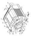
- FIG. 1is a perspective view of a vision system including a housing that allows for the removable attachment of a plurality of different lens mount types, showing the housing free of an attached lens, according to an illustrative embodiment
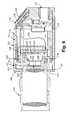
- FIG. 2is a side cross section of the housing taken along Line 2 - 2 of FIG. 1 ;
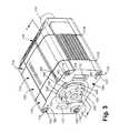
- FIG. 3is a perspective view of the vision system of FIG. 1 in which the housing includes an exemplary M12 type lens attached thereto, according to an illustrative embodiment
- FIG. 4is a side cross section of the housing taken along Line 4 - 4 of FIG. 3 ;
- FIG. 5is a perspective view of the vision system of FIG. 1 in which the housing includes an exemplary C-Mount type lens attached thereto, according to an illustrative embodiment
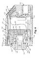
- FIG. 6is a side cross section of the housing taken along Line 6 - 6 of FIG. 5 ;
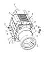
- FIG. 7is a perspective view of the vision system shown in FIG. 6 in which the housing includes the exemplary C-Mount type lens attached thereto, in which the lens is covered by an optional shroud assembly, according to an illustrative embodiment;
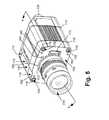
- FIG. 8is a perspective view of the vision system of FIG. 1 in which the housing includes an exemplary liquid type lens attached thereto, according to an illustrative embodiment
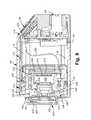
- FIG. 9is a side cross section of the housing taken along Line 9 - 9 of FIG. 8 ;
- FIG. 10is a front view of the vision system shown in FIG. 8 in which the housing includes the exemplary liquid type lens attached thereto, according to an illustrative embodiment.
- the housing 100can be constructed from polymer, metal, composite or a variety of materials in accordance with ordinary skill. In an embodiment, it consists of a front plate section 110 , a main body section 112 and a rear section 114 .
- the front plate section (or “front plate”) 110is joined to the main body and rear sections using four threaded bolts 116 that are seated within wells in the front plate 110 , and that engage threaded holes in the rear section, thereby compressing the three sections together against gaskets 118 that seal the housing against infiltration of moisture and other environmental agents.
- the construction of the housingis highly variable in alternate embodiments.
- the housingcan be constructed with an integrated or unitary rear and main body or a unitary front plate and main body.
- other fastening techniquescan be employed, such as employing joining clamps or clips between sections.
- the bolts 116are located adjacent to each of four corners of the somewhat rectangular-cross-section housing.
- the bolts 116each contain respective threaded wells at their front end that allow for the attachment of accessories using threaded fasteners, or the attachment of the housing itself to a mounting surface.
- the bolts 116can be substituted with appropriate bolts that also pass through holes in a mounting surface or accessory (not shown), and collectively join the surface/accessory to the sections of the housing in appropriate compression.
- the interior of the housing 100supports an image sensor 212 ( FIG. 2 ) that is arranged to acquire each image frame as an array of individual image pixels.
- the sensor arrayis a CMOS sensor 212 (also termed an “imager”), which acquires image data in the form of pixel data.
- a cover glass 210 idprovided to protect the sensor array 212 .
- the sensor 212is mounted on a printed circuit board 250 secured as depicted near the front end of the housing.
- the sensor circuit board 250also illustratively includes processing circuitry (e.g. a digital signal processor DSP) that receives the pixel data from the sensor array 212 and performs various vision system processes on the data in accordance with non-transitory computer-readable program instructions and/or firmware instructions.
- processing circuitrye.g. a digital signal processor DSP
- the sensor circuit board 250is interconnected with various power, control and other associated circuit components located on a circuit board 220 in the rear 114 of the housing.
- the two board assemblies 220 , 250are illustratively interconnected by a multi-lead cable 222 in this embodiment.
- Other arrangements of circuitry and interconnectionsare expressly contemplated.
- a VSoC arrangement(described above) can be provided to perform image acquisition and processing.
- the rear section 114(and/or other sections 110 , 112 of the housing) can be constructed from aluminum so as to act as a heat sink that assists in dissipating heat generated within the housing by the circuitry (described further below).
- An external connector 130are located at the rear side of the housing 100 for providing power, data and/or other interface functions.
- the connector(s)is/are operatively connected to the circuit board 220 .
- the rearalso includes an external status and control panel 140 that provides the user with status indicators and feedback on vision system operations (for example, indicating whether a symbol has been properly identified and decoded). Appropriate on/off switches and other interface buttons can also be provided at this location, or at another appropriate location on the housing 100 .
- the plane of the sensor 212is oriented perpendicularly to the longitudinal axis (i.e. camera axis) 230 of the housing 100 . It resides within a space 240 that is open to an aperture 150 within a central region of the front plate 110 .
- the space 240is bounded by an enclosing wall 242 (having a relatively planar sides that can define a rectangular cross-section tube) that provides clearance for the sensor 212 .
- the wall 242extends from a step face 244 to the surface of the sensor circuit board 250 .
- the distance DS from the step face 244 to the plane of the sensor 212is approximately 6 millimeters.
- the aperture 150is defined by an outer step 152 and a narrower inner step 154 .
- each stepis threaded as described below.
- the outer step 152defines a diameter DOS of approximately 25.4 millimeters (1 inch), and a depth (along the axial direction) LOS of approximately 5 millimeters.
- the inner step 154defines a diameter DIS of approximately 12 mm.
- the outer step 152is female-threaded to a pitch of 32 threads per inch (TPI) and the inner step 154 is female-threaded to a pitch of 0.5 mm.
- TPIthreads per inch
- the positioning of the steps and size of the spaceare constructed and arranged to accommodate the focal length of each lens type being employed herein.
- the front plate assembly 110is constructed from metal (e.g. die cast aluminum alloy), which is finished using an appropriate machining process.
- the castingincludes the depicted recesses 152 , 154 and other supporting structures (i.e. walls 242 , 251 and 252 ) for lenses and other internal components.
- the supporting walls 242 (etc.)which contact and/or surround the sensor circuit board 250 assist in directing heat away from the board 250 and its associated circuit components and into the housing structure, where the heat is dissipated into the surrounding ambient air.
- the layout and configuration of the supporting structurescan vary. In general, the thickness of walls used in such supporting structures is selected to provide sufficient structural strength with respect to the material employed in constructing the front plate 110 .
- the front plate assembly 110includes, along its front face 164 , a plurality of threaded holes 160 that can be female-threaded to any appropriate size, so as accept corresponding threaded screws (described below). These screws can be used to attach a plurality of fittings and accessories to the front plate.
- the face 164 of the front plate assembly 110includes a pair of connection sockets 170 and 172 respectively oriented to the right and left of the aperture 150 (as viewed from the front). Both sockets include respective connectors, which are interconnected with the system's processor circuitry (i.e. 250 and 220 ).
- the right socket 170is employed to operate the optics of a liquid lens (described above, and again below).
- the left socket 172is employed to interconnect and operate an illumination assembly that can be directly attached to the front plate via threaded holes 160 or can be separately mounted.
- the illumination assemblyis described in further detail in commonly assigned U.S.
- the perimeter 180 of the aperture 150includes a circumferential spring assembly 182 with a pair of diametrically opposed, radially inwardly directed retaining shoulders 184 .
- the spring assembly 182is removably secured to the front face 164 by opposed screws 186 (M2 thread in this embodiment) that threadingly seat into holes ( 502 in FIG. 5 ).
- the screws 186are separated by a distance (on-center) of approximately 28 millimeters, taken through the camera axis ( 230 ).
- the removable spring assemblyis constructed and arranged to retain a liquid lens assembly.
- a userreceives a housing 100 with a cap (not shown) to protect the aperture and sensor, and that the applicable lens is purchased separately—to be attached by the user in a straightforward manner as described further below.
- the lenscan be provided to the housing by the manufacturer. In either case, there are a wide range of lens choices available.
- the housing 110is provided with an attached M12 lens 310 according to an embodiment.
- the lensis a commercially available M12 lens with a conventional M12 threaded base.
- the male thread of the lensis secured into the female thread of the narrower, more-inset step 154 , and is stopped from further inward threading, and generally locked in place using a counter nut 320 , which is initially threaded onto the lens 310 base before attachment to the front plate assembly 110 .
- the applied counter nut 320can be adhered by the manufacturer (or another party) in place at an appropriate location along the lens using adhesive or another fixing technique. This ensures that, when the lens is tightened into place (e.g. by the user) to form a tight engagement with the front face 430 of the step 154 as shown, it is also positioned at a proper, predetermined distance with respect to the sensor's image plane. The lens 310 is thereby locked in place at a desired offset (to provide proper focal length) with respect to the plane of the sensor 212 . Alternatively, where the user seeks to vary the mounting position of the lens, the counter nut can remain unfixed to the lens thread and counter-rotated by the user (or another party) to secure the lens in a desired position.
- the front end of the lenscan include a radially outwardly oriented ring 330 that engages the inner perimeter of an optional, frustoconically shaped stopper 410 ( FIG. 4 ).
- the stopperprotects the region of the aperture 150 between the lens front and the outer step 152 , and avoids inadvertent loosening or readjustment of the tightened lens/counter ring 310 / 320 and protects against infiltration of dirt and moisture.
- the stopper 410can be any acceptable shape, or alternatively omitted. It is secured to the front plate assembly 110 by a pressed-in friction fit that resides against the female threads in the outer step 152 .
- the stoppercan be constructed from an elastomeric material. In alternate embodiments, the stopper can employ a different securing system with respect to the housing front plate assembly 110 , such as clips or mating threads.
- attachment and detachment of the exemplary M12 lens 310is relatively straightforward, and entails the threaded rotation of only a few components with respect to the inner step 154 and (optionally) the outer step 152 .
- the user or the manufacturercan desirably assemble an M12 lens vision system from a few readily available components.
- the housingcan be assembled as shown in FIGS. 5-7 .
- the male-threaded base 512 of the exemplary C-mount lens 510is threadingly attached to the female threads of the outer step 152 as shown ( FIG. 6 ).
- the base 512is tightened until its rear shoulder 620 engages the perimeter 180 of the aperture 150 .
- the perimeter 180is spaced from the plane of the sensor at an appropriate distance so as to provide the proper focal length for the lens 510 with respect to the sensor's image plane.
- the perimeter 180 upon which the lens shoulder 620can be slightly recessed (as shown) relative to the surrounding front face 164 to provide the correct clearance, or it can be raised relative thereto to provide the proper focal length.
- the step 152 and its front perimeter facecan be a lockable insert that is adjustable within the surrounding front plate assembly (using an outer coaxial thread that mates between the insert and the front plate, for example) to allow the seating location of the lens to vary, thereby varying the focal length.
- the optics of the lens 510combined with the geometry of the front plate assembly 110 focuses received light rays so that they pass free of interference from the rear end 630 of the lens 510 through the smaller diameter step 154 , and into the space 240 . In this manner, the light rays received by the lens 510 are focused to cover the area of the sensor 212 .
- the C-Mount lenscan be optionally covered by a shroud (or cover) assembly 710 ( FIG. 7 ) that primarily protects it from ingress of dirt/contaminants and moisture.
- the shroud 710can also serve to protect against inadvertent change to the lens settings.
- the shroud assemblyconsists of a gasket plate 720 that covers the front face ( 164 ) and an overlying shroud base 730 .
- the gasket plate 720 and shroud baseinclude through-holes that expose the central threaded holes ( 120 ) of each of the assembly bolts 116 . This allows the system to be mounted as described above or receive additional accessories on top of the shroud base 730 .
- the gasket plate 720 and shroud base 730thereby cover and seal the sockets ( 170 , 172 ) in this configuration.
- one or both of the sockets 170 , 172can be exposed through the gasket plate 720 and shroud base 730 .
- the shroud base 730 and gasket plate 720are secured to the front plate assembly 110 are compressibly secured by four screws (not shown) that thread into the screw holes 160 formed on the front plate assembly 110 .
- the shroud base 730is countersunk in the region of each threaded hole 160 to receive a correspondingly shaped machine screw.
- the front ring 732 of the shroud base 730receives the shroud body 740 , which overlies and covers the lens 510 .
- the shroud body 740can be constructed as a single piece, or from a plurality of pieces (e.g. a main body and nose as shown). It can be secured to the ring 732 by a threaded interconnection or another fastening arrangement.
- the versatility of the housing 100 and front plate assembly 110enables mounting of an electronically operated, auto-focusing liquid lens 810 according to an illustrative embodiment.
- a liquid lensuses two iso-density liquids—oil is an insulator while water is a conductor.
- the variation of voltage passed through the lens by surrounding circuitryleads to a change of curvature of the liquid-liquid interface, which in turn leads to a change of the focal length of the lens.
- liquid lenscan desirably simplify installation, setup and maintenance of the vision system by eliminating the need to manually touch the lens.
- the liquid lenshas extremely fast response times. It is also ideal for applications with reading distances that change from object-to-object (surface-to-surface) or during the changeover from the reading of one object to another object.
- the exemplary liquid lens 810can be based upon a commercially available liquid lens component 910 ( FIG. 9 ) available from Varioptic SA of France.
- the liquid lens component 910is mounted within an outer shell/housing 820 that is secured in place by the spring shoulders 184 described above.
- the housingcan include a C-mount base that engages the threads of the outer step 152 .
- An advantage of the spring-retained lens arrangementis that it allows for the positioning of the connector cable 830 in a location that leads properly to the socket 170 (where the cable's connector 832 is shown connected in FIG. 8 ).
- the socket and connectorcan be any acceptable multi-pin arrangement that provides sufficient connections to control the lens.
- the inner face of the lens' outer shell or housing 820engages an O-ring (or other resilient structure that allows an open central aperture) 920 that, in turn, pressurably bears upon the circuit board 922 .
- This circuit board 922includes the control circuitry employed according to the art to operate the focal length adjustment of the lens component 910 .
- the lensis compressed between the circuit board and the internal, fixed lens assembly 940 that focuses light rays from the liquid lens component onto the sensor 212 .
- the fixed lens assembly 940is secured into the front plate assembly 110 by threads that engage the inner step 154 .
- a counter ring 942prevents loosening of this lens assembly 940 .
- the pressure applied by the spring retaining shoulders 184is sufficient to retain the lens component 910 free of movement and vibration, but this pressure also remains within the desired specification to avoid over-compression of the lens component 910 , which could degrade performance or burst the lens.
- the spring retaining shouldersare arranged to engage associated abutments 1010 on each of opposing sides of the lens outer housing/shell 820 .
- the abutments 1010are located at a non-vertical and non-horizontal angle with respect to the geometry (top, bottom, right and left sides) of the system housing 100 . This allows for the cable 830 to exit the top end of the lens housing/shell 820 free of interference by the hold-down components.
- the spring shoulders 184 (and abutments 1010 )are aligned along a line that is approximately perpendicular to the line between the screws 186 .
- a larger or smaller number of screws and/or spring shoulders 184can be used to retain the lens 810 with respect to the front face 164 of the housing 100 .
- the overall spring assemblycan be constructed as a single unit with an appropriate number of retaining shoulders to secure the lens, or a multi-part unit each having one or more shoulders (as shown).
- the arrangement of components in both (or either of) the internal fixed lens assembly 942 and the overlying liquid lens module ( 810 )are highly variable in alternate embodiments.
- the depicted illustrative embodimentis an effective arrangement that can be assembled in a straightforward manner by the manufacturer or user.
- the vision system housing and associated front plate constructionprovides a highly versatile system for selecting and “directly attaching” a variety of desirable lenses and lens mount types that are traditionally not interchangeable on a single housing without (free of) additional adapters.
- Such adapterscan reduce accuracy, increase the chance of loosening of components and generally increase the system's complexity.
- the resulting vision systemallows for fewer specialized components and more customization either by the manufacturer or end user. More particularly, the system provides the end user with the ability to change out lens types so that the system can be updates or re-tasked to a new use from an earlier use, as desired.
- the front plate assemblycan be constructed and arranged to provide a different combination of mounts by appropriately sizing and threading the stepped apertures.
- various componentsare attached using threaded screws, it is expressly contemplated that other fastener types can be used for various interconnections, such as snap-connectors, rivets, clips, and the like.
- a plurality of front plate assembliescan be produced and provided to a standard main body section and rear to allow for further versatility of the vision system.
- any process or processor hereincan comprise one or more electronic hardware components, software in the form a non-transitory computer-readable medium of program instructions, or a combination of hardware and software.
- processshould be taken broadly to include various combinations of hardware components and/or software program steps that perform one or more functions in a system or method. Accordingly, this description is meant to be taken only by way of example, and not to otherwise limit the scope of this invention.
Landscapes
- Physics & Mathematics (AREA)
- General Physics & Mathematics (AREA)
- Optics & Photonics (AREA)
- Engineering & Computer Science (AREA)
- Multimedia (AREA)
- Signal Processing (AREA)
- Lens Barrels (AREA)
- Structure And Mechanism Of Cameras (AREA)
Abstract
Description
This invention relates to vision system cameras and more particularly to lens mounts for vision system cameras.
Vision systems that perform measurement, inspection, alignment of objects and/or decoding of symbology (e.g. bar codes) are used in a wide range of applications and industries. These systems are based around the use of an image sensor, which acquires images (typically grayscale or color, and in one, two or three dimensions) of the subject or object, and processes these acquired images using an on-board or interconnected vision system processor. The processor generally includes both processing hardware and non-transitory computer-readable program instructions that perform one or more vision system processes to generate a desired output based upon the image's processed information. This image information is typically provided within an array of image pixels each having various colors and/or intensities. In the example of a symbology (barcode) reader, the user or automated process acquires an image of an object that is believed to contain one or more barcodes. The image is processed to identify barcode features, which are then decoded by a decoding process and/or processor obtain the inherent alphanumeric data represented by the code.
It is increasingly desirable to provide vision systems and associated vision system components that can be used for a variety of purposes. By way of example, an integrated sensor and single instruction, multiple data (SIMD) processor, which can be termed a vision system on a chip (VSoC), is shown and described in U.S. patent application Ser. No. 12/184,187, entitled VISION SENSORS, SYSTEMS AND METHODS, by E. John McGarry, et al., the teachings of which are incorporated by reference as useful background information. This architecture provided a highly versatile and widely applicable vision system platform for a variety of vision system tasks. The ability to provide a versatile system reduces costs by eliminating the need to provide a number of purpose-built vision system arrangements for specific applications. It is therefore desirable to provide such versatile vision system platforms. Other currently available arrangements of sensors and processors (e.g. digital signal processors (DSPs) can also be employed to provide a relatively compact and robust vision system.
While programs can be readily adapted for a particular vision system task, it is more of a challenge to adapt the system's physical package to that task. For example, some vision tasks call for a larger lens, such as a cine or C-mount unit, while others can be accomplished best with a smaller M12 thread (12 mm×0.5 mm thread) lens, also termed an “S-mount”, or more basically, an “M12” lens. Others are best suited to a liquid lens, or a similar arrangement. By way of further background, a liquid lens uses two iso-density liquids—oil is an insulator while water is a conductor. The variation of voltage passed through the lens by surrounding circuitry leads to a change of curvature of the liquid-liquid interface, which in turn leads to a change of the focal length of the lens. Some significant advantages in the use of a liquid lens are the lens' ruggedness (it is free of mechanical moving parts), its fast response times, its relatively good optical quality, and its low power consumption and size. The use of a liquid lens can desirably simplify installation, setup and maintenance of the vision system by eliminating the need to manually touch the lens. Relative to other autofocus mechanisms, the liquid lens has extremely fast response times. It is also ideal for applications with reading distances that change from object-to-object (surface-to-surface) or during the changeover from the reading of one object to another object.
The choice of lens type (e.g. C-mount, M12, liquid lens, etc.) can be driven by such factors as lighting/illumination, field of view, focal distance, relative angle of the camera axis and imaged surface, and the fineness of details on the imaged surface. In addition, the cost of the lens and/or the available space for mounting the vision system can drive the choice of lens.
It is therefore desirable to provide a vision system that can readily accommodate a variety of lens types while avoiding the need of costly changes to the vision system's physical housing or package. This vision system should be able to employ multiple lens types with no reduction in quality of the acquired image when compared with using a system that provides a discrete, purpose-built lens mount.
This invention overcomes the disadvantages of the prior art by providing a vision system housing having a front plate assembly that accommodates a plurality of lens mount types. The front plate includes a central aperture that is located at a predetermined axial (camera axis) distance from a plane of an image sensor. The aperture is stepped from a wider diameter adjacent to the front to a narrower diameter more adjacent to the sensor. This arrangement of diameter and relative depth within the front plate enables threaded mounting of a plurality of lens mount types, illustratively an M12 lens mount and C-Mount. The threaded base for the M12 lens mount is provided in the smaller-diameter interior portion of the front plate aperture, adjacent to the sensor. Additionally, the threaded base for the C-Mount lens is provided at the front of the front plate, adjacent to the exterior surface of the front plate and housing. The exterior (front) surface of the front plate includes threaded holes and a spring clip arrangement (fastened by screws) constructed and arranged to accommodate a liquid lens positioned over the aperture with an associated lens assembly mounted within the aperture and in optical communication with the liquid lens. The lens is operated using an electrical connection provided by a cable that interconnects with a multi-pin socket positioned on the front plate aside the aperture. The socket interconnects with processor circuitry within the housing that enables control of the liquid lens.
In an illustrative embodiment the vision system defines a housing that includes a front plate assembly comprising an aperture aligned relative to an image sensor located within an interior of the housing, the aperture including an outer step having a first diameter and in inner step have a second diameter smaller than the first diameter. The first step is constructed and arranged to receive a first lens type base and the second step is constructed and arranged to receive a second lens type base. By way of example, the outer step is constructed and arranged to receive a C-mount lens base and the inner step is constructed and arranged to receive an M12 lens base. Moreover, the front plate assembly is constructed and arranged to receive, over the aperture, a liquid lens module. A clip assembly, illustratively comprising a spring assembly with retaining shoulders that is secured by screws to threaded holes around the aperture, engages portions of the housing or shell of the liquid lens module. The front plate assembly also illustratively includes a first socket, interconnected with control circuitry within the housing, which receives a cable to operate the liquid lens module. A second socket can also interconnect the control circuitry with an illuminator. The front plate assembly is illustratively attached to a body section of the housing using bolts having ends that are exposed at the outer face of the front plate assembly and pass into the body section. These ends can include threaded holes that receive fasteners that allow attachment of the front plate assembly to a mount or accessory.
More generally, in an illustrative embodiment, the vision system housing includes a main body section having an image sensor within the interior thereof. A front plate assembly is attached to the main body section. The front plate assembly includes threaded structures for selectively, removably and directly attaching at least three discrete types of lens thereto. By way of example, the three lens types can include a C-mount lens, and M12 lens and a liquid lens module.
The invention description below refers to the accompanying drawings, of which:
With reference toFIGS. 1 and 2 , a vision system that includes an external package or “housing”100 is shown in detail. Thehousing 100 can be constructed from polymer, metal, composite or a variety of materials in accordance with ordinary skill. In an embodiment, it consists of afront plate section 110, amain body section 112 and arear section 114. The front plate section (or “front plate”)110 is joined to the main body and rear sections using four threadedbolts 116 that are seated within wells in thefront plate 110, and that engage threaded holes in the rear section, thereby compressing the three sections together againstgaskets 118 that seal the housing against infiltration of moisture and other environmental agents. The construction of the housing is highly variable in alternate embodiments. For example, the housing can be constructed with an integrated or unitary rear and main body or a unitary front plate and main body. Likewise, other fastening techniques can be employed, such as employing joining clamps or clips between sections.
In this embodiment, thebolts 116 are located adjacent to each of four corners of the somewhat rectangular-cross-section housing. Thebolts 116 each contain respective threaded wells at their front end that allow for the attachment of accessories using threaded fasteners, or the attachment of the housing itself to a mounting surface. Alternatively, thebolts 116 can be substituted with appropriate bolts that also pass through holes in a mounting surface or accessory (not shown), and collectively join the surface/accessory to the sections of the housing in appropriate compression.
The interior of thehousing 100 supports an image sensor212 (FIG. 2 ) that is arranged to acquire each image frame as an array of individual image pixels. In an embodiment, the sensor array is a CMOS sensor212 (also termed an “imager”), which acquires image data in the form of pixel data. Acover glass 210 id provided to protect thesensor array 212. Thesensor 212 is mounted on a printedcircuit board 250 secured as depicted near the front end of the housing. Thesensor circuit board 250 also illustratively includes processing circuitry (e.g. a digital signal processor DSP) that receives the pixel data from thesensor array 212 and performs various vision system processes on the data in accordance with non-transitory computer-readable program instructions and/or firmware instructions. Thesensor circuit board 250 is interconnected with various power, control and other associated circuit components located on acircuit board 220 in the rear114 of the housing. The twoboard assemblies multi-lead cable 222 in this embodiment. Other arrangements of circuitry and interconnections are expressly contemplated. For example, in another embodiment, a VSoC arrangement (described above) can be provided to perform image acquisition and processing. The rear section114 (and/orother sections
An external connector (or a plurality of connectors)130 are located at the rear side of thehousing 100 for providing power, data and/or other interface functions. The connector(s) is/are operatively connected to thecircuit board 220. The rear also includes an external status andcontrol panel 140 that provides the user with status indicators and feedback on vision system operations (for example, indicating whether a symbol has been properly identified and decoded). Appropriate on/off switches and other interface buttons can also be provided at this location, or at another appropriate location on thehousing 100.
The plane of thesensor 212 is oriented perpendicularly to the longitudinal axis (i.e. camera axis)230 of thehousing 100. It resides within aspace 240 that is open to anaperture 150 within a central region of thefront plate 110. Thespace 240 is bounded by an enclosing wall242 (having a relatively planar sides that can define a rectangular cross-section tube) that provides clearance for thesensor 212. Thewall 242 extends from astep face 244 to the surface of thesensor circuit board 250. The distance DS from thestep face 244 to the plane of thesensor 212 is approximately 6 millimeters. Theaperture 150 is defined by anouter step 152 and a narrowerinner step 154. Each step is threaded as described below. In particular, theouter step 152 defines a diameter DOS of approximately 25.4 millimeters (1 inch), and a depth (along the axial direction) LOS of approximately 5 millimeters. Likewise, theinner step 154 defines a diameter DIS of approximately 12 mm. Theouter step 152 is female-threaded to a pitch of 32 threads per inch (TPI) and theinner step 154 is female-threaded to a pitch of 0.5 mm. In general, the positioning of the steps and size of the space are constructed and arranged to accommodate the focal length of each lens type being employed herein.
In an embodiment, thefront plate assembly 110 is constructed from metal (e.g. die cast aluminum alloy), which is finished using an appropriate machining process. The casting includes the depicted recesses152,154 and other supporting structures (i.e.walls sensor circuit board 250 assist in directing heat away from theboard 250 and its associated circuit components and into the housing structure, where the heat is dissipated into the surrounding ambient air. In alternate embodiments the layout and configuration of the supporting structures can vary. In general, the thickness of walls used in such supporting structures is selected to provide sufficient structural strength with respect to the material employed in constructing thefront plate 110. Thefront plate assembly 110 includes, along itsfront face 164, a plurality of threadedholes 160 that can be female-threaded to any appropriate size, so as accept corresponding threaded screws (described below). These screws can be used to attach a plurality of fittings and accessories to the front plate.
Note that directional terms such as “front”, “rear”, “up”, “down”, “top” bottom”, “right”, and “left”, as well as their variants and synonyms, should be taken as relative conventions only, and not as absolute indications of orientation of a structure relative to the direction of prevailing gravitational force.
With reference particularly toFIG. 1 , theface 164 of thefront plate assembly 110 includes a pair ofconnection sockets right socket 170 is employed to operate the optics of a liquid lens (described above, and again below). Theleft socket 172 is employed to interconnect and operate an illumination assembly that can be directly attached to the front plate via threadedholes 160 or can be separately mounted. The illumination assembly is described in further detail in commonly assigned U.S. patent application Ser. No. 13/302,858, entitled CAMERA SYSTEM WITH EXCHANGABLE ILLUMINATION ASSEMBLY, by Laurens Nunnink, filed on even date herewith and the teachings of which are expressly incorporated herein by reference as useful background information.
Theperimeter 180 of theaperture 150 includes acircumferential spring assembly 182 with a pair of diametrically opposed, radially inwardly directed retainingshoulders 184. Thespring assembly 182 is removably secured to thefront face 164 by opposed screws186 (M2 thread in this embodiment) that threadingly seat into holes (502 inFIG. 5 ). In an embodiment, thescrews 186 are separated by a distance (on-center) of approximately 28 millimeters, taken through the camera axis (230). As described further below, the removable spring assembly is constructed and arranged to retain a liquid lens assembly.
It is contemplated that a user receives ahousing 100 with a cap (not shown) to protect the aperture and sensor, and that the applicable lens is purchased separately—to be attached by the user in a straightforward manner as described further below. Alternatively, the lens can be provided to the housing by the manufacturer. In either case, there are a wide range of lens choices available.
Having described the generalized construction and function of thehousing 100 andfront plate assembly 110 according to an illustrative embodiment, the implementation of various types of lenses in conjunction with the housing is now described in further detail. With reference toFIGS. 3 and 4 , thehousing 110 is provided with an attachedM12 lens 310 according to an embodiment. By way of non-limiting example, the lens is a commercially available M12 lens with a conventional M12 threaded base. The male thread of the lens is secured into the female thread of the narrower, more-inset step 154, and is stopped from further inward threading, and generally locked in place using acounter nut 320, which is initially threaded onto thelens 310 base before attachment to thefront plate assembly 110. The appliedcounter nut 320 can be adhered by the manufacturer (or another party) in place at an appropriate location along the lens using adhesive or another fixing technique. This ensures that, when the lens is tightened into place (e.g. by the user) to form a tight engagement with thefront face 430 of thestep 154 as shown, it is also positioned at a proper, predetermined distance with respect to the sensor's image plane. Thelens 310 is thereby locked in place at a desired offset (to provide proper focal length) with respect to the plane of thesensor 212. Alternatively, where the user seeks to vary the mounting position of the lens, the counter nut can remain unfixed to the lens thread and counter-rotated by the user (or another party) to secure the lens in a desired position.
The front end of the lens can include a radially outwardly orientedring 330 that engages the inner perimeter of an optional, frustoconically shaped stopper410 (FIG. 4 ). The stopper protects the region of theaperture 150 between the lens front and theouter step 152, and avoids inadvertent loosening or readjustment of the tightened lens/counter ring 310/320 and protects against infiltration of dirt and moisture. Thestopper 410 can be any acceptable shape, or alternatively omitted. It is secured to thefront plate assembly 110 by a pressed-in friction fit that resides against the female threads in theouter step 152. It is illustratively mounted by pressing it into the thread well until it seats against thefront face 430 of theinner step 154 as shown (FIG. 4 ). The stopper can be constructed from an elastomeric material. In alternate embodiments, the stopper can employ a different securing system with respect to the housingfront plate assembly 110, such as clips or mating threads.
It should be clear that attachment and detachment of theexemplary M12 lens 310 is relatively straightforward, and entails the threaded rotation of only a few components with respect to theinner step 154 and (optionally) theouter step 152. Thus, the user or the manufacturer can desirably assemble an M12 lens vision system from a few readily available components. Likewise, if the user desires a C-mount-lens-based vision system, the housing can be assembled as shown inFIGS. 5-7 .
As shown, the male-threadedbase 512 of the exemplary C-mount lens 510 is threadingly attached to the female threads of theouter step 152 as shown (FIG. 6 ). Thebase 512 is tightened until itsrear shoulder 620 engages theperimeter 180 of theaperture 150. Theperimeter 180 is spaced from the plane of the sensor at an appropriate distance so as to provide the proper focal length for thelens 510 with respect to the sensor's image plane. Theperimeter 180 upon which thelens shoulder 620 can be slightly recessed (as shown) relative to the surroundingfront face 164 to provide the correct clearance, or it can be raised relative thereto to provide the proper focal length. In alternate embodiments, thestep 152 and its front perimeter face can be a lockable insert that is adjustable within the surrounding front plate assembly (using an outer coaxial thread that mates between the insert and the front plate, for example) to allow the seating location of the lens to vary, thereby varying the focal length. Notably, the optics of thelens 510, combined with the geometry of thefront plate assembly 110 focuses received light rays so that they pass free of interference from therear end 630 of thelens 510 through thesmaller diameter step 154, and into thespace 240. In this manner, the light rays received by thelens 510 are focused to cover the area of thesensor 212.
The C-Mount lens can be optionally covered by a shroud (or cover) assembly710 (FIG. 7 ) that primarily protects it from ingress of dirt/contaminants and moisture. Theshroud 710 can also serve to protect against inadvertent change to the lens settings. The shroud assembly consists of agasket plate 720 that covers the front face (164) and anoverlying shroud base 730. Thegasket plate 720 and shroud base include through-holes that expose the central threaded holes (120) of each of theassembly bolts 116. This allows the system to be mounted as described above or receive additional accessories on top of theshroud base 730. Thegasket plate 720 andshroud base 730 thereby cover and seal the sockets (170,172) in this configuration. In alternate embodiments, one or both of thesockets gasket plate 720 andshroud base 730. Theshroud base 730 andgasket plate 720 are secured to thefront plate assembly 110 are compressibly secured by four screws (not shown) that thread into the screw holes160 formed on thefront plate assembly 110. In this embodiment, theshroud base 730 is countersunk in the region of each threadedhole 160 to receive a correspondingly shaped machine screw. Different screws or any other fastener arrangement that secures theshroud base 730 and (optionally) thegasket plate 720 can be employed in alternate embodiments can be employed in alternate embodiments. Thefront ring 732 of theshroud base 730 receives theshroud body 740, which overlies and covers thelens 510. Theshroud body 740 can be constructed as a single piece, or from a plurality of pieces (e.g. a main body and nose as shown). It can be secured to thering 732 by a threaded interconnection or another fastening arrangement.
Notably, with reference toFIGS. 8-10 , the versatility of thehousing 100 andfront plate assembly 110 enables mounting of an electronically operated, auto-focusingliquid lens 810 according to an illustrative embodiment. As described also above, a liquid lens uses two iso-density liquids—oil is an insulator while water is a conductor. The variation of voltage passed through the lens by surrounding circuitry leads to a change of curvature of the liquid-liquid interface, which in turn leads to a change of the focal length of the lens. Some significant advantages in the use of a liquid lens are the lens' ruggedness (it is free of mechanical moving parts), its fast response times, its relatively good optical quality, and its low power consumption and size. The use of a liquid lens can desirably simplify installation, setup and maintenance of the vision system by eliminating the need to manually touch the lens. As noted above, relative to other autofocus mechanisms, the liquid lens has extremely fast response times. It is also ideal for applications with reading distances that change from object-to-object (surface-to-surface) or during the changeover from the reading of one object to another object.
In this embodiment, the exemplaryliquid lens 810 can be based upon a commercially available liquid lens component910 (FIG. 9 ) available from Varioptic SA of France. Theliquid lens component 910 is mounted within an outer shell/housing 820 that is secured in place by the spring shoulders184 described above. It is expressly contemplated that alternate hold-down arrangements for the liquid lens can be employed. For example, the housing can include a C-mount base that engages the threads of theouter step 152. An advantage of the spring-retained lens arrangement is that it allows for the positioning of theconnector cable 830 in a location that leads properly to the socket170 (where the cable'sconnector 832 is shown connected inFIG. 8 ). Note that the socket and connector can be any acceptable multi-pin arrangement that provides sufficient connections to control the lens.
The inner face of the lens' outer shell orhousing 820 engages an O-ring (or other resilient structure that allows an open central aperture)920 that, in turn, pressurably bears upon thecircuit board 922. Thiscircuit board 922 includes the control circuitry employed according to the art to operate the focal length adjustment of thelens component 910. The lens is compressed between the circuit board and the internal, fixedlens assembly 940 that focuses light rays from the liquid lens component onto thesensor 212. The fixedlens assembly 940 is secured into thefront plate assembly 110 by threads that engage theinner step 154. Acounter ring 942 prevents loosening of thislens assembly 940. The pressure applied by thespring retaining shoulders 184 is sufficient to retain thelens component 910 free of movement and vibration, but this pressure also remains within the desired specification to avoid over-compression of thelens component 910, which could degrade performance or burst the lens.
With reference briefly to the front view ofFIG. 10 , the spring retaining shoulders are arranged to engage associatedabutments 1010 on each of opposing sides of the lens outer housing/shell 820. Like the spring assembly hold-downscrews 186, theabutments 1010 are located at a non-vertical and non-horizontal angle with respect to the geometry (top, bottom, right and left sides) of thesystem housing 100. This allows for thecable 830 to exit the top end of the lens housing/shell 820 free of interference by the hold-down components. In this embodiment, the spring shoulders184 (and abutments1010) are aligned along a line that is approximately perpendicular to the line between thescrews 186. In alternate embodiments a larger or smaller number of screws and/or spring shoulders184 (among other fastening arrangements) can be used to retain thelens 810 with respect to thefront face 164 of thehousing 100. Likewise, it is contemplated that the overall spring assembly can be constructed as a single unit with an appropriate number of retaining shoulders to secure the lens, or a multi-part unit each having one or more shoulders (as shown).
It is expressly contemplated that the arrangement of components in both (or either of) the internal fixedlens assembly 942 and the overlying liquid lens module (810) are highly variable in alternate embodiments. The depicted illustrative embodiment is an effective arrangement that can be assembled in a straightforward manner by the manufacturer or user.
It should be clear that the vision system housing and associated front plate construction provides a highly versatile system for selecting and “directly attaching” a variety of desirable lenses and lens mount types that are traditionally not interchangeable on a single housing without (free of) additional adapters. Such adapters can reduce accuracy, increase the chance of loosening of components and generally increase the system's complexity. The resulting vision system allows for fewer specialized components and more customization either by the manufacturer or end user. More particularly, the system provides the end user with the ability to change out lens types so that the system can be updates or re-tasked to a new use from an earlier use, as desired.
The foregoing has been a detailed description of illustrative embodiments of the invention. Various modifications and additions can be made without departing from the spirit and scope of this invention. Each of the various embodiments described above may be combined with other described embodiments in order to provide multiple features. Furthermore, while the foregoing describes a number of separate embodiments of the apparatus and method of the present invention, what has been described herein is merely illustrative of the application of the principles of the present invention. For example, while the illustrative housing is adapted for use with M12 and C-mount lens bases, it is expressly contemplated that adapters can be employed to allow for attachment of other lens types, such as the T-mount lens—for example the above-described alternate embodiment having an outer step insert. Likewise, the front plate assembly can be constructed and arranged to provide a different combination of mounts by appropriately sizing and threading the stepped apertures. Moreover, while various components are attached using threaded screws, it is expressly contemplated that other fastener types can be used for various interconnections, such as snap-connectors, rivets, clips, and the like. Also, in an embodiment, a plurality of front plate assemblies can be produced and provided to a standard main body section and rear to allow for further versatility of the vision system. In addition, any process or processor herein can comprise one or more electronic hardware components, software in the form a non-transitory computer-readable medium of program instructions, or a combination of hardware and software. More generally, the term “process” should be taken broadly to include various combinations of hardware components and/or software program steps that perform one or more functions in a system or method. Accordingly, this description is meant to be taken only by way of example, and not to otherwise limit the scope of this invention.
Claims (11)
1. A vision system housing comprising:
a front plate assembly defining an aperture aligned relative to an image sensor located within an interior of the vision system housing, the aperture including an outer step having a first diameter and an inner step have a second diameter smaller than the first diameter;
the outer step being constructed and arranged to receive a C-mount lens base and the inner step is constructed and arranged to receive a lens base having a thread diameter smaller than the C-mount lens base; and
a counter ring engaged with the lens base at a predetermined location such that, when the counter ring engages a front face between the outer step and the inner step, the lens base is positioned at a predetermined distance from the image sensor.
2. The vision system ofclaim 1 , wherein a thread pitch of the outer step is female-threaded to a pitch of 32 threads per inch (TPI).
3. The vision system ofclaim 1 , wherein the lens base comprises an M12 lens base.
4. The vision system ofclaim 3 , wherein the counter ring is adhered to the M12 lens.
5. The vision system ofclaim 1 , wherein the lens base can be engaged and disengaged with the inner step.
6. The vision system ofclaim 1 , further comprising a liquid lens assembly comprising the lens base such that the inner step is constructed and arranged to receive the lens base of the liquid lens assembly.
7. The vision system ofclaim 6 , further comprising a counter ring engaged with the liquid lens assembly at a predetermined location such that, when the counter ring that engages with the front face disposed between the outer step and the inner step, the liquid lens assembly is disposed at a predetermined distance from the image sensor.
8. The vision system ofclaim 1 , further comprising a plurality of connection sockets disposed on a face of the front assembly, the plurality of connection sockets respectively configured to engage with a liquid lens assembly and an illumination assembly.
9. The vision system ofclaim 8 , wherein a thread pitch of the outer step is female-threaded to a pitch of 32 threads per inch (TPI).
10. A vision system housing comprising:
a front plate assembly defining an aperture aligned relative to an image sensor located within an interior of the housing, the aperture including an outer step having a first diameter and in inner step have a second diameter smaller than the first diameter;
the outer step being constructed and arranged to receive a C-mount lens base and the inner step being constructed and arranged to receive a lens base distinct from the C-mount lens base; and
a counter ring engaged with the lens base at a predetermined location such that, when the counter ring engages a front face between the outer step and the inner step, the lens base is positioned at a predetermined distance from the image sensor.
11. A vision system housing comprising:
a front plate assembly defining an aperture aligned relative to an image sensor located within an interior of the vision system housing, the aperture including an outer step having a first diameter and an inner step have a second diameter smaller than the first diameter;
the outer step being constructed and arranged to receive a C-mount lens base and the inner step being constructed and arranged to receive a lens adapter distinct from the C-mount lens base; and
a counter ring engaged with the lens adapter at a predetermined location such that, when the counter ring engages a front face between the outer step and the inner step, the lens adapter is positioned at a predetermined distance from the image sensor.
Priority Applications (4)
| Application Number | Priority Date | Filing Date | Title |
|---|---|---|---|
| US14/611,401US10067312B2 (en) | 2011-11-22 | 2015-02-02 | Vision system camera with mount for multiple lens types |
| US16/119,909US10678019B2 (en) | 2011-11-22 | 2018-08-31 | Vision system camera with mount for multiple lens types |
| US16/371,987US11366284B2 (en) | 2011-11-22 | 2019-04-01 | Vision system camera with mount for multiple lens types and lens module for the same |
| US17/844,481US11921350B2 (en) | 2011-11-22 | 2022-06-20 | Vision system camera with mount for multiple lens types and lens module for the same |
Applications Claiming Priority (2)
| Application Number | Priority Date | Filing Date | Title |
|---|---|---|---|
| US13/302,751US8947590B2 (en) | 2011-11-22 | 2011-11-22 | Vision system camera with mount for multiple lens types |
| US14/611,401US10067312B2 (en) | 2011-11-22 | 2015-02-02 | Vision system camera with mount for multiple lens types |
Related Parent Applications (1)
| Application Number | Title | Priority Date | Filing Date |
|---|---|---|---|
| US13/302,751ContinuationUS8947590B2 (en) | 2011-11-22 | 2011-11-22 | Vision system camera with mount for multiple lens types |
Related Child Applications (1)
| Application Number | Title | Priority Date | Filing Date |
|---|---|---|---|
| US16/119,909ContinuationUS10678019B2 (en) | 2011-11-22 | 2018-08-31 | Vision system camera with mount for multiple lens types |
Publications (2)
| Publication Number | Publication Date |
|---|---|
| US20160011396A1 US20160011396A1 (en) | 2016-01-14 |
| US10067312B2true US10067312B2 (en) | 2018-09-04 |
Family
ID=48222186
Family Applications (3)
| Application Number | Title | Priority Date | Filing Date |
|---|---|---|---|
| US13/302,751Active2032-09-11US8947590B2 (en) | 2011-11-22 | 2011-11-22 | Vision system camera with mount for multiple lens types |
| US14/611,401ActiveUS10067312B2 (en) | 2011-11-22 | 2015-02-02 | Vision system camera with mount for multiple lens types |
| US16/119,909ActiveUS10678019B2 (en) | 2011-11-22 | 2018-08-31 | Vision system camera with mount for multiple lens types |
Family Applications Before (1)
| Application Number | Title | Priority Date | Filing Date |
|---|---|---|---|
| US13/302,751Active2032-09-11US8947590B2 (en) | 2011-11-22 | 2011-11-22 | Vision system camera with mount for multiple lens types |
Family Applications After (1)
| Application Number | Title | Priority Date | Filing Date |
|---|---|---|---|
| US16/119,909ActiveUS10678019B2 (en) | 2011-11-22 | 2018-08-31 | Vision system camera with mount for multiple lens types |
Country Status (3)
| Country | Link |
|---|---|
| US (3) | US8947590B2 (en) |
| CN (3) | CN110365881B (en) |
| DE (1) | DE102012111231B4 (en) |
Cited By (2)
| Publication number | Priority date | Publication date | Assignee | Title |
|---|---|---|---|---|
| USD1061288S1 (en) | 2023-05-08 | 2025-02-11 | Lsi Industries, Inc. | Infrared sensor lens |
| USD1061289S1 (en) | 2023-05-08 | 2025-02-11 | Lsi Industries, Inc. | Infrared sensor lens |
Families Citing this family (22)
| Publication number | Priority date | Publication date | Assignee | Title |
|---|---|---|---|---|
| US8134116B2 (en) | 2009-01-12 | 2012-03-13 | Cognex Corporation | Modular focus system for image based code readers |
| US10498933B2 (en) | 2011-11-22 | 2019-12-03 | Cognex Corporation | Camera system with exchangeable illumination assembly |
| US11366284B2 (en) | 2011-11-22 | 2022-06-21 | Cognex Corporation | Vision system camera with mount for multiple lens types and lens module for the same |
| US8947590B2 (en)* | 2011-11-22 | 2015-02-03 | Cognex Corporation | Vision system camera with mount for multiple lens types |
| JP5983398B2 (en)* | 2012-12-28 | 2016-08-31 | 株式会社Jvcケンウッド | Imaging device |
| JP6459961B2 (en)* | 2013-03-15 | 2019-01-30 | 株式会社ニコン | Receiver |
| US9823552B2 (en) | 2013-12-20 | 2017-11-21 | Back Bone Gear Inc. | Lens and sensor attachment for a digital camera and related retrofit kit and retrofit method |
| US20140132815A1 (en)* | 2014-01-27 | 2014-05-15 | Meizhou XiuYing Enterprise Company Limited | Digital camera structure capable of selectively mounting a camera lens |
| CN105425527B (en)* | 2014-09-03 | 2018-03-20 | 深圳富泰宏精密工业有限公司 | More camera lens camera devices |
| AT519192B1 (en) | 2016-09-19 | 2019-03-15 | B & R Ind Automation Gmbh | Camera for industrial image processing |
| US10133158B2 (en)* | 2016-10-17 | 2018-11-20 | Panasonic Intellectual Property Management Co., Ltd. | Imaging device |
| KR101944412B1 (en)* | 2017-03-23 | 2019-01-31 | 엘지이노텍 주식회사 | Liquid lens, camera module and optical device/instrument including the same |
| JP6648375B2 (en) | 2018-05-21 | 2020-02-14 | エスゼット ディージェイアイ テクノロジー カンパニー リミテッドSz Dji Technology Co.,Ltd | Imaging system and moving object |
| USD894991S1 (en)* | 2018-07-24 | 2020-09-01 | Hanwha Techwin Co., Ltd. | Camera |
| USD896297S1 (en)* | 2018-07-24 | 2020-09-15 | Hanwha Techwin Co., Ltd. | Camera |
| JP6777171B2 (en)* | 2019-01-18 | 2020-10-28 | 株式会社ニコン | Lens barrel and imaging device |
| EP3719569B1 (en)* | 2019-04-01 | 2024-08-14 | Cognex Corporation | Vision system camera with mount for multiple lens types and lens module for the same |
| USD939325S1 (en)* | 2019-10-11 | 2021-12-28 | John F. Bently | Mounting holder |
| DE102019132337B4 (en)* | 2019-11-28 | 2024-05-23 | GeT Components Group BV | Lens adapter |
| DE102020125369A1 (en) | 2020-09-29 | 2022-03-31 | Sick Ag | lens module |
| CN112492171A (en)* | 2020-12-02 | 2021-03-12 | 陕西赛威电气测试有限公司 | Camera assembly for visually identifying sulfur hexafluoride density meter |
| USD1096890S1 (en)* | 2023-11-10 | 2025-10-07 | SAM-Dimension GmbH | Camera |
Citations (214)
| Publication number | Priority date | Publication date | Assignee | Title |
|---|---|---|---|---|
| US3682069A (en)* | 1969-05-23 | 1972-08-08 | Eclair Intern | Interchangeable lenses camera mounting |
| US3709132A (en) | 1970-11-27 | 1973-01-09 | Polaroid Corp | Photographic focus adjustment apparatus |
| US3940777A (en) | 1973-08-27 | 1976-02-24 | Canon Kabushiki Kaisha | Casing of a mechanical mounting for the interchangeable lenses and a camera system using the same |
| US4072396A (en) | 1975-07-10 | 1978-02-07 | W. R. Weaver | Focussing objective mechanism for telescopic rifle sights |
| US4160590A (en) | 1978-04-17 | 1979-07-10 | Polaroid Corporation | Removable (lens position limiting) stop for auto-manual focusing cameras |
| US4230403A (en) | 1977-02-08 | 1980-10-28 | Canon Kabushiki Kaisha | Mounting for interchangeable camera lens assembly with diaphragm means |
| US4314752A (en) | 1979-09-17 | 1982-02-09 | Nippon Kogaku K.K. | Mount device of a focal length changing auxiliary lens |
| US4451131A (en) | 1979-02-23 | 1984-05-29 | Canon Kabushiki Kaisha | Interchangeable camera lens assembly |
| US4478491A (en) | 1980-06-18 | 1984-10-23 | Canon Kabushiki Kaisha | Focus presetting mechanism for a camera lens assembly |
| US4490018A (en) | 1982-03-12 | 1984-12-25 | Kino Precision Industries, Ltd. | Photographic lens with variable range focus adjustment |
| US4494828A (en) | 1981-04-09 | 1985-01-22 | Minolta Camera Kabushiki Kaisha | Zoom lens system of relatively high zoom ratio ranging to wide angle photography |
| US4591253A (en) | 1983-10-06 | 1986-05-27 | Robotic Vision Systems, Inc. | Adaptive vision system |
| US4864341A (en) | 1983-09-02 | 1989-09-05 | Minolta Camera Kabushiki Kaisha | Mount arrangement and interchangeable lens unit for photographic camera |
| US4871238A (en) | 1986-03-06 | 1989-10-03 | Canon Kabushiki Kaisha | Photographic optical device with variable magnification |
| US4877949A (en) | 1986-08-08 | 1989-10-31 | Norand Corporation | Hand-held instant bar code reader system with automated focus based on distance measurements |
| US5010412A (en) | 1988-12-27 | 1991-04-23 | The Boeing Company | High frequency, low power light source for video camera |
| US5019699A (en) | 1988-08-31 | 1991-05-28 | Norand Corporation | Hand-held optical character reader with means for instantaneously reading information from a predetermined area at an optical sensing area |
| US5136320A (en) | 1988-06-30 | 1992-08-04 | Asahi Kogaku Kogyo Kabushiki Kaisha | Electronically controlled camera having macro and normal operational modes |
| US5155343A (en) | 1990-03-28 | 1992-10-13 | Chandler Donald G | Omnidirectional bar code reader with method and apparatus for detecting and scanning a bar code symbol |
| US5245172A (en) | 1992-05-12 | 1993-09-14 | United Parcel Service Of America, Inc. | Voice coil focusing system having an image receptor mounted on a pivotally-rotatable frame |
| US5247162A (en) | 1985-02-28 | 1993-09-21 | Symbol Technologies, Inc. | Portable laser diode scanning head having a focusing lens and an aperture |
| EP0574024A2 (en) | 1992-06-12 | 1993-12-15 | Symbol Technologies, Inc. | Adaptive bar code scanner |
| US5291232A (en) | 1988-06-30 | 1994-03-01 | Asahi Kogaku Kogyo Kabushiki Kaisha | Device for controlling an operation of a movable member |
| US5308966A (en) | 1986-08-08 | 1994-05-03 | Norand Corporation | Hand-held instant bar code reader having automatic focus control for operation over a range of distances |
| US5313053A (en) | 1990-01-18 | 1994-05-17 | Norand Corporation | Laser scanner module having integral interfacing with hand-held data capture terminal |
| US5331176A (en) | 1992-04-10 | 1994-07-19 | Veritec Inc. | Hand held two dimensional symbol reader with a symbol illumination window |
| US5349172A (en) | 1992-02-27 | 1994-09-20 | Alex Roustaei | Optical scanning head |
| US5365597A (en) | 1993-06-11 | 1994-11-15 | United Parcel Service Of America, Inc. | Method and apparatus for passive autoranging using relaxation |
| US5378883A (en) | 1991-07-19 | 1995-01-03 | Omniplanar Inc. | Omnidirectional wide range hand held bar code reader |
| US5399846A (en) | 1990-01-05 | 1995-03-21 | Symbol Technologies, Inc. | Systems utilizing a high density two dimensional bar code symbology |
| US5471043A (en) | 1992-10-02 | 1995-11-28 | Kronos Incorporated | Electro-optic barcode reader |
| US5473150A (en) | 1994-09-26 | 1995-12-05 | Allen-Bradley Company, Inc. | Bar code reader with closed-loop scan beam focusing |
| WO1996003708A1 (en) | 1994-07-26 | 1996-02-08 | Metanetics Corporation | Automatic exposure single frame imaging systems |
| US5500516A (en) | 1994-08-30 | 1996-03-19 | Norand Corporation | Portable oblique optical reader system and method |
| US5513264A (en) | 1994-04-05 | 1996-04-30 | Metanetics Corporation | Visually interactive encoding and decoding of dataforms |
| US5569902A (en) | 1995-01-17 | 1996-10-29 | Welch Allyn, Inc. | Contact two-dimensional bar code reader having pressure actuated switch |
| EP0745951A2 (en) | 1995-05-31 | 1996-12-04 | Symbol Technologies, Inc. | Optical scanners |
| US5587843A (en) | 1995-06-06 | 1996-12-24 | Industrial Technology Research Institute | Zoom lens mechanism |
| US5596368A (en) | 1992-02-12 | 1997-01-21 | Capper Technologies, Inc. | Camera aiming mechanism and method |
| EP0755018A2 (en) | 1995-07-20 | 1997-01-22 | Fujitsu Limited | Optical mark reader |
| US5598007A (en) | 1994-03-21 | 1997-01-28 | Intermec Corporation | Symbology reader with fixed focus spotter beam |
| US5627360A (en) | 1994-03-21 | 1997-05-06 | Intermec Corporation | Symbology reader with converging cursor beams |
| JPH09128471A (en) | 1995-11-02 | 1997-05-16 | Tec Corp | Code reader |
| US5640001A (en) | 1986-08-08 | 1997-06-17 | Norand Technology Corporation | Hand-held instant bar code reader having automatic focus control for operation over a range of distances |
| US5644441A (en) | 1994-10-20 | 1997-07-01 | Fuji Photo Optical Co., Ltd. | Lens mount for TV camera |
| US5672858A (en) | 1994-06-30 | 1997-09-30 | Symbol Technologies Inc. | Apparatus and method for reading indicia using charge coupled device and scanning laser beam technology |
| US5715095A (en) | 1994-02-22 | 1998-02-03 | Matsushita Electric Industrial Co., Ltd. | Color separating device and color image reading device incorporating same |
| US5734153A (en) | 1985-02-28 | 1998-03-31 | Symbol Technologies, Inc. | Hand-held scanning head with aiming beam |
| WO1998016896A1 (en) | 1996-10-16 | 1998-04-23 | Omniplanar, Inc. | Hand-held bar code reader with laser scanning and 2d image capture |
| EP0840107A2 (en) | 1996-10-31 | 1998-05-06 | Omron Corporation | Apparatus and method for image pickup and processing |
| JPH10134133A (en) | 1996-11-05 | 1998-05-22 | Olympus Optical Co Ltd | Bar code reader |
| US5756981A (en) | 1992-02-27 | 1998-05-26 | Symbol Technologies, Inc. | Optical scanner for reading and decoding one- and-two-dimensional symbologies at variable depths of field including memory efficient high speed image processing means and high accuracy image analysis means |
| US5773810A (en) | 1996-03-29 | 1998-06-30 | Welch Allyn, Inc. | Method for generating real time degree of focus signal for handheld imaging device |
| US5783811A (en) | 1995-06-26 | 1998-07-21 | Metanetics Corporation | Portable data collection device with LED targeting and illumination assembly |
| US5786582A (en) | 1992-02-27 | 1998-07-28 | Symbol Technologies, Inc. | Optical scanner for reading and decoding one- and two-dimensional symbologies at variable depths of field |
| US5786586A (en) | 1995-01-17 | 1998-07-28 | Welch Allyn, Inc. | Hand-held optical reader having a detachable lens-guide assembly |
| US5793033A (en) | 1996-03-29 | 1998-08-11 | Metanetics Corporation | Portable data collection device with viewing assembly |
| US5811828A (en) | 1991-09-17 | 1998-09-22 | Norand Corporation | Portable reader system having an adjustable optical focusing means for reading optical information over a substantial range of distances |
| US5818528A (en) | 1994-10-25 | 1998-10-06 | United Parcel Service Of America | Automatic electronic camera for label image capture |
| US5821518A (en) | 1994-10-25 | 1998-10-13 | United Parcel Service Of America, Inc. | Method and apparatus for a portable non-contact label imager |
| US5825559A (en) | 1997-06-27 | 1998-10-20 | Eastman Kodak Company | Optical assembly having a dual purpose focus |
| US5825006A (en) | 1994-03-04 | 1998-10-20 | Welch Allyn, Inc. | Optical reader having improved autodiscrimination features |
| US5844229A (en) | 1990-09-17 | 1998-12-01 | Metrologic Instruments Inc. | Cordless desktop bar code symbol reader having integrated viewing aperture for sighting of bar code symbols to be scanned |
| US5864128A (en) | 1991-10-15 | 1999-01-26 | Geo Labs, Inc. | Lens with variable focal length |
| US5886338A (en) | 1994-03-21 | 1999-03-23 | Intermec Ip Corporation | Symbology reader illumination system |
| US5943169A (en) | 1993-04-01 | 1999-08-24 | Canon Kabushiki Kaisha | Image blur preventing device |
| US5945658A (en) | 1991-06-14 | 1999-08-31 | Symbol Technologies, Inc. | Automatically selectable range laser scanner |
| CN1230815A (en) | 1998-03-26 | 1999-10-06 | 松下电工株式会社 | Electrical coupler for detachable interconnection between main unit and external unit |
| US5969321A (en) | 1986-08-08 | 1999-10-19 | Norand Corporation | Hand-held optically readable information set reader with operation over a range of distances |
| EP0957448A2 (en) | 1998-05-15 | 1999-11-17 | PSC Scanning, Inc. | Optical code reader mouse |
| US5992751A (en) | 1993-05-11 | 1999-11-30 | Norand Corporation | Portable data file readers |
| US6022124A (en) | 1997-08-19 | 2000-02-08 | Ppt Vision, Inc. | Machine-vision ring-reflector illumination system and method |
| WO2000016241A1 (en) | 1998-09-11 | 2000-03-23 | Robotic Vision Systems, Inc. | Optical focusing device |
| US6060722A (en) | 1995-05-15 | 2000-05-09 | Havens; William H. | Optical reader having illumination assembly including improved aiming pattern generator |
| US6066857A (en) | 1998-09-11 | 2000-05-23 | Robotic Vision Systems, Inc. | Variable focus optical system |
| US6073851A (en) | 1994-12-23 | 2000-06-13 | Spectra-Physics Scanning Systems, Inc. | Multi-focus optical reader with masked or apodized lens |
| US6164544A (en) | 1998-07-08 | 2000-12-26 | Welch Allyn Data Collection, Inc. | Adjustable illumination system for a barcode scanner |
| US6172709B1 (en) | 1997-08-26 | 2001-01-09 | Yamamo Optical, Ltd. | Detachable lens block and video camera system including the same |
| US6179208B1 (en) | 1997-01-31 | 2001-01-30 | Metanetics Corporation | Portable data collection device with variable focusing module for optic assembly |
| US6223986B1 (en) | 1997-04-17 | 2001-05-01 | Psc Scanning, Inc. | Aiming aid for optical data reading |
| US6266196B1 (en) | 1999-11-19 | 2001-07-24 | New Focus, Inc. | Multi-position optic mount |
| US20010012413A1 (en) | 1997-10-17 | 2001-08-09 | Andrew Longacre | Symbol-controlled image data reading system |
| US6318924B1 (en) | 2000-04-20 | 2001-11-20 | Anthony Paul Schiavo, Jr. | Quick-connect for mounting objects |
| US6339680B1 (en) | 2000-01-10 | 2002-01-15 | Jaquelynne Mauvais | Selectable multi-lens disposable camera |
| US6340114B1 (en) | 1998-06-12 | 2002-01-22 | Symbol Technologies, Inc. | Imaging engine and method for code readers |
| US20020014532A1 (en) | 2000-06-02 | 2002-02-07 | Matsuo Yomogida | Bar code reader |
| US6347163B2 (en) | 1994-10-26 | 2002-02-12 | Symbol Technologies, Inc. | System for reading two-dimensional images using ambient and/or projected light |
| US20020034320A1 (en) | 1993-10-06 | 2002-03-21 | Graeme R. Mann | Security reader for automatic detection of tampering and alteration |
| US20020039099A1 (en) | 2000-09-30 | 2002-04-04 | Hand Held Products, Inc. | Method and apparatus for simultaneous image capture and image display in an imaging device |
| US6385507B1 (en) | 1999-06-24 | 2002-05-07 | U.S. Philips Corporation | Illumination module |
| US20020057440A1 (en) | 2000-05-19 | 2002-05-16 | Michael Weiner | Document with embedded information |
| US6445450B1 (en) | 1998-10-09 | 2002-09-03 | Canon Kabushiki Kaisha | Code reading device and method with light passing through the code twice, an exposure apparatus and a device manufacturing method using the code reading |
| US6449430B1 (en) | 1999-01-11 | 2002-09-10 | Fuji Photo Film Co., Ltd. | Lens-fitted photo film unit and assembling method for the same |
| US20020130963A1 (en)* | 2001-03-15 | 2002-09-19 | Panavision, Inc. | Lens mount apparatus for a high definition video camera |
| US6474556B2 (en) | 1994-08-17 | 2002-11-05 | Metrologic Instruments, Inc. | Laser scanning system mounted over a conveyor belt along which packages bearing bar code symbols are transported and scanned |
| US20020171745A1 (en) | 2001-05-15 | 2002-11-21 | Welch Allyn Data Collection, Inc. | Multimode image capturing and decoding optical reader |
| US20020191309A1 (en) | 2001-06-15 | 2002-12-19 | Mark Taylor | Lens mounting apparatus |
| US20030019934A1 (en) | 1998-07-08 | 2003-01-30 | Hand Held Products, Inc. | Optical reader aiming assembly comprising aperture |
| US20030020491A1 (en) | 2001-05-29 | 2003-01-30 | Sick Ag | Method and an apparatus for determining distance |
| US6527183B2 (en) | 1996-10-09 | 2003-03-04 | Symbol Technologies, Inc. | One piece optical assembly for low cost optical scanner |
| US20030062413A1 (en) | 1999-10-04 | 2003-04-03 | Hand Held Products, Inc. | Optical reader comprising multiple color illumination |
| US6556355B2 (en) | 2001-03-26 | 2003-04-29 | Fuji Photo Optical Co., Ltd. | Mount conversion adaptor lens |
| EP1308875A2 (en) | 2001-11-06 | 2003-05-07 | Symbol Technologies, Inc. | High speed laser scan module with folded beam path |
| US20030132291A1 (en) | 2002-01-11 | 2003-07-17 | Metrologic Instruments, Inc. | Point of sale (POS) station having bar code reading system with integrated internet-enabled customer-kiosk terminal |
| WO2003063064A1 (en) | 2002-01-18 | 2003-07-31 | Microscan Systems Incorporated | Camera positioning and confirmation feedback system |
| WO2003062956A2 (en) | 2002-01-16 | 2003-07-31 | Metrologic Instruments, Inc. | Point of sale (pos) based bar code reading and cash register systems with integrated internet-enabled customer-kiosk terminals |
| US6607132B1 (en) | 1998-03-20 | 2003-08-19 | Symbol Technologies, Inc. | Bar code reader with an integrated scanning component module mountable on printed circuit board |
| US6636298B1 (en) | 2001-12-18 | 2003-10-21 | Cognex Technology And Investment Corporation | Method and apparatus for focusing an optical inspection system |
| US20030201327A1 (en) | 2002-04-30 | 2003-10-30 | Mehrban Jam | Variable focal length imaging device |
| US20030205620A1 (en) | 2002-05-03 | 2003-11-06 | Sung Byun | Point of sale (POS) based bar code reading systems having light-pipe based bar code read indication subsystems integrated therein |
| US6651888B1 (en) | 1999-02-02 | 2003-11-25 | Symbol Technologies, Inc. | Beam shaping system and diverging laser beam for scanning optical code |
| US6651886B2 (en) | 2001-04-13 | 2003-11-25 | Symbol Technologies, Inc. | Optical code readers with holographic optical elements |
| US6659350B2 (en) | 2000-11-01 | 2003-12-09 | Hand Held Products | Adjustable illumination system for a barcode scanner |
| US20030226895A1 (en) | 2002-06-11 | 2003-12-11 | Hand Held Products, Inc. | Long range optical reader |
| US6669093B1 (en) | 1997-12-19 | 2003-12-30 | Telxon Corporation | Hand-held dataform reader having multiple target area illumination sources for independent reading of superimposed dataforms |
| US6681994B1 (en) | 1988-08-31 | 2004-01-27 | Intermec Ip Corp. | Method and apparatus for optically reading information |
| US20040020990A1 (en) | 2002-06-04 | 2004-02-05 | Havens William H. | Optical reader having a plurality of imaging modules |
| US6689998B1 (en) | 2000-07-05 | 2004-02-10 | Psc Scanning, Inc. | Apparatus for optical distancing autofocus and imaging and method of using the same |
| US20040060032A1 (en) | 2002-05-17 | 2004-03-25 | Mccubbrey David L. | Automated system for designing and developing field programmable gate arrays |
| US6712270B2 (en) | 2002-08-15 | 2004-03-30 | Symbol Technologies, Inc. | Positioning of photodetectors in optical scanning modules for use in bar code readers for reducing specular reflection |
| US20040092138A1 (en) | 2002-11-12 | 2004-05-13 | Gateway, Inc. | Offset stackable pass-through signal connector |
| US20040159703A1 (en) | 2003-02-13 | 2004-08-19 | Eduard Kogan | Interface for interfacing an imaging engine to an optical code reader |
| US6781630B2 (en) | 1999-07-26 | 2004-08-24 | Takashi Yoshimine | Adapter system and image pick-up system |
| US6808114B1 (en) | 2000-02-23 | 2004-10-26 | Datalogic S.P.A. | Apparatus and method for acquiring and reading optical codes with result indication |
| US6809847B2 (en) | 1999-04-27 | 2004-10-26 | Psc Scanning, Inc. | Scanner with synchronously switched optics |
| US20040238637A1 (en) | 2000-04-18 | 2004-12-02 | Metrologic Instruments, Inc. | Point of sale (POS) based bar code reading and cash register systems with integrated internet-enabled customer-kiosk terminals |
| US6832729B1 (en) | 2001-03-23 | 2004-12-21 | Zih Corp. | Portable data collection device for reading fluorescent indicia |
| US6845915B2 (en) | 1997-02-03 | 2005-01-25 | Symbol Technologies, Inc. | Extended range bar code reader |
| US20050035204A1 (en) | 2003-06-30 | 2005-02-17 | Knappert Michael L. | Apparatus for aiming a scanner |
| US20050045725A1 (en) | 2003-08-25 | 2005-03-03 | Vladimir Gurevich | Axial chromatic aberration auto-focusing system and method |
| US6866198B2 (en) | 2002-10-15 | 2005-03-15 | Symbol Technologies, Inc. | Imaging bar code reader with moving beam simulation |
| US6877664B1 (en) | 2000-07-11 | 2005-04-12 | Datalogic S.P.A. | Device and optical element for the aiming and the visual indication of reading area of a coded information reader |
| WO2005041111A2 (en) | 2003-10-11 | 2005-05-06 | Metrologic Instruments, Inc. | Automatically-activated hand-supportable omni-directional laser scanning bar code symbol reader |
| US6891679B2 (en) | 2003-05-15 | 2005-05-10 | Konica Minolta Opto, Inc. | Optical system and image pickup apparatus |
| US20050103858A1 (en) | 2003-11-13 | 2005-05-19 | Metrologic Instruments, Inc. | Hand-supportable imaging-based bar code symbol reader employing a tri-mode led-based illumination subsystem |
| WO2005050390A2 (en) | 2003-11-13 | 2005-06-02 | Metrologic Instruments, Inc. | Hand-supportable imaging-based bar code symbol reader supporting narrow-area and wide-area modes of illumination and image capture |
| US6918538B2 (en) | 2002-12-18 | 2005-07-19 | Symbol Technologies, Inc. | Image scanning device having a system for determining distance to a target |
| EP1560150A1 (en) | 2001-10-19 | 2005-08-03 | Symbol Technologies, Inc. | Electro-optical assembly for image projection, especially in portable instuments |
| US20050167504A1 (en) | 1997-10-17 | 2005-08-04 | Meier Timothy P. | Bar code reading device having image processing mode |
| WO2005073895A1 (en) | 2004-01-23 | 2005-08-11 | Intermec Ip Corp. | Autofocus barcode scanner and the like employing micro-fluidic lens |
| US20050180037A1 (en) | 2004-02-18 | 2005-08-18 | Boulder Nonlinear Systems, Inc. | Electronic filter wheel |
| US20050199725A1 (en) | 2004-03-11 | 2005-09-15 | Pierre Craen | Optical adjustment for increased working range and performance in electro-optical readers |
| US20050212951A1 (en) | 2004-03-24 | 2005-09-29 | Yasuhisa Miyata | Focus adjusting method and focus adjusting apparatus |
| US6967794B2 (en) | 2001-04-27 | 2005-11-22 | Hensoldt Ag | Latch mechanism |
| US6974085B1 (en) | 1988-08-31 | 2005-12-13 | Intermec Ip Corp. | System for reading optical indicia |
| WO2006004858A2 (en) | 2004-06-29 | 2006-01-12 | Symbol Technologies, Inc. | Aiming light pattern generator in imaging readers for electro-optically reading indicia |
| US20060008267A1 (en) | 2004-07-06 | 2006-01-12 | Lg Electronics Inc. | Method and apparatus for adjusting exposure for a camera |
| US20060027659A1 (en) | 2003-08-01 | 2006-02-09 | Symbol Technologies, Inc. | Integrated exit window and imaging engine |
| US20060034596A1 (en) | 2004-08-13 | 2006-02-16 | Pentax Corporation | Assembly-stage focus adjustment mechanism of a zoom lens |
| US20060043191A1 (en) | 2004-08-31 | 2006-03-02 | Mehul Patel | System and method for aiming an optical code scanning device |
| US20060043187A1 (en) | 2004-08-27 | 2006-03-02 | Duanfeng He | Electro-optically reading direct part markings on workpieces by image capture |
| US7007843B2 (en) | 2003-06-09 | 2006-03-07 | Symbol Technologies, Inc. | Light beam shaping arrangement and method in electro-optical readers |
| US20060055819A1 (en) | 2004-09-16 | 2006-03-16 | Alex Pokrovsky | Video surveillance camera |
| US20060060653A1 (en) | 2004-09-23 | 2006-03-23 | Carl Wittenberg | Scanner system and method for simultaneously acquiring data images from multiple object planes |
| US7025272B2 (en) | 2002-12-18 | 2006-04-11 | Symbol Technologies, Inc. | System and method for auto focusing an optical code reader |
| US7025271B2 (en) | 2002-12-18 | 2006-04-11 | Symbol Technologies, Inc. | Imaging optical code reader having selectable depths of field |
| US7025273B2 (en) | 2002-12-18 | 2006-04-11 | Symbol Technologies, Inc. | Miniature auto focus voice coil actuator system |
| US20060081712A1 (en) | 2004-10-18 | 2006-04-20 | Psc Scanning, Inc. | System and method of optical reading employing virtual scan lines |
| US20060103755A1 (en) | 2004-11-18 | 2006-05-18 | George Costigan | Focusing mechanism for a vision detector |
| US7063256B2 (en) | 2003-03-04 | 2006-06-20 | United Parcel Service Of America | Item tracking and processing systems and methods |
| US7073711B2 (en) | 2002-04-19 | 2006-07-11 | Cross Match Technologies, Inc. | Mobile handheld code reader and print scanner system and method |
| US7073715B2 (en) | 2003-02-13 | 2006-07-11 | Symbol Technologies, Inc. | Interface for interfacing an imaging engine to an optical code reader |
| US7075663B2 (en) | 1998-10-30 | 2006-07-11 | Datalogic, S.P.A. | Optical device and a method for aiming and visually indicating a reading area |
| US7077325B2 (en) | 1997-02-03 | 2006-07-18 | Symbol Technologies, Inc. | Portable instrument for electro-optically reading indicia and for projecting a bit-mapped image |
| US7090137B1 (en) | 1995-12-08 | 2006-08-15 | Intermec Ip Corp | Data collection device having visual display of feedback indicators and messages |
| US20060213994A1 (en) | 2005-03-22 | 2006-09-28 | Faiz Tariq N | Barcode reading apparatus and method therefor |
| US20060251408A1 (en) | 2004-01-23 | 2006-11-09 | Olympus Corporation | Image processing system and camera |
| US7147159B2 (en) | 1994-03-04 | 2006-12-12 | Hand Held Products, Inc. | Optical reader having two-dimensional solid state image sensor and light generator |
| US20060279713A1 (en) | 2005-06-13 | 2006-12-14 | Coretronic Corporation | Illumination system for projectors |
| US20070040034A1 (en) | 1999-10-04 | 2007-02-22 | Hennick Robert J | Image sensor based optical reader |
| US20070057067A1 (en) | 2005-09-15 | 2007-03-15 | Symbol Technologies, Inc. | Sensor for activating an aiming pattern of a handheld scanner |
| US7222793B2 (en) | 2003-07-09 | 2007-05-29 | Symbol Technologies, Inc. | Arrangement and method of imaging one-dimensional and two-dimensional optical codes at a plurality of focal planes |
| US7224540B2 (en) | 2005-01-31 | 2007-05-29 | Datalogic Scanning, Inc. | Extended depth of field imaging system using chromatic aberration |
| US20070131770A1 (en) | 2005-12-13 | 2007-06-14 | Laurens Nunnink | Selectable focus direct part mark reader |
| US20070153512A1 (en) | 2005-11-22 | 2007-07-05 | Piers Hendrie | Multi-function illumination device and related method |
| US20070164115A1 (en) | 2006-01-17 | 2007-07-19 | Symboltechnologies, Inc. | Automatic exposure system for imaging-based bar code reader |
| US20070170259A1 (en) | 2006-01-25 | 2007-07-26 | Laurens Nunnink | Method and apparatus for providing a focus indication for optical imaging of visual codes |
| CN101027794A (en) | 2004-09-24 | 2007-08-29 | 皇家飞利浦电子股份有限公司 | Illumination system |
| US7264162B2 (en) | 2004-03-11 | 2007-09-04 | Symbol Technologies, Inc. | Optical adjustment of working range and beam spot size in electro-optical readers |
| US20070241195A1 (en) | 2006-04-18 | 2007-10-18 | Hand Held Products, Inc. | Optical reading device with programmable LED control |
| US20070247422A1 (en) | 2006-03-30 | 2007-10-25 | Xuuk, Inc. | Interaction techniques for flexible displays |
| US7292281B2 (en) | 2003-12-30 | 2007-11-06 | Yi Jen Cheng | Monitoring camera with a far infrared capability |
| US7315241B1 (en) | 2004-12-01 | 2008-01-01 | Hrl Laboratories, Llc | Enhanced perception lighting |
| US20080121168A1 (en) | 2005-10-07 | 2008-05-29 | Ops Solutions Llp | Light Guided Assembly System |
| GB2444399A (en) | 2006-12-01 | 2008-06-04 | Accu Sort Systems Inc | Modular camera having chassis, illumination and communication modules |
| WO2008076399A2 (en) | 2006-12-15 | 2008-06-26 | Hand Held Products, Inc. | Apparatus and method comprising deformable lens element |
| US7392951B2 (en) | 2005-05-17 | 2008-07-01 | Intermec Ip Corp. | Methods, apparatuses and articles for automatic data collection devices, for example barcode readers, in cluttered environments |
| US20080158678A1 (en)* | 2006-12-29 | 2008-07-03 | Cognex Corporation | Manually adjustable ruggedized focus mechanism |
| US7395970B2 (en) | 2000-09-06 | 2008-07-08 | Symbol Technologies, Inc. | Zero-footprint camera-based point-of-sale bar code presentation scanning system |
| US20080277480A1 (en) | 2007-05-10 | 2008-11-13 | Serge Thuries | Temperature compensated auto focus control for a microfluidic lens, such as auto focus control for a microfluidic lens of a bar code scanner |
| US7454841B2 (en) | 2005-11-01 | 2008-11-25 | Hunter Engineering Company | Method and apparatus for wheel alignment system target projection and illumination |
| TWM350188U (en) | 2008-07-15 | 2009-02-01 | Gkb Security Corp | Surveillance camera having lamp module with fast installation and removal |
| US20090057413A1 (en) | 2007-08-31 | 2009-03-05 | Symbol Technologies, Inc. | Selectable Aiming Pattern for an Imaging-Based Bar Code Reader |
| US20090135287A1 (en) | 2006-02-10 | 2009-05-28 | Chih-Yi Yang | Converter lens attachment with built-in light source for compact digital camera |
| US7549582B1 (en) | 2006-05-30 | 2009-06-23 | Cognex Technology And Investment Corporation | Method and apparatus for adjusting focus in a symbology reader |
| US20090159684A1 (en) | 2007-12-21 | 2009-06-25 | Barber Charles P | User configurable search methods for an area imaging indicia reader |
| US20090166424A1 (en) | 2007-12-28 | 2009-07-02 | Gerst Carl W | Method And Apparatus Using Aiming Pattern For Machine Vision Training |
| WO2010036403A2 (en) | 2008-05-06 | 2010-04-01 | Flashscan3D, Llc | System and method for structured light illumination with frame subwindows |
| US20100165188A1 (en) | 2008-12-29 | 2010-07-01 | Red.Com, Inc. | Modular digital camera |
| US20100176319A1 (en) | 2009-01-12 | 2010-07-15 | Cognex Corporation | Modular focus system for image based code readers (as amended) |
| US20100177319A1 (en) | 2006-08-11 | 2010-07-15 | The University Of Leeds | Optical imaging of physical objects |
| US7813047B2 (en) | 2006-12-15 | 2010-10-12 | Hand Held Products, Inc. | Apparatus and method comprising deformable lens element |
| US7853137B2 (en) | 2007-10-30 | 2010-12-14 | Lumos Technology Co., Ltd. | Fixing structure for an auxiliary lens of cameras |
| US7850377B2 (en) | 2007-04-12 | 2010-12-14 | Sony Corporation | Mounting structure for plurality of lenses, camera module, and electronic equipment |
| US20110019914A1 (en) | 2008-04-01 | 2011-01-27 | Oliver Bimber | Method and illumination device for optical contrast enhancement |
| US20110019162A1 (en) | 2009-07-23 | 2011-01-27 | Huebner Kenneth J | Object aware, transformable projection system |
| US7900839B2 (en) | 2003-11-13 | 2011-03-08 | Metrologic Instruments, Inc. | Hand-supportable digital image capture and processing system having a printed circuit board with a light transmission aperture, through which the field of view (FOV) of the image detection array and visible targeting illumination beam are projected using a FOV-folding mirror |
| US7942329B2 (en) | 2007-08-14 | 2011-05-17 | Jadak, Llc | Method for providing user feedback in an autoidentification system |
| US7957007B2 (en) | 2006-05-17 | 2011-06-07 | Mitsubishi Electric Research Laboratories, Inc. | Apparatus and method for illuminating a scene with multiplexed illumination for motion capture |
| US7994452B2 (en) | 2007-01-11 | 2011-08-09 | Disco Corporation | Laser beam machining apparatus |
| US20110249966A1 (en)* | 2010-04-09 | 2011-10-13 | Uwe Weber | Camera lens assembly and adaptation set |
| US8731389B2 (en)* | 2011-11-22 | 2014-05-20 | Cognex Corporation | Auto-focus mechanism for vision system camera |
| US8947590B2 (en)* | 2011-11-22 | 2015-02-03 | Cognex Corporation | Vision system camera with mount for multiple lens types |
| US9823552B2 (en)* | 2013-12-20 | 2017-11-21 | Back Bone Gear Inc. | Lens and sensor attachment for a digital camera and related retrofit kit and retrofit method |
Family Cites Families (27)
| Publication number | Priority date | Publication date | Assignee | Title |
|---|---|---|---|---|
| US1873149A (en) | 1930-04-19 | 1932-08-23 | Perez Fernando | Microscope for examining pictures with rasant lateral lighting |
| US2409328A (en) | 1944-10-26 | 1946-10-15 | Raymond S Wilder | Illuminating unit for optical projectors |
| JPH0670682B2 (en) | 1983-08-19 | 1994-09-07 | 日照技研株式会社 | Lighting equipment |
| US4781448A (en) | 1987-03-02 | 1988-11-01 | Medical Concepts Inc. | Zoom lens adapter for endoscopic camera |
| FR2625010B1 (en) | 1987-12-18 | 1990-04-27 | Sodern | HIGH POWER ILLUMINATOR FOR CAMERA |
| KR920006031B1 (en) | 1988-05-09 | 1992-07-27 | 다떼이시 덴끼 가부시끼 가이샤 | Inspection equipment such as substrate and its operation method |
| EP0547227A4 (en) | 1991-07-05 | 1994-08-10 | Kobe Steel Ltd | Optical surface inspection device for mill roll |
| GB9411925D0 (en)* | 1994-06-14 | 1994-08-03 | Green Andrew M | Cameras |
| US5580163A (en) | 1994-07-20 | 1996-12-03 | August Technology Corporation | Focusing light source with flexible mount for multiple light-emitting elements |
| CN1244014C (en)* | 1995-10-13 | 2006-03-01 | 株式会社尼康 | Camera system and intermediate adapter |
| JP3471201B2 (en) | 1997-09-05 | 2003-12-02 | 株式会社東芝 | Imaging module and imaging device |
| US5970260A (en)* | 1997-09-10 | 1999-10-19 | Konica Corporation | Camera equipped with zoom lens |
| US5897195A (en) | 1997-12-09 | 1999-04-27 | Optical Gaging, Products, Inc. | Oblique led illuminator device |
| US6481857B2 (en) | 1997-12-16 | 2002-11-19 | Reflexite Corporation | Perforated retroreflective film |
| JP3668383B2 (en) | 1998-02-27 | 2005-07-06 | 松下電器産業株式会社 | Electronic component mounting equipment |
| US6273338B1 (en) | 1998-09-22 | 2001-08-14 | Timothy White | Low cost color-programmable focusing ring light |
| US6663260B1 (en) | 2002-07-23 | 2003-12-16 | Dwayne A. Tieszen | Equipment work light ring |
| JP3842257B2 (en) | 2003-08-28 | 2006-11-08 | Tdk株式会社 | Lighting device |
| CN1802600B (en)* | 2003-10-14 | 2011-05-11 | 日本电产科宝株式会社 | Portable information terminal with camera |
| CN2672677Y (en)* | 2003-12-20 | 2005-01-19 | 鸿富锦精密工业(深圳)有限公司 | Lens module |
| CN100354681C (en)* | 2004-06-03 | 2007-12-12 | 精碟科技股份有限公司 | Capture lens |
| US7344273B2 (en) | 2005-03-22 | 2008-03-18 | Binary Works, Inc. | Ring light with user manipulable control |
| CN101816008A (en)* | 2005-10-28 | 2010-08-25 | 马格纳电子系统公司 | Camera module for vehicle vision system |
| JP4566930B2 (en) | 2006-03-03 | 2010-10-20 | 富士通株式会社 | Imaging device |
| US9451142B2 (en) | 2007-11-30 | 2016-09-20 | Cognex Corporation | Vision sensors, systems, and methods |
| WO2009141939A1 (en) | 2008-05-19 | 2009-11-26 | 三菱電機株式会社 | Remote controller |
| US8482664B2 (en)* | 2008-10-16 | 2013-07-09 | Magna Electronics Inc. | Compact camera and cable system for vehicular applications |
- 2011
- 2011-11-22USUS13/302,751patent/US8947590B2/enactiveActive
- 2012
- 2012-11-21DEDE102012111231.2Apatent/DE102012111231B4/enactiveActive
- 2012-11-22CNCN201910644705.XApatent/CN110365881B/enactiveActive
- 2012-11-22CNCN202210668222.5Apatent/CN115103092B/enactiveActive
- 2012-11-22CNCN2012104808371Apatent/CN103139454A/enactivePending
- 2015
- 2015-02-02USUS14/611,401patent/US10067312B2/enactiveActive
- 2018
- 2018-08-31USUS16/119,909patent/US10678019B2/enactiveActive
Patent Citations (252)
| Publication number | Priority date | Publication date | Assignee | Title |
|---|---|---|---|---|
| US3682069A (en)* | 1969-05-23 | 1972-08-08 | Eclair Intern | Interchangeable lenses camera mounting |
| US3709132A (en) | 1970-11-27 | 1973-01-09 | Polaroid Corp | Photographic focus adjustment apparatus |
| US3940777A (en) | 1973-08-27 | 1976-02-24 | Canon Kabushiki Kaisha | Casing of a mechanical mounting for the interchangeable lenses and a camera system using the same |
| US4072396A (en) | 1975-07-10 | 1978-02-07 | W. R. Weaver | Focussing objective mechanism for telescopic rifle sights |
| US4230403A (en) | 1977-02-08 | 1980-10-28 | Canon Kabushiki Kaisha | Mounting for interchangeable camera lens assembly with diaphragm means |
| US4160590A (en) | 1978-04-17 | 1979-07-10 | Polaroid Corporation | Removable (lens position limiting) stop for auto-manual focusing cameras |
| US4451131A (en) | 1979-02-23 | 1984-05-29 | Canon Kabushiki Kaisha | Interchangeable camera lens assembly |
| US4314752A (en) | 1979-09-17 | 1982-02-09 | Nippon Kogaku K.K. | Mount device of a focal length changing auxiliary lens |
| US4478491A (en) | 1980-06-18 | 1984-10-23 | Canon Kabushiki Kaisha | Focus presetting mechanism for a camera lens assembly |
| US4494828A (en) | 1981-04-09 | 1985-01-22 | Minolta Camera Kabushiki Kaisha | Zoom lens system of relatively high zoom ratio ranging to wide angle photography |
| US4490018A (en) | 1982-03-12 | 1984-12-25 | Kino Precision Industries, Ltd. | Photographic lens with variable range focus adjustment |
| US4864341A (en) | 1983-09-02 | 1989-09-05 | Minolta Camera Kabushiki Kaisha | Mount arrangement and interchangeable lens unit for photographic camera |
| US4591253A (en) | 1983-10-06 | 1986-05-27 | Robotic Vision Systems, Inc. | Adaptive vision system |
| US5247162A (en) | 1985-02-28 | 1993-09-21 | Symbol Technologies, Inc. | Portable laser diode scanning head having a focusing lens and an aperture |
| US5734153A (en) | 1985-02-28 | 1998-03-31 | Symbol Technologies, Inc. | Hand-held scanning head with aiming beam |
| US4871238A (en) | 1986-03-06 | 1989-10-03 | Canon Kabushiki Kaisha | Photographic optical device with variable magnification |
| US4877949A (en) | 1986-08-08 | 1989-10-31 | Norand Corporation | Hand-held instant bar code reader system with automated focus based on distance measurements |
| US5640001A (en) | 1986-08-08 | 1997-06-17 | Norand Technology Corporation | Hand-held instant bar code reader having automatic focus control for operation over a range of distances |
| US5308966A (en) | 1986-08-08 | 1994-05-03 | Norand Corporation | Hand-held instant bar code reader having automatic focus control for operation over a range of distances |
| US5969321A (en) | 1986-08-08 | 1999-10-19 | Norand Corporation | Hand-held optically readable information set reader with operation over a range of distances |
| US5363164A (en) | 1988-06-30 | 1994-11-08 | Asahi Kogaku Kogyo Kabushiki Kaisha | Device for initializing a camera lens upon reinitiation of power to camera |
| US5291232A (en) | 1988-06-30 | 1994-03-01 | Asahi Kogaku Kogyo Kabushiki Kaisha | Device for controlling an operation of a movable member |
| US5136320A (en) | 1988-06-30 | 1992-08-04 | Asahi Kogaku Kogyo Kabushiki Kaisha | Electronically controlled camera having macro and normal operational modes |
| US5019699A (en) | 1988-08-31 | 1991-05-28 | Norand Corporation | Hand-held optical character reader with means for instantaneously reading information from a predetermined area at an optical sensing area |
| US6681994B1 (en) | 1988-08-31 | 2004-01-27 | Intermec Ip Corp. | Method and apparatus for optically reading information |
| US6974085B1 (en) | 1988-08-31 | 2005-12-13 | Intermec Ip Corp. | System for reading optical indicia |
| US5478997A (en) | 1988-10-21 | 1995-12-26 | Symbol Technologies, Inc. | Symbol scanning system and method having adaptive pattern generation |
| US5010412A (en) | 1988-12-27 | 1991-04-23 | The Boeing Company | High frequency, low power light source for video camera |
| US5399846A (en) | 1990-01-05 | 1995-03-21 | Symbol Technologies, Inc. | Systems utilizing a high density two dimensional bar code symbology |
| US5313053A (en) | 1990-01-18 | 1994-05-17 | Norand Corporation | Laser scanner module having integral interfacing with hand-held data capture terminal |
| US5155343A (en) | 1990-03-28 | 1992-10-13 | Chandler Donald G | Omnidirectional bar code reader with method and apparatus for detecting and scanning a bar code symbol |
| US5844229A (en) | 1990-09-17 | 1998-12-01 | Metrologic Instruments Inc. | Cordless desktop bar code symbol reader having integrated viewing aperture for sighting of bar code symbols to be scanned |
| US5945658A (en) | 1991-06-14 | 1999-08-31 | Symbol Technologies, Inc. | Automatically selectable range laser scanner |
| US5378883A (en) | 1991-07-19 | 1995-01-03 | Omniplanar Inc. | Omnidirectional wide range hand held bar code reader |
| US5811828A (en) | 1991-09-17 | 1998-09-22 | Norand Corporation | Portable reader system having an adjustable optical focusing means for reading optical information over a substantial range of distances |
| US5864128A (en) | 1991-10-15 | 1999-01-26 | Geo Labs, Inc. | Lens with variable focal length |
| US5596368A (en) | 1992-02-12 | 1997-01-21 | Capper Technologies, Inc. | Camera aiming mechanism and method |
| US5756981A (en) | 1992-02-27 | 1998-05-26 | Symbol Technologies, Inc. | Optical scanner for reading and decoding one- and-two-dimensional symbologies at variable depths of field including memory efficient high speed image processing means and high accuracy image analysis means |
| US5786582A (en) | 1992-02-27 | 1998-07-28 | Symbol Technologies, Inc. | Optical scanner for reading and decoding one- and two-dimensional symbologies at variable depths of field |
| US5349172A (en) | 1992-02-27 | 1994-09-20 | Alex Roustaei | Optical scanning head |
| US5331176A (en) | 1992-04-10 | 1994-07-19 | Veritec Inc. | Hand held two dimensional symbol reader with a symbol illumination window |
| US5245172A (en) | 1992-05-12 | 1993-09-14 | United Parcel Service Of America, Inc. | Voice coil focusing system having an image receptor mounted on a pivotally-rotatable frame |
| US5608202A (en) | 1992-06-12 | 1997-03-04 | Symbol Technologies, Inc. | Symbol scanning system and method having adaptive pattern generation |
| EP0574024A2 (en) | 1992-06-12 | 1993-12-15 | Symbol Technologies, Inc. | Adaptive bar code scanner |
| US5471043A (en) | 1992-10-02 | 1995-11-28 | Kronos Incorporated | Electro-optic barcode reader |
| US5943169A (en) | 1993-04-01 | 1999-08-24 | Canon Kabushiki Kaisha | Image blur preventing device |
| US5992751A (en) | 1993-05-11 | 1999-11-30 | Norand Corporation | Portable data file readers |
| US5365597A (en) | 1993-06-11 | 1994-11-15 | United Parcel Service Of America, Inc. | Method and apparatus for passive autoranging using relaxation |
| US20020034320A1 (en) | 1993-10-06 | 2002-03-21 | Graeme R. Mann | Security reader for automatic detection of tampering and alteration |
| US5715095A (en) | 1994-02-22 | 1998-02-03 | Matsushita Electric Industrial Co., Ltd. | Color separating device and color image reading device incorporating same |
| US7147159B2 (en) | 1994-03-04 | 2006-12-12 | Hand Held Products, Inc. | Optical reader having two-dimensional solid state image sensor and light generator |
| US5825006A (en) | 1994-03-04 | 1998-10-20 | Welch Allyn, Inc. | Optical reader having improved autodiscrimination features |
| US5598007A (en) | 1994-03-21 | 1997-01-28 | Intermec Corporation | Symbology reader with fixed focus spotter beam |
| US5886338A (en) | 1994-03-21 | 1999-03-23 | Intermec Ip Corporation | Symbology reader illumination system |
| US5627360A (en) | 1994-03-21 | 1997-05-06 | Intermec Corporation | Symbology reader with converging cursor beams |
| US5659167A (en) | 1994-04-05 | 1997-08-19 | Metanetics Corporation | Visually interactive decoding of dataforms |
| US5513264A (en) | 1994-04-05 | 1996-04-30 | Metanetics Corporation | Visually interactive encoding and decoding of dataforms |
| US5672858A (en) | 1994-06-30 | 1997-09-30 | Symbol Technologies Inc. | Apparatus and method for reading indicia using charge coupled device and scanning laser beam technology |
| US5572006A (en) | 1994-07-26 | 1996-11-05 | Metanetics Corporation | Automatic exposure single frame imaging systems |
| WO1996003708A1 (en) | 1994-07-26 | 1996-02-08 | Metanetics Corporation | Automatic exposure single frame imaging systems |
| US6474556B2 (en) | 1994-08-17 | 2002-11-05 | Metrologic Instruments, Inc. | Laser scanning system mounted over a conveyor belt along which packages bearing bar code symbols are transported and scanned |
| US5500516A (en) | 1994-08-30 | 1996-03-19 | Norand Corporation | Portable oblique optical reader system and method |
| US5473150A (en) | 1994-09-26 | 1995-12-05 | Allen-Bradley Company, Inc. | Bar code reader with closed-loop scan beam focusing |
| US5644441A (en) | 1994-10-20 | 1997-07-01 | Fuji Photo Optical Co., Ltd. | Lens mount for TV camera |
| US5821518A (en) | 1994-10-25 | 1998-10-13 | United Parcel Service Of America, Inc. | Method and apparatus for a portable non-contact label imager |
| US5818528A (en) | 1994-10-25 | 1998-10-06 | United Parcel Service Of America | Automatic electronic camera for label image capture |
| US6729546B2 (en) | 1994-10-26 | 2004-05-04 | Symbol Technologies, Inc. | System for reading two-dimensional images using ambient and/or projected light |
| US6347163B2 (en) | 1994-10-26 | 2002-02-12 | Symbol Technologies, Inc. | System for reading two-dimensional images using ambient and/or projected light |
| US6073851A (en) | 1994-12-23 | 2000-06-13 | Spectra-Physics Scanning Systems, Inc. | Multi-focus optical reader with masked or apodized lens |
| US5786586A (en) | 1995-01-17 | 1998-07-28 | Welch Allyn, Inc. | Hand-held optical reader having a detachable lens-guide assembly |
| US5569902A (en) | 1995-01-17 | 1996-10-29 | Welch Allyn, Inc. | Contact two-dimensional bar code reader having pressure actuated switch |
| US6060722A (en) | 1995-05-15 | 2000-05-09 | Havens; William H. | Optical reader having illumination assembly including improved aiming pattern generator |
| EP0745951A2 (en) | 1995-05-31 | 1996-12-04 | Symbol Technologies, Inc. | Optical scanners |
| US5587843A (en) | 1995-06-06 | 1996-12-24 | Industrial Technology Research Institute | Zoom lens mechanism |
| US5783811A (en) | 1995-06-26 | 1998-07-21 | Metanetics Corporation | Portable data collection device with LED targeting and illumination assembly |
| EP0755018A2 (en) | 1995-07-20 | 1997-01-22 | Fujitsu Limited | Optical mark reader |
| JPH09128471A (en) | 1995-11-02 | 1997-05-16 | Tec Corp | Code reader |
| US7090137B1 (en) | 1995-12-08 | 2006-08-15 | Intermec Ip Corp | Data collection device having visual display of feedback indicators and messages |
| US5773810A (en) | 1996-03-29 | 1998-06-30 | Welch Allyn, Inc. | Method for generating real time degree of focus signal for handheld imaging device |
| US5834754A (en) | 1996-03-29 | 1998-11-10 | Metanetics Corporation | Portable data collection device with viewing assembly |
| US5949057A (en) | 1996-03-29 | 1999-09-07 | Telxon Corporation | Portable data collection device with crosshair targeting illumination assembly |
| US5793033A (en) | 1996-03-29 | 1998-08-11 | Metanetics Corporation | Portable data collection device with viewing assembly |
| US6527183B2 (en) | 1996-10-09 | 2003-03-04 | Symbol Technologies, Inc. | One piece optical assembly for low cost optical scanner |
| WO1998016896A1 (en) | 1996-10-16 | 1998-04-23 | Omniplanar, Inc. | Hand-held bar code reader with laser scanning and 2d image capture |
| US6223988B1 (en) | 1996-10-16 | 2001-05-01 | Omniplanar, Inc | Hand-held bar code reader with laser scanning and 2D image capture |
| EP0840107A2 (en) | 1996-10-31 | 1998-05-06 | Omron Corporation | Apparatus and method for image pickup and processing |
| JPH10134133A (en) | 1996-11-05 | 1998-05-22 | Olympus Optical Co Ltd | Bar code reader |
| US6431452B2 (en) | 1997-01-31 | 2002-08-13 | Metanetics Corporation | Portable data collection device with variable focusing module for optic assembly |
| US6179208B1 (en) | 1997-01-31 | 2001-01-30 | Metanetics Corporation | Portable data collection device with variable focusing module for optic assembly |
| US6845915B2 (en) | 1997-02-03 | 2005-01-25 | Symbol Technologies, Inc. | Extended range bar code reader |
| US7077325B2 (en) | 1997-02-03 | 2006-07-18 | Symbol Technologies, Inc. | Portable instrument for electro-optically reading indicia and for projecting a bit-mapped image |
| US6223986B1 (en) | 1997-04-17 | 2001-05-01 | Psc Scanning, Inc. | Aiming aid for optical data reading |
| US5825559A (en) | 1997-06-27 | 1998-10-20 | Eastman Kodak Company | Optical assembly having a dual purpose focus |
| US6238060B1 (en) | 1997-08-19 | 2001-05-29 | Ppt Vision, Inc. | Machine-vision ring-reflector illumination system and method |
| US6022124A (en) | 1997-08-19 | 2000-02-08 | Ppt Vision, Inc. | Machine-vision ring-reflector illumination system and method |
| US6172709B1 (en) | 1997-08-26 | 2001-01-09 | Yamamo Optical, Ltd. | Detachable lens block and video camera system including the same |
| US6298176B2 (en) | 1997-10-17 | 2001-10-02 | Welch Allyn Data Collection, Inc. | Symbol-controlled image data reading system |
| US20010012413A1 (en) | 1997-10-17 | 2001-08-09 | Andrew Longacre | Symbol-controlled image data reading system |
| US20090200380A1 (en) | 1997-10-17 | 2009-08-13 | Hand Held Products, Inc. | Bar code reading device having image processing mode |
| US20050167504A1 (en) | 1997-10-17 | 2005-08-04 | Meier Timothy P. | Bar code reading device having image processing mode |
| EP1519298A2 (en) | 1997-10-17 | 2005-03-30 | Welch Allyn Data Collection, Inc. | Symbol-controlled image data reading system |
| US6669093B1 (en) | 1997-12-19 | 2003-12-30 | Telxon Corporation | Hand-held dataform reader having multiple target area illumination sources for independent reading of superimposed dataforms |
| US6607132B1 (en) | 1998-03-20 | 2003-08-19 | Symbol Technologies, Inc. | Bar code reader with an integrated scanning component module mountable on printed circuit board |
| CN1230815A (en) | 1998-03-26 | 1999-10-06 | 松下电工株式会社 | Electrical coupler for detachable interconnection between main unit and external unit |
| EP0957448A2 (en) | 1998-05-15 | 1999-11-17 | PSC Scanning, Inc. | Optical code reader mouse |
| US6340114B1 (en) | 1998-06-12 | 2002-01-22 | Symbol Technologies, Inc. | Imaging engine and method for code readers |
| US6164544A (en) | 1998-07-08 | 2000-12-26 | Welch Allyn Data Collection, Inc. | Adjustable illumination system for a barcode scanner |
| US20030019934A1 (en) | 1998-07-08 | 2003-01-30 | Hand Held Products, Inc. | Optical reader aiming assembly comprising aperture |
| WO2000016241A1 (en) | 1998-09-11 | 2000-03-23 | Robotic Vision Systems, Inc. | Optical focusing device |
| US6098887A (en) | 1998-09-11 | 2000-08-08 | Robotic Vision Systems, Inc. | Optical focusing device and method |
| US6066857A (en) | 1998-09-11 | 2000-05-23 | Robotic Vision Systems, Inc. | Variable focus optical system |
| US6445450B1 (en) | 1998-10-09 | 2002-09-03 | Canon Kabushiki Kaisha | Code reading device and method with light passing through the code twice, an exposure apparatus and a device manufacturing method using the code reading |
| US7075663B2 (en) | 1998-10-30 | 2006-07-11 | Datalogic, S.P.A. | Optical device and a method for aiming and visually indicating a reading area |
| US7097105B2 (en) | 1998-12-03 | 2006-08-29 | Metrologic Instruments, Inc. | Automatically-activated hand-supportable omni-directional laser scanning bar code symbol reader having a user-selectable linear scanning menu-reading mode supported by a stroboscopically-pulsed omni-directional laser scanning pattern for improved bar code symbol navigation and alignment during menu-reading operations |
| US6449430B1 (en) | 1999-01-11 | 2002-09-10 | Fuji Photo Film Co., Ltd. | Lens-fitted photo film unit and assembling method for the same |
| US6651888B1 (en) | 1999-02-02 | 2003-11-25 | Symbol Technologies, Inc. | Beam shaping system and diverging laser beam for scanning optical code |
| US6809847B2 (en) | 1999-04-27 | 2004-10-26 | Psc Scanning, Inc. | Scanner with synchronously switched optics |
| US6385507B1 (en) | 1999-06-24 | 2002-05-07 | U.S. Philips Corporation | Illumination module |
| US6781630B2 (en) | 1999-07-26 | 2004-08-24 | Takashi Yoshimine | Adapter system and image pick-up system |
| US6832725B2 (en) | 1999-10-04 | 2004-12-21 | Hand Held Products, Inc. | Optical reader comprising multiple color illumination |
| US20030062413A1 (en) | 1999-10-04 | 2003-04-03 | Hand Held Products, Inc. | Optical reader comprising multiple color illumination |
| US20070040034A1 (en) | 1999-10-04 | 2007-02-22 | Hennick Robert J | Image sensor based optical reader |
| US6266196B1 (en) | 1999-11-19 | 2001-07-24 | New Focus, Inc. | Multi-position optic mount |
| US6339680B1 (en) | 2000-01-10 | 2002-01-15 | Jaquelynne Mauvais | Selectable multi-lens disposable camera |
| US7387246B2 (en) | 2000-02-23 | 2008-06-17 | Datalogic, S.P.A. | Apparatus and method for acquiring and reading optical codes with result indication |
| US6997385B2 (en) | 2000-02-23 | 2006-02-14 | Datalogic S.P.A. | Apparatus and method for acquiring and reading optical codes with result indication |
| US6808114B1 (en) | 2000-02-23 | 2004-10-26 | Datalogic S.P.A. | Apparatus and method for acquiring and reading optical codes with result indication |
| US20040238637A1 (en) | 2000-04-18 | 2004-12-02 | Metrologic Instruments, Inc. | Point of sale (POS) based bar code reading and cash register systems with integrated internet-enabled customer-kiosk terminals |
| US6318924B1 (en) | 2000-04-20 | 2001-11-20 | Anthony Paul Schiavo, Jr. | Quick-connect for mounting objects |
| US20020057440A1 (en) | 2000-05-19 | 2002-05-16 | Michael Weiner | Document with embedded information |
| US6827270B2 (en) | 2000-06-02 | 2004-12-07 | Tohoku Ricoh Co., Ltd | Bar code reader having a rotatory optical deflector and a rotation position detector |
| US20020014532A1 (en) | 2000-06-02 | 2002-02-07 | Matsuo Yomogida | Bar code reader |
| US20050133601A1 (en) | 2000-06-02 | 2005-06-23 | Tohoku Ricoh Co., Ltd. | Bar code reader |
| US6689998B1 (en) | 2000-07-05 | 2004-02-10 | Psc Scanning, Inc. | Apparatus for optical distancing autofocus and imaging and method of using the same |
| US6877664B1 (en) | 2000-07-11 | 2005-04-12 | Datalogic S.P.A. | Device and optical element for the aiming and the visual indication of reading area of a coded information reader |
| US7395970B2 (en) | 2000-09-06 | 2008-07-08 | Symbol Technologies, Inc. | Zero-footprint camera-based point-of-sale bar code presentation scanning system |
| US20020039099A1 (en) | 2000-09-30 | 2002-04-04 | Hand Held Products, Inc. | Method and apparatus for simultaneous image capture and image display in an imaging device |
| US6659350B2 (en) | 2000-11-01 | 2003-12-09 | Hand Held Products | Adjustable illumination system for a barcode scanner |
| US20020130963A1 (en)* | 2001-03-15 | 2002-09-19 | Panavision, Inc. | Lens mount apparatus for a high definition video camera |
| US6832729B1 (en) | 2001-03-23 | 2004-12-21 | Zih Corp. | Portable data collection device for reading fluorescent indicia |
| US6556355B2 (en) | 2001-03-26 | 2003-04-29 | Fuji Photo Optical Co., Ltd. | Mount conversion adaptor lens |
| US6651886B2 (en) | 2001-04-13 | 2003-11-25 | Symbol Technologies, Inc. | Optical code readers with holographic optical elements |
| US6967794B2 (en) | 2001-04-27 | 2005-11-22 | Hensoldt Ag | Latch mechanism |
| US20020171745A1 (en) | 2001-05-15 | 2002-11-21 | Welch Allyn Data Collection, Inc. | Multimode image capturing and decoding optical reader |
| US6765393B2 (en) | 2001-05-29 | 2004-07-20 | Sick, Ag | Method and an apparatus for determining distance |
| US20030020491A1 (en) | 2001-05-29 | 2003-01-30 | Sick Ag | Method and an apparatus for determining distance |
| US20020191309A1 (en) | 2001-06-15 | 2002-12-19 | Mark Taylor | Lens mounting apparatus |
| EP1560150A1 (en) | 2001-10-19 | 2005-08-03 | Symbol Technologies, Inc. | Electro-optical assembly for image projection, especially in portable instuments |
| US20030085283A1 (en) | 2001-11-06 | 2003-05-08 | Edward Barkan | High speed laser scan module with folded beam path |
| EP1308875A2 (en) | 2001-11-06 | 2003-05-07 | Symbol Technologies, Inc. | High speed laser scan module with folded beam path |
| US6805295B2 (en) | 2001-11-06 | 2004-10-19 | Symbol Technologies, Ltd. | High speed laser scan module with folded beam path |
| US6636298B1 (en) | 2001-12-18 | 2003-10-21 | Cognex Technology And Investment Corporation | Method and apparatus for focusing an optical inspection system |
| US20030132291A1 (en) | 2002-01-11 | 2003-07-17 | Metrologic Instruments, Inc. | Point of sale (POS) station having bar code reading system with integrated internet-enabled customer-kiosk terminal |
| WO2003062956A2 (en) | 2002-01-16 | 2003-07-31 | Metrologic Instruments, Inc. | Point of sale (pos) based bar code reading and cash register systems with integrated internet-enabled customer-kiosk terminals |
| WO2003063064A1 (en) | 2002-01-18 | 2003-07-31 | Microscan Systems Incorporated | Camera positioning and confirmation feedback system |
| US7311260B2 (en) | 2002-01-18 | 2007-12-25 | Microscan Systems Incorporated | Camera positioning and confirmation feedback system |
| US7073711B2 (en) | 2002-04-19 | 2006-07-11 | Cross Match Technologies, Inc. | Mobile handheld code reader and print scanner system and method |
| US6837433B2 (en) | 2002-04-30 | 2005-01-04 | Hewlett-Packard Development Company, L.P. | Variable focal length imaging device |
| US20030201327A1 (en) | 2002-04-30 | 2003-10-30 | Mehrban Jam | Variable focal length imaging device |
| US20030205620A1 (en) | 2002-05-03 | 2003-11-06 | Sung Byun | Point of sale (POS) based bar code reading systems having light-pipe based bar code read indication subsystems integrated therein |
| US20040060032A1 (en) | 2002-05-17 | 2004-03-25 | Mccubbrey David L. | Automated system for designing and developing field programmable gate arrays |
| US20040020990A1 (en) | 2002-06-04 | 2004-02-05 | Havens William H. | Optical reader having a plurality of imaging modules |
| US7055747B2 (en) | 2002-06-11 | 2006-06-06 | Hand Held Products, Inc. | Long range optical reader |
| US20030226895A1 (en) | 2002-06-11 | 2003-12-11 | Hand Held Products, Inc. | Long range optical reader |
| US6712270B2 (en) | 2002-08-15 | 2004-03-30 | Symbol Technologies, Inc. | Positioning of photodetectors in optical scanning modules for use in bar code readers for reducing specular reflection |
| US6866198B2 (en) | 2002-10-15 | 2005-03-15 | Symbol Technologies, Inc. | Imaging bar code reader with moving beam simulation |
| US20040092138A1 (en) | 2002-11-12 | 2004-05-13 | Gateway, Inc. | Offset stackable pass-through signal connector |
| US6918538B2 (en) | 2002-12-18 | 2005-07-19 | Symbol Technologies, Inc. | Image scanning device having a system for determining distance to a target |
| US7025272B2 (en) | 2002-12-18 | 2006-04-11 | Symbol Technologies, Inc. | System and method for auto focusing an optical code reader |
| US7025271B2 (en) | 2002-12-18 | 2006-04-11 | Symbol Technologies, Inc. | Imaging optical code reader having selectable depths of field |
| US7025273B2 (en) | 2002-12-18 | 2006-04-11 | Symbol Technologies, Inc. | Miniature auto focus voice coil actuator system |
| US7073715B2 (en) | 2003-02-13 | 2006-07-11 | Symbol Technologies, Inc. | Interface for interfacing an imaging engine to an optical code reader |
| US20040159703A1 (en) | 2003-02-13 | 2004-08-19 | Eduard Kogan | Interface for interfacing an imaging engine to an optical code reader |
| US7063256B2 (en) | 2003-03-04 | 2006-06-20 | United Parcel Service Of America | Item tracking and processing systems and methods |
| US6891679B2 (en) | 2003-05-15 | 2005-05-10 | Konica Minolta Opto, Inc. | Optical system and image pickup apparatus |
| US7007843B2 (en) | 2003-06-09 | 2006-03-07 | Symbol Technologies, Inc. | Light beam shaping arrangement and method in electro-optical readers |
| US20050035204A1 (en) | 2003-06-30 | 2005-02-17 | Knappert Michael L. | Apparatus for aiming a scanner |
| US7222793B2 (en) | 2003-07-09 | 2007-05-29 | Symbol Technologies, Inc. | Arrangement and method of imaging one-dimensional and two-dimensional optical codes at a plurality of focal planes |
| US20060027659A1 (en) | 2003-08-01 | 2006-02-09 | Symbol Technologies, Inc. | Integrated exit window and imaging engine |
| US20050045725A1 (en) | 2003-08-25 | 2005-03-03 | Vladimir Gurevich | Axial chromatic aberration auto-focusing system and method |
| WO2005041111A2 (en) | 2003-10-11 | 2005-05-06 | Metrologic Instruments, Inc. | Automatically-activated hand-supportable omni-directional laser scanning bar code symbol reader |
| WO2005050390A2 (en) | 2003-11-13 | 2005-06-02 | Metrologic Instruments, Inc. | Hand-supportable imaging-based bar code symbol reader supporting narrow-area and wide-area modes of illumination and image capture |
| US7900839B2 (en) | 2003-11-13 | 2011-03-08 | Metrologic Instruments, Inc. | Hand-supportable digital image capture and processing system having a printed circuit board with a light transmission aperture, through which the field of view (FOV) of the image detection array and visible targeting illumination beam are projected using a FOV-folding mirror |
| US20050103858A1 (en) | 2003-11-13 | 2005-05-19 | Metrologic Instruments, Inc. | Hand-supportable imaging-based bar code symbol reader employing a tri-mode led-based illumination subsystem |
| US20050103857A1 (en) | 2003-11-13 | 2005-05-19 | Metrologic Instruments, Inc. | Hand-supportable multi-mode imaging-based bar code symbol reader employing an automatic illumination and exposure control subsystem that automatically controls the operation of an LED-based multi-mode illumination subsystem so that detected objects are sufficiently illuminated and good quality digital images of detected objects are formed and detected by a multi-mode image formation and detection subsystem during illumination and imaging operations |
| US20050103854A1 (en) | 2003-11-13 | 2005-05-19 | Metrologic Instruments, Inc. | Hand-supportable digital imaging-based bar code symbol reader supporting narrow-area and wide-area modes of illumination and image capture |
| US20050103851A1 (en) | 2003-11-13 | 2005-05-19 | Metrologic Instruments, Inc. | Hand-supportable imaging-based bar code symbol reader employing a CMOS-type image sensor using global exposure techniques |
| US7128266B2 (en) | 2003-11-13 | 2006-10-31 | Metrologic Instruments. Inc. | Hand-supportable digital imaging-based bar code symbol reader supporting narrow-area and wide-area modes of illumination and image capture |
| US7292281B2 (en) | 2003-12-30 | 2007-11-06 | Yi Jen Cheng | Monitoring camera with a far infrared capability |
| US7296749B2 (en) | 2004-01-23 | 2007-11-20 | Intermec Ip Corp. | Autofocus barcode scanner and the like employing micro-fluidic lens |
| WO2005073895A1 (en) | 2004-01-23 | 2005-08-11 | Intermec Ip Corp. | Autofocus barcode scanner and the like employing micro-fluidic lens |
| US20060251408A1 (en) | 2004-01-23 | 2006-11-09 | Olympus Corporation | Image processing system and camera |
| US20050180037A1 (en) | 2004-02-18 | 2005-08-18 | Boulder Nonlinear Systems, Inc. | Electronic filter wheel |
| US7201318B2 (en) | 2004-03-11 | 2007-04-10 | Symbol Technologies, Inc. | Optical adjustment for increased working range and performance in electro-optical readers |
| US20050199725A1 (en) | 2004-03-11 | 2005-09-15 | Pierre Craen | Optical adjustment for increased working range and performance in electro-optical readers |
| US7264162B2 (en) | 2004-03-11 | 2007-09-04 | Symbol Technologies, Inc. | Optical adjustment of working range and beam spot size in electro-optical readers |
| US20050212951A1 (en) | 2004-03-24 | 2005-09-29 | Yasuhisa Miyata | Focus adjusting method and focus adjusting apparatus |
| WO2006004858A2 (en) | 2004-06-29 | 2006-01-12 | Symbol Technologies, Inc. | Aiming light pattern generator in imaging readers for electro-optically reading indicia |
| US20060008267A1 (en) | 2004-07-06 | 2006-01-12 | Lg Electronics Inc. | Method and apparatus for adjusting exposure for a camera |
| US20060034596A1 (en) | 2004-08-13 | 2006-02-16 | Pentax Corporation | Assembly-stage focus adjustment mechanism of a zoom lens |
| US20060043187A1 (en) | 2004-08-27 | 2006-03-02 | Duanfeng He | Electro-optically reading direct part markings on workpieces by image capture |
| US20060043191A1 (en) | 2004-08-31 | 2006-03-02 | Mehul Patel | System and method for aiming an optical code scanning device |
| WO2006026239A2 (en) | 2004-08-31 | 2006-03-09 | Symbol Technologies, Inc. | System and method for aiming an optical code scanning device |
| US20060055819A1 (en) | 2004-09-16 | 2006-03-16 | Alex Pokrovsky | Video surveillance camera |
| US20060060653A1 (en) | 2004-09-23 | 2006-03-23 | Carl Wittenberg | Scanner system and method for simultaneously acquiring data images from multiple object planes |
| CN101027794A (en) | 2004-09-24 | 2007-08-29 | 皇家飞利浦电子股份有限公司 | Illumination system |
| US20080093530A1 (en) | 2004-09-24 | 2008-04-24 | Koninklijke Philips Electronics, N.V. | Illumination System |
| US20060081712A1 (en) | 2004-10-18 | 2006-04-20 | Psc Scanning, Inc. | System and method of optical reading employing virtual scan lines |
| US20060103755A1 (en) | 2004-11-18 | 2006-05-18 | George Costigan | Focusing mechanism for a vision detector |
| US7315241B1 (en) | 2004-12-01 | 2008-01-01 | Hrl Laboratories, Llc | Enhanced perception lighting |
| US7224540B2 (en) | 2005-01-31 | 2007-05-29 | Datalogic Scanning, Inc. | Extended depth of field imaging system using chromatic aberration |
| US20060213994A1 (en) | 2005-03-22 | 2006-09-28 | Faiz Tariq N | Barcode reading apparatus and method therefor |
| US7392951B2 (en) | 2005-05-17 | 2008-07-01 | Intermec Ip Corp. | Methods, apparatuses and articles for automatic data collection devices, for example barcode readers, in cluttered environments |
| US20060279713A1 (en) | 2005-06-13 | 2006-12-14 | Coretronic Corporation | Illumination system for projectors |
| US20070057067A1 (en) | 2005-09-15 | 2007-03-15 | Symbol Technologies, Inc. | Sensor for activating an aiming pattern of a handheld scanner |
| US20080121168A1 (en) | 2005-10-07 | 2008-05-29 | Ops Solutions Llp | Light Guided Assembly System |
| US7454841B2 (en) | 2005-11-01 | 2008-11-25 | Hunter Engineering Company | Method and apparatus for wheel alignment system target projection and illumination |
| US20070153512A1 (en) | 2005-11-22 | 2007-07-05 | Piers Hendrie | Multi-function illumination device and related method |
| US20070131770A1 (en) | 2005-12-13 | 2007-06-14 | Laurens Nunnink | Selectable focus direct part mark reader |
| US20070164115A1 (en) | 2006-01-17 | 2007-07-19 | Symboltechnologies, Inc. | Automatic exposure system for imaging-based bar code reader |
| US20070170259A1 (en) | 2006-01-25 | 2007-07-26 | Laurens Nunnink | Method and apparatus for providing a focus indication for optical imaging of visual codes |
| US20090135287A1 (en) | 2006-02-10 | 2009-05-28 | Chih-Yi Yang | Converter lens attachment with built-in light source for compact digital camera |
| US20070247422A1 (en) | 2006-03-30 | 2007-10-25 | Xuuk, Inc. | Interaction techniques for flexible displays |
| US20070241195A1 (en) | 2006-04-18 | 2007-10-18 | Hand Held Products, Inc. | Optical reading device with programmable LED control |
| US7957007B2 (en) | 2006-05-17 | 2011-06-07 | Mitsubishi Electric Research Laboratories, Inc. | Apparatus and method for illuminating a scene with multiplexed illumination for motion capture |
| US7549582B1 (en) | 2006-05-30 | 2009-06-23 | Cognex Technology And Investment Corporation | Method and apparatus for adjusting focus in a symbology reader |
| US20100177319A1 (en) | 2006-08-11 | 2010-07-15 | The University Of Leeds | Optical imaging of physical objects |
| GB2444399A (en) | 2006-12-01 | 2008-06-04 | Accu Sort Systems Inc | Modular camera having chassis, illumination and communication modules |
| WO2008076399A2 (en) | 2006-12-15 | 2008-06-26 | Hand Held Products, Inc. | Apparatus and method comprising deformable lens element |
| US7813047B2 (en) | 2006-12-15 | 2010-10-12 | Hand Held Products, Inc. | Apparatus and method comprising deformable lens element |
| US20080158678A1 (en)* | 2006-12-29 | 2008-07-03 | Cognex Corporation | Manually adjustable ruggedized focus mechanism |
| US7994452B2 (en) | 2007-01-11 | 2011-08-09 | Disco Corporation | Laser beam machining apparatus |
| US7850377B2 (en) | 2007-04-12 | 2010-12-14 | Sony Corporation | Mounting structure for plurality of lenses, camera module, and electronic equipment |
| US20080277480A1 (en) | 2007-05-10 | 2008-11-13 | Serge Thuries | Temperature compensated auto focus control for a microfluidic lens, such as auto focus control for a microfluidic lens of a bar code scanner |
| US7942329B2 (en) | 2007-08-14 | 2011-05-17 | Jadak, Llc | Method for providing user feedback in an autoidentification system |
| US20090057413A1 (en) | 2007-08-31 | 2009-03-05 | Symbol Technologies, Inc. | Selectable Aiming Pattern for an Imaging-Based Bar Code Reader |
| US7686223B2 (en) | 2007-08-31 | 2010-03-30 | Symbol Technologies, Inc. | Selectable aiming pattern for an imaging-based bar code reader |
| US7853137B2 (en) | 2007-10-30 | 2010-12-14 | Lumos Technology Co., Ltd. | Fixing structure for an auxiliary lens of cameras |
| US20090159684A1 (en) | 2007-12-21 | 2009-06-25 | Barber Charles P | User configurable search methods for an area imaging indicia reader |
| US20090166424A1 (en) | 2007-12-28 | 2009-07-02 | Gerst Carl W | Method And Apparatus Using Aiming Pattern For Machine Vision Training |
| US20110019914A1 (en) | 2008-04-01 | 2011-01-27 | Oliver Bimber | Method and illumination device for optical contrast enhancement |
| WO2010036403A2 (en) | 2008-05-06 | 2010-04-01 | Flashscan3D, Llc | System and method for structured light illumination with frame subwindows |
| TWM350188U (en) | 2008-07-15 | 2009-02-01 | Gkb Security Corp | Surveillance camera having lamp module with fast installation and removal |
| US20100013922A1 (en) | 2008-07-15 | 2010-01-21 | Yi-Jen Cheng | Surveillance camera |
| US20100165188A1 (en) | 2008-12-29 | 2010-07-01 | Red.Com, Inc. | Modular digital camera |
| US20100176319A1 (en) | 2009-01-12 | 2010-07-15 | Cognex Corporation | Modular focus system for image based code readers (as amended) |
| US8134116B2 (en) | 2009-01-12 | 2012-03-13 | Cognex Corporation | Modular focus system for image based code readers |
| US20110019162A1 (en) | 2009-07-23 | 2011-01-27 | Huebner Kenneth J | Object aware, transformable projection system |
| US20110249966A1 (en)* | 2010-04-09 | 2011-10-13 | Uwe Weber | Camera lens assembly and adaptation set |
| US8731389B2 (en)* | 2011-11-22 | 2014-05-20 | Cognex Corporation | Auto-focus mechanism for vision system camera |
| US8947590B2 (en)* | 2011-11-22 | 2015-02-03 | Cognex Corporation | Vision system camera with mount for multiple lens types |
| US9823552B2 (en)* | 2013-12-20 | 2017-11-21 | Back Bone Gear Inc. | Lens and sensor attachment for a digital camera and related retrofit kit and retrofit method |
Non-Patent Citations (4)
| Title |
|---|
| Cognex Corporation, "Cognex Expands Reading Capability", Nov. 5, 2010, Publisher: Cognex corporation, Published in: US. |
| Cognex Corporation, "Dataman 100 SHD/C-Mount Kit Removal Instructions", 2007, Publisher: Cognext Corporation, Published in: US. |
| Panasonic, "Lumix G Micro System", Oct. 2008, Published in: Germany (With English Language Translation of p. 1). |
| Wikipedia, "Interchangeable Lens", Oct. 12, 2011, Published in: Germany (With English Language Translation of 1st Paragraph). |
Cited By (2)
| Publication number | Priority date | Publication date | Assignee | Title |
|---|---|---|---|---|
| USD1061288S1 (en) | 2023-05-08 | 2025-02-11 | Lsi Industries, Inc. | Infrared sensor lens |
| USD1061289S1 (en) | 2023-05-08 | 2025-02-11 | Lsi Industries, Inc. | Infrared sensor lens |
Also Published As
| Publication number | Publication date |
|---|---|
| US8947590B2 (en) | 2015-02-03 |
| CN115103092B (en) | 2025-06-03 |
| CN115103092A (en) | 2022-09-23 |
| DE102012111231A1 (en) | 2013-05-23 |
| US20160011396A1 (en) | 2016-01-14 |
| DE102012111231B4 (en) | 2018-10-11 |
| CN103139454A (en) | 2013-06-05 |
| US10678019B2 (en) | 2020-06-09 |
| CN110365881B (en) | 2022-07-01 |
| US20190265433A1 (en) | 2019-08-29 |
| US20130128105A1 (en) | 2013-05-23 |
| CN110365881A (en) | 2019-10-22 |
Similar Documents
| Publication | Publication Date | Title |
|---|---|---|
| US10678019B2 (en) | Vision system camera with mount for multiple lens types | |
| US11921350B2 (en) | Vision system camera with mount for multiple lens types and lens module for the same | |
| US11936964B2 (en) | Camera system with exchangeable illumination assembly | |
| US8941934B2 (en) | Lens connection module and connection adapter for same | |
| CA3006035C (en) | Camera module | |
| CA3099714A1 (en) | Lens assembly and camera incorporating a lens assembly | |
| CN115225784A (en) | Image pickup apparatus | |
| EP3719569B1 (en) | Vision system camera with mount for multiple lens types and lens module for the same | |
| US20100245660A1 (en) | Camera | |
| US9979933B1 (en) | Modular vision system | |
| HK1181226A (en) | Vision system camera with mount for multiple lens types | |
| CN217467441U (en) | Image pickup apparatus | |
| CN215646981U (en) | Image acquisition device | |
| JP2023169488A (en) | Image capturing device | |
| JP2001218088A (en) | Imaging device | |
| JP4380858B2 (en) | Mounting mechanism of cylindrical housing for optical sensor | |
| HK1181123A (en) | Camera system with exchangeable illumination assembly | |
| JPH05323164A (en) | Structure for attaching solid-state image pickup element for camera | |
| JP2006208801A (en) | Tripod seat | |
| JP2007074719A (en) | Camera body of video system with handgrip and video system |
Legal Events
| Date | Code | Title | Description |
|---|---|---|---|
| AS | Assignment | Owner name:COGNEX CORPORATION, MASSACHUSETTS Free format text:ASSIGNMENT OF ASSIGNORS INTEREST;ASSIGNOR:NUNNINK, LAURENS;REEL/FRAME:037542/0261 Effective date:20120221 | |
| STCF | Information on status: patent grant | Free format text:PATENTED CASE | |
| MAFP | Maintenance fee payment | Free format text:PAYMENT OF MAINTENANCE FEE, 4TH YEAR, LARGE ENTITY (ORIGINAL EVENT CODE: M1551); ENTITY STATUS OF PATENT OWNER: LARGE ENTITY Year of fee payment:4 |