US10067308B2 - Low profile fiber distribution hub - Google Patents
Low profile fiber distribution hubDownload PDFInfo
- Publication number
- US10067308B2 US10067308B2US15/632,468US201715632468AUS10067308B2US 10067308 B2US10067308 B2US 10067308B2US 201715632468 AUS201715632468 AUS 201715632468AUS 10067308 B2US10067308 B2US 10067308B2
- Authority
- US
- United States
- Prior art keywords
- frame
- disposed
- splitter
- housing
- telecommunications cabinet
- Prior art date
- Legal status (The legal status is an assumption and is not a legal conclusion. Google has not performed a legal analysis and makes no representation as to the accuracy of the status listed.)
- Active
Links
Images


Classifications
- G—PHYSICS
- G02—OPTICS
- G02B—OPTICAL ELEMENTS, SYSTEMS OR APPARATUS
- G02B6/00—Light guides; Structural details of arrangements comprising light guides and other optical elements, e.g. couplings
- G02B6/44—Mechanical structures for providing tensile strength and external protection for fibres, e.g. optical transmission cables
- G02B6/4439—Auxiliary devices
- G02B6/444—Systems or boxes with surplus lengths
- G02B6/4452—Distribution frames
- G02B6/44526—Panels or rackmounts covering a whole width of the frame or rack
- G—PHYSICS
- G02—OPTICS
- G02B—OPTICAL ELEMENTS, SYSTEMS OR APPARATUS
- G02B6/00—Light guides; Structural details of arrangements comprising light guides and other optical elements, e.g. couplings
- G02B6/44—Mechanical structures for providing tensile strength and external protection for fibres, e.g. optical transmission cables
- G02B6/4439—Auxiliary devices
- G02B6/444—Systems or boxes with surplus lengths
- G02B6/4441—Boxes
- G02B6/445—Boxes with lateral pivoting cover
- G—PHYSICS
- G02—OPTICS
- G02B—OPTICAL ELEMENTS, SYSTEMS OR APPARATUS
- G02B6/00—Light guides; Structural details of arrangements comprising light guides and other optical elements, e.g. couplings
- G02B6/24—Coupling light guides
- G02B6/36—Mechanical coupling means
- G02B6/38—Mechanical coupling means having fibre to fibre mating means
- G02B6/3807—Dismountable connectors, i.e. comprising plugs
- G02B6/3897—Connectors fixed to housings, casing, frames or circuit boards
- G—PHYSICS
- G02—OPTICS
- G02B—OPTICAL ELEMENTS, SYSTEMS OR APPARATUS
- G02B6/00—Light guides; Structural details of arrangements comprising light guides and other optical elements, e.g. couplings
- G02B6/24—Coupling light guides
- G02B6/42—Coupling light guides with opto-electronic elements
- G02B6/4201—Packages, e.g. shape, construction, internal or external details
- G02B6/4285—Optical modules characterised by a connectorised pigtail
- G—PHYSICS
- G02—OPTICS
- G02B—OPTICAL ELEMENTS, SYSTEMS OR APPARATUS
- G02B6/00—Light guides; Structural details of arrangements comprising light guides and other optical elements, e.g. couplings
- G02B6/44—Mechanical structures for providing tensile strength and external protection for fibres, e.g. optical transmission cables
- G02B6/4439—Auxiliary devices
- G02B6/444—Systems or boxes with surplus lengths
- G02B6/4452—Distribution frames
- G—PHYSICS
- G02—OPTICS
- G02B—OPTICAL ELEMENTS, SYSTEMS OR APPARATUS
- G02B6/00—Light guides; Structural details of arrangements comprising light guides and other optical elements, e.g. couplings
- G02B6/44—Mechanical structures for providing tensile strength and external protection for fibres, e.g. optical transmission cables
- G02B6/4439—Auxiliary devices
- G02B6/444—Systems or boxes with surplus lengths
- G02B6/44528—Patch-cords; Connector arrangements in the system or in the box
Definitions
- Passive optical networksare becoming prevalent in part because service providers want to deliver high bandwidth communication capabilities to customers. Passive optical networks are a desirable choice for delivering high-speed communication data because they may not employ active electronic devices, such as amplifiers and repeaters, between a central office and a subscriber termination. The absence of active electronic devices may decrease network complexity and/or cost and may increase network reliability.
- FIG. 1illustrates a network 100 deploying passive fiber optic lines.
- the network 100can include a central office 110 that connects a number of end subscribers 115 (also called end users 115 herein) in a network.
- the central office 110can additionally connect to a larger network such as the Internet (not shown) and a public switched telephone network (PSTN).
- PSTNpublic switched telephone network
- the network 100also can include fiber distribution hubs (FDHs) 130 having one or more optical splitters (e.g., 1-to-8 splitters, 1-to-16 splitters, or 1-to-32 splitters) that output a number of individual fibers that may lead to the premises of an end user 115 .
- the various lines of the networkcan be aerial or housed within underground conduits.
- the portion of the network 100 that is closest to the central office 110is generally referred to as the F 1 region, where F 1 is the “feeder fiber” from the central office.
- the F 1 portion of the networkmay include a distribution cable 120 having on the order of 12 to 48 fibers; however, alternative implementations can include fewer or more fibers.
- the portion of the network 100 that includes an FDH 130 and a number of end users 115can be referred to as an F 2 portion of the network 100 .
- the network 100includes one or more break-out locations 125 at which branch cables are separated out from main cable lines. Branch cables are often connected to drop terminals 104 that include connector interfaces for facilitating coupling the fibers of the branch cables to a plurality of different subscriber locations.
- Splitters used in an FDH 130can accept a feeder cable having a number of fibers and may split those incoming fibers into, for example, 216 to 432 individual distribution fibers that may be associated with a like number of end user locations.
- an optical splitteris provided prepackaged in an optical splitter module housing and provided with splitter output pigtails that extend from the module.
- the splitter output pigtailsare typically connectorized with, for example, SC, LC, or LX.5 connectors.
- the optical splitter moduleprovides protective packaging for the optical splitter components in the housing and thus provides for easy handling for otherwise fragile splitter components. This modular approach allows optical splitter modules to be added incrementally to FDHs 130 as required.
- the FDHs 130may be provided in outdoor or indoor environments. For example, some FDHs 130 may be mounted on pedestals or posts outdoors. Other FDHs 130 , however, are installed in compact spaces in which room may be limited. For example, an FDH 130 may be mounted within a closet or other enclosed space in which a bulky cabinet can be detrimental. Accordingly, an FDH 130 having reduced dimensions may be beneficial.
- Certain aspects of the disclosurerelate to fiber distribution hubs (FDHs) that provide an interface between the F 1 portion of the network and an F 2 portion of the network. Certain aspects relate to features that reduce the profile and other dimensions of the FDH. Other aspects relate to features adapted to enhance access to components within the FDHs. Still other aspects relate to features that enhance cable management, ease of use, and scalability.
- FDHsfiber distribution hubs
- inventive aspectscan relate to individual features and to combinations of features. It is to be understood that both the forgoing general description and the following detailed description are exemplary and explanatory only and are not restrictive of the broad inventive concepts upon which the embodiments disclosed herein are based.
- FIG. 1illustrates a network deploying passive fiber optic lines and including a central office that connects a number of end subscribers (also called end users herein) in a network in accordance with the principles of the present disclosure
- FIG. 2is a front, top isometric view of an example fiber distribution hub (FDH) including a body and a door in accordance with the principles of the present disclosure;
- FDHfiber distribution hub
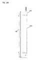
- FIG. 3is a side elevational view of the example FDH of FIG. 2 in accordance with the principles of the present disclosure
- FIG. 4is a front view of the example FDH of FIG. 2 in accordance with the principles of the present disclosure
- FIG. 5is a top plan view of the example FDH of FIG. 2 in accordance with the principles of the present disclosure
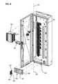
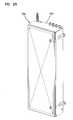
- FIG. 6is a front, top isometric view of the example FDH of FIG. 2 with the door arranged in an open position to facilitate access to telecommunication components mounted to a front side of a swing frame arranged in a first position within the FDH in accordance with the principles of the present disclosure;
- FIG. 7is schematic diagram showing an example cable routing scheme for an example FDH in accordance with the principles of the present disclosure
- FIG. 8is an isometric, partially exploded view of the example FDH of FIG. 6 with a splitter mounting location and a storage location exploded from the swing frame and with a splitter module exploded from the splitter mounting location, a termination module exploded from a termination location, and a storage module exploded from the storage location in accordance with the principles of the present disclosure;
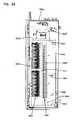
- FIG. 9is a front view of the FDH of FIG. 6 showing feeder fibers routed to splitter modules, a first splitter pigtail routed from one of the splitter modules to a storage module, and a second splitter pigtail routed from another of the splitter modules to a termination module in accordance with the principles of the present disclosure;
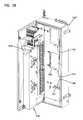
- FIG. 10is a front, top isometric view of the example FDH of FIG. 6 with the swing frame having been pivoted from the first position within the FDH through the open front side to a second position such that a rear side of the swing frame is accessible in accordance with the principles of the present disclosure;
- FIG. 11is a schematic diagram of a splitter mounting location including multiple fiber optic adapters configured to receive input fibers at first ports and splitter input connectors at second ports to connect the input fibers to a splitter in order to split signals carried by the input fibers to multiple splitter pigtails in accordance with the principles of the present disclosure;
- FIG. 12is a schematic diagram of a top, plan view of a swing frame including a termination module having fiber a slide axis extending completely in a front-to-rear direction in accordance with the principles of the present disclosure
- FIG. 13is a schematic diagram of a top, plan view of a swing frame including a termination module having fiber a slide axis extending at least partially in a front-to-rear direction in accordance with the principles of the present disclosure
- FIG. 14is a front, top isometric view of another example FDH including a body and a door in accordance with the principles of the present disclosure
- FIG. 15is a front view of the example FDH of FIG. 14 in accordance with the principles of the present disclosure.
- FIG. 16is a side elevational view of the example FDH of FIG. 14 in accordance with the principles of the present disclosure
- FIG. 17is a front, top isometric view of the example FDH of FIG. 14 with the door opened and a swing frame contained within an interior of the body of the FDH in accordance with the principles of the present disclosure;
- FIG. 18is a front view of the example FDH of FIG. 17 in accordance with the principles of the present disclosure.
- FIG. 19is a front, top isometric view of the example FDH of FIG. 17 with the swing frame pivoted through an access opening defined in a front of the body of the FDH in accordance with the principles of the present disclosure;
- FIG. 20is a front, top isometric view of the example FDH of FIG. 19 having a splice tray-type subscriber distribution cable interface in accordance with the principles of the present disclosure
- FIG. 21is a front, top isometric view of the example FDH of FIG. 19 having multi-termination connector-type subscriber distribution cable interface in accordance with the principles of the present disclosure
- FIG. 22is a front, top isometric view of one example swing frame configured to mount within an FDH in accordance with the principles of the present disclosure
- FIG. 23is a front, top isometric view of another example FDH including a body and a door in accordance with the principles of the present disclosure
- FIG. 24is a front view of the example FDH of FIG. 23 in accordance with the principles of the present disclosure.
- FIG. 25is a side elevational view of the example FDH of FIG. 23 in accordance with the principles of the present disclosure.
- FIG. 26is a front, top isometric view of the example FDH of FIG. 23 with the door opened and a swing frame contained within an interior of the body of the FDH in accordance with the principles of the present disclosure;
- FIG. 27is a front view of the example FDH of FIG. 26 in accordance with the principles of the present disclosure.
- FIG. 28is a front, top isometric view of the example FDH of FIG. 26 with the swing frame pivoted through an access opening defined in a front of the body of the FDH in accordance with the principles of the present disclosure;
- FIG. 29is a front, top isometric view of the example FDH of FIG. 28 having multi-termination connector-type subscriber distribution cable interface in accordance with the principles of the present disclosure.
- FIG. 30is a front, top isometric view of one example swing frame configured to mount within an FDH in accordance with the principles of the present disclosure.
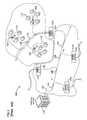
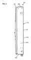
- the present disclosurerelates to a fiber distribution hub 200 having a generally rectangular, low profile enclosure 202 (see FIGS. 2-5 ).
- the enclosure 202has a generally rectangular main body 204 having a top wall 204 a ( FIG. 3 ), a bottom wall 204 b ( FIG. 3 ), a first side wall 204 c ( FIG. 4 ), a second side wall 204 d ( FIG. 2 ), and a back wall 204 e ( FIG. 3 ) defining an interior.
- the body 204also defines a generally open front side 204 f ( FIG. 6 ) opposite the back wall 204 e.
- the enclosure 202also includes a door 205 typically mounted at the open front side 204 f of the main body 204 .
- the door 205is pivotally movable from an open position (see FIG. 6 ) in which the interior of the enclosure 202 can be accessed to a closed position (see FIGS. 2-5 ) in which the open front side 204 f of the main body 204 is at least partially covered.
- the enclosure 202can include two or more doors 205 covering the open front side 204 f .
- a seal 208( FIG. 6 ) can be provided at the interface between the door 205 and the main body 204 for sealing the enclosure 202 when the door 205 is closed. In the example shown in FIG. 6 , the seal 208 is mounted to the back side of the door 205 .
- each enclosure 202can include one or more telecommunications components including telecommunications circuits (e.g., optical outputs to subscribers).
- telecommunications circuitse.g., optical outputs to subscribers.
- an example enclosurecan include at least 32 circuits (e.g., 32 fiber optic adapters such that the enclosure can provide 32 outputs to subscriber locations).
- an example enclosurecan include at least 64 circuits (e.g., 64 fiber optic adapters such that the enclosure can provide 64 outputs to subscriber locations).
- an example enclosurecan include at least 72 circuits (e.g., 72 fiber optic adapters such that the enclosure can provide 22 outputs to subscriber locations).
- an example enclosurecan include at least 96 circuits (e.g., 96 fiber optic adapters such that the enclosure can provide 96 outputs to subscriber locations).
- an example enclosurecan include at least 144 circuits (e.g., 144 fiber optic adapters such that the enclosure can provide 144 outputs to subscriber locations).
- an example enclosurecan include at least 288 circuits (e.g., 288 fiber optic adapters such that the enclosure can provide 288 outputs to subscriber locations).
- an example enclosurecan include at least 576 circuits (e.g., 576 fiber optic adapters such that the enclosure can provide 576 outputs to subscriber locations).
- the enclosurescan have depths less than 9 inches. While for low profile applications it is desirable for the enclosures have depths less than 9 inches, other embodiments of the present enclosure may have depths greater than 9 inches.
- the low profile enclosure 202is preferably sized to be placed in a location, such as a closet, without occupying a large amount of space.
- the depth D of the enclosure 202is kept small to enhance the ability of the enclosure 202 to fit within a compact space.
- the enclosure 202can have a depth D of less than or equal to about 9 inches (e.g., about 23 centimeters).
- the enclosure 202can have a depth D of less than or equal to about 8 inches (e.g., about 20 centimeters).
- the enclosure 202can have a depth D of less than or equal to about 7 inches (e.g., about 18 centimeters).
- the width W and height H of the enclosure 202can vary depending upon the number of circuits present in the fiber distribution hub 200 .
- the height H of the enclosure 202is greater than the width W, which is greater than the depth D (see FIG. 2 ).
- the height H of the enclosure 202is at least twice the width W of the enclosure 202 .
- the height His at least four times greater than the depth D of the enclosure 202 .
- the height His at least five times greater than the depth D.
- the height H of the enclosure 202is at least three times greater than the depth D and the width W of the enclosure 202 is at least 1.5 times the depth D.
- the width W of the enclosure 202is at least twice the depth D. In further embodiments, the height H of the enclosure 202 is at least 5 times as large as the depth D and the width W of the enclosure 202 is at least two times as large as the depth D.
- the enclosure 202can have a depth D of about 7 inches, a height H of about 32 inches (e.g., about 81 centimeters), and a width W of about 15 inches (e.g., about 38 centimeters).
- the enclosure 202can have a depth D of about 7 inches, a height H of about 41 inches (e.g., 104 centimeters), and a width W of about 15 inches.
- the enclosure 202can have a depth D of about 7 inches, a width W of about 30 inches (e.g., about 76 centimeters), and a height H of about 41 inches.
- example FDHs 200have depths D of less than about 9 inches, widths W of greater than 9 inches, and heights H greater than the widths W.
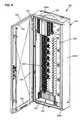
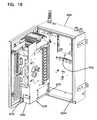
- the fiber distribution hub 200includes a swing frame 230 pivotally mounted within the enclosure 202 (see FIG. 10 ).
- the swing frame 230has a front side 233 and a rear side 234 .
- the swing frame 230is connected to the enclosure 202 by a hinge arrangement 231 defining a vertical hinge axis 232 located adjacent a front corner of the main body 204 of the low profile enclosure 202 (see FIG. 6 ).
- the vertical hinge axis 232allows the swing frame 230 to be swung between a first position (see FIG. 6 ) in which the swing frame 230 is arranged completely within the main body 204 of the enclosure 202 and a second position (see FIG. 10 ) in which the swing frame 230 is pivoted through the open front side 204 f of the main body 204 such that the rear side 234 of the swing frame 230 is accessible.
- a number of telecommunications componentscan be mounted on the swing frame 230 .
- a splitter mounting location 320 for mounting fiber optic splitter modules 325( FIG. 8 ) is located adjacent the top of the swing frame 230 .
- a termination field 340is located beneath the splitter mounting location 320 .
- a connector storage location 330is positioned beneath the termination field 340 on the swing frame 230 .
- One or more vertical cable management channels 350( FIG. 7 ) extend vertically along the swing frame 230 . In other embodiments, however, the telecommunication components can be mounted to the swing frame 230 in different configurations.
- the FDH 200generally administers connections at a termination panel between incoming fiber and outgoing fiber.
- a connectionbetween fibers includes both direct and indirect connections.
- incoming fibersinclude the fibers of a feeder cable that enters the enclosure 202 and intermediate fibers that connect the feeder cable fibers to the termination region.
- intermediate fibersinclude connectorized pigtails extending from one or more splitters and fibers that extend from a splitter and that are spliced or otherwise connected to the feeder cable.
- Examples of outgoing fibersinclude the fibers of the subscriber cable that exit the enclosure 202 and any intermediate fibers that connect the subscriber cable fibers to the termination region.
- the termination region (e.g., termination field 340 of FIG. 6 ) of the FDH 200provides an interconnect interface for optical transmission signals at a location in the network where operational access and reconfiguration are desired.
- the FDH 200can be used to split the feeder cables and terminate the split feeder cables to distribution cables routed to subscriber locations 115 ( FIG. 1 ).
- the FDH 200is designed to accommodate a range of alternative sizes and fiber counts and support factory installation of pigtails, fanouts, and splitters.
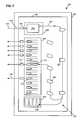
- FIG. 7is schematic diagram showing an example cable routing scheme 300 for the FDH 200 .
- a feeder cable 310can be routed initially through the enclosure 202 (e.g., typically through the back or bottom of the main body 204 as shown in FIG. 10 ).
- the jacket of the cablecan be clamped to the enclosure and fibers 310 f of the feeder cable 310 can be routed onto the swing frame 230 .
- the fibers 310 f of the feeder cable 310can include ribbon fibers.
- An example feeder cable 310may include twelve to forty-eight individual fibers 310 f connected to a service provider central office 110 ( FIG. 1 ).
- the fibers 310 f of the feeder cable 310can be routed to a fanout device 311 arranged on the swing frame 230 .
- the fanout device 311separates the fibers 310 f of the feeder cable 310 .
- the fanout device 311also can upjacket the fibers 310 f of the feeder cable 310 .
- the separated fibers 310 f of the feeder cable 310are routed from the fanout device 311 to the splitter region 320 .
- the feeder cable fibers 310 fare connected to separate splitter modules 325 , in which signals carried over the feeder cable fibers 310 f are each split into multiple signals carried over splitter pigtails 312 , each having a connectorized end 314 .
- the ends of the fibers 310 fcan be connectorized and can be connected to the splitter modules by fiber optic adapters.
- a typical splitter pigtail 312includes a coated, and possibly buffered, fiber, a jacket covering the fiber, and strength members (e.g., aramid yarn) positioned between the fiber and the jacket.
- the fibers of the feeder cable 310can be routed to a feeder cable interface (e.g., a fiber optic adapter module, a splice tray, a multi-termination connector, etc.).
- a feeder cable interfacee.g., a fiber optic adapter module, a splice tray, a multi-termination connector, etc.
- the fibers of the feeder cable 310are individually connected to separate intermediate splitter input fibers (not shown) that are routed to the splitter region 320 .
- the connectorized ends 314can be temporarily stored on a storage module 335 that is mounted at the storage region 330 of the swing frame 230 .
- the pigtails 312are routed from the splitter modules 325 to a termination module 345 that is provided at the termination region 340 of the swing frame 230 .
- the termination module 345is the dividing line between the incoming fibers and the outgoing fibers.
- a typical distribution cable 318forms the F 2 portion of a network (see FIG. 1 ) and typically includes a plurality of fibers (e.g., 144, 216, or 432 fibers) that are routed from the FDHs 130 to subscriber locations 115 ( FIG. 1 ).
- the connectorized ends 314 of the splitter pigtails 312are connected to the connectorized ends 316 of fibers optically coupled (i.e., linked) with the distribution cable 318 . These fibers may be ribbonized at a fanout 317 provided on the swing frame 230 . In some embodiments, the connectorized ends 316 terminate the fibers of the distribution cable 318 . In other embodiments, the connectorized ends 316 are provided at the ends of intermediate fibers that couple to a distribution cable 318 . For example, in one embodiment, the intermediate fibers may be spliced to fibers of a distribution cable 318 at a location within the enclosure (e.g., at splice trays mounted to the back wall of the enclosure).
- the connectorized ends 316are provided at the ends of fibers of a stub cable that is routed out of the cabinet and spliced or otherwise connected to fibers of a distribution cable at aq location outside the enclosure.
- the intermediate fibersmay be terminated with a multi-termination connector (i.e., a multi-fiber connector) which can be optically coupled to a subscriber cable terminated at a multi-termination connector.
- a multi-termination connectori.e., a multi-fiber connector
- multi-fiber connector-terminated intermediate fiberscan be found in copending U.S. application Ser. No. 11/513,910, filed Aug. 30, 3006 as “Fiber distribution hub with modular termination blocks,” the disclosure of which is hereby incorporated herein by reference.
- one or more fibers of the feeder cable 310are not connected to any of the splitter modules 325 . Rather, these fibers of the feeder cable 310 are connected through an interface device to pass-through fibers (not shown) having connectorized ends.
- the connectorized ends of the pass-through fibersare connected to the connectorized ends 316 of the subscriber cable fibers 318 at the termination region 340 of the swing frame 230 without first connecting to the splitter region 320 .
- the connectorized ends of the pass-through fiberscan be stored at the storage region 330 of the swing frame 230 when not in use. In other embodiments, however, a feeder cable 310 having a connectorized end can be routed directly to the termination region 340 of the swing frame 230 .
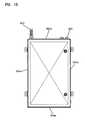
- some embodiments of the swing frame 230have a generally rectangular configuration having a height H 2 that corresponds generally to the height H of the enclosure 202 and a width W 2 that corresponds generally to the width W of the enclosure 202 (see FIG. 10 ).
- the swing frame 230also has a depth D 2 ( FIG. 10 ) that is smaller than the depth D of the enclosure 202 to accommodate cable management structures provided one the rear side 234 of the swing frame 230 .
- the swing frame 230has a rectangular rear wall 235 a ( FIG. 9 ).
- a top wall 235 b , a bottom wall 235 c , a first side wall 235 d , and a second side wall 235 eproject forwardly from the rear wall 235 a ( FIGS. 8-10 ).
- the rear, top, bottom, and side walls of the swing frame 230form a forwardly facing tray/recess 235 ( FIG. 8 ) in which telecommunications equipment can be mounted.
- a number of telecommunications componentsare mounted within the tray defined by the front side 233 of the swing frame 230 .
- a splitter mounting location 320 for mounting fiber optic splitter modules 325is located adjacent the top 235 a of the swing frame 230 .
- a termination field 340is located beneath the splitter mounting location 320 .
- a connector storage location 330is positioned beneath the termination field 340 .
- One or more vertical cable management channels 350extend vertically along the side 235 e at the front 233 of the swing frame 230 . Cable management structures (e.g., fiber storage loops, fiber radii bend limiters, storage clips, etc.) are provided in the cable management channels 350 .
- the splitter mounting location 320has a plug-and-play configuration. In this configuration, the fiber optic splitter modules 325 containing fiber optic splitters 324 are inserted into the splitter mounting location 320 and optically connected to feeder fibers 310 .
- a schematic diagram of one example splitter mounting location 320is shown in FIG. 11 .
- the splitter mounting location 320includes one or more fiber optic adapters 322 .
- a connectorized end of one of the feeder fibers 310i.e., or a splitter input fiber
- a fiber optic connector 323 mounted on a fiber optic splitter module 325plugs into the second end of the adapter 322 to couple the feeder fiber 310 to a splitter 324 arranged within the fiber optic splitter module 325 .
- the signals from the feeder fibers 310are split at the splitter 324 and directed into a plurality (e.g., 8, 16, 32, etc.) of pigtails 312 .
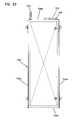
- the splitter pigtails 312are routed laterally away from the splitter modules 325 and then downwardly along the vertical cable management channel 350 .
- the ends of the pigtails 312include fiber optic connectors 314 .
- Some of the pigtails 312are routed downwardly and then looped back upwardly and plugged into termination adapters 345 at the termination field 340 so as to be optically connected to another optical fiber (e.g., a fiber 318 corresponding to a subscriber 115 ).
- Other connectorized pigtails 312can be routed downwardly along the vertical cable management channel 350 and stored at the connector storage location 330 .
- the termination field 340includes a plurality of adapter modules 345 that are disposed on the swing frame 230 .
- Each adapter module 345includes a horizontal row of fiber optic adapters (e.g., a row of 6 fiber optic adapters).
- Each of the fiber optic adaptersincludes a first port facing toward the second side wall 235 e of the swing frame 230 for receiving a connector 314 terminating one of the splitter pigtails 312 .
- Each of the fiber optic adaptersalso includes a second port facing toward the first side wall 235 d of the swing frame 230 for receiving a fiber optic connector 316 corresponding to one of the fibers 318 routed from the FDH 200 to a remote location (e.g., to a subscriber location 115 of FIG. 1 ).
- the fiber optic adaptersare configured to providing an optical coupling between fiber optic connectors inserted into the ports.
- the adapter modules 345are moveable (e.g., slideable) between a retracted position and an extended position.
- the retractable/extendable configuration of the adapter modules 345facilitates accessing the densely populated fiber optic adapters. Moving the adapter module 345 into the extended position provides enhanced access to the ports of the extended adapter module 345 and, accordingly, to the connectors 314 , 316 plugged into the ports.
- Similar sliding adapter modulesare described in greater detail in commonly owned U.S. Pat. Nos. 5,497,444; 5,717,810; 6,591,051; and in U.S. Patent Publication No. 2007/0025675, the disclosures of which are incorporated herein by reference.
- the adapter modules 345move (e.g., slide) along a slide axis As ( FIGS. 12 and 13 ) when moved from the retracted position to the extended position.
- the adapter modules 345can be oriented to slide in a forward-to-rearward direction (i.e., in a forward direction F and a rearward direction R).
- the adapter modules 345slide away from and back toward the rear wall 235 a of the swing frame 230 when moving between the retracted and extended positions.
- the slide axis Asextends in a forward-to-rearward direction with respect to the back wall 204 e of the enclosure 202 .
- the adapter modules 345can be oriented such that the slide axis As extends at an angle ⁇ with respect to the enclosure 202 and/or the swing frame 230 .
- the slide axis Asextends at least partially in a forward-to-rearward direction.
- an axis that extends “at least partially in a forward-to-rearward direction”extends at an angle ⁇ that is greater than zero and less than ninety degrees with respect to the enclosure 202 or the swing frame 230 .
- the slide axis Asextends mainly in a forward-to-rearward direction as shown in FIG. 13 .
- an axis that extends “mainly in a forward-to-rearward direction”extends at an angle ⁇ that is greater than forty-five degrees and less than ninety degrees.
- the slide axis Asextends completely in a forward-to-rearward direction as shown in FIG. 12 .
- an axis that extends “completely in a forward-to-rearward direction”extends at an angle ⁇ of about ninety degrees (plus or minus a reasonable tolerance).
- the sliding axis Asextends generally horizontally with respect to the bottom wall 204 b of the enclosure 202 and/or the bottom wall 235 c of the swing frame 230 . In another embodiment, the sliding axis As extends at an upward or downward angle with respect to the bottom wall 204 b of the enclosure 202 and/or the bottom wall 235 c of the swing frame 230 .
- Fiber optic adapters of the adapter modules 345having ports defining insertion axes along which fiber optic connectors 314 , 316 can be plugged into the fiber optic adapters.
- the portsface laterally outwardly toward the sides 235 d , 235 e of the swing frame 230 .
- the fiber optic connectors 314 , 316extend laterally outwardly from the ports of the adapter modules 345 along the insertion axes (see example insertion axis A I of FIGS. 12 and 13 ).
- the width W 2 of the swing frame 230is sufficiently wide to accommodate the minimum bend radius of the splitter pigtails 312 and the subscriber cables 318 as these cables extend outwardly from the connectors 314 , 316 . Due to the orientation of the adapter modules 345 , the depth D 2 of the swing frame 230 and, accordingly, the depth D of the enclosure body 204 need not be sufficiently deep to accommodate such a minimum bend radius limit.
- the insertion axis A Iextends and the ports face at least partially in a lateral direction.
- an axis that extends “at least partially in a lateral direction”extends at an angle ⁇ that is greater than zero and less than ninety degrees with respect to the side walls 235 d , 235 e of the swing frame 230 .
- the insertion axis A Iextends mainly in a lateral direction.
- an axis that extends “mainly in a lateral direction”extends at an angle ⁇ that is greater than forty-five degrees and less than ninety degrees with respect to the sides 235 d , 235 e of the swing frame 230 .
- the insertion axis A Iextends completely in a lateral direction.
- an axis that extends “completely in a lateral direction”extends at an angle ⁇ of about ninety degrees (plus or minus a reasonable tolerance) with respect to the sides 235 d , 235 e of the swing frame 230 .
- the connector storage location 330includes a panel 331 defining one or more openings 332 at which panel-mounted connector storage blocks 335 can be mounted.
- Each connector storage block 335includes a snap-fit connection mechanism 337 to secure the connector storage block 335 to one of the panel openings 332 .
- the connector storage blocks 335are adapted for storing and protecting the connectorized ends 314 of the splitter pigtails 312 when the splitter pigtails 312 are not connected to the termination field 340 .
- the connector storage blocks 335are configured to receive the connectorized ends 314 when dust caps are mounted over ferrules of the connectorized ends 314 .
- each of the connector storage blocks 335includes an integral (one-piece) housing 336 defining openings leading to an interior in which the connectorized ends 314 can be stored.
- the housing 336is made from plastic. Further details regarding example embodiments of the connector storage blocks 345 can be found in U.S. Pat. Nos. 7,277,620 and 7,198,409, which are hereby incorporated by reference.
- a jacketed feeder cable 310 having feeder fibers 313is routed into the enclosure 202 through the bottom wall 204 b of the enclosure 202 .
- the feeder cable 310includes a stub cable having fiber ends located outside the enclosure 202 that are spliced or otherwise connected to another length of feeder cable that extends to a location, such as a central office.
- the stub cableis installed in the enclosure 202 prior to installation of the enclosure 202 .
- the fiber ends of the stub cableare spliced to the other length of feeder cable during installation of the enclosure 202 .
- a clamp 291can be used to secure the jacketed feeder cable 310 to the back wall 204 e of the enclosure 202 .
- the feeder fibers 313 of the jacketed feeder cable 310are upjacketed in a buffer tube and routed upwardly along the hinge axis 232 of the swing frame 230 to the top, back side of the swing frame 230 .
- the fibers 313are fanned out by a fan out module 311 to which the buffer tube is secured.
- the fanned out fibers 313can be routed about a storage spool 372 to store excess fiber.
- the feeder fibers 313are routed through a vertical slot 236 that extends through the back wall 232 a of the swing frame 230 . Once passing through the vertical slot 236 , the fibers 313 are routed to the splitter mounting location 320 where the fibers 313 are optically connected to a corresponding plug and play splitter modules 325 located at the splitter mounting location 320 .
- a jacketed distribution cable 318also enters the enclosure 202 through the bottom wall 204 b of the enclosure 202 .
- the jacketed distribution cable 318includes a stub cable having fiber ends located outside the enclosure 202 that are spliced or otherwise connected to another length of distribution cable that extends to subscriber locations.
- the stub cableis installed in the enclosure 202 prior to installation of the enclosure 202 .
- the fiber ends of the stub cableare spliced to the other length of distribution cable during installation of the enclosure 202 .
- the jacketed distribution cable 318Upon entering the enclosure 202 , the jacketed distribution cable 318 is preferably clamped to the back wall 204 e of the enclosure 202 with a cable clamp 292 . Subscriber fibers 319 located within the distribution cable 318 are upjacketed in buffer tubes which are routed upwardly along the hinge axis 232 of the swing frame 230 and along the rear wall 202 e of the enclosure 202 behind the rear wall 232 a of the swing frame 230 . For example, the fibers 318 are shown extending across the back side 234 of the swing frame 230 (i.e., in a direction away from the hinge axis 232 ) and then downwardly along the back side 234 of the swing frame 230 .
- the upjacketed subscriber fibers 319are routed to fan-out modules 317 .
- the fibers 319are fanned out.
- the fanned out fibers 319can be looped around fiber storage spools 274 mounted to the back side 234 of the swing frame 230 to store excess fiber.
- the subscriber fibers 319are routed laterally across the back side 234 of the swing frame 230 and through slots 308 defined through the back wall 235 a of the swing frame 230 at a location proximate the hinge axis 232 of the swing frame 230 .
- the slots 308extend generally horizontally through the back wall 235 a of the swing frame 230 and can include enlarged portions sized for allowing a fiber optic connector (e.g., an SC connector) to pass through the slots 308 .
- a fiber optic connectore.g., an SC connector
- a plurality of the slots 308 or portions of a plurality of the slots 308can be defined through a removable panel portion that forms at least a portion of the back wall of the swing frame. During installation, the panel portion can be removed to facilitate routing fibers from the back to the front of the swing frame and to facilitate positioning the fibers in the slots 308 .
- the subscriber fibers 319After passing through the horizontal slots 308 , the subscriber fibers 319 , which have been pre-terminated with fiber optic connectors 316 , are routed to the termination field 340 and are plugged into the second ports of the fiber optic adapters of the adapter modules 345 . In this way, when the connectorized pigtails 312 are plugged into the first ports of the fiber optic adapters, the pigtails 312 are optically connected to corresponding subscriber fibers 318 plugged into the second ports of the fiber optic adapters.
- the cables 310 and 318have been shown entering the enclosure 202 from the bottom, in other embodiments, these cables can enter from the top or from any other side of the enclosure 202 .
- the feeder cable 310 and distribution cable 318can be terminated at fiber optic connectors, which can be plugged directly into the adapter modules 345 without any intermediate fibers or splitters.
- the fiber distribution hub 200can be provide with numerous cable management structures, such as fiber bend radius limiters 276 , channel brackets 278 , cable tie downs 279 , and other structures.
- FIGS. 14-21show other embodiments of fiber distribution hubs 500 , 500 ′ and 500 ′′.
- the fiber distribution hubseach have a generally rectangular, low profile enclosure 502 (see FIGS. 14-16 ).
- the enclosure 502has a generally rectangular main body 504 having a top wall 504 a ( FIG. 14 ), a bottom wall 504 b ( FIG. 16 ), a first side wall 504 c ( FIG. 15 ), a second side wall 504 d ( FIG. 15 ), and a back wall 504 e ( FIG. 16 ) defining an interior.
- the body 504also defines a generally open front side 504 f ( FIG. 19 ) opposite the back wall 504 e defining an access opening.
- the enclosure 502also includes a door 505 typically mounted at the open front side 504 f of the main body 504 .
- the door 505is pivotally movable from an open position (see FIG. 17 ) in which the interior of the enclosure 502 can be accessed to a closed position (see FIGS. 14-16 ) in which the door 505 at least partially covers the open front side 504 f of the main body 504 .
- a sealcan be provided at the interface between the door 505 and the main body 504 for sealing the enclosure 502 when the door 505 is closed.
- the enclosure 502defines at least a first entrance port 503 through which a feeder cable can enter the body 504 and at least a first exit port 507 through which a subscriber distribution cable can exit the body 504 .
- the enclosure 502can define additional entrance and/or exit ports.
- the first entrance port 503 and two exit ports 507extend through the top panel 502 a of the enclosure body 504 .
- the entrance port 503 and exit port 507can be defined in any of the walls 502 a - 502 e of the body 504 .
- one or more of the ports 503 , 507include strain relief members extending outwardly from the body 504 .
- the enclosure 502can include one or more telecommunications components including telecommunications circuits (e.g., optical outputs to subscribers).
- telecommunications circuitse.g., optical outputs to subscribers
- the enclosure 502 shown in FIGS. 14-21is configured to hold approximately 144 telecommunications circuits.
- Other embodimentscan be configured to hold greater or fewer circuits.
- the enclosure 502has a depth of less than about 9 inches. In some embodiments, the enclosure 502 has a depth of less than about 8 inches. Indeed, in some embodiments, the enclosure 502 has a depth of less than about 7 inches.
- the enclosure body 504contains cable interface components that facilitate optically coupling together incoming feeder cable(s) and outgoing distribution cable(s).
- the body 504contains at least a first feeder cable interface 542 and at least a first distribution cable interface 544 (see FIGS. 20 and 21 ).
- the first feeder cable interface 542includes a splice tray 543 .
- the first feeder cable interface 542can include one or more adapter modules for coupling connectorized ends of the feeder cable to the intermediate fibers.
- the first distribution cable interface 544includes a splice tray 545 .
- the enclosure 502can include multiple splice trays at which distribution cables can connect to intermediate fibers.
- the first distribution cable interface 544can include another type of interface.
- the first distribution cable interface 544can include one or more adapters for optically coupling connectorized ends of intermediate fibers and one or more distribution cables.
- the first distribution cable interface 544includes a panel or shelf 547 at which one or more adapters 546 configured to receive multi-termination (MT) connectors can be installed.
- MTmulti-termination
- adapters for single-termination connectorscan be installed at the shelf 547 .
- the enclosure 502can include multiple distribution cable interfaces 544 of various types (e.g., splice trays and adapters).
- the fiber distribution hub 500includes a swing frame 530 pivotally mounted within the enclosure 502 (see FIG. 19 ).
- the swing frame 530has a front side 533 ( FIG. 17 ) and a rear side 535 ( FIG. 19 ).
- the swing frame 530is connected to the enclosure 502 by a hinge arrangement 531 ( FIG. 17 ) defining a vertical hinge axis located adjacent a front corner of the main body 504 of the low profile enclosure 502 .
- the swing frame 530is configured to be moved between a first position (see FIG. 17 ) in which the swing frame 530 is arranged completely within the main body 504 of the enclosure 502 and a second position (see FIG. 19 ) in which the swing frame 530 is pivoted through the open front side 504 f of the main body 504 such that the rear side 535 of the swing frame 530 is accessible.
- the swing frame 500can include one or more locking assemblies for locking the swing frame 500 into one or more positions.
- the swing frame 530 shown in FIG. 19includes a first locking assembly 670 mounted at a front of a side panel and a second locking assembly 675 mounted at a rear side 535 of the swing frame 530 .
- Locking assembly 670engages a catch provided at the bottom of the enclosure 502 to retain the swing frame in the first position.
- the locking assembly 675engages a front edge of the enclosure 502 to retain the swing frame in the second position.
- Other swing frame embodimentscan have greater or fewer locking assemblies.
- one example swing frame 600includes a top panel 602 a , a bottom panel 602 b , a first side panel 602 c , and a second side panel 602 d extending forwardly from a rear panel 610 .
- a number of telecommunications componentscan be mounted on the swing frame 600 .
- a splitter mounting location 620 for mounting fiber optic splitter modules 625is located adjacent the top of the swing frame 600 .
- a termination field 650is located beneath the splitter mounting location 620 .
- a connector storage location 630is positioned beneath the termination field 650 on the swing frame 600 .
- One or more vertical cable management channels 640extend vertically along the swing frame 600 .
- Channel 640is located at side 602 d positioned opposite from the hinge side 602 c of the swing frame 600 .
- the telecommunication componentscan be mounted to the swing frame 600 in different configurations.
- the top panel 602 adefines the splitter mounting location 620 at which a splitter module housing 622 can be mounted.
- One or more splitter modules 625can be installed at each splitter housing 622 .
- An end panel 621is positioned adjacent the splitter mounting location 620 .
- the end panel 621facilitates routing one or more input cables to the splitter modules 625 installed at the splitter housing 622 .
- Splitter pigtails exiting the splitter modules 625can be routed over a bend radius limiter 623 defining an opposite end of the top panel 602 a from the end panel 621 .
- Side panels 626 - 628facilitate routing the splitter pigtails from the splitter modules 625 and over the bend radius limiter 623 .
- Fiber optic adapters 629are mounted at a back side of the splitter housing 622 .
- the fiber optic adapters 629couple connectors 631 of the input cables to corresponding connectors mounted to the splitter modules 625 .
- the splitter pigtailsare routed through the cable management channels 640 before being optically coupled to either the termination field 650 or the connector storage location 630 .
- the cable management channels 640includes a side cable management channel 641 extending along the second side 602 d of the swing frame 600 .
- the side cable management channel 641facilitates storage of excess length of the splitter pigtails.
- a cover flange 643 , side flanges 644 , and a bottom flange 645define boundaries of the side cable management channel 641 .
- the side cable management channel 641can include a separation panel 642 extending vertically along the second side 602 d of the swing frame 600 to divide the channel 641 into a first side and a second side.
- Splitter pigtailscan be routed over the bend radius limiter 623 of the splitter mounting location 620 , directed downwardly along the first side of the side cable management channel 641 , hung in a half loop at the bottom flange 645 , and routed upwardly along a second side of the channel 641 to a front side of the swing frame 600 .
- additional excess length of the pigtailscan be taken up by one or more bend radius limiters extending forwardly from the rear panel 610 of the swing frame 600 .
- the excess length of the splitter pigtailscan be routed over a first bend radius limiter 646 , which extends from the rear panel 610 adjacent the top of the swing frame 600 , and around a second bend radius limiter 647 positioned below the first bend radius limiter 646 .
- Angled bend radius limiters 648can be arranged along a side of the termination field 650 to facilitate routing of splitter pigtails to specific rows of the termination field 650 .
- Tabs 649can cooperate with a bottom lip protruding upwardly from the bottom panel 602 b to inhibit portions of the splitter pigtails from spilling over the front of the swing frame 600 .
- connectorized ends of the splitter pigtailsare routed to the storage location 630 when first installed on the swing frame 600 .
- the storage location 630is defined by a storage panel 635 coupled to the rear panel 610 .
- the storage panel 635defines openings 631 enabling one or more storage modules to be mounted to the storage panel 635 .
- the openings 631are sized and configured to receive a tab and latching mechanism of the storage modules.
- the openings 631are sized and configured to enable storage modules to be mounted within the openings 631 .
- the storage modulescan be otherwise installed at the storage location 630 .
- a splitter pigtailcan be routed from the storage location 630 to a first end of an appropriate adapter at the termination field 650 for optical coupling to a fiber extending from a second end of the adapter that is optically linked to a distribution cable routed to a subscriber location.
- the termination field 650includes one or more adapter modules 655 mounted to a termination panel 651 .
- the adapter modules 655are positioned in a vertical column. Other configurations of adapter modules 655 can be utilized, however.
- the adapter modules 655move (e.g., slide) from a retracted position to an extended position.
- the adapter modules 655can be oriented to slide at least partially in a forward-to-rearward direction.
- the adapter modules 655slide mainly in a forward-to-rearward direction.
- the adapter modules 655slide completely in a forward-to-rearward direction.
- the termination panel 651is configured to be installed on the rear panel 610 of the swing frame 600 .
- the termination panel 651can mount over an opening 612 defined in the rear panel 610 .
- the termination panel 651includes openings 652 through which fasteners (e.g., screws, rivets, pegs, etc.) can be inserted to securely couple the termination panel 651 to a back side of the rear panel 610 with the adapter modules 655 projecting forwardly through the opening 612 .
- fastenerse.g., screws, rivets, pegs, etc.
- the opening 652are located adjacent a first edge 611 of the opening 612 .
- the termination panel 651also includes tabs 654 defining openings 653 that align with openings 614 in the rear panel. Fasteners can be inserted through the tab openings 653 and rear panel openings 614 to further couple the termination panel 651 to the rear panel 610 .
- the tabs 654extend from a top and bottom of the termination panel 651 .
- individually jacketed fibers optically coupled/linked to a subscriber distribution cableare routed from the sliding adapter modules 655 , through the rear panel 610 , to the rear side of the swing frame 600 .
- the jacketed fiberscan be pre-cabled on the adapter modules 655 prior to installation of the termination field 650 on the swing frame 600 .
- the jacketed fiberscan be inserted through the opening 612 defined in the rear panel 610 when the termination field 650 is secured to the rear panel 610 .
- a second edge 613 the rear panel 610can include fingers 615 defining slots 616 therebetween into which the jacketed fibers can be slid during installation.
- each slot 616can hold jacketed fibers associated with one adapter module 655 . In another embodiment, each slot 616 can hold jacketed fibers associated with two or more adapter modules 655 . Fan outs 657 are mounted to the back side of the termination panel 651 adjacent the slots 616 for fanning out and individually jacketing the fibers corresponding to the subscriber distribution cable.
- the jacketed fiberscan include a single fiber enclosed within a 2 mm jacket and also can include aramid yarn reinforcement positioned between the jacket and the fiber.
- the jacketed fibersalso may include a buffer layer or tube positioned between each optical fiber and the reinforcing layer.
- one or more fingers 615can define an opening 617 configured to receive a fastener to aid in securing the termination panel 651 to the rear panel 610 .
- each finger 615defines an opening 617 .
- a fastenercan be inserted through the termination panel 651 and through the opening 617 in the finger 615 .
- a fastenercan extend through one of the adapter modules 655 , the termination panel 651 , and the opening 617 in the finger 615 .
- the jacketed fiberscan be otherwise routed to the rear side of the swing frame 600 .
- FIGS. 23-29show other embodiments of fiber distribution hubs 700 and 700 ′.
- the fiber distribution hubseach include a generally rectangular, low profile enclosure 702 (see FIGS. 23-25 ).
- the enclosure 702has a generally rectangular main body 704 having a top wall 704 a ( FIG. 23 ), a bottom wall 704 b ( FIG. 23 ), a first side wall 704 c ( FIG. 23 ), a second side wall 704 d ( FIG. 23 ), and a back wall 704 e ( FIG. 24 ) defining an interior.
- the body 704also defines a generally open front side 704 f ( FIG. 28 ) opposite the back wall 704 e .
- the enclosure 702also includes a door 705 typically mounted at the open front side 704 f of the main body 704 .
- the door 705is pivotally movable from an open position (see FIG. 27 ) in which the interior of the enclosure 702 can be accessed to a closed position (see FIGS. 23-25 ) in which the door 705 at least partially covers the open front side 704 f of the main body 704 .
- a sealcan be provided at the interface between the door 705 and the main body 704 for sealing the enclosure 702 when the door 705 is closed.
- the enclosure 702defines at least a first entrance port 703 through which a feeder cable can enter the body 704 and at least a first exit port 707 through which a subscriber distribution cable can exit the body 704 .
- the enclosure 702can define additional entrance and/or exit ports.
- the first entrance port 703 and two exit ports 707extend through the top panel 702 a of the enclosure body 704 .
- the entrance port 703 and exit port 707can be defined in any of the walls 702 a - 702 e of the body 704 .
- one or more of the ports 703 m 707include strain relief members extending outwardly from the body 704 .
- the enclosure 702can enclose one or more telecommunications components including telecommunications circuits (e.g., optical outputs to subscribers).
- telecommunications circuitse.g., optical outputs to subscribers
- the enclosure 702 shown in FIGS. 23-28is configured to hold approximately 288 telecommunications circuits.
- Other embodimentscan be configured to hold greater or fewer circuits.
- the enclosure 702has a depth of less than about 9 inches. In some embodiments, the enclosure 702 has a depth of less than about 8 inches. Indeed, in some embodiments, the enclosure 702 has a depth of less than about 7 inches.
- the enclosure body 704includes cable interface components at which incoming feeder cable(s) and outgoing distribution cable(s) can be optically coupled together within the enclosure 702 .
- the hub 700includes at least a first feeder cable interface 742 and at least first and second distribution cable interfaces 744 , 746 .
- the first feeder cable interface 742includes a splice tray. In other embodiments, however, the first feeder cable interface 742 can include one or more adapter modules for coupling connectorized ends of the feeder cable to input leads of splitter modules.
- the first distribution cable interface 744 and the second distribution cable interface 746include splice trays 745 .
- the first and/or second distribution cable interface 744 , 746can include another type of interface.
- the second distribution cable interfaces 744 , 746can include one or more adapters for optically coupling connectorized ends of intermediate fibers routed to a termination panel to one or more distribution cables.
- the first distribution cable interface 744includes a splice tray 745 and the second distribution cable interface 746 includes a panel or shelf 747 at which one or more adapters configured to receive multi-termination (MT) connectors can be installed.
- MTmulti-termination
- adapters for single-termination connectorscan be installed at the shelf 747 .
- the enclosure 702can include greater or fewer distribution cable interfaces 744 , 746 .
- the fiber distribution hub 700includes a swing frame 730 pivotally mounted within the enclosure 702 (see FIG. 28 ).
- the swing frame 730has a front side 733 ( FIG. 27 ) and a rear side 735 ( FIG. 28 ).
- the swing frame 730is connected to the enclosure 702 by a hinge arrangement defining a vertical hinge axis located adjacent a front corner of the main body 704 of the low profile enclosure 702 .
- the swing frame 730is configured to be moved between a first position (see FIG. 27 ) in which the swing frame 730 is arranged completely within the main body 704 of the enclosure 702 and a second position (see FIG. 28 ) in which the swing frame 730 is pivoted through the open front side 704 f of the main body 704 such that the rear side 735 of the swing frame 730 is accessible.
- one example swing frame 800includes a top panel 802 a , a bottom panel 802 b , a first side panel 802 c , and a second side panel 802 d extending forwardly from a rear panel 810 .
- a number of telecommunications componentscan be mounted on the swing frame 800 .
- a splitter mounting location 820 for mounting fiber optic splitter modules 825is located adjacent the top of the swing frame 800 .
- a termination field 850is located beneath the splitter mounting location 820 .
- a connector storage location 830is positioned beneath the termination field 850 on the swing frame 800 .
- One or more vertical cable management channels 840extend vertically along the swing frame 800 . In other embodiments, however, the telecommunication components can be mounted to the swing frame 800 in different configurations.
- the top panel 802 adefines the splitter mounting location 820 at which a first splitter module housing 822 and a second splitter module housing 822 ′ can be mounted.
- the second splitter module housing 822 ′is stacked above the first splitter module housing 822 .
- the splitter module housings 822 , 822 ′can be otherwise positioned adjacent each other.
- greater or fewer splitter module housingscan be installed at the splitter mounting location 820 .
- One or more splitter modules 825can be installed at each splitter housing 822 , 822 ′.
- An end panel 821is positioned adjacent the splitter mounting location 820 .
- the end panel 821facilitates routing one or more input cables to the splitter modules 825 installed at the splitter housings 822 , 822 ′.
- Splitter pigtails exiting the splitter modules 825 installed at the first splitter module housing 822can be routed over a bend radius limiter 823 defined at an opposite end of the top panel 802 a from the end panel 821 .
- Splitter pigtails exiting the splitter modules 825 installed at the second splitter module housing 822 ′can be routed over a second bend radius limiter 823 ′ extending outwardly from the bottom of the splitter module housing 822 ′.
- Retention tabs 824 , 824 ′facilitate routing the splitter pigtails from the splitter modules 825 and over the bend radius limiters 823 , 823 ′.
- the splitter pigtailsare routed along a front side of the swing frame 800 through the cable management channel 840 before being optically coupled to either the termination field 850 or the connector storage location 830 .
- the side cable management channel 840facilitates storage of excess length of the splitter pigtails.
- the cable management channel 840is defined by the rear panel 810 of the swing frame 800 , the side panel 802 d of the swing frame 800 , and a front flange 842 extending inwardly from the side panel 802 d .
- Tabs 846can cooperate with a bottom lip 847 protruding upwardly from the bottom panel 802 b of the swing frame 800 to inhibit portions of the splitter pigtails from spilling over the front of the swing frame 800 .
- Additional excess length of the pigtailscan be taken up by one or more bend radius limiters extending forwardly from the rear panel 810 of the swing frame 800 .
- the excess length of the splitter pigtailscan be routed around a first bend radius limiter 844 , which extends from the rear panel 810 adjacent a middle region of the swing frame 800 .
- Angled bend radius limiters 848can be arranged along a side of the termination field 850 to facilitate routing of splitter pigtails to specific rows of the termination field 850 .
- the angled bend radius limiters 848are arranged in a single vertical row along the side of the termination field 850 .
- Other configurations of bend radius limiters 848 that direct splitter pigtails to appropriate areas of the termination field 850are consistent with the scope of the disclosure.
- connectorized ends of the splitter pigtailsare routed to the storage location 830 when first installed on the swing frame 800 .
- the storage location 830is defined by a storage panel 835 coupled to the rear panel 810 .
- One or more storage modulescan be mounted to the storage panel 835 .
- a splitter pigtailcan be routed from the storage location 830 to the termination field 850 for optical coupling to a subscriber distribution cable.
- the termination field 850includes one or more adapter modules mounted to one or more termination panels.
- Each adapter moduleis configured to slide away from the rear panel 810 of the swing frame 800 to enable access to the connectors plugged into the adapter modules.
- the adapter modulesmove (e.g., slide) from a retracted position to an extended position.
- the adapter modulescan be oriented to slide at least partially in a forward-to-rearward direction.
- the adapter modulesslide mainly in a forward-to-rearward direction.
- the adapter modulesslide completely in a forward-to-rearward direction.
- a first group of adapter modules 855are positioned in a vertical column on a first termination panel 851 and a second group of adapter modules 855 ′ are positioned in a vertical column on a second termination panel 851 ′.
- greater or fewer groups of adapter modulescan be arranged in any suitable configuration.
- Each termination panel 851 , 851 ′is configured to be installed on the rear panel 810 of the swing frame 800 .
- the first termination panel 851can mount at a first opening 812 defined in the rear panel 810 and the second termination panel 851 ′ can mount at a second opening 812 ′ defined in the rear panel 810 .
- the termination panels 851 , 851 ′include openings 852 , 852 ′, respectively, through which fasteners (e.g., screws, rivets, pegs, etc.) can be inserted to securely couple the termination panels 851 , 851 ′ to at least first vertical edges of the opening 812 , 812 ′, respectively.
- the termination panels 851 , 851 ′also include tabs 854 , 854 ′ defining openings 853 , 853 ′ that align with openings 814 , 814 ′, respectively, in the rear panel 810 .
- Fastenerscan be inserted through the tab openings 853 , 853 ′ and rear panel openings 814 , 814 ′ to further couple the termination panels 851 , 851 ′ to the rear panel 810 .
- the tabs 854 , 854 ′extend from a top and bottom of the termination panels 851 , 851 ′.
- Jacketed fibers corresponding to subscriber distribution cablesare routed from the sliding adapter modules 855 , 855 ′, through the rear panel 810 , to the rear side of the swing frame 800 .
- the jacketed fiberscan be pre-cabled on the adapter modules 855 , 855 ′ prior to installation of the termination panels 851 , 851 ′ on the swing frame 800 .
- the jacketed fiberscan be inserted through the openings 812 , 812 ′ defined in the rear panel 810 when the termination panels 851 , 851 ′ are secured to the rear panel 810 .
- second vertical edges of the openings 812 , 812 ′can include fingers 815 , 815 ′ defining slots 816 , 816 ′, respectively, therebetween into which the jacketed fibers can be slid during installation.
- each slot 816 , 816 ′can hold jacketed fibers associated with one adapter module 855 , 855 ′, respectively.
- each slot 816 , 816 ′can hold jacketed fibers associated with two or more adapter modules 855 , 855 ′.
- one or more fingers 815 , 815 ′can define an opening configured to receive a fastener to aid in securing the termination panel 851 , 851 ′ to the rear panel 810 .
- Embodiments of the above described FDHare suitable for use within buildings or multi-dwelling units. For example, some embodiments are suitable to mount inside closets or other enclosed spaces of limited size. Aspects of the FDH facilitate access to optical components within the FDH enclosure. For example, a pivoting swing frame facilitates access to components stored at the rear of the FDH enclosure. Sliding termination modules facilitate access to individual terminated fibers while allowing for dense storage of the coupled fibers.
Landscapes
- Physics & Mathematics (AREA)
- General Physics & Mathematics (AREA)
- Optics & Photonics (AREA)
- Light Guides In General And Applications Therefor (AREA)
- Mechanical Coupling Of Light Guides (AREA)
- Connector Housings Or Holding Contact Members (AREA)
Abstract
Description
Claims (31)
Priority Applications (2)
| Application Number | Priority Date | Filing Date | Title |
|---|---|---|---|
| US15/632,468US10067308B2 (en) | 2007-10-31 | 2017-06-26 | Low profile fiber distribution hub |
| US16/116,128US10429602B2 (en) | 2007-10-31 | 2018-08-29 | Low profile fiber distribution hub |
Applications Claiming Priority (6)
| Application Number | Priority Date | Filing Date | Title |
|---|---|---|---|
| US98435607P | 2007-10-31 | 2007-10-31 | |
| US12/241,576US7751672B2 (en) | 2007-10-31 | 2008-09-30 | Low profile fiber distribution hub |
| US12/827,423US20100329623A1 (en) | 2007-10-31 | 2010-06-30 | Low profile fiber distribution hub |
| US14/312,120US9348103B2 (en) | 2007-10-31 | 2014-06-23 | Low profile fiber distribution hub |
| US15/134,034US9690063B2 (en) | 2007-10-31 | 2016-04-20 | Low profile fiber distribution hub |
| US15/632,468US10067308B2 (en) | 2007-10-31 | 2017-06-26 | Low profile fiber distribution hub |
Related Parent Applications (1)
| Application Number | Title | Priority Date | Filing Date |
|---|---|---|---|
| US15/134,034ContinuationUS9690063B2 (en) | 2007-10-31 | 2016-04-20 | Low profile fiber distribution hub |
Related Child Applications (1)
| Application Number | Title | Priority Date | Filing Date |
|---|---|---|---|
| US16/116,128ContinuationUS10429602B2 (en) | 2007-10-31 | 2018-08-29 | Low profile fiber distribution hub |
Publications (2)
| Publication Number | Publication Date |
|---|---|
| US20180045904A1 US20180045904A1 (en) | 2018-02-15 |
| US10067308B2true US10067308B2 (en) | 2018-09-04 |
Family
ID=40582963
Family Applications (6)
| Application Number | Title | Priority Date | Filing Date |
|---|---|---|---|
| US12/241,576Expired - Fee RelatedUS7751672B2 (en) | 2007-10-31 | 2008-09-30 | Low profile fiber distribution hub |
| US12/827,423AbandonedUS20100329623A1 (en) | 2007-10-31 | 2010-06-30 | Low profile fiber distribution hub |
| US14/312,120ActiveUS9348103B2 (en) | 2007-10-31 | 2014-06-23 | Low profile fiber distribution hub |
| US15/134,034Expired - Fee RelatedUS9690063B2 (en) | 2007-10-31 | 2016-04-20 | Low profile fiber distribution hub |
| US15/632,468ActiveUS10067308B2 (en) | 2007-10-31 | 2017-06-26 | Low profile fiber distribution hub |
| US16/116,128ActiveUS10429602B2 (en) | 2007-10-31 | 2018-08-29 | Low profile fiber distribution hub |
Family Applications Before (4)
| Application Number | Title | Priority Date | Filing Date |
|---|---|---|---|
| US12/241,576Expired - Fee RelatedUS7751672B2 (en) | 2007-10-31 | 2008-09-30 | Low profile fiber distribution hub |
| US12/827,423AbandonedUS20100329623A1 (en) | 2007-10-31 | 2010-06-30 | Low profile fiber distribution hub |
| US14/312,120ActiveUS9348103B2 (en) | 2007-10-31 | 2014-06-23 | Low profile fiber distribution hub |
| US15/134,034Expired - Fee RelatedUS9690063B2 (en) | 2007-10-31 | 2016-04-20 | Low profile fiber distribution hub |
Family Applications After (1)
| Application Number | Title | Priority Date | Filing Date |
|---|---|---|---|
| US16/116,128ActiveUS10429602B2 (en) | 2007-10-31 | 2018-08-29 | Low profile fiber distribution hub |
Country Status (9)
| Country | Link |
|---|---|
| US (6) | US7751672B2 (en) |
| EP (2) | EP2206004A2 (en) |
| CN (2) | CN101842727A (en) |
| AR (1) | AR069141A1 (en) |
| AU (1) | AU2008318753B2 (en) |
| BR (1) | BRPI0805110A2 (en) |
| ES (1) | ES2361544B1 (en) |
| MX (1) | MX2010004736A (en) |
| WO (1) | WO2009058882A2 (en) |
Cited By (3)
| Publication number | Priority date | Publication date | Assignee | Title |
|---|---|---|---|---|
| US20180199117A1 (en)* | 2017-01-12 | 2018-07-12 | Iap Worldwide Services Inc. | Cable management system and apparatus for portable rack-mounted electronics |
| US10429602B2 (en) | 2007-10-31 | 2019-10-01 | Commscope Technologies Llc | Low profile fiber distribution hub |
| WO2020198740A1 (en)* | 2019-03-28 | 2020-10-01 | Ppc Broadband, Inc. | Fiber distribution hub with swiveling frame body |
Families Citing this family (60)
| Publication number | Priority date | Publication date | Assignee | Title |
|---|---|---|---|---|
| US7623749B2 (en)* | 2005-08-30 | 2009-11-24 | Adc Telecommunications, Inc. | Fiber distribution hub with modular termination blocks |
| US7715679B2 (en) | 2007-05-07 | 2010-05-11 | Adc Telecommunications, Inc. | Fiber optic enclosure with external cable spool |
| US7756379B2 (en) | 2007-08-06 | 2010-07-13 | Adc Telecommunications, Inc. | Fiber optic enclosure with internal cable spool |
| US7720344B2 (en)* | 2007-10-22 | 2010-05-18 | Adc Telecommunications, Inc. | Fiber distribution hub |
| US8363997B2 (en)* | 2008-12-19 | 2013-01-29 | Commscope, Inc. Of North Carolina | System for intelligent patching of telecommunication cables with a communication network |
| CN106130646B (en) | 2009-03-05 | 2019-04-30 | Adc电信公司 | Methods, systems and apparatus for integrating wireless technologies into fiber optic networks |
| US7899300B2 (en)* | 2009-06-03 | 2011-03-01 | Emerson Network Power, Energy Systems, North America, Inc. | Dust caps for fiber optic connectors |
| US8244089B2 (en)* | 2009-06-03 | 2012-08-14 | Emerson Network Power, Energy Systems, North America, Inc. | Dust caps for fiber optic connectors |
| ES2403007A1 (en)* | 2009-07-01 | 2013-05-13 | Adc Telecommunications, Inc | Wall-mounted fiber distribution hub |
| US8606067B2 (en)* | 2009-09-04 | 2013-12-10 | Adc Telecommunications, Inc. | Pedestal terminal with swing frame |
| MX2011009233A (en)* | 2009-10-14 | 2011-09-27 | Afl Telecommunications Llc | FIBER PUMP BOX. |
| US8515234B2 (en)* | 2009-11-25 | 2013-08-20 | Adc Telecommunications, Inc. | Methods, systems and devices for providing fiber-to-the-desktop |
| WO2011076275A1 (en)* | 2009-12-23 | 2011-06-30 | Prysmian S.P.A. | Optical termination assembly |
| US9078287B2 (en) | 2010-04-14 | 2015-07-07 | Adc Telecommunications, Inc. | Fiber to the antenna |
| US8837940B2 (en) | 2010-04-14 | 2014-09-16 | Adc Telecommunications, Inc. | Methods and systems for distributing fiber optic telecommunication services to local areas and for supporting distributed antenna systems |
| CN101825755A (en)* | 2010-06-12 | 2010-09-08 | 泉州市安邦通信设备有限公司 | Box for wall-hanging two-layer optical splitting box and optical splitting box |
| CN110174737A (en) | 2010-06-23 | 2019-08-27 | Adc电信公司 | Telecommunication assembly |
| EP2671111B1 (en) | 2011-02-01 | 2018-11-07 | Opterna Technology Limiited | Fiber distribution hubs |
| US8855457B2 (en) | 2011-04-13 | 2014-10-07 | Adc Telecommunications, Inc. | Optical splitting component |
| CA2877896C (en) | 2011-06-24 | 2020-07-21 | Adc Telecommunications, Inc. | Fiber termination enclosure with modular plate assemblies |
| KR101897821B1 (en)* | 2011-08-11 | 2018-09-13 | 엘에스전선 주식회사 | Fiber distribution housing |
| CN102385129A (en)* | 2011-12-02 | 2012-03-21 | 宁波电业局 | Wall-mounted optical fiber wiring combined tank |
| EP2795811B1 (en)* | 2011-12-22 | 2018-08-22 | CommScope Technologies LLC | Fiber optic wall plate with redundancy system |
| WO2014070511A1 (en)* | 2012-10-29 | 2014-05-08 | Adc Telecommunications, Inc. | System for testing passive optical lines |
| ES1141660Y (en) | 2012-12-19 | 2015-10-14 | Tyco Electronics Raychem Bvba | Distribution device with incrementally added dividers |
| US9411118B2 (en)* | 2013-04-09 | 2016-08-09 | Opterna Technology Limited | Fiber distribution hubs and storage retaining modules |
| MX362068B (en) | 2013-08-26 | 2019-01-07 | Adc Telecommunications Inc | ARRANGEMENT OF MULTIPLEXOR WAVE DIVISION FOR SMALL CELL NETWORKS. |
| US9575274B2 (en)* | 2014-02-25 | 2017-02-21 | Commscope Technologies Llc | Fiber management structure having a splice tray with modular elements |
| AU2015276109B2 (en) | 2014-06-17 | 2020-11-19 | Adc Czech Republic, S.R.O. | Cable distribution system |
| CA2954629C (en)* | 2014-07-09 | 2021-08-24 | Corning Optical Communications LLC | Modular optical fiber distribution hub with multi-row splitter module mounting structure |
| WO2016007488A1 (en)* | 2014-07-10 | 2016-01-14 | Corning Optical Communications LLC | Optical fiber distribution hub with fiber routing structures |
| US9575273B2 (en)* | 2014-07-31 | 2017-02-21 | Corning Optical Communications LLC | Splitter module holder and coupler for adding additional splitter modules to optical fiber distribution hub |
| US9641659B2 (en)* | 2014-12-12 | 2017-05-02 | Boyce Technologies Inc. | Access node and method |
| AU2016206914B2 (en) | 2015-01-12 | 2018-04-05 | Afl Telecommunications Llc | Fiber optic terminal enclosure |
| US10031306B2 (en)* | 2015-02-27 | 2018-07-24 | Opterna Technology Limited | Fiber distribution assemblies |
| EP3822676A1 (en) | 2015-04-02 | 2021-05-19 | CommScope Technologies LLC | Fiber optic network architecture using high fiber-count fiber optic connectors |
| US10416404B2 (en) | 2015-06-12 | 2019-09-17 | Commscope Technologies Llc | Telecommunications enclosure |
| US10371913B2 (en) | 2015-09-16 | 2019-08-06 | CommScope Connectivity Begium BVBA | Splitter module and enclosure for use therein |
| WO2017083519A1 (en) | 2015-11-11 | 2017-05-18 | Afl Telecommunications Llc | Optical connection terminals for fiber optic communications networks |
| US10606009B2 (en)* | 2015-12-01 | 2020-03-31 | CommScope Connectivity Belgium BVBA | Cable distribution system with fan out devices |
| EP3408701B1 (en) | 2016-01-28 | 2023-04-26 | CommScope Connectivity Belgium BVBA | Modular telecommunications enclosure |
| USD813187S1 (en)* | 2016-04-29 | 2018-03-20 | Corning Optical Communications LLC | Telecommunication terminal cabinet |
| RU184781U1 (en)* | 2016-07-20 | 2018-11-08 | Алексей Валерьевич Щербинин | FIBER DISTRIBUTION TERMINAL |
| WO2018039213A1 (en)* | 2016-08-22 | 2018-03-01 | Commscope Technologies Llc | Cabinet and patchcord management panel |
| US10859781B2 (en) | 2016-09-20 | 2020-12-08 | Clearfield, Inc. | Optical fiber distribution systems and components |
| US10606006B2 (en) | 2016-09-20 | 2020-03-31 | Clearfield, Inc. | Optical fiber distribution systems and components |
| EP3523687B1 (en)* | 2016-10-05 | 2023-09-27 | CommScope Connectivity Belgium BVBA | Telecommunications system and methods |
| US9946044B1 (en)* | 2016-12-16 | 2018-04-17 | Ccs Technology, Inc. | Equipment cabinet with movable stile |
| US10678015B1 (en)* | 2017-05-10 | 2020-06-09 | 3-Gis | Multi-tenant architecture |
| US10935745B1 (en) | 2017-07-20 | 2021-03-02 | Forrest Tyrone Gay | Multi-carrier fiber distribution hub |
| EP3698192A4 (en)* | 2017-10-17 | 2021-09-22 | Corning Research And Development Corporation | HOUSING FOR SPLICE OF OPTICAL FIBERS |
| TWM560137U (en)* | 2018-01-30 | 2018-05-11 | 大陸商安費諾光纖技術(深圳)有限公司 | Fiber optic adapter |
| US11169344B2 (en)* | 2018-02-27 | 2021-11-09 | Commscope Technologies Llc | Common module storage within a fiber distribution hub |
| CN108770251B (en)* | 2018-08-07 | 2024-02-06 | 天津会一自动化科技有限公司 | Special automatically controlled cabinet of data acquisition and teletransmission |
| US12169318B2 (en) | 2018-08-20 | 2024-12-17 | Commscope Technologies Llc | Telecommunications equipment frame |
| US20200153214A1 (en)* | 2018-11-10 | 2020-05-14 | Doug Vaught | Electronics enclosure device |
| WO2020167639A1 (en)* | 2019-02-11 | 2020-08-20 | Commscope Technologies Llc | Splice closure |
| WO2020197958A1 (en)* | 2019-03-28 | 2020-10-01 | Commscope Technologies Llc | Fiber enclosure for remote radio units |
| USD973027S1 (en) | 2019-04-04 | 2022-12-20 | Commscope Technologies Llc | Junction box for fiber and power cables |
| WO2021071844A1 (en) | 2019-10-07 | 2021-04-15 | Commscope Technologies Llc | Fiber distribution hub including sealed splice module |
Citations (91)
| Publication number | Priority date | Publication date | Assignee | Title |
|---|---|---|---|---|
| US4747020A (en) | 1986-05-16 | 1988-05-24 | Adc Telecommunications, Inc. | Wire distribution apparatus |
| US4765710A (en) | 1985-07-30 | 1988-08-23 | Siemens Aktiengesellschaft | Distributing frame for optical waveguides and the like |
| US4792203A (en) | 1985-09-17 | 1988-12-20 | Adc Telecommunications, Inc. | Optical fiber distribution apparatus |
| US4995688A (en) | 1989-07-31 | 1991-02-26 | Adc Telecommunications, Inc. | Optical fiber distribution frame |
| DE9105800U1 (en) | 1991-05-10 | 1991-06-27 | kabelmetal electro GmbH, 3000 Hannover | Cable termination device for optical fiber cables |
| US5100221A (en) | 1990-01-22 | 1992-03-31 | Porta Systems Corp. | Optical fiber cable distribution frame and support |
| US5129030A (en) | 1991-05-30 | 1992-07-07 | At&T Bell Laboratories | Movable lightguide connector panel |
| US5179618A (en) | 1990-07-11 | 1993-01-12 | Adc Telecommunications, Inc. | Fiber optic connector module |
| US5274731A (en) | 1992-12-24 | 1993-12-28 | Adc Telecommunications, Inc. | Optical fiber cabinet |
| US5289558A (en) | 1991-10-05 | 1994-02-22 | Krone Aktiengesellshaft | Switching assembly for glass fiber cables of the telecommunication and data technology |
| US5363465A (en) | 1993-02-19 | 1994-11-08 | Adc Telecommunications, Inc. | Fiber optic connector module |
| US5367598A (en) | 1993-10-21 | 1994-11-22 | Nec America, Inc. | Interface chassis for fiber optic transport system |
| US5442726A (en) | 1994-02-22 | 1995-08-15 | Hubbell Incorporated | Optical fiber storage system |
| US5448015A (en) | 1991-12-30 | 1995-09-05 | Societe Anonyme Dite Alcatel Cit | Support and Guide device for cables carrying elcetrical or light signals |
| US5497444A (en) | 1994-01-21 | 1996-03-05 | Adc Telecommunications, Inc. | High-density fiber distribution frame |
| US5511144A (en) | 1994-06-13 | 1996-04-23 | Siecor Corporation | Optical distribution frame |
| US5636138A (en) | 1992-12-29 | 1997-06-03 | Lucent Technologies Inc. | Jumper cable selection and routing system |
| US5708751A (en) | 1996-04-24 | 1998-01-13 | Tii Industries, Inc. | Optical fiber enclosure system |
| US5734774A (en) | 1995-11-30 | 1998-03-31 | Lucent Technologies Inc. | Outdoor electronics cabinet |
| US5784515A (en) | 1995-01-23 | 1998-07-21 | Nippon Telegraph And Telephone Corporation | Optical fiber cross connection apparatus and method |
| US5823646A (en) | 1997-09-02 | 1998-10-20 | Siecor Corporation | Door assembly for optical hardware cabinet |
| WO1999027404A1 (en) | 1997-11-20 | 1999-06-03 | Siemens Aktiengesellschaft | Device for guiding lines in communication systems |
| US5945633A (en) | 1996-05-23 | 1999-08-31 | The Siemon Company | Rack mountable cable distribution enclosure having an angled adapter plate bracket |
| US6044193A (en) | 1998-07-10 | 2000-03-28 | Siecor Operations, Llc | Fiber optic interconnection enclosure having a forced air system |
| US6061492A (en) | 1997-04-09 | 2000-05-09 | Siecor Corporation | Apparatus and method for interconnecting fiber cables |
| US6160946A (en) | 1998-07-27 | 2000-12-12 | Adc Telecommunications, Inc. | Outside plant fiber distribution apparatus and method |
| US6208796B1 (en) | 1998-07-21 | 2001-03-27 | Adc Telecommunications, Inc. | Fiber optic module |
| US6236795B1 (en) | 1999-06-07 | 2001-05-22 | E. Walter Rodgers | High-density fiber optic cable distribution frame |
| US6256443B1 (en) | 1998-07-24 | 2001-07-03 | Nippon Telegraph And Telephone Corporation | Optical fiber distribution module for holding an optical fiber cord and fiber distribution system using optical fiber cords |
| US6278829B1 (en) | 1999-05-05 | 2001-08-21 | Marconi Communications, Inc. | Optical fiber routing and support apparatus |
| US6356697B1 (en) | 1999-05-04 | 2002-03-12 | Sumitomo Electric Lightwave Corp. | Optical fiber cable distribution shelf with pivotably mounted trays |
| US6385381B1 (en) | 1999-09-21 | 2002-05-07 | Lucent Technologies Inc. | Fiber optic interconnection combination closure |
| US6424781B1 (en) | 1999-03-01 | 2002-07-23 | Adc Telecommunications, Inc. | Optical fiber distribution frame with pivoting connector panels |
| JP3307618B2 (en) | 1999-10-28 | 2002-07-24 | 株式会社フジクラ | Optical distribution frame |
| US6434313B1 (en) | 2000-10-31 | 2002-08-13 | Corning Cable Systems Llc | Fiber optic closure with couplers and splice tray |
| US20020150372A1 (en) | 2001-02-12 | 2002-10-17 | Fiber Optic Network Solutions Corp. | Optical fiber enclosure system |
| US6535682B1 (en) | 1999-03-01 | 2003-03-18 | Adc Telecommunications, Inc. | Optical fiber distribution frame with connector modules |
| US6556763B1 (en) | 1999-03-01 | 2003-04-29 | Adc Telecommunications, Inc. | Optical fiber distribution frame with connector modules |
| US6591051B2 (en) | 2001-11-16 | 2003-07-08 | Adc Telecommunications, Inc. | Fiber termination block with angled slide |
| US6621975B2 (en) | 2001-11-30 | 2003-09-16 | Corning Cable Systems Llc | Distribution terminal for network access point |
| US6631237B2 (en) | 2001-03-06 | 2003-10-07 | Adc Telecommunications, Inc. | Termination and splice panel |
| US6661961B1 (en) | 2000-11-01 | 2003-12-09 | Tyco Electronics Corporation | Fiber low profile network interface device |
| US6711339B2 (en) | 2002-05-31 | 2004-03-23 | Adc Telecommunications, Inc. | Fiber management module with cable storage |
| US6715719B2 (en) | 2002-03-27 | 2004-04-06 | Adc Telecommunications, Inc. | Coupler for cable trough |
| US6760530B1 (en) | 2000-06-09 | 2004-07-06 | Cisco Technology, Inc. | Fiber cable connector clip |
| US6760531B1 (en) | 1999-03-01 | 2004-07-06 | Adc Telecommunications, Inc. | Optical fiber distribution frame with outside plant enclosure |
| US6778752B2 (en) | 2002-05-31 | 2004-08-17 | Corning Cable Systems Llc | Below grade closure for local convergence point |
| US6788786B1 (en) | 2000-09-22 | 2004-09-07 | Adc Telecommunications, Inc. | Multimedia patching box |
| US6792190B2 (en) | 2001-06-01 | 2004-09-14 | Telect, Inc. | High density fiber optic splitter/connector tray system |
| US6792191B1 (en) | 2003-04-22 | 2004-09-14 | Corning Cable Systems Llc | Local convergence cabinet |
| US6850685B2 (en) | 2002-03-27 | 2005-02-01 | Adc Telecommunications, Inc. | Termination panel with pivoting bulkhead and cable management |
| US6853795B2 (en) | 2003-03-05 | 2005-02-08 | Corning Cable Systems Llc | High density fiber optic distribution frame |
| US6870734B2 (en) | 2003-05-30 | 2005-03-22 | Adc Telecommunications, Inc. | Fiber containment system |
| US20050129379A1 (en) | 2003-11-17 | 2005-06-16 | Fiber Optic Network Solutions Corporation | Systems and methods for optical fiber distribution and management |
| US6909833B2 (en) | 2002-03-15 | 2005-06-21 | Fiber Optic Network Solutions, Inc. | Optical fiber enclosure system using integrated optical connector and coupler assembly |
| US6920213B2 (en) | 2000-09-15 | 2005-07-19 | Verizon Services Corp. | Methods and apparatus for facilitating the interaction between multiple telephone and computer users |
| US6920274B2 (en) | 2003-12-23 | 2005-07-19 | Adc Telecommunications, Inc. | High density optical fiber distribution frame with modules |
| US6925241B2 (en) | 2002-10-11 | 2005-08-02 | 3M Innovative Properties Company | Drawer for the management of optical fibers |
| US6968111B2 (en) | 2000-01-24 | 2005-11-22 | Adc Telecommunications, Inc. | Cable management panel with sliding drawer |
| US6980725B1 (en) | 2002-04-30 | 2005-12-27 | Calix Networks, Inc. | Space reuse during technology upgrade in a protection area of an outdoor enclosure |
| US20060008231A1 (en) | 2003-11-17 | 2006-01-12 | Fiber Optic Network Solutions Corporation | Hinged parking in fiber distribution hubs |
| JP3761762B2 (en) | 2000-02-23 | 2006-03-29 | 株式会社フジクラ | Optical distribution board |
| US7086539B2 (en) | 2002-10-21 | 2006-08-08 | Adc Telecommunications, Inc. | High density panel with rotating tray |
| US7142763B2 (en) | 2002-08-15 | 2006-11-28 | Ccs Technology Inc. | Optical waveguide distribution cabinet |
| US7142764B2 (en) | 2003-03-20 | 2006-11-28 | Tyco Electronics Corporation | Optical fiber interconnect cabinets, termination modules and fiber connectivity management for the same |
| US20070025675A1 (en) | 2005-07-27 | 2007-02-01 | Anne Kramer | Fiber optic adapter module |
| US20070031100A1 (en) | 2005-08-04 | 2007-02-08 | Garcia Cesar G | Optical fiber distribution cabinet |
| US7194181B2 (en)* | 2005-03-31 | 2007-03-20 | Adc Telecommunications, Inc. | Adapter block including connector storage |
| US7198409B2 (en) | 2003-06-30 | 2007-04-03 | Adc Telecommunications, Inc. | Fiber optic connector holder and method |
| US7218827B2 (en) | 2004-06-18 | 2007-05-15 | Adc Telecommunications, Inc. | Multi-position fiber optic connector holder and method |
| US7233731B2 (en) | 2003-07-02 | 2007-06-19 | Adc Telecommunications, Inc. | Telecommunications connection cabinet |
| US20070147765A1 (en) | 2005-12-28 | 2007-06-28 | Jeff Gniadek | Splitter modules for fiber distribution hubs |
| US20070165995A1 (en) | 2005-08-30 | 2007-07-19 | Randy Reagan | Fiber distribution hub with modular termination blocks |
| US20070189691A1 (en)* | 2006-02-13 | 2007-08-16 | Michael Barth | Fiber distribution hub with swing frame and modular termination panels |
| US20070192817A1 (en) | 2006-02-13 | 2007-08-16 | Landry Edward T | Fiber distribution hub with outside accessible grounding terminals |
| US20080031585A1 (en) | 2006-05-04 | 2008-02-07 | Solheid James J | Fiber Distribution Hub with Swing Frame and Wrap-Around Doors |
| US20080042536A1 (en) | 2006-08-21 | 2008-02-21 | Afl Telecommunications Llc. | Strain relief system |
| US7346254B2 (en) | 2005-08-29 | 2008-03-18 | Adc Telecommunications, Inc. | Fiber optic splitter module with connector access |
| US7352945B2 (en) | 2005-08-29 | 2008-04-01 | Adc Telecommunications, Inc. | Outside plant enclosure with pivoting fiber trays |
| US7366391B2 (en) | 2005-06-03 | 2008-04-29 | Telect Inc. | Hybrid wire-fiber management |
| US7376323B2 (en) | 2005-05-25 | 2008-05-20 | Adc Telecommunications, Inc. | Fiber optic adapter module |
| US7376321B2 (en) | 2004-08-09 | 2008-05-20 | Adc Telecommunications, Inc. | Modules including multiple rows of adapters for high density optical fiber distribution frame |
| US20080145013A1 (en) | 2006-12-13 | 2008-06-19 | Alejandro Raigoza Escoto | High density fiber optic hardware |
| US7400813B2 (en) | 2005-05-25 | 2008-07-15 | Adc Telecommunications, Inc. | Fiber optic splitter module |
| US7418181B2 (en) | 2006-02-13 | 2008-08-26 | Adc Telecommunications, Inc. | Fiber optic splitter module |
| US20080205843A1 (en)* | 2007-02-28 | 2008-08-28 | Guy Castonguay | Fiber optic drop terminals for multiple dwelling units |
| US7419384B2 (en) | 2002-03-16 | 2008-09-02 | Adc Gmbh | Plug for connection strips and method for the production thereof |
| US20080219633A1 (en) | 2007-03-09 | 2008-09-11 | Smith Trevor D | Wall mount distribution arrangement |
| US20080298762A1 (en) | 2007-06-01 | 2008-12-04 | Telect, Inc. | Structured Cabling Solutions |
| US7492575B2 (en) | 2003-02-25 | 2009-02-17 | Adc Gmbh | Slip-over distribution cabinet |
| US7751672B2 (en) | 2007-10-31 | 2010-07-06 | Adc Telecommunications, Inc. | Low profile fiber distribution hub |
Family Cites Families (1)
| Publication number | Priority date | Publication date | Assignee | Title |
|---|---|---|---|---|
| US7376322B2 (en)* | 2004-11-03 | 2008-05-20 | Adc Telecommunications, Inc. | Fiber optic module and system including rear connectors |
- 2008
- 2008-09-30USUS12/241,576patent/US7751672B2/ennot_activeExpired - Fee Related
- 2008-10-17BRBRPI0805110-0Apatent/BRPI0805110A2/ennot_activeApplication Discontinuation
- 2008-10-29CNCN200880114297Apatent/CN101842727A/enactivePending
- 2008-10-29EPEP08845682Apatent/EP2206004A2/ennot_activeWithdrawn
- 2008-10-29CNCN201310381570.5Apatent/CN103676042B/ennot_activeExpired - Fee Related
- 2008-10-29WOPCT/US2008/081605patent/WO2009058882A2/enactiveApplication Filing
- 2008-10-29EPEP10173560Apatent/EP2259114A1/ennot_activeCeased
- 2008-10-29AUAU2008318753Apatent/AU2008318753B2/ennot_activeCeased
- 2008-10-29MXMX2010004736Apatent/MX2010004736A/enactiveIP Right Grant
- 2008-10-30ESES200803093Apatent/ES2361544B1/ennot_activeExpired - Fee Related
- 2008-10-31ARARP080104777Apatent/AR069141A1/ennot_activeApplication Discontinuation
- 2010
- 2010-06-30USUS12/827,423patent/US20100329623A1/ennot_activeAbandoned
- 2014
- 2014-06-23USUS14/312,120patent/US9348103B2/enactiveActive
- 2016
- 2016-04-20USUS15/134,034patent/US9690063B2/ennot_activeExpired - Fee Related
- 2017
- 2017-06-26USUS15/632,468patent/US10067308B2/enactiveActive
- 2018
- 2018-08-29USUS16/116,128patent/US10429602B2/enactiveActive
Patent Citations (139)
| Publication number | Priority date | Publication date | Assignee | Title |
|---|---|---|---|---|
| US4765710A (en) | 1985-07-30 | 1988-08-23 | Siemens Aktiengesellschaft | Distributing frame for optical waveguides and the like |
| US4792203A (en) | 1985-09-17 | 1988-12-20 | Adc Telecommunications, Inc. | Optical fiber distribution apparatus |
| US4747020A (en) | 1986-05-16 | 1988-05-24 | Adc Telecommunications, Inc. | Wire distribution apparatus |
| US4995688A (en) | 1989-07-31 | 1991-02-26 | Adc Telecommunications, Inc. | Optical fiber distribution frame |
| USRE34955E (en) | 1989-07-31 | 1995-05-30 | Adc Telecommunications, Inc. | Optical fiber distribution frame |
| USRE37489E1 (en) | 1989-07-31 | 2002-01-01 | Adc Telecommunications, Inc. | Optical fiber distribution frame |
| US5100221A (en) | 1990-01-22 | 1992-03-31 | Porta Systems Corp. | Optical fiber cable distribution frame and support |
| US5179618A (en) | 1990-07-11 | 1993-01-12 | Adc Telecommunications, Inc. | Fiber optic connector module |
| DE9105800U1 (en) | 1991-05-10 | 1991-06-27 | kabelmetal electro GmbH, 3000 Hannover | Cable termination device for optical fiber cables |
| US5129030A (en) | 1991-05-30 | 1992-07-07 | At&T Bell Laboratories | Movable lightguide connector panel |
| US5289558A (en) | 1991-10-05 | 1994-02-22 | Krone Aktiengesellshaft | Switching assembly for glass fiber cables of the telecommunication and data technology |
| US5448015A (en) | 1991-12-30 | 1995-09-05 | Societe Anonyme Dite Alcatel Cit | Support and Guide device for cables carrying elcetrical or light signals |
| US5274731A (en) | 1992-12-24 | 1993-12-28 | Adc Telecommunications, Inc. | Optical fiber cabinet |
| US5636138A (en) | 1992-12-29 | 1997-06-03 | Lucent Technologies Inc. | Jumper cable selection and routing system |
| US5363465A (en) | 1993-02-19 | 1994-11-08 | Adc Telecommunications, Inc. | Fiber optic connector module |
| US5367598A (en) | 1993-10-21 | 1994-11-22 | Nec America, Inc. | Interface chassis for fiber optic transport system |
| US5497444A (en) | 1994-01-21 | 1996-03-05 | Adc Telecommunications, Inc. | High-density fiber distribution frame |
| US5717810A (en) | 1994-01-21 | 1998-02-10 | Adc Telecommunications, Inc. | High-density fiber distribution frame |
| US5442726A (en) | 1994-02-22 | 1995-08-15 | Hubbell Incorporated | Optical fiber storage system |
| US5511144A (en) | 1994-06-13 | 1996-04-23 | Siecor Corporation | Optical distribution frame |
| US5784515A (en) | 1995-01-23 | 1998-07-21 | Nippon Telegraph And Telephone Corporation | Optical fiber cross connection apparatus and method |
| US5734774A (en) | 1995-11-30 | 1998-03-31 | Lucent Technologies Inc. | Outdoor electronics cabinet |
| US5708751A (en) | 1996-04-24 | 1998-01-13 | Tii Industries, Inc. | Optical fiber enclosure system |
| US5945633A (en) | 1996-05-23 | 1999-08-31 | The Siemon Company | Rack mountable cable distribution enclosure having an angled adapter plate bracket |
| US6061492A (en) | 1997-04-09 | 2000-05-09 | Siecor Corporation | Apparatus and method for interconnecting fiber cables |
| US5823646A (en) | 1997-09-02 | 1998-10-20 | Siecor Corporation | Door assembly for optical hardware cabinet |
| WO1999027404A1 (en) | 1997-11-20 | 1999-06-03 | Siemens Aktiengesellschaft | Device for guiding lines in communication systems |
| US6044193A (en) | 1998-07-10 | 2000-03-28 | Siecor Operations, Llc | Fiber optic interconnection enclosure having a forced air system |
| US6208796B1 (en) | 1998-07-21 | 2001-03-27 | Adc Telecommunications, Inc. | Fiber optic module |
| US6256443B1 (en) | 1998-07-24 | 2001-07-03 | Nippon Telegraph And Telephone Corporation | Optical fiber distribution module for holding an optical fiber cord and fiber distribution system using optical fiber cords |
| US6160946A (en) | 1998-07-27 | 2000-12-12 | Adc Telecommunications, Inc. | Outside plant fiber distribution apparatus and method |
| US6363200B1 (en) | 1998-07-27 | 2002-03-26 | Adc Telecommunications, Inc. | Outside plant fiber distribution apparatus and method |
| US6535682B1 (en) | 1999-03-01 | 2003-03-18 | Adc Telecommunications, Inc. | Optical fiber distribution frame with connector modules |
| US7139461B2 (en) | 1999-03-01 | 2006-11-21 | Adc Telecommunications, Inc. | Optical fiber distribution frame with outside plant enclosure |
| US7149398B2 (en) | 1999-03-01 | 2006-12-12 | Adc Telecommunications, Inc. | Optical fiber distribution frame with outside plant enclosure |
| US7333707B2 (en) | 1999-03-01 | 2008-02-19 | Adc Telecommunications, Inc. | Optical fiber distribution frame with outside plant enclosure |
| US6424781B1 (en) | 1999-03-01 | 2002-07-23 | Adc Telecommunications, Inc. | Optical fiber distribution frame with pivoting connector panels |
| US20090022467A1 (en) | 1999-03-01 | 2009-01-22 | Adc Telecommunications, Inc. | Optical fiber distribution frame with outside plant enclosure |
| US6760531B1 (en) | 1999-03-01 | 2004-07-06 | Adc Telecommunications, Inc. | Optical fiber distribution frame with outside plant enclosure |
| US6556763B1 (en) | 1999-03-01 | 2003-04-29 | Adc Telecommunications, Inc. | Optical fiber distribution frame with connector modules |
| US6356697B1 (en) | 1999-05-04 | 2002-03-12 | Sumitomo Electric Lightwave Corp. | Optical fiber cable distribution shelf with pivotably mounted trays |
| US6278829B1 (en) | 1999-05-05 | 2001-08-21 | Marconi Communications, Inc. | Optical fiber routing and support apparatus |
| US6236795B1 (en) | 1999-06-07 | 2001-05-22 | E. Walter Rodgers | High-density fiber optic cable distribution frame |
| US6385381B1 (en) | 1999-09-21 | 2002-05-07 | Lucent Technologies Inc. | Fiber optic interconnection combination closure |
| JP3307618B2 (en) | 1999-10-28 | 2002-07-24 | 株式会社フジクラ | Optical distribution frame |
| US6968111B2 (en) | 2000-01-24 | 2005-11-22 | Adc Telecommunications, Inc. | Cable management panel with sliding drawer |
| JP3761762B2 (en) | 2000-02-23 | 2006-03-29 | 株式会社フジクラ | Optical distribution board |
| US6760530B1 (en) | 2000-06-09 | 2004-07-06 | Cisco Technology, Inc. | Fiber cable connector clip |
| US6920213B2 (en) | 2000-09-15 | 2005-07-19 | Verizon Services Corp. | Methods and apparatus for facilitating the interaction between multiple telephone and computer users |
| US6788786B1 (en) | 2000-09-22 | 2004-09-07 | Adc Telecommunications, Inc. | Multimedia patching box |
| US6434313B1 (en) | 2000-10-31 | 2002-08-13 | Corning Cable Systems Llc | Fiber optic closure with couplers and splice tray |
| US6661961B1 (en) | 2000-11-01 | 2003-12-09 | Tyco Electronics Corporation | Fiber low profile network interface device |
| US6845207B2 (en) | 2001-02-12 | 2005-01-18 | Fiber Optic Network Solutions Corp. | Optical fiber enclosure system |
| US20020150372A1 (en) | 2001-02-12 | 2002-10-17 | Fiber Optic Network Solutions Corp. | Optical fiber enclosure system |
| US6631237B2 (en) | 2001-03-06 | 2003-10-07 | Adc Telecommunications, Inc. | Termination and splice panel |
| US6792190B2 (en) | 2001-06-01 | 2004-09-14 | Telect, Inc. | High density fiber optic splitter/connector tray system |
| US6591051B2 (en) | 2001-11-16 | 2003-07-08 | Adc Telecommunications, Inc. | Fiber termination block with angled slide |
| US6621975B2 (en) | 2001-11-30 | 2003-09-16 | Corning Cable Systems Llc | Distribution terminal for network access point |
| US6909833B2 (en) | 2002-03-15 | 2005-06-21 | Fiber Optic Network Solutions, Inc. | Optical fiber enclosure system using integrated optical connector and coupler assembly |
| US7419384B2 (en) | 2002-03-16 | 2008-09-02 | Adc Gmbh | Plug for connection strips and method for the production thereof |
| US6850685B2 (en) | 2002-03-27 | 2005-02-01 | Adc Telecommunications, Inc. | Termination panel with pivoting bulkhead and cable management |
| US6715719B2 (en) | 2002-03-27 | 2004-04-06 | Adc Telecommunications, Inc. | Coupler for cable trough |
| US6980725B1 (en) | 2002-04-30 | 2005-12-27 | Calix Networks, Inc. | Space reuse during technology upgrade in a protection area of an outdoor enclosure |
| US6778752B2 (en) | 2002-05-31 | 2004-08-17 | Corning Cable Systems Llc | Below grade closure for local convergence point |
| US6711339B2 (en) | 2002-05-31 | 2004-03-23 | Adc Telecommunications, Inc. | Fiber management module with cable storage |
| US7142763B2 (en) | 2002-08-15 | 2006-11-28 | Ccs Technology Inc. | Optical waveguide distribution cabinet |
| US6925241B2 (en) | 2002-10-11 | 2005-08-02 | 3M Innovative Properties Company | Drawer for the management of optical fibers |
| US7086539B2 (en) | 2002-10-21 | 2006-08-08 | Adc Telecommunications, Inc. | High density panel with rotating tray |
| US7492575B2 (en) | 2003-02-25 | 2009-02-17 | Adc Gmbh | Slip-over distribution cabinet |
| US6853795B2 (en) | 2003-03-05 | 2005-02-08 | Corning Cable Systems Llc | High density fiber optic distribution frame |
| US7142764B2 (en) | 2003-03-20 | 2006-11-28 | Tyco Electronics Corporation | Optical fiber interconnect cabinets, termination modules and fiber connectivity management for the same |
| US7298952B2 (en) | 2003-03-20 | 2007-11-20 | Tyco Electronics Corporation | Optical fiber interconnect cabinets, termination modules and fiber connectivity management for the same |
| US6792191B1 (en) | 2003-04-22 | 2004-09-14 | Corning Cable Systems Llc | Local convergence cabinet |
| US6870734B2 (en) | 2003-05-30 | 2005-03-22 | Adc Telecommunications, Inc. | Fiber containment system |
| US7198409B2 (en) | 2003-06-30 | 2007-04-03 | Adc Telecommunications, Inc. | Fiber optic connector holder and method |
| US7407330B2 (en) | 2003-06-30 | 2008-08-05 | Adc Telecommunications, Inc. | Fiber optic connector holder and method |
| US20090087157A1 (en) | 2003-06-30 | 2009-04-02 | Adc Telecommunications, Inc. | Fiber optic connector holder and method |
| US7457503B2 (en) | 2003-07-02 | 2008-11-25 | Adc Telecommunications, Inc. | Telecommunications connection cabinet |
| US20090074372A1 (en) | 2003-07-02 | 2009-03-19 | Adc Telecommunications, Inc. | Telecommunications connection cabinet |
| US7233731B2 (en) | 2003-07-02 | 2007-06-19 | Adc Telecommunications, Inc. | Telecommunications connection cabinet |
| US7171102B2 (en) | 2003-11-17 | 2007-01-30 | Fiber Optic Network Solutions Corporation | Optical communication signal distribution enclosure |
| US7369741B2 (en) | 2003-11-17 | 2008-05-06 | Fiber Optics Network Solutions Corp. | Storage adapter with dust cap posts |
| US7200317B2 (en) | 2003-11-17 | 2007-04-03 | Fiber Optic Network Solutions Corporation | Systems and methods for optical fiber distribution and management |
| US20060008231A1 (en) | 2003-11-17 | 2006-01-12 | Fiber Optic Network Solutions Corporation | Hinged parking in fiber distribution hubs |
| US7809235B2 (en) | 2003-11-17 | 2010-10-05 | Adc Telecommunications, Inc. | Fiber distribution device |
| US7646958B1 (en) | 2003-11-17 | 2010-01-12 | Adc Telecommunications, Inc. | Fiber distribution hub with half-loop pigtail storage |
| US7088899B2 (en) | 2003-11-17 | 2006-08-08 | Fiber Optic Networks Solutions Corporation | Configuring pigtails in a fiber distribution hub |
| US7809232B2 (en) | 2003-11-17 | 2010-10-05 | Adc Telecommunications, Inc. | Fiber distribution hub |
| EP1692556A2 (en) | 2003-11-17 | 2006-08-23 | Fiber Optic Network Solutions Corporation | Frame for optical fiber distribution and management, and associated methods |
| US7471869B2 (en) | 2003-11-17 | 2008-12-30 | Fiber Optics Network Solutions Corp. | Equipment layout for fiber distribution hubs |
| US7844161B2 (en) | 2003-11-17 | 2010-11-30 | Adc Telecommunications, Inc. | Parking in fiber distribution hubs |
| US7103255B2 (en) | 2003-11-17 | 2006-09-05 | Fiber Optic Networks Solutions Corporation | Optical splitter module |
| US7400816B2 (en) | 2003-11-17 | 2008-07-15 | Fiber Optics Network Solutions Corp. | Telecommunications apparatus for distributing optical communications signals |
| US20080008436A1 (en) | 2003-11-17 | 2008-01-10 | Fiber Optics Network Solutions Corp. | Hinged parking in fiber distribution hubs |
| US20050129379A1 (en) | 2003-11-17 | 2005-06-16 | Fiber Optic Network Solutions Corporation | Systems and methods for optical fiber distribution and management |
| US7146089B2 (en) | 2003-11-17 | 2006-12-05 | Fiber Optic Network Solutions Corporation | Systems and methods for fiber distribution hub administration |
| US6983095B2 (en) | 2003-11-17 | 2006-01-03 | Fiber Optic Network Solutions Corporation | Systems and methods for managing optical fibers and components within an enclosure in an optical communications network |
| US6920274B2 (en) | 2003-12-23 | 2005-07-19 | Adc Telecommunications, Inc. | High density optical fiber distribution frame with modules |
| US20090190896A1 (en) | 2004-06-18 | 2009-07-30 | Adc Telecommunications, Inc. | Telecommunications cabinet with connector storage |
| US20080317425A1 (en) | 2004-06-18 | 2008-12-25 | Adc Telecommunications, Inc. | Telecommunications cabinet with connector storage |
| US7277620B2 (en) | 2004-06-18 | 2007-10-02 | Adc Telecommunications, Inc. | Fiber optic splitter |
| US7515805B2 (en) | 2004-06-18 | 2009-04-07 | Adc Telecommunications, Inc. | Fiber optic splitter |
| US7519259B2 (en) | 2004-06-18 | 2009-04-14 | Adc Telecommunications, Inc. | Increasing capacity of a telecommunications cabinet |
| US20090196565A1 (en) | 2004-06-18 | 2009-08-06 | Adc Telecommunications, Inc. | Telecommunications Connection Cabinet |
| US7218827B2 (en) | 2004-06-18 | 2007-05-15 | Adc Telecommunications, Inc. | Multi-position fiber optic connector holder and method |
| US7376321B2 (en) | 2004-08-09 | 2008-05-20 | Adc Telecommunications, Inc. | Modules including multiple rows of adapters for high density optical fiber distribution frame |
| US7194181B2 (en)* | 2005-03-31 | 2007-03-20 | Adc Telecommunications, Inc. | Adapter block including connector storage |
| US7400813B2 (en) | 2005-05-25 | 2008-07-15 | Adc Telecommunications, Inc. | Fiber optic splitter module |
| US7376323B2 (en) | 2005-05-25 | 2008-05-20 | Adc Telecommunications, Inc. | Fiber optic adapter module |
| US7366391B2 (en) | 2005-06-03 | 2008-04-29 | Telect Inc. | Hybrid wire-fiber management |
| US20070025675A1 (en) | 2005-07-27 | 2007-02-01 | Anne Kramer | Fiber optic adapter module |
| US7416349B2 (en) | 2005-07-27 | 2008-08-26 | Adc Telecommunications, Inc. | Fiber optic adapter module |
| US20070031100A1 (en) | 2005-08-04 | 2007-02-08 | Garcia Cesar G | Optical fiber distribution cabinet |
| US7352945B2 (en) | 2005-08-29 | 2008-04-01 | Adc Telecommunications, Inc. | Outside plant enclosure with pivoting fiber trays |
| US7346254B2 (en) | 2005-08-29 | 2008-03-18 | Adc Telecommunications, Inc. | Fiber optic splitter module with connector access |
| US7623749B2 (en) | 2005-08-30 | 2009-11-24 | Adc Telecommunications, Inc. | Fiber distribution hub with modular termination blocks |
| US20070165995A1 (en) | 2005-08-30 | 2007-07-19 | Randy Reagan | Fiber distribution hub with modular termination blocks |
| US7526172B2 (en) | 2005-12-28 | 2009-04-28 | Adc Telecommunications, Inc. | Splitter modules for fiber distribution hubs |
| US20070147765A1 (en) | 2005-12-28 | 2007-06-28 | Jeff Gniadek | Splitter modules for fiber distribution hubs |
| US7245809B1 (en) | 2005-12-28 | 2007-07-17 | Adc Telecommunications, Inc. | Splitter modules for fiber distribution hubs |
| US7418181B2 (en) | 2006-02-13 | 2008-08-26 | Adc Telecommunications, Inc. | Fiber optic splitter module |
| WO2007095037A2 (en) | 2006-02-13 | 2007-08-23 | Adc Telecommunications, Inc. | Fiber distribution hub with outside accessible grounding terminals |
| US20070192817A1 (en) | 2006-02-13 | 2007-08-16 | Landry Edward T | Fiber distribution hub with outside accessible grounding terminals |
| US20070189691A1 (en)* | 2006-02-13 | 2007-08-16 | Michael Barth | Fiber distribution hub with swing frame and modular termination panels |
| US7760984B2 (en) | 2006-05-04 | 2010-07-20 | Adc Telecommunications, Inc. | Fiber distribution hub with swing frame and wrap-around doors |
| US8577198B2 (en) | 2006-05-04 | 2013-11-05 | Adc Telecommunications, Inc. | Fiber distribution hub with swing frame and wrap-around doors |
| US20080031585A1 (en) | 2006-05-04 | 2008-02-07 | Solheid James J | Fiber Distribution Hub with Swing Frame and Wrap-Around Doors |
| US20160327762A1 (en) | 2006-05-04 | 2016-11-10 | Commscope Technologies Llc | Fiber distribution hub with swing frame and wrap-around doors |
| US9335504B2 (en) | 2006-05-04 | 2016-05-10 | Commscope Technologies Llc | Fiber distribution hub with swing frame and wrap-around doors |
| US20080042535A1 (en) | 2006-08-21 | 2008-02-21 | Afl Telecommunications Llc. | Novel design for a fiber distribution cabinet |
| US20080042536A1 (en) | 2006-08-21 | 2008-02-21 | Afl Telecommunications Llc. | Strain relief system |
| US20080145013A1 (en) | 2006-12-13 | 2008-06-19 | Alejandro Raigoza Escoto | High density fiber optic hardware |
| US20080205843A1 (en)* | 2007-02-28 | 2008-08-28 | Guy Castonguay | Fiber optic drop terminals for multiple dwelling units |
| US20080219633A1 (en) | 2007-03-09 | 2008-09-11 | Smith Trevor D | Wall mount distribution arrangement |
| US7522805B2 (en)* | 2007-03-09 | 2009-04-21 | Adc Telecommunications, Inc. | Wall mount distribution arrangement |
| US20080298762A1 (en) | 2007-06-01 | 2008-12-04 | Telect, Inc. | Structured Cabling Solutions |
| US7751672B2 (en) | 2007-10-31 | 2010-07-06 | Adc Telecommunications, Inc. | Low profile fiber distribution hub |
| US9348103B2 (en) | 2007-10-31 | 2016-05-24 | Commscope Technologies Llc | Low profile fiber distribution hub |
| US9690063B2 (en) | 2007-10-31 | 2017-06-27 | Commscope Technologies Llc | Low profile fiber distribution hub |
Non-Patent Citations (8)
| Title |
|---|
| ADC FONS Outdoor Distribution Enclosure (ODE-13) Installation Instructions, Issue 1, 20 pages (Jun. 2006). |
| European Search Report dated Nov. 4, 2010. |
| Fiber Jointing Cabinet NCD 518 8002, Ericsson Network Technologies AB, pp. 1-2 (2006). |
| International Search Report and Written Opinion dated Jun. 30, 2009. |
| Invitation to Pay Additional Fees with Partial International Search dated Apr. 22, 2009. |
| OmniReach™ FTTX Solutions Indoor FDH 3000, ADC Telecommunications, Inc., pp. 1-4 (Aug. 2007). |
| Outdoor Fiber Jointing Cabinet NBD 11601, Ericsson Network Technologies AB, pp. 1-3 (2006). |
| Turner, C., "Cleaning Up the FTTH Neighborhood," Broadband Properties, pp. 44-45 (Apr. 2006). |
Cited By (5)
| Publication number | Priority date | Publication date | Assignee | Title |
|---|---|---|---|---|
| US10429602B2 (en) | 2007-10-31 | 2019-10-01 | Commscope Technologies Llc | Low profile fiber distribution hub |
| US20180199117A1 (en)* | 2017-01-12 | 2018-07-12 | Iap Worldwide Services Inc. | Cable management system and apparatus for portable rack-mounted electronics |
| US10798469B2 (en)* | 2017-01-12 | 2020-10-06 | IAP Worldwide Services, Inc. | Cable management system and apparatus for portable rack-mounted electronics |
| WO2020198740A1 (en)* | 2019-03-28 | 2020-10-01 | Ppc Broadband, Inc. | Fiber distribution hub with swiveling frame body |
| US11353671B2 (en)* | 2019-03-28 | 2022-06-07 | Ppc Broadband, Inc. | Fiber distribution hub with swiveling frame body |
Also Published As
| Publication number | Publication date |
|---|---|
| CN103676042A (en) | 2014-03-26 |
| US9690063B2 (en) | 2017-06-27 |
| US20150078718A1 (en) | 2015-03-19 |
| US7751672B2 (en) | 2010-07-06 |
| MX2010004736A (en) | 2010-05-27 |
| CN101842727A (en) | 2010-09-22 |
| AR069141A1 (en) | 2009-12-30 |
| EP2206004A2 (en) | 2010-07-14 |
| US20190094478A1 (en) | 2019-03-28 |
| BRPI0805110A2 (en) | 2009-08-18 |
| US20160313522A1 (en) | 2016-10-27 |
| US9348103B2 (en) | 2016-05-24 |
| ES2361544A1 (en) | 2011-06-20 |
| US10429602B2 (en) | 2019-10-01 |
| AU2008318753B2 (en) | 2014-01-30 |
| WO2009058882A2 (en) | 2009-05-07 |
| AU2008318753A1 (en) | 2009-05-07 |
| WO2009058882A8 (en) | 2009-11-05 |
| EP2259114A1 (en) | 2010-12-08 |
| US20090110359A1 (en) | 2009-04-30 |
| CN103676042B (en) | 2016-05-18 |
| ES2361544B1 (en) | 2012-04-02 |
| US20180045904A1 (en) | 2018-02-15 |
| US20100329623A1 (en) | 2010-12-30 |
| WO2009058882A3 (en) | 2009-08-13 |
Similar Documents
| Publication | Publication Date | Title |
|---|---|---|
| US10429602B2 (en) | Low profile fiber distribution hub | |
| US10845560B2 (en) | Fiber distribution hub with swing frame and wrap-around doors | |
| US9810868B2 (en) | Optical fiber distribution frame with outside plant enclosure | |
| US6631237B2 (en) | Termination and splice panel | |
| CN100397129C (en) | Optical fiber distribution frame with connector module | |
| US20110091170A1 (en) | Fiber distribution hub and cable for use therewith | |
| US20110026894A1 (en) | Wall-mounted fiber distribution hub | |
| AU2014101551A4 (en) | Low profile fiber distribution hub | |
| US20220057589A1 (en) | Common Module Storage within a Fiber Distribution Hub | |
| US20230072251A1 (en) | Telecommunications enclosure |
Legal Events
| Date | Code | Title | Description |
|---|---|---|---|
| STCF | Information on status: patent grant | Free format text:PATENTED CASE | |
| AS | Assignment | Owner name:WILMINGTON TRUST, NATIONAL ASSOCIATION, AS COLLATE Free format text:PATENT SECURITY AGREEMENT;ASSIGNOR:COMMSCOPE TECHNOLOGIES LLC;REEL/FRAME:049892/0051 Effective date:20190404 Owner name:JPMORGAN CHASE BANK, N.A., NEW YORK Free format text:ABL SECURITY AGREEMENT;ASSIGNORS:COMMSCOPE, INC. OF NORTH CAROLINA;COMMSCOPE TECHNOLOGIES LLC;ARRIS ENTERPRISES LLC;AND OTHERS;REEL/FRAME:049892/0396 Effective date:20190404 Owner name:JPMORGAN CHASE BANK, N.A., NEW YORK Free format text:TERM LOAN SECURITY AGREEMENT;ASSIGNORS:COMMSCOPE, INC. OF NORTH CAROLINA;COMMSCOPE TECHNOLOGIES LLC;ARRIS ENTERPRISES LLC;AND OTHERS;REEL/FRAME:049905/0504 Effective date:20190404 Owner name:WILMINGTON TRUST, NATIONAL ASSOCIATION, AS COLLATERAL AGENT, CONNECTICUT Free format text:PATENT SECURITY AGREEMENT;ASSIGNOR:COMMSCOPE TECHNOLOGIES LLC;REEL/FRAME:049892/0051 Effective date:20190404 | |
| CC | Certificate of correction | ||
| AS | Assignment | Owner name:WILMINGTON TRUST, DELAWARE Free format text:SECURITY INTEREST;ASSIGNORS:ARRIS SOLUTIONS, INC.;ARRIS ENTERPRISES LLC;COMMSCOPE TECHNOLOGIES LLC;AND OTHERS;REEL/FRAME:060752/0001 Effective date:20211115 | |
| MAFP | Maintenance fee payment | Free format text:PAYMENT OF MAINTENANCE FEE, 4TH YEAR, LARGE ENTITY (ORIGINAL EVENT CODE: M1551); ENTITY STATUS OF PATENT OWNER: LARGE ENTITY Year of fee payment:4 | |
| AS | Assignment | Owner name:APOLLO ADMINISTRATIVE AGENCY LLC, NEW YORK Free format text:SECURITY INTEREST;ASSIGNORS:ARRIS ENTERPRISES LLC;COMMSCOPE TECHNOLOGIES LLC;COMMSCOPE INC., OF NORTH CAROLINA;AND OTHERS;REEL/FRAME:069889/0114 Effective date:20241217 | |
| AS | Assignment | Owner name:RUCKUS WIRELESS, LLC (F/K/A RUCKUS WIRELESS, INC.), NORTH CAROLINA Free format text:RELEASE OF SECURITY INTEREST AT REEL/FRAME 049905/0504;ASSIGNOR:JPMORGAN CHASE BANK, N.A., AS COLLATERAL AGENT;REEL/FRAME:071477/0255 Effective date:20241217 Owner name:COMMSCOPE TECHNOLOGIES LLC, NORTH CAROLINA Free format text:RELEASE OF SECURITY INTEREST AT REEL/FRAME 049905/0504;ASSIGNOR:JPMORGAN CHASE BANK, N.A., AS COLLATERAL AGENT;REEL/FRAME:071477/0255 Effective date:20241217 Owner name:COMMSCOPE, INC. OF NORTH CAROLINA, NORTH CAROLINA Free format text:RELEASE OF SECURITY INTEREST AT REEL/FRAME 049905/0504;ASSIGNOR:JPMORGAN CHASE BANK, N.A., AS COLLATERAL AGENT;REEL/FRAME:071477/0255 Effective date:20241217 Owner name:ARRIS SOLUTIONS, INC., NORTH CAROLINA Free format text:RELEASE OF SECURITY INTEREST AT REEL/FRAME 049905/0504;ASSIGNOR:JPMORGAN CHASE BANK, N.A., AS COLLATERAL AGENT;REEL/FRAME:071477/0255 Effective date:20241217 Owner name:ARRIS TECHNOLOGY, INC., NORTH CAROLINA Free format text:RELEASE OF SECURITY INTEREST AT REEL/FRAME 049905/0504;ASSIGNOR:JPMORGAN CHASE BANK, N.A., AS COLLATERAL AGENT;REEL/FRAME:071477/0255 Effective date:20241217 Owner name:ARRIS ENTERPRISES LLC (F/K/A ARRIS ENTERPRISES, INC.), NORTH CAROLINA Free format text:RELEASE OF SECURITY INTEREST AT REEL/FRAME 049905/0504;ASSIGNOR:JPMORGAN CHASE BANK, N.A., AS COLLATERAL AGENT;REEL/FRAME:071477/0255 Effective date:20241217 |