US10066467B2 - Electrically actuated downhole flow control apparatus - Google Patents
Electrically actuated downhole flow control apparatusDownload PDFInfo
- Publication number
- US10066467B2 US10066467B2US15/068,282US201615068282AUS10066467B2US 10066467 B2US10066467 B2US 10066467B2US 201615068282 AUS201615068282 AUS 201615068282AUS 10066467 B2US10066467 B2US 10066467B2
- Authority
- US
- United States
- Prior art keywords
- flow control
- fluid
- control apparatus
- housing
- cutter
- Prior art date
- Legal status (The legal status is an assumption and is not a legal conclusion. Google has not performed a legal analysis and makes no representation as to the accuracy of the status listed.)
- Active, expires
Links
Images


Classifications
- E—FIXED CONSTRUCTIONS
- E21—EARTH OR ROCK DRILLING; MINING
- E21B—EARTH OR ROCK DRILLING; OBTAINING OIL, GAS, WATER, SOLUBLE OR MELTABLE MATERIALS OR A SLURRY OF MINERALS FROM WELLS
- E21B43/00—Methods or apparatus for obtaining oil, gas, water, soluble or meltable materials or a slurry of minerals from wells
- E21B43/12—Methods or apparatus for controlling the flow of the obtained fluid to or in wells
- E—FIXED CONSTRUCTIONS
- E21—EARTH OR ROCK DRILLING; MINING
- E21B—EARTH OR ROCK DRILLING; OBTAINING OIL, GAS, WATER, SOLUBLE OR MELTABLE MATERIALS OR A SLURRY OF MINERALS FROM WELLS
- E21B34/00—Valve arrangements for boreholes or wells
- E21B34/06—Valve arrangements for boreholes or wells in wells
- E21B34/063—Valve or closure with destructible element, e.g. frangible disc
- E—FIXED CONSTRUCTIONS
- E21—EARTH OR ROCK DRILLING; MINING
- E21B—EARTH OR ROCK DRILLING; OBTAINING OIL, GAS, WATER, SOLUBLE OR MELTABLE MATERIALS OR A SLURRY OF MINERALS FROM WELLS
- E21B34/00—Valve arrangements for boreholes or wells
- E21B34/06—Valve arrangements for boreholes or wells in wells
- E21B34/066—Valve arrangements for boreholes or wells in wells electrically actuated
- E—FIXED CONSTRUCTIONS
- E21—EARTH OR ROCK DRILLING; MINING
- E21B—EARTH OR ROCK DRILLING; OBTAINING OIL, GAS, WATER, SOLUBLE OR MELTABLE MATERIALS OR A SLURRY OF MINERALS FROM WELLS
- E21B34/00—Valve arrangements for boreholes or wells
- E21B34/06—Valve arrangements for boreholes or wells in wells
- E21B34/10—Valve arrangements for boreholes or wells in wells operated by control fluid supplied from outside the borehole
- E21B34/102—Valve arrangements for boreholes or wells in wells operated by control fluid supplied from outside the borehole with means for locking the closing element in open or closed position
- E21B34/103—Valve arrangements for boreholes or wells in wells operated by control fluid supplied from outside the borehole with means for locking the closing element in open or closed position with a shear pin
- E—FIXED CONSTRUCTIONS
- E21—EARTH OR ROCK DRILLING; MINING
- E21B—EARTH OR ROCK DRILLING; OBTAINING OIL, GAS, WATER, SOLUBLE OR MELTABLE MATERIALS OR A SLURRY OF MINERALS FROM WELLS
- E21B2200/00—Special features related to earth drilling for obtaining oil, gas or water
- E21B2200/02—Down-hole chokes or valves for variably regulating fluid flow
- E—FIXED CONSTRUCTIONS
- E21—EARTH OR ROCK DRILLING; MINING
- E21B—EARTH OR ROCK DRILLING; OBTAINING OIL, GAS, WATER, SOLUBLE OR MELTABLE MATERIALS OR A SLURRY OF MINERALS FROM WELLS
- E21B2200/00—Special features related to earth drilling for obtaining oil, gas or water
- E21B2200/06—Sleeve valves
Definitions
- the present disclosurerelates to flow control apparatuses which are deployable downhole for controlling supply of treatment fluid to the reservoir and for controlling production of reservoir fluids from the reservoir.
- Toe valvesMechanical actuation of downhole valves can be relatively difficult, owing to the difficulty in deploying shifting tools on coiled tubing, or conventional ball drop systems, for actuating such valves, especially in deviated wellbores. This is especially the case with respect to so-called “toe valves” or “toe sleeves”, which are disposed at, or close to, the furthest end of the wellbore. Toe valves are used to enable pressure dissipation, after pressure testing of a well and prior to completion, so that guns and/or balls may be pumped down.
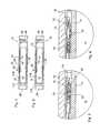
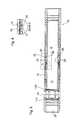
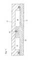
- FIG. 1is a sectional view of an embodiment of the flow control apparatus, showing the port disposed in the closed condition, and with both of the flow control valve member and the pressure control valve member disposed in the closed positions;
- FIG. 2is a detailed view of Detail “A” in FIG. 1 ;
- FIG. 3is a sectional view of an embodiment of the flow control apparatus illustrated in FIG. 1 , showing the port disposed in the closed condition, and with the pressure control valve member disposed in the open position, and with the flow control valve member disposed in the closed position;
- FIG. 4is a detailed view of Detail “B” in FIG. 3 ;
- FIG. 5is a sectional view of an embodiment of the flow control apparatus illustrated in FIG. 1 , showing the port disposed in the open condition, and with both of the flow control valve member and the pressure control valve member disposed in the open positions;
- FIG. 6is a detailed view of Detail “C” in FIG. 5 ;
- FIG. 6Ais a detailed view of Detail “D” in FIG. 5 ;
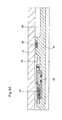
- FIG. 7is a perspective view of the flow control apparatus illustrated in FIG. 1 , with the outer housing and wiring removed for clarity;
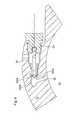
- FIG. 8is a sectional view of a fragment of another embodiment of the flow control apparatus having a cutter, illustrated prior to the puncturing of a rupture disc;
- FIG. 9is a sectional view of a fragment of another embodiment of the flow control apparatus shown in FIG. 8 , illustrated after the puncturing of a rupture disc by the cutter;
- FIG. 10is a sectional view of a fragment of another embodiment of the flow control apparatus having a shaped charge, illustrated prior to detonation of the shaped charge.
- FIG. 11is a sectional view of a fragment of the embodiment of the flow control apparatus shown in FIG. 10 , illustrated after detonation of the shaped charge;
- FIG. 12is sectional view of a fragment of another embodiment of the flow control apparatus having an exploding bolt, illustrated prior to fracturing of the bolt;
- FIG. 13is sectional view of a fragment of the embodiment of the flow control apparatus shown in FIG. 12 , illustrated after fracturing of the bolt;
- FIG. 14is a schematic illustration of the incorporation of the flow control apparatus of any one of the embodiments illustrated in FIGS. 1 to 6, 6A, and 7 to 13 , within a wellbore string disposed in a wellbore;
- FIG. 15is a schematic illustration of the incorporation of the flow control apparatus of any one of the embodiments illustrated in FIGS. 1 to 6, 6A, and 7 to 13 , within a wellbore string disposed in a wellbore, and a seismic vibration unit for generating an actuating signal to be received by the sensor.
- a flow control apparatusincluding a housing, a port, a flow control member, a sensor, and a trigger.
- the housingincludes a housing passage.
- the portextends through the housing.
- the flow control memberincludes a fluid responsive surface, and is configured for displacement, relative to the port, such that fluid communication is effected between the port and the housing passage.
- the sensoris coupled to the housing for sensing an actuating signal.
- the triggeris configured for effecting fluid communication between the housing passage and the fluid responsive surface, in response to the sensing of an actuating signal by the sensor, for effecting displacement of the flow control member.
- a flow control apparatusincluding a housing, a port, a flow control member, a sensor, a valve, and a valve actuator.
- the housingincludes a housing passage.
- the portextends through the housing.
- the flow control memberincludes a fluid responsive surface, and is configured for displacement, relative to the port, such that fluid communication is effected between the port and the housing passage.
- the sensoris coupled to the housing for sensing an actuating signal.
- the valveincludes a communication sealing surface for effecting sealing, or substantial sealing, of fluid communication between the housing passage and the fluid responsive surface.
- the valve actuatoris responsive to sensing of the actuating signal by the sensor, for effecting a change in condition of the valve such that the communication sealing surface becomes displaceable relative to the housing such that fluid communication between the housing passage and the fluid responsive surface is effectible.
- the flow control apparatusis integrated within a wellbore string that is disposed downhole within a wellbore.
- a systemincluding the wellbore string having the flow control apparatus integrated therein, and also including a seismic source disposed at the surface for generating the actuating signal.
- a flow control apparatus 10for selectively stimulating a reservoir 300 of a subterranean formation 400 .
- the flow control apparatusis deployable within a wellbore 200 .
- Suitable wellboresinclude vertical, horizontal, deviated or multi-lateral wells.
- the reservoiris stimulated by supplying treatment material from the surface 500 to a subterranean formation which includes the reservoir 300 .
- the treatment materialis a liquid including water.
- the liquidincludes water and chemical additives.
- the treatment materialis a slurry including water, proppant, and chemical additives.
- Exemplary chemical additivesinclude acids, sodium chloride, polyacrylamide, ethylene glycol, borate salts, sodium and potassium carbonates, glutaraldehyde, guar gum and other water soluble gels, citric acid, and isopropanol.
- the treatment materialis supplied to effect hydraulic fracturing of the reservoir.
- the treatment materialincludes water, and is supplied to effect waterflooding of the reservoir.
- the treatment materialincludes water, and is supplied for transporting (or “flowing”, or “pumping”) a wellbore tool (such as, for example, a perforator) downhole by application of fluid pressure.
- a wellbore toolsuch as, for example, a perforator
- the flow control apparatus 10may be deployed within the wellbore 200 and integrated within a wellbore string 100 , such as, for example, a casing string (see FIG. 8 ).
- Successive flow control apparatuses 10may be spaced from each other such that each flow control apparatus is positioned adjacent a producing interval to be stimulated by fluid treatment effected by treatment material that may be supplied through a port 18 (see below).
- the flow control apparatus 10includes a housing 12 .
- the housing 12includes interconnected top sub 12 A, outer housing 12 B, and bottom sub 12 C.
- the housing 12is coupled (such as, for example, threaded) to the wellbore string 100 .
- the wellbore string 100is lining the wellbore 200 .
- the wellbore stringis provided for, amongst other things, supporting the subterranean formation within which the wellbore is disposed.
- the wellbore stringmay include multiple segments, and segments may be connected (such as by a threaded connection).
- a housing passage 16is defined within the housing 12 .
- the housing passage 16is configured for conducting treatment material from a supply source (such as at the surface) to a port 18 that is also defined within and extends through the housing 12 .
- the housing 12includes a sealing surface configured for sealing engagement with a flow control member (see below).
- the sealing surfaceis defined by sealing members 11 A, 11 B.
- each one of the sealing members 11 A, 11 Bis, independently, disposed in sealing, or substantially sealing, engagement with both of the housing 12 and the flow control member 14 .
- the sealing, or substantially sealing, engagementeffects sealing, or substantial sealing, of fluid communication between the housing passage 16 and the port 18 (and thereby the wellbore, and, therefore, the subterranean formation 100 ).
- each one of the sealing members 11 A, 11 Bindependently, includes an o-ring.
- the o-ringis housed within a recess formed within the housing 12 .
- each one of the sealing members 11 A, 11 Bindependently, includes a molded sealing member (i.e. a sealing member that is fitted within, and/or bonded to, a groove formed within the sub that receives the sealing member).
- the port 18extends through the housing 12 , and is disposed between the sealing surfaces 11 a , 11 b . In some embodiments, for example, the port 18 extends through the housing 12 .
- the port 18effects fluid communication between the housing passage 16 and the wellbore. In this respect, during treatment, treatment material being conducted from the treatment material source via the housing passage 16 is supplied to the wellbore through the port.
- the treatment materialbeing supplied to the wellbore through the port 18 , be supplied, or at least substantially supplied, within a definite zone (or “interval”) of the subterranean formation in the vicinity of the port.
- the systemmay be configured to prevent, or at least interfere, with conduction of the treatment material, that is supplied to one zone of the subterranean formation, to a remote zone of the subterranean formation.
- such undesired conduction to a remote zone of the subterranean formationmay be effected through an annulus, that is formed within the wellbore, between the casing and the subterranean formation.
- a zonal isolation materialincludes cement, and, in such cases, during installation of the assembly within the wellbore, the casing string is cemented to the subterranean formation, and the resulting system is referred to as a cemented completion.
- the portmay be filled with a viscous liquid material having a viscosity of at least 100 mm 2 /s at 40 degrees Celsius.
- Suitable viscous liquid materialsinclude encapsulated cement retardant or grease.
- An exemplary greaseis SKF LGHP 2TM grease.
- a cement retardantis described. However, it should be understood, other types of liquid viscous materials, as defined above, could be used in substitution for cement retardants.
- the zonal isolation materialincludes a packer, and, in such cases, such completion is referred to as an open-hole completion.
- the flow control apparatus 10includes a flow control member 14 , and the flow control member 14 is positionable, relative to the housing 12 , in open and closed positions.
- the open position of the flow control member 14corresponds to an open condition of the port 18 .
- the flow control member 14includes a sleeve.
- the sleeveis slideably disposed within the housing passage 16 .
- the flow control member 14While the flow control apparatus 10 is disposed within the wellbore, while the port 18 is disposed in a closed condition, the flow control member 14 is disposed in the closed position, and disposition of the flow control member 14 in the closed position is such that the port 18 is disposed in a closed condition.
- the flow control member 14prevents, or substantially prevents, fluid flow through the port 18 , between the housing passage 16 and the wellbore.
- the flow control member 14is sealing, or substantially sealing, the port 18 such that a sealing interface is defined at the port 18 .
- the flow control member 14may be displaced from the closed position to the open position and thereby effect opening of the port 18 .
- such displacementis effected while the flow control apparatus is deployed downhole within a wellbore (such as, for example, as part of a wellbore string 200 , such as a casing string), and such displacement, and consequential opening of the port 18 , enables fluid, that is being supplied from the surface, for transporting a wellbore tool downhole through the wellbore, to be discharged through the port 18 , such that fluid pressure within the casing string remains below excessive pressures that would otherwise interfere with subsequent downhole operations.
- the apparatus 10functions as a “toe valve” or “toe sleeve”.
- the flow control member 14co-operates with the sealing members 11 A, 11 B to effect opening and closing of the port 18 .
- the flow control memberwhen the port 18 is disposed in the closed condition, the flow control member is sealingly engaged to both of the sealing surfaces 11 A, 11 B, and preventing, or substantially preventing, fluid flow from the housing passage 16 to the port 18 , and when the port 18 is disposed in the open condition, the flow control member 16 is spaced apart or retracted from at least one of the sealing members (such as the sealing surface 11 A), thereby providing a housing passage 16 for treatment material to be delivered to the port 18 from the housing passage 16 .
- the flow control member 14is configured for displacement, relative to the port 18 , from the closed position (see FIGS. 1 and 3 ) to the open position (see FIG. 5 ) in response to application of a sufficient net opening force.
- a sufficient net opening forceis effected by a fluid pressure differential.
- the housing 12includes an inlet 28 .
- the port 18When the port 18 is disposed in the open condition, fluid communication is effected between the inlet 28 and the port 18 via the housing passage 16 .
- the port 18When the port 18 is disposed in the closed condition, sealing, or substantial sealing of fluid communication, between the inlet 28 and the port 18 is effected.
- the flow control member 14including a fluid responsive surface 20 .
- the fluid responsive surface 20is said to be defined on the flow control member 14 .
- the fluid responsive surface 20is configured to receive a force applied by a communicated fluid to at least contribute to the establishment of the sufficient net opening force, which thereby effects the displacement of the flow control member 14 .
- a sensor 26is coupled to the housing for sensing an actuating signal.
- the senor 26is disposed in communication within the housing passage 16 , and the actuating signal is being transmitted within the housing passage 16 , such that the sensor 26 is disposed for sensing the actuating signal being transmitted within the housing passage 16 .
- the sensor 26is disposed within the housing passage 16 .
- the sensoris mounted to the housing 12 within a hole that is ported to the wellbore 200 , and is held in by a backing plate that is configured to resist the force generated by pressure acting on the sensor 26 .
- the senor 26is configured to receive a signal generated by a seismic source.
- the seismic sourceincludes a seismic vibrator unit 502 .
- the seismic vibration unit 502is disposed at the surface 500 .
- the sensor 26is configured to effect the displacement of the valve 24 in response to sensing of a actuating signal being transmitted via fluid within the housing passage 16 , such that the fluid communication between the housing passage 16 and the pressure responsive surface 20 is effected, and such that a force is thereby applied to the pressure responsive surface 20 so as to at least contribute to the sufficient net opening force that effects the displacement of the flow control member 14 .
- the sensor 26is a pressure sensor
- the actuating signalis one or more pressure pulses.
- An exemplary pressure sensoris a Kellar Pressure Transducer Model 6LHP/81188TM.
- suitable sensorsmay be employed, depending on the nature of the signal being used for the actuating signal.
- Other suitable sensorsinclude a Hall effect sensor, a radio frequency identification (“RFID”) sensor, or a sensor that can detect a change in chemistry (such as, for example, pH), or radiation levels, or ultrasonic waves.
- RFIDradio frequency identification
- the actuating signalis defined by a pressure pulse characterized by at least a magnitude. In some embodiments, for example, the pressure pulse is further characterized by at least a duration. In some embodiments, for example, the actuating signal is defined by a pressure pulse characterized by at least a duration.
- the actuating signalis defined by a plurality of pressure pulses. In some embodiments, for example, the actuating signal is defined by a plurality of pressure pulses, each one of the pressure pulses characterized by at least a magnitude. In some embodiments, for example, the actuating signal is defined by a plurality of pressure pulses, each one of the pressure pulses characterized by at least a magnitude and a duration. In some embodiments, for example, the actuating signal is defined by a plurality of pressure pulses, each one of the pressure pulses characterized by at least a duration. In some embodiments, for example, each one of pressure pulses is characterized by time intervals between the pulses.
- there apparatus 10includes a trigger 15 .
- the trigger 15is configured for effecting fluid communication between the housing passage 16 and the fluid responsive surface 20 , in response to the sensing of an actuating signal by the sensor 26 .
- the fluid communicationis effected for effecting the displacement of the flow control member 14 .
- the triggerincludes a valve 24 and a valve actuator 32 .
- the valve actuator 32is configured to effect a change in condition of the valve 24 such that fluid communication becomes effected between the housing passage 16 and the fluid responsive surface 20 , in response to the sensing of an actuating signal by the sensor 26 .
- the valve 24is displaceable, and the change in condition of the valve 24 , which the valve actuator 32 is configured to effect in response to the sensing of an actuating signal by the sensor 26 , includes displacement of the valve 24 .
- the valve actuator 32is configured to effect displacement of the valve 24 such that fluid communication becomes effected between the housing passage 16 and the fluid responsive surface 20 of the flow control member 14 .
- the flow control apparatus 10further includes a fluid communication passage 22 .
- the fluid communication passage 22is provided for effecting fluid communication between the housing passage 16 and the fluid responsive surface 20 so as to effect the displacement of the flow control member 14 .
- the establishing of such fluid communicationis controlled by the positioning of the valve 24 relative to the fluid communication passage 22 .
- the valve 24is configured for displacement relative to the fluid communication passage 22 .
- the valve 24includes a piston.
- the displacement of the valve 24is from a closed position (see FIGS. 1 and 2 ) to an open position (see FIGS. 3 and 4 ).
- the valve 24is occluding the fluid communication passage 22 .
- sealing, or substantial sealing, of fluid communication, between the housing passage 16 and the pressure responsive surface 20is effected.
- valve 24When the valve 24 is disposed in the open position, fluid communication is effected between the housing passage 16 and the fluid responsive surface 20 . In this respect, this enables application of a force to the fluid responsive surface 20 of the flow control member 14 by fluid communicated from the housing passage 16 , and thereby effecting displacement of the flow control member 14 .
- the valve 24may, initially, be detachably secured to the housing 12 , in the closed position.
- the detachable securingis effected by a shear pin configured for becoming sheared, in response to application of sufficient shearing force, such that the valve 24 becomes movable from the closed position to the open position.
- the shearing forceis effected by an valve actuator 32 (see below).
- the valve 24may be biased to the closed position, such as by, for example, a resilient member such as a spring.
- a resilient membersuch as a spring.
- an valve actuator used for effecting opening of the valve 24must exert sufficient force to at least overcome the biasing force being applied to the valve 24 that is maintaining the valve 24 in the closed position.
- the valve 24may be pressure balanced such that the valve 24 is disposed in the closed position.
- the fluid communication passage 22is defined within (and extends through) the flow control member 14 , and the valve 24 is disposed in a space defined between the flow control member 14 and the housing 12 , such that the displacement of the valve 24 is also relative to the flow control member 14 .
- the valve actuator 32includes an electro-mechanical trigger, such as a squib.
- the squibis configured to, in response to the signal received by the sensor 26 , effect generation of an explosion.
- the squibis mounted within the housing 12 such that the generated explosion effects the displacement of the flow control member 14 .
- Another suitable valve actuator 32is a fuse-able link or a piston pusher.
- the valve 24includes a communication sealing surface 2442 for effecting the sealing, or substantial sealing, of fluid communication between the housing passage 16 and the fluid responsive surface 20 .
- the change in condition of the valvewhich the valve actuator 3222 is configured to effect in response to the sensing of an actuating signal by the sensor 26 , includes a change in condition of the communication sealing surface 2442 such that fluid communication becomes effected between the housing passage 16 and the fluid responsive surface 20 .
- a fluid communication passage 22is extending between the housing passage 16 and the fluid responsive surface 20 , and the sealing, or substantial sealing, of fluid communication between the housing passage 16 and the fluid responsive surface 20 , is effected by sealing, or substantial sealing, of the fluid communication passage by the communication sealing surface 3222 .
- the valve actuator 3222includes a cutter 3224 configured for puncturing the communication sealing surface 2442 such that the change in condition of the communication sealing surface 3222 is effected, and a cutter actuator 3226 for effecting displacement of the cutter 3224 such that the puncturing is effected, in response to the sensing of an actuating signal by the sensor 26 .
- the cutter 3224is threaded into the housing 12 .
- the cutter actuator 3226includes a squib and is suitably mounted for effecting displacement of the cutter 3224 such that the puncturing is effected.
- the cutter 3224includes a bayonet 3228 , and the communication sealing surface is defined on a sealing member, and, in some embodiments, for example, the sealing member is defined by a rupture disc 3230 and a ferrule seat.
- the bayonet 3228punctures the rupture disc 3220 , such that fluid communication is effected between the passage 22 and the fluid responsive surface 20 via a passageway 3232 within the valve 24 .
- the trigger 15includes a shaped charge 151 for effecting generation of an explosion, in response to the sensing of an actuating signal by the sensor 26 , wherein the explosion is sufficient to effect creation of the fluid communication passage 22 that extends through the flow control member 14 and effects fluid communication between the housing passage 16 and the fluid responsive surface 20 .
- the shaped chargeis mounted to the housing 12 and disposed between the flow control member 14 and the housing 12 .
- the shaped chargeis directed at the flow control member 14 such that, when detonated, the jet produced by the charge would cut a hole in the flow control member 14 , such hole defining the fluid communication passage 22 .
- the flow control apparatus 10further includes first and second chambers 34 , 36 , and the sufficient net opening force is effected when application of an opening force, to the flow control member 14 , by fluid disposed within the first chamber 34 , exceeds a closing force, applied to the flow control member 14 , by fluid disposed within the second chamber 36 .
- Each one of the first and second chambers 34 , 36are, at least in part, defined by one or more surface portions of the flow control member 14 , such that fluid, within each one of the chambers 34 , 36 , is applying a force to the flow control member 14 .
- the fluid within the first chamber 34is applying an opening force to the flow control member 14 (in the illustrated embodiment, for example, in the downhole direction), and the fluid within the second chamber 36 is applying a closing force to the flow control member 14 (in the illustrated embodiment, in the uphole direction).
- the opening force being applied to the flow control member 14 by fluid disposed within the first chamber 34exceeds the closing force being applied to the flow control member 14 by fluid disposed within the second chamber 36 , the displacement of the flow control member 14 to the open position (see FIG. 5 ) is effected.
- the opening force applied by fluid disposed within the first chamber 34includes that applied by fluid (that is disposed in fluid communication with the housing passage 16 ) to the fluid responsive surface 20 .
- the first fluid chamber 34is disposed in fluid communication with the fluid responsive surface 20 .
- thisalso means that, under these circumstances, the first fluid chamber 34 is disposed in fluid communication with the housing passage 16 .
- the first fluid chamber 34is disposable, to a state of fluid communication with the housing passage 16 . In the embodiments illustrated in FIGS. 1 to 6, 6A, and 7 , this is effectible by displacement of the valve 26 , and in the embodiments illustrated in FIGS. 10 and 11 , this is effectible by the creation of the fluid communication passage 22 by the shaped charge 151 .
- the sufficient net opening forceis effected by a fluid pressure differential between the first chamber 34 and the second chamber 36 such that fluid pressure within the first chamber 34 exceeds fluid pressure within the second chamber 36 .
- the exceeding of the fluid pressure within the second chamber 36 by the fluid pressure within the first chamber 34is effected by the effecting of fluid communication between the first chamber 34 and the housing passage 16 , upon the displacement of the valve 24 from the closed position to the open position.
- the second chamber 36is disposed at, or substantially at, atmospheric pressure.
- the sufficient net opening force, effecting the displacement of the flow control member 14includes a force component that is (a) urging the displacement of the flow control member 14 to the open position, and (b) is being applied to the fluid responsive surface 20 by fluid (such as, for example, fluid within the first chamber 34 ) that has been communicated from the housing passage 16 in response to, in some embodiments (see FIGS. 1 to 6, 6A, and 7 ), the displacement of the valve 24 , and in other embodiments, (see FIGS. 10 and 11 ), the creation of the fluid communication passage 22 by the shaped charge 151 .
- fluidsuch as, for example, fluid within the first chamber 34
- both of the first and second chambers 34 , 36are defined by respective spaces interposed between the housing 12 and the flow control member 14 , and a chamber sealing member 38 is also included for effecting a sealing interface between the chambers 34 , 36 , while the flow control member 14 is being displaced to effect the opening of the port 18 .
- the chamber sealing member 38 , the housing 12 , and the flow control member 14are co-operatively configured such that: (i) while the flow control member is disposed in the closed position, the chamber sealing member 38 is sealing engaged to both of the housing 12 and the flow control member 14 such that the sealing, or substantial sealing, of fluid communication between the first and second chambers 34 , 36 is effected; and (ii) in response to displacement of the flow control member 14 to the open position, the chamber sealing member 38 changes its disposition, relative to the housing 12 and the flow control member 14 , such that the flow control member 14 is displaced such that there is a loss of the sealing engagement, resulting in a condition where there is an absence of sealing, or substantial sealing, engagement between the chamber sealing member 38 and at least one of the housing 12 and the flow control member 14 such that the first chamber 34 is disposed in fluid communication with the second chamber 36 .
- the pressures within the first and second chambers 34 , 36become balanced. Concomitantly, the fluid pressure differential existing between the first and second chambers 34 , 36 is now rendered non-existent or substantially non-existent, thereby removing interference in those embodiments where it is desirable to return the flow control member 14 to the closed position, and thereby close the port 18 .
- one of the housing 12 and the flow control member 14includes a recess 40 that represents a sufficient increase in spacing between the housing 12 and the flow control member 14 , as the flow control member 14 is being displaced relative to the housing 12 to the open position, such that the loss in sealing engagement of the displaceable chamber sealing member 38 with at least one of the housing 12 and the flow control member 14 is effected while the displaceable chamber sealing member 38 is disposed within the recess 40 .
- the disposition of the displaceable chamber sealing member 38 within the recess 40is effected when the flow control member 40 is disposed in the open position.
- the chamber sealing member 38is carried by the flow control member 14 and the housing 12 includes the recess 40 .
- the flow control member 14can include the recess
- the housing 12can contain the chamber sealing member 38 .
- one of the housing 12 and the flow control member 14includes a recess 40
- the housing 12 , the flow control member 14 , and the chamber sealing member 38are co-operatively configured such that, in response to the displacement of the flow control member 14 to the open position, the chamber sealing member 38 is displaced and becomes disposed within the recess 40 such that there is a loss of the sealing engagement, such that the absence of sealing, or substantial sealing, engagement between the chamber sealing member 38 and at least one of the housing 12 and the flow control member 14 is effected.
- the flow control apparatus 10further includes a controller 30 .
- the controller 30is configured to receive a sensor-transmitted signal from the sensor 26 upon the sensing of the actuating signal and, in response to the received sensor-transmitted signal, supply a transmitted signal to the trigger 15 to effect the displacement of the flow control member 14 .
- the controller 30 and the sensor 26are powered by a battery 34 that is also housed within the flow control member 14 .
- Passages 50 for wiring for electrically interconnecting the battery 34 , the sensor 26 , the controller 30 and the trigger 15 (and in those embodiments where the trigger 15 includes the valve 24 and the valve actuator, the valve actuator 32 )is also illustrated (wiring is not shown).
- the flow control apparatus 10includes a valve 241 and an valve actuator 321 .
- the valve 241includes a communication sealing surface 242 for effecting sealing, or substantial sealing, of fluid communication between the housing passage 16 and the fluid responsive surface 20 .
- the valve actuator 321is responsive to sensing of the actuating signal by the sensor 26 , for effecting a change in condition of the valve 241 such that the communication sealing surface 242 becomes displaceable relative to the housing 12 such that a loss of the sealing, or substantial sealing, of the fluid communication between the housing passage 16 and the fluid responsive surface 20 is effectible, with effect that an absence of sealing, or substantial sealing, of the fluid communication between the housing passage 16 and the fluid responsive surface 20 is effectible, such that fluid communication between the housing passage 16 and the fluid responsive surface 20 is effectible.
- the change in condition of the valve 241is from a sealing condition to a fluid communication-effectible condition.
- the housing passage 16 , valve 241 , and pressure responsive surface 20are co-operatively configured such that, while the communication sealing surface 242 is displaceable relative to the housing 12 , displacement of the communication sealing surface 242 , for effecting the fluid communication between the housing passage 16 and the fluid responsive surface 20 , is effectible in response to urging of the communication sealing surface 242 by fluid disposed within the housing passage 16 .
- the communication sealing surface 242while the communication sealing surface 242 is displaceable relative to the housing 12 , fluid, disposed within the housing passage 16 . functions to urge displacement of the communication sealing surface 242 , relative to the housing 12 , such that fluid communication between the housing passage 16 and the fluid responsive surface 20 , is effected.
- the valve 241includes a coupler 243 that interacts with the housing 12 such that, while the valve 241 is in the sealing condition, the valve 241 is coupled to the housing 12 such that the communication sealing surface 242 is effecting sealing, or substantially sealing, of fluid communication between the housing passage 16 and the fluid responsive surface 20 .
- the coupler 243is threaded to the housing 12 .
- the change in condition of the valve 241includes at least a weakening of at least a portion of the valve 241 .
- the valve 241 and the housing passage 16are co-operatively configured such that, while the at least a portion of the valve 241 is weakened, the valve 241 is conditioned for fracturing (such as, for example, at the weakened portion) in response to a force being applied by a fluid, disposed within the housing passage 16 , to the weakened portion of the valve 241 .
- the conditioning of the valve 241 for fracturingis such that, upon fracturing, the displacement of the communication sealing surface 242 is effected such that fluid communication becomes effected between the housing passage 16 and the fluid responsive surface 20 .
- the valve 241 and the housing passage 16are co-operatively disposed such that, in response to the fracturing of the valve 241 , the communication sealing surface 242 becomes displaceable such that, in response to a force applied by fluid disposed within the housing passage 16 , the communication sealing surface 242 is displaced such that fluid communication becomes effected between the housing passage 16 and the fluid responsive surface 20 .
- the change in condition of the valve 241includes a fracturing of the valve 241 .
- the fractureis identified by reference numeral 252 .
- the fracturingis such that fluid communication becomes effected between the housing passage 16 and the fluid responsive surface 20 .
- valve 241 and the housing passage 16are co-operatively disposed such that, in response to the fracturing of the valve 241 , the communication sealing surface 242 becomes displaceable such that, in response to a force applied by fluid disposed within the housing passage 16 , the communication sealing surface 242 is displaced such that fluid communication becomes effected between the housing passage 16 and the fluid responsive surface 20 .
- the fluid communication passage 22extends between the housing passage 16 and the fluid responsive surface 20 , and the sealing, or substantial sealing, of fluid communication between the housing passage 16 and the fluid responsive surface 20 , is effected by sealing, or substantial sealing, of the fluid communication passage 22 by the communication sealing surface 242 .
- the fluid communication passage 22extends through the flow control member 14 , and the valve 241 is disposed between the flow control member 14 and the housing 12 .
- the valve actuator 341includes a squib, and the change in condition is effected by an explosion generated by the squib in response to sensing of the actuating signal by the sensor 26 .
- the squibis suitably mounted to apply the necessary force to the valve 241 .
- valve 241 and the valve actuator 341are defined by an exploding bolt 250 , such that the flow control apparatus 14 includes the exploding bolt 250 .
- the squibis integrated into the bolt 250 .
- the embodiment of the flow control apparatus 10 illustrated in FIGS. 12 and 13includes first and second chambers 34 , 36 (second chamber 36 is not shown for this embodiment) disposed within the housing 12 .
- the first chamber 34is disposable into fluid communication with the housing passage 16 in response to a displacement of the communication sealing surface 242 .
- the housing 12further includes a constricting portion 46 that defines a constricted portion 48 of the housing passage 16 for interfering with movement of the flow control member 14 .
- the flow control member 14is configured to deform and become pinched by the constricting portion 46 while moving through the constricted portion 48 of the housing passage 16 . The pinching is such that interference is provided to the displacement of the flow control member 14 to the closed position.
- the flow control member 14is maintained in a position, by one or more shear pins 42 (see FIG. 6 ), such that the port 18 remain disposed in the closed condition.
- the one or more shear pins 42are provided to secure the flow control member to the casing string so that the housing passage 16 is maintained fluidically isolated from the reservoir until it is desired to treat the reservoir with treatment material.
- sufficient forcemust be applied to the one or more shear pins 42 such that the one or more shear pins become sheared, resulting in the flow control member becoming displaceable relative to the port.
- the force that effects the shearingis applied by fluid pressure being applied within the casing string.
- FIGS. 1 to 6, 6A, and 7An exemplary process for supplying fluid to a subterranean formation, through a wellbore string, disposed within a wellbore, and incorporating an embodiment of the flow control apparatus 10 illustrated in FIGS. 1 to 6, 6A, and 7 , will now be described.
- the flow control member 14is disposed in the closed position
- the first and second chambers 34 , 36are disposed at atmospheric pressure
- the valve 24is disposed in the closed position (see FIGS. 1 and 2 ).
- the shear pins 42are interfering with inadvertent opening of the flow control member 14 .
- the actuating signal(such as one or more pressure pulses) is transmitted downhole.
- the actuating signalis detected by the sensor 26 .
- the sensor 26transmits the sensor-transmitted signal to the controller 30 .
- the controller 30receives and processes the sensor-transmitted signal, and transmits an valve actuator signal to the valve actuator 32 (such as a suib).
- the valve actuator 32effects opening of the valve 24 (see FIGS. 3 and 4 ). After the valve 24 has become opened, fluid communication is effected between the first chamber 34 and the housing passage 16 via the fluid communication passage 22 .
- Pressurized fluidwithin the housing passage 16 (the pressurized fluid may or may not have already been disposed within the housing passage 16 while the actuating signal was being transmitted), is conducted to the first chamber 34 , via the fluid communication passage 22 , to effect pressurization of the first chamber 34 .
- the opening forcebeing applied by fluid within the first chamber 34
- the closing forcebeing applied by fluid within the second chamber 34
- the shear pinsbecome sheared and the flow control member 14 is urged to move downhole, thereby effecting opening of the port 18 (see FIGS. 5 and 6 ).
- the displacement of the flow control member 14is such that, after the port 18 has become disposed in the open condition, the displaceable chamber sealing member 38 , being carried by the flow control member 14 , becomes disposed within the recess.
- the fluid pressure differential, between the first and second chambers 34 , 36is sufficient to effect displacement of the sealing member 38 such that the sealing member 38 loses sealing, or substantially, sealing engagement with one or both of the housing 12 and the flow control member 14 . In doing so, pressure equalization is effected between the first and second chambers 34 , 36 .
Landscapes
- Geology (AREA)
- Life Sciences & Earth Sciences (AREA)
- Engineering & Computer Science (AREA)
- Mining & Mineral Resources (AREA)
- Physics & Mathematics (AREA)
- Environmental & Geological Engineering (AREA)
- Fluid Mechanics (AREA)
- General Life Sciences & Earth Sciences (AREA)
- Geochemistry & Mineralogy (AREA)
- Lift Valve (AREA)
- Fluid-Driven Valves (AREA)
- Safety Valves (AREA)
- Geophysics (AREA)
Abstract
Description
Claims (92)
Priority Applications (2)
| Application Number | Priority Date | Filing Date | Title |
|---|---|---|---|
| US15/068,282US10066467B2 (en) | 2015-03-12 | 2016-03-11 | Electrically actuated downhole flow control apparatus |
| US16/051,391US10808509B2 (en) | 2015-03-12 | 2018-07-31 | Electrically actuated downhole flow control apparatus |
Applications Claiming Priority (3)
| Application Number | Priority Date | Filing Date | Title |
|---|---|---|---|
| US201562132241P | 2015-03-12 | 2015-03-12 | |
| US201562160282P | 2015-05-12 | 2015-05-12 | |
| US15/068,282US10066467B2 (en) | 2015-03-12 | 2016-03-11 | Electrically actuated downhole flow control apparatus |
Related Child Applications (1)
| Application Number | Title | Priority Date | Filing Date |
|---|---|---|---|
| US16/051,391ContinuationUS10808509B2 (en) | 2015-03-12 | 2018-07-31 | Electrically actuated downhole flow control apparatus |
Publications (2)
| Publication Number | Publication Date |
|---|---|
| US20160265310A1 US20160265310A1 (en) | 2016-09-15 |
| US10066467B2true US10066467B2 (en) | 2018-09-04 |
Family
ID=56879839
Family Applications (2)
| Application Number | Title | Priority Date | Filing Date |
|---|---|---|---|
| US15/068,282Active2036-06-06US10066467B2 (en) | 2015-03-12 | 2016-03-11 | Electrically actuated downhole flow control apparatus |
| US16/051,391Active2036-07-15US10808509B2 (en) | 2015-03-12 | 2018-07-31 | Electrically actuated downhole flow control apparatus |
Family Applications After (1)
| Application Number | Title | Priority Date | Filing Date |
|---|---|---|---|
| US16/051,391Active2036-07-15US10808509B2 (en) | 2015-03-12 | 2018-07-31 | Electrically actuated downhole flow control apparatus |
Country Status (4)
| Country | Link |
|---|---|
| US (2) | US10066467B2 (en) |
| EP (1) | EP3268831B1 (en) |
| DK (1) | DK3268831T3 (en) |
| WO (1) | WO2016141456A1 (en) |
Cited By (10)
| Publication number | Priority date | Publication date | Assignee | Title |
|---|---|---|---|---|
| US20200165900A1 (en)* | 2018-11-26 | 2020-05-28 | Geodynamics, Inc. | Electronic valve with deformable seat and method |
| US10781665B2 (en) | 2012-10-16 | 2020-09-22 | Weatherford Technology Holdings, Llc | Flow control assembly |
| US10808509B2 (en)* | 2015-03-12 | 2020-10-20 | Ncs Multistage Inc. | Electrically actuated downhole flow control apparatus |
| US10900258B1 (en)* | 2017-04-17 | 2021-01-26 | Lockheed Martin Corporation | Wirelessly actuated cover for a structure |
| US10961819B2 (en) | 2018-04-13 | 2021-03-30 | Oracle Downhole Services Ltd. | Downhole valve for production or injection |
| US11591886B2 (en) | 2019-11-13 | 2023-02-28 | Oracle Downhole Services Ltd. | Gullet mandrel |
| US11702905B2 (en) | 2019-11-13 | 2023-07-18 | Oracle Downhole Services Ltd. | Method for fluid flow optimization in a wellbore |
| US11808110B2 (en) | 2019-04-24 | 2023-11-07 | Schlumberger Technology Corporation | System and methodology for actuating a downhole device |
| US12371957B2 (en) | 2021-04-06 | 2025-07-29 | Schlumberger Technology Corporation | Trigger system for a downhole tool |
| US12442276B2 (en) | 2022-03-23 | 2025-10-14 | Schlumberger Technology Corporation | Redundant trigger system |
Families Citing this family (14)
| Publication number | Priority date | Publication date | Assignee | Title |
|---|---|---|---|---|
| WO2018076119A1 (en)* | 2016-10-28 | 2018-05-03 | Ncs Multistage Inc. | Apparatus, systems and methods for isolation during multistage hydraulic fracturing |
| US11105183B2 (en) | 2016-11-18 | 2021-08-31 | Halliburton Energy Services, Inc. | Variable flow resistance system for use with a subterranean well |
| CN120719952A (en) | 2016-11-18 | 2025-09-30 | 哈利伯顿能源服务公司 | Variable flow resistance system for use with subterranean wells |
| GB2592546B (en)* | 2016-11-18 | 2022-02-23 | Halliburton Energy Services Inc | Variable flow resistance system for use with a subterranean well |
| US11255169B2 (en)* | 2017-02-13 | 2022-02-22 | Ncs Multistage Inc. | System and method for wireless control of well bore equipment |
| US11268347B2 (en) | 2017-07-24 | 2022-03-08 | National Oilwell Varco, L.P. | Testable sliding sleeve valve |
| CN111201367B (en)* | 2017-12-06 | 2022-07-08 | 哈利伯顿能源服务公司 | Electronic starter sleeve and method of use |
| US11480030B2 (en) | 2018-03-05 | 2022-10-25 | Kobold Corporation | Thermal expansion actuation system for sleeve shifting |
| CA3104454A1 (en)* | 2019-01-24 | 2020-07-30 | The Wellboss Company, Inc. | Downhole sleeve tool |
| US11261715B2 (en) | 2019-09-27 | 2022-03-01 | Ncs Multistage Inc. | In situ injection or production via a well using selective operation of multi-valve assemblies with choked configurations |
| RU197793U1 (en)* | 2020-02-20 | 2020-05-28 | Александр Васильевич Селиванов | Drill Rod for small drilling rigs |
| US11993991B2 (en) | 2022-03-31 | 2024-05-28 | Schlumberger Technology Corporation | System and method for electronically controlling downhole valve system |
| US12270277B2 (en)* | 2022-03-31 | 2025-04-08 | Schlumberger Technology Corporation | Methodology and system for electronic control and acquisition of downhole valve |
| US11952861B2 (en) | 2022-03-31 | 2024-04-09 | Schlumberger Technology Corporation | Methodology and system having downhole universal actuator |
Citations (127)
| Publication number | Priority date | Publication date | Assignee | Title |
|---|---|---|---|---|
| US4367794A (en) | 1980-12-24 | 1983-01-11 | Exxon Production Research Co. | Acoustically actuated downhole blowout preventer |
| US4510995A (en) | 1983-02-22 | 1985-04-16 | Baker Oil Tools, Inc. | Downhole locking apparatus |
| US4550780A (en) | 1972-05-23 | 1985-11-05 | Hydril Company | Pressure operated safety valve with lock means |
| US4583591A (en) | 1983-02-22 | 1986-04-22 | Baker Oil Tools, Inc. | Downhole locking apparatus |
| US4667736A (en) | 1985-05-24 | 1987-05-26 | Otis Engineering Corporation | Surface controlled subsurface safety valve |
| US4796699A (en) | 1988-05-26 | 1989-01-10 | Schlumberger Technology Corporation | Well tool control system and method |
| US4862964A (en) | 1987-04-20 | 1989-09-05 | Halliburton Company | Method and apparatus for perforating well bores using differential pressure |
| US5230383A (en) | 1991-10-07 | 1993-07-27 | Camco International Inc. | Electrically actuated well annulus safety valve |
| US5273112A (en) | 1992-12-18 | 1993-12-28 | Halliburton Company | Surface control of well annulus pressure |
| US5691712A (en) | 1995-07-25 | 1997-11-25 | Schlumberger Technology Corporation | Multiple wellbore tool apparatus including a plurality of microprocessor implemented wellbore tools for operating a corresponding plurality of included wellbore tools and acoustic transducers in response to stimulus signals and acoustic signals |
| US5819854A (en) | 1996-02-06 | 1998-10-13 | Baker Hughes Incorporated | Activation of downhole tools |
| US5975204A (en) | 1995-02-09 | 1999-11-02 | Baker Hughes Incorporated | Method and apparatus for the remote control and monitoring of production wells |
| US5979561A (en) | 1996-12-04 | 1999-11-09 | Schlumberger Technology Corporation | Downhole activation circuit valving |
| US6021095A (en) | 1990-07-09 | 2000-02-01 | Baker Hughes Inc. | Method and apparatus for remote control of wellbore end devices |
| US6172614B1 (en) | 1998-07-13 | 2001-01-09 | Halliburton Energy Services, Inc. | Method and apparatus for remote actuation of a downhole device using a resonant chamber |
| US6182764B1 (en) | 1998-05-27 | 2001-02-06 | Schlumberger Technology Corporation | Generating commands for a downhole tool using a surface fluid loop |
| US6220355B1 (en) | 1996-02-21 | 2001-04-24 | Ocre (Scotland) Limited | Downhole apparatus |
| US6283227B1 (en) | 1998-10-27 | 2001-09-04 | Schlumberger Technology Corporation | Downhole activation system that assigns and retrieves identifiers |
| US6349772B2 (en) | 1998-11-02 | 2002-02-26 | Halliburton Energy Services, Inc. | Apparatus and method for hydraulically actuating a downhole device from a remote location |
| US6382234B1 (en) | 1996-10-08 | 2002-05-07 | Weatherford/Lamb, Inc. | One shot valve for operating down-hole well working and sub-sea devices and tools |
| US6414905B1 (en) | 1990-07-09 | 2002-07-02 | Baker Hughes Incorporated | Method and apparatus for communicating coded messages in a wellbore |
| US6450263B1 (en) | 1998-12-01 | 2002-09-17 | Halliburton Energy Services, Inc. | Remotely actuated rupture disk |
| US6464006B2 (en) | 2001-02-26 | 2002-10-15 | Baker Hughes Incorporated | Single trip, multiple zone isolation, well fracturing system |
| US20030029611A1 (en) | 2001-08-10 | 2003-02-13 | Owens Steven C. | System and method for actuating a subterranean valve to terminate a reverse cementing operation |
| US6536529B1 (en) | 1998-05-27 | 2003-03-25 | Schlumberger Technology Corp. | Communicating commands to a well tool |
| US6550538B1 (en) | 2000-11-21 | 2003-04-22 | Schlumberger Technology Corporation | Communication with a downhole tool |
| US6584406B1 (en) | 2000-06-15 | 2003-06-24 | Geo-X Systems, Ltd. | Downhole process control method utilizing seismic communication |
| US6679332B2 (en) | 2000-01-24 | 2004-01-20 | Shell Oil Company | Petroleum well having downhole sensors, communication and power |
| CA2337030C (en) | 1998-07-14 | 2005-01-04 | Dwayne D. Leismer | Downhole multiplexer and related methods |
| CA2210028C (en) | 1996-07-16 | 2005-03-08 | Baker Hughes Incorporated | Hydrostatic tool with electrically operated setting mechanism |
| US6920085B2 (en) | 2001-02-14 | 2005-07-19 | Halliburton Energy Services, Inc. | Downlink telemetry system |
| CA2450408C (en) | 1996-04-01 | 2005-10-04 | Baker Hughes Incorporated | Downhole flow control devices |
| CA2236944C (en) | 1997-05-06 | 2005-12-13 | Baker Hughes Incorporated | Flow control apparatus and methods |
| US7025134B2 (en) | 2003-06-23 | 2006-04-11 | Halliburton Energy Services, Inc. | Surface pulse system for injection wells |
| CA2491444C (en) | 1996-04-26 | 2006-09-05 | Camco International Inc. | Method and apparatus for remote control of multilateral wells |
| WO2007003597A1 (en) | 2005-07-01 | 2007-01-11 | Shell Internationale Research Maatschappij B.V. | Mehod and apparatus for actuating oilfield equipment |
| US20070204995A1 (en) | 2006-01-25 | 2007-09-06 | Summit Downhole Dynamics, Ltd. | Remotely operated selective fracing system |
| CA2393504C (en) | 2000-01-04 | 2007-09-18 | Schlumberger Technology Corporation | Flow control in a wellbore |
| US20070235199A1 (en) | 2003-06-18 | 2007-10-11 | Logiudice Michael | Methods and apparatus for actuating a downhole tool |
| US7325616B2 (en) | 2004-12-14 | 2008-02-05 | Schlumberger Technology Corporation | System and method for completing multiple well intervals |
| US7347278B2 (en) | 1998-10-27 | 2008-03-25 | Schlumberger Technology Corporation | Secure activation of a downhole device |
| US7348893B2 (en) | 2004-12-22 | 2008-03-25 | Schlumberger Technology Corporation | Borehole communication and measurement system |
| US20080078553A1 (en)* | 2006-08-31 | 2008-04-03 | George Kevin R | Downhole isolation valve and methods for use |
| US7400263B2 (en) | 1998-08-28 | 2008-07-15 | Marathon Oil Company | Method and system for performing operations and for improving production in wells |
| US20080302538A1 (en) | 2005-03-15 | 2008-12-11 | Hofman Raymond A | Cemented Open Hole Selective Fracing System |
| US7493962B2 (en) | 2004-12-14 | 2009-02-24 | Schlumberger Technology Corporation | Control line telemetry |
| US20090090501A1 (en) | 2007-10-05 | 2009-04-09 | Henning Hansen | Remotely controllable wellbore valve system |
| US20090151790A1 (en) | 2007-12-12 | 2009-06-18 | Baker Hughes Incorporated | Electro-magnetic multi choke position valve |
| US7562712B2 (en) | 2004-04-16 | 2009-07-21 | Schlumberger Technology Corporation | Setting tool for hydraulically actuated devices |
| CA2541489C (en) | 2005-09-14 | 2009-08-04 | Schlumberger Canada Limited | System and method for controlling actuation of tools in a wellbore |
| US7597151B2 (en) | 2005-07-13 | 2009-10-06 | Halliburton Energy Services, Inc. | Hydraulically operated formation isolation valve for underbalanced drilling applications |
| US7640989B2 (en) | 2006-08-31 | 2010-01-05 | Halliburton Energy Services, Inc. | Electrically operated well tools |
| US7661478B2 (en) | 2006-10-19 | 2010-02-16 | Baker Hughes Incorporated | Ball drop circulation valve |
| US7673680B2 (en) | 2004-05-19 | 2010-03-09 | Omega Completion Technology Ltd. | Method for signalling a downhole device in a flowing well |
| US7849925B2 (en) | 2007-09-17 | 2010-12-14 | Schlumberger Technology Corporation | System for completing water injector wells |
| US20100314562A1 (en) | 2009-06-10 | 2010-12-16 | Baker Hughes Incorporated | Delay activated valve and method |
| US7854267B2 (en) | 2002-08-30 | 2010-12-21 | Schlumberger Technology Corporation | Methods and systems to activate downhole tools with light |
| US20110056679A1 (en) | 2009-09-09 | 2011-03-10 | Schlumberger Technology Corporation | System and method for controlling actuation of downhole tools |
| US8006952B2 (en) | 2004-11-02 | 2011-08-30 | Camcon Limited | Low power actuator and valve-actuator combination |
| US20120061095A1 (en) | 2010-06-24 | 2012-03-15 | Christian Capderou | Apparatus and Method For Remote Actuation of A Downhole Assembly |
| US8151904B2 (en) | 2006-06-30 | 2012-04-10 | Baker Hughes Incorporated | Method for improved well control with a downhole device |
| US8157022B2 (en) | 2007-09-28 | 2012-04-17 | Schlumberger Technology Corporation | Apparatus string for use in a wellbore |
| US20120138311A1 (en) | 2010-11-01 | 2012-06-07 | Oiltool Engineering Services, Inc. | Method and Apparatus for Single-Trip Time Progressive Wellbore Treatment |
| US8215411B2 (en) | 2009-11-06 | 2012-07-10 | Weatherford/Lamb, Inc. | Cluster opening sleeves for wellbore treatment and method of use |
| US20120181032A1 (en) | 2011-01-14 | 2012-07-19 | Utex Industries, Inc. | Disintegrating ball for sealing frac plug seat |
| US8267178B1 (en) | 2011-09-01 | 2012-09-18 | Team Oil Tools, Lp | Valve for hydraulic fracturing through cement outside casing |
| US8297367B2 (en) | 2010-05-21 | 2012-10-30 | Schlumberger Technology Corporation | Mechanism for activating a plurality of downhole devices |
| US8322426B2 (en) | 2010-04-28 | 2012-12-04 | Halliburton Energy Services, Inc. | Downhole actuator apparatus having a chemically activated trigger |
| CA2837180A1 (en) | 2011-07-01 | 2013-01-10 | Halliburton Energy Services, Inc. | Well tool actuator and isolation valve for use in drilling operations |
| US20130080063A1 (en) | 2010-06-21 | 2013-03-28 | Halliburton Energy Services, Inc. | Mud pulse telemetry |
| US8451137B2 (en) | 2008-10-02 | 2013-05-28 | Halliburton Energy Services, Inc. | Actuating downhole devices in a wellbore |
| WO2013109287A1 (en) | 2012-01-20 | 2013-07-25 | Halliburton Energy Services, Inc. | Subterranean well interventionless flow restrictor bypass system |
| US20130199800A1 (en) | 2012-02-03 | 2013-08-08 | Justin C. Kellner | Wiper plug elements and methods of stimulating a wellbore environment |
| WO2013154420A2 (en) | 2012-04-11 | 2013-10-17 | Mit Innovation Sdn. Bhd | Apparatus and method to remotely control fluid flow in tubular strings and wellbore annulus |
| US8573311B2 (en) | 2012-01-20 | 2013-11-05 | Halliburton Energy Services, Inc. | Pressure pulse-initiated flow restrictor bypass system |
| US20140034310A1 (en) | 2012-07-31 | 2014-02-06 | Weatherford/Lamb, Inc. | Multi-zone cemented fracturing system |
| US8646537B2 (en) | 2011-07-11 | 2014-02-11 | Halliburton Energy Services, Inc. | Remotely activated downhole apparatus and methods |
| WO2014046841A2 (en) | 2012-09-21 | 2014-03-27 | Halliburton Energy Services, Inc. | Method of completing a multi-zone fracture stimulation treatment of a wellbore |
| US8684084B2 (en) | 2006-08-31 | 2014-04-01 | Geodynamics, Inc. | Method and apparatus for selective down hole fluid communication |
| US20140102708A1 (en) | 2012-03-08 | 2014-04-17 | Petrowell Limited | Selective Fracturing System |
| WO2014060722A2 (en) | 2012-10-16 | 2014-04-24 | Petrowell Limited | Flow control assembly |
| US20140130893A1 (en) | 2011-05-16 | 2014-05-15 | Petroleum Technology Company As | Shear valve |
| CA2791214C (en) | 2001-11-28 | 2014-05-27 | Schlumberger Canada Limited | Wireless communication system and method |
| US8739879B2 (en) | 2011-12-21 | 2014-06-03 | Baker Hughes Incorporated | Hydrostatically powered fracturing sliding sleeve |
| US20140151054A1 (en) | 2012-12-04 | 2014-06-05 | Schlumberger Technology Corporation | Flow control system |
| US8757265B1 (en) | 2013-03-12 | 2014-06-24 | EirCan Downhole Technologies, LLC | Frac valve |
| US8757273B2 (en) | 2008-04-29 | 2014-06-24 | Packers Plus Energy Services Inc. | Downhole sub with hydraulically actuable sleeve valve |
| US20140182856A1 (en) | 2011-08-29 | 2014-07-03 | Halliburton Energy Services, Inc. | Downhole Fluid Flow Control System and Method having Dynamic Response to Local Well Conditions |
| US8783365B2 (en) | 2011-07-28 | 2014-07-22 | Baker Hughes Incorporated | Selective hydraulic fracturing tool and method thereof |
| US20140299330A1 (en) | 2013-02-08 | 2014-10-09 | Halliburton Energy Services, Inc | Wireless Activatable Valve Assembly |
| US8905139B2 (en) | 2009-04-24 | 2014-12-09 | Chevron U.S.A. Inc. | Blapper valve tools and related methods |
| US20150075791A1 (en) | 2013-09-16 | 2015-03-19 | Target Completions, LLC | Mandrel-less Launch Toe Initiation Sleeve (TIS) |
| US9010447B2 (en) | 2009-05-07 | 2015-04-21 | Packers Plus Energy Services Inc. | Sliding sleeve sub and method and apparatus for wellbore fluid treatment |
| US20150107829A1 (en) | 2012-05-07 | 2015-04-23 | Packers Plus Energy Services Inc. | Method and system for monitoring well operations |
| WO2015060809A1 (en) | 2013-10-21 | 2015-04-30 | Halliburton Energy Services, Inc. | Erosion resistant baffle for downhole wellbore tools |
| US20150129205A1 (en) | 2011-05-02 | 2015-05-14 | Peak Completion Technologies, Inc. | Downhole Tools, System and Methods of Using |
| US9051810B1 (en) | 2013-03-12 | 2015-06-09 | EirCan Downhole Technologies, LLC | Frac valve with ported sleeve |
| WO2015110486A1 (en) | 2014-01-21 | 2015-07-30 | Tendeka As | Downhole flow control device and method |
| US9121250B2 (en) | 2011-03-19 | 2015-09-01 | Halliburton Energy Services, Inc. | Remotely operated isolation valve |
| US20150322747A1 (en) | 2013-01-10 | 2015-11-12 | Halliburton Energy Services, Inc. | Boost assisted force balancing setting tool |
| US9194210B2 (en) | 2013-08-02 | 2015-11-24 | Halliburton Energy Services, Inc. | Downhole power delivery tool powered by hydrostatic pressure |
| WO2016020523A2 (en) | 2014-08-08 | 2016-02-11 | Welltec A/S | Downhole valve system |
| US9297241B2 (en) | 2012-07-24 | 2016-03-29 | Tartun Completion Systems Inc. | Tool and method for fracturing a wellbore |
| US9316091B2 (en) | 2013-07-26 | 2016-04-19 | Weatherford/Lamb, Inc. | Electronically-actuated cementing port collar |
| WO2016073006A1 (en) | 2014-11-07 | 2016-05-12 | Halliburton Energy Services, Inc. | Magnetic sensor assembly for actuating a wellbore valve |
| US9359859B2 (en) | 2010-07-20 | 2016-06-07 | Metrol Technology Limited | Casing valve |
| US20160177673A1 (en) | 2014-05-15 | 2016-06-23 | Halliburton Energy Services, Inc. | Control of oilfield tools using multiple magnetic signals |
| US20160208579A1 (en) | 2013-07-31 | 2016-07-21 | Halliburton Energy Services, Inc. | Selective Magnetic Positioning Tool |
| US20160222759A1 (en) | 2015-01-30 | 2016-08-04 | Schlumberger Technology Corporation | Toe initiator having an associated object catching seat |
| US20160230504A1 (en) | 2011-08-29 | 2016-08-11 | Halliburton Energy Services, Inc. | Erosion resistant baffle for downhole wellbore tools |
| US20160230505A1 (en) | 2013-09-18 | 2016-08-11 | Packers Plus Energy Services Inc. | Hydraulically actuated tool with pressure isolator |
| US9428992B2 (en) | 2013-08-02 | 2016-08-30 | Halliburton Energy Services, Inc. | Method and apparatus for restricting fluid flow in a downhole tool |
| US9428989B2 (en) | 2012-01-20 | 2016-08-30 | Halliburton Energy Services, Inc. | Subterranean well interventionless flow restrictor bypass system |
| USRE46137E1 (en) | 2011-07-29 | 2016-09-06 | Baker Hughes Incorporated | Pressure actuated ported sub for subterranean cement completions |
| US9441440B2 (en) | 2011-05-02 | 2016-09-13 | Peak Completion Technologies, Inc. | Downhole tools, system and method of using |
| US20160281464A1 (en) | 2013-10-25 | 2016-09-29 | Baker Hughes Incorporated | Multi-stage Fracturing with Smart Frack Sleeves While Leaving a Full Flow Bore |
| US9476282B2 (en) | 2013-06-24 | 2016-10-25 | Team Oil Tools, Lp | Method and apparatus for smooth bore toe valve |
| US9488035B2 (en) | 2012-12-13 | 2016-11-08 | Weatherford Technology Holdings, Llc | Sliding sleeve having deformable ball seat |
| WO2016204768A1 (en) | 2015-06-18 | 2016-12-22 | Halliburton Energy Services, Inc. | Pyrotechnic initiated hydrostatic/boost assisted down-hole activation device and method |
| US9534484B2 (en) | 2013-11-14 | 2017-01-03 | Baker Hughes Incorporated | Fracturing sequential operation method using signal responsive ported subs and packers |
| WO2017027978A1 (en) | 2015-08-20 | 2017-02-23 | Kobold Services, Inc. | Downhole operations using remote operated sleeves and apparatus therefor |
| US9650866B2 (en) | 2013-03-07 | 2017-05-16 | Geodynamics, Inc. | Hydraulic delay toe valve system and method |
| US9670750B2 (en) | 2013-08-09 | 2017-06-06 | Team Oil Tools, Lp | Methods of operating well bore stimulation valves |
| US9677370B2 (en) | 2013-06-06 | 2017-06-13 | Halliburton Energy Services, Inc. | Deformable plug and seal well system |
| CA2915601A1 (en) | 2015-12-21 | 2017-06-21 | Vanguard Completions Ltd. | Downhole drop plugs, downhole valves, frac tools, and related methods of use |
| US9702221B2 (en) | 2013-03-15 | 2017-07-11 | Peak Completion Technologies, Inc. | Downhole tools with ball trap |
| US9856411B2 (en) | 2014-10-28 | 2018-01-02 | Baker Hughes Incorporated | Methods of using a degradable component in a wellbore and related systems and methods of forming such components |
Family Cites Families (5)
| Publication number | Priority date | Publication date | Assignee | Title |
|---|---|---|---|---|
| US20120048290A1 (en) | 2010-08-24 | 2012-03-01 | Frank Anthony Cappello | Dispensing apparatus |
| US20130048290A1 (en)* | 2011-08-29 | 2013-02-28 | Halliburton Energy Services, Inc. | Injection of fluid into selected ones of multiple zones with well tools selectively responsive to magnetic patterns |
| AR093076A1 (en) | 2012-11-08 | 2015-05-20 | Shinetsu Chemical Co | FORMULATION OF SUSTAINED LIBERATION PHEROMONES |
| BR112015013258B1 (en)* | 2013-02-08 | 2021-05-11 | Halliburton Energy Services, Inc | downhole component and method of setting up a production sleeve assembly within a well |
| WO2016141456A1 (en)* | 2015-03-12 | 2016-09-15 | Ncs Multistage Inc. | Electrically actuated downhole flow control apparatus |
- 2016
- 2016-03-11WOPCT/CA2016/000068patent/WO2016141456A1/ennot_activeCeased
- 2016-03-11DKDK16760953.6Tpatent/DK3268831T3/enactive
- 2016-03-11EPEP16760953.6Apatent/EP3268831B1/enactiveActive
- 2016-03-11USUS15/068,282patent/US10066467B2/enactiveActive
- 2018
- 2018-07-31USUS16/051,391patent/US10808509B2/enactiveActive
Patent Citations (141)
| Publication number | Priority date | Publication date | Assignee | Title |
|---|---|---|---|---|
| US4550780A (en) | 1972-05-23 | 1985-11-05 | Hydril Company | Pressure operated safety valve with lock means |
| US4367794A (en) | 1980-12-24 | 1983-01-11 | Exxon Production Research Co. | Acoustically actuated downhole blowout preventer |
| US4510995A (en) | 1983-02-22 | 1985-04-16 | Baker Oil Tools, Inc. | Downhole locking apparatus |
| US4583591A (en) | 1983-02-22 | 1986-04-22 | Baker Oil Tools, Inc. | Downhole locking apparatus |
| US4667736A (en) | 1985-05-24 | 1987-05-26 | Otis Engineering Corporation | Surface controlled subsurface safety valve |
| US4862964A (en) | 1987-04-20 | 1989-09-05 | Halliburton Company | Method and apparatus for perforating well bores using differential pressure |
| US4796699A (en) | 1988-05-26 | 1989-01-10 | Schlumberger Technology Corporation | Well tool control system and method |
| US6021095A (en) | 1990-07-09 | 2000-02-01 | Baker Hughes Inc. | Method and apparatus for remote control of wellbore end devices |
| US6414905B1 (en) | 1990-07-09 | 2002-07-02 | Baker Hughes Incorporated | Method and apparatus for communicating coded messages in a wellbore |
| US5230383A (en) | 1991-10-07 | 1993-07-27 | Camco International Inc. | Electrically actuated well annulus safety valve |
| US5273112A (en) | 1992-12-18 | 1993-12-28 | Halliburton Company | Surface control of well annulus pressure |
| US5975204A (en) | 1995-02-09 | 1999-11-02 | Baker Hughes Incorporated | Method and apparatus for the remote control and monitoring of production wells |
| US5691712A (en) | 1995-07-25 | 1997-11-25 | Schlumberger Technology Corporation | Multiple wellbore tool apparatus including a plurality of microprocessor implemented wellbore tools for operating a corresponding plurality of included wellbore tools and acoustic transducers in response to stimulus signals and acoustic signals |
| US5819854A (en) | 1996-02-06 | 1998-10-13 | Baker Hughes Incorporated | Activation of downhole tools |
| US6220355B1 (en) | 1996-02-21 | 2001-04-24 | Ocre (Scotland) Limited | Downhole apparatus |
| CA2450408C (en) | 1996-04-01 | 2005-10-04 | Baker Hughes Incorporated | Downhole flow control devices |
| CA2491444C (en) | 1996-04-26 | 2006-09-05 | Camco International Inc. | Method and apparatus for remote control of multilateral wells |
| CA2210028C (en) | 1996-07-16 | 2005-03-08 | Baker Hughes Incorporated | Hydrostatic tool with electrically operated setting mechanism |
| US6382234B1 (en) | 1996-10-08 | 2002-05-07 | Weatherford/Lamb, Inc. | One shot valve for operating down-hole well working and sub-sea devices and tools |
| US5979561A (en) | 1996-12-04 | 1999-11-09 | Schlumberger Technology Corporation | Downhole activation circuit valving |
| CA2236944C (en) | 1997-05-06 | 2005-12-13 | Baker Hughes Incorporated | Flow control apparatus and methods |
| US6182764B1 (en) | 1998-05-27 | 2001-02-06 | Schlumberger Technology Corporation | Generating commands for a downhole tool using a surface fluid loop |
| US6536529B1 (en) | 1998-05-27 | 2003-03-25 | Schlumberger Technology Corp. | Communicating commands to a well tool |
| US6172614B1 (en) | 1998-07-13 | 2001-01-09 | Halliburton Energy Services, Inc. | Method and apparatus for remote actuation of a downhole device using a resonant chamber |
| CA2337030C (en) | 1998-07-14 | 2005-01-04 | Dwayne D. Leismer | Downhole multiplexer and related methods |
| US7400263B2 (en) | 1998-08-28 | 2008-07-15 | Marathon Oil Company | Method and system for performing operations and for improving production in wells |
| US7347278B2 (en) | 1998-10-27 | 2008-03-25 | Schlumberger Technology Corporation | Secure activation of a downhole device |
| US6283227B1 (en) | 1998-10-27 | 2001-09-04 | Schlumberger Technology Corporation | Downhole activation system that assigns and retrieves identifiers |
| US6604584B2 (en) | 1998-10-27 | 2003-08-12 | Schlumberger Technology Corporation | Downhole activation system |
| US6349772B2 (en) | 1998-11-02 | 2002-02-26 | Halliburton Energy Services, Inc. | Apparatus and method for hydraulically actuating a downhole device from a remote location |
| US6450263B1 (en) | 1998-12-01 | 2002-09-17 | Halliburton Energy Services, Inc. | Remotely actuated rupture disk |
| CA2393504C (en) | 2000-01-04 | 2007-09-18 | Schlumberger Technology Corporation | Flow control in a wellbore |
| US6679332B2 (en) | 2000-01-24 | 2004-01-20 | Shell Oil Company | Petroleum well having downhole sensors, communication and power |
| US6584406B1 (en) | 2000-06-15 | 2003-06-24 | Geo-X Systems, Ltd. | Downhole process control method utilizing seismic communication |
| US6550538B1 (en) | 2000-11-21 | 2003-04-22 | Schlumberger Technology Corporation | Communication with a downhole tool |
| US6920085B2 (en) | 2001-02-14 | 2005-07-19 | Halliburton Energy Services, Inc. | Downlink telemetry system |
| US6464006B2 (en) | 2001-02-26 | 2002-10-15 | Baker Hughes Incorporated | Single trip, multiple zone isolation, well fracturing system |
| US20030029611A1 (en) | 2001-08-10 | 2003-02-13 | Owens Steven C. | System and method for actuating a subterranean valve to terminate a reverse cementing operation |
| CA2791214C (en) | 2001-11-28 | 2014-05-27 | Schlumberger Canada Limited | Wireless communication system and method |
| US7854267B2 (en) | 2002-08-30 | 2010-12-21 | Schlumberger Technology Corporation | Methods and systems to activate downhole tools with light |
| US20070235199A1 (en) | 2003-06-18 | 2007-10-11 | Logiudice Michael | Methods and apparatus for actuating a downhole tool |
| CA2471067C (en) | 2003-06-18 | 2010-04-20 | Weatherford/Lamb, Inc. | Methods and apparatus for actuating a downhole tool |
| US7503398B2 (en) | 2003-06-18 | 2009-03-17 | Weatherford/Lamb, Inc. | Methods and apparatus for actuating a downhole tool |
| US7025134B2 (en) | 2003-06-23 | 2006-04-11 | Halliburton Energy Services, Inc. | Surface pulse system for injection wells |
| US7562712B2 (en) | 2004-04-16 | 2009-07-21 | Schlumberger Technology Corporation | Setting tool for hydraulically actuated devices |
| US7673680B2 (en) | 2004-05-19 | 2010-03-09 | Omega Completion Technology Ltd. | Method for signalling a downhole device in a flowing well |
| US8006952B2 (en) | 2004-11-02 | 2011-08-30 | Camcon Limited | Low power actuator and valve-actuator combination |
| US7493962B2 (en) | 2004-12-14 | 2009-02-24 | Schlumberger Technology Corporation | Control line telemetry |
| US7325616B2 (en) | 2004-12-14 | 2008-02-05 | Schlumberger Technology Corporation | System and method for completing multiple well intervals |
| US7348893B2 (en) | 2004-12-22 | 2008-03-25 | Schlumberger Technology Corporation | Borehole communication and measurement system |
| US20080302538A1 (en) | 2005-03-15 | 2008-12-11 | Hofman Raymond A | Cemented Open Hole Selective Fracing System |
| WO2007003597A1 (en) | 2005-07-01 | 2007-01-11 | Shell Internationale Research Maatschappij B.V. | Mehod and apparatus for actuating oilfield equipment |
| US7597151B2 (en) | 2005-07-13 | 2009-10-06 | Halliburton Energy Services, Inc. | Hydraulically operated formation isolation valve for underbalanced drilling applications |
| CA2541489C (en) | 2005-09-14 | 2009-08-04 | Schlumberger Canada Limited | System and method for controlling actuation of tools in a wellbore |
| US20070204995A1 (en) | 2006-01-25 | 2007-09-06 | Summit Downhole Dynamics, Ltd. | Remotely operated selective fracing system |
| US7802627B2 (en) | 2006-01-25 | 2010-09-28 | Summit Downhole Dynamics, Ltd | Remotely operated selective fracing system and method |
| US8151904B2 (en) | 2006-06-30 | 2012-04-10 | Baker Hughes Incorporated | Method for improved well control with a downhole device |
| US20080078553A1 (en)* | 2006-08-31 | 2008-04-03 | George Kevin R | Downhole isolation valve and methods for use |
| US7640989B2 (en) | 2006-08-31 | 2010-01-05 | Halliburton Energy Services, Inc. | Electrically operated well tools |
| US7963342B2 (en) | 2006-08-31 | 2011-06-21 | Marathon Oil Company | Downhole isolation valve and methods for use |
| US8684084B2 (en) | 2006-08-31 | 2014-04-01 | Geodynamics, Inc. | Method and apparatus for selective down hole fluid communication |
| US7661478B2 (en) | 2006-10-19 | 2010-02-16 | Baker Hughes Incorporated | Ball drop circulation valve |
| US7849925B2 (en) | 2007-09-17 | 2010-12-14 | Schlumberger Technology Corporation | System for completing water injector wells |
| US8157022B2 (en) | 2007-09-28 | 2012-04-17 | Schlumberger Technology Corporation | Apparatus string for use in a wellbore |
| US20090090501A1 (en) | 2007-10-05 | 2009-04-09 | Henning Hansen | Remotely controllable wellbore valve system |
| US20090151790A1 (en) | 2007-12-12 | 2009-06-18 | Baker Hughes Incorporated | Electro-magnetic multi choke position valve |
| US8757273B2 (en) | 2008-04-29 | 2014-06-24 | Packers Plus Energy Services Inc. | Downhole sub with hydraulically actuable sleeve valve |
| US20140246208A1 (en) | 2008-04-29 | 2014-09-04 | Packers Plus Energy Services Inc. | Downhole sub with hydraulically actuable sleeve valve |
| US8451137B2 (en) | 2008-10-02 | 2013-05-28 | Halliburton Energy Services, Inc. | Actuating downhole devices in a wellbore |
| US8905139B2 (en) | 2009-04-24 | 2014-12-09 | Chevron U.S.A. Inc. | Blapper valve tools and related methods |
| US20160208571A1 (en) | 2009-05-07 | 2016-07-21 | Packers Plus Energy Services Inc. | Method and apparatus for wellbore control |
| US9010447B2 (en) | 2009-05-07 | 2015-04-21 | Packers Plus Energy Services Inc. | Sliding sleeve sub and method and apparatus for wellbore fluid treatment |
| US20150204164A1 (en) | 2009-05-07 | 2015-07-23 | Packers Plus Energy Services Inc. | Sliding sleeve sub and method and apparatus for wellbore fluid treatment |
| US20100314562A1 (en) | 2009-06-10 | 2010-12-16 | Baker Hughes Incorporated | Delay activated valve and method |
| US20110056679A1 (en) | 2009-09-09 | 2011-03-10 | Schlumberger Technology Corporation | System and method for controlling actuation of downhole tools |
| US8215411B2 (en) | 2009-11-06 | 2012-07-10 | Weatherford/Lamb, Inc. | Cluster opening sleeves for wellbore treatment and method of use |
| US8322426B2 (en) | 2010-04-28 | 2012-12-04 | Halliburton Energy Services, Inc. | Downhole actuator apparatus having a chemically activated trigger |
| US8297367B2 (en) | 2010-05-21 | 2012-10-30 | Schlumberger Technology Corporation | Mechanism for activating a plurality of downhole devices |
| US20130080063A1 (en) | 2010-06-21 | 2013-03-28 | Halliburton Energy Services, Inc. | Mud pulse telemetry |
| US20120061095A1 (en) | 2010-06-24 | 2012-03-15 | Christian Capderou | Apparatus and Method For Remote Actuation of A Downhole Assembly |
| US9359859B2 (en) | 2010-07-20 | 2016-06-07 | Metrol Technology Limited | Casing valve |
| US20120138311A1 (en) | 2010-11-01 | 2012-06-07 | Oiltool Engineering Services, Inc. | Method and Apparatus for Single-Trip Time Progressive Wellbore Treatment |
| US20120181032A1 (en) | 2011-01-14 | 2012-07-19 | Utex Industries, Inc. | Disintegrating ball for sealing frac plug seat |
| US9121250B2 (en) | 2011-03-19 | 2015-09-01 | Halliburton Energy Services, Inc. | Remotely operated isolation valve |
| US9441440B2 (en) | 2011-05-02 | 2016-09-13 | Peak Completion Technologies, Inc. | Downhole tools, system and method of using |
| US20150129205A1 (en) | 2011-05-02 | 2015-05-14 | Peak Completion Technologies, Inc. | Downhole Tools, System and Methods of Using |
| US20140130893A1 (en) | 2011-05-16 | 2014-05-15 | Petroleum Technology Company As | Shear valve |
| CA2837180A1 (en) | 2011-07-01 | 2013-01-10 | Halliburton Energy Services, Inc. | Well tool actuator and isolation valve for use in drilling operations |
| US8646537B2 (en) | 2011-07-11 | 2014-02-11 | Halliburton Energy Services, Inc. | Remotely activated downhole apparatus and methods |
| US8783365B2 (en) | 2011-07-28 | 2014-07-22 | Baker Hughes Incorporated | Selective hydraulic fracturing tool and method thereof |
| USRE46137E1 (en) | 2011-07-29 | 2016-09-06 | Baker Hughes Incorporated | Pressure actuated ported sub for subterranean cement completions |
| US20140182856A1 (en) | 2011-08-29 | 2014-07-03 | Halliburton Energy Services, Inc. | Downhole Fluid Flow Control System and Method having Dynamic Response to Local Well Conditions |
| US20160230504A1 (en) | 2011-08-29 | 2016-08-11 | Halliburton Energy Services, Inc. | Erosion resistant baffle for downhole wellbore tools |
| US20140083689A1 (en) | 2011-08-29 | 2014-03-27 | Halliburton Energy Services, Inc. | Method of Completing a Multi-Zone Fracture Stimulation Treatment of a Wellbore |
| US9010442B2 (en) | 2011-08-29 | 2015-04-21 | Halliburton Energy Services, Inc. | Method of completing a multi-zone fracture stimulation treatment of a wellbore |
| US8267178B1 (en) | 2011-09-01 | 2012-09-18 | Team Oil Tools, Lp | Valve for hydraulic fracturing through cement outside casing |
| US8739879B2 (en) | 2011-12-21 | 2014-06-03 | Baker Hughes Incorporated | Hydrostatically powered fracturing sliding sleeve |
| US9428989B2 (en) | 2012-01-20 | 2016-08-30 | Halliburton Energy Services, Inc. | Subterranean well interventionless flow restrictor bypass system |
| US8573311B2 (en) | 2012-01-20 | 2013-11-05 | Halliburton Energy Services, Inc. | Pressure pulse-initiated flow restrictor bypass system |
| WO2013109287A1 (en) | 2012-01-20 | 2013-07-25 | Halliburton Energy Services, Inc. | Subterranean well interventionless flow restrictor bypass system |
| US20130199800A1 (en) | 2012-02-03 | 2013-08-08 | Justin C. Kellner | Wiper plug elements and methods of stimulating a wellbore environment |
| US9016388B2 (en) | 2012-02-03 | 2015-04-28 | Baker Hughes Incorporated | Wiper plug elements and methods of stimulating a wellbore environment |
| US20140102708A1 (en) | 2012-03-08 | 2014-04-17 | Petrowell Limited | Selective Fracturing System |
| WO2013154420A2 (en) | 2012-04-11 | 2013-10-17 | Mit Innovation Sdn. Bhd | Apparatus and method to remotely control fluid flow in tubular strings and wellbore annulus |
| US9453388B2 (en) | 2012-04-11 | 2016-09-27 | MIT Innovation Sdn Bhd | Apparatus and method to remotely control fluid flow in tubular strings and wellbore annulus |
| US20150107829A1 (en) | 2012-05-07 | 2015-04-23 | Packers Plus Energy Services Inc. | Method and system for monitoring well operations |
| US9297241B2 (en) | 2012-07-24 | 2016-03-29 | Tartun Completion Systems Inc. | Tool and method for fracturing a wellbore |
| US20140034310A1 (en) | 2012-07-31 | 2014-02-06 | Weatherford/Lamb, Inc. | Multi-zone cemented fracturing system |
| WO2014046841A2 (en) | 2012-09-21 | 2014-03-27 | Halliburton Energy Services, Inc. | Method of completing a multi-zone fracture stimulation treatment of a wellbore |
| WO2014060722A2 (en) | 2012-10-16 | 2014-04-24 | Petrowell Limited | Flow control assembly |
| US20140151054A1 (en) | 2012-12-04 | 2014-06-05 | Schlumberger Technology Corporation | Flow control system |
| US9488035B2 (en) | 2012-12-13 | 2016-11-08 | Weatherford Technology Holdings, Llc | Sliding sleeve having deformable ball seat |
| US9506321B2 (en) | 2012-12-13 | 2016-11-29 | Weatherford Technology Holdings, Llc | Sliding sleeve having ramped, contracting, segmented ball seat |
| US20150322747A1 (en) | 2013-01-10 | 2015-11-12 | Halliburton Energy Services, Inc. | Boost assisted force balancing setting tool |
| US20140299330A1 (en) | 2013-02-08 | 2014-10-09 | Halliburton Energy Services, Inc | Wireless Activatable Valve Assembly |
| US9650866B2 (en) | 2013-03-07 | 2017-05-16 | Geodynamics, Inc. | Hydraulic delay toe valve system and method |
| US8757265B1 (en) | 2013-03-12 | 2014-06-24 | EirCan Downhole Technologies, LLC | Frac valve |
| US9051810B1 (en) | 2013-03-12 | 2015-06-09 | EirCan Downhole Technologies, LLC | Frac valve with ported sleeve |
| US9702221B2 (en) | 2013-03-15 | 2017-07-11 | Peak Completion Technologies, Inc. | Downhole tools with ball trap |
| US9677370B2 (en) | 2013-06-06 | 2017-06-13 | Halliburton Energy Services, Inc. | Deformable plug and seal well system |
| US9476282B2 (en) | 2013-06-24 | 2016-10-25 | Team Oil Tools, Lp | Method and apparatus for smooth bore toe valve |
| US9316091B2 (en) | 2013-07-26 | 2016-04-19 | Weatherford/Lamb, Inc. | Electronically-actuated cementing port collar |
| US20160208579A1 (en) | 2013-07-31 | 2016-07-21 | Halliburton Energy Services, Inc. | Selective Magnetic Positioning Tool |
| US9428992B2 (en) | 2013-08-02 | 2016-08-30 | Halliburton Energy Services, Inc. | Method and apparatus for restricting fluid flow in a downhole tool |
| US9194210B2 (en) | 2013-08-02 | 2015-11-24 | Halliburton Energy Services, Inc. | Downhole power delivery tool powered by hydrostatic pressure |
| US9670750B2 (en) | 2013-08-09 | 2017-06-06 | Team Oil Tools, Lp | Methods of operating well bore stimulation valves |
| US20150075791A1 (en) | 2013-09-16 | 2015-03-19 | Target Completions, LLC | Mandrel-less Launch Toe Initiation Sleeve (TIS) |
| US20160230505A1 (en) | 2013-09-18 | 2016-08-11 | Packers Plus Energy Services Inc. | Hydraulically actuated tool with pressure isolator |
| WO2015060809A1 (en) | 2013-10-21 | 2015-04-30 | Halliburton Energy Services, Inc. | Erosion resistant baffle for downhole wellbore tools |
| US20160281464A1 (en) | 2013-10-25 | 2016-09-29 | Baker Hughes Incorporated | Multi-stage Fracturing with Smart Frack Sleeves While Leaving a Full Flow Bore |
| US9534484B2 (en) | 2013-11-14 | 2017-01-03 | Baker Hughes Incorporated | Fracturing sequential operation method using signal responsive ported subs and packers |
| WO2015110486A1 (en) | 2014-01-21 | 2015-07-30 | Tendeka As | Downhole flow control device and method |
| US20160177673A1 (en) | 2014-05-15 | 2016-06-23 | Halliburton Energy Services, Inc. | Control of oilfield tools using multiple magnetic signals |
| WO2016020523A2 (en) | 2014-08-08 | 2016-02-11 | Welltec A/S | Downhole valve system |
| US9856411B2 (en) | 2014-10-28 | 2018-01-02 | Baker Hughes Incorporated | Methods of using a degradable component in a wellbore and related systems and methods of forming such components |
| WO2016073006A1 (en) | 2014-11-07 | 2016-05-12 | Halliburton Energy Services, Inc. | Magnetic sensor assembly for actuating a wellbore valve |
| US20160222759A1 (en) | 2015-01-30 | 2016-08-04 | Schlumberger Technology Corporation | Toe initiator having an associated object catching seat |
| WO2016204768A1 (en) | 2015-06-18 | 2016-12-22 | Halliburton Energy Services, Inc. | Pyrotechnic initiated hydrostatic/boost assisted down-hole activation device and method |
| WO2017027978A1 (en) | 2015-08-20 | 2017-02-23 | Kobold Services, Inc. | Downhole operations using remote operated sleeves and apparatus therefor |
| CA2915601A1 (en) | 2015-12-21 | 2017-06-21 | Vanguard Completions Ltd. | Downhole drop plugs, downhole valves, frac tools, and related methods of use |
| US20170175487A1 (en) | 2015-12-21 | 2017-06-22 | Vanguard Completions Ltd. | Downhole drop plugs, downhole valves, frac tools, and related methods of use |
Non-Patent Citations (2)
| Title |
|---|
| Canadian Examiner's Report, Application No. 2,923,662, dated Mar. 23, 2018. |
| WIPO, International Search Report and Written Opinion for PCT Application No. PCT/CA2016/000068 dated May 18, 2016. |
Cited By (16)
| Publication number | Priority date | Publication date | Assignee | Title |
|---|---|---|---|---|
| US10781665B2 (en) | 2012-10-16 | 2020-09-22 | Weatherford Technology Holdings, Llc | Flow control assembly |
| US10808509B2 (en)* | 2015-03-12 | 2020-10-20 | Ncs Multistage Inc. | Electrically actuated downhole flow control apparatus |
| US10900258B1 (en)* | 2017-04-17 | 2021-01-26 | Lockheed Martin Corporation | Wirelessly actuated cover for a structure |
| US11486225B2 (en) | 2018-04-13 | 2022-11-01 | Oracle Downhole Services Ltd. | Bi-directional downhole valve |
| US10961819B2 (en) | 2018-04-13 | 2021-03-30 | Oracle Downhole Services Ltd. | Downhole valve for production or injection |
| US11486224B2 (en) | 2018-04-13 | 2022-11-01 | Oracle Downhole Services Ltd. | Sensor controlled downhole valve |
| US11725476B2 (en) | 2018-04-13 | 2023-08-15 | Oracle Downhole Services Ltd. | Method and system for electrical control of downhole well tool |
| WO2020112155A1 (en)* | 2018-11-26 | 2020-06-04 | Geodynamics, Inc. | Electronic valve with deformable seat and method |
| US10995585B2 (en)* | 2018-11-26 | 2021-05-04 | Geodynamics, Inc. | Electronic valve with deformable seat and method |
| US20200165900A1 (en)* | 2018-11-26 | 2020-05-28 | Geodynamics, Inc. | Electronic valve with deformable seat and method |
| US11808110B2 (en) | 2019-04-24 | 2023-11-07 | Schlumberger Technology Corporation | System and methodology for actuating a downhole device |
| US12247459B2 (en) | 2019-04-24 | 2025-03-11 | Schlumberger Technology Corporation | System and methodology for actuating a downhole device |
| US11591886B2 (en) | 2019-11-13 | 2023-02-28 | Oracle Downhole Services Ltd. | Gullet mandrel |
| US11702905B2 (en) | 2019-11-13 | 2023-07-18 | Oracle Downhole Services Ltd. | Method for fluid flow optimization in a wellbore |
| US12371957B2 (en) | 2021-04-06 | 2025-07-29 | Schlumberger Technology Corporation | Trigger system for a downhole tool |
| US12442276B2 (en) | 2022-03-23 | 2025-10-14 | Schlumberger Technology Corporation | Redundant trigger system |
Also Published As
| Publication number | Publication date |
|---|---|
| EP3268831B1 (en) | 2020-09-02 |
| EP3268831A4 (en) | 2018-11-14 |
| WO2016141456A1 (en) | 2016-09-15 |
| US20160265310A1 (en) | 2016-09-15 |
| US10808509B2 (en) | 2020-10-20 |
| US20180334889A1 (en) | 2018-11-22 |
| EP3268831A1 (en) | 2018-01-17 |
| DK3268831T3 (en) | 2020-12-07 |
Similar Documents
| Publication | Publication Date | Title |
|---|---|---|
| US10808509B2 (en) | Electrically actuated downhole flow control apparatus | |
| US10927650B2 (en) | Perforating systems and flow control for use with well completions | |
| US11078745B2 (en) | Apparatuses and methods for enabling multistage hydraulic fracturing | |
| US9784070B2 (en) | System and method for servicing a wellbore | |
| CN106103888B (en) | Ignition mechanism with time delay and metering system | |
| US20170183950A1 (en) | Apparatuses and methods for enabling multistage hydraulic fracturing | |
| US20200190954A1 (en) | Downhole flow control apparatus | |
| CA2923662C (en) | Electrically actuated downhole flow control apparatus | |
| US11591871B1 (en) | Electrically-actuated resettable downhole anchor and/or packer, and method of setting, releasing, and resetting | |
| US10161220B2 (en) | Plug-actuated flow control member | |
| DK201500614A1 (en) | Downhole tool device and method for using the same | |
| US20150027302A1 (en) | Perforating gun assembly | |
| US11306560B2 (en) | Apparatus, systems and methods for isolation during multistage hydraulic fracturing | |
| US20180128081A1 (en) | Hydraulic fracturing systems and processes utilizing port obstruction devices for seating on ports of a wellbore string | |
| US20180128080A1 (en) | Signal-responsive frac ball and hydraulic fracturing system |
Legal Events
| Date | Code | Title | Description |
|---|---|---|---|
| AS | Assignment | Owner name:NCS MULTISTAGE INC., CANADA Free format text:ASSIGNMENT OF ASSIGNORS INTEREST;ASSIGNORS:GETZLAF, DON;RAVENSBERGEN, JOHN EDWARD;GILLIS, BROCK;SIGNING DATES FROM 20180411 TO 20180412;REEL/FRAME:045703/0251 | |
| STCF | Information on status: patent grant | Free format text:PATENTED CASE | |
| AS | Assignment | Owner name:WELLS FARGO BANK NATIONAL ASSOCIATION, TEXAS Free format text:SECURITY INTEREST;ASSIGNORS:NCS MULTISTAGE HOLDINGS, INC;NCS MULTISTAGE INC.;REEL/FRAME:053520/0064 Effective date:20200806 | |
| MAFP | Maintenance fee payment | Free format text:PAYMENT OF MAINTENANCE FEE, 4TH YEAR, LARGE ENTITY (ORIGINAL EVENT CODE: M1551); ENTITY STATUS OF PATENT OWNER: LARGE ENTITY Year of fee payment:4 | |
| AS | Assignment | Owner name:JPMORGAN CHASE BANK, N.A., AS ADMINISTRATIVE AGENT, TEXAS Free format text:PATENT SECURITY AGREEMENT;ASSIGNORS:NCS MULTISTAGE, LLC;NCS MULTISTAGE INC.;REEL/FRAME:061002/0734 Effective date:20220503 Owner name:NCS MULTISTAGE INC., CANADA Free format text:RELEASE OF LIEN - PATENT AND TRADEMARK;ASSIGNOR:WELLS FARGO BANK, NATIONAL ASSOCIATION;REEL/FRAME:061002/0587 Effective date:20220503 Owner name:NCS MULTISTAGE, LLC, TEXAS Free format text:RELEASE OF LIEN - PATENT AND TRADEMARK;ASSIGNOR:WELLS FARGO BANK, NATIONAL ASSOCIATION;REEL/FRAME:061002/0587 Effective date:20220503 |