US10064984B2 - Recharging negative-pressure wound therapy - Google Patents
Recharging negative-pressure wound therapyDownload PDFInfo
- Publication number
- US10064984B2 US10064984B2US14/105,970US201314105970AUS10064984B2US 10064984 B2US10064984 B2US 10064984B2US 201314105970 AUS201314105970 AUS 201314105970AUS 10064984 B2US10064984 B2US 10064984B2
- Authority
- US
- United States
- Prior art keywords
- piston
- chamber
- vacuum chamber
- pressure
- negative
- Prior art date
- Legal status (The legal status is an assumption and is not a legal conclusion. Google has not performed a legal analysis and makes no representation as to the accuracy of the status listed.)
- Active, expires
Links
Images


Classifications
- A61M1/0049—
- A—HUMAN NECESSITIES
- A61—MEDICAL OR VETERINARY SCIENCE; HYGIENE
- A61M—DEVICES FOR INTRODUCING MEDIA INTO, OR ONTO, THE BODY; DEVICES FOR TRANSDUCING BODY MEDIA OR FOR TAKING MEDIA FROM THE BODY; DEVICES FOR PRODUCING OR ENDING SLEEP OR STUPOR
- A61M1/00—Suction or pumping devices for medical purposes; Devices for carrying-off, for treatment of, or for carrying-over, body-liquids; Drainage systems
- A61M1/90—Negative pressure wound therapy devices, i.e. devices for applying suction to a wound to promote healing, e.g. including a vacuum dressing
- A61M1/96—Suction control thereof
- A61M1/0003—
- A61M1/0009—
- A61M1/007—
- A61M1/0088—
- A—HUMAN NECESSITIES
- A61—MEDICAL OR VETERINARY SCIENCE; HYGIENE
- A61M—DEVICES FOR INTRODUCING MEDIA INTO, OR ONTO, THE BODY; DEVICES FOR TRANSDUCING BODY MEDIA OR FOR TAKING MEDIA FROM THE BODY; DEVICES FOR PRODUCING OR ENDING SLEEP OR STUPOR
- A61M1/00—Suction or pumping devices for medical purposes; Devices for carrying-off, for treatment of, or for carrying-over, body-liquids; Drainage systems
- A61M1/64—Containers with integrated suction means
- A61M1/67—Containers incorporating a piston-type member to create suction, e.g. syringes
- A—HUMAN NECESSITIES
- A61—MEDICAL OR VETERINARY SCIENCE; HYGIENE
- A61M—DEVICES FOR INTRODUCING MEDIA INTO, OR ONTO, THE BODY; DEVICES FOR TRANSDUCING BODY MEDIA OR FOR TAKING MEDIA FROM THE BODY; DEVICES FOR PRODUCING OR ENDING SLEEP OR STUPOR
- A61M1/00—Suction or pumping devices for medical purposes; Devices for carrying-off, for treatment of, or for carrying-over, body-liquids; Drainage systems
- A61M1/71—Suction drainage systems
- A61M1/78—Means for preventing overflow or contamination of the pumping systems
- A—HUMAN NECESSITIES
- A61—MEDICAL OR VETERINARY SCIENCE; HYGIENE
- A61M—DEVICES FOR INTRODUCING MEDIA INTO, OR ONTO, THE BODY; DEVICES FOR TRANSDUCING BODY MEDIA OR FOR TAKING MEDIA FROM THE BODY; DEVICES FOR PRODUCING OR ENDING SLEEP OR STUPOR
- A61M1/00—Suction or pumping devices for medical purposes; Devices for carrying-off, for treatment of, or for carrying-over, body-liquids; Drainage systems
- A61M1/80—Suction pumps
- A61M1/81—Piston pumps, e.g. syringes
- A61M1/815—Piston pumps, e.g. syringes the barrel serving as aspiration container, e.g. in a breast pump
- A—HUMAN NECESSITIES
- A61—MEDICAL OR VETERINARY SCIENCE; HYGIENE
- A61M—DEVICES FOR INTRODUCING MEDIA INTO, OR ONTO, THE BODY; DEVICES FOR TRANSDUCING BODY MEDIA OR FOR TAKING MEDIA FROM THE BODY; DEVICES FOR PRODUCING OR ENDING SLEEP OR STUPOR
- A61M1/00—Suction or pumping devices for medical purposes; Devices for carrying-off, for treatment of, or for carrying-over, body-liquids; Drainage systems
- A61M1/90—Negative pressure wound therapy devices, i.e. devices for applying suction to a wound to promote healing, e.g. including a vacuum dressing
- A61M1/98—Containers specifically adapted for negative pressure wound therapy
- A61M1/0017—
- A61M1/0052—
- A—HUMAN NECESSITIES
- A61—MEDICAL OR VETERINARY SCIENCE; HYGIENE
- A61M—DEVICES FOR INTRODUCING MEDIA INTO, OR ONTO, THE BODY; DEVICES FOR TRANSDUCING BODY MEDIA OR FOR TAKING MEDIA FROM THE BODY; DEVICES FOR PRODUCING OR ENDING SLEEP OR STUPOR
- A61M1/00—Suction or pumping devices for medical purposes; Devices for carrying-off, for treatment of, or for carrying-over, body-liquids; Drainage systems
- A61M1/60—Containers for suction drainage, adapted to be used with an external suction source
- A61M1/604—Bag or liner in a rigid container, with suction applied to both
- A—HUMAN NECESSITIES
- A61—MEDICAL OR VETERINARY SCIENCE; HYGIENE
- A61M—DEVICES FOR INTRODUCING MEDIA INTO, OR ONTO, THE BODY; DEVICES FOR TRANSDUCING BODY MEDIA OR FOR TAKING MEDIA FROM THE BODY; DEVICES FOR PRODUCING OR ENDING SLEEP OR STUPOR
- A61M1/00—Suction or pumping devices for medical purposes; Devices for carrying-off, for treatment of, or for carrying-over, body-liquids; Drainage systems
- A61M1/71—Suction drainage systems
- A61M1/78—Means for preventing overflow or contamination of the pumping systems
- A61M1/784—Means for preventing overflow or contamination of the pumping systems by filtering, sterilising or disinfecting the exhaust air, e.g. swellable filter valves
- A—HUMAN NECESSITIES
- A61—MEDICAL OR VETERINARY SCIENCE; HYGIENE
- A61M—DEVICES FOR INTRODUCING MEDIA INTO, OR ONTO, THE BODY; DEVICES FOR TRANSDUCING BODY MEDIA OR FOR TAKING MEDIA FROM THE BODY; DEVICES FOR PRODUCING OR ENDING SLEEP OR STUPOR
- A61M2205/00—General characteristics of the apparatus
- A61M2205/07—General characteristics of the apparatus having air pumping means
- A61M2205/071—General characteristics of the apparatus having air pumping means hand operated
- A61M2205/073—Syringe, piston type
Definitions
- the present inventionrelates generally to tissue treatment systems and more particularly, but without limitation, to rechargeable negative-pressure wound therapy apparatuses, systems, and methods.
- Negative-pressure therapymay provide a number of benefits, including migration of epithelial and subcutaneous tissues, improved blood flow, and micro-deformation of tissue at a tissue site. Together, these benefits can increase development of granulation tissue and reduce healing times.
- a systemin one example embodiment, generally comprises a vacuum chamber, an ambient pressure chamber, a valve configured for unidirectional flow from the vacuum chamber to the ambient pressure chamber during a charging stroke, and a liquid filter configured to retain liquid in the pump.
- the liquid filteris configured to retain liquid in the vacuum chamber during the charging stroke.
- the liquid filteris configured to retain liquid in the ambient pressure chamber during an operating stroke.
- the pumpmay additionally include a piston disposed between the vacuum chamber and the ambient pressure chamber, and a passage fluidly coupling the vacuum chamber and the ambient pressure chamber, and the valve is configured to control fluid flow through the passage.
- a lumenmay couple the vacuum chamber to a dressing to deliver negative pressure to the dressing in some illustrative embodiments.
- the pumpmay comprise a piston chamber, a port, and a piston disposed within the piston chamber and adapted to draw fluid into the piston chamber through the port as the piston moves away from the port.
- a valvemay be operatively coupled to the port and configured to block the fluid from exiting the piston chamber through the port as the piston moves toward the port, and a filter can be configured to separate gas from liquid in the fluid as the piston moves toward the filter, while retaining the liquid in the piston chamber.
- a pump with a containeris also described herein, wherein the container may be disposed within a first chamber of the pump in some illustrative embodiments.
- the containercan be fluidly coupled to a port in the pump.
- a second chamber of the pumpcan be fluidly coupled to an external environment, such as the local ambient environment.
- a passagecan fluidly couple the first chamber and the second chamber, and a valve can be configured for unidirectional fluid flow from the first chamber to the second chamber through the passage during a charging stroke.
- the filtercan be configured to retain the fluid in the container during the charging stroke.
- an apparatus for applying negative-pressure therapymay include a first chamber, a port fluidly coupled to the first chamber and adapted to draw fluid into the first chamber during an operating stroke, a first valve operatively coupled to the port and configured to block fluid flow from the first chamber through the port during a charging stroke, and a second chamber fluidly coupled to an ambient pressure source.
- a pistonmay separate the first chamber and the second chamber, and a second valve can be configured for unidirectional fluid flow from the first chamber to the second chamber during the charging stroke.
- a filtercan be configured to separate gas from liquid in the fluid as the piston moves toward the filter.
- Illustrative embodiments of the methodsinclude coupling a pump to a porous dressing, releasing stored energy in the pump to generate negative pressure in a vacuum chamber of the pump during an operating stroke, and distributing the negative pressure to the dressing. Liquids and gases can be received into the vacuum chamber during the operating stroke. The pump can be charged to store energy while retaining the liquids within the pump during a charging stroke.
- FIG. 1is a functional block diagram of an example embodiment of a negative-pressure therapy system that can manage fluids in accordance with this specification;
- FIGS. 2A-2Dare schematic diagrams illustrating additional details that may be associated with an example embodiment of a negative-pressure source in the negative-pressure therapy system of FIG. 1 ;
- FIGS. 3A-3Bare schematic diagrams illustrating additional details that may be associated with another example embodiment of a negative-pressure source in the negative-pressure therapy system of FIG. 1 ;
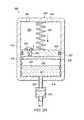
- FIG. 4is a schematic diagram illustrating additional details that may be associated with yet another example embodiment of a negative-pressure source in the negative pressure therapy system of FIG. 1 .
- FIG. 1is a simplified functional block diagram of an example embodiment of a negative-pressure therapy system 100 that can be recharged in accordance with this specification.
- negative-pressure therapy system 100may include a dressing 102 fluidly coupled to a negative-pressure source 104 .
- a regulator or controller, such as regulator 106may also be fluidly coupled to dressing 102 and negative-pressure source 104 .
- Dressing 102generally includes a drape, such as drape 108 , and a manifold, such as pressure distribution manifold 110 .
- Negative-pressure therapy system 100may also include a fluid container, such as container 112 , coupled to dressing 102 and negative-pressure source 104 .
- components of negative-pressure therapy system 100may be coupled directly or indirectly.
- negative-pressure source 104may be directly coupled to regulator 106 and indirectly coupled to dressing 102 through regulator 106 .
- Componentsmay be fluidly coupled to each other to provide a path for transferring fluids (i.e., liquid and/or gas) between the components.
- componentsmay be fluidly coupled with a tube, for example.
- a tubeis an elongated, cylindrical structure with some flexibility, but the geometry and rigidity may vary.
- componentsmay additionally or alternatively be coupled by virtue of physical proximity, being integral to a single structure, or being formed from the same piece of material. Coupling may also include mechanical, pneumatic, thermal, electrical, or chemical coupling (such as a chemical bond) in some contexts.
- pressure distribution manifold 110may be placed within, over, on, or otherwise adjacent to a tissue site.
- Drape 108may be placed over pressure distribution manifold 110 and sealed to tissue near the tissue site.
- the tissue proximate to the tissue siteis often undamaged epidermis peripheral to the tissue site.
- dressing 102can provide a sealed therapeutic environment proximate to a tissue site, substantially isolated from the external, ambient environment, and negative-pressure source 104 can reduce the pressure in the sealed therapeutic environment.
- Negative pressure applied across a tissue site through pressure distribution manifold 110 in the sealed therapeutic environmentcan induce macrostrain and microstrain in the tissue site, as well as remove exudates and other fluids from the tissue site, which can be collected in container 112 and disposed of properly.
- Negative pressuregenerally refers to a pressure less than a local ambient pressure, such as the ambient pressure in a local environment external to a sealed therapeutic environment provided by dressing 102 .
- the local ambient pressuremay also be the atmospheric pressure at which a patient is located.
- the pressuremay be less than a hydrostatic pressure associated with tissue at the tissue site. Unless otherwise indicated, values of pressure stated herein are gauge pressures.
- references to increases in negative pressuretypically refer to a decrease in absolute pressure, while decreases in negative pressure typically refer to an increase in absolute pressure.
- the fluid mechanics of using a negative-pressure source to reduce pressure in another component or location, such as within a sealed therapeutic environment,can be mathematically complex.
- the basic principles of fluid mechanics applicable to negative-pressure therapyare generally well-known to those skilled in the art, and the process of reducing pressure may be described illustratively herein as “delivering,” “distributing,” or “generating” negative pressure, for example.
- tissue sitein this context broadly refers to a wound or defect located on or within tissue, including but not limited to, bone tissue, adipose tissue, muscle tissue, neural tissue, dermal tissue, vascular tissue, connective tissue, cartilage, tendons, or ligaments.
- a woundmay include chronic, acute, traumatic, subacute, and dehisced wounds, partial-thickness burns, ulcers (such as diabetic, pressure, or venous insufficiency ulcers), flaps, and grafts, for example.
- tissue sitemay also refer to areas of tissue that are not necessarily wounded or defective, but are instead areas in which it may be desirable to add or promote the growth of additional tissue. For example, negative-pressure therapy may be used in certain tissue areas to grow additional tissue that may be harvested and transplanted to another tissue location.
- a negative-pressure sourcesuch as negative-pressure source 104
- a negative-pressure sourcemay be housed within or used in conjunction with other components, such as sensors, processing units, alarm indicators, memory, databases, software, display devices, or user interfaces that further facilitate negative-pressure therapy.
- Pressure distribution manifold 110can be generally adapted to contact a tissue site. Pressure distribution manifold 110 may be partially or fully in contact with the tissue site. If the tissue site is a wound, for example, pressure distribution manifold 110 may partially or completely fill the wound, or may be placed over the wound. Pressure distribution manifold 110 may take many forms, and may have many sizes, shapes, or thicknesses depending on a variety of factors, such as the type of treatment being implemented or the nature and size of a tissue site. For example, the size and shape of pressure distribution manifold 110 may be adapted to the contours of deep and irregular shaped tissue sites.
- a manifoldis a substance or structure adapted to collect fluids from across a tissue site under negative pressure.
- a manifoldmay also facilitate delivering fluids across a tissue site, if the fluid path is reversed or a secondary fluid path is provided, for example.
- a manifoldmay include flow channels or pathways that distribute fluids provided to and removed from a tissue site around the manifold.
- the flow channels or pathwaysmay be interconnected to increase uniformity of the removal or distribution of fluids across a tissue site.
- cellular foam, open-cell foam, porous tissue collections, and other porous materialsuch as gauze or felted mat generally include structural elements arranged to form flow channels. Liquids, gels, and other foams may also include or be cured to include flow channels.
- pressure distribution manifold 110may be a porous foam material having interconnected cells or pores adapted to apply negative pressure across a tissue site.
- the foam materialmay be either hydrophobic or hydrophilic.
- pressure distribution manifold 110can be an open-cell, reticulated polyurethane foam such as GranuFoam® dressing available from Kinetic Concepts, Inc. of San Antonio, Tex.
- pressure distribution manifold 110may be made from a hydrophilic material
- pressure distribution manifold 110may also wick fluid away from a tissue site, while continuing to apply negative pressure to the tissue site.
- the wicking properties of pressure distribution manifold 110may draw fluid away from a tissue site by capillary flow or other wicking mechanisms.
- An example of a hydrophilic foamis a polyvinyl alcohol, open-cell foam such as V.A.C. WhiteFoam® dressing available from Kinetic Concepts, Inc. of San Antonio, Tex.
- Other hydrophilic foamsmay include those made from polyether.
- Other foams that may exhibit hydrophilic characteristicsinclude hydrophobic foams that have been treated or coated to provide hydrophilicity.
- Pressure distribution manifold 110may further promote granulation at a tissue site when pressure within the sealed therapeutic environment is reduced.
- any or all of the surfaces of pressure distribution manifold 110may have an uneven, coarse, or jagged profile that can induce microstrains and stresses at a tissue site if negative pressure is applied through pressure distribution manifold 110 .
- pressure distribution manifold 110may be constructed from bioresorbable materials. Suitable bioresorbable materials may include, without limitation, a polymeric blend of polylactic acid (PLA) and polyglycolic acid (PGA). The polymeric blend may also include without limitation polycarbonates, polyfumarates, and capralactones. Pressure distribution manifold 110 may further serve as a scaffold for new cell-growth, or a scaffold material may be used in conjunction with pressure distribution manifold 110 to promote cell-growth.
- a scaffoldis generally a substance or structure used to enhance or promote the growth of cells or formation of tissue, such as a three-dimensional porous structure that provides a template for cell growth.
- Illustrative examples of scaffold materialsinclude calcium phosphate, collagen, PLA/PGA, coral hydroxy apatites, carbonates, or processed allograft materials.
- Drape 108is an example of a sealing member.
- a sealing membermay be constructed from a material that can provide a fluid seal between two components or two environments, such as between a therapeutic environment and a local ambient environment.
- the sealing membermay be, for example, an impermeable or semi-permeable, elastomeric material that can provide a seal adequate to maintain a pressure at a tissue site for a given negative-pressure source.
- the permeabilitygenerally should be low enough that a desired pressure may be maintained.
- An attachment devicemay be used to attach a sealing member to an attachment surface, such as undamaged epidermis, a gasket, or another sealing member.
- the attachment devicemay take many forms.
- an attachment devicemay be a medically-acceptable, pressure-sensitive adhesive that extends about a periphery, a portion, or an entire sealing member.
- Other example embodiments of an attachment devicemay include a double-sided tape, paste, hydrocolloid, hydrogel, silicone gel, organogel, or an acrylic adhesive.
- Container 112is representative of a container, canister, pouch, or other storage component, which can be used to manage exudates and other fluids withdrawn from a tissue site.
- a rigid containermay be preferred or required for collecting, storing, and disposing of fluids.
- fluidsmay be properly disposed of without rigid container storage, and a re-usable container could reduce waste and costs associated with negative-pressure therapy.
- negative-pressure therapycan be beneficial for conditions of all severity, but the cost and complexity of negative-pressure therapy systems often limit the application of negative-pressure therapy to large, highly-exudating wounds on patients undergoing acute or chronic care, as well as other severe conditions that are not readily susceptible to healing without application of negative pressure.
- the complexity of many negative-pressure therapy systemscan limit the ability of a person with little or no specialized knowledge from administering negative-pressure therapy.
- the size of many negative-pressure therapy systemsmay also impair mobility.
- Many negative-pressure therapy systemsalso require careful cleaning after each treatment, and may require electrical components or other powered devices to supply the negative pressure for treatment.
- a manually-actuated pumpcan be used as a source of negative pressure instead of an electrically-powered pump.
- the generation of negative pressure with a manually-actuated pumpis a function of receiving energy from an operator, storing the energy, and consuming the energy to perform mechanical work on a fluid.
- the process of receiving and storing the energyis often referred to as “charging.”
- the energycan be stored, for example, by a combination of mechanical and pneumatic methods. For example, an operator may apply force to a crank or plunger to compress or expand an elastic element, such as a spring.
- the amount of energy that can be stored in an elastic elementis generally described by Hooke's law of elasticity, which is an approximation that states that the extension of an elastic element is directly proportional to the load applied to the element.
- the amount of energy stored in a springmay be determined by the force required to deflect the spring a distance from equilibrium.
- the amount of deflection a spring may undergo in a given systemis often constrained by the physical size of a structure within which the spring is contained.
- the spring rate of a springcan be increased to increase the energy storage capacity of the spring.
- increasing the spring ratealso increases the force required to compress or extend the spring, and an operator may have difficulty deflecting the spring without a mechanical advantage.
- Means for providing a mechanical advantageinclude levers, screw threads, and ratchets, for example.
- a manually-actuated negative-pressure therapy systemcan be particularly sensitive to leaks because the capacity of such a system to generate negative pressure is typically more limited than electrically-powered pumps. If a spring is used to store energy, for example, an operator may be required to periodically compress or extend the spring as the stored energy is depleted. Thus, a manually-actuated pump in a negative-pressure therapy system may require periodic charging to maintain a therapeutic pressure.
- wound fluidcan be stored in an absorbent reservoir of a dressing instead of a large canister, or wound fluid can be drawn into a remote container within a pump housing.
- storing wound fluid in a dressingcan increase the cost and complexity of the dressing, while drawing wound fluid into a remote container requires additional energy and can increase the cost and complexity of the pump housing.
- negative-pressure therapy system 100can overcome these challenges and others by storing and managing fluids within a piston chamber of a manually-actuated pump. Negative-pressure therapy system 100 may be particularly advantageous for application to less severe conditions where the flow of air leaking into the system exceeds the flow of other fluids from the tissue site. For example, if a dressing seal can limit leaks to less than 10 ml/h and a wound produces 60 cc of fluid over 3 days, then the air leaking into the system will greatly exceed the flow of fluids from the tissue site.
- negative-pressure therapy system 100may include a pump having a piston coupled to an elastic element and disposed within a piston chamber.
- a charging forcemay be applied to compress or extend the elastic element, which moves the piston toward a port in the piston chamber. Once the charging force is removed, the spring force of the elastic element can move the piston away from the port to generate a negative pressure through the port.
- the negative pressuremay draw fluid into the piston chamber through the port as the elastic element moves the piston away from the port.
- the pumpmay draw in exudates from a tissue site through dressing 102 , as well as air from leaks in dressing 102 .
- the elastic elementmay be re-charged to maintain a therapeutic pressure. For example, a charging force may again be applied to compress or extend the elastic element, which again moves the piston toward the port.
- a valvemay be adapted to block the fluid from exiting the piston chamber through the port as the piston moves toward the port.
- a filtercan be configured to separate gas from liquid in the fluid as the piston moves toward the filter, while retaining the liquid in the piston chamber. For example, air from leaks may be expelled through the filter while exudates may be retained in the piston chamber.
- a flexible pouch with at least one liquid-blocking filtermay be disposed within a chamber between a piston and a port in the chamber. Negative pressure can be generated in the chamber as the piston moves away from the port, and the negative pressure can be delivered to a tissue site through the filter, pouch, and port.
- a one-way valveallows fluid to flow into the pouch from the tissue site as the piston moves away from the port.
- Another one-way valve in the pistonallows fluid to flow out of the chamber as the piston advances toward the port. To recharge the pump, the piston can be moved toward the pouch and the port.
- the pistonAs the piston contacts and compresses the pouch, air and other gases can be expelled from the pouch through the filter, but the liquid-blocking filter retains exudates and other liquids from the tissue site in the pouch.
- the pistoncan continue to advance toward the port until gases are substantially expelled from the pouch and the chamber.
- fluidmay be drawn from a tissue site into a chamber between a piston and a port in a pump.
- a one-way valveallows fluid to flow into the pouch from the tissue site as the piston moves away from the port.
- Another one-way valve in the pistonallows fluid to flow out of the chamber as the piston advances toward the port.
- fluidscan be expelled from the chamber through the valve in the piston to a second chamber.
- the second chambermay include a vent with a liquid-blocking filter opposite the piston. As the piston moves away from the port to compensate for leaks, the piston moves toward the vent and expels air and other gases through the vent while the liquid-blocking filter retains exudates and other liquids within the second chamber.
- fluidmay be draw from a tissue site into a chamber between a piston and a first port, and then expelled through a second port to an external container or drain.
- the second portmay be connected to a canister or bag that has the capacity to contain fluid from several charges for later disposal, or the second port may be connected to a plumbed drain.
- FIGS. 2A-2Dare schematic diagrams of a pump 200 in various operational states, illustrating additional details that may be associated with example embodiments of negative-pressure source 104 .
- pump 200may include a piston chamber 202 , a piston 204 , an elastic element 206 , an intake port 208 , and an exhaust port 210 .
- Piston chamber 202is a substantially enclosed space, such as may be generally defined by a cylinder having a side wall 212 , a base 214 , and a head 216 , wherein base 214 and head 216 are generally coupled to side wall 212 at opposing ends of side wall 212 .
- Piston chamber 202 in this example embodimentis fluidly isolated from the ambient environment, except through intake port 208 and exhaust port 210 , which are illustrated disposed within or fluidly coupled to base 214 and head 216 , respectively.
- elastic element 206may be a spring or other means for storing mechanical energy.
- elastic element 206may be a tension spring, a compression spring, a torsion spring, a constant force spring, or a variable force spring.
- Elastic element 206may be operatively engaged to piston 204 to bias piston 204 away from intake port 208 .
- elastic element 206generally represents a coil tension spring coupled or otherwise operatively engaged on one end to an interior portion of piston chamber 202 and on an opposing end to piston 204 .
- Piston 204can reciprocate within piston chamber 202 , and generally divides piston chamber 202 into a first chamber and a second chamber, such as vacuum chamber 218 and ambient pressure chamber 220 .
- a seal 221may also be disposed between piston 204 and side wall 212 , such as in a groove on a side wall of piston 204 , to prevent fluid flow between vacuum chamber 218 and ambient pressure chamber 220 along side wall 212 .
- Intake port 208may fluidly couple vacuum chamber 218 to a dressing, such as dressing 102 .
- Exhaust port 210can fluidly couple ambient pressure chamber 220 to the ambient environment. Exhaust port 210 is preferably configured to allow gas to be expelled from ambient pressure chamber 220 as piston 204 moves toward exhaust port 210 during an operating stroke.
- piston 204may be a substantially rigid barrier that can reciprocate within piston chamber 202 .
- Piston 204may be a cylinder or disk disposed within piston chamber 202 , for example.
- Other embodimentsmay include alternative types of barriers, however, such as a flexible barrier that flexes within piston chamber 202 , for example.
- piston 204is substantially solid with the exception of a conduit, passage, or port, such as passage 222 , which fluidly couples vacuum chamber 218 and ambient pressure chamber 220 through piston 204 .
- ambient pressure chamber 220is fluidly isolated from vacuum chamber 218 except through passage 222 in this illustrative embodiment.
- a valve 224may be operatively coupled to piston 204 to control fluid flow between vacuum chamber 218 and ambient pressure chamber 220 through passage 222 .
- valve 224may be a check valve or other unidirectional valve in piston 204 that allows fluid to flow from vacuum chamber 218 to ambient pressure chamber 220 , but blocks flow from ambient pressure chamber 220 to vacuum chamber 218 .
- passage 222may be a gap between piston 204 and side wall 212
- valve 224may be a flexible seal disposed around piston 204 configured to allow fluid to flow from vacuum chamber 218 to ambient pressure chamber 220 through the gap, in which case seal 221 may be eliminated.
- Container 226may also include a container 226 disposed within vacuum chamber 218 .
- Container 226is an example embodiment of container 112 , which in the illustrative embodiment of FIGS. 2A-2D is a flexible, liquid-impermeable pouch adapted to expand and contract.
- Container 226may be a bellows or accordion style container in some embodiments.
- container 226may also include a port or aperture, such as aperture 227 , which may be fluidly coupled to intake port 208 .
- At least one liquid barriermay be disposed between an interior of container 226 and the valve 224 , such as within or proximate to a second aperture in container 226 . As illustrated in FIGS. 2A-2D , the liquid barrier may be a filter 228 disposed in an aperture of container 226 opposite aperture 227 and facing piston 204 .
- Filter 228is preferably a gas-permeable, liquid-blocking filter.
- filter 228may be a sintered polymer filter that swells on contact with water.
- Suitable polymersinclude, for example, fluoropolymers such as polytetrafluoroethylene (PTFE), polyvinylidene fluoride (PVdF), or fluorinated ethylenepropylene (FEP); chlorofluoropolymers, such as polychlorotrifluoroethylene (PCTFE); polyolefins such as high density polyethylene (HDPE), polypropylene (PP), cyclic olefin copolymer (COC), or polymethylpent-1-ene (PMP); polyvinyl acetate (PVAc) or ethylene vinyl acetate (EVA); polycarbonate (PC); polyesters such as polyethylene terephthalate (PET) or PET copolymers (PETG); or polysulphones or polyethersulphones.
- the polymermay also contain charcoal to reduce odor. Additionally, filter 228 may be coated to enhance hydrophobicity in some embodiments. Polymers may be formed into membranes or sintered (particularly for PVAc, EVA, polyolefin's, and fluoropolymers).
- valve 230may be coupled to intake port 208 to control fluid flow through intake port 208 .
- valve 230may be a check valve or other unidirectional valve that allows fluid to flow through intake port 208 into container 226 , but can block fluid in container 226 from flowing out through intake port 208 .
- pump 200may be charged by applying a charging force to move piston 204 toward intake port 208 , which extends elastic element 206 and stores mechanical energy therein.
- An operatormay supply a charging force by applying hand pressure to a handle (not shown) coupled to piston 204 , or cranking a lever-based ratchet mechanism (not shown), for example.
- the charging forcemoves piston 204 toward intake port 208 , decreasing the volume of vacuum chamber 218 .
- valve 230may be configured to block fluid from flowing out through intake port 208 , decreasing the volume of vacuum chamber 218 may also increase the pressure in vacuum chamber 218 .
- the increased pressure in vacuum chamber 218may open valve 224 to allow fluid to flow from vacuum chamber 218 to ambient pressure chamber 220 during the charging stroke.
- FIG. 2Aillustrates a state of pump 200 in which piston 204 is at or near the limit of a charging stroke.
- the limit of a charging strokemay be determined by several criteria, such as a detent in piston chamber 202 , the ability of an operator to overcome the force of elastic element 206 , the incompressibility of container 226 , or the incompressibility of fluid in container 226 , for example.
- FIG. 2Billustrates a state of pump 200 in which piston 204 may be at or near a limit of an operating stroke, for example.
- Valve 224may be configured to block fluid flow through passage 222 during an operating stroke.
- vacuum chamber 218may become part of a closed system in which gas within vacuum chamber 218 generally behaves according to Boyle's law.
- the decreasing pressure in vacuum chamber 218 resulting from the expansion of vacuum chamber 218 during an operating strokecauses a pressure differential across piston 204 .
- the force on piston 204 resulting from the pressure differential on opposing sides of piston 204may be referred to as a “differential force.”
- Elastic element 206also generally exerts an elastic force on piston 204 .
- the force of elastic element 206is proportional to the spring constant of elastic element 206 and to a displacement from a state of equilibrium of the ends of elastic element 206 .
- the differential force and the force of elastic element 206can be combined to determine a net force acting on piston 204 .
- the net forcecan cause piston 204 to move reciprocally within piston chamber 202 , such as along an axis parallel to side wall 212 .
- Elastic element 206may be selected, adjusted, modified, tuned, or otherwise calibrated so that the net force can move piston 204 to increase the volume of vacuum chamber 218 if the pressure increases above a threshold value.
- this threshold valuemay generally correlate to a target pressure prescribed for negative-pressure therapy, and may be referred to herein as the “therapy pressure” or “therapeutic pressure.” While the amount and nature of pressure applied to a tissue site may vary according to therapeutic requirements, therapy pressure typically ranges between ⁇ 5 mm Hg ( ⁇ 667 Pa) and ⁇ 500 mm Hg ( ⁇ 66.7 kPa). Common therapeutic ranges are between ⁇ 75 mm Hg ( ⁇ 9.9 kPa) and ⁇ 300 mm Hg ( ⁇ 39.9 kPa).
- vacuum chamber 218 and container 226can be fluidly coupled to a remote chamber, environment, or other location, such as a sealed therapeutic environment associated with negative-pressure therapy system 100 .
- a tube(not shown) may be coupled on a first end to inlet port 208 and on a second end to a dressing, such as dressing 102 .
- the reduced pressure in vacuum chamber 218may cause fluid from a tissue site to be drawn through the dressing into pump 200 .
- FIG. 2Cillustrates a state of pump 200 in which exudate 232 has been drawn into container 226 within vacuum chamber 218 . Air from leaks, as well as other fluids, may also be drawn into container 226 , and container 226 is adapted to expand as exudate, air, and other fluids flow into container 226 .
- a pressure increase in vacuum chamber 218causes the differential force on piston 203 to decrease, and the change in net force may move piston 204 away from port 208 to increase the volume of vacuum chamber 218 .
- the increased volume of vacuum chamber 218reduces the pressure in vacuum chamber 218 to compensate for pressure increase caused by air leaking into vacuum chamber 218 from the ambient environment.
- a therapeutic pressuremay be maintained at a substantially stable level until piston 204 reaches a limit of the operating stroke.
- the limit of the operating strokemay be determined by several criteria. For example, a detent in piston chamber 202 may limit movement of piston 204 away from port 208 , or elastic element 206 may return to a state of equilibrium.
- Pump 200may be re-charged at any time during an operating stroke to maintain or extend therapeutic pressure.
- pump 200may be re-charged at the end of an operating stroke to maintain therapeutic pressure.
- a charging forcemay be applied to piston 204 again, which moves piston 204 toward intake port 208 and extends elastic element 206 again.
- Valve 224can be configured to allow air and other gases to be exhausted to ambient pressure chamber 220 as piston 204 moves toward intake port 208
- valve 230can be configured to prevent fluids from being refluxed to a tissue site through intake port 208 .
- piston 204compresses container 226 , air and other gases may be expelled through filter 228 , but liquids are blocked by filter 228 and retained within container 226 .
- piston 204may continue to move toward intake port 208 and compress container 226 until substantially all gases have been expelled from container 226 , as illustrated in FIG. 4D , and gases are effectively separated from liquids during a charging stroke.
- FIGS. 3A-3Bare schematic diagrams of a pump 300 in two operational states, illustrating additional details that may be associated with other example embodiments of negative-pressure source 104 .
- pump 300may include a piston chamber 302 , a piston 304 , an elastic element 306 , an intake port 308 , and an exhaust port 310 .
- Piston chamber 302is similar in many respects to piston chamber 202 .
- piston chamber 302is a substantially enclosed space, which may be generally defined by a cylinder having a side wall 312 , a base 314 , and a head 316 , wherein base 314 and head 316 are generally coupled to opposing ends of side wall 312 .
- Piston chamber 302 in this example embodimentis generally isolated from the ambient environment, except through intake port 308 and exhaust port 310 .
- Elastic element 306is also analogous to elastic element 206 in most respects.
- elastic element 306represents a spring or other means for storing mechanical energy.
- elastic element 306may be a tension spring, a compression spring, a torsion spring, a constant spring, or a variable spring.
- Elastic element 306may be operatively engaged to piston 304 to bias piston 304 away from intake port 308 .
- Piston 304is generally disposed within piston chamber 302 and configured to move reciprocally within piston chamber 302 .
- Piston 304divides piston chamber 302 into a first chamber and a second chamber, such as vacuum chamber 318 and ambient pressure chamber 320 .
- a seal 321may also be disposed between piston 304 and side wall 312 , such as in a groove on a side wall of piston 304 , to prevent fluid flow between vacuum chamber 318 and ambient pressure chamber 320 along side wall 312 .
- Intake port 308may fluidly couple vacuum chamber 318 to a dressing, such as dressing 102 .
- Exhaust port 310can fluidly couple ambient pressure chamber 320 to the ambient environment.
- piston 304may be a substantially rigid barrier that can reciprocate within piston chamber 302 .
- Piston 304may be a cylinder or disk disposed within piston chamber 302 , for example.
- Other embodimentsmay include alternative types of barriers, such as a flexible barrier that flexes within piston chamber 302 , for example.
- piston 304is substantially solid with the exception of a conduit, passage, or port, such as passage 322 , which fluidly couples vacuum chamber 318 and ambient pressure chamber 320 .
- ambient pressure chamber 320may be fluidly isolated from vacuum chamber 318 except through passage 322 in this illustrative embodiment.
- a valve 324may be operatively coupled to piston 304 to control fluid flow between vacuum chamber 318 and ambient pressure chamber 320 through passage 322 .
- valve 324may be a check valve or other unidirectional valve coupled to piston 304 or passage 322 that allows fluid to flow from vacuum chamber 318 to ambient pressure chamber 320 , but blocks flow from ambient pressure chamber 320 to vacuum chamber 318 .
- passage 322may be a gap between piston 304 and side wall 312
- valve 324may be a flexible seal disposed around piston 304 configured to allow fluid to flow from vacuum chamber 318 to ambient pressure chamber 320 through the gap.
- At least one liquid barriermay be disposed between ambient pressure chamber 320 and an ambient environment.
- the liquid barriermay be a filter 328 disposed within, proximate to, or otherwise fluidly coupled to exhaust port 310 between ambient pressure chamber 320 and the ambient environment.
- Exhaust port 310is preferably configured to allow gas to be expelled from ambient pressure chamber 320 as piston 304 moves toward exhaust port 310 during an operating stroke, and filter 328 may be configured to filter exudates and other liquids.
- Filter 328is analogous or similar to filter 228 in most respects.
- filter 328is preferably a gas-permeable, liquid-blocking filter.
- filter 328may be a sintered polymer filter that swells on contact with water.
- Suitable polymersinclude, for example, fluoropolymers such as PTFE, PVdF, or FEP; chlorofluoropolymers, such as PCTFE; polyolefins such as HDPE, PP, COC, or PMP; PVAc or EVA; PC; polyesters such as PET or PETG; or polysulphones or polyethersulphones.
- the polymermay also contain charcoal to reduce odor.
- filter 328may be coated to enhance hydrophobicity in some embodiments. Polymers may be formed into membranes or sintered (particularly for PVAc, EVA, polyolefin's, and fluoropolymers).
- a valve 330may be coupled to intake port 308 to control fluid flow through intake port 308 .
- valve 330may be a check valve or other unidirectional valve that allows fluid to flow through intake port 308 into vacuum chamber 318 , but can block fluid in vacuum chamber 318 from being expelled through intake port 308 , particularly during a charging stroke.
- pump 300may be charged by applying a charging force to move piston 304 toward intake port 308 , which extends elastic element 306 .
- a charging forceFor example, an operator may supply a charging force by applying hand pressure to a handle (not shown) coupled to piston 304 , or by cranking a lever-based ratchet mechanism (not shown).
- the charging strokedecreases the volume of vacuum chamber 318 .
- valve 330may be configured to block fluid from flowing out through intake port 308 during a charging stroke, the decrease in volume of vacuum chamber 318 also increases the pressure in vacuum chamber 318 .
- the increased pressure in vacuum chamber 318may open valve 324 to allow fluid to flow from vacuum chamber 318 to ambient pressure chamber 320 during the charging stroke.
- FIG. 3Aillustrates a state of pump 300 during an operating stroke, in which piston 304 is moving away from intake port 308 within piston chamber 302 .
- an operating strokemay draw exudate 332 into vacuum chamber 318 .
- Air from leaks, as well as other fluids,may also be drawn into vacuum chamber 318 during an operating stroke.
- valve 324is generally closed during an operating stroke, blocking the flow of exudates 332 and other fluids into ambient pressure chamber 320 .
- vacuum chamber 318If air from the ambient environment leaks into vacuum chamber 318 , the pressure in vacuum chamber 318 generally increases. Similar to piston 204 in pump 200 , a differential force and an elastic force act on piston 304 . A pressure increase in vacuum chamber 318 causes the differential force to decrease, and elastic element 306 may move piston 304 away from intake port 308 to increase the volume of vacuum chamber 318 . The increased volume of vacuum chamber 318 reduces the pressure in vacuum chamber 318 until reaching an equilibrium between the differential force and the elastic force. Thus, a therapeutic pressure may be maintained at a substantially stable level until piston 304 reaches a limit of the operating stroke.
- Pump 300may be recharged at any time during an operating stroke to maintain or extend therapeutic pressure.
- pump 300may be recharged at the end of an operating stroke to maintain therapeutic pressure.
- Pump 300may be recharged by applying a charging force to piston 304 again, which moves piston 304 toward intake port 308 and extends elastic element 306 again, as illustrated in FIG. 3B .
- Valve 330can be configured to prevent fluids in vacuum chamber 318 from being expelled through intake port 308 during a charging stroke.
- Valve 324can be configured to allow exudate, air, and other fluids to be expelled through passage 322 , transferring fluids from vacuum chamber 318 to ambient pressure chamber 320 during a charging stroke, also illustrated in FIG. 3B .
- Valve 324may also be configured to block fluids in ambient pressure chamber 320 from being expelled through passage 322 into vacuum chamber 320 during an operating stroke (see FIG. 3A ).
- piston 304presses fluids in ambient pressure chamber 320 toward exhaust port 310 .
- air and other gasesmay be expelled through exhaust port 310 , but filter 328 retains exudate and other liquids in ambient pressure chamber 320 . Consequently, gases are effectively separated from liquids and piston 304 may continue to move toward exhaust port 310 until all or substantially all gases have been expelled from ambient pressure chamber 320 into the ambient environment, or until otherwise reaching a limit of an operating stroke.
- FIG. 4is a schematic diagram of a pump 400 illustrating additional details that may be associated with yet another example embodiment of negative pressure source 104 .
- pump 400may include a piston chamber 402 , a piston 404 , an elastic element 406 , an intake port 408 , an exhaust port 410 , and a disposal port 411 .
- Piston chamber 402is similar in many respects to piston chamber 202 and piston chamber 302 .
- piston chamber 402may be a substantially enclosed space generally defined by a cylinder having a side wall 412 , a base 414 , and a head 416 , wherein base 414 and head 416 are generally coupled to opposing ends of side wall 412 .
- Piston chamber 402 in this example embodimentis generally isolated from the ambient environment, except through intake port 408 , exhaust port 410 , and disposal port 411 . As illustrated in FIG. 4 , intake port 408 and disposal port 411 are preferably disposed within or fluidly coupled to base 414 , and exhaust port 410 is preferably disposed within or fluidly coupled to head 416 .
- Elastic element 406is also analogous to elastic element 206 and elastic element 306 in most respects.
- elastic element 406represents a spring or other means for storing mechanical energy.
- elastic element 406may be a tension spring, a compression spring, a torsion spring, a constant spring, or a variable spring.
- Elastic element 406may be operatively engaged to piston 404 to bias piston 404 away from intake port 408 .
- Piston 404is generally disposed within piston chamber 402 and configured to move reciprocally within piston chamber 402 . Piston 404 divides piston chamber 402 into two chambers, such as vacuum chamber 418 and ambient pressure chamber 420 . A seal 421 may also be disposed between piston 404 and side wall 412 , such as in a groove on a side wall of piston 404 , to prevent fluid flow between vacuum chamber 418 and ambient pressure chamber 420 along side wall 412 .
- Intake port 408may fluidly couple vacuum chamber 418 to a dressing, such as dressing 102 .
- Exhaust port 410can fluidly couple ambient pressure chamber 420 to the ambient environment.
- Disposal port 411can fluidly couple vacuum chamber 418 to an external container, such as a remote canister or bag, or to a plumbed drain, for example.
- Piston 404may be a substantially rigid barrier that can reciprocate within piston chamber 402 .
- Piston 404may be a cylinder or disk disposed within piston chamber 402 , for example.
- Other embodimentsmay include alternative types of barriers, such as a flexible barrier that flexes within piston chamber 402 , for example.
- piston 404is substantially solid.
- ambient pressure chamber 420may be fluidly isolated from vacuum chamber 418 in this illustrative embodiment.
- a valve 430may be coupled to intake port 408 to control fluid flow through intake port 408
- a valve 432may be coupled to disposal port 411 to control fluid flow through disposal port 411
- either valve 430 or valve 432 , or bothmay be a check valve or other unidirectional valve.
- Valve 430may be configured to allow fluid to flow through intake port 408 into vacuum chamber 418 , but to block fluid in vacuum chamber 418 from being expelled through intake port 408 , particularly during a charging stroke.
- Valve 432may be a unidirectional valve configured to allow fluid to flow through disposal port 411 from vacuum chamber 418 , but to block fluid from flowing into vacuum chamber 418 through disposal port 411 .
- pump 400may be charged similarly to pump 200 or pump 300 .
- pump 400may be charged by applying a charging force to move piston 404 toward intake port 408 , which extends elastic element 406 .
- the charging strokedecreases the volume of vacuum chamber 418 .
- valve 430may be configured to block fluid from being expelled through intake port 408 during a charging stroke, any fluid contained within vacuum chamber 418 during a charging stroke can be expelled through disposal port 411 and valve 432 .
- vacuum chamber 418If air from the ambient environment leaks into vacuum chamber 418 , the pressure in vacuum chamber 418 generally increases. Similar to piston 204 and piston 304 , a differential force and an elastic force act on piston 404 . A pressure increase in vacuum chamber 418 causes the differential force to decrease, and the resulting change in the net force may move piston 404 away from intake port 408 to increase the volume of vacuum chamber 418 . The increased volume of vacuum chamber 418 reduces the pressure in vacuum chamber 418 until reaching an equilibrium between the differential force and the elastic force. Thus, a therapeutic pressure may be maintained at a substantially stable level until piston 404 reaches a limit of the operating stroke.
- Pump 400may also be recharged at any time during an operating stroke to maintain or extend therapeutic pressure.
- pump 400may be recharged at the end of an operating stroke to maintain therapeutic pressure.
- Pump 400may be recharged by applying a charging force to piston 404 again, which moves piston 404 toward intake port 408 and extends elastic element 406 again.
- Valve 430can be configured to prevent fluids in vacuum chamber 418 from being expelled through intake port 408 during a charging stroke.
- Valve 432can be configured to allow exudates, air, and other fluids to be expelled through disposal port 411 during a charging stroke.
- piston 404expels fluids in vacuum chamber 418 through disposal port 411 , which can be fluidly coupled directly to an external container or through a plumbed drain, for example.
- the external containerpreferably has capacity to store fluids from more than one charging stroke.
- negative-pressure therapy system 100can manage wound fluids to enable recharging a manually-actuated negative-pressure source.
- exudatemay be separated from air, and fluid storage may be integrated with the negative-pressure source to reduce the number of components.
- exudates and other fluidsmay be expelled to an external container.
- Negative-pressure therapy system 100may be recharged without disconnecting the negative-pressure source, and is also generally tolerant to leaks during therapy. Negative-pressure therapy system 100 may be particularly advantageous for providing therapy without external fluid storage, but some embodiments of negative-pressure therapy system 100 may also be combined with or include external fluid storage, such as dressing with an absorbent layer or an external canister.
Landscapes
- Health & Medical Sciences (AREA)
- Heart & Thoracic Surgery (AREA)
- Animal Behavior & Ethology (AREA)
- General Health & Medical Sciences (AREA)
- Anesthesiology (AREA)
- Biomedical Technology (AREA)
- Hematology (AREA)
- Life Sciences & Earth Sciences (AREA)
- Vascular Medicine (AREA)
- Engineering & Computer Science (AREA)
- Public Health (AREA)
- Veterinary Medicine (AREA)
- External Artificial Organs (AREA)
- Media Introduction/Drainage Providing Device (AREA)
- Details Of Reciprocating Pumps (AREA)
- Reciprocating Pumps (AREA)
Abstract
Description
Claims (12)
Priority Applications (2)
| Application Number | Priority Date | Filing Date | Title |
|---|---|---|---|
| US14/105,970US10064984B2 (en) | 2013-01-03 | 2013-12-13 | Recharging negative-pressure wound therapy |
| US16/052,408US20190009010A1 (en) | 2013-01-03 | 2018-08-01 | Recharging Negative-Pressure Wound Therapy |
Applications Claiming Priority (2)
| Application Number | Priority Date | Filing Date | Title |
|---|---|---|---|
| US201361748707P | 2013-01-03 | 2013-01-03 | |
| US14/105,970US10064984B2 (en) | 2013-01-03 | 2013-12-13 | Recharging negative-pressure wound therapy |
Related Child Applications (1)
| Application Number | Title | Priority Date | Filing Date |
|---|---|---|---|
| US16/052,408DivisionUS20190009010A1 (en) | 2013-01-03 | 2018-08-01 | Recharging Negative-Pressure Wound Therapy |
Publications (2)
| Publication Number | Publication Date |
|---|---|
| US20140188061A1 US20140188061A1 (en) | 2014-07-03 |
| US10064984B2true US10064984B2 (en) | 2018-09-04 |
Family
ID=49911813
Family Applications (2)
| Application Number | Title | Priority Date | Filing Date |
|---|---|---|---|
| US14/105,970Active2035-02-14US10064984B2 (en) | 2013-01-03 | 2013-12-13 | Recharging negative-pressure wound therapy |
| US16/052,408AbandonedUS20190009010A1 (en) | 2013-01-03 | 2018-08-01 | Recharging Negative-Pressure Wound Therapy |
Family Applications After (1)
| Application Number | Title | Priority Date | Filing Date |
|---|---|---|---|
| US16/052,408AbandonedUS20190009010A1 (en) | 2013-01-03 | 2018-08-01 | Recharging Negative-Pressure Wound Therapy |
Country Status (7)
| Country | Link |
|---|---|
| US (2) | US10064984B2 (en) |
| EP (3) | EP3437667B1 (en) |
| JP (2) | JP2016508056A (en) |
| CN (1) | CN104884101B (en) |
| AU (1) | AU2013371549B2 (en) |
| CA (1) | CA2893947C (en) |
| WO (1) | WO2014107285A2 (en) |
Cited By (5)
| Publication number | Priority date | Publication date | Assignee | Title |
|---|---|---|---|---|
| US20180221007A1 (en)* | 2009-06-10 | 2018-08-09 | Conmed Corporation | Tissue specimen retrieval bag, method for retrieving tissue |
| US20220080104A1 (en)* | 2013-03-13 | 2022-03-17 | Kci Licensing, Inc. | Collapsible Canister For Use With Reduced Pressure Therapy Device |
| US20230263514A1 (en)* | 2009-06-10 | 2023-08-24 | Conmed Corporation | Tissue specimen retrieval bag, method for retrieving tissue |
| US11839527B2 (en) | 2017-12-06 | 2023-12-12 | Cornell University | Manually-operated negative pressure wound therapy (NPWT) bandage with improved pump efficiency, automatic pressure indicator and automatic pressure limiter |
| US12263100B2 (en) | 2018-04-16 | 2025-04-01 | Stryker Corporation | Bone fragment collector and processor |
Families Citing this family (55)
| Publication number | Priority date | Publication date | Assignee | Title |
|---|---|---|---|---|
| GB0224986D0 (en) | 2002-10-28 | 2002-12-04 | Smith & Nephew | Apparatus |
| CA2619925A1 (en) | 2005-09-07 | 2007-03-15 | Tyco Healthcare Group Lp | Wound dressing with vacuum reservoir |
| ES2715605T3 (en) | 2007-11-21 | 2019-06-05 | Smith & Nephew | Wound dressing |
| US8152785B2 (en) | 2008-03-13 | 2012-04-10 | Tyco Healthcare Group Lp | Vacuum port for vacuum wound therapy |
| US10912869B2 (en) | 2008-05-21 | 2021-02-09 | Smith & Nephew, Inc. | Wound therapy system with related methods therefor |
| US8414519B2 (en) | 2008-05-21 | 2013-04-09 | Covidien Lp | Wound therapy system with portable container apparatus |
| ES2639776T3 (en) | 2010-09-20 | 2017-10-30 | Smith & Nephew, Plc | Negative pressure device |
| WO2013066426A2 (en) | 2011-06-24 | 2013-05-10 | Kci Licensing, Inc. | Reduced-pressure dressings employing tissue-fixation elements |
| JP6250571B2 (en) | 2012-03-12 | 2017-12-20 | スミス アンド ネフュー ピーエルシーSmith & Nephew Public Limited Company | Pressure reducing apparatus and method |
| ES2820373T3 (en)* | 2012-09-14 | 2021-04-20 | 3M Innovative Properties Co | System to regulate pressure |
| US10064984B2 (en)* | 2013-01-03 | 2018-09-04 | Kci Licensing, Inc. | Recharging negative-pressure wound therapy |
| JP6448243B2 (en)* | 2014-07-28 | 2019-01-09 | 新鋭工業販売株式会社 | Liquid storage container for aspirator |
| TR201902009T4 (en) | 2014-09-10 | 2019-03-21 | Kci Licensing Inc | Dynamic negative pressure therapy with instillation. |
| DK3288508T3 (en) | 2015-04-27 | 2020-03-09 | Smith & Nephew | REDUCED PRESSURE DEVICES |
| EP3714916A1 (en) | 2015-07-29 | 2020-09-30 | Innovative Therapies Inc. | Wound therapy device pressure monitoring and control system |
| US10821018B2 (en)* | 2015-10-23 | 2020-11-03 | C.R. Bard Inc. | Drainage bag systems and methods of using the same |
| US11364150B2 (en) | 2015-12-30 | 2022-06-21 | Smith & Nephew Plc | Negative pressure wound therapy apparatus |
| US11141513B2 (en)* | 2016-01-28 | 2021-10-12 | Kci Licensing, Inc. | Fluid container with pressure regulation |
| EP3426206B1 (en) | 2016-03-07 | 2023-05-10 | Smith & Nephew plc | Wound treatment apparatuses and methods with negative pressure source integrated into wound dressing |
| CA3022184A1 (en) | 2016-04-26 | 2017-11-02 | Smith & Nephew Plc | Wound dressings and methods of use with integrated negative pressure source having a fluid ingress inhibition component |
| JP6185212B1 (en)* | 2016-04-27 | 2017-08-23 | 悠一 佐紺 | Molded body filter using PTFE film, and disposable bag or container for medical suction device using the same |
| CA3038206A1 (en) | 2016-05-03 | 2017-11-09 | Smith & Nephew Plc | Optimizing power transfer to negative pressure sources in negative pressure therapy systems |
| WO2017191158A1 (en) | 2016-05-03 | 2017-11-09 | Smith & Nephew Plc | Systems and methods for driving negative pressure sources in negative pressure therapy systems |
| US11096831B2 (en) | 2016-05-03 | 2021-08-24 | Smith & Nephew Plc | Negative pressure wound therapy device activation and control |
| CN105920687B (en)* | 2016-05-24 | 2018-05-29 | 明基材料有限公司 | portable negative pressure device |
| CN106108985B (en)* | 2016-06-12 | 2018-09-28 | 南方医科大学 | It is a kind of to treat needling device |
| WO2018031867A1 (en) | 2016-08-11 | 2018-02-15 | Patrick Kenneth Powell | Vacuum pump |
| WO2018037075A1 (en) | 2016-08-25 | 2018-03-01 | Smith & Nephew Plc | Absorbent negative pressure wound therapy dressing |
| EP3519001B1 (en) | 2016-09-30 | 2025-05-21 | Smith & Nephew plc | Negative pressure wound treatment apparatuses and methods with integrated electronics |
| EP3551244A1 (en) | 2016-12-12 | 2019-10-16 | Smith & Nephew PLC | Pressure wound therapy status indication via external device |
| JP7231227B2 (en)* | 2017-02-22 | 2023-03-01 | コーネル ユニヴァーシティー | Mechanical vacuum dressing for mechanical management, protection and aspiration of small incisions |
| EP3592312B1 (en) | 2017-03-08 | 2024-01-10 | Smith & Nephew plc | Negative pressure wound therapy device control in presence of fault condition |
| JP7121050B2 (en) | 2017-05-09 | 2022-08-17 | スミス アンド ネフュー ピーエルシー | Redundant control of negative pressure wound therapy systems |
| EP4275711A3 (en)* | 2017-07-18 | 2024-02-28 | 3M Innovative Properties Company | Negative-pressure therapy with adjustable instillation pump chamber |
| CA3074780A1 (en) | 2017-09-13 | 2019-03-21 | Smith & Nephew Plc | Negative pressure wound treatment apparatuses and methods with integrated electronics |
| GB201718070D0 (en) | 2017-11-01 | 2017-12-13 | Smith & Nephew | Negative pressure wound treatment apparatuses and methods with integrated electronics |
| GB201718054D0 (en) | 2017-11-01 | 2017-12-13 | Smith & Nephew | Sterilization of integrated negative pressure wound treatment apparatuses and sterilization methods |
| US11497653B2 (en) | 2017-11-01 | 2022-11-15 | Smith & Nephew Plc | Negative pressure wound treatment apparatuses and methods with integrated electronics |
| GB201718072D0 (en) | 2017-11-01 | 2017-12-13 | Smith & Nephew | Negative pressure wound treatment apparatuses and methods with integrated electronics |
| US10624794B2 (en) | 2018-02-12 | 2020-04-21 | Healyx Labs, Inc. | Negative pressure wound therapy systems, devices, and methods |
| USD898925S1 (en) | 2018-09-13 | 2020-10-13 | Smith & Nephew Plc | Medical dressing |
| CN109675129A (en)* | 2019-01-17 | 2019-04-26 | 刘建玲 | A kind of surgical nursing surgery drainage device |
| CN109833531A (en)* | 2019-03-11 | 2019-06-04 | 梁桂英 | A kind of effusion discharging device for oncology nursing |
| GB201903774D0 (en) | 2019-03-20 | 2019-05-01 | Smith & Nephew | Negative pressure wound treatment apparatuses and methods with integrated electronics |
| GB201907716D0 (en) | 2019-05-31 | 2019-07-17 | Smith & Nephew | Systems and methods for extending operational time of negative pressure wound treatment apparatuses |
| CN110101463B (en)* | 2019-06-18 | 2021-08-13 | 卢乐 | Adsorber for adsorbing human tissues |
| IT202000019474A1 (en)* | 2020-08-06 | 2022-02-06 | Medicud S R L | NEGATIVE PRESSURE MEDICAL DEVICE |
| EP4284459A1 (en)* | 2021-01-26 | 2023-12-06 | KCI Manufacturing Unlimited Company | Mobility unit for negative-pressure treatment |
| CN113230469B (en)* | 2021-05-18 | 2022-10-18 | 隋超 | Drainage device for medical oncology |
| CN113440269B (en)* | 2021-08-13 | 2022-08-26 | 吉林大学 | Positioning and guiding device for neurosurgical diagnosis and treatment |
| IT202100022223A1 (en)* | 2021-08-24 | 2023-02-24 | Medicud S R L | NEGATIVE PRESSURE THERAPY DEVICE |
| IT202100022226A1 (en)* | 2021-08-24 | 2023-02-24 | Medicud S R L | NEGATIVE PRESSURE THERAPY DEVICE |
| IT202100022229A1 (en)* | 2021-08-24 | 2023-02-24 | Medicud S R L | NEGATIVE PRESSURE THERAPY DEVICE |
| WO2025175272A1 (en)* | 2024-02-15 | 2025-08-21 | Sage Products Llc | Devices, systems, and methods for urine diversion |
| CN119158741A (en)* | 2024-11-14 | 2024-12-20 | 山东津潍海润特种分离设备有限公司 | A lipophilic and hydrophobic hollow fiber membrane coating and forming device and use method |
Citations (143)
| Publication number | Priority date | Publication date | Assignee | Title |
|---|---|---|---|---|
| US1355846A (en) | 1920-02-06 | 1920-10-19 | David A Rannells | Medical appliance |
| US2547758A (en) | 1949-01-05 | 1951-04-03 | Wilmer B Keeling | Instrument for treating the male urethra |
| US2632443A (en) | 1949-04-18 | 1953-03-24 | Eleanor P Lesher | Surgical dressing |
| GB692578A (en) | 1949-09-13 | 1953-06-10 | Minnesota Mining & Mfg | Improvements in or relating to drape sheets for surgical use |
| US2682873A (en) | 1952-07-30 | 1954-07-06 | Johnson & Johnson | General purpose protective dressing |
| US2910763A (en) | 1955-08-17 | 1959-11-03 | Du Pont | Felt-like products |
| US2969057A (en) | 1957-11-04 | 1961-01-24 | Brady Co W H | Nematodic swab |
| US3066672A (en) | 1960-09-27 | 1962-12-04 | Jr William H Crosby | Method and apparatus for serial sampling of intestinal juice |
| US3084691A (en)* | 1960-11-04 | 1963-04-09 | Air Shields | Aspirator |
| US3367332A (en) | 1965-08-27 | 1968-02-06 | Gen Electric | Product and process for establishing a sterile area of skin |
| US3376868A (en)* | 1964-06-04 | 1968-04-09 | Howe Sound Co | Surgical evacuator device |
| US3520300A (en) | 1967-03-15 | 1970-07-14 | Amp Inc | Surgical sponge and suction device |
| US3568675A (en) | 1968-08-30 | 1971-03-09 | Clyde B Harvey | Fistula and penetrating wound dressing |
| US3648692A (en) | 1970-12-07 | 1972-03-14 | Parke Davis & Co | Medical-surgical dressing for burns and the like |
| US3682180A (en) | 1970-06-08 | 1972-08-08 | Coilform Co Inc | Drain clip for surgical drain |
| US3826254A (en) | 1973-02-26 | 1974-07-30 | Verco Ind | Needle or catheter retaining appliance |
| US3957051A (en)* | 1974-09-13 | 1976-05-18 | Medical Development Corporation | Pump-type syringe having double-acting piston construction |
| DE2640413A1 (en) | 1976-09-08 | 1978-03-09 | Wolf Gmbh Richard | CATHETER MONITORING DEVICE |
| US4080970A (en) | 1976-11-17 | 1978-03-28 | Miller Thomas J | Post-operative combination dressing and internal drain tube with external shield and tube connector |
| US4096853A (en) | 1975-06-21 | 1978-06-27 | Hoechst Aktiengesellschaft | Device for the introduction of contrast medium into an anus praeter |
| US4139004A (en) | 1977-02-17 | 1979-02-13 | Gonzalez Jr Harry | Bandage apparatus for treating burns |
| US4165748A (en) | 1977-11-07 | 1979-08-28 | Johnson Melissa C | Catheter tube holder |
| US4184510A (en) | 1977-03-15 | 1980-01-22 | Fibra-Sonics, Inc. | Valued device for controlling vacuum in surgery |
| WO1980002182A1 (en) | 1979-04-06 | 1980-10-16 | J Moss | Portable suction device for collecting fluids from a closed wound |
| US4233969A (en) | 1976-11-11 | 1980-11-18 | Lock Peter M | Wound dressing materials |
| US4245630A (en) | 1976-10-08 | 1981-01-20 | T. J. Smith & Nephew, Ltd. | Tearable composite strip of materials |
| US4256109A (en) | 1978-07-10 | 1981-03-17 | Nichols Robert L | Shut off valve for medical suction apparatus |
| US4261363A (en) | 1979-11-09 | 1981-04-14 | C. R. Bard, Inc. | Retention clips for body fluid drains |
| US4275721A (en) | 1978-11-28 | 1981-06-30 | Landstingens Inkopscentral Lic, Ekonomisk Forening | Vein catheter bandage |
| US4284079A (en) | 1979-06-28 | 1981-08-18 | Adair Edwin Lloyd | Method for applying a male incontinence device |
| US4297995A (en) | 1980-06-03 | 1981-11-03 | Key Pharmaceuticals, Inc. | Bandage containing attachment post |
| US4333468A (en) | 1980-08-18 | 1982-06-08 | Geist Robert W | Mesentery tube holder apparatus |
| US4373519A (en) | 1981-06-26 | 1983-02-15 | Minnesota Mining And Manufacturing Company | Composite wound dressing |
| US4382441A (en) | 1978-12-06 | 1983-05-10 | Svedman Paul | Device for treating tissues, for example skin |
| US4392853A (en) | 1981-03-16 | 1983-07-12 | Rudolph Muto | Sterile assembly for protecting and fastening an indwelling device |
| US4392858A (en) | 1981-07-16 | 1983-07-12 | Sherwood Medical Company | Wound drainage device |
| US4419097A (en) | 1981-07-31 | 1983-12-06 | Rexar Industries, Inc. | Attachment for catheter tube |
| EP0100148A1 (en) | 1982-07-06 | 1984-02-08 | Dow Corning Limited | Medical-surgical dressing and a process for the production thereof |
| US4465485A (en) | 1981-03-06 | 1984-08-14 | Becton, Dickinson And Company | Suction canister with unitary shut-off valve and filter features |
| EP0117632A2 (en) | 1983-01-27 | 1984-09-05 | Johnson & Johnson Products Inc. | Adhesive film dressing |
| US4475909A (en) | 1982-05-06 | 1984-10-09 | Eisenberg Melvin I | Male urinary device and method for applying the device |
| US4480638A (en) | 1980-03-11 | 1984-11-06 | Eduard Schmid | Cushion for holding an element of grafted skin |
| US4525374A (en) | 1984-02-27 | 1985-06-25 | Manresa, Inc. | Treating hydrophobic filters to render them hydrophilic |
| US4525166A (en) | 1981-11-21 | 1985-06-25 | Intermedicat Gmbh | Rolled flexible medical suction drainage device |
| US4540412A (en) | 1983-07-14 | 1985-09-10 | The Kendall Company | Device for moist heat therapy |
| US4543100A (en) | 1983-11-01 | 1985-09-24 | Brodsky Stuart A | Catheter and drain tube retainer |
| US4548202A (en) | 1983-06-20 | 1985-10-22 | Ethicon, Inc. | Mesh tissue fasteners |
| US4551139A (en) | 1982-02-08 | 1985-11-05 | Marion Laboratories, Inc. | Method and apparatus for burn wound treatment |
| EP0161865A2 (en) | 1984-05-03 | 1985-11-21 | Smith and Nephew Associated Companies p.l.c. | Adhesive wound dressing |
| US4569348A (en) | 1980-02-22 | 1986-02-11 | Velcro Usa Inc. | Catheter tube holder strap |
| AU550575B2 (en) | 1981-08-07 | 1986-03-27 | Richard Christian Wright | Wound drainage device |
| US4605399A (en) | 1984-12-04 | 1986-08-12 | Complex, Inc. | Transdermal infusion device |
| US4608041A (en) | 1981-10-14 | 1986-08-26 | Frese Nielsen | Device for treatment of wounds in body tissue of patients by exposure to jets of gas |
| US4640688A (en) | 1985-08-23 | 1987-02-03 | Mentor Corporation | Urine collection catheter |
| US4655754A (en) | 1984-11-09 | 1987-04-07 | Stryker Corporation | Vacuum wound drainage system and lipids baffle therefor |
| US4664662A (en) | 1984-08-02 | 1987-05-12 | Smith And Nephew Associated Companies Plc | Wound dressing |
| WO1987004626A1 (en) | 1986-01-31 | 1987-08-13 | Osmond, Roger, L., W. | Suction system for wound and gastro-intestinal drainage |
| US4710165A (en) | 1985-09-16 | 1987-12-01 | Mcneil Charles B | Wearable, variable rate suction/collection device |
| US4733659A (en) | 1986-01-17 | 1988-03-29 | Seton Company | Foam bandage |
| GB2195255A (en) | 1986-09-30 | 1988-04-07 | Vacutec Uk Limited | Method and apparatus for vacuum treatment of an epidermal surface |
| US4743232A (en) | 1986-10-06 | 1988-05-10 | The Clinipad Corporation | Package assembly for plastic film bandage |
| GB2197789A (en) | 1986-11-28 | 1988-06-02 | Smiths Industries Plc | Anti-foaming disinfectants used in surgical suction apparatus |
| US4758220A (en) | 1985-09-26 | 1988-07-19 | Alcon Laboratories, Inc. | Surgical cassette proximity sensing and latching apparatus |
| US4787888A (en) | 1987-06-01 | 1988-11-29 | University Of Connecticut | Disposable piezoelectric polymer bandage for percutaneous delivery of drugs and method for such percutaneous delivery (a) |
| US4826494A (en) | 1984-11-09 | 1989-05-02 | Stryker Corporation | Vacuum wound drainage system |
| US4838883A (en) | 1986-03-07 | 1989-06-13 | Nissho Corporation | Urine-collecting device |
| US4840187A (en) | 1986-09-11 | 1989-06-20 | Bard Limited | Sheath applicator |
| US4863449A (en) | 1987-07-06 | 1989-09-05 | Hollister Incorporated | Adhesive-lined elastic condom cathether |
| US4872450A (en)* | 1984-08-17 | 1989-10-10 | Austad Eric D | Wound dressing and method of forming same |
| US4878901A (en) | 1986-10-10 | 1989-11-07 | Sachse Hans Ernst | Condom catheter, a urethral catheter for the prevention of ascending infections |
| GB2220357A (en) | 1988-05-28 | 1990-01-10 | Smiths Industries Plc | Medico-surgical containers |
| US4897081A (en) | 1984-05-25 | 1990-01-30 | Thermedics Inc. | Percutaneous access device |
| US4906233A (en) | 1986-05-29 | 1990-03-06 | Terumo Kabushiki Kaisha | Method of securing a catheter body to a human skin surface |
| US4906240A (en) | 1988-02-01 | 1990-03-06 | Matrix Medica, Inc. | Adhesive-faced porous absorbent sheet and method of making same |
| US4919654A (en) | 1988-08-03 | 1990-04-24 | Kalt Medical Corporation | IV clamp with membrane |
| CA2005436A1 (en) | 1988-12-13 | 1990-06-13 | Glenda G. Kalt | Transparent tracheostomy tube dressing |
| US4941882A (en) | 1987-03-14 | 1990-07-17 | Smith And Nephew Associated Companies, P.L.C. | Adhesive dressing for retaining a cannula on the skin |
| US4953565A (en) | 1986-11-26 | 1990-09-04 | Shunro Tachibana | Endermic application kits for external medicines |
| WO1990010424A1 (en) | 1989-03-16 | 1990-09-20 | Smith & Nephew Plc | Absorbent devices and precursors therefor |
| US4969880A (en) | 1989-04-03 | 1990-11-13 | Zamierowski David S | Wound dressing and treatment method |
| US4985019A (en) | 1988-03-11 | 1991-01-15 | Michelson Gary K | X-ray marker |
| GB2235877A (en) | 1989-09-18 | 1991-03-20 | Antonio Talluri | Closed wound suction apparatus |
| US5037397A (en) | 1985-05-03 | 1991-08-06 | Medical Distributors, Inc. | Universal clamp |
| US5086170A (en) | 1989-01-16 | 1992-02-04 | Roussel Uclaf | Process for the preparation of azabicyclo compounds |
| US5092858A (en) | 1990-03-20 | 1992-03-03 | Becton, Dickinson And Company | Liquid gelling agent distributor device |
| US5100396A (en) | 1989-04-03 | 1992-03-31 | Zamierowski David S | Fluidic connection system and method |
| JPH04129536A (en) | 1990-09-19 | 1992-04-30 | Terumo Corp | Balance device |
| US5134994A (en) | 1990-02-12 | 1992-08-04 | Say Sam L | Field aspirator in a soft pack with externally mounted container |
| US5149331A (en) | 1991-05-03 | 1992-09-22 | Ariel Ferdman | Method and device for wound closure |
| US5167613A (en) | 1992-03-23 | 1992-12-01 | The Kendall Company | Composite vented wound dressing |
| US5176663A (en) | 1987-12-02 | 1993-01-05 | Pal Svedman | Dressing having pad with compressibility limiting elements |
| WO1993009727A1 (en) | 1991-11-14 | 1993-05-27 | Wake Forest University | Method and apparatus for treating tissue damage |
| US5215522A (en) | 1984-07-23 | 1993-06-01 | Ballard Medical Products | Single use medical aspirating device and method |
| US5232453A (en) | 1989-07-14 | 1993-08-03 | E. R. Squibb & Sons, Inc. | Catheter holder |
| US5261893A (en) | 1989-04-03 | 1993-11-16 | Zamierowski David S | Fastening system and method |
| US5278100A (en) | 1991-11-08 | 1994-01-11 | Micron Technology, Inc. | Chemical vapor deposition technique for depositing titanium silicide on semiconductor wafers |
| US5279550A (en) | 1991-12-19 | 1994-01-18 | Gish Biomedical, Inc. | Orthopedic autotransfusion system |
| US5298015A (en) | 1989-07-11 | 1994-03-29 | Nippon Zeon Co., Ltd. | Wound dressing having a porous structure |
| US5318548A (en)* | 1990-06-26 | 1994-06-07 | Regent Limited | Mucus extractor |
| US5342376A (en) | 1993-05-03 | 1994-08-30 | Dermagraphics, Inc. | Inserting device for a barbed tissue connector |
| US5344415A (en) | 1993-06-15 | 1994-09-06 | Deroyal Industries, Inc. | Sterile system for dressing vascular access site |
| DE4306478A1 (en) | 1993-03-02 | 1994-09-08 | Wolfgang Dr Wagner | Drainage device, in particular pleural drainage device, and drainage method |
| WO1994020041A1 (en) | 1993-03-09 | 1994-09-15 | Wake Forest University | Wound treatment employing reduced pressure |
| US5358494A (en) | 1989-07-11 | 1994-10-25 | Svedman Paul | Irrigation dressing |
| FR2706774A1 (en) | 1993-06-23 | 1994-12-30 | Achard Michel | Medical apparatus intended in particular for spraying and/or suction of a fluid substance |
| US5437622A (en) | 1992-04-29 | 1995-08-01 | Laboratoire Hydrex (Sa) | Transparent adhesive dressing with reinforced starter cuts |
| US5437651A (en) | 1993-09-01 | 1995-08-01 | Research Medical, Inc. | Medical suction apparatus |
| DE29504378U1 (en) | 1995-03-15 | 1995-09-14 | MTG Medizinisch, technische Gerätebau GmbH, 66299 Friedrichsthal | Electronically controlled low-vacuum pump for chest and wound drainage |
| WO1996005873A1 (en) | 1994-08-22 | 1996-02-29 | Kinetic Concepts Inc. | Wound drainage equipment |
| US5527293A (en) | 1989-04-03 | 1996-06-18 | Kinetic Concepts, Inc. | Fastening system and method |
| US5542939A (en)* | 1993-10-26 | 1996-08-06 | Daiken Iki Co., Ltd. | Fluid aspiration-collection apparatus |
| US5549584A (en) | 1994-02-14 | 1996-08-27 | The Kendall Company | Apparatus for removing fluid from a wound |
| US5556375A (en) | 1994-06-16 | 1996-09-17 | Hercules Incorporated | Wound dressing having a fenestrated base layer |
| WO1996035401A1 (en) | 1995-05-13 | 1996-11-14 | Wim Fleischmann | Device for vacuum-sealing an injury |
| US5607388A (en) | 1994-06-16 | 1997-03-04 | Hercules Incorporated | Multi-purpose wound dressing |
| WO1997018007A1 (en) | 1995-11-14 | 1997-05-22 | Kci Medical Limited | Portable wound treatment apparatus |
| WO1999013793A1 (en) | 1997-09-12 | 1999-03-25 | Kci Medical Limited | Surgical drape and suction head for wound treatment |
| US6071267A (en) | 1998-02-06 | 2000-06-06 | Kinetic Concepts, Inc. | Medical patient fluid management interface system and method |
| US6135116A (en) | 1997-07-28 | 2000-10-24 | Kci Licensing, Inc. | Therapeutic method for treating ulcers |
| US6241747B1 (en) | 1993-05-03 | 2001-06-05 | Quill Medical, Inc. | Barbed Bodily tissue connector |
| US6287316B1 (en) | 1999-03-26 | 2001-09-11 | Ethicon, Inc. | Knitted surgical mesh |
| US20020077661A1 (en) | 2000-12-20 | 2002-06-20 | Vahid Saadat | Multi-barbed device for retaining tissue in apposition and methods of use |
| US20020115951A1 (en) | 2001-02-22 | 2002-08-22 | Core Products International, Inc. | Ankle brace providing upper and lower ankle adjustment |
| US20020120185A1 (en) | 2000-05-26 | 2002-08-29 | Kci Licensing, Inc. | System for combined transcutaneous blood gas monitoring and vacuum assisted wound closure |
| US20020143286A1 (en) | 2001-03-05 | 2002-10-03 | Kci Licensing, Inc. | Vacuum assisted wound treatment apparatus and infection identification system and method |
| US6488643B1 (en) | 1998-10-08 | 2002-12-03 | Kci Licensing, Inc. | Wound healing foot wrap |
| US6493568B1 (en) | 1994-07-19 | 2002-12-10 | Kci Licensing, Inc. | Patient interface system |
| AU755496B2 (en) | 1997-09-12 | 2002-12-12 | Kci Licensing, Inc. | Surgical drape and suction head for wound treatment |
| US20020198504A1 (en)* | 2000-11-29 | 2002-12-26 | Risk James R. | Wound treatment apparatus |
| US20040064132A1 (en)* | 2002-09-16 | 2004-04-01 | Boehringer John R. | Device for treating a wound |
| US20040243105A1 (en)* | 2001-06-06 | 2004-12-02 | Swan Julian Francis Ralph | Autologous blood recovery apparatus |
| US20060079852A1 (en) | 2002-12-31 | 2006-04-13 | Bubb Stephen K | Externally-applied patient interface system and method |
| US20060216171A1 (en)* | 2005-03-23 | 2006-09-28 | Alltrade Tools Llc | Hand held pump |
| US20080108977A1 (en)* | 2006-10-13 | 2008-05-08 | Heaton Keith P | Reduced pressure delivery system having a manually-activated pump for providing treatment to low-severity wounds |
| JP4129536B2 (en) | 2000-02-24 | 2008-08-06 | ヴェネテック インターナショナル,インコーポレイテッド | Highly compatible catheter anchoring system |
| WO2008100438A1 (en) | 2007-02-09 | 2008-08-21 | Kci Licensing Inc. | System and method for applying reduced pressure at a tissue site |
| US20090240218A1 (en) | 2008-03-20 | 2009-09-24 | Tyco Healthcare Group Lp | Wound Therapy System |
| US20090254066A1 (en)* | 2006-10-13 | 2009-10-08 | Keith Patrick Heaton | Reduced pressure indicator for a reduced pressure source |
| WO2009135171A2 (en) | 2008-05-02 | 2009-11-05 | Kci Licensing, Inc. | Manually-actuated reduced pressure treatment system having regulated pressure capabilities |
| US7708724B2 (en)* | 2004-04-05 | 2010-05-04 | Blue Sky Medical Group Incorporated | Reduced pressure wound cupping treatment system |
| US20100228205A1 (en)* | 2009-03-04 | 2010-09-09 | Spiracur Inc. | Devices and methods to apply alternating level of reduced pressure to tissue |
| US20100262094A1 (en)* | 2007-11-21 | 2010-10-14 | T.J. Smith & Nephew, Limited | Suction device and dressing |
| US20140188061A1 (en)* | 2013-01-03 | 2014-07-03 | Kci Licensing, Inc. | Recharging negative-pressure wound therapy |
Family Cites Families (5)
| Publication number | Priority date | Publication date | Assignee | Title |
|---|---|---|---|---|
| CN2288937Y (en)* | 1997-03-26 | 1998-08-26 | 阎卫东 | Vacuum fresh-keeping thermal insulation pot |
| JP4970445B2 (en)* | 2005-07-24 | 2012-07-04 | カーメリ・アダハン | Wound cover and drainage system |
| US8414519B2 (en)* | 2008-05-21 | 2013-04-09 | Covidien Lp | Wound therapy system with portable container apparatus |
| CN201858109U (en)* | 2010-10-21 | 2011-06-08 | 中山市太力家庭用品制造有限公司 | A manual two-way suction pump |
| CN202645922U (en)* | 2012-06-21 | 2013-01-02 | 晏长友 | Dual-use air pump with functions of air filling and air exhausting manually |
- 2013
- 2013-12-13USUS14/105,970patent/US10064984B2/enactiveActive
- 2013-12-13CACA2893947Apatent/CA2893947C/enactiveActive
- 2013-12-13JPJP2015551687Apatent/JP2016508056A/enactivePending
- 2013-12-13EPEP18194735.9Apatent/EP3437667B1/enactiveActive
- 2013-12-13EPEP13815636.9Apatent/EP2941280B1/enactiveActive
- 2013-12-13WOPCT/US2013/074935patent/WO2014107285A2/enactiveApplication Filing
- 2013-12-13AUAU2013371549Apatent/AU2013371549B2/ennot_activeCeased
- 2013-12-13EPEP21194364.2Apatent/EP3943131A1/ennot_activeWithdrawn
- 2013-12-13CNCN201380067747.2Apatent/CN104884101B/enactiveActive
- 2018
- 2018-08-01USUS16/052,408patent/US20190009010A1/ennot_activeAbandoned
- 2018-12-14JPJP2018234356Apatent/JP6755295B2/ennot_activeExpired - Fee Related
Patent Citations (162)
| Publication number | Priority date | Publication date | Assignee | Title |
|---|---|---|---|---|
| US1355846A (en) | 1920-02-06 | 1920-10-19 | David A Rannells | Medical appliance |
| US2547758A (en) | 1949-01-05 | 1951-04-03 | Wilmer B Keeling | Instrument for treating the male urethra |
| US2632443A (en) | 1949-04-18 | 1953-03-24 | Eleanor P Lesher | Surgical dressing |
| GB692578A (en) | 1949-09-13 | 1953-06-10 | Minnesota Mining & Mfg | Improvements in or relating to drape sheets for surgical use |
| US2682873A (en) | 1952-07-30 | 1954-07-06 | Johnson & Johnson | General purpose protective dressing |
| US2910763A (en) | 1955-08-17 | 1959-11-03 | Du Pont | Felt-like products |
| US2969057A (en) | 1957-11-04 | 1961-01-24 | Brady Co W H | Nematodic swab |
| US3066672A (en) | 1960-09-27 | 1962-12-04 | Jr William H Crosby | Method and apparatus for serial sampling of intestinal juice |
| US3084691A (en)* | 1960-11-04 | 1963-04-09 | Air Shields | Aspirator |
| US3376868A (en)* | 1964-06-04 | 1968-04-09 | Howe Sound Co | Surgical evacuator device |
| US3367332A (en) | 1965-08-27 | 1968-02-06 | Gen Electric | Product and process for establishing a sterile area of skin |
| US3520300A (en) | 1967-03-15 | 1970-07-14 | Amp Inc | Surgical sponge and suction device |
| US3568675A (en) | 1968-08-30 | 1971-03-09 | Clyde B Harvey | Fistula and penetrating wound dressing |
| US3682180A (en) | 1970-06-08 | 1972-08-08 | Coilform Co Inc | Drain clip for surgical drain |
| US3648692A (en) | 1970-12-07 | 1972-03-14 | Parke Davis & Co | Medical-surgical dressing for burns and the like |
| US3826254A (en) | 1973-02-26 | 1974-07-30 | Verco Ind | Needle or catheter retaining appliance |
| US3957051A (en)* | 1974-09-13 | 1976-05-18 | Medical Development Corporation | Pump-type syringe having double-acting piston construction |
| US4096853A (en) | 1975-06-21 | 1978-06-27 | Hoechst Aktiengesellschaft | Device for the introduction of contrast medium into an anus praeter |
| DE2640413A1 (en) | 1976-09-08 | 1978-03-09 | Wolf Gmbh Richard | CATHETER MONITORING DEVICE |
| US4245630A (en) | 1976-10-08 | 1981-01-20 | T. J. Smith & Nephew, Ltd. | Tearable composite strip of materials |
| US4233969A (en) | 1976-11-11 | 1980-11-18 | Lock Peter M | Wound dressing materials |
| US4080970A (en) | 1976-11-17 | 1978-03-28 | Miller Thomas J | Post-operative combination dressing and internal drain tube with external shield and tube connector |
| US4139004A (en) | 1977-02-17 | 1979-02-13 | Gonzalez Jr Harry | Bandage apparatus for treating burns |
| US4184510A (en) | 1977-03-15 | 1980-01-22 | Fibra-Sonics, Inc. | Valued device for controlling vacuum in surgery |
| US4165748A (en) | 1977-11-07 | 1979-08-28 | Johnson Melissa C | Catheter tube holder |
| US4256109A (en) | 1978-07-10 | 1981-03-17 | Nichols Robert L | Shut off valve for medical suction apparatus |
| US4275721A (en) | 1978-11-28 | 1981-06-30 | Landstingens Inkopscentral Lic, Ekonomisk Forening | Vein catheter bandage |
| US4382441A (en) | 1978-12-06 | 1983-05-10 | Svedman Paul | Device for treating tissues, for example skin |
| WO1980002182A1 (en) | 1979-04-06 | 1980-10-16 | J Moss | Portable suction device for collecting fluids from a closed wound |
| US4284079A (en) | 1979-06-28 | 1981-08-18 | Adair Edwin Lloyd | Method for applying a male incontinence device |
| US4261363A (en) | 1979-11-09 | 1981-04-14 | C. R. Bard, Inc. | Retention clips for body fluid drains |
| US4569348A (en) | 1980-02-22 | 1986-02-11 | Velcro Usa Inc. | Catheter tube holder strap |
| US4480638A (en) | 1980-03-11 | 1984-11-06 | Eduard Schmid | Cushion for holding an element of grafted skin |
| US4297995A (en) | 1980-06-03 | 1981-11-03 | Key Pharmaceuticals, Inc. | Bandage containing attachment post |
| US4333468A (en) | 1980-08-18 | 1982-06-08 | Geist Robert W | Mesentery tube holder apparatus |
| US4465485A (en) | 1981-03-06 | 1984-08-14 | Becton, Dickinson And Company | Suction canister with unitary shut-off valve and filter features |
| US4392853A (en) | 1981-03-16 | 1983-07-12 | Rudolph Muto | Sterile assembly for protecting and fastening an indwelling device |
| US4373519A (en) | 1981-06-26 | 1983-02-15 | Minnesota Mining And Manufacturing Company | Composite wound dressing |
| US4392858A (en) | 1981-07-16 | 1983-07-12 | Sherwood Medical Company | Wound drainage device |
| US4419097A (en) | 1981-07-31 | 1983-12-06 | Rexar Industries, Inc. | Attachment for catheter tube |
| AU550575B2 (en) | 1981-08-07 | 1986-03-27 | Richard Christian Wright | Wound drainage device |
| US4608041A (en) | 1981-10-14 | 1986-08-26 | Frese Nielsen | Device for treatment of wounds in body tissue of patients by exposure to jets of gas |
| US4525166A (en) | 1981-11-21 | 1985-06-25 | Intermedicat Gmbh | Rolled flexible medical suction drainage device |
| US4551139A (en) | 1982-02-08 | 1985-11-05 | Marion Laboratories, Inc. | Method and apparatus for burn wound treatment |
| US4475909A (en) | 1982-05-06 | 1984-10-09 | Eisenberg Melvin I | Male urinary device and method for applying the device |
| EP0100148A1 (en) | 1982-07-06 | 1984-02-08 | Dow Corning Limited | Medical-surgical dressing and a process for the production thereof |
| EP0117632A2 (en) | 1983-01-27 | 1984-09-05 | Johnson & Johnson Products Inc. | Adhesive film dressing |
| US4548202A (en) | 1983-06-20 | 1985-10-22 | Ethicon, Inc. | Mesh tissue fasteners |
| US4540412A (en) | 1983-07-14 | 1985-09-10 | The Kendall Company | Device for moist heat therapy |
| US4543100A (en) | 1983-11-01 | 1985-09-24 | Brodsky Stuart A | Catheter and drain tube retainer |
| US4525374A (en) | 1984-02-27 | 1985-06-25 | Manresa, Inc. | Treating hydrophobic filters to render them hydrophilic |
| EP0161865A2 (en) | 1984-05-03 | 1985-11-21 | Smith and Nephew Associated Companies p.l.c. | Adhesive wound dressing |
| US4897081A (en) | 1984-05-25 | 1990-01-30 | Thermedics Inc. | Percutaneous access device |
| US5215522A (en) | 1984-07-23 | 1993-06-01 | Ballard Medical Products | Single use medical aspirating device and method |
| US4664662A (en) | 1984-08-02 | 1987-05-12 | Smith And Nephew Associated Companies Plc | Wound dressing |
| US4872450A (en)* | 1984-08-17 | 1989-10-10 | Austad Eric D | Wound dressing and method of forming same |
| US4826494A (en) | 1984-11-09 | 1989-05-02 | Stryker Corporation | Vacuum wound drainage system |
| US4655754A (en) | 1984-11-09 | 1987-04-07 | Stryker Corporation | Vacuum wound drainage system and lipids baffle therefor |
| US4605399A (en) | 1984-12-04 | 1986-08-12 | Complex, Inc. | Transdermal infusion device |
| US5037397A (en) | 1985-05-03 | 1991-08-06 | Medical Distributors, Inc. | Universal clamp |
| US4640688A (en) | 1985-08-23 | 1987-02-03 | Mentor Corporation | Urine collection catheter |
| US4710165A (en) | 1985-09-16 | 1987-12-01 | Mcneil Charles B | Wearable, variable rate suction/collection device |
| US4758220A (en) | 1985-09-26 | 1988-07-19 | Alcon Laboratories, Inc. | Surgical cassette proximity sensing and latching apparatus |
| US4733659A (en) | 1986-01-17 | 1988-03-29 | Seton Company | Foam bandage |
| WO1987004626A1 (en) | 1986-01-31 | 1987-08-13 | Osmond, Roger, L., W. | Suction system for wound and gastro-intestinal drainage |
| US4838883A (en) | 1986-03-07 | 1989-06-13 | Nissho Corporation | Urine-collecting device |
| US4906233A (en) | 1986-05-29 | 1990-03-06 | Terumo Kabushiki Kaisha | Method of securing a catheter body to a human skin surface |
| US4840187A (en) | 1986-09-11 | 1989-06-20 | Bard Limited | Sheath applicator |
| GB2195255A (en) | 1986-09-30 | 1988-04-07 | Vacutec Uk Limited | Method and apparatus for vacuum treatment of an epidermal surface |
| US4743232A (en) | 1986-10-06 | 1988-05-10 | The Clinipad Corporation | Package assembly for plastic film bandage |
| US4878901A (en) | 1986-10-10 | 1989-11-07 | Sachse Hans Ernst | Condom catheter, a urethral catheter for the prevention of ascending infections |
| US4953565A (en) | 1986-11-26 | 1990-09-04 | Shunro Tachibana | Endermic application kits for external medicines |
| GB2197789A (en) | 1986-11-28 | 1988-06-02 | Smiths Industries Plc | Anti-foaming disinfectants used in surgical suction apparatus |
| US4941882A (en) | 1987-03-14 | 1990-07-17 | Smith And Nephew Associated Companies, P.L.C. | Adhesive dressing for retaining a cannula on the skin |
| US4787888A (en) | 1987-06-01 | 1988-11-29 | University Of Connecticut | Disposable piezoelectric polymer bandage for percutaneous delivery of drugs and method for such percutaneous delivery (a) |
| US4863449A (en) | 1987-07-06 | 1989-09-05 | Hollister Incorporated | Adhesive-lined elastic condom cathether |
| US5176663A (en) | 1987-12-02 | 1993-01-05 | Pal Svedman | Dressing having pad with compressibility limiting elements |
| US4906240A (en) | 1988-02-01 | 1990-03-06 | Matrix Medica, Inc. | Adhesive-faced porous absorbent sheet and method of making same |
| US4985019A (en) | 1988-03-11 | 1991-01-15 | Michelson Gary K | X-ray marker |
| EP0358302A2 (en) | 1988-05-28 | 1990-03-14 | Smiths Industries Public Limited Company | Medico-surgical suction container |
| GB2220357A (en) | 1988-05-28 | 1990-01-10 | Smiths Industries Plc | Medico-surgical containers |
| US4919654A (en) | 1988-08-03 | 1990-04-24 | Kalt Medical Corporation | IV clamp with membrane |
| CA2005436A1 (en) | 1988-12-13 | 1990-06-13 | Glenda G. Kalt | Transparent tracheostomy tube dressing |
| US5086170A (en) | 1989-01-16 | 1992-02-04 | Roussel Uclaf | Process for the preparation of azabicyclo compounds |
| WO1990010424A1 (en) | 1989-03-16 | 1990-09-20 | Smith & Nephew Plc | Absorbent devices and precursors therefor |
| US5100396A (en) | 1989-04-03 | 1992-03-31 | Zamierowski David S | Fluidic connection system and method |
| US5261893A (en) | 1989-04-03 | 1993-11-16 | Zamierowski David S | Fastening system and method |
| US5527293A (en) | 1989-04-03 | 1996-06-18 | Kinetic Concepts, Inc. | Fastening system and method |
| US4969880A (en) | 1989-04-03 | 1990-11-13 | Zamierowski David S | Wound dressing and treatment method |
| US5358494A (en) | 1989-07-11 | 1994-10-25 | Svedman Paul | Irrigation dressing |
| US5298015A (en) | 1989-07-11 | 1994-03-29 | Nippon Zeon Co., Ltd. | Wound dressing having a porous structure |
| US5232453A (en) | 1989-07-14 | 1993-08-03 | E. R. Squibb & Sons, Inc. | Catheter holder |
| GB2235877A (en) | 1989-09-18 | 1991-03-20 | Antonio Talluri | Closed wound suction apparatus |
| US5134994A (en) | 1990-02-12 | 1992-08-04 | Say Sam L | Field aspirator in a soft pack with externally mounted container |
| US5092858A (en) | 1990-03-20 | 1992-03-03 | Becton, Dickinson And Company | Liquid gelling agent distributor device |
| US5318548A (en)* | 1990-06-26 | 1994-06-07 | Regent Limited | Mucus extractor |
| JPH04129536A (en) | 1990-09-19 | 1992-04-30 | Terumo Corp | Balance device |
| US5149331A (en) | 1991-05-03 | 1992-09-22 | Ariel Ferdman | Method and device for wound closure |
| US5278100A (en) | 1991-11-08 | 1994-01-11 | Micron Technology, Inc. | Chemical vapor deposition technique for depositing titanium silicide on semiconductor wafers |
| US5645081A (en) | 1991-11-14 | 1997-07-08 | Wake Forest University | Method of treating tissue damage and apparatus for same |
| US5636643A (en) | 1991-11-14 | 1997-06-10 | Wake Forest University | Wound treatment employing reduced pressure |
| WO1993009727A1 (en) | 1991-11-14 | 1993-05-27 | Wake Forest University | Method and apparatus for treating tissue damage |
| US5279550A (en) | 1991-12-19 | 1994-01-18 | Gish Biomedical, Inc. | Orthopedic autotransfusion system |
| US5167613A (en) | 1992-03-23 | 1992-12-01 | The Kendall Company | Composite vented wound dressing |
| US5437622A (en) | 1992-04-29 | 1995-08-01 | Laboratoire Hydrex (Sa) | Transparent adhesive dressing with reinforced starter cuts |
| DE4306478A1 (en) | 1993-03-02 | 1994-09-08 | Wolfgang Dr Wagner | Drainage device, in particular pleural drainage device, and drainage method |
| WO1994020041A1 (en) | 1993-03-09 | 1994-09-15 | Wake Forest University | Wound treatment employing reduced pressure |
| US6241747B1 (en) | 1993-05-03 | 2001-06-05 | Quill Medical, Inc. | Barbed Bodily tissue connector |
| US5342376A (en) | 1993-05-03 | 1994-08-30 | Dermagraphics, Inc. | Inserting device for a barbed tissue connector |
| US5344415A (en) | 1993-06-15 | 1994-09-06 | Deroyal Industries, Inc. | Sterile system for dressing vascular access site |
| FR2706774A1 (en) | 1993-06-23 | 1994-12-30 | Achard Michel | Medical apparatus intended in particular for spraying and/or suction of a fluid substance |
| US5437651A (en) | 1993-09-01 | 1995-08-01 | Research Medical, Inc. | Medical suction apparatus |
| US5542939A (en)* | 1993-10-26 | 1996-08-06 | Daiken Iki Co., Ltd. | Fluid aspiration-collection apparatus |
| US5549584A (en) | 1994-02-14 | 1996-08-27 | The Kendall Company | Apparatus for removing fluid from a wound |
| US5556375A (en) | 1994-06-16 | 1996-09-17 | Hercules Incorporated | Wound dressing having a fenestrated base layer |
| US5607388A (en) | 1994-06-16 | 1997-03-04 | Hercules Incorporated | Multi-purpose wound dressing |
| US6493568B1 (en) | 1994-07-19 | 2002-12-10 | Kci Licensing, Inc. | Patient interface system |
| WO1996005873A1 (en) | 1994-08-22 | 1996-02-29 | Kinetic Concepts Inc. | Wound drainage equipment |
| DE29504378U1 (en) | 1995-03-15 | 1995-09-14 | MTG Medizinisch, technische Gerätebau GmbH, 66299 Friedrichsthal | Electronically controlled low-vacuum pump for chest and wound drainage |
| WO1996035401A1 (en) | 1995-05-13 | 1996-11-14 | Wim Fleischmann | Device for vacuum-sealing an injury |
| WO1997018007A1 (en) | 1995-11-14 | 1997-05-22 | Kci Medical Limited | Portable wound treatment apparatus |
| US6135116A (en) | 1997-07-28 | 2000-10-24 | Kci Licensing, Inc. | Therapeutic method for treating ulcers |
| WO1999013793A1 (en) | 1997-09-12 | 1999-03-25 | Kci Medical Limited | Surgical drape and suction head for wound treatment |
| GB2333965A (en) | 1997-09-12 | 1999-08-11 | Kci Medical Ltd | Surgical drape |
| GB2329127B (en) | 1997-09-12 | 2000-08-16 | Kci Medical Ltd | Surgical drape and suction head for wound treatment |
| US6345623B1 (en) | 1997-09-12 | 2002-02-12 | Keith Patrick Heaton | Surgical drape and suction head for wound treatment |
| AU745271B2 (en) | 1997-09-12 | 2002-03-14 | Kci Licensing, Inc. | Surgical drape and suction head for wound treatment |
| US6814079B2 (en) | 1997-09-12 | 2004-11-09 | Kci Licensing, Inc. | Surgical drape and suction head for wound treatment |
| EP1018967B1 (en) | 1997-09-12 | 2004-08-18 | KCI Licensing, Inc. | Suction head for wound treatment and combination with a surgical drape |
| US6553998B2 (en) | 1997-09-12 | 2003-04-29 | Kci Licensing, Inc. | Surgical drape and suction head for wound treatment |
| AU755496B2 (en) | 1997-09-12 | 2002-12-12 | Kci Licensing, Inc. | Surgical drape and suction head for wound treatment |
| US6071267A (en) | 1998-02-06 | 2000-06-06 | Kinetic Concepts, Inc. | Medical patient fluid management interface system and method |
| US6488643B1 (en) | 1998-10-08 | 2002-12-03 | Kci Licensing, Inc. | Wound healing foot wrap |
| US6287316B1 (en) | 1999-03-26 | 2001-09-11 | Ethicon, Inc. | Knitted surgical mesh |
| JP4129536B2 (en) | 2000-02-24 | 2008-08-06 | ヴェネテック インターナショナル,インコーポレイテッド | Highly compatible catheter anchoring system |
| US20020120185A1 (en) | 2000-05-26 | 2002-08-29 | Kci Licensing, Inc. | System for combined transcutaneous blood gas monitoring and vacuum assisted wound closure |
| US20020198504A1 (en)* | 2000-11-29 | 2002-12-26 | Risk James R. | Wound treatment apparatus |
| US20020077661A1 (en) | 2000-12-20 | 2002-06-20 | Vahid Saadat | Multi-barbed device for retaining tissue in apposition and methods of use |
| US20020115951A1 (en) | 2001-02-22 | 2002-08-22 | Core Products International, Inc. | Ankle brace providing upper and lower ankle adjustment |
| US20020143286A1 (en) | 2001-03-05 | 2002-10-03 | Kci Licensing, Inc. | Vacuum assisted wound treatment apparatus and infection identification system and method |
| US20040243105A1 (en)* | 2001-06-06 | 2004-12-02 | Swan Julian Francis Ralph | Autologous blood recovery apparatus |
| US20040064132A1 (en)* | 2002-09-16 | 2004-04-01 | Boehringer John R. | Device for treating a wound |
| US20060079852A1 (en) | 2002-12-31 | 2006-04-13 | Bubb Stephen K | Externally-applied patient interface system and method |
| US7708724B2 (en)* | 2004-04-05 | 2010-05-04 | Blue Sky Medical Group Incorporated | Reduced pressure wound cupping treatment system |
| US20060216171A1 (en)* | 2005-03-23 | 2006-09-28 | Alltrade Tools Llc | Hand held pump |
| US8007257B2 (en)* | 2006-10-13 | 2011-08-30 | Kci Licensing Inc. | Reduced pressure delivery system having a manually-activated pump for providing treatment to low-severity wounds |
| US8986267B2 (en)* | 2006-10-13 | 2015-03-24 | Kci Licensing, Inc. | Reduced pressure indicator for a reduced pressure source |
| US20090254066A1 (en)* | 2006-10-13 | 2009-10-08 | Keith Patrick Heaton | Reduced pressure indicator for a reduced pressure source |
| US8679079B2 (en)* | 2006-10-13 | 2014-03-25 | Kci Licensing, Inc. | Reduced pressure delivery system having a manually-activated pump for providing treatment to low-severity wounds |
| US20080108977A1 (en)* | 2006-10-13 | 2008-05-08 | Heaton Keith P | Reduced pressure delivery system having a manually-activated pump for providing treatment to low-severity wounds |
| US8287507B2 (en)* | 2006-10-13 | 2012-10-16 | Kci Licensing, Inc. | Reduced pressure indicator for a reduced pressure source |
| US20080200905A1 (en)* | 2007-02-09 | 2008-08-21 | Keith Patrick Heaton | System and method for applying reduced pressure at a tissue site |
| US8535283B2 (en)* | 2007-02-09 | 2013-09-17 | Kci Licensing, Inc. | System and method for applying reduced pressure at a tissue site |
| WO2008100438A1 (en) | 2007-02-09 | 2008-08-21 | Kci Licensing Inc. | System and method for applying reduced pressure at a tissue site |
| US20100262094A1 (en)* | 2007-11-21 | 2010-10-14 | T.J. Smith & Nephew, Limited | Suction device and dressing |
| US20090240218A1 (en) | 2008-03-20 | 2009-09-24 | Tyco Healthcare Group Lp | Wound Therapy System |
| US20090275922A1 (en)* | 2008-05-02 | 2009-11-05 | Richard Daniel John Coulthard | Manually-actuated reduced pressure treatment system having regulated pressure capabilities |
| WO2009135171A2 (en) | 2008-05-02 | 2009-11-05 | Kci Licensing, Inc. | Manually-actuated reduced pressure treatment system having regulated pressure capabilities |
| US8864748B2 (en)* | 2008-05-02 | 2014-10-21 | Kci Licensing, Inc. | Manually-actuated reduced pressure treatment system having regulated pressure capabilities |
| US20100228205A1 (en)* | 2009-03-04 | 2010-09-09 | Spiracur Inc. | Devices and methods to apply alternating level of reduced pressure to tissue |
| US8728045B2 (en)* | 2009-03-04 | 2014-05-20 | Spiracur Inc. | Devices and methods to apply alternating level of reduced pressure to tissue |
| US20140188061A1 (en)* | 2013-01-03 | 2014-07-03 | Kci Licensing, Inc. | Recharging negative-pressure wound therapy |
Non-Patent Citations (41)
| Title |
|---|
| A.A. Safronov, Dissertation Abstract, Vacuum Therapy of Trophic Ulcers of the Lower Leg with Simultaneous Autoplasty of the Skin (Central Scientific Research Institute of Traumatology and Orthopedics, Moscow, U.S.S.R. 1967) (certified translation). |
| Arnljots, Björn et al.: "Irrigation Treatment in Split-Thickness Skin Grafting of Intractable Leg Ulcers", Scand J. Plast Reconstr. Surg., vol. 19, 1985, pp. 211-213. |
| C.E. Tennant, "The Use of Hypermia in the Postoperative Treatment of Lesions of the Extremities and Thorax," Journal of the American Medical Association 64 (1915), pp. 1548-1549. |
| Chariker, Mark E., M.D., et al; "Effective Management of incisional and cutaneous fistulae with closed suction wound drainage"; Contemporary Surgery, vol. 34, Jun. 1989, pp. 59-63. |
| Chinn, Steven D. et al.: "Closed Wound Suction Drainage", The Journal of Foot Surgery, vol. 24, No. 1, 1985, pp. 76-81. |
| D.E. Tribble, "An Improved Sump Drain-Irrigation Device of Simple Construction," Archives of Surgery 105 (1972) pp. 511-513. |
| Dattilo, Philip P., Jr., et al; "Medical Textiles: Application of an Absorbable Barbed Bi-directional Surgical Suture"; Journal of Textile and Apparel, Technology and Management, vol. 2, Issue 2, Spring 2002, pp. 1-5. |
| Davydov, Yu. A., et al; "Bacteriological and Cytological Assessment of Vacuum Therapy for Purulent Wounds"; Vestnik Khirurgi, Oct. 1988, pp. 48-52, and 8 page English translation thereof. |
| Davydov, Yu. A., et al; "Concepts for the Clinical-Biological Management of the Wound Process in the Treatment of Purulent Wounds by Means of Vacuum Therapy"; Vestnik Khirurgi, Jul. 7, 1980, pp. 132-136, and 8 page English translation thereof. |
| Davydov, Yu. A., et al; "Vacuum Therapy in the Treatment of Purulent Lactation Mastitis"; Vestnik Khirurgi, May 14, 1986, pp. 66-70, and 9 page English translation thereof. |
| Egnell Minor, Instruction Book, First Edition, 300 7502, Feb. 1975, pp. 24. |
| Egnell Minor: Addition to the Users Manual Concerning Overflow Protection—Concerns all Egnell Pumps, Feb. 3, 1983, p. 1. |
| F.E. Johnson, "An Improved Technique for Skin Graft Placement Using a Suction Drain," Surgery, Gynecology, and Obstetrics 159 (1984), pp. 584-585. |
| G. {hacek over (Z)}ivadinovic, V. ukić, {hacek over (Z)}. Maksimović, . Radak, and P. Pe{hacek over (s)}ka, "Vacuum Therapy in the Treatment of Peripheral Blood Vessels," Timok Medical Journal 11 (1986), pp. 161-164 (certified translation). |
| George V. Letsou, MD., et al; "Stimulation of Adenylate Cyclase Activity in Cultured Endothelial Cells Subjected to Cyclic Stretch"; Journal of Cardiovascular Surgery, vol. 31, 1990, pp. 634-639. |
| International Search Report for PCT International Application PCT/GB95/01983; dated Nov. 23, 1995. |
| James H. Blackburn, II, MD, et al; "Negative-Pressure Dressings as a Bolster for Skin Grafts"; Annals of Plastic Surgery, vol. 40, No. 5, May 1998, pp. 453-457. |
| Japanese Notice of Rejection corresponding to Application No. 2015551687, dated Nov. 7, 2017. |
| John Masters; "Reliable, Inexpensive and Simple Suction Dressings"; Letters to the Editor, British Journal of Plastic Surgery, 1998, vol. 51 (3), p. 267; Elsevier Science/The British Association of Plastic Surgeons, UK. |
| K.F. Jeter, T.E. Tintle, and M. Chariker, "Managing Draining Wounds and Fistulae: New and Established Methods," Chronic Wound Care, edited by D. Krasner (Health Management Publications, Inc., King of Prussia, PA 1990), pp. 240-246. |
| Kostyuchenok, B.M., et al; "Vacuum Treatment in the Surgical Management of Purulent Wounds"; Vestnik Khirurgi, Sep. 1986, pp. 18-21 and 6 page English translation thereof. |
| Louis C. Argenta, MD and Michael J. Morykwas, PhD; "Vacuum-Assisted Closure: A New Method for Wound Control and Treatment: Animal Studies & Basic Foundation"; Annals of Plastic Surgery, vol. 38, No. 6, Jun. 1997; pp. 553-562. |
| M. Schein, R. Saadia, J.R. Jamieson, and G.A.G. Decker, "The ‘Sandwich Technique’ in the Management of the Open Abdomen," British Journal of Surgery 73 (1986), pp. 369-370. |
| N.A. Bagautdinov, "Variant of External Vacuum Aspiration in the Treatment of Purulent Diseases of the Soft Tissues," Current Problems in Modern Clinical Surgery: Interdepartmental Collection, edited by V. Ye Volkov et al. (Chuvashia State University, Cheboksary, U.S.S.R. 1986);pp. 94-96 (certified translation). |
| Orringer, Jay, et al; "Management of Wounds in Patients with Complex Enterocutaneous Fistulas"; Surgery, Gynecology & Obstetrics, Jul. 1987, vol. 165, pp. 79-80. |
| Partial International Search Report for corresponding PCT/US2013/074935, dated Apr. 16, 2014. |
| PCT International Examination and Search Report, PCT International Application PCT/GB96/02802; dated Jan. 15, 1998 & Apr. 29, 1997. |
| PCT International Search Report for PCT International Application PCT/GB98/02713; dated Jan. 8, 1999. |
| PCT Written Opinion, PCT International Application PCT/GB96/02802; dated Sep. 3, 1997. |
| PCT Written Opinion; PCT International Application PCT/GB98/02713; dated Jun. 8, 1999. |
| S.E. Greer, et al "The Use of Subatmospheric Pressure Dressing Therapy to Close Lymphocutaneous Fistulas of the Groin" British Journal of Plastic Surgery (2000), vol. 53, pp. 484-487. |
| Selections from W. Meyer and V. Schmieden, Bier's Hyperemic Treatment in Surgery, Medicine, and the Specialties: A Manual of its Practical Application, (W.B. Saunders Co., Philadelphia, PA 1909), pp. 17-25, 44-64, 90-96, 167-170, and 210-211. |
| Susan Mendez-Eastmen, RN; "When Wounds Won't Heal" RN Jan. 1998, vol. 61 (1); Medical Economics Company, Inc., Montvale, NJ, USA; pp. 20-24. |
| Svedman, P. et al.: "A Dressing System Providing Fluid Supply and Suction Drainage Used for Continuous or Intermittent Irrigation", Annals of Plastic Surgery, vol. 17, No. 2, Aug. 1986, pp. 125-133. |
| Svedman, P.: "A Dressing Allowing Continuous Treatment of a Biosurface", IRCS Medical Science: Biomedical Technology, Clinical Medicine, Surgery and Transplantation, vol. 7, 1979, p. 221. |
| Svedman, P.: "Irrigation Treatment of Leg Ulcers", The Lancet, Sep. 3, 1983, pp. 532-534. |
| V.A. Kuznetsov & N.A. Bagautdinov, "Vacuum and Vacuum-Sorption Treatment of Open Septic Wounds," in II All-Union Conference on Wounds and Wound Infections: Presentation Abstracts, edited by B.M. Kostyuchenok et al. (Moscow, U.S.S.R. Oct. 28-29, 1986) pp. 91-92 ("Bagautdinov II"). |
| V.A. Solovev et al., Guidelines, The Method of Treatment of Immature External Fistulas in the Upper Gastrointestinal Tract, editor-in-chief Prov. V.I. Parahonyak (S.M. Kirov Gorky State Medical Institute, Gorky, U.S.S.R. 1987) ("Solovev Guidelines"). |
| V.A. Solovev, Dissertation Abstract, Treatment and Prevention of Suture Failures after Gastric Resection (S.M. Kirov Gorky State Medical Institute, Gorky, U.S.S.R. 1988) ("Solovev Abstract"). |
| V.A.C.® Therapy Clinical Guidelines: A Reference Source for Clinicians (Jul. 2007). |
| Yusupov. Yu. N., et al; "Active Wound Drainage", Vestnik Khirurgi, vol. 138, Issue 4, 1987, and 7 page English translation thereof. |
Cited By (8)
| Publication number | Priority date | Publication date | Assignee | Title |
|---|---|---|---|---|
| US20180221007A1 (en)* | 2009-06-10 | 2018-08-09 | Conmed Corporation | Tissue specimen retrieval bag, method for retrieving tissue |
| US11540818B2 (en)* | 2009-06-10 | 2023-01-03 | Conmed Corporation | Tissue specimen retrieval bag, method for retrieving tissue |
| US20230263514A1 (en)* | 2009-06-10 | 2023-08-24 | Conmed Corporation | Tissue specimen retrieval bag, method for retrieving tissue |
| US12075994B2 (en)* | 2009-06-10 | 2024-09-03 | Conmed Corporation | Tissue specimen retrieval bag, method for retrieving tissue |
| US20220080104A1 (en)* | 2013-03-13 | 2022-03-17 | Kci Licensing, Inc. | Collapsible Canister For Use With Reduced Pressure Therapy Device |
| US11813393B2 (en)* | 2013-03-13 | 2023-11-14 | Kci Licensing, Inc. | Collapsible canister for use with reduced pressure therapy device |
| US11839527B2 (en) | 2017-12-06 | 2023-12-12 | Cornell University | Manually-operated negative pressure wound therapy (NPWT) bandage with improved pump efficiency, automatic pressure indicator and automatic pressure limiter |
| US12263100B2 (en) | 2018-04-16 | 2025-04-01 | Stryker Corporation | Bone fragment collector and processor |
Also Published As
| Publication number | Publication date |
|---|---|
| JP2016508056A (en) | 2016-03-17 |
| CN104884101A (en) | 2015-09-02 |
| CN104884101B (en) | 2019-03-22 |
| CA2893947C (en) | 2021-02-02 |
| EP3437667A2 (en) | 2019-02-06 |
| WO2014107285A8 (en) | 2015-07-09 |
| US20140188061A1 (en) | 2014-07-03 |
| WO2014107285A2 (en) | 2014-07-10 |
| AU2013371549A1 (en) | 2015-06-11 |
| WO2014107285A3 (en) | 2014-09-25 |
| EP3943131A1 (en) | 2022-01-26 |
| JP6755295B2 (en) | 2020-09-16 |
| CA2893947A1 (en) | 2014-07-10 |
| US20190009010A1 (en) | 2019-01-10 |
| EP2941280B1 (en) | 2018-10-24 |
| EP3437667A3 (en) | 2019-05-08 |
| JP2019090414A (en) | 2019-06-13 |
| EP2941280A2 (en) | 2015-11-11 |
| EP3437667B1 (en) | 2021-09-22 |
| AU2013371549B2 (en) | 2018-07-19 |
Similar Documents
| Publication | Publication Date | Title |
|---|---|---|
| US10064984B2 (en) | Recharging negative-pressure wound therapy | |
| US11839690B2 (en) | Wound dressing layer for improved fluid removal | |
| US12403239B2 (en) | Disposable cartridge for vacuum actuated fluid delivery | |
| US10786608B2 (en) | Dynamic negative-pressure therapy with instillation | |
| EP3313468B1 (en) | Apparatus for irrigation with negative pressure | |
| US12138380B2 (en) | Negative-pressure therapy with pneumatically-actuated instillation | |
| EP3648811B1 (en) | Negative-pressure therapy with adjustable instillation pump chamber | |
| US20190290813A1 (en) | Negative-pressure therapy with disposable instillation pump chamber |
Legal Events
| Date | Code | Title | Description |
|---|---|---|---|
| AS | Assignment | Owner name:KCI LICENSING, INC., TEXAS Free format text:ASSIGNMENT OF ASSIGNORS INTEREST;ASSIGNORS:LOCKE, CHRISTOPHER BRIAN;COULTHARD, RICHARD DANIEL JOHN;ROBINSON, TIMOTHY MARK;SIGNING DATES FROM 20131127 TO 20131128;REEL/FRAME:031782/0910 | |
| AS | Assignment | Owner name:WILMINGTON TRUST, NATIONAL ASSOCIATION, AS COLLATERAL AGENT, MINNESOTA Free format text:SECOND LIEN SECURITY AGREEMENT;ASSIGNORS:KCI USA, INC.;LIFECELL CORPORATION;KCI LICENSING, INC.;REEL/FRAME:040098/0268 Effective date:20160920 Owner name:WILMINGTON TRUST, NATIONAL ASSOCIATION, AS COLLATE Free format text:SECOND LIEN SECURITY AGREEMENT;ASSIGNORS:KCI USA, INC.;LIFECELL CORPORATION;KCI LICENSING, INC.;REEL/FRAME:040098/0268 Effective date:20160920 | |
| AS | Assignment | Owner name:WILMINGTON TRUST, NATIONAL ASSOCIATION, AS COLLATERAL AGENT, MINNESOTA Free format text:LIMITED THIRD LIEN INTELLECTUAL PROPERTY SECURITY AGREEMENT;ASSIGNORS:KCI USA, INC.;LIFECELL CORPORATION;KCI LICENSING, INC.;REEL/FRAME:040291/0237 Effective date:20161006 Owner name:WILMINGTON TRUST, NATIONAL ASSOCIATION, AS COLLATE Free format text:LIMITED THIRD LIEN INTELLECTUAL PROPERTY SECURITY AGREEMENT;ASSIGNORS:KCI USA, INC.;LIFECELL CORPORATION;KCI LICENSING, INC.;REEL/FRAME:040291/0237 Effective date:20161006 | |
| AS | Assignment | Owner name:KCI USA, INC., TEXAS Free format text:RELEASE OF SECURITY INTEREST REEL/FRAME 040098/0268;ASSIGNOR:WILMINGTON TRUST;REEL/FRAME:041666/0320 Effective date:20170203 | |
| STCF | Information on status: patent grant | Free format text:PATENTED CASE | |
| AS | Assignment | Owner name:KCI LICENSING, INC., TEXAS Free format text:RELEASE OF SECURITY INTEREST IN PATENTS;ASSIGNOR:WILMINGTON TRUST, NATIONAL ASSOCIATION;REEL/FRAME:050966/0547 Effective date:20191011 Owner name:KCI USA, INC., TEXAS Free format text:RELEASE OF SECURITY INTEREST IN PATENTS;ASSIGNOR:WILMINGTON TRUST, NATIONAL ASSOCIATION;REEL/FRAME:050966/0547 Effective date:20191011 | |
| MAFP | Maintenance fee payment | Free format text:PAYMENT OF MAINTENANCE FEE, 4TH YEAR, LARGE ENTITY (ORIGINAL EVENT CODE: M1551); ENTITY STATUS OF PATENT OWNER: LARGE ENTITY Year of fee payment:4 | |
| AS | Assignment | Owner name:3M INNOVATIVE PROPERTIES COMPANY, MINNESOTA Free format text:ASSIGNMENT OF ASSIGNORS INTEREST;ASSIGNOR:KCI LICENSING, INC.;REEL/FRAME:064718/0544 Effective date:20230824 | |
| AS | Assignment | Owner name:SOLVENTUM INTELLECTUAL PROPERTIES COMPANY, MINNESOTA Free format text:ASSIGNMENT OF ASSIGNORS INTEREST;ASSIGNOR:3M INNOVATIVE PROPERTIES COMPANY;REEL/FRAME:066444/0162 Effective date:20240201 |