US10064734B2 - Glenoid implant for a shoulder prosthesis, and surgical kit - Google Patents
Glenoid implant for a shoulder prosthesis, and surgical kitDownload PDFInfo
- Publication number
- US10064734B2 US10064734B2US15/336,531US201615336531AUS10064734B2US 10064734 B2US10064734 B2US 10064734B2US 201615336531 AUS201615336531 AUS 201615336531AUS 10064734 B2US10064734 B2US 10064734B2
- Authority
- US
- United States
- Prior art keywords
- glenoid
- central element
- present
- plate
- glenoid implant
- Prior art date
- Legal status (The legal status is an assumption and is not a legal conclusion. Google has not performed a legal analysis and makes no representation as to the accuracy of the status listed.)
- Active
Links
Images


Classifications
- A—HUMAN NECESSITIES
- A61—MEDICAL OR VETERINARY SCIENCE; HYGIENE
- A61F—FILTERS IMPLANTABLE INTO BLOOD VESSELS; PROSTHESES; DEVICES PROVIDING PATENCY TO, OR PREVENTING COLLAPSING OF, TUBULAR STRUCTURES OF THE BODY, e.g. STENTS; ORTHOPAEDIC, NURSING OR CONTRACEPTIVE DEVICES; FOMENTATION; TREATMENT OR PROTECTION OF EYES OR EARS; BANDAGES, DRESSINGS OR ABSORBENT PADS; FIRST-AID KITS
- A61F2/00—Filters implantable into blood vessels; Prostheses, i.e. artificial substitutes or replacements for parts of the body; Appliances for connecting them with the body; Devices providing patency to, or preventing collapsing of, tubular structures of the body, e.g. stents
- A61F2/02—Prostheses implantable into the body
- A61F2/30—Joints
- A61F2/40—Joints for shoulders
- A61F2/4081—Glenoid components, e.g. cups
- A—HUMAN NECESSITIES
- A61—MEDICAL OR VETERINARY SCIENCE; HYGIENE
- A61F—FILTERS IMPLANTABLE INTO BLOOD VESSELS; PROSTHESES; DEVICES PROVIDING PATENCY TO, OR PREVENTING COLLAPSING OF, TUBULAR STRUCTURES OF THE BODY, e.g. STENTS; ORTHOPAEDIC, NURSING OR CONTRACEPTIVE DEVICES; FOMENTATION; TREATMENT OR PROTECTION OF EYES OR EARS; BANDAGES, DRESSINGS OR ABSORBENT PADS; FIRST-AID KITS
- A61F2/00—Filters implantable into blood vessels; Prostheses, i.e. artificial substitutes or replacements for parts of the body; Appliances for connecting them with the body; Devices providing patency to, or preventing collapsing of, tubular structures of the body, e.g. stents
- A61F2/02—Prostheses implantable into the body
- A61F2/30—Joints
- A61F2002/30001—Additional features of subject-matter classified in A61F2/28, A61F2/30 and subgroups thereof
- A61F2002/30316—The prosthesis having different structural features at different locations within the same prosthesis; Connections between prosthetic parts; Special structural features of bone or joint prostheses not otherwise provided for
- A61F2002/30329—Connections or couplings between prosthetic parts, e.g. between modular parts; Connecting elements
- A61F2002/30331—Connections or couplings between prosthetic parts, e.g. between modular parts; Connecting elements made by longitudinally pushing a protrusion into a complementarily-shaped recess, e.g. held by friction fit
- A61F2002/30332—Conically- or frustoconically-shaped protrusion and recess
- A—HUMAN NECESSITIES
- A61—MEDICAL OR VETERINARY SCIENCE; HYGIENE
- A61F—FILTERS IMPLANTABLE INTO BLOOD VESSELS; PROSTHESES; DEVICES PROVIDING PATENCY TO, OR PREVENTING COLLAPSING OF, TUBULAR STRUCTURES OF THE BODY, e.g. STENTS; ORTHOPAEDIC, NURSING OR CONTRACEPTIVE DEVICES; FOMENTATION; TREATMENT OR PROTECTION OF EYES OR EARS; BANDAGES, DRESSINGS OR ABSORBENT PADS; FIRST-AID KITS
- A61F2/00—Filters implantable into blood vessels; Prostheses, i.e. artificial substitutes or replacements for parts of the body; Appliances for connecting them with the body; Devices providing patency to, or preventing collapsing of, tubular structures of the body, e.g. stents
- A61F2/02—Prostheses implantable into the body
- A61F2/30—Joints
- A61F2002/30001—Additional features of subject-matter classified in A61F2/28, A61F2/30 and subgroups thereof
- A61F2002/30316—The prosthesis having different structural features at different locations within the same prosthesis; Connections between prosthetic parts; Special structural features of bone or joint prostheses not otherwise provided for
- A61F2002/30329—Connections or couplings between prosthetic parts, e.g. between modular parts; Connecting elements
- A61F2002/30331—Connections or couplings between prosthetic parts, e.g. between modular parts; Connecting elements made by longitudinally pushing a protrusion into a complementarily-shaped recess, e.g. held by friction fit
- A61F2002/30352—Protrusion and recess of D-shaped cross-section
- A—HUMAN NECESSITIES
- A61—MEDICAL OR VETERINARY SCIENCE; HYGIENE
- A61F—FILTERS IMPLANTABLE INTO BLOOD VESSELS; PROSTHESES; DEVICES PROVIDING PATENCY TO, OR PREVENTING COLLAPSING OF, TUBULAR STRUCTURES OF THE BODY, e.g. STENTS; ORTHOPAEDIC, NURSING OR CONTRACEPTIVE DEVICES; FOMENTATION; TREATMENT OR PROTECTION OF EYES OR EARS; BANDAGES, DRESSINGS OR ABSORBENT PADS; FIRST-AID KITS
- A61F2/00—Filters implantable into blood vessels; Prostheses, i.e. artificial substitutes or replacements for parts of the body; Appliances for connecting them with the body; Devices providing patency to, or preventing collapsing of, tubular structures of the body, e.g. stents
- A61F2/02—Prostheses implantable into the body
- A61F2/30—Joints
- A61F2002/30001—Additional features of subject-matter classified in A61F2/28, A61F2/30 and subgroups thereof
- A61F2002/30316—The prosthesis having different structural features at different locations within the same prosthesis; Connections between prosthetic parts; Special structural features of bone or joint prostheses not otherwise provided for
- A61F2002/30329—Connections or couplings between prosthetic parts, e.g. between modular parts; Connecting elements
- A61F2002/30331—Connections or couplings between prosthetic parts, e.g. between modular parts; Connecting elements made by longitudinally pushing a protrusion into a complementarily-shaped recess, e.g. held by friction fit
- A61F2002/30354—Cylindrically-shaped protrusion and recess, e.g. cylinder of circular basis
- A—HUMAN NECESSITIES
- A61—MEDICAL OR VETERINARY SCIENCE; HYGIENE
- A61F—FILTERS IMPLANTABLE INTO BLOOD VESSELS; PROSTHESES; DEVICES PROVIDING PATENCY TO, OR PREVENTING COLLAPSING OF, TUBULAR STRUCTURES OF THE BODY, e.g. STENTS; ORTHOPAEDIC, NURSING OR CONTRACEPTIVE DEVICES; FOMENTATION; TREATMENT OR PROTECTION OF EYES OR EARS; BANDAGES, DRESSINGS OR ABSORBENT PADS; FIRST-AID KITS
- A61F2/00—Filters implantable into blood vessels; Prostheses, i.e. artificial substitutes or replacements for parts of the body; Appliances for connecting them with the body; Devices providing patency to, or preventing collapsing of, tubular structures of the body, e.g. stents
- A61F2/02—Prostheses implantable into the body
- A61F2/30—Joints
- A61F2002/30001—Additional features of subject-matter classified in A61F2/28, A61F2/30 and subgroups thereof
- A61F2002/30316—The prosthesis having different structural features at different locations within the same prosthesis; Connections between prosthetic parts; Special structural features of bone or joint prostheses not otherwise provided for
- A61F2002/30329—Connections or couplings between prosthetic parts, e.g. between modular parts; Connecting elements
- A61F2002/30331—Connections or couplings between prosthetic parts, e.g. between modular parts; Connecting elements made by longitudinally pushing a protrusion into a complementarily-shaped recess, e.g. held by friction fit
- A61F2002/30362—Connections or couplings between prosthetic parts, e.g. between modular parts; Connecting elements made by longitudinally pushing a protrusion into a complementarily-shaped recess, e.g. held by friction fit with possibility of relative movement between the protrusion and the recess
- A61F2002/30364—Rotation about the common longitudinal axis
- A61F2002/30367—Rotation about the common longitudinal axis with additional means for preventing said rotation
- A61F2002/30377—
- A—HUMAN NECESSITIES
- A61—MEDICAL OR VETERINARY SCIENCE; HYGIENE
- A61F—FILTERS IMPLANTABLE INTO BLOOD VESSELS; PROSTHESES; DEVICES PROVIDING PATENCY TO, OR PREVENTING COLLAPSING OF, TUBULAR STRUCTURES OF THE BODY, e.g. STENTS; ORTHOPAEDIC, NURSING OR CONTRACEPTIVE DEVICES; FOMENTATION; TREATMENT OR PROTECTION OF EYES OR EARS; BANDAGES, DRESSINGS OR ABSORBENT PADS; FIRST-AID KITS
- A61F2/00—Filters implantable into blood vessels; Prostheses, i.e. artificial substitutes or replacements for parts of the body; Appliances for connecting them with the body; Devices providing patency to, or preventing collapsing of, tubular structures of the body, e.g. stents
- A61F2/02—Prostheses implantable into the body
- A61F2/30—Joints
- A61F2002/30001—Additional features of subject-matter classified in A61F2/28, A61F2/30 and subgroups thereof
- A61F2002/30316—The prosthesis having different structural features at different locations within the same prosthesis; Connections between prosthetic parts; Special structural features of bone or joint prostheses not otherwise provided for
- A61F2002/30329—Connections or couplings between prosthetic parts, e.g. between modular parts; Connecting elements
- A61F2002/30476—Connections or couplings between prosthetic parts, e.g. between modular parts; Connecting elements locked by an additional locking mechanism
- A61F2002/30485—Connections or couplings between prosthetic parts, e.g. between modular parts; Connecting elements locked by an additional locking mechanism plastically deformable
- A—HUMAN NECESSITIES
- A61—MEDICAL OR VETERINARY SCIENCE; HYGIENE
- A61F—FILTERS IMPLANTABLE INTO BLOOD VESSELS; PROSTHESES; DEVICES PROVIDING PATENCY TO, OR PREVENTING COLLAPSING OF, TUBULAR STRUCTURES OF THE BODY, e.g. STENTS; ORTHOPAEDIC, NURSING OR CONTRACEPTIVE DEVICES; FOMENTATION; TREATMENT OR PROTECTION OF EYES OR EARS; BANDAGES, DRESSINGS OR ABSORBENT PADS; FIRST-AID KITS
- A61F2/00—Filters implantable into blood vessels; Prostheses, i.e. artificial substitutes or replacements for parts of the body; Appliances for connecting them with the body; Devices providing patency to, or preventing collapsing of, tubular structures of the body, e.g. stents
- A61F2/02—Prostheses implantable into the body
- A61F2/30—Joints
- A61F2002/30001—Additional features of subject-matter classified in A61F2/28, A61F2/30 and subgroups thereof
- A61F2002/30316—The prosthesis having different structural features at different locations within the same prosthesis; Connections between prosthetic parts; Special structural features of bone or joint prostheses not otherwise provided for
- A61F2002/30329—Connections or couplings between prosthetic parts, e.g. between modular parts; Connecting elements
- A61F2002/30476—Connections or couplings between prosthetic parts, e.g. between modular parts; Connecting elements locked by an additional locking mechanism
- A61F2002/305—Snap connection
- A61F2002/30504—
- A—HUMAN NECESSITIES
- A61—MEDICAL OR VETERINARY SCIENCE; HYGIENE
- A61F—FILTERS IMPLANTABLE INTO BLOOD VESSELS; PROSTHESES; DEVICES PROVIDING PATENCY TO, OR PREVENTING COLLAPSING OF, TUBULAR STRUCTURES OF THE BODY, e.g. STENTS; ORTHOPAEDIC, NURSING OR CONTRACEPTIVE DEVICES; FOMENTATION; TREATMENT OR PROTECTION OF EYES OR EARS; BANDAGES, DRESSINGS OR ABSORBENT PADS; FIRST-AID KITS
- A61F2/00—Filters implantable into blood vessels; Prostheses, i.e. artificial substitutes or replacements for parts of the body; Appliances for connecting them with the body; Devices providing patency to, or preventing collapsing of, tubular structures of the body, e.g. stents
- A61F2/02—Prostheses implantable into the body
- A61F2/30—Joints
- A61F2002/30001—Additional features of subject-matter classified in A61F2/28, A61F2/30 and subgroups thereof
- A61F2002/30316—The prosthesis having different structural features at different locations within the same prosthesis; Connections between prosthetic parts; Special structural features of bone or joint prostheses not otherwise provided for
- A61F2002/30535—Special structural features of bone or joint prostheses not otherwise provided for
- A61F2002/30604—Special structural features of bone or joint prostheses not otherwise provided for modular
- A61F2002/30616—Sets comprising a plurality of prosthetic parts of different sizes or orientations
- A—HUMAN NECESSITIES
- A61—MEDICAL OR VETERINARY SCIENCE; HYGIENE
- A61F—FILTERS IMPLANTABLE INTO BLOOD VESSELS; PROSTHESES; DEVICES PROVIDING PATENCY TO, OR PREVENTING COLLAPSING OF, TUBULAR STRUCTURES OF THE BODY, e.g. STENTS; ORTHOPAEDIC, NURSING OR CONTRACEPTIVE DEVICES; FOMENTATION; TREATMENT OR PROTECTION OF EYES OR EARS; BANDAGES, DRESSINGS OR ABSORBENT PADS; FIRST-AID KITS
- A61F2/00—Filters implantable into blood vessels; Prostheses, i.e. artificial substitutes or replacements for parts of the body; Appliances for connecting them with the body; Devices providing patency to, or preventing collapsing of, tubular structures of the body, e.g. stents
- A61F2/02—Prostheses implantable into the body
- A61F2/30—Joints
- A61F2/30767—Special external or bone-contacting surface, e.g. coating for improving bone ingrowth
- A61F2/30771—Special external or bone-contacting surface, e.g. coating for improving bone ingrowth applied in original prostheses, e.g. holes or grooves
- A61F2002/30878—Special external or bone-contacting surface, e.g. coating for improving bone ingrowth applied in original prostheses, e.g. holes or grooves with non-sharp protrusions, for instance contacting the bone for anchoring, e.g. keels, pegs, pins, posts, shanks, stems, struts
- A61F2002/30886—Special external or bone-contacting surface, e.g. coating for improving bone ingrowth applied in original prostheses, e.g. holes or grooves with non-sharp protrusions, for instance contacting the bone for anchoring, e.g. keels, pegs, pins, posts, shanks, stems, struts externally-threaded
- A—HUMAN NECESSITIES
- A61—MEDICAL OR VETERINARY SCIENCE; HYGIENE
- A61F—FILTERS IMPLANTABLE INTO BLOOD VESSELS; PROSTHESES; DEVICES PROVIDING PATENCY TO, OR PREVENTING COLLAPSING OF, TUBULAR STRUCTURES OF THE BODY, e.g. STENTS; ORTHOPAEDIC, NURSING OR CONTRACEPTIVE DEVICES; FOMENTATION; TREATMENT OR PROTECTION OF EYES OR EARS; BANDAGES, DRESSINGS OR ABSORBENT PADS; FIRST-AID KITS
- A61F2220/00—Fixations or connections for prostheses classified in groups A61F2/00 - A61F2/26 or A61F2/82 or A61F9/00 or A61F11/00 or subgroups thereof
- A61F2220/0025—Connections or couplings between prosthetic parts, e.g. between modular parts; Connecting elements
- A61F2220/0033—Connections or couplings between prosthetic parts, e.g. between modular parts; Connecting elements made by longitudinally pushing a protrusion into a complementary-shaped recess, e.g. held by friction fit
- A—HUMAN NECESSITIES
- A61—MEDICAL OR VETERINARY SCIENCE; HYGIENE
- A61F—FILTERS IMPLANTABLE INTO BLOOD VESSELS; PROSTHESES; DEVICES PROVIDING PATENCY TO, OR PREVENTING COLLAPSING OF, TUBULAR STRUCTURES OF THE BODY, e.g. STENTS; ORTHOPAEDIC, NURSING OR CONTRACEPTIVE DEVICES; FOMENTATION; TREATMENT OR PROTECTION OF EYES OR EARS; BANDAGES, DRESSINGS OR ABSORBENT PADS; FIRST-AID KITS
- A61F2310/00—Prostheses classified in A61F2/28 or A61F2/30 - A61F2/44 being constructed from or coated with a particular material
- A61F2310/00005—The prosthesis being constructed from a particular material
- A61F2310/00011—Metals or alloys
- A61F2310/00023—Titanium or titanium-based alloys, e.g. Ti-Ni alloys
- A—HUMAN NECESSITIES
- A61—MEDICAL OR VETERINARY SCIENCE; HYGIENE
- A61F—FILTERS IMPLANTABLE INTO BLOOD VESSELS; PROSTHESES; DEVICES PROVIDING PATENCY TO, OR PREVENTING COLLAPSING OF, TUBULAR STRUCTURES OF THE BODY, e.g. STENTS; ORTHOPAEDIC, NURSING OR CONTRACEPTIVE DEVICES; FOMENTATION; TREATMENT OR PROTECTION OF EYES OR EARS; BANDAGES, DRESSINGS OR ABSORBENT PADS; FIRST-AID KITS
- A61F2310/00—Prostheses classified in A61F2/28 or A61F2/30 - A61F2/44 being constructed from or coated with a particular material
- A61F2310/00005—The prosthesis being constructed from a particular material
- A61F2310/00179—Ceramics or ceramic-like structures
Definitions
- Embodiments of the present inventionrelate generally to a glenoid implant for a shoulder prosthesis, as well as a surgical kit comprising such a glenoid implant.
- a shoulder prosthesistypically includes a glenoid implant intended to replace the glenoid cavity of the scapula and/or a humeral implant intended to replace the humeral head.
- the glenoid implantgenerally includes an articular body intended to articulate with the humeral head, and a fixation means to stabilize the articular body with respect to the scapula.
- a glenoid implant for a shoulder prosthesis for implantation in the glenoid of a scapulaincludes a central fixation element, an articular body configured for articulation with a humerus, the articular body including a plate, the plate including a side configured to be oriented toward the glenoid, the side including a central protrusion, wherein the central fixation element includes a means for mechanically engaging with the central protrusion, a first means for locking rotation of the central fixation element with respect to the glenoid, and a second means for locking rotation of the articular body with respect to the glenoid.
- a glenoid implantincludes a central fixation element, an articular body configured for articulation with a humerus, the articular body including a central protrusion, wherein the central fixation element and the central protrusion are configured for mechanical interengagement, a first locking mechanism configured to lock rotation of the central fixation element with respect to the glenoid, and a second locking mechanism configured to lock rotation of the articular body with respect to the glenoid.
- a method for implanting a glenoid implantincludes implanting a central fixation element into the glenoid, mechanically engaging a central protrusion of an articular body with the central fixation element, locking rotation of the central protrusion with respect to the central fixation element, and locking rotation of the articular body with respect to the glenoid.
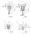
- FIG. 1illustrates a perspective view of a glenoid implant according to embodiments of the present invention.
- FIG. 2illustrates a front axial cross-sectional view of the glenoid implant of FIG. 1 , according to embodiments of the present invention.
- FIG. 3illustrates a front axial cross-sectional view of a central fixation element of the glenoid implant of FIG. 1 , according to embodiments of the present invention.
- FIG. 4illustrates a front elevation view of an articular body of the glenoid implant of FIG. 1 , according to embodiments of the present invention.
- FIG. 5illustrates a perspective view of a glenoid implant according to another embodiment of the present invention.
- FIG. 6illustrates an axial cross-sectional view of the glenoid implant of FIG. 5 , according to embodiments of the present invention.
- FIG. 7illustrates an axial cross-sectional view of a central fixation element of the glenoid implant of FIG. 5 , according to embodiments of the present invention.
- FIG. 8illustrates a perspective view of an articular body of the glenoid implant of FIG. 5 , according to embodiments of the present invention.
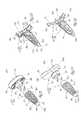
- FIG. 9illustrates an exploded perspective view of a glenoid implant according to another embodiment of the present invention.
- FIG. 10illustrates a perspective axial cross-sectional view of the glenoid implant of FIG. 9 , according to embodiments of the present invention.
- FIG. 11illustrates an exploded perspective view of a glenoid implant according to another embodiment of the present invention.
- FIG. 12illustrates a perspective axial cross-sectional view of the glenoid implant of FIG. 11 , according to embodiments of the present invention.
- FIG. 13illustrates a perspective axial cross-sectional view of the glenoid implant of FIG. 9 with the articular body of the glenoid implant of FIG. 11 superimposed thereon, according to embodiments of the present invention.
- FIG. 14illustrates an axial cross-sectional view of the glenoid implant of FIG. 9 with the articular body of the glenoid implant of FIG. 11 superimposed thereon, according to embodiments of the present invention.
- FIG. 15illustrates an exploded perspective view of a glenoid implant according to another embodiment of the present invention.
- FIG. 16illustrates a perspective axial cross-sectional view of the glenoid implant of FIG. 15 , according to embodiments of the present invention.
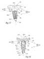
- FIG. 17illustrates a perspective view of a glenoid implant according to another embodiment of the present invention.
- FIG. 18illustrates a an axial cross-sectional view of the glenoid implant of FIG. 17 , according to embodiments of the present invention.
- FIG. 1-4show a glenoid implant 1 , referred to as anatomical (or not reversed), configured to be implanted in the glenoid of a scapula (or shoulder blade, not shown), of a human being.
- the glenoid implant 1includes an articular body 2 , a central fixation element 3 for anchoring the articular body 2 in the scapular glenoid, and a locking screw 4 configured to deter rotation of the central element 3 with respect to the scapula, according to embodiments of the present invention.
- the articular body 2after having been implanted in the glenoid, is configured to articulate with a head, eventually a prosthetic head, of a humerus (not shown) of the patient, in order to reproduce articular performance as close as possible to the original performance of the patient's shoulder.
- the terms “superior” and “inferior”are used to refer to the orientation of the glenoid implant as shown in FIG. 1 , in which the articular body 2 is toward a top of a longitudinal geometric axis X 1 -X′ 1 , and the screw 4 is toward a bottom of the axis X 1 -X′ 1 , according to embodiments of the present invention.
- an elementis located superior to another element if it is closer to X 1 than the other element, and an element is inferior to another element if it is closer to X′ 1 than the other element.
- the term “tronconical”is used to refer to a shape or surface that is or is like a truncated cone shape or surface.
- the articular body 2which is shown by itself in FIG. 4 , includes a plate 21 that is substantially perpendicular to the longitudinal geometric axis X 2 -X′ 2 of the articular body.
- the plate 21defines a superior surface 22 that is concave, which constitutes an articular surface for the articulation of the scapula with the humeral head, and by an inferior surface 23 , provided with a central protrusion 24 , which extends along the axis X 2 -X′ 2 .
- the central protrusion 24includes a superior portion 24 . 1 which is cylindrical with a circular cross-section, an intermediate portion 24 . 2 which is cylindrical with a circular cross-section that is smaller in diameter than that of the superior portion 24 .
- the intermediate portion 24 . 2is provided with five fins 25 perpendicular to the axis X 2 -X′ 2 and parallel to each other, which are separated along the length of the central portion 24 . 2 and each of which extends about the perimeter of the intermediate portion 24 . 2 , according to embodiments of the present invention.
- the articular body 2is formed of one or two synthetic materials, such as, for example, polyethylene, polyether ether ketone (“PEEK”), or polyurethane, which gives the fins 25 an elasticity to permit them to deform slightly.
- synthetic materialssuch as, for example, polyethylene, polyether ether ketone (“PEEK”), or polyurethane, which gives the fins 25 an elasticity to permit them to deform slightly.
- the inferior surface 23is also provided with a lateral post 26 which extends along a direction that is parallel to the axis X 2 -X′, according to embodiments of the present invention.
- the lateral post 26includes a superior portion 26 . 1 which is connected to the inferior surface 23 of the plate 21 , and an inferior portion 26 . 2 connected to the superior portion 26 . 1 .
- the superior portion 26 . 1is cylindrical with a circular cross-section, and its diameter is smaller than the diameter of the central protrusion 24 .
- the inferior portion 26 . 2is tronconical, and its diameter increases as it extends further from the plate 21 , according to embodiments of the present invention.
- the central fixation element 3shown in more detail in FIG. 3 , is generally formed as a hollow cylinder of circular cross section, with a longitudinal geometric axis X 3 -X′ 3 .
- the central element 3is defined by an external lateral surface 31 which includes a self-tapping thread, and is traversed longitudinally by an opening 32 , centered about the longitudinal axis X 3 -X′ 3 , which extends between a superior end 33 and an inferior end 34 of the central element 3 , according to embodiments of the present invention.
- the inferior end 34is tronconical and its diameter becomes smaller as it approaches the inferior end 34 , according to embodiments of the present invention.
- the opening 32includes a superior portion 32 . 1 that is cylindrical with a circular cross section, a tapping portion 32 . 2 of a diameter similar to the superior portion 32 . 1 , a tool receptacle portion 32 . 3 with a hexagonal transversal cross section, and an inferior portion 32 . 4 that is cylindrical with a circular cross section and that is tapped and has a smaller diameter than the superior portion 32 . 1 , according to embodiments of the present invention.
- the central element 3is made from a metal alloy or biocompatible ceramic, and its rigidity is higher than that of the articular body 2 .
- the central element 3can be made from stainless steel, titanium, titanium alloy, cobalt-chrome alloy, and/or PEEK.
- the central element 3is constructed so as to not deform in use.
- the maximum transversal area of the central element 3taken perpendicularly to the longitudinal axis X 3 -X′ 3 , is smaller than the minimal transversal area of the plate 21 of the articular body 2 , taken perpendicularly to the longitudinal axis X 2 -X′ 2 .
- the portion of the largest section of the central element 3is the superior threaded portion.
- the contact between the central element 3 and the articular body 2occurs only along a portion of the articular body 2 , for example along the central protrusion 24 , according to embodiments of the present invention.
- the central element 3is not in contact with the entirety of the inferior surface 23 of the plate 21 , according to embodiments of the present invention.
- the plate 21is 1.8 to 5 times larger at its maximum transversal section than the central element 3 . According to some embodiments of the present invention, the plate is 2.2 times larger at its maximum transversal section than the central element 3 .
- the central element 3ensures anchoring of the articular body 2 in the glenoid via the central protrusion 24 , but the central element 3 does not directly support the plate 21 , according to embodiments of the present invention.
- the screw 4with a longitudinal geometric axis X 4 -X′ 4 , includes a head 41 and a stem 44 that includes self-tapping threads, according to embodiments of the present invention.
- a blind hole 42 of hexagonal cross-section, centered on the axis X 4 -X′ 4is formed in the head 41 of the screw 4 .
- An external lateral surface 43 of the head 41is threaded, and towards the top of the head 41 is a collar 45 with a larger diameter than the threaded portion 43 .
- the screw 4is made from a metallic material or biocompatible ceramic, such as a stainless steel, titanium, titanium alloy, and/or cobalt-chromium alloy, according to embodiments of the present invention.
- a threading or self-tapping threadis “to the right” when the driving action is performed with counterclockwise rotation, and is “to the left” when the driving action is performed with clockwise rotation.
- the threading of the lateral external surface 31 of the central element 3is to the right, as shown by the arrow F 3 .
- the threading of the stem 44 of the screw 4is to the left, as shown by the arrow F 44 , and the threading of the head 41 of the screw 4 and the self-tapping of the inferior portion 32 . 4 of the opening 32 are to the right, as shown by the arrow F 41 , according to embodiments of the present invention.
- the surgeonAs the surgeon positions the glenoid implant 1 in the glenoid of the scapula, the surgeon first pierces a hole in the glenoid, of a diameter slightly smaller than the external diameter of the central element 3 . Then, the surgeon screws the central element 3 into the glenoid, using a tool (not shown) equipped with a tip of hexagonal cross section which is inserted in the tool receptacle 32 . 3 of opening 32 .
- the self-tapping threads of the central element 3permit it to penetrate into the glenoid, more precisely into the preformed hole formed by the surgeon, while tapping it.
- the central element 3permits by itself the fixation of the articular body 2 in the glenoid, according to embodiments of the present invention.
- the surgeonmakes a hole in the glenoid, of a diameter slightly smaller than the diameter of the stem 44 of the screw 4 , in passing the bit of a surgical drill through the opening 32 of the central element 3 .
- the drill bitis guided by a tool (not shown) which permits passage of the drill bit through the bottom of the central element 3 while also protecting the threading 32 . 4 on the inside of the central element 3 , according to embodiments of the present invention.
- the surgeonslides or drives the head 41 of the screw 4 into the hole, with the help of a tool (not shown) equipped with a hexagonal tip which inserts into the blind hole 42 in the screw 4 , according to embodiments of the present invention.
- the threading of the head 41 of the screw 4cooperates with the threading of the inferior portion 32 . 4 of the opening 32 .
- the axis X 3 -X′ 3 of the central element 3is then substantially in alignment with the axis X 4 -X′ 4 of the screw 4 .
- the threading of the head 41is in the same direction as the threading of the stem 44 of the screw 4 , which permits the surgeon, in the same movement, to screw the head 41 in the inferior portion 32 . 4 and to crew the stem 44 of the screw 4 into the hole which has been formed in the glenoid.
- the self-tapping threads of the stem 44 of the screwimprove the anchoring of the screw 4 in the glenoid.
- the collar 45 of the head 41 of the screw 4which has a larger diameter than the inferior portion 32 . 4 of the opening 32 , permits the retention of the head 41 in the opening 32 and prevents its passage through the opening 32 .
- the threading of the head 41 of the screw 4includes two threads, to facilitate the acceptance of the threading in the tapping of the inferior portion 32 . 4 of the opening 32 .
- the pitch of the threading of the head 41may be equal to the pitch of the threading of the stem 44 of the screw 4 to optimize the penetration of the screw 4 in the glenoid while the threading of the head 41 cooperates with the tapping of the inferior portion 32 . 4 of the opening 32 , according to embodiments of the present invention.
- the threading of the head 41may also include a stop or a brake, such as for example a transverse pin of synthetic material, for preventing a loosening or disengagement of the screw, according to embodiments of the present invention.
- a stop or a brakesuch as for example a transverse pin of synthetic material, for preventing a loosening or disengagement of the screw, according to embodiments of the present invention.
- the sub-assembly formed by these two elementsis locked in rotation, with respect to the glenoid, about the axes X 3 -X′ 3 and X 4 -X′ 4 , due to the opposed directions of the threading of the stem 44 of the screw 4 .
- the rotationis locked by the threading of the stem 44 of the screw 4 .
- the surgeonBefore or after having placed the central element 3 and the screw 4 , the surgeon pierces a lateral hole in the glenoid, adapted to receive the lateral post 26 of the articular body 2 , according to embodiments of the present invention.
- the surgeonpushes in the central protrusion of the articular body 2 into the opening 32 of the central element 3 , until the interior surface 23 of the plate 21 comes into contact against the superior end 33 of the central element.
- the axes X 2 -X′ 2 , X 3 -X′ 3 , and X 4 -X′ 4are then coincident and overlapping with the axis X 1 -X′ 1 of the glenoid implant 1 , according to embodiments of the present invention.
- the surgeonpushes the central protrusion 24 into the opening 32 until the inferior side 23 of the plate 1 comes into contact against the glenoid, without the inferior side 23 being in contact with the superior end 33 of the central element.
- Thiscan limit the wear of the articular body 2 against the central element 3 , according to embodiments of the present invention.
- the superior portion 24 . 1 of the central protrusion 24is thus lodged in the superior portion 32 . 1 of the opening 32
- the intermediate portion 24 . 2 of the central portion 24is thus lodged in the threads of the threaded portion 32 . 2 of the opening 32
- the fins 25are thus retained between the threads through a complementarity of shapes and flexible deformation.
- the lateral post 26becomes trapped in the corresponding hole formed in the glenoid, and prevents rotation of the articular body 2 about the axis X 1 -X′ 1 with respect to the glenoid, according to embodiments of the present invention.
- the fins 25prevent translation of the articular body 2 , along the length of the axis X 1 -X′ 1 , with respect to the central element 3 , as long as the strength of the forces which are applied to the glenoid implant 1 do not surpass too significantly the strength of the forces undergone by the natural articulation of the shoulder.
- the glenoid implant 1Once the glenoid implant 1 is implanted in the glenoid, its rotation about the axis X 1 -X′ 1 with respect to the glenoid is locked.
- the lateral post 26locks the rotation of the articular body 2 with respect to the glenoid, and the rotation, with respect to the glenoid, of the subassembly formed by the central element 3 and the screw 4 , is locked due to the threading pitch being in a direction different from the central element 3 and the shaft 44 of the screw 4 , according to embodiments of the present invention.
- the locking of the rotation of the glenoid implant 1 with respect to the glenoidis effective, as it prevents the glenoid implant 1 from disengaging under the action of the mechanical forces resulting from the pressure and movements of the humeral head against the superior side 22 of the articular body 2 .
- the lateral post 26which permits the locking of the articular body 2 in rotation about the axis X 1 -X′ 1 with respect to the glenoid, is optional and may be substituted for other rotational locking mechanisms, according to embodiments of the present invention.
- the superior end of the external lateral surface of the central post 24may extend superiorly of the central element 3 , and its transversal cross section may be, for example, square or hexagonal, so as to lock the rotation of the articular body 2 with respect to the glenoid, once the central element 3 is placed into the glenoid, according to embodiments of the present invention.
- the surgeonprepares a sole cavity in the glenoid, composed of a portion for receiving the central element 3 , aligned with a portion to receive the screw 4 .
- a sole cavity in the glenoidcomposed of a portion for receiving the central element 3 , aligned with a portion to receive the screw 4 .
- FIGS. 5 to 8illustrate another embodiment of a glenoid implant 101 , which includes elements generally similar to elements described with respect to glenoid implant 1 , augmented by 100.
- the glenoid implant 101with longitudinal axis X 101 -X′ 101 , includes an articular body 102 with a metal back, a central fixation element 103 for anchoring in the articular body 102 in the glenoid of a scapula, and a screw 104 for locking rotation of the central element 103 with respect to the scapula, according to embodiments of the present invention.
- the articular body 102shown from a bottom perspective view in FIG. 8 , includes a plate 121 with a circular cross-sectional shape, perpendicular to a longitudinal axis X 102 -X′ 102 of the articular body 102 .
- the plate 121is defined by a superior side 122 and by an inferior side 123 .
- An external lateral surface 126 of the plate 121may be tronconical, according to embodiments of the present invention.
- the superior sidemay be configured to receive a supplemental piece (not shown) adapted to articulate with the humerus.
- this supplemental pieceis hemispherical, and an implant which includes a concave articular surface may be implanted in the humerus.
- receptacles 121 a , 121 b , 121 c and 121 d in the form of truncated spheresare formed in the plate 121 and open toward both the superior side 122 and the inferior side 123 , according to embodiments of the present invention.
- Two inserts 105include a spherical external surface and are received in the receptacles 121 b and 121 d .
- the inserts 105are in rotational engagement with the articular body 102 , according to embodiments of the present invention.
- the inserts 105are each traversed by a threaded hole adapted to receive a screw 106 .
- the screws 106are represented by their axes 106 shown in FIG. 6 .
- the inferior side 123 of the plate 121is provided with a central protrusion 124 , with a longitudinal axis X 102 -X′ 102 , which includes a superior portion 124 . 1 that is cylindrical with a circular cross-sectional shape, connected to the inferior side 123 , and an inferior portion 124 . 2 that is tronconical, the diameter of which becomes smaller further from the plate 121 .
- the articular body 102is traversed longitudinally by an opening 125 , centered on the axis X 102 -X′ 102 , which includes a superior threaded portion 125 . 1 , and an inferior portion 125 . 2 with a circular cross-sectional shape.
- the threading of the superior portion 125 . 1is configured to permit fixation to the articular body 102 of a supplemental piece adapted to articulate with the humeral head.
- the articular body 102is metallic and/or ceramic, according to embodiments of the present invention.
- the articular body 102may be made from stainless steel, titanium, an alloy of titanium, and/or an alloy of cobalt-chromium, according to embodiments of the present invention.
- the central element 103shown in more detail in FIG. 7 , is generally formed as a cylinder with a circular cross-sectional shape, with a longitudinal axis X 103 -X′ 103 .
- the central element 13is defined by a lateral external surface 131 which includes a self-tapping thread, and is traversed longitudinally by an opening 132 which extends between a superior end 133 and an inferior end 134 of the central element 103 .
- the inferior end 134 of the central element 3is tronconical and its diameter gets smaller as it gets closer to the inferior end 134 , according to embodiments of the present invention.
- the opening 132includes a superior portion 132 . 1 which is cylindrical, with a circular cross-sectional shape, a tronconical portion 132 . 2 , of which the diameter gets smaller as it approaches the inferior end 134 , a hexagonal portion 132 . 3 , of which the transverse cross-sectional shape is a hexagon, a rounded part 132 . 4 in the form of a dome, of which the summit is oriented toward the bottom, and an inferior portion 132 . 5 which is cylindrical with a circular cross-sectional shape, according to embodiments of the present invention.
- the central element 103is metallic and ceramic, according to embodiments of the present invention.
- the central element 103may be formed of or made with stainless steel, titanium, titanium alloy, and/or cobalt-chrome alloy, according to embodiments of the present invention.
- the maximum transverse cross-sectional dimension of the central element 103is smaller than the transverse cross-sectional dimension of the plate 121 of the articular body 102 , taken perpendicularly to the longitudinal axis X 102 -X′ 102 .
- the maximum transverse cross-sectional dimension of the central element 103is located at the level of the superior end 133 , according to embodiments of the present invention.
- the contact between the central element 103 and the articular body 102is made solely between a portion of the articular body 102 , for example the central protrusion 124 , and an annular zone of the inferior surface 123 surrounding the central protrusion 124 , according to embodiments of the present invention.
- the central element 103is not in contact with the entirety of the inferior surface 123 of the plate 121 , according to embodiments of the present invention.
- the annular zone of pressure of the plate 121 on the central element 3is relatively small with respect to the overall dimensions of the inferior surface 123 , according to embodiments of the present invention.
- the central element 103ensures the anchoring of the articular body 102 in the glenoid, and the element central 103 does not support the plate 121 , according to embodiments of the present invention.
- the screw 104having a longitudinal axis X 104 -X′ 104 , includes a head 141 and a threaded stem 144 which may also be self-tapping, according to embodiments of the present invention.
- a lateral external surface 13 of the head 141is formed of a dome of which the summit is turned toward the bottom and of which the geometry is complementary to that of the rounded portion 132 . 4 of the opening 132 of the central element 103 , according to embodiments of the present invention.
- the screw 104is metallic or ceramic, according to embodiments of the present invention.
- the screw 104may be formed from stainless steel, titanium, titanium alloy, and/or cobalt-chrome, according to embodiments of the present invention.
- the threading of the external lateral surface 131 of the central element 103is to the right, as shown by the arrow F 131 , while the threading of the stem 144 of the screw 104 is to the left, as shown by the arrow F 144 , according to embodiments of the present invention.
- the surgeonWhen the surgeon has achieved the placement of the glenoid implant 101 in the glenoid, the surgeon first forms a hole in the glenoid, of a diameter slightly smaller than the external diameter of the central element 103 . Then, the surgeon inserts the central element 03 into the glenoid, for example with a tool (not shown), equipped with a hexagonal tip which is inserted into the hexagonal portion 132 . 3 , according to embodiments of the present invention.
- the self-tapping threading of the central element 103permits it to penetrate in the glenoid while also tapping.
- the surgeonmakes a hole in the glenoid, of a diameter that is slightly smaller than the diameter of the stem 144 of the screw 104 , in passing a drill bit (not shown) through the opening 132 of the central element 103 .
- the drill bitis guided by a tool (not shown) which fits into one of the portions of the opening 132 , according to embodiments of the present invention.
- the surgeonthen inserts the screw 104 into the hole which has been formed, with the help of a tool (not shown) equipped with a square tip which is inserted into the blind hole 142 of the screw 104 .
- the lateral external surface 141 of the screw 104is in contact with the lateral surface of the portion 132 . 4 of the opening of the central element 103 , according to embodiments of the present invention.
- the sub-assembly formed by these two elementsis locked in rotation, with respect to the glenoid, due to the opposed directions of the threading of the external surface 131 of the central element 103 , with respect to the threading direction of the stem 144 of the screw 104 , according to embodiments of the present invention.
- the articular body 102may be uncoupled from the central element 103 with appropriate tools, according to embodiments of the present invention.
- the screws 106are adapted to fix in a more stable manner the articular body 102 to the glenoid to lock as well the rotation of the articular body 102 with respect to the glenoid.
- the rotation of the inserts 105 in the receptacles 121 b and 121 dpermits the screws 106 to be oriented in the desired manner and direction.
- the articular body 106may be fixed to the central element 103 prior to insertion of the screw 104 or before the insertion of the central element 103 into the glenoid, according to embodiments of the present invention.
- the surgeoncouples to the articular body 102 a supplemental piece adapted to articulate with the humeral head.
- This supplemental pieceis inserted into the threading of the superior portion 125 . 1 of the receptacle 125 .
- the supplemental pieceincludes a tronconical hollow adapted to mate with the lateral surface 126 of the plate 121 , according to embodiments of the present invention.
- FIGS. 9-10illustrate a glenoid implant 201 according to another embodiment of the present invention, of which the elements similar to glenoid implant 1 carry the same reference numbers, augmented by 200.
- the glenoid implant 201also includes an articular body 202 , for example of the “metal back” type, and a central element 203 for anchoring the articular body 202 into the glenoid of a scapula, according to embodiments of the present invention.
- the articular body 202with a longitudinal axis X 202 -X′ 202 , includes a circular plate 221 which is perpendicular to the axis X 202 -X′ 202 , which is defined by a superior side 222 and an inferior side 223 .
- the plate 221 of the articular body 202also includes a lateral surface 226 .
- the inferior side 223includes a central protrusion 224 which is cylindrical with a circular cross-sectional shape, centered on the axis X 202 -X′ 202 .
- the central protrusion 224is hollow and defines a tronconical receptacle 225 , of which the diameter becomes smaller as it approaches the plate 221 .
- the superior side 222 of the plate 221is adapted to receive a supplemental piece (not shown), configured to articulate with the humeral head.
- the central element 203with a longitudinal axis X 203 -X′ 203 , includes a tronconical intermediate portion 203 . 2 with a diameter which gets smaller between a superior end 233 and an inferior end 234 of the central element 203 .
- a lateral external surface 231 of the intermediate portion 203 . 2includes a self-tapping threading and is traversed transversally by holes 238 .
- the intermediate portion 203 . 2includes near its bottom an inferior tronconical portion 203 . 3 , which has a cone shape that is sloped at a greater angle with respect to the longitudinal axis X 203 -X′ 203 than the cone shape of the intermediate portion 203 . 2 .
- the intermediate portion 203includes near its bottom an inferior tronconical portion 203 . 3 , which has a cone shape that is sloped at a greater angle with respect to the longitudinal axis X 203 -X′ 203 than the cone shape of the intermediate portion 203 .
- a peripheral groove 237is defined between the intermediate portion 203 . 2 and the superior portion 203 . 1 , according to embodiments of the present invention.
- the central element 203is traversed by a longitudinal opening 232 , centered on the axis X 203 -X′ 203 , which opens on both ends of the central element 203 .
- the opening 232includes a superior portion 232 . 1 , with a hexagonal cross-sectional shape, and an inferior portion 232 . 2 which is cylindrical with a circular cross-sectional shape and which connects the superior portion 232 . 1 to the inferior end 234 of the central element 203 , according to embodiments of the present invention.
- the holes 238are spaced or set off from one another along the intermediate portion 203 . 2 and open from the inferior portion 232 . 2 of the opening 232 , according to embodiments of the present invention.
- the maximum transverse cross-sectional dimension of the central element 203is smaller than the transverse cross-sectional dimension of the plate 221 of the articular body 202 , taken perpendicularly to the longitudinal axis X 202 -X′ 202 .
- the contact between the central element 203 and the articular body 202occurs solely along a portion of the articular body 202 , for example on the central protrusion 224 .
- the central element 203is not in contact with the entirety of the inferior surface 223 of the plate 221 .
- the central element 203helps to ensure anchoring of the articular body 202 in the glenoid, and the central element 203 does not support the inferior surface 223 of the plate 221 , according to embodiments of the present invention.
- the surgeonWhen placing the glenoid implant 201 in the scapula, the surgeon first forms a hole in the glenoid, with a diameter slightly smaller than the diameter of the central element. Next, the surgeon inserts the central element 203 into the glenoid, using a tool (not shown) equipped with a hexagonal tip which is inserted into the superior portion 232 . 1 of the opening 232 , according to embodiments of the present invention.
- the articular body 202is assembled to the central element 203 in joining the central protrusion 224 to the superior portion 203 . 1 of the central element 203 .
- the articular body 202is locked in translation and in rotation with respect to the central element 203 , due to the fixation of the “Morse cone” type between the two elements.
- the bony tissue of the glenoidcolonizes the holes 238 , which contributes to the locking of the rotation of the central element 203 with respect to the glenoid, and improves the longevity of the glenoid implant 201 .
- the rotation of the articular body 202 with respect to the glenoidis locked via the screw and the inserts (not shown), similar to screws 106 and inserts 105 , according to embodiments of the present invention.
- FIGS. 11 to 12illustrate a glenoid implant 301 , according to another embodiment of the present invention, of which the elements similar to implant 1 have the same reference numbers augmented by 300.
- the glenoid implant 301with longitudinal axis X 301 -X′ 301 , includes an articular body 302 and a central element 303 for anchoring the articular body 302 in the glenoid of a scapula, according to embodiments of the present invention.
- the articular body 302after its fixation to the glenoid, is adapted to articulate with a head, eventually a prosthetic head, of a humerus (not shown), of the patient with a view to reproducing an articular performance as close as possible to the performance of the patient's original shoulder, according to embodiments of the present invention.
- the articular body 302with a longitudinal axis X 302 -X′ 302 , includes a plate 321 , generally perpendicular to the axis X 302 -X′ 302 , defined by a superior side 322 and an inferior side 323 .
- the superior side 322includes an articular surface for articulation of the scapula with a humeral head.
- the interior face 323 of the plate 321includes a central protrusion 324 , centered on the axis X 302 -X′ 302 , of which the external lateral surface is hexagonal.
- the central protrusion 324is hollow and defines a tronconical receptacle 325 of which the diameter increases in a direction away from the plate 321 , according to embodiments of the present invention.
- the plate 321has an elongated form, and extends the length of the lengthwise axis Y 321 -Y′ 321 , perpendicular to the axis X 302 -X′ 302 .
- the central protrusion 324is set back longitudinally, along the axis Y 321 -Y′ 321 with respect to the center C 21 of the plate 321 , according to embodiments of the present invention.
- the articular body 302is fabricated from one or two synthetic biocompatible materials and adapted for partial or total articulation, such as for example polyethylene, PEEK, and/or polyurethane, according to embodiments of the present invention.
- the central element 303is substantially the same as central element 303 .
- the central element 303includes a tronconical intermediate portion 303 . 2 of which the diameter diminishes between the superior end 333 and the inferior end 334 of the central element 303 .
- One lateral external surface of the intermediate portion 303 . 2includes a self-tapping threading and is traversed transversally by holes 338 which are located at the base of the intermediate portion 303 . 3 .
- the intermediate portion 303 . 2includes near its bottom an inferior tronconical portion 303 . 3 , of which the cone shape includes a more pronounced slope than that of the intermediate portion 303 . 2 .
- the intermediate portion 303 . 2includes near its top a superior tronconical portion 303 . 2 .
- a peripheral groove 337is formed between the intermediate portion 303 . 2 and the superior portion 303 . 1 , according to embodiments of the present invention.
- the central element 303is traversed by a longitudinal opening 332 , which opens from one end of the central element 303 to the other and communicates with the holes 338 .
- the opening 332includes a superior portion 332 . 1 of hexagonal cross-sectional shape, which opens onto the superior end 333 , and an inferior portion 332 . 2 which is cylindrical and has a circular cross-sectional shape and which connects the superior portion 332 . 1 to the inferior end 334 of the central element 303 , according to embodiments of the present invention.
- the implantation of the glenoid implant 301is similar to that described for implant 201 , according to embodiments of the present invention.
- the hexagonal shape of the central protrusion 324permits the locking of the rotation of the articular body 302 with respect to the glenoid.
- the bony tissue of the glenoidmay recolonize the holes 338 and the opening 332 , which helps to ensure locking of the rotation of the central element 303 with respect to the glenoid, and improves the durability and the longevity of the glenoid implant 301 , according to embodiments of the present invention.
- the locking of the rotation of the central element 303 with respect to the glenoidis achieved partially or exclusively by the middle of the articular body 302 , according to embodiments of the present invention.
- the rotation of the articular body 302 with respect to the glenoidis locked.
- no other locking meansare needed, according to embodiments of the present invention.
- the locking between the articular body 302 and the central element 303is achieved with a mortise-and-tenon joint.
- the maximum transverse cross-sectional dimension of the central element 303taken perpendicularly to the longitudinal axis X 303 -X′ 303 , is smaller than the transverse cross-sectional dimension of the plate 321 of the articular body 302 , taken perpendicularly to the longitudinal axis X 302 -X′ 302 .
- the contact between the central element 303 and the articular body 302is achieved solely on a portion of the articular body, for example the central protrusion 324 .
- the central element 33is not in contact with the entirety of the inferior surface 323 , according to embodiments of the present invention.
- the central element 303ensures anchoring of the articular body 302 in the glenoid, and the inferior surface 323 of the plate 321 is not supported by the central element 303 , according to embodiments of the present invention.
- FIGS. 13 and 14illustrates an articular body 202 and central element 203 , according to embodiments of the present invention.
- the articular body 302is superimposed upon the articular body 202 , and is represented in a position in which it is assembled with the central element 203 , according to embodiments of the present invention.
- FIGS. 11 and 12The lateral separation of the central protrusion 324 with respect to the lengthwise axis Y 321 -Y′ 321 of the plate 321 is shown in FIGS. 11 and 12 , in which a portion of the length 321 . 1 of the plate 321 , located across from a plane P which is perpendicular to the axis X 302 -X′ 302 , laterally exceeds the articular body 202 .
- a short portion 321 . 2 of the plate 321is located on the other side of the plane P.
- the surgeonimplants the glenoid implant 301 in the scapula, he positions the articular body 301 in orienting the central protrusion 324 along the bottom, such that when the patient lifts his arm, the humeral head has a tendency to rotate the length portion 321 . 1 of the plate 321 towards the scapula, as shown by arrow F.
- the inferior face 323 of the long portion 321 . 1is in direct contact with the glenoid, since the protrusion 324 is laterally separated, which permits the glenoid to receive directly the compression force which results from the tipping of the long portion 321 . 1 , according to embodiments of the present invention.
- FIGS. 15 and 16illustrate a glenoid implant 401 , according to embodiments of the present invention.
- the elements of glenoid implant 401which are similar to the elements of glenoid implant 1 have the same reference numbers, augmented by 100.
- the glenoid implant 401includes an articular body 402 , similar or the same as articular body 302 , and a central element 403 of a “press fit” variety, for anchoring the articular body 402 in the glenoid of the scapula.
- the articular body 402with a longitudinal axis X 402 -X′ 402 , includes a plate 421 , of which the superior face 422 includes an articular surface for articulation of the scapula with the humeral head, according to embodiments of the present invention.
- An inferior surface 423 of the plate 421is provided with a central protrusion 424 having a hexagonal cross-sectional shape.
- the central protrusion 424is hollow and defines a tronconical receptacle 425 , of which the diameter diminishes as it approaches the plate 421 , according to embodiments of the present invention.
- the articular body 402is made from one or two synthetic biocompatible materials, such as, for example, polyethylene, PEEK, and/or polyurethane, according to embodiments of the present invention.
- the central element 403with a longitudinal axis X 403 -X′ 403 , includes an inferior portion 403 . 2 in the form of a prism with a hexagonal base.
- the central element 403includes a superior end 433 , and an inferior end 434 .
- the lateral stops of the central elementare beveled progressively in the direction of the inferior end 434 .
- the inferior portion 403 . 2is traversed transversally by holes 438 .
- the inferior portion 403 . 2extends towards the top along a superior portion 403 . 1 .
- a peripheral groove 437is formed between the superior portion 403 . 1 and the inferior portion 403 . 2 , according to embodiments of the present invention.
- the central element 403is made from a metallic or biocompatible ceramic material, such as a stainless steel, titanium, titanium alloy, and/or carbon alloy, according to embodiments of the present invention.
- the maximum transverse cross-sectional dimension of the central element 403taken perpendicularly to the longitudinal axis X 403 -X′ 403 , is smaller than the transverse cross-sectional dimension of the plate 421 of the articular body 302 , taken perpendicularly to the longitudinal axis X 402 -X′ 402 .
- the contact between the central element 403 and the articular body 402occurs solely along a portion of the articular body 402 , for example along the central protrusion 424 .
- the central element 403is not in contact with the totality of the inferior surface of the plate 421 .
- the central element 403ensures anchoring of the articular body 402 in the glenoid, and the inferior surface 423 of the plate 421 is not supported by the central element 403 , according to embodiments of the present invention.
- the surgeonplaces the glenoid implant 401 in the glenoid, the surgeon first forms a hole in the glenoid with dimensions slightly smaller than those of the central element 403 . Then, the surgeon impacts the central element 403 to introduce it into the hole. The penetration of the central element 403 in the glenoid is facilitated due to the lateral beveled stops. The rotation of the central element 403 with respect to the glenoid is locked due to the hexagonal shape of the transverse cross-section of the central element 403 .
- the bony colonization in the holes 438may also contribute to locking the rotation of the central element 403 with respect to the glenoid, according to embodiments of the present invention.
- the surgeonmounts the central protrusion 424 of the articular body 402 on the superior portion 403 . 1 of the central element 403 .
- the articular body 402is assembled to the central element 403 , the articular body 402 is locked in translation and in rotation with respect to the central element 403 , due to the fixation of the Morse cone type between these two elements.
- the axes X 402 -X′ 402 and X 403 -X′ 403are thus aligned and coincident with the longitudinal axis X 401 -X′ 401 of the glenoid implant.
- the rotational locking of the articular body 402 with respect to the glenoidis ensured by the hexagonal cross-sectional shape of the central protrusion 424 , and by the friction between the superior portion 403 . 1 of the central element 403 and the receptacle 425 of the central protrusion 424 , according to embodiments of the present invention.
- the glenoid implant 401is locked in rotation, about the axis X 401 -X′ 401 , with respect to the scapula, according to embodiments of the present invention.
- FIGS. 17 and 18illustrate a glenoid implant 501 , according to embodiments of the present invention.
- the elements of glenoid implant 501 which are similar to glenoid implant 1include the same reference numbers, augmented by 500.
- the glenoid implant 501includes an articular body 502 , which may be similar to or the same as the articular body 302 , and a central element 403 for anchoring the articular body 402 in the glenoid of the scapula, according to embodiments of the present invention.
- the articular body 502includes a plate 521 defined by a superior concave face 522 , which includes an articular surface for articulation of the scapula with the humeral head, and by an inferior face 523 , equipped with a central protrusion 524 that is cylindrical with a circular cross-sectional shape, according to embodiments of the present invention.
- the central protrusion 524is hollow and defines a tronconical receptacle 525 of which the diameter increases along a direction away from the plate 521 , according to embodiments of the present invention.
- the inferior side 523includes a lateral post 526 , parallel to the central protrusion 524 , which includes a superior portion 526 . 1 which is cylindrical with a circular cross-section, of a diameter that is smaller than the diameter of the central protrusion 524 , which is connected to the inferior side 523 of the plate 521 , according to embodiments of the present invention.
- the lateral post 526includes a tronconical inferior portion 526 . 2 , connected to the superior portion 526 . 1 , of which the diameter increases in a direction away from the plate 521 .
- the lateral internal surface of the central protrusion 524may be provided with a peripheral fin 527 , according to embodiments of the present invention.
- the central element 503includes a tronconical intermediate portion 503 . 2 of which the diameter decreases between a superior end 533 and an inferior end 534 of the central element 503 , and which communicates with the holes 538 .
- An external lateral surface 531 of the intermediate portion 503 . 2includes a self-tapping threading and is traversed transversally by holes 538 which are located at the bottom of the intermediate portion 503 . 2 , according to embodiments of the present invention.
- the intermediate portion 503 . 2extends toward the base with an inferior tronconical portion 503 . 3 , of which the conical shape has a slope that is higher than that of the intermediate portion 503 . 2 .
- a peripheral groove 537is formed at the interface between the superior portion 503 . 1 and the intermediate portion 503 . 2 , according to embodiments of the present invention.
- the central element 503is traversed by a longitudinal opening 532 , which opens toward both ends of the central element 503 and which communicates with the holes 538 .
- the opening 532includes a superior portion 532 . 1 of hexagonal transverse cross-sectional shape, which opens on the superior end 533 , and an inferior portion 532 . 2 which is cylindrical with a circular cross-sectional shape and which connects the superior portion 532 . 1 to the inferior end 534 of the central element 503 , according to embodiments of the present invention.
- the maximum transverse cross-sectional dimension of the central element 503is smaller than the transverse cross-sectional dimension of the plate of the articular body 502 .
- the contact between the central element 503 and the articular body 502occurs solely along a portion of the articular body 502 , for example at the central protrusion 524 , according to embodiments of the present invention.
- the central element 503is not in contact with the entirety of the inferior surface 523 of the plate 521 , according to embodiments of the present invention.
- the central element 503ensures the anchoring of the articular body 502 in the glenoid, and the inferior surface 523 of the plate 521 is not supported by the central element 503 , according to embodiments of the present invention.
- the surgeonfirst forms a hole in the glenoid with dimensions slightly smaller than those of the central element 503 , according to embodiments of the present invention.
- the surgeonmay also form in the glenoid a reception hole for the lateral post 526 .
- the surgeoninserts the central element 503 into the hole, using a tool equipped with a hexagonal tip, which may be inserted into the superior portion 532 . 1 of the opening 532 of the central element 503 , according to embodiments of the present invention.
- the surgeoninserts the articular body 502 onto the superior portion 503 . 1 of the central element.
- the peripheral fin 527positions itself in the groove 537 of the central element 503 , which serves to lock the translation of the articular body 502 with respect to the central element.
- the lateral post 526serves to lock the rotation of the articular body 502 with respect to the glenoid, according to embodiments of the present invention.
- the bony tissue of the glenoidmay recolonize the holes 538 and the opening 532 , which contributes to locking the rotation of the central element 503 with respect to the glenoid and ameliorates the durability of the glenoid implant 501 , according to embodiments of the present invention.
- the central elements 203 , 303 , 403 , 503are configured to receive any one of a metallic or ceramic or synthetic articular body.
- the central element 203 of the glenoid implant 201permits the fixation of a metallic or ceramic articular body, by means of the superior portion 203 . 1 which forms of cone of retention.
- the groove 237 of the central element 203serves to couple a synthetic articular body provided with a peripheral fin similar to fin 527 of the articular body 502 , according to embodiments of the present invention.
- the central elements 303 , 403 and 503are provided, to the same end, with a tronconical portion 303 . 1 , 403 .
- a tronconical receptacle 325 , 425 , 525defined by an articular body that is metallic or ceramic, and by a groove 337 , 437 , 537 for coupling a synthetic articular body, according to embodiments of the present invention.
- the threading of the tapped portion 32 . 2may be replaced with grooves separated along the length of the axis X 3 -X′ 3 .
- the number of fins 25may vary, according to embodiments of the present invention.
- the articular body 2may be formed of a metallic and/or ceramic material, such as pyrocarbon. Such a material may be configured to not deform, such that the fixation between the articular body 2 and the central element 3 is of a Morse cone type. Such fixation may replace the fins 25 , according to embodiments of the present invention.
- PEEKmay include a remarkable rigidity for a polymer; as such, a Morse cone type connection may be used to fix an element formed of PEEK, according to embodiments of the present invention.
- the articular bodies 302 , 402may be formed of a hard metallic material or a hard ceramic material, such as pyrocarbon, according to embodiments of the present invention.
- the superior portion 32 . 1 of the opening 32 as well as the superior portion 24 . 1are tronconical instead of cylindrical.
- the threading of the lateral external surface 31is to the left, while the threading of the shaft 44 of the screw 4 is to the right.
- the threading of the head 41 of the screw 4is also to the right and the tapping of the inferior portion 32 . 4 of the opening is also to the right, according to embodiments of the present invention.
- the threading of the lateral external surface 131is to the left, while the threading of shaft 144 of the screw 104 is to the right.
- the portion 132 . 1 of the opening 132is tronconical and the portion 132 . 2 is cylindrical, according to embodiments of the present invention.
- the screws 4 and 104are made of polymer, for example PEEK.
- the inferior portion 124 . 2 of the central protrusion 124is cylindrical with a circular cross-sectional shape.
- the portion 132 . 2is also cylindrical with a circular cross-sectional shape and is adapted to receive the inferior portion 124 . 2 of the central post 124 , such that the fixation of the articular body 102 is achieved by inserting the central pin 124 into the central element 103 with force.
- the central elementdefines a receptacle for a central protrusion of an articular body.
- the receptacle for a central elementmay include an internal threading, similar to the threading of the threaded portion 32 . 2 of the central element 32 , into which the aforementioned fins clip along the length of the central protrusion, according to embodiments of the present invention.
- the central elementmay include a tronconical receptacle for a central tronconical protrusion of the articular body, according to embodiments of the present invention.
- the hexagonal portion 32 . 3 of the central element 3 and the blind hole 42 of the head of the screw 4may include a square cross-sectional shape, for example in the form of a cross, a receptacle in the shape of Torx®, or some other geometry permitting the use of a tool, according to embodiments of the present invention.
- Other embodimentsmay also include such features, for example the blind hole 142 of the screw 104 and the hexagonal portion 132 . 2 of the central element 103 .
- Various tools with different tipsmay be used depending on the types of screws or screw heads used.
- the articular body 102 and 202may be equipped with two supplemental inserts 105 received in the receptacles 121 a and 121 c or 221 a and 221 c , according to embodiments of the present invention.
- a means comprised by the central fixation element for mechanically engaging with the central protrusionmay include, without limitation, elements 32 . 1 and 32 . 2 ; elements 132 . 1 and 132 . 2 ; elements 203 . 1 and 237 ; elements 303 . 1 and 337 ; elements 403 . 1 and 437 ; and elements 503 . 1 and 537 .
- a first means for locking rotation of the central fixation element with respect to the glenoidmay include, without limitation, elements 31 and 4 ; 131 and 104 ; 238 ; 338 ; 403 . 2 and 438 ; and 538 .
- a second means for locking rotation of the articular body with respect to the glenoidmay include, without limitation, elements 26 ; 106 ; 324 ; 424 ; and 526 .
Landscapes
- Health & Medical Sciences (AREA)
- Orthopedic Medicine & Surgery (AREA)
- Cardiology (AREA)
- Oral & Maxillofacial Surgery (AREA)
- Transplantation (AREA)
- Engineering & Computer Science (AREA)
- Biomedical Technology (AREA)
- Heart & Thoracic Surgery (AREA)
- Vascular Medicine (AREA)
- Life Sciences & Earth Sciences (AREA)
- Animal Behavior & Ethology (AREA)
- General Health & Medical Sciences (AREA)
- Public Health (AREA)
- Veterinary Medicine (AREA)
- Prostheses (AREA)
Abstract
Description
Claims (12)
Priority Applications (5)
| Application Number | Priority Date | Filing Date | Title |
|---|---|---|---|
| US15/336,531US10064734B2 (en) | 2011-02-01 | 2016-10-27 | Glenoid implant for a shoulder prosthesis, and surgical kit |
| US15/967,450US10918492B2 (en) | 2011-02-01 | 2018-04-30 | Glenoid implant for a shoulder prosthesis, and surgical kit |
| US17/149,308US11877933B2 (en) | 2011-02-01 | 2021-01-14 | Glenoid implant for a shoulder prosthesis, and surgical kit |
| US18/539,598US12290447B2 (en) | 2011-02-01 | 2023-12-14 | Glenoid implant for a shoulder prosthesis, and surgical kit |
| US19/074,746US20250235321A1 (en) | 2011-02-01 | 2025-03-10 | Glenoid implant for a shoulder prosthesis, and surgical kit |
Applications Claiming Priority (5)
| Application Number | Priority Date | Filing Date | Title |
|---|---|---|---|
| US201161438570P | 2011-02-01 | 2011-02-01 | |
| FR1150994AFR2971144A1 (en) | 2011-02-08 | 2011-02-08 | GLENOIDAL IMPLANT FOR SHOULDER PROSTHESIS AND SURGICAL KIT |
| FR20110050994 | 2011-02-08 | ||
| US13/363,159US9498345B2 (en) | 2011-02-01 | 2012-01-31 | Glenoid implant for a shoulder prosthesis, and surgical kit |
| US15/336,531US10064734B2 (en) | 2011-02-01 | 2016-10-27 | Glenoid implant for a shoulder prosthesis, and surgical kit |
Related Parent Applications (1)
| Application Number | Title | Priority Date | Filing Date |
|---|---|---|---|
| US13/363,159ContinuationUS9498345B2 (en) | 2011-02-01 | 2012-01-31 | Glenoid implant for a shoulder prosthesis, and surgical kit |
Related Child Applications (1)
| Application Number | Title | Priority Date | Filing Date |
|---|---|---|---|
| US15/967,450ContinuationUS10918492B2 (en) | 2011-02-01 | 2018-04-30 | Glenoid implant for a shoulder prosthesis, and surgical kit |
Publications (2)
| Publication Number | Publication Date |
|---|---|
| US20170042690A1 US20170042690A1 (en) | 2017-02-16 |
| US10064734B2true US10064734B2 (en) | 2018-09-04 |
Family
ID=43982207
Family Applications (6)
| Application Number | Title | Priority Date | Filing Date |
|---|---|---|---|
| US13/363,159ActiveUS9498345B2 (en) | 2011-02-01 | 2012-01-31 | Glenoid implant for a shoulder prosthesis, and surgical kit |
| US15/336,531ActiveUS10064734B2 (en) | 2011-02-01 | 2016-10-27 | Glenoid implant for a shoulder prosthesis, and surgical kit |
| US15/967,450ActiveUS10918492B2 (en) | 2011-02-01 | 2018-04-30 | Glenoid implant for a shoulder prosthesis, and surgical kit |
| US17/149,308Active2033-01-28US11877933B2 (en) | 2011-02-01 | 2021-01-14 | Glenoid implant for a shoulder prosthesis, and surgical kit |
| US18/539,598ActiveUS12290447B2 (en) | 2011-02-01 | 2023-12-14 | Glenoid implant for a shoulder prosthesis, and surgical kit |
| US19/074,746PendingUS20250235321A1 (en) | 2011-02-01 | 2025-03-10 | Glenoid implant for a shoulder prosthesis, and surgical kit |
Family Applications Before (1)
| Application Number | Title | Priority Date | Filing Date |
|---|---|---|---|
| US13/363,159ActiveUS9498345B2 (en) | 2011-02-01 | 2012-01-31 | Glenoid implant for a shoulder prosthesis, and surgical kit |
Family Applications After (4)
| Application Number | Title | Priority Date | Filing Date |
|---|---|---|---|
| US15/967,450ActiveUS10918492B2 (en) | 2011-02-01 | 2018-04-30 | Glenoid implant for a shoulder prosthesis, and surgical kit |
| US17/149,308Active2033-01-28US11877933B2 (en) | 2011-02-01 | 2021-01-14 | Glenoid implant for a shoulder prosthesis, and surgical kit |
| US18/539,598ActiveUS12290447B2 (en) | 2011-02-01 | 2023-12-14 | Glenoid implant for a shoulder prosthesis, and surgical kit |
| US19/074,746PendingUS20250235321A1 (en) | 2011-02-01 | 2025-03-10 | Glenoid implant for a shoulder prosthesis, and surgical kit |
Country Status (3)
| Country | Link |
|---|---|
| US (6) | US9498345B2 (en) |
| EP (1) | EP2481376B1 (en) |
| FR (1) | FR2971144A1 (en) |
Cited By (14)
| Publication number | Priority date | Publication date | Assignee | Title |
|---|---|---|---|---|
| US20180271668A1 (en)* | 2017-03-22 | 2018-09-27 | Stryker European Holdings I, Llc | Stemless metaphyseal humeral implant |
| US10357373B2 (en) | 2014-01-03 | 2019-07-23 | Tornier, Inc. | Reverse shoulder systems and methods |
| US20200030108A1 (en)* | 2018-07-24 | 2020-01-30 | DePuy Synthes Products, Inc. | Baseplate of a modular shoulder joint prosthesis and related methods for implanting the same |
| US10583012B1 (en) | 2018-09-07 | 2020-03-10 | Raphael S. F. Longobardi | Universal shoulder prosthesis system |
| US10722374B2 (en) | 2015-05-05 | 2020-07-28 | Tornier, Inc. | Convertible glenoid implant |
| US10918492B2 (en) | 2011-02-01 | 2021-02-16 | Tornier Sas | Glenoid implant for a shoulder prosthesis, and surgical kit |
| US11033399B2 (en) | 2016-02-28 | 2021-06-15 | Integrated Shoulder Collaboration, Inc. | Shoulder arthroplasty implant system |
| US11160661B2 (en) | 2009-12-14 | 2021-11-02 | Tornier Sas | Shoulder prosthesis glenoid component |
| US11564802B2 (en) | 2017-10-16 | 2023-01-31 | Imascap Sas | Shoulder implants and assembly |
| US11752000B2 (en) | 2020-03-03 | 2023-09-12 | Howmedica Osteonics Corp. | Glenoid implant with additively manufactured fixation posts |
| US11779471B2 (en) | 2019-08-09 | 2023-10-10 | Howmedica Osteonics Corp. | Apparatuses and methods for implanting glenoid prostheses |
| US11833055B2 (en) | 2016-02-28 | 2023-12-05 | Integrated Shoulder Collaboration, Inc. | Shoulder arthroplasty implant system |
| US12268610B2 (en) | 2020-05-07 | 2025-04-08 | Howmedica Osteonics Corp. | Stemless metaphyseal humeral implant |
| US12396862B2 (en) | 2019-05-13 | 2025-08-26 | Howmedica Osteonics Corp. | Glenoid baseplate and implant assemblies |
Families Citing this family (60)
| Publication number | Priority date | Publication date | Assignee | Title |
|---|---|---|---|---|
| US20030065397A1 (en) | 2001-08-27 | 2003-04-03 | Hanssen Arlen D. | Prosthetic implant support structure |
| US7892288B2 (en) | 2001-08-27 | 2011-02-22 | Zimmer Technology, Inc. | Femoral augments for use with knee joint prosthesis |
| US8388624B2 (en) | 2003-02-24 | 2013-03-05 | Arthrosurface Incorporated | Trochlear resurfacing system and method |
| WO2006004885A2 (en) | 2004-06-28 | 2006-01-12 | Arthrosurface, Inc. | System for articular surface replacement |
| US20230080207A1 (en) | 2005-02-25 | 2023-03-16 | Shoulder Innovations, Inc. | Methods and devices for less invasive glenoid replacement |
| US9358029B2 (en) | 2006-12-11 | 2016-06-07 | Arthrosurface Incorporated | Retrograde resection apparatus and method |
| GB0804998D0 (en)* | 2008-03-18 | 2008-04-16 | Depuy Ireland Ltd | A cup component of an orthopaedic joint prosthesis |
| WO2010121250A1 (en) | 2009-04-17 | 2010-10-21 | Arthrosurface Incorporated | Glenoid resurfacing system and method |
| US10945743B2 (en) | 2009-04-17 | 2021-03-16 | Arthrosurface Incorporated | Glenoid repair system and methods of use thereof |
| EP2542165A4 (en) | 2010-03-05 | 2015-10-07 | Arthrosurface Inc | Tibial resurfacing system and method |
| USD685474S1 (en) | 2010-07-06 | 2013-07-02 | Tornier, Inc. | Prosthesis anchor |
| FR2978912A1 (en) | 2011-08-10 | 2013-02-15 | Tornier Inc | ANCILLARY EXTRACTION OF A PROSTHESIS |
| EP2804565B1 (en) | 2011-12-22 | 2018-03-07 | Arthrosurface Incorporated | System for bone fixation |
| AT512413B1 (en)* | 2012-03-19 | 2013-08-15 | Michael Moser | Integrated flexible ice detector |
| US9498334B2 (en) | 2012-03-27 | 2016-11-22 | DePuy Synthes Products, Inc. | Glenoid defect-filling component |
| WO2014008126A1 (en) | 2012-07-03 | 2014-01-09 | Arthrosurface Incorporated | System and method for joint resurfacing and repair |
| EP2689750B1 (en) | 2012-07-23 | 2016-08-24 | Tornier Orthopedics Ireland Ltd. | Glenoidal implant for shoulder prosthesis and surgical kit |
| US20150223941A1 (en)* | 2012-08-27 | 2015-08-13 | Conformis, Inc. | Methods, Devices and Techniques for Improved Placement and Fixation of Shoulder Implant Components |
| US9492200B2 (en) | 2013-04-16 | 2016-11-15 | Arthrosurface Incorporated | Suture system and method |
| CN103264521A (en)* | 2013-05-22 | 2013-08-28 | 东北大学 | Integrated type energy-saving and environment-friendly hydraulic servo system |
| WO2015066608A1 (en)* | 2013-11-04 | 2015-05-07 | Boulris Craig | Shoulder replacement with enhanced glenoid fixation |
| FR3013211B1 (en)* | 2013-11-18 | 2017-01-06 | Fx Solutions | IMPLANT OF SHOULDER PROSTHESIS, FOR FIXING TOTALLY OR PARTIALLY BY MEANS OF A CEMENT |
| US9956083B2 (en) | 2013-12-30 | 2018-05-01 | Deltoid, Llc | Instruments and techniques for orienting prosthesis components for joint prostheses |
| US9962266B2 (en) | 2015-09-11 | 2018-05-08 | Deltoid, Llc | Arthroplasty components |
| US10433969B2 (en) | 2013-12-30 | 2019-10-08 | United Orthopedic Corp. | Arthroplasty implants and methods for orienting joint prosthesis |
| US12023253B2 (en) | 2014-01-24 | 2024-07-02 | Howmedica Osteonics Corp. | Humeral implant anchor system |
| US10456264B2 (en) | 2014-01-24 | 2019-10-29 | Tornier, Inc. | Humeral implant anchor system |
| US10624748B2 (en) | 2014-03-07 | 2020-04-21 | Arthrosurface Incorporated | System and method for repairing articular surfaces |
| US11607319B2 (en) | 2014-03-07 | 2023-03-21 | Arthrosurface Incorporated | System and method for repairing articular surfaces |
| US9931219B2 (en) | 2014-03-07 | 2018-04-03 | Arthrosurface Incorporated | Implant and anchor assembly |
| US20150272741A1 (en)* | 2014-03-26 | 2015-10-01 | Biomet Manufacturing, Llc | Press-fit glenoid with peripheral compression pegs |
| EP3270828B1 (en) | 2015-03-19 | 2019-12-25 | Limacorporate SPA | Improved glenoid anchor for a shoulder joint prosthesis |
| US20160270922A1 (en)* | 2015-03-19 | 2016-09-22 | Limacorporate S.P.A. | Glenoid Anchor for a Shoulder Joint Prosthesis |
| CA2983650C (en) | 2015-04-24 | 2021-03-16 | Biomet Manufacturing, Llc | Patient-specific augmented glenoid systems and methods |
| USD835276S1 (en) | 2015-09-11 | 2018-12-04 | United Orthopedic Corporation | Keeled glenoid |
| EP3373864B1 (en)* | 2015-11-12 | 2019-12-11 | Biomet Manufacturing, LLC | Joint implants |
| US10463499B2 (en) | 2016-03-25 | 2019-11-05 | Tornier, Inc. | Stemless shoulder implant with fixation components |
| EP3260087B1 (en)* | 2016-06-24 | 2019-08-07 | Tornier | Set for a glenoid implant |
| US11129724B2 (en) | 2016-07-28 | 2021-09-28 | Howmedica Osteonics Corp. | Stemless prosthesis anchor component |
| CA3051099C (en)* | 2017-01-20 | 2022-07-12 | Biomet Manufacturing, Llc | Modular augment component |
| EP3384876A1 (en)* | 2017-04-07 | 2018-10-10 | Kyon AG | Total shoulder prosthesis |
| EP4520302A3 (en)* | 2017-04-14 | 2025-04-16 | Shoulder Innovations, Inc. | Total shoulder prosthesis having inset glenoid implant convertible from anatomic to reverse |
| EP3630018B1 (en)* | 2017-06-02 | 2023-05-10 | OT Medizintechnik GmbH | Radial-capitellar implant |
| US11160663B2 (en) | 2017-08-04 | 2021-11-02 | Arthrosurface Incorporated | Multicomponent articular surface implant |
| MX2020003194A (en) | 2017-09-25 | 2020-12-09 | Howmedica Osteonics Corp | Patient specific stemless prosthesis anchor components. |
| US11399948B2 (en) | 2017-12-11 | 2022-08-02 | Howmedica Osteonics Corp. | Stemless prosthesis anchor components and kits |
| US12138172B2 (en)* | 2018-04-30 | 2024-11-12 | Shoulder Innovations, Inc. | Inset/onlay glenoid, porous coated convertible glenoid, and humeral heads with textured undersides |
| EP3829494B1 (en) | 2018-07-27 | 2024-08-07 | DePuy Ireland Unlimited Company | Implants |
| EP4257090A3 (en) | 2018-10-02 | 2023-12-13 | Howmedica Osteonics Corp. | Shoulder prosthesis components and assemblies |
| AU2020237088B2 (en) | 2019-03-11 | 2025-09-04 | Shoulder Innovations, Inc. | Total reverse shoulder systems and methods |
| WO2020186099A1 (en) | 2019-03-12 | 2020-09-17 | Arthrosurface Incorporated | Humeral and glenoid articular surface implant systems and methods |
| AU2020204539B2 (en)* | 2019-07-12 | 2024-10-31 | Howmedica Osteonics Corp. | Augmented glenoid design |
| USD951449S1 (en) | 2019-10-01 | 2022-05-10 | Howmedica Osteonics Corp. | Humeral implant |
| EP4527357A3 (en)* | 2019-10-01 | 2025-06-04 | Howmedica Osteonics Corporation | Shoulder prosthesis components and assemblies |
| CN114630625A (en)* | 2019-10-24 | 2022-06-14 | Ignite骨科有限责任公司 | Orthopedic implant system with reinforcement device and method of use |
| WO2022076504A1 (en)* | 2020-10-09 | 2022-04-14 | Arthrex, Inc. | Convertible orthopaedic implant systems and methods |
| AU2021269401A1 (en) | 2020-11-25 | 2022-06-09 | Howmedica Osteonics Corp. | Fixation device for unicondylar prothesis |
| AU2021277758A1 (en) | 2020-12-30 | 2022-07-14 | Howmedica Osteonics Corp. | Cementless screw-in-peg fixation |
| WO2023003660A1 (en) | 2021-07-20 | 2023-01-26 | Howmedica Osteonics Corp. | Glenoid implants |
| GB202403362D0 (en)* | 2024-03-08 | 2024-04-24 | Invibio Knees Ltd | Apparatus for fixing a prosthesis to a bone |
Citations (148)
| Publication number | Priority date | Publication date | Assignee | Title |
|---|---|---|---|---|
| US4986833A (en) | 1989-05-05 | 1991-01-22 | Worland Richard L | Glenoid component for an artificial shoulder joint |
| US5033036A (en) | 1989-03-09 | 1991-07-16 | Pioneer Electronic Corporation | Reproducing apparatus including means for gradually varying a mixing ratio of first and second channel signal in accordance with a voice signal |
| US5080673A (en) | 1988-02-03 | 1992-01-14 | Intermedics Orthopedics, Inc. | Glenoid prosthesis and method of use |
| EP0581667A1 (en) | 1992-07-29 | 1994-02-02 | Science Et Medecine Sa | Screw-in glene prosthesis |
| US5458637A (en) | 1994-11-21 | 1995-10-17 | Zimmer, Inc. | Orthopaedic base component with modular augmentation block |
| US5489311A (en) | 1994-01-21 | 1996-02-06 | Joint Medical Products Corporation | Prosthesis with orientable bearing surface |
| US5489309A (en) | 1993-01-06 | 1996-02-06 | Smith & Nephew Richards Inc. | Modular humeral component system |
| US5531973A (en) | 1994-02-18 | 1996-07-02 | The Babcock & Wilcox Company | Production of plasma generated NOx reducing precursors from a molecular nitrogen and hydrocarbon mixture |
| FR2739151A1 (en) | 1995-09-22 | 1997-03-28 | Numedic | Fixing screw for bone implants |
| US5800551A (en) | 1997-03-10 | 1998-09-01 | Biomet, Inc. | Apparatus and method for shoulder arthroplasty |
| US5954722A (en)* | 1997-07-29 | 1999-09-21 | Depuy Acromed, Inc. | Polyaxial locking plate |
| US6102954A (en) | 1992-05-18 | 2000-08-15 | Astra Aktiebolag | Joint prosthesis and apparatus for preparing the bone prior to fitting of the prosthesis |
| FR2776506B1 (en) | 1998-03-25 | 2000-08-18 | Depuy France | GLENOIDIAN SHOULDER PROSTHESIS AND ITS POSITION ANCILLARY |
| US6171342B1 (en) | 1996-07-23 | 2001-01-09 | Depuy Orthopaedics, Inc. | Medical fastening system |
| US6228119B1 (en) | 1998-06-09 | 2001-05-08 | Depuy Orthopaedics, Inc. | Modular glenoid assembly |
| US6406495B1 (en) | 1998-12-22 | 2002-06-18 | Sulzer Orthopedics Ltd. | Glenoid prosthesis and a modular system with glenoid prostheses |
| US20020095214A1 (en) | 2001-01-16 | 2002-07-18 | Hyde Edward R. | Transosseous core approach and instrumentation for joint replacement and repair |
| US6508841B2 (en) | 1993-11-01 | 2003-01-21 | Biomet, Inc. | Method and apparatus for segmental bone replacement |
| US20030149485A1 (en)* | 2002-02-04 | 2003-08-07 | Tornier Sa | Prosthetic element comprising two components and process for assembling such a prosthetic element |
| US6673115B2 (en) | 1997-09-09 | 2004-01-06 | Stryker Technologies Corporation | Anatomic glenoid shoulder prosthesis together with methods and tools for implanting same |
| US6679916B1 (en) | 2002-04-29 | 2004-01-20 | Mark A. Frankle | Shoulder prosthesis system |
| US6699289B2 (en) | 2001-12-31 | 2004-03-02 | Depuy Orthopaedics, Inc. | Augmented glenoid component having an interrupted surface and associated method for securing the augmented glenoid component to a glenoid surface of a scapula |
| US20040106928A1 (en) | 2002-12-03 | 2004-06-03 | Steven Ek | Tibial resurfacing system |
| US6761740B2 (en) | 2002-02-15 | 2004-07-13 | Tornier | Glenoid component of a shoulder prosthesis and complete shoulder prosthesis incorporating such a component |
| US6790234B1 (en) | 2002-01-04 | 2004-09-14 | Frankle Mark A | Reverse shoulder prosthesis system |
| US20040220673A1 (en)* | 2003-04-30 | 2004-11-04 | Pria Paolo Dalla | Inverse prosthesis for the articulation of the shoulder |
| US20040220674A1 (en) | 2003-04-30 | 2004-11-04 | Pria Paolo Dalla | Prosthesis for the articulation of the shoulder |
| US6860903B2 (en) | 2000-04-26 | 2005-03-01 | Zimmer Technology, Inc. | Method and apparatus for performing a minimally invasive total hip arthroplasty |
| US20050049709A1 (en) | 2003-08-25 | 2005-03-03 | Alain Tornier | Glenoid component of a shoulder prosthesis and complete shoulder prosthesis incorporating such a component |
| US20050143831A1 (en) | 2003-12-30 | 2005-06-30 | Medicinelodge, Inc. | Tibial condylar hemiplasty implants, anchor assemblies, and related methods |
| US20050149044A1 (en) | 2003-12-30 | 2005-07-07 | Medicinelodge, Inc. | Methods and apparatus for forming a tunnel through a proximal end of a tibia |
| US6953478B2 (en) | 1999-12-23 | 2005-10-11 | Depuy France | Shoulder prosthesis assembly |
| US20050261775A1 (en) | 2004-05-19 | 2005-11-24 | Zimmer Gmbh | Glenoid anchor |
| US20050278030A1 (en) | 2004-06-15 | 2005-12-15 | Tornier | Glenoidal component, set of such components and shoulder prosthesis incorporating such a glenoidal component |
| US20060074353A1 (en) | 2004-09-27 | 2006-04-06 | Deffenbaugh Daren L | Glenoid instrumentation and associated method |
| US20060100714A1 (en) | 2003-04-02 | 2006-05-11 | Ortho Development Corporation | Tibial augment connector |
| US20060122705A1 (en) | 2004-12-06 | 2006-06-08 | Morgan Jeffrey D | Hydroxyapatite backed glenoid prosthesis |
| US20060200249A1 (en) | 2005-03-03 | 2006-09-07 | Laurent Beguin | Humeral implant for shoulder prosthesis |
| US20060200248A1 (en) | 2005-03-03 | 2006-09-07 | Laurent Beguin | Prosthesis for the glenoid cavity of the scapula |
| US20070016304A1 (en) | 2003-08-11 | 2007-01-18 | Chudik Steven C | Glenoid implant for minimally invasive shoulder replacement surgery |
| US7175665B2 (en) | 2002-09-09 | 2007-02-13 | Depuy Products, Inc. | Universal tibial augment |
| US7175663B1 (en) | 2003-10-08 | 2007-02-13 | Biomet Manufacturing Corp. | Shoulder implant assembly |
| US20070055380A1 (en)* | 2005-09-08 | 2007-03-08 | Biomet Manufacturing Corp | Method and apparatus for a glenoid prosthesis |
| US7204854B2 (en) | 2002-08-15 | 2007-04-17 | Arthrex, Inc. | Metal back prosthetic glenoid component with cemented pegs and hollow metal cage screw |
| US20070100458A1 (en) | 2005-11-03 | 2007-05-03 | Lima Lto Spa | Attachment element for a prosthesis for the articulation of the shoulder |
| US20070142921A1 (en) | 2005-12-21 | 2007-06-21 | Lewis Paul Peter P | Acetabular cup with rigid fasteners |
| US20070156246A1 (en) | 2003-08-29 | 2007-07-05 | Meswania Jayantilal M | Shoulder joint prosthetic system |
| US20070179624A1 (en) | 2006-02-02 | 2007-08-02 | Biomet Manufacturing Corp | Method and apparatus for performing a shoulder implant procedure |
| EP1639966B1 (en) | 2004-09-27 | 2007-09-12 | DePuy Products, Inc. | Glenoid augment |
| US20070219638A1 (en) | 2005-10-24 | 2007-09-20 | Benoist Girard Sas | Prosthetic glenoid component |
| US20070244563A1 (en) | 2006-03-23 | 2007-10-18 | Roche Chistopher P | Reverse shoulder prosthesis |
| US7316715B2 (en) | 2005-02-18 | 2008-01-08 | Howmedica Osteonics Corp. | Polyaxial screw for acetabular cup |
| US20080269906A1 (en) | 2007-03-06 | 2008-10-30 | The Cleveland Clinic Foundation | Method and apparatus for preparing for a surgical procedure |
| US20080294268A1 (en) | 2005-11-18 | 2008-11-27 | Zimmer Gmbh | Base Platform for an Artificial Joint |
| US7462197B2 (en) | 2004-06-15 | 2008-12-09 | Tornier Sas | Glenoidal component of a shoulder prosthesis, set of elements constituting such a component and total shoulder prosthesis incorporating such a component |
| US20080306601A1 (en) | 2007-05-01 | 2008-12-11 | Dreyfuss Peter J | Partial humeral head prosthesis |
| EP1515758B1 (en) | 2002-06-27 | 2009-03-11 | Smith & Nephew Orthopaedics AG | Open-pored metal coating for joint replacement implants and method for production thereof |
| US20090149961A1 (en) | 2006-05-22 | 2009-06-11 | Mathys Ag Bettlach | Shoulder Prosthesis having a Protrusion on the Base Plate |
| US20090204225A1 (en) | 2008-02-12 | 2009-08-13 | Biomet Manufacturing Corp. | Acetabular Cup Having An Adjustable Modular Augment |
| US20090216332A1 (en) | 2007-10-12 | 2009-08-27 | Howmedica Osteonics Corp. | Expandable reverse shoulder trial |
| US7604665B2 (en) | 2006-09-20 | 2009-10-20 | Depuy Products, Inc. | Glenoid component for shoulder arthroplasty |
| US20090281630A1 (en) | 2006-06-28 | 2009-11-12 | Trois S Ortho | Shoulder prosthesis and set of instruments for the implantation thereof |
| US7637928B2 (en) | 2004-01-26 | 2009-12-29 | Synthes Usa, Llc | Variable angle locked bone fixation system |
| US7648530B2 (en) | 2004-01-22 | 2010-01-19 | Sq Products Ag | Humeral head prosthesis |
| US7666522B2 (en) | 2003-12-03 | 2010-02-23 | IMDS, Inc. | Laser based metal deposition (LBMD) of implant structures |
| US20100049327A1 (en) | 2007-03-07 | 2010-02-25 | Biomet Manufacturing Corp. | Method and Apparatus for Removing a Bearing |
| US20100161066A1 (en) | 2008-12-23 | 2010-06-24 | Depuy Products, Inc. | Shoulder Prosthesis having Augmented Metaglene Component for Use in Rotator Cuff Deficient Shoulder |
| US7753959B2 (en) | 2006-03-20 | 2010-07-13 | Biomet Manufacturing Corp. | Modular center pegged glenoid |
| US7766969B2 (en) | 2005-12-05 | 2010-08-03 | Zimmer, Inc. | Modular progressive implant for a joint articulation surface |
| US20100217399A1 (en) | 2009-02-22 | 2010-08-26 | Groh Gordon I | Base plate system for shoulder arthroplasty and method of using the same |
| US20100234959A1 (en) | 2009-03-11 | 2010-09-16 | Roche Christopher P | Motion inducing reverse shoulder assembly |
| US20100274359A1 (en)* | 2009-04-22 | 2010-10-28 | Yann Brunnarius | Joint prosthesis attachment system, device and method |
| US20100291401A1 (en) | 2009-05-15 | 2010-11-18 | Board Of Regents, The University Of Texas System | Reticulated mesh arrays and dissimilar array monoliths by additive layered manufacturing using electron and laser beam melting |
| US7854768B2 (en) | 2006-01-20 | 2010-12-21 | Zimmer Technology, Inc. | Shoulder arthroplasty system |
| US20100331990A1 (en) | 2009-06-25 | 2010-12-30 | Zimmer, Inc. | Glenoid implant with synthetic labrum |
| EP1927328B1 (en) | 2006-11-30 | 2011-01-12 | Biomet Manufacturing Corp. | Arthroscopic unicompartmental knee implantation system |
| US20110035013A1 (en) | 2006-03-20 | 2011-02-10 | Biomet Manufacturing Corp. | Modular center pegged glenoid |
| US7922769B2 (en) | 2004-09-27 | 2011-04-12 | Depuy Products, Inc. | Modular glenoid prosthesis and associated method |
| US7927335B2 (en) | 2004-09-27 | 2011-04-19 | Depuy Products, Inc. | Instrument for preparing an implant support surface and associated method |
| US20110118846A1 (en) | 2009-11-18 | 2011-05-19 | Biomet Manufacturing Corp. | Shoulder prosthetic |
| US20110144760A1 (en) | 2004-01-05 | 2011-06-16 | Conformis, Inc. | Patient-Specific and Patient-Engineered Orthopedic Implants |
| WO2011073169A1 (en) | 2009-12-14 | 2011-06-23 | Tornier | Shoulder prosthesis glenoid component |
| US20110190899A1 (en) | 2006-02-27 | 2011-08-04 | Biomet Manufacturing Corp. | Patient-specific augments |
| US8007523B2 (en)* | 1997-08-04 | 2011-08-30 | Zimmer Spine, Inc. | System and method for stabilizing the human spine with a bone plate |
| US8048161B2 (en)* | 2007-11-07 | 2011-11-01 | Arthex, Inc. | Hybrid glenoid for shoulder arthroplasty |
| US20110282393A1 (en) | 2003-09-29 | 2011-11-17 | Smith & Nephew, Inc. | Bone plate systems using provisional fixation |
| US8062376B2 (en) | 2002-07-10 | 2011-11-22 | Biomet Manufacturing Corp. | Shoulder implant assembly |
| WO2011150180A2 (en) | 2010-05-26 | 2011-12-01 | Orbis Medical Group Llc | Implantable prostheses |
| US8070820B2 (en)* | 2003-10-08 | 2011-12-06 | Biomet Manufacturing Corp. | Shoulder implant assembly |
| US20120004733A1 (en) | 2010-06-30 | 2012-01-05 | Hodorek Brian C | Modular articulating prostheses and associated methods |
| US8092545B2 (en) | 2002-02-20 | 2012-01-10 | Zimmer, Inc. | Knee arthroplasty prosthesis method |
| US8206453B2 (en) | 2004-12-01 | 2012-06-26 | Mayo Foundation For Medical Research And Education | Sigmoid notch implant |
| US20120165954A1 (en) | 2009-07-23 | 2012-06-28 | Nimal Didier | Biomedical device, method for manufacturing the same and use thereof |
| US20120191201A1 (en) | 2011-01-20 | 2012-07-26 | Biomet Manufacturing Corp. | Reverse shoulder prosthetic |
| US8231683B2 (en) | 2009-12-08 | 2012-07-31 | Depuy Products, Inc. | Shoulder prosthesis assembly having glenoid rim replacement structure |
| FR2971144A1 (en) | 2011-02-08 | 2012-08-10 | Tornier Sa | GLENOIDAL IMPLANT FOR SHOULDER PROSTHESIS AND SURGICAL KIT |
| US8241365B2 (en) | 2008-12-23 | 2012-08-14 | Depuy Products, Inc. | Shoulder prosthesis with vault-filling structure having bone-sparing configuration |
| US20120209392A1 (en) | 2011-02-07 | 2012-08-16 | Exactech, Inc. | Adjustable reverse shoulder prostheses |
| US20120221112A1 (en) | 2008-12-23 | 2012-08-30 | Depuy Products, Inc. | Rotatable Reverse Metaglene |
| US20120232670A1 (en) | 2001-05-25 | 2012-09-13 | Bojarski Raymond A | Patient-adapted and improved orthopedic implants, designs and related tools |
| US20120239156A1 (en) | 2011-03-18 | 2012-09-20 | Depuy Products, Inc. | Revision glenoid device and method |
| US20120253467A1 (en) | 2011-02-13 | 2012-10-04 | Mark Frankle | Shoulder Arthroplasty Systems and Configurations for Components Thereof |
| US8287600B2 (en)* | 2005-11-07 | 2012-10-16 | Exactech, Inc. | Mounting system and method for enhancing implant fixation to bone |
| US20120277880A1 (en)* | 2011-04-27 | 2012-11-01 | Biomet Manufacturing Corp. | Modular Glenoid Prosthesis |
| US8308807B2 (en) | 2005-11-09 | 2012-11-13 | Zimmer, Gmbh | Implant with differential anchoring |
| US20130018483A1 (en) | 2011-07-13 | 2013-01-17 | Zimmer, Inc. | Rapid manufacturing of porous metal prostheses |
| US8357201B2 (en) | 2007-04-20 | 2013-01-22 | Woodwelding Ag | Method for fastening an implant to bone tissue and corresponding implant system |
| US20130053968A1 (en) | 2011-04-13 | 2013-02-28 | Reto NARDINI | Patient Specific Joint Prosthesis |
| US20130096631A1 (en) | 2011-10-17 | 2013-04-18 | Biomet Trauma, LLC | Variable locking bone plating system |
| US20130110470A1 (en) | 2011-10-27 | 2013-05-02 | Biomet Manufacturing Corporation | Patient-Specific Glenoid Guide And Implants |
| EP1996125B1 (en) | 2006-03-21 | 2013-05-15 | Tornier, Inc. | Glenoid component with improved fixation stability |
| US8444680B2 (en) | 2009-11-09 | 2013-05-21 | Arthrex, Inc. | Polyaxial bushing for locking plate |
| US8449617B1 (en) | 2011-11-16 | 2013-05-28 | Biomet Manufacturing Corp. | Convertible glenoid implant |
| US20130150975A1 (en) | 2011-12-08 | 2013-06-13 | Imds Corporation | Shoulder Arthroplasty |
| US20130150972A1 (en) | 2011-12-08 | 2013-06-13 | Medicinelodge, Inc. Dba Imds Co-Innovation | Glenoid vault fixation |
| US20130150973A1 (en) | 2011-12-07 | 2013-06-13 | Howmedica Osteonics Corp. | Reverse shoulder baseplate with alignment guide for glenosphere |
| US8465548B2 (en)* | 2010-11-24 | 2013-06-18 | DePuy Synthes Products, LLC | Modular glenoid prosthesis |
| US8480750B2 (en) | 2010-11-24 | 2013-07-09 | DePuy Synthes Products, LLC | Modular glenoid prosthesis |
| US20130226309A1 (en) | 2010-11-10 | 2013-08-29 | Mitsubishi Materials Corporation | Porous implant material |
| US20130231754A1 (en) | 2010-11-10 | 2013-09-05 | Mitsubishi Materials Corporation | Porous implant material |
| US8532806B1 (en) | 2010-06-07 | 2013-09-10 | Marcos V. Masson | Process for manufacture of joint implants |
| US20130261751A1 (en) | 2012-03-27 | 2013-10-03 | Kyle E. Lappin | Reverse shoulder orthopaedic implant having an elliptical glenosphere component |
| US20130261752A1 (en) | 2012-03-27 | 2013-10-03 | Kyle E. Lappin | Glenoid defect-filling component |
| US20130264749A1 (en) | 2012-04-06 | 2013-10-10 | Stryker Ireland Ltd. | Surface modified unit cell lattice structures for optimized secure freeform fabrication |
| US8556981B2 (en) | 2005-12-06 | 2013-10-15 | Howmedica Osteonics Corp. | Laser-produced porous surface |
| US8556902B2 (en) | 2002-12-03 | 2013-10-15 | Arthrosurface Incorporated | System and method for retrograde procedure |
| US20130282135A1 (en) | 2011-01-04 | 2013-10-24 | Corentec Co., Ltd. | Implant for in-vivo insertion which is formed with a porous coating layer thereon |
| US8591591B2 (en) | 2011-05-25 | 2013-11-26 | Biomet Manufacturing, Llc | Spring base glenosphere |
| US8597334B2 (en) | 2008-10-17 | 2013-12-03 | Osteomed Llc | Angulated locking plate/screw interface |
| US20140025173A1 (en)* | 2012-07-23 | 2014-01-23 | Tornier Orthopedics Ireland Ltd. | Glenoid implants having adjustable base plates |
| US20140142711A1 (en) | 2002-09-27 | 2014-05-22 | DePuy Synthes Products, LLC | Concave Resurfacing Prosthesis |
| US8753402B2 (en) | 2001-07-27 | 2014-06-17 | Biomet Manufacturing, Llc | Modular humeral head resurfacing system |
| FR2977791B1 (en) | 2011-07-11 | 2014-07-04 | Cie Financiere Et Medicale | IMPLANT FORMING PART OF A PROSTHESIS OF ARTICULATION, PARTICULARLY IMPLANT OF OMOPLATE FORMING PART OF A PROSTHESIS OF ARTICULATION OF THE SHOULDER |
| US20140194995A1 (en) | 2012-12-07 | 2014-07-10 | Cleveland Clinic Foundation | Glenoid vault fixation |
| US8790402B2 (en) | 2012-01-09 | 2014-07-29 | Zimmer, Inc. | Composite device that combines porous metal and bone stimuli |
| US20140257499A1 (en) | 2013-03-08 | 2014-09-11 | Biomet Manufacturing, Llc | Modular Glenoid Base plate With Augments |
| US20140277180A1 (en) | 2013-03-14 | 2014-09-18 | Amei Technologies, Inc. | Variable angle screws, plates and systems |
| US8840676B2 (en) | 2009-05-07 | 2014-09-23 | Smith & Nephew, Inc. | Modular trial heads for a prosthetic |
| US20140371863A1 (en) | 2012-07-20 | 2014-12-18 | Biomet Manufacturing, Llc | Metallic structures having porous regions from imaged bone at pre-defined anatomic locations |
| WO2015068035A1 (en) | 2013-11-08 | 2015-05-14 | Imascap | Methods, systems and devices for pre-operatively planned adaptive glenoid implants |
| US20150142122A1 (en) | 2013-11-19 | 2015-05-21 | VXP Solutions LLC | Method and apparatus for restoring a shoulder joint and/or another joint |
| US20150150688A1 (en) | 2013-12-03 | 2015-06-04 | Biomet Manufacturing, Llc | Patient-Specific Glenoid Implant |
| WO2015103090A1 (en) | 2014-01-03 | 2015-07-09 | Tornier, Inc. | Reverse shoulder systems |
| US20150272741A1 (en)* | 2014-03-26 | 2015-10-01 | Biomet Manufacturing, Llc | Press-fit glenoid with peripheral compression pegs |
| US20160270922A1 (en)* | 2015-03-19 | 2016-09-22 | Limacorporate S.P.A. | Glenoid Anchor for a Shoulder Joint Prosthesis |
| US20160287401A1 (en)* | 2015-04-03 | 2016-10-06 | Biomet Manufacturing, Llc | Glenoid trial and implant assembly for reverse total shoulder arthroplasty and method of use |
| US20160324649A1 (en)* | 2015-05-05 | 2016-11-10 | Tornier, Inc. | Convertible glenoid implant |
| WO2017007565A2 (en) | 2015-07-08 | 2017-01-12 | Tornier, Inc. | Reverse shoulder systems and methods |
Family Cites Families (156)
| Publication number | Priority date | Publication date | Assignee | Title |
|---|---|---|---|---|
| DE2250501C3 (en) | 1972-10-14 | 1975-04-30 | Artur 7241 Tumlingen Fischer | Fixing means for the socket of a hip joint prosthesis |
| FR2567019A1 (en) | 1984-07-06 | 1986-01-10 | Fournier Gilles | Method for retaining the parts of an articular internal prosthesis. |
| US4550450A (en) | 1984-07-24 | 1985-11-05 | Kinnett James G | Total shoulder prosthesis system |
| US4725280A (en) | 1986-03-28 | 1988-02-16 | Laure Prosthetics, Inc. | Finger implant |
| US5032132A (en) | 1990-01-22 | 1991-07-16 | Boehringer Mannheim Corporation | Glenoid component |
| US5108446A (en) | 1990-11-26 | 1992-04-28 | Sulzer Brothers Limited | Hip joint prosthesis |
| DE4330248A1 (en) | 1993-09-07 | 1995-03-09 | Franz Dr Copf | Joint prosthesis |
| DE4438620A1 (en) | 1994-05-02 | 1995-11-09 | Laghaollah Dr Elhami | Joint prosthesis and device for making a bore in at least one joint head |
| GB2297257A (en) | 1995-01-24 | 1996-07-31 | Corin Medical Ltd | Shoulder prosthesis with meniscal component |
| FR2741796B1 (en) | 1995-11-30 | 1998-03-27 | Tornier Sa | DEVICE FOR FIXING A PROSTHESIS AND PARTICULARLY A GLENOIDAL PROSTHESIS OF OMOPLATE |
| US5662657A (en) | 1996-01-17 | 1997-09-02 | Sunmed, Inc. | Intramedullary bone plug |
| US6139550A (en) | 1997-02-11 | 2000-10-31 | Michelson; Gary K. | Skeletal plating system |
| DE59708326D1 (en)* | 1997-06-12 | 2002-10-31 | Sulzer Orthopaedie Ag Baar | Fastening system for metallic support shells |
| FR2773469B1 (en) | 1998-01-09 | 2000-03-03 | Alain Leonard | SURGICAL EQUIPMENT FOR THE IMPLANTATION OF A TOTAL SHOULDER PROSTHESIS, AND TOTAL SHOULDER PROSTHESIS |
| FR2795304B1 (en) | 1999-06-28 | 2001-08-03 | Aston Medical Ltd | SHOULDER JOINT PROSTHETIC ASSEMBLY |
| AU2001236569A1 (en) | 2000-01-30 | 2001-08-07 | Diamicron, Inc. | Spine prosthesis having at least one diamond articulation surface |
| US6911047B2 (en) | 2000-03-17 | 2005-06-28 | Depuy Orthopaedics, Inc. | Apparatus and method for securing a cementless glenoid component to a glenoid surface of a scapula |
| US6629997B2 (en) | 2000-03-27 | 2003-10-07 | Kevin A. Mansmann | Meniscus-type implant with hydrogel surface reinforced by three-dimensional mesh |
| US20020016634A1 (en) | 2000-07-28 | 2002-02-07 | Brian Maroney | Device and method for positioning an eccentric humeral head of a humerus prothesis for a shoulder arthroplasty |
| JP2004512923A (en) | 2000-11-16 | 2004-04-30 | ホーバー,ウィリー | Artificial joint |
| FR2821545B1 (en) | 2001-03-02 | 2003-08-29 | Aston Medical Ltd | PROSTHETIC ASSEMBLY FOR THE ARTICULATION OF THE SHOULDER |
| DE10123517C1 (en) | 2001-05-15 | 2002-11-28 | Keramed Medizintechnik Gmbh | Shoulder endoprosthesis has a joint connection formed by a protrusion on a middle part clamped by a clamping element from the proximal end of the middle part in a recess in the proximal end of a shaft |
| FR2825263A1 (en) | 2001-05-30 | 2002-12-06 | Tecknimed | Shoulder joint prosthesis has cap on humerus to engage socket with movement limiting stop surfaces |
| US6942699B2 (en) | 2001-07-11 | 2005-09-13 | Biomet, Inc. | Shoulder prosthesis |
| US6783549B1 (en) | 2001-07-27 | 2004-08-31 | Biomet, Inc. | Modular humeral head resurfacing system |
| US20030055507A1 (en) | 2001-09-11 | 2003-03-20 | Incumed, Incorporated | Modular prosthesis and insertion tool for bone structures |
| US7572295B2 (en) | 2001-12-04 | 2009-08-11 | Active Implants Corporation | Cushion bearing implants for load bearing applications |
| US20040122519A1 (en) | 2002-12-20 | 2004-06-24 | Wiley Roy C. | Prosthetic glenoid |
| FR2850010B1 (en) | 2003-01-17 | 2005-12-02 | Tornier Sa | ANCILLARY FOR THE INSTALLATION OF A PROTHETIC COTYL FOR A HIP PROSTHESIS |
| US7527631B2 (en) | 2003-03-31 | 2009-05-05 | Depuy Products, Inc. | Arthroplasty sizing gauge |
| US20050060039A1 (en) | 2003-09-11 | 2005-03-17 | Jean-Maxwell Cyprien | Shoulder glenoid prosthesis with method and tools for implanting it |
| WO2005037135A2 (en) | 2003-10-14 | 2005-04-28 | The University Of Iowa Research Foundation | Ankle prosthesis and method for implanting ankle prosthesis |
| US8574268B2 (en) | 2004-01-26 | 2013-11-05 | DePuy Synthes Product, LLC | Highly-versatile variable-angle bone plate system |
| DE102004053606A1 (en) | 2004-11-05 | 2006-05-11 | Plus Orthopedics Ag | glenoid prosthesis |
| US7883653B2 (en) | 2004-12-30 | 2011-02-08 | Depuy Products, Inc. | Method of making an implantable orthopaedic bearing |
| US8778028B2 (en) | 2005-02-25 | 2014-07-15 | Shoulder Innovations, Inc. | Methods and devices for less invasive glenoid replacement |
| US8007538B2 (en) | 2005-02-25 | 2011-08-30 | Shoulder Innovations, Llc | Shoulder implant for glenoid replacement |
| AU2012204090A1 (en) | 2005-02-25 | 2012-08-02 | Shoulder Innovations, Llc | Shoulder implant for glenoid replacement and methods of use thereof |
| EP1940322A2 (en)* | 2005-10-26 | 2008-07-09 | Exactech, Inc. | Apparatus and method to obtain bone fixation |
| FR2899790B1 (en) | 2006-04-13 | 2008-06-13 | Tornier Sas | GLENOIDAL COMPONENT FOR TOTAL SHOULDER PROSTHESIS, SET OF SUCH COMPONENTS, AND TOTAL SHOULDER PROSTHESIS COMPRISING SUCH A COMPONENT |
| US20070260321A1 (en) | 2006-05-02 | 2007-11-08 | Stchur Robert P | Conically-shaped glenoid implant with a prosthetic glenoid insert used in total shoulder arthroplasty and method |
| DE102006041551B4 (en)* | 2006-05-22 | 2018-07-19 | Mathys Ag Bettlach | shoulder prosthesis |
| FR2911773B1 (en) | 2007-01-30 | 2009-03-27 | Tornier Sas | METHOD AND ASSEMBLY OF SURGICAL INSTRUMENTATION FOR POSITIONING A TOTAL REVERSE SHOULDER PROSTHESIS, AND CORRESPONDING PROSTHESIS |
| ITUD20070092A1 (en) | 2007-05-29 | 2008-11-30 | Lima Lto S P A | PROSTHETIC ELEMENT AND RELATIVE PROCEDURE FOR IMPLEMENTATION |
| EP2262448A4 (en) | 2008-03-03 | 2014-03-26 | Arthrosurface Inc | Bone resurfacing system and method |
| DE102008021110A1 (en) | 2008-04-28 | 2009-10-29 | Smith & Nephew Orthopaedics Ag | Scapular component of a shoulder joint prosthesis |
| US8454703B2 (en) | 2008-05-21 | 2013-06-04 | Linares Medical Devices, Llc | Shoulder implant with first and second composite sub-assemblies and improved mounting anchors for establishing a secure joint |
| US9545311B2 (en) | 2009-03-05 | 2017-01-17 | Tornier, Inc. | Glenoid implant anchor post |
| US10945743B2 (en) | 2009-04-17 | 2021-03-16 | Arthrosurface Incorporated | Glenoid repair system and methods of use thereof |
| US9512445B2 (en) | 2009-08-31 | 2016-12-06 | The Cleveland Clinic Foundation | Humeral joint replacement component |
| DE102009049660B4 (en) | 2009-10-12 | 2013-07-04 | Aap Implantate Ag | Modular system for anchoring and positioning components of implants |
| US8556901B2 (en) | 2009-12-31 | 2013-10-15 | DePuy Synthes Products, LLC | Reciprocating rasps for use in an orthopaedic surgical procedure |
| FR2955248B1 (en) | 2010-01-21 | 2012-03-30 | Tornier Sa | GLENOIDAL COMPONENT OF SHOULDER PROSTHESIS |
| IT1398004B1 (en)* | 2010-02-10 | 2013-02-04 | Lima Lto S P A Ora Limacorporate Spa | GLENOID SUPPORT FOR SHOULDER PROSTHESIS |
| EP2544629A4 (en) | 2010-03-11 | 2013-09-18 | Univ Missouri | JOINT IMPLANT AND PROSTHESIS AND METHOD |
| US9579106B2 (en) | 2010-03-31 | 2017-02-28 | New York Society For The Relief Of The Ruptured And Crippled, Maintaining The Hospital For Special Surgery | Shoulder arthroplasty instrumentation |
| US8882845B2 (en) | 2010-05-05 | 2014-11-11 | DePuy Synthes Products, LLC | Mobile bearing glenoid prosthesis |
| US9232955B2 (en) | 2010-08-12 | 2016-01-12 | Smith & Nephew, Inc. | Methods and devices for installing standard and reverse shoulder implants |
| WO2012021857A2 (en) | 2010-08-13 | 2012-02-16 | Mason James Bettenga | Surgical guides |
| US20120059383A1 (en) | 2010-09-03 | 2012-03-08 | Zimmer, Inc. | Instrument for placement and implantation of a prosthetic component |
| FR2966343B1 (en)* | 2010-10-22 | 2012-12-07 | Tornier Sa | SET OF GLENOIDIAN COMPONENTS OF SHOULDER PROSTHESIS |
| FR2967046A1 (en) | 2010-11-10 | 2012-05-11 | Tornier Sa | ORTHOPEDIC BONE PREPARATION MACHINE, ESPECIALLY GLENOIDIAN PREPARATION |
| US9226830B2 (en)* | 2011-03-18 | 2016-01-05 | DePuy Synthes Products, Inc. | Device and method for retroversion correction for shoulder arthroplasty |
| EP2561835B1 (en) | 2011-08-26 | 2016-03-16 | Greatbatch Medical SA | Straight cup impactor |
| GB2494388A (en) | 2011-08-31 | 2013-03-13 | Rangan Implants & Procedures Ltd | Stemless shoulder implant assembly |
| KR20130046337A (en) | 2011-10-27 | 2013-05-07 | 삼성전자주식회사 | Multi-view device and contol method thereof, display apparatus and contol method thereof, and display system |
| US20140234629A1 (en) | 2011-11-08 | 2014-08-21 | Sabic Innovative Plastics Ip B.V. | High heat polycarbonate and siloxane copolycarbonate blends that provide ductile high heat options for flame retardant applications |
| US9248022B2 (en)* | 2012-03-27 | 2016-02-02 | DePuy Synthes Products, Inc. | Method of implanting a glenoid defect-filling component |
| JP6166775B2 (en) | 2012-03-28 | 2017-07-19 | オーソソフト インコーポレイティド | Glenoid implants using patient-specific instruments |
| CN106667543B (en) | 2012-03-30 | 2020-09-01 | 德普伊新特斯产品有限责任公司 | Stemless humeral component and associated surgical instrument and method |
| ES2627254T3 (en)* | 2012-04-23 | 2017-07-27 | Zimmer, Inc. | Glenoidal implant |
| US9044344B2 (en) | 2012-06-19 | 2015-06-02 | Howmedica Osteonics Corp. | Glenoid baseplate insertion tool |
| US20140005789A1 (en) | 2012-06-28 | 2014-01-02 | Depuy Products, Inc. | Modified Glenoid Components and Methods of Installing Same |
| US20140066998A1 (en) | 2012-09-06 | 2014-03-06 | Jean-Jacques Martin | Assembly comprising an implantable part designed to be fastened to one or more bones or bone portions to be joined, and at least one screw for fastening the implantable part to said bone(s) |
| BR112015007174A8 (en) | 2012-10-29 | 2018-04-24 | Tornier Orthopedics Ireland Ltd | Modular reverse shoulder prosthesis and respective systems |
| US9060788B2 (en) | 2012-12-11 | 2015-06-23 | Biomet Manufacturing, Llc | Patient-specific acetabular guide for anterior approach |
| WO2014115555A1 (en) | 2013-01-24 | 2014-07-31 | パナソニック株式会社 | Heat pump device |
| US20170319348A1 (en)* | 2015-08-10 | 2017-11-09 | Catalyst Orthoscience Inc. | Arthroplasty prostheses with multi-axis fixation |
| US9044330B2 (en)* | 2013-03-12 | 2015-06-02 | DePuy Synthes Products, Inc. | System and method for implanting a secondary glenoid prosthesis |
| US9480570B2 (en) | 2013-03-13 | 2016-11-01 | Biomet Manufacturing, Llc | Porous metal glenoid and associated method for molding the same |
| EP2967893B1 (en)* | 2013-03-15 | 2017-03-01 | The Cleveland Clinic Foundation | Prosthetic articulation surface mounting |
| US9289306B2 (en) | 2013-03-15 | 2016-03-22 | Catalyst Orthopaedics Llc | Humeral arthroplasty |
| US20140316416A1 (en) | 2013-04-22 | 2014-10-23 | Fei Liu | Patient-specific guidance system and acetabular component with offset stems for hip arthroplasty |
| CN104424034A (en) | 2013-09-04 | 2015-03-18 | 华为技术有限公司 | Hardware resource access method and hardware resource access device |
| GB201317285D0 (en) | 2013-09-30 | 2013-11-13 | Depuy Ireland | An instrument for positioning a cup component of an orthopaedic joint prosthesis |
| PL3054896T3 (en) | 2013-10-13 | 2018-02-28 | 41Hemiverse Ag | Joint implant |
| CA2927811C (en) | 2013-10-17 | 2022-07-05 | Imascap Sas | Methods, systems and devices for pre-operatively planned glenoid placement guides and uses thereof |
| WO2015066608A1 (en) | 2013-11-04 | 2015-05-07 | Boulris Craig | Shoulder replacement with enhanced glenoid fixation |
| US9615839B2 (en)* | 2014-03-18 | 2017-04-11 | Howmedica Osteonics Corp. | Shape-fit glenoid reaming systems and methods |
| EP2939638B1 (en) | 2014-04-30 | 2018-04-11 | Zimmer GmbH | A set for connecting a prosthetic assembly of an artificial joint to a bone |
| US9839436B2 (en) | 2014-06-03 | 2017-12-12 | Biomet Manufacturing, Llc | Patient-specific glenoid depth control |
| US10028838B2 (en) | 2014-06-30 | 2018-07-24 | Tornier, Inc. | Augmented glenoid components and devices for implanting the same |
| US9844440B2 (en)* | 2014-08-14 | 2017-12-19 | Biomet Manufacturing, Llc | Glenoid implant |
| US20160045207A1 (en) | 2014-08-14 | 2016-02-18 | Biomet Manufacturing, Llc | Flexible bone reamer |
| US9713533B2 (en) | 2014-12-02 | 2017-07-25 | Biomet Manufacturing, Llc | In-line pegged hybrid glenoid |
| US9955984B2 (en) | 2015-01-12 | 2018-05-01 | Biomet Manufacturing, Llc | Augmented glenoid and method for preparation |
| EP3270828B1 (en)* | 2015-03-19 | 2019-12-25 | Limacorporate SPA | Improved glenoid anchor for a shoulder joint prosthesis |
| US9597191B2 (en) | 2015-04-03 | 2017-03-21 | Biomet Manufacturing, Llc | Humeral trial and implant assembly and method of use |
| WO2016164385A1 (en)* | 2015-04-07 | 2016-10-13 | Zimmer, Inc. | Convertible glenoid |
| CA2983650C (en) | 2015-04-24 | 2021-03-16 | Biomet Manufacturing, Llc | Patient-specific augmented glenoid systems and methods |
| US10426624B2 (en) | 2015-06-02 | 2019-10-01 | Zimmer, Inc. | Glenosphere guide tool |
| US10799952B2 (en) | 2015-06-04 | 2020-10-13 | The Regents Of The University Of California | Selective laser sintering using functional inclusions dispersed in the matrix material being created |
| GB2547907A (en) | 2016-03-02 | 2017-09-06 | Invibio Knees Ltd | Prosthesis |
| US11013619B2 (en)* | 2016-03-22 | 2021-05-25 | Tornier | Instrumentation and method for implanting a glenoidal prosthetic component on a glenoid |
| US10463499B2 (en)* | 2016-03-25 | 2019-11-05 | Tornier, Inc. | Stemless shoulder implant with fixation components |
| US11090161B2 (en) | 2016-03-25 | 2021-08-17 | Howmedica Osteonics Corp. | Surgical instrumentation assembly, set and surgical shoulder repair method |
| EP3685804A1 (en) | 2016-03-25 | 2020-07-29 | Tornier | Joint prosthesis spacer |
| EP3260087B1 (en) | 2016-06-24 | 2019-08-07 | Tornier | Set for a glenoid implant |
| US10226350B2 (en)* | 2016-07-15 | 2019-03-12 | Encore Medical L.P. | Glenosphere with hood for augmented fixation and related methods |
| US20180085226A1 (en)* | 2016-09-26 | 2018-03-29 | Keith Baumgarten | Convertible anatomic to reverse total shoulder arthroplasty device |
| EP3332750B1 (en)* | 2016-12-09 | 2021-06-30 | Tornier | Glenoid implant for a shoulder prosthesis, and set for assembling such a glenoid implant |
| CA3051099C (en) | 2017-01-20 | 2022-07-12 | Biomet Manufacturing, Llc | Modular augment component |
| EP3592283B1 (en) | 2017-03-10 | 2024-05-08 | Alps Holding Llc | Hard-tissue implant comprising a bulk implant, a face, pillars, slots, and at least one support member |
| EP4520302A3 (en) | 2017-04-14 | 2025-04-16 | Shoulder Innovations, Inc. | Total shoulder prosthesis having inset glenoid implant convertible from anatomic to reverse |
| EP3624707B1 (en) | 2017-05-19 | 2023-07-12 | Biomet Manufacturing, LLC | Joint reaming devices |
| EP3412252B1 (en) | 2017-06-09 | 2020-02-12 | Howmedica Osteonics Corp. | Polymer interlock support structure |
| EP3651664A1 (en) | 2017-07-11 | 2020-05-20 | Tornier, Inc. | Guides and instruments for improving accuracy of glenoid implant placement |
| CA3072342A1 (en) | 2017-08-10 | 2019-02-14 | Tornier, Inc. | Patient specific glenoid bone augment components and methods of making and using the same |
| IT201700101751A1 (en)* | 2017-09-12 | 2019-03-12 | Permedica S P A | TOTAL PROSTHETICS OF PERFECTED SHOULDER |
| WO2019079104A2 (en) | 2017-10-16 | 2019-04-25 | Imascap Sas | Shoulder implants and methods of use and assembly |
| FR3074035B1 (en)* | 2017-11-28 | 2022-06-17 | Shoulder Friends Inst | GLENOID IMPLANT FOR REVERSED SHOULDER PROSTHESIS |
| EP3501457A1 (en)* | 2017-12-20 | 2019-06-26 | Materialise N.V. | Flexible porous implant fixation system |
| US10813769B2 (en)* | 2018-07-24 | 2020-10-27 | DePuy Synthes Products, Inc. | Baseplate of a modular shoulder joint prosthesis and related methods for implanting the same |
| EP3829494B1 (en)* | 2018-07-27 | 2024-08-07 | DePuy Ireland Unlimited Company | Implants |
| CA3107923A1 (en) | 2018-07-27 | 2020-01-30 | Ignite Orthopedics Llc | Implants, systems and methods of using the same |
| WO2020033911A1 (en) | 2018-08-10 | 2020-02-13 | Tornier, Inc. | Guides and instruments for improving accuracy of glenoid implant placement |
| US10583012B1 (en)* | 2018-09-07 | 2020-03-10 | Raphael S. F. Longobardi | Universal shoulder prosthesis system |
| WO2020072466A1 (en) | 2018-10-02 | 2020-04-09 | Tornier, Inc. | Metaphyseal referencing technique and instrument |
| US20220096241A1 (en) | 2019-01-24 | 2022-03-31 | Arthrosurface Incorporated | Hybrid inlay/onlay articular surface implants and methods |
| AU2020237088B2 (en)* | 2019-03-11 | 2025-09-04 | Shoulder Innovations, Inc. | Total reverse shoulder systems and methods |
| WO2020186099A1 (en)* | 2019-03-12 | 2020-09-17 | Arthrosurface Incorporated | Humeral and glenoid articular surface implant systems and methods |
| FR3093637B3 (en)* | 2019-03-12 | 2021-04-02 | Fx Solutions | ASSEMBLY FORMED BY A BONE ANCHORING BASE FORMING PART OF A JOINT PROSTHESIS AND BY AT LEAST ONE SCREW FOR FIXING THIS BASE TO A BONE |
| EP3958796B1 (en)* | 2019-04-25 | 2024-02-14 | Encore Medical, L.P. (D/B/A DJO Surgical) | Glenoid implant |
| KR102650843B1 (en) | 2019-04-25 | 2024-03-22 | 앙코르 메디컬, 엘.피.(디/비/에이 디제이오 서지컬) | glenoid implant system |
| JP7257546B2 (en) | 2019-05-13 | 2023-04-13 | ハウメディカ オステオニクス コーポレイション | Glenoid baseplate and implant assembly |
| US12433755B2 (en)* | 2019-06-14 | 2025-10-07 | Arthrosurface Incorporated | Articular surface implant systems and methods including glenoid reverse shoulder |
| IT201900009015A1 (en)* | 2019-06-14 | 2020-12-14 | Limacorporate Spa | Improved glenoidal adapter for shoulder joint prosthesis |
| US11458019B2 (en) | 2019-06-25 | 2022-10-04 | Depuy Ireland Unlimited Company | Prosthetic implants including a frame for fixation to bone and related methods |
| US11666449B2 (en)* | 2019-07-30 | 2023-06-06 | Howmedica Osteonics Corp. | Keeled glenoid implant |
| AU2020207869A1 (en)* | 2019-08-01 | 2021-02-18 | Howmedica Osteonics Corp. | Hybrid metal-backed glenoid component |
| EP3982848A1 (en) | 2019-08-09 | 2022-04-20 | Howmedica Osteonics Corp. | Apparatuses and methods for implanting glenoid prostheses |
| US11986401B2 (en) | 2019-08-13 | 2024-05-21 | Howmedica Osteonics Corp. | Shoulder implant impactor with stabilization features |
| CN114630625A (en)* | 2019-10-24 | 2022-06-14 | Ignite骨科有限责任公司 | Orthopedic implant system with reinforcement device and method of use |
| WO2021096747A1 (en)* | 2019-11-14 | 2021-05-20 | Ignite Orthopedics Llc | Implant systems and methods employing a mobile glenosphere |
| IT201900021432A1 (en)* | 2019-11-18 | 2021-05-18 | Limacorporate Spa | Glenoid component for shoulder prosthesis and relative shoulder prosthesis |
| EP3838231A1 (en)* | 2019-12-16 | 2021-06-23 | Waldemar Link GmbH & Co. KG | Component for a joint replacement |
| IT202000000925U1 (en)* | 2020-02-27 | 2021-08-27 | Permedica S P A | COUPLING SYSTEM BETWEEN THE PARTS IN A PROSTHESIS FOR THE SHOULDER JOINT |
| US20230096120A1 (en) | 2020-03-02 | 2023-03-30 | Raphael S.F. Longobardi, Llc | Universal shoulder prosthesis system and tools |
| WO2021202101A1 (en)* | 2020-04-01 | 2021-10-07 | Arthrex, Inc. | Systems and methods of forming orthopaedic implants including printed augments |
| US20230172730A1 (en) | 2020-04-20 | 2023-06-08 | Howmedica Osteonics Corp. | Inserter for glenosphere |
| US11850158B2 (en)* | 2020-05-26 | 2023-12-26 | Howmedica Osteonics Corp. | Orthopedic surgical implant device with porous material and fluid channels for cleaning the porous material |
| WO2022076504A1 (en) | 2020-10-09 | 2022-04-14 | Arthrex, Inc. | Convertible orthopaedic implant systems and methods |
| AU2021277758A1 (en)* | 2020-12-30 | 2022-07-14 | Howmedica Osteonics Corp. | Cementless screw-in-peg fixation |
| EP4231968A4 (en) | 2020-12-31 | 2024-08-07 | Howmedica Osteonics Corp. | Glenoid implants |
| US11737883B2 (en)* | 2021-03-02 | 2023-08-29 | Arthrex, Inc. | Orthopaedic implants including breakaway fastener |
| US11819415B2 (en)* | 2021-04-02 | 2023-11-21 | Arthrex, Inc. | Orthopaedic implant systems including internal networks and methods of repair |
- 2011
- 2011-02-08FRFR1150994Apatent/FR2971144A1/ennot_activeWithdrawn
- 2012
- 2012-01-31EPEP12153346.7Apatent/EP2481376B1/enactiveActive
- 2012-01-31USUS13/363,159patent/US9498345B2/enactiveActive
- 2016
- 2016-10-27USUS15/336,531patent/US10064734B2/enactiveActive
- 2018
- 2018-04-30USUS15/967,450patent/US10918492B2/enactiveActive
- 2021
- 2021-01-14USUS17/149,308patent/US11877933B2/enactiveActive
- 2023
- 2023-12-14USUS18/539,598patent/US12290447B2/enactiveActive
- 2025
- 2025-03-10USUS19/074,746patent/US20250235321A1/enactivePending
Patent Citations (183)
| Publication number | Priority date | Publication date | Assignee | Title |
|---|---|---|---|---|
| US5080673A (en) | 1988-02-03 | 1992-01-14 | Intermedics Orthopedics, Inc. | Glenoid prosthesis and method of use |
| US5033036A (en) | 1989-03-09 | 1991-07-16 | Pioneer Electronic Corporation | Reproducing apparatus including means for gradually varying a mixing ratio of first and second channel signal in accordance with a voice signal |
| US4986833A (en) | 1989-05-05 | 1991-01-22 | Worland Richard L | Glenoid component for an artificial shoulder joint |
| US6102954A (en) | 1992-05-18 | 2000-08-15 | Astra Aktiebolag | Joint prosthesis and apparatus for preparing the bone prior to fitting of the prosthesis |
| EP0581667A1 (en) | 1992-07-29 | 1994-02-02 | Science Et Medecine Sa | Screw-in glene prosthesis |
| US5489309A (en) | 1993-01-06 | 1996-02-06 | Smith & Nephew Richards Inc. | Modular humeral component system |
| US6508841B2 (en) | 1993-11-01 | 2003-01-21 | Biomet, Inc. | Method and apparatus for segmental bone replacement |
| US5489311A (en) | 1994-01-21 | 1996-02-06 | Joint Medical Products Corporation | Prosthesis with orientable bearing surface |
| US5531973A (en) | 1994-02-18 | 1996-07-02 | The Babcock & Wilcox Company | Production of plasma generated NOx reducing precursors from a molecular nitrogen and hydrocarbon mixture |
| US5458637A (en) | 1994-11-21 | 1995-10-17 | Zimmer, Inc. | Orthopaedic base component with modular augmentation block |
| FR2739151A1 (en) | 1995-09-22 | 1997-03-28 | Numedic | Fixing screw for bone implants |
| US6171342B1 (en) | 1996-07-23 | 2001-01-09 | Depuy Orthopaedics, Inc. | Medical fastening system |
| US5800551A (en) | 1997-03-10 | 1998-09-01 | Biomet, Inc. | Apparatus and method for shoulder arthroplasty |
| US5954722A (en)* | 1997-07-29 | 1999-09-21 | Depuy Acromed, Inc. | Polyaxial locking plate |
| US8007523B2 (en)* | 1997-08-04 | 2011-08-30 | Zimmer Spine, Inc. | System and method for stabilizing the human spine with a bone plate |
| US6673115B2 (en) | 1997-09-09 | 2004-01-06 | Stryker Technologies Corporation | Anatomic glenoid shoulder prosthesis together with methods and tools for implanting same |
| FR2776506B1 (en) | 1998-03-25 | 2000-08-18 | Depuy France | GLENOIDIAN SHOULDER PROSTHESIS AND ITS POSITION ANCILLARY |
| US6228119B1 (en) | 1998-06-09 | 2001-05-08 | Depuy Orthopaedics, Inc. | Modular glenoid assembly |
| US6514287B2 (en) | 1998-06-09 | 2003-02-04 | Depuy Orthopaedics, Inc. | Modular glenoid assembly having bearing insert |
| US6406495B1 (en) | 1998-12-22 | 2002-06-18 | Sulzer Orthopedics Ltd. | Glenoid prosthesis and a modular system with glenoid prostheses |
| US20100023068A1 (en) | 1999-12-23 | 2010-01-28 | Depuy France | Method of implanting a shoulder prosthesis assembly |
| US8361157B2 (en)* | 1999-12-23 | 2013-01-29 | Depuy France | Method of implanting a shoulder prosthesis assembly |
| US6953478B2 (en) | 1999-12-23 | 2005-10-11 | Depuy France | Shoulder prosthesis assembly |
| US6860903B2 (en) | 2000-04-26 | 2005-03-01 | Zimmer Technology, Inc. | Method and apparatus for performing a minimally invasive total hip arthroplasty |
| US20060142865A1 (en) | 2001-01-16 | 2006-06-29 | Hyde Edward R Jr | Transosseous core approach and instrumentation for joint replacement and repair |
| US20020095214A1 (en) | 2001-01-16 | 2002-07-18 | Hyde Edward R. | Transosseous core approach and instrumentation for joint replacement and repair |
| US20120232670A1 (en) | 2001-05-25 | 2012-09-13 | Bojarski Raymond A | Patient-adapted and improved orthopedic implants, designs and related tools |
| US8753402B2 (en) | 2001-07-27 | 2014-06-17 | Biomet Manufacturing, Llc | Modular humeral head resurfacing system |
| US6699289B2 (en) | 2001-12-31 | 2004-03-02 | Depuy Orthopaedics, Inc. | Augmented glenoid component having an interrupted surface and associated method for securing the augmented glenoid component to a glenoid surface of a scapula |
| US6790234B1 (en) | 2002-01-04 | 2004-09-14 | Frankle Mark A | Reverse shoulder prosthesis system |
| US20030149485A1 (en)* | 2002-02-04 | 2003-08-07 | Tornier Sa | Prosthetic element comprising two components and process for assembling such a prosthetic element |
| US6761740B2 (en) | 2002-02-15 | 2004-07-13 | Tornier | Glenoid component of a shoulder prosthesis and complete shoulder prosthesis incorporating such a component |
| US8092545B2 (en) | 2002-02-20 | 2012-01-10 | Zimmer, Inc. | Knee arthroplasty prosthesis method |
| US6679916B1 (en) | 2002-04-29 | 2004-01-20 | Mark A. Frankle | Shoulder prosthesis system |
| EP1515758B1 (en) | 2002-06-27 | 2009-03-11 | Smith & Nephew Orthopaedics AG | Open-pored metal coating for joint replacement implants and method for production thereof |
| US8062376B2 (en) | 2002-07-10 | 2011-11-22 | Biomet Manufacturing Corp. | Shoulder implant assembly |
| US7204854B2 (en) | 2002-08-15 | 2007-04-17 | Arthrex, Inc. | Metal back prosthetic glenoid component with cemented pegs and hollow metal cage screw |
| US7175665B2 (en) | 2002-09-09 | 2007-02-13 | Depuy Products, Inc. | Universal tibial augment |
| US20140142711A1 (en) | 2002-09-27 | 2014-05-22 | DePuy Synthes Products, LLC | Concave Resurfacing Prosthesis |
| US8556902B2 (en) | 2002-12-03 | 2013-10-15 | Arthrosurface Incorporated | System and method for retrograde procedure |
| US20040106928A1 (en) | 2002-12-03 | 2004-06-03 | Steven Ek | Tibial resurfacing system |
| US20060100714A1 (en) | 2003-04-02 | 2006-05-11 | Ortho Development Corporation | Tibial augment connector |
| EP1488764B1 (en) | 2003-04-30 | 2006-12-13 | LIMA Lto SpA | Inverse prosthesis for the shoulder joint |
| US7169184B2 (en) | 2003-04-30 | 2007-01-30 | Lima Lto Spa | Inverse prosthesis for the articulation of the shoulder |
| US20040220673A1 (en)* | 2003-04-30 | 2004-11-04 | Pria Paolo Dalla | Inverse prosthesis for the articulation of the shoulder |
| US20040220674A1 (en) | 2003-04-30 | 2004-11-04 | Pria Paolo Dalla | Prosthesis for the articulation of the shoulder |
| US20070016304A1 (en) | 2003-08-11 | 2007-01-18 | Chudik Steven C | Glenoid implant for minimally invasive shoulder replacement surgery |
| US20050049709A1 (en) | 2003-08-25 | 2005-03-03 | Alain Tornier | Glenoid component of a shoulder prosthesis and complete shoulder prosthesis incorporating such a component |
| US20070156246A1 (en) | 2003-08-29 | 2007-07-05 | Meswania Jayantilal M | Shoulder joint prosthetic system |
| US20110282393A1 (en) | 2003-09-29 | 2011-11-17 | Smith & Nephew, Inc. | Bone plate systems using provisional fixation |
| US7175663B1 (en) | 2003-10-08 | 2007-02-13 | Biomet Manufacturing Corp. | Shoulder implant assembly |
| US20120029647A1 (en) | 2003-10-08 | 2012-02-02 | Biomet Manufacturing Corp. | Shoulder Implant Assemby |
| US7621961B2 (en) | 2003-10-08 | 2009-11-24 | Biomet Manufacturing Corp. | Shoulder implant assembly |
| US8070820B2 (en)* | 2003-10-08 | 2011-12-06 | Biomet Manufacturing Corp. | Shoulder implant assembly |
| US7666522B2 (en) | 2003-12-03 | 2010-02-23 | IMDS, Inc. | Laser based metal deposition (LBMD) of implant structures |
| US20050149044A1 (en) | 2003-12-30 | 2005-07-07 | Medicinelodge, Inc. | Methods and apparatus for forming a tunnel through a proximal end of a tibia |
| US20050143831A1 (en) | 2003-12-30 | 2005-06-30 | Medicinelodge, Inc. | Tibial condylar hemiplasty implants, anchor assemblies, and related methods |
| US7462199B2 (en) | 2003-12-30 | 2008-12-09 | Medicinelodge, Inc. | Methods for mounting a tibial condylar implant |
| US20110144760A1 (en) | 2004-01-05 | 2011-06-16 | Conformis, Inc. | Patient-Specific and Patient-Engineered Orthopedic Implants |
| US7648530B2 (en) | 2004-01-22 | 2010-01-19 | Sq Products Ag | Humeral head prosthesis |
| US7637928B2 (en) | 2004-01-26 | 2009-12-29 | Synthes Usa, Llc | Variable angle locked bone fixation system |
| US20050261775A1 (en) | 2004-05-19 | 2005-11-24 | Zimmer Gmbh | Glenoid anchor |
| US7462197B2 (en) | 2004-06-15 | 2008-12-09 | Tornier Sas | Glenoidal component of a shoulder prosthesis, set of elements constituting such a component and total shoulder prosthesis incorporating such a component |
| US20050278030A1 (en) | 2004-06-15 | 2005-12-15 | Tornier | Glenoidal component, set of such components and shoulder prosthesis incorporating such a glenoidal component |
| US7927335B2 (en) | 2004-09-27 | 2011-04-19 | Depuy Products, Inc. | Instrument for preparing an implant support surface and associated method |
| US7892287B2 (en) | 2004-09-27 | 2011-02-22 | Depuy Products, Inc. | Glenoid augment and associated method |
| US8556980B2 (en) | 2004-09-27 | 2013-10-15 | DePuy Synthes Products, LLC | Glenoid augment and associated method |
| US7922769B2 (en) | 2004-09-27 | 2011-04-12 | Depuy Products, Inc. | Modular glenoid prosthesis and associated method |
| EP1639966B1 (en) | 2004-09-27 | 2007-09-12 | DePuy Products, Inc. | Glenoid augment |
| US20060074353A1 (en) | 2004-09-27 | 2006-04-06 | Deffenbaugh Daren L | Glenoid instrumentation and associated method |
| US8206453B2 (en) | 2004-12-01 | 2012-06-26 | Mayo Foundation For Medical Research And Education | Sigmoid notch implant |
| US20060122705A1 (en) | 2004-12-06 | 2006-06-08 | Morgan Jeffrey D | Hydroxyapatite backed glenoid prosthesis |
| US7316715B2 (en) | 2005-02-18 | 2008-01-08 | Howmedica Osteonics Corp. | Polyaxial screw for acetabular cup |
| US20060200248A1 (en) | 2005-03-03 | 2006-09-07 | Laurent Beguin | Prosthesis for the glenoid cavity of the scapula |
| US20060200249A1 (en) | 2005-03-03 | 2006-09-07 | Laurent Beguin | Humeral implant for shoulder prosthesis |
| EP1762201A1 (en) | 2005-09-08 | 2007-03-14 | Biomet Manufacturing Corporation | Method and apparatus for a glenoid prosthesis |
| US20070055380A1 (en)* | 2005-09-08 | 2007-03-08 | Biomet Manufacturing Corp | Method and apparatus for a glenoid prosthesis |
| US20070219638A1 (en) | 2005-10-24 | 2007-09-20 | Benoist Girard Sas | Prosthetic glenoid component |
| US20070100458A1 (en) | 2005-11-03 | 2007-05-03 | Lima Lto Spa | Attachment element for a prosthesis for the articulation of the shoulder |
| US7608109B2 (en) | 2005-11-03 | 2009-10-27 | Lima Lto Spa | Attachment element for a prosthesis for the articulation of the shoulder |
| US8287600B2 (en)* | 2005-11-07 | 2012-10-16 | Exactech, Inc. | Mounting system and method for enhancing implant fixation to bone |
| US8308807B2 (en) | 2005-11-09 | 2012-11-13 | Zimmer, Gmbh | Implant with differential anchoring |
| EP1973498B1 (en) | 2005-11-09 | 2014-04-23 | Zimmer GmbH | Implant |
| US20080294268A1 (en) | 2005-11-18 | 2008-11-27 | Zimmer Gmbh | Base Platform for an Artificial Joint |
| US8690951B2 (en) | 2005-11-18 | 2014-04-08 | Zimmer, Gmbh | Base platform for an artificial joint |
| EP1951161B1 (en) | 2005-11-18 | 2014-04-02 | Zimmer GmbH | Basis-platform for an artificial shoulder joint |
| US7766969B2 (en) | 2005-12-05 | 2010-08-03 | Zimmer, Inc. | Modular progressive implant for a joint articulation surface |
| US8556981B2 (en) | 2005-12-06 | 2013-10-15 | Howmedica Osteonics Corp. | Laser-produced porous surface |
| US20070142921A1 (en) | 2005-12-21 | 2007-06-21 | Lewis Paul Peter P | Acetabular cup with rigid fasteners |
| US7854768B2 (en) | 2006-01-20 | 2010-12-21 | Zimmer Technology, Inc. | Shoulder arthroplasty system |
| US20070179624A1 (en) | 2006-02-02 | 2007-08-02 | Biomet Manufacturing Corp | Method and apparatus for performing a shoulder implant procedure |
| US20110190899A1 (en) | 2006-02-27 | 2011-08-04 | Biomet Manufacturing Corp. | Patient-specific augments |
| US20110035013A1 (en) | 2006-03-20 | 2011-02-10 | Biomet Manufacturing Corp. | Modular center pegged glenoid |
| US8425614B2 (en) | 2006-03-20 | 2013-04-23 | Biomet Manufacturing Corp. | Modular center pegged glenoid |
| US7753959B2 (en) | 2006-03-20 | 2010-07-13 | Biomet Manufacturing Corp. | Modular center pegged glenoid |
| EP1996125B1 (en) | 2006-03-21 | 2013-05-15 | Tornier, Inc. | Glenoid component with improved fixation stability |
| US20100087927A1 (en) | 2006-03-23 | 2010-04-08 | Roche Christopher P | Reverse shoulder prosthesis |
| US20070244563A1 (en) | 2006-03-23 | 2007-10-18 | Roche Chistopher P | Reverse shoulder prosthesis |
| US20090149961A1 (en) | 2006-05-22 | 2009-06-11 | Mathys Ag Bettlach | Shoulder Prosthesis having a Protrusion on the Base Plate |
| US20090281630A1 (en) | 2006-06-28 | 2009-11-12 | Trois S Ortho | Shoulder prosthesis and set of instruments for the implantation thereof |
| EP1902689B1 (en) | 2006-09-20 | 2011-11-09 | DePuy Products, Inc. | Glenoid component for shoulder arthroplasty |
| US20100016975A1 (en) | 2006-09-20 | 2010-01-21 | Depuy Products, Inc. | Glenoid Component For Shoulder Arthroplasty |
| US7604665B2 (en) | 2006-09-20 | 2009-10-20 | Depuy Products, Inc. | Glenoid component for shoulder arthroplasty |
| EP1927328B1 (en) | 2006-11-30 | 2011-01-12 | Biomet Manufacturing Corp. | Arthroscopic unicompartmental knee implantation system |
| US20080269906A1 (en) | 2007-03-06 | 2008-10-30 | The Cleveland Clinic Foundation | Method and apparatus for preparing for a surgical procedure |
| US20100049327A1 (en) | 2007-03-07 | 2010-02-25 | Biomet Manufacturing Corp. | Method and Apparatus for Removing a Bearing |
| US8357201B2 (en) | 2007-04-20 | 2013-01-22 | Woodwelding Ag | Method for fastening an implant to bone tissue and corresponding implant system |
| US20080306601A1 (en) | 2007-05-01 | 2008-12-11 | Dreyfuss Peter J | Partial humeral head prosthesis |
| US20090216332A1 (en) | 2007-10-12 | 2009-08-27 | Howmedica Osteonics Corp. | Expandable reverse shoulder trial |
| US8048161B2 (en)* | 2007-11-07 | 2011-11-01 | Arthex, Inc. | Hybrid glenoid for shoulder arthroplasty |
| US7993408B2 (en) | 2008-02-12 | 2011-08-09 | Biomet Manufacturing Corp. | Acetabular cup having an adjustable modular augment |
| US20090204225A1 (en) | 2008-02-12 | 2009-08-13 | Biomet Manufacturing Corp. | Acetabular Cup Having An Adjustable Modular Augment |
| US8597334B2 (en) | 2008-10-17 | 2013-12-03 | Osteomed Llc | Angulated locking plate/screw interface |
| US20120221112A1 (en) | 2008-12-23 | 2012-08-30 | Depuy Products, Inc. | Rotatable Reverse Metaglene |
| US8241365B2 (en) | 2008-12-23 | 2012-08-14 | Depuy Products, Inc. | Shoulder prosthesis with vault-filling structure having bone-sparing configuration |
| US9114017B2 (en) | 2008-12-23 | 2015-08-25 | DePuy Synthes Products, Inc. | Rotatable reverse metaglene kit |
| US20100161066A1 (en) | 2008-12-23 | 2010-06-24 | Depuy Products, Inc. | Shoulder Prosthesis having Augmented Metaglene Component for Use in Rotator Cuff Deficient Shoulder |
| US8632597B2 (en) | 2008-12-23 | 2014-01-21 | DePuy Synthes Products, LLC | Rotatable reverse metaglene |
| US20100217399A1 (en) | 2009-02-22 | 2010-08-26 | Groh Gordon I | Base plate system for shoulder arthroplasty and method of using the same |
| US20100234959A1 (en) | 2009-03-11 | 2010-09-16 | Roche Christopher P | Motion inducing reverse shoulder assembly |
| US20100274359A1 (en)* | 2009-04-22 | 2010-10-28 | Yann Brunnarius | Joint prosthesis attachment system, device and method |
| US8840676B2 (en) | 2009-05-07 | 2014-09-23 | Smith & Nephew, Inc. | Modular trial heads for a prosthetic |
| US20100291401A1 (en) | 2009-05-15 | 2010-11-18 | Board Of Regents, The University Of Texas System | Reticulated mesh arrays and dissimilar array monoliths by additive layered manufacturing using electron and laser beam melting |
| US20100331990A1 (en) | 2009-06-25 | 2010-12-30 | Zimmer, Inc. | Glenoid implant with synthetic labrum |
| US20120165954A1 (en) | 2009-07-23 | 2012-06-28 | Nimal Didier | Biomedical device, method for manufacturing the same and use thereof |
| US8444680B2 (en) | 2009-11-09 | 2013-05-21 | Arthrex, Inc. | Polyaxial bushing for locking plate |
| US20110118846A1 (en) | 2009-11-18 | 2011-05-19 | Biomet Manufacturing Corp. | Shoulder prosthetic |
| US8231683B2 (en) | 2009-12-08 | 2012-07-31 | Depuy Products, Inc. | Shoulder prosthesis assembly having glenoid rim replacement structure |
| EP2335655B1 (en) | 2009-12-08 | 2013-07-31 | DePuy Products, Inc. | Shoulder prosthesis assembly |
| WO2011073169A1 (en) | 2009-12-14 | 2011-06-23 | Tornier | Shoulder prosthesis glenoid component |
| WO2011150180A2 (en) | 2010-05-26 | 2011-12-01 | Orbis Medical Group Llc | Implantable prostheses |
| US8532806B1 (en) | 2010-06-07 | 2013-09-10 | Marcos V. Masson | Process for manufacture of joint implants |
| US20120004733A1 (en) | 2010-06-30 | 2012-01-05 | Hodorek Brian C | Modular articulating prostheses and associated methods |
| US20130226309A1 (en) | 2010-11-10 | 2013-08-29 | Mitsubishi Materials Corporation | Porous implant material |
| US20130231754A1 (en) | 2010-11-10 | 2013-09-05 | Mitsubishi Materials Corporation | Porous implant material |
| US8961611B2 (en) | 2010-11-24 | 2015-02-24 | DePuy Synthes Products, LLC | Modular glenoid prosthesis |
| US8480750B2 (en) | 2010-11-24 | 2013-07-09 | DePuy Synthes Products, LLC | Modular glenoid prosthesis |
| US8465548B2 (en)* | 2010-11-24 | 2013-06-18 | DePuy Synthes Products, LLC | Modular glenoid prosthesis |
| US20130253656A1 (en) | 2010-11-24 | 2013-09-26 | Jack F. Long | Modular glenoid prosthesis |
| US20130282135A1 (en) | 2011-01-04 | 2013-10-24 | Corentec Co., Ltd. | Implant for in-vivo insertion which is formed with a porous coating layer thereon |
| US20120191201A1 (en) | 2011-01-20 | 2012-07-26 | Biomet Manufacturing Corp. | Reverse shoulder prosthetic |
| US8454702B2 (en) | 2011-01-20 | 2013-06-04 | Biomet Manufacturing Corp. | Reverse shoulder prosthetic |
| US20170042690A1 (en)* | 2011-02-01 | 2017-02-16 | Tornier Sas | Glenoid implant for a shoulder prosthesis, and surgical kit |
| EP2481376B1 (en) | 2011-02-01 | 2014-04-23 | Tornier | Glenoidal implant for shoulder prosthesis and surgical kit |
| US9498345B2 (en)* | 2011-02-01 | 2016-11-22 | Tornier Sas | Glenoid implant for a shoulder prosthesis, and surgical kit |
| US20120221111A1 (en)* | 2011-02-01 | 2012-08-30 | Burkhead Jr Wayne Z | Glenoid implant for a shoulder prosthesis, and surgical kit |
| US20120209392A1 (en) | 2011-02-07 | 2012-08-16 | Exactech, Inc. | Adjustable reverse shoulder prostheses |
| FR2971144A1 (en) | 2011-02-08 | 2012-08-10 | Tornier Sa | GLENOIDAL IMPLANT FOR SHOULDER PROSTHESIS AND SURGICAL KIT |
| US20120253467A1 (en) | 2011-02-13 | 2012-10-04 | Mark Frankle | Shoulder Arthroplasty Systems and Configurations for Components Thereof |
| US20120239156A1 (en) | 2011-03-18 | 2012-09-20 | Depuy Products, Inc. | Revision glenoid device and method |
| US20130053968A1 (en) | 2011-04-13 | 2013-02-28 | Reto NARDINI | Patient Specific Joint Prosthesis |
| US20120277880A1 (en)* | 2011-04-27 | 2012-11-01 | Biomet Manufacturing Corp. | Modular Glenoid Prosthesis |
| US8591591B2 (en) | 2011-05-25 | 2013-11-26 | Biomet Manufacturing, Llc | Spring base glenosphere |
| FR2977791B1 (en) | 2011-07-11 | 2014-07-04 | Cie Financiere Et Medicale | IMPLANT FORMING PART OF A PROSTHESIS OF ARTICULATION, PARTICULARLY IMPLANT OF OMOPLATE FORMING PART OF A PROSTHESIS OF ARTICULATION OF THE SHOULDER |
| US20130018483A1 (en) | 2011-07-13 | 2013-01-17 | Zimmer, Inc. | Rapid manufacturing of porous metal prostheses |
| US20130096631A1 (en) | 2011-10-17 | 2013-04-18 | Biomet Trauma, LLC | Variable locking bone plating system |
| US20130110470A1 (en) | 2011-10-27 | 2013-05-02 | Biomet Manufacturing Corporation | Patient-Specific Glenoid Guide And Implants |
| US8449617B1 (en) | 2011-11-16 | 2013-05-28 | Biomet Manufacturing Corp. | Convertible glenoid implant |
| US20130150973A1 (en) | 2011-12-07 | 2013-06-13 | Howmedica Osteonics Corp. | Reverse shoulder baseplate with alignment guide for glenosphere |
| US20130150972A1 (en) | 2011-12-08 | 2013-06-13 | Medicinelodge, Inc. Dba Imds Co-Innovation | Glenoid vault fixation |
| US20150094819A1 (en) | 2011-12-08 | 2015-04-02 | Coorstek Medical, LLC | Glenoid vault fixation |
| US20130150975A1 (en) | 2011-12-08 | 2013-06-13 | Imds Corporation | Shoulder Arthroplasty |
| US8790402B2 (en) | 2012-01-09 | 2014-07-29 | Zimmer, Inc. | Composite device that combines porous metal and bone stimuli |
| US20130261752A1 (en) | 2012-03-27 | 2013-10-03 | Kyle E. Lappin | Glenoid defect-filling component |
| US20130261751A1 (en) | 2012-03-27 | 2013-10-03 | Kyle E. Lappin | Reverse shoulder orthopaedic implant having an elliptical glenosphere component |
| US20130264749A1 (en) | 2012-04-06 | 2013-10-10 | Stryker Ireland Ltd. | Surface modified unit cell lattice structures for optimized secure freeform fabrication |
| US20140371863A1 (en) | 2012-07-20 | 2014-12-18 | Biomet Manufacturing, Llc | Metallic structures having porous regions from imaged bone at pre-defined anatomic locations |
| US20140025173A1 (en)* | 2012-07-23 | 2014-01-23 | Tornier Orthopedics Ireland Ltd. | Glenoid implants having adjustable base plates |
| US20140194995A1 (en) | 2012-12-07 | 2014-07-10 | Cleveland Clinic Foundation | Glenoid vault fixation |
| US20140257499A1 (en) | 2013-03-08 | 2014-09-11 | Biomet Manufacturing, Llc | Modular Glenoid Base plate With Augments |
| US20140277180A1 (en) | 2013-03-14 | 2014-09-18 | Amei Technologies, Inc. | Variable angle screws, plates and systems |
| WO2015068035A1 (en) | 2013-11-08 | 2015-05-14 | Imascap | Methods, systems and devices for pre-operatively planned adaptive glenoid implants |
| US20150142122A1 (en) | 2013-11-19 | 2015-05-21 | VXP Solutions LLC | Method and apparatus for restoring a shoulder joint and/or another joint |
| US20150150688A1 (en) | 2013-12-03 | 2015-06-04 | Biomet Manufacturing, Llc | Patient-Specific Glenoid Implant |
| WO2015103090A1 (en) | 2014-01-03 | 2015-07-09 | Tornier, Inc. | Reverse shoulder systems |
| US20150305877A1 (en)* | 2014-01-03 | 2015-10-29 | Tornier, Inc. | Reverse shoulder systems and methods |
| US9629725B2 (en) | 2014-01-03 | 2017-04-25 | Tornier, Inc. | Reverse shoulder systems and methods |
| US20150272741A1 (en)* | 2014-03-26 | 2015-10-01 | Biomet Manufacturing, Llc | Press-fit glenoid with peripheral compression pegs |
| US20160270922A1 (en)* | 2015-03-19 | 2016-09-22 | Limacorporate S.P.A. | Glenoid Anchor for a Shoulder Joint Prosthesis |
| US20160287401A1 (en)* | 2015-04-03 | 2016-10-06 | Biomet Manufacturing, Llc | Glenoid trial and implant assembly for reverse total shoulder arthroplasty and method of use |
| US20170172764A1 (en)* | 2015-04-03 | 2017-06-22 | Biomet Manufacturing, Llc | Glenoid trial and implant assembly for reverse total shoulder arthroplasty and method of use |
| US20160324649A1 (en)* | 2015-05-05 | 2016-11-10 | Tornier, Inc. | Convertible glenoid implant |
| WO2017007565A2 (en) | 2015-07-08 | 2017-01-12 | Tornier, Inc. | Reverse shoulder systems and methods |
Non-Patent Citations (21)
| Title |
|---|
| Anatomical Shoulder™ Inverse/Reverse System Surgical Technique, Product Brochure, Zimmer, Inc., published 2006, in 32 pages. |
| Boileau, et al., "Cemented polyethylene versus uncemented metal-backed glenoid components in total shoulder arthroplasty: A prospective, double-blind, randomized study," Journal of Shoulder and Elbow Surgery, Jul./Aug. 2002, vol. 11, Issue 4, pp. 351-359. |
| Boileau, et al., "Metal-backed glenoid implant with polyethylene insert is not a viable long-term therapeutic option," Journal of Shoulder and Elbow Surgery, Feb. 2015, pp. 1-10. |
| Castagna et al., "Mid-term results of a metal-backed glenoid component in total shoulder replacement," The Journal of Bone and Joint Surgery, Oct. 2010, vol. 92-B, No. 10, pp. 1410-1415. |
| Clement et al., "An uncemented metal-backed glenoid component in total shoulder arthroplasty for osteoarthritis: factors affecting survival and outcome," The Japanese Orthopaedic Association, published online Sep. 26, 2012, vol. 18, pp. 22-28. |
| Eclipse™ Stemless Shoulder Prosthesis, Surgical Technique Guide, Anthrex GmbH, 2014, in 12 pages. |
| EP Search Report and Written Opinion issued in European Patent Application No. 12153346.7, dated Mar. 8, 2012, in 6 pages. |
| Epoca Shoulder Arthroplasty System, Synthes, Inc., Apr. 2008, in 4 pages. |
| Epoca Shoulder Arthroplasty System-Stem and Glenoid Technique Guide, Synthes, Inc., Apr. 2008, in 56 pages. |
| Epoca Shoulder Arthroplasty System—Stem and Glenoid Technique Guide, Synthes, Inc., Apr. 2008, in 56 pages. |
| Extended European Search Report for EP Appl. No. 16161842.6 dated Sep. 30, 2016 in 7 pages. |
| French Search Report and Written Opinion issued in Application. No. FR1150994, dated May 27, 2011, in 7 pages. |
| International Search Report and Written Opinion issue in PCT Application No. PCT/US2016/036500, dated Mar. 22, 2017, in 18 pages. |
| Kany et al., "A convertible shoulder system: is it useful in total shoulder arthroplasty revisions?" International Orthopaedics, published online Oct. 16, 2014, vol. 39, pp. 299-304. |
| Katz et al., "New design of a cementless glenoid component in unconstrained shoulder arthroplasty: a prospective medium-term analysis of 143 cases," published online Oct. 27, 2012, vol. 23, pp. 27-34. |
| Montoya et al., "Midterm results of a total shoulder prosthesis fixed with a cementless glenoid component," Journal of Shoulder and Elbow Surgery, May 2013, vol. 22, Issue 5, pp. 628-635. |
| SMR Axioma ® TT Metal Back Surgical Technique, Product Brochure, Lima Corporate, dated Sep. 2013, in 48 pages. |
| Taunton et al., "Total Shoulder Arthroplasty with a Metal-Backed, Bone-Ingrowth Glenoid Component," The Journal of Bone and Joint Surgery, Oct. 2008, vol. 90-A, Issue 10, pp. 2180-2188. |
| Teissier et al., "The TESS reverse shoulder arthroplasty without a stem in the treatment of cuff-deficient shoulder conditions: clinical and radiographic results," Journal of Shoulder and Elbow Surgery, Jan. 2015, vol. 24, Issue 1, pp. 45-51. |
| The Anatomical Shoulder™: A true system approach, Product Brochure, Zimmer UK Ltd, printed 2006, in 6 pages. |
| Univers Revers™ Total Shoulder System, Surgical Technique Guide, Anthrex Inc., Version D, revised Jul. 2, 2015, in 28 pages. |
Cited By (29)
| Publication number | Priority date | Publication date | Assignee | Title |
|---|---|---|---|---|
| US11160661B2 (en) | 2009-12-14 | 2021-11-02 | Tornier Sas | Shoulder prosthesis glenoid component |
| US12290447B2 (en)* | 2011-02-01 | 2025-05-06 | Tornier Sas | Glenoid implant for a shoulder prosthesis, and surgical kit |
| US20240108472A1 (en)* | 2011-02-01 | 2024-04-04 | Tornier Sas | Glenoid implant for a shoulder prosthesis, and surgical kit |
| US11877933B2 (en) | 2011-02-01 | 2024-01-23 | Tornier Sas | Glenoid implant for a shoulder prosthesis, and surgical kit |
| US10918492B2 (en) | 2011-02-01 | 2021-02-16 | Tornier Sas | Glenoid implant for a shoulder prosthesis, and surgical kit |
| US11103357B2 (en) | 2014-01-03 | 2021-08-31 | Howmedica Osteonics Corp. | Reverse shoulder systems and methods |
| US10357373B2 (en) | 2014-01-03 | 2019-07-23 | Tornier, Inc. | Reverse shoulder systems and methods |
| US12144739B2 (en) | 2014-01-03 | 2024-11-19 | Howmedica Osteonics Corp. | Reverse shoulder systems and methods |
| US10722374B2 (en) | 2015-05-05 | 2020-07-28 | Tornier, Inc. | Convertible glenoid implant |
| US12150861B2 (en) | 2016-02-28 | 2024-11-26 | Integrated Shoulder Collaboration, Inc. | Shoulder arthroplasty implant system |
| US11033399B2 (en) | 2016-02-28 | 2021-06-15 | Integrated Shoulder Collaboration, Inc. | Shoulder arthroplasty implant system |
| US12220319B2 (en) | 2016-02-28 | 2025-02-11 | Integrated Shoulder Collaboration, Inc. | Shoulder arthroplasty implant system |
| US11833055B2 (en) | 2016-02-28 | 2023-12-05 | Integrated Shoulder Collaboration, Inc. | Shoulder arthroplasty implant system |
| US10779951B2 (en)* | 2017-03-22 | 2020-09-22 | Howmedica Osteonics Corp. | Stemless metaphyseal humeral implant |
| US12193942B2 (en) | 2017-03-22 | 2025-01-14 | Howmedica Osteonics Corp. | Stemless metaphyseal humeral implant |
| US11833056B2 (en) | 2017-03-22 | 2023-12-05 | Howmedica Osteonics Corp. | Stemless metaphyseal humeral implant |
| US20180271668A1 (en)* | 2017-03-22 | 2018-09-27 | Stryker European Holdings I, Llc | Stemless metaphyseal humeral implant |
| US11076962B2 (en) | 2017-03-22 | 2021-08-03 | Howmedica Osteonics Corp. | Stemless metaphyseal humeral implant |
| US11564802B2 (en) | 2017-10-16 | 2023-01-31 | Imascap Sas | Shoulder implants and assembly |
| US11903839B2 (en) | 2018-07-24 | 2024-02-20 | Depuy Ireland Unlimited Company | Baseplate of a modular shoulder joint prosthesis and related methods for implanting the same |
| US10813769B2 (en)* | 2018-07-24 | 2020-10-27 | DePuy Synthes Products, Inc. | Baseplate of a modular shoulder joint prosthesis and related methods for implanting the same |
| US20200030108A1 (en)* | 2018-07-24 | 2020-01-30 | DePuy Synthes Products, Inc. | Baseplate of a modular shoulder joint prosthesis and related methods for implanting the same |
| US12403011B2 (en) | 2018-07-24 | 2025-09-02 | Depuy Ireland Unlimited Company | Baseplate of a modular shoulder joint prosthesis and related methods for implanting the same |
| US10583012B1 (en) | 2018-09-07 | 2020-03-10 | Raphael S. F. Longobardi | Universal shoulder prosthesis system |
| US12396862B2 (en) | 2019-05-13 | 2025-08-26 | Howmedica Osteonics Corp. | Glenoid baseplate and implant assemblies |
| US11779471B2 (en) | 2019-08-09 | 2023-10-10 | Howmedica Osteonics Corp. | Apparatuses and methods for implanting glenoid prostheses |
| US12329659B2 (en) | 2019-08-09 | 2025-06-17 | Howmedica Osteonics Corp. | Apparatuses and methods for implanting glenoid prostheses |
| US11752000B2 (en) | 2020-03-03 | 2023-09-12 | Howmedica Osteonics Corp. | Glenoid implant with additively manufactured fixation posts |
| US12268610B2 (en) | 2020-05-07 | 2025-04-08 | Howmedica Osteonics Corp. | Stemless metaphyseal humeral implant |
Also Published As
| Publication number | Publication date |
|---|---|
| US20120221111A1 (en) | 2012-08-30 |
| US12290447B2 (en) | 2025-05-06 |
| US20210128312A1 (en) | 2021-05-06 |
| US20250235321A1 (en) | 2025-07-24 |
| US20240108472A1 (en) | 2024-04-04 |
| US9498345B2 (en) | 2016-11-22 |
| US20170042690A1 (en) | 2017-02-16 |
| EP2481376A1 (en) | 2012-08-01 |
| US20180243102A1 (en) | 2018-08-30 |
| FR2971144A1 (en) | 2012-08-10 |
| US11877933B2 (en) | 2024-01-23 |
| US10918492B2 (en) | 2021-02-16 |
| EP2481376B1 (en) | 2014-04-23 |
Similar Documents
| Publication | Publication Date | Title |
|---|---|---|
| US11877933B2 (en) | Glenoid implant for a shoulder prosthesis, and surgical kit | |
| US12263096B2 (en) | Zero-profile interbody spacer and coupled plate assembly | |
| US20240115393A1 (en) | Baseplate of a modular shoulder joint prosthesis and related methods for implanting the same | |
| US10034758B2 (en) | Modular humeral head resurfacing system | |
| JP6081575B2 (en) | Reverse shoulder orthopedic implant with oval glenoid component | |
| AU771598B2 (en) | Anterior lumbar interbody fusion cage with locking plate | |
| US6447546B1 (en) | Apparatus and method for fusing opposing spinal vertebrae | |
| US5755808A (en) | Connector plug for multi-component orthopedic implant | |
| US20150272641A1 (en) | Surgical Plate System and Method | |
| US20110166660A1 (en) | Implant with spiral anchor | |
| WO2025010184A1 (en) | Stemless implant assemblies with screw fixation |
Legal Events
| Date | Code | Title | Description |
|---|---|---|---|
| AS | Assignment | Owner name:MIDCAP FUNDING IV TRUST, AS AGENT, MARYLAND Free format text:SECURITY INTEREST;ASSIGNORS:WRIGHT MEDICAL GROUP N.V.;WRIGHT MEDICAL GROUP, INC.;BIOMIMETIC THERAPEUTICS CANADA, INC.;AND OTHERS;REEL/FRAME:046291/0001 Effective date:20180507 | |
| AS | Assignment | Owner name:TORNIER SAS, FRANCE Free format text:ASSIGNMENT OF ASSIGNORS INTEREST;ASSIGNORS:BURKHEAD, WAYNE Z., JR.;BOILEAU, PASCAL;WALCH, GILLES;AND OTHERS;SIGNING DATES FROM 20120427 TO 20120516;REEL/FRAME:046516/0732 | |
| STCF | Information on status: patent grant | Free format text:PATENTED CASE | |
| AS | Assignment | Owner name:ORTHOPRO, L.L.C., TENNESSEE Free format text:RELEASE BY SECURED PARTY;ASSIGNOR:MIDCAP FUNDING IV TRUST;REEL/FRAME:054480/0001 Effective date:20201112 Owner name:TORNIER US HOLDINGS, INC., MINNESOTA Free format text:RELEASE BY SECURED PARTY;ASSIGNOR:MIDCAP FUNDING IV TRUST;REEL/FRAME:054480/0001 Effective date:20201112 Owner name:WRIGHT MEDICAL GROUP INTELLECTUAL PROPERTY, INC., TENNESSEE Free format text:RELEASE BY SECURED PARTY;ASSIGNOR:MIDCAP FUNDING IV TRUST;REEL/FRAME:054480/0001 Effective date:20201112 Owner name:WHITE BOX ORTHOPEDICS, LLC, TENNESSEE Free format text:RELEASE BY SECURED PARTY;ASSIGNOR:MIDCAP FUNDING IV TRUST;REEL/FRAME:054480/0001 Effective date:20201112 Owner name:TROOPER HOLDINGS INC., MINNESOTA Free format text:RELEASE BY SECURED PARTY;ASSIGNOR:MIDCAP FUNDING IV TRUST;REEL/FRAME:054480/0001 Effective date:20201112 Owner name:BIOMIMETIC THERAPEUTICS, LLC, TENNESSEE Free format text:RELEASE BY SECURED PARTY;ASSIGNOR:MIDCAP FUNDING IV TRUST;REEL/FRAME:054480/0001 Effective date:20201112 Owner name:ORTHOHELIX SURGICAL DESIGNS, INC., MINNESOTA Free format text:RELEASE BY SECURED PARTY;ASSIGNOR:MIDCAP FUNDING IV TRUST;REEL/FRAME:054480/0001 Effective date:20201112 Owner name:BIOMIMETIC THERAPEUTICS CANADA, INC., TENNESSEE Free format text:RELEASE BY SECURED PARTY;ASSIGNOR:MIDCAP FUNDING IV TRUST;REEL/FRAME:054480/0001 Effective date:20201112 Owner name:WRIGHT MEDICAL GROUP N.V., NETHERLANDS Free format text:RELEASE BY SECURED PARTY;ASSIGNOR:MIDCAP FUNDING IV TRUST;REEL/FRAME:054480/0001 Effective date:20201112 Owner name:WRIGHT MEDICAL TECHNOLOGY, INC., TENNESSEE Free format text:RELEASE BY SECURED PARTY;ASSIGNOR:MIDCAP FUNDING IV TRUST;REEL/FRAME:054480/0001 Effective date:20201112 Owner name:SOLANA SURGICAL, LLC, TENNESSEE Free format text:RELEASE BY SECURED PARTY;ASSIGNOR:MIDCAP FUNDING IV TRUST;REEL/FRAME:054480/0001 Effective date:20201112 Owner name:WRIGHT MEDICAL GROUP, INC., TENNESSEE Free format text:RELEASE BY SECURED PARTY;ASSIGNOR:MIDCAP FUNDING IV TRUST;REEL/FRAME:054480/0001 Effective date:20201112 Owner name:TORNIER, INC., MINNESOTA Free format text:RELEASE BY SECURED PARTY;ASSIGNOR:MIDCAP FUNDING IV TRUST;REEL/FRAME:054480/0001 Effective date:20201112 Owner name:WRIGHT MEDICAL CAPITAL, INC., TENNESSEE Free format text:RELEASE BY SECURED PARTY;ASSIGNOR:MIDCAP FUNDING IV TRUST;REEL/FRAME:054480/0001 Effective date:20201112 Owner name:BIOMIMETIC THERAPEUTICS USA, INC., TENNESSEE Free format text:RELEASE BY SECURED PARTY;ASSIGNOR:MIDCAP FUNDING IV TRUST;REEL/FRAME:054480/0001 Effective date:20201112 Owner name:INBONE TECHNOLOGIES, INC., TENNESSEE Free format text:RELEASE BY SECURED PARTY;ASSIGNOR:MIDCAP FUNDING IV TRUST;REEL/FRAME:054480/0001 Effective date:20201112 | |
| MAFP | Maintenance fee payment | Free format text:PAYMENT OF MAINTENANCE FEE, 4TH YEAR, LARGE ENTITY (ORIGINAL EVENT CODE: M1551); ENTITY STATUS OF PATENT OWNER: LARGE ENTITY Year of fee payment:4 |