US10064696B2 - Devices and methods for delivering an endocardial device - Google Patents
Devices and methods for delivering an endocardial deviceDownload PDFInfo
- Publication number
- US10064696B2 US10064696B2US15/133,080US201615133080AUS10064696B2US 10064696 B2US10064696 B2US 10064696B2US 201615133080 AUS201615133080 AUS 201615133080AUS 10064696 B2US10064696 B2US 10064696B2
- Authority
- US
- United States
- Prior art keywords
- partitioning device
- delivery catheter
- ventricle
- partitioning
- catheter
- Prior art date
- Legal status (The legal status is an assumption and is not a legal conclusion. Google has not performed a legal analysis and makes no representation as to the accuracy of the status listed.)
- Expired - Lifetime, expires
Links
Images


Classifications
- A—HUMAN NECESSITIES
- A61—MEDICAL OR VETERINARY SCIENCE; HYGIENE
- A61B—DIAGNOSIS; SURGERY; IDENTIFICATION
- A61B90/00—Instruments, implements or accessories specially adapted for surgery or diagnosis and not covered by any of the groups A61B1/00 - A61B50/00, e.g. for luxation treatment or for protecting wound edges
- A61B90/39—Markers, e.g. radio-opaque or breast lesions markers
- A—HUMAN NECESSITIES
- A61—MEDICAL OR VETERINARY SCIENCE; HYGIENE
- A61B—DIAGNOSIS; SURGERY; IDENTIFICATION
- A61B17/00—Surgical instruments, devices or methods
- A61B17/12—Surgical instruments, devices or methods for ligaturing or otherwise compressing tubular parts of the body, e.g. blood vessels or umbilical cord
- A61B17/12022—Occluding by internal devices, e.g. balloons or releasable wires
- A61B17/12099—Occluding by internal devices, e.g. balloons or releasable wires characterised by the location of the occluder
- A61B17/12122—Occluding by internal devices, e.g. balloons or releasable wires characterised by the location of the occluder within the heart
- A—HUMAN NECESSITIES
- A61—MEDICAL OR VETERINARY SCIENCE; HYGIENE
- A61B—DIAGNOSIS; SURGERY; IDENTIFICATION
- A61B17/00—Surgical instruments, devices or methods
- A61B17/12—Surgical instruments, devices or methods for ligaturing or otherwise compressing tubular parts of the body, e.g. blood vessels or umbilical cord
- A61B17/12022—Occluding by internal devices, e.g. balloons or releasable wires
- A61B17/12131—Occluding by internal devices, e.g. balloons or releasable wires characterised by the type of occluding device
- A61B17/12168—Occluding by internal devices, e.g. balloons or releasable wires characterised by the type of occluding device having a mesh structure
- A61B17/12172—Occluding by internal devices, e.g. balloons or releasable wires characterised by the type of occluding device having a mesh structure having a pre-set deployed three-dimensional shape
- A—HUMAN NECESSITIES
- A61—MEDICAL OR VETERINARY SCIENCE; HYGIENE
- A61M—DEVICES FOR INTRODUCING MEDIA INTO, OR ONTO, THE BODY; DEVICES FOR TRANSDUCING BODY MEDIA OR FOR TAKING MEDIA FROM THE BODY; DEVICES FOR PRODUCING OR ENDING SLEEP OR STUPOR
- A61M25/00—Catheters; Hollow probes
- A61M25/01—Introducing, guiding, advancing, emplacing or holding catheters
- A61M25/09—Guide wires
- B—PERFORMING OPERATIONS; TRANSPORTING
- B29—WORKING OF PLASTICS; WORKING OF SUBSTANCES IN A PLASTIC STATE IN GENERAL
- B29C—SHAPING OR JOINING OF PLASTICS; SHAPING OF MATERIAL IN A PLASTIC STATE, NOT OTHERWISE PROVIDED FOR; AFTER-TREATMENT OF THE SHAPED PRODUCTS, e.g. REPAIRING
- B29C70/00—Shaping composites, i.e. plastics material comprising reinforcements, fillers or preformed parts, e.g. inserts
- B29C70/68—Shaping composites, i.e. plastics material comprising reinforcements, fillers or preformed parts, e.g. inserts by incorporating or moulding on preformed parts, e.g. inserts or layers, e.g. foam blocks
- B29C70/74—Moulding material on a relatively small portion of the preformed part, e.g. outsert moulding
- A—HUMAN NECESSITIES
- A61—MEDICAL OR VETERINARY SCIENCE; HYGIENE
- A61B—DIAGNOSIS; SURGERY; IDENTIFICATION
- A61B17/00—Surgical instruments, devices or methods
- A61B17/00234—Surgical instruments, devices or methods for minimally invasive surgery
- A61B2017/00238—Type of minimally invasive operation
- A61B2017/00243—Type of minimally invasive operation cardiac
- A—HUMAN NECESSITIES
- A61—MEDICAL OR VETERINARY SCIENCE; HYGIENE
- A61B—DIAGNOSIS; SURGERY; IDENTIFICATION
- A61B17/00—Surgical instruments, devices or methods
- A61B2017/00526—Methods of manufacturing
- A—HUMAN NECESSITIES
- A61—MEDICAL OR VETERINARY SCIENCE; HYGIENE
- A61B—DIAGNOSIS; SURGERY; IDENTIFICATION
- A61B17/00—Surgical instruments, devices or methods
- A61B2017/00831—Material properties
- A61B2017/00867—Material properties shape memory effect
- A—HUMAN NECESSITIES
- A61—MEDICAL OR VETERINARY SCIENCE; HYGIENE
- A61B—DIAGNOSIS; SURGERY; IDENTIFICATION
- A61B17/00—Surgical instruments, devices or methods
- A61B17/12—Surgical instruments, devices or methods for ligaturing or otherwise compressing tubular parts of the body, e.g. blood vessels or umbilical cord
- A61B17/12022—Occluding by internal devices, e.g. balloons or releasable wires
- A61B2017/1205—Introduction devices
- A61B2017/12054—Details concerning the detachment of the occluding device from the introduction device
- A61B2017/12095—Threaded connection
- A—HUMAN NECESSITIES
- A61—MEDICAL OR VETERINARY SCIENCE; HYGIENE
- A61B—DIAGNOSIS; SURGERY; IDENTIFICATION
- A61B90/00—Instruments, implements or accessories specially adapted for surgery or diagnosis and not covered by any of the groups A61B1/00 - A61B50/00, e.g. for luxation treatment or for protecting wound edges
- A61B90/39—Markers, e.g. radio-opaque or breast lesions markers
- A61B2090/3966—Radiopaque markers visible in an X-ray image
- B—PERFORMING OPERATIONS; TRANSPORTING
- B29—WORKING OF PLASTICS; WORKING OF SUBSTANCES IN A PLASTIC STATE IN GENERAL
- B29C—SHAPING OR JOINING OF PLASTICS; SHAPING OF MATERIAL IN A PLASTIC STATE, NOT OTHERWISE PROVIDED FOR; AFTER-TREATMENT OF THE SHAPED PRODUCTS, e.g. REPAIRING
- B29C43/00—Compression moulding, i.e. applying external pressure to flow the moulding material; Apparatus therefor
- B29C43/02—Compression moulding, i.e. applying external pressure to flow the moulding material; Apparatus therefor of articles of definite length, i.e. discrete articles
- B29C43/18—Compression moulding, i.e. applying external pressure to flow the moulding material; Apparatus therefor of articles of definite length, i.e. discrete articles incorporating preformed parts or layers, e.g. compression moulding around inserts or for coating articles
- B—PERFORMING OPERATIONS; TRANSPORTING
- B29—WORKING OF PLASTICS; WORKING OF SUBSTANCES IN A PLASTIC STATE IN GENERAL
- B29C—SHAPING OR JOINING OF PLASTICS; SHAPING OF MATERIAL IN A PLASTIC STATE, NOT OTHERWISE PROVIDED FOR; AFTER-TREATMENT OF THE SHAPED PRODUCTS, e.g. REPAIRING
- B29C65/00—Joining or sealing of preformed parts, e.g. welding of plastics materials; Apparatus therefor
- B29C65/02—Joining or sealing of preformed parts, e.g. welding of plastics materials; Apparatus therefor by heating, with or without pressure
- B29C65/18—Joining or sealing of preformed parts, e.g. welding of plastics materials; Apparatus therefor by heating, with or without pressure using heated tools
- B—PERFORMING OPERATIONS; TRANSPORTING
- B29—WORKING OF PLASTICS; WORKING OF SUBSTANCES IN A PLASTIC STATE IN GENERAL
- B29C—SHAPING OR JOINING OF PLASTICS; SHAPING OF MATERIAL IN A PLASTIC STATE, NOT OTHERWISE PROVIDED FOR; AFTER-TREATMENT OF THE SHAPED PRODUCTS, e.g. REPAIRING
- B29C66/00—General aspects of processes or apparatus for joining preformed parts
- B29C66/01—General aspects dealing with the joint area or with the area to be joined
- B29C66/05—Particular design of joint configurations
- B29C66/10—Particular design of joint configurations particular design of the joint cross-sections
- B29C66/11—Joint cross-sections comprising a single joint-segment, i.e. one of the parts to be joined comprising a single joint-segment in the joint cross-section
- B29C66/112—Single lapped joints
- B29C66/1122—Single lap to lap joints, i.e. overlap joints
- B—PERFORMING OPERATIONS; TRANSPORTING
- B29—WORKING OF PLASTICS; WORKING OF SUBSTANCES IN A PLASTIC STATE IN GENERAL
- B29C—SHAPING OR JOINING OF PLASTICS; SHAPING OF MATERIAL IN A PLASTIC STATE, NOT OTHERWISE PROVIDED FOR; AFTER-TREATMENT OF THE SHAPED PRODUCTS, e.g. REPAIRING
- B29C66/00—General aspects of processes or apparatus for joining preformed parts
- B29C66/50—General aspects of joining tubular articles; General aspects of joining long products, i.e. bars or profiled elements; General aspects of joining single elements to tubular articles, hollow articles or bars; General aspects of joining several hollow-preforms to form hollow or tubular articles
- B29C66/51—Joining tubular articles, profiled elements or bars; Joining single elements to tubular articles, hollow articles or bars; Joining several hollow-preforms to form hollow or tubular articles
- B29C66/53—Joining single elements to tubular articles, hollow articles or bars
- B29C66/532—Joining single elements to the wall of tubular articles, hollow articles or bars
- B29C66/5326—Joining single elements to the wall of tubular articles, hollow articles or bars said single elements being substantially flat
- B29C66/53261—Enclosing tubular articles between substantially flat elements
- B—PERFORMING OPERATIONS; TRANSPORTING
- B29—WORKING OF PLASTICS; WORKING OF SUBSTANCES IN A PLASTIC STATE IN GENERAL
- B29C—SHAPING OR JOINING OF PLASTICS; SHAPING OF MATERIAL IN A PLASTIC STATE, NOT OTHERWISE PROVIDED FOR; AFTER-TREATMENT OF THE SHAPED PRODUCTS, e.g. REPAIRING
- B29C66/00—General aspects of processes or apparatus for joining preformed parts
- B29C66/50—General aspects of joining tubular articles; General aspects of joining long products, i.e. bars or profiled elements; General aspects of joining single elements to tubular articles, hollow articles or bars; General aspects of joining several hollow-preforms to form hollow or tubular articles
- B29C66/51—Joining tubular articles, profiled elements or bars; Joining single elements to tubular articles, hollow articles or bars; Joining several hollow-preforms to form hollow or tubular articles
- B29C66/54—Joining several hollow-preforms, e.g. half-shells, to form hollow articles, e.g. for making balls, containers; Joining several hollow-preforms, e.g. half-cylinders, to form tubular articles
- B29C66/545—Joining several hollow-preforms, e.g. half-shells, to form hollow articles, e.g. for making balls, containers; Joining several hollow-preforms, e.g. half-cylinders, to form tubular articles one hollow-preform being placed inside the other
- B—PERFORMING OPERATIONS; TRANSPORTING
- B29—WORKING OF PLASTICS; WORKING OF SUBSTANCES IN A PLASTIC STATE IN GENERAL
- B29C—SHAPING OR JOINING OF PLASTICS; SHAPING OF MATERIAL IN A PLASTIC STATE, NOT OTHERWISE PROVIDED FOR; AFTER-TREATMENT OF THE SHAPED PRODUCTS, e.g. REPAIRING
- B29C66/00—General aspects of processes or apparatus for joining preformed parts
- B29C66/50—General aspects of joining tubular articles; General aspects of joining long products, i.e. bars or profiled elements; General aspects of joining single elements to tubular articles, hollow articles or bars; General aspects of joining several hollow-preforms to form hollow or tubular articles
- B29C66/63—Internally supporting the article during joining
- B29C66/636—Internally supporting the article during joining using a support which remains in the joined object
- B—PERFORMING OPERATIONS; TRANSPORTING
- B29—WORKING OF PLASTICS; WORKING OF SUBSTANCES IN A PLASTIC STATE IN GENERAL
- B29C—SHAPING OR JOINING OF PLASTICS; SHAPING OF MATERIAL IN A PLASTIC STATE, NOT OTHERWISE PROVIDED FOR; AFTER-TREATMENT OF THE SHAPED PRODUCTS, e.g. REPAIRING
- B29C66/00—General aspects of processes or apparatus for joining preformed parts
- B29C66/70—General aspects of processes or apparatus for joining preformed parts characterised by the composition, physical properties or the structure of the material of the parts to be joined; Joining with non-plastics material
- B29C66/71—General aspects of processes or apparatus for joining preformed parts characterised by the composition, physical properties or the structure of the material of the parts to be joined; Joining with non-plastics material characterised by the composition of the plastics material of the parts to be joined
- B29C66/712—General aspects of processes or apparatus for joining preformed parts characterised by the composition, physical properties or the structure of the material of the parts to be joined; Joining with non-plastics material characterised by the composition of the plastics material of the parts to be joined the composition of one of the parts to be joined being different from the composition of the other part
- B—PERFORMING OPERATIONS; TRANSPORTING
- B29—WORKING OF PLASTICS; WORKING OF SUBSTANCES IN A PLASTIC STATE IN GENERAL
- B29C—SHAPING OR JOINING OF PLASTICS; SHAPING OF MATERIAL IN A PLASTIC STATE, NOT OTHERWISE PROVIDED FOR; AFTER-TREATMENT OF THE SHAPED PRODUCTS, e.g. REPAIRING
- B29C66/00—General aspects of processes or apparatus for joining preformed parts
- B29C66/70—General aspects of processes or apparatus for joining preformed parts characterised by the composition, physical properties or the structure of the material of the parts to be joined; Joining with non-plastics material
- B29C66/72—General aspects of processes or apparatus for joining preformed parts characterised by the composition, physical properties or the structure of the material of the parts to be joined; Joining with non-plastics material characterised by the structure of the material of the parts to be joined
- B29C66/727—General aspects of processes or apparatus for joining preformed parts characterised by the composition, physical properties or the structure of the material of the parts to be joined; Joining with non-plastics material characterised by the structure of the material of the parts to be joined being porous, e.g. foam
- B—PERFORMING OPERATIONS; TRANSPORTING
- B29—WORKING OF PLASTICS; WORKING OF SUBSTANCES IN A PLASTIC STATE IN GENERAL
- B29C—SHAPING OR JOINING OF PLASTICS; SHAPING OF MATERIAL IN A PLASTIC STATE, NOT OTHERWISE PROVIDED FOR; AFTER-TREATMENT OF THE SHAPED PRODUCTS, e.g. REPAIRING
- B29C66/00—General aspects of processes or apparatus for joining preformed parts
- B29C66/70—General aspects of processes or apparatus for joining preformed parts characterised by the composition, physical properties or the structure of the material of the parts to be joined; Joining with non-plastics material
- B29C66/72—General aspects of processes or apparatus for joining preformed parts characterised by the composition, physical properties or the structure of the material of the parts to be joined; Joining with non-plastics material characterised by the structure of the material of the parts to be joined
- B29C66/729—Textile or other fibrous material made from plastics
- B—PERFORMING OPERATIONS; TRANSPORTING
- B29—WORKING OF PLASTICS; WORKING OF SUBSTANCES IN A PLASTIC STATE IN GENERAL
- B29C—SHAPING OR JOINING OF PLASTICS; SHAPING OF MATERIAL IN A PLASTIC STATE, NOT OTHERWISE PROVIDED FOR; AFTER-TREATMENT OF THE SHAPED PRODUCTS, e.g. REPAIRING
- B29C66/00—General aspects of processes or apparatus for joining preformed parts
- B29C66/80—General aspects of machine operations or constructions and parts thereof
- B29C66/81—General aspects of the pressing elements, i.e. the elements applying pressure on the parts to be joined in the area to be joined, e.g. the welding jaws or clamps
- B29C66/814—General aspects of the pressing elements, i.e. the elements applying pressure on the parts to be joined in the area to be joined, e.g. the welding jaws or clamps characterised by the design of the pressing elements, e.g. of the welding jaws or clamps
- B29C66/8141—General aspects of the pressing elements, i.e. the elements applying pressure on the parts to be joined in the area to be joined, e.g. the welding jaws or clamps characterised by the design of the pressing elements, e.g. of the welding jaws or clamps characterised by the surface geometry of the part of the pressing elements, e.g. welding jaws or clamps, coming into contact with the parts to be joined
- B29C66/81427—General aspects of the pressing elements, i.e. the elements applying pressure on the parts to be joined in the area to be joined, e.g. the welding jaws or clamps characterised by the design of the pressing elements, e.g. of the welding jaws or clamps characterised by the surface geometry of the part of the pressing elements, e.g. welding jaws or clamps, coming into contact with the parts to be joined comprising a single ridge, e.g. for making a weakening line; comprising a single tooth
- B29C66/81429—General aspects of the pressing elements, i.e. the elements applying pressure on the parts to be joined in the area to be joined, e.g. the welding jaws or clamps characterised by the design of the pressing elements, e.g. of the welding jaws or clamps characterised by the surface geometry of the part of the pressing elements, e.g. welding jaws or clamps, coming into contact with the parts to be joined comprising a single ridge, e.g. for making a weakening line; comprising a single tooth comprising a single tooth
- B—PERFORMING OPERATIONS; TRANSPORTING
- B29—WORKING OF PLASTICS; WORKING OF SUBSTANCES IN A PLASTIC STATE IN GENERAL
- B29C—SHAPING OR JOINING OF PLASTICS; SHAPING OF MATERIAL IN A PLASTIC STATE, NOT OTHERWISE PROVIDED FOR; AFTER-TREATMENT OF THE SHAPED PRODUCTS, e.g. REPAIRING
- B29C66/00—General aspects of processes or apparatus for joining preformed parts
- B29C66/80—General aspects of machine operations or constructions and parts thereof
- B29C66/81—General aspects of the pressing elements, i.e. the elements applying pressure on the parts to be joined in the area to be joined, e.g. the welding jaws or clamps
- B29C66/814—General aspects of the pressing elements, i.e. the elements applying pressure on the parts to be joined in the area to be joined, e.g. the welding jaws or clamps characterised by the design of the pressing elements, e.g. of the welding jaws or clamps
- B29C66/8141—General aspects of the pressing elements, i.e. the elements applying pressure on the parts to be joined in the area to be joined, e.g. the welding jaws or clamps characterised by the design of the pressing elements, e.g. of the welding jaws or clamps characterised by the surface geometry of the part of the pressing elements, e.g. welding jaws or clamps, coming into contact with the parts to be joined
- B29C66/81431—General aspects of the pressing elements, i.e. the elements applying pressure on the parts to be joined in the area to be joined, e.g. the welding jaws or clamps characterised by the design of the pressing elements, e.g. of the welding jaws or clamps characterised by the surface geometry of the part of the pressing elements, e.g. welding jaws or clamps, coming into contact with the parts to be joined comprising a single cavity, e.g. a groove
- B—PERFORMING OPERATIONS; TRANSPORTING
- B29—WORKING OF PLASTICS; WORKING OF SUBSTANCES IN A PLASTIC STATE IN GENERAL
- B29C—SHAPING OR JOINING OF PLASTICS; SHAPING OF MATERIAL IN A PLASTIC STATE, NOT OTHERWISE PROVIDED FOR; AFTER-TREATMENT OF THE SHAPED PRODUCTS, e.g. REPAIRING
- B29C66/00—General aspects of processes or apparatus for joining preformed parts
- B29C66/80—General aspects of machine operations or constructions and parts thereof
- B29C66/83—General aspects of machine operations or constructions and parts thereof characterised by the movement of the joining or pressing tools
- B29C66/832—Reciprocating joining or pressing tools
- B29C66/8322—Joining or pressing tools reciprocating along one axis
- B—PERFORMING OPERATIONS; TRANSPORTING
- B29—WORKING OF PLASTICS; WORKING OF SUBSTANCES IN A PLASTIC STATE IN GENERAL
- B29K—INDEXING SCHEME ASSOCIATED WITH SUBCLASSES B29B, B29C OR B29D, RELATING TO MOULDING MATERIALS OR TO MATERIALS FOR MOULDS, REINFORCEMENTS, FILLERS OR PREFORMED PARTS, e.g. INSERTS
- B29K2023/00—Use of polyalkenes or derivatives thereof as moulding material
- B29K2023/04—Polymers of ethylene
- B29K2023/06—PE, i.e. polyethylene
- B29K2023/0608—PE, i.e. polyethylene characterised by its density
- B29K2023/065—HDPE, i.e. high density polyethylene
- B—PERFORMING OPERATIONS; TRANSPORTING
- B29—WORKING OF PLASTICS; WORKING OF SUBSTANCES IN A PLASTIC STATE IN GENERAL
- B29K—INDEXING SCHEME ASSOCIATED WITH SUBCLASSES B29B, B29C OR B29D, RELATING TO MOULDING MATERIALS OR TO MATERIALS FOR MOULDS, REINFORCEMENTS, FILLERS OR PREFORMED PARTS, e.g. INSERTS
- B29K2027/00—Use of polyvinylhalogenides or derivatives thereof as moulding material
- B29K2027/12—Use of polyvinylhalogenides or derivatives thereof as moulding material containing fluorine
- B29K2027/18—PTFE, i.e. polytetrafluorethene, e.g. ePTFE, i.e. expanded polytetrafluorethene
- B—PERFORMING OPERATIONS; TRANSPORTING
- B29—WORKING OF PLASTICS; WORKING OF SUBSTANCES IN A PLASTIC STATE IN GENERAL
- B29L—INDEXING SCHEME ASSOCIATED WITH SUBCLASS B29C, RELATING TO PARTICULAR ARTICLES
- B29L2031/00—Other particular articles
- B29L2031/753—Medical equipment; Accessories therefor
Definitions
- U.S. patent application Ser. No. 12/893,832also claims priority as a continuation-in-part of U.S. patent application Ser. No. 12/509,289, filed on Jul. 24, 2009, now U.S. Pat. No. 8,398,537, which is a continuation of U.S. patent application Ser. No. 11/151,164, filed on Jun. 10, 2005, now U.S. Pat. No. 7,582,051.
- U.S. patent application Ser. No. 12/893,832also claims priority to U.S. Provisional Patent Application No. 61/246,920, filed on Sep. 29, 2009. Each of these patent applications is herein incorporated by reference in their entirety.
- patent application Ser. No. 12/893,832also claims priority as a continuation-in-part of U.S. patent application Ser. No. 12/509,289, filed on Jul. 24, 2009, now U.S. Pat. No. 8,398,537, which is a continuation of U.S. patent application Ser. No. 11/151,164, filed Jun. 10, 2005, now U.S. Pat. No. 7,582,051.
- U.S. patent application Ser. No. 12/893,832also claims priority to U.S. Provisional Patent Application No. 61/246,920, filed on Sep. 29, 2009. Each of these patent applications is herein incorporated by reference in their entirety.
- the present inventionrelates generally to medical/surgical devices and methods pertaining to treating heart disease, particularly heart failure. More specifically, the present invention relates to devices and methods for delivering a partitioning device to a patient's ventricle.
- Described hereinare systems, methods and devices for improving cardiac function.
- the systems, methods, and devices described hereinmay relate generally to treating heart disease, particularly heart failure, and more specifically, to systems, methods, and devices for delivering a partitioning device to a patient's ventricle.
- Heart failureannually leads to millions of hospital visits internationally. Heart failure is the description given to a myriad of symptoms that can be the result of the heart's inability to meet the body's demand for blood flow. In certain pathological conditions, the ventricles of the heart become ineffective in pumping the blood, causing a back-up of pressure in the vascular system behind the ventricle.
- a myocardial ischemiamay, for example, cause a portion of a myocardium of the heart to lose its ability to contract. Prolonged ischemia can lead to infarction of a portion of the myocardium (heart muscle) wherein the heart muscle dies and becomes scar tissue. Once this tissue dies, it no longer functions as a muscle and cannot contribute to the pumping action of the heart. When the heart tissue is no longer pumping effectively, that portion of the myocardium is said to be hypokinetic, meaning that it is less contractile than the uncompromised myocardial tissue.
- the local area of compromised myocardiummay in fact bulge out as the heart contracts, further decreasing the heart's ability to move blood forward.
- local wall motionmoves in this way, it is said to be dyskinetic, or akinetic.
- the dyskinetic portion of the myocardiummay stretch and eventually form an aneurysmic bulge.
- Certain diseasesmay cause a global dilated myopathy, i.e., a general enlargement of the heart when this situation continues for an extended period of time.
- diastolic pressuresincrease, which stretches the ventricular chamber prior to contraction and greatly increases the pressure in the heart.
- the heart tissuereforms to accommodate the chronically increased filling pressures, further increasing the work that the now compromised myocardium must perform.
- a further exampleis congestive heart failure (CHF), characterized by a progressive enlargement of the heart, particularly the left ventricle.
- CHFcongestive heart failure
- a congestive heart failure patienttypically has an ejection fraction of 40% or less, and as a consequence, is chronically fatigued, physically disabled, and burdened with pain and discomfort.
- heart valveslose the ability to close adequately.
- An incompetent mitral valveallows regurgitation of blood from the left ventricle back into the left atrium, further reducing the heart's ability to pump blood.
- Congestive heart failurecan result from a variety of conditions, including viral infections, incompetent heart valves, ischemic conditions in the heart wall, or a combination of these conditions.
- Prolonged ischemia and occlusion of coronary arteriescan result in myocardial tissue in the ventricular wall dying and becoming scar tissue. Once a portion of myocardial tissue dies, that portion no longer contributes to the pumping action of the heart.
- a local area of compromised myocardiumcan bulge during the heart contractions, further decreasing the heart's ability to pump blood, and further reducing the ejection fraction.
- ventricular partitioning devicesoffer a solution for treating heart failure. These devices generally function to partition a patient's ventricle into a productive region and a non-productive region. For such devices to function properly, they are positioned in a specific location within the patient's heart chamber. Delivery of a partitioning device may be made complicated by the anatomy of a patient and by aspects or characteristics of the delivery device or partitioning device itself. Thus, it would be beneficial to provide devices, systems and methods for delivering and deploying a partitioning device in a patient's ventricle.
- the present inventionrelates to a ventricular partitioning device and a method of employing the device in the treatment of a patient with heart failure (HF).
- Embodiments of the deviceare adapted to span a chamber of the heart, typically the left ventricle, and partition the chamber into a main productive portion and a secondary non-productive portion. This partitioning reduces the total volume of the heart chamber, reduces the stress applied to the heart and, as a result, improves the blood ejection fraction thereof.
- Embodiments of the devicehave a reinforced partitioning component with a concave, pressure-receiving surface which, in part, defines the main productive portion of the partitioned heart chamber when secured therein.
- the reinforced partitioning componentpreferably includes a hub and a membrane forming the pressure receiving surface.
- the partitioning componentis reinforced by a radially expandable frame component formed of a plurality of ribs.
- the ribs of the expandable framehave distal ends secured to the central hub and free proximal ends.
- the distal endsare preferably secured to the central hub to facilitate radial self expansion of the free proximal ends of the ribs away from a centerline axis.
- the distal ends of the ribsmay be pivotally mounted to the hub and biased outwardly or fixed to the hub.
- the ribsmay be formed of material such as superelastic NiTi alloy that permits compression of the free proximal ends of the ribs toward a centerline axis into a contracted configuration, and when released, allows for their self expansion to an expanded configuration.
- the free proximal ends of the ribsare configured to engage and preferably penetrate the tissue lining a heart chamber, typically the left ventricle, to be partitioned so as to secure the peripheral edge of the partitioning component to the heart wall and to fix the partitioning component within the chamber so as to partition the chamber in a desired manner.
- the tissue-penetrating proximal tipsare configured to penetrate the tissue lining at an angle approximately perpendicular to a centerline axis of the partitioning device.
- the tissue penetrating proximal tips of the ribsmay be provided with attachments such as barbs or hooks that prevent withdrawal of the tips from the heart wall.
- the ribs in their expanded configurationangle outwardly from the hub and the free proximal ends curve outwardly so that the membrane secured to the ribs of the expanded frame forms a trumpet-shaped, pressure receiving surface.
- the partitioning membrane in the expanded configurationhas radial dimensions from about 10 to about 160 mm, preferably about 50 to about 100 mm, as measured from the centerline axis.
- the partitioning devicemay be delivered percutaneously or intraoperatively.
- One particularly suitable delivery catheterhas an elongated shaft, a releasable securing device on the distal end of the shaft for holding the partitioning device on the distal end, and an expandable member such as an inflatable balloon on a distal portion of the shaft proximal to the distal end to press the interior of the recess formed by the pressure-receiving surface to ensure that the tissue penetrating tips or elements on the periphery of the partitioning device penetrate sufficiently into the heart wall to hold the partitioning device in a desired position to effectively partition the heart chamber.
- the inventionrelates to an intracorporeal partitioning component that includes a frame with a plurality of ribs that is integrated with one or more sheets of fabric to form a unified unilaminar, bilaminar, or multilaminar structure, as well as methods for making the partitioning component.
- Embodiments of the inventionthus include an intra partitioning component that includes a frame having a plurality of ribs with radially extending proximal ends and with distal ends secured to a hub; and a bilaminar sheet secured to the ribs of the frame by fused thermoplastic material within the bilaminar sheet of material.
- the bilaminar sheet of materialcomprises expanded polytetrafluoroethylene (ePTFE).
- the bilaminar sheetincludes a porous material; in other embodiments the bilaminar sheet includes a non-porous material.
- Embodiments of the inventionfurther include an intracorporeal partitioning component that includes a frame having a plurality of ribs with radially extending proximal ends and with distal ends secured to a hub; and a single sheet secured to the ribs of the frame by fused thermoplastic material on one side of the sheet of material to form a unilaminar structure.
- an intracorporeal partitioning componentthat includes a frame having a plurality of ribs with radially extending proximal ends and with distal ends secured to a hub; and a single sheet secured to the ribs of the frame by fused thermoplastic material on one side of the sheet of material to form a unilaminar structure.
- Embodiments of the inventionalso include an intracorporeal product that includes a first component configured for intracorporeal deployment, the component encased in thermoplastic material; and at least two sheets of ePTFE material secured to the first component by fused thermoplastic material therebetween to form at least a bilaminar sheet of ePTFE material.
- Embodiments of the inventioninclude a method of securing a polymeric sheet material to rib components of a frame structure, including disposing a tube comprising thermoplastic material over each of one or more rib components of the frame to form a thermoplastic-material-encased rib; forming an assembly by applying the thermoplastic-encased rib above a first sheet and a second sheet above the thermoplastic-encased rib; and heating the assembly to fuse the first and second sheets to the thermoplastic material to form a bilaminar sheet, the fusion occurring by the melting and reforming of the thermoplastic material between the sheets, the rib remaining within the melted and reformed thermoplastic material.
- These embodimentsinclude methods wherein the first sheet and second sheet of material include ePTFE.
- the first sheet and second sheet of materialinclude a porous material.
- the first sheet and second sheets of materialmay include a porous material, and the other of the first sheet and second sheets may include a nonporous material.
- the heatingincludes exposure to a temperature of about 500 degrees F., and in some of these embodiments the heating occurs over a period of about 120 seconds.
- the methodfurther includes applying pressure to the assembly to fuse the thermoplastic material and the ePTFE sheets to the rib component, such applied pressure being between about 60 psi and about 90 psi. In some of these embodiments, pressure is applied for a period of about 120 seconds.
- Some embodiments of the inventioninclude a method of making an intracorporeal product, including: (a) providing two ePTFE sheets; (b) providing a rib component of a frame structure; (c) deploying a thermoplastic-material containing element over at least part of the rib component; (d) applying the ePTFE sheets to at least a portion of the rib component covered by the thermoplastic element, the rib component disposed between the sheets, to form an assembly; and (e) heating the assembly to fuse the thermoplastic material and the ePTFE sheets to the rib component, the ePTFE sheets thereby forming a bilaminar ePTFE sheet structure secured to the rib component.
- the heating stepincludes exposure to a temperature ranging between about 260 degrees F. and about 530 degrees F. More particularly, the heating may include exposure to a temperature ranging between about 375 degrees F. and about 520 degrees F. Still more particularly, the heating may include exposure to a temperature ranging between about 490 degrees F. and about 510 degrees F. And in some embodiments, the heating may include exposure to a temperature of about 500 degrees F.
- Some embodiments of the method of making an intracorporeal productfurther include applying pressure to the assembly to fuse the thermoplastic material and the ePTFE sheets to the rib component.
- the pressure appliedis between about 10 psi and about 150 psi.
- the pressure appliedis between about 35 psi and about 120 psi.
- the pressure appliedis between about 60 psi and about 90 psi.
- Some embodiments of the method of making an intracorporeal productinclude applying heat and pressure to the assembly for a predetermined period of time that ranges between about 30 seconds and about 360 seconds. In some embodiments, the period of time ranges between about 75 seconds and about 240 seconds. And in some particular embodiments, the period of time is about 120 seconds.
- Some embodiments of the method of making an intracorporeal product the fusion of polyethylene material and polytetra-fluoro-ethylene (PTFE) materialoccurs by the polyethylene melting and intercalating into the ePTFE fabric, cooling, and reforming to create interlocking zones of material continuity between polyethylene and polytetrafluoroethylene (PTFE).
- PTFEpolytetra-fluoro-ethylene
- Some embodiments of the method of making an intracorporeal productinclude (a) providing one ePTFE sheet; (b) providing a rib component of a frame structure; (c) deploying a thermoplastic-material containing element over at least part of the rib component; (d) applying the ePTFE sheet to at least a portion of the rib component covered by the thermoplastic element, the rib component disposed adjacent to the sheet, to form an assembly; and (e) heating the assembly to fuse the thermoplastic material and the ePTFE sheets to the rib component, the ePTFE sheet thereby forming a unilaminar ePTFE sheet structure secured to the rib component.
- the methodmay include the steps of disposing a tube comprising thermoplastic material over each of one or more rib components of the frame; forming an assembly by applying the thermoplastic-encased rib adjacent to at least one polymeric sheet of material; and heating the assembly to fuse the sheet to the thermoplastic material to form a fused sheet, the fusion occurring by the heating and reforming of the thermoplastic material to the sheet, the rib remaining within the reformed thermoplastic material, wherein the implant is adapted to span a left ventricle.
- the methodfurther includes the step applying pressure to the assembly to form a fused sheet.
- the disposing stepmay further include forming a thermoplastic-material-encased rib. In some embodiments, the disposing step may further include forming thermoplastic-material-encased ribs having proximal portions that are not encased in the thermoplastic material. In some embodiments, the disposing step may further include forming thermoplastic-material-encased ribs having tissue-penetrating proximal ends that are not encased in the thermoplastic material.
- the disposing stepmay further include forming thermoplastic-material-encased ribs, wherein the thermoplastic material is disposed over a first portion of a first rib and a second portion of a second rib, wherein the first and second ribs are adjacent to one another and the first portion is at a different position along the length of the rib than the second portion.
- At least one polymeric sheet of materialcomprises ePTFE.
- the fused sheetis a unilaminar sheet.
- the methodincludes the steps of providing an assembly, the assembly comprising a frame structure disposed between a first and second polymeric sheet; and heating the assembly under pressure to fuse the first polymeric sheet to the second polymeric sheet around the frame structure to form a fused sheet.
- the first and second polymeric sheetscomprise ePTFE.
- the methodmay include the steps of decreasing a diameter of the frame structure; placing the frame structure into an assembly fixture, wherein the assembly fixture is configured to hold the frame structure in a loaded configuration with a decreased diameter; placing a polymeric sheet into the assembly fixture; and heating the assembly under pressure to fuse the sheet to the frame structure.
- the methodfurther includes the step of disposing a tube comprising thermoplastic material over each of one or more rib components of the frame. In some embodiments, the method further includes the step of forming an assembly by applying the thermoplastic-encased rib adjacent to at least one polymeric sheet of material. In some embodiments, the fusion occurs by the heating and reforming of the thermoplastic material to the sheet.
- the fixturemay include a first platen having male shaping portion and a rim portion positioned around the periphery of the first platen; and a second platen having female shaping portion and a rim portion positioned around the periphery of the second platen; wherein the male and female shaping portions are configured to hold the rib components of the frame structure in a loaded configuration with a decreased diameter.
- the male and female shaping portionshave complimentary curved shapes configured to hold the frame in a curved, loaded configuration with a decreased diameter.
- the two rim portionsform complementary planar surfaces which serve to hold edges of the polymeric sheet.
- the male and female shaping portionsare further configured to press the polymeric sheet.
- the polymeric sheetcomprises ePTFE.
- the systemsmay include a partitioning device or implant, applicators for inserting, repositioning and/or removing them, and methods of positioning, deploying and removing them.
- the implants described hereinare cardiac implants that may be inserted into a chamber of a patient's heart, particularly the left ventricle.
- the implantmay support the heart wall, or in some variations the implant is a ventricular partitioning device for partitioning the ventricle into productive and non-productive regions, and/or for reducing the volume of the ventricle.
- the devices and systems described hereinmay include a delivery system (or insertion tools, such as a catheter and sheath/guide tool) and a ventricular partitioning device including a plurality of ribs, configured to expand within the patient's ventricle.
- the delivery systemmay include one or more catheters (e.g., a guide catheter, delivery catheter, etc.).
- the systems described hereininclude an elongate catheter having an expandable member at the distal end of the delivery catheter configured to expand the ventricular partitioning device and a coupling element at the distal tip of the delivery catheter configured to couple the ventricular partitioning device to the delivery catheter.
- the systemmay include a delivery device (or delivery system) as described in detail herein, as well as a ventricular partitioning device. Any combination of any of the delivery systems and partitioning devices described herein may be used.
- a system for delivering a ventricular partitioning device into a patient's ventricle and deploying the partitioning device to reduce the effective volume of the ventricle by expanding the partitioning device from a collapsed delivery configuration into an expanded deployed configurationmay include: an elongate delivery catheter having a proximal end and a distal end; an expansion member near the distal end of the delivery catheter and configured to expand a plurality of struts of the partitioning device by applying pressure to the collapsed partitioning device to open the partitioning device and secure it in the ventricle; and a coupling element distal to the expansion member and configured to deployably secure to a hub of the partitioning device to retain the expansion member at least partially surrounded by the collapsed partitioning device prior to deployment.
- the systemmay further comprise an expansion control for expanding the expansion member to apply pressure and expand the ventricular partitioning device.
- an expansion controlfor expanding the expansion member to apply pressure and expand the ventricular partitioning device.
- Any appropriate expansion controlmay be used, including an inflation lumen connected to the expansion member, a pullwire for pulling on the expansion member to expand it, or the like.
- the expansion controlmay also include a manipulatable control, such as a button, knob, slider, or dial on the proximal end of the elongate delivery catheter for controlling expansion of the expansion member.
- the systemmay also include a deployment control for releasing the coupling element from the hub of the ventricular partitioning device.
- a deployment controlfor releasing the coupling element from the hub of the ventricular partitioning device.
- Any appropriate deployment controlmay be used, including (but not limited to) a torque shaft connected to the coupling element for unscrewing the coupling element from the ventricular partitioning device, a pullwire connected to the coupling element for pulling a hitch pin to release the ventricular partitioning device, or the like.
- the deployment control and the expansion controlmay be separately activated.
- the expansion controlmay be repeatedly activated to expand/contract the partitioning device.
- any of the systems described hereinmay also include a ventricular partitioning device.
- a systemmay include a ventricular partitioning device comprising an umbrella-like structure having a plurality of struts joined at a central hub.
- the cathetermay include any appropriate expansion member.
- the expansion membermay be a hydraulic expansion member comprising a plurality of openings for releasing pressurized fluid to apply pressure to expand the ventricular partitioning device, an inflatable expansion member (e.g., a balloon), or a mechanical expander.
- a mechanical expansion membermay include a plurality of struts joined at their proximal and distal ends and configured to expand outwards when the proximal and distal ends are brought closer together.
- the cathetermay also include any appropriate coupling element, including mechanical coupling members such as helical screws, hitch pins, or the like.
- the delivery catheterfurther comprises a proximal handle having a one-handed activation release.
- the systems described hereinmay also include a steering mechanism that bends the distal end region of the delivery catheter.
- the steering mechanismmay include tendons or pull wires that pull one or more sides of the catheter to bend the catheter for steering.
- the catheteris adapted to be steered by bending selectively in one or more directions.
- the catheterincludes hinge-points or cut-out regions that allow for column strength (allowing pushing/pulling of the catheter axially), while making the catheter flexible in one or more directions.
- the cathetermay also be formed of multiple layers; for example, a guide catheter may include an outer catheter formed of a metal or other appropriate material providing column strength and having a lumen in which an inner catheter resides.
- the inner cathetermay also include one or more lumen (e.g., an inflation lumen, a perfusion lumen, etc.).
- the cathetermay also include a pullwire and/or a torque wire.
- a system for delivering a ventricular partitioning device into a patient's ventricle and deploying the partitioning device to reduce the effective volume of the ventricle by expanding the partitioning device from a collapsed delivery configuration into an expanded deployed configurationmay include: an elongate delivery catheter having a proximal end and a distal end; an expansion member near the distal end of the delivery catheter and configured to expand the partitioning device by applying pressure to open the collapsed partitioning device and secure it in the ventricle; a coupling element distal to the expansion member and configured to deployably secure to a hub of the partitioning device to retain the expansion member at least partially surrounded by the collapsed partitioning device prior to deployment; an expansion control at the proximal end of the elongate delivery catheter for expanding the expansion member to apply pressure and expand the partitioning device; and a deployment control for releasing the partitioning device from the delivery catheter by separating the coupling element from the hub of the partitioning device.
- any of the systems described hereinincluding the system for delivery a partitioning device into a patient's ventricle and deploying the partitioning device, may include any of the features described.
- the systemmay include an expansion control comprising an inflation lumen connected to the expansion member, a pullwire for pulling on the expansion member to expand it, etc.
- the systemmay also include controls such as a button, knob, slider, or dial on the proximal end of the elongate delivery catheter for controlling expansion of the expansion member.
- delivery systemsfor delivering an umbrella-shaped ventricular partitioning device into a patient's ventricle and mechanically deploying the partitioning device to reduce the effective volume of the ventricle by expanding the partitioning device from a collapsed configuration into an expanded configuration.
- These systemsmay comprise: an elongate delivery catheter having a proximal end and a distal end; a mechanical expander near the distal end of the delivery catheter having a plurality of arms configured to extend outwards when operated to apply pressure to the partitioning device to open the partitioning device; and a coupling element distal to the expansion member and configured to deployably secure to a central hub of the partitioning device and to retain the expansion member at least partially surrounded by the collapsed partitioning device prior to deployment.
- the systemcomprising: an elongate delivery catheter having a proximal end and a distal end; a mechanical expander near the distal end of the delivery catheter comprising a plurality of arms joined at their proximal and distal ends and configured to expand outwards when the proximal and distal ends are brought closer together, the mechanical expander configured to apply pressure to the partitioning device to open the partitioning device and secure it in the ventricle; and a coupling element distal to the expansion member and configured to deployably secure to a hub of the partitioning device and to retain the expansion member at least partially surrounded by the collapsed partitioning device prior to deployment.
- a delivery system for delivering an umbrella-shaped ventricular partitioning device into a patient's ventricle and deploying the partitioning device to reduce the effective volume of the ventricle by expanding the partitioning device from a collapsed configuration into an expanded configurationincludes: an elongate delivery catheter having a proximal end and a distal end; an inflatable expander near the distal end of the delivery catheter configured to extend outwards when inflated to apply pressure to open the partitioning device and to secure the partitioning device in the ventricle; a distal nose spacer distal to the inflatable expander on the delivery catheter and configured to space the inflatable expander proximally from a central hub region of the partitioning device; a taper region between the distal nose spacer and the inflatable expander; and a coupling element distal to the expansion member and configured to deployably secure to the central hub of the partitioning device and to retain the expansion member at least partially surrounded by the partitioning device prior to deployment.
- the systemcomprising: an elongate delivery catheter having a proximal end and a distal end; a pressure expander near the distal end of the delivery catheter comprising a plurality of openings from a fluid source line extending along the length of the elongate delivery catheter, the plurality of openings positioned near the distal end region of the elongate delivery catheter and configured to release fluid and apply pressure to the proximal end region of the partitioning device to expand the partitioning device; and a coupling element distal to the expansion member and configured to deployably secure to a central hub of the partitioning device and to retain the expansion member at least partially surrounded by the partitioning device prior to deployment.
- the delivery systemmay include: an elongate delivery catheter having a proximal end and a distal end; a mechanical expander near the distal end of the delivery catheter comprising a plurality of arms configured to extend outwards to expand the ventricular partitioning device by applying pressure against the struts to open the ventricular partitioning device; a expansion pullwire coupled to the mechanical expander; and a coupling element distal to the expansion member and configured to deployably secure to the central hub of the partitioning device and to retain the expansion member at least partially surrounded by the collapsed partitioning device prior to deployment.
- the methods described hereinmay generally include the steps of advancing the distal end of a delivery or guide catheter into the patient's ventricle, positioning the distal end of the delivery catheter within the ventricle, expanding a ventricular partitioning device within the ventricle to partition the ventricle, and deploying the ventricular partitioning device from the distal end of the delivery catheter.
- the devicemay be secured, and/or sealed, to the ventricle wall(s).
- ventricular volume to treat heart diseasecomprising: positioning an umbrella-shaped, expandable partitioning device having a reinforced membrane in a contracted configuration near the apex of a patients' ventricle using an elongate delivery catheter to which the partitioning device is releasably coupled; expanding an expansion member near the distal end of the delivery catheter to apply pressure to the proximal end region of the contracted partitioning device to expand the partitioning device; and releasing a coupling element distal to the expansion member on the delivery catheter to deploy the partitioning device.
- the methodalso includes a step of securing the periphery of the partitioning device to the ventricle wall.
- the delivery cathetermay be configured to expand to drive open the partitioning device and secure it to the wall of the ventricle.
- the methodmay also include the step of sealing the periphery of the partitioning device to the ventricle wall.
- the methodalso includes percutaneously guiding the partitioning device on the end of the delivery catheter into the ventricle.
- the methodmay include advancing the partitioning device into the ventricle through an inner lumen of a delivery catheter.
- the methodmay include the step of expanding the expansion member by expanding an inflatable expansion member near the distal end of the delivery catheter.
- the step of expanding the expansion membermay comprise expanding a plurality of arms joined at their proximal and distal ends by bringing the proximal and distal ends closer together.
- the step of expanding the expansion membercomprises expelling fluid from a plurality of openings positioned near the distal end region of the delivery catheter to apply pressure to the proximal end region of the partitioning device to expand the partitioning device.
- the step of releasing a partitioning device from the cathetermay be performed after the device has been positioned in the appropriate region of the ventricle, typically the apical region. This guidance may be performed under visualization, such as fluoroscopy.
- the deviceOnce positioned, the device may be deployed and released from the catheter by disengaging the coupling member.
- the coupling elementmay be released by rotating a torque shaft that rotates to withdraw a helical coil screw (e.g., the screw and torque shaft may form part of the coupling element) from a hub of the partitioning device.
- the delivery systemsmay include an elongate guide catheter having a proximal end and a distal end; a conical dilator at the distal end of the elongate guide catheter, the conical dilator being removable to enable delivery of the ventricular partitioning device; a delivery catheter having a proximal end and a distal end; an expansion member near the distal end of the delivery catheter and configured to expand a plurality of struts of the partitioning device by applying pressure to the collapsed partitioning device to open the partitioning device and secure it in the ventricle; a coupling element configured to deployably secure to a hub of the partitioning device to retain the expansion member at least partially surrounded by the collapsed partitioning device prior to deployment.
- the expansion membernear the distal end of the delivery catheter and configured to expand a plurality of struts of the partitioning device by applying pressure to the collapsed partitioning device to open the partitioning device and secure it in the ventricle; a coupling element configured to deployably secure to a hub
- the delivery systemmay further include a ventricular partitioning device wherein the ventricular partitioning device comprises an umbrella-like structure having a plurality of struts joined at a central hub.
- the central hubis coupled to the coupling element such that the central hub is distal to the plurality of struts.
- the partitioning devicehas a central axis of symmetry. In some embodiments, the partitioning device has an asymmetric configuration around the hub.
- the delivery systemmay further include a steering mechanism that bends the distal end region of the guide catheter.
- the delivery catheteris steerable.
- the delivery systemmay further include at least one radio-opaque marker.
- the delivery systemmay further include a guidewire lumen.
- the guidewire lumenis continuous through the length of the delivery system.
- the guidewire lumenis configured as a rapid-exchange feature.
- the delivery systemmay further include a guidewire.
- the guidewireincludes a distal tip with an anchoring mechanism for anchoring to a cardiac wall.
- the methodsmay include the steps of positioning an umbrella-shaped, expandable partitioning device having a reinforced membrane in a contracted configuration near the apex of a patients' ventricle using an elongate delivery catheter to which the partitioning device is releasably coupled; expanding an expansion member near the distal end of the delivery catheter to apply pressure to the proximal end region of the contracted partitioning device to expand the partitioning device; and releasing a coupling element distal to the expansion member on the delivery catheter to deploy the partitioning device.
- the methodsmay further include the step of securing the periphery of the partitioning device to the ventricle wall. In some embodiments, the methods may further include the step of percutaneously delivering the partitioning device on the end of the delivery catheter into the ventricle. In some embodiments, the methods may further include the step of advancing the partitioning device into the ventricle through an inner lumen of a delivery catheter.
- the step of expanding the expansion membercomprises expanding an inflatable expansion member near the distal end of the delivery catheter. In some embodiments, the step of releasing comprises rotating a torque shaft to withdraw a helical coil screw from a hub of the partitioning device.
- the methodsmay further include the step of positioning the delivery system using a guidewire.
- the step of positioning the delivery system using a guidewirefurther comprises positioning the delivery system over a guidewire.
- the guidewireis anchored to an intended landing zone on the patient's ventricle.
- the patient's ventricleis obtained using a vascular conduit as an access route.
- the vascular conduitis part of an arterial circulation.
- the vascular conduitis part of a venous circulation, and the access route comprises a transseptal passage.
- the transseptal passageis an inter-atrial passage through a foramen ovale.
- the systemsinclude an elongate access sheath having a proximal end and a distal end; an elongate delivery catheter having a proximal and distal end; an expansion member near the distal end of the delivery catheter and configured to expand a plurality of struts of the partitioning device by applying pressure to the collapsed partitioning device to open the partitioning device and secure it in the ventricle; and a coupling element proximal to the expansion member and configured to deployably secure to a hub of the partitioning device to retain the expansion member at least partially surrounded by the collapsed partitioning device prior to deployment.
- the partitioning devicehas a central axis of symmetry; while in some embodiments, the partitioning device has an asymmetric configuration around the hub.
- the elongate delivery catheteris a delivery shaft. In some embodiments, the delivery shaft is rigid.
- the delivery systemfurther includes a ventricular partitioning device wherein the ventricular partitioning device comprises an umbrella-like structure having a plurality of struts joined at a central hub.
- the central hubis coupled to the elongate delivery catheter such that the central hub is proximal to the plurality of struts.
- the expansion memberis an inflatable balloon.
- the coupling elementcomprises a helical screw.
- the methodmay include the steps of positioning an umbrella-shaped, expandable partitioning device having a reinforced membrane in a contracted configuration near the apex of a patient's ventricle using an elongate access sheath to which the partitioning device is releasably coupled; expanding an expansion member to apply pressure to the proximal end region of the contracted partitioning device to expand the partitioning device; and releasing a coupling element proximal to the expansion member to deploy the partitioning device.
- the positioning stepfurther comprises accessing the patient's ventricle through the apex of the patient's heart.
- the methodmay further include the step of creating a cardiotomy near the apex of the patient's heart. In some embodiments, the method may further include the step of accessing the patient's heart through an intercostal access route. In some embodiments, the accessing step further comprises accessing the patient's heart percutaneously, while in some embodiments, the accessing step further comprises accessing the patient's heart surgically.
- the methodmay further include the step of pulling a delivery sheath in the proximal direction to release the partitioning device. In some embodiments, the method may further include the step of pushing a delivery sheath in the distal direction over the partitioning device to collapse the partitioning device for removal or redeployment.
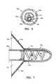
- FIG. 1is an elevational view of a partitioning device embodying features of the invention in an expanded configuration.
- FIG. 2is a plan view of the partitioning device shown in FIG. 1 .
- FIG. 3is a partial longitudinal cross-sectional view of the hub of the partitioning device shown in FIG. 1 .
- FIG. 4is a transverse cross sectional view of the hub shown in FIG. 3 taken along the lines 4 - 4 .
- FIG. 5Aillustrates a system for reducing ventricular volume including a delivery system (delivery catheter).
- FIG. 5Bis a schematic elevational view of a delivery system for the partitioning device shown in FIGS. 1 and 2 .
- FIG. 5Cshows another variation of a system for reducing ventricular volume including a partitioning device.
- FIG. 6is a transverse cross-sectional view of the delivery system shown in FIG. 5B taken along the lines 6 - 6 .
- FIG. 7is an elevational view, partially in section, of the hub shown in FIG. 3 secured to the helical coil of the delivery system shown in FIG. 5B .
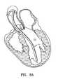
- FIGS. 8A-8Eare schematic views of a patient's left ventricular chamber illustrating the deployment of the partitioning device shown in FIGS. 1 and 2 with the delivery system shown in FIG. 5B to partition the heart chamber into a primary productive portion and a secondary, non-productive portion.
- FIG. 9illustrates deployment of the partitioning device shown in FIG. 5C .
- FIG. 10illustrates one embodiment of the delivery system configured to maintain the position of the partitioning device while the guide catheter is withdrawn.
- FIG. 11illustrates one embodiment of the delivery system configured to maintain the position of the partitioning device while the guide catheter is withdrawn.
- FIG. 12illustrates one embodiment of the delivery system configured to maintain the position of the partitioning device while the guide catheter is withdrawn.
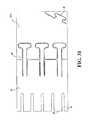
- FIG. 13illustrates one embodiment of the delivery system configured to maintain the position of the partitioning device while the guide catheter is withdrawn.
- FIG. 14illustrates one embodiment of the delivery system including an “over the wire” balloon system.
- FIG. 15illustrates one embodiment of the delivery system including an “over the wire” balloon system.
- FIGS. 16A and 16Billustrates one embodiment of the delivery system including an “over the wire” balloon system.
- FIG. 17illustrates one embodiment of the delivery system including an “over the wire” balloon system.
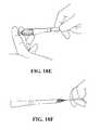
- FIGS. 18A-18Fillustrate one embodiment of the delivery system including an expandable member.
- FIG. 19illustrates one embodiment of the delivery system including an expandable member.
- FIG. 20illustrates one embodiment of the delivery system including an expandable member.
- FIG. 21illustrates one embodiment of the delivery system including an expandable member.
- FIG. 22illustrates one embodiment of a mechanical expansion member in a resting configuration.
- FIG. 23illustrates one embodiment of a mechanical expansion member in a resting configuration.
- FIG. 24illustrates one embodiment of a mechanical expansion member in resting configuration.
- FIG. 25illustrates one embodiment of a mechanical expansion member in resting configuration.
- FIGS. 26A and 26Billustrate one embodiment of the delivery system including a mechanical expansion member.
- FIG. 27illustrates one embodiment of the delivery system including the frame and the delivery catheter formed from a single tube.
- FIGS. 28A and 28Billustrate one embodiment of the delivery system including the frame and the delivery catheter formed from a single tube.
- FIG. 29illustrates one embodiment of the delivery system including the frame and the delivery catheter formed from a single tube.
- FIG. 30illustrate an alternative embodiment of a delivery system wherein the frame and catheter are formed from separate components.
- FIG. 31illustrates an alternative embodiment of the delivery system wherein the frame and the guide catheter are formed from tubes and snapped together.
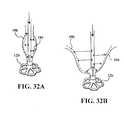
- FIGS. 32A and 32Billustrate various embodiments of the delivery system wherein the expandable member is a hydraulic system.
- FIGS. 33A and 33Billustrate one embodiment of a deployment system, i.e. handles.
- FIG. 34illustrates one embodiment of a deployment system, i.e. handles.
- FIG. 35illustrates one embodiment of a deployment system, i.e. handles.
- FIG. 36illustrates one embodiment of a deployment system, i.e. handles.
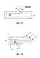
- FIG. 37illustrates one embodiment of a deployment system, i.e. handles.
- FIG. 38illustrates one embodiment of a coupling mechanism.
- FIG. 39illustrates an embodiment of a conical dilator.
- FIG. 40illustrates a partitioning device embodying features of the invention, including a guidewire lumen, the device shown in an expanded configuration.
- FIGS. 41A and 41Billustrates a delivery device configured for a transvascular approach and a transapical approach, respectively, embodying features of the invention, including at least one marker band.
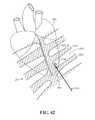
- FIG. 42illustrates a position of a transapical access zone
- FIG. 43illustrates an exemplary embodiment of a transapical delivery of a partitioning device into a ventricle.
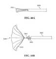
- FIGS. 44A and 44Billustrate a partitioning device and delivery system embodying features of the invention and configured for delivery via a transapical approach.
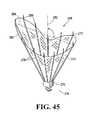
- FIG. 45illustrates one embodiment of a partitioning device in which the hub is in an asymmetric position.
- FIG. 46is a partial schematic view of the expandable frame of the partitioning device shown in FIGS. 1 and 2 in an unrestricted configuration.
- FIG. 47is a top view of the expandable frame shown in FIG. 46 .
- FIG. 48is a schematic illustration of a method of forming the partitioning device shown in FIGS. 1 and 2 from the expandable frame shown in FIGS. 46 and 47 .
- FIG. 49is a schematic illustrations of a method of forming the partitioning device shown in FIGS. 1 and 2 from the expandable frame shown in FIGS. 46 and 47 .
- FIG. 50is a schematic view of the assembled components shown in FIG. 49 , as they are situated in a laminating press.
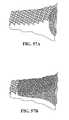
- FIGS. 51A-51Dinclude views of a bilaminar assembly for the making of an intracorporeal partitioning device, as well as views of the assembled device.
- FIG. 51Ashows an exploded and partially cutaway view of the components of the device assembled for lamination;
- FIG. 51Bprovides of cutaway view of the device within a press, the press in a closed position;
- FIG. 51Cshows a perspective view of an exemplary device;
- FIG. 51Dprovides a frontal view of the device after assembly.
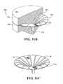
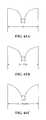
- FIGS. 52A-52Dinclude views of a unilaminar assembly for the making of an intracorporeal partitioning device, as well as views of the assembled device.
- FIG. 52Ashows an exploded and partially cutaway view of the components of the device assembled for lamination;
- FIG. 52Bprovides of cutaway view of the device within the press in a closed position;
- FIG. 52Cshows a perspective view of an exemplary device; and
- FIG. 52Dprovides a frontal view of the device after assembly.
- FIGS. 53A and 53Bprovide cross-sectional views of an assembly from which a bilaminar partitioning device is formed.
- FIG. 53Ashows a polyethylene-encased rib sandwiched between two sheets of ePTFE material as assembled prior to processing in a mold or press.
- the ribis substantially cylindrical in form, or substantially circular in cross section.
- FIG. 53Bshows the same materials after the application of heat and pressure, to form a bilaminar sheet, the sheets held together by melted and reformed polyethylene material to which they are both fused, a rib disposed within and adherent to the polyethylene.
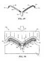
- FIGS. 54A and 54Bprovide cross-sectional views of an assembly from which a bilaminar partitioning device is formed.
- FIG. 54Ashows a polyethylene-encased rib sandwiched between two sheets of ePTFE material as assembled prior to processing in a mold or press.
- the ribis substantially rectangular, but curved in cross section.
- FIG. 54Bshows the same materials after the application of heat and pressure, to form a bilaminar sheet, the sheets held together by melted and reformed polyethylene material to which they are both fused, a rib disposed within and adherent to the polyethylene.
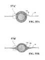
- FIGS. 55A and 55Bprovide cross-sectional views of an assembly from which a unilaminar partitioning device is formed.
- FIG. 55Ashows a polyethylene-encased rib overlaying a sheet of ePTFE material as assembled prior to processing in a mold or press.
- the ribis substantially circular in cross section.
- FIG. 55Bshows the same materials after the application of heat and pressure, to form a unilaminar sheet fused to a rib by the melted and reformed polyethylene, the polyethylene interposed between the rib and the ePTFE sheet, adhering to both.
- FIGS. 56A and 56Bprovide cross-sectional views of an assembly from which a unilaminar partitioning device is formed.
- FIG. 56Ashows a polyethylene-encased rib overlaying a sheet of ePTFE material as assembled prior to processing in a mold or press.
- the ribis substantially rectangular but curved in cross section.
- FIG. 56Bshows the same materials after the application of heat and pressure, to form a unilaminar sheet fused to a rib by the melted and reformed polyethylene, the polyethylene interposed between the rib and the ePTFE sheet, adhering to both.
- FIGS. 57A and 57Bschematically depict the formation of a unilaminar integrated structure from the polyethylene-encased rib and ePTFE material by the melting and solidified reformed polythethylene to create interlocking continuities between the ePTFE and the polyethylene.
- This structurealso depicts a portion of a larger bilaminar structure, such as a portion immediately overlaying a rib.
- FIGS. 58A and 58Bschematically depict the formation of a bilaminar integrated structure from the polyethylene-encased rib and ePTFE material by the melting and solidified reformed polythethylene to create interlocking continuities between the ePTFE and the polyethylene.
- FIG. 59shows an exploded and partially cutaway view of the components of an assembly for lamination of an intracorporeal partitioning device.
- FIGS. 60A and 60Bshow an assembled device as a result of an assembly for lamination of an intracorporeal partitioning device.
- FIGS. 61A-61Cillustrate a cross-section of a loaded frame in its free state ( FIG. 61A ), after lamination ( FIG. 61B ), and implanted ( FIG. 61C ).
- FIGS. 62A-62Cillustrate a first, second, and third embodiment showing the frame of the device described herein having sleeves.
- the devicemay include full sleeves disposed along the full length of the struts ( FIG. 62A ), partial sleeves staggered along the length of the struts ( FIG. 62B ), or shortened sleeves ( FIG. 62C ).
- FIGS. 1-4illustrate a partitioning component 10 a which embodies features of the invention and which includes a partitioning membrane 11 a , a hub 12 a , preferably centrally located on the partitioning device, and a radially expandable reinforcing frame 13 a formed of a plurality of ribs 14 a .
- Embodiments of the partitioning component 10 amay be alternatively referred to as an intracorporeal partitioning component or an intracorporeal product, referring to its position within a ventricle of the heart, and to its function in partitioning the ventricle.
- the partitioning membrane 11 ais secured to the proximal or pressure side of the frame 13 a as shown in FIG. 1 .
- the ribs of the intracorporeal device 14 ahave distal ends 15 a which are secured to the hub 12 a and free proximal ends 16 a which are configured to curve or flare away from a center line axis 17 a . Radial expansion of the free proximal ends 16 a unfurls the membrane 11 a secured to the frame 13 a so that the membrane presents a relatively smooth, pressure receiving surface 18 a which defines in part the productive portion of the patient's partitioned heart chamber.
- the distal ends 15 a of the ribs 14 aare secured within the hub 12 a and a transversely disposed connector bar 20 a is secured within the hub which is configured to secure the hub 12 a and thus the partitioning component 10 a to a delivery system such as shown in FIGS. 5A-5C and 6 a .
- the curved free proximal ends 16 a of ribs 14 aare provided with sharp tip elements 21 a which are configured to hold the frame 13 a and the membrane 11 a secured thereto in a deployed position within the patient's heart chamber.
- the sharp tip elements 21 a of the frame 13 apenetrate into tissue of the patient's heart wall in order to secure the partitioning component 10 a within the heart chamber so as to partition the ventricular chamber into a productive portion and a non-productive portion.
- the connector bar 20 a of the hub 12 aallows the partitioning device 10 a to be secured to a delivery system and to be released from the delivery system within the patient's heart chamber.
- the distal ends 15 a of the reinforcing ribs 14 aare secured within the hub 12 a in a suitable manner or they may be secured to the surface defining the inner lumen or they may be disposed within channels or bores in the wall of the hub 12 a .
- the ribs 14 aare pre-shaped so that when not constrained other than by the membrane 11 a secured thereto (as shown in FIGS. 1 and 2 ), the free proximal ends 16 a thereof expand to a desired angular displacement away from a center line axis 17 a which is about 20 degrees to about 90 degrees, preferably about 50 degrees to about 80 degrees.
- FIGS. 5A-7illustrate a suitable delivery system 30 delivering the partitioning component 10 a , 10 b shown in FIGS. 1 and 2 into a patient's heart chamber and deploying the partitioning component 10 a , 10 b to partition the heart chamber as shown in FIGS. 8A-8E and FIG. 9 .
- the delivery system 30 a , 30 bincludes a guide catheter 31 a , 31 b and a delivery catheter 32 a , 32 b .
- a transverse, cross-sectional view of delivery catheter 32 ais shown in FIG. 6 .
- the guide catheterhas an inner lumen 33 a extending between the proximal end 34 a and distal end 35 a .
- a hemostatic valve(not shown) may be provided at the proximal end 34 a of the guide catheter 31 a .
- a flush port 36 a on the proximal end 34 a of guide catheter 31 ais in fluid communication with the inner lumen 33 a.
- the delivery catheter 32 ahas an outer shaft 40 a with an inner lumen 41 a and a proximal injection port 42 a , an inner shaft 43 a disposed within the inner lumen 41 a with a first lumen 44 a and a second lumen 45 a .
- Balloon inflation port 46 ais in fluid communication with the first lumen 44 a and flush port 47 a is in fluid communication with the second lumen 45 a .
- Torque shaft 48 ais rotatably disposed within the second lumen 44 a of the inner shaft 43 a and has an injection port 49 a provided at its proximal end 50 a in fluid communication with the inner lumen 51 a of the torque shaft.
- the torque shaft 48 ais preferably formed at least in part of a hypotube formed of suitable material such as superelastic Nitinol or stainless steel.
- a torque knob 52 ais secured to the proximal end 50 a of torque shaft 48 a distal to the injection port 49 a .
- a helical coil screw 53 ais secured to the distal end of the torque shaft 48 a and rotation of the torque knob 52 a on the proximal end 50 a of the torque shaft 48 a rotates the screw 53 a on the distal end of torque shaft 48 a to facilitate deployment of a partitioning device 10 a .
- An inflatable balloon 55 ais sealingly secured to the distal end of the inner shaft 43 a and has an interior 56 a in fluid communication with the first lumen 44 a .
- Inflation fluidmay be delivered to the interior 56 a through port 44 a in the portion of the inner shaft 43 a extending through the balloon 55 a .
- Inflation of the balloon 55 a by inflation fluid through port 46 afacilitates securing the partitioning component 10 a.
- the partitioning component 10 ais secured to the distal end of the delivery catheter 32 a by means of the helical coil screw 53 a .
- the partitioning component 10 ais collapsed to a first, delivery configuration which has small enough transverse dimensions to be slidably advanced through the inner lumen 33 a of the guide catheter 31 a .
- the guide catheter 31 ahas been previously percutaneously introduced and advanced through the patient's vasculature, such as the femoral artery, in a conventional manner to the desired heart chamber.
- the delivery catheter 32 a with the partitioning component 10 a attachedis advanced through the inner lumen 33 a of the guide catheter 31 a until the partitioning component 10 a is ready for deployment from the distal end of the guide catheter 31 a into the patient's heart chamber 57 a to be partitioned, as shown in FIGS. 8A-8E .
- FIG. 5Cillustrates another variation of a system 30 b for delivering a partitioning device 10 b .
- the embodiments of the delivery systemsshow in various embodiments may be different, common features are labeled similarly.
- the delivery system 30 bincludes a guide catheter 31 b and a delivery catheter 32 b .
- the guide catheter 31 bhas an inner lumen 33 b extending between the proximal end 34 b and distal end 35 b .
- a hemostatic valve(not shown) may be provided at the proximal end 34 b of the guide catheter 31 b to seal about the outer shaft 37 b of the delivery catheter 32 b .
- a flush port 36 b on the proximal end 34 b of guide catheter 31 bis in fluid communication with the inner lumen 33 b.
- the delivery catheter 32 bhas an outer shaft 37 b with an adapter 38 b on the proximal end thereof having a proximal injection port 39 b which is in fluid communication with the interior of the shaft 37 b .
- the outer shaft 37 bmay have an inner shaft which is disposed within the interior thereof and is secured to the inner surface of the outer shaft by webs which extend along a substantial length of the inner shaft.
- the injection portmay be in fluid communication with the passageways between the inner and outer shafts and defined in part by the webs.
- a torque shaftwhich is preferably formed of hypotubing (e.g.
- a partitioning device 10 bformed of stainless steel or superelastic NiTi
- Balloon inflation port 47 bis in fluid communication with the inner lumen of the torque shaft 44 b .
- Torque shaft 44 bis rotatably disposed within the inner lumen 45 b of the inner shaft 41 b and is secured to rotating knob 49 b .
- a helical coil screw 50 bis secured to the distal end 51 b of the torque shaft 44 b and rotation of the torque knob 49 b on the proximal end 46 b of the torque shaft 44 b rotates the screw 51 b to facilitate deployment of a partitioning device 10 b .
- the proximal end 52 b of inflatable balloon 53 bis sealingly secured by adhesive 54 b about the torque shaft 44 b proximal to the distal end 51 b of the torque shaft 44 b .
- the balloon 53 bhas an interior 55 b in fluid communication with the inner lumen 48 b of the torque shaft 44 b .
- Inflation fluidmay be delivered to the balloon interior 55 b through port 47 b which is in fluid communication with the inner lumen 48 a (shown in FIG. 5B ) of the torque shaft 44 b .
- the distal end 56 b of the balloon 53 bis sealingly secured by adhesive 57 b to the helical screw 50 b .
- the proximal and distal ends 52 b and 56 b of the balloon 53 bare blocked by the adhesive masses 54 b and 57 b to prevent the loss of inflation fluid delivered to the interior 55 b of the balloon 53 b .
- Delivery of inflation fluid through a fluid discharge port 58 b in the distal end 51 b of the torque shaft 44 binflates the balloon 53 b which in turn applies pressure to the proximal surface of the partitioning device 10 b to facilitate securing the partitioning component 10 b to the wall 59 b of a heart chamber 57 b , as shown in FIG. 9 .
- the devicemay be inserted substantially as shown in FIG. 9 as described elsewhere herein.
- the partitioning component 10 a mounted on the screw 53 ais urged partially out of the inner lumen 33 a of the guide catheter 31 a until the hub 12 a engages the heart wall as shown in FIG. 8B with the free proximal ends 16 a of the ribs 14 a in a contracted configuration within the guide catheter.
- the guiding catheter 31 ais withdrawn while the delivery catheter 32 a is held in place until the proximal ends 16 a of the ribs 14 a exit the distal end of the guiding catheter.
- the free proximal ends 16 a of ribs 14 aexpand outwardly to press the sharp proximal tips 21 a of the ribs 14 a against and preferably into the tissue lining the heart chamber, as shown in FIG. 8C .
- FIG. 8EWith the partitioning device 10 a properly positioned within the heart chamber 57 a , the knob 49 a on the torque shaft 43 a is rotated counter-clockwise to disengage the helical coil screw 53 a of the delivery catheter 32 a from the stem secured within hub 12 a .
- the counter-clockwise rotation of the torque shaft 43 arotates the helical coil screw 53 a which rides on the connector bar 20 a (shown in FIGS. 4 and 7 ) secured within the hub 12 a .
- the helical coil screw 53 adisengages the connector bar 20 a (shown in FIGS.
- the delivery system 30 amay then be removed from the patient.
- the partitioning component 10 apartitions the patient's heart chamber 57 a into a main productive or operational portion 58 a and a secondary, essentially non-productive portion 59 a .
- the operational portion 58 ais much smaller than the original ventricular chamber 57 a and provides for an improved ejection fraction.
- the partitioningincreases the ejection fraction and provides an improvement in blood flow.
- the patientmay be pre-measured to determine a suitable device size.
- the patientmay be measured in one of many suitable ways, including, but not limited to, mechanical or hydraulic measurement, 3D echo, CAT scan or LV-gram.
- FIG. 9illustrates deployment of the partitioning device and delivery catheter similar illustrated in FIG. 5C ; this FIG. 9 resembles FIG. 8D , above.
- inflation fluidis introduced through the inflation port 46 a into first lumen 44 a of inner shaft 43 a of the delivery catheter 32 a where it is directed through port 44 a into the balloon interior 56 a to inflate the balloon.
- the inflated balloonpresses against the pressure receiving surface 18 a of the partitioning component 10 a to ensure that the sharp proximal tips 21 a are pressed well into the tissue lining the heart chamber.
- the knob 52 a on the torque shaft 48 ais rotated counter-clockwise to disengage the helical coil screw 53 a of the delivery catheter 32 a from the hub 12 a .
- the counter-clockwise rotation of the torque shaft 48 arotates the helical coil screw 53 a which rides on the connector bar 20 a (shown in FIGS. 4 and 7 ) secured within the hub 12 a .
- the delivery system 30 aincluding the guide catheter 31 a and the delivery catheter 32 a , may then be removed from the patient.
- the proximal end of the guide catheter 31 ais provided with a flush port 36 a to inject therapeutic or diagnostic fluids through the inner lumen 33 a .
- the proximal end of the delivery catheter 32 ais provided with a flush port 42 a in communication with inner lumen 41 a for essentially the same purpose.
- An inflation port 46 ais provided on the proximal portion of the delivery catheter for delivery of inflation fluid through the first inner lumen 44 a to the interior 56 a of the balloon 55 a .
- Flush port 47 ais provided in fluid communication with the second inner lumen 45 a of the inner shaft 43 a .
- An injection port 49 ais provided on the proximal end of the torque shaft 48 a in fluid communication with the inner lumen 51 a of the torque shaft for delivery of a variety of fluids.
- the partitioning component 10 apartitions the patient's heart chamber 57 a into a main productive or operational portion 58 a and a secondary, essentially non-productive portion 59 a .
- the operational portion 58 ais much smaller than the original ventricular chamber 57 a and provides for an improved ejection fraction.
- the partitioningincreases the ejection fraction and provides an improvement in blood flow.
- the non-productive portion 59 afills first with thrombus and subsequently with cellular growth.
- Bio-resorbable fillerssuch as polylactic acid, polyglycolic acid, polycaprolactone, and copolymers and blends may be employed to initially fill the non-productive portion 59 a .
- Fillersmay be suitably supplied in a suitable solvent such as DMSO.
- Other materials which accelerate tissue growth or thrombusmay be deployed in the non-productive portion 59 a.
- the implantalso includes a sealing element, strand 19 b , which may be used to help stiffen the edge of the membrane so that it may lie against the ventricle wall 59 b and form a seal against the wall 59 b .
- the strand 19 bmay also be used to help retrieve the device.
- the guide catheter 31 a , 31 bbegins to bend as it is withdrawn through the vascular anatomy of the patient, through the aortic arch, for example. In some instances, this bend may drive the distal tip of the delivery catheter, and therefore the partitioning device, out of position. For example, the guide catheter may drive the device towards the center of the heart, i.e. towards the ventricular septum. In some instances, it may be preferred that the delivery catheter and/or partitioning device are not moved or repositioned by the guide catheter as it is withdrawn. This may be accomplished in one of several embodiments. In a first embodiment, as shown in FIG. 10 , a ring 60 b is added to the distal end of the delivery catheter 32 b .
- a wire 62 bmay be coupled to the ring 60 b .
- the wiremay be disposed along the length of the delivery and/or guide catheter, and may be configured to maintain the position of the distal end of the delivery catheter as the guide catheter is retracted into the vascular anatomy.
- the wireis a rigidifying wire (or other element) that locks or holds the shape of the delivery catheter.
- the wireis a pull wire. By pulling on or tensioning the pull wire, as shown in FIG. 10 , the pull wire pulls on the ring 60 b , bending the delivery catheter. This may prevent the ring and distal end of the delivery catheter, and therefore the partitioning device, from moving out of position.
- the pull wiremay be used to pull the delivery catheter and partitioning device toward the apex of the heart, rather than towards the ventricular septum.
- the guide cathetermay be flexible such that the pull wire may effectively steer the delivery catheter as the guide catheter is withdrawn.
- the delivery catheter 32 bis steerable.
- the guide catheteris steerable (not shown).
- the positioning of the partitioning devicemay be more controlled.
- a steerable delivery cathetermay hold the implant in place as the guide catheter is retracted to expose and/or deploy the partitioning device.
- the steerable delivery cathetermay be steered or positioned into any number of suitable geometries.
- the delivery cathetermay be positioned into an S-curve 64 c . This S-curve, as shown in FIG. 11 , may be configured to position the catheter away from the ventricular septum and toward the apex of the heart, for example.
- the delivery cathetercould be steerable by one of several different mechanisms.
- pull wiresmay be used to lengthen and shorten various portions of the delivery catheter 32 b (within the guide catheter 31 b ) to form the S-curve 64 c .
- the delivery cathetermay include interlocking shafts, such as hypotubes 66 b , 68 b . The interlocking shafts may move with respect to one another to form the S-cure 64 c.
- the delivery cathetermay be a shape set material, such as Nitinol.
- the delivery cathetermay be stiffer than the guide catheter, such that as the guide catheter is retracted or withdrawn, it imparts minimal forces on the more stiff delivery catheter.
- the delivery cathetermay be set into any suitable shape, and be configured for any suitable vascular anatomy.
- the size of the expandable membermay be limited by the size of the delivery diameter.
- each of the componentscontributes to the overall delivery diameter.
- the delivery diameteris preferably small to enable the passing of the guide catheter through the vasculature of the patient, therefore limiting the size of the expandable member and/or the size of the delivery catheter.
- the components of the delivery system 30 a , 30 bmay be decoupled or separable from each other.
- the delivery systemmay be decoupled into four separate components: a partitioning device 10 b , a wire 70 , a detachable handle 72 , and an “over the wire” balloon system 74 .
- the wire 70may include a coupling mechanism, such as a helical screw, at the distal end that is configured to couple to the partitioning device 10 b .
- the wiremay be a conventional cardiovascular wire, or any other suitable wire.
- the wiremay have a ground profile to optimize performance.
- the handle 72may be coupled to the wire during the initial placement of the device, and then may be removed to allow the balloon system 74 to be coupled to the wire and advanced toward the partition device.
- Coupling to the wire in this examplemay be defined as positioning the handle, or balloon system, over the wire such that the wire is disposed along the length of an inside diameter of the handle or system.
- the handlemay be replaced once the balloon system is in place, or alternatively, the balloon system may include a separate handle.
- the balloon system 74having expandable member 76 (a balloon), may be a conventional balloon catheter or may be any other suitable “over the wire” system that is configured to expand the partitioning device.
- the guide catheterincludes four regions, A-D.
- Region Ais pushable such that it may advance the guide catheter through the vasculature of the patient and/or push the partitioning device 10 b out of the guide catheter.
- Region Amay also be torqueable depending on the configuration of the coupling mechanism, for example, if the coupling mechanism is a screw.
- Region Amay include a hypotube or a braided or coil wound shaft.
- Region Bmay be flexible to ensure that the device is positioned correctly, and not repositioned toward the septum, for example, during deployment. As with region A, region B may also be torqueable.
- Region Bmay include a highly flexible rigid shaft such as Nitinol (or other shape memory materials) or a braided or coil wound shaft.
- Region Cmay have a low profile such that is does not largely affect the overall delivery diameter or profile.
- Region Cmay also be pushable, such that it may advance the device and/or position the hub 12 b or foot of the device.
- Region Cmay be a hypotube or solid shaft.
- Region Dmay be removably attached to the partitioning device 10 b .
- Region Dmay include a coupling mechanism such as a coiled screw, a suture, or a hitch-pin (described below).
- regions A through Cmay form a wire, similar to wire 70 in FIG. 14 .
- a balloon system 74may be advanced over regions A through C.
- FIGS. 16A and 16Billustrate one variation of a delivery system including an expandable member that is a balloon that is deliverable over a wire forming part of the guide catheter. In this example, the balloon may be
- balloon 76 of the balloon system 74may include any number of features such that it is configured to expand the partitioning device 10 b .
- FIG. 16Ashows a conventional angioplasty balloon tip 78 A.
- FIG. 16Bshows a more aggressive tip 78 B configured to insert into the distal portion of the partitioning device 10 b when it is collapsed.
- the balloon 76may include three portions A, B, C.
- portion Aremains within the distal end of the partitioning device 10 b during delivery.
- the tip portion, portion Ais a distal nose region that may have a small profile such that it is configured to not largely contribute to the overall delivery profile.
- Portion Ais also configured to position portions B and/or C in the correct position with respect to the partitioning device.
- the length of portion Amay be selected so that when balloon 76 is fully advanced, the distal tip of portion A contacts the partitioning device, and the expandable balloon (portion C) is optimally positioned to expand the partitioning device.
- Portion Amay be part of the balloon, or it may be a separate portion such as a tube.
- Portion Amay be stiff in some embodiments.
- Portion Cis the expandable balloon portion and is configured to interact with the distal end of the partitioning device.
- Portion Bmay be a tapered region. The taper may be relatively gradual or more extreme, and allows the transition between the distal tip and the balloon, allowing the entire expandable region to be inserted into the collapsed partitioning device.
- FIGS. 18A-20Another example of an expandable member is shown in FIGS. 18A-20 .
- the expandable memberis a mechanical expander.
- the mechanical expander in this exampleis a frame 80 formed of a plurality of arms or struts that are joined at their proximal and distal ends, as shown. The arms may be collapsed down or expanded by moving the proximal and distal ends of the frame relative to one another.
- the proximal end of the frame 80may be coupled to the delivery catheter 32 b and the distal end of the frame may include a coupling mechanism 82 , such as a screw tip.
- the coupling mechanismmay be coupled to the partitioning device 10 a / 10 b , as shown in FIG. 18B .
- the frame 80may further include a mandrel 84 configured to move the frame 80 from a collapsed to an expanded configuration.
- a pull wire or other suitable mechanismmay be coupled to the mandrel 84 such that it may be moved and thereby move the frame 80 .
- FIGS. 18C to 18Fillustrate loading the implant 10 b (partitioning device) onto a guide catheter such as the one shown in FIGS. 18A and 18B .
- the implantmay be coupled to the guide catheter in an expanded state, and then collapsed down (around the mechanical expander as shown in FIG. 18D ).
- a loading toole.g., funnel
- the systemmay be loaded into a delivery catheter for inserting into the patient.
- the implantmay be flushed (e.g., with saline) first.
- FIGS. 19 and 20illustrate another variation of a delivery catheter including a mechanical expander.
- the expander regionis controlled by a mandrel 84 that is extendable and retractable to collapse or expand the mechanical expander region.
- FIG. 20shows one variation in which a proximal handle includes grips (finger grips) for actuating the expander relative to the rest of the catheter. Expanding the mechanical expander pushes against the inner portion of a collapsed implant and aids the implant in expansion and attachment (sealing) to the ventricle wall(s).
- the mechanical expanders described hereinmay have advantages compared to the balloon expanders mentioned above. For example, the mechanical expanders may be precisely controlled. In addition, the mechanical expander may be shaped to more optimally contact the implant. Finally, the mechanical expander may be expanded larger than the balloons, while having a smaller cross-sectional area, thereby allowing smaller diameter delivery/guide catheters. In addition, the mechanical expander may not require the pressurized inflation fluid.
- FIGS. 21-26illustrate variations of mechanical expanders.
- the frame 80may be formed of heat set Nitinol, or other shape memory material, in a shape such that the resting position is the expanded position, as shown.
- the framemay be made out of a tube that is laser cut to form the struts 86 of the frame 80 .
- the mandrel 84may be pushed to compress the frame radially such that it may be advanced through the guide catheter.
- the mandrel 84may then be pulled to expand the struts 86 radially to expand the frame 80 .
- the frame 80may be collapsed by pulling proximal and distal ends apart.
- the framemay be made at least in part from heat set Nitinol, or other shape memory material, in an expanded or unexpanded shape.
- the framemay be made out of a tube that is laser cut to form the struts 86 of the frame 80 .
- the mandrel 84may be pushed to compress the frame radially such that it may be advanced through the guide catheter.
- the mandrel 84may then be pulled to expand the struts 86 radially to expand the frame 80 .
- the material of the frame 80such as Nitinol, may be heat treated such that the struts are predisposed to expand. As shown in FIG.
- the frame 80may have a symmetric or asymmetric shape along its axial length.
- the frameis a teardrop shape.
- the wider diameter region of the tear drop shapeis located more proximally, nearer the region where the implant will expand the most (and contact the wall of a ventricle).
- the material of the frame 80such as Nitinol, may be heat treated such that the struts are predisposed to expand at the distal or proximal end of the frame.
- the framemay contact the device 10 a , 10 b further down on the device, requiring less radial expansion to open the implant.
- the frame 80may expand into a fully circular shape. As shown in FIG.
- the frame 80may be made out of a spiral cut tube.
- the material of the frame 80such as Nitinol, may be heat treated such that the struts are predisposed to expand. This configuration is such that at least a portion of the frame 80 will contact the device 10 a on the ribs 14 a of the device, since the spiral of the expansion member frame will place the frame arms at an angle relative to the ribs of the implant. Thus the frame may push against the ribs of the implant preferentially, rather than the membrane.
- FIG. 21illustrates an example in which the arms forming the frame are cut to bias the bending (hinge) region.
- cuts 88 in the frame materialare configured to predispose bending of the frame at specified locations. A detailed view is shown in FIG. 26A . The cuts 88 may be placed in any suitable location for any suitable device geometry.
- the mechanical expansion member (e.g., frame 80 ) and the catheter 32 bmay be made out of a single length of tube.
- the distal end region of the tubeincludes keyed slots 90 cut into the tube to form a flexible portion of the delivery catheter 32 b .
- slots 92Toward the more distal end of the tube, slots 92 have been cut into the tube to form the expandable struts 86 of frame 80 .
- the keyed slots 90may be formed by a single, continuous helical cut.
- keyed slotsmay be formed by multiple circumferential cuts along the length of the delivery catheter portion.
- FIGS. 28A and 28Billustrate partial views of “unrolled” templates for some of the laser cuts that may be made to form a catheter having a mechanical expansion member.
- FIG. 28Ashows a version with laser cut arms that run parallel to the long axis of the catheter
- FIG. 28Bshows a variation in which the laser cut arms spiral around the circumference of the catheter once it has been constructed.
- the delivery systemmay further include a tube and/or shaft 94 within the catheter.
- FIG. 29shows a more detailed example of this tube.
- a tube/shaft 94may be configured to couple to the coupling mechanism 82 (or to be part of the coupling mechanism) to release the device 10 .
- the tube/shaft 94may move independently from the rest of the catheter 32 b , and may be referred to as a torque shaft.
- the tube/shaft 94may include a lumen through which any suitable liquid may be injected.
- the systemmay further include a pull wire 96 .
- the pull wiremay function to pull and/or deflect the distal end of the catheter to steer and position the partitioning device.
- FIG. 30shows one variation of a guide catheter including an extruded plastic cover 98 over a portion of the guide catheter.
- the catheteris plastic, and the mechanical expansion members are secured thereto.
- a reflow processmay be utilized to bond the plastic onto the torque tube.
- the mechanical expansion memberbe formed of a shape memory or hyperelastic material such as Nitinol.
- the rest of the cathetere.g., the rest of the body region proximal to the expansion member
- FIG. 31illustrates one variation of a catheter (or region of a catheter) having a Nitinol mechanical expansion region and a stainless steel proximal region.
- the cathetermay be formed out of a first tube of a first material (e.g., stainless steel), and the frame 80 forming the arms of the mechanical expansion member may be formed out of a second material (e.g., Nitinol).
- first materiale.g., stainless steel
- second materiale.g., Nitinol
- the proximal end of the frame 80 and the distal end of the delivery cathetermay include cuts 100 that are configured to snap the proximal end of the frame 80 onto the distal end of the delivery catheter.
- Cuts 100provide a good mechanical interface between the frame 80 and the delivery catheter 32 b , providing enhanced column strength beyond what a simple weld may produce. Cuts 100 may also allow the tabs to bend and the tubes to be joined. After snapping the tubes together, cuts 100 are welded closed, eliminating the flexibility of the tabs thereby locking the tubes together (without requiring dissimilar metals to be welded, which may cause faults in the final product).
- the expandable memberis a pneumatic, or fluid-pressure based member, as shown in FIGS. 32A and 32B .
- the expandable membermay include a hydraulic system that is configured to apply pressure to the inner surface 18 b of the partitioning device 10 b to drive it open and/or seal it to the ventricle wall.
- the systemmay use a rapid saline injection or any other suitable system to apply pressurized fluid flow against the inner surface 18 b of the partitioning device 10 b to expand the device 10 b .
- the systemmay inject a contrast to aid in the radiopacity of the device and/or area surrounding the device.
- the expansion membermay include a fluid delivery member (tube, passage, etc.) that has multiple ports oriented at different directions/angles to drive the fluid against the partitioning device to deploy the partitioning device.
- the partitioning device 10 bmay be deployed and/or released from the guide catheter.
- the delivery systemmay include one of several variations of deployment systems, i.e. handles. The deployment of the device is preferably performed in a controlled manner. As shown in FIGS. 33A and 33B , the system may include a “pistol grip” handle.
- This embodimentmay include any of the following features: one handed actuation/deployment and release of the partitioning device 10 b , a keyed interaction between the handle and the catheter to allow for rotation of the partitioning device prior to release, a torsion spring to allow for multiple expansions of the deployment frame 80 prior to release of the partitioning device, a hitch-pin coupling mechanism 82 as described in more detail below, and a preloaded partitioning device within the delivery system.
- the systemmay include a “squeeze grip” handle.
- This handlemay also include any combination of the features listed above.
- FIG. 35shows another variation of a “squeeze grip” handle, having a trigger-like control for driving contraction/extension of a pullwire, which may be connected to a mechanical expansion member and/or a coupling element.
- the systemmay include a “remote grip” handle. This handle may be actuated by a mechanism such as a trigger 102 , a slide 104 , and/or a button.
- the systemmay include a “sliding grip” handle. This handle may be actuated by a mechanism such as a ratcheting thumb button 106 . Any of the handles described herein may be used as part of an expansion control and/or a deployment control.
- the partitioning devicemay be coupled to the delivery catheter and then released in one of several embodiments.
- a torque shaft within the delivery systemis rotated to disengage the helical coil screw 53 a , 50 b of the delivery catheter 32 a , 32 b from the hub 12 a , 12 b .
- the rotation of the torque shaft 48 a , 44 brotates the helical coil screw 53 a , 50 b which rides on the connector bar 20 a secured within the hub 12 a , 12 b .
- the coupling mechanismis a hitch-pin mechanism 108 .
- the hitch-pin 108may include several components.
- the hitch pinmay include a feature 110 in the device foot 12 b allowing for entry of the retention/release mechanism.
- the hitch pinincludes element 112 within element 110 that is configured to partially restrict the hole (feature 110 ).
- element 112is a cross pin.
- Element 113may be a tube with a notch 114 in the distal end of the tube.
- Element 115may be a rod with a bulbous feature 116 on the distal end of the rod. With tube 113 in place, the bulbous feature 116 cannot fit past cross pin 112 , however, once tube 113 is removed, the rod 115 and end 116 can be removed. Tube 113 is removed by pulling the tube in the proximal direction. This motion may be simpler than a torque motion required to decouple the helical screw embodiment.
- a conical dilator 3400may be used in combination with a guide catheter 3403 and wire 3404 to facilitate access to the vasculature.
- the use of a conical dilatormay avoid the need to use a procedural introducer sheath, thereby reducing the size of an arteriotomy or venotomy, and reducing at least one of the time, cost, and loss of blood from the patient throughout the overall procedure.
- the conical dilatormay facilitate vessel navigation and tracking of the device through the vasculature, for instance tracking through the aortic arch.
- the tapered tipmay travel through the aortic arch and across the valve less traumatically than a blunt ended catheter.
- the conical dilatormay be utilized during transseptal access procedures, as described in detail below.
- the conical dilatormay be removed from the guide catheter, prior to introduction of the delivery catheter-implant assembly into the guide catheter and/or prior to the delivery of the implant.
- the tapered dilatormay be removed by and/or with the guidewire.
- a guidewire lumen 3500may be incorporated in the device.
- the guidewire lumenmay extend throughout the whole device, as shown, or may be configured as a rapid-exchange feature. In both cases delivery of the device over a guidewire may be enabled, allowing for an additional mechanism of targeting the distal end of the device to the intended landing zone.
- a lubricious coatingmay be applied to the guidewire, or alternatively a protective sleeve may be incorporated in the device.
- the guidewiremay include an anchoring mechanism at the distal tip of the guidewire, for instance a threaded tip, which may be employed to anchor the wire at the intended anchoring site within the patient's ventricle, thus allowing the wire to act as an anchor for delivery of the partitioning device.
- the guidewiremay be positioned within the ventricle, and the distal tip of the guidewire may then be anchored or otherwise coupled to the ventricular wall. Once the guidewire is in position, the implant may be deployed over the guidewire into the patient's ventricle.
- radio-opaque markersmay be incorporated into the device.
- the markersmay be included on the implanted partitioning device and/or on the delivery system.
- Radio-opaque markersmay be constructed from biocompatible heavy metals, such as gold, platinum, and tantalum, and may be fabricated in any form or shape suitable for the intended device, such as bands, tabs, ribbons, disks, and the like. They may be in the form of components specifically included for the purpose of providing radio-opacity, or they may be inherent components of a device, made out of a radio-opaque material to provide radio-opacity. In some embodiments, as shown in FIG.
- the distal end of the elongate guide catheter and/or delivery catheter 3600 for a transvascular approachmay include a marker band 3602 .
- the catheter 3600may be delivered to the apex of the patient's heart, and the marker band 3602 may indicate the height and/or position of the anchors in their deployed configuration.
- the marker band 3602may be positioned on catheter 3600 to indicate any other suitable positioning information of the implant or other component of the system.
- the systems and methods described hereinmay be capable of delivering a partitioning device to a ventricle by a transseptal approach.
- This approachmay advantageously be used in patients with compromised femoral arterial anatomy, with a compromised aorta or aortic valve, and/or where delivery through an arterial approach may be considered undesirable or unfeasible.
- access to the left heartis achieved by way of the right heart, typically the right atrium.
- Access to the right heartis generally achieved by means of a venous access, for instance through a femoral or jugular vein.
- a guidewiremay be used to establish the access route, and may be threaded through a cardiac septum, for instance through the inter-atrial foramen ovale to establish access to the left heart. Subsequently, the guidewire may be routed through the mitral valve into the left ventricle and into vicinity of the apex of the heart. Alternatively, the use of the guidewire may be limited to access to the left atrium.
- Passage of a guide catheter through the foramenmay be enabled by the use of a conical dilator, as described above in reference to FIG. 39 , in combination with a guide catheter to dilate the transseptal aperture to allow passage of the guide catheter.
- the conical dilatormay be removed with the guidewire prior to loading the delivery catheter into the guide catheter.
- the guidewiremay be left in place during removal of the conical dilator and advanced to its desired position.
- the guidewiremay be anchored in the landing zone prior to delivering the implant.
- the delivery cathetermay then be advanced over the guidewire to the landing zone, and the partitioning device may be delivered as described above.
- positioning of the delivery cathetermay be achieved with a steerable guide catheter and/or delivery catheter, as described above in reference to FIG. 11 .
- the guidewiremay be removed prior to the introduction of the delivery catheter.
- the steerable guide cathetermay be advanced through the septum into the left atrium and used to guide the delivery catheter through the mitral valve into the left ventricle and to the intended landing zone.
- a steerable guide cathetermay be combined with a steerable delivery catheter.
- the partitioning devicemay be alternatively delivered through a transapical approach.
- a transapical approacha device is generally delivered from the apex of the heart, in contra-distinction to the orientation of transvascular delivery, as described above. Therefore, locations and orientations on the partitioning device that are “distal” in transvascular delivery may become “proximal” in transapical delivery and vice versa.
- distal and proximalrefer to locations and orientations of the devices and procedures of the invention.
- distalrefers to a location or direction away from a user.
- proximalrefers to a location or direction towards a user.
- the transapical approachmay be advantageously used in patients with extensive vascular or valvular disease, where delivery through a transvascular approach is undesirable or even unfeasible.
- an intercostal access route to the left ventriclemay be established by creating a cardiotomy near to the apex of the heart, using a surgical or a percutaneous procedure.
- FIG. 42illustrates the location of a transapical access zone.
- a heart 200is shown, underneath the rib cage 201 , showing the sternum 202 and the ribs 203 .
- a transapical access zone 204is visible through the intercostal space 205 .
- Arrow 206illustrates a possible direction of access between the ribs and through the transapical access zone to the left ventricle 207 .
- access to the heartmay be achieved by a mini-thoracotomy in an intra-costal space 205 , followed by a rib spread.
- Access to the ventricle 207may be achieved by micropuncture in the transapical access zone 204 , and dilation of the puncture to create a cardiotomy 301 (shown in FIG. 43 ).
- a procedural access sheath(not shown) may be placed.
- the procedural sheathmay have a function similar to a guide catheter in vascular placement of the device.
- the procedural sheathmay be a specifically designed guide catheter.
- the sheath or cathetermay be placed with the distal end in the left ventricle 207 of the heart 200 .
- FIG. 43an exemplary embodiment of a transapically placed partitioning device 303 is shown in position within a patient's ventricle.
- ventricular wall 300may be perforated at cardiotomy 301 .
- the cardiotomymay be located in the transapical access zone 204 , as shown in FIG. 42 .
- a delivery shaft 302may be located in the cardiotomy 301 .
- the delivery shaft 302may be a rigid or a flexible hollow member, like a rigid tube or a flexible catheter.
- the delivery shaft 302may be connected to the partitioning device 303 on the proximal side of the device, i.e. the side of the device facing the ventricular wall. As shown in FIGS.
- the delivery device 3900may be coupled to the back side of the central hub 3904 via coupling element 3906 , such that the open end 3908 of the umbrella-like structure having a plurality of struts 3902 faces away from the delivery device 3900 .
- the connectionmay be achieved with the same coupling mechanisms described for the devices delivered by the transvascular approach described herein.
- the coupling elementmay be a threaded coupler 304 , as illustrated in FIG. 43 .
- the partitioning device 303may comprise threaded end 305 , central hub 306 and ribs 307 .
- Deployment and expansion of the partitioning device 303may be achieved by the same mechanisms as those deployed for the device delivered by the transvascular approach described herein.
- an expansion membermay be placed on the distal side of the partitioning device, i.e. the side of the device facing the ventricular lumen. This is illustrated for a device expanded with the aid of a balloon 308 in FIG. 43 .
- the balloon 308may be connected to a control device (not shown) operated by a user through an inflation lumen 309 .
- the inflation lumen 309may run through a continuous lumen 310 in the delivery shaft 302 , and continuous lumen 311 in the partitioning device 303 .
- the delivery shaft 302may be a rigid tube or a flexible catheter.
- a lumen 310may run through the delivery shaft 302 and a lumen 311 may run through the device 303 to accommodate a means for controlling an expansion member 308 located on the device 303 .
- the device/delivery shaft assemblymay be loaded into the access sheath or guide catheter in a manner analogous to the loading procedure in transvascular delivery.
- the devicemay be delivered into the ventricle 207 through the access sheath or guide catheter, and be allowed to expand or partially expand.
- the access sheath or guide cathetermay be withdrawn from the cardiotomy 301 , allowing the ventricular wall 300 to seal against the delivery shaft 302 .
- the access sheathmay be a splittable sheath, to facilitate removal from the cardiotomy and the delivery shaft.
- the delivery shaft 302may be moved in a proximal direction (i.e. out of the heart) in the cardiotomy 301 , allowing it to pull a central hub 306 of the partitioning device onto the ventricular wall 300 .
- an expansion membersuch as a balloon 308 or a mechanical expansion member may be located on the device 303 in a location distal to the device, i.e. in a location facing the ventricular lumen and away from the apex.
- the expansion member 308may be expanded to fully deploy and anchor the partitioning device 303 . After collapsing or deflating, the expansion device 308 may be withdrawn through the continuous lumens 310 and 311 . Alternatively, the expansion device may be removed together with the delivery shaft 302 after passing lumen 311 . The delivery 302 shaft may be disconnected from the partitioning device 303 and withdrawn from the cardiotomy 301 , and the cardiotomy 301 may be closed in a standard manner, for instance with a purse-string suture.
- accessmay be achieved by direct puncture of the ventricular wall 300 at the transapical access zone 204 with a micropuncture needle, followed by advancing a guidewire (not shown) through the needle and exchanging the needle for an appropriate access sheath or a specifically designed guide catheter.
- Deployment of the device 303 and retrieval of the delivery shaft 302may be similar or identical to the procedures used after surgical access.
- Closure of the cardiotomy 301may be achieved with a percutaneous closure device.
- the central hub of the partitioning devicemay be located co-axially with the cardiotomy.
- the cardiotomymay not be located centrally to the segment of the ventricular wall to be partitioned away from the lumen of the ventricle. Therefore, in some cases, the use of a partitioning device with an axis of symmetry at a central hub may not result in optimal coverage of an ineffective segment of the ventricular wall. In such cases, use of an asymmetric partitioning device, as illustrated in FIG. 45 , and described in US patent application 20070213815, to Khairkharan et al. filed. May 7, 2007, may provide a more appropriate device configuration.
- the sheath 3900may be fully deployed over the implant to hold the implant in a collapsed configuration.
- the sheathmay be pulled back, away from the device, to begin to allow the expansion of the device.
- the implantis free to fully expand, either by the nature of the implant materials and design and/or with the aid of an expansion member, such as an inflatable balloon (not shown).
- itmay be desirable to re-collapse the implant while it is within the patient. For example, a user may wish to reposition the implant or remove the implant all together.
- the sheath 3900may be pushed back over the implant, thereby pushing the struts of the implant back into a collapsed or partially collapsed configuration, as shown for example in FIG. 44A .
- radio-opaque markersmay be incorporated into the device.
- the markersmay be included on the implanted partitioning device and/or on the delivery system.
- Radio-opaque markersmay be constructed from biocompatible heavy metals, such as gold, platinum and tantalum, and may be fabricated in any form or shape suitable for the intended device, such as bands, tabs, ribbons, disks and the like. They may be in the form of components specifically included for the purpose of providing radio-opacity, or they may be inherent components of a device, made out of a radio-opaque material to provide radio-opacity. In some embodiments, as shown in FIG.
- the distal end of the elongate access and/or delivery sheath 3604 for a transapical approachmay include marker bands 3606 and 3608 .
- the sheath 3604may be delivered through the apex of the patient's heart, and the marker band 3606 may indicate the height and/or position of the anchors in their deployed configuration.
- Marker band 3608may indicate the position of the central hub of the implant.
- the marker bandsmay be positioned on the sheath to indicate any other suitable positioning information of the implant or other component of the system.
- FIGS. 46 and 47illustrate the reinforcing frame 13 a in an unstressed configuration and include the ribs 14 a and the hub 12 a .
- the ribs 14 ahave a length L of about 1 to about 8 cm. In one embodiment, the ribs 14 a have a length L of about 1.5 to about 4 cm for most left ventricle deployments.
- the proximal ends 16 ahave a flared construction. To assist in properly locating the device during advancement and placement thereof into a patient's heart chamber, parts, e.g.
- Radiopaque markersmay be made with, for example, stainless steel, platinum, gold, iridium, tantalum, tungsten, silver, rhodium, nickel, bismuth, other radiopaque metals, and alloys and oxides of these metals.
- Embodiments of the partitioning device 10 aare conveniently formed by placing a thermoplastic tube 60 , e.g. polyethylene or high density polyethylene (HDPE), over the ribs 14 a of the frame 13 a as shown in FIG. 48 until the proximal ends 16 a of the ribs 14 a extend out the ends of the thermoplastic tubes as shown in FIG. 49 , to form thermoplastic-encased ribs.
- a thermoplastic tube 60e.g. polyethylene or high density polyethylene (HDPE)
- HDPEhigh density polyethylene
- a press or lamination mold 63 athat includes a female platen 62 a and a male platen 65 a , one or both of which can be heated and cooled according to process specifics.
- a first expanded polytetrafluoroethylene (ePTFE) sheet 61 a of appropriate sizeis placed in the female platen 62 a of the mold or press 63 a .
- the frame 13 awith tubes 60 slidably disposed or deployed over the ribs 14 a , is placed in platen 62 a on top of the ePTFE sheet 61 a .
- the ePTFE sheetmay be placed over the ribs.
- the center portion of the sheet 61 amay be provided with an opening through which the hub 12 a extends.
- a second ePTFE sheet 64 ais placed on top of the ribs 14 a of frame 13 a as shown in FIG. 50 .
- the melting point of the thermoplastic materialis lower than that of the ePTFE, thus the application of heat and pressure, as detailed below, is sufficient to melt the thermoplastic material but does not cause melting of the ePTFE.
- Embodiments of methods to form a partitioning device that joins ePTFE sheet material, polyethylene material, and ribs into an integral structureinclude the application of heat and pressure.
- Heat and pressuremay be applied through a mold or press 63 a for a period of predetermined period of time, such as from about 30 seconds to about 360 seconds, or more particularly from about 75 seconds to about 240 seconds, or still more particularly, for about 120 seconds.
- Either the male platen 65 a or the female platen 62 a , or both male and female platensmay be heated so as to attain an operating temperature of between about 260 degrees F. and 530 degrees F., particularly to a temperature between about 375 degrees F. and 520 degrees F., and more particularly to temperature between about 490 degrees F.
- the assemblymay be pressed (i.e., pressured or pressurized), the applied pressure being in the range of about 10 psi to about 150 psi. In some particular embodiments, the pressure is between about 35 psi and about 120 psi, and in more particular embodiments, between about 60 psi and about 90 psi.
- a single sheet of ePTFEis utilized to make a unilaminar device, the single sheet corresponding to the first sheet 61 a of FIG. 50 .
- PTFE fabricis a woven material that varies with regard to the thickness of fibers and in the internodal distance between fibers. The presence of the space or volume between fibers provides the material with a foraminous quality which is advantageous for fusion or adhesion processes.
- Various forms of ePTFEhave average internodal distances that vary from about one micron up to about 1,000 microns.
- Typical embodiments of ePTFE fabric appropriate for the manufacture of the herein described partitioning devicemay have internodal distances of between about 5 microns to about 200 microns, more particularly from about 10 microns to about 100 microns, and still more particularly from about 20 microns to about 50 microns. Aspects of the lamination process are described further below, and illustrated in FIGS. 51-58 .
- Sheetsmay be formed of either porous or non-porous ePTFE, as well as other suitable biocompatible materials, as described elsewhere herein.
- the ePTFE fabricis typically stretched during the lamination process, under the conditions of heat and pressure that are applied by the press. Such stretching may not be uniform across the fabric surface, the maximal linear stretch in portions of the fabric may be of a magnitude of 2-fold to 4-fold.
- the stretching of fabricserves, in general terms, to reduce the thickness and overall collapsed profile of the device.
- FIGS. 51A-51Dinclude further views of a bilaminar assembly for the making of an intracorporeal partitioning device (as also depicted variously in preceding FIGS. 48-50 ) and views of the assembled device.
- FIG. 51Ashows a perspective view of an exemplary device
- FIG. 51Bshows an exploded and partially cutaway view of the components of the device assembled for lamination
- FIG. 51Cprovides of cutaway view of the device within the press in a closed position
- FIG. 51Dprovides a frontal view of the device after assembly.
- the upper or male platen 65 a of a press 63 a and the lower or female platen 62 aare seen above and below, respectively, an awaiting assembly that includes, from top to bottom, a sheet of ePTFE 64 , an assembly of polyethylene 60 covered ribs 14 a that are formed into a cone-shaped configuration, and a bottom sheet of ePTFE 61 a .
- a rim portion 66 aAround the periphery of the upper platen 65 a is a rim portion 66 a
- around the periphery of the lower platen 62is a rim portion 66 a .
- FIG. 51BA perspective view of the device as it would emerge post-formation is seen in FIG. 51C ; where the polyethylene encased ribs 14 a may be seen.
- FIG. 51CA frontal plane-flattening view of the device upon removal from the press is shown in FIG.
- FIGS. 52, 53, 54, and 58Details of this structure in a before-pressing form 60 and after-pressing pressing form 60 A are shown in FIGS. 52, 53, 54, and 58 .
- FIGS. 52A-52Dinclude various views of a unilaminar assembly for the making of an intracorporeal partitioning device, as well as views of the assembled device.
- FIG. 52Ashows an exploded and partially cutaway view of the components of the device assembled for lamination;
- FIG. 52Bprovides of cutaway view of the device within a press, the press in a closed position;
- FIG. 52Cshows a perspective view of an exemplary device;
- FIG. 52Dprovides a frontal view of the device after assembly.
- the upper or male platen 65 a of a press 63 a and the lower or female platen 62 aare seen above and below, respectively, an awaiting assembly that includes, from top to bottom, an assembly of polyethylene 60 covered ribs 14 a that are formed into a cone-shaped configuration, and a bottom sheet of ePTFE 61 a that will ultimately form a unilaminar device.
- a rim portion 66 aAround the periphery of the upper platen 65 a is a rim portion 66 a
- a rim portion 66 bAround the periphery of the lower platen 62 a rim portion 66 b .
- FIG. 52BA perspective view of the device as it would emerge post-formation is seen in FIG. 52C ; where the polyethylene encased ribs 14 a may be seen.
- FIG. 52CA frontal plane-flattening view of the device upon removal from the press is shown in FIG.
- FIGS. 53, 54, and 58Details of this structure in a before-pressing form 60 and after-pressing pressing form 60 A are shown in FIGS. 53, 54, and 58 .
- An aspect of ePTFE material that relates to the internodal distances within the fabricis that such distance is preferably sufficient to accommodate the flow of melted polyethylene from the thermoplastic tubes 60 during the heating and pressuring period of embodiments of the forming process. As melted polyethylene intercalates into the ePTFE fabric and then solidifies in a reformed configuration on cooling, intermingled and interlocking zones of material continuity having been created between polyethylene and polytetra-fluoroethylene (PTFE).
- PTFEpolytetra-fluoroethylene
- These fusion zones of interlocking zones of material continuityprovide a firm bonding matrix that (1) secures the still-polyethylene-encased rib 14 a to the adjacent one ePTFE sheet (in a unilaminar embodiment) or two ePTFE sheets (in a bilaminar embodiment, and thereby within the bilaminar structure formed by the two sheets) and (2), in a bilaminar embodiment, that adheres the two ePTFE sheets together to form a bilaminar structure.
- FIGS. 53 and 54provide views of two embodiments of a metallic rib encased in a polyethylene tube 60 , prior to (A) and subsequent to (B) being fused within two ePTFE sheets ( 61 a and 64 ), to form a bilaminar dPTFE sheet, the two sheets adhering to each other in the locale of the zone of fusion between the polyethylene and the ePTFE materials.
- FIGS. 53A and 53Bdepict a rib 14 a that is substantially circular in cross section. Similar embodiments (not shown) include those with cross sectional profiles that are somewhat flattened or elliptical.
- FIGS. 54A and 54Bdepict a rib 14 a that is generally rectangular in cross section, though curved or arched as a whole in cross section in this particular embodiment, with a convex upper-facing surface and a concave lower-facing surface.
- FIG. 53Aprovides a cross sectional view of a metallic rib 14 a , substantially circular in cross section, encased in a polyethylene tube 60 , the tube disposed between the two ePTFE sheets 61 a and 64 prior to application of pressure and heat.
- FIG. 53Bprovides a view of the same materials after heat and pressure to form a bilaminar device.
- the thermoplastic material that originally comprised tube 60 disposed over the rib 14has reformed as polyethylene material 60 A, which is fused into the porous matrix of the ePTFE sheets 61 and 64 .
- the polyethylene material represented by 60 in its native form and by 60 A in its post-melt and reformed formis substantially conserved in terms of total volume, but it is redistributed as schematically depicted in FIGS. 53A-53B , as well as in FIGS. 54-58 .
- the schematically depicted polyethylene 60 and 60 Aalso depicted schematically and not necessarily to scale are the relative sizes of the ribs 14 a and the PTFE fabric 64 .
- the first and second ePTFE sheetsthereby form a bilaminar ePTFE sheet, and at sites where the bilaminar sheet surrounds the thermoplastic material; the bilaminar ePTFE and the thermoplastic material solidify, thereby securing the sheets 61 a and 64 to the ribs 14 a and preventing their delamination during use of the partitioning device.
- the encircled detail within FIG. 53A that is labeled 58 A′is a reference to FIG. 58A which provides a more detailed of the ePTFE and polyethelene materials prior to their fusion during the lamination process, as described below.
- the encircled detail within FIG. 53B that is labeled 58 B′is a reference to FIG. 58B which provides a more detailed of the ePTFE and polyethelene materials after their fusion during the lamination process, as described below.
- FIGS. 54A and 54Bprovide a representation of an embodiment of the device wherein the rib 14 a is substantially rectangular in cross section, but wherein the process of forming a device is otherwise substantially parallel to the sequence shown in FIGS. 53A and 53B .
- FIG. 54Aprovides a cross sectional view of a metallic rib 14 a , substantially rectangular in cross section, encased in a polyethylene tube 60 , the tube disposed between the two ePTFE sheets 61 a and 64 prior to application of pressure and heat to form a bilaminar device.
- FIG. 54Bprovides a view of the same materials after heat and pressure.
- thermoplastic material that originally comprised tube 60 disposed over the rib 14 ahas reformed as polyethylene material 60 A, which is fused into the porous matrix of the ePTFE sheets 61 a and 64 .
- the first and second ePTFE sheetsthereby form a bilaminar ePTFE sheet, and at sites where the bilaminar sheet surrounds the thermoplastic material; the bilaminar ePTFE and the thermoplastic material solidify, thereby securing the sheets 61 a and 64 to the ribs 14 a and preventing their delamination during use of the partitioning device.
- Sheetsmay be formed of either porous or non-porous ePTFE, as well as other suitable biocompatible materials, as described further below.
- a unilaminar structureis formed, with the ribs 14 a adhering to the ePTFE sheet 61 a by way of the melted and reformed polyethylene that originally comprised the thermoelastic tube 60 surrounding rib 14 a .
- These unilaminar embodimentsare described further below, and depicted in FIGS. 55 and 56 .
- the reforming of the polyethylene which originally encases the rib 14 a to a configuration that intercalates through the ePTFE weaveit is the reformation of the polyethylene that is substantially responsible for the integration of the ePTFE and the polyethylene-encased ribs(s) into an integrated structure.
- FIGS. 55 and 56show a cross sectional view of a rib 14 a , substantially circular in cross section, encased in a polyethylene tube 60 , the tube disposed adjacent to ePTFE sheets 64 prior to application of pressure and heat.
- FIG. 55Bprovides a view of the same materials after application of heat and pressure.
- the thermoplastic material that originally comprised tube 60 disposed over the rib 14 ahas fused into the porous matrix of the ePTFE sheet 64 .
- FIG. 55Athat is labeled 57 A′ is a reference to FIG. 57A which provides a more detailed of the ePTFE and polyethelene materials prior to their fusion during the lamination process, as described below.
- FIG. 55Bthat is labeled 57 B′ is a reference to FIG. 57B , which provides a more detailed view of the ePTFE and polyethelene materials after their fusion during the lamination process, as described below.
- FIG. 56Ashows a cross sectional view of a rib, generally rectangular in cross section, encased in a polyethylene tube 60 , the tube adjacent to ePTFE sheet 64 prior to application of pressure and heat.
- FIG. 56Bprovides a view of the same materials after heat and pressure.
- the thermoplastic material that originally comprised tube 60 disposed over the rib 14 ahas fused into the porous matrix of the ePTFE sheet 64 .
- a cooling stepis applied following the application of pressure and heat.
- a relatively passive cooling methodis appropriate for some embodiments, and can be achieved by simply placing the mold on a cold surface (for example, a chilled block of copper) or by submerging it in any suitable cold medium such as chilled water.
- more active, permeative, or quick coolingis preferred, and may be accomplished by circulating any suitable coolant (for example, chilled water, liquid nitrogen) through cooling channels built into the lamination mold body to bring the temperature into a range of about 0 degrees F. to about 32 degrees F.
- non-porous ePTFEmay be appropriate for some embodiments.
- the choice of using non-porous or porous ePTFEdepends on the intended use or desired features when the partitioning device is placed in the heart.
- a porous membranecan advantageously function as a filter-like barrier that allows blood through-flow, but blocks transit of particles or emboli.
- it may be desirable to form a significant seal between two cardiac compartments with the intervention of the partitioning devicein which case a non-porous ePTFE may be preferred.
- the membrane 11 amay also be formed of other suitable biocompatible polymeric materials such as, by way of example, may include Nylon, PET (polyethylene terephthalate), and polyesters such as Hytrel.
- the membrane 11 amay advantageously be foraminous in nature to facilitate tissue ingrowth after deployment within the patient's heart, and further, to provide an advantageous matrix for bonding with melted polyethylene material, as for example, from a thermoplastic tube 60 .
- the delivery catheter 32 and the guiding catheter 31may be formed of suitable high strength polymeric material such as, by way of example, polyetheretherketone (PEEK), polycarbonate, PET, and/or Nylon. Braided composite shafts may also be employed.
- FIGS. 57 and 58provide schematic views of the lamination zones of the device, at microscopic scale.
- Embodiments of the porous or foraminous ePTFE sheetsmay have internodal distances between woven fabric strands that range between about 5 and about 200 microns, as described above.
- the internodal areas delineated by the fibersalso provide space into which polyethylene material from the thermoplastic tubes 60 intercalates as it melts and reforms during embodiments of the lamination process. As melted polyethylene material intercalates into the unmelted ePTFE material and then solidifies into a reformed configuration on cooling, intermingled and interlocking zones of respective material-material continuity are created between polyethylene and polytetra-fluoro-ethylene (PTFE).
- PTFEpolytetra-fluoro-ethylene
- FIGS. 57 and 58are schematic views, drawn such that the internodal distances appear at a scale that is larger than that of the device as a whole.
- FIGS. 57A and 57Bschematically depict the formation of a unilaminar integrated structure from the polyethylene-encased rib and ePTFE material by the melting and solidified reformed polythethylene to create interlocking continuities between the ePTFE and the polyethylene.
- This structurealso depicts a unilaminar or split-laminar portion of a larger bilaminar structure, such as a portion immediately overlaying a rib 14 a .
- FIG. 57Adepicts a woven sheet of ePTFE disposed over or adjacent to a portion of the wall of a polyethylene tube encasing a rib before being subjected to pressure and heat within a press.
- FIG. 57Bdepicts the unified structure after the application of heat and pressure, and after the polyethylene has melted and reformed within and around the weave of the ePTFE fabric.
- FIGS. 58A and 58Bschematically depict the formation of a bilaminar integrated structure from the polyethylene-encased rib and ePTFE material by the melting and solidified reformed polythethylene to create interlocking continuities between the ePTFE and the polyethylene.
- FIG. 58Adepicts two woven sheets of ePTFE disposed, respectively, over and under a portion of the wall of a polyethylene tube encasing a rib before being subjected to pressure and heat within a press.
- FIG. 58Bdepicts the unified structure after the application of heat and pressure, and after the polyethylene has melted and reformed within and around the weave of the ePTFE fabric.
- This bilaminar structureoccurs in areas not immediately overlaying a rib 14 a , but rather in the area that lies immediately adjacent to a rib 14 a , and spreading out peripherally, thereby creating a substantial area of mutual connection between the two ePTFE sheets.
- FIG. 59shows an exploded and partially cutaway view of the components of the assembly for lamination.
- FIG. 59illustrates an alternative embodiment of an assembly for the making of an intracorporeal partitioning device, wherein the device is laminated in a partially compressed, i.e. not-free state.
- This assemblymay be configured to assemble either a unilaminar or bilaminar device.
- the assembly depicted in FIG. 59is similar to the assemblies described above with references to FIGS. 51 and 52 , however the assembly of FIG. 59 is configured to laminate the device in its non-free state.
- the implantsare assembled, or laminated, in their free, heat shaped configuration.
- a resulting device 2300is shown in FIG. 60A , having a free diameter of X, for example.
- the devices described hereinare generally configured for implantation into a ventricle of a patient's heart.
- the patient's ventriclemay be smaller in diameter than the free size of the device, or more specifically, smaller than the diameter X, as shown in FIG. 60A .
- the diameter of the ventriclemay be 20 to 30% smaller than the free diameter X of the device 2300 .
- the end-diastolic dimension of the left ventriclemay range from 36-56 mm and the end-systolic dimension of the left ventricle may range from 20-40 mm (A left ventricle in heart failure would typically have larger dimensions). Therefore, once implanted, a device laminated in its free state would likely be held in a contracted position (i.e. a loaded configuration with a decreased diameter) and not return to a free state and its free, or unloaded, dimension (e.g. diameter). Therefore, the membrane material will likely bunch between the struts to accommodate the device moving into the contracted state upon implantation.
- Excess membrane materialmay lead to, at least, a more expensive device, a larger collapsed configuration (necessitating larger guide and delivery catheters), improper sealing or engagement with the ventricle wall, and/or a combination thereof. Therefore, it may be desirable, in some configurations to laminate the frame of the device in a pre-loaded, or non-free, state, thereby reducing the amount of membrane material utilized to laminate the device.
- FIG. 59the upper or male platen 2205 of a press 2203 and the lower or female platen 2202 are seen above and below, respectively.
- a rim portionaround the periphery of the upper platen 2205 is a rim portion, and around the periphery of the lower platen 2202 is a rim portion.
- These two rim portionsform complementary planar surfaces which serve to hold edges of the sheets of ePTFE fabric as the central portion is being subjected to being pressed by the complementary surfaces of the central portion or shaping portion 2207 A of the upper platen 2205 , and the central portion 2207 B of the lower platen 2202 .
- a perspective view of the device as it would emerge post-formationis seen in FIG. 60A .
- FIG. 59 and FIG. 51 or 52will show that the shaping portions 2207 A, 2207 B have a steeper angle than the shaping portions 67 A and 67 B in FIGS. 51 and 52 . Furthermore, the height of the assembly (and the resulting device) is taller in the assembly of FIG. 59 . The assembly of FIG. 59 thereby holds the device components (particularly the frame) in a pre-loaded configuration with a decreased diameter. Furthermore, as shown by line 2208 , the curve of the shaping elements 2207 A and 2207 B may follow the curve the struts will undergo in their pre-loaded configuration. Alternatively, an assembly with a straight (not-curved 2208 ) shaping element may be utilized, however, in some instances; a straight shaping element may over constrain the struts in their pre-loaded configuration.
- a device resulting from the assembly fixture shown in FIG. 59has a diameter X′ which is smaller than diameter X as shown in FIG. 60A , and a height Y′ which is taller than Y as shown in FIG. 60A .
- an implant with diameter X equal to 85 mmmight be compared to an implant with diameter X′ equal to 75 mm.
- devices assembled in a pre-loaded statemay have increased stability and/or a decreased propensity to inverting (flipping inside out) during delivery, implantation, and/or the life of the device.
- FIGS. 61A-61Cillustrate a cross-section of a loaded frame in its free state or unstressed configuration ( FIG. 61A ), after lamination with an assembly fixture as shown in FIG. 59 ( FIG. 61B ), and implanted ( FIG. 61C ).
- the frame as shown in FIG. 61Amay be compared to the device shown in FIGS. 46 and 47 , which illustrate the reinforcing frame 13 in an unstressed configuration and include the ribs 14 and the hub 12 .
- the ribs 14have a length L of about 1 to about 8 cm, preferably, about 1.5 to about 4 cm for most left ventricle deployments.
- the proximal ends 16have a flared construction. As shown in FIG.
- the frame in its free, pre-assembled statemay have a diameter of X (e.g. 80 mm).
- the frame in its pre-loaded, assembled statemay have a diameter of X ⁇ 10% (e.g. 72 mm).
- the framemay be pre-loaded by 10% in the assembly fixture.
- the frame in its loaded, implanted statemay have a diameter of X ⁇ 30-40% (e.g. 56-64 mm).
- the framemay be pre-loaded an additional 20-30% in the patient's ventricle, specifically during diastole.
- thermoplastic tube 60e.g. polyethylene or high density polyethylene (HDPE)
- HDPEhigh density polyethylene
- FIGS. 62A-62Cillustrate a first, second, and third embodiment showing the frame of the device described herein having sleeves, or more specifically thermoplastic tubes 60 .
- the devicemay include full sleeves 60 disposed along the full length of the struts ( FIG.
- FIG. 62Apartial sleeves 60 ′ staggered along the length of the struts ( FIG. 62B ), or shortened sleeves 60 ′′ ( FIG. 62C ).
- FIG. 62Bby reducing the amount of tubing used, and by staggering the positioning of the tubing along the length of the struts 14 a , the implants collapsed profile may be reduced.
- FIG. 62Ca reduction in profile could also be accomplished by shortening the length of the tubes, keeping them away from the perimeter of the device, or proximal ends 16 a of the ribs 14 a , where most of the profile size is accumulated.
- a framemay be disposed between two sheets, and the sheets may be fused together to form the assembled implant without the need for sleeves, or more specifically thermoplastic tubes.
- a method of securing a polymeric sheet to rib components of a frame structuremay include the steps of providing an assembly, the assembly comprising a frame structure disposed between a first and second polymeric sheet; and heating the assembly under pressure to fuse the first polymeric sheet to the second polymeric sheet around the frame structure to form a fused sheet.
- the polymeric sheets of materialmay be ePTFE.
Landscapes
- Health & Medical Sciences (AREA)
- Life Sciences & Earth Sciences (AREA)
- Surgery (AREA)
- Engineering & Computer Science (AREA)
- Animal Behavior & Ethology (AREA)
- General Health & Medical Sciences (AREA)
- Veterinary Medicine (AREA)
- Public Health (AREA)
- Biomedical Technology (AREA)
- Heart & Thoracic Surgery (AREA)
- Medical Informatics (AREA)
- Molecular Biology (AREA)
- Nuclear Medicine, Radiotherapy & Molecular Imaging (AREA)
- Vascular Medicine (AREA)
- Reproductive Health (AREA)
- Cardiology (AREA)
- Oral & Maxillofacial Surgery (AREA)
- Composite Materials (AREA)
- Mechanical Engineering (AREA)
- Chemical & Material Sciences (AREA)
- Biophysics (AREA)
- Pulmonology (AREA)
- Anesthesiology (AREA)
- Hematology (AREA)
- Pathology (AREA)
- External Artificial Organs (AREA)
- Transplantation (AREA)
Abstract
Description
Claims (21)
Priority Applications (1)
| Application Number | Priority Date | Filing Date | Title |
|---|---|---|---|
| US15/133,080US10064696B2 (en) | 2000-08-09 | 2016-04-19 | Devices and methods for delivering an endocardial device |
Applications Claiming Priority (30)
| Application Number | Priority Date | Filing Date | Title |
|---|---|---|---|
| US63551100A | 2000-08-09 | 2000-08-09 | |
| US10/212,033US7303526B2 (en) | 1999-08-09 | 2002-08-01 | Device for improving cardiac function |
| US10/212,032US7279007B2 (en) | 1999-08-09 | 2002-08-01 | Method for improving cardiac function |
| US10/302,269US20030109770A1 (en) | 1999-08-09 | 2002-11-22 | Device with a porous membrane for improving cardiac function |
| US10/302,272US7887477B2 (en) | 1999-08-09 | 2002-11-22 | Method of improving cardiac function using a porous membrane |
| US10/382,962US6852076B2 (en) | 1999-08-09 | 2003-03-06 | Method for improving cardiac function |
| US10/436,959US8257428B2 (en) | 1999-08-09 | 2003-05-12 | System for improving cardiac function |
| US10/754,182US7399271B2 (en) | 2004-01-09 | 2004-01-09 | Ventricular partitioning device |
| US10/791,916US7762943B2 (en) | 2004-03-03 | 2004-03-03 | Inflatable ventricular partitioning device |
| US10/913,608US20060030881A1 (en) | 2004-08-05 | 2004-08-05 | Ventricular partitioning device |
| US11/151,156US7862500B2 (en) | 2002-08-01 | 2005-06-10 | Multiple partitioning devices for heart treatment |
| US11/151,164US7582051B2 (en) | 2005-06-10 | 2005-06-10 | Peripheral seal for a ventricular partitioning device |
| US11/199,633US20060229491A1 (en) | 2002-08-01 | 2005-08-09 | Method for treating myocardial rupture |
| US11/640,469US7674222B2 (en) | 1999-08-09 | 2006-12-14 | Cardiac device and methods of use thereof |
| US11/800,998US8747454B2 (en) | 1999-08-09 | 2007-05-07 | System for improving cardiac function |
| US11/801,075US8657873B2 (en) | 1999-08-09 | 2007-05-07 | System for improving cardiac function |
| US11/860,438US7897086B2 (en) | 2004-08-05 | 2007-09-24 | Method of making a laminar ventricular partitioning device |
| US12/125,015US20080228205A1 (en) | 2004-01-09 | 2008-05-21 | Ventricular partitioning device |
| US12/129,443US8529430B2 (en) | 2002-08-01 | 2008-05-29 | Therapeutic methods and devices following myocardial infarction |
| US12/181,282US7976455B2 (en) | 2004-03-03 | 2008-07-28 | Inflatable ventricular partitioning device |
| US12/198,022US8246671B2 (en) | 1999-08-09 | 2008-08-25 | Retrievable cardiac devices |
| US12/198,010US8500795B2 (en) | 1999-08-09 | 2008-08-25 | Retrievable devices for improving cardiac function |
| US12/268,346US8192478B2 (en) | 1999-08-09 | 2008-11-10 | System for improving cardiac function |
| US12/509,289US8398537B2 (en) | 2005-06-10 | 2009-07-24 | Peripheral seal for a ventricular partitioning device |
| US24692009P | 2009-09-29 | 2009-09-29 | |
| US12/893,832US9078660B2 (en) | 2000-08-09 | 2010-09-29 | Devices and methods for delivering an endocardial device |
| US13/827,927US9332992B2 (en) | 2004-08-05 | 2013-03-14 | Method for making a laminar ventricular partitioning device |
| US13/828,184US9332993B2 (en) | 2004-08-05 | 2013-03-14 | Devices and methods for delivering an endocardial device |
| US14/731,161US20150265405A1 (en) | 2000-08-09 | 2015-06-04 | Devices and methods for delivering an endocardial device |
| US15/133,080US10064696B2 (en) | 2000-08-09 | 2016-04-19 | Devices and methods for delivering an endocardial device |
Related Parent Applications (1)
| Application Number | Title | Priority Date | Filing Date |
|---|---|---|---|
| US13/827,927Continuation-In-PartUS9332992B2 (en) | 2000-08-09 | 2013-03-14 | Method for making a laminar ventricular partitioning device |
Publications (2)
| Publication Number | Publication Date |
|---|---|
| US20160302924A1 US20160302924A1 (en) | 2016-10-20 |
| US10064696B2true US10064696B2 (en) | 2018-09-04 |
Family
ID=57132883
Family Applications (1)
| Application Number | Title | Priority Date | Filing Date |
|---|---|---|---|
| US15/133,080Expired - LifetimeUS10064696B2 (en) | 2000-08-09 | 2016-04-19 | Devices and methods for delivering an endocardial device |
Country Status (1)
| Country | Link |
|---|---|
| US (1) | US10064696B2 (en) |
Families Citing this family (9)
| Publication number | Priority date | Publication date | Assignee | Title |
|---|---|---|---|---|
| US10307147B2 (en) | 1999-08-09 | 2019-06-04 | Edwards Lifesciences Corporation | System for improving cardiac function by sealing a partitioning membrane within a ventricle |
| KR20170066470A (en) | 2014-09-28 | 2017-06-14 | 카디오키네틱스 인크. | Apparatuses for treating cardiac dysfunction |
| WO2018097891A1 (en) | 2016-11-23 | 2018-05-31 | Hologic, Inc. | Biopsy site marker |
| US10898330B2 (en) | 2017-03-28 | 2021-01-26 | Edwards Lifesciences Corporation | Positioning, deploying, and retrieving implantable devices |
| US20190000558A1 (en)* | 2017-06-28 | 2019-01-03 | Theodore P. Abraham | Devices and methods for image-guided percutaneous cardiac valve implantation and repair |
| WO2020081814A1 (en)* | 2018-10-17 | 2020-04-23 | W. L. Gore & Associates, Inc. | Embolic filter with flexible coupling |
| US11730485B2 (en) | 2018-12-17 | 2023-08-22 | Covidien Lp | Devices, systems, and methods for the treatment of vascular defects |
| US11419611B2 (en)* | 2019-10-24 | 2022-08-23 | Virender K. Sharma | Left atrial appendage closure device and method |
| US11931041B2 (en) | 2020-05-12 | 2024-03-19 | Covidien Lp | Devices, systems, and methods for the treatment of vascular defects |
Citations (249)
| Publication number | Priority date | Publication date | Assignee | Title |
|---|---|---|---|---|
| US3874388A (en) | 1973-02-12 | 1975-04-01 | Ochsner Med Found Alton | Shunt defect closure system |
| US4007743A (en) | 1975-10-20 | 1977-02-15 | American Hospital Supply Corporation | Opening mechanism for umbrella-like intravascular shunt defect closure device |
| US4425908A (en) | 1981-10-22 | 1984-01-17 | Beth Israel Hospital | Blood clot filter |
| US4453545A (en) | 1981-05-07 | 1984-06-12 | Hiroshi Inoue | Endotracheal tube with movable endobronchial blocker for one-lung anesthesia |
| US4536893A (en) | 1982-03-03 | 1985-08-27 | Roberto Parravicini | Implant device for substaining the activity of the myocardium |
| US4588404A (en) | 1979-01-22 | 1986-05-13 | Didier Lapeyre | Total cardiac prosthesis |
| US4619246A (en) | 1984-05-23 | 1986-10-28 | William Cook, Europe A/S | Collapsible filter basket |
| US4685446A (en) | 1984-02-21 | 1987-08-11 | Choy Daniel S J | Method for using a ventricular assist device |
| US4710192A (en) | 1985-12-30 | 1987-12-01 | Liotta Domingo S | Diaphragm and method for occlusion of the descending thoracic aorta |
| US4819751A (en) | 1987-10-16 | 1989-04-11 | Baxter Travenol Laboratories, Inc. | Valvuloplasty catheter and method |
| US4832055A (en) | 1988-07-08 | 1989-05-23 | Palestrant Aubrey M | Mechanically locking blood clot filter |
| US4917089A (en) | 1988-08-29 | 1990-04-17 | Sideris Eleftherios B | Buttoned device for the transvenous occlusion of intracardiac defects |
| US4983165A (en) | 1990-01-23 | 1991-01-08 | Loiterman David A | Guidance system for vascular catheter or the like |
| US5104399A (en) | 1986-12-10 | 1992-04-14 | Endovascular Technologies, Inc. | Artificial graft and implantation method |
| US5192301A (en) | 1989-01-17 | 1993-03-09 | Nippon Zeon Co., Ltd. | Closing plug of a defect for medical use and a closing plug device utilizing it |
| US5192314A (en) | 1991-12-12 | 1993-03-09 | Daskalakis Michael K | Synthetic intraventricular implants and method of inserting |
| US5258000A (en) | 1991-11-25 | 1993-11-02 | Cook Incorporated | Tissue aperture repair device |
| US5375612A (en) | 1992-04-07 | 1994-12-27 | B. Braun Celsa | Possibly absorbable blood filter |
| US5385156A (en) | 1993-08-27 | 1995-01-31 | Rose Health Care Systems | Diagnostic and treatment method for cardiac rupture and apparatus for performing the same |
| US5389087A (en) | 1991-09-19 | 1995-02-14 | Baxter International Inc. | Fully exchangeable over-the-wire catheter with rip seam and gated side port |
| US5425744A (en) | 1991-11-05 | 1995-06-20 | C. R. Bard, Inc. | Occluder for repair of cardiac and vascular defects |
| US5433727A (en) | 1994-08-16 | 1995-07-18 | Sideris; Eleftherios B. | Centering buttoned device for the occlusion of large defects for occluding |
| US5451235A (en) | 1991-11-05 | 1995-09-19 | C.R. Bard, Inc. | Occluder and method for repair of cardiac and vascular defects |
| US5496277A (en) | 1990-04-12 | 1996-03-05 | Schneider (Usa) Inc. | Radially expandable body implantable device |
| US5527338A (en) | 1992-09-02 | 1996-06-18 | Board Of Regents, The University Of Texas System | Intravascular device |
| US5527337A (en) | 1987-06-25 | 1996-06-18 | Duke University | Bioabsorbable stent and method of making the same |
| US5549621A (en) | 1993-05-14 | 1996-08-27 | Byron C. Sutherland | Apparatus and method for performing vertical banded gastroplasty |
| US5551435A (en) | 1995-05-26 | 1996-09-03 | Sramek; Bohumir | Method and system for managing hemodynamic state and oxygen transport |
| JPH08257031A (en) | 1995-03-24 | 1996-10-08 | Toshio Saeki | Filter |
| US5578069A (en) | 1995-12-06 | 1996-11-26 | Vnetritex, Inc. | Electrode deployment mechanism and method using artificial muscle |
| US5634936A (en) | 1995-02-06 | 1997-06-03 | Scimed Life Systems, Inc. | Device for closing a septal defect |
| US5634942A (en) | 1994-04-21 | 1997-06-03 | B. Braun Celsa | Assembly comprising a blood filter for temporary or definitive use and a device for implanting it |
| US5647870A (en) | 1993-03-16 | 1997-07-15 | Ep Technologies, Inc. | Multiple electrode support structures |
| US5702343A (en) | 1996-10-02 | 1997-12-30 | Acorn Medical, Inc. | Cardiac reinforcement device |
| US5709707A (en) | 1995-10-30 | 1998-01-20 | Children's Medical Center Corporation | Self-centering umbrella-type septal closure device |
| WO1998003213A1 (en) | 1996-07-23 | 1998-01-29 | Heartport, Inc. | Minimally-invasive devices and methods for treatment of congestive heart failure |
| US5758664A (en) | 1995-06-07 | 1998-06-02 | W. L. Gore & Associates, Inc. | Method of maintaining a left ventricular assist device |
| US5791231A (en) | 1993-05-17 | 1998-08-11 | Endorobotics Corporation | Surgical robotic system and hydraulic actuator therefor |
| US5797960A (en) | 1993-02-22 | 1998-08-25 | Stevens; John H. | Method and apparatus for thoracoscopic intracardiac procedures |
| US5797849A (en) | 1995-03-28 | 1998-08-25 | Sonometrics Corporation | Method for carrying out a medical procedure using a three-dimensional tracking and imaging system |
| US5800517A (en) | 1996-08-19 | 1998-09-01 | Scimed Life Systems, Inc. | Stent delivery system with storage sleeve |
| US5800457A (en) | 1997-03-05 | 1998-09-01 | Gelbfish; Gary A. | Intravascular filter and associated methodology |
| US5833682A (en) | 1996-08-26 | 1998-11-10 | Illumenex Corporation | Light delivery system with blood flushing capability |
| US5833698A (en) | 1996-07-23 | 1998-11-10 | United States Surgical Corporation | Anastomosis instrument and method |
| US5836968A (en) | 1996-07-17 | 1998-11-17 | Nitinol Medical Technologies, Inc. | Removable embolus blood clot filter |
| US5843170A (en) | 1994-09-02 | 1998-12-01 | Ahn; Sam Seunghae | Apparatus and method for performing aneurysm repair |
| US5861003A (en) | 1996-10-23 | 1999-01-19 | The Cleveland Clinic Foundation | Apparatus and method for occluding a defect or aperture within body surface |
| US5860951A (en) | 1992-01-07 | 1999-01-19 | Arthrocare Corporation | Systems and methods for electrosurgical myocardial revascularization |
| US5865791A (en) | 1995-06-07 | 1999-02-02 | E.P. Technologies Inc. | Atrial appendage stasis reduction procedure and devices |
| US5865730A (en) | 1997-10-07 | 1999-02-02 | Ethicon Endo-Surgery, Inc. | Tissue stabilization device for use during surgery having remotely actuated feet |
| US5871017A (en) | 1996-10-15 | 1999-02-16 | Mayer; Paul W. | Relative motion cancelling platform for surgery |
| US5876449A (en) | 1995-04-01 | 1999-03-02 | Variomed Ag | Stent for the transluminal implantation in hollow organs |
| US5875782A (en) | 1996-11-14 | 1999-03-02 | Cardiothoracic Systems, Inc. | Methods and devices for minimally invasive coronary artery revascularization on a beating heart without cardiopulmonary bypass |
| US5876325A (en) | 1993-11-02 | 1999-03-02 | Olympus Optical Co., Ltd. | Surgical manipulation system |
| US5879366A (en) | 1996-12-20 | 1999-03-09 | W.L. Gore & Associates, Inc. | Self-expanding defect closure device and method of making and using |
| US5882340A (en) | 1992-04-15 | 1999-03-16 | Yoon; Inbae | Penetrating instrument having an expandable anchoring portion for triggering protrusion of a safety member and/or retraction of a penetrating member |
| US5910150A (en) | 1996-12-02 | 1999-06-08 | Angiotrax, Inc. | Apparatus for performing surgery |
| US5916145A (en) | 1998-08-07 | 1999-06-29 | Scimed Life Systems, Inc. | Device and method of using a surgical assembly with mesh sheath |
| US5925076A (en) | 1995-05-19 | 1999-07-20 | Inoue; Kanji | Appliance to be implanted, method of collapsing the appliance to be implanted and method of using the appliance to be implanted |
| US5928260A (en) | 1997-07-10 | 1999-07-27 | Scimed Life Systems, Inc. | Removable occlusion system for aneurysm neck |
| US5961440A (en) | 1997-01-02 | 1999-10-05 | Myocor, Inc. | Heart wall tension reduction apparatus and method |
| US5961539A (en) | 1997-01-17 | 1999-10-05 | Segmed, Inc. | Method and apparatus for sizing, stabilizing and/or reducing the circumference of an anatomical structure |
| US6024096A (en) | 1998-05-01 | 2000-02-15 | Correstore Inc | Anterior segment ventricular restoration apparatus and method |
| US6024756A (en) | 1996-03-22 | 2000-02-15 | Scimed Life Systems, Inc. | Method of reversibly closing a septal defect |
| US6036720A (en) | 1997-12-15 | 2000-03-14 | Target Therapeutics, Inc. | Sheet metal aneurysm neck bridge |
| US6045497A (en) | 1997-01-02 | 2000-04-04 | Myocor, Inc. | Heart wall tension reduction apparatus and method |
| US6059715A (en) | 1997-01-02 | 2000-05-09 | Myocor, Inc. | Heart wall tension reduction apparatus |
| WO2000027292A1 (en) | 1998-11-06 | 2000-05-18 | Appriva Medical, Inc. | Method and device for left atrial appendage occlusion |
| US6076013A (en) | 1999-01-14 | 2000-06-13 | Brennan; Edward F. | Apparatus and methods for treating congestive heart failure |
| US6077214A (en) | 1998-07-29 | 2000-06-20 | Myocor, Inc. | Stress reduction apparatus and method |
| US6093199A (en) | 1998-08-05 | 2000-07-25 | Endovascular Technologies, Inc. | Intra-luminal device for treatment of body cavities and lumens and method of use |
| WO2000042919A1 (en) | 1999-01-22 | 2000-07-27 | Buckberg Gerald D | Anterior and inferior segment cardiac restoration apparatus and method |
| US6096347A (en) | 1996-11-05 | 2000-08-01 | Purdue Research Foundation | Myocardial graft constructs |
| US6095968A (en) | 1998-04-10 | 2000-08-01 | Cardio Technologies, Inc. | Reinforcement device |
| US6099832A (en) | 1997-05-28 | 2000-08-08 | Genzyme Corporation | Transplants for myocardial scars |
| US6102887A (en) | 1998-08-11 | 2000-08-15 | Biocardia, Inc. | Catheter drug delivery system and method for use |
| WO2000050639A2 (en) | 1999-02-22 | 2000-08-31 | Variagenics, Inc. | Gene sequence variations with utility in determining the treatment of disease |
| US6142973A (en) | 1997-11-07 | 2000-11-07 | Ave Connaught | Balloon catheter for repairing bifurcated vessels |
| US6155968A (en) | 1998-07-23 | 2000-12-05 | Wilk; Peter J. | Method and device for improving cardiac function |
| US6156027A (en) | 1996-08-08 | 2000-12-05 | Medtronic, Inc. | Handle for catheter assembly with multifunction wire |
| US6161543A (en) | 1993-02-22 | 2000-12-19 | Epicor, Inc. | Methods of epicardial ablation for creating a lesion around the pulmonary veins |
| US6193731B1 (en) | 1998-10-27 | 2001-02-27 | Fziomed, Inc. | Laparoscopic insertion and deployment device |
| US6221092B1 (en) | 1998-03-30 | 2001-04-24 | Nissho Corporation | Closure device for transcatheter operations and catheter assembly therefor |
| WO2001030266A1 (en) | 1999-10-27 | 2001-05-03 | Atritech, Inc. | Filter apparatus for ostium of left atrial appendage |
| US6231561B1 (en) | 1999-09-20 | 2001-05-15 | Appriva Medical, Inc. | Method and apparatus for closing a body lumen |
| US6230714B1 (en) | 1998-11-18 | 2001-05-15 | Acorn Cardiovascular, Inc. | Cardiac constraint with prior venus occlusion methods |
| US6258021B1 (en) | 1993-06-17 | 2001-07-10 | Peter J. Wilk | Intrapericardial assist method |
| US6267772B1 (en) | 1992-05-20 | 2001-07-31 | C. R. Bard, Inc. | Implantable prosthesis |
| US6296656B1 (en) | 1994-08-05 | 2001-10-02 | Origin Medsystems, Inc. | Surgical helical fastener with applicator |
| WO2001078625A1 (en) | 2000-04-13 | 2001-10-25 | Paolo Ferrazzi | Endoventricular device for the treatment and correction of cardiomyopathies |
| JP2001520910A (en) | 1997-10-27 | 2001-11-06 | イルメネックス コーポレイション | Optical transmission system |
| US6334864B1 (en) | 2000-05-17 | 2002-01-01 | Aga Medical Corp. | Alignment member for delivering a non-symmetric device with a predefined orientation |
| US6343605B1 (en) | 2000-08-08 | 2002-02-05 | Scimed Life Systems, Inc. | Percutaneous transluminal myocardial implantation device and method |
| US20020019580A1 (en) | 2000-03-10 | 2002-02-14 | Lilip Lau | Expandable cardiac harness for treating congestive heart failure |
| US6348068B1 (en) | 1999-07-23 | 2002-02-19 | Sulzer Carbomedics Inc. | Multi-filament valve stent for a cardisc valvular prosthesis |
| US20020026092A1 (en) | 1998-05-01 | 2002-02-28 | Buckberg Gerald D. | Ventricular restoration patch |
| US6355052B1 (en) | 1996-02-09 | 2002-03-12 | Pfm Produkte Fur Die Medizin Aktiengesellschaft | Device for closure of body defect openings |
| US20020032481A1 (en) | 2000-09-12 | 2002-03-14 | Shlomo Gabbay | Heart valve prosthesis and sutureless implantation of a heart valve prosthesis |
| US6360749B1 (en) | 1998-10-09 | 2002-03-26 | Swaminathan Jayaraman | Modification of properties and geometry of heart tissue to influence heart function |
| US6364896B1 (en) | 1998-11-24 | 2002-04-02 | Embol-X, Inc. | Compliant framework and methods of use |
| WO2002030335A2 (en) | 2000-10-06 | 2002-04-18 | Myocor, Inc. | Endovascular splinting devices |
| US20020055767A1 (en) | 2000-10-18 | 2002-05-09 | Forde Sean T. | Over-the-wire interlock attachment/detachment mechanism |
| US20020055775A1 (en) | 1999-01-26 | 2002-05-09 | Alain F. Carpentier | Flexible heart valve |
| US6387042B1 (en) | 1998-08-28 | 2002-05-14 | Juan Hernandez Herrero | Apparatus aiding physiologic systolic and diastolic dynamics of cardiac cavities |
| WO2002045710A1 (en) | 2000-12-07 | 2002-06-13 | Neuromolecular Inc. | Methods for treating neuropsychiatric disorders with nmda receptor antagonists |
| US6406420B1 (en) | 1997-01-02 | 2002-06-18 | Myocor, Inc. | Methods and devices for improving cardiac function in hearts |
| US20020111647A1 (en) | 1999-11-08 | 2002-08-15 | Khairkhahan Alexander K. | Adjustable left atrial appendage occlusion device |
| US20020133227A1 (en) | 2001-02-28 | 2002-09-19 | Gregory Murphy | Ventricular restoration patch apparatus and method of use |
| WO2002071977A2 (en) | 2001-03-08 | 2002-09-19 | Atritech, Inc. | Atrial filter implants |
| US20020161392A1 (en) | 1998-04-27 | 2002-10-31 | Dubrul William R. | Particle-removing medical device and method |
| US20020161394A1 (en) | 1997-09-26 | 2002-10-31 | Macoviak John A. | Aortic filter catheter |
| WO2002087481A1 (en) | 2001-04-27 | 2002-11-07 | Myomend, Inc. | Prevention of myocardial infarction induced ventricular expansion and remodeling |
| US20020169360A1 (en) | 1998-07-16 | 2002-11-14 | Cardiothoracic Systems, Inc., A California Corporation | Surgical procedures and devices for increasing cardiac output of the heart |
| US6482146B1 (en) | 2000-06-13 | 2002-11-19 | Acorn Cardiovascular, Inc. | Cardiac disease treatment and device |
| US6482228B1 (en) | 2000-11-14 | 2002-11-19 | Troy R. Norred | Percutaneous aortic valve replacement |
| US20020183604A1 (en) | 2000-05-22 | 2002-12-05 | Ashok Gowda | Apparatus for access to interstitial fluid, blood, or blood plasma components |
| US20020188170A1 (en) | 2001-04-27 | 2002-12-12 | Santamore William P. | Prevention of myocardial infarction induced ventricular expansion and remodeling |
| US6506204B2 (en) | 1996-01-24 | 2003-01-14 | Aga Medical Corporation | Method and apparatus for occluding aneurysms |
| US6508756B1 (en) | 1995-06-13 | 2003-01-21 | Abiomed, Inc. | Passive cardiac assistance device |
| US6511496B1 (en) | 2000-09-12 | 2003-01-28 | Advanced Cardiovascular Systems, Inc. | Embolic protection device for use in interventional procedures |
| WO2003007778A2 (en) | 2001-07-16 | 2003-01-30 | Relaxis Ltd. | In-vivo method and device for improving diastolic function of the left ventricle |
| US20030045896A1 (en) | 2001-02-28 | 2003-03-06 | Chase Medical, Lp | Method of using a ventricular restoration shaping apparatus |
| US6537198B1 (en) | 2000-03-21 | 2003-03-25 | Myocor, Inc. | Splint assembly for improving cardiac function in hearts, and method for implanting the splint assembly |
| JP2003512129A (en) | 1999-10-27 | 2003-04-02 | アトリテック インコーポレイテッド | Barrier device for left atrial appendage stoma |
| JP2003512128A (en) | 1999-10-27 | 2003-04-02 | アトリテック インコーポレイテッド | Barrier device to cover the ostium of the left atrial appendage |
| US20030078671A1 (en) | 2001-04-27 | 2003-04-24 | Lesniak Jeanne M. | Prevention of myocardial infarction induced ventricular expansion and remodeling |
| WO2003043507A2 (en) | 2001-11-19 | 2003-05-30 | Swaminathan Jayaraman | Modification of properties and geometry of heart tissue to influence heart function |
| US6572643B1 (en) | 2000-07-19 | 2003-06-03 | Vascular Architects, Inc. | Endoprosthesis delivery catheter assembly and method |
| US20030109770A1 (en) | 1999-08-09 | 2003-06-12 | Sharkey Hugh R. | Device with a porous membrane for improving cardiac function |
| US6586414B2 (en) | 2000-03-28 | 2003-07-01 | Medicure International Inc. | Treatment of cerebrovascular disease |
| US6592608B2 (en) | 2001-12-07 | 2003-07-15 | Biopsy Sciences, Llc | Bioabsorbable sealant |
| US20030135230A1 (en) | 2002-01-17 | 2003-07-17 | Massey Joseph B. | Steerable dilatation system, dilator, and related methods for stepped dilatation |
| US20030149422A1 (en) | 2002-02-04 | 2003-08-07 | Charles Muller | Steerable catheter |
| US6613013B2 (en) | 1997-10-01 | 2003-09-02 | Boston Scientific Corporation | Guidewire compatible port and method for inserting same |
| WO2003073961A1 (en) | 2002-03-05 | 2003-09-12 | Salviac Limited | System with embolic filter and retracting snare |
| US6622730B2 (en) | 2001-03-30 | 2003-09-23 | Myocor, Inc. | Device for marking and aligning positions on the heart |
| US20030181942A1 (en) | 2002-01-25 | 2003-09-25 | Sutton Gregg S. | Atrial appendage blood filtration systems |
| US6645199B1 (en) | 1999-11-22 | 2003-11-11 | Scimed Life Systems, Inc. | Loop structures for supporting diagnostic and therapeutic elements contact with body tissue and expandable push devices for use with same |
| US20030220667A1 (en) | 1998-11-06 | 2003-11-27 | Van Der Burg Erik J. | Method of containing embolic material in the left atrial appendage |
| WO2003099320A1 (en) | 2002-05-24 | 2003-12-04 | Zensun (Shanghai) Sci-Tech.Ltd | Neuregulin based methods and compositions for treating viral myocarditis and dilated cardiomyopathy |
| WO2003103538A1 (en) | 2002-06-07 | 2003-12-18 | Acorn Cardiovascular, Inc. | Cardiac support device |
| WO2003103743A2 (en) | 2002-06-10 | 2003-12-18 | Leo Rubin | Medical device for intra-lumenal delivery of pharmaceutical agents |
| WO2004012629A1 (en) | 1999-08-09 | 2004-02-12 | Cardiokinetix, Inc. | A device for improving cardiac function |
| US20040034366A1 (en) | 1999-11-08 | 2004-02-19 | Ev3 Sunnyvale, Inc., A California Corporation | Device for containing embolic material in the LAA having a plurality of tissue retention structures |
| US20040044361A1 (en) | 1998-11-06 | 2004-03-04 | Frazier Andrew G.C. | Detachable atrial appendage occlusion balloon |
| WO2004019866A2 (en) | 2002-08-28 | 2004-03-11 | Immunex Corporation | Compositions and methods for treating cardiovascular disease |
| US20040054394A1 (en) | 2002-09-17 | 2004-03-18 | Don Lee | Stent with combined distal protection device |
| US20040064014A1 (en) | 2001-05-31 | 2004-04-01 | Melvin David B. | Devices and methods for assisting natural heart function |
| US20040122090A1 (en) | 2001-12-07 | 2004-06-24 | Lipton Stuart A. | Methods for treating neuropsychiatric disorders with nmda receptor antagonists |
| US20040133062A1 (en) | 2002-10-11 | 2004-07-08 | Suresh Pai | Minimally invasive cardiac force transfer structures |
| WO2004066805A2 (en) | 2003-01-27 | 2004-08-12 | Corassist Cardiovascular Ltd. | In vivo device for improving diastolic ventricular function |
| US6776754B1 (en) | 2000-10-04 | 2004-08-17 | Wilk Patent Development Corporation | Method for closing off lower portion of heart ventricle |
| US20040172042A1 (en) | 1998-09-24 | 2004-09-02 | Scimed Life Systems, Inc. | Retrieval devices for vena cava filter |
| US20040186511A1 (en) | 2003-03-20 | 2004-09-23 | Adam Stephens | Control handle for intraluminal devices |
| US20040215230A1 (en) | 2003-04-28 | 2004-10-28 | Frazier Andrew G. C. | Left atrial appendage occlusion device with active expansion |
| US20040220610A1 (en)* | 1999-11-08 | 2004-11-04 | Kreidler Marc S. | Thin film composite lamination |
| EP1474032A2 (en) | 2002-01-23 | 2004-11-10 | Chase Medical, L. P. | An apical patch and method of use |
| WO2004100803A1 (en) | 2003-05-12 | 2004-11-25 | Cardiokinetix, Inc. | A system for improving cardiac function |
| US20040243170A1 (en) | 2001-09-05 | 2004-12-02 | Mitta Suresh | Method and device for percutaneous surgical ventricular repair |
| US20040260346A1 (en) | 2003-01-31 | 2004-12-23 | Overall William Ryan | Detection of apex motion for monitoring cardiac dysfunction |
| US20040260331A1 (en) | 2003-06-20 | 2004-12-23 | D'aquanni Peter | Beta titanium embolic protection frame and guide wire |
| US20040267086A1 (en) | 2003-06-26 | 2004-12-30 | Anstadt Mark P. | Sensor-equipped and algorithm-controlled direct mechanical ventricular assist device |
| US20040267378A1 (en) | 2003-06-24 | 2004-12-30 | Gazi Bashir Mussa | Semi-stationary balloon in the gastric antrum provided with connecting an anchoring rod for inducing weight reduction in human beings |
| US20050007031A1 (en) | 2003-07-11 | 2005-01-13 | Hubbell Incorporated | Low voltage luminaire assembly |
| US20050015109A1 (en) | 2003-07-16 | 2005-01-20 | Samuel Lichtenstein | Methods and devices for altering blood flow through the left ventricle |
| WO2005007873A2 (en) | 2003-07-14 | 2005-01-27 | Nicholas Debeer | Encapsulation device and methods of use |
| US6852076B2 (en) | 1999-08-09 | 2005-02-08 | Cardiokinetix, Inc. | Method for improving cardiac function |
| US20050038470A1 (en) | 2003-08-15 | 2005-02-17 | Van Der Burg Erik J. | System and method for delivering a left atrial appendage containment device |
| US20050043708A1 (en) | 2002-01-31 | 2005-02-24 | Gleeson James B | Anastomosis device and method |
| US20050065548A1 (en) | 2003-09-23 | 2005-03-24 | Marino Joseph A. | Right retrieval mechanism |
| US20050085826A1 (en) | 2003-10-21 | 2005-04-21 | Scimed Life Systems, Inc. | Unfolding balloon catheter for proximal embolus protection |
| US6887192B1 (en) | 2000-09-08 | 2005-05-03 | Converge Medical, Inc. | Heart support to prevent ventricular remodeling |
| US20050096498A1 (en) | 2001-04-24 | 2005-05-05 | Houser Russell A. | Sizing and shaping device for treating congestive heart failure |
| WO2005041745A2 (en) | 2003-10-31 | 2005-05-12 | Corassist Cardiovascular Ltd. | In vivo device for improving diastolic ventricular function |
| US20050113861A1 (en) | 2003-11-25 | 2005-05-26 | Corcoran Michael P. | Left atrial appendage closure device |
| US20050113811A1 (en) | 2001-04-24 | 2005-05-26 | Houser Russell A. | Method and devices for treating ischemic congestive heart failure |
| US20050124849A1 (en) | 2001-04-24 | 2005-06-09 | Barbut Denise R. | Partial aortic occlusion devices and methods for cerebral perfusion augmentation |
| US20050137690A1 (en) | 2003-12-23 | 2005-06-23 | Sadra Medical | Low profile heart valve and delivery system |
| US20050142180A1 (en) | 2003-10-20 | 2005-06-30 | Bisgaier Charles L. | Pharmaceutical formulations, methods, and dosing regimens for the treatment and prevention of acute coronary syndromes |
| US20050177180A1 (en) | 2001-11-28 | 2005-08-11 | Aptus Endosystems, Inc. | Devices, systems, and methods for supporting tissue and/or structures within a hollow body organ |
| US20050187620A1 (en) | 2003-11-14 | 2005-08-25 | Suresh Pai | Systems for heart treatment |
| US20050216052A1 (en) | 1994-07-08 | 2005-09-29 | Ev3 Inc. | Method of forming medical devices; intravascular occlusion devices |
| WO2005091860A2 (en) | 2004-03-05 | 2005-10-06 | Advanced Resuscitation, Llc. | Method and apparatus for direct mechanical ventricular actuation with favorable conditioning and minimal heart stress |
| US20050228434A1 (en) | 2004-03-19 | 2005-10-13 | Aga Medical Corporation | Multi-layer braided structures for occluding vascular defects |
| JP2005324019A (en) | 2004-05-12 | 2005-11-24 | Medtronic Vascular Inc | Cardiovascular defect patch device and method |
| US20050277983A1 (en) | 2004-06-09 | 2005-12-15 | Usgi Medical Inc. | System for optimizing anchoring force |
| US20050277981A1 (en) | 2004-06-09 | 2005-12-15 | Usgi Medical Inc. | Apparatus and methods for optimizing anchoring force |
| US20050283218A1 (en) | 2004-06-22 | 2005-12-22 | Williams Michael S | Implantable chamber for biological induction or enhancement of muscle contraction |
| US20060025800A1 (en) | 2001-09-05 | 2006-02-02 | Mitta Suresh | Method and device for surgical ventricular repair |
| US20060030881A1 (en) | 2004-08-05 | 2006-02-09 | Cardiokinetix, Inc. | Ventricular partitioning device |
| US20060063970A1 (en) | 2002-09-06 | 2006-03-23 | Mardil, Inc. | Method and apparatus for external stabilization of the heart valves and myocardium |
| WO2006033107A2 (en) | 2004-09-22 | 2006-03-30 | Corassist Cardiovascular Ltd. | In vivo device for assisting and improving diastolic ventricular function |
| US20060069430A9 (en) | 2000-09-20 | 2006-03-30 | Ample Medical, Inc. | Devices, systems, and methods for retaining a native heart valve leaflet |
| US20060079736A1 (en) | 2004-10-13 | 2006-04-13 | Sing-Fatt Chin | Method and device for percutaneous left ventricular reconstruction |
| WO2006055683A2 (en) | 2004-11-16 | 2006-05-26 | Pulmonx | Occlusal stent and methods for its use |
| US20060116692A1 (en) | 2004-12-01 | 2006-06-01 | Scimed Life Systems, Inc. | Single operator medical device handles and related methods of use |
| US20060136043A1 (en) | 2004-12-22 | 2006-06-22 | Cully Edward H | Filament-wound implantable devices |
| US20060199995A1 (en) | 2005-03-02 | 2006-09-07 | Venkataramana Vijay | Percutaneous cardiac ventricular geometry restoration device and treatment for heart failure |
| US20060229491A1 (en) | 2002-08-01 | 2006-10-12 | Cardiokinetix, Inc. | Method for treating myocardial rupture |
| US20060259124A1 (en) | 2005-03-28 | 2006-11-16 | Terumo Kabushiki Kaisha | Stent delivery device |
| US7144363B2 (en) | 2001-10-16 | 2006-12-05 | Extensia Medical, Inc. | Systems for heart treatment |
| US20060276684A1 (en) | 2003-11-07 | 2006-12-07 | Giovanni Speziali | Device and method for treating congestive heart failure |
| US20060293739A1 (en)* | 2005-03-02 | 2006-12-28 | Venkataramana Vijay | Cardiac Ventricular Geometry Restoration Device and Treatment for Heart Failure |
| US7172551B2 (en) | 2004-04-12 | 2007-02-06 | Scimed Life Systems, Inc. | Cyclical pressure coronary assist pump |
| WO2007016349A2 (en) | 2005-07-29 | 2007-02-08 | Cvdevices, Llc | Devices and methods for percutaneous endo-ventricular reconstruction of the failing heart |
| US7175660B2 (en) | 2002-08-29 | 2007-02-13 | Mitralsolutions, Inc. | Apparatus for implanting surgical devices for controlling the internal circumference of an anatomic orifice or lumen |
| US20070129753A1 (en) | 2005-12-01 | 2007-06-07 | Chris Quinn | Method and apparatus for recapturing an implant from the left atrial appendage |
| US20070135889A1 (en) | 2003-09-03 | 2007-06-14 | Bolton Medical, Inc. | Lumen repair device with capture structure |
| US20070162048A1 (en) | 2005-12-01 | 2007-07-12 | Chris Quinn | Method and apparatus for retrieving an embolized implant |
| WO2007092354A2 (en) | 2006-02-02 | 2007-08-16 | Sadra Medical, Inc. | Medical implant delivery and deployment tool |
| WO2007143560A2 (en) | 2006-06-02 | 2007-12-13 | Cianna Medical, Inc. | Expandable brachytherapy apparatus |
| US20080015717A1 (en) | 2006-03-03 | 2008-01-17 | Griffin Paul P Jr | Auxiliary power adapter having device controls |
| WO2008010792A1 (en) | 2006-07-14 | 2008-01-24 | Venkataramana Vijay | Cardiac ventricular geometry restoration device and treatment for heart failure |
| US20080045778A1 (en) | 2006-08-02 | 2008-02-21 | Samuel Victor Lichtenstein | System for improving diastolic dysfunction |
| US7399271B2 (en) | 2004-01-09 | 2008-07-15 | Cardiokinetix, Inc. | Ventricular partitioning device |
| US7485088B2 (en) | 2001-09-05 | 2009-02-03 | Chase Medical L.P. | Method and device for percutaneous surgical ventricular repair |
| US20090112050A1 (en) | 2007-10-24 | 2009-04-30 | Circulite, Inc. | Transseptal cannula, tip, delivery system, and method |
| US7530998B1 (en) | 2003-05-30 | 2009-05-12 | Thomas David Starkey | Device and method to control volume of a ventricle |
| EP2068768A2 (en) | 2006-09-25 | 2009-06-17 | Corassist Cardiovascular Ltd. | Method and system for improving diastolic function of the heart |
| US7569062B1 (en) | 1998-07-15 | 2009-08-04 | St. Jude Medical, Inc. | Mitral and tricuspid valve repair |
| US7582051B2 (en) | 2005-06-10 | 2009-09-01 | Cardiokinetix, Inc. | Peripheral seal for a ventricular partitioning device |
| US20100030256A1 (en) | 1997-11-12 | 2010-02-04 | Genesis Technologies Llc | Medical Devices and Methods |
| US20100057185A1 (en) | 2008-09-04 | 2010-03-04 | Cook Incorporated | Sliding Split-Sleeve Implant Compressor |
| US7674222B2 (en) | 1999-08-09 | 2010-03-09 | Cardiokinetix, Inc. | Cardiac device and methods of use thereof |
| US7758491B2 (en) | 2004-04-05 | 2010-07-20 | Genesee Biomedical, Inc. | Method and apparatus for the surgical treatment of congestive heart failure |
| US7762943B2 (en) | 2004-03-03 | 2010-07-27 | Cardiokinetix, Inc. | Inflatable ventricular partitioning device |
| US20100274227A1 (en) | 2009-02-13 | 2010-10-28 | Alexander Khairkhahan | Delivery catheter handle cover |
| US7862500B2 (en) | 2002-08-01 | 2011-01-04 | Cardiokinetix, Inc. | Multiple partitioning devices for heart treatment |
| WO2011011641A2 (en) | 2009-07-22 | 2011-01-27 | The Texas A&M University System | Biphasic and dynamic adjustable support devices and methods with assist and recoil capabilities for treatment of cardiac pathologies |
| US20110092761A1 (en) | 2008-02-11 | 2011-04-21 | Corassist Cardiovascular Ltd. | Ventricular function assisting devices and methods of use thereof |
| US7938767B2 (en) | 2006-02-06 | 2011-05-10 | Northwind Ventures | Systems and methods for volume reduction |
| EP2344070A1 (en) | 2008-10-20 | 2011-07-20 | Corassist Cardiovascular Ltd. | Ventricular function assisting device and a method and apparatus for implanting it |
| KR101070811B1 (en) | 2011-02-18 | 2011-10-06 | 강원대학교산학협력단 | Ventricular compartment device |
| US20110264204A1 (en) | 2008-12-15 | 2011-10-27 | Alexander Khairkhahan | Devices and methods for delivering an endocardial device |
| US20120041257A1 (en) | 2010-08-12 | 2012-02-16 | Abbott Cardiovascular Systems, Inc. | Apparatus and methods for supporting cardiac ischemic tissue |
| EP2082690B1 (en) | 2008-01-24 | 2012-06-20 | Kardium, Inc. | Medical device to assist diastolic function and prevent ventricular enlargement |
| WO2012099418A2 (en) | 2011-01-20 | 2012-07-26 | 강원대학교산학협력단 | Ventricular partitioning device |
| US8246671B2 (en) | 1999-08-09 | 2012-08-21 | Cardiokinetix, Inc. | Retrievable cardiac devices |
| US20120245604A1 (en) | 2011-03-25 | 2012-09-27 | Kardium Inc. | Medical kit for constricting tissue or a bodily orifice, for example, a mitral valve |
| US8377114B2 (en) | 1999-08-09 | 2013-02-19 | Cardiokinetix, Inc. | Sealing and filling ventricular partitioning devices to improve cardiac function |
| US8398537B2 (en) | 2005-06-10 | 2013-03-19 | Cardiokinetix, Inc. | Peripheral seal for a ventricular partitioning device |
| WO2013065036A2 (en) | 2011-11-01 | 2013-05-10 | Corassist Cardiovascular Ltd. | A system and method for assisting the positioning of medical instruments |
| WO2013128461A1 (en) | 2012-02-29 | 2013-09-06 | Cardiapex Ltd. | Minimally invasive surgical techniques |
| US8529430B2 (en) | 2002-08-01 | 2013-09-10 | Cardiokinetix, Inc. | Therapeutic methods and devices following myocardial infarction |
| US20140180271A1 (en) | 2007-04-19 | 2014-06-26 | Jessi Ernest Johnson | Systems, apparatus, methods and procedures for the non-invasive treatment of tissue using microwave energy |
| US8790242B2 (en) | 2009-10-26 | 2014-07-29 | Cardiokinetix, Inc. | Ventricular volume reduction |
| US9078660B2 (en) | 2000-08-09 | 2015-07-14 | Cardiokinetix, Inc. | Devices and methods for delivering an endocardial device |
| US9332993B2 (en) | 2004-08-05 | 2016-05-10 | Cardiokinetix, Inc. | Devices and methods for delivering an endocardial device |
| US9332992B2 (en) | 2004-08-05 | 2016-05-10 | Cardiokinetix, Inc. | Method for making a laminar ventricular partitioning device |
- 2016
- 2016-04-19USUS15/133,080patent/US10064696B2/ennot_activeExpired - Lifetime
Patent Citations (318)
| Publication number | Priority date | Publication date | Assignee | Title |
|---|---|---|---|---|
| US3874388A (en) | 1973-02-12 | 1975-04-01 | Ochsner Med Found Alton | Shunt defect closure system |
| US4007743A (en) | 1975-10-20 | 1977-02-15 | American Hospital Supply Corporation | Opening mechanism for umbrella-like intravascular shunt defect closure device |
| US4588404A (en) | 1979-01-22 | 1986-05-13 | Didier Lapeyre | Total cardiac prosthesis |
| US4453545A (en) | 1981-05-07 | 1984-06-12 | Hiroshi Inoue | Endotracheal tube with movable endobronchial blocker for one-lung anesthesia |
| US4425908A (en) | 1981-10-22 | 1984-01-17 | Beth Israel Hospital | Blood clot filter |
| US4536893A (en) | 1982-03-03 | 1985-08-27 | Roberto Parravicini | Implant device for substaining the activity of the myocardium |
| US4685446A (en) | 1984-02-21 | 1987-08-11 | Choy Daniel S J | Method for using a ventricular assist device |
| US4619246A (en) | 1984-05-23 | 1986-10-28 | William Cook, Europe A/S | Collapsible filter basket |
| US4710192A (en) | 1985-12-30 | 1987-12-01 | Liotta Domingo S | Diaphragm and method for occlusion of the descending thoracic aorta |
| US5104399A (en) | 1986-12-10 | 1992-04-14 | Endovascular Technologies, Inc. | Artificial graft and implantation method |
| US5527337A (en) | 1987-06-25 | 1996-06-18 | Duke University | Bioabsorbable stent and method of making the same |
| US4819751A (en) | 1987-10-16 | 1989-04-11 | Baxter Travenol Laboratories, Inc. | Valvuloplasty catheter and method |
| US4832055A (en) | 1988-07-08 | 1989-05-23 | Palestrant Aubrey M | Mechanically locking blood clot filter |
| US4917089A (en) | 1988-08-29 | 1990-04-17 | Sideris Eleftherios B | Buttoned device for the transvenous occlusion of intracardiac defects |
| US5192301A (en) | 1989-01-17 | 1993-03-09 | Nippon Zeon Co., Ltd. | Closing plug of a defect for medical use and a closing plug device utilizing it |
| US4983165A (en) | 1990-01-23 | 1991-01-08 | Loiterman David A | Guidance system for vascular catheter or the like |
| US5496277A (en) | 1990-04-12 | 1996-03-05 | Schneider (Usa) Inc. | Radially expandable body implantable device |
| US5389087A (en) | 1991-09-19 | 1995-02-14 | Baxter International Inc. | Fully exchangeable over-the-wire catheter with rip seam and gated side port |
| US5425744A (en) | 1991-11-05 | 1995-06-20 | C. R. Bard, Inc. | Occluder for repair of cardiac and vascular defects |
| US5451235A (en) | 1991-11-05 | 1995-09-19 | C.R. Bard, Inc. | Occluder and method for repair of cardiac and vascular defects |
| US5258000A (en) | 1991-11-25 | 1993-11-02 | Cook Incorporated | Tissue aperture repair device |
| US5192314A (en) | 1991-12-12 | 1993-03-09 | Daskalakis Michael K | Synthetic intraventricular implants and method of inserting |
| US5860951A (en) | 1992-01-07 | 1999-01-19 | Arthrocare Corporation | Systems and methods for electrosurgical myocardial revascularization |
| US5375612A (en) | 1992-04-07 | 1994-12-27 | B. Braun Celsa | Possibly absorbable blood filter |
| US5882340A (en) | 1992-04-15 | 1999-03-16 | Yoon; Inbae | Penetrating instrument having an expandable anchoring portion for triggering protrusion of a safety member and/or retraction of a penetrating member |
| US6267772B1 (en) | 1992-05-20 | 2001-07-31 | C. R. Bard, Inc. | Implantable prosthesis |
| US5527338A (en) | 1992-09-02 | 1996-06-18 | Board Of Regents, The University Of Texas System | Intravascular device |
| US5925062A (en) | 1992-09-02 | 1999-07-20 | Board Of Regents, The University Of Texas System | Intravascular device |
| US5797960A (en) | 1993-02-22 | 1998-08-25 | Stevens; John H. | Method and apparatus for thoracoscopic intracardiac procedures |
| US5829447A (en) | 1993-02-22 | 1998-11-03 | Heartport, Inc. | Method and apparatus for thoracoscopic intracardiac procedures |
| US5924424A (en) | 1993-02-22 | 1999-07-20 | Heartport, Inc. | Method and apparatus for thoracoscopic intracardiac procedures |
| US6161543A (en) | 1993-02-22 | 2000-12-19 | Epicor, Inc. | Methods of epicardial ablation for creating a lesion around the pulmonary veins |
| US6125852A (en) | 1993-02-22 | 2000-10-03 | Heartport, Inc. | Minimally-invasive devices and methods for treatment of congestive heart failure |
| US5647870A (en) | 1993-03-16 | 1997-07-15 | Ep Technologies, Inc. | Multiple electrode support structures |
| US5549621A (en) | 1993-05-14 | 1996-08-27 | Byron C. Sutherland | Apparatus and method for performing vertical banded gastroplasty |
| US5791231A (en) | 1993-05-17 | 1998-08-11 | Endorobotics Corporation | Surgical robotic system and hydraulic actuator therefor |
| US6258021B1 (en) | 1993-06-17 | 2001-07-10 | Peter J. Wilk | Intrapericardial assist method |
| US5385156A (en) | 1993-08-27 | 1995-01-31 | Rose Health Care Systems | Diagnostic and treatment method for cardiac rupture and apparatus for performing the same |
| US5876325A (en) | 1993-11-02 | 1999-03-02 | Olympus Optical Co., Ltd. | Surgical manipulation system |
| US5634942A (en) | 1994-04-21 | 1997-06-03 | B. Braun Celsa | Assembly comprising a blood filter for temporary or definitive use and a device for implanting it |
| US20050216052A1 (en) | 1994-07-08 | 2005-09-29 | Ev3 Inc. | Method of forming medical devices; intravascular occlusion devices |
| US6296656B1 (en) | 1994-08-05 | 2001-10-02 | Origin Medsystems, Inc. | Surgical helical fastener with applicator |
| US5433727A (en) | 1994-08-16 | 1995-07-18 | Sideris; Eleftherios B. | Centering buttoned device for the occlusion of large defects for occluding |
| US5843170A (en) | 1994-09-02 | 1998-12-01 | Ahn; Sam Seunghae | Apparatus and method for performing aneurysm repair |
| US5634936A (en) | 1995-02-06 | 1997-06-03 | Scimed Life Systems, Inc. | Device for closing a septal defect |
| JPH08257031A (en) | 1995-03-24 | 1996-10-08 | Toshio Saeki | Filter |
| US5797849A (en) | 1995-03-28 | 1998-08-25 | Sonometrics Corporation | Method for carrying out a medical procedure using a three-dimensional tracking and imaging system |
| US5876449A (en) | 1995-04-01 | 1999-03-02 | Variomed Ag | Stent for the transluminal implantation in hollow organs |
| US5925076A (en) | 1995-05-19 | 1999-07-20 | Inoue; Kanji | Appliance to be implanted, method of collapsing the appliance to be implanted and method of using the appliance to be implanted |
| WO1996037859A1 (en) | 1995-05-26 | 1996-11-28 | Bohumir Sramek | System for managing hemodynamic state |
| US5551435A (en) | 1995-05-26 | 1996-09-03 | Sramek; Bohumir | Method and system for managing hemodynamic state and oxygen transport |
| US5865791A (en) | 1995-06-07 | 1999-02-02 | E.P. Technologies Inc. | Atrial appendage stasis reduction procedure and devices |
| US5758664A (en) | 1995-06-07 | 1998-06-02 | W. L. Gore & Associates, Inc. | Method of maintaining a left ventricular assist device |
| US5984917A (en) | 1995-06-07 | 1999-11-16 | Ep Technologies, Inc. | Device and method for remote insertion of a closed loop |
| US6132438A (en) | 1995-06-07 | 2000-10-17 | Ep Technologies, Inc. | Devices for installing stasis reducing means in body tissue |
| US6508756B1 (en) | 1995-06-13 | 2003-01-21 | Abiomed, Inc. | Passive cardiac assistance device |
| US5709707A (en) | 1995-10-30 | 1998-01-20 | Children's Medical Center Corporation | Self-centering umbrella-type septal closure device |
| US5578069A (en) | 1995-12-06 | 1996-11-26 | Vnetritex, Inc. | Electrode deployment mechanism and method using artificial muscle |
| US6506204B2 (en) | 1996-01-24 | 2003-01-14 | Aga Medical Corporation | Method and apparatus for occluding aneurysms |
| US6355052B1 (en) | 1996-02-09 | 2002-03-12 | Pfm Produkte Fur Die Medizin Aktiengesellschaft | Device for closure of body defect openings |
| US6024756A (en) | 1996-03-22 | 2000-02-15 | Scimed Life Systems, Inc. | Method of reversibly closing a septal defect |
| US6312446B1 (en) | 1996-03-22 | 2001-11-06 | Scimed Life Systems, Inc. | Apparatus and method for closing a septal defect |
| US5836968A (en) | 1996-07-17 | 1998-11-17 | Nitinol Medical Technologies, Inc. | Removable embolus blood clot filter |
| US5833698A (en) | 1996-07-23 | 1998-11-10 | United States Surgical Corporation | Anastomosis instrument and method |
| WO1998003213A1 (en) | 1996-07-23 | 1998-01-29 | Heartport, Inc. | Minimally-invasive devices and methods for treatment of congestive heart failure |
| US6156027A (en) | 1996-08-08 | 2000-12-05 | Medtronic, Inc. | Handle for catheter assembly with multifunction wire |
| US5800517A (en) | 1996-08-19 | 1998-09-01 | Scimed Life Systems, Inc. | Stent delivery system with storage sleeve |
| US5833682A (en) | 1996-08-26 | 1998-11-10 | Illumenex Corporation | Light delivery system with blood flushing capability |
| US6077218A (en) | 1996-10-02 | 2000-06-20 | Acorn Cardiovascular, Inc. | Cardiac reinforcement device |
| US20030149333A1 (en) | 1996-10-02 | 2003-08-07 | Acorn Cardiovascular, Inc. | Cardiac reinforcement device |
| US5702343A (en) | 1996-10-02 | 1997-12-30 | Acorn Medical, Inc. | Cardiac reinforcement device |
| US5871017A (en) | 1996-10-15 | 1999-02-16 | Mayer; Paul W. | Relative motion cancelling platform for surgery |
| US5861003A (en) | 1996-10-23 | 1999-01-19 | The Cleveland Clinic Foundation | Apparatus and method for occluding a defect or aperture within body surface |
| US6096347A (en) | 1996-11-05 | 2000-08-01 | Purdue Research Foundation | Myocardial graft constructs |
| US5875782A (en) | 1996-11-14 | 1999-03-02 | Cardiothoracic Systems, Inc. | Methods and devices for minimally invasive coronary artery revascularization on a beating heart without cardiopulmonary bypass |
| US5910150A (en) | 1996-12-02 | 1999-06-08 | Angiotrax, Inc. | Apparatus for performing surgery |
| US5879366A (en) | 1996-12-20 | 1999-03-09 | W.L. Gore & Associates, Inc. | Self-expanding defect closure device and method of making and using |
| US20020169359A1 (en) | 1997-01-02 | 2002-11-14 | Myocor, Inc. | Methods and devices for improving cardiac function in hearts |
| US5961440A (en) | 1997-01-02 | 1999-10-05 | Myocor, Inc. | Heart wall tension reduction apparatus and method |
| US6406420B1 (en) | 1997-01-02 | 2002-06-18 | Myocor, Inc. | Methods and devices for improving cardiac function in hearts |
| US6059715A (en) | 1997-01-02 | 2000-05-09 | Myocor, Inc. | Heart wall tension reduction apparatus |
| US6045497A (en) | 1997-01-02 | 2000-04-04 | Myocor, Inc. | Heart wall tension reduction apparatus and method |
| US5961539A (en) | 1997-01-17 | 1999-10-05 | Segmed, Inc. | Method and apparatus for sizing, stabilizing and/or reducing the circumference of an anatomical structure |
| US5800457A (en) | 1997-03-05 | 1998-09-01 | Gelbfish; Gary A. | Intravascular filter and associated methodology |
| US6099832A (en) | 1997-05-28 | 2000-08-08 | Genzyme Corporation | Transplants for myocardial scars |
| US5928260A (en) | 1997-07-10 | 1999-07-27 | Scimed Life Systems, Inc. | Removable occlusion system for aneurysm neck |
| US20020161394A1 (en) | 1997-09-26 | 2002-10-31 | Macoviak John A. | Aortic filter catheter |
| US6613013B2 (en) | 1997-10-01 | 2003-09-02 | Boston Scientific Corporation | Guidewire compatible port and method for inserting same |
| US5865730A (en) | 1997-10-07 | 1999-02-02 | Ethicon Endo-Surgery, Inc. | Tissue stabilization device for use during surgery having remotely actuated feet |
| JP2001520910A (en) | 1997-10-27 | 2001-11-06 | イルメネックス コーポレイション | Optical transmission system |
| US6142973A (en) | 1997-11-07 | 2000-11-07 | Ave Connaught | Balloon catheter for repairing bifurcated vessels |
| US20100030256A1 (en) | 1997-11-12 | 2010-02-04 | Genesis Technologies Llc | Medical Devices and Methods |
| US6036720A (en) | 1997-12-15 | 2000-03-14 | Target Therapeutics, Inc. | Sheet metal aneurysm neck bridge |
| US6221092B1 (en) | 1998-03-30 | 2001-04-24 | Nissho Corporation | Closure device for transcatheter operations and catheter assembly therefor |
| US6095968A (en) | 1998-04-10 | 2000-08-01 | Cardio Technologies, Inc. | Reinforcement device |
| US20020161392A1 (en) | 1998-04-27 | 2002-10-31 | Dubrul William R. | Particle-removing medical device and method |
| US6221104B1 (en) | 1998-05-01 | 2001-04-24 | Cor Restore, Inc. | Anterior and interior segment cardiac restoration apparatus and method |
| US20020026092A1 (en) | 1998-05-01 | 2002-02-28 | Buckberg Gerald D. | Ventricular restoration patch |
| US6450171B1 (en) | 1998-05-01 | 2002-09-17 | Correstore, Inc. | Anterior and inferior segment ventricular restoration apparatus and method |
| US6024096A (en) | 1998-05-01 | 2000-02-15 | Correstore Inc | Anterior segment ventricular restoration apparatus and method |
| US7569062B1 (en) | 1998-07-15 | 2009-08-04 | St. Jude Medical, Inc. | Mitral and tricuspid valve repair |
| US20020169360A1 (en) | 1998-07-16 | 2002-11-14 | Cardiothoracic Systems, Inc., A California Corporation | Surgical procedures and devices for increasing cardiac output of the heart |
| US6155968A (en) | 1998-07-23 | 2000-12-05 | Wilk; Peter J. | Method and device for improving cardiac function |
| US6077214A (en) | 1998-07-29 | 2000-06-20 | Myocor, Inc. | Stress reduction apparatus and method |
| US6093199A (en) | 1998-08-05 | 2000-07-25 | Endovascular Technologies, Inc. | Intra-luminal device for treatment of body cavities and lumens and method of use |
| US5916145A (en) | 1998-08-07 | 1999-06-29 | Scimed Life Systems, Inc. | Device and method of using a surgical assembly with mesh sheath |
| US6102887A (en) | 1998-08-11 | 2000-08-15 | Biocardia, Inc. | Catheter drug delivery system and method for use |
| US6387042B1 (en) | 1998-08-28 | 2002-05-14 | Juan Hernandez Herrero | Apparatus aiding physiologic systolic and diastolic dynamics of cardiac cavities |
| US20040172042A1 (en) | 1998-09-24 | 2004-09-02 | Scimed Life Systems, Inc. | Retrieval devices for vena cava filter |
| US6360749B1 (en) | 1998-10-09 | 2002-03-26 | Swaminathan Jayaraman | Modification of properties and geometry of heart tissue to influence heart function |
| US6685627B2 (en) | 1998-10-09 | 2004-02-03 | Swaminathan Jayaraman | Modification of properties and geometry of heart tissue to influence heart function |
| US6193731B1 (en) | 1998-10-27 | 2001-02-27 | Fziomed, Inc. | Laparoscopic insertion and deployment device |
| US20030220667A1 (en) | 1998-11-06 | 2003-11-27 | Van Der Burg Erik J. | Method of containing embolic material in the left atrial appendage |
| US20040044361A1 (en) | 1998-11-06 | 2004-03-04 | Frazier Andrew G.C. | Detachable atrial appendage occlusion balloon |
| US6152144A (en) | 1998-11-06 | 2000-11-28 | Appriva Medical, Inc. | Method and device for left atrial appendage occlusion |
| WO2000027292A1 (en) | 1998-11-06 | 2000-05-18 | Appriva Medical, Inc. | Method and device for left atrial appendage occlusion |
| US6230714B1 (en) | 1998-11-18 | 2001-05-15 | Acorn Cardiovascular, Inc. | Cardiac constraint with prior venus occlusion methods |
| US6364896B1 (en) | 1998-11-24 | 2002-04-02 | Embol-X, Inc. | Compliant framework and methods of use |
| US6076013A (en) | 1999-01-14 | 2000-06-13 | Brennan; Edward F. | Apparatus and methods for treating congestive heart failure |
| WO2000042919A1 (en) | 1999-01-22 | 2000-07-27 | Buckberg Gerald D | Anterior and inferior segment cardiac restoration apparatus and method |
| US20020055775A1 (en) | 1999-01-26 | 2002-05-09 | Alain F. Carpentier | Flexible heart valve |
| WO2000050639A2 (en) | 1999-02-22 | 2000-08-31 | Variagenics, Inc. | Gene sequence variations with utility in determining the treatment of disease |
| US6348068B1 (en) | 1999-07-23 | 2002-02-19 | Sulzer Carbomedics Inc. | Multi-filament valve stent for a cardisc valvular prosthesis |
| US20150209144A1 (en) | 1999-08-09 | 2015-07-30 | Alexander Khairkhahan | Retrievable cardiac devices |
| US20030109770A1 (en) | 1999-08-09 | 2003-06-12 | Sharkey Hugh R. | Device with a porous membrane for improving cardiac function |
| US9017394B2 (en) | 1999-08-09 | 2015-04-28 | Cardiokinetix, Inc. | Retrievable cardiac devices |
| US6852076B2 (en) | 1999-08-09 | 2005-02-08 | Cardiokinetix, Inc. | Method for improving cardiac function |
| US20070213578A1 (en) | 1999-08-09 | 2007-09-13 | Alexander Khairkhahan | System for improving cardiac function |
| US8672827B2 (en) | 1999-08-09 | 2014-03-18 | Cardiokinetix, Inc. | Cardiac device and methods of use thereof |
| US7279007B2 (en) | 1999-08-09 | 2007-10-09 | Cardioklnetix, Inc. | Method for improving cardiac function |
| US7303526B2 (en) | 1999-08-09 | 2007-12-04 | Cardiokinetix, Inc. | Device for improving cardiac function |
| US8657873B2 (en) | 1999-08-09 | 2014-02-25 | Cardiokinetix, Inc. | System for improving cardiac function |
| US8500790B2 (en) | 1999-08-09 | 2013-08-06 | Cardiokinetix, Inc. | Retrievable cardiac devices |
| US7674222B2 (en) | 1999-08-09 | 2010-03-09 | Cardiokinetix, Inc. | Cardiac device and methods of use thereof |
| US7887477B2 (en) | 1999-08-09 | 2011-02-15 | Cardiokinetix, Inc. | Method of improving cardiac function using a porous membrane |
| WO2004012629A1 (en) | 1999-08-09 | 2004-02-12 | Cardiokinetix, Inc. | A device for improving cardiac function |
| US8192478B2 (en) | 1999-08-09 | 2012-06-05 | Cardiokinetix, Inc. | System for improving cardiac function |
| US8246671B2 (en) | 1999-08-09 | 2012-08-21 | Cardiokinetix, Inc. | Retrievable cardiac devices |
| US8500795B2 (en) | 1999-08-09 | 2013-08-06 | Cardiokinetix, Inc. | Retrievable devices for improving cardiac function |
| US8257428B2 (en) | 1999-08-09 | 2012-09-04 | Cardiokinetix, Inc. | System for improving cardiac function |
| US8377114B2 (en) | 1999-08-09 | 2013-02-19 | Cardiokinetix, Inc. | Sealing and filling ventricular partitioning devices to improve cardiac function |
| US8388672B2 (en) | 1999-08-09 | 2013-03-05 | Cardiokinetix, Inc. | System for improving cardiac function by sealing a partitioning membrane within a ventricle |
| US20130165735A1 (en) | 1999-08-09 | 2013-06-27 | Alexander Khairkhahan | System for improving cardiac function by sealing a partitioning membrane within a ventricle |
| US6290674B1 (en) | 1999-09-20 | 2001-09-18 | Appriva Medical, Inc. | Method and apparatus for closing intracardiac septal defects |
| US6419669B1 (en) | 1999-09-20 | 2002-07-16 | Appriva Medical, Inc. | Method and apparatus for patching a tissue opening |
| US6231561B1 (en) | 1999-09-20 | 2001-05-15 | Appriva Medical, Inc. | Method and apparatus for closing a body lumen |
| US20010014800A1 (en) | 1999-09-20 | 2001-08-16 | Frazier Andrew G.C. | Method of reducing the volume of the heart |
| US6328727B1 (en) | 1999-09-20 | 2001-12-11 | Appriva Medical, Inc. | Transluminal anastomosis method and apparatus |
| US6436088B2 (en) | 1999-09-20 | 2002-08-20 | Appriva Medical, Inc. | Method and apparatus for closing a subcutaneous tissue opening |
| US6730108B2 (en) | 1999-10-27 | 2004-05-04 | Atritech, Inc. | Barrier device for ostium of left atrial appendage |
| US20030120337A1 (en) | 1999-10-27 | 2003-06-26 | Atritech, Inc. | Barrier device for ostium of left atrial appendage |
| US6652555B1 (en) | 1999-10-27 | 2003-11-25 | Atritech, Inc. | Barrier device for covering the ostium of left atrial appendage |
| JP2003512129A (en) | 1999-10-27 | 2003-04-02 | アトリテック インコーポレイテッド | Barrier device for left atrial appendage stoma |
| JP2003512128A (en) | 1999-10-27 | 2003-04-02 | アトリテック インコーポレイテッド | Barrier device to cover the ostium of the left atrial appendage |
| US20040127935A1 (en) | 1999-10-27 | 2004-07-01 | Atritech, Inc. | Filter apparatus for ostium of left atrial appendage |
| US6551303B1 (en) | 1999-10-27 | 2003-04-22 | Atritech, Inc. | Barrier device for ostium of left atrial appendage |
| WO2001030266A1 (en) | 1999-10-27 | 2001-05-03 | Atritech, Inc. | Filter apparatus for ostium of left atrial appendage |
| US20040220610A1 (en)* | 1999-11-08 | 2004-11-04 | Kreidler Marc S. | Thin film composite lamination |
| US20040034366A1 (en) | 1999-11-08 | 2004-02-19 | Ev3 Sunnyvale, Inc., A California Corporation | Device for containing embolic material in the LAA having a plurality of tissue retention structures |
| US20020111647A1 (en) | 1999-11-08 | 2002-08-15 | Khairkhahan Alexander K. | Adjustable left atrial appendage occlusion device |
| US6645199B1 (en) | 1999-11-22 | 2003-11-11 | Scimed Life Systems, Inc. | Loop structures for supporting diagnostic and therapeutic elements contact with body tissue and expandable push devices for use with same |
| US20020028981A1 (en) | 1999-12-23 | 2002-03-07 | Lilip Lau | Expandable cardiac harness for treating congestive heart failure |
| US20020019580A1 (en) | 2000-03-10 | 2002-02-14 | Lilip Lau | Expandable cardiac harness for treating congestive heart failure |
| US6537198B1 (en) | 2000-03-21 | 2003-03-25 | Myocor, Inc. | Splint assembly for improving cardiac function in hearts, and method for implanting the splint assembly |
| US6586414B2 (en) | 2000-03-28 | 2003-07-01 | Medicure International Inc. | Treatment of cerebrovascular disease |
| WO2001078625A1 (en) | 2000-04-13 | 2001-10-25 | Paolo Ferrazzi | Endoventricular device for the treatment and correction of cardiomyopathies |
| US6334864B1 (en) | 2000-05-17 | 2002-01-01 | Aga Medical Corp. | Alignment member for delivering a non-symmetric device with a predefined orientation |
| US20020183604A1 (en) | 2000-05-22 | 2002-12-05 | Ashok Gowda | Apparatus for access to interstitial fluid, blood, or blood plasma components |
| US6951534B2 (en) | 2000-06-13 | 2005-10-04 | Acorn Cardiovascular, Inc. | Cardiac support device |
| US6482146B1 (en) | 2000-06-13 | 2002-11-19 | Acorn Cardiovascular, Inc. | Cardiac disease treatment and device |
| US6572643B1 (en) | 2000-07-19 | 2003-06-03 | Vascular Architects, Inc. | Endoprosthesis delivery catheter assembly and method |
| US6343605B1 (en) | 2000-08-08 | 2002-02-05 | Scimed Life Systems, Inc. | Percutaneous transluminal myocardial implantation device and method |
| US20150265405A1 (en) | 2000-08-09 | 2015-09-24 | Michael P. Boutillette | Devices and methods for delivering an endocardial device |
| US9078660B2 (en) | 2000-08-09 | 2015-07-14 | Cardiokinetix, Inc. | Devices and methods for delivering an endocardial device |
| US6887192B1 (en) | 2000-09-08 | 2005-05-03 | Converge Medical, Inc. | Heart support to prevent ventricular remodeling |
| US20020032481A1 (en) | 2000-09-12 | 2002-03-14 | Shlomo Gabbay | Heart valve prosthesis and sutureless implantation of a heart valve prosthesis |
| US6511496B1 (en) | 2000-09-12 | 2003-01-28 | Advanced Cardiovascular Systems, Inc. | Embolic protection device for use in interventional procedures |
| US20060069430A9 (en) | 2000-09-20 | 2006-03-30 | Ample Medical, Inc. | Devices, systems, and methods for retaining a native heart valve leaflet |
| US6776754B1 (en) | 2000-10-04 | 2004-08-17 | Wilk Patent Development Corporation | Method for closing off lower portion of heart ventricle |
| WO2002030335A2 (en) | 2000-10-06 | 2002-04-18 | Myocor, Inc. | Endovascular splinting devices |
| US20020055767A1 (en) | 2000-10-18 | 2002-05-09 | Forde Sean T. | Over-the-wire interlock attachment/detachment mechanism |
| US6482228B1 (en) | 2000-11-14 | 2002-11-19 | Troy R. Norred | Percutaneous aortic valve replacement |
| WO2002045710A1 (en) | 2000-12-07 | 2002-06-13 | Neuromolecular Inc. | Methods for treating neuropsychiatric disorders with nmda receptor antagonists |
| US6959711B2 (en) | 2001-02-28 | 2005-11-01 | Chase Medical, L.P. | Kit and method for use during ventricular restoration |
| US20030045896A1 (en) | 2001-02-28 | 2003-03-06 | Chase Medical, Lp | Method of using a ventricular restoration shaping apparatus |
| US6702763B2 (en) | 2001-02-28 | 2004-03-09 | Chase Medical, L.P. | Sizing apparatus and method for use during ventricular restoration |
| US20020133227A1 (en) | 2001-02-28 | 2002-09-19 | Gregory Murphy | Ventricular restoration patch apparatus and method of use |
| US6994093B2 (en) | 2001-02-28 | 2006-02-07 | Chase Medical, L.P. | Ventricular restoration shaping apparatus and method of use |
| US6681773B2 (en) | 2001-02-28 | 2004-01-27 | Chase Medical, Inc. | Kit and method for use during ventricular restoration |
| WO2002071977A2 (en) | 2001-03-08 | 2002-09-19 | Atritech, Inc. | Atrial filter implants |
| US6622730B2 (en) | 2001-03-30 | 2003-09-23 | Myocor, Inc. | Device for marking and aligning positions on the heart |
| US20050096498A1 (en) | 2001-04-24 | 2005-05-05 | Houser Russell A. | Sizing and shaping device for treating congestive heart failure |
| US20050113811A1 (en) | 2001-04-24 | 2005-05-26 | Houser Russell A. | Method and devices for treating ischemic congestive heart failure |
| US20050124849A1 (en) | 2001-04-24 | 2005-06-09 | Barbut Denise R. | Partial aortic occlusion devices and methods for cerebral perfusion augmentation |
| US20020188170A1 (en) | 2001-04-27 | 2002-12-12 | Santamore William P. | Prevention of myocardial infarction induced ventricular expansion and remodeling |
| US20030078671A1 (en) | 2001-04-27 | 2003-04-24 | Lesniak Jeanne M. | Prevention of myocardial infarction induced ventricular expansion and remodeling |
| WO2002087481A1 (en) | 2001-04-27 | 2002-11-07 | Myomend, Inc. | Prevention of myocardial infarction induced ventricular expansion and remodeling |
| US20040064014A1 (en) | 2001-05-31 | 2004-04-01 | Melvin David B. | Devices and methods for assisting natural heart function |
| US7993258B2 (en) | 2001-07-16 | 2011-08-09 | Corassist Cardiovascular Ltd. | In-vivo method and device for improving diastolic function of the left ventricle |
| US20040002626A1 (en) | 2001-07-16 | 2004-01-01 | Yair Feld | In-vivo method and device for improving diastolic function of the left ventricle |
| WO2003007778A2 (en) | 2001-07-16 | 2003-01-30 | Relaxis Ltd. | In-vivo method and device for improving diastolic function of the left ventricle |
| US7485088B2 (en) | 2001-09-05 | 2009-02-03 | Chase Medical L.P. | Method and device for percutaneous surgical ventricular repair |
| US20060025800A1 (en) | 2001-09-05 | 2006-02-02 | Mitta Suresh | Method and device for surgical ventricular repair |
| US20040243170A1 (en) | 2001-09-05 | 2004-12-02 | Mitta Suresh | Method and device for percutaneous surgical ventricular repair |
| US7144363B2 (en) | 2001-10-16 | 2006-12-05 | Extensia Medical, Inc. | Systems for heart treatment |
| WO2003043507A2 (en) | 2001-11-19 | 2003-05-30 | Swaminathan Jayaraman | Modification of properties and geometry of heart tissue to influence heart function |
| US20050177180A1 (en) | 2001-11-28 | 2005-08-11 | Aptus Endosystems, Inc. | Devices, systems, and methods for supporting tissue and/or structures within a hollow body organ |
| US20040122090A1 (en) | 2001-12-07 | 2004-06-24 | Lipton Stuart A. | Methods for treating neuropsychiatric disorders with nmda receptor antagonists |
| US6592608B2 (en) | 2001-12-07 | 2003-07-15 | Biopsy Sciences, Llc | Bioabsorbable sealant |
| US20030135230A1 (en) | 2002-01-17 | 2003-07-17 | Massey Joseph B. | Steerable dilatation system, dilator, and related methods for stepped dilatation |
| EP1474032A2 (en) | 2002-01-23 | 2004-11-10 | Chase Medical, L. P. | An apical patch and method of use |
| US20030181942A1 (en) | 2002-01-25 | 2003-09-25 | Sutton Gregg S. | Atrial appendage blood filtration systems |
| US20050043708A1 (en) | 2002-01-31 | 2005-02-24 | Gleeson James B | Anastomosis device and method |
| US20030149422A1 (en) | 2002-02-04 | 2003-08-07 | Charles Muller | Steerable catheter |
| WO2003073961A1 (en) | 2002-03-05 | 2003-09-12 | Salviac Limited | System with embolic filter and retracting snare |
| WO2003090716A1 (en) | 2002-04-25 | 2003-11-06 | Myomend, Inc. | Prevention of myocardial infarction induced ventricular expansion and remodeling |
| US20060019888A1 (en) | 2002-05-24 | 2006-01-26 | Zensun (Shanghai) Sci. & Tech. Ltd. | Neuregulin based methods and compositions for treating cardiovascular diseases |
| WO2003099300A1 (en) | 2002-05-24 | 2003-12-04 | Zensun (Shanghai) Sci-Tech, Ltd. | Neuregulin based methods and compositions for treating cardiovascular diseases |
| WO2003099320A1 (en) | 2002-05-24 | 2003-12-04 | Zensun (Shanghai) Sci-Tech.Ltd | Neuregulin based methods and compositions for treating viral myocarditis and dilated cardiomyopathy |
| WO2003103538A1 (en) | 2002-06-07 | 2003-12-18 | Acorn Cardiovascular, Inc. | Cardiac support device |
| WO2003103743A2 (en) | 2002-06-10 | 2003-12-18 | Leo Rubin | Medical device for intra-lumenal delivery of pharmaceutical agents |
| US20060229491A1 (en) | 2002-08-01 | 2006-10-12 | Cardiokinetix, Inc. | Method for treating myocardial rupture |
| US8827892B2 (en) | 2002-08-01 | 2014-09-09 | Cardiokinetix, Inc. | Therapeutic methods and devices following myocardial infarction |
| US8529430B2 (en) | 2002-08-01 | 2013-09-10 | Cardiokinetix, Inc. | Therapeutic methods and devices following myocardial infarction |
| US20140343356A1 (en) | 2002-08-01 | 2014-11-20 | Serjan D. Nikolic | Therapeutic methods and devices following myocardial infarction |
| US7862500B2 (en) | 2002-08-01 | 2011-01-04 | Cardiokinetix, Inc. | Multiple partitioning devices for heart treatment |
| WO2004019866A2 (en) | 2002-08-28 | 2004-03-11 | Immunex Corporation | Compositions and methods for treating cardiovascular disease |
| US20040136992A1 (en) | 2002-08-28 | 2004-07-15 | Burton Paul B. J. | Compositions and method for treating cardiovascular disease |
| US7175660B2 (en) | 2002-08-29 | 2007-02-13 | Mitralsolutions, Inc. | Apparatus for implanting surgical devices for controlling the internal circumference of an anatomic orifice or lumen |
| US20060063970A1 (en) | 2002-09-06 | 2006-03-23 | Mardil, Inc. | Method and apparatus for external stabilization of the heart valves and myocardium |
| US20040054394A1 (en) | 2002-09-17 | 2004-03-18 | Don Lee | Stent with combined distal protection device |
| US20040133062A1 (en) | 2002-10-11 | 2004-07-08 | Suresh Pai | Minimally invasive cardiac force transfer structures |
| WO2004066805A2 (en) | 2003-01-27 | 2004-08-12 | Corassist Cardiovascular Ltd. | In vivo device for improving diastolic ventricular function |
| US20040260346A1 (en) | 2003-01-31 | 2004-12-23 | Overall William Ryan | Detection of apex motion for monitoring cardiac dysfunction |
| US20040186511A1 (en) | 2003-03-20 | 2004-09-23 | Adam Stephens | Control handle for intraluminal devices |
| US20040215230A1 (en) | 2003-04-28 | 2004-10-28 | Frazier Andrew G. C. | Left atrial appendage occlusion device with active expansion |
| WO2004100803A1 (en) | 2003-05-12 | 2004-11-25 | Cardiokinetix, Inc. | A system for improving cardiac function |
| US7530998B1 (en) | 2003-05-30 | 2009-05-12 | Thomas David Starkey | Device and method to control volume of a ventricle |
| US20040260331A1 (en) | 2003-06-20 | 2004-12-23 | D'aquanni Peter | Beta titanium embolic protection frame and guide wire |
| US20040267378A1 (en) | 2003-06-24 | 2004-12-30 | Gazi Bashir Mussa | Semi-stationary balloon in the gastric antrum provided with connecting an anchoring rod for inducing weight reduction in human beings |
| US20040267086A1 (en) | 2003-06-26 | 2004-12-30 | Anstadt Mark P. | Sensor-equipped and algorithm-controlled direct mechanical ventricular assist device |
| US20050007031A1 (en) | 2003-07-11 | 2005-01-13 | Hubbell Incorporated | Low voltage luminaire assembly |
| WO2005007873A2 (en) | 2003-07-14 | 2005-01-27 | Nicholas Debeer | Encapsulation device and methods of use |
| US20050015109A1 (en) | 2003-07-16 | 2005-01-20 | Samuel Lichtenstein | Methods and devices for altering blood flow through the left ventricle |
| US7513867B2 (en)* | 2003-07-16 | 2009-04-07 | Kardium, Inc. | Methods and devices for altering blood flow through the left ventricle |
| WO2005007031A2 (en) | 2003-07-16 | 2005-01-27 | Samuel Lichtenstein | Methods and devices for altering blood flow through the left ventricle |
| US20050038470A1 (en) | 2003-08-15 | 2005-02-17 | Van Der Burg Erik J. | System and method for delivering a left atrial appendage containment device |
| US20070135889A1 (en) | 2003-09-03 | 2007-06-14 | Bolton Medical, Inc. | Lumen repair device with capture structure |
| US20050065548A1 (en) | 2003-09-23 | 2005-03-24 | Marino Joseph A. | Right retrieval mechanism |
| US20050142180A1 (en) | 2003-10-20 | 2005-06-30 | Bisgaier Charles L. | Pharmaceutical formulations, methods, and dosing regimens for the treatment and prevention of acute coronary syndromes |
| US20050085826A1 (en) | 2003-10-21 | 2005-04-21 | Scimed Life Systems, Inc. | Unfolding balloon catheter for proximal embolus protection |
| US7824325B2 (en) | 2003-10-31 | 2010-11-02 | Corassist Cardiovascular Ltd. | In vivo for improving diastolic ventricular function |
| WO2005041745A2 (en) | 2003-10-31 | 2005-05-12 | Corassist Cardiovascular Ltd. | In vivo device for improving diastolic ventricular function |
| US20060276684A1 (en) | 2003-11-07 | 2006-12-07 | Giovanni Speziali | Device and method for treating congestive heart failure |
| US20050187620A1 (en) | 2003-11-14 | 2005-08-25 | Suresh Pai | Systems for heart treatment |
| US20050113861A1 (en) | 2003-11-25 | 2005-05-26 | Corcoran Michael P. | Left atrial appendage closure device |
| US20050137690A1 (en) | 2003-12-23 | 2005-06-23 | Sadra Medical | Low profile heart valve and delivery system |
| US7399271B2 (en) | 2004-01-09 | 2008-07-15 | Cardiokinetix, Inc. | Ventricular partitioning device |
| US20080228205A1 (en) | 2004-01-09 | 2008-09-18 | Cardiokinetix, Inc. | Ventricular partitioning device |
| US7976455B2 (en) | 2004-03-03 | 2011-07-12 | Cardiokinetix, Inc. | Inflatable ventricular partitioning device |
| US7762943B2 (en) | 2004-03-03 | 2010-07-27 | Cardiokinetix, Inc. | Inflatable ventricular partitioning device |
| WO2005091860A2 (en) | 2004-03-05 | 2005-10-06 | Advanced Resuscitation, Llc. | Method and apparatus for direct mechanical ventricular actuation with favorable conditioning and minimal heart stress |
| US20050228434A1 (en) | 2004-03-19 | 2005-10-13 | Aga Medical Corporation | Multi-layer braided structures for occluding vascular defects |
| WO2005102181A1 (en) | 2004-03-24 | 2005-11-03 | Aptus Endosystems, Inc. | Devices, systems, and methods for supporting tissue and/or structures within a hollow body organ |
| US7758491B2 (en) | 2004-04-05 | 2010-07-20 | Genesee Biomedical, Inc. | Method and apparatus for the surgical treatment of congestive heart failure |
| US7172551B2 (en) | 2004-04-12 | 2007-02-06 | Scimed Life Systems, Inc. | Cyclical pressure coronary assist pump |
| JP2005324019A (en) | 2004-05-12 | 2005-11-24 | Medtronic Vascular Inc | Cardiovascular defect patch device and method |
| US20050277981A1 (en) | 2004-06-09 | 2005-12-15 | Usgi Medical Inc. | Apparatus and methods for optimizing anchoring force |
| US20050277983A1 (en) | 2004-06-09 | 2005-12-15 | Usgi Medical Inc. | System for optimizing anchoring force |
| US20050283218A1 (en) | 2004-06-22 | 2005-12-22 | Williams Michael S | Implantable chamber for biological induction or enhancement of muscle contraction |
| US9332993B2 (en) | 2004-08-05 | 2016-05-10 | Cardiokinetix, Inc. | Devices and methods for delivering an endocardial device |
| US9332992B2 (en) | 2004-08-05 | 2016-05-10 | Cardiokinetix, Inc. | Method for making a laminar ventricular partitioning device |
| US7897086B2 (en) | 2004-08-05 | 2011-03-01 | Cardiokinetix, Inc. | Method of making a laminar ventricular partitioning device |
| US20060030881A1 (en) | 2004-08-05 | 2006-02-09 | Cardiokinetix, Inc. | Ventricular partitioning device |
| WO2006033107A2 (en) | 2004-09-22 | 2006-03-30 | Corassist Cardiovascular Ltd. | In vivo device for assisting and improving diastolic ventricular function |
| US20060079736A1 (en) | 2004-10-13 | 2006-04-13 | Sing-Fatt Chin | Method and device for percutaneous left ventricular reconstruction |
| WO2006055683A2 (en) | 2004-11-16 | 2006-05-26 | Pulmonx | Occlusal stent and methods for its use |
| US20060116692A1 (en) | 2004-12-01 | 2006-06-01 | Scimed Life Systems, Inc. | Single operator medical device handles and related methods of use |
| US20060136043A1 (en) | 2004-12-22 | 2006-06-22 | Cully Edward H | Filament-wound implantable devices |
| US20060199995A1 (en) | 2005-03-02 | 2006-09-07 | Venkataramana Vijay | Percutaneous cardiac ventricular geometry restoration device and treatment for heart failure |
| US20060293739A1 (en)* | 2005-03-02 | 2006-12-28 | Venkataramana Vijay | Cardiac Ventricular Geometry Restoration Device and Treatment for Heart Failure |
| US7320665B2 (en) | 2005-03-02 | 2008-01-22 | Venkataramana Vijay | Cardiac Ventricular Geometry Restoration Device and Treatment for Heart Failure |
| US20060259124A1 (en) | 2005-03-28 | 2006-11-16 | Terumo Kabushiki Kaisha | Stent delivery device |
| US7582051B2 (en) | 2005-06-10 | 2009-09-01 | Cardiokinetix, Inc. | Peripheral seal for a ventricular partitioning device |
| US8398537B2 (en) | 2005-06-10 | 2013-03-19 | Cardiokinetix, Inc. | Peripheral seal for a ventricular partitioning device |
| WO2007016349A2 (en) | 2005-07-29 | 2007-02-08 | Cvdevices, Llc | Devices and methods for percutaneous endo-ventricular reconstruction of the failing heart |
| US20070162048A1 (en) | 2005-12-01 | 2007-07-12 | Chris Quinn | Method and apparatus for retrieving an embolized implant |
| US20070129753A1 (en) | 2005-12-01 | 2007-06-07 | Chris Quinn | Method and apparatus for recapturing an implant from the left atrial appendage |
| WO2007092354A2 (en) | 2006-02-02 | 2007-08-16 | Sadra Medical, Inc. | Medical implant delivery and deployment tool |
| US7938767B2 (en) | 2006-02-06 | 2011-05-10 | Northwind Ventures | Systems and methods for volume reduction |
| US20110178362A1 (en) | 2006-02-06 | 2011-07-21 | Evans Michael A | Systems and methods for volume reduction |
| US20130090677A1 (en) | 2006-02-06 | 2013-04-11 | Northwind Ventures | Systems and methods for volume reduction |
| US20080015717A1 (en) | 2006-03-03 | 2008-01-17 | Griffin Paul P Jr | Auxiliary power adapter having device controls |
| WO2007143560A2 (en) | 2006-06-02 | 2007-12-13 | Cianna Medical, Inc. | Expandable brachytherapy apparatus |
| WO2008010792A1 (en) | 2006-07-14 | 2008-01-24 | Venkataramana Vijay | Cardiac ventricular geometry restoration device and treatment for heart failure |
| US20080045778A1 (en) | 2006-08-02 | 2008-02-21 | Samuel Victor Lichtenstein | System for improving diastolic dysfunction |
| US8382653B2 (en) | 2006-09-25 | 2013-02-26 | Corassist Cardiovascular Ltd. | Method and system for improving diastolic function of the heart |
| EP2068768A2 (en) | 2006-09-25 | 2009-06-17 | Corassist Cardiovascular Ltd. | Method and system for improving diastolic function of the heart |
| US20140180271A1 (en) | 2007-04-19 | 2014-06-26 | Jessi Ernest Johnson | Systems, apparatus, methods and procedures for the non-invasive treatment of tissue using microwave energy |
| US20090112050A1 (en) | 2007-10-24 | 2009-04-30 | Circulite, Inc. | Transseptal cannula, tip, delivery system, and method |
| EP2082690B1 (en) | 2008-01-24 | 2012-06-20 | Kardium, Inc. | Medical device to assist diastolic function and prevent ventricular enlargement |
| US20110092761A1 (en) | 2008-02-11 | 2011-04-21 | Corassist Cardiovascular Ltd. | Ventricular function assisting devices and methods of use thereof |
| EP2244661B1 (en) | 2008-02-11 | 2012-03-28 | Corassist Cardiovascular Ltd. | Ventricular function assisting devices |
| US20100057185A1 (en) | 2008-09-04 | 2010-03-04 | Cook Incorporated | Sliding Split-Sleeve Implant Compressor |
| US8500622B2 (en) | 2008-10-20 | 2013-08-06 | Corassist Cardiovascular Ltd. | Ventricular function assisting device and a method and apparatus for implanting it |
| EP2344070A1 (en) | 2008-10-20 | 2011-07-20 | Corassist Cardiovascular Ltd. | Ventricular function assisting device and a method and apparatus for implanting it |
| US20110264204A1 (en) | 2008-12-15 | 2011-10-27 | Alexander Khairkhahan | Devices and methods for delivering an endocardial device |
| US20100274227A1 (en) | 2009-02-13 | 2010-10-28 | Alexander Khairkhahan | Delivery catheter handle cover |
| WO2011011641A2 (en) | 2009-07-22 | 2011-01-27 | The Texas A&M University System | Biphasic and dynamic adjustable support devices and methods with assist and recoil capabilities for treatment of cardiac pathologies |
| US9039597B2 (en) | 2009-10-26 | 2015-05-26 | Cardiokinetix, Inc. | Ventricular volume reduction |
| US8790242B2 (en) | 2009-10-26 | 2014-07-29 | Cardiokinetix, Inc. | Ventricular volume reduction |
| US9364327B2 (en) | 2009-10-26 | 2016-06-14 | Cardiokinetix, Inc. | Ventricular volume reduction |
| US20120041257A1 (en) | 2010-08-12 | 2012-02-16 | Abbott Cardiovascular Systems, Inc. | Apparatus and methods for supporting cardiac ischemic tissue |
| WO2012099418A2 (en) | 2011-01-20 | 2012-07-26 | 강원대학교산학협력단 | Ventricular partitioning device |
| KR101070811B1 (en) | 2011-02-18 | 2011-10-06 | 강원대학교산학협력단 | Ventricular compartment device |
| US20120245604A1 (en) | 2011-03-25 | 2012-09-27 | Kardium Inc. | Medical kit for constricting tissue or a bodily orifice, for example, a mitral valve |
| WO2013065036A2 (en) | 2011-11-01 | 2013-05-10 | Corassist Cardiovascular Ltd. | A system and method for assisting the positioning of medical instruments |
| WO2013128461A1 (en) | 2012-02-29 | 2013-09-06 | Cardiapex Ltd. | Minimally invasive surgical techniques |
Non-Patent Citations (37)
| Title |
|---|
| AGA Medical Corporation. www.amplatzer.com/products. "The Muscular VSD Occluder" and "The Septal Occluder" device description. Accessed Apr. 3, 2002. |
| Anand et al.; Isolated myocyte contractile function is normal in postinfarct remodeled rat heart with systolic dysfunction; Circulation ; 96(11); pp. 3974-3984; Dec. 1997. |
| Artrip et al.; Left ventricular volume reduction surgery for heart failure: A physiologic perspective; J Thorac Cardiovasc Surg; vol. 122; No. 4; pp. 775-782; Oct. 2001. |
| Boersma et al.; Early thrombolytic treatment in acute myocardial infarction: reappraisal of the golden hour; Lancet: vol. 348(9030); pp. 771-775; Sep. 21, 1996. |
| Bozdag-Turan et al.; Left ventricular partitioning device in a patient with chronic heart failure: Short-term clinical follow-up; Int J Cardiol; 163(1); pp. e1-e3; (Epub) Jul. 2012. |
| Dang et al.; Akinetic myocardial infarcts must contain contracting myocytes: finite-element model study; Am J Physiol Heart Circ Physiol ; 288; pp. H1844-H1850; Apr. 2005. |
| Dang et al.; Effect of ventricular size and patch stiffness in surgical anterior ventricular restoration: a finite element model study; Ann Thorac Surg; 79; pp. 185-193; Jan. 2005. |
| Di Mattia, et al. Surgical treatment of left ventricular post-infarction aneurysm with endoventriculoplasty: late clinical and functioal results. European Journal of Cardio-thoracic Surgery. 15(4):413-418; Apr. 1999. |
| Dor, et al. Ventricular remodeling in coronary artery disease. Current Opinion in Cardiology. 12(6):533-537; Nov. 1997. |
| Dor, V. The treatment of refractory ischemic ventricular tachycardia by endoventricular patch plasty reconstruction of the left ventricle. Seminars in Thoracic and Cardiovascular Surgery. 9(2): 146-155; Apr. 1997. |
| Dor. Surgery for left ventricular aneurysm. Current Opinion in Cardiology. vol. 5; No. 6; pp. 773-780; Dec. 1990. |
| Gore Medical. www.goremedical.com. "Helex Septal Occluder" product description. Accessed Apr. 3, 2002. |
| Grossman et al.; Wall stress and patterns of hypertrophy in the human left ventricle; J Clin Invest; 56; pp. 56-64; Jul. 1975. |
| Guccione et al.; Finite element stress analysis of left ventricular mechanics in the beating dog heart; J Biomech; 28; pp. 1167-1177; Oct. 1995. |
| Guccione et al.; Mechanics of active contraction in cardiac muscle: Part II—Cylindrical models of the systolic left ventricle; J Biomech Eng; 115; pp. 82-90; Feb. 1993. |
| Gutberlet et al.; Myocardial viability assessment in patients with highly impaired left ventricular function: comparison of delayed enhancement, dobutamine stress MRI, end-diastolic wall thickness, and TI201-SPECT with functional recovery after revascularization; Eur Radiol; 15; pp. 872-880; May 2005. |
| Huisman et al.; Measurement of left ventricular wall stress; Cardiovascular Research; 14; pp. 142-153; Mar. 1980. |
| Jackson et al.; Extension of borderzone myocardium in postinfarction dilated cardiomyopathy; J Am Coll Cardiol; 40(6); 1160-7; and discussion; pp. 1168-1171; Sep. 2002. |
| James et al.; Blood Volume and Brain Natriuretic Peptide in Congestive Heart Failure: A Pilot Study; American Heart Journal; vol. 150; issue 5, pp. 984.e1-984.e6 (abstract); Dec. 6, 2005. |
| Januzzi, James L.; Natriuretic peptide testing: A window into the diagnosis and prognosis of heart failure; Cleveland Clinic Journal of Medicine; vol. 73; No. 2; pp. 149-152 and 155-157; Feb. 2006. |
| Jones et al.; Coronary Bypass Surgery with or without Surgical Ventricular Reconstruction; N Engl J Med; 360; pp. 1705-1717; Apr. 2009. |
| Katsumata, et al. An objective appraisal of partial left ventriculectomy for heart failure. Journal of Congestive Heart Failure and Circulator Support. 1(2): 97-106; (year of pub. sufficiently earlier than effective US filing date and any foreign priority date) 1999. |
| Kawata, et al. Systolic and Diastolic Function after Patch Reconstruction of Left Ventricular Aneurysms. Ann. Thorac. Surg. 5(2)9:403-407; Feb. 1995. |
| Lee et al.; A novel method for quantifying in-vivo regional left ventricular myocardial contractility in the border zone of a myocardial infarction (author manuscript, 11 pgs.); J Biomech Eng; 133; 094506; Sep. 2011. |
| Mazzaferri et al.; Percutaneous left ventricular partitioning in patients with chronic heart failure and a prior anterior myocardial infarction: Results of the Percutaneous Ventricular Restoration in Chronic Heart Failure Patients Trial; Am Heart J; 163; pp. 812-820; May 2012. |
| Nikolic et al.; Percutaneous implantation of an intraventricular device for the treatment of heart failure: experimental results and proof of concept; J Card Fail; 15(9); pp. 790-797; Nov. 2009. |
| Priola et al.; Functional characteristics of the left ventricular inflow and outflow tracts; Circ Res; 17; pp. 123-129; Aug. 1965. |
| Sagic et al.; Percutaneous implantation of the left ventricular partitioning device for chronic heart failure: a pilot study with 1-year follow-up. Eur J Heart Fail; 12; pp. 600-606; Apr. 2010. |
| Sharkey et al.; Left ventricular apex occluder. Description of a a ventricular partitioning device; EuroInterv.; 2(1); pp. 125-127; May 2006. |
| Sojitra et al.; Electropolishing of 316LVM stainless steel cardiovascular stents: an investigation of material removal, surface roughness and corrosion behaviour; Trends Biomater. Artif. Organs; 23(3); pp. 115-121; (year of pub. sufficiently earlier than effective US filing date and any foreign priority date) 2010. |
| Sun et al.; A computationally efficient formal optimization of regional myocardial contractility in a sheep with left ventricular aneurysm (author manuscript, 21 pgs.); J Biomech Eng; 131; 111001; Nov. 2009. |
| U.S. Food & Drug Administration; AneuRx Stent Graft System—Instructions for use; (pre-market approval); Sep. 29, 1999; downloaded Apr. 25, 2013 (http://www.accessdata.fda.gov/cdrh_docs/pdf/P990020c.pdf). |
| Walker et al; Magnetic resonance imaging-based finite element stress analysis after linear repair of left ventricular aneurysm (author manuscript, 17 pgs.); J Thorac Cardiovasc Surg; 135; pp. 1094-1102 e1-2; May 2008. |
| Walker et al; MRI-based finite-element analysis of left ventricular aneurysm; Am J Physiol Heart Circ Physiol; 289; pp. H692-H700; Aug. 2005. |
| Walmsley; Anatomy of left ventricular outflow tract; British Heart Journal; 41; pp. 263-267; Mar. 1979. |
| Wenk et al.; First evidence of depressed contractility in the border zone of a human myocardial infarction; Ann Thorac Surg; 93; pp. 1188-1193; Apr. 2012. |
| Wenk et al.; Regional left ventricular myocardial contractility and stress in a finite element model of posterobasal myocardial infarction (author manuscript, pgs.); J Biomech Eng; 133(4); 044501; Apr. 2011. |
Also Published As
| Publication number | Publication date |
|---|---|
| US20160302924A1 (en) | 2016-10-20 |
Similar Documents
| Publication | Publication Date | Title |
|---|---|---|
| US10064696B2 (en) | Devices and methods for delivering an endocardial device | |
| US7897086B2 (en) | Method of making a laminar ventricular partitioning device | |
| US9078660B2 (en) | Devices and methods for delivering an endocardial device | |
| US9332993B2 (en) | Devices and methods for delivering an endocardial device | |
| US10350384B2 (en) | Two-piece transseptal cannula, delivery system, and method of delivery | |
| JP5809359B2 (en) | Cannula lined with tissue ingrowth material and method of use thereof | |
| US9332992B2 (en) | Method for making a laminar ventricular partitioning device | |
| KR101713607B1 (en) | Systems and methods for making a laminar ventricular partitioning device | |
| JP5912198B2 (en) | Endocardial device delivery system and system for reducing the effective volume of the ventricle | |
| HK1144792A (en) | Two-piece transseptal cannula, delivery system, and method of delivery |
Legal Events
| Date | Code | Title | Description |
|---|---|---|---|
| AS | Assignment | Owner name:CARDIOKINETIX, INC., CALIFORNIA Free format text:ASSIGNMENT OF ASSIGNORS INTEREST;ASSIGNORS:BOUTILLETTE, MICHAEL P.;KERMODE, JAMES R.;ALEXANDER, MILES D.;AND OTHERS;SIGNING DATES FROM 20160425 TO 20160428;REEL/FRAME:040201/0515 | |
| AS | Assignment | Owner name:CARDIOKINETIX (ASSIGNMENT FOR THE BENEFIT OF CREDITORS), LLC, CALIFORNIA Free format text:ASSIGNMENT OF ASSIGNORS INTEREST;ASSIGNOR:CARDIOKINETIX, INC.;REEL/FRAME:044599/0682 Effective date:20170626 Owner name:CARDIOKINETIX (ASSIGNMENT FOR THE BENEFIT OF CREDI Free format text:ASSIGNMENT OF ASSIGNORS INTEREST;ASSIGNOR:CARDIOKINETIX, INC.;REEL/FRAME:044599/0682 Effective date:20170626 | |
| AS | Assignment | Owner name:EDWARDS LIFESCIENCES CORPORATION, CALIFORNIA Free format text:ASSIGNMENT OF ASSIGNORS INTEREST;ASSIGNOR:CARDIOKINETIX (ASSIGNMENT FOR THE BENEFIT OF CREDITORS), LLC;REEL/FRAME:044348/0922 Effective date:20170921 | |
| FEPP | Fee payment procedure | Free format text:ENTITY STATUS SET TO UNDISCOUNTED (ORIGINAL EVENT CODE: BIG.); ENTITY STATUS OF PATENT OWNER: LARGE ENTITY | |
| STCF | Information on status: patent grant | Free format text:PATENTED CASE | |
| MAFP | Maintenance fee payment | Free format text:PAYMENT OF MAINTENANCE FEE, 4TH YEAR, LARGE ENTITY (ORIGINAL EVENT CODE: M1551); ENTITY STATUS OF PATENT OWNER: LARGE ENTITY Year of fee payment:4 |