US10063392B2 - Methods and apparatus to select a voice over internet protocol (VOIP) border element - Google Patents
Methods and apparatus to select a voice over internet protocol (VOIP) border elementDownload PDFInfo
- Publication number
- US10063392B2 US10063392B2US11/842,720US84272007AUS10063392B2US 10063392 B2US10063392 B2US 10063392B2US 84272007 AUS84272007 AUS 84272007AUS 10063392 B2US10063392 B2US 10063392B2
- Authority
- US
- United States
- Prior art keywords
- address
- session initiation
- internet protocol
- border
- initiation protocol
- Prior art date
- Legal status (The legal status is an assumption and is not a legal conclusion. Google has not performed a legal analysis and makes no representation as to the accuracy of the status listed.)
- Active, expires
Links
- 238000000034methodMethods0.000titleclaimsabstractdescription38
- 230000000977initiatory effectEffects0.000claimsabstractdescription35
- 238000004891communicationMethods0.000claimsdescription31
- 230000015654memoryEffects0.000claimsdescription14
- 238000003860storageMethods0.000claimsdescription9
- 238000013507mappingMethods0.000claimsdescription3
- 230000006870functionEffects0.000description6
- 230000011664signalingEffects0.000description4
- 238000004873anchoringMethods0.000description3
- 238000009826distributionMethods0.000description2
- 238000004519manufacturing processMethods0.000description2
- 235000008694Humulus lupulusNutrition0.000description1
- 238000003491arrayMethods0.000description1
- 230000005540biological transmissionEffects0.000description1
- 230000008878couplingEffects0.000description1
- 238000010168coupling processMethods0.000description1
- 238000005859coupling reactionMethods0.000description1
- 238000010586diagramMethods0.000description1
- 230000002708enhancing effectEffects0.000description1
- 230000008571general functionEffects0.000description1
- 230000003287optical effectEffects0.000description1
- 230000004044responseEffects0.000description1
- 239000007787solidSubstances0.000description1
- 230000003068static effectEffects0.000description1
Images


Classifications
- H—ELECTRICITY
- H04—ELECTRIC COMMUNICATION TECHNIQUE
- H04L—TRANSMISSION OF DIGITAL INFORMATION, e.g. TELEGRAPHIC COMMUNICATION
- H04L12/00—Data switching networks
- H04L12/66—Arrangements for connecting between networks having differing types of switching systems, e.g. gateways
Definitions
- This disclosurerelates generally to voice over Internet protocol (VoIP) networks and, more particularly, to methods and apparatus to select a VoIP border element.
- VoIPvoice over Internet protocol
- each voice over Internet protocol (VoIP)-based devicese.g., smart telephones, personal digital assistants, etc.
- VoIP border elemente.g., a VoIP proxy and/or a session border controller
- VoIP proxy configurationmay result in sub-optimal media paths, inefficient network utilization and/or increased probabilities of poor communication session quality.
- FIGS. 1 and 2are schematic illustrations of example Internet Protocol (IP) Multimedia Subsystem (IMS) based voice over IP (VoIP) communication systems constructed in accordance with the teachings of the disclosure.
- IPInternet Protocol
- IMSInternet Multimedia Subsystem
- VoIPvoice over IP
- FIG. 3illustrates an example manner of implementing any of the example border elements of FIGS. 1 and/or 2 .
- FIG. 4is a flowchart representative of example machine accessible instructions that may be executed by, for example, a processor to implement any or all of the example voice user devices of FIGS. 1 and/or 2 .
- FIG. 5is a flowchart representative of example machine accessible instructions that may be executed, for example, a processor to implement any or all of the example border elements of FIGS. 1, 2 and/or 3 .
- FIG. 6is a schematic illustration of an example processor platform that may be used and/or programmed to carry out the example machine accessible instructions of FIGS. 4 and/or 5 to implement any of all of the example methods and apparatus described herein.
- a disclosed example methodincludes sending a first session initiation protocol (SIP) protocol message from a first voice over Internet protocol (VoIP) device, the first SIP message comprising an Internet protocol (IP) address shared by at least two VoIP border elements, and receiving a second SIP message at the first VoIP device from a second VoIP device, the second SIP message comprising a unique address for the second VoIP device, the second VoIP device to be selected based on the shared IP address.
- SIPsession initiation protocol
- VoIPvoice over Internet protocol
- IPInternet protocol
- a disclosed example voice over Internet protocol (VoIP) border elementincludes a network interface to receive a first session initiation protocol (SIP) protocol message, the first SIP message comprising an Internet protocol (IP) address shared by at least two VoIP border elements, and a media path redirector to respond to the first SIP message with a second SIP message, the second SIP message comprising a unique address for the VoIP border element.
- SIPsession initiation protocol
- IPInternet protocol
- a disclosed example voice over Internet protocol (VoIP) system of a first service providerincludes an access border to receive a first session initiation protocol (SIP) INVITE message from a VoIP user device, the SIP INVITE message comprising a called party identifier associated with a second service provider, and a call session control function (CSCF) server to send a second SIP INVITE message in response to the first SIP INVITE message, the second SIP INVITE message comprising an Internet protocol (IP) message shared by two or more peered border elements.
- SIPsession initiation protocol
- CSCFcall session control function
- IPInternet protocol
- IMSInternet multimedia subsystem
- VoIPvoice over IP
- SIPsession initiation protocol
- VoIP border elementsare applicable to other VoIP communication systems and/or networks (e.g., networks based on soft switches), VoIP devices, IMS devices, feature servers, tElephone NUMber mapping (ENUM) servers, border elements, access networks, IP networks, IMS networks and/or IMS communication systems, and/or other types of protocols, messages, and/or message exchanges.
- networkse.g., networks based on soft switches
- VoIP devicesIMS devices
- feature serverse.g., feature servers
- tElephone NUMber mapping (ENUM) serverstElephone NUMber mapping (ENUM) servers
- border elementsaccess networks, IP networks, IMS networks and/or IMS communication systems, and/or other types of protocols, messages, and/or message exchanges.
- FIG. 1is a schematic illustration of an example IMS-based VoIP communication system that includes any number and/or type(s) of VoIP user devices, two of which are designated at reference numerals 105 and 106 .
- Example VoIP user devices 105 and 106include, but are not limited to, an IMS (e.g., VoIP) phone, a VoIP residential gateway, a VoIP enabled personal computer (PC), a VoIP endpoint, a wireless VoIP device (e.g., a wireless-fidelity (WiFi) Internet protocol (IP) phone), a VoIP adapter (e.g., an analog telephone adapter (ATA)), a VoIP enabled personal digital assistant (PDA), and/or a VoIP kiosk.
- IMSe.g., VoIP
- PCVoIP enabled personal computer
- VoIP endpointe.g., a wireless VoIP device (e.g., a wireless-fidelity (WiFi) Internet protocol (IP) phone), a VoIP adapter (e.g., an analog telephone adapter (ATA)), a VoIP enabled personal digital
- the VoIP devices 105 and 106may be fixed location devices, substantially fixed location devices and/or mobile devices.
- the VoIP device 105may be a roaming west coast device and the VoIP device 106 may be an east coast device.
- the VoIP devices 105 and 106may have equipment communicatively and/or electrically coupled to it.
- a VoIP ATAmay be coupled to a telephone
- a VoIP residential gatewaymay be coupled to a PC and/or set-top box.
- the example IMS based VoIP communication system of FIG. 1includes one or more IMS networks, one of which is designated in FIG. 1 with reference numeral 110 .
- the example IMS network 110 of FIG. 1provides and/or enables IMS communication services (e.g., telephone services, Internet services, data services, messaging services, instant messaging services, electronic mail (email) services, chat services, video services, audio services, gaming services, voicemail, facsimile services, etc.) to the example VoIP devices 105 and 106 .
- IMS communication servicese.g., telephone services, Internet services, data services, messaging services, instant messaging services, electronic mail (email) services, chat services, video services, audio services, gaming services, voicemail, facsimile services, etc.
- IMS communication servicese.g., telephone services, Internet services, data services, messaging services, instant messaging services, electronic mail (email) services, chat services, video services, audio services, gaming services, voicemail, facsimile services, etc.
- Example IMS core elements 115include, but are not limited to, one or more of a call session control function (CSCF) server (e.g., proxy, interrogating, serving and/or otherwise), an ENUM server, a feature server, an application server, a DNS serves, a home subscriber serves (HSSs), a media gateway, a breakout gateway control function (BGCF) sever, a media gateway control function (MGCF) server, a softswitch, an IP router, an IP switch, etc.
- CSCFcall session control function
- the example IMS network 110 of FIG. 1includes any number of access border elements, two of which are designated at reference numerals 120 and 121 .
- the example access border elements 120 and 121 of FIG. 1implement boundary points between a) one or more private networks used to implement the example IMS network 110 , and b) one or more public networks (e.g., the Internet), one or more private networks (e.g., home and/or corporate local area networks) and/or one or more access networks by which the example VoIP devices 105 and 106 are communicatively coupled to one or both of the example border elements 120 and 121 .
- border element 120is an east coast border element and border element 121 is a west coast border element.
- the example access border elements 120 and 121may implement and/or carry out call admission control, denial of service control, SIP header manipulation and/or media anchoring. An example manner of implementing any or all of the example access border elements 120 and 121 of FIG. 1 is described below in connection with FIG. 3 .
- access border elementsare geographically located with an IMS network to provide geographically separate entry and/or exit points for the IMS network.
- a VoIP deviceis assigned to (e.g., provisioned with a specific IP address for) a particular access border element based on its geographic locations when IMS services to the VoIP device were provisioned. For example, a VoIP device located on the west coast of the United States (a so-called west coast VoIP device) would be provisioned with the IP address of an access border element located on the west coast of the United States (a so-called west coast access border element). That is, the VoIP device provisioned as such receives its IMS network access through the west coast border element. Likewise, an east coast VoIP device would traditionally be provisioned with the IP address of an east coast access border element and would obtain its network connectivity there through.
- the VoIP deviceWhen a traditionally provisioned VoIP device is moved (e.g., is associated with a roaming subscriber), the VoIP device still accesses the IMS network via its statically provisioned IP address of its assigned access border element. For example, a west coast VoIP device that is currently located on the east cost accesses an IMS network via its assigned west coast access border element. Further, when the roaming traditional VoIP device attempts to contact an east coast VoIP device, the signaling and/or media associated with the roaming VoIP device has to be transported cross-country from the roaming west coast VoIP device that is now roaming on the east coast to the west coast border element, and then back across the United States via the IMS network 110 to the east coast border element and the east coast VoIP device. In addition to consuming unnecessary communication resources, such traditional communication sessions may experience excessive latencies and/or provide lower communication session quality.
- the example west coast VoIP device 105 of FIG. 1when provisioned it is configured with an IP address 130 that is shared by the west coast access border element 121 and the east coast access border element 120 .
- An example shared IP addressis an IP anycast address.
- multiple machinese.g., access border elements
- IP routers and/or switchesare configured and/or provisioned with routing tables that allow the routers and/or switches to route IP data addressed to the IP anycast address.
- the IP routers and/or switchesperform IP anycast routing to select a path, from several potentially valid paths, to forward the traffic.
- data addressed to an IP anycast addressis only received by one destination (e.g., one access border element).
- the destinationwill be associated with a preferable (e.g., smallest) IP routing metric. For example, the destination that is geographically closest to a sender, that results in the least transmission latency, number of hops, a media path length, a media path cost, or a number of servers traversed, etc. may be selected.
- the west coast VoIP device 105When the example west coast VoIP device 105 attempts to, for example, register with the example IMS network 110 , the west coast VoIP device 105 transmits a SIP REGISTER message 131 using the shared IP address of the access border elements 120 and 121 .
- the IP routers and switchesperform IP anycast routing to route the SIP REGISTER 131 to one of the access border elements 120 , 121 (e.g., to the access border element 120 , 121 that is geographically closest to the roaming VoIP device).
- the roaming west coast VoIP device 105is closest to the east coast border element 120 and, thus, the east coast access border element 120 receives the SIP REGISTER message 131 from the VoIP device 105 via the shared IP address.
- a media path redirector 135 at the example east coast border element 120responds to the SIP REGISTER message 131 with a SIP message 132 that provides to the roaming west coast VoIP device 105 the specific and/or unique IP address of the east coast border element 120 .
- the media path redirector 135 of FIG. 1sends a SIP 3xx MOVED message 132 to the VoIP device 105 to provide the unique IP address of the east coast border element 120 .
- any other SIP message(s)may be used.
- the example west coast border element 121 of FIG. 1also includes and/or implements a media path redirector 135 .
- not all access border elementsneed include and/or implement a media path redirector 135 .
- the VoIP device 105 of FIG. 1When the example roaming west coast VoIP device 105 of FIG. 1 receives the SIP 3xx MOVED message 132 , the VoIP device 105 retransmits the SIP REGISTER message 133 using the received unique IP address of the east coast border element 120 , and uses the unique IP address for subsequent communications with the IMS network 110 . As illustrated in FIG. 1 subsequent signaling 140 associated with the VoIP device 105 are exchanged via the east coast border element 120 . Moreover, the example east coast border element 120 of FIG. 1 provides a media anchoring point for a media stream 145 received from and/or directed to the west coast VoIP device 105 .
- the signaling path 140 and/or the media path 145are substantially shorter than the example communication path 125 .
- the example IMS-based VoIP communication system of FIG. 1utilizes substantially less communication resources to implement a given communication session than traditional IMS networks.
- the illustrated example of FIG. 1implements communication sessions having lower latencies and/or higher communication session qualities.
- FIG. 2is a schematic illustration of an example IMS-based VoIP communication system that includes two VoIP service providers 205 and 206 .
- the example IMS-based VoIP communication system of FIG. 1illustrates a single VoIP service provider, and was discussed above to describe methods and apparatus to select a VoIP access border element.
- the example of FIG. 2illustrates methods and apparatus to select a VoIP peered border element.
- the example methods and apparatus of FIGS. 1 and 2may be combined to select both VoIP access border elements and peered VoIP border elements. Because some of the example devices illustrated in FIG. 2 are identical to those discussed above in connection with FIG. 1 , the descriptions of identical elements are not repeated here. Instead, identical elements are designated with identical reference numerals in FIGS.
- the example VoIP device 105is associated with the example VoIP service provider 205
- the example VoIP device 106is associated with the example VoIP service provider 206
- the example service provider network 206includes at least one access border element 208 to allow the example VoIP device 106 to be communicatively coupled to the network 206 .
- the example VoIP service provider networks 205 and 206 of FIG. 2are communicatively coupled via any number of pairs of peered border elements.
- a first pair of peered border elementsis designated in FIG. 2 with reference numerals 210 and 211
- a second pair of peered border elementsis designated with reference numerals 212 and 213 .
- the pairs of peered border elements 210 , 211 and 212 , 213are located so as to provide communicatively coupling between the VoIP service provider networks 205 and 206 at geographically dispersed locations.
- the peered border elements 210 - 213are located at IP peering locations to facilitate deterministic IP quality-of-service. However, not all IP peering locations need to support VoIP peering.
- a platform used to implement an access border element 120 , 208may be configured to, additionally or alternatively, implement a peered border element 210 - 213 .
- the service provider network 205which is associated with the initiating VoIP device 105 , must choose a peered border element 210 , 212 over which to route the requested communication session.
- the example IMS core elementsuses an IP address that is shared by each of the peered border elements 210 and 212 capable to peer with the other service provider 206 .
- An example shared IP addressis an IP anycast address.
- the IMS core elements 115determines whether the called device 106 is associated with another service provider 206 .
- the IMS core elements 115forwards a SIP INVITE message 222 to the shared IP address of the peered border elements 210 and 212 .
- the IP routers and/or switches of the service provider network 205(not shown), perform IP anycast routing to select a preferred peered border element 210 , 212 based on the shared IP address of the peered border elements 210 and 212 (e.g., the peered border element 210 , 212 that is closest to the access border element 120 ).
- a media path redirector 135 at the selected peered border element 210 , 212responds to the SIP INVITE message 222 with a SIP message 223 that provides to the IMS core elements 115 and/or the access border element 120 the specific and/or unique IP address of the selected peered border element 210 , 212 .
- the media path redirector 135 of FIG. 2sends a SIP 3xx MOVED message 223 to provide the unique IP address of the selected peered border element 210 , 212 .
- any other applicable SIP message(s)may be used.
- the example peered border elements 211 , 213may also include and/or implement a media path redirector 135 .
- the example service provider 205may use IP anycast routing to select a peered border element 210 , 212 while the peered service provider 206 does not.
- the IMS core elements 115 of FIG. 2receives the SIP 3xx MOVED message 223 from the selected peered border element 210 , 212 , the IMS core elements 115 (e.g., the CSCF server 220 ) retransmits the SIP INVITE message 234 using the received unique IP address of the selected peered border element 210 , 212 and uses the unique IP address for subsequent communications between the calling device 105 and the called VoIP device 106 .
- the example access border element 120uses the unique IP address to implement a media anchoring point for a media stream 230 between the VoIP devices 105 and 106 .
- the example IMS core elements 115e.g., the example CSCF server 220 ) perform an ENUM query based on a called party identifier (e.g., an E.164 telephone number) of the called party 106 to obtain a fully-qualified domain name (FQDN).
- the IMS core elements 115then perform a DNS lookup based on the FQDN to obtain the shared IP address.
- the IMS core elementscache an association of the shared IP address to the unique IP address returned in a subsequent SIP 3xx MOVED message.
- the IMS core elements 115forward the SIP INVITE message to the unique IP address of the peered border element 210 , 212 rather than to the shared IP address.
- a thresholde.g., sixty seconds
- the example access border elements 120 and 121 of FIG. 2may also include a media path redirector 135 (e.g., as discussed above in connection with FIG. 1 ).
- the service provider network 205is capable to select the preferred access border element 120 , 121 for the VoIP device 105 , and to select a preferred peered border element 210 , 212 for the VoIP device 106 of the service provider 206 .
- the IP address used to select the preferred access border element 120 , 121will be different from the IP address used to select the preferred peered border element 210 , 212 .
- example IMS-based VoIP communication systemshave been illustrated in FIGS. 1 and 2
- the devices, networks, systems, servers and/or processors illustrated in FIGS. 1 and 2may be combined, divided, re-arranged, eliminated and/or implemented in any way.
- the example border elements 120 , 121 , the example IMS core elements 115 , the example media path redirectors 135 , the example peered border elements 210 - 213 illustrated in FIGS. 1 and 2are logical entities. They may, therefore, be implemented separately and/or in any combination using, for example, machine accessible instructions executed by one or more computing devices and/or computing platforms (e.g., the example processing platform 600 of FIG. 6 ).
- the example VoIP devices 105 and 106 , the example border elements 120 , 121 , the example IMS core elements 115 , the example media path redirectors 135 , the example peered border elements 210 - 213 and/or, more generally, the example IMS networks 110 , 205 and/or 206may be implemented by hardware, software, firmware and/or any combination of hardware, software and/or firmware.
- the example IMS-based VoIP communication system and/or the example IMS networks 110 , 205 and/or 206may include additional devices, servers, systems, networks, gateways, portals, and/or processors in addition to, or instead of, those illustrated in FIGS. 1 and 2 , and/or may include more than one of any or all of the illustrated devices, servers, networks, systems, gateways, portals, and/or processors.
- FIG. 3illustrates an example manner of implementing any or all of the example access border elements 120 , 121 and/or any or all of the example peered border elements 210 , 211 , 212 and/or 213 of FIGS. 1 and/or 2 . While any of the example border elements 120 , 121 , 210 - 213 may be represented by FIG. 3 , for ease of discussion, the example device of FIG. 3 will be referred to as border element 120 . To communicate with devices outside of an IMS network (e.g., with a VoIP device and/or with a peered border element of another IMS network), the example border element 120 of FIG. 3 includes any type external network interface 305 .
- the example border element 120 of FIG. 3includes any type of internal network interface 310 .
- the example interfaces 305 and 310operate in accordance with any of the Institute of Electrical and Electronics Engineers (IEEE) 802.3x (a.k.a. Ethernet) family of standards.
- IEEEInstitute of Electrical and Electronics Engineers
- the example border element 120is provisioned with a shared IP address 315 and a unique IP address 320 .
- the shared IP address 315is shared with other similarly configured border elements.
- all access border elements of a particular IMS networkmay be provisioned with the same shared IP address 315 .
- all peered border elements capable to perform VoIP peering with a particular VoIP service providermay be provisioned with the same shared IP address 315 .
- a border elementis configured to operate as both an access border element and a peered border element, it may be provisioned with respective shared IP addresses 315 .
- the example unique IP address 320 of FIG. 3is specific to the border element 120 and, thus, may be used to address and/or direct IP data directly to the border element 120 .
- the example border element 120 of FIG. 3includes a media path redirector 135 .
- a SIP messagee.g., a SIP REGISTER and/or a SIP INVITE message
- the media path redirector 135responds with a SIP message that provides the example unique IP address 320 .
- An example SIP message to provide the unique IP address 320is the SIP 3xx MOVED message. However, any applicable SIP message(s) may be used.
- Example machine accessible instructions that may be used to implement the example media path redirector 135are described below in connection with FIG. 5 .
- the media path redirector 135may be implemented by modifying and/or enhancing a traditional and/or existing border element by the addition of one or more functions of the example media path redirector 135 .
- the example interfaces 305 and 310 , the example media path redirector 135 and/or, more generally, the example border element 120 of FIG. 3may be implemented by hardware, software, firmware and/or any combination of hardware, software and/or firmware.
- a border elementmay include interfaces, data structures, elements, processes and/or devices instead of, or in addition to, those illustrated in FIG. 3 and/or may include more than one of any or all of the illustrated interfaces, data structures, elements, processes and/or devices.
- the S-CSCF 145may include and/or implement one or more additional capabilities, such as call admission control, denial of service handling, and/or SIP message header manipulation.
- FIG. 4illustrates example machine accessible instructions that may be executed to implement any or all of the example VoIP devices 105 and 106 (e.g., a SIP user agent of a VoIP device) of FIGS. 1 and/or 2 .
- FIG. 5illustrates example machine accessible instructions that may be executed to implement any or all of the example access border elements 120 , 121 and/or any or all of the example peered border elements 210 , 211 , 212 and/or 213 of FIGS. 1 and/or 2 .
- the example machine accessible instructions of FIGS. 4 and/or 5may be carried out by a processor, a controller and/or any other suitable processing device.
- the example machine accessible instructions of FIGS. 4 and/or 5may be embodied in coded instructions stored on a tangible medium such as a flash memory, a ROM and/or RAM associated with a processor (e.g., the example processor 605 discussed below in connection with FIG. 6 ).
- a processore.g., the example processor 605 discussed below in connection with FIG. 6 .
- FIGS. 4 and/or 5may be implemented using any combination(s) of application specific integrated circuit(s) (ASIC(s)), programmable logic device(s) (PLD(s)), field programmable logic device(s) (FPLD(s)), discrete logic, hardware, firmware, etc. Also, some or all of the example machine accessible instructions of FIGS. 4 and/or 5 may be implemented manually or as any combination of any of the foregoing techniques, for example, any combination of firmware, software, discrete logic and/or hardware. Further, although the example machine accessible instructions of FIGS. 4 and 5 are described with reference to the flowcharts of FIGS. 4 and 5 , persons of ordinary skill in the art will readily appreciate that many other methods of implementing the example operations of FIGS. 4 and 5 may be employed.
- ASICapplication specific integrated circuit
- PLDprogrammable logic device
- FPLDfield programmable logic device
- any or all of the example machine accessible instructions of FIGS. 4 and/or 5may be carried out sequentially and/or carried out in parallel by, for example, separate processing threads, processors, devices, discrete logic, circuits, etc.
- the example machine accessible instructions of FIG. 4begin when a VoIP device (e.g., any of the example VoIP devices 105 and/or 106 of FIGS. 1 and/or 2 ) is, for example, powered-on and/or restarted.
- the VoIP devicee.g., a SIP user agent of the VoIP device sends a SIP REGISTER message to its provisioned access border element IP address (block 405 ).
- the provisioned IP addressmay be an IP address shared by one or more access border elements (e.g., the example shared IP address 130 ), or a unique IP address of a particular access border element.
- the SIP user agentreceives a SIP message containing a unique IP address of an access border element (e.g., a SIP 3xx MOVED message) (block 310 ), the SIP user agent sends another SIP REGISTER message to the unique IP address (block 315 ).
- the SIP user agentcompletes the registration process (block 320 ), and control exits from the example machine accessible instructions of FIG. 4 .
- controlproceeds to block 320 without resending the SIP REGISTER message.
- the SIP user agentcompletes the registration process (block 320 ), and control exits from the example machine accessible instructions of FIG. 4 .
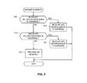
- the machine accessible instructions of FIG. 5begin when a border element (e.g., any of the example access border elements 120 and 121 and/or any of the example peered border elements 210 - 213 of FIGS. 1 and/or 2 ) receives a SIP message (e.g., from a VoIP device and/or an IMS core element, such as a CSCF server). If the received SIP message is a SIP REGISTER message addressed to a shared IP address (e.g., the example shared IP address 315 of FIG.
- the border elemente.g., the example media path redirector 135
- the border elementresponds by sending a SIP 3xx MOVED message that contains a unique IP address (e.g., the example unique IP address 320 ) (block 510 ). Control then exits from the example machine accessible instructions of FIG. 5 .
- the border elemente.g., the example media path redirector 135
- the border elementresponds by sending a SIP 3xx MOVED message that contains a unique IP address (e.g., the example unique IP address 320 ) (block 520 ). Control then exits from the example machine accessible instructions of FIG. 5 .
- the border elementperforms appropriate processing and/or handling of the received SIP message (block 525 ). Control then exits from the example machine accessible instructions of FIG. 5 .
- FIG. 6is a schematic diagram of an example processor platform 600 that may be used and/or programmed to implement all or a portion of any or all of the example VoIP devices 105 and/or 106 , and/or any or all of the example border elements 120 , 121 and/or 210 - 213 of FIGS. 1 and/or 2 .
- the processor platform 600can be implemented by one or more general purpose processors, processor cores, microcontrollers, etc.
- the processor platform 600 of the example of FIG. 6includes at least one general purpose programmable processor 605 .
- the processor 605executes coded instructions 610 and/or 612 present in main memory of the processor 605 (e.g., within a random-access memory (RAM) 615 and/or a read-only memory (ROM) 620 ).
- the processor 605may be any type of processing unit, such as a processor core, a processor and/or a microcontroller.
- the processor 605may execute, among other things, the example protocol message exchanges and/or the example machine accessible instructions of FIGS. 4 and/or 5 to implement the example methods and apparatus described herein.
- the processor 605is in communication with the main memory (including a ROM 620 and/or the RAM 615 ) via a bus 625 .
- the RAM 615may be implemented by DRAM, SDRAM, and/or any other type of RAM device, and ROM may be implemented by flash memory and/or any other desired type of memory device. Access to the memory 615 and 620 may be controlled by a memory controller (not shown).
- the processor platform 600also includes an interface circuit 630 .
- the interface circuit 630may be implemented by any type of interface standard, such as an external memory interface, serial port, general purpose input/output, etc.
- One or more input devices 635 and one or more output devices 640are connected to the interface circuit 630 .
- the input devices 635 and/or output devices 640may be used to, for example, implement the example interfaces 305 and 310 of FIG. 3 .
- At least some of the above described example methods and/or apparatusare implemented by one or more software and/or firmware programs running on a computer processor.
- dedicated hardware implementationsincluding, but not limited to, an ASIC, programmable logic arrays and other hardware devices can likewise be constructed to implement some or all of the example methods and/or apparatus described herein, either in whole or in part.
- alternative software implementationsincluding, but not limited to, distributed processing or component/object distributed processing, parallel processing, or virtual machine processing can also be constructed to implement the example methods and/or apparatus described herein.
- a tangible storage mediumsuch as: a magnetic medium (e.g., a disk or tape); a magneto-optical or optical medium such as a disk; or a solid state medium such as a memory card or other package that houses one or more read-only (non-volatile) memories, random access memories, or other re-writable (volatile) memories; or a signal containing computer instructions.
- a digital file attachment to e-mail or other self-contained information archive or set of archivesis considered a distribution medium equivalent to a tangible storage medium.
- the example software and/or firmware described hereincan be stored on a tangible storage medium or distribution medium such as those described above or equivalents and successor media.
Landscapes
- Engineering & Computer Science (AREA)
- Computer Networks & Wireless Communication (AREA)
- Signal Processing (AREA)
- Telephonic Communication Services (AREA)
- Data Exchanges In Wide-Area Networks (AREA)
Abstract
Description
This disclosure relates generally to voice over Internet protocol (VoIP) networks and, more particularly, to methods and apparatus to select a VoIP border element.
Traditionally, each voice over Internet protocol (VoIP)-based devices (e.g., smart telephones, personal digital assistants, etc.) is configured with a VoIP border element (e.g., a VoIP proxy and/or a session border controller) that is responsible for routing signaling and/or media to, from and/or on behalf the VoIP device. However, when a VoIP-based device is moved (e.g., a roaming subscriber using a mobile VoIP device) and, thus, accesses a VoIP network from a different geographic location from where the VoIP device was when provisioned, a static VoIP proxy configuration may result in sub-optimal media paths, inefficient network utilization and/or increased probabilities of poor communication session quality.
Methods and apparatus to select a voice over Internet protocol (VoIP) border element are disclosed. A disclosed example method includes sending a first session initiation protocol (SIP) protocol message from a first voice over Internet protocol (VoIP) device, the first SIP message comprising an Internet protocol (IP) address shared by at least two VoIP border elements, and receiving a second SIP message at the first VoIP device from a second VoIP device, the second SIP message comprising a unique address for the second VoIP device, the second VoIP device to be selected based on the shared IP address.
A disclosed example voice over Internet protocol (VoIP) border element includes a network interface to receive a first session initiation protocol (SIP) protocol message, the first SIP message comprising an Internet protocol (IP) address shared by at least two VoIP border elements, and a media path redirector to respond to the first SIP message with a second SIP message, the second SIP message comprising a unique address for the VoIP border element.
A disclosed example voice over Internet protocol (VoIP) system of a first service provider includes an access border to receive a first session initiation protocol (SIP) INVITE message from a VoIP user device, the SIP INVITE message comprising a called party identifier associated with a second service provider, and a call session control function (CSCF) server to send a second SIP INVITE message in response to the first SIP INVITE message, the second SIP INVITE message comprising an Internet protocol (IP) message shared by two or more peered border elements.
In the interest of brevity and clarity, throughout the following disclosure references will be made to the example Internet protocol (IP) Multimedia subsystem (IMS) based voice over IP (VoIP) communication systems ofFIGS. 1 and/or 2 . Moreover, the following disclosure will be made using session initiation protocol (SIP) messages and/or SIP-based message exchanges. However, it should be understood that the methods and apparatus described herein to select VoIP border elements are applicable to other VoIP communication systems and/or networks (e.g., networks based on soft switches), VoIP devices, IMS devices, feature servers, tElephone NUMber mapping (ENUM) servers, border elements, access networks, IP networks, IMS networks and/or IMS communication systems, and/or other types of protocols, messages, and/or message exchanges.
To provide communication services, the example IMS based VoIP communication system ofFIG. 1 includes one or more IMS networks, one of which is designated inFIG. 1 withreference numeral 110. The example IMSnetwork 110 ofFIG. 1 provides and/or enables IMS communication services (e.g., telephone services, Internet services, data services, messaging services, instant messaging services, electronic mail (email) services, chat services, video services, audio services, gaming services, voicemail, facsimile services, etc.) to theexample VoIP devices example IMS network 110 ofFIG. 1 includes any number and/or type(s) ofIMS core elements 115. ExampleIMS core elements 115 include, but are not limited to, one or more of a call session control function (CSCF) server (e.g., proxy, interrogating, serving and/or otherwise), an ENUM server, a feature server, an application server, a DNS serves, a home subscriber serves (HSSs), a media gateway, a breakout gateway control function (BGCF) sever, a media gateway control function (MGCF) server, a softswitch, an IP router, an IP switch, etc.
To provide entry and/or exits points to theexample IMS network 110, theexample IMS network 110 ofFIG. 1 includes any number of access border elements, two of which are designated atreference numerals access border elements FIG. 1 implement boundary points between a) one or more private networks used to implement theexample IMS network 110, and b) one or more public networks (e.g., the Internet), one or more private networks (e.g., home and/or corporate local area networks) and/or one or more access networks by which theexample VoIP devices example border elements FIG. 1 ,border element 120 is an east coast border element andborder element 121 is a west coast border element. In some examples, the exampleaccess border elements access border elements FIG. 1 is described below in connection withFIG. 3 .
In many IMS networks, access border elements are geographically located with an IMS network to provide geographically separate entry and/or exit points for the IMS network. Traditionally, a VoIP device is assigned to (e.g., provisioned with a specific IP address for) a particular access border element based on its geographic locations when IMS services to the VoIP device were provisioned. For example, a VoIP device located on the west coast of the United States (a so-called west coast VoIP device) would be provisioned with the IP address of an access border element located on the west coast of the United States (a so-called west coast access border element). That is, the VoIP device provisioned as such receives its IMS network access through the west coast border element. Likewise, an east coast VoIP device would traditionally be provisioned with the IP address of an east coast access border element and would obtain its network connectivity there through.
When a traditionally provisioned VoIP device is moved (e.g., is associated with a roaming subscriber), the VoIP device still accesses the IMS network via its statically provisioned IP address of its assigned access border element. For example, a west coast VoIP device that is currently located on the east cost accesses an IMS network via its assigned west coast access border element. Further, when the roaming traditional VoIP device attempts to contact an east coast VoIP device, the signaling and/or media associated with the roaming VoIP device has to be transported cross-country from the roaming west coast VoIP device that is now roaming on the east coast to the west coast border element, and then back across the United States via the IMSnetwork 110 to the east coast border element and the east coast VoIP device. In addition to consuming unnecessary communication resources, such traditional communication sessions may experience excessive latencies and/or provide lower communication session quality.
In contrast, in the illustrated example ofFIG. 1 , when the example westcoast VoIP device 105 ofFIG. 1 is provisioned it is configured with anIP address 130 that is shared by the west coastaccess border element 121 and the east coastaccess border element 120. An example shared IP address is an IP anycast address. When using IP anycast addresses, multiple machines (e.g., access border elements) are configured with an identical shared address, and IP routers and/or switches are configured and/or provisioned with routing tables that allow the routers and/or switches to route IP data addressed to the IP anycast address. When traffic is directed to an anycast address, the IP routers and/or switches perform IP anycast routing to select a path, from several potentially valid paths, to forward the traffic. Ultimately, data addressed to an IP anycast address is only received by one destination (e.g., one access border element). In many instances, the destination will be associated with a preferable (e.g., smallest) IP routing metric. For example, the destination that is geographically closest to a sender, that results in the least transmission latency, number of hops, a media path length, a media path cost, or a number of servers traversed, etc. may be selected.
When the example westcoast VoIP device 105 attempts to, for example, register with theexample IMS network 110, the westcoast VoIP device 105 transmits aSIP REGISTER message 131 using the shared IP address of theaccess border elements VoIP device 105 to theaccess border elements VoIP device 105 to a preferredaccess border element access border elements 120,121 (e.g., to theaccess border element FIG. 1 , the roaming westcoast VoIP device 105 is closest to the eastcoast border element 120 and, thus, the east coastaccess border element 120 receives theSIP REGISTER message 131 from theVoIP device 105 via the shared IP address. Amedia path redirector 135 at the example eastcoast border element 120 responds to theSIP REGISTER message 131 with aSIP message 132 that provides to the roaming westcoast VoIP device 105 the specific and/or unique IP address of the eastcoast border element 120. In the illustrated example, themedia path redirector 135 ofFIG. 1 sends a SIP3xx MOVED message 132 to theVoIP device 105 to provide the unique IP address of the eastcoast border element 120. However, any other SIP message(s) may be used. The example westcoast border element 121 ofFIG. 1 also includes and/or implements amedia path redirector 135. However, not all access border elements need include and/or implement amedia path redirector 135.
When the example roaming westcoast VoIP device 105 ofFIG. 1 receives the SIP3xx MOVED message 132, theVoIP device 105 retransmits theSIP REGISTER message 133 using the received unique IP address of the eastcoast border element 120, and uses the unique IP address for subsequent communications with theIMS network 110. As illustrated inFIG. 1 subsequent signaling 140 associated with theVoIP device 105 are exchanged via the eastcoast border element 120. Moreover, the example eastcoast border element 120 ofFIG. 1 provides a media anchoring point for amedia stream 145 received from and/or directed to the westcoast VoIP device 105.
As illustrated inFIG. 1 , thesignaling path 140 and/or themedia path 145 are substantially shorter than the example communication path125. As such, the example IMS-based VoIP communication system ofFIG. 1 utilizes substantially less communication resources to implement a given communication session than traditional IMS networks. Moreover, the illustrated example ofFIG. 1 implements communication sessions having lower latencies and/or higher communication session qualities.
The example VoIPservice provider networks FIG. 2 are communicatively coupled via any number of pairs of peered border elements. A first pair of peered border elements is designated inFIG. 2 withreference numerals 210 and211, and a second pair of peered border elements is designated withreference numerals border elements service provider networks FIG. 2 is described below in connection withFIG. 2 . In general, a platform used to implement anaccess border element 120,208 may be configured to, additionally or alternatively, implement a peered border element210-213.
When a communication session is initiated from theVoIP device 105 to theVoIP device 106 associated with theservice provider network 206, theservice provider network 205, which is associated with the initiatingVoIP device 105, must choose a peeredborder element peered border element border elements other service provider 206. An example shared IP address is an IP anycast address. When theexample VoIP device 105 sends aSIP INVITE message 221 to initiate the communication session to theVoIP device 106, the IMS core elements115 (e.g., a CSCF server220) determines whether the calleddevice 106 is associated with anotherservice provider 206. When the calleddevice 106 is associated with anotherservice provider 206, theIMS core elements 115 forwards aSIP INVITE message 222 to the shared IP address of the peeredborder elements peered border element border elements 210 and212 (e.g., the peeredborder element
A media path redirector135 at the selected peeredborder element SIP INVITE message 222 with aSIP message 223 that provides to theIMS core elements 115 and/or theaccess border element 120 the specific and/or unique IP address of the selected peeredborder element FIG. 2 sends a SIP 3xx MOVEDmessage 223 to provide the unique IP address of the selected peeredborder element border elements 211,213 may also include and/or implement amedia path redirector 135. Moreover, theexample service provider 205 may use IP anycast routing to select a peeredborder element service provider 206 does not.
When the exampleIMS core elements 115 ofFIG. 2 receives the SIP 3xx MOVEDmessage 223 from the selected peeredborder element border element device 105 and the calledVoIP device 106. Likewise, the exampleaccess border element 120 uses the unique IP address to implement a media anchoring point for amedia stream 230 between theVoIP devices
To obtain the shared IP address of the peeredborder elements service provider 206 of the calleddevice 106, the example IMS core elements115 (e.g., the example CSCF server220) perform an ENUM query based on a called party identifier (e.g., an E.164 telephone number) of the calledparty 106 to obtain a fully-qualified domain name (FQDN). TheIMS core elements 115 then perform a DNS lookup based on the FQDN to obtain the shared IP address. In some examples, the IMS core elements cache an association of the shared IP address to the unique IP address returned in a subsequent SIP 3xx MOVED message. When the age of a cache entry associated with the shared IP address is less than a threshold (e.g., sixty seconds), theIMS core elements 115 forward the SIP INVITE message to the unique IP address of the peeredborder element service provider network 205 may be reduced.
The exampleaccess border elements FIG. 2 may also include a media path redirector135 (e.g., as discussed above in connection withFIG. 1 ). When both theaccess border elements border elements service provider network 205 is capable to select the preferredaccess border element VoIP device 105, and to select a preferredpeered border element VoIP device 106 of theservice provider 206. However, the IP address used to select the preferredaccess border element border element
While example IMS-based VoIP communication systems have been illustrated inFIGS. 1 and 2 , the devices, networks, systems, servers and/or processors illustrated inFIGS. 1 and 2 may be combined, divided, re-arranged, eliminated and/or implemented in any way. For example, it will be readily appreciated by persons of ordinary skill in the art that theexample border elements IMS core elements 115, the example media path redirectors135, the example peered border elements210-213 illustrated inFIGS. 1 and 2 are logical entities. They may, therefore, be implemented separately and/or in any combination using, for example, machine accessible instructions executed by one or more computing devices and/or computing platforms (e.g., theexample processing platform 600 ofFIG. 6 ). Further, theexample VoIP devices example border elements IMS core elements 115, the example media path redirectors135, the example peered border elements210-213 and/or, more generally, theexample IMS networks example IMS networks FIGS. 1 and 2 , and/or may include more than one of any or all of the illustrated devices, servers, networks, systems, gateways, portals, and/or processors.
As illustrated inFIG. 3 , theexample border element 120 is provisioned with a sharedIP address 315 and aunique IP address 320. As described above, the sharedIP address 315 is shared with other similarly configured border elements. For example, all access border elements of a particular IMS network may be provisioned with the same sharedIP address 315. Likewise, all peered border elements capable to perform VoIP peering with a particular VoIP service provider may be provisioned with the same sharedIP address 315. If a border element is configured to operate as both an access border element and a peered border element, it may be provisioned with respective shared IP addresses315. The exampleunique IP address 320 ofFIG. 3 is specific to theborder element 120 and, thus, may be used to address and/or direct IP data directly to theborder element 120.
To re-direct media paths, theexample border element 120 ofFIG. 3 includes amedia path redirector 135. When the example media path redirector135 ofFIG. 3 receives a SIP message (e.g., a SIP REGISTER and/or a SIP INVITE message) addressed to its sharedIP address 315, the media path redirector135 responds with a SIP message that provides the exampleunique IP address 320. An example SIP message to provide theunique IP address 320 is the SIP 3xx MOVED message. However, any applicable SIP message(s) may be used. Example machine accessible instructions that may be used to implement the example media path redirector135 are described below in connection withFIG. 5 .
While an example manner of implementing any or all of the exampleaccess border elements border elements FIGS. 1 and/or 2 has been illustrated inFIG. 3 , one or more of the interfaces, data structures, elements, processes and/or devices illustrated inFIG. 3 may be combined, divided, re-arranged, omitted, eliminated and/or implemented in any other way. For example, the media path redirector135 may be implemented by modifying and/or enhancing a traditional and/or existing border element by the addition of one or more functions of the examplemedia path redirector 135. Further, the example interfaces305 and310, the example media path redirector135 and/or, more generally, theexample border element 120 ofFIG. 3 may be implemented by hardware, software, firmware and/or any combination of hardware, software and/or firmware. Further still, a border element may include interfaces, data structures, elements, processes and/or devices instead of, or in addition to, those illustrated inFIG. 3 and/or may include more than one of any or all of the illustrated interfaces, data structures, elements, processes and/or devices. For example, the S-CSCF 145 may include and/or implement one or more additional capabilities, such as call admission control, denial of service handling, and/or SIP message header manipulation.
The example machine accessible instructions ofFIGS. 4 and/or 5 may be carried out by a processor, a controller and/or any other suitable processing device. For example, the example machine accessible instructions ofFIGS. 4 and/or 5 may be embodied in coded instructions stored on a tangible medium such as a flash memory, a ROM and/or RAM associated with a processor (e.g., theexample processor 605 discussed below in connection withFIG. 6 ). Alternatively, some or all of the example machine accessible instructions ofFIGS. 4 and/or 5 may be implemented using any combination(s) of application specific integrated circuit(s) (ASIC(s)), programmable logic device(s) (PLD(s)), field programmable logic device(s) (FPLD(s)), discrete logic, hardware, firmware, etc. Also, some or all of the example machine accessible instructions ofFIGS. 4 and/or 5 may be implemented manually or as any combination of any of the foregoing techniques, for example, any combination of firmware, software, discrete logic and/or hardware. Further, although the example machine accessible instructions ofFIGS. 4 and 5 are described with reference to the flowcharts ofFIGS. 4 and 5 , persons of ordinary skill in the art will readily appreciate that many other methods of implementing the example operations ofFIGS. 4 and 5 may be employed. For example, the order of execution of the blocks may be changed, and/or one or more of the blocks described may be changed, eliminated, sub-divided, or combined. Additionally, persons of ordinary skill in the art will appreciate that any or all of the example machine accessible instructions ofFIGS. 4 and/or 5 may be carried out sequentially and/or carried out in parallel by, for example, separate processing threads, processors, devices, discrete logic, circuits, etc.
The example machine accessible instructions ofFIG. 4 begin when a VoIP device (e.g., any of theexample VoIP devices 105 and/or106 ofFIGS. 1 and/or 2 ) is, for example, powered-on and/or restarted. The VoIP device (e.g., a SIP user agent of the VoIP device sends a SIP REGISTER message to its provisioned access border element IP address (block405). As described above, the provisioned IP address may be an IP address shared by one or more access border elements (e.g., the example shared IP address130), or a unique IP address of a particular access border element. If the SIP user agent receives a SIP message containing a unique IP address of an access border element (e.g., a SIP 3xx MOVED message) (block310), the SIP user agent sends another SIP REGISTER message to the unique IP address (block315). The SIP user agent completes the registration process (block320), and control exits from the example machine accessible instructions ofFIG. 4 .
Returning to block310, if the SIP user agent does not receive a SIP message containing a unique IP address (block310), control proceeds to block320 without resending the SIP REGISTER message. The SIP user agent completes the registration process (block320), and control exits from the example machine accessible instructions ofFIG. 4 .
The machine accessible instructions ofFIG. 5 begin when a border element (e.g., any of the exampleaccess border elements FIGS. 1 and/or 2 ) receives a SIP message (e.g., from a VoIP device and/or an IMS core element, such as a CSCF server). If the received SIP message is a SIP REGISTER message addressed to a shared IP address (e.g., the example sharedIP address 315 ofFIG. 3 ) of the border element (block505), the border element (e.g., the example media path redirector135) responds by sending a SIP 3xx MOVED message that contains a unique IP address (e.g., the example unique IP address320) (block510). Control then exits from the example machine accessible instructions ofFIG. 5 .
If the received SIP message is a SIP INVITE message addressed to a shared IP address (e.g., the example sharedIP address 315 ofFIG. 3 ) of the border element (block515), the border element (e.g., the example media path redirector135) responds by sending a SIP 3xx MOVED message that contains a unique IP address (e.g., the example unique IP address320) (block520). Control then exits from the example machine accessible instructions ofFIG. 5 .
If the receive SIP message is not a SIP INVITE or a SIP REGISTER addressed to a shared IP address (block515), the border element performs appropriate processing and/or handling of the received SIP message (block525). Control then exits from the example machine accessible instructions ofFIG. 5 .
Theprocessor platform 600 of the example ofFIG. 6 includes at least one general purposeprogrammable processor 605. Theprocessor 605 executes codedinstructions 610 and/or612 present in main memory of the processor605 (e.g., within a random-access memory (RAM)615 and/or a read-only memory (ROM)620). Theprocessor 605 may be any type of processing unit, such as a processor core, a processor and/or a microcontroller. Theprocessor 605 may execute, among other things, the example protocol message exchanges and/or the example machine accessible instructions ofFIGS. 4 and/or 5 to implement the example methods and apparatus described herein.
Theprocessor 605 is in communication with the main memory (including aROM 620 and/or the RAM615) via abus 625. TheRAM 615 may be implemented by DRAM, SDRAM, and/or any other type of RAM device, and ROM may be implemented by flash memory and/or any other desired type of memory device. Access to thememory
Theprocessor platform 600 also includes aninterface circuit 630. Theinterface circuit 630 may be implemented by any type of interface standard, such as an external memory interface, serial port, general purpose input/output, etc. One ormore input devices 635 and one ormore output devices 640 are connected to theinterface circuit 630. Theinput devices 635 and/oroutput devices 640 may be used to, for example, implement the example interfaces305 and310 ofFIG. 3 .
Of course, persons of ordinary skill in the art will recognize that the order, size, and proportions of the memory illustrated in the example systems may vary. Additionally, although this patent discloses example systems including, among other components, software or firmware executed on hardware, it will be noted that such systems are merely illustrative and should not be considered as limiting. For example, it is contemplated that any or all of these hardware and software components could be embodied exclusively in hardware, exclusively in software, exclusively in firmware or in some combination of hardware, firmware and/or software. Accordingly, persons of ordinary skill in the art will readily appreciate that the above described examples are not the only way to implement such systems.
At least some of the above described example methods and/or apparatus are implemented by one or more software and/or firmware programs running on a computer processor. However, dedicated hardware implementations including, but not limited to, an ASIC, programmable logic arrays and other hardware devices can likewise be constructed to implement some or all of the example methods and/or apparatus described herein, either in whole or in part. Furthermore, alternative software implementations including, but not limited to, distributed processing or component/object distributed processing, parallel processing, or virtual machine processing can also be constructed to implement the example methods and/or apparatus described herein.
It should also be noted that the example software and/or firmware implementations described herein are optionally stored on a tangible storage medium, such as: a magnetic medium (e.g., a disk or tape); a magneto-optical or optical medium such as a disk; or a solid state medium such as a memory card or other package that houses one or more read-only (non-volatile) memories, random access memories, or other re-writable (volatile) memories; or a signal containing computer instructions. A digital file attachment to e-mail or other self-contained information archive or set of archives is considered a distribution medium equivalent to a tangible storage medium. Accordingly, the example software and/or firmware described herein can be stored on a tangible storage medium or distribution medium such as those described above or equivalents and successor media.
To the extent the above specification describes example components and functions with reference to particular devices, standards and/or protocols, it is understood that the teachings of the invention are not limited to such devices, standards and/or protocols. Such systems are periodically superseded by faster or more efficient systems having the same general purpose. Accordingly, replacement devices, standards and/or protocols having the same general functions are equivalents which are intended to be included within the scope of the accompanying claims.
Although certain example methods, apparatus and articles of manufacture have been described herein, the scope of coverage of this patent is not limited thereto. On the contrary, this patent covers all methods, apparatus and articles of manufacture fairly falling within the scope of the appended claims either literally or under the doctrine of equivalents.
Claims (26)
1. A method comprising:
sending a first session initiation protocol message from a first voice over Internet protocol device at a first time, the first session initiation protocol message including an Internet protocol address shared by at least two border elements; and
receiving a second session initiation protocol message at the first voice over Internet protocol device from a first one of the at least two border elements at a second time, the first border element being selected based on the shared Internet protocol address at the first time, the second session initiation protocol message including
a unique address for the first border element in place of the shared address when the second session initiation protocol message occurs during a first threshold period after the first time, and
the second session initiation protocol message including the shared address when the second session initiation protocol message occurs after the first threshold period.
2. A method as defined inclaim 1 , further including performing Internet protocol anycast routing to select the first one of the at least two border elements.
3. A method as defined inclaim 1 , further including selecting the first border element to reduce a latency associated with a communication path requested via the first session initiation protocol message.
4. A method as defined inclaim 1 , wherein the first border element is selected based on a minimum routing metric.
5. A method as defined inclaim 4 , wherein the minimum routing metric includes at least one of a geographic distance, a media path length, a media path cost, or a number of servers traversed.
6. A method as defined inclaim 1 , wherein the first session initiation protocol message includes a SIP REGISTER message.
7. A method as defined inclaim 1 , further including registering with an Internet protocol Multimedia Sub-system network based on the unique address.
8. A method as defined inclaim 1 , wherein the first session initiation protocol message includes a SIP INVITE message.
9. A method as defined inclaim 1 , further including initiating a communication session to a called party based on the unique address.
10. A method as defined inclaim 1 , wherein the second session initiation protocol message includes a SIP 3xx MOVED message.
11. A method as defined inclaim 1 , wherein the first voice over Internet protocol device includes a voice over Internet protocol endpoint, and the first one of the at least two border elements includes a voice over Internet protocol access border gateway.
12. A method as defined inclaim 1 , wherein the first voice over Internet protocol device includes an access border element, and the first one of the at least two border elements includes a voice over Internet protocol peered border gateway.
13. A method as defined inclaim 1 , wherein the shared Internet protocol address includes an Internet protocol anycast address.
14. A method as defined inclaim 1 , further including:
querying a telephone number mapping database to obtain a fully qualified domain name associated with a called device; and
querying a domain name service server to obtain the shared Internet protocol address based on the fully qualified domain name.
15. An apparatus comprising:
a memory having machine readable instructions stored thereon; and
a processor to execute the instructions to:
respond to a first session initiation protocol message sent at a first time with a second session initiation protocol message at a second time, the first session initiation protocol message including an Internet protocol address shared by at least two border elements, the second session initiation protocol message including
a unique address for a first one of the at least two border elements in place of the shared Internet protocol address when the second session initiation protocol message occurs during a first threshold period after the first time, and
the second session initiation protocol message including the shared address when the second session initiation protocol message occurs after the first threshold period.
16. An apparatus as defined inclaim 15 , wherein the second session initiation protocol message includes a SIP 3xx MOVED message.
17. An apparatus as defined inclaim 15 , wherein the shared Internet protocol address includes an Internet protocol anycast address.
18. An apparatus as defined inclaim 15 , wherein one of the at least two border elements include an access border element.
19. An apparatus as defined inclaim 15 , wherein one of the at least two border elements include a peered border element.
20. An apparatus as defined inclaim 15 , further including a second network interface to a private Internet protocol network, and the network interface includes an interface to a public Internet protocol network.
21. A tangible machine readable storage device comprising instructions that, when executed, cause a machine to, at least:
send a first session initiation protocol message at a first time, the first session initiation protocol message including an Internet protocol address shared by at least two border elements; and
receive a second session initiation protocol message from a first one of the at least two border elements at a second time, the second session initiation protocol message including
a unique address for the first border element in place of the shared address when the second session initiation protocol message occurs during a first threshold period after the first time, and
the second session initiation protocol message including the shared address when the second session initiation protocol message occurs after the first threshold period.
22. A tangible machine readable storage device as defined inclaim 21 , wherein the first session initiation protocol message includes at least one of a SIP REGISTER message or a SIP INVITE message, and the second session initiation protocol message includes a SIP 3xx MOVED message.
23. A tangible machine readable storage device as defined inclaim 21 , wherein the instructions, when executed, cause the machine to register with an Internet protocol Multimedia Sub-system network based on the unique address.
24. A tangible machine readable storage device as defined inclaim 21 , wherein the first voice over Internet protocol device includes a voice over Internet protocol endpoint, and the first border element includes a voice over Internet protocol access border gateway.
25. A tangible machine readable storage device as defined inclaim 21 , wherein the shared Internet protocol address includes an Internet protocol anycast address.
26. A tangible machine readable storage device as defined inclaim 21 , wherein the instructions, when executed, cause the machine to:
query a telephone number mapping database to obtain a fully qualified domain name associated with a called device; and
query a domain name service server to obtain the shared Internet protocol address based on the fully qualified domain name.
Priority Applications (1)
| Application Number | Priority Date | Filing Date | Title |
|---|---|---|---|
| US11/842,720US10063392B2 (en) | 2007-08-21 | 2007-08-21 | Methods and apparatus to select a voice over internet protocol (VOIP) border element |
Applications Claiming Priority (1)
| Application Number | Priority Date | Filing Date | Title |
|---|---|---|---|
| US11/842,720US10063392B2 (en) | 2007-08-21 | 2007-08-21 | Methods and apparatus to select a voice over internet protocol (VOIP) border element |
Publications (2)
| Publication Number | Publication Date |
|---|---|
| US20090052434A1 US20090052434A1 (en) | 2009-02-26 |
| US10063392B2true US10063392B2 (en) | 2018-08-28 |
Family
ID=40382068
Family Applications (1)
| Application Number | Title | Priority Date | Filing Date |
|---|---|---|---|
| US11/842,720Active2034-02-05US10063392B2 (en) | 2007-08-21 | 2007-08-21 | Methods and apparatus to select a voice over internet protocol (VOIP) border element |
Country Status (1)
| Country | Link |
|---|---|
| US (1) | US10063392B2 (en) |
Families Citing this family (8)
| Publication number | Priority date | Publication date | Assignee | Title |
|---|---|---|---|---|
| US7664124B2 (en)* | 2005-05-31 | 2010-02-16 | At&T Intellectual Property, I, L.P. | Methods, systems, and products for sharing content |
| US8520663B2 (en) | 2008-02-26 | 2013-08-27 | At&T Intellectual Property I, L. P. | Systems and methods to select peered border elements for an IP multimedia session based on quality-of-service |
| KR101274366B1 (en)* | 2008-09-30 | 2013-06-13 | 노키아 코포레이션 | Method and apparatus for address book contact management |
| US8874668B2 (en)* | 2011-06-10 | 2014-10-28 | Microsoft Corporation | Directing messages based on domain names |
| US10250695B2 (en)* | 2013-03-14 | 2019-04-02 | Comcast Cable Communications, Llc | Mitigation of processing loops in a communication network |
| US9973544B2 (en) | 2015-12-10 | 2018-05-15 | At&T Intellectual Property I, L.P. | Method and apparatus for enhancing inter-carrier communications |
| US11695826B2 (en)* | 2017-08-14 | 2023-07-04 | Comcast Cable Communications, Llc | Assignment of processing resource based on session data |
| US11838262B1 (en)* | 2022-11-30 | 2023-12-05 | Cujo LLC | Discovery of FQDN for target website |
Citations (56)
| Publication number | Priority date | Publication date | Assignee | Title |
|---|---|---|---|---|
| US20020004846A1 (en)* | 2000-04-28 | 2002-01-10 | Garcia-Luna-Aceves J. J. | System and method for using network layer uniform resource locator routing to locate the closest server carrying specific content |
| US20020016860A1 (en)* | 2000-04-28 | 2002-02-07 | Garcia-Luna-Aceves J. J. | System and method for resolving network layer anycast addresses to network layer unicast addresses |
| US20020075881A1 (en)* | 2000-12-18 | 2002-06-20 | Yoakum John H. | Transaction management for interworking between disparate networks |
| US6426955B1 (en) | 1997-09-16 | 2002-07-30 | Transnexus, Inc. | Internet telephony call routing engine |
| US20030079027A1 (en) | 2001-10-18 | 2003-04-24 | Michael Slocombe | Content request routing and load balancing for content distribution networks |
| US20030117954A1 (en) | 2001-12-20 | 2003-06-26 | Alcatel | Telecommunications system employing virtual service network architecture |
| US20030182410A1 (en)* | 2002-03-20 | 2003-09-25 | Sapna Balan | Method and apparatus for determination of optimum path routing |
| US20030200307A1 (en) | 2000-03-16 | 2003-10-23 | Jyoti Raju | System and method for information object routing in computer networks |
| US20040146045A1 (en) | 2002-11-13 | 2004-07-29 | Kabushiki Kaisha Toshiba | Communication scheme for preventing attack by pretending in service using anycast |
| US20040210670A1 (en) | 1999-03-05 | 2004-10-21 | Nikolaos Anerousis | System, method and apparatus for network service load and reliability management |
| US20050010653A1 (en) | 1999-09-03 | 2005-01-13 | Fastforward Networks, Inc. | Content distribution system for operation over an internetwork including content peering arrangements |
| US6856991B1 (en) | 2002-03-19 | 2005-02-15 | Cisco Technology, Inc. | Method and apparatus for routing data to a load balanced server using MPLS packet labels |
| US20050044141A1 (en) | 2001-02-19 | 2005-02-24 | Heino Hameleers | Method and system for multiple hosts anycast routing |
| US20050058125A1 (en) | 2003-09-11 | 2005-03-17 | Nokia Corporation | IP-based services for circuit-switched networks |
| US20050083912A1 (en) | 2003-10-16 | 2005-04-21 | At&T Corp. | Method and apparatus for functional architecture of voice-over-IP SIP network border element |
| US6914886B2 (en) | 2001-05-03 | 2005-07-05 | Radware Ltd. | Controlling traffic on links between autonomous systems |
| US20050190746A1 (en)* | 2004-02-27 | 2005-09-01 | Innomedia Pte Ltd. | Band signal detection and presentation for IP phone |
| US20050223095A1 (en)* | 2002-04-08 | 2005-10-06 | Bernie Volz | Method and system for enabling connections into networks with local address realms |
| US20060003734A1 (en)* | 2004-06-30 | 2006-01-05 | Nokia Corporation | Charging in a communication system |
| US20060013147A1 (en)* | 2004-05-03 | 2006-01-19 | Level 3 Communications, Inc. | Registration redirect server |
| US20060064478A1 (en) | 2004-05-03 | 2006-03-23 | Level 3 Communications, Inc. | Geo-locating load balancing |
| US7047315B1 (en) | 2002-03-19 | 2006-05-16 | Cisco Technology, Inc. | Method providing server affinity and client stickiness in a server load balancing device without TCP termination and without keeping flow states |
| US20060112170A1 (en) | 2004-05-03 | 2006-05-25 | Craig Sirkin | Geo-locating load balancing |
| US20060133356A1 (en)* | 2004-11-30 | 2006-06-22 | Kabushiki Kaisha Toshiba | Network telephone system |
| US20060146792A1 (en) | 2004-12-31 | 2006-07-06 | Sridhar Ramachandran | Voice over IP (VOIP) network infrastructure components and method |
| US20060159100A1 (en) | 2004-12-13 | 2006-07-20 | Droms Ralph E | Use of IPv6 in access networks |
| US20060165064A1 (en) | 2004-10-26 | 2006-07-27 | Brown John C | Method and apparatus for a network element to track the availability of other network elements |
| US7088718B1 (en) | 2002-03-19 | 2006-08-08 | Cisco Technology, Inc. | Server load balancing using IP option field approach to identify route to selected server |
| US20060190746A1 (en)* | 2005-02-24 | 2006-08-24 | Boerstler David W | System and method for automatic calibration of a reference voltage |
| US20060209851A1 (en) | 2005-03-04 | 2006-09-21 | John Scudder | Method and apparatus for border gateway protocol route management and routing policy modeling |
| US20060233158A1 (en) | 2005-04-19 | 2006-10-19 | Marian Croak | Method and apparatus for enabling peer-to-peer communication between endpoints on a per call basis |
| US20060233159A1 (en) | 2005-04-19 | 2006-10-19 | Marian Croak | Method and apparatus for enabling dynamic protocol interworking resolution with diverse endpoints |
| US7145898B1 (en) | 1996-11-18 | 2006-12-05 | Mci Communications Corporation | System, method and article of manufacture for selecting a gateway of a hybrid communication system architecture |
| US20070019619A1 (en) | 2005-07-22 | 2007-01-25 | Cisco Technology, Inc. | System and method for optimizing communications between session border controllers and enpoints in a network environment |
| US20070022479A1 (en)* | 2005-07-21 | 2007-01-25 | Somsubhra Sikdar | Network interface and firewall device |
| US20070019623A1 (en) | 2005-07-20 | 2007-01-25 | Mci, Inc. | Method and system for providing secure media gateways to support interdomain traversal |
| US20070025279A1 (en)* | 2005-07-14 | 2007-02-01 | Samsung Electronics Co., Ltd. | Apparatus and method for providing VoIP service based on IP multimedia subsystem |
| US20070036143A1 (en) | 2004-08-13 | 2007-02-15 | Alt Wade R | Method and system for providing voice over IP managed services utilizing a centralized data store |
| US20070036151A1 (en) | 2005-08-09 | 2007-02-15 | Alcatel | Voice over IP network architecture |
| US7180864B2 (en) | 2002-02-27 | 2007-02-20 | Lucent Technologies Inc. | Method and apparatus for exchanging routing information within an autonomous system in a packet-based data network |
| US7180912B1 (en) | 2003-01-06 | 2007-02-20 | At&T Corp. | System and method for providing a plurality of multi-media services using a number of media servers to form a preliminary interactive communication relationship with a calling communication device |
| US20070047446A1 (en) | 2005-08-30 | 2007-03-01 | Mitesh Dalal | Method and apparatus for updating best path based on real-time congestion feedback |
| US20070058629A1 (en) | 2005-09-09 | 2007-03-15 | Luft Siegfried J | Application driven fast unicast flow replication |
| US20070061397A1 (en) | 2005-07-29 | 2007-03-15 | Mci, Llc | Routing calls in a network |
| US7197040B2 (en) | 2002-07-01 | 2007-03-27 | Lucent Technologies Inc. | System and method for optimally configuring border gateway selection for transit traffic flows in a computer network |
| US20070073898A1 (en) | 2005-09-26 | 2007-03-29 | Alcatel | Intelligent border element |
| US20070086432A1 (en) | 2005-10-19 | 2007-04-19 | Marco Schneider | Methods and apparatus for automated provisioning of voice over internet protocol gateways |
| US20070086582A1 (en) | 2005-07-29 | 2007-04-19 | Verizon Business Financial Management Corp. | Application service invocation |
| US20070091878A1 (en) | 2005-09-30 | 2007-04-26 | Marian Croak | Method and apparatus for providing endpoint and access independent virtual numbers |
| US20070136413A1 (en)* | 2005-12-08 | 2007-06-14 | Nec Corporation | Sip server sharing module and sip message relay system |
| US20070206510A1 (en)* | 2006-03-03 | 2007-09-06 | Garmin Ltd. | System and method for adaptive network technique using isochronous transmission |
| US20070274219A1 (en)* | 2006-05-26 | 2007-11-29 | Lockheed Martin Corporation | Method and system for routing network communications |
| US20080084859A1 (en)* | 2006-10-10 | 2008-04-10 | Brian Scott Sullivan | System and method for maintaining a network connection in a wireless network |
| US20080123640A1 (en)* | 2006-09-20 | 2008-05-29 | Ravideep Bhatia | Method for discovering outbound sip proxy server |
| US7480260B1 (en)* | 2004-05-13 | 2009-01-20 | 3Com Corporation | Method and apparatus for implementing a presence-based universal camp-on feature in packet-based telephony systems |
| US20090323551A1 (en)* | 2004-11-22 | 2009-12-31 | Marian Croak | Method and apparatus for monitoring and the prevention of call storms in a communications network |
- 2007
- 2007-08-21USUS11/842,720patent/US10063392B2/enactiveActive
Patent Citations (63)
| Publication number | Priority date | Publication date | Assignee | Title |
|---|---|---|---|---|
| US7145898B1 (en) | 1996-11-18 | 2006-12-05 | Mci Communications Corporation | System, method and article of manufacture for selecting a gateway of a hybrid communication system architecture |
| US6426955B1 (en) | 1997-09-16 | 2002-07-30 | Transnexus, Inc. | Internet telephony call routing engine |
| US20040210670A1 (en) | 1999-03-05 | 2004-10-21 | Nikolaos Anerousis | System, method and apparatus for network service load and reliability management |
| US20050010653A1 (en) | 1999-09-03 | 2005-01-13 | Fastforward Networks, Inc. | Content distribution system for operation over an internetwork including content peering arrangements |
| US20030200307A1 (en) | 2000-03-16 | 2003-10-23 | Jyoti Raju | System and method for information object routing in computer networks |
| US20020016860A1 (en)* | 2000-04-28 | 2002-02-07 | Garcia-Luna-Aceves J. J. | System and method for resolving network layer anycast addresses to network layer unicast addresses |
| US20020004846A1 (en)* | 2000-04-28 | 2002-01-10 | Garcia-Luna-Aceves J. J. | System and method for using network layer uniform resource locator routing to locate the closest server carrying specific content |
| US7725596B2 (en)* | 2000-04-28 | 2010-05-25 | Adara Networks, Inc. | System and method for resolving network layer anycast addresses to network layer unicast addresses |
| US20020075881A1 (en)* | 2000-12-18 | 2002-06-20 | Yoakum John H. | Transaction management for interworking between disparate networks |
| US20050044141A1 (en) | 2001-02-19 | 2005-02-24 | Heino Hameleers | Method and system for multiple hosts anycast routing |
| US6914886B2 (en) | 2001-05-03 | 2005-07-05 | Radware Ltd. | Controlling traffic on links between autonomous systems |
| US20030079027A1 (en) | 2001-10-18 | 2003-04-24 | Michael Slocombe | Content request routing and load balancing for content distribution networks |
| US20030117954A1 (en) | 2001-12-20 | 2003-06-26 | Alcatel | Telecommunications system employing virtual service network architecture |
| US7180864B2 (en) | 2002-02-27 | 2007-02-20 | Lucent Technologies Inc. | Method and apparatus for exchanging routing information within an autonomous system in a packet-based data network |
| US6856991B1 (en) | 2002-03-19 | 2005-02-15 | Cisco Technology, Inc. | Method and apparatus for routing data to a load balanced server using MPLS packet labels |
| US7088718B1 (en) | 2002-03-19 | 2006-08-08 | Cisco Technology, Inc. | Server load balancing using IP option field approach to identify route to selected server |
| US20060130064A1 (en) | 2002-03-19 | 2006-06-15 | Srivastava Sunil K | Method providing server affinity and client stickiness in a server load balancing device without TCP termination and without keeping flow states |
| US7047315B1 (en) | 2002-03-19 | 2006-05-16 | Cisco Technology, Inc. | Method providing server affinity and client stickiness in a server load balancing device without TCP termination and without keeping flow states |
| US20050149531A1 (en) | 2002-03-19 | 2005-07-07 | Srivastava Sunil K. | Method and apparatus for routing data to a load balanced server using MPLS packet labels |
| US20060233155A1 (en) | 2002-03-19 | 2006-10-19 | Srivastava Sunil K | Server load balancing using IP option field approach to identify route to selected server |
| US20030182410A1 (en)* | 2002-03-20 | 2003-09-25 | Sapna Balan | Method and apparatus for determination of optimum path routing |
| US20050223095A1 (en)* | 2002-04-08 | 2005-10-06 | Bernie Volz | Method and system for enabling connections into networks with local address realms |
| US7197040B2 (en) | 2002-07-01 | 2007-03-27 | Lucent Technologies Inc. | System and method for optimally configuring border gateway selection for transit traffic flows in a computer network |
| US20040146045A1 (en) | 2002-11-13 | 2004-07-29 | Kabushiki Kaisha Toshiba | Communication scheme for preventing attack by pretending in service using anycast |
| US7180912B1 (en) | 2003-01-06 | 2007-02-20 | At&T Corp. | System and method for providing a plurality of multi-media services using a number of media servers to form a preliminary interactive communication relationship with a calling communication device |
| US20050058125A1 (en) | 2003-09-11 | 2005-03-17 | Nokia Corporation | IP-based services for circuit-switched networks |
| US20050083912A1 (en) | 2003-10-16 | 2005-04-21 | At&T Corp. | Method and apparatus for functional architecture of voice-over-IP SIP network border element |
| US20050190746A1 (en)* | 2004-02-27 | 2005-09-01 | Innomedia Pte Ltd. | Band signal detection and presentation for IP phone |
| US20060064478A1 (en) | 2004-05-03 | 2006-03-23 | Level 3 Communications, Inc. | Geo-locating load balancing |
| US20060112170A1 (en) | 2004-05-03 | 2006-05-25 | Craig Sirkin | Geo-locating load balancing |
| US20060013147A1 (en)* | 2004-05-03 | 2006-01-19 | Level 3 Communications, Inc. | Registration redirect server |
| US7480260B1 (en)* | 2004-05-13 | 2009-01-20 | 3Com Corporation | Method and apparatus for implementing a presence-based universal camp-on feature in packet-based telephony systems |
| US20060003734A1 (en)* | 2004-06-30 | 2006-01-05 | Nokia Corporation | Charging in a communication system |
| US20070036143A1 (en) | 2004-08-13 | 2007-02-15 | Alt Wade R | Method and system for providing voice over IP managed services utilizing a centralized data store |
| US20060165064A1 (en) | 2004-10-26 | 2006-07-27 | Brown John C | Method and apparatus for a network element to track the availability of other network elements |
| US20090323551A1 (en)* | 2004-11-22 | 2009-12-31 | Marian Croak | Method and apparatus for monitoring and the prevention of call storms in a communications network |
| US20060133356A1 (en)* | 2004-11-30 | 2006-06-22 | Kabushiki Kaisha Toshiba | Network telephone system |
| US20060159100A1 (en) | 2004-12-13 | 2006-07-20 | Droms Ralph E | Use of IPv6 in access networks |
| US20070019625A1 (en) | 2004-12-31 | 2007-01-25 | Sridhar Ramachandran | Methods and Apparatus for Controlling Call Admission To A Network Based On Call Peers |
| US20060146792A1 (en) | 2004-12-31 | 2006-07-06 | Sridhar Ramachandran | Voice over IP (VOIP) network infrastructure components and method |
| US20060291450A1 (en) | 2004-12-31 | 2006-12-28 | Sridhar Ramachandran | Methods and Apparatus for Forwarding IP Calls Through A Proxy Interface |
| US20060190746A1 (en)* | 2005-02-24 | 2006-08-24 | Boerstler David W | System and method for automatic calibration of a reference voltage |
| US20060209851A1 (en) | 2005-03-04 | 2006-09-21 | John Scudder | Method and apparatus for border gateway protocol route management and routing policy modeling |
| US20060233159A1 (en) | 2005-04-19 | 2006-10-19 | Marian Croak | Method and apparatus for enabling dynamic protocol interworking resolution with diverse endpoints |
| US20060233158A1 (en) | 2005-04-19 | 2006-10-19 | Marian Croak | Method and apparatus for enabling peer-to-peer communication between endpoints on a per call basis |
| US20070025279A1 (en)* | 2005-07-14 | 2007-02-01 | Samsung Electronics Co., Ltd. | Apparatus and method for providing VoIP service based on IP multimedia subsystem |
| US20070019623A1 (en) | 2005-07-20 | 2007-01-25 | Mci, Inc. | Method and system for providing secure media gateways to support interdomain traversal |
| US20070022479A1 (en)* | 2005-07-21 | 2007-01-25 | Somsubhra Sikdar | Network interface and firewall device |
| US20070019619A1 (en) | 2005-07-22 | 2007-01-25 | Cisco Technology, Inc. | System and method for optimizing communications between session border controllers and enpoints in a network environment |
| US20070061397A1 (en) | 2005-07-29 | 2007-03-15 | Mci, Llc | Routing calls in a network |
| US20070071221A1 (en) | 2005-07-29 | 2007-03-29 | Mci, Llc | Network routing |
| US20070086582A1 (en) | 2005-07-29 | 2007-04-19 | Verizon Business Financial Management Corp. | Application service invocation |
| US20070036151A1 (en) | 2005-08-09 | 2007-02-15 | Alcatel | Voice over IP network architecture |
| US20070047446A1 (en) | 2005-08-30 | 2007-03-01 | Mitesh Dalal | Method and apparatus for updating best path based on real-time congestion feedback |
| US20070058629A1 (en) | 2005-09-09 | 2007-03-15 | Luft Siegfried J | Application driven fast unicast flow replication |
| US20070073898A1 (en) | 2005-09-26 | 2007-03-29 | Alcatel | Intelligent border element |
| US20070091878A1 (en) | 2005-09-30 | 2007-04-26 | Marian Croak | Method and apparatus for providing endpoint and access independent virtual numbers |
| US20070086432A1 (en) | 2005-10-19 | 2007-04-19 | Marco Schneider | Methods and apparatus for automated provisioning of voice over internet protocol gateways |
| US20070136413A1 (en)* | 2005-12-08 | 2007-06-14 | Nec Corporation | Sip server sharing module and sip message relay system |
| US20070206510A1 (en)* | 2006-03-03 | 2007-09-06 | Garmin Ltd. | System and method for adaptive network technique using isochronous transmission |
| US20070274219A1 (en)* | 2006-05-26 | 2007-11-29 | Lockheed Martin Corporation | Method and system for routing network communications |
| US20080123640A1 (en)* | 2006-09-20 | 2008-05-29 | Ravideep Bhatia | Method for discovering outbound sip proxy server |
| US20080084859A1 (en)* | 2006-10-10 | 2008-04-10 | Brian Scott Sullivan | System and method for maintaining a network connection in a wireless network |
Non-Patent Citations (1)
| Title |
|---|
| Rosenberg, J., "Requirements for Management of Overload in the Session Initiation Protobol draft-ietf-sipping-overload-reqs-02", IETF draft recommendation, Oct. 2006, 21 pages. URL http://www.tools.ietf.org/html/draft-rosenberg-sipping-overload-reqs-02. |
Also Published As
| Publication number | Publication date |
|---|---|
| US20090052434A1 (en) | 2009-02-26 |
Similar Documents
| Publication | Publication Date | Title |
|---|---|---|
| US9307039B2 (en) | Method, system, push client, and user equipment for service communication | |
| US9124603B2 (en) | Methods and apparatus to select a peered voice over internet protocol (VoIP) border element | |
| US10063392B2 (en) | Methods and apparatus to select a voice over internet protocol (VOIP) border element | |
| US8509244B2 (en) | Method and apparatus for providing host node awareness for multiple NAT64 environments | |
| KR101503569B1 (en) | Creating a globally unique identifier of a subscriber device | |
| US8879545B2 (en) | Methods and apparatus to route a communication session directly to a voicemail mailbox | |
| US9203872B2 (en) | Distributed connectivity policy enforcement with ICE | |
| US9049209B2 (en) | Methods and apparatus to route a communication session in an internet protocol (IP) multimedia subsystem (IMS) network | |
| US8793388B2 (en) | Method and apparatus for processing a call to an aggregate endpoint device | |
| US20070297419A1 (en) | Message routing in a telecommunication system | |
| US9313168B2 (en) | Method and server entity for forwarding a message containing a host name or domain name in an internet based communications network | |
| US8693464B2 (en) | Method and apparatus for processing calls | |
| JP5518202B2 (en) | End-to-end call implementation method, end-to-end call terminal and system | |
| US20130070737A1 (en) | Method and apparatus for managing calls | |
| US8812686B2 (en) | Communications system and method | |
| US20130117460A1 (en) | Data management methods for use in a network system and network systems using the same | |
| JP2013506358A5 (en) | ||
| US20180352008A1 (en) | Network Entity Selection | |
| JP2014528183A (en) | Communication system for establishing a real-time communication session | |
| US8812694B2 (en) | Dialog establishment over a peer-to-peer architecture | |
| US11418635B2 (en) | Method of dynamic selection, by a caller, from a plurality of terminals of a callee | |
| CN102130917B (en) | Methods for registering session initiation protocol (SIP) terminal and processing service and related equipment | |
| CN117136535A (en) | Method and apparatus for selecting a media resource function or media gateway in an Internet Protocol session | |
| US20110182284A1 (en) | Proxy Server, Computer Program Product and Methods for Providing a Plurality of Internet Telephony Services | |
| US20190327666A1 (en) | Method for determining a set of encoding formats in order to establish a communication |
Legal Events
| Date | Code | Title | Description |
|---|---|---|---|
| AS | Assignment | Owner name:ATT KNOWLEDGE VENTURES L.P., NEVADA Free format text:ASSIGNMENT OF ASSIGNORS INTEREST;ASSIGNOR:JACKSON, JAMES;REEL/FRAME:019790/0417 Effective date:20070824 Owner name:AT&T KNOWLEDGE VENTURES L.P., NEVADA Free format text:ASSIGNMENT OF ASSIGNORS INTEREST;ASSIGNOR:JACKSON, JAMES;REEL/FRAME:019790/0417 Effective date:20070824 | |
| AS | Assignment | Owner name:AT&T INTELLECTUAL PROPERTY I, L.P., GEORGIA Free format text:CHANGE OF NAME;ASSIGNOR:AT&T KNOWLEDGE VENTURES, L.P.;REEL/FRAME:038616/0677 Effective date:20071001 | |
| STCF | Information on status: patent grant | Free format text:PATENTED CASE | |
| MAFP | Maintenance fee payment | Free format text:PAYMENT OF MAINTENANCE FEE, 4TH YEAR, LARGE ENTITY (ORIGINAL EVENT CODE: M1551); ENTITY STATUS OF PATENT OWNER: LARGE ENTITY Year of fee payment:4 |