US10060499B2 - Method and apparatus for an adjustable damper - Google Patents
Method and apparatus for an adjustable damperDownload PDFInfo
- Publication number
- US10060499B2 US10060499B2US13/934,067US201313934067AUS10060499B2US 10060499 B2US10060499 B2US 10060499B2US 201313934067 AUS201313934067 AUS 201313934067AUS 10060499 B2US10060499 B2US 10060499B2
- Authority
- US
- United States
- Prior art keywords
- fluid
- valve
- damping
- vehicle
- pilot
- Prior art date
- Legal status (The legal status is an assumption and is not a legal conclusion. Google has not performed a legal analysis and makes no representation as to the accuracy of the status listed.)
- Active, expires
Links
- 238000000034methodMethods0.000titledescription13
- 239000012530fluidSubstances0.000claimsabstractdescription249
- 238000013016dampingMethods0.000claimsabstractdescription193
- 239000000725suspensionSubstances0.000claimsabstractdescription94
- 230000033001locomotionEffects0.000claimsabstractdescription50
- 230000004044responseEffects0.000claimsabstractdescription25
- 230000006835compressionEffects0.000claimsdescription58
- 238000007906compressionMethods0.000claimsdescription58
- 230000037361pathwayEffects0.000claimsdescription5
- 230000004913activationEffects0.000claimsdescription2
- 230000003213activating effectEffects0.000claims1
- 230000035939shockEffects0.000description24
- 230000006870functionEffects0.000description19
- 239000006096absorbing agentSubstances0.000description17
- 230000008901benefitEffects0.000description15
- 230000008859changeEffects0.000description12
- 230000000694effectsEffects0.000description11
- 230000001133accelerationEffects0.000description10
- 230000007423decreaseEffects0.000description10
- 230000001276controlling effectEffects0.000description8
- 238000005516engineering processMethods0.000description8
- 239000007788liquidSubstances0.000description8
- 239000003921oilSubstances0.000description8
- 230000002829reductive effectEffects0.000description8
- 230000007246mechanismEffects0.000description6
- 238000004891communicationMethods0.000description5
- 238000013461designMethods0.000description5
- 230000036316preloadEffects0.000description5
- 239000011435rockSubstances0.000description5
- 230000001419dependent effectEffects0.000description4
- 238000006073displacement reactionMethods0.000description3
- 239000000314lubricantSubstances0.000description3
- 230000036961partial effectEffects0.000description3
- 238000006243chemical reactionMethods0.000description2
- 239000010720hydraulic oilSubstances0.000description2
- 230000000670limiting effectEffects0.000description2
- 230000004048modificationEffects0.000description2
- 238000012986modificationMethods0.000description2
- 230000009467reductionEffects0.000description2
- 238000010521absorption reactionMethods0.000description1
- 239000011149active materialSubstances0.000description1
- 230000008602contractionEffects0.000description1
- 230000003247decreasing effectEffects0.000description1
- 230000003292diminished effectEffects0.000description1
- 238000002474experimental methodMethods0.000description1
- 230000004907fluxEffects0.000description1
- 230000003993interactionEffects0.000description1
- 238000004519manufacturing processMethods0.000description1
- 230000002265preventionEffects0.000description1
- 230000035484reaction timeEffects0.000description1
- 238000011084recoveryMethods0.000description1
- 230000001105regulatory effectEffects0.000description1
- 230000000717retained effectEffects0.000description1
- 230000002441reversible effectEffects0.000description1
- 238000012360testing methodMethods0.000description1
Images


Classifications
- B—PERFORMING OPERATIONS; TRANSPORTING
- B62—LAND VEHICLES FOR TRAVELLING OTHERWISE THAN ON RAILS
- B62J—CYCLE SADDLES OR SEATS; AUXILIARY DEVICES OR ACCESSORIES SPECIALLY ADAPTED TO CYCLES AND NOT OTHERWISE PROVIDED FOR, e.g. ARTICLE CARRIERS OR CYCLE PROTECTORS
- B62J45/00—Electrical equipment arrangements specially adapted for use as accessories on cycles, not otherwise provided for
- B62J45/40—Sensor arrangements; Mounting thereof
- B62J45/41—Sensor arrangements; Mounting thereof characterised by the type of sensor
- B62J45/414—Acceleration sensors
- F—MECHANICAL ENGINEERING; LIGHTING; HEATING; WEAPONS; BLASTING
- F16—ENGINEERING ELEMENTS AND UNITS; GENERAL MEASURES FOR PRODUCING AND MAINTAINING EFFECTIVE FUNCTIONING OF MACHINES OR INSTALLATIONS; THERMAL INSULATION IN GENERAL
- F16F—SPRINGS; SHOCK-ABSORBERS; MEANS FOR DAMPING VIBRATION
- F16F9/00—Springs, vibration-dampers, shock-absorbers, or similarly-constructed movement-dampers using a fluid or the equivalent as damping medium
- F16F9/32—Details
- F16F9/50—Special means providing automatic damping adjustment, i.e. self-adjustment of damping by particular sliding movements of a valve element, other than flexions or displacement of valve discs; Special means providing self-adjustment of spring characteristics
- F16F9/512—Means responsive to load action, i.e. static load on the damper or dynamic fluid pressure changes in the damper, e.g. due to changes in velocity
- F16F9/5126—Piston, or piston-like valve elements
- B—PERFORMING OPERATIONS; TRANSPORTING
- B62—LAND VEHICLES FOR TRAVELLING OTHERWISE THAN ON RAILS
- B62J—CYCLE SADDLES OR SEATS; AUXILIARY DEVICES OR ACCESSORIES SPECIALLY ADAPTED TO CYCLES AND NOT OTHERWISE PROVIDED FOR, e.g. ARTICLE CARRIERS OR CYCLE PROTECTORS
- B62J45/00—Electrical equipment arrangements specially adapted for use as accessories on cycles, not otherwise provided for
- B62J45/40—Sensor arrangements; Mounting thereof
- B62J45/42—Sensor arrangements; Mounting thereof characterised by mounting
- B—PERFORMING OPERATIONS; TRANSPORTING
- B62—LAND VEHICLES FOR TRAVELLING OTHERWISE THAN ON RAILS
- B62K—CYCLES; CYCLE FRAMES; CYCLE STEERING DEVICES; RIDER-OPERATED TERMINAL CONTROLS SPECIALLY ADAPTED FOR CYCLES; CYCLE AXLE SUSPENSIONS; CYCLE SIDE-CARS, FORECARS, OR THE LIKE
- B62K25/00—Axle suspensions
- B62K25/04—Axle suspensions for mounting axles resiliently on cycle frame or fork
- B62K25/06—Axle suspensions for mounting axles resiliently on cycle frame or fork with telescopic fork, e.g. including auxiliary rocking arms
- B62K25/08—Axle suspensions for mounting axles resiliently on cycle frame or fork with telescopic fork, e.g. including auxiliary rocking arms for front wheel
- F—MECHANICAL ENGINEERING; LIGHTING; HEATING; WEAPONS; BLASTING
- F16—ENGINEERING ELEMENTS AND UNITS; GENERAL MEASURES FOR PRODUCING AND MAINTAINING EFFECTIVE FUNCTIONING OF MACHINES OR INSTALLATIONS; THERMAL INSULATION IN GENERAL
- F16F—SPRINGS; SHOCK-ABSORBERS; MEANS FOR DAMPING VIBRATION
- F16F9/00—Springs, vibration-dampers, shock-absorbers, or similarly-constructed movement-dampers using a fluid or the equivalent as damping medium
- F16F9/32—Details
- F16F9/3292—Sensor arrangements
- F—MECHANICAL ENGINEERING; LIGHTING; HEATING; WEAPONS; BLASTING
- F16—ENGINEERING ELEMENTS AND UNITS; GENERAL MEASURES FOR PRODUCING AND MAINTAINING EFFECTIVE FUNCTIONING OF MACHINES OR INSTALLATIONS; THERMAL INSULATION IN GENERAL
- F16F—SPRINGS; SHOCK-ABSORBERS; MEANS FOR DAMPING VIBRATION
- F16F9/00—Springs, vibration-dampers, shock-absorbers, or similarly-constructed movement-dampers using a fluid or the equivalent as damping medium
- F16F9/32—Details
- F16F9/44—Means on or in the damper for manual or non-automatic adjustment; such means combined with temperature correction
- F16F9/46—Means on or in the damper for manual or non-automatic adjustment; such means combined with temperature correction allowing control from a distance, i.e. location of means for control input being remote from site of valves, e.g. on damper external wall
- F16F9/464—Control of valve bias or pre-stress, e.g. electromagnetically
- B—PERFORMING OPERATIONS; TRANSPORTING
- B62—LAND VEHICLES FOR TRAVELLING OTHERWISE THAN ON RAILS
- B62J—CYCLE SADDLES OR SEATS; AUXILIARY DEVICES OR ACCESSORIES SPECIALLY ADAPTED TO CYCLES AND NOT OTHERWISE PROVIDED FOR, e.g. ARTICLE CARRIERS OR CYCLE PROTECTORS
- B62J45/00—Electrical equipment arrangements specially adapted for use as accessories on cycles, not otherwise provided for
- B62J45/40—Sensor arrangements; Mounting thereof
- B62K2207/00—
Definitions
- Embodimentsgenerally relate to a damper assembly for a vehicle. More specifically, the invention relates to an adjustable damper for use with a vehicle suspension.
- Vehicle suspension systemstypically include a spring component or components and a dampening component or components.
- mechanical springslike helical springs are used with some type of viscous fluid-based dampening mechanism and the two are mounted functionally in parallel.
- a springmay comprise pressurized gas and features of the damper or spring are user-adjustable, such as by adjusting the air pressure in a gas spring.
- a dampermay be constructed by placing a damping piston in a fluid-filled cylinder (e.g., liquid such as oil). As the damping piston is moved in the cylinder, fluid is compressed and passes from one side of the piston to the other side. Often, the piston includes vents there-through which may be covered by shim stacks to provide for different operational characteristics in compression or extension.
- damping componentsprovide a constant damping rate during compression or extension through the entire length of the stroke.
- Other conventional damping componentsprovide mechanisms for varying the damping rate.
- damping componentsare most prevalently mechanical. As various types of recreational and sporting vehicles continue to become more technologically advanced, what is needed in the art are improved techniques for varying the damping rate.
- a vehicle suspension damperincluding:
- a damping chambercontaining a damping fluid, and a piston and a piston rod moveable in the damping cylinder;
- valvefor controlling movement of said damping fluid in compression and/or rebound of said vehicle suspension damper, the valve having:
- a primary valve memberfor resisting damping fluid flow along a first fluid flow path from a first side of the valve to a second side of the valve
- the arrangementbeing such that, in use, during compression and/or rebound of said vehicle suspension damper damping fluid is urged to flow through said first fluid flow path at a first fluid pressure resisted by said primary valve member, and at the same time pressure of damping fluid in the second fluid flow path is reduced by the first and second pressure reducing means to a second fluid pressure lower than said first fluid pressure;
- the second fluid pressureacts on a said surface of said primary valve member so that the primary valve member increases its resistance to damping fluid flow along said first fluid flow path.
- the first fluid flow pathincludes a first area over which said first fluid pressure acts to urge said primary valve member open, and said surface of said primary valve member includes a second area over which said second fluid pressure acts to urge said primary valve member closed, and wherein a ratio of said first area to said second area determines how much resistance is provided by said primary valve member and thereby the damping characteristics of said vehicle suspension damper.
- the second areais smaller than said first area, for example said second area is about 60% or less of said first area.
- an exterior surface of said primary valve memberis exposed to damping fluid on said second side of said valve, and an interior surface of said primary valve member is exposed to damping fluid in said second fluid flow path, which interior surface includes said surface.
- the first pressure reducing meansprovides (i) a bleed for damping fluid at low compression or rebound velocities, and (ii) at higher compression or rebound velocities a reduction in damping fluid pressure that is directly proportional to the velocity of the damping fluid through the first pressure reducing means, whereby hydraulic locking of said primary valve member is inhibited; and/or wherein said first pressure reducing means includes at least one of an orifice, a diffuser, a labyrinth, and a screw thread.
- the second pressure reducing meansis adjustable, for example manually adjustable by a user and/or automatically adjustable by a computing device, whereby, in use, adjustment of said second pressure reducing means effects a corresponding adjustment of said second fluid pressure, and thereby a corresponding change in the resistance by said primary valve member to damping fluid flow along said first fluid flow path.
- the second pressure reducing meansincludes a pilot valve controllable by an electro-mechanical device.
- the second pressure reducing meansincludes at least one of a spool valve controlled by a magnetic latching solenoid, a needle positionable relative to a seat, a vane valve, a solenoid valve, and moveable screw.
- the primary valve memberacts directly against said first fluid pressure, the arrangement being such that, in use, when said second pressure reducing means is adjusted to reduce said second fluid pressure, said primary valve member is moved by said first fluid pressure to increase damping fluid flow through said first fluid flow path.
- the first pressure reducing meansis adapted to produce turbulent flow of damping fluid downstream thereof; and/or further comprising a diffuser in said second fluid flow path between said first and second pressure reducing means wherein, in use, said diffuser disrupts substantially linear damping fluid flow, such as a jet, in said second fluid flow path; and optionally wherein said diffuser is arranged to, in use, cause a change in velocity of said substantially linear fluid flow, for example a change in direction; and optionally wherein said diffuser includes a pin having a longitudinal axis oriented substantially perpendicularly to said linear damping fluid flow; and optionally wherein said diffuser includes at least one fluid flow port, such as a plug having at least one such fluid flow port, that forces a change in direction of said substantially linear fluid flow.
- the primary valve memberincludes an annular piston axially moveable along a valve body; and optionally wherein said valve body comprises a fluid port providing fluid communication between a valve body interior and an annular piston interior.
- valve bodyincludes said first and second pressure reducing means, and said valve body interior comprises a pilot pressure chamber that is hydraulically between said first and second pressure reducing means and that is in fluid communication with said annular piston interior via said fluid port.
- the first fluid flow pathincludes one or more shim for controlling flow of damping fluid along said first fluid flow path
- said primary valve memberis arranged apply a variable force to said one or more shim, the arrangement being such that, in use, the resistance to damping fluid flow along said first fluid path is the sum of the resistance provided by said shims and by said primary valve member.
- the valve assemblyincludes: a valve for controlling movement of a damping fluid in compression and/or rebound of said vehicle suspension damper, the valve having: a primary valve member for resisting damping fluid flow along a first fluid flow path from a first side of the valve to a second side of the valve; a first pressure reducing means and a second pressure reducing means in a second fluid flow path between said first and second sides of the valve; wherein a surface of the primary valve member is exposed to damping fluid in said second fluid flow path between said first and second pressure reducing means; the arrangement being such that, in use, during compression and/or rebound of said vehicle suspension damper damping fluid is urged to flow through said first fluid flow path at a first fluid pressure resisted by said primary valve member, and at the same time pressure of damping fluid in the second fluid flow path is reduced by the first and second pressure reducing means to a second fluid pressure lower than said first fluid pressure; and the second fluid pressure acts on a said surface of said primary valve member so that the primary valve member increases its resistance to damp
- a vehiclein one embodiment, includes a vehicle suspension damper as described above.
- a vehicle suspension damperincluding:
- a damping chambercontaining a damping fluid, and a piston and a piston rod moveable in the damping cylinder;
- valvefor controlling movement of said damping fluid in compression and/or rebound of said vehicle suspension damper, the valve having:
- a primary valve memberfor resisting damping fluid flow along a first fluid flow path from a first side of the valve to a second side of the valve
- the arrangementbeing such that, in use, during compression and/or rebound of said vehicle suspension damper damping fluid is urged to flow through said first fluid flow path at a first fluid pressure resisted by said primary valve member, and at the same time pressure of damping fluid in the second fluid flow path is reduced by the first and second pressure reducing means to a second fluid pressure lower than said first fluid pressure;
- the second fluid pressureacts on a said surface of said primary valve member whereby so that the primary valve member increases its resistance to damping fluid flow along said first fluid flow path.
- the surface of the primary valve membermay be a force-generating surface.
- the surfacemay be oriented so that, when said second fluid pressure acts against the surface, a resultant force is generated on the primary valve member tending to offer increased resistance to fluid flow through the first fluid flow path.
- the force-generating surfaceincludes an area that is substantially perpendicular to the direction of the resultant force.
- valvefurther includes a reaction surface that remains stationary relative to the force-generating surface under application of said second fluid pressure.
- reaction surfacemay be part of a valve body relative to which the primary valve member is movable by said second fluid pressure.
- the valveis positioned in the vehicle suspension damper to receive damping fluid directly from a damping cylinder, whereby the first and second pressures are each a function of damping fluid pressure in the damping cylinder.
- said first fluid flow pathincludes a first area over which said first fluid pressure acts to urge said primary valve member open, and said surface of said primary valve member includes a second area over which said second fluid pressure acts to urge said primary valve member closed, and wherein a ratio of said first area to said second area determines how much resistance is provided by said primary valve member and thereby the damping characteristics of said vehicle suspension damper.
- said second areais smaller than said first area, for example said second area is about 60% or less of said first area.
- the maximum forcedecreases. In that way it is possible to determine whether the valve member provides a ‘lock-out’ function on the damper, or whether the valve member can only restrict damping fluid flow at maximum force, but not stop it completely.
- an exterior surface of said primary valve memberis exposed to damping fluid on said second side of said valve, and an interior surface of said primary valve member is exposed to damping fluid in said second fluid flow path, which interior surface includes said surface. Since the surface is inside the primary valve member and between two pressure reducing means, the force provided by the primary valve member is not dependent on the temperature of the damping fluid or on the position of the piston and piston rod in the main damping cylinder.
- said first pressure reducing meansprovides (i) a bleed for damping fluid at low compression or rebound velocities, and (ii) at higher compression or rebound velocities a reduction in damping fluid pressure that is directly proportional to the velocity of the damping fluid through the first pressure reducing means, whereby hydraulic locking of said primary valve member is inhibited.
- said first pressure reducing meansincludes at least one of an orifice (for example a bore or channel), a diffuser, a labyrinth, and a screw thread.
- an orificefor example a bore or channel
- a diffuserfor example a diffuser
- a labyrinthfor example a screw thread
- screw threadfor example a screw thread
- the orificeis smaller in diameter than an inlet channel to the valve.
- said second pressure reducing meansis adjustable, for example manually adjustable by a user and/or automatically adjustable by a computing device, whereby, in use, adjustment of said second pressure reducing means effects a corresponding adjustment of said second fluid pressure, and thereby a corresponding change in the resistance by said primary valve member to damping fluid flow along said first fluid flow path.
- a user of the vehiclemay adjust the second pressure reducing means directly on the damper, or remotely from the damper, possibly via an intermediate electronic controller.
- adjustment of the second pressure reducing meansis performed by an electronic computing device.
- the computing devicemay be connected to one or more vehicle motion sensor, and may receive an input from the one or more vehicle motion sensor.
- the computing devicemay use the input to determine an adjustment for the second pressure reducing means that could increase or decrease damping force provided by the damper.
- Such an embodimentmay be called an ‘electronic valve’.
- the function of controlling damping according to inertiais performed by the combination of a sensor, an electronic controller and the valve described above. This arrangement permits much faster control of the valve than known inertia valves that rely on movement of a mass to effect valve control.
- Adjustability of the second pressure reducing meansenables the damping fluid pressure with the second fluid flow path to be adjusted, and thereby the force applied by the primary valve member to be adjusted also. Whilst the aforementioned area ratio controls the overall damping characteristics of the valve, adjustment of the second pressure reducing means controls the particular damping characteristics of the valve at any point in time, but within the limits set by the area ratio.
- the second pressure reducing meansis provided with a fine tuning mechanism that allows a user to fine tune the damping characteristics of the valve.
- the fine tuning mechanismis an adjuster that moves a metering edge to increase the partial block provided by the second pressure reducing means to damping fluid flow.
- said primary valve memberacts directly against said first fluid pressure, the arrangement being such that, in use, when said second pressure reducing means is adjusted to reduce said second fluid pressure, said primary valve member is moved by said first fluid pressure to increase damping fluid flow through said first fluid flow path.
- damping characteristicscan be achieved.
- a switch between ‘full firm’ and ‘full soft’ damping characteristicscan be achieved in less than 10 ms, and sometimes less than 5 ms.
- said second pressure reducing meansincludes a pilot valve controllable by an electro-mechanical device.
- the said second pressure reducing meansmay be at least one of a spool valve controlled by a magnetic latching solenoid, a needle positionable relative to a seat, a vane valve, a solenoid valve, and moveable screw.
- the first pressure reducing meansis a an orifice and the second pressure reducing means is a pilot valve
- the pilot valvecan close of its own accord. This is undesirable because the second fluid pressure increases, which causes the primary valve member to offer increased resistance to fluid flow, and may be even lock out depending on the set up. It has been found that this is due to a jet effect caused on the damping fluid by the orifice. Accordingly this problem may not be limited to the two specific kinds of first and second pressure reducing means mentioned.
- a device for disrupting damping fluid flow in the second fluid flow pathis incorporated in certain embodiments.
- the vehicle suspension damperfurther includes a diffuser in said second fluid flow path between said first and second pressure reducing means wherein, in use, said diffuser disrupts substantially linear damping fluid flow, such as a jet, in said second fluid flow path.
- said diffuseris arranged to, in use, cause a change in velocity of said substantially linear fluid flow, for example a change in direction.
- said diffuserincludes a pin having a longitudinal axis oriented substantially perpendicularly to said linear damping fluid flow.
- said diffuserincludes at least one fluid flow port, such as a plug having at least one such fluid flow port, that forces a change in direction of said substantially linear fluid flow.
- said primary valve memberincludes an annular piston axially moveable along a valve body.
- said valve bodyincludes a fluid port providing fluid communication between a valve body interior and an annular piston interior.
- said valve bodyincludes said first and second pressure reducing means
- said valve body interiorincludes a pilot pressure chamber that is hydraulically between said first and second pressure reducing means and that is in fluid communication with said annular piston interior via said fluid port.
- said first fluid flow pathincludes one or more shim for controlling flow of damping fluid along said first fluid flow path
- said primary valve memberis arranged apply a variable force to said one or more shim, the arrangement being such that, in use, the resistance to damping fluid flow along said first fluid path is the sum of the resistance provided by said shims and by said primary valve member.
- valve assemblyfor use in a vehicle suspension damper, which valve assembly includes:
- valvefor controlling movement of a damping fluid in compression and/or rebound of said vehicle suspension damper, the valve having:
- a primary valve memberfor resisting damping fluid flow along a first fluid flow path from a first side of the valve to a second side of the valve
- the arrangementbeing such that, in use, during compression and/or rebound of said vehicle suspension damper damping fluid is urged to flow through said first fluid flow path at a first fluid pressure resisted by said primary valve member, and at the same time pressure of damping fluid in the second fluid flow path is reduced by the first and second pressure reducing means to a second fluid pressure lower than said first fluid pressure;
- the second fluid pressureacts on a said surface of said primary valve member so that the primary valve member increases its resistance to damping fluid flow along said first fluid flow path.
- valve assemblymight be manufactured and sold separately from a vehicle suspension assembly.
- a vehiclecomprising a vehicle suspension damper as set out above.
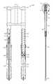
- FIG. 1Adepicts an asymmetric bicycle fork having a damping leg and a spring leg.
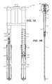
- FIG. 1Bdepicts a cross-sectional side elevation view of a shock absorber of a bicycle fork cartridge, in accordance with an embodiment.
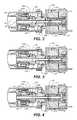
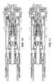
- FIG. 2 , FIG. 3 , and FIG. 4depict a cross-sectional side elevation view of various operational positions of an embodiment of the base valve assembly of detail 2 of FIG. 1B .
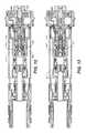
- FIG. 5A and FIG. 5Bdepict a cross-sectional side elevation view of a valve assembly of detail 2 of the shock absorber of FIG. 1B , in accordance with an embodiment.
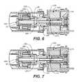
- FIG. 6 and FIG. 7each depicts a cross-sectional side elevation view of the valve assembly of detail 2 of the shock absorber of FIG. 1B , in accordance with an embodiment.
- FIG. 8A and FIG. 8Bdepict a cross-sectional side elevation view of a shock absorber, in accordance with an embodiment.
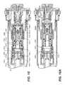
- FIGS. 9-13depict a cross-sectional side elevation view of the base valve assembly of detail 2 of FIG. 1B , including a “latching solenoid”, in accordance with an embodiment.
- FIG. 14depicts an arrangement of an embodiment on an example vehicle, in accordance with an embodiment.
- FIG. 15depicts an example vehicle suspension damper, in accordance with an embodiment.
- FIGS. 16A-16Cdepict an electronic valve, in accordance with an embodiment.
- Embodiments of vehicle suspension dampers described hereinmay include a valve assembly as is described in embodiments above.
- the valve assemblymay be used to regulate damping fluid flow in different parts of the suspension damper.
- the valve assemblymay be part of a base valve in a hydraulic suspension damper, such as a suspension fork and/or rear shock for a bicycle or motorcycle.
- the valve assemblymay be included as part of a main piston assembly of the vehicle suspension damper, and may be used to control damping in compression and/or rebound.
- the valve assemblymay be used to regulate damping fluid flow between a main damping chamber of the damping assembly and a reservoir, the reservoir for accommodating damping fluid as a piston shaft enters the main damping chamber in compression.
- valve assemblyhas wide application in vehicle suspension dampers; for example, by scaling the size of the valve assembly appropriately, it can be used in vehicles as small and light as bicycles (e.g. in the forks and/or rear shocks), and as heavy as military vehicles.
- Embodimentsprovide a system for controlling a vehicle's motion by increasing and/or decreasing damping forces within a vehicle suspension damper in quick response to sensed movement of the vehicle.
- Embodimentsmay be used in various types of vehicles, such as, but not limited to, bicycles, Side by Sides (four-wheel drive off-road vehicle), snow mobiles, etc.
- Embodimentsinclude a set of sensors coupled with a vehicle suspension damper having an electronic valve.
- Embodimentsprovide for a quicker response time, such as selectively applying damping forces, to terrain changes than the timing of responses from conventional vehicle suspension dampers.
- Conventional inertia valves of conventional vehicle suspension dampersare mechanical.
- the conventional mechanical inertia valveoperates to respond to a terrain change by applying damping forces when a vehicle's motion is sensed.
- the vehicle riderhas already experienced some type of response to the varied terrain. For example, the vehicle rider might feel the vehicle's initial response to running over a large rock.
- Mechanical inertia valveshave a response time that is measured at the speed of sound or less.
- a shock wave from a vehicle hitting a bumpwill be received and felt by the vehicle rider before the mechanical inertia valve can open and provide a “soft” ride. (A “soft” vs. “hard” mode of an inertia valve is explained below.)
- Embodiments of the present technologyinclude a set of sensors attached to the vehicle to sense vehicle motion and send control signals regarding these sensed vehicle motions to a control system of a vehicle suspension damper.
- the control systemactivates a power source of the vehicle suspension damper.
- the power sourcedelivers a current to the electronic valve.
- the currentcauses a pilot valve assembly of the electronic valve to either open or close, thereby creating a “hard” mode having maximum damping force or a “soft” mode that provides a moderate damping force, respectively.
- embodimentsalso enable components therein to provide damping functions other than via responding to a current delivered from a power source.
- a range of damping forcemay be manually selected by a user by manually adjusting a needle and jet arrangement.
- a position sensitive bottom-out needle arrangementmay provide for a needle engaging a jet deep into the travel of the suspension, thereby influencing a damping.
- Another exampleincludes a pneumatic source (e.g., air bag springs) on a semi-truck, in which the pneumatic source drives pressure in the pilot pressure chamber 1520 . As the vehicle is loaded and thereby decreases the semi-truck's ride height, the air bag pressure is increased to enable the vehicle to return to the proper ride height. This increase in air pressure also corresponds to an appropriate increase in damping.
- various embodimentsprovide some damping function options in addition to the operation of the set of sensors in combination with the inertia valve. These options include the following: an electro-mechanical device (e.g., solenoid, latching solenoid, electric motor, piezoelectric actuator); a manually adjustable needle and jet arrangement; and a pressure signal from an outside pressure source (e.g., suspension air bag).
- an electro-mechanical devicee.g., solenoid, latching solenoid, electric motor, piezoelectric actuator
- a manually adjustable needle and jet arrangemente.g., a pressure signal from an outside pressure source (e.g., suspension air bag).
- a set of sensorssuch as a set of accelerometers, in accordance with an embodiment, sense the vehicle's acceleration first. Subsequent to the sensing of the vehicle's acceleration, the vehicle's velocity is sensed, and then the vehicle's displacement is sensed. The set of sensors sends a control signal to the control system of the vehicle suspension damper as soon as the acceleration is sensed.
- a damping forceis caused to be applied by the electronic valve prior to the vehicle rider experiencing any response to terrain changes.
- the conventional mechanical inertia valveresponds to a terrain change at the speed of sound or slower, such that the vehicle rider experiences a pressure wave before the conventional mechanical inertia valve is able to apply a damping force.
- embodimentsinclude a control or orifice block with a control orifice therein.
- the control orificefunctions to meter fluid flowing through the vehicle suspension damper such that the control orifice provides additional damping functions.
- FIG. 14shows a bicycle 1405 , in accordance with an embodiment, having attached thereto a vehicle suspension damper 1410 and a set of sensors 1415 .
- the vehicle suspension damper 1410in this particular embodiment, is located within the front fork 1420 of the bicycle 1405 .
- the set of sensors 1415is configured for sensing a type of vehicle motion, such as tilt (roll), acceleration, velocity, etc. Further, the set of sensors 1415 may be positioned anywhere on the vehicle that enables the receipt of accurate sensed information and which enables communication of a control signal (regarding the sensed information) to the vehicle suspension damper 1410 .
- the set of sensors 1415if the set of sensors 1415 senses that the vehicle is experiencing acceleration, the set of sensors 1415 sends a control signal to the vehicle suspension damper 1410 .
- FIG. 15shows the vehicle suspension damper 1410 , in accordance with an embodiment.
- the vehicle suspension damper 1410includes an electronic valve 1500 .
- the electronic valve 1500includes at least a primary valve 1505 , a first pressure reducing means which in this embodiment is an orifice block 1515 , and a second pressure reducing means which in this embodiment is a pilot valve assembly 1510 , all of which components cooperatively control the flow of fluid throughout the inertia valve and manipulate the fluid pressure within the pilot pressure chamber 1520 .
- the permanent magnet 1560 of the solenoid assemblyconducts through the component 1565 to attract the pilot spool 1570 . This is the latched position as shown.
- the spool spring 1575resists this condition.
- the coilis turned on with positive polarity, it cancels the effect of the permanent magnet 1560 and the spool spring 1575 moves the pilot spool 1570 to the left or closed position.
- the electromagnetis added to the permanent magnet 1560 and the pilot spool 1570 is drawn to the right or open position.
- the main oil flow pathis through the center of the base valve and radially outwardly into piston port area 1525 . Assuming there is enough pressure in the piston ports, it then blows off the valve shims 1530 and oil flows into the reservoir 40 . A small amount of oil also flows in parallel through a second fluid flow path in the inertia valve 1500 , and in particular through the control orifice 1535 and through the solenoid assembly 1580 . This generates a pilot pressure inside the area of the primary valve 1505 .
- the valve member 1540acts to resist the valve shims 1530 from opening. This resistive force is dependent on pressure inside the area of the primary valve 1505 which is controlled by the pressure drop across the solenoid. Basically, when the solenoid is closed, there is high pressure inside the area of the primary valve 1505 (resulting in locked-out fork or firm damping, depending on the damping characteristics determined for the inertia valve 1500 , as described in greater detail below). When the solenoid is open, there is low pressure inside the area of the primary valve 1505 and the valve member 1540 pushes against valve shims 1530 with less force, allowing the valve shims 1530 to open under lower fluid pressure.
- This open position of the solenoidprovides a normally-operating fork, by which is meant the damping characteristic of the inertia valve is determined predominantly by the tuning of the valve shims 1530 (although there is some damping effect provided by the control orifice 1535 ).
- a control signalinstructs the vehicle suspension damper 1410 to increase or decrease its damping force therein.
- the vehicle suspension damper 1410is configured to respond to the control signal instruction. More particularly, the inertia valve of the vehicle suspension damper 1410 , in response to the control signal instruction, quickly manipulates the pressure in the pilot pressure chamber 1520 of the inertia valve by moving/adjusting itself to at least partially close or open the flow ports 1550 . The pressure in the pilot pressure chamber 1520 increases or decreases in proportion to the amount of closure or opening that the flow ports 1550 experience, respectively.
- fluid in the inertia valveflows along a first fluid flow path from the damping cylinder interior 35 and through the shims 1530 (unless the shims 1530 are held closed under pressure from the valve member 1540 , as will be described herein) via the piston port area 1525 .
- fluidalso flows along a second fluid flow path from the damping cylinder interior 35 and through the control orifice 1535 of the orifice block 1515 . After having flowed through the control orifice 1535 , the fluid moves into the pilot pressure chamber 1520 .
- the fluidmoves out of the pilot spool valve 1545 (wherein the pilot spool valve 1545 is in at least a partially open position) through a set of flow ports 1550 and into the reservoir 40 . Additionally, from the pilot pressure chamber 1520 , the fluid also moves into the area of the primary valve 1505 . When the fluid presents a predetermined pressure against surface 1580 of the valve member 1540 , a force proportional to the pressure is exerted on the valve member 1540 which urges it against the shims 1530 .
- the valve member 1540pushes against the shims 1530 , thereby biasing the shims 1530 toward a closed position, even though fluid is moving through the shims 1530 from the piston port area 1525 and into the reservoir 40 . If the force of the valve member 1540 against the shims 1530 is greater than the force of the fluid moving from the piston port area 1525 against the shims 1530 , then the shims 1530 will become biased toward closing.
- the shims 1530will be biased toward an open position, in which the fluid may remain flowing through the shims 1530 .
- embodimentsuse a control system to receive control signals from the set of sensors 1415 .
- the control systemactivates a power source that is attached to the inertia valve.
- the power sourcedelivers a current to the inertia valve.
- the inertia valveresponds to the delivered current by causing the pilot valve assembly 1510 to move and block or open at least a portion of the flow ports 1550 through which fluid may flow there through from the pilot pressure chamber 1520 and into the reservoir 40 , thereby at least partially closing or opening the flow parts 1550 .
- the damper piston 5moves into the damper cylinder interior 35 . More particularly, when the flow ports 1550 are at least partially closed, the fluid pressure within the pilot pressure chamber 1520 increases such that the fluid pressure in the area of the primary valve 1505 also increases. This increase in the fluid pressure in the area of the primary valve 1505 causes the valve member 1540 to move toward the shims 1530 that are open and to push against the shims 1530 , thereby causing the shims 1530 to at least partially or fully close. When these shims 1530 are at least partially or fully closed, the amount of fluid flowing there through decreases or stops.
- the movement of the damper piston 5 into the damper cylinder interior 35causes fluid to flow through the piston port area 1525 and hence out through open shims 1530 and into the reservoir 40 .
- the fluidalso flows through the control orifice 1535 into the pilot pressure chamber 1520 . If the shims 1530 are closed due to movement of the pilot valve assembly 1510 to block the flow ports 1550 , then fluid may not flow out through the shims 1530 or out through the flow ports 1550 into the reservoir 40 . Consequently, the ability of the damper piston 5 to move within the damper cylinder interior 35 to cause fluid to flow through the piston port area 1525 as well as through the flow ports 1550 is reduced or eliminated.
- the effect of the at least partial closure of the shims 1530is to cause a damping function to occur.
- the movement of the pilot valve assembly 1510 to at least partially block the flow ports 1550causes the damping (or slowing of movement) of the damper piston 5 into the damper cylinder interior 35 .
- control orifice 1535operates cooperatively with the pilot valve assembly 1510 to meter the flow of fluid to the primary valve 1505 .
- the control orifice 1535is a pathway within the orifice block 1515 and is positioned between the damper cylinder interior 35 and the pilot pressure chamber 1520 .
- the size of the control orifice 1535is tunable according to the application; the size may be variously changed.
- the control orifice 1535is a key component in enabling the quick and accurate response to sensed changes in a vehicle's motion. As will be explained herein, without the presence of the control orifice 1535 , the vehicle would not experience damping during periods of low compression speed, or experienced too much damping during periods of high compression speeds.
- the pilot valve assembly 1510would act like a bypass. In other words, without the control orifice, at low compression speed there would almost be no damping and the pilot valve assembly 1510 would act like a bypass; but at higher compression speeds, pressure drop across the pilot valve assembly 1510 would cause a high pressure in the pilot pressure chamber 1520 and therefore too much clamping force on the shims 1530 .
- the control orifice 1535thus, allows damping to occur even during periods of low compression speed, and slows the damping rate during period of high compression speed.
- the solutionis to cause a pressure drop of damping fluid before it enters the pilot pressure chamber 1520 .
- Thisis achieved with the control orifice 1535 .
- the control orifice 1535provides some damping effect at low compression speeds (by enabling damping fluid to ‘bleed’ through the control orifice), but at high compression speeds provides a significant pressure drop to ensure that the pressure inside the pilot pressure chamber does not get too high, thereby preventing the valve member 1540 from locking onto the shims 1530 .
- control orifice 1535is between 0.5 mm and 2 mm in diameter, but these sizes are dependent on the specific application and the desired damping curve. Pressure drop is directly proportional to the length of the control orifice 1535 , but inversely proportional to its diameter. Either one or both of these parameters can be changed at the design stage to affect the performance of the control orifice 1535 .
- control orifice 1535The essential function, in embodiments, of the control orifice 1535 is to create a pressure drop. Therefore, anything that will do this could be used in place of the specific arrangement shown. Some possible examples include: a diffuser; a labyrinth between parallel plates; leakage past a screw thread; etc.
- a further key feature of embodimentsis the combination of the area of the surface 1580 inside the valve member 1540 , the control orifice 1535 , the pilot valve assembly 1510 , and the way this combination enables a variable force to be applied to the shims 1530 to control the damping force at any point in time.
- the ratio of the surface area 1585 of the shims 1530(The surface area 1585 is next to the piston port area 1525 ; the pressure is acting on the surface area 1585 of the shims 1530 as well as the surface area 1580 of the inside of the valve member 1540 , within the primary valve area 1505 ) to the area of the surface 1580 inside the valve member 1540 controls the overall damping characteristic of the inertia valve 1500 , i.e., what overall range of force can be applied to the shims 1530 .
- the valve member 1540can be set up to move between full lockout and a completely soft state, or between a firm damping state and a soft state, for example.
- a particular force at any point in timeis set by the position of the pilot valve assembly 1510 , which, as explained above, controls the pressure drop across the flow ports 1550 .
- the pressure of fluid in the pilot pressure chamber 1520is also adjusted. Since the pressure inside the pilot pressure chamber 1520 acts against surface 1580 of the valve member 1540 , the force applied by the valve member 1540 to the shims is controllable by adjustment of the position of the pilot valve assembly 1510 .
- the overall resistance to fluid flow along the first fluid flow path(i.e. through piston port area 1525 and past shims 1530 ) is given by the sum of the force provided by the shims 1530 , and the force applied to the shims 1530 by the valve member 1540 .
- a significant featureis that force is generated on the valve member 1540 by control of pressure inside the area of the primary valve 1505 (in contrast to other valve bodies where force comes from pressure acting on the outside of the valve member 1540 , usually from the damper reservoir).
- the ultimate source of pressure in the pilot pressure chamber 1520is the pressure of the damping fluid in the main damping cylinder 35 during compression (but regulated by the control orifice 1535 and the pilot valve assembly 1510 to give a lower pressure in the pilot pressure chamber 1520 ).
- the pilot valve assembly 1510enables very large damping forces to be controlled using the same pilot valve assembly 1510 —this is because: (a) the pilot pressure is ‘magnified’ according to the ratio of the area of the primary valve 1505 to the area of the piston port 1525 ; and (b) because the pilot valve assembly 1510 is not required to move any element against the high pressure damping fluid; and 5) the primary valve assembly 1510 allows the damper to utilize conventional shims, but with some level of controllability over the damping force applied by the shims. This allows the shims to be tuned in a conventional manner. Furthermore, if power to the pilot valve assembly 1510 fails, the shock absorber will continue to operate (in contrast to other electronically controlled shocks where power loss causes the shock to stop working completely).
- the inertia valve 1500including the primary valve 1505 , the pilot valve assembly 1510 , and the orifice block 1515 , not only enables a variable force to be applied to shims 1530 , but also enables the control of the damping force within the vehicle at any point in time.
- the pilot valve assembly 1510meters a flow of fluid to the primary valve 1505 and enables the generation of relatively large damping forces by a relatively small solenoid (or other motive source), while using relatively low amounts of power.
- the solenoidcontinuously powers the inertia valve and does not have a latching mechanism.
- a monitorwill continuously monitor power source and its operation in order to make sure that the wires leading to the power source do not get cut, thereby providing a dangerous situation for the rider and other vehicles.
- the primary valve 1505although it is shown as an internal base valve, it is not limited to this position or application.
- itcan be mounted externally of the vehicle suspension damper (for example in a ‘piggy-back’ reservoir). Further, it could be made part of the main damper piston (either in compression or rebound directions).
- the general methodology for determining the diameter and/or length of the control orifice 1535 during designis as follows: (1) identify the desired damping curve that the damper should have; (2) determine from step (1) the target low speed damping force; (3) determine from step (1) the target high speed damping force; (4) make informed guess at control orifice diameter and/or length to achieve steps (2) and (3); (5) test the output damping forces produced by shock at different speeds within low to high speed range; (6) compare the measured damping curve against the desired damping curve; (7) if there is too much high speed damping force, then reduce the diameter of the control orifice (to lower the pressure inside the pilot pressure chamber 1520 ); (8) if there is too much low speed damping force, then decrease the area ratio (between the area of the primary valve 1505 and the piston port
- FIG. 16Ashows an electronic valve 1600 A with a diffuser pin 1605 positioned through one set of the cross holes 1610 going to the primary valve area 1505 , in accordance with an embodiment. Another set of holes remains (normal to the page) to feed oil to the valve member 1540 .
- the diffuser pin 1605functions to disrupt the jet flow coming out of the control orifice 1535 .
- FIG. 16Bshows an electronic valve 1600 B with a diffuser plug 1620 pressed into, at least one of and at least partially, the orifice block 1515 and the pilot pressure chamber 1520 , in accordance with an embodiment.
- the diffuser plug 1620also functions to disrupt the jet flow coming out of the control orifice 1535 .
- FIG. 16Cshows an electronic valve 1600 C with a diffuser pin 1630 , in accordance with an embodiment.
- the spool retainer 1635(see FIG. 16B ) is replaced with the diffuser pin 1630 .
- the diffuser pin 1630 and its position within the vehicle suspension damper 1600 Cfunctions to disrupt the jet flow coming out of the control orifice 1535 and to minimize the contact of the pilot spool assembly 1510 in the firm setting.
- the solenoidincludes a “latching” mechanism to open and close the pressure-balanced pilot spool. Due to the latching configuration of the solenoid, power is only required to open or close the pilot valve assembly 1510 . Power is not required to hold the pilot valve assembly 1510 open or closed in either setting. Consequently, embodiments enable reduced power consumption compared to the traditional shock absorber.
- FIG. 1545provides an externally-adjustable means of tuning the open state of the damper.
- An adjusterturns in or out to vary the effective orifice size of the pilot spool valve 1545 when in the open position. This allows the rider to adjust the soft setting of the damper to his preference.
- valve shims 1530is optional. Instead, it would be possible for the valve member 1540 to act directly on the fluid flow ports 1525 . In fact, valve shims are optional in any such embodiment described herein where it would be possible for the valve member 1540 (or any other similar valve member described herein) to act directly on the fluid flow ports that control the main flow through the valve assembly.
- FIGS. 1-8BThe following discussion describes the FIGS. 1-8B and embodiments shown therein.
- Integrated damper/spring vehicle shock absorbersoften include a damper body surrounded by or used in conjunction with a mechanical spring or constructed in conjunction with an air spring or both.
- the damperoften consists of a piston and shaft telescopically mounted in a fluid filled cylinder.
- the damping fluidi.e., damping liquid
- damping liquidmay be, for example, hydraulic oil.
- a mechanical springmay be a helically wound spring that surrounds or is mounted in parallel with the damper body.
- Vehicle suspension systemstypically include one or more dampers as well as one or more springs mounted to one or more vehicle axles.
- the terms “down”, “up”, “downward”, “upward”, “lower”, “upper”, and other directional referencesare relative and are used for reference only.
- FIG. 1Ashows an asymmetric bicycle fork 100 having a damping leg and a spring leg.
- the damping legincludes an upper tube 105 mounted in telescopic engagement with a lower tube 110 and having fluid damping components therein.
- the spring legincludes an upper tube 106 mounted in telescopic engagement with a lower tube 111 and having spring components therein.
- the upper legs 105 , 106may be held centralized within the lower legs 110 , 111 by an annular bushing 108 .
- the fork 100may be included as a component of a bicycle such as a mountain bicycle or an off-road vehicle such as an off-road motorcycle. In some embodiments, the fork 100 may be an “upside down” or Motocross-style motorcycle fork.
- the damping components inside the damping leginclude an internal piston 166 disposed at an upper end of a damper shaft 136 and fixed relative thereto.
- the internal piston 166is mounted in telescopic engagement with a cartridge tube 162 connected to a top cap 180 fixed at one end of the upper tube 105 .
- the interior volume of the damping legmay be filled with a damping liquid such as hydraulic oil.
- the piston 166may include shim stacks (i.e., valve members) that allow a damping liquid to flow through vented paths in the piston 166 when the upper tube 105 is moved relative to the lower tube 110 .
- a compression chamberis formed on one side of the piston 166 and a rebound chamber is formed on the other side of the piston 166 . The pressure built up in either the compression chamber or the rebound chamber during a compression stroke or a rebound stroke provides a damping force that opposes the motion of the fork 100 .
- the spring components inside the spring leginclude a helically wound spring 115 contained within the upper tube 106 and axially restrained between top cap 181 and a flange 165 .
- the flange 165is disposed at an upper end of the riser tube 163 and fixed thereto.
- the lower end of the riser tube 163is connected to the lower tube 111 in the spring leg and fixed relative thereto.
- a valve plate 155is positioned within the upper leg tube 106 and axially fixed thereto such that the plate 155 moves with the upper tube 106 .
- the valve plate 155is annular in configuration, surrounds an exterior surface of the riser tube 163 , and is axially moveable in relation thereto.
- the valve plate 155is sealed against an interior surface of the upper tube 106 and an exterior surface of the riser tube 163 .
- a substantially incompressible lubricante.g., oil
- the remainder of the volume in the lower tube 111may be filled with gas at atmospheric pressure.
- the gas in the interior volume of the lower tube 111is compressed between the valve plate 155 and the upper surface of the lubricant as the upper tube 106 telescopically extends into the lower tube 111 .
- the helically wound spring 115is compressed between the top cap 181 and the flange 165 , fixed relative to the lower tube 111 .
- the volume of the gas in the lower tube 111decreases in a nonlinear fashion as the valve plate 155 , fixed relative to the upper tube 106 , moves into the lower tube 111 . As the volume of the gas gets small, a rapid build-up in pressure occurs that opposes further travel of the fork 100 .
- the high pressure gasgreatly augments the spring force of spring 115 proximate to the “bottom-out” position where the fork 100 is fully compressed.
- the level of the incompressible lubricantmay be set to a point in the lower tube 111 such that the distance between the valve plate 155 and the level of the oil is substantially equal to a maximum desired travel of the fork 100 .
- FIG. 1Ba cross-sectional side elevation view of a shock absorber of a bicycle fork cartridge is depicted, in accordance with an embodiment. More particularly, FIG. 1B shows the inner portions of the bicycle fork leg assembly, comprising a damper piston 5 .
- the top cap 20is affixed to an upper tube (not shown) and the lower connector 10 is fixed to a lower leg tube (not shown) where the upper tube is typically telescopically mounted within the lower tube (although the reverse may also be the case).
- the damper piston 5 and piston rod 15move telescopically into and out of damper cylinder 25 .
- the volume of the piston rod 15displaces, from the cylinder 25 , a volume of damping liquid contained within the cylinder 25 corresponding to the volume of the piston rod 15 incurring into the damper cylinder 25 .
- the volume of liquidmust be replaced as the piston rod 15 leaves the interior of the damper cylinder 25 .
- Damping liquid displaced as described abovemoves from the damper cylinder 25 , through a base valve assembly of detail 2 and ultimately into an elastic bladder 30 during compression, and from the elastic bladder 30 , back through the base valve assembly of detail 2 and into the damper cylinder 25 during rebound.
- the base valve assembly of detail 2allows for the compression damping to be adjusted by the user.
- FIG. 2 , FIG. 3 , and FIG. 4show cross-sectional side elevation views of various operational positions of an embodiment of the base valve assembly of detail 2 of FIG. 1B .
- FIGS. 2-4show a continuously variable semi active arrangement, in accordance with embodiments, and as will be described in more detail below.
- a solenoid balanced by an armature biasing spring 235axially locates a pressure-balanced pilot spool 210 .
- the pressure-balanced pilot spool 210controls the pressure inside the valve body 230 . As this pressure is increased inside the valve body 230 , the axial force of the valve body 230 on the conventional valve shim increases.
- a relatively small solenoid(using relatively low amounts of power) can generate relatively large damping forces. Furthermore, due to incompressible fluid inside the valve body 230 , damping occurs as the valve opens and the valve body 230 collapses. The result is not only a controllable preload on the valve stack, but also a controllable damping rate.
- Embodiments discussed hereinmay optionally be packaged in a base valve, the compression adjuster of a shock absorber, and/or on the main piston of a shock absorber.
- FIG. 2is a detailed view of the base valve assembly of detail 2 of FIG. 1B , with the valve shown in the retracted soft position. This retracted position corresponds to minimum or no current in the solenoid.
- a first damping fluid flow path between damping cylinder interior 35 and annular reservoir 40is substantially unobstructed via bleed passage 55 , ports 50 A and upper annulus 45 .
- bleed passage 55As shown in FIG. 2 is the main piston 245 .
- FIG. 3is a detailed view of the base valve assembly of detail 2 of FIG. 1B , with the valve shown in the mid-damping position. This corresponds to medium current supplied to the solenoid.
- FIG. 3shows a partial obstruction of ports 50 A by metering edge 205 of the pilot spool 210 .
- FIG. 4is a detailed view of the base valve assembly of detail 2 of FIG. 1B , with the valve shown in the firm-damping position.
- FIG. 4shows substantial blockage of ports 50 A by the metering edge 205 of the pilot spool 210 , which is axially displaced relative to its position in FIG. 2 .
- the pilot spool 210 shown in FIG. 2is in a retracted soft position, in which the metering edge 205 of the pilot spool 210 is not obstructing the ports 50 A.
- the pilot spool 210 shown in FIG. 3is in a middle position, in which the metering edge 205 of the pilot spool 210 is partially obstructing the ports 50 A.
- the pilot spool 210 shown in FIG. 4is in a firm position, in which the metering edge 205 of the pilot spool 210 is fully obstructing ports 50 A.
- the axial displacement of the pilot spool 210is facilitated by an electromagnetic interaction between the armature 215 and the coil 220 .
- Adjustment of the current in the coil 220 (via modulation of the current from a power source [not shown]) to predetermined valuescauses the armature 215 , and hence the pilot spool 210 , to move in corresponding predetermined axial positions relative to the coil 220 .
- the pilot spool 210can be adjusted as shown in the FIGS. 2-4 .
- FIG. 5A and FIG. 5Bdepict a cross-sectional side elevation view of a valve assembly of detail 2 of the shock absorber of FIG. 1B , in accordance with an embodiment.
- FIG. 5A and FIG. 5Bshow an embodiment in which the valve body 230 acts on the valve shims 225 through a spring 75 .
- the valve body 230increases or decreases the preload on the spring 75 .
- FIG. 5Ashows the pilot spool 210 in the retracted soft position, thereby causing the preload on the spring 75 to decrease.
- FIG. 5Bshows the pilot spool 210 in the firm position, thereby causing the preload on the spring 75 to increase.
- FIG. 6 and FIG. 7depict a cross-sectional side elevation view of the valve assembly of detail 2 of the shock absorber of FIG. 1B , in accordance with an embodiment.
- FIG. 6 and FIG. 7show an embodiment including a flow control orifice 605 for limiting flow through into the bleed passage 55 during compression.
- the flow control orifice 605(by creating a pressure drop) places an upper limit on the amount of pressure in the annulus 60 , and hence the amount of “boost” or closure force that the valve body 230 can exert on the valve shims 230 .
- FIG. 6shows the metering edge 205 of the pilot spool 210 obstructing ports 50 A.
- FIG. 7shows the metering edge 205 of the pilot spool 210 partially obstructing ports 50 A.
- FIG. 8A and FIG. 8Bdepict a cross-sectional side elevation view of one end of a piston and piston rod assembly of a shock absorber, in accordance with an embodiment. More particularly, FIG. 8A shows an embodiment having a separate valve body 805 A and 805 B corresponding to each of a rebound shim set 810 and a compression shim set 815 , respectively, where a pilot spool 820 (performing, in one embodiment, similarly to the pilot spool 210 of FIGS. 1-7 described herein) alternatingly opens one area (e.g., 825 A [similar to function to annulus 60 ]) while closing the other area (e.g., 825 B [similar in function to annulus 60 ]).
- FIG. 8Ashows an embodiment having a separate valve body 805 A and 805 B corresponding to each of a rebound shim set 810 and a compression shim set 815 , respectively, where a pilot spool 820 (performing, in one embodiment, similarly to the pilot spool
- FIG. 8Ashows a “hard/soft configuration”.
- the area 825 A and area 825 Bexperience obstruction by a portion of the pilot spool 820 , thereby creating a soft compression.
- the area 825 A and area 825 Bare open to fluid flow, thereby creating a firm rebound.
- FIG. 8Bshows a “hard/hard configuration” (a firm compression and a firm rebound), in accordance with an embodiment.
- FIGS. 9-13depicts a cross-sectional side elevation view of the base valve assembly of detail 2 of FIG. 1B , including a “latching solenoid”, in accordance with an embodiment.
- Embodimentsfurther provide, in brief and as will be described below, a low-power bi-state electronic damper.
- the low-power bi-state electronic damperuses a latching solenoid to open and close a pressure-balanced pilot spool. Given the latching configuration of the solenoid, power is required only to open or close but not to hold in it in either setting, in accordance with an embodiment. The result is low power consumption.
- a further embodimentprovides an externally-adjustable means of tuning the open state of the damper.
- an adjusterthat can be turned in or out to vary the effective orifice size of the pilot spool when in the open position. This will allow the rider to adjust the soft setting of the damper to his/her preference.
- the latching solenoid 905primarily uses power to facilitate a change in position of the pilot spool 210 relative to the coil 220 but requires little or no power to maintain the pilot spool 210 in the desired position once that is achieved.
- the latching solenoid assembly 905(or latching spool valve assembly) includes: a pilot spool 210 which includes a magnetically active material; a spring 915 which is normally in compression and biases the pilot spool 210 toward a position obstructing ports 50 A; a permanent magnet 920 ; and a coil 220 where power is supplied to the coil 220 by (in one embodiment) wires 925 .
- the aforementioned componentsmay be contained within a housing 240 or “cartridge” as shown.
- the pilot spool valve assembly(including at least the pilot spool 210 and the metering edge 930 of the pilot spool 210 ) regulates damping fluid flow through a portion of the damper and adjusts the force applied to the valve shims 225 by the valve body 230 through ports 60 .
- the position of the spool valve assemblymay be adjusted axially by means of the low speed adjuster 935 .
- the low speed adjuster 935(comprising multiple pieces), being for example, threaded at its lower end to the top cap 20 via the low speed adjuster threads 940 , may be rotated to facilitate axial movement.
- the low speed adjuster 935includes a non-round shape (e.g., hexagonal) that facilitates the rotation with relative axial movement (see 1105 of FIG. 11 ).
- the pilot spool 210is biased by spring 915 toward a position wherein the metering edge 930 of the pilot spool 210 further obstructs ports 50 A (see FIG. 13 , wherein the pilot spool 210 is shown in the open pilot position with the low speed adjuster 935 in the middle position).
- a force opposing the bias of the spring 915is exerted on the magnetic component of the pilot spool 210 by the permanent magnet 920 .
- the pilot spool 210When the pilot spool 210 is in its uppermost (corresponding to open ports 50 A) position, it is retained by the magnetic force between the permanent magnet 920 and the pilot spool valve 925 where that force is sufficient to overcome the bias of the spring 915 (thereby holding the spring 915 in a compressed state).
- the pilot spool valve 925 and ports 50 Aare in the open position (see FIG. 12 ), no power input is required to maintain that state.
- a currentis applied to the coil 220 via the wires 925 .
- the currentcauses a magnetic flux around the coil 220 , which acts on the magnetic component of the pilot spool 210 causing the pilot spool 210 to move axially within the cartridge.
- the spring 915bias moves the pilot spool 210 toward closure of ports 50 A with little or no additional power input to the coil 220 .
- FIG. 10shows the pilot spool 210 in the closed pilot position with the low speed adjuster 935 in the firm position.
- FIG. 11shows the pilot spool 210 in the open pilot position with the low speed adjuster 935 in the firm position.
- FIG. 10additionally shows the low speed adjuster metering edge 1005 and the spool valve assembly housing 1010 , in accordance with an embodiment.
- FIGS. 9-13show an orifice block 955 having a tailored orifice 960 there through.
- the orifice 960meters low speed damping fluid for low speed bump response of the suspension (when magnitude and rate is insufficient to open the shims).
- the size of the orifice 960may be chosen to allow a desired amount or range of pressure to be applied to the valve body 230 through annulus 60 (ports).
- the use of the pilot spool 210then further specifies that the pressure acts on the valve body 230 by modulating the flow restriction “downstream” (during a compression stroke of the suspension) of the orifice 960 .
- FIGS. 9-13also show a pressure relief valve 965 or “blow off” valve, which is biased toward a closed position by Bellville spring(s) 970 .
- the pressure relief valve 965opens in response to an interior damper pressure above a predetermined threshold and thereby prevents damage to the damper and vehicle in the event of rapid pressure build up (usually associated with extreme suspension compression rate).
- the pressure relief valve 965may have an adjustable threshold value (in one embodiment, by modification of the compression in the Bellville spring 970 ).
- the set of sensors 1415may be positioned in various locations on various types of vehicles.
- the set of sensors 1415is positioned on the seat post of a bicycle.
- a first set of sensorsis positioned near the front wheel, while a second set of sensors is positioned near the rear wheel.
- the set of sensorsincludes three accelerometers.
- the accelerometersdefine a plane of the vehicle's body, such that the acceleration and the tilt (i.e., pitch and roll) of the vehicle body may be measured.
- the set of sensorssenses vehicle motion which is determined to meet and/or exceed a predetermined threshold, then the set of sensors sends a control signal to the control system attached to the vehicle suspension damper.
- the predetermined thresholdmay be a constant in one embodiment. However, in another embodiment, the predetermined threshold may be a variable based on other situations sensed on the vehicle.
- each wheel base (4)may include an embodiment of the system of the present technology. More specifically, each wheel base has attached thereto a different set of sensors, such as a set of accelerometers, each set being attached to a separate vehicle suspension damper. In another embodiment, one set of sensors (e.g., set of accelerometers) is attached to the ROV, as well as being attached to one or more vehicle suspension dampers.
- ROVrecreational off highway vehicle
- the vehicle suspension dampersmay each be programmed to operate in a fully open mode (i.e., soft mode), in which the pilot spool valve 1545 of the pilot valve assembly 1510 is open to the flow ports 1550 , thereby allowing fluid to flow from the damper cylinder interior 35 and into the reservoir 40 either through the first fluid flow path, with resistance provided by the shims 1530 (and no additional force provided by the valve member 1540 ), and/or through the control orifice 1535 that permits low speed bleed of damping fluid via the second fluid flow path.
- a fully open modei.e., soft mode
- the right front tire of an ROVwhen the right front tire of an ROV hits a large rock, the right front tire and a portion of the suspension attached to the tire (or attached wheel base) may rise upwards to move over the rock.
- the set of sensors attached to the ROV's right front sidewill sense the tire's upward movement, and will sense the tire reaching its peak upward movement (the peak of the rock), and will sense the tire beginning to move downwards.
- the set of sensors on the ROV's right front sidewould send control signals to the vehicle suspension damper attached to the ROV's right front side throughout the tire's movement upward and downward.
- the control system attached to the vehicle suspension damperreceives the control signals and causes the power source also attached to the vehicle suspension damper to deliver a current to the vehicle suspension damper in accordance with the control signals.
- the delivered currentfunctions to cause the pilot valve assembly 1510 to move to cause the flow ports 1550 to be at least partially blocked.
- the pressure within the pilot pressure chamber 1520increases due to the at least partially blocked flowports 1550 , thereby causing the pressure within the area of the primary valve 1505 to increase.
- the valve member 1540in response increased pressure in the area of the primary valve 1505 , is urged against the shims 1530 , thereby changing the damping characteristics of the shims 1530 .
- the fluid flowing along the first fluid flow path from the damper cylinder interior 35 and through the piston port area 1525is reduced, resulting in an increased damping effect to the vehicle's motion.
- Embodimentsenable a faster reaction time in applying damping than conventional shock absorbers provide.
- the inertia valvesenses a pressure wave (occurring at the speed of sound) after a vehicle's tire hits a bump.
- the mechanical inertia valveopens in response to receiving the pressure wave.
- the vehicle riderexperiences some form of response to the terrain before the mechanical inertia valve has a chance to open into a “soft” mode.
- the inertia valveopens into a “soft” mode before a motion significant enough for a vehicle rider to experience it has begun.
- a motionoccurs, such as an ROV wheel base beginning to move upward while running over a large rock, and thus experience a gross wheel movement
- an accelerationoccurs first and is thus measured first by embodiments.
- a velocity, and then a displacementfollows and are also measured in some embodiments.
- a control signalis sent from the set of accelerometers to the control system before enough of a vehicle motion has occurred such that the vehicle rider experiences a minimal response to the terrain and certainly less than would be provided should a mechanical inertia valve be provided.
- one or more set of sensorsmay be attached to each ROV wheel base, and independently control the vehicle suspension damper to account for and respond to various rolls and other types of vehicle motion.
- Embodimentsenable the quick response to sensed acceleration such that the acceleration may be prevented, or at least reduced.
- one or more motion sensoris provided on a forward or front part of a vehicle, and a signal or signals from the one or more motion sensor is used to control a damper mounted on a rear part of the vehicle.
- motion information learned from the movement of the front part of the vehiclecan be used to anticipate movement of the rear part of the vehicle, and adjustments made to control the damper on the rear part accordingly.
- one embodimentenables the control of both compression and the rebound state of the vehicle suspension damper, such that acceleration as measured at each wheel base is maintained as close to zero as possible throughout off-road riding over varied terrain.
- Embodimentsenable the quick recovery from and/or prevention of a vehicle rider experiencing a vehicle's response to terrain, such as a roll.
- more than one type of sensoris used.
- an accelerometer and a gyrometermay be used.
- numerous methods for determining orientation in a plane in space using a sensor attached to an objectare well known in the art.
Landscapes
- Engineering & Computer Science (AREA)
- General Engineering & Computer Science (AREA)
- Mechanical Engineering (AREA)
- Physics & Mathematics (AREA)
- Electromagnetism (AREA)
- Fluid Mechanics (AREA)
- Vehicle Body Suspensions (AREA)
- Fluid-Damping Devices (AREA)
Abstract
Description
Claims (21)
Priority Applications (27)
| Application Number | Priority Date | Filing Date | Title |
|---|---|---|---|
| US13/934,067US10060499B2 (en) | 2009-01-07 | 2013-07-02 | Method and apparatus for an adjustable damper |
| US14/251,446US10047817B2 (en) | 2009-01-07 | 2014-04-11 | Method and apparatus for an adjustable damper |
| US14/466,831US9452654B2 (en) | 2009-01-07 | 2014-08-22 | Method and apparatus for an adjustable damper |
| US15/275,078US10040329B2 (en) | 2009-01-07 | 2016-09-23 | Method and apparatus for an adjustable damper |
| US16/042,563US10814689B2 (en) | 2009-01-07 | 2018-07-23 | Method and apparatus for an adjustable damper |
| US16/045,403US11168758B2 (en) | 2009-01-07 | 2018-07-25 | Method and apparatus for an adjustable damper |
| US16/046,497US10670106B2 (en) | 2009-01-07 | 2018-07-26 | Method and apparatus for an adjustable damper |
| US16/051,156US10800220B2 (en) | 2009-01-07 | 2018-07-31 | Method and apparatus for an adjustable damper |
| US16/051,245US10336149B2 (en) | 2009-01-07 | 2018-07-31 | Method and apparatus for an adjustable damper |
| US16/051,023US10336148B2 (en) | 2009-01-07 | 2018-07-31 | Method and apparatus for an adjustable damper |
| US16/051,346US10807433B2 (en) | 2009-01-07 | 2018-07-31 | Method and apparatus for an adjustable damper |
| US16/051,302US10821795B2 (en) | 2009-01-07 | 2018-07-31 | Method and apparatus for an adjustable damper |
| US16/175,656US11306798B2 (en) | 2008-05-09 | 2018-10-30 | Position sensitive suspension damping with an active valve |
| US16/203,203US12122205B2 (en) | 2009-01-07 | 2018-11-28 | Active valve for an internal bypass |
| US16/424,334US11660924B2 (en) | 2009-01-07 | 2019-05-28 | Method and apparatus for an adjustable damper |
| US16/425,240US11173765B2 (en) | 2009-01-07 | 2019-05-29 | Method and apparatus for an adjustable damper |
| US16/888,720US11549565B2 (en) | 2009-01-07 | 2020-05-30 | Method and apparatus for an adjustable damper |
| US17/068,569US20210023900A1 (en) | 2009-01-07 | 2020-10-12 | Method and apparatus for an adjustable damper |
| US17/073,730US11794543B2 (en) | 2009-01-07 | 2020-10-19 | Method and apparatus for an adjustable damper |
| US17/078,858US12134293B2 (en) | 2009-01-07 | 2020-10-23 | Method and apparatus for an adjustable damper |
| US17/083,837US12257871B2 (en) | 2009-01-07 | 2020-10-29 | Method and apparatus for an adjustable damper |
| US17/519,897US12091122B2 (en) | 2009-01-07 | 2021-11-05 | Method and apparatus for an adjustable damper |
| US17/526,425US11890908B2 (en) | 2009-01-07 | 2021-11-15 | Method and apparatus for an adjustable damper |
| US17/722,240US20220389983A1 (en) | 2008-05-09 | 2022-04-15 | Position sensitive suspension damping with an active valve |
| US17/722,211US20230019929A1 (en) | 2008-05-09 | 2022-04-15 | Position sensitive suspension damping with an active valve |
| US17/956,632US20230131078A1 (en) | 2009-01-07 | 2022-09-29 | Method and apparatus for an adjustable damper |
| US18/740,129US12377699B2 (en) | 2009-01-07 | 2024-06-11 | Method and apparatus for an adjustable damper |
Applications Claiming Priority (14)
| Application Number | Priority Date | Filing Date | Title |
|---|---|---|---|
| US14315209P | 2009-01-07 | 2009-01-07 | |
| US12/684,072US20100170760A1 (en) | 2009-01-07 | 2010-01-07 | Remotely Operated Bypass for a Suspension Damper |
| US29682610P | 2010-01-20 | 2010-01-20 | |
| US36112710P | 2010-07-02 | 2010-07-02 | |
| US13/010,697US8857580B2 (en) | 2009-01-07 | 2011-01-20 | Remotely operated bypass for a suspension damper |
| US201161491858P | 2011-05-31 | 2011-05-31 | |
| US13/175,244US8627932B2 (en) | 2009-01-07 | 2011-07-01 | Bypass for a suspension damper |
| US13/189,216US9239090B2 (en) | 2009-01-07 | 2011-07-22 | Suspension damper with remotely-operable valve |
| US201261645465P | 2012-05-10 | 2012-05-10 | |
| US13/485,401US20120305350A1 (en) | 2011-05-31 | 2012-05-31 | Methods and apparatus for position sensitive suspension damping |
| US201261667327P | 2012-07-02 | 2012-07-02 | |
| US201261709041P | 2012-10-02 | 2012-10-02 | |
| US13/843,704US9033122B2 (en) | 2009-01-07 | 2013-03-15 | Method and apparatus for an adjustable damper |
| US13/934,067US10060499B2 (en) | 2009-01-07 | 2013-07-02 | Method and apparatus for an adjustable damper |
Related Parent Applications (6)
| Application Number | Title | Priority Date | Filing Date |
|---|---|---|---|
| US12/684,072Continuation-In-PartUS20100170760A1 (en) | 2008-05-09 | 2010-01-07 | Remotely Operated Bypass for a Suspension Damper |
| US13/189,216Continuation-In-PartUS9239090B2 (en) | 2008-05-09 | 2011-07-22 | Suspension damper with remotely-operable valve |
| US13/485,401Continuation-In-PartUS20120305350A1 (en) | 2008-05-09 | 2012-05-31 | Methods and apparatus for position sensitive suspension damping |
| US13/843,704Continuation-In-PartUS9033122B2 (en) | 2008-05-09 | 2013-03-15 | Method and apparatus for an adjustable damper |
| US13/934,067Continuation-In-PartUS10060499B2 (en) | 2008-05-09 | 2013-07-02 | Method and apparatus for an adjustable damper |
| US14/251,446Continuation-In-PartUS10047817B2 (en) | 2008-05-09 | 2014-04-11 | Method and apparatus for an adjustable damper |
Related Child Applications (4)
| Application Number | Title | Priority Date | Filing Date |
|---|---|---|---|
| US13/843,704Continuation-In-PartUS9033122B2 (en) | 2008-05-09 | 2013-03-15 | Method and apparatus for an adjustable damper |
| US13/934,067Continuation-In-PartUS10060499B2 (en) | 2008-05-09 | 2013-07-02 | Method and apparatus for an adjustable damper |
| US14/251,446Continuation-In-PartUS10047817B2 (en) | 2008-05-09 | 2014-04-11 | Method and apparatus for an adjustable damper |
| US16/045,403ContinuationUS11168758B2 (en) | 2009-01-07 | 2018-07-25 | Method and apparatus for an adjustable damper |
Publications (2)
| Publication Number | Publication Date |
|---|---|
| US20130292218A1 US20130292218A1 (en) | 2013-11-07 |
| US10060499B2true US10060499B2 (en) | 2018-08-28 |
Family
ID=49511705
Family Applications (3)
| Application Number | Title | Priority Date | Filing Date |
|---|---|---|---|
| US13/934,067Active2030-01-21US10060499B2 (en) | 2008-05-09 | 2013-07-02 | Method and apparatus for an adjustable damper |
| US16/045,403ActiveUS11168758B2 (en) | 2009-01-07 | 2018-07-25 | Method and apparatus for an adjustable damper |
| US17/519,897ActiveUS12091122B2 (en) | 2009-01-07 | 2021-11-05 | Method and apparatus for an adjustable damper |
Family Applications After (2)
| Application Number | Title | Priority Date | Filing Date |
|---|---|---|---|
| US16/045,403ActiveUS11168758B2 (en) | 2009-01-07 | 2018-07-25 | Method and apparatus for an adjustable damper |
| US17/519,897ActiveUS12091122B2 (en) | 2009-01-07 | 2021-11-05 | Method and apparatus for an adjustable damper |
Country Status (1)
| Country | Link |
|---|---|
| US (3) | US10060499B2 (en) |
Cited By (28)
| Publication number | Priority date | Publication date | Assignee | Title |
|---|---|---|---|---|
| US20210214041A1 (en)* | 2020-01-13 | 2021-07-15 | Sram, Llc | Bicycle suspension components |
| EP3888957A1 (en) | 2020-04-02 | 2021-10-06 | Fox Factory, Inc. | System for vehicle suspension management |
| EP3939813A1 (en) | 2020-07-15 | 2022-01-19 | Fox Factory, Inc. | Active valve customizable tune application |
| EP4015264A1 (en) | 2020-12-17 | 2022-06-22 | Fox Factory, Inc. | Sway bar system |
| EP4019304A1 (en) | 2020-12-28 | 2022-06-29 | Fox Factory, Inc. | Wireless active suspension system |
| EP4021029A1 (en) | 2020-12-28 | 2022-06-29 | Fox Factory, Inc. | Wireless switch for an active component |
| EP4036436A1 (en) | 2021-02-01 | 2022-08-03 | Fox Factory, Inc. | Three-port adjuster |
| EP4040011A1 (en) | 2021-01-28 | 2022-08-10 | Fox Factory, Inc. | A damper with an annular base valve flow system |
| EP4046833A1 (en) | 2021-02-23 | 2022-08-24 | Fox Factory, Inc. | Vehicle and bump sensor |
| EP4108557A1 (en) | 2021-06-24 | 2022-12-28 | Fox Factory, Inc. | Electronically actuated dropper seatpost |
| EP4112969A1 (en) | 2021-06-16 | 2023-01-04 | Fox Factory, Inc. | Adjustable shock assembly |
| EP4119901A1 (en) | 2021-07-14 | 2023-01-18 | Fox Factory, Inc. | Timely component movement measuring system for a vehicle |
| EP4147890A1 (en) | 2021-09-14 | 2023-03-15 | Fox Factory, Inc. | Vehicle and wireless active suspension system |
| EP4183604A1 (en) | 2021-11-18 | 2023-05-24 | Fox Factory, Inc. | Plug and play suspension system |
| EP4230448A1 (en) | 2022-02-04 | 2023-08-23 | Fox Factory, Inc. | Limited range sharing of localized suspension setup information |
| EP4269137A1 (en) | 2022-04-26 | 2023-11-01 | Fox Factory, Inc. | System and method |
| US11833876B2 (en) | 2020-07-15 | 2023-12-05 | Fox Factory, Inc. | Rough road detection |
| US11926189B2 (en) | 2017-09-29 | 2024-03-12 | Fox Factory, Inc. | Electronically controlled sway bar damping link |
| EP4357229A1 (en) | 2022-10-19 | 2024-04-24 | Fox Factory, Inc. | Suspension component |
| EP4400399A1 (en) | 2022-12-13 | 2024-07-17 | Fox Factory, Inc. | Air spring assembly |
| EP4407208A1 (en) | 2023-01-24 | 2024-07-31 | Fox Factory, Inc. | Live valve assembly |
| US12083850B2 (en) | 2021-12-20 | 2024-09-10 | Fox Factory, Inc. | Electronically controlled sway bar damping link |
| US12103344B2 (en) | 2021-08-06 | 2024-10-01 | AllTech Motorsports Inc. | Control coil over internal bypass damper for automotive suspensions |
| US12234879B2 (en) | 2020-04-09 | 2025-02-25 | Fox Factory, Inc. | User accessible shock travel spacer |
| US12270062B2 (en) | 2017-09-08 | 2025-04-08 | Fox Factory, Inc. | Electronically controlled sway bar damping link |
| US12311720B2 (en) | 2022-02-23 | 2025-05-27 | Fox Factory, Inc. | Hydraulic cross-linked suspension |
| US12330734B2 (en) | 2022-04-15 | 2025-06-17 | Fox Factory, Inc. | Active suspension and body wearable device integration |
| US12391085B2 (en) | 2022-12-09 | 2025-08-19 | Fox Factory, Inc. | Motorized adjustment of a damper bleed |
Families Citing this family (39)
| Publication number | Priority date | Publication date | Assignee | Title |
|---|---|---|---|---|
| US20120305350A1 (en) | 2011-05-31 | 2012-12-06 | Ericksen Everet O | Methods and apparatus for position sensitive suspension damping |
| US11306798B2 (en) | 2008-05-09 | 2022-04-19 | Fox Factory, Inc. | Position sensitive suspension damping with an active valve |
| US9033122B2 (en) | 2009-01-07 | 2015-05-19 | Fox Factory, Inc. | Method and apparatus for an adjustable damper |
| US8857580B2 (en) | 2009-01-07 | 2014-10-14 | Fox Factory, Inc. | Remotely operated bypass for a suspension damper |
| US9452654B2 (en) | 2009-01-07 | 2016-09-27 | Fox Factory, Inc. | Method and apparatus for an adjustable damper |
| US10060499B2 (en) | 2009-01-07 | 2018-08-28 | Fox Factory, Inc. | Method and apparatus for an adjustable damper |
| US20100170760A1 (en) | 2009-01-07 | 2010-07-08 | John Marking | Remotely Operated Bypass for a Suspension Damper |
| US8627932B2 (en) | 2009-01-07 | 2014-01-14 | Fox Factory, Inc. | Bypass for a suspension damper |
| US10047817B2 (en) | 2009-01-07 | 2018-08-14 | Fox Factory, Inc. | Method and apparatus for an adjustable damper |
| US8393446B2 (en) | 2008-08-25 | 2013-03-12 | David M Haugen | Methods and apparatus for suspension lock out and signal generation |
| US10036443B2 (en) | 2009-03-19 | 2018-07-31 | Fox Factory, Inc. | Methods and apparatus for suspension adjustment |
| US9422018B2 (en) | 2008-11-25 | 2016-08-23 | Fox Factory, Inc. | Seat post |
| US9140325B2 (en) | 2009-03-19 | 2015-09-22 | Fox Factory, Inc. | Methods and apparatus for selective spring pre-load adjustment |
| US9038791B2 (en) | 2009-01-07 | 2015-05-26 | Fox Factory, Inc. | Compression isolator for a suspension damper |
| US10821795B2 (en) | 2009-01-07 | 2020-11-03 | Fox Factory, Inc. | Method and apparatus for an adjustable damper |
| US12122205B2 (en) | 2009-01-07 | 2024-10-22 | Fox Factory, Inc. | Active valve for an internal bypass |
| US11299233B2 (en) | 2009-01-07 | 2022-04-12 | Fox Factory, Inc. | Method and apparatus for an adjustable damper |
| US9556925B2 (en) | 2009-01-07 | 2017-01-31 | Fox Factory, Inc. | Suspension damper with by-pass valves |
| US8936139B2 (en) | 2009-03-19 | 2015-01-20 | Fox Factory, Inc. | Methods and apparatus for suspension adjustment |
| US8672106B2 (en) | 2009-10-13 | 2014-03-18 | Fox Factory, Inc. | Self-regulating suspension |
| EP2312180B1 (en) | 2009-10-13 | 2019-09-18 | Fox Factory, Inc. | Apparatus for controlling a fluid damper |
| US10697514B2 (en) | 2010-01-20 | 2020-06-30 | Fox Factory, Inc. | Remotely operated bypass for a suspension damper |
| EP2402239B1 (en) | 2010-07-02 | 2020-09-02 | Fox Factory, Inc. | Adjustable seat post |
| EP2495472B1 (en) | 2011-03-03 | 2024-05-01 | Fox Factory, Inc. | Cooler for a suspension damper |
| EP3929459A1 (en) | 2011-09-12 | 2021-12-29 | Fox Factory, Inc. | Methods and apparatus for suspension set up |
| US11279199B2 (en) | 2012-01-25 | 2022-03-22 | Fox Factory, Inc. | Suspension damper with by-pass valves |
| US10330171B2 (en) | 2012-05-10 | 2019-06-25 | Fox Factory, Inc. | Method and apparatus for an adjustable damper |
| MX337399B (en)* | 2012-06-08 | 2016-03-02 | Msi Defense Solutions Llc | An electronically adjustable damper and system. |
| US9428022B2 (en)* | 2012-10-17 | 2016-08-30 | Air Lift Company | System and method for controlling a fluid suspension system |
| JP6408828B2 (en)* | 2014-08-11 | 2018-10-17 | Kyb株式会社 | Suspension device |
| US10737546B2 (en) | 2016-04-08 | 2020-08-11 | Fox Factory, Inc. | Electronic compression and rebound control |
| EP3488121B1 (en) | 2016-07-20 | 2022-03-02 | Elka Suspension Inc. | Position-relative damper assist system |
| US10549803B2 (en)* | 2017-06-30 | 2020-02-04 | Sram, Llc | Seat post assembly |
| US10668968B2 (en)* | 2017-06-30 | 2020-06-02 | Sram, Llc | Seat post assembly |
| EP3687841A1 (en)* | 2017-09-28 | 2020-08-05 | Saint-Gobain Performance Plastics Pampus GmbH | Suspension assembly and method of making and using the same |
| TWI847427B (en)* | 2017-09-28 | 2024-07-01 | 美商速聯有限責任公司 | Controllable cycle suspension |
| EP3489049B1 (en)* | 2017-11-28 | 2024-09-18 | Volvo Car Corporation | Electronic high impact damper (ehid) |
| WO2020089837A1 (en)* | 2018-10-31 | 2020-05-07 | Bombardier Recreational Products Inc. | Shock absorber for a vehicle |
| US20230302867A1 (en)* | 2022-02-23 | 2023-09-28 | Fox Factory, Inc. | Hydraulic cross-linked suspension |
Citations (466)
| Publication number | Priority date | Publication date | Assignee | Title |
|---|---|---|---|---|
| US1492731A (en) | 1922-12-14 | 1924-05-06 | Kerr Benjamin | Shock absorber |
| US1575973A (en) | 1926-03-09 | Shock absorber | ||
| US1655786A (en) | 1924-07-09 | 1928-01-10 | Guerritore Orazio | Vehicle spring suspension |
| US1923011A (en) | 1928-07-05 | 1933-08-15 | Rollin H Moulton | Shock absorber |
| US1948600A (en) | 1931-08-15 | 1934-02-27 | Walter B Templeton | Adjustable dance floor support |
| US2018312A (en) | 1930-08-20 | 1935-10-22 | Rollin H Moulton | Shock absorber |
| US2259437A (en) | 1939-03-01 | 1941-10-21 | Peter P Dean | Control apparatus |
| US2492331A (en) | 1947-03-27 | 1949-12-27 | Spring Russell Mason | Shock absorber valve regulator |
| US2540525A (en) | 1947-05-09 | 1951-02-06 | Grinnell Corp | Spring support |
| US2559633A (en) | 1947-12-31 | 1951-07-10 | Katz Maurice | Hydraulic device for damping oscillations for spring suspensions of vehicles and the like |
| US2697600A (en) | 1949-07-20 | 1954-12-21 | Jean A Gregoire | Suspension means for vehicles |
| US2725076A (en) | 1953-07-03 | 1955-11-29 | Crane Co | Guided closure unit for check valves and the like |
| US2729308A (en) | 1952-01-05 | 1956-01-03 | Gabriel Co | Multiple stage shock absorber |
| US2784962A (en) | 1954-05-04 | 1957-03-12 | Grinnell Corp | Adjustment scales for spring devices |
| US2838140A (en) | 1955-11-03 | 1958-06-10 | Marlin B Rasmusson | Hydraulic dash-pot controller for an actuator |
| US2846028A (en) | 1955-03-30 | 1958-08-05 | Gunther Roland Eric | Magnetic fluid damping device |
| US2879971A (en) | 1954-10-20 | 1959-03-31 | Honeywell Regulator Co | Valve apparatus |
| US2883181A (en) | 1955-11-14 | 1959-04-21 | Cleveland Pneumatic Ind Inc | Landing gear construction |
| US2897613A (en) | 1956-04-25 | 1959-08-04 | Int Harvester Co | Hydraulic carrying-lock for earth-working scrapers |
| US2941629A (en) | 1954-12-06 | 1960-06-21 | Rohacs Etienne | Valves |
| US2991804A (en) | 1959-05-27 | 1961-07-11 | Gen Motors Corp | Air suspension and control apparatus therefor |
| US3003595A (en) | 1959-03-06 | 1961-10-10 | Gabriel Co | Shock absorbers |
| US3056598A (en) | 1958-04-18 | 1962-10-02 | Short Brothers & Harland Ltd | Under-carriage shock absorbers for aircraft |
| US3073586A (en) | 1959-09-03 | 1963-01-15 | Cleveland Pneumatic Ind Inc | Aircraft landing gear |
| US3085530A (en) | 1958-10-22 | 1963-04-16 | Floyd M Williamson | Hydraulic press ram cushion |
| US3087583A (en) | 1959-10-07 | 1963-04-30 | Otis Elevator Co | Extended roller guide for elevators |
| US3202413A (en) | 1962-04-13 | 1965-08-24 | Hoesch Ag | Fluid-pressure devices for vehicle suspensions or the like |
| US3206153A (en) | 1963-02-25 | 1965-09-14 | Bjorgensen Designs Ltd | Tilt swivel mechanism for chairs |
| US3284076A (en) | 1964-07-20 | 1966-11-08 | Thomas & Betts Corp | Adjustable tensioning means for tools |
| US3286797A (en) | 1964-06-29 | 1966-11-22 | Parker Hannifin Corp | Hydraulic control unit |
| US3405625A (en) | 1966-04-28 | 1968-10-15 | Speed O Print Business Machine | Photocopy machine with fluid bath and liquid reservoir package elevator |
| US3419849A (en) | 1962-11-30 | 1968-12-31 | Burroughs Corp | Modular computer system |
| US3420493A (en) | 1965-12-13 | 1969-01-07 | Wilbur P Kraft | Combination metering,check and shut-off valve |
| US3528700A (en) | 1968-03-27 | 1970-09-15 | Albert Kamin | Adjustable clamp and spring arrangement for seat support |
| US3556137A (en) | 1969-05-15 | 1971-01-19 | Sloan Valve Co | Control valves |
| US3559027A (en) | 1967-09-27 | 1971-01-26 | Harold B Arsem | Electric shock absorber |
| US3575442A (en) | 1969-07-14 | 1971-04-20 | Gen Motors Corp | Semiautomatic door actuated vehicle leveling system |
| US3584331A (en) | 1969-06-13 | 1971-06-15 | Rixson Inc | Hydraulic door checking mechanism |
| US3603575A (en) | 1969-07-07 | 1971-09-07 | Chapman Performance Products I | Adjustable vehicle-stabilizing unit |
| US3605960A (en) | 1969-05-27 | 1971-09-20 | Jerome R Singer | Automatically adjustable shock absorbers |
| US3701544A (en) | 1970-10-13 | 1972-10-31 | Frank M Stankovich | Motorcycle front end assembly |
| US3714953A (en) | 1971-10-20 | 1973-02-06 | Nat Water Blast Inc | Pressure relief valve |
| US3750856A (en) | 1971-12-09 | 1973-08-07 | G Kenworthy | Adjustable, pressure compensating shock absorber/buffer |
| US3784228A (en) | 1971-10-22 | 1974-01-08 | Hoesch Ag | Regulating apparatus for a fluid controlled car suspension |
| US3791408A (en)* | 1972-05-31 | 1974-02-12 | Yuken Kogyo Co Ltd | Electromagnetic pressure-telecontrolling valve |
| US3830482A (en) | 1972-10-17 | 1974-08-20 | K Norris | Adjustable coil spring lifter |
| US3842753A (en) | 1973-08-03 | 1974-10-22 | Rohr Industries Inc | Suspension dampening for a surface support vehicle by magnetic means |
| US3861487A (en) | 1973-05-16 | 1975-01-21 | Walter L Gill | Electric power means for vehicles |
| US3941402A (en) | 1975-03-03 | 1976-03-02 | Yankowski Anthony P | Electromagnetic shock absorber |
| US3981204A (en) | 1975-01-06 | 1976-09-21 | Starbard Raymond Edward | Shock absorber drive unit |
| US3986118A (en) | 1975-05-02 | 1976-10-12 | Goodyear Aerospace Corporation | Simplified wheel speed transducer |
| US4022113A (en) | 1975-12-10 | 1977-05-10 | Blatt Leland F | Flow control valve |
| US4032829A (en) | 1975-08-22 | 1977-06-28 | Schenavar Harold E | Road shock energy converter for charging vehicle batteries |
| US4036335A (en) | 1971-09-13 | 1977-07-19 | Arnold A. Cowan | Adjustable shock absorber |
| US4072087A (en) | 1975-09-17 | 1978-02-07 | Caterpillar Tractor Co. | Digital positioner for remote actuation of a control valve |
| US4103881A (en) | 1976-09-13 | 1978-08-01 | Simich Irene C | Load regulator |
| US4131657A (en) | 1977-03-10 | 1978-12-26 | Gte Sylvania Incorporated | Electric automotive choke |
| US4139186A (en) | 1976-11-26 | 1979-02-13 | Itt Industries, Inc. | Retractable shock absorber |
| US4159106A (en) | 1977-11-10 | 1979-06-26 | Nyman Bengt E | Vehicular suspension unit |
| US4174098A (en) | 1978-07-03 | 1979-11-13 | Ace Controls, Inc. | Shock absorber and mounting means therefor |
| US4183509A (en) | 1977-03-22 | 1980-01-15 | Honda Giken Kogyo Kabushiki Kaisha | Shock absorber for vehicle use |
| US4291850A (en) | 1979-03-19 | 1981-09-29 | Lockheed Corporation | Contractable shock absorber strut |
| US4305566A (en)* | 1979-10-31 | 1981-12-15 | Fluid Controls, Inc. | Fluid control valve |
| US4333668A (en) | 1979-12-17 | 1982-06-08 | The Bendix Corporation | Electronic adaptive ride control system |
| US4334711A (en) | 1980-10-27 | 1982-06-15 | American Standard Inc. | System for automatically delaying application of a snow brake for a railway vehicle |
| US4337850A (en) | 1978-02-06 | 1982-07-06 | Tokico Ltd. | Hydraulic damper |
| US4348016A (en) | 1978-09-06 | 1982-09-07 | Lucien Milly | Process and device for suspension of vehicle wheels |
| JPS57173632A (en) | 1981-04-21 | 1982-10-26 | Kayaba Ind Co Ltd | Hydraulic buffer |
| JPS57173632U (en) | 1981-04-28 | 1982-11-01 | ||
| JPS57182506A (en) | 1981-05-01 | 1982-11-10 | Kayaba Ind Co Ltd | Damping force controller of hydraulic pressure buffer |
| US4366969A (en) | 1981-07-21 | 1983-01-04 | Moog Automotive, Inc. | Adjustable leveling suspension unit for vehicles |
| GB2104183A (en) | 1981-06-18 | 1983-03-02 | Tokico Ltd | Shock absorber with metering rod or tube |
| US4387781A (en) | 1981-02-02 | 1983-06-14 | Ezell Harry E | Electrical generating system for vehicles |
| US4437548A (en) | 1980-03-12 | 1984-03-20 | Tokico Ltd. | Shock absorber |
| US4474363A (en) | 1982-03-20 | 1984-10-02 | Toyota Jidosha Kabushiki Kaisha | Suspension for automobile |
| US4491207A (en) | 1983-07-15 | 1985-01-01 | Lord Corporation | Fluid control means for vehicle suspension system |
| US4500827A (en) | 1984-06-11 | 1985-02-19 | Merritt Thomas D | Linear reciprocating electrical generator |
| US4502673A (en) | 1982-02-11 | 1985-03-05 | Applied Power Inc. | Integral shock absorber and spring assembly |
| US4529180A (en) | 1984-01-30 | 1985-07-16 | Menasco Inc. | Thermally efficient shock absorber |
| US4548233A (en)* | 1983-04-27 | 1985-10-22 | Mannesmann Rexroth Gmbh | Electrically controlled pressure relief valve including a hydraulic bias |
| GB2159604A (en) | 1984-05-28 | 1985-12-04 | Boge Gmbh | An adjustable hydraulic damper |
| US4570851A (en) | 1984-05-07 | 1986-02-18 | Cirillo John R | Temperature regulating, pressure relief flow valves employing shaped memory alloys |
| US4620619A (en) | 1982-05-20 | 1986-11-04 | Atsugi Motor Parts Co., Ltd. | Variable-damping-force shock absorber |
| US4624346A (en) | 1983-07-20 | 1986-11-25 | Creusot-Loire | Multi-ratio hydraulic energy dissipater |
| US4634142A (en) | 1983-08-15 | 1987-01-06 | C & K Venture Income I-Coast | Computer optimized adaptive suspension system |
| EP0207409A2 (en) | 1985-07-02 | 1987-01-07 | Bayerische Motoren Werke Aktiengesellschaft, Patentabteilung AJ-3 | Valve system for an adjustable hydraulic damper |
| DE3532292A1 (en) | 1985-09-11 | 1987-03-19 | Fichtel & Sachs Ag | Vibration damper having an adjustable damping force |
| GB2180320A (en) | 1985-09-11 | 1987-03-25 | Fichtel & Sachs Ag | Vibration damper with variable damping force |
| US4655440A (en) | 1984-04-14 | 1987-04-07 | Robert Bosch Gmbh | Apparatus for controlling vehicle spring firmness |
| US4659104A (en) | 1984-12-20 | 1987-04-21 | Nissan Motor Company, Limited | Automatic level control system for automotive vehicle with fail-safe system therefor |
| US4660689A (en) | 1985-03-22 | 1987-04-28 | Toyota Jidosha Kabushiki Kaisha | Hydraulic buffer |
| US4673194A (en) | 1985-06-14 | 1987-06-16 | Nissan Motor Company, Limited | Automotive suspension control system with self-adjustment feature |
| US4709779A (en) | 1985-02-20 | 1987-12-01 | Nissan Motor Co., Ltd. | Vibration damping system for power unit |
| US4729459A (en) | 1984-10-01 | 1988-03-08 | Nippon Soken, Inc. | Adjustable damping force type shock absorber |
| US4732244A (en) | 1986-01-30 | 1988-03-22 | White Power Production B.V. | Hydraulic shock damper assembly for use in vehicles |
| US4744444A (en) | 1978-04-12 | 1988-05-17 | Craig L. Gillingham | Shock absorber |
| US4750735A (en) | 1986-10-09 | 1988-06-14 | M & R Industries, Inc. | Adjustable hydraulic load-resisting mechanisms for exercise machines |
| US4765648A (en) | 1986-05-02 | 1988-08-23 | Gaydon Technology Limited | Suspension system for a motor vehicle |
| US4773671A (en) | 1986-02-21 | 1988-09-27 | Honda Giken Kogyo Kabushiki Kaisha | Method of controlling damping force of damper |
| DE3709447A1 (en) | 1987-03-23 | 1988-10-13 | Bilstein August Gmbh Co Kg | ADJUSTABLE SHOCK ABSORBER, ESPECIALLY FOR MOTOR VEHICLES |
| DE3711442A1 (en) | 1987-04-04 | 1988-10-20 | Boge Ag | Hydraulic, adjustable vibration damper |
| US4786034A (en) | 1986-04-02 | 1988-11-22 | Robert Bosch Gmbh | Apparatus for damping courses of movement |
| FR2617928A1 (en) | 1986-12-09 | 1989-01-13 | Renault | Shock absorber including materials with shape memory |
| EP0304801A2 (en) | 1987-08-25 | 1989-03-01 | Trw Inc. | Strut with controlled variable damping rate |
| US4815575A (en) | 1988-04-04 | 1989-03-28 | General Motors Corporation | Electric, variable damping vehicle suspension |
| JPH0193637A (en) | 1987-10-05 | 1989-04-12 | Nhk Spring Co Ltd | Suspension for vehicle |
| US4821852A (en) | 1986-07-25 | 1989-04-18 | Toyota Jidosha Kabushiki Kaisha | Shock absorber |
| JPH01106721A (en) | 1987-10-20 | 1989-04-24 | Tokico Ltd | Shock absorber |
| US4826207A (en) | 1987-01-16 | 1989-05-02 | Honda Giken Kogyo Kabushiki Kaisha | Compound suspension system |
| US4830395A (en) | 1988-02-22 | 1989-05-16 | Foley Jimmy D | Stabilizer system for racing cars |
| DE3738048A1 (en) | 1987-11-09 | 1989-05-18 | Rexroth Mannesmann Gmbh | Device for damping the self-movements of the masses of a linear two-mass oscillator |
| US4836578A (en) | 1987-12-28 | 1989-06-06 | Ford Motor Company | High resolution digital suspension position sensor for automotive vehicle |
| US4838394A (en) | 1988-09-06 | 1989-06-13 | Lemme Charles D | Adjustable shock absorber and system |
| US4858733A (en) | 1986-12-29 | 1989-08-22 | Bridgestone Corporation | Electroviscous liquid-filled suspension device and control damping device therefor |
| US4919166A (en) | 1988-07-05 | 1990-04-24 | Sims Anthony M | Two-way flow valve |
| US4936424A (en) | 1989-05-09 | 1990-06-26 | Costa Vince F | Hydraulic shock absorber with pressure sensitive external valving |
| JPH02168038A (en) | 1988-09-30 | 1990-06-28 | Tokico Ltd | Hydraulic shock absorber |
| US4949262A (en) | 1987-09-03 | 1990-08-14 | Kabushiki Kaisha Toyota Chuo Kenkyusho | Electronic controlled fluid suspension system with an advance control and a feedback control of a vehicle attitude |
| US4949989A (en) | 1988-04-19 | 1990-08-21 | Atsugi Motor Parts Co., Ltd. | Automotive suspension system with variable suspension characteristics and variable damping force shock absorber therefor |
| US4975849A (en) | 1986-06-20 | 1990-12-04 | Tokico Ltd. | Suspension controller for vehicle |
| US4984819A (en) | 1988-04-14 | 1991-01-15 | Atsugi Motor Parts Company, Limited | Automotive suspension system and shock absorber therefor |
| DE3924166C1 (en) | 1989-07-21 | 1991-02-28 | Boge Ag, 5208 Eitorf, De | Hydraulic vibration damper with valved piston - has changeover control rod with several surface recesses with different widths |
| JPH03113139A (en) | 1989-09-25 | 1991-05-14 | Tokico Ltd | Hydraulic buffer |
| US5027303A (en) | 1989-07-17 | 1991-06-25 | Witte Don C | Measuring apparatus for pedal-crank assembly |
| US5036934A (en) | 1989-03-30 | 1991-08-06 | Nishina Edward T | Electro motor car |
| US5040381A (en) | 1990-04-19 | 1991-08-20 | Prime Computer, Inc. | Apparatus for cooling circuits |
| US5044614A (en) | 1990-02-22 | 1991-09-03 | Rau John A | Shock absorber spring adjuster |
| US5060959A (en) | 1988-10-05 | 1991-10-29 | Ford Motor Company | Electrically powered active suspension for a vehicle |
| US5072812A (en) | 1989-01-10 | 1991-12-17 | Tokico Ltd. | Hydraulic shock absorber |
| US5074624A (en) | 1988-10-05 | 1991-12-24 | Knorr-Bremse Ag | Bogie vehicle with electrohydraulic brakes and hydropneumatic suspension |
| US5076404A (en) | 1989-06-02 | 1991-12-31 | Stromsholmens Mekaniska Verkstad Ab | Time delay device for a gas spring |
| US5080392A (en) | 1990-04-26 | 1992-01-14 | Cb Auto Design Inc. | Suspension unit |
| US5094325A (en) | 1990-06-21 | 1992-03-10 | Smith J Marlow | Vehicle shock absorber assembly |
| DE4029090A1 (en) | 1990-09-13 | 1992-03-19 | Hilti Ag | Sound damping pipe-clip insert - has portion on protrusion towards pipe allowing slide movement |
| US5105918A (en) | 1989-10-23 | 1992-04-21 | Nippondenso Co., Ltd. | Detection of damping force for shock absorber control |
| US5113980A (en) | 1990-09-11 | 1992-05-19 | Hyrad Corporation | Quick response adjustable shock absorber and system |
| JPH04203540A (en) | 1990-11-29 | 1992-07-24 | Mazda Motor Corp | Damping force adjusting type hydraulic buffer |
| US5152547A (en) | 1990-11-02 | 1992-10-06 | Davis Leo W | Dual piston strut |
| US5161653A (en) | 1989-04-18 | 1992-11-10 | Hare Sr Nicholas S | Electro-rheological shock absorber |
| US5163742A (en) | 1990-03-08 | 1992-11-17 | Mercedes-Benz Ag | Method of distributing brake pressure to the axles of a motor vehicle with an abs pressure-medium brake |
| US5178242A (en) | 1990-11-19 | 1993-01-12 | Atsugi Unisia Corporation | Hydraulic damper |
| US5186481A (en) | 1991-04-03 | 1993-02-16 | Rockshox, Inc. | Bicycle with improved front fork wheel suspension |
| US5203584A (en) | 1990-04-17 | 1993-04-20 | Mazada Motor Corporation | Suspension system for a vehicle |
| US5207774A (en) | 1991-11-27 | 1993-05-04 | Lord Corporation | Valving for a controllable shock absorber |
| JPH05149364A (en) | 1991-11-30 | 1993-06-15 | Tokico Ltd | Damping force adjustable hydraulic shock absorber |
| US5230364A (en)* | 1991-04-06 | 1993-07-27 | Vickers, Incorporated | Pressure relief valve |
| US5236169A (en) | 1991-08-12 | 1993-08-17 | T.J.S.W. Inc. | Adjustable height shock absorbing bicycle seat mounting post assembly |
| US5248014A (en) | 1990-10-19 | 1993-09-28 | Tokico Ltd. | Hydraulic shock absorber |
| US5259487A (en) | 1992-07-14 | 1993-11-09 | The Lubrizol Corporation | Adjustable dampers using electrorheological fluids |
| US5263559A (en) | 1989-09-23 | 1993-11-23 | Robert Bosch Gmbh | Damping system for a shock absorber having a one-way check valve |
| US5265902A (en) | 1992-02-25 | 1993-11-30 | Lewis Roy A | Vehicle suspension member |
| US5277283A (en) | 1988-09-19 | 1994-01-11 | Atsugi Unisia Corporation | Variable damping-characteristics shock absorber with adjustable orifice construction variable of fluid flow restriction depending upon fluid pressure difference |
| US5284330A (en) | 1992-06-18 | 1994-02-08 | Lord Corporation | Magnetorheological fluid devices |
| US5293971A (en) | 1988-08-02 | 1994-03-15 | Atsugi Unisia Corporation | Shock absorber with damping valve structure having wide range variable damping characteristics |
| JPH06101735A (en) | 1992-09-17 | 1994-04-12 | Tokico Ltd | Hydraulic shock absorber |
| US5307907A (en) | 1991-06-11 | 1994-05-03 | Atsugi Unisia Corporation | Hydraulic damper |
| US5318066A (en)* | 1990-09-07 | 1994-06-07 | Alfred Teves Gmbh | Solenoid valve for hydraulic brake units with slip control |
| JPH06185562A (en) | 1992-12-18 | 1994-07-05 | Tokico Ltd | Hydraulic shock absorber |
| US5347186A (en) | 1992-05-26 | 1994-09-13 | Mcq Associates, Inc. | Linear motion electric power generator |
| US5348112A (en) | 1993-02-19 | 1994-09-20 | Works Performance Products, Inc. | Motorcycle height adjuster |
| DE4406918A1 (en) | 1993-03-18 | 1994-09-22 | Fichtel & Sachs Ag | Damping valve device |
| US5372223A (en) | 1990-12-27 | 1994-12-13 | Koni B.V. | Twin-pipe shock absorber |
| US5372224A (en) | 1992-02-07 | 1994-12-13 | Fichtel & Sachs Ag | Oscillation damper |
| US5381952A (en) | 1993-10-15 | 1995-01-17 | Standard-Thomson Corporation | Fail-safe thermostat |
| US5390949A (en) | 1993-03-08 | 1995-02-21 | The University Of Toledo | Active suspension systems and components using piezoelectric sensing and actuation devices |
| US5396973A (en) | 1991-11-15 | 1995-03-14 | Lord Corporation | Variable shock absorber with integrated controller, actuator and sensors |
| US5398787A (en)* | 1991-02-11 | 1995-03-21 | Fichtel & Sachs Ag | Damping pilot valve having vibration damper-related characteristic curves |
| US5413196A (en)* | 1992-03-19 | 1995-05-09 | Fichtel & Sachs Ag | Oscillation damper |
| GB2289111A (en) | 1994-05-02 | 1995-11-08 | Fichtel & Sachs Ag | Vehicle suspension damper control system with a single acceleration sensor |
| US5467280A (en) | 1992-08-04 | 1995-11-14 | Unisia Jecs Corporation | Vehicular suspension system utilizing variable damping force shock absorber |
| US5480011A (en) | 1992-09-29 | 1996-01-02 | Showa Corp. | Hydraulic damper |
| JPH084818A (en) | 1994-06-15 | 1996-01-12 | Tokico Ltd | Damping force adjustable hydraulic shock absorber |
| US5487006A (en) | 1988-11-14 | 1996-01-23 | Atsugi Unisia Corporation | System for detecting road roughness for suspension control and automotive suspension control system utilizing thus detected road roughness as control parameter |
| US5551674A (en) | 1994-07-06 | 1996-09-03 | Johnsen; Thore K. | Adjustable resilient support device |
| US5553836A (en) | 1995-05-11 | 1996-09-10 | Patentials Incorporated | Adjustable suspension system |
| US5578877A (en) | 1994-06-13 | 1996-11-26 | General Electric Company | Apparatus for converting vibratory motion to electrical energy |
| US5588510A (en) | 1995-09-25 | 1996-12-31 | Husco International, Inc. | Variable damping force shock absorber |
| US5598337A (en) | 1992-09-30 | 1997-01-28 | Mazda Motor Corporation | Suspension apparatus with driving state feedback for vehicles |
| US5597180A (en)* | 1994-08-15 | 1997-01-28 | Ganzel; Blaise J. | Vehicle roll control apparatus |
| US5601164A (en) | 1993-11-11 | 1997-02-11 | Bridgestone Corporation | Device using electrorheological fluid |
| US5651433A (en)* | 1992-07-15 | 1997-07-29 | Fichtel & Sachs Ag | Fluid operated oscillation damper |
| US5657840A (en)* | 1986-06-05 | 1997-08-19 | Lizell; Magnus B. | Method and apparatus for absorbing mechanical shock |
| US5687575A (en) | 1996-04-29 | 1997-11-18 | Regents Of The University Of California | Miniature thermo-electric cooled cryogenic pump |
| US5699885A (en) | 1993-03-18 | 1997-12-23 | Fichtel & Sachs Ag | Vibration damper with adjustable damping force |
| US5722645A (en) | 1995-06-16 | 1998-03-03 | Dr. Ing. H. C. F. Porsche Ag | Arrangement for influencing coil spring travel |
| US5803443A (en) | 1997-09-24 | 1998-09-08 | Chang; Wu-Sung | Shock absorber for motor vehicles |
| US5806159A (en) | 1994-07-26 | 1998-09-15 | Nec Corporation | Piezoelectric ceramic transformer |
| WO1998040231A2 (en) | 1997-03-13 | 1998-09-17 | Cannondale Corporation | Electronic suspension system for a wheeled vehicle |
| US5810128A (en) | 1995-05-18 | 1998-09-22 | Yamaha Hatsudoki Kabushiki Kaisha | Shock absorber |
| US5813731A (en) | 1996-06-17 | 1998-09-29 | Hhb Limited, L.L.C. | Hydraulic parking brake system for railway vehicles |
| US5813456A (en) | 1996-11-12 | 1998-09-29 | Milner; John E. | Retrievable bridge plug and retrieving tool |
| US5818132A (en) | 1997-01-13 | 1998-10-06 | Konotchick; John A. | Linear motion electric power generator |
| US5826935A (en) | 1997-11-19 | 1998-10-27 | Defreitas; Renato J. | Automatic bicycle seat adjuster |
| WO1999006231A1 (en) | 1997-07-31 | 1999-02-11 | Outback Bicycles, Inc. | Continuosly compensating bicycle suspension system |
| US5872418A (en) | 1994-10-31 | 1999-02-16 | Pi Ceramic Gmbh | Piezoelectric motor |
| US5884921A (en) | 1996-08-29 | 1999-03-23 | Toyota Jidosha Kabushiki Kaisha | Electric control apparatus for damper device in suspension system of automotive vehicle |
| US5937975A (en)* | 1996-06-21 | 1999-08-17 | Fichtel & Sachs Ag | Vibration damper for a motor vehicle and a vibration damper having a damping valve with adjustable damping force for a motor vehicle |
| US5947238A (en) | 1997-03-05 | 1999-09-07 | Lord Corporation | Passive magnetorheological fluid device with excursion dependent characteristic |
| US5952823A (en) | 1996-03-22 | 1999-09-14 | Mts Systems Corporation | Magnetostrictive linear displacement transducer for a shock absorber |
| US5954318A (en) | 1997-05-01 | 1999-09-21 | Kluhsman Machine, Inc. | Suspension assembly having detent nut adjustment |
| US5956951A (en) | 1996-09-20 | 1999-09-28 | Mr Technologies | Adjustable magneto-rheological fluid device |
| US5988655A (en) | 1996-11-08 | 1999-11-23 | Kayaba Kogyo Kabushiki Kaisha | Vehicular height adjusting device |
| US5992450A (en)* | 1998-06-30 | 1999-11-30 | Eaton Corporation | Cartridge valve having solenoid bypass and integral relief valve |
| US5996746A (en) | 1997-07-03 | 1999-12-07 | Rockshox, Inc. | Adjustable twin tube shock absorber |
| US5996745A (en) | 1997-05-15 | 1999-12-07 | K-2 Corporation | Piezoelectric shock absorber valve |
| US5999868A (en) | 1996-02-26 | 1999-12-07 | Board Of Regents The University Of Texas System | Constant force suspension, near constant force suspension, and associated control algorithms |
| US6000702A (en) | 1996-04-20 | 1999-12-14 | Daimlerchrysler Ag | Active vehicle suspension system |
| US6017047A (en) | 1997-04-28 | 2000-01-25 | Hoose; Howard | Vehicle suspension |
| US6035979A (en) | 1996-06-21 | 2000-03-14 | Fichtel & Sachs Ag | Vibration damper and a vibration damper with a damping valve having an adjustable damping force |
| US6058340A (en) | 1993-12-28 | 2000-05-02 | Tokico Ltd. | Suspension control apparatus |
| WO2000027658A1 (en) | 1998-11-11 | 2000-05-18 | Kenmar Company Trust | Suspension control unit and control valve |
| US6067490A (en) | 1997-03-18 | 2000-05-23 | Tokico, Ltd. | Suspension control apparatus utilizing a PWM type proportional solenoid valve |
| US6073536A (en) | 1998-03-02 | 2000-06-13 | Campbell; A. Keith | Automotive hydraulic system and method for driving a hydraulic accessory in parallel with a power steering unit |
| US6073700A (en) | 1997-07-25 | 2000-06-13 | Hochiki Kabushiki Kaisha | Sprinkler head |
| US6092011A (en) | 1997-04-08 | 2000-07-18 | Unisia Jecs Corporation | Apparatus and method for controlling damping force characteristic of vehicular shock absorber |
| US6105988A (en) | 1997-07-16 | 2000-08-22 | Rockshox, Inc. | Adjustable suspension system having positive and negative springs |
| US6131709A (en) | 1997-11-25 | 2000-10-17 | Lord Corporation | Adjustable valve and vibration damper utilizing same |
| US6135434A (en) | 1998-02-03 | 2000-10-24 | Fox Factory, Inc. | Shock absorber with positive and negative gas spring chambers |
| US6141969A (en) | 1998-03-10 | 2000-11-07 | Rover Group Limited | Beverage vessel holder |
| EP1050696A2 (en) | 1999-05-04 | 2000-11-08 | PAIOLI S.p.A. | Twin-piston shock absorber particularly for vehicle suspensions |
| US6151930A (en) | 1997-10-29 | 2000-11-28 | Lord Corporation | Washing machine having a controllable field responsive damper |
| US6179098B1 (en) | 1998-04-24 | 2001-01-30 | Honda Giken Kogyo Kabushiki Kaisha | Vehicular damper with vehicle height adjusting function having an internal heat source |
| US6199669B1 (en) | 1999-06-02 | 2001-03-13 | Bill Huang | Brake caliper for a bicycle disk brake |
| US6213263B1 (en) | 1996-07-24 | 2001-04-10 | Donerre Amortisseur | Oil damper system |
| US6215217B1 (en) | 1999-01-06 | 2001-04-10 | Kabushiki Kaisha Sankyo Seiki Seisakusho | Dynamic pressure bearing motor |
| US6217049B1 (en) | 1997-07-03 | 2001-04-17 | Rockshox, Inc. | Bicycle suspension system with spring preload adjuster and hydraulic lockout device |
| US6244398B1 (en) | 1997-05-15 | 2001-06-12 | K2 Bike Inc. | Shock absorber with variable bypass damping |
| US6254067B1 (en) | 1999-08-02 | 2001-07-03 | Giant Manufacturing Co., Ltd. | Fluid regulating device for use with a hydraulic cylinder to obtain a variable shock absorbing effect |
| US6279702B1 (en) | 2001-01-05 | 2001-08-28 | Mando Corporation | Shock absorber using a hydraulic fluid and a magnetorheological fluid |
| US20010017334A1 (en) | 2000-02-29 | 2001-08-30 | Vincent Alan Henry | Vibration damping apparatus |
| US6293530B1 (en) | 1995-01-10 | 2001-09-25 | Liquidspring Technologies, Inc. | Compressible liquid vibration control system |
| US6296092B1 (en) | 1998-10-28 | 2001-10-02 | Fox Factory, Inc. | Position-sensitive shock absorber |
| US6311962B1 (en) | 1998-02-03 | 2001-11-06 | Fox Factory, Inc. | Shock absorber with external air cylinder spring |
| US6318525B1 (en) | 1999-05-07 | 2001-11-20 | Marzocchi, S.P.A. | Shock absorber with improved damping |
| US6322468B1 (en) | 1999-11-17 | 2001-11-27 | Borgwarner Inc. | Pressure relief valve and dual path vent disc for hydraulic tensioner |
| US20020000352A1 (en) | 2000-05-31 | 2002-01-03 | Takuya Matsumoto | Damping force control type hydraulic shock absorber |
| US6343807B1 (en) | 2001-01-19 | 2002-02-05 | Answer Products, Inc. | Multi-travel suspension fork for cycles |
| US20020032508A1 (en) | 2000-07-31 | 2002-03-14 | Toru Uchino | Suspension control system |
| US6360857B1 (en) | 1999-03-19 | 2002-03-26 | Fox Factory, Inc. | Damping adjuster for shock absorber |
| US6371262B1 (en)* | 1999-04-28 | 2002-04-16 | Tokico Ltd. | Damping force control type hydraulic shock absorber |
| US6371267B1 (en) | 2000-11-06 | 2002-04-16 | General Motors Corporation | Liquid cooled magnetorheological fluid clutch for automotive transmissions |
| US6378885B1 (en) | 1998-03-02 | 2002-04-30 | Anthony S. Ellsworth | Bicycle suspension apparatus and related method |
| US20020050518A1 (en) | 1997-12-08 | 2002-05-02 | Roustaei Alexander R. | Sensor array |
| US6389341B1 (en) | 2001-01-12 | 2002-05-14 | Davis Family Irrevocable Trust | Control system for a vehicle suspension |
| US6390747B1 (en) | 1999-09-24 | 2002-05-21 | Alfred Commins | Shrinkage compensator for building tiedowns |
| US20020063469A1 (en) | 2000-11-17 | 2002-05-30 | Akitaka Nishio | Vehicle motion control device |
| US6401883B1 (en) | 1999-09-22 | 2002-06-11 | Mts Systems Corporation | Vehicle suspension strut having a continuous position sensor |
| US6418360B1 (en) | 1999-01-08 | 2002-07-09 | Shockware | Sensor structure for measuring vehicle suspension related information |
| US20020089107A1 (en) | 2000-12-29 | 2002-07-11 | You-Seok Koh | Motor controlled suspension system for adjusting the height of a vehicle body and a damping force |
| US6427812B2 (en) | 1997-07-08 | 2002-08-06 | Active Control Experts, Inc. | Damper and valve |
| US20020113347A1 (en) | 2000-05-08 | 2002-08-22 | Lorin Robbins | Adjustable shock absorber |
| US20020121416A1 (en) | 2001-02-19 | 2002-09-05 | Yohei Katayama | Hydraulic cylinder apparatus |
| US6446771B1 (en) | 1998-12-02 | 2002-09-10 | öHLINS RACING AB | Shock absorber |
| EP1241087A1 (en) | 2001-03-13 | 2002-09-18 | Shimano Inc. | Bicycle suspension |
| US20020130000A1 (en) | 2001-03-14 | 2002-09-19 | Delphi Technologies, Inc. | Magneto-rheological damper with ferromagnetic housing insert |
| US20020130003A1 (en) | 2001-03-16 | 2002-09-19 | Delphi Technologies, Inc. | Magnetorheological dampers with improved wear resistance |
| US6467593B1 (en) | 1999-09-30 | 2002-10-22 | Mauro Corradini | Hydraulic shock absorber with progressive braking effect |
| US6474753B1 (en) | 1996-08-21 | 2002-11-05 | Continental Teves Ag & Co., Ohg | Automatically actuated braking system |
| US20020185581A1 (en) | 2001-06-11 | 2002-12-12 | Trask Brian C. | Bicycle seat elevation adjuster |
| US6501554B1 (en) | 2000-06-20 | 2002-12-31 | Ppt Vision, Inc. | 3D scanner and method for measuring heights and angles of manufactured parts |
| US20030001358A1 (en) | 2001-07-02 | 2003-01-02 | Becker William M. | Bicycle fork cartridge assembly |
| US6510929B1 (en) | 1999-11-29 | 2003-01-28 | The Board Of Regents Of The University And Community College System Of Nevada | Controllable magneto-rheological fluid damper |
| US6520297B1 (en) | 2000-04-06 | 2003-02-18 | Avid, L.L.C. | Cable feed for a mechanical ball bearing disc brake |
| US20030034697A1 (en) | 2001-05-07 | 2003-02-20 | Goldner Ronald B. | Electromagnetic linear generator and shock absorber |
| US20030051954A1 (en) | 2001-09-18 | 2003-03-20 | Darryl Sendrea | Temperature compensating shock absorber |
| US20030065430A1 (en) | 2001-10-01 | 2003-04-03 | Jianbo Lu | Attitude sensing system for an automotive vehicle |
| US20030075403A1 (en) | 1999-08-10 | 2003-04-24 | Lars Dernebo | Arrangement for a piston and cylinder device |
| US20030103651A1 (en) | 2001-12-03 | 2003-06-05 | Kurt Novak | Photogrammetric apparatus |
| US20030160369A1 (en) | 2002-01-11 | 2003-08-28 | Laplante John A. | Semi-active shock absorber control system |
| US6619615B1 (en)* | 1999-02-06 | 2003-09-16 | Zf Friedrichshafen Ag | Propotional control pressure valve |
| EP1355209A1 (en) | 2002-04-18 | 2003-10-22 | Ford Global Technologies, LLC | Vehicle control system |
| US6648109B2 (en) | 2001-09-13 | 2003-11-18 | Meritor Heavy Vehicle Technology, Llc | Adjustable shock absorber |
| US20040017455A1 (en) | 2002-07-05 | 2004-01-29 | Kremers Martinus Antonius | Method of printing a receiving material with hot melt ink and an inkjet printer suitable for applying such a method |
| US20040021754A1 (en) | 2002-07-05 | 2004-02-05 | Kremers Martinus Antonius | Meltable ink for an inkjet printer and a method of selecting such an ink |
| US20040075350A1 (en) | 2002-08-13 | 2004-04-22 | Zf Sachs Ag | Spring support having a height-adjustable spring plate |
| US20040099312A1 (en)* | 2002-11-22 | 2004-05-27 | Victor Equipment Company | Gas pressure regulator |
| DE202004005229U1 (en) | 2003-04-02 | 2004-07-01 | Gustav Magenwirth Gmbh & Co. Kg | Stroke-dependent damping system |
| US6782980B2 (en) | 2001-11-29 | 2004-08-31 | Tokico Ltd. | Controllable damping force hydraulic shock absorber |
| US20040208687A1 (en) | 2003-04-18 | 2004-10-21 | Wayne Sicz | Adjustable bicycle seat post assembly |
| US20040222056A1 (en) | 2001-08-30 | 2004-11-11 | Fox Robert C. | Inertia valve shock absorber |
| US6817454B2 (en) | 2001-12-12 | 2004-11-16 | Tokico Ltd. | Damping force control type hydraulic shock absorber |
| US20040256778A1 (en) | 2003-06-17 | 2004-12-23 | Frank Verriet | ATV coil spring preload equalizing adjuster |
| DE10326675A1 (en) | 2003-06-13 | 2004-12-30 | Zf Friedrichshafen Ag | Control device for a motor vehicle's chassis has an electronic control device, a vibration generator, an electronic module and a sensor and/or actuator |
| US6840257B2 (en) | 2001-05-08 | 2005-01-11 | Alberto Arena | Proportional valve with shape memory alloy actuator |
| US6857625B2 (en) | 2001-01-15 | 2005-02-22 | Thyssenkrupp Automotive Ag | Spring carrier |
| US6863291B2 (en) | 2000-01-13 | 2005-03-08 | Shimano, Inc. | Bicycle suspension |
| US20050077131A1 (en) | 2003-10-08 | 2005-04-14 | Peter Russell | Shock absorber apparatus |
| US20050110229A1 (en) | 2003-10-16 | 2005-05-26 | Ryoji Kimura | Vehicle height adjusting apparatus |
| US20050121269A1 (en) | 2003-12-08 | 2005-06-09 | Namuduri Chandra S. | Fluid damper having continuously variable damping response |
| US6920951B2 (en) | 2003-04-17 | 2005-07-26 | Visteon Global Technologies, Inc. | Regenerative damping method and apparatus |
| US20050173849A1 (en) | 2004-02-10 | 2005-08-11 | Bart Vandewal | Electronically controlled frequency dependent damping |
| US6935157B2 (en) | 2002-10-11 | 2005-08-30 | Larry D. Miller | Anti-bob system for cycles |
| US20050199455A1 (en) | 2004-03-12 | 2005-09-15 | Browne Alan L. | Customizable strut assemblies and articles that employ the same |
| US6959906B2 (en) | 2003-02-11 | 2005-11-01 | Thyssenkrupp Bilstein Gmbh | Blow-off valve for a hydraulic dashpot |
| US6959921B2 (en) | 2003-01-13 | 2005-11-01 | Arvinmeritor Technology, Llc | Temperature responsive valve assembly for a pneumatic spring |
| US6966412B2 (en) | 2003-02-24 | 2005-11-22 | Arctic Cat Inc. | Position-sensitive shock absorber |
| US6978871B2 (en) | 2003-09-17 | 2005-12-27 | Tenneco Automotive Operating Company Inc. | Adjustable damper with control valve, mounted in an external collar |
| US6978872B2 (en) | 2002-05-29 | 2005-12-27 | Progressive Suspension Inc. | Hydraulic dampers with pressure regulated control valve |
| US6991076B2 (en) | 1999-04-06 | 2006-01-31 | Specialized Bicycle Components, Inc. | Bicycle damping enhancement system |
| EP1623856A2 (en) | 2004-08-06 | 2006-02-08 | Honda Motor Co., Ltd. | Suspension control system |
| US20060064223A1 (en) | 2004-09-20 | 2006-03-23 | Darrell Voss | Vehicle systems and method |
| US20060066074A1 (en) | 2004-09-29 | 2006-03-30 | Maverick American Llc | Adjustable bicycle seat assemblies and methods of use |
| US20060065496A1 (en) | 2001-08-30 | 2006-03-30 | Fox Factory, Inc. | Inertia valve shock absorber |
| US7025367B2 (en) | 2002-10-08 | 2006-04-11 | Mckinnon Paul G | Adjustable air cushion bicycle seat |
| US20060081431A1 (en) | 2004-10-14 | 2006-04-20 | Tenneco Automotive Operating Company, Inc. | Amplitude controlled orifice valving |
| US20060096817A1 (en) | 2004-11-08 | 2006-05-11 | Norgaard Bret M | Fluid flow regulation of a vehicle shock absorber/damper |
| US20060113834A1 (en) | 2004-11-30 | 2006-06-01 | Nobumichi Hanawa | Damping valve and shock absorber using same |
| US20060124414A1 (en) | 2004-12-09 | 2006-06-15 | Nobumichi Hanawa | Front fork |
| US20060163551A1 (en) | 2005-01-27 | 2006-07-27 | Duane Coenen | Hydraulic vehicle jack system |
| US20060163787A1 (en) | 2005-01-14 | 2006-07-27 | Zf Friedrichshafen Ag | Spring carrier with adjustable spring collar |
| US20060175792A1 (en) | 2004-04-13 | 2006-08-10 | Kimir Seatpost | Adjustable Bicycle Seat Post Assembly |
| US20060185951A1 (en) | 2003-10-20 | 2006-08-24 | Akira Tanaka | Hydraulic shock absorber system for a vehicle |
| US20060213082A1 (en) | 2005-03-23 | 2006-09-28 | Meschan David F | Athletic shoe with removable resilient element |
| US20060219503A1 (en) | 2005-03-29 | 2006-10-05 | Mando Corporation | Air suspension and electronically controlled suspension system |
| US20060225976A1 (en) | 2005-04-12 | 2006-10-12 | Takao Nakadate | Controllable damping force hydraulic shock absorber |
| US20060237272A1 (en)* | 2004-06-04 | 2006-10-26 | Tan-Cheng Huang | Shock absorber |
| US7147207B2 (en) | 2004-11-04 | 2006-12-12 | Sram Corporation | Actuator apparatus for controlling a valve mechanism of a suspension system |
| US20060289258A1 (en) | 2003-07-08 | 2006-12-28 | Fox Robert C | Damper with pressure-sensitive compression damping |
| US20070008096A1 (en) | 2005-05-14 | 2007-01-11 | Tracy Randy L | Reversibly mountable acceleration/de-acceleration warning light |
| US20070034464A1 (en) | 2005-08-11 | 2007-02-15 | Barefoot Darek C | Magnetic valve for shock absorbers |
| US20070039790A1 (en) | 2005-08-22 | 2007-02-22 | Technology Investments Limited | Vehicle suspension spring system |
| US20070051573A1 (en) | 2004-11-08 | 2007-03-08 | Norgaard Bret M | Fluid flow regulation of a vehicle shock absorber/damper |
| US20070080515A1 (en) | 2005-08-18 | 2007-04-12 | Mcandrews Michael | Position sensitive shock absorber |
| US20070088475A1 (en) | 2005-10-17 | 2007-04-19 | John Nordgren | Method and apparatus for controlling damping of a vehicle suspension |
| US7208845B2 (en) | 2004-04-15 | 2007-04-24 | Halliburton Energy Services, Inc. | Vibration based power generator |
| US20070090518A1 (en) | 2005-10-20 | 2007-04-26 | Ioan Sauciuc | Microelectronic cooling apparatus and associated method |
| US20070119669A1 (en) | 2003-04-04 | 2007-05-31 | Anderfaas Eric N | Magnetorheological damper system |
| US7234680B2 (en) | 2001-05-31 | 2007-06-26 | Wendell Hull | Combination valve and regulator with vented seat for use with pressurized gas cylinders, particularly oxygen cylinders |
| US7243763B2 (en) | 2000-03-29 | 2007-07-17 | Lord Corporation | System comprising magnetically actuated motion control device |
| KR20070076226A (en) | 2006-01-18 | 2007-07-24 | 주식회사 만도 | Electronically controlled suspension device and anti-squat control method using the same |
| US7287760B1 (en) | 2006-08-21 | 2007-10-30 | Bfs Diversified Products, Llc | Vehicle suspension system and method |
| US7293764B2 (en) | 2006-02-03 | 2007-11-13 | Neotek Co., Ltd. | Adjusting mechanism with a helical spring of large diameter |
| US7299112B2 (en) | 2004-11-03 | 2007-11-20 | Activeshock, Inc. | Electrically controlled pressure relief valve and system and method for controlling same |
| JP2007302211A (en) | 2006-05-15 | 2007-11-22 | Toyota Motor Corp | Suspension system |
| US20080018065A1 (en) | 2004-04-28 | 2008-01-24 | Isuzu Motors Limited | Vehicle Height Adjustment Device And Vehicle Height Adjustment Method |
| US20080029730A1 (en) | 2006-08-07 | 2008-02-07 | Kayaba Industry Co., Ltd. | Rotary valve |
| US20080041677A1 (en) | 2004-12-09 | 2008-02-21 | Namuduri Chandra S | Magnetorheological device and system and method for using the same |
| US20080059025A1 (en) | 2006-08-29 | 2008-03-06 | Honda Motor Co., Ltd. | Vehicle state estimation system |
| US20080067019A1 (en) | 2006-09-19 | 2008-03-20 | Delphi Technologies, Inc. | Magnetorheological damper |
| US7363129B1 (en) | 2007-01-05 | 2008-04-22 | Moon Valley Software | Apparatus, system and method that interfaces with an automobile engine control unit |
| US20080099968A1 (en) | 2006-10-27 | 2008-05-01 | Answer Products, Inc. | Adjustable and progressive coil spring system for two wheeled vehicles |
| US20080116622A1 (en) | 2006-11-16 | 2008-05-22 | Fox Factory, Inc. | Gas spring curve control in an adjustable-volume gas-pressurized device |
| WO2008086605A1 (en) | 2007-01-16 | 2008-07-24 | Denis Boivin | Position sensitive damper |
| US20080185244A1 (en) | 2007-02-07 | 2008-08-07 | Atsushi Maeda | Hydraulic shock absorber |
| US7413063B1 (en) | 2003-02-24 | 2008-08-19 | Davis Family Irrevocable Trust | Compressible fluid magnetorheological suspension strut |
| US7422092B2 (en) | 2003-07-07 | 2008-09-09 | Gregory Hitchcock | Controllable compressible fluid damper |
| US20080250844A1 (en) | 2007-04-02 | 2008-10-16 | Gartner Bill J | Methods and Apparatus for Developing a Vehicle Suspension |
| US20080303320A1 (en) | 2007-06-06 | 2008-12-11 | Paul Steven Schranz | Adjustable seat support |
| US20080314706A1 (en) | 2007-06-20 | 2008-12-25 | Saiman Lun | Gas cup assembly and damper having same |
| US20090001684A1 (en) | 2007-06-29 | 2009-01-01 | Specialized Bicycle Components, Inc. | Bicycle suspension assembly |
| US20090020382A1 (en)* | 2007-07-19 | 2009-01-22 | Van Weelden Curtis L | Piston With An Integral Electrically Operated Adjustment Valve For A Hydraulic Vibration Damper |
| US20090038897A1 (en) | 2007-06-29 | 2009-02-12 | Hitachi, Ltd. | Shock absorber |
| US20090071773A1 (en) | 2007-09-13 | 2009-03-19 | Saiman Lun | Magnetorheological (MR) piston, MR piston assembly, and MR damper system |
| US7523617B2 (en) | 2004-10-22 | 2009-04-28 | Nextreme Thermal Solutions, Inc. | Thin film thermoelectric devices for hot-spot thermal management in microprocessors and other electronics |
| US20090121398A1 (en) | 2005-10-07 | 2009-05-14 | Toyota Jidosha Kabushiki Kaisha | Electromagnetic shock absorber for vehicle |
| US20090171532A1 (en) | 2007-12-31 | 2009-07-02 | Jri Development Group, Llc | Method, system, and device for optimizing a vehicle's suspension |
| US20090192673A1 (en) | 2008-01-24 | 2009-07-30 | Cannondale Bicycle Corporation | Bicycle user interface system and method of operation thereof |
| US7569952B1 (en) | 2003-04-18 | 2009-08-04 | Ferro Solutions, Inc. | High efficiency, inductive vibration energy harvester |
| US20090200126A1 (en) | 2008-02-12 | 2009-08-13 | Honda Motor Co., Ltd. | Variable damping-force damper and manufacturing method of the same |
| US7581743B2 (en) | 2005-11-14 | 2009-09-01 | Santa Cruz Bicycles, Inc. | Bicycle rear wheel suspension system with controlled variable shock rate |
| US20090236807A1 (en) | 2008-03-19 | 2009-09-24 | Wootten Dennis K | Methods and apparatus for suspending vehicles |
| US20090261542A1 (en) | 2008-03-19 | 2009-10-22 | Mcintyre Kevin Joseph | Suspension height adjustment mechanism |
| US20090277736A1 (en) | 2008-05-09 | 2009-11-12 | Specialized Bicycle Components, Inc. | Bicycle damper |
| US20090288924A1 (en)* | 2008-05-20 | 2009-11-26 | Todd Michael Murray | Hydraulic vibration damper piston with an integral electrically operated adjustment valve |
| US20090294231A1 (en) | 2008-06-02 | 2009-12-03 | Lord Corporation | Magneto-rheological fluid damper having enhanced on-state yield strength |
| US20090302558A1 (en) | 2008-06-06 | 2009-12-10 | Shimano Inc. | Bicycle suspension system |
| US20090324327A1 (en) | 2008-06-30 | 2009-12-31 | Specialized Bicycle Components, Inc. | Vertically adjustable bicycle assembly |
| US20100010709A1 (en) | 2008-01-24 | 2010-01-14 | Cannondale Bicycle Corporation | Bicycle distributed computing arrangement and method of operation |
| US20100044975A1 (en) | 2008-07-24 | 2010-02-25 | Joshua Benjamin Yablon | Vehicle suspension damper |
| US7673936B2 (en) | 2007-10-25 | 2010-03-09 | Jung Yu Hsu | Adjustable bicycle seat assembly |
| US20100059964A1 (en) | 2008-09-05 | 2010-03-11 | Sram Corporation | Bicycle Suspension System |
| US20100066051A1 (en) | 2008-08-25 | 2010-03-18 | Haugen David M | Methods and apparatus for suspension lock out and signal generation |
| US7684911B2 (en) | 2005-06-20 | 2010-03-23 | Gm Global Technology Operations, Inc. | Suspension control calibration integrity |
| US7703585B2 (en) | 2002-06-25 | 2010-04-27 | Fox Factory, Inc. | Integrated and self-contained suspension assembly having an on-the-fly adjustable air spring |
| US20100109277A1 (en) | 2008-11-06 | 2010-05-06 | Furrer Fredrick J | Adjustable Monotube Shock Absorber |
| US7722056B2 (en) | 2005-04-15 | 2010-05-25 | Toyota Jidosha Kabushiki Kaisha | Damping force generation system and vehicle suspension system constructed by including the same |
| US7730906B2 (en)* | 2005-06-15 | 2010-06-08 | Dipl.-Ing. Wolfgang E. Schultz | Solenoid with path converter |
| US20100170760A1 (en) | 2009-01-07 | 2010-07-08 | John Marking | Remotely Operated Bypass for a Suspension Damper |
| US20100207351A1 (en) | 2009-02-19 | 2010-08-19 | Jochen Klieber | Adjustable-Length Seat Post |
| US20100224454A1 (en) | 2009-03-03 | 2010-09-09 | Chen-Hsieh Chen | Stepless pressure-varying shock absorber |
| US20100244340A1 (en) | 2008-03-19 | 2010-09-30 | Wootten Dennis K | Methods and apparatus for combined variable damping and variable spring rate suspension |
| US20100252972A1 (en) | 2009-03-19 | 2010-10-07 | Christopher Paul Cox | Methods and apparatus for selective spring pre-load adjustment |
| US20100276238A1 (en) | 2007-10-09 | 2010-11-04 | Dominique Crasset | Device for controlling a hydraulic suspension shock-absorbing device |
| US20100276906A1 (en) | 2009-05-04 | 2010-11-04 | Mario Galasso | Suspension system for a vehicle |
| US7837213B2 (en) | 2007-04-16 | 2010-11-23 | Trek Bicycle Corporation | Bicycle rear wheel suspension system |
| DE202010012738U1 (en) | 2009-09-21 | 2010-11-25 | Shimano Inc., Sakai | Electronic control device for a height-adjustable seat post assembly of a bicycle |
| US20100308628A1 (en) | 2009-06-05 | 2010-12-09 | Jung Yu Hsu | Adjustment device for bicycle seat |
| US20100314917A1 (en) | 2009-06-16 | 2010-12-16 | Hsieh Shu-Erh | Saddle Adjusting Device |
| US7857325B2 (en) | 2005-12-16 | 2010-12-28 | Srats, Inc. | Adjustable-height suspension system |
| US20100327542A1 (en) | 2009-06-29 | 2010-12-30 | Shimano, Inc. | Apparatus for controlling a bicycle suspension element |
| US7872764B2 (en) | 2007-10-16 | 2011-01-18 | Magna Electronics Inc. | Machine vision for predictive suspension |
| US20110086686A1 (en) | 2009-10-08 | 2011-04-14 | Jason Avent | Interactive computer game |
| US7931132B2 (en) | 2006-04-26 | 2011-04-26 | Robert Bosch Gmbh | Damper |
| US20110097139A1 (en) | 2009-10-22 | 2011-04-28 | Jung-Yu Hsu | Longitudinally adjustable assembly for a bicycle seat |
| US20110095507A1 (en) | 2008-04-02 | 2011-04-28 | Pierre-Geoffroy Plantet | Bicycle suspension system |
| US20110109060A1 (en) | 2009-08-31 | 2011-05-12 | Praxis Works LLC | Active shock-damping system |
| US20110127706A1 (en) | 2008-07-16 | 2011-06-02 | The University Of Sheffield | Dampers for mountain bikes |
| US20110174582A1 (en) | 2010-01-20 | 2011-07-21 | Wootten Dennis K | Methods and apparatus for variable damping adjuster |
| EP2357098A2 (en) | 2010-02-05 | 2011-08-17 | Fox Factory, Inc. | Method and apparatus for suspension adjustment |
| US20110202236A1 (en) | 2009-03-19 | 2011-08-18 | Mario Galasso | Methods and apparatus for suspension adjustment |
| US20110204201A1 (en) | 2010-02-23 | 2011-08-25 | Shimano Inc. | Height adjustable seatpost assembly |
| US20110214956A1 (en) | 2009-01-07 | 2011-09-08 | John Marking | Remotely operated bypass for a suspension damper |
| US8016349B2 (en) | 2009-08-28 | 2011-09-13 | Shimano Inc. | Motorized bicycle seatpost assembly |
| US20110257848A1 (en) | 2010-04-16 | 2011-10-20 | Shimano Inc. | Bicycle seat height adjustment method |
| US20110284333A1 (en) | 2010-05-20 | 2011-11-24 | Suspa Gmbh | Damper |
| US8069964B2 (en) | 2007-06-21 | 2011-12-06 | Tenneco Automotive Operating Company Inc. | Junction bleed |
| US20110315494A1 (en) | 2009-01-07 | 2011-12-29 | John Marking | Bypass for a suspension damper |
| US20120006949A1 (en) | 2010-07-02 | 2012-01-12 | Andrew Laird | Positive lock adjustable seat post |
| EP2410203A2 (en) | 2010-07-22 | 2012-01-25 | Fox Factory, Inc. | Suspension Damper with Remotely-Operable Valve |
| US20120018264A1 (en) | 2010-07-21 | 2012-01-26 | King Shock Technology, Inc. | Adjustable internal bypass shock absorber featuring a fluid flow regulator |
| US20120018263A1 (en) | 2009-01-07 | 2012-01-26 | John Marking | Suspension damper with remotely-operable valve |
| US20120048665A1 (en) | 2009-01-07 | 2012-03-01 | John Marking | Compression isolator for a suspension damper |
| US8136877B2 (en) | 2010-02-03 | 2012-03-20 | Austin A. Walsh | Bicycle seat height adjusting assembly |
| US20120080279A1 (en) | 2009-03-19 | 2012-04-05 | Fox Factory, Inc. | Methods and apparatus for sag adjustment |
| US8151952B2 (en) | 2006-11-02 | 2012-04-10 | Continental Teves Ag & Co. Ohg | Proportional control valve |
| US8210106B2 (en) | 2008-02-26 | 2012-07-03 | Electro-Motive Diesel, Inc. | Adjustable cab isolator bracket |
| US20120181126A1 (en) | 2009-09-29 | 2012-07-19 | Koni B.V. | Adjustable shock absorber |
| EP2479095A2 (en) | 2011-01-25 | 2012-07-25 | DT Swiss AG | Shock absorber for a bicycle |
| US8256587B2 (en) | 2007-07-18 | 2012-09-04 | Eab Engineering As | Shock absorber |
| EP2495472A2 (en) | 2011-03-03 | 2012-09-05 | Fox Factory, Inc. | Cooler for a suspension damper |
| US8262100B2 (en) | 2010-09-28 | 2012-09-11 | Georges Thomas | Vehicle height adjustment suspension device |
| US20120228906A1 (en) | 2011-03-11 | 2012-09-13 | Specialized Bicycle Components, Inc. | Adjustable assembly for a bicycle |
| US20120253600A1 (en) | 2011-03-31 | 2012-10-04 | Shimano Inc. | Bicycle component control apparatus |
| US20120253599A1 (en) | 2011-03-30 | 2012-10-04 | Shimano Inc. | Bicycle suspension control apparatus |
| US8285447B2 (en) | 2007-03-20 | 2012-10-09 | Enpulz, L.L.C. | Look ahead vehicle suspension system |
| US8292274B2 (en) | 2003-01-10 | 2012-10-23 | Barnes Group Inc. | Dampened compression spring rod |
| US8291889B2 (en)* | 2009-05-07 | 2012-10-23 | Caterpillar Inc. | Pressure control in low static leak fuel system |
| US20120274043A1 (en) | 2009-11-26 | 2012-11-01 | Lee Chang-Yong | Apparatus for adjusting the height of a saddle for a bicycle |
| US8307965B2 (en) | 2005-10-13 | 2012-11-13 | Zf Friedrichshafen Ag | Vibration damper with adjustable damping force |
| US8308124B2 (en) | 2010-10-28 | 2012-11-13 | Jung Yu Hsu | Control device for adjustable bicycle seat |
| US8317261B2 (en) | 2010-11-03 | 2012-11-27 | Austin A. Walsh | Bicycle seat height adjusting assembly |
| US20120305350A1 (en) | 2011-05-31 | 2012-12-06 | Ericksen Everet O | Methods and apparatus for position sensitive suspension damping |
| US20120312648A1 (en) | 2011-06-09 | 2012-12-13 | Mando Corporation | Valve structure of shock absorber having variable flow channel |
| US20130001030A1 (en) | 2009-11-23 | 2013-01-03 | Beijingwest Industries Co., Ltd | Bi-stable shock absorber assembly |
| US20130037361A1 (en) | 2011-08-11 | 2013-02-14 | Mando Corporation | Piston assembly of shock absorber |
| US20130090195A1 (en) | 2011-10-05 | 2013-04-11 | Shimano, Inc. | Apparatus for controlling multiple bicycle operating characteristics |
| US8423244B2 (en) | 2009-05-16 | 2013-04-16 | Bayerische Motoren Werke Aktiengesellschaft | Device and method for controlled damping of a vehicle |
| US20130119634A1 (en) | 2011-08-24 | 2013-05-16 | Trek Bicycle Corp. | Automatic drop seatpost |
| US20130144489A1 (en) | 2011-09-12 | 2013-06-06 | Fox Factory, Inc. | Methods and apparatus for suspension set up |
| US20130168195A1 (en) | 2011-12-30 | 2013-07-04 | Mando Corporation | Piston assembly of shock absorber |
| US8556049B2 (en) | 2010-11-08 | 2013-10-15 | Mando Corporation | Damping force controlling valve assembly for shock absorber |
| US20130292218A1 (en) | 2009-01-07 | 2013-11-07 | Fox Factory, Inc. | Method and apparatus for an adjustable damper |
| US8596663B2 (en) | 2011-03-29 | 2013-12-03 | Shimano Inc. | Fluid flow control structure |
| US20130333993A1 (en) | 2012-06-13 | 2013-12-19 | Mando Corporation | Piston assembly of shock absorber |
| US20140048365A1 (en) | 2012-08-14 | 2014-02-20 | Mando Corporation | Valve assembly of shock absorber |
| US20140061419A1 (en) | 2012-08-30 | 2014-03-06 | Tien Hsin Industries Co., Ltd. | Multi-position adjustable height seat post |
| US8781680B2 (en) | 2011-02-28 | 2014-07-15 | Shimano Inc. | Bicycle suspension control setting device |
| US8781690B2 (en) | 2011-11-28 | 2014-07-15 | Shimano Inc. | Bicycle seat position indicator |
| US8888115B2 (en) | 2010-04-07 | 2014-11-18 | Specialized Bicycle Components, Inc. | Bicycle seat tube |
| US8936139B2 (en) | 2009-03-19 | 2015-01-20 | Fox Factory, Inc. | Methods and apparatus for suspension adjustment |
| US8950771B2 (en) | 2010-06-05 | 2015-02-10 | B-Labs Ag | Bicycle frame having a height-adjustable saddle pillar |
| US8955653B2 (en) | 2009-10-13 | 2015-02-17 | Fox Factory, Incorporated | Methods and apparatus for controlling a fluid damper |
| EP2848582A1 (en) | 2013-09-12 | 2015-03-18 | Micro Matic A/S | A safety relief valve |
| US20150081171A1 (en) | 2009-01-07 | 2015-03-19 | Fox Factory, Inc. | Method and apparatus for an adjustable damper |
| US8991571B2 (en) | 2011-03-30 | 2015-03-31 | Showa Corporation | Hydraulic shock absorber |
| US9033122B2 (en) | 2009-01-07 | 2015-05-19 | Fox Factory, Inc. | Method and apparatus for an adjustable damper |
| US9073592B2 (en) | 2011-10-12 | 2015-07-07 | Jung Yu Hsu | Height adjustable seat tube with oil storage unit |
| US20150197308A1 (en) | 2012-08-21 | 2015-07-16 | Befra Electronic, S.R.O | Electronically Controlled Suspension System, Method for Controlling a Suspension System and Computer Program |
| US9126647B2 (en) | 2013-01-30 | 2015-09-08 | Taiwan Hodaka Industrial Co., Ltd. | Bicycle seat post structure |
| US9157523B2 (en) | 2013-05-27 | 2015-10-13 | Shimano Inc. | Bicycle component actuation apparatus |
| US9194456B2 (en) | 2009-10-13 | 2015-11-24 | Fox Factory, Inc. | Suspension system |
| US9199690B2 (en) | 2013-12-27 | 2015-12-01 | Shimano Inc. | Bicycle suspension system |
| US9422018B2 (en) | 2008-11-25 | 2016-08-23 | Fox Factory, Inc. | Seat post |
| US9556925B2 (en) | 2009-01-07 | 2017-01-31 | Fox Factory, Inc. | Suspension damper with by-pass valves |
| US20170291466A1 (en) | 2016-04-08 | 2017-10-12 | Fox Factory, Inc. | Electronic compression and rebound control |
| US20180010666A1 (en) | 2010-01-20 | 2018-01-11 | Fox Factory, Inc. | Remotely operated bypass for a suspension damper |
Family Cites Families (385)
| Publication number | Priority date | Publication date | Assignee | Title |
|---|---|---|---|---|
| US1313763A (en) | 1919-08-19 | Shock-ajsojbes | ||
| US1409849A (en) | 1922-03-14 | Check valve fob dashpots and the like | ||
| US1307502A (en) | 1919-06-24 | Spuing control and shock-absorber for automobiles | ||
| US435995A (en) | 1890-09-09 | John boyd dunlop | ||
| US1078060A (en) | 1912-09-14 | 1913-11-11 | Edmund W Newman | Shock-absorber. |
| US1468652A (en) | 1918-10-11 | 1923-09-25 | William J Storey | Shock absorber |
| US1560477A (en) | 1923-06-23 | 1925-11-03 | John W Kessler | Shock absorber |
| US1571788A (en) | 1925-04-23 | 1926-02-02 | J C Craig | Shock absorber |
| US1970239A (en) | 1931-01-21 | 1934-08-14 | Landeweer Klaas | Shock absorber for motor vehicles and the like |
| US2186266A (en) | 1936-08-20 | 1940-01-09 | Onions John Henry | Shock absorber for aircraft |
| US2098119A (en) | 1936-10-19 | 1937-11-02 | Southern Steel Co | Combination fitting for gas dispensing systems |
| US2115072A (en) | 1937-01-25 | 1938-04-26 | Gen Motors Corp | Pneumatic suspension device |
| US2122407A (en) | 1937-03-15 | 1938-07-05 | Houde Eng Corp | Hydraulic shock absorber |
| US2354340A (en) | 1943-05-07 | 1944-07-25 | Gustaf E Utter | Loom picker check |
| US2379750A (en) | 1943-09-22 | 1945-07-03 | Gen Motors Corp | Shock absorber |
| US2363867A (en) | 1944-02-08 | 1944-11-28 | Malcolm D Isely | Hydraulic snubber |
| US2518553A (en) | 1945-10-18 | 1950-08-15 | Gabriel Co | Closure plate and valve assembly for shock absorbers |
| US2588520A (en) | 1946-10-12 | 1952-03-11 | Minneapolis Moline Co | Hydraulically operated check valve mechanism |
| US2705119A (en) | 1949-12-06 | 1955-03-29 | Ridge Tool Co | Pipe support stand |
| US2778378A (en) | 1952-07-28 | 1957-01-22 | Bendix Aviat Corp | Combination sequence and locking valve |
| US2809722A (en) | 1953-09-09 | 1957-10-15 | Pullman Standard Car Mfg Co | Pneumatic shock absorber with rebound control |
| GB806307A (en) | 1955-06-02 | 1958-12-23 | William Kenneth Wasdell | Improvements in or relating to hydraulic shock absorbers |
| US2853974A (en) | 1955-10-31 | 1958-09-30 | Westinghouse Air Brake Co | Piston cushioning arrangement for cylinders |
| US2924304A (en) | 1957-05-23 | 1960-02-09 | Gabriel Co | Shock absorber with recoil cushion |
| US2967065A (en) | 1957-12-09 | 1961-01-03 | Ford Motor Co | Vehicle air suspension system control valve means |
| GB881114A (en) | 1959-08-28 | 1961-11-01 | Dewandre Co Ltd C | Improvements in or relating to air suspension systems for vehicles |
| US2973744A (en) | 1960-03-09 | 1961-03-07 | W E Hennells Company | Cushioning structure for fluid actuated cylinder |
| US3071394A (en) | 1960-10-21 | 1963-01-01 | Weatherhead Co | Control valve for vehicle suspension |
| US3107753A (en) | 1961-02-24 | 1963-10-22 | Georgette Daniel | Pneumatic motion regulator |
| US3127958A (en) | 1961-06-30 | 1964-04-07 | Ford Motor Co | Shock absorber with improved relief valve structure |
| US3175645A (en) | 1962-09-13 | 1965-03-30 | Stabilus Ind Handels Gmbh | Shock absorber with primary and secondary damping chambers |
| FR1343760A (en) | 1962-10-13 | 1963-11-22 | Cie Parisienne Outil Air Compr | Damping cylinders |
| US3216535A (en) | 1963-08-19 | 1965-11-09 | Gen Motors Corp | Shock absorber of the rod metered type |
| NL132645C (en) | 1964-08-31 | 1900-01-01 | ||
| GB1132038A (en) | 1966-03-17 | 1968-10-30 | Woodhead Mfg Company Ltd | Vibration dampers |
| DE1263407B (en) | 1966-03-30 | 1968-03-14 | Siegfried Haenchen | Hydraulic buffer |
| DE1555311A1 (en) | 1966-04-16 | 1970-08-20 | Fichtel & Sachs Ag | Vibration damper that is automatically adjustable depending on the spring load |
| DE1755810B2 (en) | 1967-06-22 | 1976-07-01 | Moulton Developments Ltd., Bradfordon-Avon, Wiltshire (Grossbritannien) | CHASSIS FOR MULTI-AXLE COMMERCIAL VEHICLES WITH TORSION-RESISTANT VEHICLE FRAME, SINGLE-WHEEL SUSPENSION AND HYDRAULIC WHEEL PRESSURE COMPENSATION |
| DE1775415A1 (en) | 1968-08-08 | 1971-07-01 | Fichtel & Sachs Ag | Vibration damper, strut or hydropneumatic suspension with load-dependent vibration damping |
| DE1805483A1 (en) | 1968-10-26 | 1970-05-14 | Siemens Ag | Dental equipment stand with horizontal arm |
| US3560033A (en) | 1969-02-25 | 1971-02-02 | Homer A Barkus | Telescopic positive lock strut |
| US3618972A (en) | 1970-03-05 | 1971-11-09 | Walter T Buhl | Valve for a pneumatic leveling system |
| JPS4837572A (en) | 1971-09-17 | 1973-06-02 | ||
| US3792644A (en) | 1973-05-14 | 1974-02-19 | Stanley Works | Hydraulic operator and circuit therefor |
| US3995883A (en) | 1973-11-21 | 1976-12-07 | Lucas Aerospace Limited | Land vehicle wheel suspension arrangements |
| US3903613A (en) | 1974-02-07 | 1975-09-09 | Aaron M Bisberg | Bicycle training device for simulating the movement of a bicycle equipped with gears |
| US3981479A (en) | 1974-06-14 | 1976-09-21 | Snap-Tite, Inc. | Check valve |
| US3974910A (en) | 1975-02-28 | 1976-08-17 | Papai Imre F | Fluid cylinder decelerating means |
| DE2516478C3 (en) | 1975-04-15 | 1978-12-07 | Suspa-Federungstechnik Fritz Bauer & Soehne Ohg, 8503 Altdorf | Gas spring |
| US4121610A (en) | 1976-02-02 | 1978-10-24 | Ambac Industries Incorporated | Electrically operated proportional flow control hydraulic valve and manually operable remote control device therefor |
| FR2343179A1 (en) | 1976-03-05 | 1977-09-30 | Poclain Sa | TARE DISCHARGE VALVE AND REMOTE TARGET ADJUSTMENT DEVICE |
| US4114735A (en) | 1976-03-15 | 1978-09-19 | Tokico Ltd. | Hydraulic damper and valve structure |
| DE2619176C2 (en) | 1976-04-30 | 1982-10-21 | Stabilus Gmbh, 5400 Koblenz | Gas spring with no extension force when the piston rod is retracted |
| US4192346A (en) | 1976-08-25 | 1980-03-11 | Shoketsu Kinzoku Kogyo Kabushiki Kaisha | Control valve |
| US4153237A (en) | 1976-11-01 | 1979-05-08 | Supalla Steven A | Hydrapneumatic suspension unit and valving structure |
| NL185595C (en) | 1977-05-09 | 1990-06-01 | Lely Nv C Van Der | COUPLING ELEMENT IN THE LIFTING ATTACHMENT OF AN IMPLEMENT TO A TRACTOR OR SIMILAR VEHICLE. |
| FR2432424A1 (en) | 1978-08-02 | 1980-02-29 | Micmo | Lock for bicycle saddle post - has eccentric spindle working in transverse bore in pull rod which has locking member at one end |
| DE2855561A1 (en) | 1978-12-22 | 1980-07-10 | Fichtel & Sachs Ag | SHOCK ABSORBER OR SHOCK ABSORBER FOR VEHICLES WITH PRESSURE STOP |
| FR2449236A1 (en) | 1979-02-16 | 1980-09-12 | Brochot Maurice | Hydraulic two=way ram shock absorber for car - has remote controlled pneumatic bellows to vary resistance valves to transfer feed |
| JPS5610844A (en) | 1979-07-02 | 1981-02-03 | Toyota Motor Corp | Feedback control system vibration absorbing suspension |
| FR2529002A2 (en) | 1979-10-10 | 1983-12-23 | Laporte Yves | Autonomous multi-facet road sign with remote control - uses photo-voltaic cell array to provide energy for rechargeable battery driving motor which can act directly or pressurise fluid |
| CA1152116A (en) | 1980-07-10 | 1983-08-16 | Showa Manufacturing Co., Ltd. | Hydraulic shock absorber |
| US4550899A (en) | 1980-08-21 | 1985-11-05 | Power Components Inc. | Pneumatic spring |
| JPS5981290A (en) | 1982-11-01 | 1984-05-10 | 本田技研工業株式会社 | Attitude controller on braking of motorcycle |
| DE3241901C2 (en) | 1982-11-12 | 1987-02-12 | Daimler-Benz Ag, 7000 Stuttgart | Hydro-pneumatic suspension strut for vehicles, especially motor vehicles |
| US4465299A (en) | 1982-11-30 | 1984-08-14 | Paccar Inc. | Vehicle suspension with load-controlled damping and load-controlled damper |
| JPS6092916A (en) | 1983-10-27 | 1985-05-24 | Honda Motor Co Ltd | Control unit for car suspension |
| GB8411319D0 (en) | 1984-05-03 | 1984-06-06 | Armstrong Patents Co Ltd | Shock absorbers |
| DE3418262A1 (en) | 1984-05-17 | 1985-11-21 | Boge Gmbh, 5208 Eitorf | HYDRAULIC, ADJUSTABLE SHOCK ABSORBER |
| US4588053A (en) | 1984-09-19 | 1986-05-13 | The United States Of America As Represented By The Secretary Of The Air Force | Multiple rate shock isolator damping valve |
| JPS61163011A (en) | 1985-01-14 | 1986-07-23 | Nissan Motor Co Ltd | Electronically controlled shock absorber device |
| US4647068A (en) | 1985-01-16 | 1987-03-03 | Toyota Jidosha Kabushiki Kaisha | Rear suspension controller |
| US4616810A (en) | 1985-03-28 | 1986-10-14 | Richardson Wayne U | Liquid cooled shock absorber |
| DE3524863A1 (en) | 1985-04-12 | 1986-10-30 | Robert Bosch Gmbh, 7000 Stuttgart | METHOD AND DEVICE FOR CONTROLLING THE SUSPENSION, IN PARTICULAR FOR VEHICLES |
| DE3524862A1 (en) | 1985-04-12 | 1986-10-30 | Robert Bosch Gmbh, 7000 Stuttgart | DEVICE FOR DAMPING MOTION PROCESSES |
| JPS61175641U (en) | 1985-04-20 | 1986-11-01 | ||
| FI71429C (en) | 1985-06-27 | 1986-12-19 | Tunturipyoerae Oy | MOMENTMAETNINGSANORDNING FOER EN CYKELERGOMETER |
| US4662616A (en) | 1985-07-23 | 1987-05-05 | Rantom, Inc. | Combined check and exhaust valve for high pressure gas spring |
| DE8529250U1 (en) | 1985-10-15 | 1990-03-15 | Festo KG, 7300 Esslingen | Pneumatic or hydraulic shock absorber |
| JPS62124378A (en) | 1985-11-19 | 1987-06-05 | Mitsubishi Electric Corp | flow control valve device |
| DE3609862A1 (en) | 1986-03-22 | 1987-10-01 | Boge Gmbh | ADJUSTABLE SHOCK ABSORBER |
| DE3738284A1 (en) | 1986-12-09 | 1988-06-30 | Bosch Gmbh Robert | DEVICE FOR ACTIVE CHASSIS CONTROL IN MOTOR VEHICLES |
| US4838527A (en) | 1987-03-03 | 1989-06-13 | Power Components, Inc. | Convertible gas spring |
| FR2618507B1 (en) | 1987-07-21 | 1993-12-03 | Sirven Jacques | HYDRAULIC SHOCK ABSORBER PROVIDED WITH MEANS FOR VARYING THE OPERATING CHARACTERISTICS |
| US4838306A (en) | 1987-08-10 | 1989-06-13 | Aladdin Engineering & Mfg., Inc. | Pneumatic locking valve with manual override |
| US4806082A (en) | 1987-11-09 | 1989-02-21 | Pennwalt Corporation | Fluid actuated pump with improved flow-limiting fluid refill valve |
| DE3803888A1 (en) | 1988-02-09 | 1989-08-17 | Boge Ag | ADJUSTABLE VIBRATION DAMPER |
| FR2636390B1 (en) | 1988-09-14 | 1994-02-18 | Peugeot Automobiles | HYDROPNEUMATIC SUSPENSION JACK FOR VEHICLE |
| US4958706A (en) | 1988-11-14 | 1990-09-25 | Richardson Donald G | Adjustable shock absorbers |
| US4938228A (en) | 1989-02-15 | 1990-07-03 | Righter William H | Wrist worn heart rate monitor |
| GB8909073D0 (en) | 1989-04-21 | 1989-06-07 | Lotus Group Plc | Vehicle suspension system |
| GB8910392D0 (en) | 1989-05-05 | 1989-06-21 | Lotus Group Plc | A vehicle suspension control system |
| EP0403803B1 (en) | 1989-06-20 | 1992-07-01 | AUGUST BILSTEIN GMBH & CO. KG | Semi-active suspension |
| US5031455A (en) | 1989-09-05 | 1991-07-16 | Cline David J | Bicycle power meter |
| DE59006499D1 (en) | 1989-10-28 | 1994-08-25 | Hemscheidt Fahrwerktech Gmbh | Hydropneumatic suspension system. |
| JP2503930Y2 (en) | 1990-03-15 | 1996-07-03 | 愛三工業株式会社 | Idle speed control device |
| US5231583A (en) | 1990-06-08 | 1993-07-27 | Monroe Auto Equipment Company | Method and apparatus for dynamic leveling of a vehicle using an active suspension system |
| US5207300A (en) | 1990-06-29 | 1993-05-04 | Boge Aktiengesellschaft | Hydraulic, adjustable vibration damper for motor vehicles |
| DE4022099C1 (en) | 1990-07-11 | 1991-12-12 | Boge Ag, 5208 Eitorf, De | Adjustable hydraulic car shock absorber - uses atmos pressure as low one, and has seal between low pressure side and valve plug |
| US5161817A (en) | 1990-10-16 | 1992-11-10 | Imo Industries Inc. | Fluid-operated leveling valve systems |
| JP2644375B2 (en) | 1990-11-30 | 1997-08-25 | ミルトン ドラモンド、ジェームソン | Liquid cooling buffer |
| DE4136224A1 (en) | 1991-01-31 | 1992-08-06 | Fichtel & Sachs Ag | METHOD AND DEVICE FOR CONTROLLING A VIBRATION DAMPER |
| DE4105771A1 (en) | 1991-02-23 | 1992-08-27 | Boge Ag | Hydraulic adjustable vibration damper for vehicle - involves controlling pressure forces in damping valve |
| GB2255056B (en) | 1991-04-23 | 1994-12-14 | Lotus Car | A vehicle suspension system |
| DE4129581C2 (en) | 1991-09-06 | 2000-10-05 | Continental Teves Ag & Co Ohg | Controllable valve arrangement for controllable two-pipe vibration dampers |
| DE4137821A1 (en) | 1991-11-16 | 1993-05-19 | Boge Ag | HYDRAULIC, ADJUSTABLE VIBRATION DAMPER |
| IT1252262B (en) | 1991-11-18 | 1995-06-08 | Catene Calibrate Regina | AUTOMATED TRANSMISSION FOR BICYCLE |
| US5295916A (en) | 1991-12-12 | 1994-03-22 | Chattin Jessie R | Automatic transmission for multispeed bicycle |
| JP2603391B2 (en) | 1991-12-25 | 1997-04-23 | 鹿島建設株式会社 | Variable damping device for damping structures |
| EP0552568B1 (en) | 1991-12-27 | 1997-07-16 | Bridgestone Corporation | A process and an apparatus for controlling vibration damping force in a vibration damping device |
| US5283733A (en) | 1992-03-24 | 1994-02-01 | Colley Russell H | Computer on-line golf scoring device |
| JPH05319054A (en) | 1992-05-15 | 1993-12-03 | Nissan Motor Co Ltd | Suspension control device |
| US5328004A (en) | 1992-08-21 | 1994-07-12 | General Motors Corporation | Bypass valve assembly for a hydraulic damper |
| US5275086A (en) | 1992-08-27 | 1994-01-04 | Unlimited Solutions, Inc. | Fluid actuator with internal pressure relief valve |
| US5310203A (en) | 1992-12-03 | 1994-05-10 | Chen Tsai L | Bicycle shock-absorbing apparatus |
| US5295563A (en) | 1993-03-01 | 1994-03-22 | General Motors Corporation | Active suspension actuator with control flow through the piston rod |
| DE4424991A1 (en) | 1993-10-15 | 1995-04-20 | Fichtel & Sachs Ag | Vibration damper with load-dependent damping |
| EP0659598A1 (en) | 1993-12-21 | 1995-06-28 | Unisia Jecs Corporation | Apparatus and method for controlling damping force characteristic of vehicular shock absorber |
| US5586637A (en) | 1994-02-22 | 1996-12-24 | Aidlin; Samuel S. | Variable angle conveyor assembly with stepped cleat |
| US5445366A (en) | 1994-06-08 | 1995-08-29 | Industrial Technology Research Corporation | Hydraulic shock absorbing device for a bicycle front fork |
| US5529152A (en) | 1994-07-08 | 1996-06-25 | Aimrite Systems International, Inc. | Variable constant force hydraulic components and systems |
| US5503258A (en) | 1994-08-16 | 1996-04-02 | Ford Motor Co. | Hydraulic shock absorber |
| US5542150A (en) | 1994-08-30 | 1996-08-06 | Tu; A-Shih | Simple push button type link control structure |
| US5566794A (en) | 1994-09-02 | 1996-10-22 | Ace Controls, Inc. | Shock absorber having nonadjustable metering |
| US5697477A (en) | 1994-10-07 | 1997-12-16 | Nifco Inc. | Air damper |
| JP3285302B2 (en) | 1994-10-21 | 2002-05-27 | ヤマハ発動機株式会社 | Attenuator |
| US6112868A (en) | 1994-10-31 | 2000-09-05 | Gabriel Ride Control Products, Inc. | Externally adjustable dampening control for a shock absorber |
| US5592401A (en) | 1995-02-28 | 1997-01-07 | Virtual Technologies, Inc. | Accurate, rapid, reliable position sensing using multiple sensing technologies |
| KR0166223B1 (en) | 1995-03-29 | 1998-12-01 | 서상기 | Pneumatic cylinder |
| US5850352A (en) | 1995-03-31 | 1998-12-15 | The Regents Of The University Of California | Immersive video, including video hypermosaicing to generate from multiple video views of a scene a three-dimensional video mosaic from which diverse virtual video scene images are synthesized, including panoramic, scene interactive and stereoscopic images |
| US20020055422A1 (en) | 1995-05-18 | 2002-05-09 | Matthew Airmet | Stationary exercise apparatus adaptable for use with video games and including springed tilting features |
| US5599244A (en) | 1995-08-14 | 1997-02-04 | Ethington; Russell A. | Automatic transmission shifter for velocipedes |
| US5558190A (en) | 1995-10-06 | 1996-09-24 | Chang; John | Damping device adapted for use in exercise apparatus |
| US6219045B1 (en) | 1995-11-13 | 2001-04-17 | Worlds, Inc. | Scalable virtual world chat client-server system |
| US5634563A (en) | 1995-11-28 | 1997-06-03 | Peng; Jung-Ching | CD storage rack |
| JP4288430B2 (en) | 1995-12-26 | 2009-07-01 | 株式会社日立製作所 | Damping force adjustable hydraulic shock absorber |
| US5833036A (en) | 1996-03-20 | 1998-11-10 | Pro-Formance Shocks, Inc. | Rebound adjustable shock absorber |
| AU2343097A (en) | 1996-03-21 | 1997-10-10 | Mpath Interactive, Inc. | Network match maker for selecting clients based on attributes of servers and communication links |
| EP0958002A4 (en) | 1996-05-08 | 2001-03-28 | Real Vision Corp | Real time simulation using position sensing |
| JP3118414B2 (en) | 1996-05-22 | 2000-12-18 | 株式会社豊田中央研究所 | Vehicle sprung unsprung relative speed calculation device |
| SE9602507L (en) | 1996-06-25 | 1997-12-26 | Oehlins Racing Ab | Shock |
| US5957252A (en) | 1996-08-02 | 1999-09-28 | Berthold; Brian D. | Hydraulic suspension unit |
| JP3689829B2 (en) | 1996-10-04 | 2005-08-31 | 株式会社日立製作所 | Suspension control device |
| WO1998022727A1 (en)* | 1996-11-21 | 1998-05-28 | Advanced Fluid Systems Limited | Flow-control valve and damper |
| US5829733A (en) | 1996-11-29 | 1998-11-03 | Becker; William R. | Adjustable height shock absorbing bicycle seat mounting assembly |
| KR19980043226U (en) | 1996-12-24 | 1998-09-25 | 추호석 | Hydraulic and Pneumatic Dampers |
| US6050583A (en) | 1997-01-13 | 2000-04-18 | Bohn; David D. | Electronically controlled bicycle suspension apparatus |
| US5816281A (en) | 1997-02-21 | 1998-10-06 | Mixon; Charles S. | Brake bleeding tool |
| JPH10338017A (en) | 1997-04-11 | 1998-12-22 | Tokico Ltd | Cylinder device and vehicle height adjustment device |
| US5988330A (en) | 1997-07-03 | 1999-11-23 | Morris; Jay | Adjustable shock absorber |
| US5853071A (en) | 1997-07-10 | 1998-12-29 | Mcdonnell Douglas Corporation | Bleed valve for bleeding fluid from a hydraulic circuit |
| US6336648B1 (en) | 1997-12-15 | 2002-01-08 | David D. Bohn | Electronically controlled anti-dive suspension apparatus for two-wheeled vehicles |
| DE19757276B4 (en) | 1997-12-22 | 2009-10-08 | Zf Sachs Ag | Hydraulic, adjustable vibration damper |
| BR9907925A (en) | 1998-01-27 | 2001-12-26 | Atlas Copco Wagner Inc | Lamination-resistant hydraulic suspension system, kit and method for load handling vehicle |
| DE19901639B4 (en) | 1998-02-14 | 2009-04-02 | Zf Sachs Ag | Pressure-responsive valve, especially for a vibration damper |
| JP3442643B2 (en) | 1998-02-27 | 2003-09-02 | 三菱電機株式会社 | Step motor |
| US6013007A (en) | 1998-03-26 | 2000-01-11 | Liquid Spark, Llc | Athlete's GPS-based performance monitor |
| US7593481B2 (en) | 1998-08-31 | 2009-09-22 | Kamilo Feher | CDMA, W-CDMA, 3rd generation interoperable modem format selectable (MFS) systems with GMSK modulated systems |
| US6120049A (en) | 1998-10-29 | 2000-09-19 | Answer Products, Inc. | Bicycle shock absorber including lockout means |
| DE19853854A1 (en) | 1998-11-23 | 2000-05-25 | Anton Pfeifer | Foot valve has bypass valve with control hole and acting as excess pressure valve, and pressure damping valve |
| JP4086397B2 (en) | 1999-01-22 | 2008-05-14 | 横浜ゴム株式会社 | Wheel dynamic load characteristic measurement device |
| GB2347479B (en) | 1999-03-02 | 2001-01-17 | Atb Sales Ltd | Damper |
| JP4200404B2 (en) | 1999-03-31 | 2008-12-24 | 株式会社日立製作所 | Suspension control device |
| US6321888B1 (en) | 1999-05-25 | 2001-11-27 | Tenneco Automotive Inc. | Damper with externally mounted semi-active system |
| US6378816B1 (en) | 1999-06-04 | 2002-04-30 | Joel W. Pfister | Linear motion table leg |
| US6359837B1 (en) | 1999-06-30 | 2002-03-19 | Casio Computer Co., Ltd. | Camera, camera system, information recording system, timepiece, and link system for camera and timepiece |
| US7166062B1 (en) | 1999-07-08 | 2007-01-23 | Icon Ip, Inc. | System for interaction with exercise device |
| US7166064B2 (en) | 1999-07-08 | 2007-01-23 | Icon Ip, Inc. | Systems and methods for enabling two-way communication between one or more exercise devices and computer devices and for enabling users of the one or more exercise devices to competitively exercise |
| US6458060B1 (en) | 1999-07-08 | 2002-10-01 | Icon Ip, Inc. | Systems and methods for interaction with exercise device |
| US7260369B2 (en) | 2005-08-03 | 2007-08-21 | Kamilo Feher | Location finder, tracker, communication and remote control system |
| US6382370B1 (en) | 1999-09-01 | 2002-05-07 | K2 Bike, Inc. | Shock absorber with an adjustable lock-out value and two-stage flow restriction |
| US6203026B1 (en) | 1999-09-22 | 2001-03-20 | Marcus Jones | Air suspension override system |
| IT1310731B1 (en) | 1999-11-23 | 2002-02-22 | Campagnolo Srl | SPEED CHANGE DEVICE FOR BICYCLES. |
| US6460567B1 (en) | 1999-11-24 | 2002-10-08 | Hansen Technologies Corpporation | Sealed motor driven valve |
| GB2360658B (en) | 2000-03-20 | 2004-09-08 | Hewlett Packard Co | Camera with user identity data |
| US7195250B2 (en) | 2000-03-27 | 2007-03-27 | Bose Corporation | Surface vehicle vertical trajectory planning |
| EP2277725B1 (en) | 2000-03-27 | 2015-04-08 | Bose Corporation | Surface vehicle vertical trajectory planning |
| US6746371B1 (en) | 2000-04-28 | 2004-06-08 | International Business Machines Corporation | Managing fitness activity across diverse exercise machines utilizing a portable computer system |
| US6394238B1 (en) | 2000-05-25 | 2002-05-28 | Husco International, Inc. | Regenerative suspension for an off-road vehicle |
| JP3513084B2 (en) | 2000-06-14 | 2004-03-31 | 株式会社東芝 | Information processing system, information equipment and information processing method |
| US8225370B2 (en) | 2000-07-13 | 2012-07-17 | Sony Corporation | Digital broadcast signal processing apparatus and digital broadcast signal processing method |
| US6367833B1 (en) | 2000-09-13 | 2002-04-09 | Shimano, Inc. | Automatic shifting control device for a bicycle |
| DE10054236A1 (en) | 2000-11-02 | 2002-07-25 | Okin Ges Fuer Antriebstechnik | telescopic arm |
| DE10062999C5 (en) | 2000-12-16 | 2009-05-28 | Thyssenkrupp Bilstein Suspension Gmbh | Adjustable vibration damper with a damping force control |
| US6431573B1 (en) | 2000-12-29 | 2002-08-13 | Massachusetts Institute Of Technology | Automatic transmission for a cycle, such as a bicycle, and a cycle having such as transmission |
| US6527093B2 (en) | 2001-02-09 | 2003-03-04 | Delphi Technologies, Inc. | Pressure controlled suspension damper |
| DE10123491A1 (en) | 2001-05-15 | 2002-11-21 | Porsche Ag | Adjustable shock absorber for a motor vehicle |
| US7032475B2 (en) | 2001-06-07 | 2006-04-25 | Shimano Inc. | Hydraulic gear shift mechanism |
| US7736272B2 (en) | 2001-08-21 | 2010-06-15 | Pantometrics, Ltd. | Exercise system with graphical feedback and method of gauging fitness progress |
| US20030040348A1 (en) | 2001-08-21 | 2003-02-27 | Martens Mark Hugo | Graphical workout feedback system |
| US6659241B2 (en) | 2001-08-22 | 2003-12-09 | Meritor Heavy Vehicle Technology, Llc | Shock absorber compression damping adjustment |
| US6604751B2 (en) | 2001-08-30 | 2003-08-12 | Fox Factory, Inc. | Inertia valve shock absorber |
| US20030054327A1 (en) | 2001-09-20 | 2003-03-20 | Evensen Mark H. | Repetitive motion feedback system and method of practicing a repetitive motion |
| US6701234B1 (en) | 2001-10-18 | 2004-03-02 | Andrew John Vogelsang | Portable motion recording device for motor vehicles |
| US6921351B1 (en) | 2001-10-19 | 2005-07-26 | Cybergym, Inc. | Method and apparatus for remote interactive exercise and health equipment |
| US20030100392A1 (en) | 2001-11-23 | 2003-05-29 | Tadashi Ichida | Method and apparatus for shifting a bicycle transmission |
| US6850269B2 (en) | 2001-12-03 | 2005-02-01 | James F. Maguire | Mobile traffic camera system |
| US6609686B2 (en) | 2002-01-18 | 2003-08-26 | Tam Srl | Adjustable support apparatus |
| WO2003070546A1 (en) | 2002-02-22 | 2003-08-28 | Noboru Iwayama | Elevating mechanism of saddle and bicycle having that mechanism |
| EP1485635A4 (en) | 2002-03-18 | 2005-09-14 | S Gregory Smith | Variable response bushing |
| US6902513B1 (en) | 2002-04-02 | 2005-06-07 | Mcclure Daniel R. | Interactive fitness equipment |
| US6836711B2 (en) | 2002-04-05 | 2004-12-28 | Michael Leonard Gentilcore | Bicycle data acquisition |
| US20030216845A1 (en) | 2002-05-15 | 2003-11-20 | Williston Scott Lawton | Automatic tire inflation based on vehicle loading conditions |
| US7289138B2 (en) | 2002-07-02 | 2007-10-30 | Fuji Xerox Co., Ltd. | Intersection detection in panoramic video |
| US20040091111A1 (en) | 2002-07-16 | 2004-05-13 | Levy Kenneth L. | Digital watermarking and fingerprinting applications |
| US6755113B2 (en) | 2002-07-30 | 2004-06-29 | Ha Wse Company Limited | Accumulated semi-active hydraulic damper |
| NZ538804A (en) | 2002-08-14 | 2007-10-26 | Heyring Technologies Pty Ltd | A water craft |
| US6931958B2 (en) | 2002-08-23 | 2005-08-23 | Shimaro, Inc. | Apparatus for controlling first and second bicycle transmissions |
| DE10240568A1 (en) | 2002-08-29 | 2004-03-11 | Fludicon Gmbh | Shock absorption system for two-wheelers |
| US6883650B2 (en) | 2002-11-15 | 2005-04-26 | Arvinmeritor Technology, Llc. | Adjustable shock absorber |
| US20040103146A1 (en) | 2002-11-26 | 2004-05-27 | Seung-Hun Park | Method and system for physically exercising with plurality of participants using network |
| US6853955B1 (en) | 2002-12-13 | 2005-02-08 | Garmin Ltd. | Portable apparatus with performance monitoring and audio entertainment features |
| US6868320B1 (en) | 2002-12-23 | 2005-03-15 | Garmin Ltd. | Methods, devices, and systems for automatic flight logs |
| US7292867B2 (en) | 2003-01-16 | 2007-11-06 | Bones In Motion, Inc. | Location-aware fitness training device, methods, and program products that support real-time interactive communication and automated route generation |
| US7143875B2 (en) | 2003-02-05 | 2006-12-05 | Kajima Corporation | Attenuation coefficient switching type hydraulic damper |
| JP3770394B2 (en) | 2003-02-25 | 2006-04-26 | 株式会社シマノ | Bicycle shift control device |
| JP3703810B2 (en) | 2003-02-25 | 2005-10-05 | 株式会社シマノ | Bicycle automatic transmission control device |
| JP2004256047A (en) | 2003-02-27 | 2004-09-16 | Shimano Inc | Distance display system for bicycle and its device |
| US6691991B1 (en) | 2003-03-18 | 2004-02-17 | Tan-Cheng Huang | Shock absorber |
| JP3777360B2 (en) | 2003-03-27 | 2006-05-24 | 株式会社シマノ | Bicycle information processing device |
| US6837827B1 (en) | 2003-06-17 | 2005-01-04 | Garmin Ltd. | Personal training device using GPS data |
| US8205730B2 (en) | 2003-07-08 | 2012-06-26 | Fox Factory, Inc. | Shock absorber with pressure-controlled damping |
| US20070213126A1 (en) | 2003-07-14 | 2007-09-13 | Fusion Sport International Pty Ltd | Sports Training And Testing Methods, Appartaus And System |
| DE60302782T2 (en) | 2003-07-24 | 2006-07-13 | Campagnolo S.R.L. | Method for shifting a bicycle transmission with electric auxiliary drive and switching device |
| WO2005015384A1 (en) | 2003-08-12 | 2005-02-17 | Robertson Graeme K | Shock absorber assembly |
| US7217224B2 (en) | 2003-08-14 | 2007-05-15 | Tom Thomas | Virtual exercise system and method |
| US7330511B2 (en) | 2003-08-18 | 2008-02-12 | Koplar Interactive Systems International, L.L.C. | Method and system for embedding device positional data in video signals |
| EP1658217B1 (en) | 2003-08-19 | 2017-10-04 | Tramanco Pty Ltd | A method for logging the performance of a vehicle suspension system |
| US20050056507A1 (en) | 2003-09-15 | 2005-03-17 | Molina Simon Anne De | Shock absorber staged valving system |
| JP2005119549A (en) | 2003-10-17 | 2005-05-12 | Suzuki Motor Corp | Information exchange system, motorcycle, and device, method and computer program for providing information |
| JP2005119548A (en) | 2003-10-17 | 2005-05-12 | Nissan Motor Co Ltd | Electric vehicle suspension system |
| US7163223B2 (en) | 2003-11-19 | 2007-01-16 | Sram Corporation | Lockout mechanism for a suspension system |
| WO2005074542A2 (en) | 2004-01-30 | 2005-08-18 | Carl Daikeler | Method and apparatus for creating a virtual workout community |
| US20060120080A1 (en) | 2004-02-03 | 2006-06-08 | Gene Sipinski | Control and an integrated circuit for a multisensory apparatus |
| US20050195094A1 (en) | 2004-03-05 | 2005-09-08 | White Russell W. | System and method for utilizing a bicycle computer to monitor athletic performance |
| US7270222B1 (en) | 2004-03-23 | 2007-09-18 | Brandon Aymar | Externally adjustable internal bypass shock absorber |
| SE526801C2 (en) | 2004-03-24 | 2005-11-08 | Oehlins Racing Ab | Telescopic fork legs for vehicles, preferably motorcycles |
| US7155336B2 (en) | 2004-03-24 | 2006-12-26 | A9.Com, Inc. | System and method for automatically collecting images of objects at geographic locations and displaying same in online directories |
| JP2005297655A (en) | 2004-04-08 | 2005-10-27 | Shimano Inc | Speed-change control device for bicycle and control method of front derailleur |
| US7901292B1 (en) | 2004-04-15 | 2011-03-08 | Navteq North America, Llc | Method for comparing performances on remotely located courses |
| US7764990B2 (en) | 2004-07-01 | 2010-07-27 | Suunto Oy | Method and device for measuring exercise level during exercise and for measuring fatigue |
| US7628414B2 (en) | 2004-08-06 | 2009-12-08 | Illinois Tool Works Inc. | Vehicle roll stabilizing damper system |
| US8321177B2 (en) | 2004-08-19 | 2012-11-27 | Tramanco Pty Ltd. | Method for logging the performance of a vehicle suspension system |
| US7302961B2 (en) | 2004-09-01 | 2007-12-04 | Flow-Safe, Inc. | Surge relief valve |
| US7320469B2 (en) | 2004-10-07 | 2008-01-22 | Arvinmeritor Technology, Llc | Ride height control system for walking beam suspension |
| US20060176216A1 (en) | 2004-11-17 | 2006-08-10 | Hipskind Jason C | Tracking and timing system |
| US20070272458A1 (en) | 2004-12-09 | 2007-11-29 | Kabushikikaisha Equos Research | Wheel Supporting and Driving Device |
| US7254516B2 (en) | 2004-12-17 | 2007-08-07 | Nike, Inc. | Multi-sensor monitoring of athletic performance |
| US7401680B2 (en) | 2004-12-23 | 2008-07-22 | Phonak Ag | Hearing protection earplug and use of the same |
| WO2006070842A1 (en) | 2004-12-27 | 2006-07-06 | Equos Research Co., Ltd. | Wheel control device and control device |
| US7416189B2 (en) | 2005-02-17 | 2008-08-26 | Spartan Motors Chassis, Inc. | Vehicle ride control system |
| CN101238003A (en) | 2005-03-01 | 2008-08-06 | 凯耐提克控股有限公司 | Hydraulic system for a vehicle suspension |
| US7204466B2 (en) | 2005-03-11 | 2007-04-17 | Wu-Hong Hsieh | Quick-acting telescopic tube |
| US20060253210A1 (en) | 2005-03-26 | 2006-11-09 | Outland Research, Llc | Intelligent Pace-Setting Portable Media Player |
| US7963377B2 (en) | 2005-04-06 | 2011-06-21 | GM Global Technology Operations LLC | Dual stage dampers for vehicles suspensions |
| US7320387B2 (en) | 2005-04-06 | 2008-01-22 | Arvinmeritor Technology, Llc | Load adaptive damper with transient air signal restrictor |
| US7395167B2 (en) | 2005-04-29 | 2008-07-01 | The University Of Vermont And State Agricultural College | Method of making a decision on the status of a mechanical system using input and response data acquired in situ |
| US7591187B2 (en) | 2005-05-10 | 2009-09-22 | Microstrain, Inc. | Wireless vibrating strain gauge for smart civil structures |
| DE102005025811A1 (en) | 2005-06-02 | 2006-12-07 | Kamm, Thomas, Dipl.-Wirtsch.-Ing. (FH) | Electronically controlled/regulated chassis for e.g. bicycle, has sensors measuring front wheel oscillating systems acceleration and chassis`s body acceleration, and adjusting damping coefficients of wheel damping unit or rear damper |
| US20070006489A1 (en) | 2005-07-11 | 2007-01-11 | Nike, Inc. | Control systems and foot-receiving device products containing such systems |
| JP4852919B2 (en) | 2005-07-25 | 2012-01-11 | アイシン・エィ・ダブリュ株式会社 | Vehicle ride control system and vehicle ride control method |
| US20070021885A1 (en) | 2005-07-25 | 2007-01-25 | Honeywell International Inc. | System and method for personalizing motor vehicle ride or handling characteristics |
| WO2007016584A2 (en) | 2005-08-01 | 2007-02-08 | Merkel Carolyn M | Wearable fitness device and fitness device interchangeable with plural wearable articles |
| EP1919573B1 (en) | 2005-08-08 | 2012-08-01 | Dayton Technologies Limited | Performance monitoring apparatus |
| SE528985C2 (en) | 2005-08-19 | 2007-04-03 | Oehlins Racing Ab | Method of applying partition plunger in space and device at such partition plunger |
| US20070070069A1 (en) | 2005-09-26 | 2007-03-29 | Supun Samarasekera | System and method for enhanced situation awareness and visualization of environments |
| DE202006008605U1 (en) | 2005-12-01 | 2006-10-26 | Shimano Inc., Sakai | Bicycle movement controlling unit, has two levers independent of each other, where one lever can be actuated from starting position to control position by exertion of pressure on one of the actuation areas of respective lever |
| US20070170688A1 (en) | 2006-01-25 | 2007-07-26 | Watson Edward M | Real-Time Bicycle-Mounted Pedal Stroke Power Analysis System |
| US20070213150A1 (en) | 2006-02-03 | 2007-09-13 | Jesse Chattin | Automatic transmission for multi-speed bicycle |
| US7845602B1 (en) | 2006-02-09 | 2010-12-07 | Primos, Inc. | Telescoping support stand apparatus |
| US8146876B1 (en) | 2006-02-09 | 2012-04-03 | Primos, Inc. | Telescoping support stand apparatus |
| US8042427B2 (en) | 2006-02-16 | 2011-10-25 | Shimano Inc. | Bicycle shifter |
| SE531628C2 (en) | 2006-03-20 | 2009-06-09 | Oehlins Racing Ab | Attenuator device and manufacture of such attenuator device |
| US7717025B2 (en) | 2006-03-27 | 2010-05-18 | Timothy David Webster | Fluid actuator with limit sensors and fluid limit valves |
| US8845496B2 (en) | 2006-03-29 | 2014-09-30 | Nokia Corporation | System and method for gaming |
| JP4768503B2 (en) | 2006-04-26 | 2011-09-07 | カヤバ工業株式会社 | Rear wheel suspension system for motorcycles |
| US8322497B2 (en) | 2006-05-01 | 2012-12-04 | Lord Corporation | Magneto-rheological dampers for semi-active suspension systems |
| US20070260372A1 (en) | 2006-05-08 | 2007-11-08 | Langer William J | Dynamic vehicle suspension system testing and simulation |
| US7340334B2 (en) | 2006-06-07 | 2008-03-04 | Honda Motor Co., Ltd. | Control device of variable damping force damper |
| US7874957B2 (en) | 2006-07-06 | 2011-01-25 | Artis, Llc | Apparatus for measuring exercise performance |
| US7878310B2 (en) | 2006-08-07 | 2011-02-01 | Specialized Bicycle Components, Inc. | Bicycle damper |
| US7771320B2 (en) | 2006-09-07 | 2010-08-10 | Nike, Inc. | Athletic performance sensing and/or tracking systems and methods |
| JP2008062895A (en) | 2006-09-11 | 2008-03-21 | Honda Motor Co Ltd | Electrical device control system |
| JP4519113B2 (en) | 2006-09-12 | 2010-08-04 | トヨタ自動車株式会社 | Vehicle suspension system |
| US8430770B2 (en) | 2006-10-07 | 2013-04-30 | Brian M. Dugan | Systems and methods for measuring and/or analyzing swing information |
| US7840346B2 (en) | 2006-11-02 | 2010-11-23 | Nokia Corporation | Real time performance comparison |
| US20080119330A1 (en) | 2006-11-22 | 2008-05-22 | Boson Technology Co., Ltd. | Intelligent vehicle meter |
| US20080163718A1 (en) | 2007-01-05 | 2008-07-10 | Chiang Cheng Hsun | Ergonomic Road Bicycle Handlebar |
| US8727947B2 (en) | 2007-02-16 | 2014-05-20 | Nike, Inc. | Real-time comparison of athletic information |
| US7931563B2 (en) | 2007-03-08 | 2011-04-26 | Health Hero Network, Inc. | Virtual trainer system and method |
| WO2008114445A1 (en) | 2007-03-20 | 2008-09-25 | Pioneer Corporation | Training device, training method, training program, and recording medium |
| JP4972440B2 (en) | 2007-03-27 | 2012-07-11 | 本田技研工業株式会社 | Control device for damping force variable damper |
| US20080254944A1 (en) | 2007-04-14 | 2008-10-16 | Muri John I | Monitoring of a Wearable Athletic Device |
| ITMI20071181A1 (en) | 2007-06-12 | 2008-12-13 | Campagnolo Srl | ELECTRONIC CONTROL METHOD OF A BICYCLE CHANGE AND ELECTRONIC BICYCLE SYSTEM |
| KR20100055404A (en) | 2007-07-26 | 2010-05-26 | 도요 세이칸 가부시키가이샤 | Coupler |
| US8221290B2 (en) | 2007-08-17 | 2012-07-17 | Adidas International Marketing B.V. | Sports electronic training system with electronic gaming features, and applications thereof |
| US8121785B2 (en) | 2007-08-28 | 2012-02-21 | Garmin Switzerland Gmbh | Bicycle computer having position-determining functionality |
| DE102007040734B4 (en) | 2007-08-29 | 2009-05-07 | Audi Ag | Suspension strut for a suspension of motor vehicles |
| US8010286B2 (en) | 2007-09-07 | 2011-08-30 | Maritz Inc. | Automated narration and recording for drive events |
| US8121784B2 (en) | 2007-09-07 | 2012-02-21 | Maritz, Inc. | GPS triggered narration and recording for drive events |
| EP2036746B1 (en) | 2007-09-17 | 2014-07-23 | S & T Daewoo Co., Ltd. | Sensor module comprising acceleration sensor and relative displacement sensor, damper and electronically controllable suspension system comprising the same, and method of controlling vehicle movement using the same |
| US20090098981A1 (en) | 2007-10-11 | 2009-04-16 | Del Giorno Ralph J | Virtual Trainer |
| US7766794B2 (en) | 2007-11-02 | 2010-08-03 | Microsoft Corporation | Mobile exercise enhancement with virtual competition |
| SE532590C2 (en) | 2007-11-09 | 2010-03-02 | Bae Systems Haegglunds Ab | Suspension device and method of suspension and / or damping of vehicles |
| DE102007056700B4 (en) | 2007-11-24 | 2012-03-29 | Grammer Aktiengesellschaft | Device with a suspension system and method for adjusting a suspension system |
| JP4930346B2 (en) | 2007-11-29 | 2012-05-16 | トヨタ自動車株式会社 | Suspension system |
| DE102007063365A1 (en) | 2007-12-29 | 2009-07-02 | Marzell Maier | Device for adjusting the height of a seat post |
| ITTO20080168A1 (en) | 2008-03-05 | 2009-09-06 | Sistemi Sospensioni Spa | DYNAMIC CONTROL SYSTEM OF A VEHICLE, WITH ADJUSTMENT CHARACTERISTICS OF THE CONTROL PARAMETERS CALIBRATED BY THE USER. |
| JP2011516210A (en) | 2008-04-09 | 2011-05-26 | ナイキ インターナショナル リミテッド | System and method for athletic performance racing |
| US10047817B2 (en) | 2009-01-07 | 2018-08-14 | Fox Factory, Inc. | Method and apparatus for an adjustable damper |
| US20130081273A1 (en) | 2008-05-09 | 2013-04-04 | Specialized Bicycle Components, Inc. | Bicycle shock absorber |
| US8960389B2 (en) | 2009-09-18 | 2015-02-24 | Specialized Bicycle Components, Inc. | Bicycle shock absorber with slidable inertia mass |
| EP2116739B1 (en) | 2008-05-09 | 2020-02-26 | Fox Factory, Inc. | Methods and apparatus for position sensitive suspension dampening |
| US11306798B2 (en) | 2008-05-09 | 2022-04-19 | Fox Factory, Inc. | Position sensitive suspension damping with an active valve |
| US8021270B2 (en) | 2008-07-03 | 2011-09-20 | D Eredita Michael | Online sporting system |
| US8262058B2 (en) | 2008-08-28 | 2012-09-11 | Kot Norbert J | Balanced pilot operated check valve |
| US7775128B2 (en) | 2008-09-04 | 2010-08-17 | Saris Cycling Group, Inc. | Cassette-based power meter |
| DE102008042822A1 (en) | 2008-10-14 | 2010-04-15 | Robert Bosch Gmbh | Damper i.e. shock damper, for commercial motor vehicle, has valve arranged within piston plunger, and rotatably supported folding top disk adjusting effective cross section of fluid channel for parameter of characteristic damper values |
| EP3666347B1 (en) | 2008-11-25 | 2021-10-20 | Fox Factory, Inc. | Computer usable storage medium for virtual competition |
| US7959165B2 (en) | 2008-12-02 | 2011-06-14 | Watson & Chalin Manufacturing, Inc. | Suspension system run height adjustment |
| DE202008015968U1 (en) | 2008-12-03 | 2010-04-29 | Rose Versand Gmbh | Retractable seat post |
| US8201476B2 (en) | 2008-12-09 | 2012-06-19 | Shimano Inc. | Bicycle operating device |
| US9051710B2 (en) | 2008-12-15 | 2015-06-09 | Caterpillar Inc. | Machine employing cab mounts and method for controlling cab mounts based on operator input |
| US12122205B2 (en) | 2009-01-07 | 2024-10-22 | Fox Factory, Inc. | Active valve for an internal bypass |
| US9528565B2 (en) | 2014-09-16 | 2016-12-27 | Fox Factory, Inc. | Adjustable internal bypass |
| US10821795B2 (en) | 2009-01-07 | 2020-11-03 | Fox Factory, Inc. | Method and apparatus for an adjustable damper |
| US8364389B2 (en) | 2009-02-02 | 2013-01-29 | Apple Inc. | Systems and methods for integrating a portable electronic device with a bicycle |
| US7874567B2 (en) | 2009-03-02 | 2011-01-25 | Shimano Inc. | Bicycle shifting control apparatus |
| WO2010117762A2 (en) | 2009-03-30 | 2010-10-14 | Lord Corporation | Land vehicles and systems with controllable suspension systems |
| US8260496B2 (en) | 2009-06-18 | 2012-09-04 | Honda Motor Co., Ltd. | Adaptive active suspension and aware vehicle network system and method |
| JP5426431B2 (en) | 2009-06-30 | 2014-02-26 | 株式会社ショーワ | Hydraulic shock absorber |
| JP5246509B2 (en) | 2009-06-30 | 2013-07-24 | 日立オートモティブシステムズ株式会社 | Hydraulic cylinder |
| WO2011021084A2 (en) | 2009-08-18 | 2011-02-24 | Toyota Jidosha Kabushiki Kaisha | Vehicle control system |
| US8616351B2 (en) | 2009-10-06 | 2013-12-31 | Tenneco Automotive Operating Company Inc. | Damper with digital valve |
| FR2952031B1 (en) | 2009-10-29 | 2011-11-18 | Michel Georges Isnard | TELESCOPIC SEAT POST FOR BICYCLE |
| DE102010015951A1 (en) | 2010-03-12 | 2011-09-15 | Muhr Und Bender Kg | Leaf spring for motor vehicles |
| US20110232147A1 (en) | 2010-03-23 | 2011-09-29 | Michael Daniel Zoellner | Pressure measuring device for bullet seating |
| CN102039791B (en) | 2010-06-13 | 2012-07-25 | 中联重科股份有限公司 | Vehicle body inclination angle adjusting unit, oil-gas suspension mechanism and mobile crane |
| US9047778B1 (en) | 2010-06-25 | 2015-06-02 | Cellco Partnership | Collision avoidance system using telematics unit |
| US8480064B2 (en) | 2010-07-09 | 2013-07-09 | Specialized Bicycle Components, Inc. | Bicycle with suspension |
| TW201240872A (en) | 2011-04-13 | 2012-10-16 | J D Components Co Ltd | Gearshift control system of power assisting bicycle |
| RU2469224C1 (en) | 2011-06-10 | 2012-12-10 | Государственное образовательное учреждение высшего профессионального образования "Южно-Уральский государственный университет" | Automotive suspension adaptive damper |
| US8246065B1 (en) | 2011-07-05 | 2012-08-21 | Shimano Inc. | Height adjustable seatpost assembly |
| JP5159928B2 (en) | 2011-07-29 | 2013-03-13 | 株式会社シマノ | Bicycle communication adapter |
| NL2007728C2 (en) | 2011-11-06 | 2013-05-08 | Tractive Suspension B V | Adjustable telescopic fork for a motorcycle, externally adjustable fork tube assembly, suspension system and motorcycle comprising the same. |
| JP5733426B2 (en) | 2012-01-11 | 2015-06-10 | トヨタ自動車株式会社 | vehicle |
| JP5733431B2 (en) | 2012-01-25 | 2015-06-10 | 日産自動車株式会社 | Vehicle control apparatus and vehicle control method |
| US9103400B2 (en) | 2012-05-09 | 2015-08-11 | Fox Factory, Inc. | Method and apparatus for an adjustable damper |
| US10330171B2 (en) | 2012-05-10 | 2019-06-25 | Fox Factory, Inc. | Method and apparatus for an adjustable damper |
| GB2505945B (en) | 2012-09-17 | 2019-08-28 | Knorr Bremse Systems For Commercial Vehicles Ltd | A trailer automatic level control |
| JP5936271B2 (en) | 2012-10-09 | 2016-06-22 | Kyb株式会社 | Suspension device |
| US8909424B2 (en) | 2012-10-11 | 2014-12-09 | Sram, Llc | Electronic shifting systems and methods |
| ITAN20120145A1 (en) | 2012-11-08 | 2014-05-09 | Tenneco Marzocchi S R L | FORK WITH SOLENOID VALVE. |
| JP6130684B2 (en)* | 2013-02-15 | 2017-05-17 | Kyb株式会社 | Solenoid valve |
| JP5952760B2 (en)* | 2013-03-13 | 2016-07-13 | Kyb株式会社 | Damping valve |
| US8991840B2 (en) | 2013-03-14 | 2015-03-31 | Oshkosh Defense, Llc | Load dependent damper for a vehicle suspension system |
| US8935036B1 (en) | 2013-09-06 | 2015-01-13 | State Farm Mutual Automobile Insurance Company | Systems and methods for updating a driving tip model using telematics data |
| US9229712B2 (en) | 2013-09-10 | 2016-01-05 | Shimano Inc. | Bicycle component control apparatus |
| DE112014004495T5 (en) | 2013-09-30 | 2016-07-21 | Showa Corporation | Pressure damper and damping force generating mechanism |
| DE102013112739B4 (en) | 2013-11-19 | 2018-10-04 | Thomas Ripa | Traversing stage for a hydraulic shock absorber and shock absorber with the travel stage |
| US9672240B2 (en) | 2013-11-21 | 2017-06-06 | Here Global B.V. | Apparatus and method to update geographic database |
| US9435652B2 (en) | 2013-12-19 | 2016-09-06 | Novatel Wireless, Inc. | Dynamic routing intelligent vehicle enhancement system |
| DE102013021892A1 (en) | 2013-12-23 | 2015-06-25 | Dt Swiss Ag | Suspension control for a two-wheeler and method |
| DE102014207055B4 (en) | 2014-03-04 | 2016-05-12 | Zf Friedrichshafen Ag | Vibration damper with level control |
| JP6351336B2 (en) | 2014-03-31 | 2018-07-04 | 日立オートモティブシステムズ株式会社 | Shock absorber |
| US9950764B2 (en) | 2014-04-09 | 2018-04-24 | Shimano Inc. | Bicycle operating device |
| US9944145B2 (en) | 2014-04-11 | 2018-04-17 | Oshkosh Defense, Llc | Suspension element |
| GB201512713D0 (en) | 2014-08-01 | 2015-08-26 | Ford Global Tech Llc | Electric bicycle |
| JP6378618B2 (en) | 2014-11-25 | 2018-08-22 | Kyb株式会社 | Damping valve and shock absorber |
| US20160153515A1 (en) | 2014-12-02 | 2016-06-02 | Cycling Sports Group, Inc. | Valve Assembly For Bicycle Suspension System |
| JP6194902B2 (en) | 2015-01-13 | 2017-09-13 | トヨタ自動車株式会社 | Stabilizer device |
| US10354333B1 (en) | 2015-01-20 | 2019-07-16 | State Farm Mutual Automobile Insurance Company | Providing insurance discounts based upon usage of telematics data-based risk mitigation and prevention functionality |
| US20180174446A1 (en) | 2015-02-09 | 2018-06-21 | Kevin Sunlin Wang | System and method for traffic violation avoidance |
| US10453348B2 (en) | 2015-06-15 | 2019-10-22 | ImageKeeper LLC | Unmanned aerial vehicle management |
| US9963181B2 (en) | 2015-10-19 | 2018-05-08 | Fox Factory, Inc. | Infinite adjust seat post with pressure relief valve |
| US11194846B2 (en) | 2016-11-28 | 2021-12-07 | Here Global B.V. | Method and apparatus for providing automated generation of parking restriction data using machine learning |
| JP6838372B2 (en) | 2016-12-02 | 2021-03-03 | アイシン精機株式会社 | Damping force adjustment mechanism |
| US10029533B1 (en) | 2017-01-23 | 2018-07-24 | Caterpillar Underground Mining Pty Ltd | Vehicle suspension control system |
| US20190154100A1 (en) | 2017-01-30 | 2019-05-23 | Fox Factory, Inc. | Twin tube shock with adjustable pressure regulation |
| US10578179B2 (en) | 2017-04-26 | 2020-03-03 | Fox Factory, Inc. | Multi-mode air shock |
| US10933709B2 (en) | 2017-12-19 | 2021-03-02 | Ronald D. Shaw | Off-road vehicle suspension monitoring and adjustment system |
| DE102018201091A1 (en) | 2018-01-24 | 2019-07-25 | Thyssenkrupp Ag | Piston damper tube assembly, vibration damper and a method for operating a compression stage of a vibration damper |
| US10941857B2 (en) | 2018-03-28 | 2021-03-09 | Avraham Sonenthal | Self-shifting bicycle that shifts as a function of power output |
| US10569836B2 (en) | 2019-03-25 | 2020-02-25 | Hazem Nihad Hamed | Automatic bicycle shifter and chain driver |
| US10640171B2 (en) | 2019-03-25 | 2020-05-05 | Hazem Nihad Hamed | Automatic bicycle shifter and user interface |
- 2013
- 2013-07-02USUS13/934,067patent/US10060499B2/enactiveActive
- 2018
- 2018-07-25USUS16/045,403patent/US11168758B2/enactiveActive
- 2021
- 2021-11-05USUS17/519,897patent/US12091122B2/enactiveActive
Patent Citations (575)
| Publication number | Priority date | Publication date | Assignee | Title |
|---|---|---|---|---|
| US1575973A (en) | 1926-03-09 | Shock absorber | ||
| US1492731A (en) | 1922-12-14 | 1924-05-06 | Kerr Benjamin | Shock absorber |
| US1655786A (en) | 1924-07-09 | 1928-01-10 | Guerritore Orazio | Vehicle spring suspension |
| US1923011A (en) | 1928-07-05 | 1933-08-15 | Rollin H Moulton | Shock absorber |
| US2018312A (en) | 1930-08-20 | 1935-10-22 | Rollin H Moulton | Shock absorber |
| US1948600A (en) | 1931-08-15 | 1934-02-27 | Walter B Templeton | Adjustable dance floor support |
| US2259437A (en) | 1939-03-01 | 1941-10-21 | Peter P Dean | Control apparatus |
| US2492331A (en) | 1947-03-27 | 1949-12-27 | Spring Russell Mason | Shock absorber valve regulator |
| US2540525A (en) | 1947-05-09 | 1951-02-06 | Grinnell Corp | Spring support |
| US2559633A (en) | 1947-12-31 | 1951-07-10 | Katz Maurice | Hydraulic device for damping oscillations for spring suspensions of vehicles and the like |
| US2697600A (en) | 1949-07-20 | 1954-12-21 | Jean A Gregoire | Suspension means for vehicles |
| US2729308A (en) | 1952-01-05 | 1956-01-03 | Gabriel Co | Multiple stage shock absorber |
| US2725076A (en) | 1953-07-03 | 1955-11-29 | Crane Co | Guided closure unit for check valves and the like |
| US2784962A (en) | 1954-05-04 | 1957-03-12 | Grinnell Corp | Adjustment scales for spring devices |
| US2879971A (en) | 1954-10-20 | 1959-03-31 | Honeywell Regulator Co | Valve apparatus |
| US2941629A (en) | 1954-12-06 | 1960-06-21 | Rohacs Etienne | Valves |
| US2846028A (en) | 1955-03-30 | 1958-08-05 | Gunther Roland Eric | Magnetic fluid damping device |
| US2838140A (en) | 1955-11-03 | 1958-06-10 | Marlin B Rasmusson | Hydraulic dash-pot controller for an actuator |
| US2883181A (en) | 1955-11-14 | 1959-04-21 | Cleveland Pneumatic Ind Inc | Landing gear construction |
| US2897613A (en) | 1956-04-25 | 1959-08-04 | Int Harvester Co | Hydraulic carrying-lock for earth-working scrapers |
| US3056598A (en) | 1958-04-18 | 1962-10-02 | Short Brothers & Harland Ltd | Under-carriage shock absorbers for aircraft |
| US3085530A (en) | 1958-10-22 | 1963-04-16 | Floyd M Williamson | Hydraulic press ram cushion |
| US3003595A (en) | 1959-03-06 | 1961-10-10 | Gabriel Co | Shock absorbers |
| US2991804A (en) | 1959-05-27 | 1961-07-11 | Gen Motors Corp | Air suspension and control apparatus therefor |
| US3073586A (en) | 1959-09-03 | 1963-01-15 | Cleveland Pneumatic Ind Inc | Aircraft landing gear |
| US3087583A (en) | 1959-10-07 | 1963-04-30 | Otis Elevator Co | Extended roller guide for elevators |
| US3202413A (en) | 1962-04-13 | 1965-08-24 | Hoesch Ag | Fluid-pressure devices for vehicle suspensions or the like |
| US3419849A (en) | 1962-11-30 | 1968-12-31 | Burroughs Corp | Modular computer system |
| US3206153A (en) | 1963-02-25 | 1965-09-14 | Bjorgensen Designs Ltd | Tilt swivel mechanism for chairs |
| US3286797A (en) | 1964-06-29 | 1966-11-22 | Parker Hannifin Corp | Hydraulic control unit |
| US3284076A (en) | 1964-07-20 | 1966-11-08 | Thomas & Betts Corp | Adjustable tensioning means for tools |
| US3420493A (en) | 1965-12-13 | 1969-01-07 | Wilbur P Kraft | Combination metering,check and shut-off valve |
| US3405625A (en) | 1966-04-28 | 1968-10-15 | Speed O Print Business Machine | Photocopy machine with fluid bath and liquid reservoir package elevator |
| US3559027A (en) | 1967-09-27 | 1971-01-26 | Harold B Arsem | Electric shock absorber |
| US3528700A (en) | 1968-03-27 | 1970-09-15 | Albert Kamin | Adjustable clamp and spring arrangement for seat support |
| US3556137A (en) | 1969-05-15 | 1971-01-19 | Sloan Valve Co | Control valves |
| US3605960A (en) | 1969-05-27 | 1971-09-20 | Jerome R Singer | Automatically adjustable shock absorbers |
| US3584331A (en) | 1969-06-13 | 1971-06-15 | Rixson Inc | Hydraulic door checking mechanism |
| US3603575A (en) | 1969-07-07 | 1971-09-07 | Chapman Performance Products I | Adjustable vehicle-stabilizing unit |
| US3575442A (en) | 1969-07-14 | 1971-04-20 | Gen Motors Corp | Semiautomatic door actuated vehicle leveling system |
| US3701544A (en) | 1970-10-13 | 1972-10-31 | Frank M Stankovich | Motorcycle front end assembly |
| US4036335A (en) | 1971-09-13 | 1977-07-19 | Arnold A. Cowan | Adjustable shock absorber |
| US3714953A (en) | 1971-10-20 | 1973-02-06 | Nat Water Blast Inc | Pressure relief valve |
| US3784228A (en) | 1971-10-22 | 1974-01-08 | Hoesch Ag | Regulating apparatus for a fluid controlled car suspension |
| US3750856A (en) | 1971-12-09 | 1973-08-07 | G Kenworthy | Adjustable, pressure compensating shock absorber/buffer |
| US3791408A (en)* | 1972-05-31 | 1974-02-12 | Yuken Kogyo Co Ltd | Electromagnetic pressure-telecontrolling valve |
| US3830482A (en) | 1972-10-17 | 1974-08-20 | K Norris | Adjustable coil spring lifter |
| US3861487A (en) | 1973-05-16 | 1975-01-21 | Walter L Gill | Electric power means for vehicles |
| US3842753A (en) | 1973-08-03 | 1974-10-22 | Rohr Industries Inc | Suspension dampening for a surface support vehicle by magnetic means |
| US3981204A (en) | 1975-01-06 | 1976-09-21 | Starbard Raymond Edward | Shock absorber drive unit |
| US3941402A (en) | 1975-03-03 | 1976-03-02 | Yankowski Anthony P | Electromagnetic shock absorber |
| US3986118A (en) | 1975-05-02 | 1976-10-12 | Goodyear Aerospace Corporation | Simplified wheel speed transducer |
| US4032829A (en) | 1975-08-22 | 1977-06-28 | Schenavar Harold E | Road shock energy converter for charging vehicle batteries |
| US4072087A (en) | 1975-09-17 | 1978-02-07 | Caterpillar Tractor Co. | Digital positioner for remote actuation of a control valve |
| US4022113A (en) | 1975-12-10 | 1977-05-10 | Blatt Leland F | Flow control valve |
| US4103881A (en) | 1976-09-13 | 1978-08-01 | Simich Irene C | Load regulator |
| US4139186A (en) | 1976-11-26 | 1979-02-13 | Itt Industries, Inc. | Retractable shock absorber |
| US4131657A (en) | 1977-03-10 | 1978-12-26 | Gte Sylvania Incorporated | Electric automotive choke |
| US4183509A (en) | 1977-03-22 | 1980-01-15 | Honda Giken Kogyo Kabushiki Kaisha | Shock absorber for vehicle use |
| US4159106A (en) | 1977-11-10 | 1979-06-26 | Nyman Bengt E | Vehicular suspension unit |
| US4337850A (en) | 1978-02-06 | 1982-07-06 | Tokico Ltd. | Hydraulic damper |
| US4744444A (en) | 1978-04-12 | 1988-05-17 | Craig L. Gillingham | Shock absorber |
| US4174098A (en) | 1978-07-03 | 1979-11-13 | Ace Controls, Inc. | Shock absorber and mounting means therefor |
| US4348016A (en) | 1978-09-06 | 1982-09-07 | Lucien Milly | Process and device for suspension of vehicle wheels |
| US4291850A (en) | 1979-03-19 | 1981-09-29 | Lockheed Corporation | Contractable shock absorber strut |
| US4305566A (en)* | 1979-10-31 | 1981-12-15 | Fluid Controls, Inc. | Fluid control valve |
| US4333668A (en) | 1979-12-17 | 1982-06-08 | The Bendix Corporation | Electronic adaptive ride control system |
| US4437548A (en) | 1980-03-12 | 1984-03-20 | Tokico Ltd. | Shock absorber |
| US4334711A (en) | 1980-10-27 | 1982-06-15 | American Standard Inc. | System for automatically delaying application of a snow brake for a railway vehicle |
| US4387781A (en) | 1981-02-02 | 1983-06-14 | Ezell Harry E | Electrical generating system for vehicles |
| JPS57173632A (en) | 1981-04-21 | 1982-10-26 | Kayaba Ind Co Ltd | Hydraulic buffer |
| JPS57173632U (en) | 1981-04-28 | 1982-11-01 | ||
| JPS57182506A (en) | 1981-05-01 | 1982-11-10 | Kayaba Ind Co Ltd | Damping force controller of hydraulic pressure buffer |
| GB2104183A (en) | 1981-06-18 | 1983-03-02 | Tokico Ltd | Shock absorber with metering rod or tube |
| US4366969A (en) | 1981-07-21 | 1983-01-04 | Moog Automotive, Inc. | Adjustable leveling suspension unit for vehicles |
| US4502673A (en) | 1982-02-11 | 1985-03-05 | Applied Power Inc. | Integral shock absorber and spring assembly |
| US4474363A (en) | 1982-03-20 | 1984-10-02 | Toyota Jidosha Kabushiki Kaisha | Suspension for automobile |
| US4620619A (en) | 1982-05-20 | 1986-11-04 | Atsugi Motor Parts Co., Ltd. | Variable-damping-force shock absorber |
| US4548233A (en)* | 1983-04-27 | 1985-10-22 | Mannesmann Rexroth Gmbh | Electrically controlled pressure relief valve including a hydraulic bias |
| US4491207A (en) | 1983-07-15 | 1985-01-01 | Lord Corporation | Fluid control means for vehicle suspension system |
| US4624346A (en) | 1983-07-20 | 1986-11-25 | Creusot-Loire | Multi-ratio hydraulic energy dissipater |
| US4634142A (en) | 1983-08-15 | 1987-01-06 | C & K Venture Income I-Coast | Computer optimized adaptive suspension system |
| US4529180A (en) | 1984-01-30 | 1985-07-16 | Menasco Inc. | Thermally efficient shock absorber |
| US4655440A (en) | 1984-04-14 | 1987-04-07 | Robert Bosch Gmbh | Apparatus for controlling vehicle spring firmness |
| US4570851A (en) | 1984-05-07 | 1986-02-18 | Cirillo John R | Temperature regulating, pressure relief flow valves employing shaped memory alloys |
| GB2159604A (en) | 1984-05-28 | 1985-12-04 | Boge Gmbh | An adjustable hydraulic damper |
| US4500827A (en) | 1984-06-11 | 1985-02-19 | Merritt Thomas D | Linear reciprocating electrical generator |
| US4729459A (en) | 1984-10-01 | 1988-03-08 | Nippon Soken, Inc. | Adjustable damping force type shock absorber |
| US4659104A (en) | 1984-12-20 | 1987-04-21 | Nissan Motor Company, Limited | Automatic level control system for automotive vehicle with fail-safe system therefor |
| US4709779A (en) | 1985-02-20 | 1987-12-01 | Nissan Motor Co., Ltd. | Vibration damping system for power unit |
| US4660689A (en) | 1985-03-22 | 1987-04-28 | Toyota Jidosha Kabushiki Kaisha | Hydraulic buffer |
| US4673194A (en) | 1985-06-14 | 1987-06-16 | Nissan Motor Company, Limited | Automotive suspension control system with self-adjustment feature |
| EP0207409A2 (en) | 1985-07-02 | 1987-01-07 | Bayerische Motoren Werke Aktiengesellschaft, Patentabteilung AJ-3 | Valve system for an adjustable hydraulic damper |
| GB2180320A (en) | 1985-09-11 | 1987-03-25 | Fichtel & Sachs Ag | Vibration damper with variable damping force |
| DE3532292A1 (en) | 1985-09-11 | 1987-03-19 | Fichtel & Sachs Ag | Vibration damper having an adjustable damping force |
| US4732244A (en) | 1986-01-30 | 1988-03-22 | White Power Production B.V. | Hydraulic shock damper assembly for use in vehicles |
| US4773671A (en) | 1986-02-21 | 1988-09-27 | Honda Giken Kogyo Kabushiki Kaisha | Method of controlling damping force of damper |
| US4786034A (en) | 1986-04-02 | 1988-11-22 | Robert Bosch Gmbh | Apparatus for damping courses of movement |
| US4765648A (en) | 1986-05-02 | 1988-08-23 | Gaydon Technology Limited | Suspension system for a motor vehicle |
| US5657840A (en)* | 1986-06-05 | 1997-08-19 | Lizell; Magnus B. | Method and apparatus for absorbing mechanical shock |
| US4975849A (en) | 1986-06-20 | 1990-12-04 | Tokico Ltd. | Suspension controller for vehicle |
| US4821852A (en) | 1986-07-25 | 1989-04-18 | Toyota Jidosha Kabushiki Kaisha | Shock absorber |
| US4750735A (en) | 1986-10-09 | 1988-06-14 | M & R Industries, Inc. | Adjustable hydraulic load-resisting mechanisms for exercise machines |
| FR2617928A1 (en) | 1986-12-09 | 1989-01-13 | Renault | Shock absorber including materials with shape memory |
| US4858733A (en) | 1986-12-29 | 1989-08-22 | Bridgestone Corporation | Electroviscous liquid-filled suspension device and control damping device therefor |
| US4826207A (en) | 1987-01-16 | 1989-05-02 | Honda Giken Kogyo Kabushiki Kaisha | Compound suspension system |
| DE3709447A1 (en) | 1987-03-23 | 1988-10-13 | Bilstein August Gmbh Co Kg | ADJUSTABLE SHOCK ABSORBER, ESPECIALLY FOR MOTOR VEHICLES |
| DE3711442A1 (en) | 1987-04-04 | 1988-10-20 | Boge Ag | Hydraulic, adjustable vibration damper |
| US4846317A (en) | 1987-08-25 | 1989-07-11 | Trw Inc. | Strut with controlled variable damping rate |
| EP0304801A2 (en) | 1987-08-25 | 1989-03-01 | Trw Inc. | Strut with controlled variable damping rate |
| US4949262A (en) | 1987-09-03 | 1990-08-14 | Kabushiki Kaisha Toyota Chuo Kenkyusho | Electronic controlled fluid suspension system with an advance control and a feedback control of a vehicle attitude |
| JPH0193637A (en) | 1987-10-05 | 1989-04-12 | Nhk Spring Co Ltd | Suspension for vehicle |
| JPH01106721A (en) | 1987-10-20 | 1989-04-24 | Tokico Ltd | Shock absorber |
| DE3738048A1 (en) | 1987-11-09 | 1989-05-18 | Rexroth Mannesmann Gmbh | Device for damping the self-movements of the masses of a linear two-mass oscillator |
| US4836578A (en) | 1987-12-28 | 1989-06-06 | Ford Motor Company | High resolution digital suspension position sensor for automotive vehicle |
| US4830395A (en) | 1988-02-22 | 1989-05-16 | Foley Jimmy D | Stabilizer system for racing cars |
| US4815575A (en) | 1988-04-04 | 1989-03-28 | General Motors Corporation | Electric, variable damping vehicle suspension |
| US4984819A (en) | 1988-04-14 | 1991-01-15 | Atsugi Motor Parts Company, Limited | Automotive suspension system and shock absorber therefor |
| US4949989A (en) | 1988-04-19 | 1990-08-21 | Atsugi Motor Parts Co., Ltd. | Automotive suspension system with variable suspension characteristics and variable damping force shock absorber therefor |
| US4919166A (en) | 1988-07-05 | 1990-04-24 | Sims Anthony M | Two-way flow valve |
| US5293971A (en) | 1988-08-02 | 1994-03-15 | Atsugi Unisia Corporation | Shock absorber with damping valve structure having wide range variable damping characteristics |
| US4838394A (en) | 1988-09-06 | 1989-06-13 | Lemme Charles D | Adjustable shock absorber and system |
| US4838394B1 (en) | 1988-09-06 | 1992-12-01 | D Lemme Charles | |
| US5277283A (en) | 1988-09-19 | 1994-01-11 | Atsugi Unisia Corporation | Variable damping-characteristics shock absorber with adjustable orifice construction variable of fluid flow restriction depending upon fluid pressure difference |
| JPH02168038A (en) | 1988-09-30 | 1990-06-28 | Tokico Ltd | Hydraulic shock absorber |
| US5060959A (en) | 1988-10-05 | 1991-10-29 | Ford Motor Company | Electrically powered active suspension for a vehicle |
| US5074624A (en) | 1988-10-05 | 1991-12-24 | Knorr-Bremse Ag | Bogie vehicle with electrohydraulic brakes and hydropneumatic suspension |
| US5487006A (en) | 1988-11-14 | 1996-01-23 | Atsugi Unisia Corporation | System for detecting road roughness for suspension control and automotive suspension control system utilizing thus detected road roughness as control parameter |
| US5072812A (en) | 1989-01-10 | 1991-12-17 | Tokico Ltd. | Hydraulic shock absorber |
| US5036934A (en) | 1989-03-30 | 1991-08-06 | Nishina Edward T | Electro motor car |
| US5161653A (en) | 1989-04-18 | 1992-11-10 | Hare Sr Nicholas S | Electro-rheological shock absorber |
| US4936424A (en) | 1989-05-09 | 1990-06-26 | Costa Vince F | Hydraulic shock absorber with pressure sensitive external valving |
| US5076404A (en) | 1989-06-02 | 1991-12-31 | Stromsholmens Mekaniska Verkstad Ab | Time delay device for a gas spring |
| US5027303A (en) | 1989-07-17 | 1991-06-25 | Witte Don C | Measuring apparatus for pedal-crank assembly |
| DE3924166C1 (en) | 1989-07-21 | 1991-02-28 | Boge Ag, 5208 Eitorf, De | Hydraulic vibration damper with valved piston - has changeover control rod with several surface recesses with different widths |
| US5263559A (en) | 1989-09-23 | 1993-11-23 | Robert Bosch Gmbh | Damping system for a shock absorber having a one-way check valve |
| JPH03113139A (en) | 1989-09-25 | 1991-05-14 | Tokico Ltd | Hydraulic buffer |
| US5105918A (en) | 1989-10-23 | 1992-04-21 | Nippondenso Co., Ltd. | Detection of damping force for shock absorber control |
| US5044614A (en) | 1990-02-22 | 1991-09-03 | Rau John A | Shock absorber spring adjuster |
| US5163742A (en) | 1990-03-08 | 1992-11-17 | Mercedes-Benz Ag | Method of distributing brake pressure to the axles of a motor vehicle with an abs pressure-medium brake |
| US5203584A (en) | 1990-04-17 | 1993-04-20 | Mazada Motor Corporation | Suspension system for a vehicle |
| US5040381A (en) | 1990-04-19 | 1991-08-20 | Prime Computer, Inc. | Apparatus for cooling circuits |
| US5080392A (en) | 1990-04-26 | 1992-01-14 | Cb Auto Design Inc. | Suspension unit |
| US5094325A (en) | 1990-06-21 | 1992-03-10 | Smith J Marlow | Vehicle shock absorber assembly |
| US5318066A (en)* | 1990-09-07 | 1994-06-07 | Alfred Teves Gmbh | Solenoid valve for hydraulic brake units with slip control |
| US5113980A (en) | 1990-09-11 | 1992-05-19 | Hyrad Corporation | Quick response adjustable shock absorber and system |
| DE4029090A1 (en) | 1990-09-13 | 1992-03-19 | Hilti Ag | Sound damping pipe-clip insert - has portion on protrusion towards pipe allowing slide movement |
| US5248014A (en) | 1990-10-19 | 1993-09-28 | Tokico Ltd. | Hydraulic shock absorber |
| US5152547A (en) | 1990-11-02 | 1992-10-06 | Davis Leo W | Dual piston strut |
| US5178242A (en) | 1990-11-19 | 1993-01-12 | Atsugi Unisia Corporation | Hydraulic damper |
| JPH04203540A (en) | 1990-11-29 | 1992-07-24 | Mazda Motor Corp | Damping force adjusting type hydraulic buffer |
| US5372223A (en) | 1990-12-27 | 1994-12-13 | Koni B.V. | Twin-pipe shock absorber |
| US5398787A (en)* | 1991-02-11 | 1995-03-21 | Fichtel & Sachs Ag | Damping pilot valve having vibration damper-related characteristic curves |
| US5186481A (en) | 1991-04-03 | 1993-02-16 | Rockshox, Inc. | Bicycle with improved front fork wheel suspension |
| US5230364A (en)* | 1991-04-06 | 1993-07-27 | Vickers, Incorporated | Pressure relief valve |
| US5307907A (en) | 1991-06-11 | 1994-05-03 | Atsugi Unisia Corporation | Hydraulic damper |
| US5236169A (en) | 1991-08-12 | 1993-08-17 | T.J.S.W. Inc. | Adjustable height shock absorbing bicycle seat mounting post assembly |
| US5396973A (en) | 1991-11-15 | 1995-03-14 | Lord Corporation | Variable shock absorber with integrated controller, actuator and sensors |
| US5207774A (en) | 1991-11-27 | 1993-05-04 | Lord Corporation | Valving for a controllable shock absorber |
| JPH05149364A (en) | 1991-11-30 | 1993-06-15 | Tokico Ltd | Damping force adjustable hydraulic shock absorber |
| US5372224A (en) | 1992-02-07 | 1994-12-13 | Fichtel & Sachs Ag | Oscillation damper |
| US5265902A (en) | 1992-02-25 | 1993-11-30 | Lewis Roy A | Vehicle suspension member |
| US5413196A (en)* | 1992-03-19 | 1995-05-09 | Fichtel & Sachs Ag | Oscillation damper |
| US5347186A (en) | 1992-05-26 | 1994-09-13 | Mcq Associates, Inc. | Linear motion electric power generator |
| US5284330A (en) | 1992-06-18 | 1994-02-08 | Lord Corporation | Magnetorheological fluid devices |
| US5259487A (en) | 1992-07-14 | 1993-11-09 | The Lubrizol Corporation | Adjustable dampers using electrorheological fluids |
| US5651433A (en)* | 1992-07-15 | 1997-07-29 | Fichtel & Sachs Ag | Fluid operated oscillation damper |
| US5467280A (en) | 1992-08-04 | 1995-11-14 | Unisia Jecs Corporation | Vehicular suspension system utilizing variable damping force shock absorber |
| JPH06101735A (en) | 1992-09-17 | 1994-04-12 | Tokico Ltd | Hydraulic shock absorber |
| US5480011A (en) | 1992-09-29 | 1996-01-02 | Showa Corp. | Hydraulic damper |
| US5598337A (en) | 1992-09-30 | 1997-01-28 | Mazda Motor Corporation | Suspension apparatus with driving state feedback for vehicles |
| JPH06185562A (en) | 1992-12-18 | 1994-07-05 | Tokico Ltd | Hydraulic shock absorber |
| US5348112A (en) | 1993-02-19 | 1994-09-20 | Works Performance Products, Inc. | Motorcycle height adjuster |
| US5390949A (en) | 1993-03-08 | 1995-02-21 | The University Of Toledo | Active suspension systems and components using piezoelectric sensing and actuation devices |
| DE4406918A1 (en) | 1993-03-18 | 1994-09-22 | Fichtel & Sachs Ag | Damping valve device |
| US5699885A (en) | 1993-03-18 | 1997-12-23 | Fichtel & Sachs Ag | Vibration damper with adjustable damping force |
| US5381952A (en) | 1993-10-15 | 1995-01-17 | Standard-Thomson Corporation | Fail-safe thermostat |
| US5601164A (en) | 1993-11-11 | 1997-02-11 | Bridgestone Corporation | Device using electrorheological fluid |
| US6058340A (en) | 1993-12-28 | 2000-05-02 | Tokico Ltd. | Suspension control apparatus |
| GB2289111A (en) | 1994-05-02 | 1995-11-08 | Fichtel & Sachs Ag | Vehicle suspension damper control system with a single acceleration sensor |
| US5578877A (en) | 1994-06-13 | 1996-11-26 | General Electric Company | Apparatus for converting vibratory motion to electrical energy |
| JPH084818A (en) | 1994-06-15 | 1996-01-12 | Tokico Ltd | Damping force adjustable hydraulic shock absorber |
| US5551674A (en) | 1994-07-06 | 1996-09-03 | Johnsen; Thore K. | Adjustable resilient support device |
| US5806159A (en) | 1994-07-26 | 1998-09-15 | Nec Corporation | Piezoelectric ceramic transformer |
| US5597180A (en)* | 1994-08-15 | 1997-01-28 | Ganzel; Blaise J. | Vehicle roll control apparatus |
| US5872418A (en) | 1994-10-31 | 1999-02-16 | Pi Ceramic Gmbh | Piezoelectric motor |
| US6293530B1 (en) | 1995-01-10 | 2001-09-25 | Liquidspring Technologies, Inc. | Compressible liquid vibration control system |
| US5553836A (en) | 1995-05-11 | 1996-09-10 | Patentials Incorporated | Adjustable suspension system |
| US5810128A (en) | 1995-05-18 | 1998-09-22 | Yamaha Hatsudoki Kabushiki Kaisha | Shock absorber |
| US5722645A (en) | 1995-06-16 | 1998-03-03 | Dr. Ing. H. C. F. Porsche Ag | Arrangement for influencing coil spring travel |
| US5588510A (en) | 1995-09-25 | 1996-12-31 | Husco International, Inc. | Variable damping force shock absorber |
| US5999868A (en) | 1996-02-26 | 1999-12-07 | Board Of Regents The University Of Texas System | Constant force suspension, near constant force suspension, and associated control algorithms |
| US5952823A (en) | 1996-03-22 | 1999-09-14 | Mts Systems Corporation | Magnetostrictive linear displacement transducer for a shock absorber |
| US6000702A (en) | 1996-04-20 | 1999-12-14 | Daimlerchrysler Ag | Active vehicle suspension system |
| US5687575A (en) | 1996-04-29 | 1997-11-18 | Regents Of The University Of California | Miniature thermo-electric cooled cryogenic pump |
| US5813731A (en) | 1996-06-17 | 1998-09-29 | Hhb Limited, L.L.C. | Hydraulic parking brake system for railway vehicles |
| US6035979A (en) | 1996-06-21 | 2000-03-14 | Fichtel & Sachs Ag | Vibration damper and a vibration damper with a damping valve having an adjustable damping force |
| US5937975A (en)* | 1996-06-21 | 1999-08-17 | Fichtel & Sachs Ag | Vibration damper for a motor vehicle and a vibration damper having a damping valve with adjustable damping force for a motor vehicle |
| US6213263B1 (en) | 1996-07-24 | 2001-04-10 | Donerre Amortisseur | Oil damper system |
| US6474753B1 (en) | 1996-08-21 | 2002-11-05 | Continental Teves Ag & Co., Ohg | Automatically actuated braking system |
| US5884921A (en) | 1996-08-29 | 1999-03-23 | Toyota Jidosha Kabushiki Kaisha | Electric control apparatus for damper device in suspension system of automotive vehicle |
| US5956951A (en) | 1996-09-20 | 1999-09-28 | Mr Technologies | Adjustable magneto-rheological fluid device |
| US5988655A (en) | 1996-11-08 | 1999-11-23 | Kayaba Kogyo Kabushiki Kaisha | Vehicular height adjusting device |
| US5813456A (en) | 1996-11-12 | 1998-09-29 | Milner; John E. | Retrievable bridge plug and retrieving tool |
| US5818132A (en) | 1997-01-13 | 1998-10-06 | Konotchick; John A. | Linear motion electric power generator |
| US5947238A (en) | 1997-03-05 | 1999-09-07 | Lord Corporation | Passive magnetorheological fluid device with excursion dependent characteristic |
| WO1998040231A2 (en) | 1997-03-13 | 1998-09-17 | Cannondale Corporation | Electronic suspension system for a wheeled vehicle |
| US5971116A (en) | 1997-03-13 | 1999-10-26 | Cannondale Corporation | Electronic suspension system for a wheeled vehicle |
| US6073736A (en) | 1997-03-13 | 2000-06-13 | Cannondale Corporation | Valve assembly for a suspension system for a wheeled vehicle |
| US6067490A (en) | 1997-03-18 | 2000-05-23 | Tokico, Ltd. | Suspension control apparatus utilizing a PWM type proportional solenoid valve |
| US6092011A (en) | 1997-04-08 | 2000-07-18 | Unisia Jecs Corporation | Apparatus and method for controlling damping force characteristic of vehicular shock absorber |
| US6017047A (en) | 1997-04-28 | 2000-01-25 | Hoose; Howard | Vehicle suspension |
| US5954318A (en) | 1997-05-01 | 1999-09-21 | Kluhsman Machine, Inc. | Suspension assembly having detent nut adjustment |
| US5996745A (en) | 1997-05-15 | 1999-12-07 | K-2 Corporation | Piezoelectric shock absorber valve |
| US6244398B1 (en) | 1997-05-15 | 2001-06-12 | K2 Bike Inc. | Shock absorber with variable bypass damping |
| US6217049B1 (en) | 1997-07-03 | 2001-04-17 | Rockshox, Inc. | Bicycle suspension system with spring preload adjuster and hydraulic lockout device |
| US5996746A (en) | 1997-07-03 | 1999-12-07 | Rockshox, Inc. | Adjustable twin tube shock absorber |
| US6427812B2 (en) | 1997-07-08 | 2002-08-06 | Active Control Experts, Inc. | Damper and valve |
| US6105988A (en) | 1997-07-16 | 2000-08-22 | Rockshox, Inc. | Adjustable suspension system having positive and negative springs |
| US6073700A (en) | 1997-07-25 | 2000-06-13 | Hochiki Kabushiki Kaisha | Sprinkler head |
| WO1999006231A1 (en) | 1997-07-31 | 1999-02-11 | Outback Bicycles, Inc. | Continuosly compensating bicycle suspension system |
| US5803443A (en) | 1997-09-24 | 1998-09-08 | Chang; Wu-Sung | Shock absorber for motor vehicles |
| US6151930A (en) | 1997-10-29 | 2000-11-28 | Lord Corporation | Washing machine having a controllable field responsive damper |
| US5826935A (en) | 1997-11-19 | 1998-10-27 | Defreitas; Renato J. | Automatic bicycle seat adjuster |
| US6131709A (en) | 1997-11-25 | 2000-10-17 | Lord Corporation | Adjustable valve and vibration damper utilizing same |
| US20020050518A1 (en) | 1997-12-08 | 2002-05-02 | Roustaei Alexander R. | Sensor array |
| US6135434A (en) | 1998-02-03 | 2000-10-24 | Fox Factory, Inc. | Shock absorber with positive and negative gas spring chambers |
| US6311962B1 (en) | 1998-02-03 | 2001-11-06 | Fox Factory, Inc. | Shock absorber with external air cylinder spring |
| US6073536A (en) | 1998-03-02 | 2000-06-13 | Campbell; A. Keith | Automotive hydraulic system and method for driving a hydraulic accessory in parallel with a power steering unit |
| US6378885B1 (en) | 1998-03-02 | 2002-04-30 | Anthony S. Ellsworth | Bicycle suspension apparatus and related method |
| US6141969A (en) | 1998-03-10 | 2000-11-07 | Rover Group Limited | Beverage vessel holder |
| US6179098B1 (en) | 1998-04-24 | 2001-01-30 | Honda Giken Kogyo Kabushiki Kaisha | Vehicular damper with vehicle height adjusting function having an internal heat source |
| US5992450A (en)* | 1998-06-30 | 1999-11-30 | Eaton Corporation | Cartridge valve having solenoid bypass and integral relief valve |
| US20010042663A1 (en) | 1998-10-28 | 2001-11-22 | Fox Factory, Inc. | Position-sensitive shock absorber |
| US6296092B1 (en) | 1998-10-28 | 2001-10-02 | Fox Factory, Inc. | Position-sensitive shock absorber |
| US6415895B2 (en) | 1998-10-28 | 2002-07-09 | Fox Factory, Inc. | Position-sensitive shock absorber |
| US6502837B1 (en) | 1998-11-11 | 2003-01-07 | Kenmar Company Trust | Enhanced computer optimized adaptive suspension system and method |
| WO2000027658A1 (en) | 1998-11-11 | 2000-05-18 | Kenmar Company Trust | Suspension control unit and control valve |
| US7076351B2 (en) | 1998-11-11 | 2006-07-11 | Great Northern Technologies, Llc | Enhanced computer optimized adaptive suspension system and method |
| US20030001346A1 (en) | 1998-11-11 | 2003-01-02 | Hamilton James M. | Enhanced computer optimized adaptive suspension system and method |
| US20050098401A1 (en) | 1998-11-11 | 2005-05-12 | Hamilton James M. | Enhanced computer optimized adaptive suspension system and method |
| US6446771B1 (en) | 1998-12-02 | 2002-09-10 | öHLINS RACING AB | Shock absorber |
| US6215217B1 (en) | 1999-01-06 | 2001-04-10 | Kabushiki Kaisha Sankyo Seiki Seisakusho | Dynamic pressure bearing motor |
| US6418360B1 (en) | 1999-01-08 | 2002-07-09 | Shockware | Sensor structure for measuring vehicle suspension related information |
| US6619615B1 (en)* | 1999-02-06 | 2003-09-16 | Zf Friedrichshafen Ag | Propotional control pressure valve |
| US6360857B1 (en) | 1999-03-19 | 2002-03-26 | Fox Factory, Inc. | Damping adjuster for shock absorber |
| US20080093820A1 (en) | 1999-04-06 | 2008-04-24 | Specialized Bicycle Components, Inc. | Bicycle damping enhancement system |
| US6991076B2 (en) | 1999-04-06 | 2006-01-31 | Specialized Bicycle Components, Inc. | Bicycle damping enhancement system |
| US7694987B2 (en) | 1999-04-06 | 2010-04-13 | Specialized Bicycle Components, Inc. | Bicycle damping enhancement system |
| US7270221B2 (en) | 1999-04-06 | 2007-09-18 | Specialized Bicycle Components, Inc. | Bicycle damping enhancement system |
| US6371262B1 (en)* | 1999-04-28 | 2002-04-16 | Tokico Ltd. | Damping force control type hydraulic shock absorber |
| EP1050696A2 (en) | 1999-05-04 | 2000-11-08 | PAIOLI S.p.A. | Twin-piston shock absorber particularly for vehicle suspensions |
| US6318525B1 (en) | 1999-05-07 | 2001-11-20 | Marzocchi, S.P.A. | Shock absorber with improved damping |
| US6199669B1 (en) | 1999-06-02 | 2001-03-13 | Bill Huang | Brake caliper for a bicycle disk brake |
| US6254067B1 (en) | 1999-08-02 | 2001-07-03 | Giant Manufacturing Co., Ltd. | Fluid regulating device for use with a hydraulic cylinder to obtain a variable shock absorbing effect |
| US20030075403A1 (en) | 1999-08-10 | 2003-04-24 | Lars Dernebo | Arrangement for a piston and cylinder device |
| US6659240B2 (en) | 1999-08-10 | 2003-12-09 | Lars Dernebo | Arrangement for a piston and cylinder device |
| US6401883B1 (en) | 1999-09-22 | 2002-06-11 | Mts Systems Corporation | Vehicle suspension strut having a continuous position sensor |
| US6390747B1 (en) | 1999-09-24 | 2002-05-21 | Alfred Commins | Shrinkage compensator for building tiedowns |
| US6467593B1 (en) | 1999-09-30 | 2002-10-22 | Mauro Corradini | Hydraulic shock absorber with progressive braking effect |
| US6322468B1 (en) | 1999-11-17 | 2001-11-27 | Borgwarner Inc. | Pressure relief valve and dual path vent disc for hydraulic tensioner |
| US6510929B1 (en) | 1999-11-29 | 2003-01-28 | The Board Of Regents Of The University And Community College System Of Nevada | Controllable magneto-rheological fluid damper |
| US6863291B2 (en) | 2000-01-13 | 2005-03-08 | Shimano, Inc. | Bicycle suspension |
| US20010017334A1 (en) | 2000-02-29 | 2001-08-30 | Vincent Alan Henry | Vibration damping apparatus |
| US7243763B2 (en) | 2000-03-29 | 2007-07-17 | Lord Corporation | System comprising magnetically actuated motion control device |
| US6520297B1 (en) | 2000-04-06 | 2003-02-18 | Avid, L.L.C. | Cable feed for a mechanical ball bearing disc brake |
| US20020113347A1 (en) | 2000-05-08 | 2002-08-22 | Lorin Robbins | Adjustable shock absorber |
| US6474454B2 (en) | 2000-05-31 | 2002-11-05 | Tokico Ltd. | Damping force control type hydraulic shock absorber |
| US20020000352A1 (en) | 2000-05-31 | 2002-01-03 | Takuya Matsumoto | Damping force control type hydraulic shock absorber |
| US6501554B1 (en) | 2000-06-20 | 2002-12-31 | Ppt Vision, Inc. | 3D scanner and method for measuring heights and angles of manufactured parts |
| US20020032508A1 (en) | 2000-07-31 | 2002-03-14 | Toru Uchino | Suspension control system |
| US6434460B1 (en) | 2000-07-31 | 2002-08-13 | Tokico Ltd. | Suspension control system |
| US6371267B1 (en) | 2000-11-06 | 2002-04-16 | General Motors Corporation | Liquid cooled magnetorheological fluid clutch for automotive transmissions |
| US20020063469A1 (en) | 2000-11-17 | 2002-05-30 | Akitaka Nishio | Vehicle motion control device |
| US6672687B2 (en) | 2000-11-17 | 2004-01-06 | Aisin Seiki Kabushiki Kaisha | Vehicle motion control device |
| US20020089107A1 (en) | 2000-12-29 | 2002-07-11 | You-Seok Koh | Motor controlled suspension system for adjusting the height of a vehicle body and a damping force |
| US6279702B1 (en) | 2001-01-05 | 2001-08-28 | Mando Corporation | Shock absorber using a hydraulic fluid and a magnetorheological fluid |
| US6389341B1 (en) | 2001-01-12 | 2002-05-14 | Davis Family Irrevocable Trust | Control system for a vehicle suspension |
| US6857625B2 (en) | 2001-01-15 | 2005-02-22 | Thyssenkrupp Automotive Ag | Spring carrier |
| US6343807B1 (en) | 2001-01-19 | 2002-02-05 | Answer Products, Inc. | Multi-travel suspension fork for cycles |
| US20020121416A1 (en) | 2001-02-19 | 2002-09-05 | Yohei Katayama | Hydraulic cylinder apparatus |
| EP1241087A1 (en) | 2001-03-13 | 2002-09-18 | Shimano Inc. | Bicycle suspension |
| US20020130000A1 (en) | 2001-03-14 | 2002-09-19 | Delphi Technologies, Inc. | Magneto-rheological damper with ferromagnetic housing insert |
| US20020130003A1 (en) | 2001-03-16 | 2002-09-19 | Delphi Technologies, Inc. | Magnetorheological dampers with improved wear resistance |
| US20030034697A1 (en) | 2001-05-07 | 2003-02-20 | Goldner Ronald B. | Electromagnetic linear generator and shock absorber |
| US6952060B2 (en) | 2001-05-07 | 2005-10-04 | Trustees Of Tufts College | Electromagnetic linear generator and shock absorber |
| US6840257B2 (en) | 2001-05-08 | 2005-01-11 | Alberto Arena | Proportional valve with shape memory alloy actuator |
| US7234680B2 (en) | 2001-05-31 | 2007-06-26 | Wendell Hull | Combination valve and regulator with vented seat for use with pressurized gas cylinders, particularly oxygen cylinders |
| US20020185581A1 (en) | 2001-06-11 | 2002-12-12 | Trask Brian C. | Bicycle seat elevation adjuster |
| US6592136B2 (en) | 2001-07-02 | 2003-07-15 | Fox Factory, Inc. | Bicycle fork cartridge assembly |
| US20030001358A1 (en) | 2001-07-02 | 2003-01-02 | Becker William M. | Bicycle fork cartridge assembly |
| US20070007743A1 (en) | 2001-07-02 | 2007-01-11 | Fox Factory, Inc. | Bicycle Fork Having Lock-out, Blow-off, and Adjustable Blow-off Threshold |
| US7163222B2 (en) | 2001-07-02 | 2007-01-16 | Fox Factory, Inc. | Bicycle fork having lock-out, blow-off, and adjustable blow-off threshold |
| US7490705B2 (en) | 2001-08-30 | 2009-02-17 | Fox Factory, Inc. | Bicycle suspension assembly including inertia valve and gas spring |
| US7128192B2 (en) | 2001-08-30 | 2006-10-31 | Fox Factory, Inc. | Inertia valve shock absorber |
| US20040222056A1 (en) | 2001-08-30 | 2004-11-11 | Fox Robert C. | Inertia valve shock absorber |
| US7484603B2 (en) | 2001-08-30 | 2009-02-03 | Fox Factory, Inc. | Shock absorber with electronic control |
| US20060065496A1 (en) | 2001-08-30 | 2006-03-30 | Fox Factory, Inc. | Inertia valve shock absorber |
| US6648109B2 (en) | 2001-09-13 | 2003-11-18 | Meritor Heavy Vehicle Technology, Llc | Adjustable shock absorber |
| US20030051954A1 (en) | 2001-09-18 | 2003-03-20 | Darryl Sendrea | Temperature compensating shock absorber |
| US20030065430A1 (en) | 2001-10-01 | 2003-04-03 | Jianbo Lu | Attitude sensing system for an automotive vehicle |
| US6782980B2 (en) | 2001-11-29 | 2004-08-31 | Tokico Ltd. | Controllable damping force hydraulic shock absorber |
| US20030103651A1 (en) | 2001-12-03 | 2003-06-05 | Kurt Novak | Photogrammetric apparatus |
| US6817454B2 (en) | 2001-12-12 | 2004-11-16 | Tokico Ltd. | Damping force control type hydraulic shock absorber |
| US20030160369A1 (en) | 2002-01-11 | 2003-08-28 | Laplante John A. | Semi-active shock absorber control system |
| US6732033B2 (en) | 2002-01-11 | 2004-05-04 | Active Shock, Inc. | Semi-active shock absorber control system |
| EP1355209A1 (en) | 2002-04-18 | 2003-10-22 | Ford Global Technologies, LLC | Vehicle control system |
| US6978872B2 (en) | 2002-05-29 | 2005-12-27 | Progressive Suspension Inc. | Hydraulic dampers with pressure regulated control valve |
| US7703585B2 (en) | 2002-06-25 | 2010-04-27 | Fox Factory, Inc. | Integrated and self-contained suspension assembly having an on-the-fly adjustable air spring |
| US20040021754A1 (en) | 2002-07-05 | 2004-02-05 | Kremers Martinus Antonius | Meltable ink for an inkjet printer and a method of selecting such an ink |
| US6923853B2 (en) | 2002-07-05 | 2005-08-02 | Oce Technologies, B.V. | Meltable ink for an inkjet printer and a method of selecting such an ink |
| US6905203B2 (en) | 2002-07-05 | 2005-06-14 | Océ-Technologies B.V. | Method of printing a receiving material with hot melt ink and an inkjet printer suitable for applying such a method |
| US20040017455A1 (en) | 2002-07-05 | 2004-01-29 | Kremers Martinus Antonius | Method of printing a receiving material with hot melt ink and an inkjet printer suitable for applying such a method |
| US7135794B2 (en) | 2002-08-13 | 2006-11-14 | Zf Sachs Ag | Spring support having a height-adjustable spring plate |
| US20040075350A1 (en) | 2002-08-13 | 2004-04-22 | Zf Sachs Ag | Spring support having a height-adjustable spring plate |
| US7025367B2 (en) | 2002-10-08 | 2006-04-11 | Mckinnon Paul G | Adjustable air cushion bicycle seat |
| US6935157B2 (en) | 2002-10-11 | 2005-08-30 | Larry D. Miller | Anti-bob system for cycles |
| US20040099312A1 (en)* | 2002-11-22 | 2004-05-27 | Victor Equipment Company | Gas pressure regulator |
| US8292274B2 (en) | 2003-01-10 | 2012-10-23 | Barnes Group Inc. | Dampened compression spring rod |
| US6959921B2 (en) | 2003-01-13 | 2005-11-01 | Arvinmeritor Technology, Llc | Temperature responsive valve assembly for a pneumatic spring |
| US6959906B2 (en) | 2003-02-11 | 2005-11-01 | Thyssenkrupp Bilstein Gmbh | Blow-off valve for a hydraulic dashpot |
| US7413063B1 (en) | 2003-02-24 | 2008-08-19 | Davis Family Irrevocable Trust | Compressible fluid magnetorheological suspension strut |
| US6966412B2 (en) | 2003-02-24 | 2005-11-22 | Arctic Cat Inc. | Position-sensitive shock absorber |
| US7770701B1 (en) | 2003-02-24 | 2010-08-10 | Horstman, Inc. | Suspension strut for use with a compressible magnetorheological fluid |
| DE202004005229U1 (en) | 2003-04-02 | 2004-07-01 | Gustav Magenwirth Gmbh & Co. Kg | Stroke-dependent damping system |
| US20100032254A1 (en) | 2003-04-04 | 2010-02-11 | Anderfaas Eric N | Magnetorheological Damper System |
| US7234575B2 (en) | 2003-04-04 | 2007-06-26 | Millenworks | Magnetorheological damper system |
| US7600616B2 (en) | 2003-04-04 | 2009-10-13 | Millenworks | Magnetorheological damper system |
| US8413773B2 (en) | 2003-04-04 | 2013-04-09 | Millenworks | Magnetorheological damper system |
| US20070119669A1 (en) | 2003-04-04 | 2007-05-31 | Anderfaas Eric N | Magnetorheological damper system |
| US6920951B2 (en) | 2003-04-17 | 2005-07-26 | Visteon Global Technologies, Inc. | Regenerative damping method and apparatus |
| US20040208687A1 (en) | 2003-04-18 | 2004-10-21 | Wayne Sicz | Adjustable bicycle seat post assembly |
| US7569952B1 (en) | 2003-04-18 | 2009-08-04 | Ferro Solutions, Inc. | High efficiency, inductive vibration energy harvester |
| DE10326675A1 (en) | 2003-06-13 | 2004-12-30 | Zf Friedrichshafen Ag | Control device for a motor vehicle's chassis has an electronic control device, a vibration generator, an electronic module and a sensor and/or actuator |
| US20040256778A1 (en) | 2003-06-17 | 2004-12-23 | Frank Verriet | ATV coil spring preload equalizing adjuster |
| US7422092B2 (en) | 2003-07-07 | 2008-09-09 | Gregory Hitchcock | Controllable compressible fluid damper |
| US7374028B2 (en) | 2003-07-08 | 2008-05-20 | Fox Factory, Inc. | Damper with pressure-sensitive compression damping |
| US20060289258A1 (en) | 2003-07-08 | 2006-12-28 | Fox Robert C | Damper with pressure-sensitive compression damping |
| US6978871B2 (en) | 2003-09-17 | 2005-12-27 | Tenneco Automotive Operating Company Inc. | Adjustable damper with control valve, mounted in an external collar |
| US20050077131A1 (en) | 2003-10-08 | 2005-04-14 | Peter Russell | Shock absorber apparatus |
| US20050110229A1 (en) | 2003-10-16 | 2005-05-26 | Ryoji Kimura | Vehicle height adjusting apparatus |
| US7316406B2 (en) | 2003-10-16 | 2008-01-08 | Mitsubishi Fuso Truck And Bus Corporation | Vehicle height adjusting apparatus |
| US20060185951A1 (en) | 2003-10-20 | 2006-08-24 | Akira Tanaka | Hydraulic shock absorber system for a vehicle |
| US20050121269A1 (en) | 2003-12-08 | 2005-06-09 | Namuduri Chandra S. | Fluid damper having continuously variable damping response |
| US8210330B2 (en) | 2004-02-10 | 2012-07-03 | Tenneco Automotive Operating Company Inc. | Electronically controlled frequency dependent damping |
| US20050173849A1 (en) | 2004-02-10 | 2005-08-11 | Bart Vandewal | Electronically controlled frequency dependent damping |
| US20080006494A1 (en) | 2004-02-10 | 2008-01-10 | Bart Vandewal | Electronically controlled frequency dependent damping |
| US20050199455A1 (en) | 2004-03-12 | 2005-09-15 | Browne Alan L. | Customizable strut assemblies and articles that employ the same |
| US20060175792A1 (en) | 2004-04-13 | 2006-08-10 | Kimir Seatpost | Adjustable Bicycle Seat Post Assembly |
| US7208845B2 (en) | 2004-04-15 | 2007-04-24 | Halliburton Energy Services, Inc. | Vibration based power generator |
| US20080018065A1 (en) | 2004-04-28 | 2008-01-24 | Isuzu Motors Limited | Vehicle Height Adjustment Device And Vehicle Height Adjustment Method |
| US7631882B2 (en) | 2004-04-28 | 2009-12-15 | Isuzu Motors Limited | Vehicle height adjustment device and vehicle height adjustment method |
| US20060237272A1 (en)* | 2004-06-04 | 2006-10-26 | Tan-Cheng Huang | Shock absorber |
| EP1623856A2 (en) | 2004-08-06 | 2006-02-08 | Honda Motor Co., Ltd. | Suspension control system |
| US20060064223A1 (en) | 2004-09-20 | 2006-03-23 | Darrell Voss | Vehicle systems and method |
| US20060066074A1 (en) | 2004-09-29 | 2006-03-30 | Maverick American Llc | Adjustable bicycle seat assemblies and methods of use |
| US20060081431A1 (en) | 2004-10-14 | 2006-04-20 | Tenneco Automotive Operating Company, Inc. | Amplitude controlled orifice valving |
| US7523617B2 (en) | 2004-10-22 | 2009-04-28 | Nextreme Thermal Solutions, Inc. | Thin film thermoelectric devices for hot-spot thermal management in microprocessors and other electronics |
| US7299112B2 (en) | 2004-11-03 | 2007-11-20 | Activeshock, Inc. | Electrically controlled pressure relief valve and system and method for controlling same |
| US7147207B2 (en) | 2004-11-04 | 2006-12-12 | Sram Corporation | Actuator apparatus for controlling a valve mechanism of a suspension system |
| US7628259B2 (en) | 2004-11-08 | 2009-12-08 | Thyssenkrupp Bilstein Of America, Inc. | Fluid flow regulation of a vehicle shock absorber/damper |
| US20060096817A1 (en) | 2004-11-08 | 2006-05-11 | Norgaard Bret M | Fluid flow regulation of a vehicle shock absorber/damper |
| US7325660B2 (en) | 2004-11-08 | 2008-02-05 | Thyssenkrupp Bilstein Of America, Inc. | Fluid flow regulation of a vehicle shock absorber/damper |
| US20070051573A1 (en) | 2004-11-08 | 2007-03-08 | Norgaard Bret M | Fluid flow regulation of a vehicle shock absorber/damper |
| US20060113834A1 (en) | 2004-11-30 | 2006-06-01 | Nobumichi Hanawa | Damping valve and shock absorber using same |
| US7591352B2 (en) | 2004-11-30 | 2009-09-22 | Kayaba Industry Co., Ltd. | Damping valve and shock absorber using same |
| US20080041677A1 (en) | 2004-12-09 | 2008-02-21 | Namuduri Chandra S | Magnetorheological device and system and method for using the same |
| US20060124414A1 (en) | 2004-12-09 | 2006-06-15 | Nobumichi Hanawa | Front fork |
| US7441638B2 (en) | 2004-12-09 | 2008-10-28 | Kayaba Industry Co., Ltd. | Front fork |
| US7469910B2 (en) | 2005-01-14 | 2008-12-30 | Zf Friedrichshafen Ag | Spring carrier with adustable spring collar |
| US20060163787A1 (en) | 2005-01-14 | 2006-07-27 | Zf Friedrichshafen Ag | Spring carrier with adjustable spring collar |
| US20060163551A1 (en) | 2005-01-27 | 2006-07-27 | Duane Coenen | Hydraulic vehicle jack system |
| US7726042B2 (en) | 2005-03-23 | 2010-06-01 | Meschan David F | Athletic shoe with removable resilient element |
| US20060213082A1 (en) | 2005-03-23 | 2006-09-28 | Meschan David F | Athletic shoe with removable resilient element |
| US20060219503A1 (en) | 2005-03-29 | 2006-10-05 | Mando Corporation | Air suspension and electronically controlled suspension system |
| US20060225976A1 (en) | 2005-04-12 | 2006-10-12 | Takao Nakadate | Controllable damping force hydraulic shock absorber |
| US7694785B2 (en) | 2005-04-12 | 2010-04-13 | Hitachi, Ltd. | Controllable damping force hydraulic shock absorber |
| US7722056B2 (en) | 2005-04-15 | 2010-05-25 | Toyota Jidosha Kabushiki Kaisha | Damping force generation system and vehicle suspension system constructed by including the same |
| US7397355B2 (en) | 2005-05-14 | 2008-07-08 | Randy Lee Tracy | Reversibly mountable acceleration/de-acceleration warning light |
| US20070008096A1 (en) | 2005-05-14 | 2007-01-11 | Tracy Randy L | Reversibly mountable acceleration/de-acceleration warning light |
| US7730906B2 (en)* | 2005-06-15 | 2010-06-08 | Dipl.-Ing. Wolfgang E. Schultz | Solenoid with path converter |
| US7684911B2 (en) | 2005-06-20 | 2010-03-23 | Gm Global Technology Operations, Inc. | Suspension control calibration integrity |
| US8104591B2 (en) | 2005-08-11 | 2012-01-31 | Eko Sport, Inc. | Magnetic valve for shock absorbers |
| US20070034464A1 (en) | 2005-08-11 | 2007-02-15 | Barefoot Darek C | Magnetic valve for shock absorbers |
| US20070080515A1 (en) | 2005-08-18 | 2007-04-12 | Mcandrews Michael | Position sensitive shock absorber |
| US7779974B2 (en) | 2005-08-22 | 2010-08-24 | Technology Investments Limited | Vehicle suspension spring system |
| EP1757473A2 (en) | 2005-08-22 | 2007-02-28 | Technology Investments Limited | Vehicle suspension spring system |
| US20070039790A1 (en) | 2005-08-22 | 2007-02-22 | Technology Investments Limited | Vehicle suspension spring system |
| US8127900B2 (en) | 2005-10-07 | 2012-03-06 | Toyota Jidosha Kabushiki Kaisha | Electromagnetic shock absorber for vehicle |
| US20090121398A1 (en) | 2005-10-07 | 2009-05-14 | Toyota Jidosha Kabushiki Kaisha | Electromagnetic shock absorber for vehicle |
| US8307965B2 (en) | 2005-10-13 | 2012-11-13 | Zf Friedrichshafen Ag | Vibration damper with adjustable damping force |
| US20070088475A1 (en) | 2005-10-17 | 2007-04-19 | John Nordgren | Method and apparatus for controlling damping of a vehicle suspension |
| US20070090518A1 (en) | 2005-10-20 | 2007-04-26 | Ioan Sauciuc | Microelectronic cooling apparatus and associated method |
| US7795711B2 (en) | 2005-10-20 | 2010-09-14 | Intel Corporation | Microelectronic cooling apparatus and associated method |
| US7581743B2 (en) | 2005-11-14 | 2009-09-01 | Santa Cruz Bicycles, Inc. | Bicycle rear wheel suspension system with controlled variable shock rate |
| US7857325B2 (en) | 2005-12-16 | 2010-12-28 | Srats, Inc. | Adjustable-height suspension system |
| KR20070076226A (en) | 2006-01-18 | 2007-07-24 | 주식회사 만도 | Electronically controlled suspension device and anti-squat control method using the same |
| US7293764B2 (en) | 2006-02-03 | 2007-11-13 | Neotek Co., Ltd. | Adjusting mechanism with a helical spring of large diameter |
| US7931132B2 (en) | 2006-04-26 | 2011-04-26 | Robert Bosch Gmbh | Damper |
| JP2007302211A (en) | 2006-05-15 | 2007-11-22 | Toyota Motor Corp | Suspension system |
| US20080029730A1 (en) | 2006-08-07 | 2008-02-07 | Kayaba Industry Co., Ltd. | Rotary valve |
| US8262062B2 (en) | 2006-08-07 | 2012-09-11 | Kayaba Industry Co., Ltd. | Rotary valve |
| US7287760B1 (en) | 2006-08-21 | 2007-10-30 | Bfs Diversified Products, Llc | Vehicle suspension system and method |
| US20080059025A1 (en) | 2006-08-29 | 2008-03-06 | Honda Motor Co., Ltd. | Vehicle state estimation system |
| US20080067019A1 (en) | 2006-09-19 | 2008-03-20 | Delphi Technologies, Inc. | Magnetorheological damper |
| US20080099968A1 (en) | 2006-10-27 | 2008-05-01 | Answer Products, Inc. | Adjustable and progressive coil spring system for two wheeled vehicles |
| US8151952B2 (en) | 2006-11-02 | 2012-04-10 | Continental Teves Ag & Co. Ohg | Proportional control valve |
| US20080116622A1 (en) | 2006-11-16 | 2008-05-22 | Fox Factory, Inc. | Gas spring curve control in an adjustable-volume gas-pressurized device |
| US7363129B1 (en) | 2007-01-05 | 2008-04-22 | Moon Valley Software | Apparatus, system and method that interfaces with an automobile engine control unit |
| WO2008086605A1 (en) | 2007-01-16 | 2008-07-24 | Denis Boivin | Position sensitive damper |
| US8556048B2 (en) | 2007-02-07 | 2013-10-15 | Hitachi, Ltd. | Hydraulic shock absorber |
| US20080185244A1 (en) | 2007-02-07 | 2008-08-07 | Atsushi Maeda | Hydraulic shock absorber |
| US8285447B2 (en) | 2007-03-20 | 2012-10-09 | Enpulz, L.L.C. | Look ahead vehicle suspension system |
| US20080250844A1 (en) | 2007-04-02 | 2008-10-16 | Gartner Bill J | Methods and Apparatus for Developing a Vehicle Suspension |
| US7946163B2 (en) | 2007-04-02 | 2011-05-24 | Penske Racing Shocks | Methods and apparatus for developing a vehicle suspension |
| US7837213B2 (en) | 2007-04-16 | 2010-11-23 | Trek Bicycle Corporation | Bicycle rear wheel suspension system |
| US20080303320A1 (en) | 2007-06-06 | 2008-12-11 | Paul Steven Schranz | Adjustable seat support |
| US20080314706A1 (en) | 2007-06-20 | 2008-12-25 | Saiman Lun | Gas cup assembly and damper having same |
| US8069964B2 (en) | 2007-06-21 | 2011-12-06 | Tenneco Automotive Operating Company Inc. | Junction bleed |
| US20090001684A1 (en) | 2007-06-29 | 2009-01-01 | Specialized Bicycle Components, Inc. | Bicycle suspension assembly |
| US20090038897A1 (en) | 2007-06-29 | 2009-02-12 | Hitachi, Ltd. | Shock absorber |
| US8256587B2 (en) | 2007-07-18 | 2012-09-04 | Eab Engineering As | Shock absorber |
| US20090020382A1 (en)* | 2007-07-19 | 2009-01-22 | Van Weelden Curtis L | Piston With An Integral Electrically Operated Adjustment Valve For A Hydraulic Vibration Damper |
| US20090071773A1 (en) | 2007-09-13 | 2009-03-19 | Saiman Lun | Magnetorheological (MR) piston, MR piston assembly, and MR damper system |
| US20100276238A1 (en) | 2007-10-09 | 2010-11-04 | Dominique Crasset | Device for controlling a hydraulic suspension shock-absorbing device |
| US7872764B2 (en) | 2007-10-16 | 2011-01-18 | Magna Electronics Inc. | Machine vision for predictive suspension |
| US7673936B2 (en) | 2007-10-25 | 2010-03-09 | Jung Yu Hsu | Adjustable bicycle seat assembly |
| US20090171532A1 (en) | 2007-12-31 | 2009-07-02 | Jri Development Group, Llc | Method, system, and device for optimizing a vehicle's suspension |
| US8056392B2 (en) | 2007-12-31 | 2011-11-15 | Jri Development Group, Llc | Method, system, and device for optimizing a vehicle's suspension |
| US20090192673A1 (en) | 2008-01-24 | 2009-07-30 | Cannondale Bicycle Corporation | Bicycle user interface system and method of operation thereof |
| US20100010709A1 (en) | 2008-01-24 | 2010-01-14 | Cannondale Bicycle Corporation | Bicycle distributed computing arrangement and method of operation |
| EP2103512A2 (en) | 2008-01-24 | 2009-09-23 | Cannondale Bicycle Corporation | Bicycle user interface system and method of operation thereof |
| US20090200126A1 (en) | 2008-02-12 | 2009-08-13 | Honda Motor Co., Ltd. | Variable damping-force damper and manufacturing method of the same |
| US8210106B2 (en) | 2008-02-26 | 2012-07-03 | Electro-Motive Diesel, Inc. | Adjustable cab isolator bracket |
| US20100244340A1 (en) | 2008-03-19 | 2010-09-30 | Wootten Dennis K | Methods and apparatus for combined variable damping and variable spring rate suspension |
| US20090236807A1 (en) | 2008-03-19 | 2009-09-24 | Wootten Dennis K | Methods and apparatus for suspending vehicles |
| US20090261542A1 (en) | 2008-03-19 | 2009-10-22 | Mcintyre Kevin Joseph | Suspension height adjustment mechanism |
| US8087676B2 (en) | 2008-03-19 | 2012-01-03 | Mcintyre Kevin Joseph | Suspension height adjustment mechanism |
| US8286982B2 (en) | 2008-04-02 | 2012-10-16 | Cycles Lapierre | Bicycle suspension system |
| US20110095507A1 (en) | 2008-04-02 | 2011-04-28 | Pierre-Geoffroy Plantet | Bicycle suspension system |
| US20090277736A1 (en) | 2008-05-09 | 2009-11-12 | Specialized Bicycle Components, Inc. | Bicycle damper |
| US8336683B2 (en) | 2008-05-09 | 2012-12-25 | Specialized Bicycle Components, Inc. | Bicycle damper |
| US7654369B2 (en) | 2008-05-20 | 2010-02-02 | Husco International, Inc. | Hydraulic vibration damper piston with an integral electrically operated adjustment valve |
| US20090288924A1 (en)* | 2008-05-20 | 2009-11-26 | Todd Michael Murray | Hydraulic vibration damper piston with an integral electrically operated adjustment valve |
| US20090294231A1 (en) | 2008-06-02 | 2009-12-03 | Lord Corporation | Magneto-rheological fluid damper having enhanced on-state yield strength |
| US20090302558A1 (en) | 2008-06-06 | 2009-12-10 | Shimano Inc. | Bicycle suspension system |
| US7722069B2 (en) | 2008-06-06 | 2010-05-25 | Shimano Inc. | Bicycle suspension system |
| US20090324327A1 (en) | 2008-06-30 | 2009-12-31 | Specialized Bicycle Components, Inc. | Vertically adjustable bicycle assembly |
| US8770357B2 (en) | 2008-07-16 | 2014-07-08 | University Of Sheffield | Dampers for mountain bikes |
| US20110127706A1 (en) | 2008-07-16 | 2011-06-02 | The University Of Sheffield | Dampers for mountain bikes |
| US20100044975A1 (en) | 2008-07-24 | 2010-02-25 | Joshua Benjamin Yablon | Vehicle suspension damper |
| US8393446B2 (en) | 2008-08-25 | 2013-03-12 | David M Haugen | Methods and apparatus for suspension lock out and signal generation |
| US20100066051A1 (en) | 2008-08-25 | 2010-03-18 | Haugen David M | Methods and apparatus for suspension lock out and signal generation |
| US20100059964A1 (en) | 2008-09-05 | 2010-03-11 | Sram Corporation | Bicycle Suspension System |
| US20100109277A1 (en) | 2008-11-06 | 2010-05-06 | Furrer Fredrick J | Adjustable Monotube Shock Absorber |
| US9422018B2 (en) | 2008-11-25 | 2016-08-23 | Fox Factory, Inc. | Seat post |
| US20160355226A1 (en) | 2008-11-25 | 2016-12-08 | Fox Factory, Inc. | Seat post |
| US9120362B2 (en) | 2009-01-07 | 2015-09-01 | Fox Factory, Inc. | Bypass for a suspension damper |
| US20110214956A1 (en) | 2009-01-07 | 2011-09-08 | John Marking | Remotely operated bypass for a suspension damper |
| US20160290431A1 (en) | 2009-01-07 | 2016-10-06 | Fox Factory, Inc. | Compression isolator for a suspension damper |
| US20110315494A1 (en) | 2009-01-07 | 2011-12-29 | John Marking | Bypass for a suspension damper |
| US9239090B2 (en) | 2009-01-07 | 2016-01-19 | Fox Factory, Inc. | Suspension damper with remotely-operable valve |
| US9038791B2 (en) | 2009-01-07 | 2015-05-26 | Fox Factory, Inc. | Compression isolator for a suspension damper |
| US9033122B2 (en) | 2009-01-07 | 2015-05-19 | Fox Factory, Inc. | Method and apparatus for an adjustable damper |
| US20150081171A1 (en) | 2009-01-07 | 2015-03-19 | Fox Factory, Inc. | Method and apparatus for an adjustable damper |
| US8857580B2 (en) | 2009-01-07 | 2014-10-14 | Fox Factory, Inc. | Remotely operated bypass for a suspension damper |
| US20120018263A1 (en) | 2009-01-07 | 2012-01-26 | John Marking | Suspension damper with remotely-operable valve |
| US9353818B2 (en) | 2009-01-07 | 2016-05-31 | Fox Factory, Inc. | Remotely operated bypass for a suspension damper |
| US20120048665A1 (en) | 2009-01-07 | 2012-03-01 | John Marking | Compression isolator for a suspension damper |
| US20170008363A1 (en) | 2009-01-07 | 2017-01-12 | Fox Factory, Inc. | Method and apparatus for an adjustable damper |
| US20180031071A1 (en) | 2009-01-07 | 2018-02-01 | Fox Factory, Inc. | Compression isolator for a suspension damper |
| US20140027219A1 (en) | 2009-01-07 | 2014-01-30 | Fox Factory, Inc. | Remotely operated bypass for a suspension damper |
| US9452654B2 (en) | 2009-01-07 | 2016-09-27 | Fox Factory, Inc. | Method and apparatus for an adjustable damper |
| US8627932B2 (en) | 2009-01-07 | 2014-01-14 | Fox Factory, Inc. | Bypass for a suspension damper |
| US9556925B2 (en) | 2009-01-07 | 2017-01-31 | Fox Factory, Inc. | Suspension damper with by-pass valves |
| US9616728B2 (en) | 2009-01-07 | 2017-04-11 | Fox Factory, Inc. | Bypass for a suspension damper |
| US20140008160A1 (en) | 2009-01-07 | 2014-01-09 | Fox Factory, Inc. | Remotely operated bypass for a suspension damper |
| US20130292218A1 (en) | 2009-01-07 | 2013-11-07 | Fox Factory, Inc. | Method and apparatus for an adjustable damper |
| US20170136843A1 (en) | 2009-01-07 | 2017-05-18 | Fox Factory, Inc. | Suspension damper with by-pass valves |
| US20160153516A1 (en) | 2009-01-07 | 2016-06-02 | Fox Factory, Inc. | Suspension damper with remotely-operable valve |
| US9663181B2 (en) | 2009-01-07 | 2017-05-30 | Fox Factory, Inc. | Method and apparatus for an adjustable damper |
| US9366307B2 (en) | 2009-01-07 | 2016-06-14 | Fox Factory, Inc. | Compression isolator for a suspension damper |
| US20170184174A1 (en) | 2009-01-07 | 2017-06-29 | Fox Factory, Inc. | Bypass for a suspension damper |
| US20160265615A1 (en) | 2009-01-07 | 2016-09-15 | Fox Factory, Inc. | Remotely operated bypass for a suspension damper |
| US20170259876A1 (en) | 2009-01-07 | 2017-09-14 | Fox Factory, Inc. | Method and apparatus for an adjustable damper |
| US9784333B2 (en) | 2009-01-07 | 2017-10-10 | Fox Factory, Inc. | Compression isolator for a suspension damper |
| US20100170760A1 (en) | 2009-01-07 | 2010-07-08 | John Marking | Remotely Operated Bypass for a Suspension Damper |
| US7909348B2 (en) | 2009-02-19 | 2011-03-22 | Jochen Klieber | Adjustable-length seat post |
| US20100207351A1 (en) | 2009-02-19 | 2010-08-19 | Jochen Klieber | Adjustable-Length Seat Post |
| US20100224454A1 (en) | 2009-03-03 | 2010-09-09 | Chen-Hsieh Chen | Stepless pressure-varying shock absorber |
| US9278598B2 (en) | 2009-03-19 | 2016-03-08 | Fox Factory, Inc. | Methods and apparatus for suspension set up |
| US20120080279A1 (en) | 2009-03-19 | 2012-04-05 | Fox Factory, Inc. | Methods and apparatus for sag adjustment |
| US8936139B2 (en) | 2009-03-19 | 2015-01-20 | Fox Factory, Inc. | Methods and apparatus for suspension adjustment |
| US20160319899A1 (en) | 2009-03-19 | 2016-11-03 | Fox Factory, Inc. | Methods and apparatus for suspension adjustment |
| US20100252972A1 (en) | 2009-03-19 | 2010-10-07 | Christopher Paul Cox | Methods and apparatus for selective spring pre-load adjustment |
| US20110202236A1 (en) | 2009-03-19 | 2011-08-18 | Mario Galasso | Methods and apparatus for suspension adjustment |
| US9682604B2 (en) | 2009-03-19 | 2017-06-20 | Fox Factory, Inc. | Methods and apparatus for selective spring pre-load adjustment |
| US9140325B2 (en) | 2009-03-19 | 2015-09-22 | Fox Factory, Inc. | Methods and apparatus for selective spring pre-load adjustment |
| US20160185178A1 (en) | 2009-03-19 | 2016-06-30 | Fox Factory, Inc. | Methods and apparatus for suspension set up |
| EP2248691A1 (en) | 2009-05-04 | 2010-11-10 | Fox Factory, Inc. | Suspension system for a vehicle |
| US20100276906A1 (en) | 2009-05-04 | 2010-11-04 | Mario Galasso | Suspension system for a vehicle |
| US8291889B2 (en)* | 2009-05-07 | 2012-10-23 | Caterpillar Inc. | Pressure control in low static leak fuel system |
| US8423244B2 (en) | 2009-05-16 | 2013-04-16 | Bayerische Motoren Werke Aktiengesellschaft | Device and method for controlled damping of a vehicle |
| US20100308628A1 (en) | 2009-06-05 | 2010-12-09 | Jung Yu Hsu | Adjustment device for bicycle seat |
| US8191964B2 (en) | 2009-06-05 | 2012-06-05 | Jung Yu Hsu | Adjustment device for bicycle seat |
| US20100314917A1 (en) | 2009-06-16 | 2010-12-16 | Hsieh Shu-Erh | Saddle Adjusting Device |
| US20100327542A1 (en) | 2009-06-29 | 2010-12-30 | Shimano, Inc. | Apparatus for controlling a bicycle suspension element |
| US8091910B2 (en) | 2009-06-29 | 2012-01-10 | Shimano, Inc. | Apparatus for controlling a bicycle suspension element |
| US8016349B2 (en) | 2009-08-28 | 2011-09-13 | Shimano Inc. | Motorized bicycle seatpost assembly |
| US20110109060A1 (en) | 2009-08-31 | 2011-05-12 | Praxis Works LLC | Active shock-damping system |
| DE202010012738U1 (en) | 2009-09-21 | 2010-11-25 | Shimano Inc., Sakai | Electronic control device for a height-adjustable seat post assembly of a bicycle |
| US20120181126A1 (en) | 2009-09-29 | 2012-07-19 | Koni B.V. | Adjustable shock absorber |
| US20110086686A1 (en) | 2009-10-08 | 2011-04-14 | Jason Avent | Interactive computer game |
| US9194456B2 (en) | 2009-10-13 | 2015-11-24 | Fox Factory, Inc. | Suspension system |
| US9550405B2 (en) | 2009-10-13 | 2017-01-24 | Fox Factory, Inc. | Methods and apparatus for controlling a fluid damper |
| US8955653B2 (en) | 2009-10-13 | 2015-02-17 | Fox Factory, Incorporated | Methods and apparatus for controlling a fluid damper |
| US20110097139A1 (en) | 2009-10-22 | 2011-04-28 | Jung-Yu Hsu | Longitudinally adjustable assembly for a bicycle seat |
| US20130001030A1 (en) | 2009-11-23 | 2013-01-03 | Beijingwest Industries Co., Ltd | Bi-stable shock absorber assembly |
| US20120274043A1 (en) | 2009-11-26 | 2012-11-01 | Lee Chang-Yong | Apparatus for adjusting the height of a saddle for a bicycle |
| US8641073B2 (en) | 2009-11-26 | 2014-02-04 | Chang-yong Lee | Apparatus for adjusting the height of a saddle for a bicycle |
| US20110174582A1 (en) | 2010-01-20 | 2011-07-21 | Wootten Dennis K | Methods and apparatus for variable damping adjuster |
| US8622180B2 (en) | 2010-01-20 | 2014-01-07 | Fox Factory, Inc. | Methods and apparatus for variable damping adjuster |
| US20180010666A1 (en) | 2010-01-20 | 2018-01-11 | Fox Factory, Inc. | Remotely operated bypass for a suspension damper |
| US8136877B2 (en) | 2010-02-03 | 2012-03-20 | Austin A. Walsh | Bicycle seat height adjusting assembly |
| EP2357098A2 (en) | 2010-02-05 | 2011-08-17 | Fox Factory, Inc. | Method and apparatus for suspension adjustment |
| EP2357098B1 (en) | 2010-02-05 | 2014-10-29 | Fox Factory, Inc. | Method and apparatus for suspension adjustment |
| US20110204201A1 (en) | 2010-02-23 | 2011-08-25 | Shimano Inc. | Height adjustable seatpost assembly |
| US8888115B2 (en) | 2010-04-07 | 2014-11-18 | Specialized Bicycle Components, Inc. | Bicycle seat tube |
| US20110257848A1 (en) | 2010-04-16 | 2011-10-20 | Shimano Inc. | Bicycle seat height adjustment method |
| US8550551B2 (en) | 2010-04-16 | 2013-10-08 | Shimano Inc. | Bicycle seat height adjustment method |
| US20110284333A1 (en) | 2010-05-20 | 2011-11-24 | Suspa Gmbh | Damper |
| US8950771B2 (en) | 2010-06-05 | 2015-02-10 | B-Labs Ag | Bicycle frame having a height-adjustable saddle pillar |
| US20120006949A1 (en) | 2010-07-02 | 2012-01-12 | Andrew Laird | Positive lock adjustable seat post |
| US8814109B2 (en) | 2010-07-02 | 2014-08-26 | Fox Factory, Inc. | Positive lock adjustable seat post |
| US20120018264A1 (en) | 2010-07-21 | 2012-01-26 | King Shock Technology, Inc. | Adjustable internal bypass shock absorber featuring a fluid flow regulator |
| EP2410203A2 (en) | 2010-07-22 | 2012-01-25 | Fox Factory, Inc. | Suspension Damper with Remotely-Operable Valve |
| US8262100B2 (en) | 2010-09-28 | 2012-09-11 | Georges Thomas | Vehicle height adjustment suspension device |
| US8308124B2 (en) | 2010-10-28 | 2012-11-13 | Jung Yu Hsu | Control device for adjustable bicycle seat |
| US8317261B2 (en) | 2010-11-03 | 2012-11-27 | Austin A. Walsh | Bicycle seat height adjusting assembly |
| US8556049B2 (en) | 2010-11-08 | 2013-10-15 | Mando Corporation | Damping force controlling valve assembly for shock absorber |
| EP2479095A2 (en) | 2011-01-25 | 2012-07-25 | DT Swiss AG | Shock absorber for a bicycle |
| US8967343B2 (en) | 2011-01-25 | 2015-03-03 | Dt Swiss Inc. | Shock absorber for a bicycle |
| US8781680B2 (en) | 2011-02-28 | 2014-07-15 | Shimano Inc. | Bicycle suspension control setting device |
| US8763770B2 (en) | 2011-03-03 | 2014-07-01 | Fox Factory, Inc. | Cooler for a suspension damper |
| US20120222927A1 (en) | 2011-03-03 | 2012-09-06 | John Marking | Cooler for a suspension damper |
| EP2495472A2 (en) | 2011-03-03 | 2012-09-05 | Fox Factory, Inc. | Cooler for a suspension damper |
| US20120228906A1 (en) | 2011-03-11 | 2012-09-13 | Specialized Bicycle Components, Inc. | Adjustable assembly for a bicycle |
| US8596663B2 (en) | 2011-03-29 | 2013-12-03 | Shimano Inc. | Fluid flow control structure |
| US8991571B2 (en) | 2011-03-30 | 2015-03-31 | Showa Corporation | Hydraulic shock absorber |
| US8458080B2 (en) | 2011-03-30 | 2013-06-04 | Shimano Inc. | Bicycle suspension control apparatus |
| US20120253599A1 (en) | 2011-03-30 | 2012-10-04 | Shimano Inc. | Bicycle suspension control apparatus |
| US8655548B2 (en) | 2011-03-31 | 2014-02-18 | Shimano Inc. | Bicycle component control apparatus |
| US20120253600A1 (en) | 2011-03-31 | 2012-10-04 | Shimano Inc. | Bicycle component control apparatus |
| US20120305350A1 (en) | 2011-05-31 | 2012-12-06 | Ericksen Everet O | Methods and apparatus for position sensitive suspension damping |
| US20120312648A1 (en) | 2011-06-09 | 2012-12-13 | Mando Corporation | Valve structure of shock absorber having variable flow channel |
| US20130037361A1 (en) | 2011-08-11 | 2013-02-14 | Mando Corporation | Piston assembly of shock absorber |
| US8752682B2 (en) | 2011-08-11 | 2014-06-17 | Mando Corporation | Piston assembly of shock absorber |
| US20130119634A1 (en) | 2011-08-24 | 2013-05-16 | Trek Bicycle Corp. | Automatic drop seatpost |
| US8833786B2 (en) | 2011-08-24 | 2014-09-16 | Trek Bicycle Corporation | Automatic drop seatpost |
| US20130144489A1 (en) | 2011-09-12 | 2013-06-06 | Fox Factory, Inc. | Methods and apparatus for suspension set up |
| US8838335B2 (en) | 2011-09-12 | 2014-09-16 | Fox Factory, Inc. | Methods and apparatus for suspension set up |
| US8744699B2 (en) | 2011-10-05 | 2014-06-03 | Shimano, Inc. | Apparatus for controlling multiple bicycle operating characteristics |
| US20130090195A1 (en) | 2011-10-05 | 2013-04-11 | Shimano, Inc. | Apparatus for controlling multiple bicycle operating characteristics |
| US9073592B2 (en) | 2011-10-12 | 2015-07-07 | Jung Yu Hsu | Height adjustable seat tube with oil storage unit |
| US8781690B2 (en) | 2011-11-28 | 2014-07-15 | Shimano Inc. | Bicycle seat position indicator |
| US20130168195A1 (en) | 2011-12-30 | 2013-07-04 | Mando Corporation | Piston assembly of shock absorber |
| US20130333993A1 (en) | 2012-06-13 | 2013-12-19 | Mando Corporation | Piston assembly of shock absorber |
| US20140048365A1 (en) | 2012-08-14 | 2014-02-20 | Mando Corporation | Valve assembly of shock absorber |
| US20150197308A1 (en) | 2012-08-21 | 2015-07-16 | Befra Electronic, S.R.O | Electronically Controlled Suspension System, Method for Controlling a Suspension System and Computer Program |
| US20140061419A1 (en) | 2012-08-30 | 2014-03-06 | Tien Hsin Industries Co., Ltd. | Multi-position adjustable height seat post |
| US9126647B2 (en) | 2013-01-30 | 2015-09-08 | Taiwan Hodaka Industrial Co., Ltd. | Bicycle seat post structure |
| US9157523B2 (en) | 2013-05-27 | 2015-10-13 | Shimano Inc. | Bicycle component actuation apparatus |
| EP2848582A1 (en) | 2013-09-12 | 2015-03-18 | Micro Matic A/S | A safety relief valve |
| US9199690B2 (en) | 2013-12-27 | 2015-12-01 | Shimano Inc. | Bicycle suspension system |
| US20170291466A1 (en) | 2016-04-08 | 2017-10-12 | Fox Factory, Inc. | Electronic compression and rebound control |
Non-Patent Citations (21)
| Title |
|---|
| "European Search Report for European Application No. 10187320, 2 pages, Sep. 25, 2017 (Sep. 25, 2017)". |
| "European Search Report for European Application No. 11153607, 3 pages, Aug. 10, 2012 (Aug. 10, 2012))". |
| "European Search Report for European Application No. 11172553, 2 pages, Sep. 25, 2017 (Sep. 25, 2017)". |
| "European Search Report for European Application No. 11175126, 2 pages, Sep. 25, 2017 (Sep. 25, 2017)". |
| "European Search Report for European Application No. 12170370 , 2 pages, Nov. 15, 2017 (Nov. 15, 2017)". |
| "European Search Report for European Application No. 12184150, 10 pages, Dec. 12, 2017 (Dec. 12, 2017)". |
| "European Search Report for European Application No. 13174817.0, 13 pages, Jan. 8, 2018 (Jan. 8, 2018))". |
| "European Search Report for European Application No. 17188022, 9 pages, Feb. 1, 2018, (Feb. 1, 2018))". |
| 31 December 1984, MBI PUBLISHING COMPANY AND MOTORBOOKS, USA, ISBN: 978-0-87938-186-8, article CARROLL SMITH: "THE BUMP STOP", pages: 207, XP055430818 |
| Electronic Translation of DE3709447A1. |
| EP Search Report for European Application No. 15163428.4, dated Jul. 3, 2017, 7 Pages. |
| European Patent Office Final Decision dated Mar. 21, 2013, European Patent Application No. 10161906.2. |
| European Search Report and Written Opinion, European Patent Application No. 13165362.8, dated Sep. 24, 2014, 6 Pages. |
| European Search Report, European Patent Application No. 14189773.6, dated May 4, 2015, 4 Pages. |
| Fachkunde Fahrradtechnik 4 Auflage, Gressmann_Inhaltv und S, 2011, 206-207. |
| Grounds of Appeal, EP App. No. 11153607.4, dated Jun. 1, 2018, 28 Pages. |
| Nilsson, "Opposition Letter Against EP-2357098", Oct. 13, 2017, 7 pages. |
| Puhn, "How To Make Your Car Handle", HPBooks, 1981, 7 Pages. |
| Shiozaki, et al., "SP-861-Vehicle Dynamics and Electronic Controlled Suspensions SAE Technical Paper Series No. 910661", International Congress and Exposition, Detroit, Mich., Feb. 25-Mar. 1, 1991. |
| Smith, ""The Bump Stop"in Engineer to win-Chapter 13: Springs and Shock Absorbers", MBI Publishing Company and Motorbooks, USA XP055430818, ISBN: 978-0-87938-186-8, Dec. 31, 1984, 207. |
| Statement of Grounds of Appeal, EP App. No. 11153607.4, dated May 28, 2018, 88 Pages. |
Cited By (40)
| Publication number | Priority date | Publication date | Assignee | Title |
|---|---|---|---|---|
| US12270062B2 (en) | 2017-09-08 | 2025-04-08 | Fox Factory, Inc. | Electronically controlled sway bar damping link |
| US11926189B2 (en) | 2017-09-29 | 2024-03-12 | Fox Factory, Inc. | Electronically controlled sway bar damping link |
| US20210214041A1 (en)* | 2020-01-13 | 2021-07-15 | Sram, Llc | Bicycle suspension components |
| EP3888957A1 (en) | 2020-04-02 | 2021-10-06 | Fox Factory, Inc. | System for vehicle suspension management |
| US12234879B2 (en) | 2020-04-09 | 2025-02-25 | Fox Factory, Inc. | User accessible shock travel spacer |
| EP3939813A1 (en) | 2020-07-15 | 2022-01-19 | Fox Factory, Inc. | Active valve customizable tune application |
| EP3939812A1 (en) | 2020-07-15 | 2022-01-19 | Fox Factory, Inc. | Rough road detection |
| US11833876B2 (en) | 2020-07-15 | 2023-12-05 | Fox Factory, Inc. | Rough road detection |
| US12311717B2 (en) | 2020-07-15 | 2025-05-27 | Fox Factory, Inc. | Rough road detection |
| EP4015264A1 (en) | 2020-12-17 | 2022-06-22 | Fox Factory, Inc. | Sway bar system |
| US12263711B2 (en) | 2020-12-17 | 2025-04-01 | Fox Factory, Inc. | Automated control system for an electronically controlled sway bar link |
| US11634003B2 (en) | 2020-12-17 | 2023-04-25 | Fox Factory, Inc. | Automated control system for an electronically controlled sway bar link |
| EP4021029A1 (en) | 2020-12-28 | 2022-06-29 | Fox Factory, Inc. | Wireless switch for an active component |
| US12065214B2 (en) | 2020-12-28 | 2024-08-20 | Fox Factory, Inc. | Wireless active suspension system |
| EP4588771A2 (en) | 2020-12-28 | 2025-07-23 | Fox Factory, Inc. | Wireless active suspension system |
| US12428098B2 (en) | 2020-12-28 | 2025-09-30 | Fox Factory, Inc. | Wireless active suspension system |
| EP4019304A1 (en) | 2020-12-28 | 2022-06-29 | Fox Factory, Inc. | Wireless active suspension system |
| EP4040011A1 (en) | 2021-01-28 | 2022-08-10 | Fox Factory, Inc. | A damper with an annular base valve flow system |
| EP4036436A1 (en) | 2021-02-01 | 2022-08-03 | Fox Factory, Inc. | Three-port adjuster |
| US12330459B2 (en) | 2021-02-01 | 2025-06-17 | Fox Factory, Inc. | Three-port adjuster |
| EP4046833A1 (en) | 2021-02-23 | 2022-08-24 | Fox Factory, Inc. | Vehicle and bump sensor |
| EP4112969A1 (en) | 2021-06-16 | 2023-01-04 | Fox Factory, Inc. | Adjustable shock assembly |
| EP4588766A2 (en) | 2021-06-24 | 2025-07-23 | Fox Factory, Inc. | Electronically actuated dropper seatpost |
| EP4108557A1 (en) | 2021-06-24 | 2022-12-28 | Fox Factory, Inc. | Electronically actuated dropper seatpost |
| EP4119901A1 (en) | 2021-07-14 | 2023-01-18 | Fox Factory, Inc. | Timely component movement measuring system for a vehicle |
| US12103344B2 (en) | 2021-08-06 | 2024-10-01 | AllTech Motorsports Inc. | Control coil over internal bypass damper for automotive suspensions |
| US12429106B2 (en) | 2021-09-14 | 2025-09-30 | Fox Factory, Inc. | Wireless active suspension system with at least one wireless sensor coupled with at least one unsprung mass |
| EP4147890A1 (en) | 2021-09-14 | 2023-03-15 | Fox Factory, Inc. | Vehicle and wireless active suspension system |
| US12350991B2 (en) | 2021-11-18 | 2025-07-08 | Fox Factory, Inc. | Plug and play suspension |
| EP4183604A1 (en) | 2021-11-18 | 2023-05-24 | Fox Factory, Inc. | Plug and play suspension system |
| US12083850B2 (en) | 2021-12-20 | 2024-09-10 | Fox Factory, Inc. | Electronically controlled sway bar damping link |
| EP4230448A1 (en) | 2022-02-04 | 2023-08-23 | Fox Factory, Inc. | Limited range sharing of localized suspension setup information |
| US12311720B2 (en) | 2022-02-23 | 2025-05-27 | Fox Factory, Inc. | Hydraulic cross-linked suspension |
| US12330734B2 (en) | 2022-04-15 | 2025-06-17 | Fox Factory, Inc. | Active suspension and body wearable device integration |
| US20240198753A1 (en)* | 2022-04-26 | 2024-06-20 | Fox Factory, Inc. | E-sway algorithm |
| EP4269137A1 (en) | 2022-04-26 | 2023-11-01 | Fox Factory, Inc. | System and method |
| EP4357229A1 (en) | 2022-10-19 | 2024-04-24 | Fox Factory, Inc. | Suspension component |
| US12391085B2 (en) | 2022-12-09 | 2025-08-19 | Fox Factory, Inc. | Motorized adjustment of a damper bleed |
| EP4400399A1 (en) | 2022-12-13 | 2024-07-17 | Fox Factory, Inc. | Air spring assembly |
| EP4407208A1 (en) | 2023-01-24 | 2024-07-31 | Fox Factory, Inc. | Live valve assembly |
Also Published As
| Publication number | Publication date |
|---|---|
| US20220250703A1 (en) | 2022-08-11 |
| US20180328446A1 (en) | 2018-11-15 |
| US12091122B2 (en) | 2024-09-17 |
| US20130292218A1 (en) | 2013-11-07 |
| US11168758B2 (en) | 2021-11-09 |
Similar Documents
| Publication | Publication Date | Title |
|---|---|---|
| US12091122B2 (en) | Method and apparatus for an adjustable damper | |
| EP2682333B1 (en) | Method and apparatus for an adjustable damper | |
| US10670106B2 (en) | Method and apparatus for an adjustable damper | |
| US11890908B2 (en) | Method and apparatus for an adjustable damper | |
| US20230019929A1 (en) | Position sensitive suspension damping with an active valve | |
| US20180339566A1 (en) | Method and apparatus for an adjustable damper | |
| US11884122B2 (en) | Mechanical bypass of a valve body | |
| US12371122B2 (en) | Method and apparatus for an adjustable damper | |
| EP2939857B1 (en) | Method and apparatus for an adjustable damper |
Legal Events
| Date | Code | Title | Description |
|---|---|---|---|
| AS | Assignment | Owner name:FOX FACTORY, INC., CALIFORNIA Free format text:ASSIGNMENT OF ASSIGNORS INTEREST;ASSIGNORS:ERICKSEN, EVERET OWEN;FOX, ROBERT C.;MARKING, JOHN;REEL/FRAME:034762/0082 Effective date:20140128 | |
| AS | Assignment | Owner name:FOX FACTORY, INC., CALIFORNIA Free format text:CORRECTIVE ASSIGNMENT TO CORRECT THE ASSIGNEE ADDRESS PREVIOUSLY RECORDED AT REEL: 034762 FRAME: 0082. ASSIGNOR(S) HEREBY CONFIRMS THE ASSIGNMENT;ASSIGNORS:ERICKSEN, EVERET OWEN;FOX, ROBERT C.;MARKING, JOHN;REEL/FRAME:035653/0777 Effective date:20140128 | |
| STCF | Information on status: patent grant | Free format text:PATENTED CASE | |
| CC | Certificate of correction | ||
| AS | Assignment | Owner name:BANK OF AMERICA, N.A., AS ADMINISTRATIVE AGENT, CA Free format text:PATENT SECURITY AGREEMENT;ASSIGNOR:FOX FACTORY, INC.;REEL/FRAME:049388/0585 Effective date:20190603 Owner name:BANK OF AMERICA, N.A., AS ADMINISTRATIVE AGENT, CALIFORNIA Free format text:PATENT SECURITY AGREEMENT;ASSIGNOR:FOX FACTORY, INC.;REEL/FRAME:049388/0585 Effective date:20190603 | |
| MAFP | Maintenance fee payment | Free format text:PAYMENT OF MAINTENANCE FEE, 4TH YEAR, LARGE ENTITY (ORIGINAL EVENT CODE: M1551); ENTITY STATUS OF PATENT OWNER: LARGE ENTITY Year of fee payment:4 | |
| AS | Assignment | Owner name:WELLS FARGO BANK, NATIONAL ASSOCIATION, NORTH CAROLINA Free format text:SECURITY INTEREST;ASSIGNOR:FOX FACTORY, INC.;REEL/FRAME:059616/0435 Effective date:20220405 | |
| AS | Assignment | Owner name:FOX FACTORY, INC., GEORGIA Free format text:RELEASE BY SECURED PARTY;ASSIGNOR:BANK OF AMERICA, N.A.;REEL/FRAME:059704/0224 Effective date:20220405 |