US10056791B2 - Self-optimizing power transfer - Google Patents
Self-optimizing power transferDownload PDFInfo
- Publication number
- US10056791B2 US10056791B2US13/549,097US201213549097AUS10056791B2US 10056791 B2US10056791 B2US 10056791B2US 201213549097 AUS201213549097 AUS 201213549097AUS 10056791 B2US10056791 B2US 10056791B2
- Authority
- US
- United States
- Prior art keywords
- self
- propelled device
- charging
- charging interface
- charging station
- Prior art date
- Legal status (The legal status is an assumption and is not a legal conclusion. Google has not performed a legal analysis and makes no representation as to the accuracy of the status listed.)
- Active, expires
Links
- 238000012546transferMethods0.000titledescription19
- 238000000034methodMethods0.000claimsabstractdescription26
- 230000001939inductive effectEffects0.000claimsdescription34
- 230000007246mechanismEffects0.000claimsdescription20
- 230000004044responseEffects0.000claimsdescription10
- 238000012544monitoring processMethods0.000claimsdescription5
- 230000005484gravityEffects0.000claimsdescription2
- 238000001514detection methodMethods0.000description46
- 230000005540biological transmissionEffects0.000description12
- 238000004891communicationMethods0.000description8
- 238000012545processingMethods0.000description6
- 238000005259measurementMethods0.000description4
- 238000010586diagramMethods0.000description3
- 230000008569processEffects0.000description3
- 230000008859changeEffects0.000description2
- 230000006870functionEffects0.000description2
- 239000011435rockSubstances0.000description2
- 238000004140cleaningMethods0.000description1
- 238000004590computer programMethods0.000description1
- 230000005055memory storageEffects0.000description1
- 238000012986modificationMethods0.000description1
- 230000004048modificationEffects0.000description1
- XLYOFNOQVPJJNP-UHFFFAOYSA-NwaterSubstancesOXLYOFNOQVPJJNP-UHFFFAOYSA-N0.000description1
Images


Classifications
- H—ELECTRICITY
- H02—GENERATION; CONVERSION OR DISTRIBUTION OF ELECTRIC POWER
- H02J—CIRCUIT ARRANGEMENTS OR SYSTEMS FOR SUPPLYING OR DISTRIBUTING ELECTRIC POWER; SYSTEMS FOR STORING ELECTRIC ENERGY
- H02J50/00—Circuit arrangements or systems for wireless supply or distribution of electric power
- H02J50/10—Circuit arrangements or systems for wireless supply or distribution of electric power using inductive coupling
- H—ELECTRICITY
- H02—GENERATION; CONVERSION OR DISTRIBUTION OF ELECTRIC POWER
- H02J—CIRCUIT ARRANGEMENTS OR SYSTEMS FOR SUPPLYING OR DISTRIBUTING ELECTRIC POWER; SYSTEMS FOR STORING ELECTRIC ENERGY
- H02J50/00—Circuit arrangements or systems for wireless supply or distribution of electric power
- H02J50/80—Circuit arrangements or systems for wireless supply or distribution of electric power involving the exchange of data, concerning supply or distribution of electric power, between transmitting devices and receiving devices
- H—ELECTRICITY
- H02—GENERATION; CONVERSION OR DISTRIBUTION OF ELECTRIC POWER
- H02J—CIRCUIT ARRANGEMENTS OR SYSTEMS FOR SUPPLYING OR DISTRIBUTING ELECTRIC POWER; SYSTEMS FOR STORING ELECTRIC ENERGY
- H02J50/00—Circuit arrangements or systems for wireless supply or distribution of electric power
- H02J50/90—Circuit arrangements or systems for wireless supply or distribution of electric power involving detection or optimisation of position, e.g. alignment
- H02J7/0027—
- H—ELECTRICITY
- H02—GENERATION; CONVERSION OR DISTRIBUTION OF ELECTRIC POWER
- H02J—CIRCUIT ARRANGEMENTS OR SYSTEMS FOR SUPPLYING OR DISTRIBUTING ELECTRIC POWER; SYSTEMS FOR STORING ELECTRIC ENERGY
- H02J7/00—Circuit arrangements for charging or depolarising batteries or for supplying loads from batteries
- H02J7/0029—Circuit arrangements for charging or depolarising batteries or for supplying loads from batteries with safety or protection devices or circuits
- H02J7/00302—Overcharge protection
- H—ELECTRICITY
- H02—GENERATION; CONVERSION OR DISTRIBUTION OF ELECTRIC POWER
- H02J—CIRCUIT ARRANGEMENTS OR SYSTEMS FOR SUPPLYING OR DISTRIBUTING ELECTRIC POWER; SYSTEMS FOR STORING ELECTRIC ENERGY
- H02J7/00—Circuit arrangements for charging or depolarising batteries or for supplying loads from batteries
- H02J7/0042—Circuit arrangements for charging or depolarising batteries or for supplying loads from batteries characterised by the mechanical construction
- H02J7/025—
- H02J5/005—
- Y—GENERAL TAGGING OF NEW TECHNOLOGICAL DEVELOPMENTS; GENERAL TAGGING OF CROSS-SECTIONAL TECHNOLOGIES SPANNING OVER SEVERAL SECTIONS OF THE IPC; TECHNICAL SUBJECTS COVERED BY FORMER USPC CROSS-REFERENCE ART COLLECTIONS [XRACs] AND DIGESTS
- Y02—TECHNOLOGIES OR APPLICATIONS FOR MITIGATION OR ADAPTATION AGAINST CLIMATE CHANGE
- Y02T—CLIMATE CHANGE MITIGATION TECHNOLOGIES RELATED TO TRANSPORTATION
- Y02T10/00—Road transport of goods or passengers
- Y02T10/60—Other road transportation technologies with climate change mitigation effect
- Y02T10/70—Energy storage systems for electromobility, e.g. batteries
Definitions
- Self-propelled devicestypically operate off of internal batteries. Such devices typically have a need to recharge batteries. Many devices use charging stations or docks to recharge batteries.
- FIG. 1illustrates an example system for a self-optimizing power transfer device, under an embodiment
- FIG. 2illustrates an example method for operating a self-optimizing power transfer device, according to an embodiment
- FIG. 3illustrates an example scenario of a device detecting misalignment, under an embodiment
- FIGS. 4A-4Billustrate an example scenario of a self-optimizing power transfer device and a charging station, under an embodiment
- FIG. 5illustrates an example hardware diagram of a self-optimizing power transfer device, under an embodiment.
- Embodiments described hereinprovide for a self-propelled device that is able to automatically move or adjust its position relative to a charging station or dock when it detects that its charging interface is misaligned with a charging interface of the charging station.
- the self-propelled devicecan include a drive system (e.g., a drive mechanism) that enables the device to move in one or more directions, and in various speeds.
- a drive systeme.g., a drive mechanism
- the devicecan automatically control its drive system to move, thereby achieving alignment.
- the self-propelled devicecan be referred to by different terms and phrases, including robot, robotic device, controlled device, smart device, computing device, autonomous device, remote device, and remote-controlled device.
- a self-propelled devicecan be configured to autonomously move around without user input.
- the charging stationcan include an inductive charging interface that enables power to be transferred inductively to an inductive charging interface of the device.
- the devicecan receive power from the charging station when the device is positioned so that its inductive charging interface is aligned or substantially aligned with the inductive charging interface of the charging station.
- the self-propelled devicecan be docked to the charging station (e.g., at least a portion of the housing of the device can be in contact with a portion of the housing or surface of the charging station) or be placed in operational proximity with the charging station. Operational proximity is defined to be sufficient proximity between the device and the charging station in order to enable one device to transfer power inductively to the other.
- a power source of the devicesuch as one or more rechargeable batteries, can be recharged via the power transfer between the inductive charging interfaces.
- the devicecan detect that its charging interface and the charging interface of the charging station is misaligned by monitoring the power transmission from the charging station to the device. By monitoring the power transmission, the device can determine whether the amount of power being received from the charging station is less than a threshold amount (e.g., receiving power less than a certain power level or receiving power less than a certain percent). If the amount of power received is less than the threshold amount (e.g., during an interval of time), the device can determine that there is misalignment.
- a threshold amounte.g., receiving power less than a certain power level or receiving power less than a certain percent
- the devicecan detect that its charging interface and the charging interface of the charging station are misaligned by using inputs detected by one or more sensors of the device.
- the devicecan include, for example, one or more accelerometers, one or more gyroscopes, or one or more magnetometers that provide sensor inputs to the device.
- the devicecan determine its state and/or position and/or orientation with respect to the charging station. Based on these inputs, the device can determine whether its charging interface is aligned with the charging interface of the charging station.
- the devicecan use the inputs and other information to search for the location of maximum power transfer (e.g., a location on the charging station).
- Embodimentsalso provide for a charging station for a self-propelled device that includes a contoured receptacle to receive the self-propelled device.
- the self-propelled devicecan have a spherical shape to fit in the receptacle of the charging station.
- the self-propelled devicecan automatically change its position and/or orientation within the receptacle when it detects that its charging interface is misaligned from the charging interface of the charging station.
- One or more embodiments described hereinprovide that methods, techniques, and actions performed by a device are performed programmatically, or as a computer-implemented method.
- Programmaticallymeans through the use of code or computer-executable instructions. These instructions can be stored in one or more memory resources of the device.
- a programmatically performed stepmay or may not be automatic.
- a programmatic module or componentcan include a program, a sub-routine, a portion of a program, or a software component or a hardware component capable of performing one or more stated tasks or functions.
- a module or componentcan exist on a hardware component independently of other modules or components.
- a module or componentcan be a shared element or process of other modules, programs or machines.
- Some embodiments described hereincan generally require the use of processing and memory resources.
- Memory, processing, and network resourcesmay all be used in connection with the establishment, use, or performance of any embodiment described herein (including with the performance of any method or with the implementation of any system).
- one or more embodiments described hereinmay be implemented through the use of instructions that are executable by one or more processors. These instructions may be carried on a computer-readable medium.
- Machines shown or described with figures belowprovide examples of processing resources and computer-readable mediums on which instructions for implementing embodiments of the invention can be carried and/or executed.
- the numerous machines shown with embodiments of the inventioninclude processor(s) and various forms of memory for holding data and instructions.
- Examples of computer-readable mediumsinclude permanent memory storage devices, such as hard drives on personal computers or servers.
- Other examples of computer storage mediumsinclude portable storage units, such as CD or DVD units, flash memory (such as carried on smart phones, multifunctional devices or tablets), and magnetic memory.
- Computers, terminals, network enabled devicesare all examples of machines and devices that utilize processors, memory, and instructions stored on computer-readable mediums. Additionally, embodiments may be implemented in the form of computer-programs, or a computer usable carrier medium capable of carrying such a program.
- FIG. 1illustrates an example system for a self-optimizing power transfer device, under an embodiment.
- a systemsuch as described with respect to FIG. 1 can be implemented on, for example, a self-propelled or robotic device, or in another example, can be implemented, in part, on the self-propelled device, and also in part, on a computing device that is remote from the self-propelled device.
- system 100can detect whether a charging interface of the self-propelled device and a charging interface of a charging station is misaligned when the self-propelled device is being charged by the charging station. If misalignment is detected, system 100 can automatically cause the self-propelled device to move or adjust its position on the charging station in order to achieve alignment.
- system 100includes components such as alignment detection 110 , inertial measurement unit 120 , and power management 130 . These components of system 100 can be implemented through separate hardware and/or software (e.g., through a combination of memory and processing resources of the self-propelled device). In one embodiment, the alignment detection 110 and the inertial measurement unit 120 are implemented as separate software components that are executed on, for example, a processor of the self-propelled device.
- the components of system 100combine to (i) detect that the self-propelled device is being charged by a charging station or dock, (ii) determine that a charging interface of the self-propelled device and a charging interface of the charging station is misaligned, and (iii) automatically cause the self-propelled device to move on the charging station to achieve alignment when misalignment is present.
- system 100also communicates with a drive system 140 and a charging interface 150 .
- the self-propelled devicecan correspond to a remote-controlled or robotic device that is capable of moving in one or more directions.
- the self-propelled devicecan be a radio-controlled vehicle (e.g., a toy car), aircraft, helicopter, hovercraft, balloon, boat, submarine, spherical ball, vacuum cleaner, etc., that is capable of moving either autonomously or via user control from a remote computing device (e.g., a remote control or a smart phone).
- the drive system 140can enable the self-propelled device to move.
- the drive system 140can include one or more motors, one or more actuators, one or more propellers, one or more wheels, one or more axles, one or more gear drives, etc., that enable the self-propelled device to move in one or more directions and in various distances and speeds (e.g., in the air, in the water, on the ground) in response to commands or control signals from a controller component (not illustrated in FIG. 1 ).
- a controller componentnot illustrated in FIG. 1
- one or more components of system 100can be implemented, at least in part, by the controller component (e.g., the alignment detection 120 can be part of a controller component).
- the self-propelled devicecan also be powered by a power source (e.g., one or more batteries) that can be rechargeable or replaced.
- the power sourcecan be coupled to a charging interface 150 so that the power source can be recharged without having the user remove and replace the power source.
- the charging interface 150can include electrical contacts that are exposed on the housing (or can be exposed by a user removing a cover) of the self-propelled device to enable a user to connect a power cable (e.g., from an AC adapter, a micro-USB cable) to the charging interface 150 or to enable the user to place the self-propelled device on a charging station with electrical contacts that can mate with the contacts of the charging interface 150 .
- the charging interface 150can receive power from an external power source in order to recharge the power source of the self-propelled device.
- the housing of the self-propelled devicecan be shaped or configured so that no electrical contacts are exposed on the housing.
- the charging interface 150can be an inductive charging interface so that it can inductively receive power from another inductive charging interface of a charging station or dock (not illustrated in FIG. 1 ).
- the inductive charging interfaceallows for power to be received without using a wired electrical connection from the charging station.
- the charging interface 150can then receive magnetic energy (e.g., via one or more coils) and convert it to electrical energy in order to recharge the power source of the self-propelled device.
- the power management 130can detect power 131 being received from the charging station via the charging interface 150 .
- the power management 130can measure the amount of power being received by communicating with the charging interface 150 and/or by measuring the power source itself (e.g., determining that the amount of energy of one or more batteries is being increased).
- the power management 130can, for example, detect power 131 being received by the charging interface 150 and measure the amount of power being received per second or per minute (or other duration of time).
- the power management 130can also determine the fluctuation of the amount of power being received from the charging station within a time period (e.g., detect that power is being received for a short period of time, then power not being received, then power being received again, etc.).
- the power management 130can then provide the power information 133 of the received power 133 to the alignment detection 110 .
- the alignment detection 110can use the power information 133 to detect whether the power source of the self-propelled device is being charged. In one embodiment, when the alignment detection 110 detects that charging is taking place, the alignment detection 110 can send a signal to a controller component of the self-propelled device to place the device in a charging mode or operation. In other embodiments, the device can also use information provided by other components or mechanisms to determine whether charging is taking place (e.g., the user indicates charging via a user input mechanism, or a sensor of the charging station or the device detects placement of the device).
- the alignment detection 110can also use the power information 131 in order to determine the power transmission efficiency between the self-propelled device and the charging station when power is being received via the charging interface 150 .
- the alignment detection 110can use information about the charging settings, capabilities, and/or specifications of the self-propelled device to determine a threshold amount of power (or rate of power) the charging interface 150 should be receiving under optimal or efficient conditions (e.g., the threshold can correspond to an efficient power transmission).
- the alignment detection 110can compare the current receiving power conditions via the power information 131 (e.g., in terms of absolute values or percentages) with the optimal/efficient power threshold levels in order to determine whether power is being transferred efficiently.
- the alignment detection 110can determine that the charging interface 150 of the self-propelled device is not substantially or efficiently aligned (e.g., is deemed to be misaligned) with the charging interface of the charging station.
- the term “substantial” or its variantsis intended to mean at least 90% of the stated quantity, measurement or expression.
- the charging interfaces of the device and the charging stationcan be inductive charging interfaces.
- the power information 131can indicate that the device is receiving power and the power management 130 can use the information to determine how much power is being received.
- the charging interface 150 of the devicecan include a pair of electrical contacts that is to be coupled or mated with a pair of contacts on a surface of the charging station.
- the charging interfaces of the device and charging stationare properly (e.g., substantially) aligned, power can be efficiently transferred from the charging station to the charging interface 150 of the device.
- the deviceis placed into contact with the surface of the charging station so that the charging interfaces of the device and the charging station are misaligned (e.g., the pair of contacts are not substantially aligned), for example, there can be a fluctuation of power being transferred within a time period so that power is received for a short period of time, then not received, then being received again, etc.
- the alignment detection 110can determine that a misalignment of the charging interfaces exists.
- the alignment detection 110can also determine whether there is a misalignment of the charging interfaces by using position and/or orientation and/or movement information 121 received from the inertial measurement unit (IMU) 12 . According to various embodiments, the alignment detection 110 can detect an amount of misalignment by using just the power information 133 or just the position/movement information 121 , or by using both.
- IMUinertial measurement unit
- the self-propelled devicecan include one or more sensors, such as one or more accelerometers 122 , one or more gyroscopes 124 , one or more magnetometers 126 , or one or more other sensing mechanisms 128 .
- sensorscan provide sensor input about the current state of the self-propelled device with respect to the surrounding environment to the IMU 120 .
- a sensor 122 , 124 , 126individually or in combination with one or more other sensors 128 , can provide input to the IMU 120 so that system 100 can be aware of or maintain information of the device's position and/or orientation and/or movement relative to a reference point (e.g., the ground or in the direction of gravity).
- a reference pointe.g., the ground or in the direction of gravity
- the alignment detection 110can communicate with or be part of a controller component of system 100 , which can also receive the position/movement information 121 from the IMU 120 .
- the controller componentcan measure or estimate the current/present state (e.g., stationary or moving) and/or position of the self-propelled device, including various rotational angles about three axes (relative to the center of the device), such as pitch, roll, and yaw angles.
- the controller component of system 100can also use this information to provide drive control signals 111 to the drive system 140 for controlling the movement of the self-propelled device.
- the alignment detection 110can use the current position/movement information 121 of the device (at the time the device begins to recharge) to determine whether the device is properly positioned or oriented on the surface of the charging station. For example, the alignment detection 110 can use information corresponding to the optimal position/orientation of the self-propelling device and compare it with the current position/movement information 121 of the self-propelling device.
- the alignment detection 110can determine that the charging interface 150 is in a proper charging position and that the charging interface 150 is substantially aligned with the charging interface of the charging station. In other embodiments, based on the current position/movement information 121 , the alignment detection 110 can also determine the amount of misalignment (e.g., that the pitch rotational angle is misaligned by a certain degree, while the roll rotational angle is misaligned by a different amount).
- the alignment detection 110can detect whether or not the charging interface 150 of the self-propelled device is substantially aligned with the charging interface of the charging station. If the alignment detection 110 detects that the charging interfaces are misaligned (e.g., not substantially aligned), the alignment detection 110 can automatically cause the device to move, rotate, and/or reposition itself with respect to the surface of the charging station in order to achieve alignment.
- the alignment detection 110can cause the device to continue to move (e.g., rock back and forth, and left to right) until the power management 130 provides power information 133 indicating that power transmission has been optimized (e.g., that power is being received at a particular threshold, such as at least 90%).
- the alignment detection 110can provide driving controls 111 to the drive system 140 of the self-propelled device in order to cause the device to move in the appropriate direction(s) to align the charging interface 150 with the charging interface of the charging station.
- the alignment detection 110can use the driving controls 111 to cause one or more wheels of the device to swivel (e.g., make the car turn left or right) and rotate (e.g., move the car forward or backward) a particular amount in order to substantially align the charging interface 150 with the charging interface of the charging station.
- swivele.g., make the car turn left or right
- rotatee.g., move the car forward or backward
- the driving controls 111can cause the device to roll in a particular direction so that each of the pitch, roll, or yaw angles are within the appropriate threshold corresponding to the optimal position/orientation of the self-propelling device. In this manner, system 100 enables the device to self-optimize the power transmission during its charging process.
- the alignment detection 110can also search for the location of maximum power transfer.
- the alignment detection 110can continually or periodically receive updated power information 133 or position/movement information 121 as it causes the device to move, rotate, and/or reposition itself with respect to the surface of the charging station in order to achieve alignment (and maximum power transfer).
- the alignment detection 110can intelligently search for the region or area on the surface of the charging station by using the updated power information 133 and/or position/movement information 121 to determine whether the device is being moved closer to achieving alignment (or maximum power transfer) or being moved further away. In this manner, the alignment detection 110 can dynamically control the drive system 140 to search and find the location for receiving a maximum amount of power.
- FIG. 2illustrates an example method for operating a self-optimizing power transfer device, according to an embodiment.
- the self-propelled devicedetects power being received from a charging station in order to charge a power source (e.g., a rechargeable battery) of the device (step 200 ).
- the self-propelled devicecan include a charging interface 150 that receives power from the charging station and can recharge the battery of the device.
- the charging interfacecan be an inductive charging interface that receives magnetic energy (e.g., via one or more coils) and converts it to electrical energy.
- the alignment detection 110can determine that the self-propelled device is being charged (e.g., is placed on a surface of the charging station).
- the devicealso detects whether there is misalignment between the charging interface 150 of the device and the charging interface of the charging station (step 210 ).
- the alignment detection 110can detect the charging interfaces are misaligned by monitoring the power transmission from the charging station (sub-step 212 ) and/or by detecting current device state/position/orientation using sensor inputs (sub-step 214 ).
- the alignment detection 110monitors the power transmission, it can compare the received power information 133 with a threshold amount of power (or rate of power) the charging interface 150 should be receiving under optimal or efficient conditions. If the alignment detection 110 determines that the amount of power being received is less than a predetermined threshold, the alignment detection 110 can determine that the charging interfaces are misaligned.
- the alignment detection 110can detect whether there is misalignment by receiving position/movement information 121 based on sensor inputs from one or more sensors and comparing the current device position/orientation with the optimal position/orientation that the self-propelling device should be positioned in. If the alignment detection 110 determines that the position/orientation of the device is different more than a threshold amount (e.g., the pitch, roll, and/or yaw is different by five or more degrees), the alignment detection 110 can determine that the charging interfaces are misaligned.
- a threshold amounte.g., the pitch, roll, and/or yaw is different by five or more degrees
- the alignment detection 110can automatically cause the device to be moved based on the detected misalignment (step 220 ).
- the devicecan be a self-propelling device that can automatically move its position or orientation relative to the charging station in response to the sensor inputs (and/or in response to power signal inputs).
- the alignment detection 110can cause the device to be moved by controlling the drive system of the device. The device will be moved in one or more directions (or rotate or change orientations) in order to achieve substantial alignment between the charging interface 150 of the device and the charging interface of the charging station.
- the alignment detection 110can measure the amount of misalignment (e.g., the difference between the degrees of the pitch, roll, and/or yaw of the current device position/orientation with the degrees of the respective optimal position/orientation that the device should be in for efficient recharging)
- the devicecan be caused to move to correct the measured amount of misalignment (e.g., if the pitch is off by 15 degrees, rotate by 15 degrees in the opposite direction).
- the self-propelled devicecan detect whether there is misalignment between the charging interfaces even without first detecting that power is being received from the charging station.
- the self-propelled devicecan be placed into a charging state (e.g., via a user input) or be aware that the user is attempting to charge the device using one or more sensors of the self-propelled device and/or one or more sensors of the charging station.
- the self-propelled devicecan automatically determine that there is misalignment between the charging interfaces when the device is placed in charging state and (i) no power is being received from by the charging interface of the device (e.g., the power management 130 transmits power information 133 to the alignment detection that indicates that no power is being received), and/or (ii) the rotational angles of the device (e.g., the pitch, roll, yaw) are significantly different from the angles corresponding to the optimal position/orientation the self-propelling device should be in for efficient charging.
- the power management 130transmits power information 133 to the alignment detection that indicates that no power is being received
- the rotational angles of the devicee.g., the pitch, roll, yaw
- the alignment detection 110can also search for the location of maximum power transfer.
- the alignment detection 110can intelligently search for a location on the surface of the charging station by using the monitored power and/or sensor inputs to determine if the device is being moved closer to achieving alignment (or maximum power transfer) or being moved further away.
- the alignment detection 110can dynamically control the drive system 140 to search and find the location for receiving a maximum amount of power.
- the alignment detection 110can use received and/or stored information (e.g., stored in a memory resource) about the charging station (e.g., which can provide information about where the charging interfaces are positioned on the charging surface) to search for the location of maximum power.
- stored informatione.g., stored in a memory resource
- the charging statione.g., which can provide information about where the charging interfaces are positioned on the charging surface
- the steps described in FIG. 2can be performed by components implemented by resources on multiple devices.
- the self-propelled devicecan include a wireless communication component for implementing wireless communications with another device (e.g., a controller remote from the self-propelled device, such as a remote-control or a smart phone).
- the wireless communication componentcan implement a WI-FI protocol, a BLUETOOTH protocol, or other protocols in alternative implementations.
- the self-propelled devicecan transmit, to the remote device, information that some amount of power is being received from a charging station (e.g., that it is being charged) (step 200 ).
- the remote devicecan also receive information about the power transmission and/or information about the current state/position/orientation of the self-propelled from the self-propelled device so that it can use its memory and processing resources to detect whether there is misalignment between the self-propelled device and the charging station (step 210 ).
- the remote devicecan transmit control signals for controlling the movement of the self-propelled device to achieve alignment on the charging station (step 220 ).
- the remote devicecan continue to receive power information of the power transmission and/or current position/orientation information of the self-propelled device (e.g., real-time feedback) to better control the drive system of the self-propelled device.
- FIG. 3illustrates an example scenario of a device detecting misalignment, under an embodiment.
- the operation of the self-propelled device in FIG. 3can be performed by using the system described in FIG. 1 and method described in FIG. 2 .
- FIG. 3illustrates a top view (e.g., looking down from a user's viewpoint) of a self-propelled device being positioned on a surface of a charging station.
- a userhas placed the self-propelled device 310 on a surface of the charging station 320 in order to recharge the power source of the self-propelled device 310 .
- the charging interface of the self-propelled device 310 and the charging interface of the charging station 320can be inductive charging interfaces.
- the self-propelled device 310can include one or more coils 312 as part of its charging interface and the charging station 320 can include one or more coils 322 as part of its charging interface.
- the userhas assumed that the charging interfaces of the device and charging station will be aligned in a particular region of the surface of the charging station 320 (e.g., near the center of the charging station 320 ), and has initially placed the self-propelled device 310 in that region.
- the coil 312 of the charging interface of the self-propelled device 310 and the coil 322 of the charging interface of the charging station 320are misaligned 330 (e.g., they are not substantially aligned with each other). Because misalignment 330 is present, the power transmission has not been optimized (e.g., it is not efficient).
- the self-propelled device 310When the self-propelled device 310 is placed into contact with the charging station 320 so that at least some amount of power can be transmitted via the charging interfaces, the self-propelled device 310 can determine that charging has been initiated. The self-propelled device 310 can detect whether misalignment 330 exists between the charging interfaces and can also determine the amount of misalignment based on power transmission information and/or current device state/position/orientation information. Based on this information, the self-propelled device 310 can automatically be caused to move or reposition itself with respect to the charging station 320 in order to achieve alignment (e.g., correct or reduce the misalignment 330 ). For example, the self-propelled device 310 can control its drive system to substantially align the one or more coils 312 of its charging interface with the one or more coils 322 of the charging interface of the charging station 320 .
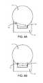
- FIGS. 4A-4Billustrate an example scenario of a self-optimizing power transfer device and a charging station, under an embodiment.
- FIGS. 4A-4Billustrate a cross-sectional view of the self-optimizing power transfer device being docked with or placed in contact with the charging station, according to an embodiment.
- the operation of the self-propelled device in FIGS. 4A-4Bcan be performed by using the system described in FIG. 1 and method described in FIG. 2 .
- FIGS. 4A-4Billustrate a potential challenge a user may encounter in trying to manually align the charging interfaces of a self-propelled device and a charging station.
- the device 410 in FIGS. 4A-4Bis in the shape of a sphere, there is no top or bottom of the device (e.g., compared to a remote-controlled toy car, for example).
- the self-propelled device 410can have a housing in a shape of a sphere.
- the charging station 420can have a housing with a base and an upper surface (e.g., a receptacle) that is contoured to receive the self-propelled device 410 when the self-propelled device 410 is placed into contact with the upper surface (e.g., when the device 410 is to be charged).
- the charging interface 422 of the charging station 420can be provided within the housing of the charging station 420 in or near the center of the receiving surface. In one embodiment, the charging interface 422 can be shaped so that at least a portion of the charging interface 422 is shaped to mirror the shape of the housing of the charging station 420 .
- the charging interface 422can include one or more coils (e.g., wires that are wound in a circle) that can be wound so that it curves with the curvature of the housing of the charging station 420 .
- the charging interface 412can include one or more coils that are wound to match the spherical shape of the housing of the device 410 .
- the usercan try to estimate the location of charging interface 412 within the device 410 and try to align the charging interface 412 with the charging interface 422 of the charging station 420 .
- the housing of the device 410can include one or more features that the user can use to try to align the charging interface 412 with the charging interface 422 (e.g., a marking on the surface of the housing of the device 410 that indicates where the charging interface 412 is located, or a marking on a surface of the housing of the device 410 that indicates to the user that the charging interface 412 is on the opposing surface).
- the device 410can be weighted toward the charging interface 412 .
- the userhas placed the self-propelled device 410 in the charging station 420 in order to charge the power source of the device 410 .
- the charging interface 412 of the self-propelled device 410 and the charging interface 422 of the charging station 420are misaligned from each other (e.g., is not substantially aligned) so that power is not being optimally or efficiently transmitted and/or received by the charging interface 412 .
- the self-propelled device 410detects that charging has occurred and detects that there is a misalignment between the charging interface 412 and the charging interface 422 (as described in FIGS. 1 and 2 ).
- the device 410can be automatically caused to move on the surface of the charging station 420 until the charging interface 412 and the charging interface 422 reach substantial alignment.
- the drive system of the device 410can include multiple motors and wheels within the spherical housing of the device 410 to cause the device 410 to move in one or more directions, in one or more speeds.
- the device 410can control the drive system to cause the device to, for example, rotate or rock back and forth within the receiving surface of the charging station 420 in order for the charging interfaces 412 , 422 to achieve alignment.
- the device 410determines that substantial alignment has been achieved, as illustrated in FIG. 4B , the device 410 can remain stationary with respect to the charging station 420 .
- FIG. 5illustrates an example hardware diagram of a self-optimizing power transfer device, under an embodiment.
- system 100may be implemented by memory and processor resources as described in FIG. 5 .
- the self-propelled device 500includes one or more processors 510 , memory resources 520 , one or more output devices 530 , one or more communication sub-systems 540 (including wireless communication sub-systems), and one or more sensors 560 .
- the communication sub-systems 540enables the device 500 to exchange wireless communications with another device using different mediums and protocols (e.g., WI-FI, BLUETOOTH, Infrared).
- the device 500can also include a charging interface 570 , a power source 580 (e.g., one or more batteries), and a drive system 590 .
- the device 500can also include one or more input mechanisms 550 (e.g., a button, a switch, a touch-sensitive input device).
- the processor 510is configured with software and/or other logic to perform one or more processes, steps and other functions described with embodiments, such as described by FIGS. 1-4B , and elsewhere in the application.
- Processor 510is configured, with instructions and data stored in the memory resources 520 , to implement the system 100 (as described with FIG. 1 ). For example, instructions for implementing the alignment detection, the IMU, and the power management can be stored in the memory resources 520 of the device 500 .
- the processor 510can execute instructions for detecting whether the charging interface 570 of the device 500 is substantially aligned (or misaligned) with the charging interface of a charging station, and if misalignment is detected, automatically control the drive system 590 to cause the device 500 to move or reposition itself on the surface of the charging station to achieve alignment.
- the processor 510can control the output devices 530 , such as a speaker or one or more light sources, in order to provide an indication to a user of one or more operations of the device 500 .
- the processor 510can cause a speaker to output a noise (e.g., a beep sound or buzz sound) if misalignment is detected, or cause a light source to be turned on (e.g., a green color compared to a red color) if alignment is achieved.
- FIG. 5illustrates the power source 580 only being coupled to the charging interface 570 , the other components of device 500 can also be coupled to the power source 580 in order to be powered.
- the system and method as described in FIGS. 1-2can be implemented by memory and processing resources of a vehicle, such as a car.
- a charging interfacesuch as an inductive charging interface, may be provided on an underside region of the vehicle so that it can receive power from another charging interface that is provided on a charging station (e.g., one that is low to the ground).
- the vehiclecan be parked over a charging station by a user, for example, in a garage or parking space so that the charging interface can receive power from the charging interface of the charging station when the interfaces are substantially aligned. If the vehicle is parked and the system detects misalignment, the vehicle or the charging interface can be automatically caused to move in one or more directions until alignment is achieved (e.g., without the user having to manually move the vehicle).
- the self-propelled devicecan also be an automatic vacuum cleaner that automatically returns to its charging station after a cleaning period.
- one or more components of the system 100can be implemented by the charging station when the self-propelled device is placed into contact with a surface of the charging station (e.g., when the device is initially being charged).
- the charging stationcan be the remote device that can wirelessly communicate with the self-propelled device, as discussed with respect to FIGS. 1-2 .
- the charging station or dockcan include one or more mechanical features that can cause the self-propelled device to be moved relative to the charging interface of the charging station. For example, when misalignment is detected, at least a portion of the surface (just above the charging interface) of the charging station can move so that the self-propelled device can be rotated or moved relative to the charging interface of the charging station until alignment is achieved.
Landscapes
- Engineering & Computer Science (AREA)
- Power Engineering (AREA)
- Computer Networks & Wireless Communication (AREA)
- Charge And Discharge Circuits For Batteries Or The Like (AREA)
Abstract
Description
Self-propelled devices typically operate off of internal batteries. Such devices typically have a need to recharge batteries. Many devices use charging stations or docks to recharge batteries.
The disclosure herein is illustrated by way of example, and not by way of limitation, in the figures of the accompanying drawings and in which like reference numerals refer to similar elements, and in which:
Embodiments described herein provide for a self-propelled device that is able to automatically move or adjust its position relative to a charging station or dock when it detects that its charging interface is misaligned with a charging interface of the charging station.
In some embodiments, the self-propelled device can include a drive system (e.g., a drive mechanism) that enables the device to move in one or more directions, and in various speeds. When the device detects that its charging interface is misaligned with the charging interface of the charging station or dock, the device can automatically control its drive system to move, thereby achieving alignment. In some cases, the self-propelled device can be referred to by different terms and phrases, including robot, robotic device, controlled device, smart device, computing device, autonomous device, remote device, and remote-controlled device. In some embodiments, a self-propelled device can be configured to autonomously move around without user input.
In one embodiment, the charging station can include an inductive charging interface that enables power to be transferred inductively to an inductive charging interface of the device. The device can receive power from the charging station when the device is positioned so that its inductive charging interface is aligned or substantially aligned with the inductive charging interface of the charging station. For example, the self-propelled device can be docked to the charging station (e.g., at least a portion of the housing of the device can be in contact with a portion of the housing or surface of the charging station) or be placed in operational proximity with the charging station. Operational proximity is defined to be sufficient proximity between the device and the charging station in order to enable one device to transfer power inductively to the other. In this manner, a power source of the device, such as one or more rechargeable batteries, can be recharged via the power transfer between the inductive charging interfaces.
According to one or more embodiments, the device can detect that its charging interface and the charging interface of the charging station is misaligned by monitoring the power transmission from the charging station to the device. By monitoring the power transmission, the device can determine whether the amount of power being received from the charging station is less than a threshold amount (e.g., receiving power less than a certain power level or receiving power less than a certain percent). If the amount of power received is less than the threshold amount (e.g., during an interval of time), the device can determine that there is misalignment.
In another embodiment, the device can detect that its charging interface and the charging interface of the charging station are misaligned by using inputs detected by one or more sensors of the device. The device can include, for example, one or more accelerometers, one or more gyroscopes, or one or more magnetometers that provide sensor inputs to the device. Using inputs detected by the one or more sensors, the device can determine its state and/or position and/or orientation with respect to the charging station. Based on these inputs, the device can determine whether its charging interface is aligned with the charging interface of the charging station. In addition, the device can use the inputs and other information to search for the location of maximum power transfer (e.g., a location on the charging station).
Embodiments also provide for a charging station for a self-propelled device that includes a contoured receptacle to receive the self-propelled device. The self-propelled device can have a spherical shape to fit in the receptacle of the charging station. The self-propelled device can automatically change its position and/or orientation within the receptacle when it detects that its charging interface is misaligned from the charging interface of the charging station.
One or more embodiments described herein provide that methods, techniques, and actions performed by a device are performed programmatically, or as a computer-implemented method. Programmatically, as used herein, means through the use of code or computer-executable instructions. These instructions can be stored in one or more memory resources of the device. A programmatically performed step may or may not be automatic.
One or more embodiments described herein can be implemented using programmatic modules or components. A programmatic module or component can include a program, a sub-routine, a portion of a program, or a software component or a hardware component capable of performing one or more stated tasks or functions. As used herein, a module or component can exist on a hardware component independently of other modules or components. Alternatively, a module or component can be a shared element or process of other modules, programs or machines.
Some embodiments described herein can generally require the use of processing and memory resources. Memory, processing, and network resources may all be used in connection with the establishment, use, or performance of any embodiment described herein (including with the performance of any method or with the implementation of any system).
Furthermore, one or more embodiments described herein may be implemented through the use of instructions that are executable by one or more processors. These instructions may be carried on a computer-readable medium. Machines shown or described with figures below provide examples of processing resources and computer-readable mediums on which instructions for implementing embodiments of the invention can be carried and/or executed. In particular, the numerous machines shown with embodiments of the invention include processor(s) and various forms of memory for holding data and instructions. Examples of computer-readable mediums include permanent memory storage devices, such as hard drives on personal computers or servers. Other examples of computer storage mediums include portable storage units, such as CD or DVD units, flash memory (such as carried on smart phones, multifunctional devices or tablets), and magnetic memory. Computers, terminals, network enabled devices (e.g., mobile devices, such as cell phones) are all examples of machines and devices that utilize processors, memory, and instructions stored on computer-readable mediums. Additionally, embodiments may be implemented in the form of computer-programs, or a computer usable carrier medium capable of carrying such a program.
System Description
According to an embodiment,system 100 includes components such asalignment detection 110,inertial measurement unit 120, andpower management 130. These components ofsystem 100 can be implemented through separate hardware and/or software (e.g., through a combination of memory and processing resources of the self-propelled device). In one embodiment, thealignment detection 110 and theinertial measurement unit 120 are implemented as separate software components that are executed on, for example, a processor of the self-propelled device. The components ofsystem 100 combine to (i) detect that the self-propelled device is being charged by a charging station or dock, (ii) determine that a charging interface of the self-propelled device and a charging interface of the charging station is misaligned, and (iii) automatically cause the self-propelled device to move on the charging station to achieve alignment when misalignment is present.
In one embodiment,system 100 also communicates with adrive system 140 and acharging interface 150. The self-propelled device can correspond to a remote-controlled or robotic device that is capable of moving in one or more directions. For example, the self-propelled device can be a radio-controlled vehicle (e.g., a toy car), aircraft, helicopter, hovercraft, balloon, boat, submarine, spherical ball, vacuum cleaner, etc., that is capable of moving either autonomously or via user control from a remote computing device (e.g., a remote control or a smart phone). Thedrive system 140 can enable the self-propelled device to move.
According to different implementations, thedrive system 140 can include one or more motors, one or more actuators, one or more propellers, one or more wheels, one or more axles, one or more gear drives, etc., that enable the self-propelled device to move in one or more directions and in various distances and speeds (e.g., in the air, in the water, on the ground) in response to commands or control signals from a controller component (not illustrated inFIG. 1 ). In some embodiments, one or more components ofsystem 100 can be implemented, at least in part, by the controller component (e.g., thealignment detection 120 can be part of a controller component).
The self-propelled device can also be powered by a power source (e.g., one or more batteries) that can be rechargeable or replaced. The power source can be coupled to a charginginterface 150 so that the power source can be recharged without having the user remove and replace the power source. In one embodiment, the charginginterface 150 can include electrical contacts that are exposed on the housing (or can be exposed by a user removing a cover) of the self-propelled device to enable a user to connect a power cable (e.g., from an AC adapter, a micro-USB cable) to the charginginterface 150 or to enable the user to place the self-propelled device on a charging station with electrical contacts that can mate with the contacts of the charginginterface 150. The charginginterface 150 can receive power from an external power source in order to recharge the power source of the self-propelled device.
In some embodiments, the housing of the self-propelled device can be shaped or configured so that no electrical contacts are exposed on the housing. For example, in some cases, having a charging mechanism that does not require a user to plug in a cord can be easy to use. According to embodiments, the charginginterface 150 can be an inductive charging interface so that it can inductively receive power from another inductive charging interface of a charging station or dock (not illustrated inFIG. 1 ). The inductive charging interface allows for power to be received without using a wired electrical connection from the charging station. The charginginterface 150 can then receive magnetic energy (e.g., via one or more coils) and convert it to electrical energy in order to recharge the power source of the self-propelled device.
Thepower management 130 can detectpower 131 being received from the charging station via the charginginterface 150. In some embodiments, thepower management 130 can measure the amount of power being received by communicating with the charginginterface 150 and/or by measuring the power source itself (e.g., determining that the amount of energy of one or more batteries is being increased). Thepower management 130 can, for example, detectpower 131 being received by the charginginterface 150 and measure the amount of power being received per second or per minute (or other duration of time). In other embodiments, thepower management 130 can also determine the fluctuation of the amount of power being received from the charging station within a time period (e.g., detect that power is being received for a short period of time, then power not being received, then power being received again, etc.). Thepower management 130 can then provide thepower information 133 of the receivedpower 133 to thealignment detection 110.
Thealignment detection 110 can use thepower information 133 to detect whether the power source of the self-propelled device is being charged. In one embodiment, when thealignment detection 110 detects that charging is taking place, thealignment detection 110 can send a signal to a controller component of the self-propelled device to place the device in a charging mode or operation. In other embodiments, the device can also use information provided by other components or mechanisms to determine whether charging is taking place (e.g., the user indicates charging via a user input mechanism, or a sensor of the charging station or the device detects placement of the device).
According to embodiments, thealignment detection 110 can also use thepower information 131 in order to determine the power transmission efficiency between the self-propelled device and the charging station when power is being received via the charginginterface 150. For example, thealignment detection 110 can use information about the charging settings, capabilities, and/or specifications of the self-propelled device to determine a threshold amount of power (or rate of power) the charginginterface 150 should be receiving under optimal or efficient conditions (e.g., the threshold can correspond to an efficient power transmission). Thealignment detection 110 can compare the current receiving power conditions via the power information131 (e.g., in terms of absolute values or percentages) with the optimal/efficient power threshold levels in order to determine whether power is being transferred efficiently. If the received power amount is less is than the threshold, thealignment detection 110 can determine that the charginginterface 150 of the self-propelled device is not substantially or efficiently aligned (e.g., is deemed to be misaligned) with the charging interface of the charging station. As used herein, the term “substantial” or its variants (e.g., “substantially”) is intended to mean at least 90% of the stated quantity, measurement or expression.
For example, the charging interfaces of the device and the charging station can be inductive charging interfaces. When the device and the charging station are placed in operational proximity with each other (e.g., sufficient proximity to enable the charging station to transfer power inductively to the device), thepower information 131 can indicate that the device is receiving power and thepower management 130 can use the information to determine how much power is being received.
In some embodiments, the charginginterface 150 of the device can include a pair of electrical contacts that is to be coupled or mated with a pair of contacts on a surface of the charging station. When the charging interfaces of the device and charging station are properly (e.g., substantially) aligned, power can be efficiently transferred from the charging station to the charginginterface 150 of the device. However, if the device is placed into contact with the surface of the charging station so that the charging interfaces of the device and the charging station are misaligned (e.g., the pair of contacts are not substantially aligned), for example, there can be a fluctuation of power being transferred within a time period so that power is received for a short period of time, then not received, then being received again, etc. When such condition is present, thealignment detection 110 can determine that a misalignment of the charging interfaces exists.
In some embodiments, thealignment detection 110 can also determine whether there is a misalignment of the charging interfaces by using position and/or orientation and/ormovement information 121 received from the inertial measurement unit (IMU)12. According to various embodiments, thealignment detection 110 can detect an amount of misalignment by using just thepower information 133 or just the position/movement information 121, or by using both.
According to an embodiment, the self-propelled device can include one or more sensors, such as one ormore accelerometers 122, one ormore gyroscopes 124, one ormore magnetometers 126, or one or moreother sensing mechanisms 128. These sensors can provide sensor input about the current state of the self-propelled device with respect to the surrounding environment to theIMU 120. For example, asensor other sensors 128, can provide input to theIMU 120 so thatsystem 100 can be aware of or maintain information of the device's position and/or orientation and/or movement relative to a reference point (e.g., the ground or in the direction of gravity).
In some embodiments, thealignment detection 110 can communicate with or be part of a controller component ofsystem 100, which can also receive the position/movement information 121 from theIMU 120. Using the position/movement information 121, the controller component can measure or estimate the current/present state (e.g., stationary or moving) and/or position of the self-propelled device, including various rotational angles about three axes (relative to the center of the device), such as pitch, roll, and yaw angles. The controller component ofsystem 100 can also use this information to provide drive control signals111 to thedrive system 140 for controlling the movement of the self-propelled device.
According to an embodiment, when the self-propelled device is being charged (e.g., placed into contact with a surface of the charging station and receiving at least some amount of power from the charging station), thealignment detection 110 can use the current position/movement information 121 of the device (at the time the device begins to recharge) to determine whether the device is properly positioned or oriented on the surface of the charging station. For example, thealignment detection 110 can use information corresponding to the optimal position/orientation of the self-propelling device and compare it with the current position/movement information 121 of the self-propelling device. If the current position/movement information 121 is within a certain percentage or threshold corresponding to the optimal position/orientation of the self-propelling device (e.g., plus or minus 5 degrees with respect to each of the pitch, roll, or yaw angles), thealignment detection 110 can determine that the charginginterface 150 is in a proper charging position and that the charginginterface 150 is substantially aligned with the charging interface of the charging station. In other embodiments, based on the current position/movement information 121, thealignment detection 110 can also determine the amount of misalignment (e.g., that the pitch rotational angle is misaligned by a certain degree, while the roll rotational angle is misaligned by a different amount).
Based on at least one of thepower information 133 or the position/movement information 121, thealignment detection 110 can detect whether or not the charginginterface 150 of the self-propelled device is substantially aligned with the charging interface of the charging station. If thealignment detection 110 detects that the charging interfaces are misaligned (e.g., not substantially aligned), thealignment detection 110 can automatically cause the device to move, rotate, and/or reposition itself with respect to the surface of the charging station in order to achieve alignment. For example, thealignment detection 110 can cause the device to continue to move (e.g., rock back and forth, and left to right) until thepower management 130 providespower information 133 indicating that power transmission has been optimized (e.g., that power is being received at a particular threshold, such as at least 90%). Thealignment detection 110 can provide drivingcontrols 111 to thedrive system 140 of the self-propelled device in order to cause the device to move in the appropriate direction(s) to align the charginginterface 150 with the charging interface of the charging station.
For example, if the self-propelled device is a remote-controlled toy car, thealignment detection 110 can use the driving controls111 to cause one or more wheels of the device to swivel (e.g., make the car turn left or right) and rotate (e.g., move the car forward or backward) a particular amount in order to substantially align the charginginterface 150 with the charging interface of the charging station. In another example, if the self-propelled device is a spherical device that is capable of using adrive system 140 capable of causing the device to roll, the drivingcontrols 111 can cause the device to roll in a particular direction so that each of the pitch, roll, or yaw angles are within the appropriate threshold corresponding to the optimal position/orientation of the self-propelling device. In this manner,system 100 enables the device to self-optimize the power transmission during its charging process.
In one embodiment, thealignment detection 110 can also search for the location of maximum power transfer. For example, thealignment detection 110 can continually or periodically receive updatedpower information 133 or position/movement information 121 as it causes the device to move, rotate, and/or reposition itself with respect to the surface of the charging station in order to achieve alignment (and maximum power transfer). Thealignment detection 110 can intelligently search for the region or area on the surface of the charging station by using the updatedpower information 133 and/or position/movement information 121 to determine whether the device is being moved closer to achieving alignment (or maximum power transfer) or being moved further away. In this manner, thealignment detection 110 can dynamically control thedrive system 140 to search and find the location for receiving a maximum amount of power.
Methodology
A method such as described by an embodiment ofFIG. 2 can be implemented using, for example, components described with an embodiment ofFIG. 1 . Accordingly, references made to elements ofFIG. 1 are for purposes of illustrating a suitable element or component for performing a step or sub-step being described.FIG. 2 illustrates an example method for operating a self-optimizing power transfer device, according to an embodiment.
InFIG. 2 , the self-propelled device detects power being received from a charging station in order to charge a power source (e.g., a rechargeable battery) of the device (step200). The self-propelled device can include a charginginterface 150 that receives power from the charging station and can recharge the battery of the device. In some embodiments, the charging interface can be an inductive charging interface that receives magnetic energy (e.g., via one or more coils) and converts it to electrical energy. When thepower management 130 detects that an amount of power is being received from the charging station via the charginginterface 150, thealignment detection 110 can determine that the self-propelled device is being charged (e.g., is placed on a surface of the charging station).
The device also detects whether there is misalignment between the charginginterface 150 of the device and the charging interface of the charging station (step210). According to embodiments, thealignment detection 110 can detect the charging interfaces are misaligned by monitoring the power transmission from the charging station (sub-step212) and/or by detecting current device state/position/orientation using sensor inputs (sub-step214). When thealignment detection 110 monitors the power transmission, it can compare the receivedpower information 133 with a threshold amount of power (or rate of power) the charginginterface 150 should be receiving under optimal or efficient conditions. If thealignment detection 110 determines that the amount of power being received is less than a predetermined threshold, thealignment detection 110 can determine that the charging interfaces are misaligned.
In another embodiment, thealignment detection 110 can detect whether there is misalignment by receiving position/movement information 121 based on sensor inputs from one or more sensors and comparing the current device position/orientation with the optimal position/orientation that the self-propelling device should be positioned in. If thealignment detection 110 determines that the position/orientation of the device is different more than a threshold amount (e.g., the pitch, roll, and/or yaw is different by five or more degrees), thealignment detection 110 can determine that the charging interfaces are misaligned.
In response to detecting that the charging interfaces of the device and the charging station are misaligned (based on the monitored power or based on sensor inputs), thealignment detection 110 can automatically cause the device to be moved based on the detected misalignment (step220). For example, the device can be a self-propelling device that can automatically move its position or orientation relative to the charging station in response to the sensor inputs (and/or in response to power signal inputs). Thealignment detection 110 can cause the device to be moved by controlling the drive system of the device. The device will be moved in one or more directions (or rotate or change orientations) in order to achieve substantial alignment between the charginginterface 150 of the device and the charging interface of the charging station.
In some embodiments, because thealignment detection 110 can measure the amount of misalignment (e.g., the difference between the degrees of the pitch, roll, and/or yaw of the current device position/orientation with the degrees of the respective optimal position/orientation that the device should be in for efficient recharging), the device can be caused to move to correct the measured amount of misalignment (e.g., if the pitch is off by 15 degrees, rotate by 15 degrees in the opposite direction).
In one embodiment, the self-propelled device can detect whether there is misalignment between the charging interfaces even without first detecting that power is being received from the charging station. For example, the self-propelled device can be placed into a charging state (e.g., via a user input) or be aware that the user is attempting to charge the device using one or more sensors of the self-propelled device and/or one or more sensors of the charging station. In some embodiments, the self-propelled device can automatically determine that there is misalignment between the charging interfaces when the device is placed in charging state and (i) no power is being received from by the charging interface of the device (e.g., thepower management 130 transmitspower information 133 to the alignment detection that indicates that no power is being received), and/or (ii) the rotational angles of the device (e.g., the pitch, roll, yaw) are significantly different from the angles corresponding to the optimal position/orientation the self-propelling device should be in for efficient charging.
As an addition or alternative, in response to detecting that the charging interfaces of the device and the charging station are misaligned (based on the monitored power and/or based on sensor inputs), thealignment detection 110 can also search for the location of maximum power transfer. In one embodiment, thealignment detection 110 can intelligently search for a location on the surface of the charging station by using the monitored power and/or sensor inputs to determine if the device is being moved closer to achieving alignment (or maximum power transfer) or being moved further away. Thealignment detection 110 can dynamically control thedrive system 140 to search and find the location for receiving a maximum amount of power. In other embodiments, thealignment detection 110 can use received and/or stored information (e.g., stored in a memory resource) about the charging station (e.g., which can provide information about where the charging interfaces are positioned on the charging surface) to search for the location of maximum power.
According to one or more embodiments, the steps described inFIG. 2 can be performed by components implemented by resources on multiple devices. For example, the self-propelled device can include a wireless communication component for implementing wireless communications with another device (e.g., a controller remote from the self-propelled device, such as a remote-control or a smart phone). The wireless communication component can implement a WI-FI protocol, a BLUETOOTH protocol, or other protocols in alternative implementations. Using the wireless communication component, the self-propelled device can transmit, to the remote device, information that some amount of power is being received from a charging station (e.g., that it is being charged) (step200).
The remote device can also receive information about the power transmission and/or information about the current state/position/orientation of the self-propelled from the self-propelled device so that it can use its memory and processing resources to detect whether there is misalignment between the self-propelled device and the charging station (step210). The remote device can transmit control signals for controlling the movement of the self-propelled device to achieve alignment on the charging station (step220). During this time, the remote device can continue to receive power information of the power transmission and/or current position/orientation information of the self-propelled device (e.g., real-time feedback) to better control the drive system of the self-propelled device.
Example Scenarios
In the example provided, the user has assumed that the charging interfaces of the device and charging station will be aligned in a particular region of the surface of the charging station320 (e.g., near the center of the charging station320), and has initially placed the self-propelleddevice 310 in that region. However, as illustrated inFIG. 3 , thecoil 312 of the charging interface of the self-propelleddevice 310 and thecoil 322 of the charging interface of the chargingstation 320 are misaligned330 (e.g., they are not substantially aligned with each other). Becausemisalignment 330 is present, the power transmission has not been optimized (e.g., it is not efficient).
When the self-propelleddevice 310 is placed into contact with the chargingstation 320 so that at least some amount of power can be transmitted via the charging interfaces, the self-propelleddevice 310 can determine that charging has been initiated. The self-propelleddevice 310 can detect whethermisalignment 330 exists between the charging interfaces and can also determine the amount of misalignment based on power transmission information and/or current device state/position/orientation information. Based on this information, the self-propelleddevice 310 can automatically be caused to move or reposition itself with respect to the chargingstation 320 in order to achieve alignment (e.g., correct or reduce the misalignment330). For example, the self-propelleddevice 310 can control its drive system to substantially align the one ormore coils 312 of its charging interface with the one ormore coils 322 of the charging interface of the chargingstation 320.
The example scenario ofFIGS. 4A-4B illustrate a potential challenge a user may encounter in trying to manually align the charging interfaces of a self-propelled device and a charging station. For example, because thedevice 410 inFIGS. 4A-4B is in the shape of a sphere, there is no top or bottom of the device (e.g., compared to a remote-controlled toy car, for example). As such, it may be difficult for the user to know exactly where the charginginterface 412 of thedevice 410 is located (especially if the charginginterface 412 is an inductive charging interface without exposed electrical contacts).
According to an embodiment, the self-propelleddevice 410 can have a housing in a shape of a sphere. The chargingstation 420 can have a housing with a base and an upper surface (e.g., a receptacle) that is contoured to receive the self-propelleddevice 410 when the self-propelleddevice 410 is placed into contact with the upper surface (e.g., when thedevice 410 is to be charged). The charginginterface 422 of the chargingstation 420 can be provided within the housing of the chargingstation 420 in or near the center of the receiving surface. In one embodiment, the charginginterface 422 can be shaped so that at least a portion of the charginginterface 422 is shaped to mirror the shape of the housing of the chargingstation 420. For example, the charginginterface 422 can include one or more coils (e.g., wires that are wound in a circle) that can be wound so that it curves with the curvature of the housing of the chargingstation 420. Similarly, the charginginterface 412 can include one or more coils that are wound to match the spherical shape of the housing of thedevice 410.
When the user wants to charge the self-propelleddevice 410 using the chargingstation 420, the user can try to estimate the location of charginginterface 412 within thedevice 410 and try to align the charginginterface 412 with the charginginterface 422 of the chargingstation 420. In one embodiment, the housing of thedevice 410 can include one or more features that the user can use to try to align the charginginterface 412 with the charging interface422 (e.g., a marking on the surface of the housing of thedevice 410 that indicates where the charginginterface 412 is located, or a marking on a surface of the housing of thedevice 410 that indicates to the user that the charginginterface 412 is on the opposing surface). In another embodiment, thedevice 410 can be weighted toward the charginginterface 412.
InFIG. 4A , the user has placed the self-propelleddevice 410 in the chargingstation 420 in order to charge the power source of thedevice 410. However, the charginginterface 412 of the self-propelleddevice 410 and the charginginterface 422 of the chargingstation 420 are misaligned from each other (e.g., is not substantially aligned) so that power is not being optimally or efficiently transmitted and/or received by the charginginterface 412. The self-propelleddevice 410 detects that charging has occurred and detects that there is a misalignment between the charginginterface 412 and the charging interface422 (as described inFIGS. 1 and 2 ).
In response to detecting the misalignment, thedevice 410 can be automatically caused to move on the surface of the chargingstation 420 until the charginginterface 412 and the charginginterface 422 reach substantial alignment. In one embodiment, the drive system of thedevice 410 can include multiple motors and wheels within the spherical housing of thedevice 410 to cause thedevice 410 to move in one or more directions, in one or more speeds. Thedevice 410 can control the drive system to cause the device to, for example, rotate or rock back and forth within the receiving surface of the chargingstation 420 in order for the charginginterfaces device 410 determines that substantial alignment has been achieved, as illustrated inFIG. 4B , thedevice 410 can remain stationary with respect to the chargingstation 420.
Hardware Diagram
In one embodiment, the self-propelleddevice 500 includes one ormore processors 510,memory resources 520, one ormore output devices 530, one or more communication sub-systems540 (including wireless communication sub-systems), and one ormore sensors 560. According to different implementations, thecommunication sub-systems 540 enables thedevice 500 to exchange wireless communications with another device using different mediums and protocols (e.g., WI-FI, BLUETOOTH, Infrared). Thedevice 500 can also include a charginginterface 570, a power source580 (e.g., one or more batteries), and adrive system 590. In some embodiments, thedevice 500 can also include one or more input mechanisms550 (e.g., a button, a switch, a touch-sensitive input device).
Theprocessor 510 is configured with software and/or other logic to perform one or more processes, steps and other functions described with embodiments, such as described byFIGS. 1-4B , and elsewhere in the application.Processor 510 is configured, with instructions and data stored in thememory resources 520, to implement the system100 (as described withFIG. 1 ). For example, instructions for implementing the alignment detection, the IMU, and the power management can be stored in thememory resources 520 of thedevice 500. Theprocessor 510 can execute instructions for detecting whether the charginginterface 570 of thedevice 500 is substantially aligned (or misaligned) with the charging interface of a charging station, and if misalignment is detected, automatically control thedrive system 590 to cause thedevice 500 to move or reposition itself on the surface of the charging station to achieve alignment.
In one embodiment, theprocessor 510 can control theoutput devices 530, such as a speaker or one or more light sources, in order to provide an indication to a user of one or more operations of thedevice 500. For example, in some embodiments, theprocessor 510 can cause a speaker to output a noise (e.g., a beep sound or buzz sound) if misalignment is detected, or cause a light source to be turned on (e.g., a green color compared to a red color) if alignment is achieved. AlthoughFIG. 5 illustrates thepower source 580 only being coupled to the charginginterface 570, the other components ofdevice 500 can also be coupled to thepower source 580 in order to be powered.
In an alternative embodiment, the system and method as described inFIGS. 1-2 , for example, can be implemented by memory and processing resources of a vehicle, such as a car. A charging interface, such as an inductive charging interface, may be provided on an underside region of the vehicle so that it can receive power from another charging interface that is provided on a charging station (e.g., one that is low to the ground). The vehicle can be parked over a charging station by a user, for example, in a garage or parking space so that the charging interface can receive power from the charging interface of the charging station when the interfaces are substantially aligned. If the vehicle is parked and the system detects misalignment, the vehicle or the charging interface can be automatically caused to move in one or more directions until alignment is achieved (e.g., without the user having to manually move the vehicle).
In other embodiments, the self-propelled device can also be an automatic vacuum cleaner that automatically returns to its charging station after a cleaning period.
In another embodiment, one or more components of thesystem 100 can be implemented by the charging station when the self-propelled device is placed into contact with a surface of the charging station (e.g., when the device is initially being charged). The charging station can be the remote device that can wirelessly communicate with the self-propelled device, as discussed with respect toFIGS. 1-2 . The charging station or dock can include one or more mechanical features that can cause the self-propelled device to be moved relative to the charging interface of the charging station. For example, when misalignment is detected, at least a portion of the surface (just above the charging interface) of the charging station can move so that the self-propelled device can be rotated or moved relative to the charging interface of the charging station until alignment is achieved.
It is contemplated for embodiments described herein to extend to individual elements and concepts described herein, independently of other concepts, ideas or system, as well as for embodiments to include combinations of elements recited anywhere in this application. Although embodiments are described in detail herein with reference to the accompanying drawings, it is to be understood that the invention is not limited to those precise embodiments. As such, many modifications and variations will be apparent to practitioners skilled in this art. Accordingly, it is intended that the scope of the invention be defined by the following claims and their equivalents. Furthermore, it is contemplated that a particular feature described either individually or as part of an embodiment can be combined with other individually described features, or parts of other embodiments, even if the other features and embodiments make no mention of the particular feature. Thus, the absence of describing combinations should not preclude the inventor from claiming rights to such combinations.
Claims (20)
1. A method for charging a power source of a self-propelled device having a spherical housing and an internal drive system within the spherical housing to propel the self-propelled device, the method being performed by one or more processors of the self-propelled device and comprising:
detecting a misalignment between an inductive charging interface of the self-propelled device and an inductive charging interface of a charging dock when the self-propelled device is placed in a receptacle of the charging dock; and
in response to detecting the misalignment, automatically causing the internal drive system of the self-propelled device to rotate within the spherical housing of self-propelled device, so as to move the inductive charging interface of the self-propelled device relative to the charging dock to achieve an alignment between the inductive charging interface of the self-propelled device and the inductive charging interface of the charging dock,
wherein detecting the misalignment includes at least one of (a) monitoring an amount of power being received by the self-propelled device from the charging dock, and (b) receiving input from one or more sensors of the self-propelled device that indicate one or more angles of rotation of the self-propelled device relative to the charging dock.
2. The method ofclaim 1 , wherein detecting the misalignment includes monitoring the amount of power being received by the self-propelled device from the charging dock.
3. The method ofclaim 2 , wherein detecting the misalignment includes determining that the amount of power being received by the self-propelled device is less than a threshold amount.
4. The method ofclaim 3 , wherein automatically causing the internal drive system to rotate within the spherical housing relative to the charging dock to achieve the alignment is performed in response to determining that the amount of power being received by the self-propelled device is less than the threshold amount.
5. The method ofclaim 1 , wherein detecting the misalignment includes receiving input from the one or more sensors of the self-propelled device that indicate one or more angles of rotation of the self-propelled device relative to the charging dock.
6. The method ofclaim 5 , wherein detecting the misalignment includes determining that the one or more angles of rotation of the self-propelled device is different than one or more threshold angles of rotation by a threshold amount.
7. The method ofclaim 6 , wherein automatically causing the internal drive system to rotate relative to the charging dock to achieve the alignment is performed in response to determining that the one or more angles of rotation of the self-propelled device is different than one or more threshold angles of rotation by the threshold amount.
8. The method ofclaim 5 , wherein the input from the one or more sensors is based on a downward direction of gravity.
9. The method ofclaim 1 , wherein automatically causing the internal drive system to rotate within the spherical housing comprises adjusting a pitch, a roll, and a yaw of the internal drive system to achieve the alignment.
10. A self-propelled device comprising:
a spherical housing;
a power source;
an inductive charging interface coupled to the power source;
an internal drive system within the spherical housing for propelling the self-propelled device; and
a control mechanism coupled to the inductive charging interface and the internal drive system, the control mechanism to (i) detect a misalignment between the inductive charging interface of the self-propelled device and an inductive charging interface of a charging station when the self-propelled device is placed in a receptacle of the charging station, and (ii) in response to detecting the misalignment, automatically causing the internal drive system to rotate within the spherical housing of the self-propelled device, so as to move the inductive charging interface of the self-propelled device relative to the charging station and the spherical housing to achieve an alignment between the inductive charging interface of the self-propelled device and the inductive charging interface of the charging station, wherein the control mechanism detects the misalignment by at least one of (a) receiving input from one or more sensors that indicate one or more angles of rotation of the internal drive system relative to the charging station and (b) analyzing a power signal from the charging station.
11. The self-propelled device ofclaim 10 , further comprising the one or more sensors, wherein the control mechanism uses the one or more sensors in order to detect the misalignment.
12. The self-propelled device ofclaim 11 , wherein the control mechanism detects the misalignment by receiving the input from the one or more sensors that indicate one or more angles of rotation of the self-propelled device relative to the charging station.
13. The self-propelled device ofclaim 12 , wherein the control mechanism detects the misalignment by determining that the one or more angles of rotation of the self-propelled device are different from one or more threshold angles of rotation by a threshold amount.
14. The self-propelled device ofclaim 10 , wherein the control mechanism detects the misalignment by analyzing the power signal from the charging station, and determining that an amount of power being received by the self-propelled device is less than a threshold amount.
15. The self-propelled device ofclaim 10 , wherein automatically causing the internal drive system to rotate within the spherical housing comprises adjusting a pitch, a roll, and a yaw of the internal drive system to achieve the alignment.
16. The self-propelled device ofclaim 10 , wherein the control mechanism includes one or more processors.
17. A system comprising:
a charging station comprising an inductive charging interface; and
a self-propelled device comprising:
a spherical housing;
a power source;
an inductive charging interface coupled to the power source;
an internal drive system within the spherical housing for propelling the self-propelled device; and
a control mechanism coupled to the inductive charging interface and the internal drive system, the control mechanism to (i) detect a misalignment between the inductive charging interface of the self-propelled device and the inductive charging interface of the charging station when the self-propelled device is placed in a receptacle of the charging station, and (ii) automatically cause the internal drive system to rotate within the spherical housing of the self-propelled device, so as to move the inductive charging interface of the self-propelled device relative to the charging station to achieve an alignment between the inductive charging interface of the self-propelled device and the inductive charging interface of the charging station, wherein the control mechanism detects the misalignment by at least one of (a) receiving input from one or more sensors that indicate one or more angles of rotation of the internal drive system relative to the charging station and (b) analyzing a power signal from the charging station.
18. The system ofclaim 17 , wherein the self-propelled device further comprises the one or more sensors, and wherein the control mechanism of the self-propelled device uses the one or more sensors in order to detect the misalignment.
19. The system ofclaim 18 , wherein the control mechanism of the self-propelled device detects the misalignment by (i) receiving input from the one or more sensors that indicate one or more angles of rotation of the self-propelled device relative to the charging station, and (ii) determining that the one or more angles of rotation of the self-propelled device are different from one or more threshold angles of rotation by a threshold amount.
20. The system ofclaim 17 , wherein the control mechanism of the self-propelled device detects the misalignment by (i) analyzing the power signal from the inductive charging interface of the self-propelled device, and (ii) determining that an amount of power being received by the self-propelled device is less than a threshold amount.
Priority Applications (8)
| Application Number | Priority Date | Filing Date | Title |
|---|---|---|---|
| US13/549,097US10056791B2 (en) | 2012-07-13 | 2012-07-13 | Self-optimizing power transfer |
| JP2015521853AJP6328628B2 (en) | 2012-07-13 | 2013-07-12 | Self-optimized power transfer |
| EP13817382.8AEP2873134A4 (en) | 2012-07-13 | 2013-07-12 | Self-optimizing power transfer |
| CN201710962414.6ACN107919696A (en) | 2012-07-13 | 2013-07-12 | self-optimizing power transmission |
| CN201380036857.2ACN104471827B (en) | 2012-07-13 | 2013-07-12 | Self-Optimizing Power Delivery |
| HK15108254.7AHK1207748B (en) | 2012-07-13 | 2013-07-12 | Self-optimizing power transfer |
| PCT/US2013/050327WO2014012026A1 (en) | 2012-07-13 | 2013-07-12 | Self-optimizing power transfer |
| KR1020157003642AKR101790626B1 (en) | 2012-07-13 | 2013-07-12 | Self-optimizing power transfer |
Applications Claiming Priority (1)
| Application Number | Priority Date | Filing Date | Title |
|---|---|---|---|
| US13/549,097US10056791B2 (en) | 2012-07-13 | 2012-07-13 | Self-optimizing power transfer |
Publications (2)
| Publication Number | Publication Date |
|---|---|
| US20140015493A1 US20140015493A1 (en) | 2014-01-16 |
| US10056791B2true US10056791B2 (en) | 2018-08-21 |
Family
ID=49913436
Family Applications (1)
| Application Number | Title | Priority Date | Filing Date |
|---|---|---|---|
| US13/549,097Active2033-09-04US10056791B2 (en) | 2012-07-13 | 2012-07-13 | Self-optimizing power transfer |
Country Status (6)
| Country | Link |
|---|---|
| US (1) | US10056791B2 (en) |
| EP (1) | EP2873134A4 (en) |
| JP (1) | JP6328628B2 (en) |
| KR (1) | KR101790626B1 (en) |
| CN (2) | CN107919696A (en) |
| WO (1) | WO2014012026A1 (en) |
Cited By (4)
| Publication number | Priority date | Publication date | Assignee | Title |
|---|---|---|---|---|
| US20170225582A1 (en)* | 2014-10-29 | 2017-08-10 | Bayerische Motoren Werke Aktiengesellschaft | Method and Base Unit for Inductively Charging Electric and Hybrid Vehicles |
| US20170355275A1 (en)* | 2016-06-14 | 2017-12-14 | Intel Corporation | Vehicular inductive power transfer systems and methods |
| CN107834614A (en)* | 2017-07-28 | 2018-03-23 | 张涛 | A kind of charging method for adapting to different model mobile phone automatic charging |
| US20240278990A1 (en)* | 2018-05-09 | 2024-08-22 | Ocado Innovation Limited | Apparatus and method for charging a robotic load handling device |
Families Citing this family (39)
| Publication number | Priority date | Publication date | Assignee | Title |
|---|---|---|---|---|
| US9836046B2 (en) | 2011-01-05 | 2017-12-05 | Adam Wilson | System and method for controlling a self-propelled device using a dynamically configurable instruction library |
| US9429940B2 (en) | 2011-01-05 | 2016-08-30 | Sphero, Inc. | Self propelled device with magnetic coupling |
| US10281915B2 (en) | 2011-01-05 | 2019-05-07 | Sphero, Inc. | Multi-purposed self-propelled device |
| US9090214B2 (en) | 2011-01-05 | 2015-07-28 | Orbotix, Inc. | Magnetically coupled accessory for a self-propelled device |
| US9218316B2 (en) | 2011-01-05 | 2015-12-22 | Sphero, Inc. | Remotely controlling a self-propelled device in a virtualized environment |
| US20120229660A1 (en)* | 2011-03-09 | 2012-09-13 | Matthews Cynthia C | Methods and apparatus for remote controlled devices |
| US9440350B2 (en)* | 2012-03-02 | 2016-09-13 | Positec Power Tools (Suzhou) Co., Ltd | Automatically travelling device and control method therefor |
| US9280717B2 (en) | 2012-05-14 | 2016-03-08 | Sphero, Inc. | Operating a computing device by detecting rounded objects in an image |
| US9827487B2 (en) | 2012-05-14 | 2017-11-28 | Sphero, Inc. | Interactive augmented reality using a self-propelled device |
| US9829882B2 (en) | 2013-12-20 | 2017-11-28 | Sphero, Inc. | Self-propelled device with center of mass drive system |
| US9650814B2 (en)* | 2013-12-31 | 2017-05-16 | Henge Docks Llc | Alignment and drive system for motorized horizontal docking station |
| EP3117685B1 (en)* | 2014-01-30 | 2018-05-30 | Hewlett-Packard Development Company, L.P. | Wireless power alignment |
| US10164688B2 (en)* | 2014-04-30 | 2018-12-25 | Apple Inc. | Actuator assisted alignment of connectible devices |
| CN103986244B (en)* | 2014-05-28 | 2016-09-14 | 北京必创科技股份有限公司 | A kind of wireless power supply and tuning methods thereof |
| US9449754B2 (en)* | 2014-05-30 | 2016-09-20 | Apple Inc. | Coil constructions for improved inductive energy transfer |
| CN103986247B (en)* | 2014-06-11 | 2017-01-18 | 广东美的厨房电器制造有限公司 | Wireless power supply method and wireless power supply system for dust collector and dust collector |
| CN108565920B (en)* | 2014-06-12 | 2021-07-27 | 深圳市大疆创新科技有限公司 | A charging system, power supply device and aircraft |
| EP3268828B1 (en)* | 2015-03-09 | 2019-05-08 | Saudi Arabian Oil Company | Field deployable docking station for mobile robots |
| CN106033826A (en)* | 2015-03-17 | 2016-10-19 | 李昊阳 | Multi-rotary-wing unmanned aerial vehicle returning automatic charging method |
| US20160336809A1 (en)* | 2015-05-12 | 2016-11-17 | Powermat Technologies Ltd. | System and methods for sensor based coil monitoring of a wireless power receiver |
| US20160341573A1 (en)* | 2015-05-18 | 2016-11-24 | Qualcomm Incorporated | Integration of solenoid positioning antennas in wireless inductive charging power applications |
| ES2793950T3 (en)* | 2015-07-01 | 2020-11-17 | Ericsson Telefon Ab L M | Inhibit scrolling of a wirelessly rechargeable device |
| CN106549271B (en)* | 2015-09-18 | 2020-04-07 | 宇龙计算机通信科技(深圳)有限公司 | Interface docking method and device |
| EP3320597B1 (en) | 2016-01-13 | 2020-10-14 | Hewlett-Packard Development Company, L.P. | Movable charging coil within wristband |
| USD807888S1 (en) | 2016-03-16 | 2018-01-16 | Hewlett-Packard Development Company, L.P. | Tablet cover |
| US10011182B2 (en) | 2016-03-24 | 2018-07-03 | Ford Global Technologies, Llc | Inductive charger alignment systems for vehicles |
| DE102016211178A1 (en)* | 2016-06-22 | 2017-12-28 | Siemens Healthcare Gmbh | Medical technology system |
| CH712752A1 (en)* | 2016-07-28 | 2018-01-31 | Wrh Walter Reist Holding Ag | Rolling body for temporarily receiving goods or goods for the purpose of storage and / or transport and method for operating such a rolling body. |
| US10399449B2 (en)* | 2016-08-08 | 2019-09-03 | Hyundai Motor Company | Wireless charging control apparatus and method for optimal charging by adjusting the inclination of the electric vehicle being charged |
| CN106451704A (en)* | 2016-12-05 | 2017-02-22 | 青岛鲁渝能源科技有限公司 | Wireless charging system and wireless charging method applied to mobile terminal |
| US10562406B2 (en)* | 2018-03-12 | 2020-02-18 | Toyota Motor Engineering & Manufacturing North America, Inc. | System and method for autonomous charging of an autonomous vehicle |
| CN109245202A (en)* | 2018-09-07 | 2019-01-18 | 深圳拓邦股份有限公司 | Intelligence machine equipment recharging method, device and equipment |
| US11342796B2 (en) | 2018-09-07 | 2022-05-24 | Google Llc | Controlling wireless charging |
| WO2020184794A1 (en)* | 2019-03-13 | 2020-09-17 | 모비케이 주식회사 | Wireless charging mount enabling auto-alignment and wireless charging of smartphone |
| WO2021243377A1 (en)* | 2020-05-29 | 2021-12-02 | Shure Acquisition Holdings, Inc. | System and method for wireless power transfer and communication |
| CN112349985A (en)* | 2020-11-06 | 2021-02-09 | 歌尔科技有限公司 | Method, system and device for processing charging abnormity and electronic equipment |
| US12327681B2 (en) | 2021-09-13 | 2025-06-10 | Apple Inc. | Magnetic alignment assembly for inductive charging systems |
| WO2023080670A1 (en)* | 2021-11-03 | 2023-05-11 | 삼성전자 주식회사 | Electronic device for displaying information guiding alignment with charging device |
| JP2024157766A (en)* | 2023-04-26 | 2024-11-08 | 株式会社Octa Robotics | Mobile object and mobile object charging method |
Citations (368)
| Publication number | Priority date | Publication date | Assignee | Title |
|---|---|---|---|---|
| US90546A (en) | 1869-05-25 | Improvement in velocipedes | ||
| GB189803727A (en) | 1898-02-15 | 1898-12-31 | Jakob Tobell | Improvements in the Process and Apparatus for Winnowing, Cleaning, and Sorting Coffee Berries and the like. |
| US2796601A (en) | 1954-06-25 | 1957-06-18 | Zenith Radio Corp | Television receiver control arrangement |
| US2977714A (en) | 1958-12-02 | 1961-04-04 | Blair W Gibson | Self propelled toy |
| US3313365A (en) | 1965-05-07 | 1967-04-11 | Harold A Jackson | Two-wheeled motor vehicle |
| US3667156A (en) | 1970-12-02 | 1972-06-06 | Eijiro Tomiyama | Motor-driven rolling toy |
| US3683216A (en) | 1971-02-24 | 1972-08-08 | Richard F Post | Inertial energy storage apparatus and system for utilizing the same |
| US3821995A (en) | 1971-10-15 | 1974-07-02 | E Aghnides | Vehicle with composite wheel |
| US4310987A (en) | 1980-04-24 | 1982-01-19 | Chieffo Joseph M | Amusement device |
| US4519466A (en) | 1982-03-30 | 1985-05-28 | Eiko Shiraishi | Omnidirectional drive system |
| US4601675A (en) | 1984-05-25 | 1986-07-22 | Robinson Donald E | Mechanized toy ball |
| US4733737A (en) | 1985-08-29 | 1988-03-29 | Reza Falamak | Drivable steerable platform for industrial, domestic, entertainment and like uses |
| US4893182A (en) | 1988-03-18 | 1990-01-09 | Micronyx, Inc. | Video tracking and display system |
| US4897070A (en) | 1989-04-14 | 1990-01-30 | Wagstaff Ronald D | Two-wheeled motorized toy |
| EP0371149A1 (en) | 1988-11-18 | 1990-06-06 | Posch, Stefan jun. | Rollable toy or art object |
| US4996468A (en) | 1987-09-28 | 1991-02-26 | Tennant Company | Automated guided vehicle |
| JPH03182290A (en) | 1989-12-08 | 1991-08-08 | Masatoshi Ikeda | Magic ball |
| US5087000A (en) | 1990-04-20 | 1992-02-11 | Taiyo Kogyo Co., Ltd. | Toy airplane |
| US5213176A (en) | 1989-12-08 | 1993-05-25 | Hitachi, Ltd. | Self-propelled vehicle |
| US5297981A (en) | 1993-02-04 | 1994-03-29 | The Ertl Company, Inc. | Self-propelled bouncing ball |
| US5342051A (en) | 1992-10-30 | 1994-08-30 | Accu-Sport International, Inc. | Apparatus and method for tracking the flight of a golf ball |
| US5413345A (en) | 1993-02-19 | 1995-05-09 | Nauck; George S. | Golf shot tracking and analysis system |
| US5439408A (en) | 1994-04-26 | 1995-08-08 | Wilkinson; William T. | Remote controlled movable ball amusement device |
| JPH07308462A (en) | 1994-05-17 | 1995-11-28 | Jii K Tec:Kk | Spherical mobile object and rolling device therefor |
| US5513854A (en) | 1993-04-19 | 1996-05-07 | Daver; Gil J. G. | System used for real time acquistion of data pertaining to persons in motion |
| US5595121A (en) | 1994-04-15 | 1997-01-21 | The Walt Disney Company | Amusement ride and self-propelled vehicle therefor |
| US5628232A (en) | 1994-01-14 | 1997-05-13 | Rosen Motors Lp | Flywheel rotor with conical hub and methods of manufacture therefor |
| US5644139A (en) | 1995-03-02 | 1997-07-01 | Allen; Ross R. | Navigation technique for detecting movement of navigation sensors relative to an object |
| WO1997025239A1 (en) | 1996-01-09 | 1997-07-17 | Teknillinen Korkeakoulu | Ball robot and method for determining position thereof |
| JPH09254838A (en) | 1996-03-19 | 1997-09-30 | Sony Corp | Spherical moving device |
| US5739657A (en) | 1995-05-10 | 1998-04-14 | Fujitsu Limited | Apparatus for controlling motion of normal wheeled omni-directional vehicle and method thereof |
| US5759083A (en) | 1997-01-24 | 1998-06-02 | Soma International Ltd. | Toy vehicle with integral ball playing apparatus |
| US5780826A (en) | 1995-03-27 | 1998-07-14 | Toyo Umpanki Co., Ltd. | Container handling apparatus and management system |
| US5793142A (en) | 1996-05-02 | 1998-08-11 | Chrysler Corporation | Solid rotor assembly |
| US5871386A (en) | 1997-07-25 | 1999-02-16 | William T. Wilkinson | Remote controlled movable ball amusement device |
| US5953056A (en) | 1996-12-20 | 1999-09-14 | Whack & Track, Inc. | System and method for enhancing display of a sporting event |
| US5952796A (en) | 1996-02-23 | 1999-09-14 | Colgate; James E. | Cobots |
| US6021222A (en) | 1994-08-16 | 2000-02-01 | Ricoh Co., Ltd. | System and method for the detection of a circle image for pattern recognition |
| JP2000218578A (en) | 1999-02-03 | 2000-08-08 | Sony Corp | Spherical robot |
| US6144128A (en) | 1993-11-08 | 2000-11-07 | Rosen Motors, L.P. | Safety system for flywheel system for mobile energy storage |
| US6227933B1 (en)* | 1999-06-15 | 2001-05-08 | Universite De Sherbrooke | Robot ball |
| US6246927B1 (en) | 1997-05-05 | 2001-06-12 | Ralph Dratman | Inter-cooperating toys |
| CN1302717A (en) | 2001-02-15 | 2001-07-11 | 上海交通大学 | Movable spherical robot |
| US6315667B1 (en) | 2000-03-28 | 2001-11-13 | Robert Steinhart | System for remote control of a model airplane |
| US6320352B2 (en) | 1999-12-06 | 2001-11-20 | Kabushiki Kaisha Toyoda Jidoshokki Seisakusho | Electric coupling apparatus for charging device |
| US20020011368A1 (en) | 1999-10-20 | 2002-01-31 | Lely Research Holding A.G., A Swiss Limited Liability Company | Self-propelled drive wheel |
| US20020036104A1 (en) | 2000-09-22 | 2002-03-28 | Kerrebrock Peter A. | Transformable vehicle |
| DE10146862A1 (en) | 2000-10-17 | 2002-05-02 | Richard Eckl | Fully movable vehicle in shape of ball has drive system possessing only two drive wheels which are installed opposite and parallel to one another at same height |
| JP2002126373A (en) | 2000-10-23 | 2002-05-08 | Izumi Toda | Running-on-ball toy |
| US6390213B1 (en) | 1998-11-16 | 2002-05-21 | Joel N. Bleicher | Maneuverable self-propelled cart |
| US6449010B1 (en) | 1996-12-20 | 2002-09-10 | Forsum Digital Effects | System and method for enhancing display of a sporting event |
| US6456938B1 (en) | 1999-07-23 | 2002-09-24 | Kent Deon Barnard | Personal dGPS golf course cartographer, navigator and internet web site with map exchange and tutor |
| US6459955B1 (en) | 1999-11-18 | 2002-10-01 | The Procter & Gamble Company | Home cleaning robot |
| US6458008B1 (en) | 2000-09-05 | 2002-10-01 | Jamie Hyneman | Remote control device with gyroscopic stabilization and directional control |
| US20020142701A1 (en) | 2001-03-30 | 2002-10-03 | Rosenberg Louis B. | Haptic remote control for toys |
| US6535793B2 (en) | 2000-05-01 | 2003-03-18 | Irobot Corporation | Method and system for remote control of mobile robot |
| US20030093182A1 (en) | 1999-12-28 | 2003-05-15 | Taku Yokoyama | Information transmission system, information transmission method, robot, information recording medium, online sales system, online sales method and sales server |
| US6573883B1 (en) | 1998-06-24 | 2003-06-03 | Hewlett Packard Development Company, L.P. | Method and apparatus for controlling a computing device with gestures |
| US20030118217A1 (en) | 2000-08-09 | 2003-06-26 | Kenji Kondo | Eye position detection method and device |
| US6615109B1 (en) | 2000-02-10 | 2003-09-02 | Sony Corporation | System and method for generating an action of an automatic apparatus |
| US20030179176A1 (en) | 2002-03-21 | 2003-09-25 | International Business Machines Corporation | Model controller computer interface |
| US20030216835A1 (en) | 2002-05-17 | 2003-11-20 | Yoshiaki Wakui | Movable robot |
| US20030216834A1 (en) | 2000-05-01 | 2003-11-20 | Allard James R. | Method and system for remote control of mobile robot |
| US20040002843A1 (en) | 2002-05-13 | 2004-01-01 | Consolidated Global Fun Unlimited, Llc | Method and system for interacting with simulated phenomena |
| US20040015266A1 (en) | 2000-12-04 | 2004-01-22 | Hans Skoog | Robot system |
| JP2004148439A (en) | 2002-10-30 | 2004-05-27 | Sony Corp | Spherical robot and spherical robot control method |
| US6764373B1 (en) | 1999-10-29 | 2004-07-20 | Sony Corporation | Charging system for mobile robot, method for searching charging station, mobile robot, connector, and electrical connection structure |
| US6785590B2 (en) | 2000-02-09 | 2004-08-31 | Sony Corporation | Robotic device management system and method, and information management apparatus |
| US20040168837A1 (en) | 2002-11-27 | 2004-09-02 | Universite De Sherbrooke | Modular robotic platform |
| US6786795B1 (en) | 2002-02-07 | 2004-09-07 | Bang Zoom Design Ltd. | Remote-controlled tractor trailer toy |
| US6789768B1 (en) | 1999-05-27 | 2004-09-14 | Steadicopter Ltd | Bordered flying tool |
| US20040182614A1 (en)* | 2003-01-31 | 2004-09-23 | Yoshiaki Wakui | Movable robot |
| US20040186623A1 (en) | 2001-05-25 | 2004-09-23 | Mike Dooley | Toy robot programming |
| US20040192163A1 (en) | 2003-03-29 | 2004-09-30 | Siegel Robert Paul | Remotely controlled steerable ball |
| US20040198159A1 (en) | 2003-01-06 | 2004-10-07 | Yang-Sheng Xu | Mobile roly-poly-type apparatus and method |
| US20050004723A1 (en) | 2003-06-20 | 2005-01-06 | Geneva Aerospace | Vehicle control system including related methods and components |
| US6856696B1 (en) | 1998-09-10 | 2005-02-15 | Ecchandes Inc | Visual device |
| US6859555B1 (en) | 2000-09-19 | 2005-02-22 | Siemens Corporate Research, Inc. | Fast dominant circle detection through horizontal and vertical scanning |
| US20050091684A1 (en)* | 2003-09-29 | 2005-04-28 | Shunichi Kawabata | Robot apparatus for supporting user's actions |
| US6901110B1 (en) | 2000-03-10 | 2005-05-31 | Obvious Technology | Systems and methods for tracking objects in video sequences |
| US6902464B1 (en) | 2004-05-19 | 2005-06-07 | Silver Manufactory Holdings Company Limited | Rolling toy |
| JP2005165692A (en) | 2003-12-02 | 2005-06-23 | Canon System Solutions Inc | Image processor and image processing method |
| US20050186884A1 (en) | 2004-02-19 | 2005-08-25 | Evans Janet E. | Remote control game system with selective component disablement |
| US6945843B1 (en) | 2004-04-28 | 2005-09-20 | Motosko Stephen J | Toy lowrider model vehicle |
| US20050216186A1 (en) | 2004-03-24 | 2005-09-29 | Dorfman Barnaby M | System and method for displaying images in an online directory |
| US20050226192A1 (en) | 2004-04-13 | 2005-10-13 | Red Walter E | Systems and methods for controlling and monitoring multiple electronic devices |
| US20050264472A1 (en) | 2002-09-23 | 2005-12-01 | Rast Rodger H | Display methods and systems |
| US6980956B1 (en) | 1999-01-07 | 2005-12-27 | Sony Corporation | Machine apparatus and its driving method, and recorded medium |
| US20060080802A1 (en) | 2004-10-18 | 2006-04-20 | Funai Electric Co., Ltd. | Self-propelled cleaner charging-type travel system and charging-type travel system |
| CN1765595A (en) | 2004-10-29 | 2006-05-03 | 三星光州电子株式会社 | Robot control system and robot control method |
| US20060101465A1 (en) | 2004-11-09 | 2006-05-11 | Hitachi, Ltd. | Distributed control system |
| WO2006049559A1 (en) | 2004-11-02 | 2006-05-11 | Viktor Kaznov | Ball robot |
| US7058205B2 (en) | 2001-12-07 | 2006-06-06 | Xerox Corporation | Robust, on-line, view-based appearance models for visual motion analysis and visual tracking |
| US20060132318A1 (en) | 2004-10-27 | 2006-06-22 | Funai Electric Co., Ltd. | Self-propelled cleaner and self-propelled traveling apparatus |
| US20060241812A1 (en) | 2005-04-25 | 2006-10-26 | Lg Electronics Inc. | Robot system capable of specifying moving area |
| US7130741B2 (en) | 2003-10-23 | 2006-10-31 | International Business Machines Corporation | Navigating a UAV with a remote control device |
| US20060271251A1 (en) | 2005-02-17 | 2006-11-30 | Hopkins Jeffrey A | Unmanned vehicle control |
| US7170047B2 (en) | 2004-07-19 | 2007-01-30 | Anadish Kumar Pal | Opto-electronic encoder with three-dimensional scales |
| US7173604B2 (en) | 2004-03-23 | 2007-02-06 | Fujitsu Limited | Gesture identification of controlled devices |
| US20070034734A1 (en) | 2005-04-15 | 2007-02-15 | Urban Aeronautics Ltd. | Flight control system especially suited for VTOL vehicles |
| US20070085706A1 (en) | 2005-10-13 | 2007-04-19 | Honeywell International Inc. | Intuitive wind velocity and direction presentation |
| US20070112462A1 (en) | 2005-11-10 | 2007-05-17 | Jong-Myeong Kim | Method for detecting if command implementation was completed on robot common framework, method for transmitting and receiving signals and device thereof |
| US20070150103A1 (en) | 2005-12-08 | 2007-06-28 | Electronics And Telecommunications Research Institute | Positioning method and system for indoor moving robot |
| US20070162862A1 (en) | 2005-07-06 | 2007-07-12 | Gemini Mobile Technologies, Inc. | Selective user monitoring in an online environment |
| US20070192910A1 (en) | 2005-09-30 | 2007-08-16 | Clara Vu | Companion robot for personal interaction |
| JP2007213353A (en) | 2006-02-09 | 2007-08-23 | Honda Motor Co Ltd | Apparatus for detecting three-dimensional object |
| US20070215394A1 (en)* | 2006-03-15 | 2007-09-20 | Sun Hanxu | Spherical walking robot |
| US7283647B2 (en) | 2003-07-16 | 2007-10-16 | Mcnitt Michael J | Method and system for physical motion analysis and training of a golf club swing motion using image analysis techniques |
| US20070249422A1 (en) | 2005-10-11 | 2007-10-25 | Zeetoo, Inc. | Universal Controller For Toys And Games |
| US7292711B2 (en) | 2002-06-06 | 2007-11-06 | Wintriss Engineering Corporation | Flight parameter measurement system |
| US20070259592A1 (en) | 2006-05-04 | 2007-11-08 | Jun Imai | Thermochromic toy for revealing hidden codes |
| US7298869B1 (en) | 2003-07-21 | 2007-11-20 | Abernathy Donald A | Multispectral data acquisition system and method |
| US20070282484A1 (en) | 2006-06-01 | 2007-12-06 | Samsung Electronics Co., Ltd. | Method, medium and apparatus classifying and collecting area feature information according to a robot's moving path, and a robot controlled by the area features |
| US20080009965A1 (en) | 2006-07-05 | 2008-01-10 | Battelle Energy Alliance, Llc | Autonomous Navigation System and Method |
| WO2008008847A2 (en) | 2006-07-11 | 2008-01-17 | Sony Corporation | Using quantum nanodots in motion pictures or video games |
| US7324663B2 (en) | 2002-06-06 | 2008-01-29 | Wintriss Engineering Corporation | Flight parameter measurement system |
| US20080033641A1 (en) | 2006-07-25 | 2008-02-07 | Medalia Michael J | Method of generating a three-dimensional interactive tour of a geographic location |
| US7328671B2 (en) | 2004-07-15 | 2008-02-12 | Lawrence Kates | System and method for computer-controlled animal toy |
| JP2008040725A (en) | 2006-08-04 | 2008-02-21 | Funai Electric Co Ltd | Charging system for self-propelled device |
| US7340077B2 (en) | 2002-02-15 | 2008-03-04 | Canesta, Inc. | Gesture recognition system using depth perceptive sensors |
| US7340344B2 (en) | 2004-09-10 | 2008-03-04 | Honeywell International Inc. | Spherical position monitoring system |
| US7344430B2 (en) | 2005-05-12 | 2008-03-18 | Hasty Christopher M | Remote/occupant controlled toy vehicle |
| US20080077284A1 (en) | 2006-04-19 | 2008-03-27 | Swope John M | System for position and velocity sense of an aircraft |
| US20080082208A1 (en) | 2006-09-29 | 2008-04-03 | Samsung Electronics Co., Ltd. | Method, apparatus, and medium for controlling mobile device based on image of real space including the mobile device |
| US20080086241A1 (en) | 2006-10-06 | 2008-04-10 | Irobot Corporation | Autonomous Behaviors for a Remove Vehicle |
| KR20080040725A (en) | 2005-07-25 | 2008-05-08 | 에프씨아이 | Electrical connecting device having mating state indication means |
| US20080121097A1 (en) | 2001-12-14 | 2008-05-29 | Irobot Corporation | Remote digital firing system |
| EP1944573A2 (en) | 2007-01-11 | 2008-07-16 | Honeywell International Inc. | Method and system for wireless power transfers through multiple ports |
| US20080174268A1 (en) | 2006-12-27 | 2008-07-24 | Keun Mo Koo | Automatic charging apparatus of autonomous mobile robot and automatic charging method using the same |
| US20080174448A1 (en) | 2006-10-31 | 2008-07-24 | Edison Hudson | Modular Controller |
| US20080182479A1 (en) | 2007-01-26 | 2008-07-31 | Ellihay Corp. | Items With Stretchable Members And/Or Magnetic Action |
| KR20080073626A (en) | 2007-02-06 | 2008-08-11 | 성균관대학교산학협력단 | Automatic charging system for mobile robot and its charging method |
| US7424867B2 (en) | 2004-07-15 | 2008-09-16 | Lawrence Kates | Camera system for canines, felines, or other animals |
| US20080240507A1 (en) | 2007-03-30 | 2008-10-02 | Denso Corporation | Information device operation apparatus |
| US7432718B2 (en) | 2005-11-10 | 2008-10-07 | Sony Corporation | Electronic device and method of controlling same |
| KR20080092595A (en) | 2007-04-12 | 2008-10-16 | (주)한국로보틱스 | Mobile Robot Charging System and Method |
| US20080263628A1 (en) | 2007-04-20 | 2008-10-23 | Innovation First, Inc. | Managing communications between robots and controllers |
| US20080267450A1 (en) | 2005-06-14 | 2008-10-30 | Maki Sugimoto | Position Tracking Device, Position Tracking Method, Position Tracking Program and Mixed Reality Providing System |
| CN201147642Y (en) | 2007-09-28 | 2008-11-12 | 骆毅斯 | Deformed structure of deformation bullet toy |
| US7463001B2 (en) | 2001-09-21 | 2008-12-09 | Fumiaki Tsurukawa | Soccer and fighting robot, and driving and operating device of the robot |
| KR20090000013A (en) | 2006-12-14 | 2009-01-07 | 주식회사 케이티 | Gaming system of walking robot for network games |
| US20090016583A1 (en) | 2007-07-10 | 2009-01-15 | Siemens Medical Solutions Usa, Inc. | System and Method for Detecting Spherical and Ellipsoidal Objects Using Cutting Planes |
| US20090018712A1 (en) | 2007-07-13 | 2009-01-15 | Jerry Richard Duncan | Method and system for remotely monitoring and controlling a vehicle via a virtual environment |
| US20090033623A1 (en) | 2007-08-01 | 2009-02-05 | Ming-Yen Lin | Three-dimensional virtual input and simulation apparatus |
| US20090055019A1 (en) | 2007-05-08 | 2009-02-26 | Massachusetts Institute Of Technology | Interactive systems employing robotic companions |
| US7499077B2 (en) | 2001-06-04 | 2009-03-03 | Sharp Laboratories Of America, Inc. | Summarization of football video content |
| US20090057238A1 (en) | 2007-09-04 | 2009-03-05 | Efraim Garti | Pool cleaning robot |
| US7501780B2 (en)* | 2006-03-30 | 2009-03-10 | Kabushiki Kaisha Toshiba | Docking system |
| US20090069084A1 (en) | 2007-09-12 | 2009-03-12 | Reece Alex D | System and Methods for Monitoring and Controlling the Actions of an Avatar in a Virtual Environment |
| US20090073034A1 (en) | 2007-05-19 | 2009-03-19 | Ching-Fang Lin | 4D GIS virtual reality for controlling, monitoring and prediction of manned/unmanned system |
| US20090078484A1 (en) | 2006-03-13 | 2009-03-26 | Matswitch Technology Worldwide Pty Ltd | Magnetic wheel |
| US20090081923A1 (en) | 2007-09-20 | 2009-03-26 | Evolution Robotics | Robotic game systems and methods |
| CN201220111Y (en) | 2008-05-20 | 2009-04-15 | 夏洪刚 | Toy ball |
| US7526362B2 (en) | 2004-03-12 | 2009-04-28 | Samsung Electronics Co., Ltd. | Remote robot control method using three-dimensional pointing procedure and robot control system using the remote robot control method |
| US7538764B2 (en) | 2001-01-05 | 2009-05-26 | Interuniversitair Micro-Elektronica Centrum (Imec) | System and method to obtain surface structures of multi-dimensional objects, and to represent those surface structures for animation, transmission and display |
| US20090133467A1 (en) | 2005-08-01 | 2009-05-28 | Toyota Jidosha Kabushiki Kaisha | Robot Equipped with a Gyro and Gyro Calibration Apparatus, Program, and Method |
| US7542597B2 (en) | 2002-04-19 | 2009-06-02 | Visiongate, Inc. | Method for correction of relative object-detector motion between successive views |
| US20090157221A1 (en) | 2007-12-14 | 2009-06-18 | Hon Hai Precision Industry Co., Ltd. | Robotic system, robot and mobile phone |
| US20090153349A1 (en) | 2007-12-17 | 2009-06-18 | Omni Motion Technology Corporation | Handheld controller and method of controlling a controlled object by detecting a movement of a handheld controller |
| US20090164638A1 (en) | 2007-12-24 | 2009-06-25 | Electronics And Telecommunications Research Institute | System and method for uplink resource allocation in mobile internet |
| US20090161983A1 (en) | 2007-12-21 | 2009-06-25 | Sony Corporation And Sony Electronics, Inc. | Method for automatic detection and correction of halo artifacts in images |
| KR20090069873A (en) | 2007-12-26 | 2009-07-01 | 주식회사 포스코 | High-strength resistive ratio structural steel with excellent low temperature toughness and tensile strength at welded heat affected zone and its manufacturing method |
| US20090171516A1 (en) | 2005-10-27 | 2009-07-02 | Stefan Reich | Method and Apparatus For Remotely Controlling and Stabilizing Unmanned Aircraft |
| US20090187299A1 (en) | 2008-01-23 | 2009-07-23 | Fregene Kingsley Oc | Method and System for Autonomous Tracking of a Mobile Target by an Unmanned Aerial Vehicle |
| US20090198371A1 (en) | 2008-02-01 | 2009-08-06 | Emanuel David C | Apparatus and method for asset tracking |
| US20090204261A1 (en) | 2006-02-17 | 2009-08-13 | Abb Research Ltd. | Industrial robot system |
| US20090222148A1 (en) | 2006-06-21 | 2009-09-03 | Calspan Corporation | Autonomous Outer Loop Control of Man-Rated Fly-By-Wire Aircraft |
| US20090245656A1 (en) | 2008-03-25 | 2009-10-01 | Fujifilm Corporation | Similar semicircle detecting apparatus and computer-readable storage medium storing similar semicircle detecting program |
| US20090257741A1 (en) | 2008-04-10 | 2009-10-15 | Camera Motion Research, Llc | Stabilizer Device for Optical Equipment |
| US20090256822A1 (en) | 2008-04-15 | 2009-10-15 | Nicholas Amireh | Touch screen remote control device for use with a toy |
| US20090262074A1 (en) | 2007-01-05 | 2009-10-22 | Invensense Inc. | Controlling and accessing content using motion processing on mobile devices |
| US20090265671A1 (en) | 2008-04-21 | 2009-10-22 | Invensense | Mobile devices with motion gesture recognition |
| US20090278932A1 (en) | 2008-05-09 | 2009-11-12 | Steven Yi | System and Method of Optical Sensing in an Aerial Vehicle |
| US20090284553A1 (en) | 2006-11-09 | 2009-11-19 | Parrot | Method of defining a game zone for a video game system |
| US20090316012A1 (en) | 2008-06-21 | 2009-12-24 | Matos Jeffrey A | Method of processing multiple video images |
| US7639874B2 (en) | 2006-08-03 | 2009-12-29 | Tandent Vision Science, Inc. | Methods for discriminating moving objects in motion image sequences |
| KR20100001408A (en) | 2008-06-27 | 2010-01-06 | 가톨릭대학교 산학협력단 | Robot game system and robot game method relating virtual space to real space |
| US20100004798A1 (en) | 2005-01-25 | 2010-01-07 | William Kress Bodin | Navigating a UAV to a next waypoint |
| US20100002909A1 (en) | 2008-06-30 | 2010-01-07 | Total Immersion | Method and device for detecting in real time interactions between a user and an augmented reality scene |
| US20100010669A1 (en) | 2008-07-14 | 2010-01-14 | Samsung Electronics Co. Ltd. | Event execution method and system for robot synchronized with mobile terminal |
| US20100010672A1 (en) | 2008-07-10 | 2010-01-14 | Yulun Wang | Docking system for a tele-presence robot |
| US20100032224A1 (en) | 2008-08-06 | 2010-02-11 | Hong Fu Jin Precision Industry (Shenzhen) Co., Ltd. | Robot and moving mechanism therefor |
| US20100057059A1 (en) | 2006-11-29 | 2010-03-04 | Nidek Co., Ltd. | Corneal surgery apparatus |
| US20100063652A1 (en) | 2008-09-11 | 2010-03-11 | Noel Wayne Anderson | Garment for Use Near Autonomous Machines |
| US20100066676A1 (en) | 2006-02-08 | 2010-03-18 | Oblong Industries, Inc. | Gestural Control of Autonomous and Semi-Autonomous Systems |
| US20100084513A1 (en) | 2008-09-09 | 2010-04-08 | Aeryon Labs Inc. | Method and system for directing unmanned vehicles |
| US20100090661A1 (en) | 2008-10-15 | 2010-04-15 | Primax Electronics Ltd. | Automatic mouse charging system |
| US7702131B2 (en) | 2005-10-13 | 2010-04-20 | Fujifilm Corporation | Segmenting images and simulating motion blur using an image sequence |
| US7699683B2 (en) | 2005-06-22 | 2010-04-20 | Mga Entertainment, Inc. | Remote control paintball gun |
| US20100106344A1 (en) | 2008-10-27 | 2010-04-29 | Edwards Dean B | Unmanned land vehicle having universal interfaces for attachments and autonomous operation capabilities and method of operation thereof |
| US7714895B2 (en) | 2002-12-30 | 2010-05-11 | Abb Research Ltd. | Interactive and shared augmented reality system and method having local and remote access |
| US7714880B2 (en) | 2001-11-16 | 2010-05-11 | Honeywell International Inc. | Method and apparatus for displaying images on a display |
| US7729537B2 (en) | 2005-08-01 | 2010-06-01 | Siemens Medical Solutions Usa, Inc. | Editing of presegemented images/volumes with the multilabel random walker or graph cut segmentations |
| US20100145236A1 (en) | 2008-12-07 | 2010-06-10 | Apdm, Inc. | System and Apparatus for Continuous Monitoring of Movement Disorders |
| US20100169098A1 (en) | 2007-05-17 | 2010-07-01 | Kimberly Patch | System and method of a list commands utility for a speech recognition command system |
| US20100172287A1 (en) | 2007-10-25 | 2010-07-08 | Krieter Marcus | Temporal network server connected devices with off-line ad hoc update and interaction capability |
| US7755660B2 (en) | 2003-05-02 | 2010-07-13 | Ensco, Inc. | Video inspection system for inspection of rail components and method thereof |
| US20100178982A1 (en) | 2009-01-13 | 2010-07-15 | Meimadtek Ltd. | Method and system for operating a self-propelled vehicle according to scene images |
| US20100183195A1 (en) | 2009-01-21 | 2010-07-22 | Texas Instruments Incorporated | Method and Apparatus for Object Detection in an Image |
| US7773773B2 (en) | 2006-10-18 | 2010-08-10 | Ut-Battelle, Llc | Method and system for determining a volume of an object from two-dimensional images |
| US20100234993A1 (en) | 2008-06-19 | 2010-09-16 | Seelinger Michael J | Method and System for Providing Autonomous Control of a Platform |
| US20100241289A1 (en) | 2006-06-22 | 2010-09-23 | Roy Sandberg | Method and apparatus for path planning, selection, and visualization |
| US20100261526A1 (en) | 2005-05-13 | 2010-10-14 | Anderson Thomas G | Human-computer user interaction |
| US20100264756A1 (en) | 2008-10-29 | 2010-10-21 | Georgia Tech Research Corporation | Multiple-Degree Of Freedom System And Method Of Using Same |
| US7822507B2 (en) | 2005-08-31 | 2010-10-26 | Sony Corporation | Input device and inputting method |
| US20100283988A1 (en) | 2009-05-08 | 2010-11-11 | Raytheon Company | Semi-active optical tracking system |
| US20100305781A1 (en) | 2007-09-21 | 2010-12-02 | The Boeing Company | Predicting aircraft trajectory |
| US20100302359A1 (en) | 2009-06-01 | 2010-12-02 | Honeywell International Inc. | Unmanned Aerial Vehicle Communication |
| US20100305778A1 (en) | 2009-05-27 | 2010-12-02 | Honeywell International Inc. | Adaptive user interface for semi-automatic operation |
| US20100302247A1 (en) | 2009-05-29 | 2010-12-02 | Microsoft Corporation | Target digitization, extraction, and tracking |
| US7847504B2 (en) | 2006-10-10 | 2010-12-07 | Carnegie Mellon University | Dynamic balancing mobile robot |
| US20100312917A1 (en) | 2009-06-04 | 2010-12-09 | Defense Technologies, Inc. | Open architecture command system |
| US7853357B2 (en) | 2003-03-11 | 2010-12-14 | Sony Corporation | Robot behavior control based on current and predictive internal, external condition and states with levels of activations |
| US20100324753A1 (en) | 2009-06-17 | 2010-12-23 | Toyota Jidosha Kabushiki Kaisha | Vehicle, system including the same, vehicle motion producing method |
| US20110018794A1 (en) | 2009-07-23 | 2011-01-27 | Qualcomm Incorporated | Method and apparatus for controlling mobile and consumer electronic devices |
| US20110035054A1 (en) | 2007-08-08 | 2011-02-10 | Wave Group Ltd. | System for Extending The Observation, Surveillance, and Navigational Capabilities of a Robot |
| US7889226B2 (en) | 2006-11-20 | 2011-02-15 | Codian Ltd | Hardware architecture for video conferencing |
| US20110050940A1 (en) | 2009-09-01 | 2011-03-03 | Oswald Lanz | Method for efficient target detection from images robust to occlusion |
| US20110060492A1 (en)* | 2008-05-09 | 2011-03-10 | Rotundus Ab | Unitary rolling vehicle |
| US20110065488A1 (en) | 2009-09-15 | 2011-03-17 | Nintendo Co., Ltd. | Storage medium having stored thereon information processing program and information processing apparatus |
| US20110071652A1 (en) | 2001-02-09 | 2011-03-24 | Roy-G-Biv Corporation | Event Management Systems and Methods for Motion Control Systems |
| US20110071702A1 (en) | 2003-12-09 | 2011-03-24 | Yulun Wang | Protocol for a remotely controlled videoconferencing robot |
| US20110082566A1 (en) | 2008-09-04 | 2011-04-07 | Herr Hugh M | Implementing a stand-up sequence using a lower-extremity prosthesis or orthosis |
| US20110087371A1 (en) | 2008-06-05 | 2011-04-14 | Roy Benjamin Sandberg | Responsive control method and system for a telepresence robot |
| CN102060060A (en) | 2010-12-30 | 2011-05-18 | 泰山学院 | Electromagnetically-driven spherical robot |
| US20110132671A1 (en) | 2008-08-01 | 2011-06-09 | So-Young Lee | Small mobile robot with built-in auxiliary wheel for overcoming topography |
| US20110138416A1 (en) | 2009-12-04 | 2011-06-09 | Lg Electronics Inc. | Augmented remote controller and method for operating the same |
| US20110153885A1 (en) | 2009-12-20 | 2011-06-23 | Mak Tony K | Plug-in Peripheral Device for Enabling Smart Portable Device to be Universal Remote Control |
| US20110156943A1 (en) | 2009-12-24 | 2011-06-30 | Silverlit Limited | Remote controller |
| US7979162B2 (en) | 2002-10-07 | 2011-07-12 | Abb Research Ltd. | Wireless controller and a method for wireless control of a device mounted on a robot |
| US20110174565A1 (en) | 2009-11-27 | 2011-07-21 | Alstom Technology Ltd | Vehicle and method for the independent inspection of hard-to-reach inner spaces |
| US20110183732A1 (en) | 2008-03-25 | 2011-07-28 | WSM Gaming, Inc. | Generating casino floor maps |
| US20110201362A1 (en) | 2010-02-12 | 2011-08-18 | Samsung Electronics Co., Ltd. | Augmented Media Message |
| US20110213278A1 (en) | 2010-02-26 | 2011-09-01 | Apdm, Inc. | Movement monitoring system and apparatus for objective assessment of movement disorders |
| US20110231013A1 (en) | 2010-03-17 | 2011-09-22 | Disney Enterprises, Inc. | Magnetic spherical balancing robot drive |
| US8025551B2 (en) | 2006-09-20 | 2011-09-27 | Mattel, Inc. | Multi-mode three wheeled toy vehicle |
| US20110234488A1 (en) | 2008-12-01 | 2011-09-29 | National University Of Singapore | Portable engine for entertainment, education, or communication |
| US20110237324A1 (en) | 2010-03-29 | 2011-09-29 | Microsoft Corporation | Parental control settings based on body dimensions |
| US20110246904A1 (en) | 2010-04-01 | 2011-10-06 | Gus Pinto | Interacting with Remote Applications Displayed Within a Virtual Desktop of a Tablet Computing Device |
| US20110249869A1 (en) | 2009-01-05 | 2011-10-13 | Freescale Semiconductor, Inc. | System and method for efficient image feature extraction |
| US20110250967A1 (en) | 2010-04-13 | 2011-10-13 | Kulas Charles J | Gamepiece controller using a movable position-sensing display device |
| US20110249074A1 (en) | 2010-04-07 | 2011-10-13 | Cranfill Elizabeth C | In Conference Display Adjustments |
| US8038504B1 (en) | 2010-12-10 | 2011-10-18 | Silverlit Limited | Toy vehicle |
| US20110273379A1 (en) | 2010-05-05 | 2011-11-10 | Google Inc. | Directional pad on touchscreen |
| US20110283223A1 (en) | 2010-05-16 | 2011-11-17 | Nokia Corporation | Method and apparatus for rendering user interface for location-based service having main view portion and preview portion |
| US20110285349A1 (en)* | 2010-05-19 | 2011-11-24 | Qualcomm Incorporated | Adaptive wireless energy transfer system |
| US20110286631A1 (en) | 2010-05-21 | 2011-11-24 | Qualcomm Incorporated | Real time tracking/detection of multiple targets |
| US20110294397A1 (en) | 2010-05-25 | 2011-12-01 | Fun Tram Corporation | Remote control ball assembly |
| US20110291926A1 (en) | 2002-02-15 | 2011-12-01 | Canesta, Inc. | Gesture recognition system using depth perceptive sensors |
| US20110301901A1 (en) | 2010-06-04 | 2011-12-08 | Apple Inc. | Calibration for three dimensional motion sensor |
| US8077981B2 (en) | 2007-07-27 | 2011-12-13 | Sportvision, Inc. | Providing virtual inserts using image tracking with camera and position sensors |
| US20110304633A1 (en) | 2010-06-09 | 2011-12-15 | Paul Beardsley | display with robotic pixels |
| US20110313568A1 (en) | 2009-01-07 | 2011-12-22 | Trevor Blackwell | Robot Including Electrically Activated Joints |
| US20110308873A1 (en) | 2010-06-22 | 2011-12-22 | Duksan Mecasys Inc. | Throw type compact reconnaissance robot |
| US20110320830A1 (en) | 2010-06-25 | 2011-12-29 | Kabushiki Kaisha Toshiba | System for controlling apparatus driven by battery |
| US20110320153A1 (en) | 2010-06-23 | 2011-12-29 | Mako Surgical Corp. | Inertially Tracked Objects |
| US20120009845A1 (en) | 2010-07-07 | 2012-01-12 | Juniper Holding Corp. | Configurable location-aware toy capable of communicating with like toys and associated system infrastructure for communicating with such toys |
| JP2012022457A (en) | 2010-07-13 | 2012-02-02 | Japan Science & Technology Agency | Task instruction system |
| US20120035799A1 (en) | 2010-01-13 | 2012-02-09 | Meimadtek Ltd. | Method and system for operating a self-propelled vehicle according to scene images |
| US20120043149A1 (en) | 2010-08-19 | 2012-02-23 | Duksan Mecasys Inc. | Launchable remote-control attack device |
| US8128450B2 (en) | 2006-05-04 | 2012-03-06 | Mattel, Inc. | Thermochromic transformable toy |
| US8128500B1 (en) | 2007-07-13 | 2012-03-06 | Ganz | System and method for generating a virtual environment for land-based and underwater virtual characters |
| JP4893862B1 (en) | 2011-03-11 | 2012-03-07 | オムロン株式会社 | Image processing apparatus and image processing method |
| US20120059520A1 (en) | 2010-09-03 | 2012-03-08 | Kossett Alex J | Systems and methods to robotize payload equipment |
| US20120065747A1 (en) | 2003-09-25 | 2012-03-15 | Roy-G-Biv Corporation | Database Event Driven Motion Systems |
| US20120072023A1 (en) | 2010-09-22 | 2012-03-22 | Toyota Motor Engineering & Manufacturing North America, Inc. | Human-Robot Interface Apparatuses and Methods of Controlling Robots |
| US8144118B2 (en) | 2005-01-21 | 2012-03-27 | Qualcomm Incorporated | Motion-based tracking |
| US20120083945A1 (en) | 2010-08-26 | 2012-04-05 | John Robert Oakley | Helicopter with multi-rotors and wireless capability |
| US20120083962A1 (en) | 2010-09-30 | 2012-04-05 | Honda Motor Co., Ltd. | Control apparatus for autonomous operating vehicle |
| CN102421629A (en) | 2009-05-14 | 2012-04-18 | 丰田自动车株式会社 | Non-contact power reception device and vehicle equipped with same |
| DE102010042395A1 (en) | 2010-10-13 | 2012-04-19 | Continental Automotive Gmbh | Method for inductive charging of battery in vehicle e.g. electric car, involves performing the inductive coupling of primary coil in loading station and secondary coil of vehicle while maintaining preset gap between coils |
| DE102011108689A1 (en) | 2011-07-27 | 2012-04-26 | Daimler Ag | Electrical charging system for inductive charging battery of e.g. electrical vehicle, has steering and/or brake of vehicle transmitting control instructions to drive so that energy reception point is automatically aligned at output station |
| US20120100915A1 (en) | 2009-06-25 | 2012-04-26 | Tictacti Ltd. | System and method for ad placement in video game content |
| US20120099756A1 (en) | 2010-10-20 | 2012-04-26 | Faiz Feisal Sherman | Product Identification |
| US20120106783A1 (en) | 2010-10-29 | 2012-05-03 | Altek Corporation | Object tracking method |
| US20120112553A1 (en)* | 2010-11-04 | 2012-05-10 | Access Business Group International Llc | Wireless power system and method with improved alignment |
| US8180436B2 (en) | 2006-04-12 | 2012-05-15 | The Invention Science Fund I, Llc | Systems for autofluorescent imaging and target ablation |
| US20120129605A1 (en) | 2010-11-19 | 2012-05-24 | Total Immersion | Method and device for detecting and tracking non-rigid objects in movement, in real time, in a video stream, enabling a user to interact with a computer system |
| US8190295B1 (en) | 2008-05-14 | 2012-05-29 | Sandia Corporation | Apparatus and method for modifying the operation of a robotic vehicle in a real environment, to emulate the operation of the robotic vehicle operating in a mixed reality environment |
| US20120143482A1 (en) | 2010-12-02 | 2012-06-07 | Honeywell International Inc. | Electronically file and fly unmanned aerial vehicle |
| US20120146775A1 (en) | 2009-07-31 | 2012-06-14 | Sony Computer Entertainment Inc. | Remote Control System |
| US20120149359A1 (en) | 2010-12-09 | 2012-06-14 | Huang jun-sheng | Wireless remote control device using mobile phone |
| US20120155724A1 (en) | 2010-12-16 | 2012-06-21 | Olympus Corporation | Image processing apparatus, image processing method and computer-readable recording device |
| US20120167014A1 (en) | 2010-12-23 | 2012-06-28 | Electronics And Telecommunications Research Institute | Visual surrogate for indirect experience and apparatus and method for providing the same |
| US8210289B1 (en) | 2010-01-12 | 2012-07-03 | The United States Of America, As Represented By The Secretary Of The Navy | High velocity microbot |
| US20120168240A1 (en)* | 2011-01-05 | 2012-07-05 | Adam Wilson | System and method for controlling a self-propelled device using a dynamically configurable instruction library |
| US20120173018A1 (en) | 2010-12-30 | 2012-07-05 | Irobot Corporation | Mobile Human Interface Robot |
| US20120185115A1 (en) | 2007-10-05 | 2012-07-19 | Jason Dean | Laserbot: programmable robotic apparatus with laser |
| US20120193154A1 (en) | 2011-01-29 | 2012-08-02 | GM Global Technology Operations LLC | Semi-autonomous vehicle providing cargo space |
| US20120197439A1 (en) | 2011-01-28 | 2012-08-02 | Intouch Health | Interfacing with a mobile telepresence robot |
| US20120215355A1 (en) | 2009-08-06 | 2012-08-23 | The Regents Of The University Of California | Multimodal Dynamic Robotic Systems |
| US8258917B2 (en) | 2010-03-03 | 2012-09-04 | Measurement Systems, Inc. | Intuitive multiple degrees of freedom portable control device |
| US20120229647A1 (en) | 2011-03-08 | 2012-09-13 | Bank Of America Corporation | Real-time video image analysis for providing security |
| US20120232977A1 (en) | 2011-03-08 | 2012-09-13 | Bank Of America Corporation | Real-time video image analysis for providing targeted offers |
| US20120233015A1 (en) | 2011-03-08 | 2012-09-13 | Bank Of America Corporation | Populating budgets and/or wish lists using real-time video image analysis |
| US20120240077A1 (en) | 2011-03-16 | 2012-09-20 | Nokia Corporation | Method and apparatus for displaying interactive preview information in a location-based user interface |
| US8274406B2 (en) | 2002-12-17 | 2012-09-25 | Evolution Robotics, Inc. | Systems and methods for using multiple hypotheses in a visual simultaneous localization and mapping system |
| US8275544B1 (en) | 2005-11-21 | 2012-09-25 | Miltec Missiles & Space | Magnetically stabilized forward observation platform |
| US20120244969A1 (en)* | 2011-03-25 | 2012-09-27 | May Patents Ltd. | System and Method for a Motion Sensing Device |
| US20120258645A1 (en) | 2011-04-11 | 2012-10-11 | Randy Cheng | Shooting device for RC helicopter |
| US20120263154A1 (en) | 2011-04-13 | 2012-10-18 | Autonomy Corporation Ltd | Methods and systems for generating and joining shared experience |
| US20120262002A1 (en)* | 2011-04-13 | 2012-10-18 | Qualcomm Incorporated | Antenna alignment and vehicle guidance for wireless charging of electric vehicles |
| US20120293548A1 (en) | 2011-05-20 | 2012-11-22 | Microsoft Corporation | Event augmentation with real-time information |
| US20120291926A1 (en) | 2011-05-21 | 2012-11-22 | Abhijeet Misra | Aluminum alloys |
| US20120298430A1 (en) | 2011-05-26 | 2012-11-29 | Schroll Gregory C | Internal means for rotating an object between gravitationally stable states |
| US20120298049A1 (en) | 2008-10-16 | 2012-11-29 | Lucky Litter Llc | Light projecting pet toy |
| US20120302129A1 (en) | 2011-05-23 | 2012-11-29 | Qualcomm Incorporated | Method and apparatus for remote controlled object gaming with proximity-based augmented reality enhancement |
| US8326469B2 (en) | 2006-07-14 | 2012-12-04 | Irobot Corporation | Autonomous behaviors for a remote vehicle |
| US20120307001A1 (en) | 2011-06-03 | 2012-12-06 | Nintendo Co., Ltd. | Information processing system, information processing device, storage medium storing information processing program, and moving image reproduction control method |
| US20120306850A1 (en) | 2011-06-02 | 2012-12-06 | Microsoft Corporation | Distributed asynchronous localization and mapping for augmented reality |
| US20120309261A1 (en) | 2011-06-01 | 2012-12-06 | Nintendo Of America Inc. | Remotely controlled mobile device control system |
| US20120311810A1 (en) | 2011-01-03 | 2012-12-13 | Irobot Corporation | Autonomous coverage robot |
| US8352643B2 (en) | 2010-09-30 | 2013-01-08 | Immersion Corporation | Haptically enhanced interactivity with interactive content |
| US8355818B2 (en) | 2009-09-03 | 2013-01-15 | Battelle Energy Alliance, Llc | Robots, systems, and methods for hazard evaluation and visualization |
| US20130022274A1 (en) | 2011-07-22 | 2013-01-24 | Qualcomm Incorporated | Specifying values by occluding a pattern on a target |
| US8364136B2 (en) | 1999-02-01 | 2013-01-29 | Steven M Hoffberg | Mobile system, a method of operating mobile system and a non-transitory computer readable medium for a programmable control of a mobile system |
| US20130040533A1 (en) | 2011-08-12 | 2013-02-14 | Andrew Kevin Miller | Miniature vehicle and set |
| US8376756B2 (en) | 2007-12-14 | 2013-02-19 | John R. Robb | Multi-contact universally jointed power and/or signal connector devices constructed utilizing deformed printed circuit boards |
| US20130050069A1 (en) | 2011-08-23 | 2013-02-28 | Sony Corporation, A Japanese Corporation | Method and system for use in providing three dimensional user interface |
| US8392065B2 (en) | 2008-09-11 | 2013-03-05 | Deere & Company | Leader-follower semi-autonomous vehicle with operator on side |
| US8396611B2 (en) | 2006-07-14 | 2013-03-12 | Irobot Corporation | Autonomous behaviors for a remote vehicle |
| US20130065482A1 (en) | 2009-11-12 | 2013-03-14 | Liberation Consulting Limited | Toy systems and position systems |
| US8400619B1 (en) | 2008-08-22 | 2013-03-19 | Intelligent Automation, Inc. | Systems and methods for automatic target tracking and beam steering |
| US8417384B2 (en) | 2007-06-29 | 2013-04-09 | Sony Corporation | Information processing system, robot apparatus, and control method therefor |
| US8430192B2 (en) | 2010-01-04 | 2013-04-30 | Carla R. Gillett | Robotic omniwheel vehicle |
| US20130109272A1 (en) | 2011-10-31 | 2013-05-02 | Stephen M. RINDLISBACHER | Method of Controlling a Vehicle or Toy via a Motion-Sensing Device and/or Touch Screen |
| US20130105239A1 (en) | 2011-10-30 | 2013-05-02 | Hei Tao Fung | Telerobot for Facilitating Interaction between Users |
| US20130113307A1 (en) | 2011-11-09 | 2013-05-09 | Electronics And Telecommunications Research Institute | Spherical Wheel Motor |
| US8442661B1 (en) | 2008-11-25 | 2013-05-14 | Anybots 2.0, Inc. | Remotely controlled self-balancing robot including a stabilized laser pointer |
| US8456298B2 (en) | 2010-11-02 | 2013-06-04 | Timo Valtonen | Apparatus and method for portable tracking |
| US20130143482A1 (en) | 2010-06-10 | 2013-06-06 | Jason Regler | Media Delivery System and a Portable Communications Module for Audio and Remote Control of Interactive Toys or Devices |
| US8459383B1 (en) | 2010-07-09 | 2013-06-11 | Daniel Burget | Spherical drive system |
| US20130200207A1 (en) | 2012-02-03 | 2013-08-08 | Eads Deutschland Gmbh | Air-to-Surface Surveillance and/or Weapons System and Method for Air-Based Inspection and/or Engagement of Objects on Land or Sea |
| US8522902B2 (en) | 2009-09-18 | 2013-09-03 | Honda Motor Co., Ltd. | Inverted pendulum type vehicle |
| US8540038B1 (en) | 2009-01-09 | 2013-09-24 | The United States Of America As Represented By The Secretary Of The Navy | Low profile omnidirectional vehicle |
| US20130259386A1 (en) | 2012-03-30 | 2013-10-03 | MindTree Limited | Circular Object Identification System |
| US20130265225A1 (en) | 2007-01-05 | 2013-10-10 | Invensense, Inc. | Controlling and accessing content using motion processing on mobile devices |
| US8577595B2 (en) | 2008-07-17 | 2013-11-05 | Memsic, Inc. | Location and path-map generation data acquisition and analysis systems |
| US20130293584A1 (en) | 2011-12-20 | 2013-11-07 | Glen J. Anderson | User-to-user communication enhancement with augmented reality |
| US20130307875A1 (en) | 2012-02-08 | 2013-11-21 | Glen J. Anderson | Augmented reality creation using a real scene |
| US8600600B2 (en) | 2011-12-08 | 2013-12-03 | Hyundai Motor Company | System for driving spherical wheel |
| US20140008496A1 (en) | 2012-07-05 | 2014-01-09 | Zhou Ye | Using handheld device to control flying object |
| US20140051513A1 (en) | 2012-05-14 | 2014-02-20 | Fabrizio Polo | Interactive augmented reality using a self-propelled device |
| US20140120887A1 (en) | 2011-06-24 | 2014-05-01 | Zte Corporation | Method, system, terminal, and server for implementing mobile augmented reality service |
| US8766983B2 (en) | 2006-05-07 | 2014-07-01 | Sony Computer Entertainment Inc. | Methods and systems for processing an interchange of real time effects during video communication |
| US8788130B1 (en) | 2012-05-29 | 2014-07-22 | The United States Of America As Represented By The Secretary Of The Navy | Electromagnet-based rolling robot |
| US20140207280A1 (en) | 2013-01-18 | 2014-07-24 | Irobot Corporation | Environmental management systems including mobile robots and methods using same |
| US8805947B1 (en) | 2008-02-27 | 2014-08-12 | Parallels IP Holdings GmbH | Method and system for remote device access in virtual environment |
| US20140238762A1 (en) | 2011-01-05 | 2014-08-28 | Orbotix, Inc. | Multi-purposed self-propelled device |
| US20140249697A1 (en) | 2012-11-14 | 2014-09-04 | Lars-Berno Fredriksson | Model vehicle remote control system |
| US8838273B2 (en) | 2008-12-10 | 2014-09-16 | Southwest Research Institute | System for autonomously dispensing media on large scale surfaces |
| US8862301B2 (en) | 2012-05-14 | 2014-10-14 | Honda Motor Co., Ltd. | Inverted pendulum type vehicle |
| US8882559B2 (en) | 2012-08-27 | 2014-11-11 | Bergen E. Fessenmaier | Mixed reality remote control toy and methods therfor |
| US8885882B1 (en) | 2011-07-14 | 2014-11-11 | The Research Foundation For The State University Of New York | Real time eye tracking for human computer interaction |
| US20140371954A1 (en) | 2011-12-21 | 2014-12-18 | Kt Corporation | Method and system for remote control, and remote-controlled user interface |
| US20150091697A1 (en) | 2013-09-30 | 2015-04-02 | Futaba Corporation | Radio Control Transmitter |
| US9008860B2 (en) | 2009-02-06 | 2015-04-14 | Bae Systems Plc | Touch-screen vehicle remote control |
| US9011197B2 (en) | 2009-03-04 | 2015-04-21 | Disney Enterprises, Inc. | Robotic marionettes on magnetically-supported and highly mobile puppeteer platforms |
| US9014848B2 (en) | 2010-05-20 | 2015-04-21 | Irobot Corporation | Mobile robot system |
| US9041622B2 (en) | 2012-06-12 | 2015-05-26 | Microsoft Technology Licensing, Llc | Controlling a virtual object with a real controller device |
| US20150175202A1 (en) | 2013-12-20 | 2015-06-25 | Orbotix, Inc. | Self-propelled device with center of mass drive system |
| US9090214B2 (en) | 2011-01-05 | 2015-07-28 | Orbotix, Inc. | Magnetically coupled accessory for a self-propelled device |
| US20150268666A1 (en) | 2013-07-31 | 2015-09-24 | SZ DJI Technology Co., Ltd | Remote control method and terminal |
| US9218316B2 (en) | 2011-01-05 | 2015-12-22 | Sphero, Inc. | Remotely controlling a self-propelled device in a virtualized environment |
| US9280717B2 (en) | 2012-05-14 | 2016-03-08 | Sphero, Inc. | Operating a computing device by detecting rounded objects in an image |
| US9292758B2 (en) | 2012-05-14 | 2016-03-22 | Sphero, Inc. | Augmentation of elements in data content |
| US9429940B2 (en) | 2011-01-05 | 2016-08-30 | Sphero, Inc. | Self propelled device with magnetic coupling |
| US20160291595A1 (en) | 2005-12-02 | 2016-10-06 | Irobot Corporation | Robot System |
Family Cites Families (9)
| Publication number | Priority date | Publication date | Assignee | Title |
|---|---|---|---|---|
| JPH0523264A (en)* | 1991-07-19 | 1993-02-02 | Matsushita Electric Ind Co Ltd | Mobile robot |
| US5594318A (en)* | 1995-04-10 | 1997-01-14 | Norvik Traction Inc. | Traction battery charging with inductive coupling |
| JP3470315B2 (en)* | 1999-11-30 | 2003-11-25 | 日本航空電子工業株式会社 | Tilt sensor |
| JP3657889B2 (en)* | 2001-05-25 | 2005-06-08 | 株式会社東芝 | Rechargeable vacuum cleaner |
| JP4026001B2 (en)* | 2003-02-26 | 2007-12-26 | ソニー株式会社 | Non-contact power transmission system, video display device, sound output device, and electronic device |
| JP2007072802A (en)* | 2005-09-07 | 2007-03-22 | Akebono Brake Ind Co Ltd | Information communication system using helmet with camera |
| JP4281777B2 (en)* | 2006-10-05 | 2009-06-17 | トヨタ自動車株式会社 | Mobile object with tilt angle estimation mechanism |
| WO2010018485A1 (en)* | 2008-08-12 | 2010-02-18 | Koninklijke Philips Electronics N.V. | Motion detection system |
| CN102044900B (en)* | 2010-11-15 | 2016-04-20 | 西安福安创意咨询有限责任公司 | A kind of automatic alignment charging method for electric vehicle |
- 2012
- 2012-07-13USUS13/549,097patent/US10056791B2/enactiveActive
- 2013
- 2013-07-12CNCN201710962414.6Apatent/CN107919696A/enactivePending
- 2013-07-12CNCN201380036857.2Apatent/CN104471827B/enactiveActive
- 2013-07-12WOPCT/US2013/050327patent/WO2014012026A1/enactiveApplication Filing
- 2013-07-12EPEP13817382.8Apatent/EP2873134A4/ennot_activeWithdrawn
- 2013-07-12JPJP2015521853Apatent/JP6328628B2/ennot_activeExpired - Fee Related
- 2013-07-12KRKR1020157003642Apatent/KR101790626B1/ennot_activeExpired - Fee Related
Patent Citations (422)
| Publication number | Priority date | Publication date | Assignee | Title |
|---|---|---|---|---|
| US90546A (en) | 1869-05-25 | Improvement in velocipedes | ||
| GB189803727A (en) | 1898-02-15 | 1898-12-31 | Jakob Tobell | Improvements in the Process and Apparatus for Winnowing, Cleaning, and Sorting Coffee Berries and the like. |
| US2796601A (en) | 1954-06-25 | 1957-06-18 | Zenith Radio Corp | Television receiver control arrangement |
| US2977714A (en) | 1958-12-02 | 1961-04-04 | Blair W Gibson | Self propelled toy |
| US3313365A (en) | 1965-05-07 | 1967-04-11 | Harold A Jackson | Two-wheeled motor vehicle |
| US3667156A (en) | 1970-12-02 | 1972-06-06 | Eijiro Tomiyama | Motor-driven rolling toy |
| US3683216A (en) | 1971-02-24 | 1972-08-08 | Richard F Post | Inertial energy storage apparatus and system for utilizing the same |
| US3821995A (en) | 1971-10-15 | 1974-07-02 | E Aghnides | Vehicle with composite wheel |
| US4310987A (en) | 1980-04-24 | 1982-01-19 | Chieffo Joseph M | Amusement device |
| US4519466A (en) | 1982-03-30 | 1985-05-28 | Eiko Shiraishi | Omnidirectional drive system |
| US4601675A (en) | 1984-05-25 | 1986-07-22 | Robinson Donald E | Mechanized toy ball |
| US4733737A (en) | 1985-08-29 | 1988-03-29 | Reza Falamak | Drivable steerable platform for industrial, domestic, entertainment and like uses |
| US4996468A (en) | 1987-09-28 | 1991-02-26 | Tennant Company | Automated guided vehicle |
| US4893182A (en) | 1988-03-18 | 1990-01-09 | Micronyx, Inc. | Video tracking and display system |
| EP0371149A1 (en) | 1988-11-18 | 1990-06-06 | Posch, Stefan jun. | Rollable toy or art object |
| US4897070A (en) | 1989-04-14 | 1990-01-30 | Wagstaff Ronald D | Two-wheeled motorized toy |
| US5213176A (en) | 1989-12-08 | 1993-05-25 | Hitachi, Ltd. | Self-propelled vehicle |
| JPH03182290A (en) | 1989-12-08 | 1991-08-08 | Masatoshi Ikeda | Magic ball |
| US5087000A (en) | 1990-04-20 | 1992-02-11 | Taiyo Kogyo Co., Ltd. | Toy airplane |
| US5489099A (en) | 1992-10-30 | 1996-02-06 | Accu-Sport International, Inc. | Apparatus and method for tracking the flight of a golf ball |
| US5342051A (en) | 1992-10-30 | 1994-08-30 | Accu-Sport International, Inc. | Apparatus and method for tracking the flight of a golf ball |
| US5297981A (en) | 1993-02-04 | 1994-03-29 | The Ertl Company, Inc. | Self-propelled bouncing ball |
| US5413345A (en) | 1993-02-19 | 1995-05-09 | Nauck; George S. | Golf shot tracking and analysis system |
| US5513854A (en) | 1993-04-19 | 1996-05-07 | Daver; Gil J. G. | System used for real time acquistion of data pertaining to persons in motion |
| US6144128A (en) | 1993-11-08 | 2000-11-07 | Rosen Motors, L.P. | Safety system for flywheel system for mobile energy storage |
| US5628232A (en) | 1994-01-14 | 1997-05-13 | Rosen Motors Lp | Flywheel rotor with conical hub and methods of manufacture therefor |
| US5595121A (en) | 1994-04-15 | 1997-01-21 | The Walt Disney Company | Amusement ride and self-propelled vehicle therefor |
| US5439408A (en) | 1994-04-26 | 1995-08-08 | Wilkinson; William T. | Remote controlled movable ball amusement device |
| JPH07308462A (en) | 1994-05-17 | 1995-11-28 | Jii K Tec:Kk | Spherical mobile object and rolling device therefor |
| US6021222A (en) | 1994-08-16 | 2000-02-01 | Ricoh Co., Ltd. | System and method for the detection of a circle image for pattern recognition |
| US5644139A (en) | 1995-03-02 | 1997-07-01 | Allen; Ross R. | Navigation technique for detecting movement of navigation sensors relative to an object |
| US5780826A (en) | 1995-03-27 | 1998-07-14 | Toyo Umpanki Co., Ltd. | Container handling apparatus and management system |
| US5739657A (en) | 1995-05-10 | 1998-04-14 | Fujitsu Limited | Apparatus for controlling motion of normal wheeled omni-directional vehicle and method thereof |
| WO1997025239A1 (en) | 1996-01-09 | 1997-07-17 | Teknillinen Korkeakoulu | Ball robot and method for determining position thereof |
| US5952796A (en) | 1996-02-23 | 1999-09-14 | Colgate; James E. | Cobots |
| JPH09254838A (en) | 1996-03-19 | 1997-09-30 | Sony Corp | Spherical moving device |
| US5793142A (en) | 1996-05-02 | 1998-08-11 | Chrysler Corporation | Solid rotor assembly |
| US5953056A (en) | 1996-12-20 | 1999-09-14 | Whack & Track, Inc. | System and method for enhancing display of a sporting event |
| US6449010B1 (en) | 1996-12-20 | 2002-09-10 | Forsum Digital Effects | System and method for enhancing display of a sporting event |
| US5759083A (en) | 1997-01-24 | 1998-06-02 | Soma International Ltd. | Toy vehicle with integral ball playing apparatus |
| US6246927B1 (en) | 1997-05-05 | 2001-06-12 | Ralph Dratman | Inter-cooperating toys |
| US5871386A (en) | 1997-07-25 | 1999-02-16 | William T. Wilkinson | Remote controlled movable ball amusement device |
| US6573883B1 (en) | 1998-06-24 | 2003-06-03 | Hewlett Packard Development Company, L.P. | Method and apparatus for controlling a computing device with gestures |
| US6856696B1 (en) | 1998-09-10 | 2005-02-15 | Ecchandes Inc | Visual device |
| US6390213B1 (en) | 1998-11-16 | 2002-05-21 | Joel N. Bleicher | Maneuverable self-propelled cart |
| US6980956B1 (en) | 1999-01-07 | 2005-12-27 | Sony Corporation | Machine apparatus and its driving method, and recorded medium |
| US8364136B2 (en) | 1999-02-01 | 2013-01-29 | Steven M Hoffberg | Mobile system, a method of operating mobile system and a non-transitory computer readable medium for a programmable control of a mobile system |
| JP2000218578A (en) | 1999-02-03 | 2000-08-08 | Sony Corp | Spherical robot |
| US6789768B1 (en) | 1999-05-27 | 2004-09-14 | Steadicopter Ltd | Bordered flying tool |
| US6227933B1 (en)* | 1999-06-15 | 2001-05-08 | Universite De Sherbrooke | Robot ball |
| US6456938B1 (en) | 1999-07-23 | 2002-09-24 | Kent Deon Barnard | Personal dGPS golf course cartographer, navigator and internet web site with map exchange and tutor |
| US20020011368A1 (en) | 1999-10-20 | 2002-01-31 | Lely Research Holding A.G., A Swiss Limited Liability Company | Self-propelled drive wheel |
| US6764373B1 (en) | 1999-10-29 | 2004-07-20 | Sony Corporation | Charging system for mobile robot, method for searching charging station, mobile robot, connector, and electrical connection structure |
| US6459955B1 (en) | 1999-11-18 | 2002-10-01 | The Procter & Gamble Company | Home cleaning robot |
| US6320352B2 (en) | 1999-12-06 | 2001-11-20 | Kabushiki Kaisha Toyoda Jidoshokki Seisakusho | Electric coupling apparatus for charging device |
| US20030093182A1 (en) | 1999-12-28 | 2003-05-15 | Taku Yokoyama | Information transmission system, information transmission method, robot, information recording medium, online sales system, online sales method and sales server |
| US6785590B2 (en) | 2000-02-09 | 2004-08-31 | Sony Corporation | Robotic device management system and method, and information management apparatus |
| US6615109B1 (en) | 2000-02-10 | 2003-09-02 | Sony Corporation | System and method for generating an action of an automatic apparatus |
| US7069113B2 (en) | 2000-02-10 | 2006-06-27 | Sony Corporation | Automatic apparatus, information server, robotic apparatus and commercial transaction method for performing an action based on information |
| US6901110B1 (en) | 2000-03-10 | 2005-05-31 | Obvious Technology | Systems and methods for tracking objects in video sequences |
| US6315667B1 (en) | 2000-03-28 | 2001-11-13 | Robert Steinhart | System for remote control of a model airplane |
| US6535793B2 (en) | 2000-05-01 | 2003-03-18 | Irobot Corporation | Method and system for remote control of mobile robot |
| US20030216834A1 (en) | 2000-05-01 | 2003-11-20 | Allard James R. | Method and system for remote control of mobile robot |
| US20030118217A1 (en) | 2000-08-09 | 2003-06-26 | Kenji Kondo | Eye position detection method and device |
| US6458008B1 (en) | 2000-09-05 | 2002-10-01 | Jamie Hyneman | Remote control device with gyroscopic stabilization and directional control |
| US6859555B1 (en) | 2000-09-19 | 2005-02-22 | Siemens Corporate Research, Inc. | Fast dominant circle detection through horizontal and vertical scanning |
| US6502657B2 (en) | 2000-09-22 | 2003-01-07 | The Charles Stark Draper Laboratory, Inc. | Transformable vehicle |
| US20020036104A1 (en) | 2000-09-22 | 2002-03-28 | Kerrebrock Peter A. | Transformable vehicle |
| DE10146862A1 (en) | 2000-10-17 | 2002-05-02 | Richard Eckl | Fully movable vehicle in shape of ball has drive system possessing only two drive wheels which are installed opposite and parallel to one another at same height |
| JP2002126373A (en) | 2000-10-23 | 2002-05-08 | Izumi Toda | Running-on-ball toy |
| US20040015266A1 (en) | 2000-12-04 | 2004-01-22 | Hans Skoog | Robot system |
| US7538764B2 (en) | 2001-01-05 | 2009-05-26 | Interuniversitair Micro-Elektronica Centrum (Imec) | System and method to obtain surface structures of multi-dimensional objects, and to represent those surface structures for animation, transmission and display |
| US20110071652A1 (en) | 2001-02-09 | 2011-03-24 | Roy-G-Biv Corporation | Event Management Systems and Methods for Motion Control Systems |
| CN1302717A (en) | 2001-02-15 | 2001-07-11 | 上海交通大学 | Movable spherical robot |
| US20020142701A1 (en) | 2001-03-30 | 2002-10-03 | Rosenberg Louis B. | Haptic remote control for toys |
| US20040186623A1 (en) | 2001-05-25 | 2004-09-23 | Mike Dooley | Toy robot programming |
| US7499077B2 (en) | 2001-06-04 | 2009-03-03 | Sharp Laboratories Of America, Inc. | Summarization of football video content |
| US7463001B2 (en) | 2001-09-21 | 2008-12-09 | Fumiaki Tsurukawa | Soccer and fighting robot, and driving and operating device of the robot |
| US7714880B2 (en) | 2001-11-16 | 2010-05-11 | Honeywell International Inc. | Method and apparatus for displaying images on a display |
| US7058205B2 (en) | 2001-12-07 | 2006-06-06 | Xerox Corporation | Robust, on-line, view-based appearance models for visual motion analysis and visual tracking |
| US20080121097A1 (en) | 2001-12-14 | 2008-05-29 | Irobot Corporation | Remote digital firing system |
| US6786795B1 (en) | 2002-02-07 | 2004-09-07 | Bang Zoom Design Ltd. | Remote-controlled tractor trailer toy |
| US7340077B2 (en) | 2002-02-15 | 2008-03-04 | Canesta, Inc. | Gesture recognition system using depth perceptive sensors |
| US20110291926A1 (en) | 2002-02-15 | 2011-12-01 | Canesta, Inc. | Gesture recognition system using depth perceptive sensors |
| US20030179176A1 (en) | 2002-03-21 | 2003-09-25 | International Business Machines Corporation | Model controller computer interface |
| US7542597B2 (en) | 2002-04-19 | 2009-06-02 | Visiongate, Inc. | Method for correction of relative object-detector motion between successive views |
| US20040002843A1 (en) | 2002-05-13 | 2004-01-01 | Consolidated Global Fun Unlimited, Llc | Method and system for interacting with simulated phenomena |
| US20030216835A1 (en) | 2002-05-17 | 2003-11-20 | Yoshiaki Wakui | Movable robot |
| JP2004042246A (en) | 2002-05-17 | 2004-02-12 | Victor Co Of Japan Ltd | Moving robot |
| US7292711B2 (en) | 2002-06-06 | 2007-11-06 | Wintriss Engineering Corporation | Flight parameter measurement system |
| US7324663B2 (en) | 2002-06-06 | 2008-01-29 | Wintriss Engineering Corporation | Flight parameter measurement system |
| US20050264472A1 (en) | 2002-09-23 | 2005-12-01 | Rast Rodger H | Display methods and systems |
| US7979162B2 (en) | 2002-10-07 | 2011-07-12 | Abb Research Ltd. | Wireless controller and a method for wireless control of a device mounted on a robot |
| JP2004148439A (en) | 2002-10-30 | 2004-05-27 | Sony Corp | Spherical robot and spherical robot control method |
| US20040168837A1 (en) | 2002-11-27 | 2004-09-02 | Universite De Sherbrooke | Modular robotic platform |
| US8274406B2 (en) | 2002-12-17 | 2012-09-25 | Evolution Robotics, Inc. | Systems and methods for using multiple hypotheses in a visual simultaneous localization and mapping system |
| US7714895B2 (en) | 2002-12-30 | 2010-05-11 | Abb Research Ltd. | Interactive and shared augmented reality system and method having local and remote access |
| US20040198159A1 (en) | 2003-01-06 | 2004-10-07 | Yang-Sheng Xu | Mobile roly-poly-type apparatus and method |
| US7258591B2 (en) | 2003-01-06 | 2007-08-21 | The Chinese University Of Hong Kong | Mobile roly-poly-type apparatus and method |
| US20040182614A1 (en)* | 2003-01-31 | 2004-09-23 | Yoshiaki Wakui | Movable robot |
| US7853357B2 (en) | 2003-03-11 | 2010-12-14 | Sony Corporation | Robot behavior control based on current and predictive internal, external condition and states with levels of activations |
| US20040192163A1 (en) | 2003-03-29 | 2004-09-30 | Siegel Robert Paul | Remotely controlled steerable ball |
| US7755660B2 (en) | 2003-05-02 | 2010-07-13 | Ensco, Inc. | Video inspection system for inspection of rail components and method thereof |
| US20050004723A1 (en) | 2003-06-20 | 2005-01-06 | Geneva Aerospace | Vehicle control system including related methods and components |
| US20110184590A1 (en) | 2003-06-20 | 2011-07-28 | Geneva Aerospace | Unmanned aerial vehicle take-off and landing systems |
| US7283647B2 (en) | 2003-07-16 | 2007-10-16 | Mcnitt Michael J | Method and system for physical motion analysis and training of a golf club swing motion using image analysis techniques |
| US7298869B1 (en) | 2003-07-21 | 2007-11-20 | Abernathy Donald A | Multispectral data acquisition system and method |
| US20120065747A1 (en) | 2003-09-25 | 2012-03-15 | Roy-G-Biv Corporation | Database Event Driven Motion Systems |
| US20050091684A1 (en)* | 2003-09-29 | 2005-04-28 | Shunichi Kawabata | Robot apparatus for supporting user's actions |
| US7130741B2 (en) | 2003-10-23 | 2006-10-31 | International Business Machines Corporation | Navigating a UAV with a remote control device |
| JP2005165692A (en) | 2003-12-02 | 2005-06-23 | Canon System Solutions Inc | Image processor and image processing method |
| US20110071702A1 (en) | 2003-12-09 | 2011-03-24 | Yulun Wang | Protocol for a remotely controlled videoconferencing robot |
| US20050186884A1 (en) | 2004-02-19 | 2005-08-25 | Evans Janet E. | Remote control game system with selective component disablement |
| US7526362B2 (en) | 2004-03-12 | 2009-04-28 | Samsung Electronics Co., Ltd. | Remote robot control method using three-dimensional pointing procedure and robot control system using the remote robot control method |
| US7173604B2 (en) | 2004-03-23 | 2007-02-06 | Fujitsu Limited | Gesture identification of controlled devices |
| US20050216186A1 (en) | 2004-03-24 | 2005-09-29 | Dorfman Barnaby M | System and method for displaying images in an online directory |
| US20050226192A1 (en) | 2004-04-13 | 2005-10-13 | Red Walter E | Systems and methods for controlling and monitoring multiple electronic devices |
| US6945843B1 (en) | 2004-04-28 | 2005-09-20 | Motosko Stephen J | Toy lowrider model vehicle |
| US6902464B1 (en) | 2004-05-19 | 2005-06-07 | Silver Manufactory Holdings Company Limited | Rolling toy |
| US7424867B2 (en) | 2004-07-15 | 2008-09-16 | Lawrence Kates | Camera system for canines, felines, or other animals |
| US7328671B2 (en) | 2004-07-15 | 2008-02-12 | Lawrence Kates | System and method for computer-controlled animal toy |
| US7409924B2 (en) | 2004-07-15 | 2008-08-12 | Lawrence Kates | Training, management, and/or entertainment system for canines, felines, or other animals |
| US7170047B2 (en) | 2004-07-19 | 2007-01-30 | Anadish Kumar Pal | Opto-electronic encoder with three-dimensional scales |
| US7340344B2 (en) | 2004-09-10 | 2008-03-04 | Honeywell International Inc. | Spherical position monitoring system |
| US20060080802A1 (en) | 2004-10-18 | 2006-04-20 | Funai Electric Co., Ltd. | Self-propelled cleaner charging-type travel system and charging-type travel system |
| US20060132318A1 (en) | 2004-10-27 | 2006-06-22 | Funai Electric Co., Ltd. | Self-propelled cleaner and self-propelled traveling apparatus |
| CN1765595A (en) | 2004-10-29 | 2006-05-03 | 三星光州电子株式会社 | Robot control system and robot control method |
| US20060095158A1 (en) | 2004-10-29 | 2006-05-04 | Samsung Gwangju Electronics Co., Ltd | Robot control system and robot control method thereof |
| US8099189B2 (en) | 2004-11-02 | 2012-01-17 | Rotundus Ab | Ball robot |
| WO2006049559A1 (en) | 2004-11-02 | 2006-05-11 | Viktor Kaznov | Ball robot |
| US20060101465A1 (en) | 2004-11-09 | 2006-05-11 | Hitachi, Ltd. | Distributed control system |
| US8144118B2 (en) | 2005-01-21 | 2012-03-27 | Qualcomm Incorporated | Motion-based tracking |
| US20100004798A1 (en) | 2005-01-25 | 2010-01-07 | William Kress Bodin | Navigating a UAV to a next waypoint |
| US20060271251A1 (en) | 2005-02-17 | 2006-11-30 | Hopkins Jeffrey A | Unmanned vehicle control |
| US20070034734A1 (en) | 2005-04-15 | 2007-02-15 | Urban Aeronautics Ltd. | Flight control system especially suited for VTOL vehicles |
| US20060241812A1 (en) | 2005-04-25 | 2006-10-26 | Lg Electronics Inc. | Robot system capable of specifying moving area |
| US7344430B2 (en) | 2005-05-12 | 2008-03-18 | Hasty Christopher M | Remote/occupant controlled toy vehicle |
| US20100261526A1 (en) | 2005-05-13 | 2010-10-14 | Anderson Thomas G | Human-computer user interaction |
| US20080267450A1 (en) | 2005-06-14 | 2008-10-30 | Maki Sugimoto | Position Tracking Device, Position Tracking Method, Position Tracking Program and Mixed Reality Providing System |
| US7699683B2 (en) | 2005-06-22 | 2010-04-20 | Mga Entertainment, Inc. | Remote control paintball gun |
| US20070162862A1 (en) | 2005-07-06 | 2007-07-12 | Gemini Mobile Technologies, Inc. | Selective user monitoring in an online environment |
| KR20080040725A (en) | 2005-07-25 | 2008-05-08 | 에프씨아이 | Electrical connecting device having mating state indication means |
| US20090133467A1 (en) | 2005-08-01 | 2009-05-28 | Toyota Jidosha Kabushiki Kaisha | Robot Equipped with a Gyro and Gyro Calibration Apparatus, Program, and Method |
| US7729537B2 (en) | 2005-08-01 | 2010-06-01 | Siemens Medical Solutions Usa, Inc. | Editing of presegemented images/volumes with the multilabel random walker or graph cut segmentations |
| US7822507B2 (en) | 2005-08-31 | 2010-10-26 | Sony Corporation | Input device and inputting method |
| US8195333B2 (en) | 2005-09-30 | 2012-06-05 | Irobot Corporation | Companion robot for personal interaction |
| US20070192910A1 (en) | 2005-09-30 | 2007-08-16 | Clara Vu | Companion robot for personal interaction |
| US7957837B2 (en) | 2005-09-30 | 2011-06-07 | Irobot Corporation | Companion robot for personal interaction |
| US20070249422A1 (en) | 2005-10-11 | 2007-10-25 | Zeetoo, Inc. | Universal Controller For Toys And Games |
| US8142287B2 (en) | 2005-10-11 | 2012-03-27 | Zeemote Technology Inc. | Universal controller for toys and games |
| US7702131B2 (en) | 2005-10-13 | 2010-04-20 | Fujifilm Corporation | Segmenting images and simulating motion blur using an image sequence |
| US20070085706A1 (en) | 2005-10-13 | 2007-04-19 | Honeywell International Inc. | Intuitive wind velocity and direction presentation |
| US20090171516A1 (en) | 2005-10-27 | 2009-07-02 | Stefan Reich | Method and Apparatus For Remotely Controlling and Stabilizing Unmanned Aircraft |
| US7432718B2 (en) | 2005-11-10 | 2008-10-07 | Sony Corporation | Electronic device and method of controlling same |
| US20070112462A1 (en) | 2005-11-10 | 2007-05-17 | Jong-Myeong Kim | Method for detecting if command implementation was completed on robot common framework, method for transmitting and receiving signals and device thereof |
| US8275544B1 (en) | 2005-11-21 | 2012-09-25 | Miltec Missiles & Space | Magnetically stabilized forward observation platform |
| US20160291595A1 (en) | 2005-12-02 | 2016-10-06 | Irobot Corporation | Robot System |
| US20070150103A1 (en) | 2005-12-08 | 2007-06-28 | Electronics And Telecommunications Research Institute | Positioning method and system for indoor moving robot |
| US20100066676A1 (en) | 2006-02-08 | 2010-03-18 | Oblong Industries, Inc. | Gestural Control of Autonomous and Semi-Autonomous Systems |
| US20090226035A1 (en) | 2006-02-09 | 2009-09-10 | Honda Motor Co., Ltd | Three-Dimensional Object Detecting Device |
| JP2007213353A (en) | 2006-02-09 | 2007-08-23 | Honda Motor Co Ltd | Apparatus for detecting three-dimensional object |
| US20090204261A1 (en) | 2006-02-17 | 2009-08-13 | Abb Research Ltd. | Industrial robot system |
| CN101426664A (en) | 2006-03-13 | 2009-05-06 | 磁转换技术全球控股有限公司 | Magnetic wheel |
| US20120200380A1 (en) | 2006-03-13 | 2012-08-09 | Magswitch Technology Worldwide Pty Ltd | Magnetic wheel |
| US20090078484A1 (en) | 2006-03-13 | 2009-03-26 | Matswitch Technology Worldwide Pty Ltd | Magnetic wheel |
| US20070215394A1 (en)* | 2006-03-15 | 2007-09-20 | Sun Hanxu | Spherical walking robot |
| US7726422B2 (en) | 2006-03-15 | 2010-06-01 | Beijing University Of Posts & Telecommunications | Spherical walking robot |
| US7501780B2 (en)* | 2006-03-30 | 2009-03-10 | Kabushiki Kaisha Toshiba | Docking system |
| US8180436B2 (en) | 2006-04-12 | 2012-05-15 | The Invention Science Fund I, Llc | Systems for autofluorescent imaging and target ablation |
| US20080077284A1 (en) | 2006-04-19 | 2008-03-27 | Swope John M | System for position and velocity sense of an aircraft |
| US20070259592A1 (en) | 2006-05-04 | 2007-11-08 | Jun Imai | Thermochromic toy for revealing hidden codes |
| US8128450B2 (en) | 2006-05-04 | 2012-03-06 | Mattel, Inc. | Thermochromic transformable toy |
| US8766983B2 (en) | 2006-05-07 | 2014-07-01 | Sony Computer Entertainment Inc. | Methods and systems for processing an interchange of real time effects during video communication |
| US20070282484A1 (en) | 2006-06-01 | 2007-12-06 | Samsung Electronics Co., Ltd. | Method, medium and apparatus classifying and collecting area feature information according to a robot's moving path, and a robot controlled by the area features |
| US20090222148A1 (en) | 2006-06-21 | 2009-09-03 | Calspan Corporation | Autonomous Outer Loop Control of Man-Rated Fly-By-Wire Aircraft |
| US20100241289A1 (en) | 2006-06-22 | 2010-09-23 | Roy Sandberg | Method and apparatus for path planning, selection, and visualization |
| US20080009965A1 (en) | 2006-07-05 | 2008-01-10 | Battelle Energy Alliance, Llc | Autonomous Navigation System and Method |
| WO2008008847A2 (en) | 2006-07-11 | 2008-01-17 | Sony Corporation | Using quantum nanodots in motion pictures or video games |
| US8326469B2 (en) | 2006-07-14 | 2012-12-04 | Irobot Corporation | Autonomous behaviors for a remote vehicle |
| US8396611B2 (en) | 2006-07-14 | 2013-03-12 | Irobot Corporation | Autonomous behaviors for a remote vehicle |
| US20080033641A1 (en) | 2006-07-25 | 2008-02-07 | Medalia Michael J | Method of generating a three-dimensional interactive tour of a geographic location |
| US7639874B2 (en) | 2006-08-03 | 2009-12-29 | Tandent Vision Science, Inc. | Methods for discriminating moving objects in motion image sequences |
| JP2008040725A (en) | 2006-08-04 | 2008-02-21 | Funai Electric Co Ltd | Charging system for self-propelled device |
| US8025551B2 (en) | 2006-09-20 | 2011-09-27 | Mattel, Inc. | Multi-mode three wheeled toy vehicle |
| US20080082208A1 (en) | 2006-09-29 | 2008-04-03 | Samsung Electronics Co., Ltd. | Method, apparatus, and medium for controlling mobile device based on image of real space including the mobile device |
| US20080086241A1 (en) | 2006-10-06 | 2008-04-10 | Irobot Corporation | Autonomous Behaviors for a Remove Vehicle |
| US7847504B2 (en) | 2006-10-10 | 2010-12-07 | Carnegie Mellon University | Dynamic balancing mobile robot |
| US7773773B2 (en) | 2006-10-18 | 2010-08-10 | Ut-Battelle, Llc | Method and system for determining a volume of an object from two-dimensional images |
| US20080174448A1 (en) | 2006-10-31 | 2008-07-24 | Edison Hudson | Modular Controller |
| US20090284553A1 (en) | 2006-11-09 | 2009-11-19 | Parrot | Method of defining a game zone for a video game system |
| US7889226B2 (en) | 2006-11-20 | 2011-02-15 | Codian Ltd | Hardware architecture for video conferencing |
| US20100057059A1 (en) | 2006-11-29 | 2010-03-04 | Nidek Co., Ltd. | Corneal surgery apparatus |
| US8523846B2 (en) | 2006-11-29 | 2013-09-03 | Nidek Co., Ltd. | Corneal surgery apparatus |
| KR20090000013A (en) | 2006-12-14 | 2009-01-07 | 주식회사 케이티 | Gaming system of walking robot for network games |
| US20080174268A1 (en) | 2006-12-27 | 2008-07-24 | Keun Mo Koo | Automatic charging apparatus of autonomous mobile robot and automatic charging method using the same |
| US20130265225A1 (en) | 2007-01-05 | 2013-10-10 | Invensense, Inc. | Controlling and accessing content using motion processing on mobile devices |
| US20090262074A1 (en) | 2007-01-05 | 2009-10-22 | Invensense Inc. | Controlling and accessing content using motion processing on mobile devices |
| EP1944573A3 (en) | 2007-01-11 | 2012-11-07 | Honeywell International Inc. | Method and system for wireless power transfers through multiple ports |
| EP1944573A2 (en) | 2007-01-11 | 2008-07-16 | Honeywell International Inc. | Method and system for wireless power transfers through multiple ports |
| US20080182479A1 (en) | 2007-01-26 | 2008-07-31 | Ellihay Corp. | Items With Stretchable Members And/Or Magnetic Action |
| KR20080073626A (en) | 2007-02-06 | 2008-08-11 | 성균관대학교산학협력단 | Automatic charging system for mobile robot and its charging method |
| US20080240507A1 (en) | 2007-03-30 | 2008-10-02 | Denso Corporation | Information device operation apparatus |
| KR20080092595A (en) | 2007-04-12 | 2008-10-16 | (주)한국로보틱스 | Mobile Robot Charging System and Method |
| US20080263628A1 (en) | 2007-04-20 | 2008-10-23 | Innovation First, Inc. | Managing communications between robots and controllers |
| US20080269949A1 (en) | 2007-04-20 | 2008-10-30 | Innovation First, Inc. | Securing communications with robots |
| US20090055019A1 (en) | 2007-05-08 | 2009-02-26 | Massachusetts Institute Of Technology | Interactive systems employing robotic companions |
| US20100169098A1 (en) | 2007-05-17 | 2010-07-01 | Kimberly Patch | System and method of a list commands utility for a speech recognition command system |
| US20090073034A1 (en) | 2007-05-19 | 2009-03-19 | Ching-Fang Lin | 4D GIS virtual reality for controlling, monitoring and prediction of manned/unmanned system |
| US8417384B2 (en) | 2007-06-29 | 2013-04-09 | Sony Corporation | Information processing system, robot apparatus, and control method therefor |
| US20090016583A1 (en) | 2007-07-10 | 2009-01-15 | Siemens Medical Solutions Usa, Inc. | System and Method for Detecting Spherical and Ellipsoidal Objects Using Cutting Planes |
| US20090018712A1 (en) | 2007-07-13 | 2009-01-15 | Jerry Richard Duncan | Method and system for remotely monitoring and controlling a vehicle via a virtual environment |
| US8128500B1 (en) | 2007-07-13 | 2012-03-06 | Ganz | System and method for generating a virtual environment for land-based and underwater virtual characters |
| US8077981B2 (en) | 2007-07-27 | 2011-12-13 | Sportvision, Inc. | Providing virtual inserts using image tracking with camera and position sensors |
| US20090033623A1 (en) | 2007-08-01 | 2009-02-05 | Ming-Yen Lin | Three-dimensional virtual input and simulation apparatus |
| US20110035054A1 (en) | 2007-08-08 | 2011-02-10 | Wave Group Ltd. | System for Extending The Observation, Surveillance, and Navigational Capabilities of a Robot |
| US20090057238A1 (en) | 2007-09-04 | 2009-03-05 | Efraim Garti | Pool cleaning robot |
| US20090069084A1 (en) | 2007-09-12 | 2009-03-12 | Reece Alex D | System and Methods for Monitoring and Controlling the Actions of an Avatar in a Virtual Environment |
| US20090081923A1 (en) | 2007-09-20 | 2009-03-26 | Evolution Robotics | Robotic game systems and methods |
| US20100305781A1 (en) | 2007-09-21 | 2010-12-02 | The Boeing Company | Predicting aircraft trajectory |
| CN201147642Y (en) | 2007-09-28 | 2008-11-12 | 骆毅斯 | Deformed structure of deformation bullet toy |
| US20120185115A1 (en) | 2007-10-05 | 2012-07-19 | Jason Dean | Laserbot: programmable robotic apparatus with laser |
| US20100172287A1 (en) | 2007-10-25 | 2010-07-08 | Krieter Marcus | Temporal network server connected devices with off-line ad hoc update and interaction capability |
| US8376756B2 (en) | 2007-12-14 | 2013-02-19 | John R. Robb | Multi-contact universally jointed power and/or signal connector devices constructed utilizing deformed printed circuit boards |
| US20090157221A1 (en) | 2007-12-14 | 2009-06-18 | Hon Hai Precision Industry Co., Ltd. | Robotic system, robot and mobile phone |
| US20090153349A1 (en) | 2007-12-17 | 2009-06-18 | Omni Motion Technology Corporation | Handheld controller and method of controlling a controlled object by detecting a movement of a handheld controller |
| US20090161983A1 (en) | 2007-12-21 | 2009-06-25 | Sony Corporation And Sony Electronics, Inc. | Method for automatic detection and correction of halo artifacts in images |
| US20090164638A1 (en) | 2007-12-24 | 2009-06-25 | Electronics And Telecommunications Research Institute | System and method for uplink resource allocation in mobile internet |
| KR20090069873A (en) | 2007-12-26 | 2009-07-01 | 주식회사 포스코 | High-strength resistive ratio structural steel with excellent low temperature toughness and tensile strength at welded heat affected zone and its manufacturing method |
| US20090187299A1 (en) | 2008-01-23 | 2009-07-23 | Fregene Kingsley Oc | Method and System for Autonomous Tracking of a Mobile Target by an Unmanned Aerial Vehicle |
| US20090198371A1 (en) | 2008-02-01 | 2009-08-06 | Emanuel David C | Apparatus and method for asset tracking |
| US8805947B1 (en) | 2008-02-27 | 2014-08-12 | Parallels IP Holdings GmbH | Method and system for remote device access in virtual environment |
| US20110183732A1 (en) | 2008-03-25 | 2011-07-28 | WSM Gaming, Inc. | Generating casino floor maps |
| US20090245656A1 (en) | 2008-03-25 | 2009-10-01 | Fujifilm Corporation | Similar semicircle detecting apparatus and computer-readable storage medium storing similar semicircle detecting program |
| US20090257741A1 (en) | 2008-04-10 | 2009-10-15 | Camera Motion Research, Llc | Stabilizer Device for Optical Equipment |
| US20090256822A1 (en) | 2008-04-15 | 2009-10-15 | Nicholas Amireh | Touch screen remote control device for use with a toy |
| US20090265671A1 (en) | 2008-04-21 | 2009-10-22 | Invensense | Mobile devices with motion gesture recognition |
| US20110060492A1 (en)* | 2008-05-09 | 2011-03-10 | Rotundus Ab | Unitary rolling vehicle |
| US20090278932A1 (en) | 2008-05-09 | 2009-11-12 | Steven Yi | System and Method of Optical Sensing in an Aerial Vehicle |
| US8670889B2 (en) | 2008-05-09 | 2014-03-11 | Rotundus Ab | Unitary rolling vehicle |
| US8190295B1 (en) | 2008-05-14 | 2012-05-29 | Sandia Corporation | Apparatus and method for modifying the operation of a robotic vehicle in a real environment, to emulate the operation of the robotic vehicle operating in a mixed reality environment |
| CN201220111Y (en) | 2008-05-20 | 2009-04-15 | 夏洪刚 | Toy ball |
| US20110087371A1 (en) | 2008-06-05 | 2011-04-14 | Roy Benjamin Sandberg | Responsive control method and system for a telepresence robot |
| US20100234993A1 (en) | 2008-06-19 | 2010-09-16 | Seelinger Michael J | Method and System for Providing Autonomous Control of a Platform |
| US20090316012A1 (en) | 2008-06-21 | 2009-12-24 | Matos Jeffrey A | Method of processing multiple video images |
| KR20100001408A (en) | 2008-06-27 | 2010-01-06 | 가톨릭대학교 산학협력단 | Robot game system and robot game method relating virtual space to real space |
| US20100002909A1 (en) | 2008-06-30 | 2010-01-07 | Total Immersion | Method and device for detecting in real time interactions between a user and an augmented reality scene |
| US20100010672A1 (en) | 2008-07-10 | 2010-01-14 | Yulun Wang | Docking system for a tele-presence robot |
| US20100010669A1 (en) | 2008-07-14 | 2010-01-14 | Samsung Electronics Co. Ltd. | Event execution method and system for robot synchronized with mobile terminal |
| US8577595B2 (en) | 2008-07-17 | 2013-11-05 | Memsic, Inc. | Location and path-map generation data acquisition and analysis systems |
| US20110132671A1 (en) | 2008-08-01 | 2011-06-09 | So-Young Lee | Small mobile robot with built-in auxiliary wheel for overcoming topography |
| US20100032224A1 (en) | 2008-08-06 | 2010-02-11 | Hong Fu Jin Precision Industry (Shenzhen) Co., Ltd. | Robot and moving mechanism therefor |
| US8400619B1 (en) | 2008-08-22 | 2013-03-19 | Intelligent Automation, Inc. | Systems and methods for automatic target tracking and beam steering |
| US20110082566A1 (en) | 2008-09-04 | 2011-04-07 | Herr Hugh M | Implementing a stand-up sequence using a lower-extremity prosthesis or orthosis |
| US20100084513A1 (en) | 2008-09-09 | 2010-04-08 | Aeryon Labs Inc. | Method and system for directing unmanned vehicles |
| US20100063652A1 (en) | 2008-09-11 | 2010-03-11 | Noel Wayne Anderson | Garment for Use Near Autonomous Machines |
| US8392065B2 (en) | 2008-09-11 | 2013-03-05 | Deere & Company | Leader-follower semi-autonomous vehicle with operator on side |
| TW201015393A (en) | 2008-10-15 | 2010-04-16 | Primax Electronics Ltd | Mouse system with automatic charging function |
| US20100090661A1 (en) | 2008-10-15 | 2010-04-15 | Primax Electronics Ltd. | Automatic mouse charging system |
| US20120298049A1 (en) | 2008-10-16 | 2012-11-29 | Lucky Litter Llc | Light projecting pet toy |
| US20100106344A1 (en) | 2008-10-27 | 2010-04-29 | Edwards Dean B | Unmanned land vehicle having universal interfaces for attachments and autonomous operation capabilities and method of operation thereof |
| US20100264756A1 (en) | 2008-10-29 | 2010-10-21 | Georgia Tech Research Corporation | Multiple-Degree Of Freedom System And Method Of Using Same |
| US8442661B1 (en) | 2008-11-25 | 2013-05-14 | Anybots 2.0, Inc. | Remotely controlled self-balancing robot including a stabilized laser pointer |
| US20110234488A1 (en) | 2008-12-01 | 2011-09-29 | National University Of Singapore | Portable engine for entertainment, education, or communication |
| US20100145236A1 (en) | 2008-12-07 | 2010-06-10 | Apdm, Inc. | System and Apparatus for Continuous Monitoring of Movement Disorders |
| US8838273B2 (en) | 2008-12-10 | 2014-09-16 | Southwest Research Institute | System for autonomously dispensing media on large scale surfaces |
| US20110249869A1 (en) | 2009-01-05 | 2011-10-13 | Freescale Semiconductor, Inc. | System and method for efficient image feature extraction |
| US20110313568A1 (en) | 2009-01-07 | 2011-12-22 | Trevor Blackwell | Robot Including Electrically Activated Joints |
| US8540038B1 (en) | 2009-01-09 | 2013-09-24 | The United States Of America As Represented By The Secretary Of The Navy | Low profile omnidirectional vehicle |
| US20100178982A1 (en) | 2009-01-13 | 2010-07-15 | Meimadtek Ltd. | Method and system for operating a self-propelled vehicle according to scene images |
| US20110003640A9 (en) | 2009-01-13 | 2011-01-06 | Meimadtek Ltd. | Method and system for operating a self-propelled vehicle according to scene images |
| US20100183195A1 (en) | 2009-01-21 | 2010-07-22 | Texas Instruments Incorporated | Method and Apparatus for Object Detection in an Image |
| US9008860B2 (en) | 2009-02-06 | 2015-04-14 | Bae Systems Plc | Touch-screen vehicle remote control |
| US9011197B2 (en) | 2009-03-04 | 2015-04-21 | Disney Enterprises, Inc. | Robotic marionettes on magnetically-supported and highly mobile puppeteer platforms |
| US20100283988A1 (en) | 2009-05-08 | 2010-11-11 | Raytheon Company | Semi-active optical tracking system |
| CN102421629A (en) | 2009-05-14 | 2012-04-18 | 丰田自动车株式会社 | Non-contact power reception device and vehicle equipped with same |
| US20100305778A1 (en) | 2009-05-27 | 2010-12-02 | Honeywell International Inc. | Adaptive user interface for semi-automatic operation |
| US20100302247A1 (en) | 2009-05-29 | 2010-12-02 | Microsoft Corporation | Target digitization, extraction, and tracking |
| US20100302359A1 (en) | 2009-06-01 | 2010-12-02 | Honeywell International Inc. | Unmanned Aerial Vehicle Communication |
| US20100312917A1 (en) | 2009-06-04 | 2010-12-09 | Defense Technologies, Inc. | Open architecture command system |
| US20100324753A1 (en) | 2009-06-17 | 2010-12-23 | Toyota Jidosha Kabushiki Kaisha | Vehicle, system including the same, vehicle motion producing method |
| US20120100915A1 (en) | 2009-06-25 | 2012-04-26 | Tictacti Ltd. | System and method for ad placement in video game content |
| US20110018794A1 (en) | 2009-07-23 | 2011-01-27 | Qualcomm Incorporated | Method and apparatus for controlling mobile and consumer electronic devices |
| US20110022196A1 (en) | 2009-07-23 | 2011-01-27 | Qualcomm Incorporated | Method and apparatus for distributed user interfaces using wearable devices to control mobile and consumer electronic devices |
| US20110018731A1 (en) | 2009-07-23 | 2011-01-27 | Qualcomm Incorporated | Method and apparatus for communicating control information by a wearable device to control mobile and consumer electronic devices |
| US20120146775A1 (en) | 2009-07-31 | 2012-06-14 | Sony Computer Entertainment Inc. | Remote Control System |
| US20120215355A1 (en) | 2009-08-06 | 2012-08-23 | The Regents Of The University Of California | Multimodal Dynamic Robotic Systems |
| US20110050940A1 (en) | 2009-09-01 | 2011-03-03 | Oswald Lanz | Method for efficient target detection from images robust to occlusion |
| US8355818B2 (en) | 2009-09-03 | 2013-01-15 | Battelle Energy Alliance, Llc | Robots, systems, and methods for hazard evaluation and visualization |
| US20110065488A1 (en) | 2009-09-15 | 2011-03-17 | Nintendo Co., Ltd. | Storage medium having stored thereon information processing program and information processing apparatus |
| US8522902B2 (en) | 2009-09-18 | 2013-09-03 | Honda Motor Co., Ltd. | Inverted pendulum type vehicle |
| US20130065482A1 (en) | 2009-11-12 | 2013-03-14 | Liberation Consulting Limited | Toy systems and position systems |
| US20110174565A1 (en) | 2009-11-27 | 2011-07-21 | Alstom Technology Ltd | Vehicle and method for the independent inspection of hard-to-reach inner spaces |
| US20110138416A1 (en) | 2009-12-04 | 2011-06-09 | Lg Electronics Inc. | Augmented remote controller and method for operating the same |
| US20110153885A1 (en) | 2009-12-20 | 2011-06-23 | Mak Tony K | Plug-in Peripheral Device for Enabling Smart Portable Device to be Universal Remote Control |
| US20110156943A1 (en) | 2009-12-24 | 2011-06-30 | Silverlit Limited | Remote controller |
| US8330639B2 (en) | 2009-12-24 | 2012-12-11 | Silverlit Limited | Remote controller |
| US8430192B2 (en) | 2010-01-04 | 2013-04-30 | Carla R. Gillett | Robotic omniwheel vehicle |
| US8210289B1 (en) | 2010-01-12 | 2012-07-03 | The United States Of America, As Represented By The Secretary Of The Navy | High velocity microbot |
| US20120035799A1 (en) | 2010-01-13 | 2012-02-09 | Meimadtek Ltd. | Method and system for operating a self-propelled vehicle according to scene images |
| US20110201362A1 (en) | 2010-02-12 | 2011-08-18 | Samsung Electronics Co., Ltd. | Augmented Media Message |
| US20110213278A1 (en) | 2010-02-26 | 2011-09-01 | Apdm, Inc. | Movement monitoring system and apparatus for objective assessment of movement disorders |
| US8258917B2 (en) | 2010-03-03 | 2012-09-04 | Measurement Systems, Inc. | Intuitive multiple degrees of freedom portable control device |
| US8269447B2 (en) | 2010-03-17 | 2012-09-18 | Disney Enterprises, Inc. | Magnetic spherical balancing robot drive |
| US20110231013A1 (en) | 2010-03-17 | 2011-09-22 | Disney Enterprises, Inc. | Magnetic spherical balancing robot drive |
| US20110237324A1 (en) | 2010-03-29 | 2011-09-29 | Microsoft Corporation | Parental control settings based on body dimensions |
| US20110246904A1 (en) | 2010-04-01 | 2011-10-06 | Gus Pinto | Interacting with Remote Applications Displayed Within a Virtual Desktop of a Tablet Computing Device |
| US20110249074A1 (en) | 2010-04-07 | 2011-10-13 | Cranfill Elizabeth C | In Conference Display Adjustments |
| US20110250967A1 (en) | 2010-04-13 | 2011-10-13 | Kulas Charles J | Gamepiece controller using a movable position-sensing display device |
| US20110273379A1 (en) | 2010-05-05 | 2011-11-10 | Google Inc. | Directional pad on touchscreen |
| US20110283223A1 (en) | 2010-05-16 | 2011-11-17 | Nokia Corporation | Method and apparatus for rendering user interface for location-based service having main view portion and preview portion |
| US20110285349A1 (en)* | 2010-05-19 | 2011-11-24 | Qualcomm Incorporated | Adaptive wireless energy transfer system |
| US9014848B2 (en) | 2010-05-20 | 2015-04-21 | Irobot Corporation | Mobile robot system |
| US20110286631A1 (en) | 2010-05-21 | 2011-11-24 | Qualcomm Incorporated | Real time tracking/detection of multiple targets |
| US20110294397A1 (en) | 2010-05-25 | 2011-12-01 | Fun Tram Corporation | Remote control ball assembly |
| US20110301901A1 (en) | 2010-06-04 | 2011-12-08 | Apple Inc. | Calibration for three dimensional motion sensor |
| US20110304633A1 (en) | 2010-06-09 | 2011-12-15 | Paul Beardsley | display with robotic pixels |
| US20130143482A1 (en) | 2010-06-10 | 2013-06-06 | Jason Regler | Media Delivery System and a Portable Communications Module for Audio and Remote Control of Interactive Toys or Devices |
| US20110308873A1 (en) | 2010-06-22 | 2011-12-22 | Duksan Mecasys Inc. | Throw type compact reconnaissance robot |
| US20110320153A1 (en) | 2010-06-23 | 2011-12-29 | Mako Surgical Corp. | Inertially Tracked Objects |
| US20110320830A1 (en) | 2010-06-25 | 2011-12-29 | Kabushiki Kaisha Toshiba | System for controlling apparatus driven by battery |
| US20120009845A1 (en) | 2010-07-07 | 2012-01-12 | Juniper Holding Corp. | Configurable location-aware toy capable of communicating with like toys and associated system infrastructure for communicating with such toys |
| US8459383B1 (en) | 2010-07-09 | 2013-06-11 | Daniel Burget | Spherical drive system |
| JP2012022457A (en) | 2010-07-13 | 2012-02-02 | Japan Science & Technology Agency | Task instruction system |
| US20120043149A1 (en) | 2010-08-19 | 2012-02-23 | Duksan Mecasys Inc. | Launchable remote-control attack device |
| US20120083945A1 (en) | 2010-08-26 | 2012-04-05 | John Robert Oakley | Helicopter with multi-rotors and wireless capability |
| US20120059520A1 (en) | 2010-09-03 | 2012-03-08 | Kossett Alex J | Systems and methods to robotize payload equipment |
| US20120072023A1 (en) | 2010-09-22 | 2012-03-22 | Toyota Motor Engineering & Manufacturing North America, Inc. | Human-Robot Interface Apparatuses and Methods of Controlling Robots |
| US8352643B2 (en) | 2010-09-30 | 2013-01-08 | Immersion Corporation | Haptically enhanced interactivity with interactive content |
| US20120083962A1 (en) | 2010-09-30 | 2012-04-05 | Honda Motor Co., Ltd. | Control apparatus for autonomous operating vehicle |
| DE102010042395A1 (en) | 2010-10-13 | 2012-04-19 | Continental Automotive Gmbh | Method for inductive charging of battery in vehicle e.g. electric car, involves performing the inductive coupling of primary coil in loading station and secondary coil of vehicle while maintaining preset gap between coils |
| US20120099756A1 (en) | 2010-10-20 | 2012-04-26 | Faiz Feisal Sherman | Product Identification |
| US20120106783A1 (en) | 2010-10-29 | 2012-05-03 | Altek Corporation | Object tracking method |
| US8456298B2 (en) | 2010-11-02 | 2013-06-04 | Timo Valtonen | Apparatus and method for portable tracking |
| US20120112553A1 (en)* | 2010-11-04 | 2012-05-10 | Access Business Group International Llc | Wireless power system and method with improved alignment |
| US20120129605A1 (en) | 2010-11-19 | 2012-05-24 | Total Immersion | Method and device for detecting and tracking non-rigid objects in movement, in real time, in a video stream, enabling a user to interact with a computer system |
| US20120143482A1 (en) | 2010-12-02 | 2012-06-07 | Honeywell International Inc. | Electronically file and fly unmanned aerial vehicle |
| US20120149359A1 (en) | 2010-12-09 | 2012-06-14 | Huang jun-sheng | Wireless remote control device using mobile phone |
| US8038504B1 (en) | 2010-12-10 | 2011-10-18 | Silverlit Limited | Toy vehicle |
| US20120155724A1 (en) | 2010-12-16 | 2012-06-21 | Olympus Corporation | Image processing apparatus, image processing method and computer-readable recording device |
| US20120167014A1 (en) | 2010-12-23 | 2012-06-28 | Electronics And Telecommunications Research Institute | Visual surrogate for indirect experience and apparatus and method for providing the same |
| US20120173018A1 (en) | 2010-12-30 | 2012-07-05 | Irobot Corporation | Mobile Human Interface Robot |
| CN102060060A (en) | 2010-12-30 | 2011-05-18 | 泰山学院 | Electromagnetically-driven spherical robot |
| US20120311810A1 (en) | 2011-01-03 | 2012-12-13 | Irobot Corporation | Autonomous coverage robot |
| US20140238762A1 (en) | 2011-01-05 | 2014-08-28 | Orbotix, Inc. | Multi-purposed self-propelled device |
| US20160033967A1 (en) | 2011-01-05 | 2016-02-04 | Sphero, Inc. | Self-propelled device with actively engaged drive system |
| US20160349748A1 (en) | 2011-01-05 | 2016-12-01 | Sphero, Inc. | Self propelled device with magnetic coupling |
| US9481410B2 (en) | 2011-01-05 | 2016-11-01 | Sphero, Inc. | Magnetically coupled accessory for a self-propelled device |
| US8751063B2 (en) | 2011-01-05 | 2014-06-10 | Orbotix, Inc. | Orienting a user interface of a controller for operating a self-propelled device |
| US20160291591A1 (en) | 2011-01-05 | 2016-10-06 | Sphero, Inc. | Self-propelled device implementing three-dimensional control |
| US9457730B2 (en) | 2011-01-05 | 2016-10-04 | Sphero, Inc. | Self propelled device with magnetic coupling |
| US20160282871A1 (en) | 2011-01-05 | 2016-09-29 | Sphero, Inc. | Self-propelled device for interpreting input from a controller device |
| US9429940B2 (en) | 2011-01-05 | 2016-08-30 | Sphero, Inc. | Self propelled device with magnetic coupling |
| US20160246299A1 (en) | 2011-01-05 | 2016-08-25 | Sphero, Inc. | Multi-purposed self-propelled device |
| US9394016B2 (en) | 2011-01-05 | 2016-07-19 | Sphero, Inc. | Self-propelled device for interpreting input from a controller device |
| US9395725B2 (en) | 2011-01-05 | 2016-07-19 | Sphero, Inc. | Self-propelled device implementing three-dimensional control |
| US20160202696A1 (en) | 2011-01-05 | 2016-07-14 | Sphero, Inc. | Orienting a user interface of a controller for operating a self-propelled device |
| US9389612B2 (en) | 2011-01-05 | 2016-07-12 | Sphero, Inc. | Self-propelled device implementing three-dimensional control |
| US20160090133A1 (en) | 2011-01-05 | 2016-03-31 | Sphero, Inc. | Magnetically coupled accessory for a self-propelled device |
| US9290220B2 (en) | 2011-01-05 | 2016-03-22 | Sphero, Inc. | Orienting a user interface of a controller for operating a self-propelled device |
| US20160054734A1 (en) | 2011-01-05 | 2016-02-25 | Sphero, Inc. | Remotely controlling a self-propelled device in a virtualized environment |
| WO2012094349A2 (en) | 2011-01-05 | 2012-07-12 | Orbotix, Inc. | Self-propelled device with actively engaged drive system |
| US9218316B2 (en) | 2011-01-05 | 2015-12-22 | Sphero, Inc. | Remotely controlling a self-propelled device in a virtualized environment |
| US9211920B1 (en) | 2011-01-05 | 2015-12-15 | Sphero, Inc. | Magnetically coupled accessory for a self-propelled device |
| US20120173047A1 (en) | 2011-01-05 | 2012-07-05 | Bernstein Ian H | Self-propelled device with actively engaged drive system |
| US9193404B2 (en) | 2011-01-05 | 2015-11-24 | Sphero, Inc. | Self-propelled device with actively engaged drive system |
| US20120173050A1 (en) | 2011-01-05 | 2012-07-05 | Bernstein Ian H | System and method for controlling a self-propelled device in connection with a virtual environment |
| US8571781B2 (en) | 2011-01-05 | 2013-10-29 | Orbotix, Inc. | Self-propelled device with actively engaged drive system |
| US20120168240A1 (en)* | 2011-01-05 | 2012-07-05 | Adam Wilson | System and method for controlling a self-propelled device using a dynamically configurable instruction library |
| US9150263B2 (en) | 2011-01-05 | 2015-10-06 | Sphero, Inc. | Self-propelled device implementing three-dimensional control |
| US9114838B2 (en)* | 2011-01-05 | 2015-08-25 | Sphero, Inc. | Self-propelled device for interpreting input from a controller device |
| US9090214B2 (en) | 2011-01-05 | 2015-07-28 | Orbotix, Inc. | Magnetically coupled accessory for a self-propelled device |
| WO2012103525A2 (en) | 2011-01-28 | 2012-08-02 | Intouch Technologies, Inc. | Interfacing with a mobile telepresence robot |
| US20120197439A1 (en) | 2011-01-28 | 2012-08-02 | Intouch Health | Interfacing with a mobile telepresence robot |
| US20120193154A1 (en) | 2011-01-29 | 2012-08-02 | GM Global Technology Operations LLC | Semi-autonomous vehicle providing cargo space |
| US20120229647A1 (en) | 2011-03-08 | 2012-09-13 | Bank Of America Corporation | Real-time video image analysis for providing security |
| US20120232977A1 (en) | 2011-03-08 | 2012-09-13 | Bank Of America Corporation | Real-time video image analysis for providing targeted offers |
| US20120233015A1 (en) | 2011-03-08 | 2012-09-13 | Bank Of America Corporation | Populating budgets and/or wish lists using real-time video image analysis |
| JP4893862B1 (en) | 2011-03-11 | 2012-03-07 | オムロン株式会社 | Image processing apparatus and image processing method |
| US20120240077A1 (en) | 2011-03-16 | 2012-09-20 | Nokia Corporation | Method and apparatus for displaying interactive preview information in a location-based user interface |
| US20120244969A1 (en)* | 2011-03-25 | 2012-09-27 | May Patents Ltd. | System and Method for a Motion Sensing Device |
| US20120258645A1 (en) | 2011-04-11 | 2012-10-11 | Randy Cheng | Shooting device for RC helicopter |
| US20120262002A1 (en)* | 2011-04-13 | 2012-10-18 | Qualcomm Incorporated | Antenna alignment and vehicle guidance for wireless charging of electric vehicles |
| US20120263154A1 (en) | 2011-04-13 | 2012-10-18 | Autonomy Corporation Ltd | Methods and systems for generating and joining shared experience |
| US20120293548A1 (en) | 2011-05-20 | 2012-11-22 | Microsoft Corporation | Event augmentation with real-time information |
| US20120291926A1 (en) | 2011-05-21 | 2012-11-22 | Abhijeet Misra | Aluminum alloys |
| US20120302129A1 (en) | 2011-05-23 | 2012-11-29 | Qualcomm Incorporated | Method and apparatus for remote controlled object gaming with proximity-based augmented reality enhancement |
| US8672062B2 (en) | 2011-05-26 | 2014-03-18 | Gregory C Schroll | Internal means for rotating an object between gravitationally stable states |
| US20120298430A1 (en) | 2011-05-26 | 2012-11-29 | Schroll Gregory C | Internal means for rotating an object between gravitationally stable states |
| US20120309261A1 (en) | 2011-06-01 | 2012-12-06 | Nintendo Of America Inc. | Remotely controlled mobile device control system |
| US20120306850A1 (en) | 2011-06-02 | 2012-12-06 | Microsoft Corporation | Distributed asynchronous localization and mapping for augmented reality |
| US20120307001A1 (en) | 2011-06-03 | 2012-12-06 | Nintendo Co., Ltd. | Information processing system, information processing device, storage medium storing information processing program, and moving image reproduction control method |
| US20140120887A1 (en) | 2011-06-24 | 2014-05-01 | Zte Corporation | Method, system, terminal, and server for implementing mobile augmented reality service |
| US8885882B1 (en) | 2011-07-14 | 2014-11-11 | The Research Foundation For The State University Of New York | Real time eye tracking for human computer interaction |
| US20130022274A1 (en) | 2011-07-22 | 2013-01-24 | Qualcomm Incorporated | Specifying values by occluding a pattern on a target |
| DE102011108689A1 (en) | 2011-07-27 | 2012-04-26 | Daimler Ag | Electrical charging system for inductive charging battery of e.g. electrical vehicle, has steering and/or brake of vehicle transmitting control instructions to drive so that energy reception point is automatically aligned at output station |
| US20130040533A1 (en) | 2011-08-12 | 2013-02-14 | Andrew Kevin Miller | Miniature vehicle and set |
| US20130050069A1 (en) | 2011-08-23 | 2013-02-28 | Sony Corporation, A Japanese Corporation | Method and system for use in providing three dimensional user interface |
| US20130105239A1 (en) | 2011-10-30 | 2013-05-02 | Hei Tao Fung | Telerobot for Facilitating Interaction between Users |
| US20130109272A1 (en) | 2011-10-31 | 2013-05-02 | Stephen M. RINDLISBACHER | Method of Controlling a Vehicle or Toy via a Motion-Sensing Device and/or Touch Screen |
| US20130113307A1 (en) | 2011-11-09 | 2013-05-09 | Electronics And Telecommunications Research Institute | Spherical Wheel Motor |
| US8600600B2 (en) | 2011-12-08 | 2013-12-03 | Hyundai Motor Company | System for driving spherical wheel |
| US20130293584A1 (en) | 2011-12-20 | 2013-11-07 | Glen J. Anderson | User-to-user communication enhancement with augmented reality |
| US20140371954A1 (en) | 2011-12-21 | 2014-12-18 | Kt Corporation | Method and system for remote control, and remote-controlled user interface |
| US20130200207A1 (en) | 2012-02-03 | 2013-08-08 | Eads Deutschland Gmbh | Air-to-Surface Surveillance and/or Weapons System and Method for Air-Based Inspection and/or Engagement of Objects on Land or Sea |
| US20130307875A1 (en) | 2012-02-08 | 2013-11-21 | Glen J. Anderson | Augmented reality creation using a real scene |
| US20130259386A1 (en) | 2012-03-30 | 2013-10-03 | MindTree Limited | Circular Object Identification System |
| US8811675B2 (en) | 2012-03-30 | 2014-08-19 | MindTree Limited | Circular object identification system |
| US8862301B2 (en) | 2012-05-14 | 2014-10-14 | Honda Motor Co., Ltd. | Inverted pendulum type vehicle |
| US9280717B2 (en) | 2012-05-14 | 2016-03-08 | Sphero, Inc. | Operating a computing device by detecting rounded objects in an image |
| US20160148367A1 (en) | 2012-05-14 | 2016-05-26 | Sphero, Inc. | Operating a computing device by detecting rounded objects in an image |
| US9483876B2 (en) | 2012-05-14 | 2016-11-01 | Sphero, Inc. | Augmentation of elements in a data content |
| US20140051513A1 (en) | 2012-05-14 | 2014-02-20 | Fabrizio Polo | Interactive augmented reality using a self-propelled device |
| US9292758B2 (en) | 2012-05-14 | 2016-03-22 | Sphero, Inc. | Augmentation of elements in data content |
| US8788130B1 (en) | 2012-05-29 | 2014-07-22 | The United States Of America As Represented By The Secretary Of The Navy | Electromagnet-based rolling robot |
| US9041622B2 (en) | 2012-06-12 | 2015-05-26 | Microsoft Technology Licensing, Llc | Controlling a virtual object with a real controller device |
| US20140008496A1 (en) | 2012-07-05 | 2014-01-09 | Zhou Ye | Using handheld device to control flying object |
| US8882559B2 (en) | 2012-08-27 | 2014-11-11 | Bergen E. Fessenmaier | Mixed reality remote control toy and methods therfor |
| US20140249697A1 (en) | 2012-11-14 | 2014-09-04 | Lars-Berno Fredriksson | Model vehicle remote control system |
| US20140207280A1 (en) | 2013-01-18 | 2014-07-24 | Irobot Corporation | Environmental management systems including mobile robots and methods using same |
| US20150268666A1 (en) | 2013-07-31 | 2015-09-24 | SZ DJI Technology Co., Ltd | Remote control method and terminal |
| US20150091697A1 (en) | 2013-09-30 | 2015-04-02 | Futaba Corporation | Radio Control Transmitter |
| US20150175202A1 (en) | 2013-12-20 | 2015-06-25 | Orbotix, Inc. | Self-propelled device with center of mass drive system |
Non-Patent Citations (224)
| Title |
|---|
| "Roll, Pitch, and Yaw, How Things Fly", How Things Fly website, https://howthingsfly.si.edu/flight-dynamics/roll-pitch-and-yaw. |
| A. Milelle et al., "Model-Based Relative Localization for Cooperative Robots Using Stero Vision", Dec. 3, 2005, https://infoscience.epfi.ch/record/97591/files/Model-Based_Relative_Localization_MILELLA05.pdf. |
| Arioui, "Force Feedback Stabilization for Remote Control of an Assistive Mobile Robot", AACC Publication, 2011, pp. 4898-4903. |
| Chinese Notice of Allowance in Application 201380036857.2, dated Aug. 1, 2017, 4 pages. |
| Chinese Notice of Allowance in Application 201510463007.1, dated Mar. 5, 2018, 6 pages. |
| Chinese Notice of Allowance in Application 201510463336.6, dated Nov. 17, 2017, 4 pages. |
| Chinese Office Action in Application 201480029695.4, dated Feb. 23, 2018, 14 pages. |
| Chinese Office Action in Application 201480029695.4, dated May 27, 2017, 22 pages. |
| Chinese Office Action in Application 201510463007.1, dated May 31, 2017, 8 pages. |
| Chinese Office Action in Application 201510463336.6, dated Jul. 17, 2017, 5 pages. (No English Translation). |
| Chinese Office Action in Application 201620300686, dated May 2, 2017, 2 pages. (No English Translation). |
| Chinese Office Action in Application 201620300686, dated Sep. 9, 2016, 3 pages. |
| Chinese Office Action in Application 201620300686.0, dated Feb. 3, 2016, 5 pages. |
| Chinese Office Action in Application 201702030180700, dated Feb. 7, 2017, 8 pages. |
| Diolaiti et al., "Tele-operation of a Mobile Robot Through Haptic Feedback", IEEE, 2002, p. 1-6. |
| European Extended Search Report in Application 14853882.0, dated Jun. 22, 2017, 6 pages. |
| European Office Action in Application 12731845.7, dated Oct. 25, 2017, 6 pages. |
| European Office Action in Application 13790911.5, dated Jan. 26, 2018, 7 pages. |
| European Office Action in Application 13817382.8, dated Nov. 14, 2017, 5 pages. |
| European Office Action in Application 13817383.8, dated Apr. 20, 2017, 6 pages. |
| European Search Report dated Mar. 11, 2016 for related EP Application No. 13817382.8 filed Jul. 12, 2013. |
| European Search Report in Application 12731945.7, dated Nov. 6, 2014, 7 pages. |
| European Search Report in Application 13790911.5, dated Oct. 14, 2016, 10 pages. |
| European Search Report in Application 14795148.7, dated Dec. 7, 2016, 7 pages. |
| European Search Report in Application 15831882.4, dated Mar. 1, 2018, 16 pages. |
| Final Office Action dated Nov. 13, 2013, for related U.S. Appl. No. 13/342,914, filed Jan. 3, 2012, 30 pages. |
| Final Office Action dated Nov. 15, 2013, for related U.S. Appl. No. 13/342,892, filed Jan. 3, 2013, 21 pages. |
| Final Office Action dated Nov. 18, 2013, for related U.S. Appl. No. 13/342,874, filed Jan. 3, 2012, 21 pages. |
| Final Office Action dated Nov. 18, 2013, for related U.S. Appl. No. 13/342,884, filed Jan. 3, 2013, 19 pages. |
| First Office Action dated Nov. 14, 2016 for CN 201380036857.2 filed Jan. 9, 2015. |
| GearBox Ball Prototype Jun. 29, 2010, Pictures from Video [online]. Orbotix, Inc., Jun. 30, 2010, 91 pages. Retrieved from the internet<URL: http://www.youtube.com/watch?v=qRBM7bAaXpU>. |
| Halme et al., "Motion Control of a Spherical Mobile Robot", Helsinki, IEEE AMC, 1996, pp. 259-264, 6 pages. |
| Harmo et al., "Moving Eye—Interactive Teleprescence over Internet with a Ball Shaped Mobile Robot," Automation Tech Lab, Finland, Oct. 2, 2001, 6 pages, http://automation.tkk.fi/files/tervetaas/movingeye4.pdf. |
| Hashimoto et al., "TouchMe: An Augmented Reality Based Remote Robot Manipulation", Nov. 2011, pp. 61-66. |
| Japanense Office Action in 2015-512768, dated Sep. 26, 2017,10 pages. |
| Japanese Office Action in Application 2015-512768, dated Dec. 6, 2016, 9 pages. |
| Japanese Office Action in Application 2015-521853, dated Oct. 31, 2017, 6 pages. |
| Joshi et al., "Design, modeling and controllability of a spherical mobile robot", 13th Natl Conf on Mechanism & Machines, IISc, Bangalore, India, Dec. 13, 2007, 6 pages. |
| Korean Notice of Allowance in Application 10-2015-7003642, dated Jul. 25, 2017, 4 pages. |
| Korean Office Action in Application 10-2014-7034020, dated Dec. 23, 2016, 11 pages. |
| Korean Office Action in Application 10-2014-7034020, dated Jun. 30, 2017, 11 pages. |
| Korean Office Action in Application 10-2015-7003642, dated Nov. 28, 2016, 13 pages. |
| Koshiyama et al., Machine Translation for JP 2000-218578, Aug. 8, 2000, 11 Pages. |
| Liu et al., "Motion Control of a Spherical Mobile Robot by Feetback Linearization", 7th WC on IC&A, Jun. 27, 2008, Chongqing, China, 1 page, Abstract Only. |
| Loy et al., "Fast Radial Symmetry for Detecing Points of Interest", IEEE Transactions on Pattern Analysis and Machine Intelligence, IEEE Computer Society, USA, vol. 25, No. 8, Aug. 1, 2003, 15 pages. |
| Non-Final Office Action dated Apr. 16, 2013, for related U.S. Appl. No. 13/342,884, filed Jan. 3, 2013, 20 pages. |
| Non-Final Office Action dated Apr. 9, 2013, for related U.S. Appl. No. 13/342,892, filed Jan. 3, 2013, 19 pages. |
| Non-Final Office Action dated Dec. 20, 2013, for related U.S. Appl. No. 13/342,908, filed Jan. 3, 2012, 28 pages. |
| Non-Final Office Action dated Jun. 13, 2013, for related U.S. Appl. No. 13/342,908, filed Jan. 3, 2012, 36 pages. |
| Non-Final Office Action dated Jun. 3, 2013, for related U.S. Appl. No. 13/342,914, filed Jan. 3, 2012, 32 pages. |
| Non-Final Office Action dated May 13, 2013, for related U.S. Appl. No. 13/342,874, filed Jan. 3, 2012, 17 pages. |
| Non-Final Office Action dated Oct. 16, 2012, for related U.S. Appl. No. 13/342,853, filed Feb. 19, 2013, 10 pages. |
| Notice of Allowance dated Apr. 19, 2013, for related U.S. Appl. No. 13/342,853, filed Feb. 19, 2013, 11 pages. |
| Notification of Transmittal of International Search Report and the Written Opinion of the International Searching Authority dated Aug. 28, 2013, for related PCT Application No. PCT/US2013/041023 filed May 14, 2013, 11 pages. |
| Notification of Transmittal of International Search Report and the Written Opinion of the International Searching Authority dated Dec. 3, 2012, for related PCT Application No. PCT/US2012/020115 filed Jan. 3, 2012, 11 pages. |
| Notification of Transmittal of International Search Report and the Written Opinion of the International Searching Authority dated Oct. 15, 2013, for related PCT Application No. PCT/US2013/050327 filed Jul. 12, 2013, 13 pages. |
| Osorio et al., "Mobile Robots Design and Implementation: From Virtual Simulation to Real Robots", IDME Publication, 2010, 6 pages. |
| PCT International Preliminary Report on Patentability in PCT/US2015/030877, dated Feb. 23, 2017, 5 pages. |
| PCT International Preliminary Report on Patentability in PCT/US2015/044885, dated Feb. 23, 2017, 5 pages. |
| PCT International Search Report in PCT/US2014/037013, dated Aug. 26, 2014, 8 pages. |
| PCT International Search Report in PCT/US2014/059973, dated Dec. 17, 2014, 11 pages. |
| PCT International Search Report in PCT/US2014/068606, dated Mar. 2, 2015, 7 pages. |
| PCT International Search Report in PCT/US2015/030877, dated Aug. 13, 2015, 5 pages. |
| PCT International Search Report in PCT/US2015/044885, dated Oct. 29, 2015, 7 pages. |
| Shu, et al., "Motion Control of Spherical Robot Based on Conservation of Angular Momentum", IEEE Intl Conf on Mechatronics & Automation, Aug. 2012, Changchun, China, pp. 599-604, 6 pages. |
| Simsarian et al., "Achieving Virtual Presence with a Semi-autonomous Robot through a Multi-reality and speech control interface", 1996, pp. 50-63. |
| U.S. Appl. No. 13/342,853, Amendment and Response filed Feb. 19, 2013, 7 pages. |
| U.S. Appl. No. 13/342,853, Notice of Allowance dated Jun. 20, 2013, 6 pages. |
| U.S. Appl. No. 13/342,874, Amendment and Response filed Jan. 21, 2014, 13 pages. |
| U.S. Appl. No. 13/342,874, Amendment and Response filed Jul. 14, 2014, 13 pages. |
| U.S. Appl. No. 13/342,874, Amendment and Response filed Jul. 7, 2015, 9 pages. |
| U.S. Appl. No. 13/342,874, Amendment and Response filed Mar. 5, 2015, 11 pages. |
| U.S. Appl. No. 13/342,874, Amendment and Response filed Sep. 13, 2013, 21 pages. |
| U.S. Appl. No. 13/342,874, Notice of Allowance dated Aug. 11, 2015, 3 pages. |
| U.S. Appl. No. 13/342,874, Notice of Allowance dated Jul. 24, 2015, 18 pages. |
| U.S. Appl. No. 13/342,874, Office Action dated Apr. 29, 2014, 16 pages. |
| U.S. Appl. No. 13/342,874, Office Action dated Apr. 7, 2015, 8 pages. |
| U.S. Appl. No. 13/342,874, Office Action dated Sep. 4, 2014, 16 pages. |
| U.S. Appl. No. 13/342,884, Amendment and Response filed Jan. 21, 2014, 11 pages. |
| U.S. Appl. No. 13/342,884, Amendment and Response filed Sep. 16, 2013, 32 pages. |
| U.S. Appl. No. 13/342,884, Notice of Allowance dated Feb. 19, 2014, 14 pages. |
| U.S. Appl. No. 13/342,892, Amendment and Response filed Feb. 18, 2014, 12 pages. |
| U.S. Appl. No. 13/342,892, Amendment and Response filed Sep. 9, 2013, 27 pages. |
| U.S. Appl. No. 13/342,892, Appeal Brief filed Jul. 17, 2014, 30 pages. |
| U.S. Appl. No. 13/342,892, Board Decision dated May 5, 2017, 8 pages. |
| U.S. Appl. No. 13/342,892, Notice of Allowance dated Jun. 7, 2017, 7 pages. |
| U.S. Appl. No. 13/342,892, Response to Appeal Brief dated Aug. 6, 2014, 16 pages. |
| U.S. Appl. No. 13/342,892, Supplemental Notice of Allowance dated Jul. 26, 2017, 2 pages. |
| U.S. Appl. No. 13/342,892, Supplemental Notice of Allowance dated Jun. 29, 2017, 2 pages. |
| U.S. Appl. No. 13/342,908, Advisory Action dated Aug. 11, 2014, 3 pages. |
| U.S. Appl. No. 13/342,908, Advisory Action dated Sep. 18, 2014, 4 pages. |
| U.S. Appl. No. 13/342,908, Amendment and Response filed Apr. 6, 2015, 12 pages. |
| U.S. Appl. No. 13/342,908, Amendment and Response filed Aug. 4, 2014, 13 pages. |
| U.S. Appl. No. 13/342,908, Amendment and Response filed Mar. 20, 2014, 21 pages. |
| U.S. Appl. No. 13/342,908, Amendment and Response filed Oct. 15, 2013, 32 pages. |
| U.S. Appl. No. 13/342,908, Amendment and Response filed Sep. 5, 2014, 18 pages. |
| U.S. Appl. No. 13/342,908, Notice of Allowance dated Apr. 29, 2015, 12 pages. |
| U.S. Appl. No. 13/342,908, Office Action dated Jun. 5, 2014, 21 pages. |
| U.S. Appl. No. 13/342,908, Supplemental Amendment and Response filed Apr. 17, 2015, 10 pages. |
| U.S. Appl. No. 13/342,914, Advisory Action dated Feb. 13, 2014, 3 pages. |
| U.S. Appl. No. 13/342,914, Amendment and Response filed Feb. 3, 2014, 12 pages. |
| U.S. Appl. No. 13/342,914, Amendment and Response filed Sep. 3, 2013, 24 pages. |
| U.S. Appl. No. 13/342,914, Appeal Brief filed Jul. 3, 2014, 27 pages. |
| U.S. Appl. No. 13/342,914, Decision on Appeal mailed Feb. 1, 2017, 8 pages. |
| U.S. Appl. No. 13/342,914, Response to Appeal Brief dated Jul. 29, 2014, 10 pages. |
| U.S. Appl. No. 13/766,455, Amendment and Response filed Jul. 15, 2015, 11 pages. |
| U.S. Appl. No. 13/766,455, Notice of Allowance dated Aug. 20, 2015, 15 pages. |
| U.S. Appl. No. 13/766,455, Office Action dated Apr. 15, 2015, 9 pages. |
| U.S. Appl. No. 13/894,247, Amendment and Response filed Aug. 13, 2015, 9 pages. |
| U.S. Appl. No. 13/894,247, Notice of Allowance dated Oct. 29, 2015, 7 pages. |
| U.S. Appl. No. 13/894,247, Office Action dated Jun. 12, 2015, 14 pages. |
| U.S. Appl. No. 14/035,841 Amendment and Response filed Sep. 14, 2015, 12 pages. |
| U.S. Appl. No. 14/035,841, Notice of Allowance dated Oct. 16, 2015, 2 pages. |
| U.S. Appl. No. 14/035,841, Notice of Allowance dated Oct. 7, 2015, 2 pages. |
| U.S. Appl. No. 14/035,841, Notice of Allowance dated Sep. 25, 2015, 5 pages. |
| U.S. Appl. No. 14/035,841, Office Action dated May 13, 2015, 12 pages. |
| U.S. Appl. No. 14/054,636, Amendment and Response filed Mar. 17, 2016, 13 pages. |
| U.S. Appl. No. 14/054,636, Amendment and Response filed Sep. 23, 2016, 14 pages. |
| U.S. Appl. No. 14/054,636, Notice of Allowance dated Dec. 21, 2016, 8 pages. |
| U.S. Appl. No. 14/054,636, Notice of Allowance dated Jul. 7, 2017, 7 pages. |
| U.S. Appl. No. 14/054,636, Notice of Allowance dated Mar. 1, 2017, 7 pages. |
| U.S. Appl. No. 14/054,636, Office Action dated Jan. 20, 2016, 14 pages. |
| U.S. Appl. No. 14/054,636, Office Action dated Jun. 24, 2016, 23 pages. |
| U.S. Appl. No. 14/054,636, Supplemental Notice of Allowance dated Aug. 2, 2017, 4 pages. |
| U.S. Appl. No. 14/137,954, Amendment and Response filed Aug. 3, 2015, 14 pages. |
| U.S. Appl. No. 14/137,954, Amendment and Response filed Feb. 5, 2016, 11 pages. |
| U.S. Appl. No. 14/137,954, Amendment and Response filed Jun. 6, 2016, 12 pages. |
| U.S. Appl. No. 14/137,954, Notice of Allowance dated Jun. 29, 2017, 8 pages. |
| U.S. Appl. No. 14/137,954, Notice of Allowance dated Sep. 26, 2016, 8 pages. |
| U.S. Appl. No. 14/137,954, Office Action dated Apr. 12, 2016, 27 pages. |
| U.S. Appl. No. 14/137,954, Office Action dated May 4, 2015, 26 pages. |
| U.S. Appl. No. 14/137,954, Office Action dated Nov. 5, 2015, 31 pages. |
| U.S. Appl. No. 14/137,954, Supplemental Notice of Allowance dated Jul. 27, 2017, 2 pages. |
| U.S. Appl. No. 14/146,631, Office Action dated Feb. 2, 2018, 12 pages. |
| U.S. Appl. No. 14/148,541, Amendment and Response filed Sep. 4, 2015, 14 pages. |
| U.S. Appl. No. 14/148,541, Notice of Allowance dated Nov. 18, 2015, 11 pages. |
| U.S. Appl. No. 14/148,541, Office Action dated Jun. 4, 2015, 18 pages. |
| U.S. Appl. No. 14/261,288, Amendment and Response filed Nov. 5, 2015, 12 pages. |
| U.S. Appl. No. 14/261,288, Notice of Allowance dated Nov. 23, 2015, 10 pages. |
| U.S. Appl. No. 14/261,288, Office Action dated Jul. 7, 2015, 13 pages. |
| U.S. Appl. No. 14/271,203, Advisory Action dated Jan. 18, 2018, 3 pages. |
| U.S. Appl. No. 14/271,203, Advisory Action dated Mar. 2, 2016, 3 pages. |
| U.S. Appl. No. 14/271,203, Amendment and Response filed Aug. 18, 2017, 11 pages. |
| U.S. Appl. No. 14/271,203, Amendment and Response filed Dec. 22, 2017, 12 pages. |
| U.S. Appl. No. 14/271,203, Amendment and Response filed Feb. 1, 2017, 12 pages. |
| U.S. Appl. No. 14/271,203, Amendment and Response filed Feb. 23, 2016, 9 pages. |
| U.S. Appl. No. 14/271,203, Amendment and Response filed Jun. 6, 2016, 9 pages. |
| U.S. Appl. No. 14/271,203, Amendment and Response filed Mar. 11, 2016, 9 pages. |
| U.S. Appl. No. 14/271,203, Amendment and Response filed Oct. 26, 2015, 10 pages. |
| U.S. Appl. No. 14/271,203, Office Action dated Apr. 4, 2016, 10 pages. |
| U.S. Appl. No. 14/271,203, Office Action dated Apr. 6, 2018, 13 pages. |
| U.S. Appl. No. 14/271,203, Office Action dated Aug. 1, 2016, 17 pages. |
| U.S. Appl. No. 14/271,203, Office Action dated Dec. 21, 2015, 10 pages. |
| U.S. Appl. No. 14/271,203, Office Action dated Feb. 21, 2017, 12 pages. |
| U.S. Appl. No. 14/271,203, Office Action dated Jul. 27, 2015, 11 pages. |
| U.S. Appl. No. 14/271,203, Office Action dated Oct. 18, 2017, 13 pages. |
| U.S. Appl. No. 14/459,235, Notice of Allowance dated Jun. 25, 2015, 7 pages. |
| U.S. Appl. No. 14/459,235, Notice of Allowance dated Mar. 6, 2015, 9 pages. |
| U.S. Appl. No. 14/663,446, Notice of Allowance dated Sep. 25, 2015, 9 pages. |
| U.S. Appl. No. 14/691,349, Amendment and Response filed Aug. 28, 2015, 11 pages. |
| U.S. Appl. No. 14/691,349, Amendment and Response filed Jan. 26, 2016, 6 pages. |
| U.S. Appl. No. 14/691,349, Notice of Allowance dated Jun. 6, 2016, 5 pages. |
| U.S. Appl. No. 14/691,349, Notice of Allowance dated Mar. 4, 2016, 5 pages. |
| U.S. Appl. No. 14/691,349, Office Action dated Jul. 17, 2015, 9 pages. |
| U.S. Appl. No. 14/832,801, Amendment and Response filed Feb. 12, 2016, 8 pages. |
| U.S. Appl. No. 14/832,801, Amendment and Response filed Feb. 5, 2016, 10 pages. |
| U.S. Appl. No. 14/832,801, Notice of Allowance dated Mar. 22, 2016, 10 pages. |
| U.S. Appl. No. 14/832,801, Notice of Allowance dated May 11, 2016, 5 pages. |
| U.S. Appl. No. 14/832,801, Office Action dated Nov. 6, 2015, 6 pages. |
| U.S. Appl. No. 14/839,610, Amendment and Response filed Feb. 18, 2016, 11 pages. |
| U.S. Appl. No. 14/839,610, Notice of Allowance dated Mar. 23, 2016, 16 pages. |
| U.S. Appl. No. 14/839,610, Office Action dated Nov. 18, 2015, 7 pages. |
| U.S. Appl. No. 14/850,910, Amendment and Response filed Feb. 18, 2016, 7 pages. |
| U.S. Appl. No. 14/850,910, Notice of Allowance dated Mar. 17, 2016, 11 pages. |
| U.S. Appl. No. 14/850,910, Office Action dated Nov. 25, 2015, 8 pages. |
| U.S. Appl. No. 14/884,632, Notice of Allowance dated May 15, 2017, 8 pages. |
| U.S. Appl. No. 14/884,632, Office Action dated Jan. 25, 2017, 7 pages. |
| U.S. Appl. No. 14/884,632, Supplemental Notice of Allowance dated Jul. 28, 2017, 2 pages. |
| U.S. Appl. No. 14/884,632, Supplemental Notice of Allowance dated Jun. 1, 2017, 2 pages. |
| U.S. Appl. No. 14/933,827, Advisory Action dated Dec. 28, 2017, 2 pages. |
| U.S. Appl. No. 14/933,827, Amendment and Response filed Dec. 18, 2017, 6 pages. |
| U.S. Appl. No. 14/933,827, Amendment and Response filed Mar. 29, 2018, 6 pages. |
| U.S. Appl. No. 14/933,827, Amendment and Response filed Oct. 20, 2017, 6 pages. |
| U.S. Appl. No. 14/933,827, Office Action dated May 10, 2018, 7 pages. |
| U.S. Appl. No. 14/933,827, Office Action dated Nov. 22, 2017, 8 pages. |
| U.S. Appl. No. 14/968,594, Amendment and Response filed Apr. 5, 2016, 7 pages. |
| U.S. Appl. No. 14/968,594, Notice of Allowance dated Jul. 19, 2016, 6 pages. |
| U.S. Appl. No. 14/968,594, Office Action dated Feb. 3, 2016, 5 pages. |
| U.S. Appl. No. 14/975,510, Amendment and Response filed May 12, 2016, 8 pages. |
| U.S. Appl. No. 14/975,510, Notice of Allowance dated Jul. 7, 2016, 5 pages. |
| U.S. Appl. No. 14/975,510, Office Action dated Feb. 12, 2016, 6 pages. |
| U.S. Appl. No. 15/010,337, Office Action dated Dec. 22, 2017, 12 pages. |
| U.S. Appl. No. 15/017,211, Notice of Allowance dated Aug. 8, 2016, 4 pages. |
| U.S. Appl. No. 15/017,211, Notice of Allowance dated Jul. 5, 2016, 10 pages. |
| U.S. Appl. No. 15/040,331, Amendment and Response filed Jul. 10, 2017, 10 pages. |
| U.S. Appl. No. 15/040,331, Notice of Allowance dated Aug. 1, 2017, 9 pages. |
| U.S. Appl. No. 15/146,631, Advisory Action dated Apr. 23, 2018, 2 pages. |
| U.S. Appl. No. 15/146,631, Amendment and Response filed Aug. 18, 2017, 10 pages. |
| U.S. Appl. No. 15/146,631, Amendment and Response filed Dec. 18, 2017, 9 pages. |
| U.S. Appl. No. 15/146,631, Office Action dated May 16, 2017, 11 pages. |
| U.S. Appl. No. 15/146,631, Office Action dated Sep. 21, 2017, 14 pages. |
| U.S. Appl. No. 15/177,809, Amendment and Response filed Nov. 17, 2017, 7 pages. |
| U.S. Appl. No. 15/177,809, Notice of Allowance dated Dec. 12, 2017, 8 pages. |
| U.S. Appl. No. 15/177,809, Office Action dated Aug. 16, 2017, 6 pages. |
| U.S. Appl. No. 15/177,809, Supplemental Notice of Allowance dated Mar. 15, 2018, 2 pages. |
| U.S. Appl. No. 15/177,809, Supplemental Notice of Allowance dated Mar. 21, 2018, 2 pages. |
| U.S. Appl. No. 15/180,485 Supplemental Notice of Allowance dated Mar. 15, 2018, 2 pages. |
| U.S. Appl. No. 15/180,485, Amendment and Response filed Dec. 22, 2017, 8 pages. |
| U.S. Appl. No. 15/180,485, Amendment and Response filed Nov. 17, 2017, 11 pages. |
| U.S. Appl. No. 15/180,485, Notice of Allowance dated Jan. 26, 2018, 10 pages. |
| U.S. Appl. No. 15/180,485, Office Action dated Aug. 17, 2017, 9 pages. |
| U.S. Appl. No. 15/180,485, Office Action dated Dec. 7, 2017, 9 pages. |
| U.S. Appl. No. 15/232,490, Amendment and Response filed Feb. 22, 2017, 3 pages. |
| U.S. Appl. No. 15/232,490, Amendment and Response filed Jul. 10, 2017, 3 pages. |
| U.S. Appl. No. 15/232,490, Notice of Allowance dated Aug. 10, 2017, 5 pages. |
| U.S. Appl. No. 15/232,490, Notice of Allowance dated Sep. 21, 2017, 7 pages. |
| U.S. Appl. No. 15/232,490, Office Action dated Sep. 23, 2016, 5 pages. |
| U.S. Appl. No. 15/281,478, Amendment and Response filed Jan. 29, 2018, 8 pages. |
| U.S. Appl. No. 15/281,478, Amendment and Response filed Sep. 5, 2017, 8 pages. |
| U.S. Appl. No. 15/281,478, Notice of Allowance dated Feb. 22, 2018, 8 pages. |
| U.S. Appl. No. 15/281,478, Office Action dated Dec. 15, 2017, 6 pages. |
| U.S. Appl. No. 15/281,478, Office Action dated May 5, 2017, 5 pages. |
| US 9,342,073, 05/2016, Berstein et al. (withdrawn) |
| Wright's Brothers Propulsion System, Smithsonian national Air and Space Museum, retrieved Aug. 17, 2017, https://airandspace.si.edu/exhibitions/wright-brothers/online/fly/1903/propulsion.cfm, 5 pages. |
Cited By (6)
| Publication number | Priority date | Publication date | Assignee | Title |
|---|---|---|---|---|
| US20170225582A1 (en)* | 2014-10-29 | 2017-08-10 | Bayerische Motoren Werke Aktiengesellschaft | Method and Base Unit for Inductively Charging Electric and Hybrid Vehicles |
| US20170355275A1 (en)* | 2016-06-14 | 2017-12-14 | Intel Corporation | Vehicular inductive power transfer systems and methods |
| US10688874B2 (en)* | 2016-06-14 | 2020-06-23 | Intel Corporation | Vehicular inductive power transfer systems and methods |
| CN107834614A (en)* | 2017-07-28 | 2018-03-23 | 张涛 | A kind of charging method for adapting to different model mobile phone automatic charging |
| CN107834614B (en)* | 2017-07-28 | 2020-07-10 | 赣州市瑞嘉达电子有限公司 | Charging method suitable for automatic charging of mobile phones of different models |
| US20240278990A1 (en)* | 2018-05-09 | 2024-08-22 | Ocado Innovation Limited | Apparatus and method for charging a robotic load handling device |
Also Published As
| Publication number | Publication date |
|---|---|
| EP2873134A4 (en) | 2016-04-13 |
| JP6328628B2 (en) | 2018-05-23 |
| CN104471827A (en) | 2015-03-25 |
| EP2873134A1 (en) | 2015-05-20 |
| US20140015493A1 (en) | 2014-01-16 |
| CN104471827B (en) | 2017-11-17 |
| KR101790626B1 (en) | 2017-11-20 |
| CN107919696A (en) | 2018-04-17 |
| HK1207748A1 (en) | 2016-02-05 |
| WO2014012026A1 (en) | 2014-01-16 |
| JP2015528275A (en) | 2015-09-24 |
| KR20150034253A (en) | 2015-04-02 |
Similar Documents
| Publication | Publication Date | Title |
|---|---|---|
| US10056791B2 (en) | Self-optimizing power transfer | |
| US11454963B2 (en) | Self-propelled device with center of mass drive system | |
| US12156620B2 (en) | Autonomous moving device and docking station | |
| US8515580B2 (en) | Docking process for recharging an autonomous mobile device | |
| US11991759B2 (en) | Signal strength representation and automatic connection and control upon a self-propelled device | |
| US20250052084A1 (en) | Wireless automatic swimming pool cleaners and associated systems and methods | |
| US8212521B2 (en) | System and method for charging a mobile device | |
| CN108431713B (en) | Docking system and method for charging a mobile robot | |
| CN102709993A (en) | Laser alignment device and method for underwater wireless charging system | |
| CN105406556B (en) | A kind of ancillary equipment charging system and method | |
| US20170025905A1 (en) | Method of automatic charging | |
| JP2018163496A (en) | Autonomous mobile device, autonomous mobile method and program | |
| CN101502406B (en) | Floor processing system as well as rapid butt-joint method for floor treating device and charging stand | |
| JP6382634B2 (en) | Autonomous vehicle | |
| JP2008117185A (en) | Self-propelled mobile system | |
| HK1207748B (en) | Self-optimizing power transfer | |
| KR20180046994A (en) | Portable Drone Recharge Platform | |
| WO2017130649A1 (en) | Autonomous robot | |
| CN106325309A (en) | Control device for wireless body-feeling holder |
Legal Events
| Date | Code | Title | Description |
|---|---|---|---|
| AS | Assignment | Owner name:ORBOTIX, INC., COLORADO Free format text:ASSIGNMENT OF ASSIGNORS INTEREST;ASSIGNORS:WIRZ, BEN;ATWELL, JAMES;REEL/FRAME:028548/0285 Effective date:20120712 | |
| AS | Assignment | Owner name:SPHERO, INC., COLORADO Free format text:CHANGE OF NAME;ASSIGNOR:ORBOTIX, INC.;REEL/FRAME:036073/0911 Effective date:20150630 | |
| STCF | Information on status: patent grant | Free format text:PATENTED CASE | |
| AS | Assignment | Owner name:SILICON VALLEY BANK, ILLINOIS Free format text:SECURITY INTEREST;ASSIGNOR:SPHERO, INC.;REEL/FRAME:052623/0705 Effective date:20200501 | |
| MAFP | Maintenance fee payment | Free format text:PAYMENT OF MAINTENANCE FEE, 4TH YR, SMALL ENTITY (ORIGINAL EVENT CODE: M2551); ENTITY STATUS OF PATENT OWNER: SMALL ENTITY Year of fee payment:4 |