US10055890B2 - Augmented reality for wireless mobile devices - Google Patents
Augmented reality for wireless mobile devicesDownload PDFInfo
- Publication number
- US10055890B2 US10055890B2US15/266,136US201615266136AUS10055890B2US 10055890 B2US10055890 B2US 10055890B2US 201615266136 AUS201615266136 AUS 201615266136AUS 10055890 B2US10055890 B2US 10055890B2
- Authority
- US
- United States
- Prior art keywords
- digital
- mobile device
- model
- coordinates
- data
- Prior art date
- Legal status (The legal status is an assumption and is not a legal conclusion. Google has not performed a legal analysis and makes no representation as to the accuracy of the status listed.)
- Active, expires
Links
Images


Classifications
- G—PHYSICS
- G06—COMPUTING OR CALCULATING; COUNTING
- G06T—IMAGE DATA PROCESSING OR GENERATION, IN GENERAL
- G06T19/00—Manipulating 3D models or images for computer graphics
- G06T19/006—Mixed reality
- G06K9/00671—
- G06K9/4671—
- G—PHYSICS
- G06—COMPUTING OR CALCULATING; COUNTING
- G06T—IMAGE DATA PROCESSING OR GENERATION, IN GENERAL
- G06T11/00—2D [Two Dimensional] image generation
- G06T11/60—Editing figures and text; Combining figures or text
- G—PHYSICS
- G06—COMPUTING OR CALCULATING; COUNTING
- G06T—IMAGE DATA PROCESSING OR GENERATION, IN GENERAL
- G06T15/00—3D [Three Dimensional] image rendering
- G—PHYSICS
- G06—COMPUTING OR CALCULATING; COUNTING
- G06T—IMAGE DATA PROCESSING OR GENERATION, IN GENERAL
- G06T7/00—Image analysis
- G06T7/70—Determining position or orientation of objects or cameras
- G06T7/73—Determining position or orientation of objects or cameras using feature-based methods
- G—PHYSICS
- G06—COMPUTING OR CALCULATING; COUNTING
- G06V—IMAGE OR VIDEO RECOGNITION OR UNDERSTANDING
- G06V20/00—Scenes; Scene-specific elements
- G06V20/20—Scenes; Scene-specific elements in augmented reality scenes
- G—PHYSICS
- G09—EDUCATION; CRYPTOGRAPHY; DISPLAY; ADVERTISING; SEALS
- G09G—ARRANGEMENTS OR CIRCUITS FOR CONTROL OF INDICATING DEVICES USING STATIC MEANS TO PRESENT VARIABLE INFORMATION
- G09G5/00—Control arrangements or circuits for visual indicators common to cathode-ray tube indicators and other visual indicators
- G09G5/003—Details of a display terminal, the details relating to the control arrangement of the display terminal and to the interfaces thereto
- G—PHYSICS
- G06—COMPUTING OR CALCULATING; COUNTING
- G06T—IMAGE DATA PROCESSING OR GENERATION, IN GENERAL
- G06T2215/00—Indexing scheme for image rendering
- G06T2215/16—Using real world measurements to influence rendering
- G—PHYSICS
- G09—EDUCATION; CRYPTOGRAPHY; DISPLAY; ADVERTISING; SEALS
- G09G—ARRANGEMENTS OR CIRCUITS FOR CONTROL OF INDICATING DEVICES USING STATIC MEANS TO PRESENT VARIABLE INFORMATION
- G09G2370/00—Aspects of data communication
- G09G2370/16—Use of wireless transmission of display information
Definitions
- the present inventionrelates to relates to a process of capturing and rendering data on a mobile device and, in particular, an augmented reality system that registers external information with real objects.
- Augmented Realityenhances a user's perception of, and interaction with, the real world.
- Virtual objectsare used to display information utilized to perform real-world tasks.
- a userdirectly sees the real world through optics, with graphics combined within the user's field of view.
- Spatially and temporally correct display of digital information on real world objectsis difficult to achieve on mobile AR devices. It would be desirable to have system that is device independent (phone, head mounted display, etc.), and that provides transport efficient (minimized data sets to address growing mobile network bandwidth issues along with high speed download) and process-bandwidth-efficient (simplified processing to maintain mobile device battery life and to provide low latency) geo-spatial registration of digital data onto real world objects.
- the present inventionis directed toward augmented reality for wireless mobile devices.
- a model representing objects located at corresponding geographic coordinates of a geographic coordinate systemis stored in a memory device.
- the modelincludes a data structure of model layers in which a wireframe representation of the objects is represented in a base model layer. In the model, surface detail of the objects increases from the base model layer to an uppermost model layer.
- a data structureis also stored in the memory device which has a plurality of digital data layers encompassing digital coordinates of a digital coordinate system corresponding with respective geographic coordinates of the geographic coordinate system.
- digital contentis stored in the memory device on pre-selected one or more of the digital data layers at pre-selected digital coordinates thereon. The digital content includes data for augmenting scenes containing the objects at the respective locations.
- One or more of the digital data layersare logically linked with one or more of the model.
- the location and spatial orientation of a mobile device in which a scene is viewed by the mobile deviceis received.
- the digital content on the digital data layer logically linked to a selected one of the model layers for geographic coordinates that include the sceneare transmitted over a wireless communication channel to the mobile device.
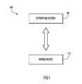
- FIG. 1illustrates a schematic view of an augmented reality system for executing a geo-registration process in accordance with an embodiment of the present invention.
- FIG. 2Aillustrates a synthetic geometry model in accordance with an embodiment of the invention.
- FIGS. 2B and 2Cillustrate digital information (data layers) that may be associated with the synthetic geometry model in accordance with an embodiment of the invention.
- FIG. 2Dillustrates the synthetic geometry model of FIG. 2A associated with the digital data of FIG. 2C .
- FIG. 3illustrates a mobile device in accordance with an embodiment of the invention.
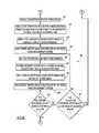
- FIGS. 4A and 4Billustrate an on-device registration process for an augmented reality system in accordance with an embodiment of the invention.
- FIGS. 5A, 5B, and 5Cillustrate an off-device process flow for an augmented reality system in accordance with an embodiment of the invention.
- the augmented reality system 100includes an enterprise system 105 and a mobile device 115 that communicates via a wireless network.
- the enterprise system 105also called a synthetic geometry or geo-registration server
- the enterprise system 105generates and hosts the geometry or model, with the geometry being created outside of the system 105 .
- This synthetic geometrymay exist in several different forms, and may be hosted on the same system, with software access to any or all of the forms.
- the generation of the synthetic geometrymay be accomplished using real world data or entirely synthesized data (i.e. 3D models) or a combination of the two.
- synthetic geometrymay be initially created from external, real world data via, e.g., synthetic aperture radar (SAR) or light detection and ranging (LIDAR).
- SARsynthetic aperture radar
- LIDARlight detection and ranging
- LIDAR point cloudsmay be processed into surface geometry, or wireframes or two-dimensional imagery may be processed to create surface or texture models.
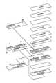
- the synthetic geometry 200may include one or more layers or models of increasing complexity and/or detail. Referring to FIG. 2 , showing a geometry configuration in accordance with and embodiment of the invention, the synthetic geometry 200 includes as its nominal base form a wire frame representation or model 210 . Additional layers, moreover, may be set for various detail levels. As shown, the higher levels may include surface models 220 , texture models 230 , and imagery-based models 240 . The imagery based model or layer 240 may take in imagery from a number of sources and, moreover, may contain geo-location coordinates.
- models 210 - 240may be used in a layer-like context, with more detailed layers on top of simpler (less detailed) layers, resulting in transport efficiency that increases from the top (imagery) layer toward the bottom (wireframe) layer.
- the simplest geometric representationsis a wireframe model, it should be understood that the layers may be further simplified to a smaller group of lines or even reference points that can have their real world versions extracted from video imagery.
- the modelmay contain any number of models 225 n+ 1.
- the synthetic geometry 200is based on a digital coordinate system 250 . That is, the key imagery points, derived from the synthetic geometry, are used for the digital coordinate system data points.
- the digital coordinate systemmay be the same as a GPS coordinate system or, at a minimum, or may be correlated to a GPS coordinate system (the GPS coordinate system may be simplified to any general, external, widespread coordinate system, i.e. an accessible, ubiquitous coordinate system).
- the enterprise system 105then, generates a wireframe model or other simplified representation of real world objects (i.e. surface models) designed to register digital content with the real world.
- geographic image sourcesare assigned coordinate points to key data set features, i.e., every endpoint of lines of wireframe where the coordinates are based on GPS location information.
- the edges of a buildinginclude distinct coordinate values, as does the edges of a street.
- the enterprise system 105extracts these coordinate values from the image sources to generate a wireframe representation of the world. Stated another way, the enterprise system 105 creates a simplified geometry of the real world objects (synthetic geometry) from sources other than the mobile device.
- the wireframe representationis a mathematically efficient geo target set.
- Content authoring toolsmay use this synthetic geometry construct to create and geo-register content, with the content containing links to the digital coordinate system to control placement of the digital data.
- the layer constructmay be used in the same way that animation software constructs content by first working with wireframe geometry and then incrementally adds geometry details such as shading and texturing to minimize processing when generating the content. This processing minimization is primarily performed to minimize the development time from the time required to render the images.
- the effect of using the simplified geometry sets or layers for content generationwill be to allow accurate content placement and faster development of the content, giving developers the ability to control the accuracy and duration of their work.
- the content authoring toolsmay be given access to the synthetic geometry databases via an Application Programming Interface (API) that enables web based access.
- APIApplication Programming Interface
- the web basis for thisis required so that the database is always kept up-to-date and the content developers always access the most up-to-date geometry.
- Content generator web accesswill also enable the connections necessary for end user access and tracking.
- the content authoring toolsmay be utilized to develop digital content/information utilizing the synthetic geometry 200 , which is then saved on the enterprise system in a layered structure (with data existing on one or many layers).
- This digital data informationis then associated with the geometry model (e.g., the nominal layer of the model).
- n+1 data layersmay be created. Referring to FIGS. 2C-2D , a first digital data layer 255 including content A and content B 1 , a second digital data layer 260 including content B 2 and content C, a third digital data layer 265 , and a fourth digital data layer 270 n+ 1 including content B 3 may be provided. As shown in FIG.
- the digital datamay be selective associated with one or more of the geometry model layers 210 , 220 , 225 n+ 1 230 , 240 .
- the digital data layers 255 , 260 , 265 , 270 n+ 1are essentially filters, being selected and organized via the content authoring tools.
- Digital data layers 255 , 260 , 265 , 270 n+ 1may be organized in any number of ways, including by importance, location (nearest item taking priority), temporal based, etc.
- user filters on the mobile devicemay be used to select the predefined digital data layers, or to generate new selection filters that cross multiple digital data layers or filter within a layer.
- All of the contentincludes metadata with the geo-location information, along with the nominal layer and grouping information.
- the mobile device 115may include one or more processing devices for executing a software application (i.e., software program instructions).
- the mobile device 115includes a mobile telephone such as a smartphone or a tablet computer.
- the mobile device 115is a head-up display in the form of eyewear including one or more cameras 310 and a display system 320 configured to display images on the lenses 330 of the eyewear.
- the display system 320may be an OLED microdisplay that projects an illuminated image toward the lens.
- the mobile devicemay also be a mobile phone, tablet, or other portable computing device that includes a display.
- the mobile device 115is equipped with one or more of a global positioning system (GPS) device, a compass, and an inertial measurement unit (IMU).
- GPSglobal positioning system
- IMUinertial measurement unit
- the mobile device 115includes a data transceiver operable to wirelessly transmit data to (e.g., GPS and camera image data) and to receive data (digital data) from the enterprise system 105 .
- the mobile device 115may be configured to engage in wireless communications such as sending and receiving telephone calls and/or wireless data in conjunction with text messages such as emails, short message service (SMS) messages, pages and other data messages that may include multimedia attachments, documents, audio files, video files, images and other graphics.
- SMSshort message service
- the mobile device 115may include a wireless transceiver for communicating over a long range wireless network such as a cellular, PCS, CDMA, GPRS, GSM, iDEN or other wireless communications network.
- the wireless communicationmay further include a transceiver for communicating over a short-range wireless network such as an IEEE 802.11 compatible network, a Wimax network, another wireless local area network connection or other communications link.
- the mobile device 115may include a short or medium range transceiver operating in conjunction with a communication standard such Bluetooth® or other standard short or medium range communication protocol.
- the mobile device 115further includes executable software that initiates the data transfer process.
- the softwaremay be stored on the mobile device 115 in the form of a specialized application, or may be executed via HTML5.
- the device softwarewill selectively read the GPS, IMU, and magnetometers (e.g., a compass), and/or other sensors disposed on the mobile device 115 .
- the softwarereads the IMU and magnetometer to determine the location and pointing vector of the user, and reads the GPS to determine the user's location.
- the mobile device 115may use other methods for determining its location such as WLAN (WI-FI) or other technologies.
- WI-FIwireless local area network
- the systemcould use WLAN information to download indoor layouts and use multiple WLAN sources or other RF for image based sources for navigation reference points.
- this location informationwill be sent to the enterprise system 105 (i.e. the synthetic geometry server).
- the enterprise system 105pulls geometry data for the area surrounding the user (Step 425 ), and then sends back to the user a nominal geometry set (Step 430 ), which is received by the mobile device 115 (Step 435 ).
- the enterprise system 105pulls and sends a 2 km diameter wireframe representation of the user's geo-location. This query to the enterprise system 105 may serve to trigger user tracking initiation.
- the usermay download the synthetic geometry in advance, or the range or area of the synthetic geometry may be increased (relevant data for the area may also be downloaded for later use).
- the surrounding geometry and extra information including geometry beyond the original setmay be saved or cached within the mobile device to improve the load times when the user is moving through different areas.
- the mobile devicemay pull this extra information based on dynamic bandwidth measurement, i.e., pulling information if there is available bandwidth.
- An additional method for reducing the downloaded datasetis to use a prefetch function that downloads information based on previous user requests for a particular area. Based on system expectations of where the user is going, i.e., from the destination address, etc. the system may download the information for that location in advance.
- the IMU and magnetometerswill set the user's pointing vector (where the user is looking based on the orientation of the mobile device 115 , i.e. what the screen shows on a mobile phone or imagery from cameras on a head mounted system).
- the pointing vectormay be determined from the GPS position of the user and a comparison of imagery from the camera on the mobile device to imagery databases.
- the original query for informationmay also operate on this pointing vector to reduce the overall data download requirements, i.e. download a smaller geometry set.
- the mobile devicecould select the level of data to download based on dynamic bandwidth measurements.
- the mobile devicemay start with the data around the pointing vector, and sequentially load in the geometry and additional information outside the pointing vector.
- the software on the mobile device 115enters a loop 440 , extracting the synthetic geometry and generating a pre-filter that is a reduced data set enabling simplified computation on the mobile device (Step 445 ).
- This pre-filteringmay entail hidden line removal and perspective setting for wireframe geometry.
- the resulting pre-filtered datais used for a geometry correlation engine on the mobile device.
- the pre-filteringreduces the size of the data set required for correlation and provides the targets for correlation.
- the correlationwill look at the synthetic geometry and try to match real world geometry to it, i.e. the edges of buildings as lines of wireframes may be matched to real building edges.
- the real world geometry used in the correlation engineis extracted from one or more cameras or imagers on the mobile device.
- the camera on the mobile device 115captures frames of video (Step 450 ) from which the geometry is extracted.
- the extractionmay be accomplished on each single frame; alternatively, if there is no movement sensed by the device sensors, the frequency of extraction may be reduced.
- Algorithms for geometry extractione.g., edge extraction, face extraction, etc.
- implemented in codeextract the relevant information from geometric objects such as buildings in the imager's field of view (i.e. extraction of the edges from the sides and roof of a building).
- other sensorsmay provide inputs to the correlation engine, such as the accelerometers to provide the nominal gravity vector.
- Additional processing routinesFFTs, wavelet transforms, etc. may additionally be used to help find the desired geometries.
- Processing routinesmay also be used to find predominating orientation vectors such as verticals and horizontals that will aid in establishing the user's pose (i.e. find the dominate features assuming predominate orientations of those frequencies). Additionally, more advanced imaging capabilities such as polarimetry may be used to help in determining orientation.
- the filtered geometryis overlaid on the video frame and geometry matching (i.e., overlaid onto edges) is performed (Step 455 ), with the filtered geometry data coordinate system then being applied to the video image (Step 460 ). If the location of the pointing vector of the mobile device has changed, the process is directed back into the loop 440 (step 465 ), the process determines whether the movement is beyond the range of the geometry data set (Step 470 ) and, if so, reenters the loop 440 .
- Step 480the process continues into another loop 475 , in which the next video frame being grabbed (Step 480 ) and the coordinate system synchronization maintained by continuous comparison to filtered geometry, location information, and through electronic image stabilization techniques (Step 485 ).
- FIGS. 5A, 5B, and 5CAn alternate process flow 500 where the initial matching or subsequent occasional matching is performed off of the mobile device 115 , i.e., at the enterprise or other similar level, (e.g., cloud based processing) is shown in FIGS. 5A, 5B, and 5C .
- the offloading of the processing from the mobile device onto external resourcesmay be partitioned in any number of ways in order to optimize on device power consumption, processing bandwidth, transport bandwidth, etc.
- the mobile device 115determines its location coordinates via, e.g., GPS (Step 501 ), as well as reads the device's IMU and/or compass (Step 502 ).
- the device 115After capturing image frames (Step 503 ), the device 115 determines its pointing vector (Step 504 ), and sends this information to the enterprise system 105 (Step 505 ).
- the enterprise serverextracts geometry data for the area surrounding the user (Step 506 ), and then performs geometric filtering (Step 507 ).
- the filtered geometryis overlaid onto the video frame and geometry matching is executed (Step 508 ), and then supplied to the video image (Step 509 ).
- the enterprise system 105sends the geometry data to the mobile device 115 , along with the initial coordinate system matching (Step 510 ), the data being received by the mobile device (Step 511 ). Additionally, digital information is sent to (Step 512 ) and received by (Step 513 ) the mobile device 115 .
- the mobile device 115tracks any pointing vector changes from the frames sent to the enterprise server during the initial coordinate system matching (Step 514 ), and then matches the coordinate system based on any changes that occurred during off-device process (Step 515 ).
- the mobile device 115now displays digital data, overlaying it onto the real world view (Step 516 ).
- the processcontinues entering a feedback loop 520 (Steps 521 - 526 ), as needed. That is, to improve system accuracy, a feedback loop may be included between the GPS, IMU, and magnetometers. As the GPS is periodically updated during movement, a path may be correlated to the IMU and magnetometer signals.
- the processmay enter another loop 530 , with the next video frame being grabbed (Step 531 ) and the coordinate system being maintained as indicated (Step 532 ).
- the usermay be given the option of performing a manual overlay of the geometry onto the real world imagery if the system cannot perform an adequate lock.
- Other methods of providing a lockmay incorporate a calibration process, an example of which may be accomplished through the image capture of a known object (at a known location).
- the scaling of the objectmay provide distance, while the edges or other geometry information may be used to set orientation of the user.
- the use of multiple objectsmay further increase accuracy.
- Another feedback loop using existing photographic databasesmay be constructed. Correlation edges and/or image correlation from known poses and positional data incorporated in metadata associated with 2D imagery may be used to correlate the user's position and pose.
- synthetic geometrymay additionally be used for indoor registration and the setting of way points or otherwise used for navigation.
- the edges of walls, doors, pillars, windows, etc. from architectural or design drawingsmay be used for the edge matching filters on the mobile device.
- the geometry of the buildingmay be downloaded to the mobile device, and the same processing as is done for outdoor geometry may be used to geo-register the mobile device, i.e., hidden line removal, perspective setting, geometry correlation, etc.
- distances between featureswill also be known, so that as the geometry is correlated, the user's changing position within the structure may also be correlated, allowing the user to navigate within the building.
Landscapes
- Engineering & Computer Science (AREA)
- Theoretical Computer Science (AREA)
- Physics & Mathematics (AREA)
- General Physics & Mathematics (AREA)
- Computer Hardware Design (AREA)
- Computer Graphics (AREA)
- General Engineering & Computer Science (AREA)
- Software Systems (AREA)
- Computer Vision & Pattern Recognition (AREA)
- Multimedia (AREA)
- Processing Or Creating Images (AREA)
- Studio Devices (AREA)
- User Interface Of Digital Computer (AREA)
Abstract
Description
Claims (18)
Priority Applications (1)
| Application Number | Priority Date | Filing Date | Title |
|---|---|---|---|
| US15/266,136US10055890B2 (en) | 2012-10-24 | 2016-09-15 | Augmented reality for wireless mobile devices |
Applications Claiming Priority (4)
| Application Number | Priority Date | Filing Date | Title |
|---|---|---|---|
| US201261717788P | 2012-10-24 | 2012-10-24 | |
| US13/837,902US9129429B2 (en) | 2012-10-24 | 2013-03-15 | Augmented reality on wireless mobile devices |
| US14/830,407US20150356790A1 (en) | 2012-10-24 | 2015-08-19 | Augmented Reality Control Systems |
| US15/266,136US10055890B2 (en) | 2012-10-24 | 2016-09-15 | Augmented reality for wireless mobile devices |
Related Parent Applications (1)
| Application Number | Title | Priority Date | Filing Date |
|---|---|---|---|
| US14/830,407DivisionUS20150356790A1 (en) | 2012-10-24 | 2015-08-19 | Augmented Reality Control Systems |
Publications (2)
| Publication Number | Publication Date |
|---|---|
| US20170004658A1 US20170004658A1 (en) | 2017-01-05 |
| US10055890B2true US10055890B2 (en) | 2018-08-21 |
Family
ID=50484959
Family Applications (3)
| Application Number | Title | Priority Date | Filing Date |
|---|---|---|---|
| US13/837,902Active2033-09-28US9129429B2 (en) | 2012-10-24 | 2013-03-15 | Augmented reality on wireless mobile devices |
| US14/830,407AbandonedUS20150356790A1 (en) | 2012-10-24 | 2015-08-19 | Augmented Reality Control Systems |
| US15/266,136Active2033-04-13US10055890B2 (en) | 2012-10-24 | 2016-09-15 | Augmented reality for wireless mobile devices |
Family Applications Before (2)
| Application Number | Title | Priority Date | Filing Date |
|---|---|---|---|
| US13/837,902Active2033-09-28US9129429B2 (en) | 2012-10-24 | 2013-03-15 | Augmented reality on wireless mobile devices |
| US14/830,407AbandonedUS20150356790A1 (en) | 2012-10-24 | 2015-08-19 | Augmented Reality Control Systems |
Country Status (4)
| Country | Link |
|---|---|
| US (3) | US9129429B2 (en) |
| EP (1) | EP2912577A4 (en) |
| AU (1) | AU2013334573B2 (en) |
| WO (1) | WO2014066580A2 (en) |
Families Citing this family (32)
| Publication number | Priority date | Publication date | Assignee | Title |
|---|---|---|---|---|
| WO2014125134A1 (en)* | 2013-02-14 | 2014-08-21 | Manin Company Construcciones En Acero Inoxidable, S.L.U. | Method for the representation of geographically located virtual environments and mobile device |
| US9947138B2 (en) | 2014-04-15 | 2018-04-17 | Huntington Ingalls Incorporated | System and method for augmented reality display of dynamic environment information |
| US9864909B2 (en) | 2014-04-25 | 2018-01-09 | Huntington Ingalls Incorporated | System and method for using augmented reality display in surface treatment procedures |
| US10915754B2 (en) | 2014-06-09 | 2021-02-09 | Huntington Ingalls Incorporated | System and method for use of augmented reality in outfitting a dynamic structural space |
| US10504294B2 (en) | 2014-06-09 | 2019-12-10 | Huntington Ingalls Incorporated | System and method for augmented reality discrepancy determination and reporting |
| WO2015191346A1 (en) | 2014-06-09 | 2015-12-17 | Huntington Ingalls Incorporated | System and method for augmented reality display of electrical system information |
| US9898867B2 (en)* | 2014-07-16 | 2018-02-20 | Huntington Ingalls Incorporated | System and method for augmented reality display of hoisting and rigging information |
| US9892560B2 (en) | 2014-09-11 | 2018-02-13 | Nant Holdings Ip, Llc | Marker-based augmented reality authoring tools |
| US10181219B1 (en) | 2015-01-21 | 2019-01-15 | Google Llc | Phone control and presence in virtual reality |
| US10102674B2 (en) | 2015-03-09 | 2018-10-16 | Google Llc | Virtual reality headset connected to a mobile computing device |
| US10878278B1 (en)* | 2015-05-16 | 2020-12-29 | Sturfee, Inc. | Geo-localization based on remotely sensed visual features |
| CN107851335A (en)* | 2015-06-23 | 2018-03-27 | 飞利浦照明控股有限公司 | For making the visual augmented reality equipment of luminaire light fixture |
| WO2017061281A1 (en) | 2015-10-08 | 2017-04-13 | ソニー株式会社 | Information processing device and information processing method |
| US10578880B2 (en) | 2016-06-21 | 2020-03-03 | Intel Corporation | Augmenting reality via antenna and interaction profile |
| CN107870420A (en)* | 2016-09-27 | 2018-04-03 | 上海蔚兰动力科技有限公司 | The adjustable reflector of head-up display device and include its head-up display device |
| US10008042B2 (en)* | 2016-09-30 | 2018-06-26 | Intel Corporation | Augmented reality rendered structured content |
| US20180192044A1 (en)* | 2017-01-03 | 2018-07-05 | Black Sails Technology Inc. | Method and System for Providing A Viewport Division Scheme for Virtual Reality (VR) Video Streaming |
| US10846533B2 (en) | 2017-03-27 | 2020-11-24 | Seattle Avionics, Inc. | Systems and methods for augmented reality aviation interfaces |
| US10565464B2 (en) | 2017-12-21 | 2020-02-18 | At&T Intellectual Property I, L.P. | Adaptive cloud offloading of mobile augmented reality |
| US11417071B1 (en)* | 2018-02-23 | 2022-08-16 | Red Pacs, Llc | Virtual toolkit for radiologists |
| CN113196209A (en) | 2018-10-05 | 2021-07-30 | 奇跃公司 | Rendering location-specific virtual content at any location |
| US11763503B2 (en)* | 2019-02-25 | 2023-09-19 | Life Impact Solutions | Media alteration based on variable geolocation metadata |
| US11151792B2 (en) | 2019-04-26 | 2021-10-19 | Google Llc | System and method for creating persistent mappings in augmented reality |
| US11163997B2 (en)* | 2019-05-05 | 2021-11-02 | Google Llc | Methods and apparatus for venue based augmented reality |
| US11546721B2 (en) | 2019-06-18 | 2023-01-03 | The Calany Holding S.À.R.L. | Location-based application activation |
| US11341727B2 (en) | 2019-06-18 | 2022-05-24 | The Calany Holding S. À R.L. | Location-based platform for multiple 3D engines for delivering location-based 3D content to a user |
| CN112102497B (en) | 2019-06-18 | 2024-09-10 | 卡兰控股有限公司 | System and method for attaching applications and interactions to static objects |
| CN112102498A (en) | 2019-06-18 | 2020-12-18 | 明日基金知识产权控股有限公司 | System and method for virtually attaching applications to dynamic objects and enabling interaction with dynamic objects |
| US11516296B2 (en) | 2019-06-18 | 2022-11-29 | THE CALANY Holding S.ÀR.L | Location-based application stream activation |
| US11257294B2 (en) | 2019-10-15 | 2022-02-22 | Magic Leap, Inc. | Cross reality system supporting multiple device types |
| WO2021118962A1 (en) | 2019-12-09 | 2021-06-17 | Magic Leap, Inc. | Cross reality system with simplified programming of virtual content |
| EP4111425A4 (en) | 2020-02-26 | 2024-03-13 | Magic Leap, Inc. | CROSS-REALLY SYSTEM WITH FAST LOCALIZATION |
Citations (81)
| Publication number | Priority date | Publication date | Assignee | Title |
|---|---|---|---|---|
| US3589796A (en) | 1966-09-19 | 1971-06-29 | United Aircraft Corp | Collimated viewing system |
| US4729634A (en) | 1985-02-04 | 1988-03-08 | United Technologies Corporation | Reflective head-up display |
| US4808979A (en) | 1987-04-02 | 1989-02-28 | Tektronix, Inc. | Cursor for use in 3-D imaging systems |
| US5355224A (en) | 1992-09-16 | 1994-10-11 | Varo Inc. | Apparatus including a mangin mirror for superimposing variable graphical and alphanumeric information onto the image plane of an optical viewing device |
| US5585813A (en) | 1992-10-05 | 1996-12-17 | Rockwell International Corporation | All aspect head aiming display |
| US5661604A (en) | 1993-12-22 | 1997-08-26 | Olympus Optical Co., Ltd. | Image display apparatus |
| US5838490A (en) | 1996-11-04 | 1998-11-17 | Honeywell Inc. | Head mounted display system using mangin mirror combiner |
| US6098118A (en) | 1996-05-22 | 2000-08-01 | Geovector Corp. | Method for controlling electronic devices in response to sensed conditions using physical characteristic signal indicating use or anticipated use of the electronic device |
| US6181302B1 (en) | 1996-04-24 | 2001-01-30 | C. Macgill Lynde | Marine navigation binoculars with virtual display superimposing real world image |
| US6349001B1 (en) | 1997-10-30 | 2002-02-19 | The Microoptical Corporation | Eyeglass interface system |
| US6362912B1 (en) | 1999-08-05 | 2002-03-26 | Microvision, Inc. | Scanned imaging apparatus with switched feeds |
| US6445362B1 (en) | 1999-08-05 | 2002-09-03 | Microvision, Inc. | Scanned display with variation compensation |
| US6452544B1 (en) | 2001-05-24 | 2002-09-17 | Nokia Corporation | Portable map display system for presenting a 3D map image and method thereof |
| US20020196202A1 (en) | 2000-08-09 | 2002-12-26 | Bastian Mark Stanley | Method for displaying emergency first responder command, control, and safety information using augmented reality |
| US6578017B1 (en) | 1999-02-26 | 2003-06-10 | Information Decision Technologies, Llc | Method to aid object detection in images by incorporating contextual information |
| US6633304B2 (en) | 2000-11-24 | 2003-10-14 | Canon Kabushiki Kaisha | Mixed reality presentation apparatus and control method thereof |
| US20030210228A1 (en) | 2000-02-25 | 2003-11-13 | Ebersole John Franklin | Augmented reality situational awareness system and method |
| US20040066793A1 (en)* | 2002-10-04 | 2004-04-08 | Koninklijke Philips Electronics N.V. | Method and system for improving transmission efficiency using multiple-description layered encoding |
| US6917370B2 (en) | 2002-05-13 | 2005-07-12 | Charles Benton | Interacting augmented reality and virtual reality |
| US6937221B2 (en) | 1998-08-05 | 2005-08-30 | Microvision, Inc. | Scanned beam display |
| US20050275714A1 (en) | 2004-06-09 | 2005-12-15 | Murata Manufacturing Co., Ltd. | Eyeglass interface device and security system |
| US7002551B2 (en) | 2002-09-25 | 2006-02-21 | Hrl Laboratories, Llc | Optical see-through augmented reality modified-scale display |
| US7075687B2 (en) | 1999-08-05 | 2006-07-11 | Microvision, Inc. | Scanned beam image capture device with a plurality of scan regions |
| US7131728B2 (en) | 2003-12-31 | 2006-11-07 | Symbol Technologies, Inc. | Method and apparatus for displaying information in automotive application using a laser projection display |
| US20060262140A1 (en) | 2005-05-18 | 2006-11-23 | Kujawa Gregory A | Method and apparatus to facilitate visual augmentation of perceived reality |
| US7158096B1 (en) | 1999-06-21 | 2007-01-02 | The Microoptical Corporation | Compact, head-mountable display device with suspended eyepiece assembly |
| US20070035562A1 (en) | 2002-09-25 | 2007-02-15 | Azuma Ronald T | Method and apparatus for image enhancement |
| US7190329B2 (en) | 1998-08-05 | 2007-03-13 | Microvision, Inc. | Apparatus for remotely imaging a region |
| US20070070508A1 (en) | 2002-11-27 | 2007-03-29 | Frank Ruhle | Collimating optical member for real world simulation |
| US7209271B2 (en) | 1999-08-05 | 2007-04-24 | Microvision, Inc | Multiple beam scanning imager |
| US7310174B2 (en) | 1999-08-05 | 2007-12-18 | Microvision, Inc. | Method and apparatus for scanning regions |
| US7339737B2 (en) | 2004-04-23 | 2008-03-04 | Microvision, Inc. | Beam multiplier that can be used as an exit-pupil expander and related system and method |
| US20080074423A1 (en) | 2006-09-25 | 2008-03-27 | Raytheon Company | Method and System for Displaying Graphical Objects on a Digital Map |
| US7365892B2 (en) | 2004-09-17 | 2008-04-29 | Microvision, Inc. | Scanned light display system using array of collimating elements in conjunction with large numerical aperture light emitter array |
| US7400432B2 (en) | 2002-05-17 | 2008-07-15 | Microvision, Inc. | Scanning-mirror structure having a cut or a composite design to reduce deformation of the mirror face, and related system and method |
| US7428093B2 (en) | 1998-08-05 | 2008-09-23 | Microvision, Inc. | Optical scanning system with correction |
| US20080291219A1 (en) | 2007-05-23 | 2008-11-27 | Canon Kabushiki Kaisha | Mixed reality presentation apparatus and control method thereof, and computer program |
| US7460305B2 (en) | 2004-02-04 | 2008-12-02 | Microvision, Inc. | Scanned-beam heads-up display and related systems and methods |
| US7460120B2 (en) | 2003-11-13 | 2008-12-02 | Panasonic Corporation | Map display apparatus |
| US20080298689A1 (en)* | 2005-02-11 | 2008-12-04 | Anthony Peter Ashbrook | Storing Information for Access Using a Captured Image |
| US7473888B2 (en) | 1999-08-05 | 2009-01-06 | Microvision, Inc. | Display with compensated light source drive |
| US20090027772A1 (en) | 2007-07-26 | 2009-01-29 | Real D | Head-Mounted Single Panel Stereoscopic Display |
| US20090096790A1 (en) | 2007-10-11 | 2009-04-16 | Mvtec Software Gmbh | System and method for 3d object recognition |
| US7538724B1 (en) | 2007-06-15 | 2009-05-26 | Itt Manufacturing Enterprises, Inc. | Method and system for relative tracking |
| US20090141020A1 (en) | 2007-12-03 | 2009-06-04 | Freund Joseph G | Systems and methods for rapid three-dimensional modeling with real facade texture |
| US7567282B2 (en) | 2003-12-18 | 2009-07-28 | Anthrotronix, Inc. | Operator control unit with tracking |
| US7589901B2 (en) | 2007-07-10 | 2009-09-15 | Microvision, Inc. | Substrate-guided relays for use with scanned beam light sources |
| US7639209B2 (en) | 2004-05-07 | 2009-12-29 | Microvision, Inc. | Scanned light display system using large numerical aperture light source, method of using same, and method of making scanning mirror assemblies |
| US7653268B1 (en) | 2008-07-03 | 2010-01-26 | Microvision, Inc. | Substrate guided relay with polarization rotating apparatus |
| US7656585B1 (en) | 2008-08-19 | 2010-02-02 | Microvision, Inc. | Embedded relay lens for head-up displays or the like |
| US7710655B2 (en) | 2005-11-21 | 2010-05-04 | Microvision, Inc. | Display with image-guiding substrate |
| US7715103B2 (en) | 2007-09-10 | 2010-05-11 | Microvision, Inc. | Buried numerical aperture expander having transparent properties |
| US20100127971A1 (en) | 2008-11-21 | 2010-05-27 | Geovector Corp. | Methods of rendering graphical images |
| US7733572B1 (en) | 2008-06-09 | 2010-06-08 | Rockwell Collins, Inc. | Catadioptric system, apparatus, and method for producing images on a universal, head-up display |
| US7777960B2 (en) | 2007-09-10 | 2010-08-17 | Microvision, Inc. | Wide field of view head-up display system |
| US7791809B2 (en) | 2008-03-13 | 2010-09-07 | Day And Night Display Systems, Inc. | Visor heads-up display |
| US7791810B2 (en) | 2007-12-21 | 2010-09-07 | Microvision, Inc. | Scanned beam display having high uniformity and diminished coherent artifacts |
| US7791807B2 (en) | 2008-02-06 | 2010-09-07 | Microvision, Inc. | Avoiding interference artifacts in a head-up display or a reflected see-through type display |
| US7796155B1 (en) | 2003-12-19 | 2010-09-14 | Hrl Laboratories, Llc | Method and apparatus for real-time group interactive augmented-reality area monitoring, suitable for enhancing the enjoyment of entertainment events |
| US20100238161A1 (en) | 2009-03-19 | 2010-09-23 | Kenneth Varga | Computer-aided system for 360º heads up display of safety/mission critical data |
| US20100259673A1 (en) | 2009-04-14 | 2010-10-14 | Russell Shawn R | Mobile video eyewear data receiving and transmitting system |
| US20100290127A1 (en) | 2009-05-13 | 2010-11-18 | NVIS Inc. | Head-mounted optical apparatus using an oled display |
| US20100305724A1 (en) | 2007-12-19 | 2010-12-02 | Robert Eric Fry | Vehicle competition implementation system |
| US7850306B2 (en) | 2008-08-28 | 2010-12-14 | Nokia Corporation | Visual cognition aware display and visual data transmission architecture |
| US7854523B2 (en) | 2008-08-26 | 2010-12-21 | Microvision, Inc. | Optical relay for compact head up display |
| US20110102460A1 (en) | 2009-11-04 | 2011-05-05 | Parker Jordan | Platform for widespread augmented reality and 3d mapping |
| US7949214B2 (en) | 2008-11-06 | 2011-05-24 | Microvision, Inc. | Substrate guided relay with pupil expanding input coupler |
| US7954953B2 (en) | 2008-07-30 | 2011-06-07 | Microvision, Inc. | Scanned beam overlay projection |
| US7956858B2 (en) | 2006-04-11 | 2011-06-07 | Microvision, Inc. | Integrated photonics module and devices using integrated photonics modules |
| US20110187744A1 (en) | 2010-01-29 | 2011-08-04 | Pantech Co., Ltd. | System, terminal, server, and method for providing augmented reality |
| US20110227813A1 (en) | 2010-02-28 | 2011-09-22 | Osterhout Group, Inc. | Augmented reality eyepiece with secondary attached optic for surroundings environment vision correction |
| US20110254859A1 (en) | 2010-04-19 | 2011-10-20 | Kouichi Matsuda | Image processing system, image processing apparatus, image processing method, and program |
| US20110270522A1 (en) | 2010-04-30 | 2011-11-03 | Ryan Fink | Visual training devices, systems, and methods |
| US20110282799A1 (en) | 2005-07-14 | 2011-11-17 | Huston Charles D | GPS Based Friend Location and Identification System and Method |
| US20120002086A1 (en) | 2010-06-30 | 2012-01-05 | Apple Inc. | Optically Projected Mosaic Rendering |
| US20120019557A1 (en) | 2010-07-22 | 2012-01-26 | Sony Ericsson Mobile Communications Ab | Displaying augmented reality information |
| US8160411B2 (en) | 2006-12-28 | 2012-04-17 | Nokia Corporation | Device for expanding an exit pupil in two dimensions |
| US20120120070A1 (en) | 2007-03-08 | 2012-05-17 | Yohan Baillot | System and method to display maintenance and operational instructions of an apparatus using augmented reality |
| US20130127851A1 (en)* | 2011-11-22 | 2013-05-23 | Raytheon Company | Structure discovery in a point cloud |
| US20140055491A1 (en)* | 2012-08-27 | 2014-02-27 | Empire Technology Development Llc | Indicating the geographic origin of a digitally-mediated communication |
| US20140068444A1 (en)* | 2012-08-31 | 2014-03-06 | Nokia Corporation | Method and apparatus for incorporating media elements from content items in location-based viewing |
Family Cites Families (7)
| Publication number | Priority date | Publication date | Assignee | Title |
|---|---|---|---|---|
| US5706290A (en)* | 1994-12-15 | 1998-01-06 | Shaw; Venson | Method and apparatus including system architecture for multimedia communication |
| US7305396B2 (en)* | 2002-12-31 | 2007-12-04 | Robert Bosch Gmbh | Hierarchical system and method for on-demand loading of data in a navigation system |
| US9510048B2 (en)* | 2009-05-26 | 2016-11-29 | Red Hat Israel, Ltd. | Dynamically changing streaming video quality |
| US20110279445A1 (en)* | 2010-05-16 | 2011-11-17 | Nokia Corporation | Method and apparatus for presenting location-based content |
| US20110279453A1 (en)* | 2010-05-16 | 2011-11-17 | Nokia Corporation | Method and apparatus for rendering a location-based user interface |
| IL208600A (en)* | 2010-10-10 | 2016-07-31 | Rafael Advanced Defense Systems Ltd | Network-based real time registered augmented reality for mobile devices |
| US9275499B2 (en)* | 2010-11-08 | 2016-03-01 | Sony Corporation | Augmented reality interface for video |
- 2013
- 2013-03-15USUS13/837,902patent/US9129429B2/enactiveActive
- 2013-10-24AUAU2013334573Apatent/AU2013334573B2/enactiveActive
- 2013-10-24WOPCT/US2013/066511patent/WO2014066580A2/enactiveApplication Filing
- 2013-10-24EPEP13849487.7Apatent/EP2912577A4/ennot_activeCeased
- 2015
- 2015-08-19USUS14/830,407patent/US20150356790A1/ennot_activeAbandoned
- 2016
- 2016-09-15USUS15/266,136patent/US10055890B2/enactiveActive
Patent Citations (91)
| Publication number | Priority date | Publication date | Assignee | Title |
|---|---|---|---|---|
| US3589796A (en) | 1966-09-19 | 1971-06-29 | United Aircraft Corp | Collimated viewing system |
| US4729634A (en) | 1985-02-04 | 1988-03-08 | United Technologies Corporation | Reflective head-up display |
| US4808979A (en) | 1987-04-02 | 1989-02-28 | Tektronix, Inc. | Cursor for use in 3-D imaging systems |
| US5355224A (en) | 1992-09-16 | 1994-10-11 | Varo Inc. | Apparatus including a mangin mirror for superimposing variable graphical and alphanumeric information onto the image plane of an optical viewing device |
| US5585813A (en) | 1992-10-05 | 1996-12-17 | Rockwell International Corporation | All aspect head aiming display |
| US5661604A (en) | 1993-12-22 | 1997-08-26 | Olympus Optical Co., Ltd. | Image display apparatus |
| US6181302B1 (en) | 1996-04-24 | 2001-01-30 | C. Macgill Lynde | Marine navigation binoculars with virtual display superimposing real world image |
| US6098118A (en) | 1996-05-22 | 2000-08-01 | Geovector Corp. | Method for controlling electronic devices in response to sensed conditions using physical characteristic signal indicating use or anticipated use of the electronic device |
| US5838490A (en) | 1996-11-04 | 1998-11-17 | Honeywell Inc. | Head mounted display system using mangin mirror combiner |
| US6349001B1 (en) | 1997-10-30 | 2002-02-19 | The Microoptical Corporation | Eyeglass interface system |
| US7428093B2 (en) | 1998-08-05 | 2008-09-23 | Microvision, Inc. | Optical scanning system with correction |
| US7190329B2 (en) | 1998-08-05 | 2007-03-13 | Microvision, Inc. | Apparatus for remotely imaging a region |
| US6937221B2 (en) | 1998-08-05 | 2005-08-30 | Microvision, Inc. | Scanned beam display |
| US6578017B1 (en) | 1999-02-26 | 2003-06-10 | Information Decision Technologies, Llc | Method to aid object detection in images by incorporating contextual information |
| US7158096B1 (en) | 1999-06-21 | 2007-01-02 | The Microoptical Corporation | Compact, head-mountable display device with suspended eyepiece assembly |
| US7843403B2 (en) | 1999-06-21 | 2010-11-30 | Myvu Corporation | Compact, head-mountable display device with suspended eyepiece assembly |
| US6362912B1 (en) | 1999-08-05 | 2002-03-26 | Microvision, Inc. | Scanned imaging apparatus with switched feeds |
| US7310174B2 (en) | 1999-08-05 | 2007-12-18 | Microvision, Inc. | Method and apparatus for scanning regions |
| US7473888B2 (en) | 1999-08-05 | 2009-01-06 | Microvision, Inc. | Display with compensated light source drive |
| US7209271B2 (en) | 1999-08-05 | 2007-04-24 | Microvision, Inc | Multiple beam scanning imager |
| US6445362B1 (en) | 1999-08-05 | 2002-09-03 | Microvision, Inc. | Scanned display with variation compensation |
| US7075687B2 (en) | 1999-08-05 | 2006-07-11 | Microvision, Inc. | Scanned beam image capture device with a plurality of scan regions |
| US20030210228A1 (en) | 2000-02-25 | 2003-11-13 | Ebersole John Franklin | Augmented reality situational awareness system and method |
| US20020196202A1 (en) | 2000-08-09 | 2002-12-26 | Bastian Mark Stanley | Method for displaying emergency first responder command, control, and safety information using augmented reality |
| US6633304B2 (en) | 2000-11-24 | 2003-10-14 | Canon Kabushiki Kaisha | Mixed reality presentation apparatus and control method thereof |
| US6452544B1 (en) | 2001-05-24 | 2002-09-17 | Nokia Corporation | Portable map display system for presenting a 3D map image and method thereof |
| US6917370B2 (en) | 2002-05-13 | 2005-07-12 | Charles Benton | Interacting augmented reality and virtual reality |
| US7400432B2 (en) | 2002-05-17 | 2008-07-15 | Microvision, Inc. | Scanning-mirror structure having a cut or a composite design to reduce deformation of the mirror face, and related system and method |
| US20070035562A1 (en) | 2002-09-25 | 2007-02-15 | Azuma Ronald T | Method and apparatus for image enhancement |
| US7002551B2 (en) | 2002-09-25 | 2006-02-21 | Hrl Laboratories, Llc | Optical see-through augmented reality modified-scale display |
| US20040066793A1 (en)* | 2002-10-04 | 2004-04-08 | Koninklijke Philips Electronics N.V. | Method and system for improving transmission efficiency using multiple-description layered encoding |
| US20070070508A1 (en) | 2002-11-27 | 2007-03-29 | Frank Ruhle | Collimating optical member for real world simulation |
| US7460120B2 (en) | 2003-11-13 | 2008-12-02 | Panasonic Corporation | Map display apparatus |
| US7567282B2 (en) | 2003-12-18 | 2009-07-28 | Anthrotronix, Inc. | Operator control unit with tracking |
| US7796155B1 (en) | 2003-12-19 | 2010-09-14 | Hrl Laboratories, Llc | Method and apparatus for real-time group interactive augmented-reality area monitoring, suitable for enhancing the enjoyment of entertainment events |
| US7131728B2 (en) | 2003-12-31 | 2006-11-07 | Symbol Technologies, Inc. | Method and apparatus for displaying information in automotive application using a laser projection display |
| US7826141B2 (en) | 2004-02-04 | 2010-11-02 | Microvision, Inc. | Scanned-beam heads-up display and related systems and methods |
| US7460305B2 (en) | 2004-02-04 | 2008-12-02 | Microvision, Inc. | Scanned-beam heads-up display and related systems and methods |
| US7339737B2 (en) | 2004-04-23 | 2008-03-04 | Microvision, Inc. | Beam multiplier that can be used as an exit-pupil expander and related system and method |
| US7580189B2 (en) | 2004-04-23 | 2009-08-25 | Microvision, Inc. | Optical element that includes a microlens array and related method |
| US7639209B2 (en) | 2004-05-07 | 2009-12-29 | Microvision, Inc. | Scanned light display system using large numerical aperture light source, method of using same, and method of making scanning mirror assemblies |
| US7724210B2 (en) | 2004-05-07 | 2010-05-25 | Microvision, Inc. | Scanned light display system using large numerical aperture light source, method of using same, and method of making scanning mirror assemblies |
| US20050275714A1 (en) | 2004-06-09 | 2005-12-15 | Murata Manufacturing Co., Ltd. | Eyeglass interface device and security system |
| US7365892B2 (en) | 2004-09-17 | 2008-04-29 | Microvision, Inc. | Scanned light display system using array of collimating elements in conjunction with large numerical aperture light emitter array |
| US20080298689A1 (en)* | 2005-02-11 | 2008-12-04 | Anthony Peter Ashbrook | Storing Information for Access Using a Captured Image |
| US20060262140A1 (en) | 2005-05-18 | 2006-11-23 | Kujawa Gregory A | Method and apparatus to facilitate visual augmentation of perceived reality |
| US20110282799A1 (en) | 2005-07-14 | 2011-11-17 | Huston Charles D | GPS Based Friend Location and Identification System and Method |
| US7710655B2 (en) | 2005-11-21 | 2010-05-04 | Microvision, Inc. | Display with image-guiding substrate |
| US7736006B2 (en) | 2005-11-21 | 2010-06-15 | Microvision, Inc. | Substrate-guided display with improved image quality |
| US7905603B2 (en) | 2005-11-21 | 2011-03-15 | Microvision, Inc. | Substrate-guided display having polarization selective input structure |
| US7959308B2 (en) | 2005-11-21 | 2011-06-14 | Microvision, Inc. | Substrate-guided display with improved image quality |
| US7978189B2 (en) | 2006-04-11 | 2011-07-12 | Microvision, Inc. | Integrated photonics module and devices using integrated photonics modules |
| US7956858B2 (en) | 2006-04-11 | 2011-06-07 | Microvision, Inc. | Integrated photonics module and devices using integrated photonics modules |
| US7986315B2 (en) | 2006-04-11 | 2011-07-26 | Microvision, Inc. | Integrated photonics module and devices using integrated photonics modules |
| US20080074423A1 (en) | 2006-09-25 | 2008-03-27 | Raytheon Company | Method and System for Displaying Graphical Objects on a Digital Map |
| US8160411B2 (en) | 2006-12-28 | 2012-04-17 | Nokia Corporation | Device for expanding an exit pupil in two dimensions |
| US20120120070A1 (en) | 2007-03-08 | 2012-05-17 | Yohan Baillot | System and method to display maintenance and operational instructions of an apparatus using augmented reality |
| US20080291219A1 (en) | 2007-05-23 | 2008-11-27 | Canon Kabushiki Kaisha | Mixed reality presentation apparatus and control method thereof, and computer program |
| US7538724B1 (en) | 2007-06-15 | 2009-05-26 | Itt Manufacturing Enterprises, Inc. | Method and system for relative tracking |
| US7839575B2 (en) | 2007-07-10 | 2010-11-23 | Microvision, Inc. | Optical device for use with scanned beam light sources |
| US7589901B2 (en) | 2007-07-10 | 2009-09-15 | Microvision, Inc. | Substrate-guided relays for use with scanned beam light sources |
| US20090027772A1 (en) | 2007-07-26 | 2009-01-29 | Real D | Head-Mounted Single Panel Stereoscopic Display |
| US7715103B2 (en) | 2007-09-10 | 2010-05-11 | Microvision, Inc. | Buried numerical aperture expander having transparent properties |
| US7777960B2 (en) | 2007-09-10 | 2010-08-17 | Microvision, Inc. | Wide field of view head-up display system |
| US20090096790A1 (en) | 2007-10-11 | 2009-04-16 | Mvtec Software Gmbh | System and method for 3d object recognition |
| US20090141020A1 (en) | 2007-12-03 | 2009-06-04 | Freund Joseph G | Systems and methods for rapid three-dimensional modeling with real facade texture |
| US20100305724A1 (en) | 2007-12-19 | 2010-12-02 | Robert Eric Fry | Vehicle competition implementation system |
| US7791810B2 (en) | 2007-12-21 | 2010-09-07 | Microvision, Inc. | Scanned beam display having high uniformity and diminished coherent artifacts |
| US7791807B2 (en) | 2008-02-06 | 2010-09-07 | Microvision, Inc. | Avoiding interference artifacts in a head-up display or a reflected see-through type display |
| US7791809B2 (en) | 2008-03-13 | 2010-09-07 | Day And Night Display Systems, Inc. | Visor heads-up display |
| US7733572B1 (en) | 2008-06-09 | 2010-06-08 | Rockwell Collins, Inc. | Catadioptric system, apparatus, and method for producing images on a universal, head-up display |
| US7653268B1 (en) | 2008-07-03 | 2010-01-26 | Microvision, Inc. | Substrate guided relay with polarization rotating apparatus |
| US7954953B2 (en) | 2008-07-30 | 2011-06-07 | Microvision, Inc. | Scanned beam overlay projection |
| US7656585B1 (en) | 2008-08-19 | 2010-02-02 | Microvision, Inc. | Embedded relay lens for head-up displays or the like |
| US7854523B2 (en) | 2008-08-26 | 2010-12-21 | Microvision, Inc. | Optical relay for compact head up display |
| US7850306B2 (en) | 2008-08-28 | 2010-12-14 | Nokia Corporation | Visual cognition aware display and visual data transmission architecture |
| US7949214B2 (en) | 2008-11-06 | 2011-05-24 | Microvision, Inc. | Substrate guided relay with pupil expanding input coupler |
| US20100127971A1 (en) | 2008-11-21 | 2010-05-27 | Geovector Corp. | Methods of rendering graphical images |
| US20100238161A1 (en) | 2009-03-19 | 2010-09-23 | Kenneth Varga | Computer-aided system for 360º heads up display of safety/mission critical data |
| US20100259673A1 (en) | 2009-04-14 | 2010-10-14 | Russell Shawn R | Mobile video eyewear data receiving and transmitting system |
| US20100290127A1 (en) | 2009-05-13 | 2010-11-18 | NVIS Inc. | Head-mounted optical apparatus using an oled display |
| US20110102460A1 (en) | 2009-11-04 | 2011-05-05 | Parker Jordan | Platform for widespread augmented reality and 3d mapping |
| US20110187744A1 (en) | 2010-01-29 | 2011-08-04 | Pantech Co., Ltd. | System, terminal, server, and method for providing augmented reality |
| US20110227813A1 (en) | 2010-02-28 | 2011-09-22 | Osterhout Group, Inc. | Augmented reality eyepiece with secondary attached optic for surroundings environment vision correction |
| US20110254859A1 (en) | 2010-04-19 | 2011-10-20 | Kouichi Matsuda | Image processing system, image processing apparatus, image processing method, and program |
| US20110270522A1 (en) | 2010-04-30 | 2011-11-03 | Ryan Fink | Visual training devices, systems, and methods |
| US20120002086A1 (en) | 2010-06-30 | 2012-01-05 | Apple Inc. | Optically Projected Mosaic Rendering |
| US20120019557A1 (en) | 2010-07-22 | 2012-01-26 | Sony Ericsson Mobile Communications Ab | Displaying augmented reality information |
| US20130127851A1 (en)* | 2011-11-22 | 2013-05-23 | Raytheon Company | Structure discovery in a point cloud |
| US20140055491A1 (en)* | 2012-08-27 | 2014-02-27 | Empire Technology Development Llc | Indicating the geographic origin of a digitally-mediated communication |
| US20140068444A1 (en)* | 2012-08-31 | 2014-03-06 | Nokia Corporation | Method and apparatus for incorporating media elements from content items in location-based viewing |
Non-Patent Citations (1)
| Title |
|---|
| International Search Report and Written Opinion in counterpart International Application No. PCT/US13/66511, dated Apr. 24, 2014. |
Also Published As
| Publication number | Publication date |
|---|---|
| WO2014066580A3 (en) | 2014-06-19 |
| AU2013334573A1 (en) | 2015-05-28 |
| EP2912577A2 (en) | 2015-09-02 |
| EP2912577A4 (en) | 2016-08-10 |
| WO2014066580A2 (en) | 2014-05-01 |
| US20140111544A1 (en) | 2014-04-24 |
| US20170004658A1 (en) | 2017-01-05 |
| US20150356790A1 (en) | 2015-12-10 |
| AU2013334573B2 (en) | 2017-03-16 |
| US9129429B2 (en) | 2015-09-08 |
Similar Documents
| Publication | Publication Date | Title |
|---|---|---|
| US10055890B2 (en) | Augmented reality for wireless mobile devices | |
| KR102635705B1 (en) | Interfaces for organizing and sharing destination locations | |
| CN112041887B (en) | Efficient parallel optical flow algorithm and GPU implementation | |
| EP3234806B1 (en) | Scalable 3d mapping system | |
| US10586395B2 (en) | Remote object detection and local tracking using visual odometry | |
| US20170323478A1 (en) | Method and apparatus for evaluating environmental structures for in-situ content augmentation | |
| EP2625847B1 (en) | Network-based real time registered augmented reality for mobile devices | |
| US9454847B2 (en) | System and method of indicating transition between street level images | |
| CN102959946B (en) | Techniques for augmenting image data based on related 3D point cloud data | |
| US20180225877A1 (en) | Mobile augmented reality system | |
| US9558559B2 (en) | Method and apparatus for determining camera location information and/or camera pose information according to a global coordinate system | |
| US9424255B2 (en) | Server-assisted object recognition and tracking for mobile devices | |
| WO2021121306A1 (en) | Visual location method and system | |
| CN115937722A (en) | A device positioning method, device and system | |
| US20250173969A1 (en) | Three-dimensional mapping using disparate visual datasets | |
| CN105353878B (en) | Real enhancement information processing method, apparatus and system | |
| US12412338B2 (en) | Augmented three-dimensional structure generation | |
| KR102272757B1 (en) | System and method for producing panoramic image and video |
Legal Events
| Date | Code | Title | Description |
|---|---|---|---|
| STCF | Information on status: patent grant | Free format text:PATENTED CASE | |
| AS | Assignment | Owner name:ELBIT SYSTEMS OF AMERICA, LLC, TEXAS Free format text:ASSIGNMENT OF ASSIGNORS INTEREST;ASSIGNORS:L3HARRIS TECHNOLOGIES, INC.;EAGLE TECHNOLOGY, LLC;REEL/FRAME:050375/0008 Effective date:20190913 Owner name:WELLS FARGO BANK, NATIONAL ASSOCIATION, TEXAS Free format text:SECURITY INTEREST;ASSIGNOR:ELBIT SYSTEMS OF AMERICA, LLC;REEL/FRAME:050375/0425 Effective date:20190913 | |
| AS | Assignment | Owner name:L3HARRIS TECHNOLOGIES, INC., DELAWARE Free format text:CHANGE OF NAME;ASSIGNOR:HARRIS CORPORATION;REEL/FRAME:050409/0288 Effective date:20190628 | |
| MAFP | Maintenance fee payment | Free format text:PAYMENT OF MAINTENANCE FEE, 4TH YEAR, LARGE ENTITY (ORIGINAL EVENT CODE: M1551); ENTITY STATUS OF PATENT OWNER: LARGE ENTITY Year of fee payment:4 | |
| AS | Assignment | Owner name:CAPITAL ONE, NATIONAL ASSOCIATION, AS AGENT, ILLINOIS Free format text:SECURITY INTEREST;ASSIGNORS:ELBIT SYSTEMS OF AMERICA, LLC;SPARTON CORPORATION;SPARTON DELEON SPRINGS, LLC;AND OTHERS;REEL/FRAME:066642/0935 Effective date:20240221 Owner name:ELBIT SYSTEMS OF AMERICA, LLC, TEXAS Free format text:RELEASE BY SECURED PARTY;ASSIGNOR:WELLS FARGO BANK, NATIONAL ASSOCIATION;REEL/FRAME:066644/0612 Effective date:20240221 |