US10054534B1 - Group calibration of environmental sensors - Google Patents
Group calibration of environmental sensorsDownload PDFInfo
- Publication number
- US10054534B1 US10054534B1US15/156,954US201615156954AUS10054534B1US 10054534 B1US10054534 B1US 10054534B1US 201615156954 AUS201615156954 AUS 201615156954AUS 10054534 B1US10054534 B1US 10054534B1
- Authority
- US
- United States
- Prior art keywords
- airborne particle
- fine airborne
- sensors
- candidate
- calibration
- Prior art date
- Legal status (The legal status is an assumption and is not a legal conclusion. Google has not performed a legal analysis and makes no representation as to the accuracy of the status listed.)
- Active - Reinstated, expires
Links
- 230000007613environmental effectEffects0.000titleabstractdescription92
- 239000002245particleSubstances0.000claimsabstractdescription184
- 238000000034methodMethods0.000claimsabstractdescription30
- 230000005284excitationEffects0.000claimsabstractdescription16
- 238000004891communicationMethods0.000claimsdescription17
- 230000003287optical effectEffects0.000claimsdescription8
- 238000004519manufacturing processMethods0.000claimsdescription3
- 230000008569processEffects0.000abstractdescription14
- 238000004422calculation algorithmMethods0.000abstractdescription12
- 238000007619statistical methodMethods0.000abstractdescription2
- 239000003570airSubstances0.000description12
- 230000001276controlling effectEffects0.000description5
- 239000012080ambient airSubstances0.000description4
- 230000006399behaviorEffects0.000description4
- 230000008901benefitEffects0.000description4
- 238000010586diagramMethods0.000description4
- 239000010419fine particleSubstances0.000description4
- 230000006870functionEffects0.000description3
- 238000005259measurementMethods0.000description3
- 230000006978adaptationEffects0.000description2
- 238000003915air pollutionMethods0.000description2
- 230000004075alterationEffects0.000description2
- 230000002596correlated effectEffects0.000description2
- 230000001186cumulative effectEffects0.000description2
- 230000036541healthEffects0.000description2
- 230000002452interceptive effectEffects0.000description2
- 239000011159matrix materialSubstances0.000description2
- 238000012986modificationMethods0.000description2
- 230000004048modificationEffects0.000description2
- 230000035945sensitivityEffects0.000description2
- 208000006096Attention Deficit Disorder with HyperactivityDiseases0.000description1
- 208000036864Attention deficit/hyperactivity diseaseDiseases0.000description1
- 206010003805AutismDiseases0.000description1
- 208000020706Autistic diseaseDiseases0.000description1
- ILXQDCPYPCWMHB-UHFFFAOYSA-NC.C.C.C.C.C.C.[Mn].[Mn]Chemical compoundC.C.C.C.C.C.C.[Mn].[Mn]ILXQDCPYPCWMHB-UHFFFAOYSA-N0.000description1
- 208000024172Cardiovascular diseaseDiseases0.000description1
- 208000019693Lung diseaseDiseases0.000description1
- 208000015802attention deficit-hyperactivity diseaseDiseases0.000description1
- 238000004364calculation methodMethods0.000description1
- 239000006185dispersionSubstances0.000description1
- 239000000428dustSubstances0.000description1
- 238000001914filtrationMethods0.000description1
- 238000005286illuminationMethods0.000description1
- 230000007774longtermEffects0.000description1
- 230000000116mitigating effectEffects0.000description1
- 238000005457optimizationMethods0.000description1
- 238000012545processingMethods0.000description1
- 238000003908quality control methodMethods0.000description1
- 238000011160researchMethods0.000description1
- 238000012552reviewMethods0.000description1
- 238000005070samplingMethods0.000description1
- 239000004065semiconductorSubstances0.000description1
- 230000009131signaling functionEffects0.000description1
- 238000013403standard screening designMethods0.000description1
- 238000003860storageMethods0.000description1
- 230000007704transitionEffects0.000description1
Images


Classifications
- G—PHYSICS
- G01—MEASURING; TESTING
- G01N—INVESTIGATING OR ANALYSING MATERIALS BY DETERMINING THEIR CHEMICAL OR PHYSICAL PROPERTIES
- G01N15/00—Investigating characteristics of particles; Investigating permeability, pore-volume or surface-area of porous materials
- G01N15/10—Investigating individual particles
- G01N15/14—Optical investigation techniques, e.g. flow cytometry
- G01N15/1429—Signal processing
- G—PHYSICS
- G01—MEASURING; TESTING
- G01N—INVESTIGATING OR ANALYSING MATERIALS BY DETERMINING THEIR CHEMICAL OR PHYSICAL PROPERTIES
- G01N15/00—Investigating characteristics of particles; Investigating permeability, pore-volume or surface-area of porous materials
- G01N15/06—Investigating concentration of particle suspensions
- G01N15/075—Investigating concentration of particle suspensions by optical means
- G—PHYSICS
- G01—MEASURING; TESTING
- G01N—INVESTIGATING OR ANALYSING MATERIALS BY DETERMINING THEIR CHEMICAL OR PHYSICAL PROPERTIES
- G01N15/00—Investigating characteristics of particles; Investigating permeability, pore-volume or surface-area of porous materials
- G01N2015/0042—Investigating dispersion of solids
- G01N2015/0046—Investigating dispersion of solids in gas, e.g. smoke
- G01N2015/0693—
- G—PHYSICS
- G01—MEASURING; TESTING
- G01N—INVESTIGATING OR ANALYSING MATERIALS BY DETERMINING THEIR CHEMICAL OR PHYSICAL PROPERTIES
- G01N15/00—Investigating characteristics of particles; Investigating permeability, pore-volume or surface-area of porous materials
- G01N15/10—Investigating individual particles
- G01N2015/1026—Recognising analyser failures, e.g. bubbles; Quality control for particle analysers
- G01N2015/1068—
Definitions
- the present inventionis directed to systems and methods for batch (or group) calibration of environmental sensors, such as air quality monitors.
- the candidate sensors and a high-performance reference sensorare located in an enclosure (e.g., a calibration chamber) with a particle excitation system (preferably PM2.5 particles) that controls the particle concentration in the enclosure.
- the calibration processcan include multiple phases with different particle concentrations in each phase, and the candidate and reference sensors continuously report their environmental readings (e.g., particle concentration readings) to a calibration server during these phases.
- the calibration serverBased on the collected data, the calibration server: (i) identifies for removal candidate sensors with outlying behavior through statistical analysis; and (ii) computes calibration values for the particle count estimation algorithms for the remaining candidate sensors that are optimized to minimize the error relative to the reference sensor(s).
- This calibration processprovides many advantages relative to existing environmental sensor calibration techniques. First, it lowers the calibration cost per sensor since they are calibrated in batch, which helps maintain a low overall cost for the sensor, making them more affordable to the general public. Second, sensors with outlying behavior can be efficiently and accurately identified and removed so that they are not placed in use. Third, the calibration values can be archived for quality control and diagnostic purposes.
- FIG. 1is block diagram of an environmental sensor according to various embodiments of the present invention.
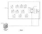
- FIG. 2is diagram of a calibration system for calibrating candidate air quality sensors according to various embodiments of the present invention.
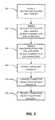
- FIG. 3is a flow chart of the calibration process implemented by the calibration system of FIG. 2 according to various embodiments of the present invention.
- the present inventionis directed to systems and methods for calibrating a number of candidate environmental sensors in a group or batch. Before describing the group calibration process, details about an exemplary candidate environmental sensor M are first provided.
- FIG. 1is a block diagram of a candidate environmental sensor M according to various embodiments of the present invention.
- the illustrated environmental sensor Mcomprises an optical particle sensor 12 , a programmable processor circuit (e.g., a microprocessor) 14 with associated memory 16 (e.g., on-board memory), a touch-screen display 18 , and a wireless transceiver circuit 20 (e.g., a Wi-Fi module, chip or chipset).
- the particle sensor 12subjects incoming ambient air around the sensor M to infrared LED illumination and measures reflections of infrared light by detecting short-term, perpendicular reflections using a photodetector chip in order to detect and count particles in the air around the sensor.
- the optical particle sensor 12can be designed to detect and count particles that are 10 microns or less in diameters, and preferably 0.3 to 10 microns. Fine airborne particles smaller than 2.5 microns, often denoted as PM 2.5 , can pose serious health risks. Thus, the particle sensor 12 preferably detects PM 2.5 particles.
- the sensor Mis preferably for indoor use, such as in a user's home. That way, with the sensor M the user can continuously monitor the air quality in their home.
- the particle sensor 12may be, for example, a DSM501A dust sensor.
- the sensorcan include a fan forcing inflow of the sampling air, and measures the dispersion of reflected lights (from an illuminating LED) by particles in an optical chamber of the particle sensor 12 . This measurement is converted to a pulse width modulated (PWM) output signal.
- PWMpulse width modulated
- the particle sensor 12can include a digital output connected to the microprocessor 14 , where the digital pin voltage is pulled low when particles are detected in the sensor's optical chamber, with the duty cycle being approximately proportional to the number of detected particles.
- the microprocessor 14by executing code stored in the memory 16 , implements an air quality estimation algorithm to compute an air quality measure (e.g., an environmental reading), records raw particle sensor output values, and uses these values to compute and store estimated particle concentration values or readings for the sensor's ambient air in memory 16 .
- the computed particle concentration valuescan comprise volume-based concentration values (e.g., particles per liter) or mass-based concentration values (mg or ⁇ g per cubic cm).
- Additional resident firmware code in the memory 16 and executed by the processor 14serves to control the pixels of the touch-screen display 18 , which preferably is a color TFT touchscreen, in order to render interactive screens, detect screen touch events, and govern transitions between separate interactive screen modes, including real-time and historical review modes.
- the processor's algorithmsamples the sensor output, such as 10,000 times per second. The number of low samples each second can be used by the processor's estimation algorithm to determine the particle count.
- an asymmetric filtering functioncan be used.
- the processor 14can use the following piecewise function to continuously update the cumulative particle count estimate est t at time t, where raw t is the raw sensor value at time t:
- A, B, and Dare constants (e.g., calibration values) that can be determined through the calibration process that is described herein.
- Equation 1shows, if the raw value is non-zero, the current particle count estimate is incremented or decremented at a rate proportional to the difference between the estimate and the raw value scaled by a constant. If the raw value is zero, the estimate exponentially decays toward zero, preferably at a lower rate.
- the resulting behavioris that the particle count estimate quickly responds to non-zero raw values, but decays toward zero slowly due to the potential for long pauses between pulses.
- the processor 14can also be programmed to convert the particle count to an estimated particle weight (e.g., micrograms per cubic meter).
- the wireless transceiver subsystem 20is commanded by the microprocessor 14 to establish, in various embodiments, a Wi-Fi (IEEE 802.11) connection to pre-configured Wi-Fi stations (an infrastructure network) or directly to another Wi-Fi enabled device (an ad hoc network); establish an authenticated connection to Internet-based storage servers; and transmit air quality estimates and raw values from the sensor M continuously.
- the wireless transceiver subsystem 20could use other wireless communication protocols, in addition to or in lieu of the WiFi protocol, such as ZigBee (IEEE 802.15.4), Bluetooth, or wireless USB, for example.
- FIG. 2is a block diagram of a system for batch calibrating a number of candidate environmental sensors M according to various embodiments of the present invention. Calibrating a number of candidate sensors in a group at once avoids the cost associated with calibrating each sensor separately, which should result in lower retail costs for the sensors. Additionally, calibrating multiple sensors simultaneously allows for identification of sensors with outlying behavior through statistical cross-correlation.
- the candidate sensors M to be calibratedcan be placed within an enclosure 30 , e.g., a calibration chamber, with one or more reference environmental sensor(s) R.
- the reference sensor Ris preferably a high-performance, typically laser-based (as opposed to LED), calibrated particle-counting devices, such as a HHPC-6 and/or a HHPC-6+ particle counter.
- the calibration chamber 30could be a room, or it could be a smaller, specialized calibration enclosure.
- a specialized calibration chamberprovides the advantage that it reduces human exposure to the fine particles used in the calibration process, makes it easier to collect the particles afterward for reuse, and allows for better control of the enclosure environment (more homogenous particle concentration).
- the calibration systemalso includes a particle excitation system for dispersing particles throughout the volume of the calibration chamber 30 .
- the excitation systemmay comprise an open container 32 of fine particles (e.g., PM 2.5 particles) that sits on top of a vibration system 34 such that when the vibration system 34 is operated, it vibrates the particle container 32 such that the fine particles in the container drift into the ambient air of the enclosure 30 .
- the vibration system 34may comprise, for example, a loudspeaker, such as a sub-woofer, or some other vibrator suitable for vibrating the particle container 32 so that the fine particles therein are dispersed throughout the volume of the calibration chamber 30 .
- the amplitude and frequency of the vibrations of the vibration system 34can be controlled by a calibration server 40 , as described in more detail below, to thereby control the environmental state of the calibration chamber 30 .
- changing the amplitudechanges the number of particles dispersed into the calibration chamber 30 (higher amplitude, more particles), whereas varying the frequency varies the size of the particles emitted into the calibration chamber 30 (higher frequency, lower average particle size).
- the vibration system 34can nominally operate at around 100 Hz or so, for example.
- the calibration systemmay also include a fan 42 for distributing the particles throughout the calibration chamber 30 .
- the fan 42can also be controlled by the calibration server 40 as described further below.
- Each of the candidate sensors M and the reference sensor(s) Ris in communication with the calibration server 40 via a wired or wireless communication link.
- the sensors Mmay establish direct, ad hoc Wi-Fi communication links with the calibration server 40 or they may communicate through an infrastructure Wi-Fi network (e.g., communication to the network through one or more wireless access points (not shown)).
- the reference sensor Rcould also be in communication with the calibration server 40 via a Wi-Fi network just like the candidate sensors M.
- Other wireless protocols besides Wi-Ficould also be used, such a ZigBee, Bluetooth or wireless USB as described above.
- any or all of the candidate or reference sensorscan have a wired, two-way data connection to the calibration server 40 .
- the calibration server 40can also be in communication with the vibration system 34 and/or the fan 42 via wired and/or wireless communication links to provide a feedback loop for the particle excitation system. That is, for example, if the particle concentration from the sensors (particularly the reference sensor(s) R) is not at the desired level, the calibration server 40 can adjust the vibration system 34 (e.g., the amplitude of the vibrations or frequency) and/or the fan 42 until the particle concentration in the enclosure is at the desired level.
- the vibration system 34e.g., the amplitude of the vibrations or frequency
- the vibration system 34is actuated such that particles from the container 32 are emitted into the volume of the calibration chamber 30 .
- the fan 34can optionally blow the particles around the calibration chamber 30 .
- the sensors M, Rcontinuously report their time-stamped environmental readings (e.g., particle concentration readings) to the calibration server 40 .
- Each sensor M, Ralso has an ID or address that is reported to the calibration server 40 so that the server 40 can record each sensors' readings over time.
- the calibration server 40may be programmed to, among other things:
- FIG. 3is a flow chart of an exemplary calibration process according to various embodiments of the present invention.
- the excitation systemis powered on and the particle concentration level is adjusted to a target of, for example, 500 particles per liter.
- All sensors M, Rare turned on such that they collect and continuously report to the calibration server 40 their respective environmental readings.
- the readings from the sensors M, Rare preferably all of the same type for the various phases so that they can be compared.
- Phase 1may last for a brief period of time, such as five minutes, to allow all sensors M, R to reach equilibrium (e.g., a homogenous environment). As such, the readings from Phase 1 are not used in the calibration process in various embodiments. Any sensor M that cannot establish a connection to the calibration server 40 for some reason during Phase 1 can optionally be removed physically from the calibration chamber 30 or just ignored for the remainder of the calibration process.
- the particle concentrationis maintained at the level of Phase 1 (e.g., 500 particles per liter) for a period of time (e.g., five minutes).
- the sensors M, Rcontinue reporting their time-series environmental readings to the calibration server 40 during the time period of Phase 2.
- the particle concentrationcan be increased, such as doubled (e.g., 1000 particles per liter) for a period of time.
- the duration of the time period for Phase 3can be the same or different than the duration of the time period for Phase 2, but is preferably longer, such as twice as long (e.g., 10 minutes) to allow time for the particle concentration to ramp up to the heightened concentration level and the sensors reach equilibrium.
- the sensors M, Rcontinuously report their time-series environmental readings to the calibration server 40 during the time period of Phase 3.
- the average size of the particlescan be the same for Phases 1 through 3.
- the same container 32 or containers with identical particle characteristicscan be used for the each phase, such that the average size of the particles in the ambient air of the calibration chamber is roughly dictated by the average size of the particles in the container 32 (subject to possible variations in size due to changes in frequency of the vibration system 34 ).
- the average particle sizecan be, for example, two microns in diameter for each phase of the calibration process.
- the resulting datasetcontains 15 minutes of data from each sensor M, R (assuming Phase 2 is five minutes and Phase 3 is ten minutes).
- the sensors M, Rmay report their readings every second, for example, to the calibration server, for a total of 900 data points per sensor M, R in this example.
- the server 40can identify for removal (or to ignore) sensors M′′ whose readings excessively deviate from the norm. For example, for each pair of sensors, the server 40 can compute the r 2 correlation coefficient, which can be stored in a square matrix, such as shown below (assuming n candidate sensors M).
- the server 40then can compute the average r 2 correlation coefficient for each candidate sensor M (i.e., average the values in one row of the matrix, such as indicated by the dashed box above for sensor M1).
- candidate sensors M′′whose average r 2 correlation coefficient is below some threshold value (e.g., 80%) can be removed since their readings were not closely correlated to the other sensors in the enclosure, even though the conditions in the enclosure were roughly the same (homogenous) for every sensor.
- the calibration server 40optimizes the algorithm constants for each remaining sensor M′ (the sensors not removed at step 104 ).
- the algorithm constantscan be optimized for each sensor M′, for example, by minimizing the absolute percentage error between the sensor M′ and the reference sensor R. If multiple reference sensors are used (such as in one enclosure or if there are multiple simultaneous batch calibrations each with their own reference sensor), the reference sensor R that is spatially closest to the subject sensor M′ can be used for the optimization.
- the server 40could be pre-programmed with data about the spatially closest reference sensor R for each candidate sensor M in this situation, for example.
- the calibration server 40can transmit the optimized algorithm values for each remaining sensor M′ to that sensor.
- the sensors M′store their respective calibrated algorithm values in memory 16 such that the sensors M′ use them in the field when measuring air quality.
- the server 40can also store the calibration values for each sensor M′.
- the time periods, particle concentrations and average particle sizes for the calibration phasescan differ from the examples described above in other variations of the inventive calibration process. Also, the steps shown in FIG. 3 could be performed in different orders or some steps could be performed simultaneously, all within the scope of the present invention.
- the calibration server 40may comprise a central processing unit (CPU) that comprises one or more microprocessors.
- the server 40may also comprise primary and second computer memory.
- Software for programming the server 40 to perform the functions described herein, including the calculations for classifying acceptable sensors and for determining their calibration values,can be stored in the computer memory and executed by the CPU.
- the primary memorycan comprise RAM;
- the secondary computer memorycan comprise magnetic, optical or semiconductor memory, such as HDDs, SSDs, optical disks, and/or magnetic tapes, for example.
- the calibration server 40could be replaced by another similarly programmed computer devices (or a network of such devices), such as a workstation, personal computer, laptop, tablet computer, smartphone, etc.
- the present inventionis directed to a system for calibrating environmental sensors.
- the systemcomprises the calibration chamber 30 and the calibration server 40 .
- the calibration chamber 30comprises a plurality of environmental sensors, including one or more candidate environmental sensors M to be calibrated and at least one reference environmental sensor R.
- the calibration chamber 30also comprises the particle excitation system for changing the environmental state of the calibration chamber.
- the calibration server 40is in communication (e.g., wired or wireless communication) with the plurality of environmental sensors M, R and the particle excitation system.
- the environmental sensors M, Rcomprise circuitry for reporting their respective environmental readings to the calibration server 40 .
- the calibration server 40is programmed to control the particle excitation system to expose the plurality of environmental sensors to known and measurable environmental states (e.g., different particle concentration levels) across a dynamic range based on the environmental readings reported at least one of the environmental sensors M, R.
- the calibration server 40classifies each of the one or more candidate environmental sensors M into two or more classes based on the environmental readings reported from at least the candidate environmental sensors, where the two or more classes comprise an unacceptable class and an acceptable class.
- the calibration server 40determines calibration values and transmits those calibration values to the acceptable candidate environmental sensors M′, which the acceptable sensors M′ store in their on-board memory 16 .
- the particle excitation systemcomprises a vibration system 34 and an open container 32 of particles on the vibrator.
- the particle excitation systemcan further comprise a fan 42 .
- the calibration server 40can control the amplitude and frequency of vibrations from the vibration system 34 to dynamically control the environmental state of the calibration chamber 30 .
- the environmental sensors in the calibration chambercan comprise optical particle sensors.
- Some or all of the candidate environmental sensor(s) Mcan comprise a LED light source
- the reference environmental sensor(s) Rcan comprise a laser light source.
- the environmental readings reported from the environmental sensors M, R to the calibration server 40can comprise particle concentration readings, such as volume-based particle concentration readings (e.g., particles per cubic centimeter) or mass-based particle concentration readings (e.g., milli- or micrograms per cubic centimeter).
- the environmental sensors M, Rcan also report their respective environmental readings over time, such that the calibration server 40 receives time-series particle concentration readings.
- the calibration chamber 30comprises two or more reference environmental sensors R, and the calibration values for each acceptable candidate environmental sensor M′ are determined by the calibration server 40 based on the reference environmental sensor R that is spatially closest to the acceptable candidate environmental sensor M′ in the calibration chamber 30 .
- the calibration server 40can be programmed to determine the calibration values by, for each of the acceptable candidate environmental sensors M′, minimizing errors of the environmental readings by the acceptable candidate environmental sensor M′ relative to the spatially-closest reference candidate sensor R over two or more environmental states (e.g., the Phase 2 and Phase 3 states).
- the calibration server 40can be programmed to classify the candidate environmental sensors M based on computed correlation coefficients for each candidate environmental sensor to the other candidate environmental sensors over two or more environmental states (e.g., the Phase 2 and Phase 3 states). To that end, the calibration server 40 can compute an average correlation coefficient (e.g., an average correlation coefficient) for each of the candidate environmental sensors M and classify as acceptable candidate environmental sensors M whose average correlation coefficient is above a threshold value.
- an average correlation coefficiente.g., an average correlation coefficient
- the present inventionis directed to a method of calibrating one or more candidate environmental sensors.
- the methodcomprises placing a plurality of environmental sensors in a calibration chamber 30 .
- the plurality of environmental sensorscomprises one or more candidate environmental sensors M to be calibrated and at least one reference environmental sensor R.
- the methodfurther comprises the step of controlling the environmental state of the calibration chamber 30 to expose the environmental sensors M, R to known and measurable environmental states across a dynamic range.
- the methodfurther comprises, for each of the one or more candidate environmental sensors M, classifying, by a calibration server 40 that is in communication with the plurality of environmental sensors M, R, the candidate environmental sensors M into two or more classes based on environmental readings from at least the candidate environmental sensors, where the two or more classes comprise an unacceptable class and an acceptable class.
- the methodfurther comprises, for each of the one or more candidate environmental sensors classified as acceptable, (i) determining, by the calibration server 40 , calibration values and (ii) transmitting, by the calibration server 40 , the calibration values to the candidate environmental sensors M′.
- the present inventionis directed to a method of manufacturing a candidate environmental sensor M.
- the methodcomprises the step of placing the candidate environmental sensor M and at least one reference environmental sensor R in a calibration chamber 30 .
- the methodfurther comprises the step of controlling an environmental state of the calibration chamber 30 to expose the candidate environmental sensor M and the at least one reference environmental sensor R to known and measurable environmental states across a dynamic range.
- the methodfurther comprises the step of determining, by a calibration server 40 that is in communication with the candidate environmental sensor M and the at least one reference sensor R, whether the candidate environmental sensor M is acceptable based on environmental readings from the candidate environmental sensor M. Upon a determination that the candidate environmental sensor M is acceptable, the method further comprises
Landscapes
- Chemical & Material Sciences (AREA)
- Life Sciences & Earth Sciences (AREA)
- Dispersion Chemistry (AREA)
- Physics & Mathematics (AREA)
- Health & Medical Sciences (AREA)
- Analytical Chemistry (AREA)
- Biochemistry (AREA)
- General Health & Medical Sciences (AREA)
- General Physics & Mathematics (AREA)
- Immunology (AREA)
- Pathology (AREA)
- Signal Processing (AREA)
- Engineering & Computer Science (AREA)
- Investigating Or Analysing Materials By Optical Means (AREA)
Abstract
Description
A, B, and D are constants (e.g., calibration values) that can be determined through the calibration process that is described herein. As
- Collect and record the time series environmental readings from the sensors M, R;
- Control the ambient in conditions in the
calibration chamber 30 based on the environmental readings, particularly based on the high-performance reference sensor R, by controlling the vibration system34 (e.g., controlling amplitude and/or frequency) and/or controlling thefan 42, to achieve known and measurable particle concentration levels over a dynamic range; - Identify candidate sensors M″ that are not acceptable;
- Compute the calibration values for the respective candidate sensors M′ that are acceptable and transmit those values back the acceptable candidate sensors M′; and
- Archive the calibration values in a memory unit of the
calibration server 40.

The
Claims (17)
Priority Applications (1)
| Application Number | Priority Date | Filing Date | Title |
|---|---|---|---|
| US15/156,954US10054534B1 (en) | 2015-07-08 | 2016-05-17 | Group calibration of environmental sensors |
Applications Claiming Priority (2)
| Application Number | Priority Date | Filing Date | Title |
|---|---|---|---|
| US201562189978P | 2015-07-08 | 2015-07-08 | |
| US15/156,954US10054534B1 (en) | 2015-07-08 | 2016-05-17 | Group calibration of environmental sensors |
Publications (1)
| Publication Number | Publication Date |
|---|---|
| US10054534B1true US10054534B1 (en) | 2018-08-21 |
Family
ID=63143891
Family Applications (1)
| Application Number | Title | Priority Date | Filing Date |
|---|---|---|---|
| US15/156,954Active - Reinstated2036-08-30US10054534B1 (en) | 2015-07-08 | 2016-05-17 | Group calibration of environmental sensors |
Country Status (1)
| Country | Link |
|---|---|
| US (1) | US10054534B1 (en) |
Cited By (23)
| Publication number | Priority date | Publication date | Assignee | Title |
|---|---|---|---|---|
| CN110514785A (en)* | 2019-07-31 | 2019-11-29 | 北京佳华智联科技有限公司 | Sensing data on-line calibration method, apparatus, electronic equipment and storage medium |
| US10599116B2 (en) | 2014-02-28 | 2020-03-24 | Delos Living Llc | Methods for enhancing wellness associated with habitable environments |
| US10691148B2 (en) | 2012-08-28 | 2020-06-23 | Delos Living Llc | Systems, methods and articles for enhancing wellness associated with habitable environments |
| US10718703B2 (en) | 2014-04-30 | 2020-07-21 | Particles Plus, Inc. | Particle counter with advanced features |
| US10802009B2 (en)* | 2016-12-06 | 2020-10-13 | Ning Zeng | Networked environmental monitoring system and method |
| US10923226B2 (en) | 2015-01-13 | 2021-02-16 | Delos Living Llc | Systems, methods and articles for monitoring and enhancing human wellness |
| US10983040B2 (en) | 2013-03-15 | 2021-04-20 | Particles Plus, Inc. | Particle counter with integrated bootloader |
| CN113454452A (en)* | 2018-12-19 | 2021-09-28 | 伊莱肯兹公司 | Method for calibrating a gas sensor |
| US11169077B2 (en) | 2013-03-15 | 2021-11-09 | Particles Plus, Inc. | Personal air quality monitoring system |
| US11238028B2 (en)* | 2019-04-12 | 2022-02-01 | Aclima Inc. | Signal processing for multi-sensor groups |
| GB2598719A (en)* | 2020-09-01 | 2022-03-16 | Airsensa Products Ltd | Automated sensor calibration device |
| US11307186B2 (en) | 2019-05-10 | 2022-04-19 | Aclima Inc. | Integration and active flow control for environmental sensors |
| US11338107B2 (en) | 2016-08-24 | 2022-05-24 | Delos Living Llc | Systems, methods and articles for enhancing wellness associated with habitable environments |
| CN114659672A (en)* | 2022-03-08 | 2022-06-24 | 中国人民解放军火箭军工程大学 | A method for detecting abnormal state of environmental monitoring sensor |
| US11579072B2 (en) | 2013-03-15 | 2023-02-14 | Particles Plus, Inc. | Personal air quality monitoring system |
| US11649977B2 (en) | 2018-09-14 | 2023-05-16 | Delos Living Llc | Systems and methods for air remediation |
| US11668481B2 (en) | 2017-08-30 | 2023-06-06 | Delos Living Llc | Systems, methods and articles for assessing and/or improving health and well-being |
| WO2023135337A1 (en)* | 2022-01-17 | 2023-07-20 | Bernard Technologies GmbH | Method for calibrating an ego-device |
| US20230359228A1 (en)* | 2018-02-26 | 2023-11-09 | Fujikin Incorporated | Flow rate control device and flow rate control method |
| US11844163B2 (en) | 2019-02-26 | 2023-12-12 | Delos Living Llc | Method and apparatus for lighting in an office environment |
| US11898898B2 (en) | 2019-03-25 | 2024-02-13 | Delos Living Llc | Systems and methods for acoustic monitoring |
| US11988591B2 (en) | 2020-07-01 | 2024-05-21 | Particles Plus, Inc. | Modular optical particle counter sensor and apparatus |
| US12044611B2 (en) | 2013-03-15 | 2024-07-23 | Particles Plus, Inc. | Particle counter with integrated bootloader |
Citations (32)
| Publication number | Priority date | Publication date | Assignee | Title |
|---|---|---|---|---|
| US3933433A (en)* | 1974-12-18 | 1976-01-20 | Dynamation Enterprises, Inc. | Method and apparatus for gas detection |
| US4185491A (en)* | 1977-01-10 | 1980-01-29 | British Steel Corporation | Gas monitors |
| US4279142A (en)* | 1975-09-25 | 1981-07-21 | Westinghouse Electric Corp. | Technique for in situ calibration of a gas detector |
| US4364234A (en)* | 1981-03-25 | 1982-12-21 | Koolatron Industries, Ltd. | Control circuitry for thermoelectric environmental chamber |
| US4384925A (en)* | 1980-10-24 | 1983-05-24 | Becton Dickinson And Company | Gas sensing unit with automatic calibration method |
| US4847493A (en)* | 1987-10-09 | 1989-07-11 | Masstron, Inc. | Calibration of a mass spectrometer |
| US5239492A (en)* | 1990-10-11 | 1993-08-24 | Spacelabs Medical, Inc. | Automatic internal calibration circuit and method |
| US5317156A (en)* | 1992-01-29 | 1994-05-31 | Sri International | Diagnostic tests using near-infrared laser absorption spectroscopy |
| US5367577A (en)* | 1989-08-18 | 1994-11-22 | Datalab Oy | Optical testing for genuineness of bank notes and similar paper bills |
| US6171366B1 (en)* | 1996-04-23 | 2001-01-09 | Lab, S.A. | Control systems for operating gas cleaning devices |
| US6918281B2 (en)* | 2000-05-11 | 2005-07-19 | Zellweger Analytics Limited | Gas sensor calibration system |
| US7201033B2 (en)* | 2003-08-14 | 2007-04-10 | Fluid Components International Llc | Flowmeter in-situ calibration verification system |
| US7401493B2 (en)* | 2000-12-11 | 2008-07-22 | Honeywell Analytics, Ltd. | Gas sensor calibration method |
| US20080225910A1 (en) | 2007-03-15 | 2008-09-18 | Finisar Corporation | Laser driver bias current calibration |
| US20090082987A1 (en) | 2007-09-20 | 2009-03-26 | Collins Daniel J | Use of statistics to determine calibration of instruments |
| WO2010046711A2 (en) | 2008-10-24 | 2010-04-29 | Transense Technologies Plc | Callibration coefficients for sensor based measurements |
| US20110031386A1 (en) | 2007-08-16 | 2011-02-10 | Helmut Pradel | Device and method for calibrating a sensor system |
| US20110072879A1 (en) | 2009-09-25 | 2011-03-31 | Peter Damion Bellis | Systems and methods for remotely calibrating a gas sensor |
| US8101905B2 (en)* | 2008-09-04 | 2012-01-24 | The Boeing Company | Infrared sensor calibration system and method |
| US8222606B1 (en)* | 2011-05-31 | 2012-07-17 | Airware, Inc. | Air sampler for recalibration of absorption biased designed NDIR gas sensors |
| US20120330596A1 (en)* | 2011-06-21 | 2012-12-27 | General Electric Company | Self-calibrating sensor, system, and computer program product |
| US20130325252A1 (en) | 2010-12-09 | 2013-12-05 | Stefan Schommer | Method and device for calibrating and adjusting a vehicle surroundings sensor |
| WO2014005714A1 (en) | 2012-07-06 | 2014-01-09 | Giesecke & Devrient Gmbh | Calibration of a magnetic sensor |
| US20140083159A1 (en) | 2012-09-21 | 2014-03-27 | Horiba Stec, Co.,Ltd. | Self-calibrating mechanism and self-calibrating method for flow rate sensor, and diagnostic mechanism and diagnostic method for fluid sensor |
| US20140092933A1 (en) | 2012-03-20 | 2014-04-03 | Canon U.S. Life Sciences, Inc. | Compound calibrator for thermal sensors |
| US20140180048A1 (en)* | 2012-12-20 | 2014-06-26 | Becton, Dickinson And Company | System and method for using multiple sensor calibration methods |
| US20140273042A1 (en) | 2013-03-15 | 2014-09-18 | Tandem Diabetes Care, Inc. | Predictive calibration |
| US8993956B2 (en)* | 2007-08-16 | 2015-03-31 | Giesecke & Devrient Gmbh | Method for calibrating a sensor system |
| WO2016054004A1 (en) | 2014-09-30 | 2016-04-07 | Sikorsky Aircraft Corporation | Online sensor calibration verification system |
| US9316627B2 (en)* | 2014-01-15 | 2016-04-19 | Oy Sparklike Ab | Method and device for determining gas component inside a transparent container |
| US9395334B2 (en)* | 2011-03-30 | 2016-07-19 | Fujitsu Limited | Atmospheric environment measuring apparatus, atmospheric environment measuring method and atmospheric environment measuring system |
| US9664607B2 (en)* | 2013-11-29 | 2017-05-30 | Seoul Viosys Co., Ltd. | Portable apparatus for estimating air quality and methods of operating the same |
- 2016
- 2016-05-17USUS15/156,954patent/US10054534B1/enactiveActive - Reinstated
Patent Citations (34)
| Publication number | Priority date | Publication date | Assignee | Title |
|---|---|---|---|---|
| US3933433A (en)* | 1974-12-18 | 1976-01-20 | Dynamation Enterprises, Inc. | Method and apparatus for gas detection |
| US4279142A (en)* | 1975-09-25 | 1981-07-21 | Westinghouse Electric Corp. | Technique for in situ calibration of a gas detector |
| US4185491A (en)* | 1977-01-10 | 1980-01-29 | British Steel Corporation | Gas monitors |
| US4384925A (en)* | 1980-10-24 | 1983-05-24 | Becton Dickinson And Company | Gas sensing unit with automatic calibration method |
| US4364234A (en)* | 1981-03-25 | 1982-12-21 | Koolatron Industries, Ltd. | Control circuitry for thermoelectric environmental chamber |
| US4847493A (en)* | 1987-10-09 | 1989-07-11 | Masstron, Inc. | Calibration of a mass spectrometer |
| US5367577A (en)* | 1989-08-18 | 1994-11-22 | Datalab Oy | Optical testing for genuineness of bank notes and similar paper bills |
| US5239492A (en)* | 1990-10-11 | 1993-08-24 | Spacelabs Medical, Inc. | Automatic internal calibration circuit and method |
| US5317156A (en)* | 1992-01-29 | 1994-05-31 | Sri International | Diagnostic tests using near-infrared laser absorption spectroscopy |
| US6171366B1 (en)* | 1996-04-23 | 2001-01-09 | Lab, S.A. | Control systems for operating gas cleaning devices |
| US6918281B2 (en)* | 2000-05-11 | 2005-07-19 | Zellweger Analytics Limited | Gas sensor calibration system |
| US7401493B2 (en)* | 2000-12-11 | 2008-07-22 | Honeywell Analytics, Ltd. | Gas sensor calibration method |
| US7201033B2 (en)* | 2003-08-14 | 2007-04-10 | Fluid Components International Llc | Flowmeter in-situ calibration verification system |
| US20080225910A1 (en) | 2007-03-15 | 2008-09-18 | Finisar Corporation | Laser driver bias current calibration |
| US20110031386A1 (en) | 2007-08-16 | 2011-02-10 | Helmut Pradel | Device and method for calibrating a sensor system |
| US8993956B2 (en)* | 2007-08-16 | 2015-03-31 | Giesecke & Devrient Gmbh | Method for calibrating a sensor system |
| US20090082987A1 (en) | 2007-09-20 | 2009-03-26 | Collins Daniel J | Use of statistics to determine calibration of instruments |
| US8101905B2 (en)* | 2008-09-04 | 2012-01-24 | The Boeing Company | Infrared sensor calibration system and method |
| WO2010046711A2 (en) | 2008-10-24 | 2010-04-29 | Transense Technologies Plc | Callibration coefficients for sensor based measurements |
| US20110072879A1 (en) | 2009-09-25 | 2011-03-31 | Peter Damion Bellis | Systems and methods for remotely calibrating a gas sensor |
| US8220308B2 (en)* | 2009-09-25 | 2012-07-17 | General Electric Company | Systems and methods for remotely calibrating a gas sensor |
| US20130325252A1 (en) | 2010-12-09 | 2013-12-05 | Stefan Schommer | Method and device for calibrating and adjusting a vehicle surroundings sensor |
| US9395334B2 (en)* | 2011-03-30 | 2016-07-19 | Fujitsu Limited | Atmospheric environment measuring apparatus, atmospheric environment measuring method and atmospheric environment measuring system |
| US8222606B1 (en)* | 2011-05-31 | 2012-07-17 | Airware, Inc. | Air sampler for recalibration of absorption biased designed NDIR gas sensors |
| US20120330596A1 (en)* | 2011-06-21 | 2012-12-27 | General Electric Company | Self-calibrating sensor, system, and computer program product |
| US20140092933A1 (en) | 2012-03-20 | 2014-04-03 | Canon U.S. Life Sciences, Inc. | Compound calibrator for thermal sensors |
| WO2014005714A1 (en) | 2012-07-06 | 2014-01-09 | Giesecke & Devrient Gmbh | Calibration of a magnetic sensor |
| US9057636B2 (en)* | 2012-09-21 | 2015-06-16 | Horiba Stec, Co. Ltd. | Self-calibrating mechanism and self-calibrating method for flow rate sensor, and diagnostic mechanism and diagnostic method for fluid sensor |
| US20140083159A1 (en) | 2012-09-21 | 2014-03-27 | Horiba Stec, Co.,Ltd. | Self-calibrating mechanism and self-calibrating method for flow rate sensor, and diagnostic mechanism and diagnostic method for fluid sensor |
| US20140180048A1 (en)* | 2012-12-20 | 2014-06-26 | Becton, Dickinson And Company | System and method for using multiple sensor calibration methods |
| US20140273042A1 (en) | 2013-03-15 | 2014-09-18 | Tandem Diabetes Care, Inc. | Predictive calibration |
| US9664607B2 (en)* | 2013-11-29 | 2017-05-30 | Seoul Viosys Co., Ltd. | Portable apparatus for estimating air quality and methods of operating the same |
| US9316627B2 (en)* | 2014-01-15 | 2016-04-19 | Oy Sparklike Ab | Method and device for determining gas component inside a transparent container |
| WO2016054004A1 (en) | 2014-09-30 | 2016-04-07 | Sikorsky Aircraft Corporation | Online sensor calibration verification system |
Cited By (45)
| Publication number | Priority date | Publication date | Assignee | Title |
|---|---|---|---|---|
| US10845829B2 (en) | 2012-08-28 | 2020-11-24 | Delos Living Llc | Systems, methods and articles for enhancing wellness associated with habitable environments |
| US11587673B2 (en) | 2012-08-28 | 2023-02-21 | Delos Living Llc | Systems, methods and articles for enhancing wellness associated with habitable environments |
| US10691148B2 (en) | 2012-08-28 | 2020-06-23 | Delos Living Llc | Systems, methods and articles for enhancing wellness associated with habitable environments |
| US10928842B2 (en) | 2012-08-28 | 2021-02-23 | Delos Living Llc | Systems and methods for enhancing wellness associated with habitable environments |
| US11169077B2 (en) | 2013-03-15 | 2021-11-09 | Particles Plus, Inc. | Personal air quality monitoring system |
| US11579072B2 (en) | 2013-03-15 | 2023-02-14 | Particles Plus, Inc. | Personal air quality monitoring system |
| US11519842B2 (en) | 2013-03-15 | 2022-12-06 | Particles Plus, Inc. | Multiple particle sensors in a particle counter |
| US11913869B2 (en) | 2013-03-15 | 2024-02-27 | Particles Plus, Inc. | Personal air quality monitoring system |
| US12044611B2 (en) | 2013-03-15 | 2024-07-23 | Particles Plus, Inc. | Particle counter with integrated bootloader |
| US10983040B2 (en) | 2013-03-15 | 2021-04-20 | Particles Plus, Inc. | Particle counter with integrated bootloader |
| US10599116B2 (en) | 2014-02-28 | 2020-03-24 | Delos Living Llc | Methods for enhancing wellness associated with habitable environments |
| US11763401B2 (en) | 2014-02-28 | 2023-09-19 | Delos Living Llc | Systems, methods and articles for enhancing wellness associated with habitable environments |
| US10712722B2 (en) | 2014-02-28 | 2020-07-14 | Delos Living Llc | Systems and articles for enhancing wellness associated with habitable environments |
| US12306088B2 (en) | 2014-04-30 | 2025-05-20 | Particles Plus, Inc. | Particle counter with advanced features |
| US11835443B2 (en) | 2014-04-30 | 2023-12-05 | Particles Plus, Inc. | Real time monitoring of particle count data |
| US11841313B2 (en) | 2014-04-30 | 2023-12-12 | Particles Plus, Inc. | Power management for optical particle counters |
| US11846581B2 (en) | 2014-04-30 | 2023-12-19 | Particles Plus, Inc. | Instrument networking for optical particle counters |
| US10718703B2 (en) | 2014-04-30 | 2020-07-21 | Particles Plus, Inc. | Particle counter with advanced features |
| US10923226B2 (en) | 2015-01-13 | 2021-02-16 | Delos Living Llc | Systems, methods and articles for monitoring and enhancing human wellness |
| US11338107B2 (en) | 2016-08-24 | 2022-05-24 | Delos Living Llc | Systems, methods and articles for enhancing wellness associated with habitable environments |
| US12031966B2 (en)* | 2016-12-06 | 2024-07-09 | Ning Zeng | Networked environmental monitoring system and method |
| US10802009B2 (en)* | 2016-12-06 | 2020-10-13 | Ning Zeng | Networked environmental monitoring system and method |
| US20210041406A1 (en)* | 2016-12-06 | 2021-02-11 | Ning Zeng | Networked Environmental Monitoring System and Method |
| US11668481B2 (en) | 2017-08-30 | 2023-06-06 | Delos Living Llc | Systems, methods and articles for assessing and/or improving health and well-being |
| US12007797B2 (en)* | 2018-02-26 | 2024-06-11 | Fujikin Incorporated | Flow rate control device and flow rate control method |
| US20230359228A1 (en)* | 2018-02-26 | 2023-11-09 | Fujikin Incorporated | Flow rate control device and flow rate control method |
| US11649977B2 (en) | 2018-09-14 | 2023-05-16 | Delos Living Llc | Systems and methods for air remediation |
| CN113454452A (en)* | 2018-12-19 | 2021-09-28 | 伊莱肯兹公司 | Method for calibrating a gas sensor |
| CN113454452B (en)* | 2018-12-19 | 2024-03-08 | 伊莱肯兹公司 | Method for calibrating a gas sensor |
| US11844163B2 (en) | 2019-02-26 | 2023-12-12 | Delos Living Llc | Method and apparatus for lighting in an office environment |
| US11898898B2 (en) | 2019-03-25 | 2024-02-13 | Delos Living Llc | Systems and methods for acoustic monitoring |
| US12259871B2 (en) | 2019-04-12 | 2025-03-25 | Aclima Inc. | Signal processing for multi-sensor groups |
| US11720544B2 (en) | 2019-04-12 | 2023-08-08 | Aclima Inc. | Signal processing for multi-sensor groups |
| US11238028B2 (en)* | 2019-04-12 | 2022-02-01 | Aclima Inc. | Signal processing for multi-sensor groups |
| US11867679B2 (en) | 2019-05-10 | 2024-01-09 | Aclima Inc. | Integration and active flow control for environmental sensors |
| US11307186B2 (en) | 2019-05-10 | 2022-04-19 | Aclima Inc. | Integration and active flow control for environmental sensors |
| CN110514785B (en)* | 2019-07-31 | 2022-02-11 | 北京佳华智联科技有限公司 | Sensor data online calibration method and device, electronic equipment and storage medium |
| CN110514785A (en)* | 2019-07-31 | 2019-11-29 | 北京佳华智联科技有限公司 | Sensing data on-line calibration method, apparatus, electronic equipment and storage medium |
| US11988591B2 (en) | 2020-07-01 | 2024-05-21 | Particles Plus, Inc. | Modular optical particle counter sensor and apparatus |
| US12055474B2 (en) | 2020-07-01 | 2024-08-06 | Particles Plus, Inc. | Modular optical particle counter sensor and apparatus |
| US12436084B2 (en) | 2020-07-01 | 2025-10-07 | Particles Plus, Inc. | Modular optical particle counter sensor and apparatus |
| GB2598719A (en)* | 2020-09-01 | 2022-03-16 | Airsensa Products Ltd | Automated sensor calibration device |
| WO2023135337A1 (en)* | 2022-01-17 | 2023-07-20 | Bernard Technologies GmbH | Method for calibrating an ego-device |
| CN114659672B (en)* | 2022-03-08 | 2024-12-06 | 中国人民解放军火箭军工程大学 | A method for detecting abnormal state of environmental monitoring sensor |
| CN114659672A (en)* | 2022-03-08 | 2022-06-24 | 中国人民解放军火箭军工程大学 | A method for detecting abnormal state of environmental monitoring sensor |
Similar Documents
| Publication | Publication Date | Title |
|---|---|---|
| US10054534B1 (en) | Group calibration of environmental sensors | |
| US11846581B2 (en) | Instrument networking for optical particle counters | |
| US11910137B2 (en) | Processing time-series measurement entries of a measurement database | |
| US11791045B1 (en) | Apparatus for informed personal well-being decision making and associated method | |
| JP5655005B2 (en) | Monitoring system and method | |
| US20150284214A1 (en) | Elevator health check | |
| EP2876893B1 (en) | Cloud-based monitoring apparatus | |
| CN108701397B (en) | baby tracker | |
| US20180088098A1 (en) | System, Method, and Apparatus for Condition Monitoring of Food and Other Perishable Products As Well As Environmentally Sensitive Industrial Supply Chains | |
| JP6637077B2 (en) | Optical particle sensor and sensing method | |
| JP2021193611A (en) | Gravimeter, advice information providing system, and bottle | |
| JP6467181B2 (en) | Method and system for dynamic workflow prioritization and tasking | |
| CN107430025A (en) | Foods or drinkses preparation system, method and kit | |
| US20150032412A1 (en) | Low power movement sensor | |
| US11137479B1 (en) | Product specific correction for a sensor-based device | |
| JP2009145346A5 (en) | ||
| US11010711B1 (en) | Test-enabled measurements for a sensor-based device | |
| CN110864776A (en) | Weighing equipment predictive maintenance algorithm and weighing equipment predictive maintenance method | |
| CN205649656U (en) | Intelligence feeding bottle and measurement system thereof | |
| CN118159813A (en) | System and method for measuring temperature of individual | |
| US11361011B1 (en) | Sensor-related improvements to automatic replenishment devices | |
| US11963062B1 (en) | System and method for identifying product engagements | |
| CN106503435A (en) | A kind of baby's feed information monitoring system and method | |
| US11893080B2 (en) | Computing device and method using a neural network to determine whether or not to process images of an image flow | |
| WO2018108646A1 (en) | Fanless airborne pollutant sensing |
Legal Events
| Date | Code | Title | Description |
|---|---|---|---|
| STCF | Information on status: patent grant | Free format text:PATENTED CASE | |
| FEPP | Fee payment procedure | Free format text:MAINTENANCE FEE REMINDER MAILED (ORIGINAL EVENT CODE: REM.); ENTITY STATUS OF PATENT OWNER: SMALL ENTITY | |
| LAPS | Lapse for failure to pay maintenance fees | Free format text:PATENT EXPIRED FOR FAILURE TO PAY MAINTENANCE FEES (ORIGINAL EVENT CODE: EXP.); ENTITY STATUS OF PATENT OWNER: SMALL ENTITY | |
| STCH | Information on status: patent discontinuation | Free format text:PATENT EXPIRED DUE TO NONPAYMENT OF MAINTENANCE FEES UNDER 37 CFR 1.362 | |
| FP | Lapsed due to failure to pay maintenance fee | Effective date:20220821 | |
| PRDP | Patent reinstated due to the acceptance of a late maintenance fee | Effective date:20221027 | |
| FEPP | Fee payment procedure | Free format text:PETITION RELATED TO MAINTENANCE FEES FILED (ORIGINAL EVENT CODE: PMFP); ENTITY STATUS OF PATENT OWNER: SMALL ENTITY Free format text:PETITION RELATED TO MAINTENANCE FEES GRANTED (ORIGINAL EVENT CODE: PMFG); ENTITY STATUS OF PATENT OWNER: SMALL ENTITY Free format text:SURCHARGE, PETITION TO ACCEPT PYMT AFTER EXP, UNINTENTIONAL. (ORIGINAL EVENT CODE: M2558); ENTITY STATUS OF PATENT OWNER: SMALL ENTITY | |
| MAFP | Maintenance fee payment | Free format text:PAYMENT OF MAINTENANCE FEE, 4TH YR, SMALL ENTITY (ORIGINAL EVENT CODE: M2551); ENTITY STATUS OF PATENT OWNER: SMALL ENTITY Year of fee payment:4 | |
| STCF | Information on status: patent grant | Free format text:PATENTED CASE |