US10053868B2 - Floor panel and floor covering consisting of a plurality of such floor panels - Google Patents
Floor panel and floor covering consisting of a plurality of such floor panelsDownload PDFInfo
- Publication number
- US10053868B2 US10053868B2US14/969,576US201514969576AUS10053868B2US 10053868 B2US10053868 B2US 10053868B2US 201514969576 AUS201514969576 AUS 201514969576AUS 10053868 B2US10053868 B2US 10053868B2
- Authority
- US
- United States
- Prior art keywords
- upward
- downward
- tongue
- floor panel
- flank
- Prior art date
- Legal status (The legal status is an assumption and is not a legal conclusion. Google has not performed a legal analysis and makes no representation as to the accuracy of the status listed.)
- Active, expires
Links
Images


Classifications
- E—FIXED CONSTRUCTIONS
- E04—BUILDING
- E04F—FINISHING WORK ON BUILDINGS, e.g. STAIRS, FLOORS
- E04F15/00—Flooring
- E04F15/02—Flooring or floor layers composed of a number of similar elements
- E04F15/02038—Flooring or floor layers composed of a number of similar elements characterised by tongue and groove connections between neighbouring flooring elements
- E—FIXED CONSTRUCTIONS
- E04—BUILDING
- E04C—STRUCTURAL ELEMENTS; BUILDING MATERIALS
- E04C2/00—Building elements of relatively thin form for the construction of parts of buildings, e.g. sheet materials, slabs, or panels
- E04C2/30—Building elements of relatively thin form for the construction of parts of buildings, e.g. sheet materials, slabs, or panels characterised by the shape or structure
- E04C2/38—Building elements of relatively thin form for the construction of parts of buildings, e.g. sheet materials, slabs, or panels characterised by the shape or structure with attached ribs, flanges, or the like, e.g. framed panels
- E—FIXED CONSTRUCTIONS
- E04—BUILDING
- E04C—STRUCTURAL ELEMENTS; BUILDING MATERIALS
- E04C2/00—Building elements of relatively thin form for the construction of parts of buildings, e.g. sheet materials, slabs, or panels
- E04C2/30—Building elements of relatively thin form for the construction of parts of buildings, e.g. sheet materials, slabs, or panels characterised by the shape or structure
- E04C2/40—Building elements of relatively thin form for the construction of parts of buildings, e.g. sheet materials, slabs, or panels characterised by the shape or structure composed of a number of smaller components rigidly or movably connected together, e.g. interlocking, hingedly connected of particular shape, e.g. not rectangular of variable shape or size, e.g. flexible or telescopic panels
- E—FIXED CONSTRUCTIONS
- E04—BUILDING
- E04F—FINISHING WORK ON BUILDINGS, e.g. STAIRS, FLOORS
- E04F15/00—Flooring
- E04F15/02—Flooring or floor layers composed of a number of similar elements
- E—FIXED CONSTRUCTIONS
- E04—BUILDING
- E04F—FINISHING WORK ON BUILDINGS, e.g. STAIRS, FLOORS
- E04F2201/00—Joining sheets or plates or panels
- E04F2201/01—Joining sheets, plates or panels with edges in abutting relationship
- E04F2201/0123—Joining sheets, plates or panels with edges in abutting relationship by moving the sheets, plates or panels parallel to the abutting edges
- E—FIXED CONSTRUCTIONS
- E04—BUILDING
- E04F—FINISHING WORK ON BUILDINGS, e.g. STAIRS, FLOORS
- E04F2201/00—Joining sheets or plates or panels
- E04F2201/01—Joining sheets, plates or panels with edges in abutting relationship
- E04F2201/0138—Joining sheets, plates or panels with edges in abutting relationship by moving the sheets, plates or panels perpendicular to the main plane
- E04F2201/0146—Joining sheets, plates or panels with edges in abutting relationship by moving the sheets, plates or panels perpendicular to the main plane with snap action of the edge connectors
- E—FIXED CONSTRUCTIONS
- E04—BUILDING
- E04F—FINISHING WORK ON BUILDINGS, e.g. STAIRS, FLOORS
- E04F2201/00—Joining sheets or plates or panels
- E04F2201/03—Undercut connections, e.g. using undercut tongues or grooves
- E—FIXED CONSTRUCTIONS
- E04—BUILDING
- E04F—FINISHING WORK ON BUILDINGS, e.g. STAIRS, FLOORS
- E04F2201/00—Joining sheets or plates or panels
- E04F2201/04—Other details of tongues or grooves
- F—MECHANICAL ENGINEERING; LIGHTING; HEATING; WEAPONS; BLASTING
- F16—ENGINEERING ELEMENTS AND UNITS; GENERAL MEASURES FOR PRODUCING AND MAINTAINING EFFECTIVE FUNCTIONING OF MACHINES OR INSTALLATIONS; THERMAL INSULATION IN GENERAL
- F16B—DEVICES FOR FASTENING OR SECURING CONSTRUCTIONAL ELEMENTS OR MACHINE PARTS TOGETHER, e.g. NAILS, BOLTS, CIRCLIPS, CLAMPS, CLIPS OR WEDGES; JOINTS OR JOINTING
- F16B5/00—Joining sheets or plates, e.g. panels, to one another or to strips or bars parallel to them
- F16B5/0004—Joining sheets, plates or panels in abutting relationship
- F16B5/0056—Joining sheets, plates or panels in abutting relationship by moving the sheets, plates or panels or the interlocking key perpendicular to the main plane
- Y—GENERAL TAGGING OF NEW TECHNOLOGICAL DEVELOPMENTS; GENERAL TAGGING OF CROSS-SECTIONAL TECHNOLOGIES SPANNING OVER SEVERAL SECTIONS OF THE IPC; TECHNICAL SUBJECTS COVERED BY FORMER USPC CROSS-REFERENCE ART COLLECTIONS [XRACs] AND DIGESTS
- Y10—TECHNICAL SUBJECTS COVERED BY FORMER USPC
- Y10T—TECHNICAL SUBJECTS COVERED BY FORMER US CLASSIFICATION
- Y10T428/00—Stock material or miscellaneous articles
- Y10T428/24—Structurally defined web or sheet [e.g., overall dimension, etc.]
- Y10T428/24479—Structurally defined web or sheet [e.g., overall dimension, etc.] including variation in thickness
- Y10T428/24488—Differential nonuniformity at margin
Definitions
- the inventionrelates to a floor panel, in particular a laminated floor panel.
- the inventionalso relates to a floor covering consisting of a plurality of mutually coupled floor panels according to the invention.
- the inventionfurther relates to a method for mutually coupling two floor panels, in particular laminated floor panels, according to the invention.
- the U.S. Pat. No. 6,490,836describes a laminate consisting of floor panels which can be mutually coupled, wherein the coupling of two floor panels can be realized by having the floor panels engage each other at an angle, followed by tilting the floor panels relative to each other, whereby the floor panels can in fact be hooked into each other.
- the known laminatecan be laid relatively easily by a user, the known floor covering also has a number of drawbacks.
- a significant drawback of the known floor coveringis that, due to the tilting movement required to realize the coupling, relatively great forces are exerted on the floor parts, which can result in permanent damage (breakage).
- Another drawback of the known laminateis that a relatively large amount of space is required to enable mutual coupling of the floor panels, which makes coupling of a floor panel to an adjacent floor panel considerably more difficult, or even impossible, in a limited space, such as for instance close to a wall or under a radiator.
- the inventionhas for its object to provide an improved floor panel which can be coupled in improved manner to an adjacent floor panel.
- the inventionprovides for this purpose a floor panel, comprising: a centrally located core provided with an upper side and a lower side, at least one first resilient coupling part and second resilient coupling part connected respectively to opposite edges of the core, which first coupling part comprises a single tongue, at least one upward flank lying at a distance from the upward tongue and a single upward groove formed between the upward tongue and the upward flank, wherein: at least a part of a side of the upward tongue facing toward the upward flank extends in the direction of the normal of the upper side of the core, at least a part of a side of the upward tongue facing toward the upward flank forms an aligning edge for the purpose of coupling the first coupling part to a second coupling part of an adjacent floor panel, at least a part of a side of the upward tongue facing away from the upward flank is provided with a first locking element which is connected substantially rigidly to the upward tongue and adapted for co-action with a second locking element of a second coupling part of an adjacent floor panel, which second coupling part comprises a single downward tongue,
- the substantially complementarily formed coupling parts of adjacent floor panelscan be coupled to each other relatively simply, but durably and efficiently.
- a forcewill here be exerted on one or both coupling parts, whereby the one or both coupling parts will deform elastically (move resiliently), as a consequence of which the volume taken up by the downward groove and/or upward groove will be increased such that the upward tongue and the downward tongue can be arranged relatively simply in respectively the downward groove and the upward groove.
- This locked couplingwherein both coupling parts mutually engage in relatively reliable manner, will counter friction of parts of the coupling against each other, whereby the coupling as such will generally generate relatively little noise.
- the applied aligning edgesgenerally also referred to as chamferings or guide surfaces, herein facilitate hooking together of the two coupling parts, by the substantially linear displacement of the coupling parts relative to each other.
- Applying the mutually co-acting locking elementsprevents a substantially vertical displacement of the two floor panels relative to each other. Because both the first locking element and the second locking element are connected substantially rigidly to respectively the upward tongue and the downward flank, a relatively durable and strong locking can be realized, since no use is made of relatively weak resilient locking parts in which material fatigue could moreover occur relatively quickly.
- the locking in the floor panel according to the inventionis realized by deforming the first coupling part and/or the second coupling part relative to the core, whereby the locking elements can engage round each other or into each other.
- the first locking elementcan otherwise form an integral part of the upward tongue, wherein the first locking element can for instance be formed by a protruding (outward bulging) or recessed (inward bulging) edge deformation of the upward tongue.
- the second locking elementcan also form an integral part of the downward tongue, wherein the second locking element can for instance be formed by a recessed or protruding edge deformation of the downward flank.
- the upward groove of the first coupling partwill generally be given a form such that it is adapted for receiving in locked manner at least a part of a downward tongue of a second coupling part of an adjacent floor panel.
- a first lockingwill thus be formed by confining the downward tongue of a floor panel in the upward groove of an adjacent floor panel and by confining the upward tongue of the adjacent floor panel in the upward groove of the floor panel, and a second locking will be formed by applying the locking elements.
- the normalis understood to mean a normal vector of a plane, i.e. a vector perpendicular to this plane and thus originating from said plane.
- a plane formed by the upper side or lower side of the corecan then be taken as basis to enable definition of an unambiguous direction of the normal of the upper side or the lower side of the core. Since the floor panel will generally support on a flat, horizontal surface, the direction of the normal of both the upper side of the core and the lower side of the core will then be oriented substantially vertically.
- the characteristic orientation of the side of the upward tongue facing toward the upward flank, the side of the downward tongue facing toward the downward flankprovides for a first locking mechanism (inner lock) during coupling of the floor panel to an adjacent floor panel.
- a second locking mechanism(outer lock) is formed by the locking elements which co-act mutually, and furthermore at a distance from the above mentioned (inner) tongue walls, in a coupled position of two floor panels.
- At least one coupling partcomprises a bridge part connected to the core and an end part connected resiliently to the bridge part, wherein the end part is adapted to move resiliently (elastically) in a direction enclosing an angle, in particular a substantially perpendicular angle, with a plane formed by the core.
- the end parts of the coupling partsthus generally move resiliently in upward and/or downward direction here.
- the upward flank of the first coupling partherein forms part of the bridge part of the first coupling part, wherein the upward tongue of the first coupling part forms part of the end part of the first coupling part.
- the downward flank of the second coupling part hereinalso forms part of the bridge part of the second coupling part, wherein the downward tongue of the second coupling part forms part of the end part of the second coupling part.
- the grooves of the coupling partscan be temporarily widened by means of resilient movement, whereby realizing a coupling between the two coupling parts can be facilitated.
- the coupling partsare designed such that at least a part of a side of the upward tongue facing toward the upward flank extends in the direction of the normal of the upper side of the core, and that at least a part of a side of the downward tongue facing toward the downward flank extends in the direction of the normal of the lower side of the core.
- Each of the upward tongue and the downward tongueis preferably substantially rigid, which means that the tongues are not configured to be subjected to deformation.
- the tongues as suchare relatively stiff and hence non-flexible.
- the tonguesare preferably substantially solid, which means that the tongues are substantially massive and thus completely filled with material and are therefore not provided with grooves at an upper surface which would weaken the construction of the tongue and hence of the floor panel connection to be realised.
- At least a part of the upward flank adjoining the upper side of the floor panelis adapted to make contact with at least a part of the downward tongue adjoining the upper side of another floor panel in a coupled state of these floor panels. Engagement of these surfaces will lead to an increase of the effective contact surface between the coupling elements and hence to an increase of stability and sturdiness of the connection between two floor panels.
- the upper side of the floor panelis adapted to engage substantially seamless to the upper side of another floor panel, as a result of which a seamless connection between two floor panels, and in particular the upper surfaces thereof, can be realised.
- the first locking elementis positioned at a distance from an upper side of the upward tongue. This is favourable, since this will commonly result in the situation that the first locking element is positioned at a lower level than the upward aligning edge of the floor panel, which has the advantage that the maximum deformation of the second coupling part can be reduced, whereas the connection process and deformation process can be executed in successive steps. Less deformation leads to less material stress which is in favour of the life span of the coupling part(s) and hence of the floor panel(s).
- the second locking elementis complementary positioned at a distance from an upper side of the downward groove.
- the effective height of the downward aligned edgeis larger than the effective height of the upward tongue. This commonly results in the situation that the downward aligning edge of a floor panel does not engage another floor panel in case of a pre-aligned state (intermediate state), as shown e.g. in FIG. 18 .
- the position-selective contactless pre-alignmentdoes prevent or counteract forcing the downward aligning edge of a floor panel along the upper surface of another floor panel, which could damage the floor panels.
- the mutual angle enclosed by at least a part of a side of the upward tongue facing toward the upward flank and the normal of the upper side of the coreis substantially equal to the mutual angle enclosed by at least a part of a side of the downward tongue facing toward the downward flank and the normal of the lower side of the core.
- a close-fitting connection of the two tongue parts to each othercan hereby be realized, this generally enhancing the firmness of the coupling between the two floor panels.
- the angle enclosed by on the one hand the direction in which at least a part of a side of the upward tongue facing toward the upward flank extends and on the other the normal of the upper side of the corelies between 0 and 60 degrees, in particular between 0 and 45 degrees, more particularly between 0 and 10 degrees.
- the angle enclosed by on the one hand the direction in which at least a part of a side of the downward tongue facing toward the downward flank extends and on the other the normal of the lower side of the corelies between 0 and 60 degrees, in particular between 0 and 45 degrees, more particularly between 0 and 10 degrees.
- the eventual inclination of the tongue side facing toward the flankusually also depends on the production means applied to manufacture the floor panel.
- inclination of the downward aligned edgeis less than the inclination of at least an upper part of the upward flank, as result of which an expansion chamber will be formed between both surface which will be favourable to allow play and to compensate expansion, e.g. due to moist absorption by the floor panels.
- an upper side of the upward tongueextends in a direction toward the normal of the upper side of the core. This has the result that the thickness of the upward tongue decreases in the direction of the side of the tongue facing away from the upward flank.
- the aligning edgesare preferably formed by a flat surface so as to allow guiding of another coupling part during the process of coupling two floor panels to proceed be generally in as controlled a manner as possible.
- at least a part of the aligning edge of the second coupling parthas a substantially flatter orientation than at least a part of the upward flank of the first coupling part.
- a part of the upward flank of the first coupling part connecting to the coreforms a stop surface for at least a part of the side of the downward tongue facing away from the downward flank.
- a part of the upward flank of the first coupling part connecting to the coreis here preferably oriented substantially vertically.
- At least a part of the side of the downward tongue facing away from the downward flankis here also preferably oriented substantially vertically.
- the upward grooveis generally advantageous for the upward groove to be adapted to receive with clamping fit a downward tongue of an adjacent panel.
- Receiving the upward groove, or at least a part thereof, with clamping fit in the downward tonguehas the advantage that the downward tongue is enclosed relatively close-fittingly by the upward groove, this usually enhancing the firmness of the coupled construction.
- the downward grooveis adapted to receive with clamping fit an upward tongue of an adjacent panel.
- the upward flank and the downward flankextend in a substantially parallel direction. This makes it possible to connect the flanks, as well as the locking elements, relatively closely to each other in a coupled position, this generally enhancing the locking effect realized by the locking elements.
- the first locking elementcomprises at least one outward bulge
- the second locking elementcomprises at least one recess, which outward bulge is adapted to be at least partially received in a recess of an adjacent coupled floor panel for the purpose of realizing a locked coupling.
- This embodiment variantis generally advantageous from a production engineering viewpoint.
- the first locking element and the second locking elementpreferably take a complementary form, whereby a form-fitting connection of the locking elements of adjacent floor panels to each other will be realized, this enhancing the effectiveness of the locking.
- the first locking elementis positioned at a distance from an upper side of the upward tongue.
- Positioning the first locking element at a distance from the upper side of the upward tonguehas a number of advantages.
- a first advantageis that this positioning of the first locking element can facilitate the coupling between adjacent floor panels, since the first locking element will be positioned lower than (a lower part of) the aligning edge of the upward tongue, whereby the coupling between two coupling parts can be performed in stages.
- the tongue sides facing toward the associated flankswill first engage each other, after which the locking elements engage each other, this generally requiring a less great maximum pivoting (amplitude), and thereby deformation of a second coupling part of an adjacent floor panel, than if the first aligning edge and the first locking element were to be located at more or less the same height.
- a further advantage of positioning the first locking element at a distance from an upper side of the upward tongueis that the distance to the resilient connection between each coupling part and the core, generally formed by the resilient bridge of each coupling part, is increased, whereby a torque exerted on the coupling parts can be compensated relatively quickly by the locking elements, which can further enhance the reliability of the locking.
- first coupling partcomprising a plurality of upward tongues lying at a distance from each other, wherein an upward groove is positioned between each two adjacent upward tongues
- second coupling partcomprising a plurality of downward grooves positioned a distance from each other for the purpose of receiving the above stated upward tongues.
- a plurality of sides of the floor panelcomprise a first coupling part
- a plurality of sides of the floor panelcomprise a second coupling part, wherein each first coupling part and each second coupling part lie on opposite sides of the floor panel.
- each side of the floor panelcan be provided with a coupling part, this increasing the coupling options of the floor panel.
- the first coupling part and the second coupling partpreferably form an integral part of the core. From a structural, production engineering and logistics viewpoint this integral connection between the core and the coupling parts is generally recommended.
- the floor panelis manufactured at least partially from wood.
- the floor panelcan herein form a wooden plank and/or a parquet floor panel.
- the floor panel according to the inventionis however also exceptionally suitable for application as laminated floor panel, wherein the floor panel comprises a laminate of a carrier layer comprising a wood product and at least one top layer arranged on an upper side of the carrier layer.
- the top layerwill here generally take a hardened (wear-resistant) and transparent form, and in particular be impregnated with resin.
- the carrier layergenerally comprises a wood fibreboard, in particular an MDF board (Medium Density Fibreboard) or HDF board (High Density Fibreboard).
- top layer and the carrier layercan be arranged a decorative layer generally formed by a photo of wood or of tiles printed on paper usually saturated in melamine resin.
- a wood or tile structurecan further be pressed into the top layer, whereby the top layer in fact also forms an embossed layer.
- the top layercan also be manufactured at least partially of plastic, metal or textile, in particular carpet. It is also possible to envisage the floor panel being manufactured wholly from plastic, metal and/or textile instead of being manufactured from wood.
- the floor panelis manufactured at least partially from plastic. It is possible here to envisage the floor panel according to the invention being manufactured substantially wholly from plastic.
- the inventionalso relates to a floor covering consisting of mutually coupled floor panels according to the invention.
- the inventionfurther relates to a method for mutually connecting two floor panels according to the invention, comprising the steps of: A) having a second coupling part of a first floor panel engage on a first coupling part of a second floor panel, B) exerting a force on the second coupling part of the first floor panel in the direction of the first coupling part of the second floor panel, such that an end part of the second coupling part of the first floor panel will pivot in upward direction and/or an end part of the first coupling part of the second floor panel will pivot in a downward direction, whereby a downward tongue of the second coupling part of the first floor panel is arranged at least partially, in particular substantially, in an upward groove of the first coupling part of the second floor panel, and C) releasing the force exerted during step B), whereby the at least one deformed coupling part will pivot back to an initial position and the downward tongue of the second coupling part of the first floor panel will be locked in the upward groove of the first coupling part of the second floor panel.
- step A)an intermediate state is realised wherein the floor panels are pre-aligned with respect to each other.
- step B)a substantially linear displacement of the floor panels relative to each other will generally take place here, which results in a temporary deformation of at least one of the coupling parts and the subsequent realizing of a snap connection between the two coupling parts.
- the first coupling part and the second coupling partwill generally no longer be deformed, and the first coupling part and the second coupling part will have once again assumed the substantially original (relaxed) form. It is expected that this relaxation in the coupled position enhances the durability of the coupling parts, and thereby the durability of the coupling of the floor panels.
- the second coupling part of the first floor panelengages both a side of the upward tongue facing towards the upward flank and a side of the upward tongue facing away from the upward flank of the second coupling part of the second floor panel, as a result of which a relatively stable intermediate state (pre-alignment state) can be realised.
- the aligning edge of the first coupling part of the first floor panelis positioned at a distance from the second coupling part of the second floor panel, which will facilitate coupling of the floor panels, and which will prevent scraping of (the upper surface of) the floor panels against each other, which could undesirably damage the floor panels.
- FIG. 1is a side view of a floor panel according to the invention
- FIG. 2is a side view of an assembly of coupled floor panels according to FIG. 1 ,
- FIG. 3is a side view of another floor panel according to the invention.
- FIG. 4is a side view of a part of an assembly of coupled floor panels according to FIG. 3 ,
- FIG. 5is a perspective view of the floor panel according to FIG. 3 .
- FIG. 6is a transverse side view of yet another floor panel according to the invention.
- FIGS. 7A-7Fshow successive method steps for realizing a coupling between two floor panels according to FIG. 6 .
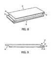
- FIG. 8is a perspective view of the floor panel according to FIGS. 6 and 7 .
- FIG. 9is another transverse side view of the floor panel according to FIGS. 6-8 .
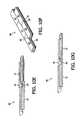
- FIGS. 10A-10Gshow a first method for laying a floor constructed from floor panels according to FIGS. 6-9 .
- FIGS. 11A-11Gshow a second method for laying a floor constructed from floor panels according to FIGS. 6-9 .
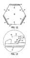
- FIG. 12is a top view of another embodiment of a floor panel according to the invention.
- FIG. 13shows a detail view of a part of the floor panel according to FIGS. 6-11G .
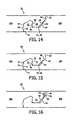
- FIG. 14shows a side view of a part of an assembly of another embodiment of connected floor panels according to the invention.
- FIG. 15shows a side view of a part of an assembly of yet another embodiment of connected floor panels according to the invention.
- FIG. 16shows a side view of a part of an assembly of still another embodiment of connected floor panels according to the invention.
- FIG. 17shows a side view of a part of an assembly of a further embodiment of connected floor panels according to the invention
- FIG. 18shows a side view of a part of an assembly of another embodiment of connected floor panels according to the invention.
- FIG. 19shows a side view of a part of an assembly of another embodiment of connected floor panels according to the invention.
- FIG. 20shows a detailed mathematical view of an intermediate state (pre-alignment state) of the orientation of two floor panels as shown in FIG. 7 c.
- FIG. 1shows a side view of a floor panel 1 according to the invention.
- Floor panel 1comprises a plate-like core 2 which is manufactured from fibreboard, in particular MDF (Medium Density Fibreboard) or HDF (High Density Fibreboard) or chipboard and on which a top layer 3 is arranged.
- the opposite longitudinal sides of core 2are provided with a first coupling part 4 and a second coupling part 5 .
- the part of floor panel 1 lying between first coupling part 4 and second coupling part 5forms the central part 6 of floor panel 1 .
- First coupling part 4comprises an upward tongue 7 , an upward flank 8 and an upward groove 9 formed between upward tongue 7 and upward flank 8 .
- Second coupling part 5comprises a downward tongue 10 , a downward flank 11 and a downward groove 12 formed between downward tongue 10 and downward flank 11 .
- upward tongue 7 , upward flank 8 and upward groove 9extend in the direction (indicated by means of arrow A) of the normal of central part 6 (indicated by means of arrow N 1 ) of the central floor panel 1 .
- the angle ⁇ enclosed by arrows A and N 1is equal to the angle ⁇ enclosed by arrows B and N 2 , these angles equaling 30°.
- the first coupling part 4is provided with a ridge 13 which in the coupled situation co-acts with a recess 14 arranged in a second coupling part 5 of an adjacent floor panel 1 (see FIG. 2 ) for the purpose of realizing a locking between the two floor panels 1 .
- both coupling parts 4 , 5are provided with a protective lip 15 , 16 adapted to be received in a complementary receiving space 17 , 18 of coupling parts 4 , 5 .
- Downward tongue 10is provided with an angled outer end 10 a , of which one side is positioned substantially horizontally and one side substantially vertically.
- coupling parts 4 , 5engage form-fittingly into each other. Coupling can take place by simply displacing first coupling part 4 of a floor panel 1 in linear direction (indicated by means of arrow C) in the direction of second coupling part 2 of an adjacent floor panel 1 , whereby the coupling parts engage fixedly in each other.
- FIG. 3shows a side view of another floor panel 19 according to the invention.
- Floor panel 19comprises a plate-like core 20 which is manufactured from fibreboard, in particular MDF (Medium Density Fibreboard) or HDF (High Density Fibreboard) or chipboard and on which a top layer 21 is arranged.
- the opposite longitudinal sides of core 20are provided with a first coupling part 22 and a second coupling part 23 which is complementary relative to first coupling part 22 .
- the part of floor panel 19 located between first coupling part 22 and second coupling part 23is designated the central part 24 of floor panel 19 .
- First coupling part 22comprises an upward tongue 25 , an upward flank 26 and an upward groove 27 formed between upward tongue 25 and upward flank 26 .
- Second coupling part 23comprises a downward tongue 28 , a downward flank 29 and a downward groove 30 formed between downward tongue 28 and downward flank 29 .
- upward tongue 25 , upward flank 26 and upward groove 27extend in the direction (indicated by means of arrows A 1 , A 2 and A 3 ) of the normal of central part 24 (indicated by means of arrow N) of floor panel 19 .
- Downward flank 29extends in this exemplary embodiment in a direction substantially the same as the normal of central part 24 of floor panel 19 .
- first coupling part 22is provided with a outward bulge 31 and second coupling part 23 is provided with a complementary recess 32 for the purpose of being able to realize a locking during coupling of floor panel 19 to an adjacent floor panel 19 (see FIG. 4 ).
- upward groove 27 of first coupling part 22 of a floor panel 19 and a downward tongue 28 of a second coupling part 23 of an adjacent floor panel 19mutually enclose an air space 33 .
- FIG. 5further shows that side edges 34 (end surfaces) of floor panel 19 are provided with an upward profile 35 and a complementary downward profile 36 for realizing a lateral coupling between two floor panels 19 positioned against each other on end surfaces 34 .
- FIG. 6shows a side view of yet another rectangular floor panel 37 according to the invention.
- Floor panel 37comprises a core 38 provided with an upper side 38 a and a lower side 38 b , and coupling parts 39 , 40 positioned on opposite longitudinal sides of core 38 and connected integrally to core 38 .
- a first coupling part 39comprises an upward tongue 41 , an upward flank 42 and an upward groove 43 formed between upward tongue 41 and upward flank 42 .
- a side 41 a of upward tongue 41 facing toward upward flank 42extends in the direction of the normal N 1 of the upper side 38 a of core 38 .
- the tangent R 1 and the normal N 1 of upper side 38 a of core 38are thus directed toward each other (converging orientation), wherein the angle enclosed by R 1 and N 1 amounts to 5 degrees.
- Another side 41 b of upward tongue 41 facing toward upward flank 42forms an aligning edge enabling facilitated realization of a coupling to an adjacent floor panel. As shown, this side 41 b functioning as aligning edge is directed away from the normal N 1 of upper side 38 a of the core.
- An upper side 41 d of upward tongue 41does however extend in the direction of the normal N 1 of upper side 38 a of core 38 , and runs inclining downward in the direction of the side 41 e of upward tongue 41 facing away from upward flank 42 .
- This chamferingprovides the option of giving the complementary second coupling part 40 a more robust and therefore stronger form.
- the side 41 e of upward tongue 41 facing away from upward flank 42is oriented substantially vertically and is moreover provided with an outward bulge 44 .
- a lower part 42 a of upward flank 42is oriented diagonally, while an upper part 42 b of upward flank 42 is shown to be substantially vertical and forms a stop surface for second coupling part 40 .
- a lower wall part 43 a of upward groove 43is oriented substantially horizontally in this exemplary embodiment.
- a bridge 45 lying between lower wall part 43 a of upward groove 43 and a lower side 39 ahas a somewhat elastic nature and is adapted to allow upward tongue 41 to pivot relative to upward flank 42 , this resulting in a (temporary) widening of upward groove 43 , whereby coupling of floor panel 37 to an adjacent floor panel can be facilitated (see FIGS. 7A-7F ).
- Second coupling part 40is substantially complementary to first coupling part 39 .
- Second coupling part 40comprises a downward tongue 46 , a downward flank 47 and a downward groove 48 formed between downward tongue 46 and downward flank 47 .
- a side 46 a of downward tongue 46 facing toward downward flank 47lies in the direction of the normal N 2 of the lower side 38 b of core 38 .
- a tangent R 2 of side 46 a of downward tongue 46 and the normal of the lower side 38 b of core 38are mutually converging.
- the tangent R 2 and the normal N 2enclose a mutual angle of 5 degrees.
- a side 46 b facing away from downward flank 47is diagonally oriented, but has a flatter orientation than the complementary side 42 a of upward flank 42 , whereby a gap (air space) will be formed in the coupled position (see also FIG. 7F ), which will generally facilitate coupling between two floor panels 37 .
- the inclining side 46 b of downward tongue 46also functions as aligning edge for the purpose of further facilitating coupling between two floor panels 37 .
- Another side 46 c facing away from downward flank 47takes a substantially vertical form and forms a complementary stop surface for stop surface 42 b of upward flank 42 (of an adjacent floor panel).
- Downward tongue 46is further provided with a side 46 d which is facing toward downward flank 47 and which functions as aligning edge for first coupling part 39 of an adjacent floor panel.
- an upper side 48 a of downward groove 48likewise has an inclining orientation, whereby the (average) distance between upper side 48 a of downward groove 48 and an upper side 40 a of second coupling part 40 is sufficiently large to impart sufficient strength to second coupling part 40 as such.
- Downward flank 47is oriented substantially vertically and is provided with a recess 49 adapted to receive the outward bulge 44 of upward tongue 41 (of an adjacent floor panel).
- a bridge 50 lying between upper side 48 a of downward groove 48 and upper side 40 ahas a somewhat elastic nature and is adapted to allow downward tongue 46 to pivot relative to downward flank 47 , this resulting in a (temporary) widening of downward groove 48 , whereby coupling of floor panel 37 to an adjacent floor panel can be facilitated (see FIGS. 7A-7F ).
- the shown floor panel 37can form a parquet floor panel, a plank, a laminated floor panel or a plastic floor panel.
- FIGS. 7A-7Fshow successive method steps for realizing a coupling between two floor panels 37 a , 37 b as according to FIG. 6 .
- first (optional) stepas shown in FIG. 7A , second coupling part 40 of a first floor panel 37 a is displaced in the direction of first coupling part 39 of a second floor panel 37 b by sliding first floor panel 37 a over second floor panel 37 b (see arrow).
- first (optional) stepas shown in FIG. 7A
- second coupling part 40 of a first floor panel 37 ais displaced in the direction of first coupling part 39 of a second floor panel 37 b by sliding first floor panel 37 a over second floor panel 37 b (see arrow).
- second coupling part 40 of first floor panel 37 awill then be brought into line with first coupling part 39 of second floor panel 37 b by having the lower side 38 b of core 38 of the first floor panel 37 a slide along upper side 41 d of upward tongue 41 of second floor panel 37 b (see arrow) until aligning edge 46 a of downward tongue 46 of first floor panel 37 a supports on aligning edge 41 b of upward tongue 41 of second floor panel 37 b ( FIG. 7C ).
- the other aligning edge 46 b of downward tongue 46 of first floor panel 37will generally also make contact here with upper side 38 a of core 38 .
- Another method of disassembling floor panels 37 a , 37 bis to slide floor panels 37 a , 37 b along each other, whereby coupling parts 39 , 40 can be removed from each other, which will result in uncoupling of floor panels 37 a , 37 b.
- FIG. 8shows a perspective view of floor panel 37 according to FIGS. 6 and 7 , which also shows that a first coupling part 51 and a second coupling part 52 are positioned on the opposite short sides of the rectangular floor panel 37 .
- a transverse side view of the short sides of floor panel 37is shown in FIG. 9 .
- first coupling part 51largely corresponds structurally to the construction of first coupling part 39 shown in FIG. 6
- second coupling part 52largely corresponds structurally to the construction of second coupling part 40 shown in FIG. 6
- first coupling part 51 shown in FIG. 8comprises a less deep upward groove 53 compared to upward groove 43 of the long side of floor panel 37 as shown in FIG. 6 .
- a first locking element 54connects to an upper side 55 of an upward tongue 56 of first coupling part 51 .
- a flat lower side 57 defining upward groove 43further has smaller dimensions than this lower side as shown in FIG. 6
- upward tongue 56has smaller dimensions than upward tongue 41 as shown in FIG. 6 .
- the second coupling part 52 shown in FIG. 8is correspondingly modified relative to second coupling part 40 as shown in FIG. 6 .
- the dimensioning of the first coupling part 51 and second coupling part 52 arranged on the short sides relative to the first coupling part 39 and second coupling part 40 positioned on the long sidesis particularly intended to facilitate mutual coupling of floor panels 37 , as further shown in FIGS. 10A-10G (first method) and FIGS. 11A-11G (second method).
- FIGS. 10A-10Gshow a first method of laying a floor 58 constructed from floor panels 37 as according to FIGS. 6-9 .
- a floor panel 37 ahas to be coupled to already laid floor panels 37 ( FIG. 10A )
- the relevant floor panel 37can then be pushed in transverse direction (see arrow A) over the already laid floor panels 37 ( FIGS. 10B and 10C ), wherein first coupling part 39 of one or more already laid floor panels 37 is coupled to second coupling part 40 of the floor panel 37 for laying.
- the floor panel 37 for layingis pushed in longitudinal direction (see arrow B) ( FIGS. 10D and 10E ), whereby the short sides of the floor panels can be connected to each other by causing second coupling part 52 of the floor panel 37 for laying to co-act with first coupling part 51 of the adjacent floor panel 37 .
- FIGS. 11A-11Gshow a second method of laying a floor 58 constructed from floor panels 37 as according to FIGS. 6-9 .
- a floor panel 37 ahas to be coupled to already laid floor panels 37 ( FIG. 11A )
- a corner point 37 a of the relevant floor panel 37 for layingcan then be positioned in a corner formed by already coupled floor panels ( FIGS. 11B and 11C and successively FIGS.
- FIG. 12shows a top view of an alternative floor panel 59 according to the invention.
- Floor panel 59comprises six equal sides 60 , wherein sides 60 are alternately provided with a first coupling part 61 and a second coupling part 62 .
- First coupling part 61is structurally identical to first coupling part 39 as shown in FIG. 6
- second coupling part 62is structurally identical to second coupling part 40 as shown in FIG. 6 .
- a floorcan be manufactured with a honeycomb pattern by coupling the hexagonal floor panels 59 through co-action of first coupling parts 61 and second coupling parts 62 of different floor panels 59 .
- FIG. 13shows a detail view of a part of floor panel 37 according to FIGS. 6-11G , wherein particularly the first coupling part 39 is shown.
- FIG. 13also shows that upper part 42 b of upward flank 42 is shown substantially vertically and is provided with an offset, overhanging connecting surface 63 .
- the advantage of applying an overhanging connecting surface 63is that a second coupling part 40 of an adjacent panel 37 (indicated by means of broken lines) will be able to fit closely onto the overhanging connecting surface 63 , wherein an air gap 64 is also formed between the two coupling parts 39 , 40 just below the overhanging connecting surface 63 .
- This clearance intentionally created between the two coupling parts 39 , 40is usually advantageous for the purpose of accurate connection of coupling parts 39 , 40 to each other, since irregularities in the form of floor panel 37 or expansion of floor panel 37 can be compensated by air gap 64 .
- a side 46 b facing away from the downward flankhas a flatter orientation than the complementary side 42 a of upward flank 42 , whereby a further air gap 65 will also be formed in the coupled position, which will generally further facilitate coupling between two floor panels 37 .
- FIG. 14shows a side view of a part of an assembly 51 of another embodiment of floor panels 52 a , 52 b according to the invention. From a constructive point of view the floor panel 52 , 52 b as shown is for a substantial part similar to the floor panel 37 as shown in FIG. 6 , wherein the floor panels are mutually connected by means of three locking mechanism.
- a first locking mechanismis also present in the floor panel 37 as shown in FIG. 6 , and is based upon the cooperation between an outward bulge 53 positioned at an outward surface 54 of an upward tongue 55 of the right floor panel 52 b , and a recess 56 positioned at a downward flank 57 of the left floor panel 52 a .
- a second locking mechanismwhich is also present in the floor panel 37 as shown in FIG.
- a third locking mechanismis formed by the application of an additional outward bulge 62 positioned at an outer surface 63 of the downward tongue 59 , and which is more in particular positioned between an aligning edge 64 and a vertical top end 65 of the outer surface 63 of the downward tongue 59 , of the left floor panel 52 a .
- Said additional bulge 55co-acts with and snap-fits into a complementary recess 66 applied to an upward flank 67 of the right floor panel 52 b .
- an expansion chamber 68is present in order to be able to compensate play in case of expansion of the floor panels 52 , 52 b , for example due to moist absorption.
- FIG. 15shows a side view of a part of an assembly 69 of another embodiment of floor panels 70 a , 70 b according to the invention having three locking mechanisms.
- a first locking mechanismis based upon the cooperation between an outward bulge 71 positioned at an outward surface 72 of an upward tongue 73 of the right floor panel 70 b , and a recess 74 positioned at a downward flank 75 of the left floor panel 70 a .
- a second locking mechanismis formed by the engagement of an inclined surface 76 of the downward tongue 77 of the left floor panel 70 a , to an inclined surface 78 of the upward tongue 73 which results in locking the downward tongue 78 of the left floor panel 70 a into an upward groove 79 of the right floor panel 70 b .
- a third locking mechanismis formed by the application of an additional outward bulge 80 positioned at an outer surface 81 of the downward tongue 77 , and which is more in particular positioned between an aligning edge 82 and a vertical top end 83 of the outer surface 81 of the downward tongue 77 , of the left floor panel 70 a , wherein there is a smooth transition between the bulge 80 and the vertical top end 83 .
- Said additional bulge 80co-acts with and snap-fits into a complementary recess 84 applied to an upward flank 85 of the right floor panel 70 b .
- an expansion chamber 86is present in order to be able to compensate play in case of expansion of the floor panels 70 , 70 b , for example due to moist absorption.
- FIG. 16shows a side view of a part of an assembly 87 of another embodiment of floor panels 88 a , 88 b according to the invention having three locking mechanisms.
- the first and second locking mechanismsare identical to the first and second locking mechanism as shown in FIG. 6 , FIG. 14 , and FIG. 15 .
- the third locking mechanismis based upon the application of an outward bulge 89 positioned at an outward surface 90 of a downward tongue 91 of the left floor panel 88 a which co-acts with a complementary recess 92 of an upward flank 93 of a right floor panel 88 b .
- the bulge 89is adapted to deform slightly with respect to a core part of the downward tongue 91 due to the presence of a substantially vertical slot 94 , adjacent to the bulge 89 , applied into an aligning edge 95 of the downward tongue 91 .
- This flexibilityfacilitates snapping of the bulge 89 into the recess 92 , and hence realization of the connection between the floor panels 88 a , 88 b.
- FIG. 17shows a side view of a part of an assembly 96 of another embodiment of floor panels 97 a , 97 b according to the invention having three locking mechanisms.
- the first and second locking mechanismsare identical to the first and second locking mechanism as shown in FIG. 6 , FIG. 14 , FIG. 15 , and FIG. 16 .
- the third locking mechanismis based upon the application of an outward bulge 98 positioned at an outward surface 99 of a downward tongue 100 of the left floor panel a which co-acts with a complementary recess 101 of an upward flank 102 of a right floor panel 97 b .
- the bulge 98is adapted to deform slightly with respect to a core part of the downward tongue 100 due to the presence of a substantially vertical slot 103 applied into a horizontal bottom surface 104 of the downward tongue 100 . This flexibility facilitates snapping of the bulge 98 into the recess 101 , and hence realisation of the connection between the floor panels 97 a , 97 b.
- FIG. 18shows a side view of a part of an assembly 105 of another embodiment of floor panels 106 a , 106 b according to the invention having three locking mechanisms.
- the first and second locking mechanismsare identical to the first and second locking mechanism as shown in the previous figures.
- the third locking mechanismis based upon the application of a slot 107 positioned at an outward surface 108 of a downward tongue 109 of the left floor panel 106 a which co-acts with a horizontally displaceable spring pin 110 contained by an opposite recess 111 of an upward flank 112 of the right floor panel 106 b .
- An outer end of the spring pin 110is conically shaped as to facilitate connection of both floor panels 106 a , 106 b.
- FIG. 19shows a side view of a part of an assembly 113 of another embodiment of floor panels 114 a , 114 b according to the invention having three locking mechanisms.
- the first and second locking mechanismsare identical to the first and second locking mechanism as shown in the previous figures.
- the third locking mechanismis based upon the application of a horizontal slot 115 positioned at an outward surface 116 of a downward tongue 117 of the left floor panel 114 a , wherein said slot 115 is bounded by a protruding locking edge 118 which co-acts with a complementary counter edge 119 making part of an upward flank 120 of the right floor panel 114 b.
- FIG. 20shows a detail of the floor panels 37 a , 37 b as according to FIG. 7 c which is considered as an intermediate state in which pre-alignment of the floor panels 37 a - 37 b takes place.
- the references in this FIG. 18are defined as follows:
- the actual width w 1 of the downward tongue 46is defined by the distance between a line 11 through the point a of floor panel 37 b in a direction perpendicular to the top surface of floor panel 37 b and a line 12 through the point c of floor panel 37 a in a direction perpendicular to the top surface of floor panel 37 b in a direction parallel to the angled outer end 120 of the downward tongue 46 ;
- the effective width w 2 of the downward tongue 46is defined by the shortest distance between the line 11 and the line 12 in a direction parallel to the top surface of floor panel 37 b;
- the width w 3 of the upward groove 43is defined by the shortest distance between the line 11 and a line 13 through the corner d of floor panel 37 b in a direction perpendicular to the top surface of floor panel 37 b;
- the width w 4 of the downward tongue 46is defined by the shortest distance between a line 14 through the point b of floor panel 37 b in a direction perpendicular to the top surface of floor panel 37 b and the line 13
- h 1the actual height of the downward tongue 46 , as defined by the shortest between the angled outer end 120 of the downward tongue 46 and a line through point c parallel to the angled outer end 120 of the downward tongue 46 ;
- h 2the effective height of the downward groove 48 , as defined by the shortest distance between a line 15 through point a of floor panel 37 b in a direction parallel to the top surface of the floor panel 37 b and a line 16 through point e in the roof of the downward groove 48 in a direction parallel to line 15 ;
- ⁇the angle between the line through point c of floor panel 37 a in a direction parallel to the angled outer end 121 of the downward tongue 46 and a line through point c of floor panel 37 a in a direction parallel to the top surface of the floor panel 37 b ;
- ⁇the angle between the line 11 and a flank f of floor panel 37 a.
- the floor panels 37 a , 37 b as shown in this mutual orientationare undeformed. Between the upper corner d of the floor panel 37 b and the point c of the floor panel 37 a is a small space so as not to damage or the corner d by a force generated onto floor panel 37 a .
- Floor panels 37 a and 37 bcan be coupled as explained in FIG. 7 . During coupling the second coupling part 40 will deform. The contact point between the floor panels 37 a and 37 b will then move from point a to point b, wherein the downward tongue 46 will be able to be inserted into upward groove 43 of the floor panel 37 b.
- the mutual relation between the floor panels 37 a , 37 bare dimensions as follows: w 2 ⁇ w 3 w 2 ⁇ w 4 w 3> w 4 w 2 ⁇ w 1*cos ⁇ h 1 ⁇ h 2*cos ⁇ ⁇ w 1 ⁇ w 3*cos ⁇
Landscapes
- Engineering & Computer Science (AREA)
- Architecture (AREA)
- Civil Engineering (AREA)
- Structural Engineering (AREA)
- Floor Finish (AREA)
- Glass Compositions (AREA)
- Road Repair (AREA)
- Laminated Bodies (AREA)
- Building Environments (AREA)
Abstract
Description
w2<w3
w2≤w4
w3>w4
w2≈w1*cos δ
h1≈h2*cos φ
δ<φ
w1<w3*cos δ
Claims (3)
Priority Applications (8)
| Application Number | Priority Date | Filing Date | Title |
|---|---|---|---|
| US14/969,576US10053868B2 (en) | 2009-06-12 | 2015-12-15 | Floor panel and floor covering consisting of a plurality of such floor panels |
| US16/053,036US10738478B2 (en) | 2009-06-12 | 2018-08-02 | Floor panel and floor covering consisting of a plurality of such floor panels |
| US16/053,132US10738479B2 (en) | 2009-06-12 | 2018-08-02 | Floor panel and floor covering consisting of a plurality of such floor panels |
| US16/363,372US10738480B2 (en) | 2009-06-12 | 2019-03-25 | Floor panel and floor covering consisting of a plurality of such floor panels |
| US16/364,693US10738481B2 (en) | 2009-06-12 | 2019-03-26 | Floor panel and floor covering consisting of a plurality of such floor panels |
| US16/364,738US10738482B2 (en) | 2009-06-12 | 2019-03-26 | Floor panel and floor covering consisting of a plurality of such floor panels |
| US16/932,911US11668100B2 (en) | 2009-06-12 | 2020-07-20 | Floor panel and floor covering consisting of a plurality of such floor panels |
| US18/088,016US20230127455A1 (en) | 2009-06-12 | 2022-12-23 | Floor Panel and Floor Covering Consisting of a Plurality of Such Floor Panels |
Applications Claiming Priority (10)
| Application Number | Priority Date | Filing Date | Title |
|---|---|---|---|
| NL2003019ANL2003019C2 (en) | 2009-06-12 | 2009-06-12 | FLOOR PANEL AND FLOOR COVERAGE CONSISING OF MULTIPLE OF SUCH FLOOR PANELS. |
| NL2003019 | 2009-06-12 | ||
| NLPCT/NL2009/050540 | 2009-09-09 | ||
| WOPCT/NL2009/050540 | 2009-09-09 | ||
| PCT/NL2009/050540WO2010143943A1 (en) | 2009-06-12 | 2009-09-09 | Floor panel and floor covering consisting of a plurality of such floor panels |
| PCT/NL2010/050365WO2010143962A2 (en) | 2009-06-12 | 2010-06-14 | Floor panel and floor covering consisting of a plurality of such floor panels |
| US13/316,871US8745952B2 (en) | 2009-06-12 | 2011-12-12 | Floor panel and floor covering consisting of a plurality of such floor panels |
| US14/251,766US8978336B2 (en) | 2009-06-12 | 2014-04-14 | Floor panel and floor covering consisting of a plurality of such floor panels |
| US14/617,543US9217250B2 (en) | 2009-06-12 | 2015-02-09 | Floor panel and floor covering consisting of a plurality of such floor panels |
| US14/969,576US10053868B2 (en) | 2009-06-12 | 2015-12-15 | Floor panel and floor covering consisting of a plurality of such floor panels |
Related Parent Applications (1)
| Application Number | Title | Priority Date | Filing Date |
|---|---|---|---|
| US14/617,543ContinuationUS9217250B2 (en) | 2009-06-12 | 2015-02-09 | Floor panel and floor covering consisting of a plurality of such floor panels |
Related Child Applications (2)
| Application Number | Title | Priority Date | Filing Date |
|---|---|---|---|
| US16/053,132ContinuationUS10738479B2 (en) | 2009-06-12 | 2018-08-02 | Floor panel and floor covering consisting of a plurality of such floor panels |
| US16/053,036ContinuationUS10738478B2 (en) | 2009-06-12 | 2018-08-02 | Floor panel and floor covering consisting of a plurality of such floor panels |
Publications (2)
| Publication Number | Publication Date |
|---|---|
| US20160186443A1 US20160186443A1 (en) | 2016-06-30 |
| US10053868B2true US10053868B2 (en) | 2018-08-21 |
Family
ID=41327542
Family Applications (11)
| Application Number | Title | Priority Date | Filing Date |
|---|---|---|---|
| US13/316,871ActiveUS8745952B2 (en) | 2009-06-12 | 2011-12-12 | Floor panel and floor covering consisting of a plurality of such floor panels |
| US14/251,766ActiveUS8978336B2 (en) | 2009-06-12 | 2014-04-14 | Floor panel and floor covering consisting of a plurality of such floor panels |
| US14/617,543ActiveUS9217250B2 (en) | 2009-06-12 | 2015-02-09 | Floor panel and floor covering consisting of a plurality of such floor panels |
| US14/969,576Active2030-09-11US10053868B2 (en) | 2009-06-12 | 2015-12-15 | Floor panel and floor covering consisting of a plurality of such floor panels |
| US16/053,036Active2030-09-14US10738478B2 (en) | 2009-06-12 | 2018-08-02 | Floor panel and floor covering consisting of a plurality of such floor panels |
| US16/053,132ActiveUS10738479B2 (en) | 2009-06-12 | 2018-08-02 | Floor panel and floor covering consisting of a plurality of such floor panels |
| US16/363,372ActiveUS10738480B2 (en) | 2009-06-12 | 2019-03-25 | Floor panel and floor covering consisting of a plurality of such floor panels |
| US16/364,693ActiveUS10738481B2 (en) | 2009-06-12 | 2019-03-26 | Floor panel and floor covering consisting of a plurality of such floor panels |
| US16/364,738ActiveUS10738482B2 (en) | 2009-06-12 | 2019-03-26 | Floor panel and floor covering consisting of a plurality of such floor panels |
| US16/932,911Active2030-06-16US11668100B2 (en) | 2009-06-12 | 2020-07-20 | Floor panel and floor covering consisting of a plurality of such floor panels |
| US18/088,016PendingUS20230127455A1 (en) | 2009-06-12 | 2022-12-23 | Floor Panel and Floor Covering Consisting of a Plurality of Such Floor Panels |
Family Applications Before (3)
| Application Number | Title | Priority Date | Filing Date |
|---|---|---|---|
| US13/316,871ActiveUS8745952B2 (en) | 2009-06-12 | 2011-12-12 | Floor panel and floor covering consisting of a plurality of such floor panels |
| US14/251,766ActiveUS8978336B2 (en) | 2009-06-12 | 2014-04-14 | Floor panel and floor covering consisting of a plurality of such floor panels |
| US14/617,543ActiveUS9217250B2 (en) | 2009-06-12 | 2015-02-09 | Floor panel and floor covering consisting of a plurality of such floor panels |
Family Applications After (7)
| Application Number | Title | Priority Date | Filing Date |
|---|---|---|---|
| US16/053,036Active2030-09-14US10738478B2 (en) | 2009-06-12 | 2018-08-02 | Floor panel and floor covering consisting of a plurality of such floor panels |
| US16/053,132ActiveUS10738479B2 (en) | 2009-06-12 | 2018-08-02 | Floor panel and floor covering consisting of a plurality of such floor panels |
| US16/363,372ActiveUS10738480B2 (en) | 2009-06-12 | 2019-03-25 | Floor panel and floor covering consisting of a plurality of such floor panels |
| US16/364,693ActiveUS10738481B2 (en) | 2009-06-12 | 2019-03-26 | Floor panel and floor covering consisting of a plurality of such floor panels |
| US16/364,738ActiveUS10738482B2 (en) | 2009-06-12 | 2019-03-26 | Floor panel and floor covering consisting of a plurality of such floor panels |
| US16/932,911Active2030-06-16US11668100B2 (en) | 2009-06-12 | 2020-07-20 | Floor panel and floor covering consisting of a plurality of such floor panels |
| US18/088,016PendingUS20230127455A1 (en) | 2009-06-12 | 2022-12-23 | Floor Panel and Floor Covering Consisting of a Plurality of Such Floor Panels |
Country Status (20)
| Country | Link |
|---|---|
| US (11) | US8745952B2 (en) |
| EP (8) | EP3231959B1 (en) |
| CN (2) | CN104831899B (en) |
| CA (5) | CA2965644C (en) |
| CY (6) | CY1115579T1 (en) |
| DE (1) | DE202010018229U1 (en) |
| DK (6) | DK3176345T3 (en) |
| ES (8) | ES2713748T3 (en) |
| HR (6) | HRP20140566T1 (en) |
| HU (5) | HUE029427T2 (en) |
| LT (4) | LT3176345T (en) |
| NL (1) | NL2003019C2 (en) |
| NO (1) | NO3070228T3 (en) |
| PL (8) | PL3070228T3 (en) |
| PT (6) | PT3070228T (en) |
| RU (1) | RU2537423C2 (en) |
| SI (6) | SI3070228T1 (en) |
| SM (1) | SMT202000654T1 (en) |
| TR (3) | TR201902376T4 (en) |
| WO (2) | WO2010143943A1 (en) |
Cited By (2)
| Publication number | Priority date | Publication date | Assignee | Title |
|---|---|---|---|---|
| US10947741B2 (en) | 2017-04-26 | 2021-03-16 | I4F Licensing Nv | Panel and covering |
| US20230127455A1 (en)* | 2009-06-12 | 2023-04-27 | I4F Licensing Nv | Floor Panel and Floor Covering Consisting of a Plurality of Such Floor Panels |
Families Citing this family (98)
| Publication number | Priority date | Publication date | Assignee | Title |
|---|---|---|---|---|
| PL2473687T3 (en) | 2009-09-04 | 2019-10-31 | Vaelinge Innovation Ab | A method of assembling resilient floorboards which are provided with a mechanical locking system |
| US11725395B2 (en) | 2009-09-04 | 2023-08-15 | Välinge Innovation AB | Resilient floor |
| US8365499B2 (en) | 2009-09-04 | 2013-02-05 | Valinge Innovation Ab | Resilient floor |
| PL4092213T3 (en) | 2010-01-11 | 2024-03-25 | Välinge Innovation AB | Floor covering with interlocking design |
| CN102619323A (en)* | 2011-01-27 | 2012-08-01 | 张国平 | Plastic material barb type lock floor |
| CN102155083B (en)* | 2011-01-29 | 2014-07-23 | 刘谦益 | Floor connection structure |
| JP6254519B2 (en)* | 2011-03-18 | 2017-12-27 | イノテック インターナショナル プロプライエタリー リミテッド | Vertical joining system and related surface coating system |
| US8806832B2 (en) | 2011-03-18 | 2014-08-19 | Inotec Global Limited | Vertical joint system and associated surface covering system |
| UA109938C2 (en) | 2011-05-06 | 2015-10-26 | MECHANICAL LOCKING SYSTEM FOR CONSTRUCTION PANELS | |
| CN102493625B (en)* | 2011-12-21 | 2014-12-10 | 张家铭 | Locking type plate connector and its plate |
| BE1022209B1 (en)* | 2012-01-12 | 2016-03-01 | I.V.C. N.V. | FLOOR PANEL |
| EP2812510B1 (en) | 2012-02-07 | 2018-03-07 | Flooring Industries Limited, SARL | Floor panel for forming a floor covering, floor covering formed from such floor panels and method for manufacturing such floor panels |
| US10760283B2 (en) | 2012-02-23 | 2020-09-01 | Admiral Composite Technologies, Inc. | Deck system and components |
| US9394698B2 (en)* | 2012-02-23 | 2016-07-19 | Admiral Composite Technologies, Inc. | Deck system and components |
| US9353533B2 (en) | 2012-02-23 | 2016-05-31 | Admiral Composite Technologies, Inc. | Deck system components |
| US9216541B2 (en) | 2012-04-04 | 2015-12-22 | Valinge Innovation Ab | Method for producing a mechanical locking system for building panels |
| US9803381B1 (en)* | 2013-03-07 | 2017-10-31 | Homecare Products, Inc. | Ramp and/or platform assembly |
| EA201992325A1 (en) | 2013-03-25 | 2020-05-31 | Велинге Инновейшн Аб | FLOOR PANELS EQUIPPED WITH MECHANICAL FIXING SYSTEM AND METHOD FOR PRODUCING SUCH FIXING SYSTEM |
| CN109854597B (en) | 2013-09-16 | 2021-03-19 | 瓦林格创新股份有限公司 | Combination product and method for assembling the same |
| US9726210B2 (en) | 2013-09-16 | 2017-08-08 | Valinge Innovation Ab | Assembled product and a method of assembling the product |
| CA2861259C (en)* | 2013-11-01 | 2016-06-14 | Groupe Isolofoam Inc. | Rigid insulating panel and rigid insulation panel assembly |
| WO2015070890A1 (en)* | 2013-11-12 | 2015-05-21 | Grigorij Wagner | Flooring component |
| MX376334B (en)* | 2014-01-10 | 2025-03-07 | Vaelinge Innovation Ab | FURNITURE BOARD. |
| US9714672B2 (en) | 2014-01-10 | 2017-07-25 | Valinge Innovation Ab | Panels comprising a mechanical locking device and an assembled product comprising the panels |
| WO2015130169A1 (en) | 2014-02-26 | 2015-09-03 | Innovations 4 Flooring Holding N.V. | Panel interconnectable with similar panels for forming a covering |
| USD928988S1 (en) | 2014-02-26 | 2021-08-24 | I4F Licensing Nv | Panel interconnectable with similar panels for forming a covering |
| EP3851684A1 (en) | 2014-05-09 | 2021-07-21 | Välinge Innovation AB | Mechanical locking system for building panels |
| FR3024990B1 (en) | 2014-08-25 | 2018-11-16 | Gerflor | FLOOR PANEL FOR REALIZING A COATING. |
| US9752328B2 (en)* | 2014-08-27 | 2017-09-05 | James Hardie Technology Limited | Cladding element |
| EP3186459B1 (en) | 2014-08-29 | 2019-06-26 | Välinge Innovation AB | Vertical joint system for a surface covering panel |
| WO2016046800A1 (en) | 2014-09-26 | 2016-03-31 | Flooring Industries Limited, Sarl | Floor panel for forming a floor covering and method for manufacturing a floor panel. |
| NO3031998T3 (en)* | 2014-12-08 | 2018-02-24 | ||
| ES2758673T3 (en) | 2014-12-19 | 2020-05-06 | Vaelinge Innovation Ab | Panels comprising a mechanical locking device |
| BR112017012681B1 (en) | 2014-12-22 | 2022-05-03 | Ceraloc Innovation Ab | Set of essentially identical floor panels |
| ES2826556T3 (en)* | 2015-01-15 | 2021-05-18 | Flooring Ind Ltd Sarl | Floor panel to form a floor covering |
| US12071770B2 (en) | 2015-01-16 | 2024-08-27 | Unilin Bv | Floor panel for forming a floor covering |
| WO2016114712A1 (en) | 2015-01-16 | 2016-07-21 | Ceraloc Innovation Ab | Mechanical locking system for floor panels |
| BE1022985B1 (en)* | 2015-01-16 | 2016-10-27 | Flooring Industries Limited Sarl | Floor panel for forming a floor covering |
| EP3285620A4 (en) | 2015-04-21 | 2018-11-14 | Välinge Innovation AB | Panel with a slider |
| KR20170141223A (en) | 2015-04-30 | 2017-12-22 | 뵈린게 이노베이션 에이비이 | A panel having a fastening device |
| UA125554C2 (en) | 2015-09-22 | 2022-04-20 | Велінге Інновейшн Аб | Panels comprising a mechanical locking device and an assembled product comprising the panels |
| MX2018006522A (en) | 2015-12-03 | 2018-11-29 | Vaelinge Innovation Ab | Panels comprising a mechanical locking device and an assembled product comprising the panels. |
| CA3008157C (en) | 2015-12-17 | 2023-08-22 | Valinge Innovation Ab | A method for producing a mechanical locking system for panels |
| MX2018007995A (en)* | 2015-12-31 | 2019-01-10 | Flooring Ind Ltd Sarl | Floor panel for forming a floor covering. |
| BE1023779B1 (en) | 2015-12-31 | 2017-07-24 | Flooring Industries Limited Sarl | FLOOR PANEL FOR FORMING A FLOOR COVERING |
| BE1023818B1 (en) | 2016-01-15 | 2017-08-01 | Flooring Industries Limited Sarl | Floor panel for forming a floor covering |
| EP3407765B1 (en) | 2016-01-26 | 2021-03-03 | Välinge Innovation AB | Panels comprising a mechanical locking device to obtain a furniture product |
| KR20180109957A (en) | 2016-02-04 | 2018-10-08 | 뵈린게 이노베이션 에이비이 | Set of panels for assembled products |
| CA3011703A1 (en) | 2016-02-09 | 2017-08-17 | Valinge Innovation Ab | Element and method for providing dismantling groove |
| US10415613B2 (en) | 2016-02-09 | 2019-09-17 | Valinge Innovation Ab | Set of panel-shaped elements for a composed element |
| JP6921834B2 (en) | 2016-02-15 | 2021-08-18 | ベーリンゲ、イノベイション、アクチボラグVaelinge Innovation Ab | How to form panels for furniture products |
| AU2017335148B2 (en) | 2016-09-30 | 2023-04-20 | Välinge Innovation AB | Set of panels assembled by vertical displacement and locked together in the vertical and horizontal direction |
| CN117703894A (en) | 2016-10-27 | 2024-03-15 | 瓦林格创新股份有限公司 | Panel assembly with mechanical locking means |
| CN113356508A (en) | 2017-03-21 | 2021-09-07 | 地板工业有限公司 | Panel panel |
| US11015351B2 (en)* | 2017-03-21 | 2021-05-25 | Flooring Industries Limited, Sarl | Floor panel for forming a floor covering |
| HRP20230089T1 (en) | 2017-05-15 | 2023-03-17 | Välinge Innovation AB | Elements and a locking device for an assembled product |
| NL2018970B1 (en)* | 2017-05-23 | 2018-12-04 | Innovations 4 Flooring Holding Nv | Multi-purpose tile system |
| UA125235C2 (en)* | 2017-07-18 | 2022-02-02 | Зайло Текнолоджіз Аґ | PANELS WITH REMOVABLE EMBROIDERED EDGE FOR WALL, CEILING OR FLOOR COVERINGS |
| EP3701104B1 (en)* | 2017-10-26 | 2023-03-01 | Flooring Industries Limited, SARL | Plurality of floor panels and floor panels used hereby |
| CN111465773B (en) | 2017-12-22 | 2021-11-02 | 瓦林格创新股份有限公司 | Panel set, method for assembling the panel set and locking device for furniture products |
| RU2740868C1 (en) | 2017-12-22 | 2021-01-21 | Велинге Инновейшн Аб | Set of panels, method of their assembling and locking device for furniture product |
| AU2018400651B2 (en) | 2018-01-09 | 2024-06-13 | Välinge Innovation AB | Set of panels |
| NL2020256B1 (en)* | 2018-01-09 | 2019-07-15 | Innovations4Flooring Holding N V | Panel |
| EP4324999A3 (en) | 2018-01-11 | 2024-05-15 | Unilin, BV | Set of floor panels and method for installing this set of floor panels |
| MY204146A (en) | 2018-03-23 | 2024-08-09 | Vlinge Innovation Ab | Panels comprising a mechanical locking device and an assembled product comprising the panels |
| EP3543427A1 (en) | 2018-03-23 | 2019-09-25 | Franz Eschlbeck | Panel, second panel, panel connection and method of manufacturing the panel connection |
| DE202018101660U1 (en) | 2018-03-23 | 2018-04-23 | Franz Eschlbeck | Panel, second panel and panel connection |
| US10590659B2 (en) | 2018-04-05 | 2020-03-17 | 888804 Ontario Limited | Pre-finished insulated panel system for cladding a building |
| PL3781822T3 (en) | 2018-04-18 | 2024-11-18 | Välinge Innovation AB | Set of panels with a mechanical locking device |
| US11448252B2 (en) | 2018-04-18 | 2022-09-20 | Valinge Innovation Ab | Set of panels with a mechanical locking device |
| EA202092409A1 (en) | 2018-04-18 | 2021-02-26 | Велинге Инновейшн Аб | SYMMETRIC TONGUE AND T-SHAPED KNOT |
| PL3781824T3 (en) | 2018-04-18 | 2024-06-24 | Välinge Innovation AB | Set of panels with a mechanical locking device |
| US11614114B2 (en) | 2018-04-19 | 2023-03-28 | Valinge Innovation Ab | Panels for an assembled product |
| CN108468395B (en)* | 2018-04-20 | 2019-05-17 | 重庆大学 | The mounting structure being connect for wall with wall and its assembly, method for dismounting |
| CN108532793B (en)* | 2018-04-20 | 2019-05-17 | 重庆大学 | Assembled wallboard and its assembly method, method for dismounting |
| NL2020972B1 (en)* | 2018-05-23 | 2019-12-02 | Innovations4Flooring Holding N V | Multi-purpose tile system, tile covering, and tile |
| CN112429138B (en)* | 2018-08-26 | 2022-10-21 | 深圳市领航致远科技有限公司 | Car shell of car and car of riding instead of walk |
| PT3844407T (en) | 2018-08-30 | 2024-06-18 | Vaelinge Innovation Ab | Set of panels with a mechanical locking device |
| NL2021884B1 (en)* | 2018-10-26 | 2020-05-13 | I4F Licensing Nv | Panel, in particular a floor panel or wall panel |
| NL2021887B1 (en)* | 2018-10-26 | 2020-05-13 | I4F Licensing Nv | Multi-purpose tile system, tile covering, and tile |
| EA202191590A1 (en) | 2018-12-05 | 2021-10-18 | И4Ф Лайсенсинг Нв | DECORATIVE PANEL AND DECORATIVE FLOOR COVERING CONSISTS OF THE SPECIFIED PANELS |
| EP4137705B1 (en) | 2019-01-30 | 2024-09-25 | I4F Licensing Nv | Floor panel and floor covering |
| EA202192054A1 (en) | 2019-01-30 | 2021-12-31 | И4Ф Лайсенсинг Нв | PANEL AND COATING CONTAINING PANEL |
| RU192866U1 (en)* | 2019-04-05 | 2019-10-03 | Общество с ограниченной ответственностью "АКВАТОН" | PANEL WITH CONNECTIVITY WITH SIMILAR PANELS FOR FORMING COVERINGS |
| BE1027299B1 (en)* | 2019-05-22 | 2020-12-22 | Flooring Ind Ltd Sarl | Floor panel for forming a floor covering |
| CN110259008B (en)* | 2019-06-06 | 2021-08-17 | 东莞市唯美陶瓷工业园有限公司 | Ceramic tile and processing method thereof |
| CA3149193A1 (en) | 2019-09-06 | 2021-03-11 | Antonio Giuseppe Perra | Floor panel having inclined flanks and floor made thereof |
| EP3798386A1 (en)* | 2019-09-24 | 2021-03-31 | Välinge Innovation AB | Set of panels with mechanically locking edges |
| HUE062883T2 (en) | 2019-11-07 | 2023-12-28 | Lignum Tech Ag | Panels with a detachable protruding lip for wall-, ceiling- or floor coverings |
| WO2022224086A1 (en) | 2021-04-21 | 2022-10-27 | Flooring Industries Limited, Sarl | Decorative panel and method for manufacturing a decorative panel |
| EP4079527B1 (en) | 2021-04-21 | 2025-10-01 | Unilin, BV | Decorative panel and method for manufacturing a decorative panel |
| BE1029518B1 (en)* | 2021-06-23 | 2023-01-30 | Flooring Ind Ltd Sarl | Decorative panel |
| EP4359621A1 (en)* | 2021-06-23 | 2024-05-01 | Unilin, BV | Decorative panel |
| MX2024003694A (en)* | 2021-09-30 | 2024-04-09 | I4F Licensing Nv | INTERCONNECTABLE PANEL WITH SIMILAR PANELS TO FORM A COVERING. |
| CN215978833U (en)* | 2021-10-15 | 2022-03-08 | 杭州金盟道路设施有限公司 | Spliced wallboard |
| DE202023102907U1 (en) | 2022-09-27 | 2023-08-09 | Flooring Industries Limited, Sarl | Device for testing panels |
| CN119895226A (en) | 2022-09-27 | 2025-04-25 | 尤尼林有限公司 | Method for inspecting sheet material and apparatus therefor |
| BE1030916B1 (en) | 2022-09-27 | 2024-04-22 | Flooring Ind Ltd Sarl | Method for inspecting panels, and equipment used for this |
Citations (54)
| Publication number | Priority date | Publication date | Assignee | Title |
|---|---|---|---|---|
| GB816243A (en) | 1956-10-16 | 1959-07-08 | Seby Carl J | Improvements in or relating to elements for forming floor covering or the like |
| US3921312A (en) | 1974-11-26 | 1975-11-25 | Craig Fuller | Educational construction |
| FR2416988A1 (en) | 1978-02-08 | 1979-09-07 | Marty Parquets | Tongue and groove joint for timber panelling - has minor tongue which yields under lateral forces to allow for dehydration warping etc. |
| US4426820A (en) | 1979-04-24 | 1984-01-24 | Heinz Terbrack | Panel for a composite surface and a method of assembling same |
| EP0214643A2 (en) | 1985-09-09 | 1987-03-18 | Wolfgang Rosner | Groove and tongue joint between two adjoining wooden panels |
| US4696132A (en) | 1985-04-22 | 1987-09-29 | Leblanc J T | Foldable shelter system and method of construction |
| JPH0170939U (en) | 1987-10-29 | 1989-05-11 | ||
| GB2216976A (en) | 1988-03-16 | 1989-10-18 | Council Of Forest Ind Of Briti | Tongue and groove joints |
| JPH0324538U (en) | 1989-07-13 | 1991-03-13 | ||
| US5182892A (en) | 1991-08-15 | 1993-02-02 | Louisiana-Pacific Corporation | Tongue and groove board product |
| US5274979A (en) | 1992-12-22 | 1994-01-04 | Tsai Jui Hsing | Insulating plate unit |
| JPH06117081A (en) | 1992-10-05 | 1994-04-26 | Council Of Forest Ind Of British Colombia | Panel with protrusions and grooves |
| JPH07300979A (en) | 1994-05-02 | 1995-11-14 | Daiken Trade & Ind Co Ltd | Floor material |
| JPH08270193A (en) | 1995-03-30 | 1996-10-15 | Daiken Trade & Ind Co Ltd | Architectural floorboard |
| FR2746127A1 (en) | 1996-03-13 | 1997-09-19 | Le Parquet Chene | Block for parquet flooring |
| JPH1144084A (en) | 1997-07-30 | 1999-02-16 | Natl House Ind Co Ltd | Laying structure of floor plate material |
| US6006486A (en) | 1996-06-11 | 1999-12-28 | Unilin Beheer Bv, Besloten Vennootschap | Floor panel with edge connectors |
| CN2361725Y (en) | 1999-02-10 | 2000-02-02 | 宁波保税区中欧实业有限公司 | Press-paving locking strengthening composite floor |
| US6098365A (en) | 1998-11-19 | 2000-08-08 | Apa - The Engineered Wood Association | Radius tongue and groove profile |
| US6131355A (en) | 1996-11-21 | 2000-10-17 | Crane Plastics Company Limited Partnership | Deck plank |
| WO2000063510A1 (en) | 1999-04-20 | 2000-10-26 | Patt S.R.L. | Floor covering consisting of floor panels and method for the assembly thereof |
| DE19933343A1 (en) | 1999-07-16 | 2001-02-01 | Ledermann & Co | Method of laying floor tiles consists of interlocking tongues and grooves in adjoining surface edges |
| CA2363184A1 (en) | 1999-12-27 | 2001-07-05 | Kronospan Technical Company Limited | Panel with a shaped plug-in section |
| WO2001088306A1 (en) | 2000-05-16 | 2001-11-22 | Kronospan Technical Company Ltd. | Panels comprising coupling means |
| EP1243721A2 (en) | 1999-06-30 | 2002-09-25 | Akzenta Paneele + Profile GmbH | Floor covering, panel and panel fastening system |
| FR2826391A1 (en) | 2001-06-20 | 2002-12-27 | Arnaud Becker | Assembly mechanism for panel edges comprises male and female parts fitting longitudinal edges, male part being elastically deformable |
| US20030093964A1 (en) | 2001-10-16 | 2003-05-22 | Bushey Richard D. | Floor grid system |
| US6591568B1 (en) | 2000-03-31 | 2003-07-15 | Pergo (Europe) Ab | Flooring material |
| US6766622B1 (en) | 1998-07-24 | 2004-07-27 | Unilin Beheer B.V. | Floor panel for floor covering and method for making the floor panel |
| US6769219B2 (en) | 2000-01-13 | 2004-08-03 | Hulsta-Werke Huls Gmbh & Co. | Panel elements |
| US20040177584A1 (en) | 2003-03-06 | 2004-09-16 | Valinge Aluminium Ab | Flooring and method for installation and manufacturing thereof |
| US20050028474A1 (en) | 2003-08-07 | 2005-02-10 | Soon-Bae Kim | Sectional flooring |
| EP1518032A1 (en) | 2002-06-28 | 2005-03-30 | Fritz Egger GmbH & Co | Panel of a floor system, particularly a laminate floor |
| DE202005004537U1 (en) | 2005-03-17 | 2005-06-16 | Schulte, Johannes | Panel for floor, wall or ceiling covering has rectangular panel with engaging locking strips, whereby respective coupling protrusions and channels interlock and facing flanks of protrusions are in contact |
| US20050171246A1 (en) | 1999-12-20 | 2005-08-04 | Psi International Inc. | Method and apparatus for forming composite material and composite material therefrom |
| US20050183370A1 (en) | 2004-02-06 | 2005-08-25 | Cripps Milo F. | Interlocking Tile |
| US20060156666A1 (en) | 2005-01-20 | 2006-07-20 | Caufield Francis J | Synthetic boards for exterior water-resistant applications |
| EP1585875B1 (en) | 2002-12-09 | 2006-10-04 | Kronospan Technical Company Ltd. | Construktion kit comprising panels of wood-based material and panels for the passage of cables or ducts |
| US20060260253A1 (en) | 2005-05-23 | 2006-11-23 | Quality Craft Ltd. | Laminate flooring panel bevel and method of manufacturing same |
| WO2006133690A1 (en) | 2005-06-16 | 2006-12-21 | Akzenta Paneele + Profile Gmbh | Floor panel provided with a core made of a derived timber product, a decorative layer and locking sections |
| US20070130872A1 (en) | 2005-12-08 | 2007-06-14 | Goodwin Milton W | Wide width lock and fold laminate |
| DE102006011887A1 (en) | 2006-01-13 | 2007-07-19 | Akzenta Paneele + Profile Gmbh | Blocking element, panel with separate blocking element, method of installing a panel covering of panels with blocking elements, and method and device for pre-assembling a blocking element on a panel |
| WO2007118352A1 (en) | 2006-04-14 | 2007-10-25 | Yekalon Industry Inc. | A floor block, a floor system and a laying method therefor |
| US20080034701A1 (en) | 2005-02-15 | 2008-02-14 | Valinge Innovation Ab | Building panel with compressed edges and method of making same |
| US7398625B2 (en) | 2000-04-10 | 2008-07-15 | Valinge Innovation Ab | Locking system for floorboards |
| DE202008011589U1 (en) | 2008-09-01 | 2008-11-27 | Akzenta Paneele + Profile Gmbh | Plastic floor panel with mechanical locking edges |
| US20090126308A1 (en) | 1999-06-30 | 2009-05-21 | Akzenta Paneele + Profile Gmbh | Panel and panel fastening system |
| US7617651B2 (en) | 2002-11-12 | 2009-11-17 | Kronotec Ag | Floor panel |
| US7874119B2 (en) | 1999-04-30 | 2011-01-25 | Valinge Innovation Ab | Locking system, floorboard comprising such a locking system, as well as method for making floorboards |
| US20110056167A1 (en) | 2009-09-04 | 2011-03-10 | Valinge Innovation Ab | Resilient floor |
| US20130309441A1 (en) | 2011-01-28 | 2013-11-21 | Akzenta Paneele + Profile Gmbh | Panel |
| US8689512B2 (en) | 2006-11-15 | 2014-04-08 | Valinge Innovation Ab | Mechanical locking of floor panels with vertical folding |
| US20140150369A1 (en) | 2001-08-10 | 2014-06-05 | Akzenta Paneele + Profile Gmbh | Panel and fastening system for such panel |
| US20140283477A1 (en) | 2010-12-22 | 2014-09-25 | Akzenta Paneele + Profile Gmbh | Panel |
Family Cites Families (156)
| Publication number | Priority date | Publication date | Assignee | Title |
|---|---|---|---|---|
| US792979A (en) | 1903-01-19 | 1905-06-20 | Elisha J Fulghum | Wood flooring. |
| GB316243A (en) | 1928-04-26 | 1929-07-26 | David Sidney Bilantz | Improvements in and relating to gramophones and the like |
| CH345451A (en) | 1956-06-27 | 1960-03-31 | Piodi Roberto | Rubber floor or similar material |
| US3082488A (en) | 1957-05-16 | 1963-03-26 | Nusbaum Mortimer | Floor or like tile |
| FR1293043A (en) | 1961-03-27 | 1962-05-11 | Piraud Plastiques Ets | Flooring Tile |
| US3428471A (en) | 1967-11-08 | 1969-02-18 | Mannington Mills | Method for the manufacture of embossed vinyl floor coverings and products obtained thereby |
| US3514393A (en) | 1969-04-15 | 1970-05-26 | Axel Verner Eisby | Electrical apparatus for treating surfaces of work pieces to improve the adhesion of printing inks or adhesives thereto |
| US3650549A (en) | 1970-06-18 | 1972-03-21 | Exxon Research Engineering Co | Drain, waste and vent expansion joint |
| US3723220A (en) | 1970-12-01 | 1973-03-27 | Exxon Research Engineering Co | High-pressure laminates with deeply embossed surface |
| US4136224A (en) | 1971-12-11 | 1979-01-23 | Dai Nippon Printing Co., Ltd. | Decorative laminated structures and method of making the same |
| US3870591A (en) | 1972-06-27 | 1975-03-11 | Armstrong Cork Co | Dimensionally stable, flexible plastic surface coverings |
| US4018957A (en) | 1975-04-01 | 1977-04-19 | Gaf Corporation | Coated fabric sheet-type material having resilient backing and process for making same |
| CA1059386A (en) | 1975-05-23 | 1979-07-31 | Congoleum Industries | Processes of applying urethane top coatings to resilient floor coverings |
| US4296582A (en) | 1975-12-31 | 1981-10-27 | Star Manufacturing Company Of Oklahoma | Construction system and fasteners therefore |
| US4113909A (en) | 1977-01-27 | 1978-09-12 | Norfield Corporation | Method for forming expanded panels from thermoformable material and the resultant product |
| US4164389A (en) | 1977-01-27 | 1979-08-14 | Norfield Corporation | Apparatus for forming expanded panels |
| SE414067B (en) | 1977-03-30 | 1980-07-07 | Wicanders Korkfabriker Ab | DISCOVERED FLOOR ELEMENT WITH NOTE AND SPONGE FIT |
| US4180615A (en) | 1977-11-07 | 1979-12-25 | Gaf Corporation | Vinyl tile and production thereof |
| DE2835924A1 (en) | 1978-08-16 | 1980-02-28 | Pelt & Hooykaas | WALL PANELING OR FLOOR PANELING |
| US4315050A (en) | 1980-01-25 | 1982-02-09 | Norfield Corporation | Laminates structure of an expanded core panel and a flat sheet of material which does not easily bond and a process for making the same |
| US4312686A (en) | 1980-02-11 | 1982-01-26 | American Biltrite Inc. | Printed and embossed floor covering and method and apparatus for its manufacture |
| US4329307A (en) | 1980-03-31 | 1982-05-11 | American Hoechst Corporation | Method for forming plastic sheet |
| IT1140962B (en) | 1980-05-20 | 1986-10-10 | Guidotti & C Spa Labor | NICOTINIC GLUCOSAMINE DERIVATIVES, PROCEDURE FOR PREPARATION AND RELATED COMPOSITIONS |
| CA1162471A (en) | 1980-06-25 | 1984-02-21 | Terence C. O'neill | Decorative laminate of thermoplastic material |
| US4449346A (en) | 1980-11-12 | 1984-05-22 | Tremblay J Gerard | Panel assembly |
| US4337321A (en) | 1980-12-02 | 1982-06-29 | The Dow Chemical Company | Multi-staged foaming of thermoplastic resin |
| JPS6059379B2 (en) | 1981-03-31 | 1985-12-25 | 住友ゴム工業株式会社 | floor paving structure |
| EP0085196A1 (en) | 1982-01-29 | 1983-08-10 | JANSSEN & FRITSEN B.V. | Couplable mat |
| US4393187A (en) | 1982-06-23 | 1983-07-12 | Congoleum Corporation | Stain resistant, abrasion resistant polyurethane coating composition, substrate coated therewith and production thereof |
| US4456643A (en) | 1982-07-29 | 1984-06-26 | Armstrong World Industries, Inc. | Decorative laminate |
| US4689259A (en) | 1982-09-29 | 1987-08-25 | Armstrong World Industries, Inc. | Floor tile product and process |
| DE3244953C2 (en) | 1982-12-04 | 1984-11-29 | Röhm GmbH, 6100 Darmstadt | Process for the production of a hollow plastic sheet |
| US4571353A (en) | 1984-04-26 | 1986-02-18 | Interface Flooring Systems, Inc. | Interlocking carpet tile |
| DE3418282A1 (en) | 1984-05-17 | 1985-11-21 | Hoechst Ag, 6230 Frankfurt | DECORATIVE PLATE WITH IMPROVED SURFACE PROPERTIES |
| US4599264A (en) | 1984-10-24 | 1986-07-08 | Armstrong World Industries, Inc. | Decorative laminate |
| US4644720A (en) | 1984-11-01 | 1987-02-24 | Schneider Raymond H | Hardwood flooring system |
| CA1293436C (en) | 1985-11-01 | 1991-12-24 | Jack Henry Witman | Stain and scratch resistant resilient surface coverings |
| US4698258A (en) | 1986-05-22 | 1987-10-06 | Harkins Jr Joseph C | Surface covering product and process therefor |
| AT388704B (en) | 1986-06-12 | 1989-08-25 | Isovolta | LAMINATE PANEL AND COMPONENT MADE FROM IT WITH AT LEAST ONE ROUNDED SURFACE AREA |
| US4710415A (en) | 1986-09-11 | 1987-12-01 | Compo Industries, Inc. | Reinforced foam anti-fatigue floor tile module and method of making same |
| NO863756L (en) | 1986-09-22 | 1988-03-23 | Spydevold Baard | METHOD FOR CELLPLAST PREPARATION. |
| US5103614A (en) | 1987-05-12 | 1992-04-14 | Eidai Industry Co., Ltd. | Soundproofing woody flooring |
| SE460274B (en) | 1988-02-18 | 1989-09-25 | Perstorp Ab | PROCEDURES FOR PREPARING A RESISTANT, DECORATIVE TEMPORARY LAMINATE |
| US5022200A (en) | 1988-07-08 | 1991-06-11 | Sico Incorporated | Interlocking sections for portable floors and the like |
| SE467150B (en) | 1988-08-25 | 1992-06-01 | Perstorp Ab | DECORATIVE HEARD PLASTIC LAMINATE WITH EXTREMELY FOREIGN Durability |
| US5303526A (en) | 1989-02-08 | 1994-04-19 | Robbins, Inc. | Resilient portable floor system |
| NO894583L (en) | 1989-07-17 | 1991-01-18 | Placell As | PROCEDURE FOR CELLPLAST MANUFACTURING. |
| US5066531A (en) | 1989-09-05 | 1991-11-19 | Ametek | Variable thickness foam plank |
| US5643677A (en) | 1989-09-15 | 1997-07-01 | Armstrong World Industries, Inc. | Aminoplast/polyurethane wear layer for PVC support surface |
| US5122212A (en) | 1989-10-27 | 1992-06-16 | American Biltrite, Inc. | Method and apparatus for the manufacture of printed and embossed floor covering |
| NL9000933A (en) | 1990-04-19 | 1991-11-18 | Hollandsche Betongroep Nv | SPORTS FLOOR. |
| US5050653A (en) | 1990-06-01 | 1991-09-24 | Brown Donald W | Laminated wood process for using waste offcut strips and products thereof |
| DE4122099C1 (en) | 1991-04-12 | 1992-10-01 | Bayer Ag, 5090 Leverkusen, De | |
| US5458953A (en) | 1991-09-12 | 1995-10-17 | Mannington Mills, Inc. | Resilient floor covering and method of making same |
| US5349796A (en) | 1991-12-20 | 1994-09-27 | Structural Panels, Inc. | Building panel and method |
| AU2973792A (en) | 1991-12-20 | 1993-06-24 | Geon Company, The | Polyvinyl chloride compositions having high surface tension |
| GB2262940A (en) | 1991-12-23 | 1993-07-07 | Amtico Co | Floor coverings |
| US5834081A (en) | 1991-12-30 | 1998-11-10 | The Amtico Company Limited | Tiles, method of manufacturing tiles from plastic material and equipment for facilitating such manufacture |
| US5830937A (en) | 1992-02-04 | 1998-11-03 | Congoleum Corporation | Coating and wearlayer compositions for surface coverings |
| JPH08503493A (en) | 1992-02-04 | 1996-04-16 | コンゴレアム コーポレーション | Decorative floor coverings having the appearance of ceramic tiles and compositions and methods for making the floor coverings |
| US5425986A (en) | 1992-07-21 | 1995-06-20 | Masco Corporation | High pressure laminate structure |
| US5985429A (en) | 1992-08-31 | 1999-11-16 | Andersen Corporation | Polymer fiber composite with mechanical properties enhanced by particle size distribution |
| US5318832A (en) | 1992-11-02 | 1994-06-07 | Gencorp Inc. | Anti-fracture, water-resistant, masonry-bondable membrane |
| US5593008A (en) | 1992-12-14 | 1997-01-14 | Magnusson; Thorsten | Dual purpose case |
| DE4242530C2 (en) | 1992-12-16 | 1996-09-12 | Walter Friedl | Building element for walls, ceilings or roofs of buildings |
| WO1994017996A1 (en) | 1993-02-08 | 1994-08-18 | Mannington Mills, Inc. | Self-induced tension surface covering having a wear surface face-in roll packaging |
| GB9306187D0 (en) | 1993-03-25 | 1993-05-19 | Amtico Co | Floor coverings |
| SE501014C2 (en) | 1993-05-10 | 1994-10-17 | Tony Pervan | Grout for thin liquid hard floors |
| GB2285012A (en) | 1993-12-22 | 1995-06-28 | Amtico Company Limited The | Plastic floor coverings |
| DE9401365U1 (en) | 1994-01-27 | 1994-03-17 | DLW AG, 74321 Bietigheim-Bissingen | Plate-shaped floor element |
| US5824415A (en) | 1994-06-22 | 1998-10-20 | Dai Nippon Printing Co., Ltd. | Decorative material |
| AU3153895A (en) | 1994-07-29 | 1996-03-04 | Sico Incorporated | Floor panel |
| US5508103A (en) | 1995-01-30 | 1996-04-16 | Marley Mouldings Inc. | Extrusion product with decorative enhancement and process of making the same |
| SE9500810D0 (en) | 1995-03-07 | 1995-03-07 | Perstorp Flooring Ab | Floor tile |
| US6421970B1 (en) | 1995-03-07 | 2002-07-23 | Perstorp Flooring Ab | Flooring panel or wall panel and use thereof |
| US5780147A (en) | 1995-03-14 | 1998-07-14 | Daiso Co., Ltd. | Laminate having improved dimensional stability and heat resistance |
| US5670237A (en) | 1995-06-07 | 1997-09-23 | Mannington Mills, Inc. | Method for making a surface covering product and products resulting from said method |
| US5901510A (en) | 1995-10-27 | 1999-05-11 | Ellingson; Robert T. | Doorjamb assembly with extruded unitary molding and stop members |
| US5755068A (en) | 1995-11-17 | 1998-05-26 | Ormiston; Fred I. | Veneer panels and method of making |
| GB9523780D0 (en) | 1995-11-21 | 1996-01-24 | Amtico Co | Floor coverings |
| CA2189836C (en) | 1995-12-04 | 2004-05-25 | Angela S. Rosenberry | Coating composition and floor covering including the composition |
| US5630304A (en) | 1995-12-28 | 1997-05-20 | Austin; John | Adjustable interlock floor tile |
| JP3658714B2 (en) | 1996-02-09 | 2005-06-08 | アイン興産株式会社 | Pattern formation method for woody synthetic board |
| CN2301491Y (en) | 1996-03-06 | 1998-12-23 | 陈全富 | Composite PVC flooring |
| JPH10979A (en) | 1996-06-17 | 1998-01-06 | Kobe Steel Ltd | Emergency road laying and vehicle removing |
| US5836128A (en) | 1996-11-21 | 1998-11-17 | Crane Plastics Company Limited Partnership | Deck plank |
| US5747133A (en) | 1996-12-19 | 1998-05-05 | E. I. Du Pont De Nemours And Company | Decorative composite floor coverings |
| US5968630A (en) | 1997-02-11 | 1999-10-19 | Tenneco Protective Packaging, Inc. | Laminate film-foam flooring composition |
| US7014802B1 (en) | 1997-02-20 | 2006-03-21 | Mannington Mills, Of Delaware, Inc. | Methods to make a surface covering having a natural appearance |
| US6228463B1 (en) | 1997-02-20 | 2001-05-08 | Mannington Mills, Inc. | Contrasting gloss surface coverings optionally containing dispersed wear-resistant particles and methods of making the same |
| US5797237A (en) | 1997-02-28 | 1998-08-25 | Standard Plywoods, Incorporated | Flooring system |
| FR2761295B1 (en) | 1997-04-01 | 2002-08-09 | Gerflor Sa | COMPOSITE SHEET, FLOOR COVERING COMPRISING SAME, AND METHODS OF MAKING SAME |
| US5791144A (en) | 1997-05-09 | 1998-08-11 | Alliedsignal Inc. | Turbocharger pressure compensation system |
| IT1293573B1 (en) | 1997-07-07 | 1999-03-08 | Elmex Foam Italia S P A | MAT WITH INTERLOCKABLE MODULAR ELEMENTS FOR SPORTS ENCOUNTERS, SUCH AS FIGHTING, KARATE, JUDO AND SIMILAR AND RELATIVE PROCEDURE |
| US5836632A (en) | 1997-07-29 | 1998-11-17 | Jerry M. Ball | Load balancing lifting apparatus |
| KR100258600B1 (en) | 1997-10-06 | 2000-06-15 | 성재갑 | Melamine Sheet Laminated Vinyl Chloride Flooring |
| JP4036509B2 (en) | 1997-11-07 | 2008-01-23 | 株式会社バンダイナムコゲームス | Image generating apparatus and information storage medium |
| US6324809B1 (en) | 1997-11-25 | 2001-12-04 | Premark Rwp Holdings, Inc. | Article with interlocking edges and covering product prepared therefrom |
| SE515789C2 (en) | 1999-02-10 | 2001-10-08 | Perstorp Flooring Ab | Floor covering material comprising floor elements which are intended to be joined vertically |
| SE514645C2 (en) | 1998-10-06 | 2001-03-26 | Perstorp Flooring Ab | Floor covering material comprising disc-shaped floor elements intended to be joined by separate joint profiles |
| US5989668A (en) | 1998-10-16 | 1999-11-23 | Nelson; Thomas J. | Waterproof laminate panel |
| KR100395314B1 (en) | 1999-04-14 | 2003-08-21 | 미쯔이카가쿠 가부시기가이샤 | Laminated Product |
| US6333076B1 (en) | 1999-07-28 | 2001-12-25 | Armstrong World Industries, Inc. | Composition and method for manufacturing a surface covering product having a controlled gloss surface coated wearlayer |
| DE29914604U1 (en) | 1999-08-20 | 2001-01-04 | KRONOTEX GmbH Holz- und Kunstharzwerkstoffe Export Import, 16909 Heiligengrabe | Panel, especially floor panel |
| US6449918B1 (en) | 1999-11-08 | 2002-09-17 | Premark Rwp Holdings, Inc. | Multipanel floor system panel connector with seal |
| CA2387803C (en) | 1999-12-09 | 2010-02-09 | Valspar Sourcing, Inc. | Abrasion resistant coatings |
| US6250040B1 (en) | 1999-12-10 | 2001-06-26 | Guerry E Green | Solid core vinyl screen door |
| US7763345B2 (en) | 1999-12-14 | 2010-07-27 | Mannington Mills, Inc. | Thermoplastic planks and methods for making the same |
| US6617009B1 (en) | 1999-12-14 | 2003-09-09 | Mannington Mills, Inc. | Thermoplastic planks and methods for making the same |
| US7169460B1 (en) | 1999-12-14 | 2007-01-30 | Mannington Mills, Inc. | Thermoplastic planks and methods for making the same |
| SE516696C2 (en) | 1999-12-23 | 2002-02-12 | Perstorp Flooring Ab | Process for producing surface elements comprising an upper decorative layer as well as surface elements produced according to the method |
| DE10120062B4 (en) | 2001-04-24 | 2008-03-20 | Kronotec Ag | floor panel |
| DE20108941U1 (en) | 2001-05-29 | 2001-08-16 | ANDY - OSMANN Holzprodukte GmbH, 47441 Moers | Panel, in particular laminate panel |
| DE20109840U1 (en)* | 2001-06-17 | 2001-09-06 | Kronospan Technical Co. Ltd., Nikosia | Plates with push-in profile |
| US20020189183A1 (en) | 2001-06-19 | 2002-12-19 | Ricciardelli Thomas E. | Decorative interlocking tile |
| US20030019174A1 (en) | 2001-07-25 | 2003-01-30 | Manuel Bolduc | Method for installing wood flooring |
| US8028486B2 (en) | 2001-07-27 | 2011-10-04 | Valinge Innovation Ab | Floor panel with sealing means |
| US20030041730A1 (en) | 2001-08-30 | 2003-03-06 | Beall Douglas M. | Honeycomb with varying channel size |
| SE525558C2 (en) | 2001-09-20 | 2005-03-08 | Vaelinge Innovation Ab | System for forming a floor covering, set of floorboards and method for manufacturing two different types of floorboards |
| EP1308577A3 (en) | 2001-10-31 | 2003-10-15 | E.F.P. Floor Products Fussböden GmbH | Flooring system with a plurality of panels |
| DE20203311U1 (en) | 2002-03-01 | 2002-05-08 | hülsta-werke Hüls GmbH & Co. KG, 48703 Stadtlohn | panel member |
| DE10214972A1 (en) | 2002-04-04 | 2003-10-30 | Akzenta Paneele & Profile Gmbh | Panel and locking system for panels |
| EP1520947B1 (en) | 2002-04-13 | 2010-11-17 | Kronoplus Technical AG | Panelling with edging and laying aid |
| DE20206751U1 (en) | 2002-04-29 | 2002-08-08 | Kronospan Tech Co Ltd | Panels connectable by lowering |
| EP1900889B1 (en) | 2002-05-31 | 2012-03-07 | Flooring Technologies Ltd. | Flooring panel |
| CN100368652C (en)* | 2002-06-19 | 2008-02-13 | 魏策帕尔克特股份有限两合公司 | Panel element and a connection system for panel element |
| DE10242647B4 (en) | 2002-09-13 | 2007-06-14 | Kronotec Ag | paneling |
| DE60312212T2 (en) | 2002-11-13 | 2008-01-10 | Aktiebolag Gustaf Kähr | FLOOR PLATE AND FLOOR COVER FOR ELASTIC FLOOR |
| DE50309830D1 (en)* | 2002-11-15 | 2008-06-26 | Flooring Technologies Ltd | Device consisting of two interconnected construction panels and an insert for locking these building panels |
| KR20040099514A (en) | 2003-05-19 | 2004-12-02 | 리스카 테크놀로지 리미티드 | Improved process for dissolving polyvinyl chloride resin for the manufacture of PVC solution |
| DE20313661U1 (en) | 2003-09-05 | 2003-11-13 | Kronospan Technical Co. Ltd., Nikosia | Panel with protected V-groove |
| SE526596C2 (en) | 2004-01-13 | 2005-10-11 | Vaelinge Innovation Ab | Floating floor with mechanical locking system that allows movement between the floorboards |
| ES2378330T3 (en)* | 2004-10-22 | 2012-04-11 | Välinge Innovation AB | A method of providing floor panels with a mechanical locking system |
| DE102005059540A1 (en) | 2005-08-19 | 2007-06-14 | Bauer, Jörg R. | Reliably fastened to each other, flat components, and component |
| CN2841817Y (en)* | 2005-08-29 | 2006-11-29 | 德尔集团苏州木业研究院有限公司 | Automatic interlinked lock catch floor |
| CN101037891A (en)* | 2006-03-17 | 2007-09-19 | 四川升达林产工业集团有限公司 | Floor with lock connection mode |
| BE1017157A3 (en) | 2006-06-02 | 2008-03-04 | Flooring Ind Ltd | FLOOR COVERING, FLOOR ELEMENT AND METHOD FOR MANUFACTURING FLOOR ELEMENTS. |
| CN101067351A (en)* | 2006-07-21 | 2007-11-07 | 朱赛瑜 | Floor lock latch |
| PL2570565T3 (en) | 2006-11-15 | 2019-05-31 | Vaelinge Innovation Ab | Mechanical locking of floor panels with vertical folding |
| DE102006058655B4 (en) | 2006-12-11 | 2010-01-21 | Ulrich Windmöller Consulting GmbH | floor panel |
| KR100870496B1 (en) | 2007-04-27 | 2008-11-25 | 주식회사 이지테크 | Flooring Flooring for Vertical Construction |
| US8220217B2 (en)* | 2007-07-20 | 2012-07-17 | Innovaris Ag | Flooring system |
| DE102007035811A1 (en) | 2007-07-31 | 2009-02-05 | Hamberger Industriewerke Gmbh | Bond between laid floorboards has macro tooth structures along the longitudinal and narrow edges, meshing together, with hooks at the narrow ends |
| DE102008031167B4 (en) | 2008-07-03 | 2015-07-09 | Flooring Technologies Ltd. | Method for connecting and locking glueless laying floor panels |
| DE202008010555U1 (en) | 2008-08-08 | 2009-12-17 | Akzenta Paneele + Profile Gmbh | Plastic panel with hook profile |
| US8037656B2 (en) | 2008-08-08 | 2011-10-18 | Liu David C | Flooring boards with press down locking mechanism |
| CN101492950B (en) | 2008-09-10 | 2011-01-12 | 滁州扬子木业有限公司 | Floor with fastening device |
| NL2003019C2 (en)* | 2009-06-12 | 2010-12-15 | 4Sight Innovation Bv | FLOOR PANEL AND FLOOR COVERAGE CONSISING OF MULTIPLE OF SUCH FLOOR PANELS. |
| PT2339092T (en) | 2009-12-22 | 2019-07-19 | Flooring Ind Ltd Sarl | Method for producing covering panels |
| EA201992325A1 (en)* | 2013-03-25 | 2020-05-31 | Велинге Инновейшн Аб | FLOOR PANELS EQUIPPED WITH MECHANICAL FIXING SYSTEM AND METHOD FOR PRODUCING SUCH FIXING SYSTEM |
| NL2020972B1 (en)* | 2018-05-23 | 2019-12-02 | Innovations4Flooring Holding N V | Multi-purpose tile system, tile covering, and tile |
| US11060302B2 (en)* | 2019-01-10 | 2021-07-13 | Valinge Innovation Ab | Unlocking system for panels |
| EP4034730B1 (en)* | 2019-09-23 | 2025-05-07 | Unilin, BV | Floor or wall covering |
| EP4086408B1 (en)* | 2021-05-05 | 2024-10-16 | Bart Oerlemans BV | Panel |
| NL2028776B1 (en)* | 2021-07-19 | 2023-01-25 | I4F Licensing Nv | Multi-purpose tile system, tile covering, and tile |
| US20240229452A1 (en)* | 2023-01-10 | 2024-07-11 | Välinge Innovation AB | Set of building panels comprising a locking device |
- 2009
- 2009-06-12NLNL2003019Apatent/NL2003019C2/enactive
- 2009-09-09WOPCT/NL2009/050540patent/WO2010143943A1/enactiveApplication Filing
- 2010
- 2010-06-14EPEP17168052.3Apatent/EP3231959B1/enactiveActive
- 2010-06-14EPEP18207086.2Apatent/EP3486401B1/enactiveActive
- 2010-06-14PLPL16155968Tpatent/PL3070228T3/enunknown
- 2010-06-14HRHRP20140566ATpatent/HRP20140566T1/enunknown
- 2010-06-14HUHUE13199885Apatent/HUE029427T2/enunknown
- 2010-06-14HUHUE16205089Apatent/HUE042153T2/enunknown
- 2010-06-14PTPT161559687Tpatent/PT3070228T/enunknown
- 2010-06-14EPEP16155968.7Apatent/EP3070228B1/enactiveActive
- 2010-06-14PTPT17168052Tpatent/PT3231959T/enunknown
- 2010-06-14EPEP23214434.5Apatent/EP4325070B1/enactiveActive
- 2010-06-14PLPL18207086.2Tpatent/PL3486401T3/enunknown
- 2010-06-14PTPT182070862Tpatent/PT3486401T/enunknown
- 2010-06-14ESES16205089Tpatent/ES2713748T3/enactiveActive
- 2010-06-14DKDK16205089.2Tpatent/DK3176345T3/enactive
- 2010-06-14ESES17168052Tpatent/ES2712687T3/enactiveActive
- 2010-06-14LTLTEP16205089.2Tpatent/LT3176345T/enunknown
- 2010-06-14PLPL13199885Tpatent/PL2719845T3/enunknown
- 2010-06-14LTLTEP17168052.3Tpatent/LT3231959T/enunknown
- 2010-06-14CACA2965644Apatent/CA2965644C/enactiveActive
- 2010-06-14SISI201031696Tpatent/SI3070228T1/enunknown
- 2010-06-14EPEP10730565.8Apatent/EP2440724B1/enactiveActive
- 2010-06-14ESES13199885.8Tpatent/ES2578008T3/enactiveActive
- 2010-06-14LTLTEP18207086.2Tpatent/LT3486401T/enunknown
- 2010-06-14DEDE202010018229.8Upatent/DE202010018229U1/ennot_activeExpired - Lifetime
- 2010-06-14SISI201030634Tpatent/SI2440724T1/enunknown
- 2010-06-14SISI201032042Tpatent/SI3486401T1/enunknown
- 2010-06-14PTPT131998858Tpatent/PT2719845T/enunknown
- 2010-06-14CACA3101282Apatent/CA3101282C/enactiveActive
- 2010-06-14DKDK13199885.8Tpatent/DK2719845T3/enactive
- 2010-06-14RURU2012100772/03Apatent/RU2537423C2/enactive
- 2010-06-14LTLTEP16155968.7Tpatent/LT3070228T/enunknown
- 2010-06-14TRTR2019/02376Tpatent/TR201902376T4/enunknown
- 2010-06-14DKDK10730565.8Tpatent/DK2440724T3/enactive
- 2010-06-14SISI201031856Tpatent/SI3231959T1/enunknown
- 2010-06-14TRTR2018/07375Tpatent/TR201807375T4/enunknown
- 2010-06-14PLPL16205089Tpatent/PL3176345T3/enunknown
- 2010-06-14PTPT16205089Tpatent/PT3176345T/enunknown
- 2010-06-14PLPL23214434.5Tpatent/PL4325070T3/enunknown
- 2010-06-14PLPL17168052Tpatent/PL3231959T3/enunknown
- 2010-06-14CNCN201410557939.8Apatent/CN104831899B/enactiveActive
- 2010-06-14DKDK17168052.3Tpatent/DK3231959T3/enactive
- 2010-06-14CACA2764957Apatent/CA2764957C/enactiveActive
- 2010-06-14HUHUE16155968Apatent/HUE038195T2/enunknown
- 2010-06-14PTPT107305658Tpatent/PT2440724E/enunknown
- 2010-06-14PLPL10730565Tpatent/PL2440724T3/enunknown
- 2010-06-14EPEP16205089.2Apatent/EP3176345B1/enactiveActive
- 2010-06-14EPEP20198916.7Apatent/EP3789562B1/enactiveActive
- 2010-06-14DKDK16155968.7Tpatent/DK3070228T3/enactive
- 2010-06-14DKDK18207086.2Tpatent/DK3486401T3/enactive
- 2010-06-14ESES18207086Tpatent/ES2836888T3/enactiveActive
- 2010-06-14EPEP13199885.8Apatent/EP2719845B1/enactiveActive
- 2010-06-14SMSM20200654Tpatent/SMT202000654T1/enunknown
- 2010-06-14SISI201031208Apatent/SI2719845T1/enunknown
- 2010-06-14ESES23214434Tpatent/ES3024087T3/enactiveActive
- 2010-06-14ESES16155968.7Tpatent/ES2671413T3/enactiveActive
- 2010-06-14HUHUE18207086Apatent/HUE051967T2/enunknown
- 2010-06-14WOPCT/NL2010/050365patent/WO2010143962A2/enactiveApplication Filing
- 2010-06-14TRTR2019/02605Tpatent/TR201902605T4/enunknown
- 2010-06-14CACA2908083Apatent/CA2908083C/enactiveActive
- 2010-06-14SISI201031857Tpatent/SI3176345T1/enunknown
- 2010-06-14CACA3217506Apatent/CA3217506A1/enactivePending
- 2010-06-14NONO16155968Apatent/NO3070228T3/nounknown
- 2010-06-14ESES10730565.8Tpatent/ES2474465T3/enactiveActive
- 2010-06-14HUHUE17168052Apatent/HUE042686T2/enunknown
- 2010-06-14CNCN201080035772.9Apatent/CN102725463B/enactiveActive
- 2010-06-14PLPL20198916.7Tpatent/PL3789562T3/enunknown
- 2010-06-14ESES20198916Tpatent/ES2976591T3/enactiveActive
- 2011
- 2011-12-12USUS13/316,871patent/US8745952B2/enactiveActive
- 2014
- 2014-04-14USUS14/251,766patent/US8978336B2/enactiveActive
- 2014-06-19CYCY20141100449Tpatent/CY1115579T1/enunknown
- 2015
- 2015-02-09USUS14/617,543patent/US9217250B2/enactiveActive
- 2015-12-15USUS14/969,576patent/US10053868B2/enactiveActive
- 2016
- 2016-06-06HRHRP20160613TTpatent/HRP20160613T1/enunknown
- 2016-06-15CYCY20161100526Tpatent/CY1117665T1/enunknown
- 2018
- 2018-05-22HRHRP20180805TTpatent/HRP20180805T1/enunknown
- 2018-05-30CYCY20181100577Tpatent/CY1120298T1/enunknown
- 2018-08-02USUS16/053,036patent/US10738478B2/enactiveActive
- 2018-08-02USUS16/053,132patent/US10738479B2/enactiveActive
- 2019
- 2019-02-12CYCY20191100185Tpatent/CY1121585T1/enunknown
- 2019-02-14CYCY20191100201Tpatent/CY1121520T1/enunknown
- 2019-02-14HRHRP20190307TTpatent/HRP20190307T1/enunknown
- 2019-02-22HRHRP20190353TTpatent/HRP20190353T1/enunknown
- 2019-03-25USUS16/363,372patent/US10738480B2/enactiveActive
- 2019-03-26USUS16/364,693patent/US10738481B2/enactiveActive
- 2019-03-26USUS16/364,738patent/US10738482B2/enactiveActive
- 2020
- 2020-07-20USUS16/932,911patent/US11668100B2/enactiveActive
- 2020-12-04HRHRP20201941TTpatent/HRP20201941T1/enunknown
- 2020-12-08CYCY20201101152Tpatent/CY1123806T1/enunknown
- 2022
- 2022-12-23USUS18/088,016patent/US20230127455A1/enactivePending
Patent Citations (74)
| Publication number | Priority date | Publication date | Assignee | Title |
|---|---|---|---|---|
| GB816243A (en) | 1956-10-16 | 1959-07-08 | Seby Carl J | Improvements in or relating to elements for forming floor covering or the like |
| US3921312A (en) | 1974-11-26 | 1975-11-25 | Craig Fuller | Educational construction |
| FR2416988A1 (en) | 1978-02-08 | 1979-09-07 | Marty Parquets | Tongue and groove joint for timber panelling - has minor tongue which yields under lateral forces to allow for dehydration warping etc. |
| US4426820A (en) | 1979-04-24 | 1984-01-24 | Heinz Terbrack | Panel for a composite surface and a method of assembling same |
| US4696132A (en) | 1985-04-22 | 1987-09-29 | Leblanc J T | Foldable shelter system and method of construction |
| EP0214643A2 (en) | 1985-09-09 | 1987-03-18 | Wolfgang Rosner | Groove and tongue joint between two adjoining wooden panels |
| JPH0170939U (en) | 1987-10-29 | 1989-05-11 | ||
| GB2216976A (en) | 1988-03-16 | 1989-10-18 | Council Of Forest Ind Of Briti | Tongue and groove joints |
| JPH0324538U (en) | 1989-07-13 | 1991-03-13 | ||
| US5182892A (en) | 1991-08-15 | 1993-02-02 | Louisiana-Pacific Corporation | Tongue and groove board product |
| JPH06117081A (en) | 1992-10-05 | 1994-04-26 | Council Of Forest Ind Of British Colombia | Panel with protrusions and grooves |
| US5274979A (en) | 1992-12-22 | 1994-01-04 | Tsai Jui Hsing | Insulating plate unit |
| JPH07300979A (en) | 1994-05-02 | 1995-11-14 | Daiken Trade & Ind Co Ltd | Floor material |
| JPH08270193A (en) | 1995-03-30 | 1996-10-15 | Daiken Trade & Ind Co Ltd | Architectural floorboard |
| FR2746127A1 (en) | 1996-03-13 | 1997-09-19 | Le Parquet Chene | Block for parquet flooring |
| US6874292B2 (en) | 1996-06-11 | 2005-04-05 | Unilin Beheer Bv, Besloten Vennootschap | Floor panels with edge connectors |
| US6006486A (en) | 1996-06-11 | 1999-12-28 | Unilin Beheer Bv, Besloten Vennootschap | Floor panel with edge connectors |
| US6955020B2 (en) | 1996-06-11 | 2005-10-18 | Unilin Beheer Bv, Besloten Vennootschap | Floor panels with edge connectors |
| US6928779B2 (en) | 1996-06-11 | 2005-08-16 | Unilin Beheer Bv, Besloten Vennootschap | Floor panels with edge connectors |
| US7810297B2 (en) | 1996-06-11 | 2010-10-12 | Unilin Beheer B.V., Besloten Vennootschap | Floor panels with edge connectors |
| US7654054B2 (en) | 1996-06-11 | 2010-02-02 | Uniliin Beheer B.V. besloten vennootschap | Floor panels with edge connectors |
| US8789334B2 (en) | 1996-06-11 | 2014-07-29 | Unilin Beheer B.V., Besloten Vennootschap | Floor panels with edge connectors |
| US7712280B2 (en) | 1996-06-11 | 2010-05-11 | Unilin Beheer B.V., Besloten Vennootschap | Floor panels with edge connectors |
| US6490836B1 (en) | 1996-06-11 | 2002-12-10 | Unilin Beheer B.V. Besloten Vennootschap | Floor panel with edge connectors |
| US7757453B2 (en) | 1996-06-11 | 2010-07-20 | Unilin Beheer B.V., Besloten Vennootschap | Floor panels with edge connectors |
| US6131355A (en) | 1996-11-21 | 2000-10-17 | Crane Plastics Company Limited Partnership | Deck plank |
| JPH1144084A (en) | 1997-07-30 | 1999-02-16 | Natl House Ind Co Ltd | Laying structure of floor plate material |
| US6766622B1 (en) | 1998-07-24 | 2004-07-27 | Unilin Beheer B.V. | Floor panel for floor covering and method for making the floor panel |
| US6098365A (en) | 1998-11-19 | 2000-08-08 | Apa - The Engineered Wood Association | Radius tongue and groove profile |
| CN2361725Y (en) | 1999-02-10 | 2000-02-02 | 宁波保税区中欧实业有限公司 | Press-paving locking strengthening composite floor |
| WO2000063510A1 (en) | 1999-04-20 | 2000-10-26 | Patt S.R.L. | Floor covering consisting of floor panels and method for the assembly thereof |
| US7874119B2 (en) | 1999-04-30 | 2011-01-25 | Valinge Innovation Ab | Locking system, floorboard comprising such a locking system, as well as method for making floorboards |
| US8215076B2 (en) | 1999-04-30 | 2012-07-10 | Välinge Innovation AB | Locking system, floorboard comprising such a locking system, as well as method for making floorboards |
| US6505452B1 (en) | 1999-06-30 | 2003-01-14 | Akzenta Paneele + Profile Gmbh | Panel and fastening system for panels |
| EP1243721A2 (en) | 1999-06-30 | 2002-09-25 | Akzenta Paneele + Profile GmbH | Floor covering, panel and panel fastening system |
| US20090126308A1 (en) | 1999-06-30 | 2009-05-21 | Akzenta Paneele + Profile Gmbh | Panel and panel fastening system |
| DE19933343A1 (en) | 1999-07-16 | 2001-02-01 | Ledermann & Co | Method of laying floor tiles consists of interlocking tongues and grooves in adjoining surface edges |
| US20050171246A1 (en) | 1999-12-20 | 2005-08-04 | Psi International Inc. | Method and apparatus for forming composite material and composite material therefrom |
| CA2363184A1 (en) | 1999-12-27 | 2001-07-05 | Kronospan Technical Company Limited | Panel with a shaped plug-in section |
| US6880307B2 (en) | 2000-01-13 | 2005-04-19 | Hulsta-Werke Huls Gmbh & Co., Kg | Panel element |
| US6769219B2 (en) | 2000-01-13 | 2004-08-03 | Hulsta-Werke Huls Gmbh & Co. | Panel elements |
| US20140165493A1 (en) | 2000-03-31 | 2014-06-19 | Pergo (Europe) Ab | Building panels |
| US7121058B2 (en) | 2000-03-31 | 2006-10-17 | Pergo (Europe) Ab | Building panels |
| US20090019808A1 (en) | 2000-03-31 | 2009-01-22 | Jorgen Palsson | Building panels |
| US6591568B1 (en) | 2000-03-31 | 2003-07-15 | Pergo (Europe) Ab | Flooring material |
| US7398625B2 (en) | 2000-04-10 | 2008-07-15 | Valinge Innovation Ab | Locking system for floorboards |
| US7980043B2 (en) | 2000-05-16 | 2011-07-19 | Kronoplus Technical Ag | Panels with coupling means |
| WO2001088306A1 (en) | 2000-05-16 | 2001-11-22 | Kronospan Technical Company Ltd. | Panels comprising coupling means |
| FR2826391A1 (en) | 2001-06-20 | 2002-12-27 | Arnaud Becker | Assembly mechanism for panel edges comprises male and female parts fitting longitudinal edges, male part being elastically deformable |
| US20140150369A1 (en) | 2001-08-10 | 2014-06-05 | Akzenta Paneele + Profile Gmbh | Panel and fastening system for such panel |
| US20030093964A1 (en) | 2001-10-16 | 2003-05-22 | Bushey Richard D. | Floor grid system |
| EP1518032A1 (en) | 2002-06-28 | 2005-03-30 | Fritz Egger GmbH & Co | Panel of a floor system, particularly a laminate floor |
| US7617651B2 (en) | 2002-11-12 | 2009-11-17 | Kronotec Ag | Floor panel |
| EP1585875B1 (en) | 2002-12-09 | 2006-10-04 | Kronospan Technical Company Ltd. | Construktion kit comprising panels of wood-based material and panels for the passage of cables or ducts |
| US20040177584A1 (en) | 2003-03-06 | 2004-09-16 | Valinge Aluminium Ab | Flooring and method for installation and manufacturing thereof |
| US20050028474A1 (en) | 2003-08-07 | 2005-02-10 | Soon-Bae Kim | Sectional flooring |
| US20050183370A1 (en) | 2004-02-06 | 2005-08-25 | Cripps Milo F. | Interlocking Tile |
| US20060156666A1 (en) | 2005-01-20 | 2006-07-20 | Caufield Francis J | Synthetic boards for exterior water-resistant applications |
| US20080034701A1 (en) | 2005-02-15 | 2008-02-14 | Valinge Innovation Ab | Building panel with compressed edges and method of making same |
| DE202005004537U1 (en) | 2005-03-17 | 2005-06-16 | Schulte, Johannes | Panel for floor, wall or ceiling covering has rectangular panel with engaging locking strips, whereby respective coupling protrusions and channels interlock and facing flanks of protrusions are in contact |
| US20060260253A1 (en) | 2005-05-23 | 2006-11-23 | Quality Craft Ltd. | Laminate flooring panel bevel and method of manufacturing same |
| WO2006133690A1 (en) | 2005-06-16 | 2006-12-21 | Akzenta Paneele + Profile Gmbh | Floor panel provided with a core made of a derived timber product, a decorative layer and locking sections |
| US8375672B2 (en) | 2005-06-16 | 2013-02-19 | Akzenta Paneele + Profile Gmbh | Floor panel provided with a core made of a derived timber product, a decorative layer and locking sections |
| US20070130872A1 (en) | 2005-12-08 | 2007-06-14 | Goodwin Milton W | Wide width lock and fold laminate |
| DE102006011887A1 (en) | 2006-01-13 | 2007-07-19 | Akzenta Paneele + Profile Gmbh | Blocking element, panel with separate blocking element, method of installing a panel covering of panels with blocking elements, and method and device for pre-assembling a blocking element on a panel |
| US8091238B2 (en) | 2006-01-13 | 2012-01-10 | Akzenta Paneele + Profile Gmbh | Apparatus for premounting of locking elements to a panel |
| US8281549B2 (en) | 2006-04-14 | 2012-10-09 | Yekalon Industry, Inc. | Floor panel, flooring system and method for laying flooring system |
| WO2007118352A1 (en) | 2006-04-14 | 2007-10-25 | Yekalon Industry Inc. | A floor block, a floor system and a laying method therefor |
| US8689512B2 (en) | 2006-11-15 | 2014-04-08 | Valinge Innovation Ab | Mechanical locking of floor panels with vertical folding |
| US20110138722A1 (en) | 2008-09-01 | 2011-06-16 | Akzenta Paneele & Profile Gmbh | Floor panel made of plastic having mechanical locking edges |
| DE202008011589U1 (en) | 2008-09-01 | 2008-11-27 | Akzenta Paneele + Profile Gmbh | Plastic floor panel with mechanical locking edges |
| US20110056167A1 (en) | 2009-09-04 | 2011-03-10 | Valinge Innovation Ab | Resilient floor |
| US20140283477A1 (en) | 2010-12-22 | 2014-09-25 | Akzenta Paneele + Profile Gmbh | Panel |
| US20130309441A1 (en) | 2011-01-28 | 2013-11-21 | Akzenta Paneele + Profile Gmbh | Panel |
Cited By (3)
| Publication number | Priority date | Publication date | Assignee | Title |
|---|---|---|---|---|
| US20230127455A1 (en)* | 2009-06-12 | 2023-04-27 | I4F Licensing Nv | Floor Panel and Floor Covering Consisting of a Plurality of Such Floor Panels |
| US10947741B2 (en) | 2017-04-26 | 2021-03-16 | I4F Licensing Nv | Panel and covering |
| US11441319B2 (en) | 2017-04-26 | 2022-09-13 | I4F Licensing Nv | Panel and covering |
Also Published As
Similar Documents
| Publication | Publication Date | Title |
|---|---|---|
| US11668100B2 (en) | Floor panel and floor covering consisting of a plurality of such floor panels |
Legal Events
| Date | Code | Title | Description |
|---|---|---|---|
| AS | Assignment | Owner name:4SIGHT INNOVATION B.V., NETHERLANDS Free format text:ASSIGNMENT OF ASSIGNORS INTEREST;ASSIGNORS:PERRA, ANTONIO GIUSEPPE;ZWEED, SANDER GORDON;SIGNING DATES FROM 20110224 TO 20120223;REEL/FRAME:037295/0525 Owner name:INNOVATIONS 4 FLOORING HOLDING N. V., CURACAO Free format text:ASSIGNMENT OF ASSIGNORS INTEREST;ASSIGNOR:4SIGHT INNOVATION B.V.;REEL/FRAME:037295/0732 Effective date:20140820 | |
| STCF | Information on status: patent grant | Free format text:PATENTED CASE | |
| IPR | Aia trial proceeding filed before the patent and appeal board: inter partes review | Free format text:TRIAL NO: IPR2019-00517 Opponent name:Vä Effective date:20190110 | |
| IPR | Aia trial proceeding filed before the patent and appeal board: inter partes review | Free format text:TRIAL NO: IPR2019-00766 Opponent name:FLOORING INDUSTRIES LIMITED SARL Effective date:20190301 | |
| AS | Assignment | Owner name:I4F LICENSING NV, BELGIUM Free format text:ASSIGNMENT OF ASSIGNORS INTEREST;ASSIGNOR:INNOVATIONS4FLOORING HOLDING N.V.;REEL/FRAME:051781/0061 Effective date:20191231 Owner name:INNOVATIONS4FLOORING HOLDING N.V., CURACAO Free format text:CHANGE OF NAME;ASSIGNOR:INNOVATIONS4FLOORING HOLDING CURACAO N.V.;REEL/FRAME:051882/0368 Effective date:20170519 Owner name:INNOVATIONS4FLOORING HOLDING CURACAO N.V., CURACAO Free format text:CHANGE OF NAME;ASSIGNOR:INNOVATIONS 4FLOORING HOLDING CURACAO N.V.;REEL/FRAME:051882/0317 Effective date:20170330 Owner name:INNOVATIONS 4FLOORING HOLDING CURACAO N.V., CURACAO Free format text:CHANGE OF NAME;ASSIGNOR:INNOVATIONS 4 FLOORING HOLDING N.V.;REEL/FRAME:051882/0287 Effective date:20161220 | |
| AS | Assignment | Owner name:I4F INTERNATIONAL B.V., NETHERLANDS Free format text:PATENT SECURITY AGREEMENT;ASSIGNOR:I4F LICENSING NV;REEL/FRAME:054157/0625 Effective date:20200806 | |
| MAFP | Maintenance fee payment | Free format text:PAYMENT OF MAINTENANCE FEE, 4TH YEAR, LARGE ENTITY (ORIGINAL EVENT CODE: M1551); ENTITY STATUS OF PATENT OWNER: LARGE ENTITY Year of fee payment:4 | |
| AS | Assignment | Owner name:I4F LICENSING NV, BELGIUM Free format text:CHANGE OF ADDRESS;ASSIGNOR:I4F LICENSING NV;REEL/FRAME:067260/0496 Effective date:20230905 | |
| AS | Assignment | Owner name:BNP PARIBAS FORTIS NV, BELGIUM Free format text:SECURITY INTEREST;ASSIGNOR:I4F LICENSING NV;REEL/FRAME:071800/0403 Effective date:20250623 |