US10052733B2 - Lighting systems for power tools - Google Patents
Lighting systems for power toolsDownload PDFInfo
- Publication number
- US10052733B2 US10052733B2US15/172,247US201615172247AUS10052733B2US 10052733 B2US10052733 B2US 10052733B2US 201615172247 AUS201615172247 AUS 201615172247AUS 10052733 B2US10052733 B2US 10052733B2
- Authority
- US
- United States
- Prior art keywords
- nosepiece
- power tool
- electrical
- housing assembly
- trigger
- Prior art date
- Legal status (The legal status is an assumption and is not a legal conclusion. Google has not performed a legal analysis and makes no representation as to the accuracy of the status listed.)
- Active, expires
Links
- 230000004044responseEffects0.000claimsabstractdescription10
- 230000006870functionEffects0.000claimsdescription33
- 230000000994depressogenic effectEffects0.000claimsdescription24
- 210000000080chela (arthropods)Anatomy0.000claimsdescription11
- 230000001681protective effectEffects0.000claimsdescription11
- 238000005286illuminationMethods0.000claimsdescription9
- 238000011109contaminationMethods0.000claimsdescription8
- 230000000977initiatory effectEffects0.000claimsdescription8
- 230000000007visual effectEffects0.000claimsdescription7
- 230000004913activationEffects0.000claimsdescription6
- 230000000712assemblyEffects0.000claimsdescription6
- 238000000429assemblyMethods0.000claimsdescription6
- 230000007935neutral effectEffects0.000description28
- 230000007246mechanismEffects0.000description13
- 238000000034methodMethods0.000description13
- 239000003086colorantSubstances0.000description6
- 230000008569processEffects0.000description6
- 230000008901benefitEffects0.000description5
- 230000013011matingEffects0.000description5
- RYGMFSIKBFXOCR-UHFFFAOYSA-NCopperChemical compound[Cu]RYGMFSIKBFXOCR-UHFFFAOYSA-N0.000description4
- 229910052802copperInorganic materials0.000description4
- 239000010949copperSubstances0.000description4
- 230000003287optical effectEffects0.000description4
- 238000012423maintenanceMethods0.000description3
- 239000002184metalSubstances0.000description3
- 229910052751metalInorganic materials0.000description3
- 230000004048modificationEffects0.000description3
- 238000012986modificationMethods0.000description3
- 230000004397blinkingEffects0.000description2
- 238000009429electrical wiringMethods0.000description2
- 239000000853adhesiveSubstances0.000description1
- 230000001070adhesive effectEffects0.000description1
- 230000008859changeEffects0.000description1
- 230000008878couplingEffects0.000description1
- 238000010168coupling processMethods0.000description1
- 238000005859coupling reactionMethods0.000description1
- 230000007547defectEffects0.000description1
- 230000000881depressing effectEffects0.000description1
- 238000010586diagramMethods0.000description1
- 238000005516engineering processMethods0.000description1
- 239000000835fiberSubstances0.000description1
- 239000012530fluidSubstances0.000description1
- 239000004519greaseSubstances0.000description1
- 230000001939inductive effectEffects0.000description1
- 230000003993interactionEffects0.000description1
- 238000004886process controlMethods0.000description1
- 230000008439repair processEffects0.000description1
Images


Classifications
- B—PERFORMING OPERATIONS; TRANSPORTING
- B23—MACHINE TOOLS; METAL-WORKING NOT OTHERWISE PROVIDED FOR
- B23Q—DETAILS, COMPONENTS, OR ACCESSORIES FOR MACHINE TOOLS, e.g. ARRANGEMENTS FOR COPYING OR CONTROLLING; MACHINE TOOLS IN GENERAL CHARACTERISED BY THE CONSTRUCTION OF PARTICULAR DETAILS OR COMPONENTS; COMBINATIONS OR ASSOCIATIONS OF METAL-WORKING MACHINES, NOT DIRECTED TO A PARTICULAR RESULT
- B23Q17/00—Arrangements for observing, indicating or measuring on machine tools
- B23Q17/24—Arrangements for observing, indicating or measuring on machine tools using optics or electromagnetic waves
- B23Q17/2404—Arrangements for improving direct observation of the working space, e.g. using mirrors or lamps
- B—PERFORMING OPERATIONS; TRANSPORTING
- B25—HAND TOOLS; PORTABLE POWER-DRIVEN TOOLS; MANIPULATORS
- B25B—TOOLS OR BENCH DEVICES NOT OTHERWISE PROVIDED FOR, FOR FASTENING, CONNECTING, DISENGAGING OR HOLDING
- B25B21/00—Portable power-driven screw or nut setting or loosening tools; Attachments for drilling apparatus serving the same purpose
- B25B21/02—Portable power-driven screw or nut setting or loosening tools; Attachments for drilling apparatus serving the same purpose with means for imparting impact to screwdriver blade or nut socket
- B—PERFORMING OPERATIONS; TRANSPORTING
- B25—HAND TOOLS; PORTABLE POWER-DRIVEN TOOLS; MANIPULATORS
- B25B—TOOLS OR BENCH DEVICES NOT OTHERWISE PROVIDED FOR, FOR FASTENING, CONNECTING, DISENGAGING OR HOLDING
- B25B23/00—Details of, or accessories for, spanners, wrenches, screwdrivers
- B25B23/18—Devices for illuminating the head of the screw or the nut
- B—PERFORMING OPERATIONS; TRANSPORTING
- B25—HAND TOOLS; PORTABLE POWER-DRIVEN TOOLS; MANIPULATORS
- B25F—COMBINATION OR MULTI-PURPOSE TOOLS NOT OTHERWISE PROVIDED FOR; DETAILS OR COMPONENTS OF PORTABLE POWER-DRIVEN TOOLS NOT PARTICULARLY RELATED TO THE OPERATIONS PERFORMED AND NOT OTHERWISE PROVIDED FOR
- B25F5/00—Details or components of portable power-driven tools not particularly related to the operations performed and not otherwise provided for
- B25F5/02—Construction of casings, bodies or handles
- F—MECHANICAL ENGINEERING; LIGHTING; HEATING; WEAPONS; BLASTING
- F21—LIGHTING
- F21V—FUNCTIONAL FEATURES OR DETAILS OF LIGHTING DEVICES OR SYSTEMS THEREOF; STRUCTURAL COMBINATIONS OF LIGHTING DEVICES WITH OTHER ARTICLES, NOT OTHERWISE PROVIDED FOR
- F21V19/00—Fastening of light sources or lamp holders
- F21V19/001—Fastening of light sources or lamp holders the light sources being semiconductors devices, e.g. LEDs
- F—MECHANICAL ENGINEERING; LIGHTING; HEATING; WEAPONS; BLASTING
- F21—LIGHTING
- F21V—FUNCTIONAL FEATURES OR DETAILS OF LIGHTING DEVICES OR SYSTEMS THEREOF; STRUCTURAL COMBINATIONS OF LIGHTING DEVICES WITH OTHER ARTICLES, NOT OTHERWISE PROVIDED FOR
- F21V33/00—Structural combinations of lighting devices with other articles, not otherwise provided for
- H—ELECTRICITY
- H01—ELECTRIC ELEMENTS
- H01H—ELECTRIC SWITCHES; RELAYS; SELECTORS; EMERGENCY PROTECTIVE DEVICES
- H01H9/00—Details of switching devices, not covered by groups H01H1/00 - H01H7/00
- H01H9/20—Interlocking, locking, or latching mechanisms
- H01H9/26—Interlocking, locking, or latching mechanisms for interlocking two or more switches
- H—ELECTRICITY
- H01—ELECTRIC ELEMENTS
- H01R—ELECTRICALLY-CONDUCTIVE CONNECTIONS; STRUCTURAL ASSOCIATIONS OF A PLURALITY OF MUTUALLY-INSULATED ELECTRICAL CONNECTING ELEMENTS; COUPLING DEVICES; CURRENT COLLECTORS
- H01R33/00—Coupling devices specially adapted for supporting apparatus and having one part acting as a holder providing support and electrical connection via a counterpart which is structurally associated with the apparatus, e.g. lamp holders; Separate parts thereof
Definitions
- the present disclosurerelates, generally, to power tools and, more particularly, to lighting systems for power tools.
- An illustrative embodiment of the present disclosureprovides hand-held power tool which comprises a housing assembly, a motive source, an output spindle, at least one handle, and a nosepiece.
- the housing assemblysupports the motive source.
- the output spindleprotrudes from an output end of the housing assembly, and is functionally coupled to the motive source such that the output spindle rotates in response to activation of the motive source when the motive source is supplied with power.
- the at least one handleextends from the housing assembly, and includes a trigger configured to be actuated to initiate a plurality of functions.
- the nosepieceis removably attached to the output end of the housing assembly.
- the nosepiecesupports one or more chip-on-board (COB) light emitting diodes (LED) to illuminate a work space.
- COBchip-on-board
- the one or more COB LEDis located adjacent the output spindle. Actuation of the trigger initiates the functions selected from the group consisting of turning on the one or more COB LED, turning off the plurality of COB LED, adjusting brightness of the one or more COB LED.
- the nosepiece and the housing assemblyform an electrical connection assembly that provides electrical power to the nosepiece.
- the electrical connection assemblyincludes a first electrical connector supported by the nosepiece configured to mate with a second electrical connector supported on the housing assembly. Electrical power is supplied from an electrical power source to the electrical connection assembly and to the one or more COB LED.
- the one or more COB LEDform a path adjacent at least a portion of the output spindle, wherein the path being selected from the group consisting of an annular ring around the output spindle, one or more linear paths, one or more curved paths, and U-shaped pattern; actuation of the trigger supplies power to a controller, wherein the controller initiates the plurality of functions of the one or more COB LED selected from the group consisting of operating as a visual indicator, an operational condition of the power tool, and aesthetic lighting; initiating at least one function of the plurality of functions being caused by actuating the trigger multiple times; a protective lens coupled to the nosepiece and covering the one or more COB LED to prevent contamination or damage to the one or more COB LED as well as wires, and connections related to the one or more COB LED; a timer electrically connected to a controller such that initiating at least one function of the plurality of functions caused by actuating the trigger sets the timer to maintain illumination of the one or
- the housing assemblysupports the motive source.
- the output spindleprotrudes from an output end of the housing assembly, and is functionally coupled to the motive source such that the output spindle rotates in response to activation of the motive source when the motive source is supplied with power
- the handleextends from the housing, and includes a trigger configured to be actuated to initiate a plurality of functions.
- the housingsupports one or more of chip-on-board (COB) light emitting diodes (LED) at the output end of the housing.
- COB LEDchip-on-board
- the one or more of COB LEDare located adjacent the output spindle, and are configured to turn on, off, and vary in brightness.
- actuation of the triggerinitiates the plurality of functions of turning on, turning off, and adjusting brightness of the one or more COB LED; a nosepiece removably attached to the output end of the housing; a nosepiece configured to direct light illuminated from the one or more COB LED toward a work space adjacent the output spindle; a nosepiece, wherein the nosepiece and the housing form an electrical connection assembly that provides electrical power to the nosepiece, wherein the electrical connection assembly includes a first electrical connector supported by the nosepiece configured to mate with a second electrical connector supported on the housing; and wherein the electrical power is supplied from an electrical power source to the electrical connection assembly; the one or more COB LED forms a path adjacent at least a portion of the output spindle, wherein the path is selected from the group consisting of an annular ring around the output spindle, one or more linear paths, one or more curved paths, and U-shaped pattern; actuation of the trigger initiates the plurality of functions of the
- the housing assemblysupports the motive source.
- the output spindleprotrudes from an output end of the housing assembly, and is functionally coupled to the motive source such that the output spindle rotates in response to activation of the motive source when the motive source is supplied with power.
- the housingsupports one or more chip-on-board (COB) light emitting diodes (LED) at the output end of the housing, and the one or more COB LED are located adjacent the output spindle.
- COBchip-on-board
- LEDlight emitting diodes
- a handleextending from the housing and a trigger operatively coupled to the handle, wherein the trigger is configured to be actuated to initiate a plurality of functions; the one or more COB LED are configured to turn on, off, and vary in brightness; actuation of the trigger initiates the plurality of functions selected from the group consisting of turning the one or more COB LED on, off, and adjusting brightness; a nosepiece removably attached to the output end of the housing; a nosepiece configured to direct light illuminated from the one or more COB LED toward a work space adjacent the output spindle; a nosepiece, wherein the nosepiece and the housing form an electrical connection assembly that provides electrical power to the nosepiece, wherein the electrical connection assembly includes a first electrical connector supported by the nosepiece configured to mate with a second electrical connector supported by the housing, and wherein electrical power is supplied from an electrical power source to the electrical connection assembly; the one or more COB LED form a path adjacent at least a portion of the
- the housingsupports a motor having a rotor configured to rotate when the motor is supplied with power.
- the output spindleprotrudes from an output end of the housing, and is functionally coupled to the rotor such that the output spindle rotates in response to a rotation of the rotor.
- the housingalso supports at least one electrical accessory that is connectable to an external power connector located on the housing.
- the at least one electrical accessorybeing selected from the group consisting of a chip-on-board (COB) light emitting diodes (LED), RFID transceiver, power port, sensor, fan, and diagnostic device.
- COBchip-on-board
- LEDlight emitting diodes
- the housing assemblysupports the motive source.
- the output spindleprotrudes from an output end of the housing assembly, and is functionally coupled to the motive source such that the output spindle rotates in response to activation of the motive source when supplied with power.
- the one or more headlightsis positioned on the output end of the housing, and is configured to illuminate a work space of the power tool.
- the forward/neutral/reverse (F/N/R) switchis supported in the housing, and configured to control the motor such that (i) the rotor rotates in one direction when the F/N/R switch is in a forward position, (ii) the rotor rotates in an opposite direction when the F/N/R switch is in a reverse position, and (iii) the rotor is restricted from rotating when the F/N/R switch is in a neutral position.
- the triggersupported in the housing and configured to control the supply of power to the motor when the F/N/R switch is in the forward and reverse positions and to control operation of the one or more headlights when the F/N/R switch is in the neutral position.
- FIG. 1is a perspective view of one illustrative embodiment of a power tool
- FIG. 2is a side elevation view of the power tool of FIG. 1 ;
- FIG. 3is a front elevation view of the power tool of FIG. 1 ;
- FIG. 4is a rear elevation view of the power tool of FIG. 1 ;
- FIG. 5is a simplified block diagram of various components of the power tool of FIG. 1 ;
- FIGS. 6 and 7are exploded perspective views showing a nose piece of the power tool of FIG. 1 ;
- FIGS. 8, 9, 10, 11, 12, 13, 14, and 15are various perspective views of electrical connectors of the power tool of FIG. 1 ;
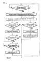
- FIG. 16is a simplified flow chart of one illustrative embodiment of a headlight control process that may be performed by the power tool of FIG. 1 ;
- FIG. 17is a simplified flow chart of another illustrative embodiment of a headlight control process that may be performed by the power tool of FIG. 1 ;
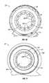
- FIGS. 18 and 19are cross-sectional side elevation views of a front end of the power tool of FIG. 1 ;
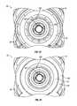
- FIGS. 20, 21, 22, and 23are front elevation views of the nose piece, both with and without overmolding.
- FIGS. 24 and 25are cross-sectional side elevation views showing detail of overmolding on the nose piece and one or more retaining clips of the nose piece of the power tool of FIG. 1 .
- FIGS. 1-5illustrate one embodiment of a power tool 10 . More particularly and as shown in FIGS. 1 and 2 , an impact tool 10 , that includes a housing 12 and a hammer case 14 .
- Housing 12includes a motive source such an electric motor, air, or other fluid-powered motor.
- Impact tool 10may further include a motor housing 15 , a handle 20 , and a power source housing 30 , among other components.
- Motor housing 15encloses a motor 38 (See FIG. 5 ) configured to provide a motive force and a gear assembly 70 (See FIG. 5 ) configured to translate the motive force from the motor 38 to an output spindle 50 of the power tool 10 .
- handle 20extends between the motor housing 15 and the power source housing 30 and is configured to be graspable by a user of the power tool 10 .
- Power source housing 30is coupled to an end of the handle 20 opposite motor housing 15 and is configured to connect to a power source, for example, a battery 34 or a source of motive fluid, such as compressed air.
- the power tool 10is an electric impact tool, which is powered by battery 34 removably coupled to the power source housing 30 .
- the motoris an electric motor, more particularly a brushless direct-current (DC) motor.
- the power tool 10also includes a controller 70 (See FIG. 5 ) supported in housing 12 , connected to the power source, and configured to manage a plurality of processes associated with the operation of the power tool 10 .
- the controllerincludes a processor, memory, an input/output subsystem, and other components as might be necessary to perform the functions disclosed herein.
- Controller 70may be embodied as any type of electronics capable of implementing digital logic.
- the memorymay be configured as a read-only memory (ROM), a random access memory (RAM), a flash memory, or an electronically-erasable programmable ROM (EEPROM).
- Housing 12includes a number of user-selectable input devices (e.g., triggers, switches, and knobs) configured to allow the user to adjust one or more user selectable features of the power tool 10 .
- housing 12includes a trigger 36 positioned on handle 20 near motor housing 15 , such that trigger 36 may be operated by a user grasping handle 20 of the power tool 10 .
- the primary function of trigger 36is to control the supply of power to the motor and, hence, the motive force delivered by motor 38 to output spindle 50 .
- Trigger 36is spring loaded and will default to keeping the power tool 10 powered off. As the user pulls trigger 36 , power is supplied from the power source to motor 38 causing motor 38 to rotate.
- trigger 36includes many (including infinite) positions, such that the more trigger 36 is depressed, the more power is supplied to motor 38 and the faster a rotor 39 (See, e.g., FIG. 18 ) of the motor rotates.
- trigger 36may also be used to control other features of the power tool 10 , such as the operation of lighting unit 60 of the power tool 10 .
- depressing trigger 36may turn on lighting unit 60 of the power tool 10 and supply power to motor 38 causing motor 38 to turn and produce a motive force.
- trigger 36is only partially depressed lighting unit 60 of the power tool 10 will turn on, but motor 38 of the power tool 10 will not rotate, thereby allowing the user to illuminate the work space of the power tool 10 before operating the power tool 10 .
- Housing 12may also include a Forward/Neutral/Reverse (“F/N/R”) switch 40 supported in housing 12 to be adjustable by the user of the power tool 10 .
- the F/N/R switch 40is positioned in the handle 12 of the power tool 10 near trigger 36 and near the motor housing 15 .
- the illustrative embodiment of the F/N/R switch 40includes a forward position, a neutral position, and reverse position. The forward position is configured to cause motor 38 to rotate in one direction when trigger 36 is depressed, while the reverse position is configured to cause motor 38 to rotate in an opposite direction when trigger 36 is depressed.
- the neutral positiondisconnects trigger 36 from the motor, such that even if trigger 36 is depressed motor 38 will not rotate.
- Housing 12also includes a rotary knob 42 positioned on a rear portion 18 of the housing 12 , as shown in FIG. 4 .
- Knob 42faces the user during normal operation of the power tool 10 .
- Rotary knob 42is configured to allow the user to select one of a plurality of modes of operation of the power tool 10 .
- knob 42When knob 42 is rotated, it passes through a plurality of detents that correspond to respective modes of operation.
- knob 42includes spring loaded features that engage with the respective detent features of the power tool 10 .
- the spring loaded features on knob 42may be “leaf spring” type features that are integral to the knob 42 or may be a plurality of components to create a spring loaded feature set (e.g., a sliding plunger preloaded by a coil spring).
- the tool housinghas a plurality of grooves to accept the spring loaded features on knob 42 to create the necessary detents that correspond to rotary positions of the knob.
- the detent groovesmay be incorporated into the rear surface of an electric motor which is adjacent to knob 42 .
- the spring loaded featuresmay be integrated into the tool housing or the rear surface of motor 38 , and the detent grooves may be integrated into knob 42 .
- each detented rotary position of knob 42corresponds to a respective operational mode of the power tool 10 .
- the power tool 10may include user output devices, such as indicator lights, to indicate the operational parameters of the power tool 10 .
- indicator lightssuch as chip-on-board (COB) light emitting diodes (LEDs) are used as indicator lights to provide feedback to the user about the operating conditions of the power tool 100 .
- the feedback provided by such indicator lightsmay include a battery charge level, an operational mode selected, a reminder to perform maintenance, a fault indication, or an indication of completion of fastening.
- the COB LEDsmay also provide non-functional aesthetic lighting in the power tool 100 .
- the COB LEDsmay light up in different colors and/or may blink/flash in different patterns to convey various messages to the user.
- the user output deviceis a COB LEDs configured to display the battery charge level as a “bar graph.”
- the user output devices of the power tool 100may be embodied as any type of audio outputs, visual outputs (e.g., lights or various screens), and/or tactile outputs, by way of example.
- the hammer case 14supports an impact mechanism 80 and output spindle 50 . (See FIGS. 1, 5, and 18 .) Output spindle 50 is configured to couple to any number of work attachments.
- hammer case 14includes a removable nose piece 32 , which supports lighting unit 60 and includes a nose piece electrical connector 62 that is configured to mate with a corresponding electrical connector 64 in the housing.
- nose piece 32may additionally or alternatively support other electrical accessories, such as sensors or human machine interfaces, by way of example.
- the electrical connector 64 in the housingis connected to battery 34 and controller 70 of the power tool 10 and is configured to provide power and/or control signals to any electrical accessories supported by nose piece 32 of hammer case 14 , such as lighting unit 60 .
- the impact mechanism 80 of the power tool 10may be any type of impact mechanism, such as a ball-and-cam impact mechanism (sometimes called a “Potts” mechanism) or a Maurer mechanism.
- the impact mechanismincludes an anvil 84 (See FIG. 5 ) coupled to (or integrally formed with) output spindle 50 and configured to rotate about an output axis 66 and a hammer 82 coupled to the output of motor 38 and configured to rotate in response to rotation of the motor 38 .
- Hammer 82includes one or more jaws that are configured to strike anvil 84 , and thereby cause the anvil 84 and output spindle 50 to rotate.
- the illustrated anvil 84 and output spindle 50are formed as a single unitary, monolithic component.
- One end of this componentextends outside hammer case 14 and functions as output spindle 50 .
- Another end of this componentextends inside hammer case 14 and functions as anvil 84 of impact mechanism 80 .
- the second end of this componentmay be formed with two jaws to create anvil 84 .
- the jaws of hammer 82are configured to impact anvil 84 to functionally drive output spindle 50 in response to rotation of motor 38 .
- the term “functionally drive”is herein defined as a relationship in which the jaws of the hammer 82 rotate to impact the respective jaws of anvil 84 and, thereby, cause intermittent rotation of output spindle 50 .
- the impact cycleis repeated twice every rotation of motor 38 .
- Removable nose piece 32is positioned to couple to an output end of hammer case 14 of the power tool 10 .
- nose piece 32includes lighting unit 60 and nose piece electrical connector 62 and is configured to keep the mating electrical connectors from inadvertently disconnecting.
- the hammer case 14may include at least one lighting unit 60 .
- lighting unit 60 on the hammer case 14is a headlight configured to illuminate the work space of the power tool 10 .
- the headlightis positioned in nose piece 32 of the hammer case 14 such that it surrounds output spindle 50 and is configured to shine light along output axis 66 , defined by output spindle 50 , and illuminate a work space of the power tool 10 .
- Lighting unit 60includes one or more lights installed in the hammer case 14 , a protective clear lens 61 configured to prevent damage and contamination to the lights caused by foreign debris, and electrical circuitry to provide power and control signals to the headlight.
- the one or more lightsare COB LEDs formed as an annular ring that surrounds the output spindle and illuminates the work space of the power tool 10 .
- the one or more lightsare two or more COB LEDs formed as arcs that cooperate to surround output spindle 50 .
- COB LEDsemployed on power tools have typically been either “through hole” or “surface mounted” LEDs.
- the use of one or more COB LEDs as a headlightprovides several advantages over these commonly used types of LEDs.
- COB LEDsare more effective as a floodlight than previous “through hole” or “surface mounted” LEDs.
- the use of COB LEDs on a power toolprovides greater light output (lumens) in a smaller package size, and COB LEDs also create a more consistent light beam than previous light emitting sources used on power tools.
- Another advantage of COB LEDsis that they can be shaped to match any profile of a tool. This allows COB LEDs to produce a continuous beam of light that is positioned to maximize the light delivered to the work space of the power tool.
- Lighting unit 60 of the power tool 10may be powered by any number or type of power supplies.
- the lighting unitis powered directly from battery 34 or through a constant current source which in turn draws its power from battery 34 removably coupled to the power tool 10 .
- the lighting unitmay instead be powered by a constant current source which in turn draws its power from a line voltage.
- itmay be powered by a constant current source that draws its power from an onboard battery of the power tool 10 .
- the lighting unit 60comprises COB LEDs that are used as a “headlight” to illuminate the work space of the power tool 10 .
- the lighting unitmay be mounted near output spindle 50 of power tool 10 and may be configured to be in any shape and size which best suits illuminating the work space of the power tool 10 .
- output spindle 50may protrude through a hole in the center of the COB LED headlight.
- the COB LED headlightmay have other shapes, such as a “U” shape that wraps around output spindle 50 of the power tool 10 .
- lighting unit 60may include various patterns or arrangements of the diodes of the COB LEDs that optimize the illumination for specific applications.
- the COB LEDsmay be mounted to the power tool 10 via adhesives, tape, threaded fasteners or integrated clip features with corresponding mating components.
- Lighting unit 60may include a protective clear lens 61 to prevent damage and contamination by foreign debris to the lights of the power tool 10 .
- Protective clear lens 61may be connected to lighting unit 60 or hammer case 14 via integrated threads, separate threaded fasteners or integrated clip features. The wires running from the power source to the lighting unit may be routed inside the tool housing and the hammer case.
- lighting unit 60turns on whenever power is supplied to the motor of the power tool 10 , for example, when the user depresses trigger 36 of the power tool 10 .
- controller 70may cause lighting unit 60 to flash various patterns, or emit certain colors of light, or both, to indicate certain events to the user of the power tool 10 , such as, for example, completion of fastening operation, faults/errors, maintenance reminders, or other operational conditions of the power tool 10 .
- an additional lighting unitmay be positioned on the power tool 10 (either on hammer case 14 or on housing 12 ) and used as an indicator to provide feedback to the user.
- This additional lighting unitmay also include one or more COB LEDs to provide illumination for visual indicators.
- COB LEDsmay be used to indicate the battery charge level. When the battery is at full charge, all diodes on the board are illuminated. As the battery discharges, diodes of the COB LEDs are switched off creating a “sliding scale” indicator. Alternatively, or in conjunction, diodes of different colors may be switched on or off to indicate different battery charge levels.
- COB LEDs used as visual indicatorsmay be configured to be any of size or shape, such as, for example, a rectangular bar, an arc, a trapezoid or a triangle.
- the additional lighting unitmay be configured to convey information to the user about various operational conditions of the power tool 10 , such as the speed of rotation of various parts of the power tool 10 , the torque applied by the power tool 10 to a fastener, the temperature of the power tool 100 , the operational mode setting of the power tool 10 , and/or a timer countdown.
- an additional lighting unitmay be used for aesthetic lighting.
- COB LEDsmay be mounted to the exterior of the power tool 10 or the interior of the housing in such a manner that the light inside is visible through vents or other holes in the housing.
- the brightness, color of emitted light, and pattern of lighting changesmay be controlled by inputs from the user.
- Nose piece 32 of hammer case 14also includes nose piece electrical connector 62 that is configured to mate with a corresponding electrical connector 62 (See FIG. 7 ) in the housing and provide energy from the power source to electrical components supported in the hammer case 14 , such as, for example the lighting unit(s).
- electric power toolswhether corded or cordless, utilize a plurality of wires on the inside of the tool to connect electrical components. Often, electrical wires that are routed through tight areas of the tool between the components of the tool can complicate assembly of the tool and the serviceability of the tool.
- wires that are routed between hammer case 14 and housing 12 of the power tool 10must be connected before hammer case 14 is fully installed and must be disconnected before the hammer case can be fully removed from tool housing 12 .
- nose piece electrical connector 62includes two male terminals 118 configured to mate with two corresponding female terminals 122 of electrical connector 64 in housing 12 of power tool 10 . (See FIGS. 9, 10, 11 .)
- connectorsmate 62 and 64 with one another creating the necessary electrical connection and providing power and control signals to the electrical components of hammer case 14 , such as lighting unit 60 .
- Hammer case 14is secured to the housing with a plurality of fasteners, which in turn keeps the electrical connectors from separating from one another while the power tool 10 is assembled.
- lighting unit 60 mounted to the front face of the hammer case 14is supplied with electrical power by the plurality of wires 110 that are routed through housing 12 and the pair of electrical connectors 118 and 122 .
- one or more lengths of wire 110connect lighting unit 60 to nose piece electrical connector 62 and one or more lengths of wire connect the electrical components of housing 12 (e.g., the battery and the controller) to the housing electrical connector 64 .
- hammer case 14When hammer case 14 is installed on the power tool 10 , the two electrical connectors 62 and 64 mate with one another creating an electrical connection between the electrical components in hammer case 14 and the electrical components in housing 12 .
- Hammer case 14is mechanically secured to housing 12 with a plurality of threaded fasteners, which mechanical connection also serves to keep the mating electrical connectors from inadvertently disconnecting.
- nose piece 32is shown exploded from hammer case 14 .
- Nose piece 32includes a nose frame 111 , a lighting unit 60 , a lens 61 , an electrical connector 62 , electrical wiring 110 and overmolding 106 .
- Nose piece 32defines an aperture 104 configured to allow output spindle 50 to pass through.
- output end 100 of hammer case 14includes an annular flange 102 surrounding output spindle 50 that is configured to engage one or more retaining clips 109 built into aperture 104 of nose piece 32 .
- nose piece electrical connection 62 and housing electrical connection 64 of power tool 10are shown.
- the nose piece electrical connection 62includes two male terminals and housing electrical connection 64 includes two female terminals configured to receive the two male terminals.
- the two connectorsform a blade and socket pair, where housing 12 includes sockets 122 (See e.g., FIG. 15 ) and nose piece 32 includes blades 118 .
- the male terminals of the hammer caseare flat, rigid blades made of a conductive metal (e.g., copper).
- the female terminals of the housinginclude flexible beams 140 made of a conductive metal (e.g., copper) that are configured to provide the necessary normal force on the rigid blades to form an electrical connection.
- the female terminals 122 of housing 12are generally “U”-shaped receptacles.
- the male connectors 118are coupled to the female connectors 122 by an interference fit, where an electrical connection between the connectors is maintained by the two flexible beams 140 of each female terminal applying a pinching force on each blade 118 of the corresponding male terminal.
- nose piece electrical connectors 62are positioned on removable nose piece 32 of hammer case 14 and housing electrical connectors 64 are positioned in a corresponding location in housing 12 near trigger 36 .
- Nose piece 32includes piloting features 145 , as shown in FIG. 14 , configured to protect the electrical connectors 118 , guiding nose piece electrical connectors 62 to mate with the corresponding housing electrical connectors 64 , and secure nose piece 32 to housing 12 .
- Piloting features 145include two sidewalls 134 extending parallel to the male terminals 118 and a top wall 147 .
- An inner surface of each sidewall 134includes a flange 126 configured to interface with a corresponding structure on housing 12 and secure nose 32 piece to housing 12 . (See FIG. 11 .)
- the male terminals 118 of nose piece electrical connector 62include a blade extending from a leading end to a wired end. The leading end of the blade is oriented to face away from the nose piece and interact with the female terminal 122 . The wired ends of the male terminals 118 is oriented toward nose piece 32 and is configured to connect to the wiring of the hammer case.
- the female terminals 122 of housing connectorinclude two flexible beams 140 . (See FIG. 15 .) Each flexible beam 140 extends from a first end of the female terminal to a second end of the female terminal and forms a slot to receive the blade 118 of the corresponding male terminal.
- the first end of the female terminalis oriented to be facing the tool housing and includes a base 137 that includes wire connectors 139 configured to connect to the wires of housing 12 .
- the two flexible beamsextend from base 137 and form a pincer 138 near the second end of the female terminal.
- Flexible beams 140are angled such that at the first end of the female terminal the flexible beams are separated by a first distance 142 , and at pincer 138 near the second end of the female terminal the flexible beams are separated by a second distance 144 , which is less than first distance 142 .
- the flexible beams 140approximately touch at pincer 138 .
- the flexible beamsflare 132 outward. Flare 132 of the flexible beams 140 is configured to guide blades 118 of the nose piece electrical connector 62 into the slot defined by the flexible beams 140 .
- Nose piece 32is advanced onto power tool 10 , leading end 120 of each blade of each male terminal 118 contacts flare 136 of flexible beams 140 of corresponding female terminal 122 .
- Flare 132 of flexible beams 140guides blade 118 of the male terminal to pincer 138 . (See FIGS. 10, 11, 12, 13, and 15 .)
- the advancing of the blade 118 of each male terminalpushes flexible beams 140 outward, such that the distance between flexible beams 140 at the pincer 138 is greater than the second distance 144 , thereby allowing each blade to advance into a slot defined by the flexible beams 140 of each corresponding female terminal 122 .
- Flexible beams 140 of each female connector 122are configured to apply a force on each blade 118 at the pincer 138 , thereby establishing an electrical connection between the two electrical connectors.
- nose piece 32When the power tool 10 is disassembled, nose piece 32 is advanced in the opposite direction away from housing 12 of the power tool 10 , blades 118 of the male terminals are advanced out of female terminals 122 breaking the electrical connection. After blades 118 are removed from female terminals 122 , the distance between the flexible blades of each female terminal at pincer 138 is approximately the second distance 144 .
- housing electrical connectors 64may include the male terminals, and the nose piece electrical connectors may include the female terminals.
- the electrical connector pairmay be used to provide power to the electrical motor, electrostatic discharge protection, provide power to a display screen, or provide an electrical connection for sensors, such as, for example, transducers, encoders, ultrasonic transceivers, laser/optical transceivers, proximity sensors, and/or radio frequency identification (RFID) transceivers supported in or by the hammer case.
- sensorssuch as, for example, transducers, encoders, ultrasonic transceivers, laser/optical transceivers, proximity sensors, and/or radio frequency identification (RFID) transceivers supported in or by the hammer case.
- RFIDradio frequency identification
- an ultrasonic transceiver supported by hammer case 14may be used to inspect the fastener for defects or cracks.
- optical transceivers supported by the hammer casemay be used to measure the proximity of the power tool 10 to the other objects.
- an RFID transceiver supported in hammer case 14may identify the attachment that is installed on output spindle 50 , allowing the motor controller to adjust the operation mode of the power tool 10 to suit the attachment. For example, an impact wrench may be able to recognize that a torque stick has been installed and reduce motor 38 speed to allow the mechanism to operate less erratically.
- optical transceivers supported by hammer case 14can be used for process control.
- the optical transceiversmay identify how many fasteners need to be tightened and determine when the operator has used the power tool 10 on each identified fastener.
- hammer case 14can be removed from the power tool 10 and the tool housing electrical connection may be configured to serve as a diagnostic port that interfaces with an external computing device.
- the power tool 10may include a variety of removable and interchangeable nose pieces, with each removable nose piece having different features, such as different colors of LED headlights or different configurations/shapes of the headlight.
- hammer case 14may include a lock-out or dongle device that disables the power tool 10 to deter theft of the tool or to enhance safety when repairing or servicing the tool.
- the methodcontrols the light output of lighting unit 60 of power tool 10 .
- the different light output modesmay include changes in brightness of the light, the pattern of the light (e.g., flashing or blinking), the color of the light produced by the lighting unit, and/or the amount of time light is emitted from the lighting unit.
- the power tool 10includes an additional switch to allow the user to alter the light output of lighting unit 60 .
- the light output of lighting unit 60is controlled by trigger 36 of the power tool 10 .
- the F/N/R switch 40When the F/N/R switch 40 is in the neutral position 152 the rotor of the motor of the power tool 10 will not rotate when the trigger is pulled as indicated at 154 .
- a mechanical lock and the controllercooperate to prevent the motor from rotating while the F/N/R switch 40 is in the neutral position.
- a mechanical lockengages trigger 36 and allows trigger 36 to be pulled far enough to close the electrical circuit that powers up controller 70 , but not far enough to close the electrical circuit that powers up motor 38 .
- controller 70while the F/N/R switch 40 is in the neutral position, controller 70 is configured to prevent motor 38 from being powered.
- controller 70while F/N/R switch 40 is in the neutral position, controller 70 is configured to latch a circuit when the trigger is pulled that keeps electrical power supplied to the controller for a period of time after the trigger is released.
- the methodbegins with the controller determining if F/N/R switch 40 is in the neutral position AT 152 . If F/N/R switch 40 is not in the neutral position and trigger 36 is depressed by the user, motor 38 rotates in the direction indicated by F/N/R switch 40 . In the illustrative embodiment, controller 70 will activate the desired headlight output setting when trigger 36 is depressed and F/N/R switch 40 is in the forward position or the reverse position. If controller 70 determines that F/N/R switch 40 is in the neutral position, controller 70 disables the electrical connection between battery 34 and motor 38 , such that motor 38 cannot receive power. Controller 70 also determines what light output mode light unit 60 of the power tool 10 is currently using to emit light. In the illustrative embodiment, the current light output mode of the power tool 10 is stored in the memory of controller 70 .
- a light output modemay include any of a combination of brightness characteristics, color characteristics, pattern characteristics, or timing characteristics that the controller uses to determine how the headlight should emit light.
- light output modesmay include emitting light at full brightness, emitting light at 66% brightness, emitting light at 33% brightness, emitting no light, emitting light in any of a variety of colors, emitting light in a flashing or blinking pattern, emitting light for certain amounts of time, and/or emitting light using any combination of the previously discussed features of brightness, color, pattern, and/or time.
- controller 70is configured to allow the user to control light unit 60 of the power tool 10 by pulling trigger 36 while F/N/R switch 40 is in the neutral position.
- trigger 36is pulled once as indicated at 158 by the user, it will cause the controller to turn on/off light unit 60 at 162 .
- the userpulls trigger 36 while F/N/R switch 40 is in the neutral position and light unit 60 is already turned on as indicated at 166 , then it will turn off. This allows the power tool 100 to be used as a task light without motor 38 rotating.
- an illumination timercauses the headlight of the power tool 100 to turn off after a predetermined amount of time as indicated at 170 and 172 , thereby conserving the power stored in the battery of the power tool 10 .
- the illumination timeris set to turn off lighting unit 60 after ten minutes of uninterrupted use.
- the controllermay toggle through various light output modes as indicated at 164 .
- the light output modemay be changed from a full brightness mode to a 66% brightness mode.
- Controller 70may be configured to toggle through each of the light output modes in successive order and even store the light modes in memory at 168 .
- the usermay cycle between light output modes with single pulls 174 of the trigger 36 .
- tool 10may either act as a headlight or it can cycle through light output modes.
- the first pull 178 of trigger 36 when F/N/R switch 40 is in the neutral positionmay cause controller 70 to turn on the headlight in the current light output mode at 180 - and 182 . If the user wants to cycle through light output modes, the user may pull the trigger again within a predetermined time period at 184 .
- This time periodis used to determine if the user has made a final selection of a light output mode.
- controller 70will wait for predetermined time period. If the user pulls trigger 36 within this time period, controller 70 will cause the power tool to cycle to a different light output mode 186 . If the user does not pull the trigger within the predetermined time period, controller 70 will store the selected light output mode at 188 for use during the forward and reverse operations and will continue outputting light according to the selected light output mode. After the predetermined time period has expired, if the user pulls the trigger again the controller will turn off the headlight. Lighting unit 60 may also be turned off by an illumination timer or by moving the F/N/R switch 40 to a forward or reverse position.
- the light output mode selected by the useris stored in the memory of the controller to be used during the normal operation of the power tool 10 .
- controller 70retrieves the current light output mode stored in memory and operates the headlight of the power tool 10 according the characteristics of the current light output mode. For example, if the trigger is depressed while F/N/R switch 40 is in the forward position and the current light output mode is 33% brightness, the controller will cause the headlight to turn on with 33% brightness while trigger 36 is depressed.
- certain light output modesmay be configured to allow the headlight of the power tool 10 to stay on for a certain period of time after the trigger is released.
- lighting unit 60may be configured to stay on for a few seconds after the trigger is released, thereby allowing the user to inspect the work just accomplished. In other embodiments, the headlight turns off when motor 38 stops.
- other user inputsmay be used to control lighting unit 60 of the power tool 10 .
- holding down trigger 36may cause lighting unit 32 to cycle through various modes of operation and releasing trigger 36 at the moment when lighting unit 60 is operating in the desired mode or brightness may cause controller 70 to save the light output setting.
- actuation of trigger 36may cause the power tool 10 to go into a light output selection mode. While in this mode, rotation of a power regulator knob 42 may allow the user to select the desired light output mode.
- Releasing trigger 36 or re-actuating trigger 36may cause controller 70 to save the light output setting.
- a push/pull operation of knob 42may control the light output settings.
- knob 42there may be several detents as knob 42 is moved axially which correlate to respective light output modes.
- other buttons, toggles, or sliders mounted in accessible locations adjacent to the power regulator knobmay be used to control the light output modes.
- an optically clear capacitive touch sensor integrated into the protective lens covering the headlightmay be used to control the light output settings. In such embodiments, when the user touches lens 61 , controller 70 may toggle through the available light output modes.
- one or more light output modesmay adjust how long the lighting unit stays illuminated after trigger 36 is released or after the fastening operation is completed.
- one or more light output modesmay adjust the length of time the lighting unit stays illuminated when being used in the task light mode.
- one or more light output modesmay include the feature of having the lighting unit gradually dim instead of turning off abruptly.
- one or more light output modesmay include a safety strobe mode of operation where the lighting unit flashes in any number of colors. The safety strobe mode may be used when performing roadside repairs with the power tool 10 .
- one or more light output modesmay include the feature of having the lighting unit flash when the power tool 10 ′s battery charge state is low. In another example, one or more light output modes may include the feature of having the lighting unit 60 flash to indicate internal errors experienced by the power tool 10 . In another example, one or more light output modes may include the ability to turn specific LEDs of the lighting unit on/off to change the beam spread of the LED.
- nose piece 32includes a lens 61 and rubber overmolding 106 .
- Overmolding 106 on the lens 61protects the front end of power tool 10 and lens 61 from damage caused by foreign debris that is generated in the work space of the tool, for example overmolding 106 prevents lens from being scratched.
- Overmolding 106also seals lighting unit 60 (e.g., the COB LED) and prevents debris from damaging the lighting unit.
- Overmolding 106also covers retaining clips 109 of the nose piece. (See FIGS. 18, 19, 20, 21 , and 22 .)
- Overmolding 106further provides structural support and dampens vibrations of the lighting unit's printed circuit board (PCB) caused by the operation of the tool.
- the rubber overmolding 106may be extended radially inward through the aperture to seal output spindle 50 and keep grease inside the hammer case interior of the tool and foreign debris out of the hammer case interior.
- hammer case 14 of power tool 10houses a gear assembly 72 and impact mechanism 80 .
- Output spindle 50extends from impact mechanism 80 to the outside of the tool through a flange aperture 104 defined by flange 102 of the hammer case. (See FIGS. 6 and 24 .)
- output spindle 50is formed as a monolithic piece with anvil 84 of the impact mechanism 80 .
- the gear assembly 72is a planetary gear set with the rotor extending into the gear assembly and configured to act as the sun gear of the gear assembly. As the rotor rotates, the gear assemble rotates and causes the impact mechanism to function.
- nose piece 32includes the nose frame 11 , lighting unit 60 , protective lens 61 , nose piece electrical connector 62 , electrical wiring 110 connecting lighting unit 60 to the electrical connector 62 , and overmolding 106 .
- Nose piece 32includes an opening 113 that defines an output spindle aperture 104 configured to allow output spindle 50 to pass through.
- One or more retaining clips 109are formed in the opening 113 of nose piece 32 . The one or more retaining clips 109 are configured to engage with annular flange 102 of hammer case 14 that surrounds output spindle 50 .
- FIGS. 20 and 22show nose piece 32 without overmolding 106 and FIGS. 21 and 23 show nose piece 32 with overmolding 106 .
- FIGS. 20 and 22show the one or more retaining clips 109 spaced radially around the opening 113 of nose piece 32 . Gaps 115 are formed between each of retaining clips 109 .
- the one or more retaining clips 109are engaged with annular flange 102 of the output end of hammer case 14 .
- overmolding 106 of nose piece 32also includes an inner overmolding 107 .
- the inner overmolding 107extends from the retaining clips 109 of nose piece 32 onto lens 61 .
- inner overmolding 107partially fills any gaps 165 (See FIG. 20 ) between the one or more retaining clips 109 providing structure support for the same. Inner overmolding 107 also seals the interior portions of nose piece 32 from foreign debris.
- a rubber overmolding 106is positioned between lens 61 and the lighting unit 60 and is configured to support the lighting unit's PCB with an interference fit. Overmolding 106 also extends from about an outer diameter of lighting unit 60 and around an outer surface of frame 111 of the nose piece 32 . In some embodiments, overmolding 106 covers part of lens 61 . As shown in FIGS. 6 , 7 , 18 , and 19 , overmolding 106 extends from lens 61 , along frame 111 , and terminates near nose piece electrical connector 62 .
- each retaining clip 109includes a rounded end 133 configured to be received by a rounded surface 135 in the annular flange 102 .
- the interaction between annular flange 102 and the retaining clips 109secures nose piece 32 to hammer case 14 .
- Annular flange 102also includes a chamfer 137 surface that is configured to deflect the retaining clips 109 inwardly toward lens 61 , as nose piece 32 is advanced onto hammer case 14 . Once nose piece 32 has passed a certain distance through aperture 104 , retaining clips 109 deflect back outwardly and engage the rounded surface 135 .
Landscapes
- Engineering & Computer Science (AREA)
- Mechanical Engineering (AREA)
- General Engineering & Computer Science (AREA)
- Physics & Mathematics (AREA)
- Optics & Photonics (AREA)
- Electromagnetism (AREA)
- Details Of Spanners, Wrenches, And Screw Drivers And Accessories (AREA)
Abstract
Description
Claims (16)
Priority Applications (3)
| Application Number | Priority Date | Filing Date | Title |
|---|---|---|---|
| US15/172,247US10052733B2 (en) | 2015-06-05 | 2016-06-03 | Lighting systems for power tools |
| PCT/US2016/035681WO2016196905A1 (en) | 2015-06-05 | 2016-06-03 | Lighting systems for power tools |
| US16/107,859US10960509B2 (en) | 2015-06-05 | 2018-08-21 | Lighting systems for power tools |
Applications Claiming Priority (2)
| Application Number | Priority Date | Filing Date | Title |
|---|---|---|---|
| US201562171791P | 2015-06-05 | 2015-06-05 | |
| US15/172,247US10052733B2 (en) | 2015-06-05 | 2016-06-03 | Lighting systems for power tools |
Related Child Applications (1)
| Application Number | Title | Priority Date | Filing Date |
|---|---|---|---|
| US16/107,859ContinuationUS10960509B2 (en) | 2015-06-05 | 2018-08-21 | Lighting systems for power tools |
Publications (2)
| Publication Number | Publication Date |
|---|---|
| US20160354889A1 US20160354889A1 (en) | 2016-12-08 |
| US10052733B2true US10052733B2 (en) | 2018-08-21 |
Family
ID=61099569
Family Applications (2)
| Application Number | Title | Priority Date | Filing Date |
|---|---|---|---|
| US15/172,247Active2036-08-05US10052733B2 (en) | 2015-06-05 | 2016-06-03 | Lighting systems for power tools |
| US16/107,859Active2036-06-18US10960509B2 (en) | 2015-06-05 | 2018-08-21 | Lighting systems for power tools |
Family Applications After (1)
| Application Number | Title | Priority Date | Filing Date |
|---|---|---|---|
| US16/107,859Active2036-06-18US10960509B2 (en) | 2015-06-05 | 2018-08-21 | Lighting systems for power tools |
Country Status (4)
| Country | Link |
|---|---|
| US (2) | US10052733B2 (en) |
| EP (1) | EP3302880A4 (en) |
| CN (2) | CN107635725B (en) |
| WO (1) | WO2016196905A1 (en) |
Cited By (15)
| Publication number | Priority date | Publication date | Assignee | Title |
|---|---|---|---|---|
| US10615670B2 (en)* | 2015-06-05 | 2020-04-07 | Ingersoll-Rand Industrial U.S., Inc. | Power tool user interfaces |
| US11213937B1 (en) | 2020-09-22 | 2022-01-04 | Snap-On Incorporated | Tool illumination source |
| US11260517B2 (en) | 2015-06-05 | 2022-03-01 | Ingersoll-Rand Industrial U.S., Inc. | Power tool housings |
| USD947636S1 (en) | 2020-10-14 | 2022-04-05 | Black & Decker Inc. | Impact tool |
| USD956501S1 (en) | 2020-11-06 | 2022-07-05 | Black & Decker Inc. | Impact tool |
| US11453106B2 (en) | 2019-10-25 | 2022-09-27 | Milwaukee Electric Tool Corporation | Rotary power tool having work light brightness control unit |
| US11491616B2 (en)* | 2015-06-05 | 2022-11-08 | Ingersoll-Rand Industrial U.S., Inc. | Power tools with user-selectable operational modes |
| US11602832B2 (en) | 2015-06-05 | 2023-03-14 | Ingersoll-Rand Industrial U.S., Inc. | Impact tools with ring gear alignment features |
| US11772245B2 (en) | 2020-02-24 | 2023-10-03 | Milwaukee Electric Tool Corporation | Impact tool |
| US12097603B2 (en) | 2020-06-12 | 2024-09-24 | Milwaukee Electric Tool Corporation | Oscillating power tool with lighting assembly |
| US12098839B2 (en) | 2022-05-10 | 2024-09-24 | Ingersoll-Rand Industrial U.S., Inc. | Application-targeted light on powered ratchet or right-angle power tool |
| US12186880B2 (en) | 2020-06-12 | 2025-01-07 | Milwaukee Electric Tool Corporation | Oscillating power tool |
| DE102023212810A1 (en)* | 2023-12-15 | 2025-06-18 | Robert Bosch Gesellschaft mit beschränkter Haftung | Electric hand tool |
| USD1090213S1 (en) | 2023-10-26 | 2025-08-26 | Snap-On Incorporated | Tool housing |
| US12410912B2 (en) | 2021-11-12 | 2025-09-09 | Milwaukee Electric Tool Corporation | Shadowless lighting system for a handheld power tool |
Families Citing this family (34)
| Publication number | Priority date | Publication date | Assignee | Title |
|---|---|---|---|---|
| WO2016196891A1 (en)* | 2015-06-05 | 2016-12-08 | Ingersoll-Rand Company | Power tool user interfaces |
| EP3484663B1 (en)* | 2016-09-28 | 2021-03-24 | Milwaukee Electric Tool Corporation | Trigger assembly |
| EP3318366B1 (en)* | 2016-11-07 | 2021-07-07 | Nanjing Chervon Industry Co., Ltd. | Power tool |
| US10926368B2 (en) | 2017-09-27 | 2021-02-23 | Ingersoll-Rand Industrial U.S., Inc. | Part illumination status lights |
| DE102017222550A1 (en)* | 2017-12-13 | 2019-06-13 | Robert Bosch Gmbh | Add-on module for use with a tool and implement |
| US10987784B2 (en)* | 2018-02-23 | 2021-04-27 | Ingersoll-Rand Industrial U.S., Inc. | Cordless impact tool with brushless, sensorless, motor and drive |
| US11794320B2 (en) | 2018-04-13 | 2023-10-24 | Snap-On Incorporated | System and method for indicating torque |
| USD861450S1 (en) | 2018-05-11 | 2019-10-01 | Snap-On Incorporated | Electronic torque screwdriver |
| CN112423939A (en)* | 2018-07-20 | 2021-02-26 | 詹姆斯·格雷戈里·布鲁尔 | Lanyard system for a power tool |
| WO2020068608A1 (en)* | 2018-09-24 | 2020-04-02 | Milwaukee Electric Tool Corporation | Power tool including input control device on top portion of housing |
| US11621531B2 (en) | 2018-09-28 | 2023-04-04 | Hubbell Incorporated | Power tool with crimp localization |
| WO2021034652A1 (en) | 2019-08-16 | 2021-02-25 | Milwaukee Electric Tool Corporation | Mode selection of a power tool |
| US12122033B2 (en)* | 2020-01-06 | 2024-10-22 | Robbox Inc. | Apparatus and method of an interactive power tool |
| JP7495793B2 (en)* | 2020-02-17 | 2024-06-05 | 株式会社マキタ | Work Machine |
| CN115917454A (en) | 2020-06-21 | 2023-04-04 | 哈勃股份有限公司 | Power tools with images of crimping |
| DE102020212708A1 (en)* | 2020-10-08 | 2022-04-14 | Robert Bosch Gesellschaft mit beschränkter Haftung | hand tool |
| US11684986B2 (en)* | 2020-12-18 | 2023-06-27 | Ridge Tool Company | Pipe threading mechanisms and systems |
| CN114643566A (en)* | 2020-12-18 | 2022-06-21 | 南京泉峰科技有限公司 | Electric tool |
| GB2612637A (en) | 2021-11-08 | 2023-05-10 | Black & Decker Inc | A power tool, power tool accessory and coupling arrangement therefor |
| US12377525B2 (en)* | 2021-12-13 | 2025-08-05 | Makita Corporation | Impact tool |
| EP4272901A1 (en)* | 2022-05-03 | 2023-11-08 | Milwaukee Electric Tool Corporation | Method and power tool including loss of control mitigation |
| JP2023167146A (en) | 2022-05-11 | 2023-11-24 | 株式会社マキタ | Power tool |
| US20230364756A1 (en) | 2022-05-11 | 2023-11-16 | Makita Corporation | Power tool |
| JP2023167145A (en)* | 2022-05-11 | 2023-11-24 | 株式会社マキタ | power tools |
| JP2023167120A (en)* | 2022-05-11 | 2023-11-24 | 株式会社マキタ | Power tool, light unit, and projector |
| JP2024025036A (en)* | 2022-08-10 | 2024-02-26 | 株式会社マキタ | impact tools |
| JP2024027698A (en) | 2022-08-18 | 2024-03-01 | 株式会社マキタ | electric work equipment |
| JP2024047269A (en) | 2022-09-26 | 2024-04-05 | 株式会社マキタ | Electric work machine and screwing tool |
| JP2024059481A (en) | 2022-10-18 | 2024-05-01 | 株式会社マキタ | Electric work machine |
| US12409533B2 (en)* | 2022-11-30 | 2025-09-09 | Makita Corporation | Impact tool |
| JP2024084235A (en) | 2022-12-13 | 2024-06-25 | 株式会社マキタ | Power tool |
| US12337446B2 (en)* | 2023-01-18 | 2025-06-24 | Makita Corporation | Impact tool |
| EP4446062A1 (en)* | 2023-03-13 | 2024-10-16 | Milwaukee Electric Tool Corporation | Power tool with lighting assembly and wire passageway |
| US12429213B2 (en)* | 2023-05-16 | 2025-09-30 | Milwaukee Electric Tool Corporation | Power tool utilizing optical fibers to output light |
Citations (157)
| Publication number | Priority date | Publication date | Assignee | Title |
|---|---|---|---|---|
| US1495153A (en) | 1920-03-31 | 1924-05-27 | Benjamin Electric Mfg Co | Separable attachment fixture |
| US2543979A (en) | 1946-01-31 | 1951-03-06 | Chicago Pneumatic Tool Co | Impact wrench torque control |
| US2637825A (en) | 1949-03-24 | 1953-05-05 | American Mach & Foundry | Dynamoelectric machine |
| US2858701A (en) | 1955-06-29 | 1958-11-04 | Frederick P Willcox | Single shaft portable power tool for rotating and reciprocating motions |
| US3225232A (en) | 1962-10-17 | 1965-12-21 | Singer Co | Variable speed portable tool |
| GB1068990A (en) | 1964-04-20 | 1967-05-17 | Singer Co | Variable-speed portable electric tools |
| US3336490A (en) | 1966-12-23 | 1967-08-15 | Singer Co | Variable-speed portable electric tools |
| US3353078A (en) | 1965-01-29 | 1967-11-14 | Smith Corp A O | Dynamoelectric machine and control therefor |
| US3611095A (en) | 1968-05-31 | 1971-10-05 | Metabowerke Kg | Speed control and overload protection device for an electric power tool |
| US4032806A (en) | 1976-02-02 | 1977-06-28 | The Singer Company | Battery powered power tools |
| US4156821A (en) | 1976-04-12 | 1979-05-29 | Sanyo Electric Co., Ltd. | Capacitor run motor |
| US4284109A (en) | 1979-10-19 | 1981-08-18 | Cooper Industries, Inc. | Electric conductor wrapping tool |
| US4292571A (en) | 1980-02-14 | 1981-09-29 | Black & Decker Inc. | Control device for controlling the rotational speed of a portable power tool |
| US4307325A (en) | 1980-01-28 | 1981-12-22 | Black & Decker Inc. | Digital control system for electric motors in power tools and the like |
| US4412158A (en) | 1980-02-21 | 1983-10-25 | Black & Decker Inc. | Speed control circuit for an electric power tool |
| US4454459A (en) | 1980-02-05 | 1984-06-12 | Black & Decker Inc. | Method of controlling the speed of a drill, hammer-drill, or rotary hammer and apparatus therefor |
| US4506743A (en) | 1981-11-13 | 1985-03-26 | Black & Decker Inc. | Latching arrangement for power tools |
| US4510404A (en) | 1983-03-31 | 1985-04-09 | The Singer Company | Mounting for electronic circuit board in power hand tool |
| US4513381A (en) | 1982-06-07 | 1985-04-23 | The Singer Company | Speed regulator for power tool |
| EP0271903A2 (en) | 1986-12-17 | 1988-06-22 | SPS TECHNOLOGIES, Inc. | Apparatus for tightening screw-threaded fasteners |
| US4791833A (en) | 1984-07-16 | 1988-12-20 | Japan Storage Battery Co., Ltd. | Reduction gear mechanism for motor-driven drill incorporating speed changing mechanism |
| US4893942A (en) | 1987-12-23 | 1990-01-16 | Whirlpool Corporation | Membrane potentiometer speed selection control for an electric food mixer |
| US4991472A (en) | 1988-11-04 | 1991-02-12 | James Curtis Hilliard | D.C. direct drive impact wrench |
| US5105130A (en) | 1988-05-24 | 1992-04-14 | Black & Decker Inc. | Keyboard controlled multi-function power tool with visual display |
| US5138243A (en) | 1989-07-15 | 1992-08-11 | Kress-Elektrik Gmbh & Co. | Switching device for the electric switching of electric tools |
| US5200658A (en) | 1990-11-28 | 1993-04-06 | Sumitomo Electric Industries, Ltd. | Electric motor with through-bolt guides for mounting |
| US5203242A (en) | 1991-12-18 | 1993-04-20 | Hansson Gunnar C | Power tool for two-step tightening of screw joints |
| EP0585541A2 (en) | 1992-07-31 | 1994-03-09 | Marquardt GmbH | Electric switch for speed control of motors |
| US5365155A (en) | 1990-10-22 | 1994-11-15 | Marquardt Gmbh | Rotational speed control and use of same to control the rotational speed of an electric hand tool motor |
| US5473519A (en) | 1995-03-09 | 1995-12-05 | Ingersoll-Rand Company | Light ring for power tools |
| US5525842A (en) | 1994-12-02 | 1996-06-11 | Volt-Aire Corporation | Air tool with integrated generator and light ring assembly |
| US5526460A (en) | 1994-04-25 | 1996-06-11 | Black & Decker Inc. | Impact wrench having speed control circuit |
| US5531278A (en) | 1995-07-07 | 1996-07-02 | Lin; Pi-Chu | Power drill with drill bit unit capable of providing intermittent axial impact |
| JPH08193896A (en) | 1995-01-18 | 1996-07-30 | Toyota Motor Corp | Torque detector |
| US5561734A (en) | 1992-08-13 | 1996-10-01 | Milwaukee Electric Tool Corporation | Dial speed control for hand-held power tool |
| JPH08294878A (en) | 1995-04-25 | 1996-11-12 | Nissan Motor Co Ltd | Measuring method of tightening axial force in bolt and nut tightening and impact type screw tightening device |
| DE19518591A1 (en) | 1995-05-20 | 1996-12-12 | Promed Gmbh | Motorised finger-nail cosmetic care apparatus |
| US5712543A (en) | 1995-10-31 | 1998-01-27 | Smith & Nephew Endoscopy Inc. | Magnetic switching element for controlling a surgical device |
| US5714861A (en) | 1994-05-27 | 1998-02-03 | Eaton Corporation | Variable speed control for a hand-held electric power tool |
| US5738177A (en) | 1995-07-28 | 1998-04-14 | Black & Decker Inc. | Production assembly tool |
| US5804936A (en) | 1995-10-31 | 1998-09-08 | Smith & Nephew, Inc. | Motor controlled surgical system |
| WO1998053959A1 (en) | 1997-05-29 | 1998-12-03 | Ingersoll-Rand Company | Resonant oscillating mass-based torquing tool |
| EP0911119A2 (en) | 1997-10-27 | 1999-04-28 | Atlas Copco Tools Ab | Method for determining the installed torque in a screw joint at impulse tightening and a torque impulse tool for tightening a screw joint to a predetermined torque level |
| US5992257A (en) | 1996-10-11 | 1999-11-30 | Black & Decker Inc. | Power tool with mode change switch |
| US6037724A (en) | 1997-05-01 | 2000-03-14 | Osteomed Corporation | Electronic controlled surgical power tool |
| US6043575A (en) | 1999-03-05 | 2000-03-28 | Snap-On Tools Company | Power tool with air deflector for venting motor exhaust air |
| JP2000218561A (en) | 1999-02-04 | 2000-08-08 | Honda Motor Co Ltd | Fastening device with torque guarantee |
| WO2000064639A1 (en) | 1999-04-28 | 2000-11-02 | Atlas Copco Tools Ab | System for tightening fasteners having ultra-sonic sound wave generating and sensing means |
| WO2001044776A1 (en) | 1999-12-16 | 2001-06-21 | Magna-Lastic Devices, Inc. | Impact tool control method and apparatus and impact tool using the same |
| US6318189B1 (en) | 1998-11-18 | 2001-11-20 | Robert D. Donaldson | Digital torque-responsive pneumatic tool |
| US6353705B1 (en) | 1999-07-26 | 2002-03-05 | Makita Corporation | Speed control circuit of a direct current motor |
| WO2002030624A2 (en) | 2000-10-11 | 2002-04-18 | Ingersoll-Rand Company | Electronically controlled torque management system for threaded fastening |
| US20020096342A1 (en) | 2001-01-23 | 2002-07-25 | Rodney Milbourne | 360 degree clutch collar |
| US20020131267A1 (en) | 1997-07-10 | 2002-09-19 | Van Osenbruggen Anthony Alfred | Illumination by hand-operated power tools |
| JP2002331427A (en) | 2001-05-09 | 2002-11-19 | Shigeru Co Ltd | Erroneous assembling preventive device |
| US6508313B1 (en) | 2001-07-23 | 2003-01-21 | Snap-On Technologies, Inc. | Impact tool battery pack with acoustically-triggered timed impact shutoff |
| US6511200B2 (en) | 1999-07-13 | 2003-01-28 | Makita Corporation | Power tools having timer devices |
| US20030121679A1 (en) | 2001-12-27 | 2003-07-03 | Taga Corporation | Insert for a plastic power tool housing |
| US6598684B2 (en) | 2000-11-17 | 2003-07-29 | Makita Corporation | Impact power tools |
| US20030149508A1 (en) | 2002-02-07 | 2003-08-07 | Masahiro Watanabe | Power tools |
| US6691796B1 (en) | 2003-02-24 | 2004-02-17 | Mobiletron Electronics Co., Ltd. | Power tool having an operating knob for controlling operation in one of rotary drive and hammering modes |
| US6713905B2 (en) | 2001-08-30 | 2004-03-30 | S-B Power Tool Company | Electric-motor rotary power tool having a light source with a self-generating power supply |
| WO2004029569A1 (en) | 2002-09-25 | 2004-04-08 | Fast Technology Ag. | Torque signal transmission |
| US6725945B2 (en) | 2001-11-15 | 2004-04-27 | Makita Corporation | Impact tool with improved operability |
| JP2004202600A (en) | 2002-12-24 | 2004-07-22 | Toyota Motor Corp | Tightening torque judgment device |
| JP2004239681A (en) | 2003-02-04 | 2004-08-26 | Toyota Motor Corp | Tightening torque measuring device |
| US6814461B2 (en) | 2003-03-03 | 2004-11-09 | One World Technologies Limited | Battery-operated power tool with light source |
| EP1524085A2 (en) | 2003-10-14 | 2005-04-20 | Matsushita Electric Works, Ltd. | Power fastening tool |
| US6933632B2 (en) | 2002-05-10 | 2005-08-23 | Hilti Aktiengesellschaft | Commutating rotary switch |
| US20050183870A1 (en) | 2004-02-23 | 2005-08-25 | Ryobi Ltd. | Electric power tool |
| US6945337B2 (en) | 2003-10-14 | 2005-09-20 | Matsushita Electric Works, Ltd. | Power impact tool |
| JP2005254400A (en) | 2004-03-12 | 2005-09-22 | Makita Corp | Tightening tool |
| EP1595650A2 (en) | 2004-05-12 | 2005-11-16 | Matsushita Electric Works, Ltd. | Rotary impact tool |
| EP1595649A2 (en) | 2004-05-12 | 2005-11-16 | Matsushita Electric Works, Ltd. | Rotary impact tool |
| US20050257945A1 (en) | 2004-05-20 | 2005-11-24 | Justis Michael S | Motor housing and assembly process for impact wrench |
| US6968908B2 (en) | 2003-02-05 | 2005-11-29 | Makita Corporation | Power tools |
| US20060012584A1 (en) | 1998-10-26 | 2006-01-19 | Vassallo Steven P | Mechanisms for control knobs and other interface devices |
| US7058291B2 (en) | 2000-01-07 | 2006-06-06 | Black & Decker Inc. | Brushless DC motor |
| US7109675B2 (en) | 2001-05-09 | 2006-09-19 | Makita Corporation | Power tools |
| US7112934B2 (en) | 1993-07-06 | 2006-09-26 | Black & Decker Inc. | Electrical power tool having a motor control circuit for providing control over the torque output of the power tool |
| JP2006272488A (en) | 2005-03-28 | 2006-10-12 | Matsushita Electric Works Ltd | Impact rotary tool |
| US20060237205A1 (en) | 2005-04-21 | 2006-10-26 | Eastway Fair Company Limited | Mode selector mechanism for an impact driver |
| JP2006312210A (en) | 2005-05-09 | 2006-11-16 | Uryu Seisaku Ltd | Managing device of screw fastening operation in torque control wrench |
| US7152329B2 (en) | 2001-05-15 | 2006-12-26 | Makita Corporation | Electric jigsaw capable of improved illumination of workpieces |
| US7236243B2 (en) | 2004-04-12 | 2007-06-26 | Michael Thomas Beecroft | Hand-held spectrometer |
| US7237622B2 (en) | 2004-05-13 | 2007-07-03 | Yu Hui Liao | Pneumatic tool having pressure release device |
| US20070180959A1 (en) | 2006-02-08 | 2007-08-09 | Makita Corporation | Tightening tool |
| US20070193762A1 (en) | 2006-02-23 | 2007-08-23 | Matsushita Electric Works, Ltd. | Electric power tool |
| US7322427B2 (en) | 2004-06-16 | 2008-01-29 | Makita Corporation | Power impact tool |
| US20080025017A1 (en) | 2006-07-26 | 2008-01-31 | Naoki Tadokoro | Power tool equipped with light |
| US20080032848A1 (en) | 2006-08-01 | 2008-02-07 | Eastway Fair Company Limited | Variable speed transmission for a power tool |
| US7334648B2 (en) | 2005-06-30 | 2008-02-26 | Matsushita Electric Works, Ltd. | Rotary impact power tool |
| US20080048650A1 (en) | 2004-10-22 | 2008-02-28 | Delphi Technologies, Inc. | Position sensor and assembly |
| US20080122302A1 (en) | 2006-10-30 | 2008-05-29 | Leininger Jon J | Pneumatic tool having integrated electricity generator with external stator |
| US7397153B2 (en) | 2004-08-05 | 2008-07-08 | Robert Bosch Gmbh | Power tool |
| EP1982798A2 (en) | 2000-03-16 | 2008-10-22 | Makita Corporation | Power tool |
| WO2009011633A1 (en) | 2007-07-13 | 2009-01-22 | Atlas Copco Tools Ab | Regulator for a power tool |
| US7494437B2 (en) | 2007-01-04 | 2009-02-24 | Ting Kuang Chen | Impact power tool |
| EP2042271A2 (en) | 2007-09-28 | 2009-04-01 | Panasonic Electric Works Co., Ltd. | Impact power tool |
| EP2075094A1 (en) | 2007-12-28 | 2009-07-01 | Robert Bosch GmbH | Rotary power tool with a gearbox to motor interface that facilitates assembly |
| RU2360786C2 (en) | 2007-09-12 | 2009-07-10 | ЗАКРЫТОЕ АКЦИОНЕРНОЕ ОБЩЕСТВО "ИНГЕРСОЛЛ-РЭНД СиАйЭс" | Method of controlling tightening quality in assembling threaded joints by impact nut runner, and device to this end |
| US20090221222A1 (en) | 2008-02-28 | 2009-09-03 | Techway Industrial Co., Ltd. | Electric grinding gun |
| JP2009269137A (en) | 2008-05-08 | 2009-11-19 | Hitachi Koki Co Ltd | Oil pulse tool |
| JP2010012585A (en) | 2008-07-07 | 2010-01-21 | Hitachi Koki Co Ltd | Power tool |
| WO2010110716A1 (en) | 2009-03-27 | 2010-09-30 | Atlas Copco Tools Ab | Method and device for ultrasonic measurements |
| US7839112B2 (en) | 2008-06-10 | 2010-11-23 | Mobiletron Electronics Co., Ltd. | Torque control circuit for impact tool |
| US7882899B2 (en) | 2007-08-29 | 2011-02-08 | Positec Power Tools (Suzhou) Co., Ltd | Power tool having control system for changing rotational speed of output shaft |
| JP2011031369A (en) | 2009-08-05 | 2011-02-17 | Hitachi Koki Co Ltd | Impact type screwing device |
| JP2011067910A (en) | 2009-09-25 | 2011-04-07 | Toku Hanbai Kk | Wheel nut tightening tool for automobile tire replacement |
| US7928615B2 (en) | 2008-09-29 | 2011-04-19 | Sanyo Denki Co., Ltd. | Molded motor |
| US20110188232A1 (en) | 2009-02-25 | 2011-08-04 | Friedman Brian E | Power tool with a light for illuminating a workpiece |
| WO2011099487A1 (en) | 2010-02-11 | 2011-08-18 | Hitachi Koki Co., Ltd. | Impact tool |
| WO2011102559A1 (en) | 2010-02-22 | 2011-08-25 | Hitachi Koki Co., Ltd. | Impact tool |
| US8016048B2 (en) | 2007-04-23 | 2011-09-13 | Hitachi Koki Co., Ltd. | Electrical power tool |
| US20110248650A1 (en) | 2010-04-07 | 2011-10-13 | Black & Decker Inc. | Power Tool with Light Unit |
| JP2011230272A (en) | 2010-04-30 | 2011-11-17 | Hitachi Koki Co Ltd | Power tool |
| WO2012002578A1 (en) | 2010-06-30 | 2012-01-05 | Hitachi Koki Co., Ltd. | Impact tool |
| JP2012035358A (en) | 2010-08-05 | 2012-02-23 | Toyota Motor Corp | Impact type fastening tool |
| WO2012023452A1 (en) | 2010-08-17 | 2012-02-23 | パナソニック電工パワーツール株式会社 | Rotary impact tool |
| US8122971B2 (en) | 2005-09-13 | 2012-02-28 | Techtronic Power Tools Technology Limited | Impact rotary tool with drill mode |
| TW201231843A (en) | 2011-01-17 | 2012-08-01 | Nidec Shimpo Corp | Transmission box |
| US8267924B2 (en) | 2007-04-13 | 2012-09-18 | Tyco Healthcare Group Lp | Powered surgical instrument |
| US8303449B2 (en) | 2006-08-01 | 2012-11-06 | Techtronic Power Tools Technology Limited | Automatic transmission for a power tool |
| US20120279736A1 (en) | 2009-07-29 | 2012-11-08 | Hitachi Koki Co., Ltd. | Impact tool |
| US20120318549A1 (en) | 2011-06-15 | 2012-12-20 | Makita Corporation | Impact tool |
| US8371708B2 (en) | 2008-03-26 | 2013-02-12 | Makita Corporation | Electric power tool |
| US8381830B2 (en) | 2009-05-05 | 2013-02-26 | Black & Decker Inc. | Power tool with integrated bit retention device |
| US20130062086A1 (en) | 2010-05-31 | 2013-03-14 | Hitachi Koki Co., Ltd. | Power tool |
| WO2013037325A1 (en) | 2011-09-16 | 2013-03-21 | 苏州宝时得电动工具有限公司 | Electrician's screwdriver and portable hand-held tool |
| US20130075121A1 (en) | 2010-03-08 | 2013-03-28 | Hitachi Koki Co., Ltd. | Impact tool |
| US8415911B2 (en) | 2009-07-17 | 2013-04-09 | Johnson Electric S.A. | Power tool with a DC brush motor and with a second power source |
| US8430180B2 (en) | 2008-01-24 | 2013-04-30 | Black & Decker, Inc. | Control mechanism for a power tool |
| US20130161040A1 (en) | 2008-11-08 | 2013-06-27 | Black & Decker Inc. | Power tool |
| US8496366B2 (en) | 2008-12-16 | 2013-07-30 | Robert Bosch Gmbh | Hand-held power tool |
| US20130228356A1 (en) | 2012-03-05 | 2013-09-05 | Ingersoll-Rand Company | Power tools with titanium hammer cases and associated flange interfaces |
| US8528658B2 (en) | 2009-12-18 | 2013-09-10 | Robert Bosch Gmbh | Power drill |
| US20130267374A1 (en) | 2012-04-05 | 2013-10-10 | Robert Bosch Gmbh | Handheld power tool having a planetary gear set |
| US20130269961A1 (en) | 2012-04-13 | 2013-10-17 | Black & Decker Inc. | Electronic clutch for power tool |
| US20130274797A1 (en) | 2010-11-19 | 2013-10-17 | Covidien Lp | Surgical device |
| US20130270932A1 (en) | 2010-06-14 | 2013-10-17 | Black & Decker Inc. | Rotor assembly for brushless motor for a power tool |
| US20130284480A1 (en) | 2012-04-30 | 2013-10-31 | Hitachi Koki Co., Ltd. | Power tool |
| WO2013164905A1 (en) | 2012-04-30 | 2013-11-07 | Hitachi Koki Co., Ltd. | Power tool |
| US20130313925A1 (en) | 2012-05-24 | 2013-11-28 | Milwaukee Electric Tool Corporation | Brushless dc motor power tool with combined pcb design |
| US20130327552A1 (en) | 2012-06-08 | 2013-12-12 | Black & Decker Inc. | Power tool having multiple operating modes |
| WO2013183535A1 (en) | 2012-06-05 | 2013-12-12 | 株式会社マキタ | Rotary impact tool |
| US8607893B2 (en) | 2010-01-28 | 2013-12-17 | Makita Corporation | Impact tool with a protecting cover |
| US20140036482A1 (en) | 2010-09-30 | 2014-02-06 | Black & Decker Inc. | Lighted power tool |
| US20140069676A1 (en) | 2012-09-07 | 2014-03-13 | Robert Bosch Gmbh | Slide Switch for a Power Tool |
| US20140100687A1 (en) | 2012-10-04 | 2014-04-10 | Black & Decker Inc. | Power tool hall effect mode selector switch |
| US8727034B2 (en) | 2007-03-12 | 2014-05-20 | Robert Bosch Gmbh | Rotary power tool operable in first speed mode and a second speed mode |
| US8757286B2 (en) | 2005-02-14 | 2014-06-24 | Makita Corporation | Impact tool |
| US20140182869A1 (en) | 2012-12-27 | 2014-07-03 | Makita Corporation | Impact tool |
| WO2014108110A1 (en) | 2013-01-10 | 2014-07-17 | Alfred Raith Gmbh | Switching and control device for a power tool, and method for controlling said power tool |
| US8800679B2 (en) | 2010-01-07 | 2014-08-12 | Black & Decker Inc. | Trigger profile for a power tool |
| WO2014124859A1 (en) | 2013-02-15 | 2014-08-21 | Babyliss Faco Sprl | Drive unit for electric household appliance parts |
| US8820430B2 (en) | 2006-05-19 | 2014-09-02 | Black & Decker Inc. | Mode change mechanism for a power tool |
| CN104676315A (en) | 2014-09-02 | 2015-06-03 | 周焕球 | Internal reflection lamp |
Family Cites Families (6)
| Publication number | Priority date | Publication date | Assignee | Title |
|---|---|---|---|---|
| US2855679A (en)* | 1955-11-08 | 1958-10-14 | Howard G Gibble | Gage attachment for drills |
| JP3916883B2 (en)* | 2001-05-15 | 2007-05-23 | 株式会社マキタ | Electric tool |
| DE102004051913A1 (en)* | 2004-08-09 | 2006-02-23 | Robert Bosch Gmbh | Cordless Screwdriver |
| US8519558B2 (en)* | 2006-10-30 | 2013-08-27 | Jon J. Leininger | Tool having integrated electricity generator with external stator and power conditioner |
| DE202006018761U1 (en)* | 2006-12-12 | 2007-02-15 | Lighting Innovation Group Ag | Lighting device for working area near production device comprises cooling system, which is arranged in production device, and lighting unit which has LED whereby lighting unit stands in thermal contact with production device |
| EP2524775B1 (en)* | 2011-05-19 | 2019-10-16 | Black & Decker Inc. | Power tool with light unit |
- 2016
- 2016-06-03CNCN201680031710.8Apatent/CN107635725B/enactiveActive
- 2016-06-03EPEP16804509.4Apatent/EP3302880A4/enactivePending
- 2016-06-03USUS15/172,247patent/US10052733B2/enactiveActive
- 2016-06-03WOPCT/US2016/035681patent/WO2016196905A1/ennot_activeCeased
- 2016-06-03CNCN201910984472.8Apatent/CN110712163B/enactiveActive
- 2018
- 2018-08-21USUS16/107,859patent/US10960509B2/enactiveActive
Patent Citations (170)
| Publication number | Priority date | Publication date | Assignee | Title |
|---|---|---|---|---|
| US1495153A (en) | 1920-03-31 | 1924-05-27 | Benjamin Electric Mfg Co | Separable attachment fixture |
| US2543979A (en) | 1946-01-31 | 1951-03-06 | Chicago Pneumatic Tool Co | Impact wrench torque control |
| US2637825A (en) | 1949-03-24 | 1953-05-05 | American Mach & Foundry | Dynamoelectric machine |
| US2858701A (en) | 1955-06-29 | 1958-11-04 | Frederick P Willcox | Single shaft portable power tool for rotating and reciprocating motions |
| US3225232A (en) | 1962-10-17 | 1965-12-21 | Singer Co | Variable speed portable tool |
| GB1068990A (en) | 1964-04-20 | 1967-05-17 | Singer Co | Variable-speed portable electric tools |
| US3353078A (en) | 1965-01-29 | 1967-11-14 | Smith Corp A O | Dynamoelectric machine and control therefor |
| US3336490A (en) | 1966-12-23 | 1967-08-15 | Singer Co | Variable-speed portable electric tools |
| US3611095A (en) | 1968-05-31 | 1971-10-05 | Metabowerke Kg | Speed control and overload protection device for an electric power tool |
| US4032806A (en) | 1976-02-02 | 1977-06-28 | The Singer Company | Battery powered power tools |
| US4156821A (en) | 1976-04-12 | 1979-05-29 | Sanyo Electric Co., Ltd. | Capacitor run motor |
| US4284109A (en) | 1979-10-19 | 1981-08-18 | Cooper Industries, Inc. | Electric conductor wrapping tool |
| US4307325A (en) | 1980-01-28 | 1981-12-22 | Black & Decker Inc. | Digital control system for electric motors in power tools and the like |
| US4454459A (en) | 1980-02-05 | 1984-06-12 | Black & Decker Inc. | Method of controlling the speed of a drill, hammer-drill, or rotary hammer and apparatus therefor |
| US4292571A (en) | 1980-02-14 | 1981-09-29 | Black & Decker Inc. | Control device for controlling the rotational speed of a portable power tool |
| US4412158A (en) | 1980-02-21 | 1983-10-25 | Black & Decker Inc. | Speed control circuit for an electric power tool |
| US4506743A (en) | 1981-11-13 | 1985-03-26 | Black & Decker Inc. | Latching arrangement for power tools |
| US4513381A (en) | 1982-06-07 | 1985-04-23 | The Singer Company | Speed regulator for power tool |
| US4510404A (en) | 1983-03-31 | 1985-04-09 | The Singer Company | Mounting for electronic circuit board in power hand tool |
| US4791833A (en) | 1984-07-16 | 1988-12-20 | Japan Storage Battery Co., Ltd. | Reduction gear mechanism for motor-driven drill incorporating speed changing mechanism |
| EP0271903A2 (en) | 1986-12-17 | 1988-06-22 | SPS TECHNOLOGIES, Inc. | Apparatus for tightening screw-threaded fasteners |
| US4893942A (en) | 1987-12-23 | 1990-01-16 | Whirlpool Corporation | Membrane potentiometer speed selection control for an electric food mixer |
| US5105130A (en) | 1988-05-24 | 1992-04-14 | Black & Decker Inc. | Keyboard controlled multi-function power tool with visual display |
| US4991472A (en) | 1988-11-04 | 1991-02-12 | James Curtis Hilliard | D.C. direct drive impact wrench |
| US5138243A (en) | 1989-07-15 | 1992-08-11 | Kress-Elektrik Gmbh & Co. | Switching device for the electric switching of electric tools |
| US5365155A (en) | 1990-10-22 | 1994-11-15 | Marquardt Gmbh | Rotational speed control and use of same to control the rotational speed of an electric hand tool motor |
| US5200658A (en) | 1990-11-28 | 1993-04-06 | Sumitomo Electric Industries, Ltd. | Electric motor with through-bolt guides for mounting |
| US5203242A (en) | 1991-12-18 | 1993-04-20 | Hansson Gunnar C | Power tool for two-step tightening of screw joints |
| EP0585541A2 (en) | 1992-07-31 | 1994-03-09 | Marquardt GmbH | Electric switch for speed control of motors |
| US5561734A (en) | 1992-08-13 | 1996-10-01 | Milwaukee Electric Tool Corporation | Dial speed control for hand-held power tool |
| US7112934B2 (en) | 1993-07-06 | 2006-09-26 | Black & Decker Inc. | Electrical power tool having a motor control circuit for providing control over the torque output of the power tool |
| US5526460A (en) | 1994-04-25 | 1996-06-11 | Black & Decker Inc. | Impact wrench having speed control circuit |
| US5714861A (en) | 1994-05-27 | 1998-02-03 | Eaton Corporation | Variable speed control for a hand-held electric power tool |
| US5525842A (en) | 1994-12-02 | 1996-06-11 | Volt-Aire Corporation | Air tool with integrated generator and light ring assembly |
| JPH08193896A (en) | 1995-01-18 | 1996-07-30 | Toyota Motor Corp | Torque detector |
| US5473519A (en) | 1995-03-09 | 1995-12-05 | Ingersoll-Rand Company | Light ring for power tools |
| JPH08294878A (en) | 1995-04-25 | 1996-11-12 | Nissan Motor Co Ltd | Measuring method of tightening axial force in bolt and nut tightening and impact type screw tightening device |
| DE19518591A1 (en) | 1995-05-20 | 1996-12-12 | Promed Gmbh | Motorised finger-nail cosmetic care apparatus |
| US5531278A (en) | 1995-07-07 | 1996-07-02 | Lin; Pi-Chu | Power drill with drill bit unit capable of providing intermittent axial impact |
| US5738177A (en) | 1995-07-28 | 1998-04-14 | Black & Decker Inc. | Production assembly tool |
| US5804936A (en) | 1995-10-31 | 1998-09-08 | Smith & Nephew, Inc. | Motor controlled surgical system |
| US5712543A (en) | 1995-10-31 | 1998-01-27 | Smith & Nephew Endoscopy Inc. | Magnetic switching element for controlling a surgical device |
| US5992257A (en) | 1996-10-11 | 1999-11-30 | Black & Decker Inc. | Power tool with mode change switch |
| US6037724A (en) | 1997-05-01 | 2000-03-14 | Osteomed Corporation | Electronic controlled surgical power tool |
| WO1998053959A1 (en) | 1997-05-29 | 1998-12-03 | Ingersoll-Rand Company | Resonant oscillating mass-based torquing tool |
| US20020131267A1 (en) | 1997-07-10 | 2002-09-19 | Van Osenbruggen Anthony Alfred | Illumination by hand-operated power tools |
| EP0911119A2 (en) | 1997-10-27 | 1999-04-28 | Atlas Copco Tools Ab | Method for determining the installed torque in a screw joint at impulse tightening and a torque impulse tool for tightening a screw joint to a predetermined torque level |
| US20060012584A1 (en) | 1998-10-26 | 2006-01-19 | Vassallo Steven P | Mechanisms for control knobs and other interface devices |
| US6318189B1 (en) | 1998-11-18 | 2001-11-20 | Robert D. Donaldson | Digital torque-responsive pneumatic tool |
| JP2000218561A (en) | 1999-02-04 | 2000-08-08 | Honda Motor Co Ltd | Fastening device with torque guarantee |
| US6043575A (en) | 1999-03-05 | 2000-03-28 | Snap-On Tools Company | Power tool with air deflector for venting motor exhaust air |
| WO2000064639A1 (en) | 1999-04-28 | 2000-11-02 | Atlas Copco Tools Ab | System for tightening fasteners having ultra-sonic sound wave generating and sensing means |
| US6511200B2 (en) | 1999-07-13 | 2003-01-28 | Makita Corporation | Power tools having timer devices |
| US6353705B1 (en) | 1999-07-26 | 2002-03-05 | Makita Corporation | Speed control circuit of a direct current motor |
| WO2001044776A1 (en) | 1999-12-16 | 2001-06-21 | Magna-Lastic Devices, Inc. | Impact tool control method and apparatus and impact tool using the same |
| US7058291B2 (en) | 2000-01-07 | 2006-06-06 | Black & Decker Inc. | Brushless DC motor |
| EP1982798A2 (en) | 2000-03-16 | 2008-10-22 | Makita Corporation | Power tool |
| US8210275B2 (en) | 2000-03-16 | 2012-07-03 | Makita Corporation | Power tools |
| WO2002030624A2 (en) | 2000-10-11 | 2002-04-18 | Ingersoll-Rand Company | Electronically controlled torque management system for threaded fastening |
| US6598684B2 (en) | 2000-11-17 | 2003-07-29 | Makita Corporation | Impact power tools |
| EP1867438A2 (en) | 2000-11-17 | 2007-12-19 | Makita Corporation | Impact power tools |
| EP1207016B1 (en) | 2000-11-17 | 2009-01-07 | Makita Corporation | Impact power tools |
| US20020096342A1 (en) | 2001-01-23 | 2002-07-25 | Rodney Milbourne | 360 degree clutch collar |
| US7109675B2 (en) | 2001-05-09 | 2006-09-19 | Makita Corporation | Power tools |
| EP2256899B1 (en) | 2001-05-09 | 2011-08-03 | Makita Corporation | Power tools |
| JP2002331427A (en) | 2001-05-09 | 2002-11-19 | Shigeru Co Ltd | Erroneous assembling preventive device |
| US7152329B2 (en) | 2001-05-15 | 2006-12-26 | Makita Corporation | Electric jigsaw capable of improved illumination of workpieces |
| US6508313B1 (en) | 2001-07-23 | 2003-01-21 | Snap-On Technologies, Inc. | Impact tool battery pack with acoustically-triggered timed impact shutoff |
| US6713905B2 (en) | 2001-08-30 | 2004-03-30 | S-B Power Tool Company | Electric-motor rotary power tool having a light source with a self-generating power supply |
| US6725945B2 (en) | 2001-11-15 | 2004-04-27 | Makita Corporation | Impact tool with improved operability |
| US20030121679A1 (en) | 2001-12-27 | 2003-07-03 | Taga Corporation | Insert for a plastic power tool housing |
| US20030149508A1 (en) | 2002-02-07 | 2003-08-07 | Masahiro Watanabe | Power tools |
| US6933632B2 (en) | 2002-05-10 | 2005-08-23 | Hilti Aktiengesellschaft | Commutating rotary switch |
| WO2004029569A1 (en) | 2002-09-25 | 2004-04-08 | Fast Technology Ag. | Torque signal transmission |
| JP2004202600A (en) | 2002-12-24 | 2004-07-22 | Toyota Motor Corp | Tightening torque judgment device |
| JP2004239681A (en) | 2003-02-04 | 2004-08-26 | Toyota Motor Corp | Tightening torque measuring device |
| EP1447177B1 (en) | 2003-02-05 | 2011-04-20 | Makita Corporation | Power tool with a torque limiter using only rotational angle detecting means |
| US6968908B2 (en) | 2003-02-05 | 2005-11-29 | Makita Corporation | Power tools |
| US6691796B1 (en) | 2003-02-24 | 2004-02-17 | Mobiletron Electronics Co., Ltd. | Power tool having an operating knob for controlling operation in one of rotary drive and hammering modes |
| US6814461B2 (en) | 2003-03-03 | 2004-11-09 | One World Technologies Limited | Battery-operated power tool with light source |
| US7155986B2 (en) | 2003-10-14 | 2007-01-02 | Matsushita Electric Works, Ltd. | Power fastening tool |
| EP1524084B1 (en) | 2003-10-14 | 2009-08-19 | Panasonic Electric Works Co., Ltd. | Power impact tool |
| US6945337B2 (en) | 2003-10-14 | 2005-09-20 | Matsushita Electric Works, Ltd. | Power impact tool |
| EP1524085A2 (en) | 2003-10-14 | 2005-04-20 | Matsushita Electric Works, Ltd. | Power fastening tool |
| US7090032B2 (en) | 2004-02-23 | 2006-08-15 | Ryobi Ltd. | Electric power tool |
| US20050183870A1 (en) | 2004-02-23 | 2005-08-25 | Ryobi Ltd. | Electric power tool |
| JP2005254400A (en) | 2004-03-12 | 2005-09-22 | Makita Corp | Tightening tool |
| US7236243B2 (en) | 2004-04-12 | 2007-06-26 | Michael Thomas Beecroft | Hand-held spectrometer |
| EP1595650A2 (en) | 2004-05-12 | 2005-11-16 | Matsushita Electric Works, Ltd. | Rotary impact tool |
| EP1595649A2 (en) | 2004-05-12 | 2005-11-16 | Matsushita Electric Works, Ltd. | Rotary impact tool |
| US7419013B2 (en) | 2004-05-12 | 2008-09-02 | Matsushita Electric Works, Ltd. | Rotary impact tool |
| US7237622B2 (en) | 2004-05-13 | 2007-07-03 | Yu Hui Liao | Pneumatic tool having pressure release device |
| US20050257945A1 (en) | 2004-05-20 | 2005-11-24 | Justis Michael S | Motor housing and assembly process for impact wrench |
| US7322427B2 (en) | 2004-06-16 | 2008-01-29 | Makita Corporation | Power impact tool |
| US7397153B2 (en) | 2004-08-05 | 2008-07-08 | Robert Bosch Gmbh | Power tool |
| US20080048650A1 (en) | 2004-10-22 | 2008-02-28 | Delphi Technologies, Inc. | Position sensor and assembly |
| US8757286B2 (en) | 2005-02-14 | 2014-06-24 | Makita Corporation | Impact tool |
| JP2006272488A (en) | 2005-03-28 | 2006-10-12 | Matsushita Electric Works Ltd | Impact rotary tool |
| US20060237205A1 (en) | 2005-04-21 | 2006-10-26 | Eastway Fair Company Limited | Mode selector mechanism for an impact driver |
| JP2006312210A (en) | 2005-05-09 | 2006-11-16 | Uryu Seisaku Ltd | Managing device of screw fastening operation in torque control wrench |
| US7334648B2 (en) | 2005-06-30 | 2008-02-26 | Matsushita Electric Works, Ltd. | Rotary impact power tool |
| US8122971B2 (en) | 2005-09-13 | 2012-02-28 | Techtronic Power Tools Technology Limited | Impact rotary tool with drill mode |
| US20070180959A1 (en) | 2006-02-08 | 2007-08-09 | Makita Corporation | Tightening tool |
| US20070193762A1 (en) | 2006-02-23 | 2007-08-23 | Matsushita Electric Works, Ltd. | Electric power tool |
| US8820430B2 (en) | 2006-05-19 | 2014-09-02 | Black & Decker Inc. | Mode change mechanism for a power tool |
| US20080025017A1 (en) | 2006-07-26 | 2008-01-31 | Naoki Tadokoro | Power tool equipped with light |
| US7677752B2 (en) | 2006-07-26 | 2010-03-16 | Hitachi Koki Co., Ltd. | Power tool equipped with light |
| US8303449B2 (en) | 2006-08-01 | 2012-11-06 | Techtronic Power Tools Technology Limited | Automatic transmission for a power tool |
| US20080032848A1 (en) | 2006-08-01 | 2008-02-07 | Eastway Fair Company Limited | Variable speed transmission for a power tool |
| US20080122302A1 (en) | 2006-10-30 | 2008-05-29 | Leininger Jon J | Pneumatic tool having integrated electricity generator with external stator |
| US7705482B2 (en) | 2006-10-30 | 2010-04-27 | H&S Autoshot Mfg. Co. Ltd. | Tool having integrated electricity generator with external stator |
| US7494437B2 (en) | 2007-01-04 | 2009-02-24 | Ting Kuang Chen | Impact power tool |
| US8727034B2 (en) | 2007-03-12 | 2014-05-20 | Robert Bosch Gmbh | Rotary power tool operable in first speed mode and a second speed mode |
| US8267924B2 (en) | 2007-04-13 | 2012-09-18 | Tyco Healthcare Group Lp | Powered surgical instrument |
| US8016048B2 (en) | 2007-04-23 | 2011-09-13 | Hitachi Koki Co., Ltd. | Electrical power tool |
| WO2009011633A1 (en) | 2007-07-13 | 2009-01-22 | Atlas Copco Tools Ab | Regulator for a power tool |
| US7882899B2 (en) | 2007-08-29 | 2011-02-08 | Positec Power Tools (Suzhou) Co., Ltd | Power tool having control system for changing rotational speed of output shaft |
| RU2360786C2 (en) | 2007-09-12 | 2009-07-10 | ЗАКРЫТОЕ АКЦИОНЕРНОЕ ОБЩЕСТВО "ИНГЕРСОЛЛ-РЭНД СиАйЭс" | Method of controlling tightening quality in assembling threaded joints by impact nut runner, and device to this end |
| EP2042271A2 (en) | 2007-09-28 | 2009-04-01 | Panasonic Electric Works Co., Ltd. | Impact power tool |
| EP2075094A1 (en) | 2007-12-28 | 2009-07-01 | Robert Bosch GmbH | Rotary power tool with a gearbox to motor interface that facilitates assembly |
| US8430180B2 (en) | 2008-01-24 | 2013-04-30 | Black & Decker, Inc. | Control mechanism for a power tool |
| US20090221222A1 (en) | 2008-02-28 | 2009-09-03 | Techway Industrial Co., Ltd. | Electric grinding gun |
| US8371708B2 (en) | 2008-03-26 | 2013-02-12 | Makita Corporation | Electric power tool |
| JP2009269137A (en) | 2008-05-08 | 2009-11-19 | Hitachi Koki Co Ltd | Oil pulse tool |
| US7839112B2 (en) | 2008-06-10 | 2010-11-23 | Mobiletron Electronics Co., Ltd. | Torque control circuit for impact tool |
| JP2010012585A (en) | 2008-07-07 | 2010-01-21 | Hitachi Koki Co Ltd | Power tool |
| US7928615B2 (en) | 2008-09-29 | 2011-04-19 | Sanyo Denki Co., Ltd. | Molded motor |
| US20130161040A1 (en) | 2008-11-08 | 2013-06-27 | Black & Decker Inc. | Power tool |
| US8496366B2 (en) | 2008-12-16 | 2013-07-30 | Robert Bosch Gmbh | Hand-held power tool |
| US20110188232A1 (en) | 2009-02-25 | 2011-08-04 | Friedman Brian E | Power tool with a light for illuminating a workpiece |
| US8317350B2 (en) | 2009-02-25 | 2012-11-27 | Black & Decker Inc. | Power tool with a light for illuminating a workpiece |
| WO2010110716A1 (en) | 2009-03-27 | 2010-09-30 | Atlas Copco Tools Ab | Method and device for ultrasonic measurements |
| US8381830B2 (en) | 2009-05-05 | 2013-02-26 | Black & Decker Inc. | Power tool with integrated bit retention device |
| US8415911B2 (en) | 2009-07-17 | 2013-04-09 | Johnson Electric S.A. | Power tool with a DC brush motor and with a second power source |
| US20120279736A1 (en) | 2009-07-29 | 2012-11-08 | Hitachi Koki Co., Ltd. | Impact tool |
| JP2011031369A (en) | 2009-08-05 | 2011-02-17 | Hitachi Koki Co Ltd | Impact type screwing device |
| JP2011067910A (en) | 2009-09-25 | 2011-04-07 | Toku Hanbai Kk | Wheel nut tightening tool for automobile tire replacement |
| US8528658B2 (en) | 2009-12-18 | 2013-09-10 | Robert Bosch Gmbh | Power drill |
| US8800679B2 (en) | 2010-01-07 | 2014-08-12 | Black & Decker Inc. | Trigger profile for a power tool |
| US8607893B2 (en) | 2010-01-28 | 2013-12-17 | Makita Corporation | Impact tool with a protecting cover |
| WO2011099487A1 (en) | 2010-02-11 | 2011-08-18 | Hitachi Koki Co., Ltd. | Impact tool |
| WO2011102559A1 (en) | 2010-02-22 | 2011-08-25 | Hitachi Koki Co., Ltd. | Impact tool |
| US20130075121A1 (en) | 2010-03-08 | 2013-03-28 | Hitachi Koki Co., Ltd. | Impact tool |
| US20110248650A1 (en) | 2010-04-07 | 2011-10-13 | Black & Decker Inc. | Power Tool with Light Unit |
| JP2011230272A (en) | 2010-04-30 | 2011-11-17 | Hitachi Koki Co Ltd | Power tool |
| US20130062086A1 (en) | 2010-05-31 | 2013-03-14 | Hitachi Koki Co., Ltd. | Power tool |
| US20130270932A1 (en) | 2010-06-14 | 2013-10-17 | Black & Decker Inc. | Rotor assembly for brushless motor for a power tool |
| WO2012002578A1 (en) | 2010-06-30 | 2012-01-05 | Hitachi Koki Co., Ltd. | Impact tool |
| US20130087355A1 (en) | 2010-06-30 | 2013-04-11 | Hitachi Koki Co., Ltd. | Impact Tool |
| JP2012035358A (en) | 2010-08-05 | 2012-02-23 | Toyota Motor Corp | Impact type fastening tool |
| WO2012023452A1 (en) | 2010-08-17 | 2012-02-23 | パナソニック電工パワーツール株式会社 | Rotary impact tool |
| US20140036482A1 (en) | 2010-09-30 | 2014-02-06 | Black & Decker Inc. | Lighted power tool |
| US20130274797A1 (en) | 2010-11-19 | 2013-10-17 | Covidien Lp | Surgical device |
| TW201231843A (en) | 2011-01-17 | 2012-08-01 | Nidec Shimpo Corp | Transmission box |
| US20120318549A1 (en) | 2011-06-15 | 2012-12-20 | Makita Corporation | Impact tool |
| WO2013037325A1 (en) | 2011-09-16 | 2013-03-21 | 苏州宝时得电动工具有限公司 | Electrician's screwdriver and portable hand-held tool |
| US20130228356A1 (en) | 2012-03-05 | 2013-09-05 | Ingersoll-Rand Company | Power tools with titanium hammer cases and associated flange interfaces |
| US20130267374A1 (en) | 2012-04-05 | 2013-10-10 | Robert Bosch Gmbh | Handheld power tool having a planetary gear set |
| US20130269961A1 (en) | 2012-04-13 | 2013-10-17 | Black & Decker Inc. | Electronic clutch for power tool |
| US20130284480A1 (en) | 2012-04-30 | 2013-10-31 | Hitachi Koki Co., Ltd. | Power tool |
| WO2013164905A1 (en) | 2012-04-30 | 2013-11-07 | Hitachi Koki Co., Ltd. | Power tool |
| US20130313925A1 (en) | 2012-05-24 | 2013-11-28 | Milwaukee Electric Tool Corporation | Brushless dc motor power tool with combined pcb design |
| WO2013183535A1 (en) | 2012-06-05 | 2013-12-12 | 株式会社マキタ | Rotary impact tool |
| US20130327552A1 (en) | 2012-06-08 | 2013-12-12 | Black & Decker Inc. | Power tool having multiple operating modes |
| US20140069676A1 (en) | 2012-09-07 | 2014-03-13 | Robert Bosch Gmbh | Slide Switch for a Power Tool |
| US20140100687A1 (en) | 2012-10-04 | 2014-04-10 | Black & Decker Inc. | Power tool hall effect mode selector switch |
| US20140182869A1 (en) | 2012-12-27 | 2014-07-03 | Makita Corporation | Impact tool |
| WO2014108110A1 (en) | 2013-01-10 | 2014-07-17 | Alfred Raith Gmbh | Switching and control device for a power tool, and method for controlling said power tool |
| WO2014124859A1 (en) | 2013-02-15 | 2014-08-21 | Babyliss Faco Sprl | Drive unit for electric household appliance parts |
| CN104676315A (en) | 2014-09-02 | 2015-06-03 | 周焕球 | Internal reflection lamp |
Non-Patent Citations (34)
| Title |
|---|
| "Air Impact Wrench 588A1 Maintenance Information"; Ingersoll-Rand, Nov. 1, 2007. |
| "LifeBox Series by Streamlight"; Retrieved on Sep. 2, 2014 from: http://www.streamlight.com/en-ca/product/c lass.html?cid=6 ; Dated Sep. 2, 2014. |
| 2145QiMax ¾ Air Impactool "Maximum Impact"; Ingersoll-Rand, Aug. 26, 2014. |
| 3W Portable Rechargeable LED Work Light with Magnetic Base Power Car Charger, from: http://www.ebay.com/itm/like/141277021128?lpid=82 ; Dated Sep. 10, 2014. |
| Ac85-265v or Dc12v/24v Epistar Cob Led Chip Led Work Flashlight, from: http://www.alibaba.com/product-detail/AC85-265v-or-dc12v-24v-epistar_ 1450867344.html ; Dated Sep. 10, 2014. |
| Ace LED Work Light with Stand; Retrieved on Sep. 2, 2014 from: http://www.acehardware.com/product/index.jsp ?productId=19607576 ; Dated Sep. 2, 2014. |
| ATD 80304 Saber 3 Watt Cob LED Strip Light Plus 2.4watt Top Light, from: https://www.google.com/shopping/product/3819105557822370488?q=COB+LED+flashlight&espv=2&biw=1680&bih=94 9&bav=on.2 ; Dated Sep. 10, 2014. |
| ATD 80304 Saber 3Watt Cob LED Strip Light Plus 2.4watt Top Light, from: https://www.google.com/shopping/product/3819105557822370488?q=COB+LED+flashlight&espv=2&biw=1680&bih=94 9&bav=on.2 ; Dated Sep. 10, 2014. |
| ATD Tools 80335 35W Cob LED Worklight w/Stand, from: https://www.google.com/shopping/product/16993246027546592360?q=COB+LED+flashlight&espv= 2&biw=1680&bih=949&bav=on.2 ; Dated Sep. 10, 2014. |
| Clipstrip™ Aqua-Waterproof & Rechargeable LED Strip Light, from: http://www.cliplight.com/automotive/li ghting/compact-series/clipstrip-aqu a/; Dated Sep. 10, 2014. |
| Clipstrip™ Aqua—Waterproof & Rechargeable LED Strip Light, from: http://www.cliplight.com/automotive/li ghting/compact-series/clipstrip-aqu a/; Dated Sep. 10, 2014. |
| CN 104676315 dated Jun. 3, 2015, Chou; English Translation. |
| Dial a Speed; Taken from the Internet on Aug. 29, 2014 from http://makezine.com/projects/the-dial-a-spee d/. |
| Festool RO 90 DX; Taken from the Internet on Aug. 29, 2014 from http://www.thewoolnerd.com/reviews/festo olRO90DX.html. |
| Hot Sell High Brightness Cob Flashlight, from http://www.alibaba.com/product-detail/Hot-sell-high-brightn ess-COB-Flashlight_1850789033.html ; Dated Sep. 10, 2014. |
| International Search Report dated Aug. 26, 2016; PCT/US2016/035665; Filing Date Jun. 3, 2016. |
| International Search Report dated Aug. 31, 2016; PCT/US2016/035698; Filing Date Jun. 3, 2016. |
| International Search Report dated Oct. 7, 2016; PCT/US2016/035807; Filing Date Jun. 3, 2016. |
| International Search Report dated Sep. 14, 2016; PCT/US2016/035674; Filing Date Jun. 3, 2016. |
| International Search Report dated Sep. 2, 2016; PCT/US2016/35797; Filing Date Jun. 3, 2016. |
| International Search Report dated Sep. 6, 2016; PCT/US2016/03568 ; Filing Date Jun. 3, 2016. |
| International Search Report; PCT/US2016/035681 Filing Date Jun. 3, 2016; dated Sep. 6, 2016. |
| Jimmy Houston Folding Flip Light; Retrieved on Sep. 2, 2014 from: http://www.walmart.com/ip/20512279?wmlsp artner=wlpa&adid=22222222227014895251&wl0=&wl1=g&wl2=c&wl3=40969534952 &wl4=&wl5=pla&wl6=78912422192&veh=sem#ProductDetail ; Dated Sep. 2, 2014. |
| Laser-Flex 2D by Penn Tool Co.; Retrieved on Sep. 2, 2014 from: http://www.penntoolco.com/catalog/products/ products.cfm?categoryID=1351 ; Dated Sep. 2, 2014. |
| Makita Flashlight, ML140, 14.4V, from http://www.globalindustrial.com/p/tools/portable-work-lights/Flashl ights-Handheld/flashlight-ml140-144 v ; Dated Sep. 10, 2014. |
| Office Action dated Oct. 6, 2017; U.S. Appl. No. 15/172,247. |
| PELICAN Remote Area Lighting; Retrieved on Sep. 2, 2014 from: http://www.grainger.com/product/PELICAN-Remot e-Area-Lighting-System- 5RZY8?s_pp=false&picUrl=//static.grainger.com /rp/s/is/image/Grainger/5RZY8_AS01? $smthumb$ ; Dated Sep. 2, 2014. |
| SYCLONE by Streamlight; Retrieved on Sep. 2, 2014 from: http://www.smokesign.com/syrefl.html ; Dated Sep. 2, 2014. |
| U.S. Appl. No. 15/172,193, Power Tool User Interfaces, filed Jun. 3, 2016. |
| U.S. Appl. No. 15/172,214, Power Tool Housings, filed Jun. 3, 2016. |
| U.S. Appl. No. 15/172,284, Power Tool User Interfaces, filed Jun. 3, 2016. |
| U.S. Appl. No. 15/172,420, Impact Tools With Ring Gear Alignment Features, filed Jun. 3, 2016. |
| U.S. Appl. No. 15/172,501, Power Tools With User-Selectable Operational Modes, filed Jun. 3, 2016. |
| Zoro LED Worklight by Cooper; Retrieved on Sep. 2, 2014 from: http://www.zoro.com/i/G4585287/?utm_source=g oogle_shopping&utm_medium=cpc&utm_campaign=Google_Shopping_Feed&gclid= CPm46JHwwsACFRMLMgod_H8AyA ; Dated Sep. 2, 2014. |
Cited By (18)
| Publication number | Priority date | Publication date | Assignee | Title |
|---|---|---|---|---|
| US11707831B2 (en) | 2015-06-05 | 2023-07-25 | Ingersoll-Rand Industrial U.S., Inc. | Power tool housings |
| US10615670B2 (en)* | 2015-06-05 | 2020-04-07 | Ingersoll-Rand Industrial U.S., Inc. | Power tool user interfaces |
| US11260517B2 (en) | 2015-06-05 | 2022-03-01 | Ingersoll-Rand Industrial U.S., Inc. | Power tool housings |
| US11784538B2 (en) | 2015-06-05 | 2023-10-10 | Ingersoll-Rand Industrial U.S., Inc. | Power tool user interfaces |
| US11491616B2 (en)* | 2015-06-05 | 2022-11-08 | Ingersoll-Rand Industrial U.S., Inc. | Power tools with user-selectable operational modes |
| US11602832B2 (en) | 2015-06-05 | 2023-03-14 | Ingersoll-Rand Industrial U.S., Inc. | Impact tools with ring gear alignment features |
| US11453106B2 (en) | 2019-10-25 | 2022-09-27 | Milwaukee Electric Tool Corporation | Rotary power tool having work light brightness control unit |
| US11772245B2 (en) | 2020-02-24 | 2023-10-03 | Milwaukee Electric Tool Corporation | Impact tool |
| US12097603B2 (en) | 2020-06-12 | 2024-09-24 | Milwaukee Electric Tool Corporation | Oscillating power tool with lighting assembly |
| US12186880B2 (en) | 2020-06-12 | 2025-01-07 | Milwaukee Electric Tool Corporation | Oscillating power tool |
| US11819984B2 (en) | 2020-09-22 | 2023-11-21 | Snap-On Incorporated | Tool illumination device |
| US11213937B1 (en) | 2020-09-22 | 2022-01-04 | Snap-On Incorporated | Tool illumination source |
| USD947636S1 (en) | 2020-10-14 | 2022-04-05 | Black & Decker Inc. | Impact tool |
| USD956501S1 (en) | 2020-11-06 | 2022-07-05 | Black & Decker Inc. | Impact tool |
| US12410912B2 (en) | 2021-11-12 | 2025-09-09 | Milwaukee Electric Tool Corporation | Shadowless lighting system for a handheld power tool |
| US12098839B2 (en) | 2022-05-10 | 2024-09-24 | Ingersoll-Rand Industrial U.S., Inc. | Application-targeted light on powered ratchet or right-angle power tool |
| USD1090213S1 (en) | 2023-10-26 | 2025-08-26 | Snap-On Incorporated | Tool housing |
| DE102023212810A1 (en)* | 2023-12-15 | 2025-06-18 | Robert Bosch Gesellschaft mit beschränkter Haftung | Electric hand tool |
Also Published As
| Publication number | Publication date |
|---|---|
| WO2016196905A1 (en) | 2016-12-08 |
| CN107635725B (en) | 2019-11-12 |
| CN107635725A (en) | 2018-01-26 |
| US20190001457A1 (en) | 2019-01-03 |
| US20160354889A1 (en) | 2016-12-08 |
| EP3302880A1 (en) | 2018-04-11 |
| EP3302880A4 (en) | 2019-04-03 |
| CN110712163B (en) | 2021-09-24 |
| US10960509B2 (en) | 2021-03-30 |
| CN110712163A (en) | 2020-01-21 |
Similar Documents
| Publication | Publication Date | Title |
|---|---|---|
| US10960509B2 (en) | Lighting systems for power tools | |
| EP2412488B1 (en) | Power Tool | |
| US10040181B2 (en) | Hand-held power tool with lighting element | |
| US8371708B2 (en) | Electric power tool | |
| EP3318366B1 (en) | Power tool | |
| US9197153B2 (en) | Power tool having display that displays residual capacity of battery | |
| US6364500B1 (en) | Lighted handle | |
| US9630302B2 (en) | Electric screwdriver | |
| EP3797877A2 (en) | Electric glue gun | |
| GB2409183A (en) | Power tool with light | |
| EP2896486B1 (en) | Motor driven appliance | |
| CN108366878A (en) | Method and system for making the dimmed acceleration of the optical element in welding protection device react | |
| JP2019107710A (en) | Electrical equipment | |
| US20200269404A1 (en) | Pneumatic tool | |
| US20250073793A1 (en) | Cutting saw and control method of the cutting saw | |
| CN205938750U (en) | Electric tool's illumination structure | |
| JP2004174667A (en) | Chuck for power tool and power tool | |
| JP4844752B2 (en) | Electric tool | |
| CN206605460U (en) | Electric tool with lighting device | |
| KR20120136664A (en) | Screwdriver comprising mirror assembly | |
| CN2677098Y (en) | electrical tools | |
| JP5671332B2 (en) | Electric tool | |
| CN106625452A (en) | Power tool with light emitting device and method for operating power tool | |
| JP5324976B2 (en) | Electric tool | |
| EP3715056B1 (en) | Electric power tool |
Legal Events
| Date | Code | Title | Description |
|---|---|---|---|
| AS | Assignment | Owner name:INGERSOLL-RAND COMPANY, NEW JERSEY Free format text:ASSIGNMENT OF ASSIGNORS INTEREST;ASSIGNORS:ELY, SEAN C., MR;BARTOSZEK, JASON CHRISTOPHER, MR;DOUGHERTY, THOMAS S., MR;AND OTHERS;SIGNING DATES FROM 20160825 TO 20160907;REEL/FRAME:039687/0787 | |
| AS | Assignment | Owner name:INGERSOLL-RAND COMPANY, NORTH CAROLINA Free format text:CORRECTIVE ASSIGNMENT TO CORRECT THE STATE OF ASSIGNEE PREVIOUSLY RECORDED ON REEL 039687 FRAME 0787. ASSIGNOR(S) HEREBY CONFIRMS THE ASSIGNMENT;ASSIGNORS:ELY, SEAN C.;BARTOSZEK, JASON CHRISTOPHER;DOUGHERTY, THOMAS S.;AND OTHERS;SIGNING DATES FROM 20160825 TO 20160907;REEL/FRAME:040488/0414 | |
| STCF | Information on status: patent grant | Free format text:PATENTED CASE | |
| AS | Assignment | Owner name:INGERSOLL-RAND INDUSTRIAL U.S., INC., NORTH CAROLI Free format text:ASSIGNMENT OF ASSIGNORS INTEREST;ASSIGNOR:INGERSOLL-RAND COMPANY;REEL/FRAME:051318/0354 Effective date:20191130 Owner name:INGERSOLL-RAND INDUSTRIAL U.S., INC., NORTH CAROLINA Free format text:ASSIGNMENT OF ASSIGNORS INTEREST;ASSIGNOR:INGERSOLL-RAND COMPANY;REEL/FRAME:051318/0354 Effective date:20191130 | |
| AS | Assignment | Owner name:CITIBANK, N.A., AS ADMINISTRATIVE AGENT AND COLLATERAL AGENT, DELAWARE Free format text:SECURITY INTEREST;ASSIGNORS:CLUB CAR, LLC;MILTON ROY, LLC;HASKEL INTERNATIONAL, LLC;AND OTHERS;REEL/FRAME:052072/0381 Effective date:20200229 | |
| MAFP | Maintenance fee payment | Free format text:PAYMENT OF MAINTENANCE FEE, 4TH YEAR, LARGE ENTITY (ORIGINAL EVENT CODE: M1551); ENTITY STATUS OF PATENT OWNER: LARGE ENTITY Year of fee payment:4 | |
| AS | Assignment | Owner name:INGERSOLL-RAND INDUSTRIAL U.S., INC., NORTH CAROLINA Free format text:RELEASE OF PATENT SECURITY INTEREST;ASSIGNOR:CITIBANK, N.A., AS COLLATERAL AGENT;REEL/FRAME:067401/0811 Effective date:20240510 Owner name:MILTON ROY, LLC, NORTH CAROLINA Free format text:RELEASE OF PATENT SECURITY INTEREST;ASSIGNOR:CITIBANK, N.A., AS COLLATERAL AGENT;REEL/FRAME:067401/0811 Effective date:20240510 Owner name:HASKEL INTERNATIONAL, LLC, CALIFORNIA Free format text:RELEASE OF PATENT SECURITY INTEREST;ASSIGNOR:CITIBANK, N.A., AS COLLATERAL AGENT;REEL/FRAME:067401/0811 Effective date:20240510 |