US10052116B2 - Devices and methods for treating tissue - Google Patents
Devices and methods for treating tissueDownload PDFInfo
- Publication number
- US10052116B2 US10052116B2US14/790,598US201514790598AUS10052116B2US 10052116 B2US10052116 B2US 10052116B2US 201514790598 AUS201514790598 AUS 201514790598AUS 10052116 B2US10052116 B2US 10052116B2
- Authority
- US
- United States
- Prior art keywords
- tissue
- guidewire
- agent
- target tissue
- delivery device
- Prior art date
- Legal status (The legal status is an assumption and is not a legal conclusion. Google has not performed a legal analysis and makes no representation as to the accuracy of the status listed.)
- Active, expires
Links
- 0C(C1)C(C2)C1C1CC(*3)=CCCC3C2C1Chemical compoundC(C1)C(C2)C1C1CC(*3)=CCCC3C2C10.000description4
Images


Classifications
- A—HUMAN NECESSITIES
- A61—MEDICAL OR VETERINARY SCIENCE; HYGIENE
- A61B—DIAGNOSIS; SURGERY; IDENTIFICATION
- A61B17/00—Surgical instruments, devices or methods
- A61B17/32—Surgical cutting instruments
- A—HUMAN NECESSITIES
- A61—MEDICAL OR VETERINARY SCIENCE; HYGIENE
- A61B—DIAGNOSIS; SURGERY; IDENTIFICATION
- A61B17/00—Surgical instruments, devices or methods
- A61B17/16—Instruments for performing osteoclasis; Drills or chisels for bones; Trepans
- A61B17/1659—Surgical rasps, files, planes, or scrapers
- A—HUMAN NECESSITIES
- A61—MEDICAL OR VETERINARY SCIENCE; HYGIENE
- A61B—DIAGNOSIS; SURGERY; IDENTIFICATION
- A61B17/00—Surgical instruments, devices or methods
- A61B17/16—Instruments for performing osteoclasis; Drills or chisels for bones; Trepans
- A61B17/1662—Instruments for performing osteoclasis; Drills or chisels for bones; Trepans for particular parts of the body
- A61B17/1671—Instruments for performing osteoclasis; Drills or chisels for bones; Trepans for particular parts of the body for the spine
- A—HUMAN NECESSITIES
- A61—MEDICAL OR VETERINARY SCIENCE; HYGIENE
- A61B—DIAGNOSIS; SURGERY; IDENTIFICATION
- A61B17/00—Surgical instruments, devices or methods
- A61B17/32—Surgical cutting instruments
- A61B17/320016—Endoscopic cutting instruments, e.g. arthroscopes, resectoscopes
- A—HUMAN NECESSITIES
- A61—MEDICAL OR VETERINARY SCIENCE; HYGIENE
- A61B—DIAGNOSIS; SURGERY; IDENTIFICATION
- A61B17/00—Surgical instruments, devices or methods
- A61B17/34—Trocars; Puncturing needles
- A61B17/3468—Trocars; Puncturing needles for implanting or removing devices, e.g. prostheses, implants, seeds, wires
- A—HUMAN NECESSITIES
- A61—MEDICAL OR VETERINARY SCIENCE; HYGIENE
- A61B—DIAGNOSIS; SURGERY; IDENTIFICATION
- A61B18/00—Surgical instruments, devices or methods for transferring non-mechanical forms of energy to or from the body
- A61B18/04—Surgical instruments, devices or methods for transferring non-mechanical forms of energy to or from the body by heating
- A61B18/12—Surgical instruments, devices or methods for transferring non-mechanical forms of energy to or from the body by heating by passing a current through the tissue to be heated, e.g. high-frequency current
- A61B18/14—Probes or electrodes therefor
- A61B18/1487—Trocar-like, i.e. devices producing an enlarged transcutaneous opening
- A—HUMAN NECESSITIES
- A61—MEDICAL OR VETERINARY SCIENCE; HYGIENE
- A61B—DIAGNOSIS; SURGERY; IDENTIFICATION
- A61B90/00—Instruments, implements or accessories specially adapted for surgery or diagnosis and not covered by any of the groups A61B1/00 - A61B50/00, e.g. for luxation treatment or for protecting wound edges
- A61B90/04—Protection of tissue around surgical sites against effects of non-mechanical surgery, e.g. laser surgery
- A—HUMAN NECESSITIES
- A61—MEDICAL OR VETERINARY SCIENCE; HYGIENE
- A61F—FILTERS IMPLANTABLE INTO BLOOD VESSELS; PROSTHESES; DEVICES PROVIDING PATENCY TO, OR PREVENTING COLLAPSING OF, TUBULAR STRUCTURES OF THE BODY, e.g. STENTS; ORTHOPAEDIC, NURSING OR CONTRACEPTIVE DEVICES; FOMENTATION; TREATMENT OR PROTECTION OF EYES OR EARS; BANDAGES, DRESSINGS OR ABSORBENT PADS; FIRST-AID KITS
- A61F2/00—Filters implantable into blood vessels; Prostheses, i.e. artificial substitutes or replacements for parts of the body; Appliances for connecting them with the body; Devices providing patency to, or preventing collapsing of, tubular structures of the body, e.g. stents
- A61F2/0004—Closure means for urethra or rectum, i.e. anti-incontinence devices or support slings against pelvic prolapse
- A61F2/0031—Closure means for urethra or rectum, i.e. anti-incontinence devices or support slings against pelvic prolapse for constricting the lumen; Support slings for the urethra
- A61F2/0036—Closure means for urethra or rectum, i.e. anti-incontinence devices or support slings against pelvic prolapse for constricting the lumen; Support slings for the urethra implantable
- A61F2/0045—Support slings
- A—HUMAN NECESSITIES
- A61—MEDICAL OR VETERINARY SCIENCE; HYGIENE
- A61M—DEVICES FOR INTRODUCING MEDIA INTO, OR ONTO, THE BODY; DEVICES FOR TRANSDUCING BODY MEDIA OR FOR TAKING MEDIA FROM THE BODY; DEVICES FOR PRODUCING OR ENDING SLEEP OR STUPOR
- A61M25/00—Catheters; Hollow probes
- A61M25/0067—Catheters; Hollow probes characterised by the distal end, e.g. tips
- A—HUMAN NECESSITIES
- A61—MEDICAL OR VETERINARY SCIENCE; HYGIENE
- A61B—DIAGNOSIS; SURGERY; IDENTIFICATION
- A61B17/00—Surgical instruments, devices or methods
- A61B17/14—Surgical saws
- A61B17/149—Chain, wire or band saws
- A—HUMAN NECESSITIES
- A61—MEDICAL OR VETERINARY SCIENCE; HYGIENE
- A61B—DIAGNOSIS; SURGERY; IDENTIFICATION
- A61B17/00—Surgical instruments, devices or methods
- A61B17/34—Trocars; Puncturing needles
- A61B17/3401—Puncturing needles for the peridural or subarachnoid space or the plexus, e.g. for anaesthesia
- A—HUMAN NECESSITIES
- A61—MEDICAL OR VETERINARY SCIENCE; HYGIENE
- A61B—DIAGNOSIS; SURGERY; IDENTIFICATION
- A61B17/00—Surgical instruments, devices or methods
- A61B17/34—Trocars; Puncturing needles
- A61B17/3403—Needle locating or guiding means
- A—HUMAN NECESSITIES
- A61—MEDICAL OR VETERINARY SCIENCE; HYGIENE
- A61B—DIAGNOSIS; SURGERY; IDENTIFICATION
- A61B18/00—Surgical instruments, devices or methods for transferring non-mechanical forms of energy to or from the body
- A61B18/04—Surgical instruments, devices or methods for transferring non-mechanical forms of energy to or from the body by heating
- A61B18/12—Surgical instruments, devices or methods for transferring non-mechanical forms of energy to or from the body by heating by passing a current through the tissue to be heated, e.g. high-frequency current
- A61B18/14—Probes or electrodes therefor
- A61B18/1477—Needle-like probes
- A—HUMAN NECESSITIES
- A61—MEDICAL OR VETERINARY SCIENCE; HYGIENE
- A61B—DIAGNOSIS; SURGERY; IDENTIFICATION
- A61B17/00—Surgical instruments, devices or methods
- A61B17/00234—Surgical instruments, devices or methods for minimally invasive surgery
- A61B2017/00238—Type of minimally invasive operation
- A61B2017/00261—Discectomy
- A—HUMAN NECESSITIES
- A61—MEDICAL OR VETERINARY SCIENCE; HYGIENE
- A61B—DIAGNOSIS; SURGERY; IDENTIFICATION
- A61B17/00—Surgical instruments, devices or methods
- A61B17/00234—Surgical instruments, devices or methods for minimally invasive surgery
- A61B2017/00292—Surgical instruments, devices or methods for minimally invasive surgery mounted on or guided by flexible, e.g. catheter-like, means
- A61B2017/003—Steerable
- A61B2017/00318—Steering mechanisms
- A61B2017/00331—Steering mechanisms with preformed bends
- A—HUMAN NECESSITIES
- A61—MEDICAL OR VETERINARY SCIENCE; HYGIENE
- A61B—DIAGNOSIS; SURGERY; IDENTIFICATION
- A61B17/00—Surgical instruments, devices or methods
- A61B2017/00831—Material properties
- A61B2017/00867—Material properties shape memory effect
- A—HUMAN NECESSITIES
- A61—MEDICAL OR VETERINARY SCIENCE; HYGIENE
- A61B—DIAGNOSIS; SURGERY; IDENTIFICATION
- A61B17/00—Surgical instruments, devices or methods
- A61B17/22—Implements for squeezing-off ulcers or the like on inner organs of the body; Implements for scraping-out cavities of body organs, e.g. bones; for invasive removal or destruction of calculus using mechanical vibrations; for removing obstructions in blood vessels, not otherwise provided for
- A61B2017/22038—Implements for squeezing-off ulcers or the like on inner organs of the body; Implements for scraping-out cavities of body organs, e.g. bones; for invasive removal or destruction of calculus using mechanical vibrations; for removing obstructions in blood vessels, not otherwise provided for with a guide wire
- A61B2017/22049—Means for locking the guide wire in the catheter
- A—HUMAN NECESSITIES
- A61—MEDICAL OR VETERINARY SCIENCE; HYGIENE
- A61B—DIAGNOSIS; SURGERY; IDENTIFICATION
- A61B17/00—Surgical instruments, devices or methods
- A61B17/32—Surgical cutting instruments
- A61B2017/320004—Surgical cutting instruments abrasive
- A—HUMAN NECESSITIES
- A61—MEDICAL OR VETERINARY SCIENCE; HYGIENE
- A61B—DIAGNOSIS; SURGERY; IDENTIFICATION
- A61B17/00—Surgical instruments, devices or methods
- A61B17/32—Surgical cutting instruments
- A61B2017/320044—Blunt dissectors
- A—HUMAN NECESSITIES
- A61—MEDICAL OR VETERINARY SCIENCE; HYGIENE
- A61B—DIAGNOSIS; SURGERY; IDENTIFICATION
- A61B17/00—Surgical instruments, devices or methods
- A61B17/32—Surgical cutting instruments
- A61B2017/32006—Surgical cutting instruments with a cutting strip, band or chain, e.g. like a chainsaw
- A—HUMAN NECESSITIES
- A61—MEDICAL OR VETERINARY SCIENCE; HYGIENE
- A61B—DIAGNOSIS; SURGERY; IDENTIFICATION
- A61B18/00—Surgical instruments, devices or methods for transferring non-mechanical forms of energy to or from the body
- A61B18/04—Surgical instruments, devices or methods for transferring non-mechanical forms of energy to or from the body by heating
- A61B18/12—Surgical instruments, devices or methods for transferring non-mechanical forms of energy to or from the body by heating by passing a current through the tissue to be heated, e.g. high-frequency current
- A61B18/14—Probes or electrodes therefor
- A61B2018/1405—Electrodes having a specific shape
- A61B2018/1407—Loop
- A—HUMAN NECESSITIES
- A61—MEDICAL OR VETERINARY SCIENCE; HYGIENE
- A61B—DIAGNOSIS; SURGERY; IDENTIFICATION
- A61B18/00—Surgical instruments, devices or methods for transferring non-mechanical forms of energy to or from the body
- A61B18/04—Surgical instruments, devices or methods for transferring non-mechanical forms of energy to or from the body by heating
- A61B18/12—Surgical instruments, devices or methods for transferring non-mechanical forms of energy to or from the body by heating by passing a current through the tissue to be heated, e.g. high-frequency current
- A61B18/14—Probes or electrodes therefor
- A61B2018/1405—Electrodes having a specific shape
- A61B2018/1425—Needle
- A—HUMAN NECESSITIES
- A61—MEDICAL OR VETERINARY SCIENCE; HYGIENE
- A61B—DIAGNOSIS; SURGERY; IDENTIFICATION
- A61B90/00—Instruments, implements or accessories specially adapted for surgery or diagnosis and not covered by any of the groups A61B1/00 - A61B50/00, e.g. for luxation treatment or for protecting wound edges
- A61B90/06—Measuring instruments not otherwise provided for
- A61B2090/061—Measuring instruments not otherwise provided for for measuring dimensions, e.g. length
- A—HUMAN NECESSITIES
- A61—MEDICAL OR VETERINARY SCIENCE; HYGIENE
- A61B—DIAGNOSIS; SURGERY; IDENTIFICATION
- A61B90/00—Instruments, implements or accessories specially adapted for surgery or diagnosis and not covered by any of the groups A61B1/00 - A61B50/00, e.g. for luxation treatment or for protecting wound edges
- A61B90/08—Accessories or related features not otherwise provided for
- A61B2090/0801—Prevention of accidental cutting or pricking
- A61B2090/08021—Prevention of accidental cutting or pricking of the patient or his organs
- A—HUMAN NECESSITIES
- A61—MEDICAL OR VETERINARY SCIENCE; HYGIENE
- A61M—DEVICES FOR INTRODUCING MEDIA INTO, OR ONTO, THE BODY; DEVICES FOR TRANSDUCING BODY MEDIA OR FOR TAKING MEDIA FROM THE BODY; DEVICES FOR PRODUCING OR ENDING SLEEP OR STUPOR
- A61M2210/00—Anatomical parts of the body
- A61M2210/10—Trunk
- A61M2210/1003—Spinal column
- A—HUMAN NECESSITIES
- A61—MEDICAL OR VETERINARY SCIENCE; HYGIENE
- A61M—DEVICES FOR INTRODUCING MEDIA INTO, OR ONTO, THE BODY; DEVICES FOR TRANSDUCING BODY MEDIA OR FOR TAKING MEDIA FROM THE BODY; DEVICES FOR PRODUCING OR ENDING SLEEP OR STUPOR
- A61M25/00—Catheters; Hollow probes
- A61M25/01—Introducing, guiding, advancing, emplacing or holding catheters
- A61M25/09—Guide wires
- A—HUMAN NECESSITIES
- A61—MEDICAL OR VETERINARY SCIENCE; HYGIENE
- A61N—ELECTROTHERAPY; MAGNETOTHERAPY; RADIATION THERAPY; ULTRASOUND THERAPY
- A61N1/00—Electrotherapy; Circuits therefor
- A61N1/02—Details
- A61N1/04—Electrodes
- A61N1/05—Electrodes for implantation or insertion into the body, e.g. heart electrode
- A61N1/0551—Spinal or peripheral nerve electrodes
- A—HUMAN NECESSITIES
- A61—MEDICAL OR VETERINARY SCIENCE; HYGIENE
- A61N—ELECTROTHERAPY; MAGNETOTHERAPY; RADIATION THERAPY; ULTRASOUND THERAPY
- A61N1/00—Electrotherapy; Circuits therefor
- A61N1/18—Applying electric currents by contact electrodes
- A61N1/32—Applying electric currents by contact electrodes alternating or intermittent currents
- A61N1/36—Applying electric currents by contact electrodes alternating or intermittent currents for stimulation
- A61N1/36014—External stimulators, e.g. with patch electrodes
- A61N1/36017—External stimulators, e.g. with patch electrodes with leads or electrodes penetrating the skin
Definitions
- U.S. Ser. No. 12/911,537also claims priority to U.S. Provisional Patent Application No. 61/254,656, titled “TISSUE REMOVAL DEVICES AND METHODS”, filed on Oct. 23, 2009; U.S. Provisional Patent Application No. 61/260,012, titled “DEVICES AND METHODS FOR DELIVERING HEMOSTATIC AGENTS”, filed on Nov. 11, 2009; U.S. Provisional Patent Application No. 61/289,075, titled “DEVICES AND METHODS FOR STOPPING OR PREVENTING BLEEDING”, filed on Dec. 22, 2009; U.S. Provisional Patent Application No.
- Described hereinare systems, devices, and methods of using them, for performing surgical procedures.
- described hereinare systems, devices and methods for spinal decompression procedures.
- Minimally invasive (or “less invasive”) surgical proceduresoften involve modifying tissue through one or more small incisions or percutaneous access, and thus may be more technically challenging procedures.
- Some of the challenges of minimally invasive tissue modification proceduresinclude working in a smaller operating field, working with smaller devices, and trying to operate with reduced or even no direct visualization of the tissue (or tissues) being modified.
- arthroscopic surgical techniquesfor repairing joints such as the knee or the shoulder, it may be quite challenging to modify certain tissues to achieve a desired result, due to the required small size of arthroscopic instruments, the confined surgical space of the joint, lack of direct visualization of the surgical space, and the like. It may be particularly challenging in some surgical procedures, for example, to cut or contour bone or ligamentous tissue with currently available minimally invasive tools and techniques. For example, trying to shave a thin slice of bone off a curved bony surface, using a small-diameter tool in a confined space with little or no ability to see the surface being cut, as may be required in some procedures, may be incredibly challenging or even impossible using currently available devices.
- spinal stenosisoccurs when nerve tissue and/or the blood vessels supplying nerve tissue in the spine become impinged by one or more structures pressing against them, causing symptoms.
- the most common form of spinal stenosisoccurs in the lower (or lumbar) spine and can cause severe pain, numbness and/or loss of function in the lower back and/or one or both lower limb.
- FIG. 1which shows the lateral aspect of a facet joint complex
- the facet joint complexincludes a superior articular process (SAP) and an inferior articular process (IAP).
- SAPsuperior articular process
- IAPinferior articular process
- two nerve roots branching from the cauda equinaexit the central spinal canal and extend through intervertebral foramina on either side of the vertebra.
- Spinal stenosiscan occur when the spinal cord, cauda equina and/or nerve root(s) are impinged by one or more tissues in the spine, such as buckled or thickened ligamentum flavum, hypertrophied facet joint (shown as superior articular processes in FIG. 1 ), osteophytes (or “bone spurs”) on vertebrae, spondylolisthesis (sliding of one vertebra relative to an adjacent vertebra), facet joint synovial cysts, and/or collapse, bulging or herniation of an intervertebral disc. Impingement of neural and/or neurovascular tissue in the spine by one or more of these tissues may cause pain, numbness and/or loss of strength or mobility in one or both of a patient's lower limbs and/or of the patient's back.
- tissues in the spinesuch as buckled or thickened ligamentum flavum, hypertrophied facet joint (shown as superior articular processes in FIG. 1 ), osteophytes (or “
- spinal stenosisoccurs with an incidence of between 4% and 6% (or more) of adults aged 50 and older and is the most frequent reason cited for back surgery in patients aged 60 and older.
- Patients suffering from spinal stenosisare typically first treated with conservative approaches such as exercise therapy, analgesics, anti-inflammatory medications, and epidural steroid injections. When these conservative treatment options fail and symptoms are severe, as is frequently the case, surgery may be required to remove impinging tissue and decompress the impinged nerve tissue.
- Lumbar spinal stenosis surgeryinvolves first making an incision in the back and stripping muscles and supporting structures away from the spine to expose the posterior aspect of the vertebral column. Thickened ligamentum flavum is then exposed by complete or partial removal of the bony arch (lamina) covering the back of the spinal canal (laminectomy or laminotomy). In addition, the surgery often includes partial or complete facetectomy (removal of all or part of one or more facet joints), to remove impinging ligamentum flavum or bone tissue.
- Spinal stenosis surgeryis performed under general anesthesia, and patients are usually admitted to the hospital for five to seven days after surgery, with full recovery from surgery requiring between six weeks and three months. Many patients need extended therapy at a rehabilitation facility to regain enough mobility to live independently.
- Described hereinare devices, systems and methods that may address many of the problems and identified needs described above.
- the methodinclude the steps of advancing a wire into the patient from a first location, through a neural foramen, and out of the patient from a second location; connecting a tissue modification device to the wire; positioning the tissue modification device through the neural foramen using the wire; modifying target tissue in the spine by moving the tissue modification device against the target tissue; and delivering an agent to modified target tissue, wherein the agent is configured to inhibit blood flow from the modified target tissue.
- the step of advancing a wireincludes advancing the wire around at least part of a target tissue and out of the patient from the second location, so that both ends of the wire are external to the patient.
- the step of positioning the tissue modification deviceincludes pulling the wire to position the tissue modification device. While in some embodiments, the step of positioning the tissue modification device includes positioning the tissue modification device such that cutting edges on the device are positioned adjacent to the tissue to be treated. In some embodiments, the step of modifying tissue includes pulling on the end of the wire extending from the second location to move the tissue modification device against the tissue.
- the step of delivering an agent to the modified target tissueincludes delivering an agent to the modified target tissue through a delivery device.
- the delivery deviceis a cannula having an atraumatic tip.
- the delivery deviceincludes a radio opaque marker at a distal end of the device.
- the methodfurther includes the step of coupling a syringe to the delivery device.
- the methodfurther includes the step of providing suction and irrigation to the modified target tissue through the delivery device.
- the methodfurther includes the step of positioning the delivery device using the wire.
- the step of positioning the delivery deviceincludes threading the delivery device over the wire.
- the step of positioning the delivery deviceincludes connecting the distal end of the delivery device to the proximal end of the wire.
- the step of positioning the delivery deviceincludes positioning the delivery device through the neural foramen.
- the step of positioning the delivery deviceincludes positioning the delivery device through an interlaminar window.
- the step of positioning the delivery deviceincludes positioning a catheter of the delivery device, wherein the catheter includes a distal end and a proximal end, wherein the proximal end includes a connector.
- the step of positioning the delivery deviceincludes positioning the distal end of the catheter adjacent to the modified target tissue while the connector remains outside of the patient.
- the step of positioning the delivery deviceincludes removably locking the delivery device onto the wire with the connector.
- the agentis at least one of a haemostatic agent, a tissue sealant, a vasoconstrictor, a corticosteroid, a local anesthetic, an analgesic, and any combination thereof.
- the methodinclude the steps of advancing a wire into the patient from a first location, through a neural foramen adjacent to a facet joint having a superior articular process, and out of the patient from a second location; connecting a tissue modification device to the wire; positioning the tissue modification device through the neural foramen using the wire; and modifying target tissue in the spine by moving the tissue modification device against the target tissue to remove target tissue located ventral to the superior articular process while avoiding non-target tissue located lateral to the superior articular process.
- the step of advancing a wireincludes advancing the wire through the neural foramen and away from a lateral aspect of the superior articular process. In some embodiments, the step of advancing a wire includes advancing the wire through a probe having an inner cannula and an outer cannula. In some embodiments, the method further includes the step of advancing the inner cannula out of the outer cannula to a position such that a distal tip of the inner cannula points away from a lateral aspect of the superior articular process.
- the tissue modification deviceincludes an elongate body having a stiffness that varies along the length of the elongate body.
- the distal portion of the elongate bodyhas a stiffness that is greater than the proximal portion such that the distal portion of the elongate body does not wrap around a lateral aspect of the superior articular process.
- the step of modifying tissueincludes reciprocating the tissue modification device against the target tissue by alternately pulling on the end of the wire extending from the first location and a proximal end of the tissue modification device extending from the second location.
- the step of modifying tissueincludes reciprocating the tissue modification device such that the tissue modification device is reciprocated against target tissue located ventral to the superior articular process and not reciprocated against non-target tissue located lateral to the superior articular process.
- a distal handleis coupled to the end of the wire extending from the second location and the tissue modification device includes a proximal handle positioned outside of the patient at the first location.
- the step of modifying tissueincludes holding the distal handle and the proximal handle a distance apart from one another such that the tissue modification device is not reciprocated against the non-target tissue located lateral to the superior articular process.
- the step of modifying tissueincludes holding the distal handle and the proximal handle a distance apart from one another such that the such that the wire extending from the second location is not parallel to the tissue modification device.
- a device for delivering an agent to tissue in a patient's spineincludes a elongate flexible catheter having a proximal end and a distal end, wherein the distal end of the elongate catheter is configured to be advanced into the patient from a first location and toward a neural foramen; a connector coupled to the proximal end of the catheter that remains outside of the patient and is configured to receive a syringe containing an agent; and an aperture at the distal end portion of the catheter configured to deliver the agent to the tissue.
- a kit having a device for delivering an agent to tissue in a patient's spineincludes a catheter and a connector, wherein the connector is configured to couple to a guidewire, a catheter, and a syringe.
- the kitfurther includes a syringe having a hemostatic agent, wherein the syringe configured to couple to the connector.
- the kitfurther includes a guidewire configured to couple to the connector.
- the kitfurther includes a guidewire delivery probe.
- the kitfurther includes a tissue modification device.
- FIG. 1illustrates the vascular anatomy of a spinal region.
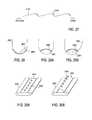
- FIG. 2is a posterior view of the spine indicating decompression paths at disc level and along the nerve root.
- FIG. 3is a posterior view of the spine indicating a decompression path for adjacent level lateral recess decompression.
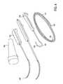
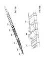
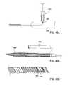
- FIG. 4illustrates a system of devices including a guidewire, a probe for positioning a guidewire, and a tissue modification device for use with the guidewire.
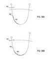
- FIGS. 5A and 5Billustrate a probe for positioning a guidewire.
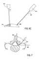
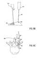
- FIGS. 6A-6C and FIG. 7demonstrate a path of a probe, guidewire, and tissue modification device through a spinal region.
- FIGS. 8A-8Cdemonstrate an alternative path of a probe, guidewire, and tissue modification device through a spinal region.
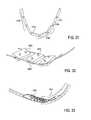
- FIGS. 9A and 9Billustrate a space between the tissue modification device and portion of the spinal region.
- FIGS. 10A and 10Billustrate a space between the tissue modification device and portion of the spinal region.
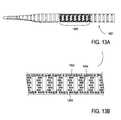
- FIGS. 11-15Bshow various components and configurations of tissue modification devices.
- FIGS. 16A and 16Billustrate a space between the tissue modification device and portion of the spinal region.
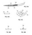
- FIGS. 17A-19show various configurations of radius limiting straps coupled to tissue modification devices.
- FIGS. 20A-25show various configurations where the tissue modification device includes some variation of a flexible or compressible blade guard.
- FIGS. 26-27show various configurations where the tissue modification device cuts when it is reciprocated in a first direction and does not cut when it is reciprocated in the second direction.
- FIGS. 28-30Bshow various configurations wherein a substrate or shield bends to move the blades toward or away from the tissue.
- FIGS. 31-32show various configurations wherein the rungs of the tissue modification device are movable.
- FIG. 33shows a configuration wherein the tissue modification device includes a shield the covers the distal end of the device.
- FIG. 34-36Bshow configurations wherein the travel of the tissue modification device within the body is limited in at least one direction.
- FIGS. 37A-38Bshow configurations wherein the tissue modification device includes a channel to direct an agent, such as a haemostatic agent.
- FIGS. 39-40Bshow configurations wherein a catheter or bladder may be coupled to a tissue modification device or to a guidewire directly.
- FIGS. 41A-41Bshow a configuration wherein the cable or tube connecting the rungs or the elongate body is configured to deliver an agent, such as a haemostatic agent.
- FIGS. 42A-44Bshow configurations wherein the tissue modification device further comprises a bladder or other device to deliver an agent, such as a haemostatic agent.
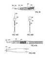
- FIGS. 45A-49illustrate various embodiments of delivery devices.
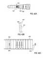
- FIG. 50illustrates a first embodiment of a kit including a connector, a catheter, and a syringe.
- FIGS. 51A-51Cillustrate an embodiment of a probe delivery device.
- the devices, systems and methods described hereinmay be use in any appropriate surgical procedure, particularly for the surgical treatment of spinal stenosis.
- systemsincluding one or more of the following devices: a guidewire, a probe for positioning a guidewire, and a tissue modification device for use with the guidewire.
- the systems and methodsmay be used to decompress one or more spinal regions.
- any of these devicesmay be used to decompress nerve roots within the spinal anatomy along various paths. Because these devices are flexible, and may be appropriately sized and shaped to fit within a neural foramen, these devices may be used to accesses appropriate regions of the spine from a single access point (e.g., from the patient's midline or near-midline region).
- systems and methods described hereinmay be used to decompress one or more spinal regions they may also be configured to avoid portions of the vascular anatomy or other non target tissue within the spinal regions that are being decompressed. Furthermore, the devices, systems and methods described herein may be use in any appropriate surgical procedure, particularly for stopping or preventing bleeding during the surgical treatment of spinal stenosis.
- FIG. 1which shows the lateral aspect of a facet joint complex
- Haemostatic agents or other devices or methods for stopping or preventing bleedingmay be delivered to an artery or other vessel that has been or may be damaged or ruptured or is otherwise bleeding.
- the agentwill promote homeostasis and stop or prevent unwanted and/or excessive bleeding.
- vasoconstrictors or vasopressors, such as Epinephrinemay be delivered to the surgical site to constrict the surrounding vessels to slow or stop bleeding.
- the agent delivered to the surgical sitemay include a tissue sealant, a steroid, a corticosteroid, a local anesthetic, and/or an analgesic.
- a hemostatic agentwhich may also be an antihemorrhagic (antihaemorrhagic) agent include substances that promote hemostasis (i.e., to stop bleeding).
- stypticsalso spelled stiptics
- Stypticmay include astringents.
- Antihemorrhagic agents used in medicinemay have various mechanisms of action, including inhibiting fibrinolysis or promoting coagulation (particularly in systemic agent), causing vasoconstriction or promoting platelet aggregation (particularly in local agents).
- Such agentsinclude microfibrillar collagen, chitosan, antiliem01Thagic drugs such as antifibrinolytics, vitamin K, fibrinogen, and blood coagulation factors, anhydrous aluminum sulfate, potassium alum, titanium dioxide, styptic powder, etc. These examples are illustrative only, and any appropriate hemostatic agent may be used with the methods, devices and systems described herein.
- FIG. 1which shows the lateral aspect of a facet joint complex
- the facet joint complexincludes a superior articular process (SAP) and an inferior articular process (IAP).
- SAPsuperior articular process
- IAPinferior articular process
- a tissue modification devicemay be positioned below (ventral) to the SAP to remove tissue in that area while, in some embodiments as described in detail below, avoiding the tissue (including vascular anatomy) on lateral side of the SAP.
- devices, systems and methodsmay be configured to stop or prevent the bleeding of non-target tissue, such as blood vessels.
- the devices, systems and methodsmay be configured to deliver hemostatic agents or tissue sealants to the non-target tissue.
- devices, systems and methodsmay be configured to avoid the tissue (including vascular anatomy) on lateral side of the SAP in one of several variations, as described in detail below.
- a probe and guidewiremay be configured and/or the method of use may be configured such that the guidewire is positioned to avoid the tissue (including vascular anatomy) on lateral side of the SAP.
- the proximal and distal handles of the devicemay be held a distance apart from one another such that the tissue modification device is positioned and moved to avoid the tissue (including vascular anatomy) on lateral side of the SAP.
- the tissue modification devicemay be configured to have a variable stiffness along the length of the device. A more stiff portion of the device will prevent the device from wrapping around the lateral side of the SAP and will therefore not remove tissue (including vascular anatomy) on lateral side of the SAP.
- the proceduremay be used to decompress spinal nerve roots on the unilateral or contralateral side from the access point.
- a probe or guidemay be introduced into the spinal epidural space (or along or just within the ligamentum flavum) at an appropriate spinal level using image guidance and/or tracking (e.g., electromagnetic tracking). Introduction may be either via percutaneous puncture or open laminotomy.
- the devicemay be used to decompress an ipsilateral or contralateral proximal nerve (in a lateral recess).
- a guide or probemay be deployed immediately cephalad to the caudal segment pedicle on the appropriate side (e.g., location 1810 ). This access point can be confirmed radiographically. If neural structures adjacent to the guide cannot be directly visualized, the relationship of these structures to the guide or tissue modification devices can be determined using electrical stimulation, ultrasound imaging, endoscopic mean or other techniques.
- the guidewiremay be threaded along a path from location 1810 to where it exits through the foramen, as shown by at least one of arrows 1812 (for ipsilateral decompression of the nerve root origin at the disc level) and 1814 (for contralateral decompression of the nerve root origin at the disc level).
- the guidewiremay be threaded along a path from location 1810 to where it exits through the foramen, as shown by at least one of arrows 1816 (for ipsilateral decompression along the nerve root) and 1818 (for contralateral decompression along the nerve root).
- the probe/guideis removed once the guidewire has been positioned.
- the guidewiremay include a wire exchange tip on its proximal end, as described in more detail below.
- a flexible tissue modification deviceis attached to the proximal wire exchange tip, and a distal handle may be secured to guidewire at the distal wire tip.
- the devicecan then be introduced into the epidural space and then into the lateral recess by careful upward force applied to the distal handle.
- the deviceis pulled by the guidewire on the path through the spinal anatomy.
- suitable pathsinclude paths shown by arrows 1812 and 1814 and/or 1816 and 1818 to decompress the nerve root origin at disc level and/or along the nerve root, respectively.
- binlanual reciprocating strokesmay be utilized to decompress dorsal impinging bone or soft tissue at the nerve root origin.
- the probe/guidemay be reinserted to decompress the ipsilateral or contralateral distal (foraminal) portion of the nerve root, so that the same (or a different) tissue modification device may be used to decompress another region of the spine (or nerve root) using the same access or entry site.
- the devices described hereincan used to decompress the ipsilateral or contralateral (not shown), or both, regions adjacent the level proximal to the nerve root (lateral recess).
- a guidemay be deployed in the same access point (location 1810 ) as described above. As shown in FIG. 3 , the guidewire can then be threaded along a path from location 210 to where it exits through the foramen, as shown by arrow 220 (for ipsilateral decompression of the adjacent nerve root origin).
- a guidewire and a probe for positioning a guidewireare systems including one or more of the following devices: a guidewire and a probe for positioning a guidewire.
- the guidewire 101 shown in FIG. 4is typically long (e.g., elongated) and flexible, and may have a sharp (tissue penetrating) distal end 103 and a proximal end 102 that allows it to be coupled to a guidewire coupling member securely.
- the guidewire 101includes a ball or other shaped end (which may be conical, tubular, ring, etc.) secured to the distal end for coupling to a guidewire coupling member.
- the proximal end 102may be configured to lock into a guidewire coupling member I 06 at the distal end of a tissue modification device (such as the one 105 indicated in FIG. 4 ).
- a guidewire coupler memberis configured to attach to a guidewire (e.g., one end of a guidewire) so that the tissue modification device can be manipulated, at least in part, by pulling on the guidewire after the guidewire has been secured to the device.
- a guidewiremay be inserted into the body from a first location outside of the body, then passed around the target tissue (e.g., around a spinal foramen) and out of the body from a second position.
- the distal end of the guidewiremay then be coupled to the flexible tissue modification device 105 and pulled through the body until the tissue modifying region of the device, e.g., the portion of the device including cutting edges or blades, is positioned opposite the target tissue.
- the distal end of the devicemay be completely withdrawn from the patient, so that it can be grasped and manipulated.
- the distal end of the tissue-modification deviceremains coupled to the guidewire, and the guidewire may be grasped to manipulate the distal end of the tissue-modification device.
- a handle 110may be attached to the distal end of the guidewire.
- the proximal end of the guidewiremay be configured to pass through the probe 109 so that the probe may be removed from over the proximal end of the guidewire during operation.
- the distal end 107 of the probe 109 described hereinmay be curved or bent, and/or may be curveable or bendable.
- the outer distal endmay be more or less curved.
- the inner cannula 108may be configured to bend as it exits the distal end of the outer cannula, as shown, thereby increasing the ability of the probe to guide a guidewire around a target tissue.
- the probe 1009includes a handle portion having a pusher or plunger 1002 that communicates with an internal cannula slideably disposed within the external cannula so that the internal cannula may be extended from the distal end of the probe for placement around a target tissue, as illustrated in FIG. 5B .
- the pusherincludes a flanged 1003 proximal end having a finger (e.g., thumb) pushing surface that is perpendicular to the long axis of the device (including the long axis of the handle).
- this proximal endmay be formed to more readily allow insertion of a guidewire by guiding the guidewire into the lumen of the inner cannula.
- the pusheris calibrated 1005 along the side in a top-facing surface.
- the calibration shown in this exampleincludes markings to indicate depth (e.g., how far down the pusher has been extended), which corresponds to how far out of the distal end the inner cannula is extended.
- the calibrationsmay include alphanumeric symbols, colors, textures, or any combination of the like.
- the calibrationsmay be referenced to distance (e.g., depth, length, etc.), or they may be un-referenced (as shown in FIG. 5A ).
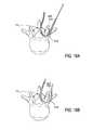
- the probe 400may be configured and/or used such that the guidewire is positioned to avoid the tissue (including vascular anatomy) on lateral side of the SAP.
- the probe 400may be passed from outside of a patient's body at a first location 401 and through a spinal neural foramen 402 between a spinal nerve root or ganglia and a facet joint complex 403 .
- the probeis configured such that inner cannula 404 may be advanced through outer cannula 405 . The inner cannula advances out of the outer cannula to a position such that the tip 406 of the inner cannula points away from the lateral aspect of the SAP of the joint complex 403 .
- the inner cannulamay include a plunger ( 610 in FIG. SA) coupled to the inner cannula that is configured to advance the inner cannula through the outer cannula.
- the outer cannulamay include a handle 409 coupled to the outer cannula used to grasp and position the probe.
- the plunger and the handlemay be configured such that the inner cannula may only be advanced within the outer cannula to a point where the plunger hits the handle and cannot be further advanced.
- the plunger and the handlemay be configured such that the inner cannula may only be advanced to a position such that the tip 406 of the inner cannula points away from the lateral aspect of the SAP of the joint complex 403 .
- the inner cannulamay be configured such that it may advance further to a position where it may wrap around the lateral aspect of the SAP, as shown in FIGS. 8A-8C .
- the plungermay include marking such that a user may only advance the plunger and the inner cannula to the desired position.
- the plunger 410has been advanced such that there is an gap X between the plunger and the handle 409 .
- the gapmay be any suitable distance such that the tip 406 of the inner cannula points away from the lateral aspect of the SAP of the joint complex 403 .
- a guidewire 407is passed via the cannulated guide or probe.
- the guidewirecan be sharp on its distal end and penetrate the skin dorsolaterally after exiting the foramen.
- the guidewire 407may be passed through the inner cannula 404 from outside of a patient's body at a first location 401 , through a spinal neural foramen 402 between a spinal nerve root or ganglia and a facet joint complex 403 where the guidewire exits the inner cannula and is advanced out of the patient's body at a second location 408 .
- the guidewireis passed a distance from the lateral side of the facet joint complex 403 such that the entering portion of the guidewire through the probe 400 is not parallel to the exiting portion of the guidewire 407 .
- the anglemay be any suitable angle greater than 0 degrees such that the guidewire avoids the tissue (including vascular anatomy) on lateral side of the SAP.
- the entering portion and the exiting portionare parallel to one another as shown in FIG. 8B .
- the anglemay range from about 10 to 60 degrees.
- the anglemay be about 30 degrees, or the angle may be about 45 degrees.
- the exiting portionis less than 90 degrees from the entering portion 500 due to anatomical limitations such as the transverse process as shown by line 502 .
- the probe/guideis removed once the guidewire has been positioned.
- the guidewiremay include a wire exchange tip on its proximal end.
- a flexible tissue modification device 411(as described in more detail below) is attached to the proximal wire exchange tip, and a distal handle 412 may be secured to guidewire 407 at the distal end portion of the wire.
- the devicecan then be introduced into the epidural space and then into the lateral recess by careful upward force applied to the distal handle 412 .
- the tissue modification device 411is pulled by the guidewire 407 along the path established by the guidewire as described above.
- the deviceis pulled by the guidewire on the path through the spinal anatomy.
- suitable pathsinclude paths shown by arrows 1812 and 1814 and/or 1816 and 1818 to decompress the nerve root origin at disc level and/or along the nerve root, respectively.
- the probe 600may be configured and/or used such that the guidewire is positioned to wrap around the tissue (including vascular anatomy) on lateral side of the SAP. As shown, the probe 600 may be passed from outside of a patient's body at a first location and through a spinal neural foramen between a spinal nerve root or ganglia and a facet joint complex 603 . As shown, the probe is configured such that inner cannula 604 may be advanced through outer cannula 605 .
- the inner cannulaadvances out of the outer cannula to a position such that the tip 606 of the inner cannula wraps up and around the lateral aspect of the SAP of the joint complex 603 .
- a guidewire 607is passed via the cannulated guide or probe.
- the guidewirecan be sharp on its distal end and penetrate the skin dorsolaterally after exiting the foramen. As shown in FIG.
- the guidewire 607may be passed through the inner cannula 604 from outside of a patient's body at a first location 601 , through a spinal neural foramen 602 between a spinal nerve root or ganglia and a facet joint complex 603 where the guidewire exits the inner cannula and is advanced out of the patient's body at a second location 608 ( FIG. 8B ).
- the guidewireis substantially along the lateral side of the facet joint complex 603 such that the entering portion of the guidewire through the probe 600 is about parallel to the exiting portion of the guidewire 607 .
- the probe/guideis removed once the guidewire has been positioned.
- the guidewiremay include a wire exchange tip on its proximal end.
- a flexible tissue modification device 611(as described in more detail below) is attached to the proximal wire exchange tip, and a distal handle 612 may be secured to guidewire 607 at the distal end portion of the wire.
- the devicecan then be introduced into the epidural space and then into the lateral recess by careful upward force applied to the distal handle 612 .
- the tissue modification device 611is pulled by the guidewire 607 along the path established by the guidewire as described above.
- the tissue modification device 711is pulled by the guidewire along the path established by the guidewire as described above in reference to FIGS. 6A to 7 .
- the tissue modification device 711may be pulled from outside of a patient's body at a first location 401 ( FIG. 6C ), through a spinal neural foramen 702 between a spinal nerve root or ganglia and a facet joint complex 703 .
- the tissue modification device 711is pulled a distance from the lateral side of the facet joint complex 703 such that there is a space 714 between the tissue modification device and the lateral aspect of the SAP.
- the tissue modification device 711is pulled by the guidewire along the path established by the guidewire as described above in reference to FIGS. 8A to 8C .
- the tissue modification device 711may be pulled from outside of a patient's body at a first location 601 ( FIG. 8B ), through a spinal neural foramen 702 between a spinal nerve root or ganglia and a facet joint complex 703 .
- the tissue modification device 711is substantially along the lateral side of the facet joint complex 703 such that there a smaller space 714 ′ (when compared to 714 of FIG. 9A ) between the tissue modification device and the lateral aspect of the SAP.
- FIGS. 9A and 9Billustrate the difference in the size of the space 714 and 714 ′ between the tissue modification device and the lateral aspect of the SAP when, as shown in FIG. 6A , the probe and guidewire are inserted such that the tip 406 of the inner cannula points away from the lateral aspect of the SAP of the joint complex 403 ( FIG. 9A ) versus when, as shown in FIG. 8A , the tip 606 of the inner cannula points up and around the lateral aspect of the SAP of the joint complex 603 , respectively. As shown, there is a larger space 714 in FIG. 9A .
- bimanual reciprocating strokesmay be utilized to decompress dorsal impinging bone or soft tissue at the nerve root origin.
- the proximal handle 413 of the tissue modification device and the distal handle 412may be held a distance apart while moving the tissue modification device to remove tissue, such that the tissue modification device is positioned and moved to avoid the tissue (including vascular anatomy) on lateral side of the SAP.
- the proximal handle 613 of the tissue modification device and the distal handle 612may be held a closer together while moving the tissue modification device to remove tissue, such that the tissue modification device is positioned substantially along lateral side of the SAP.
- FIGS. 10A and 10Billustrate the difference in the size of the space 814 and 814 ′ between the tissue modification device and the lateral aspect of the SAP.
- FIG. 10 Athe proximal handle of the tissue modification device and the distal handle are held close together (as shown in FIG. 8B ).
- FIG. 10Bthe proximal handle of the tissue modification device and the distal handle are held a distance from one another (as shown in FIG. 6C ). As shown, there is a larger space 814 ′ in FIG. 10B .
- tissue modification devicesDescribed herein are systems including a tissue modification device.
- tissue modification devices and systemsas well as methods for making and using tissue modification devices and systems, are provided herein.
- a flexible tissue-modification device as described hereinis configured to remove tissue from a patient.
- these tissue-modification devicesmay be configured to decompress spinal stenosis.
- the tissue modification devicemay be configured to have a variable stiffness along the length of the device.
- the tissue modification regions 1200 , 1201 , and 1202 of the devicesmay have any suitable stiffness.
- tissue modification region 1200that includes “dog bone” rungs, as described below, has a “semi-stiff” modification region.
- Tissue modification region 1201includes a radius limiting strap coupled to the device such that the tissue modification region of the device is “stiff”.
- Tissue modification region 1202is more flexible than regions 1200 and 1201 .
- a more stiff portion of the devicewill prevent the device from wrapping around the lateral side of the SAP and will therefore not remove tissue (including vascular anatomy) on lateral side of the SAP.
- the more stiff portion of the tissue modification deviceis the tissue modification region.
- the more stiff portionmay be any other suitable portion(s) of the device.
- These devicestypically include a flexible elongate body that extends proximally to distally (proximal/distal), and is configured to be inserted into a patient so that it extends around the target tissue, so that it can be bimanually pulled against the target tissue by applying tension to either end of the device.
- the devicemay be extended into, through, and/or around a spinal foramen.
- the deviceis flexible in at least one plane and has a variable stiffness along the length of the device.
- the deviceincludes a first major surface (e.g., a front) and a second major surface (a back), and has edges (minor surfaces) between the first and second major surfaces.
- the first major surfacemay be referred to as the anterior or front surface and the second major surface may be referred to as the posterior or back surface.
- the devices described hereinmay be flexible along the anterior and posterior surfaces, and the anterior or front surface may include one or more cutting edges configured to cut tissue as the anterior surface of the device is urged against a tissue.
- the posterior surfacemay be configured to shield or protect non-target tissue.
- the deviceis urged against the target tissue and may be moved in the proximal/distal direction to modify (e.g., cut) the target tissue.
- both the proximal and distal ends of the tissue-modification devicemay be pulled to urge the device against the target tissue, and may each be alternately pulled to a greater degree than the other handle to slide the device over the target tissue, allowing the cutting edges to cut and modify the target tissue.
- a tissue modification deviceis formed from a plurality of flexibly connected rungs.
- a rungmay also be referred to as a link or crosspiece.
- a rungmay be stiff (e.g., made of a relatively rigid material) or flexible.
- the rungsmay be connected to or may form the anterior (front) major surface. At least some of these rungs include one or more cutting edges, which may be configured as blades. The cutting edges may be formed as part of the rung, or attached to the rung.
- Individual rungsmay have any appropriate shape.
- a rungmay have a rectangular shape, an oval shape, a trapezoidal shape, or the like.
- the rungis relatively flat (e.g., having a thickness that is substantially less than the length and width).
- a rungmay be smooth, rough or some combination. Different rungs in the same device may be different shapes and sizes, as illustrated below.
- a rungmay be directly or indirectly connected to adjacent rungs.
- Rungsare flexibly connected to adjacent rungs and/or to another portion of the tissue modification device.
- a connectorsuch as a cable, wire, chain, string, sheet, ribbon, mesh, fabric, or the like, may be used to connect adjacent rungs.
- the connectormay be flexible, or stiff.
- a connectormay extend only between adjacent rungs, or it may extend along all or a portion of the length of the device so that multiple rungs may be attached to the same connector. More than one connector may be used to connect adjacent rungs. For example, rungs may be connected between two parallel wires. In some variations, the rungs are directly connected to adjacent rungs by a hinge joint or the like. Combinations of connectors and direct connections between rungs may be used.
- rungsmay be separated from each other by a space. The space may be an opening. In some variations, one or more spacers are used to separate adjacent rungs. The spacing between adjacent rungs may be different.
- FIG. 12illustrates one variation of a tissue modification device having a plurality of rungs.
- FIG. 12is a partially exploded, perspective view illustrating enlargements of various regions.
- the tissue-modification device shown in FIG. 12is flexible and includes individual rungs that may articulate relative to each other.
- This deviceincludes two parallel cables 201 , 201 ′ and a plurality of rungs 205 , 205 ′, 206 , 203 extend between the cables.
- the cablesare the connectors that link adjacent rungs.
- the two cablesare joined at the proximal 233 and distal 235 regions.
- the cableis joined at the proximal and distal ends, or is formed from a single cable; in some variations the two cables are separate.
- At least a portion of the cableis flexible. Any appropriate cable may be used, including metal or polymeric cables. Cables may be single-filament or formed of multiple filaments. The portion of the cable towards the distal end of the device, as shown in this example, may be hinged, and the links between distal and proximal sections may be connected in flexible junctions.
- the links or rungs 205 , 205 ′, 206 , 203 spanning the cableshave different shapes and sizes.
- the rungs 203 in the central regioneach include one or more cutting edges 211 projecting from the anterior (target tissue facing) surface. These cutting rungs 203 may form a tissue modifying region of the device.
- the cutting edges shownare triangular or pointed, although any appropriate shape may be used. Further, these cutting edges may be oriented in any desired manner; the orientation of the cutting edges may help steer or guide the device as it is urged against a target tissue to cut the tissue. In this example the cutting edges are oriented in parallel with the long axis (the distal/proximal axis) of the device.
- the tissue modification devicemay be configured to have a variable stiffness along the length of the device.
- the variable stiffnessmay be achieved by one of several variations, or a combination thereof.
- the geometry of the rungs 211 that make up the tissue modification regionhas a different geometry than other rungs on the tissue modification device.
- the rungs that make up the tissue modification region 1400 of the tissue modification device 1401are “dog bone” shaped rungs or “I” shaped rungs.
- a “dog bone” rungincludes rung portions 1402 and 1403 that are coupled to the cables of the device.
- Rung portions 1402 and 1403are wider than the center rung portion 1404 thereby creating a “dog bone” geometry.
- a series of rungs having a “dog bone” geometryis more stiff than a series of rungs having a standard rectangular geometry because the rung portions 1402 and 1403 are wider (or longer, with respect to the entire device) than the standard rectangular geometry.
- the flexibility of a portion of the deviceis determined by the number of flex points within the portion.
- a flex pointis a point along the device where two rungs (or a rung and a spacer) may flex and bend with respect to one another. For example, a portion of the device having a length of 1 inch with 10 flex points will be more flexible than a portion of the device having a length of 1 inch with 5 flex points. The wider the rungs are along the cable, the less flex points.
- the variable stiffness along the length of the devicemay be determined by an alternative rung geometry as shown in FIGS. 14A and 14B .
- the rungincludes a male portion 1515 and a female portion 1516 adapted to receive the male portion.
- the height (or thickness) of the receiving portion (or the overall geometry of the shape of the receiving portion) vs. the overall height or shape of the rungis varied in order to dial in the desired stiffness on the cutting side of the system.
- the male and female portionswill interact that the rungs are only able to bend a certain amount with respect to each other.
- the rungsmay be fed onto a cable, or as in FIG. 14B , the rungs may snap together and not need to be fed onto a cable.
- variable stiffness along the length of the devicemay be determined by the flexibility of the cables.
- the cablesmay be more stiff along the tissue modification region of the device and more flexible in other regions of the device.
- the stiffness of the cablesmay be determined by the material of the cables, the thickness or diameter of the cables, the number of cables used, etc.
- the variation shown in FIGS. 15A and 15Bincludes both rungs 2405 having a triangular (or other suitable shaped cutting edge) and rungs 2406 having tombstone shaped cutting edges.
- the tombstone shaped cutting edgesare located toward the outer side or edge of the rung, while the triangular shaped cutting edges may be located toward the center of the rung.
- the tombstone cutting edgesmay be sized and configured to cut a flexible and/or soft tissue, including ligament, such as ligamentum flavum in a patient's spine; while the triangular shaped cutting edges may be sized and configured to cut a rigid tissue, including bone, such as the bone of a facet joint, the bone that defines a central canal, and/or the bone that defines a neural foramen of a spine of a patient, including a pedicle.
- the tombstone cutting edges positioned toward the outer edges of the rungwill cut a swath or strip of soft tissue. By positioning the cutting edge toward the outer edge of the rung, the cutting edge will cut an outline of the swath or strip into the soft tissue.
- the deviceincludes tombstone cutting edges toward the proximal end of the device while the device will not include cutting edges, specifically tombstone cutting edges, toward the distal end of the device. By having not cutting rungs toward the distal end of the device, this will prevent the distal end of the device from cutting on the lateral side of the SAP and will therefore not remove tissue (including vascular anatomy) on lateral side of the SAP.
- cutting rungs 203are separated by a gap formed by spacing elements 209 between the rungs. These spacing elements are also attached to the connector 201 , 201 ′ that flexibly connects the rungs. In FIG. 12 the spacers are threaded on the two parallel cables.
- the sizes of the connectors and/or spacing elements 209may be varied to change the spacing between the rungs, and also the longitudinal shape (curvature) of the device, as described in greater detail, below.
- the sizes of the connectors and/or spacing elements 209may also be varied indifferent regions along the length of the device to change the stiffness of the device in various regions.
- the proximal end 233 of the device shown in FIG. 12includes a handle 231 which may be permanently or removeably attached to the proximal end.
- the distal end 235 shown in FIG. 12includes a guidewire coupler 237 that is flexibly attached to the distal end of the device.
- a guidewire coupleris configured to attach to a guidewire (e.g., one end of a guidewire) so that the device can be manipulated, at least in part, by pulling on the guidewire after the guidewire has been secured to the device.
- a guidewiremay be inserted into the body from a first location outside of the body, then passed around the target tissue (e.g., around a spinal foramen) and out of the body from a second position.
- the distal end of the guidewiremay then be coupled to the flexible tissue modification device (such as the one shown in FIG. 12 ) and pulled through the body until the tissue modifying region of the device, e.g., the portion of the device including cutting rungs 203 , is positioned opposite the target tissue.
- the guidewire usedincludes a tip region that is enlarged and may engage the guidewire coupler.
- the guidewiremay have a proximal end with a flange or ball. This enlarged region may be configured to fit into an opening on the guidewire coupler 242 so that the guidewire can be pulled distally from outside of the patient.
- the distal end of the devicemay be completely withdrawn, so that it can be grasped and manipulated.
- the distal end of the tissue-modification deviceremains coupled to the guidewire, and the guidewire may be grasped to manipulate the distal end of the tissue-modification device.
- a handlemay be attached to the guidewire.
- the deviceis urged against the target tissue and may be moved in the proximal/distal direction to modify (e.g., cut) the target tissue.
- both the proximal and distal ends of the tissue-modification devicemay be pulled to urge the device against the target tissue, and may each be alternately pulled to a greater degree than the other handle to slide the device over the target tissue, allowing the cutting edges to cut and modify the target tissue.
- the blade(s) cut the tissuea moment is generated between the tip of the blade and the base of the blade, on the rung, where the cable runs through the rung.
- the base of the blade rungmust be sufficiently wide to resist rotating about the length of the cable.
- the tissue modification devicemay be configured to have a variable stiffness along the length of the device.
- the variable stiffnessmay be achieved by one of several variations, or a combination thereof.
- the tissue modification devicemay include a radius limiter.
- the radius limiteris configured to allow flexibility of elongate body while limiting the radius of curvature that the tissue modification region may achieve in at least one direction (e.g. concave or convex curvature).
- the radius limitermay be one of several variations.
- FIGS. 16A and 16Billustrate the difference in the size of the space 1714 and 1714 ′ between the tissue modification device and the lateral aspect of the SAP. As shown in FIG. 16A , the tissue modification device does not include a radius limiting strap. As shown in FIG. 16B , the tissue modification device does include a radius limiting strap. As shown, there is a larger space 1714 ′ in FIG. 16B .
- the radius limiting strap 1801is coupled to the elongate body of the tissue modification device 1800 by a plurality of connectors 1802 linking the radius limiting strap to the elongate body.
- FIG. 17Ashows the back (posterior) side of the device.
- the radius limiting strapis coupled to the posterior side of the device such that it does not interfere with the cutting edges on the front (anterior) side of the device.
- the radius limiting strapis a cable that is fed through the connectors.
- the connectorsare coupled to the elongate body. Additionally, the radius limiter may be coupled to at least one of the connectors.
- the radius limitermay be allowed to move with respect to the connectors and/or the elongate body.
- the radius limiteris positioned toward the center of the elongate body, but may alternatively be positioned in any other suitable position on the elongate body.
- the radius limiting strap 1901is coupled to the elongate body of the tissue modification device 1900 at points 1903 and 1904 .
- the strap 1901is positioned on the posterior side of the device such that it does not interfere with the cutting edges on the front (anterior) side of the device.
- Connection points 1903 and 1904are located on the front (anterior) side of the device, as shown in FIG. 18A , however they may be located on the back side or any combination thereof.
- the radius limiting strapis a flat strap.
- the radius limitermay be coupled at at least one point along the length of the strap. In some embodiments, the radius limiter may be allowed to move with respect to the elongate body.
- the radius limiteris positioned toward the center of the elongate body, but may alternatively be positioned in any other suitable position on the elongate body.
- the strap 1901has a constant width and is located along the tissue modification region of the device.
- the strap 2001may have a varying width along its length and it may run along the device in regions in addition to the tissue modification region.
- the strap 2001is thin toward the proximal and distal ends of the strap and is wider toward the center of the strap. The wider portion of the strap will limit the flexibility of the device more than the thin portion of the strap.
- the thick portion of the strapis behind the tissue modification region of the device and the thin portions of the device are behind the non tissue modifying regions of the device.
- FIGS. 20A-25show various configurations where the tissue modification device includes some variation of a flexible or compressible blade guard.
- the tissue modification devicemay be configured to avoid cutting or damaging the soft tissue laterally from the facet joint and neural foramen (such as the foraminal vasculature and other healthy or non-target tissue).
- the tissue modification devicemay be configured to be soft tissue sparing.
- the blade guardswill cover the blade.
- bone or a harder tissuee.g. tissue, such as ligament, on top of bone
- the blade guardswill bend, flex, or compress, and allow the blade to enter into the target tissue to cut, or otherwise modify the target tissue. As shown in FIG.
- a blade 2100may be surrounded by a flexible or compressible material 2101 .
- the materialmay be a foam, rubber, silicone, or other flexible or compressible material.
- the blade guards 2102may include a plastic or metal spring adjacent to the blade 2100 .
- a substrate having flexible or rigid atraumatic ridges 2103may be placed adjacent to the elongate body 2104 .
- the ridgesmay be placed between the rungs 2105 of the elongate body.
- the ridges 2103may be spring loaded so that they may be raised or lowered between the rungs of the device.
- the blade guards 2106may include flexible bumps, such as silicone or other plastic, between each of the blades 2100 .
- the tissue modification devicemay further include brushes or bristles 2107 between the blades 2100 and/or rungs 2105 to push the soft, non-target tissue away from the blades.
- the tissue modification devicemay further include a spring shield 2108 coupled along the length of the device. When the shield comes in contact with hard target tissue, it will flex down around the blades 2100 , allowing the blades to cut into the target tissue.
- the tissue modification devicemay be coated in a layer of foam 2109 or other coating that will cover the blades 2100 , yet compress or flex out of the way so that the blades can cut into the target tissue.
- FIGS. 26-27show various configurations where the tissue modification device cuts when it is reciprocated in a first direction and does not cut when it is reciprocated in the second direction.
- the tissue modification devicemay be configured to avoid cutting or damaging the soft tissue laterally from the facet joint and neural foramen (such as the foraminal vasculature and other healthy or non-target tissue) by being configured to cut when the device is moved across the tissue in a first direction (medially, for example) and not cut when the device is moved across the tissue in a second direction (laterally toward the non-target tissue, for example).
- a first directionmediumally, for example
- a second directionlaterally toward the non-target tissue, for example
- the rungs 2105may each have a flexible cover 2110 that can be moved over the blade 2100 to expose the blade in a first direction and a rigid back 2111 that holds the cover fixed when the device is moved in the opposite direction.
- the substrate or elongate body 2104 ′may have a zig zag configuration with blades 2100 only positioned on the sides facing in a first direction. Therefore, the device can cut when the blades are moved in a first direction and cannot cut when the blades are moved in a second direction.
- FIGS. 28-30Bshow various configurations wherein a substrate or shield bends to move the blades toward or away from the tissue.
- the tissue modification device 2800may include a shield 2801 that covers a portion of the device.
- the shieldmay cover the distal blades 2802 such that the device cannot cut as far laterally beyond the facet joint and the neural foramen.
- the shieldmay be fixed at the distal end, and as the device is bent into a curved configuration around the facet joint, the shield may pop up to cover the blades.
- the blades 2900may be coupled to a curved substrate 2901 .
- the blades toward the center of the devicewill perform the majority of the cutting, while the blades toward the proximal and distal ends of the device will not cut as much.
- the configuration in FIG. 29Bis coupled to a wire 2902 at the distal end so that as the distal wire is pulled, the blades will be pulled further into a curved configuration.
- FIG. 30A and FIG. 30Billustrate an embodiment where the blades 3000 of the tissue modification device 3002 are coupled to a substrate 3001 .
- the substratemay be configured to bend up (like a “tape measure”) such that the blades can engage into the target tissue, while in other portions, the blades will be on a straight substrate and will be lower in the tissue modification device and will not cut, or will not cut as deeply.
- FIGS. 31-32show various configurations wherein the rungs of the tissue modification device are movable.
- the tissue modification deviceincludes multiple blades sections or rungs 3100 .
- Each sectionmay be coupled to the adjacent section via a cam 3101 .
- the cammay be configured such that it can bend or rotate the blade sections.
- the cam in this curved configurationmay bend or rotate the sections such that the blades 3103 are facing up toward the target tissue.
- the camsmay rotate or push the blades out of the substrate or shield (not shown).
- the camsmay rotate the bladed sections such that blades are not exposed to the tissue and will not cut or otherwise modify (or modify to a less degree) the non-target tissue located in these positions.
- the blade sections 3200are rotatable about a pivot joint 3200 such that in some configurations, the blades 3203 are rotated up, while in other configurations, the blades are 3203 are rotated down and away from the tissue.
- the rungs toward the distal and proximal endsmay be exposed, while the rungs at the center of the device may be rotated such that the blades are exposed and the blades may cut tissue.
- FIG. 33shows a configuration wherein the tissue modification device 3300 includes a shield 3301 that covers the distal end of the device.
- the shieldmay be fixed such that the tissue modification device may move into and out of the shield, while the shield covers the distal cutting blades as they moved through the lateral portion of the spine.
- FIGS. 34-36Bshow configurations wherein the travel of the tissue modification device 3400 within the body of a patient is limited in at least one direction.
- the tissue modification device 3400includes a physical stop 3401 at the proximal end of the device. This stop will prevent the device from entering too far into, or beyond, the facet joint or neural foramen, such that it will not cut the healthy tissue lateral to the superior articular process of the spine.
- the tissue modification device 3500may be coupled to the guidewire 3501 via a spring 3502 . In this configuration, the tissue modification device may be reciprocated in a unimanual fashion.
- the distal handle 3503may be held in place, while the proximal handle 3504 is pulled and then released. When the proximal handle is released the spring will return the tissue modification device to position.
- the length of the guidewiremay determine the distance that the tissue modification device may be moved laterally through the spine.
- the distal guidewiremay be a rigid element, holding the distal portion of the tissue modification device (e.g. the distal end of the spring) in place.
- the tissue modification device 3600may include a physical stop 3601 outside of the patient that may prevent the blades 3602 device from being moved too far laterally (toward the right in the figure) in the spine.
- the stopmay be fixed to a frame within the operating room.
- the stopmay be coupled to a METRX frame.
- the stopmay be adjustable along the proximal end of the device.
- a delivery deviceas described herein is configured to deliver a hemostatic agent, tissue sealant analgesics, anti-inflammatories, or any other suitable agent to a desired surgical site.
- these delivery devicesmay be configured to deliver an agent to a surgical site for a spinal decompression procedure.
- the hemostatic agentsmay be delivered to an artery or other vessel that has been damaged or ruptured or is otherwise bleeding. The agent will promote hemostasis and stop or prevent unwanted and/or excessive bleeding.
- the agent(s)may be delivered to the surgical site via an agent deliver device.
- the delivery devicemay be any suitable device having any suitable configuration such that the agent may be delivered to the desired tissue and/or area within the surgical site.
- the tissue modification devicemay be configured to deliver an agent to the surgical site.
- the delivery devicemay be a catheter that may be pulled into position within the surgical site via a guidewire.
- a probe or cannulamay be configured to deliver an agent to the surgical site.
- the tissue modification devicemay be configured to receive and deliver an agent to tissue and/or a surgical site.
- the agentmay be selected to stop or slow bleeding, such as a haemostatic agent.
- FIGS. 37A-38Bshow configurations wherein the tissue modification device 3700 includes a channel 3701 to direct an agent, such as a haemostatic agent toward a tissue or surgical site.
- the distal end 3702 of the tissue modification devicemay include a channel 3701 .
- the rungs 3703 toward the distal end portion of the deviceinclude a recess to form a channel 3701 .
- the devicemay be pulled proximally (i.e. at least partially out of the patient) such that a user may couple a catheter 3704 or syringe to the channel 3701 and deliver an agent to the channel, as shown in FIG. 37C .
- the tissue modification devicemay be used to directly deliver the agent to the desired location.
- the agentmay travel through the channel from the catheter to the desired location or the agent may be placed in the channel, and the device may be moved such that the channel is adjacent to the bleeding tissue.
- a usermay pull up on the distal and proximal ends of the tissue modification device to pull the device up against the target tissue and deliver the agent from the channel.
- the channel 3801may be configured to receive a shaped catheter 3804 .
- the cathetermay be placed into the channel either before, during, or after the device is used to modify tissue.
- the shaped cathetermay then be used to deliver the agent to the desired location.
- FIGS. 39-40Bshow configurations wherein a catheter 3903 ( FIG. 40A ) or bladder 3901 ( FIG. 39 ) may be coupled to a tissue modification device 3900 or to a guidewire 3902 directly.
- a catheter 3903 or bladder 3901 or cathetermay be removably coupled to the tissue modification device.
- the device 3900may coupled to a guidewire 3902 via a guidewire coupler 3905 at the distal end of the device. The device may then be pulled distilling into position within a spine of the patient with the guidewire and may then be reciprocated to cut target tissue within the spine.
- the devicemay then be pulled back proximally, at least partially out of the spine of the patient.
- the bladder 3901may be hooked on via hooks 3904 , or otherwise coupled, to the tissue modification device 3900 , and the guidewire 3902 may be used to pull the device and bladder distally into position.
- An agentmay then be delivered through the bladder.
- the bladdermay be configured to function as a shield and cover the blades 3906 of the device, such that the blades cannot cut while an agent is being delivered from the bladder 3901 .
- the tissue modification device(not shown) may be pulled back proximally and removed from the spine and then removed from the guidewire 3902 .
- a catheter 3903 with a guidewire coupler 3905 at its distal endmay then be coupled to the guidewire.
- the guidewiremay then be used to pull the catheter into position within the patient and the agent may be delivered.
- the agentmay be delivered via apertures 3907 in the guidewire coupler, the catheter, or any other suitable location.
- FIGS. 41A-41Bshow a configuration wherein the cable or tube 4100 connecting the rungs 4101 of the elongate body 4102 is configured to deliver an agent, such as a haemostatic agent.
- the tissue modification devicemay be a flexible runged device.
- the rungsmay be connected via a cable 4100 .
- the cablemay be a hollow tube configured to receive and deliver an agent.
- the tip geometry of the tissue modification devicemay be modified such that the agent may be delivered from the tube through apertures 4103 in the device and into the desired location within the patient.
- FIGS. 42A-44Bshow configurations wherein the tissue modification device further comprises a bladder, disposed along the length of the device, or other device to deliver an agent, such as a haemostatic agent.
- the rungs 4200may be modified such that they have a hole 4201 through their width to receive a tube or bladder 4202 .
- the rung 4200may also include a hole 4206 to receive a cable.
- the cablemay be configured to connect the multiple rungs of the device.
- a tube or bladder 4202may be disposed along the length of the device such that it exits the distal end 4203 of the device as shown in FIGS. 42A-42C .
- the devicemay include multiple holes 4204 or simply an opening 4205 for the distal open end of the tube, through which the agent may be delivered.
- the bladder or tubemay run proximally through the device to the proximal handle 4300 of the device.
- the proximal handle of the devicemay include a coupler 4301 configured to connect to a syringe 4302 , as shown in FIG. 43A , or, as shown in FIG. 44B , the proximal handle 4300 may alternatively include a syringe or chamber 4303 within the proximal handle.
- the bladder( 4400 and 4401 respectively) may be coupled to the back, non-abrasive, side of the tissue modification device 4402 .
- the bladder 4400 of FIG. 43Bmay include apertures 4404 positioned between the rungs 4405 of the device. As shown, the agent will be delivered via the apertures 4404 between the rungs of the device to the target tissue or surgical site.
- the delivery devicemay be a catheter that may be pulled into position within the surgical site via a guidewire.
- a guidewire 101has been threaded along a path from an access location (such as through an interlaminar window 501 ) to where it exits through a foramen 502 of the spine 500 .
- a distal guidewire handle 110is coupled to the distal end of the guidewire.
- the delivery deviceincludes a catheter 505 and a connector 506 .
- Catheter 505preferably has a length such that the proximal end may be accessed outside of the patient and the distal end (not visible) is positioned within the surgical site adjacent to the necessary anatomical structures, such as blood vessels for example.
- the cathetermay be sized and configured to be fed through a METRX tube (Medtronic) or other minimally invasive surgical access device.
- the outer diameter of the catheteris about 1 mm to about 10 mm. In one specific embodiment, the catheter is a 14 gauge catheter.
- the connectormay be a Y-tube such as a “Tuey” valve.
- the connectorincludes a first branch 507 that is sized and configured to receive the guidewire 101 .
- Branch 507may include a locking mechanism such that the connector can lock down on the guidewire and prevent further motion of the guidewire through the connector. The lock may also prevent agent from escaping out of the connector through branch 507 .
- the connectoralso includes a second branch 508 that is sized and configured to receive a syringe.
- the syringepreferably contains an agent 510 , such as a hemostatic agent.
- the syringemay be coupled, over the guidewire, to branch 507 and an irrigation and/or suction source may be coupled to branch 508 .
- an additional two-way connectormay be coupled to branch 508 such that the connector 506 becomes a three-way connector.
- the delivery devicealso includes a catheter 505 and a connector 506 , however as shown, the connector may include three branches 507 , 508 , and 512 .
- the connectormay be a three-way valve, for example.
- the connectorincludes a first branch 507 that is sized and configured to receive the guidewire 101 .
- Branch 507may include a locking mechanism such that the connector can lock down on the guidewire and prevent further motion of the guidewire through the connector. The lock may also prevent agent from escaping out of the connector through branch 507 .
- the connectoralso includes a second branch 508 that is sized and configured to receive a syringe.
- the syringepreferably contains an agent 510 , such as a hemostatic agent.
- branch 512 and 508may be configured to provide suction and irrigation to the surgical site.
- branch 512may be configured to couple to a suction device.
- Apertures 513are in fluid communication with branch 512 and the suction device. Apertures 513 may be positioned within the surgical site, and may be configured to remove fluids such as blood or flushing fluids, such as saline, from the surgical site.
- Branch 508may be configured to couple to an irrigation device.
- Apertures 514are in fluid communication with branch 508 and the irrigation device.
- Apertures 514may be positioned within the surgical site, and may be configured to deliver fluids such irrigation or flushing fluids, such as saline, to the surgical site. These fluids may then be received by apertures 513 and removed as described above.
- catheter 505includes three lumens. Any one of the branches and their respective lumens or apertures may be configured to couple to the guidewire 101 , couple to an agent delivery syringe and deliver the agent to the surgical site, couple to a suction device and provide suction to the surgical site, and/or couple to an irrigation device and provide irrigation to the surgical site.
- the delivery deviceas shown in FIG. 45B , may also include a marker 515 .
- Marker 515is positioned near the distal end of the catheter 505 , and in some embodiments marks the position of apertures 513 and 514 and/or the distal end of the catheter. Marker 515 may be radiopaque such that it can be visualized fluoroscopically or by any other suitable visualization modality.
- the cathetermay include a plurality of markers that may be positioned at any suitable location along the length of the delivery device. Alternatively, the entire delivery device, or a portion thereof, may be made of a radiopaque material, or a material treated to become radiopaque.
- the delivery devicemay be thread over the guidewire 101 at any point during a surgery—before tissue modification, during tissue modification, after tissue modification, and/or any combination thereof.
- the catheter 505is thread over the guidewire such that the catheter is positioned into a desired position within the surgical site.
- the delivery devicemay be coupled to the proximal end of the guidewire and delivered to the surgical site by way of an interlaminar window.
- the delivery devicemay be coupled to the distal end of the guidewire (in addition to or instead of the distal handle 110 ).
- the delivery devicemay be delivered to the surgical site by way of a spinal foramen. Once in the desired position, the locking mechanism of branch 507 may be clamped down on the guidewire.
- the catheterin some embodiments, is made from a material that is stiff enough such that the catheter will not buckle or be pushed back along the guidewire by the spinal anatomy as the catheter is inserted into position.
- the cathetermay include a hole at the distal end of the catheter through which the agent may be delivered. Alternatively (or additionally) the catheter may include holes or fenestrations along a portion of the length of the catheter.
- the catheterin some variations, may be thin and flexible and ribbon shaped. For example, in variations in which the delivery device has an elongated ribbon shape that is long and flat with a width greater than the thickness, the device includes a first major surface (e.g., a front) and a second major surface (a back), and has edges (minor surfaces) between the first and second major surfaces.
- the first major surfacemay be referred to as the anterior or front surface and the second major surface may be referred to as the posterior or back surface.
- the anterior surface of the cathetermay be positioned such that it faces toward the back of the patient, i.e. toward the facet joint, for example.
- the cathetermay have holes for the agent along only the anterior surface, or may have holes on both the anterior surface and the posterior surface.
- the syringe(coupled to a catheter, or independently) may be fed over the guidewire directly, rather than coupling to a connector.
- the syringemay have a lumen disposed along the length of the catheter through which the guidewire may be fed.
- the guidewiremay be used to guide the syringe (or other suitable agent receptacle) into the correct position within the surgical site.
- the syringe or delivery devicemay include a grommet or o-ring to seal the space between the guidewire and the syringe to prevent any leakage of the agent to be delivered.
- the guidewiremay be coupled to the end of the delivery device.
- the proximal shaped end of the guidewiremay be coupled to the distal end of the catheter (or other portion of the delivery device) and may be used to pull the catheter into location.
- the cathetermay have a guidewire coupler at the distal end of the catheter and a hole or a plurality of holes on the catheter proximal to the guidewire coupler.
- the catheter or other portion of the delivery devicemay include a rapid exchange lumen.
- the catheterincludes a lumen that runs substantially along the length of the catheter, fluidically connecting ng an injection port (into which the agent is delivered, via a syringe for example) to the holes through which the agent is delivered to the surgical site.
- the catheterincludes a second “rapid exchange” lumen that is sized and configured to receive the guidewire. This lumen does not run the length of the catheter but functions to couple the catheter to the guidewire.
- the delivery devicemay include a ribbon 600 and at least one port 601 fluidically coupled to the ribbon.
- the ribbon 600includes at least one lumen along the length of the ribbon through which the guidewire 602 may run.
- the ribbon 600may be coupled to the guidewire by being fed over the guidewire (as shown) or may include a guidewire coupler at its distal end and be coupled to the guidewire in an end-to-end configuration.
- the port(s) 601may be fluidically connected to the same lumen through which the guidewire runs, or may be connected to an additional lumen. That lumen is also fluidically connected to holes 603 in the ribbon through which the agent may flow to the desired surgical location. As shown in FIG.
- the surgeon or other usermay grasp the distal handle 604 (coupled to the distal end of the guidewire 602 ) and the proximal end of the guidewire (which may be coupled to a proximal handle or other device) in one hand, while delivering an agent through a syringe 605 into port 601 with a second hand.
- a second usermay operate the syringe.
- the agentis delivered through the delivery device the user may pull up (i.e. away from the patient) on the distal and proximal ends of the guidewire to position the ribbon directly against the tissue to be treated.
- the devicein which the delivery device has an elongated ribbon shape, the device includes a first major surface (e.g., a front, shown) and a second major surface (a back, not shown).
- the first major surfacemay be referred to as the anterior or front surface and the second major surface may be referred to as the posterior or back surface.
- the anterior surface of the cathetermay be positioned such that it faces toward the back of the patient, i.e. toward the facet joint, for example.
- the delivery devicemay also include a balloon 700 .
- the balloonmay be a low-pressure, high-volume balloon.
- the balloonmay contain the agent and may function to deliver the agent through holes 701 upon inflation.
- the delivery devicemay include a two sided applicator.
- the applicator 800as shown in cross section in FIG. 48 , has an elongated ribbon shape having a first major surface (e.g., a front, shown as 801 ) and a second major surface (a back, not shown).
- the delivery deviceincludes two lumens: a front lumen 802 and a back lumen 803 that fluidically couple front holes 804 and back holes (not shown) to a front injection port and a back injection port, respectively.
- the holesare located toward the middle or distal end of the delivery device and the injection ports are location at the proximal end of the delivery device which remains outside of the patient.
- the anterior surface of the deviceWhen the delivery device is positioned within the surgical site, the anterior surface of the device may be positioned such that it faces toward the back of the patient, i.e. toward the facet joint, for example; and the posterior surface of the device may be positioned such that it faces toward the front of the patient, i.e. toward the nerves and other non-target tissue.
- Different agents with different functionsmay be injected into the different lumens and delivered to different anatomy having different requirements.
- a hemostatic agentmay be delivered to the surgical site and tissue removal area while an analgesic may be delivered to a nerve on the opposite side of the device.
- Other possible agentsare listed in FIG. 48 .
- a ribbon shaped delivery devicemay include larger edges 900 , 901 along at least a portion of the length of the ribbon.
- the injected materialseems more likely to remain at the target site, as shown in FIG. 49 as the edges may function to act as a barrier and keep the injected agent toward the center of the delivery device.
- the edges 900 and 901may include lumens 902 and 903 .
- the lumensmay couple injection ports to the holes through which the agent is delivered.
- lumen 903is fluidically connected to holes 904 .
- the holes connected to lumen 902may be located on the top side of edge 900 or may be located on the opposite side of the device from holes 904 .
- a tissue modification deviceas described above, or a neural localization device may further include agent injection ports and/or holes to deliver the agents.
- the tissue modification devicemay deliver hemostatic agent or analgesics to the surgical site while the tissue modification device is also modifying and/or removing target tissue.
- a delivery device, a tissue modification device, and or a neural localization devicemay be configured to deliver energy to the surgical site, such that the bleeding may be stopped or prevented with cautery rather than by delivering a chemical agent to the surgical site.
- the devicemay be configured to deliver heat and/or electricity (such as a bipolar or monopolar signal) to the surgical site.
- the bleedingcould be stopped or prevented with electrocauterization and/or ligation, which is the process of destroying tissue to stop or prevent bleeding using heat conduction from a metal probe or electrode heated by electric current.
- the tissuecould be ablated (i.e. heated) using high frequency alternating current, such as radiofrequency waves, to stop or prevent bleeding.
- the delivery devicemay be packaged and provided to a user in a kit 1100 .
- the kitincludes connector 1002 and a catheter 1003 .
- the connector 1002may include two branches, as shown, or alternatively, the connector may include a single branch or more than two branches.
- the cathetermay be sized and configured (for example, having a suitable length) to be fed through a METRX tube (Medtronic) or other minimally invasive surgical access device.
- the outer diameter of the catheter 1003may be about 1 mm to 10 mm. In one specific embodiment, the catheter is a 14 gauge catheter.
- Kit 1100may further include syringe.
- Syringemay include a hemostatic delivery agent, or may be filled upon removal from the kit by the user.
- the components of the kitare preferably packaged in a single unit.
- the package and each of the componentsare preferably sterilized and packaged in sterilized packaging.
- the components along with the packagingmay be sterilized once assembled.
- the kit 1100may further comprise a guidewire, a guidewire delivery probe, a neural localization device, and/or a tissue modification device.
- a probe or cannulamay be configured to deliver an agent to the surgical site.
- a probe or cannula configured to deliver an agent to the surgical sitemay be positioned within the spine of a patient in a similar fashion.
- the distal end of the probemay be advanced through and interlaminar window or laminotomy and advanced toward or through a neural foramen.
- the distal end of the probe delivery devicemay then be places in the surgical site adjacent to the target tissue.
- the probemay include an outer cannula and an inner cannula, slideable disposed within the outer cannula. Alternatively, as shown in FIGS.
- the delivery device probe 5100may only include a single outer cannula. As shown, the distal end portion of the probe may be curved 5101 such that it may better access the desired tissue within the spine. Furthermore, the distal end of the delivery device may have an atraumatic end S 102 such that the probe may be advanced within the spine without damaging tissue such as never or vascular tissue.
- the atraumatic tipmay include a curved tip, as shown. In some embodiment, an extrusion may be molded around the distal tip of the catheter. Alternatively, the atraumatic tip may be a cap pressed into or welded to the end of the probe.
- the distal end portion of the probemay be molded as two halves (“clam shell”) that are then welded or snapped together. In this embodiment, the end may be closed and the probe may have apertures on the top and or bottom portion of the probe through which to deliver the agent.
- the delivery devicemay further include a connector S 103 toward the proximal end of the cannula.
- the connectormay a luer connector to receive a catheter and/or a syringe.
- the delivery devicemay include a syringe or plunger suitable to deliver the agent through the device.
- the probe 5100may be metal, plastic, or any other suitable material. In some embodiments, the material is rigid and/or has column strength such that the probe may be advanced into the spine without buckling.
- the probe or delivery device of FIG. 5A to 5B or 51A to 51Cmay be configured to include an electrode or electrodes toward the distal end of the probe.
- the electrodemay be configured to deliver electricity.
- the electricitymay be used to stimulate nerve to determine the position of the nerve with respect to the probe.
- the energymay be used to ablate or cauterize the tissue adjacent to the electrode of the probe.
- the entire metal tip of the probemay be electrified, however the majority of the tip may be insulated (with PEBAX for example) such that only a portion of the metal probe tip is exposed and able to delivery energy.
- devices, systems and methods of the present inventionmay be used in any of a number of other anatomical locations in a patient's body.
- the flexible tissue modification devices of the present inventionmay be used in minimally invasive procedures in the shoulder, elbow, wrist, hand, hip, knee, foot, ankle, other joints, or other anatomical locations in the body.
- some embodimentsmay be used to remove or otherwise modify ligamentum flavum and/or bone in a spine to treat spinal stenosis
- other tissuesmay be modified to treat any of a number of other conditions.
- treated tissuesmay include but are not limited to ligament, tendon, bone, tumor, cyst, cartilage, scar, osteophyte, inflammatory tissue and the like.
- Non-target tissuesmay include neural tissue and/or neurovascular tissue in some embodiments or any of a number of other tissues and/or structures in other embodiments.
- a flexible tissue modification devicemay be used to incise a transverse carpal ligament in a wrist while inhibiting damage to the median nerve, to perform a minimally invasive carpal tunnel release procedure.
- various embodiments described hereinmay be used to modify any of a number of different tissues, in any of a number of anatomical locations in the body, to treat any of a number of different conditions.
Landscapes
- Health & Medical Sciences (AREA)
- Life Sciences & Earth Sciences (AREA)
- Surgery (AREA)
- Engineering & Computer Science (AREA)
- Public Health (AREA)
- General Health & Medical Sciences (AREA)
- Veterinary Medicine (AREA)
- Biomedical Technology (AREA)
- Heart & Thoracic Surgery (AREA)
- Animal Behavior & Ethology (AREA)
- Nuclear Medicine, Radiotherapy & Molecular Imaging (AREA)
- Medical Informatics (AREA)
- Molecular Biology (AREA)
- Oral & Maxillofacial Surgery (AREA)
- Orthopedic Medicine & Surgery (AREA)
- Dentistry (AREA)
- Pathology (AREA)
- Urology & Nephrology (AREA)
- Otolaryngology (AREA)
- Physics & Mathematics (AREA)
- Plasma & Fusion (AREA)
- Cardiology (AREA)
- Transplantation (AREA)
- Vascular Medicine (AREA)
- Biophysics (AREA)
- Pulmonology (AREA)
- Anesthesiology (AREA)
- Hematology (AREA)
- Surgical Instruments (AREA)
Abstract
Description
Claims (9)
Priority Applications (2)
| Application Number | Priority Date | Filing Date | Title |
|---|---|---|---|
| US14/790,598US10052116B2 (en) | 2004-10-15 | 2015-07-02 | Devices and methods for treating tissue |
| US16/020,229US11382647B2 (en) | 2004-10-15 | 2018-06-27 | Devices and methods for treating tissue |
Applications Claiming Priority (13)
| Application Number | Priority Date | Filing Date | Title |
|---|---|---|---|
| US61930604P | 2004-10-15 | 2004-10-15 | |
| US62286504P | 2004-10-28 | 2004-10-28 | |
| US68186405P | 2005-05-16 | 2005-05-16 | |
| US68171905P | 2005-05-16 | 2005-05-16 | |
| US68519005P | 2005-05-27 | 2005-05-27 | |
| US11/251,205US7918849B2 (en) | 2004-10-15 | 2005-10-15 | Devices and methods for tissue access |
| US11/468,247US7857813B2 (en) | 2006-08-29 | 2006-08-29 | Tissue access guidewire system and method |
| US25465609P | 2009-10-23 | 2009-10-23 | |
| US26001209P | 2009-11-11 | 2009-11-11 | |
| US28907509P | 2009-12-22 | 2009-12-22 | |
| US38860110P | 2010-09-30 | 2010-09-30 | |
| US12/911,537US9101386B2 (en) | 2004-10-15 | 2010-10-25 | Devices and methods for treating tissue |
| US14/790,598US10052116B2 (en) | 2004-10-15 | 2015-07-02 | Devices and methods for treating tissue |
Related Parent Applications (1)
| Application Number | Title | Priority Date | Filing Date |
|---|---|---|---|
| US12/911,537DivisionUS9101386B2 (en) | 2004-10-15 | 2010-10-25 | Devices and methods for treating tissue |
Related Child Applications (1)
| Application Number | Title | Priority Date | Filing Date |
|---|---|---|---|
| US16/020,229DivisionUS11382647B2 (en) | 2004-10-15 | 2018-06-27 | Devices and methods for treating tissue |
Publications (2)
| Publication Number | Publication Date |
|---|---|
| US20150306348A1 US20150306348A1 (en) | 2015-10-29 |
| US10052116B2true US10052116B2 (en) | 2018-08-21 |
Family
ID=43648295
Family Applications (3)
| Application Number | Title | Priority Date | Filing Date |
|---|---|---|---|
| US12/911,537Active2029-03-10US9101386B2 (en) | 2004-10-15 | 2010-10-25 | Devices and methods for treating tissue |
| US14/790,598Active2027-03-12US10052116B2 (en) | 2004-10-15 | 2015-07-02 | Devices and methods for treating tissue |
| US16/020,229Active2025-10-28US11382647B2 (en) | 2004-10-15 | 2018-06-27 | Devices and methods for treating tissue |
Family Applications Before (1)
| Application Number | Title | Priority Date | Filing Date |
|---|---|---|---|
| US12/911,537Active2029-03-10US9101386B2 (en) | 2004-10-15 | 2010-10-25 | Devices and methods for treating tissue |
Family Applications After (1)
| Application Number | Title | Priority Date | Filing Date |
|---|---|---|---|
| US16/020,229Active2025-10-28US11382647B2 (en) | 2004-10-15 | 2018-06-27 | Devices and methods for treating tissue |
Country Status (1)
| Country | Link |
|---|---|
| US (3) | US9101386B2 (en) |
Cited By (3)
| Publication number | Priority date | Publication date | Assignee | Title |
|---|---|---|---|---|
| US11707292B2 (en) | 2021-02-01 | 2023-07-25 | Mazor Robotics Ltd. | Disc cleaning surgical tool |
| US12102348B2 (en) | 2016-09-07 | 2024-10-01 | Vertos Medical, Inc. | Percutaneous lateral recess resection methods and instruments |
| US12324572B2 (en) | 2022-06-16 | 2025-06-10 | Vertos Medical, Inc. | Integrated instrument assembly |
Families Citing this family (74)
| Publication number | Priority date | Publication date | Assignee | Title |
|---|---|---|---|---|
| US8774913B2 (en) | 2002-04-08 | 2014-07-08 | Medtronic Ardian Luxembourg S.A.R.L. | Methods and apparatus for intravasculary-induced neuromodulation |
| US7653438B2 (en) | 2002-04-08 | 2010-01-26 | Ardian, Inc. | Methods and apparatus for renal neuromodulation |
| GB2403148C2 (en) | 2003-06-23 | 2013-02-13 | Microsulis Ltd | Radiation applicator |
| GB2415630C2 (en) | 2004-07-02 | 2007-03-22 | Microsulis Ltd | Radiation applicator and method of radiating tissue |
| US8221397B2 (en) | 2004-10-15 | 2012-07-17 | Baxano, Inc. | Devices and methods for tissue modification |
| US7578819B2 (en) | 2005-05-16 | 2009-08-25 | Baxano, Inc. | Spinal access and neural localization |
| US8048080B2 (en) | 2004-10-15 | 2011-11-01 | Baxano, Inc. | Flexible tissue rasp |
| US7959577B2 (en) | 2007-09-06 | 2011-06-14 | Baxano, Inc. | Method, system, and apparatus for neural localization |
| US8613745B2 (en) | 2004-10-15 | 2013-12-24 | Baxano Surgical, Inc. | Methods, systems and devices for carpal tunnel release |
| JP5243034B2 (en) | 2004-10-15 | 2013-07-24 | バクサノ,インク. | Tissue removal device |
| US8430881B2 (en)* | 2004-10-15 | 2013-04-30 | Baxano, Inc. | Mechanical tissue modification devices and methods |
| US20110190772A1 (en) | 2004-10-15 | 2011-08-04 | Vahid Saadat | Powered tissue modification devices and methods |
| US20100331883A1 (en) | 2004-10-15 | 2010-12-30 | Schmitz Gregory P | Access and tissue modification systems and methods |
| US7857813B2 (en) | 2006-08-29 | 2010-12-28 | Baxano, Inc. | Tissue access guidewire system and method |
| US8062300B2 (en) | 2006-05-04 | 2011-11-22 | Baxano, Inc. | Tissue removal with at least partially flexible devices |
| US8257356B2 (en) | 2004-10-15 | 2012-09-04 | Baxano, Inc. | Guidewire exchange systems to treat spinal stenosis |
| US8062298B2 (en)* | 2005-10-15 | 2011-11-22 | Baxano, Inc. | Flexible tissue removal devices and methods |
| US8366712B2 (en) | 2005-10-15 | 2013-02-05 | Baxano, Inc. | Multiple pathways for spinal nerve root decompression from a single access point |
| US8092456B2 (en) | 2005-10-15 | 2012-01-10 | Baxano, Inc. | Multiple pathways for spinal nerve root decompression from a single access point |
| US8192436B2 (en) | 2007-12-07 | 2012-06-05 | Baxano, Inc. | Tissue modification devices |
| US8398641B2 (en) | 2008-07-01 | 2013-03-19 | Baxano, Inc. | Tissue modification devices and methods |
| US9314253B2 (en) | 2008-07-01 | 2016-04-19 | Amendia, Inc. | Tissue modification devices and methods |
| US8409206B2 (en)* | 2008-07-01 | 2013-04-02 | Baxano, Inc. | Tissue modification devices and methods |
| US8652129B2 (en) | 2008-12-31 | 2014-02-18 | Medtronic Ardian Luxembourg S.A.R.L. | Apparatus, systems, and methods for achieving intravascular, thermally-induced renal neuromodulation |
| EP2405823A4 (en)* | 2009-03-13 | 2012-07-04 | Baxano Inc | Flexible neural localization devices and methods |
| US8632534B2 (en) | 2009-04-03 | 2014-01-21 | Angiodynamics, Inc. | Irreversible electroporation (IRE) for congestive obstructive pulmonary disease (COPD) |
| WO2010138919A2 (en) | 2009-05-28 | 2010-12-02 | Angiodynamics, Inc. | System and method for synchronizing energy delivery to the cardiac rhythm |
| US9895189B2 (en) | 2009-06-19 | 2018-02-20 | Angiodynamics, Inc. | Methods of sterilization and treating infection using irreversible electroporation |
| US8394102B2 (en) | 2009-06-25 | 2013-03-12 | Baxano, Inc. | Surgical tools for treatment of spinal stenosis |
| US8753364B2 (en) | 2009-08-07 | 2014-06-17 | Thayer Intellectual Property, Inc. | Systems and methods for treatment of compressed nerves |
| WO2011017665A2 (en) | 2009-08-07 | 2011-02-10 | Thayer Intellectual Property, Inc. | Systems and methods for treatment of compressed nerves |
| US8652157B2 (en) | 2009-08-07 | 2014-02-18 | Thayer Intellectual Property, Inc. | Systems and methods for treatment of compressed nerves |
| US20110160772A1 (en)* | 2009-12-28 | 2011-06-30 | Arcenio Gregory B | Systems and methods for performing spinal fusion |
| US10065093B2 (en)* | 2010-04-15 | 2018-09-04 | Clarence K. Cohens | Cat's claw golf tool with tread cleaning |
| US8870863B2 (en) | 2010-04-26 | 2014-10-28 | Medtronic Ardian Luxembourg S.A.R.L. | Catheter apparatuses, systems, and methods for renal neuromodulation |
| WO2011140206A1 (en) | 2010-05-04 | 2011-11-10 | The Ohio State University | Surgical device, method of performing surgery using same, and surgical device kit |
| US20120029411A1 (en)* | 2010-07-28 | 2012-02-02 | Kyphon SÀRL | Carpal tunnel drainage |
| USD666725S1 (en) | 2010-09-15 | 2012-09-04 | Thayer Intellectual Property, Inc. | Handle for a medical device |
| USD674489S1 (en) | 2010-09-15 | 2013-01-15 | Thayer Intellectual Property, Inc. | Handle for a medical device |
| USD673683S1 (en) | 2010-09-15 | 2013-01-01 | Thayer Intellectual Property, Inc. | Medical device |
| EP2627274B1 (en) | 2010-10-13 | 2022-12-14 | AngioDynamics, Inc. | System for electrically ablating tissue of a patient |
| CA2833543A1 (en) | 2011-05-05 | 2012-11-08 | Zyga Technology, Inc. | Sacroiliac fusion system |
| CA2842292C (en) | 2011-07-18 | 2018-10-02 | Truminim International Corporation | Percutaneous methods for spinal stenosis and foraminal stenosis |
| US9078665B2 (en) | 2011-09-28 | 2015-07-14 | Angiodynamics, Inc. | Multiple treatment zone ablation probe |
| US9414881B2 (en) | 2012-02-08 | 2016-08-16 | Angiodynamics, Inc. | System and method for increasing a target zone for electrical ablation |
| US20140137416A1 (en)* | 2012-11-22 | 2014-05-22 | Horvath Iosif Robert | Cutting Blade Cutting Device |
| AU2013397838B2 (en) | 2013-08-07 | 2018-08-16 | Covidien Lp | Bipolar surgical instrument with tissue stop |
| US9861375B2 (en)* | 2014-01-09 | 2018-01-09 | Zyga Technology, Inc. | Undercutting system for use in conjunction with sacroiliac fusion |
| US20150265303A1 (en)* | 2014-03-20 | 2015-09-24 | Warsaw Orthopedic, Inc. | Spinal correction release system and method |
| US12114911B2 (en) | 2014-08-28 | 2024-10-15 | Angiodynamics, Inc. | System and method for ablating a tissue site by electroporation with real-time pulse monitoring |
| US20160106478A1 (en)* | 2014-10-20 | 2016-04-21 | Warsaw Orthopedic, Inc. | Surgical system and method |
| CN105395236A (en)* | 2015-12-29 | 2016-03-16 | 四川大学华西医院 | Minimally invasive bone extractor |
| WO2018026832A1 (en) | 2016-08-01 | 2018-02-08 | Buffalo Filter Llc | Electrosurgical device with vacuum port having multiple swivel connections |
| US11406445B2 (en) | 2016-08-04 | 2022-08-09 | Buffalo Filter Llc | Electrosurgical device |
| US10631887B2 (en) | 2016-08-15 | 2020-04-28 | Covidien Lp | Electrosurgical forceps for video assisted thoracoscopic surgery and other surgical procedures |
| US10905492B2 (en) | 2016-11-17 | 2021-02-02 | Angiodynamics, Inc. | Techniques for irreversible electroporation using a single-pole tine-style internal device communicating with an external surface electrode |
| US11172980B2 (en) | 2017-05-12 | 2021-11-16 | Covidien Lp | Electrosurgical forceps for grasping, treating, and/or dividing tissue |
| US10973567B2 (en) | 2017-05-12 | 2021-04-13 | Covidien Lp | Electrosurgical forceps for grasping, treating, and/or dividing tissue |
| USD854684S1 (en) | 2017-06-08 | 2019-07-23 | Covidien Lp | Open vessel sealer with mechanical cutter |
| USD854149S1 (en) | 2017-06-08 | 2019-07-16 | Covidien Lp | End effector for open vessel sealer |
| USD843574S1 (en) | 2017-06-08 | 2019-03-19 | Covidien Lp | Knife for open vessel sealer |
| US11633205B1 (en) | 2017-08-01 | 2023-04-25 | Advance Research System, Llc | Lateral disc cutter with replaceable blades |
| US11160577B2 (en) | 2017-08-01 | 2021-11-02 | Advance Research System, Llc | Lateral disc cutter |
| US11471211B2 (en) | 2018-10-12 | 2022-10-18 | Covidien Lp | Electrosurgical forceps |
| US11376062B2 (en) | 2018-10-12 | 2022-07-05 | Covidien Lp | Electrosurgical forceps |
| US11350982B2 (en) | 2018-12-05 | 2022-06-07 | Covidien Lp | Electrosurgical forceps |
| US11523861B2 (en) | 2019-03-22 | 2022-12-13 | Covidien Lp | Methods for manufacturing a jaw assembly for an electrosurgical forceps |
| US12402934B2 (en) | 2019-09-15 | 2025-09-02 | Covidien Lp | Electrosurgical instrument for grasping, treating, and/or dividing tissue incorporating thermal management feature |
| US11622804B2 (en) | 2020-03-16 | 2023-04-11 | Covidien Lp | Forceps with linear trigger mechanism |
| US12295641B2 (en) | 2020-07-01 | 2025-05-13 | Covidien Lp | Electrosurgical forceps with swivel action nerve probe |
| US11660109B2 (en) | 2020-09-08 | 2023-05-30 | Covidien Lp | Cutting elements for surgical instruments such as for use in robotic surgical systems |
| US20240138868A1 (en) | 2022-10-28 | 2024-05-02 | Expand Medical Ltd. | Implant delivery device |
| WO2025072668A1 (en)* | 2023-09-29 | 2025-04-03 | Checkpoint Surgical, Inc. | Minimally invasive nerve regeneration systems and method |
| USD1084316S1 (en) | 2023-11-20 | 2025-07-15 | Angiodynamics, Inc. | Ferrule |
Citations (661)
| Publication number | Priority date | Publication date | Assignee | Title |
|---|---|---|---|---|
| US184804A (en) | 1876-11-28 | Improvement in surgical saws | ||
| US273806A (en) | 1883-03-13 | Machine for making wooden rings | ||
| US289104A (en) | 1883-11-27 | Combined rasp and saw | ||
| US432384A (en) | 1890-07-15 | Roll-paper holder and cutter | ||
| US863389A (en) | 1906-06-07 | 1907-08-13 | E N Dickerson | Flexible file. |
| US1039487A (en) | 1912-03-09 | 1912-09-24 | Williams Patent Crusher & Pulv | Abrasive. |
| US1201467A (en) | 1915-04-26 | 1916-10-17 | Emil J Hoglund | Bone-cutting instrument. |
| US1374638A (en) | 1920-01-06 | 1921-04-12 | Cew Charles A De | Hand power-driven band-saw |
| US1543195A (en) | 1921-07-07 | 1925-06-23 | Thygesen Jens Peter Nielsen | Device for cutting up fetal and like objects in animals |
| US1690812A (en) | 1927-10-08 | 1928-11-06 | John P Benning | File |
| US1938200A (en) | 1933-12-05 | Band-saw operating mechanism | ||
| US2243757A (en) | 1939-11-09 | 1941-05-27 | Continental Machines | File band |
| US2269749A (en) | 1940-09-16 | 1942-01-13 | Continental Machines | File band |
| US2372553A (en) | 1942-06-11 | 1945-03-27 | Continental Machines | File band |
| US2437697A (en) | 1946-04-01 | 1948-03-16 | Kalom Lawrence | Electrical probe |
| US2516882A (en) | 1948-01-22 | 1950-08-01 | Kalom Lawrence | Electrical probe |
| US2704064A (en) | 1952-09-10 | 1955-03-15 | Meditron Company | Neurosurgical stimulator |
| US2820281A (en) | 1956-11-30 | 1958-01-21 | Red Devil Tools | Abrasive article |
| US2843128A (en) | 1957-03-18 | 1958-07-15 | Storz Instr Co | Adenotome |
| US2982005A (en) | 1952-02-06 | 1961-05-02 | Simmonds Aerocessories Ltd | Cutting and abrading machines |
| USRE25582E (en) | 1964-05-19 | D a vi es | ||
| US3150470A (en) | 1961-08-11 | 1964-09-29 | Lee H Barron | Diamond coated wire saw |
| US3200814A (en) | 1963-03-12 | 1965-08-17 | Ellis R Taylor | Apparatus for measuring reflexes, tremors and the like |
| US3214824A (en) | 1964-03-06 | 1965-11-02 | Otho O Brown | Scaling device for cylindrical objects and the like |
| US3389447A (en) | 1967-05-26 | 1968-06-25 | Theobald Elwin | Omnidirectional cutting tool |
| US3491776A (en) | 1967-06-08 | 1970-01-27 | Floxite Co Inc | Dental cleaner for the removal of tobacco and other stains from teeth |
| US3495590A (en) | 1967-03-15 | 1970-02-17 | Warren Zeiller | Surgical cast and cast removal saw |
| US3528152A (en) | 1966-03-17 | 1970-09-15 | Shinnosuke Funakubo | Band-type file |
| US3624484A (en) | 1968-12-13 | 1971-11-30 | Wellcome Foundation Ltd Inc Th | Oscillator output circuit configuration |
| US3640280A (en) | 1969-11-26 | 1972-02-08 | Daniel R Slanker | Power-driven reciprocating bone surgery instrument |
| US3651844A (en) | 1970-02-24 | 1972-03-28 | Terry B C Barnes | All purpose saw |
| US3664329A (en) | 1970-03-09 | 1972-05-23 | Concept | Nerve locator/stimulator |
| US3682162A (en) | 1968-12-13 | 1972-08-08 | Wellcome Found | Combined electrode and hypodermic syringe needle |
| US3699729A (en) | 1971-05-14 | 1972-10-24 | Carrier Craft Corp | Sanding hand tool |
| US3752166A (en) | 1969-12-24 | 1973-08-14 | American Filtrona Corp | Tobacco smoke filter |
| US3774355A (en) | 1971-10-15 | 1973-11-27 | Remington Arms Co Inc | Armored metal file band and production thereof |
| US3830226A (en) | 1973-06-15 | 1974-08-20 | Concept | Variable output nerve locator |
| US3835859A (en) | 1973-02-22 | 1974-09-17 | R Roberts | Surgical instrument |
| US3956858A (en) | 1973-11-23 | 1976-05-18 | Remington Arms Company, Inc. | Flexible hand held abrading tool |
| US3957036A (en) | 1975-02-03 | 1976-05-18 | Baylor College Of Medicine | Method and apparatus for recording activity in intact nerves |
| US3978862A (en) | 1974-08-26 | 1976-09-07 | Stryker Corporation | Surgical cutting device |
| US3999294A (en) | 1976-05-07 | 1976-12-28 | George Shoben | Flexible bladed saw |
| GB1460837A (en) | 1974-05-21 | 1977-01-06 | Selflex Co Ltd | Blade for a surgical bone saw |
| US4015931A (en) | 1975-09-29 | 1977-04-05 | Engelhard Minerals & Chemicals Corporation | Bonded-abrasive wire saw |
| US4099519A (en) | 1977-01-14 | 1978-07-11 | Warren Fred E | Diagnostic device |
| US4108182A (en) | 1977-02-16 | 1978-08-22 | Concept Inc. | Reciprocation vitreous suction cutter head |
| US4160320A (en) | 1977-04-06 | 1979-07-10 | Best & Donovan | Hand held band saw |
| US4172440A (en) | 1976-03-27 | 1979-10-30 | Hoechst Aktiengesellschaft | Cutting monofilament |
| US4203444A (en) | 1977-11-07 | 1980-05-20 | Dyonics, Inc. | Surgical instrument suitable for closed surgery such as of the knee |
| US4207897A (en) | 1976-07-21 | 1980-06-17 | Spembly Limited | Cryosurgical probe |
| US4259276A (en) | 1977-06-24 | 1981-03-31 | Rawlings Derek S | Hole forming |
| US4405061A (en) | 1981-08-18 | 1983-09-20 | National Instrument Co., Inc. | Filling machine |
| USD273806S (en) | 1981-08-03 | 1984-05-08 | Zimmer, Inc. | Reamer/rasp tool, with disposable, debris retaining cutting surface |
| US4464836A (en) | 1982-09-15 | 1984-08-14 | Hissa Robert E | Friction saw and handle assembly |
| US4502184A (en) | 1983-06-30 | 1985-03-05 | Kentmaster Manufacturing Co., Inc. | Reversible carcass saw |
| US4515168A (en) | 1983-07-22 | 1985-05-07 | Chester Martin H | Clamp-on nerve stimulator and locator |
| US4518022A (en) | 1982-09-29 | 1985-05-21 | Valdes Guillermo A | Oscillating cutting element |
| US4545374A (en) | 1982-09-03 | 1985-10-08 | Jacobson Robert E | Method and instruments for performing a percutaneous lumbar diskectomy |
| US4573448A (en) | 1983-10-05 | 1986-03-04 | Pilling Co. | Method for decompressing herniated intervertebral discs |
| US4580545A (en) | 1984-02-29 | 1986-04-08 | Florida Wire And Cable Company | Stone sawing strand |
| US4590949A (en) | 1984-11-01 | 1986-05-27 | Cordis Corporation | Neural stimulating lead with stabilizing mechanism and method for using same |
| US4616660A (en) | 1984-12-10 | 1986-10-14 | Suncoast Medical Manufacturing, Inc. | Variable alternating current output nerve locator/stimulator |
| US4621636A (en) | 1979-07-23 | 1986-11-11 | Fogarty Thomas J | Endarterectomy method and apparatus |
| US4625725A (en) | 1983-08-30 | 1986-12-02 | Snowden-Pencer, Inc. | Surgical rasp and method of manufacture |
| US4660571A (en) | 1985-07-18 | 1987-04-28 | Cordis Corporation | Percutaneous lead having radially adjustable electrode |
| US4678459A (en) | 1984-07-23 | 1987-07-07 | E-Z-Em, Inc. | Irrigating, cutting and aspirating system for percutaneous surgery |
| US4690642A (en) | 1984-11-09 | 1987-09-01 | G-C Dental Industrial Corp. | Dental polishing strip |
| US4700702A (en) | 1985-12-09 | 1987-10-20 | Tatiana Nilsson | Instrument for cutting tissues in surgery |
| US4709699A (en) | 1986-08-06 | 1987-12-01 | Fort Wayne Metals Research Products Corporation | Surgeon's Gigli saw and method |
| US4741343A (en) | 1985-05-06 | 1988-05-03 | Massachusetts Institute Of Technology | Method and apparatus for measuring oxygen partial pressure and temperature in living tissue |
| US4750249A (en) | 1986-09-08 | 1988-06-14 | Richardson Henry A | Pipe scraping tool |
| US4794931A (en) | 1986-02-28 | 1989-01-03 | Cardiovascular Imaging Systems, Inc. | Catheter apparatus, system and method for intravascular two-dimensional ultrasonography |
| US4808157A (en) | 1987-07-13 | 1989-02-28 | Neuro Delivery Technology, Inc. | Multi-lumen epidural-spinal needle |
| US4817628A (en) | 1985-10-18 | 1989-04-04 | David L. Zealear | System and method for evaluating neurological function controlling muscular movements |
| US4856193A (en) | 1987-07-24 | 1989-08-15 | Grachan Ronald A | Saw |
| US4867155A (en) | 1988-06-21 | 1989-09-19 | Nu-Tech Industries, Inc. | Arthroscopic cutting device |
| US4872452A (en) | 1989-01-09 | 1989-10-10 | Minnesota Mining And Manufacturing Company | Bone rasp |
| US4873978A (en) | 1987-12-04 | 1989-10-17 | Robert Ginsburg | Device and method for emboli retrieval |
| US4883460A (en) | 1988-04-25 | 1989-11-28 | Zanetti Paul H | Technique for removing deposits from body vessels |
| US4894063A (en) | 1983-05-24 | 1990-01-16 | Baxter International Inc. | Barrier layer for implantable tendons and ligaments |
| EP0359883A1 (en) | 1988-09-23 | 1990-03-28 | Nobuo Ishihara | Hand files |
| US4912799A (en) | 1989-01-30 | 1990-04-03 | Coleman Jr Lewis E | Water main scraper |
| USRE33258E (en) | 1984-07-23 | 1990-07-10 | Surgical Dynamics Inc. | Irrigating, cutting and aspirating system for percutaneous surgery |
| US4943295A (en) | 1988-07-13 | 1990-07-24 | Hartlaub Thaddeus J | Surgical cutting tool |
| US4946462A (en) | 1988-12-12 | 1990-08-07 | Watanabe Robert S | Arthroscopic guide and method |
| US4957117A (en) | 1988-11-03 | 1990-09-18 | Ramsey Foundation | One-handed percutaneous transluminal angioplasty steering device and method |
| US4962766A (en) | 1989-07-19 | 1990-10-16 | Herzon Garrett D | Nerve locator and stimulator |
| US4973329A (en) | 1988-05-16 | 1990-11-27 | Medical Innovations Corporation | Assembly of wire inserter and lock for a medical wire |
| US4990148A (en) | 1989-01-13 | 1991-02-05 | Codman & Shurtleff, Inc. | Thin footplate rongeur |
| US4994036A (en) | 1988-09-09 | 1991-02-19 | B. Braun Melsungen Ag | Catheter set for spinal anaesthesia |
| US4994072A (en) | 1988-08-31 | 1991-02-19 | Meadox Medicals, Inc. | Dilation catheter |
| US4995200A (en) | 1990-02-27 | 1991-02-26 | Edward Eberhart | Sanding tool |
| US5019082A (en) | 1987-01-08 | 1991-05-28 | Sulzer Brothers Limited | Rasp-like reaming instrument |
| US5025787A (en) | 1986-10-08 | 1991-06-25 | The Imperial College Of Science, Technology & Medicine | Intrauterine probe |
| US5026386A (en) | 1988-12-23 | 1991-06-25 | Michelson Gary K | Flaval separator |
| US5026379A (en) | 1989-12-05 | 1991-06-25 | Inbae Yoon | Multi-functional instruments and stretchable ligating and occluding devices |
| US5078137A (en) | 1986-05-05 | 1992-01-07 | Massachusetts Institute Of Technology | Apparatus for measuring oxygen partial pressure and temperature, in living tissue |
| US5089003A (en) | 1989-12-22 | 1992-02-18 | Zimmer, Inc. | Rasp tool including detachable handle member |
| US5100424A (en) | 1990-05-21 | 1992-03-31 | Cardiovascular Imaging Systems, Inc. | Intravascular catheter having combined imaging abrasion head |
| US5108403A (en) | 1990-11-09 | 1992-04-28 | Stern Mark S | Bone waxing device |
| DE4036804A1 (en) | 1990-11-19 | 1992-05-21 | Univ Halle Wittenberg | Instruments for decompression of cervical narrow spinal channel - act to remove dorsal edge points of vertebrae and ventral bridge building of damaged segments |
| US5123400A (en) | 1991-06-20 | 1992-06-23 | Blount, Inc. | Saw chain having headless fastener |
| US5125928A (en) | 1989-04-13 | 1992-06-30 | Everest Medical Corporation | Ablation catheter with selectively deployable electrodes |
| US5147364A (en) | 1981-08-20 | 1992-09-15 | Ohio Medical Instrument Company | Osteotomy saw/file, cutting guide and method |
| US5152749A (en) | 1991-06-28 | 1992-10-06 | American Medical Systems, Inc. | Instrument placement apparatus |
| US5161534A (en) | 1991-09-05 | 1992-11-10 | C. R. Bard, Inc. | Tool for manipulating a medical guidewire |
| US5163939A (en) | 1991-06-27 | 1992-11-17 | Frederick Winston | Disk flow and methods therefor |
| WO1992022259A2 (en) | 1991-06-11 | 1992-12-23 | Advanced Osseous Technologies, Inc. | Ultrasonic tool connector |
| US5176649A (en) | 1991-01-28 | 1993-01-05 | Akio Wakabayashi | Insertion device for use with curved, rigid endoscopic instruments and the like |
| US5178145A (en) | 1991-07-24 | 1993-01-12 | Rea James L | Self retaining laryngeal surface electrode and method for independent identification of human recurrent laryngeal nerve |
| US5178161A (en) | 1988-09-02 | 1993-01-12 | The Board Of Trustees Of The Leland Stanford Junior University | Microelectronic interface |
| US5191888A (en) | 1990-04-18 | 1993-03-09 | Cordis Corporation | Assembly of an extension guidewire and an alignment tool for same |
| US5195507A (en) | 1990-11-06 | 1993-03-23 | Ethicon, Inc. | Endoscopic surgical instrument for displacing tissue or organs |
| US5201704A (en) | 1989-11-07 | 1993-04-13 | Ray Joel W | Method of making and using a hemostatic agent applicator |
| US5215105A (en) | 1989-11-14 | 1993-06-01 | Custom Medical Concepts, Inc. | Method of treating epidural lesions |
| US5219358A (en) | 1991-08-29 | 1993-06-15 | Ethicon, Inc. | Shape memory effect surgical needles |
| US5234435A (en) | 1991-03-08 | 1993-08-10 | Seagrave Jr Richard A | Surgical method and apparatus |
| US5242418A (en) | 1992-05-22 | 1993-09-07 | Weinstein James D | Protective means for a needle or similar cannula medical device |
| US5250035A (en) | 1992-04-20 | 1993-10-05 | Abbott Laboratories | Cannula and stylet system |
| US5255691A (en) | 1991-11-13 | 1993-10-26 | Medtronic, Inc. | Percutaneous epidural lead introducing system and method |
| US5271415A (en) | 1992-01-28 | 1993-12-21 | Baxter International Inc. | Guidewire extension system |
| US5281218A (en) | 1992-06-05 | 1994-01-25 | Cardiac Pathways Corporation | Catheter having needle electrode for radiofrequency ablation |
| US5284154A (en) | 1992-04-14 | 1994-02-08 | Brigham And Women's Hospital | Apparatus for locating a nerve and for protecting nerves from injury during surgery |
| US5300077A (en) | 1990-07-16 | 1994-04-05 | Arthrotek | Method and instruments for ACL reconstruction |
| US5325868A (en) | 1993-05-04 | 1994-07-05 | Kimmelstiel Carey D | Self-gripping medical wire torquer |
| US5341807A (en) | 1992-06-30 | 1994-08-30 | American Cardiac Ablation Co., Inc. | Ablation catheter positioning system |
| US5351679A (en) | 1992-08-17 | 1994-10-04 | Ilya Mayzels | Surgical endoscopic retractor instrument |
| US5353789A (en) | 1991-11-21 | 1994-10-11 | Dragerwerk Ag | A flaccid mask with straps and a supporting element that force the mask into sealing engagement with the wearer's face in response to force exerted by the straps on the supporting element |
| US5353784A (en) | 1993-04-02 | 1994-10-11 | The Research Foundation Of Suny | Endoscopic device and method of use |
| US5353802A (en) | 1990-10-18 | 1994-10-11 | Centrum For Dentalteknik Och Biomaterial | Device for measurement of electrical impedance of organic and biological materials |
| US5360441A (en) | 1992-10-30 | 1994-11-01 | Medtronic, Inc. | Lead with stylet capture member |
| US5365928A (en) | 1992-11-25 | 1994-11-22 | Medrad, Inc. | Endorectal probe with planar moveable MRI coil |
| US5374261A (en) | 1990-07-24 | 1994-12-20 | Yoon; Inbae | Multifunctional devices for use in endoscopic surgical procedures and methods-therefor |
| FR2706309A1 (en) | 1993-06-17 | 1994-12-23 | Sofamor | Instrument for surgical treatment of an intervertebral disc by the anterior route. |
| US5383879A (en) | 1990-01-22 | 1995-01-24 | Phillips; Arnold G. | Bone wax applicator and method for dressing bone tissue |
| US5385146A (en) | 1993-01-08 | 1995-01-31 | Goldreyer; Bruce N. | Orthogonal sensing for use in clinical electrophysiology |
| US5387218A (en) | 1990-12-06 | 1995-02-07 | University College London | Surgical instrument for shaping a bone |
| US5396880A (en) | 1992-04-08 | 1995-03-14 | Danek Medical, Inc. | Endoscope for direct visualization of the spine and epidural space |
| US5421348A (en) | 1993-11-29 | 1995-06-06 | Cordis Corporation | Rotating guidewire extension system with mechanically locking extension wire |
| US5437661A (en) | 1994-03-23 | 1995-08-01 | Rieser; Bernhard | Method for removal of prolapsed nucleus pulposus material on an intervertebral disc using a laser |
| US5439464A (en) | 1993-03-09 | 1995-08-08 | Shapiro Partners Limited | Method and instruments for performing arthroscopic spinal surgery |
| US5441044A (en) | 1993-08-16 | 1995-08-15 | United States Surgical Corporation | Surgical retractor |
| US5441510A (en) | 1993-09-01 | 1995-08-15 | Technology Development Center | Bi-axial cutter apparatus for catheter |
| US5454815A (en) | 1992-04-01 | 1995-10-03 | Imt Integral Medizintechnik Trading Ag | Bone rasp made of plastics |
| US5456254A (en) | 1991-02-15 | 1995-10-10 | Cardiac Pathways Corp | Flexible strip assembly having insulating layer with conductive pads exposed through insulating layer and device utilizing the same |
| US5496325A (en) | 1994-08-09 | 1996-03-05 | Mclees; Donald J. | Split stem surgical saw blade |
| US5512037A (en) | 1994-05-12 | 1996-04-30 | United States Surgical Corporation | Percutaneous surgical retractor |
| US5515848A (en) | 1991-10-22 | 1996-05-14 | Pi Medical Corporation | Implantable microelectrode |
| US5531749A (en) | 1993-06-10 | 1996-07-02 | Gary K. Michelson | Spinal bone waxer |
| US5534009A (en) | 1987-10-13 | 1996-07-09 | United States Surgical Corporation | Trocar assembly with rotatable tip |
| WO1996022057A1 (en) | 1995-01-17 | 1996-07-25 | W.L. Gore & Associates, Inc. | Guided bone rasp |
| US5546958A (en) | 1994-03-31 | 1996-08-20 | Lake Region Manufacturing Company, Inc. | Guidewire extension system with tactile connection indication |
| US5554110A (en) | 1992-08-12 | 1996-09-10 | Vidamed, Inc. | Medical ablation apparatus |
| US5555892A (en) | 1994-11-14 | 1996-09-17 | Tipton; Clyde C. | Biopsy shaver |
| US5560372A (en) | 1994-02-02 | 1996-10-01 | Cory; Philip C. | Non-invasive, peripheral nerve mapping device and method of use |
| US5562695A (en) | 1995-01-10 | 1996-10-08 | Obenchain; Theodore G. | Nerve deflecting conduit needle and method |
| US5571181A (en) | 1992-05-11 | 1996-11-05 | Li; Shu-Tung | Soft tissue closure systems |
| US5582618A (en) | 1993-01-12 | 1996-12-10 | R.J. Surgical Instruments, Inc. | Surgical cutting instrument |
| US5591170A (en) | 1994-10-14 | 1997-01-07 | Genesis Orthopedics | Intramedullary bone cutting saw |
| US5598848A (en) | 1994-03-31 | 1997-02-04 | Ep Technologies, Inc. | Systems and methods for positioning multiple electrode structures in electrical contact with the myocardium |
| US5620447A (en) | 1993-01-29 | 1997-04-15 | Smith & Nephew Dyonics Inc. | Surgical instrument |
| WO1997014362A1 (en) | 1995-10-18 | 1997-04-24 | Applied Medical Resources Corporation | Apparatus and method for disrupting vein valves |
| US5630426A (en) | 1995-03-03 | 1997-05-20 | Neovision Corporation | Apparatus and method for characterization and treatment of tumors |
| US5634475A (en) | 1994-09-01 | 1997-06-03 | Datascope Investment Corp. | Guidewire delivery assist device and system |
| US5643304A (en) | 1993-02-16 | 1997-07-01 | Danek Medical, Inc. | Method and apparatus for minimally invasive tissue removal |
| US5651373A (en) | 1993-09-24 | 1997-07-29 | Cardiometrics, Inc. | Extension device, assembly thereof, heater for use therewith and method |
| US5656012A (en) | 1994-10-06 | 1997-08-12 | United States Surgical Corporation | Surgical retractor |
| WO1997034536A2 (en) | 1996-03-22 | 1997-09-25 | Sdgi Holdings, Inc. | Devices and methods for percutaneous surgery |
| US5681324A (en) | 1993-06-16 | 1997-10-28 | Ethicon, Inc. | Surgical tissue retrieval instrument |
| US5680860A (en) | 1994-07-07 | 1997-10-28 | Cardiac Pathways Corporation | Mapping and/or ablation catheter with coilable distal extremity and method for using same |
| US5697889A (en) | 1994-03-16 | 1997-12-16 | Gus J. Slotman | Surgical instruments useful for endoscopic spinal procedures |
| US5709697A (en) | 1995-11-22 | 1998-01-20 | United States Surgical Corporation | Apparatus and method for removing tissue |
| US5725530A (en) | 1996-06-19 | 1998-03-10 | Popken; John A. | Surgical saw and methods therefor |
| RU2107459C1 (en) | 1994-09-29 | 1998-03-27 | Нижегородский государственный научно-исследовательский институт травматологии и ортопедии | Method and device for searching nerves and plexus nervosus |
| US5735792A (en) | 1992-11-25 | 1998-04-07 | Clarus Medical Systems, Inc. | Surgical instrument including viewing optics and an atraumatic probe |
| US5755732A (en) | 1994-03-16 | 1998-05-26 | United States Surgical Corporation | Surgical instruments useful for endoscopic spinal procedures |
| US5759159A (en) | 1996-09-25 | 1998-06-02 | Ormco Corporation | Method and apparatus for apical detection with complex impedance measurement |
| US5762629A (en) | 1991-10-30 | 1998-06-09 | Smith & Nephew, Inc. | Oval cannula assembly and method of use |
| US5766168A (en) | 1996-01-11 | 1998-06-16 | Northgate Technologies, Inc. | Perforated resectoscope electrode assembly |
| US5769865A (en) | 1997-02-25 | 1998-06-23 | Surgical Insight, Inc. | Instrument and method for transection of a ligament |
| US5775331A (en) | 1995-06-07 | 1998-07-07 | Uromed Corporation | Apparatus and method for locating a nerve |
| US5779642A (en) | 1996-01-16 | 1998-07-14 | Nightengale; Christopher | Interrogation device and method |
| US5788653A (en) | 1996-04-03 | 1998-08-04 | Cordis Corporation | Guidewire extension with sliding release mechanism |
| US5792044A (en) | 1996-03-22 | 1998-08-11 | Danek Medical, Inc. | Devices and methods for percutaneous surgery |
| US5795308A (en) | 1995-03-09 | 1998-08-18 | Russin; Lincoln D. | Apparatus for coaxial breast biopsy |
| US5800350A (en) | 1993-11-01 | 1998-09-01 | Polartechnics, Limited | Apparatus for tissue type recognition |
| US5803902A (en) | 1994-10-06 | 1998-09-08 | United States Surgical Corporation | Surgical retractor |
| US5803904A (en) | 1997-10-28 | 1998-09-08 | Mehdizadeh; Hamid | Nerve root retractor and disc space separator |
| US5807263A (en) | 1992-06-17 | 1998-09-15 | Non-Invasivie Technology, Inc. | Imaging of biological tissue using photon migration with high directionality techniques |
| US5810744A (en) | 1993-05-17 | 1998-09-22 | Boston Scientific Corporation | Instrument for collecting multiple biopsy specimens |
| US5813405A (en) | 1990-04-18 | 1998-09-29 | Cordis Corporation | Snap-in connection assembly for extension guidewire system |
| US5824040A (en) | 1995-12-01 | 1998-10-20 | Medtronic, Inc. | Endoluminal prostheses and therapies for highly variable body lumens |
| US5830188A (en) | 1996-12-11 | 1998-11-03 | Board Of Regents, The University Of Texas System | Curved cannula for continuous spinal anesthesia |
| US5830151A (en) | 1995-04-10 | 1998-11-03 | Innovative Design Associates | Apparatus for locating and anesthetizing peripheral nerves a method therefor |
| US5830157A (en) | 1997-05-09 | 1998-11-03 | Merit Medical Systems, Inc. | Guidewire connection guide and method of use |
| US5833692A (en) | 1993-01-29 | 1998-11-10 | Smith & Nephew, Inc. | Surgical instrument |
| US5836810A (en) | 1994-01-04 | 1998-11-17 | Aasum; Thomas | Abrading or polishing device |
| US5836948A (en) | 1997-01-02 | 1998-11-17 | Saint Francis Medical Technologies, Llc | Spine distraction implant and method |
| US5843110A (en) | 1995-03-29 | 1998-12-01 | Linvatec Corporation | Apparatus and method for harvesting a bone-tendon-bone ligament graft |
| US5846196A (en) | 1995-12-13 | 1998-12-08 | Cordis Europa N.V. | Intravascular multielectrode cardiac mapping probe |
| US5846244A (en) | 1995-09-18 | 1998-12-08 | Exactech, Inc. | Counter-balanced oscillating surgical saw |
| US5851214A (en) | 1994-10-07 | 1998-12-22 | United States Surgical Corporation | Surgical instrument useful for endoscopic procedures |
| US5851191A (en) | 1997-07-01 | 1998-12-22 | Neurometrix, Inc. | Apparatus and methods for assessment of neuromuscular function |
| US5851209A (en) | 1996-01-16 | 1998-12-22 | Hospital For Joint Diseases | Bone cerclage tool |
| US5853373A (en) | 1996-08-05 | 1998-12-29 | Becton, Dickinson And Company | Bi-level charge pulse apparatus to facilitate nerve location during peripheral nerve block procedures |
| US5865844A (en) | 1989-08-18 | 1999-02-02 | Endovascular Instruments, Inc. | Anti-stenotic method and product for occluded and partially occluded arteries |
| US5868767A (en) | 1994-12-23 | 1999-02-09 | Devices For Vascular Intervention | Universal catheter with interchangeable work element |
| US5895417A (en) | 1996-03-06 | 1999-04-20 | Cardiac Pathways Corporation | Deflectable loop design for a linear lesion ablation apparatus |
| WO1999018866A1 (en) | 1997-10-14 | 1999-04-22 | Parallax Medical, Inc. | Precision instruments for use in vertebroplasty |
| US5897583A (en) | 1994-07-13 | 1999-04-27 | Fraunhofer Gesellschaft Zur Forderung Der Angewandten Forschung E.V. | Flexible artificial nerve plates |
| US5899909A (en) | 1994-08-30 | 1999-05-04 | Medscand Medical Ab | Surgical instrument for treating female urinary incontinence |
| WO1999021500A1 (en) | 1997-10-27 | 1999-05-06 | Saint Francis Medical Technologies, Llc | Spine distraction implant |
| US5904657A (en) | 1997-02-26 | 1999-05-18 | Unsworth; John D. | System for guiding devices in body lumens |
| US5916173A (en) | 1997-02-26 | 1999-06-29 | Kirsner; Vaclav | Methods and apparatus for monitoring fertility status in the mammalian vagina |
| US5918604A (en) | 1997-02-12 | 1999-07-06 | Arthrex, Inc. | Method of loading tendons into the knee |
| US5919190A (en) | 1996-12-20 | 1999-07-06 | Vandusseldorp; Gregg A. | Cutting loop for an electrocautery probe |
| US5928158A (en) | 1997-03-25 | 1999-07-27 | Aristides; Arellano | Medical instrument with nerve sensor |
| US5941822A (en) | 1997-03-17 | 1999-08-24 | Polartechnics Limited | Apparatus for tissue type recognition within a body canal |
| US5961522A (en) | 1997-11-10 | 1999-10-05 | Mehdizadeh; Hamid M. | Laminectomy chisel and guide apparatus |
| JP2960140B2 (en) | 1990-10-02 | 1999-10-06 | ユニチカ株式会社 | Surgical suture assembly |
| US5972013A (en) | 1997-09-19 | 1999-10-26 | Comedicus Incorporated | Direct pericardial access device with deflecting mechanism and method |
| US5976110A (en) | 1998-01-14 | 1999-11-02 | Duke University | Catheter system for administration of continuous peripheral nerve anesthetic |
| US5976146A (en) | 1997-07-11 | 1999-11-02 | Olympus Optical Co., Ltd. | Surgical operation system and method of securing working space for surgical operation in body |
| US6002964A (en) | 1998-07-15 | 1999-12-14 | Feler; Claudio A. | Epidural nerve root stimulation |
| US6004326A (en) | 1997-09-10 | 1999-12-21 | United States Surgical | Method and instrumentation for implant insertion |
| US6004330A (en) | 1989-08-16 | 1999-12-21 | Medtronic, Inc. | Device or apparatus for manipulating matter |
| US6010493A (en) | 1992-07-06 | 2000-01-04 | Catheter Imaging Systems | Method of epidural surgery |
| US6015406A (en) | 1996-01-09 | 2000-01-18 | Gyrus Medical Limited | Electrosurgical instrument |
| US6022362A (en) | 1998-09-03 | 2000-02-08 | Rubicor Medical, Inc. | Excisional biopsy devices and methods |
| US6030401A (en) | 1998-10-07 | 2000-02-29 | Nuvasive, Inc. | Vertebral enplate decorticator and osteophyte resector |
| US6030383A (en) | 1996-05-21 | 2000-02-29 | Benderev; Theodore V. | Electrosurgical instrument and method of use |
| US6038480A (en) | 1996-04-04 | 2000-03-14 | Medtronic, Inc. | Living tissue stimulation and recording techniques with local control of active sites |
| US6048345A (en) | 1999-04-08 | 2000-04-11 | Joseph J. Berke | Motorized reciprocating surgical file apparatus and method |
| US6068642A (en) | 1996-03-01 | 2000-05-30 | Orthopaedic Innovations, Inc. | Flexible cutting tool and methods for its use |
| US6073051A (en) | 1996-08-13 | 2000-06-06 | Oratec Interventions, Inc. | Apparatus for treating intervertebal discs with electromagnetic energy |
| US6099514A (en) | 1996-08-13 | 2000-08-08 | Oratec Interventions, Inc. | Method and apparatus for delivering or removing material from the interior of an intervertebral disc |
| US6102930A (en) | 1997-05-16 | 2000-08-15 | Simmons, Jr.; Edward D. | Volumetric measurement device and method in lateral recess and foraminal spinal stenosis |
| US6106558A (en) | 1997-09-15 | 2000-08-22 | Applied Medical Research, Inc. | Neuro decompression device |
| US6113534A (en) | 1998-03-19 | 2000-09-05 | Koros; Tibor B. | Adjustable heart surface stabilizer |
| US6132387A (en) | 1997-07-01 | 2000-10-17 | Neurometrix, Inc. | Neuromuscular electrode |
| USD432384S (en) | 2000-01-21 | 2000-10-24 | Sandpaper tool | |
| US6136014A (en) | 1998-09-01 | 2000-10-24 | Vivant Medical, Inc. | Percutaneous tissue removal device |
| US6142993A (en) | 1998-02-27 | 2000-11-07 | Ep Technologies, Inc. | Collapsible spline structure using a balloon as an expanding actuator |
| US6142994A (en) | 1994-10-07 | 2000-11-07 | Ep Technologies, Inc. | Surgical method and apparatus for positioning a diagnostic a therapeutic element within the body |
| US6146380A (en) | 1998-01-09 | 2000-11-14 | Radionics, Inc. | Bent tip electrical surgical probe |
| WO2000067651A1 (en) | 1999-05-10 | 2000-11-16 | Highgate Orthopedics, Inc. | Systems and methods for spinal fixation |
| US6152894A (en) | 1997-10-27 | 2000-11-28 | Kubler; Harald | Surgical cutting instrument |
| US6169916B1 (en) | 1996-08-08 | 2001-01-02 | Medtronic Inc. | Electrophysiology catheter with multifunctional wire and method for making |
| WO2001008571A1 (en) | 1999-08-01 | 2001-02-08 | Disc-O-Tech Medical Technologies Ltd. | Method and apparatus for spinal procedures |
| US6205360B1 (en) | 1995-09-07 | 2001-03-20 | Cochlear Limited | Apparatus and method for automatically determining stimulation parameters |
| US6214001B1 (en) | 1997-09-19 | 2001-04-10 | Oratec Interventions, Inc. | Electrocauterizing tool for orthopedic shave devices |
| US6214016B1 (en) | 1999-04-29 | 2001-04-10 | Medtronic, Inc. | Medical instrument positioning device internal to a catheter or lead and method of use |
| US6236892B1 (en) | 1999-10-07 | 2001-05-22 | Claudio A. Feler | Spinal cord stimulation lead |
| US6256540B1 (en) | 1994-01-28 | 2001-07-03 | Ep Technologies | Systems and methods for examining the electrical characteristic of cardiac tissue |
| US6259945B1 (en) | 1999-04-30 | 2001-07-10 | Uromed Corporation | Method and device for locating a nerve |
| US6261582B1 (en) | 1996-10-15 | 2001-07-17 | C. R. Bard, Inc. | Surgical method and composition therefor |
| US6266551B1 (en) | 1996-02-15 | 2001-07-24 | Biosense, Inc. | Catheter calibration and usage monitoring system |
| US6266558B1 (en) | 1998-12-01 | 2001-07-24 | Neurometrix, Inc. | Apparatus and method for nerve conduction measurements with automatic setting of stimulus intensity |
| US6267760B1 (en) | 1998-05-05 | 2001-07-31 | Scimed Life Systems, Inc. | Surgical method and apparatus for positioning a diagnostic or therapeutic element within the body and forming an incision in tissue with minimal blood loss |
| US20010014806A1 (en) | 1999-05-03 | 2001-08-16 | Ellman Alan G. | Electrosurgical handpiece for treating tissue |
| US6277094B1 (en) | 1999-04-28 | 2001-08-21 | Medtronic, Inc. | Apparatus and method for dilating ligaments and tissue by the alternating insertion of expandable tubes |
| US6280447B1 (en) | 1998-12-23 | 2001-08-28 | Nuvasive, Inc. | Bony tissue resector |
| WO2001062168A2 (en) | 2000-02-25 | 2001-08-30 | Oratec Interventions, Inc. | Apparatus and method for accessing and performing a function within an intervertebral disc |
| US6292702B1 (en) | 1998-04-30 | 2001-09-18 | Medtronic, Inc. | Apparatus and method for expanding a stimulation lead body in situ |
| US20010025192A1 (en) | 1999-04-29 | 2001-09-27 | Medtronic, Inc. | Single and multi-polar implantable lead for sacral nerve electrical stimulation |
| US6298256B1 (en) | 1999-09-10 | 2001-10-02 | Frank-Egbert Meyer | Device and method for the location and catheterization of the surroundings of a nerve |
| US6312392B1 (en) | 2000-04-06 | 2001-11-06 | Garrett D. Herzon | Bipolar handheld nerve locator and evaluator |
| US20010039419A1 (en) | 2000-04-27 | 2001-11-08 | Medtronic, Inc. | Vibration sensitive ablation device and method |
| US6324432B1 (en) | 1999-11-01 | 2001-11-27 | Compex Sa | Electrical neuromuscular stimulator for measuring muscle responses to electrical stimulation pulses |
| US6324418B1 (en) | 1997-09-29 | 2001-11-27 | Boston Scientific Corporation | Portable tissue spectroscopy apparatus and method |
| US6334068B1 (en) | 1999-09-14 | 2001-12-25 | Medtronic Xomed, Inc. | Intraoperative neuroelectrophysiological monitor |
| US6343226B1 (en) | 1999-06-25 | 2002-01-29 | Neurokinetic Aps | Multifunction electrode for neural tissue stimulation |
| WO2002007901A1 (en) | 2000-07-25 | 2002-01-31 | Alan Bertram Kingsbury | Flexible file and method for making it |
| US20020022788A1 (en) | 1999-08-19 | 2002-02-21 | Tim Corvi | Apparatus and methods for material capture and removal |
| CN1338911A (en) | 1999-02-02 | 2002-03-06 | 库尔斯恩蒂斯股份公司 | Device with flexible shaft for extracting bone fragments |
| US20020029060A1 (en) | 1998-07-29 | 2002-03-07 | Michael Hogendijk | Surgical cutting instrument and method of use |
| US6358254B1 (en) | 2000-09-11 | 2002-03-19 | D. Greg Anderson | Method and implant for expanding a spinal canal |
| US6360750B1 (en) | 1999-04-29 | 2002-03-26 | Medtronic, Inc. | Minimally invasive surgical techniques for implanting devices that deliver stimulant to the nervous system |
| US6364886B1 (en) | 1996-06-04 | 2002-04-02 | Joseph H. Sklar | Apparatus and method for reconstructing ligaments |
| US6368324B1 (en) | 1999-09-24 | 2002-04-09 | Medtronic Xomed, Inc. | Powered surgical handpiece assemblies and handpiece adapter assemblies |
| US6370411B1 (en) | 1998-02-10 | 2002-04-09 | Biosense, Inc. | Catheter calibration |
| WO2002034120A2 (en) | 2000-10-27 | 2002-05-02 | Blackstone Medical, Inc. | Facet fixation devices |
| US6383509B1 (en) | 2000-06-02 | 2002-05-07 | Allergan Sales, Inc. | Biodegradable neurotoxin implant |
| US6390906B1 (en) | 1998-07-06 | 2002-05-21 | Saint-Gobain Abrasives Technology Company | Flexible abrasive belts |
| US6391028B1 (en) | 1997-02-12 | 2002-05-21 | Oratec Interventions, Inc. | Probe with distally orientated concave curve for arthroscopic surgery |
| US6416505B1 (en) | 1998-05-05 | 2002-07-09 | Scimed Life Systems, Inc. | Surgical method and apparatus for positioning a diagnostic or therapeutic element within the body and pressure application probe for use with same |
| US6423071B1 (en) | 2000-07-25 | 2002-07-23 | Kevin Jon Lawson | Surgical tool and method for passing pilot-line sutures through spinal vertebrae |
| US6423080B1 (en) | 1997-02-13 | 2002-07-23 | Scimed Life Systems, Inc. | Percutaneous and hiatal devices and methods for use in minimally invasive pelvic surgery |
| US6425887B1 (en) | 1998-12-09 | 2002-07-30 | Cook Incorporated | Multi-directional needle medical device |
| US6428486B2 (en) | 1994-03-24 | 2002-08-06 | Ethicon Endo-Surgery, Inc. | Methods and devices for automated biopsy and collection of soft tissue |
| US20020106681A1 (en) | 2000-11-24 | 2002-08-08 | Alvin Wexler | High definition electrical impedance tomography methods for the detection and diagnosis of early stages of breast cancer |
| US6436101B1 (en) | 1999-10-13 | 2002-08-20 | James S. Hamada | Rasp for use in spine surgery |
| US6442848B1 (en) | 1999-03-22 | 2002-09-03 | Ethan Dean | Coping saw |
| US6446621B1 (en) | 1998-01-21 | 2002-09-10 | Hagby Asahi Ab | Saw wire |
| US20020128700A1 (en) | 2001-03-08 | 2002-09-12 | Cross Thomas E. | Lead with adjustable angular and spatial relationships between electrodes |
| US6451335B1 (en) | 1998-07-02 | 2002-09-17 | Euro-Celtique S.A. | Formulations and methods for providing prolonged local anesthesia |
| US6454767B2 (en) | 1992-11-12 | 2002-09-24 | Neville Alleyne | Protection device |
| US20020138091A1 (en) | 2001-03-23 | 2002-09-26 | Devonrex, Inc. | Micro-invasive nucleotomy device and method |
| WO2002076311A2 (en) | 2001-03-23 | 2002-10-03 | Sdgi Holdings, Inc. | Devices and methods for percutaneous surgery |
| US6466817B1 (en) | 1999-11-24 | 2002-10-15 | Nuvasive, Inc. | Nerve proximity and status detection system and method |
| US6468289B1 (en) | 1990-06-28 | 2002-10-22 | Peter M. Bonutti | Apparatus and method for tissue removal |
| US20020165590A1 (en) | 2001-01-16 | 2002-11-07 | Crowe Louis Michael | Apparatus for stimulating a muscle of a subject |
| US6478805B1 (en) | 1999-04-16 | 2002-11-12 | Nuvasive, Inc. | System for removing cut tissue from the inner bore of a surgical instrument |
| US6487439B1 (en) | 1997-03-17 | 2002-11-26 | Victor N. Skladnev | Glove-mounted hybrid probe for tissue type recognition |
| US6488636B2 (en) | 1997-09-19 | 2002-12-03 | United States Surgical Corporation | Biopsy apparatus |
| US20020183647A1 (en) | 1997-07-01 | 2002-12-05 | Gozani Shai N. | Apparatus and method for performing nerve conduction studies with localization of evoked responses |
| US6491646B1 (en) | 1993-03-11 | 2002-12-10 | Lake Region Manufacturing, Inc. | Guidewire extension system |
| US6500189B1 (en) | 1999-04-29 | 2002-12-31 | Karl Storz Gmbh & Co. Kg | Medical instrument for dissecting tissue |
| US6500128B2 (en) | 2000-06-08 | 2002-12-31 | Nuvasive, Inc. | Nerve movement and status detection system and method |
| US20030015203A1 (en) | 1995-12-01 | 2003-01-23 | Joshua Makower | Device, system and method for implantation of filaments and particles in the body |
| US6512958B1 (en) | 2001-04-26 | 2003-01-28 | Medtronic, Inc. | Percutaneous medical probe and flexible guide wire |
| US6516223B2 (en) | 1997-08-01 | 2003-02-04 | Genetronics, Inc. | Apparatus for electroporation mediated delivery for drugs and genes |
| US6527786B1 (en) | 1998-04-09 | 2003-03-04 | Origin Medsystems, Inc. | System and method of use for ligating and cutting tissue |
| US6533749B1 (en) | 1999-09-24 | 2003-03-18 | Medtronic Xomed, Inc. | Angled rotary tissue cutting instrument with flexible inner member |
| US6540742B1 (en) | 1997-07-24 | 2003-04-01 | Stuart Thomas | Intraoperative endocardial and epicardial ablation probe |
| US6540761B2 (en) | 1995-01-23 | 2003-04-01 | Russell A. Houser | Tissue cutting/tissue removing device with vacuum feature |
| WO2003026482A2 (en) | 2001-09-25 | 2003-04-03 | Nuvasive, Inc. | System and methods for performing surgical procedures and assessments |
| US6546270B1 (en) | 2000-07-07 | 2003-04-08 | Biosense, Inc. | Multi-electrode catheter, system and method |
| US20030074037A1 (en) | 2001-10-17 | 2003-04-17 | Rehabilicare, Inc. | Electrical nerve stimulation device |
| JP2003116868A (en) | 2001-10-19 | 2003-04-22 | Yamashita Hiroyuki | Surgical ribbon file |
| US6558390B2 (en) | 2000-02-16 | 2003-05-06 | Axiamed, Inc. | Methods and apparatus for performing therapeutic procedures in the spine |
| US6558353B2 (en) | 2001-01-25 | 2003-05-06 | Walter A. Zohmann | Spinal needle |
| US6564088B1 (en) | 2000-01-21 | 2003-05-13 | University Of Massachusetts | Probe for localized tissue spectroscopy |
| US6562033B2 (en) | 2001-04-09 | 2003-05-13 | Baylis Medical Co. | Intradiscal lesioning apparatus |
| US6564078B1 (en) | 1998-12-23 | 2003-05-13 | Nuvasive, Inc. | Nerve surveillance cannula systems |
| US6564079B1 (en) | 2000-07-27 | 2003-05-13 | Ckm Diagnostics, Inc. | Electrode array and skin attachment system for noninvasive nerve location and imaging device |
| US6569160B1 (en) | 2000-07-07 | 2003-05-27 | Biosense, Inc. | System and method for detecting electrode-tissue contact |
| US20030105503A1 (en) | 2001-06-08 | 2003-06-05 | Nuvasive, Inc. | Relative nerve movement and status detection system and method |
| US6575979B1 (en) | 2000-02-16 | 2003-06-10 | Axiamed, Inc. | Method and apparatus for providing posterior or anterior trans-sacral access to spinal vertebrae |
| US6579291B1 (en) | 2000-10-10 | 2003-06-17 | Spinalabs, Llc | Devices and methods for the treatment of spinal disorders |
| US20030113906A1 (en) | 2001-12-14 | 2003-06-19 | Sangha Jangbir S. | Method and apparatus for DNA collection |
| US6584345B2 (en) | 2001-03-13 | 2003-06-24 | Biosense, Inc. | Apparatus and method for measuring a plurality of electrical signals from the body of a patient |
| US20030130655A1 (en) | 1995-06-07 | 2003-07-10 | Arthrocare Corporation | Electrosurgical systems and methods for removing and modifying tissue |
| US20030130738A1 (en) | 2001-11-08 | 2003-07-10 | Arthrocare Corporation | System and method for repairing a damaged intervertebral disc |
| US6595932B2 (en) | 1998-12-28 | 2003-07-22 | Micrus Corporation | Composite guidewire |
| US6606523B1 (en) | 1999-04-14 | 2003-08-12 | Transneuronix Inc. | Gastric stimulator apparatus and method for installing |
| WO2003066147A1 (en) | 2002-02-04 | 2003-08-14 | Kaplan Aaron V | Methods and apparatus for pericardial access |
| EP1340467A2 (en) | 1996-05-09 | 2003-09-03 | Olympus Optical Co., Ltd. | A cavity retaining tool for general surgery |
| US20030167021A1 (en) | 2002-03-04 | 2003-09-04 | Shimm Peter B. | Apparatus for locating and anesthetizing nerve groups |
| US6620129B2 (en) | 2001-07-09 | 2003-09-16 | Eric C. Stecker | Enlargeable multifunctional devices |
| US6624510B1 (en) | 2000-09-28 | 2003-09-23 | University Of Iowa Research Foundation | Electrode array having a thin, flexible substrate |
| US6622731B2 (en) | 2001-01-11 | 2003-09-23 | Rita Medical Systems, Inc. | Bone-treatment instrument and method |
| US6626916B1 (en) | 1998-12-31 | 2003-09-30 | Teresa T. Yeung | Tissue fastening devices and methods for sustained holding strength |
| US20030187368A1 (en) | 2000-06-12 | 2003-10-02 | Masataka Sata | Medical guide wire doubling as a catheter |
| US20030188749A1 (en) | 2002-04-05 | 2003-10-09 | Nichols Travis R. | Systems and methods for endotracheal intubation |
| US6632184B1 (en) | 2000-02-11 | 2003-10-14 | Regents Of The University Of Minnesota | Method and device for deflecting a probe |
| US20030212400A1 (en) | 2002-03-12 | 2003-11-13 | Aesculap Ag & Co. Kg | Methods for treating spinal stenosis by pedicle distraction |
| US6648883B2 (en) | 2001-04-26 | 2003-11-18 | Medtronic, Inc. | Ablation system and method of use |
| USRE38335E1 (en) | 1994-05-24 | 2003-11-25 | Endius Incorporated | Surgical instrument |
| US20030225415A1 (en) | 2002-01-18 | 2003-12-04 | Alain Richard | Method and apparatus for reconstructing bone surfaces during surgery |
| US6666874B2 (en) | 1998-04-10 | 2003-12-23 | Endicor Medical, Inc. | Rotational atherectomy system with serrated cutting tip |
| US6673068B1 (en) | 2000-04-12 | 2004-01-06 | Afx, Inc. | Electrode arrangement for use in a medical instrument |
| US6673063B2 (en) | 2000-10-06 | 2004-01-06 | Expanding Concepts, Llc. | Epidural thermal posterior annuloplasty |
| US20040006391A1 (en) | 1999-10-22 | 2004-01-08 | Archus Orthopedics Inc. | Facet arthroplasty devices and methods |
| US20040006379A1 (en) | 2000-10-06 | 2004-01-08 | Expanding Concepts, L.L.C. | Epidural thermal posterior annuloplasty |
| WO2004002331A1 (en) | 2002-06-29 | 2004-01-08 | Hee-Young Lee | Facial bone contouring device using hollowed rasp provided with non-plugging holes formed through cutting plane |
| US6678552B2 (en) | 1994-10-24 | 2004-01-13 | Transscan Medical Ltd. | Tissue characterization based on impedance images and on impedance measurements |
| US6682535B2 (en) | 1999-06-16 | 2004-01-27 | Thomas Hoogland | Apparatus for decompressing herniated intervertebral discs |
| US6682536B2 (en) | 2000-03-22 | 2004-01-27 | Advanced Stent Technologies, Inc. | Guidewire introducer sheath |
| US20040019359A1 (en) | 2002-07-24 | 2004-01-29 | Worley Seth J. | Telescopic introducer with a compound curvature for inducing alignment and method of using the same |
| US20040030330A1 (en) | 2002-04-18 | 2004-02-12 | Brassell James L. | Electrosurgery systems |
| US6699246B2 (en) | 1997-01-02 | 2004-03-02 | St. Francis Medical Technologies, Inc. | Spine distraction implant |
| JP2004065380A (en) | 2002-08-02 | 2004-03-04 | Manii Kk | Surgical file |
| US20040049208A1 (en) | 2002-04-03 | 2004-03-11 | Thomas Fogarty, M.D. | Methods and systems for vein harvesting and fistula creation |
| US20040064058A1 (en) | 2001-10-24 | 2004-04-01 | Mckay William F. | Methods and instruments for treating pseudoarthrosis |
| WO2004028351A2 (en) | 2002-09-27 | 2004-04-08 | Surgifile, Inc. | Shielded reciprocating surgical file |
| US6723049B2 (en) | 2001-06-15 | 2004-04-20 | Polartechnics Limited | Apparatus for tissue type recognition using multiple measurement techniques |
| US6726531B1 (en) | 1999-03-26 | 2004-04-27 | Stephen K. Harrel | Abrasive tool having safe and active areas |
| US6726685B2 (en) | 2001-06-06 | 2004-04-27 | Oratec Interventions, Inc. | Intervertebral disc device employing looped probe |
| US6733496B2 (en) | 2001-06-06 | 2004-05-11 | Oratec Interventions, Inc. | Intervertebral disc device employing flexible probe |
| US6736815B2 (en) | 2001-09-06 | 2004-05-18 | Core Medical, Inc. | Apparatus and methods for treating spinal discs |
| US6736835B2 (en) | 2002-03-21 | 2004-05-18 | Depuy Acromed, Inc. | Early intervention spinal treatment methods and devices for use therein |
| US20040097927A1 (en) | 2001-02-13 | 2004-05-20 | Yeung Jeffrey E. | Intervertebral disc repair |
| WO2004043272A1 (en) | 2002-11-14 | 2004-05-27 | Sydney West Area Health Service | An intramural needle-tipped surgical device |
| US20040106940A1 (en) | 2002-11-08 | 2004-06-03 | Shaolian Samuel M. | Transpedicular intervertebral disk access methods and devices |
| US6746451B2 (en) | 2001-06-01 | 2004-06-08 | Lance M. Middleton | Tissue cavitation device and method |
| US20040122482A1 (en) | 2002-12-20 | 2004-06-24 | James Tung | Nerve proximity method and device |
| US20040122433A1 (en) | 2001-02-06 | 2004-06-24 | Thierry Loubens | Endoscopic rongeur-type surgical instrument |
| US20040127893A1 (en) | 2002-12-13 | 2004-07-01 | Arthrocare Corporation | Methods for visualizing and treating intervertebral discs |
| US6760616B2 (en) | 2000-05-18 | 2004-07-06 | Nu Vasive, Inc. | Tissue discrimination and applications in medical procedures |
| US6764491B2 (en) | 1999-10-21 | 2004-07-20 | Sdgi Holdings, Inc. | Devices and techniques for a posterior lateral disc space approach |
| US20040143280A1 (en) | 2003-01-17 | 2004-07-22 | Loubert Suddaby | Flexible wire transection the transverse carpal ligament |
| US20040143165A1 (en) | 2000-01-21 | 2004-07-22 | Neville Alleyne | Intervertebral disc repair methods and apparatus |
| US6772012B2 (en) | 1995-06-07 | 2004-08-03 | Arthrocare Corporation | Methods for electrosurgical treatment of spinal tissue |
| US6776765B2 (en) | 2001-08-21 | 2004-08-17 | Synovis Life Technologies, Inc. | Steerable stylet |
| US20040162609A1 (en) | 1999-12-23 | 2004-08-19 | Hossainy Syed F.A. | Coating for implantable devices and a method of forming the same |
| US20040167553A1 (en) | 2000-12-20 | 2004-08-26 | Fox Hollow Technologies, Inc. | Methods and devices for cutting tissue |
| US20040167444A1 (en) | 1998-02-13 | 2004-08-26 | Ventrica, Inc., Corporation Of Delaware | Placing a guide member into a heart chamber through a coronary vessel and delivering devices for placing the coronary vessel in communication with the heart chamber |
| US6786876B2 (en) | 2001-06-20 | 2004-09-07 | Microvention, Inc. | Medical devices having full or partial polymer coatings and their methods of manufacture |
| US6788966B2 (en) | 2001-10-22 | 2004-09-07 | Transscan Medical Ltd. | Diagnosis probe |
| US6790210B1 (en) | 2000-02-16 | 2004-09-14 | Trans1, Inc. | Methods and apparatus for forming curved axial bores through spinal vertebrae |
| WO2004078066A2 (en) | 2003-03-03 | 2004-09-16 | Sinus Rhythm Technologies, Inc. | Primary examiner |
| US20040181150A1 (en) | 1999-09-01 | 2004-09-16 | Bacchus Vascular, Inc. | Methods and apparatus for accessing and treating body lumens |
| US6795737B2 (en) | 1998-04-30 | 2004-09-21 | Medtronic Inc. | Techniques for positioning therapy delivery elements within a spinal cord or a brain |
| WO2004080316A1 (en) | 2003-03-13 | 2004-09-23 | Sdgi Holdings, Inc. | Vertebral endplate preparation tool kit |
| US20040199084A1 (en) | 1999-11-24 | 2004-10-07 | Nuvasive, Inc. | Electromyography system |
| US20040199159A1 (en) | 2001-09-12 | 2004-10-07 | Manoa Medical, Inc., A Delaware Corporation | Devices and methods for tissue severing and removal |
| US6805695B2 (en) | 2000-04-04 | 2004-10-19 | Spinalabs, Llc | Devices and methods for annular repair of intervertebral discs |
| US6807444B2 (en) | 2001-11-05 | 2004-10-19 | Hosheng Tu | Apparatus and methods for monitoring tissue impedance |
| US6805697B1 (en) | 1999-05-07 | 2004-10-19 | University Of Virginia Patent Foundation | Method and system for fusing a spinal region |
| US20040225233A1 (en) | 2003-05-09 | 2004-11-11 | Frankowski Brian J. | Magnetic guidewires |
| WO2004096080A2 (en) | 2003-04-25 | 2004-11-11 | Vertelink Corporation | System and method for minimally invasive posterior fixation |
| US6830570B1 (en) | 1999-10-21 | 2004-12-14 | Sdgi Holdings, Inc. | Devices and techniques for a posterior lateral disc space approach |
| US6832111B2 (en) | 2001-07-06 | 2004-12-14 | Hosheng Tu | Device for tumor diagnosis and methods thereof |
| US6830561B2 (en) | 2002-05-08 | 2004-12-14 | Scimed Life Systems, Inc. | Catheter with protective sleeve |
| US20040260358A1 (en) | 2003-06-17 | 2004-12-23 | Robin Vaughan | Triggered electromyographic test device and methods of use thereof |
| US6845264B1 (en) | 1998-10-08 | 2005-01-18 | Victor Skladnev | Apparatus for recognizing tissue types |
| US6847849B2 (en) | 2000-11-15 | 2005-01-25 | Medtronic, Inc. | Minimally invasive apparatus for implanting a sacral stimulation lead |
| US20050027199A1 (en) | 2001-04-11 | 2005-02-03 | Clarke Dana S. | Tissue structure identification in advance of instrument |
| WO2005009300A1 (en) | 2003-07-24 | 2005-02-03 | Byung-Kwan Choi | Prosthesis for vertebra |
| US6851430B2 (en) | 2000-05-01 | 2005-02-08 | Paul M. Tsou | Method and apparatus for endoscopic spinal surgery |
| US20050033393A1 (en) | 2003-08-08 | 2005-02-10 | Advanced Neuromodulation Systems, Inc. | Apparatus and method for implanting an electrical stimulation system and a paddle style electrical stimulation lead |
| US6865409B2 (en) | 2001-11-07 | 2005-03-08 | Kinesense, Inc. | Surface electromyographic electrode assembly |
| US6875221B2 (en) | 2001-12-14 | 2005-04-05 | Bausch & Lomb Incorporated | Turbine driven vitrectomy cutter |
| US6882879B2 (en) | 2000-07-19 | 2005-04-19 | Innovamedica S.A. De C.V. | Impedance spectroscopy system and catheter for ischemic mucosal damage monitoring in hollow viscous organs |
| US6884220B2 (en) | 2001-06-29 | 2005-04-26 | The Trustees Of Columbia University In The City Of New York | Optical transesophageal echocardiography probe |
| US6890353B2 (en) | 2001-03-23 | 2005-05-10 | Viacor, Inc. | Method and apparatus for reducing mitral regurgitation |
| EP1315463B1 (en) | 2000-09-07 | 2005-05-11 | Sherwood Services AG | Apparatus for the treatment of the intervertebral disc |
| US6895283B2 (en) | 2000-08-10 | 2005-05-17 | Advanced Neuromodulation Systems, Inc. | Stimulation/sensing lead adapted for percutaneous insertion |
| US6899716B2 (en) | 2000-02-16 | 2005-05-31 | Trans1, Inc. | Method and apparatus for spinal augmentation |
| US6907884B2 (en) | 2002-09-30 | 2005-06-21 | Depay Acromed, Inc. | Method of straddling an intraosseous nerve |
| WO2005057467A2 (en) | 2003-12-02 | 2005-06-23 | Subqiview Inc. | Tissue characterization using an eddy-current probe |
| US6911003B2 (en) | 2002-03-07 | 2005-06-28 | Ams Research Corporation | Transobturator surgical articles and methods |
| US6911016B2 (en) | 2001-08-06 | 2005-06-28 | Scimed Life Systems, Inc. | Guidewire extension system |
| US20050149035A1 (en) | 2003-10-17 | 2005-07-07 | Nuvasive, Inc. | Surgical access system and related methods |
| US6916328B2 (en) | 2001-11-15 | 2005-07-12 | Expanding Concepts, L.L.C | Percutaneous cellulite removal system |
| US6923813B2 (en) | 2003-09-03 | 2005-08-02 | Kyphon Inc. | Devices for creating voids in interior body regions and related methods |
| US20050171587A1 (en) | 2003-11-25 | 2005-08-04 | Advanced Neuromodulation Systems, Inc. | Directional stimulation lead and orientation system |
| US6929647B2 (en) | 2001-02-21 | 2005-08-16 | Howmedica Osteonics Corp. | Instrumentation and method for implant insertion |
| US20050182454A1 (en) | 2001-07-11 | 2005-08-18 | Nuvasive, Inc. | System and methods for determining nerve proximity, direction, and pathology during surgery |
| WO2005077282A1 (en) | 2004-02-11 | 2005-08-25 | Spinevision | Exploration device for monitoring the penetration of an instrument into an anatomical structure |
| US20050187537A1 (en) | 2004-02-19 | 2005-08-25 | Loeb Marvin P. | Angular deflection apparatus for use in confined spaces and method of use |
| US20050197661A1 (en) | 2004-03-03 | 2005-09-08 | Scimed Life Systems, Inc. | Tissue removal probe with sliding burr in cutting window |
| US20050203599A1 (en) | 2004-03-12 | 2005-09-15 | Scimed Life Systems, Inc. | Modular stimulation lead network |
| US20050209610A1 (en) | 2004-03-03 | 2005-09-22 | Scimed Life Systems, Inc. | Radially adjustable tissue removal device |
| US20050209617A1 (en) | 2004-03-05 | 2005-09-22 | Paul Koven | Valvulotome |
| US20050209622A1 (en) | 2004-03-03 | 2005-09-22 | Scimed Life Systems, Inc. | Tissue removal probe with irrigation and aspiration ports |
| US6949104B2 (en) | 2002-05-31 | 2005-09-27 | Jack Griffis | Guide wire steering handle |
| US20050216023A1 (en) | 2004-03-29 | 2005-09-29 | Luke Aram | Method and apparatus for arthroscopic bone preparation |
| WO2005089433A2 (en) | 2004-03-18 | 2005-09-29 | Onset Medical, Inc. | Expandable medical access device |
| US20050222598A1 (en) | 2004-04-05 | 2005-10-06 | Manoa Medical, Inc., A Delaware Corporation | Tissue cutting device |
| US20050222647A1 (en) | 2004-03-30 | 2005-10-06 | Wahlstrand Carl D | Lead electrode for use in an MRI-safe implantable medical device |
| US6953461B2 (en) | 2002-05-16 | 2005-10-11 | Tissuelink Medical, Inc. | Fluid-assisted medical devices, systems and methods |
| US6962587B2 (en) | 2000-07-25 | 2005-11-08 | Rita Medical Systems, Inc. | Method for detecting and treating tumors using localized impedance measurement |
| US20050256423A1 (en) | 2002-07-01 | 2005-11-17 | Vaclav Kirsner | Vaginal probe |
| US20050261692A1 (en) | 2004-05-21 | 2005-11-24 | Scimed Life Systems, Inc. | Articulating tissue removal probe and methods of using the same |
| US6969392B2 (en) | 2002-05-01 | 2005-11-29 | Nevmet Corporation | Multiportal device and method for percutaneous surgery |
| US20050267529A1 (en) | 2004-05-13 | 2005-12-01 | Heber Crockett | Devices, systems and methods for tissue repair |
| US6971986B2 (en) | 2001-01-23 | 2005-12-06 | American Medical Systems, Inc. | Sling delivery system and method of use |
| US6972199B2 (en) | 2000-07-25 | 2005-12-06 | Verimetra, Inc. | Method of making a cutting instrument having integrated sensors |
| US6973342B1 (en) | 2000-03-02 | 2005-12-06 | Advanced Neuromodulation Systems, Inc. | Flexible bio-probe assembly |
| US20050277942A1 (en) | 2004-05-27 | 2005-12-15 | Kullas Karen E | Method and apparatus for delivering a prosthetic fabric into a patient |
| US20050283148A1 (en) | 2004-06-17 | 2005-12-22 | Janssen William M | Ablation apparatus and system to limit nerve conduction |
| US20050283204A1 (en) | 2004-01-30 | 2005-12-22 | Felix Buhlmann | Automated adaptive muscle stimulation method and apparatus |
| EP1611851A1 (en) | 2004-06-30 | 2006-01-04 | Thompson Surgical Instruments, Inc. | Elongateable surgical port and dilator |
| US20060004369A1 (en) | 2004-06-17 | 2006-01-05 | Scimed Life Systems, Inc. | Slidable sheaths for tissue removal devices |
| US6991643B2 (en) | 2000-12-20 | 2006-01-31 | Usgi Medical Inc. | Multi-barbed device for retaining tissue in apposition and methods of use |
| US20060025702A1 (en) | 2004-07-29 | 2006-02-02 | Medtronic Xomed, Inc. | Stimulator handpiece for an evoked potential monitoring system |
| US20060025703A1 (en) | 2003-08-05 | 2006-02-02 | Nuvasive, Inc. | System and methods for performing dynamic pedicle integrity assessments |
| US20060025797A1 (en) | 2004-07-15 | 2006-02-02 | James Lock | Cannula for in utero surgery |
| US6994693B2 (en) | 2001-07-17 | 2006-02-07 | Yale University | Tunneler-needle combination for tunneled catheter placement |
| WO2006015302A1 (en) | 2004-07-29 | 2006-02-09 | X-Sten, Corp. | Spinal ligament modification devices |
| US20060030854A1 (en) | 2004-02-02 | 2006-02-09 | Haines Timothy G | Methods and apparatus for wireplasty bone resection |
| US6999820B2 (en) | 2003-05-29 | 2006-02-14 | Advanced Neuromodulation Systems, Inc. | Winged electrode body for spinal cord stimulation |
| US6997934B2 (en) | 1999-08-19 | 2006-02-14 | Fox Hollow Technologies, Inc. | Atherectomy catheter with aligned imager |
| WO2006017507A2 (en) | 2004-08-03 | 2006-02-16 | Triage Medical | Telescopic percutaneous tissue dilation systems and related methods |
| US7001333B2 (en) | 2000-12-20 | 2006-02-21 | Hamel Ross J | Surgical retractor system |
| US7008431B2 (en) | 2001-10-30 | 2006-03-07 | Depuy Spine, Inc. | Configured and sized cannula |
| US7010352B2 (en) | 2002-12-11 | 2006-03-07 | The Mcw Research Foundation, Inc. | Transcutaneous electrical nerve locator |
| US7011663B2 (en) | 1989-08-28 | 2006-03-14 | Gary Karlin Michelson | Surgical rongeur having a removable storage member |
| US7011635B1 (en) | 1999-12-10 | 2006-03-14 | Sedat | Manual control device for a surgical guide |
| US20060064101A1 (en) | 2004-02-12 | 2006-03-23 | Arthrocare Corporation | Bone access system |
| WO2006039279A2 (en) | 2004-09-29 | 2006-04-13 | Synthes (U.S.A) | Less invasive surgical system and methods |
| US20060085049A1 (en) | 2004-10-20 | 2006-04-20 | Nervonix, Inc. | Active electrode, bio-impedance based, tissue discrimination system and methods of use |
| US20060085048A1 (en) | 2004-10-20 | 2006-04-20 | Nervonix, Inc. | Algorithms for an active electrode, bioimpedance-based tissue discrimination system |
| WO2006042206A2 (en) | 2004-10-06 | 2006-04-20 | Nuvasive, Inc. | Systems and methods for direct restoration of foraminal volume |
| US7033373B2 (en) | 2000-11-03 | 2006-04-25 | Satiety, Inc. | Method and device for use in minimally invasive placement of space-occupying intragastric devices |
| US20060089650A1 (en) | 2003-04-11 | 2006-04-27 | Martin Nolde | Rasp attachment for a motor-driven surgical hand-held device |
| US20060089688A1 (en) | 2004-10-25 | 2006-04-27 | Dorin Panescu | Method and apparatus to reduce wrinkles through application of radio frequency energy to nerves |
| US20060089633A1 (en) | 2004-10-15 | 2006-04-27 | Baxano, Inc. | Devices and methods for tissue access |
| WO2006047598A1 (en) | 2002-09-27 | 2006-05-04 | Surgifile, Inc. | Surgical file system |
| US20060095028A1 (en) | 2004-10-15 | 2006-05-04 | Baxano, Inc. | Devices and methods for tissue access |
| US7047084B2 (en) | 2002-11-20 | 2006-05-16 | Advanced Neuromodulation Systems, Inc. | Apparatus for directionally stimulating nerve tissue |
| US7048682B2 (en) | 2001-01-23 | 2006-05-23 | American Medical Systems, Inc. | Surgical articles and methods |
| WO2006058195A2 (en) | 2004-11-23 | 2006-06-01 | Pneumrx, Inc. | Steerable device for accessing a target site and methods |
| WO2006058079A2 (en) | 2004-11-22 | 2006-06-01 | Endius, Inc. | Expandable device for providing access to the spine |
| US20060122458A1 (en) | 2004-10-15 | 2006-06-08 | Baxano, Inc. | Devices and methods for tissue access |
| US20060122653A1 (en) | 2001-12-04 | 2006-06-08 | Kerry Bradley | Apparatus and method for determining the relative position and orientation of neurostimulation leads |
| US20060122620A1 (en) | 2004-10-20 | 2006-06-08 | The Board Of Trustees Of The Leland Stanford Junior University | Systems and methods for stabilizing the motion or adjusting the position of the spine |
| WO2006062555A2 (en) | 2004-12-06 | 2006-06-15 | Mckinley Laurence M | Improved surgical rongeur |
| US20060129201A1 (en) | 2004-12-06 | 2006-06-15 | Lee Philip H J | Stimulation of the stomach in response to sensed parameters to treat obesity |
| US7063682B1 (en) | 1996-12-19 | 2006-06-20 | Ep Technologies, Inc. | Catheter distal assembly with pull wires |
| US7069083B2 (en) | 2002-12-13 | 2006-06-27 | Advanced Neuromodulation Systems, Inc. | System and method for electrical stimulation of the intervertebral disc |
| US20060142753A1 (en) | 2001-04-26 | 2006-06-29 | Medtronic, Inc. | Ablation system and method of use |
| US7070556B2 (en) | 2002-03-07 | 2006-07-04 | Ams Research Corporation | Transobturator surgical articles and methods |
| US7070596B1 (en) | 2000-08-09 | 2006-07-04 | Arthrocare Corporation | Electrosurgical apparatus having a curved distal section |
| US20060149278A1 (en) | 2004-11-24 | 2006-07-06 | Abdou Amy M | Devices and methods for inter-vertebral orthopedic device placement |
| US7079883B2 (en) | 1998-12-23 | 2006-07-18 | Nuvaslve, Inc. | Nerve surveillance cannulae systems |
| US7081122B1 (en) | 1999-10-19 | 2006-07-25 | Kyphon Inc. | Hand-held instruments that access interior body regions |
| US20060173374A1 (en) | 2005-01-31 | 2006-08-03 | Neubardt Seth L | Electrically insulated surgical probing tool |
| US7087053B2 (en) | 2004-05-27 | 2006-08-08 | St. Jude Medical, Atrial Fibrillation Division, Inc. | Catheter with bifurcated, collapsible tip for sensing and ablating |
| WO2006086241A2 (en) | 2005-02-04 | 2006-08-17 | Nuvasive, Inc. | Methods and apparatus for treating spinal stenosis |
| US20060195107A1 (en) | 2005-02-02 | 2006-08-31 | Jones Bryan S | Ultrasonic cutting device |
| US20060200219A1 (en) | 2005-03-01 | 2006-09-07 | Ndi Medical, Llc | Systems and methods for differentiating and/or identifying tissue regions innervated by targeted nerves for diagnostic and/or therapeutic purposes |
| US7107104B2 (en) | 2003-05-30 | 2006-09-12 | Medtronic, Inc. | Implantable cortical neural lead and method |
| US20060206178A1 (en) | 2005-03-11 | 2006-09-14 | Kim Daniel H | Percutaneous endoscopic access tools for the spinal epidural space and related methods of treatment |
| EP1006885B1 (en) | 1996-10-23 | 2006-09-20 | Oratec Interventions, Inc. | Apparatus for treating intervertebral discs |
| WO2006102085A2 (en) | 2005-03-18 | 2006-09-28 | Alphaspine, Inc. | Less invasive access port system and method for using the same |
| US20060224060A1 (en) | 2005-03-31 | 2006-10-05 | Garell P C | Neural probe array |
| US7118576B2 (en) | 2002-05-15 | 2006-10-10 | Nevmet Corporation | Multiportal device with linked cannulae and method for percutaneous surgery |
| US20060241648A1 (en) | 2005-02-04 | 2006-10-26 | Bleich Jeffery L | Methods and apparatus for tissue modification |
| US20060264952A1 (en) | 2005-05-18 | 2006-11-23 | Nelson Charles L | Methods of Using Minimally Invasive Actuable Bone Fixation Devices |
| US20060276836A1 (en) | 2005-06-07 | 2006-12-07 | Bergin Patrick J | Hemostatic wire guided bandage and method of use |
| US20060276720A1 (en) | 2005-06-03 | 2006-12-07 | Mcginnis William C | Method of using dermatomal somatosensory evoked potentials in real-time for surgical and clinical management |
| US20060276802A1 (en) | 2005-03-29 | 2006-12-07 | Edward Vresilovic | Method and apparatus for implanting a hydrogel prosthesis for a nucleus pulposus |
| US20070010717A1 (en) | 2000-02-16 | 2007-01-11 | Cragg Andrew H | Methods of performing procedures in the spine |
| US20070016185A1 (en) | 2005-04-29 | 2007-01-18 | Tullis Philip J | Medical Bipolar Electrode Assembly With A Cannula Having A Bipolar Active Tip And A Separate Supply Electrode And Medical Monopolar Electrode Assembly With A Cannula Having A Monopolar Active Tip And A Separate Temperature-Transducer Post |
| WO2007008709A2 (en) | 2005-07-12 | 2007-01-18 | Kyphon Inc. | Measurement instrument for percutaneous surgery |
| US20070016097A1 (en) | 2003-01-15 | 2007-01-18 | Nuvasive, Inc. | System and methods for determining nerve direction to a surgical instrument |
| US7166073B2 (en) | 2000-09-29 | 2007-01-23 | Stephen Ritland | Method and device for microsurgical intermuscular spinal surgery |
| US7166081B2 (en) | 2002-11-22 | 2007-01-23 | Mckinley Laurence M | Method for locating, measuring, and evaluating the enlargement of a foramen |
| US7166107B2 (en) | 2000-09-11 | 2007-01-23 | D. Greg Anderson | Percutaneous technique and implant for expanding the spinal canal |
| US7169147B2 (en) | 2003-05-30 | 2007-01-30 | Olympus Winter & Ibe Gmbh | Ureter resectoscope |
| US7169107B2 (en) | 2002-01-25 | 2007-01-30 | Karen Jersey-Willuhn | Conductivity reconstruction based on inverse finite element measurements in a tissue monitoring system |
| US20070027464A1 (en) | 2005-07-29 | 2007-02-01 | X-Sten, Corp. | Device for resecting spinal tissue |
| US20070027514A1 (en) | 2005-07-29 | 2007-02-01 | Medtronic, Inc. | Electrical stimulation lead with conformable array of electrodes |
| US7181289B2 (en) | 2000-03-20 | 2007-02-20 | Pflueger D Russell | Epidural nerve root access catheter and treatment methods |
| WO2007022194A2 (en) | 2005-08-16 | 2007-02-22 | Benvenue Medical, Inc. | Spinal tissue distraction devices |
| WO2007021588A1 (en) | 2005-08-12 | 2007-02-22 | Stryker Spine | System and method for spinal implant placement |
| US20070055263A1 (en) | 2005-07-29 | 2007-03-08 | X-Sten Corp. | Tools for Percutaneous Spinal Ligament Decompression and Device for Supporting Same |
| US20070055262A1 (en) | 2005-05-10 | 2007-03-08 | Mani., Inc. | Surgical saw |
| US7192430B2 (en) | 1998-07-13 | 2007-03-20 | Cytyc Corporation | Apparatuses and methods for interstitial tissue removal |
| US20070073356A1 (en) | 2005-06-09 | 2007-03-29 | Medtronic, Inc. | Combination therapy including peripheral nerve field stimulation |
| US7198626B2 (en) | 2000-12-07 | 2007-04-03 | Rubicor Medical, Inc. | Methods and devices for radiofrequency electrosurgery |
| US7198598B2 (en) | 1996-03-22 | 2007-04-03 | Warsaw Orthopedic, Inc. | Devices and methods for percutaneous surgery |
| US7207949B2 (en) | 2003-09-25 | 2007-04-24 | Nuvasive, Inc. | Surgical access system and related methods |
| US7211082B2 (en) | 1998-09-11 | 2007-05-01 | Stereotaxis, Inc. | Magnetically navigable telescoping catheter and method of navigating telescoping catheter |
| US7216001B2 (en) | 2003-01-22 | 2007-05-08 | Medtronic Xomed, Inc. | Apparatus for intraoperative neural monitoring |
| US7214186B2 (en) | 2000-09-29 | 2007-05-08 | Stephen Ritland | Method and device for retractor for microsurgical intermuscular lumbar arthrodesis |
| US7214197B2 (en) | 2001-11-06 | 2007-05-08 | Prass Richard L | Intraoperative neurophysiological monitoring system |
| US20070106219A1 (en) | 2005-10-31 | 2007-05-10 | Andreas Grabinsky | Cleveland round tip (CRT) needle |
| WO2007059343A2 (en) | 2005-11-16 | 2007-05-24 | Boston Scientific Neuromodulation Corporation | Implantable stimulator configured to be implanted within a patient in a pre-determined orientation |
| US7223278B2 (en) | 1998-08-20 | 2007-05-29 | Endius, Inc. | Cannula for receiving surgical instruments |
| US20070123766A1 (en) | 2005-09-29 | 2007-05-31 | Whalen John J Iii | Microelectrode systems for neuro-stimulation and neuro-sensing and microchip packaging and related methods |
| US20070123890A1 (en) | 2005-11-04 | 2007-05-31 | X-Sten, Corp. | Tissue retrieval devices and methods |
| US20070123888A1 (en) | 2004-10-15 | 2007-05-31 | Baxano, Inc. | Flexible tissue rasp |
| WO2007067632A2 (en) | 2005-12-06 | 2007-06-14 | Epi-Sci, Llc | Method and system for detecting electrophysiological changes in pre-cancerous and cancerous tissue and epithelium |
| US7236832B2 (en) | 2002-12-09 | 2007-06-26 | Val-Chum, Societe En Commandite | Neuromuscular monitoring using phonomyography |
| US7238189B2 (en) | 2003-03-18 | 2007-07-03 | Arthrex, Inc. | ACL reconstruction technique using retrodrill |
| US7239911B2 (en) | 2002-07-08 | 2007-07-03 | Siemens Aktiengesellschaft | Method for localizing at least one focal lesion in a biological tissue section |
| US20070162061A1 (en) | 2005-11-04 | 2007-07-12 | X-Sten, Corp. | Tissue excision devices and methods |
| US20070162044A1 (en) | 2005-11-23 | 2007-07-12 | Trinity Orthopedics | Percutaneous transpedicular access, fusion, discectomy, and stabilization system and method |
| US20070162062A1 (en) | 2005-12-08 | 2007-07-12 | Norton Britt K | Reciprocating apparatus and methods for removal of intervertebral disc tissues |
| US7245789B2 (en) | 2002-10-07 | 2007-07-17 | Vascular Imaging Corporation | Systems and methods for minimally-invasive optical-acoustic imaging |
| US20070168007A1 (en) | 2005-01-11 | 2007-07-19 | Advanced Bionics Corporation | Lead Assembly and Method of Making Same |
| US20070166345A1 (en) | 2003-11-28 | 2007-07-19 | Dusan Pavcnik | Vascular occlusion methods, systems and devices |
| US20070213735A1 (en) | 2004-10-15 | 2007-09-13 | Vahid Saadat | Powered tissue modification devices and methods |
| US20070213734A1 (en) | 2006-03-13 | 2007-09-13 | Bleich Jeffery L | Tissue modification barrier devices and methods |
| US20070213795A1 (en) | 2003-05-08 | 2007-09-13 | Kerry Bradley | Implantable medical lead |
| US20070213733A1 (en) | 2004-10-15 | 2007-09-13 | Bleich Jeffery L | Mechanical tissue modification devices and methods |
| US20070213584A1 (en) | 2006-03-10 | 2007-09-13 | Kim Daniel H | Percutaneous access and visualization of the spine |
| US20070213583A1 (en) | 2006-03-10 | 2007-09-13 | Kim Daniel H | Percutaneous access and visualization of the spine |
| US7270658B2 (en) | 2000-05-12 | 2007-09-18 | Arthrocare Corporation | Systems and methods for electrosurgery |
| US7270659B2 (en) | 1995-06-07 | 2007-09-18 | Arthrocare Corporation | Methods for electrosurgical treatment of spinal tissue |
| US20070225703A1 (en) | 2005-10-15 | 2007-09-27 | Baxano, Inc. | Flexible Tissue Removal Devices and Methods |
| US7282033B2 (en) | 2002-09-04 | 2007-10-16 | Urmey William F | Positioning system for a nerve stimulator needle |
| US20070255162A1 (en) | 2005-11-18 | 2007-11-01 | Marwan Abboud | Bioimpedance measurement system and method |
| US20070255369A1 (en) | 2006-04-28 | 2007-11-01 | Bonde Eric H | Multi-electrode peripheral nerve evaluation lead and related system and method of use |
| US20070260252A1 (en) | 2006-05-04 | 2007-11-08 | Baxano, Inc. | Tissue Removal with at Least Partially Flexible Devices |
| US7295881B2 (en) | 2003-12-29 | 2007-11-13 | Biocontrol Medical Ltd. | Nerve-branch-specific action-potential activation, inhibition, and monitoring |
| US20070270865A1 (en) | 2006-04-05 | 2007-11-22 | Uri Arnin | Spinal reamer |
| US20070270795A1 (en) | 2001-04-26 | 2007-11-22 | Francischelli David E | Ablation system and method of use |
| US20070276286A1 (en) | 2006-05-27 | 2007-11-29 | Craig James Miller | Device for Tissue Diagnosis and Spatial Tissue Mapping |
| US20070276390A1 (en) | 2006-05-09 | 2007-11-29 | X-Sten, Inc. | Ipsilateral Approach to Minimally Invasive Ligament Decompression Procedure |
| US20070282217A1 (en) | 2006-06-01 | 2007-12-06 | Mcginnis William J | Methods & systems for intraoperatively monitoring nerve & muscle frequency latency and amplitude |
| US20070299459A1 (en) | 2006-06-26 | 2007-12-27 | X-Sten Corp. | Percutaneous Tissue Access Device |
| US20070299403A1 (en) | 2006-06-23 | 2007-12-27 | Crowe John E | Directional introducer |
| US7318823B2 (en) | 1995-04-13 | 2008-01-15 | Arthrocare Corporation | Methods for repairing damaged intervertebral discs |
| US20080015582A1 (en) | 2006-06-09 | 2008-01-17 | Endius, Inc. | Methods and apparatus for access to and/or treatment of the spine |
| WO2008008898A2 (en) | 2006-07-13 | 2008-01-17 | Baxano, Inc. | Spinal access and neural localization |
| US20080033465A1 (en) | 2006-08-01 | 2008-02-07 | Baxano, Inc. | Multi-Wire Tissue Cutter |
| US7337005B2 (en) | 2004-09-08 | 2008-02-26 | Spinal Modulations, Inc. | Methods for stimulating a nerve root ganglion |
| US20080051812A1 (en) | 2006-08-01 | 2008-02-28 | Baxano, Inc. | Multi-Wire Tissue Cutter |
| US20080058874A1 (en) | 2006-09-01 | 2008-03-06 | Randy Westlund | Method and apparatus for optimizing vagal nerve stimulation using laryngeal activity |
| US20080086034A1 (en) | 2006-08-29 | 2008-04-10 | Baxano, Inc. | Tissue Access Guidewire System and Method |
| US20080091227A1 (en) | 2006-08-25 | 2008-04-17 | Baxano, Inc. | Surgical probe and method of making |
| US20080097465A1 (en) | 2006-10-21 | 2008-04-24 | Aaron Rollins | Guidewire Manipulation Device |
| US20080103504A1 (en) | 2006-10-30 | 2008-05-01 | Schmitz Gregory P | Percutaneous spinal stenosis treatment |
| US20080119711A1 (en) | 2006-11-16 | 2008-05-22 | Suwas Nikumb | Neurological probe and method of using same |
| US20080125709A1 (en) | 2003-12-31 | 2008-05-29 | Gregory Waimong Chang | Needle catheter |
| US20080140153A1 (en) | 2006-12-06 | 2008-06-12 | Spinal Modulation, Inc. | Expandable stimulation leads and methods of use |
| US20080140169A1 (en) | 2006-12-06 | 2008-06-12 | Spinal Modulation, Inc. | Delivery devices, systems and methods for stimulating nerve tissue on multiple spinal levels |
| US20080147084A1 (en) | 2006-12-07 | 2008-06-19 | Baxano, Inc. | Tissue removal devices and methods |
| US20080161810A1 (en) | 2006-10-18 | 2008-07-03 | Warsaw Orthopedic, Inc. | Guide and Cutter for Contouring Facet Joints and Methods of Use |
| US20080161809A1 (en) | 2006-10-03 | 2008-07-03 | Baxano, Inc. | Articulating Tissue Cutting Device |
| US20080197024A1 (en) | 2003-12-05 | 2008-08-21 | Dexcom, Inc. | Analyte sensor |
| US20080200912A1 (en) | 2007-02-15 | 2008-08-21 | Long Gary L | Electroporation ablation apparatus, system, and method |
| US20080221586A1 (en) | 2007-02-09 | 2008-09-11 | Alphatec Spine, Inc. | Curviliner spinal access method and device |
| US20080221383A1 (en) | 2007-02-12 | 2008-09-11 | Vertos Medical, Inc. | Tissue excision devices and methods |
| US20080255439A1 (en) | 2004-06-01 | 2008-10-16 | California Institute Of Technology | Microfabricated Neural Probes and Methods of Making Same |
| CN101291633A (en) | 2005-08-31 | 2008-10-22 | 斯巴尼沃克斯医学公司 | Implantable devices and methods for treating micro-architecture deterioration of bone tissue |
| US20080275458A1 (en) | 2004-10-15 | 2008-11-06 | Bleich Jeffery L | Guidewire exchange systems to treat spinal stenosis |
| US7449019B2 (en) | 1999-01-25 | 2008-11-11 | Smith & Nephew, Inc. | Intervertebral decompression |
| US7452351B2 (en) | 2004-04-16 | 2008-11-18 | Kyphon Sarl | Spinal diagnostic methods and apparatus |
| US20080288005A1 (en) | 2004-02-27 | 2008-11-20 | Jackson Roger P | Orthopedic implant rod reduction tool set and method |
| US20080312660A1 (en) | 2007-06-15 | 2008-12-18 | Baxano, Inc. | Devices and methods for measuring the space around a nerve root |
| US20080319459A1 (en) | 2005-12-23 | 2008-12-25 | Azad Al-Najjar | Laparoscopic Instrument |
| US7476226B2 (en) | 2000-09-01 | 2009-01-13 | Synthes (U.S.A.) | Tools and methods for creating cavities in bone |
| US20090018610A1 (en) | 2004-10-07 | 2009-01-15 | James Gharib | System and methods for assessing the neuromuscular pathway prior to nerve testing |
| US20090018507A1 (en) | 2007-07-09 | 2009-01-15 | Baxano, Inc. | Spinal access system and method |
| WO2009012265A2 (en) | 2007-07-16 | 2009-01-22 | Zimmer Spine, Inc. | Surgical site access system and deployment device for same |
| WO2009018220A1 (en) | 2007-07-31 | 2009-02-05 | Zimmer Spine, Inc. | Method for stabilizing a facet joint |
| WO2009021116A2 (en) | 2007-08-07 | 2009-02-12 | Synthes (U.S.A.) | Dynamic cable system |
| US7494473B2 (en) | 2003-07-30 | 2009-02-24 | Intact Medical Corp. | Electrical apparatus and system with improved tissue capture component |
| US20090054804A1 (en) | 2007-04-03 | 2009-02-26 | Nuvasive Inc. | Neurophysiologic monitoring system |
| US20090054941A1 (en) | 2007-08-20 | 2009-02-26 | Medtronic, Inc. | Stimulation field management |
| US20090054936A1 (en) | 2007-08-20 | 2009-02-26 | Medtronic, Inc. | Implantable medical lead with biased electrode |
| US20090062872A1 (en) | 2007-08-27 | 2009-03-05 | Singfatt Chin | Balloon cannula system for accessing and visualizing spine and related methods |
| US7500977B2 (en) | 2003-10-23 | 2009-03-10 | Trans1 Inc. | Method and apparatus for manipulating material in the spine |
| US20090069709A1 (en) | 2007-09-06 | 2009-03-12 | Baxano, Inc. | Method, system, and apparatus for neural localization |
| US7503920B2 (en) | 2004-08-11 | 2009-03-17 | Tzony Siegal | Spinal surgery system and method |
| WO2009036156A1 (en) | 2007-09-14 | 2009-03-19 | Synthes Usa, Llc | Interspinous spacer |
| US7507218B2 (en) | 2004-04-26 | 2009-03-24 | Gyrus Acmi, Inc. | Stent with flexible elements |
| US20090082763A1 (en) | 1999-06-22 | 2009-03-26 | Senorx,Inc. | Shapeable electrosurgical scalpel |
| WO2009046046A1 (en) | 2007-10-01 | 2009-04-09 | Warsaw Orthopedic, Inc. | Flexible members for correcting spinal deformities |
| US20090105604A1 (en) | 2005-02-02 | 2009-04-23 | Nuvasive, Inc. | System and Methods for Monitoring During Anterior Surgery |
| US20090105788A1 (en) | 2007-10-18 | 2009-04-23 | Innovative Surgical Solutions, Llc | Minimally invasive nerve monitoring device and method |
| US20090118709A1 (en) | 2007-11-06 | 2009-05-07 | Vertos Medical, Inc. A Delaware Corporation | Tissue Excision Tool, Kits and Methods of Using the Same |
| WO2009058566A1 (en) | 2007-10-29 | 2009-05-07 | Zimmer Spine, Inc. | Minimally invasive interbody device and method |
| US20090124934A1 (en) | 2007-11-09 | 2009-05-14 | Abbott Laboratories | Guidewire torque device |
| US20090138056A1 (en) | 2003-12-16 | 2009-05-28 | Depuy Spine, Inc. | Methods and devices for minimally invasive spinal fixation element placement |
| US20090143829A1 (en) | 2003-05-16 | 2009-06-04 | Zimmer Spine, Inc. | Access device for minimally invasive surgery |
| US20090143807A1 (en) | 2007-12-03 | 2009-06-04 | Vertos Medical, Inc., A Delaware Corporation | Percutaneous Devices for Separating Tissue, Kits and Methods of Using the Same |
| US20090149865A1 (en) | 2007-12-07 | 2009-06-11 | Schmitz Gregory P | Tissue modification devices |
| US20090171381A1 (en) | 2007-12-28 | 2009-07-02 | Schmitz Gregory P | Devices, methods and systems for neural localization |
| US20090177241A1 (en) | 2005-10-15 | 2009-07-09 | Bleich Jeffery L | Multiple pathways for spinal nerve root decompression from a single access point |
| US20090177112A1 (en) | 2005-02-02 | 2009-07-09 | James Gharib | System and Methods for Performing Neurophysiologic Assessments During Spine Surgery |
| US20090177144A1 (en) | 2007-12-17 | 2009-07-09 | California Institute Of Technology | Micromachined neural probes |
| US20090182382A1 (en) | 2006-02-07 | 2009-07-16 | Warsaw Orthopedic, Inc. | Surgical instruments and techniques for percutaneous placement of spinal stablization elements |
| US20090204192A1 (en) | 2008-02-11 | 2009-08-13 | Intelect Medical, Inc. | Directional electrode devices with locating features |
| US20090204119A1 (en) | 2004-10-15 | 2009-08-13 | Bleich Jeffery L | Devices and methods for tissue modification |
| US7617006B2 (en) | 2006-04-28 | 2009-11-10 | Medtronic, Inc. | Medical electrical lead for spinal cord stimulation |
| US20090299166A1 (en) | 2006-09-11 | 2009-12-03 | University Of Florida Research Foundation, Inc. | Mems flexible substrate neural probe and method of fabricating same |
| WO2009151926A2 (en) | 2008-05-23 | 2009-12-17 | Spine View, Inc. | Method and devices for treating spinal stenosis |
| US20100004654A1 (en) | 2008-07-01 | 2010-01-07 | Schmitz Gregory P | Access and tissue modification systems and methods |
| US7648521B2 (en) | 2007-03-15 | 2010-01-19 | Zimmer Spine, Inc. | System and method for minimally invasive spinal surgery |
| US7655026B2 (en) | 2006-01-31 | 2010-02-02 | Warsaw Orthopedic, Inc. | Expandable spinal rods and methods of use |
| WO2010014538A1 (en) | 2008-07-28 | 2010-02-04 | Spine View, Inc. | Penetrating member with direct visualization |
| US20100057087A1 (en) | 2004-12-20 | 2010-03-04 | Spinascope, Inc. | Surgical instrument for orthopedic surgery |
| US7738969B2 (en) | 2004-10-15 | 2010-06-15 | Baxano, Inc. | Devices and methods for selective surgical removal of tissue |
| US20100274250A1 (en) | 2008-07-01 | 2010-10-28 | Wallace Michael P | Tissue modification devices and methods |
| US20100331900A1 (en) | 2009-06-25 | 2010-12-30 | Baxano, Inc. | Surgical tools for treatment of spinal stenosis |
| US20100331883A1 (en) | 2004-10-15 | 2010-12-30 | Schmitz Gregory P | Access and tissue modification systems and methods |
| US20110004207A1 (en) | 2004-10-15 | 2011-01-06 | Baxano, Inc. | Flexible Neural Localization Devices and Methods |
| US20110190772A1 (en) | 2004-10-15 | 2011-08-04 | Vahid Saadat | Powered tissue modification devices and methods |
| US20110224710A1 (en) | 2004-10-15 | 2011-09-15 | Bleich Jeffery L | Methods, systems and devices for carpal tunnel release |
| US20120143206A1 (en) | 2009-06-25 | 2012-06-07 | Wallace Michael P | Surgical tools for treatment of spinal stenosis |
| US20120191003A1 (en) | 2004-10-15 | 2012-07-26 | Robert Garabedian | Flexible neural localization devices and methods |
| US8366712B2 (en) | 2005-10-15 | 2013-02-05 | Baxano, Inc. | Multiple pathways for spinal nerve root decompression from a single access point |
| US8398641B2 (en) | 2008-07-01 | 2013-03-19 | Baxano, Inc. | Tissue modification devices and methods |
| US20130150856A1 (en) | 2008-07-01 | 2013-06-13 | Ronnie I. MIMRAN | Tissue modification devices and methods |
Family Cites Families (12)
| Publication number | Priority date | Publication date | Assignee | Title |
|---|---|---|---|---|
| US4194513A (en)* | 1977-05-05 | 1980-03-25 | Indiana University Foundation | Antenatal cell extracting device and method |
| US4327736A (en)* | 1979-11-20 | 1982-05-04 | Kanji Inoue | Balloon catheter |
| DE3209403A1 (en) | 1982-03-16 | 1983-09-22 | M.A.N. Maschinenfabrik Augsburg-Nürnberg AG, 8000 München | Device for making an excavation in a bone |
| US20030050644A1 (en)* | 2001-09-11 | 2003-03-13 | Boucher Ryan P. | Systems and methods for accessing and treating diseased or fractured bone employing a guide wire |
| US20030073987A1 (en) | 2001-10-16 | 2003-04-17 | Olympus Optical Co., Ltd. | Treating apparatus and treating device for treating living-body tissue |
| US9247952B2 (en) | 2004-10-15 | 2016-02-02 | Amendia, Inc. | Devices and methods for tissue access |
| US20070067034A1 (en) | 2005-08-31 | 2007-03-22 | Chirico Paul E | Implantable devices and methods for treating micro-architecture deterioration of bone tissue |
| EP2136714A4 (en)* | 2007-02-06 | 2013-04-03 | Microcube Llc | A delivery system for delivering a medical device to a location within a patient's body |
| AU2009271047B2 (en) | 2008-07-14 | 2014-04-17 | Baxano Surgical, Inc. | Tissue modification devices |
| US20110160772A1 (en) | 2009-12-28 | 2011-06-30 | Arcenio Gregory B | Systems and methods for performing spinal fusion |
| WO2014066550A1 (en) | 2012-10-23 | 2014-05-01 | Baxano Surgical, Inc. | Tissue modification devices |
| US20140276848A1 (en) | 2013-03-13 | 2014-09-18 | Roy Leguidleguid | Tissue modification devices |
- 2010
- 2010-10-25USUS12/911,537patent/US9101386B2/enactiveActive
- 2015
- 2015-07-02USUS14/790,598patent/US10052116B2/enactiveActive
- 2018
- 2018-06-27USUS16/020,229patent/US11382647B2/enactiveActive
Patent Citations (780)
| Publication number | Priority date | Publication date | Assignee | Title |
|---|---|---|---|---|
| USRE25582E (en) | 1964-05-19 | D a vi es | ||
| US273806A (en) | 1883-03-13 | Machine for making wooden rings | ||
| US184804A (en) | 1876-11-28 | Improvement in surgical saws | ||
| US432384A (en) | 1890-07-15 | Roll-paper holder and cutter | ||
| US1938200A (en) | 1933-12-05 | Band-saw operating mechanism | ||
| US289104A (en) | 1883-11-27 | Combined rasp and saw | ||
| US863389A (en) | 1906-06-07 | 1907-08-13 | E N Dickerson | Flexible file. |
| US1039487A (en) | 1912-03-09 | 1912-09-24 | Williams Patent Crusher & Pulv | Abrasive. |
| US1201467A (en) | 1915-04-26 | 1916-10-17 | Emil J Hoglund | Bone-cutting instrument. |
| US1374638A (en) | 1920-01-06 | 1921-04-12 | Cew Charles A De | Hand power-driven band-saw |
| US1543195A (en) | 1921-07-07 | 1925-06-23 | Thygesen Jens Peter Nielsen | Device for cutting up fetal and like objects in animals |
| US1690812A (en) | 1927-10-08 | 1928-11-06 | John P Benning | File |
| US2243757A (en) | 1939-11-09 | 1941-05-27 | Continental Machines | File band |
| US2269749A (en) | 1940-09-16 | 1942-01-13 | Continental Machines | File band |
| US2372553A (en) | 1942-06-11 | 1945-03-27 | Continental Machines | File band |
| US2437697A (en) | 1946-04-01 | 1948-03-16 | Kalom Lawrence | Electrical probe |
| US2516882A (en) | 1948-01-22 | 1950-08-01 | Kalom Lawrence | Electrical probe |
| US2982005A (en) | 1952-02-06 | 1961-05-02 | Simmonds Aerocessories Ltd | Cutting and abrading machines |
| US2704064A (en) | 1952-09-10 | 1955-03-15 | Meditron Company | Neurosurgical stimulator |
| US2820281A (en) | 1956-11-30 | 1958-01-21 | Red Devil Tools | Abrasive article |
| US2843128A (en) | 1957-03-18 | 1958-07-15 | Storz Instr Co | Adenotome |
| US3150470A (en) | 1961-08-11 | 1964-09-29 | Lee H Barron | Diamond coated wire saw |
| US3200814A (en) | 1963-03-12 | 1965-08-17 | Ellis R Taylor | Apparatus for measuring reflexes, tremors and the like |
| US3214824A (en) | 1964-03-06 | 1965-11-02 | Otho O Brown | Scaling device for cylindrical objects and the like |
| US3528152A (en) | 1966-03-17 | 1970-09-15 | Shinnosuke Funakubo | Band-type file |
| US3495590A (en) | 1967-03-15 | 1970-02-17 | Warren Zeiller | Surgical cast and cast removal saw |
| US3389447A (en) | 1967-05-26 | 1968-06-25 | Theobald Elwin | Omnidirectional cutting tool |
| US3491776A (en) | 1967-06-08 | 1970-01-27 | Floxite Co Inc | Dental cleaner for the removal of tobacco and other stains from teeth |
| US3682162A (en) | 1968-12-13 | 1972-08-08 | Wellcome Found | Combined electrode and hypodermic syringe needle |
| US3624484A (en) | 1968-12-13 | 1971-11-30 | Wellcome Foundation Ltd Inc Th | Oscillator output circuit configuration |
| US3640280A (en) | 1969-11-26 | 1972-02-08 | Daniel R Slanker | Power-driven reciprocating bone surgery instrument |
| US3752166A (en) | 1969-12-24 | 1973-08-14 | American Filtrona Corp | Tobacco smoke filter |
| US3651844A (en) | 1970-02-24 | 1972-03-28 | Terry B C Barnes | All purpose saw |
| US3664329A (en) | 1970-03-09 | 1972-05-23 | Concept | Nerve locator/stimulator |
| US3699729A (en) | 1971-05-14 | 1972-10-24 | Carrier Craft Corp | Sanding hand tool |
| US3774355A (en) | 1971-10-15 | 1973-11-27 | Remington Arms Co Inc | Armored metal file band and production thereof |
| US3835859A (en) | 1973-02-22 | 1974-09-17 | R Roberts | Surgical instrument |
| US3830226A (en) | 1973-06-15 | 1974-08-20 | Concept | Variable output nerve locator |
| US3956858A (en) | 1973-11-23 | 1976-05-18 | Remington Arms Company, Inc. | Flexible hand held abrading tool |
| GB1460837A (en) | 1974-05-21 | 1977-01-06 | Selflex Co Ltd | Blade for a surgical bone saw |
| US3978862A (en) | 1974-08-26 | 1976-09-07 | Stryker Corporation | Surgical cutting device |
| US3957036A (en) | 1975-02-03 | 1976-05-18 | Baylor College Of Medicine | Method and apparatus for recording activity in intact nerves |
| US4015931A (en) | 1975-09-29 | 1977-04-05 | Engelhard Minerals & Chemicals Corporation | Bonded-abrasive wire saw |
| US4172440A (en) | 1976-03-27 | 1979-10-30 | Hoechst Aktiengesellschaft | Cutting monofilament |
| US3999294A (en) | 1976-05-07 | 1976-12-28 | George Shoben | Flexible bladed saw |
| US4207897A (en) | 1976-07-21 | 1980-06-17 | Spembly Limited | Cryosurgical probe |
| US4099519A (en) | 1977-01-14 | 1978-07-11 | Warren Fred E | Diagnostic device |
| US4108182A (en) | 1977-02-16 | 1978-08-22 | Concept Inc. | Reciprocation vitreous suction cutter head |
| US4160320A (en) | 1977-04-06 | 1979-07-10 | Best & Donovan | Hand held band saw |
| US4259276A (en) | 1977-06-24 | 1981-03-31 | Rawlings Derek S | Hole forming |
| US4203444A (en) | 1977-11-07 | 1980-05-20 | Dyonics, Inc. | Surgical instrument suitable for closed surgery such as of the knee |
| US4203444B1 (en) | 1977-11-07 | 1987-07-21 | ||
| US4621636A (en) | 1979-07-23 | 1986-11-11 | Fogarty Thomas J | Endarterectomy method and apparatus |
| USD273806S (en) | 1981-08-03 | 1984-05-08 | Zimmer, Inc. | Reamer/rasp tool, with disposable, debris retaining cutting surface |
| US4405061A (en) | 1981-08-18 | 1983-09-20 | National Instrument Co., Inc. | Filling machine |
| US5147364A (en) | 1981-08-20 | 1992-09-15 | Ohio Medical Instrument Company | Osteotomy saw/file, cutting guide and method |
| US4545374A (en) | 1982-09-03 | 1985-10-08 | Jacobson Robert E | Method and instruments for performing a percutaneous lumbar diskectomy |
| US4464836A (en) | 1982-09-15 | 1984-08-14 | Hissa Robert E | Friction saw and handle assembly |
| US4518022A (en) | 1982-09-29 | 1985-05-21 | Valdes Guillermo A | Oscillating cutting element |
| US4894063A (en) | 1983-05-24 | 1990-01-16 | Baxter International Inc. | Barrier layer for implantable tendons and ligaments |
| US4502184A (en) | 1983-06-30 | 1985-03-05 | Kentmaster Manufacturing Co., Inc. | Reversible carcass saw |
| US4515168A (en) | 1983-07-22 | 1985-05-07 | Chester Martin H | Clamp-on nerve stimulator and locator |
| US4625725A (en) | 1983-08-30 | 1986-12-02 | Snowden-Pencer, Inc. | Surgical rasp and method of manufacture |
| US4573448A (en) | 1983-10-05 | 1986-03-04 | Pilling Co. | Method for decompressing herniated intervertebral discs |
| US4580545A (en) | 1984-02-29 | 1986-04-08 | Florida Wire And Cable Company | Stone sawing strand |
| USRE33258E (en) | 1984-07-23 | 1990-07-10 | Surgical Dynamics Inc. | Irrigating, cutting and aspirating system for percutaneous surgery |
| US4678459A (en) | 1984-07-23 | 1987-07-07 | E-Z-Em, Inc. | Irrigating, cutting and aspirating system for percutaneous surgery |
| US4590949A (en) | 1984-11-01 | 1986-05-27 | Cordis Corporation | Neural stimulating lead with stabilizing mechanism and method for using same |
| US4690642A (en) | 1984-11-09 | 1987-09-01 | G-C Dental Industrial Corp. | Dental polishing strip |
| US4616660A (en) | 1984-12-10 | 1986-10-14 | Suncoast Medical Manufacturing, Inc. | Variable alternating current output nerve locator/stimulator |
| US4741343A (en) | 1985-05-06 | 1988-05-03 | Massachusetts Institute Of Technology | Method and apparatus for measuring oxygen partial pressure and temperature in living tissue |
| US4660571A (en) | 1985-07-18 | 1987-04-28 | Cordis Corporation | Percutaneous lead having radially adjustable electrode |
| US4817628A (en) | 1985-10-18 | 1989-04-04 | David L. Zealear | System and method for evaluating neurological function controlling muscular movements |
| US4700702A (en) | 1985-12-09 | 1987-10-20 | Tatiana Nilsson | Instrument for cutting tissues in surgery |
| US4794931A (en) | 1986-02-28 | 1989-01-03 | Cardiovascular Imaging Systems, Inc. | Catheter apparatus, system and method for intravascular two-dimensional ultrasonography |
| US5078137A (en) | 1986-05-05 | 1992-01-07 | Massachusetts Institute Of Technology | Apparatus for measuring oxygen partial pressure and temperature, in living tissue |
| US4709699A (en) | 1986-08-06 | 1987-12-01 | Fort Wayne Metals Research Products Corporation | Surgeon's Gigli saw and method |
| US4750249A (en) | 1986-09-08 | 1988-06-14 | Richardson Henry A | Pipe scraping tool |
| US5025787A (en) | 1986-10-08 | 1991-06-25 | The Imperial College Of Science, Technology & Medicine | Intrauterine probe |
| US5019082A (en) | 1987-01-08 | 1991-05-28 | Sulzer Brothers Limited | Rasp-like reaming instrument |
| US4808157A (en) | 1987-07-13 | 1989-02-28 | Neuro Delivery Technology, Inc. | Multi-lumen epidural-spinal needle |
| US4856193A (en) | 1987-07-24 | 1989-08-15 | Grachan Ronald A | Saw |
| US5534009A (en) | 1987-10-13 | 1996-07-09 | United States Surgical Corporation | Trocar assembly with rotatable tip |
| US4873978A (en) | 1987-12-04 | 1989-10-17 | Robert Ginsburg | Device and method for emboli retrieval |
| US4883460A (en) | 1988-04-25 | 1989-11-28 | Zanetti Paul H | Technique for removing deposits from body vessels |
| US4973329A (en) | 1988-05-16 | 1990-11-27 | Medical Innovations Corporation | Assembly of wire inserter and lock for a medical wire |
| US4867155A (en) | 1988-06-21 | 1989-09-19 | Nu-Tech Industries, Inc. | Arthroscopic cutting device |
| US4943295A (en) | 1988-07-13 | 1990-07-24 | Hartlaub Thaddeus J | Surgical cutting tool |
| US4994072A (en) | 1988-08-31 | 1991-02-19 | Meadox Medicals, Inc. | Dilation catheter |
| US5178161A (en) | 1988-09-02 | 1993-01-12 | The Board Of Trustees Of The Leland Stanford Junior University | Microelectronic interface |
| US4994036A (en) | 1988-09-09 | 1991-02-19 | B. Braun Melsungen Ag | Catheter set for spinal anaesthesia |
| EP0359883A1 (en) | 1988-09-23 | 1990-03-28 | Nobuo Ishihara | Hand files |
| US5423331A (en) | 1988-11-03 | 1995-06-13 | Ramsey Foundation | One-handed angioplasty steering device and method |
| US4957117A (en) | 1988-11-03 | 1990-09-18 | Ramsey Foundation | One-handed percutaneous transluminal angioplasty steering device and method |
| US4946462A (en) | 1988-12-12 | 1990-08-07 | Watanabe Robert S | Arthroscopic guide and method |
| US5026386A (en) | 1988-12-23 | 1991-06-25 | Michelson Gary K | Flaval separator |
| US4872452A (en) | 1989-01-09 | 1989-10-10 | Minnesota Mining And Manufacturing Company | Bone rasp |
| US4990148A (en) | 1989-01-13 | 1991-02-05 | Codman & Shurtleff, Inc. | Thin footplate rongeur |
| US4912799A (en) | 1989-01-30 | 1990-04-03 | Coleman Jr Lewis E | Water main scraper |
| US5125928A (en) | 1989-04-13 | 1992-06-30 | Everest Medical Corporation | Ablation catheter with selectively deployable electrodes |
| US4962766A (en) | 1989-07-19 | 1990-10-16 | Herzon Garrett D | Nerve locator and stimulator |
| US6004330A (en) | 1989-08-16 | 1999-12-21 | Medtronic, Inc. | Device or apparatus for manipulating matter |
| US5865844A (en) | 1989-08-18 | 1999-02-02 | Endovascular Instruments, Inc. | Anti-stenotic method and product for occluded and partially occluded arteries |
| US7011663B2 (en) | 1989-08-28 | 2006-03-14 | Gary Karlin Michelson | Surgical rongeur having a removable storage member |
| US5201704A (en) | 1989-11-07 | 1993-04-13 | Ray Joel W | Method of making and using a hemostatic agent applicator |
| US5215105A (en) | 1989-11-14 | 1993-06-01 | Custom Medical Concepts, Inc. | Method of treating epidural lesions |
| US5026379A (en) | 1989-12-05 | 1991-06-25 | Inbae Yoon | Multi-functional instruments and stretchable ligating and occluding devices |
| US5089003A (en) | 1989-12-22 | 1992-02-18 | Zimmer, Inc. | Rasp tool including detachable handle member |
| US5383879A (en) | 1990-01-22 | 1995-01-24 | Phillips; Arnold G. | Bone wax applicator and method for dressing bone tissue |
| US4995200A (en) | 1990-02-27 | 1991-02-26 | Edward Eberhart | Sanding tool |
| US5813405A (en) | 1990-04-18 | 1998-09-29 | Cordis Corporation | Snap-in connection assembly for extension guidewire system |
| US5191888A (en) | 1990-04-18 | 1993-03-09 | Cordis Corporation | Assembly of an extension guidewire and an alignment tool for same |
| US5100424A (en) | 1990-05-21 | 1992-03-31 | Cardiovascular Imaging Systems, Inc. | Intravascular catheter having combined imaging abrasion head |
| US6468289B1 (en) | 1990-06-28 | 2002-10-22 | Peter M. Bonutti | Apparatus and method for tissue removal |
| US5300077A (en) | 1990-07-16 | 1994-04-05 | Arthrotek | Method and instruments for ACL reconstruction |
| US5374261A (en) | 1990-07-24 | 1994-12-20 | Yoon; Inbae | Multifunctional devices for use in endoscopic surgical procedures and methods-therefor |
| JP2960140B2 (en) | 1990-10-02 | 1999-10-06 | ユニチカ株式会社 | Surgical suture assembly |
| US5353802A (en) | 1990-10-18 | 1994-10-11 | Centrum For Dentalteknik Och Biomaterial | Device for measurement of electrical impedance of organic and biological materials |
| US5195507A (en) | 1990-11-06 | 1993-03-23 | Ethicon, Inc. | Endoscopic surgical instrument for displacing tissue or organs |
| US5108403A (en) | 1990-11-09 | 1992-04-28 | Stern Mark S | Bone waxing device |
| DE4036804A1 (en) | 1990-11-19 | 1992-05-21 | Univ Halle Wittenberg | Instruments for decompression of cervical narrow spinal channel - act to remove dorsal edge points of vertebrae and ventral bridge building of damaged segments |
| US5387218A (en) | 1990-12-06 | 1995-02-07 | University College London | Surgical instrument for shaping a bone |
| US5176649A (en) | 1991-01-28 | 1993-01-05 | Akio Wakabayashi | Insertion device for use with curved, rigid endoscopic instruments and the like |
| US5456254A (en) | 1991-02-15 | 1995-10-10 | Cardiac Pathways Corp | Flexible strip assembly having insulating layer with conductive pads exposed through insulating layer and device utilizing the same |
| US5234435A (en) | 1991-03-08 | 1993-08-10 | Seagrave Jr Richard A | Surgical method and apparatus |
| WO1992022259A2 (en) | 1991-06-11 | 1992-12-23 | Advanced Osseous Technologies, Inc. | Ultrasonic tool connector |
| US5123400A (en) | 1991-06-20 | 1992-06-23 | Blount, Inc. | Saw chain having headless fastener |
| US5163939A (en) | 1991-06-27 | 1992-11-17 | Frederick Winston | Disk flow and methods therefor |
| US5152749A (en) | 1991-06-28 | 1992-10-06 | American Medical Systems, Inc. | Instrument placement apparatus |
| US5178145A (en) | 1991-07-24 | 1993-01-12 | Rea James L | Self retaining laryngeal surface electrode and method for independent identification of human recurrent laryngeal nerve |
| US5219358A (en) | 1991-08-29 | 1993-06-15 | Ethicon, Inc. | Shape memory effect surgical needles |
| US5161534A (en) | 1991-09-05 | 1992-11-10 | C. R. Bard, Inc. | Tool for manipulating a medical guidewire |
| US5515848A (en) | 1991-10-22 | 1996-05-14 | Pi Medical Corporation | Implantable microelectrode |
| US5762629A (en) | 1991-10-30 | 1998-06-09 | Smith & Nephew, Inc. | Oval cannula assembly and method of use |
| US5255691A (en) | 1991-11-13 | 1993-10-26 | Medtronic, Inc. | Percutaneous epidural lead introducing system and method |
| US5353789A (en) | 1991-11-21 | 1994-10-11 | Dragerwerk Ag | A flaccid mask with straps and a supporting element that force the mask into sealing engagement with the wearer's face in response to force exerted by the straps on the supporting element |
| US5271415A (en) | 1992-01-28 | 1993-12-21 | Baxter International Inc. | Guidewire extension system |
| US5454815A (en) | 1992-04-01 | 1995-10-03 | Imt Integral Medizintechnik Trading Ag | Bone rasp made of plastics |
| US5396880A (en) | 1992-04-08 | 1995-03-14 | Danek Medical, Inc. | Endoscope for direct visualization of the spine and epidural space |
| US5284154A (en) | 1992-04-14 | 1994-02-08 | Brigham And Women's Hospital | Apparatus for locating a nerve and for protecting nerves from injury during surgery |
| US5284153A (en) | 1992-04-14 | 1994-02-08 | Brigham And Women's Hospital | Method for locating a nerve and for protecting nerves from injury during surgery |
| US5250035A (en) | 1992-04-20 | 1993-10-05 | Abbott Laboratories | Cannula and stylet system |
| US5571181A (en) | 1992-05-11 | 1996-11-05 | Li; Shu-Tung | Soft tissue closure systems |
| US5242418A (en) | 1992-05-22 | 1993-09-07 | Weinstein James D | Protective means for a needle or similar cannula medical device |
| US5281218A (en) | 1992-06-05 | 1994-01-25 | Cardiac Pathways Corporation | Catheter having needle electrode for radiofrequency ablation |
| US6272367B1 (en) | 1992-06-17 | 2001-08-07 | Non-Invasive Technology, Inc. | Examination of a biological tissue using photon migration between a plurality of input and detection locations |
| US5807263A (en) | 1992-06-17 | 1998-09-15 | Non-Invasivie Technology, Inc. | Imaging of biological tissue using photon migration with high directionality techniques |
| US5341807A (en) | 1992-06-30 | 1994-08-30 | American Cardiac Ablation Co., Inc. | Ablation catheter positioning system |
| US6010493A (en) | 1992-07-06 | 2000-01-04 | Catheter Imaging Systems | Method of epidural surgery |
| US6464682B1 (en) | 1992-07-06 | 2002-10-15 | Catheter Imaging Systems, Inc. | Method of epidural surgery |
| US6470209B2 (en) | 1992-07-06 | 2002-10-22 | Catheter Imaging Systems, Inc. | System for enhancing visibility in the epidural space |
| US5554110A (en) | 1992-08-12 | 1996-09-10 | Vidamed, Inc. | Medical ablation apparatus |
| US5351679A (en) | 1992-08-17 | 1994-10-04 | Ilya Mayzels | Surgical endoscopic retractor instrument |
| US5360441A (en) | 1992-10-30 | 1994-11-01 | Medtronic, Inc. | Lead with stylet capture member |
| US6454767B2 (en) | 1992-11-12 | 2002-09-24 | Neville Alleyne | Protection device |
| US5365928A (en) | 1992-11-25 | 1994-11-22 | Medrad, Inc. | Endorectal probe with planar moveable MRI coil |
| US5735792A (en) | 1992-11-25 | 1998-04-07 | Clarus Medical Systems, Inc. | Surgical instrument including viewing optics and an atraumatic probe |
| US5385146A (en) | 1993-01-08 | 1995-01-31 | Goldreyer; Bruce N. | Orthogonal sensing for use in clinical electrophysiology |
| US5582618A (en) | 1993-01-12 | 1996-12-10 | R.J. Surgical Instruments, Inc. | Surgical cutting instrument |
| US5620447A (en) | 1993-01-29 | 1997-04-15 | Smith & Nephew Dyonics Inc. | Surgical instrument |
| US5833692A (en) | 1993-01-29 | 1998-11-10 | Smith & Nephew, Inc. | Surgical instrument |
| US5643304A (en) | 1993-02-16 | 1997-07-01 | Danek Medical, Inc. | Method and apparatus for minimally invasive tissue removal |
| US5439464A (en) | 1993-03-09 | 1995-08-08 | Shapiro Partners Limited | Method and instruments for performing arthroscopic spinal surgery |
| US6491646B1 (en) | 1993-03-11 | 2002-12-10 | Lake Region Manufacturing, Inc. | Guidewire extension system |
| US5353784A (en) | 1993-04-02 | 1994-10-11 | The Research Foundation Of Suny | Endoscopic device and method of use |
| US5325868A (en) | 1993-05-04 | 1994-07-05 | Kimmelstiel Carey D | Self-gripping medical wire torquer |
| US5810744A (en) | 1993-05-17 | 1998-09-22 | Boston Scientific Corporation | Instrument for collecting multiple biopsy specimens |
| US5531749A (en) | 1993-06-10 | 1996-07-02 | Gary K. Michelson | Spinal bone waxer |
| US5681324A (en) | 1993-06-16 | 1997-10-28 | Ethicon, Inc. | Surgical tissue retrieval instrument |
| FR2706309A1 (en) | 1993-06-17 | 1994-12-23 | Sofamor | Instrument for surgical treatment of an intervertebral disc by the anterior route. |
| US5441044A (en) | 1993-08-16 | 1995-08-15 | United States Surgical Corporation | Surgical retractor |
| US5441510A (en) | 1993-09-01 | 1995-08-15 | Technology Development Center | Bi-axial cutter apparatus for catheter |
| US5651373A (en) | 1993-09-24 | 1997-07-29 | Cardiometrics, Inc. | Extension device, assembly thereof, heater for use therewith and method |
| US5800350A (en) | 1993-11-01 | 1998-09-01 | Polartechnics, Limited | Apparatus for tissue type recognition |
| US5421348A (en) | 1993-11-29 | 1995-06-06 | Cordis Corporation | Rotating guidewire extension system with mechanically locking extension wire |
| US5836810A (en) | 1994-01-04 | 1998-11-17 | Aasum; Thomas | Abrading or polishing device |
| US6597955B2 (en) | 1994-01-28 | 2003-07-22 | Ep Technologies, Inc. | Systems and methods for examining the electrical characteristic of cardiac tissue |
| US6256540B1 (en) | 1994-01-28 | 2001-07-03 | Ep Technologies | Systems and methods for examining the electrical characteristic of cardiac tissue |
| US6370435B2 (en) | 1994-01-28 | 2002-04-09 | Ep Technologies, Inc. | Systems and methods for examining the electrical characteristic of cardiac tissue |
| US5560372A (en) | 1994-02-02 | 1996-10-01 | Cory; Philip C. | Non-invasive, peripheral nerve mapping device and method of use |
| US5755732A (en) | 1994-03-16 | 1998-05-26 | United States Surgical Corporation | Surgical instruments useful for endoscopic spinal procedures |
| US5697889A (en) | 1994-03-16 | 1997-12-16 | Gus J. Slotman | Surgical instruments useful for endoscopic spinal procedures |
| US5437661A (en) | 1994-03-23 | 1995-08-01 | Rieser; Bernhard | Method for removal of prolapsed nucleus pulposus material on an intervertebral disc using a laser |
| US6428486B2 (en) | 1994-03-24 | 2002-08-06 | Ethicon Endo-Surgery, Inc. | Methods and devices for automated biopsy and collection of soft tissue |
| US5546958A (en) | 1994-03-31 | 1996-08-20 | Lake Region Manufacturing Company, Inc. | Guidewire extension system with tactile connection indication |
| US5598848A (en) | 1994-03-31 | 1997-02-04 | Ep Technologies, Inc. | Systems and methods for positioning multiple electrode structures in electrical contact with the myocardium |
| US5512037A (en) | 1994-05-12 | 1996-04-30 | United States Surgical Corporation | Percutaneous surgical retractor |
| USRE38335E1 (en) | 1994-05-24 | 2003-11-25 | Endius Incorporated | Surgical instrument |
| US5680860A (en) | 1994-07-07 | 1997-10-28 | Cardiac Pathways Corporation | Mapping and/or ablation catheter with coilable distal extremity and method for using same |
| US5897583A (en) | 1994-07-13 | 1999-04-27 | Fraunhofer Gesellschaft Zur Forderung Der Angewandten Forschung E.V. | Flexible artificial nerve plates |
| US5496325A (en) | 1994-08-09 | 1996-03-05 | Mclees; Donald J. | Split stem surgical saw blade |
| US5899909A (en) | 1994-08-30 | 1999-05-04 | Medscand Medical Ab | Surgical instrument for treating female urinary incontinence |
| US5634475A (en) | 1994-09-01 | 1997-06-03 | Datascope Investment Corp. | Guidewire delivery assist device and system |
| RU2107459C1 (en) | 1994-09-29 | 1998-03-27 | Нижегородский государственный научно-исследовательский институт травматологии и ортопедии | Method and device for searching nerves and plexus nervosus |
| US5656012A (en) | 1994-10-06 | 1997-08-12 | United States Surgical Corporation | Surgical retractor |
| US5803902A (en) | 1994-10-06 | 1998-09-08 | United States Surgical Corporation | Surgical retractor |
| US6142994A (en) | 1994-10-07 | 2000-11-07 | Ep Technologies, Inc. | Surgical method and apparatus for positioning a diagnostic a therapeutic element within the body |
| US5851214A (en) | 1994-10-07 | 1998-12-22 | United States Surgical Corporation | Surgical instrument useful for endoscopic procedures |
| US5591170A (en) | 1994-10-14 | 1997-01-07 | Genesis Orthopedics | Intramedullary bone cutting saw |
| US6678552B2 (en) | 1994-10-24 | 2004-01-13 | Transscan Medical Ltd. | Tissue characterization based on impedance images and on impedance measurements |
| US7141019B2 (en) | 1994-10-24 | 2006-11-28 | Mirabel Medical Systems Ltd. | Tissue characterization based on impedance images and on impedance measurements |
| US5555892A (en) | 1994-11-14 | 1996-09-17 | Tipton; Clyde C. | Biopsy shaver |
| US5868767A (en) | 1994-12-23 | 1999-02-09 | Devices For Vascular Intervention | Universal catheter with interchangeable work element |
| US5562695A (en) | 1995-01-10 | 1996-10-08 | Obenchain; Theodore G. | Nerve deflecting conduit needle and method |
| US5879353A (en) | 1995-01-17 | 1999-03-09 | Gore Enterprise Holdings, Inc. | Guided bone rasp |
| WO1996022057A1 (en) | 1995-01-17 | 1996-07-25 | W.L. Gore & Associates, Inc. | Guided bone rasp |
| US6872204B2 (en) | 1995-01-23 | 2005-03-29 | Russell A. | Tissue cutting catheter and RF cutting method |
| US6540761B2 (en) | 1995-01-23 | 2003-04-01 | Russell A. Houser | Tissue cutting/tissue removing device with vacuum feature |
| US5928159A (en) | 1995-03-03 | 1999-07-27 | Neothermia Corporation | Apparatus and method for characterization and treatment of tumors |
| US5630426A (en) | 1995-03-03 | 1997-05-20 | Neovision Corporation | Apparatus and method for characterization and treatment of tumors |
| US5795308A (en) | 1995-03-09 | 1998-08-18 | Russin; Lincoln D. | Apparatus for coaxial breast biopsy |
| US5843110A (en) | 1995-03-29 | 1998-12-01 | Linvatec Corporation | Apparatus and method for harvesting a bone-tendon-bone ligament graft |
| US5830151A (en) | 1995-04-10 | 1998-11-03 | Innovative Design Associates | Apparatus for locating and anesthetizing peripheral nerves a method therefor |
| US7318823B2 (en) | 1995-04-13 | 2008-01-15 | Arthrocare Corporation | Methods for repairing damaged intervertebral discs |
| US20030130655A1 (en) | 1995-06-07 | 2003-07-10 | Arthrocare Corporation | Electrosurgical systems and methods for removing and modifying tissue |
| US6772012B2 (en) | 1995-06-07 | 2004-08-03 | Arthrocare Corporation | Methods for electrosurgical treatment of spinal tissue |
| US5775331A (en) | 1995-06-07 | 1998-07-07 | Uromed Corporation | Apparatus and method for locating a nerve |
| US7270659B2 (en) | 1995-06-07 | 2007-09-18 | Arthrocare Corporation | Methods for electrosurgical treatment of spinal tissue |
| US6205360B1 (en) | 1995-09-07 | 2001-03-20 | Cochlear Limited | Apparatus and method for automatically determining stimulation parameters |
| US5846244A (en) | 1995-09-18 | 1998-12-08 | Exactech, Inc. | Counter-balanced oscillating surgical saw |
| WO1997014362A1 (en) | 1995-10-18 | 1997-04-24 | Applied Medical Resources Corporation | Apparatus and method for disrupting vein valves |
| US5709697A (en) | 1995-11-22 | 1998-01-20 | United States Surgical Corporation | Apparatus and method for removing tissue |
| US20030015203A1 (en) | 1995-12-01 | 2003-01-23 | Joshua Makower | Device, system and method for implantation of filaments and particles in the body |
| US5824040A (en) | 1995-12-01 | 1998-10-20 | Medtronic, Inc. | Endoluminal prostheses and therapies for highly variable body lumens |
| US5846196A (en) | 1995-12-13 | 1998-12-08 | Cordis Europa N.V. | Intravascular multielectrode cardiac mapping probe |
| US6015406A (en) | 1996-01-09 | 2000-01-18 | Gyrus Medical Limited | Electrosurgical instrument |
| US5766168A (en) | 1996-01-11 | 1998-06-16 | Northgate Technologies, Inc. | Perforated resectoscope electrode assembly |
| US5885219A (en) | 1996-01-16 | 1999-03-23 | Nightengale; Christopher | Interrogation device and method |
| US5779642A (en) | 1996-01-16 | 1998-07-14 | Nightengale; Christopher | Interrogation device and method |
| US5851209A (en) | 1996-01-16 | 1998-12-22 | Hospital For Joint Diseases | Bone cerclage tool |
| US6266551B1 (en) | 1996-02-15 | 2001-07-24 | Biosense, Inc. | Catheter calibration and usage monitoring system |
| US6068642A (en) | 1996-03-01 | 2000-05-30 | Orthopaedic Innovations, Inc. | Flexible cutting tool and methods for its use |
| US5895417A (en) | 1996-03-06 | 1999-04-20 | Cardiac Pathways Corporation | Deflectable loop design for a linear lesion ablation apparatus |
| US7198598B2 (en) | 1996-03-22 | 2007-04-03 | Warsaw Orthopedic, Inc. | Devices and methods for percutaneous surgery |
| US6425859B1 (en) | 1996-03-22 | 2002-07-30 | Sdgi Holdings, Inc. | Cannula and a retractor for percutaneous surgery |
| US5792044A (en) | 1996-03-22 | 1998-08-11 | Danek Medical, Inc. | Devices and methods for percutaneous surgery |
| WO1997034536A2 (en) | 1996-03-22 | 1997-09-25 | Sdgi Holdings, Inc. | Devices and methods for percutaneous surgery |
| US6520907B1 (en) | 1996-03-22 | 2003-02-18 | Sdgi Holdings, Inc. | Methods for accessing the spinal column |
| US5788653A (en) | 1996-04-03 | 1998-08-04 | Cordis Corporation | Guidewire extension with sliding release mechanism |
| US6038480A (en) | 1996-04-04 | 2000-03-14 | Medtronic, Inc. | Living tissue stimulation and recording techniques with local control of active sites |
| EP1340467A2 (en) | 1996-05-09 | 2003-09-03 | Olympus Optical Co., Ltd. | A cavity retaining tool for general surgery |
| US6030383A (en) | 1996-05-21 | 2000-02-29 | Benderev; Theodore V. | Electrosurgical instrument and method of use |
| US20040220576A1 (en) | 1996-06-04 | 2004-11-04 | Sklar Joseph H | Apparatus and method for reconstructing ligaments |
| US6364886B1 (en) | 1996-06-04 | 2002-04-02 | Joseph H. Sklar | Apparatus and method for reconstructing ligaments |
| US6685709B2 (en) | 1996-06-04 | 2004-02-03 | Joseph H. Sklar | Apparatus and method for reconstructing ligaments |
| US5725530A (en) | 1996-06-19 | 1998-03-10 | Popken; John A. | Surgical saw and methods therefor |
| US5853373A (en) | 1996-08-05 | 1998-12-29 | Becton, Dickinson And Company | Bi-level charge pulse apparatus to facilitate nerve location during peripheral nerve block procedures |
| US6325764B1 (en) | 1996-08-05 | 2001-12-04 | Becton, Dickinson And Company | Bi-level charge pulse apparatus to facilitate nerve location during peripheral nerve block procedures |
| US6169916B1 (en) | 1996-08-08 | 2001-01-02 | Medtronic Inc. | Electrophysiology catheter with multifunctional wire and method for making |
| US6099514A (en) | 1996-08-13 | 2000-08-08 | Oratec Interventions, Inc. | Method and apparatus for delivering or removing material from the interior of an intervertebral disc |
| US6073051A (en) | 1996-08-13 | 2000-06-06 | Oratec Interventions, Inc. | Apparatus for treating intervertebal discs with electromagnetic energy |
| US7282061B2 (en) | 1996-08-13 | 2007-10-16 | Oratec Interventions, Inc. | Method of treating intervertebral disc |
| US5759159A (en) | 1996-09-25 | 1998-06-02 | Ormco Corporation | Method and apparatus for apical detection with complex impedance measurement |
| US6261582B1 (en) | 1996-10-15 | 2001-07-17 | C. R. Bard, Inc. | Surgical method and composition therefor |
| EP1006885B1 (en) | 1996-10-23 | 2006-09-20 | Oratec Interventions, Inc. | Apparatus for treating intervertebral discs |
| US5830188A (en) | 1996-12-11 | 1998-11-03 | Board Of Regents, The University Of Texas System | Curved cannula for continuous spinal anesthesia |
| US7063682B1 (en) | 1996-12-19 | 2006-06-20 | Ep Technologies, Inc. | Catheter distal assembly with pull wires |
| US5919190A (en) | 1996-12-20 | 1999-07-06 | Vandusseldorp; Gregg A. | Cutting loop for an electrocautery probe |
| US6699246B2 (en) | 1997-01-02 | 2004-03-02 | St. Francis Medical Technologies, Inc. | Spine distraction implant |
| US5836948A (en) | 1997-01-02 | 1998-11-17 | Saint Francis Medical Technologies, Llc | Spine distraction implant and method |
| US7666209B2 (en) | 1997-01-02 | 2010-02-23 | Kyphon Sarl | Spine distraction implant and method |
| US5918604A (en) | 1997-02-12 | 1999-07-06 | Arthrex, Inc. | Method of loading tendons into the knee |
| US6391028B1 (en) | 1997-02-12 | 2002-05-21 | Oratec Interventions, Inc. | Probe with distally orientated concave curve for arthroscopic surgery |
| US20080146867A1 (en) | 1997-02-13 | 2008-06-19 | Scimed Life Systems, Inc. | Devices for minimally invasive pelvic surgery |
| US20080125621A1 (en) | 1997-02-13 | 2008-05-29 | Scimed Life Systems, Inc. | Devices for minimally invasive pelvic surgery |
| US6423080B1 (en) | 1997-02-13 | 2002-07-23 | Scimed Life Systems, Inc. | Percutaneous and hiatal devices and methods for use in minimally invasive pelvic surgery |
| US6752814B2 (en) | 1997-02-13 | 2004-06-22 | Scimed Life Systems, Inc. | Devices for minimally invasive pelvic surgery |
| US5769865A (en) | 1997-02-25 | 1998-06-23 | Surgical Insight, Inc. | Instrument and method for transection of a ligament |
| US5916173A (en) | 1997-02-26 | 1999-06-29 | Kirsner; Vaclav | Methods and apparatus for monitoring fertility status in the mammalian vagina |
| US5904657A (en) | 1997-02-26 | 1999-05-18 | Unsworth; John D. | System for guiding devices in body lumens |
| US5941822A (en) | 1997-03-17 | 1999-08-24 | Polartechnics Limited | Apparatus for tissue type recognition within a body canal |
| US6487439B1 (en) | 1997-03-17 | 2002-11-26 | Victor N. Skladnev | Glove-mounted hybrid probe for tissue type recognition |
| US5928158A (en) | 1997-03-25 | 1999-07-27 | Aristides; Arellano | Medical instrument with nerve sensor |
| US5830157A (en) | 1997-05-09 | 1998-11-03 | Merit Medical Systems, Inc. | Guidewire connection guide and method of use |
| US6102930A (en) | 1997-05-16 | 2000-08-15 | Simmons, Jr.; Edward D. | Volumetric measurement device and method in lateral recess and foraminal spinal stenosis |
| US6132387A (en) | 1997-07-01 | 2000-10-17 | Neurometrix, Inc. | Neuromuscular electrode |
| US20020183647A1 (en) | 1997-07-01 | 2002-12-05 | Gozani Shai N. | Apparatus and method for performing nerve conduction studies with localization of evoked responses |
| US5851191A (en) | 1997-07-01 | 1998-12-22 | Neurometrix, Inc. | Apparatus and methods for assessment of neuromuscular function |
| US5976146A (en) | 1997-07-11 | 1999-11-02 | Olympus Optical Co., Ltd. | Surgical operation system and method of securing working space for surgical operation in body |
| US6540742B1 (en) | 1997-07-24 | 2003-04-01 | Stuart Thomas | Intraoperative endocardial and epicardial ablation probe |
| US7041099B2 (en) | 1997-07-24 | 2006-05-09 | Western Sydney Area Health Service | Intraoperative endocardial and epicardial ablation probe |
| US6516223B2 (en) | 1997-08-01 | 2003-02-04 | Genetronics, Inc. | Apparatus for electroporation mediated delivery for drugs and genes |
| US6004326A (en) | 1997-09-10 | 1999-12-21 | United States Surgical | Method and instrumentation for implant insertion |
| US6106558A (en) | 1997-09-15 | 2000-08-22 | Applied Medical Research, Inc. | Neuro decompression device |
| US6214001B1 (en) | 1997-09-19 | 2001-04-10 | Oratec Interventions, Inc. | Electrocauterizing tool for orthopedic shave devices |
| US6488636B2 (en) | 1997-09-19 | 2002-12-03 | United States Surgical Corporation | Biopsy apparatus |
| US5972013A (en) | 1997-09-19 | 1999-10-26 | Comedicus Incorporated | Direct pericardial access device with deflecting mechanism and method |
| US6324418B1 (en) | 1997-09-29 | 2001-11-27 | Boston Scientific Corporation | Portable tissue spectroscopy apparatus and method |
| WO1999018866A1 (en) | 1997-10-14 | 1999-04-22 | Parallax Medical, Inc. | Precision instruments for use in vertebroplasty |
| WO1999021500A1 (en) | 1997-10-27 | 1999-05-06 | Saint Francis Medical Technologies, Llc | Spine distraction implant |
| US6152894A (en) | 1997-10-27 | 2000-11-28 | Kubler; Harald | Surgical cutting instrument |
| US5803904A (en) | 1997-10-28 | 1998-09-08 | Mehdizadeh; Hamid | Nerve root retractor and disc space separator |
| US5961522A (en) | 1997-11-10 | 1999-10-05 | Mehdizadeh; Hamid M. | Laminectomy chisel and guide apparatus |
| US6146380A (en) | 1998-01-09 | 2000-11-14 | Radionics, Inc. | Bent tip electrical surgical probe |
| US5976110A (en) | 1998-01-14 | 1999-11-02 | Duke University | Catheter system for administration of continuous peripheral nerve anesthetic |
| US6446621B1 (en) | 1998-01-21 | 2002-09-10 | Hagby Asahi Ab | Saw wire |
| US6370411B1 (en) | 1998-02-10 | 2002-04-09 | Biosense, Inc. | Catheter calibration |
| US20040167444A1 (en) | 1998-02-13 | 2004-08-26 | Ventrica, Inc., Corporation Of Delaware | Placing a guide member into a heart chamber through a coronary vessel and delivering devices for placing the coronary vessel in communication with the heart chamber |
| US6142993A (en) | 1998-02-27 | 2000-11-07 | Ep Technologies, Inc. | Collapsible spline structure using a balloon as an expanding actuator |
| US6113534A (en) | 1998-03-19 | 2000-09-05 | Koros; Tibor B. | Adjustable heart surface stabilizer |
| US6527786B1 (en) | 1998-04-09 | 2003-03-04 | Origin Medsystems, Inc. | System and method of use for ligating and cutting tissue |
| US6666874B2 (en) | 1998-04-10 | 2003-12-23 | Endicor Medical, Inc. | Rotational atherectomy system with serrated cutting tip |
| US6795737B2 (en) | 1998-04-30 | 2004-09-21 | Medtronic Inc. | Techniques for positioning therapy delivery elements within a spinal cord or a brain |
| US6292702B1 (en) | 1998-04-30 | 2001-09-18 | Medtronic, Inc. | Apparatus and method for expanding a stimulation lead body in situ |
| US6267760B1 (en) | 1998-05-05 | 2001-07-31 | Scimed Life Systems, Inc. | Surgical method and apparatus for positioning a diagnostic or therapeutic element within the body and forming an incision in tissue with minimal blood loss |
| US6416505B1 (en) | 1998-05-05 | 2002-07-09 | Scimed Life Systems, Inc. | Surgical method and apparatus for positioning a diagnostic or therapeutic element within the body and pressure application probe for use with same |
| US6451335B1 (en) | 1998-07-02 | 2002-09-17 | Euro-Celtique S.A. | Formulations and methods for providing prolonged local anesthesia |
| US6390906B1 (en) | 1998-07-06 | 2002-05-21 | Saint-Gobain Abrasives Technology Company | Flexible abrasive belts |
| US7192430B2 (en) | 1998-07-13 | 2007-03-20 | Cytyc Corporation | Apparatuses and methods for interstitial tissue removal |
| US6002964A (en) | 1998-07-15 | 1999-12-14 | Feler; Claudio A. | Epidural nerve root stimulation |
| US20020029060A1 (en) | 1998-07-29 | 2002-03-07 | Michael Hogendijk | Surgical cutting instrument and method of use |
| US7223278B2 (en) | 1998-08-20 | 2007-05-29 | Endius, Inc. | Cannula for receiving surgical instruments |
| US6136014A (en) | 1998-09-01 | 2000-10-24 | Vivant Medical, Inc. | Percutaneous tissue removal device |
| US6022362A (en) | 1998-09-03 | 2000-02-08 | Rubicor Medical, Inc. | Excisional biopsy devices and methods |
| US7211082B2 (en) | 1998-09-11 | 2007-05-01 | Stereotaxis, Inc. | Magnetically navigable telescoping catheter and method of navigating telescoping catheter |
| US6030401A (en) | 1998-10-07 | 2000-02-29 | Nuvasive, Inc. | Vertebral enplate decorticator and osteophyte resector |
| US6845264B1 (en) | 1998-10-08 | 2005-01-18 | Victor Skladnev | Apparatus for recognizing tissue types |
| US6266558B1 (en) | 1998-12-01 | 2001-07-24 | Neurometrix, Inc. | Apparatus and method for nerve conduction measurements with automatic setting of stimulus intensity |
| US6425887B1 (en) | 1998-12-09 | 2002-07-30 | Cook Incorporated | Multi-directional needle medical device |
| US6592559B1 (en) | 1998-12-09 | 2003-07-15 | Cook Incorporated | Hollow, curved, superlastic medical needle |
| US6564078B1 (en) | 1998-12-23 | 2003-05-13 | Nuvasive, Inc. | Nerve surveillance cannula systems |
| US20080064945A1 (en) | 1998-12-23 | 2008-03-13 | Nuvasive, Inc. | Nerve surveillance cannulae systems |
| US6280447B1 (en) | 1998-12-23 | 2001-08-28 | Nuvasive, Inc. | Bony tissue resector |
| US7079883B2 (en) | 1998-12-23 | 2006-07-18 | Nuvaslve, Inc. | Nerve surveillance cannulae systems |
| US20070049962A1 (en) | 1998-12-23 | 2007-03-01 | Nuvasive, Inc. | Nerve surveillance cannulae systems |
| US6595932B2 (en) | 1998-12-28 | 2003-07-22 | Micrus Corporation | Composite guidewire |
| US7014616B2 (en) | 1998-12-28 | 2006-03-21 | Micrus Corporation | Composite guidewire |
| US6626916B1 (en) | 1998-12-31 | 2003-09-30 | Teresa T. Yeung | Tissue fastening devices and methods for sustained holding strength |
| US7449019B2 (en) | 1999-01-25 | 2008-11-11 | Smith & Nephew, Inc. | Intervertebral decompression |
| CN1338911A (en) | 1999-02-02 | 2002-03-06 | 库尔斯恩蒂斯股份公司 | Device with flexible shaft for extracting bone fragments |
| US6442848B1 (en) | 1999-03-22 | 2002-09-03 | Ethan Dean | Coping saw |
| US6726531B1 (en) | 1999-03-26 | 2004-04-27 | Stephen K. Harrel | Abrasive tool having safe and active areas |
| US6048345A (en) | 1999-04-08 | 2000-04-11 | Joseph J. Berke | Motorized reciprocating surgical file apparatus and method |
| US6606523B1 (en) | 1999-04-14 | 2003-08-12 | Transneuronix Inc. | Gastric stimulator apparatus and method for installing |
| US6478805B1 (en) | 1999-04-16 | 2002-11-12 | Nuvasive, Inc. | System for removing cut tissue from the inner bore of a surgical instrument |
| US6277094B1 (en) | 1999-04-28 | 2001-08-21 | Medtronic, Inc. | Apparatus and method for dilating ligaments and tissue by the alternating insertion of expandable tubes |
| US20010025192A1 (en) | 1999-04-29 | 2001-09-27 | Medtronic, Inc. | Single and multi-polar implantable lead for sacral nerve electrical stimulation |
| US6251115B1 (en) | 1999-04-29 | 2001-06-26 | Medtronic, Inc. | Method for the medical treatment of the neurological system |
| US6214016B1 (en) | 1999-04-29 | 2001-04-10 | Medtronic, Inc. | Medical instrument positioning device internal to a catheter or lead and method of use |
| US6500189B1 (en) | 1999-04-29 | 2002-12-31 | Karl Storz Gmbh & Co. Kg | Medical instrument for dissecting tissue |
| US6360750B1 (en) | 1999-04-29 | 2002-03-26 | Medtronic, Inc. | Minimally invasive surgical techniques for implanting devices that deliver stimulant to the nervous system |
| US6535759B1 (en) | 1999-04-30 | 2003-03-18 | Blue Torch Medical Technologies, Inc. | Method and device for locating and mapping nerves |
| US6259945B1 (en) | 1999-04-30 | 2001-07-10 | Uromed Corporation | Method and device for locating a nerve |
| US20010014806A1 (en) | 1999-05-03 | 2001-08-16 | Ellman Alan G. | Electrosurgical handpiece for treating tissue |
| US6805697B1 (en) | 1999-05-07 | 2004-10-19 | University Of Virginia Patent Foundation | Method and system for fusing a spinal region |
| US6607530B1 (en) | 1999-05-10 | 2003-08-19 | Highgate Orthopedics, Inc. | Systems and methods for spinal fixation |
| WO2000067651A1 (en) | 1999-05-10 | 2000-11-16 | Highgate Orthopedics, Inc. | Systems and methods for spinal fixation |
| EP1207794B1 (en) | 1999-06-16 | 2004-05-26 | joimax GmbH | Apparatus for decompressing herniated intervertebral discs |
| US6682535B2 (en) | 1999-06-16 | 2004-01-27 | Thomas Hoogland | Apparatus for decompressing herniated intervertebral discs |
| US20090082763A1 (en) | 1999-06-22 | 2009-03-26 | Senorx,Inc. | Shapeable electrosurgical scalpel |
| US6343226B1 (en) | 1999-06-25 | 2002-01-29 | Neurokinetic Aps | Multifunction electrode for neural tissue stimulation |
| US7189240B1 (en) | 1999-08-01 | 2007-03-13 | Disc-O-Tech Medical Technologies Ltd. | Method and apparatus for spinal procedures |
| WO2001008571A1 (en) | 1999-08-01 | 2001-02-08 | Disc-O-Tech Medical Technologies Ltd. | Method and apparatus for spinal procedures |
| US6638233B2 (en) | 1999-08-19 | 2003-10-28 | Fox Hollow Technologies, Inc. | Apparatus and methods for material capture and removal |
| US20020022788A1 (en) | 1999-08-19 | 2002-02-21 | Tim Corvi | Apparatus and methods for material capture and removal |
| US6997934B2 (en) | 1999-08-19 | 2006-02-14 | Fox Hollow Technologies, Inc. | Atherectomy catheter with aligned imager |
| US20040181150A1 (en) | 1999-09-01 | 2004-09-16 | Bacchus Vascular, Inc. | Methods and apparatus for accessing and treating body lumens |
| US6298256B1 (en) | 1999-09-10 | 2001-10-02 | Frank-Egbert Meyer | Device and method for the location and catheterization of the surroundings of a nerve |
| US6334068B1 (en) | 1999-09-14 | 2001-12-25 | Medtronic Xomed, Inc. | Intraoperative neuroelectrophysiological monitor |
| US6368324B1 (en) | 1999-09-24 | 2002-04-09 | Medtronic Xomed, Inc. | Powered surgical handpiece assemblies and handpiece adapter assemblies |
| US6610066B2 (en) | 1999-09-24 | 2003-08-26 | Medtronic Xomed, Inc. | Suction rasp and handpiece adapter assembly and powered surgical handpiece assembly including a suction rasp |
| US6533749B1 (en) | 1999-09-24 | 2003-03-18 | Medtronic Xomed, Inc. | Angled rotary tissue cutting instrument with flexible inner member |
| US6236892B1 (en) | 1999-10-07 | 2001-05-22 | Claudio A. Feler | Spinal cord stimulation lead |
| US6436101B1 (en) | 1999-10-13 | 2002-08-20 | James S. Hamada | Rasp for use in spine surgery |
| US7081122B1 (en) | 1999-10-19 | 2006-07-25 | Kyphon Inc. | Hand-held instruments that access interior body regions |
| US6830570B1 (en) | 1999-10-21 | 2004-12-14 | Sdgi Holdings, Inc. | Devices and techniques for a posterior lateral disc space approach |
| US6764491B2 (en) | 1999-10-21 | 2004-07-20 | Sdgi Holdings, Inc. | Devices and techniques for a posterior lateral disc space approach |
| US20040006391A1 (en) | 1999-10-22 | 2004-01-08 | Archus Orthopedics Inc. | Facet arthroplasty devices and methods |
| US6324432B1 (en) | 1999-11-01 | 2001-11-27 | Compex Sa | Electrical neuromuscular stimulator for measuring muscle responses to electrical stimulation pulses |
| US20040199084A1 (en) | 1999-11-24 | 2004-10-07 | Nuvasive, Inc. | Electromyography system |
| US20080064977A1 (en) | 1999-11-24 | 2008-03-13 | Nuvasive, Inc. | Electromyography system |
| US20070293782A1 (en) | 1999-11-24 | 2007-12-20 | Nu Vasive, Inc. | Electromyography system |
| US20080065178A1 (en) | 1999-11-24 | 2008-03-13 | Nuvasive, Inc. | Electromyography system |
| US20080064976A1 (en) | 1999-11-24 | 2008-03-13 | Nuvasive, Inc. | Electromyography system |
| US20080071191A1 (en) | 1999-11-24 | 2008-03-20 | Nuvasive, Inc. | Electromyography system |
| US7177677B2 (en) | 1999-11-24 | 2007-02-13 | Nuvasive, Inc. | Nerve proximity and status detection system and method |
| US6466817B1 (en) | 1999-11-24 | 2002-10-15 | Nuvasive, Inc. | Nerve proximity and status detection system and method |
| US7470236B1 (en) | 1999-11-24 | 2008-12-30 | Nuvasive, Inc. | Electromyography system |
| US7011635B1 (en) | 1999-12-10 | 2006-03-14 | Sedat | Manual control device for a surgical guide |
| US20040162609A1 (en) | 1999-12-23 | 2004-08-19 | Hossainy Syed F.A. | Coating for implantable devices and a method of forming the same |
| US6564088B1 (en) | 2000-01-21 | 2003-05-13 | University Of Massachusetts | Probe for localized tissue spectroscopy |
| US20040143165A1 (en) | 2000-01-21 | 2004-07-22 | Neville Alleyne | Intervertebral disc repair methods and apparatus |
| USD432384S (en) | 2000-01-21 | 2000-10-24 | Sandpaper tool | |
| US6632184B1 (en) | 2000-02-11 | 2003-10-14 | Regents Of The University Of Minnesota | Method and device for deflecting a probe |
| US20040059260A1 (en) | 2000-02-11 | 2004-03-25 | Regents Of The University Of Minnesota | Method and device for deflecting a probe |
| US7087058B2 (en) | 2000-02-16 | 2006-08-08 | Trans1, Inc. | Method and apparatus for providing posterior or anterior trans-sacral access to spinal vertebrae |
| US20070010717A1 (en) | 2000-02-16 | 2007-01-11 | Cragg Andrew H | Methods of performing procedures in the spine |
| US6899716B2 (en) | 2000-02-16 | 2005-05-31 | Trans1, Inc. | Method and apparatus for spinal augmentation |
| US6558390B2 (en) | 2000-02-16 | 2003-05-06 | Axiamed, Inc. | Methods and apparatus for performing therapeutic procedures in the spine |
| US6790210B1 (en) | 2000-02-16 | 2004-09-14 | Trans1, Inc. | Methods and apparatus for forming curved axial bores through spinal vertebrae |
| US6575979B1 (en) | 2000-02-16 | 2003-06-10 | Axiamed, Inc. | Method and apparatus for providing posterior or anterior trans-sacral access to spinal vertebrae |
| WO2001062168A2 (en) | 2000-02-25 | 2001-08-30 | Oratec Interventions, Inc. | Apparatus and method for accessing and performing a function within an intervertebral disc |
| US6973342B1 (en) | 2000-03-02 | 2005-12-06 | Advanced Neuromodulation Systems, Inc. | Flexible bio-probe assembly |
| US7181289B2 (en) | 2000-03-20 | 2007-02-20 | Pflueger D Russell | Epidural nerve root access catheter and treatment methods |
| US6682536B2 (en) | 2000-03-22 | 2004-01-27 | Advanced Stent Technologies, Inc. | Guidewire introducer sheath |
| US20050049592A1 (en) | 2000-04-04 | 2005-03-03 | Keith Peter T. | Devices and methods for annular repair of intervertebral discs |
| US6805695B2 (en) | 2000-04-04 | 2004-10-19 | Spinalabs, Llc | Devices and methods for annular repair of intervertebral discs |
| US6312392B1 (en) | 2000-04-06 | 2001-11-06 | Garrett D. Herzon | Bipolar handheld nerve locator and evaluator |
| US6673068B1 (en) | 2000-04-12 | 2004-01-06 | Afx, Inc. | Electrode arrangement for use in a medical instrument |
| US6976986B2 (en) | 2000-04-12 | 2005-12-20 | Afx, Inc. | Electrode arrangement for use in a medical instrument |
| US20010039419A1 (en) | 2000-04-27 | 2001-11-08 | Medtronic, Inc. | Vibration sensitive ablation device and method |
| US6851430B2 (en) | 2000-05-01 | 2005-02-08 | Paul M. Tsou | Method and apparatus for endoscopic spinal surgery |
| US7270658B2 (en) | 2000-05-12 | 2007-09-18 | Arthrocare Corporation | Systems and methods for electrosurgery |
| US20060224078A1 (en) | 2000-05-18 | 2006-10-05 | Nuvasive, Inc. | Tissue discrimination and applications in medical procedures |
| US7050848B2 (en) | 2000-05-18 | 2006-05-23 | Nuvasive, Inc. | Tissue discrimination and applications in medical procedures |
| US6760616B2 (en) | 2000-05-18 | 2004-07-06 | Nu Vasive, Inc. | Tissue discrimination and applications in medical procedures |
| US6383509B1 (en) | 2000-06-02 | 2002-05-07 | Allergan Sales, Inc. | Biodegradable neurotoxin implant |
| US6500128B2 (en) | 2000-06-08 | 2002-12-31 | Nuvasive, Inc. | Nerve movement and status detection system and method |
| US20030187368A1 (en) | 2000-06-12 | 2003-10-02 | Masataka Sata | Medical guide wire doubling as a catheter |
| US6569160B1 (en) | 2000-07-07 | 2003-05-27 | Biosense, Inc. | System and method for detecting electrode-tissue contact |
| US6546270B1 (en) | 2000-07-07 | 2003-04-08 | Biosense, Inc. | Multi-electrode catheter, system and method |
| US6882879B2 (en) | 2000-07-19 | 2005-04-19 | Innovamedica S.A. De C.V. | Impedance spectroscopy system and catheter for ischemic mucosal damage monitoring in hollow viscous organs |
| US20060015035A1 (en) | 2000-07-19 | 2006-01-19 | Rock Emilio S | Impedance spectroscopy system for ischemic mucosal damage monitoring in hollow viscous organs |
| WO2002007901A1 (en) | 2000-07-25 | 2002-01-31 | Alan Bertram Kingsbury | Flexible file and method for making it |
| US6972199B2 (en) | 2000-07-25 | 2005-12-06 | Verimetra, Inc. | Method of making a cutting instrument having integrated sensors |
| US7419487B2 (en) | 2000-07-25 | 2008-09-02 | Angiodynamics, Inc. | Apparatus for detecting and treating tumors using localized impedance measurement |
| US6423071B1 (en) | 2000-07-25 | 2002-07-23 | Kevin Jon Lawson | Surgical tool and method for passing pilot-line sutures through spinal vertebrae |
| US6962587B2 (en) | 2000-07-25 | 2005-11-08 | Rita Medical Systems, Inc. | Method for detecting and treating tumors using localized impedance measurement |
| US6609018B2 (en) | 2000-07-27 | 2003-08-19 | Ckm Diagnostics, Inc. | Electrode array and sensor attachment system for noninvasive nerve location and imaging device |
| US6564079B1 (en) | 2000-07-27 | 2003-05-13 | Ckm Diagnostics, Inc. | Electrode array and skin attachment system for noninvasive nerve location and imaging device |
| US7070596B1 (en) | 2000-08-09 | 2006-07-04 | Arthrocare Corporation | Electrosurgical apparatus having a curved distal section |
| US6895283B2 (en) | 2000-08-10 | 2005-05-17 | Advanced Neuromodulation Systems, Inc. | Stimulation/sensing lead adapted for percutaneous insertion |
| US7476226B2 (en) | 2000-09-01 | 2009-01-13 | Synthes (U.S.A.) | Tools and methods for creating cavities in bone |
| EP1315463B1 (en) | 2000-09-07 | 2005-05-11 | Sherwood Services AG | Apparatus for the treatment of the intervertebral disc |
| US7166107B2 (en) | 2000-09-11 | 2007-01-23 | D. Greg Anderson | Percutaneous technique and implant for expanding the spinal canal |
| US6358254B1 (en) | 2000-09-11 | 2002-03-19 | D. Greg Anderson | Method and implant for expanding a spinal canal |
| US6624510B1 (en) | 2000-09-28 | 2003-09-23 | University Of Iowa Research Foundation | Electrode array having a thin, flexible substrate |
| US7214186B2 (en) | 2000-09-29 | 2007-05-08 | Stephen Ritland | Method and device for retractor for microsurgical intermuscular lumbar arthrodesis |
| US7166073B2 (en) | 2000-09-29 | 2007-01-23 | Stephen Ritland | Method and device for microsurgical intermuscular spinal surgery |
| US20040111084A1 (en) | 2000-10-06 | 2004-06-10 | Expanding Concepts, L.L.C. | Epidural thermal posterior annuloplasty |
| US6673063B2 (en) | 2000-10-06 | 2004-01-06 | Expanding Concepts, Llc. | Epidural thermal posterior annuloplasty |
| US20040006379A1 (en) | 2000-10-06 | 2004-01-08 | Expanding Concepts, L.L.C. | Epidural thermal posterior annuloplasty |
| US6579291B1 (en) | 2000-10-10 | 2003-06-17 | Spinalabs, Llc | Devices and methods for the treatment of spinal disorders |
| WO2002034120A2 (en) | 2000-10-27 | 2002-05-02 | Blackstone Medical, Inc. | Facet fixation devices |
| US7033373B2 (en) | 2000-11-03 | 2006-04-25 | Satiety, Inc. | Method and device for use in minimally invasive placement of space-occupying intragastric devices |
| US6847849B2 (en) | 2000-11-15 | 2005-01-25 | Medtronic, Inc. | Minimally invasive apparatus for implanting a sacral stimulation lead |
| US20020106681A1 (en) | 2000-11-24 | 2002-08-08 | Alvin Wexler | High definition electrical impedance tomography methods for the detection and diagnosis of early stages of breast cancer |
| US7198626B2 (en) | 2000-12-07 | 2007-04-03 | Rubicor Medical, Inc. | Methods and devices for radiofrequency electrosurgery |
| US6991643B2 (en) | 2000-12-20 | 2006-01-31 | Usgi Medical Inc. | Multi-barbed device for retaining tissue in apposition and methods of use |
| US7001333B2 (en) | 2000-12-20 | 2006-02-21 | Hamel Ross J | Surgical retractor system |
| US20040167553A1 (en) | 2000-12-20 | 2004-08-26 | Fox Hollow Technologies, Inc. | Methods and devices for cutting tissue |
| US6622731B2 (en) | 2001-01-11 | 2003-09-23 | Rita Medical Systems, Inc. | Bone-treatment instrument and method |
| US20020165590A1 (en) | 2001-01-16 | 2002-11-07 | Crowe Louis Michael | Apparatus for stimulating a muscle of a subject |
| US6971986B2 (en) | 2001-01-23 | 2005-12-06 | American Medical Systems, Inc. | Sling delivery system and method of use |
| US7048682B2 (en) | 2001-01-23 | 2006-05-23 | American Medical Systems, Inc. | Surgical articles and methods |
| US6558353B2 (en) | 2001-01-25 | 2003-05-06 | Walter A. Zohmann | Spinal needle |
| US20040122433A1 (en) | 2001-02-06 | 2004-06-24 | Thierry Loubens | Endoscopic rongeur-type surgical instrument |
| US20040097927A1 (en) | 2001-02-13 | 2004-05-20 | Yeung Jeffrey E. | Intervertebral disc repair |
| US6929647B2 (en) | 2001-02-21 | 2005-08-16 | Howmedica Osteonics Corp. | Instrumentation and method for implant insertion |
| US20020128700A1 (en) | 2001-03-08 | 2002-09-12 | Cross Thomas E. | Lead with adjustable angular and spatial relationships between electrodes |
| US6584345B2 (en) | 2001-03-13 | 2003-06-24 | Biosense, Inc. | Apparatus and method for measuring a plurality of electrical signals from the body of a patient |
| WO2002076311A2 (en) | 2001-03-23 | 2002-10-03 | Sdgi Holdings, Inc. | Devices and methods for percutaneous surgery |
| US6890353B2 (en) | 2001-03-23 | 2005-05-10 | Viacor, Inc. | Method and apparatus for reducing mitral regurgitation |
| US20020138091A1 (en) | 2001-03-23 | 2002-09-26 | Devonrex, Inc. | Micro-invasive nucleotomy device and method |
| US6562033B2 (en) | 2001-04-09 | 2003-05-13 | Baylis Medical Co. | Intradiscal lesioning apparatus |
| US20050027199A1 (en) | 2001-04-11 | 2005-02-03 | Clarke Dana S. | Tissue structure identification in advance of instrument |
| US6512958B1 (en) | 2001-04-26 | 2003-01-28 | Medtronic, Inc. | Percutaneous medical probe and flexible guide wire |
| US7367972B2 (en) | 2001-04-26 | 2008-05-06 | Medtronic, Inc. | Ablation system |
| US20060142753A1 (en) | 2001-04-26 | 2006-06-29 | Medtronic, Inc. | Ablation system and method of use |
| US20070270795A1 (en) | 2001-04-26 | 2007-11-22 | Francischelli David E | Ablation system and method of use |
| US6648883B2 (en) | 2001-04-26 | 2003-11-18 | Medtronic, Inc. | Ablation system and method of use |
| US6746451B2 (en) | 2001-06-01 | 2004-06-08 | Lance M. Middleton | Tissue cavitation device and method |
| US6726685B2 (en) | 2001-06-06 | 2004-04-27 | Oratec Interventions, Inc. | Intervertebral disc device employing looped probe |
| US6733496B2 (en) | 2001-06-06 | 2004-05-11 | Oratec Interventions, Inc. | Intervertebral disc device employing flexible probe |
| US20030105503A1 (en) | 2001-06-08 | 2003-06-05 | Nuvasive, Inc. | Relative nerve movement and status detection system and method |
| US6723049B2 (en) | 2001-06-15 | 2004-04-20 | Polartechnics Limited | Apparatus for tissue type recognition using multiple measurement techniques |
| US6786876B2 (en) | 2001-06-20 | 2004-09-07 | Microvention, Inc. | Medical devices having full or partial polymer coatings and their methods of manufacture |
| US6884220B2 (en) | 2001-06-29 | 2005-04-26 | The Trustees Of Columbia University In The City Of New York | Optical transesophageal echocardiography probe |
| US6832111B2 (en) | 2001-07-06 | 2004-12-14 | Hosheng Tu | Device for tumor diagnosis and methods thereof |
| US6620129B2 (en) | 2001-07-09 | 2003-09-16 | Eric C. Stecker | Enlargeable multifunctional devices |
| US20050182454A1 (en) | 2001-07-11 | 2005-08-18 | Nuvasive, Inc. | System and methods for determining nerve proximity, direction, and pathology during surgery |
| US20090209879A1 (en) | 2001-07-11 | 2009-08-20 | Nuvasive, Inc. | System and Methods for Determining Nerve Proximity, Direction, and Pathology During Surgery |
| US6994693B2 (en) | 2001-07-17 | 2006-02-07 | Yale University | Tunneler-needle combination for tunneled catheter placement |
| US6911016B2 (en) | 2001-08-06 | 2005-06-28 | Scimed Life Systems, Inc. | Guidewire extension system |
| US6776765B2 (en) | 2001-08-21 | 2004-08-17 | Synovis Life Technologies, Inc. | Steerable stylet |
| US6736815B2 (en) | 2001-09-06 | 2004-05-18 | Core Medical, Inc. | Apparatus and methods for treating spinal discs |
| US20040199159A1 (en) | 2001-09-12 | 2004-10-07 | Manoa Medical, Inc., A Delaware Corporation | Devices and methods for tissue severing and removal |
| WO2003026482A2 (en) | 2001-09-25 | 2003-04-03 | Nuvasive, Inc. | System and methods for performing surgical procedures and assessments |
| US20090204016A1 (en) | 2001-09-25 | 2009-08-13 | Nuvasive, Inc. | System And Methods For Performing Surgical Procedures and Assessments |
| US20090192403A1 (en) | 2001-09-25 | 2009-07-30 | Nuvasive, Inc. | System And Methods For Performing Surgical Procedures and Assessments |
| US7522953B2 (en) | 2001-09-25 | 2009-04-21 | Nuvasive, Inc. | System and methods for performing surgical procedures and assessments |
| US20030074037A1 (en) | 2001-10-17 | 2003-04-17 | Rehabilicare, Inc. | Electrical nerve stimulation device |
| JP2003116868A (en) | 2001-10-19 | 2003-04-22 | Yamashita Hiroyuki | Surgical ribbon file |
| US20030225412A1 (en) | 2001-10-19 | 2003-12-04 | Tateru Shiraishi | Surgical ribbon file |
| EP1304080A2 (en) | 2001-10-19 | 2003-04-23 | Mani, Inc. | Surgical ribbon file |
| US6788966B2 (en) | 2001-10-22 | 2004-09-07 | Transscan Medical Ltd. | Diagnosis probe |
| US20040064058A1 (en) | 2001-10-24 | 2004-04-01 | Mckay William F. | Methods and instruments for treating pseudoarthrosis |
| US7008431B2 (en) | 2001-10-30 | 2006-03-07 | Depuy Spine, Inc. | Configured and sized cannula |
| US6807444B2 (en) | 2001-11-05 | 2004-10-19 | Hosheng Tu | Apparatus and methods for monitoring tissue impedance |
| US7214197B2 (en) | 2001-11-06 | 2007-05-08 | Prass Richard L | Intraoperative neurophysiological monitoring system |
| US6865409B2 (en) | 2001-11-07 | 2005-03-08 | Kinesense, Inc. | Surface electromyographic electrode assembly |
| US20030130738A1 (en) | 2001-11-08 | 2003-07-10 | Arthrocare Corporation | System and method for repairing a damaged intervertebral disc |
| US6916328B2 (en) | 2001-11-15 | 2005-07-12 | Expanding Concepts, L.L.C | Percutaneous cellulite removal system |
| US20060122653A1 (en) | 2001-12-04 | 2006-06-08 | Kerry Bradley | Apparatus and method for determining the relative position and orientation of neurostimulation leads |
| US20060122654A1 (en) | 2001-12-04 | 2006-06-08 | Kerry Bradley | Apparatus and method for determining the relative position and orientation of neurostimulation leads |
| US20030113906A1 (en) | 2001-12-14 | 2003-06-19 | Sangha Jangbir S. | Method and apparatus for DNA collection |
| US6875221B2 (en) | 2001-12-14 | 2005-04-05 | Bausch & Lomb Incorporated | Turbine driven vitrectomy cutter |
| US20030225415A1 (en) | 2002-01-18 | 2003-12-04 | Alain Richard | Method and apparatus for reconstructing bone surfaces during surgery |
| US7169107B2 (en) | 2002-01-25 | 2007-01-30 | Karen Jersey-Willuhn | Conductivity reconstruction based on inverse finite element measurements in a tissue monitoring system |
| WO2003066147A1 (en) | 2002-02-04 | 2003-08-14 | Kaplan Aaron V | Methods and apparatus for pericardial access |
| US20030167021A1 (en) | 2002-03-04 | 2003-09-04 | Shimm Peter B. | Apparatus for locating and anesthetizing nerve groups |
| US6911003B2 (en) | 2002-03-07 | 2005-06-28 | Ams Research Corporation | Transobturator surgical articles and methods |
| US7070556B2 (en) | 2002-03-07 | 2006-07-04 | Ams Research Corporation | Transobturator surgical articles and methods |
| US20030212400A1 (en) | 2002-03-12 | 2003-11-13 | Aesculap Ag & Co. Kg | Methods for treating spinal stenosis by pedicle distraction |
| US6736835B2 (en) | 2002-03-21 | 2004-05-18 | Depuy Acromed, Inc. | Early intervention spinal treatment methods and devices for use therein |
| US20040049208A1 (en) | 2002-04-03 | 2004-03-11 | Thomas Fogarty, M.D. | Methods and systems for vein harvesting and fistula creation |
| US20030188749A1 (en) | 2002-04-05 | 2003-10-09 | Nichols Travis R. | Systems and methods for endotracheal intubation |
| US20040030330A1 (en) | 2002-04-18 | 2004-02-12 | Brassell James L. | Electrosurgery systems |
| US6969392B2 (en) | 2002-05-01 | 2005-11-29 | Nevmet Corporation | Multiportal device and method for percutaneous surgery |
| US6830561B2 (en) | 2002-05-08 | 2004-12-14 | Scimed Life Systems, Inc. | Catheter with protective sleeve |
| US7118576B2 (en) | 2002-05-15 | 2006-10-10 | Nevmet Corporation | Multiportal device with linked cannulae and method for percutaneous surgery |
| US6953461B2 (en) | 2002-05-16 | 2005-10-11 | Tissuelink Medical, Inc. | Fluid-assisted medical devices, systems and methods |
| US6949104B2 (en) | 2002-05-31 | 2005-09-27 | Jack Griffis | Guide wire steering handle |
| WO2004002331A1 (en) | 2002-06-29 | 2004-01-08 | Hee-Young Lee | Facial bone contouring device using hollowed rasp provided with non-plugging holes formed through cutting plane |
| US20050256423A1 (en) | 2002-07-01 | 2005-11-17 | Vaclav Kirsner | Vaginal probe |
| US7239911B2 (en) | 2002-07-08 | 2007-07-03 | Siemens Aktiengesellschaft | Method for localizing at least one focal lesion in a biological tissue section |
| US20040019359A1 (en) | 2002-07-24 | 2004-01-29 | Worley Seth J. | Telescopic introducer with a compound curvature for inducing alignment and method of using the same |
| JP2004065380A (en) | 2002-08-02 | 2004-03-04 | Manii Kk | Surgical file |
| US7282033B2 (en) | 2002-09-04 | 2007-10-16 | Urmey William F | Positioning system for a nerve stimulator needle |
| US20060079919A1 (en) | 2002-09-27 | 2006-04-13 | Harp Richard J | Drive apparatus |
| US20060206117A1 (en) | 2002-09-27 | 2006-09-14 | Harp Richard J | Surgical system with a blade |
| US20080058820A1 (en) | 2002-09-27 | 2008-03-06 | Harp Richard J | Reciprocating cutting tool |
| US20060200153A1 (en) | 2002-09-27 | 2006-09-07 | Harp Richard J | Surgical assembly for tissue removal |
| WO2006047598A1 (en) | 2002-09-27 | 2006-05-04 | Surgifile, Inc. | Surgical file system |
| WO2004028351A2 (en) | 2002-09-27 | 2004-04-08 | Surgifile, Inc. | Shielded reciprocating surgical file |
| US20060200154A1 (en) | 2002-09-27 | 2006-09-07 | Harp Richard J | Surgical file system with fluid system |
| US7666186B2 (en) | 2002-09-27 | 2010-02-23 | Surgitech, Llc | Surgical system with a blade |
| US20060161189A1 (en) | 2002-09-27 | 2006-07-20 | Harp Richard J | Surgical file system with a visualization instrument |
| US7390330B2 (en) | 2002-09-27 | 2008-06-24 | Surgitech, Llc | Reciprocating surgical file |
| US20060200155A1 (en) | 2002-09-27 | 2006-09-07 | Harp Richard J | Surgical file instrument |
| US20060058732A1 (en) | 2002-09-27 | 2006-03-16 | Harp Richard J | Pump system |
| US6907884B2 (en) | 2002-09-30 | 2005-06-21 | Depay Acromed, Inc. | Method of straddling an intraosseous nerve |
| US7245789B2 (en) | 2002-10-07 | 2007-07-17 | Vascular Imaging Corporation | Systems and methods for minimally-invasive optical-acoustic imaging |
| US7641658B2 (en) | 2002-11-08 | 2010-01-05 | Warsaw Orthopedic, Inc. | Transpedicular intervertebral disk access methods and devices |
| US20040106940A1 (en) | 2002-11-08 | 2004-06-03 | Shaolian Samuel M. | Transpedicular intervertebral disk access methods and devices |
| WO2004043272A1 (en) | 2002-11-14 | 2004-05-27 | Sydney West Area Health Service | An intramural needle-tipped surgical device |
| US7047084B2 (en) | 2002-11-20 | 2006-05-16 | Advanced Neuromodulation Systems, Inc. | Apparatus for directionally stimulating nerve tissue |
| US7172562B2 (en) | 2002-11-22 | 2007-02-06 | Mckinley Laurence M | System, method and apparatus for locating, measuring and evaluating the enlargement of a foramen |
| US7166081B2 (en) | 2002-11-22 | 2007-01-23 | Mckinley Laurence M | Method for locating, measuring, and evaluating the enlargement of a foramen |
| US7236832B2 (en) | 2002-12-09 | 2007-06-26 | Val-Chum, Societe En Commandite | Neuromuscular monitoring using phonomyography |
| US7010352B2 (en) | 2002-12-11 | 2006-03-07 | The Mcw Research Foundation, Inc. | Transcutaneous electrical nerve locator |
| US7069083B2 (en) | 2002-12-13 | 2006-06-27 | Advanced Neuromodulation Systems, Inc. | System and method for electrical stimulation of the intervertebral disc |
| US20040127893A1 (en) | 2002-12-13 | 2004-07-01 | Arthrocare Corporation | Methods for visualizing and treating intervertebral discs |
| US20040122482A1 (en) | 2002-12-20 | 2004-06-24 | James Tung | Nerve proximity method and device |
| WO2004056267A1 (en) | 2002-12-20 | 2004-07-08 | Baylis Medical Company Inc. | Nerve proximity method and device |
| US20070016097A1 (en) | 2003-01-15 | 2007-01-18 | Nuvasive, Inc. | System and methods for determining nerve direction to a surgical instrument |
| US20060271080A1 (en) | 2003-01-17 | 2006-11-30 | Loubert Suddaby | Flexible Wire Transection of the Transverse Carpal Ligament |
| US20040143280A1 (en) | 2003-01-17 | 2004-07-22 | Loubert Suddaby | Flexible wire transection the transverse carpal ligament |
| US7216001B2 (en) | 2003-01-22 | 2007-05-08 | Medtronic Xomed, Inc. | Apparatus for intraoperative neural monitoring |
| WO2004078066A2 (en) | 2003-03-03 | 2004-09-16 | Sinus Rhythm Technologies, Inc. | Primary examiner |
| WO2004080316A1 (en) | 2003-03-13 | 2004-09-23 | Sdgi Holdings, Inc. | Vertebral endplate preparation tool kit |
| US7238189B2 (en) | 2003-03-18 | 2007-07-03 | Arthrex, Inc. | ACL reconstruction technique using retrodrill |
| US20060089650A1 (en) | 2003-04-11 | 2006-04-27 | Martin Nolde | Rasp attachment for a motor-driven surgical hand-held device |
| WO2004096080A2 (en) | 2003-04-25 | 2004-11-11 | Vertelink Corporation | System and method for minimally invasive posterior fixation |
| US20070213795A1 (en) | 2003-05-08 | 2007-09-13 | Kerry Bradley | Implantable medical lead |
| US20040225233A1 (en) | 2003-05-09 | 2004-11-11 | Frankowski Brian J. | Magnetic guidewires |
| US20090143829A1 (en) | 2003-05-16 | 2009-06-04 | Zimmer Spine, Inc. | Access device for minimally invasive surgery |
| US6999820B2 (en) | 2003-05-29 | 2006-02-14 | Advanced Neuromodulation Systems, Inc. | Winged electrode body for spinal cord stimulation |
| US7169147B2 (en) | 2003-05-30 | 2007-01-30 | Olympus Winter & Ibe Gmbh | Ureter resectoscope |
| US7107104B2 (en) | 2003-05-30 | 2006-09-12 | Medtronic, Inc. | Implantable cortical neural lead and method |
| US20040260358A1 (en) | 2003-06-17 | 2004-12-23 | Robin Vaughan | Triggered electromyographic test device and methods of use thereof |
| WO2005009300A1 (en) | 2003-07-24 | 2005-02-03 | Byung-Kwan Choi | Prosthesis for vertebra |
| US7494473B2 (en) | 2003-07-30 | 2009-02-24 | Intact Medical Corp. | Electrical apparatus and system with improved tissue capture component |
| US20060025703A1 (en) | 2003-08-05 | 2006-02-02 | Nuvasive, Inc. | System and methods for performing dynamic pedicle integrity assessments |
| US20050033393A1 (en) | 2003-08-08 | 2005-02-10 | Advanced Neuromodulation Systems, Inc. | Apparatus and method for implanting an electrical stimulation system and a paddle style electrical stimulation lead |
| US6923813B2 (en) | 2003-09-03 | 2005-08-02 | Kyphon Inc. | Devices for creating voids in interior body regions and related methods |
| US7207949B2 (en) | 2003-09-25 | 2007-04-24 | Nuvasive, Inc. | Surgical access system and related methods |
| US20050149035A1 (en) | 2003-10-17 | 2005-07-07 | Nuvasive, Inc. | Surgical access system and related methods |
| US7500977B2 (en) | 2003-10-23 | 2009-03-10 | Trans1 Inc. | Method and apparatus for manipulating material in the spine |
| US20050171587A1 (en) | 2003-11-25 | 2005-08-04 | Advanced Neuromodulation Systems, Inc. | Directional stimulation lead and orientation system |
| US20070166345A1 (en) | 2003-11-28 | 2007-07-19 | Dusan Pavcnik | Vascular occlusion methods, systems and devices |
| WO2005057467A2 (en) | 2003-12-02 | 2005-06-23 | Subqiview Inc. | Tissue characterization using an eddy-current probe |
| US20080197024A1 (en) | 2003-12-05 | 2008-08-21 | Dexcom, Inc. | Analyte sensor |
| US20090138056A1 (en) | 2003-12-16 | 2009-05-28 | Depuy Spine, Inc. | Methods and devices for minimally invasive spinal fixation element placement |
| US7295881B2 (en) | 2003-12-29 | 2007-11-13 | Biocontrol Medical Ltd. | Nerve-branch-specific action-potential activation, inhibition, and monitoring |
| US20080125709A1 (en) | 2003-12-31 | 2008-05-29 | Gregory Waimong Chang | Needle catheter |
| US20050283204A1 (en) | 2004-01-30 | 2005-12-22 | Felix Buhlmann | Automated adaptive muscle stimulation method and apparatus |
| US20060030854A1 (en) | 2004-02-02 | 2006-02-09 | Haines Timothy G | Methods and apparatus for wireplasty bone resection |
| WO2005077282A1 (en) | 2004-02-11 | 2005-08-25 | Spinevision | Exploration device for monitoring the penetration of an instrument into an anatomical structure |
| US20060064101A1 (en) | 2004-02-12 | 2006-03-23 | Arthrocare Corporation | Bone access system |
| US20050187537A1 (en) | 2004-02-19 | 2005-08-25 | Loeb Marvin P. | Angular deflection apparatus for use in confined spaces and method of use |
| US20080288005A1 (en) | 2004-02-27 | 2008-11-20 | Jackson Roger P | Orthopedic implant rod reduction tool set and method |
| US20050197661A1 (en) | 2004-03-03 | 2005-09-08 | Scimed Life Systems, Inc. | Tissue removal probe with sliding burr in cutting window |
| US20050209610A1 (en) | 2004-03-03 | 2005-09-22 | Scimed Life Systems, Inc. | Radially adjustable tissue removal device |
| US20050209622A1 (en) | 2004-03-03 | 2005-09-22 | Scimed Life Systems, Inc. | Tissue removal probe with irrigation and aspiration ports |
| US20050209617A1 (en) | 2004-03-05 | 2005-09-22 | Paul Koven | Valvulotome |
| US20050203599A1 (en) | 2004-03-12 | 2005-09-15 | Scimed Life Systems, Inc. | Modular stimulation lead network |
| WO2005089433A2 (en) | 2004-03-18 | 2005-09-29 | Onset Medical, Inc. | Expandable medical access device |
| US20050216023A1 (en) | 2004-03-29 | 2005-09-29 | Luke Aram | Method and apparatus for arthroscopic bone preparation |
| US20050222647A1 (en) | 2004-03-30 | 2005-10-06 | Wahlstrand Carl D | Lead electrode for use in an MRI-safe implantable medical device |
| US20050222598A1 (en) | 2004-04-05 | 2005-10-06 | Manoa Medical, Inc., A Delaware Corporation | Tissue cutting device |
| US7452351B2 (en) | 2004-04-16 | 2008-11-18 | Kyphon Sarl | Spinal diagnostic methods and apparatus |
| US7507218B2 (en) | 2004-04-26 | 2009-03-24 | Gyrus Acmi, Inc. | Stent with flexible elements |
| US20050267529A1 (en) | 2004-05-13 | 2005-12-01 | Heber Crockett | Devices, systems and methods for tissue repair |
| US20050261692A1 (en) | 2004-05-21 | 2005-11-24 | Scimed Life Systems, Inc. | Articulating tissue removal probe and methods of using the same |
| US20050277942A1 (en) | 2004-05-27 | 2005-12-15 | Kullas Karen E | Method and apparatus for delivering a prosthetic fabric into a patient |
| US7087053B2 (en) | 2004-05-27 | 2006-08-08 | St. Jude Medical, Atrial Fibrillation Division, Inc. | Catheter with bifurcated, collapsible tip for sensing and ablating |
| US20080255439A1 (en) | 2004-06-01 | 2008-10-16 | California Institute Of Technology | Microfabricated Neural Probes and Methods of Making Same |
| WO2006009705A2 (en) | 2004-06-17 | 2006-01-26 | Jnj Technology Holdings, L.L.C. | Ablation apparatus and system to limit nerve conduction |
| US20050283148A1 (en) | 2004-06-17 | 2005-12-22 | Janssen William M | Ablation apparatus and system to limit nerve conduction |
| US20060004369A1 (en) | 2004-06-17 | 2006-01-05 | Scimed Life Systems, Inc. | Slidable sheaths for tissue removal devices |
| EP1611851A1 (en) | 2004-06-30 | 2006-01-04 | Thompson Surgical Instruments, Inc. | Elongateable surgical port and dilator |
| US20060025797A1 (en) | 2004-07-15 | 2006-02-02 | James Lock | Cannula for in utero surgery |
| US20060206115A1 (en) | 2004-07-29 | 2006-09-14 | X-Sten | Ligament decompression kit with contrast |
| US20070198019A1 (en) | 2004-07-29 | 2007-08-23 | X-Sten Corp. | Spinal ligament modification devices |
| US20060264994A1 (en) | 2004-07-29 | 2006-11-23 | X-Sten | Spinal Decompression Method Using Tissue Retraction |
| US20060235452A1 (en) | 2004-07-29 | 2006-10-19 | X-Sten | Ligament Decompression Tool with Tissue Removal Device |
| US20060235451A1 (en) | 2004-07-29 | 2006-10-19 | X-Sten | Ligament Decompression Tool with Tissue Engaging Device |
| US20060036211A1 (en) | 2004-07-29 | 2006-02-16 | X-Sten, Inc. | Spinal ligament modification kit |
| US20060036271A1 (en) | 2004-07-29 | 2006-02-16 | X-Sten, Inc. | Spinal ligament modification devices |
| US20060036272A1 (en) | 2004-07-29 | 2006-02-16 | X-Sten, Inc. | Spinal ligament modification |
| US20060184175A1 (en) | 2004-07-29 | 2006-08-17 | X-Sten, Inc. | Spinal ligament modification devices |
| WO2006015302A1 (en) | 2004-07-29 | 2006-02-09 | X-Sten, Corp. | Spinal ligament modification devices |
| US20060025702A1 (en) | 2004-07-29 | 2006-02-02 | Medtronic Xomed, Inc. | Stimulator handpiece for an evoked potential monitoring system |
| WO2006017507A2 (en) | 2004-08-03 | 2006-02-16 | Triage Medical | Telescopic percutaneous tissue dilation systems and related methods |
| US7503920B2 (en) | 2004-08-11 | 2009-03-17 | Tzony Siegal | Spinal surgery system and method |
| US7337006B2 (en) | 2004-09-08 | 2008-02-26 | Spinal Modulation, Inc. | Methods and systems for modulating neural tissue |
| US7337005B2 (en) | 2004-09-08 | 2008-02-26 | Spinal Modulations, Inc. | Methods for stimulating a nerve root ganglion |
| WO2006039279A2 (en) | 2004-09-29 | 2006-04-13 | Synthes (U.S.A) | Less invasive surgical system and methods |
| WO2006042206A2 (en) | 2004-10-06 | 2006-04-20 | Nuvasive, Inc. | Systems and methods for direct restoration of foraminal volume |
| US20090018610A1 (en) | 2004-10-07 | 2009-01-15 | James Gharib | System and methods for assessing the neuromuscular pathway prior to nerve testing |
| US20090204119A1 (en) | 2004-10-15 | 2009-08-13 | Bleich Jeffery L | Devices and methods for tissue modification |
| US20080275458A1 (en) | 2004-10-15 | 2008-11-06 | Bleich Jeffery L | Guidewire exchange systems to treat spinal stenosis |
| US20100094231A1 (en) | 2004-10-15 | 2010-04-15 | Bleich Jeffery L | Devices and methods for tissue modification |
| US20070123888A1 (en) | 2004-10-15 | 2007-05-31 | Baxano, Inc. | Flexible tissue rasp |
| WO2006044727A2 (en) | 2004-10-15 | 2006-04-27 | Baxano, Inc. | Devices and methods for tissue removal |
| US20070213735A1 (en) | 2004-10-15 | 2007-09-13 | Vahid Saadat | Powered tissue modification devices and methods |
| US20130310837A1 (en) | 2004-10-15 | 2013-11-21 | Vahid Saadat | Powered tissue modification devices and methods |
| US7738969B2 (en) | 2004-10-15 | 2010-06-15 | Baxano, Inc. | Devices and methods for selective surgical removal of tissue |
| US20070213733A1 (en) | 2004-10-15 | 2007-09-13 | Bleich Jeffery L | Mechanical tissue modification devices and methods |
| US7740631B2 (en) | 2004-10-15 | 2010-06-22 | Baxano, Inc. | Devices and methods for tissue modification |
| US20130053851A1 (en) | 2004-10-15 | 2013-02-28 | Gregory P. Schmitz | Access and tissue modification systems and methods |
| US7553307B2 (en) | 2004-10-15 | 2009-06-30 | Baxano, Inc. | Devices and methods for tissue modification |
| US20060089633A1 (en) | 2004-10-15 | 2006-04-27 | Baxano, Inc. | Devices and methods for tissue access |
| US20060095059A1 (en) | 2004-10-15 | 2006-05-04 | Baxano, Inc. | Devices and methods for tissue modification |
| US20060095028A1 (en) | 2004-10-15 | 2006-05-04 | Baxano, Inc. | Devices and methods for tissue access |
| US7555343B2 (en) | 2004-10-15 | 2009-06-30 | Baxano, Inc. | Devices and methods for selective surgical removal of tissue |
| US20060100651A1 (en) | 2004-10-15 | 2006-05-11 | Baxano, Inc. | Devices and methods for tissue access |
| US20100331883A1 (en) | 2004-10-15 | 2010-12-30 | Schmitz Gregory P | Access and tissue modification systems and methods |
| US20120239041A1 (en) | 2004-10-15 | 2012-09-20 | Bleich Jeffery L | Devices and methods for tissue modification |
| US20110004207A1 (en) | 2004-10-15 | 2011-01-06 | Baxano, Inc. | Flexible Neural Localization Devices and Methods |
| US20120191003A1 (en) | 2004-10-15 | 2012-07-26 | Robert Garabedian | Flexible neural localization devices and methods |
| US7738968B2 (en) | 2004-10-15 | 2010-06-15 | Baxano, Inc. | Devices and methods for selective surgical removal of tissue |
| US20120184809A1 (en) | 2004-10-15 | 2012-07-19 | Bleich Jeffery L | Devices and methods for tissue modification |
| US20120123294A1 (en) | 2004-10-15 | 2012-05-17 | Benjamin Kao-Shing Sun | Flexible neural localization devices and methods |
| US20120016368A1 (en) | 2004-10-15 | 2012-01-19 | Bleich Jeffery L | Flexible tissue rasp |
| US20060122458A1 (en) | 2004-10-15 | 2006-06-08 | Baxano, Inc. | Devices and methods for tissue access |
| US20110224709A1 (en) | 2004-10-15 | 2011-09-15 | Bleich Jeffery L | Methods, systems and devices for carpal tunnel release |
| US20110224710A1 (en) | 2004-10-15 | 2011-09-15 | Bleich Jeffery L | Methods, systems and devices for carpal tunnel release |
| US20110190772A1 (en) | 2004-10-15 | 2011-08-04 | Vahid Saadat | Powered tissue modification devices and methods |
| US20060085049A1 (en) | 2004-10-20 | 2006-04-20 | Nervonix, Inc. | Active electrode, bio-impedance based, tissue discrimination system and methods of use |
| US20060122620A1 (en) | 2004-10-20 | 2006-06-08 | The Board Of Trustees Of The Leland Stanford Junior University | Systems and methods for stabilizing the motion or adjusting the position of the spine |
| US20060085048A1 (en) | 2004-10-20 | 2006-04-20 | Nervonix, Inc. | Algorithms for an active electrode, bioimpedance-based tissue discrimination system |
| US20060089688A1 (en) | 2004-10-25 | 2006-04-27 | Dorin Panescu | Method and apparatus to reduce wrinkles through application of radio frequency energy to nerves |
| WO2006058079A2 (en) | 2004-11-22 | 2006-06-01 | Endius, Inc. | Expandable device for providing access to the spine |
| WO2006058079A3 (en) | 2004-11-22 | 2006-11-30 | Endius Inc | Expandable device for providing access to the spine |
| WO2006058195A2 (en) | 2004-11-23 | 2006-06-01 | Pneumrx, Inc. | Steerable device for accessing a target site and methods |
| US20060149278A1 (en) | 2004-11-24 | 2006-07-06 | Abdou Amy M | Devices and methods for inter-vertebral orthopedic device placement |
| US20060129201A1 (en) | 2004-12-06 | 2006-06-15 | Lee Philip H J | Stimulation of the stomach in response to sensed parameters to treat obesity |
| WO2006062555A2 (en) | 2004-12-06 | 2006-06-15 | Mckinley Laurence M | Improved surgical rongeur |
| US20100057087A1 (en) | 2004-12-20 | 2010-03-04 | Spinascope, Inc. | Surgical instrument for orthopedic surgery |
| US20070168007A1 (en) | 2005-01-11 | 2007-07-19 | Advanced Bionics Corporation | Lead Assembly and Method of Making Same |
| US20060173374A1 (en) | 2005-01-31 | 2006-08-03 | Neubardt Seth L | Electrically insulated surgical probing tool |
| US20060195107A1 (en) | 2005-02-02 | 2006-08-31 | Jones Bryan S | Ultrasonic cutting device |
| US20090105604A1 (en) | 2005-02-02 | 2009-04-23 | Nuvasive, Inc. | System and Methods for Monitoring During Anterior Surgery |
| US20090177112A1 (en) | 2005-02-02 | 2009-07-09 | James Gharib | System and Methods for Performing Neurophysiologic Assessments During Spine Surgery |
| US20060241648A1 (en) | 2005-02-04 | 2006-10-26 | Bleich Jeffery L | Methods and apparatus for tissue modification |
| WO2006086241A2 (en) | 2005-02-04 | 2006-08-17 | Nuvasive, Inc. | Methods and apparatus for treating spinal stenosis |
| US20060200219A1 (en) | 2005-03-01 | 2006-09-07 | Ndi Medical, Llc | Systems and methods for differentiating and/or identifying tissue regions innervated by targeted nerves for diagnostic and/or therapeutic purposes |
| US20060206178A1 (en) | 2005-03-11 | 2006-09-14 | Kim Daniel H | Percutaneous endoscopic access tools for the spinal epidural space and related methods of treatment |
| US20060206118A1 (en) | 2005-03-11 | 2006-09-14 | Kim Daniel H | Percutaneous endoscopic access tools for the spinal epidural space and related methods of treatment |
| WO2006099285A2 (en) | 2005-03-11 | 2006-09-21 | The Board Of Trustees Of The Leland Stanford Junior University | Percutaneous endoscopic access tools for the spinal epidural space and related methods of treatment |
| WO2006102085A2 (en) | 2005-03-18 | 2006-09-28 | Alphaspine, Inc. | Less invasive access port system and method for using the same |
| US20060276802A1 (en) | 2005-03-29 | 2006-12-07 | Edward Vresilovic | Method and apparatus for implanting a hydrogel prosthesis for a nucleus pulposus |
| US20060224060A1 (en) | 2005-03-31 | 2006-10-05 | Garell P C | Neural probe array |
| US20070016185A1 (en) | 2005-04-29 | 2007-01-18 | Tullis Philip J | Medical Bipolar Electrode Assembly With A Cannula Having A Bipolar Active Tip And A Separate Supply Electrode And Medical Monopolar Electrode Assembly With A Cannula Having A Monopolar Active Tip And A Separate Temperature-Transducer Post |
| US20070055262A1 (en) | 2005-05-10 | 2007-03-08 | Mani., Inc. | Surgical saw |
| US20100010334A1 (en) | 2005-05-16 | 2010-01-14 | Bleich Jeffery L | Spinal access and neural localization |
| US7578819B2 (en) | 2005-05-16 | 2009-08-25 | Baxano, Inc. | Spinal access and neural localization |
| US20060264952A1 (en) | 2005-05-18 | 2006-11-23 | Nelson Charles L | Methods of Using Minimally Invasive Actuable Bone Fixation Devices |
| US20060276720A1 (en) | 2005-06-03 | 2006-12-07 | Mcginnis William C | Method of using dermatomal somatosensory evoked potentials in real-time for surgical and clinical management |
| US20060276836A1 (en) | 2005-06-07 | 2006-12-07 | Bergin Patrick J | Hemostatic wire guided bandage and method of use |
| US20070073356A1 (en) | 2005-06-09 | 2007-03-29 | Medtronic, Inc. | Combination therapy including peripheral nerve field stimulation |
| WO2007008709A2 (en) | 2005-07-12 | 2007-01-18 | Kyphon Inc. | Measurement instrument for percutaneous surgery |
| US7383639B2 (en) | 2005-07-12 | 2008-06-10 | Medtronic Spine Llc | Measurement instrument for percutaneous surgery |
| US20070055215A1 (en) | 2005-07-29 | 2007-03-08 | X-Sten Corp. | Percutaneous Tissue Excision Devices and Methods |
| US20070027464A1 (en) | 2005-07-29 | 2007-02-01 | X-Sten, Corp. | Device for resecting spinal tissue |
| US20070055263A1 (en) | 2005-07-29 | 2007-03-08 | X-Sten Corp. | Tools for Percutaneous Spinal Ligament Decompression and Device for Supporting Same |
| US20070027514A1 (en) | 2005-07-29 | 2007-02-01 | Medtronic, Inc. | Electrical stimulation lead with conformable array of electrodes |
| WO2007021588A1 (en) | 2005-08-12 | 2007-02-22 | Stryker Spine | System and method for spinal implant placement |
| WO2007022194A2 (en) | 2005-08-16 | 2007-02-22 | Benvenue Medical, Inc. | Spinal tissue distraction devices |
| CN101291633A (en) | 2005-08-31 | 2008-10-22 | 斯巴尼沃克斯医学公司 | Implantable devices and methods for treating micro-architecture deterioration of bone tissue |
| US20070123766A1 (en) | 2005-09-29 | 2007-05-31 | Whalen John J Iii | Microelectrode systems for neuro-stimulation and neuro-sensing and microchip packaging and related methods |
| US20070225703A1 (en) | 2005-10-15 | 2007-09-27 | Baxano, Inc. | Flexible Tissue Removal Devices and Methods |
| US20090177241A1 (en) | 2005-10-15 | 2009-07-09 | Bleich Jeffery L | Multiple pathways for spinal nerve root decompression from a single access point |
| US20130150855A1 (en) | 2005-10-15 | 2013-06-13 | Jeffery L. Bleich | Multiple pathways for spinal nerve root decompression from a single access point |
| US8366712B2 (en) | 2005-10-15 | 2013-02-05 | Baxano, Inc. | Multiple pathways for spinal nerve root decompression from a single access point |
| US20070106219A1 (en) | 2005-10-31 | 2007-05-10 | Andreas Grabinsky | Cleveland round tip (CRT) needle |
| US20070162061A1 (en) | 2005-11-04 | 2007-07-12 | X-Sten, Corp. | Tissue excision devices and methods |
| US20070123890A1 (en) | 2005-11-04 | 2007-05-31 | X-Sten, Corp. | Tissue retrieval devices and methods |
| WO2007059343A2 (en) | 2005-11-16 | 2007-05-24 | Boston Scientific Neuromodulation Corporation | Implantable stimulator configured to be implanted within a patient in a pre-determined orientation |
| US20070255162A1 (en) | 2005-11-18 | 2007-11-01 | Marwan Abboud | Bioimpedance measurement system and method |
| US20070162044A1 (en) | 2005-11-23 | 2007-07-12 | Trinity Orthopedics | Percutaneous transpedicular access, fusion, discectomy, and stabilization system and method |
| WO2007067632A2 (en) | 2005-12-06 | 2007-06-14 | Epi-Sci, Llc | Method and system for detecting electrophysiological changes in pre-cancerous and cancerous tissue and epithelium |
| US20070162062A1 (en) | 2005-12-08 | 2007-07-12 | Norton Britt K | Reciprocating apparatus and methods for removal of intervertebral disc tissues |
| US20080319459A1 (en) | 2005-12-23 | 2008-12-25 | Azad Al-Najjar | Laparoscopic Instrument |
| US7655026B2 (en) | 2006-01-31 | 2010-02-02 | Warsaw Orthopedic, Inc. | Expandable spinal rods and methods of use |
| US20090182382A1 (en) | 2006-02-07 | 2009-07-16 | Warsaw Orthopedic, Inc. | Surgical instruments and techniques for percutaneous placement of spinal stablization elements |
| US20070213584A1 (en) | 2006-03-10 | 2007-09-13 | Kim Daniel H | Percutaneous access and visualization of the spine |
| US20070213583A1 (en) | 2006-03-10 | 2007-09-13 | Kim Daniel H | Percutaneous access and visualization of the spine |
| US20070213734A1 (en) | 2006-03-13 | 2007-09-13 | Bleich Jeffery L | Tissue modification barrier devices and methods |
| US20070270865A1 (en) | 2006-04-05 | 2007-11-22 | Uri Arnin | Spinal reamer |
| US7617006B2 (en) | 2006-04-28 | 2009-11-10 | Medtronic, Inc. | Medical electrical lead for spinal cord stimulation |
| US20070255369A1 (en) | 2006-04-28 | 2007-11-01 | Bonde Eric H | Multi-electrode peripheral nerve evaluation lead and related system and method of use |
| US20140074097A1 (en) | 2006-05-04 | 2014-03-13 | Gregory P. Schmitz | Flexible tissue removal devices and methods |
| US20070260252A1 (en) | 2006-05-04 | 2007-11-08 | Baxano, Inc. | Tissue Removal with at Least Partially Flexible Devices |
| US20120022538A1 (en) | 2006-05-04 | 2012-01-26 | Schmitz Gregory P | Flexible tissue removal devices and methods |
| US20090036936A1 (en) | 2006-05-09 | 2009-02-05 | Vertos Medical, Inc. | Translaminar approach to minimally invasive ligament decompression procedure |
| US20070276390A1 (en) | 2006-05-09 | 2007-11-29 | X-Sten, Inc. | Ipsilateral Approach to Minimally Invasive Ligament Decompression Procedure |
| US20070276286A1 (en) | 2006-05-27 | 2007-11-29 | Craig James Miller | Device for Tissue Diagnosis and Spatial Tissue Mapping |
| US20070282217A1 (en) | 2006-06-01 | 2007-12-06 | Mcginnis William J | Methods & systems for intraoperatively monitoring nerve & muscle frequency latency and amplitude |
| US20080015582A1 (en) | 2006-06-09 | 2008-01-17 | Endius, Inc. | Methods and apparatus for access to and/or treatment of the spine |
| US20070299403A1 (en) | 2006-06-23 | 2007-12-27 | Crowe John E | Directional introducer |
| US20070299459A1 (en) | 2006-06-26 | 2007-12-27 | X-Sten Corp. | Percutaneous Tissue Access Device |
| WO2008008898A2 (en) | 2006-07-13 | 2008-01-17 | Baxano, Inc. | Spinal access and neural localization |
| US20080051812A1 (en) | 2006-08-01 | 2008-02-28 | Baxano, Inc. | Multi-Wire Tissue Cutter |
| US20080033465A1 (en) | 2006-08-01 | 2008-02-07 | Baxano, Inc. | Multi-Wire Tissue Cutter |
| US20080091227A1 (en) | 2006-08-25 | 2008-04-17 | Baxano, Inc. | Surgical probe and method of making |
| US20080086034A1 (en) | 2006-08-29 | 2008-04-10 | Baxano, Inc. | Tissue Access Guidewire System and Method |
| US7857813B2 (en) | 2006-08-29 | 2010-12-28 | Baxano, Inc. | Tissue access guidewire system and method |
| US20080058874A1 (en) | 2006-09-01 | 2008-03-06 | Randy Westlund | Method and apparatus for optimizing vagal nerve stimulation using laryngeal activity |
| US20090299166A1 (en) | 2006-09-11 | 2009-12-03 | University Of Florida Research Foundation, Inc. | Mems flexible substrate neural probe and method of fabricating same |
| US20080161809A1 (en) | 2006-10-03 | 2008-07-03 | Baxano, Inc. | Articulating Tissue Cutting Device |
| US20080161810A1 (en) | 2006-10-18 | 2008-07-03 | Warsaw Orthopedic, Inc. | Guide and Cutter for Contouring Facet Joints and Methods of Use |
| US20080097465A1 (en) | 2006-10-21 | 2008-04-24 | Aaron Rollins | Guidewire Manipulation Device |
| US20080103504A1 (en) | 2006-10-30 | 2008-05-01 | Schmitz Gregory P | Percutaneous spinal stenosis treatment |
| US20080119711A1 (en) | 2006-11-16 | 2008-05-22 | Suwas Nikumb | Neurological probe and method of using same |
| US20080140153A1 (en) | 2006-12-06 | 2008-06-12 | Spinal Modulation, Inc. | Expandable stimulation leads and methods of use |
| US20080140169A1 (en) | 2006-12-06 | 2008-06-12 | Spinal Modulation, Inc. | Delivery devices, systems and methods for stimulating nerve tissue on multiple spinal levels |
| US20080147084A1 (en) | 2006-12-07 | 2008-06-19 | Baxano, Inc. | Tissue removal devices and methods |
| US20080221586A1 (en) | 2007-02-09 | 2008-09-11 | Alphatec Spine, Inc. | Curviliner spinal access method and device |
| US20080221383A1 (en) | 2007-02-12 | 2008-09-11 | Vertos Medical, Inc. | Tissue excision devices and methods |
| US20080200912A1 (en) | 2007-02-15 | 2008-08-21 | Long Gary L | Electroporation ablation apparatus, system, and method |
| US7648521B2 (en) | 2007-03-15 | 2010-01-19 | Zimmer Spine, Inc. | System and method for minimally invasive spinal surgery |
| US20090054804A1 (en) | 2007-04-03 | 2009-02-26 | Nuvasive Inc. | Neurophysiologic monitoring system |
| WO2008157513A1 (en) | 2007-06-15 | 2008-12-24 | Baxano, Inc. | Devices and methods for measuring the space around a nerve root |
| US20080312660A1 (en) | 2007-06-15 | 2008-12-18 | Baxano, Inc. | Devices and methods for measuring the space around a nerve root |
| US20090018507A1 (en) | 2007-07-09 | 2009-01-15 | Baxano, Inc. | Spinal access system and method |
| WO2009012265A2 (en) | 2007-07-16 | 2009-01-22 | Zimmer Spine, Inc. | Surgical site access system and deployment device for same |
| WO2009018220A1 (en) | 2007-07-31 | 2009-02-05 | Zimmer Spine, Inc. | Method for stabilizing a facet joint |
| WO2009021116A2 (en) | 2007-08-07 | 2009-02-12 | Synthes (U.S.A.) | Dynamic cable system |
| US20090054941A1 (en) | 2007-08-20 | 2009-02-26 | Medtronic, Inc. | Stimulation field management |
| US20090054936A1 (en) | 2007-08-20 | 2009-02-26 | Medtronic, Inc. | Implantable medical lead with biased electrode |
| US20090062872A1 (en) | 2007-08-27 | 2009-03-05 | Singfatt Chin | Balloon cannula system for accessing and visualizing spine and related methods |
| US20090216284A1 (en) | 2007-08-27 | 2009-08-27 | Singfatt Chin | Balloon cannula system for accessing and visualizing spine and related methods |
| US20090062871A1 (en) | 2007-08-27 | 2009-03-05 | Singfatt Chin | Balloon cannula system for accessing and visualizing spine and related methods |
| US20090069709A1 (en) | 2007-09-06 | 2009-03-12 | Baxano, Inc. | Method, system, and apparatus for neural localization |
| US20130012831A1 (en) | 2007-09-06 | 2013-01-10 | Schmitz Gregory P | Method, system and apparatus for neural localization |
| US8303516B2 (en) | 2007-09-06 | 2012-11-06 | Baxano, Inc. | Method, system and apparatus for neural localization |
| US20130053853A1 (en) | 2007-09-06 | 2013-02-28 | Gregory P. Schmitz | Devices, methods and systems for neural localization |
| WO2009036156A1 (en) | 2007-09-14 | 2009-03-19 | Synthes Usa, Llc | Interspinous spacer |
| WO2009046046A1 (en) | 2007-10-01 | 2009-04-09 | Warsaw Orthopedic, Inc. | Flexible members for correcting spinal deformities |
| US20090105788A1 (en) | 2007-10-18 | 2009-04-23 | Innovative Surgical Solutions, Llc | Minimally invasive nerve monitoring device and method |
| WO2009058566A1 (en) | 2007-10-29 | 2009-05-07 | Zimmer Spine, Inc. | Minimally invasive interbody device and method |
| US20090118709A1 (en) | 2007-11-06 | 2009-05-07 | Vertos Medical, Inc. A Delaware Corporation | Tissue Excision Tool, Kits and Methods of Using the Same |
| US20090124934A1 (en) | 2007-11-09 | 2009-05-14 | Abbott Laboratories | Guidewire torque device |
| US20090143807A1 (en) | 2007-12-03 | 2009-06-04 | Vertos Medical, Inc., A Delaware Corporation | Percutaneous Devices for Separating Tissue, Kits and Methods of Using the Same |
| US20120065639A1 (en) | 2007-12-07 | 2012-03-15 | Schmitz Gregory P | Tissue modification devices |
| US20090149865A1 (en) | 2007-12-07 | 2009-06-11 | Schmitz Gregory P | Tissue modification devices |
| US20090177144A1 (en) | 2007-12-17 | 2009-07-09 | California Institute Of Technology | Micromachined neural probes |
| US20090171381A1 (en) | 2007-12-28 | 2009-07-02 | Schmitz Gregory P | Devices, methods and systems for neural localization |
| US20090204192A1 (en) | 2008-02-11 | 2009-08-13 | Intelect Medical, Inc. | Directional electrode devices with locating features |
| WO2009151926A2 (en) | 2008-05-23 | 2009-12-17 | Spine View, Inc. | Method and devices for treating spinal stenosis |
| US20100274250A1 (en) | 2008-07-01 | 2010-10-28 | Wallace Michael P | Tissue modification devices and methods |
| US20100004654A1 (en) | 2008-07-01 | 2010-01-07 | Schmitz Gregory P | Access and tissue modification systems and methods |
| US8398641B2 (en) | 2008-07-01 | 2013-03-19 | Baxano, Inc. | Tissue modification devices and methods |
| US20130150856A1 (en) | 2008-07-01 | 2013-06-13 | Ronnie I. MIMRAN | Tissue modification devices and methods |
| WO2010014538A1 (en) | 2008-07-28 | 2010-02-04 | Spine View, Inc. | Penetrating member with direct visualization |
| US20120143206A1 (en) | 2009-06-25 | 2012-06-07 | Wallace Michael P | Surgical tools for treatment of spinal stenosis |
| US20100331900A1 (en) | 2009-06-25 | 2010-12-30 | Baxano, Inc. | Surgical tools for treatment of spinal stenosis |
Non-Patent Citations (64)
| Title |
|---|
| Abdel-Wanis et al., "Tumor growth potential after tumoral and instrumental contamination: an in-vivo comparative study of T-saw, Gigli saw, and scalpel," Journal of orthopaedic science, 2001, vol. 6, 424-429. Jan. 1, 2001. |
| Arcenio et al.; U.S. Appl. No. 12/980,165 entitled "Systems and Methods for Performing Spinal Fusion", filed Dec. 28, 2010. |
| Barer Malvin, "Instrument to Enhance Passage of the Gigli Saw," Journal of Pediatric Orthopedics, Raven Press, New York, 1984, 4:762-763. Jan. 1, 1984. |
| Baumgart et al., "Indikation and Technik der Knochendurchtrennung," Der Chirura, 1998, vol. 69:1188-1196. (in German with Eng Summary). Jan. 1, 1998. |
| Bleich et al.; U.S. Appl. No. 12/984,162 entitled "Devices and Methods for Tissue Access", filed Jan. 4, 2011. |
| Bleich et al.; U.S. Appl. No. 14/180,221 entitled "Flexible tissue rasp," filed Feb. 13, 2014. |
| Bohinski et al., "Novel use of a threadwire saw for high sacral amputation," Journal of neurosurnerv: Spine, 2005, vol. 3, 71-78. Jan. 1, 2005. |
| Brunori et al., "Celebrating the centennial (1894-1994): Leonardo Gigli and his wire saw," J. Neurosun:i, 1995, 82:1086-1090. Jan. 1, 1995. |
| Burrows, Harold, "Surgical instruments and appliances used in operations," Faber and Faber, London, 1937, total pp. 4. Jan. 1, 1937. |
| Cadman Laminectomy Shaver (a Johnson & Johnson company www.codman.com) catalogue, pp. 416-431, [online] Retrieved from the internet: <URL: http:IIwww.codman.com/PDFs/Cataloa 04 R.pdf >. Jan. 1, 2001. |
| Dammann, Gordon, Pictorial Encyclopedia of Civil War Medical Instruments and Equipment, Pictorial Histories Publishing Company, Missoula, Montana, 1983, Total pp. 2. Jan. 1, 1983. |
| Edwards et al; "T-Saw Laminoplasty for the Management of Cervical Spondylotic Myelopathy," SPINE, Lippincott Williams & Wilkins, Inc., 2000, vol. 25 (14): 1788-1794. Jan. 1, 2000. |
| Ellman Int. Disc-FX System Accessories K052241 [online] Retrieved from the Internet: <URL: http://www.ellman.com/medical/ >. Jan. 1, 2001. |
| Eralp et al., "A comparison of two osteotomy techniques for tibial lengthening," Archives of orthopaedic and trauma surqerv, 2004, vol. 124:298-300. Jan. 1, 2004. |
| Fessler Richard G, "Minimally Invasive Microendoscopic Decompressive Laminotomy for Lumbar Stenosis," American Association of Neurological Surgeons, 2006, Online CME course, [Retrieved on Jun. 29, 2006 from the internet http://www.aans.emedtrain.com/lumbar ste Jan. 1, 2006. |
| Fujita et al., "Chordoma in the Cervical Spine Managed with En Bloc Excision," SPINE, Lippincott Williams & Wilkins, Inc., 1999, 24 (17), 1848-1851. Jan. 1, 1999. |
| Goel, Atul, "Neurosurgical forum, Supraorbital Craniotomy," Journal of Neurosurgery, 1994, vol. 81, 642-643. Jan. 1, 1994. |
| Gore Smoother User Manual, W. L. Gore & Associates, Inc. Flagstaff, AZ., Dec. 1999, Total pp. 3. Jan. 1, 1999. |
| Hara et al., "En Bloc Laminoplasty Performed with Threadwire Saw: Technical Note," Neurosurgery, Jan. 2001, vol. 48, No. 1, pp. 235-239. Jan. 1, 2001. |
| Hata et al; "A less invasive surgery for rotator cuff tear: Mini-open repair," Journal of Shoulder and Elbow Surciery, 2001, vol. 10 No. 1, 11-16. Jan. 1, 2001. |
| Herkowitz, "The Cervical Spine Surgery Atlas", 2004, Lippincott Williams & Wilkins; 2nd Edition; pp. 203-206, & 208; Dec. 2003. |
| Honl et al; "The Use of Water-Jetting Technology in Prostheses Revision Surgery—First Results of Parameter Studies on Bone and Bone Cement," J. Biomed Mater Res (Applied Biomaterials), John Wiley & Sons, Inc, 2000, 53, 6: 781-790. Jan. 1, 2000. |
| Integra Ruggles TM Kerrison Rongeurs [online] Retrieved from the internet: <URL: http://www.inteqra-Is.com/products!? product=22>. Jan. 1, 2001. |
| Jun, Byung-Yoon, "Posterior Lumbar Interbody Fusion With Restoration of Lamina and Facet Fusion," SPINE, Lippincott Williams & Wilkins, Inc., 2000, vol. 25 No. 8, 917-922. Jan. 1, 2000. |
| Kawahara et al., "Recapping T-Saw Laminoplasty for Spinal Cord Tumors," SPINE, 1999, vol. 24 No. 13, DD. 1363-1370. Jan. 1, 1999. |
| Leguidleguid et al.; U.S. Appl. No. 14/061,641 entitled "Tissue Modification Devices," filed Oct. 23, 2013. |
| Leguidleguid et al.; U.S. Appl. No. 14/209,418 entitled "Tissue Modification Devices," filed Mar. 13, 2014. |
| Martin-Benlloch et al., "Expansive Laminoplasty as a Method for Managing Cervical Multilevel Spondylotic Myelopathy," Spine, Lippincott Williams & Wilkins, Inc., 2003, vol. 28 No. 7, 680-684. Jan. 1, 2003. |
| Miyamoto et al., "Kyphectomy Using a Surgical Threadwire (T-saw) for Kyphotic Deformity in a Child With Myelomeningocele," SPINE, Lippincott Williams & Wilkins, Inc., 2003, vol. 28 No. 10, E187-E190. Jan. 1, 2003. |
| Mopec Bone-Cutting tool, Product brochure, Total pp. 4. First accessed Dec. 15, 2005. |
| Nakagiri et al., "Thoracoscopic Rib Resection Using a Gigli Saw," The Annals of Thoracic Surgery, 2005, vol. 80, 755-756. Jan. 1, 2005. |
| Ohta et al., "Superimposed Mechanomyographic Response at Different Contraction Intensity in Medial Gastrocnemius and Soleus Muscles," International Journal of Sport and Health Science: vol. 5, 63-70, Nov. 2007. |
| Osaka et al., "Clinical significance of a wide excision policy for sacrococcygeal chordoma," J Cancer Res Clin Oncol, 2005, Total pp. 6. Jan. 1, 2005. |
| Paktiss et al., "Afghan Percutaneous Osteotomy," Journal of Pediatric Orthopaedics, Raven Press Ltd, New York, 1993, vol. 13 No. 4, 531-533. Jan. 1, 1993. |
| Paley et al., "Percutaneous Osteotomies," Orthopedic Clinics of North America, 1991, vol. 22 No. 4, 613-624. Jan. 1, 1991. |
| Pancoast, Joseph, "A Treatise on Operative Jan. 1, 1844 Surgery," Carey and Hart, Philadelphia,1844, Total pp. 11. Jan. 1, 1844. |
| Park et al; "Cases of the Excision of Carious Joints," John Scrymgeour, Glasgow, 1806, Total pp. 6. Jan. 1, 1806. |
| Peavy et al., "Comparison of Cortical Bone Ablations by Using Infrared Laser Wavelengths 2.9 to 9.2 μm, Lasers in Surgery and Medicine," 1999, vol. 26, 421-434. Jan. 1, 1999. |
| Peltier, Leonard Orthopedics: A History and Iconography, Norman Publishing, San Francisco, 1993, Total pp. 3. Jan. 1, 1993. |
| Reckling Frederick, "Modified Stethoscope Earpiece Makes Excellent Gigli Saw Guide," J Bone and Joint Surgery Am, Dec. 1972, 54-A(8}, 1787-1788. Dec. 1, 1972. |
| Rutkow, Ira, "Surgery an Illustrated History," Mosby-Year Book, Inc., St. Louis, 1993, Total pp. 4. Jan. 1, 1993. |
| Schmitz et al.; U.S. Appl. No. 12/917,253; entitled "Tissue Access Guidewire System and Method"; filed Nov. 1, 2010. |
| Schmitz et al.; U.S. Appl. No. 14/023,893 entitled "Tissue Access Guidewire System and Method," filed Sep. 11, 2013. |
| Schmitz et al.; U.S. Appl. No. 14/064,085 entitled "Access and Tissue Modification Systems and Methods," filed Oct. 25, 2013. |
| Schmitz et al.; U.S. Appl. No. 14/195,197 entitled "Tissue modification devices," filed Mar. 3, 2014. |
| Schwieger et al., "Abrasive Water Jet Cutting as a New Procedure for Cutting Cancellous Bone-In Vitro Testing in Comparison with the Oscillating Saw," Wiley Interscience, www.interscience,wiley.com, Sep. 20, 2004, 223-228. 9120104. |
| Sen, Cengiz, Tibia proksimalinde Gigli testeresi ile yapilanperkutan osteotominin guvenilirligi: Kadavra calismasi, Acta orthopaedica et traurnatologica turcica, 2002, vol. 36, 136-140; (In Russian w/ Eng Summary). Jan. 1, 2002. |
| Shiraishi et al., "Results of Skip Laminectomy—Minimum 2-Year Follow-up Study Compared With Open-Door Laminoplasty," Spine, Lippincott Williams & Wilkins, Inc., 2003, vol. 28 No. 24, 2667-2672. Jan. 1, 2003. |
| Shiraishi T., "A new technique for exposure of the cervical spine laminae," Journal of neurosurgery. Spine, 2002, vol. 96(1), 122-126. Jan. 1, 2002. |
| Shiraishi T., Skip laminectomy—a new treatment for cervical spondylotic myelopathy, preserving bilateral muscular attachments to the spinous processes: a oreliminary report, Spine, 2002, vol. 2(2), 108-115. Jan. 1, 2002. |
| Skippen et al., "The Chain Saw—A Scottish Invention," Scottish Medical Journal, 2004, vol. 49(2), 72-75. Jan. 1, 2004. |
| Stevens et al., "Calvarial Bone Graft Harvest Using the Gigli Saw," Journal of Oral and Maxillofacial Surgery, 1998, vol. 56, 798-799. Jan. 1, 1998. |
| Takada et al., "Unusual Metastasis to the Cauda Equina From Renal Cell Carcinoma," SPINE, Lippincott Williams & Wilkins, Inc., 2003, vol. 28 No. 6, E114-E117. Jan. 1, 2003. |
| Tomita et al., "Expansive Midline T-Saw Laminoplasty (Modified Spinour Process-Splitting) for the Management of Cervical Myelopathy," SPINE, Lippincott Williams & Wilkins, Inc, 1998, 23(1), 32-37. Jan. 1, 1998. |
| Tomita et al., "The Threadwire Saw: a New Device for Cutting Bone," The Journal of Bone and Joint Surgery, 1996, vol. 78, 1915-1917. Jan. 1, 1996. |
| Tomita et al., "The Use of the T-Saw for Expansive Midline laminoplasty in the Treatment of Cervical Myelopathy," Orthopedics and Traumatology, No. 3, pp. 169-178, 2002 Jan. 1, 2002. |
| Tomita et al., "Total en bloc spondylectomy and circumspinal decompression for solitary spinal metastasis," Paraplegia, 1994, 32:36-46. Jan. 1, 1994. |
| Tomita K. et al., "Total en bloc spondylectomy for solitary spinal metastases," International Orthopaedics (SICOT), 1994, 18: 291-298. Jan. 1, 1994. |
| Truax, Charles, "The Mechanics of Surgery," Chicago, IL; 1899, Total pp. 3. Jan. 1, 1899. |
| US Surgical Kerrison Spinal Rongeur K943116 [online] Retrieved from the internet: <URL: http://www.ussurg.com/uss/index.html>. Jan. 1, 2001. |
| Wallace et al.; U.S. Appl. No. 13/007,381 entitled "Tissue Modification Devices", filed Jan. 14, 2011. |
| Wallace et al.; U.S. Appl. No. 13/728,767 entitled "Devices, systems and methods for tissue modification," filed Dec. 27, 2012. |
| Wilkins, Robert H, "Neurosurgical Classics," Johnson Reprint Corporation, New York, 1965, 377-382. Jan. 1, 1965. |
| Zeppelin Laminectomy Rongeur K901372, [online] Retrieved from the Internet: <URL: http://www.zeppelin-medical.com/download/instruments.pdf>. Oct. 24, 2006. |
Cited By (4)
| Publication number | Priority date | Publication date | Assignee | Title |
|---|---|---|---|---|
| US12102348B2 (en) | 2016-09-07 | 2024-10-01 | Vertos Medical, Inc. | Percutaneous lateral recess resection methods and instruments |
| US11707292B2 (en) | 2021-02-01 | 2023-07-25 | Mazor Robotics Ltd. | Disc cleaning surgical tool |
| US12324572B2 (en) | 2022-06-16 | 2025-06-10 | Vertos Medical, Inc. | Integrated instrument assembly |
| US12342999B2 (en) | 2022-06-16 | 2025-07-01 | Vertos Medical, Inc. | Integrated instrument assembly |
Also Published As
| Publication number | Publication date |
|---|---|
| US20180303508A1 (en) | 2018-10-25 |
| US20150306348A1 (en) | 2015-10-29 |
| US11382647B2 (en) | 2022-07-12 |
| US20110060314A1 (en) | 2011-03-10 |
| US9101386B2 (en) | 2015-08-11 |
Similar Documents
| Publication | Publication Date | Title |
|---|---|---|
| US11382647B2 (en) | Devices and methods for treating tissue | |
| US9463041B2 (en) | Devices and methods for tissue access | |
| US8647346B2 (en) | Devices and methods for tissue modification | |
| US7738969B2 (en) | Devices and methods for selective surgical removal of tissue | |
| US9492151B2 (en) | Multiple pathways for spinal nerve root decompression from a single access point | |
| US7555343B2 (en) | Devices and methods for selective surgical removal of tissue | |
| US8192435B2 (en) | Devices and methods for tissue modification | |
| US8419653B2 (en) | Spinal access and neural localization | |
| US8092456B2 (en) | Multiple pathways for spinal nerve root decompression from a single access point | |
| US20060122458A1 (en) | Devices and methods for tissue access |
Legal Events
| Date | Code | Title | Description |
|---|---|---|---|
| AS | Assignment | Owner name:ANTARES CAPITAL LP, AS AGENT, ILLINOIS Free format text:SECURITY INTEREST;ASSIGNOR:AMENDIA, INC.;REEL/FRAME:038587/0753 Effective date:20160429 | |
| AS | Assignment | Owner name:CORTLAND CAPITAL MARKET SERVICES LLC, AS AGENT, IL Free format text:SECURITY INTEREST;ASSIGNOR:AMENDIA, INC.;REEL/FRAME:038606/0520 Effective date:20160429 | |
| STCF | Information on status: patent grant | Free format text:PATENTED CASE | |
| AS | Assignment | Owner name:SPINAL ELEMENTS, INC., CALIFORNIA Free format text:MERGER AND CHANGE OF NAME;ASSIGNORS:SPINAL ELEMENTS, INC.;AMENDIA, INC.;REEL/FRAME:052024/0805 Effective date:20191231 | |
| MAFP | Maintenance fee payment | Free format text:PAYMENT OF MAINTENANCE FEE, 4TH YR, SMALL ENTITY (ORIGINAL EVENT CODE: M2551); ENTITY STATUS OF PATENT OWNER: SMALL ENTITY Year of fee payment:4 | |
| AS | Assignment | Owner name:PERCEPTIVE CREDIT HOLDINGS IV, LP, NEW YORK Free format text:SECURITY INTEREST;ASSIGNORS:SPINAL ELEMENTS, INC.;CUSTOM SPINE ACQUISITION, INC.;OMNI ACQUISITION INC.;REEL/FRAME:067596/0295 Effective date:20240531 | |
| AS | Assignment | Owner name:SPINAL ELEMENTS, INC. (F.K.A. AMENDIA, INC.), CALIFORNIA Free format text:RELEASE BY SECURED PARTY;ASSIGNOR:CORTLAND CAPITAL MARKET SERVICES LLC, AS AGENT;REEL/FRAME:067605/0676 Effective date:20240531 Owner name:SPINAL ELEMENTS, INC. (F.K.A. AMENDIA, INC.), CALIFORNIA Free format text:RELEASE BY SECURED PARTY;ASSIGNOR:ANTARES CAPITAL LP, AS ADMINISTRATIVE AGENT;REEL/FRAME:067605/0599 Effective date:20240531 |