US10051097B2 - Techniques and apparatus for controlling access to components of a personal communication structure (PCS) - Google Patents
Techniques and apparatus for controlling access to components of a personal communication structure (PCS)Download PDFInfo
- Publication number
- US10051097B2 US10051097B2US15/240,493US201615240493AUS10051097B2US 10051097 B2US10051097 B2US 10051097B2US 201615240493 AUS201615240493 AUS 201615240493AUS 10051097 B2US10051097 B2US 10051097B2
- Authority
- US
- United States
- Prior art keywords
- compartment
- pcs
- access
- subsystem
- display
- Prior art date
- Legal status (The legal status is an assumption and is not a legal conclusion. Google has not performed a legal analysis and makes no representation as to the accuracy of the status listed.)
- Active
Links
Images


Classifications
- E—FIXED CONSTRUCTIONS
- E04—BUILDING
- E04H—BUILDINGS OR LIKE STRUCTURES FOR PARTICULAR PURPOSES; SWIMMING OR SPLASH BATHS OR POOLS; MASTS; FENCING; TENTS OR CANOPIES, IN GENERAL
- E04H3/00—Buildings or groups of buildings for public or similar purposes; Institutions, e.g. infirmaries or prisons
- E04H3/02—Hotels; Motels; Coffee-houses; Restaurants; Shops; Department stores
- E04H3/04—Restaurants or shops having arrangements for self-service
- H—ELECTRICITY
- H04—ELECTRIC COMMUNICATION TECHNIQUE
- H04M—TELEPHONIC COMMUNICATION
- H04M1/00—Substation equipment, e.g. for use by subscribers
- H04M1/02—Constructional features of telephone sets
- H04M1/18—Telephone sets specially adapted for use in ships, mines, or other places exposed to adverse environment
- E—FIXED CONSTRUCTIONS
- E04—BUILDING
- E04H—BUILDINGS OR LIKE STRUCTURES FOR PARTICULAR PURPOSES; SWIMMING OR SPLASH BATHS OR POOLS; MASTS; FENCING; TENTS OR CANOPIES, IN GENERAL
- E04H1/00—Buildings or groups of buildings for dwelling or office purposes; General layout, e.g. modular co-ordination or staggered storeys
- E04H1/12—Small buildings or other erections for limited occupation, erected in the open air or arranged in buildings, e.g. kiosks, waiting shelters for bus stops or for filling stations, roofs for railway platforms, watchmen's huts or dressing cubicles
- E04H1/14—Telephone cabinets
- G—PHYSICS
- G07—CHECKING-DEVICES
- G07C—TIME OR ATTENDANCE REGISTERS; REGISTERING OR INDICATING THE WORKING OF MACHINES; GENERATING RANDOM NUMBERS; VOTING OR LOTTERY APPARATUS; ARRANGEMENTS, SYSTEMS OR APPARATUS FOR CHECKING NOT PROVIDED FOR ELSEWHERE
- G07C9/00—Individual registration on entry or exit
- G07C9/00174—Electronically operated locks; Circuits therefor; Nonmechanical keys therefor, e.g. passive or active electrical keys or other data carriers without mechanical keys
- G07C9/00896—Electronically operated locks; Circuits therefor; Nonmechanical keys therefor, e.g. passive or active electrical keys or other data carriers without mechanical keys specially adapted for particular uses
- H—ELECTRICITY
- H04—ELECTRIC COMMUNICATION TECHNIQUE
- H04M—TELEPHONIC COMMUNICATION
- H04M1/00—Substation equipment, e.g. for use by subscribers
- H04M1/02—Constructional features of telephone sets
- H—ELECTRICITY
- H04—ELECTRIC COMMUNICATION TECHNIQUE
- H04W—WIRELESS COMMUNICATION NETWORKS
- H04W12/00—Security arrangements; Authentication; Protecting privacy or anonymity
- H04W12/06—Authentication
- H04W12/069—Authentication using certificates or pre-shared keys
- H—ELECTRICITY
- H04—ELECTRIC COMMUNICATION TECHNIQUE
- H04W—WIRELESS COMMUNICATION NETWORKS
- H04W12/00—Security arrangements; Authentication; Protecting privacy or anonymity
- H04W12/08—Access security
- H04W12/082—Access security using revocation of authorisation
- H—ELECTRICITY
- H04—ELECTRIC COMMUNICATION TECHNIQUE
- H04W—WIRELESS COMMUNICATION NETWORKS
- H04W12/00—Security arrangements; Authentication; Protecting privacy or anonymity
- H04W12/08—Access security
- H04W12/084—Access security using delegated authorisation, e.g. open authorisation [OAuth] protocol
- E—FIXED CONSTRUCTIONS
- E04—BUILDING
- E04H—BUILDINGS OR LIKE STRUCTURES FOR PARTICULAR PURPOSES; SWIMMING OR SPLASH BATHS OR POOLS; MASTS; FENCING; TENTS OR CANOPIES, IN GENERAL
- E04H1/00—Buildings or groups of buildings for dwelling or office purposes; General layout, e.g. modular co-ordination or staggered storeys
- E04H1/12—Small buildings or other erections for limited occupation, erected in the open air or arranged in buildings, e.g. kiosks, waiting shelters for bus stops or for filling stations, roofs for railway platforms, watchmen's huts or dressing cubicles
- E04H1/1205—Small buildings erected in the open air
- E04H1/1222—Sales kiosks
- G—PHYSICS
- G07—CHECKING-DEVICES
- G07C—TIME OR ATTENDANCE REGISTERS; REGISTERING OR INDICATING THE WORKING OF MACHINES; GENERATING RANDOM NUMBERS; VOTING OR LOTTERY APPARATUS; ARRANGEMENTS, SYSTEMS OR APPARATUS FOR CHECKING NOT PROVIDED FOR ELSEWHERE
- G07C9/00—Individual registration on entry or exit
- G07C9/00174—Electronically operated locks; Circuits therefor; Nonmechanical keys therefor, e.g. passive or active electrical keys or other data carriers without mechanical keys
- G07C2009/00753—Electronically operated locks; Circuits therefor; Nonmechanical keys therefor, e.g. passive or active electrical keys or other data carriers without mechanical keys operated by active electrical keys
- G—PHYSICS
- G08—SIGNALLING
- G08B—SIGNALLING OR CALLING SYSTEMS; ORDER TELEGRAPHS; ALARM SYSTEMS
- G08B13/00—Burglar, theft or intruder alarms
- G08B13/18—Actuation by interference with heat, light, or radiation of shorter wavelength; Actuation by intruding sources of heat, light, or radiation of shorter wavelength
- G08B13/189—Actuation by interference with heat, light, or radiation of shorter wavelength; Actuation by intruding sources of heat, light, or radiation of shorter wavelength using passive radiation detection systems
- G08B13/194—Actuation by interference with heat, light, or radiation of shorter wavelength; Actuation by intruding sources of heat, light, or radiation of shorter wavelength using passive radiation detection systems using image scanning and comparing systems
- G08B13/196—Actuation by interference with heat, light, or radiation of shorter wavelength; Actuation by intruding sources of heat, light, or radiation of shorter wavelength using passive radiation detection systems using image scanning and comparing systems using television cameras
- G08B13/19697—Arrangements wherein non-video detectors generate an alarm themselves
- G—PHYSICS
- G08—SIGNALLING
- G08B—SIGNALLING OR CALLING SYSTEMS; ORDER TELEGRAPHS; ALARM SYSTEMS
- G08B13/00—Burglar, theft or intruder alarms
- G08B13/22—Electrical actuation
- H—ELECTRICITY
- H04—ELECTRIC COMMUNICATION TECHNIQUE
- H04W—WIRELESS COMMUNICATION NETWORKS
- H04W88/00—Devices specially adapted for wireless communication networks, e.g. terminals, base stations or access point devices
- H04W88/02—Terminal devices
Definitions
- the present disclosurerelates generally to techniques and apparatus for controlling access to components of a personal communication structure (PCS). Some embodiments relate specifically to techniques and apparatus for compartmentalizing subsystems of a PCS and independently controlling access to the individual compartments.
- PCSpersonal communication structure
- various structurescan be used for communication or to obtain access to goods and services.
- telephone boothscan be used to place telephone calls.
- Interactive kioskscan be used to obtain access to information, products, and/or services.
- Some interactive kiosksare self-service kiosks, which allow patrons of a business to perform service tasks that were historically performed by business employees.
- the automated teller machineis a self-service kiosk that allows users to deposit funds into a financial account, withdraw funds from an account, check an account balance, etc.—tasks that were historically performed with the assistance of a human bank teller.
- some retail storesallow customers to scan and pay for their items at self-service checkout kiosks rather than checkout stations staffed by human cashiers.
- An interactive kioskgenerally includes a computer terminal, which executes software and/or controls hardware peripherals to perform the kiosk's tasks.
- Many interactive kiosksare deployed inside buildings that are accessible to the public (e.g., banks, stores), in areas where the building operators can monitor the kiosks and protect them from unauthorized access.
- interactive kiosksare integrated into walls of buildings (e.g., some ATMs are integrated into walls of banks), fastened to walls, or placed against walls, which can protect the kiosks from unauthorized access and reduce the occurrence of potentially dangerous events such as the kiosks tipping or overturning.
- wireless network coveragemay be poor or nonexistent.
- the number of network users or the volume of network trafficmay exceed the capacity of the network, leaving some users unable to connect to the network, and degrading quality of service for users who are able to connect (e.g., degrading audio quality of phone calls or reducing rates of data communication).
- PCSspersonal communication structures
- Such PCSsmay enhance access to communication networks by expanding network coverage (e.g., making communication networks available in areas where they would otherwise be unavailable), expanding network capacity (e.g., increasing the capacity of communication networks in areas where such networks are available), expanding access to end-user computing devices and telephones, and/or expanding access to charging outlets for mobile computing devices.
- the PCSsmay improve the employment prospects, educational opportunities, and/or quality of life for individuals, families, and communities that would otherwise have limited access to communication networks.
- the interior portions of a PCSmay be secured to protect the PCS's components from vandalism, theft, and damage (e.g., from unwanted handling or exposure to the ambient environment), protect people from safety hazards (e.g., electrical hazards), prevent unauthorized parties from accessing the PCS's components, etc.
- vandalism, theft, and damagee.g., from unwanted handling or exposure to the ambient environment
- safety hazardse.g., electrical hazards
- PCSpersonal communication structure
- Such an arrangement of secure PCS compartmentmay facilitate maintenance and operation of the PCS in scenarios where different maintenance providers and/or operators of the PCS need access only to limited subsets of the PCS's components.
- a PCSincluding independently accessible compartments at least partially enclosing respective subsystems of the PCS.
- the independently accessible compartmentsinclude an electronics compartment, a communications compartment, and a display compartment.
- the electronics, communications, and display compartmentsat least partially enclose a power distribution subsystem, a communications subsystem, and a display subsystem, respectively.
- the PCSalso includes an access controller operable to provide access independently to respective interiors of at least a subset of the compartments.
- the electronics compartmentfurther at least partially encloses a networking subsystem and/or a maintenance subsystem.
- the electronics compartmentincludes a power distribution compartment and an independently accessible networking compartment, wherein the power distribution compartment at least partially encloses the power distribution subsystem, and wherein the networking compartment at least partially encloses a networking subsystem.
- the independently accessible compartmentsfurther include a networking compartment at least partially enclosing a networking subsystem and/or a maintenance compartment at least partially enclosing a maintenance subsystem.
- the electronics compartmentincludes an access panel movable between an open position and a closed position, and a lock operable to lock the access panel in the closed position.
- the access controlleris operable to provide access to an interior of the electronics compartment by disengaging the lock and/or moving the access panel to the open position.
- the electronics compartmentis disposed along a lower portion of the PCS.
- the communications subsystemincludes at least one communication device selected from the group consisting of a wireless access point, a radio access node, and an antenna.
- the radio access nodeincludes a small cell operable to communicate with 3G mobile networks, 4G mobile networks, and/or LTE mobile networks.
- at least one side of the communications compartmentis attached to a frame of the PCS by at least one security fastener.
- the communications compartmentis located proximate a top of the PCS.
- the display subsystemincludes a display panel operable to display images.
- the display compartmentincludes an access member movable between an open position and a closed position, and a lock operable to lock the access member in the closed position.
- the lockincludes a connector coupled to the access member and a mating interlocking connector coupled to a frame of the PCS.
- the access memberincludes a housing, wherein the housing includes a frame, a transparent covering secured to the frame, and a cavity formed by the frame and the transparent covering, and wherein the display panel is secured to the frame and disposed within the cavity.
- the access controlleris operable to provide access to an interior of the display compartment by disengaging the lock and/or moving the access member to the open position.
- the display compartmentis disposed along an upper portion of the PCS.
- the access controllerincludes a processing device, wherein the subset of the independently accessible compartments include respective locks, and wherein the processing device is configured to independently disengage the respective locks.
- the processing deviceis adapted to disengage each of the locks by controlling a solenoid driver, a rotary actuator, a linear actuator, an electromagnet, a cam, and/or a lever.
- the access controlleris configured to detect closure of an access member of at least one compartment, wherein the access member is movable between an open position and a closed position, and wherein the access controller is configured to engage the lock associated with the at least one compartment based on detection of the closure of the access member.
- the processing deviceis configured to receive authentication data and to disengage at least one of the locks based on the authentication data meeting authentication requirements associated with the locks.
- the access controllerfurther includes a data input device configured to provide the authentication data to the processing device.
- the access controlleris configured to detect unauthorized access and/or attempted unauthorized access.
- the access controlleris configured to collect evidence of the unauthorized access and/or the attempted unauthorized access.
- the PCSfurther includes a camera, wherein the access controller is configured to collect the evidence by operating the camera to acquire at least one image of a region proximate to the PCS.
- the access controlleris configured to provide an alert regarding the unauthorized access and/or the attempted unauthorized access.
- the access controlleris configured to provide the alert by performing sounding an alarm, displaying a message via the display subsystem, and/or sending a silent alert to a security provider.
- the independently accessible compartmentsfurther include a user interface compartment at least partially enclosing a user interface subsystem.
- the PCSfurther includes an air intake compartment at least partially enclosing an air intake subsystem.
- the PCSfurther includes a mounting compartment, wherein the mounting compartment encloses at least one power connection and at least one network connection.
- a personal communication structureincluding a plurality of independently accessible compartments at least partially enclosing respective subsystems of the PCS.
- the plurality of independently accessible compartmentsinclude an electronics compartment disposed along a lower portion of the PCS, a communications compartment located proximate a top of the PCS, and a display compartment disposed along an upper portion of the PCS.
- the electronics compartmentat least partially encloses a power distribution subsystem.
- the communications compartmentat least partially encloses a communications subsystem.
- the display compartmentat least partially encloses a display subsystem.
- the electronics compartmentfurther at least partially encloses a networking subsystem and/or a maintenance subsystem.
- the electronics compartmentincludes an access panel movable between an open position and a closed position, and a lock operable to lock the access panel in the closed position.
- the access controlleris operable to provide access to an interior of the electronics compartment by disengaging the lock and/or moving the access panel to the open position.
- the communications subsystemincludes at least one communication device selected from the group consisting of a wireless access point, a radio access node, and an antenna.
- the radio access nodeincludes a small cell.
- the small cellis operable to communicate with 3G mobile networks, 4G mobile networks, and/or LTE mobile networks.
- the display subsystemincludes a display panel operable to display images.
- the display compartmentincludes an access member movable between an open position and a closed position, and a lock operable to lock the access member in the closed position.
- the lockincludes a connector coupled to the access member and a mating interlocking connector coupled to a frame of the PCS.
- the access memberincludes a housing, wherein the housing includes a frame, a transparent covering secured to the frame, and a cavity formed by the frame and the transparent covering, and wherein the display panel is secured to the frame and disposed within the cavity.
- the access controlleris operable to provide access to an interior of the display compartment by disengaging the lock and/or moving the access member to the open position.
- the PCSfurther includes an access controller operable to provide access independently to respective interiors of at least a subset of the compartments.
- the access controllerincludes a processing device, wherein the subset of the independently accessible compartments include respective locks, and wherein the processing device is configured to independently disengage the respective locks.
- the processing deviceis configured to receive authentication data and to disengage at least one of the locks based on the authentication data meeting authentication requirements associated with the locks.
- the PCSfurther includes a data input device adapted to provide the authentication data to the processing device, and an air intake compartment at least partially enclosing an air intake subsystem and the data input device.
- the independently accessible compartmentsfurther include a user interface compartment at least partially enclosing a user interface subsystem.
- an access-control method for a personal communication structureincludes receiving authentication data via an interface of the PCS.
- the PCSincludes a plurality of independently accessible compartments at least partially enclosing respective subsystems of the PCS.
- the plurality of independently accessible compartmentsincludes an electronics compartment at least partially enclosing a power distribution subsystem, a communications compartment at least partially enclosing a communications subsystem, and a display compartment at least partially enclosing a display subsystem.
- the methodfurther includes, based, at least in part, on a determination that the authentication data meets authentication requirements associated with a first of the independently accessible compartments, providing access to an interior of the first compartment without providing access to interiors of other independently accessible compartments.
- providing access to the interior of the first compartmentincludes moving an access panel of the first compartment from a closed position to an open position and/or disengaging a lock coupled to the access panel.
- the access panel of the first compartmentis moved to the open position without moving access panels of the other independently accessible compartments.
- the lock of the first compartmentis disengaged without disengaging locks of the other independently accessible compartments.
- the methodfurther includes receiving permission to provide authorized access to the interior of the first compartment, wherein the access to the interior of the first compartment is provided based, at least in part, on the receipt of the permission to provide authorized access to the interior of the first compartment and on the determination that the authentication data meets the authentication requirements associated with the first compartment.
- the permission to provide authorized access to the interior of the first compartmentis received from a remote entity through a communication network.
- the permission to provide authorized access to the interior of the first compartmentis limited to a specified time period. In some embodiments, the specified time period is based, at least in part, on a repair schedule and/or a maintenance schedule.
- the methodfurther includes requesting permission to provide authorized access to the interior of the first compartment, prior to receiving the permission.
- the step of requesting permissionis based on a maintenance subsystem of the PCS recommending servicing of a component of the PCS accessible via the first compartment.
- the step of requesting the permission to provide authorized access to the interior of the first compartmentincludes transmitting a code to at least one of an address and a phone number associated with a security provider.
- the methodfurther includes providing an indication that authorized access to the interior of the first compartment is permitted.
- providing the indicationincludes activating a light on the PCS, activating a light on the first compartment, and/or displaying a message.
- FIG. 1is a block diagram of a personal communication structure (PCS), in accordance with some embodiments
- FIG. 2is a schematic of a power distribution subsystem of a PCS, in accordance with some embodiments
- FIG. 3is a schematic of a network subsystem of a PCS, in accordance with some embodiments.
- FIG. 4is a schematic of a maintenance subsystem of a PCS, in accordance with some embodiments.
- FIG. 5is a block diagram of a user interface subsystem of a PCS, in accordance with some embodiments.
- FIG. 6is a schematic of a user interface subsystem of a PCS, in accordance with some embodiments.
- FIG. 7is a schematic of a display module of a PCS, in accordance with some embodiments.
- FIG. 8illustrates an arrangement of compartments of a PCS, in accordance with some embodiments.
- FIGS. 9A, 9B, and 9Cshow respective front perspective, side, and exploded front perspective views of a PCS, in accordance with some embodiments.
- FIGS. 10A, 10B, and 10Cshow respective side perspective, front perspective, and exploded front perspective views of a frame of a PCS, in accordance with some embodiments;
- FIG. 11shows a perspective view of a portion of a PCS, in accordance with some embodiments.
- FIGS. 12A and 12Bshow front perspective views of a PCS with ribbed panels, in accordance with some embodiments
- FIG. 12Cshows a schematic side view of a ribbed panel, in accordance with some embodiments.
- FIG. 13illustrates a system for controlling access to components of a PCS, in accordance with some embodiments
- FIG. 14shows a perspective view of a security fastener
- FIG. 15shows a block diagram of an access controller, in accordance with some embodiments.
- FIG. 16shows a perspective view of an electronics compartment, in accordance with some embodiments.
- FIGS. 17A and 17Bshow respective front and rear perspective views of an electronics cabinet, in accordance with some embodiments.
- FIGS. 18A and 18Bshow respective front and exploded front perspective views of an air intake assembly, in accordance with some embodiments
- FIGS. 19A and 19Bshow respective front perspective and rear perspective views of a user interface device, in accordance with some embodiments.
- FIG. 20shows a perspective view of a display compartment, in accordance with some embodiments.
- FIG. 21shows an exploded perspective view of display module, in accordance with some embodiments.
- FIG. 22shows a perspective cut-away view of a compartment lock of a display compartment, in accordance with some embodiments
- FIGS. 23A and 23Bshow side views of a compartment lock of a display compartment with the lock engaged ( FIG. 23A ) and disengaged ( FIG. 23B ), in accordance with some embodiments;
- FIG. 24shows a perspective view of a communications compartment, in accordance with some embodiments.
- FIG. 25shows a perspective view of a mounting compartment, in accordance with some embodiments.
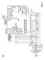
- FIG. 1illustrates a personal communication structure (PCS) 100 , according to some embodiments.
- PCS 100enhances access to communication networks in public or semi-public places.
- PCS 100includes an electronics subsystem 140 , a user interface subsystem 150 , a temperature control subsystem 160 , a display subsystem 170 , a communications subsystem 180 , and/or a mounting subsystem 190 .
- Electronics subsystem 140may include a power distribution subsystem 110 , a network subsystem 120 , and/or a maintenance subsystem 130 . These and other components of PCS 100 are described in further detail below.
- Power distribution subsystem 110distributes electrical power to components of PCS 100 .
- Power distribution subsystem 100may provide power to network subsystem 120 , maintenance subsystem 130 , other components of electronics subsystem 140 , user interface subsystem 150 , temperature control subsystem 160 , display subsystem 170 , and/or communications subsystem 180 .
- Power distribution subsystem 110may distribute power provided by any suitable power source(s) including, without limitation, batteries, solar panels, a power line 112 coupled to a power grid, etc.
- power distribution subsystem 110includes one or more power converters operable to convert power from one form (e.g., AC power) into another form (e.g., DC power) suitable for the PCS's components.
- power distribution subsystem 110includes one or more voltage level converters operable to change the voltage level of a signal to a level compatible with a component of the PCS.
- the ground terminal of the power distribution subsystem 110may be coupled to a reference potential 114 via the chassis of the PCS or via any other suitable path.
- FIG. 2shows a schematic of a power distribution subsystem 110 , according to some embodiments.
- power distribution subsystem (PDS) 110includes a power conversion system 204 , a power distribution board 202 , and a battery 206 .
- the inputs to power conversion system 204include AC power supply signals (e.g., 120 VAC at 60 Hz) carried on a hot line 212 , a neutral line 214 , and a ground line 216 .
- the hot line 212 and neutral line 214may be coupled to power conversion system 204 by quick disconnect devices 207 and 208 , respectively, whereby the hot and neutral lines may be safely disconnected from power distribution subsystem 110 if the PCS is separated from its footing.
- Ground line 216may be coupled to a ground terminal of the PCS 100 .
- Power conversion system 204processes the AC power supply signals and converts the processed signals into DC power supply signals.
- power conversion system 204includes a current transformer 222 , AC power distribution unit 223 , ground-fault circuit interrupter 224 (e.g., circuit breakers), AC line filter 226 , and rectifier 218 .
- Rectifier 218may function as a DC power supply (e.g., a 24 V, 75 A, 2 kW DC power supply).
- the outputs of various components of power conversion system 204may be provided as inputs to power distribution board 202 .
- Power distribution board 202may detect power system faults and distribute DC power signals to other components of the PCS.
- power distribution board 202uses the AC signals provided by power conversion system 204 to perform fault detection (e.g., ground fault detection, stray voltage detection, etc.).
- power distribution board 202uses the DC power supply signals provided by power conversion system 204 and/or battery 206 to produce DC power supply signals at various voltage levels (e.g., 5V, 12V, and 24V DC), and distributes those DC power supply signals to suitable components of the PCS 100 .
- power distribution system DC power signalscan be switched on and off.
- staggered activation of high-power devicese.g., one or more components of display subsystem 170
- the power distribution subsystem 110is able to measure output current and can shut off power supply signals when the device reaches an over-current threshold.
- an error messagemay be sent to a maintenance center, indicating that the PCS requires servicing.
- Battery 206may provide backup power for components of PCS 100 , including but not limited to user interface subsystem 150 , which may implement emergency communication (e.g., E911) functionality.
- power distribution board 202may charge battery 206 (e.g., at 24 VDC) when power conversion system 204 is producing DC power and PCS 100 is not using all the available DC power.
- a solar charging systemmay charge battery 206 during power outages or at other times.
- the power distribution subsystem 110can detect whether the ground-fault circuit interrupter 224 has tripped.
- the ability to detect activation of the ground-fault circuit interrupter 224can facilitate maintenance of the PCS. For example, while on back-up battery power, the PDS may determine whether AC power is lost (e.g., by sensing whether AC power supply signals are present) or the ground-fault circuit interrupter 224 has tripped. A suitable message can then be sent to the maintenance center, indicating, for example, whether the PCS requires service.
- network subsystem 120controls communication on a network 124 within PCS 100 , and communication between internal network 124 and a network 126 external to the PCS.
- network subsystem 120uses network 124 to communicate with power distribution system 110 , maintenance subsystem 130 , user interface subsystem 150 , temperature control subsystem 160 , display subsystem 170 , and/or communications subsystem 180 .
- the nodes of network 124may be arranged in one or more suitable network topologies, including, without limitation, a bus (e.g., with network subsystem 120 as the bus controller), star network (e.g., with network subsystem 120 as the central hub), ring network, mesh network, tree network, point-to-point network, etc.
- Network 124may be implemented using one or more suitable communication technologies, including, without limitation, Ethernet, DVI (Digital Visual Interface), HDMI (High-Definition Multimedia Interface), USB (Universal Serial Bus), SMB (System Management Bus), I2C (Inter-Integrated Circuit) bus, VGA (Video Graphics Array), SCSI (Small Computer System Interface), SPI (Serial Peripheral Interface) bus, LVDS (low-voltage differential signaling), etc.
- DVIDigital Visual Interface
- HDMIHigh-Definition Multimedia Interface
- USBUniversal Serial Bus
- SMBSystem Management Bus
- I2CInter-Integrated Circuit
- VGAVideo Graphics Array
- SCSISerial Computer System Interface
- SPISerial Peripheral Interface
- LVDSlow-voltage differential signaling
- Network subsystem 120may send and receive any suitable data.
- network subsystem 120may control the operation of other components of PCS 100 by sending control data to the PCS's subsystems.
- Network subsystem 120may forward commands received from a suitable source, including, without limitation, other PCS subsystems and/or network 126 .
- network subsystem 120may send operand data to components of PCS 100 for processing by those components (e.g., data to be displayed by display subsystem 170 or user interface subsystem 150 , data to be transmitted by communications subsystem 180 , etc.).
- network subsystem 120communicates with network 126 via data link 122 .
- Data link 122may be implemented using a suitable communications line, including, without limitation, an Ethernet cable, coaxial cable, or optical fiber.
- network subsystem 120may include a signal conversion device adapted to convert the signals received on data link 122 from one form (e.g., optical signals) into another form (e.g., electrical signals).
- FIG. 3shows a schematic of a network subsystem 120 , in accordance with some embodiments.
- network subsystem 120includes a fiber junction box 302 , a service delivery switch 304 , and a network switch 306 .
- data link 122includes one or more optical fibers.
- Fiber junction box 302may optically couple the optical fibers of data link 122 to one or more internal optical fibers 322 .
- fiber junction box 302includes one or more quick disconnect devices, whereby the optical fibers of data link 122 may be protected from damage if PCS 100 is separated from its footing.
- Service delivery switch 304may convert the optical signals received on optical fibers 322 into electrical signals representing network traffic (e.g., Ethernet packets), and provide that network traffic to network switch 306 .
- service delivery switch 304may convert the network traffic (e.g., Ethernet packets) received from network switch 306 into optical signals, and provide those optical signals to fiber junction box 302 .
- Network switch 306may switch network traffic between PCS subsystems, or between a PCS subsystem and network 126 . In some embodiments, network switch 306 is an Ethernet switch. Network switch 306 may be powered by power distribution subsystem 110 .
- network subsystem 120includes a power-over-Ethernet (POE) injector 308 .
- the POE injector 308may provide power to one or more PCS subsystems, including, without limitation, communications subsystem 180 .
- maintenance subsystem 130runs maintenance diagnostics on components of PCS 100 .
- maintenance subsystem 130performs tests on the PCS's components and/or initiates self-tests of the PCS's components. Such tests may be performed periodically (e.g., daily, weekly, monthly, etc.), intermittently, randomly or at other suitable times.
- components of PCS 100may perform such tests in response to commands received via network subsystem 120 (e.g., commands issued by a PCS operator via network 126 or via communications subsystem 180 ), or in response to other suitable events.
- maintenance subsystem 130may determine whether a tested component is operating properly. If a tested component is not operating properly, maintenance subsystem 130 may output data describing the component's malfunction (e.g., transmit an error code to a PCS operator via network 126 or communications subsystem 180 , display an error message via display subsystem 170 or user interface subsystem 150 , etc.), take action to resolve the malfunction (e.g., reboot the malfunctioning component), turn off power to the faulty component or to the entire PCS (e.g., if the malfunction presents a safety hazard), etc.
- data describing the component's malfunctione.g., transmit an error code to a PCS operator via network 126 or communications subsystem 180 , display an error message via display subsystem 170 or user interface subsystem 150 , etc.
- take action to resolve the malfunctione.g., reboot the malfunctioning component
- turn off power to the faulty component or to the entire PCSe.g., if the malfunction presents a safety hazard
- maintenance subsystem 130may be adapted to control or adjust the operation of power distribution subsystem 110 , for safety purposes or other suitable purposes. As described above, if a safety hazard is detected, maintenance subsystem 130 may control power distribution subsystem 110 to deactivate the PCS 100 or the unsafe component(s). Alternatively, maintenance subsystem 130 may control power distribution subsystem 110 to “power cycle” or “reboot” a malfunctioning component.
- FIG. 4shows a schematic of a maintenance subsystem 130 , in accordance with some embodiments.
- maintenance subsystem 130includes one or more processing devices 400 .
- the processing device(s)may include, without limitation, a microprocessor, microcontroller, small-board computer, system on a chip (SoC) (e.g., Qualcomm Snapdragon, Nvidia Tegra, Intel Atom, Samsung Exynos, Apple A7, Motorola X8, etc.), or other suitable processing device.
- SoCsystem on a chip
- the processing device(s) 400may communicate with other components of PCS 100 via network subsystem 120 to perform maintenance tasks, or for other suitable purposes.
- processing device(s) 400are powered by power distribution subsystem 110 .
- electronics subsystem 140may include other components.
- electronics subsystem 140includes one or more illumination controllers, which control illumination of one or more lights coupled to or proximate to the PCS. When lit, the lights controlled by the illumination controller may illuminate user interface subsystem 150 or other portions of PCS 100 .
- electronics subsystem 140includes one or more sensor controllers, which control one or more sensor devices (e.g., microphones, cameras, ambient light sensors, pressure sensors, voltage sensors, environmental sensors, accelerometers, etc.).
- Such sensorsmay be used for any suitable purpose, including, without limitation, adjusting the brightness of displays and/or lights based on ambient lighting, surveilling the region proximate to the PCS (e.g., when an attempt to gain unauthorized access to the PCS is detected), etc.
- User interface subsystem 150provides an interactive user interface, which may be used to access a communication network.
- user interface subsystem 150may include one or more user input devices 552 , output devices 554 , network modules 556 (e.g., network interface controllers, wireless transceivers, etc.), processing devices 557 , and/or power supply ports 558 .
- the user input device(s) 552may include, without limitation, a touchscreen, touchpad, keyboard, keypad, trackball, one or more microphones, camera, buttons, switches, etc.
- the output device(s) 554may include, without limitation, a display unit (e.g., touchscreen, LCD display, etc.), light(s), speaker(s), audio jack(s) (e.g., headset jacks, including microphone), etc.
- the one or more network modules 556may include, without limitation, a 3G mobile network transceiver, 4G mobile network transceiver, LTE mobile network transceiver, Wi-Fi transceiver, RFID reader, Bluetooth transceiver, Near Field Communication (NFC) transceiver, Ethernet adapter, etc.
- at least one of the network modules 556may be configured to access network 126 via network subsystem 120 or to access a communication network via communications subsystem 180 .
- the one or more processing devicesmay include, without limitation, a microprocessor, microcontroller, small board computer, or system on a chip (SoC) (e.g., Qualcomm Snapdragon, Nvidia Tegra, Intel Atom, Samsung Exynos, Apple A7, Motorola X8, etc.).
- SoCsystem on a chip
- the one or more power supply ports 558may include, without limitation, one or more USB charging ports, a two-prong or three-prong AC power outlet (e.g., providing current limited AC power at 120 V, 60 Hz), etc.
- User interface subsystem 150may enhance users' access to communication networks in several ways.
- user interface subsystem 150may provide users access to communication networks (e.g., the Internet) via network module(s) 556 .
- a usermay provide inputs via user input device(s) 552 to control a web browser or other network-based application executing on processing device(s) 557 , which may access a communication network via network module(s) 556 .
- the data obtained from the communication networkmay be processed by processing device(s) 557 and provided to the user via output device(s) 554 .
- a usermay connect a computing device (e.g., a mobile computing device) to user interface subsystem 150 via a network module 556 (e.g., a Wi-Fi access point), and access a communication network via another network module 556 (e.g., a mobile network transceiver), via communications subsystem 180 , or via network 126 .
- a network module 556e.g., a Wi-Fi access point
- another network module 556e.g., a mobile network transceiver
- usersmay charge mobile computing devices via power supply port(s) 558 , and access communication networks through the charged devices.
- PCS 100includes an assisted listening unit that transmits the PCS's audio outputs to hearing assistance devices (e.g., hearing aids, Cochlear implants, etc.) within the assisted listening unit's range via a “hearing loop” (e.g., an “audio induction loop” or “audio-frequency induction loop”).
- the assisted listening unitmay include a loop coil and a loop amplifier adapted to drive amplified signals into the loop coil, thereby creating a magnetic field that delivers the amplified signals to hearing assistance devices within the unit's range.
- the loop coilmay be included in or located proximate to user interface subsystem 150 , or disposed at another suitable location in, on, or near PCS 100 .
- user interface subsystem 150includes an interface for adjusting the assisted listening unit (e.g., for increasing or decreasing the signal strength or range of the assisted listening unit).
- the assisted listening unit's interfacemay include, without limitation, one or more buttons, dials, switches, and/or software-based interfaces.
- a usermay control the range of the assisted listening unit and/or the volume of the audio output provided by the assisted listening unit.
- user interface subsystem 150includes interface components for placing a phone call.
- User interface subsystemmay implement the phone calls using voice-over-IP (VOIP) technology.
- VOIPvoice-over-IP
- the user's speechmay be captured via the user interface subsystem's microphone, and the speech of other parties to the phone call may be provided via the user interface subsystem's speaker(s).
- the user interface subsystem 150permits users to place phone calls to emergency responders (e.g., E911 calls).
- the E911 callsmay be placed using VOIP technology (e.g., via a network module 556 of user interface 150 , via communications subsystem 180 , or via network 126 ) or another suitable technology.
- the user input devices 552include a microphone system
- the processing device 557is able to perform noise cancellation on the microphone system.
- the PCSmay be located in an environment with high levels of ambient street noise.
- the processing device 557may perform a noise cancelling process that distinguishes the user's speech from the background noise and removes at least some of the background noise from the audio stream.
- the noise cancellation techniquemay also detect and remove background noise picked up by the headset's microphone.
- FIG. 6shows an exemplary schematic of the user interface subsystem 150 , in accordance with some embodiments.
- user interface subsystem 150includes one or more processing devices 600 .
- the processing device(s) 600may include, without limitation, a microprocessor, microcontroller, small-board computer, system on a chip (SoC) (e.g., Qualcomm Snapdragon, Nvidia Tegra, Intel Atom, Samsung Exynos, Apple A7, Motorola X8, etc.), or other suitable processing device.
- SoCsystem on a chip
- the processing device(s) 600may communicate with other components of PCS 100 via network subsystem 120 .
- processing device(s) 600are powered by power distribution subsystem 110 .
- user interface subsystem 150includes a keypad 601 , headset jack 602 , speaker 603 , two microphones ( 604 , 605 ), and an E911 button 606 , all of which are coupled to the processing device(s) 600 .
- Processing device(s) 600may be adapted to initiate an E911 communication when E911 button 606 is pressed, and to send and receive E911 messages via a wireless communication module 607 (e.g., a 3G, 4G, or LTE mobile network transceiver, including a suitable antenna, which may be located proximate to the top of the PCS).
- a wireless communication module 607e.g., a 3G, 4G, or LTE mobile network transceiver, including a suitable antenna, which may be located proximate to the top of the PCS.
- the E911 buttoncontains an indicator.
- the indicatoris an illumination ring.
- the illumination ringmay help a user to locate the button at night, and/or may flash when a user presses the button to indicate a E911 call is in progress.
- user interface subsystem 150includes a touchscreen 612 , display 614 , camera 616 , hearing loop coil 618 , hearing loop amplifier 619 , and USB charging port(s) 620 .
- the touchscreen 612 , display 614 , camera 616 , and hearing loop coil 618may be packaged together in a tablet computing device 610 .
- the USB charging port(s) 620 and hearing loop amplifier 619may be powered by power distribution subsystem 110 .
- temperature control subsystem 160controls the temperature within PCS 100 .
- temperature control subsystem 160may cool the components of PCS 100 .
- Some of the PCS's componentsgenerate heat and the PCS 100 may absorb heat from its environment (e.g., via radiation or convection), particularly when the ambient temperature is high or the PCS is exposed to direct sunlight. Extreme heat can interfere with the operation of the PCS or even permanently damage some of the PCS's components.
- temperature control system 160may, under appropriate conditions, heat the components of PCS 100 .
- Some PCSsmay be located in cold environments (e.g., outdoors in regions with cold ambient temperatures). Like extreme heat, extreme cold can interfere with the PCS's operation or damage its components.
- Temperature control subsystem 160may include one or more components suitable for heating and/or cooling the PCS.
- temperature control subsystem 160includes one or more fans operable to circulate ambient air through the PCS, which can cool the PCS.
- the PCS 100includes one or more heat sinks, and the ambient air circulated by temperature control subsystem 160 passes proximate to the heat sink(s).
- temperature control subsystem 160includes one or more fans operable to recirculate air in portions (e.g., airtight compartments) of PCS 100 , which can facilitate the transfer of heat from those portions of the PCS to other regions of the PCS and/or to the ambient environment. The fans may be single-speed fans or variable-speed fans.
- temperature control subsystem 160includes one or more heaters, which can heat the PCS. In some embodiments, one or more fans and/or heaters are located apart from temperature control subsystem 160 , but controlled by the temperature control subsystem.
- Temperature control subsystem 160may control the PCS's temperature by controlling the operation of the fan(s) and/or heater(s). In some embodiments, temperature control subsystem 160 controls the PCS's temperature based, at least in part, on the temperature inside or in an area proximate to the PCS. Temperature control subsystem 160 may obtain temperature information regarding the temperature in or near PCS 100 from one or more temperature sensors. The temperature sensors may be located inside the PCS, on an outer surface of the PCS, proximate to the PCS, and/or in any other suitable location. Temperature control subsystem 160 may include one or more sensor drivers that can activate the sensor(s) and obtain temperature measurements from the sensor(s). Alternatively or in addition, temperature control subsystem may obtain temperature information regarding the temperature in the vicinity of the PCS from a suitable source (e.g., a website) via a communication network (e.g., network 126 ).
- a suitable sourcee.g., a website
- a communication networke.g., network 126
- the temperature control system 160adds or removes active fans (e.g. switches fans on or off) in specific areas of the PCS based on the temperature sensor information. For example, active fans may be added when the ambient temperature is high (e.g., above a threshold). Conversely, active fans may be removed when the ambient temperature is low (e.g., below a threshold) to reduce power usage.
- active fansmay be organized in addressable groups to facilitate addition and removal of active fans.
- the temperature control subsystem 160uses a feedback-based control system (e.g., a feedback loop) to control the speeds of the fans.
- the fansmay include tachometers, and the tachometer outputs may be fed back to the temperature control subsystem, which may use the tachometer outputs to determine the speeds of the fans.
- the temperature control subsystem 160may increase the speeds of the fans as the internal temperature increases or decrease the speeds of the fans as the temperature decreases.
- the temperature control subsystem 160uses the fan tachometer output to determine whether a fan fault has occurred. For example, the temperature control subsystem 160 may detect a fan fault when the tachometer output indicates that there is little or no fan rotation (e.g., the rate of fan rotation is below a threshold). When a fan fault is detected, the PCS may notify the maintenance center of the fault, so the PCS can be serviced to replace or repair the faulty fan.
- temperature control subsystem 160controls the PCS's temperature based on environmental information, which may include temperature information and/or other information associated with the PCS's environment.
- environmental informationmay include sunlight information indicating whether the PCS is exposed to direct sunlight. Sunlight information may be obtained from a camera or other suitable optical sensor.
- environmental informationmay include humidity information indicating the humidity levels in the PCS's environment, time-of-day information indicating the current time at the PCS's location, weather information indicating the weather in the PCS's environment, etc.
- temperature control subsystem 160may control the fan(s) and/or heater(s) to adjust the PCS's temperature.
- temperature control subsystem 160may activate one or more heaters when the PCS's temperature is below a lower threshold temperature, and/or activate one or more fans when the PCS's temperature is above an upper threshold temperature.
- the number of heater units and/or fans activated by temperature control subsystem 160is determined based on the environmental information.
- the settings of the activated heaters and/or fanse.g., the fan speeds, the heater temperatures, etc.
- temperature control subsystemmay instruct power distribution subsystem 110 to deactivate the PCS or at least one component thereof.
- Display subsystem 170includes one or more display modules, each of which includes at least one display device.
- the display devicemay include, without limitation, a liquid crystal display (LCD), light-emitting diode (LED) display, organic light-emitting diode (OLED) display, cathode ray tube (CRT), electroluminescent display (ELD), electronic paper/electronic ink display (e.g., a bi-stable or multi-stable electrophoretic or electro-wetting display), plasma display, thin-film transistor (TFT) display, 3D display (e.g., volumetric display, holographic display, integral imaging display, compressive light field display, etc.), stereoscopic display, etc.
- display subsystem 170includes two display modules disposed on opposite sides of the PCS, such that the modules' display devices face in opposite directions.
- a display devicemay display suitable information, including, without limitation, news information, weather information, emergency information (e.g., instructions for dealing with an emergency, evacuation routes, etc.), travel information (e.g., traffic conditions, road conditions, speed limits, alternative route information, public transit schedules, locations of and/or directions to public transportation facilities, etc.), tourism information (e.g., locations of and/or directions to popular tourist attractions), advertisements, etc.
- the displayed informationmay be displayed in one or more suitable formats, including, without limitation, text, still images, and/or video.
- Display subsystem 170may include one or more processing devices adapted to control the display of information by the display device(s).
- each display modulemay include a processing device adapted to control the display module's display device.
- display subsystem 170includes one or more cameras.
- each display modulemay include one or more cameras.
- Display subsystem 170may use the cameras to determine the ambient light levels, and may adjust the brightness of the display device(s) accordingly. For example, if the ambient light level at the PCS is high (e.g., because the sun is shining on the PCS), display subsystem 170 may increase the brightness of the display(s) (e.g., by increasing the brightness of the display backlight(s)), so that the displayed information is readily viewable by onlookers or passers-by. On the other hand, if the ambient light level at the PCS is low, display subsystem 170 may decrease the brightness of the display(s), to reduce the display subsystem's power usage and/or heat generation. In some embodiments, the brightness levels of the PCS's displays may be controlled independently.
- display subsystem 170may use the cameras to obtain information about “potential viewers” (e.g., people viewing the PCS, viewing a display device of the PCS, using the PCS, and/or in the vicinity of the PCS).
- display subsystem 170may determine, based on images of the area proximate to the PCS (e.g., images acquired by the PCS's camera(s)), a potential viewer's apparent demographic information, including, without limitation, age, sex, race/ethnicity, etc.
- display subsystem 170may use facial-recognition techniques to determine a potential viewer's identity.
- Display subsystem 170may use information about the PCS's potential viewers to select the information to be displayed by the display device(s) (e.g., to select advertisements for display based on the identities or demographics of the potential viewers). Alternatively or in addition, display subsystem 170 may track the identities and/or demographics of the potential viewers who have been in the vicinity of the PCS when particular advertisements have been displayed. Tracking information about potential viewers of advertisements and/or controlling the display of advertisements based on information about the potential viewers may increase the value of the PCS's advertising impressions to potential advertisers.
- Display subsystem 170may obtain information about a potential viewer from the potential viewer, from analysis of images of the potential viewer, and/or from the potential viewer's computing device (e.g., smartphone).
- a potential viewer who connects to a communication network through a PCS 100may provide authentication data (e.g., a username, password, and/or other credentials), and the PCS may use that authentication data to access the potential viewer's account information, which may identify the potential viewer and/or provide information about the potential viewer (e.g., the potential viewer's attributes and/or interests).
- the potential viewermay have provided such information when registering for access to the PCS (or set of PCSs), or the PCS may have inferred such information based on the potential viewer's activities on the communication network.
- a PCS 100may identify a potential viewer or attributes thereof based on identifying information transmitted by the potential viewer's computing device when the computing device is within range of the PCS, even if the computing device is not connected to a network via the PCS 100 .
- FIG. 7is a schematic of a display module 700 , in accordance with some embodiments.
- a PCS 100includes two display modules 700 .
- a display module 700includes one or more processing device(s) 710 .
- Each processing device 710may include, without limitation, a microprocessor, microcontroller, small-board computer, system on a chip (SoC) (e.g., Qualcomm Snapdragon, Nvidia Tegra, Intel Atom, Samsung Exynos, Apple A7, Motorola X8, etc.), or other suitable processing device.
- SoCsystem on a chip
- the processing device(s) 710may communicate with other components of PCS 100 via network subsystem 120 .
- each processing device 710is powered by power distribution subsystem 110 .
- SoCsystem on a chip
- display module 700also includes a display device 720 .
- Display device 720may include a display panel 721 , ambient light sensor 722 , two cameras ( 723 , 724 ), temperature sensor 725 , frame rate controller 726 , power/backlight controller 727 , and one or more fans 728 .
- the processing device 710is able to read the ambient light sensor 722 and send a control signal to the power/backlight controller 727 .
- the control signalis a pulse width modulated (PWM) output.
- PWMpulse width modulated
- the duty cycle of the PWM signalmay be increased, thereby causing the power/backlight controller to increase the backlight brightness, so that the display image is viewable in bright sunlight.
- the PWM control signalmay be digital or converted to an analog output via a digital to analog converter.
- communications subsystem 180includes one or more communication modules.
- the communication module(s)include one or more radio access nodes.
- the radio access node(s)may include small cells (e.g., low-power radio access nodes with ranges between roughly 10 m and 1-2 km, including, but not limited to, femtocells, picocells, and microcells), macrocells (e.g., radio access nodes with ranges of up to a few tens of kilometers), etc.
- the radio access node(s)may reduce congestion in mobile data networks (e.g., 3G, 4G, or LTE networks) by expanding network capacity and offloading traffic from more congested portions of the network to the portions of the network associated with the radio access node(s).
- mobile data networkse.g., 3G, 4G, or LTE networks
- PCSs with radio access node(s) in an area where mobile data networks are congestedmay, in some embodiments, greatly reduce network congestion and improve quality of service for many network users.
- communications subsystem 180includes at least one wireless access point.
- Computing devicesmay connect to the wireless access point using a suitable wireless adapter, including, without limitation, a Wi-Fi or WiMAX adapter.
- a suitable wireless adapterincluding, without limitation, a Wi-Fi or WiMAX adapter.
- communications subsystem 180may provide access to a local area network (LAN) or wide area network (WAN) (e.g., network 126 , or a 3G, 4G, or LTE network accessed via the communications subsystem's radio access node(s)).
- LANlocal area network
- WANwide area network
- PCS operatorsmay use the wireless access points to provide wireless broadband network access to individuals, subscribers, communities, etc. Use of the wireless access points may further improve the quality of service on mobile data networks by offloading some users from the mobile data networks to the wireless access point.
- mounting subsystem 190includes a mounting device that releasably secures the PCS to a support (e.g., a footing).
- the mounting devicemay be adapted to break when a shear force above a predetermined value is applied to the mounting device, thereby allowing the PCS to move.
- Such releasable mountingcan reduce the damage caused to people and property when an automobile collides with the PCS.
- PCS 100may include compartments and components of PCS 100 may be disposed in the compartments.
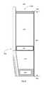
- FIG. 8illustrates an arrangement of compartments of a PCS 100 , according to some embodiments.
- the PCS's top portion 805 and base portion 806are identified in FIG. 8 , as is the PCS's height 807 .
- PCS 100includes mounting compartment 890 , electronics compartment 840 , user interface compartment 850 , air intake compartment 865 , display compartment 870 , and communications compartment 880 .
- Electronics compartment 840may enclose electronics subsystem 140 .
- User interface compartment 850 , display compartment 870 , and communications compartment 880may enclose user interface subsystem 150 , display subsystem 170 , and communications subsystem 180 , respectively.
- display compartment 870may enclose, in addition to display subsystem 870 , one or more heat sinks
- Mounting compartment 890may enclose at least a portion of a mounting subsystem 190 .
- Air intake compartment 865may enclose at least portions of temperature control subsystem 160 .
- air intake compartment 865may enclose one or more fans, which may draw ambient air into the air intake area.
- the one or more fansmay also draw air into the air intake area from electronics compartment 840 .
- the fansmay move the air through display compartment 870 (e.g., across one or more heat sinks), and the air may be discharged through an exhaust in communications compartment 880 .
- air intake compartment 865may enclose one or more heaters.
- communications compartment 880is located proximate to the top 805 of the PCS
- display compartment 870is disposed along an upper portion of the PCS and below communications compartment 880
- an air intake compartment 865is located proximate to a middle portion of the PCS (in the direction of the PCS's height) and below display compartment 870 .
- Mounting compartment 890is located proximate a base 806 of the PCS
- electronics compartment 840is disposed along a lower portion of the PCS between mounting compartment 890 and air intake compartment 865
- user interface compartment 850is disposed along a lower portion of the PCS adjacent to air intake compartment 865 and electronics compartment 840 .
- Embodiments of a PCSare not limited by the compartmentalization scheme illustrated in FIG. 8 .
- a PCSmay include none of the compartments illustrated in FIG. 8 , any combination of the compartments illustrated in FIG. 8 , and/or other compartments not illustrated in FIG. 8 .
- the location and/or shape of that compartmentmay differ from the location and/or shape of the corresponding compartment in FIG. 8 .
- a PCSmay include a compartment that encloses two or more PCS subsystems that are enclosed by different compartments in the example of FIG. 8 .
- a PCSmay include separate compartments enclosing respective portions of a PCS subsystem that is enclosed by a single compartment in the example of FIG. 8 .
- a PCSmay include a compartment that encloses other compartments.
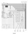
- FIGS. 9A, 9B, and 9Cshow respective front perspective, side, and exploded front perspective views of a PCS 100 , in accordance with some embodiments.
- the PCS's top portion 805 and base portion 806are identified in FIGS. 9A-9B , as are the PCS's height 807 , width 908 , and length 909 .
- PCS 100may include a frame 1000 .
- the frame 1000is (or is part of) a structural system that supports the components of PCS 100 .
- the frame 1000forms portions of the PCS's compartments (e.g., communications compartment 880 , display compartment 870 , air intake compartment 865 , user interface compartment 850 , electronics compartment 840 , and mounting compartment 890 ).
- communications compartment 880may include a radio access node 981 , a wireless access point 983 , and/or one or more antennas.
- the bottom of communications compartment 880may be formed by a portion of frame 1000 , and the top and sides of communications compartment 880 may be formed by a removable cap 985 .
- Display compartment 870may include a heat sink 903 and a display module 700 .
- display compartment 870includes a second display module (and, optionally, a second heat sink) arranged back-to-back (e.g., in parallel) with display module 700 and heat sink 903 , such that display module 700 and the second display module face in opposite directions.
- Air intake compartment 865may include an air intake assembly 967 .
- the air intake assembly 967may include a grill, a filter, and a fan assembly.
- User interface compartment 850may include a user interface device 951 .
- the user interface device 951may include a table computer, keypad, an emergency call button, microphone(s), speakers, and a mobile device charging port.
- Electronics compartment 840may include an electronics cabinet 941 , and may be formed by portions of frame 1000 and a cover panel 943 .
- Mounting compartment 890may at least partially enclose mounting subsystem 190 , and may be formed by portions of frame 1000 and a cover panel 991 .
- FIGS. 10A-10Cshow the frame 1000 of a PCS 100 , according to some embodiments, and illustrate how the frame 1000 partially forms the PCS's compartments.
- the frame 1000is the frame of a monocoque structure, wherein the frame supports the components, forms the compartments and is also the outer face (or “skin”) of portions of the PCS (e.g., the user interface compartment 850 and the opposing side 1050 of the PCS).
- This approachmay simplify construction by reducing the number of brackets, mounting accessories, part count, etc.
- the frame 1000is that of a traditional structure, and the outer skins are attached to the frame.
- the framesupports the components of the PCS, forms the compartments of the PCS, and acts as a rigid structural chassis.
- One advantage of this approachis field replaceability. If an outer skin is damaged (e.g., by vandalism or by ordinary wear and tear), the damaged skin can be replaced with a new skin. As long as the frame remains uncompromised, damaged outer skins can be removed, replaced, and (optionally) sent to a service facility for refurbishing. Refurbishing methods may include removing dents and/or scratches, sanding, texturing, reshaping, and/or re-painting. Skins that are not suitable for refurbishing (e.g., due to extensive damage) may be recycled and turned into new parts.
- frame 1000may include a bottom member 1001 a , a lower front member 1001 b , a cross-frame member 1001 c , an upper front member 1001 d , a rear member 1001 e , and a top member 1001 f .
- lower portions of lower front member 1001 b and rear member 1001 eare joined to opposite sides of bottom member 1001 a .
- One side of cross-frame member 1001 cis joined to an upper portion of lower front member 1001 b and a lower portion of upper front member 1001 d .
- cross-frame member 1001 cThe opposite side of cross-frame member 1001 c is joined to rear member 1001 e proximate to a midpoint between the rear member's top and base ends.
- the upper portions of upper front member 1001 d and rear member 1001 eare joined to opposite sides of top member 1001 f.
- top member 1001 f and the upper portion of upper front member 1001 dform a bottom and a side of communications compartment 880 .
- Two sides of display compartment 870are formed by upper front member 1001 d and rear member 1001 e
- the top and bottom of display compartment 870are formed by top member 1001 f and cross-frame member 1001 c , respectively.
- Cross-frame member 1001 cforms the top, bottom, and two sides of air intake compartment 865 .
- User interface compartment 850is formed in part by the bottom portion of upper front member 1001 d , the top portion of lower front member 1001 b , and a side of cross-frame member 1001 c .
- Two sides of electronics compartment 840are formed by lower front member 1001 b and the lower portion of rear member 1001 e , and the top and bottom of electronics compartment 840 are formed by cross-frame member 1001 c and bottom member 1001 a , respectively.
- Bottom member 1001 aforms mounting compartment 890 .
- Embodiments of frame 1000are not limited by the configuration shown in FIGS. 10A-10C .
- FIG. 11which shows a front-perspective view of a portion of PCS 100
- some embodiments of frame 1000further include one or more cross-frame members 1001 g coupled to upper front member 1001 d and an upper portion of rear member 1001 e to form an I-beam.
- cross-frame member(s) 1001 gmay include one or more ribbed heat sinks 1161 .
- a ribbed heat sink 1161may include a substantially planar member 1163 and fins 1162 extending from the substantially planar member 1163 (e.g., in one or more directions substantially perpendicular to the surface of the substantially planar member).
- Frame 1000may facilitate cooling of the PCS's compartments.
- one or more (e.g., all) members of frame 1000may have relatively high thermal conductivity (e.g., average thermal conductivity of at least 90, 100, 110, or 120 Btu/(hr*° F.*ft)).
- the frame member(s) with relatively high thermal conductivitymay function as heat sinks (including, but not limited to, cross-frame member(s) 1001 g ), such that heat from the compartments is transferred to the PCS's ambient environment through the frame member(s).
- the member(s) of frame 1000 with relatively high thermal conductivitymay substantially consist of materials with relatively high thermal conductivity, including, without limitation, aluminum, thermal pyrolytic graphite, silicon carbide, etc.
- one or more member(s) of frame 1000may substantially consist of aluminum.
- bottom member 1001 a , lower front member 1001 b , cross-frame member 1001 c , cross-frame member(s) 1001 g , and/or top member 1001 fmay be metal castings.
- upper front member 1001 d and/or rear member 1001 emay be extruded metal, polymer, composite, etc.
- portions of a PCS's frame 1000 and/or compartmentsmay be covered by ribbed panels 1200 .
- the ribbed panels 1200may discourage vandalism of PCS 100 , since the panel ribs might offer a less appealing target for drawing, painting, or etching than other, smoother surfaces.
- the ribbed panelsmay be swappable, as shown in FIG. 12B , such that a damaged or vandalized panel could be quickly replaced with a pristine panel.
- a ribbed panel 1200may include a substantially planar member 1202 and a set of ribs 1204 extending from the planar member.
- the angle 1206 between the outer surface of a rib and the outer surface of the planar memberis between approximately 95° and 115°.
- the thickness 1208 of a rib 1204 at the rib's basemay be between approximately 0.25′′ and 0.5′′ and the width 1210 of a rib 1204 may be between approximately 0.3′′ and 0.6′′. Other dimensions may be used.
- one or more of the compartments of a personal communication structure (PCS) 100may be secured. Securing a PCS's compartments may protect the PCS's components from vandalism, theft, and damage (e.g., from unwanted handling or exposure to the ambient environment), protect people from safety hazards (e.g., electrical hazards), and/or prevent unauthorized parties from accessing the PCS's components.
- PCSpersonal communication structure
- a PCS's compartmentsit may be necessary or desirable for authorized parties to access the components enclosed in a PCS's compartments. For example, it may be desirable for an authorized party to access a PCS subsystem to perform maintenance, to perform tests, to repair or replace a component, to adjust a component's settings, etc. In some cases, it may be desirable for one party to have access to one set of PCS components and for another party to have access to another set of PCS components, without either party having access to both sets of components. More generally, it may be desirable for different parties to have access only to specified subsets of the PCS's components.
- an electricians' unionmay be desirable for an electricians' union to have access to the PCS's power distribution subsystem 110 , so that the union's electricians can maintain or repair the power distribution subsystem, but there may be no reason for the electricians to have access to any other PCS components.
- a telecommunications company's personnelmay be desirable for a telecommunications company's personnel to have access to the PCS's communications subsystem 180 , but there may be no reason for the company's personnel to have access to any other PCS components.
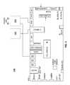
- FIG. 13illustrates a system 1300 for controlling access to components of a PCS, according to some embodiments.
- Access-control system 1300may independently secure at least a subset of the compartments of a PCS 100 (e.g., access-control system 1300 may apply different security measures to different compartments in the subset, which may include requiring users to provide different authentication tokens and/or information to access different compartments in the subset).
- the independently secured compartmentsmay be independently accessible (e.g., the interior of any compartment in the subset may be accessed without accessing the interiors of other compartments in the subset).
- Providing independently secured and independently accessible compartmentsmay facilitate the task of maintaining overall security, while granting different parties access to different sets of PCS components.
- access-control system 1300includes one or more compartment locks (e.g., locks 1302 a - f ) and one or more compartment access members (e.g., access members 1304 a - f ) associated with one or more respective compartments (e.g., electronics compartment 840 , air intake compartment 865 , display compartment 870 , communications compartment 880 , mounting compartment 890 , and user interface compartment 850 ).
- compartment lockse.g., locks 1302 a - f
- compartment access memberse.g., access members 1304 a - f
- respective compartmentse.g., electronics compartment 840 , air intake compartment 865 , display compartment 870 , communications compartment 880 , mounting compartment 890 , and user interface compartment 850 .
- the compartment locks 1302may include, without limitation, mechanical locks, electronic locks, electromechanical locks, etc.
- mechanical locksinclude warded locks, tumbler locks (e.g., pin tumbler locks, wafer tumbler locks, disc tumbler locks, lever tumbler locks), combination locks, security fasteners (e.g., “security” or “tamper-proof” screws, bolts, anchors, nuts), etc.
- a security fastenermay have an atypical shape and/or atypical dimensions relative to commercially available fasteners of the same type.
- a security fastener 1400may be a machine screw 1402 with an atypical screw drive 1404 or head configuration.
- a security fastenercan generally be unlocked or unfastened using a specialized tool that conforms to or otherwise accommodates the fastener's atypical shape and/or dimensions.
- Other mechanical lockscan generally be opened with physical keys or a combination code.
- Non-limiting examples of electronic or electromechanical locksinclude keycard locks, RFID locks, smart locks, cyber locks, etc.
- a keycard lockcan generally be unlocked by presenting a suitable security token (e.g., a keycard with appropriate key data) to a keycard reader.
- an RFID lockcan generally be unlocked by presenting a suitable security token (e.g., an RFID tag with appropriate key data) to an RFID reader.
- a smart lockcan generally be unlocked by presenting suitable authentication data to an access controller 1310 , which confirms the validity of the authentication data and disengages the lock.
- authentication datainclude biometric data (e.g., fingerprint data, retinal scan data, voice print data or other speech-based data, etc.), security credentials (e.g., username, password, personal identification number (PIN), etc.) cryptographic data, etc.
- biometric datae.g., fingerprint data, retinal scan data, voice print data or other speech-based data, etc.
- security credentialse.g., username, password, personal identification number (PIN), etc.
- PINpersonal identification number
- a cyber lockgenerally includes an electronic cylinder that can be unlocked by inserting a suitable cyber key.
- a cyber keyis generally an electronic key that can communicate with a cyber lock to engage and disengage the cyber lock's cylinder.
- a cyber keymay provide power to the cyber lock.
- a cyber keymay contain internal memory that stores security information, which may include but is not limited to: one or more encrypted access codes, information identifying one or more PCS structures the key can access, dates and times when the key is authorized to access a particular PCS or set of PCSs, and/or date/time ranges when the key is authorized to access a particular PCS or set of PCSs.
- a cyber keymay be capable of disabling access to the security information and/or deleting the security information in response to input signals (e.g., input signals received wirelessly from a remote service center, indicating that the key has been lost or stolen).
- a cyber key's security information(e.g., schedules, credentials, authorizations, permissions, etc.) generally may be updated using wireless communications (e.g., Bluetooth and/or Wi-Fi) when connected to an authorized network.
- a cyber key associated with a PCS 100may connect to an authorized network through the PCS 100 (e.g., via the communications subsystem 180 ).
- Some of the above examples of cyber keysmay contain an internal rechargeable battery that powers the cyber lock when the key is inserted into the lock.
- a cyber keymay communicate with a cyber lock (e.g., when the key is inserted into the lock). Such communication may occur wirelessly or via a wired connection (e.g., a USB interface).
- Some examples of commercially available electronic or electromechanical locksinclude electromagnetic locks, electric latch releases, electronically-actuated deadbolts, motorized locks and solenoid locks.
- an electronic or electromechanical lockincludes a locking mechanism and an actuator.
- locking mechanismsinclude deadbolts, latches, electromagnets, etc.
- actuatorsinclude solenoid drivers, rotary actuators, linear actuators (e.g., a linear actuator that moves a deadbolt or unlatches a latch), electromagnets, cams, levers, etc.
- access-control system 1300may include an access controller 1310 and a security interface 1320 .
- access controller 1310controls one or more actuators for one or more compartments, and uses the appropriate actuator to disengage a corresponding lock 1302 and/or open a corresponding access member 1304 upon provision of suitable authentication data. For example, when a user provides the appropriate authentication data for display compartment 870 , access controller 1310 may drive an actuator to disengage lock 1302 c , and (optionally) open compartment 870 by driving an actuator to move access member 1304 c .
- the authentication datais provided to access controller 1310 by security interface 1320 (e.g., via network subsystem 120 ).
- authentication datais provided to access controller 1310 over a communication network (e.g., via network subsystem 120 and/or communication subsystem 180 ).
- access controller 1310includes one or more processing devices 1510 and one or more actuator drivers 1520 , as shown in FIG. 15 .
- the processing device(s) 1510 and actuator driver(s) 1520may be powered by power distribution subsystem 110 .
- Processing device(s) 1510may include, without limitation, a microprocessor, microcontroller, small-board computer, system on a chip (SoC) (e.g., Qualcomm Snapdragon, Nvidia Tegra, Intel Atom, Samsung Exynos, Apple A7, Motorola X8, etc.), or other suitable processing device.
- SoCsystem on a chip
- Actuator driver(s) 1520may include hardware (e.g., I/O ports) and/or software (e.g., driver software) controlled by processing device(s) 1510 and adapted to communicate with actuators (e.g., the actuators of locks 1302 and/or access members 1304 ).
- actuatorse.g., the actuators of locks 1302 and/or access members 1304 .
- access controller 1310engages a lock 1302 and/or disengages a lock 1302 by sending suitable control signals to the lock's actuator via an actuator driver 1520 .
- access controller 1310opens an access member 1304 and/or closes an access member 1304 by sending suitable control signals to the access member's actuator via an actuator driver 1520 .
- access controller 1310determines whether a lock 1302 is engaged or disengaged, or determines whether an access member 1304 is open or closed, by sending a suitable query to the corresponding actuator, which may reply to the query by sending data to processing device(s) 1510 indicating the actuator's state. In some embodiments, when access controller 1310 detects closure of a compartment's access member 1304 , access controller 1310 may engage the compartment's lock 1302 .
- access controller 1310includes one or more processing device(s) 1510 .
- access controller 1310is implemented on one or more processing devices of a subsystem of PCS 100 .
- Access controller 1310may, for example, be implemented on the maintenance subsystem's processing device(s) 600 , which may be equipped with suitable actuator driver(s) 1520 .
- a usermay provide authentication data to access controller 1310 via security interface 1320 .
- Security interface 1320may include a keycard reader, RFID reader, keyboard, keypad, touchscreen, fingerprint scanner, retinal scanner, camera, microphone, data access port, and/or other suitable data input device.
- the keycard reader and RFID readercan be used to read authentication data from a keycard and an RFID tag, respectively.
- the keyboard, keypad, or touchscreencan be used to enter security credentials.
- the fingerprint scanner, retinal scanner, camera, or microphonemay be used to enter biometric data.
- the data access portmay be used to upload authentication data, including but not limited to cryptographic keys.
- security interface 1320is configured to send the user-provided authentication data to access controller 1310 via network subsystem 120 .
- security interface 1320includes a processing device adapted to encrypt the user-provided authentication data before sending the data to access controller 1310 .
- security interface 1320sends the authentication data to access controller 1310 via a dedicated link that is not part of network subsystem 120 .
- a usermay provide authentication data to access controller 1310 over a communication network (e.g., network 126 , or a network coupled to communication subsystem 180 ).
- Access controller 1310may analyze the user-provided authentication data to determine whether it is valid.
- the userspecifies which compartment(s) the user is attempting to access and access controller 1310 analyzes the authentication data to determine whether it is valid for the specified compartment(s).
- the userprovides authentication data without specifying which compartment(s) the user is attempting to access and access controller 1310 analyzes the authentication data to determine whether it is valid for any compartment.
- access controller 1310may perform one or more suitable authentication procedures (e.g., fingerprint matching, voiceprint matching, retinal scan matching, username matching, password matching, PIN matching, one-factor authentication, two-factor authentication, multi-factor authentication, etc.).
- permission to access a compartment of the PCS 100may be remotely granted, denied, or revoked (e.g., by a remote service center), and the grant, denial, or revocation of permission to access the compartment may be communicated to the access controller 1310 over a communication network (e.g., network 126 , a network coupled to communication subsystem 180 , etc.).
- the access controllermay acknowledge the grant, denial, or revocation of permission over the communication network.
- the entity that grants, denies, or revokes permission to access a compartment of the PCS 100may determine whether to grant, deny, or revoke permission based on any suitable information.
- the entitygrants permission to access a compartment during predetermined time periods.
- the entitymay grant permission to access a compartment during time periods specified by repair or maintenance schedules for components located in the compartment.
- the entitymay deny access to the display compartment 870 for display subsystem 170 maintenance except during periods generally characterized by low pedestrian foot traffic, such as early morning hours. It can be appreciated that during periods of high pedestrian foot traffic, it is desirable for the display subsystem 170 to be showing advertisements.
- the maintenance subsystem 130may communicate with the entity (e.g., a remote service center).
- the maintenance subsystem 130may indicate to the entity whether (or when) maintenance or repair of a PCS component or subsystem is recommended or permitted.
- the entitygrants permission to access a compartment based on communication from the maintenance subsystem indicating that repair or maintenance of a component or subsystem in the compartment is recommended or permitted.
- the maintenance subsystem 130may indicate that repair or replacement of a PCS component in a compartment is recommended in response to administering a diagnostic test (e.g., a self-test) and detecting a fault.
- the PCS 100may send user-provided authentication data to the entity, which may determine whether the authentication data is valid for one or more compartments and grant permission to access the compartment(s) if the authentication data is determined to be valid.
- the PCS 100may implement two-factor access control based on (1) user-provided authentication data and/or items (e.g., security tokens, keys, etc.) and (2) a grant, denial, or revocation of permission to access a compartment.
- the grant, denial, or revocation of permission to access a compartmentmay function as a grant, denial, or revocation of permission to allow authorized access to the compartment.
- the access controller 1310may allow users who provide valid authentication data/item(s) for the compartment to access the interior of the compartment.
- the access controller 1310may not allow a user to access the interior of the compartment, even if the user provides valid authentication data/item(s) for the compartment.
- the PCS 100may permit a user to access a PCS compartment if the user provides suitable authentication data/item(s) and a remote entity grants permission to access the compartment, but not if the authentication data/item(s) are unsuitable nor if the remote entity denies or revokes permission.
- the remote entitymay determine that the authentication data/item(s) are compromised, deny permission to access the compartment, and instruct the access controller 1310 to revoke the user's privileges to access one or more compartments by disabling authentication data/item(s) assigned to or in the possession of the user.
- compromised authentication data/item(s)e.g., stolen authentication data or a lost/stolen key
- access controller 1310may send a message to a remote entity (e.g., service center) requesting permission to allow authorized access to a compartment, and the remote entity may then reply with a grant or denial of permission to allow authorized access to the compartment.
- the access controller 1310may send such a request before a user provides authentication data/item(s) for the compartment, after the user provides the authentication data/item(s) but before the authentication data/item(s) are validated, or after the user-provided authentication data/item(s) are validated.
- a request to access a compartmentis sent to the remote entity before a user attempts to gain access to the compartment (e.g., by providing authentication data/item(s)).
- a usermay gain access to the compartment by providing suitable authentication data/item(s).
- the access controller 1310provides an indication that permission to access a compartment (or permission to allow authorized access to a compartment) has been granted. For example, when access permission has been granted (and not revoked), the access controller 1310 may illuminate a light-emitting diode (e.g., a green LED) to indicate that access (e.g., authorized access) to the compartment is permitted.
- the indicatormay be disposed in any suitable location, including, but not limited to, on the corresponding compartment or on an electronic key provided by the user.
- the access controller 1310may activate an indicator on a key wirelessly (e.g., over a wireless network) or via a wired connection (e.g., when the key is inserted into an interface connector or lock).
- the PCS 100may implement single-factor access control based on user-provided authentication data/item(s) or on a grant, denial, or revocation of permission to access a compartment.
- the access controller 1310may open or unlock a compartment in response to receiving a grant of permission to access the compartment, without requiring the user to provide authentication data/item(s).
- a usermay transmit a code to a remote entity (e.g., by emailing the code to an email address associated with the entity, by sending a text message to a phone number associated with the entity, etc.), and, after validating the code, the entity may grant permission to access the compartment.
- the usermay transmit the code via a mobile device that wirelessly connects to a network through the PCS 100 (e.g., through an access node of the PCS 100 ).
- the entityidentifies a compartment of the PCS 100 and determines whether to grant permission to access the compartment based on the transmitted code, the email address/phone number to which the code was transmitted, and/or the email address/phone number from which the code was sent.
- the entitymay use an automated process to grant permission to access a compartment.
- Access controller 1310may detect and respond to attempts to gain unauthorized access to compartment(s) of PCS 100 . In some embodiments, access controller 1310 determines that a user is attempting to gain unauthorized access to a PCS compartment if invalid authentication data is provided in more than N consecutive authentication attempts, where N is a predetermined number. In some embodiments, access controller 1310 determines that a user is attempting to gain unauthorized access to a PCS compartment (or has gained unauthorized access) if access controller 1310 detects disengagement of the compartment's lock or opening of the compartment's access member without a corresponding entry of the compartment's authentication data.
- access controller 1310may take remedial action.
- access controller 1310collects evidence of the unauthorized access (or attempt) by activating a camera to acquire one or more images (e.g., still images or video) of a region proximate to the PCS.
- the acquired imagesmay include images of the user who has accessed (or attempted to access) the PCS.
- access controller 1310sounds an alarm, displays a message via display subsystem 170 , initiates communication with a security provider, and/or performs other suitable actions to draw attention and/or alert interested parties to the unauthorized access.
- the access controllerwhen unauthorized access to one or more compartments is detected, silently alerts a remote security center (e.g., alerts the remote security center without alerting the user), which in turn takes action based on the unauthorized access.
- a remote security centere.g., alerts the remote security center without alerting the user
- the security centermay, for example, deploy security personnel or alert the local police.
- FIG. 16shows a perspective view of electronics compartment 840 , according to some embodiments.
- cover panel 943functions as access member 1304 a for electronics compartment 840 .
- the lock 1302 a for electronics compartment 840includes a set of latches 1604 and a corresponding set of latch receptacles 1606 . When the lock is engaged, the interlocking of the latches 1604 and the latch receptacles 1606 holds the access member securely in the closed position.
- the lockmay be disengaged by access controller 1310 , which may drive one or more actuators coupled to the latch receptacles 1606 to release the latches 1604 or vice versa, thereby allowing the access member to be moved from the closed position (e.g., a position in which the interior of the compartment is inaccessible, such as the position of cover panel 943 in FIG. 9A ) to the open position (e.g., a position in which the interior of the compartment is accessible, such as the position of cover panel 943 in FIG. 16 ).
- the cover panel 943may be hinged and/or removable.
- FIGS. 17A and 17Bshow front perspective and rear perspective views of the electronics cabinet 941 , according to some embodiments.
- Electronics cabinet 941may include three sub-compartments 1710 , 1720 , and 1730 .
- Sub-compartments 1710 , 1720 , and 1730(or a subset thereof) may be independently secured and independently accessible.
- sub-compartments 1710 , 1720 , and 1730enclose, respectively, power distribution subsystem 110 , network subsystem 120 , and maintenance subsystem 130 .
- the power distribution subsystem 110 and the network subsystem 120may be located on the same side of the electronics cabinet 941 (e.g., with the power distribution subsystem 110 located between the base of the PCS 100 and the network subsystem 120 ), and the maintenance subsystem 130 may be located on the opposite side of the electronics cabinet 941 .
- sub-compartment 1720encloses network subsystem 120
- sub-compartments 1710 and 1730collectively enclose power distribution subsystem 110 and maintenance subsystem 130 (e.g., portions of the power distribution subsystem 110 and/or portions of the maintenance subsystem 130 may be located in both the sub-compartment 1710 and the sub-compartment 1730 ).
- electronics compartment 840may not enclose an electronics cabinet 941 .
- Electronics compartment 840may enclose electronics subsystem 140 without partitioning subsystems 110 , 120 , and 130 into sub-compartments.
- an electronics compartment 840encloses three sub-compartments 1710 , 1720 , and 1730 , which in turn enclose power distribution subsystem 110 , network subsystem 120 , and maintenance subsystem 130 .
- PCS 100may not include an electronics compartment 840 enclosing multiple compartments. Instead, PCS 100 may include three compartments which respectively enclose subsystems 110 , 120 and 130 .
- FIGS. 18A and 18Bshow front perspective and exploded front perspective views, respectively, of an air intake assembly 967 , according to some embodiments.
- Air intake assembly 967may be enclosed in air intake compartment 865 and may implement a portion of temperature control subsystem 160 .
- air intake assembly 967includes a grill 1802 , a filter 1806 , and a fan assembly 1804 .
- the grill 1802may function as access member 1304 b , and may be secured to the PCS by security fasteners 1808 , which may function as lock 1302 b .
- security fasteners 1808which may function as lock 1302 b .
- lock 1302 bmay be engaged by using security fasteners 1808 to fasten grill 1802 to the PCS.
- air intake compartment 865may enclose two air intake assemblies 967 disposed proximate to each other, on opposite sides of PCS 100 .
- FIGS. 19A and 19Bshow front perspective and rear perspective views, respectively, of a user interface device 951 , according to some embodiments.
- User interface device 951may be partially enclosed in user interface compartment 850 and may implement a user interface subsystem 150 .
- user interface device 951includes a user interface panel 1902 and a tablet computer 1900 fastened to the user interface panel 1902 by security fasteners 1904 .
- the security fastenersare accessible via the interior of air intake compartment 865 , but not accessible from the exterior of the PCS 100 .
- the lock 1302 f and access member 1304 f for user interface compartment 850may include, respectively, the lock 1302 b and the access member 1304 b for air intake compartment 865 .
- FIG. 20shows a perspective view of a display compartment 870 , according to some embodiments.
- display compartment 870includes a display module 700 and a heat sink 903 .
- display compartment 870includes a second display module (and, optionally, a second heat sink) arranged back-to-back with display module 700 and heat sink 903 , such that display module 700 and the second display module face outwardly in opposite directions.
- FIG. 21shows an exploded perspective view of a display module 700 , according to some embodiments.
- display module 700includes a housing and a display panel 2104 .
- the housingmay include a housing frame 2102 , a covering frame 2106 , and a transparent covering 2108 .
- Display module 700may be assembled by positioning display panel 2104 in cavity 2110 , fastening the display panel to housing frame 2102 , and using covering frame 2106 to secure transparent covering 2108 over display panel 2104 .
- Transparent covering 2108may include toughened glass (e.g., “Gorilla Glass”® manufactured by Corning, Inc.).
- the assembled display module 700functions as the access member 1304 c for display compartment 870 .
- FIG. 9Ashows access member 1304 c (display module 700 ) in the closed position
- FIG. 20shows the access member in the open or service position.
- FIG. 22shows a cut-away perspective view of compartment lock 1302 c of display compartment 870 , according to some embodiments.
- compartment lock 1302 cincludes a connector 2202 (e.g., a pin) coupled to the housing of display module 700 , and a mating interlocking connector 2204 (e.g., an L-shaped receptacle) formed in a retention member 2208 of PCS 100 .
- FIG. 22also shows an actuator 2206 .
- actuator 2206is operable to disengage lock 1302 c by moving retention member 2208 such that connector 2202 is released from mating interlocking connector 2204 (e.g., moving retention member 2208 toward the PCS's base).
- the operation of compartment lock 1302 c and actuator 2206are described in more detail below, with reference to FIGS. 23A and 23B .
- FIG. 23Ashows a cross-sectional view of compartment lock 1302 c of display compartment 870 with the lock engaged and the access member (display module 700 ) in the closed position, according to some embodiments.
- lock 1302 cis engaged by positioning connector 2202 within mating interlocking connector 2204 , such that mating interlocking connector 2204 prevents connector 2202 from moving laterally.
- display module 700is held in the closed position.
- actuator 2206is operable to disengage lock 1302 c by retracting a pin 2302 into an aperture of a spool 2306 , thereby moving mating interlocking connector 2204 downward such that connector 2202 can move laterally toward the exterior of the PCS 100 .
- actuator 2206includes a bias member 2304 (e.g., a spring) that biases lock 1302 c toward the engaged position. Actuator 2206 may be controlled by access controller 1310 .
- FIG. 23Bshows a cross-sectional view of compartment lock 1302 c of display compartment 870 with the lock disengaged and the access member (display module 700 ) in the open position, according to some embodiments.
- pin 2302has been retracted, thereby causing retention member 2208 and mating interlocking connector 2204 to move downward, thereby releasing connector 2202 to move laterally toward the exterior of PCS 100 .
- compartment lock 1302 c of display compartment 870includes a connector 2202 and a mating interlocking connector 2204 .
- a compartment lock 1302 cmay include multiple pairs of connectors and mating interlocking connectors.
- the connectorsmay be arranged around a periphery of display module 700
- the mating interlocking connectorsmay be arranged around a periphery of display compartment 870 .
- retention member 2208may include one or more mating interlocking connectors
- a second retention member disposed on the opposite side of display module 700may also include one or more mating interlocking connectors.
- the connectors 2202may be disposed on the retention members 2208
- the mating interlocking connectors 2204may be disposed on the display module 700 .
- PCS 100may include two display modules 700 facing in opposite directions.
- either one or both display modulesmay be equipped with compartment locks 1302 c and actuators 2206 that operate independently or in unison.
- FIG. 24shows a perspective view of a communications compartment 880 , according to some embodiments.
- communications compartment 880includes a removable cap 985 , which may function as access member 1304 d , and may be secured to the PCS by inserting security fasteners through apertures 2404 and 2406 .
- the security fastenersmay function as compartment lock 1302 d .
- the closed and open positions of access member 1304 dare illustrated in FIG. 9A and FIG. 24 , respectively.
- Mounting compartment 890may include a cover panel 991 .
- cover panel 991functions as access member 1304 e for mounting compartment 890 .
- the lock 1302 e for mounting compartment 890includes a set of latches disposed proximate the periphery of cover panel 991 and a corresponding set of latch receptacles disposed proximate the periphery of mounting compartment 890 or vice versa. When the lock is engaged, the interlocking of the latches and the latch receptacles may hold the access member securely in the closed position.
- the lockmay be disengaged by access controller 1310 , which may drive one or more actuators coupled to the latch receptacles to release the latches, thereby allowing the access member to be moved from the closed position (e.g., a position in which the interior of the compartment is inaccessible, such as the position of cover panel 991 in FIG. 9A ) to the open position (e.g., a position in which the interior of the compartment is accessible, such as the position of cover panel 991 in FIG. 9C ).
- the closed positione.g., a position in which the interior of the compartment is inaccessible, such as the position of cover panel 991 in FIG. 9A
- the open positione.g., a position in which the interior of the compartment is accessible, such as the position of cover panel 991 in FIG. 9C ).
- the mounting compartment 890contains a mains power connection and one or more network connections.
- the network connection(s)may be, for example, fiber optic and/or copper network connections, depending, for example, on where the PCS is located and what type of network service is available.
- PCS 100may receive input data through one or more fiber network connections, provide output data through one or more copper network connections, or vice versa.
- the mounting compartment 890may contain one or more junction boxes 2500 for connecting power and/or network connections.
- the junction boxes 2500are attached to the mounting compartment 890 before the PCS 100 is installed, which may facilitate securing of the power and network cabling 2502 (e.g., fastening of the cabling to the PCS).
- the junction boxesare attached to the PCS 100 before it is installed on mounting subsystem 190 .
- a portion 2504 of the mounting subsystem 190forms a bottom surface of the mounting compartment 890 .
- portions of the power and/or network cablingare located in the mounting subsystem 190 before the PCS 100 is mounted, and the cabling is connected to the PCS's mains power connection and network connection(s) after the PCS 100 is mounted.
- one or more compartments of PCS 100are hierarchically secured, such that access to one or more compartments is a precondition for accessing another compartment.
- security interface 1320may be disposed within a compartment C (e.g., air intake compartment 865 or communication compartment 880 ), such that a user can access the security interface 1320 only after accessing the compartment C. The user can then provide authentication data to access controller 1310 via security interface 1320 , and thereby gain access to other compartments (e.g., display compartment 870 , electronics compartment 840 , or mounting compartment 890 ).
- the security interface 1320may include a key reader disposed on an exterior surface of the PCS 100 or proximate to the PCS 100 .
- Embodimentshave been described in which an access controller performs an authentication process and controls engagement/disengagement of compartment locks and/or opening/closing of compartment access members.
- the various authentication and control methods or processes outlined hereincan be coded as software that is executable on one or more processors that employ one of a variety of operating systems or platforms. Additionally, such software can be written using any of a number of suitable programming languages and/or programming or scripting tools, and also can be compiled as executable machine language code or intermediate code that is executed on a framework or virtual machine. Also, the acts performed as part of the techniques described herein can be performed in any suitable order.
- the authentication and/or control techniquescan be embodied as a computer readable medium (or multiple computer readable media) (e.g., a computer memory, one or more floppy discs, compact discs, optical discs, magnetic tapes, flash memories, circuit configurations in Field Programmable Gate Arrays or other semiconductor devices, or other tangible computer storage medium) encoded with one or more programs that, when executed on one or more computers or other processors, perform methods that implement the various techniques discussed above.
- the computer readable medium or mediacan be non-transitory.
- the computer readable medium or mediacan be transportable, such that the program or programs stored thereon can be loaded onto one or more different computers or other processors to implement various aspects of the present invention as discussed above.
- programor “software” are used herein in a generic sense to refer to computer code or set of computer-executable instructions that can be employed to program a computer or other processor to implement various aspects described in the present disclosure. Additionally, it should be appreciated that according to one aspect of this disclosure, one or more computer programs that when executed perform techniques described herein need not reside on a single computer or processor, but can be distributed in a modular fashion amongst a number of different computers or processors to implement various aspects of the present invention.
- Computer-executable instructionscan be in many forms, such as program modules, executed by one or more computers or other devices.
- program modulesinclude routines, programs, objects, components, data structures, etc. that perform particular tasks or implement particular abstract data types.
- functionality of the program modulescan be combined or distributed as desired in various embodiments.
- data structurescan be stored in computer-readable media in any suitable form.
- data structurescan be shown to have fields that are related through location in the data structure. Such relationships can likewise be achieved by assigning storage for the fields with locations in a computer-readable medium that conveys relationship between the fields.
- any suitable mechanismcan be used to establish a relationship between information in fields of a data structure, including through the use of pointers, tags or other mechanisms that establish a relationship between data elements.
- the technique(s)can be implemented as computer instructions stored in portions of a computer's random access memory to provide control logic that affects the processes described above.
- the programcan be written in any one of a number of high-level languages, such as FORTRAN, PASCAL, C, C++, C#, Java, JavaScript, Tcl, or BASIC.
- the programcan be written in a script, macro, or functionality embedded in commercially available software, such as EXCEL or VISUAL BASIC.
- the softwarecan be implemented in an assembly language directed to a microprocessor resident on a computer.
- the softwarecan be implemented in Intel 80 ⁇ 86 assembly language if it is configured to run on an IBM PC or PC clone.
- the softwarecan be embedded on an article of manufacture including, but not limited to, “computer-readable program means” such as a floppy disk, a hard disk, an optical disk, a magnetic tape, a PROM, an EPROM, or CD-ROM.
- Embodimentshave been described in which various aspects of the techniques described herein are applied to a personal communication structure (PCS).
- PCSpersonal communication structure
- aspects of the techniques described hereinmay be applied to any suitable structure including, without limitation, a kiosk (e.g., an interactive kiosk), pay station (e.g., parking pay station), automated teller machine (ATM), article of street furniture (e.g., mailbox, bench, traffic barrier, bollard, telephone booth, streetlamp, traffic signal, traffic sign, public transit sign, public transit shelter, taxi stand, public lavatory, fountain, watering trough, memorial, sculpture, waste receptacle, fire hydrant, vending machine, utility pole, etc.), etc.
- a kioske.g., an interactive kiosk
- pay statione.g., parking pay station
- ATMautomated teller machine
- article of street furnituree.g., mailbox, bench, traffic barrier, bollard, telephone booth, streetlamp, traffic signal, traffic sign, public transit sign, public transit shelter, taxi stand
- Xhas a value of approximately Y” or “X is approximately equal to Y”
- Xshould be understood to mean that one value (X) is within a predetermined range of another value (Y).
- the predetermined rangemay be plus or minus 20%, 10%, 5%, 3%, 1%, 0.1%, or less than 0.1%, unless otherwise indicated.
- a reference to “A and/or B”, when used in conjunction with open-ended language such as “comprising”can refer, in one embodiment, to A only (optionally including elements other than B); in another embodiment, to B only (optionally including elements other than A); in yet another embodiment, to both A and B (optionally including other elements); etc.
- the phrase “at least one,” in reference to a list of one or more elements,should be understood to mean at least one element selected from any one or more of the elements in the list of elements, but not necessarily including at least one of each and every element specifically listed within the list of elements and not excluding any combinations of elements in the list of elements.
- This definitionalso allows that elements may optionally be present other than the elements specifically identified within the list of elements to which the phrase “at least one” refers, whether related or unrelated to those elements specifically identified.
- “at least one of A and B”can refer, in one embodiment, to at least one, optionally including more than one, A, with no B present (and optionally including elements other than B); in another embodiment, to at least one, optionally including more than one, B, with no A present (and optionally including elements other than A); in yet another embodiment, to at least one, optionally including more than one, A, and at least one, optionally including more than one, B (and optionally including other elements); etc.
- ordinal termssuch as “first,” “second,” “third,” etc., in the claims to modify a claim element does not by itself connote any priority, precedence, or order of one claim element over another or the temporal order in which acts of a method are performed. Ordinal terms are used merely as labels to distinguish one claim element having a certain name from another element having a same name (but for use of the ordinal term), to distinguish the claim elements.
Landscapes
- Engineering & Computer Science (AREA)
- Computer Security & Cryptography (AREA)
- Architecture (AREA)
- Signal Processing (AREA)
- Computer Networks & Wireless Communication (AREA)
- Civil Engineering (AREA)
- Structural Engineering (AREA)
- Physics & Mathematics (AREA)
- General Physics & Mathematics (AREA)
- Alarm Systems (AREA)
Abstract
Description
Claims (29)
Priority Applications (6)
| Application Number | Priority Date | Filing Date | Title |
|---|---|---|---|
| US15/240,493US10051097B2 (en) | 2015-10-15 | 2016-08-18 | Techniques and apparatus for controlling access to components of a personal communication structure (PCS) |
| PCT/US2016/050972WO2017044764A1 (en) | 2015-09-11 | 2016-09-09 | Techniques and apparatus for controlling access to components of a personal communication structure (pcs) |
| PCT/US2016/050965WO2017044758A1 (en) | 2015-09-11 | 2016-09-09 | Techniques and apparatus for securing a structure to a support |
| CA2998411ACA2998411A1 (en) | 2015-09-11 | 2016-09-09 | Techniques and apparatus for controlling access to components of a personal communication structure (pcs) |
| PCT/US2016/050968WO2017044760A2 (en) | 2015-09-11 | 2016-09-09 | Techniques and apparatus for operating a personal communication structure (pcs) |
| US15/352,122US10270918B2 (en) | 2015-10-15 | 2016-11-15 | Method and apparatus for power and temperature control of compartments within a personal communication structure (PCS) |
Applications Claiming Priority (3)
| Application Number | Priority Date | Filing Date | Title |
|---|---|---|---|
| US14/884,044US9451060B1 (en) | 2015-10-15 | 2015-10-15 | Techniques and apparatus for controlling access to components of a personal communication structure (PCS) |
| US14/884,052US20170111521A1 (en) | 2015-10-15 | 2015-10-15 | Techniques and apparatus for controlling access to components of a personal communication structure (pcs) |
| US15/240,493US10051097B2 (en) | 2015-10-15 | 2016-08-18 | Techniques and apparatus for controlling access to components of a personal communication structure (PCS) |
Related Parent Applications (1)
| Application Number | Title | Priority Date | Filing Date |
|---|---|---|---|
| US14/884,044ContinuationUS9451060B1 (en) | 2015-09-11 | 2015-10-15 | Techniques and apparatus for controlling access to components of a personal communication structure (PCS) |
Related Child Applications (1)
| Application Number | Title | Priority Date | Filing Date |
|---|---|---|---|
| US15/352,122Continuation-In-PartUS10270918B2 (en) | 2015-10-15 | 2016-11-15 | Method and apparatus for power and temperature control of compartments within a personal communication structure (PCS) |
Publications (2)
| Publication Number | Publication Date |
|---|---|
| US20170111486A1 US20170111486A1 (en) | 2017-04-20 |
| US10051097B2true US10051097B2 (en) | 2018-08-14 |
Family
ID=56896235
Family Applications (2)
| Application Number | Title | Priority Date | Filing Date |
|---|---|---|---|
| US14/884,044ActiveUS9451060B1 (en) | 2015-09-11 | 2015-10-15 | Techniques and apparatus for controlling access to components of a personal communication structure (PCS) |
| US15/240,493ActiveUS10051097B2 (en) | 2015-09-11 | 2016-08-18 | Techniques and apparatus for controlling access to components of a personal communication structure (PCS) |
Family Applications Before (1)
| Application Number | Title | Priority Date | Filing Date |
|---|---|---|---|
| US14/884,044ActiveUS9451060B1 (en) | 2015-09-11 | 2015-10-15 | Techniques and apparatus for controlling access to components of a personal communication structure (PCS) |
Country Status (1)
| Country | Link |
|---|---|
| US (2) | US9451060B1 (en) |
Cited By (1)
| Publication number | Priority date | Publication date | Assignee | Title |
|---|---|---|---|---|
| US10332325B2 (en)* | 2017-09-05 | 2019-06-25 | Suprema Inc. | Access control system and access control method using the same |
Families Citing this family (74)
| Publication number | Priority date | Publication date | Assignee | Title |
|---|---|---|---|---|
| US12185512B2 (en) | 2007-11-16 | 2024-12-31 | Manufacturing Resources International, Inc. | Electronic display assembly with thermal management |
| US8854595B2 (en) | 2008-03-03 | 2014-10-07 | Manufacturing Resources International, Inc. | Constricted convection cooling system for an electronic display |
| US8654302B2 (en) | 2008-03-03 | 2014-02-18 | Manufacturing Resources International, Inc. | Heat exchanger for an electronic display |
| US8773633B2 (en) | 2008-03-03 | 2014-07-08 | Manufacturing Resources International, Inc. | Expanded heat sink for electronic displays |
| US9173325B2 (en) | 2008-03-26 | 2015-10-27 | Manufacturing Resources International, Inc. | Heat exchanger for back to back electronic displays |
| US8497972B2 (en) | 2009-11-13 | 2013-07-30 | Manufacturing Resources International, Inc. | Thermal plate with optional cooling loop in electronic display |
| US8693185B2 (en) | 2008-03-26 | 2014-04-08 | Manufacturing Resources International, Inc. | System and method for maintaining a consistent temperature gradient across an electronic display |
| US8125163B2 (en) | 2008-05-21 | 2012-02-28 | Manufacturing Resources International, Inc. | Backlight adjustment system |
| US8749749B2 (en) | 2008-12-18 | 2014-06-10 | Manufacturing Resources International, Inc. | System for cooling an electronic image assembly with manifolds and ambient gas |
| US10827656B2 (en) | 2008-12-18 | 2020-11-03 | Manufacturing Resources International, Inc. | System for cooling an electronic image assembly with circulating gas and ambient gas |
| JP2012514956A (en) | 2009-01-08 | 2012-06-28 | マニュファクチャリング・リソーシズ・インターナショナル・インコーポレーテッド | Electronic display with parts that can be mounted and accessed |
| US9286020B2 (en) | 2011-02-03 | 2016-03-15 | Manufacturing Resources International, Inc. | System and method for dynamic load sharing between electronic displays |
| EP2769376A4 (en) | 2011-09-23 | 2015-07-22 | Mri Inc | SYSTEM AND METHOD FOR ENVIRONMENTALLY ADAPTING DISPLAY CHARACTERISTICS |
| EP2909829B1 (en) | 2012-10-16 | 2020-02-12 | Manufacturing Resources International, INC. | Back pan cooling assembly for electronic display |
| US10524384B2 (en) | 2013-03-15 | 2019-12-31 | Manufacturing Resources International, Inc. | Cooling assembly for an electronic display |
| WO2014149773A1 (en) | 2013-03-15 | 2014-09-25 | Manufacturing Resources International, Inc. | Heat exchange assembly for an electronic display |
| AU2014287438B2 (en) | 2013-07-08 | 2017-09-28 | Manufacturing Resources International, Inc. | Figure eight closed loop cooling system for electronic display |
| JP6305564B2 (en) | 2014-04-30 | 2018-04-04 | マニュファクチャリング・リソーシズ・インターナショナル・インコーポレーテッド | Back-to-back electronic display assembly |
| US9723765B2 (en) | 2015-02-17 | 2017-08-01 | Manufacturing Resources International, Inc. | Perimeter ventilation system for electronic display |
| US10319408B2 (en) | 2015-03-30 | 2019-06-11 | Manufacturing Resources International, Inc. | Monolithic display with separately controllable sections |
| US10593255B2 (en) | 2015-05-14 | 2020-03-17 | Manufacturing Resources International, Inc. | Electronic display with environmental adaptation of display characteristics based on location |
| US9924583B2 (en) | 2015-05-14 | 2018-03-20 | Mnaufacturing Resources International, Inc. | Display brightness control based on location data |
| US10607520B2 (en) | 2015-05-14 | 2020-03-31 | Manufacturing Resources International, Inc. | Method for environmental adaptation of display characteristics based on location |
| US10922736B2 (en) | 2015-05-15 | 2021-02-16 | Manufacturing Resources International, Inc. | Smart electronic display for restaurants |
| US10269156B2 (en) | 2015-06-05 | 2019-04-23 | Manufacturing Resources International, Inc. | System and method for blending order confirmation over menu board background |
| US11172273B2 (en) | 2015-08-10 | 2021-11-09 | Delta Energy & Communications, Inc. | Transformer monitor, communications and data collection device |
| US10055869B2 (en) | 2015-08-11 | 2018-08-21 | Delta Energy & Communications, Inc. | Enhanced reality system for visualizing, evaluating, diagnosing, optimizing and servicing smart grids and incorporated components |
| US10055966B2 (en) | 2015-09-03 | 2018-08-21 | Delta Energy & Communications, Inc. | System and method for determination and remediation of energy diversion in a smart grid network |
| US9451060B1 (en) | 2015-10-15 | 2016-09-20 | Civiq Smartscapes, Llc | Techniques and apparatus for controlling access to components of a personal communication structure (PCS) |
| US9823690B2 (en) | 2015-09-11 | 2017-11-21 | Civiq Smartscapes, Llc | Techniques and apparatus for securing a structure to a support |
| CA3000206C (en) | 2015-10-02 | 2023-10-17 | Delta Energy & Communications, Inc. | Supplemental and alternative digital data delivery and receipt mesh network realized through the placement of enhanced transformer mounted monitoring devices |
| US10270918B2 (en) | 2015-10-15 | 2019-04-23 | Civiq Smartscapes, Llc | Method and apparatus for power and temperature control of compartments within a personal communication structure (PCS) |
| WO2017070646A1 (en) | 2015-10-22 | 2017-04-27 | Delta Energy & Communications, Inc. | Data transfer facilitation across a distributed mesh network using light and optical based technology |
| WO2017087496A1 (en) | 2015-11-16 | 2017-05-26 | Civiq Smartscapes, Llc | Systems and techniques for vandalism detection in a personal communication structure (pcs) |
| MX389497B (en)* | 2016-02-24 | 2025-03-11 | Delta Energy & Communications Inc | 802.11S distributed mesh network using transformer module hardware for data capture and transmission |
| US10820445B2 (en) | 2016-03-04 | 2020-10-27 | Manufacturing Resources International, Inc. | Cooling system for double sided display assembly |
| US10319271B2 (en) | 2016-03-22 | 2019-06-11 | Manufacturing Resources International, Inc. | Cyclic redundancy check for electronic displays |
| CA3024512C (en) | 2016-05-31 | 2020-12-29 | Manufacturing Resources International, Inc. | Electronic display remote image verification system and method |
| WO2018009917A1 (en) | 2016-07-08 | 2018-01-11 | Manufacturing Resources International, Inc. | Controlling display brightness based on image capture device data |
| WO2018031717A2 (en) | 2016-08-10 | 2018-02-15 | Manufacturing Resources International, Inc. | Dynamic dimming led backlight for lcd array |
| WO2018035143A1 (en) | 2016-08-15 | 2018-02-22 | Delta Energy & Communications, Inc. | Integrated solution of internet of things and smart grid network |
| EP4239992A3 (en)* | 2017-03-10 | 2023-10-18 | Bonx Inc. | Communication system and mobile communication terminal |
| AU2018237580B2 (en) | 2017-03-24 | 2020-10-15 | Manufacturing Resources International, Inc. | Roof mounting apparatus and system for vehicle topper |
| KR102262912B1 (en) | 2017-04-27 | 2021-06-10 | 매뉴팩처링 리소시스 인터내셔널 인코포레이티드 | A system and method for preventing warping of a display device |
| US10485113B2 (en) | 2017-04-27 | 2019-11-19 | Manufacturing Resources International, Inc. | Field serviceable and replaceable display |
| US10345780B2 (en)* | 2017-06-16 | 2019-07-09 | International Business Machines Corporation | Dynamic threshold parameter updates based on periodic performance review of any device |
| US10559965B2 (en) | 2017-09-21 | 2020-02-11 | Manufacturing Resources International, Inc. | Display assembly having multiple charging ports |
| CN111868719A (en)* | 2018-04-30 | 2020-10-30 | 惠普发展公司,有限责任合伙企业 | Self-service machine equipment maintenance |
| US10578658B2 (en) | 2018-05-07 | 2020-03-03 | Manufacturing Resources International, Inc. | System and method for measuring power consumption of an electronic display assembly |
| WO2019241546A1 (en) | 2018-06-14 | 2019-12-19 | Manufacturing Resources International, Inc. | System and method for detecting gas recirculation or airway occlusion |
| US10602626B2 (en) | 2018-07-30 | 2020-03-24 | Manufacturing Resources International, Inc. | Housing assembly for an integrated display unit |
| USD888706S1 (en) | 2019-01-25 | 2020-06-30 | TCC Teleplex LLC | Internet access portal |
| US11096317B2 (en) | 2019-02-26 | 2021-08-17 | Manufacturing Resources International, Inc. | Display assembly with loopback cooling |
| US10795413B1 (en) | 2019-04-03 | 2020-10-06 | Manufacturing Resources International, Inc. | Electronic display assembly with a channel for ambient air in an access panel |
| US11496091B2 (en) | 2019-08-27 | 2022-11-08 | Manufacturing Resources International, Inc. | Electronic display assemblies with solar panels |
| US11285895B2 (en) | 2019-08-27 | 2022-03-29 | Manufacturing Resources International, Inc. | Solar powered vehicle mounted display |
| US11526044B2 (en) | 2020-03-27 | 2022-12-13 | Manufacturing Resources International, Inc. | Display unit with orientation based operation |
| US11477923B2 (en) | 2020-10-02 | 2022-10-18 | Manufacturing Resources International, Inc. | Field customizable airflow system for a communications box |
| US11470749B2 (en) | 2020-10-23 | 2022-10-11 | Manufacturing Resources International, Inc. | Forced air cooling for display assemblies using centrifugal fans |
| US11778757B2 (en) | 2020-10-23 | 2023-10-03 | Manufacturing Resources International, Inc. | Display assemblies incorporating electric vehicle charging equipment |
| AU2022238796B2 (en) | 2021-03-15 | 2024-09-19 | Manufacturing Resources International, Inc. | Fan control for electronic display assemblies |
| US12105370B2 (en) | 2021-03-15 | 2024-10-01 | Manufacturing Resources International, Inc. | Fan control for electronic display assemblies |
| US20220311764A1 (en)* | 2021-03-24 | 2022-09-29 | Daniel Oke | Device for and method of automatically disabling access to a meeting via computer |
| US11966263B2 (en) | 2021-07-28 | 2024-04-23 | Manufacturing Resources International, Inc. | Display assemblies for providing compressive forces at electronic display layers |
| US12408312B2 (en) | 2021-07-28 | 2025-09-02 | Manufacturing Resources International, Inc. | Display assemblies with vents |
| US11762231B2 (en) | 2021-08-23 | 2023-09-19 | Manufacturing Resources International, Inc. | Display assemblies inducing turbulent flow |
| US11919393B2 (en) | 2021-08-23 | 2024-03-05 | Manufacturing Resources International, Inc. | Display assemblies inducing relatively turbulent flow and integrating electric vehicle charging equipment |
| US11744054B2 (en) | 2021-08-23 | 2023-08-29 | Manufacturing Resources International, Inc. | Fan unit for providing improved airflow within display assemblies |
| US11895362B2 (en) | 2021-10-29 | 2024-02-06 | Manufacturing Resources International, Inc. | Proof of play for images displayed at electronic displays |
| US11968813B2 (en) | 2021-11-23 | 2024-04-23 | Manufacturing Resources International, Inc. | Display assembly with divided interior space |
| US12072561B2 (en) | 2022-07-22 | 2024-08-27 | Manufacturing Resources International, Inc. | Self-contained electronic display assembly, mounting structure and methods for the same |
| US12010813B2 (en) | 2022-07-22 | 2024-06-11 | Manufacturing Resources International, Inc. | Self-contained electronic display assembly, mounting structure and methods for the same |
| US12035486B1 (en) | 2022-07-25 | 2024-07-09 | Manufacturing Resources International, Inc. | Electronic display assembly with fabric panel communications box |
| US12027132B1 (en) | 2023-06-27 | 2024-07-02 | Manufacturing Resources International, Inc. | Display units with automated power governing |
Citations (192)
| Publication number | Priority date | Publication date | Assignee | Title |
|---|---|---|---|---|
| US2029221A (en) | 1934-06-06 | 1936-01-28 | Burgess Lab Inc C F | Illuminated display apparatus |
| US4923319A (en) | 1989-06-22 | 1990-05-08 | Dent Clifford M | Breakaway connector |
| EP0387011A2 (en) | 1989-03-06 | 1990-09-12 | Agilis Corporation | Modular computer and interface system |
| US5061023A (en) | 1990-07-06 | 1991-10-29 | Northern Telecom Limited | Telephone terminal bases |
| US5170195A (en) | 1990-09-17 | 1992-12-08 | Pioneer Electronic Corporation | Cooling device for a liquid crystal panel |
| US5415949A (en) | 1992-10-02 | 1995-05-16 | Voltek, Inc. | Metal-air cell and power system using metal-air cells |
| US5465819A (en) | 1992-09-29 | 1995-11-14 | Borg-Warner Automotive, Inc. | Power transmitting assembly |
| US5484217A (en) | 1994-07-15 | 1996-01-16 | Decks, Inc. | Restorable breakaway post |
| US5587740A (en) | 1995-08-17 | 1996-12-24 | Brennan; James M. | Digital photo kiosk |
| US5665938A (en) | 1994-07-21 | 1997-09-09 | Boshear; Jerry A. | Electronic display enclosure |
| US5682216A (en) | 1996-04-01 | 1997-10-28 | Ctx Opto-Electronics Corp. | LCD projector capable of preventing thermal shimmering by using a thermal diffusion film |
| US5772300A (en) | 1995-10-18 | 1998-06-30 | Sony Corporation | Liquid crystal panel and liquid crystal projector |
| US5791770A (en) | 1997-02-27 | 1998-08-11 | Aavid Thermal Products, Inc. | Light source cooler for LCD monitor |
| US5841310A (en) | 1997-04-08 | 1998-11-24 | Burr-Brown Corporation | Current-to-voltage integrator for analog-to-digital converter, and method |
| US5860253A (en) | 1997-04-08 | 1999-01-19 | Lapointe; Jean | Collapsible post structure |
| DE19817929A1 (en) | 1997-10-24 | 1999-05-06 | Mannesmann Ag | Communication system, in particular for processing and / or transmitting data and / or signals, method for handling such a communication system and telecommunication cell |
| EP0936794A2 (en) | 1998-02-13 | 1999-08-18 | Nokia Mobile Phones Ltd. | Radio communications device with emergency services |
| US5948301A (en) | 1997-01-31 | 1999-09-07 | Bel Group Llc | Food thermalization device |
| US5961289A (en) | 1995-11-22 | 1999-10-05 | Deutsche Forshungsanstalt Fur Luft-Und Raumfahrt E.V. | Cooling axial flow fan with reduced noise levels caused by swept laminar and/or asymmetrically staggered blades |
| US5991153A (en) | 1997-10-31 | 1999-11-23 | Lacerta Enterprises, Inc. | Heat transfer system and method for electronic displays |
| US6002240A (en) | 1997-12-12 | 1999-12-14 | Dell Usa, L.P. | Self heating of batteries at low temperatures |
| US6010065A (en) | 1994-03-15 | 2000-01-04 | Diebold, Incorporated | Service method for automated banking machine |
| DE19903812A1 (en) | 1999-02-02 | 2000-08-03 | Hans Protschka | Mobile information and communication system |
| US6104451A (en) | 1998-03-16 | 2000-08-15 | Hitachi, Ltd. | Thin display housing with multiple chambers and fans |
| US6176421B1 (en) | 1999-02-04 | 2001-01-23 | Marconi Commerce Systems Inc. | Fuel dispenser architecture having server |
| US6210066B1 (en) | 1998-10-27 | 2001-04-03 | Clifford Dent | Breakaway bracket assembly |
| US6223982B1 (en) | 1999-03-05 | 2001-05-01 | Tristram C. Dunn | Impact resistant mailbox support |
| US20010032918A1 (en) | 1999-06-15 | 2001-10-25 | Barnes Theodore D. | Breadaway sign post |
| US6364761B1 (en) | 2000-06-19 | 2002-04-02 | Intel Corporation | Redundant cooling system for computer assembly |
| US6384811B1 (en) | 1999-06-08 | 2002-05-07 | Compal Electronics, Inc. | Portable computer having a display module moveable among closed, keyboard typing and image viewing positions |
| US6493440B2 (en) | 2001-04-23 | 2002-12-10 | Gilbarco Inc. | Thermal management for a thin environmentally-sealed LCD display enclosure |
| US6512670B1 (en) | 2000-10-05 | 2003-01-28 | International Business Machines Corporation | Detachable displays or portable devices |
| US20030080949A1 (en) | 1993-06-29 | 2003-05-01 | Ditzik Richard J. | Desktop device with adjustable flat screen display |
| US20030214781A1 (en) | 2002-05-14 | 2003-11-20 | Dell Products L.P. | Computer system cooling using temperature monitoring |
| WO2003103451A1 (en) | 2002-06-05 | 2003-12-18 | Acketts Group Limited | Plinth for automated teller machine |
| US20040085713A1 (en) | 2002-10-31 | 2004-05-06 | Sun Microsystems, Inc. | Security mechanism for a network device |
| US6766005B1 (en) | 1999-07-09 | 2004-07-20 | Schlumberger Systems | Payphone management system |
| US6788544B1 (en) | 2003-04-11 | 2004-09-07 | Hewlett-Packard Development Company, L.P. | Field replaceable unit access device and method |
| US6792708B2 (en) | 2001-03-02 | 2004-09-21 | Dicke Tool Company | Lightweight collapsible sign |
| US20040187505A1 (en) | 2003-03-28 | 2004-09-30 | Caterpillar, Inc. | Integrated cooling system |
| US20040203570A1 (en) | 2002-11-27 | 2004-10-14 | Jeffrey Berger | Apparatus and method for utilizing an emergency button of a communication device accessory |
| US20050038749A1 (en) | 2001-12-21 | 2005-02-17 | Fitch Stephan J | Method, system and apparatus for media distribution and viewing verification |
| EP1530383A1 (en) | 2003-11-10 | 2005-05-11 | Research In Motion Limited | Methods and system for limiting communication capabilities in mobile communication devices |
| US20050166482A1 (en) | 2001-11-02 | 2005-08-04 | Xcessories Squaredy | Breakaway signpost connector |
| US6928559B1 (en) | 1997-06-27 | 2005-08-09 | Broadcom Corporation | Battery powered device with dynamic power and performance management |
| US20050210331A1 (en) | 2004-03-19 | 2005-09-22 | Connelly Jon C | Method and apparatus for automating the root cause analysis of system failures |
| US20050237694A1 (en) | 2004-04-21 | 2005-10-27 | Analog Devices, Inc. | Methods and apparatus for reducing thermal noise |
| US6969212B1 (en) | 2004-06-22 | 2005-11-29 | Richens Carolyn M | Self-aligning pivotable delineator pole |
| US20060034051A1 (en) | 2004-08-10 | 2006-02-16 | Jian Wang | Electronic device having a temperature control system including a ductwork assembly |
| US20060059790A1 (en) | 2004-08-31 | 2006-03-23 | Yeung Hubert K | Systems and methods for modular instrument design and fabrication |
| DE202006001363U1 (en) | 2006-01-25 | 2006-04-06 | Kirchbach, Dieter | Telephone and emergency call column (TNS) for open and enclosed telephone cells, containing earpiece with microphone, emergency call button |
| US20060117085A1 (en) | 2004-11-30 | 2006-06-01 | Fujitsu Component Limited | Console device and rack-mount system |
| US20060186676A1 (en) | 2005-02-23 | 2006-08-24 | Aisin Seiki Kabushiki Kaisha | Door lock apparatus for a vehicle |
| US20060203143A1 (en) | 2005-03-09 | 2006-09-14 | Dong-Hyok Shin | Chassis base assembly and flat panel display device having the smae |
| US7108445B2 (en) | 2003-01-31 | 2006-09-19 | Joseph Henriques, Jr. | Adaptor for a mailbox post |
| US20060220895A1 (en) | 2005-03-18 | 2006-10-05 | Edwards Systems Technology, Inc. | Ambient light sensing solar powered pulsed LED visual indicator apparatus and method |
| US20060218828A1 (en) | 2005-03-29 | 2006-10-05 | Adaptive Micro Systems Llc | Access system for a display panel assembly |
| US20060228165A1 (en) | 2005-04-08 | 2006-10-12 | Yonan Joseph A Iii | Reusable, breakaway connector section for highway sign posts |
| US20060238307A1 (en) | 2002-01-09 | 2006-10-26 | Bauer Donald G | Intelligent station using multiple RF antennae and inventory control system and method incorporating same |
| US20060244700A1 (en) | 2005-03-15 | 2006-11-02 | Noriyuki Sano | Monitor system |
| US7157838B2 (en) | 2002-10-10 | 2007-01-02 | Barco N.V. | Light emission display arrangements |
| US20070060097A1 (en) | 2005-08-02 | 2007-03-15 | Edge Stephen W | VOIP emergency call support |
| US7195222B2 (en) | 2004-04-23 | 2007-03-27 | Dent Clifford M | Flanged base and breakaway system connector for road accessory posts |
| US20070082651A1 (en) | 2005-02-01 | 2007-04-12 | Loizeaux Marion A | Multi-site personal emergency telephone system method and device |
| FR2892517A1 (en) | 2005-10-25 | 2007-04-27 | Tag Technologies Soc Par Actio | METHOD OF PROCESSING ACCELERATION MEASUREMENTS DELIVERED BY AN ACCELEROMETER, ACCELEROMETRIC SENSOR AND ALARM SYSTEM EQUIPPED WITH SUCH SENSORS |
| US20070103866A1 (en) | 2005-11-04 | 2007-05-10 | Lg Electronics Inc. | Flat display device and cooling apparatus for the same |
| US20070170237A1 (en) | 2006-01-19 | 2007-07-26 | Neff Richard D | Mail receptacle with delivery indicator |
| US20070183849A1 (en) | 2006-02-03 | 2007-08-09 | Kenneth Rock | Modular dock bumper |
| WO2007116116A1 (en) | 2006-04-11 | 2007-10-18 | Symbicon Oy | Electronic information board |
| US20070263610A1 (en) | 2006-04-04 | 2007-11-15 | Don Mitchell | SS7 MAP/Lg+ to SIP based call signaling conversion gateway for wireless VoIP E911 |
| US7339782B1 (en) | 2004-09-30 | 2008-03-04 | Lockheed Martin Corporation | Multi-display screen console with front access |
| US20080053129A1 (en) | 2003-01-08 | 2008-03-06 | Ise Corporation | Vehicle Rooftop Engine Cooling System and Method |
| US20080113821A1 (en) | 2006-11-09 | 2008-05-15 | Igt | Gaming machine with vertical door-mounted display |
| US7374258B2 (en) | 2001-01-26 | 2008-05-20 | Julian Bowron | Modular kiosk |
| US7405926B2 (en) | 2005-04-18 | 2008-07-29 | Aten International Co., Ltd. | Sliding flat panel display and keyboard module |
| US20080181385A1 (en) | 2007-01-31 | 2008-07-31 | Ronald Eveland | Apparatus and System for Converting Public Switch Telephone Network to Wireless Personal Area Network |
| US20080204556A1 (en) | 2007-02-23 | 2008-08-28 | De Miranda Federico Thoth Jorg | Vehicle camera security system |
| US20080255901A1 (en)* | 2007-03-26 | 2008-10-16 | John Stuart Carroll | Kiosk systems and methods |
| US20090003312A1 (en) | 2007-06-26 | 2009-01-01 | Leonardo Velazquez | Methods and apparatus to provide enhanced 911 (e911) services for nomadic users |
| US20090050763A1 (en) | 2007-01-05 | 2009-02-26 | Jay Dittmer | In-wall mount |
| US20090149153A1 (en) | 2007-12-05 | 2009-06-11 | Apple Inc. | Method and system for prolonging emergency calls |
| US20090231807A1 (en) | 2008-03-13 | 2009-09-17 | Bouissiere Michael F | Waterproof Ventilated Display Enclosure |
| US20090241620A1 (en) | 2008-03-27 | 2009-10-01 | Medeco Security Locks, Inc. | Cylinder Lock and Auxiliary Locking Mechanism |
| US20090241388A1 (en) | 2008-03-26 | 2009-10-01 | Manufacturing Resources International, Inc. | Advertising displays |
| WO2009135308A1 (en) | 2008-05-07 | 2009-11-12 | Venture Dynamics Corporation | Video display system |
| US20090280770A1 (en) | 2008-05-07 | 2009-11-12 | Qualcomm Incorporated | System, apparatus and method to enable mobile stations to identify calls based on predetermined values set in a call header |
| WO2009143764A1 (en) | 2008-05-27 | 2009-12-03 | Shenzhen New Super-Bright Lcd Display Co., Ltd. | Lcd apparatus with heat dissipation arrangements |
| US20090302188A1 (en) | 2007-02-09 | 2009-12-10 | Lewis Donnie G | Breakaway signpost adapter |
| US7734764B2 (en) | 2004-12-17 | 2010-06-08 | General Electric Company | Automated remote monitoring and diagnostics service method and system |
| US20100149736A1 (en) | 2007-01-05 | 2010-06-17 | Jay Dittmer | Wall-avoiding self-balancing mount for tilt positioning of a flat panel electronic display |
| US7748681B2 (en) | 2006-02-23 | 2010-07-06 | Clifford Dent | Support post assembly with hinge plate and mounting bracket assembly |
| US20100211804A1 (en) | 2009-02-19 | 2010-08-19 | Alan Brumley | System And Method For Dynamic Modular Information Handling System Power Distribution |
| US20100213724A1 (en) | 2009-02-26 | 2010-08-26 | Adam Rite Manufacturing Co. | Multiple point door locking system, with handle turning direction control |
| US20100222132A1 (en)* | 2004-09-29 | 2010-09-02 | Kirk Edward Sanford | Systems for Enhancing Funding of Gaming |
| US7793026B1 (en) | 2008-10-13 | 2010-09-07 | Hewlett-Packard Development Company, L.P. | Computer system with peripheral modules attached to a display/CPU assembly |
| US20100237143A1 (en) | 2009-03-17 | 2010-09-23 | Labrecque Jr Maurice J | Flexible mailbox post assembly |
| US7894194B2 (en) | 2008-01-25 | 2011-02-22 | Aten International Co., Ltd. | Rack-mounted foldable computer console for KVM switch |
| US20110080348A1 (en) | 2009-10-01 | 2011-04-07 | Apple Inc. | Electronic devices with a primary display and a selectively illuminated secondary display |
| EP2328130A1 (en) | 2009-11-27 | 2011-06-01 | NCR Corporation | Self-service kiosk with multiple secure service areas |
| US7980533B1 (en) | 2004-03-02 | 2011-07-19 | Designorations, Inc. | Breakaway coupling for road-side signs |
| US7985139B2 (en) | 2006-11-14 | 2011-07-26 | Multimedia Games, Inc. | Gaming machine cabinet with vertically operating doors |
| US8006435B2 (en) | 2007-03-30 | 2011-08-30 | Daktronics, Inc. | Safety gate system having an electronic display |
| US8006897B1 (en) | 2007-09-07 | 2011-08-30 | Diebold Self-Service Systems Division Of Diebold, Incorporated | Banking system controlled responsive to data bearing records |
| US20110217681A1 (en) | 2010-03-03 | 2011-09-08 | Brian Krejcarek | Sensor network for incentivizing behavioral actions |
| US20110226505A1 (en) | 2010-03-16 | 2011-09-22 | Powerwave Technologies, Inc. | Walk-in outdoor electronic equipment enclosure |
| US8037651B2 (en) | 2008-03-19 | 2011-10-18 | Clifford Dent | Ground anchor assembly |
| US20110274093A1 (en) | 2010-05-05 | 2011-11-10 | Ymax Communications Corp. | Non-Carrier Dependent Femtocell and Related Methods |
| US8108724B2 (en) | 2009-12-17 | 2012-01-31 | Hewlett-Packard Development Company, L.P. | Field replaceable unit failure determination |
| US20120032062A1 (en) | 2010-08-04 | 2012-02-09 | Brian Newville | Television mount assembly |
| US8116081B2 (en)* | 2009-05-22 | 2012-02-14 | Cinema Scene Marketing & Promotions, Llc | Digital display kiosk |
| US8125163B2 (en) | 2008-05-21 | 2012-02-28 | Manufacturing Resources International, Inc. | Backlight adjustment system |
| US20120068985A1 (en) | 2010-09-16 | 2012-03-22 | Nuvoton Technology Corporation | Chip and computer system |
| US8154768B2 (en) | 2007-12-27 | 2012-04-10 | Brother Kogyo Kabushiki Kaisha | Display device and electrical apparatus having such display device |
| EP2439912A1 (en) | 2009-06-04 | 2012-04-11 | Mitsubishi Steel MFG. CO., LTD. | Tilting mechanism and sliding device |
| US20120096350A1 (en) | 2010-10-15 | 2012-04-19 | Hon Hai Precision Industry Co., Ltd. | Electronic device |
| US20120113582A1 (en) | 2010-11-09 | 2012-05-10 | Hitachi, Ltd. | Structural fabric of a storage apparatus for mounting storage devices |
| US8189134B2 (en) | 2008-09-19 | 2012-05-29 | Manufacturing Resources International, Inc. | Durable display panel with impact resistance |
| CN202248971U (en) | 2011-08-26 | 2012-05-30 | 范忠州 | Convenient intelligent information kiosk |
| US8208115B2 (en) | 2007-11-16 | 2012-06-26 | Manufacturing Resources International, Inc. | Fluid cooled display |
| US8212959B2 (en) | 2010-03-08 | 2012-07-03 | Ciil Technologies, Llc | Display enclosure |
| US20120213351A1 (en) | 2011-02-22 | 2012-08-23 | Boyce Technologies, Inc. | Public communications intercom system |
| US8274622B2 (en) | 2008-03-03 | 2012-09-25 | Manufacturing Resources International, Inc. | System for using constricted convection with closed loop plenum as the convection plate |
| US20120262271A1 (en)* | 2011-04-18 | 2012-10-18 | Richard Torgersrud | Interactive audio/video system and device for use in a secure facility |
| US8297067B2 (en) | 2010-06-23 | 2012-10-30 | Ietip Llc | Space-saving high-density modular data pod systems and energy-efficient cooling systems |
| US8310824B2 (en) | 2009-11-13 | 2012-11-13 | Manufacturing Resources International, Inc. | Field serviceable electronic display |
| US20120295580A1 (en) | 2011-05-19 | 2012-11-22 | Boku, Inc. | Systems and Methods to Detect Fraudulent Payment Requests |
| US8323089B2 (en) | 2008-04-03 | 2012-12-04 | Universal Entertainment Corporation | Gaming system having large display and plural gaming machines |
| US8351013B2 (en) | 2008-03-03 | 2013-01-08 | Manufacturing Resources International, Inc. | Combined serial/parallel light configuration and single layer PCB containing the same |
| US8351014B2 (en) | 2008-03-03 | 2013-01-08 | Manufacturing Resources International, Inc. | Heat exchanger for back to back electronic displays |
| US8350799B2 (en) | 2009-06-03 | 2013-01-08 | Manufacturing Resources International, Inc. | Dynamic dimming LED backlight |
| US8358397B2 (en) | 2008-03-03 | 2013-01-22 | Manufacturing Resources International, Inc. | System for cooling an electronic display |
| US8369083B2 (en) | 2010-02-16 | 2013-02-05 | Manufacturing Resources International, Inc. | System and method for selectively engaging cooling fans within an electronic display |
| US8373841B2 (en) | 2007-11-16 | 2013-02-12 | Manufacturing Resources International, Inc. | Shared isolated gas cooling system for oppositely facing electronic displays |
| US8379182B2 (en) | 2007-11-16 | 2013-02-19 | Manufacturing Resources International, Inc. | Cooling system for outdoor electronic displays |
| US8427007B2 (en) | 2010-02-24 | 2013-04-23 | Schneider Electric It Corporation | Field replaceable management module |
| US8439761B2 (en) | 2008-11-17 | 2013-05-14 | Elite Casino Products, Inc. | Gaming cabinet with a gaming deck capable of being slid away from the display and rotated in either upward or downward directions |
| US20130147626A1 (en) | 2009-04-06 | 2013-06-13 | Hassan Hammoud | Electronic Mailbox System |
| US20130158714A1 (en) | 2011-12-14 | 2013-06-20 | Honeywell International Inc. | Hvac controller with user activated performance test |
| US8482520B2 (en) | 2009-01-30 | 2013-07-09 | Research In Motion Limited | Method for tap detection and for interacting with and a handheld electronic device, and a handheld electronic device configured therefor |
| US8497972B2 (en) | 2009-11-13 | 2013-07-30 | Manufacturing Resources International, Inc. | Thermal plate with optional cooling loop in electronic display |
| CN203097341U (en) | 2013-01-31 | 2013-07-31 | 钟立 | Multi-media public information kiosk |
| US8508155B2 (en) | 2010-04-14 | 2013-08-13 | Manufacturing Resources International, Inc. | System and method for calibrating backlight devices |
| US8523135B2 (en) | 2010-04-07 | 2013-09-03 | 648560 Alberta Ltd. | Breakaway device for posts |
| US20130229098A1 (en) | 2012-03-05 | 2013-09-05 | Adam Quinn Pletcher | Modular Rapid Access Illuminated Drawer Safe With Dual Access Methods |
| US20130237175A1 (en) | 2012-03-12 | 2013-09-12 | Rave Wireless, Inc. | Adaptive mobile messaging interface for implementing emergency protocols |
| US8548422B2 (en) | 2008-03-05 | 2013-10-01 | Nevin C. Jenkins | Versatile personal medical emergency communication system |
| US8569910B2 (en) | 2009-02-24 | 2013-10-29 | Manufacturing Resources International, Inc. | System and method for controlling the operation parameters response to current draw |
| US8606428B2 (en) | 2011-02-25 | 2013-12-10 | Cisco Technology, Inc. | Cooling fan control system |
| US20130332271A1 (en) | 2012-06-08 | 2013-12-12 | Ronny Hay | Computer-controlled, unattended, automated checkout store outlet system and related method |
| DE202012008748U1 (en) | 2012-09-12 | 2013-12-16 | Lumino Licht Elektronik Gmbh | Stationary information arrangement |
| US8654302B2 (en) | 2008-03-03 | 2014-02-18 | Manufacturing Resources International, Inc. | Heat exchanger for an electronic display |
| US20140069154A1 (en) | 2012-09-11 | 2014-03-13 | Moshe Dolev | Reversible door and multipoint lock |
| US20140089077A1 (en) | 2012-09-21 | 2014-03-27 | Coinstar, Inc. | Consumer operated kiosks for purchasing fresh foods and associated systems and methods |
| US8700226B2 (en) | 2009-02-24 | 2014-04-15 | Manufacturing Resources International, Inc. | Method for driving a cooling fan within an electronic display |
| US8711321B2 (en) | 2007-11-16 | 2014-04-29 | Manufacturing Resources International, Inc. | System for thermally controlling displays |
| US8713377B2 (en) | 2011-12-15 | 2014-04-29 | General Electric Company | System and method to assess serviceability of device |
| US20140148171A1 (en) | 2011-05-26 | 2014-05-29 | Telefonica, S.A. | Method for cell reselection and cell handover in a wireless communication system |
| US8749749B2 (en) | 2008-12-18 | 2014-06-10 | Manufacturing Resources International, Inc. | System for cooling an electronic image assembly with manifolds and ambient gas |
| US8755021B2 (en) | 2011-05-04 | 2014-06-17 | Manufacturing Resources International, Inc. | System for cooling an electronic image assembly with manifolds and ambient gas |
| US8767923B1 (en) | 2011-10-14 | 2014-07-01 | Securus Techologies, Inc. | Emergency communication within controlled-environment facilities |
| US8767165B2 (en) | 2007-11-16 | 2014-07-01 | Manufacturing Resources International, Inc. | Isolated gas cooling system for an electronic display |
| US8773633B2 (en) | 2008-03-03 | 2014-07-08 | Manufacturing Resources International, Inc. | Expanded heat sink for electronic displays |
| US8804091B2 (en) | 2010-08-20 | 2014-08-12 | Manufacturing Resources International, Inc. | System and method for thermally controlling an electronic display with reduced noise emissions |
| US20140224591A1 (en)* | 2013-02-13 | 2014-08-14 | Edy Christian Encinas GARCIA | Elevators and elevator arrangements with maintenance cabinet in landing wall |
| DE102013202127A1 (en) | 2013-02-08 | 2014-08-14 | Robert Bosch Gmbh | Energy transmission assembly for energy transmission system located in public space, has sensing unit that detects motion quantity and provides sensor signal based on motion quantity |
| US8823916B2 (en) | 2008-03-03 | 2014-09-02 | Manufacturing Resources International, Inc. | System for cooling an electronic image assembly with a heat exchanger having internal fans |
| US8854595B2 (en) | 2008-03-03 | 2014-10-07 | Manufacturing Resources International, Inc. | Constricted convection cooling system for an electronic display |
| US8927909B2 (en) | 2010-10-11 | 2015-01-06 | Stmicroelectronics, Inc. | Closed loop temperature controlled circuit to improve device stability |
| US8983647B1 (en) | 2012-12-13 | 2015-03-17 | Amazon Technologies, Inc. | Inventory system with climate-controlled inventory |
| US8994559B1 (en) | 2012-08-15 | 2015-03-31 | Michael A LaRocco | Signal pylon |
| US20150097663A1 (en) | 2013-10-07 | 2015-04-09 | Google Inc. | Smart-home multi-functional hazard detector providing location-specific feature configuration |
| US20150106150A1 (en) | 2013-10-15 | 2015-04-16 | Kastle Systems International Llc | System and method for managing event participant authorizations |
| US20150110453A1 (en) | 2013-10-18 | 2015-04-23 | Centurylink Intellectual Property Llc | Fiber-to-the-Premises (FTTP) Methods and Systems |
| CN104695733A (en) | 2013-12-10 | 2015-06-10 | 北京华夏聚龙自动化股份公司 | Safety protective system used for bank self-service kiosk |
| WO2015123142A1 (en) | 2014-02-11 | 2015-08-20 | Peerless Industries, Inc. | Kiosk apparatus with temperature control system |
| US9116263B2 (en) | 2009-03-11 | 2015-08-25 | Cisco Technology, Inc. | System and method for detecting a failure in a field replaceable unit |
| US20150244297A1 (en) | 2014-02-27 | 2015-08-27 | General Electric Company | System and method for reducing ice and/or condensation formed on a power component |
| US20150249353A1 (en) | 2014-02-28 | 2015-09-03 | Nrg Energy, Inc. | Power Pack Vending Apparatus, System and Method of Use |
| US20150286259A1 (en) | 2014-04-07 | 2015-10-08 | Google, Inc. | Systems and methods for thermal management of a chassis-coupled modular mobile electronic device |
| US20150286258A1 (en) | 2014-04-07 | 2015-10-08 | Neil K. HABERMEHL | Temperature control system for transmitter chip |
| US20150289405A1 (en) | 2013-02-28 | 2015-10-08 | Oracle International Corporation | System for blind mate adapting field replaceable units to bays in storage rack |
| US9451060B1 (en) | 2015-10-15 | 2016-09-20 | Civiq Smartscapes, Llc | Techniques and apparatus for controlling access to components of a personal communication structure (PCS) |
| US9516485B1 (en) | 2015-11-13 | 2016-12-06 | Civiq Smartscapes, Llc | Systems and methods for making emergency phone calls |
| US20170074453A1 (en) | 2015-09-11 | 2017-03-16 | Civiq Smartscapes, Llc | Techniques and apparatus for securing a structure to a support |
| US20170083043A1 (en) | 2015-09-17 | 2017-03-23 | Civiq Smartscapes, Llc | Techniques and apparatus for mounting a housing on a personal communication structure (pcs) |
| US20170083062A1 (en) | 2015-09-17 | 2017-03-23 | Civiq Smartscapes, Llc | Techniques and apparatus for controlling the temperature of a personal communication structure (pcs) |
| US20170111521A1 (en) | 2015-10-15 | 2017-04-20 | Civiq Smartscapes, Llc | Techniques and apparatus for controlling access to components of a personal communication structure (pcs) |
| US20170111520A1 (en) | 2015-10-15 | 2017-04-20 | Civiq Smartscapes, Llc | Method and apparatus for power and temperature control of compartments within a personal communication structure (pcs) |
| US20170140344A1 (en) | 2015-11-16 | 2017-05-18 | Civiq Smartscapes, Llc | Systems and methods for field replacement of serviceable units |
| US20170163519A1 (en) | 2015-11-16 | 2017-06-08 | Civiq Smartscapes, Llc | Techniques and systems for servicing a personal communication structure (pcs) |
| US20170175411A1 (en) | 2015-11-16 | 2017-06-22 | Civiq Smartscapes, Llc | Systems and techniques for vandalism detection in a personal communication structure (pcs) |
| US9786141B2 (en) | 2015-05-20 | 2017-10-10 | Package Guard, Inc | Package delivery notification and protection device, system and method |
- 2015
- 2015-10-15USUS14/884,044patent/US9451060B1/enactiveActive
- 2016
- 2016-08-18USUS15/240,493patent/US10051097B2/enactiveActive
Patent Citations (208)
| Publication number | Priority date | Publication date | Assignee | Title |
|---|---|---|---|---|
| US2029221A (en) | 1934-06-06 | 1936-01-28 | Burgess Lab Inc C F | Illuminated display apparatus |
| EP0387011A2 (en) | 1989-03-06 | 1990-09-12 | Agilis Corporation | Modular computer and interface system |
| US4923319A (en) | 1989-06-22 | 1990-05-08 | Dent Clifford M | Breakaway connector |
| US5061023A (en) | 1990-07-06 | 1991-10-29 | Northern Telecom Limited | Telephone terminal bases |
| US5170195A (en) | 1990-09-17 | 1992-12-08 | Pioneer Electronic Corporation | Cooling device for a liquid crystal panel |
| US5465819A (en) | 1992-09-29 | 1995-11-14 | Borg-Warner Automotive, Inc. | Power transmitting assembly |
| US5415949A (en) | 1992-10-02 | 1995-05-16 | Voltek, Inc. | Metal-air cell and power system using metal-air cells |
| US20030080949A1 (en) | 1993-06-29 | 2003-05-01 | Ditzik Richard J. | Desktop device with adjustable flat screen display |
| US6010065A (en) | 1994-03-15 | 2000-01-04 | Diebold, Incorporated | Service method for automated banking machine |
| US5484217A (en) | 1994-07-15 | 1996-01-16 | Decks, Inc. | Restorable breakaway post |
| US5665938A (en) | 1994-07-21 | 1997-09-09 | Boshear; Jerry A. | Electronic display enclosure |
| US5587740A (en) | 1995-08-17 | 1996-12-24 | Brennan; James M. | Digital photo kiosk |
| US5772300A (en) | 1995-10-18 | 1998-06-30 | Sony Corporation | Liquid crystal panel and liquid crystal projector |
| US5961289A (en) | 1995-11-22 | 1999-10-05 | Deutsche Forshungsanstalt Fur Luft-Und Raumfahrt E.V. | Cooling axial flow fan with reduced noise levels caused by swept laminar and/or asymmetrically staggered blades |
| US5682216A (en) | 1996-04-01 | 1997-10-28 | Ctx Opto-Electronics Corp. | LCD projector capable of preventing thermal shimmering by using a thermal diffusion film |
| US5948301A (en) | 1997-01-31 | 1999-09-07 | Bel Group Llc | Food thermalization device |
| US5791770A (en) | 1997-02-27 | 1998-08-11 | Aavid Thermal Products, Inc. | Light source cooler for LCD monitor |
| US5860253A (en) | 1997-04-08 | 1999-01-19 | Lapointe; Jean | Collapsible post structure |
| US5841310A (en) | 1997-04-08 | 1998-11-24 | Burr-Brown Corporation | Current-to-voltage integrator for analog-to-digital converter, and method |
| US6928559B1 (en) | 1997-06-27 | 2005-08-09 | Broadcom Corporation | Battery powered device with dynamic power and performance management |
| DE19817929A1 (en) | 1997-10-24 | 1999-05-06 | Mannesmann Ag | Communication system, in particular for processing and / or transmitting data and / or signals, method for handling such a communication system and telecommunication cell |
| US5991153A (en) | 1997-10-31 | 1999-11-23 | Lacerta Enterprises, Inc. | Heat transfer system and method for electronic displays |
| US6002240A (en) | 1997-12-12 | 1999-12-14 | Dell Usa, L.P. | Self heating of batteries at low temperatures |
| EP0936794A2 (en) | 1998-02-13 | 1999-08-18 | Nokia Mobile Phones Ltd. | Radio communications device with emergency services |
| US6104451A (en) | 1998-03-16 | 2000-08-15 | Hitachi, Ltd. | Thin display housing with multiple chambers and fans |
| US6210066B1 (en) | 1998-10-27 | 2001-04-03 | Clifford Dent | Breakaway bracket assembly |
| DE19903812A1 (en) | 1999-02-02 | 2000-08-03 | Hans Protschka | Mobile information and communication system |
| US6176421B1 (en) | 1999-02-04 | 2001-01-23 | Marconi Commerce Systems Inc. | Fuel dispenser architecture having server |
| US6223982B1 (en) | 1999-03-05 | 2001-05-01 | Tristram C. Dunn | Impact resistant mailbox support |
| US6384811B1 (en) | 1999-06-08 | 2002-05-07 | Compal Electronics, Inc. | Portable computer having a display module moveable among closed, keyboard typing and image viewing positions |
| US6390436B2 (en) | 1999-06-15 | 2002-05-21 | Theodore D. Barnes | Breakaway sign post |
| US20010032918A1 (en) | 1999-06-15 | 2001-10-25 | Barnes Theodore D. | Breadaway sign post |
| US6766005B1 (en) | 1999-07-09 | 2004-07-20 | Schlumberger Systems | Payphone management system |
| US6364761B1 (en) | 2000-06-19 | 2002-04-02 | Intel Corporation | Redundant cooling system for computer assembly |
| US6512670B1 (en) | 2000-10-05 | 2003-01-28 | International Business Machines Corporation | Detachable displays or portable devices |
| US7374258B2 (en) | 2001-01-26 | 2008-05-20 | Julian Bowron | Modular kiosk |
| US6792708B2 (en) | 2001-03-02 | 2004-09-21 | Dicke Tool Company | Lightweight collapsible sign |
| US6493440B2 (en) | 2001-04-23 | 2002-12-10 | Gilbarco Inc. | Thermal management for a thin environmentally-sealed LCD display enclosure |
| US20050166482A1 (en) | 2001-11-02 | 2005-08-04 | Xcessories Squaredy | Breakaway signpost connector |
| US20050038749A1 (en) | 2001-12-21 | 2005-02-17 | Fitch Stephan J | Method, system and apparatus for media distribution and viewing verification |
| US20060238307A1 (en) | 2002-01-09 | 2006-10-26 | Bauer Donald G | Intelligent station using multiple RF antennae and inventory control system and method incorporating same |
| US20030214781A1 (en) | 2002-05-14 | 2003-11-20 | Dell Products L.P. | Computer system cooling using temperature monitoring |
| WO2003103451A1 (en) | 2002-06-05 | 2003-12-18 | Acketts Group Limited | Plinth for automated teller machine |
| US7157838B2 (en) | 2002-10-10 | 2007-01-02 | Barco N.V. | Light emission display arrangements |
| US20040085713A1 (en) | 2002-10-31 | 2004-05-06 | Sun Microsystems, Inc. | Security mechanism for a network device |
| US20040203570A1 (en) | 2002-11-27 | 2004-10-14 | Jeffrey Berger | Apparatus and method for utilizing an emergency button of a communication device accessory |
| US20080053129A1 (en) | 2003-01-08 | 2008-03-06 | Ise Corporation | Vehicle Rooftop Engine Cooling System and Method |
| US7108445B2 (en) | 2003-01-31 | 2006-09-19 | Joseph Henriques, Jr. | Adaptor for a mailbox post |
| US20040187505A1 (en) | 2003-03-28 | 2004-09-30 | Caterpillar, Inc. | Integrated cooling system |
| US6788544B1 (en) | 2003-04-11 | 2004-09-07 | Hewlett-Packard Development Company, L.P. | Field replaceable unit access device and method |
| EP1530383A1 (en) | 2003-11-10 | 2005-05-11 | Research In Motion Limited | Methods and system for limiting communication capabilities in mobile communication devices |
| US7980533B1 (en) | 2004-03-02 | 2011-07-19 | Designorations, Inc. | Breakaway coupling for road-side signs |
| US20050210331A1 (en) | 2004-03-19 | 2005-09-22 | Connelly Jon C | Method and apparatus for automating the root cause analysis of system failures |
| US20050237694A1 (en) | 2004-04-21 | 2005-10-27 | Analog Devices, Inc. | Methods and apparatus for reducing thermal noise |
| US7195222B2 (en) | 2004-04-23 | 2007-03-27 | Dent Clifford M | Flanged base and breakaway system connector for road accessory posts |
| US6969212B1 (en) | 2004-06-22 | 2005-11-29 | Richens Carolyn M | Self-aligning pivotable delineator pole |
| US20060034051A1 (en) | 2004-08-10 | 2006-02-16 | Jian Wang | Electronic device having a temperature control system including a ductwork assembly |
| US20060059790A1 (en) | 2004-08-31 | 2006-03-23 | Yeung Hubert K | Systems and methods for modular instrument design and fabrication |
| US20100222132A1 (en)* | 2004-09-29 | 2010-09-02 | Kirk Edward Sanford | Systems for Enhancing Funding of Gaming |
| US7339782B1 (en) | 2004-09-30 | 2008-03-04 | Lockheed Martin Corporation | Multi-display screen console with front access |
| US20060117085A1 (en) | 2004-11-30 | 2006-06-01 | Fujitsu Component Limited | Console device and rack-mount system |
| US7734764B2 (en) | 2004-12-17 | 2010-06-08 | General Electric Company | Automated remote monitoring and diagnostics service method and system |
| US20070082651A1 (en) | 2005-02-01 | 2007-04-12 | Loizeaux Marion A | Multi-site personal emergency telephone system method and device |
| US20060186676A1 (en) | 2005-02-23 | 2006-08-24 | Aisin Seiki Kabushiki Kaisha | Door lock apparatus for a vehicle |
| US20060203143A1 (en) | 2005-03-09 | 2006-09-14 | Dong-Hyok Shin | Chassis base assembly and flat panel display device having the smae |
| US20060244700A1 (en) | 2005-03-15 | 2006-11-02 | Noriyuki Sano | Monitor system |
| US20060220895A1 (en) | 2005-03-18 | 2006-10-05 | Edwards Systems Technology, Inc. | Ambient light sensing solar powered pulsed LED visual indicator apparatus and method |
| US20060218828A1 (en) | 2005-03-29 | 2006-10-05 | Adaptive Micro Systems Llc | Access system for a display panel assembly |
| US20060228165A1 (en) | 2005-04-08 | 2006-10-12 | Yonan Joseph A Iii | Reusable, breakaway connector section for highway sign posts |
| US7405926B2 (en) | 2005-04-18 | 2008-07-29 | Aten International Co., Ltd. | Sliding flat panel display and keyboard module |
| US20080204982A1 (en) | 2005-04-18 | 2008-08-28 | Sui-An Wu | Sliding flat panel display and keyboard module |
| US20070060097A1 (en) | 2005-08-02 | 2007-03-15 | Edge Stephen W | VOIP emergency call support |
| FR2892517A1 (en) | 2005-10-25 | 2007-04-27 | Tag Technologies Soc Par Actio | METHOD OF PROCESSING ACCELERATION MEASUREMENTS DELIVERED BY AN ACCELEROMETER, ACCELEROMETRIC SENSOR AND ALARM SYSTEM EQUIPPED WITH SUCH SENSORS |
| US20070103866A1 (en) | 2005-11-04 | 2007-05-10 | Lg Electronics Inc. | Flat display device and cooling apparatus for the same |
| US20070170237A1 (en) | 2006-01-19 | 2007-07-26 | Neff Richard D | Mail receptacle with delivery indicator |
| DE202006001363U1 (en) | 2006-01-25 | 2006-04-06 | Kirchbach, Dieter | Telephone and emergency call column (TNS) for open and enclosed telephone cells, containing earpiece with microphone, emergency call button |
| US20070183849A1 (en) | 2006-02-03 | 2007-08-09 | Kenneth Rock | Modular dock bumper |
| US7748681B2 (en) | 2006-02-23 | 2010-07-06 | Clifford Dent | Support post assembly with hinge plate and mounting bracket assembly |
| US20070263610A1 (en) | 2006-04-04 | 2007-11-15 | Don Mitchell | SS7 MAP/Lg+ to SIP based call signaling conversion gateway for wireless VoIP E911 |
| WO2007116116A1 (en) | 2006-04-11 | 2007-10-18 | Symbicon Oy | Electronic information board |
| US20080113821A1 (en) | 2006-11-09 | 2008-05-15 | Igt | Gaming machine with vertical door-mounted display |
| US7985139B2 (en) | 2006-11-14 | 2011-07-26 | Multimedia Games, Inc. | Gaming machine cabinet with vertically operating doors |
| US20090050763A1 (en) | 2007-01-05 | 2009-02-26 | Jay Dittmer | In-wall mount |
| US20100149736A1 (en) | 2007-01-05 | 2010-06-17 | Jay Dittmer | Wall-avoiding self-balancing mount for tilt positioning of a flat panel electronic display |
| US20080181385A1 (en) | 2007-01-31 | 2008-07-31 | Ronald Eveland | Apparatus and System for Converting Public Switch Telephone Network to Wireless Personal Area Network |
| US20090302188A1 (en) | 2007-02-09 | 2009-12-10 | Lewis Donnie G | Breakaway signpost adapter |
| US20080204556A1 (en) | 2007-02-23 | 2008-08-28 | De Miranda Federico Thoth Jorg | Vehicle camera security system |
| US20080255901A1 (en)* | 2007-03-26 | 2008-10-16 | John Stuart Carroll | Kiosk systems and methods |
| US8006435B2 (en) | 2007-03-30 | 2011-08-30 | Daktronics, Inc. | Safety gate system having an electronic display |
| US20090003312A1 (en) | 2007-06-26 | 2009-01-01 | Leonardo Velazquez | Methods and apparatus to provide enhanced 911 (e911) services for nomadic users |
| US8006897B1 (en) | 2007-09-07 | 2011-08-30 | Diebold Self-Service Systems Division Of Diebold, Incorporated | Banking system controlled responsive to data bearing records |
| US8379182B2 (en) | 2007-11-16 | 2013-02-19 | Manufacturing Resources International, Inc. | Cooling system for outdoor electronic displays |
| US8373841B2 (en) | 2007-11-16 | 2013-02-12 | Manufacturing Resources International, Inc. | Shared isolated gas cooling system for oppositely facing electronic displays |
| US8711321B2 (en) | 2007-11-16 | 2014-04-29 | Manufacturing Resources International, Inc. | System for thermally controlling displays |
| US8767165B2 (en) | 2007-11-16 | 2014-07-01 | Manufacturing Resources International, Inc. | Isolated gas cooling system for an electronic display |
| US8208115B2 (en) | 2007-11-16 | 2012-06-26 | Manufacturing Resources International, Inc. | Fluid cooled display |
| US20090149153A1 (en) | 2007-12-05 | 2009-06-11 | Apple Inc. | Method and system for prolonging emergency calls |
| US8154768B2 (en) | 2007-12-27 | 2012-04-10 | Brother Kogyo Kabushiki Kaisha | Display device and electrical apparatus having such display device |
| US7894194B2 (en) | 2008-01-25 | 2011-02-22 | Aten International Co., Ltd. | Rack-mounted foldable computer console for KVM switch |
| US8358397B2 (en) | 2008-03-03 | 2013-01-22 | Manufacturing Resources International, Inc. | System for cooling an electronic display |
| US8351014B2 (en) | 2008-03-03 | 2013-01-08 | Manufacturing Resources International, Inc. | Heat exchanger for back to back electronic displays |
| US8854572B2 (en) | 2008-03-03 | 2014-10-07 | Manufacturing Resources International, Inc. | System for using constricted convection with closed loop cooling system as the convection plate |
| US8274622B2 (en) | 2008-03-03 | 2012-09-25 | Manufacturing Resources International, Inc. | System for using constricted convection with closed loop plenum as the convection plate |
| US8854595B2 (en) | 2008-03-03 | 2014-10-07 | Manufacturing Resources International, Inc. | Constricted convection cooling system for an electronic display |
| US8654302B2 (en) | 2008-03-03 | 2014-02-18 | Manufacturing Resources International, Inc. | Heat exchanger for an electronic display |
| US8482695B2 (en) | 2008-03-03 | 2013-07-09 | Manufacturing Resources International, Inc. | System for using constricted convection with closed loop cooling system as the convection plate |
| US8773633B2 (en) | 2008-03-03 | 2014-07-08 | Manufacturing Resources International, Inc. | Expanded heat sink for electronic displays |
| US9030641B2 (en) | 2008-03-03 | 2015-05-12 | Manufacturing Resources International, Inc. | Heat exchanger for back to back electronic displays |
| US8351013B2 (en) | 2008-03-03 | 2013-01-08 | Manufacturing Resources International, Inc. | Combined serial/parallel light configuration and single layer PCB containing the same |
| US8823916B2 (en) | 2008-03-03 | 2014-09-02 | Manufacturing Resources International, Inc. | System for cooling an electronic image assembly with a heat exchanger having internal fans |
| US8548422B2 (en) | 2008-03-05 | 2013-10-01 | Nevin C. Jenkins | Versatile personal medical emergency communication system |
| US20090231807A1 (en) | 2008-03-13 | 2009-09-17 | Bouissiere Michael F | Waterproof Ventilated Display Enclosure |
| US8037651B2 (en) | 2008-03-19 | 2011-10-18 | Clifford Dent | Ground anchor assembly |
| US8281531B2 (en) | 2008-03-19 | 2012-10-09 | Clifford Dent | Ground anchor assembly |
| US20090241388A1 (en) | 2008-03-26 | 2009-10-01 | Manufacturing Resources International, Inc. | Advertising displays |
| US20090241620A1 (en) | 2008-03-27 | 2009-10-01 | Medeco Security Locks, Inc. | Cylinder Lock and Auxiliary Locking Mechanism |
| US8323089B2 (en) | 2008-04-03 | 2012-12-04 | Universal Entertainment Corporation | Gaming system having large display and plural gaming machines |
| US20090280770A1 (en) | 2008-05-07 | 2009-11-12 | Qualcomm Incorporated | System, apparatus and method to enable mobile stations to identify calls based on predetermined values set in a call header |
| WO2009135308A1 (en) | 2008-05-07 | 2009-11-12 | Venture Dynamics Corporation | Video display system |
| US8472174B2 (en) | 2008-05-07 | 2013-06-25 | Vertigo Digital Displays Inc. | Video display system |
| US8125163B2 (en) | 2008-05-21 | 2012-02-28 | Manufacturing Resources International, Inc. | Backlight adjustment system |
| WO2009143764A1 (en) | 2008-05-27 | 2009-12-03 | Shenzhen New Super-Bright Lcd Display Co., Ltd. | Lcd apparatus with heat dissipation arrangements |
| US8189134B2 (en) | 2008-09-19 | 2012-05-29 | Manufacturing Resources International, Inc. | Durable display panel with impact resistance |
| US7793026B1 (en) | 2008-10-13 | 2010-09-07 | Hewlett-Packard Development Company, L.P. | Computer system with peripheral modules attached to a display/CPU assembly |
| US8439761B2 (en) | 2008-11-17 | 2013-05-14 | Elite Casino Products, Inc. | Gaming cabinet with a gaming deck capable of being slid away from the display and rotated in either upward or downward directions |
| US8988647B2 (en) | 2008-12-18 | 2015-03-24 | Manufacturing Resources International, Inc. | System for cooling an electronic image assembly with manifolds and ambient gas |
| US8749749B2 (en) | 2008-12-18 | 2014-06-10 | Manufacturing Resources International, Inc. | System for cooling an electronic image assembly with manifolds and ambient gas |
| US8482520B2 (en) | 2009-01-30 | 2013-07-09 | Research In Motion Limited | Method for tap detection and for interacting with and a handheld electronic device, and a handheld electronic device configured therefor |
| US20100211804A1 (en) | 2009-02-19 | 2010-08-19 | Alan Brumley | System And Method For Dynamic Modular Information Handling System Power Distribution |
| US8700226B2 (en) | 2009-02-24 | 2014-04-15 | Manufacturing Resources International, Inc. | Method for driving a cooling fan within an electronic display |
| US8569910B2 (en) | 2009-02-24 | 2013-10-29 | Manufacturing Resources International, Inc. | System and method for controlling the operation parameters response to current draw |
| US20100213724A1 (en) | 2009-02-26 | 2010-08-26 | Adam Rite Manufacturing Co. | Multiple point door locking system, with handle turning direction control |
| US9116263B2 (en) | 2009-03-11 | 2015-08-25 | Cisco Technology, Inc. | System and method for detecting a failure in a field replaceable unit |
| US20100237143A1 (en) | 2009-03-17 | 2010-09-23 | Labrecque Jr Maurice J | Flexible mailbox post assembly |
| US20130147626A1 (en) | 2009-04-06 | 2013-06-13 | Hassan Hammoud | Electronic Mailbox System |
| US8116081B2 (en)* | 2009-05-22 | 2012-02-14 | Cinema Scene Marketing & Promotions, Llc | Digital display kiosk |
| US8350799B2 (en) | 2009-06-03 | 2013-01-08 | Manufacturing Resources International, Inc. | Dynamic dimming LED backlight |
| EP2439912A1 (en) | 2009-06-04 | 2012-04-11 | Mitsubishi Steel MFG. CO., LTD. | Tilting mechanism and sliding device |
| US20110080348A1 (en) | 2009-10-01 | 2011-04-07 | Apple Inc. | Electronic devices with a primary display and a selectively illuminated secondary display |
| US8310824B2 (en) | 2009-11-13 | 2012-11-13 | Manufacturing Resources International, Inc. | Field serviceable electronic display |
| US9072166B2 (en) | 2009-11-13 | 2015-06-30 | Manufacturing Resources International, Inc. | Field serviceable electronic display |
| US8497972B2 (en) | 2009-11-13 | 2013-07-30 | Manufacturing Resources International, Inc. | Thermal plate with optional cooling loop in electronic display |
| US8321052B2 (en) | 2009-11-27 | 2012-11-27 | Ncr Corporation | Self-service kiosk with multiple secure service areas |
| EP2328130A1 (en) | 2009-11-27 | 2011-06-01 | NCR Corporation | Self-service kiosk with multiple secure service areas |
| US8108724B2 (en) | 2009-12-17 | 2012-01-31 | Hewlett-Packard Development Company, L.P. | Field replaceable unit failure determination |
| US8649170B2 (en) | 2010-02-16 | 2014-02-11 | Manufacturing Resources International, Inc. | System and method for selectively engaging cooling fans within an electronic display |
| US8369083B2 (en) | 2010-02-16 | 2013-02-05 | Manufacturing Resources International, Inc. | System and method for selectively engaging cooling fans within an electronic display |
| US8427007B2 (en) | 2010-02-24 | 2013-04-23 | Schneider Electric It Corporation | Field replaceable management module |
| US20110217681A1 (en) | 2010-03-03 | 2011-09-08 | Brian Krejcarek | Sensor network for incentivizing behavioral actions |
| US8212959B2 (en) | 2010-03-08 | 2012-07-03 | Ciil Technologies, Llc | Display enclosure |
| US20110226505A1 (en) | 2010-03-16 | 2011-09-22 | Powerwave Technologies, Inc. | Walk-in outdoor electronic equipment enclosure |
| US8523135B2 (en) | 2010-04-07 | 2013-09-03 | 648560 Alberta Ltd. | Breakaway device for posts |
| US8508155B2 (en) | 2010-04-14 | 2013-08-13 | Manufacturing Resources International, Inc. | System and method for calibrating backlight devices |
| US20110274093A1 (en) | 2010-05-05 | 2011-11-10 | Ymax Communications Corp. | Non-Carrier Dependent Femtocell and Related Methods |
| US8297067B2 (en) | 2010-06-23 | 2012-10-30 | Ietip Llc | Space-saving high-density modular data pod systems and energy-efficient cooling systems |
| US20120032062A1 (en) | 2010-08-04 | 2012-02-09 | Brian Newville | Television mount assembly |
| US8804091B2 (en) | 2010-08-20 | 2014-08-12 | Manufacturing Resources International, Inc. | System and method for thermally controlling an electronic display with reduced noise emissions |
| US20120068985A1 (en) | 2010-09-16 | 2012-03-22 | Nuvoton Technology Corporation | Chip and computer system |
| US8927909B2 (en) | 2010-10-11 | 2015-01-06 | Stmicroelectronics, Inc. | Closed loop temperature controlled circuit to improve device stability |
| US20120096350A1 (en) | 2010-10-15 | 2012-04-19 | Hon Hai Precision Industry Co., Ltd. | Electronic device |
| US20120113582A1 (en) | 2010-11-09 | 2012-05-10 | Hitachi, Ltd. | Structural fabric of a storage apparatus for mounting storage devices |
| US20120213351A1 (en) | 2011-02-22 | 2012-08-23 | Boyce Technologies, Inc. | Public communications intercom system |
| US8345845B2 (en) | 2011-02-22 | 2013-01-01 | Boyce Technologies, Inc. | Public communications intercom system |
| US8606428B2 (en) | 2011-02-25 | 2013-12-10 | Cisco Technology, Inc. | Cooling fan control system |
| US20120262271A1 (en)* | 2011-04-18 | 2012-10-18 | Richard Torgersrud | Interactive audio/video system and device for use in a secure facility |
| US8755021B2 (en) | 2011-05-04 | 2014-06-17 | Manufacturing Resources International, Inc. | System for cooling an electronic image assembly with manifolds and ambient gas |
| US20120295580A1 (en) | 2011-05-19 | 2012-11-22 | Boku, Inc. | Systems and Methods to Detect Fraudulent Payment Requests |
| US20140148171A1 (en) | 2011-05-26 | 2014-05-29 | Telefonica, S.A. | Method for cell reselection and cell handover in a wireless communication system |
| CN202248971U (en) | 2011-08-26 | 2012-05-30 | 范忠州 | Convenient intelligent information kiosk |
| US8767923B1 (en) | 2011-10-14 | 2014-07-01 | Securus Techologies, Inc. | Emergency communication within controlled-environment facilities |
| US20130158714A1 (en) | 2011-12-14 | 2013-06-20 | Honeywell International Inc. | Hvac controller with user activated performance test |
| US8713377B2 (en) | 2011-12-15 | 2014-04-29 | General Electric Company | System and method to assess serviceability of device |
| US20130229098A1 (en) | 2012-03-05 | 2013-09-05 | Adam Quinn Pletcher | Modular Rapid Access Illuminated Drawer Safe With Dual Access Methods |
| US20130237175A1 (en) | 2012-03-12 | 2013-09-12 | Rave Wireless, Inc. | Adaptive mobile messaging interface for implementing emergency protocols |
| US20130332271A1 (en) | 2012-06-08 | 2013-12-12 | Ronny Hay | Computer-controlled, unattended, automated checkout store outlet system and related method |
| US8994559B1 (en) | 2012-08-15 | 2015-03-31 | Michael A LaRocco | Signal pylon |
| US20140069154A1 (en) | 2012-09-11 | 2014-03-13 | Moshe Dolev | Reversible door and multipoint lock |
| DE202012008748U1 (en) | 2012-09-12 | 2013-12-16 | Lumino Licht Elektronik Gmbh | Stationary information arrangement |
| US20140089077A1 (en) | 2012-09-21 | 2014-03-27 | Coinstar, Inc. | Consumer operated kiosks for purchasing fresh foods and associated systems and methods |
| US8983647B1 (en) | 2012-12-13 | 2015-03-17 | Amazon Technologies, Inc. | Inventory system with climate-controlled inventory |
| CN203097341U (en) | 2013-01-31 | 2013-07-31 | 钟立 | Multi-media public information kiosk |
| DE102013202127A1 (en) | 2013-02-08 | 2014-08-14 | Robert Bosch Gmbh | Energy transmission assembly for energy transmission system located in public space, has sensing unit that detects motion quantity and provides sensor signal based on motion quantity |
| US20140224591A1 (en)* | 2013-02-13 | 2014-08-14 | Edy Christian Encinas GARCIA | Elevators and elevator arrangements with maintenance cabinet in landing wall |
| US20150289405A1 (en) | 2013-02-28 | 2015-10-08 | Oracle International Corporation | System for blind mate adapting field replaceable units to bays in storage rack |
| US20150097663A1 (en) | 2013-10-07 | 2015-04-09 | Google Inc. | Smart-home multi-functional hazard detector providing location-specific feature configuration |
| US20150106150A1 (en) | 2013-10-15 | 2015-04-16 | Kastle Systems International Llc | System and method for managing event participant authorizations |
| US20150110453A1 (en) | 2013-10-18 | 2015-04-23 | Centurylink Intellectual Property Llc | Fiber-to-the-Premises (FTTP) Methods and Systems |
| CN104695733A (en) | 2013-12-10 | 2015-06-10 | 北京华夏聚龙自动化股份公司 | Safety protective system used for bank self-service kiosk |
| WO2015123142A1 (en) | 2014-02-11 | 2015-08-20 | Peerless Industries, Inc. | Kiosk apparatus with temperature control system |
| US20150244297A1 (en) | 2014-02-27 | 2015-08-27 | General Electric Company | System and method for reducing ice and/or condensation formed on a power component |
| US20150249353A1 (en) | 2014-02-28 | 2015-09-03 | Nrg Energy, Inc. | Power Pack Vending Apparatus, System and Method of Use |
| US20150286259A1 (en) | 2014-04-07 | 2015-10-08 | Google, Inc. | Systems and methods for thermal management of a chassis-coupled modular mobile electronic device |
| US20150286258A1 (en) | 2014-04-07 | 2015-10-08 | Neil K. HABERMEHL | Temperature control system for transmitter chip |
| US9786141B2 (en) | 2015-05-20 | 2017-10-10 | Package Guard, Inc | Package delivery notification and protection device, system and method |
| US9823690B2 (en) | 2015-09-11 | 2017-11-21 | Civiq Smartscapes, Llc | Techniques and apparatus for securing a structure to a support |
| US20170074453A1 (en) | 2015-09-11 | 2017-03-16 | Civiq Smartscapes, Llc | Techniques and apparatus for securing a structure to a support |
| US9703320B2 (en) | 2015-09-17 | 2017-07-11 | Civiq Smartscapes, Llc | Techniques and apparatus for mounting a housing on a personal communication structure (PCS) |
| US20170083043A1 (en) | 2015-09-17 | 2017-03-23 | Civiq Smartscapes, Llc | Techniques and apparatus for mounting a housing on a personal communication structure (pcs) |
| US20170083062A1 (en) | 2015-09-17 | 2017-03-23 | Civiq Smartscapes, Llc | Techniques and apparatus for controlling the temperature of a personal communication structure (pcs) |
| US9622392B1 (en) | 2015-09-17 | 2017-04-11 | Civiq Smartscapes, Llc | Techniques and apparatus for controlling the temperature of a personal communication structure (PCS) |
| US9451060B1 (en) | 2015-10-15 | 2016-09-20 | Civiq Smartscapes, Llc | Techniques and apparatus for controlling access to components of a personal communication structure (PCS) |
| US20170111520A1 (en) | 2015-10-15 | 2017-04-20 | Civiq Smartscapes, Llc | Method and apparatus for power and temperature control of compartments within a personal communication structure (pcs) |
| US20170111521A1 (en) | 2015-10-15 | 2017-04-20 | Civiq Smartscapes, Llc | Techniques and apparatus for controlling access to components of a personal communication structure (pcs) |
| US9516485B1 (en) | 2015-11-13 | 2016-12-06 | Civiq Smartscapes, Llc | Systems and methods for making emergency phone calls |
| US20170140344A1 (en) | 2015-11-16 | 2017-05-18 | Civiq Smartscapes, Llc | Systems and methods for field replacement of serviceable units |
| US20170147992A1 (en) | 2015-11-16 | 2017-05-25 | Civiq Smartscapes, Llc | Systems and methods for field replacement of serviceable units |
| US20170163519A1 (en) | 2015-11-16 | 2017-06-08 | Civiq Smartscapes, Llc | Techniques and systems for servicing a personal communication structure (pcs) |
| US20170175411A1 (en) | 2015-11-16 | 2017-06-22 | Civiq Smartscapes, Llc | Systems and techniques for vandalism detection in a personal communication structure (pcs) |
Non-Patent Citations (10)
| Title |
|---|
| City Bridge, LLC, "Link NYC Technical Proposal," submitted Jul. 21, 2014 to the City of New York Department of Information, Technology and Telecommunications in response to Request for Proposals for a Franchise to Install, Operate and Maintain Public Communications Structures (248 pages). |
| CityBridge & LinkNYC Media Data Sheet, available at <http://civiqsmartscapes.com/img/solutions/LinkNYC-Media-Kit.pdf>, published Mar. 2015 (13 pages). |
| International Search Report and the Written Opinion of the International Search Authority for International Application No. PCT/US2016/062037 dated Nov. 6, 2017 (10 pages). |
| International Search Report and the Written Opinion of the International Searching Authority for International Application No. PCT/US2016/050965 dated Dec. 9, 2016 (13 pages). |
| International Search Report and the Written Opinion of the International Searching Authority for International Application No. PCT/US2016/050968 dated Mar. 23, 2017 (26 pages). |
| International Search Report and the Written Opinion of the International Searching Authority for International Application No. PCT/US2016/050972 dated Dec. 7, 2016 (14 pages). |
| International Search Report and the Written Opinion of the International Searching Authority for International Application No. PCT/US2016/061511 dated Feb. 15, 2017 (12 pages). |
| International Search Report and the Written Opinion of the International Searching Authority for International Application No. PCT/US2016/062240 dated Mar. 24, 2017 (10 pages). |
| International Search Report and the Written Opinion of the International Searching Authority for International Application No. PCT/US2016/062244 dated Apr. 12, 2017 (18 pages). |
| International Search Report and the Written Opinion of the International Searching Authority for International Application No. PCT/US2016/062345 dated Mar. 20, 2017 (9 pages). |
Cited By (5)
| Publication number | Priority date | Publication date | Assignee | Title |
|---|---|---|---|---|
| US20220351561A1 (en)* | 2017-08-05 | 2022-11-03 | Suprema Inc. | Access control system and access control method using the same |
| US10332325B2 (en)* | 2017-09-05 | 2019-06-25 | Suprema Inc. | Access control system and access control method using the same |
| US20190266818A1 (en)* | 2017-09-05 | 2019-08-29 | Suprema Inc. | Access control system and access control method using the same |
| US11386733B2 (en)* | 2017-09-05 | 2022-07-12 | Suprema Inc. | Access control system and access control method using the same |
| US11651638B2 (en)* | 2017-09-05 | 2023-05-16 | Suprema Inc. | Access control system and access control method using the same |
Also Published As
| Publication number | Publication date |
|---|---|
| US20170111486A1 (en) | 2017-04-20 |
| US9451060B1 (en) | 2016-09-20 |
Similar Documents
| Publication | Publication Date | Title |
|---|---|---|
| US10051097B2 (en) | Techniques and apparatus for controlling access to components of a personal communication structure (PCS) | |
| US10127781B2 (en) | Systems and techniques for vandalism detection in a personal communication structure (PCS) | |
| US10270918B2 (en) | Method and apparatus for power and temperature control of compartments within a personal communication structure (PCS) | |
| US20170111521A1 (en) | Techniques and apparatus for controlling access to components of a personal communication structure (pcs) | |
| US20170163519A1 (en) | Techniques and systems for servicing a personal communication structure (pcs) | |
| WO2017044764A1 (en) | Techniques and apparatus for controlling access to components of a personal communication structure (pcs) | |
| US20170147992A1 (en) | Systems and methods for field replacement of serviceable units | |
| US9703320B2 (en) | Techniques and apparatus for mounting a housing on a personal communication structure (PCS) | |
| US9622392B1 (en) | Techniques and apparatus for controlling the temperature of a personal communication structure (PCS) | |
| US9516485B1 (en) | Systems and methods for making emergency phone calls | |
| US9823690B2 (en) | Techniques and apparatus for securing a structure to a support | |
| CA2976023C (en) | Systems and methods for entry control | |
| US10147249B1 (en) | Personal intermediary communication device | |
| US10573106B1 (en) | Personal intermediary access device | |
| US10158831B1 (en) | Entranceway or foyer-based, communication apparatus and system | |
| MX2011001931A (en) | Data packet generator for generating passcodes. | |
| CN106355714B (en) | A kind of fingerprint lock management system and method | |
| CA2998411A1 (en) | Techniques and apparatus for controlling access to components of a personal communication structure (pcs) | |
| WO2017087387A2 (en) | Method and apparatus for power and temperature control of compartments with a personal communication structure (pcs) | |
| KR20120045668A (en) | Security reinforced door lock with external power connection or motion detection sensor | |
| JP2023086930A (en) | image display device | |
| CN210166845U (en) | Face recognition equipment | |
| KR20170015955A (en) | A digital doorlock which performs additional authentication by user's callback | |
| TWI395160B (en) | Non-contact brush card outdoor telecommunications box monitoring device and the use of the device monitoring method | |
| KR20250106399A (en) | The way to get QUANTUM D.N.A(Data.Network.AIoT) 4D |
Legal Events
| Date | Code | Title | Description |
|---|---|---|---|
| AS | Assignment | Owner name:COMARK INTERACTIVE SOLUTIONS, LLC, MASSACHUSETTS Free format text:ASSIGNMENT OF ASSIGNORS INTEREST;ASSIGNORS:BOWERS, KYLE R.;LEE, BENJAMIN P.;SHAH, PARAG N.;AND OTHERS;REEL/FRAME:040760/0510 Effective date:20151016 Owner name:CIVIQ SMARTSCAPES, LLC, MASSACHUSETTS Free format text:CHANGE OF NAME;ASSIGNOR:COMARK INTERACTIVE SOLUTIONS, LLC;REEL/FRAME:041187/0875 Effective date:20151013 | |
| STCF | Information on status: patent grant | Free format text:PATENTED CASE | |
| AS | Assignment | Owner name:CITYBRIDGE, LLC, NEW YORK Free format text:ASSIGNMENT OF ASSIGNORS INTEREST;ASSIGNOR:CIVIQ SMARTSCAPES, LLC;REEL/FRAME:056487/0906 Effective date:20210603 | |
| AS | Assignment | Owner name:NEW YORK CITY WIRELESS INFRASTRUCTURE PROJECT FUND II, LLC, NEW YORK Free format text:PATENT SECURITY AGREEMENT;ASSIGNOR:CITYBRIDGE, LLC;REEL/FRAME:056547/0198 Effective date:20210603 | |
| AS | Assignment | Owner name:ZENFI NETWORKS, LLC, NEW YORK Free format text:SECURITY INTEREST;ASSIGNOR:CITYBRIDGE, LLC;REEL/FRAME:056568/0442 Effective date:20210519 | |
| FEPP | Fee payment procedure | Free format text:MAINTENANCE FEE REMINDER MAILED (ORIGINAL EVENT CODE: REM.); ENTITY STATUS OF PATENT OWNER: SMALL ENTITY | |
| FEPP | Fee payment procedure | Free format text:SURCHARGE FOR LATE PAYMENT, SMALL ENTITY (ORIGINAL EVENT CODE: M2554); ENTITY STATUS OF PATENT OWNER: SMALL ENTITY | |
| MAFP | Maintenance fee payment | Free format text:PAYMENT OF MAINTENANCE FEE, 4TH YR, SMALL ENTITY (ORIGINAL EVENT CODE: M2551); ENTITY STATUS OF PATENT OWNER: SMALL ENTITY Year of fee payment:4 |