US10051000B2 - Efficient use of IPsec tunnels in multi-path environment - Google Patents
Efficient use of IPsec tunnels in multi-path environmentDownload PDFInfo
- Publication number
- US10051000B2 US10051000B2US14/811,695US201514811695AUS10051000B2US 10051000 B2US10051000 B2US 10051000B2US 201514811695 AUS201514811695 AUS 201514811695AUS 10051000 B2US10051000 B2US 10051000B2
- Authority
- US
- United States
- Prior art keywords
- datagram
- connections
- metadata
- encoded
- computing entity
- Prior art date
- Legal status (The legal status is an assumption and is not a legal conclusion. Google has not performed a legal analysis and makes no representation as to the accuracy of the status listed.)
- Active, expires
Links
Images


Classifications
- H—ELECTRICITY
- H04—ELECTRIC COMMUNICATION TECHNIQUE
- H04L—TRANSMISSION OF DIGITAL INFORMATION, e.g. TELEGRAPHIC COMMUNICATION
- H04L63/00—Network architectures or network communication protocols for network security
- H04L63/16—Implementing security features at a particular protocol layer
- H04L63/164—Implementing security features at a particular protocol layer at the network layer
- H—ELECTRICITY
- H04—ELECTRIC COMMUNICATION TECHNIQUE
- H04L—TRANSMISSION OF DIGITAL INFORMATION, e.g. TELEGRAPHIC COMMUNICATION
- H04L63/00—Network architectures or network communication protocols for network security
- H04L63/02—Network architectures or network communication protocols for network security for separating internal from external traffic, e.g. firewalls
- H04L63/0272—Virtual private networks
- H—ELECTRICITY
- H04—ELECTRIC COMMUNICATION TECHNIQUE
- H04L—TRANSMISSION OF DIGITAL INFORMATION, e.g. TELEGRAPHIC COMMUNICATION
- H04L63/00—Network architectures or network communication protocols for network security
- H04L63/04—Network architectures or network communication protocols for network security for providing a confidential data exchange among entities communicating through data packet networks
- H04L63/0428—Network architectures or network communication protocols for network security for providing a confidential data exchange among entities communicating through data packet networks wherein the data content is protected, e.g. by encrypting or encapsulating the payload
- H04W76/022—
- H—ELECTRICITY
- H04—ELECTRIC COMMUNICATION TECHNIQUE
- H04W—WIRELESS COMMUNICATION NETWORKS
- H04W76/00—Connection management
- H04W76/10—Connection setup
- H04W76/12—Setup of transport tunnels
Definitions
- connections between remote computing environmentsare reliable and efficient.
- Organizationscan improve reliability in a number of ways including utilizing multiple connections across different internet service providers or networks in order to ensure that if one connection fails, other connections are available to maintain the network. Connections can traverse public networks, such as the Internet, or directly connect two endpoints on a private link.
- Organizationscan increase efficiency by spreading their network traffic across multiple connections to increase overall bandwidth or by employing specific networking protocols that can increase efficiency when used on direct, private links. In some instances, organizations might also utilize specific types of connections for specific applications or purposes that are separate from their general network traffic.
- IPsecInternet Protocol Security
- IETFInternet Engineering Task Force
- RRCRequest For Comment
- IPsecrequires creating a shared set of credentials between a source and destination to allow for the secure communication. These credentials must be negotiated using a technology, such as Internet Key Exchange (“IKE”).
- IKEInternet Key Exchange
- SASecurity Association
- each one-way connectionrequires its own SA.
- SAsare necessary for each one-way link depending on the specific variation of IPsec that is utilized. Accordingly, every two-way connection between endpoints requires the negotiation of either two or four SAs to setup. Maintaining an IPsec setup across a typical two-way link can be fairly simple. But as the number of redundant or additional links grows, so does the number of SAs that must be negotiated and maintained. Maintaining multiple simultaneous IPsec connections to ensure reliable and secure communication in modern computing networks results in significant networking overhead and managerial challenges.
- FIG. 1is a block diagram of an exemplary network environment, consistent with embodiments of the present disclosure.
- FIGS. 2A-2Bare block diagrams of an exemplary computing device, consistent with embodiments of the present disclosure.
- FIG. 3A-3Care block diagrams of exemplary datagrams, consistent with embodiments of the present disclosure.
- FIG. 4is a block diagram of an exemplary appliance provided in an exemplary network environment, consistent with embodiments of the present disclosure.
- FIG. 5is a flowchart representing an exemplary method of transmitting datagrams, consistent with embodiments of the present disclosure.
- FIG. 6is a flowchart representing an exemplary method of receiving datagrams, consistent with embodiments of the present disclosure.
- the embodiments described hereinprovide for secure communication between two network endpoints. These endpoints can be connected through one or more network connections.
- the secure communication provided by the described embodimentscan utilize multiple network pathways simultaneously while only requiring the setup and maintenance for one IPsec connection. These technologies can drastically reduce the overhead and maintenance requirements for managing IPsec communications over multiple simultaneous links. Further in eliminating much of the overhead required to provide IPsec communications across multiple pathways, these technologies improve network efficiency and bandwidth.
- the embodiments describedcan additionally provide for intelligent selection of individual pathways based on data associated with each datagram transmitted across the networks.
- FIG. 1is a block diagram of an exemplary network environment 100 . While exemplary network environment 100 is directed to a virtual network environment, it is appreciated that the network environment can be any type of network that communicates using packets.
- Network environment 100can include one or more client devices 102 , a public network 104 , one or more gateways 106 , one or more appliances 108 , a private network 110 , a data center 120 , and a branch office 140 .
- One or more client devices 102are devices that can acquire remote services from data center 120 through various means.
- Client devices 102can communicate with data center 120 either directly (e.g., client device 102 E) or indirectly through a public network 104 (e.g., client devices 102 A-D) or a private network 110 (e.g., client device 102 F).
- a communication linkcan be established.
- a linkcan be established by public network 104 , gateway 106 A, and appliance 108 A, thereby providing a client device (e.g., client devices 102 A-D) access to data center 120 .
- a linkcan also be established by branch office 140 including appliance 108 C, private network 110 , and appliance 108 A, thereby providing a client device (e.g., client device 102 F) access to data center 120 .
- Additional linkscan also be established by appliance 108 B, gateway 106 B, public network 104 , gateway 106 A and appliance 108 A providing client device 102 G with access to data center 120 through a public network 104 .
- client devices 102are portrayed as a computer (e.g., client devices 102 A, 102 E, 102 F, and 102 G), a laptop (e.g., client device 102 B), a tablet (e.g., client device 102 C), and a mobile smart phone (e.g., client device 102 D), it is appreciated that client device 102 could be any type of device (e.g., such as a wearable smart watch) that communicates packets to and from data center 120 .
- client device 102could be any type of device (e.g., such as a wearable smart watch) that communicates packets to and from data center 120 .
- Public network 104 and private network 110can be any type of network such as a wide area network (WAN), a local area network (LAN), or a metropolitan area network (MAN).
- WANwide area network
- LANlocal area network
- MANmetropolitan area network
- a WANcan be the Internet or the World Wide Web
- a LANcan be a corporate Intranet.
- Public network 104 and private network 110can be a wired network or a wireless network.
- Gateways 106 A-Bare physical devices or are software that is part of a physical device that interfaces between two networks having different protocols. Gateways 106 A-B, for example, can be a server, a router, a host, or a proxy server. In some embodiments, gateways 106 A-B can include or be coupled to a firewall separating gateways 106 A-B from public network 104 (e.g., Internet). Gateways 106 A-B have the ability to modify signals received from client device 102 into signals that appliances 108 A-B and/or data center 120 can understand and vice versa.
- public network 104e.g., Internet
- Appliance 108 Ais a device that can optimize and control wide area network (WAN) traffic.
- appliance 108 Aoptimizes other types of network traffic, such as local area network (LAN) traffic, metropolitan area network (MAN) traffic, or wireless network traffic.
- Appliance 108 Acan also handle different network like Multiprotocol Label Switching (“MPLS”) common in many corporate networks.
- MPLSMultiprotocol Label Switching
- Appliance 108 Acan optimize network traffic by, for example, scheduling data packets in an established communication link so that the data packets can be transmitted or dropped at a scheduled time and rate.
- appliance 108 Ais a physical device, such as Citrix System's Branch Repeater, Netscaler, or CloudBridge.
- appliance 108 Acan be a virtual appliance.
- appliance 108 Acan be a physical device having multiple instances of virtual machines (e.g., virtual Cloud Bridge).
- a first appliancee.g., appliance 108 A
- a second appliancee.g., appliance 108 B or appliance 108 C
- the first appliancecan be located between the WAN and a corporate LAN (e.g., data center 120 ), while a second appliance (e.g., appliance 108 C) can be located between a branch office (e.g., branch office 140 ) and a WAN connection.
- An additional appliancee.g., appliance 108 B
- the functionality of gateway 106 A and appliance 108 Acan be located in a single physical device. Appliances 108 A, 108 B, and 108 C can be functionally the same or similar.
- Data center 120is a central repository, either physical or virtual, for the storage, management, and dissemination of data and information pertaining to a particular public or private entity.
- Data center 120can be used to house computer systems and associated components, such as one or physical servers, virtual servers, and storage systems.
- Data center 120can include, among other things, one or more servers (e.g., server 122 ) and a backend system 130 .
- data center 120can include gateway 106 , appliance 108 , or a combination of both.
- Server 122is an entity represented by an IP address and can exist as a single entity or a member of a server farm.
- Server 122can be a physical server or a virtual server.
- server 122can include a hardware layer, an operating system, and a hypervisor creating or managing one or more virtual machines.
- Server 122provides one or more services to an endpoint. These services include providing one or more applications 128 to one or more endpoints (e.g., client devices 102 A-G or branch office 140 ).
- applications 128can include WindowsTM-based applications and computing resources.
- Desktop delivery controller 124is a device that enables delivery of services, such as virtual desktops 126 to client devices (e.g., client devices 102 A-G or branch office 140 ).
- Desktop delivery controller 124provides functionality required to manage, maintain, and optimize all virtual desktop communications.
- the servicesinclude providing one or more virtual desktops 126 that can provide one or more applications 128 .
- Virtual desktops 126can include hosted shared desktops allowing multiple user to access a single shared Remote Desktop Services desktop, virtual desktop infrastructure desktops allowing each user to have their own virtual machine, streaming disk images, a local virtual machine, individual applications (e.g., one or more applications 128 ), or a combination thereof.
- Backend system 130is a single or multiple instances of computer networking hardware, appliances, or servers in a server farm or a bank of servers and interfaces directly or indirectly with server 122 .
- backend system 130can include MicrosoftTM Active Directory, which can provide a number of network services, including lightweight directory access protocol (LDAP) directory services, Kerberos-based authentication, domain name system (DNS) based naming and other network information, and synchronization of directory updates amongst several servers.
- Backend system 130can also include, among other things, an Oracle backend server, a SQL Server backend, and/or a dynamic host configuration protocol (DHCP).
- Backend system 130can provide data, services, or a combination of both to data center 120 , which can then provide that information via varying forms to client devices 102 or branch office 140 .
- Branch office 140is part of a local area network (LAN) that is part of the WAN having data center 120 .
- Branch office 140can include, among other things, appliance 108 C and remote backend 142 .
- appliance 108 Ccan sit between branch office 140 and private network 110 .
- Remote backend 142can be set up in similar manner as backend system 130 of data center 120 .
- Client device 102 Fcan be located on-site to branch office 140 or can be located remotely from branch office 140 .
- Appliances 108 A-C and gateways 106 A-Bcan be deployed as or executed on any type and form of computing device, such as a computer or networking devices capable of communicating on any type and form of network described herein.
- each computing device 200includes a central processing unit (CPU) 221 and a main memory 222 .
- CPU 221can be any logic circuitry that responds to and processes instructions fetched from the main memory 222 .
- CPU 221can be a single or multiple microprocessors, field-programmable gate arrays (FPGAs), or digital signal processors (DSPs) capable of executing particular sets of instructions stored in a memory (e.g., main memory 222 ) or cache (e.g., cache 240 ).
- the memoryincludes a tangible and/or non-transitory computer-readable medium, such as a flexible disk, a hard disk, a CD-ROM (compact disk read-only memory), MO (magneto-optical) drive, a DVD-ROM (digital versatile disk read-only memory), a DVD-RAM (digital versatile disk random-access memory), a RAM, a PROM, EPROM, FLASH-EPROM or any other flash memory, a cache, a register, any other memory chip or cartridge, or a semiconductor memory.
- Main memory 222can be one or more memory chips capable of storing data and allowing any storage location to be directly accessed by CPU 221 .
- Main memory 222can be any type of random access memory (RAM), or any other available memory chip capable of operating as described herein.
- CPU 221communicates with main memory 222 via a system bus 250 .
- Computing device 200can also include a visual display device 224 and an input/output (I/O) device 230 (e.g., a keyboard, mouse, or pointing device) connected through I/O controller 223 , both of which communicate via system bus 250 .
- I/Oinput/output
- CPU 221can also communicate with memory 222 and other devices in manners other than through system bus 250 , such as through serial communication manners or point-to-point communication manners.
- I/O device 230can also provide storage and/or an installation medium for the computing device 200 .
- FIG. 2Bdepicts an embodiment of an exemplary computing device 200 in which CPU 221 communicates directly with main memory 222 via a memory port 203 .
- CPU 221can communicate with a cache 240 via a secondary bus, sometimes referred to as a backside bus. In some other embodiments, CPU 221 can communicate with cache 240 via system bus 250 .
- Cache 240typically has a faster response time than main memory 222 .
- CPU 221can communicate directly with I/O device 230 via an I/O port.
- I/O device 230can be a bridge 270 between system bus 250 and an external communication bus, such as a USB bus, an Apple Desktop Bus, an RS-232 serial connection, a SCSI bus, a Fire Wire bus, a FireWire 800 bus, an Ethernet bus, an AppleTalk bus, a Gigabit Ethernet bus, an Asynchronous Transfer Mode bus, a HIPPI bus, a Super HIPPI bus, a SerialPlus bus, a SCl/LAMP bus, a FibreChannel bus, or a Serial Attached small computer system interface bus.
- an external communication bussuch as a USB bus, an Apple Desktop Bus, an RS-232 serial connection, a SCSI bus, a Fire Wire bus, a FireWire 800 bus, an Ethernet bus, an AppleTalk bus, a Gigabit Ethernet bus, an Asynchronous Transfer Mode bus, a HIPPI bus, a Super HIPPI bus, a SerialPlus bus, a SCl/LAMP bus, a FibreChannel bus, or
- computing device 200can support any suitable installation device 216 , such as a floppy disk drive for receiving floppy disks such as 3.5-inch, 5.25-inch disks or ZIP disks; a CD-ROM drive; a CD-R/RW drive; a DVD-ROM drive; tape drives of various formats; a USB device; a hard-drive; or any other device suitable for installing software and programs such as any client agent 220 , or portion thereof.
- Computing device 200can further comprise a storage device 228 , such as one or more hard disk drives or redundant arrays of independent disks, for storing an operating system and other related software, and for storing application software programs such as any program related to client agent 220 .
- any of the installation devices 216could also be used as storage device 228 .
- computing device 200can include a network interface 218 to interface to a LAN, WAN, MAN, or the Internet through a variety of connections including, but not limited to, standard telephone lines, LAN or WAN links (e.g., 802.11, T1, T3, 56 kb, X.25), broadband connections (e.g., ISDN, Frame Relay, ATM), wireless connections, or some combination of any or all of the above.
- Network interface 218can comprise a built-in network adapter, network interface card, PCMCIA network card, card bus network adapter, wireless network adapter, USB network adapter, modem or any other device suitable for interfacing computing device 200 to any type of network capable of communication and performing the operations described herein.
- IPInternet Protocol
- IPv4IP version 4
- IPv6IP version 6
- IPsecIP Security Security
- a computing entitycan be a hardware implemented computing device (e.g., any of gateways 106 , appliances 108 , client devices 102 from FIG. 1 ) or a virtual computing device (e.g., a software module executing on appliances 108 ) capable of receiving datagrams. Specific modes and variants of IPsec operation are described in more detail below.
- the two endpoints of the IPsec connectioncan negotiate a set of security parameters to use to protect the transmitted data.
- These security parameterscan be created and shared outside of a computer network environment. Alternatively, these security parameters can be set up using known methods such as IKE to create an SA.
- IKEAuthentication Header
- ESPEncapsulating Security Protocol
- Each one-way connection between two endpointsrequires an SA.
- a two-way IPsec connection using either the Authentication Header (“AH”) or Encapsulating Security Protocol (“ESP”) variant of IPsecrequires at least two SAs. In some embodiments, where both AH and ESP are used in combination, as many as four SAs can be required for two-way communication between endpoints.
- FIGS. 3A-3Care block diagrams of exemplary datagrams consistent with the present disclosure.
- FIG. 3Ais a block diagram representing a standard IP datagram 300 , consistent with embodiments of the present disclosure.
- IP datagram 300is a networking packet that contains information to allow routing of data across the Internet or other networks.
- IP datagram 300can be an IP datagram consistent with either IPv4 or IPv6.
- IP datagram 300can include IP header 301 , which can contain a variety of information and settings that control how IP datagram 300 is transmitted across a network.
- IP header 301can include host information in the form of IP addresses to indicate the source and destination for the datagram.
- IP datagram 300include IP data 320 .
- IP data 320can include raw data or include additional encapsulations of data in protocols such as the well-known User Datagram Protocol or the Transmission Control Protocol.
- the datagrams in FIG. 3Binclude the IPsec AH datagram both in transport 350 mode and tunnel 351 mode.
- the datagrams shown in FIG. 3Cinclude the IPsec ESP datagram in transport 355 mode and tunnel 356 mode.
- FIGS. 3B-3Crepresent exemplary IP datagrams modified to conform to various IPsec modes of operation.
- IPseccan encode IP datagrams according to various modes.
- IPseccan create Authentication Header (“AH”) datagrams or Encapsulating Security Payload (“ESP”) datagrams.
- AHAuthentication Header
- ESPEncapsulating Security Payload
- IPsec AHallows for the modification of IP datagrams so that the datagram can be authenticated. This authentication can, among other things, allow verification of the datagram source and/or ensure that the datagram has not changed in transit. IPsec AH does not provide for the encryption of the datagram although the data encapsulated in the datagram can be encrypted prior to modification by IPsec using some other process or application. IPsec AH can verify data by calculating a cryptographic hash of some of the fields in the datagram's IP header (e.g., IP header 301 ) and transmitting the calculated hash with the datagram.
- IP header 301e.g., IP header 301
- IPsec ESPcan allow for encryption of the IPsec payload, which includes the original IP datagram (e.g., IP datagram 300 ). IPsec ESP can also provide authentication using a cryptographic hash of the fields in the various headers similar to IPsec AH.
- transport modeprovides IPsec protection, in either AH or ESP form, from a source endpoint to a destination endpoint.
- IPsec protectionin either AH or ESP form, from a source endpoint to a destination endpoint.
- Transport modecan be used to secure a direct link between two hosts.
- Tunnel modeprovides IPsec protection, in either AH or ESP form, along a portion of a connection between two endpoints.
- tunnel modecan be used to secure the entire path between two endpoints, it is commonly used when two endpoints on separate secure networks communicate across an unsecured network such as the Internet.
- Tunnel modecan allow for only the portion of the connection crossing the public, unsecured network to be encapsulated with IPsec.
- FIG. 3Bis a block diagram of exemplary IP datagram 300 encapsulated using IPsec AH, consistent with embodiments of the present disclosure.
- IPseccan calculate the cryptographic hash and insert the calculated hash as part of AH header 310 .
- AH header 310can be inserted into the original IP datagram between IP header 301 and data 320 .
- a new cryptographic hashcan be calculated and compared against the information stored in AH header 310 . If the hashes match, AH header 310 can be removed from the datagram leaving the original IP datagram 300 . IP datagram 300 can then be provided to the relevant process or application.
- IPseccalculates the cryptographic hash in the same way as can be done in transport 350 mode.
- AH header 310is placed before IP header 301 .
- the entire datagram(e.g., AH header 310 , IP header 301 , and data 320 ) is then encapsulated in a new IP header that can specify new IP fields for the datagram.
- the destinationcan remove new IP header 330 , perform the same authentication check using AH header 310 as is done in transport 350 mode, strip AH header 310 , and route IP datagram 300 based on the original destination and fields in IP header 301 .
- FIG. 3Cis a block diagram of exemplary IP datagram 300 encapsulated using IPsec ESP, consistent with embodiments of the present disclosure.
- IPseccan encrypt data 320 using a standard encryption algorithm (e.g., DES, triple-DES, AES, and Blowfish) and predetermined encryption keys and include ESP header 340 and ESP trailer 341 in the datagram and surrounding data 320 .
- ESP header 340 and ESP trailer 341can include information to assist with decryption.
- IPsec ESPcan include authentication by calculating a cryptographic hash in a similar manner done in IPsec AH and can include the authentication details in ESP auth 342 .
- IP header 301At the destination specified in IP header 301 , authentication information, if it is included, can be verified and ESP auth 342 can be stripped from the datagram. Further, data 320 can be decrypted using predetermined encryption keys stored in an associated SA and the information in ESP header 340 and ESP trailer 341 . The destination can strip ESP header 340 and ESP trailer 341 following decryption leaving only the original IP datagram consisting of IP header 301 and data 320 . The IP datagram can then be provided to the relevant process or application.
- IPSec ESPencrypts the entire original IP datagram, including both IP header 301 and data 320 .
- ESP header 340is placed before IP header 301 and ESP trailer 341 is placed after data 320 .
- optional authenticationcan be provided using a cryptographic hash of various header fields that are included in ESP auth 342 .
- IPsec ESPcan create new IP header 330 to control routing of the encapsulated datagram and places it at the beginning of the datagram.
- the destination devicecan verify the information in ESP auth 342 , decrypt IP Header 301 and data 320 using the information in ESP header 340 , ESP trailer 341 , and predetermined keys, remove new IP header 330 , ESP header 340 , ESP trailer 341 , and ESP auth 342 from the datagram, and route the datagram according to the original information in IP header 301 .
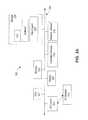
- FIG. 4is a block diagram of an exemplary appliance 410 provided in an exemplary network environment, consistent with embodiments of the present disclosure.
- Appliance 410can be any of appliances 108 A-C from FIG. 1 .
- Appliance 410can be a module, which is a packaged functional hardware unit designed for use with other components or a part of a program that performs a particular function of related functions.
- appliance 410can also include a gateway that can be any of gateways 106 A-B from FIG. 1 .
- appliance 410can process outgoing packets and can accept datagrams from other networks (e.g., private network 401 ) or client devices (e.g., client 403 ).
- Appliance 410can process the datagrams, analyzing their contents, produce IPsec protected datagrams and forward those datagrams across any one of multiple connections based on the information previously analyzed. Appliance 410 can support multiple simultaneous connections without needing to create additional SAs to support IPsec.
- Private network 401can be any private network attached to additional computing devices. Private network can be private network 110 from FIG. 1 . Devices or other computing devices attached to private network 401 can send datagrams intended for another network or device to appliance 410 for processing.
- client 403can provide datagrams intended for other networks or devices to appliance 410 for processing.
- Client 403can be one of client devices 102 A-G.
- Client 403can be directly connected to appliance 410 without passing through an intermediate network.
- Appliance 410can receive datagrams from private network 401 , client 403 , or any other computing device sending data to a network or computing device reachable by appliance 410 .
- Appliance 410can be source S 1 -S 3 for multiple links connecting to destinations D 1 -D 3 , respectively. While appliance 410 is shown as the source of network connections, it is appreciated that appliance 410 can also receive data from other network devices or computers intended for private network 401 or client 403 .
- Appliance 410can consist of multiple components designed to provide a single IPsec channel across a network. In some embodiments appliance 410 is combined with gateway 420 . In other embodiments gateway 420 is a separate component communicatively coupled with appliance 410 .
- Appliance 410includes classifier 411 .
- Classifier 411is a module that can analyze datagrams supplied to appliance 410 .
- Classifier 411can inspect the datagrams and create metadata associated with the datagram to assist with routing decisions.
- the metadata associated with each datagramcan be based on a variety of factors (e.g., the source or destination IP address, the underlying application, the additional protocols used in the datagram, the content of the datagram itself, or other attributes of the datagram).
- This metadatacan be assigned according to preset rules or can be dynamic based on changing requirements of the system. For example, if the data in the IP datagram corresponds to type of traffic, metadata that indicates the particular DSCP tag can be added to the datagram.
- the metadatacan indicate that the datagram contains Voice over IP (“VOIP”) traffic classified using DSCP tag Expedited Forwarding (“EF”) that can require a higher priority than other types of network traffic.
- VOIPVoice over IP
- EFExpedited Forwarding
- the specific metadatacan affect the links that are chosen for different types of traffic. For example, datagrams associated with DSCP tag EF can be transmitted using a specific physical link best suited to this type of traffic. Datagrams with metadata that indicate the datagram carries VOIP traffic can be transmitted using low latency and low jitter connections to ensure a higher quality of service.
- IPsec 412is a module designed to encode an IP datagram consistent with the IPsec specification and based on the properties stored in SA 413 .
- SA 413can be an SA created according to a process such as IKE to allow IPsec communication with a desired endpoint (e.g., gateway 421 or appliance 430 ).
- SA 413is created prior to datagrams being transmitted by appliance 410 .
- Many IPsec modules commonly availablecan be incorporated into appliance 410 to provide the functionality described for IPsec 412 .
- Packet analyzer 417is a module designed to analyze encoded datagrams and associated metadata, to provide routing information, and to add additional fields to the datagram. For example, packet analyzer might determine, based on the metadata provided by classifier 411 , that the datagram should be sent using an MPLS connection. In another example, packet analyzer 417 will determine that the datagram can be sent according to the fastest route or that the datagram has a low importance and can be prioritized below other network traffic. These determinations can be associated with the encoded datagram as additional metadata. Further, packet analyzer 417 can add a timestamp and sequence number to the encoded datagram.
- This timestamp and sequence numbercan be used by a receiving appliance (e.g., appliance 430 ) to reassemble a sequence of datagrams that were sent across different physical links in the proper order.
- packet analyzercan provide the datagram and associated metadata to gateway 420 .
- Gateway 420is a module designed to handle the routing and physical connections to remote networks and devices. As previously described, in some embodiments, gateway 420 is part of appliance 410 . In other embodiments gateway 420 is a separate module. Gateway 420 provides physical connections to other networks or computing devices. Additionally, gateway 420 can include modules or functionality designed to route network traffic and monitor physical network links. When physical network links fail, gateway 420 can re-establish the connection. Because SA is setup at a virtual endpoint prior to gateway 420 , re-establishing physical links does not require the overhead associated with creating new SAs. Instead, when physical links are re-established, they are already part of the IPsec protected pathway without the need for a new SA.
- Gateway 420can include packet router 421 .
- Packet router 421is a module designed to route IP datagrams according to the content and metadata associated with those datagrams, and the current state of the various network connections. Packet router 421 can base routing decisions solely on the information in the datagram's metadata or can combine the metadata information with information provided by link evaluator 422 . Link evaluator 422 is described in more detail below. Packet router 421 can use the provided information to select the optimal link (e.g., one of network connections represented by network sources S 1 -S 3 ) for a specific datagram.
- the optimal linke.g., one of network connections represented by network sources S 1 -S 3
- packet router 421can choose a dedicated physical link for best suited for this type of traffic. For example, if data provided by link evaluator 422 indicates that a particular link is degraded or overwhelmed, packet router 421 can avoid adding new traffic to that physical link. After packet router 421 chooses a link, the datagram can be transmitted on the selected connection.
- Link evaluator 422is a module designed to continually analyze the status of active network connections. After datagrams are transmitted from sources S 1 -S 3 , the source can provide transmission statistics to link evaluator 422 . This can include the time for the datagram to reach one of destinations D 1 -D 3 , the error rate of a particular connection, or any other statistic relevant to the status of a network link. Link evaluator 422 can combine the information from each of the network connections and provide that information to packet router 421 to assist with routing decisions. Additionally, link evaluator 422 can detect when a particular connection has failed and alert gateway 420 that the link must be re-established.
- Gateway 421is a module designed to receive datagrams arriving on multiple physical connections and combine them into a single datagram stream for decoding. Although not shown in FIG. 4 , gateway 421 can include the same components as gateway 421 for transmitting datagrams. Accordingly, in some embodiments, the communication between gateway 420 and gateway 421 is two-way, meaning that gateway 421 can operate as both a destination and a source. Gateway 421 can forward the datagrams received at destinations D 1 -D 3 to appliance 430 .
- Appliance 430can include IPsec module 432 , which can decode an IP datagram consistent with the IPsec specification and based on the properties stored in SA 433 .
- SA 433can be an SA setup according to a process such as IKE to allow IPsec communication with a desired endpoint. (e.g., gateway 420 or appliance 410 ).
- SA 433is created prior to datagrams being received by appliance 430 .
- Many IPsec modules commonly availablecan be incorporated into appliance 430 to provide the functionality described for IPsec 432 .
- IPsec 432can have the same structure and functionality as IPsec 412 (and vice versa).
- SA 433can match SA 413 to allow IPsec 432 to decode datagrams encoded with IPsec 412 .
- appliance 430can route the datagrams according to the IP addresses in the original IP headers.
- the datagramscan, for example, be routed directly to client device 405 or 404 , which can be an example of client device 102 from FIG. 1 .
- Datagramscan also be forwarded to private network 402 for further routing.
- Private network 402can be an example of private network 110 from FIG. 1 .
- FIG. 4demonstrates an embodiment consistent with the present disclosure that allows, for example, a client device (e.g., client device 403 ) to communicate in a secure manner with a remote client device (e.g., client device 405 ).
- a client devicee.g., client device 403
- a remote client devicee.g., client device 405
- creating the IPsec tunnel at appliance 410 and appliance 430 instead of at the location of the physical network linkse.g., S 1 -S 3 to D 1 -D 3
- the disclosed embodimentscan intelligently route traffic to optimize the available network links.
- the disclosed embodimentscan eliminate much of the overhead and difficulty with managing a separate IPsec tunnel for each physical link. Moreover, the disclosed embodiments improve prior systems that only encapsulate multi-link IPsec tunnel management into a separate module or component without reducing or eliminating the overhead and difficulties associated with maintaining multiple IPsec connections.
- FIG. 4The embodiment and modules or components disclosed in FIG. 4 are exemplary. It is appreciated that many of the components could be combined or separated and placed in different configurations. The structure of FIG. 4 is not meant to be limiting.
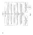
- FIG. 5is a flowchart representing an exemplary method 500 for providing an IPsec encoded datagram to a remote computing environment across multiple physical links. It will be readily appreciated that the illustrated procedure can be altered to delete steps or further include additional steps.
- an appliancee.g., appliance 410
- the obtained datagramcan originate at a local client (e.g., client 403 ) or some other computing device communicatively coupled to the appliance.
- the appliancecan then classify (step 520 ) the datagram according to the destination and other characteristics.
- a classifiere.g., classifier 411
- the classifiercan associate (step 530 ) metadata with the datagram based on the classification.
- This metadatacan describe the contents or nature of the datagram for later use by a routing engine.
- the metadatacan indicate, among other things, the type of data in the datagram, the importance of the datagram, and the encapsulated protocols.
- the appliancecan encode (step 540 ) the datagram using an encoding that follows IPsec policies.
- the appliancecan use any standard IPsec module or system.
- the SA used by the IPsec module or systemcan be negotiated ahead of time using commonly understood techniques such as IKE.
- the appliancecan (e.g., using packet analyzer 417 ) associate (step 550 ) additional control information to the encoded datagram.
- the additional informationcan include, at least, a timestamp and a sequence number. The timestamp and sequence number can be used at the destination endpoint to reorganize datagrams that have taken different paths into the same sequence as they were produced.
- the appliancecan (e.g., using gateway 420 , packet router 421 , and sources S 1 -S 3 ) transmit (step 560 ) the encoded datagram based on the associated metadata and the appliance's knowledge of the each individual network link.
- the appliancecan favor links having faster response times in order to optimize bandwidth.
- the sourcee.g., one of S 1 -S 3 from FIG. 4
- the sourcewill be determined solely based on the metadata associated with the datagram. For example, a datagram carrying MPLS data may be tied to a specific network link.
- the source of the transmissioncan obtain (step 570 ) transmission statistics about the specific physical connection used. Those statistics can include, for example, the number of dropped packets, the error rates, the latency, and other analytics related to the physical link. These connection statistics can be provided to the appliance (e.g., using link evaluator 422 ). The appliance can evaluate (step 580 ) the connection statistics and provide the evaluations to the appliance (e.g., using packet router 421 ). Accordingly, the evaluations are updated periodically as the datagrams are transmitted and network conditions fluctuate.
- FIG. 6is a flowchart representing an exemplary method 600 for receiving an IPsec encoded datagram from a remote computing environment across multiple physical links. It will be readily appreciated that the illustrated procedure can be altered to delete steps or further include additional steps.
- an appliancee.g., appliance 430
- the obtained datagramcan originate at a remote client (e.g., client 403 ) or some other computing device communicatively coupled to the appliance.
- the appliancecan organize (step 620 ) the datagram among other datagrams obtained based on the timestamp and sequence number embedded in the datagram. Although each datagram is individually processed, because the datagrams can be transmitted across any one of many physical links, they may not arrive in the same order in which they were sent. In some embodiments, the organization can occur after the datagram has been decoded.
- the appliancecan decode (step 630 ) the datagram (e.g., using an IPsec 432 and SA 433 ) in the proper sequence based on the timestamps and sequence numbers of the related datagrams.
- the appliancecan than route (step 640 ) the decoded datagram to a computing device (e.g., client 405 , client 404 , or another device connected to private network 402 ) according to the original IP header destination.
Landscapes
- Engineering & Computer Science (AREA)
- Computer Security & Cryptography (AREA)
- Computer Networks & Wireless Communication (AREA)
- Signal Processing (AREA)
- Computer Hardware Design (AREA)
- Computing Systems (AREA)
- General Engineering & Computer Science (AREA)
- Data Exchanges In Wide-Area Networks (AREA)
Abstract
Description
Claims (19)
Priority Applications (7)
| Application Number | Priority Date | Filing Date | Title |
|---|---|---|---|
| US14/811,695US10051000B2 (en) | 2015-07-28 | 2015-07-28 | Efficient use of IPsec tunnels in multi-path environment |
| PCT/US2016/044317WO2017019798A1 (en) | 2015-07-28 | 2016-07-27 | Efficient use of ipsec tunnels in a multi-path environment |
| KR1020187002657AKR102200857B1 (en) | 2015-07-28 | 2016-07-27 | Efficient use of IPsec tunnels in a multipath environment |
| JP2017568321AJP7075216B2 (en) | 2015-07-28 | 2016-07-27 | Efficient use of IPsec tunnels in a multipath environment |
| EP16747986.4AEP3329651B1 (en) | 2015-07-28 | 2016-07-27 | Efficient use of ipsec tunnels in a multi-path environment |
| CN201680042825.7ACN107852411B (en) | 2015-07-28 | 2016-07-27 | Efficient use of IPsec tunnels in a multipath environment |
| US16/028,106US10992709B2 (en) | 2015-07-28 | 2018-07-05 | Efficient use of IPsec tunnels in multi-path environment |
Applications Claiming Priority (1)
| Application Number | Priority Date | Filing Date | Title |
|---|---|---|---|
| US14/811,695US10051000B2 (en) | 2015-07-28 | 2015-07-28 | Efficient use of IPsec tunnels in multi-path environment |
Related Child Applications (1)
| Application Number | Title | Priority Date | Filing Date |
|---|---|---|---|
| US16/028,106ContinuationUS10992709B2 (en) | 2015-07-28 | 2018-07-05 | Efficient use of IPsec tunnels in multi-path environment |
Publications (2)
| Publication Number | Publication Date |
|---|---|
| US20170034213A1 US20170034213A1 (en) | 2017-02-02 |
| US10051000B2true US10051000B2 (en) | 2018-08-14 |
Family
ID=56609989
Family Applications (2)
| Application Number | Title | Priority Date | Filing Date |
|---|---|---|---|
| US14/811,695Active2035-08-14US10051000B2 (en) | 2015-07-28 | 2015-07-28 | Efficient use of IPsec tunnels in multi-path environment |
| US16/028,106Active2035-08-08US10992709B2 (en) | 2015-07-28 | 2018-07-05 | Efficient use of IPsec tunnels in multi-path environment |
Family Applications After (1)
| Application Number | Title | Priority Date | Filing Date |
|---|---|---|---|
| US16/028,106Active2035-08-08US10992709B2 (en) | 2015-07-28 | 2018-07-05 | Efficient use of IPsec tunnels in multi-path environment |
Country Status (6)
| Country | Link |
|---|---|
| US (2) | US10051000B2 (en) |
| EP (1) | EP3329651B1 (en) |
| JP (1) | JP7075216B2 (en) |
| KR (1) | KR102200857B1 (en) |
| CN (1) | CN107852411B (en) |
| WO (1) | WO2017019798A1 (en) |
Families Citing this family (15)
| Publication number | Priority date | Publication date | Assignee | Title |
|---|---|---|---|---|
| US11900090B2 (en) | 2015-10-27 | 2024-02-13 | Airwatch Llc | Enforcement of updates for devices unassociated with a directory service |
| US10860304B2 (en)* | 2015-10-27 | 2020-12-08 | Airwatch Llc | Enforcement of updates for devices unassociated with a directory service |
| CN106656914A (en)* | 2015-10-29 | 2017-05-10 | 阿里巴巴集团控股有限公司 | Anti-attack data transmission method and apparatus |
| US10250578B2 (en)* | 2015-11-03 | 2019-04-02 | Qualcomm Incorporated | Internet key exchange (IKE) for secure association between devices |
| US20190036814A1 (en)* | 2017-07-31 | 2019-01-31 | Cisco Technology, Inc. | Traffic steering with path ordering |
| US20190036842A1 (en)* | 2017-07-31 | 2019-01-31 | Cisco Technology, Inc. | Traffic steering in fastpath |
| US10771435B2 (en)* | 2018-11-20 | 2020-09-08 | Netskope, Inc. | Zero trust and zero knowledge application access system |
| WO2019072307A2 (en) | 2018-12-28 | 2019-04-18 | Alibaba Group Holding Limited | Accelerating transaction deliveries in blockchain networks using acceleration nodes |
| WO2019072308A2 (en) | 2018-12-28 | 2019-04-18 | Alibaba Group Holding Limited | Improving blockchain transaction speeds using global acceleration nodes |
| CN109863522B (en)* | 2018-12-28 | 2023-09-26 | 创新先进技术有限公司 | Accelerating transaction delivery in blockchain networks using transaction retransmissions |
| US11509673B2 (en)* | 2019-06-11 | 2022-11-22 | Zscaler, Inc. | Automated estimation of network security policy risk |
| US11477172B2 (en)* | 2020-01-24 | 2022-10-18 | International Business Machines Corporation | Securing data compression |
| CN113691490B (en)* | 2020-05-19 | 2024-10-22 | 华为技术有限公司 | A method and device for verifying SRv6 message |
| US20240340186A1 (en)* | 2021-07-21 | 2024-10-10 | Visa International Service Association | Authentication using group signatures of user devices |
| US12223029B2 (en)* | 2022-01-12 | 2025-02-11 | Dell Products, L.P. | Systems and methods for transfer of workspace orchestration |
Citations (22)
| Publication number | Priority date | Publication date | Assignee | Title |
|---|---|---|---|---|
| US20040215955A1 (en)* | 2003-04-24 | 2004-10-28 | Masaaki Tamai | Encrypted packet, processing device, method, program, and program recording medium |
| US20050076228A1 (en)* | 2003-10-02 | 2005-04-07 | Davis John M. | System and method for a secure I/O interface |
| US20050198531A1 (en) | 2004-03-02 | 2005-09-08 | Marufa Kaniz | Two parallel engines for high speed transmit IPSEC processing |
| AU2005201275A1 (en) | 2004-03-26 | 2005-10-13 | Canon Kabushiki Kaisha | Internet protocol tunnelling using templates |
| US20070186100A1 (en)* | 2006-02-03 | 2007-08-09 | Fujitsu Limited | Packet communication system |
| WO2007103338A2 (en) | 2006-03-08 | 2007-09-13 | Cipheroptics, Inc. | Technique for processing data packets in a communication network |
| US20090144819A1 (en)* | 2007-11-29 | 2009-06-04 | Uppinder Singh Babbar | Flow classification for encrypted and tunneled packet streams |
| US7571463B1 (en)* | 2003-01-24 | 2009-08-04 | Nortel Networks Limited | Method an apparatus for providing a scalable and secure network without point to point associations |
| US20100098419A1 (en)* | 2008-10-20 | 2010-04-22 | Broadlight, Ltd. | Gigabit passive optical network (gpon) residential gateway |
| US20100223458A1 (en)* | 2009-02-27 | 2010-09-02 | Mcgrew David | Pair-wise keying for tunneled virtual private networks |
| US20130039487A1 (en)* | 2011-08-12 | 2013-02-14 | Cisco Technology, Inc. | Coordinating compression information for unreliable encrypted streams through key establishment protocols |
| US20130091352A1 (en)* | 2011-10-05 | 2013-04-11 | Cisco Technology, Inc. | Techniques to Classify Virtual Private Network Traffic Based on Identity |
| US20130103940A1 (en)* | 2011-10-19 | 2013-04-25 | Alexandru R. Badea | Methods, systems, and computer readable media for performing encapsulating security payload (esp) rehashing |
| US8477616B1 (en)* | 2001-06-05 | 2013-07-02 | Avaya Inc. | Method for achieving high-availability of itineraries in a real-time network scheduled packet routing system |
| US20130263249A1 (en) | 2012-03-30 | 2013-10-03 | Futurewei Technologies, Inc. | Enhancing IPSEC Performance and Security Against Eavesdropping |
| US20130298182A1 (en)* | 2012-05-01 | 2013-11-07 | Fortinet, Inc. | Policy-based configuration of internet protocol security for a virtual private network |
| US20130311778A1 (en)* | 2012-05-16 | 2013-11-21 | Cisco Technology, Inc. | System and method for secure cloud service delivery with prioritized services in a network environment |
| US20140101435A1 (en)* | 2012-10-10 | 2014-04-10 | Canon Kabushiki Kaisha | Encrypted communication apparatus and control method therefor |
| US20150085664A1 (en)* | 2013-09-20 | 2015-03-26 | Telecommunication Systems, Inc. | Quality of Service to Over the Top Applications Used With VPN |
| WO2015047143A1 (en) | 2013-09-30 | 2015-04-02 | Telefonaktiebolaget L M Ericsson (Publ) | A method performed at an ip network node for ipsec establishment |
| US20150195265A1 (en)* | 2014-01-08 | 2015-07-09 | Sonicwall, Inc. | Virtual private network dead peer detection |
| US20150295899A1 (en)* | 2014-04-09 | 2015-10-15 | Cisco Technology, Inc. | Group Member Recovery Techniques |
Family Cites Families (108)
| Publication number | Priority date | Publication date | Assignee | Title |
|---|---|---|---|---|
| JP2798534B2 (en)* | 1991-10-01 | 1998-09-17 | 日本電気株式会社 | Multi-link control method |
| US6438612B1 (en)* | 1998-09-11 | 2002-08-20 | Ssh Communications Security, Ltd. | Method and arrangement for secure tunneling of data between virtual routers |
| JP3540183B2 (en) | 1999-01-21 | 2004-07-07 | 株式会社東芝 | Multilink communication device |
| US20030014627A1 (en)* | 1999-07-08 | 2003-01-16 | Broadcom Corporation | Distributed processing in a cryptography acceleration chip |
| US7600131B1 (en)* | 1999-07-08 | 2009-10-06 | Broadcom Corporation | Distributed processing in a cryptography acceleration chip |
| US7082530B1 (en)* | 1999-12-31 | 2006-07-25 | Intel Corporation | Method and apparatus for accelerating hardware encryption with multiple networking interfaces |
| US6941377B1 (en)* | 1999-12-31 | 2005-09-06 | Intel Corporation | Method and apparatus for secondary use of devices with encryption |
| US7181012B2 (en)* | 2000-09-11 | 2007-02-20 | Telefonaktiebolaget Lm Ericsson (Publ) | Secured map messages for telecommunications networks |
| US6839754B2 (en)* | 2000-09-15 | 2005-01-04 | Wm. Marsh Rice University | Network tomography using closely-spaced unicast packets |
| JP3639208B2 (en)* | 2000-11-28 | 2005-04-20 | 株式会社東芝 | Mobile communication system, mobile terminal device, AAAH server device, authentication charging service providing method, authentication charging service enjoying method, mobile terminal device information providing method, and partner terminal confirmation method |
| US7664119B2 (en)* | 2001-03-30 | 2010-02-16 | Intel Corporation | Method and apparatus to perform network routing |
| US7296155B1 (en)* | 2001-06-08 | 2007-11-13 | Cisco Technology, Inc. | Process and system providing internet protocol security without secure domain resolution |
| US20030002676A1 (en)* | 2001-06-29 | 2003-01-02 | Stachura Thomas L. | Method and apparatus to secure network communications |
| US7389412B2 (en)* | 2001-08-10 | 2008-06-17 | Interactive Technology Limited Of Hk | System and method for secure network roaming |
| US20030031151A1 (en)* | 2001-08-10 | 2003-02-13 | Mukesh Sharma | System and method for secure roaming in wireless local area networks |
| FI116027B (en)* | 2001-09-28 | 2005-08-31 | Netseal Mobility Technologies | Procedures and systems to ensure the secure transmission of messages |
| JP3678200B2 (en) | 2002-01-11 | 2005-08-03 | Kddi株式会社 | Route distribution device for improving confidentiality of communication contents |
| FI116017B (en)* | 2002-01-22 | 2005-08-31 | Netseal Mobility Technologies | Procedure for sending messages over secure mobile communication links |
| FI118170B (en)* | 2002-01-22 | 2007-07-31 | Netseal Mobility Technologies | A method and system for transmitting a message over a secure connection |
| JP2003229798A (en)* | 2002-02-05 | 2003-08-15 | Hitachi Ltd | Wireless relay system |
| US6792534B2 (en)* | 2002-03-22 | 2004-09-14 | General Instrument Corporation | End-to end protection of media stream encryption keys for voice-over-IP systems |
| US7287269B2 (en)* | 2002-07-29 | 2007-10-23 | International Buiness Machines Corporation | System and method for authenticating and configuring computing devices |
| FR2844941B1 (en)* | 2002-09-24 | 2005-02-18 | At & T Corp | REQUEST FOR SECURE ACCESS TO THE RESOURCES OF AN INTRANET NETWORK |
| JP4346898B2 (en)* | 2002-12-09 | 2009-10-21 | Necインフロンティア株式会社 | Maintenance interface user authentication method and apparatus in client-server distributed system |
| JPWO2004059903A1 (en)* | 2002-12-25 | 2006-05-11 | 株式会社日立製作所 | Network device, network system, and group management method |
| WO2004080026A1 (en)* | 2003-03-04 | 2004-09-16 | Lukas Wunner | Method, system and storage medium for introducing data network accessibility information |
| GB0312681D0 (en)* | 2003-06-03 | 2003-07-09 | Ericsson Telefon Ab L M | IP mobility |
| US7421578B1 (en)* | 2003-07-22 | 2008-09-02 | Cisco Technology, Inc. | Method and apparatus for electing a leader node in a computer network |
| US7333799B2 (en)* | 2003-08-29 | 2008-02-19 | Microsoft Corporation | WAP XML extension to define VPN connections |
| US20050138380A1 (en)* | 2003-12-22 | 2005-06-23 | Fedronic Dominique L.J. | Entry control system |
| US7305706B2 (en)* | 2004-01-15 | 2007-12-04 | Cisco Technology, Inc. | Establishing a virtual private network for a road warrior |
| JP3955025B2 (en)* | 2004-01-15 | 2007-08-08 | 松下電器産業株式会社 | Mobile radio terminal device, virtual private network relay device, and connection authentication server |
| JP4006403B2 (en)* | 2004-01-21 | 2007-11-14 | キヤノン株式会社 | Digital signature issuing device |
| EP1562346A1 (en)* | 2004-02-06 | 2005-08-10 | Matsushita Electric Industrial Co., Ltd. | Method and system for reliably disconnecting IPSec security associations |
| JP3976324B2 (en)* | 2004-02-27 | 2007-09-19 | 株式会社日立製作所 | A system that allocates storage areas to computers according to security levels |
| US8186026B2 (en)* | 2004-03-03 | 2012-05-29 | Rockstar Bidco, LP | Technique for maintaining secure network connections |
| US7461152B2 (en)* | 2004-03-31 | 2008-12-02 | International Business Machines Corporation | Apparatus and method for sharing a shared resource across logical partitions or systems |
| JP2005310025A (en)* | 2004-04-26 | 2005-11-04 | Hitachi Ltd | Storage device, computer system, and initiator authorization method |
| BRPI0418877B1 (en)* | 2004-05-31 | 2020-03-17 | Telecom Italia S.P.A. | METHOD AND SYSTEM TO ENABLE A USER TO COMMUNICATE IN A PRIVATE VIRTUAL NETWORK THROUGH A PUBLIC COMMUNICATION NETWORK, AND, PUBLIC COMMUNICATION NETWORK |
| US8364948B2 (en)* | 2004-07-02 | 2013-01-29 | Hewlett-Packard Development Company, L.P. | System and method for supporting secured communication by an aliased cluster |
| US7940779B2 (en)* | 2004-09-30 | 2011-05-10 | Telecom Italia S.P.A. | Method and system for controlling mobility in a communication network, related network and computer program product therefor |
| US9794237B2 (en)* | 2005-01-31 | 2017-10-17 | Unisys Corporation | Secured networks and endpoints applying internet protocol security |
| US7577130B2 (en)* | 2005-02-18 | 2009-08-18 | Microsoft Corporation | SyncML based OMA connectivity object to provision VPN connections |
| US8438629B2 (en)* | 2005-02-21 | 2013-05-07 | Samsung Electronics Co., Ltd. | Packet security method and apparatus |
| US7505442B2 (en)* | 2005-04-05 | 2009-03-17 | Nokia Corporation | Routing transformation, security, and authorization for delegated prefixes |
| US20060230446A1 (en)* | 2005-04-06 | 2006-10-12 | Vu Lan N | Hybrid SSL/IPSec network management system |
| US20070006296A1 (en)* | 2005-06-29 | 2007-01-04 | Nakhjiri Madjid F | System and method for establishing a shared key between network peers |
| EP1949724A4 (en)* | 2005-11-16 | 2011-07-06 | Nokia Corp | SYSTEM AND METHOD FOR ESTABLISHING INDEPENDENT SUPPORT CONNECTIONS AND SECURITY |
| US8201233B2 (en)* | 2006-02-06 | 2012-06-12 | Cisco Technology, Inc. | Secure extended authentication bypass |
| US20090063851A1 (en)* | 2006-03-20 | 2009-03-05 | Nijdam Mark J | Establishing communications |
| WO2007120915A2 (en)* | 2006-04-17 | 2007-10-25 | Starent Networks Corporation | System and method for traffic localization |
| GB2442044B8 (en)* | 2006-05-11 | 2011-02-23 | Ericsson Telefon Ab L M | Addressing and routing mechanism for web server clusters. |
| US20080076425A1 (en)* | 2006-09-22 | 2008-03-27 | Amit Khetawat | Method and apparatus for resource management |
| JP2008035272A (en)* | 2006-07-28 | 2008-02-14 | Canon Inc | Information processing system and data communication method in the system |
| US8204502B2 (en)* | 2006-09-22 | 2012-06-19 | Kineto Wireless, Inc. | Method and apparatus for user equipment registration |
| US20080076419A1 (en)* | 2006-09-22 | 2008-03-27 | Amit Khetawat | Method and apparatus for discovery |
| US7995994B2 (en)* | 2006-09-22 | 2011-08-09 | Kineto Wireless, Inc. | Method and apparatus for preventing theft of service in a communication system |
| US20080076392A1 (en)* | 2006-09-22 | 2008-03-27 | Amit Khetawat | Method and apparatus for securing a wireless air interface |
| US20080076412A1 (en)* | 2006-09-22 | 2008-03-27 | Amit Khetawat | Method and apparatus for registering an access point |
| US8073428B2 (en)* | 2006-09-22 | 2011-12-06 | Kineto Wireless, Inc. | Method and apparatus for securing communication between an access point and a network controller |
| US8036664B2 (en)* | 2006-09-22 | 2011-10-11 | Kineto Wireless, Inc. | Method and apparatus for determining rove-out |
| JP2008103988A (en)* | 2006-10-19 | 2008-05-01 | Fujitsu Ltd | Cryptographic communication system, apparatus, method and program |
| US8607302B2 (en)* | 2006-11-29 | 2013-12-10 | Red Hat, Inc. | Method and system for sharing labeled information between different security realms |
| US8239706B1 (en)* | 2007-01-03 | 2012-08-07 | Board Of Governors For Higher Education, State Of Rhode Island And Providence Plantations | Data retrieval system and method that provides retrieval of data to any point in time |
| KR100839941B1 (en)* | 2007-01-08 | 2008-06-20 | 성균관대학교산학협력단 | Abnormal ISP traffic control system using IP setting information and session information and control method thereof |
| US8549135B1 (en)* | 2007-05-18 | 2013-10-01 | Raytheon Company | Method and apparatus for performing quality of service in secure networks |
| CN100596062C (en)* | 2007-08-16 | 2010-03-24 | 杭州华三通信技术有限公司 | Distributed message transmission security protection device and method |
| JP5167759B2 (en)* | 2007-10-24 | 2013-03-21 | 日本電気株式会社 | Communication system, communication method, authentication information management server, and small base station |
| JP2009111437A (en)* | 2007-10-26 | 2009-05-21 | Hitachi Ltd | Network system |
| EP2226967B1 (en)* | 2007-12-19 | 2017-10-25 | Fujitsu Limited | Encryption implementation control system and encryption implementation control devices |
| CN101197664B (en)* | 2008-01-03 | 2010-12-08 | 杭州华三通信技术有限公司 | Method, system and device for key management protocol negotiation |
| US20090262702A1 (en)* | 2008-04-18 | 2009-10-22 | Amit Khetawat | Method and Apparatus for Direct Transfer of RANAP Messages in a Home Node B System |
| US8413226B2 (en)* | 2008-05-13 | 2013-04-02 | Telefonaktiebolaget Lm Ericsson (Publ) | User-type handling in a wireless access network |
| JP2010034860A (en)* | 2008-07-29 | 2010-02-12 | Fujitsu Ltd | Ip network communicating method which has security function, and communicating system |
| US8612582B2 (en)* | 2008-12-19 | 2013-12-17 | Openpeak Inc. | Managed services portals and method of operation of same |
| US8788655B2 (en)* | 2008-12-19 | 2014-07-22 | Openpeak Inc. | Systems for accepting and approving applications and methods of operation of same |
| US8615581B2 (en)* | 2008-12-19 | 2013-12-24 | Openpeak Inc. | System for managing devices and method of operation of same |
| US8650290B2 (en)* | 2008-12-19 | 2014-02-11 | Openpeak Inc. | Portable computing device and method of operation of same |
| US8856322B2 (en)* | 2008-12-19 | 2014-10-07 | Openpeak Inc. | Supervisory portal systems and methods of operation of same |
| US8745213B2 (en)* | 2008-12-19 | 2014-06-03 | Openpeak Inc. | Managed services platform and method of operation of same |
| CN101478755B (en)* | 2009-01-21 | 2011-05-11 | 中兴通讯股份有限公司 | Network security HTTP negotiation method and related apparatus |
| CN101998494B (en)* | 2009-08-21 | 2016-02-03 | 华为技术有限公司 | The method of Business Stream shared resource, system and IAD |
| CA2789291A1 (en)* | 2010-02-26 | 2011-09-01 | General Instrument Corporation | Dynamic cryptographic subscriber-device identity binding for subscriber mobility |
| JP2011199340A (en)* | 2010-03-17 | 2011-10-06 | Fujitsu Ltd | Communication apparatus and method, and communication system |
| US8671273B2 (en)* | 2010-04-15 | 2014-03-11 | The University Of Maryland | Method of performance-aware security of unicast communication in hybrid satellite networks |
| WO2011143094A2 (en)* | 2010-05-09 | 2011-11-17 | Citrix Systems, Inc. | Systems and methods for allocation of classes of service to network connections corresponding to virtual channels |
| WO2011151924A1 (en)* | 2010-06-04 | 2011-12-08 | 富士通株式会社 | Processing device, processing method, and processing program |
| CN102006294B (en)* | 2010-11-25 | 2014-08-20 | 中兴通讯股份有限公司 | IP multimedia subsystem (IMS) multimedia communication method and system as well as terminal and IMS core network |
| US8654723B2 (en)* | 2011-03-04 | 2014-02-18 | Rogers Communications Inc. | Method and device for re-using IPSec tunnel in customer premises equipment |
| US10637782B2 (en)* | 2011-03-23 | 2020-04-28 | Hughes Network Systems, Llc | System and method for policy-based multipath WAN transports for improved quality of service over broadband networks |
| US9264397B2 (en)* | 2011-10-18 | 2016-02-16 | Bluecat Networks (Usa) Inc. | Method and system for implementing a user network identity address provisioning server |
| JP5906896B2 (en)* | 2012-03-29 | 2016-04-20 | 富士通株式会社 | Network system and communication control method |
| US9930543B2 (en)* | 2012-05-04 | 2018-03-27 | Parallel Limited | Optimizing mobile network bandwidth |
| JP2013247447A (en)* | 2012-05-24 | 2013-12-09 | Nec Corp | Service control device, relay device, femtocell base station, communication system, control method, and program |
| US10091102B2 (en)* | 2013-01-09 | 2018-10-02 | Cisco Technology, Inc. | Tunnel sub-interface using IP header field |
| US9602470B2 (en)* | 2013-05-23 | 2017-03-21 | Sercomm Corporation | Network device, IPsec system and method for establishing IPsec tunnel using the same |
| US20150149220A1 (en)* | 2013-11-26 | 2015-05-28 | Verizon Patent And Licensing Inc. | Methods and Procedures for a Travel Assistance Platform |
| CN105940644B (en)* | 2013-12-02 | 2019-11-12 | 阿卡麦科技公司 | Distribution-optimized Virtual Private Network (VPN)-as-a-service while maintaining end-to-end data security |
| US9813343B2 (en)* | 2013-12-03 | 2017-11-07 | Akamai Technologies, Inc. | Virtual private network (VPN)-as-a-service with load-balanced tunnel endpoints |
| US10153940B2 (en)* | 2014-09-16 | 2018-12-11 | CloudGenix, Inc. | Methods and systems for detection of asymmetric network data traffic and associated network devices |
| US9847875B1 (en)* | 2016-06-20 | 2017-12-19 | Verizon Patent And Licensing Inc. | Methods and systems for bootstrapping an end-to-end application layer session security keyset based on a subscriber identity master security credential |
| US20170374025A1 (en)* | 2016-06-28 | 2017-12-28 | Fortinet, Inc. | Internet protocol security (ipsec) interface configuration and management |
| KR102246671B1 (en)* | 2016-11-11 | 2021-05-03 | 텔레호낙티에볼라게트 엘엠 에릭슨(피유비엘) | User Plane Model for Non-3GPP Access to the 5th Generation Core Network |
| US10721097B2 (en)* | 2018-04-24 | 2020-07-21 | Microsoft Technology Licensing, Llc | Dynamic scaling of virtual private network connections |
| US10951478B2 (en)* | 2018-04-30 | 2021-03-16 | Cisco Technology, Inc. | User plane group |
| US10812370B2 (en)* | 2018-08-03 | 2020-10-20 | Arista Networks, Inc. | Unified control plane over MPLS and internet interfaces through BGP |
| US11349653B2 (en)* | 2018-12-18 | 2022-05-31 | Hewlett Packard Enterprise Development Lp | Multiple-site private network secured by IPsec using blockchain network for key exchange |
| US11265714B2 (en)* | 2018-12-28 | 2022-03-01 | Cable Television Laboratories, Inc. | Systems and methods for subscriber certificate provisioning |
- 2015
- 2015-07-28USUS14/811,695patent/US10051000B2/enactiveActive
- 2016
- 2016-07-27CNCN201680042825.7Apatent/CN107852411B/ennot_activeExpired - Fee Related
- 2016-07-27KRKR1020187002657Apatent/KR102200857B1/ennot_activeExpired - Fee Related
- 2016-07-27JPJP2017568321Apatent/JP7075216B2/enactiveActive
- 2016-07-27WOPCT/US2016/044317patent/WO2017019798A1/ennot_activeCeased
- 2016-07-27EPEP16747986.4Apatent/EP3329651B1/enactiveActive
- 2018
- 2018-07-05USUS16/028,106patent/US10992709B2/enactiveActive
Patent Citations (22)
| Publication number | Priority date | Publication date | Assignee | Title |
|---|---|---|---|---|
| US8477616B1 (en)* | 2001-06-05 | 2013-07-02 | Avaya Inc. | Method for achieving high-availability of itineraries in a real-time network scheduled packet routing system |
| US7571463B1 (en)* | 2003-01-24 | 2009-08-04 | Nortel Networks Limited | Method an apparatus for providing a scalable and secure network without point to point associations |
| US20040215955A1 (en)* | 2003-04-24 | 2004-10-28 | Masaaki Tamai | Encrypted packet, processing device, method, program, and program recording medium |
| US20050076228A1 (en)* | 2003-10-02 | 2005-04-07 | Davis John M. | System and method for a secure I/O interface |
| US20050198531A1 (en) | 2004-03-02 | 2005-09-08 | Marufa Kaniz | Two parallel engines for high speed transmit IPSEC processing |
| AU2005201275A1 (en) | 2004-03-26 | 2005-10-13 | Canon Kabushiki Kaisha | Internet protocol tunnelling using templates |
| US20070186100A1 (en)* | 2006-02-03 | 2007-08-09 | Fujitsu Limited | Packet communication system |
| WO2007103338A2 (en) | 2006-03-08 | 2007-09-13 | Cipheroptics, Inc. | Technique for processing data packets in a communication network |
| US20090144819A1 (en)* | 2007-11-29 | 2009-06-04 | Uppinder Singh Babbar | Flow classification for encrypted and tunneled packet streams |
| US20100098419A1 (en)* | 2008-10-20 | 2010-04-22 | Broadlight, Ltd. | Gigabit passive optical network (gpon) residential gateway |
| US20100223458A1 (en)* | 2009-02-27 | 2010-09-02 | Mcgrew David | Pair-wise keying for tunneled virtual private networks |
| US20130039487A1 (en)* | 2011-08-12 | 2013-02-14 | Cisco Technology, Inc. | Coordinating compression information for unreliable encrypted streams through key establishment protocols |
| US20130091352A1 (en)* | 2011-10-05 | 2013-04-11 | Cisco Technology, Inc. | Techniques to Classify Virtual Private Network Traffic Based on Identity |
| US20130103940A1 (en)* | 2011-10-19 | 2013-04-25 | Alexandru R. Badea | Methods, systems, and computer readable media for performing encapsulating security payload (esp) rehashing |
| US20130263249A1 (en) | 2012-03-30 | 2013-10-03 | Futurewei Technologies, Inc. | Enhancing IPSEC Performance and Security Against Eavesdropping |
| US20130298182A1 (en)* | 2012-05-01 | 2013-11-07 | Fortinet, Inc. | Policy-based configuration of internet protocol security for a virtual private network |
| US20130311778A1 (en)* | 2012-05-16 | 2013-11-21 | Cisco Technology, Inc. | System and method for secure cloud service delivery with prioritized services in a network environment |
| US20140101435A1 (en)* | 2012-10-10 | 2014-04-10 | Canon Kabushiki Kaisha | Encrypted communication apparatus and control method therefor |
| US20150085664A1 (en)* | 2013-09-20 | 2015-03-26 | Telecommunication Systems, Inc. | Quality of Service to Over the Top Applications Used With VPN |
| WO2015047143A1 (en) | 2013-09-30 | 2015-04-02 | Telefonaktiebolaget L M Ericsson (Publ) | A method performed at an ip network node for ipsec establishment |
| US20150195265A1 (en)* | 2014-01-08 | 2015-07-09 | Sonicwall, Inc. | Virtual private network dead peer detection |
| US20150295899A1 (en)* | 2014-04-09 | 2015-10-15 | Cisco Technology, Inc. | Group Member Recovery Techniques |
Non-Patent Citations (3)
| Title |
|---|
| International Search Report and Written Opinion for International Appl. No. PCT/US2016/044317, dated Oct. 5, 2016. |
| PCT Patent Application US2016/044317 filed Jul. 27, 2016; International Search Report and Written Opinion dated Oct. 5, 2016. |
| Zhang, Yun-he, "A Multi-Link Aggregate IPSEC Model," 2009 First International Workshop on Education Technology and Computer Science, 2009 IEEE, pp. 489-493. |
Also Published As
| Publication number | Publication date |
|---|---|
| KR102200857B1 (en) | 2021-01-13 |
| US20170034213A1 (en) | 2017-02-02 |
| US20180316723A1 (en) | 2018-11-01 |
| JP7075216B2 (en) | 2022-05-25 |
| EP3329651A1 (en) | 2018-06-06 |
| JP2018522481A (en) | 2018-08-09 |
| WO2017019798A1 (en) | 2017-02-02 |
| KR20180035813A (en) | 2018-04-06 |
| CN107852411A (en) | 2018-03-27 |
| US10992709B2 (en) | 2021-04-27 |
| CN107852411B (en) | 2021-08-10 |
| EP3329651B1 (en) | 2021-04-14 |
Similar Documents
| Publication | Publication Date | Title |
|---|---|---|
| US10992709B2 (en) | Efficient use of IPsec tunnels in multi-path environment | |
| US20210352017A1 (en) | Virtual private network (vpn)-as-a-service with load- balanced tunnel endpoints | |
| US10630784B2 (en) | Facilitating a secure 3 party network session by a network device | |
| US10305904B2 (en) | Facilitating secure network traffic by an application delivery controller | |
| CA2870048C (en) | Multi-tunnel virtual private network | |
| US11303614B2 (en) | System and method for providing improved optimization for secure session connections | |
| US10447591B2 (en) | Executing multiple virtual private network (VPN) endpoints associated with an endpoint pool address | |
| US20110113236A1 (en) | Methods, systems, and computer readable media for offloading internet protocol security (ipsec) processing using an ipsec proxy mechanism | |
| US11134060B2 (en) | Mobile virtual private network configuration | |
| JP6075871B2 (en) | Network system, communication control method, communication control apparatus, and communication control program |
Legal Events
| Date | Code | Title | Description |
|---|---|---|---|
| AS | Assignment | Owner name:CITRIX SYSTEMS, INC., FLORIDA Free format text:ASSIGNMENT OF ASSIGNORS INTEREST;ASSIGNOR:MURGIA, MARCO ANTONIO;REEL/FRAME:036249/0539 Effective date:20150724 | |
| STCF | Information on status: patent grant | Free format text:PATENTED CASE | |
| MAFP | Maintenance fee payment | Free format text:PAYMENT OF MAINTENANCE FEE, 4TH YEAR, LARGE ENTITY (ORIGINAL EVENT CODE: M1551); ENTITY STATUS OF PATENT OWNER: LARGE ENTITY Year of fee payment:4 | |
| AS | Assignment | Owner name:WILMINGTON TRUST, NATIONAL ASSOCIATION, DELAWARE Free format text:SECURITY INTEREST;ASSIGNOR:CITRIX SYSTEMS, INC.;REEL/FRAME:062079/0001 Effective date:20220930 | |
| AS | Assignment | Owner name:GOLDMAN SACHS BANK USA, AS COLLATERAL AGENT, NEW YORK Free format text:SECOND LIEN PATENT SECURITY AGREEMENT;ASSIGNORS:TIBCO SOFTWARE INC.;CITRIX SYSTEMS, INC.;REEL/FRAME:062113/0001 Effective date:20220930 Owner name:WILMINGTON TRUST, NATIONAL ASSOCIATION, AS NOTES COLLATERAL AGENT, DELAWARE Free format text:PATENT SECURITY AGREEMENT;ASSIGNORS:TIBCO SOFTWARE INC.;CITRIX SYSTEMS, INC.;REEL/FRAME:062113/0470 Effective date:20220930 Owner name:BANK OF AMERICA, N.A., AS COLLATERAL AGENT, NORTH CAROLINA Free format text:PATENT SECURITY AGREEMENT;ASSIGNORS:TIBCO SOFTWARE INC.;CITRIX SYSTEMS, INC.;REEL/FRAME:062112/0262 Effective date:20220930 | |
| AS | Assignment | Owner name:CLOUD SOFTWARE GROUP, INC. (F/K/A TIBCO SOFTWARE INC.), FLORIDA Free format text:RELEASE AND REASSIGNMENT OF SECURITY INTEREST IN PATENT (REEL/FRAME 062113/0001);ASSIGNOR:GOLDMAN SACHS BANK USA, AS COLLATERAL AGENT;REEL/FRAME:063339/0525 Effective date:20230410 Owner name:CITRIX SYSTEMS, INC., FLORIDA Free format text:RELEASE AND REASSIGNMENT OF SECURITY INTEREST IN PATENT (REEL/FRAME 062113/0001);ASSIGNOR:GOLDMAN SACHS BANK USA, AS COLLATERAL AGENT;REEL/FRAME:063339/0525 Effective date:20230410 Owner name:WILMINGTON TRUST, NATIONAL ASSOCIATION, AS NOTES COLLATERAL AGENT, DELAWARE Free format text:PATENT SECURITY AGREEMENT;ASSIGNORS:CLOUD SOFTWARE GROUP, INC. (F/K/A TIBCO SOFTWARE INC.);CITRIX SYSTEMS, INC.;REEL/FRAME:063340/0164 Effective date:20230410 | |
| AS | Assignment | Owner name:WILMINGTON TRUST, NATIONAL ASSOCIATION, AS NOTES COLLATERAL AGENT, DELAWARE Free format text:SECURITY INTEREST;ASSIGNORS:CLOUD SOFTWARE GROUP, INC. (F/K/A TIBCO SOFTWARE INC.);CITRIX SYSTEMS, INC.;REEL/FRAME:067662/0568 Effective date:20240522 |