US10047817B2 - Method and apparatus for an adjustable damper - Google Patents
Method and apparatus for an adjustable damperDownload PDFInfo
- Publication number
- US10047817B2 US10047817B2US14/251,446US201414251446AUS10047817B2US 10047817 B2US10047817 B2US 10047817B2US 201414251446 AUS201414251446 AUS 201414251446AUS 10047817 B2US10047817 B2US 10047817B2
- Authority
- US
- United States
- Prior art keywords
- vehicle
- vehicle suspension
- suspension damper
- valve
- damping
- Prior art date
- Legal status (The legal status is an assumption and is not a legal conclusion. Google has not performed a legal analysis and makes no representation as to the accuracy of the status listed.)
- Active
Links
- 238000000034methodMethods0.000titleclaimsabstractdescription165
- 239000000725suspensionSubstances0.000claimsabstractdescription270
- 230000001133accelerationEffects0.000claimsabstractdescription215
- 238000013016dampingMethods0.000claimsabstractdescription193
- 230000033001locomotionEffects0.000claimsabstractdescription91
- 230000001276controlling effectEffects0.000claimsabstractdescription38
- 230000002829reductive effectEffects0.000claimsabstractdescription20
- 230000001105regulatory effectEffects0.000claimsabstractdescription18
- 238000012544monitoring processMethods0.000claimsabstractdescription15
- 239000012530fluidSubstances0.000claimsdescription77
- 230000004913activationEffects0.000claimsdescription28
- 230000008878couplingEffects0.000claimsdescription4
- 238000010168coupling processMethods0.000claimsdescription4
- 238000005859coupling reactionMethods0.000claimsdescription4
- 230000003213activating effectEffects0.000claimsdescription3
- 230000006835compressionEffects0.000description73
- 238000007906compressionMethods0.000description73
- 238000010586diagramMethods0.000description46
- 239000011295pitchSubstances0.000description43
- 230000035939shockEffects0.000description36
- 238000001514detection methodMethods0.000description35
- 230000004044responseEffects0.000description33
- 239000013641positive controlSubstances0.000description24
- 230000008901benefitEffects0.000description22
- 230000006870functionEffects0.000description22
- 239000013642negative controlSubstances0.000description20
- 239000006096absorbing agentSubstances0.000description19
- 230000015654memoryEffects0.000description14
- 230000001960triggered effectEffects0.000description11
- 230000000694effectsEffects0.000description10
- 239000011435rockSubstances0.000description9
- 230000001351cycling effectEffects0.000description8
- 238000013500data storageMethods0.000description8
- 230000007423decreaseEffects0.000description8
- 239000007788liquidSubstances0.000description8
- 238000005259measurementMethods0.000description8
- 239000003921oilSubstances0.000description8
- 238000003825pressingMethods0.000description8
- 230000008859changeEffects0.000description7
- 230000000670limiting effectEffects0.000description7
- 230000007246mechanismEffects0.000description7
- 230000036316preloadEffects0.000description7
- 238000005516engineering processMethods0.000description6
- 230000009194climbingEffects0.000description5
- 230000003247decreasing effectEffects0.000description5
- 230000001419dependent effectEffects0.000description5
- 238000013461designMethods0.000description5
- 229910000831SteelInorganic materials0.000description4
- 238000013459approachMethods0.000description4
- 238000004891communicationMethods0.000description4
- 230000005484gravityEffects0.000description4
- 239000010959steelSubstances0.000description4
- 230000009471actionEffects0.000description3
- 230000000903blocking effectEffects0.000description3
- 238000006243chemical reactionMethods0.000description3
- 230000001934delayEffects0.000description3
- 238000006073displacement reactionMethods0.000description3
- 239000000314lubricantSubstances0.000description3
- 230000003287optical effectEffects0.000description3
- 230000008569processEffects0.000description3
- 238000000429assemblyMethods0.000description2
- 230000000712assemblyEffects0.000description2
- 239000010720hydraulic oilSubstances0.000description2
- 230000036961partial effectEffects0.000description2
- 230000002093peripheral effectEffects0.000description2
- 238000012545processingMethods0.000description2
- 239000007787solidSubstances0.000description2
- 230000001052transient effectEffects0.000description2
- 238000010521absorption reactionMethods0.000description1
- 239000011149active materialSubstances0.000description1
- 230000002411adverseEffects0.000description1
- 230000005540biological transmissionEffects0.000description1
- 230000004397blinkingEffects0.000description1
- 238000009530blood pressure measurementMethods0.000description1
- 239000003086colorantSubstances0.000description1
- 230000008602contractionEffects0.000description1
- 230000003292diminished effectEffects0.000description1
- 238000002474experimental methodMethods0.000description1
- 238000001914filtrationMethods0.000description1
- 230000004907fluxEffects0.000description1
- 230000003993interactionEffects0.000description1
- 230000009191jumpingEffects0.000description1
- 239000004973liquid crystal related substanceSubstances0.000description1
- 230000004048modificationEffects0.000description1
- 238000012986modificationMethods0.000description1
- 230000037361pathwayEffects0.000description1
- 239000002243precursorSubstances0.000description1
- 230000009467reductionEffects0.000description1
- 230000000717retained effectEffects0.000description1
- 230000002441reversible effectEffects0.000description1
- 238000005096rolling processMethods0.000description1
- 230000011664signalingEffects0.000description1
- 230000009192sprintingEffects0.000description1
- 230000003068static effectEffects0.000description1
- 230000002459sustained effectEffects0.000description1
- 238000012360testing methodMethods0.000description1
- 210000003813thumbAnatomy0.000description1
Images


Classifications
- F—MECHANICAL ENGINEERING; LIGHTING; HEATING; WEAPONS; BLASTING
- F16—ENGINEERING ELEMENTS AND UNITS; GENERAL MEASURES FOR PRODUCING AND MAINTAINING EFFECTIVE FUNCTIONING OF MACHINES OR INSTALLATIONS; THERMAL INSULATION IN GENERAL
- F16F—SPRINGS; SHOCK-ABSORBERS; MEANS FOR DAMPING VIBRATION
- F16F9/00—Springs, vibration-dampers, shock-absorbers, or similarly-constructed movement-dampers using a fluid or the equivalent as damping medium
- F16F9/32—Details
- F16F9/50—Special means providing automatic damping adjustment, i.e. self-adjustment of damping by particular sliding movements of a valve element, other than flexions or displacement of valve discs; Special means providing self-adjustment of spring characteristics
- F16F9/512—Means responsive to load action, i.e. static load on the damper or dynamic fluid pressure changes in the damper, e.g. due to changes in velocity
- F16F9/5126—Piston, or piston-like valve elements
- B—PERFORMING OPERATIONS; TRANSPORTING
- B60—VEHICLES IN GENERAL
- B60G—VEHICLE SUSPENSION ARRANGEMENTS
- B60G17/00—Resilient suspensions having means for adjusting the spring or vibration-damper characteristics, for regulating the distance between a supporting surface and a sprung part of vehicle or for locking suspension during use to meet varying vehicular or surface conditions, e.g. due to speed or load
- B60G17/015—Resilient suspensions having means for adjusting the spring or vibration-damper characteristics, for regulating the distance between a supporting surface and a sprung part of vehicle or for locking suspension during use to meet varying vehicular or surface conditions, e.g. due to speed or load the regulating means comprising electric or electronic elements
- B60G17/016—Resilient suspensions having means for adjusting the spring or vibration-damper characteristics, for regulating the distance between a supporting surface and a sprung part of vehicle or for locking suspension during use to meet varying vehicular or surface conditions, e.g. due to speed or load the regulating means comprising electric or electronic elements characterised by their responsiveness, when the vehicle is travelling, to specific motion, a specific condition, or driver input
- B60G17/0161—Resilient suspensions having means for adjusting the spring or vibration-damper characteristics, for regulating the distance between a supporting surface and a sprung part of vehicle or for locking suspension during use to meet varying vehicular or surface conditions, e.g. due to speed or load the regulating means comprising electric or electronic elements characterised by their responsiveness, when the vehicle is travelling, to specific motion, a specific condition, or driver input mainly during straight-line motion
- B—PERFORMING OPERATIONS; TRANSPORTING
- B60—VEHICLES IN GENERAL
- B60G—VEHICLE SUSPENSION ARRANGEMENTS
- B60G17/00—Resilient suspensions having means for adjusting the spring or vibration-damper characteristics, for regulating the distance between a supporting surface and a sprung part of vehicle or for locking suspension during use to meet varying vehicular or surface conditions, e.g. due to speed or load
- B60G17/015—Resilient suspensions having means for adjusting the spring or vibration-damper characteristics, for regulating the distance between a supporting surface and a sprung part of vehicle or for locking suspension during use to meet varying vehicular or surface conditions, e.g. due to speed or load the regulating means comprising electric or electronic elements
- B60G17/019—Resilient suspensions having means for adjusting the spring or vibration-damper characteristics, for regulating the distance between a supporting surface and a sprung part of vehicle or for locking suspension during use to meet varying vehicular or surface conditions, e.g. due to speed or load the regulating means comprising electric or electronic elements characterised by the type of sensor or the arrangement thereof
- B60G17/01908—Acceleration or inclination sensors
- F—MECHANICAL ENGINEERING; LIGHTING; HEATING; WEAPONS; BLASTING
- F16—ENGINEERING ELEMENTS AND UNITS; GENERAL MEASURES FOR PRODUCING AND MAINTAINING EFFECTIVE FUNCTIONING OF MACHINES OR INSTALLATIONS; THERMAL INSULATION IN GENERAL
- F16F—SPRINGS; SHOCK-ABSORBERS; MEANS FOR DAMPING VIBRATION
- F16F9/00—Springs, vibration-dampers, shock-absorbers, or similarly-constructed movement-dampers using a fluid or the equivalent as damping medium
- F16F9/32—Details
- F16F9/50—Special means providing automatic damping adjustment, i.e. self-adjustment of damping by particular sliding movements of a valve element, other than flexions or displacement of valve discs; Special means providing self-adjustment of spring characteristics
- F16F9/512—Means responsive to load action, i.e. static load on the damper or dynamic fluid pressure changes in the damper, e.g. due to changes in velocity
Definitions
- Embodimentsgenerally relate to a damper assembly for a vehicle. More specifically, the invention relates to an adjustable damper for use with a vehicle suspension.
- Vehicle suspension systemstypically include a spring component or components and a dampening component or components.
- mechanical springslike helical springs are used with some type of viscous fluid-based dampening mechanism and the two are mounted functionally in parallel.
- a springmay comprise pressurized gas and features of the damper or spring are user-adjustable, such as by adjusting the air pressure in a gas spring.
- a dampermay be constructed by placing a damping piston in a fluid-filled cylinder (e.g., liquid such as oil). As the damping piston is moved in the cylinder, fluid is compressed and passes from one side of the piston to the other side. Often, the piston includes vents there through which may be covered by shim stacks to provide for different operational characteristics in compression or extension.
- damping componentsprovide a constant damping rate during compression or extension through the entire length of the stroke.
- Other conventional damping componentsprovide mechanisms for varying the damping rate.
- damping componentsare most prevalently mechanical. As various types of recreational and sporting vehicles continue to become more technologically advanced, what is needed in the art are improved techniques for varying the damping rate.
- FIG. 1Adepicts an asymmetric bicycle fork having a damping leg and a spring leg.
- FIG. 1Bdepicts a cross-sectional side elevation view of a shock absorber of a bicycle fork cartridge, in accordance with an embodiment.
- FIG. 2 , FIG. 3 , and FIG. 4depict a cross-sectional side elevation view of various operational positions of an embodiment of the base valve assembly of detail 2 of FIG. 1B .
- FIG. 5A and FIG. 5Bdepict a cross-sectional side elevation view of a valve assembly of detail 2 of the shock absorber of FIG. 1B , in accordance with an embodiment.
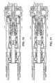
- FIG. 6 and FIG. 7each depicts a cross-sectional side elevation view of the valve assembly of detail 2 of the shock absorber of FIG. 1B , in accordance with an embodiment.
- FIG. 8A and FIG. 8Bdepict a cross-sectional side elevation view of a shock absorber, in accordance with an embodiment.
- FIGS. 9-13depict a cross-sectional side elevation view of the base valve assembly of detail 2 of FIG. 1B , including a “latching solenoid”, in accordance with an embodiment.
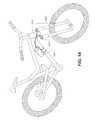
- FIG. 14depicts an arrangement of an embodiment on an example vehicle, in accordance with an embodiment.
- FIG. 15depicts an example electronic valve of a vehicle suspension damper, in accordance with an embodiment.
- FIGS. 16A-16Cdepict an electronic valve, in accordance with an embodiment.
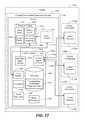
- FIG. 17is an example block diagram of a system 1700 for controlling vehicle motion, in accordance with embodiments.
- FIG. 18is a flow diagram of a method 1800 for controlling vehicle motion, in accordance with embodiments.
- FIG. 19is a flow diagram of a method 1900 for controlling vehicle motion, in accordance with various embodiments.
- FIG. 20is a flow diagram of a method 2000 for controlling vehicle motion, in accordance with various embodiments.
- FIG. 21is a flow diagram of a method 2100 for controlling vehicle motion, in accordance with various embodiments.
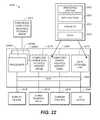
- FIG. 22is a block diagram of an example computer system with which or upon which various embodiments of the present invention may be implemented.
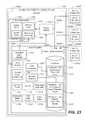
- FIG. 23block diagram of a system 2300 for controlling vehicle motion, in accordance with an embodiment.
- FIG. 24is a flow diagram of a method 2400 for controlling vehicle motion, in accordance with an embodiment.
- FIG. 25Ais a flow diagram of a method 2500 for controlling vehicle motion, in accordance with embodiments.
- FIG. 26is a flapper valve, in accordance with an embodiment.
- FIG. 27is an illustration of a valve with a blow-off, in accordance with an embodiment.
- the electronic computing devicemanipulates and transforms data represented as physical (electronic) quantities within the electronic computing device's processors, registers, and/or memories into other data similarly represented as physical quantities within the electronic computing device's memories, registers and/or other such information storage, processing, transmission, and/or display components of the electronic computing device or other electronic computing device(s). Under the direction of computer-readable instructions, the electronic computing device may carry out operations of one or more of the methods described herein.
- Example techniques, systems, and methods for controlling vehicle motionare described herein. Discussion begins with a high level description of conventional (i.e., that technology which exists, other than the present technology described herein) damping components and of embodiments of the novel present technology. The discussion continues with a description of a vehicle suspension damper and an electronic valve within the vehicle suspension damper, in accordance with embodiments. (See FIGS. 1-16 .) Following, the discussion turns to a description of a systems and methods for controlling vehicle motion, as it relates to multi-wheeled vehicles (e.g., bicycles, cars, side-by-sides, military vehicles), using novel control systems, in accordance with embodiments. (See FIGS. 17-22 .) Next, an example computer system is described, with which or upon which various systems, components, and/or methods (or portions thereof) may be implemented (See FIG. 23 ).
- multi-wheeled vehiclese.g., bicycles, cars, side-by-sides, military vehicles
- some conventional damping componentsprovide a constant passive damping rate during compression or extension through the entire length of the stroke.
- Other conventional damping componentsprovide mechanisms for varying the damping rate.
- damping componentsare most prevalently mechanical.
- conventional inertia valves of conventional vehicle suspension dampersare also mechanical. The conventional mechanical inertia valve operates to respond to a terrain change by applying damping forces when a vehicle's motion is sensed. However, by the time that the mechanical inertia valve senses the vehicle motion and then actually applies the damping force, the vehicle rider has already experienced some type of response to the varied terrain. For example, the vehicle rider might feel the vehicle's initial response to running over a large rock.
- Mechanical inertia valveshave a response time that is measured at the speed of sound or less. Thus, a shock wave from a vehicle hitting a bump will be received and felt by the vehicle rider before the mechanical inertia valve can open and provide a “soft” ride. (A “soft” vs. “hard” setting of an inertia valve is explained below.)
- a sensoris placed on the front fork while a vehicle suspension damper is placed on the rear shock.
- the sensorsenses the vehicle motion at the front of the vehicle and sends a signal regarding this vehicle motion to the vehicle suspension damper at the rear of the vehicle. Having received the signal at the rear of the vehicle, by the time the back wheel runs over the rock, the vehicle suspension damper on the rear shock had just enough time to adjust a valve therein to open, thus providing damping at the vehicle's rear.
- vehicle suspension damperin various embodiments, includes a novel control system and an electronic valve, as will be described herein.
- the vehicle suspension damperis positioned between the vehicle's wheel base and the vehicle's frame.
- an electronic valve of a vehicle suspension damper attached to the front forkresponds quickly to received signals that indicate that the vehicle's front wheel base is moving (i.e., accelerating) over an obstacle (e.g., rock).
- the control systemresponds to the receipt of the signals by quickly causing the electronic valve to open into a “soft” mode.
- the responseoccurs before the vehicle's back wheel runs over the same obstacle.
- the soft modeprovides damping within the vehicle suspension damper. Due to the damping provided, the vehicle's frame is enabled to experience less acceleration than that experienced by the vehicle's front wheel while traversing the obstacle. Thus, the vehicle rider experiences a smoother ride through the frame of the vehicle, even while the vehicle is moving over various obstacles.
- the control systemreceives a set of control signals from a set of sensors attached to a vehicle component (e.g., wheel, frame, etc.) of a vehicle.
- At least one control signal of the set of control signalsincludes an acceleration value corresponding to a movement of the vehicle component.
- the control systemcompares the acceleration value to a predetermined acceleration threshold value corresponding to the vehicle component.
- the control systemalso monitors a state of at least one pilot valve assembly within at least one vehicle suspension damper that is attached to the vehicle. The state of the pilot valve assembly controls a damping force within the at least one vehicle suspension damper.
- the control systemBased on the comparison performed between the measured acceleration value and the predetermined acceleration threshold value as well as the determination of a state of the pilot valve assembly, the control system sends an activation signal to a power source of the at least one vehicle suspension damper.
- the activation signalactivates the power source to deliver a current to the at least one pilot valve assembly.
- the at least one valve assemblyadjusts to a desired state.
- the desired stateis configured to adjust the damping force, thereby reducing an acceleration of the vehicle frame.
- embodiments relating to two-wheeled vehiclesalso provide varying user selectable modes of operation, wherein each selected mode of operation triggers varying methods of detection and response to terrain changes relating to detecting bumps, sensing power input by the rider, and adjusting rebound damping.
- the systems and methods for controlling vehicle motion in multi-wheeled vehicles other than two-wheeled vehiclesinclude many of the features of the novel control system discussed with regard to two-wheeled vehicles.
- embodimentsmay not only deduce the vertical acceleration values, but also deduce from the received set of control signals, that include acceleration values associated with various vehicle components, the multi-wheeled vehicle's roll and pitch.
- These measured acceleration valuesrelate to the tilt (e.g., roll, pitch) of the vehicle and are compared to a database having thereon preprogrammed acceleration threshold values associated with vehicle components as it relates to tilt.
- the control systemreceives measured velocity values associated with user-induced events (e.g., turning a steering wheel, pressing/releasing a brake pedal, pressing/releasing the gas pedal, thereby causing a throttle to open/close).
- the control systemcompares these measured velocity values relating to user-induced events to a database having preprogrammed thereon velocity threshold values associated with vehicle components.
- the control systemBased on the comparison performed with regard to the measured acceleration values with the predetermined acceleration threshold values and the measured velocity values with the predetermined velocity threshold values, as well as the determined state of valves within various vehicle suspension dampers attached to vehicle components, the control system sends an activation signal to power sources of the vehicle suspension dampers.
- the activation signalactivates the power source to deliver a current to valve assemblies within the vehicle suspension dampers. Once delivered, the valve assemblies adjust to a desired state.
- the desired stateis configured to adjust the damping force to reduce or eliminate the tilt of the vehicle's frame. In other words, the orientation of the vehicle frame is placed as close to level as possible.
- embodiments relating to multi-wheeled vehiclesalso provide various system modes within which the vehicle suspension dampers may operate, along with control modes for affecting roll and pitch dynamics of the vehicle. Further, embodiments provide methods and systems for implementing delays and rebound settle time, for de-conflicting multiple control modes and for cycling between different system modes.
- Embodimentsthus provide systems and methods for controlling a vehicle's motion by increasing and/or decreasing damping forces within a vehicle suspension damper in quick response to sensed movement of vehicle components (e.g., vehicle wheel base).
- vehicle componentse.g., vehicle wheel base
- embodimentsmay be used in various types of multi-wheeled vehicles, such as, but not limited to, bicycles, side-by-sides (four-wheel drive off-road vehicle), snow mobiles, etc. These embodiments may be positioned in both the front fork and the rear shock.
- Conventional vehicle suspension dampers(including conventional electronic dampers) cannot respond quickly enough to a sensed movement of a vehicle's front wheel traversing an obstacle such that the rider avoids feeling the effect via the vehicle's frame.
- embodiments of the present technologyquickly and selectively apply damping forces through the vehicle suspension dampers (that are coupled with both the vehicle's forks and the vehicle's frame). Such damping enables the vehicle's frame, and thus the vehicle's rider, to experience less acceleration than that being experienced by the wheel base(s).
- embodimentsprovide for a control system that enables the use of sensors and an electronic valve to read the terrain and make changes to the vehicle suspension damper(s) in real time.
- the novel control systemenables at least the following novel functions: the execution of novel algorithms that enable a quicker response and adjustment to the vehicle suspension damper(s) than conventional vehicle suspension dampers; a quiet operation since there are no audible electronic valve actuation sounds; a power efficient model that is designed for low power consumption; an easily tunable model that may use conventional means in combination with the novel control system, such as, but not limited to, valve shims; a fail-safe shock absorber, as the electronic valve also functions as a conventional shock if power is lost; a small model that can be packaged in bicycle forks and shocks; and a versatile model that may function in conventional shocks, twin tube shocks and bypass shocks.
- Integrated damper/spring vehicle shock absorbersoften include a damper body surrounded by or used in conjunction with a mechanical spring or constructed in conjunction with an air spring or both.
- the damperoften consists of a piston and shaft telescopically mounted in a fluid filled cylinder.
- the damping fluidi.e., damping liquid
- damping liquidmay be, for example, hydraulic oil.
- a mechanical springmay be a helically wound spring that surrounds or is mounted in parallel with the damper body.
- Vehicle suspension systemstypically include one or more dampers as well as one or more springs mounted to one or more vehicle axles.
- the terms “down”, “up”, “downward”, “upward”, “lower”, “upper”, and other directional referencesare relative and are used for reference only.
- FIG. 1Ashows an asymmetric bicycle fork 100 having a damping leg and a spring leg.
- the damping legincludes an upper tube 105 mounted in telescopic engagement with a lower tube 110 and having fluid damping components therein.
- the spring legincludes an upper tube 106 mounted in telescopic engagement with a lower tube 111 and having spring components therein.
- the upper legs 105 , 106may be held centralized within the lower legs 110 , 111 by an annular bushing 108 .
- the fork 100may be included as a component of a bicycle such as a mountain bicycle or an off-road vehicle such as an off-road motorcycle. In some embodiments, the fork 100 may be an “upside down” or Motocross-style motorcycle fork.
- the damping components inside the damping leginclude an internal piston 166 disposed at an upper end of a damper shaft 136 and fixed relative thereto.
- the internal piston 166is mounted in telescopic engagement with a cartridge tube 162 connected to a top cap 180 fixed at one end of the upper tube 105 .
- the interior volume of the damping legmay be filled with a damping liquid such as hydraulic oil.
- the piston 166may include shim stacks (i.e., valve members) that allow a damping liquid to flow through vented paths in the piston 166 when the upper tube 105 is moved relative to the lower tube 110 .
- a compression chamberis formed on one side of the piston 166 and a rebound chamber is formed on the other side of the piston 166 . The pressure built up in either the compression chamber or the rebound chamber during a compression stroke or a rebound stroke provides a damping force that opposes the motion of the fork 100 .
- the spring components inside the spring leginclude a helically wound spring 115 contained within the upper tube 106 and axially restrained between top cap 181 and a flange 165 .
- the flange 165is disposed at an upper end of the riser tube 163 and fixed thereto.
- the lower end of the riser tube 163is connected to the lower tube 111 in the spring leg and fixed relative thereto.
- a valve plate 155is positioned within the upper leg tube 106 and axially fixed thereto such that the plate 155 moves with the upper tube 106 .
- the valve plate 155is annular in configuration, surrounds an exterior surface of the riser tube 163 , and is axially moveable in relation thereto.
- the valve plate 155is sealed against an interior surface of the upper tube 106 and an exterior surface of the riser tube 163 .
- a substantially incompressible lubricante.g., oil
- the remainder of the volume in the lower tube 111may be filled with gas at atmospheric pressure.
- the gas in the interior volume of the lower tube 111is compressed between the valve plate 155 and the upper surface of the lubricant as the upper tube 106 telescopically extends into the lower tube 111 .
- the helically wound spring 115is compressed between the top cap 181 and the flange 165 , fixed relative to the lower tube 111 .
- the volume of the gas in the lower tube 111decreases in a nonlinear fashion as the valve plate 155 , fixed relative to the upper tube 106 , moves into the lower tube 111 . As the volume of the gas gets small, a rapid build-up in pressure occurs that opposes further travel of the fork 100 .
- the high pressure gasgreatly augments the spring force of spring 115 proximate to the “bottom-out” position where the fork 100 is fully compressed.
- the level of the incompressible lubricantmay be set to a point in the lower tube 111 such that the distance between the valve plate 155 and the level of the oil is substantially equal to a maximum desired travel of the fork 100 .
- FIG. 1Ba cross-sectional side elevation view of a shock absorber of a bicycle fork cartridge is depicted, in accordance with an embodiment. More particularly, FIG. 1B shows the inner portions of the bicycle fork leg assembly, comprising a damper piston 5 .
- the top cap 20is affixed to an upper tube (not shown) and the lower connector 10 is fixed to a lower leg tube (not shown) where the upper tube is typically telescopically mounted within the lower tube (although the reverse may also be the case).
- the damper piston 5 and piston rod 15move telescopically into and out of damper cylinder 25 .
- the volume of the piston rod 15displaces, from the cylinder 25 , a volume of damping liquid contained within the cylinder 25 corresponding to the volume of the piston rod 15 incurring into the damper cylinder 25 .
- the volume of liquidmust be replaced as the piston rod 15 leaves the interior of the damper cylinder 25 .
- Damping liquid displaced as described abovemoves from the damper cylinder 25 , through a base valve assembly of detail 2 and ultimately into an elastic bladder 30 during compression, and from the elastic bladder 30 , back through the base valve assembly of detail 2 and into the damper cylinder 25 during rebound.
- the base valve assembly of detail 2allows for the compression damping to be adjusted by the user.
- FIG. 2 , FIG. 3 , and FIG. 4show cross-sectional side elevation views of various operational positions of an embodiment of the base valve assembly of detail 2 of FIG. 1B .
- FIGS. 2-4show a continuously variable semi active arrangement, in accordance with embodiments, and as will be described in more detail below.
- a solenoid balanced by an armature biasing spring 235axially locates a pressure-balanced pilot spool 210 .
- the pressure-balanced pilot spool 210controls the pressure inside the valve body 230 . As this pressure is increased inside the valve body 230 , the axial force of the valve body 230 on the conventional valve shim increases.
- a relatively small solenoid(using relatively low amounts of power) can generate relatively large damping forces. Furthermore, due to incompressible fluid inside the valve body 230 , damping occurs as the valve opens and the valve body 230 collapses. The result is not only a controllable preload on the valve stack, but also a controllable damping rate.
- Embodiments discussed hereinmay optionally be packaged in a base valve, the compression adjuster of a shock absorber, and/or on the main piston of a shock absorber.
- FIG. 2is a detailed view of the base valve assembly of detail 2 of FIG. 1B , with the valve shown in a retracted soft position. This retracted position corresponds to minimum or no current in the solenoid.
- a first damping fluid flow path between damping cylinder interior 35 and annular reservoir 40is substantially unobstructed via bleed passage 55 , ports 50 A and upper annulus 45 .
- bleed passage 55As shown in FIG. 2 is the main piston 245 .
- FIG. 3is a detailed view of the base valve assembly of detail 2 of FIG. 1B , with the valve shown in the mid-damping position. This corresponds to medium current supplied to the solenoid.
- FIG. 3shows a partial obstruction of ports 50 A by metering edge 205 of the pilot spool 210 .
- FIG. 4is a detailed view of the base valve assembly of detail 2 of FIG. 1B , with the valve shown in the firm-damping position.
- FIG. 4shows substantial blockage of ports 50 A by the metering edge 205 of the pilot spool 210 , which is axially displaced relative to its position in FIG. 2 .
- the pilot spool 210 shown in FIG. 2is in a retracted soft position, in which the metering edge 205 of the pilot spool 210 is not obstructing the ports 50 A.
- the pilot spool 210 shown in FIG. 3is in a middle position, in which the metering edge 205 of the pilot spool 210 is partially obstructing the ports 50 A.
- the pilot spool 210 shown in FIG. 4is in a firm position, in which the metering edge 205 of the pilot spool 210 is fully obstructing ports 50 A.
- the axial displacement of the pilot spool 210is facilitated by an electromagnetic interaction between the armature 215 and the coil 220 .
- Adjustment of the current in the coil 220 (via modulation of the current from a power source [not shown]) to predetermined valuescauses the armature 215 , and hence the pilot spool 210 , to move in corresponding predetermined axial positions relative to the coil 220 .
- the pilot spool 210can be adjusted as shown in the FIGS. 2-4 .
- FIG. 5A and FIG. 5Bdepict a cross-sectional side elevation view of a valve assembly of detail 2 of the shock absorber of FIG. 1B , in accordance with an embodiment.
- FIG. 5A and FIG. 5Bshow an embodiment in which the valve body 230 acts on the valve shims 225 through a spring 75 .
- the valve body 230increases or decreases the preload on the spring 75 .
- FIG. 5Ashows the pilot spool 210 in the retracted soft position, thereby causing the preload on the spring 75 to decrease.
- FIG. 5Bshows the pilot spool 210 in the firm position, thereby causing the preload on the spring 75 to increase.
- FIG. 6 and FIG. 7depict a cross-sectional side elevation view of the valve assembly of detail 2 of the shock absorber of FIG. 1B , in accordance with an embodiment.
- FIG. 6 and FIG. 7show an embodiment including a flow control orifice 605 for limiting flow through into the bleed passage 55 during compression.
- the flow control orifice 605(by creating a pressure drop) places an upper limit on the amount of pressure in the annulus 60 , and hence the amount of “boost” or closure force that the valve body 230 can exert on the valve shims 225 .
- FIG. 6shows the metering edge 205 of the pilot spool 210 obstructing ports 50 A.
- FIG. 7shows the metering edge 205 of the pilot spool 210 partially obstructing ports 50 A.
- FIG. 8A and FIG. 8Bdepict a cross-sectional side elevation view of one end of a piston and piston rod assembly of a shock absorber, in accordance with an embodiment. More particularly, FIG. 8A shows an embodiment having a separate valve body 805 A and 805 B corresponding to each of a rebound shim set 810 and a compression shim set 815 , respectively, where a pilot spool 820 (performing, in one embodiment, similarly to the pilot spool 210 of FIGS. 1-7 described herein) alternatingly opens one area (e.g., 825 A [similar to function to annulus 60 ]) while closing the other area (e.g., 825 B [similar in function to annulus 60 ]).
- FIG. 8Ashows an embodiment having a separate valve body 805 A and 805 B corresponding to each of a rebound shim set 810 and a compression shim set 815 , respectively, where a pilot spool 820 (performing, in one embodiment, similarly to the pilot spool
- FIG. 8Ashows a “hard/soft configuration”.
- the area 825 A and area 825 Bexperience obstruction by a portion of the pilot spool 820 , thereby creating a soft compression.
- the area 825 A and area 825 Bare open to fluid flow, thereby creating a firm rebound.
- FIG. 8Bshows a “hard/hard configuration” (a firm compression and a firm rebound), in accordance with an embodiment.
- FIGS. 9-13depicts a cross-sectional side elevation view of the base valve assembly of detail 2 of FIG. 1B , including a “latching solenoid”, in accordance with an embodiment.
- Embodimentsfurther provide, in brief and as will be described below, a low-power bi-state electronic damper.
- the low-power bi-state electronic damperuses a latching solenoid to open and close a pressure-balanced pilot spool. Given the latching configuration of the solenoid, power is required only to open or close but not to hold in it in either setting, in accordance with an embodiment. The result is low power consumption.
- a further embodimentprovides an externally-adjustable means of tuning the open state of the damper.
- an adjusterthat can be turned in or out to vary the effective orifice size of the pilot spool when in the open position. This will allow the rider to adjust the soft setting of the damper to his/her preference.
- the latching solenoid 905primarily uses power to facilitate a change in position of the pilot spool 210 relative to the coil 220 but requires little or no power to maintain the pilot spool 210 in the desired position once that is achieved.
- the latching solenoid assembly 905(or latching spool valve assembly) includes: a pilot spool 210 which includes a magnetically active material; a spring 915 which is normally in compression and biases the pilot spool 210 toward a position obstructing port 60 ; a permanent magnet 920 ; and a coil 220 where power is supplied to the coil 220 by (in one embodiment) wires 925 .
- the aforementioned componentsmay be contained within a housing 240 or “cartridge” as shown.
- the pilot spool valve assembly(including at least the pilot spool 210 and the metering edge 930 of the pilot spool 210 ) regulates damping fluid flow through a portion of the damper and adjusts the force applied to the valve shims 225 by the valve body 230 through ports 60 .
- the position of the spool valve assemblymay be adjusted axially by means of the low speed adjuster 935 .
- the low speed adjuster 935(comprising multiple pieces), being for example, threaded at its lower end to the top cap 20 via the low speed adjuster threads 940 , may be rotated to facilitate axial movement.
- the low speed adjuster 935includes a non-round shape (e.g., hexagonal) that facilitates the rotation with relative axial movement (see 1105 of FIG. 11 ).
- the pilot spool 210is biased by spring 915 toward a position wherein the metering edge 930 of the pilot spool 210 further obstructs ports 50 A (see FIG. 13 , wherein the pilot spool 210 is shown in the open pilot position with the low speed adjuster 935 in the middle position).
- a force opposing the bias of the spring 915is exerted on the magnetic component of the pilot spool 210 by the permanent magnet 920 .
- the pilot spool 210When the pilot spool 210 is in its uppermost (corresponding to open ports 50 A) position, it is retained by the magnetic force between the permanent magnet 920 and the pilot spool valve 210 where that force is sufficient to overcome the bias of the spring 915 (thereby holding the spring 915 in a compressed state).
- the pilot spool valve 210 and ports 50 Aare in the open position (see FIG. 12 ), no power input is required to maintain that state.
- a currentis applied to the coil 220 via the wires 925 .
- the currentcauses a magnetic flux around the coil 220 , which acts on the magnetic component of the pilot spool 210 causing the pilot spool 210 to move axially within the cartridge.
- the spring 915bias moves the pilot spool 210 toward closure of ports 50 A with little or no additional power input to the coil 220 .
- FIG. 10shows the pilot spool 210 in the closed pilot position with the low speed adjuster 935 in the firm position.
- FIG. 11shows the pilot spool 210 in the open pilot position with the low speed adjuster 935 in the firm position.
- FIG. 10additionally shows the low speed adjuster metering edge 1005 and the spool valve assembly housing 1010 , in accordance with an embodiment.
- FIGS. 9-13show an orifice block 955 having a tailored orifice 960 there through.
- the orifice 960meters low speed damping fluid for low speed bump response of the suspension (when magnitude and rate is insufficient to open the shims).
- the size of the orifice 960may be chosen to allow a desired amount or range of pressure to be applied to the valve body 230 through annulus 60 (ports).
- the use of the pilot spool 210then further specifies that the pressure acts on the valve body 230 by modulating the flow restriction “downstream” (during a compression stroke of the suspension) of the orifice 960 .
- FIGS. 9-13also show a pressure relief valve 965 or “blow off” valve, which is biased toward a closed position by Bellville spring(s) 970 .
- the pressure relief valve 965opens in response to an interior damper pressure above a predetermined threshold and thereby prevents damage to the damper and vehicle in the event of rapid pressure build up (usually associated with extreme suspension compression rate).
- the pressure relief valve 965may have an adjustable threshold value (in one embodiment, by modification of the compression in the Bellville spring 970 ).
- FIG. 14shows a bicycle 1405 , in accordance with an embodiment, having attached thereto a vehicle suspension damper 1410 and a set of sensors 1415 .
- the vehicle suspension damper 1410in this particular embodiment, is located within the front fork 1420 and the rear shock of the bicycle 1405 .
- the set of sensors 1415is configured for sensing a type of vehicle motion, such as tilt (e.g., roll and pitch), acceleration, velocity, position, etc. Further, the set of sensors 1415 may be positioned anywhere on the vehicle that enables the receipt of accurate sensed information and which enables communication of a control signal (regarding the sensed information) to the vehicle suspension damper 1410 .
- the set of sensors 1415if the set of sensors 1415 senses that the vehicle is experiencing acceleration, the set of sensors 1415 sends a control signal to the vehicle suspension damper 1410 .
- FIG. 15shows the electronic valve 1500 of vehicle suspension damper 1410 , in accordance with an embodiment.
- the electronic valve 1500includes at least a primary valve 1505 , a first pressure reducing means which in this embodiment is an orifice block 1515 , and a second pressure reducing means which in this embodiment is a pilot valve assembly 1510 , all of which components cooperatively control the flow of fluid throughout the inertia valve and manipulate the fluid pressure within the pilot pressure chamber 1520 .
- the permanent magnet 1560 of the solenoid assembly 1580conducts through the component 1565 to attract the pilot spool 1570 . This is the latched position as shown.
- the spool spring 1575resists this condition.
- the coilis turned on with positive polarity, it cancels the effect of the permanent magnet 1560 and the spool spring 1575 moves the pilot spool 1570 to the left or closed position.
- the electromagnetis added to the permanent magnet 1560 and the pilot spool 1570 is drawn to the right or open position.
- the main oil flow pathis through the center of the base valve and radially outwardly into piston port area 1525 . Assuming there is enough pressure in the piston ports, it then blows off the valve shims 1530 and oil flows into the reservoir 40 . A small amount of oil also flows in parallel through a second fluid flow path in the electronic valve 1500 (also called an inertia valve), and in particular through the control orifice 1535 and through the solenoid assembly 1580 . This generates a pilot pressure inside the area of the primary valve 1505 .
- the valve member 1540acts to resist the valve shims 1530 from opening. This resistive force is dependent on pressure inside the area of the primary valve 1505 which is controlled by the pressure drop across the solenoid. Basically, when the solenoid is closed, there is high pressure inside the area of the primary valve 1505 (resulting in locked-out fork or firm damping, depending on the damping characteristics determined for the electronic valve 1500 , as described in greater detail below). When the solenoid is in an open position, there is low pressure inside the area of the primary valve 1505 and the valve member 1540 pushes against valve shims 1530 with less force, allowing the valve shims 1530 to open under lower fluid pressure.
- This open position of the solenoidprovides a normally-operating fork, by which is meant the damping characteristic of the inertia valve is determined predominantly by the tuning of the valve shims 1530 (although there is some damping effect provided by the control orifice 1535 ).
- a control signalinstructs the vehicle suspension damper 1410 to increase or decrease its damping force therein.
- the vehicle suspension damper 1410is configured to respond to the control signal instruction. More particularly, the inertia valve 1500 of the vehicle suspension damper 1410 , in response to the control signal instruction, quickly manipulates the pressure in the pilot pressure chamber 1520 of the inertia valve 1500 by moving/adjusting the pilot valve assembly 1510 to at least partially close or open the flow ports 1550 . The pressure in the pilot pressure chamber 1520 increases or decreases in proportion to the amount of closure or opening that the flow ports 1550 experience, respectively.
- fluid in the inertia valve 1500flows along a first fluid flow path from the damping cylinder interior 35 and through the shims 1530 (unless the shims 1530 are held closed under pressure from the valve member 1540 , as will be described herein) via the piston port area 1525 . Additionally, fluid also flows along a second fluid flow path from the damping cylinder interior 35 and through the control orifice 1535 of the orifice block 1515 . After having flowed through the control orifice 1535 , the fluid moves into the pilot pressure chamber 1520 .
- the fluidmoves out of the pilot spool valve 1545 (wherein the pilot spool valve 1545 is in at least a partially open position) through a set of flow ports 1550 and into the reservoir 40 . Additionally, from the pilot pressure chamber 1520 , the fluid also moves into the area of the primary valve 1505 . When the fluid presents a predetermined pressure against surface 1580 of the valve member 1540 , a force proportional to the pressure is exerted on the valve member 1540 which urges it against the shims 1530 .
- the valve member 1540pushes against the shims 1530 , thereby biasing the shims 1530 toward a closed position, even though fluid is moving through the shims 1530 from the piston port area 1525 and into the reservoir 40 . If the force of the valve member 1540 against the shims 1530 is greater than the force of the fluid moving from the piston port area 1525 against the shims 1530 , then the shims 1530 will become biased toward closing.
- the shims 1530will be biased toward an open position, in which the fluid may remain flowing through the shims 1530 .
- embodimentsuse a control system to receive control signals from the set of sensors 1415 .
- the control systemactivates a power source that is attached to the electronic valve.
- the power sourcedelivers a current to the electronic valve.
- the electronic valveresponds to the delivered current by causing the pilot valve assembly 1510 to move and block or open at least a portion of the flow ports 1550 through which fluid may flow there through from the pilot pressure chamber 1520 and into the reservoir 40 , thereby at least partially closing or opening the flow parts 1550 .
- the damper piston 5moves into the damper cylinder interior 35 . More particularly, when the flow ports 1550 are at least partially closed, the fluid pressure within the pilot pressure chamber 1520 increases such that the fluid pressure in the area of the primary valve 1505 also increases. This increase in the fluid pressure in the area of the primary valve 1505 causes the valve member 1540 to move toward the shims 1530 that are open and to push against the shims 1530 , thereby causing the shims 1530 to at least partially or fully close. When these shims 1530 are at least partially or fully closed, the amount of fluid flowing there through decreases or stops.
- the movement of the damper piston 5 into the damper cylinder interior 35causes fluid to flow through the piston port area 1525 and hence out through open shims 1530 and into the reservoir 40 .
- the fluidalso flows through the control orifice 1535 into the pilot pressure chamber 1520 . If the shims 1530 are closed due to movement of the pilot valve assembly 1510 to block the flow ports 1550 , then fluid may not flow out through the shims 1530 or out through the flow ports 1550 into the reservoir 40 . Consequently, the ability of the damper piston 5 to move within the damper cylinder interior 35 to cause fluid to flow through the piston port area 1525 as well as through the flow ports 1550 is reduced or eliminated.
- the effect of the at least partial closure of the shims 1530is to cause a damping function to occur.
- the movement of the pilot valve assembly 1510 to at least partially block the flow ports 1550causes the damping (or slowing of movement) of the damper piston 5 into the damper cylinder interior 35 .
- control orifice 1535operates cooperatively with the pilot valve assembly 1510 to meter the flow of fluid to the primary valve 1505 .
- the control orifice 1535is a pathway within the orifice block 1515 and is positioned between the damper cylinder interior 35 and the pilot pressure chamber 1520 .
- the size of the control orifice 1535is tunable according to the application; the size may be variously changed.
- the control orifice 1535is a key component in enabling the quick and accurate response to sensed changes in a vehicle's motion. As will be explained herein, without the presence of the control orifice 1535 , the vehicle would not experience damping during periods of low compression speed, or experienced too much damping during periods of high compression speeds.
- the pilot valve assembly 1510would act like a bypass. In other words, without the control orifice, at low compression speed there would almost be no damping and the control orifice 1535 and pilot valve assembly 1510 would act like a bypass; but at higher compression speeds, pressure drop across the pilot valve assembly 1510 would cause a high pressure in the pilot pressure chamber 1520 and therefore too much clamping force on the shims 1530 .
- the control orifice 1535thus, allows damping to occur even during periods of low compression speed, and slows the damping rate during periods of high compression speed.
- the solutionis to cause a pressure drop of damping fluid before it enters the pilot pressure chamber 1520 .
- Thisis achieved with the control orifice 1535 .
- the control orifice 1535provides some damping effect at low compression speeds (by enabling damping fluid to ‘bleed’ through the control orifice), but at high compression speeds provides a significant pressure drop to ensure that the pressure inside the pilot pressure chamber does not get too high, thereby preventing the valve member 1540 from locking onto the shims 1530 .
- control orifice 1535is between 0.5 mm and 2 mm in diameter, but these sizes are dependent on the specific application and the desired damping curve. Pressure drop is directly proportional to the length of the control orifice 1535 , but inversely proportional to its diameter. Either one or both of these parameters can be changed at the design stage to affect the performance of the control orifice 1535 .
- control orifice 1535The essential function, in embodiments, of the control orifice 1535 is to create a pressure drop. Therefore, anything that will do this could be used in place of the specific arrangement shown. Some possible examples include, but are not limited to: a diffuser; a labyrinth between parallel plates; and leakage past a screw thread.
- a further key feature of embodimentsis the combination of the area of the surface 1580 inside the valve member 1540 , the control orifice 1535 , the pilot valve assembly 1510 , and the way this combination enables a variable force to be applied to the shims 1530 to control the damping force at any point in time.
- the ratio of the surface area 1585 of the shims 1530(The surface area 1585 is next to the piston port area 1525 ; the pressure is acting on the surface area 1585 of the shims 1530 as well as the surface area 1580 of the inside of the valve member 1540 , within the primary valve area 1505 ) to the surface area 1580 inside the valve member 1540 controls the overall damping characteristic of the electronic valve 1500 , i.e., what overall range of force can be applied to the shims 1530 .
- the valve member 1540can be set up to move between full lockout and a completely soft state, or between a firm damping state and a soft state, for example.
- a particular force at any point in timeis set by the position of the pilot valve assembly 1510 , which, as explained above, controls the pressure drop across the flow ports 1550 .
- the pressure of fluid in the pilot pressure chamber 1520is also adjusted. Since the pressure inside the pilot pressure chamber 1520 acts against surface 1580 of the valve member 1540 , the force applied by the valve member 1540 to the shims is controllable by adjustment of the position of the pilot valve assembly 1510 .
- the overall resistance to fluid flow along the first fluid flow path(i.e. through piston port area 1525 and past shims 1530 ) is given by the sum of the force provided by the shims 1530 , and the force applied to the shims 1530 by the valve member 1540 .
- a significant featureis that force is generated on the valve member 1540 by control of pressure inside the area of the primary valve 1505 (in contrast to other valve bodies where force comes from pressure acting on the outside of the valve member 1540 , usually from the damper reservoir).
- the ultimate source of pressure in the pilot pressure chamber 1520is the pressure of the damping fluid in the main damping cylinder 35 during compression (but regulated by the control orifice 1535 and the pilot valve assembly 1510 to give a lower pressure in the pilot pressure chamber 1520 ).
- the pilot valve assembly 1510enables very large damping forces to be controlled using the same pilot valve assembly 1510 —this is because: (a) the pilot pressure is ‘magnified’ according to the ratio of the area of the primary valve 1505 to the area of the piston port 1525 ; and (b) because the pilot valve assembly 1510 is not required to move any element against the high pressure damping fluid; and 5) the primary valve assembly 1510 allows the damper to utilize conventional shims, but with some level of controllability over the damping force applied by the shims. This allows the shims to be tuned in a conventional manner. Furthermore, if power to the pilot valve assembly 1510 fails, the shock absorber will continue to operate (in contrast to other electronically controlled shocks where power loss causes the shock to stop working completely).
- the electronic valve 1500including the primary valve 1505 , the pilot valve assembly 1510 , and the orifice block 1515 , not only enables a variable force to be applied to shims 1530 , but also enables the control of the damping force within the vehicle at any point in time.
- the pilot valve assembly 1510meters a flow of fluid to the primary valve 1505 and enables the generation of relatively large damping forces by a relatively small solenoid (or other motive source), while using relatively low amounts of power.
- the solenoidcontinuously powers the inertia valve and does not have a latching mechanism.
- a monitorwill continuously monitor a power source and its operation in order to make sure that the wires leading to the power source do not get cut, thereby providing a dangerous situation for the rider and other vehicles.
- the primary valve 1505although it is shown as an internal base valve, it is not limited to this position or application.
- itcan be mounted externally of the vehicle suspension damper (for example in a ‘piggy-back’ reservoir). Further, it could be made part of the main damper piston (either in compression or rebound directions).
- the general methodology for determining the diameter and/or length of the control orifice 1535 during designis as follows: (1) identify the desired damping curve that the damper should have; (2) determine from step (1) the target low speed damping force; (3) determine from step (1) the target high speed damping force; (4) make informed guess at control orifice diameter and/or length to achieve steps (2) and (3); (5) test the output damping forces produced by shock at different speeds within low to high speed range; (6) compare the measured damping curve against the desired damping curve; (7) if there is too much high speed damping force, then reduce the diameter of the control orifice (to lower the pressure inside the pilot pressure chamber 1520 ); (8) if there is too much low speed damping force, then decrease the area ratio (between the area of the primary valve 1505 and the piston port
- FIG. 16Ashows an electronic valve 1600 A with a diffuser pin 1605 positioned through one set of the cross holes 1610 going to the primary valve area 1505 , in accordance with an embodiment. Another set of holes remains (normal to the page) to feed oil to the valve member 1540 .
- the diffuser pin 1605functions to disrupt the jet flow coming out of the control orifice 1535 .
- FIG. 16Bshows an electronic valve 1600 B with a diffuser plug 1620 pressed into, at least one of and at least partially, the orifice block 1515 and the pilot pressure chamber 1520 , in accordance with an embodiment.
- the diffuser plug 1620also functions to disrupt the jet flow coming out of the control orifice 1535 .
- FIG. 16Cshows an electronic valve 1600 C with a diffuser pin 1630 , in accordance with an embodiment.
- the spool retainer 1635(see FIG. 16B ) is replaced with the diffuser pin 1630 .
- the diffuser pin 1630 and its position within the vehicle suspension damper 1600 Cfunctions to disrupt the jet flow coming out of the control orifice 1535 and to minimize the contact of the pilot spool assembly 1510 in the firm setting.
- the solenoidincludes a “latching” mechanism to open and close the pressure-balanced pilot spool. Due to the latching configuration of the solenoid, power is only required to open or close the pilot valve assembly 1510 . Power is not required to hold the pilot valve assembly 1510 open or closed in either setting. Consequently, embodiments enable reduced power consumption compared to the traditional shock absorber.
- FIG. 1545provides an externally-adjustable means of tuning the open state of the damper.
- An adjusterturns in or out to vary the effective orifice size of the pilot spool valve 1545 when in the open position. This allows the rider to adjust the soft setting of the damper to his preference.
- valve shims 1530is optional. Instead, it would be possible for the valve member 1540 to act directly on the fluid flow ports 1525 . In fact, valve shims are optional in any such embodiment described herein where it would be possible for the valve member 1540 (or any other similar valve member described herein) to act directly on the fluid flow ports that control the main flow through the valve assembly.
- the set of sensors 1415may be positioned in various locations on various types of vehicles.
- the set of sensors 1415is positioned on the seat post of a bicycle.
- a first set of sensorsis positioned near the front wheel, while a second set of sensors is positioned near the rear wheel.
- the set of sensorsincludes three accelerometers.
- the accelerometersdefine a plane of the vehicle's body, such that the acceleration, and in other embodiments, the acceleration and the tilt (i.e., pitch and roll), of the vehicle body may be measured.
- the set of sensorssends a control signal to the control system attached to the vehicle suspension damper.
- the control systemdetermines if the sensed vehicle motion meet and/or exceeds a predetermined threshold.
- the predetermined thresholdmay be a constant in one embodiment. However, in another embodiment, the predetermined threshold may be a variable based on other situations sensed at the vehicle.
- the power sourceOnce a control signal is received by the power source, the power source that is attached to the vehicle suspension damper becomes activated. Upon activation, the power source sends a current to the vehicle suspension damper, thereby causing the pilot valve assembly to move, as is described herein.
- Various methods of sensing via accelerometers and other forms of motion via sensorsare known in the art.
- the vehicle upon which a set of sensors and a vehicle suspension damper is attachedmay be a multi-wheeled vehicle, such as, but not limited to, a bicycle, a side-by-side, a snowmobile, a car, a truck, etc.
- more than one set of sensorsmay be used, such as the non-limiting example of a side-by-side vehicle (e.g., recreational off-highway vehicle [ROV]).
- each wheel basee.g., four
- each wheel basehas attached thereto a different set of sensors, such as a set of accelerometers, each set being attached to a separate vehicle suspension damper.
- one set of sensorse.g., set of accelerometers
- the vehicle suspension dampersmay each be programmed to operate in a fully open mode (i.e., soft mode), in which the pilot spool valve 1545 of the pilot valve assembly 1510 is open to the flow ports 1550 , thereby allowing fluid to flow from the damper cylinder interior 35 and into the reservoir 40 either through the first fluid flow path, with resistance provided by the shims 1530 (and no additional force provided by the valve member 1540 ), and/or through the control orifice 1535 that permits low speed bleed of damping fluid via the second fluid flow path.
- a fully open modei.e., soft mode
- the right front tire of an ROVwhen the right front tire of an ROV hits a large rock, the right front tire and a portion of the suspension attached to the tire (or attached wheel base) may rise upwards to move over the rock.
- the set of sensors attached to the ROV's right front sidewill sense the tire's upward movement, and will sense the tire reaching its peak upward movement (the peak of the rock), and will sense the tire beginning to move downwards.
- the set of sensors on the ROV's right front sidewould send control signals to the vehicle suspension damper attached to the ROV's right front side throughout the tire's movement upward and downward.
- the control system attached to the vehicle suspension damperreceives the control signals and causes the power source also attached to the vehicle suspension damper to deliver a current to the vehicle suspension damper in accordance with the control signals.
- the delivered currentfunctions to cause the pilot valve assembly 1510 to move to cause the flow ports 1550 to be at least partially blocked.
- the pressure within the pilot pressure chamber 1520increases due to the at least partially blocked flowports 1550 , thereby causing the pressure within the area of the primary valve 1505 to increase.
- the valve member 1540in response to increased pressure in the area of the primary valve 1505 , is urged against the shims 1530 , thereby changing the damping characteristics of the shims 1530 .
- the fluid flowing along the first fluid flow path from the damper cylinder interior 35 and through the piston port area 1525is reduced, resulting in placing the vehicle suspension damper in a firm damping setting.
- Embodimentsprovide a significant advantage over conventional shock absorber systems.
- an inertia valvesenses a pressure wave (occurring at the speed of sound) after a vehicle's tire hits a bump.
- the inertia valveopens in response to receiving the pressure wave.
- the vehicle riderstill experiences some form of response to the terrain before the inertia valve has a chance to open into a “soft” mode.
- embodiments of the present technologyuse an electronic valve attached to accelerometers; the electronic valve opens into a “soft” mode before a motion significant enough for a vehicle rider to experience the motion has begun.
- embodimentssend a control signal from a set of accelerometers that communicate the acceleration values of the wheel to a control system that is connected (wire or wirelessly) to the electronic valve.
- the set of accelerometersare positioned to measure the acceleration experienced by the wheel base. These acceleration signals are sent at the beginning of the wheel's ascent over the rock.
- the electronic valveis opened into a soft mode in response to receiving the signals from the set of accelerometers.
- the soft modeis initiated before the wheel experiences such a large acceleration upwards that the vehicle rider feels a reaction to the wheel's motion through the vehicle's frame.
- embodimentsenable a quick response to a sensed acceleration of a vehicle wheel such that an acceleration of a vehicle frame due to the movement of the vehicle wheel may be reduced or prevented.
- one or more set of sensorsmay be attached to each ROV wheel base, and independently control the vehicle suspension damper to account for and respond to various rolls and other types of vehicle motion.
- one or more motion sensorsare provided on a forward or front part of a vehicle, and a signal or signals from the one or more motion sensors is used to control a vehicle suspension damper mounted on a rear part of the vehicle.
- motion information learned from the movement of the front part of the vehiclecan be used to anticipate movement of the rear part of the vehicle, and adjustments may be made to control the damper on the rear part accordingly.
- one embodimentenables the control of both compression and the rebound state of the vehicle suspension damper, such that acceleration at the vehicle frame is maintained as close to zero as possible throughout off-road riding and over varied terrain, regardless of the acceleration being experienced at the vehicle's wheel.
- more than one type of sensoris used.
- an accelerometer and a gyrometermay be used.
- the set of control signals sent to the control systemmay include, but are not limited to the following values: acceleration values; tilt (e.g., pitch, roll) values; and velocity values.
- acceleration valuese.g., acceleration values
- tilte.g., pitch, roll
- velocity valuese.g., velocity values
- numerous methods for determining orientation in a plane in space using a sensor attached to an objectare well known in the art.
- the adjustment of the vehicle compression dampers to a desired statebased on a comparison of the measured signal values with a database of threshold values, enables the reduction of the tilt of a vehicle's frame.
- FIG. 17is an example block diagram of a system 1700 for controlling vehicle motion, in accordance with embodiments.
- the system 1700in various embodiments and as will be described herein below in the section “Example Methods of Use”, is used to detect and control bump events, front and rear link events, rebound stoke detection events, power detection events, and rebound damping adjustment events.
- the systemincludes a control system 1725 and an electronic valve 1500 .
- the control system 1725includes: a control signal accessor 1730 ; a comparer 1740 ; a pilot valve assembly monitor 1745 ; and an activation signal sender 1750 .
- the electronic valve 1500is shown to include: a pilot valve assembly 1505 ; a primary valve 1510 ; and an orifice block 1515 comprising a control orifice 1535 .
- the control system 1725may be located on a custom PCB with surface mount components.
- the control system 1725may be miniaturized such that it is small enough to be packaged in bicycle forks and shocks.
- the control system 1725may be packaged in the fork steer tube. It should be appreciated that the control system 1725 may be packaged and positioned on the vehicle in any manner that leaves sufficient frame clearance for riding the vehicle.
- control signal accessor 1730accesses a set of control signals 1735 (shown herein to be control signals 1735 A, 1735 B and 1735 C), wherein at least one control signal (for example, control signal 1735 B) of the set of control signals 1735 includes an acceleration value corresponding to a movement of a vehicle component 1765 B of the vehicle 1710 .
- control signal accessor 1730may retrieve control signals from a set of sensors, such as the set of sensors 1770 B.
- the control signal accessor 1730may receive control signals from a set of sensors.
- the set of sensorsmay include as many accelerometers that are necessary to measure the acceleration (including tilt) of the vehicle component.
- each bicycle wheelhas a MEMS accelerometer oriented such that the sensing axis is aligned with the wheel path during the compression of the bicycle's vehicle suspension damper.
- the sensing axisis aligned with the direction of wheel travel at the ride height.
- ride heightis used to refer to a position of the vehicle frame, taking into account the rider's weight, which accommodates an approximate vehicle suspension damper position being intermediate of a fully extended position and a fully compressed position, such that the natural position of the vehicle suspension damper is in the middle of its stroke. In this beginning position, if and when the wheel experiences varied terrain, and thus experiences acceleration, the vehicle suspension damper responds by adjusting to a compressed and/or expanded position.
- the pilot valve assembly monitor 1745monitors a state of at least one pilot valve assembly (such as pilot valve assembly 1505 ) within at least one vehicle suspension damper (such as vehicle suspension damper 1705 ) attached to the vehicle 1710 .
- the “state”refers to the open, partially open, or closed position of the pilot valve assembly 1505 .
- the state of the pilot valve assembly 1505influences (or controls) a damping force within the vehicle suspension damper 1705 .
- the pilot valve assembly monitor 1745monitors the state of the at least one pilot valve assembly by following the control logic of prior instructions given to the pilot valve assembly. For example, the last instruction given by the control system 1725 may have been to open the pilot valve assembly 1505 .
- the pilot valve assembly monitor 1745would know that the state of the pilot valve assembly 1505 is “open”. In another embodiment, if the control system 1725 has yet to give state instructions to the pilot valve assembly 1505 , then the control system is preprogrammed to consider the pilot valve assembly 1505 to be in a defaulted state, such as, in one example, in a “firm” mode (fully or partially closed). In yet another embodiment, if the control system 1725 has yet to give state instructions to the pilot valve assembly 1505 , then the control system 1725 causes the solenoid to retract, placing the vehicle suspension damper in the soft mode. In yet another embodiment, the pilot valve assembly monitor 1745 cooperates with a one or more sensors configured to sense the state of the pilot valve assembly 1505 .
- the comparer 1740compares the acceleration value to a predetermined acceleration threshold value corresponding to the vehicle component 1765 B.
- the predetermined acceleration threshold valueappears in the database 1755 .
- the control system 1725includes the database 1755 . However, in another embodiment the database 1755 resides external to and accessible by the control system 1725 . Among other information, the database 1755 stores one or more (a set of) predetermined acceleration threshold values (including tilt threshold values [e.g., roll and pitch]) that correspond to various vehicle components of the vehicle 1710 .
- linked to each of the predetermined acceleration threshold values and stored at a database, such as database 1755are instructions that direct the control system 1725 to determine whether a measured acceleration value associated with a vehicle component exceeds the predetermined acceleration threshold value for the vehicle component.
- a measured acceleration value associated with a vehicle componentexceeds the predetermined acceleration threshold value for the vehicle component.
- the comparer 1740compares this acceleration value, “A”, with the predetermined acceleration threshold value, “B”, stored in the database 1755 .
- the database 1755indicates therein that if the acceleration value “A” exceeds the predetermined acceleration threshold value, “B”, and if the pilot valve assembly 1505 is found to be closed, then the control system 1725 is to send a particular activation signal 1720 to the power source 1715 such that the power source sends a current of “C” amperes to the pilot valve assembly 1505 .
- the pilot valve assembly 1505opens, thereby decreasing damping forces provided in the pilot pressure chamber.
- the vehicle suspension damperis set to a default position of “firm” (or closed).
- linked to each predetermined acceleration threshold value corresponding to a particular vehicle componentare instructions that direct the control system 1725 to send immediately, not send, or delay in sending an activation signal 1715 depending on various determined factors. These factors include whether the predetermined acceleration threshold value was found to be exceeded and the current state of the pilot valve assembly (e.g., open or closed).
- the activation signal sender 1750based on the comparing performed by the comparer 1740 and the monitoring performed by the pilot valve assembly monitor 1745 , sends an activation signal 1720 to a power source 1715 of the vehicle suspension damper 1705 .
- the activation signal 1720activates the power source 1715 to deliver a current 1775 to the pilot valve assembly 1505 .
- the pilot valve assembly 1505adjusts to a desired state.
- the desired state of the pilot valve assembly 1505is configured to adjust the damping force within the vehicle suspension damper 1705 to ultimately reduce an acceleration of the frame of the vehicle.
- reduceit is meant that the acceleration of the vehicle's frame is brought closer to zero via the adjustment in the damping force within the vehicle suspension damper.
- control system 1725may determine that the measured acceleration value “A” exceeds the predetermined acceleration threshold value “B” and that the pilot valve assembly 1505 is in a closed state.
- the instructions of the database 1755direct the control system 1725 to enable the pilot valve assembly 1505 to fully open to lessen the damping force in the pilot pressure chamber 1520 within the vehicle suspension damper 1705 by sending an activation signal 1715 to the power source that directs the power source 1715 to send a current of “D” amperes to the pilot valve assembly 1505 , thereby causing the pilot valve assembly 1505 to fully open.
- One implementation of an embodimentuses a latching solenoid to control the pilot valve assembly 1505 .
- the latching solenoidonly requires power to change a state; no power is required to maintain a state.
- the battery voltagei.e., power source 1715
- the measured valueis used to provide a Pulse Width Modulated (“PWM”) signal to the latching solenoid to ensure that it gets the same resultant applied voltage while the battery drains during use.
- PWMPulse Width Modulated
- control system 1725monitors the state of the pilot valve assembly 1505 , and only sends an activation signal 1715 (e.g., a pulse to actuate) if the pilot valve assembly 1505 is not in the desired state. For example, a pulse is not sent if the pilot valve assembly 1505 is already found to be open.
- an activation signal 1715e.g., a pulse to actuate
- control system 1725may also include any of the following: a timer applicator 1785 ; and a mode determiner 1795 .
- detection eventsare user configurable, such that upon detection of the detection event, the control system 1725 causes the pilot valve assembly 1505 to adjust to an open, partially open, or closed position.
- a usermay configure the triggers that ultimately cause the pilot valve assembly 1505 to open or close based on variables such as, but not limited to, power (torque, RPM), cadence, sitting on the vehicle, standing on the vehicle, speed, and a GPS reading.
- the timer applicator 1785sets a timer upon the opening of a pilot valve assembly 1505 .
- the control system 1725will cause the pilot valve assembly 1505 to close.
- the timer applicator 1785functions at particular preprogrammed times during various event detections. In one example of the implementation of the time applicator 1785 , when a bicycle runs over a bump with sufficient magnitude (preprogrammed magnitude) that the pilot valve assembly 1505 opens, the pilot valve assembly 1505 then stays open for a certain amount of preprogrammed time. When this timer expires, the pilot valve assembly 1505 will close.
- the control system 1725resets the timer such that the time will run for a preprogrammed amount of time.
- the system 1700including the control system 1725 and the electronic valve 1500 , is fast enough such that if the time does expire, the control system 1725 is able to reset the vehicle suspension damper to a former mode setting. Then, if the bicycle then hits another bump, the control system 1725 will cause the pilot valve assembly 1505 to open up fast enough such that the rider is prevented from receiving a rigid shock.
- control systemis user configurable.
- a usermay set the control system to respond to terrain changes according to a particular riding scenario, such as, but not limited to: climbing; trail riding; and descending.
- the control systemis further configurable to respond to bumps, freefalls, and power input by the rider (e.g., torque, cadence, and speed).
- control system 1725may be configured to operate in one of at least three modes: climb mode; trail mode; and descend mode.
- the vehicle suspension damper 1705enables the user to select a particular mode of operation via user input mechanisms known in the art (e.g., buttons, switches [on the vehicle handlebar], voice activation, etc.).
- the mode determiner 1795determines under what system mode the control system 1725 is operating (e.g., climb, trail, and descend).
- the vehicle suspension damperwhen the two-wheeled vehicle is in the climb mode, the vehicle suspension damper is in a firmer setting. Typically, but not always, the vehicle suspension damper is experiencing a full lock-out and is fully closed.
- the vehicle suspension damperWhen the two-wheeled vehicle is in the descend mode, the vehicle suspension damper is in a softer setting and the control system 1725 has been inactivated.
- the vehicle suspension damperWhen the two-wheeled vehicle is in the trail mode, the vehicle suspension damper is nominally firm with the vehicle suspension damper automatically switching to a soft setting in response to receiving acceleration inputs at each wheel.
- the vehiclehas at least one light mechanism (e.g., LEDs) on the handlebars (for example, one light each for the front and back vehicle suspension damper), configured to indicate when the pilot valve assembly 1505 is open and thus in the soft mode by showing patterns of light (e.g., on, off, blinking, dull, bright, varying colors).
- Examples of when a user may want the vehicle suspension damper in the firm setting and locked outis when the user is climbing up a fire road or maybe sprinting to a finish line. In these scenarios, the user does not want the soft suspension or the possibility of vehicle suspension damper switching to a softer mode. Examples of when a user may want the vehicle suspension damper to be in a soft setting and open are when the user is dirt jumping or going downhill.
- While in the trail modea method of operation, according to embodiments described below, detects a bump, and automatically (without user input) switches the vehicle suspension damper 1705 to a soft (or softer) setting.
- the novel control system(s) described hereinare integrated into an existing vehicle's control unit or stands alongside the exiting control unit to achieve a complete system.
- the novel control system(s)are enabled to use sensors that are already attached to a vehicle.
- the novel control system(s) and/or the attached electronic valve as discussed hereinis enabled to cooperatively function with existing passive position-sensitive systems (e.g., 4.4 By-PassTM, FORD SVTTM).
- novel control system(s) described hereinmay be packaged in several different shock absorber platforms such that multiple performance levels may be achieved at varying price points.
- the novel control systemsmay be packaged in a vehicle suspension damper only capable of compression.
- novel control systemsmay be packed in a twin tube, which is capable of compression and rebound.
- control system 1725is programmable. In one embodiment, data within the control system 1725 may be adjusted via an input/output device 2220 and display device 2218 (see FIG. 22 ).
- the flow diagrams thereofillustrate example methods 1800 , 1900 , 2000 and 2100 used by various embodiments.
- the flow diagramsinclude methods 1800 , 1900 , 2000 and 2100 and operations thereof that, in various embodiments, are carried out by one or more processors (e.g., processor(s) 2206 of FIG. 22 ) under the control of computer-readable and computer-executable instructions.
- processorse.g., processor(s) 2206 of FIG. 22
- the one or more processorsmay be in physically separate locations or electronic devices/computing systems.
- the computer-readable and computer-executable instructionsreside, for example, in tangible data storage features such as volatile memory, non-volatile memory, and/or a data storage unit (see e.g., 2208 , 2210 , and 2212 of FIG. 22 ).
- the computer-readable and computer-executable instructionscan also reside on any tangible computer-readable media such as a hard disk drive, floppy disk, magnetic tape, Compact Disc, Digital versatile Disc, and the like.
- the computer-readable storage mediais non-transitory.
- the computer-readable and computer-executable instructionswhich may reside on computer-readable storage media, are used to control or operate in conjunction with, for example, one or more components of a control system 1725 , a user's electronic computing device or user interface thereof, and/or one or more of processors 2206 .
- the computer-readable instructionsWhen executed by one or more computer systems or portion(s) thereof, such as a processor, the computer-readable instructions cause the computer system(s) to perform operations described by the methods of flow diagrams 1800 , 1900 , 2000 and 2100 .
- a flow diagramsillustrate example methods 1800 , 1900 , 2000 and 2100 used by various embodiments.
- the flow diagramsinclude some steps that, in various embodiments, are carried out by a processor under the control of computer-readable and computer-executable instructions.
- steps described herein and in conjunction with the flow chartare, or may be, implemented using a computer, in various embodiments.
- the computer-readable and computer-executable instructionscan reside in any tangible computer readable storage media.
- tangible computer readable storage mediainclude random access memory, read only memory, magnetic disks, solid state drives/“disks”, and optical disks, any or all of which may be employed with control system 1725 .
- stepsare disclosed in methods 1800 , 1900 , 2000 and 2100 on the flow diagrams (in FIGS. 18, 19, 20 and 21 ), such steps are examples. That is, embodiments are well suited to performing various other steps or variations of the steps recited in methods 1800 , 1900 , 2000 and 2100 .
- the steps in methods 1800 , 1900 , 2000 and 2100may be performed in an order different than presented and/or not all of the steps described in the methods 1800 , 1900 , 2000 and 2100 may be performed. It is further appreciated that steps described in the methods 1800 , 1900 , 2000 and 2100 may be implemented in hardware, or a combination of hardware with firmware and/or software.
- Various embodimentsenable the detection of and response to events experienced by the vehicle, such as, but not limited to, bump detection events, power detection events, rebound stroke detection event, front and rear link events, and rebound damping adjustment events. Below is a description of embodiments configured for responding to the aforementioned detected events.
- Detecting bumps on the groundrequires filtering out rider input. Acceleration that is measured at a vehicle's wheels (the acceleration being the result of rider input [e.g., standing, pedaling inputs, etc.]) is in the opposite direction as accelerations resulting from ground input. Thus, since the two accelerations are so different, the rider's input may easily be filtered out, thereby enabling the detection of bumps on the ground during a bicycle ride.
- Embodimentsinclude user configurable settings (via, for example, buttons and switches on the handlebar) for establishing minimum bump magnitudes required to cause the vehicle suspension damper 1705 to change to a soft damping setting.
- the rideris able to adjust the magnitude of the bump detection for different scenarios. For example, if the rider wants to go very fast, or is standing on his bicycle, then the rider probably wants firmer g thresholds, which means that the rider will set the g thresholds to be high. However, if the user is sitting on the bicycle's seat, or riding downhill, then the rider probably wants softer g thresholds, which means the rider will set the g thresholds to be low.
- FIGS. 18 and 19flow diagrams for methods for controlling vehicle motion, in accordance with embodiments, and relating to bump detection events.
- FIG. 18describes a method 1800 of an operation of control system 1725 before, during and after a bump is or is not detected (e.g., a vehicle riding over a bump).
- FIG. 19follows with a description of a method 1900 of detecting a bump and the response thereto, in accordance with embodiments. Reference will be made to elements of FIGS. 15 and 17 to facilitate the explanation of the operations of the methods of flow diagrams 1800 and 1900 .
- the method of flow diagrams 1800 and 1900describe a use of or instructions for operation of control system 1725 .
- a mode of a vehicle suspension damperis determined. For example, mode determiner 1795 of the control system 1725 determines that the vehicle suspension damper 1705 is in the descend mode. If the vehicle suspension damper is determined to be in the descend mode, the method 1900 then moves to operation 1806 .
- control system 1725opens the pilot valve assembly 1505 .
- the operation 1800then returns to start 1802 .
- the method 1800moves to operation 1808 .
- the control system 1725causes the pilot valve assembly 1505 to close or, the rebound to close. The method 1800 then returns to start 1802 .
- the control system 1725determines that the vehicle suspension damper 1705 is in the trail mode.
- the method 1800moves to operation 1810 .
- the control system 1725reads accelerometers.
- reading the accelerometersentails the control system 1725 accessing a set of control signals 1735 , wherein the set of control signals 1735 includes at least one measured acceleration value corresponding to a movement of the vehicle component, such as vehicle component 1765 B, of the vehicle 1710 .
- the term, “accessing”refers to the control system 1725 retrieving the set of control signals 1735 from the set of sensors 1770 .
- the term accessingrefers to the control system 1725 receiving the set of control signals 1735 from the set of sensors.
- the method 1800moves to operation 1812 .
- the control system 1725determines if the measured acceleration value is greater than the predetermined acceleration threshold value OR if the vehicle component 1765 is experiencing free-fall.
- the set of sensorsmay include sensors that are configured to detect acceleration independent of the orientation of the sensor. The sensor can detect if the vehicle component is experiencing a zero g—the vehicle component is in free-fall.
- control system 1725determines that a vehicle component is experiencing a zero-g for a preprogrammed number of seconds (e.g., more than 10 ms) (using a timer that is preprogrammed to expire and run out after 10 ms has elapsed), then the control system 1725 causes the pilot valve assembly 1505 to open up into the soft mode, providing a nice cushioned landing for the bicycle.
- a preprogrammed number of secondse.g., more than 10 ms
- the control system 1725causes the pilot valve assembly 1505 to open up into the soft mode, providing a nice cushioned landing for the bicycle.
- the pilot valve assembly 1505will open up when a bicycle hits a little crest, as a set timer will prevent such opening.
- the control valve 1725finds that the measured acceleration value is less than the predetermined acceleration threshold value AND the vehicle component 1765 is not experiencing free-fall, then the method 1800 moves to operation 1814 .
- the control system 1725determines if the pilot valve assembly 1505 is open. If the control system 1725 determines that the pilot valve assembly 1505 is not open, the method 1800 returns to the start 1802 . However, if the control system 1725 determines that the pilot valve assembly 1505 is open, then the method 1800 moves to operation 1816 .
- the control system 1725determines if the pilot valve assembly 1505 is open. If the control system 1725 determines that the pilot valve assembly 1505 is not open, the method 1800 moves to operation 1820 .
- the control system 1725will cause the pilot valve assembly 1505 to open.
- the activation signal sender 1750will send an activation signal 1720 to the power source 1715 to cause the power source 1715 to deliver a current 1775 to the pilot valve assembly 1505 , thereby causing the pilot valve assembly 1505 to open.
- a free-fall eventis treated like a bump event for the purposes of actuating a latching solenoid of the pilot valve assembly and resetting the timer.
- control system 1725finds that the pilot valve assembly 1725 is open, then the method 1800 moves to operation 1822 .
- control system 1725sets a timer for the pilot valve assembly 1505 to remain open.
- a timer applicator 1785 of the control system 1725sets the timer according to predetermined instructions.
- the predetermined instructionsare preprogrammed by the user and/or are factory settings. The method 1800 then moves to operation 1816 .
- the control system 1725determines if the timer that was set at operation 1822 has expired. If the control system 1725 determines that the timer has expired, then the method 1800 moves to operation 1824 . At operation 1816 , in one embodiment, if the control system 1725 determines that the timer has not expired, then the method 1800 returns to the start 1802 .
- the control system 1725determines if rebounding is occurring. If the control system 1725 determines that rebounding is occurring, then the method 1800 moves to operation 1826 . At operation 1824 , in one embodiment, if the control system 1725 determines that rebounding is not occurring, then the method 1800 returns to start 1802 .
- control system 1725causes the pilot valve assembly 1505 to close.
- the method 1800then returns to start 1802 .
- a measured acceleration value associated with a movement of a vehicle component 1765 of a vehicle 1710is compared with a predetermined acceleration threshold value that corresponds to the vehicle component 1765 , wherein the vehicle component 1765 is coupled with a frame of the vehicle 1710 via at least one vehicle suspension damper 1705 .
- a state of at least one valve within the at least one vehicle suspension damper 1705 of the vehicle 1710is monitored, wherein the state controls a damping force within the at least one vehicle suspension damper 1705 .
- the at least one valveincludes any of the following: a pilot valve assembly 1510 (also considered to be a valve); a pilot spool valve 1545 of the pilot valve assembly 1510 ; a primary valve 1505 ; a valve member 1540 ; and a flapper valve 2600 (see FIG. 26 ).
- a pilot valve assembly 1510 , a pilot spool valve 1545 of the pilot valve assembly 1510 , a primary valve 1505 , a valve member 1540 , and a flapper valve, incorporated in the electronic valve 1500 of the vehicle suspension damper 1705all are enabled to regulate damping forces within the vehicle suspension damper 1705 by opening and closing. When a current is applied to the electronic valve 1500 and components therein, ultimately, these various valves open and close.
- damping forces within the at least one vehicle suspension damperare regulated by actuating the at least one valve to adjust to a desired state, such that an acceleration of the frame of the vehicle is reduced (i.e., refers to getting closer to zero g's).
- a set of control signalsare accessed, wherein at least one control signal of the set of control signals comprises the measured acceleration value.
- a mode switch setting for the at least one vehicle suspension damperis determined.
- a timerconfigured to hold the at least one valve in the first desired state for a predetermined period of time is set.
- a second activation signalis sent to a power source of the at least one vehicle suspension damper, the second activation signal activating the power source to deliver a current to the at least one valve, wherein upon delivery of the current, the at least one valve adjusts to a closed position.
- method 1900 described aboveenables the detection of the following events, for controlling vehicle motion: a bump detection event as described; a power detection event; a rebound event; a free-fall detection event; and a front and rear linking event.
- the vehicle suspension damperin one embodiment, has two sub-modes as it relates to a power detection event mode: high power; and low power.
- high power sub-modethe method 1900 for detecting bump events is utilized.
- low power modethe vehicle suspension damper is placed in a soft setting.
- a set of sensors capable of measuring power, torque and cadenceare used.
- the compression dampingwill be placed in the soft setting (by opening the pilot valve assembly).
- the method 2000 for detecting bumpsis used to determine a pilot valve assembly setting for acquiring a desired damping state.
- the compression dampingis placed in a firm setting (by closing the pilot valve assembly).
- FIG. 20describes a method 2000 of detecting a power output from a rider and the response thereto, in accordance with embodiments. Reference will be made to elements of FIGS. 15 and 17 to facilitate the explanation of the operations of the methods of flow diagram 2000 . In some embodiments, the method of flow diagram 2000 describes a use of or instructions for operation of control system 1725 .
- the method 2000starts.
- a power measurement value associated with user input to a vehicleis compared to a predetermined power measurement threshold value.
- a measured acceleration value associated with a movement of a vehicle component 1765 of a vehicle 1710is compared with a predetermined acceleration threshold value that corresponds to the vehicle component 1765 ; a state of at least one valve within at least one vehicle suspension damper 1705 of the vehicle 1710 is monitored, wherein the state controls a damping force within the at least one vehicle suspension damper 1705 ; wherein the vehicle component 1765 is coupled with a frame of the vehicle 1710 via the at least one vehicle suspension damper 1705 , and based on the comparing and the monitoring, damping forces are regulated within the at least one vehicle suspension damper 1705 by actuating the at least one valve to adjust to a desired state, such that an acceleration of the frame of the vehicle 1710 is reduced.
- the at least one valvee.g., pilot valve assembly 1505 .
- the at least one valveis actuated to be fully open, thereby achieving a soft setting for the at least one vehicle suspension damper.
- the pressure transduceris able to provide an indication of a rebounding stroke by sensing if the pressure is increasing or decreasing (if one is in a compression stroke or a rebound stroke, respectively).
- the pressure transducerindicates a decreasing pressure measurement
- the set of sensorsread the pressure transducer's measurements and send control signals to the control system 1725 .
- the control signalsindicate that pressure is decreasing in the spring and the bicycle is thus in the rebound stroke.
- the control system 1725then causes the vehicle suspension damper 1705 to revert to a firm mode (with a closed pilot valve assembly 1505 ).
- a vehicle suspension dampermay revert to the firm mode during a compression stroke with an audible and distracting clicking sound.
- a set of sensorsis attached to the pressure transducer, enabling a set of control signals containing acceleration values associated with a rebound event to be sent to the control system.
- the vehicle suspension damperin one embodiment, has two sub-modes as it relates to the rebound damping adjustment event mode: 1) normal rebound damping; and 2) high rebound damping.
- the normal rebound damping sub-modethe method 1900 of FIG. 19 for controlling vehicle motion relating to bump detection is utilized, as it refers to the trail and descend mode, discussed herein with reference to FIG. 18 .
- the high rebound damping modethe method 1900 for detecting bump events is utilized, as it refers to the climb mode, discussed herein with reference to FIG. 18 .
- rebound damping settings for the trail mode and the descend modemay be utilized.
- the rebound adjustmentis performed using a stepper motor in the bottom of the bicycle's front fork.
- a stepper motorin the bottom of the bicycle's front fork.
- actuatorssuch as a DC brushed or brushless motor or a peizo motor can be used.
- the motorturns the rebound adjuster needle in the same manner that a rider would turn the adjuster on a fork with a manual adjuster.
- the stepper motorprovides for discrete adjustments rather than for an opening and a closing of a valve.
- control systemautomatically sets the correct amount of rebound damping according to preprogrammed instructions stored thereon, or stored external to the control system (though accessible by the control system).
- a pressure transducer attached to an air springis used, in this embodiment, since the correct amount of rebound is dependent on the air spring preload (which is dependent on the rider's weight).
- FIG. 21a flow diagram for a method 2100 for controlling vehicle motion, in accordance with embodiments, and relating to rebound stroke detection events.
- FIG. 21describes a method 2100 of detecting a rebound stroke and the response thereto, in accordance with embodiments. Reference will be made to elements of FIGS. 15 and 17 to facilitate the explanation of the operations of the method 2100 of the flow diagram. In some embodiments, the method 2100 of flow diagram describes a use of or instructions for operation of control system 1725 .
- the method 2100starts.
- At operation 2102in one embodiment, it is determined that at least one vehicle suspension damper of a vehicle is in a rebounding mode.
- a measured acceleration value associated with a movement of a vehicle component 1765 of the vehicle 1710is compared with a predetermined acceleration threshold value that corresponds to the vehicle component 1765 .
- a state of at least one valve within the at least one vehicle suspension damper 1705 of the vehicle 1710is monitored, wherein the state controls a damping force within the at least one vehicle suspension damper 1705 , and wherein the vehicle component is coupled with a frame of the vehicle via the at least one vehicle suspension damper 1705 .
- damping forces within the at least one vehicle suspension damper 1705are regulated by actuating the at least one valve (e.g., pilot valve assembly 1505 ) to adjust to a desired state, such that an acceleration of the frame of the vehicle 1710 is reduced.
- the at least one valvee.g., pilot valve assembly 1505
- the control system of the rear vehicle suspension damperis programmed to respond to detected terrain changes in either the front or the rear wheels, such as a bump, by causing the pilot valve assembly of the rear vehicle suspension damper to open.
- the control system of the front vehicle suspension damperis programmed to only respond to terrain changes detected at the front wheel, by causing the pilot valve assembly of the front vehicle suspension damper to open.
- the control system 1725is preprogrammed to cause the back vehicle suspension damper to open upon the detection of a bump at the front or the rear of the vehicle.
- FIG. 22illustrates one example of a type of computer (computer system 2200 ) that can be used in accordance with or to implement various embodiments which are discussed herein. It is appreciated that computer system 2200 of FIG.
- Computer system 2200 of FIG. 22is well adapted to having peripheral non-transitory computer-readable storage media 2202 such as, for example, a floppy disk, a compact disc, digital versatile disc, other disc based storage, universal serial bus “thumb” drive, removable memory card, and the like coupled thereto.
- peripheral non-transitory computer-readable storage media 2202such as, for example, a floppy disk, a compact disc, digital versatile disc, other disc based storage, universal serial bus “thumb” drive, removable memory card, and the like coupled thereto.
- System 2200 of FIG. 22includes an address/data bus 2204 for communicating information, and a processor 2206 A coupled with bus 2204 for processing information and instructions. As depicted in FIG. 22 , system 2200 is also well suited to a multi-processor environment in which a plurality of processors 2206 A, 2206 B, and 2206 B are present. Conversely, system 2200 is also well suited to having a single processor such as, for example, processor 2206 A. Processors 2206 A, 2206 B, and 2206 B may be any of various types of microprocessors. System 2200 also includes data storage features such as a computer usable volatile memory 2208 , e.g., random access memory (RAM), coupled with bus 2204 for storing information and instructions for processors 2206 A, 2206 B, and 2206 B.
- RAMrandom access memory
- System 2200also includes computer usable non-volatile memory 2210 , e.g., read only memory (ROM), coupled with bus 1004 for storing static information and instructions for processors 2206 A, 2206 B, and 2206 B. Also present in system 2200 is a data storage unit 2212 (e.g., a magnetic or optical disk and disk drive) coupled with bus 2204 for storing information and instructions. System 2200 also includes an optional alphanumeric input device 2214 including alphanumeric and function keys coupled with bus 2204 for communicating information and command selections to processor 2206 A or processors 2206 A, 2206 B, and 2206 B.
- ROMread only memory
- System 2200also includes an optional cursor control device 2216 coupled with bus 2204 for communicating user input information and command selections to processor 2206 A or processors 2206 A, 2206 B, and 2206 B.
- system 2200also includes an optional display device 2218 coupled with bus 2204 for displaying information.
- optional display device 2218 of FIG. 22may be a liquid crystal device, cathode ray tube, plasma display device or other display device suitable for creating graphic images and alphanumeric characters recognizable to a user.
- Optional cursor control device 2216allows the computer user to dynamically signal the movement of a visible symbol (cursor) on a display screen of display device 2218 and indicate user selections of selectable items displayed on display device 2218 .
- cursor control device 2216are known in the art including a trackball, mouse, touch pad, joystick or special keys on alphanumeric input device 2214 capable of signaling movement of a given direction or manner of displacement.
- a cursorcan be directed and/or activated via input from alphanumeric input device 2214 using special keys and key sequence commands.
- System 2200is also well suited to having a cursor directed by other means such as, for example, voice commands.
- System 2200also includes an I/O device 2220 for coupling system 2200 with external entities.
- I/O device 2220is a modem for enabling wired or wireless communications between system 2200 and an external network such as, but not limited to, the Internet.
- an operating system 2222when present, an operating system 2222 , applications 2224 , modules 2226 , and data 2228 are shown as typically residing in one or some combination of computer usable volatile memory 2208 (e.g., RAM), computer usable non-volatile memory 2210 (e.g., ROM), and data storage unit 2212 .
- computer usable volatile memory 2208e.g., RAM
- computer usable non-volatile memory 2210e.g., ROM
- data storage unit 2212e.g., all or portions of various embodiments described herein are stored, for example, as an application 2224 and/or module 2226 in memory locations within RAM 2208 , computer-readable storage media within data storage unit 2212 , peripheral computer-readable storage media 2202 , and/or other tangible computer-readable storage media.
- Example System for Controlling Vehicle Motion of a Multi-Wheeled Vehiclee.g., Truck, Car, Side-By-Side
- a Multi-Wheeled Vehiclee.g., Truck, Car, Side-By-Side
- the system 2300for controlling vehicle motion is described in relation to controlling the motion of a multi-wheeled vehicle that has more than two wheels, such as, but not limited to, trucks, cars, and more specialized vehicles such as, but not limited to side-by-sides and snowmobiles, in accordance with embodiments.
- a multi-wheeled vehiclethat has more than two wheels, such as, but not limited to, trucks, cars, and more specialized vehicles such as, but not limited to side-by-sides and snowmobiles, in accordance with embodiments.
- four-wheeled vehiclesmay have four vehicle suspension dampers attached therewith, one vehicle suspension damper attached to each wheel and to the vehicle's frame.
- Various embodimentsprovide a system and method for detecting rolls, pitches, and heave of four-wheeled vehicles. For example and with regard to detecting rolls, if a car turns a corner sharply left and begins to roll to the right, embodiments sense the velocity of the steering wheel as it is being turned, as well as the translational acceleration associated with the roll experienced by the vehicle. The translational acceleration (distance/time 2 ) associated with the roll measures side accelerations. In response to this sensing and in order to control the roll, a control system causes the outer right front and back vehicle suspension dampers to firm up, in some embodiments. Of note, in some embodiments, the vehicle's pitch is measured by sensing the velocity of the throttle pedal as it is being pressed and/or released.
- the vehicle's pitchis measured by sensing the velocity and/or the position of the throttle pedal as it is being pressed and/or released. In yet other embodiments, the vehicle's pitch is measured by sensing the acceleration of the vehicle.
- the control systemdoes not utilize throttle pedal information to measure roll.
- FIG. 23is a block diagram of a system 2300 for controlling vehicle motion, in accordance with an embodiment.
- the system 2300includes the electronic valve 1500 (shown in FIG. 15 ) and the control system 2304 .
- the control system 2304includes the following components: a control signal accessor 2356 ; a first comparer 2306 ; a second comparer 2310 ; a valve monitor 2352 ; a control mode determiner 2354 ; and an activation signal sender 2350 .
- the control signal accessor 2356 , the first comparer 2306 , and the valve monitor 2352have similar features and functions as the control signal accessor 1730 , the comparer 1740 , the valve monitor 1745 , and the activation signal sender 1750 , respectively.
- control system 2304optionally includes: a database 2316 , a hold-off timer 2326 ; a tracker 2330 ; a hold logic delayer 2332 ; a rebound settle timer 2328 ; a weightings applicator 2334 ; and a signal filter 2336 .
- the database 2316optionally includes predetermined acceleration threshold values 2318 and predetermined user-induced inputs threshold values 2348 .
- the predetermined user-induced inputs threshold values 2348include predetermine velocity threshold values 2320 .
- control system 2304may be part of the vehicle suspension damper 2302 (that is, for example, on a side-by-side), or it may be wire/wirelessly connected to the control system 2304 .
- control system 2304 of system 2300is further configured for comparing a set of values associated with at least one user-induced input (such as a user turning a steering wheel and the velocity resulting therefrom) with at least one user-induced input threshold value.
- embodimentsprovide for a control system 2304 that accesses a set of control signals 2342 that includes both acceleration values and a set of values associated with user-induced inputs (such as velocity values [of a steering wheel being turned and/or a throttle pedal being pressed upon and/or released] measured by a set of gyrometers).
- a control system 2304accesses a set of control signals 2342 that includes both acceleration values and a set of values associated with user-induced inputs (such as velocity values [of a steering wheel being turned and/or a throttle pedal being pressed upon and/or released] measured by a set of gyrometers).
- the set of sensors 2340 A, 2340 B and 2340 C(hereinafter, set of sensors 2340 , unless specifically noted otherwise) attached to the vehicle component 2338 A, 2338 B and 2338 C (hereinafter, vehicle component 2338 , unless specifically noted otherwise), respectively, may include one or more sensors, such as, but not limited to, accelerometers and gyrometers.
- the acceleration values with respect to the four-wheeled vehiclesare lateral (side-to-side motion) and longitudinal g's (forward and backwards motion).
- the acceleration values with respect to four-wheeled vehiclesare lateral g's, longitudinal g's and vertical g's (up and down motion).
- the acceleration values for embodiments with respect to the two-wheeled vehiclesmeasure vertical g's.
- User-induced inputsare those inputs by a user that cause a movement to a vehicle component of the vehicle.
- user-induced inputsmay include, but are not limited to any of the following: turning a steering wheel; pressing a brake pedal (the ON/OFF resultant position of the brake pedal being pressed is measured); and pressing a throttle pedal (a velocity and/or position of the throttle pedal is measured).
- a set of values associated with the user-induced inputsmay any of the following: a measured velocity value of the turning of a steering wheel; a brake's on/off status; velocities associated with pressing down on the brake and/or the throttle pedal; and the difference in the positions of the throttle pedal before and after being pressed (or the absolute throttle position).
- the user-induced inputs that are measuredare inputs received before acceleration is measured, yet relevant in quickly determining corrective damping forces required to control the roll, pitch and heave once experienced.
- the user-induced inputsare precursors to the sensed accelerations of various vehicle components (e.g., vehicle wheels).
- the first comparer 2306 and the second comparer 2310compare these values to threshold values, such as those found in database 2316 (a store of information).
- the activation signal sender 2350sends an activation signal to the power source 2358 to deliver a current to the electronic valve 1500 , and more particularly, a valve (e.g., of the pilot valve assembly 1505 ), based upon the following: 1) the comparison made between the measured acceleration value and the predetermined acceleration threshold value 2318 discussed herein; 2) the comparison made between the measured velocity of the steering wheel as it is being turned (the set of values associated with user-induced inputs) and the predetermined velocity threshold value 2320 of the predetermined user-induced inputs threshold values 2348 ; and 3) the monitoring of the state of the electronic valve 1500 .
- a valvee.g., of the pilot valve assembly 1505
- embodimentsmay include, but are not limited to, other configurations having a control system in wire/wireless communication with the vehicle suspension damper to which it is controlling, such as: 1) a vehicle with only one control system that is wire and/or wirelessly connected to all vehicle suspension dampers attached thereto; 2) a vehicle with one control system attached to one vehicle suspension damper, wherein the one control system controls the other control systems attached to other vehicle suspension dampers (that are attached to different wheels) of the vehicle; and 3) a vehicle with one control system that is not attached to a vehicle suspension damper, wherein the one control system controls other control systems that are attached to vehicle suspension dampers on the vehicle.
- the systemhas at least four user selectable modes: a soft mode; a firm mode; an auto mode; and a remote mode.
- all the vehicle suspension dampersare soft for compression and rebound.
- all rebound and/or compressionare firm.
- the firmness of the rebound and/or compressionis adjustable through system settings.
- the adjustable system settingsare factory set and are finite in number.
- an infinite number of adjustable system settingsare provided.
- the usermay customize and re-configure a finite number of system settings.
- all vehicle suspension dampersare placed in the soft setting with the control system transiently setting various vehicle suspension dampers to be firm.
- a wireless browser interfaceenables the soft, firm and auto mode to be selected.
- the control system 2304monitors the position setting of a mechanical switch positioned on the vehicle, wherein the position setting may be set at one of the following modes: soft; firm; auto; and remote (i.e., at least partially wireless). Compression and rebounds are used to reduce the tilt of the vehicle frame. Particular advantages associated with using rebound adjustments are at least the following: a vehicle suspension damper in a hard rebound mode lowers the vehicle's center gravity; and the suspension is allowed to compress and absorb bumps while performing a controlled turn, thereby reducing the feeling of a harsh ride.
- the control system 2304When the vehicle suspension damper is in the auto mode, the control system 2304 causes the damping force within the vehicle suspension dampers to be adjusted when the trigger logic described below is found to be accurate for the roll and pitch positive and negative modes.
- the desired state of the vehicle suspension damper that is achieved from this adjustmentis considered to be a control mode.
- Trigger Logicis logic implemented by the control system 2304 that determines whether or not the vehicle suspension damper is allowed to pass into one of the control modes when the vehicle suspension damper is in an auto mode. Operational examples of trigger logic implemented by the control system 2304 are described below.
- “Hold Logic”is logic that is implemented by the control system 2304 that holds the system in a given control mode even after the possibly transient trigger logic has become false (becomes inaccurate). Operational examples of hold logic implemented by the control system will be described below.
- Embodimentsalso provide various damper control settings available to be implemented for each control mode.
- a damper control settingis one in which the damping force within the vehicle suspension damper is adjusted for one or more of the vehicle suspension dampers attached to the vehicle.
- the vehicle's roll and pitchare ultimately determined from measuring the vehicle's acceleration and measuring the vehicle component movement caused by user-induced inputs.
- bothhave defined positive and negative directions.
- the vehicle axisis defined as having an x-axis, a z-axis, and a y-axis.
- the x-axisis defined as being out the front of the vehicle.
- the z-axisis defined as being up.
- the y-axisis defined as following the right hand rule, which means the y-axis is out the left side of the vehicle.
- a roll positive modeis defined as a positive rotation about the x-axis of the vehicle associated with a left turn.
- a roll negative modeis defined as a negative rotation about the x-axis of the vehicle associated with a right turn.
- a pitch positive mode, occurring during a dive,is defined as a positive rotation about the y-axis of the vehicle associated with braking.
- a pitch negative mode, occurring during a squat,is defined as a negative rotation about the y-axis of the vehicle associated with throttling.
- control modesinformation associated with the control modes, the trigger and hold logic associated with each control mode and the damper control setting options available for each control mode are stored, in one embodiment, in database 2316 .
- the informationis accessible by first comparer 2306 , second comparer 2310 and control mode determiner 2322 .
- the control system 2304Upon exceeding a threshold (defined by the trigger logic below) while the vehicle experiences a roll positive or a roll negative, the control system 2304 causes the pilot valve assembly 1505 to adjust to achieve a control state in which the roll positive and the roll negative are reduced or eliminated. Implementation options also available to achieve such a control state are listed below. With regard to the roll positive and roll negative controls that define circumstances when the roll positive and roll negative control modes are triggered or the control modes are held in place, the following definitions apply:
- “ThreshSteerVelTrigger”This is the threshold required for steering wheel velocity to trigger a roll control, subject to the side acceleration being above at least “threshSideAccelRollAllow”.
- the main advantage of triggering a damping force change on steering wheel velocity over side accelerationis that the side acceleration signal lags that of the signal for the velocity value corresponding to the turning of the steering wheel.
- This thresholdis adjustable and may be tuned for trigger and hold logic (tuned by the end user or hard coded).
- ThreshSideAccelRollAllowThis is the threshold required for side acceleration to allow threshSteerVelTrigger to trigger roll control.
- the threshSideAccelRollAllowis nominally set less than zero given that it is used to ensure the steering wheel velocity signal is not inconsistent with the side acceleration signal which, for example, would be the case in a counter steer maneuver. Setting this threshold too high adversely affects the system response time by forcing it to wait for the side acceleration signal to build up.
- This thresholdis adjustable and may be tuned for trigger and hold logic (tuned by the end user or hard coded).
- Option 1Firm inside rebound front and back.
- Option 2Firm outside compression front and back.
- Option 3(1) Firm inside rebound front and back; and (2) Firm outside compression front and back.
- Option 4(1) Firm inside rebound front and back; (2) Firm outside compression front and back; and (3) Firm outside rebound front and back.
- a control signal accessor 2356 of the vehicleaccesses a set of control signals 2342 that includes the measured side acceleration value and the measured steering wheel velocity value.
- the first comparer 2306compares the measured side acceleration value to the predetermined acceleration threshold values 2318 (stored at the database 2316 ).
- the first comparer 2306determines if the measured acceleration value is more or less than the predetermined acceleration threshold value.
- the first comparer 2306accesses the database 2316 to find trigger logic that matches the statement in which the comparison between the measured acceleration value and the predetermined acceleration threshold value holds true.
- the trigger logicis linked to a particular control mode that is pre-assigned to that particular trigger logic. If the trigger logic describes the comparison between the measured values and the predetermined threshold values accurately, then the trigger logic is determined to be true. The control system 2304 will then actuate the valve within the electronic valve 1500 according to the control mode assigned to the trigger logic statement.
- the first comparer 2306finds that the measured side acceleration value was greater than the predetermined side acceleration threshold value.
- the second comparer 2310finds that the measured steering wheel velocity value is greater than the predetermined user-induced input threshold value.
- one set of trigger logic that is linked to the roll positive controlis as follows:
- the control mode determiner 2354determines which control mode is linked to these logic statements. Once the control mode is determined, the control system 2304 actuates a valve (e.g., pilot valve assembly 1510 ) within the electronic valve 1500 to adjust the vehicle suspension damper. In this example, the first comparer 2306 found that the following statement is accurate: (side acceleration>threshSideAccelRollTrigger). The control mode determiner 2354 determines that the accurate statement is linked to the roll positive control.
- the control system 2304actuates the electronic valve 1500 , and more particularly, the pilot valve assembly 1510 therein.
- the control system 2304is enabled to implement the roll positive control mode, according to at least the options discussed herein with regard to the roll positive control mode.
- the second comparer 2310finds that the steer velocity value is greater than the predetermined steer velocity threshold value (of the predetermined velocity threshold values 2320 ).
- the second comparer 2310finds the following first portion of a statement to be accurate: ((steer velocity>threshSteerVelTrigger).
- control mode determiner 2354may determine a control mode for a vehicle suspension damper in which trigger logic that includes only acceleration comparisons are used. However, in another embodiment, the control mode determiner 2354 may determine a control mode for a vehicle suspension damper in which trigger logic includes both acceleration comparisons and user-induced inputs comparisons.
- the control mode determiner 2356operates in a similar manner in interpreting the trigger logic and hold logic linked to other control modes. Thus, in one embodiment, should the trigger logic (a.k.a. control logic) be determined to be accurate, the control mode determiner 2356 follows the link from the trigger logic to find the control mode setting.
- the steering velocity threshold (“threshSteerVelTrigger”) valueis 10 rad./sec.
- the acceleration trigger threshold(“threshSideAccelRollTrigger”) value is 0.7 g's
- the acceleration hold threshold (“threshSideAccelRollHold”) valueis 0.2 g's
- the acceleration allow threshold(“threshSideAccelRollAllow”) value is ⁇ 0.1 g's.
- a first example scenarioinvolves the triggering of an adjustment of the vehicle suspension dampers upon receiving a steering wheel velocity measurement, but the holding of the control mode as to the vehicle suspension damper upon receiving a particular side acceleration value.
- a vehicle riderturns a steering wheel while the vehicle is directed into a turn.
- the set of sensors 2342send a velocity signal to the control signal accessor 2356 .
- the second comparer 2310compares the measured velocity value of 15 rad/sec. to the predetermined velocity threshold values 2320 and to the trigger logic also stored at the database 2316 and determines that the measured velocity value of 15 rad/sec. is higher than the predetermined velocity threshold value of 10 rad/sec.
- the set of sensors 2342also sends to the control signal accessor 2356 a side acceleration value of 0.4 g's.
- the first comparer 2306compares the measured side acceleration value of 0.4 g's to the predetermined acceleration trigger threshold value of the predetermined acceleration threshold values 2318 and to the trigger logic also stored at the database 2316 and determines that the measured side acceleration value of 0.4 g's is lower than the predetermined acceleration trigger threshold value for side acceleration of 0.7 g's. Since at least one of the trigger logics, namely, the steering wheel velocity, is true, then the control system 2304 is triggered to cause the power source 2358 to be actuated such that the electronic valve 1500 receives a current. The current causes the electronic valve to close into the firm mode.
- the control system 2304would be triggered to cause the vehicle suspension damper to return to the soft mode (by causing the electronic valve 1500 to open).
- the logicrequires the side acceleration value to fall below 0.7 g's before the control system 2304 is possibly triggered to adjust the damping of the vehicle suspension damper.
- the control system 2304does not cause the vehicle suspension damper to be adjusted throughout the turn.
- the side acceleration valuesfall below 0.2 g's and thus below the “threshSideAccelRollHold” value, and the control system 2304 is triggered to cause the vehicle suspension damper to adjust to the soft mode.
- a second example scenarioinvolves the triggering of an adjustment of the vehicle suspension dampers upon receiving a first side acceleration value, and the holding of the control mode as to the vehicle suspension damper upon receiving a second side acceleration value. For example, if a vehicle is traveling down a straight path that has various obstacles causing the vehicle to jump and dip, then the vehicle is caused to rattle back and forth (i.e., from side-to-side). If the side acceleration trigger threshold value was set at 0.2 g's and there was no hold logic, then due to the measured side acceleration from the side-to-side movement, the control system would be constantly triggered to cause the vehicle suspension damper to switch in and out of the hard mode, as if the vehicle were in fact repeatedly turning.
- hold logicwas not available to be programmed, then one would either have to program the trigger logic to have low acceleration trigger threshold values of about 0.2 g's and suffer the system constantly falsely triggering on bumps (due to the side-to-side rocking movement) that it perceives as turns, or set the trigger logic to have high acceleration trigger threshold values of about 0.7 g's and suffer the system not staying in the hard mode through an entire turn.
- the side acceleration trigger threshold valueis set at 0.7 g's, it is not until the vehicle actually moves into a turn that the vehicle experiences g's above 0.7 g's. If the vehicle's side acceleration value is measured at 0.8 g's, then the control system causes the vehicle suspension to adjust to be in the hard mode. The hold logic ensures that the vehicle suspension damper will remain in the hard mode until the side acceleration g's are measured below the acceleration hold threshold value of 0.2 g ⁇ s.
- a third example scenarioinvolves counter steering. For instance, suppose that a driver turns a steering wheel to the left as he heads into a turn. The steering wheel velocity is measured at 25 rad/sec. and the side acceleration g's are measured at 0.6 g's. Since the steering wheel velocity measured at 25 rad/sec. and the side acceleration g's measured at 0.6 g's are above the steering wheel threshold velocity (“threshSteerVelTrigger”) of 10 rad./sec. and the side allow acceleration threshold (“threshSideAccelRollAllow”) value of ⁇ 0.1 g's, respectively, the control system causes the vehicle suspension damper to adjust to the firm mode.
- threshSteerVelTriggerthe steering wheel threshold velocity
- threshSideAccelRollAllowside allow acceleration threshold
- counter steeringis counter to that which is expected, such as when a driver turns a steering wheel to the right, it is expected that the resulting side acceleration g's will be directed to the right (negative Y-axis). However, in counter steering, such as in the foregoing example, the resulting side acceleration g's are directed to the left (positive).
- the side acceleration allow threshold valueis at ⁇ 0.1 g's; the measured side acceleration for a right turn must be below ⁇ ( ⁇ 0.1) g's (which is equal to +0.1 g's) (according to the “Roll Negative Control Trigger Logic” described above) for the acceleration allow threshold to be accurate.
- the control systemwill cause the vehicle suspension damper to remain in its current firm mode (will not cause the vehicle suspension dampers to adjust to a soft mode).
- the vehicle suspension damperwill cause the vehicle suspension damper to remain in its current firm mode (will not cause the vehicle suspension dampers to adjust to a soft mode).
- the control system 2304Upon exceeding a threshold (defined by the trigger logic below) while the vehicle is experiencing a pitch positive (e.g., dive), the control system 2304 causes the pilot valve assembly 1505 to adjust to achieve a control state in which the pitch positive is reduced or eliminated. Implementation options also available to achieve such a control state are listed below. With regard to the pitch positive controls that define circumstances when the pitch positive control modes are triggered or the control modes are held in place, the following definitions apply:
- This thresholdis nominally set below 1 g, effectively negating it. This threshold is adjustable and may be tuned for trigger and hold logic (tuned by the end user or hard coded).
- Option 1(1) Firm rear rebound left and right.
- Option 2(1) Firm front compression left and right.
- Option 3(1) Firm rear rebound left and right; and (2) Firm front compression left and right.
- Option 4(1) Firm rear rebound left and right; (2) Soft front rebound left and right; and (3) Soft front compression left and right.
- the control system 2304Upon exceeding a threshold (defined by the trigger logic below) while the vehicle is experiencing a pitch negative (e.g., squat), the control system 2304 causes the pilot valve assembly 1505 to adjust to achieve a control state in which the pitch negative is reduced or eliminated. Implementation options also available to achieve such a control state are listed below. With regard to the pitch negative controls defining circumstances when the pitch negative control modes are triggered or the control modes are held in place, the following definitions apply:
- the main advantage of triggering on the time derivative of the throttle position as opposed to simply the forward accelerationis that the acceleration signal lags that of the throttle.
- the derivative of the throttleis used because, in general, the steady state position of the throttle is related to velocity and not to the acceleration of the vehicle. This threshold is adjustable and may be tuned for trigger and hold logic (tuned by the end user or hard coded).
- TheshForwardAccelThrottleTriggerThis is the threshold required for forward acceleration to be above in order to trigger negative pitch control, even without the changes in the throttle position. This allows the system to initiate negative pitch control even if the throttle is not being pressed. This threshold value is nominally set above 1 g, effectively negating it. This threshold is adjustable and may be tuned for trigger and hold logic (tuned by the end user or hard coded).
- This thresholdis adjustable and may be tuned for trigger and hold logic (tuned by the end user or hard coded).
- Option 1(1) Firm front rebound left and right.
- Option 2(1) Firm rear compression left and right.
- Option 3(1) Firm front rebound left and right; and (2) Firm rear compression left and right.
- Option 4(1) Firm front rebound left and right; (2) Soft rear rebound left and right; and (3) Soft rear compression left and right.
- FIG. 23is a block diagram of the control system 2304 , in accordance with an embodiment.
- embodimentsfurther include: a hold-off timer 2326 ; a tracker 2330 ; a hold logic delayer 2332 ; a rebound settle timer 2328 ; a weighting applicator 2334 ; and a signal filter 2336 .
- the hold-off timer 2326may be used when the vehicle suspension damper 2302 is in any of the roll and pitch positive and negative control modes.
- the hold-off timer 2326enables a time to be set between the time that a first trigger logic is passed and the time that a second trigger logic is allowed to be passed.
- the implementation of the hold-off timer 2326limits the amount of cycling the vehicle suspension damper 2302 will experience between passive damper settings. (“Cycling” refers to the vehicle suspension damper rapidly cycling between the soft and damper firm settings of the dampers. This may or may not be a significant problem for the rider of vehicle performance. Cycling is more wearing on the solenoids and power circuitry of the vehicle suspension damper.
- control system 2304further optionally includes, in one embodiment, a tracker 2330 for tracking the times at which a trigger logic is passed.
- the tracker 2330tracks the time at which the trigger logic is passed and the hold-off timer 2326 is configured to disallow another pass until a minimum hold-off time is reached. If the trigger logic goes false before the hold-off time is reached, the trigger will not pass, and the hold-off timer 2326 is not reset. There is only a hold-off timer 2326 for going into the damper firm setting, and not coming out of it. This still limits cycling, without increasing the system minimum reaction response time to short stimulus.
- the hold logic delayer 2332is programmed to provide a delay that gives time for the hold logic to become true after the trigger logic goes true.
- thishas the disadvantage of increasing the minimum reaction response time of the vehicle suspension damper to even short stimulus (e.g., cycling).
- An example of where this delay may be usefulis if the steering wheel is turned so fast that the side acceleration signals do not build up before the steering velocity signal drops back off again. Theoretically, the side accelerations values should present themselves to the control system as the wheels turn, but this is not necessarily true. For example, there are situations in which the front tires are not getting great traction at an exact moment. Another example in which this delay may be useful is when the gas pedal is slammed down faster than the engine has time to respond.
- the rebound settle timer 2328establishes a period of time for the vehicle suspension to settle down before the compression is set firmed. This is a method for controlling the height of the vehicle's center of gravity in firm mode. This method can be reversed through user settings so that the vehicle has increased clearance.
- the weightings applicator 2334resolves the situation in which different system control modes make conflicting requests to the same vehicle suspension damper.
- the weightings applicator 2334provides weightings associated with each control mode for each of the vehicle suspension dampers that system control mode can affect. Then the weightings applicator 2334 implements the request with the highest weighting.
- the signal filter 2336filters the control signals that are accessed by the control system 2304 .
- the control system 2304includes the signal filter 2336 .
- the signal filter 2336is external to the control system 2304 .
- the signal filter 2336reduces signal noise levels and helps filter extremely transient signals or glitches.
- the signal filter 2336in one embodiment, also adds signal latency, which can have various effects on the control system 2304 and hence the vehicle suspension damper 2302 , including reducing the need for system delays and dampers.
- Multi-Wheeled Vehiclese.g., Side-By-Side
- the flow diagrams thereofillustrate example methods 2400 and 2500 used by various embodiments.
- the flow diagramsinclude methods 2400 and 2500 and operations thereof that, in various embodiments, are carried out by one or more processors (e.g., processor(s) 2206 of FIG. 22 ) under the control of computer-readable and computer-executable instructions.
- processorse.g., processor(s) 2206 of FIG. 22
- the one or more processorsmay be in physically separate locations or electronic devices/computing systems.
- the computer-readable and computer-executable instructionsreside, for example, in tangible data storage features such as volatile memory, non-volatile memory, and/or a data storage unit (see e.g., 2208 , 2210 , 2212 of FIG. 22 ).
- the computer-readable and computer-executable instructionscan also reside on any tangible computer-readable media such as a hard disk drive, floppy disk, magnetic tape, Compact Disc, Digital versatile Disc, and the like.
- the computer-readable storage mediais non-transitory.
- the computer-readable and computer-executable instructions, which may reside on computer-readable storage media,are used to control or operate in conjunction with, for example, one or more components of a control system 2304 , a user's electronic computing device or user interface thereof, and/or one or more of processors 2206 .
- the computer-readable instructionsWhen executed by one or more computer systems or portion(s) thereof, such as a processor, the computer-readable instructions cause the computer system(s) to perform operations described by the methods 2400 and 2500 of the flow diagrams.
- flow diagramsillustrate example methods 2400 and 2500 used by various embodiments.
- the flow diagramsinclude some steps that, in various embodiments, are carried out by a processor under the control of computer-readable and computer-executable instructions. In this fashion, steps described herein and in conjunction with the flow diagrams are, or may be, implemented using a computer, in various embodiments.
- the computer-readable and computer-executable instructionscan reside in any tangible computer readable storage media.
- tangible computer readable storage mediainclude random access memory, read only memory, magnetic disks, solid state drives/“disks”, and optical disks, any or all of which may be employed with control system 2304 .
- stepsare disclosed in methods 2400 and 2500 on the flow diagrams (in FIGS. 24, 25A and 25B ), such steps are examples. That is, embodiments are well suited to performing various other steps or variations of the steps recited in methods 2400 and 2500 .
- the steps in methods 2400 and 2500may be performed in an order different than presented and/or not all of the steps described in the methods 2400 and 2500 may be performed. It is further appreciated that steps described in the methods 2400 and 2500 may be implemented in hardware, or a combination of hardware with firmware and/or software
- FIGS. 24, 25A and 25Bflow diagrams for methods 2400 and 2500 for controlling vehicle motion, in accordance with embodiments, and relating to side-by-side roll and/or pitch control.
- FIG. 24describes a method 2400 of an operation of control system 2304 detecting and responding to a detection of roll and/or pitch of a vehicle component.
- FIGS. 25A and 25Bfollow with a description of a method 2500 of controlling vehicle motion, wherein both translational acceleration (roll/pitch) and user-induced inputs are taken into consideration when determining a response to sensed acceleration.
- the methods 2400 and 2500 of the flow diagramsdescribe a use of or instructions for operation of control system 2304 .
- the method 2100starts at operation 2105 .
- the method 2100moves to operation 2110 .
- the control system 2304determines under which system mode the vehicle suspension damper 2202 is operating, the soft mode, the firm mode or the auto mode. It should be appreciated that the system mode, in one embodiment, is selected by a user of the vehicle suspension damper 2202 . In another embodiment, the system mode is preprogrammed to default to a particular mode, unless overridden by a user.
- control system 2304determines if the vehicle suspension dampers on the vehicle are in the soft mode. If the control system 2304 determines that all of the vehicle suspension dampers are in the soft mode, then the method 2400 returns to start 2405 . If the control system 2304 determines that all of the vehicle suspension dampers are not in the soft mode, then the method 2400 moves to operation 2420 .
- control system 2304causes any vehicle suspension damper that is not in the soft mode to adjust to become in the soft mode. After all vehicle suspension dampers are found to be in the soft mode according to the system setting, then the method 2400 returns to start 2405 .
- control system 2304determines that the vehicle suspension damper 2402 is operating in the firm mode, then the method 2400 moves to operation 2425 .
- the control system 2304determines if the rebound is firm and the compression is soft. If the control system 2304 determines that the rebound of the vehicle suspension damper 2302 is firm and the compression of the vehicle suspension dampers is soft, then the method 2400 moves to operation 2435 .
- the method 2400moves to operation 2430 .
- the control system 2304causes all rebound of the vehicle suspension dampers to become firm and all compression of the vehicle suspension dampers to become soft. The method 2400 then moves to operation 2435 .
- the control system 2304determines if there is a rebound settle time remaining and if the compression of the vehicle suspension dampers is still soft. It the control system 2304 determines that there is rebound settle time remaining and the compression of the vehicle dampers is soft, then the method 2400 moves to operation 2440 .
- the control system 2304causes all of the compression in the vehicle suspension dampers to be firm. The method 2400 then returns to the start 2405 .
- control system 2304determines that there is no rebound settle time remaining and the compression of the vehicle suspension dampers is soft, then the method 2400 moves to start 2405 .
- the control system 2304determines if the control system 2304 determines that the vehicle suspension damper 2302 is operating in the auto mode. If the control system 2304 determines that the control mode state is not active, then the method 2400 moves to operation 2450 . At operation 2450 , in one embodiment, the control system 2304 determines whether a trigger logic is passed AND if a time applied by a hold-off timer 2326 is in place. If the control system 2305 determines both conditions have occurred, then the method 2400 moves to operation 2455 . At operation 2455 , the control system 2304 resets the hold-off time and sets the control mode state to active.
- control system 2304determines that either a trigger logic has not passed OR a time has not been applied by the hold-off timer 2426 , then the method 2400 moves to operation 2475 .
- control system 2304sets the control mode state to inactive. The method 2400 then moves to operation 2480 .
- control system 2304determines that the control mode state is active, then the method 2400 moves to operation 2470 .
- the control system 2304determines if the hold logic has passed OR if the trigger logic is passed OR if the delay for hold has passed.
- control system 2304determines that either a hold logic has passed OR a trigger logic has passed OR a delay for hold has passed, then the method 2400 moves to operation 2460 .
- the control system 2304determines under what damping control setting the vehicle suspension damper 2302 is operating.
- the method 2400returns to the start 2405 .
- the control system 2304determines that the vehicle suspension damper 2302 is operating under a different damper control setting then desired, the control system 2304 adjusts the vehicle suspension damper 2302 so that it operates under the desired damper control setting. The method 2400 then returns to start 2405 .
- control system 2304determines that either a hold logic has not passed OR a trigger logic has not passed OR a delay for hold has not passed, then the method 2400 moves to operation 2475 .
- control system 2304sets the control mode state to inactive. Then, the method 2400 moves to operation 2480 .
- control system 2304determines if the vehicle suspension dampers are soft.
- the method 2400if the control system 2304 determines that the vehicle suspension dampers are soft, then the method 2400 returns to the start 2405 . At operation 2480 , in one embodiment, if the control system 2304 determines that the vehicle suspension dampers are not soft, then the method 2400 moves to operation 2485 .
- control system 2304functions, as described herein, to cause the vehicle suspension dampers to become soft.
- the method 2400then returns to the start 2405 .
- the checks for whether or not a vehicle suspension damper is already set according to the method 2400need to be done individually for each vehicle suspension damper.
- FIGS. 25A and 25Bis a flow diagram of a method 2500 for controlling vehicle motion, in accordance with embodiments.
- a set of control signalsare accessed, wherein at least a first control signal of the set of control signals includes a measured acceleration value associated with a movement of a vehicle component of a vehicle, and at least a second control signal of the set of control signals comprises a set of values associated with user-induced inputs, wherein the vehicle component is coupled with a frame of the vehicle via at least one vehicle suspension damper.
- the measured acceleration valueis compared with a predetermined acceleration threshold value that corresponds to the vehicle component to achieve an acceleration value threshold approach status.
- the predetermined acceleration threshold valuesare located at the database 2316 and include the trigger logic, the hold logic, and the damper control setting options described herein.
- the control system 2304compares the measured acceleration values with the acceleration threshold values expressed in the trigger logic and hold logic.
- the comparing, at step 2504includes determining if the measured acceleration values do or do not exceed the predetermined acceleration threshold values corresponding to the relevant vehicle component. Further, the control system 2304 will pass into the appropriate control mode based on the comparisons made at step 2504 and 2506 .
- control system 2304is preprogrammed to select a particular control mode implementation option. These implementation decisions may be factory settings or individually customized by the rider/user. Additionally, it should also be appreciated that in one embodiment, the rider may override the control system 2304 's selection.
- the set of values associated with the user-induced inputsare compared to predetermined user-induced inputs threshold values to achieve a user-induced input threshold value approach status.
- the predetermined user-induced inputs threshold valuesare located at the database 2316 .
- the database 2316includes at least one of, optionally the following which is described herein: the trigger logic; the hold logic; and the damper control setting options.
- the comparing, at step 2506includes determining if the measured user-induced inputs (represented as values) does or does not exceed the user-induced inputs threshold values corresponding to the relevant vehicle component. Further, the control system 2304 will pass into the appropriate control mode based on the comparisons made at step 2504 and 2506 .
- a state of at least one valve within at least one vehicle suspension damper of the vehicleis monitored, wherein the state controls a damping force within the at least one vehicle suspension damper.
- damping forcesare regulated within the at least one vehicle suspension damper by actuating the at least one valve to adjust to a desired state, such that a tilt of the vehicle's frame is reduced.
- a mode switch setting for the at least one vehicle suspension damperis determined.
- a period of time to hold the at least one vehicle suspension damper in the desired stateis set, such that the period of time begins when a first threshold value is determined to have been exceeded and ends when a second threshold value is determined to have been exceeded.
- a period of time for the at least one vehicle suspension damper to settle down before a compression mode of the at least one vehicle suspension damper is set to firmis established.
- a set of times when threshold values are determined to have been exceededis tracked.
- Embodimentsprovide systems and method for better control of vehicle body motion during turns. For example, when the vehicle is moving straight, the vehicle suspension damper will generally be in a soft mode. However, when the driver of the vehicle turns the steering wheel in anticipation of turning a corner, embodiments sense the velocity of the turning steering wheel through a gyrometer, and sense the acceleration (roll) of the vehicle as per the turn. In response to receiving information regarding the steering wheel velocity and the translational acceleration of the vehicle, embodiments actuate the pilot valve assembly to acquire a closed position, such that the outside shocks of the vehicle may become firm.
- the vehicle suspension dampersare firmed up until a certain predetermined velocity is reached, such as, for example, 20 rad/sec. for the steering wheel). After the predetermined velocity threshold is exceeded, then the vehicle suspension damper reverts to a softer mode.
- a certain predetermined velocitysuch as, for example, 20 rad/sec. for the steering wheel.
- a pressure relief valveis disposed on the pilot valve assembly of the electronic valve. More particularly and with reference to FIGS. 15 and 26 , in one embodiment, a flapper valve, like that shown in FIG. 26 , is disposed onto the valve member 1540 of the electronic valve 1500 . It should be appreciated that while a flapper valve is shown in FIG. 26 , the pressure relief valve may be a valve other than a flapper valve.
- valve member 1540applies less force on the valve shims 1530 , thereby allowing the valve shims 1530 to open and release damping fluid into the reservoir 40 .
- a currentis delivered to the flapper valve, which actuates the opening of the flapper valve and releases a portion of the damping fluid there through.
- the damping fluidmoves from the pilot pressure chamber 1520 to the reservoir 40 .
- the blow-off valveis a passive valve and does not include components that communicate electronically with the control system 2304 .
- pressure within the primary valvecauses the blow-off valve to open, thereby releasing damping fluid into the reservoir 40 and providing a damping effect within the vehicle suspension damper.
- FIG. 27is an illustration of a blow-off valve 2700 enabled to be disposed onto the valve member 1540 of the electronic valve 1500 , in accordance with embodiments. Shown in FIG. 27 is the steel ball 2705 blocking fluid flow 2715 from the pilot pressure chamber 1520 , through the passageway 2710 , and into the reservoir 40 .
- the cap 2720provides a preload to the piece 2725 . A portion of the piece 2725 is trapped under the lid of the cap 2720 .
- the cap 2720is screwed or pushed down onto the threads 2730 of the blow-off valve 2700 (given the piece 2725 has a sufficiently rigid disposition), the greater resistance the piece 2725 provides against the steel ball 2705 , thereby keeping the steel ball 2705 at the position at the top of the passageway 2710 , thereby blocking the passageway 2710 .
- a blow-off valvesuch as the flapper valve 2600
- the flapper valve 2600is preloaded, enabling the piece 2725 to provide a certain predetermined amount of resistance to fluid flow 2715 through its passageway 2710 .
- the resistance threshold of the piece 2725is exceeded, the steel ball 2705 is pushed away from its position blocking the passageway 2710 , thereby providing an opening for damping fluid to flow there through.
- the flapper valve 2600provides a blow off for the pressure build-up from the damping fluid being compressed within the pilot pressure chamber 1520 . This blow-off operation causes the vehicle suspension damper to become more soft than the fully firm mode provided in turns during low vehicle speed.
- Advantages to using the combination of the flapper vale with the electronic valveinclude conserving power by providing a mechanically operated blow-off during non-critical riding periods, but still enable the electronic valve to function as intended. Further, the flapper valve enables more sensitive adjustments to be made, and thus enabling a smoother ride, to the vehicle suspension dampers in response to bump detection events by allowing a smaller quantity of blow-off to occur than that which occurs during the opening and closing of the pilot valve assembly.
- an electronic valve 1500with a secondary valve (e.g., a flapper valve) attached thereto.
- the secondary valveis in fluid communication with the primary valve via the passageway 2710 .
- the secondary valveincludes a preloaded release valve (e.g., piece 2730 ) that can open upon the occurrence of a detection event (e.g., bump detection while detecting rolling). Upon opening, damping fluid flows there through, thus releasing the fluid pressure build up in the pilot pressure chamber 1520 when the pilot valve assembly 1510 is closed.
- a detection evente.g., bump detection while detecting rolling
- a range of damping forcemay be manually selected by a user by manually adjusting a needle and jet arrangement.
- a position sensitive bottom-out needle arrangementmay provide for a needle engaging a jet deep into the travel of the suspension, thereby influencing a damping.
- a pneumatic sourcee.g., air bag springs
- the pneumatic sourcedrives pressure in the pilot pressure chamber (see 1520 of FIG. 15 ).
- the air bag pressureis increased to enable the vehicle to return to the proper ride height.
- This increase in air pressurealso corresponds to an appropriate increase in damping.
- the components within embodimentsare still enabled to provide damping functions; and/or 2) if the power source for some reason became unavailable, the components within embodiments are still enabled to provide damping functions.
- various embodimentsprovide some damping function options in addition to the operation of the set of sensors in combination with the inertia valve.
- an electro-mechanical devicee.g., solenoid, latching solenoid, electric motor, piezoelectric actuator
- a manually adjustable needle and jet arrangemente.g., a manually adjustable needle and jet arrangement
- a pressure signal from an outside pressure sourcee.g., suspension air bag
Landscapes
- Engineering & Computer Science (AREA)
- General Engineering & Computer Science (AREA)
- Mechanical Engineering (AREA)
- Physics & Mathematics (AREA)
- Fluid Mechanics (AREA)
- Fluid-Damping Devices (AREA)
- Vehicle Body Suspensions (AREA)
Abstract
Description
- i. Roll Positive Control Trigger Logic:
- a. ((steer velocity>threshSteerVelTrigger) AND
- (side acceleration>threshSideAccelRollAllow)); OR
- b. (side acceleration<threshSideAccelRollTrigger).
- ii. Roll Negative Control Trigger Logic:
- a. ((steer velocity<-threshSteerVelTrigger) AND
- (side acceleration<-threshSideAccelRollAllow)); OR
- b. (side acceleration<-threshSideAccelRollTrigger).
- i. Roll Positive Control Trigger Logic:
- i. Roll Positive Control Hold Logic:
- a. (side acceleration>threshSideAccelRollHold); OR
- b. (steer position>threshSteerPosHold).
- ii. Roll Negative Control Hold Logic:
- a. (side acceleration<-threshSideAccelRollHold); OR
b. (steer position>-threshSteerPosHold).
- a. (side acceleration<-threshSideAccelRollHold); OR
- i. Roll Positive Control Hold Logic:
- a. ((steer velocity>threshSteerVelTrigger) AND
- (side acceleration>threshSideAccelRollAllow)); OR
- b. (side acceleration>threshSideAccelRollTrigger).
- i. ((brake on) AND
- (forward acceleration<threshForwardAccelBrakeAllow)); OR
- ii. (forward acceleration<threshForwardAccelBrakeTrigger)
- i. ((brake on) AND
- i. Forward acceleration<threshForwardAccelBrakeHold.
- i. ((throttle pedal velocity>threshThrottle) AND
- (forward acceleration>threshForwardAccelThrottleAllow)); OR
- ii. (forward acceleration>threshForwardAccelThrottleTrigger)
- i. ((throttle pedal velocity>threshThrottle) AND
- i. Forward acceleration>threshForwardAccelThrottleHold
Claims (13)
Priority Applications (26)
| Application Number | Priority Date | Filing Date | Title |
|---|---|---|---|
| US14/251,446US10047817B2 (en) | 2009-01-07 | 2014-04-11 | Method and apparatus for an adjustable damper |
| US14/466,831US9452654B2 (en) | 2009-01-07 | 2014-08-22 | Method and apparatus for an adjustable damper |
| EP15163428.4AEP2939857B1 (en) | 2014-04-11 | 2015-04-13 | Method and apparatus for an adjustable damper |
| EP21173940.4AEP3929008A1 (en) | 2014-04-11 | 2015-04-13 | Method and apparatus for an adjustable damper |
| US15/275,078US10040329B2 (en) | 2009-01-07 | 2016-09-23 | Method and apparatus for an adjustable damper |
| US16/042,563US10814689B2 (en) | 2009-01-07 | 2018-07-23 | Method and apparatus for an adjustable damper |
| US16/046,497US10670106B2 (en) | 2009-01-07 | 2018-07-26 | Method and apparatus for an adjustable damper |
| US16/051,156US10800220B2 (en) | 2009-01-07 | 2018-07-31 | Method and apparatus for an adjustable damper |
| US16/051,302US10821795B2 (en) | 2009-01-07 | 2018-07-31 | Method and apparatus for an adjustable damper |
| US16/051,346US10807433B2 (en) | 2009-01-07 | 2018-07-31 | Method and apparatus for an adjustable damper |
| US16/051,245US10336149B2 (en) | 2009-01-07 | 2018-07-31 | Method and apparatus for an adjustable damper |
| US16/051,023US10336148B2 (en) | 2009-01-07 | 2018-07-31 | Method and apparatus for an adjustable damper |
| US16/175,656US11306798B2 (en) | 2008-05-09 | 2018-10-30 | Position sensitive suspension damping with an active valve |
| US16/203,203US12122205B2 (en) | 2009-01-07 | 2018-11-28 | Active valve for an internal bypass |
| US16/424,334US11660924B2 (en) | 2009-01-07 | 2019-05-28 | Method and apparatus for an adjustable damper |
| US16/425,240US11173765B2 (en) | 2009-01-07 | 2019-05-29 | Method and apparatus for an adjustable damper |
| US16/888,720US11549565B2 (en) | 2009-01-07 | 2020-05-30 | Method and apparatus for an adjustable damper |
| US17/068,569US20210023900A1 (en) | 2009-01-07 | 2020-10-12 | Method and apparatus for an adjustable damper |
| US17/073,730US11794543B2 (en) | 2009-01-07 | 2020-10-19 | Method and apparatus for an adjustable damper |
| US17/078,858US12134293B2 (en) | 2009-01-07 | 2020-10-23 | Method and apparatus for an adjustable damper |
| US17/083,837US12257871B2 (en) | 2009-01-07 | 2020-10-29 | Method and apparatus for an adjustable damper |
| US17/526,425US11890908B2 (en) | 2009-01-07 | 2021-11-15 | Method and apparatus for an adjustable damper |
| US17/722,240US20220389983A1 (en) | 2008-05-09 | 2022-04-15 | Position sensitive suspension damping with an active valve |
| US17/722,211US20230019929A1 (en) | 2008-05-09 | 2022-04-15 | Position sensitive suspension damping with an active valve |
| US17/956,632US20230131078A1 (en) | 2009-01-07 | 2022-09-29 | Method and apparatus for an adjustable damper |
| US18/740,129US12377699B2 (en) | 2009-01-07 | 2024-06-11 | Method and apparatus for an adjustable damper |
Applications Claiming Priority (15)
| Application Number | Priority Date | Filing Date | Title |
|---|---|---|---|
| US14315209P | 2009-01-07 | 2009-01-07 | |
| US12/684,072US20100170760A1 (en) | 2009-01-07 | 2010-01-07 | Remotely Operated Bypass for a Suspension Damper |
| US29682610P | 2010-01-20 | 2010-01-20 | |
| US36112710P | 2010-07-02 | 2010-07-02 | |
| US13/010,697US8857580B2 (en) | 2009-01-07 | 2011-01-20 | Remotely operated bypass for a suspension damper |
| US201161491858P | 2011-05-31 | 2011-05-31 | |
| US13/175,244US8627932B2 (en) | 2009-01-07 | 2011-07-01 | Bypass for a suspension damper |
| US13/189,216US9239090B2 (en) | 2009-01-07 | 2011-07-22 | Suspension damper with remotely-operable valve |
| US201261645465P | 2012-05-10 | 2012-05-10 | |
| US13/485,401US20120305350A1 (en) | 2011-05-31 | 2012-05-31 | Methods and apparatus for position sensitive suspension damping |
| US201261667327P | 2012-07-02 | 2012-07-02 | |
| US201261709041P | 2012-10-02 | 2012-10-02 | |
| US13/843,704US9033122B2 (en) | 2009-01-07 | 2013-03-15 | Method and apparatus for an adjustable damper |
| US13/934,067US10060499B2 (en) | 2009-01-07 | 2013-07-02 | Method and apparatus for an adjustable damper |
| US14/251,446US10047817B2 (en) | 2009-01-07 | 2014-04-11 | Method and apparatus for an adjustable damper |
Related Parent Applications (6)
| Application Number | Title | Priority Date | Filing Date |
|---|---|---|---|
| US12/684,072Continuation-In-PartUS20100170760A1 (en) | 2008-05-09 | 2010-01-07 | Remotely Operated Bypass for a Suspension Damper |
| US13/189,216Continuation-In-PartUS9239090B2 (en) | 2008-05-09 | 2011-07-22 | Suspension damper with remotely-operable valve |
| US13/485,401Continuation-In-PartUS20120305350A1 (en) | 2008-05-09 | 2012-05-31 | Methods and apparatus for position sensitive suspension damping |
| US13/934,067Continuation-In-PartUS10060499B2 (en) | 2008-05-09 | 2013-07-02 | Method and apparatus for an adjustable damper |
| US14/022,030Continuation-In-PartUS9303712B2 (en) | 2008-05-09 | 2013-09-09 | Methods and apparatus for position sensitive suspension damping |
| US14/251,446Continuation-In-PartUS10047817B2 (en) | 2008-05-09 | 2014-04-11 | Method and apparatus for an adjustable damper |
Related Child Applications (4)
| Application Number | Title | Priority Date | Filing Date |
|---|---|---|---|
| US13/934,067Continuation-In-PartUS10060499B2 (en) | 2008-05-09 | 2013-07-02 | Method and apparatus for an adjustable damper |
| US14/251,446Continuation-In-PartUS10047817B2 (en) | 2008-05-09 | 2014-04-11 | Method and apparatus for an adjustable damper |
| US14/466,831Continuation-In-PartUS9452654B2 (en) | 2008-05-09 | 2014-08-22 | Method and apparatus for an adjustable damper |
| US16/046,497ContinuationUS10670106B2 (en) | 2009-01-07 | 2018-07-26 | Method and apparatus for an adjustable damper |
Publications (2)
| Publication Number | Publication Date |
|---|---|
| US20140316652A1 US20140316652A1 (en) | 2014-10-23 |
| US10047817B2true US10047817B2 (en) | 2018-08-14 |
Family
ID=51729639
Family Applications (3)
| Application Number | Title | Priority Date | Filing Date |
|---|---|---|---|
| US14/251,446ActiveUS10047817B2 (en) | 2008-05-09 | 2014-04-11 | Method and apparatus for an adjustable damper |
| US16/046,497ActiveUS10670106B2 (en) | 2009-01-07 | 2018-07-26 | Method and apparatus for an adjustable damper |
| US16/888,720ActiveUS11549565B2 (en) | 2009-01-07 | 2020-05-30 | Method and apparatus for an adjustable damper |
Family Applications After (2)
| Application Number | Title | Priority Date | Filing Date |
|---|---|---|---|
| US16/046,497ActiveUS10670106B2 (en) | 2009-01-07 | 2018-07-26 | Method and apparatus for an adjustable damper |
| US16/888,720ActiveUS11549565B2 (en) | 2009-01-07 | 2020-05-30 | Method and apparatus for an adjustable damper |
Country Status (1)
| Country | Link |
|---|---|
| US (3) | US10047817B2 (en) |
Cited By (20)
| Publication number | Priority date | Publication date | Assignee | Title |
|---|---|---|---|---|
| US20190160905A1 (en)* | 2017-11-28 | 2019-05-30 | Volvo Car Corporation | Method for a vehicle, an arrangement for a vehicle and a vehicle |
| US20190283835A1 (en)* | 2018-03-16 | 2019-09-19 | Honda Motor Co., Ltd. | Vehicle |
| US20210003189A1 (en)* | 2018-06-20 | 2021-01-07 | Showa Corporation | Valve mechanism and shock absorber |
| EP4015264A1 (en) | 2020-12-17 | 2022-06-22 | Fox Factory, Inc. | Sway bar system |
| EP4021029A1 (en) | 2020-12-28 | 2022-06-29 | Fox Factory, Inc. | Wireless switch for an active component |
| EP4019304A1 (en) | 2020-12-28 | 2022-06-29 | Fox Factory, Inc. | Wireless active suspension system |
| EP4036436A1 (en) | 2021-02-01 | 2022-08-03 | Fox Factory, Inc. | Three-port adjuster |
| EP4040011A1 (en) | 2021-01-28 | 2022-08-10 | Fox Factory, Inc. | A damper with an annular base valve flow system |
| EP4046833A1 (en) | 2021-02-23 | 2022-08-24 | Fox Factory, Inc. | Vehicle and bump sensor |
| US20230364958A1 (en)* | 2022-05-13 | 2023-11-16 | Ford Global Technologies, Llc | Suspension system with dynamic weight balancing control |
| US11926189B2 (en) | 2017-09-29 | 2024-03-12 | Fox Factory, Inc. | Electronically controlled sway bar damping link |
| US12071193B2 (en) | 2018-10-03 | 2024-08-27 | Motion Instruments Inc. | System for balancing dampening forces on a suspension system |
| US12083850B2 (en) | 2021-12-20 | 2024-09-10 | Fox Factory, Inc. | Electronically controlled sway bar damping link |
| US20240308618A1 (en)* | 2009-01-07 | 2024-09-19 | Fox Factory, Inc. | Method and apparatus for an adjustable damper |
| US12103344B2 (en) | 2021-08-06 | 2024-10-01 | AllTech Motorsports Inc. | Control coil over internal bypass damper for automotive suspensions |
| US12122205B2 (en) | 2009-01-07 | 2024-10-22 | Fox Factory, Inc. | Active valve for an internal bypass |
| US12134293B2 (en) | 2009-01-07 | 2024-11-05 | Fox Factory, Inc. | Method and apparatus for an adjustable damper |
| US12163569B2 (en) | 2009-03-19 | 2024-12-10 | Fox Factory, Inc. | Methods and apparatus for suspension adjustment |
| US12270062B2 (en) | 2017-09-08 | 2025-04-08 | Fox Factory, Inc. | Electronically controlled sway bar damping link |
| US12311720B2 (en) | 2022-02-23 | 2025-05-27 | Fox Factory, Inc. | Hydraulic cross-linked suspension |
Families Citing this family (55)
| Publication number | Priority date | Publication date | Assignee | Title |
|---|---|---|---|---|
| US20120305350A1 (en) | 2011-05-31 | 2012-12-06 | Ericksen Everet O | Methods and apparatus for position sensitive suspension damping |
| US20100170760A1 (en) | 2009-01-07 | 2010-07-08 | John Marking | Remotely Operated Bypass for a Suspension Damper |
| US9033122B2 (en) | 2009-01-07 | 2015-05-19 | Fox Factory, Inc. | Method and apparatus for an adjustable damper |
| US11306798B2 (en) | 2008-05-09 | 2022-04-19 | Fox Factory, Inc. | Position sensitive suspension damping with an active valve |
| US8627932B2 (en) | 2009-01-07 | 2014-01-14 | Fox Factory, Inc. | Bypass for a suspension damper |
| US10060499B2 (en) | 2009-01-07 | 2018-08-28 | Fox Factory, Inc. | Method and apparatus for an adjustable damper |
| US8857580B2 (en) | 2009-01-07 | 2014-10-14 | Fox Factory, Inc. | Remotely operated bypass for a suspension damper |
| US10047817B2 (en) | 2009-01-07 | 2018-08-14 | Fox Factory, Inc. | Method and apparatus for an adjustable damper |
| US8393446B2 (en) | 2008-08-25 | 2013-03-12 | David M Haugen | Methods and apparatus for suspension lock out and signal generation |
| US9140325B2 (en) | 2009-03-19 | 2015-09-22 | Fox Factory, Inc. | Methods and apparatus for selective spring pre-load adjustment |
| US9422018B2 (en) | 2008-11-25 | 2016-08-23 | Fox Factory, Inc. | Seat post |
| US10821795B2 (en) | 2009-01-07 | 2020-11-03 | Fox Factory, Inc. | Method and apparatus for an adjustable damper |
| US9038791B2 (en) | 2009-01-07 | 2015-05-26 | Fox Factory, Inc. | Compression isolator for a suspension damper |
| US8936139B2 (en) | 2009-03-19 | 2015-01-20 | Fox Factory, Inc. | Methods and apparatus for suspension adjustment |
| US8672106B2 (en) | 2009-10-13 | 2014-03-18 | Fox Factory, Inc. | Self-regulating suspension |
| EP2312180B1 (en) | 2009-10-13 | 2019-09-18 | Fox Factory, Inc. | Apparatus for controlling a fluid damper |
| US10697514B2 (en) | 2010-01-20 | 2020-06-30 | Fox Factory, Inc. | Remotely operated bypass for a suspension damper |
| EP2402239B1 (en) | 2010-07-02 | 2020-09-02 | Fox Factory, Inc. | Adjustable seat post |
| EP2495472B1 (en)* | 2011-03-03 | 2024-05-01 | Fox Factory, Inc. | Cooler for a suspension damper |
| EP3929459A1 (en) | 2011-09-12 | 2021-12-29 | Fox Factory, Inc. | Methods and apparatus for suspension set up |
| US11279199B2 (en) | 2012-01-25 | 2022-03-22 | Fox Factory, Inc. | Suspension damper with by-pass valves |
| US10330171B2 (en) | 2012-05-10 | 2019-06-25 | Fox Factory, Inc. | Method and apparatus for an adjustable damper |
| JP6152326B2 (en)* | 2013-09-19 | 2017-06-21 | 株式会社ショーワ | Vehicle height adjustment device |
| US9676441B2 (en)* | 2013-11-12 | 2017-06-13 | Giant Manufacturing Co. Ltd | Automatic shock absorber system for bicycle |
| JP6079700B2 (en)* | 2014-05-27 | 2017-02-15 | トヨタ自動車株式会社 | Absorber system for vehicles |
| JP6191547B2 (en) | 2014-06-05 | 2017-09-06 | トヨタ自動車株式会社 | Shock absorber system |
| DE102014008425B4 (en)* | 2014-06-07 | 2017-09-14 | Audi Ag | Method for proactively controlling suspension components |
| US10336397B2 (en)* | 2014-12-29 | 2019-07-02 | Peter Tristan Ridet | System and method for dynamic motorcycle frame |
| JP6137706B2 (en)* | 2015-03-19 | 2017-05-31 | 本田技研工業株式会社 | Vehicle suspension control device |
| JP6407072B2 (en)* | 2015-03-20 | 2018-10-17 | 株式会社ショーワ | Vehicle height adjustment device |
| DE102015107707A1 (en)* | 2015-05-18 | 2016-11-24 | Dt Swiss Ag | Suspension control for a muscle-operated two-wheeler |
| US10737546B2 (en) | 2016-04-08 | 2020-08-11 | Fox Factory, Inc. | Electronic compression and rebound control |
| JP6879695B2 (en)* | 2016-08-30 | 2021-06-02 | Kyb株式会社 | Semi-active damper |
| US10286745B2 (en)* | 2016-11-07 | 2019-05-14 | Ford Global Technologies, Llc | Vehicle damping control |
| US10507825B2 (en)* | 2016-11-08 | 2019-12-17 | Ford Global Technologies, Llc | Vehicle pitch control during a stop |
| EP3687841A1 (en)* | 2017-09-28 | 2020-08-05 | Saint-Gobain Performance Plastics Pampus GmbH | Suspension assembly and method of making and using the same |
| TWI847427B (en)* | 2017-09-28 | 2024-07-01 | 美商速聯有限責任公司 | Controllable cycle suspension |
| CN108868278B (en)* | 2018-08-17 | 2023-09-22 | 河海大学 | A performance self-testing viscous fluid damper |
| US20200079463A1 (en) | 2018-09-07 | 2020-03-12 | Trvstper, Inc. | Dual sided suspension assembly for a cycle wheel |
| US11230348B2 (en) | 2018-09-25 | 2022-01-25 | Specialized Bicycle Components, Inc. | Trailing link cycle wheel suspension assembly having gas pistons with unequal gas piston areas |
| US11230346B2 (en) | 2018-09-25 | 2022-01-25 | Specialized Bicycle Components Inc. | Cycle wheel suspension assembly having gas pistons with unequal gas piston areas |
| US11230347B2 (en) | 2018-09-25 | 2022-01-25 | Specialized Bicycle Components, Inc. | Cycle wheel suspension assembly having gas pistons with unequal gas piston areas |
| US12319381B2 (en) | 2018-09-25 | 2025-06-03 | Specialized Bicycle Components, Inc. | Trailing link cycle wheel suspension assembly having gas pistons with unequal gas piston areas |
| US11208172B2 (en) | 2018-10-05 | 2021-12-28 | Specialized Bicycle Components, Inc. | Suspension pivot assemblies having a retention feature |
| KR102448779B1 (en)* | 2018-10-12 | 2022-09-28 | 히다치 아스테모 가부시키가이샤 | suspension control unit |
| US11345432B2 (en) | 2018-10-12 | 2022-05-31 | Specialized Bicycle Components, Inc. | Suspension assembly for a cycle having a fork arm with dual opposing tapers |
| US11273887B2 (en) | 2018-10-16 | 2022-03-15 | Specialized Bicycle Components, Inc. | Cycle suspension with travel indicator |
| US11524744B2 (en) | 2019-04-09 | 2022-12-13 | Specialized Bicycle Components, Inc. | Cycle suspension with rotation sensor |
| US11505024B2 (en) | 2019-10-08 | 2022-11-22 | Off-Road Research LLC | Electronically controlled external damper reservoir |
| US11724769B2 (en) | 2019-12-17 | 2023-08-15 | Sram, Llc | Bicycle suspension components and electronic control devices |
| US11833876B2 (en) | 2020-07-15 | 2023-12-05 | Fox Factory, Inc. | Rough road detection |
| CN113253614B (en)* | 2021-06-22 | 2021-10-15 | 天津端数智能科技有限公司 | Method of controlling nonlinear closed-loop system and design method of active controller |
| FR3147262A1 (en)* | 2023-03-31 | 2024-10-04 | Airbus Helicopters | Method and system for detecting a hard landing |
| US11904978B1 (en)* | 2023-09-07 | 2024-02-20 | Manoj Apte | Hybridized mountain bike suspension |
| USD1053284S1 (en) | 2024-06-05 | 2024-12-03 | Yonghua Liu | Leg muscle exerciser |
Citations (448)
| Publication number | Priority date | Publication date | Assignee | Title |
|---|---|---|---|---|
| US1492731A (en) | 1922-12-14 | 1924-05-06 | Kerr Benjamin | Shock absorber |
| US1575973A (en) | 1926-03-09 | Shock absorber | ||
| US1655786A (en) | 1924-07-09 | 1928-01-10 | Guerritore Orazio | Vehicle spring suspension |
| US1948600A (en) | 1931-08-15 | 1934-02-27 | Walter B Templeton | Adjustable dance floor support |
| US2018312A (en) | 1930-08-20 | 1935-10-22 | Rollin H Moulton | Shock absorber |
| US2259437A (en) | 1939-03-01 | 1941-10-21 | Peter P Dean | Control apparatus |
| US2492331A (en) | 1947-03-27 | 1949-12-27 | Spring Russell Mason | Shock absorber valve regulator |
| US2540525A (en) | 1947-05-09 | 1951-02-06 | Grinnell Corp | Spring support |
| US2559633A (en) | 1947-12-31 | 1951-07-10 | Katz Maurice | Hydraulic device for damping oscillations for spring suspensions of vehicles and the like |
| US2697600A (en) | 1949-07-20 | 1954-12-21 | Jean A Gregoire | Suspension means for vehicles |
| US2725076A (en) | 1953-07-03 | 1955-11-29 | Crane Co | Guided closure unit for check valves and the like |
| US2729308A (en) | 1952-01-05 | 1956-01-03 | Gabriel Co | Multiple stage shock absorber |
| US2784962A (en) | 1954-05-04 | 1957-03-12 | Grinnell Corp | Adjustment scales for spring devices |
| US2838140A (en) | 1955-11-03 | 1958-06-10 | Marlin B Rasmusson | Hydraulic dash-pot controller for an actuator |
| US2846028A (en) | 1955-03-30 | 1958-08-05 | Gunther Roland Eric | Magnetic fluid damping device |
| US2879971A (en) | 1954-10-20 | 1959-03-31 | Honeywell Regulator Co | Valve apparatus |
| US2883181A (en) | 1955-11-14 | 1959-04-21 | Cleveland Pneumatic Ind Inc | Landing gear construction |
| US2897613A (en) | 1956-04-25 | 1959-08-04 | Int Harvester Co | Hydraulic carrying-lock for earth-working scrapers |
| US2941629A (en) | 1954-12-06 | 1960-06-21 | Rohacs Etienne | Valves |
| US2991804A (en) | 1959-05-27 | 1961-07-11 | Gen Motors Corp | Air suspension and control apparatus therefor |
| US3003595A (en) | 1959-03-06 | 1961-10-10 | Gabriel Co | Shock absorbers |
| US3056598A (en) | 1958-04-18 | 1962-10-02 | Short Brothers & Harland Ltd | Under-carriage shock absorbers for aircraft |
| US3073586A (en) | 1959-09-03 | 1963-01-15 | Cleveland Pneumatic Ind Inc | Aircraft landing gear |
| US3087583A (en) | 1959-10-07 | 1963-04-30 | Otis Elevator Co | Extended roller guide for elevators |
| US3202413A (en) | 1962-04-13 | 1965-08-24 | Hoesch Ag | Fluid-pressure devices for vehicle suspensions or the like |
| US3206153A (en) | 1963-02-25 | 1965-09-14 | Bjorgensen Designs Ltd | Tilt swivel mechanism for chairs |
| US3284076A (en) | 1964-07-20 | 1966-11-08 | Thomas & Betts Corp | Adjustable tensioning means for tools |
| US3286797A (en) | 1964-06-29 | 1966-11-22 | Parker Hannifin Corp | Hydraulic control unit |
| US3405625A (en) | 1966-04-28 | 1968-10-15 | Speed O Print Business Machine | Photocopy machine with fluid bath and liquid reservoir package elevator |
| US3419849A (en) | 1962-11-30 | 1968-12-31 | Burroughs Corp | Modular computer system |
| US3420493A (en) | 1965-12-13 | 1969-01-07 | Wilbur P Kraft | Combination metering,check and shut-off valve |
| US3528700A (en) | 1968-03-27 | 1970-09-15 | Albert Kamin | Adjustable clamp and spring arrangement for seat support |
| US3556137A (en) | 1969-05-15 | 1971-01-19 | Sloan Valve Co | Control valves |
| US3559027A (en) | 1967-09-27 | 1971-01-26 | Harold B Arsem | Electric shock absorber |
| US3584331A (en) | 1969-06-13 | 1971-06-15 | Rixson Inc | Hydraulic door checking mechanism |
| US3603575A (en) | 1969-07-07 | 1971-09-07 | Chapman Performance Products I | Adjustable vehicle-stabilizing unit |
| US3605960A (en) | 1969-05-27 | 1971-09-20 | Jerome R Singer | Automatically adjustable shock absorbers |
| US3701544A (en) | 1970-10-13 | 1972-10-31 | Frank M Stankovich | Motorcycle front end assembly |
| US3714953A (en) | 1971-10-20 | 1973-02-06 | Nat Water Blast Inc | Pressure relief valve |
| US3750856A (en) | 1971-12-09 | 1973-08-07 | G Kenworthy | Adjustable, pressure compensating shock absorber/buffer |
| US3791408A (en) | 1972-05-31 | 1974-02-12 | Yuken Kogyo Co Ltd | Electromagnetic pressure-telecontrolling valve |
| US3830482A (en) | 1972-10-17 | 1974-08-20 | K Norris | Adjustable coil spring lifter |
| US3842753A (en) | 1973-08-03 | 1974-10-22 | Rohr Industries Inc | Suspension dampening for a surface support vehicle by magnetic means |
| US3861487A (en) | 1973-05-16 | 1975-01-21 | Walter L Gill | Electric power means for vehicles |
| US3941402A (en) | 1975-03-03 | 1976-03-02 | Yankowski Anthony P | Electromagnetic shock absorber |
| US3981204A (en) | 1975-01-06 | 1976-09-21 | Starbard Raymond Edward | Shock absorber drive unit |
| US3986118A (en) | 1975-05-02 | 1976-10-12 | Goodyear Aerospace Corporation | Simplified wheel speed transducer |
| US4022113A (en) | 1975-12-10 | 1977-05-10 | Blatt Leland F | Flow control valve |
| US4032829A (en) | 1975-08-22 | 1977-06-28 | Schenavar Harold E | Road shock energy converter for charging vehicle batteries |
| US4036335A (en) | 1971-09-13 | 1977-07-19 | Arnold A. Cowan | Adjustable shock absorber |
| US4072087A (en) | 1975-09-17 | 1978-02-07 | Caterpillar Tractor Co. | Digital positioner for remote actuation of a control valve |
| US4103881A (en) | 1976-09-13 | 1978-08-01 | Simich Irene C | Load regulator |
| US4131657A (en) | 1977-03-10 | 1978-12-26 | Gte Sylvania Incorporated | Electric automotive choke |
| US4139186A (en) | 1976-11-26 | 1979-02-13 | Itt Industries, Inc. | Retractable shock absorber |
| US4159106A (en) | 1977-11-10 | 1979-06-26 | Nyman Bengt E | Vehicular suspension unit |
| US4174098A (en) | 1978-07-03 | 1979-11-13 | Ace Controls, Inc. | Shock absorber and mounting means therefor |
| US4183509A (en) | 1977-03-22 | 1980-01-15 | Honda Giken Kogyo Kabushiki Kaisha | Shock absorber for vehicle use |
| US4291850A (en) | 1979-03-19 | 1981-09-29 | Lockheed Corporation | Contractable shock absorber strut |
| US4305566A (en) | 1979-10-31 | 1981-12-15 | Fluid Controls, Inc. | Fluid control valve |
| US4333668A (en) | 1979-12-17 | 1982-06-08 | The Bendix Corporation | Electronic adaptive ride control system |
| US4334711A (en) | 1980-10-27 | 1982-06-15 | American Standard Inc. | System for automatically delaying application of a snow brake for a railway vehicle |
| US4337850A (en) | 1978-02-06 | 1982-07-06 | Tokico Ltd. | Hydraulic damper |
| US4348016A (en) | 1978-09-06 | 1982-09-07 | Lucien Milly | Process and device for suspension of vehicle wheels |
| JPS57173632A (en) | 1981-04-21 | 1982-10-26 | Kayaba Ind Co Ltd | Hydraulic buffer |
| JPS57182506A (en) | 1981-05-01 | 1982-11-10 | Kayaba Ind Co Ltd | Damping force controller of hydraulic pressure buffer |
| US4366969A (en) | 1981-07-21 | 1983-01-04 | Moog Automotive, Inc. | Adjustable leveling suspension unit for vehicles |
| GB2104183A (en) | 1981-06-18 | 1983-03-02 | Tokico Ltd | Shock absorber with metering rod or tube |
| US4387781A (en) | 1981-02-02 | 1983-06-14 | Ezell Harry E | Electrical generating system for vehicles |
| US4437548A (en) | 1980-03-12 | 1984-03-20 | Tokico Ltd. | Shock absorber |
| US4474363A (en) | 1982-03-20 | 1984-10-02 | Toyota Jidosha Kabushiki Kaisha | Suspension for automobile |
| US4491207A (en) | 1983-07-15 | 1985-01-01 | Lord Corporation | Fluid control means for vehicle suspension system |
| US4500827A (en) | 1984-06-11 | 1985-02-19 | Merritt Thomas D | Linear reciprocating electrical generator |
| US4502673A (en) | 1982-02-11 | 1985-03-05 | Applied Power Inc. | Integral shock absorber and spring assembly |
| US4529180A (en) | 1984-01-30 | 1985-07-16 | Menasco Inc. | Thermally efficient shock absorber |
| US4548233A (en) | 1983-04-27 | 1985-10-22 | Mannesmann Rexroth Gmbh | Electrically controlled pressure relief valve including a hydraulic bias |
| GB2159604A (en) | 1984-05-28 | 1985-12-04 | Boge Gmbh | An adjustable hydraulic damper |
| US4570851A (en) | 1984-05-07 | 1986-02-18 | Cirillo John R | Temperature regulating, pressure relief flow valves employing shaped memory alloys |
| US4620619A (en) | 1982-05-20 | 1986-11-04 | Atsugi Motor Parts Co., Ltd. | Variable-damping-force shock absorber |
| US4624346A (en) | 1983-07-20 | 1986-11-25 | Creusot-Loire | Multi-ratio hydraulic energy dissipater |
| US4634142A (en) | 1983-08-15 | 1987-01-06 | C & K Venture Income I-Coast | Computer optimized adaptive suspension system |
| EP0207409A2 (en) | 1985-07-02 | 1987-01-07 | Bayerische Motoren Werke Aktiengesellschaft, Patentabteilung AJ-3 | Valve system for an adjustable hydraulic damper |
| DE3532292A1 (en) | 1985-09-11 | 1987-03-19 | Fichtel & Sachs Ag | Vibration damper having an adjustable damping force |
| GB2180320A (en) | 1985-09-11 | 1987-03-25 | Fichtel & Sachs Ag | Vibration damper with variable damping force |
| US4659104A (en) | 1984-12-20 | 1987-04-21 | Nissan Motor Company, Limited | Automatic level control system for automotive vehicle with fail-safe system therefor |
| US4660689A (en) | 1985-03-22 | 1987-04-28 | Toyota Jidosha Kabushiki Kaisha | Hydraulic buffer |
| US4673194A (en) | 1985-06-14 | 1987-06-16 | Nissan Motor Company, Limited | Automotive suspension control system with self-adjustment feature |
| US4709779A (en) | 1985-02-20 | 1987-12-01 | Nissan Motor Co., Ltd. | Vibration damping system for power unit |
| US4729459A (en) | 1984-10-01 | 1988-03-08 | Nippon Soken, Inc. | Adjustable damping force type shock absorber |
| US4744444A (en) | 1978-04-12 | 1988-05-17 | Craig L. Gillingham | Shock absorber |
| US4750735A (en) | 1986-10-09 | 1988-06-14 | M & R Industries, Inc. | Adjustable hydraulic load-resisting mechanisms for exercise machines |
| US4765648A (en)* | 1986-05-02 | 1988-08-23 | Gaydon Technology Limited | Suspension system for a motor vehicle |
| US4773671A (en) | 1986-02-21 | 1988-09-27 | Honda Giken Kogyo Kabushiki Kaisha | Method of controlling damping force of damper |
| DE3709447A1 (en) | 1987-03-23 | 1988-10-13 | Bilstein August Gmbh Co Kg | ADJUSTABLE SHOCK ABSORBER, ESPECIALLY FOR MOTOR VEHICLES |
| DE3711442A1 (en) | 1987-04-04 | 1988-10-20 | Boge Ag | Hydraulic, adjustable vibration damper |
| US4786034A (en) | 1986-04-02 | 1988-11-22 | Robert Bosch Gmbh | Apparatus for damping courses of movement |
| FR2617928A1 (en) | 1986-12-09 | 1989-01-13 | Renault | Shock absorber including materials with shape memory |
| EP0304801A2 (en) | 1987-08-25 | 1989-03-01 | Trw Inc. | Strut with controlled variable damping rate |
| US4815575A (en) | 1988-04-04 | 1989-03-28 | General Motors Corporation | Electric, variable damping vehicle suspension |
| JPH0193637A (en) | 1987-10-05 | 1989-04-12 | Nhk Spring Co Ltd | Suspension for vehicle |
| US4821852A (en) | 1986-07-25 | 1989-04-18 | Toyota Jidosha Kabushiki Kaisha | Shock absorber |
| JPH01106721A (en) | 1987-10-20 | 1989-04-24 | Tokico Ltd | Shock absorber |
| US4826207A (en) | 1987-01-16 | 1989-05-02 | Honda Giken Kogyo Kabushiki Kaisha | Compound suspension system |
| US4830395A (en) | 1988-02-22 | 1989-05-16 | Foley Jimmy D | Stabilizer system for racing cars |
| DE3738048A1 (en) | 1987-11-09 | 1989-05-18 | Rexroth Mannesmann Gmbh | Device for damping the self-movements of the masses of a linear two-mass oscillator |
| US4836578A (en) | 1987-12-28 | 1989-06-06 | Ford Motor Company | High resolution digital suspension position sensor for automotive vehicle |
| US4838394A (en) | 1988-09-06 | 1989-06-13 | Lemme Charles D | Adjustable shock absorber and system |
| US4858733A (en) | 1986-12-29 | 1989-08-22 | Bridgestone Corporation | Electroviscous liquid-filled suspension device and control damping device therefor |
| US4919166A (en) | 1988-07-05 | 1990-04-24 | Sims Anthony M | Two-way flow valve |
| US4936424A (en) | 1989-05-09 | 1990-06-26 | Costa Vince F | Hydraulic shock absorber with pressure sensitive external valving |
| JPH02168038A (en) | 1988-09-30 | 1990-06-28 | Tokico Ltd | Hydraulic shock absorber |
| US4949989A (en) | 1988-04-19 | 1990-08-21 | Atsugi Motor Parts Co., Ltd. | Automotive suspension system with variable suspension characteristics and variable damping force shock absorber therefor |
| US4975849A (en) | 1986-06-20 | 1990-12-04 | Tokico Ltd. | Suspension controller for vehicle |
| US4984819A (en) | 1988-04-14 | 1991-01-15 | Atsugi Motor Parts Company, Limited | Automotive suspension system and shock absorber therefor |
| DE3924166C1 (en) | 1989-07-21 | 1991-02-28 | Boge Ag, 5208 Eitorf, De | Hydraulic vibration damper with valved piston - has changeover control rod with several surface recesses with different widths |
| JPH03113139A (en) | 1989-09-25 | 1991-05-14 | Tokico Ltd | Hydraulic buffer |
| US5027303A (en) | 1989-07-17 | 1991-06-25 | Witte Don C | Measuring apparatus for pedal-crank assembly |
| US5036934A (en) | 1989-03-30 | 1991-08-06 | Nishina Edward T | Electro motor car |
| US5040381A (en) | 1990-04-19 | 1991-08-20 | Prime Computer, Inc. | Apparatus for cooling circuits |
| US5044614A (en) | 1990-02-22 | 1991-09-03 | Rau John A | Shock absorber spring adjuster |
| US5060959A (en) | 1988-10-05 | 1991-10-29 | Ford Motor Company | Electrically powered active suspension for a vehicle |
| US5072812A (en) | 1989-01-10 | 1991-12-17 | Tokico Ltd. | Hydraulic shock absorber |
| US5076404A (en) | 1989-06-02 | 1991-12-31 | Stromsholmens Mekaniska Verkstad Ab | Time delay device for a gas spring |
| US5080392A (en) | 1990-04-26 | 1992-01-14 | Cb Auto Design Inc. | Suspension unit |
| DE4029090A1 (en) | 1990-09-13 | 1992-03-19 | Hilti Ag | Sound damping pipe-clip insert - has portion on protrusion towards pipe allowing slide movement |
| US5105918A (en) | 1989-10-23 | 1992-04-21 | Nippondenso Co., Ltd. | Detection of damping force for shock absorber control |
| US5113980A (en) | 1990-09-11 | 1992-05-19 | Hyrad Corporation | Quick response adjustable shock absorber and system |
| JPH04203540A (en) | 1990-11-29 | 1992-07-24 | Mazda Motor Corp | Damping force adjusting type hydraulic buffer |
| US5152547A (en) | 1990-11-02 | 1992-10-06 | Davis Leo W | Dual piston strut |
| US5161653A (en) | 1989-04-18 | 1992-11-10 | Hare Sr Nicholas S | Electro-rheological shock absorber |
| US5163742A (en) | 1990-03-08 | 1992-11-17 | Mercedes-Benz Ag | Method of distributing brake pressure to the axles of a motor vehicle with an abs pressure-medium brake |
| US5178242A (en) | 1990-11-19 | 1993-01-12 | Atsugi Unisia Corporation | Hydraulic damper |
| US5186481A (en) | 1991-04-03 | 1993-02-16 | Rockshox, Inc. | Bicycle with improved front fork wheel suspension |
| US5203584A (en) | 1990-04-17 | 1993-04-20 | Mazada Motor Corporation | Suspension system for a vehicle |
| US5207774A (en) | 1991-11-27 | 1993-05-04 | Lord Corporation | Valving for a controllable shock absorber |
| JPH05149364A (en) | 1991-11-30 | 1993-06-15 | Tokico Ltd | Damping force adjustable hydraulic shock absorber |
| US5230364A (en) | 1991-04-06 | 1993-07-27 | Vickers, Incorporated | Pressure relief valve |
| US5236169A (en) | 1991-08-12 | 1993-08-17 | T.J.S.W. Inc. | Adjustable height shock absorbing bicycle seat mounting post assembly |
| US5248014A (en) | 1990-10-19 | 1993-09-28 | Tokico Ltd. | Hydraulic shock absorber |
| US5259487A (en) | 1992-07-14 | 1993-11-09 | The Lubrizol Corporation | Adjustable dampers using electrorheological fluids |
| US5263559A (en) | 1989-09-23 | 1993-11-23 | Robert Bosch Gmbh | Damping system for a shock absorber having a one-way check valve |
| US5265902A (en) | 1992-02-25 | 1993-11-30 | Lewis Roy A | Vehicle suspension member |
| US5277283A (en) | 1988-09-19 | 1994-01-11 | Atsugi Unisia Corporation | Variable damping-characteristics shock absorber with adjustable orifice construction variable of fluid flow restriction depending upon fluid pressure difference |
| US5284330A (en) | 1992-06-18 | 1994-02-08 | Lord Corporation | Magnetorheological fluid devices |
| US5293971A (en) | 1988-08-02 | 1994-03-15 | Atsugi Unisia Corporation | Shock absorber with damping valve structure having wide range variable damping characteristics |
| JPH06101735A (en) | 1992-09-17 | 1994-04-12 | Tokico Ltd | Hydraulic shock absorber |
| US5307907A (en) | 1991-06-11 | 1994-05-03 | Atsugi Unisia Corporation | Hydraulic damper |
| US5318066A (en) | 1990-09-07 | 1994-06-07 | Alfred Teves Gmbh | Solenoid valve for hydraulic brake units with slip control |
| JPH06185562A (en) | 1992-12-18 | 1994-07-05 | Tokico Ltd | Hydraulic shock absorber |
| US5347186A (en) | 1992-05-26 | 1994-09-13 | Mcq Associates, Inc. | Linear motion electric power generator |
| US5348112A (en) | 1993-02-19 | 1994-09-20 | Works Performance Products, Inc. | Motorcycle height adjuster |
| DE4406918A1 (en) | 1993-03-18 | 1994-09-22 | Fichtel & Sachs Ag | Damping valve device |
| US5372224A (en) | 1992-02-07 | 1994-12-13 | Fichtel & Sachs Ag | Oscillation damper |
| US5372223A (en) | 1990-12-27 | 1994-12-13 | Koni B.V. | Twin-pipe shock absorber |
| US5381952A (en) | 1993-10-15 | 1995-01-17 | Standard-Thomson Corporation | Fail-safe thermostat |
| US5390949A (en) | 1993-03-08 | 1995-02-21 | The University Of Toledo | Active suspension systems and components using piezoelectric sensing and actuation devices |
| US5396973A (en) | 1991-11-15 | 1995-03-14 | Lord Corporation | Variable shock absorber with integrated controller, actuator and sensors |
| US5398787A (en) | 1991-02-11 | 1995-03-21 | Fichtel & Sachs Ag | Damping pilot valve having vibration damper-related characteristic curves |
| US5413196A (en) | 1992-03-19 | 1995-05-09 | Fichtel & Sachs Ag | Oscillation damper |
| GB2289111A (en) | 1994-05-02 | 1995-11-08 | Fichtel & Sachs Ag | Vehicle suspension damper control system with a single acceleration sensor |
| US5467280A (en) | 1992-08-04 | 1995-11-14 | Unisia Jecs Corporation | Vehicular suspension system utilizing variable damping force shock absorber |
| US5480011A (en) | 1992-09-29 | 1996-01-02 | Showa Corp. | Hydraulic damper |
| JPH084818A (en) | 1994-06-15 | 1996-01-12 | Tokico Ltd | Damping force adjustable hydraulic shock absorber |
| US5487006A (en) | 1988-11-14 | 1996-01-23 | Atsugi Unisia Corporation | System for detecting road roughness for suspension control and automotive suspension control system utilizing thus detected road roughness as control parameter |
| US5551674A (en) | 1994-07-06 | 1996-09-03 | Johnsen; Thore K. | Adjustable resilient support device |
| US5553836A (en) | 1995-05-11 | 1996-09-10 | Patentials Incorporated | Adjustable suspension system |
| US5578877A (en) | 1994-06-13 | 1996-11-26 | General Electric Company | Apparatus for converting vibratory motion to electrical energy |
| US5588510A (en) | 1995-09-25 | 1996-12-31 | Husco International, Inc. | Variable damping force shock absorber |
| US5598337A (en) | 1992-09-30 | 1997-01-28 | Mazda Motor Corporation | Suspension apparatus with driving state feedback for vehicles |
| US5597180A (en) | 1994-08-15 | 1997-01-28 | Ganzel; Blaise J. | Vehicle roll control apparatus |
| US5601164A (en) | 1993-11-11 | 1997-02-11 | Bridgestone Corporation | Device using electrorheological fluid |
| US5651433A (en) | 1992-07-15 | 1997-07-29 | Fichtel & Sachs Ag | Fluid operated oscillation damper |
| US5657840A (en) | 1986-06-05 | 1997-08-19 | Lizell; Magnus B. | Method and apparatus for absorbing mechanical shock |
| US5687575A (en) | 1996-04-29 | 1997-11-18 | Regents Of The University Of California | Miniature thermo-electric cooled cryogenic pump |
| US5699885A (en) | 1993-03-18 | 1997-12-23 | Fichtel & Sachs Ag | Vibration damper with adjustable damping force |
| US5722645A (en) | 1995-06-16 | 1998-03-03 | Dr. Ing. H. C. F. Porsche Ag | Arrangement for influencing coil spring travel |
| US5803443A (en) | 1997-09-24 | 1998-09-08 | Chang; Wu-Sung | Shock absorber for motor vehicles |
| US5806159A (en) | 1994-07-26 | 1998-09-15 | Nec Corporation | Piezoelectric ceramic transformer |
| WO1998040231A2 (en) | 1997-03-13 | 1998-09-17 | Cannondale Corporation | Electronic suspension system for a wheeled vehicle |
| US5810128A (en) | 1995-05-18 | 1998-09-22 | Yamaha Hatsudoki Kabushiki Kaisha | Shock absorber |
| US5813456A (en) | 1996-11-12 | 1998-09-29 | Milner; John E. | Retrievable bridge plug and retrieving tool |
| US5813731A (en) | 1996-06-17 | 1998-09-29 | Hhb Limited, L.L.C. | Hydraulic parking brake system for railway vehicles |
| US5818132A (en) | 1997-01-13 | 1998-10-06 | Konotchick; John A. | Linear motion electric power generator |
| US5826935A (en) | 1997-11-19 | 1998-10-27 | Defreitas; Renato J. | Automatic bicycle seat adjuster |
| WO1999006231A1 (en) | 1997-07-31 | 1999-02-11 | Outback Bicycles, Inc. | Continuosly compensating bicycle suspension system |
| US5872418A (en) | 1994-10-31 | 1999-02-16 | Pi Ceramic Gmbh | Piezoelectric motor |
| US5884921A (en) | 1996-08-29 | 1999-03-23 | Toyota Jidosha Kabushiki Kaisha | Electric control apparatus for damper device in suspension system of automotive vehicle |
| US5937975A (en) | 1996-06-21 | 1999-08-17 | Fichtel & Sachs Ag | Vibration damper for a motor vehicle and a vibration damper having a damping valve with adjustable damping force for a motor vehicle |
| US5947238A (en) | 1997-03-05 | 1999-09-07 | Lord Corporation | Passive magnetorheological fluid device with excursion dependent characteristic |
| US5952823A (en) | 1996-03-22 | 1999-09-14 | Mts Systems Corporation | Magnetostrictive linear displacement transducer for a shock absorber |
| US5954318A (en) | 1997-05-01 | 1999-09-21 | Kluhsman Machine, Inc. | Suspension assembly having detent nut adjustment |
| US5956951A (en) | 1996-09-20 | 1999-09-28 | Mr Technologies | Adjustable magneto-rheological fluid device |
| US5988655A (en) | 1996-11-08 | 1999-11-23 | Kayaba Kogyo Kabushiki Kaisha | Vehicular height adjusting device |
| US5992450A (en) | 1998-06-30 | 1999-11-30 | Eaton Corporation | Cartridge valve having solenoid bypass and integral relief valve |
| US5996745A (en) | 1997-05-15 | 1999-12-07 | K-2 Corporation | Piezoelectric shock absorber valve |
| US5996746A (en) | 1997-07-03 | 1999-12-07 | Rockshox, Inc. | Adjustable twin tube shock absorber |
| US5999868A (en) | 1996-02-26 | 1999-12-07 | Board Of Regents The University Of Texas System | Constant force suspension, near constant force suspension, and associated control algorithms |
| US6000702A (en) | 1996-04-20 | 1999-12-14 | Daimlerchrysler Ag | Active vehicle suspension system |
| US6035979A (en) | 1996-06-21 | 2000-03-14 | Fichtel & Sachs Ag | Vibration damper and a vibration damper with a damping valve having an adjustable damping force |
| US6058340A (en) | 1993-12-28 | 2000-05-02 | Tokico Ltd. | Suspension control apparatus |
| WO2000027658A1 (en) | 1998-11-11 | 2000-05-18 | Kenmar Company Trust | Suspension control unit and control valve |
| US6067490A (en) | 1997-03-18 | 2000-05-23 | Tokico, Ltd. | Suspension control apparatus utilizing a PWM type proportional solenoid valve |
| US6073536A (en) | 1998-03-02 | 2000-06-13 | Campbell; A. Keith | Automotive hydraulic system and method for driving a hydraulic accessory in parallel with a power steering unit |
| US6073700A (en) | 1997-07-25 | 2000-06-13 | Hochiki Kabushiki Kaisha | Sprinkler head |
| US6092011A (en) | 1997-04-08 | 2000-07-18 | Unisia Jecs Corporation | Apparatus and method for controlling damping force characteristic of vehicular shock absorber |
| US6131709A (en) | 1997-11-25 | 2000-10-17 | Lord Corporation | Adjustable valve and vibration damper utilizing same |
| US6135434A (en) | 1998-02-03 | 2000-10-24 | Fox Factory, Inc. | Shock absorber with positive and negative gas spring chambers |
| US6141969A (en) | 1998-03-10 | 2000-11-07 | Rover Group Limited | Beverage vessel holder |
| EP1050696A2 (en) | 1999-05-04 | 2000-11-08 | PAIOLI S.p.A. | Twin-piston shock absorber particularly for vehicle suspensions |
| US6151930A (en) | 1997-10-29 | 2000-11-28 | Lord Corporation | Washing machine having a controllable field responsive damper |
| US6179098B1 (en) | 1998-04-24 | 2001-01-30 | Honda Giken Kogyo Kabushiki Kaisha | Vehicular damper with vehicle height adjusting function having an internal heat source |
| US6199669B1 (en) | 1999-06-02 | 2001-03-13 | Bill Huang | Brake caliper for a bicycle disk brake |
| US6213263B1 (en) | 1996-07-24 | 2001-04-10 | Donerre Amortisseur | Oil damper system |
| US6215217B1 (en) | 1999-01-06 | 2001-04-10 | Kabushiki Kaisha Sankyo Seiki Seisakusho | Dynamic pressure bearing motor |
| US6217049B1 (en) | 1997-07-03 | 2001-04-17 | Rockshox, Inc. | Bicycle suspension system with spring preload adjuster and hydraulic lockout device |
| US6244398B1 (en) | 1997-05-15 | 2001-06-12 | K2 Bike Inc. | Shock absorber with variable bypass damping |
| US6254067B1 (en) | 1999-08-02 | 2001-07-03 | Giant Manufacturing Co., Ltd. | Fluid regulating device for use with a hydraulic cylinder to obtain a variable shock absorbing effect |
| US6279702B1 (en) | 2001-01-05 | 2001-08-28 | Mando Corporation | Shock absorber using a hydraulic fluid and a magnetorheological fluid |
| US20010017334A1 (en) | 2000-02-29 | 2001-08-30 | Vincent Alan Henry | Vibration damping apparatus |
| US6293530B1 (en) | 1995-01-10 | 2001-09-25 | Liquidspring Technologies, Inc. | Compressible liquid vibration control system |
| US6296092B1 (en) | 1998-10-28 | 2001-10-02 | Fox Factory, Inc. | Position-sensitive shock absorber |
| US6311962B1 (en) | 1998-02-03 | 2001-11-06 | Fox Factory, Inc. | Shock absorber with external air cylinder spring |
| US6318525B1 (en) | 1999-05-07 | 2001-11-20 | Marzocchi, S.P.A. | Shock absorber with improved damping |
| US6322468B1 (en) | 1999-11-17 | 2001-11-27 | Borgwarner Inc. | Pressure relief valve and dual path vent disc for hydraulic tensioner |
| US20020000352A1 (en)* | 2000-05-31 | 2002-01-03 | Takuya Matsumoto | Damping force control type hydraulic shock absorber |
| US6343807B1 (en) | 2001-01-19 | 2002-02-05 | Answer Products, Inc. | Multi-travel suspension fork for cycles |
| US20020032508A1 (en) | 2000-07-31 | 2002-03-14 | Toru Uchino | Suspension control system |
| US6360857B1 (en) | 1999-03-19 | 2002-03-26 | Fox Factory, Inc. | Damping adjuster for shock absorber |
| US6371267B1 (en) | 2000-11-06 | 2002-04-16 | General Motors Corporation | Liquid cooled magnetorheological fluid clutch for automotive transmissions |
| US6371262B1 (en) | 1999-04-28 | 2002-04-16 | Tokico Ltd. | Damping force control type hydraulic shock absorber |
| US6378885B1 (en) | 1998-03-02 | 2002-04-30 | Anthony S. Ellsworth | Bicycle suspension apparatus and related method |
| US20020050518A1 (en) | 1997-12-08 | 2002-05-02 | Roustaei Alexander R. | Sensor array |
| US6389341B1 (en) | 2001-01-12 | 2002-05-14 | Davis Family Irrevocable Trust | Control system for a vehicle suspension |
| US6390747B1 (en) | 1999-09-24 | 2002-05-21 | Alfred Commins | Shrinkage compensator for building tiedowns |
| US20020063469A1 (en) | 2000-11-17 | 2002-05-30 | Akitaka Nishio | Vehicle motion control device |
| US6401883B1 (en) | 1999-09-22 | 2002-06-11 | Mts Systems Corporation | Vehicle suspension strut having a continuous position sensor |
| US6418360B1 (en) | 1999-01-08 | 2002-07-09 | Shockware | Sensor structure for measuring vehicle suspension related information |
| US20020089107A1 (en) | 2000-12-29 | 2002-07-11 | You-Seok Koh | Motor controlled suspension system for adjusting the height of a vehicle body and a damping force |
| US6427812B2 (en) | 1997-07-08 | 2002-08-06 | Active Control Experts, Inc. | Damper and valve |
| US20020121416A1 (en) | 2001-02-19 | 2002-09-05 | Yohei Katayama | Hydraulic cylinder apparatus |
| US6446771B1 (en) | 1998-12-02 | 2002-09-10 | öHLINS RACING AB | Shock absorber |
| EP1241087A1 (en) | 2001-03-13 | 2002-09-18 | Shimano Inc. | Bicycle suspension |
| US20020130003A1 (en) | 2001-03-16 | 2002-09-19 | Delphi Technologies, Inc. | Magnetorheological dampers with improved wear resistance |
| US20020130000A1 (en) | 2001-03-14 | 2002-09-19 | Delphi Technologies, Inc. | Magneto-rheological damper with ferromagnetic housing insert |
| US6467593B1 (en) | 1999-09-30 | 2002-10-22 | Mauro Corradini | Hydraulic shock absorber with progressive braking effect |
| US6474753B1 (en) | 1996-08-21 | 2002-11-05 | Continental Teves Ag & Co., Ohg | Automatically actuated braking system |
| US20020185581A1 (en) | 2001-06-11 | 2002-12-12 | Trask Brian C. | Bicycle seat elevation adjuster |
| US6501554B1 (en) | 2000-06-20 | 2002-12-31 | Ppt Vision, Inc. | 3D scanner and method for measuring heights and angles of manufactured parts |
| US20030001358A1 (en) | 2001-07-02 | 2003-01-02 | Becker William M. | Bicycle fork cartridge assembly |
| US6510929B1 (en) | 1999-11-29 | 2003-01-28 | The Board Of Regents Of The University And Community College System Of Nevada | Controllable magneto-rheological fluid damper |
| US6520297B1 (en) | 2000-04-06 | 2003-02-18 | Avid, L.L.C. | Cable feed for a mechanical ball bearing disc brake |
| US20030034697A1 (en) | 2001-05-07 | 2003-02-20 | Goldner Ronald B. | Electromagnetic linear generator and shock absorber |
| US20030051954A1 (en) | 2001-09-18 | 2003-03-20 | Darryl Sendrea | Temperature compensating shock absorber |
| US20030065430A1 (en) | 2001-10-01 | 2003-04-03 | Jianbo Lu | Attitude sensing system for an automotive vehicle |
| US20030075403A1 (en) | 1999-08-10 | 2003-04-24 | Lars Dernebo | Arrangement for a piston and cylinder device |
| US20030103651A1 (en) | 2001-12-03 | 2003-06-05 | Kurt Novak | Photogrammetric apparatus |
| US20030160369A1 (en) | 2002-01-11 | 2003-08-28 | Laplante John A. | Semi-active shock absorber control system |
| US6619615B1 (en) | 1999-02-06 | 2003-09-16 | Zf Friedrichshafen Ag | Propotional control pressure valve |
| EP1355209A1 (en) | 2002-04-18 | 2003-10-22 | Ford Global Technologies, LLC | Vehicle control system |
| US6648109B2 (en) | 2001-09-13 | 2003-11-18 | Meritor Heavy Vehicle Technology, Llc | Adjustable shock absorber |
| US20040017455A1 (en) | 2002-07-05 | 2004-01-29 | Kremers Martinus Antonius | Method of printing a receiving material with hot melt ink and an inkjet printer suitable for applying such a method |
| US20040021754A1 (en) | 2002-07-05 | 2004-02-05 | Kremers Martinus Antonius | Meltable ink for an inkjet printer and a method of selecting such an ink |
| US20040075350A1 (en) | 2002-08-13 | 2004-04-22 | Zf Sachs Ag | Spring support having a height-adjustable spring plate |
| US20040099312A1 (en) | 2002-11-22 | 2004-05-27 | Victor Equipment Company | Gas pressure regulator |
| DE202004005229U1 (en) | 2003-04-02 | 2004-07-01 | Gustav Magenwirth Gmbh & Co. Kg | Stroke-dependent damping system |
| US6782980B2 (en) | 2001-11-29 | 2004-08-31 | Tokico Ltd. | Controllable damping force hydraulic shock absorber |
| US20040208687A1 (en) | 2003-04-18 | 2004-10-21 | Wayne Sicz | Adjustable bicycle seat post assembly |
| US20040222056A1 (en) | 2001-08-30 | 2004-11-11 | Fox Robert C. | Inertia valve shock absorber |
| US6817454B2 (en) | 2001-12-12 | 2004-11-16 | Tokico Ltd. | Damping force control type hydraulic shock absorber |
| US20040256778A1 (en) | 2003-06-17 | 2004-12-23 | Frank Verriet | ATV coil spring preload equalizing adjuster |
| DE10326675A1 (en) | 2003-06-13 | 2004-12-30 | Zf Friedrichshafen Ag | Control device for a motor vehicle's chassis has an electronic control device, a vibration generator, an electronic module and a sensor and/or actuator |
| US6840257B2 (en) | 2001-05-08 | 2005-01-11 | Alberto Arena | Proportional valve with shape memory alloy actuator |
| US6857625B2 (en) | 2001-01-15 | 2005-02-22 | Thyssenkrupp Automotive Ag | Spring carrier |
| US6863291B2 (en) | 2000-01-13 | 2005-03-08 | Shimano, Inc. | Bicycle suspension |
| US20050077131A1 (en) | 2003-10-08 | 2005-04-14 | Peter Russell | Shock absorber apparatus |
| US20050110229A1 (en) | 2003-10-16 | 2005-05-26 | Ryoji Kimura | Vehicle height adjusting apparatus |
| US20050121269A1 (en) | 2003-12-08 | 2005-06-09 | Namuduri Chandra S. | Fluid damper having continuously variable damping response |
| US6920951B2 (en) | 2003-04-17 | 2005-07-26 | Visteon Global Technologies, Inc. | Regenerative damping method and apparatus |
| US20050173849A1 (en) | 2004-02-10 | 2005-08-11 | Bart Vandewal | Electronically controlled frequency dependent damping |
| US6935157B2 (en) | 2002-10-11 | 2005-08-30 | Larry D. Miller | Anti-bob system for cycles |
| US20050199455A1 (en) | 2004-03-12 | 2005-09-15 | Browne Alan L. | Customizable strut assemblies and articles that employ the same |
| US6959906B2 (en) | 2003-02-11 | 2005-11-01 | Thyssenkrupp Bilstein Gmbh | Blow-off valve for a hydraulic dashpot |
| US6959921B2 (en) | 2003-01-13 | 2005-11-01 | Arvinmeritor Technology, Llc | Temperature responsive valve assembly for a pneumatic spring |
| US6966412B2 (en) | 2003-02-24 | 2005-11-22 | Arctic Cat Inc. | Position-sensitive shock absorber |
| US6978872B2 (en) | 2002-05-29 | 2005-12-27 | Progressive Suspension Inc. | Hydraulic dampers with pressure regulated control valve |
| US6978871B2 (en) | 2003-09-17 | 2005-12-27 | Tenneco Automotive Operating Company Inc. | Adjustable damper with control valve, mounted in an external collar |
| US6991076B2 (en) | 1999-04-06 | 2006-01-31 | Specialized Bicycle Components, Inc. | Bicycle damping enhancement system |
| EP1623856A2 (en) | 2004-08-06 | 2006-02-08 | Honda Motor Co., Ltd. | Suspension control system |
| US20060064223A1 (en) | 2004-09-20 | 2006-03-23 | Darrell Voss | Vehicle systems and method |
| US20060066074A1 (en) | 2004-09-29 | 2006-03-30 | Maverick American Llc | Adjustable bicycle seat assemblies and methods of use |
| US20060065496A1 (en) | 2001-08-30 | 2006-03-30 | Fox Factory, Inc. | Inertia valve shock absorber |
| US7025367B2 (en) | 2002-10-08 | 2006-04-11 | Mckinnon Paul G | Adjustable air cushion bicycle seat |
| US20060081431A1 (en) | 2004-10-14 | 2006-04-20 | Tenneco Automotive Operating Company, Inc. | Amplitude controlled orifice valving |
| US20060096817A1 (en) | 2004-11-08 | 2006-05-11 | Norgaard Bret M | Fluid flow regulation of a vehicle shock absorber/damper |
| US20060113834A1 (en) | 2004-11-30 | 2006-06-01 | Nobumichi Hanawa | Damping valve and shock absorber using same |
| US20060124414A1 (en) | 2004-12-09 | 2006-06-15 | Nobumichi Hanawa | Front fork |
| US20060163787A1 (en) | 2005-01-14 | 2006-07-27 | Zf Friedrichshafen Ag | Spring carrier with adjustable spring collar |
| US20060163551A1 (en) | 2005-01-27 | 2006-07-27 | Duane Coenen | Hydraulic vehicle jack system |
| US20060175792A1 (en) | 2004-04-13 | 2006-08-10 | Kimir Seatpost | Adjustable Bicycle Seat Post Assembly |
| US20060213082A1 (en) | 2005-03-23 | 2006-09-28 | Meschan David F | Athletic shoe with removable resilient element |
| US20060219503A1 (en) | 2005-03-29 | 2006-10-05 | Mando Corporation | Air suspension and electronically controlled suspension system |
| US20060225976A1 (en) | 2005-04-12 | 2006-10-12 | Takao Nakadate | Controllable damping force hydraulic shock absorber |
| US20060237272A1 (en) | 2004-06-04 | 2006-10-26 | Tan-Cheng Huang | Shock absorber |
| US7147207B2 (en) | 2004-11-04 | 2006-12-12 | Sram Corporation | Actuator apparatus for controlling a valve mechanism of a suspension system |
| US20060289258A1 (en) | 2003-07-08 | 2006-12-28 | Fox Robert C | Damper with pressure-sensitive compression damping |
| US20070008096A1 (en) | 2005-05-14 | 2007-01-11 | Tracy Randy L | Reversibly mountable acceleration/de-acceleration warning light |
| US20070034464A1 (en) | 2005-08-11 | 2007-02-15 | Barefoot Darek C | Magnetic valve for shock absorbers |
| US20070039790A1 (en) | 2005-08-22 | 2007-02-22 | Technology Investments Limited | Vehicle suspension spring system |
| US20070051573A1 (en) | 2004-11-08 | 2007-03-08 | Norgaard Bret M | Fluid flow regulation of a vehicle shock absorber/damper |
| US20070080515A1 (en) | 2005-08-18 | 2007-04-12 | Mcandrews Michael | Position sensitive shock absorber |
| US20070088475A1 (en) | 2005-10-17 | 2007-04-19 | John Nordgren | Method and apparatus for controlling damping of a vehicle suspension |
| US7208845B2 (en) | 2004-04-15 | 2007-04-24 | Halliburton Energy Services, Inc. | Vibration based power generator |
| US20070090518A1 (en) | 2005-10-20 | 2007-04-26 | Ioan Sauciuc | Microelectronic cooling apparatus and associated method |
| US20070119669A1 (en) | 2003-04-04 | 2007-05-31 | Anderfaas Eric N | Magnetorheological damper system |
| US7234680B2 (en) | 2001-05-31 | 2007-06-26 | Wendell Hull | Combination valve and regulator with vented seat for use with pressurized gas cylinders, particularly oxygen cylinders |
| US7243763B2 (en) | 2000-03-29 | 2007-07-17 | Lord Corporation | System comprising magnetically actuated motion control device |
| KR20070076226A (en) | 2006-01-18 | 2007-07-24 | 주식회사 만도 | Electronically controlled suspension device and anti-squat control method using the same |
| US7287760B1 (en) | 2006-08-21 | 2007-10-30 | Bfs Diversified Products, Llc | Vehicle suspension system and method |
| US7293764B2 (en) | 2006-02-03 | 2007-11-13 | Neotek Co., Ltd. | Adjusting mechanism with a helical spring of large diameter |
| US7299112B2 (en) | 2004-11-03 | 2007-11-20 | Activeshock, Inc. | Electrically controlled pressure relief valve and system and method for controlling same |
| JP2007302211A (en) | 2006-05-15 | 2007-11-22 | Toyota Motor Corp | Suspension system |
| US20080018065A1 (en) | 2004-04-28 | 2008-01-24 | Isuzu Motors Limited | Vehicle Height Adjustment Device And Vehicle Height Adjustment Method |
| US20080029730A1 (en) | 2006-08-07 | 2008-02-07 | Kayaba Industry Co., Ltd. | Rotary valve |
| US20080041677A1 (en) | 2004-12-09 | 2008-02-21 | Namuduri Chandra S | Magnetorheological device and system and method for using the same |
| US20080059025A1 (en) | 2006-08-29 | 2008-03-06 | Honda Motor Co., Ltd. | Vehicle state estimation system |
| US20080067019A1 (en) | 2006-09-19 | 2008-03-20 | Delphi Technologies, Inc. | Magnetorheological damper |
| US7363129B1 (en) | 2007-01-05 | 2008-04-22 | Moon Valley Software | Apparatus, system and method that interfaces with an automobile engine control unit |
| US20080099968A1 (en) | 2006-10-27 | 2008-05-01 | Answer Products, Inc. | Adjustable and progressive coil spring system for two wheeled vehicles |
| US20080116622A1 (en) | 2006-11-16 | 2008-05-22 | Fox Factory, Inc. | Gas spring curve control in an adjustable-volume gas-pressurized device |
| WO2008086605A1 (en) | 2007-01-16 | 2008-07-24 | Denis Boivin | Position sensitive damper |
| US20080185244A1 (en) | 2007-02-07 | 2008-08-07 | Atsushi Maeda | Hydraulic shock absorber |
| US7413063B1 (en) | 2003-02-24 | 2008-08-19 | Davis Family Irrevocable Trust | Compressible fluid magnetorheological suspension strut |
| US7422092B2 (en) | 2003-07-07 | 2008-09-09 | Gregory Hitchcock | Controllable compressible fluid damper |
| US20080250844A1 (en) | 2007-04-02 | 2008-10-16 | Gartner Bill J | Methods and Apparatus for Developing a Vehicle Suspension |
| US20080303320A1 (en) | 2007-06-06 | 2008-12-11 | Paul Steven Schranz | Adjustable seat support |
| US20080314706A1 (en) | 2007-06-20 | 2008-12-25 | Saiman Lun | Gas cup assembly and damper having same |
| US20090001684A1 (en) | 2007-06-29 | 2009-01-01 | Specialized Bicycle Components, Inc. | Bicycle suspension assembly |
| US20090020382A1 (en) | 2007-07-19 | 2009-01-22 | Van Weelden Curtis L | Piston With An Integral Electrically Operated Adjustment Valve For A Hydraulic Vibration Damper |
| US20090038897A1 (en) | 2007-06-29 | 2009-02-12 | Hitachi, Ltd. | Shock absorber |
| US20090071773A1 (en) | 2007-09-13 | 2009-03-19 | Saiman Lun | Magnetorheological (MR) piston, MR piston assembly, and MR damper system |
| US7523617B2 (en) | 2004-10-22 | 2009-04-28 | Nextreme Thermal Solutions, Inc. | Thin film thermoelectric devices for hot-spot thermal management in microprocessors and other electronics |
| US20090121398A1 (en) | 2005-10-07 | 2009-05-14 | Toyota Jidosha Kabushiki Kaisha | Electromagnetic shock absorber for vehicle |
| US20090171532A1 (en) | 2007-12-31 | 2009-07-02 | Jri Development Group, Llc | Method, system, and device for optimizing a vehicle's suspension |
| US20090192673A1 (en) | 2008-01-24 | 2009-07-30 | Cannondale Bicycle Corporation | Bicycle user interface system and method of operation thereof |
| US7569952B1 (en) | 2003-04-18 | 2009-08-04 | Ferro Solutions, Inc. | High efficiency, inductive vibration energy harvester |
| US20090200126A1 (en) | 2008-02-12 | 2009-08-13 | Honda Motor Co., Ltd. | Variable damping-force damper and manufacturing method of the same |
| US7581743B2 (en) | 2005-11-14 | 2009-09-01 | Santa Cruz Bicycles, Inc. | Bicycle rear wheel suspension system with controlled variable shock rate |
| US20090236807A1 (en) | 2008-03-19 | 2009-09-24 | Wootten Dennis K | Methods and apparatus for suspending vehicles |
| US20090261542A1 (en) | 2008-03-19 | 2009-10-22 | Mcintyre Kevin Joseph | Suspension height adjustment mechanism |
| US20090277736A1 (en) | 2008-05-09 | 2009-11-12 | Specialized Bicycle Components, Inc. | Bicycle damper |
| US20090288924A1 (en) | 2008-05-20 | 2009-11-26 | Todd Michael Murray | Hydraulic vibration damper piston with an integral electrically operated adjustment valve |
| US20090294231A1 (en) | 2008-06-02 | 2009-12-03 | Lord Corporation | Magneto-rheological fluid damper having enhanced on-state yield strength |
| US20090302558A1 (en) | 2008-06-06 | 2009-12-10 | Shimano Inc. | Bicycle suspension system |
| US20090324327A1 (en) | 2008-06-30 | 2009-12-31 | Specialized Bicycle Components, Inc. | Vertically adjustable bicycle assembly |
| US20100010709A1 (en) | 2008-01-24 | 2010-01-14 | Cannondale Bicycle Corporation | Bicycle distributed computing arrangement and method of operation |
| US20100044975A1 (en) | 2008-07-24 | 2010-02-25 | Joshua Benjamin Yablon | Vehicle suspension damper |
| US7673936B2 (en) | 2007-10-25 | 2010-03-09 | Jung Yu Hsu | Adjustable bicycle seat assembly |
| US20100059964A1 (en) | 2008-09-05 | 2010-03-11 | Sram Corporation | Bicycle Suspension System |
| US20100066051A1 (en) | 2008-08-25 | 2010-03-18 | Haugen David M | Methods and apparatus for suspension lock out and signal generation |
| US7684911B2 (en) | 2005-06-20 | 2010-03-23 | Gm Global Technology Operations, Inc. | Suspension control calibration integrity |
| US20100109277A1 (en) | 2008-11-06 | 2010-05-06 | Furrer Fredrick J | Adjustable Monotube Shock Absorber |
| US7722056B2 (en) | 2005-04-15 | 2010-05-25 | Toyota Jidosha Kabushiki Kaisha | Damping force generation system and vehicle suspension system constructed by including the same |
| US7730906B2 (en) | 2005-06-15 | 2010-06-08 | Dipl.-Ing. Wolfgang E. Schultz | Solenoid with path converter |
| US20100170760A1 (en) | 2009-01-07 | 2010-07-08 | John Marking | Remotely Operated Bypass for a Suspension Damper |
| US20100207351A1 (en) | 2009-02-19 | 2010-08-19 | Jochen Klieber | Adjustable-Length Seat Post |
| US20100224454A1 (en) | 2009-03-03 | 2010-09-09 | Chen-Hsieh Chen | Stepless pressure-varying shock absorber |
| US20100244340A1 (en) | 2008-03-19 | 2010-09-30 | Wootten Dennis K | Methods and apparatus for combined variable damping and variable spring rate suspension |
| US20100252972A1 (en) | 2009-03-19 | 2010-10-07 | Christopher Paul Cox | Methods and apparatus for selective spring pre-load adjustment |
| US20100276906A1 (en) | 2009-05-04 | 2010-11-04 | Mario Galasso | Suspension system for a vehicle |
| US20100276238A1 (en) | 2007-10-09 | 2010-11-04 | Dominique Crasset | Device for controlling a hydraulic suspension shock-absorbing device |
| US7837213B2 (en) | 2007-04-16 | 2010-11-23 | Trek Bicycle Corporation | Bicycle rear wheel suspension system |
| DE202010012738U1 (en) | 2009-09-21 | 2010-11-25 | Shimano Inc., Sakai | Electronic control device for a height-adjustable seat post assembly of a bicycle |
| US20100308628A1 (en) | 2009-06-05 | 2010-12-09 | Jung Yu Hsu | Adjustment device for bicycle seat |
| US20100314917A1 (en) | 2009-06-16 | 2010-12-16 | Hsieh Shu-Erh | Saddle Adjusting Device |
| US7857325B2 (en) | 2005-12-16 | 2010-12-28 | Srats, Inc. | Adjustable-height suspension system |
| US20100327542A1 (en) | 2009-06-29 | 2010-12-30 | Shimano, Inc. | Apparatus for controlling a bicycle suspension element |
| US20110086686A1 (en) | 2009-10-08 | 2011-04-14 | Jason Avent | Interactive computer game |
| US7931132B2 (en) | 2006-04-26 | 2011-04-26 | Robert Bosch Gmbh | Damper |
| US20110095507A1 (en) | 2008-04-02 | 2011-04-28 | Pierre-Geoffroy Plantet | Bicycle suspension system |
| US20110097139A1 (en) | 2009-10-22 | 2011-04-28 | Jung-Yu Hsu | Longitudinally adjustable assembly for a bicycle seat |
| US20110109060A1 (en) | 2009-08-31 | 2011-05-12 | Praxis Works LLC | Active shock-damping system |
| US20110127706A1 (en)* | 2008-07-16 | 2011-06-02 | The University Of Sheffield | Dampers for mountain bikes |
| US20110174582A1 (en) | 2010-01-20 | 2011-07-21 | Wootten Dennis K | Methods and apparatus for variable damping adjuster |
| EP2357098A2 (en) | 2010-02-05 | 2011-08-17 | Fox Factory, Inc. | Method and apparatus for suspension adjustment |
| US20110202236A1 (en) | 2009-03-19 | 2011-08-18 | Mario Galasso | Methods and apparatus for suspension adjustment |
| US20110204201A1 (en) | 2010-02-23 | 2011-08-25 | Shimano Inc. | Height adjustable seatpost assembly |
| US20110214956A1 (en) | 2009-01-07 | 2011-09-08 | John Marking | Remotely operated bypass for a suspension damper |
| US8016349B2 (en) | 2009-08-28 | 2011-09-13 | Shimano Inc. | Motorized bicycle seatpost assembly |
| US20110257848A1 (en) | 2010-04-16 | 2011-10-20 | Shimano Inc. | Bicycle seat height adjustment method |
| US20110284333A1 (en) | 2010-05-20 | 2011-11-24 | Suspa Gmbh | Damper |
| US8069964B2 (en) | 2007-06-21 | 2011-12-06 | Tenneco Automotive Operating Company Inc. | Junction bleed |
| US20110315494A1 (en) | 2009-01-07 | 2011-12-29 | John Marking | Bypass for a suspension damper |
| US20120006949A1 (en) | 2010-07-02 | 2012-01-12 | Andrew Laird | Positive lock adjustable seat post |
| EP2410203A2 (en) | 2010-07-22 | 2012-01-25 | Fox Factory, Inc. | Suspension Damper with Remotely-Operable Valve |
| US20120018264A1 (en) | 2010-07-21 | 2012-01-26 | King Shock Technology, Inc. | Adjustable internal bypass shock absorber featuring a fluid flow regulator |
| US20120018263A1 (en) | 2009-01-07 | 2012-01-26 | John Marking | Suspension damper with remotely-operable valve |
| US20120048665A1 (en) | 2009-01-07 | 2012-03-01 | John Marking | Compression isolator for a suspension damper |
| US8136877B2 (en) | 2010-02-03 | 2012-03-20 | Austin A. Walsh | Bicycle seat height adjusting assembly |
| US20120080279A1 (en) | 2009-03-19 | 2012-04-05 | Fox Factory, Inc. | Methods and apparatus for sag adjustment |
| US8151952B2 (en) | 2006-11-02 | 2012-04-10 | Continental Teves Ag & Co. Ohg | Proportional control valve |
| US8210106B2 (en) | 2008-02-26 | 2012-07-03 | Electro-Motive Diesel, Inc. | Adjustable cab isolator bracket |
| US20120181126A1 (en)* | 2009-09-29 | 2012-07-19 | Koni B.V. | Adjustable shock absorber |
| EP2479095A2 (en) | 2011-01-25 | 2012-07-25 | DT Swiss AG | Shock absorber for a bicycle |
| US8256587B2 (en) | 2007-07-18 | 2012-09-04 | Eab Engineering As | Shock absorber |
| EP2495472A2 (en) | 2011-03-03 | 2012-09-05 | Fox Factory, Inc. | Cooler for a suspension damper |
| US8262100B2 (en) | 2010-09-28 | 2012-09-11 | Georges Thomas | Vehicle height adjustment suspension device |
| US20120228906A1 (en) | 2011-03-11 | 2012-09-13 | Specialized Bicycle Components, Inc. | Adjustable assembly for a bicycle |
| US20120253600A1 (en) | 2011-03-31 | 2012-10-04 | Shimano Inc. | Bicycle component control apparatus |
| US20120253599A1 (en) | 2011-03-30 | 2012-10-04 | Shimano Inc. | Bicycle suspension control apparatus |
| US8291889B2 (en) | 2009-05-07 | 2012-10-23 | Caterpillar Inc. | Pressure control in low static leak fuel system |
| US8292274B2 (en) | 2003-01-10 | 2012-10-23 | Barnes Group Inc. | Dampened compression spring rod |
| US20120274043A1 (en) | 2009-11-26 | 2012-11-01 | Lee Chang-Yong | Apparatus for adjusting the height of a saddle for a bicycle |
| US8307965B2 (en) | 2005-10-13 | 2012-11-13 | Zf Friedrichshafen Ag | Vibration damper with adjustable damping force |
| US8308124B2 (en) | 2010-10-28 | 2012-11-13 | Jung Yu Hsu | Control device for adjustable bicycle seat |
| US8317261B2 (en) | 2010-11-03 | 2012-11-27 | Austin A. Walsh | Bicycle seat height adjusting assembly |
| US20120305350A1 (en) | 2011-05-31 | 2012-12-06 | Ericksen Everet O | Methods and apparatus for position sensitive suspension damping |
| US20120312648A1 (en) | 2011-06-09 | 2012-12-13 | Mando Corporation | Valve structure of shock absorber having variable flow channel |
| US20130001030A1 (en) | 2009-11-23 | 2013-01-03 | Beijingwest Industries Co., Ltd | Bi-stable shock absorber assembly |
| US20130037361A1 (en) | 2011-08-11 | 2013-02-14 | Mando Corporation | Piston assembly of shock absorber |
| US20130090195A1 (en) | 2011-10-05 | 2013-04-11 | Shimano, Inc. | Apparatus for controlling multiple bicycle operating characteristics |
| US8423244B2 (en) | 2009-05-16 | 2013-04-16 | Bayerische Motoren Werke Aktiengesellschaft | Device and method for controlled damping of a vehicle |
| US20130119634A1 (en) | 2011-08-24 | 2013-05-16 | Trek Bicycle Corp. | Automatic drop seatpost |
| US20130144489A1 (en) | 2011-09-12 | 2013-06-06 | Fox Factory, Inc. | Methods and apparatus for suspension set up |
| US20130168195A1 (en) | 2011-12-30 | 2013-07-04 | Mando Corporation | Piston assembly of shock absorber |
| US8556049B2 (en) | 2010-11-08 | 2013-10-15 | Mando Corporation | Damping force controlling valve assembly for shock absorber |
| US20130292218A1 (en) | 2009-01-07 | 2013-11-07 | Fox Factory, Inc. | Method and apparatus for an adjustable damper |
| US8596663B2 (en) | 2011-03-29 | 2013-12-03 | Shimano Inc. | Fluid flow control structure |
| US20130333993A1 (en) | 2012-06-13 | 2013-12-19 | Mando Corporation | Piston assembly of shock absorber |
| US20140048365A1 (en) | 2012-08-14 | 2014-02-20 | Mando Corporation | Valve assembly of shock absorber |
| US20140061419A1 (en) | 2012-08-30 | 2014-03-06 | Tien Hsin Industries Co., Ltd. | Multi-position adjustable height seat post |
| US8781690B2 (en) | 2011-11-28 | 2014-07-15 | Shimano Inc. | Bicycle seat position indicator |
| US8781680B2 (en) | 2011-02-28 | 2014-07-15 | Shimano Inc. | Bicycle suspension control setting device |
| US8888115B2 (en) | 2010-04-07 | 2014-11-18 | Specialized Bicycle Components, Inc. | Bicycle seat tube |
| US8950771B2 (en) | 2010-06-05 | 2015-02-10 | B-Labs Ag | Bicycle frame having a height-adjustable saddle pillar |
| US8955653B2 (en) | 2009-10-13 | 2015-02-17 | Fox Factory, Incorporated | Methods and apparatus for controlling a fluid damper |
| EP2848582A1 (en) | 2013-09-12 | 2015-03-18 | Micro Matic A/S | A safety relief valve |
| US20150081171A1 (en) | 2009-01-07 | 2015-03-19 | Fox Factory, Inc. | Method and apparatus for an adjustable damper |
| US8991571B2 (en) | 2011-03-30 | 2015-03-31 | Showa Corporation | Hydraulic shock absorber |
| US9033122B2 (en) | 2009-01-07 | 2015-05-19 | Fox Factory, Inc. | Method and apparatus for an adjustable damper |
| US9073592B2 (en) | 2011-10-12 | 2015-07-07 | Jung Yu Hsu | Height adjustable seat tube with oil storage unit |
| US20150197308A1 (en) | 2012-08-21 | 2015-07-16 | Befra Electronic, S.R.O | Electronically Controlled Suspension System, Method for Controlling a Suspension System and Computer Program |
| US9126647B2 (en) | 2013-01-30 | 2015-09-08 | Taiwan Hodaka Industrial Co., Ltd. | Bicycle seat post structure |
| US9157523B2 (en) | 2013-05-27 | 2015-10-13 | Shimano Inc. | Bicycle component actuation apparatus |
| US9194456B2 (en) | 2009-10-13 | 2015-11-24 | Fox Factory, Inc. | Suspension system |
| US9199690B2 (en) | 2013-12-27 | 2015-12-01 | Shimano Inc. | Bicycle suspension system |
| US9422018B2 (en) | 2008-11-25 | 2016-08-23 | Fox Factory, Inc. | Seat post |
| US9556925B2 (en) | 2009-01-07 | 2017-01-31 | Fox Factory, Inc. | Suspension damper with by-pass valves |
| US20170291466A1 (en) | 2016-04-08 | 2017-10-12 | Fox Factory, Inc. | Electronic compression and rebound control |
| US20180010666A1 (en) | 2010-01-20 | 2018-01-11 | Fox Factory, Inc. | Remotely operated bypass for a suspension damper |
Family Cites Families (340)
| Publication number | Priority date | Publication date | Assignee | Title |
|---|---|---|---|---|
| US435995A (en) | 1890-09-09 | John boyd dunlop | ||
| US1409849A (en) | 1922-03-14 | Check valve fob dashpots and the like | ||
| US1307502A (en) | 1919-06-24 | Spuing control and shock-absorber for automobiles | ||
| US1313763A (en) | 1919-08-19 | Shock-ajsojbes | ||
| DE406918C (en) | 1924-12-08 | Westinghouse Brake & Signal | Rail signal apparatus for railways | |
| US1078060A (en) | 1912-09-14 | 1913-11-11 | Edmund W Newman | Shock-absorber. |
| US1468652A (en) | 1918-10-11 | 1923-09-25 | William J Storey | Shock absorber |
| US1560477A (en) | 1923-06-23 | 1925-11-03 | John W Kessler | Shock absorber |
| US1571788A (en) | 1925-04-23 | 1926-02-02 | J C Craig | Shock absorber |
| BE400162A (en) | 1928-07-05 | |||
| US1970239A (en) | 1931-01-21 | 1934-08-14 | Landeweer Klaas | Shock absorber for motor vehicles and the like |
| US2186266A (en) | 1936-08-20 | 1940-01-09 | Onions John Henry | Shock absorber for aircraft |
| US2098119A (en)* | 1936-10-19 | 1937-11-02 | Southern Steel Co | Combination fitting for gas dispensing systems |
| US2115072A (en) | 1937-01-25 | 1938-04-26 | Gen Motors Corp | Pneumatic suspension device |
| US2122407A (en) | 1937-03-15 | 1938-07-05 | Houde Eng Corp | Hydraulic shock absorber |
| US2354340A (en) | 1943-05-07 | 1944-07-25 | Gustaf E Utter | Loom picker check |
| US2363867A (en) | 1944-02-08 | 1944-11-28 | Malcolm D Isely | Hydraulic snubber |
| US2518553A (en) | 1945-10-18 | 1950-08-15 | Gabriel Co | Closure plate and valve assembly for shock absorbers |
| US2588520A (en) | 1946-10-12 | 1952-03-11 | Minneapolis Moline Co | Hydraulically operated check valve mechanism |
| US2705119A (en) | 1949-12-06 | 1955-03-29 | Ridge Tool Co | Pipe support stand |
| US2778378A (en) | 1952-07-28 | 1957-01-22 | Bendix Aviat Corp | Combination sequence and locking valve |
| US2809722A (en) | 1953-09-09 | 1957-10-15 | Pullman Standard Car Mfg Co | Pneumatic shock absorber with rebound control |
| GB806307A (en) | 1955-06-02 | 1958-12-23 | William Kenneth Wasdell | Improvements in or relating to hydraulic shock absorbers |
| US2853974A (en) | 1955-10-31 | 1958-09-30 | Westinghouse Air Brake Co | Piston cushioning arrangement for cylinders |
| US2924304A (en) | 1957-05-23 | 1960-02-09 | Gabriel Co | Shock absorber with recoil cushion |
| US2967065A (en) | 1957-12-09 | 1961-01-03 | Ford Motor Co | Vehicle air suspension system control valve means |
| US3085530A (en) | 1958-10-22 | 1963-04-16 | Floyd M Williamson | Hydraulic press ram cushion |
| GB881114A (en) | 1959-08-28 | 1961-11-01 | Dewandre Co Ltd C | Improvements in or relating to air suspension systems for vehicles |
| US2973744A (en) | 1960-03-09 | 1961-03-07 | W E Hennells Company | Cushioning structure for fluid actuated cylinder |
| US3071394A (en) | 1960-10-21 | 1963-01-01 | Weatherhead Co | Control valve for vehicle suspension |
| US3107753A (en) | 1961-02-24 | 1963-10-22 | Georgette Daniel | Pneumatic motion regulator |
| US3127958A (en) | 1961-06-30 | 1964-04-07 | Ford Motor Co | Shock absorber with improved relief valve structure |
| US3175645A (en) | 1962-09-13 | 1965-03-30 | Stabilus Ind Handels Gmbh | Shock absorber with primary and secondary damping chambers |
| FR1343760A (en) | 1962-10-13 | 1963-11-22 | Cie Parisienne Outil Air Compr | Damping cylinders |
| US3216535A (en) | 1963-08-19 | 1965-11-09 | Gen Motors Corp | Shock absorber of the rod metered type |
| NL132645C (en) | 1964-08-31 | 1900-01-01 | ||
| GB1132038A (en) | 1966-03-17 | 1968-10-30 | Woodhead Mfg Company Ltd | Vibration dampers |
| DE1263407B (en) | 1966-03-30 | 1968-03-14 | Siegfried Haenchen | Hydraulic buffer |
| DE1555311A1 (en) | 1966-04-16 | 1970-08-20 | Fichtel & Sachs Ag | Vibration damper that is automatically adjustable depending on the spring load |
| DE1755810B2 (en) | 1967-06-22 | 1976-07-01 | Moulton Developments Ltd., Bradfordon-Avon, Wiltshire (Grossbritannien) | CHASSIS FOR MULTI-AXLE COMMERCIAL VEHICLES WITH TORSION-RESISTANT VEHICLE FRAME, SINGLE-WHEEL SUSPENSION AND HYDRAULIC WHEEL PRESSURE COMPENSATION |
| DE1775415A1 (en) | 1968-08-08 | 1971-07-01 | Fichtel & Sachs Ag | Vibration damper, strut or hydropneumatic suspension with load-dependent vibration damping |
| DE1805483A1 (en) | 1968-10-26 | 1970-05-14 | Siemens Ag | Dental equipment stand with horizontal arm |
| US3560033A (en) | 1969-02-25 | 1971-02-02 | Homer A Barkus | Telescopic positive lock strut |
| US3575442A (en) | 1969-07-14 | 1971-04-20 | Gen Motors Corp | Semiautomatic door actuated vehicle leveling system |
| US3618972A (en) | 1970-03-05 | 1971-11-09 | Walter T Buhl | Valve for a pneumatic leveling system |
| JPS4837572A (en) | 1971-09-17 | 1973-06-02 | ||
| BE785928A (en) | 1971-10-22 | 1973-01-08 | Hoesch Ag | HYDROPNEUMATIC SUSPENSION INSTALLATION WITH INDEPENDENT EXCITATION |
| US3792644A (en) | 1973-05-14 | 1974-02-19 | Stanley Works | Hydraulic operator and circuit therefor |
| US3995883A (en)* | 1973-11-21 | 1976-12-07 | Lucas Aerospace Limited | Land vehicle wheel suspension arrangements |
| US3903613A (en) | 1974-02-07 | 1975-09-09 | Aaron M Bisberg | Bicycle training device for simulating the movement of a bicycle equipped with gears |
| US3981479A (en) | 1974-06-14 | 1976-09-21 | Snap-Tite, Inc. | Check valve |
| DE2516478C3 (en) | 1975-04-15 | 1978-12-07 | Suspa-Federungstechnik Fritz Bauer & Soehne Ohg, 8503 Altdorf | Gas spring |
| US4121610A (en) | 1976-02-02 | 1978-10-24 | Ambac Industries Incorporated | Electrically operated proportional flow control hydraulic valve and manually operable remote control device therefor |
| FR2343179A1 (en) | 1976-03-05 | 1977-09-30 | Poclain Sa | TARE DISCHARGE VALVE AND REMOTE TARGET ADJUSTMENT DEVICE |
| US4114735A (en) | 1976-03-15 | 1978-09-19 | Tokico Ltd. | Hydraulic damper and valve structure |
| DE2619176C2 (en) | 1976-04-30 | 1982-10-21 | Stabilus Gmbh, 5400 Koblenz | Gas spring with no extension force when the piston rod is retracted |
| US4192346A (en) | 1976-08-25 | 1980-03-11 | Shoketsu Kinzoku Kogyo Kabushiki Kaisha | Control valve |
| US4153237A (en) | 1976-11-01 | 1979-05-08 | Supalla Steven A | Hydrapneumatic suspension unit and valving structure |
| NL185595C (en) | 1977-05-09 | 1990-06-01 | Lely Nv C Van Der | COUPLING ELEMENT IN THE LIFTING ATTACHMENT OF AN IMPLEMENT TO A TRACTOR OR SIMILAR VEHICLE. |
| FR2432424A1 (en) | 1978-08-02 | 1980-02-29 | Micmo | Lock for bicycle saddle post - has eccentric spindle working in transverse bore in pull rod which has locking member at one end |
| DE2855561A1 (en) | 1978-12-22 | 1980-07-10 | Fichtel & Sachs Ag | SHOCK ABSORBER OR SHOCK ABSORBER FOR VEHICLES WITH PRESSURE STOP |
| FR2449236A1 (en) | 1979-02-16 | 1980-09-12 | Brochot Maurice | Hydraulic two=way ram shock absorber for car - has remote controlled pneumatic bellows to vary resistance valves to transfer feed |
| JPS5610844A (en) | 1979-07-02 | 1981-02-03 | Toyota Motor Corp | Feedback control system vibration absorbing suspension |
| FR2529002A2 (en) | 1979-10-10 | 1983-12-23 | Laporte Yves | Autonomous multi-facet road sign with remote control - uses photo-voltaic cell array to provide energy for rechargeable battery driving motor which can act directly or pressurise fluid |
| CA1152116A (en) | 1980-07-10 | 1983-08-16 | Showa Manufacturing Co., Ltd. | Hydraulic shock absorber |
| US4550899A (en) | 1980-08-21 | 1985-11-05 | Power Components Inc. | Pneumatic spring |
| JPS5981290A (en) | 1982-11-01 | 1984-05-10 | 本田技研工業株式会社 | Attitude controller on braking of motorcycle |
| DE3241901C2 (en) | 1982-11-12 | 1987-02-12 | Daimler-Benz Ag, 7000 Stuttgart | Hydro-pneumatic suspension strut for vehicles, especially motor vehicles |
| US4465299A (en) | 1982-11-30 | 1984-08-14 | Paccar Inc. | Vehicle suspension with load-controlled damping and load-controlled damper |
| JPS6092916A (en) | 1983-10-27 | 1985-05-24 | Honda Motor Co Ltd | Control unit for car suspension |
| DE3414257C2 (en) | 1984-04-14 | 1993-12-02 | Bosch Gmbh Robert | Spring element with variable hardness for vehicles |
| GB8411319D0 (en) | 1984-05-03 | 1984-06-06 | Armstrong Patents Co Ltd | Shock absorbers |
| DE3418262A1 (en) | 1984-05-17 | 1985-11-21 | Boge Gmbh, 5208 Eitorf | HYDRAULIC, ADJUSTABLE SHOCK ABSORBER |
| JPS61163011A (en)* | 1985-01-14 | 1986-07-23 | Nissan Motor Co Ltd | Electronically controlled shock absorber device |
| US4647068A (en) | 1985-01-16 | 1987-03-03 | Toyota Jidosha Kabushiki Kaisha | Rear suspension controller |
| US4616810A (en) | 1985-03-28 | 1986-10-14 | Richardson Wayne U | Liquid cooled shock absorber |
| DE3524863A1 (en) | 1985-04-12 | 1986-10-30 | Robert Bosch Gmbh, 7000 Stuttgart | METHOD AND DEVICE FOR CONTROLLING THE SUSPENSION, IN PARTICULAR FOR VEHICLES |
| DE3524862A1 (en) | 1985-04-12 | 1986-10-30 | Robert Bosch Gmbh, 7000 Stuttgart | DEVICE FOR DAMPING MOTION PROCESSES |
| JPS61175641U (en) | 1985-04-20 | 1986-11-01 | ||
| FI71429C (en) | 1985-06-27 | 1986-12-19 | Tunturipyoerae Oy | MOMENTMAETNINGSANORDNING FOER EN CYKELERGOMETER |
| US4662616A (en) | 1985-07-23 | 1987-05-05 | Rantom, Inc. | Combined check and exhaust valve for high pressure gas spring |
| DE8529250U1 (en) | 1985-10-15 | 1990-03-15 | Festo KG, 7300 Esslingen | Pneumatic or hydraulic shock absorber |
| JPS62124378A (en) | 1985-11-19 | 1987-06-05 | Mitsubishi Electric Corp | flow control valve device |
| NL8600211A (en) | 1986-01-30 | 1987-08-17 | White Power Prod Bv | HYDRAULIC SHOCK ABSORBER. |
| DE3609862A1 (en) | 1986-03-22 | 1987-10-01 | Boge Gmbh | ADJUSTABLE SHOCK ABSORBER |
| DE3738284A1 (en)* | 1986-12-09 | 1988-06-30 | Bosch Gmbh Robert | DEVICE FOR ACTIVE CHASSIS CONTROL IN MOTOR VEHICLES |
| US4838527A (en) | 1987-03-03 | 1989-06-13 | Power Components, Inc. | Convertible gas spring |
| FR2618507B1 (en) | 1987-07-21 | 1993-12-03 | Sirven Jacques | HYDRAULIC SHOCK ABSORBER PROVIDED WITH MEANS FOR VARYING THE OPERATING CHARACTERISTICS |
| US4838306A (en) | 1987-08-10 | 1989-06-13 | Aladdin Engineering & Mfg., Inc. | Pneumatic locking valve with manual override |
| EP0306819B1 (en) | 1987-09-03 | 1992-01-08 | Toyota Jidosha Kabushiki Kaisha | Electronic controlled fluid suspension system with an advance control and a feedback control of a vehicle attitude |
| US4806082A (en) | 1987-11-09 | 1989-02-21 | Pennwalt Corporation | Fluid actuated pump with improved flow-limiting fluid refill valve |
| DE3803888A1 (en) | 1988-02-09 | 1989-08-17 | Boge Ag | ADJUSTABLE VIBRATION DAMPER |
| FR2636390B1 (en) | 1988-09-14 | 1994-02-18 | Peugeot Automobiles | HYDROPNEUMATIC SUSPENSION JACK FOR VEHICLE |
| DE3833922A1 (en) | 1988-10-05 | 1990-04-12 | Knorr Bremse Ag | Bogie vehicle with electro-hydraulic brake and hydraulic suspension |
| US4958706A (en) | 1988-11-14 | 1990-09-25 | Richardson Donald G | Adjustable shock absorbers |
| US4938228A (en) | 1989-02-15 | 1990-07-03 | Righter William H | Wrist worn heart rate monitor |
| GB8909073D0 (en)* | 1989-04-21 | 1989-06-07 | Lotus Group Plc | Vehicle suspension system |
| GB8910392D0 (en)* | 1989-05-05 | 1989-06-21 | Lotus Group Plc | A vehicle suspension control system |
| EP0403803B1 (en) | 1989-06-20 | 1992-07-01 | AUGUST BILSTEIN GMBH & CO. KG | Semi-active suspension |
| US5031455A (en) | 1989-09-05 | 1991-07-16 | Cline David J | Bicycle power meter |
| DE59006499D1 (en)* | 1989-10-28 | 1994-08-25 | Hemscheidt Fahrwerktech Gmbh | Hydropneumatic suspension system. |
| JP2503930Y2 (en) | 1990-03-15 | 1996-07-03 | 愛三工業株式会社 | Idle speed control device |
| US5231583A (en)* | 1990-06-08 | 1993-07-27 | Monroe Auto Equipment Company | Method and apparatus for dynamic leveling of a vehicle using an active suspension system |
| US5094325A (en) | 1990-06-21 | 1992-03-10 | Smith J Marlow | Vehicle shock absorber assembly |
| DE4022099C1 (en) | 1990-07-11 | 1991-12-12 | Boge Ag, 5208 Eitorf, De | Adjustable hydraulic car shock absorber - uses atmos pressure as low one, and has seal between low pressure side and valve plug |
| US5161817A (en) | 1990-10-16 | 1992-11-10 | Imo Industries Inc. | Fluid-operated leveling valve systems |
| JP2644375B2 (en) | 1990-11-30 | 1997-08-25 | ミルトン ドラモンド、ジェームソン | Liquid cooling buffer |
| DE4136224A1 (en) | 1991-01-31 | 1992-08-06 | Fichtel & Sachs Ag | METHOD AND DEVICE FOR CONTROLLING A VIBRATION DAMPER |
| DE4105771A1 (en) | 1991-02-23 | 1992-08-27 | Boge Ag | Hydraulic adjustable vibration damper for vehicle - involves controlling pressure forces in damping valve |
| DE4129581C2 (en) | 1991-09-06 | 2000-10-05 | Continental Teves Ag & Co Ohg | Controllable valve arrangement for controllable two-pipe vibration dampers |
| DE4137821A1 (en) | 1991-11-16 | 1993-05-19 | Boge Ag | HYDRAULIC, ADJUSTABLE VIBRATION DAMPER |
| JP2603391B2 (en) | 1991-12-25 | 1997-04-23 | 鹿島建設株式会社 | Variable damping device for damping structures |
| EP0552568B1 (en) | 1991-12-27 | 1997-07-16 | Bridgestone Corporation | A process and an apparatus for controlling vibration damping force in a vibration damping device |
| US5283733A (en) | 1992-03-24 | 1994-02-01 | Colley Russell H | Computer on-line golf scoring device |
| US5328004A (en) | 1992-08-21 | 1994-07-12 | General Motors Corporation | Bypass valve assembly for a hydraulic damper |
| US5275086A (en) | 1992-08-27 | 1994-01-04 | Unlimited Solutions, Inc. | Fluid actuator with internal pressure relief valve |
| US5310203A (en) | 1992-12-03 | 1994-05-10 | Chen Tsai L | Bicycle shock-absorbing apparatus |
| US5295563A (en) | 1993-03-01 | 1994-03-22 | General Motors Corporation | Active suspension actuator with control flow through the piston rod |
| EP0659598A1 (en)* | 1993-12-21 | 1995-06-28 | Unisia Jecs Corporation | Apparatus and method for controlling damping force characteristic of vehicular shock absorber |
| US5586637A (en) | 1994-02-22 | 1996-12-24 | Aidlin; Samuel S. | Variable angle conveyor assembly with stepped cleat |
| US5445366A (en) | 1994-06-08 | 1995-08-29 | Industrial Technology Research Corporation | Hydraulic shock absorbing device for a bicycle front fork |
| US5529152A (en) | 1994-07-08 | 1996-06-25 | Aimrite Systems International, Inc. | Variable constant force hydraulic components and systems |
| US5503258A (en) | 1994-08-16 | 1996-04-02 | Ford Motor Co. | Hydraulic shock absorber |
| US5542150A (en) | 1994-08-30 | 1996-08-06 | Tu; A-Shih | Simple push button type link control structure |
| US5566794A (en) | 1994-09-02 | 1996-10-22 | Ace Controls, Inc. | Shock absorber having nonadjustable metering |
| US5697477A (en) | 1994-10-07 | 1997-12-16 | Nifco Inc. | Air damper |
| JP3285302B2 (en) | 1994-10-21 | 2002-05-27 | ヤマハ発動機株式会社 | Attenuator |
| US6112868A (en) | 1994-10-31 | 2000-09-05 | Gabriel Ride Control Products, Inc. | Externally adjustable dampening control for a shock absorber |
| US5592401A (en) | 1995-02-28 | 1997-01-07 | Virtual Technologies, Inc. | Accurate, rapid, reliable position sensing using multiple sensing technologies |
| KR0166223B1 (en) | 1995-03-29 | 1998-12-01 | 서상기 | Pneumatic cylinder |
| US5850352A (en) | 1995-03-31 | 1998-12-15 | The Regents Of The University Of California | Immersive video, including video hypermosaicing to generate from multiple video views of a scene a three-dimensional video mosaic from which diverse virtual video scene images are synthesized, including panoramic, scene interactive and stereoscopic images |
| US20020055422A1 (en) | 1995-05-18 | 2002-05-09 | Matthew Airmet | Stationary exercise apparatus adaptable for use with video games and including springed tilting features |
| US5558190A (en) | 1995-10-06 | 1996-09-24 | Chang; John | Damping device adapted for use in exercise apparatus |
| US6219045B1 (en) | 1995-11-13 | 2001-04-17 | Worlds, Inc. | Scalable virtual world chat client-server system |
| US5634563A (en) | 1995-11-28 | 1997-06-03 | Peng; Jung-Ching | CD storage rack |
| US5833036A (en) | 1996-03-20 | 1998-11-10 | Pro-Formance Shocks, Inc. | Rebound adjustable shock absorber |
| AU2343097A (en) | 1996-03-21 | 1997-10-10 | Mpath Interactive, Inc. | Network match maker for selecting clients based on attributes of servers and communication links |
| EP0958002A4 (en) | 1996-05-08 | 2001-03-28 | Real Vision Corp | Real time simulation using position sensing |
| JP3118414B2 (en)* | 1996-05-22 | 2000-12-18 | 株式会社豊田中央研究所 | Vehicle sprung unsprung relative speed calculation device |
| SE9602507L (en) | 1996-06-25 | 1997-12-26 | Oehlins Racing Ab | Shock |
| US5957252A (en) | 1996-08-02 | 1999-09-28 | Berthold; Brian D. | Hydraulic suspension unit |
| JP3689829B2 (en)* | 1996-10-04 | 2005-08-31 | 株式会社日立製作所 | Suspension control device |
| US5829733A (en) | 1996-11-29 | 1998-11-03 | Becker; William R. | Adjustable height shock absorbing bicycle seat mounting assembly |
| KR19980043226U (en) | 1996-12-24 | 1998-09-25 | 추호석 | Hydraulic and Pneumatic Dampers |
| US6050583A (en) | 1997-01-13 | 2000-04-18 | Bohn; David D. | Electronically controlled bicycle suspension apparatus |
| US5816281A (en) | 1997-02-21 | 1998-10-06 | Mixon; Charles S. | Brake bleeding tool |
| JPH10338017A (en) | 1997-04-11 | 1998-12-22 | Tokico Ltd | Cylinder device and vehicle height adjustment device |
| US6017047A (en) | 1997-04-28 | 2000-01-25 | Hoose; Howard | Vehicle suspension |
| US5988330A (en) | 1997-07-03 | 1999-11-23 | Morris; Jay | Adjustable shock absorber |
| US5853071A (en) | 1997-07-10 | 1998-12-29 | Mcdonnell Douglas Corporation | Bleed valve for bleeding fluid from a hydraulic circuit |
| US6105988A (en) | 1997-07-16 | 2000-08-22 | Rockshox, Inc. | Adjustable suspension system having positive and negative springs |
| US6336648B1 (en) | 1997-12-15 | 2002-01-08 | David D. Bohn | Electronically controlled anti-dive suspension apparatus for two-wheeled vehicles |
| BR9907925A (en) | 1998-01-27 | 2001-12-26 | Atlas Copco Wagner Inc | Lamination-resistant hydraulic suspension system, kit and method for load handling vehicle |
| JP3442643B2 (en) | 1998-02-27 | 2003-09-02 | 三菱電機株式会社 | Step motor |
| US6013007A (en) | 1998-03-26 | 2000-01-11 | Liquid Spark, Llc | Athlete's GPS-based performance monitor |
| US7593481B2 (en) | 1998-08-31 | 2009-09-22 | Kamilo Feher | CDMA, W-CDMA, 3rd generation interoperable modem format selectable (MFS) systems with GMSK modulated systems |
| US6120049A (en) | 1998-10-29 | 2000-09-19 | Answer Products, Inc. | Bicycle shock absorber including lockout means |
| DE19853854A1 (en) | 1998-11-23 | 2000-05-25 | Anton Pfeifer | Foot valve has bypass valve with control hole and acting as excess pressure valve, and pressure damping valve |
| JP4086397B2 (en)* | 1999-01-22 | 2008-05-14 | 横浜ゴム株式会社 | Wheel dynamic load characteristic measurement device |
| JP4200404B2 (en) | 1999-03-31 | 2008-12-24 | 株式会社日立製作所 | Suspension control device |
| US6321888B1 (en) | 1999-05-25 | 2001-11-27 | Tenneco Automotive Inc. | Damper with externally mounted semi-active system |
| US6378816B1 (en) | 1999-06-04 | 2002-04-30 | Joel W. Pfister | Linear motion table leg |
| US6359837B1 (en) | 1999-06-30 | 2002-03-19 | Casio Computer Co., Ltd. | Camera, camera system, information recording system, timepiece, and link system for camera and timepiece |
| US7166062B1 (en) | 1999-07-08 | 2007-01-23 | Icon Ip, Inc. | System for interaction with exercise device |
| US7166064B2 (en) | 1999-07-08 | 2007-01-23 | Icon Ip, Inc. | Systems and methods for enabling two-way communication between one or more exercise devices and computer devices and for enabling users of the one or more exercise devices to competitively exercise |
| US6458060B1 (en) | 1999-07-08 | 2002-10-01 | Icon Ip, Inc. | Systems and methods for interaction with exercise device |
| US7260369B2 (en) | 2005-08-03 | 2007-08-21 | Kamilo Feher | Location finder, tracker, communication and remote control system |
| US6382370B1 (en) | 1999-09-01 | 2002-05-07 | K2 Bike, Inc. | Shock absorber with an adjustable lock-out value and two-stage flow restriction |
| US6203026B1 (en) | 1999-09-22 | 2001-03-20 | Marcus Jones | Air suspension override system |
| IT1310731B1 (en) | 1999-11-23 | 2002-02-22 | Campagnolo Srl | SPEED CHANGE DEVICE FOR BICYCLES. |
| US6460567B1 (en) | 1999-11-24 | 2002-10-08 | Hansen Technologies Corpporation | Sealed motor driven valve |
| GB2360658B (en) | 2000-03-20 | 2004-09-08 | Hewlett Packard Co | Camera with user identity data |
| EP2277725B1 (en) | 2000-03-27 | 2015-04-08 | Bose Corporation | Surface vehicle vertical trajectory planning |
| US7195250B2 (en) | 2000-03-27 | 2007-03-27 | Bose Corporation | Surface vehicle vertical trajectory planning |
| US6746371B1 (en) | 2000-04-28 | 2004-06-08 | International Business Machines Corporation | Managing fitness activity across diverse exercise machines utilizing a portable computer system |
| US20020113347A1 (en) | 2000-05-08 | 2002-08-22 | Lorin Robbins | Adjustable shock absorber |
| US6394238B1 (en) | 2000-05-25 | 2002-05-28 | Husco International, Inc. | Regenerative suspension for an off-road vehicle |
| JP3513084B2 (en) | 2000-06-14 | 2004-03-31 | 株式会社東芝 | Information processing system, information equipment and information processing method |
| US8225370B2 (en) | 2000-07-13 | 2012-07-17 | Sony Corporation | Digital broadcast signal processing apparatus and digital broadcast signal processing method |
| US6367833B1 (en) | 2000-09-13 | 2002-04-09 | Shimano, Inc. | Automatic shifting control device for a bicycle |
| DE10054236A1 (en) | 2000-11-02 | 2002-07-25 | Okin Ges Fuer Antriebstechnik | telescopic arm |
| DE10062999C5 (en) | 2000-12-16 | 2009-05-28 | Thyssenkrupp Bilstein Suspension Gmbh | Adjustable vibration damper with a damping force control |
| US6527093B2 (en) | 2001-02-09 | 2003-03-04 | Delphi Technologies, Inc. | Pressure controlled suspension damper |
| US7032475B2 (en) | 2001-06-07 | 2006-04-25 | Shimano Inc. | Hydraulic gear shift mechanism |
| US20030040348A1 (en) | 2001-08-21 | 2003-02-27 | Martens Mark Hugo | Graphical workout feedback system |
| US7736272B2 (en) | 2001-08-21 | 2010-06-15 | Pantometrics, Ltd. | Exercise system with graphical feedback and method of gauging fitness progress |
| US6659241B2 (en) | 2001-08-22 | 2003-12-09 | Meritor Heavy Vehicle Technology, Llc | Shock absorber compression damping adjustment |
| US6604751B2 (en) | 2001-08-30 | 2003-08-12 | Fox Factory, Inc. | Inertia valve shock absorber |
| US20030054327A1 (en) | 2001-09-20 | 2003-03-20 | Evensen Mark H. | Repetitive motion feedback system and method of practicing a repetitive motion |
| US6701234B1 (en) | 2001-10-18 | 2004-03-02 | Andrew John Vogelsang | Portable motion recording device for motor vehicles |
| US6921351B1 (en) | 2001-10-19 | 2005-07-26 | Cybergym, Inc. | Method and apparatus for remote interactive exercise and health equipment |
| US6850269B2 (en) | 2001-12-03 | 2005-02-01 | James F. Maguire | Mobile traffic camera system |
| US6609686B2 (en) | 2002-01-18 | 2003-08-26 | Tam Srl | Adjustable support apparatus |
| WO2003070546A1 (en) | 2002-02-22 | 2003-08-28 | Noboru Iwayama | Elevating mechanism of saddle and bicycle having that mechanism |
| US6902513B1 (en) | 2002-04-02 | 2005-06-07 | Mcclure Daniel R. | Interactive fitness equipment |
| US6836711B2 (en) | 2002-04-05 | 2004-12-28 | Michael Leonard Gentilcore | Bicycle data acquisition |
| US20030216845A1 (en) | 2002-05-15 | 2003-11-20 | Williston Scott Lawton | Automatic tire inflation based on vehicle loading conditions |
| US7703585B2 (en) | 2002-06-25 | 2010-04-27 | Fox Factory, Inc. | Integrated and self-contained suspension assembly having an on-the-fly adjustable air spring |
| US7289138B2 (en) | 2002-07-02 | 2007-10-30 | Fuji Xerox Co., Ltd. | Intersection detection in panoramic video |
| US20040091111A1 (en) | 2002-07-16 | 2004-05-13 | Levy Kenneth L. | Digital watermarking and fingerprinting applications |
| US6755113B2 (en) | 2002-07-30 | 2004-06-29 | Ha Wse Company Limited | Accumulated semi-active hydraulic damper |
| DE10240568A1 (en) | 2002-08-29 | 2004-03-11 | Fludicon Gmbh | Shock absorption system for two-wheelers |
| US6883650B2 (en) | 2002-11-15 | 2005-04-26 | Arvinmeritor Technology, Llc. | Adjustable shock absorber |
| US20040103146A1 (en) | 2002-11-26 | 2004-05-27 | Seung-Hun Park | Method and system for physically exercising with plurality of participants using network |
| US6853955B1 (en) | 2002-12-13 | 2005-02-08 | Garmin Ltd. | Portable apparatus with performance monitoring and audio entertainment features |
| US6868320B1 (en) | 2002-12-23 | 2005-03-15 | Garmin Ltd. | Methods, devices, and systems for automatic flight logs |
| US7292867B2 (en) | 2003-01-16 | 2007-11-06 | Bones In Motion, Inc. | Location-aware fitness training device, methods, and program products that support real-time interactive communication and automated route generation |
| US7143875B2 (en) | 2003-02-05 | 2006-12-05 | Kajima Corporation | Attenuation coefficient switching type hydraulic damper |
| JP2004256047A (en) | 2003-02-27 | 2004-09-16 | Shimano Inc | Distance display system for bicycle and its device |
| JP3777360B2 (en) | 2003-03-27 | 2006-05-24 | 株式会社シマノ | Bicycle information processing device |
| US6837827B1 (en) | 2003-06-17 | 2005-01-04 | Garmin Ltd. | Personal training device using GPS data |
| US20070213126A1 (en) | 2003-07-14 | 2007-09-13 | Fusion Sport International Pty Ltd | Sports Training And Testing Methods, Appartaus And System |
| WO2005015384A1 (en) | 2003-08-12 | 2005-02-17 | Robertson Graeme K | Shock absorber assembly |
| US7217224B2 (en) | 2003-08-14 | 2007-05-15 | Tom Thomas | Virtual exercise system and method |
| US7330511B2 (en) | 2003-08-18 | 2008-02-12 | Koplar Interactive Systems International, L.L.C. | Method and system for embedding device positional data in video signals |
| US20050056507A1 (en) | 2003-09-15 | 2005-03-17 | Molina Simon Anne De | Shock absorber staged valving system |
| JP2005119548A (en) | 2003-10-17 | 2005-05-12 | Nissan Motor Co Ltd | Electric vehicle suspension system |
| JP2005119549A (en) | 2003-10-17 | 2005-05-12 | Suzuki Motor Corp | Information exchange system, motorcycle, and device, method and computer program for providing information |
| EP1677026A1 (en) | 2003-10-20 | 2006-07-05 | Yamaha Hatsudoki Kabushiki Kaisha | Hydraulic shock-absorbing device for vehicle |
| US7163223B2 (en) | 2003-11-19 | 2007-01-16 | Sram Corporation | Lockout mechanism for a suspension system |
| WO2005074542A2 (en) | 2004-01-30 | 2005-08-18 | Carl Daikeler | Method and apparatus for creating a virtual workout community |
| US20050195094A1 (en) | 2004-03-05 | 2005-09-08 | White Russell W. | System and method for utilizing a bicycle computer to monitor athletic performance |
| US7270222B1 (en) | 2004-03-23 | 2007-09-18 | Brandon Aymar | Externally adjustable internal bypass shock absorber |
| US7155336B2 (en) | 2004-03-24 | 2006-12-26 | A9.Com, Inc. | System and method for automatically collecting images of objects at geographic locations and displaying same in online directories |
| SE526801C2 (en) | 2004-03-24 | 2005-11-08 | Oehlins Racing Ab | Telescopic fork legs for vehicles, preferably motorcycles |
| JP2005297655A (en) | 2004-04-08 | 2005-10-27 | Shimano Inc | Speed-change control device for bicycle and control method of front derailleur |
| US7901292B1 (en) | 2004-04-15 | 2011-03-08 | Navteq North America, Llc | Method for comparing performances on remotely located courses |
| US7764990B2 (en) | 2004-07-01 | 2010-07-27 | Suunto Oy | Method and device for measuring exercise level during exercise and for measuring fatigue |
| US7628414B2 (en)* | 2004-08-06 | 2009-12-08 | Illinois Tool Works Inc. | Vehicle roll stabilizing damper system |
| US7302961B2 (en) | 2004-09-01 | 2007-12-04 | Flow-Safe, Inc. | Surge relief valve |
| US7320469B2 (en) | 2004-10-07 | 2008-01-22 | Arvinmeritor Technology, Llc | Ride height control system for walking beam suspension |
| US20060176216A1 (en) | 2004-11-17 | 2006-08-10 | Hipskind Jason C | Tracking and timing system |
| US20070272458A1 (en) | 2004-12-09 | 2007-11-29 | Kabushikikaisha Equos Research | Wheel Supporting and Driving Device |
| US7254516B2 (en) | 2004-12-17 | 2007-08-07 | Nike, Inc. | Multi-sensor monitoring of athletic performance |
| US7401680B2 (en) | 2004-12-23 | 2008-07-22 | Phonak Ag | Hearing protection earplug and use of the same |
| CN101238003A (en) | 2005-03-01 | 2008-08-06 | 凯耐提克控股有限公司 | Hydraulic system for a vehicle suspension |
| US7204466B2 (en) | 2005-03-11 | 2007-04-17 | Wu-Hong Hsieh | Quick-acting telescopic tube |
| US20060253210A1 (en) | 2005-03-26 | 2006-11-09 | Outland Research, Llc | Intelligent Pace-Setting Portable Media Player |
| US7591187B2 (en) | 2005-05-10 | 2009-09-22 | Microstrain, Inc. | Wireless vibrating strain gauge for smart civil structures |
| DE102005025811A1 (en) | 2005-06-02 | 2006-12-07 | Kamm, Thomas, Dipl.-Wirtsch.-Ing. (FH) | Electronically controlled/regulated chassis for e.g. bicycle, has sensors measuring front wheel oscillating systems acceleration and chassis`s body acceleration, and adjusting damping coefficients of wheel damping unit or rear damper |
| US20070006489A1 (en) | 2005-07-11 | 2007-01-11 | Nike, Inc. | Control systems and foot-receiving device products containing such systems |
| US20070021885A1 (en) | 2005-07-25 | 2007-01-25 | Honeywell International Inc. | System and method for personalizing motor vehicle ride or handling characteristics |
| WO2007016584A2 (en) | 2005-08-01 | 2007-02-08 | Merkel Carolyn M | Wearable fitness device and fitness device interchangeable with plural wearable articles |
| EP1919573B1 (en) | 2005-08-08 | 2012-08-01 | Dayton Technologies Limited | Performance monitoring apparatus |
| SE528985C2 (en) | 2005-08-19 | 2007-04-03 | Oehlins Racing Ab | Method of applying partition plunger in space and device at such partition plunger |
| US20070070069A1 (en) | 2005-09-26 | 2007-03-29 | Supun Samarasekera | System and method for enhanced situation awareness and visualization of environments |
| DE202006008605U1 (en) | 2005-12-01 | 2006-10-26 | Shimano Inc., Sakai | Bicycle movement controlling unit, has two levers independent of each other, where one lever can be actuated from starting position to control position by exertion of pressure on one of the actuation areas of respective lever |
| US20070170688A1 (en) | 2006-01-25 | 2007-07-26 | Watson Edward M | Real-Time Bicycle-Mounted Pedal Stroke Power Analysis System |
| US8146876B1 (en) | 2006-02-09 | 2012-04-03 | Primos, Inc. | Telescoping support stand apparatus |
| US7845602B1 (en) | 2006-02-09 | 2010-12-07 | Primos, Inc. | Telescoping support stand apparatus |
| US8042427B2 (en) | 2006-02-16 | 2011-10-25 | Shimano Inc. | Bicycle shifter |
| SE531628C2 (en) | 2006-03-20 | 2009-06-09 | Oehlins Racing Ab | Attenuator device and manufacture of such attenuator device |
| US8845496B2 (en) | 2006-03-29 | 2014-09-30 | Nokia Corporation | System and method for gaming |
| US7340334B2 (en) | 2006-06-07 | 2008-03-04 | Honda Motor Co., Ltd. | Control device of variable damping force damper |
| US7874957B2 (en) | 2006-07-06 | 2011-01-25 | Artis, Llc | Apparatus for measuring exercise performance |
| US7878310B2 (en) | 2006-08-07 | 2011-02-01 | Specialized Bicycle Components, Inc. | Bicycle damper |
| US7771320B2 (en) | 2006-09-07 | 2010-08-10 | Nike, Inc. | Athletic performance sensing and/or tracking systems and methods |
| JP2008062895A (en)* | 2006-09-11 | 2008-03-21 | Honda Motor Co Ltd | Electrical device control system |
| US8430770B2 (en) | 2006-10-07 | 2013-04-30 | Brian M. Dugan | Systems and methods for measuring and/or analyzing swing information |
| US7840346B2 (en) | 2006-11-02 | 2010-11-23 | Nokia Corporation | Real time performance comparison |
| US20080119330A1 (en) | 2006-11-22 | 2008-05-22 | Boson Technology Co., Ltd. | Intelligent vehicle meter |
| US20080163718A1 (en) | 2007-01-05 | 2008-07-10 | Chiang Cheng Hsun | Ergonomic Road Bicycle Handlebar |
| US8727947B2 (en) | 2007-02-16 | 2014-05-20 | Nike, Inc. | Real-time comparison of athletic information |
| US7931563B2 (en) | 2007-03-08 | 2011-04-26 | Health Hero Network, Inc. | Virtual trainer system and method |
| WO2008114445A1 (en) | 2007-03-20 | 2008-09-25 | Pioneer Corporation | Training device, training method, training program, and recording medium |
| US8285447B2 (en) | 2007-03-20 | 2012-10-09 | Enpulz, L.L.C. | Look ahead vehicle suspension system |
| JP4972440B2 (en) | 2007-03-27 | 2012-07-11 | 本田技研工業株式会社 | Control device for damping force variable damper |
| US20080254944A1 (en) | 2007-04-14 | 2008-10-16 | Muri John I | Monitoring of a Wearable Athletic Device |
| ITMI20071181A1 (en) | 2007-06-12 | 2008-12-13 | Campagnolo Srl | ELECTRONIC CONTROL METHOD OF A BICYCLE CHANGE AND ELECTRONIC BICYCLE SYSTEM |
| KR20100055404A (en) | 2007-07-26 | 2010-05-26 | 도요 세이칸 가부시키가이샤 | Coupler |
| US8221290B2 (en) | 2007-08-17 | 2012-07-17 | Adidas International Marketing B.V. | Sports electronic training system with electronic gaming features, and applications thereof |
| US8121785B2 (en) | 2007-08-28 | 2012-02-21 | Garmin Switzerland Gmbh | Bicycle computer having position-determining functionality |
| US8010286B2 (en) | 2007-09-07 | 2011-08-30 | Maritz Inc. | Automated narration and recording for drive events |
| US8121784B2 (en) | 2007-09-07 | 2012-02-21 | Maritz, Inc. | GPS triggered narration and recording for drive events |
| EP2036746B1 (en)* | 2007-09-17 | 2014-07-23 | S & T Daewoo Co., Ltd. | Sensor module comprising acceleration sensor and relative displacement sensor, damper and electronically controllable suspension system comprising the same, and method of controlling vehicle movement using the same |
| US20090098981A1 (en) | 2007-10-11 | 2009-04-16 | Del Giorno Ralph J | Virtual Trainer |
| US7872764B2 (en) | 2007-10-16 | 2011-01-18 | Magna Electronics Inc. | Machine vision for predictive suspension |
| US7766794B2 (en) | 2007-11-02 | 2010-08-03 | Microsoft Corporation | Mobile exercise enhancement with virtual competition |
| SE532590C2 (en) | 2007-11-09 | 2010-03-02 | Bae Systems Haegglunds Ab | Suspension device and method of suspension and / or damping of vehicles |
| JP4930346B2 (en)* | 2007-11-29 | 2012-05-16 | トヨタ自動車株式会社 | Suspension system |
| DE102007063365A1 (en) | 2007-12-29 | 2009-07-02 | Marzell Maier | Device for adjusting the height of a seat post |
| ITTO20080168A1 (en) | 2008-03-05 | 2009-09-06 | Sistemi Sospensioni Spa | DYNAMIC CONTROL SYSTEM OF A VEHICLE, WITH ADJUSTMENT CHARACTERISTICS OF THE CONTROL PARAMETERS CALIBRATED BY THE USER. |
| JP2011516210A (en) | 2008-04-09 | 2011-05-26 | ナイキ インターナショナル リミテッド | System and method for athletic performance racing |
| EP2116739B1 (en) | 2008-05-09 | 2020-02-26 | Fox Factory, Inc. | Methods and apparatus for position sensitive suspension dampening |
| US8960389B2 (en) | 2009-09-18 | 2015-02-24 | Specialized Bicycle Components, Inc. | Bicycle shock absorber with slidable inertia mass |
| US10047817B2 (en) | 2009-01-07 | 2018-08-14 | Fox Factory, Inc. | Method and apparatus for an adjustable damper |
| US11306798B2 (en) | 2008-05-09 | 2022-04-19 | Fox Factory, Inc. | Position sensitive suspension damping with an active valve |
| US8021270B2 (en) | 2008-07-03 | 2011-09-20 | D Eredita Michael | Online sporting system |
| US8262058B2 (en) | 2008-08-28 | 2012-09-11 | Kot Norbert J | Balanced pilot operated check valve |
| US7775128B2 (en) | 2008-09-04 | 2010-08-17 | Saris Cycling Group, Inc. | Cassette-based power meter |
| DE102008042822A1 (en) | 2008-10-14 | 2010-04-15 | Robert Bosch Gmbh | Damper i.e. shock damper, for commercial motor vehicle, has valve arranged within piston plunger, and rotatably supported folding top disk adjusting effective cross section of fluid channel for parameter of characteristic damper values |
| EP3666347B1 (en) | 2008-11-25 | 2021-10-20 | Fox Factory, Inc. | Computer usable storage medium for virtual competition |
| US7959165B2 (en) | 2008-12-02 | 2011-06-14 | Watson & Chalin Manufacturing, Inc. | Suspension system run height adjustment |
| DE202008015968U1 (en) | 2008-12-03 | 2010-04-29 | Rose Versand Gmbh | Retractable seat post |
| US8201476B2 (en) | 2008-12-09 | 2012-06-19 | Shimano Inc. | Bicycle operating device |
| US9051710B2 (en) | 2008-12-15 | 2015-06-09 | Caterpillar Inc. | Machine employing cab mounts and method for controlling cab mounts based on operator input |
| US12122205B2 (en) | 2009-01-07 | 2024-10-22 | Fox Factory, Inc. | Active valve for an internal bypass |
| US9528565B2 (en) | 2014-09-16 | 2016-12-27 | Fox Factory, Inc. | Adjustable internal bypass |
| US10821795B2 (en)* | 2009-01-07 | 2020-11-03 | Fox Factory, Inc. | Method and apparatus for an adjustable damper |
| US8364389B2 (en) | 2009-02-02 | 2013-01-29 | Apple Inc. | Systems and methods for integrating a portable electronic device with a bicycle |
| US7874567B2 (en) | 2009-03-02 | 2011-01-25 | Shimano Inc. | Bicycle shifting control apparatus |
| US8936139B2 (en) | 2009-03-19 | 2015-01-20 | Fox Factory, Inc. | Methods and apparatus for suspension adjustment |
| US8260496B2 (en) | 2009-06-18 | 2012-09-04 | Honda Motor Co., Ltd. | Adaptive active suspension and aware vehicle network system and method |
| JP5426431B2 (en) | 2009-06-30 | 2014-02-26 | 株式会社ショーワ | Hydraulic shock absorber |
| JP5246509B2 (en) | 2009-06-30 | 2013-07-24 | 日立オートモティブシステムズ株式会社 | Hydraulic cylinder |
| US8616351B2 (en) | 2009-10-06 | 2013-12-31 | Tenneco Automotive Operating Company Inc. | Damper with digital valve |
| FR2952031B1 (en) | 2009-10-29 | 2011-11-18 | Michel Georges Isnard | TELESCOPIC SEAT POST FOR BICYCLE |
| CN102039791B (en)* | 2010-06-13 | 2012-07-25 | 中联重科股份有限公司 | Vehicle body inclination angle adjusting unit, oil-gas suspension mechanism and mobile crane |
| US9047778B1 (en) | 2010-06-25 | 2015-06-02 | Cellco Partnership | Collision avoidance system using telematics unit |
| US8480064B2 (en) | 2010-07-09 | 2013-07-09 | Specialized Bicycle Components, Inc. | Bicycle with suspension |
| RU2469224C1 (en) | 2011-06-10 | 2012-12-10 | Государственное образовательное учреждение высшего профессионального образования "Южно-Уральский государственный университет" | Automotive suspension adaptive damper |
| US8246065B1 (en) | 2011-07-05 | 2012-08-21 | Shimano Inc. | Height adjustable seatpost assembly |
| JP5159928B2 (en) | 2011-07-29 | 2013-03-13 | 株式会社シマノ | Bicycle communication adapter |
| NL2007728C2 (en) | 2011-11-06 | 2013-05-08 | Tractive Suspension B V | Adjustable telescopic fork for a motorcycle, externally adjustable fork tube assembly, suspension system and motorcycle comprising the same. |
| JP5733426B2 (en)* | 2012-01-11 | 2015-06-10 | トヨタ自動車株式会社 | vehicle |
| JP5733431B2 (en)* | 2012-01-25 | 2015-06-10 | 日産自動車株式会社 | Vehicle control apparatus and vehicle control method |
| US9103400B2 (en) | 2012-05-09 | 2015-08-11 | Fox Factory, Inc. | Method and apparatus for an adjustable damper |
| US10330171B2 (en) | 2012-05-10 | 2019-06-25 | Fox Factory, Inc. | Method and apparatus for an adjustable damper |
| JP5936271B2 (en) | 2012-10-09 | 2016-06-22 | Kyb株式会社 | Suspension device |
| ITAN20120145A1 (en) | 2012-11-08 | 2014-05-09 | Tenneco Marzocchi S R L | FORK WITH SOLENOID VALVE. |
| JP5952760B2 (en) | 2013-03-13 | 2016-07-13 | Kyb株式会社 | Damping valve |
| US8991840B2 (en) | 2013-03-14 | 2015-03-31 | Oshkosh Defense, Llc | Load dependent damper for a vehicle suspension system |
| US8935036B1 (en) | 2013-09-06 | 2015-01-13 | State Farm Mutual Automobile Insurance Company | Systems and methods for updating a driving tip model using telematics data |
| US9229712B2 (en) | 2013-09-10 | 2016-01-05 | Shimano Inc. | Bicycle component control apparatus |
| DE102013112739B4 (en) | 2013-11-19 | 2018-10-04 | Thomas Ripa | Traversing stage for a hydraulic shock absorber and shock absorber with the travel stage |
| US9672240B2 (en) | 2013-11-21 | 2017-06-06 | Here Global B.V. | Apparatus and method to update geographic database |
| US9435652B2 (en) | 2013-12-19 | 2016-09-06 | Novatel Wireless, Inc. | Dynamic routing intelligent vehicle enhancement system |
| DE102013021892A1 (en) | 2013-12-23 | 2015-06-25 | Dt Swiss Ag | Suspension control for a two-wheeler and method |
| DE102014207055B4 (en) | 2014-03-04 | 2016-05-12 | Zf Friedrichshafen Ag | Vibration damper with level control |
| US9950764B2 (en) | 2014-04-09 | 2018-04-24 | Shimano Inc. | Bicycle operating device |
| GB201512713D0 (en) | 2014-08-01 | 2015-08-26 | Ford Global Tech Llc | Electric bicycle |
| US20160153515A1 (en)* | 2014-12-02 | 2016-06-02 | Cycling Sports Group, Inc. | Valve Assembly For Bicycle Suspension System |
| JP6194902B2 (en) | 2015-01-13 | 2017-09-13 | トヨタ自動車株式会社 | Stabilizer device |
| US10354333B1 (en) | 2015-01-20 | 2019-07-16 | State Farm Mutual Automobile Insurance Company | Providing insurance discounts based upon usage of telematics data-based risk mitigation and prevention functionality |
| US20180174446A1 (en) | 2015-02-09 | 2018-06-21 | Kevin Sunlin Wang | System and method for traffic violation avoidance |
| US10453348B2 (en) | 2015-06-15 | 2019-10-22 | ImageKeeper LLC | Unmanned aerial vehicle management |
| US9963181B2 (en) | 2015-10-19 | 2018-05-08 | Fox Factory, Inc. | Infinite adjust seat post with pressure relief valve |
| US11194846B2 (en) | 2016-11-28 | 2021-12-07 | Here Global B.V. | Method and apparatus for providing automated generation of parking restriction data using machine learning |
| US20190154100A1 (en) | 2017-01-30 | 2019-05-23 | Fox Factory, Inc. | Twin tube shock with adjustable pressure regulation |
| US10933709B2 (en) | 2017-12-19 | 2021-03-02 | Ronald D. Shaw | Off-road vehicle suspension monitoring and adjustment system |
- 2014
- 2014-04-11USUS14/251,446patent/US10047817B2/enactiveActive
- 2018
- 2018-07-26USUS16/046,497patent/US10670106B2/enactiveActive
- 2020
- 2020-05-30USUS16/888,720patent/US11549565B2/enactiveActive
Patent Citations (553)
| Publication number | Priority date | Publication date | Assignee | Title |
|---|---|---|---|---|
| US1575973A (en) | 1926-03-09 | Shock absorber | ||
| US1492731A (en) | 1922-12-14 | 1924-05-06 | Kerr Benjamin | Shock absorber |
| US1655786A (en) | 1924-07-09 | 1928-01-10 | Guerritore Orazio | Vehicle spring suspension |
| US2018312A (en) | 1930-08-20 | 1935-10-22 | Rollin H Moulton | Shock absorber |
| US1948600A (en) | 1931-08-15 | 1934-02-27 | Walter B Templeton | Adjustable dance floor support |
| US2259437A (en) | 1939-03-01 | 1941-10-21 | Peter P Dean | Control apparatus |
| US2492331A (en) | 1947-03-27 | 1949-12-27 | Spring Russell Mason | Shock absorber valve regulator |
| US2540525A (en) | 1947-05-09 | 1951-02-06 | Grinnell Corp | Spring support |
| US2559633A (en) | 1947-12-31 | 1951-07-10 | Katz Maurice | Hydraulic device for damping oscillations for spring suspensions of vehicles and the like |
| US2697600A (en) | 1949-07-20 | 1954-12-21 | Jean A Gregoire | Suspension means for vehicles |
| US2729308A (en) | 1952-01-05 | 1956-01-03 | Gabriel Co | Multiple stage shock absorber |
| US2725076A (en) | 1953-07-03 | 1955-11-29 | Crane Co | Guided closure unit for check valves and the like |
| US2784962A (en) | 1954-05-04 | 1957-03-12 | Grinnell Corp | Adjustment scales for spring devices |
| US2879971A (en) | 1954-10-20 | 1959-03-31 | Honeywell Regulator Co | Valve apparatus |
| US2941629A (en) | 1954-12-06 | 1960-06-21 | Rohacs Etienne | Valves |
| US2846028A (en) | 1955-03-30 | 1958-08-05 | Gunther Roland Eric | Magnetic fluid damping device |
| US2838140A (en) | 1955-11-03 | 1958-06-10 | Marlin B Rasmusson | Hydraulic dash-pot controller for an actuator |
| US2883181A (en) | 1955-11-14 | 1959-04-21 | Cleveland Pneumatic Ind Inc | Landing gear construction |
| US2897613A (en) | 1956-04-25 | 1959-08-04 | Int Harvester Co | Hydraulic carrying-lock for earth-working scrapers |
| US3056598A (en) | 1958-04-18 | 1962-10-02 | Short Brothers & Harland Ltd | Under-carriage shock absorbers for aircraft |
| US3003595A (en) | 1959-03-06 | 1961-10-10 | Gabriel Co | Shock absorbers |
| US2991804A (en) | 1959-05-27 | 1961-07-11 | Gen Motors Corp | Air suspension and control apparatus therefor |
| US3073586A (en) | 1959-09-03 | 1963-01-15 | Cleveland Pneumatic Ind Inc | Aircraft landing gear |
| US3087583A (en) | 1959-10-07 | 1963-04-30 | Otis Elevator Co | Extended roller guide for elevators |
| US3202413A (en) | 1962-04-13 | 1965-08-24 | Hoesch Ag | Fluid-pressure devices for vehicle suspensions or the like |
| US3419849A (en) | 1962-11-30 | 1968-12-31 | Burroughs Corp | Modular computer system |
| US3206153A (en) | 1963-02-25 | 1965-09-14 | Bjorgensen Designs Ltd | Tilt swivel mechanism for chairs |
| US3286797A (en) | 1964-06-29 | 1966-11-22 | Parker Hannifin Corp | Hydraulic control unit |
| US3284076A (en) | 1964-07-20 | 1966-11-08 | Thomas & Betts Corp | Adjustable tensioning means for tools |
| US3420493A (en) | 1965-12-13 | 1969-01-07 | Wilbur P Kraft | Combination metering,check and shut-off valve |
| US3405625A (en) | 1966-04-28 | 1968-10-15 | Speed O Print Business Machine | Photocopy machine with fluid bath and liquid reservoir package elevator |
| US3559027A (en) | 1967-09-27 | 1971-01-26 | Harold B Arsem | Electric shock absorber |
| US3528700A (en) | 1968-03-27 | 1970-09-15 | Albert Kamin | Adjustable clamp and spring arrangement for seat support |
| US3556137A (en) | 1969-05-15 | 1971-01-19 | Sloan Valve Co | Control valves |
| US3605960A (en) | 1969-05-27 | 1971-09-20 | Jerome R Singer | Automatically adjustable shock absorbers |
| US3584331A (en) | 1969-06-13 | 1971-06-15 | Rixson Inc | Hydraulic door checking mechanism |
| US3603575A (en) | 1969-07-07 | 1971-09-07 | Chapman Performance Products I | Adjustable vehicle-stabilizing unit |
| US3701544A (en) | 1970-10-13 | 1972-10-31 | Frank M Stankovich | Motorcycle front end assembly |
| US4036335A (en) | 1971-09-13 | 1977-07-19 | Arnold A. Cowan | Adjustable shock absorber |
| US3714953A (en) | 1971-10-20 | 1973-02-06 | Nat Water Blast Inc | Pressure relief valve |
| US3750856A (en) | 1971-12-09 | 1973-08-07 | G Kenworthy | Adjustable, pressure compensating shock absorber/buffer |
| US3791408A (en) | 1972-05-31 | 1974-02-12 | Yuken Kogyo Co Ltd | Electromagnetic pressure-telecontrolling valve |
| US3830482A (en) | 1972-10-17 | 1974-08-20 | K Norris | Adjustable coil spring lifter |
| US3861487A (en) | 1973-05-16 | 1975-01-21 | Walter L Gill | Electric power means for vehicles |
| US3842753A (en) | 1973-08-03 | 1974-10-22 | Rohr Industries Inc | Suspension dampening for a surface support vehicle by magnetic means |
| US3981204A (en) | 1975-01-06 | 1976-09-21 | Starbard Raymond Edward | Shock absorber drive unit |
| US3941402A (en) | 1975-03-03 | 1976-03-02 | Yankowski Anthony P | Electromagnetic shock absorber |
| US3986118A (en) | 1975-05-02 | 1976-10-12 | Goodyear Aerospace Corporation | Simplified wheel speed transducer |
| US4032829A (en) | 1975-08-22 | 1977-06-28 | Schenavar Harold E | Road shock energy converter for charging vehicle batteries |
| US4072087A (en) | 1975-09-17 | 1978-02-07 | Caterpillar Tractor Co. | Digital positioner for remote actuation of a control valve |
| US4022113A (en) | 1975-12-10 | 1977-05-10 | Blatt Leland F | Flow control valve |
| US4103881A (en) | 1976-09-13 | 1978-08-01 | Simich Irene C | Load regulator |
| US4139186A (en) | 1976-11-26 | 1979-02-13 | Itt Industries, Inc. | Retractable shock absorber |
| US4131657A (en) | 1977-03-10 | 1978-12-26 | Gte Sylvania Incorporated | Electric automotive choke |
| US4183509A (en) | 1977-03-22 | 1980-01-15 | Honda Giken Kogyo Kabushiki Kaisha | Shock absorber for vehicle use |
| US4159106A (en) | 1977-11-10 | 1979-06-26 | Nyman Bengt E | Vehicular suspension unit |
| US4337850A (en) | 1978-02-06 | 1982-07-06 | Tokico Ltd. | Hydraulic damper |
| US4744444A (en) | 1978-04-12 | 1988-05-17 | Craig L. Gillingham | Shock absorber |
| US4174098A (en) | 1978-07-03 | 1979-11-13 | Ace Controls, Inc. | Shock absorber and mounting means therefor |
| US4348016A (en) | 1978-09-06 | 1982-09-07 | Lucien Milly | Process and device for suspension of vehicle wheels |
| US4291850A (en) | 1979-03-19 | 1981-09-29 | Lockheed Corporation | Contractable shock absorber strut |
| US4305566A (en) | 1979-10-31 | 1981-12-15 | Fluid Controls, Inc. | Fluid control valve |
| US4333668A (en) | 1979-12-17 | 1982-06-08 | The Bendix Corporation | Electronic adaptive ride control system |
| US4437548A (en) | 1980-03-12 | 1984-03-20 | Tokico Ltd. | Shock absorber |
| US4334711A (en) | 1980-10-27 | 1982-06-15 | American Standard Inc. | System for automatically delaying application of a snow brake for a railway vehicle |
| US4387781A (en) | 1981-02-02 | 1983-06-14 | Ezell Harry E | Electrical generating system for vehicles |
| JPS57173632A (en) | 1981-04-21 | 1982-10-26 | Kayaba Ind Co Ltd | Hydraulic buffer |
| JPS57182506A (en) | 1981-05-01 | 1982-11-10 | Kayaba Ind Co Ltd | Damping force controller of hydraulic pressure buffer |
| GB2104183A (en) | 1981-06-18 | 1983-03-02 | Tokico Ltd | Shock absorber with metering rod or tube |
| US4366969A (en) | 1981-07-21 | 1983-01-04 | Moog Automotive, Inc. | Adjustable leveling suspension unit for vehicles |
| US4502673A (en) | 1982-02-11 | 1985-03-05 | Applied Power Inc. | Integral shock absorber and spring assembly |
| US4474363A (en) | 1982-03-20 | 1984-10-02 | Toyota Jidosha Kabushiki Kaisha | Suspension for automobile |
| US4620619A (en) | 1982-05-20 | 1986-11-04 | Atsugi Motor Parts Co., Ltd. | Variable-damping-force shock absorber |
| US4548233A (en) | 1983-04-27 | 1985-10-22 | Mannesmann Rexroth Gmbh | Electrically controlled pressure relief valve including a hydraulic bias |
| US4491207A (en) | 1983-07-15 | 1985-01-01 | Lord Corporation | Fluid control means for vehicle suspension system |
| US4624346A (en) | 1983-07-20 | 1986-11-25 | Creusot-Loire | Multi-ratio hydraulic energy dissipater |
| US4634142A (en) | 1983-08-15 | 1987-01-06 | C & K Venture Income I-Coast | Computer optimized adaptive suspension system |
| US4529180A (en) | 1984-01-30 | 1985-07-16 | Menasco Inc. | Thermally efficient shock absorber |
| US4570851A (en) | 1984-05-07 | 1986-02-18 | Cirillo John R | Temperature regulating, pressure relief flow valves employing shaped memory alloys |
| GB2159604A (en) | 1984-05-28 | 1985-12-04 | Boge Gmbh | An adjustable hydraulic damper |
| US4500827A (en) | 1984-06-11 | 1985-02-19 | Merritt Thomas D | Linear reciprocating electrical generator |
| US4729459A (en) | 1984-10-01 | 1988-03-08 | Nippon Soken, Inc. | Adjustable damping force type shock absorber |
| US4659104A (en) | 1984-12-20 | 1987-04-21 | Nissan Motor Company, Limited | Automatic level control system for automotive vehicle with fail-safe system therefor |
| US4709779A (en) | 1985-02-20 | 1987-12-01 | Nissan Motor Co., Ltd. | Vibration damping system for power unit |
| US4660689A (en) | 1985-03-22 | 1987-04-28 | Toyota Jidosha Kabushiki Kaisha | Hydraulic buffer |
| US4673194A (en) | 1985-06-14 | 1987-06-16 | Nissan Motor Company, Limited | Automotive suspension control system with self-adjustment feature |
| EP0207409A2 (en) | 1985-07-02 | 1987-01-07 | Bayerische Motoren Werke Aktiengesellschaft, Patentabteilung AJ-3 | Valve system for an adjustable hydraulic damper |
| DE3532292A1 (en) | 1985-09-11 | 1987-03-19 | Fichtel & Sachs Ag | Vibration damper having an adjustable damping force |
| GB2180320A (en) | 1985-09-11 | 1987-03-25 | Fichtel & Sachs Ag | Vibration damper with variable damping force |
| US4773671A (en) | 1986-02-21 | 1988-09-27 | Honda Giken Kogyo Kabushiki Kaisha | Method of controlling damping force of damper |
| US4786034A (en) | 1986-04-02 | 1988-11-22 | Robert Bosch Gmbh | Apparatus for damping courses of movement |
| US4765648A (en)* | 1986-05-02 | 1988-08-23 | Gaydon Technology Limited | Suspension system for a motor vehicle |
| US5657840A (en) | 1986-06-05 | 1997-08-19 | Lizell; Magnus B. | Method and apparatus for absorbing mechanical shock |
| US4975849A (en) | 1986-06-20 | 1990-12-04 | Tokico Ltd. | Suspension controller for vehicle |
| US4821852A (en) | 1986-07-25 | 1989-04-18 | Toyota Jidosha Kabushiki Kaisha | Shock absorber |
| US4750735A (en) | 1986-10-09 | 1988-06-14 | M & R Industries, Inc. | Adjustable hydraulic load-resisting mechanisms for exercise machines |
| FR2617928A1 (en) | 1986-12-09 | 1989-01-13 | Renault | Shock absorber including materials with shape memory |
| US4858733A (en) | 1986-12-29 | 1989-08-22 | Bridgestone Corporation | Electroviscous liquid-filled suspension device and control damping device therefor |
| US4826207A (en) | 1987-01-16 | 1989-05-02 | Honda Giken Kogyo Kabushiki Kaisha | Compound suspension system |
| DE3709447A1 (en) | 1987-03-23 | 1988-10-13 | Bilstein August Gmbh Co Kg | ADJUSTABLE SHOCK ABSORBER, ESPECIALLY FOR MOTOR VEHICLES |
| DE3711442A1 (en) | 1987-04-04 | 1988-10-20 | Boge Ag | Hydraulic, adjustable vibration damper |
| EP0304801A2 (en) | 1987-08-25 | 1989-03-01 | Trw Inc. | Strut with controlled variable damping rate |
| JPH0193637A (en) | 1987-10-05 | 1989-04-12 | Nhk Spring Co Ltd | Suspension for vehicle |
| JPH01106721A (en) | 1987-10-20 | 1989-04-24 | Tokico Ltd | Shock absorber |
| DE3738048A1 (en) | 1987-11-09 | 1989-05-18 | Rexroth Mannesmann Gmbh | Device for damping the self-movements of the masses of a linear two-mass oscillator |
| US4836578A (en) | 1987-12-28 | 1989-06-06 | Ford Motor Company | High resolution digital suspension position sensor for automotive vehicle |
| US4830395A (en) | 1988-02-22 | 1989-05-16 | Foley Jimmy D | Stabilizer system for racing cars |
| US4815575A (en) | 1988-04-04 | 1989-03-28 | General Motors Corporation | Electric, variable damping vehicle suspension |
| US4984819A (en) | 1988-04-14 | 1991-01-15 | Atsugi Motor Parts Company, Limited | Automotive suspension system and shock absorber therefor |
| US4949989A (en) | 1988-04-19 | 1990-08-21 | Atsugi Motor Parts Co., Ltd. | Automotive suspension system with variable suspension characteristics and variable damping force shock absorber therefor |
| US4919166A (en) | 1988-07-05 | 1990-04-24 | Sims Anthony M | Two-way flow valve |
| US5293971A (en) | 1988-08-02 | 1994-03-15 | Atsugi Unisia Corporation | Shock absorber with damping valve structure having wide range variable damping characteristics |
| US4838394A (en) | 1988-09-06 | 1989-06-13 | Lemme Charles D | Adjustable shock absorber and system |
| US4838394B1 (en) | 1988-09-06 | 1992-12-01 | D Lemme Charles | |
| US5277283A (en) | 1988-09-19 | 1994-01-11 | Atsugi Unisia Corporation | Variable damping-characteristics shock absorber with adjustable orifice construction variable of fluid flow restriction depending upon fluid pressure difference |
| JPH02168038A (en) | 1988-09-30 | 1990-06-28 | Tokico Ltd | Hydraulic shock absorber |
| US5060959A (en) | 1988-10-05 | 1991-10-29 | Ford Motor Company | Electrically powered active suspension for a vehicle |
| US5487006A (en) | 1988-11-14 | 1996-01-23 | Atsugi Unisia Corporation | System for detecting road roughness for suspension control and automotive suspension control system utilizing thus detected road roughness as control parameter |
| US5072812A (en) | 1989-01-10 | 1991-12-17 | Tokico Ltd. | Hydraulic shock absorber |
| US5036934A (en) | 1989-03-30 | 1991-08-06 | Nishina Edward T | Electro motor car |
| US5161653A (en) | 1989-04-18 | 1992-11-10 | Hare Sr Nicholas S | Electro-rheological shock absorber |
| US4936424A (en) | 1989-05-09 | 1990-06-26 | Costa Vince F | Hydraulic shock absorber with pressure sensitive external valving |
| US5076404A (en) | 1989-06-02 | 1991-12-31 | Stromsholmens Mekaniska Verkstad Ab | Time delay device for a gas spring |
| US5027303A (en) | 1989-07-17 | 1991-06-25 | Witte Don C | Measuring apparatus for pedal-crank assembly |
| DE3924166C1 (en) | 1989-07-21 | 1991-02-28 | Boge Ag, 5208 Eitorf, De | Hydraulic vibration damper with valved piston - has changeover control rod with several surface recesses with different widths |
| US5263559A (en) | 1989-09-23 | 1993-11-23 | Robert Bosch Gmbh | Damping system for a shock absorber having a one-way check valve |
| JPH03113139A (en) | 1989-09-25 | 1991-05-14 | Tokico Ltd | Hydraulic buffer |
| US5105918A (en) | 1989-10-23 | 1992-04-21 | Nippondenso Co., Ltd. | Detection of damping force for shock absorber control |
| US5044614A (en) | 1990-02-22 | 1991-09-03 | Rau John A | Shock absorber spring adjuster |
| US5163742A (en) | 1990-03-08 | 1992-11-17 | Mercedes-Benz Ag | Method of distributing brake pressure to the axles of a motor vehicle with an abs pressure-medium brake |
| US5203584A (en) | 1990-04-17 | 1993-04-20 | Mazada Motor Corporation | Suspension system for a vehicle |
| US5040381A (en) | 1990-04-19 | 1991-08-20 | Prime Computer, Inc. | Apparatus for cooling circuits |
| US5080392A (en) | 1990-04-26 | 1992-01-14 | Cb Auto Design Inc. | Suspension unit |
| US5318066A (en) | 1990-09-07 | 1994-06-07 | Alfred Teves Gmbh | Solenoid valve for hydraulic brake units with slip control |
| US5113980A (en) | 1990-09-11 | 1992-05-19 | Hyrad Corporation | Quick response adjustable shock absorber and system |
| DE4029090A1 (en) | 1990-09-13 | 1992-03-19 | Hilti Ag | Sound damping pipe-clip insert - has portion on protrusion towards pipe allowing slide movement |
| US5248014A (en) | 1990-10-19 | 1993-09-28 | Tokico Ltd. | Hydraulic shock absorber |
| US5152547A (en) | 1990-11-02 | 1992-10-06 | Davis Leo W | Dual piston strut |
| US5178242A (en) | 1990-11-19 | 1993-01-12 | Atsugi Unisia Corporation | Hydraulic damper |
| JPH04203540A (en) | 1990-11-29 | 1992-07-24 | Mazda Motor Corp | Damping force adjusting type hydraulic buffer |
| US5372223A (en) | 1990-12-27 | 1994-12-13 | Koni B.V. | Twin-pipe shock absorber |
| US5398787A (en) | 1991-02-11 | 1995-03-21 | Fichtel & Sachs Ag | Damping pilot valve having vibration damper-related characteristic curves |
| US5186481A (en) | 1991-04-03 | 1993-02-16 | Rockshox, Inc. | Bicycle with improved front fork wheel suspension |
| US5230364A (en) | 1991-04-06 | 1993-07-27 | Vickers, Incorporated | Pressure relief valve |
| US5307907A (en) | 1991-06-11 | 1994-05-03 | Atsugi Unisia Corporation | Hydraulic damper |
| US5236169A (en) | 1991-08-12 | 1993-08-17 | T.J.S.W. Inc. | Adjustable height shock absorbing bicycle seat mounting post assembly |
| US5396973A (en) | 1991-11-15 | 1995-03-14 | Lord Corporation | Variable shock absorber with integrated controller, actuator and sensors |
| US5207774A (en) | 1991-11-27 | 1993-05-04 | Lord Corporation | Valving for a controllable shock absorber |
| JPH05149364A (en) | 1991-11-30 | 1993-06-15 | Tokico Ltd | Damping force adjustable hydraulic shock absorber |
| US5372224A (en) | 1992-02-07 | 1994-12-13 | Fichtel & Sachs Ag | Oscillation damper |
| US5265902A (en) | 1992-02-25 | 1993-11-30 | Lewis Roy A | Vehicle suspension member |
| US5413196A (en) | 1992-03-19 | 1995-05-09 | Fichtel & Sachs Ag | Oscillation damper |
| US5347186A (en) | 1992-05-26 | 1994-09-13 | Mcq Associates, Inc. | Linear motion electric power generator |
| US5284330A (en) | 1992-06-18 | 1994-02-08 | Lord Corporation | Magnetorheological fluid devices |
| US5259487A (en) | 1992-07-14 | 1993-11-09 | The Lubrizol Corporation | Adjustable dampers using electrorheological fluids |
| US5651433A (en) | 1992-07-15 | 1997-07-29 | Fichtel & Sachs Ag | Fluid operated oscillation damper |
| US5467280A (en) | 1992-08-04 | 1995-11-14 | Unisia Jecs Corporation | Vehicular suspension system utilizing variable damping force shock absorber |
| JPH06101735A (en) | 1992-09-17 | 1994-04-12 | Tokico Ltd | Hydraulic shock absorber |
| US5480011A (en) | 1992-09-29 | 1996-01-02 | Showa Corp. | Hydraulic damper |
| US5598337A (en) | 1992-09-30 | 1997-01-28 | Mazda Motor Corporation | Suspension apparatus with driving state feedback for vehicles |
| JPH06185562A (en) | 1992-12-18 | 1994-07-05 | Tokico Ltd | Hydraulic shock absorber |
| US5348112A (en) | 1993-02-19 | 1994-09-20 | Works Performance Products, Inc. | Motorcycle height adjuster |
| US5390949A (en) | 1993-03-08 | 1995-02-21 | The University Of Toledo | Active suspension systems and components using piezoelectric sensing and actuation devices |
| DE4406918A1 (en) | 1993-03-18 | 1994-09-22 | Fichtel & Sachs Ag | Damping valve device |
| US5699885A (en) | 1993-03-18 | 1997-12-23 | Fichtel & Sachs Ag | Vibration damper with adjustable damping force |
| US5381952A (en) | 1993-10-15 | 1995-01-17 | Standard-Thomson Corporation | Fail-safe thermostat |
| US5601164A (en) | 1993-11-11 | 1997-02-11 | Bridgestone Corporation | Device using electrorheological fluid |
| US6058340A (en) | 1993-12-28 | 2000-05-02 | Tokico Ltd. | Suspension control apparatus |
| GB2289111A (en) | 1994-05-02 | 1995-11-08 | Fichtel & Sachs Ag | Vehicle suspension damper control system with a single acceleration sensor |
| US5578877A (en) | 1994-06-13 | 1996-11-26 | General Electric Company | Apparatus for converting vibratory motion to electrical energy |
| JPH084818A (en) | 1994-06-15 | 1996-01-12 | Tokico Ltd | Damping force adjustable hydraulic shock absorber |
| US5551674A (en) | 1994-07-06 | 1996-09-03 | Johnsen; Thore K. | Adjustable resilient support device |
| US5806159A (en) | 1994-07-26 | 1998-09-15 | Nec Corporation | Piezoelectric ceramic transformer |
| US5597180A (en) | 1994-08-15 | 1997-01-28 | Ganzel; Blaise J. | Vehicle roll control apparatus |
| US5872418A (en) | 1994-10-31 | 1999-02-16 | Pi Ceramic Gmbh | Piezoelectric motor |
| US6293530B1 (en) | 1995-01-10 | 2001-09-25 | Liquidspring Technologies, Inc. | Compressible liquid vibration control system |
| US5553836A (en) | 1995-05-11 | 1996-09-10 | Patentials Incorporated | Adjustable suspension system |
| US5810128A (en) | 1995-05-18 | 1998-09-22 | Yamaha Hatsudoki Kabushiki Kaisha | Shock absorber |
| US5722645A (en) | 1995-06-16 | 1998-03-03 | Dr. Ing. H. C. F. Porsche Ag | Arrangement for influencing coil spring travel |
| US5588510A (en) | 1995-09-25 | 1996-12-31 | Husco International, Inc. | Variable damping force shock absorber |
| US5999868A (en) | 1996-02-26 | 1999-12-07 | Board Of Regents The University Of Texas System | Constant force suspension, near constant force suspension, and associated control algorithms |
| US5952823A (en) | 1996-03-22 | 1999-09-14 | Mts Systems Corporation | Magnetostrictive linear displacement transducer for a shock absorber |
| US6000702A (en) | 1996-04-20 | 1999-12-14 | Daimlerchrysler Ag | Active vehicle suspension system |
| US5687575A (en) | 1996-04-29 | 1997-11-18 | Regents Of The University Of California | Miniature thermo-electric cooled cryogenic pump |
| US5813731A (en) | 1996-06-17 | 1998-09-29 | Hhb Limited, L.L.C. | Hydraulic parking brake system for railway vehicles |
| US5937975A (en) | 1996-06-21 | 1999-08-17 | Fichtel & Sachs Ag | Vibration damper for a motor vehicle and a vibration damper having a damping valve with adjustable damping force for a motor vehicle |
| US6035979A (en) | 1996-06-21 | 2000-03-14 | Fichtel & Sachs Ag | Vibration damper and a vibration damper with a damping valve having an adjustable damping force |
| US6213263B1 (en) | 1996-07-24 | 2001-04-10 | Donerre Amortisseur | Oil damper system |
| US6474753B1 (en) | 1996-08-21 | 2002-11-05 | Continental Teves Ag & Co., Ohg | Automatically actuated braking system |
| US5884921A (en) | 1996-08-29 | 1999-03-23 | Toyota Jidosha Kabushiki Kaisha | Electric control apparatus for damper device in suspension system of automotive vehicle |
| US5956951A (en) | 1996-09-20 | 1999-09-28 | Mr Technologies | Adjustable magneto-rheological fluid device |
| US5988655A (en) | 1996-11-08 | 1999-11-23 | Kayaba Kogyo Kabushiki Kaisha | Vehicular height adjusting device |
| US5813456A (en) | 1996-11-12 | 1998-09-29 | Milner; John E. | Retrievable bridge plug and retrieving tool |
| US5818132A (en) | 1997-01-13 | 1998-10-06 | Konotchick; John A. | Linear motion electric power generator |
| US5947238A (en) | 1997-03-05 | 1999-09-07 | Lord Corporation | Passive magnetorheological fluid device with excursion dependent characteristic |
| US5971116A (en) | 1997-03-13 | 1999-10-26 | Cannondale Corporation | Electronic suspension system for a wheeled vehicle |
| WO1998040231A2 (en) | 1997-03-13 | 1998-09-17 | Cannondale Corporation | Electronic suspension system for a wheeled vehicle |
| US6073736A (en) | 1997-03-13 | 2000-06-13 | Cannondale Corporation | Valve assembly for a suspension system for a wheeled vehicle |
| US6067490A (en) | 1997-03-18 | 2000-05-23 | Tokico, Ltd. | Suspension control apparatus utilizing a PWM type proportional solenoid valve |
| US6092011A (en) | 1997-04-08 | 2000-07-18 | Unisia Jecs Corporation | Apparatus and method for controlling damping force characteristic of vehicular shock absorber |
| US5954318A (en) | 1997-05-01 | 1999-09-21 | Kluhsman Machine, Inc. | Suspension assembly having detent nut adjustment |
| US5996745A (en) | 1997-05-15 | 1999-12-07 | K-2 Corporation | Piezoelectric shock absorber valve |
| US6244398B1 (en) | 1997-05-15 | 2001-06-12 | K2 Bike Inc. | Shock absorber with variable bypass damping |
| US6217049B1 (en) | 1997-07-03 | 2001-04-17 | Rockshox, Inc. | Bicycle suspension system with spring preload adjuster and hydraulic lockout device |
| US5996746A (en) | 1997-07-03 | 1999-12-07 | Rockshox, Inc. | Adjustable twin tube shock absorber |
| US6427812B2 (en) | 1997-07-08 | 2002-08-06 | Active Control Experts, Inc. | Damper and valve |
| US6073700A (en) | 1997-07-25 | 2000-06-13 | Hochiki Kabushiki Kaisha | Sprinkler head |
| WO1999006231A1 (en) | 1997-07-31 | 1999-02-11 | Outback Bicycles, Inc. | Continuosly compensating bicycle suspension system |
| US5803443A (en) | 1997-09-24 | 1998-09-08 | Chang; Wu-Sung | Shock absorber for motor vehicles |
| US6151930A (en) | 1997-10-29 | 2000-11-28 | Lord Corporation | Washing machine having a controllable field responsive damper |
| US5826935A (en) | 1997-11-19 | 1998-10-27 | Defreitas; Renato J. | Automatic bicycle seat adjuster |
| US6131709A (en) | 1997-11-25 | 2000-10-17 | Lord Corporation | Adjustable valve and vibration damper utilizing same |
| US20020050518A1 (en) | 1997-12-08 | 2002-05-02 | Roustaei Alexander R. | Sensor array |
| US6135434A (en) | 1998-02-03 | 2000-10-24 | Fox Factory, Inc. | Shock absorber with positive and negative gas spring chambers |
| US6311962B1 (en) | 1998-02-03 | 2001-11-06 | Fox Factory, Inc. | Shock absorber with external air cylinder spring |
| US6378885B1 (en) | 1998-03-02 | 2002-04-30 | Anthony S. Ellsworth | Bicycle suspension apparatus and related method |
| US6073536A (en) | 1998-03-02 | 2000-06-13 | Campbell; A. Keith | Automotive hydraulic system and method for driving a hydraulic accessory in parallel with a power steering unit |
| US6141969A (en) | 1998-03-10 | 2000-11-07 | Rover Group Limited | Beverage vessel holder |
| US6179098B1 (en) | 1998-04-24 | 2001-01-30 | Honda Giken Kogyo Kabushiki Kaisha | Vehicular damper with vehicle height adjusting function having an internal heat source |
| US5992450A (en) | 1998-06-30 | 1999-11-30 | Eaton Corporation | Cartridge valve having solenoid bypass and integral relief valve |
| US6415895B2 (en) | 1998-10-28 | 2002-07-09 | Fox Factory, Inc. | Position-sensitive shock absorber |
| US6296092B1 (en) | 1998-10-28 | 2001-10-02 | Fox Factory, Inc. | Position-sensitive shock absorber |
| US20010042663A1 (en) | 1998-10-28 | 2001-11-22 | Fox Factory, Inc. | Position-sensitive shock absorber |
| US20030001346A1 (en) | 1998-11-11 | 2003-01-02 | Hamilton James M. | Enhanced computer optimized adaptive suspension system and method |
| WO2000027658A1 (en) | 1998-11-11 | 2000-05-18 | Kenmar Company Trust | Suspension control unit and control valve |
| US7076351B2 (en) | 1998-11-11 | 2006-07-11 | Great Northern Technologies, Llc | Enhanced computer optimized adaptive suspension system and method |
| US20050098401A1 (en) | 1998-11-11 | 2005-05-12 | Hamilton James M. | Enhanced computer optimized adaptive suspension system and method |
| US6502837B1 (en) | 1998-11-11 | 2003-01-07 | Kenmar Company Trust | Enhanced computer optimized adaptive suspension system and method |
| US6446771B1 (en) | 1998-12-02 | 2002-09-10 | öHLINS RACING AB | Shock absorber |
| US6215217B1 (en) | 1999-01-06 | 2001-04-10 | Kabushiki Kaisha Sankyo Seiki Seisakusho | Dynamic pressure bearing motor |
| US6418360B1 (en) | 1999-01-08 | 2002-07-09 | Shockware | Sensor structure for measuring vehicle suspension related information |
| US6619615B1 (en) | 1999-02-06 | 2003-09-16 | Zf Friedrichshafen Ag | Propotional control pressure valve |
| US6360857B1 (en) | 1999-03-19 | 2002-03-26 | Fox Factory, Inc. | Damping adjuster for shock absorber |
| US20080093820A1 (en) | 1999-04-06 | 2008-04-24 | Specialized Bicycle Components, Inc. | Bicycle damping enhancement system |
| US6991076B2 (en) | 1999-04-06 | 2006-01-31 | Specialized Bicycle Components, Inc. | Bicycle damping enhancement system |
| US7270221B2 (en) | 1999-04-06 | 2007-09-18 | Specialized Bicycle Components, Inc. | Bicycle damping enhancement system |
| US7694987B2 (en) | 1999-04-06 | 2010-04-13 | Specialized Bicycle Components, Inc. | Bicycle damping enhancement system |
| US6371262B1 (en) | 1999-04-28 | 2002-04-16 | Tokico Ltd. | Damping force control type hydraulic shock absorber |
| EP1050696A2 (en) | 1999-05-04 | 2000-11-08 | PAIOLI S.p.A. | Twin-piston shock absorber particularly for vehicle suspensions |
| US6318525B1 (en) | 1999-05-07 | 2001-11-20 | Marzocchi, S.P.A. | Shock absorber with improved damping |
| US6199669B1 (en) | 1999-06-02 | 2001-03-13 | Bill Huang | Brake caliper for a bicycle disk brake |
| US6254067B1 (en) | 1999-08-02 | 2001-07-03 | Giant Manufacturing Co., Ltd. | Fluid regulating device for use with a hydraulic cylinder to obtain a variable shock absorbing effect |
| US6659240B2 (en) | 1999-08-10 | 2003-12-09 | Lars Dernebo | Arrangement for a piston and cylinder device |
| US20030075403A1 (en) | 1999-08-10 | 2003-04-24 | Lars Dernebo | Arrangement for a piston and cylinder device |
| US6401883B1 (en) | 1999-09-22 | 2002-06-11 | Mts Systems Corporation | Vehicle suspension strut having a continuous position sensor |
| US6390747B1 (en) | 1999-09-24 | 2002-05-21 | Alfred Commins | Shrinkage compensator for building tiedowns |
| US6467593B1 (en) | 1999-09-30 | 2002-10-22 | Mauro Corradini | Hydraulic shock absorber with progressive braking effect |
| US6322468B1 (en) | 1999-11-17 | 2001-11-27 | Borgwarner Inc. | Pressure relief valve and dual path vent disc for hydraulic tensioner |
| US6510929B1 (en) | 1999-11-29 | 2003-01-28 | The Board Of Regents Of The University And Community College System Of Nevada | Controllable magneto-rheological fluid damper |
| US6863291B2 (en) | 2000-01-13 | 2005-03-08 | Shimano, Inc. | Bicycle suspension |
| US20010017334A1 (en) | 2000-02-29 | 2001-08-30 | Vincent Alan Henry | Vibration damping apparatus |
| US7243763B2 (en) | 2000-03-29 | 2007-07-17 | Lord Corporation | System comprising magnetically actuated motion control device |
| US6520297B1 (en) | 2000-04-06 | 2003-02-18 | Avid, L.L.C. | Cable feed for a mechanical ball bearing disc brake |
| US6474454B2 (en) | 2000-05-31 | 2002-11-05 | Tokico Ltd. | Damping force control type hydraulic shock absorber |
| US20020000352A1 (en)* | 2000-05-31 | 2002-01-03 | Takuya Matsumoto | Damping force control type hydraulic shock absorber |
| US6501554B1 (en) | 2000-06-20 | 2002-12-31 | Ppt Vision, Inc. | 3D scanner and method for measuring heights and angles of manufactured parts |
| US20020032508A1 (en) | 2000-07-31 | 2002-03-14 | Toru Uchino | Suspension control system |
| US6434460B1 (en) | 2000-07-31 | 2002-08-13 | Tokico Ltd. | Suspension control system |
| US6371267B1 (en) | 2000-11-06 | 2002-04-16 | General Motors Corporation | Liquid cooled magnetorheological fluid clutch for automotive transmissions |
| US6672687B2 (en) | 2000-11-17 | 2004-01-06 | Aisin Seiki Kabushiki Kaisha | Vehicle motion control device |
| US20020063469A1 (en) | 2000-11-17 | 2002-05-30 | Akitaka Nishio | Vehicle motion control device |
| US20020089107A1 (en) | 2000-12-29 | 2002-07-11 | You-Seok Koh | Motor controlled suspension system for adjusting the height of a vehicle body and a damping force |
| US6279702B1 (en) | 2001-01-05 | 2001-08-28 | Mando Corporation | Shock absorber using a hydraulic fluid and a magnetorheological fluid |
| US6389341B1 (en) | 2001-01-12 | 2002-05-14 | Davis Family Irrevocable Trust | Control system for a vehicle suspension |
| US6857625B2 (en) | 2001-01-15 | 2005-02-22 | Thyssenkrupp Automotive Ag | Spring carrier |
| US6343807B1 (en) | 2001-01-19 | 2002-02-05 | Answer Products, Inc. | Multi-travel suspension fork for cycles |
| US20020121416A1 (en) | 2001-02-19 | 2002-09-05 | Yohei Katayama | Hydraulic cylinder apparatus |
| EP1241087A1 (en) | 2001-03-13 | 2002-09-18 | Shimano Inc. | Bicycle suspension |
| US20020130000A1 (en) | 2001-03-14 | 2002-09-19 | Delphi Technologies, Inc. | Magneto-rheological damper with ferromagnetic housing insert |
| US20020130003A1 (en) | 2001-03-16 | 2002-09-19 | Delphi Technologies, Inc. | Magnetorheological dampers with improved wear resistance |
| US20030034697A1 (en) | 2001-05-07 | 2003-02-20 | Goldner Ronald B. | Electromagnetic linear generator and shock absorber |
| US6952060B2 (en) | 2001-05-07 | 2005-10-04 | Trustees Of Tufts College | Electromagnetic linear generator and shock absorber |
| US6840257B2 (en) | 2001-05-08 | 2005-01-11 | Alberto Arena | Proportional valve with shape memory alloy actuator |
| US7234680B2 (en) | 2001-05-31 | 2007-06-26 | Wendell Hull | Combination valve and regulator with vented seat for use with pressurized gas cylinders, particularly oxygen cylinders |
| US20020185581A1 (en) | 2001-06-11 | 2002-12-12 | Trask Brian C. | Bicycle seat elevation adjuster |
| US7163222B2 (en) | 2001-07-02 | 2007-01-16 | Fox Factory, Inc. | Bicycle fork having lock-out, blow-off, and adjustable blow-off threshold |
| US20070007743A1 (en) | 2001-07-02 | 2007-01-11 | Fox Factory, Inc. | Bicycle Fork Having Lock-out, Blow-off, and Adjustable Blow-off Threshold |
| US6592136B2 (en) | 2001-07-02 | 2003-07-15 | Fox Factory, Inc. | Bicycle fork cartridge assembly |
| US20030001358A1 (en) | 2001-07-02 | 2003-01-02 | Becker William M. | Bicycle fork cartridge assembly |
| US7128192B2 (en) | 2001-08-30 | 2006-10-31 | Fox Factory, Inc. | Inertia valve shock absorber |
| US7484603B2 (en) | 2001-08-30 | 2009-02-03 | Fox Factory, Inc. | Shock absorber with electronic control |
| US20040222056A1 (en) | 2001-08-30 | 2004-11-11 | Fox Robert C. | Inertia valve shock absorber |
| US7490705B2 (en) | 2001-08-30 | 2009-02-17 | Fox Factory, Inc. | Bicycle suspension assembly including inertia valve and gas spring |
| US20060065496A1 (en) | 2001-08-30 | 2006-03-30 | Fox Factory, Inc. | Inertia valve shock absorber |
| US6648109B2 (en) | 2001-09-13 | 2003-11-18 | Meritor Heavy Vehicle Technology, Llc | Adjustable shock absorber |
| US20030051954A1 (en) | 2001-09-18 | 2003-03-20 | Darryl Sendrea | Temperature compensating shock absorber |
| US20030065430A1 (en) | 2001-10-01 | 2003-04-03 | Jianbo Lu | Attitude sensing system for an automotive vehicle |
| US6782980B2 (en) | 2001-11-29 | 2004-08-31 | Tokico Ltd. | Controllable damping force hydraulic shock absorber |
| US20030103651A1 (en) | 2001-12-03 | 2003-06-05 | Kurt Novak | Photogrammetric apparatus |
| US6817454B2 (en) | 2001-12-12 | 2004-11-16 | Tokico Ltd. | Damping force control type hydraulic shock absorber |
| US6732033B2 (en) | 2002-01-11 | 2004-05-04 | Active Shock, Inc. | Semi-active shock absorber control system |
| US20030160369A1 (en) | 2002-01-11 | 2003-08-28 | Laplante John A. | Semi-active shock absorber control system |
| EP1355209A1 (en) | 2002-04-18 | 2003-10-22 | Ford Global Technologies, LLC | Vehicle control system |
| US6978872B2 (en) | 2002-05-29 | 2005-12-27 | Progressive Suspension Inc. | Hydraulic dampers with pressure regulated control valve |
| US6905203B2 (en) | 2002-07-05 | 2005-06-14 | Océ-Technologies B.V. | Method of printing a receiving material with hot melt ink and an inkjet printer suitable for applying such a method |
| US6923853B2 (en) | 2002-07-05 | 2005-08-02 | Oce Technologies, B.V. | Meltable ink for an inkjet printer and a method of selecting such an ink |
| US20040021754A1 (en) | 2002-07-05 | 2004-02-05 | Kremers Martinus Antonius | Meltable ink for an inkjet printer and a method of selecting such an ink |
| US20040017455A1 (en) | 2002-07-05 | 2004-01-29 | Kremers Martinus Antonius | Method of printing a receiving material with hot melt ink and an inkjet printer suitable for applying such a method |
| US20040075350A1 (en) | 2002-08-13 | 2004-04-22 | Zf Sachs Ag | Spring support having a height-adjustable spring plate |
| US7135794B2 (en) | 2002-08-13 | 2006-11-14 | Zf Sachs Ag | Spring support having a height-adjustable spring plate |
| US7025367B2 (en) | 2002-10-08 | 2006-04-11 | Mckinnon Paul G | Adjustable air cushion bicycle seat |
| US6935157B2 (en) | 2002-10-11 | 2005-08-30 | Larry D. Miller | Anti-bob system for cycles |
| US20040099312A1 (en) | 2002-11-22 | 2004-05-27 | Victor Equipment Company | Gas pressure regulator |
| US8292274B2 (en) | 2003-01-10 | 2012-10-23 | Barnes Group Inc. | Dampened compression spring rod |
| US6959921B2 (en) | 2003-01-13 | 2005-11-01 | Arvinmeritor Technology, Llc | Temperature responsive valve assembly for a pneumatic spring |
| US6959906B2 (en) | 2003-02-11 | 2005-11-01 | Thyssenkrupp Bilstein Gmbh | Blow-off valve for a hydraulic dashpot |
| US7770701B1 (en) | 2003-02-24 | 2010-08-10 | Horstman, Inc. | Suspension strut for use with a compressible magnetorheological fluid |
| US6966412B2 (en) | 2003-02-24 | 2005-11-22 | Arctic Cat Inc. | Position-sensitive shock absorber |
| US7413063B1 (en) | 2003-02-24 | 2008-08-19 | Davis Family Irrevocable Trust | Compressible fluid magnetorheological suspension strut |
| DE202004005229U1 (en) | 2003-04-02 | 2004-07-01 | Gustav Magenwirth Gmbh & Co. Kg | Stroke-dependent damping system |
| US8413773B2 (en) | 2003-04-04 | 2013-04-09 | Millenworks | Magnetorheological damper system |
| US20100032254A1 (en) | 2003-04-04 | 2010-02-11 | Anderfaas Eric N | Magnetorheological Damper System |
| US7600616B2 (en) | 2003-04-04 | 2009-10-13 | Millenworks | Magnetorheological damper system |
| US20070119669A1 (en) | 2003-04-04 | 2007-05-31 | Anderfaas Eric N | Magnetorheological damper system |
| US7234575B2 (en) | 2003-04-04 | 2007-06-26 | Millenworks | Magnetorheological damper system |
| US6920951B2 (en) | 2003-04-17 | 2005-07-26 | Visteon Global Technologies, Inc. | Regenerative damping method and apparatus |
| US7569952B1 (en) | 2003-04-18 | 2009-08-04 | Ferro Solutions, Inc. | High efficiency, inductive vibration energy harvester |
| US20040208687A1 (en) | 2003-04-18 | 2004-10-21 | Wayne Sicz | Adjustable bicycle seat post assembly |
| DE10326675A1 (en) | 2003-06-13 | 2004-12-30 | Zf Friedrichshafen Ag | Control device for a motor vehicle's chassis has an electronic control device, a vibration generator, an electronic module and a sensor and/or actuator |
| US20040256778A1 (en) | 2003-06-17 | 2004-12-23 | Frank Verriet | ATV coil spring preload equalizing adjuster |
| US7422092B2 (en) | 2003-07-07 | 2008-09-09 | Gregory Hitchcock | Controllable compressible fluid damper |
| US7374028B2 (en) | 2003-07-08 | 2008-05-20 | Fox Factory, Inc. | Damper with pressure-sensitive compression damping |
| US20060289258A1 (en) | 2003-07-08 | 2006-12-28 | Fox Robert C | Damper with pressure-sensitive compression damping |
| US6978871B2 (en) | 2003-09-17 | 2005-12-27 | Tenneco Automotive Operating Company Inc. | Adjustable damper with control valve, mounted in an external collar |
| US20050077131A1 (en) | 2003-10-08 | 2005-04-14 | Peter Russell | Shock absorber apparatus |
| US7316406B2 (en) | 2003-10-16 | 2008-01-08 | Mitsubishi Fuso Truck And Bus Corporation | Vehicle height adjusting apparatus |
| US20050110229A1 (en) | 2003-10-16 | 2005-05-26 | Ryoji Kimura | Vehicle height adjusting apparatus |
| US20050121269A1 (en) | 2003-12-08 | 2005-06-09 | Namuduri Chandra S. | Fluid damper having continuously variable damping response |
| US8210330B2 (en) | 2004-02-10 | 2012-07-03 | Tenneco Automotive Operating Company Inc. | Electronically controlled frequency dependent damping |
| US20080006494A1 (en) | 2004-02-10 | 2008-01-10 | Bart Vandewal | Electronically controlled frequency dependent damping |
| US20050173849A1 (en) | 2004-02-10 | 2005-08-11 | Bart Vandewal | Electronically controlled frequency dependent damping |
| US20050199455A1 (en) | 2004-03-12 | 2005-09-15 | Browne Alan L. | Customizable strut assemblies and articles that employ the same |
| US20060175792A1 (en) | 2004-04-13 | 2006-08-10 | Kimir Seatpost | Adjustable Bicycle Seat Post Assembly |
| US7208845B2 (en) | 2004-04-15 | 2007-04-24 | Halliburton Energy Services, Inc. | Vibration based power generator |
| US7631882B2 (en) | 2004-04-28 | 2009-12-15 | Isuzu Motors Limited | Vehicle height adjustment device and vehicle height adjustment method |
| US20080018065A1 (en) | 2004-04-28 | 2008-01-24 | Isuzu Motors Limited | Vehicle Height Adjustment Device And Vehicle Height Adjustment Method |
| US20060237272A1 (en) | 2004-06-04 | 2006-10-26 | Tan-Cheng Huang | Shock absorber |
| EP1623856A2 (en) | 2004-08-06 | 2006-02-08 | Honda Motor Co., Ltd. | Suspension control system |
| US20060064223A1 (en) | 2004-09-20 | 2006-03-23 | Darrell Voss | Vehicle systems and method |
| US20060066074A1 (en) | 2004-09-29 | 2006-03-30 | Maverick American Llc | Adjustable bicycle seat assemblies and methods of use |
| US20060081431A1 (en) | 2004-10-14 | 2006-04-20 | Tenneco Automotive Operating Company, Inc. | Amplitude controlled orifice valving |
| US7523617B2 (en) | 2004-10-22 | 2009-04-28 | Nextreme Thermal Solutions, Inc. | Thin film thermoelectric devices for hot-spot thermal management in microprocessors and other electronics |
| US7299112B2 (en) | 2004-11-03 | 2007-11-20 | Activeshock, Inc. | Electrically controlled pressure relief valve and system and method for controlling same |
| US7147207B2 (en) | 2004-11-04 | 2006-12-12 | Sram Corporation | Actuator apparatus for controlling a valve mechanism of a suspension system |
| US20070051573A1 (en) | 2004-11-08 | 2007-03-08 | Norgaard Bret M | Fluid flow regulation of a vehicle shock absorber/damper |
| US7628259B2 (en) | 2004-11-08 | 2009-12-08 | Thyssenkrupp Bilstein Of America, Inc. | Fluid flow regulation of a vehicle shock absorber/damper |
| US20060096817A1 (en) | 2004-11-08 | 2006-05-11 | Norgaard Bret M | Fluid flow regulation of a vehicle shock absorber/damper |
| US7325660B2 (en) | 2004-11-08 | 2008-02-05 | Thyssenkrupp Bilstein Of America, Inc. | Fluid flow regulation of a vehicle shock absorber/damper |
| US20060113834A1 (en) | 2004-11-30 | 2006-06-01 | Nobumichi Hanawa | Damping valve and shock absorber using same |
| US7591352B2 (en) | 2004-11-30 | 2009-09-22 | Kayaba Industry Co., Ltd. | Damping valve and shock absorber using same |
| US20080041677A1 (en) | 2004-12-09 | 2008-02-21 | Namuduri Chandra S | Magnetorheological device and system and method for using the same |
| US20060124414A1 (en) | 2004-12-09 | 2006-06-15 | Nobumichi Hanawa | Front fork |
| US7441638B2 (en) | 2004-12-09 | 2008-10-28 | Kayaba Industry Co., Ltd. | Front fork |
| US20060163787A1 (en) | 2005-01-14 | 2006-07-27 | Zf Friedrichshafen Ag | Spring carrier with adjustable spring collar |
| US7469910B2 (en) | 2005-01-14 | 2008-12-30 | Zf Friedrichshafen Ag | Spring carrier with adustable spring collar |
| US20060163551A1 (en) | 2005-01-27 | 2006-07-27 | Duane Coenen | Hydraulic vehicle jack system |
| US20060213082A1 (en) | 2005-03-23 | 2006-09-28 | Meschan David F | Athletic shoe with removable resilient element |
| US7726042B2 (en) | 2005-03-23 | 2010-06-01 | Meschan David F | Athletic shoe with removable resilient element |
| US20060219503A1 (en) | 2005-03-29 | 2006-10-05 | Mando Corporation | Air suspension and electronically controlled suspension system |
| US7694785B2 (en) | 2005-04-12 | 2010-04-13 | Hitachi, Ltd. | Controllable damping force hydraulic shock absorber |
| US20060225976A1 (en) | 2005-04-12 | 2006-10-12 | Takao Nakadate | Controllable damping force hydraulic shock absorber |
| US7722056B2 (en) | 2005-04-15 | 2010-05-25 | Toyota Jidosha Kabushiki Kaisha | Damping force generation system and vehicle suspension system constructed by including the same |
| US7397355B2 (en) | 2005-05-14 | 2008-07-08 | Randy Lee Tracy | Reversibly mountable acceleration/de-acceleration warning light |
| US20070008096A1 (en) | 2005-05-14 | 2007-01-11 | Tracy Randy L | Reversibly mountable acceleration/de-acceleration warning light |
| US7730906B2 (en) | 2005-06-15 | 2010-06-08 | Dipl.-Ing. Wolfgang E. Schultz | Solenoid with path converter |
| US7684911B2 (en) | 2005-06-20 | 2010-03-23 | Gm Global Technology Operations, Inc. | Suspension control calibration integrity |
| US8104591B2 (en) | 2005-08-11 | 2012-01-31 | Eko Sport, Inc. | Magnetic valve for shock absorbers |
| US20070034464A1 (en) | 2005-08-11 | 2007-02-15 | Barefoot Darek C | Magnetic valve for shock absorbers |
| US20070080515A1 (en) | 2005-08-18 | 2007-04-12 | Mcandrews Michael | Position sensitive shock absorber |
| US7779974B2 (en) | 2005-08-22 | 2010-08-24 | Technology Investments Limited | Vehicle suspension spring system |
| EP1757473A2 (en) | 2005-08-22 | 2007-02-28 | Technology Investments Limited | Vehicle suspension spring system |
| US20070039790A1 (en) | 2005-08-22 | 2007-02-22 | Technology Investments Limited | Vehicle suspension spring system |
| US8127900B2 (en) | 2005-10-07 | 2012-03-06 | Toyota Jidosha Kabushiki Kaisha | Electromagnetic shock absorber for vehicle |
| US20090121398A1 (en) | 2005-10-07 | 2009-05-14 | Toyota Jidosha Kabushiki Kaisha | Electromagnetic shock absorber for vehicle |
| US8307965B2 (en) | 2005-10-13 | 2012-11-13 | Zf Friedrichshafen Ag | Vibration damper with adjustable damping force |
| US20070088475A1 (en) | 2005-10-17 | 2007-04-19 | John Nordgren | Method and apparatus for controlling damping of a vehicle suspension |
| US20070090518A1 (en) | 2005-10-20 | 2007-04-26 | Ioan Sauciuc | Microelectronic cooling apparatus and associated method |
| US7795711B2 (en) | 2005-10-20 | 2010-09-14 | Intel Corporation | Microelectronic cooling apparatus and associated method |
| US7581743B2 (en) | 2005-11-14 | 2009-09-01 | Santa Cruz Bicycles, Inc. | Bicycle rear wheel suspension system with controlled variable shock rate |
| US7857325B2 (en) | 2005-12-16 | 2010-12-28 | Srats, Inc. | Adjustable-height suspension system |
| KR20070076226A (en) | 2006-01-18 | 2007-07-24 | 주식회사 만도 | Electronically controlled suspension device and anti-squat control method using the same |
| US7293764B2 (en) | 2006-02-03 | 2007-11-13 | Neotek Co., Ltd. | Adjusting mechanism with a helical spring of large diameter |
| US7931132B2 (en) | 2006-04-26 | 2011-04-26 | Robert Bosch Gmbh | Damper |
| JP2007302211A (en) | 2006-05-15 | 2007-11-22 | Toyota Motor Corp | Suspension system |
| US20080029730A1 (en) | 2006-08-07 | 2008-02-07 | Kayaba Industry Co., Ltd. | Rotary valve |
| US8262062B2 (en) | 2006-08-07 | 2012-09-11 | Kayaba Industry Co., Ltd. | Rotary valve |
| US7287760B1 (en) | 2006-08-21 | 2007-10-30 | Bfs Diversified Products, Llc | Vehicle suspension system and method |
| US20080059025A1 (en) | 2006-08-29 | 2008-03-06 | Honda Motor Co., Ltd. | Vehicle state estimation system |
| US20080067019A1 (en) | 2006-09-19 | 2008-03-20 | Delphi Technologies, Inc. | Magnetorheological damper |
| US20080099968A1 (en) | 2006-10-27 | 2008-05-01 | Answer Products, Inc. | Adjustable and progressive coil spring system for two wheeled vehicles |
| US8151952B2 (en) | 2006-11-02 | 2012-04-10 | Continental Teves Ag & Co. Ohg | Proportional control valve |
| US20080116622A1 (en) | 2006-11-16 | 2008-05-22 | Fox Factory, Inc. | Gas spring curve control in an adjustable-volume gas-pressurized device |
| US7363129B1 (en) | 2007-01-05 | 2008-04-22 | Moon Valley Software | Apparatus, system and method that interfaces with an automobile engine control unit |
| WO2008086605A1 (en) | 2007-01-16 | 2008-07-24 | Denis Boivin | Position sensitive damper |
| US8556048B2 (en) | 2007-02-07 | 2013-10-15 | Hitachi, Ltd. | Hydraulic shock absorber |
| US20080185244A1 (en) | 2007-02-07 | 2008-08-07 | Atsushi Maeda | Hydraulic shock absorber |
| US7946163B2 (en) | 2007-04-02 | 2011-05-24 | Penske Racing Shocks | Methods and apparatus for developing a vehicle suspension |
| US20080250844A1 (en) | 2007-04-02 | 2008-10-16 | Gartner Bill J | Methods and Apparatus for Developing a Vehicle Suspension |
| US7837213B2 (en) | 2007-04-16 | 2010-11-23 | Trek Bicycle Corporation | Bicycle rear wheel suspension system |
| US20080303320A1 (en) | 2007-06-06 | 2008-12-11 | Paul Steven Schranz | Adjustable seat support |
| US20080314706A1 (en) | 2007-06-20 | 2008-12-25 | Saiman Lun | Gas cup assembly and damper having same |
| US8069964B2 (en) | 2007-06-21 | 2011-12-06 | Tenneco Automotive Operating Company Inc. | Junction bleed |
| US20090038897A1 (en) | 2007-06-29 | 2009-02-12 | Hitachi, Ltd. | Shock absorber |
| US20090001684A1 (en) | 2007-06-29 | 2009-01-01 | Specialized Bicycle Components, Inc. | Bicycle suspension assembly |
| US8256587B2 (en) | 2007-07-18 | 2012-09-04 | Eab Engineering As | Shock absorber |
| US20090020382A1 (en) | 2007-07-19 | 2009-01-22 | Van Weelden Curtis L | Piston With An Integral Electrically Operated Adjustment Valve For A Hydraulic Vibration Damper |
| US20090071773A1 (en) | 2007-09-13 | 2009-03-19 | Saiman Lun | Magnetorheological (MR) piston, MR piston assembly, and MR damper system |
| US20100276238A1 (en) | 2007-10-09 | 2010-11-04 | Dominique Crasset | Device for controlling a hydraulic suspension shock-absorbing device |
| US7673936B2 (en) | 2007-10-25 | 2010-03-09 | Jung Yu Hsu | Adjustable bicycle seat assembly |
| US8056392B2 (en) | 2007-12-31 | 2011-11-15 | Jri Development Group, Llc | Method, system, and device for optimizing a vehicle's suspension |
| US20090171532A1 (en) | 2007-12-31 | 2009-07-02 | Jri Development Group, Llc | Method, system, and device for optimizing a vehicle's suspension |
| US20100010709A1 (en) | 2008-01-24 | 2010-01-14 | Cannondale Bicycle Corporation | Bicycle distributed computing arrangement and method of operation |
| EP2103512A2 (en) | 2008-01-24 | 2009-09-23 | Cannondale Bicycle Corporation | Bicycle user interface system and method of operation thereof |
| US20090192673A1 (en) | 2008-01-24 | 2009-07-30 | Cannondale Bicycle Corporation | Bicycle user interface system and method of operation thereof |
| US20090200126A1 (en) | 2008-02-12 | 2009-08-13 | Honda Motor Co., Ltd. | Variable damping-force damper and manufacturing method of the same |
| US8210106B2 (en) | 2008-02-26 | 2012-07-03 | Electro-Motive Diesel, Inc. | Adjustable cab isolator bracket |
| US8087676B2 (en) | 2008-03-19 | 2012-01-03 | Mcintyre Kevin Joseph | Suspension height adjustment mechanism |
| US20090261542A1 (en) | 2008-03-19 | 2009-10-22 | Mcintyre Kevin Joseph | Suspension height adjustment mechanism |
| US20100244340A1 (en) | 2008-03-19 | 2010-09-30 | Wootten Dennis K | Methods and apparatus for combined variable damping and variable spring rate suspension |
| US20090236807A1 (en) | 2008-03-19 | 2009-09-24 | Wootten Dennis K | Methods and apparatus for suspending vehicles |
| US20110095507A1 (en) | 2008-04-02 | 2011-04-28 | Pierre-Geoffroy Plantet | Bicycle suspension system |
| US8286982B2 (en) | 2008-04-02 | 2012-10-16 | Cycles Lapierre | Bicycle suspension system |
| US8336683B2 (en) | 2008-05-09 | 2012-12-25 | Specialized Bicycle Components, Inc. | Bicycle damper |
| US20090277736A1 (en) | 2008-05-09 | 2009-11-12 | Specialized Bicycle Components, Inc. | Bicycle damper |
| US20090288924A1 (en) | 2008-05-20 | 2009-11-26 | Todd Michael Murray | Hydraulic vibration damper piston with an integral electrically operated adjustment valve |
| US7654369B2 (en) | 2008-05-20 | 2010-02-02 | Husco International, Inc. | Hydraulic vibration damper piston with an integral electrically operated adjustment valve |
| US20090294231A1 (en) | 2008-06-02 | 2009-12-03 | Lord Corporation | Magneto-rheological fluid damper having enhanced on-state yield strength |
| US20090302558A1 (en) | 2008-06-06 | 2009-12-10 | Shimano Inc. | Bicycle suspension system |
| US7722069B2 (en) | 2008-06-06 | 2010-05-25 | Shimano Inc. | Bicycle suspension system |
| US20090324327A1 (en) | 2008-06-30 | 2009-12-31 | Specialized Bicycle Components, Inc. | Vertically adjustable bicycle assembly |
| US8770357B2 (en) | 2008-07-16 | 2014-07-08 | University Of Sheffield | Dampers for mountain bikes |
| US20110127706A1 (en)* | 2008-07-16 | 2011-06-02 | The University Of Sheffield | Dampers for mountain bikes |
| US20100044975A1 (en) | 2008-07-24 | 2010-02-25 | Joshua Benjamin Yablon | Vehicle suspension damper |
| US8393446B2 (en) | 2008-08-25 | 2013-03-12 | David M Haugen | Methods and apparatus for suspension lock out and signal generation |
| US20100066051A1 (en) | 2008-08-25 | 2010-03-18 | Haugen David M | Methods and apparatus for suspension lock out and signal generation |
| US20100059964A1 (en) | 2008-09-05 | 2010-03-11 | Sram Corporation | Bicycle Suspension System |
| US20100109277A1 (en) | 2008-11-06 | 2010-05-06 | Furrer Fredrick J | Adjustable Monotube Shock Absorber |
| US20160355226A1 (en) | 2008-11-25 | 2016-12-08 | Fox Factory, Inc. | Seat post |
| US9422018B2 (en) | 2008-11-25 | 2016-08-23 | Fox Factory, Inc. | Seat post |
| US20150081171A1 (en) | 2009-01-07 | 2015-03-19 | Fox Factory, Inc. | Method and apparatus for an adjustable damper |
| US8857580B2 (en) | 2009-01-07 | 2014-10-14 | Fox Factory, Inc. | Remotely operated bypass for a suspension damper |
| US20160153516A1 (en) | 2009-01-07 | 2016-06-02 | Fox Factory, Inc. | Suspension damper with remotely-operable valve |
| US20180031071A1 (en) | 2009-01-07 | 2018-02-01 | Fox Factory, Inc. | Compression isolator for a suspension damper |
| US20110315494A1 (en) | 2009-01-07 | 2011-12-29 | John Marking | Bypass for a suspension damper |
| US20100170760A1 (en) | 2009-01-07 | 2010-07-08 | John Marking | Remotely Operated Bypass for a Suspension Damper |
| US9353818B2 (en) | 2009-01-07 | 2016-05-31 | Fox Factory, Inc. | Remotely operated bypass for a suspension damper |
| US9239090B2 (en) | 2009-01-07 | 2016-01-19 | Fox Factory, Inc. | Suspension damper with remotely-operable valve |
| US9120362B2 (en) | 2009-01-07 | 2015-09-01 | Fox Factory, Inc. | Bypass for a suspension damper |
| US9038791B2 (en) | 2009-01-07 | 2015-05-26 | Fox Factory, Inc. | Compression isolator for a suspension damper |
| US20120018263A1 (en) | 2009-01-07 | 2012-01-26 | John Marking | Suspension damper with remotely-operable valve |
| US20110214956A1 (en) | 2009-01-07 | 2011-09-08 | John Marking | Remotely operated bypass for a suspension damper |
| US20120048665A1 (en) | 2009-01-07 | 2012-03-01 | John Marking | Compression isolator for a suspension damper |
| US20160265615A1 (en) | 2009-01-07 | 2016-09-15 | Fox Factory, Inc. | Remotely operated bypass for a suspension damper |
| US9033122B2 (en) | 2009-01-07 | 2015-05-19 | Fox Factory, Inc. | Method and apparatus for an adjustable damper |
| US9366307B2 (en) | 2009-01-07 | 2016-06-14 | Fox Factory, Inc. | Compression isolator for a suspension damper |
| US9784333B2 (en) | 2009-01-07 | 2017-10-10 | Fox Factory, Inc. | Compression isolator for a suspension damper |
| US20160290431A1 (en) | 2009-01-07 | 2016-10-06 | Fox Factory, Inc. | Compression isolator for a suspension damper |
| US9452654B2 (en) | 2009-01-07 | 2016-09-27 | Fox Factory, Inc. | Method and apparatus for an adjustable damper |
| US20170008363A1 (en) | 2009-01-07 | 2017-01-12 | Fox Factory, Inc. | Method and apparatus for an adjustable damper |
| US9556925B2 (en) | 2009-01-07 | 2017-01-31 | Fox Factory, Inc. | Suspension damper with by-pass valves |
| US20140027219A1 (en) | 2009-01-07 | 2014-01-30 | Fox Factory, Inc. | Remotely operated bypass for a suspension damper |
| US9616728B2 (en) | 2009-01-07 | 2017-04-11 | Fox Factory, Inc. | Bypass for a suspension damper |
| US8627932B2 (en) | 2009-01-07 | 2014-01-14 | Fox Factory, Inc. | Bypass for a suspension damper |
| US20140008160A1 (en) | 2009-01-07 | 2014-01-09 | Fox Factory, Inc. | Remotely operated bypass for a suspension damper |
| US20130292218A1 (en) | 2009-01-07 | 2013-11-07 | Fox Factory, Inc. | Method and apparatus for an adjustable damper |
| US20170136843A1 (en) | 2009-01-07 | 2017-05-18 | Fox Factory, Inc. | Suspension damper with by-pass valves |
| US9663181B2 (en) | 2009-01-07 | 2017-05-30 | Fox Factory, Inc. | Method and apparatus for an adjustable damper |
| US20170184174A1 (en) | 2009-01-07 | 2017-06-29 | Fox Factory, Inc. | Bypass for a suspension damper |
| US20170259876A1 (en) | 2009-01-07 | 2017-09-14 | Fox Factory, Inc. | Method and apparatus for an adjustable damper |
| US7909348B2 (en) | 2009-02-19 | 2011-03-22 | Jochen Klieber | Adjustable-length seat post |
| US20100207351A1 (en) | 2009-02-19 | 2010-08-19 | Jochen Klieber | Adjustable-Length Seat Post |
| US20100224454A1 (en) | 2009-03-03 | 2010-09-09 | Chen-Hsieh Chen | Stepless pressure-varying shock absorber |
| US20120080279A1 (en) | 2009-03-19 | 2012-04-05 | Fox Factory, Inc. | Methods and apparatus for sag adjustment |
| US9278598B2 (en) | 2009-03-19 | 2016-03-08 | Fox Factory, Inc. | Methods and apparatus for suspension set up |
| US9140325B2 (en) | 2009-03-19 | 2015-09-22 | Fox Factory, Inc. | Methods and apparatus for selective spring pre-load adjustment |
| US20160185178A1 (en) | 2009-03-19 | 2016-06-30 | Fox Factory, Inc. | Methods and apparatus for suspension set up |
| US20110202236A1 (en) | 2009-03-19 | 2011-08-18 | Mario Galasso | Methods and apparatus for suspension adjustment |
| US20100252972A1 (en) | 2009-03-19 | 2010-10-07 | Christopher Paul Cox | Methods and apparatus for selective spring pre-load adjustment |
| US9682604B2 (en) | 2009-03-19 | 2017-06-20 | Fox Factory, Inc. | Methods and apparatus for selective spring pre-load adjustment |
| EP2248691A1 (en) | 2009-05-04 | 2010-11-10 | Fox Factory, Inc. | Suspension system for a vehicle |
| US20100276906A1 (en) | 2009-05-04 | 2010-11-04 | Mario Galasso | Suspension system for a vehicle |
| US8291889B2 (en) | 2009-05-07 | 2012-10-23 | Caterpillar Inc. | Pressure control in low static leak fuel system |
| US8423244B2 (en) | 2009-05-16 | 2013-04-16 | Bayerische Motoren Werke Aktiengesellschaft | Device and method for controlled damping of a vehicle |
| US20100308628A1 (en) | 2009-06-05 | 2010-12-09 | Jung Yu Hsu | Adjustment device for bicycle seat |
| US8191964B2 (en) | 2009-06-05 | 2012-06-05 | Jung Yu Hsu | Adjustment device for bicycle seat |
| US20100314917A1 (en) | 2009-06-16 | 2010-12-16 | Hsieh Shu-Erh | Saddle Adjusting Device |
| US20100327542A1 (en) | 2009-06-29 | 2010-12-30 | Shimano, Inc. | Apparatus for controlling a bicycle suspension element |
| US8091910B2 (en) | 2009-06-29 | 2012-01-10 | Shimano, Inc. | Apparatus for controlling a bicycle suspension element |
| US8016349B2 (en) | 2009-08-28 | 2011-09-13 | Shimano Inc. | Motorized bicycle seatpost assembly |
| US20110109060A1 (en) | 2009-08-31 | 2011-05-12 | Praxis Works LLC | Active shock-damping system |
| DE202010012738U1 (en) | 2009-09-21 | 2010-11-25 | Shimano Inc., Sakai | Electronic control device for a height-adjustable seat post assembly of a bicycle |
| US20120181126A1 (en)* | 2009-09-29 | 2012-07-19 | Koni B.V. | Adjustable shock absorber |
| US20110086686A1 (en) | 2009-10-08 | 2011-04-14 | Jason Avent | Interactive computer game |
| US8955653B2 (en) | 2009-10-13 | 2015-02-17 | Fox Factory, Incorporated | Methods and apparatus for controlling a fluid damper |
| US9194456B2 (en) | 2009-10-13 | 2015-11-24 | Fox Factory, Inc. | Suspension system |
| US9550405B2 (en) | 2009-10-13 | 2017-01-24 | Fox Factory, Inc. | Methods and apparatus for controlling a fluid damper |
| US20110097139A1 (en) | 2009-10-22 | 2011-04-28 | Jung-Yu Hsu | Longitudinally adjustable assembly for a bicycle seat |
| US20130001030A1 (en) | 2009-11-23 | 2013-01-03 | Beijingwest Industries Co., Ltd | Bi-stable shock absorber assembly |
| US8641073B2 (en) | 2009-11-26 | 2014-02-04 | Chang-yong Lee | Apparatus for adjusting the height of a saddle for a bicycle |
| US20120274043A1 (en) | 2009-11-26 | 2012-11-01 | Lee Chang-Yong | Apparatus for adjusting the height of a saddle for a bicycle |
| US20180010666A1 (en) | 2010-01-20 | 2018-01-11 | Fox Factory, Inc. | Remotely operated bypass for a suspension damper |
| US20110174582A1 (en) | 2010-01-20 | 2011-07-21 | Wootten Dennis K | Methods and apparatus for variable damping adjuster |
| US8136877B2 (en) | 2010-02-03 | 2012-03-20 | Austin A. Walsh | Bicycle seat height adjusting assembly |
| EP2357098A2 (en) | 2010-02-05 | 2011-08-17 | Fox Factory, Inc. | Method and apparatus for suspension adjustment |
| EP2357098B1 (en) | 2010-02-05 | 2014-10-29 | Fox Factory, Inc. | Method and apparatus for suspension adjustment |
| US20110204201A1 (en) | 2010-02-23 | 2011-08-25 | Shimano Inc. | Height adjustable seatpost assembly |
| US8888115B2 (en) | 2010-04-07 | 2014-11-18 | Specialized Bicycle Components, Inc. | Bicycle seat tube |
| US20110257848A1 (en) | 2010-04-16 | 2011-10-20 | Shimano Inc. | Bicycle seat height adjustment method |
| US8550551B2 (en) | 2010-04-16 | 2013-10-08 | Shimano Inc. | Bicycle seat height adjustment method |
| US20110284333A1 (en) | 2010-05-20 | 2011-11-24 | Suspa Gmbh | Damper |
| US8950771B2 (en) | 2010-06-05 | 2015-02-10 | B-Labs Ag | Bicycle frame having a height-adjustable saddle pillar |
| US8814109B2 (en) | 2010-07-02 | 2014-08-26 | Fox Factory, Inc. | Positive lock adjustable seat post |
| US20120006949A1 (en) | 2010-07-02 | 2012-01-12 | Andrew Laird | Positive lock adjustable seat post |
| US20120018264A1 (en) | 2010-07-21 | 2012-01-26 | King Shock Technology, Inc. | Adjustable internal bypass shock absorber featuring a fluid flow regulator |
| EP2410203A2 (en) | 2010-07-22 | 2012-01-25 | Fox Factory, Inc. | Suspension Damper with Remotely-Operable Valve |
| US8262100B2 (en) | 2010-09-28 | 2012-09-11 | Georges Thomas | Vehicle height adjustment suspension device |
| US8308124B2 (en) | 2010-10-28 | 2012-11-13 | Jung Yu Hsu | Control device for adjustable bicycle seat |
| US8317261B2 (en) | 2010-11-03 | 2012-11-27 | Austin A. Walsh | Bicycle seat height adjusting assembly |
| US8556049B2 (en) | 2010-11-08 | 2013-10-15 | Mando Corporation | Damping force controlling valve assembly for shock absorber |
| US8967343B2 (en) | 2011-01-25 | 2015-03-03 | Dt Swiss Inc. | Shock absorber for a bicycle |
| EP2479095A2 (en) | 2011-01-25 | 2012-07-25 | DT Swiss AG | Shock absorber for a bicycle |
| US8781680B2 (en) | 2011-02-28 | 2014-07-15 | Shimano Inc. | Bicycle suspension control setting device |
| EP2495472A2 (en) | 2011-03-03 | 2012-09-05 | Fox Factory, Inc. | Cooler for a suspension damper |
| US20120222927A1 (en) | 2011-03-03 | 2012-09-06 | John Marking | Cooler for a suspension damper |
| US20120228906A1 (en) | 2011-03-11 | 2012-09-13 | Specialized Bicycle Components, Inc. | Adjustable assembly for a bicycle |
| US8596663B2 (en) | 2011-03-29 | 2013-12-03 | Shimano Inc. | Fluid flow control structure |
| US20120253599A1 (en) | 2011-03-30 | 2012-10-04 | Shimano Inc. | Bicycle suspension control apparatus |
| US8991571B2 (en) | 2011-03-30 | 2015-03-31 | Showa Corporation | Hydraulic shock absorber |
| US8458080B2 (en) | 2011-03-30 | 2013-06-04 | Shimano Inc. | Bicycle suspension control apparatus |
| US20120253600A1 (en) | 2011-03-31 | 2012-10-04 | Shimano Inc. | Bicycle component control apparatus |
| US8655548B2 (en) | 2011-03-31 | 2014-02-18 | Shimano Inc. | Bicycle component control apparatus |
| US20120305350A1 (en) | 2011-05-31 | 2012-12-06 | Ericksen Everet O | Methods and apparatus for position sensitive suspension damping |
| US20120312648A1 (en) | 2011-06-09 | 2012-12-13 | Mando Corporation | Valve structure of shock absorber having variable flow channel |
| US8752682B2 (en) | 2011-08-11 | 2014-06-17 | Mando Corporation | Piston assembly of shock absorber |
| US20130037361A1 (en) | 2011-08-11 | 2013-02-14 | Mando Corporation | Piston assembly of shock absorber |
| US20130119634A1 (en) | 2011-08-24 | 2013-05-16 | Trek Bicycle Corp. | Automatic drop seatpost |
| US8833786B2 (en) | 2011-08-24 | 2014-09-16 | Trek Bicycle Corporation | Automatic drop seatpost |
| US20130144489A1 (en) | 2011-09-12 | 2013-06-06 | Fox Factory, Inc. | Methods and apparatus for suspension set up |
| US8838335B2 (en) | 2011-09-12 | 2014-09-16 | Fox Factory, Inc. | Methods and apparatus for suspension set up |
| US20130090195A1 (en) | 2011-10-05 | 2013-04-11 | Shimano, Inc. | Apparatus for controlling multiple bicycle operating characteristics |
| US8744699B2 (en) | 2011-10-05 | 2014-06-03 | Shimano, Inc. | Apparatus for controlling multiple bicycle operating characteristics |
| US9073592B2 (en) | 2011-10-12 | 2015-07-07 | Jung Yu Hsu | Height adjustable seat tube with oil storage unit |
| US8781690B2 (en) | 2011-11-28 | 2014-07-15 | Shimano Inc. | Bicycle seat position indicator |
| US20130168195A1 (en) | 2011-12-30 | 2013-07-04 | Mando Corporation | Piston assembly of shock absorber |
| US20130333993A1 (en) | 2012-06-13 | 2013-12-19 | Mando Corporation | Piston assembly of shock absorber |
| US20140048365A1 (en) | 2012-08-14 | 2014-02-20 | Mando Corporation | Valve assembly of shock absorber |
| US20150197308A1 (en) | 2012-08-21 | 2015-07-16 | Befra Electronic, S.R.O | Electronically Controlled Suspension System, Method for Controlling a Suspension System and Computer Program |
| US20140061419A1 (en) | 2012-08-30 | 2014-03-06 | Tien Hsin Industries Co., Ltd. | Multi-position adjustable height seat post |
| US9126647B2 (en) | 2013-01-30 | 2015-09-08 | Taiwan Hodaka Industrial Co., Ltd. | Bicycle seat post structure |
| US9157523B2 (en) | 2013-05-27 | 2015-10-13 | Shimano Inc. | Bicycle component actuation apparatus |
| EP2848582A1 (en) | 2013-09-12 | 2015-03-18 | Micro Matic A/S | A safety relief valve |
| US9199690B2 (en) | 2013-12-27 | 2015-12-01 | Shimano Inc. | Bicycle suspension system |
| US20170291466A1 (en) | 2016-04-08 | 2017-10-12 | Fox Factory, Inc. | Electronic compression and rebound control |
Non-Patent Citations (22)
Cited By (33)
| Publication number | Priority date | Publication date | Assignee | Title |
|---|---|---|---|---|
| US12371122B2 (en)* | 2009-01-07 | 2025-07-29 | Fox Factory, Inc. | Method and apparatus for an adjustable damper |
| US20240308618A1 (en)* | 2009-01-07 | 2024-09-19 | Fox Factory, Inc. | Method and apparatus for an adjustable damper |
| US12122205B2 (en) | 2009-01-07 | 2024-10-22 | Fox Factory, Inc. | Active valve for an internal bypass |
| US12134293B2 (en) | 2009-01-07 | 2024-11-05 | Fox Factory, Inc. | Method and apparatus for an adjustable damper |
| US12257871B2 (en) | 2009-01-07 | 2025-03-25 | Fox Factory, Inc. | Method and apparatus for an adjustable damper |
| US12377699B2 (en) | 2009-01-07 | 2025-08-05 | Fox Factory, Inc. | Method and apparatus for an adjustable damper |
| US12163569B2 (en) | 2009-03-19 | 2024-12-10 | Fox Factory, Inc. | Methods and apparatus for suspension adjustment |
| US12270062B2 (en) | 2017-09-08 | 2025-04-08 | Fox Factory, Inc. | Electronically controlled sway bar damping link |
| US11926189B2 (en) | 2017-09-29 | 2024-03-12 | Fox Factory, Inc. | Electronically controlled sway bar damping link |
| US20190160905A1 (en)* | 2017-11-28 | 2019-05-30 | Volvo Car Corporation | Method for a vehicle, an arrangement for a vehicle and a vehicle |
| US10792970B2 (en)* | 2017-11-28 | 2020-10-06 | Volvo Car Corporation | Method for a vehicle, an arrangement for a vehicle and a vehicle |
| US10994800B2 (en)* | 2018-03-16 | 2021-05-04 | Honda Motor Co., Ltd. | Vehicle |
| US20190283835A1 (en)* | 2018-03-16 | 2019-09-19 | Honda Motor Co., Ltd. | Vehicle |
| US20210003189A1 (en)* | 2018-06-20 | 2021-01-07 | Showa Corporation | Valve mechanism and shock absorber |
| US11796025B2 (en)* | 2018-06-20 | 2023-10-24 | Hitachi Astemo, Ltd. | Valve mechanism and shock absorber |
| US12071193B2 (en) | 2018-10-03 | 2024-08-27 | Motion Instruments Inc. | System for balancing dampening forces on a suspension system |
| US12263711B2 (en) | 2020-12-17 | 2025-04-01 | Fox Factory, Inc. | Automated control system for an electronically controlled sway bar link |
| EP4015264A1 (en) | 2020-12-17 | 2022-06-22 | Fox Factory, Inc. | Sway bar system |
| US11634003B2 (en) | 2020-12-17 | 2023-04-25 | Fox Factory, Inc. | Automated control system for an electronically controlled sway bar link |
| US12428098B2 (en) | 2020-12-28 | 2025-09-30 | Fox Factory, Inc. | Wireless active suspension system |
| EP4021029A1 (en) | 2020-12-28 | 2022-06-29 | Fox Factory, Inc. | Wireless switch for an active component |
| EP4588771A2 (en) | 2020-12-28 | 2025-07-23 | Fox Factory, Inc. | Wireless active suspension system |
| US12065214B2 (en) | 2020-12-28 | 2024-08-20 | Fox Factory, Inc. | Wireless active suspension system |
| EP4019304A1 (en) | 2020-12-28 | 2022-06-29 | Fox Factory, Inc. | Wireless active suspension system |
| EP4040011A1 (en) | 2021-01-28 | 2022-08-10 | Fox Factory, Inc. | A damper with an annular base valve flow system |
| US12330459B2 (en) | 2021-02-01 | 2025-06-17 | Fox Factory, Inc. | Three-port adjuster |
| EP4036436A1 (en) | 2021-02-01 | 2022-08-03 | Fox Factory, Inc. | Three-port adjuster |
| EP4046833A1 (en) | 2021-02-23 | 2022-08-24 | Fox Factory, Inc. | Vehicle and bump sensor |
| US12103344B2 (en) | 2021-08-06 | 2024-10-01 | AllTech Motorsports Inc. | Control coil over internal bypass damper for automotive suspensions |
| US12083850B2 (en) | 2021-12-20 | 2024-09-10 | Fox Factory, Inc. | Electronically controlled sway bar damping link |
| US12311720B2 (en) | 2022-02-23 | 2025-05-27 | Fox Factory, Inc. | Hydraulic cross-linked suspension |
| US12097735B2 (en)* | 2022-05-13 | 2024-09-24 | Ford Global Technologies, Llc | Suspension system with dynamic weight balancing control |
| US20230364958A1 (en)* | 2022-05-13 | 2023-11-16 | Ford Global Technologies, Llc | Suspension system with dynamic weight balancing control |
Also Published As
| Publication number | Publication date |
|---|---|
| US11549565B2 (en) | 2023-01-10 |
| US20180355946A1 (en) | 2018-12-13 |
| US20200292025A1 (en) | 2020-09-17 |
| US20140316652A1 (en) | 2014-10-23 |
| US10670106B2 (en) | 2020-06-02 |
Similar Documents
| Publication | Publication Date | Title |
|---|---|---|
| US11549565B2 (en) | Method and apparatus for an adjustable damper | |
| US12134293B2 (en) | Method and apparatus for an adjustable damper | |
| EP2939857B1 (en) | Method and apparatus for an adjustable damper | |
| US10821795B2 (en) | Method and apparatus for an adjustable damper | |
| US12091122B2 (en) | Method and apparatus for an adjustable damper | |
| EP3786049B1 (en) | System for controlling a vehicle's motion |
Legal Events
| Date | Code | Title | Description |
|---|---|---|---|
| AS | Assignment | Owner name:FOX FACTORY, INC., CALIFORNIA Free format text:ASSIGNMENT OF ASSIGNORS INTEREST;ASSIGNORS:ERICKSEN, EVERET OWEN;O'NEAL, GEORGE;MCLELLAN, MATT;SIGNING DATES FROM 20160606 TO 20160808;REEL/FRAME:039866/0027 | |
| STCF | Information on status: patent grant | Free format text:PATENTED CASE | |
| AS | Assignment | Owner name:BANK OF AMERICA, N.A., AS ADMINISTRATIVE AGENT, CA Free format text:PATENT SECURITY AGREEMENT;ASSIGNOR:FOX FACTORY, INC.;REEL/FRAME:049388/0585 Effective date:20190603 Owner name:BANK OF AMERICA, N.A., AS ADMINISTRATIVE AGENT, CALIFORNIA Free format text:PATENT SECURITY AGREEMENT;ASSIGNOR:FOX FACTORY, INC.;REEL/FRAME:049388/0585 Effective date:20190603 | |
| MAFP | Maintenance fee payment | Free format text:PAYMENT OF MAINTENANCE FEE, 4TH YEAR, LARGE ENTITY (ORIGINAL EVENT CODE: M1551); ENTITY STATUS OF PATENT OWNER: LARGE ENTITY Year of fee payment:4 | |
| AS | Assignment | Owner name:WELLS FARGO BANK, NATIONAL ASSOCIATION, NORTH CAROLINA Free format text:SECURITY INTEREST;ASSIGNOR:FOX FACTORY, INC.;REEL/FRAME:059616/0435 Effective date:20220405 | |
| AS | Assignment | Owner name:FOX FACTORY, INC., GEORGIA Free format text:RELEASE BY SECURED PARTY;ASSIGNOR:BANK OF AMERICA, N.A.;REEL/FRAME:059704/0224 Effective date:20220405 |