US10045715B2 - Self-compensating bed scale system for removable components - Google Patents
Self-compensating bed scale system for removable componentsDownload PDFInfo
- Publication number
- US10045715B2 US10045715B2US15/137,306US201615137306AUS10045715B2US 10045715 B2US10045715 B2US 10045715B2US 201615137306 AUS201615137306 AUS 201615137306AUS 10045715 B2US10045715 B2US 10045715B2
- Authority
- US
- United States
- Prior art keywords
- patient support
- support apparatus
- weight
- patient
- removable components
- Prior art date
- Legal status (The legal status is an assumption and is not a legal conclusion. Google has not performed a legal analysis and makes no representation as to the accuracy of the status listed.)
- Active, expires
Links
Images


Classifications
- A—HUMAN NECESSITIES
- A61—MEDICAL OR VETERINARY SCIENCE; HYGIENE
- A61B—DIAGNOSIS; SURGERY; IDENTIFICATION
- A61B5/00—Measuring for diagnostic purposes; Identification of persons
- A61B5/103—Measuring devices for testing the shape, pattern, colour, size or movement of the body or parts thereof, for diagnostic purposes
- A61B5/11—Measuring movement of the entire body or parts thereof, e.g. head or hand tremor or mobility of a limb
- A61B5/1113—Local tracking of patients, e.g. in a hospital or private home
- A61B5/1115—Monitoring leaving of a patient support, e.g. a bed or a wheelchair
- A—HUMAN NECESSITIES
- A61—MEDICAL OR VETERINARY SCIENCE; HYGIENE
- A61B—DIAGNOSIS; SURGERY; IDENTIFICATION
- A61B5/00—Measuring for diagnostic purposes; Identification of persons
- A61B5/68—Arrangements of detecting, measuring or recording means, e.g. sensors, in relation to patient
- A61B5/6887—Arrangements of detecting, measuring or recording means, e.g. sensors, in relation to patient mounted on external non-worn devices, e.g. non-medical devices
- A61B5/6892—Mats
- A—HUMAN NECESSITIES
- A61—MEDICAL OR VETERINARY SCIENCE; HYGIENE
- A61B—DIAGNOSIS; SURGERY; IDENTIFICATION
- A61B5/00—Measuring for diagnostic purposes; Identification of persons
- A61B5/72—Signal processing specially adapted for physiological signals or for diagnostic purposes
- A61B5/7271—Specific aspects of physiological measurement analysis
- A61B5/7278—Artificial waveform generation or derivation, e.g. synthesizing signals from measured signals
- A—HUMAN NECESSITIES
- A61—MEDICAL OR VETERINARY SCIENCE; HYGIENE
- A61B—DIAGNOSIS; SURGERY; IDENTIFICATION
- A61B5/00—Measuring for diagnostic purposes; Identification of persons
- A61B5/74—Details of notification to user or communication with user or patient; User input means
- A61B5/742—Details of notification to user or communication with user or patient; User input means using visual displays
- A—HUMAN NECESSITIES
- A61—MEDICAL OR VETERINARY SCIENCE; HYGIENE
- A61B—DIAGNOSIS; SURGERY; IDENTIFICATION
- A61B5/00—Measuring for diagnostic purposes; Identification of persons
- A61B5/74—Details of notification to user or communication with user or patient; User input means
- A61B5/7475—User input or interface means, e.g. keyboard, pointing device, joystick
- A—HUMAN NECESSITIES
- A61—MEDICAL OR VETERINARY SCIENCE; HYGIENE
- A61G—TRANSPORT, PERSONAL CONVEYANCES, OR ACCOMMODATION SPECIALLY ADAPTED FOR PATIENTS OR DISABLED PERSONS; OPERATING TABLES OR CHAIRS; CHAIRS FOR DENTISTRY; FUNERAL DEVICES
- A61G7/00—Beds specially adapted for nursing; Devices for lifting patients or disabled persons
- A61G7/002—Beds specially adapted for nursing; Devices for lifting patients or disabled persons having adjustable mattress frame
- A61G7/018—Control or drive mechanisms
- A—HUMAN NECESSITIES
- A61—MEDICAL OR VETERINARY SCIENCE; HYGIENE
- A61G—TRANSPORT, PERSONAL CONVEYANCES, OR ACCOMMODATION SPECIALLY ADAPTED FOR PATIENTS OR DISABLED PERSONS; OPERATING TABLES OR CHAIRS; CHAIRS FOR DENTISTRY; FUNERAL DEVICES
- A61G7/00—Beds specially adapted for nursing; Devices for lifting patients or disabled persons
- A61G7/05—Parts, details or accessories of beds
- A61G7/0506—Head or foot boards
- A—HUMAN NECESSITIES
- A61—MEDICAL OR VETERINARY SCIENCE; HYGIENE
- A61G—TRANSPORT, PERSONAL CONVEYANCES, OR ACCOMMODATION SPECIALLY ADAPTED FOR PATIENTS OR DISABLED PERSONS; OPERATING TABLES OR CHAIRS; CHAIRS FOR DENTISTRY; FUNERAL DEVICES
- A61G7/00—Beds specially adapted for nursing; Devices for lifting patients or disabled persons
- A61G7/05—Parts, details or accessories of beds
- A61G7/0507—Side-rails
- A—HUMAN NECESSITIES
- A61—MEDICAL OR VETERINARY SCIENCE; HYGIENE
- A61G—TRANSPORT, PERSONAL CONVEYANCES, OR ACCOMMODATION SPECIALLY ADAPTED FOR PATIENTS OR DISABLED PERSONS; OPERATING TABLES OR CHAIRS; CHAIRS FOR DENTISTRY; FUNERAL DEVICES
- A61G7/00—Beds specially adapted for nursing; Devices for lifting patients or disabled persons
- A61G7/05—Parts, details or accessories of beds
- A61G7/0527—Weighing devices
- A—HUMAN NECESSITIES
- A61—MEDICAL OR VETERINARY SCIENCE; HYGIENE
- A61G—TRANSPORT, PERSONAL CONVEYANCES, OR ACCOMMODATION SPECIALLY ADAPTED FOR PATIENTS OR DISABLED PERSONS; OPERATING TABLES OR CHAIRS; CHAIRS FOR DENTISTRY; FUNERAL DEVICES
- A61G9/00—Bed-pans, urinals or other sanitary devices for bed-ridden persons; Cleaning devices therefor, e.g. combined with toilet-urinals
- A61G9/006—Urinals
- G—PHYSICS
- G01—MEASURING; TESTING
- G01G—WEIGHING
- G01G19/00—Weighing apparatus or methods adapted for special purposes not provided for in the preceding groups
- G01G19/44—Weighing apparatus or methods adapted for special purposes not provided for in the preceding groups for weighing persons
- G—PHYSICS
- G01—MEASURING; TESTING
- G01G—WEIGHING
- G01G19/00—Weighing apparatus or methods adapted for special purposes not provided for in the preceding groups
- G01G19/52—Weighing apparatus combined with other objects, e.g. furniture
- G—PHYSICS
- G01—MEASURING; TESTING
- G01G—WEIGHING
- G01G23/00—Auxiliary devices for weighing apparatus
- G01G23/14—Devices for determining tare weight or for cancelling out the tare by zeroising, e.g. mechanically operated
- A—HUMAN NECESSITIES
- A61—MEDICAL OR VETERINARY SCIENCE; HYGIENE
- A61B—DIAGNOSIS; SURGERY; IDENTIFICATION
- A61B2562/00—Details of sensors; Constructional details of sensor housings or probes; Accessories for sensors
- A61B2562/02—Details of sensors specially adapted for in-vivo measurements
- A61B2562/0252—Load cells
- A—HUMAN NECESSITIES
- A61—MEDICAL OR VETERINARY SCIENCE; HYGIENE
- A61G—TRANSPORT, PERSONAL CONVEYANCES, OR ACCOMMODATION SPECIALLY ADAPTED FOR PATIENTS OR DISABLED PERSONS; OPERATING TABLES OR CHAIRS; CHAIRS FOR DENTISTRY; FUNERAL DEVICES
- A61G2203/00—General characteristics of devices
- A61G2203/30—General characteristics of devices characterised by sensor means
- A61G2203/44—General characteristics of devices characterised by sensor means for weight
- A—HUMAN NECESSITIES
- A61—MEDICAL OR VETERINARY SCIENCE; HYGIENE
- A61M—DEVICES FOR INTRODUCING MEDIA INTO, OR ONTO, THE BODY; DEVICES FOR TRANSDUCING BODY MEDIA OR FOR TAKING MEDIA FROM THE BODY; DEVICES FOR PRODUCING OR ENDING SLEEP OR STUPOR
- A61M2209/00—Ancillary equipment
- A61M2209/08—Supports for equipment
Definitions
- the present disclosureis related to a patient support apparatus that includes a control system for automatically calculating a true weight of a patient placed on the patient support apparatus. More specifically, the present disclosure is directed to a patient support apparatus having removable components such as headboard, footboard, siderail, infusion support, drainage container, or urinal container.
- a care facilitysuch as a hospital or a nursing home
- patientsare often placed on patient support apparatuses for an extended period of time.
- Patients who are positioned on the patient support apparatus for extended periodshave an increased risk of developing certain complications or injuries, such as certain skin condition that may increase the potential of nosocomial pressure ulcers occurring.
- some patient support apparatusesuse load information gathered from an integrated scale system to derive pressure set points for a dynamic support surface, which continually redistributes the pressure of the dynamic support surface against the patient's skin.
- the weight attributable to the added or removed removable components while the patient remains on a patient support apparatusoften causes errors in calculating the true weight of the patient, which in turn can lead to non-optimal pressure set points being derived from dynamic support surfaces.
- caregiversoften monitor the weight of a patient who is in a care facility to diagnose and treat certain medical conditions. For example, some caregivers closely monitor a patient's weight loss or weight gain throughout a course of treatment to determine, for example, whether the patient is retaining water. To facilitate making those determinations, some caregivers use an amount of weight calculated by the patient support apparatus upon which the patient is being supported. The weight attributable to added or removed removable components while the patient remains on the patient support apparatus may cause incorrect weight readings and result in incorrect diagnosis or treatment to certain medical conditions.
- a patient support apparatuscomprises a patient support, a plurality of load cells, a plurality of detectors, and a controller.
- the plurality of load cellssupports the patient support.
- Each load cellis configured to produce a signal indicative of an amount of weight on that load cell.
- Each detectoris configured to produce a signal indicative of a presence of a corresponding removable component.
- the controlleris in communication with the plurality of the load cells and the plurality of detectors.
- the controlleris configured to receive the signal produced by each of the load cells and the detectors.
- the controlleris also configured to determine a weight of the patient being supported on the patient support.
- the controlleris further configured to detect, subsequent to determining the weight of the patient, any subsequent removal or addition of one or more of the removable components of the patient support apparatus based on the signals produced by the plurality of detectors.
- the controlleris still yet configured to update the weight of the patient being supported on the patient support considering the effect of the removal or addition of the one or more of the removable components.
- the controllermay be further configured to determine an initial tare weight of the empty patient support apparatus, and determine whether the patient support is supporting a patient as a function of the signals produced by the plurality of load cells.
- the controllermay be further configured to determine whether the patient support is supporting the patient by determining a current occupancy state of the patient support apparatus.
- the current occupancy state of the patient support apparatusmay comprise at least one of an occupied state and an unoccupied state.
- the occupied statemay be indicated when the patient support is determined to be supporting the patient and the unoccupied state may be indicated when the patient support is determined not to be supporting the patient.
- the controlleris further configured to the controller may be further configured to automatically update the tare weight of the patient support apparatus.
- the tare weight of the patient support apparatusmay include the total amount of weight of the empty patient support apparatus being compensated for a first amount of weight and second amount of weight, the first amount of weight corresponding to the weight of the subsequently added removable components, and the second amount of weight corresponding to the weight of the subsequently removed removable components of the patient support apparatus.
- updating the tare weight in response to detecting the addition or removal of the removable componentsmay include updating the tare weight in response to (i) determining that the patient support is no longer supporting the patient, (ii) storing the removable components initially detected on the empty patient support apparatus, (iii) storing total weight of the empty patient support apparatus as a function of initial tare weight, and (iv) updating the tare weight by supplementing the weight of the removable components added to the patient support apparatus or by offsetting the weight of the removable components removed from the patient support apparatus in response to signals received from the plurality of detectors.
- the controllermay be further configured to determine a normalized amount of weight of each removable component of the patient support apparatus as a function of the signals produced by the plurality of load cells.
- the controllermay be still further configured to detect the removable components currently attached to the patient support apparatus in response to detecting a presence or absence of the corresponding removable component by the plurality of detectors.
- the controllermay be configured to determine and store a total weight of the removable components currently attached to the patient support apparatus.
- the controllermay be still further configured to detect any subsequent addition or removal of the removable components from the patient support apparatus.
- the controllermay be further configured to set an initial occupancy state of the patient support apparatus to an unoccupied state.
- the controllermay determine a normalized amount of weight on the plurality of load cells as a function of the signals produced by the plurality of load cells.
- the controllermay also set the current occupancy state of the patient support apparatus to the occupied state in response to the normalized amount of weight on the plurality of load cells satisfying an occupied condition, the occupied condition defining a first normalized threshold value for which the normalized amount of weight on the plurality of load cells must exceed.
- the controllermay still yet be configured to set the current occupancy state of the patient support apparatus to the unoccupied state in response to the normalized amount of weight on the plurality of load cells satisfying an unoccupied condition, the unoccupied condition defining a second normalized threshold value for which the normalized amount of weight on the plurality of load cells must be below.
- the controlleris further configured to determine, in response to determining that the patient support is no longer supporting the patient, a total amount of weight of the empty patient support apparatus as a function of signals received from the plurality of load cells.
- the controllermay also be configured to set and store the total amount of weight of the empty patient support apparatus as an initial tare weight of the patient support apparatus.
- the total amount of weight of the empty patient support apparatusmay include the amount of weight on the plurality of load cells of the empty patient support apparatus.
- the amount of weight of the empty patient support apparatusmay also include the total amount of weight of the removable components currently attached to the empty patient support apparatus.
- updating a weight of the patientmay include (i) determining the empty patient support apparatus as a function of signals received from the plurality of load cells, (ii) determining the presence or absence of removable components of the patient support apparatus in response to the signals received from the plurality of detectors, (iii) determining the tare weight of the patient support apparatus, and (iv) offsetting the updated tare weight from the total amount of weight of the patient support apparatus.
- the controllermay comprise a processor; and at least one machine-readable storage medium including a plurality of instructions.
- the instructionsmay, in response to being executed by the processor, automatically determine the patient weight based on the signals from the load cells and the sensors.
- determining the presence or absence of removable components of the patient support apparatusmay include detecting the signal produced by one or more corresponding detectors associated with each removable component.
- the removable component of the patient support apparatusmay include a headboard, a footboard, a siderail, an infusion support, a drainage container, or a urinal container.
- the patient support apparatusmay further include a user interface that includes a graphical display and the presence or absence of any one of the removable components may be indicated by an icon representation of the patient support apparatus.
- the information regarding the presence or absence of removable componentsmay be transmitted to a graphical display remote from the patient support apparatus.
- the remote graphical displaymay be a mobile computing device associated with a particular caregiver.
- a method of determining and displaying a patient weight on a patient support apparatusincludes receiving information from a plurality of load cells configured to support the patient, each load cell configured to produce a signal indicative of an amount of weight on that load cell.
- the methodalso includes receiving information from a plurality of detectors, each detector configured to produce a signal indicative of a presence of a corresponding removable component of the patient support apparatus.
- the methodfurther includes determining, from the information, a weight of the patient being supported on the patient support.
- the methodalso includes detecting, subsequent to determining the weight of the patient, any subsequent removal or addition of one or more of the removable components of the patient support apparatus based on the signals produced by the plurality of detectors.
- the methodstill further includes updating the weight of the patient being supported on the patient support considering the effect of the removal or addition of the one or more of the removable components.
- the methodmay further include determining an initial tare weight of the empty patient support apparatus and determining whether the patient support is supporting a patient as a function of the signals produced by the plurality of load cells.
- the methodmay further include determining whether the patient support is supporting the patient comprises determining a current occupancy state of the patient support apparatus, wherein the current occupancy state of the patient support apparatus comprises at least one of an occupied state and an unoccupied state, the occupied state being indicated when the patient support is determined to be supporting the patient and the unoccupied state being indicated when the patient support is determined not to be supporting the patient.
- the methodmay further include automatically updating the tare weight of the patient support apparatus.
- the tare weight of the patient support apparatusmay include the total amount of weight of the empty patient support apparatus being compensated for a first amount of weight and second amount of weight, the first amount of weight corresponding to the weight of the subsequently added removable components, and the second amount of weight corresponding to the weight of the subsequently removed removable components of the patient support apparatus.
- the methodmay further include updating a tare weight in response to detecting the addition or removal of the removable components comprises updating the tare weight in response to (i) determining that the patient support is no longer supporting the patient, (ii) storing the removable components initially detected on the empty patient support apparatus, (iii) storing total weight of the empty patient support apparatus as a function of initial tare weight, and (iv) updating the tare weight by supplementing the weight of the removable components added to the patient support apparatus or by offsetting the weight of the removable components removed from the patient support apparatus in response to signals received from the plurality of detectors.
- the methodmay further include determining a normalized amount of weight of each removable component of the patient support apparatus as a function of the signals produced by the plurality of load cells, detecting the removable components currently attached to the patient support apparatus in response to detecting a presence or absence of the corresponding removable component by the plurality of detectors, determining and storing a total weight of the removable components currently attached to the patient support apparatus, and detecting any subsequent addition or removal of the removable components from the patient support apparatus.
- the methodmay further include determining the presence or absence of removable components of the patient support apparatus comprises detecting the signal produced by one or more corresponding detectors associated with each removable component.
- a removable component of the patient support apparatusmay include a headboard, footboard, siderail, infusion support, drainage container, or a urinal container.
- the methodmay further include graphically indicating the presence or absence of any one of the removable components by an icon representation of the patient support apparatus.
- a method of determining the weight of one or more removable components of a patient support apparatus that includes a plurality of load cellscomprises determining an initial tare weight for the patient support apparatus.
- the methodfurther includes prompting a user to add a first removable component to the patient support apparatus.
- the methodfurther includes detecting the presence of the removable component by a sensor associated with the removable component.
- the methodstill further includes determining, using the load cells, the weight of the removable component.
- the methodmay further include storing the weight of the first removable component in a memory device.
- the methodmay further include determining an updated tare weight based on the added weight of the first removable component.
- the methodmay further include storing the updated tare weight in a memory device.
- the methodmay further include prompting a user to add a second removable component to the patient support apparatus, detecting the presence of the second removable component based on a signal associated with the second removable component, and determining, using the load cells, the weight of the second removable component.
- the methodmay further include storing the weight of the second removable component in a memory device.
- the methodmay further include determining an updated tare weight based on the added weight of the second removable component.
- the methodmay further include storing the updated tare weight in a memory device.
- the methodmay further include monitoring the sensor associated with the first removable component and the sensor associated with the second removable component to determine if either the first or second removable component is removed, and, if a removable component is detected to be removed, updating the tare weight to account for the removal of the weight of the component that has been removed.
- a patient support apparatusincludes a patient support, a plurality of load cells, a plurality of detectors, and a controller.
- the plurality of load cellssupports the patient support.
- Each load cellis configured to produce a signal indicative of an amount of weight on that load cell.
- Each detectoris configured to produce a signal indicative of a presence of a corresponding removable component.
- the controlleris in communication with the plurality of load cells and the plurality of detectors.
- the controlleris configured to receive the signal produced by each of the plurality of load cells and each of the plurality of detectors, determine an initial tare weight of the empty patient support apparatus, determine whether the patient support is supporting a patient as a function of the signals produced by the plurality of load cells, and determine the weight of the patient being supported on the patient support.
- the controlleris further configured to detect, subsequent to determining the weight of the patient, any subsequent removal or addition of the removable components of the patient support apparatus, update the tare weight of the patient support apparatus, and update the weight of the patient being supported on the patient support.
- the controlleris configured to determine the normalized amount of weight of each removable component of the patient support apparatus as a function of the signals produced by the plurality of load cells.
- the controlleris further configured to detect the removable component currently attached to the patient support apparatus in response to detecting a presence or absence of the corresponding removable component by the plurality of detectors, determine and store the total weight of the removable components currently attached to the patient support apparatus, and detect any subsequent removal or addition of the removable components on the patient support apparatus.
- determining whether the patient support is supporting the patientmay further include determining a current occupancy state of the patient support apparatus.
- the current occupancy state of the patient support apparatusmay further include at least one of an occupied state and an unoccupied state.
- the occupied stateis indicated when the patient support is determined to be supporting the patient and the unoccupied state is indicated when the patient support is determined not to be supporting the patient.
- the controlleris further configured to set an initial occupancy state of the patient support apparatus to the unoccupied state and determine a normalized amount of weight on the plurality of load cells as a function of the signals produced by the plurality of load cells.
- the controlleris further configured to set the current occupancy state of the patient support apparatus to the occupied state in response to the normalized amount of weight on the plurality of load cells satisfying an occupied condition.
- the occupied conditiondefines a first normalized threshold value for which the normalized amount of weight on the plurality of load cells must exceed.
- the controllermay further be configured to set the current occupancy state of the patient support apparatus to the unoccupied state in response to the normalized amount of weight on the plurality of load cells satisfying an unoccupied condition.
- the unoccupied conditiondefines a second normalized threshold value for which the normalized amount of weight on the plurality of load cells must be below.
- the controlleris further configured to determine, in response to determining that the patient support is no longer supporting the patient, a total amount of weight of the empty patient support apparatus as a function of signals received from the plurality of load cells, and set and store the total amount of weight of the empty patient support apparatus as an initial tare weight of the patient support apparatus.
- the total amount of weight of the empty patient support apparatuscomprises the amount of weight on the plurality of load cells of the non-patient support apparatus.
- the amount of weight of the non-patient support apparatusmay further include the total amount of weight of the removable components currently attached to the patient support apparatus.
- the tare weight of the patient support apparatuscomprises the total amount of weight of the empty patient support apparatus being compensated for a first amount of weight and second amount of weight.
- the first amount of weightcorresponds to the weight of the subsequently added removable component and the second amount of weight corresponds to the weight of the subsequently removed removable components of the patient support apparatus.
- updating the tare weight of the patient support apparatus in response to detecting the addition or removal of the removable componentscomprises updating the tare weight in response to (i) determining that the patient support is no longer supporting the patient, (ii) storing the removable components initially detected on the empty patient support apparatus, (ii) storing total weight of the empty patient support apparatus as a function of initial tare weight, and (iv) updating the tare weight by supplementing the weight of the removable components added to the patient support apparatus or by offsetting the weight of the removable components removed from the patient support apparatus in response to signals received from the plurality of detectors.
- updating a weight of the patientmay further include (i) determining the empty patient support apparatus as a function of signals received from the plurality of load cells, (ii) determining the presence or absence of removable components of the patient support apparatus based on signals received from the plurality of detectors, (iii) determining the updated tare weight of the patient support apparatus, and (iv) offsetting the updated tare weight from the total weight of the patient support apparatus.
- a patient support apparatusincludes a processor and at least one machine-readable storage medium.
- the at least one machine-readable storage mediumincludes a plurality of instructions, that in response to being executed by the processor, result in the patient support apparatus receiving, (i) a signal produced by each of a plurality of load cells supporting a patient support of the patient support apparatus, the signal produced by each load cell indicating an amount of weight on that load cell, and (ii) a signal produced by each of the plurality of detectors associated with each removable components of the patient support apparatus, the signal produced by each detector indicating the presence or absence of the removable component.
- the at least one machine-readable storage mediumfurther includes a plurality of instructions, that in response to being executed by the processor, result in the patient support apparatus determining a tare weight of the patient support apparatus by compensating the weight indicated by the load cells, determining a weight of a patient being supported on the patient support by offsetting the tare weight from the weight indicated by the load cells, detecting, subsequent to determining the weight of the patient, further changes in the tare weight of the patient support apparatus, and updating the weight of the patient by updating the tare weight of the patient support apparatus.
- determining the presence or absence of removable components of the patient support apparatuscomprises detecting the signal produced by one or more corresponding detectors associated with each removable component.
- the removable component of the patient support apparatusmay further include headboard, footboard, siderail, infusion support, drainage container, or urinal container.
- the tare weight of the patient support apparatuscomprises a current weight of the empty patient support apparatus including a current weight of the removable components that are detected.
- each load cellis configured to produce a signal indicative of an amount of weight on that load cell and the plurality of load cells is configured to produce a signal indicative of a total amount of weight on the patient support apparatus.
- the plurality of load cellsdetermines the weight of the empty patient support apparatus.
- the weight of the empty patient support apparatuscorresponds to the weight of non-patient items placed on the plurality of load cells on the patient support, including the currently attached removable components of the patient support apparatus.
- the detectorsare configured to determine the presence or absence of removable components of the patient support apparatus and produce corresponding signals to the processor.
- the examples of the detecting mechanisminclude hall-effect mechanisms or switch-type mechanisms.
- the controlleris configure to determine, in response to determining the patient support is no longer supporting the patient, the weight of the empty patient support apparatus as a function of signals received from the plurality of load cells, set and store the weight of the empty patient support apparatus as an initial tare weight of the patient support apparatus, detect, subsequent to determining the weight of the empty patient support apparatus, any subsequent removal or addition of removable components of the patient support apparatus as a function of signals received from the plurality of detectors, update the tare weight by assessing the weight of the empty patient support apparatus and the weight of currently attached removable components, and determine the weight of the patient by offsetting the tare weight.
- a method for determining and storing weights of each and every removable component on a patient support apparatusmay further include the step of determining, on a controller of the patient support apparatus, whether a historical weight data of each and every removable components is stored in a memory of the patient support apparatus.
- the methodfurther includes the step of detecting, on the controller, subsequent to loading each removable component on the patient support apparatus, the presence of each removable component in response to receiving a signal produced by one or more corresponding detectors.
- the methodfurther includes the steps of determining an amount of weight of each and every removable component in response to receiving a signal produced by a plurality of load cells and storing the amount of weight of each and every removable component in the memory of the patient support apparatus.
- detecting each removable component loaded on the patient support apparatusmay further include the step of loading each removable component into the corresponding mounting sockets of the patient support apparatus.
- Each mounting socketcomprises one or more detectors that are configured to determine the presence or absence of removable components of the patient support apparatus and produce corresponding signals to the processor.
- a method for adjusting a tare weightincludes the steps of receiving, on a controller of a patient support apparatus, an initial tare weight of the patient support apparatus, detecting, on the controller, an addition or removal of any removable components on the patient support apparatus in response to receiving a signal produced by each of a plurality of detectors indicating a presence or absence of a corresponding removable component, determining and compensating, on the controller, an amount of weight of the removable components that has been added or removed from the patient support apparatus, and updating, on the controller, the tare weight of the patient support apparatus.
- compensating the amount of weight of the removable componentscomprises a current total amount of weight on the plurality of load cells being compensated for a first amount of weight and a second amount of weight.
- the first amount of weightcorresponds to the weight of the removable components added to the patient support apparatus in response to signals received from the plurality of detectors
- the second amount of weightcorresponds to the weight of the removable components removed from the patient support apparatus in response to signals received from the plurality of detectors.
- the method for adjusting a tare weightfurther includes receiving, on the controller of a patient support apparatus, a signal produced by each of a plurality of load cells supporting a patient support, the signal produced by each load cell indicating an amount of weight on that load cell.
- the methodmay further include the step of determining, on the controller, whether the patient support of the patient support apparatus is supporting a patient as a function of the signals produced by the plurality of load cells.
- the methodmay further include the steps of determining, on the controller, subsequent to determining that the patient support apparatus is not supporting a patient, an amount of weight of the empty patient support apparatus, and storing, on the controller, the amount of weight of the empty patient support apparatus as an initial tare weight of the patient support apparatus.
- determining whether the patient support is supporting a patientmay further include the steps of determining a current occupancy state of the patient support apparatus.
- the current occupancy state of the patient support apparatuscomprises at least one of an occupied state and an unoccupied state.
- the occupied stateis indicated when the patient support is determined to be supporting the patient and the unoccupied state is indicated when the patient support is determined not to be supporting the patient.
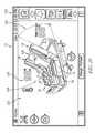
- FIG. 1is a perspective view from the foot end on the patient's left of a patient support apparatus
- FIG. 2is a perspective view of the patient support apparatus of FIG. 1 with a siderail detached from the patient support apparatus;
- FIG. 3is a perspective view from the head end on the patient's left of the patient support apparatus of FIG. 1 , wherein the patient support apparatus further includes a patient helper attached thereto;
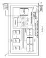
- FIG. 4is a block diagram of a portion of the electrical system of the patient support apparatus of FIG. 1 used to determine a tare weight of the patient support apparatus;
- FIG. 5is a block diagram of the positions of a number of load cells and mounting sockets relative to the patient support apparatus of FIG. 1 ;
- FIG. 6is a cross-section of a first embodiment of the mounting socket in the upper frame of the patient support apparatus of FIG. 1 with an embedded hall-effect mechanism detector;
- FIG. 7is a cross-section of a second embodiment of a mounting socket in the upper frame of the patient support apparatus of FIG. 1 with an embedded switch-type mechanism detector FIG. 7 showing a portion of a siderail in a first position;
- FIG. 8is a cross-section of the second embodiment of the mounting socket in the upper frame of the patient support apparatus of FIG. 1 with an embedded switch-type mechanism detector FIG. 7 showing the portion of the sidereal in a second position activating the switch;
- FIG. 9is a cross-section of a third embodiment of the mounting socket in the upper frame of the patient support apparatus of FIG. 1 with a hall-effect mechanism detector positioned at the bottom end of the mounting socket;
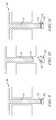
- FIG. 10is a cross-section of a fourth embodiment of a mounting socket in the upper frame of the patient support apparatus of FIG. 1 with a switch-type mechanism detector at the bottom end of the mounting socket FIG. 10 showing a portion of a siderail in a first position;
- FIG. 11is a cross-section of the fourth embodiment of the mounting socket in the upper frame of the patient support apparatus of FIG. 1 with a switch-type mechanism detector at the bottom end of the mounting socket FIG. 10 showing the portion of the sidereal in a second position activating the switch;
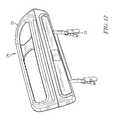
- FIG. 12is a perspective view of a siderail of the patient support apparatus of FIG. 1 ;
- FIG. 13is a flow chart showing a routine process performed by the processor of the patient support apparatus of FIG. 1 to determine the true patient weight;
- FIG. 14is a flow chart showing a sub-routine process for determining and storing each and every removable component of the patient support apparatus that forms one part of the routine process of FIG. 13 ;
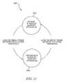
- FIG. 15is a state diagram illustrating one embodiment of a control sub-routine for determining whether a patient is being supported by the patient support apparatus that forms one part of the routine process of FIG. 13 ;
- FIG. 16is a flow chart showing a sub-routine process for initializing a tare weight that forms one part of the routine process of FIG. 13 ;
- FIG. 17is a flow chart showing a sub-routine process for determining and offsetting the tare weight that forms one part of the routine process of FIG. 13 ;
- FIG. 18is a flow chart showing a sub-routine process for updating a tare weight as a function of historical weight information that forms one part of the routine of FIG. 17 ;
- FIG. 19is a depiction of a particular embodiment of a user interface screen of the patient support apparatus of FIG. 1 , the user interface screen depicting a status of subsystems of the patient support apparatus including a depiction of the barriers present on the patient support apparatus;
- FIG. 20is a depiction of the user interface similar to FIG. 19 , with FIG. 20 showing that a siderail that has been removed from the patient support apparatus no longer appears on the user interface.
- FIG. 1An illustrative patient support apparatus embodied as a hospital bed 10 is shown in FIG. 1 .
- the patient support apparatus 10 of FIG. 1has an auto-tare function, which detects and compensates for any addition or removal of one or more removable components 14 that affect determination of the true patient weight.
- the patient support apparatus 10has a number of removable components 14 attached to a fixed bed frame 16 as shown in FIG. 1 .
- the fixed bed frame 16includes a base frame 26 with casters 38 and an upper frame 28 .
- the upper frame 28includes a number of mattress support sections that support a therapy surface 30 .
- the illustrative patient support apparatus 10has a user interface 70 that includes an input panel or control panel 56 that is affixed to the footboard 20 of the patient support apparatus 10 .
- the user interface 70is coupled to the controller 410 as shown in FIG. 4 .
- the user interface 70includes a graphical user interface 72 that includes a touchscreen panel that allows a user to modify various subsystems of the patient support apparatus 10 .
- the graphical user interface 72also provides graphical real-time status indications relative to the patient support apparatus 10 to the user. As will be discussed in further detail below, this real-time status provides important feedback to the user or caregiver as the operational parameters of the patient support apparatus 10 are modified.
- all removable components 14including a headboard 18 , a footboard 20 , siderails 22 , and a patient helper 24 , are in an attached position.
- the removable component 14has vertically projected prongs 15 that are configured to fit into mounting sockets 52 which are located along the edges of the upper frame 28 as shown in FIG. 2 .
- Each removable component 14is removable from the patient support apparatus 10 to provide easier access for the patient and caregivers.
- the siderail 22is removed by sliding a rail latch 40 toward an unlock position and lifting up the siderail 22 from the mounting sockets 52 as shown in FIG. 2 .
- To attach the siderail 22 back to the patient support apparatus 10align and mount the prongs 15 of the siderail 22 into the corresponding mounting sockets 52 then slide the rail latch 40 toward a lock position.
- Each mounting socket 52has one or more detectors 50 .
- Each detector 50is configured to produce a signal indicative of the presence or absence of the corresponding removable component 14 .
- Each detector 50detects the presence of the removable component 14 by detecting the prong 15 of the removable component 14 which is vertically projected into the cylindrical space 58 of the mounting socket 52 .
- the mounting socket 52has one or more embedded detectors 50 mounted on the surface 60 of the cylindrical space 58 of the mounting socket 52 .
- the mounting socket 52has the embedded hall-effect mechanism detector 50 as shown in FIG. 6 .
- the embedded hall-effect mechanism detector 50detects the prong 15 of the removable component 14 when the prong 15 comes in near proximity with the embedded hall-effect mechanism detector 50 in the cylindrical space 58 of the mounting socket 52 .
- the mounting socket 52has the embedded switch-type mechanism detector 50 as shown in FIGS. 7-8 .
- the embedded switch-type mechanism detector 50is inactive when the corresponding removable component 14 is not attached to the patient support apparatus 10 as shown in FIG. 7 .
- the embedded switch-type mechanism detector 50is activated when the embedded switch 62 is in a physical contact with the tip 13 of the prong 15 of the removable component 14 as shown in FIG. 8 .
- each mounting socket 52has a detector 50 at the lower end of the cylindrical space 58 of the mounting socket 52 , which is horizontally parallel to the upper frame 28 .
- the tip 13 of the prong 15 of the removable component 14rests on the near surface of the detector 50 .
- the mounting socket 52has the hall-effect mechanism detector 50 as shown in FIG. 9 .
- the hall-effect mechanism detector 50detects the tip 13 of the prong 15 of the removable component 14 when the prong 15 comes in near proximity with the detector 50 at the lower end of the cylindrical space 58 of the mounting socket 52 .
- the mounting socket 52has the switch-type mechanism detector 50 as shown in FIGS. 10-11 .
- the switch-type mechanism detector 50is inactive when the corresponding removable component 14 is not attached to the patient support apparatus 10 as shown in FIG. 10 .
- the switch-type mechanism detector 50is activated when the switch 62 is in a physical contact with the tip 13 of the prong 15 of the removable component 14 as shown in FIG. 11 .
- the base frame 26supports a weigh frame 54 that is mounted via frame member 57 a and 57 b to the upper frame 28 configured to support the therapy surface 30 .
- a number of load cells 68 a - dare positioned between the weigh frame 54 and the base frame 26 , wherein each load cell 68 a - d is configured to produce a signal indicative of a weight supported by that load cell 68 a - d from the weigh frame 54 relative to the base frame 26 .
- the patient support apparatus 10includes a weigh scale module 80 configured to automatically update a tare weight for use in determining a true patient weight.
- the weigh scale module 80includes a processor module 82 that is in communication with each of the load cells 68 and detectors 50 .
- the processor module 400includes a microprocessor-based controller 86 having a flash memory unit 88 and a local random-access memory (RAM) unit 414 .
- the local RAM unit 414is utilized by the controller 86 to temporarily store information corresponding to features and functions provided by the patient support apparatus 10 . More specifically, the controller 86 is configured to adjust the tare weight of the patient support apparatus 10 based on the signals provided by the load cells 68 and the detectors 50 .
- the presence or absence of the removable components 14is indicated graphically on the touchscreen 72 .
- the touchscreen 72is divided into a main menu portion 120 and a status portion 122 .
- the status of several removable components 14is indicated graphically.
- a foot-end siderail shown in FIG. 19 and indicated by reference numeral 76is not present, the foot-end siderail is not displayed graphically as indicated in FIG. 20 .
- This variationprovides immediate feedback to a caregiver or other user of the status of the various components of the patient support apparatus 10 .
- a graphical representation 124 of the patient support apparatus 10shows a head section 126 in a raised position and provides an indicia 128 of the head angle.
- indicia 130in the form of animated bubbles, shows that the air fluidized portion of the surface 30 is active.
- the touchscreen 72also displays the current temperature 130 through indicia on the touchscreen 72 .
- the main menu portion 120shows a scroll bar that has several icons that allow a user to select one of several options that may be displayed and controlled on the status portion 122 .
- the disclosed embodimentshows the presence of the removable component 14 , illustratively embodied as the siderail 76 as present in FIG. 19 and absent in FIG. 20 , it should be understood that other approaches to indicating the absence of the siderail 76 may be used to signal the caregiver or user.
- the missing removable component 14may flash on and off, be shown in phantom or ghosting on the display, or may be shown on the screen but separated from the bed, as examples.
- the display 72may be shown on a remote display 140 (seen in FIG. 4 ), such as a nurse station, for example, with the indication of the presence and absence of removable components 14 using the same techniques discussed above.
- a remote displaymay be a wired or wireless connection with the display 140 driven by display 72 , or may be a duplicate display 142 that is rebuilt at a remote location by a separate controller that receives data regarding the status of the patient support apparatus 10 from controller 410 and creates the remote display from that data. Still further, the remote display 140 or 142 may be presented on a mobile computing device, such as a personal digital assistant, used by a caregiver. The presentation on the mobile computing device may in addition to both the local display 72 , remote display 140 or 142 , or may be an alternative to either or all.
- an initial process 200 for determining the weights of each and every removable component 14 and store the weights in the memory 84is shown.
- the initial process 200illustratively begins at decision step 202 where the controller 86 is operable to determine whether historical weight data of each removable component 14 is stored in a memory 84 of the patient support apparatus 10 . If the controller 86 determines that the historical weight data of each removable component 14 does not exist in the memory 84 , the initial process 200 advances to decision step 204 in which the controller 86 determines whether any removable components 14 are currently attached to the patient support apparatus 10 .
- the controller 86determines whether or not any removable components 14 are currently attached to the patient support apparatus 10 in response to receiving signals produced by one or more detectors 50 . If the controller 86 determines that none of the removable components 14 are currently attached to the patient support apparatus 10 , the initial process 200 advances to step 206 .
- one removable component 14is added on the patient support apparatus 10 at a time.
- one or more detectors 50detect the presence of the particular removable component 14 and produce the signal to the controller 86 .
- the controller 86receives the signal from the detectors 50 , the initial process 200 proceeds to step 210 where the controller 86 determines which removable component 14 is detected on the patient support apparatus 10 and stores the weight of each removable component 14 in the memory 84 . Once the weights of each and every removable component 14 are stored in the memory 84 , the initial process 200 proceeds to step 102 of a routine process 100 .
- FIG. 15is a state diagram 600 illustrating one embodiment of the occupancy states of the patient support apparatus 10 as determined by the controller 86 .
- the controller 86determines whether or not a patient 36 is being supported by a support surface of the therapy surface 30 and updates the occupancy state accordingly.
- the controller 86determines two discrete states of occupancy, an occupied state 602 indicative of the patient 36 being in the patient support apparatus 10 and an unoccupied state 604 indicative of the patient 36 not being in the patient support apparatus 10 .
- the controller 86may determine that the patient is both partially in and partially out of the patient support apparatus 10 (e.g., the patient is sitting on the edge of the patient support apparatus 10 ) at any given point of time.
- the controller 86initializes the occupancy state of the patient support apparatus 10 to the unoccupied state 604 . After initialization, the controller 86 updates the occupancy state of the patient support apparatus 10 to the occupied state 602 in response to determining that a normalized amount of weight on the weigh frame 54 satisfies a reference occupied threshold. For example, in one embodiment, the controller 86 updates the occupancy state of the patient support apparatus 10 to the occupied state 602 in response to determining that the normalized amount of weight on the weigh frame 54 meets or exceeds 31 pounds. In the illustrative embodiment, the controller 86 updates the occupancy state of the patient support apparatus 10 to the occupied state 602 .
- the controller 86updates the occupancy state of the patient support apparatus 10 to the unoccupied state 604 in response to determining that the normalized amount of weight on the weigh frame 54 satisfies a reference unoccupied threshold. For example, in the illustrated embodiment, the controller 86 updates the occupancy state of the patient support apparatus 10 to the unoccupied state 604 in response to determining that the normalized amount of weight on the weigh frame 54 meets or falls below 65 pounds. In the present embodiment, the controller 86 updates the occupancy state of the patient support apparatus 10 to the unoccupied state 604 .
- the routine process 100advances to step 300 in which the tare weight of the empty patient support apparatus 10 is initialized and stored.
- the initial tare weightincludes the weight of the empty patient support apparatus 10 with any removable components 14 detected on the patient support apparatus 10 .
- the controller 86also detects any removable components 14 initially present on the empty patient support apparatus 10 and stores the information in the local RAM unit 414 .
- the routine process 100advances to decision step 104 where the controller 86 is operable to determine whether auto-tare functionality has been enabled on the patient support apparatus 10 .
- step 106the controller 86 is operable to check again an occupancy state of the patient support apparatus 10 to determine whether the patient 36 is supported on the patient support apparatus 10 . If the controller 86 determines that the patient 36 is now supported on the patient support apparatus 10 , the routine process 100 proceeds to step 108 where the controller 86 captures and stores the total weight on a weigh frame 54 of the patient support apparatus 10 . After storing the total weight of the patient support apparatus 10 , the routine process 100 advances to step 400 to determine and offset the tare weight.
- the controller 86determines whether a historical tare weight data exists. For example, in one embodiment, the controller 86 determines whether the historical tare weight data corresponding to the patient support apparatus 10 exists. If the controller 86 determines that the historical tare weight data for the patient support apparatus 10 exists, then the routine process 100 advances to step 406 in which the controller 86 recalls the historical tare weight data. However, if the controller 86 instead determines at decision step 402 that the historical tare weight data for the patient support apparatus 10 does not exist, then the routine process 100 advances to step 404 in which the controller 86 recalls the initial tare weight data from step 300 .
- the detectors 50After determining the initial or historical tare weight in step 404 or 406 , respectively, the detectors 50 detect and the controller 86 recognizes which removable components 14 was added or removed from the patient support apparatus 10 . If the detectors 50 detect any removable components 14 added on the patient support apparatus 10 at decision step 408 , the controller 86 adds the predetermined weights of the added removable components 14 to the initial or historical tare weight. If, however, the detectors 50 detect any removable components 14 removed from the patient support apparatus 10 at decision step 412 , the controller 86 subtracts the predetermined weights of the removed removable components 14 from the initial or historical tare weight. Accordingly, at step 500 , the controller 86 updates the initial or historical tare weight as a function of the historical tare weight data.
- the controller 86determines whether a historical tare weight data exists. For example, in one embodiment, the controller 86 determines whether the historical tare weight data corresponding to the patient support apparatus 10 exists. If the controller 86 determines that the historical tare weight data for the patient support apparatus 10 exists, then the process 100 advances to step 506 in which the controller 86 update the existing historical tare weight data. However, if the controller 86 instead determines at decision step 502 that the historical tare weight data for the patient support apparatus 10 does not exist, then the process 500 advances to step 504 in which the controller 86 update the new tare weight as a function of historical tare weight data.
- step 110the routine process 100 proceeds to step 110 to determine the true patient weight.
- the controller 86determines the true weight of patient that is solely attributable to the patient by offsetting the updated tare weight from the total amount of weight on the patient support apparatus 10 .
Landscapes
- Health & Medical Sciences (AREA)
- Life Sciences & Earth Sciences (AREA)
- Animal Behavior & Ethology (AREA)
- General Health & Medical Sciences (AREA)
- Public Health (AREA)
- Veterinary Medicine (AREA)
- Nursing (AREA)
- Physics & Mathematics (AREA)
- Engineering & Computer Science (AREA)
- Biophysics (AREA)
- Heart & Thoracic Surgery (AREA)
- Surgery (AREA)
- Molecular Biology (AREA)
- Pathology (AREA)
- Medical Informatics (AREA)
- Biomedical Technology (AREA)
- General Physics & Mathematics (AREA)
- Physiology (AREA)
- Dentistry (AREA)
- Oral & Maxillofacial Surgery (AREA)
- Artificial Intelligence (AREA)
- Computer Vision & Pattern Recognition (AREA)
- Psychiatry (AREA)
- Signal Processing (AREA)
- Epidemiology (AREA)
- Apparatus Associated With Microorganisms And Enzymes (AREA)
- Invalid Beds And Related Equipment (AREA)
Abstract
Description
Claims (17)
Priority Applications (2)
| Application Number | Priority Date | Filing Date | Title |
|---|---|---|---|
| US15/137,306US10045715B2 (en) | 2015-04-27 | 2016-04-25 | Self-compensating bed scale system for removable components |
| US16/046,046US10660544B2 (en) | 2015-04-27 | 2018-07-26 | Self-compensating bed scale system for removable components |
Applications Claiming Priority (2)
| Application Number | Priority Date | Filing Date | Title |
|---|---|---|---|
| US201562153128P | 2015-04-27 | 2015-04-27 | |
| US15/137,306US10045715B2 (en) | 2015-04-27 | 2016-04-25 | Self-compensating bed scale system for removable components |
Related Child Applications (1)
| Application Number | Title | Priority Date | Filing Date |
|---|---|---|---|
| US16/046,046ContinuationUS10660544B2 (en) | 2015-04-27 | 2018-07-26 | Self-compensating bed scale system for removable components |
Publications (2)
| Publication Number | Publication Date |
|---|---|
| US20160310045A1 US20160310045A1 (en) | 2016-10-27 |
| US10045715B2true US10045715B2 (en) | 2018-08-14 |
Family
ID=55967039
Family Applications (2)
| Application Number | Title | Priority Date | Filing Date |
|---|---|---|---|
| US15/137,306Active2036-10-21US10045715B2 (en) | 2015-04-27 | 2016-04-25 | Self-compensating bed scale system for removable components |
| US16/046,046Active2036-04-29US10660544B2 (en) | 2015-04-27 | 2018-07-26 | Self-compensating bed scale system for removable components |
Family Applications After (1)
| Application Number | Title | Priority Date | Filing Date |
|---|---|---|---|
| US16/046,046Active2036-04-29US10660544B2 (en) | 2015-04-27 | 2018-07-26 | Self-compensating bed scale system for removable components |
Country Status (2)
| Country | Link |
|---|---|
| US (2) | US10045715B2 (en) |
| EP (1) | EP3087963B1 (en) |
Cited By (4)
| Publication number | Priority date | Publication date | Assignee | Title |
|---|---|---|---|---|
| USD855369S1 (en)* | 2015-01-29 | 2019-08-06 | Hill-Rom Services, Inc. | Foot rail for patient bed |
| CN111044132A (en)* | 2019-12-17 | 2020-04-21 | 天津市环湖医院(天津市神经外科研究所、天津市脑系科中心医院) | Novel sitting type weight measuring instrument |
| US10660544B2 (en) | 2015-04-27 | 2020-05-26 | Hill-Rom Services, Inc. | Self-compensating bed scale system for removable components |
| US11484223B2 (en)* | 2014-10-17 | 2022-11-01 | Stryker Corporation | Person support apparatuses with motion monitoring |
Families Citing this family (15)
| Publication number | Priority date | Publication date | Assignee | Title |
|---|---|---|---|---|
| US10489661B1 (en) | 2016-03-08 | 2019-11-26 | Ocuvera LLC | Medical environment monitoring system |
| US10444060B2 (en) | 2016-05-13 | 2019-10-15 | Adaptec Medical Devices LLC | Fluid container measurement system |
| EP3581108B1 (en) | 2016-05-13 | 2021-01-13 | Adaptec Medical Devices LLC | Fluid container measurement system employing load cell linkage member |
| US10898400B2 (en) | 2016-12-01 | 2021-01-26 | Stryker Corporation | Person support apparatuses with load cells |
| US10600204B1 (en) | 2016-12-28 | 2020-03-24 | Ocuvera | Medical environment bedsore detection and prevention system |
| US10497247B2 (en) | 2017-11-20 | 2019-12-03 | Umano Medical Inc. | Hospital bed exit detection, height limiting and tare weight recalibrating systems and methods |
| CN108744148B (en)* | 2018-04-09 | 2021-04-02 | 深圳市联新移动医疗科技有限公司 | Monitoring method and device for automatic calibration weighing basis in no-load state |
| US11357682B2 (en) | 2018-09-30 | 2022-06-14 | Hill-Rom Services, Inc. | Structures for causing movement of elements of a bed |
| US11367535B2 (en) | 2018-09-30 | 2022-06-21 | Hill-Rom Services, Inc. | Patient care system for a home environment |
| US11229568B2 (en) | 2018-09-30 | 2022-01-25 | Hill-Rom Services, Inc. | Mattress support for adding hospital bed functionality to an in-home bed |
| US11400001B2 (en) | 2018-10-01 | 2022-08-02 | Hill-Rom Services, Inc. | Method and apparatus for upgrading a bed to include moveable components |
| US11241347B2 (en) | 2018-10-01 | 2022-02-08 | Hill-Rom Services, Inc. | Mattress support for adding hospital bed modular control system for upgrading a bed to include movable components |
| US10959534B2 (en) | 2019-02-28 | 2021-03-30 | Hill-Rom Services, Inc. | Oblique hinged panels and bladder apparatus for sleep disorders |
| CN111772978A (en)* | 2020-06-30 | 2020-10-16 | 黄晓静 | Novel nursing bed of intracardiac branch of academic or vocational study |
| US20240299226A1 (en)* | 2021-10-13 | 2024-09-12 | Stryker Corporation | Patient support apparatus with automatic scale functionality |
Citations (65)
| Publication number | Priority date | Publication date | Assignee | Title |
|---|---|---|---|---|
| US3096061A (en) | 1961-06-28 | 1963-07-02 | Standard Mirror Co Inc | Support for mounting a rear vision mirror on a windshield |
| US3217818A (en) | 1964-04-06 | 1965-11-16 | Harvey J Engelsher | Pneumatic weighing device |
| US3876018A (en) | 1972-01-03 | 1975-04-08 | Said Mracek By Said Bauer | Portable support for a bed patient |
| US4015677A (en) | 1975-07-25 | 1977-04-05 | The United States Of America As Represented By The Secretary Of The Navy | Automatic patient weighing system |
| US4023633A (en) | 1975-12-22 | 1977-05-17 | Swersey Burt L | Flexure scale |
| US4363368A (en) | 1981-03-13 | 1982-12-14 | Health Care Innovations, Inc. | Medical patient weighing scale |
| US4551882A (en) | 1981-05-04 | 1985-11-12 | Cobe Asdt, Inc. | Scale of flat construction |
| US4601356A (en) | 1985-02-01 | 1986-07-22 | Muccillo Jr Vincent J | Suspended platform scale structure |
| US4751754A (en) | 1987-04-02 | 1988-06-21 | Hill-Rom Company, Inc. | Dual hydraulic hospital bed with emergency bypass circuit |
| US4953244A (en) | 1987-12-28 | 1990-09-04 | Hill-Rom Company, Inc. | Hospital bed for weighing patients |
| US5131103A (en) | 1990-12-18 | 1992-07-21 | Thomas Jimmy W | Integrated back support and bed apparatus and method |
| US5245718A (en) | 1992-10-09 | 1993-09-21 | Joerns Healthcare, Inc. | Adjustable bed with single actuator |
| US5276432A (en)* | 1992-01-15 | 1994-01-04 | Stryker Corporation | Patient exit detection mechanism for hospital bed |
| US5393938A (en)* | 1993-05-06 | 1995-02-28 | Bio Clinic Corporation | In-bed patient scale |
| US5808552A (en) | 1996-11-25 | 1998-09-15 | Hill-Rom, Inc. | Patient detection system for a patient-support device |
| US5823278A (en)* | 1994-10-13 | 1998-10-20 | Future Systems, Inc. | Caster mounted weighing system |
| US5831221A (en) | 1994-10-13 | 1998-11-03 | Future Sysems, Inc. | Caster mounted weighing system |
| US5859390A (en) | 1996-10-23 | 1999-01-12 | Hill-Rom, Inc. | Hospital bed scale mounting apparatus |
| US5861582A (en) | 1996-01-23 | 1999-01-19 | Synapse Technology, Inc. | Patient weighing system |
| US5906016A (en) | 1988-03-23 | 1999-05-25 | Hill-Rom | Patient care system |
| US6067019A (en) | 1996-11-25 | 2000-05-23 | Hill-Rom, Inc. | Bed exit detection apparatus |
| US6092838A (en) | 1998-04-06 | 2000-07-25 | Walker; Robert R. | System and method for determining the weight of a person in a seat in a vehicle |
| US6133837A (en) | 1999-03-05 | 2000-10-17 | Hill-Rom, Inc. | Patient position system and method for a support surface |
| US6208250B1 (en) | 1999-03-05 | 2001-03-27 | Hill-Rom, Inc. | Patient position detection apparatus for a bed |
| US6469263B1 (en) | 1999-09-18 | 2002-10-22 | Raye's, Inc. | Hospital bed weighing system |
| US6481688B1 (en) | 1992-11-30 | 2002-11-19 | Hill-Rom Services, Inc. | Hospital bed communication and control device |
| US20030010345A1 (en) | 2002-08-02 | 2003-01-16 | Arthur Koblasz | Patient monitoring devices and methods |
| US6680443B2 (en) | 2001-06-22 | 2004-01-20 | Hill-Rom Services, Inc. | Load cell apparatus having a gap measuring device |
| US6791460B2 (en) | 1999-03-05 | 2004-09-14 | Hill-Rom Services, Inc. | Patient position detection apparatus for a bed |
| US6793279B2 (en) | 1998-05-18 | 2004-09-21 | Ultra-Mek, Inc. | Reclining seating unit movable to heart-rest position |
| US6829796B2 (en) | 2001-10-02 | 2004-12-14 | Hill-Rom Services, Inc. | Integrated barrier and fluid supply for a hospital bed |
| US20050077861A1 (en) | 2003-10-10 | 2005-04-14 | Midmark Corporation | Load compensation system for power chair |
| US6924441B1 (en) | 1999-09-29 | 2005-08-02 | Hill-Rom Services, Inc. | Load cell apparatus |
| US20050273940A1 (en) | 2004-04-30 | 2005-12-15 | Robert Petrosenko | Lack of patient movement monitor and method |
| US20060059814A1 (en) | 2004-09-13 | 2006-03-23 | Metz Darrell L | Load cell to frame interface for hospital bed |
| US20060195986A1 (en) | 2005-03-07 | 2006-09-07 | Reza Hakamiun | Footboard for a hospital bed |
| US20070094792A1 (en) | 2005-10-31 | 2007-05-03 | Sims Dewey M Jr | Variable motion rocking bed |
| US20070268147A1 (en) | 2004-08-09 | 2007-11-22 | Hill-Rom Services, Inc. | Load-cell based hospital bed control |
| US20070272450A1 (en) | 2003-12-12 | 2007-11-29 | Hill-Rom Services, Inc. | Seat Force Sensor |
| US20080066230A1 (en) | 2006-09-18 | 2008-03-20 | Hallock Joseph H | Safety bed having elevating mattress |
| EP1975750A2 (en) | 2007-03-30 | 2008-10-01 | Hill-Rom Services, Inc. | User interface for hospital bed |
| US7469436B2 (en) | 2004-04-30 | 2008-12-30 | Hill-Rom Services, Inc. | Pressure relief surface |
| US20090013462A1 (en) | 2006-08-14 | 2009-01-15 | Mohammad Hassan Mahdjoubi | Multi-purpose Hospital Bed |
| US20090139032A1 (en) | 2007-11-30 | 2009-06-04 | Siemens Medical Solutions Usa, Inc. | Mechanism for Remotely Measuring Bed Deflection |
| US20090217460A1 (en) | 2005-07-08 | 2009-09-03 | Bobey John A | Patient support |
| US7698765B2 (en) | 2004-04-30 | 2010-04-20 | Hill-Rom Services, Inc. | Patient support |
| US7834768B2 (en) | 1999-03-05 | 2010-11-16 | Hill-Rom Services, Inc. | Obstruction detection apparatus for a bed |
| US20100308846A1 (en) | 2009-06-05 | 2010-12-09 | Gilles Camus | Pressure sensor comprising a capacitive cell and support device comprising said sensor |
| US20110010858A1 (en) | 2008-02-15 | 2011-01-20 | Milan Tesar | Positioning mechanism of a bed |
| US8056950B2 (en) | 2004-09-24 | 2011-11-15 | Stryker Corporation | In-ambulance cot shut-off device |
| US8261381B2 (en) | 2006-09-18 | 2012-09-11 | Sleep Safe Beds, Llc | Safety bed frame mounting system |
| US8266743B2 (en) | 2010-08-23 | 2012-09-18 | Midmark Corporation | Examination table with motion tracking |
| US8344860B2 (en) | 2004-08-02 | 2013-01-01 | Hill-Rom Services, Inc. | Patient support apparatus alert system |
| US8432287B2 (en) | 2010-07-30 | 2013-04-30 | Hill-Rom Services, Inc. | Apparatus for controlling room lighting in response to bed exit |
| US8464380B2 (en) | 2005-07-08 | 2013-06-18 | Hill-Rom Services, Inc. | Patient support apparatus having alert light |
| US8537008B2 (en) | 2008-09-19 | 2013-09-17 | Hill-Rom Services, Inc. | Bed status indicators |
| US20140080413A1 (en)* | 2012-09-17 | 2014-03-20 | Stryker Corporation | Communication systems for patient support apparatuses |
| US8717181B2 (en) | 2010-07-29 | 2014-05-06 | Hill-Rom Services, Inc. | Bed exit alert silence with automatic re-enable |
| US20140124273A1 (en) | 2012-11-05 | 2014-05-08 | Hill-Rom Services, Inc. | Automatic Weight Offset Calculation for Bed Scale Systems |
| US20140151577A1 (en) | 2010-06-04 | 2014-06-05 | Dow Global Technologies Llc | Fluorescence Method for Determining Occlusion in Enclosed Spaces |
| US8745788B2 (en) | 2005-07-26 | 2014-06-10 | Hill-Rom Services. Inc. | System and method for controlling an air mattress |
| US8844079B2 (en) | 2005-07-08 | 2014-09-30 | Hill-Rom Services, Inc. | Pressure control for a hospital bed |
| US8921717B2 (en) | 2012-11-05 | 2014-12-30 | S R Instruments, Inc. | Weight magnitude and weight position indication systems and methods |
| US8973186B2 (en) | 2011-12-08 | 2015-03-10 | Hill-Rom Services, Inc. | Optimization of the operation of a patient-support apparatus based on patient response |
| US20160022218A1 (en)* | 2013-03-15 | 2016-01-28 | Stryker Corporation | Patient support apparatus with patient information sensors |
Family Cites Families (1)
| Publication number | Priority date | Publication date | Assignee | Title |
|---|---|---|---|---|
| US10045715B2 (en) | 2015-04-27 | 2018-08-14 | Hill-Rom Services, Inc. | Self-compensating bed scale system for removable components |
- 2016
- 2016-04-25USUS15/137,306patent/US10045715B2/enactiveActive
- 2016-04-26EPEP16167021.1Apatent/EP3087963B1/enactiveActive
- 2018
- 2018-07-26USUS16/046,046patent/US10660544B2/enactiveActive
Patent Citations (107)
| Publication number | Priority date | Publication date | Assignee | Title |
|---|---|---|---|---|
| US3096061A (en) | 1961-06-28 | 1963-07-02 | Standard Mirror Co Inc | Support for mounting a rear vision mirror on a windshield |
| US3217818A (en) | 1964-04-06 | 1965-11-16 | Harvey J Engelsher | Pneumatic weighing device |
| US3876018A (en) | 1972-01-03 | 1975-04-08 | Said Mracek By Said Bauer | Portable support for a bed patient |
| US4015677A (en) | 1975-07-25 | 1977-04-05 | The United States Of America As Represented By The Secretary Of The Navy | Automatic patient weighing system |
| US4023633A (en) | 1975-12-22 | 1977-05-17 | Swersey Burt L | Flexure scale |
| US4363368A (en) | 1981-03-13 | 1982-12-14 | Health Care Innovations, Inc. | Medical patient weighing scale |
| US4551882A (en) | 1981-05-04 | 1985-11-12 | Cobe Asdt, Inc. | Scale of flat construction |
| US4601356A (en) | 1985-02-01 | 1986-07-22 | Muccillo Jr Vincent J | Suspended platform scale structure |
| US4751754A (en) | 1987-04-02 | 1988-06-21 | Hill-Rom Company, Inc. | Dual hydraulic hospital bed with emergency bypass circuit |
| US4953244A (en) | 1987-12-28 | 1990-09-04 | Hill-Rom Company, Inc. | Hospital bed for weighing patients |
| US5906016A (en) | 1988-03-23 | 1999-05-25 | Hill-Rom | Patient care system |
| US6668408B2 (en) | 1988-03-23 | 2003-12-30 | Hill-Rom Services, Inc. | Patient care system |
| US5131103A (en) | 1990-12-18 | 1992-07-21 | Thomas Jimmy W | Integrated back support and bed apparatus and method |
| US5276432A (en)* | 1992-01-15 | 1994-01-04 | Stryker Corporation | Patient exit detection mechanism for hospital bed |
| US6438776B2 (en) | 1992-04-03 | 2002-08-27 | Hill-Rom Services, Inc. | Patient care system |
| US5245718A (en) | 1992-10-09 | 1993-09-21 | Joerns Healthcare, Inc. | Adjustable bed with single actuator |
| US6560798B2 (en) | 1992-11-30 | 2003-05-13 | Hill-Rom Services, Inc. | Hospital bed communication and control device |
| US6481688B1 (en) | 1992-11-30 | 2002-11-19 | Hill-Rom Services, Inc. | Hospital bed communication and control device |
| US6761344B2 (en) | 1992-11-30 | 2004-07-13 | Hill-Rom Services, Inc. | Hospital bed communication and control device |
| US5393938A (en)* | 1993-05-06 | 1995-02-28 | Bio Clinic Corporation | In-bed patient scale |
| US5823278A (en)* | 1994-10-13 | 1998-10-20 | Future Systems, Inc. | Caster mounted weighing system |
| US5831221A (en) | 1994-10-13 | 1998-11-03 | Future Sysems, Inc. | Caster mounted weighing system |
| US5861582A (en) | 1996-01-23 | 1999-01-19 | Synapse Technology, Inc. | Patient weighing system |
| US5859390A (en) | 1996-10-23 | 1999-01-12 | Hill-Rom, Inc. | Hospital bed scale mounting apparatus |
| US5808552A (en) | 1996-11-25 | 1998-09-15 | Hill-Rom, Inc. | Patient detection system for a patient-support device |
| US6067019A (en) | 1996-11-25 | 2000-05-23 | Hill-Rom, Inc. | Bed exit detection apparatus |
| US6092838A (en) | 1998-04-06 | 2000-07-25 | Walker; Robert R. | System and method for determining the weight of a person in a seat in a vehicle |
| US6793279B2 (en) | 1998-05-18 | 2004-09-21 | Ultra-Mek, Inc. | Reclining seating unit movable to heart-rest position |
| US7986242B2 (en) | 1999-03-05 | 2011-07-26 | Hill-Rom Services, Inc. | Electrical connector assembly suitable for a bed footboard |
| US20110037597A1 (en) | 1999-03-05 | 2011-02-17 | Dixon Stephen A | Body position monitoring system |
| US8400311B2 (en) | 1999-03-05 | 2013-03-19 | Hill-Rom Services, Inc. | Hospital bed having alert light |
| US8525682B2 (en) | 1999-03-05 | 2013-09-03 | Hill-Rom Services, Inc. | Hospital bed having alert light |
| US6320510B2 (en) | 1999-03-05 | 2001-11-20 | Douglas J. Menkedick | Bed control apparatus |
| US6791460B2 (en) | 1999-03-05 | 2004-09-14 | Hill-Rom Services, Inc. | Patient position detection apparatus for a bed |
| US6208250B1 (en) | 1999-03-05 | 2001-03-27 | Hill-Rom, Inc. | Patient position detection apparatus for a bed |
| US7834768B2 (en) | 1999-03-05 | 2010-11-16 | Hill-Rom Services, Inc. | Obstruction detection apparatus for a bed |
| US20050035871A1 (en) | 1999-03-05 | 2005-02-17 | Hill-Rom Services, Inc. | Patient position detection apparatus for a bed |
| US8258963B2 (en) | 1999-03-05 | 2012-09-04 | Hill-Rom Services, Inc. | Body position monitoring system |
| US7978084B2 (en) | 1999-03-05 | 2011-07-12 | Hill-Rom Services, Inc. | Body position monitoring system |
| US6133837A (en) | 1999-03-05 | 2000-10-17 | Hill-Rom, Inc. | Patient position system and method for a support surface |
| US8830070B2 (en) | 1999-03-05 | 2014-09-09 | Hill-Rom Services, Inc. | Hospital bed having alert light |
| US20050166324A1 (en) | 1999-03-05 | 2005-08-04 | Dixon Stephen A. | Romovable footboard for a hospital bed |
| US20080010747A1 (en) | 1999-03-05 | 2008-01-17 | Dixon Stephen A | Electrical Connector Assembly Suitable for a Bed Footboard |
| US6469263B1 (en) | 1999-09-18 | 2002-10-22 | Raye's, Inc. | Hospital bed weighing system |
| US6924441B1 (en) | 1999-09-29 | 2005-08-02 | Hill-Rom Services, Inc. | Load cell apparatus |
| US6680443B2 (en) | 2001-06-22 | 2004-01-20 | Hill-Rom Services, Inc. | Load cell apparatus having a gap measuring device |
| US20050091753A1 (en) | 2001-10-02 | 2005-05-05 | Hill-Rom Services, Inc. | Patient support apparatus |
| US7310839B2 (en) | 2001-10-02 | 2007-12-25 | Hill-Rom Services, Inc. | Patient support apparatus |
| US6829796B2 (en) | 2001-10-02 | 2004-12-14 | Hill-Rom Services, Inc. | Integrated barrier and fluid supply for a hospital bed |
| US20030010345A1 (en) | 2002-08-02 | 2003-01-16 | Arthur Koblasz | Patient monitoring devices and methods |
| US20050077861A1 (en) | 2003-10-10 | 2005-04-14 | Midmark Corporation | Load compensation system for power chair |
| US6907630B2 (en) | 2003-10-10 | 2005-06-21 | Midmark Corporation | Load compensation system for power chair |
| US7459645B2 (en) | 2003-12-12 | 2008-12-02 | Hill-Rom Services, Inc. | Seat force sensor for a patient support |
| US7714238B2 (en) | 2003-12-12 | 2010-05-11 | Hill-Rom Services, Inc. | Mattress seat force sensing method |
| US20070272450A1 (en) | 2003-12-12 | 2007-11-29 | Hill-Rom Services, Inc. | Seat Force Sensor |
| US20090084609A1 (en) | 2003-12-12 | 2009-04-02 | Skinner Andrew F | Mattress seat force sensing method |
| US20090270770A1 (en) | 2004-04-30 | 2009-10-29 | Robert Petrosenko | Graphical patient movement monitor |
| US7469436B2 (en) | 2004-04-30 | 2008-12-30 | Hill-Rom Services, Inc. | Pressure relief surface |
| US7937791B2 (en) | 2004-04-30 | 2011-05-10 | Hill-Rom Services, Inc. | Pressure relief surface |
| US8146191B2 (en) | 2004-04-30 | 2012-04-03 | Hill-Rom Services, Inc. | Patient support |
| US7973666B2 (en) | 2004-04-30 | 2011-07-05 | Hill-Rom Services, Inc. | Graphical patient movement monitor |
| US8196240B2 (en) | 2004-04-30 | 2012-06-12 | Hill-Rom Services, Inc. | Pressure relief surface |
| US7557718B2 (en) | 2004-04-30 | 2009-07-07 | Hill-Rom Services, Inc. | Lack of patient movement monitor and method |
| US20050273940A1 (en) | 2004-04-30 | 2005-12-15 | Robert Petrosenko | Lack of patient movement monitor and method |
| US7698765B2 (en) | 2004-04-30 | 2010-04-20 | Hill-Rom Services, Inc. | Patient support |
| US8344860B2 (en) | 2004-08-02 | 2013-01-01 | Hill-Rom Services, Inc. | Patient support apparatus alert system |
| US20070268147A1 (en) | 2004-08-09 | 2007-11-22 | Hill-Rom Services, Inc. | Load-cell based hospital bed control |
| US20060059814A1 (en) | 2004-09-13 | 2006-03-23 | Metz Darrell L | Load cell to frame interface for hospital bed |
| US7176391B2 (en) | 2004-09-13 | 2007-02-13 | Hill-Rom Services, Inc. | Load cell to frame interface for hospital bed |
| US20070107948A1 (en) | 2004-09-13 | 2007-05-17 | Metz Darrell L | Load cell to frame interface for hospital bed |
| US7335839B2 (en) | 2004-09-13 | 2008-02-26 | Hill-Rom Services, Inc. | Load cell interface for a bed having a stud receiver with a roller axis parallel with an axis of a load cell stud |
| US8056950B2 (en) | 2004-09-24 | 2011-11-15 | Stryker Corporation | In-ambulance cot shut-off device |
| US20060195986A1 (en) | 2005-03-07 | 2006-09-07 | Reza Hakamiun | Footboard for a hospital bed |
| US8844079B2 (en) | 2005-07-08 | 2014-09-30 | Hill-Rom Services, Inc. | Pressure control for a hospital bed |
| US9220650B2 (en) | 2005-07-08 | 2015-12-29 | Hill-Rom Services, Inc. | Patient support apparatus having alert light |
| US8464380B2 (en) | 2005-07-08 | 2013-06-18 | Hill-Rom Services, Inc. | Patient support apparatus having alert light |
| US20090217460A1 (en) | 2005-07-08 | 2009-09-03 | Bobey John A | Patient support |
| US8745788B2 (en) | 2005-07-26 | 2014-06-10 | Hill-Rom Services. Inc. | System and method for controlling an air mattress |
| US7478446B2 (en) | 2005-10-31 | 2009-01-20 | Sims Jr Dewey M | Variable motion rocking bed |
| US20070094792A1 (en) | 2005-10-31 | 2007-05-03 | Sims Dewey M Jr | Variable motion rocking bed |
| US7281284B2 (en) | 2005-10-31 | 2007-10-16 | Sims Jr Dewey M | Variable motion rocking bed |
| US20090013462A1 (en) | 2006-08-14 | 2009-01-15 | Mohammad Hassan Mahdjoubi | Multi-purpose Hospital Bed |
| US7818831B2 (en) | 2006-08-14 | 2010-10-26 | Mohammad Hassan Mahdjoubi | Multi-purpose hospital bed |
| US20080066230A1 (en) | 2006-09-18 | 2008-03-20 | Hallock Joseph H | Safety bed having elevating mattress |
| US7681260B2 (en) | 2006-09-18 | 2010-03-23 | Sleep Safe Beds, Llc | Safety bed having elevating mattress |
| US8261381B2 (en) | 2006-09-18 | 2012-09-11 | Sleep Safe Beds, Llc | Safety bed frame mounting system |
| EP1975750A2 (en) | 2007-03-30 | 2008-10-01 | Hill-Rom Services, Inc. | User interface for hospital bed |
| US7600434B2 (en) | 2007-11-30 | 2009-10-13 | Siemens Medical Solutions Usa, Inc. | Mechanism for remotely measuring medical treatment system bed deflection |
| US20090139032A1 (en) | 2007-11-30 | 2009-06-04 | Siemens Medical Solutions Usa, Inc. | Mechanism for Remotely Measuring Bed Deflection |
| US20110010858A1 (en) | 2008-02-15 | 2011-01-20 | Milan Tesar | Positioning mechanism of a bed |
| US8112836B2 (en) | 2008-02-15 | 2012-02-14 | Linet Spol. S.R.O. | Positioning mechanism of a bed |
| US20110094031A1 (en) | 2008-02-15 | 2011-04-28 | Milan Tesar | Positioning mechanism of a bed |
| US8959680B2 (en) | 2008-02-15 | 2015-02-24 | Linet Spol. S.R.O. | Positioning mechanism of a bed |
| US8537008B2 (en) | 2008-09-19 | 2013-09-17 | Hill-Rom Services, Inc. | Bed status indicators |
| US8593284B2 (en) | 2008-09-19 | 2013-11-26 | Hill-Rom Services, Inc. | System and method for reporting status of a bed |
| US8847756B2 (en) | 2008-09-19 | 2014-09-30 | Hill-Rom Services, Inc. | Bed status indicators |
| US8598893B2 (en) | 2009-06-05 | 2013-12-03 | Hill-Rom Industries Sa | Pressure sensor comprising a capacitive cell and support device comprising said sensor |
| US20100308846A1 (en) | 2009-06-05 | 2010-12-09 | Gilles Camus | Pressure sensor comprising a capacitive cell and support device comprising said sensor |
| US20140151577A1 (en) | 2010-06-04 | 2014-06-05 | Dow Global Technologies Llc | Fluorescence Method for Determining Occlusion in Enclosed Spaces |
| US8717181B2 (en) | 2010-07-29 | 2014-05-06 | Hill-Rom Services, Inc. | Bed exit alert silence with automatic re-enable |
| US8432287B2 (en) | 2010-07-30 | 2013-04-30 | Hill-Rom Services, Inc. | Apparatus for controlling room lighting in response to bed exit |
| US8266743B2 (en) | 2010-08-23 | 2012-09-18 | Midmark Corporation | Examination table with motion tracking |
| US8973186B2 (en) | 2011-12-08 | 2015-03-10 | Hill-Rom Services, Inc. | Optimization of the operation of a patient-support apparatus based on patient response |
| US20140080413A1 (en)* | 2012-09-17 | 2014-03-20 | Stryker Corporation | Communication systems for patient support apparatuses |
| US20140124273A1 (en) | 2012-11-05 | 2014-05-08 | Hill-Rom Services, Inc. | Automatic Weight Offset Calculation for Bed Scale Systems |
| US8921717B2 (en) | 2012-11-05 | 2014-12-30 | S R Instruments, Inc. | Weight magnitude and weight position indication systems and methods |
| US20160022218A1 (en)* | 2013-03-15 | 2016-01-28 | Stryker Corporation | Patient support apparatus with patient information sensors |
Non-Patent Citations (3)
| Title |
|---|
| Bib Data Sheet for WO 2014/151577, from the EPO website; Dec. 15, 2017.* |
| Detailed Description section fromWO 2014/151577, from the EPO website; Dec. 15, 2017.* |
| Search Report for Related European Application 16167021.1-1651, 7 pages. |
Cited By (4)
| Publication number | Priority date | Publication date | Assignee | Title |
|---|---|---|---|---|
| US11484223B2 (en)* | 2014-10-17 | 2022-11-01 | Stryker Corporation | Person support apparatuses with motion monitoring |
| USD855369S1 (en)* | 2015-01-29 | 2019-08-06 | Hill-Rom Services, Inc. | Foot rail for patient bed |
| US10660544B2 (en) | 2015-04-27 | 2020-05-26 | Hill-Rom Services, Inc. | Self-compensating bed scale system for removable components |
| CN111044132A (en)* | 2019-12-17 | 2020-04-21 | 天津市环湖医院(天津市神经外科研究所、天津市脑系科中心医院) | Novel sitting type weight measuring instrument |
Also Published As
| Publication number | Publication date |
|---|---|
| US20180333082A1 (en) | 2018-11-22 |
| US10660544B2 (en) | 2020-05-26 |
| US20160310045A1 (en) | 2016-10-27 |
| EP3087963A1 (en) | 2016-11-02 |
| EP3087963B1 (en) | 2018-09-12 |
Similar Documents
| Publication | Publication Date | Title |
|---|---|---|
| US10660544B2 (en) | Self-compensating bed scale system for removable components | |
| US11484223B2 (en) | Person support apparatuses with motion monitoring | |
| US9383250B2 (en) | Automatic weight offset calculation for bed scale systems | |
| US9320444B2 (en) | Patient support apparatus with patient information sensors | |
| US8437876B2 (en) | Patient health based support apparatus configuration | |
| EP2680744B1 (en) | Sensing system and method for patient supports | |
| US10054479B2 (en) | Bed with automatic weight offset detection and modification | |
| US9233038B2 (en) | Patient support with a microclimate system and a graphical user interface | |
| EP3653110B1 (en) | System for determining a pressure injury score and altering a treatment plan based on the pressure injury score | |
| US11666498B2 (en) | Patient support apparatus with equipment weight log | |
| EP2689763A1 (en) | Proxy caregiver interface | |
| EP2398438B1 (en) | System and method for bed height adjustment | |
| US20240299226A1 (en) | Patient support apparatus with automatic scale functionality | |
| US20240366446A1 (en) | Patient support apparatus with locking features | |
| EP4233712A1 (en) | Monitor to detect a patient's sleep state and movement | |
| JP2021146120A (en) | Information detection device, monitoring system and information detection method | |
| JP2016019649A (en) | Bed occupancy state detection method and bed occupancy state detection device |
Legal Events
| Date | Code | Title | Description |
|---|---|---|---|
| AS | Assignment | Owner name:JPMORGAN CHASE BANK, N.A., AS COLLATERAL AGENT, ILLINOIS Free format text:SECURITY AGREEMENT;ASSIGNORS:HILL-ROM SERVICES, INC.;ASPEN SURGICAL PRODUCTS, INC.;ALLEN MEDICAL SYSTEMS, INC.;AND OTHERS;REEL/FRAME:040145/0445 Effective date:20160921 Owner name:JPMORGAN CHASE BANK, N.A., AS COLLATERAL AGENT, IL Free format text:SECURITY AGREEMENT;ASSIGNORS:HILL-ROM SERVICES, INC.;ASPEN SURGICAL PRODUCTS, INC.;ALLEN MEDICAL SYSTEMS, INC.;AND OTHERS;REEL/FRAME:040145/0445 Effective date:20160921 | |
| AS | Assignment | Owner name:HILL-ROM SERVICES, INC., INDIANA Free format text:ASSIGNMENT OF ASSIGNORS INTEREST;ASSIGNORS:HOFFMAN, BRIAN J;VILTRO, MIKE J;HILDENBRAND, CHRIS L;AND OTHERS;SIGNING DATES FROM 20160503 TO 20160926;REEL/FRAME:039933/0561 | |
| STCF | Information on status: patent grant | Free format text:PATENTED CASE | |
| AS | Assignment | Owner name:MORTARA INSTRUMENT SERVICES, INC., WISCONSIN Free format text:RELEASE BY SECURED PARTY;ASSIGNOR:JPMORGAN CHASE BANK, N.A.;REEL/FRAME:050254/0513 Effective date:20190830 Owner name:ALLEN MEDICAL SYSTEMS, INC., ILLINOIS Free format text:RELEASE BY SECURED PARTY;ASSIGNOR:JPMORGAN CHASE BANK, N.A.;REEL/FRAME:050254/0513 Effective date:20190830 Owner name:MORTARA INSTRUMENT, INC., WISCONSIN Free format text:RELEASE BY SECURED PARTY;ASSIGNOR:JPMORGAN CHASE BANK, N.A.;REEL/FRAME:050254/0513 Effective date:20190830 Owner name:HILL-ROM COMPANY, INC., ILLINOIS Free format text:RELEASE BY SECURED PARTY;ASSIGNOR:JPMORGAN CHASE BANK, N.A.;REEL/FRAME:050254/0513 Effective date:20190830 Owner name:HILL-ROM, INC., ILLINOIS Free format text:RELEASE BY SECURED PARTY;ASSIGNOR:JPMORGAN CHASE BANK, N.A.;REEL/FRAME:050254/0513 Effective date:20190830 Owner name:HILL-ROM SERVICES, INC., ILLINOIS Free format text:RELEASE BY SECURED PARTY;ASSIGNOR:JPMORGAN CHASE BANK, N.A.;REEL/FRAME:050254/0513 Effective date:20190830 Owner name:WELCH ALLYN, INC., NEW YORK Free format text:RELEASE BY SECURED PARTY;ASSIGNOR:JPMORGAN CHASE BANK, N.A.;REEL/FRAME:050254/0513 Effective date:20190830 Owner name:ANODYNE MEDICAL DEVICE, INC., FLORIDA Free format text:RELEASE BY SECURED PARTY;ASSIGNOR:JPMORGAN CHASE BANK, N.A.;REEL/FRAME:050254/0513 Effective date:20190830 Owner name:VOALTE, INC., FLORIDA Free format text:RELEASE BY SECURED PARTY;ASSIGNOR:JPMORGAN CHASE BANK, N.A.;REEL/FRAME:050254/0513 Effective date:20190830 | |
| AS | Assignment | Owner name:JPMORGAN CHASE BANK, N.A., ILLINOIS Free format text:SECURITY AGREEMENT;ASSIGNORS:HILL-ROM HOLDINGS, INC.;HILL-ROM, INC.;HILL-ROM SERVICES, INC.;AND OTHERS;REEL/FRAME:050260/0644 Effective date:20190830 | |
| AS | Assignment | Owner name:HILL-ROM HOLDINGS, INC., ILLINOIS Free format text:RELEASE OF SECURITY INTEREST AT REEL/FRAME 050260/0644;ASSIGNOR:JPMORGAN CHASE BANK, N.A.;REEL/FRAME:058517/0001 Effective date:20211213 Owner name:BARDY DIAGNOSTICS, INC., ILLINOIS Free format text:RELEASE OF SECURITY INTEREST AT REEL/FRAME 050260/0644;ASSIGNOR:JPMORGAN CHASE BANK, N.A.;REEL/FRAME:058517/0001 Effective date:20211213 Owner name:VOALTE, INC., FLORIDA Free format text:RELEASE OF SECURITY INTEREST AT REEL/FRAME 050260/0644;ASSIGNOR:JPMORGAN CHASE BANK, N.A.;REEL/FRAME:058517/0001 Effective date:20211213 Owner name:HILL-ROM, INC., ILLINOIS Free format text:RELEASE OF SECURITY INTEREST AT REEL/FRAME 050260/0644;ASSIGNOR:JPMORGAN CHASE BANK, N.A.;REEL/FRAME:058517/0001 Effective date:20211213 Owner name:WELCH ALLYN, INC., NEW YORK Free format text:RELEASE OF SECURITY INTEREST AT REEL/FRAME 050260/0644;ASSIGNOR:JPMORGAN CHASE BANK, N.A.;REEL/FRAME:058517/0001 Effective date:20211213 Owner name:ALLEN MEDICAL SYSTEMS, INC., ILLINOIS Free format text:RELEASE OF SECURITY INTEREST AT REEL/FRAME 050260/0644;ASSIGNOR:JPMORGAN CHASE BANK, N.A.;REEL/FRAME:058517/0001 Effective date:20211213 Owner name:HILL-ROM SERVICES, INC., ILLINOIS Free format text:RELEASE OF SECURITY INTEREST AT REEL/FRAME 050260/0644;ASSIGNOR:JPMORGAN CHASE BANK, N.A.;REEL/FRAME:058517/0001 Effective date:20211213 Owner name:BREATHE TECHNOLOGIES, INC., CALIFORNIA Free format text:RELEASE OF SECURITY INTEREST AT REEL/FRAME 050260/0644;ASSIGNOR:JPMORGAN CHASE BANK, N.A.;REEL/FRAME:058517/0001 Effective date:20211213 | |
| MAFP | Maintenance fee payment | Free format text:PAYMENT OF MAINTENANCE FEE, 4TH YEAR, LARGE ENTITY (ORIGINAL EVENT CODE: M1551); ENTITY STATUS OF PATENT OWNER: LARGE ENTITY Year of fee payment:4 |