US10044095B2 - Radiating structure with integrated proximity sensing - Google Patents
Radiating structure with integrated proximity sensingDownload PDFInfo
- Publication number
- US10044095B2 US10044095B2US14/152,351US201414152351AUS10044095B2US 10044095 B2US10044095 B2US 10044095B2US 201414152351 AUS201414152351 AUS 201414152351AUS 10044095 B2US10044095 B2US 10044095B2
- Authority
- US
- United States
- Prior art keywords
- metal plate
- computing device
- radiating structure
- proximity
- radiating
- Prior art date
- Legal status (The legal status is an assumption and is not a legal conclusion. Google has not performed a legal analysis and makes no representation as to the accuracy of the status listed.)
- Active
Links
Images


Classifications
- H—ELECTRICITY
- H01—ELECTRIC ELEMENTS
- H01Q—ANTENNAS, i.e. RADIO AERIALS
- H01Q1/00—Details of, or arrangements associated with, antennas
- H01Q1/12—Supports; Mounting means
- H01Q1/22—Supports; Mounting means by structural association with other equipment or articles
- H01Q1/24—Supports; Mounting means by structural association with other equipment or articles with receiving set
- H—ELECTRICITY
- H01—ELECTRIC ELEMENTS
- H01B—CABLES; CONDUCTORS; INSULATORS; SELECTION OF MATERIALS FOR THEIR CONDUCTIVE, INSULATING OR DIELECTRIC PROPERTIES
- H01B19/00—Apparatus or processes specially adapted for manufacturing insulators or insulating bodies
- H—ELECTRICITY
- H01—ELECTRIC ELEMENTS
- H01B—CABLES; CONDUCTORS; INSULATORS; SELECTION OF MATERIALS FOR THEIR CONDUCTIVE, INSULATING OR DIELECTRIC PROPERTIES
- H01B7/00—Insulated conductors or cables characterised by their form
- H01B7/02—Disposition of insulation
- H—ELECTRICITY
- H01—ELECTRIC ELEMENTS
- H01Q—ANTENNAS, i.e. RADIO AERIALS
- H01Q1/00—Details of, or arrangements associated with, antennas
- H01Q1/12—Supports; Mounting means
- H01Q1/22—Supports; Mounting means by structural association with other equipment or articles
- H01Q1/2258—Supports; Mounting means by structural association with other equipment or articles used with computer equipment
- H—ELECTRICITY
- H01—ELECTRIC ELEMENTS
- H01Q—ANTENNAS, i.e. RADIO AERIALS
- H01Q1/00—Details of, or arrangements associated with, antennas
- H01Q1/12—Supports; Mounting means
- H01Q1/22—Supports; Mounting means by structural association with other equipment or articles
- H01Q1/24—Supports; Mounting means by structural association with other equipment or articles with receiving set
- H01Q1/241—Supports; Mounting means by structural association with other equipment or articles with receiving set used in mobile communications, e.g. GSM
- H01Q1/242—Supports; Mounting means by structural association with other equipment or articles with receiving set used in mobile communications, e.g. GSM specially adapted for hand-held use
- H01Q1/243—Supports; Mounting means by structural association with other equipment or articles with receiving set used in mobile communications, e.g. GSM specially adapted for hand-held use with built-in antennas
- H—ELECTRICITY
- H01—ELECTRIC ELEMENTS
- H01Q—ANTENNAS, i.e. RADIO AERIALS
- H01Q1/00—Details of, or arrangements associated with, antennas
- H01Q1/12—Supports; Mounting means
- H01Q1/22—Supports; Mounting means by structural association with other equipment or articles
- H01Q1/24—Supports; Mounting means by structural association with other equipment or articles with receiving set
- H01Q1/241—Supports; Mounting means by structural association with other equipment or articles with receiving set used in mobile communications, e.g. GSM
- H01Q1/242—Supports; Mounting means by structural association with other equipment or articles with receiving set used in mobile communications, e.g. GSM specially adapted for hand-held use
- H01Q1/245—Supports; Mounting means by structural association with other equipment or articles with receiving set used in mobile communications, e.g. GSM specially adapted for hand-held use with means for shaping the antenna pattern, e.g. in order to protect user against rf exposure
- H—ELECTRICITY
- H01—ELECTRIC ELEMENTS
- H01Q—ANTENNAS, i.e. RADIO AERIALS
- H01Q1/00—Details of, or arrangements associated with, antennas
- H01Q1/44—Details of, or arrangements associated with, antennas using equipment having another main function to serve additionally as an antenna, e.g. means for giving an antenna an aesthetic aspect
- H—ELECTRICITY
- H04—ELECTRIC COMMUNICATION TECHNIQUE
- H04B—TRANSMISSION
- H04B1/00—Details of transmission systems, not covered by a single one of groups H04B3/00 - H04B13/00; Details of transmission systems not characterised by the medium used for transmission
- H04B1/02—Transmitters
- H04B1/04—Circuits
- H04B2001/0408—Circuits with power amplifiers
- H04B2001/0416—Circuits with power amplifiers having gain or transmission power control
- Y—GENERAL TAGGING OF NEW TECHNOLOGICAL DEVELOPMENTS; GENERAL TAGGING OF CROSS-SECTIONAL TECHNOLOGIES SPANNING OVER SEVERAL SECTIONS OF THE IPC; TECHNICAL SUBJECTS COVERED BY FORMER USPC CROSS-REFERENCE ART COLLECTIONS [XRACs] AND DIGESTS
- Y10—TECHNICAL SUBJECTS COVERED BY FORMER USPC
- Y10T—TECHNICAL SUBJECTS COVERED BY FORMER US CLASSIFICATION
- Y10T29/00—Metal working
- Y10T29/49—Method of mechanical manufacture
- Y10T29/49002—Electrical device making
- Y10T29/49016—Antenna or wave energy "plumbing" making
- Y10T29/49018—Antenna or wave energy "plumbing" making with other electrical component
Definitions
- Antennas for computing devicespresent challenges relating to receiving and transmitting radio waves at one or more select frequencies. These challenges are magnified by a current trend of housing such computing devices (and their antennas) in metal cases, as the metal cases tend to shield incoming and outgoing radio waves. Shielding incoming and outgoing radio waves can decrease functionality of a computing device.
- government agencieshave imposed regulations limiting radio frequency (RF) transmission power from some wireless electronic devices, such as tablet computers and mobile phones.
- RFradio frequency
- the radiating structureincludes an insulator forming a boundary with a metal plate at the exterior surface.
- At least one proximity sensoris positioned to detect proximity of a conductive body via an exposure point located on the radiating structure.
- FIG. 1illustrates an example metal computing device case that includes a radiating structure and components for capacitive proximity sensing.
- FIG. 2illustrates another example metal computing device case that includes a radiating structure and components for proximity sensing.
- FIG. 3illustrates another example of a system that includes a radiating structure and components for proximity sensing.
- FIG. 4illustrates two portions of an example metal computing device case that includes a radiating structure and components for proximity sensing
- FIG. 5illustrates two portions of yet another example computing device case that includes a radiating structure and components for proximity sensing.
- FIG. 6illustrates another example metal computing device case that includes a radiating structure and components for proximity sensing.
- FIG. 7illustrates example components of a system that includes a radiating structure and components for proximity sensing.
- FIG. 8illustrates example operations for using a proximity sensing system formed as part of a radiating structure in a metal computing device case.
- SARabsorption rate
- RFradio frequency
- Implementations of the disclosed technologyinclude a radiating structure with integrated proximity sensing components that provide for dynamic alteration of transmission power of the radiating structure.
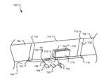
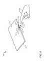
- FIG. 1illustrates an example metal computing device case 100 that includes a radiating structure and components for capacitive proximity sensing.
- the metal computing device case 100may be, without limitation, a casing of a tablet computer, laptop, mobile phone, personal data assistant, cell phone, smart phone, Blu-Ray player, gaming system, or any other device including wireless communications circuitry for transmitting a radio-frequency carrier wave.
- the metal computing device case 100includes antenna assembly 102 that forms a part of an exterior surface of the metal computing device case 100 , such that an exposed portion of the metal computing device case 100 performs as a part of a radiating structure for operation of the antenna assembly 102 .
- the antenna assembly 102may be formed by, among other components, one or more metal plates (e.g., a metal plate 104 ), cut-outs, notches, or insulating components (e.g., an insulator 108 ).
- the insulator 108insulates a boundary of at least one radiating component of the antenna assembly 102 and may be, for example, a plastic, ceramic or other dielectric insert or filling material. In FIG. 1 , the insulator 108 bounds the antenna assembly 104 on four sides. Alternatively, a separate insulator may be employed on one or more sides of the metal plate 104 .
- a variety of other implementationsare disclosed herein or otherwise contemplated.
- the antenna structure 102is coupled to a radio (not shown) that generates a carrier wave, such as a radio frequency (RF) wave.
- a radionot shown
- the antenna assembly 102may be designed to resonate at one or more particular frequencies, and/or, for certain applications may be designed to radiate very limited, or substantially zero, power at a particular frequency or set of frequencies.
- the antenna structure 102represents an active antenna radiating at a mobile telephone RF frequency. Other implementations are also contemplated.
- the metal electronic device case 100also includes a proximity sensing system 106 (shown as positioned behind or beneath the metal plate 104 ) including at least detection circuitry and one or more proximity sensors.
- Proximity sensors included in the antenna assembly 102may include without limitation one or more of a capacitance sensor, an infrared sensor, an RGB sensor, a thermal sensor, a microphone, a stereoscopic sensor, a scanned laser sensor, an ultrasound sensor, and a millimeter wave sensor, etc. Proximity may be detected optically using time-of-flight or structure light methods.
- the proximity sensors of the proximity sensing subsystem 106collect data from one or more exposure points located within the antenna assembly 102 of the metal electronic device case 100 .
- an “exposure point”is an area located within the antenna assembly or on an exterior surface of the metal computing device case 100 from which proximity data is collected (e.g., a capacitive sensor pad, an infrared transparent or translucent port, a window port, etc.).
- the exposure pointprovides a field of sensing (e.g., a field of view, a capacitive coupling, an RF field, an audio signal field, etc.) that is exterior to the metal computing device case 100 , such that the exposure point is substantially transparent to the proximity sensing element.
- the proximity sensing elementmay be on the surface of the metal computing device case 100 or within the metal computing device case 100 .
- substantially transparent exposure pointsinclude without limitation a non-metallic surface for a capacitive sensor, an IR transparent sensor for an IR sensor, a speaker/microphone for an audio sensor, etc.
- Proximity datarefers to data from which a distance between the antenna assembly 102 and a conductive object (e.g., a human) can be inferred. Examples of proximity data include without limitation thermal profiles, capacitance measurements, acoustic reflections, etc.
- the frequency shift of a resonant RF elementmay be used to infer proximity (e.g., a patch antenna will detune (lower in frequency) when brought very close to a dielectric body). One could use this dielectric loading effect and resulting frequency shift to infer proximity.
- the exposure pointsmay be located on the metal plate 104 , the insulator 108 , or other metal or non-metal components that operate as part of the radiating structure. Additionally, exposure points can be located within one or more holes formed in an exterior surface of the antenna assembly 102 . The position of each of the exposure points is associated with a location of transmitting components of the antenna assembly 102 . Thus, proximity data collected at the exposure points allows for human proximity detection in the area proximal to such transmitting components. For example, SAR regulations impose particular limits on electromagnetic radiation transmissions when a human body part is within zero to three centimeters of a transmitting antenna. Thus, exposure points are, in one implementation, positioned so that proximity data collected at each of the exposure points may assist in a determination of whether a human body part is within three centimeters of the antenna assembly 102 .
- the proximity sensing subsystem 106projects a signal, such as an electrical field, visible light (e.g., RGB light), invisible light (e.g., IR light), acoustic waves, etc., into a field of view.
- the signalis reflected from the field of view, and the reflected signal is detected at one or more exposure points on the radiating structure 102 .
- the proximity sensing subsystem 106utilizes one or more passive sensors (e.g., a thermal sensor, an electric field sensor, etc.) to detect a signal emitted or radiated from the field of view.
- the proximity sensing subsystem 106includes an IR illuminator and an IR sensor to detect reflected IR light emitted from the IR illuminator.
- the proximity sensing subsystem 106also includes detection circuitry for processing proximity data collected by the proximity sensors.
- the processing circuitrymay include hardware, firmware, and/or software to identify a correlation between saved information (e.g., information associated with human proximity to one or more proximity sensors) and observed waveforms, temperature profiles, depth maps, etc.
- saved informatione.g., information associated with human proximity to one or more proximity sensors
- the proximity sensing subsystem 106may also be coupled to control circuitry (not shown) to vary a behavior (e.g., transmission power level, output wave frequency, etc.) of the antenna assembly 102 responsive to variations in proximity data collected by the proximity sensors.
- the proximity sensing subsystem 106alters a behavior of the antenna assembly 102 when proximity data collected by the proximity sensors satisfies a human proximity condition.
- the human proximity conditionmay take on a variety of values and forms depending upon the type(s) of proximity sensors utilized. For example, a human proximity condition may be satisfied when an IR sensor detects a thermal profile indicative of a particular object (e.g., a human hand 110 ) within a certain distance of the radiating structure 102 .
- a human proximity conditionis satisfied when a transmitted light pulse (RGB, IR, etc.) is reflected back to a proximity sensor within a predetermined time interval, indicating that a reflective object is within a given distance of the antenna assembly 102 .
- Distancemay be determined by measuring a phase shift between a transmitted signal and the reflected signal, the time difference between a transmitted light pulse and the reflected light pulse, the magnitude of reflected light detected during a shutter period.
- a human proximity conditionis satisfied when a capacitance sensing chip detects an AC voltage change that exceeds a stored threshold value, indicating that an object is within a given distance of the antenna assembly 102 .
- a variety of other implementationsis also contemplated.
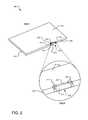
- FIG. 2illustrates an example metal computing device case 200 that includes a radiating structure and components for proximity sensing.
- the metal computing device case 200includes a back face 202 , a front face (not shown), and four side faces including visible side faces 204 and 206 .
- the four side facesbound the back face 202 and the front face. In other implementations, fewer than four sides may partially bound the back face 202 .
- the back face 202 and one or more of the side facesmay be joined at an abrupt corner, at a curved corner (e.g., a continuous arc between the back face and the side face), or in various continuous intersecting surface combinations.
- the side facesneed not be perpendicular to the back face (e.g., a side face may be positioned at an obtuse or acute angle with the back face).
- the back face and one or more side facesare integrated into a single piece construction, although other assembled configurations are also contemplated.
- An antenna assembly 208forms a part of the metal computing device case 200 and functions to transmit a carrier wave, such as an RF wave.
- the antenna assembly 208includes a metal plate 210 (e.g., part of the metal side face 204 of the metal computing device case 200 or another metal plate) separated from the metal side face 204 , the metal back face 202 , and the front face (not shown) by three cut-out slots 212 , 214 , and 216 .
- the metal plate 210may alternatively be formed as part of the back face 202 of the metal computing device case 200 .
- the exterior surface of the metal plate 210is exposed (e.g., the surface of the metal plate 210 is exposed to a user's environment, touchable by a user, etc.), and the interior surface of the metal plate 210 is coupled to a feed structure (not shown) within the interior of the metal computing device case 200 .
- Multiple such antenna structuresmay be formed in the metal back face 202 or any metal side face of the metal computing device case 200 .
- one or more antennasmay be formed below the exterior surface of a computing device for which the exterior surface is non-conductive, or semi-conductive, e.g., a polycarbonate material.
- the metal back face 202 and various metal side facesgenerally form a back section of the metal computing device case 200 in which electronic and mechanical components of the computing device are located.
- a front facetypically includes a display surface, such as a touch screen display. The front face is assembled to the back section of the metal computing device case 200 to enclose the electronic components of the computing device, including at least one processor, tangible storage (e.g., memory, magnetic storage disk), display electronics, communication electronics, etc.
- An insulator 222which may be plastic or other dielectric material, fills each of the cut-out slots 212 , 214 , and 216 .
- the insulator 222provides insulation between the metal plate 210 and adjacent edges of the metal back face 202 and metal side face 204 .
- the metal plate 210is also insulated from the front face by a dielectric material, an insulating gasket, contact with a glass layer in the front section of the device, etc.
- View Billustrates a magnified view of a portion of the metal computing device case 200 including the antenna assembly 208 .
- a plurality of proximity sensorscollects data from exposure points 220 on one or more exposed surfaces of the metal computing device case 200 .
- an exposure pointmay be a region on an opaque or translucent exterior surface or a hole (e.g., a slot or aperture) in an exterior surface.
- the exposure points 220are regions on an exterior surface of the insulator 222 .
- the insulator 222is translucent such that one or more sensors behind or embedded within the insulating material can make use of an exposed field of view through the insulator 222 and to a user environment.
- the insulator 222is opaque and the proximity sensors collect data through the insulator 222 without utilizing an exposed field of view to the user environment.
- An opaque exposure pointmay be used where the detection method is based on signals that can pass through an opaque material, such as colored polycarbonate plastic, without significant attenuation. Such materials would be considered substantially transparent to the proximity sensing element.
- Ultrasonic audio emitters used in Doppler-type distance measurement systemsmay also be placed behind opaque materials given that audio signals in certain frequency ranges may pass through opaque materials without being attenuated below a detectable level.
- One or more proximity sensors positioned within the metal computing device case 200collect proximity data via the exposure points 220 .
- a plurality of IR sensorsmay be included within the metal computing device case 200 and each positioned in alignment with a corresponding exposure point so as to collect proximity data from a field of view visible through each of the exposure points.
- the positioning and number of the proximity sensors 220may vary depending on design criteria.
- exposure pointsare located on two different surfaces of the metal computing device case 200 (e.g., on the insulator inserts in the slots in the back surface 202 and the side surface 204 ). In other implementations, the exposure points are located on a single surface or three or more surfaces of the metal computing device case 200 .
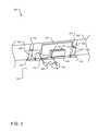
- FIG. 3illustrates another example of a system 300 that includes a radiating structure and components for proximity sensing.
- the system 300is formed as part of a metal electronic device case including a metal side face 302 , a metal back face 304 , and a metal plate 310 .
- the metal plate 310forms an exterior metal surface of the metal computing device.
- An insulator 322electrically insulates the metal plate 310 from the metal side face 302 and the metal back face 304 by filling slots 312 , 314 , and 316 and providing insulation between the metal plate 310 and the metal side face 302 and between the metal plate 310 and the metal back face 304 , closing gaps in the metal computing device case.
- the insulatormay have a voltage-dependent dielectric constant.
- a radiating function(e.g., transmission of a carrier wave) is performed in part by a high dielectric constant ceramic block 332 capacitively coupled to the metal plate 310 coupled across a dielectric spacer 330 .
- the dielectric spacer 330is fed by the feed structure 317 , which is electrically connected between a radio 318 and a metallized surface 319 on the ceramic block 332 .
- the radio 318is attached to a printed circuit board (PCB) (not shown).
- the ceramic block 332may operate as the only an active antenna structure or may operate as an active antenna relative to a parasitic antenna including the metal plate 310 and the rest of the surrounding metal computing device case.
- the metal plate 310is connected to the ground plane of the metal back face 304 via a series and/or parallel resonant circuit 320 (e.g., including an inductor and/or capacitor), which may allow for multi-band operation.
- Proximity sensors 328are positioned within the metal computing device case and adjacent to each of a plurality of holes or translucent portions of the insulator 322 (e.g., adjacent to each of the exposure points illustrated in FIG. 2 ). In another implementation, the proximity sensors 328 are embedded within material of the insulator 322 rather than positioned adjacent to it, as shown. Each of the proximity sensors 328 is coupled to a proximity detection circuit 324 mounted on a PCB within the metal electronic device case.
- the proximity detection circuit 324may include, for example, hardware (e.g., an integrated circuit, microprocessor, tangible storage such as memory, etc.) or hardware in combination with software and/or firmware, configured to adjust a transmission power of the radiating structure based on input from the proximity sensors 328 .
- the proximity detection circuit 324may process data from the proximity sensors 328 to determine whether a human proximity condition is satisfied.
- the proximity detection circuit 324compares a measured IR temperature profile to a stored temperature profile of a human.
- proximity sensors 328may detect infrared light radiated from an object.
- proximity sensors 328which may be IR detectors, will begin to detect infrared radiation emitted from the human hand.
- Each proximity sensor 328may detect varying levels of infrared radiation based on the velocity and angle-of-approach of the approaching hand.
- the proximity detection circuit 328may analyze signals from the proximity 328 to determine that the approaching object is indeed a human hand.
- Proximity detection circuit 328may include, or have access to, predetermined data representing sensor signals for a scenario of an approaching human hand. The real-time detected data may be compared to the predetermined data to determine that the object is a human hand at a particular distance from the proximity sensors 328 .
- Predetermined data for various objects at various distancesmay be stored to enable proximity detection circuit 328 to accurately estimate, for example, the composition and proximity of the object.
- IR radiation detectionmay advantageously provide information about the composition of an object.
- inanimate objectsmay have a heat signature that is very different from the heat signature of a human hand.
- the proximity detection circuit 324compares a measured light travel time (e.g., an out-and-back time of a light pulse in the IR or visible light spectrum, or a phase shift of modulated light) to a stored threshold associated with a proximity between an object and the system 300 .
- a proximity detection circuit 324 based on time-of-flightmay include predetermined data representing time-of-flight measurements objects and proximities.
- the aggregated data of all four proximity sensors 328may be analyzed to determine that an approaching object is a pencil, a human hand, a tabletop, etc., because each of these objects may have different absolute differences from the object to a given sensor.
- Proximity detection circuit 324may be operable to combine and analyze the data collected from several proximity sensors to estimate the size of an object and the object's distance, to determine whether to reduce the transmitted power, and if so, by how much, as further explained below.
- the previously mentioned RF frequency shift configurationincludes a resonant RF structure (e.g., a patch antenna element) and a swept frequency RF excitation applied to it.
- the frequency rangeincludes the structure's resonant frequency and is wide enough to cover the extent of the detuned resonant frequency that occurs when a dielectric object is brought near the structure.
- RF monitoring circuitrycan observe signal amplitude and/or phase across frequency (and RF match). Changes in resonant frequencies can be used to infer proximity of dielectric bodies.
- the proximity detection circuit 324is communicatively coupled to a power control circuit 336 that controls power to one or more transmitting components of the system 300 , such as the radio 318 or the feed structure 317 .
- This couplingallows the power control circuit 336 to dynamically adjust transmission power of the system 300 based on input from the proximity detection circuit 324 .
- the proximity detection circuit 324may provide the power control circuit 336 with a signal when a stored human proximity condition is satisfied. Responsive to this signal, the power control circuit 336 dynamically adjusts transmission power of radiating components of the system 300 .
- FIG. 4illustrates two portions 401 and 403 of an example metal computing device case that includes a radiating structure and components for proximity sensing.
- the portion 403typically contains a display assembly while the portion 401 typically encloses (at least partially) most other components of the computing device.
- the metal computing device case 400includes a back face 404 and four side faces 406 , 408 , 410 , and 412 bounding the back face.
- a back face antenna assembly 402is integrated as a part of the metal computing device case 400 .
- the back face antenna assembly 402includes cut-out 414 (also referred to as an aperture or slot) created in the back face 404 .
- the cut-out 414is shown as L-shaped with segments parallel to two adjacent side faces of the computing device case 400 .
- the back face antenna assembly 402also includes a notch 416 cut from the back face that cuts through the corner of two intersecting side faces (e.g., the side faces 408 and 406 ).
- the cut-out 414 and notch 416form at least one elongated metal arm (e.g., elongated metal arms 418 and 420 ) from the areas of the computing device case 400 surrounding the cut-out 414 and notch 416 .
- a carrier wave signalis fed to one of the elongated metal arms 418 or 420 , such as by way of a feed structure (e.g., a conductive wire or strip) coupled between the elongated metal arm 418 and a radio (not shown).
- a feed structuree.g., a conductive wire or strip
- the cut-out 414 , notch 416 , and the elongated metal arms 418 and 420perform a radiating function of the back face antenna assembly 402 .
- the cut-out 414 , notch 416 , and the elongated metal arms 418 and 420transmit a carrier wave.
- the dimensions of the cut-out 414influence the impedance matching for different radio frequency bands, while the size and shape of a conductive feed structure (not shown) influences the resonant frequencies of the radiating structure 402 .
- the elongated arms 418 and 420can be excited directly (e.g., galvanically, like a Planar Inverted-F Antenna), capacitively, or via some other excitation method.
- the cut-out 414 and notch 416may be filled with an insulator, such as a plastic insert, ceramic, or other dielectric material, which may have a voltage-dependent dielectric constant.
- Such a radiating structuremay be designed to resonate at one or more particular frequencies, and/or, for certain applications, may be designed to radiate very limited, or substantially zero, power at a particular frequency or set of frequencies.
- One or more proximity sensorscollect data from corresponding exposure points (e.g., exposure points 422 and 424 ) of the metal electronic device case 400 .
- An exposure pointmay be, for example, a region on an opaque or translucent exterior surface of the metal computing device case 400 or a hole (e.g., a slot or aperture) formed in an exterior surface of the metal computing device case 400 .
- the exposure pointsare illustrated on the insulating material within the cut-out 414 (e.g., the exposure point 422 ) and along the metal side faces 406 and 408 (e.g., the exposure point 424 ).
- Multiple exposure pointsmay feed into one proximity sensor, for example, by using lenses and/or mirrors to pipe light from one emitter and to one detector.
- each exposure pointmay be associated with one emitter/detector pair.
- each exposure pointmay be associated with a single IR sensor or with multiple IR sensors.
- the insulating material in the cut-out 414is translucent such that one or more sensors behind or embedded within the insulating material can make use of an exposed field of view through the insulating material to a user environment.
- the insulating materialis opaque and the proximity sensors collect data through the insulating material without utilizing an exposed field of view to the user environment.
- the exposure points on the side faces 406 and 408may be translucent or opaque surface regions or inserts. In various implementations, the positioning and number of the proximity sensors and exposure points may vary depending on design criteria.
- Each of the proximity sensors included in the metal electronic device case 400is coupled to a proximity detection circuit (not shown), which is communicatively coupled to one or more transmitting components of the back face antenna assembly 402 , such as a radio or feed structure internal to the electronic device case 400 .
- the proximity detection circuitdynamically adjusts transmission power of the back face antenna assembly 402 based on the input from the proximity sensors.
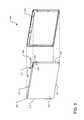
- FIG. 5illustrates two portions 501 and 503 of an example computing device case 500 that includes a radiating structure and components for proximity sensing.
- a side face antenna assembly 502is integrated as part of the metal computing device case 500 .
- the metal computing device caseincludes a back face 504 and four side faces 506 , 508 , 510 , and 512 bounding the back face 504 .
- the side face antenna assembly 502includes a cut-out 514 created in one or more of the side faces (in this case, in side faces 506 and 508 ).
- the side face antenna assembly 502also includes a notch 520 cut through an edge portion (i.e., an elongated metal arm 515 ) of the side face 506 .
- the cut-out 514is L-shaped and formed along two adjacent side faces of the computing device case.
- An insulating materialsuch as a plastic, ceramic, or other insulating material, fills both the cut-out 514 and the notch 520 .
- the insulating materialis a translucent material permeable by visible or invisible (e.g., IR) light.
- the elongated metal arm 515 , cut-out 514 , and notch 520perform a radiating function of the side face antenna assembly 502 .
- the elongated arm 515can be exited directly (e.g., galvanically, like a Planar Inverted-F Antenna), capacitively, or via some other excitation method.
- Such a radiating structuremay be designed to resonate at one or more particular frequencies, and/or, for certain applications, may be designed to radiate very limited, or substantially zero, power at a particular frequency or set of frequencies.
- a carrier wave signalis fed to the elongated metal arm 515 such as by way of a feed structure (e.g., a conductive wire or strip) coupled to a radio (not shown) located on a printed circuit board (PCB) within the metal electronic device case 500 .
- a feed structuree.g., a conductive wire or strip
- a radionot shown located on a printed circuit board (PCB) within the metal electronic device case 500 .
- the length of the elongated metal arm 515is defined to resonate close to the lowest frequency of antenna operation.
- a plurality of proximity sensorscollect proximity data from a field of view visible through or from each of a number of corresponding exposure points (e.g., exposure points 524 and 526 ) on an exterior surface of the metal computing device case 500 .
- exposure pointsare shown on the insulating material filling the cut-out 514 and shown on the back face 504 in a corner region proximal to the elongated arm 515 and the cut-out 514 .
- the positioning and number of the proximity sensorsmay vary depending on design criteria.
- a proximity detection circuit(not shown) is communicatively coupled to one or more transmitting components of the back face antenna assembly 502 , such as a radio or feed structure internal to the electronic device case 500 .
- the proximity detection circuitreceives proximity data from the proximity sensors and dynamically adjusts transmission power of the back face antenna assembly 502 based on the proximity data.
- FIG. 6illustrates another example metal computing device case 600 that includes a radiating structure and components for proximity sensing.
- the computing device case 600includes a back face 602 , a front face (not shown) and four side faces including visible side faces 604 and 606 .
- the metal computing device case 600includes components to perform both a radiating function and a capacitance sensing function.
- the metal computing device case 600includes an antenna assembly 608 that transmits a carrier wave, such as an RF wave, and includes a part of the metal computing device case 600 .
- antenna assembly 608includes a metal plate 610 (e.g., part of the metal side face 604 of the metal computing device case 600 or another metal plate) separated from the metal side face 604 , the metal back face 602 , and the front face (not shown) by three cut-out slots 612 , 614 , and 616 .
- the metal plate 610may alternatively be formed as part of the back face 602 of the metal computing device case 600 .
- the exterior surface of the metal plate 610is exposed (e.g., the surface of the metal plate 610 is exposed to a user's environment, touchable by a user, etc.), and the interior surface of the metal plate 610 is coupled to a feed structure (not shown) within the interior of the metal computing device.
- An insulator 622(e.g., plastic or other dielectric material) fills each of the cut-out slots 612 , 614 , and 616 .
- the insulator 622provides insulation between the metal plate 610 and adjacent edges of the metal back face 602 and metal side face 604 .
- the metal plate 610may be insulated from the front face by a dielectric material, an insulating gasket, insulating contact with a glass layer in the front section of the device, etc.
- the metal plate 610acts as a capacitance pad for a capacitance sensing proximity sensor.
- a conductive object 630such as a human body part
- approaches the metal plate 610a measureable change in AC voltage of the metal plate 610 is observed.
- the conductive object 630 and the metal plate 610effectively serve as parallel plates in a parallel plate capacitor; thus, the magnitude of the change in AC voltage depends on the “gap” size between the conductive object 630 and the metal plate 610 .
- a predetermined distancee.g., a distance for which SAR regulations mandate a reduction in RF transmission power
- the change in AC voltageexceeds a stored threshold value and a human proximity condition is satisfied.
- a power control circuitselectively alters (e.g., reduces) transmission power of the antenna assembly 608 .
- the power control circuitselectively alters (e.g., increases) transmission power of the antenna assembly 608 .
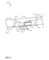
- FIG. 7illustrates example components of a system 700 that includes a radiating structure and components for proximity sensing.
- the system 700is formed as part of a metal electronic device case including a metal side face 702 , a metal back face 704 , and a metal plate 710 .
- the metal plate 710forms an exterior metal surface of the metal computing device.
- Slots 712 , 714 , and 716are filled with an insulator 722 (e.g., plastic), providing insulation between the metal plate 710 and the metal side face 702 and between the metal plate 710 and the metal back face 704 and closing gaps in the metal computing device case.
- the insulator 722may have a voltage-dependent dielectric constant.
- the system 700includes components to perform both a radiating function (e.g., transmission of a carrier wave) and a capacitance sensing function.
- the radiating functionis performed in part by a high dielectric constant ceramic block 732 capacitively coupled to the metal plate 710 across a dielectric spacer 730 .
- the dielectric spacer 730is fed by a feed structure 717 , which is electrically connected between a radio 718 and a metallized surface 719 on the ceramic block 732 .
- the radio 718is coupled to a PCB (not shown) on the metal back face 704 .
- the ceramic block 732may operate as the only radiating structure or may operate as an active antenna in combination with the metal plate 710 and the rest of the surrounding metal computing device case acting as a parasitic antenna.
- the metal plate 710is connected to the ground plane of the metal back face 704 via a series and/or parallel resonant circuit 720 , which may allow for multi-band operation.
- a capacitance sensing function of the system 700is performed by the metal plate 710 and a proximity sensing circuit 724 (e.g., a capacitance sensing chip) electrically coupled to the metal plate 710 .
- a proximity sensing circuit 724e.g., a capacitance sensing chip
- FIG. 7illustrates a first inductor 740 in series with a second inductor 742 .
- the first inductor 740is positioned closer to the metal plate 710 than the second inductor 742 .
- the first inductor 740is coupled directly to the metal plate and the second inductor 742 is coupled directly to the proximity sensing circuit 724 .
- the first inductor 740is a low value inductor that functions to block a transmission signal generated by the radio 718 , ensuring that a radiation function of the system 700 is unchanged or substantially unchanged by the proximity sensing system 724 .
- the first inductor 740has an inductance value substantially between 2 and 22 nanoHenry (nH).
- the second inductor 742is a high value inductor that functions to prevent noise from the proximity sensing circuit 724 from affecting the radiating function of the metal plate 710 .
- the second inductor 742has an inductance of greater than about 100 nH.
- Inductor 740is chosen to be high impedance at or close to the intended RF operating frequency of the antenna. The actual component value used is determined based on component parasitics and the frequency bands that are to be covered by the antenna (usually wanting to avoid having inductor 740 be self-resonant at or near the operating bands of the antenna in order to avoid losses in the antenna performance itself).
- a resisteris used in place of the second inductor 742 .
- the principle in this implementationis that an open circuit (a very high resistance value) would essentially make the circuitry on the far side of the resistor invisible to the RF circuit/antenna function.
- Example RF specificationscan be satisfied for chip resistor values of 1 k ⁇ or higher, and generally 10 k ⁇ or lower, although resistor values outside of this range may also be employed.
- the proximity sensing circuit 724is also communicatively coupled to a power control circuit 736 , which controls power to one or more transmitting components of the system 700 , such as the radio 718 or the feed structure 717 .
- This couplingallows the power control circuit 736 to dynamically adjust transmission power of the system 700 based on the input from the proximity sensing circuit 724 .
- the proximity sensing circuit 724may output a signal to the power control circuit 736 that indicates that a human proximity condition is met. Responsive to this signal, the power control circuit 736 dynamically adjusts transmission power of the radio 718 .
- FIG. 8illustrates example operations 800 for using a proximity sensing system formed as part of a radiating structure in a metal computing device case.
- a forming operation 802provides a metal computing device case including a metal back face and one or more metal side faces bounding at least a portion of the metal back face.
- the metal computing device casefurther includes a radiating structure having a ceramic block acting as a capacitive feed to a metal plate positioned on the exterior of the metal computing device case, such as in a metal side face or metal back face.
- a circuite.g., a series or parallel resonant circuit, a series inductor circuit, a switched inductor circuit, etc. couples the metal plate to the ground plane of the metal computing device.
- the radiating structuremay be in the form of a back face or side face antenna assembly as described with regard to FIG. 4 or 5 , or some variations thereof.
- An exciting operation 804excites the radiating structure in the metal computing device case causing the radiating structure to radiate at one or more frequencies over time.
- a collection operation 806collects proximity data from at least one exposure point on the exterior surface of the metal computing device.
- An alteration operation 808alters an excitation behavior (e.g., a transmission power) of the radiating structure based on the proximity data collected. For example, if the proximity data collected satisfies a human proximity condition, a transmission power of the radiating structure may be reduced. When the proximity data indicates that the human proximity condition is no longer satisfied (e.g., the human has moved away from a proximity sensor), transmission power of the radiating structure may be increased.
- an excitation behaviore.g., a transmission power
- the implementations of the invention described hereinare implemented as logical steps in one or more computer systems.
- the logical operations of the present inventionare implemented (1) as a sequence of processor-implemented steps executing in one or more computer systems and (2) as interconnected machine or circuit modules within one or more computer systems.
- the implementationis a matter of choice, dependent on the performance requirements of the computer system implementing the invention. Accordingly, the logical operations making up the embodiments of the invention described herein are referred to variously as operations, steps, objects, or modules.
- logical operationsmay be performed in any order, adding and omitting as desired, unless explicitly claimed otherwise or a specific order is inherently necessitated by the claim language.
Landscapes
- Engineering & Computer Science (AREA)
- Computer Networks & Wireless Communication (AREA)
- Signal Processing (AREA)
- Computer Hardware Design (AREA)
- General Engineering & Computer Science (AREA)
- Electronic Switches (AREA)
- Support Of Aerials (AREA)
- Geophysics And Detection Of Objects (AREA)
Abstract
Description
Claims (20)
Priority Applications (6)
| Application Number | Priority Date | Filing Date | Title |
|---|---|---|---|
| US14/152,351US10044095B2 (en) | 2014-01-10 | 2014-01-10 | Radiating structure with integrated proximity sensing |
| KR1020167021094AKR102329147B1 (en) | 2014-01-10 | 2014-12-26 | Radiating structure with integrated proximity sensing |
| CN201480072727.9ACN105874647B (en) | 2014-01-10 | 2014-12-26 | Radiating structure with integrated proximity sensing |
| PCT/US2014/072411WO2015105695A1 (en) | 2014-01-10 | 2014-12-26 | Radiating structure with integrated proximity sensing |
| EP14830773.9AEP3092678B1 (en) | 2014-01-10 | 2014-12-26 | Radiating structure with integrated proximity sensing |
| US15/822,945US10276922B2 (en) | 2014-01-10 | 2017-11-27 | Radiating structure with integrated proximity sensing |
Applications Claiming Priority (1)
| Application Number | Priority Date | Filing Date | Title |
|---|---|---|---|
| US14/152,351US10044095B2 (en) | 2014-01-10 | 2014-01-10 | Radiating structure with integrated proximity sensing |
Related Child Applications (1)
| Application Number | Title | Priority Date | Filing Date |
|---|---|---|---|
| US15/822,945ContinuationUS10276922B2 (en) | 2014-01-10 | 2017-11-27 | Radiating structure with integrated proximity sensing |
Publications (2)
| Publication Number | Publication Date |
|---|---|
| US20150200444A1 US20150200444A1 (en) | 2015-07-16 |
| US10044095B2true US10044095B2 (en) | 2018-08-07 |
Family
ID=52396821
Family Applications (2)
| Application Number | Title | Priority Date | Filing Date |
|---|---|---|---|
| US14/152,351ActiveUS10044095B2 (en) | 2014-01-10 | 2014-01-10 | Radiating structure with integrated proximity sensing |
| US15/822,945ActiveUS10276922B2 (en) | 2014-01-10 | 2017-11-27 | Radiating structure with integrated proximity sensing |
Family Applications After (1)
| Application Number | Title | Priority Date | Filing Date |
|---|---|---|---|
| US15/822,945ActiveUS10276922B2 (en) | 2014-01-10 | 2017-11-27 | Radiating structure with integrated proximity sensing |
Country Status (5)
| Country | Link |
|---|---|
| US (2) | US10044095B2 (en) |
| EP (1) | EP3092678B1 (en) |
| KR (1) | KR102329147B1 (en) |
| CN (1) | CN105874647B (en) |
| WO (1) | WO2015105695A1 (en) |
Cited By (6)
| Publication number | Priority date | Publication date | Assignee | Title |
|---|---|---|---|---|
| US10224974B2 (en) | 2017-03-31 | 2019-03-05 | Microsoft Technology Licensing, Llc | Proximity-independent SAR mitigation |
| US10276922B2 (en) | 2014-01-10 | 2019-04-30 | Microsoft Technology Licensing, Llc | Radiating structure with integrated proximity sensing |
| US10461406B2 (en) | 2017-01-23 | 2019-10-29 | Microsoft Technology Licensing, Llc | Loop antenna with integrated proximity sensing |
| US11310748B2 (en)* | 2018-11-02 | 2022-04-19 | Apple Inc. | Dynamic power reduction requests for wireless communications |
| EP4002065A1 (en) | 2020-11-24 | 2022-05-25 | Simon, S.A.U. | Devices and methods for touchless actuation of electric loads |
| US20230268965A1 (en)* | 2018-09-12 | 2023-08-24 | Zte Corporation | Vehicle-mounted telematics box (tbox) and antenna real-time switching method and apparatus, and non-transitory computer-readable storage medium |
Families Citing this family (28)
| Publication number | Priority date | Publication date | Assignee | Title |
|---|---|---|---|---|
| US9871544B2 (en) | 2013-05-29 | 2018-01-16 | Microsoft Technology Licensing, Llc | Specific absorption rate mitigation |
| US10893488B2 (en) | 2013-06-14 | 2021-01-12 | Microsoft Technology Licensing, Llc | Radio frequency (RF) power back-off optimization for specific absorption rate (SAR) compliance |
| TWI536658B (en)* | 2013-10-03 | 2016-06-01 | 緯創資通股份有限公司 | Mobile communication device and radiation power adjusting method thereof |
| US9813997B2 (en) | 2014-01-10 | 2017-11-07 | Microsoft Technology Licensing, Llc | Antenna coupling for sensing and dynamic transmission |
| US9563316B2 (en) | 2014-01-10 | 2017-02-07 | Microsoft Technology Licensing, Llc | Radiofrequency-wave-transparent capacitive sensor pad |
| US9769769B2 (en) | 2014-06-30 | 2017-09-19 | Microsoft Technology Licensing, Llc | Detecting proximity using antenna feedback |
| US9774929B2 (en)* | 2014-09-22 | 2017-09-26 | Itron, Inc. | Infrared proximity sensor control of devices |
| US9785174B2 (en) | 2014-10-03 | 2017-10-10 | Microsoft Technology Licensing, Llc | Predictive transmission power control for back-off |
| US9871545B2 (en) | 2014-12-05 | 2018-01-16 | Microsoft Technology Licensing, Llc | Selective specific absorption rate adjustment |
| KR102465926B1 (en)* | 2015-11-25 | 2022-11-14 | 삼성전자주식회사 | Antenna and electronic device having it |
| US10013038B2 (en) | 2016-01-05 | 2018-07-03 | Microsoft Technology Licensing, Llc | Dynamic antenna power control for multi-context device |
| US9929763B1 (en)* | 2016-03-28 | 2018-03-27 | Amazon Technologies, Inc. | Proximity sensor arrangement for wireless devices |
| US10078103B2 (en) | 2016-08-26 | 2018-09-18 | Microsoft Technology Licensing, Llc | Fringing field booster |
| US10337886B2 (en) | 2017-01-23 | 2019-07-02 | Microsoft Technology Licensing, Llc | Active proximity sensor with adaptive electric field control |
| CN107179609A (en)* | 2017-06-12 | 2017-09-19 | 京东方科技集团股份有限公司 | Virtual reality glasses |
| US10716072B2 (en)* | 2017-07-25 | 2020-07-14 | Hewlett-Packard Development Company, L.P. | Controlling radio frequency (RF) output power of antennas |
| US11031966B2 (en)* | 2018-05-04 | 2021-06-08 | Microsoft Technology Licensing, Llc | Ultrasonic proximity sensing for SAR mitigation |
| CN109088151B (en)* | 2018-07-04 | 2021-04-20 | 深圳市万普拉斯科技有限公司 | Antenna system and mobile terminal |
| NO346391B1 (en)* | 2018-10-04 | 2022-07-04 | Elliptic Laboratories As | Absorption rate detection |
| KR102706848B1 (en)* | 2018-12-20 | 2024-09-19 | 삼성전자주식회사 | An electronic device having array antenna and power backoff method for antenna array |
| KR102709851B1 (en)* | 2019-08-13 | 2024-09-26 | 삼성전자주식회사 | Electronic device for backing-off transmission power based on sar and method for operating thereof |
| CN110677533B (en)* | 2019-08-21 | 2021-06-29 | 深圳市万普拉斯科技有限公司 | Mobile terminal control method, device, mobile terminal and storage medium |
| CN112671956B (en) | 2019-10-16 | 2023-06-30 | 北京小米移动软件有限公司 | Human body distance detection module of electronic equipment, electronic equipment and control method thereof |
| CN113675622B (en)* | 2020-05-13 | 2024-11-19 | 北京小米移动软件有限公司 | Antenna structures and electronics |
| US12244052B2 (en)* | 2020-06-26 | 2025-03-04 | Motorola Mobility Llc | Communication device having a heat sink antenna |
| CN115755191A (en)* | 2022-11-23 | 2023-03-07 | 珠海格力电器股份有限公司 | Induction detection device and method and equipment with metal shell |
| US12026344B2 (en)* | 2022-12-05 | 2024-07-02 | Cypress Semiconductor Corporation | Hover detection for touchscreens |
| US20240387981A1 (en)* | 2023-05-18 | 2024-11-21 | Microsoft Technology Licensing, Llc | Thin film capacitance sensor for proximity detection |
Citations (226)
| Publication number | Priority date | Publication date | Assignee | Title |
|---|---|---|---|---|
| US4016490A (en) | 1974-12-19 | 1977-04-05 | Robert Bosch G.M.B.H. | Capacitative proximity sensing system |
| US4729129A (en) | 1986-10-15 | 1988-03-01 | Itt Avionics A Division Of Itt Corporation | VSWR protection circuit apparatus |
| US4806944A (en) | 1987-09-14 | 1989-02-21 | General Electric Company | Switchable matching network for an element of a steerable antenna array |
| US5166679A (en) | 1991-06-06 | 1992-11-24 | The United States Of America As Represented By The Administrator Of The National Aeronautics & Space Administration | Driven shielding capacitive proximity sensor |
| US5212621A (en) | 1990-04-26 | 1993-05-18 | Cnc Retrofits, Inc. | Proximity switched machine control method and apparatus |
| US5408690A (en) | 1990-10-01 | 1995-04-18 | Murata Mfg. Co., Ltd. | Antenna supervising apparatus comprising a standing wave ratio measuring unit |
| CN1123476A (en) | 1994-09-16 | 1996-05-29 | 摩托罗拉公司 | Antenna structure and a radio communication device incorporating the same |
| US5564086A (en) | 1993-11-29 | 1996-10-08 | Motorola, Inc. | Method and apparatus for enhancing an operating characteristic of a radio transmitter |
| CN1179864A (en) | 1995-03-31 | 1998-04-22 | 夸尔柯姆股份有限公司 | Method and device for power control in mobile communication system |
| EP0843421A2 (en) | 1996-11-13 | 1998-05-20 | Nokia Mobile Phones Ltd. | A system for limiting the transmitted power of a mobile communications means |
| WO2000042797A1 (en) | 1999-01-12 | 2000-07-20 | Qualcomm Incorporated | System and method for the automatic identification of accessories coupled to a wireless communication device |
| US6178310B1 (en) | 1996-12-30 | 2001-01-23 | Lg Information & Communications, Ltd. | Transmitting and receiving antenna voltage standing wave ratios measuring circuit of base station in mobile communication system |
| WO2001048858A2 (en) | 1999-12-14 | 2001-07-05 | Rangestar Wireless, Inc. | Low sar broadband antenna assembly |
| US20020009976A1 (en)* | 2000-01-07 | 2002-01-24 | Rashidi Taymor S. | Radiation protection device for cellular telephones |
| JP2002043957A (en) | 2000-07-19 | 2002-02-08 | Hitachi Kokusai Electric Inc | High frequency signal transmission device |
| US20020175814A1 (en) | 2001-02-07 | 2002-11-28 | David Wadlow | Control system with capacitive detector |
| US20030021608A1 (en) | 2001-07-24 | 2003-01-30 | Canon Kabushiki Kaisha | Image forming apparatus |
| US20030029028A1 (en) | 2001-08-09 | 2003-02-13 | Yusuke Watanabe | Method and apparatus of manufacturing non-resonance knock sensor |
| GB2380359A (en) | 2001-09-28 | 2003-04-02 | Agere Systems Inc | A proximity regulation system for use with a portable cellphone and method of operation |
| EP1298809A2 (en) | 2001-09-28 | 2003-04-02 | Siemens Information and Communication Mobile LLC | System and method for reducing SAR values |
| US20030210203A1 (en) | 2002-05-09 | 2003-11-13 | Phillips James P. | Sensor-driven adaptive counterpoise antenna system |
| US20030214310A1 (en) | 2002-05-08 | 2003-11-20 | Mcintosh Robert B. | Planar capacitive transducer |
| US20030228846A1 (en) | 2002-06-05 | 2003-12-11 | Shlomo Berliner | Method and system for radio-frequency proximity detection using received signal strength variance |
| WO2004015813A1 (en) | 2002-08-05 | 2004-02-19 | Koninklijke Philips Electronics N.V. | Antenna diversity system and method for operating said system |
| US20040075613A1 (en) | 2002-06-21 | 2004-04-22 | Perry Jarmuszewski | Multiple-element antenna with parasitic coupler |
| US20040108957A1 (en) | 2002-12-06 | 2004-06-10 | Naoko Umehara | Pattern antenna |
| US20040113847A1 (en) | 2002-12-12 | 2004-06-17 | Yihong Qi | Antenna with near-field radiation control |
| US20040160378A1 (en)* | 2003-02-13 | 2004-08-19 | Abrams Ted A. | Radio frequency electromagnetic emissions shield |
| EP1469550A2 (en) | 2003-04-18 | 2004-10-20 | Matsushita Electric Industrial Co., Ltd. | Radio antenna apparatus provided with controller for controlling SAR (specific absorption rate) and radio communication apparatus using the same radio antenna apparatus |
| WO2004091046A1 (en) | 2003-04-03 | 2004-10-21 | Kyocera Wireless Corp. | System and method for regulating antenna electrical length |
| US20040222925A1 (en) | 2001-04-11 | 2004-11-11 | Kyocera Wireless Corp. | Inverted-F ferroelectric antenna |
| US20050017906A1 (en) | 2003-07-24 | 2005-01-27 | Man Ying Tong | Floating conductor pad for antenna performance stabilization and noise reduction |
| WO2005018046A1 (en) | 2003-08-07 | 2005-02-24 | Sony Ericsson Mobile Communications Ab | Tunable parasitic resonators |
| US20050093623A1 (en) | 2002-01-24 | 2005-05-05 | Broadcom Corporation | Input buffer amplifier with centroidal layout |
| GB2409345A (en) | 2003-12-12 | 2005-06-22 | Antenova Ltd | Antenna for mobile communications having an elevated dielectric pellet feed |
| US20050184914A1 (en) | 2004-02-23 | 2005-08-25 | Nokia Corporation | Diversity antenna arrangement |
| US6989745B1 (en) | 2001-09-06 | 2006-01-24 | Vistascape Security Systems Corp. | Sensor device for use in surveillance system |
| US7009944B1 (en) | 1998-10-27 | 2006-03-07 | Roke Manor Research Limited | Method of and apparatus for power control |
| US7053629B2 (en) | 2001-09-28 | 2006-05-30 | Siemens Communications, Inc. | System and method for detecting the proximity of a body |
| US7062288B2 (en) | 2000-08-17 | 2006-06-13 | Siemens Aktiengesellschaft | Method for controlling the transmission power in a radio communication system |
| US7071776B2 (en) | 2001-10-22 | 2006-07-04 | Kyocera Wireless Corp. | Systems and methods for controlling output power in a communication device |
| US7124193B1 (en) | 2000-08-24 | 2006-10-17 | At&T Corp. | Method of using link adaptation and power control for streaming services in wireless networks |
| US20060244663A1 (en) | 2005-04-29 | 2006-11-02 | Vulcan Portals, Inc. | Compact, multi-element antenna and method |
| EP1732167A1 (en) | 2005-05-31 | 2006-12-13 | Research In Motion Limited | Mobile wireless communications device comprising a satellite positioning system antenna and electrically conductive director element therefor |
| US7151382B1 (en) | 2005-09-22 | 2006-12-19 | Rockwell Collins, Inc. | Apparatus and method for radio frequency power and standing wave ratio measurement |
| US7167093B2 (en) | 2002-12-10 | 2007-01-23 | Invisa, Inc. | Method of steering capacitor fields for use in capacitive sensing security systems |
| US20070037619A1 (en) | 2005-06-03 | 2007-02-15 | Lenovo (Singapore) Pte. Ltd. | Method for controlling antennas of mobile terminal device and such a mobile terminal device |
| WO2007043150A1 (en) | 2005-10-06 | 2007-04-19 | Matsushita Electric Industrial Co., Ltd. | Antenna device for portable terminal, and portable terminal |
| US20070111681A1 (en) | 2005-11-14 | 2007-05-17 | Alberth William P Jr | Transmit power allocation in wireless communication devices |
| US20070122307A1 (en) | 2003-08-07 | 2007-05-31 | Chip-Centro De Higienizacao Por Ionizacao De Produtos | "Process for eliminating/reducing compounds with a musty taste/odour in materials that are to come into contact with foodstuffs and in foods or drinks" |
| US20070120745A1 (en) | 2005-11-29 | 2007-05-31 | Research In Motion Limited | Mobile wireless communications device comprising a satellite positioning system antenna with active and passive elements and related methods |
| JP2007194995A (en) | 2006-01-20 | 2007-08-02 | Murata Mfg Co Ltd | Antenna and radio communication device |
| US20080051165A1 (en) | 2006-08-28 | 2008-02-28 | Motorola, Inc. | Rf power control using proximity sensor |
| US20080055160A1 (en) | 2006-08-29 | 2008-03-06 | Samsung Electronics Co., Ltd. | Dual-band inverted F antenna reducing SAR |
| US20080158065A1 (en) | 2006-12-28 | 2008-07-03 | Samsung Electronics Co., Ltd. | Mobile terminal for reducing specific absorption rate |
| US20080218493A1 (en) | 2003-09-03 | 2008-09-11 | Vantage Controls, Inc. | Display With Motion Sensor |
| US20080254836A1 (en) | 2007-04-10 | 2008-10-16 | Research In Motion Limited | Mobile wireless communications device including a ground patch providing specific absorption rate (sar) reduction and related methods |
| US20090033562A1 (en) | 2005-02-01 | 2009-02-05 | Matsushita Electric Industrial Co., Ltd. | Portable wireless apparatus |
| US20090047998A1 (en) | 2007-08-16 | 2009-02-19 | Motorola, Inc. | Method and apparatus for controlling power transmission levels for a mobile station having transmit diversity |
| US7541874B2 (en) | 2006-03-29 | 2009-06-02 | Panasonic Corporation | High-frequency power amplifier device |
| CN100504407C (en) | 2003-08-18 | 2009-06-24 | 成像微波技术应用公司 | Apparatus for controlling the specific absorption rate of mass-produced radiators |
| US20090230884A1 (en)* | 2006-06-30 | 2009-09-17 | Koninklijke Philips Electronics N.V. | Device and method for controlling a lighting system by proximity sensing of a spot-light control device and spotlight control device |
| US20090253459A1 (en) | 2008-04-02 | 2009-10-08 | Sony Ericksson Mobile Communications Japan Inc. | Mobile communication terminal and method of controlling transmission characteristic thereof |
| US20090295648A1 (en) | 2008-06-03 | 2009-12-03 | Dorsey John G | Antenna diversity systems for portable electronic devices |
| WO2009149023A1 (en) | 2008-06-05 | 2009-12-10 | Apple Inc. | Electronic device with proximity-based radio power control |
| US20090325511A1 (en) | 2006-10-23 | 2009-12-31 | Nam Yun Kim | Rf sensor system and method for operating the same |
| US20100026664A1 (en) | 2008-08-01 | 2010-02-04 | Geaghan Bernard O | Touch sensitive devices with composite electrodes |
| EP2015548B1 (en) | 2007-06-21 | 2010-02-24 | Research In Motion Limited | Mobile wireless communications device including electrically conductive, electrically floating beam shaping elements and related methods |
| US20100052997A1 (en) | 2008-08-29 | 2010-03-04 | Chi Mei Communication Systems, Inc. | Antenna modules and portable electronic devices using the same |
| US20100056210A1 (en) | 2008-09-03 | 2010-03-04 | Modu Ltd. | Low radiation wireless communicator |
| US20100067419A1 (en) | 2006-11-20 | 2010-03-18 | Jinhua Liu | Method and arrangement for efficiently utilizing radio resources in a communication system |
| US20100113111A1 (en)* | 2008-11-06 | 2010-05-06 | Wong Alfred Y | Radiation Redirecting External Case For Portable Communication Device and Antenna Embedded In Battery of Portable Communication Device |
| US7729715B2 (en) | 2005-12-30 | 2010-06-01 | Motorola, Inc. | Method and apparatus for power reduction for E-TFC selection |
| US20100234058A1 (en) | 2006-05-29 | 2010-09-16 | Rong Hu | Channel Quality Prediction in HSDPA Systems |
| US20100234081A1 (en)* | 2009-03-13 | 2010-09-16 | Wong Alfred Y | Rf radiation redirection away from portable communication device user |
| US20100279751A1 (en) | 2009-05-01 | 2010-11-04 | Sierra Wireless, Inc. | Method and apparatus for controlling radiation characteristics of transmitter of wireless device in correspondence with transmitter orientation |
| US20100283691A1 (en) | 2009-05-07 | 2010-11-11 | Ethertronics, Inc. | Spatial filter for near field modification in a wireless communication device |
| US20100317302A1 (en) | 2009-06-12 | 2010-12-16 | Novatel Wireless | System and method for controlling rf explosure levels |
| US20100321325A1 (en) | 2009-06-17 | 2010-12-23 | Springer Gregory A | Touch and display panel antennas |
| US20110001675A1 (en) | 2009-07-01 | 2011-01-06 | Chi Mei Communication Systems, Inc. | Antenna of portable electronic devices |
| EP2276108A1 (en) | 2009-07-17 | 2011-01-19 | Apple Inc. | Electronic devices with parasitic antenna resonating elements that reduce near field radiation |
| US20110012793A1 (en) | 2009-07-17 | 2011-01-20 | Amm David T | Electronic devices with capacitive proximity sensors for proximity-based radio-frequency power control |
| US20110043408A1 (en) | 2009-08-20 | 2011-02-24 | Qualcomm Incorporated | Compact multi-band planar inverted f antenna |
| US20110063042A1 (en) | 2000-07-20 | 2011-03-17 | Paratek Microwave, Inc. | Tunable microwave devices with auto-adjusting matching circuit |
| US7917175B2 (en) | 2004-01-16 | 2011-03-29 | Kt Corporation | Device and method for remotely measuring and monitoring antenna system using mobile terminal |
| WO2011051554A1 (en) | 2009-10-27 | 2011-05-05 | Pulse Finland Oy | Method and arrangement for matching an antenna |
| CN102064812A (en) | 2010-12-30 | 2011-05-18 | 广东盈科电子有限公司 | Inducing device for distinguishing person or object at close distance |
| WO2011058128A1 (en) | 2009-11-12 | 2011-05-19 | Irex Technologies B.V. | Sar limit compliant consumer device |
| US20110117973A1 (en) | 2009-11-13 | 2011-05-19 | Motorola, Inc. | Radiated power control systems and methods in wireless communication devices |
| CN102077234A (en) | 2008-06-27 | 2011-05-25 | 微软公司 | Dynamic selection of sensitivity of tilt functionality |
| US20110124363A1 (en) | 2009-11-24 | 2011-05-26 | Symbol Technologies, Inc. | Setting sar exposure limit of mobile devices |
| US20110157077A1 (en) | 2008-06-25 | 2011-06-30 | Bradley Martin | Capacitive sensor system with noise reduction |
| US20110199267A1 (en) | 2008-10-20 | 2011-08-18 | Panasonic Corporation | Antenna device |
| US20110222469A1 (en) | 2010-03-11 | 2011-09-15 | Shirook Ali | Modulation and coding scheme selection method for a specific absorption rate compliant communication device |
| US20110250928A1 (en) | 2010-04-13 | 2011-10-13 | Schlub Robert W | Adjustable wireless circuitry with antenna-based proximity detector |
| EP2381527A1 (en) | 2010-04-22 | 2011-10-26 | Research In Motion Limited | Antenna assembly with electrically extended ground plane arrangement and associated method |
| EP2383364A1 (en) | 2009-01-20 | 2011-11-02 | Shin-Etsu Polymer Co. Ltd. | Radio wave-transmitting decorative member and method for producing same |
| US8063375B2 (en) | 2007-06-22 | 2011-11-22 | Intel-Ge Care Innovations Llc | Sensible motion detector |
| US20110298669A1 (en) | 2010-06-08 | 2011-12-08 | Research In Motion Limited | Low frequency dual-antenna diversity system |
| EP2405534A1 (en) | 2010-07-06 | 2012-01-11 | Apple Inc. | Tunable antenna systems |
| EP2410661A1 (en) | 2010-07-20 | 2012-01-25 | Research In Motion Limited | Radiation power level control system and method for a wireless communication device based on a tracked radiation history |
| US20120021707A1 (en) | 2010-07-26 | 2012-01-26 | Qualcomm Incorporated | Apparatus and method for adjustment of transmitter power in a system |
| US20120021800A1 (en) | 2010-07-20 | 2012-01-26 | Research In Motion Limited | Radiation Power Level Control System and Method for a Wireless Communication Device Based on a Tracked Radiation History |
| US20120023225A1 (en) | 2009-07-20 | 2012-01-26 | Imes Kevin R | Energy management system and method |
| US20120044115A1 (en)* | 2009-03-13 | 2012-02-23 | Pong Research Corporation | External Case for Redistribution of RF Radiation Away From Wireless Communication Device User and Wireless Communication Device Incorporating RF Radiation Redistribution Elements |
| US20120071195A1 (en) | 2010-09-21 | 2012-03-22 | Broadcom Corporation | Transmit Power Management for Specific Absorption Rates |
| US20120074961A1 (en) | 2010-09-29 | 2012-03-29 | Kopin Corporation | Capacitive sensor with active shield electrode |
| WO2012061582A1 (en) | 2010-11-04 | 2012-05-10 | Qualcomm Incorporated | Method and apparatus for specific absorption rate backoff in power headroom report |
| US20120133561A1 (en) | 2010-11-26 | 2012-05-31 | Anand Konanur | Method and apparatus for in-mold laminate antennas |
| CN202276339U (en) | 2011-10-18 | 2012-06-13 | 中兴通讯股份有限公司 | Wireless terminal |
| US20120164962A1 (en) | 2010-12-28 | 2012-06-28 | Chi Mei Communication Systems, Inc. | Proximity sensor module and electronic device using same |
| US8213982B2 (en) | 2009-06-01 | 2012-07-03 | Hewlett-Packard Development Company, L.P. | Enhanced internal antenna architecture for a mobile computing device |
| US20120172079A1 (en) | 2010-12-30 | 2012-07-05 | Telefonaktiebolaget Lm Ericsson (Publ) | Methods and Apparatuses for Enabling Power Back-Off Indication in PHR in a Telecommunications System |
| US20120178494A1 (en) | 2011-01-07 | 2012-07-12 | Interdigital Patent Holdings, Inc. | Methods, apparatus and systems for handling additional power backoff |
| US20120190398A1 (en) | 2011-01-21 | 2012-07-26 | Nokia Corporation | Usage of antenna for power adjustment |
| US20120214422A1 (en) | 2011-02-17 | 2012-08-23 | Futurewei Technologies, Inc. | Adaptive Maximum Power Limiting Using Capacitive Sensing in a Wireless Device |
| WO2012113754A1 (en) | 2011-02-23 | 2012-08-30 | Microchip Technology Germany Gmbh & Co. Kg | Capacitive sensor device and radio transceiver with a capacitive device and a method for adjusting a transmission power of a handheld radio transceiver |
| US20120223865A1 (en) | 2011-03-01 | 2012-09-06 | Qingxiang Li | Antenna structures with carriers and shields |
| WO2012122113A1 (en) | 2011-03-04 | 2012-09-13 | Qualcomm Incorporated | Systems and methods for dynamic transmission power limit back-off for specific absorption rate compliance |
| WO2012122116A1 (en) | 2011-03-04 | 2012-09-13 | Qualcomm Incorporated | Systems and methods for dynamic transmission power limit back-off for specific absorption rate compliance |
| US20120231784A1 (en) | 2010-11-16 | 2012-09-13 | Muhammad Kazmi | Dynamic sar emission control to minimize rf exposure |
| US8269511B2 (en) | 2009-09-08 | 2012-09-18 | Synaptics Incorporated | Sensing and defining an input object |
| EP2509229A1 (en) | 2011-04-05 | 2012-10-10 | Research In Motion Limited | Mobile wireless communications device with proximity based transmitted power control and related methods |
| WO2012143936A1 (en) | 2011-04-21 | 2012-10-26 | Muthukumar Prasad | Smart active antenna radiation pattern optimising system for mobile devices achieved by sensing device proximity environment with property, position, orientation, signal quality and operating modes |
| US20120276861A1 (en) | 2011-04-28 | 2012-11-01 | Fujitsu Limited | Information processing apparatus and radio wave intensity control method |
| US20120295554A1 (en) | 2011-05-16 | 2012-11-22 | Paratek Microwave, Inc. | Method and apparatus for tuning a communication device |
| US20120299772A1 (en) | 2009-03-13 | 2012-11-29 | Victor Shtrom | Adjustment of radiation patterns utilizing a position sensor |
| US20120298497A1 (en) | 2010-02-09 | 2012-11-29 | Oji Paper Co., Ltd. | Conductive laminate and touch panel using same |
| US8324549B2 (en) | 2009-05-07 | 2012-12-04 | Fraunhofer-Gesellschaft Zur Foerderung Der Angewandten Forschung E.V. | Detector for detecting electromagnetic radiation having dopant concentration of a well increases monotonically in the direction parallel to the surface of a semiconductor substrate |
| US8326385B2 (en) | 2011-04-05 | 2012-12-04 | Research In Motion Limited | Mobile wireless communications device with proximity based transmitted power control and related methods |
| US20120315847A1 (en) | 2010-03-25 | 2012-12-13 | Silego Technology, Inc. | Capacitive coupling based proximity sensor |
| US20120329524A1 (en) | 2011-06-22 | 2012-12-27 | Kent Joel C | Touch sensor and antenna integration along an electronic device housing |
| US20120329517A1 (en) | 2011-06-24 | 2012-12-27 | Vladimir Aleksandrovich Elin | Mobile radio unit with a dosimeter-radiometer |
| WO2012176217A1 (en) | 2011-06-20 | 2012-12-27 | Muthukumar Prasad | Smart active antenna radiation pattern optimising system for mobile devices achieved by sensing device proximity environment with property, position, orientation, signal quality and operating modes |
| US20130016621A1 (en) | 2011-07-13 | 2013-01-17 | Samsung Electronics Co., Ltd. | Device and method for restricting transmission output in a portable terminal |
| WO2013011352A1 (en) | 2011-07-18 | 2013-01-24 | Nokia Corporation | Intelligent radio frequency power control |
| US20130026846A1 (en) | 2011-07-28 | 2013-01-31 | Stmicroelectronics Sa | Transformer of the balanced-unbalanced type |
| US20130033400A1 (en) | 2011-08-02 | 2013-02-07 | Hung-Chung Chiang | Antenna apparatus having sensing component coupled to first antenna component to additionally act as second antenna component and related signal processing device |
| US20130045700A1 (en) | 2011-08-18 | 2013-02-21 | Michael J. Stallman | Wireless electronic device with antenna cycling |
| US20130050046A1 (en) | 2011-08-31 | 2013-02-28 | Daniel W. Jarvis | Customizable antenna feed structure |
| US20130051261A1 (en) | 2011-06-21 | 2013-02-28 | Telefonaktiebolaget Lm Ericsson (Publ) | Selecting Uplink Multi-Antenna Transmission to Enhance Coverage |
| US20130060517A1 (en) | 2011-09-07 | 2013-03-07 | Futurewei Technologies, Inc. | Wireless Dongle Angular Position Sensor |
| EP2568605A1 (en) | 2011-09-06 | 2013-03-13 | Huf Hülsbeck & Fürst GmbH & Co. KG | Capacitative sensor assembly |
| US8401851B2 (en) | 2004-08-12 | 2013-03-19 | At&T Intellectual Property I, L.P. | System and method for targeted tuning of a speech recognition system |
| US8442572B2 (en) | 2006-09-08 | 2013-05-14 | Qualcomm Incorporated | Method and apparatus for adjustments for delta-based power control in wireless communication systems |
| US20130120257A1 (en) | 2010-08-31 | 2013-05-16 | Eumplus Co., Ltd | Movement sensing device using proximity sensor and method of sensing movement |
| US20130122827A1 (en) | 2011-11-14 | 2013-05-16 | Research In Motion Limited | Radiation Power Level Control System and Method for a Wireless Communication Device Having Tunable Elements |
| US20130127677A1 (en) | 2011-11-17 | 2013-05-23 | Hsiao-Yi Lin | Radio-Frequency Device and Wireless Communication Device |
| US20130137487A1 (en) | 2011-11-30 | 2013-05-30 | Koichi Sato | Portable information terminal |
| US20130149957A1 (en) | 2011-06-14 | 2013-06-13 | Ethertronics, Inc | Adaptive repeater for improved communication system performance |
| US20130157564A1 (en) | 2011-12-14 | 2013-06-20 | Microchip Technology Incorporated | Capacitive/Inductive Proximity Detection for Wi-Fi Protection |
| WO2013101106A1 (en) | 2011-12-29 | 2013-07-04 | Intel Corporation | Wireless device and method for antenna selection |
| US20130169348A1 (en) | 2012-01-04 | 2013-07-04 | Futurewei Technologies, Inc. | SAR Control Using Capacitive Sensor and Transmission Duty Cycle Control in a Wireless Device |
| WO2013103948A2 (en) | 2012-01-08 | 2013-07-11 | Access Business Group International Llc | Wireless power transfer through conductive materials |
| US20130178174A1 (en) | 2012-01-05 | 2013-07-11 | Research In Motion Limited | Portable electronic device for reducing specific absorption rate |
| US20130178167A1 (en) | 2012-01-09 | 2013-07-11 | Novatel Wireless, Inc. | System and method for reducing specific absorption rate of a wireless communications device |
| US20130203363A1 (en) | 2010-07-30 | 2013-08-08 | Magdi Limited | Personal Communications Device with Reduced Adverse Effects on Living Systems |
| CN103248747A (en) | 2012-02-09 | 2013-08-14 | 中兴通讯股份有限公司 | Method for adjusting electromagnetic wave energy absorption ratio based on sensor and mobile terminal |
| US20130210477A1 (en) | 2012-02-15 | 2013-08-15 | Microchip Technology Incorporated | Proximity Detection Using an Antenna and Directional Coupler Switch |
| US8515496B2 (en) | 2011-12-15 | 2013-08-20 | Amazon Technologies, Inc. | Antenna deployment switching for data communication of a user device |
| US20130217342A1 (en) | 2012-02-22 | 2013-08-22 | Motorola Mobility, Inc. | Antenna element as capacitive proximity/touch sensor for adaptive antenna performance improvement |
| US8520586B1 (en) | 2009-12-16 | 2013-08-27 | Qualcomm Incorporated | Discovery and connection coexistence mechanism for wireless devices |
| US20130241670A1 (en) | 2012-03-14 | 2013-09-19 | Broadcom Corporation | Power distributing duplexer system |
| WO2013141791A1 (en) | 2012-03-19 | 2013-09-26 | Telefonaktiebolaget L M Ericsson (Publ) | Methods and apparatus for adjusting maximum output power level |
| US8547952B2 (en) | 2008-08-08 | 2013-10-01 | Telefonaktiebolaget L M Ericsson (Publ). | Method for selecting an enhanced transport format combination based on determined power consumption |
| US8548388B2 (en) | 2010-12-16 | 2013-10-01 | Quanta Computer Inc. | Method of reducing specific absoption rate for an electronic device, and the electronic device |
| US20130278474A1 (en) | 2012-04-20 | 2013-10-24 | Thales | Directional Mobile Antenna with Polarization Switching by Displacement of Radiating Panels |
| US8577289B2 (en) | 2011-02-17 | 2013-11-05 | Apple Inc. | Antenna with integrated proximity sensor for proximity-based radio-frequency power control |
| WO2013165419A1 (en) | 2012-05-03 | 2013-11-07 | Hewlett-Packard Development Company, L.P. | Controlling electromagnetic radiation from an electronic device |
| US20130293244A1 (en) | 2012-05-03 | 2013-11-07 | Texas Instruments, Incorporated | Material-discerning proximity sensing |
| WO2013169527A1 (en) | 2012-05-10 | 2013-11-14 | Apple Inc. | Antenna and proximity sensor structures having printed circuit and dielectric carrier layers |
| US20130310105A1 (en) | 2011-03-31 | 2013-11-21 | Ntt Docomo, Inc. | Mobile station and method for use in radio communication system |
| US20130310106A1 (en) | 2012-02-03 | 2013-11-21 | Huawei Device Co., Ltd. | Proximity detection device and mobile terminal |
| US20130314365A1 (en) | 2012-05-23 | 2013-11-28 | Adrian Woolley | Proximity Detection Using Multiple Inputs |
| US20130335291A1 (en) | 2012-06-15 | 2013-12-19 | Qualcomm Incorporated | Dual/wideband termination for hybrid transformer |
| US20140015595A1 (en) | 2012-07-13 | 2014-01-16 | Semtech Corporation | Capacitive body proximity sensor system |
| US20140021801A1 (en) | 2012-07-19 | 2014-01-23 | Wistron Corporation | Proximity sensing structure and electronic device having proximity sensing capability |
| WO2014036532A1 (en) | 2012-08-31 | 2014-03-06 | Analog Devices, Inc. | Environment detection and capacitive gesture system for mobile devices |
| US20140066124A1 (en) | 2012-08-31 | 2014-03-06 | Analog Devices, Inc. | Environment detection for mobile devices |
| US20140071008A1 (en) | 2012-08-10 | 2014-03-13 | Laurent Desclos | Antenna with proximity sensor function |
| US20140078094A1 (en) | 2012-09-14 | 2014-03-20 | Songnan Yang | Co-existence of touch sensor and nfc antenna |
| US20140087663A1 (en) | 2012-09-26 | 2014-03-27 | Apple Inc. | Transmission power modulation to facilitate in-device coexistence between wireless communication technologies |
| US20140098491A1 (en) | 2012-10-04 | 2014-04-10 | Htc Corporation | Electronic device, accessory and method of operating electronic device and accessory |
| US20140098693A1 (en) | 2012-10-10 | 2014-04-10 | Apple, Inc. | Triggering cell transition in an uplink power limited condition |
| US8723531B2 (en) | 2009-03-12 | 2014-05-13 | Sige Semiconductor, Inc. | Integrated VSWR detector for monolithic microwave integrated circuits |
| US20140139380A1 (en) | 2012-11-19 | 2014-05-22 | Apple Inc. | Shared Antenna Structures for Near-Field Communications and Non-Near-Field Communications Circuitry |
| US20140141733A1 (en) | 2012-11-16 | 2014-05-22 | Hong Wong | Adaptive antenna selection |
| US20140152121A1 (en) | 2012-12-03 | 2014-06-05 | Fih (Hong Kong) Limited | Electronic device and method for adjusting amount of electric power supplied to proximity sensor of the electronic devic |
| US20140159980A1 (en) | 2012-11-24 | 2014-06-12 | Erin Finegold | Radio frequency emission guard for portable wireless electronic device |
| US20140173269A1 (en) | 2012-12-18 | 2014-06-19 | Apple Inc. | Event Sharing Protocol for Data Processing Devices |
| US20140176938A1 (en) | 2012-12-24 | 2014-06-26 | Industrial Technology Research Institute | Method and system of detecting tilt angle of object surface and method and system of compensating the same |
| US20140177371A1 (en) | 2012-12-20 | 2014-06-26 | Lsi Corporation | Suspend sdram refresh cycles during normal ddr operation |
| US8775103B1 (en) | 2011-06-17 | 2014-07-08 | Amazon Technologies, Inc. | Proximity sensor calibration and configuration |
| US8792930B1 (en) | 2010-01-22 | 2014-07-29 | Amazon Technologies, Inc. | Power management for wireless transmissions |
| US8798695B1 (en) | 2012-09-17 | 2014-08-05 | Amazon Technologies, Inc. | Proximity sensor using antennas of a user device |
| US20140274188A1 (en) | 2013-03-13 | 2014-09-18 | Motorola Mobility Llc | Reduced-power transmitting from a communications device |
| US20140280450A1 (en)* | 2013-03-13 | 2014-09-18 | Aliphcom | Proximity and interface controls of media devices for media presentations |
| US20140274189A1 (en) | 2013-03-13 | 2014-09-18 | Motorola Mobility Llc | Reduced-power transmitting from a communications device |
| US20140292587A1 (en) | 2013-04-02 | 2014-10-02 | Apple Inc. | Electronic Device With Reduced Emitted Radiation During Loaded Antenna Operating Conditions |
| US8860526B2 (en) | 2010-04-20 | 2014-10-14 | Blackberry Limited | Method and apparatus for managing interference in a communication device |
| US20140307570A1 (en) | 2013-04-10 | 2014-10-16 | Pantech Co., Ltd. | Portable device and method for transmitting signals for communication |
| US20140315592A1 (en) | 2013-04-18 | 2014-10-23 | Apple Inc. | Wireless Device With Dynamically Adjusted Maximum Transmit Powers |
| US20140357313A1 (en) | 2013-05-29 | 2014-12-04 | Microsoft Corporation | Specific Absorption Rate Mitigation |
| US20140370929A1 (en) | 2013-06-14 | 2014-12-18 | Microsoft Corporation | Radio Frequency (RF) Power Back-Off Optimization for Specific Absorption Rate (SAR) Compliance |
| US8922443B2 (en) | 2012-09-27 | 2014-12-30 | Apple Inc. | Distributed loop antenna with multiple subloops |
| US20150031408A1 (en) | 2013-07-25 | 2015-01-29 | Qualcomm Incorporated | System and Methods for Controlling Transmit Power on Multi-SIM Devices in Compliance with Specific Absorption Rate Limits |
| US20150053575A1 (en) | 2011-10-21 | 2015-02-26 | University Of Manitoba | Passive wireless sensor |
| US8975903B2 (en) | 2011-06-09 | 2015-03-10 | Ford Global Technologies, Llc | Proximity switch having learned sensitivity and method therefor |
| US20150141080A1 (en) | 2013-11-21 | 2015-05-21 | Microsoft Corporation | Object Detection and Characterization |
| US20150169093A1 (en) | 2012-07-24 | 2015-06-18 | Panasonic Intellectual Property Corporation Of America | Portable terminal, information display control method, and information display control system |
| US20150177371A1 (en) | 2013-12-20 | 2015-06-25 | Delta Mobile Systems, Inc | Calibrated radar apparatus and associated methods |
| US20150201385A1 (en) | 2014-01-10 | 2015-07-16 | Microsoft Corporation | Antenna coupling for sensing and dynamic transmission |
| US20150201387A1 (en) | 2014-01-10 | 2015-07-16 | Microsoft Corporation | Radio Frequency (RF) Attenuation Functions for Specific Absorption Rate (SAR) Compliance |
| US20150199042A1 (en) | 2014-01-10 | 2015-07-16 | Microsoft Corporation | Radiofrequency-wave-transparent capacitive sensor pad |
| US20150200444A1 (en) | 2014-01-10 | 2015-07-16 | Microsoft Corporation | Radiating structure with integrated proximity sensing |
| WO2015134117A1 (en) | 2014-03-03 | 2015-09-11 | Apple Inc. | Electronic device with shared antenna structures and balun |
| US20150288074A1 (en) | 2012-10-24 | 2015-10-08 | Microsoft Corporation | Sar reduction in radio transmitting devices |
| US20150382307A1 (en) | 2014-06-30 | 2015-12-31 | Microsoft Corporation | Detecting proximity using antenna feedback |
| US20160064801A1 (en) | 2014-09-03 | 2016-03-03 | Apple Inc. | Electronic Device Antenna With Reduced Lossy Mode |
| US20160098053A1 (en) | 2014-10-03 | 2016-04-07 | Microsoft Corporation | Predictive transmission power control for back-off |
| US9325355B2 (en) | 2013-02-14 | 2016-04-26 | Blackberry Limited | Methods and apparatus for performing impedance matching |
| US9337833B2 (en) | 2011-11-14 | 2016-05-10 | Atmel Corporation | Driven shield for shaping an electric field of a touch sensor |
| US20160164563A1 (en) | 2014-12-05 | 2016-06-09 | Microsoft Technology Licensing, Llc | Selective specific absorption rate adjustment |
| US20160204836A1 (en) | 2015-01-14 | 2016-07-14 | Samsung Electronics Co., Ltd. | Antenna device and method of controlling the same |
| WO2016111897A1 (en) | 2015-01-09 | 2016-07-14 | Apple Inc. | Electronic device having antenna tuning integrated circuits with sensors |
| US9466872B2 (en) | 2012-11-09 | 2016-10-11 | Futurewei Technologies, Inc. | Tunable dual loop antenna system |
Family Cites Families (12)
| Publication number | Priority date | Publication date | Assignee | Title |
|---|---|---|---|---|
| US6411108B1 (en) | 1999-11-05 | 2002-06-25 | Sensor Technologies, Inc. | Noncontact signal analyzer |
| JP2003110329A (en) | 2001-07-25 | 2003-04-11 | Matsushita Electric Ind Co Ltd | Built-in antenna device |
| US8068054B2 (en) | 2008-02-02 | 2011-11-29 | Zanio, Inc. | Receiver with means for ensuring bona fide of received signals |
| AU2014202603B2 (en) | 2009-07-17 | 2015-07-09 | Apple Inc. | Electronic devices with capacitive proximity sensors for proximity-based radio-frequency power control |
| EP2458681B1 (en)* | 2009-11-13 | 2019-07-03 | Hitachi Metals, Ltd. | Frequency variable antenna circuit, antenna component constituting the same, and wireless communication device using those |
| CN201805000U (en)* | 2010-08-16 | 2011-04-20 | 佳邦科技股份有限公司 | Antenna structure integrated in metal housing |
| KR101722237B1 (en) | 2010-09-28 | 2017-03-31 | 삼성전자주식회사 | Device and method for controlling power in mobile telephone |
| US9093752B2 (en)* | 2013-03-08 | 2015-07-28 | Apple Inc. | Electronic device with capacitively loaded antenna |
| US10122081B2 (en) | 2014-03-13 | 2018-11-06 | Google Technology Holdings LLC | Hand grip sensor for external chassis antenna |
| US10312593B2 (en) | 2014-04-16 | 2019-06-04 | Apple Inc. | Antennas for near-field and non-near-field communications |
| US9973228B2 (en) | 2014-08-26 | 2018-05-15 | Pulse Finland Oy | Antenna apparatus with an integrated proximity sensor and methods |
| US10461406B2 (en) | 2017-01-23 | 2019-10-29 | Microsoft Technology Licensing, Llc | Loop antenna with integrated proximity sensing |
- 2014
- 2014-01-10USUS14/152,351patent/US10044095B2/enactiveActive
- 2014-12-26WOPCT/US2014/072411patent/WO2015105695A1/enactiveApplication Filing
- 2014-12-26CNCN201480072727.9Apatent/CN105874647B/enactiveActive
- 2014-12-26KRKR1020167021094Apatent/KR102329147B1/enactiveActive
- 2014-12-26EPEP14830773.9Apatent/EP3092678B1/enactiveActive
- 2017
- 2017-11-27USUS15/822,945patent/US10276922B2/enactiveActive
Patent Citations (260)
| Publication number | Priority date | Publication date | Assignee | Title |
|---|---|---|---|---|
| US4016490A (en) | 1974-12-19 | 1977-04-05 | Robert Bosch G.M.B.H. | Capacitative proximity sensing system |
| US4729129A (en) | 1986-10-15 | 1988-03-01 | Itt Avionics A Division Of Itt Corporation | VSWR protection circuit apparatus |
| US4806944A (en) | 1987-09-14 | 1989-02-21 | General Electric Company | Switchable matching network for an element of a steerable antenna array |
| US5212621A (en) | 1990-04-26 | 1993-05-18 | Cnc Retrofits, Inc. | Proximity switched machine control method and apparatus |
| US5408690A (en) | 1990-10-01 | 1995-04-18 | Murata Mfg. Co., Ltd. | Antenna supervising apparatus comprising a standing wave ratio measuring unit |
| US5166679A (en) | 1991-06-06 | 1992-11-24 | The United States Of America As Represented By The Administrator Of The National Aeronautics & Space Administration | Driven shielding capacitive proximity sensor |
| US5564086A (en) | 1993-11-29 | 1996-10-08 | Motorola, Inc. | Method and apparatus for enhancing an operating characteristic of a radio transmitter |
| CN1123476A (en) | 1994-09-16 | 1996-05-29 | 摩托罗拉公司 | Antenna structure and a radio communication device incorporating the same |
| CN1179864A (en) | 1995-03-31 | 1998-04-22 | 夸尔柯姆股份有限公司 | Method and device for power control in mobile communication system |
| EP0843421A2 (en) | 1996-11-13 | 1998-05-20 | Nokia Mobile Phones Ltd. | A system for limiting the transmitted power of a mobile communications means |
| US6178310B1 (en) | 1996-12-30 | 2001-01-23 | Lg Information & Communications, Ltd. | Transmitting and receiving antenna voltage standing wave ratios measuring circuit of base station in mobile communication system |
| US7009944B1 (en) | 1998-10-27 | 2006-03-07 | Roke Manor Research Limited | Method of and apparatus for power control |
| WO2000042797A1 (en) | 1999-01-12 | 2000-07-20 | Qualcomm Incorporated | System and method for the automatic identification of accessories coupled to a wireless communication device |
| WO2001048858A2 (en) | 1999-12-14 | 2001-07-05 | Rangestar Wireless, Inc. | Low sar broadband antenna assembly |
| WO2001048858A3 (en) | 1999-12-14 | 2002-05-02 | Rangestar Wireless Inc | Low sar broadband antenna assembly |
| US20020009976A1 (en)* | 2000-01-07 | 2002-01-24 | Rashidi Taymor S. | Radiation protection device for cellular telephones |
| JP2002043957A (en) | 2000-07-19 | 2002-02-08 | Hitachi Kokusai Electric Inc | High frequency signal transmission device |
| US20110063042A1 (en) | 2000-07-20 | 2011-03-17 | Paratek Microwave, Inc. | Tunable microwave devices with auto-adjusting matching circuit |
| US7062288B2 (en) | 2000-08-17 | 2006-06-13 | Siemens Aktiengesellschaft | Method for controlling the transmission power in a radio communication system |
| US7124193B1 (en) | 2000-08-24 | 2006-10-17 | At&T Corp. | Method of using link adaptation and power control for streaming services in wireless networks |
| US20020175814A1 (en) | 2001-02-07 | 2002-11-28 | David Wadlow | Control system with capacitive detector |
| US20040222925A1 (en) | 2001-04-11 | 2004-11-11 | Kyocera Wireless Corp. | Inverted-F ferroelectric antenna |
| US20030021608A1 (en) | 2001-07-24 | 2003-01-30 | Canon Kabushiki Kaisha | Image forming apparatus |
| US20030029028A1 (en) | 2001-08-09 | 2003-02-13 | Yusuke Watanabe | Method and apparatus of manufacturing non-resonance knock sensor |
| US6989745B1 (en) | 2001-09-06 | 2006-01-24 | Vistascape Security Systems Corp. | Sensor device for use in surveillance system |
| US20030064732A1 (en) | 2001-09-28 | 2003-04-03 | Agere Systems Inc. | Proximity regulation system for use with a portable cell phone and a method of operation thereof |
| US7146139B2 (en) | 2001-09-28 | 2006-12-05 | Siemens Communications, Inc. | System and method for reducing SAR values |
| US20030064761A1 (en) | 2001-09-28 | 2003-04-03 | Siemens Information And Communication Mobile Llc | System and method for reducing SAR values |
| US7053629B2 (en) | 2001-09-28 | 2006-05-30 | Siemens Communications, Inc. | System and method for detecting the proximity of a body |
| EP1298809A2 (en) | 2001-09-28 | 2003-04-02 | Siemens Information and Communication Mobile LLC | System and method for reducing SAR values |
| GB2380359A (en) | 2001-09-28 | 2003-04-02 | Agere Systems Inc | A proximity regulation system for use with a portable cellphone and method of operation |
| US7071776B2 (en) | 2001-10-22 | 2006-07-04 | Kyocera Wireless Corp. | Systems and methods for controlling output power in a communication device |
| US20050093623A1 (en) | 2002-01-24 | 2005-05-05 | Broadcom Corporation | Input buffer amplifier with centroidal layout |
| US20030214310A1 (en) | 2002-05-08 | 2003-11-20 | Mcintosh Robert B. | Planar capacitive transducer |
| US6657595B1 (en) | 2002-05-09 | 2003-12-02 | Motorola, Inc. | Sensor-driven adaptive counterpoise antenna system |
| US20030210203A1 (en) | 2002-05-09 | 2003-11-13 | Phillips James P. | Sensor-driven adaptive counterpoise antenna system |
| US20030228846A1 (en) | 2002-06-05 | 2003-12-11 | Shlomo Berliner | Method and system for radio-frequency proximity detection using received signal strength variance |
| US20040075613A1 (en) | 2002-06-21 | 2004-04-22 | Perry Jarmuszewski | Multiple-element antenna with parasitic coupler |
| WO2004015813A1 (en) | 2002-08-05 | 2004-02-19 | Koninklijke Philips Electronics N.V. | Antenna diversity system and method for operating said system |
| US20040108957A1 (en) | 2002-12-06 | 2004-06-10 | Naoko Umehara | Pattern antenna |
| US7167093B2 (en) | 2002-12-10 | 2007-01-23 | Invisa, Inc. | Method of steering capacitor fields for use in capacitive sensing security systems |
| US20040113847A1 (en) | 2002-12-12 | 2004-06-17 | Yihong Qi | Antenna with near-field radiation control |
| US20040160378A1 (en)* | 2003-02-13 | 2004-08-19 | Abrams Ted A. | Radio frequency electromagnetic emissions shield |
| WO2004091046A1 (en) | 2003-04-03 | 2004-10-21 | Kyocera Wireless Corp. | System and method for regulating antenna electrical length |
| EP1469550A2 (en) | 2003-04-18 | 2004-10-20 | Matsushita Electric Industrial Co., Ltd. | Radio antenna apparatus provided with controller for controlling SAR (specific absorption rate) and radio communication apparatus using the same radio antenna apparatus |
| EP1469550A3 (en) | 2003-04-18 | 2004-12-01 | Matsushita Electric Industrial Co., Ltd. | Radio antenna apparatus provided with controller for controlling SAR (specific absorption rate) and radio communication apparatus using the same radio antenna apparatus |
| US20050017906A1 (en) | 2003-07-24 | 2005-01-27 | Man Ying Tong | Floating conductor pad for antenna performance stabilization and noise reduction |
| US7162264B2 (en) | 2003-08-07 | 2007-01-09 | Sony Ericsson Mobile Communications Ab | Tunable parasitic resonators |
| WO2005018046A1 (en) | 2003-08-07 | 2005-02-24 | Sony Ericsson Mobile Communications Ab | Tunable parasitic resonators |
| US20070122307A1 (en) | 2003-08-07 | 2007-05-31 | Chip-Centro De Higienizacao Por Ionizacao De Produtos | "Process for eliminating/reducing compounds with a musty taste/odour in materials that are to come into contact with foodstuffs and in foods or drinks" |
| CN100504407C (en) | 2003-08-18 | 2009-06-24 | 成像微波技术应用公司 | Apparatus for controlling the specific absorption rate of mass-produced radiators |
| US20080218493A1 (en) | 2003-09-03 | 2008-09-11 | Vantage Controls, Inc. | Display With Motion Sensor |
| GB2409345A (en) | 2003-12-12 | 2005-06-22 | Antenova Ltd | Antenna for mobile communications having an elevated dielectric pellet feed |
| US7917175B2 (en) | 2004-01-16 | 2011-03-29 | Kt Corporation | Device and method for remotely measuring and monitoring antenna system using mobile terminal |
| US20050184914A1 (en) | 2004-02-23 | 2005-08-25 | Nokia Corporation | Diversity antenna arrangement |
| US8401851B2 (en) | 2004-08-12 | 2013-03-19 | At&T Intellectual Property I, L.P. | System and method for targeted tuning of a speech recognition system |
| US20090033562A1 (en) | 2005-02-01 | 2009-02-05 | Matsushita Electric Industrial Co., Ltd. | Portable wireless apparatus |
| US20060244663A1 (en) | 2005-04-29 | 2006-11-02 | Vulcan Portals, Inc. | Compact, multi-element antenna and method |
| EP1732167A1 (en) | 2005-05-31 | 2006-12-13 | Research In Motion Limited | Mobile wireless communications device comprising a satellite positioning system antenna and electrically conductive director element therefor |
| US20070037619A1 (en) | 2005-06-03 | 2007-02-15 | Lenovo (Singapore) Pte. Ltd. | Method for controlling antennas of mobile terminal device and such a mobile terminal device |
| US7151382B1 (en) | 2005-09-22 | 2006-12-19 | Rockwell Collins, Inc. | Apparatus and method for radio frequency power and standing wave ratio measurement |
| WO2007043150A1 (en) | 2005-10-06 | 2007-04-19 | Matsushita Electric Industrial Co., Ltd. | Antenna device for portable terminal, and portable terminal |
| US20070111681A1 (en) | 2005-11-14 | 2007-05-17 | Alberth William P Jr | Transmit power allocation in wireless communication devices |
| US20070120745A1 (en) | 2005-11-29 | 2007-05-31 | Research In Motion Limited | Mobile wireless communications device comprising a satellite positioning system antenna with active and passive elements and related methods |
| US7729715B2 (en) | 2005-12-30 | 2010-06-01 | Motorola, Inc. | Method and apparatus for power reduction for E-TFC selection |
| JP2007194995A (en) | 2006-01-20 | 2007-08-02 | Murata Mfg Co Ltd | Antenna and radio communication device |
| US7541874B2 (en) | 2006-03-29 | 2009-06-02 | Panasonic Corporation | High-frequency power amplifier device |
| US20100234058A1 (en) | 2006-05-29 | 2010-09-16 | Rong Hu | Channel Quality Prediction in HSDPA Systems |
| US8559999B2 (en) | 2006-05-29 | 2013-10-15 | Telefonaktiebolaget Lm Ericsson (Publ) | Channel quality prediction in HSDPA systems |
| US8134461B2 (en)* | 2006-06-30 | 2012-03-13 | Koninkiljke Philips Electronics N.V. | Device and method for controlling a lighting system by proximity sensing of a spot-light control device and spotlight control device |
| US20090230884A1 (en)* | 2006-06-30 | 2009-09-17 | Koninklijke Philips Electronics N.V. | Device and method for controlling a lighting system by proximity sensing of a spot-light control device and spotlight control device |
| US20080051165A1 (en) | 2006-08-28 | 2008-02-28 | Motorola, Inc. | Rf power control using proximity sensor |
| US20080055160A1 (en) | 2006-08-29 | 2008-03-06 | Samsung Electronics Co., Ltd. | Dual-band inverted F antenna reducing SAR |
| US8442572B2 (en) | 2006-09-08 | 2013-05-14 | Qualcomm Incorporated | Method and apparatus for adjustments for delta-based power control in wireless communication systems |
| US20090325511A1 (en) | 2006-10-23 | 2009-12-31 | Nam Yun Kim | Rf sensor system and method for operating the same |
| US8208423B2 (en) | 2006-11-20 | 2012-06-26 | Telefonaktiebolaget L M Ericsson (Publ) | Method and arrangement for efficiently utilizing radio resources in a communication system |
| US20100067419A1 (en) | 2006-11-20 | 2010-03-18 | Jinhua Liu | Method and arrangement for efficiently utilizing radio resources in a communication system |
| US20080158065A1 (en) | 2006-12-28 | 2008-07-03 | Samsung Electronics Co., Ltd. | Mobile terminal for reducing specific absorption rate |
| US20080254836A1 (en) | 2007-04-10 | 2008-10-16 | Research In Motion Limited | Mobile wireless communications device including a ground patch providing specific absorption rate (sar) reduction and related methods |
| EP2015548B1 (en) | 2007-06-21 | 2010-02-24 | Research In Motion Limited | Mobile wireless communications device including electrically conductive, electrically floating beam shaping elements and related methods |
| US8063375B2 (en) | 2007-06-22 | 2011-11-22 | Intel-Ge Care Innovations Llc | Sensible motion detector |
| US20090047998A1 (en) | 2007-08-16 | 2009-02-19 | Motorola, Inc. | Method and apparatus for controlling power transmission levels for a mobile station having transmit diversity |
| US20090253459A1 (en) | 2008-04-02 | 2009-10-08 | Sony Ericksson Mobile Communications Japan Inc. | Mobile communication terminal and method of controlling transmission characteristic thereof |
| US20090295648A1 (en) | 2008-06-03 | 2009-12-03 | Dorsey John G | Antenna diversity systems for portable electronic devices |
| WO2009149023A1 (en) | 2008-06-05 | 2009-12-10 | Apple Inc. | Electronic device with proximity-based radio power control |
| US20090305742A1 (en) | 2008-06-05 | 2009-12-10 | Ruben Caballero | Electronic device with proximity-based radio power control |
| US8417296B2 (en) | 2008-06-05 | 2013-04-09 | Apple Inc. | Electronic device with proximity-based radio power control |
| US20110157077A1 (en) | 2008-06-25 | 2011-06-30 | Bradley Martin | Capacitive sensor system with noise reduction |
| CN102077234A (en) | 2008-06-27 | 2011-05-25 | 微软公司 | Dynamic selection of sensitivity of tilt functionality |
| US20100026664A1 (en) | 2008-08-01 | 2010-02-04 | Geaghan Bernard O | Touch sensitive devices with composite electrodes |
| US8547952B2 (en) | 2008-08-08 | 2013-10-01 | Telefonaktiebolaget L M Ericsson (Publ). | Method for selecting an enhanced transport format combination based on determined power consumption |
| US20100052997A1 (en) | 2008-08-29 | 2010-03-04 | Chi Mei Communication Systems, Inc. | Antenna modules and portable electronic devices using the same |
| US20100056210A1 (en) | 2008-09-03 | 2010-03-04 | Modu Ltd. | Low radiation wireless communicator |
| US20110199267A1 (en) | 2008-10-20 | 2011-08-18 | Panasonic Corporation | Antenna device |
| US20100113111A1 (en)* | 2008-11-06 | 2010-05-06 | Wong Alfred Y | Radiation Redirecting External Case For Portable Communication Device and Antenna Embedded In Battery of Portable Communication Device |
| EP2383364A1 (en) | 2009-01-20 | 2011-11-02 | Shin-Etsu Polymer Co. Ltd. | Radio wave-transmitting decorative member and method for producing same |
| US8723531B2 (en) | 2009-03-12 | 2014-05-13 | Sige Semiconductor, Inc. | Integrated VSWR detector for monolithic microwave integrated circuits |
| US20100234081A1 (en)* | 2009-03-13 | 2010-09-16 | Wong Alfred Y | Rf radiation redirection away from portable communication device user |
| US20120044115A1 (en)* | 2009-03-13 | 2012-02-23 | Pong Research Corporation | External Case for Redistribution of RF Radiation Away From Wireless Communication Device User and Wireless Communication Device Incorporating RF Radiation Redistribution Elements |
| US20120299772A1 (en) | 2009-03-13 | 2012-11-29 | Victor Shtrom | Adjustment of radiation patterns utilizing a position sensor |
| US20100279751A1 (en) | 2009-05-01 | 2010-11-04 | Sierra Wireless, Inc. | Method and apparatus for controlling radiation characteristics of transmitter of wireless device in correspondence with transmitter orientation |
| US20100283691A1 (en) | 2009-05-07 | 2010-11-11 | Ethertronics, Inc. | Spatial filter for near field modification in a wireless communication device |
| US8324549B2 (en) | 2009-05-07 | 2012-12-04 | Fraunhofer-Gesellschaft Zur Foerderung Der Angewandten Forschung E.V. | Detector for detecting electromagnetic radiation having dopant concentration of a well increases monotonically in the direction parallel to the surface of a semiconductor substrate |
| US8213982B2 (en) | 2009-06-01 | 2012-07-03 | Hewlett-Packard Development Company, L.P. | Enhanced internal antenna architecture for a mobile computing device |
| US20100317302A1 (en) | 2009-06-12 | 2010-12-16 | Novatel Wireless | System and method for controlling rf explosure levels |
| US20100321325A1 (en) | 2009-06-17 | 2010-12-23 | Springer Gregory A | Touch and display panel antennas |
| US20110001675A1 (en) | 2009-07-01 | 2011-01-06 | Chi Mei Communication Systems, Inc. | Antenna of portable electronic devices |
| US8432322B2 (en) | 2009-07-17 | 2013-04-30 | Apple Inc. | Electronic devices with capacitive proximity sensors for proximity-based radio-frequency power control |
| EP2276108A1 (en) | 2009-07-17 | 2011-01-19 | Apple Inc. | Electronic devices with parasitic antenna resonating elements that reduce near field radiation |
| US20110012794A1 (en) | 2009-07-17 | 2011-01-20 | Schlub Robert W | Electronic devices with parasitic antenna resonating elements that reduce near field radiation |
| US8466839B2 (en) | 2009-07-17 | 2013-06-18 | Apple Inc. | Electronic devices with parasitic antenna resonating elements that reduce near field radiation |
| US20110012793A1 (en) | 2009-07-17 | 2011-01-20 | Amm David T | Electronic devices with capacitive proximity sensors for proximity-based radio-frequency power control |
| US20120023225A1 (en) | 2009-07-20 | 2012-01-26 | Imes Kevin R | Energy management system and method |
| US20110043408A1 (en) | 2009-08-20 | 2011-02-24 | Qualcomm Incorporated | Compact multi-band planar inverted f antenna |
| US8269511B2 (en) | 2009-09-08 | 2012-09-18 | Synaptics Incorporated | Sensing and defining an input object |
| WO2011051554A1 (en) | 2009-10-27 | 2011-05-05 | Pulse Finland Oy | Method and arrangement for matching an antenna |
| CN102714346A (en) | 2009-10-27 | 2012-10-03 | 脉冲芬兰有限公司 | Method and arrangement for matching an antenna |
| WO2011058128A1 (en) | 2009-11-12 | 2011-05-19 | Irex Technologies B.V. | Sar limit compliant consumer device |
| US20110117973A1 (en) | 2009-11-13 | 2011-05-19 | Motorola, Inc. | Radiated power control systems and methods in wireless communication devices |
| US8483632B2 (en) | 2009-11-13 | 2013-07-09 | Motorola Mobility Llc | Radiated power control systems and methods in wireless communication devices |
| US20110124363A1 (en) | 2009-11-24 | 2011-05-26 | Symbol Technologies, Inc. | Setting sar exposure limit of mobile devices |
| US8520586B1 (en) | 2009-12-16 | 2013-08-27 | Qualcomm Incorporated | Discovery and connection coexistence mechanism for wireless devices |
| US8792930B1 (en) | 2010-01-22 | 2014-07-29 | Amazon Technologies, Inc. | Power management for wireless transmissions |
| US20120298497A1 (en) | 2010-02-09 | 2012-11-29 | Oji Paper Co., Ltd. | Conductive laminate and touch panel using same |
| US20110222469A1 (en) | 2010-03-11 | 2011-09-15 | Shirook Ali | Modulation and coding scheme selection method for a specific absorption rate compliant communication device |
| US20120315847A1 (en) | 2010-03-25 | 2012-12-13 | Silego Technology, Inc. | Capacitive coupling based proximity sensor |
| US20140206297A1 (en) | 2010-04-13 | 2014-07-24 | Apple Inc | Adjustable Wireless Circuitry with Antenna-Based Proximity Detector |
| US20110250928A1 (en) | 2010-04-13 | 2011-10-13 | Schlub Robert W | Adjustable wireless circuitry with antenna-based proximity detector |
| US8860526B2 (en) | 2010-04-20 | 2014-10-14 | Blackberry Limited | Method and apparatus for managing interference in a communication device |
| EP2381527A1 (en) | 2010-04-22 | 2011-10-26 | Research In Motion Limited | Antenna assembly with electrically extended ground plane arrangement and associated method |
| US20110298669A1 (en) | 2010-06-08 | 2011-12-08 | Research In Motion Limited | Low frequency dual-antenna diversity system |
| EP2405534A1 (en) | 2010-07-06 | 2012-01-11 | Apple Inc. | Tunable antenna systems |
| US20120021800A1 (en) | 2010-07-20 | 2012-01-26 | Research In Motion Limited | Radiation Power Level Control System and Method for a Wireless Communication Device Based on a Tracked Radiation History |
| EP2410661A1 (en) | 2010-07-20 | 2012-01-25 | Research In Motion Limited | Radiation power level control system and method for a wireless communication device based on a tracked radiation history |
| US20120021707A1 (en) | 2010-07-26 | 2012-01-26 | Qualcomm Incorporated | Apparatus and method for adjustment of transmitter power in a system |
| US20130203363A1 (en) | 2010-07-30 | 2013-08-08 | Magdi Limited | Personal Communications Device with Reduced Adverse Effects on Living Systems |
| US20130120257A1 (en) | 2010-08-31 | 2013-05-16 | Eumplus Co., Ltd | Movement sensing device using proximity sensor and method of sensing movement |
| US20120071195A1 (en) | 2010-09-21 | 2012-03-22 | Broadcom Corporation | Transmit Power Management for Specific Absorption Rates |
| CN102835036A (en) | 2010-09-21 | 2012-12-19 | 美国博通公司 | Transmit Power Management for SAR |
| US20120074961A1 (en) | 2010-09-29 | 2012-03-29 | Kopin Corporation | Capacitive sensor with active shield electrode |
| US8565205B2 (en) | 2010-11-04 | 2013-10-22 | Qualcomm Incorporated | Specific absorption rate backoff in power headroom report |
| WO2012061582A1 (en) | 2010-11-04 | 2012-05-10 | Qualcomm Incorporated | Method and apparatus for specific absorption rate backoff in power headroom report |
| US20120147801A1 (en) | 2010-11-04 | 2012-06-14 | Qualcomm Incorporated | Specific absorption rate backoff in power headroom report |
| US20120231784A1 (en) | 2010-11-16 | 2012-09-13 | Muhammad Kazmi | Dynamic sar emission control to minimize rf exposure |
| US20120133561A1 (en) | 2010-11-26 | 2012-05-31 | Anand Konanur | Method and apparatus for in-mold laminate antennas |
| US8548388B2 (en) | 2010-12-16 | 2013-10-01 | Quanta Computer Inc. | Method of reducing specific absoption rate for an electronic device, and the electronic device |
| US20120164962A1 (en) | 2010-12-28 | 2012-06-28 | Chi Mei Communication Systems, Inc. | Proximity sensor module and electronic device using same |
| US20120172079A1 (en) | 2010-12-30 | 2012-07-05 | Telefonaktiebolaget Lm Ericsson (Publ) | Methods and Apparatuses for Enabling Power Back-Off Indication in PHR in a Telecommunications System |
| WO2012091651A1 (en) | 2010-12-30 | 2012-07-05 | Telefonaktiebolaget L M Ericsson (Publ) | Methods and apparatuses for enabling power back-off indication in phr in a telecommunications system |
| CN102064812A (en) | 2010-12-30 | 2011-05-18 | 广东盈科电子有限公司 | Inducing device for distinguishing person or object at close distance |
| US20120178494A1 (en) | 2011-01-07 | 2012-07-12 | Interdigital Patent Holdings, Inc. | Methods, apparatus and systems for handling additional power backoff |
| US20120190398A1 (en) | 2011-01-21 | 2012-07-26 | Nokia Corporation | Usage of antenna for power adjustment |
| US20120214422A1 (en) | 2011-02-17 | 2012-08-23 | Futurewei Technologies, Inc. | Adaptive Maximum Power Limiting Using Capacitive Sensing in a Wireless Device |
| US8577289B2 (en) | 2011-02-17 | 2013-11-05 | Apple Inc. | Antenna with integrated proximity sensor for proximity-based radio-frequency power control |
| WO2012113754A1 (en) | 2011-02-23 | 2012-08-30 | Microchip Technology Germany Gmbh & Co. Kg | Capacitive sensor device and radio transceiver with a capacitive device and a method for adjusting a transmission power of a handheld radio transceiver |
| US20140155000A1 (en) | 2011-02-23 | 2014-06-05 | Holger Erkens | Capacitive Sensor Device And Radio Transceiver With A Capacitive Sensor Device And A Method For Adjusting A Transmission Power Of A Handheld Radio Transceiver |
| US20120223865A1 (en) | 2011-03-01 | 2012-09-06 | Qingxiang Li | Antenna structures with carriers and shields |
| WO2012122116A1 (en) | 2011-03-04 | 2012-09-13 | Qualcomm Incorporated | Systems and methods for dynamic transmission power limit back-off for specific absorption rate compliance |
| US20120270592A1 (en) | 2011-03-04 | 2012-10-25 | Qualcomm Incorporated | Systems and methods for dynamic transmission power limit back-off for specific absorption rate compliance |
| US20120270519A1 (en) | 2011-03-04 | 2012-10-25 | Qualcomm Incorporated | Systems and methods for dynamic transmission power limit back-off for specific absorption rate compliance |
| WO2012122113A1 (en) | 2011-03-04 | 2012-09-13 | Qualcomm Incorporated | Systems and methods for dynamic transmission power limit back-off for specific absorption rate compliance |
| US8781437B2 (en) | 2011-03-04 | 2014-07-15 | Qualcomm Incorporated | Systems and methods for dynamic transmission power limit back-off for specific absorption rate compliance |
| US20130310105A1 (en) | 2011-03-31 | 2013-11-21 | Ntt Docomo, Inc. | Mobile station and method for use in radio communication system |
| US8326385B2 (en) | 2011-04-05 | 2012-12-04 | Research In Motion Limited | Mobile wireless communications device with proximity based transmitted power control and related methods |
| US20130005413A1 (en) | 2011-04-05 | 2013-01-03 | Research In Motion Limited | Mobile wireless communications device with proximity based transmitted power control and related methods |
| EP2509229A1 (en) | 2011-04-05 | 2012-10-10 | Research In Motion Limited | Mobile wireless communications device with proximity based transmitted power control and related methods |
| WO2012143936A1 (en) | 2011-04-21 | 2012-10-26 | Muthukumar Prasad | Smart active antenna radiation pattern optimising system for mobile devices achieved by sensing device proximity environment with property, position, orientation, signal quality and operating modes |
| US20120276861A1 (en) | 2011-04-28 | 2012-11-01 | Fujitsu Limited | Information processing apparatus and radio wave intensity control method |
| US20120295554A1 (en) | 2011-05-16 | 2012-11-22 | Paratek Microwave, Inc. | Method and apparatus for tuning a communication device |
| US8975903B2 (en) | 2011-06-09 | 2015-03-10 | Ford Global Technologies, Llc | Proximity switch having learned sensitivity and method therefor |
| US20130149957A1 (en) | 2011-06-14 | 2013-06-13 | Ethertronics, Inc | Adaptive repeater for improved communication system performance |
| US8775103B1 (en) | 2011-06-17 | 2014-07-08 | Amazon Technologies, Inc. | Proximity sensor calibration and configuration |
| US20140128032A1 (en) | 2011-06-20 | 2014-05-08 | Prasad Muthukumar | Smart Active Antenna Radiation Pattern Optimising System For Mobile Devices Achieved By Sensing Device Proximity Environment With Property, Position, Orientation, Signal Quality And Operating Modes |
| WO2012176217A1 (en) | 2011-06-20 | 2012-12-27 | Muthukumar Prasad | Smart active antenna radiation pattern optimising system for mobile devices achieved by sensing device proximity environment with property, position, orientation, signal quality and operating modes |
| US20130051261A1 (en) | 2011-06-21 | 2013-02-28 | Telefonaktiebolaget Lm Ericsson (Publ) | Selecting Uplink Multi-Antenna Transmission to Enhance Coverage |
| US20120329524A1 (en) | 2011-06-22 | 2012-12-27 | Kent Joel C | Touch sensor and antenna integration along an electronic device housing |
| US20120329517A1 (en) | 2011-06-24 | 2012-12-27 | Vladimir Aleksandrovich Elin | Mobile radio unit with a dosimeter-radiometer |
| US20130016621A1 (en) | 2011-07-13 | 2013-01-17 | Samsung Electronics Co., Ltd. | Device and method for restricting transmission output in a portable terminal |
| WO2013011352A1 (en) | 2011-07-18 | 2013-01-24 | Nokia Corporation | Intelligent radio frequency power control |
| US20130026846A1 (en) | 2011-07-28 | 2013-01-31 | Stmicroelectronics Sa | Transformer of the balanced-unbalanced type |
| US20130033400A1 (en) | 2011-08-02 | 2013-02-07 | Hung-Chung Chiang | Antenna apparatus having sensing component coupled to first antenna component to additionally act as second antenna component and related signal processing device |
| US20130045700A1 (en) | 2011-08-18 | 2013-02-21 | Michael J. Stallman | Wireless electronic device with antenna cycling |
| US20130050046A1 (en) | 2011-08-31 | 2013-02-28 | Daniel W. Jarvis | Customizable antenna feed structure |
| EP2568605A1 (en) | 2011-09-06 | 2013-03-13 | Huf Hülsbeck & Fürst GmbH & Co. KG | Capacitative sensor assembly |
| US20130060517A1 (en) | 2011-09-07 | 2013-03-07 | Futurewei Technologies, Inc. | Wireless Dongle Angular Position Sensor |
| CN202276339U (en) | 2011-10-18 | 2012-06-13 | 中兴通讯股份有限公司 | Wireless terminal |
| WO2012152103A1 (en) | 2011-10-18 | 2012-11-15 | 中兴通讯股份有限公司 | Wireless terminal |
| US20150053575A1 (en) | 2011-10-21 | 2015-02-26 | University Of Manitoba | Passive wireless sensor |
| US9337833B2 (en) | 2011-11-14 | 2016-05-10 | Atmel Corporation | Driven shield for shaping an electric field of a touch sensor |
| US20130122827A1 (en) | 2011-11-14 | 2013-05-16 | Research In Motion Limited | Radiation Power Level Control System and Method for a Wireless Communication Device Having Tunable Elements |
| US8723749B2 (en) | 2011-11-17 | 2014-05-13 | Wistron Neweb Corporation | Radio-frequency device and wireless communication device |
| US20130127677A1 (en) | 2011-11-17 | 2013-05-23 | Hsiao-Yi Lin | Radio-Frequency Device and Wireless Communication Device |
| US20130137487A1 (en) | 2011-11-30 | 2013-05-30 | Koichi Sato | Portable information terminal |
| US20130157564A1 (en) | 2011-12-14 | 2013-06-20 | Microchip Technology Incorporated | Capacitive/Inductive Proximity Detection for Wi-Fi Protection |
| US8515496B2 (en) | 2011-12-15 | 2013-08-20 | Amazon Technologies, Inc. | Antenna deployment switching for data communication of a user device |
| WO2013101106A1 (en) | 2011-12-29 | 2013-07-04 | Intel Corporation | Wireless device and method for antenna selection |
| US20130169348A1 (en) | 2012-01-04 | 2013-07-04 | Futurewei Technologies, Inc. | SAR Control Using Capacitive Sensor and Transmission Duty Cycle Control in a Wireless Device |
| US20130178174A1 (en) | 2012-01-05 | 2013-07-11 | Research In Motion Limited | Portable electronic device for reducing specific absorption rate |
| WO2013103948A2 (en) | 2012-01-08 | 2013-07-11 | Access Business Group International Llc | Wireless power transfer through conductive materials |
| US20130178167A1 (en) | 2012-01-09 | 2013-07-11 | Novatel Wireless, Inc. | System and method for reducing specific absorption rate of a wireless communications device |
| US20130310106A1 (en) | 2012-02-03 | 2013-11-21 | Huawei Device Co., Ltd. | Proximity detection device and mobile terminal |
| EP2787780A1 (en) | 2012-02-09 | 2014-10-08 | ZTE Corporation | Method and mobile terminal for regulating specific absorption rate by using sensor |
| US20140357207A1 (en) | 2012-02-09 | 2014-12-04 | Zte Corporation | Method And Mobile Terminal For Regulating Specific Absorption Rate By Using Sensor |
| CN103248747A (en) | 2012-02-09 | 2013-08-14 | 中兴通讯股份有限公司 | Method for adjusting electromagnetic wave energy absorption ratio based on sensor and mobile terminal |
| US20130210477A1 (en) | 2012-02-15 | 2013-08-15 | Microchip Technology Incorporated | Proximity Detection Using an Antenna and Directional Coupler Switch |
| US20130217342A1 (en) | 2012-02-22 | 2013-08-22 | Motorola Mobility, Inc. | Antenna element as capacitive proximity/touch sensor for adaptive antenna performance improvement |
| US20130241670A1 (en) | 2012-03-14 | 2013-09-19 | Broadcom Corporation | Power distributing duplexer system |
| WO2013141791A1 (en) | 2012-03-19 | 2013-09-26 | Telefonaktiebolaget L M Ericsson (Publ) | Methods and apparatus for adjusting maximum output power level |
| US20130278474A1 (en) | 2012-04-20 | 2013-10-24 | Thales | Directional Mobile Antenna with Polarization Switching by Displacement of Radiating Panels |
| WO2013165419A1 (en) | 2012-05-03 | 2013-11-07 | Hewlett-Packard Development Company, L.P. | Controlling electromagnetic radiation from an electronic device |
| US20130293244A1 (en) | 2012-05-03 | 2013-11-07 | Texas Instruments, Incorporated | Material-discerning proximity sensing |
| US20130300618A1 (en) | 2012-05-10 | 2013-11-14 | Salih Yarga | Antenna and Proximity Sensor Structures Having Printed Circuit and Dielectric Carrier Layers |
| WO2013169527A1 (en) | 2012-05-10 | 2013-11-14 | Apple Inc. | Antenna and proximity sensor structures having printed circuit and dielectric carrier layers |
| US20130314365A1 (en) | 2012-05-23 | 2013-11-28 | Adrian Woolley | Proximity Detection Using Multiple Inputs |
| US20130335291A1 (en) | 2012-06-15 | 2013-12-19 | Qualcomm Incorporated | Dual/wideband termination for hybrid transformer |
| US20140015595A1 (en) | 2012-07-13 | 2014-01-16 | Semtech Corporation | Capacitive body proximity sensor system |
| US20140021801A1 (en) | 2012-07-19 | 2014-01-23 | Wistron Corporation | Proximity sensing structure and electronic device having proximity sensing capability |
| US20150169093A1 (en) | 2012-07-24 | 2015-06-18 | Panasonic Intellectual Property Corporation Of America | Portable terminal, information display control method, and information display control system |
| US20140071008A1 (en) | 2012-08-10 | 2014-03-13 | Laurent Desclos | Antenna with proximity sensor function |
| US20140066124A1 (en) | 2012-08-31 | 2014-03-06 | Analog Devices, Inc. | Environment detection for mobile devices |
| WO2014036532A1 (en) | 2012-08-31 | 2014-03-06 | Analog Devices, Inc. | Environment detection and capacitive gesture system for mobile devices |
| US20140078094A1 (en) | 2012-09-14 | 2014-03-20 | Songnan Yang | Co-existence of touch sensor and nfc antenna |
| US8798695B1 (en) | 2012-09-17 | 2014-08-05 | Amazon Technologies, Inc. | Proximity sensor using antennas of a user device |
| US20140087663A1 (en) | 2012-09-26 | 2014-03-27 | Apple Inc. | Transmission power modulation to facilitate in-device coexistence between wireless communication technologies |
| US8922443B2 (en) | 2012-09-27 | 2014-12-30 | Apple Inc. | Distributed loop antenna with multiple subloops |
| US20140098491A1 (en) | 2012-10-04 | 2014-04-10 | Htc Corporation | Electronic device, accessory and method of operating electronic device and accessory |
| US20140098693A1 (en) | 2012-10-10 | 2014-04-10 | Apple, Inc. | Triggering cell transition in an uplink power limited condition |
| US20150288074A1 (en) | 2012-10-24 | 2015-10-08 | Microsoft Corporation | Sar reduction in radio transmitting devices |
| US9466872B2 (en) | 2012-11-09 | 2016-10-11 | Futurewei Technologies, Inc. | Tunable dual loop antenna system |
| US20140141733A1 (en) | 2012-11-16 | 2014-05-22 | Hong Wong | Adaptive antenna selection |
| US20140139380A1 (en) | 2012-11-19 | 2014-05-22 | Apple Inc. | Shared Antenna Structures for Near-Field Communications and Non-Near-Field Communications Circuitry |
| US20140159980A1 (en) | 2012-11-24 | 2014-06-12 | Erin Finegold | Radio frequency emission guard for portable wireless electronic device |
| US20140152121A1 (en) | 2012-12-03 | 2014-06-05 | Fih (Hong Kong) Limited | Electronic device and method for adjusting amount of electric power supplied to proximity sensor of the electronic devic |
| US20140173269A1 (en) | 2012-12-18 | 2014-06-19 | Apple Inc. | Event Sharing Protocol for Data Processing Devices |
| US20140177371A1 (en) | 2012-12-20 | 2014-06-26 | Lsi Corporation | Suspend sdram refresh cycles during normal ddr operation |
| US20140176938A1 (en) | 2012-12-24 | 2014-06-26 | Industrial Technology Research Institute | Method and system of detecting tilt angle of object surface and method and system of compensating the same |
| US9325355B2 (en) | 2013-02-14 | 2016-04-26 | Blackberry Limited | Methods and apparatus for performing impedance matching |
| US20140274189A1 (en) | 2013-03-13 | 2014-09-18 | Motorola Mobility Llc | Reduced-power transmitting from a communications device |
| US20140280450A1 (en)* | 2013-03-13 | 2014-09-18 | Aliphcom | Proximity and interface controls of media devices for media presentations |
| US20140274188A1 (en) | 2013-03-13 | 2014-09-18 | Motorola Mobility Llc | Reduced-power transmitting from a communications device |
| US20140292587A1 (en) | 2013-04-02 | 2014-10-02 | Apple Inc. | Electronic Device With Reduced Emitted Radiation During Loaded Antenna Operating Conditions |
| US20140307570A1 (en) | 2013-04-10 | 2014-10-16 | Pantech Co., Ltd. | Portable device and method for transmitting signals for communication |
| US20140315592A1 (en) | 2013-04-18 | 2014-10-23 | Apple Inc. | Wireless Device With Dynamically Adjusted Maximum Transmit Powers |
| US20160049978A1 (en) | 2013-05-29 | 2016-02-18 | Microsoft Technology Licensing, Llc | Specific Absorption Rate Mitigation |
| US20140357313A1 (en) | 2013-05-29 | 2014-12-04 | Microsoft Corporation | Specific Absorption Rate Mitigation |
| US20140370929A1 (en) | 2013-06-14 | 2014-12-18 | Microsoft Corporation | Radio Frequency (RF) Power Back-Off Optimization for Specific Absorption Rate (SAR) Compliance |
| US20150031408A1 (en) | 2013-07-25 | 2015-01-29 | Qualcomm Incorporated | System and Methods for Controlling Transmit Power on Multi-SIM Devices in Compliance with Specific Absorption Rate Limits |
| US20150141080A1 (en) | 2013-11-21 | 2015-05-21 | Microsoft Corporation | Object Detection and Characterization |
| US20150177371A1 (en) | 2013-12-20 | 2015-06-25 | Delta Mobile Systems, Inc | Calibrated radar apparatus and associated methods |
| US20150201387A1 (en) | 2014-01-10 | 2015-07-16 | Microsoft Corporation | Radio Frequency (RF) Attenuation Functions for Specific Absorption Rate (SAR) Compliance |
| US20150200444A1 (en) | 2014-01-10 | 2015-07-16 | Microsoft Corporation | Radiating structure with integrated proximity sensing |
| US20150199042A1 (en) | 2014-01-10 | 2015-07-16 | Microsoft Corporation | Radiofrequency-wave-transparent capacitive sensor pad |
| US20150201385A1 (en) | 2014-01-10 | 2015-07-16 | Microsoft Corporation | Antenna coupling for sensing and dynamic transmission |
| WO2015134117A1 (en) | 2014-03-03 | 2015-09-11 | Apple Inc. | Electronic device with shared antenna structures and balun |
| US20150382307A1 (en) | 2014-06-30 | 2015-12-31 | Microsoft Corporation | Detecting proximity using antenna feedback |
| US20160064801A1 (en) | 2014-09-03 | 2016-03-03 | Apple Inc. | Electronic Device Antenna With Reduced Lossy Mode |
| US20160098053A1 (en) | 2014-10-03 | 2016-04-07 | Microsoft Corporation | Predictive transmission power control for back-off |
| US20160164563A1 (en) | 2014-12-05 | 2016-06-09 | Microsoft Technology Licensing, Llc | Selective specific absorption rate adjustment |
| WO2016111897A1 (en) | 2015-01-09 | 2016-07-14 | Apple Inc. | Electronic device having antenna tuning integrated circuits with sensors |
| US20160204836A1 (en) | 2015-01-14 | 2016-07-14 | Samsung Electronics Co., Ltd. | Antenna device and method of controlling the same |
Non-Patent Citations (101)
| Title |
|---|
| "Digital Silicon Microphone has 2.6 X 1.6 mm2 Footprint", Published on: Dec. 12, 2005, Available at: http://news.thomasnet.com/fullstory/Digital-Silicon-Microphone-has-2-6-x-1-6-mm-footprint-471386. |
| "Final Office Action Issued in U.S. Appl. No. 14/927,287", dated May 11, 2016, 34 Pages. |
| "Final Office Action", U.S. Appl. No. 13/918,846, dated Mar. 2, 2016, 20 pages. |
| "Final Office Action", U.S. Appl. No. 13/918,846, dated Oct. 26, 2016, 25 pages. |
| "Final Office Action", U.S. Appl. No. 14/086,866, dated May 19, 2016, 7 pages. |
| "Final Office Action", U.S. Appl. No. 14/320,320, dated Jul. 29, 2016, 10 pages. |
| "Final Office Action", U.S. Appl. No. 14/562,212, dated Jun. 17, 2016, 17 pages. |
| "International Preliminary Report on Patentability Issued in PCT Application No. PCT/US2014/072411", dated Mar. 23, 2016, 8 Pages. |
| "International Search Report and Written Opinion", Application No. PCT/US2014/039479, dated Sep. 19, 2014, 11 Pages. |
| "International Search Report and Written Opinion", Application No. PCT/US2014/042023, dated Aug. 29, 2014, 11 Pages. |
| "International Search Report and Written Opinion", Application No. PCT/US2014/072411, dated Mar. 27, 2015, 10 Pages. |
| "International Search Report and Written Opinion", Application No. PCT/US2014/072412, dated Mar. 30, 2015, 12 Pages. |
| "International Search Report and Written Opinion", Application No. PCT/US2014/072414, dated Apr. 14, 2015, 9 Pages. |
| "Low SAR Solution for Tablet PC", Published on: Sep. 27, 2011, Available at: http://www.auden.com.tw/TRC/webspace/disk/AudenSARSolutiondatasheet_110927.pdf. |
| "Non-Final Office Action", U.S. Appl. No. 13/905,088, dated Mar. 23, 2015, 37 pages. |
| "Non-Final Office Action", U.S. Appl. No. 13/918,846, dated Jun. 14, 2016, 21 pages. |
| "Non-Final Office Action", U.S. Appl. No. 13/918,846, dated Sep. 23, 2015, 16 pages. |
| "Non-Final Office Action", U.S. Appl. No. 14/086,866, dated Oct. 17, 2016, 7 pages. |
| "Non-Final Office Action", U.S. Appl. No. 14/152,086, dated Jul. 22, 2015, 13 pages. |
| "Non-Final Office Action", U.S. Appl. No. 14/152,086, dated Nov. 30, 2015, 19 pages. |
| "Non-Final Office Action", U.S. Appl. No. 14/152,529, dated Jan. 22, 2016, 18 pages. |
| "Non-Final Office Action", U.S. Appl. No. 14/152,529, dated Sep. 22, 2015, 18 pages. |
| "Non-Final Office Action", U.S. Appl. No. 14/152,652, dated Apr. 18, 2016 9 pages. |
| "Non-Final Office Action", U.S. Appl. No. 14/152,652, dated Dec. 23, 2015, 9 pages. |
| "Non-Final Office Action", U.S. Appl. No. 14/152,652, dated Jan. 5, 2016, 29 pages. |
| "Non-Final Office Action", U.S. Appl. No. 14/320,320, dated Jan. 21, 2016, 9 pages. |
| "Non-Final Office Action", U.S. Appl. No. 14/506,478, dated Jul. 1, 2016, 10 pages. |
| "Non-Final Office Action", U.S. Appl. No. 14/562,212, dated Dec. 18, 2015, 16 pages. |
| "Non-Final Office Action", U.S. Appl. No. 14/927,287, dated Dec. 21, 2015, 28 pages. |
| "Non-Final Office Action", U.S. Appl. No. 14/987,964, dated Nov. 30, 2016, 8 pages. |
| "SAR Evaluation Considerations for Laptop, Notebook, Netbook and Tablet Computers," Federal Communications Commission Office of Engineering and Technology Laboratory Division, May 28, 2013, 14 pages. |
| "Second Office Action Issued in Chinese Patent Application No. 201380055749.X", dated Jan. 25, 2017, 10 Pages. |
| "Second Written Opinion Issued in PCT Application No. PCT/US2015/062851", dated Oct. 28, 2016, 8 Pages. |
| "Second Written Opinion", Application No. PCT/US2014/042023, dated Mar. 2, 2015, 6 Pages. |
| "Semtech Launches Smart Proximity Sensor for Short-Range Human Presence Detection & SAR Regulations in Mobile & Tablet PC Applications", Published on: Jul. 24, 2012, Available at: http://www.semtech.com/Press-Releases/2012/Semtech-Launches-Smart-Proximity-Sensor-for-Short-Range-Human-Presence-Detection-SAR-Regulations-in-Mobile-Tablet-PC-Applications.html. |
| Ban, et al., "A Dual-Loop Antenna Design for Hepta-Band WWAN/LTE Metal-Rimmed Smartphone Applications", In Journal of IEEE Transactions on Antennas and Propagation, vol. 63, Issue 1, Jan. 2015, 8 pages. |
| Chung, et al., "A dual-mode antenna for wireless charging and Near Field Communication", In Proceedings of EEE International Symposium on Antennas and Propagation & USNC/URSI National Radio Science Meeting, Jul. 24, 2015, 5 pages. |
| Curto, et al., "Circular Loop Antenna Operating at 434 MHz for Medical Applications: Loop-Tissue Interaction", In Proceeding of: Irish Signals and Systems Conference, Jul. 2006, 6 pages. |
| Design of Printed Trace Differential Loop Antennas, http://www.silabs.com/Support%20Documents/TechnicalDocs/AN639.pdf, Retrieved on: Nov. 17, 2016, 28 pages. |
| Harper et al., "Active Proximity Sensor With Adaptive Electric Field Control", U.S. Appl. No. 15/413,196, filed Jan. 23, 2016, 35 pages. |
| Harper, "Loop Antenna With Integrated Proximity Sensing", U.S. Appl. No. 15/412,997, filed Jan. 23, 2016, 32 pages. |
| Hochwald, et al "Minimizing Exposure to Electromagnetic Radiation in Portable Devices", In Proceedings of Information Theory and Applications Workshop, Feb. 5, 2012, pp. 107. |
| Holopainen, et al., "Broadband Equivalent Circuit Model for Capacitive Coupling Element-Based Mobile Terminal Antenna", In IEEE Antennas and Wireless Propagation Letters, vol. 9, Jul. 8, 2010, 4 pages. |
| I.B. Bonev et al, "Parmetric Study of Antenna with Parasitic Element for Improving the Hearing Aids Compatibility of Mobile Phones and the Specific Absorption Rate in the Head", Proceedings in Progress in Electromagnetics Research Symposium, Marrakesh, Morocco, Mar. 20-23, 2011, 5 pages. |
| International Preliminary Examining Authority, International Preliminary Report on Patentability for PCT/US2014/065856, dated Feb. 10, 2016, 8 pages. |
| International Preliminary Examining Authority, International Preliminary Report on Patentability for PCT/US2014/072413, dated Mar. 24, 2016, 7 pages. |
| International Preliminary Examining Authority, International Preliminary Report on Patentability for PCT/US2014/072414; dated Mar. 23, 2016, 7 pages. |
| International Preliminary Examining Authority, International Preliminary Report on Patentability for PCT/US2015/037563, dated Sep. 13, 2016, 11 pages. |
| International Preliminary Examining Authority, International Preliminary Report on Patentability for PCT/US2015/052769, dated Sep. 20, 2016, 16 pages. |
| International Preliminary Examining Authority, International Preliminary Report on Patentability for PCT/US2015/062851, dated Feb. 22, 2017, 19 pages. |
| International Preliminary Examining Authority, Second Written Opinion of the International Preliminary Examining Authority for PCT/2014/065856, dated Oct. 13, 2015, 6 pages. |
| International Preliminary Examining Authority, Second Written Opinion of the International Preliminary Examining Authority for PCT/2015/037563, dated Jun. 1, 2016, 5 pages. |
| International Preliminary Examining Authority, United States Patent and Trademark Office, International Preliminary Report on Patentability, Application No. PCT/US2013/066441, dated May 7, 2015, 9 pages. |
| International Preliminary Report of Patentability issued in PCT Application No. PCT/US2014/072412; dated Mar. 22, 2016, 7 pages. |
| International Search Authority, U.S. Patent and Trademark Office, International Search Report and Written Opinion for PCT/US2015/037563, dated Aug. 31, 2015, 13 pages. |
| International Searching Authority, U.S. Patent and Trademark Office, International Search Report and Written Opinion for PCT/US2014/072413 dated Jul. 16, 2015, 16 pages. |
| International Searching Authority, U.S. Patent and Trademark Office, International Search Report and Written Opinion for PCT/US2015/037563, dated Aug. 20, 2015, dated Aug. 31, 2015, 13 pages. |
| International Searching Authority, U.S. Patent and Trademark Office, International Search Report and Written Opinion for PCT/US2015/052769, dated Feb. 17, 2016, 27 pages. |
| International Searching Authority, U.S. Patent and Trademark Office, International Search Report and Written Opinion for PCT/US2016/069056, dated Mar. 31, 2017, 17 pages. |
| International Searching Authority, U.S. Patent and Trademark Office, International Search Report for PCT/US2014/072411, dated Mar. 20, 2015, 4 pages. |
| International Searching Authority, U.S. Patent and Trademark Office, Search Report and Written Opinion for PCT/US2014/072413, dated Jul. 16, 2015, 16 pages. |
| International Searching Authority, U.S. Patent and Trademark Office, Second International Search Report and Written Opinion for PCT/US2014/072412, dated Aug. 5, 2015, dated Oct. 5, 2015, 11 pages. |
| International Searching Authority, U.S. Patent and Trademark Office, Second Written Opinion of International Preliminary Examining Authority for PCT/US2014/072412, dated Dec. 4, 2015, 5 pages. |
| International Searching Authority, U.S. Patent and Trademark Office, Second Written Opinion of the International Preliminary Examining Authority for PCT/US2014/072414 dated Dec. 9, 2015, 29 pages. |
| International Searching Authority, U.S. Patent and Trademark Office, Updated Search Report for PCT/US2014/072412, dated Oct. 5, 2015, 3 pages. |
| International Searching Authority, U.S. Patent and Trademark Office, Updated Written Opinion for PCT/US2014/072412, dated Oct. 5, 2015, 8 pages. |
| International Searching Authority, U.S. Patent and Trademark Office, Written Opinion for PCT/US2014/072411, mailed Mar. 27, 2015, 6 pages. |
| International Searching Authority, U.S. Patent and Trademark Office, Written Opinion of the International Preliminary Examining Authority for PCT/US2014/072413 dated Dec. 17, 2015, 6 pages. |
| International Searching Authority, United States Patent and Trademark Office, International Preliminary Report on Patentability, Application No. PCT/US2014/039479, dated Jun. 15, 2015, 27 pages. |
| International Searching Authority, United States Patent and Trademark Office, International Search Report and Written Opinion for Application No. PCT/US2013/066441, dated Dec. 12, 2013, 12 Pages. |
| International Searching Authority, United States Patent and Trademark Office, Search Report and Written Opinion for PCT/US2014/065856, dated Feb. 4, 2015, 10 pages. |
| International Searching Authority, United States Patent and Trademark Office, Second Written Opinion of IPEA for PCT/US2014/065856, dated Oct. 13, 2015, 6 pages. |
| International Seraching Authority, U.S. Patent and Trademark Office, International Search Report and Written Opinion for PCT/US2015/062851, dated Jan. 28, 2016, dated Feb. 5, 2016, 11 pages. |
| J. Poutanen, "Interaction Between Mobile Terminal Antenna and User" Helsinki University of Technology Master's Thesis, Oct. 9, 2007, 100 pages. |
| Khawand, et al., "Radiating Structure with Integrated Proximity Sensing" formerly titled as "SAR Sensor Execution where Part of One or More Antennas is on the Exterior Surface of a Mobile Device", unfiled US Patent Application. |
| Khawand, et al.,' "Radio Frequency (RF) Power Back-Off Optimization for Specific Abdorption Rate (SAR) Compliance", U.S. Appl. No. 13/918,846, Jun. 14, 2013, 40 pages. |
| Mercer, et al., "Dynamic Antenna Power Control for Multi-Context Device", U.S. Appl. No. 14/987,964, filed Date: Jan. 5, 2016, 52 pages. |
| Mercer, et al.,' "Specific Absorption Rate Mitigation", U.S. Appl. No. 13/905,088, May 19, 2013, 53 pages. |
| Mrazovac, "Reaching the Next Level of Indoor Human Presence Detection: An RF Based Solution", 11th International Conference on Telecommunications in Modern Satellite, Cable and Broadcasting Services, Oct. 16, 2013, 4 pages. |
| Mumcu, et al., "Small Wideband Double-Loop Antennas Using Lumped Inductors and Coupling Capacitors", In Journal of IEEE Antennas and Wireless Propagation Letters, vol. 10, Feb. 4, 2011, 5 pages. |
| Myllymaki, Sami "Capacitive Antenna Sensor for Proximity Recognition"; http://herkules.oulu/fi/isbn9789514299155/isbn9789514299155.pdf, dated Nov. 30, 2012, 60 pages. |
| Office Action and Search Report Issued in Chinese Patent Application No. 201480031132.9, dated Nov. 2, 2016, 10 Pages. |
| Office Action and Search Report Issued in Chinese Patent Application No. 201480033869.4, dated Dec. 19, 2016, 7 Pages. |
| Office Action and Search Report Issued in Chinese Patent Application No. 201480063903.02, dated Apr. 19, 2017, 11 Pages. |
| Office Action Issued in Chinese Patent Application No. 201380055749.X, dated Jun. 6, 2016, 12 Pages. |
| Office Action Issued in Columbian Patent Application No. NC2016/0000122, dated Aug. 19, 2016, 2 Pages. |
| Office Action Issued in United Kingdom Patent Application No. 1219096.3, dated Jan. 28, 2016, 5 Pages. |
| Osoinach, Bryce, "Proximity Capacitive Sensor Technology for Touch Sensing Applications", In White Paper of Proximity Sensing, 2007, 7 pages. |
| Ozyalcin, et al., "SAR Simulations in Wireless Communication and Safety Discussions in the Society", In Proceedings of Turkish Journal of Electrical Engineering & Computer Sciences, vol. 10, Issue 2, Dec. 31, 2013, 16 pages. |
| Pal, et al., "A low-profile switched-beam dual-band capacitively coupled Square Loop Antenna", In Proceedings of Antennas and Propagation Conference, Nov. 11, 2013, 5 Pages. |
| Pal, et al., "Dual-Band Low-Profile Capacitively Coupled Beam-Steerable Square-Loop Antenna", In Journal of IEEE Transactions on Antennas and Propagation, vol. 62, Issue 3, Mar. 2014, pp. 1204-1211. |
| Poutanent, et al., "Behavior of Mobile Terminal Antennas near Human Tissue at a Wide Frequency Range", In International Workshop on Antenna Technology: Small Antennas and Novel Metamaterials, Mar. 4, 2008, 4 pages. |
| Quddious, et al., "An inkjet printed meandered dipole antenna for RF passive sensing applications", In Proceedings of 10th European Conference on Antennas and Propagation, Apr. 2016, 4 Pages. |
| Rogerson, James, "Samsung reveals a folding phone-to-tablet prototype", http://www.techradar.com/us/news/phone-and-communications/mobile..nes/samsung-reveals-a-folding-phone-to-tablet-prototype-1197384,7 pages. |
| Second Written Opinion Issued in PCT Application No. PCT/US2014/072411, dated Nov. 26, 2015, 7 Pages. |
| Second Written Opinion Issued in PCT Application No. PCT/US2015/052769, dated Jul. 7, 2016, 5 Pages. |
| Standing, et al., "Radiofrequency-Wave-Transparent Capacitive Sensor Pad", U.S. Appl. No. 15/384,742, filed Dec. 20, 2016, 26 pages. |
| Sterner, et al., "Development of an Antenna Sensor for Occupant Detection in Passenger Transportation", In Proceedings of Procedia Engineering, vol. 47, Sep. 9, 2012, 6 pages. |
| Toit, Riaan Du, "Using Proximity Sensing to Meet Mobile Device FCC SAR Regulations", Published on: Apr. 17, 2012, Available at: http://www.eetimes.com/General/PrintView/4371201. |
| U.S. Appl. No. 13/905,088, Mercer, et al. "Specific Absorption Rate Mitigation", Filed Date: May 29, 2013. |
| U.S. Appl. No. 13/918,846, Pai, et al., "Radio Frequency (RF) Power Back-Off Optimization for Specific Absorption Rate (SAR) Compliance", Filed Date: Jun. 14, 2013. |
Cited By (12)
| Publication number | Priority date | Publication date | Assignee | Title |
|---|---|---|---|---|
| US10276922B2 (en) | 2014-01-10 | 2019-04-30 | Microsoft Technology Licensing, Llc | Radiating structure with integrated proximity sensing |
| US10461406B2 (en) | 2017-01-23 | 2019-10-29 | Microsoft Technology Licensing, Llc | Loop antenna with integrated proximity sensing |
| US10224974B2 (en) | 2017-03-31 | 2019-03-05 | Microsoft Technology Licensing, Llc | Proximity-independent SAR mitigation |
| US20230268965A1 (en)* | 2018-09-12 | 2023-08-24 | Zte Corporation | Vehicle-mounted telematics box (tbox) and antenna real-time switching method and apparatus, and non-transitory computer-readable storage medium |
| US11923935B2 (en)* | 2018-09-12 | 2024-03-05 | Zte Corporation | Vehicle-mounted telematics box (TBOX), antenna real-time switching method and apparatus, and non-transitory computer-readable storage medium |
| US11310748B2 (en)* | 2018-11-02 | 2022-04-19 | Apple Inc. | Dynamic power reduction requests for wireless communications |
| US20220248337A1 (en)* | 2018-11-02 | 2022-08-04 | Apple Inc. | Dynamic power reduction requests for wireless communications |
| US12028813B2 (en)* | 2018-11-02 | 2024-07-02 | Apple Inc. | Dynamic power reduction requests for wireless communications |
| US20240314699A1 (en)* | 2018-11-02 | 2024-09-19 | Apple Inc. | Dynamic power reduction requests for wireless communications |
| US12414047B2 (en)* | 2018-11-02 | 2025-09-09 | Apple Inc. | Dynamic power reduction requests for wireless communications |
| EP4002065A1 (en) | 2020-11-24 | 2022-05-25 | Simon, S.A.U. | Devices and methods for touchless actuation of electric loads |
| WO2022112283A1 (en) | 2020-11-24 | 2022-06-02 | Simon S.A.U. | Devices and methods for touchless actuation of electric loads |
Also Published As
| Publication number | Publication date |
|---|---|
| US20180248249A1 (en) | 2018-08-30 |
| US10276922B2 (en) | 2019-04-30 |
| US20150200444A1 (en) | 2015-07-16 |
| CN105874647B (en) | 2022-01-25 |
| EP3092678A1 (en) | 2016-11-16 |
| KR102329147B1 (en) | 2021-11-18 |
| WO2015105695A1 (en) | 2015-07-16 |
| KR20160107222A (en) | 2016-09-13 |
| EP3092678B1 (en) | 2020-11-18 |
| CN105874647A (en) | 2016-08-17 |
Similar Documents
| Publication | Publication Date | Title |
|---|---|---|
| US10276922B2 (en) | Radiating structure with integrated proximity sensing | |
| US10168848B2 (en) | Radiofrequency-wave-transparent capacitive sensor pad | |
| CN105900498B (en) | Antenna coupling for sensing and dynamic transmission | |
| CN111491051A (en) | mobile terminal | |
| EP3422577B1 (en) | Capacitive proximity sensor | |
| US11343372B2 (en) | Shielding a capacitance sensor during ear-speaker mode of a mobile device | |
| CN203071924U (en) | Hand-held wireless communication device | |
| US20240144755A1 (en) | Access control electronics for wireless locks | |
| CN113376701B (en) | Antenna module, temperature change detection method and device and related applications | |
| CN215953876U (en) | Antenna module and related electronic equipment | |
| NZ721260B2 (en) | Antenna coupling for sensing and dynamic transmission | |
| JP2015059746A (en) | Human body detection sensor |
Legal Events
| Date | Code | Title | Description |
|---|---|---|---|
| AS | Assignment | Owner name:MICROSOFT CORPORATION, WASHINGTON Free format text:ASSIGNMENT OF ASSIGNORS INTEREST;ASSIGNORS:MERCER, SEAN RUSSELL;KHAWAND, CHARBEL;SIGNING DATES FROM 20140109 TO 20140110;REEL/FRAME:031940/0924 | |
| AS | Assignment | Owner name:MICROSOFT TECHNOLOGY LICENSING, LLC, WASHINGTON Free format text:ASSIGNMENT OF ASSIGNORS INTEREST;ASSIGNOR:MICROSOFT CORPORATION;REEL/FRAME:034747/0417 Effective date:20141014 Owner name:MICROSOFT TECHNOLOGY LICENSING, LLC, WASHINGTON Free format text:ASSIGNMENT OF ASSIGNORS INTEREST;ASSIGNOR:MICROSOFT CORPORATION;REEL/FRAME:039025/0454 Effective date:20141014 | |
| STCF | Information on status: patent grant | Free format text:PATENTED CASE | |
| MAFP | Maintenance fee payment | Free format text:PAYMENT OF MAINTENANCE FEE, 4TH YEAR, LARGE ENTITY (ORIGINAL EVENT CODE: M1551); ENTITY STATUS OF PATENT OWNER: LARGE ENTITY Year of fee payment:4 |