US10041666B2 - Burner panels including dry-tip burners, submerged combustion melters, and methods - Google Patents
Burner panels including dry-tip burners, submerged combustion melters, and methodsDownload PDFInfo
- Publication number
- US10041666B2 US10041666B2US14/838,229US201514838229AUS10041666B2US 10041666 B2US10041666 B2US 10041666B2US 201514838229 AUS201514838229 AUS 201514838229AUS 10041666 B2US10041666 B2US 10041666B2
- Authority
- US
- United States
- Prior art keywords
- fluid
- cooled
- submerged combustion
- panel
- conduit
- Prior art date
- Legal status (The legal status is an assumption and is not a legal conclusion. Google has not performed a legal analysis and makes no representation as to the accuracy of the status listed.)
- Active, expires
Links
Images


Classifications
- F—MECHANICAL ENGINEERING; LIGHTING; HEATING; WEAPONS; BLASTING
- F23—COMBUSTION APPARATUS; COMBUSTION PROCESSES
- F23C—METHODS OR APPARATUS FOR COMBUSTION USING FLUID FUEL OR SOLID FUEL SUSPENDED IN A CARRIER GAS OR AIR
- F23C3/00—Combustion apparatus characterised by the shape of the combustion chamber
- F23C3/004—Combustion apparatus characterised by the shape of the combustion chamber the chamber being arranged for submerged combustion
- C—CHEMISTRY; METALLURGY
- C03—GLASS; MINERAL OR SLAG WOOL
- C03B—MANUFACTURE, SHAPING, OR SUPPLEMENTARY PROCESSES
- C03B5/00—Melting in furnaces; Furnaces so far as specially adapted for glass manufacture
- C03B5/16—Special features of the melting process; Auxiliary means specially adapted for glass-melting furnaces
- C03B5/167—Means for preventing damage to equipment, e.g. by molten glass, hot gases, batches
- C03B5/1672—Use of materials therefor
- C03B5/1675—Platinum group metals
- C—CHEMISTRY; METALLURGY
- C03—GLASS; MINERAL OR SLAG WOOL
- C03B—MANUFACTURE, SHAPING, OR SUPPLEMENTARY PROCESSES
- C03B5/00—Melting in furnaces; Furnaces so far as specially adapted for glass manufacture
- C03B5/16—Special features of the melting process; Auxiliary means specially adapted for glass-melting furnaces
- C03B5/235—Heating the glass
- C03B5/2356—Submerged heating, e.g. by using heat pipes, hot gas or submerged combustion burners
- F—MECHANICAL ENGINEERING; LIGHTING; HEATING; WEAPONS; BLASTING
- F23—COMBUSTION APPARATUS; COMBUSTION PROCESSES
- F23D—BURNERS
- F23D11/00—Burners using a direct spraying action of liquid droplets or vaporised liquid into the combustion space
- F23D11/10—Burners using a direct spraying action of liquid droplets or vaporised liquid into the combustion space the spraying being induced by a gaseous medium, e.g. water vapour
- F23D11/12—Burners using a direct spraying action of liquid droplets or vaporised liquid into the combustion space the spraying being induced by a gaseous medium, e.g. water vapour characterised by the shape or arrangement of the outlets from the nozzle
- F—MECHANICAL ENGINEERING; LIGHTING; HEATING; WEAPONS; BLASTING
- F23—COMBUSTION APPARATUS; COMBUSTION PROCESSES
- F23D—BURNERS
- F23D11/00—Burners using a direct spraying action of liquid droplets or vaporised liquid into the combustion space
- F23D11/36—Details
- F—MECHANICAL ENGINEERING; LIGHTING; HEATING; WEAPONS; BLASTING
- F23—COMBUSTION APPARATUS; COMBUSTION PROCESSES
- F23D—BURNERS
- F23D14/00—Burners for combustion of a gas, e.g. of a gas stored under pressure as a liquid
- F23D14/20—Non-premix gas burners, i.e. in which gaseous fuel is mixed with combustion air on arrival at the combustion zone
- F23D14/22—Non-premix gas burners, i.e. in which gaseous fuel is mixed with combustion air on arrival at the combustion zone with separate air and gas feed ducts, e.g. with ducts running parallel or crossing each other
- F—MECHANICAL ENGINEERING; LIGHTING; HEATING; WEAPONS; BLASTING
- F23—COMBUSTION APPARATUS; COMBUSTION PROCESSES
- F23D—BURNERS
- F23D14/00—Burners for combustion of a gas, e.g. of a gas stored under pressure as a liquid
- F23D14/46—Details
- F23D14/72—Safety devices, e.g. operative in case of failure of gas supply
- F23D14/78—Cooling burner parts
- Y—GENERAL TAGGING OF NEW TECHNOLOGICAL DEVELOPMENTS; GENERAL TAGGING OF CROSS-SECTIONAL TECHNOLOGIES SPANNING OVER SEVERAL SECTIONS OF THE IPC; TECHNICAL SUBJECTS COVERED BY FORMER USPC CROSS-REFERENCE ART COLLECTIONS [XRACs] AND DIGESTS
- Y02—TECHNOLOGIES OR APPLICATIONS FOR MITIGATION OR ADAPTATION AGAINST CLIMATE CHANGE
- Y02P—CLIMATE CHANGE MITIGATION TECHNOLOGIES IN THE PRODUCTION OR PROCESSING OF GOODS
- Y02P40/00—Technologies relating to the processing of minerals
- Y02P40/50—Glass production, e.g. reusing waste heat during processing or shaping
Definitions
- the present disclosurerelates generally to the field of combustion burners, combustion burner panels, and methods of use, and more specifically to burners, burner panels, submerged combustion melters, and methods of their use, particularly for melting glass-forming materials, mineral wool forming materials, and other non-metallic inorganic materials.
- a submerged combustion meltermay be employed to melt glass batch and/or waste glass materials to produce molten glass, or may melt mineral wool feedstock to make mineral or rock wool, by passing oxygen, oxygen-enriched mixtures, or air along with a liquid, gaseous and/or particulate fuel (some of which may be in one or more of the feedstock materials), directly into a molten pool of glass or other material, usually through burners submerged in a turbulent melt pool.
- SCsubmerged combustion
- SC burnersare predominately water-cooled, nozzle mix designs and may avoid premixing of oxidant and fuel for safety reasons due to the increased reactivity of using oxygen or oxygen-enriched oxidants as the oxidant versus air.
- certain submerged combustion burnersemploy a smooth exterior surface, half-toroid metallic burner tip of the same or similar material as the remainder of the burner, where the fuel and oxidant begin mixing just after escaping the burner tip.
- the burner tipis placed in an extreme environment.
- the burner tipmay be exposed to corrosive oxidants, fuels, and/or combustion products, high temperature direct contact with molten and/or unmelted materials, internal pressure from water or other coolant, vaporization of coolant within the burner tip, thermal cycling, and the like.
- thermal fatigue resistance, high melting point, high temperature corrosion/oxidation resistance, high temperature structural strength, and ability to join/fabricateare some of the key requirements for designing next generation SC burners.
- noble metalsometimes referred to as precious metal
- SC burner panelsare described that may reduce or eliminate problems with known SC burners, melters, and methods of using the melters to produce molten glass and other non-metallic inorganic materials, such as rock wool and mineral wool.
- One aspect of this disclosureis a combustion burner panel comprising:
- burner panel embodimentssuch as those including fluid-cooled protective members, and submerged combustion melters (SCM) comprising at least one burner panel of this disclosure, and methods of producing molten non-metallic inorganic materials such as molten glass, in the SCMs, are considered aspects of this disclosure.
- the fuelmay be a substantially gaseous fuel selected from the group consisting of methane, natural gas, liquefied natural gas, propane, carbon monoxide, hydrogen, steam-reformed natural gas, atomized oil or mixtures thereof, and the oxidant may be an oxygen stream comprising at least 90 mole percent oxygen.
- FIGS. 1,2, 5, 6, and 7are schematic cross-sectional views of five burner panels in accordance with the present disclosure.
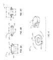
- FIGS. 3A, 3B, and 3Care schematic cross-sectional views of three non-fluid-cooled protective members in accordance with the present disclosure
- FIG. 4is a schematic perspective view, partially in phantom, of another non-fluid-cooled protective member in accordance with the present disclosure
- FIG. 8is a schematic cross-sectional view of an SCM in accordance with the present disclosure.
- FIG. 9is a schematic logic diagram of a method of melting non-metallic inorganic materials in accordance with the present disclosure.
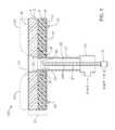
- FIGS. 10A and 10Bare schematic perspective and cross-sectional views, respectfully, of a fluid-cooled burner panel in accordance with the present disclosure.
- one drawback to present SC burners employing a metallic burner tip of the same or similar material as the remainder of the burneris that, when using such burners in an SCM for the manufacture of glass, the burner tip is placed in an extreme environment.
- One problemis that the tip of the burner is exposed to the extreme high temperatures of an oxy-gas flame when oxygen-enriched oxidants are used. Such flames, when deflected, can melt the burner tip.
- Using noble metals and alloys for burner tipspresents the additional challenge of attaching the burner tip to the base metal of the remainder of the burner. The present application is devoted to resolving this challenge with a new approach to burner design for submerged combustion.
- “Submerged” as used hereinmeans that combustion gases emanate from combustion burners or combustion burner panels under the level of the molten glass; the burners or burner panels may be floor-mounted, wall-mounted, or in melter embodiments comprising more than one submerged combustion burner, any combination thereof (for example, two floor mounted burner panels and one wall mounted burner panel).
- Burner panels described hereinmay form part of an SCM floor and/or wall structure. In certain embodiments one or more burner panels described herein may form the entire floor.
- a “burner panel”is simply a panel equipped to emit fuel and oxidant, or in some embodiments only one of these (for example a burner panel may only emit fuel, while another burner panel emits only oxidant, and vice versa).
- SCas used herein means “submerged combustion” unless otherwise specifically noted, and “SCM” means submerged combustion melter unless otherwise specifically noted.
- combustion gasesmeans substantially gaseous mixtures comprised primarily of combustion products, such as oxides of carbon (such as carbon monoxide, carbon dioxide), oxides of nitrogen, oxides of sulfur, and water, as well as partially combusted fuel, non-combusted fuel, and any excess oxidant.
- Combustion productsmay include liquids and solids, for example soot and unburned liquid fuels.
- Oxidantas used herein includes air and gases having the same molar concentration of oxygen as air, oxygen-enriched air (air having oxygen concentration greater than 21 mole percent), and “pure” oxygen, such as industrial grade oxygen, food grade oxygen, and cryogenic oxygen.
- Oxygen-enriched airmay have 50 mole percent or more oxygen, and in certain embodiments may be 90 mole percent or more oxygen.
- fuelmeans a combustible composition comprising a major portion of, for example, methane, natural gas, liquefied natural gas, propane, hydrogen, steam-reformed natural gas, atomized hydrocarbon oil, combustible powders and other flowable solids (for example coal powders, carbon black, soot, and the like), and the like.
- Fuels useful in the disclosuremay comprise minor amounts of non-fuels therein, including oxidants, for purposes such as premixing the fuel with the oxidant, or atomizing liquid or particulate fuels.
- fuelincludes gaseous fuels, liquid fuels, flowable solids, such as powdered carbon or particulate material, waste materials, slurries, and mixtures or other combinations thereof.
- the sources of oxidant and fuelmay be one or more conduits, pipelines, storage facility, cylinders, or, in embodiments where the oxidant is air, ambient air.
- Oxygen-enriched oxidantsmay be supplied from a pipeline, cylinder, storage facility, cryogenic air separation unit, membrane permeation separator, or adsorption unit such as a vacuum swing adsorption unit.
- Burner panels of the present disclosureaim to solve the problem of short life of SC burners. In certain embodiments this may be accomplished by use of burner panels including fluid-cooled or non-fluid-cooled protective members for the external-most conduit of the sets of conduits, thus reducing the exposure of the burner tip to extreme high temperatures as well as reducing the severity of extreme thermal cycling experienced by SC burner tips.
- Certain burner panel embodimentsmay comprise burner panels wherein the outer conduit of at least some of the sets of concentric conduits are oxidant conduits, and the at least one inner conduit is one or more fuel conduits.
- Certain burner panel embodimentsmay comprise non-fluid cooled or fluid-cooled protective members comprising one or more noble metals. Certain burner panel embodiments may comprise non-fluid cooled or fluid-cooled protective members consisting essentially of one or more noble metals. Certain burner panel embodiments may comprise non-fluid cooled or fluid-cooled protective members consisting of one or more noble metals.
- Certain burner panel embodimentsmay comprise those wherein the lower fluid-cooled portion and the upper non-fluid cooled portion are positioned in layers, with the lower fluid-cooled portion supporting the sets of conduits and the associated protective members.
- Certain burner panel embodimentsmay comprise those wherein the non-fluid cooled protective member is a shaped annular disk having a through passage, the through passage of the shaped annular disk having an internal diameter d1 substantially equal to but not larger than an internal diameter D1 of the outer conduit. Certain burner panel embodiments may comprise those wherein an internal surface of the through passage of the shaped annular disk and a portion of a top surface of the shaped annular disk are not engulfed by the fluid-cooled or non-fluid-cooled portions of the panel body.
- Certain burner panel embodimentsmay comprise those wherein the layers of the fluid-cooled and non-fluid-cooled portions form a seam there between, and wherein a top surface of the non-fluid cooled protective member and the seam are at substantially equal distance d6 from a top surface of the non-fluid-cooled portion, and a bottom surface of the protective member is below the seam a distance d7, where d6 ⁇ d7.
- Certain burner panel embodimentsmay comprise those wherein a portion of the through passage through the non-fluid-cooled portion has an inner surface angled away from a longitudinal axis through the substantially concentric conduits at an angle ranging from 0 degrees to about 45 degrees.
- Certain burner panel embodimentsmay further include a retaining member positioned about an external portion of the non-fluid cooled protective member.
- Certain burner panel embodimentsmay comprise those wherein a distal end of the one or more fuel conduits extends a height H above a bottom surface of the non-fluid cooled protective member.
- Certain burner panel embodimentsmay comprise those wherein the non-fluid cooled protective member comprises one or more male portions extending away from the protective member, the male portions fitting in respective female receptacles in the panel body.
- Certain combustion burner panelsmay comprise a panel body having a first major surface defined by a lower fluid-cooled portion of the panel body, and a second major surface defined by an upper non-fluid cooled portion of the panel body, the panel body having at least one through passage extending from the first to the second major surface, the through passage diameter being greater in the lower fluid-cooled portion than in the upper non-fluid cooled portion, the panel body supporting at least one set of substantially concentric at least one inner conduit and an outer conduit, each conduit comprising proximal and distal ends, the at least one inner conduit forming a primary passage and the outer conduit forming a secondary passage between the outer conduit and the at least one inner conduit; and (b) a fluid-cooled protective member associated with each set and having connections for coolant fluid supply and return, each fluid-cooled protective member positioned adjacent at least a portion of the circumference of the outer conduit between the proximal and distal ends thereof at approximately a position of the fluid-cooled portion of the panel body.
- Certain burner panel embodimentsmay comprise those wherein each fluid-cooled protective member is a fluid-cooled collar having an internal diameter about the same as an external diameter of the outer conduit, the fluid-cooled collar having an external diameter larger than the internal diameter.
- Certain burner panel embodimentsmay comprise a mounting sleeve.
- the mounting sleevehaving a diameter at least sufficient to accommodate the external diameter of the fluid-cooled collar.
- Certain burner panel embodimentsmay comprise wherein the panel body fluid-cooled portion and non-fluid-cooled portion are positioned in layers, and wherein the layers of the fluid-cooled and non-fluid-cooled portions form a seam there between, and wherein a top surface of the fluid-cooled protective member and the seam are at substantially equal distance d6 from a top surface of the non-fluid-cooled portion, and a bottom surface of the fluid-cooled protective member is below the seam a distance d7, where d6 ⁇ d7.
- Certain burner panel embodimentsmay comprise wherein the outer conduit is an oxidant conduit and extends a height h2 above the seam, and the inner conduit is a fuel conduit and extends a height h3 above the seam, wherein h2>h3.
- the burner panelmay include only one or more fuel conduits, or only one or more oxidant conduits. These embodiments may be paired with other panels supplying fuel or oxidant (as the case might be), the pair resulting in combustion of the fuel from one panel with the oxidant from the other panel.
- the burner panelmay comprise a pre-disposed layer or layers of glass, ceramic, refractory, and/or refractory metal or other protective material as a protective skull over the non-fluid cooled body portion or layer.
- the layer or layers of protective materialmay or may not be the same as the material to be melted in the SCM.
- the burner panelmay include a pre-disposed layer or layers of glass, ceramic, refractory, and/or refractory metal or other protective material on surfaces of the through passage through the non-fluid-cooled portions of the burner panel body.
- the layer or layers of protective materialmay or may not be the same as the material to be melted in the SCM.
- the protective membermay be installed and/or removed from the burner panel separately from the set of conduits.
- the protective member of a burner panelmay be removed from a position inside of an SCM, while the conduits of the same burner panel may be removed from the burner panel from outside of an SCM.
- FIGS. 1, 2, 5, 6, and 7are schematic cross-sectional views of five burner panels in accordance with the present disclosure.
- Embodiments 100 , 200 , 300 , 400 , and 500 illustrated schematically in FIGS. 1, 2, 5, 6, and 7respectively each includes a panel body 2 comprised of a non-fluid-cooled portion 4 and a fluid-cooled portion 6 , the fluid-cooled portion 6 including a metal (preferably steel or other high-strength material) portion 8 and a metal or other material cooling sub-portion 10 .
- One structure of cooling sub-portion 10is described in conjunction with schematic FIGS. 10A and 10B , illustrating a metal support plate 11 having a plurality of metal or other material conduits 13 for flow of coolant fluid there through.
- coolant fluidpasses through one conduit 13 in one direction and returns in the next adjacent conduit 13 via elbows 15 .
- each conduit 13may flow coolant fluid in the same direction, with the chilled coolant fluid supplied via a chilled fluid manifold, and warmed coolant fluid collected in a second manifold (not illustrated).
- a chilled fluid manifoldsupplied via a chilled fluid manifold
- warmed coolant fluidcollected in a second manifold (not illustrated).
- Other arrangementsare possible.
- a seam 12is present between non-fluid-cooled portion 4 and fluid-cooled portion 6 .
- One or more through passages 14are present, extending from a first major surface 16 of panel body 2 to a second major surface 18 .
- another layer or layers 20may be present as post-formed skulls of the glass or other material being melted in the SCM, as discussed herein, and therefore are depicted schematically in phantom.
- layer or layers 20are pre-formed as part of the original or virgin burner panel, and are therefore depicted using solid, non-phantom lines.
- second major surface 18is formed by the top surface of pre-formed layer 20 .
- burner panel 100includes an outer conduit 22 , an inner conduit 24 (which may be more than one conduit) that are substantially concentric.
- substantially concentricmeans that conduits 22 , 24 may be concentric, or conduit 24 may be non-concentric with a longitudinal axis “L” of conduit 22 (see FIG. 5 ), especially if conduit 24 is comprised of more than one conduit. If conduit 24 is more than one conduit (for example 2 to 10, or 2 to 8, or 2 to 6, or 3 to 6 conduits), the conduits 24 may be centered about the longitudinal axis L of conduit 22 .
- Conduit(s) 24define a primary passage 26 for fuel (“F”) or oxidant (“O”), while the space between outer conduit 22 and inner conduit(s) 24 defines a secondary passage 28 for fuel or oxidant.
- fuelmay flow through primary passage 26 (and thus conduit(s) 24 may be referred to as “fuel conduit(s)”) while oxidant may flow through secondary passage 28 (and thus conduit 22 may be referred to as an “oxidant conduit”).
- conduit 22may be the fuel conduit while conduit(s) 24 may be the oxidant conduit.
- Outer conduit 22may be welded to metal support plate 11 ( FIG. 10A ) of metal support and cooling portion 10 , or connected via flange or other connection, such as threaded fittings. In this way, outer and inner conduits 22 , 24 may be removed from burner panel 100 , such as by cutting the connection between support plate 11 and outer conduit 22 , or using a torch, or unthreading.
- burner panel 100includes a plenum 30 through which outer conduit 22 maybe connected to a source of F or O, and a connector 32 for connecting inner conduit 24 to a source of F or O.
- a non-fluid-cooled protective member 36which may be a shaped annular disk comprised of one or more noble metals.
- a distal end 40 of inner conduit 24is illustrated, as well as coolant fluid inlet and outlet connections 48 , 49 .
- Embodiment 100 illustrated in FIG. 1also shows diameter D4 of though passage 14 through non-fluid-cooled portion or layer 4 .
- Diameter 14 in embodiment 100is illustrated as increasing in the direction of flow, but this is not necessary.
- the diameter D4may initially be constant, but over time during operation may broaden as illustrated due to erosion.
- the rate of erosionmay be controlled by selection of the material of non-fluid-cooled portion 4 , or at least that portion forming through passage 14 .
- through passage 14may be formed from a controllably erodible material that erodes at a faster or slow rate than the material of non-fluid-cooled portion 4 .
- Skull layer 20is depicted in phantom in embodiment 100 , as in this embodiment it would be formed during operation of the SCM.
- FIGS. 3A, 3B, and 3Care schematic cross-sectional views of three embodiments 110 , 120 , and 130 of non-fluid-cooled protective member 36 in accordance with the present disclosure, illustrating some of the variety of shapes that the shaped annular disk 36 may take.
- Embodiment 110is an annulus having an internal surface 42 having diameter that is a constant magnitude of d1, and an external surface 44 having diameter d2 that increases from one face (lower or bottom face) to a second face (upper or top face) of the annulus.
- Embodiment 120is an annulus having a constant internal diameter portion 42 A of diameter d1, and an increasing internal diameter portion 42 B of diameter d3, and an external surface 44 having a diameter d2 that increases from one face to a second face of the annulus.
- Embodiment 130is an annulus having an internal surface 42 having diameter that is a constant magnitude of d1, and an external surface 44 having a constant external diameter portion 44 of diameter d4, and a large diameter heat transfer extension 46 of diameter d5, where d4 ⁇ d5.
- the designis intended to transfer heat away from the position indicated at 50 , which is the position of highest temperature of the shaped annular disk during operation.
- Ranges for magnitude of d1, d2, d3, d4, and d5are provided in Table 1. It will be understood that these are approximate ranges (each number includes the word “about” before it), are not exclusive ranges, and that any range within the tabulated ranges are explicitly disclosed herein.
- RangePref. range Dimension Range (in.) (in.) Range (cm) (cm) d1 0.25-5.0 1.0-3.0 0.635-12.7 2.54-7.62 d2 0.5-7.0 1.0-5.0 1.27-17.8 2.54-12.7 d3 0.25-6.0 0.5-4.0 0.635-15.2 1.27-10.2 d4 0.5-5.5 1.0-4.0 1.27-13.97 2.54-10.2 d5 1.0-7.0 2.0-5.0 2.54-17.8 5.08-12.7
- Embodiment 200includes many of the features of embodiment 100 of FIG. 1 , but with the following changes.
- Embodiment 200includes a pre-formed or deposited skull of protective material 20 , and further illustrates more dimensions of burner panels of this disclosure.
- Outer conduit 22has an inner diameter D1, and outer diameter D2, while non-fluid cooled portion 4 has a thickness d6.
- a height H1which is a thickness of protective member 36 , and also illustrates the height of distal end 40 of inner conduit 24 above a lower surface of protective member 36 .
- Embodiment 200also illustrates a distance d7, which is the distance from the bottom surface of protective member 36 to a top surface of the non-fluid-cooled portion 4 .
- Embodiment 200also illustrates a retaining member 52 welded or brazed to protective member 36 about at least a portion of its upper periphery.
- Retaining member 52may be a circumferential ring, or may be one or more male portions 54 , 56 that fit into corresponding female portions 58 in fluid-cooled portion 6 as illustrated in embodiment 220 of FIG. 4 .
- the thicknesses of pre-formed portion or layer 20 and portion 6are not indicated in the figures, but are multiples or fractions of thickness d6 of non-fluid-cooled portion 4 .
- the thickness of layer 20may range from about 0.1 to about 10 times d6, or from about 0.5 to about 5 times d6; the thickness of layer 6 may range from about 0.5 to about 2 times d6, or from about 0.75 to about 1.25 times d6.
- Ranges for magnitude of d6, d7, H1, D1, D2, and D3 (inner diameter of inner conduit 24 )are provided in Table 2. It will be understood that these are approximate ranges (each number includes the word “about” before it), are not exclusive ranges, and that any range within the tabulated ranges are explicitly disclosed herein.
- FIG. 2Pref. Range.
- Embodiments 300 , 400 , and 500illustrate embodiments employing a fluid-cooled protective member 72 fluidly connected to a supply of coolant fluid through one or more coolant fluid supply conduits 80 , and fluidly connected to a return of coolant fluid through one or more return conduits 82 .
- the designation “CFI”indicates “coolant fluid in” and the designation “CFO” means “coolant fluid out.”
- Embodiment 300includes an outer conduit 22 having an expansion nozzle 70 attached thereto, for example by welding. Alternatively, nozzle 70 and outer conduit 22 may be formed from a single ingot of metal.
- Embodiments 300 , 400 , and 500also illustrate the use of a mounting sleeve 74 , mounting sleeve first half flange 76 , and second half flange 78 , the flange halves held together with appropriate bolts and gaskets, not illustrated.
- Conduits 80 , 82pass through half flange 78 .
- Fluid-cooled protective member 72is preferably a hollow annulus, although the annulus need not be completely hollow; for example, there may be support structures, baffles, heat transfer structures, and other features inside of fluid-cooled protective member 72 .
- embodiment 300includes a height H2, defining how far nozzle 70 extends above major surface 18 .
- a height H3is also illustrated, defining the distance a distal end of nozzle 70 extends above distal end of inner conduit 40 , and a nozzle angle “ ⁇ ”, forming a non-fluid-cooled combustion region 90 .
- Embodiment 400 illustrated schematically in FIG. 6differs from embodiment 300 only in that the protective material skull 20 is preformed, and embodiment 400 includes no nozzle 70 ; in this configuration, H2>H3.
- Embodiment 500 illustrated schematically in FIG. 7differs from embodiment 400 only in that the protective material skull 20 is post-formed.
- RangePref. Range Dimension Range (in.) (in.) Range (cm) (cm) H2 0-5.0 0-3.0 0-12.7 0-7.62 H3 0.5-7.0 0.5-5.0 1.27-17.8 1.27-12.7 ⁇ 0-45 0-30 — —
- FIGS. 5, 6, and 7may also be employed in the burner panels such as illustrated in FIGS. 1 and 2 , embodiments 100 , and 200 .
- SCM embodiment 600comprises a melter having a floor 200 (which may be a burner panel in accordance with the present disclosure), a roof or ceiling 652 , a feed end wall 654 A, a first portion of an exit end wall 654 B, and a second portion of the exit end wall 654 C.
- Feed end wall 654 A and exit end wall portion 654 Bmay form angles “ ⁇ ” and “ ⁇ ”, respectively, with respect to floor 2 , as indicated.
- Angles ⁇ and ⁇may be the same or different, and generally may range from about 30 degrees to about 90 degrees, or from about 45 degrees to about 75 degrees.
- Exit end wall portion 654 Cmay form an angle “ ⁇ ” with respect to skimmer 680 .
- Angle ⁇may be the range from 0 to about 70 degrees, or from about 30 degrees to about 75 degrees. Increasing this angle beyond these ranges may require more floor space for the melters, and/or more material of construction, both of which are generally undesirable. Decreasing this angle may promote escape of unmelted or melted material up stack 656 , or deposition onto internal surfaces of stack 656 , both of which are also undesirable.
- a pre-formed or post-formed frozen and/or highly viscous layer or layers 670 of material being meltedmay be formed on the inside surfaces of walls 654 A, 654 B, the post-formed layer or layers due to the use of fluid-cooled panels for these walls.
- walls 654 A, 654 B, 654 C, floor 200 , and roof 652may be comprised of a fluid-cooled metal shell 672 and a non-fluid-cooled refractory panel 674 .
- System embodiment 600further includes an exhaust stack 656 , and submerged combustion fuel and oxidant conduits 24 , 22 , in one or more burner panels making up floor 200 which create during operation a highly turbulent melt indicated at 668 having a variable surface 669 .
- fuel and oxidant conduits 24 , 22are positioned to emit fuel and oxidant into molten material in the melting zone 668 in a fashion so that the gases combust and penetrate the melt generally perpendicularly to floor panel 200 .
- one or more fuel or oxidant conduits 24 , 22may emit fuel or oxidant into the melt at an angle to floor 200 , where the angle may be more or less than 45 degrees, but in certain embodiments may be 30 degrees, or 40 degrees, or 50 degrees, or 60 degrees, or 70 degrees, or 80 degrees.
- the initial raw materialcan be introduced into the melter of system 600 on a batch, semi-continuous or continuous basis.
- a port 660is arranged at end 654 A of the melter through which the initial raw material is introduced by a feeder 658 .
- Other embodimentsmay include a slanted or angled feed chute in which large pieces of feed material (such as basalt or other material) may be fed and optionally pre-heated by out going melter exhaust without becoming fluidized.
- a “batch blanket” 662may form along wall 654 A, as illustrated in FIG. 8 .
- Feed port 660may be positioned above the average glass melt level, indicated by dashed line 666 .
- the amount of the initial raw material introduced into the melteris generally a function of, for example, the capacity and operating conditions of the melter as well as the rate at which the molten material is removed from the melter.
- the initial raw material feedstockmay include any material suitable for forming molten inorganic materials, such as glass, such as, for example, limestone, glass, sand, soda ash, feldspar, basalt or other rock wool forming material, and mixtures thereof.
- a glass composition for producing glass fibersis “E-glass,” which typically includes 52-56% SiO 2 , 12-16% Al 2 O 3 , 0-0.8% Fe 2 O 3 , 16-25% CaO, 0-6% MgO, 0-10% B 2 O 3 , 0-2% Na 2 O+K 2 O, 0-1.5% TiO 2 and 0-1% F 2 .
- Other glass compositionsmay be used, such as those described in assignee's published U.S. application 20080276652.
- the initial raw materialcan be provided in any form such as, for example, relatively small particles, or in the case of rock wool or mineral wool manufacture, in large pieces 5 cm or more in diameter.
- submerged combustion burners and burner panelsmay produce violent turbulence of the molten inorganic material in the SCM and may result in sloshing of molten material, pulsing of combustion burners, popping of large bubbles above submerged burners, ejection of molten material from the melt against the walls and ceiling of melter, and the like.
- one or more of these phenomenamay result in undesirably short life of temperature sensors and other components used to monitor a submerged combustion melter's operation, making monitoring difficult, and use of signals from these sensors for melter control all but impossible for more than a limited time period.
- Processes and systems of the present disclosuremay include indirect measurement of melt temperature in the melter itself, as disclosed in assignee's U.S.
- thermocouplesfor monitoring and/or control of the melter, for example using a controller.
- a signalmay be transmitted by wire or wirelessly from a thermocouple to a controller, which may control the melter by adjusting any number of parameters, for example feed rate of feeder 658 may be adjusted through a signal, and one or more of fuel and/or oxidant conduits 24 , 22 may be adjusted via a signal, it being understood that suitable transmitters and actuators, such as valves and the like, are not illustrated for clarity.
- system embodiment 600includes a melter exit structure 676 for discharging the molten glass or similar material.
- Melter exit structure 676is positioned generally downstream of melter exit ends 654 B, 654 C as illustrated of FIG. 8 , and may fluidly and mechanically connect the melter vessel to a molten material conditioning channel, or other channel or structure (not illustrated).
- Melter exit structure 676comprises a fluid-cooled transition channel 678 , having generally rectangular cross-section in embodiment 600 , although any other cross-section would suffice, such as hexagonal, trapezoidal, oval, circular, and the like.
- fluid-cooled transition channel 678is configured to form a frozen layer or highly viscous layer, or combination thereof, of material being melted on inner surfaces of fluid-cooled transition channel 678 and thus protect melter exit structure 676 from the mechanical energy imparted from the melter vessel to melter exit structure 676 .
- Melter exit structure 676may in certain embodiments comprise an essentially rectangular, fluid-cooled, ceramic or metallic box having a length, a width, a height. In these embodiments, length may range from about 5 to about 50 percent, or from about 10 to about 40 percent, of the entire length of the melter apparatus.
- the width of melt exit structure 676may be the same as the width of the melter apparatus, or may be less or more than the width of the melter apparatus.
- the heightmay range from about 5 to about 50 percent, or from about 10 to about 40 percent, of the entire height of the melter apparatus, measured from floor 200 to ceiling 652 .
- Melter length, width and heightdepend primarily on the amount of raw material to be fed, the amount of molten material to be produced, and the desired throughputs mentioned herein.
- a fluid-cooled skimmer 680may be provided, extending downward from the ceiling of the melter vessel and positioned upstream of fluid-cooled transition channel 678 .
- Fluid-cooled skimmer 680has a lower distal end 682 extending a distance L s ranging from about 1 inch to about 12 inches (from about 2.5 cm to about 30 cm) below the average melt level 666 , which may be from about 0.2 to about 0.8, or from about 0.25 to about 0.75 times the height of 676 .
- Fluid-cooled skimmer 680may be configured to form a frozen layer or highly viscous layer, or combination thereof, of material being melted on its outer surfaces.
- Skimmer lower distal end 682defines, in conjunction with a lower wall of melter exit structure 676 , a throat 684 of the melter vessel, throat 684 configured to control flow of molten glass or other material from the melter vessel into melter exit structure 676 .
- throat 684is arranged below average melt level 666 .
- Molten materialcan be removed from melter exit structure 676 on a batch, semi-continuous basis or continuous basis. In an exemplary embodiment, the molten material continuously flows through throat 684 and generally horizontally through melter exit structure 676 , and is removed continuously from melter exit structure 676 to a conditioning channel (not illustrated). Thereafter, the molten material can be processed by any suitable known technique, for example, a process for forming glass or other fibers.
- Certain embodimentsmay include an overlapping refractory material layer 686 on at least the inner surface of fluid-cooled transition channel 678 that are exposed to molten material.
- the overlapping refractory materialmay comprise a seamless insert of dense chrome, molybdenum, or other dense ceramic or metallic material.
- the dense chrome or other refractory materialmay be inserted into the melter exit structure and may provide a seamless transition form the melter vessel to a conditioning channel (not illustrated).
- Dam opening 688accommodates a movable, fluid-cooled dam 690 , which is illustrated schematically in FIG. 8 in a retracted position. Dam 690 may be manipulated by a prime mover 692 , such as one or more motors, jack screws, or the like. Fluid-cooled dam 690 comprises dimensions allowing the dam to be extended an entire distance from top to bottom of fluid-cooled transition channel 678 and completely isolate the melting zone of the melter vessel from the conditioning channel.
- FIG. 9is a schematic logic diagram of a method of melting non-metallic inorganic materials in accordance with the present disclosure.
- the methodcomprises feeding the feedstock into a submerged combustion melter comprising a combustion burner panel comprising a panel body having a first major surface defined by a lower fluid-cooled portion of the panel body, and a second major surface defined by an upper non-fluid cooled portion of the panel body, the panel body having at least one through passage extending from the first to the second major surface, the panel body supporting at least one set of substantially concentric at least one inner conduit and an outer conduit in the through passage, each conduit comprising proximal and distal ends, the at least one inner conduit forming a primary passage and the outer conduit forming a secondary passage between the outer conduit and the at least one inner conduit; and a non-fluid cooled protective member associated with each set, each non-fluid cooled protective member supported at least partially internally of the panel body and positioned at the distal end of the outer conduit of each set (box 702
- Melter apparatus in accordance with the present disclosuremay also comprise one or more wall-mounted submerged combustion burners, and/or one or more roof-mounted burners (not illustrated). Roof-mounted burners may be useful to pre-heat the melter apparatus melting zones, and serve as ignition sources for one or more submerged combustion burners and/or burner panels. Melter apparatus having only wall-mounted, submerged-combustion burners or burner panels are also considered within the present disclosure. Roof-mounted burners may be oxy-fuel burners, but as they are only used in certain situations, are more likely to be air/fuel burners. Most often they would be shut-off after pre-heating the melter and/or after starting one or more submerged combustion burners.
- all submerged combustion burners and burner panelsare oxy/fuel burners or oxy-fuel burner panels (where “oxy” means oxygen, or oxygen-enriched air, as described earlier), but this is not necessarily so in all embodiments; some or all of the submerged combustion burners or burner panels may be air/fuel burners.
- heatingmay be supplemented by electrical heating in certain embodiments, in certain melter zones.
- Suitable materials for glass-contact refractorywhich may be present in SC melters and downstream flow channels, and refractory panel bodies of burner panels, include fused zirconia (ZrO 2 ), fused cast AZS (alumina-zirconia-silica), rebonded AZS, or fused cast alumina (Al 2 O 3 ).
- the melter geometry and operating temperature, burner body panel geometry, and type of glass or other product to be produced,may dictate the choice of a particular material, among other parameters.
- fluid-cooledmeans use of a coolant fluid (heat transfer fluid) to transfer heat away from the burner panel.
- Heat transfer fluidsmay be any gaseous, liquid, slurry, or some combination of gaseous, liquid, and slurry compositions that functions or is capable of being modified to function as a heat transfer fluid.
- Gaseous heat transfer fluidsmay be selected from air, including ambient air and treated air (for example, air treated to remove moisture), inorganic gases, such as nitrogen, argon, and helium, organic gases such as fluoro-, chloro- and chlorofluorocarbons, including perfluorinated versions, such as tetrafluoromethane, and hexafluoroethane, and tetrafluoroethylene, and the like, and mixtures of inert gases with small portions of non-inert gases, such as hydrogen.
- Heat transfer liquids and slurriesmay be selected from liquids and slurries that may be organic, inorganic, or some combination thereof, for example, water, salt solutions, glycol solutions, oils and the like. Other possible heat transfer fluids include steam (if cooler than the expected glass melt temperature), carbon dioxide, or mixtures thereof with nitrogen. Heat transfer fluids may be compositions comprising both gas and liquid phases, such as the higher chlorofluorocarbons.
- Certain SCMs of this disclosuremay comprise one or more non-submerged burners.
- Suitable non-submerged combustion burnersmay comprise a fuel inlet conduit having an exit nozzle, the conduit and nozzle inserted into a cavity of a ceramic burner block, the ceramic burner block in turn inserted into either the SCM roof or the SCM wall structure, or both the SCM roof and SCM wall structure.
- Downstream flow channelsmay also comprise one or more non-submerged burners.
- one or more fuel and/or oxidant conduits in the SCM and/or flow channel(s) downstream thereofmay be adjustable with respect to direction of flow of the fuel or oxidant or both. Adjustment may be via automatic, semi-automatic, or manual control.
- Certain system embodimentsmay comprise a mount that mounts the fuel or oxidant conduit in a burner panel of the SCM and/or flow channel comprising a refractory, or refractory-lined ball joint.
- Other mountsmay comprise rails mounted in slots in the wall or roof.
- the fuel and/or oxidant conduitsmay be mounted outside of the melter or channel, on supports that allow adjustment of the fuel or oxidant flow direction. Useable supports include those comprising ball joints, cradles, rails, and the like.
- Certain SCMs and method embodiments of this disclosuremay include fluid-cooled panels such as disclosed in Applicant's U.S. Pat. No. 8,769,992. Certain systems and processes of the present disclosure may utilize measurement and control schemes such as described in Applicant's U.S. Pat. No. 9,096,453, and/or feed batch densification systems and methods as described in Applicant's U.S. Pat. No. 9,643,869. Certain SCMs and processes of the present disclosure may utilize devices for delivery of treating compositions such as disclosed in Applicant's U.S. Pat. No. 8,973,405.
- combustion (flame) temperaturemay be controlled by monitoring one or more parameters selected from velocity of the fuel, velocity of the primary oxidant, mass and/or volume flow rate of the fuel, mass and/or volume flow rate of the primary oxidant, energy content of the fuel, temperature of the fuel as it enters the burner panel, temperature of the primary oxidant as it enters the burner panel, temperature of the effluent, pressure of the primary oxidant entering the burner panel, humidity of the oxidant, burner panel geometry, combustion ratio, and combinations thereof.
- Certain SCMs and processes of this disclosuremay also measure and/or monitor feed rate of batch or other feedstock materials, such as rock wool or mineral wool feedstock, glass batch, cullet, mat or wound roving and treatment compositions, mass of feed, and use these measurements for control purposes.
- feedstock materialssuch as rock wool or mineral wool feedstock, glass batch, cullet, mat or wound roving and treatment compositions, mass of feed, and use these measurements for control purposes.
- Oxidant and fuel conduits of burner panels of the present disclosuremay be comprised of metal, ceramic, ceramic-lined metal, or combination thereof.
- Suitable metalsinclude carbon steels, stainless steels, for example, but not limited to, 306 and 316 steel, as well as titanium alloys, aluminum alloys, and the like.
- High-strength materials like C-110 and C-125 metallurgies that are NACE qualifiedmay be employed for burner body components.
- NACErefers to the corrosion prevention organization formerly known as the National Association of Corrosion Engineers, now operating under the name NACE International, Houston, Tex.
- Use of high strength steel and other high strength materialsmay significantly reduce the conduit wall thickness required, reducing weight of the conduits and/or space required for conduits.
- Protection members of burner panels of the present disclosuremay comprise noble metals and/or other exotic corrosion and/or fatigue-resistant materials, such as platinum (Pt), ruthenium (Ru), rhodium (Rh), palladium (Pd), silver (Ag), osmium (Os), iridium (Ir), and gold (Au); alloys of two or more noble metals; and alloys of one or more noble metals with a base metal.
- the protective membermay comprise an 80 wt. percent platinum/20 wt. percent rhodium alloy attached to the outer base metal conduit using brazing, welding or soldering of certain regions, as further explained in assignee's International Application No. PCT/US2013/042182 filed May 22, 2013 (WO2014-189504A1).
- alloys of two or more noble metalsmay have any range of noble metals.
- alloys of two noble metalsmay have a range of about 0.01 to about 99.99 percent of a first noble metal and 99.99 to 0.01 percent of a second noble metal.
- any and all ranges in between 0 and 99.99 percent first noble metal and 99.99 and 0 percent second noble metalare considered within the present disclosure, including 0 to about 99 percent of first noble metal; 0 to about 98 percent; 0 to about 97 percent; 0 to about 96; 0 to about 95; 0 to about 90; 0 to about 80; 0 to about 75; 0 to about 70; 0 to about 65; 0 to about 60; 0 to about 55; 0 to about 50; 0 to about 45, 0 to about 40; 0 to about 35; 0 to about 30; 0 to about 25; 0 to about 20; 0 to about 19; 0 to about 18; 0 to about 17; 0 to about 16; 0 to about 15; 0 to about 14; 0 to about 13; 0 to about 12; 0 to about 11; 0 to about 10; 0 to about 9; 0 to about 8; 0 to about 7; 0 to about 6, 0 to about 5; 0 to about 4;
- the percentages of each individual noble metalmay range from equal amounts of all noble metals in the composition (about 33.33 percent of each), to compositions comprising, or consisting essentially of, or consisting of 0.01 percent of a first noble metal, 0.01 percent of a second noble metal, and 99.98 percent of a third noble metal. Any and all ranges in between about 33.33 percent of each, and 0.01 percent of a first noble metal, 0.01 percent of a second noble metal, and 99.98 percent of a third noble metal, are considered within the present disclosure.
- burner panelswill have a satisfactory service life of at least 12 months under conditions existing in a continuously operating SCM.
- the SCMmay comprise a floor, a roof, and a sidewall structure connecting the floor and roof defining an internal space, at least a portion of the internal space comprising a melting zone, and one or more combustion burner panels of this disclosure in either the floor, the roof, or the sidewall structure, or any two or more of these, producing combustion gases and configured to emit the combustion gases from a position under a level of, and positioned to transfer heat to and produce, a turbulent molten mass of glass containing bubbles in the melting zone.
- the total quantities of fuel and oxidant used by burner panels of the present disclosuremay be such that the flow of oxygen may range from about 0.9 to about 1.2 of the theoretical stoichiometric flow of oxygen necessary to obtain the complete combustion of the fuel flow. Another expression of this statement is that the combustion ratio may range from about 0.9 to about 1.2.
- the velocity of the fuel in the various burner panel embodiments of the present disclosuredepends on the burner panel geometry used, but generally is at least about 15 meters/second (m/s).
- the upper limit of fuel velocitydepends primarily on the desired penetration of flame and/or combustion products into the glass melt and the geometry of the burner panel; if the fuel velocity is too low, the flame temperature may be too low, providing inadequate temperature in the melter, which is not desired, and if the fuel flow is too high, flame and/or combustion products might impinge on a melter wall or roof, or cause carryover of melt into the exhaust, or be wasted, which is also not desired.
- Bafflesmay be provided extending from the roof, and/or in the melter exhaust stack, or transition region between the melter and stack, in order to safeguard against this.
- Oxidant velocityshould be monitored so that flame and/or combustion products do not impinge on an SCM wall or roof, or cause carryover of melt into the exhaust, or be wasted. Oxidant velocities depend on fuel flow rate and fuel velocity, but in general should not exceed about 200 ft/sec at 400 scfh flow rate.
- a combustion process control schememay be employed.
- a master controllermay be employed, but the disclosure is not so limited, as any combination of controllers could be used.
- the controllermay be selected from PI controllers, PID controllers (including any known or reasonably foreseeable variations of these), and may compute a residual equal to a difference between a measured value and a set point to produce an output to one or more control elements.
- the controllermay compute the residual continuously or non-continuously.
- Other possible implementations of the disclosureare those wherein the controller comprises more specialized control strategies, such as strategies selected from feed forward, cascade control, internal feedback loops, model predictive control, neural networks, and Kalman filtering techniques.
- controlmeans to verify or regulate by comparing with a standard or desired value.
- Controlmay be closed loop, feedback, feed-forward, cascade, model predictive, adaptive, heuristic and combinations thereof.
- controllermeans a device at least capable of accepting input from sensors and meters in real time or near-real time, and sending commands directly to burner panel control elements, and/or to local devices associated with burner panel control elements able to accept commands.
- a controllermay also be capable of accepting input from human operators; accessing databases, such as relational databases; sending data to and accessing data in databases, data warehouses or data marts; and sending information to and accepting input from a display device readable by a human.
- a controllermay also interface with or have integrated therewith one or more software application modules, and may supervise interaction between databases and one or more software application modules.
- PID controllermeans a controller using proportional, integral, and derivative features. In some cases the derivative mode may not be used or its influence reduced significantly so that the controller may be deemed a PI controller. It will also be recognized by those of skill in the control art that there are existing variations of PI and PID controllers, depending on how the discretization is performed. These known and foreseeable variations of PI, PID and other controllers are considered within the disclosure.
- the controllermay utilize Model Predictive Control (MPC).
- MPCis an advanced multivariable control method for use in multiple input/multiple output (MIMO) systems.
- MPCcomputes a sequence of manipulated variable adjustments in order to optimise the future behavior of the process in question. It may be difficult to explicitly state stability of an MPC control scheme, and in certain embodiments of the present disclosure it may be necessary to use nonlinear MPC.
- PID controlmay be used on strong mono-variable loops with few or nonproblematic interactions, while one or more networks of MPC might be used, or other multivariable control structures, for strong interconnected loops.
- computing time considerationsmay be a limiting factor.
- Some embodimentsmay employ nonlinear MPC.
- a feed forward algorithmif used, will in the most general sense be task specific, meaning that it will be specially designed to the task it is designed to solve. This specific design might be difficult to design, but a lot is gained by using a more general algorithm, such as a first or second order filter with a given gain and time constants.
Landscapes
- Engineering & Computer Science (AREA)
- Chemical & Material Sciences (AREA)
- Combustion & Propulsion (AREA)
- Mechanical Engineering (AREA)
- General Engineering & Computer Science (AREA)
- Materials Engineering (AREA)
- Organic Chemistry (AREA)
- Gas Burners (AREA)
Abstract
Description
Technical Field
The present disclosure relates generally to the field of combustion burners, combustion burner panels, and methods of use, and more specifically to burners, burner panels, submerged combustion melters, and methods of their use, particularly for melting glass-forming materials, mineral wool forming materials, and other non-metallic inorganic materials.
Background Art
A submerged combustion melter (SCM) may be employed to melt glass batch and/or waste glass materials to produce molten glass, or may melt mineral wool feedstock to make mineral or rock wool, by passing oxygen, oxygen-enriched mixtures, or air along with a liquid, gaseous and/or particulate fuel (some of which may be in one or more of the feedstock materials), directly into a molten pool of glass or other material, usually through burners submerged in a turbulent melt pool. The introduction of high flow rates of products of combustion of the oxidant and fuel into the molten material, and the expansion of the gases during submerged combustion (SC), cause rapid melting of the feedstock and much turbulence and foaming.
In the context of SCMs, SC burners are predominately water-cooled, nozzle mix designs and may avoid premixing of oxidant and fuel for safety reasons due to the increased reactivity of using oxygen or oxygen-enriched oxidants as the oxidant versus air. Nevertheless, certain submerged combustion burners employ a smooth exterior surface, half-toroid metallic burner tip of the same or similar material as the remainder of the burner, where the fuel and oxidant begin mixing just after escaping the burner tip. When using such burners in an SCM for the manufacture of glass or other molten materials, the burner tip is placed in an extreme environment. The burner tip may be exposed to corrosive oxidants, fuels, and/or combustion products, high temperature direct contact with molten and/or unmelted materials, internal pressure from water or other coolant, vaporization of coolant within the burner tip, thermal cycling, and the like. As a result, it has been determined that thermal fatigue resistance, high melting point, high temperature corrosion/oxidation resistance, high temperature structural strength, and ability to join/fabricate are some of the key requirements for designing next generation SC burners.
Due to these requirements, noble metal (sometimes referred to as precious metal) alloys have become the focus. However, being expensive alloys, it is not presently economical to fabricate the entire burner using these materials. Because of this, up until now the burner designer was left with the challenge of determining how to best attach the non-noble metal portion of the burner to the noble metal tip without sacrificing other concerns, such as good mechanical strength, coolant leak proofing, and noble metal recovery. It would be an advanced in the submerged combustion melter art to avoid some or all of these issues, and prolong the run-length or campaign length of submerged combustion melters.
In accordance with the present disclosure, submerged combustion (SC) burner panels are described that may reduce or eliminate problems with known SC burners, melters, and methods of using the melters to produce molten glass and other non-metallic inorganic materials, such as rock wool and mineral wool.
One aspect of this disclosure is a combustion burner panel comprising:
- (a) a panel body having a first major surface defined by a lower fluid-cooled portion of the panel body, and a second major surface defined by an upper non-fluid cooled portion of the panel body, the panel body having at least one through passage extending from the first to the second major surface, the panel body supporting at least one set of substantially concentric at least one inner conduit and an outer conduit in the through passage, each conduit comprising proximal and distal ends, the at least one inner conduit forming a primary passage and the outer conduit forming a secondary passage between the outer conduit and the at least one inner conduit; and
- (b) a non-fluid cooled protective member associated with each set, each non-fluid cooled protective member supported at least partially internally of the panel body and positioned at the distal end of the outer conduit of each set.
Other burner panel embodiments, such as those including fluid-cooled protective members, and submerged combustion melters (SCM) comprising at least one burner panel of this disclosure, and methods of producing molten non-metallic inorganic materials such as molten glass, in the SCMs, are considered aspects of this disclosure. Certain methods within the disclosure include methods wherein the fuel may be a substantially gaseous fuel selected from the group consisting of methane, natural gas, liquefied natural gas, propane, carbon monoxide, hydrogen, steam-reformed natural gas, atomized oil or mixtures thereof, and the oxidant may be an oxygen stream comprising at least 90 mole percent oxygen.
Burner panels, melters, and methods of the disclosure will become more apparent upon review of the brief description of the drawings, the detailed description of the disclosure, and the claims that follow.
The manner in which the objectives of the disclosure and other desirable characteristics can be obtained is explained in the following description and attached drawings in which:
It is to be noted, however, that the appended drawings are schematic in nature, may not be to scale, and illustrate only typical embodiments of this disclosure and are therefore not to be considered limiting of its scope, for the disclosure may admit to other equally effective embodiments.
In the following description, numerous details are set forth to provide an understanding of the disclosed SC burner panels, SCMs, and methods. However, it will be understood by those skilled in the art that the apparatus and methods covered by the claims may be practiced without these details and that numerous variations or modifications from the specifically described embodiments may be possible and are deemed within the claims. For example, wherever the term “comprising” is used, embodiments where “consisting essentially of” and “consisting of” are explicitly disclosed herein and are part of this disclosure. All U.S. published patent applications and U.S. patents referenced herein are hereby explicitly incorporated herein by reference. In the event definitions of terms in the referenced patents and applications conflict with how those terms are defined in the present application, the definitions for those terms that are provided in the present application shall be deemed controlling. All percentages herein are based on weight unless otherwise specified.
As explained briefly in the Background, one drawback to present SC burners employing a metallic burner tip of the same or similar material as the remainder of the burner is that, when using such burners in an SCM for the manufacture of glass, the burner tip is placed in an extreme environment. One problem is that the tip of the burner is exposed to the extreme high temperatures of an oxy-gas flame when oxygen-enriched oxidants are used. Such flames, when deflected, can melt the burner tip. Using noble metals and alloys for burner tips presents the additional challenge of attaching the burner tip to the base metal of the remainder of the burner. The present application is devoted to resolving this challenge with a new approach to burner design for submerged combustion.
Various terms are used throughout this disclosure. “Submerged” as used herein means that combustion gases emanate from combustion burners or combustion burner panels under the level of the molten glass; the burners or burner panels may be floor-mounted, wall-mounted, or in melter embodiments comprising more than one submerged combustion burner, any combination thereof (for example, two floor mounted burner panels and one wall mounted burner panel). Burner panels described herein may form part of an SCM floor and/or wall structure. In certain embodiments one or more burner panels described herein may form the entire floor. A “burner panel” is simply a panel equipped to emit fuel and oxidant, or in some embodiments only one of these (for example a burner panel may only emit fuel, while another burner panel emits only oxidant, and vice versa). “SC” as used herein means “submerged combustion” unless otherwise specifically noted, and “SCM” means submerged combustion melter unless otherwise specifically noted.
As used herein the phrase “combustion gases” as used herein means substantially gaseous mixtures comprised primarily of combustion products, such as oxides of carbon (such as carbon monoxide, carbon dioxide), oxides of nitrogen, oxides of sulfur, and water, as well as partially combusted fuel, non-combusted fuel, and any excess oxidant. Combustion products may include liquids and solids, for example soot and unburned liquid fuels.
“Oxidant” as used herein includes air and gases having the same molar concentration of oxygen as air, oxygen-enriched air (air having oxygen concentration greater than 21 mole percent), and “pure” oxygen, such as industrial grade oxygen, food grade oxygen, and cryogenic oxygen. Oxygen-enriched air may have 50 mole percent or more oxygen, and in certain embodiments may be 90 mole percent or more oxygen.
The term “fuel”, according to this disclosure, means a combustible composition comprising a major portion of, for example, methane, natural gas, liquefied natural gas, propane, hydrogen, steam-reformed natural gas, atomized hydrocarbon oil, combustible powders and other flowable solids (for example coal powders, carbon black, soot, and the like), and the like. Fuels useful in the disclosure may comprise minor amounts of non-fuels therein, including oxidants, for purposes such as premixing the fuel with the oxidant, or atomizing liquid or particulate fuels. As used herein the term “fuel” includes gaseous fuels, liquid fuels, flowable solids, such as powdered carbon or particulate material, waste materials, slurries, and mixtures or other combinations thereof.
The sources of oxidant and fuel may be one or more conduits, pipelines, storage facility, cylinders, or, in embodiments where the oxidant is air, ambient air. Oxygen-enriched oxidants may be supplied from a pipeline, cylinder, storage facility, cryogenic air separation unit, membrane permeation separator, or adsorption unit such as a vacuum swing adsorption unit.
Burner panels of the present disclosure aim to solve the problem of short life of SC burners. In certain embodiments this may be accomplished by use of burner panels including fluid-cooled or non-fluid-cooled protective members for the external-most conduit of the sets of conduits, thus reducing the exposure of the burner tip to extreme high temperatures as well as reducing the severity of extreme thermal cycling experienced by SC burner tips.
Certain burner panel embodiments may comprise burner panels wherein the outer conduit of at least some of the sets of concentric conduits are oxidant conduits, and the at least one inner conduit is one or more fuel conduits.
Certain burner panel embodiments may comprise non-fluid cooled or fluid-cooled protective members comprising one or more noble metals. Certain burner panel embodiments may comprise non-fluid cooled or fluid-cooled protective members consisting essentially of one or more noble metals. Certain burner panel embodiments may comprise non-fluid cooled or fluid-cooled protective members consisting of one or more noble metals.
Certain burner panel embodiments may comprise those wherein the lower fluid-cooled portion and the upper non-fluid cooled portion are positioned in layers, with the lower fluid-cooled portion supporting the sets of conduits and the associated protective members.
Certain burner panel embodiments may comprise those wherein the non-fluid cooled protective member is a shaped annular disk having a through passage, the through passage of the shaped annular disk having an internal diameter d1 substantially equal to but not larger than an internal diameter D1 of the outer conduit. Certain burner panel embodiments may comprise those wherein an internal surface of the through passage of the shaped annular disk and a portion of a top surface of the shaped annular disk are not engulfed by the fluid-cooled or non-fluid-cooled portions of the panel body.
Certain burner panel embodiments may comprise those wherein the layers of the fluid-cooled and non-fluid-cooled portions form a seam there between, and wherein a top surface of the non-fluid cooled protective member and the seam are at substantially equal distance d6 from a top surface of the non-fluid-cooled portion, and a bottom surface of the protective member is below the seam a distance d7, where d6<d7.
Certain burner panel embodiments may comprise those wherein a portion of the through passage through the non-fluid-cooled portion has an inner surface angled away from a longitudinal axis through the substantially concentric conduits at an angle ranging from 0 degrees to about 45 degrees.
Certain burner panel embodiments may comprise those wherein the shaped annular disk non-fluid cooled protective member has a shape selected from the group consisting of:
- (a) an annulus having a constant internal diameter d1, and an external diameter d2 that increases from one face to a second face of the annulus;
- (b) an annulus having a constant internal diameter portion of diameter d1, and an increasing internal diameter portion of diameter d3, and an external diameter d2 that increases from one face to a second face;
- (c) an annulus having a constant internal diameter d1, a constant external diameter portion of diameter d4, and a large diameter portion of diameter d5, where d4<d5.
Certain burner panel embodiments may further include a retaining member positioned about an external portion of the non-fluid cooled protective member.
Certain burner panel embodiments may comprise those wherein a distal end of the one or more fuel conduits extends a height H above a bottom surface of the non-fluid cooled protective member.
Certain burner panel embodiments may comprise those wherein the non-fluid cooled protective member comprises one or more male portions extending away from the protective member, the male portions fitting in respective female receptacles in the panel body.
Certain combustion burner panels may comprise a panel body having a first major surface defined by a lower fluid-cooled portion of the panel body, and a second major surface defined by an upper non-fluid cooled portion of the panel body, the panel body having at least one through passage extending from the first to the second major surface, the through passage diameter being greater in the lower fluid-cooled portion than in the upper non-fluid cooled portion, the panel body supporting at least one set of substantially concentric at least one inner conduit and an outer conduit, each conduit comprising proximal and distal ends, the at least one inner conduit forming a primary passage and the outer conduit forming a secondary passage between the outer conduit and the at least one inner conduit; and (b) a fluid-cooled protective member associated with each set and having connections for coolant fluid supply and return, each fluid-cooled protective member positioned adjacent at least a portion of the circumference of the outer conduit between the proximal and distal ends thereof at approximately a position of the fluid-cooled portion of the panel body.
Certain burner panel embodiments may comprise those wherein each fluid-cooled protective member is a fluid-cooled collar having an internal diameter about the same as an external diameter of the outer conduit, the fluid-cooled collar having an external diameter larger than the internal diameter.
Certain burner panel embodiments may comprise a mounting sleeve. In certain burner panel embodiments the mounting sleeve having a diameter at least sufficient to accommodate the external diameter of the fluid-cooled collar.
Certain burner panel embodiments may comprise wherein the panel body fluid-cooled portion and non-fluid-cooled portion are positioned in layers, and wherein the layers of the fluid-cooled and non-fluid-cooled portions form a seam there between, and wherein a top surface of the fluid-cooled protective member and the seam are at substantially equal distance d6 from a top surface of the non-fluid-cooled portion, and a bottom surface of the fluid-cooled protective member is below the seam a distance d7, where d6<d7.
Certain burner panel embodiments may comprise wherein the outer conduit is an oxidant conduit and extends a height h2 above the seam, and the inner conduit is a fuel conduit and extends a height h3 above the seam, wherein h2>h3.
In certain embodiments, the burner panel may include only one or more fuel conduits, or only one or more oxidant conduits. These embodiments may be paired with other panels supplying fuel or oxidant (as the case might be), the pair resulting in combustion of the fuel from one panel with the oxidant from the other panel.
In certain embodiments the burner panel may comprise a pre-disposed layer or layers of glass, ceramic, refractory, and/or refractory metal or other protective material as a protective skull over the non-fluid cooled body portion or layer. The layer or layers of protective material may or may not be the same as the material to be melted in the SCM.
In certain embodiments, the burner panel may include a pre-disposed layer or layers of glass, ceramic, refractory, and/or refractory metal or other protective material on surfaces of the through passage through the non-fluid-cooled portions of the burner panel body. The layer or layers of protective material may or may not be the same as the material to be melted in the SCM.
In certain burner panel embodiments, the protective member may be installed and/or removed from the burner panel separately from the set of conduits. In certain embodiments, the protective member of a burner panel may be removed from a position inside of an SCM, while the conduits of the same burner panel may be removed from the burner panel from outside of an SCM.
Still referring toFIGS. 1, 2, 5, 6, and 7 , aseam 12 is present between non-fluid-cooledportion 4 and fluid-cooledportion 6. One or more throughpassages 14 are present, extending from a firstmajor surface 16 ofpanel body 2 to a secondmajor surface 18. As indicated inembodiments FIGS. 1, 5, and 7 , another layer or layers20 may be present as post-formed skulls of the glass or other material being melted in the SCM, as discussed herein, and therefore are depicted schematically in phantom. Inembodiments FIGS. 2 and 6 , however, layer or layers20 are pre-formed as part of the original or virgin burner panel, and are therefore depicted using solid, non-phantom lines. In cases where the burner panel includes a pre-formed protective layer or layers, secondmajor surface 18 is formed by the top surface ofpre-formed layer 20.
Referring again toFIG. 1 ,burner panel 100 includes anouter conduit 22, an inner conduit24 (which may be more than one conduit) that are substantially concentric. As used herein, “substantially concentric” means thatconduits conduit 24 may be non-concentric with a longitudinal axis “L” of conduit22 (seeFIG. 5 ), especially ifconduit 24 is comprised of more than one conduit. Ifconduit 24 is more than one conduit (for example 2 to 10, or 2 to 8, or 2 to 6, or 3 to 6 conduits), theconduits 24 may be centered about the longitudinal axis L ofconduit 22. Conduit(s)24 define aprimary passage 26 for fuel (“F”) or oxidant (“O”), while the space betweenouter conduit 22 and inner conduit(s)24 defines asecondary passage 28 for fuel or oxidant. For example, during operation fuel may flow through primary passage26 (and thus conduit(s)24 may be referred to as “fuel conduit(s)”) while oxidant may flow through secondary passage28 (and thusconduit 22 may be referred to as an “oxidant conduit”). In other embodiments,conduit 22 may be the fuel conduit while conduit(s)24 may be the oxidant conduit.Outer conduit 22 may be welded to metal support plate11 (FIG. 10A ) of metal support and coolingportion 10, or connected via flange or other connection, such as threaded fittings. In this way, outer andinner conduits burner panel 100, such as by cutting the connection betweensupport plate 11 andouter conduit 22, or using a torch, or unthreading.
Still referring toembodiment 100 andFIG. 1 ,burner panel 100 includes aplenum 30 through whichouter conduit 22 maybe connected to a source of F or O, and aconnector 32 for connectinginner conduit 24 to a source of F or O. At adistal end 34 ofouter conduit 22 is associated a non-fluid-cooledprotective member 36, which may be a shaped annular disk comprised of one or more noble metals. Adistal end 40 ofinner conduit 24 is illustrated, as well as coolant fluid inlet andoutlet connections
| TABLE 1 |
| Shaped Annular Disk Dimensions |
| Pref. Range. | Pref. range | |||
| Dimension | Range (in.) | (in.) | Range (cm) | (cm) |
| d1 | 0.25-5.0 | 1.0-3.0 | 0.635-12.7 | 2.54-7.62 |
| d2 | 0.5-7.0 | 1.0-5.0 | 1.27-17.8 | 2.54-12.7 |
| d3 | 0.25-6.0 | 0.5-4.0 | 0.635-15.2 | 1.27-10.2 |
| d4 | 0.5-5.5 | 1.0-4.0 | 1.27-13.97 | 2.54-10.2 |
| d5 | 1.0-7.0 | 2.0-5.0 | 2.54-17.8 | 5.08-12.7 |
Referring now toFIG. 2 ,embodiment 200 includes many of the features ofembodiment 100 ofFIG. 1 , but with the following changes.Embodiment 200 includes a pre-formed or deposited skull ofprotective material 20, and further illustrates more dimensions of burner panels of this disclosure.Outer conduit 22 has an inner diameter D1, and outer diameter D2, while non-fluid cooledportion 4 has a thickness d6. Further illustrated is a height H1, which is a thickness ofprotective member 36, and also illustrates the height ofdistal end 40 ofinner conduit 24 above a lower surface ofprotective member 36.Embodiment 200 also illustrates a distance d7, which is the distance from the bottom surface ofprotective member 36 to a top surface of the non-fluid-cooledportion 4.Embodiment 200 also illustrates a retainingmember 52 welded or brazed toprotective member 36 about at least a portion of its upper periphery. Retainingmember 52 may be a circumferential ring, or may be one or moremale portions female portions 58 in fluid-cooledportion 6 as illustrated inembodiment 220 ofFIG. 4 . The thicknesses of pre-formed portion orlayer 20 andportion 6 are not indicated in the figures, but are multiples or fractions of thickness d6 of non-fluid-cooledportion 4. The thickness oflayer 20 may range from about 0.1 to about 10 times d6, or from about 0.5 to about 5 times d6; the thickness oflayer 6 may range from about 0.5 to about 2 times d6, or from about 0.75 to about 1.25 times d6. Ranges for magnitude of d6, d7, H1, D1, D2, and D3 (inner diameter of inner conduit24) are provided in Table 2. It will be understood that these are approximate ranges (each number includes the word “about” before it), are not exclusive ranges, and that any range within the tabulated ranges are explicitly disclosed herein.
| TABLE 2 |
| Burner Panel Dimensions, FIG. 2 |
| Pref. Range. | Pref. range | |||
| Dimension | Range (in.) | (in.) | Range (cm) | (cm) |
| d6 | 0.25-5.0 | 1.0-3.0 | 0.635-12.7 | 2.54-7.62 |
| d7 | 0.5-7.0 | 1.5-5.0 | 1.27-17.8 | 3.81-12.7 |
| H1 | 0.25-2.0 | 0.5-1.0 | 0.635-5.08 | 1.27-2.54 |
| D1 | 0.5-5.5 | 1.0-4.0 | 1.27-13.97 | 2.54-10.2 |
| D2 | 0.75-6.0 | 1.25-3.75 | 1.91-15.2 | 3.18-9.53 |
| D3 | 0.125-2.0 | 0.5-1.0 | 0.32-5.08 | 1.27-2.54 |
Referring now toFIGS. 5, 6, and 7 , illustrated are threeother embodiments Embodiments protective member 72 fluidly connected to a supply of coolant fluid through one or more coolantfluid supply conduits 80, and fluidly connected to a return of coolant fluid through one ormore return conduits 82. The designation “CFI” indicates “coolant fluid in” and the designation “CFO” means “coolant fluid out.”Embodiment 300 includes anouter conduit 22 having anexpansion nozzle 70 attached thereto, for example by welding. Alternatively,nozzle 70 andouter conduit 22 may be formed from a single ingot of metal.Embodiments sleeve 74, mounting sleevefirst half flange 76, andsecond half flange 78, the flange halves held together with appropriate bolts and gaskets, not illustrated.Conduits half flange 78. Fluid-cooledprotective member 72 is preferably a hollow annulus, although the annulus need not be completely hollow; for example, there may be support structures, baffles, heat transfer structures, and other features inside of fluid-cooledprotective member 72.
Still referring toFIG. 5 ,embodiment 300 includes a height H2, defining howfar nozzle 70 extends abovemajor surface 18. A height H3 is also illustrated, defining the distance a distal end ofnozzle 70 extends above distal end ofinner conduit 40, and a nozzle angle “θ”, forming a non-fluid-cooledcombustion region 90. In this configuration, H2<H3.Embodiment 400 illustrated schematically inFIG. 6 differs fromembodiment 300 only in that theprotective material skull 20 is preformed, andembodiment 400 includes nonozzle 70; in this configuration, H2>H3.Embodiment 500 illustrated schematically inFIG. 7 differs fromembodiment 400 only in that theprotective material skull 20 is post-formed. The structures illustrated schematically inFIGS. 5, 6, and 7 differ from known SC burners, such as disclosed in U.S. Pat. No. 7,273,583, which discloses and teaches fluid-cooled combustion chambers as an important feature. The burner panels described herein extend the operating life of theouter conduit 22, while not hindering combustion by fluid cooling of the combustion chamber. The ranges of H2, H3, and the angle α are provided in Table 3. It will be understood that these are approximate ranges (each number includes the word “about” before it), are not exclusive ranges, and that any range within the tabulated ranges are explicitly disclosed herein.
| TABLE 3 |
| Dimensions for FIG. 5 |
| Pref. Range. | Pref. range | |||
| Dimension | Range (in.) | (in.) | Range (cm) | (cm) |
| H2 | 0-5.0 | 0-3.0 | 0-12.7 | 0-7.62 |
| H3 | 0.5-7.0 | 0.5-5.0 | 1.27-17.8 | 1.27-12.7 |
| θ | 0-45 | 0-30 | — | — |
It is also noted that sleeve and flange arrangement illustrated inFIGS. 5, 6, and 7 , may also be employed in the burner panels such as illustrated inFIGS. 1 and 2 ,embodiments
Referring now toFIG. 8 ,embodiment 600 of an SCM in accordance with the present disclosure is illustrated in vertical sectional view.SCM embodiment 600 comprises a melter having a floor200 (which may be a burner panel in accordance with the present disclosure), a roof orceiling 652, afeed end wall 654A, a first portion of anexit end wall 654B, and a second portion of the exit end wall654C.Feed end wall 654A and exitend wall portion 654B may form angles “α” and “β”, respectively, with respect tofloor 2, as indicated. Angles α and β may be the same or different, and generally may range from about 30 degrees to about 90 degrees, or from about 45 degrees to about 75 degrees. Decreasing these angles beyond these ranges may require more floor space for the melters, and/or more material of construction, both of which are generally undesirable. Increasing these angles may promote dead spaces in corners, which is also undesirable. Exit end wall portion654C may form an angle “γ” with respect toskimmer 680. Angle γ may be the range from 0 to about 70 degrees, or from about 30 degrees to about 75 degrees. Increasing this angle beyond these ranges may require more floor space for the melters, and/or more material of construction, both of which are generally undesirable. Decreasing this angle may promote escape of unmelted or melted material upstack 656, or deposition onto internal surfaces ofstack 656, both of which are also undesirable. A pre-formed or post-formed frozen and/or highly viscous layer or layers670 of material being melted may be formed on the inside surfaces ofwalls
One or more or all ofwalls floor 200, androof 652 may be comprised of a fluid-cooledmetal shell 672 and a non-fluid-cooledrefractory panel 674.
The initial raw material can be introduced into the melter ofsystem 600 on a batch, semi-continuous or continuous basis. In some embodiments, aport 660 is arranged atend 654A of the melter through which the initial raw material is introduced by afeeder 658. Other embodiments may include a slanted or angled feed chute in which large pieces of feed material (such as basalt or other material) may be fed and optionally pre-heated by out going melter exhaust without becoming fluidized. In some embodiments a “batch blanket”662 may form alongwall 654A, as illustrated inFIG. 8 .Feed port 660 may be positioned above the average glass melt level, indicated by dashedline 666. The amount of the initial raw material introduced into the melter is generally a function of, for example, the capacity and operating conditions of the melter as well as the rate at which the molten material is removed from the melter.
The initial raw material feedstock may include any material suitable for forming molten inorganic materials, such as glass, such as, for example, limestone, glass, sand, soda ash, feldspar, basalt or other rock wool forming material, and mixtures thereof. In one embodiment, a glass composition for producing glass fibers is “E-glass,” which typically includes 52-56% SiO2, 12-16% Al2O3, 0-0.8% Fe2O3, 16-25% CaO, 0-6% MgO, 0-10% B2O3, 0-2% Na2O+K2O, 0-1.5% TiO2and 0-1% F2. Other glass compositions may be used, such as those described in assignee's published U.S. application 20080276652. The initial raw material can be provided in any form such as, for example, relatively small particles, or in the case of rock wool or mineral wool manufacture, in large pieces 5 cm or more in diameter.
As noted herein, submerged combustion burners and burner panels may produce violent turbulence of the molten inorganic material in the SCM and may result in sloshing of molten material, pulsing of combustion burners, popping of large bubbles above submerged burners, ejection of molten material from the melt against the walls and ceiling of melter, and the like. Frequently, one or more of these phenomena may result in undesirably short life of temperature sensors and other components used to monitor a submerged combustion melter's operation, making monitoring difficult, and use of signals from these sensors for melter control all but impossible for more than a limited time period. Processes and systems of the present disclosure may include indirect measurement of melt temperature in the melter itself, as disclosed in assignee's U.S. Pat. No. 9,096,453, using one or more thermocouples for monitoring and/or control of the melter, for example using a controller. A signal may be transmitted by wire or wirelessly from a thermocouple to a controller, which may control the melter by adjusting any number of parameters, for example feed rate offeeder 658 may be adjusted through a signal, and one or more of fuel and/oroxidant conduits
Referring again toFIG. 8 ,system embodiment 600 includes amelter exit structure 676 for discharging the molten glass or similar material.Melter exit structure 676 is positioned generally downstream of melter exit ends654B,654C as illustrated ofFIG. 8 , and may fluidly and mechanically connect the melter vessel to a molten material conditioning channel, or other channel or structure (not illustrated).Melter exit structure 676 comprises a fluid-cooled transition channel678, having generally rectangular cross-section inembodiment 600, although any other cross-section would suffice, such as hexagonal, trapezoidal, oval, circular, and the like. Regardless of cross-sectional shape, fluid-cooled transition channel678 is configured to form a frozen layer or highly viscous layer, or combination thereof, of material being melted on inner surfaces of fluid-cooled transition channel678 and thus protectmelter exit structure 676 from the mechanical energy imparted from the melter vessel tomelter exit structure 676.Melter exit structure 676 may in certain embodiments comprise an essentially rectangular, fluid-cooled, ceramic or metallic box having a length, a width, a height. In these embodiments, length may range from about 5 to about 50 percent, or from about 10 to about 40 percent, of the entire length of the melter apparatus. The width ofmelt exit structure 676 may be the same as the width of the melter apparatus, or may be less or more than the width of the melter apparatus. The height may range from about 5 to about 50 percent, or from about 10 to about 40 percent, of the entire height of the melter apparatus, measured fromfloor 200 toceiling 652. Melter length, width and height depend primarily on the amount of raw material to be fed, the amount of molten material to be produced, and the desired throughputs mentioned herein.
A fluid-cooledskimmer 680 may be provided, extending downward from the ceiling of the melter vessel and positioned upstream of fluid-cooled transition channel678. Fluid-cooledskimmer 680 has a lowerdistal end 682 extending a distance Lsranging from about 1 inch to about 12 inches (from about 2.5 cm to about 30 cm) below theaverage melt level 666, which may be from about 0.2 to about 0.8, or from about 0.25 to about 0.75 times the height of676. Fluid-cooledskimmer 680 may be configured to form a frozen layer or highly viscous layer, or combination thereof, of material being melted on its outer surfaces. Skimmer lowerdistal end 682 defines, in conjunction with a lower wall ofmelter exit structure 676, a throat684 of the melter vessel, throat684 configured to control flow of molten glass or other material from the melter vessel intomelter exit structure 676. Preferably, throat684 is arranged belowaverage melt level 666. Molten material can be removed frommelter exit structure 676 on a batch, semi-continuous basis or continuous basis. In an exemplary embodiment, the molten material continuously flows through throat684 and generally horizontally throughmelter exit structure 676, and is removed continuously frommelter exit structure 676 to a conditioning channel (not illustrated). Thereafter, the molten material can be processed by any suitable known technique, for example, a process for forming glass or other fibers.
Certain embodiments may include an overlappingrefractory material layer 686 on at least the inner surface of fluid-cooled transition channel678 that are exposed to molten material. In certain embodiments the overlapping refractory material may comprise a seamless insert of dense chrome, molybdenum, or other dense ceramic or metallic material. The dense chrome or other refractory material may be inserted into the melter exit structure and may provide a seamless transition form the melter vessel to a conditioning channel (not illustrated).
Another optional feature ofsystem embodiment 600 is the provision of a fluid-cooleddam opening 688 in the upper wall or ceiling ofmelt exit structure 676.Dam opening 688 accommodates a movable, fluid-cooleddam 690, which is illustrated schematically inFIG. 8 in a retracted position.Dam 690 may be manipulated by aprime mover 692, such as one or more motors, jack screws, or the like. Fluid-cooleddam 690 comprises dimensions allowing the dam to be extended an entire distance from top to bottom of fluid-cooled transition channel678 and completely isolate the melting zone of the melter vessel from the conditioning channel.
Melter apparatus in accordance with the present disclosure may also comprise one or more wall-mounted submerged combustion burners, and/or one or more roof-mounted burners (not illustrated). Roof-mounted burners may be useful to pre-heat the melter apparatus melting zones, and serve as ignition sources for one or more submerged combustion burners and/or burner panels. Melter apparatus having only wall-mounted, submerged-combustion burners or burner panels are also considered within the present disclosure. Roof-mounted burners may be oxy-fuel burners, but as they are only used in certain situations, are more likely to be air/fuel burners. Most often they would be shut-off after pre-heating the melter and/or after starting one or more submerged combustion burners. In certain embodiments, if there is a possibility of carryover of batch particles to the exhaust, one or more roof-mounted burners could be used to form a curtain to prevent particulate carryover. In certain embodiments, all submerged combustion burners and burner panels are oxy/fuel burners or oxy-fuel burner panels (where “oxy” means oxygen, or oxygen-enriched air, as described earlier), but this is not necessarily so in all embodiments; some or all of the submerged combustion burners or burner panels may be air/fuel burners. Furthermore, heating may be supplemented by electrical heating in certain embodiments, in certain melter zones.
Suitable materials for glass-contact refractory, which may be present in SC melters and downstream flow channels, and refractory panel bodies of burner panels, include fused zirconia (ZrO2), fused cast AZS (alumina-zirconia-silica), rebonded AZS, or fused cast alumina (Al2O3). The melter geometry and operating temperature, burner body panel geometry, and type of glass or other product to be produced, may dictate the choice of a particular material, among other parameters.
The term “fluid-cooled” means use of a coolant fluid (heat transfer fluid) to transfer heat away from the burner panel. Heat transfer fluids may be any gaseous, liquid, slurry, or some combination of gaseous, liquid, and slurry compositions that functions or is capable of being modified to function as a heat transfer fluid. Gaseous heat transfer fluids may be selected from air, including ambient air and treated air (for example, air treated to remove moisture), inorganic gases, such as nitrogen, argon, and helium, organic gases such as fluoro-, chloro- and chlorofluorocarbons, including perfluorinated versions, such as tetrafluoromethane, and hexafluoroethane, and tetrafluoroethylene, and the like, and mixtures of inert gases with small portions of non-inert gases, such as hydrogen. Heat transfer liquids and slurries may be selected from liquids and slurries that may be organic, inorganic, or some combination thereof, for example, water, salt solutions, glycol solutions, oils and the like. Other possible heat transfer fluids include steam (if cooler than the expected glass melt temperature), carbon dioxide, or mixtures thereof with nitrogen. Heat transfer fluids may be compositions comprising both gas and liquid phases, such as the higher chlorofluorocarbons.
Certain SCMs of this disclosure may comprise one or more non-submerged burners. Suitable non-submerged combustion burners may comprise a fuel inlet conduit having an exit nozzle, the conduit and nozzle inserted into a cavity of a ceramic burner block, the ceramic burner block in turn inserted into either the SCM roof or the SCM wall structure, or both the SCM roof and SCM wall structure. Downstream flow channels may also comprise one or more non-submerged burners.
In certain SCMs, one or more fuel and/or oxidant conduits in the SCM and/or flow channel(s) downstream thereof may be adjustable with respect to direction of flow of the fuel or oxidant or both. Adjustment may be via automatic, semi-automatic, or manual control. Certain system embodiments may comprise a mount that mounts the fuel or oxidant conduit in a burner panel of the SCM and/or flow channel comprising a refractory, or refractory-lined ball joint. Other mounts may comprise rails mounted in slots in the wall or roof. In yet other embodiments the fuel and/or oxidant conduits may be mounted outside of the melter or channel, on supports that allow adjustment of the fuel or oxidant flow direction. Useable supports include those comprising ball joints, cradles, rails, and the like.
Certain SCMs and method embodiments of this disclosure may include fluid-cooled panels such as disclosed in Applicant's U.S. Pat. No. 8,769,992. Certain systems and processes of the present disclosure may utilize measurement and control schemes such as described in Applicant's U.S. Pat. No. 9,096,453, and/or feed batch densification systems and methods as described in Applicant's U.S. Pat. No. 9,643,869. Certain SCMs and processes of the present disclosure may utilize devices for delivery of treating compositions such as disclosed in Applicant's U.S. Pat. No. 8,973,405.
Certain SCMs and process embodiments of this disclosure may be controlled by one or more controllers. For example, combustion (flame) temperature may be controlled by monitoring one or more parameters selected from velocity of the fuel, velocity of the primary oxidant, mass and/or volume flow rate of the fuel, mass and/or volume flow rate of the primary oxidant, energy content of the fuel, temperature of the fuel as it enters the burner panel, temperature of the primary oxidant as it enters the burner panel, temperature of the effluent, pressure of the primary oxidant entering the burner panel, humidity of the oxidant, burner panel geometry, combustion ratio, and combinations thereof. Certain SCMs and processes of this disclosure may also measure and/or monitor feed rate of batch or other feedstock materials, such as rock wool or mineral wool feedstock, glass batch, cullet, mat or wound roving and treatment compositions, mass of feed, and use these measurements for control purposes.
Oxidant and fuel conduits of burner panels of the present disclosure may be comprised of metal, ceramic, ceramic-lined metal, or combination thereof. Suitable metals include carbon steels, stainless steels, for example, but not limited to, 306 and 316 steel, as well as titanium alloys, aluminum alloys, and the like. High-strength materials like C-110 and C-125 metallurgies that are NACE qualified may be employed for burner body components. (As used herein, “NACE” refers to the corrosion prevention organization formerly known as the National Association of Corrosion Engineers, now operating under the name NACE International, Houston, Tex.) Use of high strength steel and other high strength materials may significantly reduce the conduit wall thickness required, reducing weight of the conduits and/or space required for conduits.
Protection members of burner panels of the present disclosure may comprise noble metals and/or other exotic corrosion and/or fatigue-resistant materials, such as platinum (Pt), ruthenium (Ru), rhodium (Rh), palladium (Pd), silver (Ag), osmium (Os), iridium (Ir), and gold (Au); alloys of two or more noble metals; and alloys of one or more noble metals with a base metal. In certain embodiments the protective member may comprise an 80 wt. percent platinum/20 wt. percent rhodium alloy attached to the outer base metal conduit using brazing, welding or soldering of certain regions, as further explained in assignee's International Application No. PCT/US2013/042182 filed May 22, 2013 (WO2014-189504A1).
When in alloyed form, alloys of two or more noble metals may have any range of noble metals. For example, alloys of two noble metals may have a range of about 0.01 to about 99.99 percent of a first noble metal and 99.99 to 0.01 percent of a second noble metal. Any and all ranges in between 0 and 99.99 percent first noble metal and 99.99 and 0 percent second noble metal are considered within the present disclosure, including 0 to about 99 percent of first noble metal; 0 to about 98 percent; 0 to about 97 percent; 0 to about 96; 0 to about 95; 0 to about 90; 0 to about 80; 0 to about 75; 0 to about 70; 0 to about 65; 0 to about 60; 0 to about 55; 0 to about 50; 0 to about 45, 0 to about 40; 0 to about 35; 0 to about 30; 0 to about 25; 0 to about 20; 0 to about 19; 0 to about 18; 0 to about 17; 0 to about 16; 0 to about 15; 0 to about 14; 0 to about 13; 0 to about 12; 0 to about 11; 0 to about 10; 0 to about 9; 0 to about 8; 0 to about 7; 0 to about 6, 0 to about 5; 0 to about 4; 0 to about 3; 0 to about 2; 0 to about 1; and 0 to about 0.5 percent of a first noble metal; with the balance comprising a second noble metal, or consisting essentially of (or consisting of) a second noble metal (for example with one or more base metals present at no more than about 10 percent, or no more than about 9 percent base metal, or no more than about 8, or about 7, or about 6, or about 5, or about 4, or about 3, or about 2, or no more than about 1 percent base metal).
In certain noble metal alloy embodiments comprising three or more noble metals, the percentages of each individual noble metal may range from equal amounts of all noble metals in the composition (about 33.33 percent of each), to compositions comprising, or consisting essentially of, or consisting of 0.01 percent of a first noble metal, 0.01 percent of a second noble metal, and 99.98 percent of a third noble metal. Any and all ranges in between about 33.33 percent of each, and 0.01 percent of a first noble metal, 0.01 percent of a second noble metal, and 99.98 percent of a third noble metal, are considered within the present disclosure.
The choice of a particular material is dictated among other parameters by the chemistry, pressure, and temperature of fuel and oxidant used and type of melt to be produced. The skilled artisan, having knowledge of the particular application, pressures, temperatures, and available materials, will be able design the most cost effective, safe, and operable burner panels for each particular application without undue experimentation.
The terms “corrosion resistant” and “fatigue resistant” as used herein refer to two different failure mechanisms that may occur simultaneously, and it is theorized that these failure mechanisms may actually influence each other in profound ways. Preferably, burner panels will have a satisfactory service life of at least 12 months under conditions existing in a continuously operating SCM. As used herein the SCM may comprise a floor, a roof, and a sidewall structure connecting the floor and roof defining an internal space, at least a portion of the internal space comprising a melting zone, and one or more combustion burner panels of this disclosure in either the floor, the roof, or the sidewall structure, or any two or more of these, producing combustion gases and configured to emit the combustion gases from a position under a level of, and positioned to transfer heat to and produce, a turbulent molten mass of glass containing bubbles in the melting zone.
The total quantities of fuel and oxidant used by burner panels of the present disclosure may be such that the flow of oxygen may range from about 0.9 to about 1.2 of the theoretical stoichiometric flow of oxygen necessary to obtain the complete combustion of the fuel flow. Another expression of this statement is that the combustion ratio may range from about 0.9 to about 1.2.
The velocity of the fuel in the various burner panel embodiments of the present disclosure depends on the burner panel geometry used, but generally is at least about 15 meters/second (m/s). The upper limit of fuel velocity depends primarily on the desired penetration of flame and/or combustion products into the glass melt and the geometry of the burner panel; if the fuel velocity is too low, the flame temperature may be too low, providing inadequate temperature in the melter, which is not desired, and if the fuel flow is too high, flame and/or combustion products might impinge on a melter wall or roof, or cause carryover of melt into the exhaust, or be wasted, which is also not desired. Baffles may be provided extending from the roof, and/or in the melter exhaust stack, or transition region between the melter and stack, in order to safeguard against this. Similarly, oxidant velocity should be monitored so that flame and/or combustion products do not impinge on an SCM wall or roof, or cause carryover of melt into the exhaust, or be wasted. Oxidant velocities depend on fuel flow rate and fuel velocity, but in general should not exceed about 200 ft/sec at 400 scfh flow rate.
A combustion process control scheme may be employed. A master controller may be employed, but the disclosure is not so limited, as any combination of controllers could be used. The controller may be selected from PI controllers, PID controllers (including any known or reasonably foreseeable variations of these), and may compute a residual equal to a difference between a measured value and a set point to produce an output to one or more control elements. The controller may compute the residual continuously or non-continuously. Other possible implementations of the disclosure are those wherein the controller comprises more specialized control strategies, such as strategies selected from feed forward, cascade control, internal feedback loops, model predictive control, neural networks, and Kalman filtering techniques.
The term “control”, used as a transitive verb, means to verify or regulate by comparing with a standard or desired value. Control may be closed loop, feedback, feed-forward, cascade, model predictive, adaptive, heuristic and combinations thereof. The term “controller” means a device at least capable of accepting input from sensors and meters in real time or near-real time, and sending commands directly to burner panel control elements, and/or to local devices associated with burner panel control elements able to accept commands. A controller may also be capable of accepting input from human operators; accessing databases, such as relational databases; sending data to and accessing data in databases, data warehouses or data marts; and sending information to and accepting input from a display device readable by a human. A controller may also interface with or have integrated therewith one or more software application modules, and may supervise interaction between databases and one or more software application modules.
The phrase “PID controller” means a controller using proportional, integral, and derivative features. In some cases the derivative mode may not be used or its influence reduced significantly so that the controller may be deemed a PI controller. It will also be recognized by those of skill in the control art that there are existing variations of PI and PID controllers, depending on how the discretization is performed. These known and foreseeable variations of PI, PID and other controllers are considered within the disclosure.
The controller may utilize Model Predictive Control (MPC). MPC is an advanced multivariable control method for use in multiple input/multiple output (MIMO) systems. MPC computes a sequence of manipulated variable adjustments in order to optimise the future behavior of the process in question. It may be difficult to explicitly state stability of an MPC control scheme, and in certain embodiments of the present disclosure it may be necessary to use nonlinear MPC. In so-called advanced control of various systems, PID control may be used on strong mono-variable loops with few or nonproblematic interactions, while one or more networks of MPC might be used, or other multivariable control structures, for strong interconnected loops. Furthermore, computing time considerations may be a limiting factor. Some embodiments may employ nonlinear MPC.
A feed forward algorithm, if used, will in the most general sense be task specific, meaning that it will be specially designed to the task it is designed to solve. This specific design might be difficult to design, but a lot is gained by using a more general algorithm, such as a first or second order filter with a given gain and time constants.
Although only a few exemplary embodiments of this disclosure have been described in detail above, those skilled in the art will readily appreciate that many modifications are possible in the exemplary embodiments without materially departing from the novel teachings and advantages of this disclosure. Accordingly, all such modifications are intended to be included within the scope of this disclosure as defined in the following claims. In the claims, no clauses are intended to be in the means-plus-function format allowed by 35 U.S.C. § 112, Section F, unless “means for” is explicitly recited together with an associated function. “Means for” clauses are intended to cover the structures, materials, and/or acts described herein as performing the recited function and not only structural equivalents, but also equivalent structures.
Claims (21)
1. A submerged combustion burner panel comprising:
(a) a panel body having a first major surface defined by a lower fluid-cooled portion of the panel body, and a second major surface defined by an upper non-fluid cooled portion of the panel body, the lower fluid-cooled portion and the upper non-fluid cooled portion positioned in layers, the panel body having at least one through passage extending from the first to the second major surface, the panel body supporting at least one non-fluid cooled set of substantially concentric inner conduit and an outer conduit in the through passage, each conduit comprising proximal and distal ends, the inner conduit forming a primary passage and the outer conduit forming a secondary passage between the outer conduit and the inner conduit, the distal end of each of the inner conduit extending beyond the distal end of the outer conduit a distance H; and
(b) a non-fluid cooled shaped annular disk protective member associated with each set, each non-fluid cooled shaped annular disk protective member having a through passage and a thickness equal to the distance H, and supported at least partially internally of the panel body and positioned at the distal end of the outer conduit of each set, the lower fluid-cooled portion of the panel body supporting both an upper portion of the outer conduit of the sets of conduits and the associated protective members in the through passage.
2. The submerged combustion burner panel ofclaim 1 wherein the outer conduit of at least some of the sets of concentric conduits are oxidant conduits, and the inner conduit is a fuel conduit.
3. The submerged combustion burner panel ofclaim 1 wherein each protective member is comprised of one or more noble metals.
4. The submerged combustion burner panel ofclaim 1 wherein each protective member consists essentially of one or more noble metals.
5. The submerged combustion burner panel ofclaim 1 wherein each protective member consists of one or more noble metals.
6. The submerged combustion burner panel ofclaim 1 wherein the non-fluid cooled shaped annular disk protective member through passage having an internal diameter d1 substantially equal to but not larger than an internal diameter D1 of the outer conduit.
7. The submerged combustion burner panel ofclaim 6 wherein an internal surface of the through passage of the non-fluid cooled shaped annular disk protective member and a portion of a top surface of the shaped annular disk are not engulfed by the fluid-cooled or non-fluid-cooled portions of the panel body.
8. The submerged combustion burner panel ofclaim 1 wherein the layers of the fluid-cooled and non-fluid-cooled portions form a seam there between, and wherein a top surface of the non-fluid cooled shaped annular disk protective member and the seam are at substantially equal distance d6 from a top surface of the non-fluid-cooled portion, and a bottom surface of the protective member is below the seam a distance d7, where d6<d7.
9. The submerged combustion burner panel ofclaim 8 wherein a portion of the through passage through the non-fluid-cooled portion has an inner surface angled away from a longitudinal axis through the substantially concentric conduits at an angle ranging from 0 degrees to about 45 degrees.
10. The submerged combustion burner panel ofclaim 6 wherein the non-fluid cooled shaped annular disk protective member has a shape selected from the group consisting of:
(a) an annulus having a constant internal diameter d1, and an external diameter d2 that increases from one face to a second face of the annulus;
(b) an annulus having a constant internal diameter portion of diameter d1, and an increasing internal diameter portion of diameter d3, and an external diameter d2 that increases from one face to a second face;
(c) an annulus having a constant internal diameter d1, a constant external diameter portion of diameter d4, and a large diameter portion of diameter d5, where d4<d5.
11. The submerged combustion burner panel ofclaim 6 further including a retaining member positioned about an external portion of the non-fluid cooled shaped annular disk protective member.
12. The submerged combustion burner panel ofclaim 1 wherein the non-fluid cooled shaped annular disk protective member comprises one or more male portions extending away from the non-fluid cooled shaped annular disk protective member, the male portions fitting in respective female receptacles in the panel body.
13. A submerged combustion melter including one or more submerged combustion burner panels ofclaim 1 .
14. A method of melting non-metallic inorganic feedstock using a submerged combustion melter, the method comprising (a) feeding the feedstock into the submerged combustion melter ofclaim 13 , and (b) melting the feedstock.
15. A submerged combustion burner panel comprising:
(a) a panel body having a first major surface defined by a lower fluid-cooled portion of the panel body, and a second major surface defined by an upper non-fluid cooled portion of the panel body, the panel body having at least one through passage extending from the first to the second major surface, the panel body supporting at least one non-fluid cooled set of substantially concentric inner conduit and an outer conduit in the through passage, each conduit comprising proximal and distal ends, the inner conduit forming a primary passage and the outer conduit forming a secondary passage between the outer conduit and the inner conduit, the distal end of the inner conduit recessed from the distal end of the outer conduit a distance H; and
(b) a non-fluid cooled protective member associated with each set, each non-fluid cooled protective member supported at least partially internally of the panel body and positioned at the distal end of the outer conduit of each set, the non-fluid cooled protective member is a shaped annular disk having a through passage and a thickness equal to the distance H, the through passage of the shaped annular disk having an internal diameter d1 substantially equal to but not larger than an internal diameter D1 of the outer conduit, the shaped annular disk having a top surface and a bottom surface that are parallel, and each of the top and bottom surfaces are perpendicular to a longitudinal axis of the inner conduit, the lower fluid-cooled portion of the panel body supporting both an upper portion of the outer conduit of the sets of conduits and the associated protective members in the through passage.
16. The submerged combustion burner panel ofclaim 15 wherein each non-fluid cooled protective member is comprised of one or more noble metals.
17. The submerged combustion burner panel ofclaim 15 wherein an internal surface of the through passage of the shaped annular disk and a portion of the top surface of the shaped annular disk are not engulfed by the fluid-cooled or non-fluid-cooled portions of the panel body.
18. The submerged combustion burner panel ofclaim 15 wherein the shaped annular disk has a shape selected from the group consisting of:
(a) an annulus having a constant internal diameter d1, and an external diameter d2 that increases from one face to a second face of the annulus;
(b) an annulus having a constant internal diameter portion of diameter d1, and an increasing internal diameter portion of diameter d3, and an external diameter d2 that increases from one face to a second face;
(c) an annulus having a constant internal diameter d1, a constant external diameter portion of diameter d4, and a large diameter portion of diameter d5, where d4<d5.
19. The submerged combustion burner panel ofclaim 15 further including a retaining member positioned about an external portion of the non-fluid cooled protective member.
20. A submerged combustion melter including one or more submerged combustion burner panels ofclaim 15 .
21. A method of melting non-metallic inorganic feedstock using a submerged combustion melter, the method comprising (a) feeding the feedstock into the submerged combustion melter ofclaim 20 , and (b) melting the feedstock.
Priority Applications (6)
| Application Number | Priority Date | Filing Date | Title |
|---|---|---|---|
| US14/838,229US10041666B2 (en) | 2015-08-27 | 2015-08-27 | Burner panels including dry-tip burners, submerged combustion melters, and methods |
| CA2938594ACA2938594A1 (en) | 2015-08-27 | 2016-08-11 | Burner panels including dry-tip burners, submerged combustion melters, and methods |
| SI201630730TSI3135638T1 (en) | 2015-08-27 | 2016-08-26 | Submerged combustion melter and method |
| EP16185986.3AEP3135638B1 (en) | 2015-08-27 | 2016-08-26 | Submerged combustion melter and method |
| PL16185986TPL3135638T3 (en) | 2015-08-27 | 2016-08-26 | Submerged combustion melter and method |
| US16/027,597US10955132B2 (en) | 2015-08-27 | 2018-07-05 | Burner panels including dry-tip burners, submerged combustion melters, and methods |
Applications Claiming Priority (1)
| Application Number | Priority Date | Filing Date | Title |
|---|---|---|---|
| US14/838,229US10041666B2 (en) | 2015-08-27 | 2015-08-27 | Burner panels including dry-tip burners, submerged combustion melters, and methods |
Related Child Applications (1)
| Application Number | Title | Priority Date | Filing Date |
|---|---|---|---|
| US16/027,597DivisionUS10955132B2 (en) | 2015-08-27 | 2018-07-05 | Burner panels including dry-tip burners, submerged combustion melters, and methods |
Publications (2)
| Publication Number | Publication Date |
|---|---|
| US20170059154A1 US20170059154A1 (en) | 2017-03-02 |
| US10041666B2true US10041666B2 (en) | 2018-08-07 |
Family
ID=56888931
Family Applications (2)
| Application Number | Title | Priority Date | Filing Date |
|---|---|---|---|
| US14/838,229Active2036-05-19US10041666B2 (en) | 2015-08-27 | 2015-08-27 | Burner panels including dry-tip burners, submerged combustion melters, and methods |
| US16/027,597Active2036-08-02US10955132B2 (en) | 2015-08-27 | 2018-07-05 | Burner panels including dry-tip burners, submerged combustion melters, and methods |
Family Applications After (1)
| Application Number | Title | Priority Date | Filing Date |
|---|---|---|---|
| US16/027,597Active2036-08-02US10955132B2 (en) | 2015-08-27 | 2018-07-05 | Burner panels including dry-tip burners, submerged combustion melters, and methods |
Country Status (5)
| Country | Link |
|---|---|
| US (2) | US10041666B2 (en) |
| EP (1) | EP3135638B1 (en) |
| CA (1) | CA2938594A1 (en) |
| PL (1) | PL3135638T3 (en) |
| SI (1) | SI3135638T1 (en) |
Cited By (4)
| Publication number | Priority date | Publication date | Assignee | Title |
|---|---|---|---|---|
| US20180031231A1 (en)* | 2015-02-05 | 2018-02-01 | Casale Sa | Burner for the production of synthesis gas and related cooling circuit |
| US20190072273A1 (en)* | 2017-09-05 | 2019-03-07 | Toyota Jidosha Kabushiki Kaisha | Nozzle structure for hydrogen gas burner apparatus |
| US11390551B2 (en) | 2019-10-01 | 2022-07-19 | Owens-Brockway Glass Container Inc. | Cooling panel for a melter |
| US11912608B2 (en) | 2019-10-01 | 2024-02-27 | Owens-Brockway Glass Container Inc. | Glass manufacturing |
Families Citing this family (7)
| Publication number | Priority date | Publication date | Assignee | Title |
|---|---|---|---|---|
| WO2014193390A1 (en)* | 2013-05-30 | 2014-12-04 | Johns Manville | Submerged combustion burners with mixing improving means for glass melters |
| FR3074262B1 (en)* | 2017-11-30 | 2020-12-11 | Saint Gobain Isover | BURNER INCLUDING A WEAR PART |
| USD849227S1 (en) | 2017-12-12 | 2019-05-21 | Systems Spray-Cooled, Inc. | Burner bump out |
| USD851743S1 (en) | 2017-12-19 | 2019-06-18 | Systems Spray-Cooled, Inc | Burner bump out |
| USD849228S1 (en) | 2017-12-19 | 2019-05-21 | Systems Spray-Cooled, Inc | Burner bump out |
| US10955135B2 (en) | 2018-06-18 | 2021-03-23 | Systems Spray-Cooled, Inc. | Burner panel for a metallurgical furnace |
| US20200407257A1 (en)* | 2019-06-28 | 2020-12-31 | Owens-Brockway Glass Container Inc. | Burner for a melting chamber |
Citations (410)
| Publication number | Priority date | Publication date | Assignee | Title |
|---|---|---|---|---|
| GB191301772A (en) | 1913-01-22 | 1914-01-22 | Louis Frederick Tooth | Improvements in or relating to Gas-fired Furnaces or Kilns. |
| GB191407633A (en) | 1914-03-26 | 1915-03-26 | Louis Frederick Tooth | Improved Gas-fired Furnace for the Cupellation or Refining of Silver, Glass Bending, Enamelling and other like purposes. |
| GB164073A (en) | 1920-01-29 | 1921-05-30 | Morris William Travers | Improvements in furnaces |
| US1579353A (en) | 1924-11-01 | 1926-04-06 | Good Robert | Water-cooled bridge |
| US1636151A (en) | 1922-08-23 | 1927-07-19 | Shaw John Schofield | Furnace for melting and refining glass and other like purposes |
| US1679295A (en) | 1927-01-13 | 1928-07-31 | Hazel Atlas Glass Co | Bridge wall for glass tanks |
| US1706857A (en) | 1925-08-14 | 1929-03-26 | Hartford Empire Co | Apparatus for the precise determination of the level of glass in alpha furnace |
| US1716433A (en) | 1925-03-17 | 1929-06-11 | Ellis Foster Co | Submerged combustion process |
| US1875474A (en) | 1932-09-06 | To libbey-owens | ||
| US1883023A (en) | 1926-05-11 | 1932-10-18 | Edwin E Slick | Glass furnace |
| US1937321A (en) | 1933-01-16 | 1933-11-28 | Hartford Empire Co | Apparatus for making glass |
| US1944855A (en) | 1932-07-28 | 1934-01-23 | Hartford Empire Co | Method of and apparatus for making glass |
| US1989103A (en) | 1932-02-06 | 1935-01-29 | Laclede Christy Clay Products | Glass melting tank |
| US2042560A (en) | 1934-09-28 | 1936-06-02 | Andrew H Stewart | Furnace wall |
| US2064546A (en) | 1935-04-06 | 1936-12-15 | Pittsburgh Plate Glass Co | Glass melting tank |
| US2118479A (en) | 1938-03-24 | 1938-05-24 | Submerged Comb Company Of Amer | Submerged combustion burner |
| US2174533A (en) | 1937-02-23 | 1939-10-03 | Theodore S See | Submerged combustion control system |
| US2183596A (en)* | 1938-01-28 | 1939-12-19 | Eastman Kodak Co | Burner construction |
| US2269459A (en) | 1937-08-11 | 1942-01-13 | Owens Corning Fiberglass Corp | Tubular fiber |
| US2360548A (en)* | 1944-10-17 | Combustion method | ||
| US2432942A (en) | 1943-04-05 | 1947-12-16 | Submerged Comb Company Of Amer | Submerged combustion system |
| US2455907A (en) | 1944-04-15 | 1948-12-07 | Owens Corning Fiberglass Corp | Apparatus for melting glass |
| US2658094A (en) | 1950-05-10 | 1953-11-03 | Gen Electric | Combined electrode and skimmer for electric glass melting furnaces |
| US2677003A (en) | 1949-01-04 | 1954-04-27 | Saint Gobain | Glass furnace |
| US2679749A (en) | 1948-10-30 | 1954-06-01 | Brockway Glass Co Inc | Molten glass viscosity measuring apparatus |
| US2691689A (en) | 1948-01-12 | 1954-10-12 | Saint Gobain | Glass tank furnace and method of operating the same |
| US2718096A (en) | 1947-07-17 | 1955-09-20 | Union Des Verreries Mecaniques | Apparatus for melting glass and the like |
| US2773545A (en) | 1952-10-24 | 1956-12-11 | Swift & Co | Submerged combustion evaporation |
| US2781756A (en) | 1952-04-26 | 1957-02-19 | Kenneth A Kobe | Apparatus for submerged combustion of liquid fuels |
| US2836233A (en)* | 1953-10-30 | 1958-05-27 | Shell Dev | Nozzle for gas burners and the like having circumferential slots |
| US2867972A (en) | 1951-12-05 | 1959-01-13 | Anaconda Co | Submerged flame evaporator |
| US2878644A (en) | 1956-05-01 | 1959-03-24 | Experiment Inc | Sonic velocity submerged combustion burner |
| US2890166A (en) | 1952-10-14 | 1959-06-09 | Submerged Comb Company Of Amer | Process and apparatus for utilizing submerged combustion |
| US2902029A (en) | 1958-04-30 | 1959-09-01 | Int Minerals & Chem Corp | Heating apparatus employing submerged secondary combustion chamber |
| US2981250A (en) | 1958-02-07 | 1961-04-25 | Richard M Stewart | Submerged combustion heating apparatus |
| US3020165A (en) | 1960-07-05 | 1962-02-06 | Bausch & Lomb | Low viscosity glass compositions |
| US3056283A (en) | 1959-06-23 | 1962-10-02 | Owens Corning Fiberglass Corp | Apparatus for measuring the viscosity of glass at high temperatures |
| US3073683A (en) | 1959-08-25 | 1963-01-15 | Collier Carbon & Chemical Co | Apparatus for submerged combustion heating of liquids |
| US3084392A (en) | 1958-04-02 | 1963-04-09 | Johns Manville Fiber Glass Inc | Method for producing a gaseous blast and for producing glass fibers |
| US3088812A (en) | 1959-02-12 | 1963-05-07 | Thermal Res & Engineering Corp | Submerged exhaust combustion unit |
| US3104947A (en) | 1959-08-25 | 1963-09-24 | Collier Carbon & Chemical Co | Submerged combustion concentration apparatus and process |
| US3129087A (en) | 1961-05-15 | 1964-04-14 | Corning Glass Works | Apparatus for controlled heat treatment of glass |
| US3160578A (en) | 1960-12-12 | 1964-12-08 | Exxon Research Engineering Co | Submerged combustion distillation |
| US3165452A (en) | 1959-06-15 | 1965-01-12 | Submerged Comb Inc | Submerged combustion and flash evaporation system and process |
| US3170781A (en) | 1959-11-18 | 1965-02-23 | Owens Illinois Glass Co | Apparatus for feeding gaseous materials to glass melting furnaces |
| US3174820A (en) | 1961-11-13 | 1965-03-23 | Submerged Comb Company Of Amer | Method for utilizing submerged combustion |
| US3215189A (en) | 1963-05-13 | 1965-11-02 | Lummus Co | Evaporative process using submerged combustion |
| US3224855A (en) | 1960-11-28 | 1965-12-21 | Glaverbel | Process and furnace for melting and working products such as glass |
| US3226220A (en) | 1961-09-06 | 1965-12-28 | Glaverbel | Device for the protection of barriers in glass furnaces |
| US3237929A (en) | 1960-12-09 | 1966-03-01 | Glaverbel | Process and apparatus for heating molten materials by injection of flames into the bath |
| US3239325A (en) | 1960-06-30 | 1966-03-08 | Owens Corning Fiberglass Corp | Viscometer for glass furnace |
| US3241548A (en) | 1962-05-07 | 1966-03-22 | Selas Corp Of America | Submerged combustion apparatus embodying a shallow, closed, rectilinear tank and upstanding liquid separation chamber at one end thereof |
| US3245769A (en) | 1962-10-25 | 1966-04-12 | Corning Glass Works | Method of introducing material into molten glass |
| US3248206A (en) | 1962-07-02 | 1966-04-26 | Bausch & Lomb | Glass containing pot furnace |
| US3248205A (en) | 1962-12-21 | 1966-04-26 | Selas Corp Of America | Glass melting furnace with submerged gas burners |
| US3260587A (en) | 1962-12-05 | 1966-07-12 | Selas Corp Of America | Method of melting glass with submerged combustion heaters and apparatus therefor |
| US3267984A (en)* | 1964-11-12 | 1966-08-23 | Zink Co John | Burner assembly producing radiant heat |
| US3268313A (en) | 1962-10-01 | 1966-08-23 | Pittsburgh Plate Glass Co | Method and apparatus for forming hollow glass fibers |
| US3285834A (en) | 1962-12-10 | 1966-11-15 | Lummus Co | Multiple-effect evaporation utilizing submerged combustion heat |
| US3294512A (en) | 1963-05-22 | 1966-12-27 | Harvey L Penberthy | Glass furnace |
| US3325298A (en) | 1962-11-23 | 1967-06-13 | Libbey Owens Ford Glass Co | Increasing the melting rate of glass batch |
| US3375095A (en) | 1964-10-09 | 1968-03-26 | Brockway Glass Co Inc | Treatment of melting glass with so2 |
| US3380463A (en) | 1965-07-30 | 1968-04-30 | Owens Corning Fiberglass Corp | Viscosity measuring process and apparatus |
| US3385686A (en) | 1963-10-19 | 1968-05-28 | Glaverbel | Device for the working of pasty fusion products |
| US3402025A (en) | 1964-10-14 | 1968-09-17 | Kerr Mc Gee Oil Ind Inc | Potassium chloride recovery from potash ores using submerged combustion heating |
| US3407862A (en) | 1966-07-07 | 1968-10-29 | Armour Agricult Chem | Submerged combustion apparatus for the concentration of phosphoric acids |
| US3407805A (en) | 1965-12-02 | 1968-10-29 | Hanrez Sa J Atel | Apparatus for submerged combustion heating |
| US3420510A (en) | 1967-03-31 | 1969-01-07 | Owens Corning Fiberglass Corp | Method of and apparatus for heating material |
| US3421873A (en) | 1966-03-17 | 1969-01-14 | Jerome A Burgman | Method and apparatus for producing an intermittently hollow glass filament |
| US3421876A (en) | 1965-11-04 | 1969-01-14 | Anchor Hocking Glass Corp | Glass furnace with two separate throat passages |
| US3432399A (en) | 1967-01-30 | 1969-03-11 | Fluor Corp | Still and column with submerged combustion burners in the still |
| US3442633A (en) | 1964-01-02 | 1969-05-06 | Walter Merton Perry | Method and apparatus for conveying and for treating glass fibers |
| US3445214A (en) | 1965-03-03 | 1969-05-20 | Pilkington Brothers Ltd | Method and apparatus for electrical viscosity control of float glass |
| US3498779A (en) | 1967-10-30 | 1970-03-03 | Owens Illinois Inc | Apparatus for melting highly corrosive glass compositions |
| US3510393A (en) | 1962-10-01 | 1970-05-05 | Ppg Industries Inc | Hollow glass article |
| US3519412A (en) | 1966-04-19 | 1970-07-07 | Boussois Souchon Neuvesel Sa | Apparatus for melting and refining glass |
| US3525674A (en) | 1966-05-23 | 1970-08-25 | Barnebey Cheney Co | Submerged combustion carbonization |
| US3533770A (en) | 1967-08-23 | 1970-10-13 | Corning Glass Works | Pneumatic feeder system for low viscosity molten glass |
| US3547611A (en) | 1968-03-28 | 1970-12-15 | Johns Manville | Control system for glass melting furnaces |
| US3563683A (en) | 1969-04-03 | 1971-02-16 | Selas Corp Of America | Industrial burner |
| US3573016A (en) | 1968-07-24 | 1971-03-30 | Owens Corning Fiberglass Corp | Method and apparatus for forming fibers |
| US3592151A (en) | 1970-03-09 | 1971-07-13 | Morgan Construction Co | Method and apparatus for refuse incineration |
| US3592623A (en) | 1969-04-04 | 1971-07-13 | Air Reduction | Glass melting furnace and method of operating it |
| US3600149A (en) | 1969-09-26 | 1971-08-17 | Corning Glass Works | Temperature control system for a glass tank forehearth |
| US3606825A (en) | 1969-12-24 | 1971-09-21 | Glass Container Ind Res | Process fo melting glass |
| US3607209A (en) | 1969-05-26 | 1971-09-21 | Thermo Electron Corp | Glass furnace with heat pipe melting |
| US3617234A (en) | 1969-09-16 | 1971-11-02 | Ppg Industries Inc | Apparatus for conditioning glass |
| US3627504A (en) | 1969-12-29 | 1971-12-14 | Glass Container Ind Res | Method of adding colorant to molten glass |
| US3632335A (en) | 1968-03-29 | 1972-01-04 | Conzinc Riotinto Ltd | Separation of molten materials |
| US3692017A (en) | 1969-11-28 | 1972-09-19 | Gaz De France | Submerged combustion heat-generator, in particular for the production of very hot water |
| US3717139A (en) | 1969-11-28 | 1973-02-20 | Gaz De France | Submerged combustion heat-generator |
| US3738792A (en) | 1972-02-11 | 1973-06-12 | Selas Corp Of America | Industrial burner |
| US3741742A (en) | 1971-07-19 | 1973-06-26 | Johns Manville | Method of and apparatus for introducing and controlling flow of batchin a furnace |
| US3741656A (en) | 1971-05-27 | 1973-06-26 | Bendix Corp | Fill level measuring device |
| US3746527A (en) | 1971-05-20 | 1973-07-17 | Ppg Industries Inc | Method and apparatus for homogenizing viscous molten glass |
| US3747588A (en) | 1971-06-10 | 1973-07-24 | C & W Walker Ltd | Oil burning submerged combustion units |
| US3754879A (en) | 1970-10-29 | 1973-08-28 | American Optical Corp | Method for forming a doubly clad glass monofiber element having a lowviscosity outer cladding |
| US3756800A (en) | 1970-10-29 | 1973-09-04 | R Phaneuf | Low viscosity outer cladding apparatus for forming a doubly clad glass monofiber element having a |
| US3763915A (en) | 1970-07-22 | 1973-10-09 | Copper Refineries Pty Ltd | Evaporative treatment of liquids by submerged combustion |
| US3764287A (en) | 1972-03-20 | 1973-10-09 | G Brocious | Method of an apparatus for melting and refining glass |
| US3771988A (en) | 1972-02-14 | 1973-11-13 | Ppg Industries Inc | High temperature apparatus for conditioning glass |
| US3788832A (en) | 1972-08-25 | 1974-01-29 | Inst Gas Technology | Process for pre-treating and melting glassmaking materials |
| US3818893A (en) | 1973-08-07 | 1974-06-25 | T Watanabe | Submerged combustion type vaporizer |
| US3836315A (en)* | 1971-10-14 | 1974-09-17 | Pyronics Inc | Burner apparatus for flame propagation control |
| US3835909A (en) | 1972-05-15 | 1974-09-17 | Ozark Mahoning Co | Methods and apparatus for submerged combustion (with air pollution control) |
| US3840002A (en) | 1972-05-15 | 1974-10-08 | C Douglas | Methods and apparatus for submerged combustion (with air pollution control) |
| US3856496A (en) | 1973-01-26 | 1974-12-24 | Leone Int Sales Corp | Glass melting furnace and process |
| US3861858A (en)* | 1972-12-11 | 1975-01-21 | Midland Ross Corp | Throat mix burner |
| US3885945A (en) | 1974-03-20 | 1975-05-27 | Owens Corning Fiberglass Corp | Method of and apparatus for electrically heating molten glass |
| US3907585A (en) | 1973-12-03 | 1975-09-23 | Owens Illinois Inc | Method of producing a sealing glass composition with a uniform viscosity |
| US3913560A (en) | 1972-08-04 | 1975-10-21 | Aquitaine Petrole | Submerged combustion installation |
| US3929445A (en) | 1974-07-05 | 1975-12-30 | Alfred Zippe | Mixture feeder for continuous electric glass-melting furnace |
| US3936290A (en) | 1974-04-08 | 1976-02-03 | Ppg Industries, Inc. | Novel flat glass-producing furnace |
| US3951635A (en) | 1974-11-29 | 1976-04-20 | Owens-Illinois, Inc. | Method for rapidly melting and refining glass |
| US3976464A (en) | 1974-08-05 | 1976-08-24 | Owens-Corning Fiberglas Corporation | Skimmer |
| GB1449439A (en) | 1974-04-04 | 1976-09-15 | Saint Gobain | Constituents for glass |
| US4001001A (en) | 1976-01-19 | 1977-01-04 | Ppg Industries, Inc. | Horizontal glassmaking furnace |
| US4004903A (en) | 1975-06-05 | 1977-01-25 | Libbey-Owens-Ford Company | Method of and apparatus for increasing the melting rate of glass making materials |
| US4028083A (en) | 1974-08-19 | 1977-06-07 | Johns-Manville Corporation | Method and apparatus for controlling temperature within a furnace |
| US4083711A (en) | 1977-03-28 | 1978-04-11 | Ppg Industries, Inc. | Glass forehearth having a viscosity pump |
| US4101304A (en) | 1976-04-12 | 1978-07-18 | Bfg Glassgroup | Method and apparatus for feeding glass out of a melting tank to a flat glass forming means |
| US4110098A (en) | 1974-08-14 | 1978-08-29 | Saint-Gobain Industries | Molten glass refining apparatus |
| US4153438A (en) | 1974-10-03 | 1979-05-08 | Owens-Corning Fiberglas Corporation | Method and apparatus for controlling the viscosity of glass streams |
| US4185982A (en) | 1978-06-07 | 1980-01-29 | Ppg Industries, Inc. | Method of measuring temperature of a sheet with a noncontacting-type pyrometer |
| US4203761A (en) | 1973-02-21 | 1980-05-20 | Robert C. LeMay | Process of smelting with submerged burner |
| US4205966A (en) | 1978-11-02 | 1980-06-03 | Fuji Photo Film Co., Ltd. | System for ultrasonic wave type bubble removal |
| US4208201A (en) | 1975-05-15 | 1980-06-17 | Owens-Corning Fiberglas Corporation | Process and apparatus for treatment of exhaust gases from glass melting furnaces |
| US4226564A (en) | 1977-05-24 | 1980-10-07 | Asahi Glass Company, Limited | Apparatus for feeding glass batch materials into a glass melting furnace |
| US4238226A (en) | 1979-07-16 | 1980-12-09 | Midrex Corporation | Method for producing molten iron by submerged combustion |
| US4249927A (en) | 1979-08-01 | 1981-02-10 | Kabushiki Kaisha Ohara Kogaku Garasu Seizosho | Method and apparatus for manufacturing glass products by controlling free flow of low viscosity molten glass |
| US4270740A (en) | 1979-07-16 | 1981-06-02 | Midrex Corporation | Apparatus for producing molten iron by submerged combustion |
| US4282023A (en) | 1980-08-01 | 1981-08-04 | Ppg Industries, Inc. | Glass melting enhancement by toroidal batch shaping |
| US4303435A (en) | 1979-03-22 | 1981-12-01 | Ppg Industries, Inc. | Glass ribbon float tank with a pyrometer assembly having a heated viewing tube and method of use |
| US4309204A (en) | 1979-11-19 | 1982-01-05 | Owens-Corning Fiberglas Corporation | Process and apparatus for remelting scrap glass |
| US4316734A (en) | 1980-03-03 | 1982-02-23 | Battelle Memorial Institute | Removing inclusions |
| US4323718A (en) | 1979-06-23 | 1982-04-06 | Hoechst Aktiengesellschaft | Arc furnace roof |
| US4349376A (en)* | 1981-06-08 | 1982-09-14 | Owens-Corning Fiberglas Corporation | Liquid cooled skimmer |
| US4360373A (en) | 1981-04-02 | 1982-11-23 | Ppg Industries, Inc. | Method of and apparatus for controlling erosion of a refractory threshold |
| US4397692A (en) | 1982-03-12 | 1983-08-09 | Manville Service Corporation | Method for the reclamation of glass fiber from scrap fiber glass mat |
| US4398925A (en) | 1982-01-21 | 1983-08-16 | The United States Of America As Represented By The Administrator Of The National Aeronautics And Space Administration | Acoustic bubble removal method |
| US4405351A (en) | 1981-06-29 | 1983-09-20 | Owens-Corning Fiberglas Corporation | Method for controlling a glass melting furnace |
| US4406683A (en) | 1981-12-04 | 1983-09-27 | Ppg Industries, Inc. | Method of and apparatus for removing gas inclusions from a molten glass pool |
| US4413882A (en) | 1980-07-03 | 1983-11-08 | Corning Glass Works | Low viscosity core glass optical fiber |
| JPS58199728A (en) | 1982-05-17 | 1983-11-21 | Agency Of Ind Science & Technol | Glass melting furnace |
| US4424071A (en) | 1982-09-27 | 1984-01-03 | Toledo Engineering Co., Inc. | Molten mass temperature conditioner |
| US4432780A (en) | 1982-08-27 | 1984-02-21 | Owens-Corning Fiberglas Corporation | Glass fiber scrap reclamation |
| US4443228A (en)* | 1982-06-29 | 1984-04-17 | Texaco Inc. | Partial oxidation burner |
| US4455762A (en) | 1981-03-16 | 1984-06-26 | Olin Corporation | Glass batch pellet production and drying process and apparatus |
| US4461576A (en) | 1981-02-18 | 1984-07-24 | Courser Incorporated | Optical measuring system |
| US4488537A (en) | 1982-04-07 | 1984-12-18 | Francois Laurent | Method and installation for improving the efficiency of a submerged-combustion heating installation |
| US4508970A (en) | 1982-07-15 | 1985-04-02 | Motorola, Inc. | Melt level sensing system and method |
| US4539034A (en) | 1984-07-19 | 1985-09-03 | Ppg Industries, Inc. | Melting of glass with staged submerged combustion |
| US4542106A (en) | 1983-12-19 | 1985-09-17 | Ppg Industries, Inc. | Fiber glass composition |
| US4545800A (en) | 1984-07-19 | 1985-10-08 | Ppg Industries, Inc. | Submerged oxygen-hydrogen combustion melting of glass |
| US4549896A (en) | 1984-08-27 | 1985-10-29 | Owens-Corning Fiberglas Corporation | Apparatus and method for removing gaseous inclusions from molten material |
| US4599100A (en) | 1985-04-01 | 1986-07-08 | Ppg Industries, Inc. | Melting glass with port and melter burners for NOx control |
| US4622007A (en) | 1984-08-17 | 1986-11-11 | American Combustion, Inc. | Variable heat generating method and apparatus |
| US4626199A (en) | 1985-04-25 | 1986-12-02 | United States Gypsum Company | Submerged combustion calcination |
| US4632687A (en) | 1985-06-25 | 1986-12-30 | Ppg Industries, Inc. | Method of melting raw materials for glass or the like using solid fuels or fuel-batch mixtures |
| US4634461A (en) | 1985-06-25 | 1987-01-06 | Ppg Industries, Inc. | Method of melting raw materials for glass or the like with staged combustion and preheating |
| US4657586A (en) | 1985-10-25 | 1987-04-14 | Union Carbide Corporation | Submerged combustion in molten materials |
| US4718931A (en) | 1987-02-05 | 1988-01-12 | Corning Glass Works | Method of controlling melting in a cold crown glass melter |
| US4723708A (en) | 1986-05-09 | 1988-02-09 | Sono-Tek Corporation | Central bolt ultrasonic atomizer |
| DE3629965A1 (en) | 1986-09-03 | 1988-03-17 | Kernforschungsz Karlsruhe | Device for level measuring |
| US4735642A (en) | 1985-10-20 | 1988-04-05 | Ppg Industries, Inc. | Hollow glass fiber bushing assembly |
| US4738938A (en) | 1986-01-02 | 1988-04-19 | Ppg Industries, Inc. | Melting and vacuum refining of glass or the like and composition of sheet |
| US4758259A (en) | 1986-10-02 | 1988-07-19 | Ppg Industries, Inc. | Hollow glass fiber bushing, method of making hollow fibers and the hollow glass fibers made by that method |
| US4794860A (en) | 1986-07-07 | 1989-01-03 | Ppg Industries, Inc. | Foam control method for vacuum refining of glassy materials |
| US4798616A (en) | 1986-10-02 | 1989-01-17 | Ppg Industries, Inc. | Multi-stage process and apparatus for refining glass or the like |
| US4812372A (en) | 1988-01-25 | 1989-03-14 | Owens-Corning Fiberglas Corporation | Refractory metal substrate and coatings therefor |
| US4814387A (en) | 1987-08-14 | 1989-03-21 | The B. F. Goodrich Company | Low inherent viscosity-high glass transition temperature enhancing agents produced by suspension polymerization as an overpolymer on polyvinyl chloride resins |
| US4816056A (en) | 1987-10-02 | 1989-03-28 | Ppg Industries, Inc. | Heating and agitating method for multi-stage melting and refining of glass |
| US4818265A (en) | 1987-12-14 | 1989-04-04 | Ppg Industries, Inc. | Barrier apparatus and method of use for melting and refining glass or the like |
| IT1208172B (en) | 1983-10-10 | 1989-06-06 | Owens Corning Fiberglass Corp | Electric melting of solidified glass in furnace throat |
| EP0181248B1 (en) | 1984-10-16 | 1989-10-18 | Gaz De France | Process for heating a liquid by submerged combustion, and apparatus for carrying out this process |
| US4877449A (en) | 1987-07-22 | 1989-10-31 | Institute Of Gas Technology | Vertical shaft melting furnace and method of melting |
| US4877436A (en) | 1989-03-13 | 1989-10-31 | Sheinkop Isac | Continuous viscosity monitoring of glass |
| US4878829A (en) | 1988-05-05 | 1989-11-07 | Union Carbide Corporation | Fuel jet burner and combustion method |
| US4882736A (en) | 1987-05-30 | 1989-11-21 | Sorg Gmbh & Co. Kg | Method for efficiently using flue gas energy in a glass furnace |
| US4886539A (en) | 1989-04-03 | 1989-12-12 | Ppg Industries, Inc. | Method of vacuum refining of glassy materials with selenium foaming agent |
| US4900337A (en) | 1987-08-18 | 1990-02-13 | Saint-Gobain Vitrage | Method and apparatus for working molten glass |
| US4919700A (en) | 1989-01-03 | 1990-04-24 | Ppg Industries, Inc. | Vacuum refining of glassy materials with selected water content |
| US4927886A (en) | 1987-08-14 | 1990-05-22 | The B. F. Goodrich Company | Low inherent viscosity-high glass transition temperature enhancing agents produced by mass reaction polymerization as an overpolymer on polyvinyl chloride resins |
| US4932035A (en) | 1987-05-30 | 1990-06-05 | Sorg Gmbh & Co. Kg | Discontinuous glass melting furnace |
| US4953376A (en) | 1989-05-09 | 1990-09-04 | Merlone John C | Metal spinning process and apparatus and product made thereby |
| US4963731A (en) | 1989-08-11 | 1990-10-16 | Courser, Incorporated | Optical level measurement system |
| US4969942A (en) | 1990-01-02 | 1990-11-13 | Ppg Industries, Inc. | Glass melter exhaust duct cleaning method and apparatus |
| US4973346A (en) | 1989-10-30 | 1990-11-27 | Union Carbide Corporation | Glassmelting method with reduced nox generation |
| US5011086A (en) | 1987-06-16 | 1991-04-30 | Ransburg Corporation | Spray coating device for electrically conductive coating liquids |
| US5032230A (en) | 1988-08-22 | 1991-07-16 | Deep Woods, Inc. | Vacuum draft submerged combustion separation system |
| US5052874A (en) | 1990-04-12 | 1991-10-01 | Jr Johanson, Inc. | Compacting screw feeder |
| US5062789A (en) | 1988-06-08 | 1991-11-05 | Gitman Gregory M | Aspirating combustion system |
| US5097802A (en) | 1990-11-30 | 1992-03-24 | Raytheon Company | Condensing furnace with submerged combustion |
| US5168109A (en) | 1987-08-14 | 1992-12-01 | B. F. Goodrich Company | Process for preparing low inherent viscosity-high glass transition agents as an overpolymer on polyvinyl chloride resins |
| US5169424A (en) | 1990-05-07 | 1992-12-08 | Grinnen Kent F | Forehearth structure |
| US5194747A (en) | 1991-10-21 | 1993-03-16 | Midland Manufacturing Corp. | Liquid level gauge comparing moldulations of incident and reflected loser beams |
| DE4000358C2 (en) | 1989-03-24 | 1993-03-25 | Beteiligungen Sorg Gmbh & Co Kg, 8770 Lohr, De | |
| US5199866A (en) | 1992-03-30 | 1993-04-06 | Air Products And Chemicals, Inc. | Adjustable momentum self-cooled oxy/fuel burner for heating in high temperature environments |
| US5204082A (en) | 1991-07-18 | 1993-04-20 | C.F. Braun Inc. | Sulfur dioxide generation by submerged combustion and reduced thermal cycling by use of a hot recycle of sulfur |
| US5299929A (en) | 1993-02-26 | 1994-04-05 | The Boc Group, Inc. | Fuel burner apparatus and method employing divergent flow nozzle |
| US5374595A (en) | 1993-01-22 | 1994-12-20 | Corning Incorporated | High liquidus viscosity glasses for flat panel displays |
| US5405082A (en) | 1993-07-06 | 1995-04-11 | Corning Incorporated | Oxy/fuel burner with low volume fuel stream projection |
| US5412882A (en) | 1992-04-24 | 1995-05-09 | Zippe, Gmbh & Co. | Method and heat-exchanger for preheating broken glass and glass-batching melt-goods or similar bulk goods using a heating gas |
| US5449286A (en) | 1993-06-22 | 1995-09-12 | Praxair Technology, Inc. | Controlled flame fuel jet combustion |
| US5473885A (en) | 1994-06-24 | 1995-12-12 | Lockheed Corporation | Pulse detonation engine |
| US5483548A (en) | 1983-01-10 | 1996-01-09 | Coble; Gary L. | Insulated furnace door and wall panel system |
| DE4424814A1 (en) | 1994-07-14 | 1996-01-18 | Horn Aug Soehne | Melting tank for glass or residues |
| US5490775A (en) | 1993-11-08 | 1996-02-13 | Combustion Tec, Inc. | Forward injection oxy-fuel burner |
| US5522721A (en) | 1993-10-29 | 1996-06-04 | L'air Liquide, Societe Anonyme Pour L'etude Et L'exploitation Des Procedes Georges Claude | Process for combustion in an industrial furnace |
| US5545031A (en) | 1994-12-30 | 1996-08-13 | Combustion Tec, Inc. | Method and apparatus for injecting fuel and oxidant into a combustion burner |
| US5575637A (en) | 1994-11-04 | 1996-11-19 | Air Products And Chemicals, Inc. | Method and device for low-NOx high efficiency heating in high temperature furnaces |
| US5586999A (en) | 1992-06-05 | 1996-12-24 | Praxair Technology, Inc. | Method for producing glass with lower alkali content |
| US5595703A (en) | 1994-03-10 | 1997-01-21 | Materialise, Naamloze Vennootschap | Method for supporting an object made by means of stereolithography or another rapid prototype production method |
| US5606965A (en) | 1994-03-22 | 1997-03-04 | Panz; Eric | Submerged combustion system |
| US5613994A (en) | 1993-03-23 | 1997-03-25 | Saint-Gobain Vitrage International | Electric furnace for melting glass |
| US5615668A (en) | 1994-03-22 | 1997-04-01 | Inproheat Industires Ltd. | Apparatus for cooling combustion chamber in a submerged combustion heating system |
| FR2740860A1 (en) | 1995-11-02 | 1997-05-09 | Gaz De France | Oxygen=enriched gas burner for waste incineration, fusion or vitrification |
| US5636623A (en) | 1994-03-22 | 1997-06-10 | Inproheat Industries Ltd. | Method and apparatus for minimizing turbulence in a submerged combustion system |
| DE19619919A1 (en) | 1996-05-17 | 1997-08-14 | Sorg Gmbh & Co Kg | Glass furnace fuel and oxygen introduced in alternating pulses |
| US5672827A (en) | 1995-06-07 | 1997-09-30 | American Air Liquide Inc. | Method for measuring the flow rate of a species contained in an exhaust gas stream of a combustion process |
| US5713668A (en) | 1996-08-23 | 1998-02-03 | Accutru International Corporation | Self-verifying temperature sensor |
| US5718741A (en) | 1995-05-19 | 1998-02-17 | Owens-Brockway Glass Container Inc. | Directly cooled, side fired forehearth |
| US5736476A (en) | 1995-09-30 | 1998-04-07 | Schott Rohrglas Gmbh | Borosilicate glass of high chemical resistance and low viscosity which contains zirconium oxide and lithium oxide |
| US5743723A (en) | 1995-09-15 | 1998-04-28 | American Air Liquide, Inc. | Oxy-fuel burner having coaxial fuel and oxidant outlets |
| US5765964A (en) | 1996-07-22 | 1998-06-16 | Aerochem Research Laboratories, Inc. | Submerged combustion process and apparatus for removing volatile contaminants from groundwater or subsurface soil |
| US5814121A (en) | 1996-02-08 | 1998-09-29 | The Boc Group, Inc. | Oxygen-gas fuel burner and glass forehearth containing the oxygen-gas fuel burner |
| US5813846A (en)* | 1997-04-02 | 1998-09-29 | North American Manufacturing Company | Low NOx flat flame burner |
| US5829962A (en) | 1996-05-29 | 1998-11-03 | L'air Liquide, Societe Anonyme Pour L'etude Et, L'exploitation Des Procedes Georges | Method and apparatus for optical flame control of combustion burners |
| US5833447A (en) | 1995-07-17 | 1998-11-10 | L'air Liquide, Societe Anonyme Pour L'etude Et, L'exploitation Des Procedes Georges Claude | Combustion process and apparatus therefore containing separate injection of fuel and oxidant streams |
| WO1998055411A1 (en) | 1997-06-02 | 1998-12-10 | Owens Corning | Method and apparatus for melting of glass batch materials |
| US5849058A (en) | 1995-11-21 | 1998-12-15 | Asahi Glass Company Ltd. | Refining method for molten glass and an apparatus for refining molten glass |
| US5863195A (en) | 1996-08-05 | 1999-01-26 | The Boc Group Plc | Oxygen-fuel burner |
| US5871343A (en)* | 1998-05-21 | 1999-02-16 | Air Products And Chemicals, Inc. | Method and apparatus for reducing NOx production during air-oxygen-fuel combustion |
| US5944507A (en) | 1997-05-07 | 1999-08-31 | The Boc Group Plc | Oxy/oil swirl burner |
| US5954498A (en) | 1998-02-26 | 1999-09-21 | American Air Liquide, Inc. | Oxidizing oxygen-fuel burner firing for reducing NOx emissions from high temperature furnaces |
| US5975886A (en) | 1996-11-25 | 1999-11-02 | L'air Liquide, Societe Anonyme Pour L'etude Et L'exploitation Des Procedes Georges Claude | Combustion process and apparatus therefore containing separate injection of fuel and oxidant streams |
| US5984667A (en) | 1995-07-17 | 1999-11-16 | American Air Liquide, Inc. | Combustion process and apparatus therefore containing separate injection of fuel and oxidant streams |
| US5993203A (en) | 1995-11-01 | 1999-11-30 | Gas Research Institute | Heat transfer enhancements for increasing fuel efficiency in high temperature furnaces |
| US6029910A (en) | 1998-02-05 | 2000-02-29 | American Air Liquide, Inc. | Low firing rate oxy-fuel burner |
| US6036480A (en) | 1996-02-16 | 2000-03-14 | Aos Holding Company | Combustion burner for a water heater |
| US6039787A (en) | 1996-09-17 | 2000-03-21 | "Holderbahk" Financiere Glarus AG | Process for reclaiming combustion residues |
| US6044667A (en) | 1997-08-25 | 2000-04-04 | Guardian Fiberglass, Inc. | Glass melting apparatus and method |
| US6045353A (en) | 1996-05-29 | 2000-04-04 | American Air Liquide, Inc. | Method and apparatus for optical flame control of combustion burners |
| JP2000128560A (en)* | 1998-10-23 | 2000-05-09 | Shin Etsu Chem Co Ltd | Burner for optical fiber preform processing |
| US6071116A (en) | 1997-04-15 | 2000-06-06 | American Air Liquide, Inc. | Heat recovery apparatus and methods of use |
| US6077072A (en) | 1998-09-18 | 2000-06-20 | American Air Liquide Inc. | Prefferential oxygen firing system for counter-current mineral calcining |
| US6085551A (en) | 1997-03-14 | 2000-07-11 | Beteiligungen Sorg Gmbh & Co. Kg | Method and apparatus for manufacturing high melting point glasses with volatile components |
| KR20000050572A (en) | 1999-01-12 | 2000-08-05 | 서두칠 | Apparatus for cooling glass melter |
| US6109062A (en) | 1996-10-08 | 2000-08-29 | Richards; Raymond S. | Apparatus for melting molten material |
| US6113389A (en) | 1999-06-01 | 2000-09-05 | American Air Liquide, Inc. | Method and system for increasing the efficiency and productivity of a high temperature furnace |
| US6116896A (en) | 1999-09-15 | 2000-09-12 | Air Liquide America Inc. | System and method for oxidant injection in rotary kilns |
| US6120889A (en) | 1999-06-03 | 2000-09-19 | Eastman Chemical Company | Low melt viscosity amorphous copolyesters with enhanced glass transition temperatures |
| US6123542A (en) | 1998-11-03 | 2000-09-26 | American Air Liquide | Self-cooled oxygen-fuel burner for use in high-temperature and high-particulate furnaces |
| US6126438A (en) | 1999-06-23 | 2000-10-03 | American Air Liquide | Preheated fuel and oxidant combustion burner |
| US6154481A (en) | 1998-04-06 | 2000-11-28 | Beteiligungen Sorg Gmbh Co. Kg | Method of operation of a glass melting furnace and a glass melting furnace for the practice of the method |
| US6156285A (en) | 1998-11-12 | 2000-12-05 | Dow Corning Corporation | Method for densifying particulate silica |
| US6178777B1 (en) | 1997-08-25 | 2001-01-30 | Guardian Fiberglass, Inc. | Side-discharge melter for use in the manufacture of fiberglass, and corresponding method |
| US6183848B1 (en) | 1999-06-03 | 2001-02-06 | Eastman Chemical Company | Low melt viscosity amorphous copolyesters with enhanced glass transition temperatures having improved gas barrier properties |
| US6210703B1 (en) | 1997-12-19 | 2001-04-03 | Ppg Industries Ohio, Inc. | Glass fiber chemical delivery system |
| US6237369B1 (en) | 1997-12-17 | 2001-05-29 | Owens Corning Fiberglas Technology, Inc. | Roof-mounted oxygen-fuel burner for a glass melting furnace and process of using the oxygen-fuel burner |
| US6241514B1 (en) | 1999-09-15 | 2001-06-05 | L'air Liquide, Societe Anonyme Pour L'etude Et L'exploitation Des Procedes Georges Claude | Oxidant-driven dust recycling process and device for rotary kilns |
| US6244197B1 (en) | 1999-01-04 | 2001-06-12 | Gary L. Coble | Thermal induced cooling of industrial furnace components |
| US6247315B1 (en) | 2000-03-08 | 2001-06-19 | American Air Liquids, Inc. | Oxidant control in co-generation installations |
| US6250136B1 (en) | 1997-07-01 | 2001-06-26 | Igreja Virgilio Dos Reis Cardoso | Molten glass viscosity and/or level meter |
| US6293277B1 (en) | 1999-09-30 | 2001-09-25 | Inproheat Industries Ltd. | Sludge treatment system using two-stage heat recovery submerged combustion |
| US6314896B1 (en) | 1999-06-10 | 2001-11-13 | L'air Liquide, Societe Anonyme Pour L'etude Et L'exploitation Des Procedes Georges Claude | Method for operating a boiler using oxygen-enriched oxidants |
| US20010039813A1 (en) | 1999-08-16 | 2001-11-15 | Simpson Neil George | Method of heating a glass melting furnace using a roof mounted, staged combustion oxygen-fuel burner |
| US6332339B1 (en) | 1999-04-13 | 2001-12-25 | Asahi Glass Company, Limited | Vacuum degassing method for molten glass flow |
| DE10029983A1 (en) | 2000-06-26 | 2002-01-10 | Sorg Gmbh & Co Kg | Process for melting and refining molten glass comprises moving the glass in a melting reactor along a path through a shaft, and producing a collecting volume consisting of an upper volume and a lower volume for the melt below the path |
| US6339610B1 (en) | 1999-05-28 | 2002-01-15 | Schott Glas | Glass melting tank and process for melting glass |
| US6338337B1 (en) | 1999-09-30 | 2002-01-15 | Inproheat Industries Ltd. | Two-stage heat recovery for submerged combustion heating system |
| US6344747B1 (en) | 1999-03-11 | 2002-02-05 | Accutru International | Device and method for monitoring the condition of a thermocouple |
| US6386271B1 (en) | 1999-06-11 | 2002-05-14 | Sumitomo Metal Industries, Ltd. | Method for continuous casting of steel |
| US20020086077A1 (en) | 1999-08-05 | 2002-07-04 | Markus Noller | Device for extruding plastic compounds |
| US6422041B1 (en) | 1999-08-16 | 2002-07-23 | The Boc Group, Inc. | Method of boosting a glass melting furnace using a roof mounted oxygen-fuel burner |
| US20020124598A1 (en) | 1998-07-29 | 2002-09-12 | Alicja Borysowicz | Apparatus for controlling glass melting and/or refining furnaces |
| US6454562B1 (en) | 2000-04-20 | 2002-09-24 | L'air Liquide-Societe' Anonyme A' Directoire Et Conseil De Surveillance Pour L'etude Et L'exploitation Des Procedes Georges Claude | Oxy-boost control in furnaces |
| US20020134112A1 (en) | 2001-03-23 | 2002-09-26 | Thomas Barrow | Melting of glass |
| US6460376B1 (en) | 1998-01-09 | 2002-10-08 | Saint-Gobain Glass France | Method and device for melting and refining materials capable of being vitrified |
| US20020152770A1 (en) | 2001-04-18 | 2002-10-24 | Jurgen Becher | Method and apparatus for heating glass melting furnaces with fossil fuels |
| US20020162358A1 (en) | 1998-01-26 | 2002-11-07 | Pierre Jeanvoine | Method and device for melting and refining materials capable of being vitrified |
| US20020166343A1 (en) | 2001-05-03 | 2002-11-14 | The Boc Group, Inc. | Rapid glass melting or premelting |
| US20030000250A1 (en) | 2001-06-14 | 2003-01-02 | Alfonso Arechaga | Glass melting furnace |
| US20030015000A1 (en) | 2001-07-18 | 2003-01-23 | Hayes James C. | Method for controlling foam production in reduced pressure fining |
| US20030037571A1 (en) | 2001-08-21 | 2003-02-27 | Hisashi Kobayashi | Method for controlling glass furnace atmosphere |
| US6536651B2 (en) | 2000-11-17 | 2003-03-25 | Hitachi, Ltd. | Friction stir welding method |
| US6558606B1 (en) | 2000-01-28 | 2003-05-06 | 3D Systems, Inc. | Stereolithographic process of making a three-dimensional object |
| US6578779B2 (en) | 2000-10-18 | 2003-06-17 | Behr Systems, Inc. | Rotary atomizer with bell element |
| US6660106B1 (en) | 2001-08-22 | 2003-12-09 | The Boeing Company | Methods of manufacture of spin-forming blanks, particularly for fabrication of rocket domes |
| US20040025569A1 (en) | 2000-09-01 | 2004-02-12 | Hartmut Damm | Device for determining and/or monitoring the density and/or the level of a filling material in a container |
| US6694791B1 (en) | 2000-08-31 | 2004-02-24 | Hayes-Albion Corporation | Method of spin forming and part made thereof |
| US6701617B2 (en) | 2002-08-06 | 2004-03-09 | Visteon Global Technologies, Inc. | Spin-forming method for making catalytic converter |
| US6708527B1 (en) | 2001-08-14 | 2004-03-23 | Praxair Technology, Inc. | Glass feeder operated with oxy-gas combustion |
| US6711942B2 (en) | 2000-10-10 | 2004-03-30 | Endress + Hauser Gmbh & Co. Kg | Apparatus for determining and/or monitoring the viscosity of a medium in a container |
| US6736129B1 (en) | 2001-03-12 | 2004-05-18 | David G. Smith | Submerged combustion snow melting apparatus |
| US20040099009A1 (en) | 2002-08-09 | 2004-05-27 | Wilfried Linz | Method for refining a glass melt and an apparatus for melting and refining a glass melt |
| US6755645B2 (en)* | 2002-01-10 | 2004-06-29 | Tokyo Gas Company Limited | Burner for decomposing nonflammable materials |
| US20040128098A1 (en) | 2001-01-30 | 2004-07-01 | Joachim Neuhaus | Method for determining and representing an optimal arrangement and installation of a radiometric measuring system |
| US20040131988A1 (en) | 2001-05-16 | 2004-07-08 | Baker David J. | Exhaust positioned at the downstream end of a glass melting furnace |
| US20040168474A1 (en) | 2003-02-27 | 2004-09-02 | Saint-Gobain Glass France | Process for producing a glass by mixing molten glasses |
| US6805773B1 (en)* | 1999-07-28 | 2004-10-19 | Texaco Inc. And Texaco Development Corporation | Method of protecting a surface in a gasifier |
| EP1337789B1 (en) | 2000-12-01 | 2004-12-01 | Bekaert Combustion Technology Nv | Premix burner with curved impermeable end cap |
| KR100465272B1 (en) | 2002-03-20 | 2005-01-13 | 주식회사 쎄코텍 | Apparatus for manufacturing basalt continuous fibers |
| US6857999B2 (en) | 2000-12-15 | 2005-02-22 | Saint-Gobain Glass France | Method for destroying and/or inerting waste |
| US20050039491A1 (en) | 2001-11-27 | 2005-02-24 | Saint-Gobain Isover | Device and method for melting vitrifiable materials |
| US20050061030A1 (en) | 2003-08-08 | 2005-03-24 | Hoya Corporation | Method of manufacturing glass melt and method of manufacturing molded glass material |
| US20050083989A1 (en) | 2003-07-02 | 2005-04-21 | Schott Glas | Process and apparatus for melting inorganic substances |
| US6883349B1 (en) | 1999-02-05 | 2005-04-26 | Saint-Gobain Glass France | Method for preparing raw materials for glass-making |
| US20050103323A1 (en) | 2003-10-16 | 2005-05-19 | Engdahl Gerald E. | Submerged combustion water heater |
| US6918256B2 (en) | 2002-02-13 | 2005-07-19 | Alstom Technology Ltd | Method for the reduction of combustion-driven oscillations in combustion systems and premixing burner for carrying out the method |
| US20050236747A1 (en) | 2004-04-27 | 2005-10-27 | Rue David M | Process and apparatus for uniform combustion within a molten material |
| US7027467B2 (en) | 2000-06-20 | 2006-04-11 | Evotec Technologies Gmbh | Fiber laser |
| US20060101859A1 (en) | 2002-11-29 | 2006-05-18 | Masataka Takagi | Glass melting gurnace and method for producing glass |
| US20060122450A1 (en) | 2004-11-24 | 2006-06-08 | Korea Hydro & Nuclear Power Co., Ltd | Apparatus and method for vitrification of spent resin containing transition metals |
| US20060144089A1 (en) | 2002-12-03 | 2006-07-06 | Rainer Eichholz | Method and apparatus for heating melts |
| US20060162387A1 (en) | 2001-08-20 | 2006-07-27 | Stefan Schmitt | Process and device for production of molten glass |
| DE102005033330B3 (en) | 2005-07-16 | 2006-08-03 | Schott Ag | Triangular glass melting vat has main melting zone separated by sloped sub-surface barrier from refining zone |
| US20060174655A1 (en) | 2003-04-15 | 2006-08-10 | Hisashi Kobayashi | Process of fining glassmelts using helium bubblles |
| US20060177785A1 (en) | 2004-12-13 | 2006-08-10 | Varagani Rajani K | Advanced control system for enhanced operation of oscillating combustion in combustors |
| US7116888B1 (en) | 2005-04-13 | 2006-10-03 | Corning, Incorporated | Chalcogenide glass for low viscosity extrusion and injection molding |
| US20060287482A1 (en) | 2005-06-17 | 2006-12-21 | Crawford Emmett D | Polyester compositions containing cyclobutanediol having a certain combination of inherent viscosity and high glass transition temperature and articles made therefrom |
| US7175423B1 (en) | 2000-10-26 | 2007-02-13 | Bloom Engineering Company, Inc. | Air staged low-NOx burner |
| US20070051136A1 (en) | 2002-12-19 | 2007-03-08 | Charles Watkinson | Method and apparatus for forming glass flakes and fibres |
| US20070106054A1 (en) | 2005-10-28 | 2007-05-10 | Crawford Emmett D | Polyester compositions containing cyclobutanediol having a certain combination of inherent viscosity and high glass transition temperature and articles made therefrom |
| US20070122332A1 (en) | 2003-09-19 | 2007-05-31 | Saint-Gobain Glass France | Preparation of silicate or glass in a furnace with burners immersed in a reducing medium |
| US20070130994A1 (en) | 2005-12-08 | 2007-06-14 | Boratav Olus N | Method and apparatus for drawing a low liquidus viscosity glass |
| US7231788B2 (en) | 2000-11-06 | 2007-06-19 | Schott Ag | Method and device for refining a glass melt using negative pressure |
| US20070137259A1 (en) | 2005-12-21 | 2007-06-21 | Borders Harley A | Processes and systems for making inorganic fibers |
| US20070220922A1 (en) | 2006-03-23 | 2007-09-27 | Bauer Jon F | Method for making glass fibers |
| US20070266737A1 (en) | 2000-08-25 | 2007-11-22 | Playtex Procucts, Inc. | Method and a device for the refining of glass |
| US20070278404A1 (en) | 2004-02-16 | 2007-12-06 | Endress + Co. Kg | Radiometric Measuring Device |
| US20080035078A1 (en) | 2006-08-09 | 2008-02-14 | Weicheng Li | Method and device of turbine submerged combustion boiler |
| US7392668B2 (en) | 2003-06-10 | 2008-07-01 | Ocv Intellectual Capital Llc | Low heat capacity gas oxy fired burner |
| WO2008103291A1 (en) | 2007-02-16 | 2008-08-28 | Selas Fluid Processing Corporation | Apparatus and process for submerged combustion/ambient air liquefied natural gas vaporization |
| US20080227615A1 (en) | 2007-03-15 | 2008-09-18 | Mcginnis Peter B | Low viscosity E-glass composition enabling the use of platinum and rhodium free bushings |
| US20080256981A1 (en) | 2004-07-29 | 2008-10-23 | Saint-Gobain Isover | Method and Device for Treating Fibrous Wastes for Recycling |
| US7441686B2 (en) | 2003-01-14 | 2008-10-28 | Honda Motor Co., Ltd. | Friction stir welding apparatus |
| US7448231B2 (en) | 2001-10-08 | 2008-11-11 | Saint-Gobain Glass France | Process for preparing batch materials for the manufacture of glass |
| EP1990321A1 (en) | 2007-05-11 | 2008-11-12 | Johns Manville | Submerged combustion for melting high-temperature glass |
| US20080278404A1 (en) | 2007-05-10 | 2008-11-13 | Viasat, Inc. | Worm Gear Elevation Adjustment of a Parabolic Dish |
| US7454925B2 (en) | 2005-12-29 | 2008-11-25 | Corning Incorporated | Method of forming a glass melt |
| US20080293857A1 (en) | 2005-10-28 | 2008-11-27 | Eastman Chemical Company | Polyester Compositions Containing Cyclobutanediol Having a Certain Combination of Inherent Viscosity and Moderate Glass Transition Temperature and Articles Made Therefrom |
| US20080302136A1 (en) | 2007-06-05 | 2008-12-11 | Jon Frederick Bauer | Process for recycling glass fiber |
| US20090044568A1 (en) | 2007-08-15 | 2009-02-19 | Albert Lewis | Submerged fired vertical furnance |
| US7509819B2 (en) | 2002-04-04 | 2009-03-31 | Ocv Intellectual Capital, Llc | Oxygen-fired front end for glass forming operation |
| US20090120133A1 (en) | 2007-11-08 | 2009-05-14 | Raymond Eugene Fraley | Process and system for fining glass |
| US20090176639A1 (en) | 2004-07-28 | 2009-07-09 | Saint-Gobain Glass France | Method and furnace with series-arranged baths for producing glass frits |
| WO2009091558A1 (en) | 2008-01-18 | 2009-07-23 | Gas Technology Institute | Submerged combustion melter |
| US7581948B2 (en) | 2005-12-21 | 2009-09-01 | Johns Manville | Burner apparatus and methods for making inorganic fibers |
| US20090220899A1 (en) | 2006-01-11 | 2009-09-03 | Ntnu Technology Transfer As | Method for Burning of Gaseous and Burner |
| US20090235695A1 (en) | 2006-04-07 | 2009-09-24 | Saint-Gobain Glass France | Furnace with immersed burner and overhead burner |
| US7622677B2 (en) | 2006-09-26 | 2009-11-24 | Accutru International Corporation | Mineral insulated metal sheathed cable connector and method of forming the connector |
| EP2133315A1 (en) | 2008-06-10 | 2009-12-16 | Rolf Wenning | High-performance glass melting method as a 'High-Efficiency-Glas-Melter'-method (HEGM) and corresponding device for glass manufacture |
| EP2138465A2 (en) | 2008-06-27 | 2009-12-30 | ZIPPE Industrieanlagen GmbH | Heat-exchanger and method for operating same |
| US20090320525A1 (en) | 2008-06-26 | 2009-12-31 | William Weston Johnson | Method of bubbling a gas into a glass melt |
| WO2010011701A2 (en) | 2008-07-25 | 2010-01-28 | Dielectric Solutions, Llc | Glass fiber composition and printed circuit board made from the glass fiber composition |
| US20100064732A1 (en) | 2007-03-20 | 2010-03-18 | Saint-Gobain Glass France | Glass-melting installation comprising two furnaces |
| US20100087574A1 (en) | 2005-10-28 | 2010-04-08 | Emmett Dudley Crawford | Polyester compositions containing cyclobutanediol having a certain combination of inherent viscosity and moderate glass transition temperature and articles made therefrom |
| US20100089383A1 (en) | 2008-10-13 | 2010-04-15 | Curtis Richard Cowles | Submergible Combustion Burner |
| EP1986966B1 (en) | 2005-01-26 | 2010-04-21 | Saint-Gobain Glass France | Immersed burner with regulated flame |
| US20100143601A1 (en) | 2007-03-30 | 2010-06-10 | Corning Incorporated | Three dimensional micro-fabricated burners |
| US20100162757A1 (en) | 2007-01-12 | 2010-07-01 | Brodie Sally H | Novel process |
| US7748592B2 (en) | 2005-06-21 | 2010-07-06 | Kawasaki Jukogyo Kabushiki Kaisha | Friction stir welding device |
| US7778290B2 (en) | 2005-10-02 | 2010-08-17 | Elbit Systems Electro-Optics Elop Ltd. | Fiber lasers |
| US20100236323A1 (en) | 2007-09-13 | 2010-09-23 | Endress + Hauser Gmbh + Co Kg | Method for determining and/ or monitoring viscosity and corresponding apparatus |
| US20100242543A1 (en) | 2006-08-12 | 2010-09-30 | Simone Monika Ritter | Method and system for producing glass, in which chemical reduction of glass components is avoided |
| US7832365B2 (en) | 2005-09-07 | 2010-11-16 | Fives North American Combustion, Inc. | Submerged combustion vaporizer with low NOx |
| US20100300153A1 (en) | 2009-05-28 | 2010-12-02 | Zhifa Zhang | Downward Firing Oxygen-Fuel Burners for Glass Melting Furnaces |
| US20100304314A1 (en) | 2007-05-10 | 2010-12-02 | Saint-Gobain Emballage | Low nox mixed injector |
| US7845314B2 (en) | 2006-11-13 | 2010-12-07 | Smith David G | Submerged combustion disposal of produced water |
| US20100307196A1 (en) | 2009-06-08 | 2010-12-09 | Richardson Andrew P | Burner injection system for glass melting |
| US20100313604A1 (en) | 2009-06-12 | 2010-12-16 | Air Products And Chemicals, Inc. | Furnace and Process for Controlling the Oxidative State of Molten Materials |
| US20100326137A1 (en) | 2008-02-08 | 2010-12-30 | Saint-Gobain Glass France | Low nox glass furnace with high heat transfer |
| US20110048125A1 (en) | 2008-02-07 | 2011-03-03 | Johnson Matthey Plc | Level measurement using an inclined array of sources of ionising radiation |
| US20110061642A1 (en) | 2008-02-05 | 2011-03-17 | Saint-Gobain Glass France | Low-nox gas injector |
| US20110088432A1 (en) | 2009-10-21 | 2011-04-21 | Purnode Bruno A | Molten glass delivery and refining system |
| US20110107670A1 (en) | 2008-04-09 | 2011-05-12 | Saint-Gobain Glass France | Gasification of combustible organic materials |
| EP2397446A2 (en) | 2010-06-17 | 2011-12-21 | Johns Manville | Panel-cooled submerged combustion melter geometry and methods of making molten glass |
| EP2404880A1 (en) | 2010-07-07 | 2012-01-11 | ZIPPE GmbH & Co. KG | Pre-heating device for pre-heating glass batch |
| US20120033792A1 (en) | 2010-08-06 | 2012-02-09 | Thermo Fisher Scientific Inc. | Optimal detector position for gamma backscatter |
| EP2433911A1 (en) | 2010-09-23 | 2012-03-28 | Johns Manville | Methods and apparatus for recycling glass products using submerged combustion |
| WO2012048790A1 (en) | 2010-10-14 | 2012-04-19 | Schott Ag | Energy-efficient high-temperature refining |
| US20120104306A1 (en) | 2005-06-20 | 2012-05-03 | Nakagawa Sangyo Co., Ltd. | Method for manufacturing basalt fiber |
| US20120216567A1 (en) | 2011-02-28 | 2012-08-30 | Daniel Robert Boughton | Method and apparatus for applying ultrasonic acoustic energy to a glass melt |
| US20120216576A1 (en) | 2011-02-28 | 2012-08-30 | Daniel Robert Boughton | Ultrasonic transducer assembly for applying ultrasonic acoustic energy to a glass melt |
| US20120216568A1 (en) | 2011-02-28 | 2012-08-30 | Fisher Jr Dale Madard | Glass melting method, system, and apparatus |
| US8279899B2 (en) | 2007-05-18 | 2012-10-02 | Fujikura Ltd. | Fiber laser |
| US8285411B2 (en) | 2007-09-17 | 2012-10-09 | 3D Systems, Inc. | Region-based supports for parts produced by solid freeform fabrication |
| US20130072371A1 (en) | 2011-03-17 | 2013-03-21 | Ppg Industries Ohio, Inc. | Method of, and apparatus for, using a glass fluxing agent to reduce foam during melting of glass batch |
| EP2578548A2 (en) | 2011-10-07 | 2013-04-10 | Johns Manville | Methods of using a submerged combustion melter to produce glass products |
| US20130086949A1 (en) | 2011-10-07 | 2013-04-11 | Mark William Charbonneau | Burner apparatus, submerged combustion melters including the burner, and methods of use |
| US20130086950A1 (en) | 2011-10-07 | 2013-04-11 | Aaron Morgan Huber | Submerged combustion glass manufacturing systems and methods |
| US20130086951A1 (en) | 2010-06-17 | 2013-04-11 | Mark William Charbonneau | Systems and methods for glass manufacturing |
| US20130086944A1 (en) | 2010-06-17 | 2013-04-11 | Jeffrey M. Shock | Systems and methods for making foamed glass using submerged combustion |
| US8424342B2 (en) | 2003-04-02 | 2013-04-23 | Schott Ag | Melting and refining in tanks with cooled walls |
| US20130123990A1 (en) | 2011-11-16 | 2013-05-16 | Thermo Fisher Scientific Inc. | Density profile measurement by detecting backscattered radiation with position-sensitive detector |
| US8487262B2 (en) | 2007-11-09 | 2013-07-16 | Endress + Hauser Gmbh + Co. Kg | Radiometric measuring device |
| US20130283861A1 (en)* | 2012-04-27 | 2013-10-31 | John Euford Mobley | Submerged combustion melter comprising a melt exit structure designed to minimize impact of mechanical energy, and methods of making molten glass |
| US20130327092A1 (en) | 2012-06-11 | 2013-12-12 | Mark William Charbonneau | Submerged combustion melting processes for producing glass and similar materials, and systems for carrying out such processes |
| US20140007622A1 (en) | 2012-07-03 | 2014-01-09 | Jeffrey M. Shock | Processes for producing molten glasses from glass batches using turbulent submerged combustion melting, and systems for carrying out such processes |
| US20140090419A1 (en) | 2010-06-17 | 2014-04-03 | Johns Manville | Apparatus, systems and methods for reducing foaming downstream of a submerged combustion melter producing molten glass |
| US20140090423A1 (en) | 2012-10-03 | 2014-04-03 | Johns Manville | Submerged combustion melters having an extended treatment zone and methods of producing molten glass |
| US8707739B2 (en) | 2012-06-11 | 2014-04-29 | Johns Manville | Apparatus, systems and methods for conditioning molten glass |
| US20140144185A1 (en) | 2012-11-29 | 2014-05-29 | Johns Manville | Methods and systems for making well-fined glass using submerged combustion |
| JP2014189429A (en) | 2013-03-26 | 2014-10-06 | Osaka Gas Co Ltd | Glass melting furnace |
| WO2014189506A1 (en) | 2013-05-22 | 2014-11-27 | Johns Manville | Submerged combustion burners and melters, and methods of use |
| WO2014193388A1 (en) | 2013-05-30 | 2014-12-04 | Johns Manville | Submerged combustion glass melting systems and methods of use |
| US8991215B2 (en) | 2010-06-17 | 2015-03-31 | Johns Manville | Methods and systems for controlling bubble size and bubble decay rate in foamed glass produced by a submerged combustion melter |
| US9032760B2 (en) | 2012-07-03 | 2015-05-19 | Johns Manville | Process of using a submerged combustion melter to produce hollow glass fiber or solid glass fiber having entrained bubbles, and burners and systems to make such fibers |
| US9096452B2 (en) | 2010-06-17 | 2015-08-04 | Johns Manville | Methods and systems for destabilizing foam in equipment downstream of a submerged combustion melter |
Family Cites Families (4)
| Publication number | Priority date | Publication date | Assignee | Title |
|---|---|---|---|---|
| US4600425A (en)* | 1985-03-29 | 1986-07-15 | Ppg Industries, Inc. | Bubbler with protective sleeve or fluid coolant jacket |
| RO114827B1 (en) | 1993-11-10 | 1999-07-30 | Teodor Buzia | Submerged burner for melting silicates |
| US5941459A (en)* | 1997-07-01 | 1999-08-24 | Texaco Inc | Fuel injector nozzle with protective refractory insert |
| US10131563B2 (en) | 2013-05-22 | 2018-11-20 | Johns Manville | Submerged combustion burners |
- 2015
- 2015-08-27USUS14/838,229patent/US10041666B2/enactiveActive
- 2016
- 2016-08-11CACA2938594Apatent/CA2938594A1/enactivePending
- 2016-08-26SISI201630730Tpatent/SI3135638T1/enunknown
- 2016-08-26EPEP16185986.3Apatent/EP3135638B1/enactiveActive
- 2016-08-26PLPL16185986Tpatent/PL3135638T3/enunknown
- 2018
- 2018-07-05USUS16/027,597patent/US10955132B2/enactiveActive
Patent Citations (486)
| Publication number | Priority date | Publication date | Assignee | Title |
|---|---|---|---|---|
| US1875474A (en) | 1932-09-06 | To libbey-owens | ||
| US2360548A (en)* | 1944-10-17 | Combustion method | ||
| GB191301772A (en) | 1913-01-22 | 1914-01-22 | Louis Frederick Tooth | Improvements in or relating to Gas-fired Furnaces or Kilns. |
| GB191407633A (en) | 1914-03-26 | 1915-03-26 | Louis Frederick Tooth | Improved Gas-fired Furnace for the Cupellation or Refining of Silver, Glass Bending, Enamelling and other like purposes. |
| GB164073A (en) | 1920-01-29 | 1921-05-30 | Morris William Travers | Improvements in furnaces |
| US1636151A (en) | 1922-08-23 | 1927-07-19 | Shaw John Schofield | Furnace for melting and refining glass and other like purposes |
| US1579353A (en) | 1924-11-01 | 1926-04-06 | Good Robert | Water-cooled bridge |
| US1716433A (en) | 1925-03-17 | 1929-06-11 | Ellis Foster Co | Submerged combustion process |
| US1706857A (en) | 1925-08-14 | 1929-03-26 | Hartford Empire Co | Apparatus for the precise determination of the level of glass in alpha furnace |
| US1883023A (en) | 1926-05-11 | 1932-10-18 | Edwin E Slick | Glass furnace |
| US1679295A (en) | 1927-01-13 | 1928-07-31 | Hazel Atlas Glass Co | Bridge wall for glass tanks |
| US1989103A (en) | 1932-02-06 | 1935-01-29 | Laclede Christy Clay Products | Glass melting tank |
| US1944855A (en) | 1932-07-28 | 1934-01-23 | Hartford Empire Co | Method of and apparatus for making glass |
| US1937321A (en) | 1933-01-16 | 1933-11-28 | Hartford Empire Co | Apparatus for making glass |
| US2042560A (en) | 1934-09-28 | 1936-06-02 | Andrew H Stewart | Furnace wall |
| US2064546A (en) | 1935-04-06 | 1936-12-15 | Pittsburgh Plate Glass Co | Glass melting tank |
| US2174533A (en) | 1937-02-23 | 1939-10-03 | Theodore S See | Submerged combustion control system |
| US2269459A (en) | 1937-08-11 | 1942-01-13 | Owens Corning Fiberglass Corp | Tubular fiber |
| US2183596A (en)* | 1938-01-28 | 1939-12-19 | Eastman Kodak Co | Burner construction |
| US2118479A (en) | 1938-03-24 | 1938-05-24 | Submerged Comb Company Of Amer | Submerged combustion burner |
| US2432942A (en) | 1943-04-05 | 1947-12-16 | Submerged Comb Company Of Amer | Submerged combustion system |
| US2455907A (en) | 1944-04-15 | 1948-12-07 | Owens Corning Fiberglass Corp | Apparatus for melting glass |
| US2718096A (en) | 1947-07-17 | 1955-09-20 | Union Des Verreries Mecaniques | Apparatus for melting glass and the like |
| US2691689A (en) | 1948-01-12 | 1954-10-12 | Saint Gobain | Glass tank furnace and method of operating the same |
| US2679749A (en) | 1948-10-30 | 1954-06-01 | Brockway Glass Co Inc | Molten glass viscosity measuring apparatus |
| US2677003A (en) | 1949-01-04 | 1954-04-27 | Saint Gobain | Glass furnace |
| US2658094A (en) | 1950-05-10 | 1953-11-03 | Gen Electric | Combined electrode and skimmer for electric glass melting furnaces |
| US2867972A (en) | 1951-12-05 | 1959-01-13 | Anaconda Co | Submerged flame evaporator |
| US2781756A (en) | 1952-04-26 | 1957-02-19 | Kenneth A Kobe | Apparatus for submerged combustion of liquid fuels |
| US2890166A (en) | 1952-10-14 | 1959-06-09 | Submerged Comb Company Of Amer | Process and apparatus for utilizing submerged combustion |
| US2773545A (en) | 1952-10-24 | 1956-12-11 | Swift & Co | Submerged combustion evaporation |
| US2836233A (en)* | 1953-10-30 | 1958-05-27 | Shell Dev | Nozzle for gas burners and the like having circumferential slots |
| US2878644A (en) | 1956-05-01 | 1959-03-24 | Experiment Inc | Sonic velocity submerged combustion burner |
| US2981250A (en) | 1958-02-07 | 1961-04-25 | Richard M Stewart | Submerged combustion heating apparatus |
| US3084392A (en) | 1958-04-02 | 1963-04-09 | Johns Manville Fiber Glass Inc | Method for producing a gaseous blast and for producing glass fibers |
| US2902029A (en) | 1958-04-30 | 1959-09-01 | Int Minerals & Chem Corp | Heating apparatus employing submerged secondary combustion chamber |
| US3088812A (en) | 1959-02-12 | 1963-05-07 | Thermal Res & Engineering Corp | Submerged exhaust combustion unit |
| US3165452A (en) | 1959-06-15 | 1965-01-12 | Submerged Comb Inc | Submerged combustion and flash evaporation system and process |
| US3056283A (en) | 1959-06-23 | 1962-10-02 | Owens Corning Fiberglass Corp | Apparatus for measuring the viscosity of glass at high temperatures |
| US3073683A (en) | 1959-08-25 | 1963-01-15 | Collier Carbon & Chemical Co | Apparatus for submerged combustion heating of liquids |
| US3104947A (en) | 1959-08-25 | 1963-09-24 | Collier Carbon & Chemical Co | Submerged combustion concentration apparatus and process |
| US3170781A (en) | 1959-11-18 | 1965-02-23 | Owens Illinois Glass Co | Apparatus for feeding gaseous materials to glass melting furnaces |
| US3239325A (en) | 1960-06-30 | 1966-03-08 | Owens Corning Fiberglass Corp | Viscometer for glass furnace |
| US3020165A (en) | 1960-07-05 | 1962-02-06 | Bausch & Lomb | Low viscosity glass compositions |
| US3224855A (en) | 1960-11-28 | 1965-12-21 | Glaverbel | Process and furnace for melting and working products such as glass |
| US3237929A (en) | 1960-12-09 | 1966-03-01 | Glaverbel | Process and apparatus for heating molten materials by injection of flames into the bath |
| US3160578A (en) | 1960-12-12 | 1964-12-08 | Exxon Research Engineering Co | Submerged combustion distillation |
| US3129087A (en) | 1961-05-15 | 1964-04-14 | Corning Glass Works | Apparatus for controlled heat treatment of glass |
| US3226220A (en) | 1961-09-06 | 1965-12-28 | Glaverbel | Device for the protection of barriers in glass furnaces |
| US3174820A (en) | 1961-11-13 | 1965-03-23 | Submerged Comb Company Of Amer | Method for utilizing submerged combustion |
| US3241548A (en) | 1962-05-07 | 1966-03-22 | Selas Corp Of America | Submerged combustion apparatus embodying a shallow, closed, rectilinear tank and upstanding liquid separation chamber at one end thereof |
| US3248206A (en) | 1962-07-02 | 1966-04-26 | Bausch & Lomb | Glass containing pot furnace |
| US3268313A (en) | 1962-10-01 | 1966-08-23 | Pittsburgh Plate Glass Co | Method and apparatus for forming hollow glass fibers |
| US3510393A (en) | 1962-10-01 | 1970-05-05 | Ppg Industries Inc | Hollow glass article |
| US3245769A (en) | 1962-10-25 | 1966-04-12 | Corning Glass Works | Method of introducing material into molten glass |
| US3325298A (en) | 1962-11-23 | 1967-06-13 | Libbey Owens Ford Glass Co | Increasing the melting rate of glass batch |
| US3260587A (en) | 1962-12-05 | 1966-07-12 | Selas Corp Of America | Method of melting glass with submerged combustion heaters and apparatus therefor |
| US3285834A (en) | 1962-12-10 | 1966-11-15 | Lummus Co | Multiple-effect evaporation utilizing submerged combustion heat |
| US3248205A (en) | 1962-12-21 | 1966-04-26 | Selas Corp Of America | Glass melting furnace with submerged gas burners |
| US3215189A (en) | 1963-05-13 | 1965-11-02 | Lummus Co | Evaporative process using submerged combustion |
| US3294512A (en) | 1963-05-22 | 1966-12-27 | Harvey L Penberthy | Glass furnace |
| US3385686A (en) | 1963-10-19 | 1968-05-28 | Glaverbel | Device for the working of pasty fusion products |
| US3442633A (en) | 1964-01-02 | 1969-05-06 | Walter Merton Perry | Method and apparatus for conveying and for treating glass fibers |
| US3375095A (en) | 1964-10-09 | 1968-03-26 | Brockway Glass Co Inc | Treatment of melting glass with so2 |
| US3402025A (en) | 1964-10-14 | 1968-09-17 | Kerr Mc Gee Oil Ind Inc | Potassium chloride recovery from potash ores using submerged combustion heating |
| US3267984A (en)* | 1964-11-12 | 1966-08-23 | Zink Co John | Burner assembly producing radiant heat |
| US3445214A (en) | 1965-03-03 | 1969-05-20 | Pilkington Brothers Ltd | Method and apparatus for electrical viscosity control of float glass |
| US3380463A (en) | 1965-07-30 | 1968-04-30 | Owens Corning Fiberglass Corp | Viscosity measuring process and apparatus |
| US3421876A (en) | 1965-11-04 | 1969-01-14 | Anchor Hocking Glass Corp | Glass furnace with two separate throat passages |
| US3407805A (en) | 1965-12-02 | 1968-10-29 | Hanrez Sa J Atel | Apparatus for submerged combustion heating |
| US3421873A (en) | 1966-03-17 | 1969-01-14 | Jerome A Burgman | Method and apparatus for producing an intermittently hollow glass filament |
| US3519412A (en) | 1966-04-19 | 1970-07-07 | Boussois Souchon Neuvesel Sa | Apparatus for melting and refining glass |
| US3525674A (en) | 1966-05-23 | 1970-08-25 | Barnebey Cheney Co | Submerged combustion carbonization |
| US3407862A (en) | 1966-07-07 | 1968-10-29 | Armour Agricult Chem | Submerged combustion apparatus for the concentration of phosphoric acids |
| US3432399A (en) | 1967-01-30 | 1969-03-11 | Fluor Corp | Still and column with submerged combustion burners in the still |
| US3420510A (en) | 1967-03-31 | 1969-01-07 | Owens Corning Fiberglass Corp | Method of and apparatus for heating material |
| US3533770A (en) | 1967-08-23 | 1970-10-13 | Corning Glass Works | Pneumatic feeder system for low viscosity molten glass |
| US3498779A (en) | 1967-10-30 | 1970-03-03 | Owens Illinois Inc | Apparatus for melting highly corrosive glass compositions |
| US3547611A (en) | 1968-03-28 | 1970-12-15 | Johns Manville | Control system for glass melting furnaces |
| US3632335A (en) | 1968-03-29 | 1972-01-04 | Conzinc Riotinto Ltd | Separation of molten materials |
| US3573016A (en) | 1968-07-24 | 1971-03-30 | Owens Corning Fiberglass Corp | Method and apparatus for forming fibers |
| US3563683A (en) | 1969-04-03 | 1971-02-16 | Selas Corp Of America | Industrial burner |
| US3592623A (en) | 1969-04-04 | 1971-07-13 | Air Reduction | Glass melting furnace and method of operating it |
| US3607209A (en) | 1969-05-26 | 1971-09-21 | Thermo Electron Corp | Glass furnace with heat pipe melting |
| US3617234A (en) | 1969-09-16 | 1971-11-02 | Ppg Industries Inc | Apparatus for conditioning glass |
| US3600149A (en) | 1969-09-26 | 1971-08-17 | Corning Glass Works | Temperature control system for a glass tank forehearth |
| US3692017A (en) | 1969-11-28 | 1972-09-19 | Gaz De France | Submerged combustion heat-generator, in particular for the production of very hot water |
| US3717139A (en) | 1969-11-28 | 1973-02-20 | Gaz De France | Submerged combustion heat-generator |
| US3606825A (en) | 1969-12-24 | 1971-09-21 | Glass Container Ind Res | Process fo melting glass |
| US3627504A (en) | 1969-12-29 | 1971-12-14 | Glass Container Ind Res | Method of adding colorant to molten glass |
| US3592151A (en) | 1970-03-09 | 1971-07-13 | Morgan Construction Co | Method and apparatus for refuse incineration |
| US3763915A (en) | 1970-07-22 | 1973-10-09 | Copper Refineries Pty Ltd | Evaporative treatment of liquids by submerged combustion |
| US3756800A (en) | 1970-10-29 | 1973-09-04 | R Phaneuf | Low viscosity outer cladding apparatus for forming a doubly clad glass monofiber element having a |
| US3754879A (en) | 1970-10-29 | 1973-08-28 | American Optical Corp | Method for forming a doubly clad glass monofiber element having a lowviscosity outer cladding |
| US3746527A (en) | 1971-05-20 | 1973-07-17 | Ppg Industries Inc | Method and apparatus for homogenizing viscous molten glass |
| US3741656A (en) | 1971-05-27 | 1973-06-26 | Bendix Corp | Fill level measuring device |
| US3747588A (en) | 1971-06-10 | 1973-07-24 | C & W Walker Ltd | Oil burning submerged combustion units |
| US3741742A (en) | 1971-07-19 | 1973-06-26 | Johns Manville | Method of and apparatus for introducing and controlling flow of batchin a furnace |
| US3836315A (en)* | 1971-10-14 | 1974-09-17 | Pyronics Inc | Burner apparatus for flame propagation control |
| US3738792A (en) | 1972-02-11 | 1973-06-12 | Selas Corp Of America | Industrial burner |
| US3771988A (en) | 1972-02-14 | 1973-11-13 | Ppg Industries Inc | High temperature apparatus for conditioning glass |
| US3764287A (en) | 1972-03-20 | 1973-10-09 | G Brocious | Method of an apparatus for melting and refining glass |
| US3835909A (en) | 1972-05-15 | 1974-09-17 | Ozark Mahoning Co | Methods and apparatus for submerged combustion (with air pollution control) |
| US3840002A (en) | 1972-05-15 | 1974-10-08 | C Douglas | Methods and apparatus for submerged combustion (with air pollution control) |
| US3913560A (en) | 1972-08-04 | 1975-10-21 | Aquitaine Petrole | Submerged combustion installation |
| US3788832A (en) | 1972-08-25 | 1974-01-29 | Inst Gas Technology | Process for pre-treating and melting glassmaking materials |
| US3861858A (en)* | 1972-12-11 | 1975-01-21 | Midland Ross Corp | Throat mix burner |
| US3856496A (en) | 1973-01-26 | 1974-12-24 | Leone Int Sales Corp | Glass melting furnace and process |
| US4203761A (en) | 1973-02-21 | 1980-05-20 | Robert C. LeMay | Process of smelting with submerged burner |
| US3818893A (en) | 1973-08-07 | 1974-06-25 | T Watanabe | Submerged combustion type vaporizer |
| US3907585A (en) | 1973-12-03 | 1975-09-23 | Owens Illinois Inc | Method of producing a sealing glass composition with a uniform viscosity |
| US3885945A (en) | 1974-03-20 | 1975-05-27 | Owens Corning Fiberglass Corp | Method of and apparatus for electrically heating molten glass |
| GB1449439A (en) | 1974-04-04 | 1976-09-15 | Saint Gobain | Constituents for glass |
| US3936290A (en) | 1974-04-08 | 1976-02-03 | Ppg Industries, Inc. | Novel flat glass-producing furnace |
| US3929445A (en) | 1974-07-05 | 1975-12-30 | Alfred Zippe | Mixture feeder for continuous electric glass-melting furnace |
| US3976464A (en) | 1974-08-05 | 1976-08-24 | Owens-Corning Fiberglas Corporation | Skimmer |
| US4110098A (en) | 1974-08-14 | 1978-08-29 | Saint-Gobain Industries | Molten glass refining apparatus |
| US4028083A (en) | 1974-08-19 | 1977-06-07 | Johns-Manville Corporation | Method and apparatus for controlling temperature within a furnace |
| US4153438A (en) | 1974-10-03 | 1979-05-08 | Owens-Corning Fiberglas Corporation | Method and apparatus for controlling the viscosity of glass streams |
| US3951635A (en) | 1974-11-29 | 1976-04-20 | Owens-Illinois, Inc. | Method for rapidly melting and refining glass |
| US4208201A (en) | 1975-05-15 | 1980-06-17 | Owens-Corning Fiberglas Corporation | Process and apparatus for treatment of exhaust gases from glass melting furnaces |
| US4004903A (en) | 1975-06-05 | 1977-01-25 | Libbey-Owens-Ford Company | Method of and apparatus for increasing the melting rate of glass making materials |
| US4001001A (en) | 1976-01-19 | 1977-01-04 | Ppg Industries, Inc. | Horizontal glassmaking furnace |
| US4101304A (en) | 1976-04-12 | 1978-07-18 | Bfg Glassgroup | Method and apparatus for feeding glass out of a melting tank to a flat glass forming means |
| US4083711A (en) | 1977-03-28 | 1978-04-11 | Ppg Industries, Inc. | Glass forehearth having a viscosity pump |
| US4226564A (en) | 1977-05-24 | 1980-10-07 | Asahi Glass Company, Limited | Apparatus for feeding glass batch materials into a glass melting furnace |
| US4185982A (en) | 1978-06-07 | 1980-01-29 | Ppg Industries, Inc. | Method of measuring temperature of a sheet with a noncontacting-type pyrometer |
| US4205966A (en) | 1978-11-02 | 1980-06-03 | Fuji Photo Film Co., Ltd. | System for ultrasonic wave type bubble removal |
| US4303435A (en) | 1979-03-22 | 1981-12-01 | Ppg Industries, Inc. | Glass ribbon float tank with a pyrometer assembly having a heated viewing tube and method of use |
| US4323718A (en) | 1979-06-23 | 1982-04-06 | Hoechst Aktiengesellschaft | Arc furnace roof |
| US4238226A (en) | 1979-07-16 | 1980-12-09 | Midrex Corporation | Method for producing molten iron by submerged combustion |
| US4270740A (en) | 1979-07-16 | 1981-06-02 | Midrex Corporation | Apparatus for producing molten iron by submerged combustion |
| US4249927A (en) | 1979-08-01 | 1981-02-10 | Kabushiki Kaisha Ohara Kogaku Garasu Seizosho | Method and apparatus for manufacturing glass products by controlling free flow of low viscosity molten glass |
| US4309204A (en) | 1979-11-19 | 1982-01-05 | Owens-Corning Fiberglas Corporation | Process and apparatus for remelting scrap glass |
| US4316734A (en) | 1980-03-03 | 1982-02-23 | Battelle Memorial Institute | Removing inclusions |
| US4413882A (en) | 1980-07-03 | 1983-11-08 | Corning Glass Works | Low viscosity core glass optical fiber |
| US4282023A (en) | 1980-08-01 | 1981-08-04 | Ppg Industries, Inc. | Glass melting enhancement by toroidal batch shaping |
| US4461576A (en) | 1981-02-18 | 1984-07-24 | Courser Incorporated | Optical measuring system |
| US4455762A (en) | 1981-03-16 | 1984-06-26 | Olin Corporation | Glass batch pellet production and drying process and apparatus |
| US4360373A (en) | 1981-04-02 | 1982-11-23 | Ppg Industries, Inc. | Method of and apparatus for controlling erosion of a refractory threshold |
| US4349376A (en)* | 1981-06-08 | 1982-09-14 | Owens-Corning Fiberglas Corporation | Liquid cooled skimmer |
| US4405351A (en) | 1981-06-29 | 1983-09-20 | Owens-Corning Fiberglas Corporation | Method for controlling a glass melting furnace |
| US4406683A (en) | 1981-12-04 | 1983-09-27 | Ppg Industries, Inc. | Method of and apparatus for removing gas inclusions from a molten glass pool |
| US4398925A (en) | 1982-01-21 | 1983-08-16 | The United States Of America As Represented By The Administrator Of The National Aeronautics And Space Administration | Acoustic bubble removal method |
| US4397692A (en) | 1982-03-12 | 1983-08-09 | Manville Service Corporation | Method for the reclamation of glass fiber from scrap fiber glass mat |
| US4488537A (en) | 1982-04-07 | 1984-12-18 | Francois Laurent | Method and installation for improving the efficiency of a submerged-combustion heating installation |
| JPS58199728A (en) | 1982-05-17 | 1983-11-21 | Agency Of Ind Science & Technol | Glass melting furnace |
| US4443228A (en)* | 1982-06-29 | 1984-04-17 | Texaco Inc. | Partial oxidation burner |
| US4508970A (en) | 1982-07-15 | 1985-04-02 | Motorola, Inc. | Melt level sensing system and method |
| US4432780A (en) | 1982-08-27 | 1984-02-21 | Owens-Corning Fiberglas Corporation | Glass fiber scrap reclamation |
| US4424071A (en) | 1982-09-27 | 1984-01-03 | Toledo Engineering Co., Inc. | Molten mass temperature conditioner |
| US5483548A (en) | 1983-01-10 | 1996-01-09 | Coble; Gary L. | Insulated furnace door and wall panel system |
| IT1208172B (en) | 1983-10-10 | 1989-06-06 | Owens Corning Fiberglass Corp | Electric melting of solidified glass in furnace throat |
| US4542106A (en) | 1983-12-19 | 1985-09-17 | Ppg Industries, Inc. | Fiber glass composition |
| US4539034A (en) | 1984-07-19 | 1985-09-03 | Ppg Industries, Inc. | Melting of glass with staged submerged combustion |
| US4545800A (en) | 1984-07-19 | 1985-10-08 | Ppg Industries, Inc. | Submerged oxygen-hydrogen combustion melting of glass |
| US4622007A (en) | 1984-08-17 | 1986-11-11 | American Combustion, Inc. | Variable heat generating method and apparatus |
| US4549896A (en) | 1984-08-27 | 1985-10-29 | Owens-Corning Fiberglas Corporation | Apparatus and method for removing gaseous inclusions from molten material |
| EP0181248B1 (en) | 1984-10-16 | 1989-10-18 | Gaz De France | Process for heating a liquid by submerged combustion, and apparatus for carrying out this process |
| US4599100A (en) | 1985-04-01 | 1986-07-08 | Ppg Industries, Inc. | Melting glass with port and melter burners for NOx control |
| US4626199A (en) | 1985-04-25 | 1986-12-02 | United States Gypsum Company | Submerged combustion calcination |
| US4632687A (en) | 1985-06-25 | 1986-12-30 | Ppg Industries, Inc. | Method of melting raw materials for glass or the like using solid fuels or fuel-batch mixtures |
| US4634461A (en) | 1985-06-25 | 1987-01-06 | Ppg Industries, Inc. | Method of melting raw materials for glass or the like with staged combustion and preheating |
| US4735642A (en) | 1985-10-20 | 1988-04-05 | Ppg Industries, Inc. | Hollow glass fiber bushing assembly |
| US4657586A (en) | 1985-10-25 | 1987-04-14 | Union Carbide Corporation | Submerged combustion in molten materials |
| US4738938A (en) | 1986-01-02 | 1988-04-19 | Ppg Industries, Inc. | Melting and vacuum refining of glass or the like and composition of sheet |
| US4723708A (en) | 1986-05-09 | 1988-02-09 | Sono-Tek Corporation | Central bolt ultrasonic atomizer |
| US4794860A (en) | 1986-07-07 | 1989-01-03 | Ppg Industries, Inc. | Foam control method for vacuum refining of glassy materials |
| DE3629965A1 (en) | 1986-09-03 | 1988-03-17 | Kernforschungsz Karlsruhe | Device for level measuring |
| US4798616A (en) | 1986-10-02 | 1989-01-17 | Ppg Industries, Inc. | Multi-stage process and apparatus for refining glass or the like |
| US4758259A (en) | 1986-10-02 | 1988-07-19 | Ppg Industries, Inc. | Hollow glass fiber bushing, method of making hollow fibers and the hollow glass fibers made by that method |
| US4718931A (en) | 1987-02-05 | 1988-01-12 | Corning Glass Works | Method of controlling melting in a cold crown glass melter |
| US4932035A (en) | 1987-05-30 | 1990-06-05 | Sorg Gmbh & Co. Kg | Discontinuous glass melting furnace |
| US4882736A (en) | 1987-05-30 | 1989-11-21 | Sorg Gmbh & Co. Kg | Method for efficiently using flue gas energy in a glass furnace |
| US5011086A (en) | 1987-06-16 | 1991-04-30 | Ransburg Corporation | Spray coating device for electrically conductive coating liquids |
| US4877449A (en) | 1987-07-22 | 1989-10-31 | Institute Of Gas Technology | Vertical shaft melting furnace and method of melting |
| US4814387A (en) | 1987-08-14 | 1989-03-21 | The B. F. Goodrich Company | Low inherent viscosity-high glass transition temperature enhancing agents produced by suspension polymerization as an overpolymer on polyvinyl chloride resins |
| US5168109A (en) | 1987-08-14 | 1992-12-01 | B. F. Goodrich Company | Process for preparing low inherent viscosity-high glass transition agents as an overpolymer on polyvinyl chloride resins |
| US4927886A (en) | 1987-08-14 | 1990-05-22 | The B. F. Goodrich Company | Low inherent viscosity-high glass transition temperature enhancing agents produced by mass reaction polymerization as an overpolymer on polyvinyl chloride resins |
| US4900337A (en) | 1987-08-18 | 1990-02-13 | Saint-Gobain Vitrage | Method and apparatus for working molten glass |
| US4816056A (en) | 1987-10-02 | 1989-03-28 | Ppg Industries, Inc. | Heating and agitating method for multi-stage melting and refining of glass |
| US4818265A (en) | 1987-12-14 | 1989-04-04 | Ppg Industries, Inc. | Barrier apparatus and method of use for melting and refining glass or the like |
| US4812372A (en) | 1988-01-25 | 1989-03-14 | Owens-Corning Fiberglas Corporation | Refractory metal substrate and coatings therefor |
| US4878829A (en) | 1988-05-05 | 1989-11-07 | Union Carbide Corporation | Fuel jet burner and combustion method |
| US5062789A (en) | 1988-06-08 | 1991-11-05 | Gitman Gregory M | Aspirating combustion system |
| US5032230A (en) | 1988-08-22 | 1991-07-16 | Deep Woods, Inc. | Vacuum draft submerged combustion separation system |
| US4919700A (en) | 1989-01-03 | 1990-04-24 | Ppg Industries, Inc. | Vacuum refining of glassy materials with selected water content |
| US4877436A (en) | 1989-03-13 | 1989-10-31 | Sheinkop Isac | Continuous viscosity monitoring of glass |
| DE4000358C2 (en) | 1989-03-24 | 1993-03-25 | Beteiligungen Sorg Gmbh & Co Kg, 8770 Lohr, De | |
| US4886539A (en) | 1989-04-03 | 1989-12-12 | Ppg Industries, Inc. | Method of vacuum refining of glassy materials with selenium foaming agent |
| US4953376A (en) | 1989-05-09 | 1990-09-04 | Merlone John C | Metal spinning process and apparatus and product made thereby |
| US4963731A (en) | 1989-08-11 | 1990-10-16 | Courser, Incorporated | Optical level measurement system |
| US4973346A (en) | 1989-10-30 | 1990-11-27 | Union Carbide Corporation | Glassmelting method with reduced nox generation |
| US4969942A (en) | 1990-01-02 | 1990-11-13 | Ppg Industries, Inc. | Glass melter exhaust duct cleaning method and apparatus |
| US5052874A (en) | 1990-04-12 | 1991-10-01 | Jr Johanson, Inc. | Compacting screw feeder |
| US5169424A (en) | 1990-05-07 | 1992-12-08 | Grinnen Kent F | Forehearth structure |
| US5097802A (en) | 1990-11-30 | 1992-03-24 | Raytheon Company | Condensing furnace with submerged combustion |
| US5204082A (en) | 1991-07-18 | 1993-04-20 | C.F. Braun Inc. | Sulfur dioxide generation by submerged combustion and reduced thermal cycling by use of a hot recycle of sulfur |
| US5194747A (en) | 1991-10-21 | 1993-03-16 | Midland Manufacturing Corp. | Liquid level gauge comparing moldulations of incident and reflected loser beams |
| US5199866A (en) | 1992-03-30 | 1993-04-06 | Air Products And Chemicals, Inc. | Adjustable momentum self-cooled oxy/fuel burner for heating in high temperature environments |
| US5412882A (en) | 1992-04-24 | 1995-05-09 | Zippe, Gmbh & Co. | Method and heat-exchanger for preheating broken glass and glass-batching melt-goods or similar bulk goods using a heating gas |
| US5586999A (en) | 1992-06-05 | 1996-12-24 | Praxair Technology, Inc. | Method for producing glass with lower alkali content |
| US5374595A (en) | 1993-01-22 | 1994-12-20 | Corning Incorporated | High liquidus viscosity glasses for flat panel displays |
| US5299929A (en) | 1993-02-26 | 1994-04-05 | The Boc Group, Inc. | Fuel burner apparatus and method employing divergent flow nozzle |
| US5360171A (en) | 1993-02-26 | 1994-11-01 | The Boc Group, Inc. | Fuel burner apparatus and method employing divergent flow nozzle |
| US5613994A (en) | 1993-03-23 | 1997-03-25 | Saint-Gobain Vitrage International | Electric furnace for melting glass |
| US5449286A (en) | 1993-06-22 | 1995-09-12 | Praxair Technology, Inc. | Controlled flame fuel jet combustion |
| US5405082A (en) | 1993-07-06 | 1995-04-11 | Corning Incorporated | Oxy/fuel burner with low volume fuel stream projection |
| US5522721A (en) | 1993-10-29 | 1996-06-04 | L'air Liquide, Societe Anonyme Pour L'etude Et L'exploitation Des Procedes Georges Claude | Process for combustion in an industrial furnace |
| US5490775A (en) | 1993-11-08 | 1996-02-13 | Combustion Tec, Inc. | Forward injection oxy-fuel burner |
| US5595703A (en) | 1994-03-10 | 1997-01-21 | Materialise, Naamloze Vennootschap | Method for supporting an object made by means of stereolithography or another rapid prototype production method |
| US5606965A (en) | 1994-03-22 | 1997-03-04 | Panz; Eric | Submerged combustion system |
| US5615668A (en) | 1994-03-22 | 1997-04-01 | Inproheat Industires Ltd. | Apparatus for cooling combustion chamber in a submerged combustion heating system |
| US5636623A (en) | 1994-03-22 | 1997-06-10 | Inproheat Industries Ltd. | Method and apparatus for minimizing turbulence in a submerged combustion system |
| US5473885A (en) | 1994-06-24 | 1995-12-12 | Lockheed Corporation | Pulse detonation engine |
| DE4424814A1 (en) | 1994-07-14 | 1996-01-18 | Horn Aug Soehne | Melting tank for glass or residues |
| US5575637A (en) | 1994-11-04 | 1996-11-19 | Air Products And Chemicals, Inc. | Method and device for low-NOx high efficiency heating in high temperature furnaces |
| US5545031A (en) | 1994-12-30 | 1996-08-13 | Combustion Tec, Inc. | Method and apparatus for injecting fuel and oxidant into a combustion burner |
| US5944864A (en) | 1995-05-19 | 1999-08-31 | Owens-Brockway Glass Container Inc. | Directly cooled, side fired forehearth |
| US5718741A (en) | 1995-05-19 | 1998-02-17 | Owens-Brockway Glass Container Inc. | Directly cooled, side fired forehearth |
| US5672827A (en) | 1995-06-07 | 1997-09-30 | American Air Liquide Inc. | Method for measuring the flow rate of a species contained in an exhaust gas stream of a combustion process |
| US5984667A (en) | 1995-07-17 | 1999-11-16 | American Air Liquide, Inc. | Combustion process and apparatus therefore containing separate injection of fuel and oxidant streams |
| US5833447A (en) | 1995-07-17 | 1998-11-10 | L'air Liquide, Societe Anonyme Pour L'etude Et, L'exploitation Des Procedes Georges Claude | Combustion process and apparatus therefore containing separate injection of fuel and oxidant streams |
| US6068468A (en) | 1995-07-17 | 2000-05-30 | American Air Liquide, Inc. | Refractory block for use in a burner assembly |
| US5743723A (en) | 1995-09-15 | 1998-04-28 | American Air Liquide, Inc. | Oxy-fuel burner having coaxial fuel and oxidant outlets |
| US5736476A (en) | 1995-09-30 | 1998-04-07 | Schott Rohrglas Gmbh | Borosilicate glass of high chemical resistance and low viscosity which contains zirconium oxide and lithium oxide |
| US5993203A (en) | 1995-11-01 | 1999-11-30 | Gas Research Institute | Heat transfer enhancements for increasing fuel efficiency in high temperature furnaces |
| FR2740860A1 (en) | 1995-11-02 | 1997-05-09 | Gaz De France | Oxygen=enriched gas burner for waste incineration, fusion or vitrification |
| US5724901A (en) | 1995-11-02 | 1998-03-10 | Gaz Metropolitan And Company Limited | Oxygen-enriched gas burner for incinerating waste materials |
| US5849058A (en) | 1995-11-21 | 1998-12-15 | Asahi Glass Company Ltd. | Refining method for molten glass and an apparatus for refining molten glass |
| US5814121A (en) | 1996-02-08 | 1998-09-29 | The Boc Group, Inc. | Oxygen-gas fuel burner and glass forehearth containing the oxygen-gas fuel burner |
| US6036480A (en) | 1996-02-16 | 2000-03-14 | Aos Holding Company | Combustion burner for a water heater |
| DE19619919A1 (en) | 1996-05-17 | 1997-08-14 | Sorg Gmbh & Co Kg | Glass furnace fuel and oxygen introduced in alternating pulses |
| US6244857B1 (en) | 1996-05-29 | 2001-06-12 | American Air Liquide Inc. | Method and apparatus for optical flame control of combustion burners |
| US5829962A (en) | 1996-05-29 | 1998-11-03 | L'air Liquide, Societe Anonyme Pour L'etude Et, L'exploitation Des Procedes Georges | Method and apparatus for optical flame control of combustion burners |
| US6045353A (en) | 1996-05-29 | 2000-04-04 | American Air Liquide, Inc. | Method and apparatus for optical flame control of combustion burners |
| US5765964A (en) | 1996-07-22 | 1998-06-16 | Aerochem Research Laboratories, Inc. | Submerged combustion process and apparatus for removing volatile contaminants from groundwater or subsurface soil |
| US5863195A (en) | 1996-08-05 | 1999-01-26 | The Boc Group Plc | Oxygen-fuel burner |
| US5713668A (en) | 1996-08-23 | 1998-02-03 | Accutru International Corporation | Self-verifying temperature sensor |
| US5887978A (en) | 1996-08-23 | 1999-03-30 | Accutru International Corporation | Self-verifying temperature sensor |
| US6039787A (en) | 1996-09-17 | 2000-03-21 | "Holderbahk" Financiere Glarus AG | Process for reclaiming combustion residues |
| US6357264B1 (en) | 1996-10-08 | 2002-03-19 | Raymond S. Richards | Apparatus for melting molten material |
| US6109062A (en) | 1996-10-08 | 2000-08-29 | Richards; Raymond S. | Apparatus for melting molten material |
| US6074197A (en) | 1996-11-25 | 2000-06-13 | American Air Liquide, Inc. | Combustion process and apparatus therefore containing separate injection of fuel and oxidant streams |
| US5975886A (en) | 1996-11-25 | 1999-11-02 | L'air Liquide, Societe Anonyme Pour L'etude Et L'exploitation Des Procedes Georges Claude | Combustion process and apparatus therefore containing separate injection of fuel and oxidant streams |
| US6085551A (en) | 1997-03-14 | 2000-07-11 | Beteiligungen Sorg Gmbh & Co. Kg | Method and apparatus for manufacturing high melting point glasses with volatile components |
| US5813846A (en)* | 1997-04-02 | 1998-09-29 | North American Manufacturing Company | Low NOx flat flame burner |
| US6250916B1 (en) | 1997-04-15 | 2001-06-26 | American Air Liquide, Inc. | Heat recovery apparatus and methods of use |
| US6071116A (en) | 1997-04-15 | 2000-06-06 | American Air Liquide, Inc. | Heat recovery apparatus and methods of use |
| US5944507A (en) | 1997-05-07 | 1999-08-31 | The Boc Group Plc | Oxy/oil swirl burner |
| WO1998055411A1 (en) | 1997-06-02 | 1998-12-10 | Owens Corning | Method and apparatus for melting of glass batch materials |
| US5979191A (en) | 1997-06-02 | 1999-11-09 | Owens Corning Fiberglas Technology, Inc. | Method and apparatus for melting of glass batch materials |
| US6250136B1 (en) | 1997-07-01 | 2001-06-26 | Igreja Virgilio Dos Reis Cardoso | Molten glass viscosity and/or level meter |
| US6314760B1 (en) | 1997-08-25 | 2001-11-13 | Guardian Fiberglass, Inc. | Glass melting apparatus and method |
| US6044667A (en) | 1997-08-25 | 2000-04-04 | Guardian Fiberglass, Inc. | Glass melting apparatus and method |
| US6418755B2 (en) | 1997-08-25 | 2002-07-16 | Guardian Fiberglass, Inc. | Glass melting apparatus and method including exhausting the furnace atmosphere by removal of a heating element |
| US6178777B1 (en) | 1997-08-25 | 2001-01-30 | Guardian Fiberglass, Inc. | Side-discharge melter for use in the manufacture of fiberglass, and corresponding method |
| US6237369B1 (en) | 1997-12-17 | 2001-05-29 | Owens Corning Fiberglas Technology, Inc. | Roof-mounted oxygen-fuel burner for a glass melting furnace and process of using the oxygen-fuel burner |
| US6210703B1 (en) | 1997-12-19 | 2001-04-03 | Ppg Industries Ohio, Inc. | Glass fiber chemical delivery system |
| US6274164B1 (en) | 1997-12-19 | 2001-08-14 | Ppg Industries Ohio, Inc. | Glass fiber chemical delivery system |
| US6739152B2 (en) | 1998-01-09 | 2004-05-25 | Saint-Gobain Glass France | Process for melting and refining vitrifiable materials |
| US20030029197A1 (en) | 1998-01-09 | 2003-02-13 | Saint-Gobain Glass France | Process for melting and refining vitrifiable materials |
| US6460376B1 (en) | 1998-01-09 | 2002-10-08 | Saint-Gobain Glass France | Method and device for melting and refining materials capable of being vitrified |
| US7624595B2 (en) | 1998-01-09 | 2009-12-01 | Saint-Gobain Glass France | Method and device for melting and refining materials capable of being vitrified |
| US7565819B2 (en) | 1998-01-26 | 2009-07-28 | Saint-Gobain Glass France | Method and device for melting and refining materials capable of being vitrified |
| US20060000239A1 (en) | 1998-01-26 | 2006-01-05 | Saint-Gobain Vitrage | Method and device for melting and refining materials capable of being vitrified |
| US20020162358A1 (en) | 1998-01-26 | 2002-11-07 | Pierre Jeanvoine | Method and device for melting and refining materials capable of being vitrified |
| US6029910A (en) | 1998-02-05 | 2000-02-29 | American Air Liquide, Inc. | Low firing rate oxy-fuel burner |
| US6171100B1 (en) | 1998-02-26 | 2001-01-09 | American Air Liquide, Inc. | Oxidizing oxygen-fuel burner firing for reducing NOx emissions from high temperature furnaces |
| US5954498A (en) | 1998-02-26 | 1999-09-21 | American Air Liquide, Inc. | Oxidizing oxygen-fuel burner firing for reducing NOx emissions from high temperature furnaces |
| US6154481A (en) | 1998-04-06 | 2000-11-28 | Beteiligungen Sorg Gmbh Co. Kg | Method of operation of a glass melting furnace and a glass melting furnace for the practice of the method |
| US5871343A (en)* | 1998-05-21 | 1999-02-16 | Air Products And Chemicals, Inc. | Method and apparatus for reducing NOx production during air-oxygen-fuel combustion |
| US6796147B2 (en) | 1998-07-29 | 2004-09-28 | Stein Heurtey | Apparatus for controlling glass melting and/or refining furnaces |
| US20020124598A1 (en) | 1998-07-29 | 2002-09-12 | Alicja Borysowicz | Apparatus for controlling glass melting and/or refining furnaces |
| US6077072A (en) | 1998-09-18 | 2000-06-20 | American Air Liquide Inc. | Prefferential oxygen firing system for counter-current mineral calcining |
| JP2000128560A (en)* | 1998-10-23 | 2000-05-09 | Shin Etsu Chem Co Ltd | Burner for optical fiber preform processing |
| US6123542A (en) | 1998-11-03 | 2000-09-26 | American Air Liquide | Self-cooled oxygen-fuel burner for use in high-temperature and high-particulate furnaces |
| US6276924B1 (en) | 1998-11-03 | 2001-08-21 | American Air Liquide, Inc. | Self-cooled oxygen-fuel for use in high-temperature and high-particulate furnaces |
| US6210151B1 (en) | 1998-11-03 | 2001-04-03 | American Air Liquide | Self-cooled oxygen-fuel burner for use in high-temperature and high-particulate furnaces |
| US6156285A (en) | 1998-11-12 | 2000-12-05 | Dow Corning Corporation | Method for densifying particulate silica |
| US6244197B1 (en) | 1999-01-04 | 2001-06-12 | Gary L. Coble | Thermal induced cooling of industrial furnace components |
| KR20000050572A (en) | 1999-01-12 | 2000-08-05 | 서두칠 | Apparatus for cooling glass melter |
| US6883349B1 (en) | 1999-02-05 | 2005-04-26 | Saint-Gobain Glass France | Method for preparing raw materials for glass-making |
| US6344747B1 (en) | 1999-03-11 | 2002-02-05 | Accutru International | Device and method for monitoring the condition of a thermocouple |
| US6536238B2 (en) | 1999-04-13 | 2003-03-25 | Asahi Glass Company, Limited | Vacuum degassing method for molten glass flow |
| US6332339B1 (en) | 1999-04-13 | 2001-12-25 | Asahi Glass Company, Limited | Vacuum degassing method for molten glass flow |
| US6339610B1 (en) | 1999-05-28 | 2002-01-15 | Schott Glas | Glass melting tank and process for melting glass |
| US6113389A (en) | 1999-06-01 | 2000-09-05 | American Air Liquide, Inc. | Method and system for increasing the efficiency and productivity of a high temperature furnace |
| US6276928B1 (en) | 1999-06-01 | 2001-08-21 | American Air Liquide, Inc. | Method of retrofitting a furnace to provide oxygen enrichment |
| US6120889A (en) | 1999-06-03 | 2000-09-19 | Eastman Chemical Company | Low melt viscosity amorphous copolyesters with enhanced glass transition temperatures |
| US6183848B1 (en) | 1999-06-03 | 2001-02-06 | Eastman Chemical Company | Low melt viscosity amorphous copolyesters with enhanced glass transition temperatures having improved gas barrier properties |
| US6314896B1 (en) | 1999-06-10 | 2001-11-13 | L'air Liquide, Societe Anonyme Pour L'etude Et L'exploitation Des Procedes Georges Claude | Method for operating a boiler using oxygen-enriched oxidants |
| US6386271B1 (en) | 1999-06-11 | 2002-05-14 | Sumitomo Metal Industries, Ltd. | Method for continuous casting of steel |
| US6126438A (en) | 1999-06-23 | 2000-10-03 | American Air Liquide | Preheated fuel and oxidant combustion burner |
| US6805773B1 (en)* | 1999-07-28 | 2004-10-19 | Texaco Inc. And Texaco Development Corporation | Method of protecting a surface in a gasifier |
| US20020086077A1 (en) | 1999-08-05 | 2002-07-04 | Markus Noller | Device for extruding plastic compounds |
| US6705118B2 (en) | 1999-08-16 | 2004-03-16 | The Boc Group, Inc. | Method of boosting a glass melting furnace using a roof mounted oxygen-fuel burner |
| US6422041B1 (en) | 1999-08-16 | 2002-07-23 | The Boc Group, Inc. | Method of boosting a glass melting furnace using a roof mounted oxygen-fuel burner |
| US20010039813A1 (en) | 1999-08-16 | 2001-11-15 | Simpson Neil George | Method of heating a glass melting furnace using a roof mounted, staged combustion oxygen-fuel burner |
| US6241514B1 (en) | 1999-09-15 | 2001-06-05 | L'air Liquide, Societe Anonyme Pour L'etude Et L'exploitation Des Procedes Georges Claude | Oxidant-driven dust recycling process and device for rotary kilns |
| US6116896A (en) | 1999-09-15 | 2000-09-12 | Air Liquide America Inc. | System and method for oxidant injection in rotary kilns |
| US6293277B1 (en) | 1999-09-30 | 2001-09-25 | Inproheat Industries Ltd. | Sludge treatment system using two-stage heat recovery submerged combustion |
| US6338337B1 (en) | 1999-09-30 | 2002-01-15 | Inproheat Industries Ltd. | Two-stage heat recovery for submerged combustion heating system |
| US6797351B2 (en) | 2000-01-28 | 2004-09-28 | 3D Systems, Inc. | Stereolithographic supports |
| US6558606B1 (en) | 2000-01-28 | 2003-05-06 | 3D Systems, Inc. | Stereolithographic process of making a three-dimensional object |
| US6247315B1 (en) | 2000-03-08 | 2001-06-19 | American Air Liquids, Inc. | Oxidant control in co-generation installations |
| US6454562B1 (en) | 2000-04-20 | 2002-09-24 | L'air Liquide-Societe' Anonyme A' Directoire Et Conseil De Surveillance Pour L'etude Et L'exploitation Des Procedes Georges Claude | Oxy-boost control in furnaces |
| US7027467B2 (en) | 2000-06-20 | 2006-04-11 | Evotec Technologies Gmbh | Fiber laser |
| DE10029983A1 (en) | 2000-06-26 | 2002-01-10 | Sorg Gmbh & Co Kg | Process for melting and refining molten glass comprises moving the glass in a melting reactor along a path through a shaft, and producing a collecting volume consisting of an upper volume and a lower volume for the melt below the path |
| DE10029983C2 (en) | 2000-06-26 | 2003-09-25 | Sorg Gmbh & Co Kg | Method and device for melting and refining glass with heat recovery |
| US20070266737A1 (en) | 2000-08-25 | 2007-11-22 | Playtex Procucts, Inc. | Method and a device for the refining of glass |
| US6694791B1 (en) | 2000-08-31 | 2004-02-24 | Hayes-Albion Corporation | Method of spin forming and part made thereof |
| US20040025569A1 (en) | 2000-09-01 | 2004-02-12 | Hartmut Damm | Device for determining and/or monitoring the density and/or the level of a filling material in a container |
| US6711942B2 (en) | 2000-10-10 | 2004-03-30 | Endress + Hauser Gmbh & Co. Kg | Apparatus for determining and/or monitoring the viscosity of a medium in a container |
| US6578779B2 (en) | 2000-10-18 | 2003-06-17 | Behr Systems, Inc. | Rotary atomizer with bell element |
| US7175423B1 (en) | 2000-10-26 | 2007-02-13 | Bloom Engineering Company, Inc. | Air staged low-NOx burner |
| US7231788B2 (en) | 2000-11-06 | 2007-06-19 | Schott Ag | Method and device for refining a glass melt using negative pressure |
| US6536651B2 (en) | 2000-11-17 | 2003-03-25 | Hitachi, Ltd. | Friction stir welding method |
| EP1337789B1 (en) | 2000-12-01 | 2004-12-01 | Bekaert Combustion Technology Nv | Premix burner with curved impermeable end cap |
| US6857999B2 (en) | 2000-12-15 | 2005-02-22 | Saint-Gobain Glass France | Method for destroying and/or inerting waste |
| US20040128098A1 (en) | 2001-01-30 | 2004-07-01 | Joachim Neuhaus | Method for determining and representing an optimal arrangement and installation of a radiometric measuring system |
| US6736129B1 (en) | 2001-03-12 | 2004-05-18 | David G. Smith | Submerged combustion snow melting apparatus |
| US6715319B2 (en) | 2001-03-23 | 2004-04-06 | Pilkington Plc | Melting of glass |
| US20020134112A1 (en) | 2001-03-23 | 2002-09-26 | Thomas Barrow | Melting of glass |
| US20020152770A1 (en) | 2001-04-18 | 2002-10-24 | Jurgen Becher | Method and apparatus for heating glass melting furnaces with fossil fuels |
| US6722161B2 (en) | 2001-05-03 | 2004-04-20 | The Boc Group, Inc. | Rapid glass melting or premelting |
| US20020166343A1 (en) | 2001-05-03 | 2002-11-14 | The Boc Group, Inc. | Rapid glass melting or premelting |
| US20040131988A1 (en) | 2001-05-16 | 2004-07-08 | Baker David J. | Exhaust positioned at the downstream end of a glass melting furnace |
| US6701751B2 (en) | 2001-06-14 | 2004-03-09 | Avacon, S.A. | Glass melting furnace |
| US20030000250A1 (en) | 2001-06-14 | 2003-01-02 | Alfonso Arechaga | Glass melting furnace |
| US6854290B2 (en) | 2001-07-18 | 2005-02-15 | Corning Incorporated | Method for controlling foam production in reduced pressure fining |
| US7134300B2 (en) | 2001-07-18 | 2006-11-14 | Corning Incorporated | Method for controlling foam production in reduced pressure fining |
| US20030015000A1 (en) | 2001-07-18 | 2003-01-23 | Hayes James C. | Method for controlling foam production in reduced pressure fining |
| US6708527B1 (en) | 2001-08-14 | 2004-03-23 | Praxair Technology, Inc. | Glass feeder operated with oxy-gas combustion |
| US20060162387A1 (en) | 2001-08-20 | 2006-07-27 | Stefan Schmitt | Process and device for production of molten glass |
| US20030037571A1 (en) | 2001-08-21 | 2003-02-27 | Hisashi Kobayashi | Method for controlling glass furnace atmosphere |
| US6660106B1 (en) | 2001-08-22 | 2003-12-09 | The Boeing Company | Methods of manufacture of spin-forming blanks, particularly for fabrication of rocket domes |
| US20090042709A1 (en) | 2001-10-08 | 2009-02-12 | Saint-Gobain Glass France | Process for preparing batch materials for the manufacture of glass |
| US7448231B2 (en) | 2001-10-08 | 2008-11-11 | Saint-Gobain Glass France | Process for preparing batch materials for the manufacture of glass |
| US7428827B2 (en) | 2001-11-27 | 2008-09-30 | Saint-Gobain Isover | Device and method for melting vitrifiable materials |
| US20050039491A1 (en) | 2001-11-27 | 2005-02-24 | Saint-Gobain Isover | Device and method for melting vitrifiable materials |
| US6755645B2 (en)* | 2002-01-10 | 2004-06-29 | Tokyo Gas Company Limited | Burner for decomposing nonflammable materials |
| US6918256B2 (en) | 2002-02-13 | 2005-07-19 | Alstom Technology Ltd | Method for the reduction of combustion-driven oscillations in combustion systems and premixing burner for carrying out the method |
| KR100465272B1 (en) | 2002-03-20 | 2005-01-13 | 주식회사 쎄코텍 | Apparatus for manufacturing basalt continuous fibers |
| US7509819B2 (en) | 2002-04-04 | 2009-03-31 | Ocv Intellectual Capital, Llc | Oxygen-fired front end for glass forming operation |
| US6701617B2 (en) | 2002-08-06 | 2004-03-09 | Visteon Global Technologies, Inc. | Spin-forming method for making catalytic converter |
| US20040099009A1 (en) | 2002-08-09 | 2004-05-27 | Wilfried Linz | Method for refining a glass melt and an apparatus for melting and refining a glass melt |
| US20060101859A1 (en) | 2002-11-29 | 2006-05-18 | Masataka Takagi | Glass melting gurnace and method for producing glass |
| US20060144089A1 (en) | 2002-12-03 | 2006-07-06 | Rainer Eichholz | Method and apparatus for heating melts |
| US20100139325A1 (en) | 2002-12-19 | 2010-06-10 | Charles Watkinson | Method and Apparatus for Forming Glass Flakes and Fibres |
| US7946136B2 (en) | 2002-12-19 | 2011-05-24 | Glass-Flake Limited | Method and apparatus for forming glass flakes and fibres |
| US20070051136A1 (en) | 2002-12-19 | 2007-03-08 | Charles Watkinson | Method and apparatus for forming glass flakes and fibres |
| US7441686B2 (en) | 2003-01-14 | 2008-10-28 | Honda Motor Co., Ltd. | Friction stir welding apparatus |
| US20070212546A1 (en) | 2003-02-27 | 2007-09-13 | Saint-Gobain Glass France | Process for producing a glass by mixing molten glasses |
| US20040168474A1 (en) | 2003-02-27 | 2004-09-02 | Saint-Gobain Glass France | Process for producing a glass by mixing molten glasses |
| US20040224833A1 (en) | 2003-02-27 | 2004-11-11 | Saint-Gobain Glass France | Process for producing a glass by mixing molten glasses |
| US8424342B2 (en) | 2003-04-02 | 2013-04-23 | Schott Ag | Melting and refining in tanks with cooled walls |
| US20060174655A1 (en) | 2003-04-15 | 2006-08-10 | Hisashi Kobayashi | Process of fining glassmelts using helium bubblles |
| US7392668B2 (en) | 2003-06-10 | 2008-07-01 | Ocv Intellectual Capital Llc | Low heat capacity gas oxy fired burner |
| US20050083989A1 (en) | 2003-07-02 | 2005-04-21 | Schott Glas | Process and apparatus for melting inorganic substances |
| US20050061030A1 (en) | 2003-08-08 | 2005-03-24 | Hoya Corporation | Method of manufacturing glass melt and method of manufacturing molded glass material |
| US7383698B2 (en) | 2003-08-08 | 2008-06-10 | Hoya Corporation | Method of manufacturing glass melt and method of manufacturing molded glass material |
| US20070122332A1 (en) | 2003-09-19 | 2007-05-31 | Saint-Gobain Glass France | Preparation of silicate or glass in a furnace with burners immersed in a reducing medium |
| US7578988B2 (en) | 2003-09-19 | 2009-08-25 | Saint-Gobain Glass France | Preparation of silicate or glass in a furnace with burners immersed in a reducing medium |
| EP1667934B1 (en) | 2003-09-19 | 2011-02-16 | Saint-Gobain Glass France | Preparation of silicate in a furnace with burners immersed in a reducing medium |
| US7168395B2 (en) | 2003-10-16 | 2007-01-30 | Gerald E Engdahl | Submerged combustion LNG vaporizer |
| US20050103323A1 (en) | 2003-10-16 | 2005-05-19 | Engdahl Gerald E. | Submerged combustion water heater |
| US20070278404A1 (en) | 2004-02-16 | 2007-12-06 | Endress + Co. Kg | Radiometric Measuring Device |
| US20050236747A1 (en) | 2004-04-27 | 2005-10-27 | Rue David M | Process and apparatus for uniform combustion within a molten material |
| US7273583B2 (en) | 2004-04-27 | 2007-09-25 | Gas Technology Institute | Process and apparatus for uniform combustion within a molten material |
| US20090176639A1 (en) | 2004-07-28 | 2009-07-09 | Saint-Gobain Glass France | Method and furnace with series-arranged baths for producing glass frits |
| US20080256981A1 (en) | 2004-07-29 | 2008-10-23 | Saint-Gobain Isover | Method and Device for Treating Fibrous Wastes for Recycling |
| US20060122450A1 (en) | 2004-11-24 | 2006-06-08 | Korea Hydro & Nuclear Power Co., Ltd | Apparatus and method for vitrification of spent resin containing transition metals |
| US20060177785A1 (en) | 2004-12-13 | 2006-08-10 | Varagani Rajani K | Advanced control system for enhanced operation of oscillating combustion in combustors |
| EP1986966B1 (en) | 2005-01-26 | 2010-04-21 | Saint-Gobain Glass France | Immersed burner with regulated flame |
| US7330634B2 (en) | 2005-04-13 | 2008-02-12 | Corning Incorporated | Chalcogenide glass for low viscosity extrusion and injection molding |
| US20060257097A1 (en) | 2005-04-13 | 2006-11-16 | Aitken Bruce G | Chalcogenide glass for low viscosity extrusion and injection molding |
| US20060233512A1 (en) | 2005-04-13 | 2006-10-19 | Aitken Bruce G | Chalcogenide glass for low viscosity extrusion and injection molding |
| US7116888B1 (en) | 2005-04-13 | 2006-10-03 | Corning, Incorporated | Chalcogenide glass for low viscosity extrusion and injection molding |
| US20060293494A1 (en) | 2005-06-17 | 2006-12-28 | Crawford Emmett D | Film(s) and/or sheet(s) comprising polyester compositions which comprise cyclobutanediol and have a certain combination of inherent viscosity and moderate glass transition temperature |
| US7781562B2 (en) | 2005-06-17 | 2010-08-24 | Eastman Chemical Company | Polyester compositions containing cyclobutanediol having a certain combination of inherent viscosity and moderate glass transition temperature and articles made therefrom |
| US20110054091A1 (en) | 2005-06-17 | 2011-03-03 | Eastman Chemical Company | Film(s) and/or sheet(s) comprising polyester compositions which comprise cyclobutanediol and have a certain combination of inherent viscosity and moderate glass transition temperature |
| US20060293495A1 (en) | 2005-06-17 | 2006-12-28 | Crawford Emmett D | Polyester compositions containing cyclobutanediol having a certain combination of inherent viscosity and moderate glass transition temperature and articles made therefrom |
| US20100120979A1 (en) | 2005-06-17 | 2010-05-13 | Emmett Dudley Crawford | Film(s) and/or sheet(s) comprising polyester compositions which comprise cyclobutanediol and have a certain combination of inherent viscosity and high glass transition temperature |
| US7855267B2 (en) | 2005-06-17 | 2010-12-21 | Eastman Chemical Company | Film(s) and/or sheet(s) comprising polyester compositions which comprise cyclobutanediol and have a certain combination of inherent viscosity and moderate glass transition temperature |
| US20060287482A1 (en) | 2005-06-17 | 2006-12-21 | Crawford Emmett D | Polyester compositions containing cyclobutanediol having a certain combination of inherent viscosity and high glass transition temperature and articles made therefrom |
| US20100227971A1 (en) | 2005-06-17 | 2010-09-09 | Eastman Chemical Company | Polyester Compositions Containing Cyclobutanediol Having a Certain Combination of Inherent Viscosity and Moderate Glass Transition Temperature and Articles Made Therefrom |
| US20120104306A1 (en) | 2005-06-20 | 2012-05-03 | Nakagawa Sangyo Co., Ltd. | Method for manufacturing basalt fiber |
| US7748592B2 (en) | 2005-06-21 | 2010-07-06 | Kawasaki Jukogyo Kabushiki Kaisha | Friction stir welding device |
| DE102005033330B3 (en) | 2005-07-16 | 2006-08-03 | Schott Ag | Triangular glass melting vat has main melting zone separated by sloped sub-surface barrier from refining zone |
| US7832365B2 (en) | 2005-09-07 | 2010-11-16 | Fives North American Combustion, Inc. | Submerged combustion vaporizer with low NOx |
| US8033254B2 (en) | 2005-09-07 | 2011-10-11 | Fives North American Combustion, Inc. | Submerged combustion vaporizer with low NOx |
| US7778290B2 (en) | 2005-10-02 | 2010-08-17 | Elbit Systems Electro-Optics Elop Ltd. | Fiber lasers |
| US20070106054A1 (en) | 2005-10-28 | 2007-05-10 | Crawford Emmett D | Polyester compositions containing cyclobutanediol having a certain combination of inherent viscosity and high glass transition temperature and articles made therefrom |
| US20080293857A1 (en) | 2005-10-28 | 2008-11-27 | Eastman Chemical Company | Polyester Compositions Containing Cyclobutanediol Having a Certain Combination of Inherent Viscosity and Moderate Glass Transition Temperature and Articles Made Therefrom |
| US20100087574A1 (en) | 2005-10-28 | 2010-04-08 | Emmett Dudley Crawford | Polyester compositions containing cyclobutanediol having a certain combination of inherent viscosity and moderate glass transition temperature and articles made therefrom |
| US20070130994A1 (en) | 2005-12-08 | 2007-06-14 | Boratav Olus N | Method and apparatus for drawing a low liquidus viscosity glass |
| US7802452B2 (en) | 2005-12-21 | 2010-09-28 | Johns Manville | Processes for making inorganic fibers |
| US20070137259A1 (en) | 2005-12-21 | 2007-06-21 | Borders Harley A | Processes and systems for making inorganic fibers |
| US20100319404A1 (en) | 2005-12-21 | 2010-12-23 | Harley Allen Borders | Processes and systems for making inorganic fibers |
| US7581948B2 (en) | 2005-12-21 | 2009-09-01 | Johns Manville | Burner apparatus and methods for making inorganic fibers |
| US7454925B2 (en) | 2005-12-29 | 2008-11-25 | Corning Incorporated | Method of forming a glass melt |
| US20090220899A1 (en) | 2006-01-11 | 2009-09-03 | Ntnu Technology Transfer As | Method for Burning of Gaseous and Burner |
| US20070220922A1 (en) | 2006-03-23 | 2007-09-27 | Bauer Jon F | Method for making glass fibers |
| US20090235695A1 (en) | 2006-04-07 | 2009-09-24 | Saint-Gobain Glass France | Furnace with immersed burner and overhead burner |
| US20080035078A1 (en) | 2006-08-09 | 2008-02-14 | Weicheng Li | Method and device of turbine submerged combustion boiler |
| US20100242543A1 (en) | 2006-08-12 | 2010-09-30 | Simone Monika Ritter | Method and system for producing glass, in which chemical reduction of glass components is avoided |
| US7622677B2 (en) | 2006-09-26 | 2009-11-24 | Accutru International Corporation | Mineral insulated metal sheathed cable connector and method of forming the connector |
| US7845314B2 (en) | 2006-11-13 | 2010-12-07 | Smith David G | Submerged combustion disposal of produced water |
| US20100162757A1 (en) | 2007-01-12 | 2010-07-01 | Brodie Sally H | Novel process |
| WO2008103291A1 (en) | 2007-02-16 | 2008-08-28 | Selas Fluid Processing Corporation | Apparatus and process for submerged combustion/ambient air liquefied natural gas vaporization |
| US7767606B2 (en) | 2007-03-15 | 2010-08-03 | Ocv Intellectual Capital, Llc | Low viscosity E-glass composition enabling the use of platinum and rhodium free bushings |
| US20080227615A1 (en) | 2007-03-15 | 2008-09-18 | Mcginnis Peter B | Low viscosity E-glass composition enabling the use of platinum and rhodium free bushings |
| US20100064732A1 (en) | 2007-03-20 | 2010-03-18 | Saint-Gobain Glass France | Glass-melting installation comprising two furnaces |
| US20100143601A1 (en) | 2007-03-30 | 2010-06-10 | Corning Incorporated | Three dimensional micro-fabricated burners |
| US20100304314A1 (en) | 2007-05-10 | 2010-12-02 | Saint-Gobain Emballage | Low nox mixed injector |
| US20080278404A1 (en) | 2007-05-10 | 2008-11-13 | Viasat, Inc. | Worm Gear Elevation Adjustment of a Parabolic Dish |
| US20080276652A1 (en) | 2007-05-11 | 2008-11-13 | Jon Frederick Bauer | Submerged combustion for melting high-temperature glass |
| EP1990321A1 (en) | 2007-05-11 | 2008-11-12 | Johns Manville | Submerged combustion for melting high-temperature glass |
| US8279899B2 (en) | 2007-05-18 | 2012-10-02 | Fujikura Ltd. | Fiber laser |
| US20080302136A1 (en) | 2007-06-05 | 2008-12-11 | Jon Frederick Bauer | Process for recycling glass fiber |
| US20090044568A1 (en) | 2007-08-15 | 2009-02-19 | Albert Lewis | Submerged fired vertical furnance |
| US20100236323A1 (en) | 2007-09-13 | 2010-09-23 | Endress + Hauser Gmbh + Co Kg | Method for determining and/ or monitoring viscosity and corresponding apparatus |
| US8285411B2 (en) | 2007-09-17 | 2012-10-09 | 3D Systems, Inc. | Region-based supports for parts produced by solid freeform fabrication |
| US20090120133A1 (en) | 2007-11-08 | 2009-05-14 | Raymond Eugene Fraley | Process and system for fining glass |
| US8487262B2 (en) | 2007-11-09 | 2013-07-16 | Endress + Hauser Gmbh + Co. Kg | Radiometric measuring device |
| US20110236846A1 (en) | 2008-01-18 | 2011-09-29 | Gas Technology Institute | Submerged combustion melter |
| WO2009091558A1 (en) | 2008-01-18 | 2009-07-23 | Gas Technology Institute | Submerged combustion melter |
| US20110061642A1 (en) | 2008-02-05 | 2011-03-17 | Saint-Gobain Glass France | Low-nox gas injector |
| US20110048125A1 (en) | 2008-02-07 | 2011-03-03 | Johnson Matthey Plc | Level measurement using an inclined array of sources of ionising radiation |
| US20100326137A1 (en) | 2008-02-08 | 2010-12-30 | Saint-Gobain Glass France | Low nox glass furnace with high heat transfer |
| US20110107670A1 (en) | 2008-04-09 | 2011-05-12 | Saint-Gobain Glass France | Gasification of combustible organic materials |
| EP2133315A1 (en) | 2008-06-10 | 2009-12-16 | Rolf Wenning | High-performance glass melting method as a 'High-Efficiency-Glas-Melter'-method (HEGM) and corresponding device for glass manufacture |
| US20090320525A1 (en) | 2008-06-26 | 2009-12-31 | William Weston Johnson | Method of bubbling a gas into a glass melt |
| EP2138465A2 (en) | 2008-06-27 | 2009-12-30 | ZIPPE Industrieanlagen GmbH | Heat-exchanger and method for operating same |
| WO2010011701A2 (en) | 2008-07-25 | 2010-01-28 | Dielectric Solutions, Llc | Glass fiber composition and printed circuit board made from the glass fiber composition |
| US20100089383A1 (en) | 2008-10-13 | 2010-04-15 | Curtis Richard Cowles | Submergible Combustion Burner |
| WO2010045196A2 (en) | 2008-10-13 | 2010-04-22 | Corning Incorporated | Submergible combustion burner |
| WO2010045196A3 (en) | 2008-10-13 | 2012-06-07 | Corning Incorporated | Submergible combustion burner |
| US20100300153A1 (en) | 2009-05-28 | 2010-12-02 | Zhifa Zhang | Downward Firing Oxygen-Fuel Burners for Glass Melting Furnaces |
| US20100307196A1 (en) | 2009-06-08 | 2010-12-09 | Richardson Andrew P | Burner injection system for glass melting |
| US20100313604A1 (en) | 2009-06-12 | 2010-12-16 | Air Products And Chemicals, Inc. | Furnace and Process for Controlling the Oxidative State of Molten Materials |
| US20110088432A1 (en) | 2009-10-21 | 2011-04-21 | Purnode Bruno A | Molten glass delivery and refining system |
| US8402787B2 (en) | 2009-10-21 | 2013-03-26 | Ocv Intellectual Capital, Llc | Molten glass delivery and refining system |
| US20130086951A1 (en) | 2010-06-17 | 2013-04-11 | Mark William Charbonneau | Systems and methods for glass manufacturing |
| US8991215B2 (en) | 2010-06-17 | 2015-03-31 | Johns Manville | Methods and systems for controlling bubble size and bubble decay rate in foamed glass produced by a submerged combustion melter |
| US20140090422A1 (en) | 2010-06-17 | 2014-04-03 | Johns Manville | Methods and systems for destabilizing foam in equipment downstream of a submerged combustion melter |
| US20140090419A1 (en) | 2010-06-17 | 2014-04-03 | Johns Manville | Apparatus, systems and methods for reducing foaming downstream of a submerged combustion melter producing molten glass |
| US8973405B2 (en) | 2010-06-17 | 2015-03-10 | Johns Manville | Apparatus, systems and methods for reducing foaming downstream of a submerged combustion melter producing molten glass |
| US8973400B2 (en) | 2010-06-17 | 2015-03-10 | Johns Manville | Methods of using a submerged combustion melter to produce glass products |
| EP2397446A2 (en) | 2010-06-17 | 2011-12-21 | Johns Manville | Panel-cooled submerged combustion melter geometry and methods of making molten glass |
| US20130086944A1 (en) | 2010-06-17 | 2013-04-11 | Jeffrey M. Shock | Systems and methods for making foamed glass using submerged combustion |
| US20110308280A1 (en) | 2010-06-17 | 2011-12-22 | Aaron Morgan Huber | Panel-cooled submerged combustion melter geometry and methods of making molten glass |
| US9096452B2 (en) | 2010-06-17 | 2015-08-04 | Johns Manville | Methods and systems for destabilizing foam in equipment downstream of a submerged combustion melter |
| US9021838B2 (en) | 2010-06-17 | 2015-05-05 | Johns Manville | Systems and methods for glass manufacturing |
| US20130086952A1 (en) | 2010-06-17 | 2013-04-11 | Mark William Charbonneau | Methods of using a submerged combustion melter to produce glass products |
| US8997525B2 (en) | 2010-06-17 | 2015-04-07 | Johns Manville | Systems and methods for making foamed glass using submerged combustion |
| US8769992B2 (en) | 2010-06-17 | 2014-07-08 | Johns Manville | Panel-cooled submerged combustion melter geometry and methods of making molten glass |
| EP2404880A1 (en) | 2010-07-07 | 2012-01-11 | ZIPPE GmbH & Co. KG | Pre-heating device for pre-heating glass batch |
| US20120033792A1 (en) | 2010-08-06 | 2012-02-09 | Thermo Fisher Scientific Inc. | Optimal detector position for gamma backscatter |
| EP2433911A1 (en) | 2010-09-23 | 2012-03-28 | Johns Manville | Methods and apparatus for recycling glass products using submerged combustion |
| US20120077135A1 (en) | 2010-09-23 | 2012-03-29 | Mark William Charbonneau | Methods and apparatus for recycling glass products using submerged combustion |
| US8650914B2 (en) | 2010-09-23 | 2014-02-18 | Johns Manville | Methods and apparatus for recycling glass products using submerged combustion |
| US20130279532A1 (en) | 2010-10-14 | 2013-10-24 | Schott Ag | Energy efficient high-temperature refining |
| WO2012048790A1 (en) | 2010-10-14 | 2012-04-19 | Schott Ag | Energy-efficient high-temperature refining |
| US20120216568A1 (en) | 2011-02-28 | 2012-08-30 | Fisher Jr Dale Madard | Glass melting method, system, and apparatus |
| US20120216576A1 (en) | 2011-02-28 | 2012-08-30 | Daniel Robert Boughton | Ultrasonic transducer assembly for applying ultrasonic acoustic energy to a glass melt |
| US20120216567A1 (en) | 2011-02-28 | 2012-08-30 | Daniel Robert Boughton | Method and apparatus for applying ultrasonic acoustic energy to a glass melt |
| US20130072371A1 (en) | 2011-03-17 | 2013-03-21 | Ppg Industries Ohio, Inc. | Method of, and apparatus for, using a glass fluxing agent to reduce foam during melting of glass batch |
| US8875544B2 (en) | 2011-10-07 | 2014-11-04 | Johns Manville | Burner apparatus, submerged combustion melters including the burner, and methods of use |
| US8707740B2 (en) | 2011-10-07 | 2014-04-29 | Johns Manville | Submerged combustion glass manufacturing systems and methods |
| EP2578548A2 (en) | 2011-10-07 | 2013-04-10 | Johns Manville | Methods of using a submerged combustion melter to produce glass products |
| US20130086949A1 (en) | 2011-10-07 | 2013-04-11 | Mark William Charbonneau | Burner apparatus, submerged combustion melters including the burner, and methods of use |
| US20130086950A1 (en) | 2011-10-07 | 2013-04-11 | Aaron Morgan Huber | Submerged combustion glass manufacturing systems and methods |
| US20130123990A1 (en) | 2011-11-16 | 2013-05-16 | Thermo Fisher Scientific Inc. | Density profile measurement by detecting backscattered radiation with position-sensitive detector |
| US20130283861A1 (en)* | 2012-04-27 | 2013-10-31 | John Euford Mobley | Submerged combustion melter comprising a melt exit structure designed to minimize impact of mechanical energy, and methods of making molten glass |
| US20130327092A1 (en) | 2012-06-11 | 2013-12-12 | Mark William Charbonneau | Submerged combustion melting processes for producing glass and similar materials, and systems for carrying out such processes |
| US8707739B2 (en) | 2012-06-11 | 2014-04-29 | Johns Manville | Apparatus, systems and methods for conditioning molten glass |
| US9096453B2 (en) | 2012-06-11 | 2015-08-04 | Johns Manville | Submerged combustion melting processes for producing glass and similar materials, and systems for carrying out such processes |
| US20140007622A1 (en) | 2012-07-03 | 2014-01-09 | Jeffrey M. Shock | Processes for producing molten glasses from glass batches using turbulent submerged combustion melting, and systems for carrying out such processes |
| US9032760B2 (en) | 2012-07-03 | 2015-05-19 | Johns Manville | Process of using a submerged combustion melter to produce hollow glass fiber or solid glass fiber having entrained bubbles, and burners and systems to make such fibers |
| US20140090423A1 (en) | 2012-10-03 | 2014-04-03 | Johns Manville | Submerged combustion melters having an extended treatment zone and methods of producing molten glass |
| US20140144185A1 (en) | 2012-11-29 | 2014-05-29 | Johns Manville | Methods and systems for making well-fined glass using submerged combustion |
| JP2014189429A (en) | 2013-03-26 | 2014-10-06 | Osaka Gas Co Ltd | Glass melting furnace |
| WO2014189506A1 (en) | 2013-05-22 | 2014-11-27 | Johns Manville | Submerged combustion burners and melters, and methods of use |
| WO2014193388A1 (en) | 2013-05-30 | 2014-12-04 | Johns Manville | Submerged combustion glass melting systems and methods of use |
Non-Patent Citations (27)
| Title |
|---|
| "AccuTru Temperature Measurement," AccuTru International Corporation, 2003. |
| "Canty Process Technology" brochure, date unknown, received in Apr. 2012 at American Institute of Chemical Engineers, Spring Meeting, Houston, TX. |
| "Gamma Irradiators for Radiation Processing" Booklet, International Atomic Energy Agency, Vienna, Austria. |
| "Glass Industry of the Future", United States Department of Energy, report 02-GA50113-03, pp. 1-17, Sep. 30, 2008. |
| "Glass Melting Technology—A Technical and Economic Assessment," 2004, U.S, Department of Energy, pp. 1-292. |
| "Glass Melting", Battelle PNNL MST Handbook, U.S. Department of Energy, Pacific Northwest Laboratory, retrieved from the Internet Apr. 20, 2012. |
| "Glass Technologies—The Legacy of a Successful Public-Private Partnership", 2007, U.S. Department of Energy, pp. 1-32. |
| "Roll Compaction", brochure from The Fitzpatrick Company, Elmhurst, Illinois, retrieved from the Internet Apr. 20, 2012. |
| Clare et al., "Density and Surface Tension of Borate Containing Silicate Melts", Glass Technology—European Journal of Glass Science and Technology, Part A, pp. 59-62, vol. 44, No. 2, Apr. 1, 2003. |
| Conradt et al, Foaming behavior on glass melts, Glastechniche Berichte 60 (1987) Nr. 6, S. 189-201 Abstract Fraunhofer ISC. |
| Furman, BJ, ME 120 Experimental Methods Vibration Measurement, San Jose University Department of Mechanical and Aerospace Engineering. |
| Gerber, J., "Les Densimetres Industriels," Petrole et Techniques, Association Francaise des Techniciens du Petrole, Jun. 1, 1989, pp. 26-27, No. 349, Paris, France. |
| Higley, BA, Glass Melter System Technologies for Vitrification of High-Sodium Content Low-Level, Radioactive, Liquid Wastes—Phase I: SBS Demonstration With Simulated Low-Level Waste—Final Test Report, Westinghouse Hanford Company. |
| Kim et al., "Effect of Furnace Atmosphere on E-glass Foaming", Journal of Non-Crystalline Solids, 352(50/51), pp. 5287-95, 2006. |
| Kim et al., "Foaming in Glass Melts Produced by Sodium Sulfate Decomposition under Isothermal Conditions", Journal of the American Ceramic Society, 74(3), pp. 551-555, 1991. |
| Kim et al., "Foaming in Glass Melts Produced by Sodium Sulfate Decomposition under Ramp Heating Conditions", Journal of the American Ceramic Society, 75(11), pp. 2959-2963, 1992. |
| Muijsenberg, E., Eisenga, M. and Buchmayer, J. (2010) "Increase of Glass Production Efficiency and Energy Efficiency with Model-Based Predictive Control", in 70th Conference on Glass Problems: Ceramic Engineering and Science Proceedings, vol. 31, Issue 1 (ed C. H. Drummond), John Wiley & Sons, Inc., Hoboken, NJ, USA. doi: 10.1002/9780470769843.ch15. |
| Muijsenberg, H. P. H., Neff, G., Muller, J., Chmelar, J., Bodi, R. and Matustikj, F. (2008) "An Advanced Control System to Increase Glass Quality and Glass Production Yields Based on GS ESLLI Technology", in A Collection of Papers Presented at the 66th Conference on Glass Problems; Ceramic Engineering and Science Proceedings, vol. 27, Issue 1 (ed W. M. Kriven), John Wiley & Sons, Inc., Hoboken, NJ, USA. doi: 10.1002/9780470291306.ch3. |
| National & Laboratory, US DOE contract No. DE-AC09-08SR22470, Oct. 2011. |
| Oblain, V.M. et al., "Submerged Combustion Furnace for Glass Melts," Ceramic Engineering and Science Proceedings, Jan. 1, 1996, pp. 84-92, vol. 17—No. 2, American Ceramic Society Inc., US. |
| Report for Treating Hanford LAW and WTP SW Simulants: Pilot Plant Mineralizing Flowsheet Apr. 2009, Department of Energy Environmental Management Consolidated Business Center by THOR Treatment Technologies, LLC. |
| Rue et al, "Submerged Combustion Melting of Glass," International Journal of Applied Glass Science, Nov. 9, 2011, pp. 262-274, vo1. 2, No. 4. |
| Rue, "Energy-Efficient Glass Melting—The Next Generation Melter", Gas Technology Institute, Project No. 20621 Final Report (2008). |
| Seward, T.P., "Modeling of Glass Making Processes for Improved Efficiency", DE-FG07-96EE41262, Final Report, Mar. 31, 2003. |
| Sims, Richard, "Batch charging technologies—a review", www.glassonweb.com, Nikolaus Sorg Gmbh & Co KG (May 2011). |
| Stevenson, "Foam Engineering: Fundamentals and Applications", Chapter 16, pp. 336-389, John Wiley & Sons (Mar. 13, 2012). |
| Van Limpt et al., "Modelling the evaporation of boron species. Part 1. Alkali-free borosilicate glass melts", Glass Technology—European Journal of Glass Science and Technology, Part A, 52(3): pp. 77-87, 2011. |
Cited By (7)
| Publication number | Priority date | Publication date | Assignee | Title |
|---|---|---|---|---|
| US20180031231A1 (en)* | 2015-02-05 | 2018-02-01 | Casale Sa | Burner for the production of synthesis gas and related cooling circuit |
| US11313556B2 (en)* | 2015-02-05 | 2022-04-26 | Casale Sa | Burner for the production of synthesis gas and related cooling circuit |
| US20190072273A1 (en)* | 2017-09-05 | 2019-03-07 | Toyota Jidosha Kabushiki Kaisha | Nozzle structure for hydrogen gas burner apparatus |
| US11098893B2 (en)* | 2017-09-05 | 2021-08-24 | Toyota Jidosha Kabushiki Kaisha | Nozzle structure for hydrogen gas burner apparatus |
| US11390551B2 (en) | 2019-10-01 | 2022-07-19 | Owens-Brockway Glass Container Inc. | Cooling panel for a melter |
| US11912608B2 (en) | 2019-10-01 | 2024-02-27 | Owens-Brockway Glass Container Inc. | Glass manufacturing |
| US12195381B2 (en) | 2019-10-01 | 2025-01-14 | Owens-Brockway Glass Container Inc. | Cooling panel for a melter |
Also Published As
| Publication number | Publication date |
|---|---|
| SI3135638T1 (en) | 2020-07-31 |
| US20180313532A1 (en) | 2018-11-01 |
| US20170059154A1 (en) | 2017-03-02 |
| CA2938594A1 (en) | 2017-02-27 |
| PL3135638T3 (en) | 2020-06-29 |
| EP3135638B1 (en) | 2020-01-29 |
| EP3135638A1 (en) | 2017-03-01 |
| US10955132B2 (en) | 2021-03-23 |
Similar Documents
| Publication | Publication Date | Title |
|---|---|---|
| US10955132B2 (en) | Burner panels including dry-tip burners, submerged combustion melters, and methods | |
| US10472268B2 (en) | Systems and methods for glass manufacturing | |
| EP3293154B1 (en) | Submerged combustion melters, wall structures or panels of same, and methods of using same | |
| US10087097B2 (en) | Submerged combustion melting processes for producing glass and similar materials, and systems for carrying out such processes | |
| US10793459B2 (en) | Effective discharge of exhaust from submerged combustion melters and methods | |
| US9815726B2 (en) | Apparatus, systems, and methods for pre-heating feedstock to a melter using melter exhaust | |
| US8707739B2 (en) | Apparatus, systems and methods for conditioning molten glass | |
| US11396470B2 (en) | Continuous flow submerged combustion melter cooling wall panels, submerged combustion melters, and methods of using same | |
| US11248787B2 (en) | Consumable tip burners, submerged combustion melters including same, and methods | |
| US10670261B2 (en) | Burner panels, submerged combustion melters, and methods | |
| US10131563B2 (en) | Submerged combustion burners | |
| US20180044214A1 (en) | Impingement burners, conditionng channels including same, and methods | |
| US9777922B2 (en) | Submerged combustion burners and melters, and methods of use |
Legal Events
| Date | Code | Title | Description |
|---|---|---|---|
| AS | Assignment | Owner name:JOHNS MANVILLE, COLORADO Free format text:ASSIGNMENT OF ASSIGNORS INTEREST;ASSIGNORS:LUKA, MICHAEL WILLIAM;BAKER, JOHN WAYNE;SIGNING DATES FROM 20150908 TO 20150909;REEL/FRAME:036530/0814 | |
| STCF | Information on status: patent grant | Free format text:PATENTED CASE | |
| MAFP | Maintenance fee payment | Free format text:PAYMENT OF MAINTENANCE FEE, 4TH YEAR, LARGE ENTITY (ORIGINAL EVENT CODE: M1551); ENTITY STATUS OF PATENT OWNER: LARGE ENTITY Year of fee payment:4 |