US10041594B2 - Energized screw gland - Google Patents
Energized screw glandDownload PDFInfo
- Publication number
- US10041594B2 US10041594B2US14/570,907US201414570907AUS10041594B2US 10041594 B2US10041594 B2US 10041594B2US 201414570907 AUS201414570907 AUS 201414570907AUS 10041594 B2US10041594 B2US 10041594B2
- Authority
- US
- United States
- Prior art keywords
- piston
- retainer
- assembly
- plug
- biasing member
- Prior art date
- Legal status (The legal status is an assumption and is not a legal conclusion. Google has not performed a legal analysis and makes no representation as to the accuracy of the status listed.)
- Expired - Fee Related, expires
Links
Images


Classifications
- F—MECHANICAL ENGINEERING; LIGHTING; HEATING; WEAPONS; BLASTING
- F16—ENGINEERING ELEMENTS AND UNITS; GENERAL MEASURES FOR PRODUCING AND MAINTAINING EFFECTIVE FUNCTIONING OF MACHINES OR INSTALLATIONS; THERMAL INSULATION IN GENERAL
- F16J—PISTONS; CYLINDERS; SEALINGS
- F16J10/00—Engine or like cylinders; Features of hollow, e.g. cylindrical, bodies in general
- F16J10/02—Cylinders designed to receive moving pistons or plungers
- F—MECHANICAL ENGINEERING; LIGHTING; HEATING; WEAPONS; BLASTING
- F04—POSITIVE - DISPLACEMENT MACHINES FOR LIQUIDS; PUMPS FOR LIQUIDS OR ELASTIC FLUIDS
- F04B—POSITIVE-DISPLACEMENT MACHINES FOR LIQUIDS; PUMPS
- F04B53/00—Component parts, details or accessories not provided for in, or of interest apart from, groups F04B1/00 - F04B23/00 or F04B39/00 - F04B47/00
- F04B53/16—Casings; Cylinders; Cylinder liners or heads; Fluid connections
- F—MECHANICAL ENGINEERING; LIGHTING; HEATING; WEAPONS; BLASTING
- F16—ENGINEERING ELEMENTS AND UNITS; GENERAL MEASURES FOR PRODUCING AND MAINTAINING EFFECTIVE FUNCTIONING OF MACHINES OR INSTALLATIONS; THERMAL INSULATION IN GENERAL
- F16B—DEVICES FOR FASTENING OR SECURING CONSTRUCTIONAL ELEMENTS OR MACHINE PARTS TOGETHER, e.g. NAILS, BOLTS, CIRCLIPS, CLAMPS, CLIPS OR WEDGES; JOINTS OR JOINTING
- F16B31/00—Screwed connections specially modified in view of tensile load; Break-bolts
- F16B31/04—Screwed connections specially modified in view of tensile load; Break-bolts for maintaining a tensile load
- F—MECHANICAL ENGINEERING; LIGHTING; HEATING; WEAPONS; BLASTING
- F16—ENGINEERING ELEMENTS AND UNITS; GENERAL MEASURES FOR PRODUCING AND MAINTAINING EFFECTIVE FUNCTIONING OF MACHINES OR INSTALLATIONS; THERMAL INSULATION IN GENERAL
- F16J—PISTONS; CYLINDERS; SEALINGS
- F16J1/00—Pistons; Trunk pistons; Plungers
- F16J1/005—Pistons; Trunk pistons; Plungers obtained by assembling several pieces
- F16J1/006—Pistons; Trunk pistons; Plungers obtained by assembling several pieces of different materials
- F16J1/008—Pistons; Trunk pistons; Plungers obtained by assembling several pieces of different materials with sealing lips
- F—MECHANICAL ENGINEERING; LIGHTING; HEATING; WEAPONS; BLASTING
- F16—ENGINEERING ELEMENTS AND UNITS; GENERAL MEASURES FOR PRODUCING AND MAINTAINING EFFECTIVE FUNCTIONING OF MACHINES OR INSTALLATIONS; THERMAL INSULATION IN GENERAL
- F16B—DEVICES FOR FASTENING OR SECURING CONSTRUCTIONAL ELEMENTS OR MACHINE PARTS TOGETHER, e.g. NAILS, BOLTS, CIRCLIPS, CLAMPS, CLIPS OR WEDGES; JOINTS OR JOINTING
- F16B31/00—Screwed connections specially modified in view of tensile load; Break-bolts
- F16B31/04—Screwed connections specially modified in view of tensile load; Break-bolts for maintaining a tensile load
- F16B31/043—Prestressed connections tensioned by means of liquid, grease, rubber, explosive charge, or the like
Definitions
- Embodiments of the present disclosuregenerally relate to a screw gland.
- Multiplex reciprocating pumpsare commonly used in the oil and gas industry.
- the pumpsare used to pump fluids at high pressure into one or more wells that are drilled into the ground.
- the pumpshave a fluid end through which the fluids flow, and a power end that drives the fluids through the fluid end.
- the internal and/or external componentse.g. screw glands, covers, valves, pistons, liners, seals, etc.
- the internal and/or external componentse.g. screw glands, covers, valves, pistons, liners, seals, etc.
- the fluid endare abrasive, corrosive, and/or are pumped at high pressures and flow rates, which wear out the fluid end components.
- Installing and removing one or more fluid end componentscan be difficult due to spatial limitations and additional tools required for removal/installation.
- the fluid endmay be confined next to other heavy machinery, such as the power end, which limits the amount of working space available.
- Installing and removing a screw gland of the fluid endfor example, which requires using a long cheater bar, tommy bar, or C-spanner and a heavy hammer to rotate the screw gland, is difficult in such confined spaces. Also, impacting the long cheater bar, tommy bar, or C-spanner with the heavy hammer to rotate the screw gland of the fluid end, when combined with the limited amount of working space, increases safety hazard risks for the workers installing/removing the screw gland.
- a screw gland assemblycomprises a body having threads formed on an outer surface of the body; a piston retainer coupled to the body; a piston disposed within the body; and a biasing member disposed between the piston retainer and the piston, wherein the piston is moveable relative to the body against a bias force of the biasing member.
- a method of installing a screw glandcomprises threading the screw gland into a body, wherein the screw gland comprises a piston that forms a chamber within a piston housing, and a biasing member that forces the piston to at least partially extend out of the piston housing; supplying pressurized fluid into the chamber to force the piston to at least partially retract into the piston housing and compress the biasing member; and releasing the pressurized fluid so that the biasing member forces the piston to at least partially extend out of the piston housing and compress a seal.
- FIG. 1illustrates a screw gland, according to one embodiment disclosed herein.
- FIG. 2A and FIG. 2Billustrate a sectional view of the screw gland in an un-actuated position, according to one embodiment disclosed herein.
- FIG. 3A and FIG. 3Billustrate a sectional view of the screw gland in an actuated position, according to one embodiment disclosed herein.
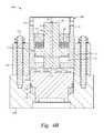
- FIG. 4A , FIG. 4B , and FIG. 4Cillustrate an installation process for the screw gland, according to one embodiment disclosed herein.
- Embodiments of this disclosureinclude a screw gland having a piston that is energized by a biasing member, such as a spring, to compress a seal within a fluid end.
- the screw glandhas a threaded body that can be attached directly into a module of the fluid end or by utilizing an additional threaded adapter ring.
- a pressurized fluidacts on the piston to compress the biasing member, when the screw gland is threaded into the module of the fluid end module or the adapter ring.
- the pressurized fluidis then released so that the piston, energized by the biasing member, applies a constant force onto a plug, which compresses the seal that is disposed within the module of the fluid end.
- the screw glandallows access into the module of the fluid end but also maintains the seal within the fluid end to prevent leaks during operation.
- FIG. 1illustrates a screw gland 100 for use with a fluid end of a multiplex reciprocating pump.
- a multiplex reciprocating pump and a fluid endthat can be used with the embodiments disclosed herein are described in U.S. Patent Application Publication No. 2013/0263932, filed on Mar. 15, 2013, the contents of which are herein incorporated by reference in its entirety.
- the screw gland 100is described herein as a component of a fluid end, the screw gland 100 can be used with other types of equipment.
- FIG. 2A and FIG. 2Billustrate a sectional view of the screw gland 100 in an un-actuated position.
- the screw gland 100includes a body 10 having threads 11 formed on an outer surface of the body 10 , and one or more openings 12 formed through the body 10 .
- the screw gland 100can be threaded via the threads 11 directly into a module of a fluid end or directly into a threaded adapter ring to retain a plug and a seal within a bore of the module, as further illustrated in FIG. 4A-4C .
- a toolsuch as a cheater bar, a tommy bar, or a C-spanner, can be inserted through one or more of the openings 12 to help rotate the screw gland 100 into a thread engagement.
- the screw gland 100further includes a piston 20 that is retained within a bore of the body 10 by a piston retainer 30 .
- the body 10acts as a piston housing for the piston 20 .
- the piston retainer 30is threaded into engagement with threads 31 formed on the inner surface of the body 10 .
- One or more seals 32are disposed between the piston retainer 30 and a retainer end 21 of the piston 20 that at least partially extends through the piston retainer 30 .
- the piston 20may include the retainer end 21 , a middle portion 22 , and a plug end 23 .
- the retainer end 21at least partially extends through a bore of the piston retainer 30 .
- the middle portion 22has an outer diameter that is greater than an outer diameter of the retainer end 21 , and is located below the piston retainer 30 within the body 10 .
- the plug end 23at least partially extends through a bore in an end of the body 10 , or through a bore in an additional piston retainer that is coupled to the end of the body 10 .
- a chamber 25is formed between the middle portion 22 of the piston 20 and the end of the body 10 .
- One or more seals 26are disposed between the outer surface of the middle portion 22 of the piston 20 and the inner surface of the body 10 .
- One or more seals 27are disposed between the outer surface of the plug end 23 of the piston 20 and the inner surface of the body 10 .
- the chamber 25is sealed by the seals 26 , 27 .
- a second piston retainermay be threaded into engagement with the end of the body 10 (below the middle portion 22 of the piston 20 ) to retain the piston 20 within the body 10 from below.
- a fluid path 24is formed through the piston 20 to supply fluid into the chamber 25 to pressurize the chamber 25 .
- a pressure fittingmay be coupled to the retainer end 21 of the piston 20 to supply pressurized fluid into the fluid path 24 and the chamber 25 .
- the piston 20is forced to at least partially retract into the body 10 against a bias force of one or more biasing members 40 , such as springs, that are disposed between the piston retainer 30 and the middle portion 22 of the piston 20 .
- the chamber 25is pressurized to a pressure sufficient to generate a force on the piston 20 that is greater than the bias force of the biasing member 40 , the piston 20 is at least partially retracted into the body 10 to compress the biasing member 40 .
- the biasing member 40may be any device that stores energy and is able to force the piston 40 to at least partially extend out of the body 10 when the energy is released.
- the biasing member 40may be a mechanical device, such as a spring, and/or a compressible fluid, such as a gas.
- FIG. 3A and FIG. 3Billustrate a sectional view of the screw gland 100 in an actuated position.
- a pressurized fluid(identified by reference arrow “F”) is supplied into the chamber 25 via fluid path 24 at a pressure sufficient to generate a force on the piston 20 that is greater than the bias force of the biasing member 40 .
- the seals 26 , 27seal the pressurized fluid within the chamber 25 .
- the piston 20is at least partially retracted into the body 10 relative to the piston retainer 30 .
- the retainer end 21 of the piston 20moves through the bore of the piston retainer 30 .
- the biasing member 40is compressed between the piston retainer 30 and the middle portion 22 of the piston 20 .
- the plug end 23 of the piston 20may at least partially extend out of and beyond the end of the body 10 .
- the plug end 23 of the piston 20may be recessed or flush with the end of the body 10 .
- FIG. 4A , FIG. 4B , and FIG. 4Cillustrate a process for installing the screw gland 100 of a fluid end 200 , according to one embodiment.
- the fluid end 200includes a threaded adapter ring 210 that is coupled to a module 220 by one or more bolts 225 .
- the screw gland 100may be threaded directly into the threaded adapter ring 210 , or alternatively directly into the module 220 without the need for the threaded adapter ring 210 .
- the threaded adapter ring 210 and/or the module 220may include a body having one or more internal bores.
- the body of the module 220may be formed by a forged and/or cast metallic and/or ceramic material.
- the screw gland 100retains a plug 230 and a seal 235 within the module 220 .
- the seal 235is compressed by the plug 230 via the screw gland 100 to hold internal pressure within the module 220 when pressurized and to prevent fluid from leaking out across the seal 235 through the end of the module 220 .
- the screw gland 100 , the plug 230 , and the seal 235can all be removed to provide access to additional components (e.g. valves, pistons, liners, seals, etc.), such as component 236 , disposed within the module 220 .
- the plug 230may be coupled to or integrally formed with the piston 20 of the screw gland 100 .
- the body 10 of the screw gland 100can be threaded into a threaded bore of the threaded adapter ring 210 .
- the screw gland 100is threaded via threads 11 into the threaded adapter ring 210 at least partially and/or until the plug end 23 of the piston 20 contacts the plug 230 as illustrated in FIG. 4A .
- the screw gland 100may be threaded into the threaded adapter ring 210 such that the plug end 23 of the piston 20 applies a force onto the plug 230 to compress the seal 235 and retain these components with the module 220 .
- the piston retainer 30is moved with the body 10 as the body 10 is threaded into the threaded adapter ring 210 .
- the piston retainer 30retains the biasing member 40 , which forces the piston 20 to at least partially extend out of the body 10 against the plug 230 .
- the biasing member 40may begin to be compressed between the piston retainer 30 and the middle portion 22 of the piston 20 as the body 10 is further threaded into the threaded adapter ring 210 .
- the screw gland 100may only be hand tightened to a point where an additional force is needed to fully compress the biasing member 40 .
- the screw gland 100may only be partially threaded into the threaded adapter ring 210 to a position where the plug end 23 of the piston 20 does not contact the plug 230 prior to pressurizing the screw gland 100 as further described below.
- a pressurized fluid(identified by reference arrow “F”) is supplied into the chamber 25 via the fluid path 24 .
- the pressurized fluidforces the piston 20 to at least partially retract into the body 10 against the bias force of the biasing member 40 to compress the biasing member 40 .
- the pressurized fluidis supplied at a pressure sufficient to generate a force on the piston 20 that compresses the biasing member 40 between the middle portion 22 of the piston 20 and the piston retainer 30 .
- a gapis formed between the plug end 23 of the piston 20 and the plug 230 .
- the body 10is further threaded into the threaded adapter ring 210 (such as by hand tightening or by using additional tooling such as a tommy bar or C-spanner) until the plug end 23 of the piston 20 contacts the plug 230 .
- the pressurized fluidcan be released from the chamber 25 and/or the pressure within the chamber 25 can be reduced so that the biasing member 40 creates a retention force on the piston 20 that forces the piston 20 to at least partially extend out of the body 10 against the plug 230 to compress the seal 235 to form a seal with the module 220 .
- the plug 230 and the seal 235are held within the module 220 by the force produced by the biasing member 40 acting on the piston 20 against the plug 230 .
- the threaded engagement of the body 10 in the threaded adapter ring 210provides a back-up retention mechanism in the event of a failure of the piston 20 , the piston retainer 30 , and/or the biasing member 40 .
- pressurized fluidmay be supplied to the chamber 25 to force the piston 20 to compress the biasing member 40 , e.g. the screw gland 100 may be moved into the actuated position, before the screw gland 100 is threaded into the threaded adapter ring 210 or directly into the module 220 .
- the screw gland 100(when in the actuated position as illustrated in FIG. 3A and FIG. 3B ) can then be threaded into the threaded adapter ring 210 until the plug end 23 of the piston 20 contacts the plug 230 or until the piston 20 is close to but not yet contacting the plug 230 .
- the pressurized fluidcan be released from the chamber 25 and/or the pressure within the chamber 25 can be reduced so that the biasing member 40 creates a retention force on the piston 20 that forces the piston 20 to at least partially extend out of the body 10 against the plug 230 to compress the seal 235 to form a seal with the module 220 .
- Pressurized fluidmay be supplied into the chamber 25 to force the piston 20 to at least partially retract into the body 10 , and then the body 10 can be unscrewed manually (by hand and/or by using additional tooling such as a tommy bar or C-spanner) from the threaded adapter ring 210 .
- the pressurized fluidcan be released from the chamber 25 before the body 10 is completely unthreaded from the threaded adapter ring 210 .
- the body 10can be unscrewed with or without supplying pressurized fluid into the chamber 25 .
- screw gland 100is an increase in worker safety by eliminating the need for heavy (sledge) hammers during installation and removal. Another advantage of the screw gland 100 is a reduction of the installation and removal time by utilizing a bias member force rather than a manual force. Another advantage of the screw gland 100 is that in the event of a failure of the piston 20 , the piston retainer 30 , and/or the biasing member 40 , the screw gland 100 still has the original functionality of manual tightening by inserting a cheater bar, a tommy bar, or a C-spanner into the openings 12 and impacting with a heavy hammer. Another advantage is that the screw gland 100 can be used with existing fluid end designs simply by replacing prior OEM screw glands with the screw gland 100 described herein.
Landscapes
- Engineering & Computer Science (AREA)
- General Engineering & Computer Science (AREA)
- Mechanical Engineering (AREA)
- Chemical & Material Sciences (AREA)
- Combustion & Propulsion (AREA)
- Details Of Reciprocating Pumps (AREA)
- Braking Arrangements (AREA)
- Pistons, Piston Rings, And Cylinders (AREA)
Abstract
Description
Claims (11)
Priority Applications (2)
| Application Number | Priority Date | Filing Date | Title |
|---|---|---|---|
| US14/570,907US10041594B2 (en) | 2014-12-15 | 2014-12-15 | Energized screw gland |
| PCT/US2015/061793WO2016099799A2 (en) | 2014-12-15 | 2015-11-20 | Energized screw gland |
Applications Claiming Priority (1)
| Application Number | Priority Date | Filing Date | Title |
|---|---|---|---|
| US14/570,907US10041594B2 (en) | 2014-12-15 | 2014-12-15 | Energized screw gland |
Publications (2)
| Publication Number | Publication Date |
|---|---|
| US20160169385A1 US20160169385A1 (en) | 2016-06-16 |
| US10041594B2true US10041594B2 (en) | 2018-08-07 |
Family
ID=55085883
Family Applications (1)
| Application Number | Title | Priority Date | Filing Date |
|---|---|---|---|
| US14/570,907Expired - Fee RelatedUS10041594B2 (en) | 2014-12-15 | 2014-12-15 | Energized screw gland |
Country Status (2)
| Country | Link |
|---|---|
| US (1) | US10041594B2 (en) |
| WO (1) | WO2016099799A2 (en) |
Cited By (3)
| Publication number | Priority date | Publication date | Assignee | Title |
|---|---|---|---|---|
| US20190127968A1 (en)* | 2017-11-01 | 2019-05-02 | Cetres Holdings, Llc | Hydraulic expandable connector |
| US20200080660A1 (en)* | 2018-09-11 | 2020-03-12 | Gardner Denver Petroleum Pumps, Llc | Hydraulic fluid pump and retainer assembly for same |
| US12442176B2 (en) | 2023-04-19 | 2025-10-14 | Cetres Holdings, Llc | Hydraulic expandable connector |
Families Citing this family (6)
| Publication number | Priority date | Publication date | Assignee | Title |
|---|---|---|---|---|
| US9995300B2 (en) | 2015-12-02 | 2018-06-12 | Forum Us, Inc. | Cartridge retention system |
| US10252405B2 (en) | 2016-05-19 | 2019-04-09 | Forum Us, Inc. | Bolt tensioning system |
| US11131295B2 (en) | 2019-03-11 | 2021-09-28 | Gardner Denver Petroleum Pumps, Llc | Hydraulic fluid pump and retainer assembly for same |
| US11384858B2 (en) | 2020-02-28 | 2022-07-12 | Forum Us, Inc. | Locking assembly apparatus and methods for fluid ends |
| CA3174954A1 (en)* | 2020-04-14 | 2021-10-21 | Justin Lane POEHLS | Modular suction gland assembly |
| US20230151914A1 (en)* | 2021-11-15 | 2023-05-18 | Spm Oil & Gas Inc. | Tensioner and method of using same |
Citations (39)
| Publication number | Priority date | Publication date | Assignee | Title |
|---|---|---|---|---|
| US3841193A (en)* | 1972-06-02 | 1974-10-15 | Tokyo Shibaura Electric Co | Fastening device |
| US3870439A (en) | 1973-01-08 | 1975-03-11 | American Aero Ind | High pressure pump fluid end |
| US3926090A (en)* | 1973-03-23 | 1975-12-16 | Hi Shear Corp | Separation nut |
| DE2512780A1 (en) | 1975-03-22 | 1976-10-07 | Hans Werner Dipl Ing Loeckmann | Hydraulic pressure amplifier with internal pressure relief - between pressure chamber and work space |
| US3986584A (en)* | 1975-03-20 | 1976-10-19 | Westinghouse Air Brake Company | Fail-safe disc brake with spring actuated slack adjuster |
| US4087074A (en)* | 1976-11-26 | 1978-05-02 | The Parker & Harper Mfg. Co., Inc. | Spring return valve actuator |
| US4277229A (en) | 1977-11-21 | 1981-07-07 | Partek Corporation Of Houston | High pressure fluid delivery system |
| DE3047674A1 (en) | 1980-12-18 | 1982-07-15 | Hohmann, Hans, 5778 Meschede | Hydraulic nut-tightening resetting device - has springs in cover bores pressing piston against cylinder shoulder keeping stretching bushing rotatable |
| US4516477A (en)* | 1982-09-24 | 1985-05-14 | Lewis Edwin C | Closure for openings in pumps |
| FR2560336A1 (en) | 1984-02-29 | 1985-08-30 | Poclain Sa | System for compensating for wear on a sealing gasket |
| US4569506A (en) | 1984-02-08 | 1986-02-11 | Automation Industries, Inc. | Self-contained stud tensioner and tightener device |
| EP0222625A1 (en) | 1985-11-04 | 1987-05-20 | Framatome | Tensioning device for screwing and unscrewing bolts or studs |
| US4723352A (en) | 1985-06-25 | 1988-02-09 | Conn-Weld Industries, Inc. | Method of applying and removing fluid actuated nut |
| US4725176A (en) | 1985-06-25 | 1988-02-16 | Conn-Weld Industries, Inc. | Fluid actuated nut |
| US4729158A (en) | 1986-05-05 | 1988-03-08 | Williams Donald L | Tool for aiding the assembly of drill stabilizer to the drill collar when up the bottom hole assembly |
| GB2285489A (en) | 1993-12-11 | 1995-07-12 | Kennedy T M & Company Ltd | Aligning and securing cylinder liners of reciprocating pumps |
| GB2295433A (en) | 1994-11-24 | 1996-05-29 | Hydra Tight Ltd | Hydraulic bolt or stud tensioning apparatus |
| US5904071A (en) | 1996-01-24 | 1999-05-18 | T M Kennedy & Company Limited | Piston rod assembly |
| WO2000014406A2 (en) | 1998-09-03 | 2000-03-16 | Southwest Oilfield Products, Inc. | Liner retainer assembly |
| WO2004106743A1 (en) | 2003-05-29 | 2004-12-09 | Spicket Valves And Pumps Limited | Liner retention system |
| EP1526281A2 (en) | 2003-10-23 | 2005-04-27 | National-Oilwell, L.P. | Assembly and method for attaching a liner to a pump module |
| US6929287B2 (en) | 2000-12-20 | 2005-08-16 | P-Quip Limited | Apparatus for connecting flanged pipes |
| DE202006004050U1 (en) | 2005-03-21 | 2006-06-01 | Metso Paper, Inc. | Hydraulic retaining unit for use with long tension unit, has part movable proportional to another part and including adjusting unit for adjusting its movement with respect to latter part |
| US7234388B2 (en) | 2004-04-13 | 2007-06-26 | Helmerich & Payne, Inc. | Liner retention system |
| US20070166121A1 (en)* | 2006-01-13 | 2007-07-19 | Oceaneering International, Inc. | Self locking tensioner |
| US7367789B2 (en)* | 2003-10-01 | 2008-05-06 | Flow International Corporation | Device for maintaining a static seal of a high pressure pump |
| US7658131B1 (en) | 2008-04-23 | 2010-02-09 | Titan Technologies International, Inc. | Subsea tensioner system |
| US7757366B2 (en) | 2002-08-19 | 2010-07-20 | Marine Direct Consultants Ltd. | Coupling for connecting tubes with a nut-runner |
| US20120063936A1 (en) | 2010-09-10 | 2012-03-15 | Phoinix Global LLC | Modular fluid end for a multiplex plunger pump |
| US20120180280A1 (en) | 2011-01-16 | 2012-07-19 | Michael James Psimas | Hydraulically Activated Tension Relief System for Threaded Fasteners |
| US8616590B2 (en) | 2010-02-04 | 2013-12-31 | Weatherford/Lamb, Inc. | Hydraulic tensioning flange connector |
| EP2687320A2 (en) | 2012-07-18 | 2014-01-22 | Frank Hohmann | Tensioning device for extending a threaded bolt |
| US20140083541A1 (en) | 2012-09-24 | 2014-03-27 | Gardner Denver, Inc. | Fluid end of a high pressure pump having a groove adapted to receive a spring retainer of a suction valve |
| US20140245868A1 (en) | 2008-11-14 | 2014-09-04 | Wagner Vermögensverwaltungs-GmbH & Co. KG | Screw tensioning device |
| US20150101681A1 (en) | 2013-10-10 | 2015-04-16 | PSI Pressure Systems Corp. | High pressure fluid system |
| US9188146B1 (en) | 2010-08-05 | 2015-11-17 | Riverhawk Company | Hydraulic rod tensioning system |
| EP3069827A1 (en) | 2015-03-19 | 2016-09-21 | Hohmann, Jörg | Clamping device for stretching a threaded bolt |
| US20170107983A1 (en) | 2015-10-14 | 2017-04-20 | Forum Us, Inc | Valve cover and liner retainer for a fluid end of a pump |
| US20170334048A1 (en) | 2016-05-19 | 2017-11-23 | Forum Us, Inc. | Bolt tensioning system |
- 2014
- 2014-12-15USUS14/570,907patent/US10041594B2/ennot_activeExpired - Fee Related
- 2015
- 2015-11-20WOPCT/US2015/061793patent/WO2016099799A2/enactiveApplication Filing
Patent Citations (47)
| Publication number | Priority date | Publication date | Assignee | Title |
|---|---|---|---|---|
| US3841193A (en)* | 1972-06-02 | 1974-10-15 | Tokyo Shibaura Electric Co | Fastening device |
| US3870439A (en) | 1973-01-08 | 1975-03-11 | American Aero Ind | High pressure pump fluid end |
| US3926090A (en)* | 1973-03-23 | 1975-12-16 | Hi Shear Corp | Separation nut |
| US3986584A (en)* | 1975-03-20 | 1976-10-19 | Westinghouse Air Brake Company | Fail-safe disc brake with spring actuated slack adjuster |
| DE2512780A1 (en) | 1975-03-22 | 1976-10-07 | Hans Werner Dipl Ing Loeckmann | Hydraulic pressure amplifier with internal pressure relief - between pressure chamber and work space |
| US4087074A (en)* | 1976-11-26 | 1978-05-02 | The Parker & Harper Mfg. Co., Inc. | Spring return valve actuator |
| US4277229A (en) | 1977-11-21 | 1981-07-07 | Partek Corporation Of Houston | High pressure fluid delivery system |
| DE3047674A1 (en) | 1980-12-18 | 1982-07-15 | Hohmann, Hans, 5778 Meschede | Hydraulic nut-tightening resetting device - has springs in cover bores pressing piston against cylinder shoulder keeping stretching bushing rotatable |
| US4516477A (en)* | 1982-09-24 | 1985-05-14 | Lewis Edwin C | Closure for openings in pumps |
| US4569506A (en) | 1984-02-08 | 1986-02-11 | Automation Industries, Inc. | Self-contained stud tensioner and tightener device |
| FR2560336A1 (en) | 1984-02-29 | 1985-08-30 | Poclain Sa | System for compensating for wear on a sealing gasket |
| US4723352A (en) | 1985-06-25 | 1988-02-09 | Conn-Weld Industries, Inc. | Method of applying and removing fluid actuated nut |
| US4725176A (en) | 1985-06-25 | 1988-02-16 | Conn-Weld Industries, Inc. | Fluid actuated nut |
| EP0222625A1 (en) | 1985-11-04 | 1987-05-20 | Framatome | Tensioning device for screwing and unscrewing bolts or studs |
| US4729158A (en) | 1986-05-05 | 1988-03-08 | Williams Donald L | Tool for aiding the assembly of drill stabilizer to the drill collar when up the bottom hole assembly |
| GB2285489A (en) | 1993-12-11 | 1995-07-12 | Kennedy T M & Company Ltd | Aligning and securing cylinder liners of reciprocating pumps |
| US5572920A (en) | 1993-12-11 | 1996-11-12 | T. M. Kennedy & Company Limited | Cylinder liner securing apparatus |
| USRE37483E1 (en) | 1993-12-11 | 2001-12-25 | P-Quip Limited | Cylinder liner securing apparatus |
| GB2295433A (en) | 1994-11-24 | 1996-05-29 | Hydra Tight Ltd | Hydraulic bolt or stud tensioning apparatus |
| US5904071A (en) | 1996-01-24 | 1999-05-18 | T M Kennedy & Company Limited | Piston rod assembly |
| WO2000014406A2 (en) | 1998-09-03 | 2000-03-16 | Southwest Oilfield Products, Inc. | Liner retainer assembly |
| US6209445B1 (en)* | 1998-09-03 | 2001-04-03 | Southwest Oilfield Products, Inc. | Liner retainer assembly |
| US6929287B2 (en) | 2000-12-20 | 2005-08-16 | P-Quip Limited | Apparatus for connecting flanged pipes |
| US7757366B2 (en) | 2002-08-19 | 2010-07-20 | Marine Direct Consultants Ltd. | Coupling for connecting tubes with a nut-runner |
| WO2004106743A1 (en) | 2003-05-29 | 2004-12-09 | Spicket Valves And Pumps Limited | Liner retention system |
| US8186263B2 (en) | 2003-05-29 | 2012-05-29 | Spicket Valves & Pumps Ltd. | Liner retention system |
| US7748310B2 (en) | 2003-05-29 | 2010-07-06 | Spickey Valves and Pumps Limited | Liner retention system |
| US7367789B2 (en)* | 2003-10-01 | 2008-05-06 | Flow International Corporation | Device for maintaining a static seal of a high pressure pump |
| US7287460B2 (en) | 2003-10-23 | 2007-10-30 | National-Oilwell Varco, L.P. | Hydraulic retention system for reciprocating pump cylinder liner |
| EP1526281A2 (en) | 2003-10-23 | 2005-04-27 | National-Oilwell, L.P. | Assembly and method for attaching a liner to a pump module |
| US7234388B2 (en) | 2004-04-13 | 2007-06-26 | Helmerich & Payne, Inc. | Liner retention system |
| DE202006004050U1 (en) | 2005-03-21 | 2006-06-01 | Metso Paper, Inc. | Hydraulic retaining unit for use with long tension unit, has part movable proportional to another part and including adjusting unit for adjusting its movement with respect to latter part |
| US20070166121A1 (en)* | 2006-01-13 | 2007-07-19 | Oceaneering International, Inc. | Self locking tensioner |
| US7658131B1 (en) | 2008-04-23 | 2010-02-09 | Titan Technologies International, Inc. | Subsea tensioner system |
| US20140245868A1 (en) | 2008-11-14 | 2014-09-04 | Wagner Vermögensverwaltungs-GmbH & Co. KG | Screw tensioning device |
| US8616590B2 (en) | 2010-02-04 | 2013-12-31 | Weatherford/Lamb, Inc. | Hydraulic tensioning flange connector |
| US9188146B1 (en) | 2010-08-05 | 2015-11-17 | Riverhawk Company | Hydraulic rod tensioning system |
| US20120063936A1 (en) | 2010-09-10 | 2012-03-15 | Phoinix Global LLC | Modular fluid end for a multiplex plunger pump |
| US20130263932A1 (en) | 2010-09-10 | 2013-10-10 | Forum Us, Inc. | Modular fluid end for a multiplex plunger pump |
| US8465268B2 (en) | 2010-09-10 | 2013-06-18 | Phoinix Global LLC | Compression clamp for a modular fluid end for a multiplex plunger pump |
| US20120180280A1 (en) | 2011-01-16 | 2012-07-19 | Michael James Psimas | Hydraulically Activated Tension Relief System for Threaded Fasteners |
| EP2687320A2 (en) | 2012-07-18 | 2014-01-22 | Frank Hohmann | Tensioning device for extending a threaded bolt |
| US20140083541A1 (en) | 2012-09-24 | 2014-03-27 | Gardner Denver, Inc. | Fluid end of a high pressure pump having a groove adapted to receive a spring retainer of a suction valve |
| US20150101681A1 (en) | 2013-10-10 | 2015-04-16 | PSI Pressure Systems Corp. | High pressure fluid system |
| EP3069827A1 (en) | 2015-03-19 | 2016-09-21 | Hohmann, Jörg | Clamping device for stretching a threaded bolt |
| US20170107983A1 (en) | 2015-10-14 | 2017-04-20 | Forum Us, Inc | Valve cover and liner retainer for a fluid end of a pump |
| US20170334048A1 (en) | 2016-05-19 | 2017-11-23 | Forum Us, Inc. | Bolt tensioning system |
Non-Patent Citations (5)
| Title |
|---|
| Great Britain Combined Search and Examination Report dated Jul. 28, 2017, corresponding to GB1704150.0. |
| International Search Report and Written Opinion dated Apr. 7, 2017, corresponding to Application No. PCT/US2016/064805. |
| International Search Report and Written Opinion dated Dec. 19, 2016, corresponding to Application No. PCT/US2016/055951. |
| International Search Report and Written Opinion dated Jul. 25, 2016 for PCT Application No. PCT/US2015/061793. |
| International Search Report and Written Opinion dated Jun. 7, 2017, corresponding to Application No. PCT/US2017/021775. |
Cited By (7)
| Publication number | Priority date | Publication date | Assignee | Title |
|---|---|---|---|---|
| US20190127968A1 (en)* | 2017-11-01 | 2019-05-02 | Cetres Holdings, Llc | Hydraulic expandable connector |
| US11203863B2 (en)* | 2017-11-01 | 2021-12-21 | Cetres Holdings, Llc | Hydraulic expandable connector |
| US11643805B2 (en) | 2017-11-01 | 2023-05-09 | Cetres Holdings, Llc | Hydraulic expandable connector |
| US11643804B2 (en) | 2017-11-01 | 2023-05-09 | Cetres Holdings, Llc | Hydraulic expandable connector |
| US20200080660A1 (en)* | 2018-09-11 | 2020-03-12 | Gardner Denver Petroleum Pumps, Llc | Hydraulic fluid pump and retainer assembly for same |
| US11359739B2 (en)* | 2018-09-11 | 2022-06-14 | Gd Energy Products, Llc | Hydraulic fluid pump and retainer assembly for same |
| US12442176B2 (en) | 2023-04-19 | 2025-10-14 | Cetres Holdings, Llc | Hydraulic expandable connector |
Also Published As
| Publication number | Publication date |
|---|---|
| WO2016099799A2 (en) | 2016-06-23 |
| WO2016099799A3 (en) | 2016-09-09 |
| US20160169385A1 (en) | 2016-06-16 |
Similar Documents
| Publication | Publication Date | Title |
|---|---|---|
| US10041594B2 (en) | Energized screw gland | |
| US11421680B1 (en) | Packing bore wear sleeve retainer system | |
| US11674509B2 (en) | Long sleeve cartridge for a fluid end block | |
| CA2342779C (en) | Liner retainer assembly | |
| US8511218B2 (en) | Clamping device for cylinder sleeves and use thereof, and mud pump having a clamping | |
| US20170107983A1 (en) | Valve cover and liner retainer for a fluid end of a pump | |
| US8402880B2 (en) | Packing nut lock and access bore cover locking assembly | |
| US8550102B2 (en) | Easily replaceable valve assembly for a high pressure pump | |
| EP3458225B1 (en) | Bolt tensioning system | |
| US20160319626A1 (en) | Plunger packing nut with integral packing | |
| US7287460B2 (en) | Hydraulic retention system for reciprocating pump cylinder liner | |
| US8561523B2 (en) | Reciprocating pump having a piston assembly | |
| US6588318B2 (en) | Hydraulic retention system for reciprocating pump cylinder liner | |
| EP1669605A2 (en) | Assembly and method for preloading a cylinder liner and cylinder liner cartridge assembly | |
| US11149855B2 (en) | Compression seal for use on reciprocating pump | |
| US11149728B2 (en) | Pump plunger protective packaging | |
| US6502827B1 (en) | Sealing device and a method of repairing/replacing sealing devices | |
| US9995300B2 (en) | Cartridge retention system | |
| US20250155304A1 (en) | Safety device for fluid ends | |
| US20240271615A1 (en) | Power end rod assembly | |
| US20130069319A1 (en) | Remotely adjustable shaft seal |
Legal Events
| Date | Code | Title | Description |
|---|---|---|---|
| AS | Assignment | Owner name:FORUM US, INC., TEXAS Free format text:ASSIGNMENT OF ASSIGNORS INTEREST;ASSIGNORS:PATTERSON, STEPHEN;ANWER, SOHAIB;LEMAN, LOUIS;SIGNING DATES FROM 20141215 TO 20150203;REEL/FRAME:035189/0698 | |
| AS | Assignment | Owner name:WELLS FARGO BANK, NATIONAL ASSOCIATION, NORTH CAROLINA Free format text:SECURITY INTEREST;ASSIGNORS:FORUM ENERGY TECHNOLOGIES, INC.;FORUM CANADA ULC;REEL/FRAME:044635/0355 Effective date:20171030 Owner name:WELLS FARGO BANK, NATIONAL ASSOCIATION, NORTH CARO Free format text:SECURITY INTEREST;ASSIGNORS:FORUM ENERGY TECHNOLOGIES, INC.;FORUM CANADA ULC;REEL/FRAME:044635/0355 Effective date:20171030 | |
| AS | Assignment | Owner name:WELLS FARGO BANK, NATIONAL ASSOCIATION, NORTH CAROLINA Free format text:SECURITY INTEREST;ASSIGNORS:FORUM ENERGY TECHNOLOGIES, INC.;FORUM CANADA ULC;REEL/FRAME:044812/0161 Effective date:20171030 Owner name:WELLS FARGO BANK, NATIONAL ASSOCIATION, NORTH CARO Free format text:SECURITY INTEREST;ASSIGNORS:FORUM ENERGY TECHNOLOGIES, INC.;FORUM CANADA ULC;REEL/FRAME:044812/0161 Effective date:20171030 | |
| STCF | Information on status: patent grant | Free format text:PATENTED CASE | |
| AS | Assignment | Owner name:US BANK, NATIONAL ASSOCIATION, TEXAS Free format text:SECURITY INTEREST;ASSIGNORS:FORUM ENERGY TECHNOLOGIES, INC.;FORUM US, INC.;GLOBAL TUBING, LLC;REEL/FRAME:053399/0930 Effective date:20200804 | |
| FEPP | Fee payment procedure | Free format text:MAINTENANCE FEE REMINDER MAILED (ORIGINAL EVENT CODE: REM.); ENTITY STATUS OF PATENT OWNER: LARGE ENTITY | |
| LAPS | Lapse for failure to pay maintenance fees | Free format text:PATENT EXPIRED FOR FAILURE TO PAY MAINTENANCE FEES (ORIGINAL EVENT CODE: EXP.); ENTITY STATUS OF PATENT OWNER: LARGE ENTITY | |
| STCH | Information on status: patent discontinuation | Free format text:PATENT EXPIRED DUE TO NONPAYMENT OF MAINTENANCE FEES UNDER 37 CFR 1.362 | |
| FP | Lapsed due to failure to pay maintenance fee | Effective date:20220807 | |
| AS | Assignment | Owner name:VARIPERM ENERGY SERVICES PARTNERSHIP, CANADA Free format text:SECURITY INTEREST;ASSIGNORS:FORUM ENERGY TECHNOLOGIES, INC.;FORUM US, INC.;GLOBAL TUBING, LLC;AND OTHERS;REEL/FRAME:066565/0968 Effective date:20240104 | |
| AS | Assignment | Owner name:GLAS USA LLC, AS SUCESSOR AGENT AND ASSIGNEE, NEW JERSEY Free format text:ASSIGNMENT AND ASSUMPTION OF SECOND LIEN TERM LOAN INTELLECTUAL PROPERTY SECURITY AGREEMENTS;ASSIGNOR:VARIPERM ENERGY SERVICES PARTNERSHIP, AS RESIGNING COLLATERAL AGENT AND ASSIGNOR;REEL/FRAME:069067/0317 Effective date:20240923 | |
| AS | Assignment | Owner name:GLOBAL TUBING, LLC, TEXAS Free format text:RELEASE OF PATENT SECURITY AGREEMENT RECORDED AT REEL 053399/FRAME 0930;ASSIGNOR:U.S. BANK NATIONAL ASSOCIATION;REEL/FRAME:069318/0330 Effective date:20241108 Owner name:FORUM US, INC., TEXAS Free format text:RELEASE OF PATENT SECURITY AGREEMENT RECORDED AT REEL 053399/FRAME 0930;ASSIGNOR:U.S. BANK NATIONAL ASSOCIATION;REEL/FRAME:069318/0330 Effective date:20241108 Owner name:FORUM ENERGY TECHNOLOGIES, INC., TEXAS Free format text:RELEASE OF PATENT SECURITY AGREEMENT RECORDED AT REEL 053399/FRAME 0930;ASSIGNOR:U.S. BANK NATIONAL ASSOCIATION;REEL/FRAME:069318/0330 Effective date:20241108 | |
| AS | Assignment | Owner name:VARIPERM ENERGY SERVICES INC., TEXAS Free format text:RELEASE OF SECOND LIEN SECURITY INTEREST IN PATENTS RECORDED AT REEL 066565/FRAME 0968;ASSIGNOR:GLAS USA LLC;REEL/FRAME:069338/0131 Effective date:20241107 Owner name:GLOBAL TUBING, LLC, TEXAS Free format text:RELEASE OF SECOND LIEN SECURITY INTEREST IN PATENTS RECORDED AT REEL 066565/FRAME 0968;ASSIGNOR:GLAS USA LLC;REEL/FRAME:069338/0131 Effective date:20241107 Owner name:FORUM US, INC., TEXAS Free format text:RELEASE OF SECOND LIEN SECURITY INTEREST IN PATENTS RECORDED AT REEL 066565/FRAME 0968;ASSIGNOR:GLAS USA LLC;REEL/FRAME:069338/0131 Effective date:20241107 Owner name:FORUM ENERGY TECHNOLOGIES, INC., TEXAS Free format text:RELEASE OF SECOND LIEN SECURITY INTEREST IN PATENTS RECORDED AT REEL 066565/FRAME 0968;ASSIGNOR:GLAS USA LLC;REEL/FRAME:069338/0131 Effective date:20241107 |