US10041236B2 - Multi-function fixture for a lavatory system - Google Patents
Multi-function fixture for a lavatory systemDownload PDFInfo
- Publication number
- US10041236B2 US10041236B2US15/176,406US201615176406AUS10041236B2US 10041236 B2US10041236 B2US 10041236B2US 201615176406 AUS201615176406 AUS 201615176406AUS 10041236 B2US10041236 B2US 10041236B2
- Authority
- US
- United States
- Prior art keywords
- leg
- passage
- basin
- fixture
- air
- Prior art date
- Legal status (The legal status is an assumption and is not a legal conclusion. Google has not performed a legal analysis and makes no representation as to the accuracy of the status listed.)
- Active, expires
Links
Images


Classifications
- E—FIXED CONSTRUCTIONS
- E03—WATER SUPPLY; SEWERAGE
- E03C—DOMESTIC PLUMBING INSTALLATIONS FOR FRESH WATER OR WASTE WATER; SINKS
- E03C1/00—Domestic plumbing installations for fresh water or waste water; Sinks
- E03C1/12—Plumbing installations for waste water; Basins or fountains connected thereto; Sinks
- E03C1/18—Sinks, whether or not connected to the waste-pipe
- A—HUMAN NECESSITIES
- A47—FURNITURE; DOMESTIC ARTICLES OR APPLIANCES; COFFEE MILLS; SPICE MILLS; SUCTION CLEANERS IN GENERAL
- A47K—SANITARY EQUIPMENT NOT OTHERWISE PROVIDED FOR; TOILET ACCESSORIES
- A47K10/00—Body-drying implements; Toilet paper; Holders therefor
- A47K10/48—Drying by means of hot air
- A—HUMAN NECESSITIES
- A47—FURNITURE; DOMESTIC ARTICLES OR APPLIANCES; COFFEE MILLS; SPICE MILLS; SUCTION CLEANERS IN GENERAL
- A47K—SANITARY EQUIPMENT NOT OTHERWISE PROVIDED FOR; TOILET ACCESSORIES
- A47K5/00—Holders or dispensers for soap, toothpaste, or the like
- A47K5/06—Dispensers for soap
- A47K5/12—Dispensers for soap for liquid or pasty soap
- E—FIXED CONSTRUCTIONS
- E03—WATER SUPPLY; SEWERAGE
- E03C—DOMESTIC PLUMBING INSTALLATIONS FOR FRESH WATER OR WASTE WATER; SINKS
- E03C1/00—Domestic plumbing installations for fresh water or waste water; Sinks
- E03C1/02—Plumbing installations for fresh water
- E03C1/04—Water-basin installations specially adapted to wash-basins or baths
- E03C1/0404—Constructional or functional features of the spout
- E—FIXED CONSTRUCTIONS
- E03—WATER SUPPLY; SEWERAGE
- E03C—DOMESTIC PLUMBING INSTALLATIONS FOR FRESH WATER OR WASTE WATER; SINKS
- E03C1/00—Domestic plumbing installations for fresh water or waste water; Sinks
- E03C1/02—Plumbing installations for fresh water
- E03C1/05—Arrangements of devices on wash-basins, baths, sinks, or the like for remote control of taps
- E03C1/055—Electrical control devices, e.g. with push buttons, control panels or the like
- E03C1/057—Electrical control devices, e.g. with push buttons, control panels or the like touchless, i.e. using sensors
- A—HUMAN NECESSITIES
- A47—FURNITURE; DOMESTIC ARTICLES OR APPLIANCES; COFFEE MILLS; SPICE MILLS; SUCTION CLEANERS IN GENERAL
- A47K—SANITARY EQUIPMENT NOT OTHERWISE PROVIDED FOR; TOILET ACCESSORIES
- A47K5/00—Holders or dispensers for soap, toothpaste, or the like
- A47K5/06—Dispensers for soap
- A47K5/12—Dispensers for soap for liquid or pasty soap
- A47K2005/1218—Table mounted; Dispensers integrated with the mixing tap
- A—HUMAN NECESSITIES
- A47—FURNITURE; DOMESTIC ARTICLES OR APPLIANCES; COFFEE MILLS; SPICE MILLS; SUCTION CLEANERS IN GENERAL
- A47K—SANITARY EQUIPMENT NOT OTHERWISE PROVIDED FOR; TOILET ACCESSORIES
- A47K2210/00—Combinations of water taps, soap dispensers and hand dryers
Definitions
- the present inventionrelates in general to the field of lavatory systems. More particularly, the present invention relates to a lavatory system having a multi-function fixture. Specifically, a preferred embodiment of the present invention relates to a multi-function fixture for a lavatory system at which a user receives soap and water to wash hands and at which an air flow is provided to dry the hands after washing.
- washroomshave historically included separate soap dispensers, wash basins with faucets, and hand dryers or towel dispensers.
- Soap dispensersmay be located between wash stations or in a location convenient to several wash stations. When a user dispenses soap, excess soap may drip from the dispenser. If a user has previously placed hands under the faucet to first wet hands, then water also drips from the user's hands as soap is applied. If the soap dispenser is not located over the wash basin, the excess soap and/or water drips on the deck of the basin or on the floor depending on the location of the soap dispenser.
- the present inventionis directed to a fixture for a lavatory system that incorporates each of the dispensing features required to wash and dry a user's hands and that does not require additional space per user.
- a primary object of the inventionto provide a multi-function fixture that dispenses soap, water, and air to a user.
- a visual indicators to a userto direct the user to each dispensing region on the multi-function fixture to receive soap, water, and air as desired.
- a multi-function fixturemay be installed within the space of existing wash stations.
- Yet another object of the inventionis to provide an apparatus that has one or more of the characteristics discussed above but which is relatively simple to manufacture and assemble and maintain using a minimum of equipment.
- the lavatory fixtureincludes a first leg and a second leg, where a first end of each leg is configured to be mounted to an upper surface of a deck for the lavatory fixture.
- the legextends upward from the deck and forward toward the basin, such that a second end of each leg is located over the basin of the lavatory fixture.
- a connecting sectionextends between the second ends of each leg and is positioned over the basin of the lavatory fixture.
- the connecting sectionincludes outlets to dispense water, soap, and air to wash a user's hands.
- the fixturealso includes indicators located proximate to each of the outlets to provide an indication to the user as to the location of each outlet and/or to guide a user to the outlets during the hand washing process.
- a sensor located near each outletidentifies the presence of a user's hands near the outlet and dispenses water, soap, or air accordingly.
- a controller within the lavatory fixturereceives inputs from each sensor and activates the appropriate pump, fan, valve, and the like to deliver the desired product at the appropriate outlet. Further, the controller may provide interlocks to prevent, for example, the air and water from being dispensed at the same time.
- a lavatory systemcomprising a basin and a fixture.
- the basinincludes a first side, a second side opposite the first side, a third side extending between the first side and the second side, and a fourth side extending between the first side and the second side.
- the fixtureextends over the basin for dispensing soap, water and air.
- the fixtureincludes a first leg, a second leg spaced apart from the first leg, and a connecting section for connecting the first leg to the second leg.
- a first tubecarries the water through either the first passage or the second passage, and a second tube carries soap through either the first passage or the second passage.
- the connecting sectionincludes at least one first exit point for dispensing the water, at least one second exit point for dispensing the soap, and at least one third exit point for dispensing the air.
- the fixtureis a single casting
- the first legincludes a first base
- the second legincludes a second base
- each of the first and second basesare configured to attach to the basin.
- the lavatory systemmay include a first hole in the basin for receiving a portion of the first base, and a second hole in the basin for receiving a portion of the second base.
- the first passageis configured to maximize an area for air flow through the first leg and includes an inner wall separating the first passage from the connecting section.
- An air outletis proximate the inner wall, where the air outlet is the at least one third exit point and the inner wall equalizes the air flow within the first passage by pressure shock when the air flow hits the inner wall thereby bending the air flow generally 90° to point downwardly and exit the air outlet.
- a nozzlemay be located in the air outlet that is configured to straighten the air flow through the air outlet, and the nozzle may include a grid for preventing items from getting into the air outlet.
- the first passagemay include a boss located in the air flow and shaped to minimize air disturbance as the air flow travels over the boss.
- An aeratormay be mounted proximate the at least one first exit point, where the aerator is configured with an entrance for the first tube, and the entrance adds a swirling motion to the water.
- the connecting sectionincludes an upper surface and a lower surface, and the aerator is nearly flush with the lower surface of the connecting section.
- the lavatory systemmay include a translucent material for constructing at least a portion of the lower surface of the connecting section so that sensors can sense through the material.
- the lavatory systemmay also include a first indicator identifying the at least one first exit point, a second indicator identifying the at least one second exit point, and a third indicator identifying the at least one third exit point.
- a control circuitenables each of the first indicator, the second indicator, and the third indicator to indicate to a user where to put hands of the user.
- a drain channelmay extend longitudinally between the first side and the second side of the basin.
- a rear surface of the drain channelis defined in part by the third side of the basin, and a front surface of the drain channel abuts a lower edge of the fourth side, where the fourth side is sloped downward from a front of the basin toward a rear of the basin.
- a drain openingextends through a lower surface of the drain channel, and a drain cover is removably mounted to the drain opening.
- the drain coverdefines a surface displaced above and substantially covering the drain channel and extends between the first side and the second side of the basin.
- the drain coverfurther includes a plurality of bumpers located at intervals along both a front side and a rear side of the drain cover and, when the drain cover is inserted in the drain channel, the bumpers are positioned between the front side of the drain cover and the front surface of the drain channel and between the rear side of the drain cover and the rear surface of the drain channel.
- a fixture for a lavatory system having a deck and a basin in the deckis disclosed.
- the lavatory systemis configured to be mounted to a lavatory wall, and the fixture is operable to dispense soap, water, and air.
- the fixtureincludes a first leg, a second leg, and a connecting section.
- the first leghas a first end, a second end, and a first passage extending between the first end and the second end of the first leg.
- the first end of the first legis configured to be mounted to the deck, and the second end of the first leg is configured to be positioned over the basin.
- the second leghas a first end, a second end, and a second passage extending between the first end and the second end of the second leg.
- the first end of the second legis configured to be mounted to the deck, and the second end of the second leg is configured to be positioned over the basin.
- the connecting sectionextends between the first leg and the second leg and has a water outlet, a soap outlet and an air outlet.
- the fixtureincludes a first tube operable to carry the water through either the first leg or the second leg to the water outlet on the connecting section and a second tube operable to carry the soap through either the first leg or the second leg to the soap outlet on the connecting section.
- a duct to transmit the air to the air outlet on the connecting sectionis defined by either the first passage or the second passage.
- a lavatory fixture for a wash stationincludes a first and a second generally r-shaped leg.
- the first generally r-shaped legincludes a first end, a second end, and a first passage extending through the first leg.
- the first end of the first leghas a first mounting surface and an opening in communication with the first passage and extending through the first mounting surface.
- the second generally r-shaped leg, displaced from the first legincludes a first end, a second end, and a second passage extending through the second leg.
- the first end of the second leghas a second mounting surface and an opening in communication with the second passage and extending through the second mounting surface.
- the first and second mounting surfaceseach engage a surface to mount to the lavatory fixture.
- the fixturealso includes an outlet portion having a first end, a second end, and a plurality of outlets.
- the first end of the outlet portionis connected to the second end of the first leg, and the first end of the outlet portion has a third passage and an opening establishing fluid communication between the first passage and the third passage.
- the second end of the outlet portionis connected to the second end of the second leg, and the second end of the outlet portion has a fourth passage and an opening establishing fluid communication between the second passage and the fourth passage.
- a first outlet, selected from the plurality of outlets,is located proximate the first end of the outlet portion, is in communication with the third passage, and is further in communication with an air blower via the first and third passages to discharge air.
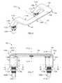
- FIG. 1is an isometric view of a lavatory system incorporating a multi-function fixture according to one embodiment of the present invention
- FIG. 2is front elevation view of the lavatory system of FIG. 1 ;
- FIG. 3is a top plan view of the lavatory system of FIG. 1 ;
- FIG. 4is a side elevation view of the lavatory system of FIG. 1 ;
- FIG. 5is a sectional view of the lavatory system of FIG. 3 taken at 5 - 5 ;
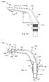
- FIG. 6is an isometric view of a multi-function fixture according to one embodiment of the invention.
- FIG. 7is a front elevation view of the multi-function fixture of FIG. 6 ;
- FIG. 8is a bottom plan view of the multi-function fixture of FIG. 6 ;
- FIG. 9is a right side elevation view of the multi-function fixture of FIG. 6 ;
- FIG. 10is a left side elevation view of the multi-function fixture of FIG. 6 ;
- FIG. 11is a sectional view of the multi-function fixture of FIG. 7 taken at 11 - 11 ;
- FIG. 12is a sectional view of the multi-function fixture of FIG. 7 taken at 12 - 12 ;
- FIG. 13is a sectional view of the multi-function fixture of FIG. 7 taken at 13 - 13 ;
- FIG. 14is a partial top view of the multi-function fixture of FIG. 6 with the upper surface removed;
- FIG. 15is a sectional view of one leg of the multi-function fixture of FIG. 7 taken at 15 - 15 ;
- FIG. 16is a sectional view of one leg of the multi-function fixture of FIG. 7 taken at 16 - 16 ;
- FIG. 17is a block diagram representation of the control system for the lavatory system of FIG. 1 ;
- FIG. 18is a partial isometric view of a drain for the lavatory system of FIG. 1 ;
- FIG. 19is a partial isometric view of one embodiment of a drain cover for the lavatory system of FIG. 1 ;
- FIG. 20is a top plan view of a drain for the lavatory system of FIG. 1 ;
- FIG. 21is a top plan view of the drain cover of FIG. 19 ;
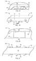
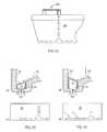
- FIG. 22is a sectional view of a basin, drain channel, and drain cover for the lavatory system according to another embodiment of the drain cover;
- FIG. 23is a sectional view of a basin, drain channel, and drain cover for the lavatory system according to another embodiment of the drain cover;
- FIG. 24is an isometric sectional view of a basin, drain channel, and drain cover for the lavatory system according to another embodiment of the drain channel;
- FIG. 25is a front sectional view of the basin, drain channel, and drain cover of FIG. 24 ;
- FIG. 26is a top sectional view of the basin and drain channel of FIG. 24 ;
- FIG. 27is a side sectional view of the basin, drain channel, and drain cover of FIG. 24 ;
- FIG. 28is an isometric sectional view of a basin, drain channel, and drain cover for the lavatory system according to another embodiment of the drain channel;
- FIG. 29is a front sectional view of the basin, drain channel, and drain cover of FIG. 28 ;
- FIG. 30is a top sectional view of the basin and drain channel of FIG. 28 ;
- FIG. 31is a side sectional view of the basin, drain channel, and drain cover of FIG. 28 ;
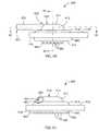
- FIG. 32is a partial flow diagram for air dispensed from the fixture according to one embodiment of the invention.
- FIG. 33 ais a partial flow diagram for air dispensed from the fixture across the drain cover of FIG. 22 ;
- FIG. 33 bis a partial flow diagram for air within the basin using the drain cover of FIG. 22 ;
- FIG. 34 ais a partial flow diagram for air dispensed from the fixture across the drain cover of FIG. 23 ;
- FIG. 34 bis a partial flow diagram for air within the basin using the drain cover of FIG. 23 ;
- FIG. 35is a partial flow diagram for air through an air return within the basin according to one embodiment of the invention.
- FIG. 36is a partial flow diagram for air through an air return within the basin according to another embodiment of the invention.
- FIG. 37is a flow diagram illustrating air recirculation from the fixture, within the basin, and back to the fan according to one embodiment of the invention.
- FIG. 38is an isometric view of one embodiment of an aerator for the fixture used in the lavatory system
- FIG. 39is a top plan view of the aerator of FIG. 38 ;
- FIG. 40is a first side elevation view of the aerator of FIG. 38 ;
- FIG. 41is a second side elevation view of the aerator of FIG. 38 ;
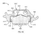
- FIG. 42is a sectional view of the aerator of FIG. 38 taken at 42 - 42 in FIG. 40 ;
- FIG. 43is a sectional view of the aerator of FIG. 38 taken at 43 - 43 in FIG. 40 .
- the lavatory system 10includes a deck 12 that is configured to be mounted to a wall. With reference also to FIG. 5 , wall mounts 21 are secured to the wall and the deck 12 is secured to the wall mounts 21 .
- the deck 12has an upper surface 14 and an outer periphery 16 extending downward from the upper surface 14 and around the deck 12 .
- a basin 20is located within the deck 12 . According to one embodiment of the invention, the deck 12 and the basin 20 may be integrally formed as a single unit. According to another embodiment of the invention, the basin 20 may be mounted to the deck 12 .
- the lavatory system 10may be free-standing, supported by the floor rather than being wall mounted. Rather, than including a wall mount 21 , a support frame (not shown) may extend up from the floor, or other surface, on which the lavatory system 10 is installed.
- the basin 20is a recessed area below the upper surface 14 of the deck 12 and is configured to receive products dispensed into the lavatory system.
- the basin 20includes a first side 22 (see also FIG. 3 ) and a second side 24 , where the second side 24 is opposite the first side.
- Each of the first and second sides 22 , 24extend generally orthogonal to and away from the wall on which the lavatory system 10 is mounted.
- the basin 20also includes a third side 26 extending downward from an upper edge which joins the upper surface 14 of the deck 12 along the rear of the basin and further extends between the first side 22 and the second side 24 .
- the third side 26extends downward and the lower end of the third side forms, in part, a drain channel 62 in the bottom of the basin 20 .
- the basin 20further includes a fourth side 28 extending downward from an upper edge which joins the upper surface 14 of the deck 12 along the front of the basin and also extends between the first side 22 and the second side 24 .
- the fourth side 28 of the basin 20is sloped inward and downward from the front edge of the basin to a front edge of the drain channel 62 .
- the lavatory system 10includes a housing 40 located below the deck 12 and extending around the lower portion of the lavatory system 10 .
- the housing 40includes a first side 42 and a second side 44 , where the second side is opposite the first side.
- a rear edge of each of the first side 42 and the second side 44abuts the wall to which the lavatory system 10 is mounted.
- Each of the first side 42 and the second side 44extend forward, generally orthogonal to the wall.
- a front surface 46 of the housingextends downward and to the rear from a lower surface 15 of the deck 12 .
- the front surface 46extends the height of each of the first and second sides 42 , 44 .
- each of the first side 42 , second side 44 , and front surface 46extend to the floor.
- the each of the first side 42 , second side 44 , and front surface 46extend to some height above the floor.
- the front surface 46is sloped to the rear from where it abuts the lower surface 15 of the deck 12 .
- the housing 40may include a bottom surface (not shown) if the housing does not extend to the floor.
- the housingmay be open on the bottom as defined by the periphery of the first side 42 , second side 44 , front surface 46 and wall to which the lavatory system 10 is mounted.
- the housing 40encloses the components of the lavatory system 10 located below the deck to provide a measure of protection to the components and to provide an aesthetically pleasing appearance to the lavatory system 10 .
- the housing 40is described in detail with respect to the illustrated embodiment, it is understood that the housing 40 may take various shapes as would be understood to one skilled in the art without deviating from the scope of the invention.
- the lavatory system 10further includes a drain system 60 extending longitudinally across the width of the basin 20 .
- the drain system 60includes a drain channel 62 and a drain cap 70 .
- the drain channel 62is generally u-shaped.
- the drain channel 62has a rear wall 63 and a front wall 64 extending the width of the basin 20 .
- the rear wall 63 of the drain channel 62may be coplanar with the third side 26 of the basin 20 and form a continuous surface.
- the drain channel 62may be offset from the third side 26 of the basin, forming a channel in a lower surface (not shown) of the basin 20 .
- the drain channel 62includes a lower surface 65 which also extends the width of the basin between the rear wall 63 and the front wall 64 .
- An opening 66 in the lower surface 65 of the drain channel 62allows waste water to exist the basin 20 into a drainpipe 90 (as shown in FIG. 5 ).
- the periphery of the drain opening 66includes a pair of notches 68 , where a first notch 68 is located to the rear of the drain opening 66 and a second notch is located to the front of the drain opening 66 .
- Each notch 68is configured to receive a tab 76 from the drain cap 70 as will be discussed in more detail below.
- the drain cap 70is configured to be removably mounted within the drain system 60 .
- the drain cap 70includes a front surface 72 , a rear surface 74 , and a top surface 73 , where the top surface 73 spans between the front surface 72 and the rear surface 74 and each of the front, rear, and top surfaces extend the width of the drain channel 62 .
- Each of the front surface 72 and the rear surface 74have a tab 76 extending downward from the respective surface.
- the tab 76includes a first surface 77 , which is generally coplanar with and protrudes downward from the corresponding front or rear surface, and a second surface 78 , which is generally orthogonal to and protrudes outward from the first surface 77 .
- the drain cap 70 and the tabs 76are constructed of a sheet material, such as a stainless steel.
- the thickness of the sheet materialprovides sufficient rigidity that the drain cap 70 retains its desired shape if removed from the drain channel 62 .
- the width of each tab 76 and the thickness of the sheet material for the drain cap 70allows the tab 76 to deflect inward when a force is applied. Such a force may be applied, for example, when inserting the drain cap 70 into the drain channel.
- Each tab 76is deflected inward as the drain cap 70 is inserted into the drain channel and as each tab 76 is inserted through the notch 68 in the periphery of the drain opening 66 .
- the height of the first surface 77 of the tab 76is equal to or greater than a thickness of the lower surface 65 of the drain channel 62 .
- the material from which the tab 76 is madeis resilient such that it returns to its original position once the tabs 76 are fully through the opening 66 in the drain channel 62 .
- the second surface 78 of each tab 76extends under the lower surface 65 of the drain channel, positively retaining the drain cap 70 within the drain channel 62 .
- each of the front surface 72 and the rear surface 74 of the drain cap 70include a series of bumpers 75 affixed to the surface and spaced out along the length of the drain cap.
- the bumpers 75fit between the front surface 72 of the drain cap 70 and the front wall 64 of the drain channel 62 and between the rear surface 74 of the drain cap 70 and the rear wall 63 of the drain channel 62 .
- the bumpers 75define a press fit between the surfaces and help align the drain cap 70 within the drain channel 62 .
- the drain cap 70is preferably made from a metal material, such as stainless steel, and the basin 20 and drain channel 62 are preferably made from a synthetic resin material, stone material, or combination thereof, the bumpers 75 aid in preventing damage to the drain channel 62 from the drain cap 70 as the cap is inserted into or removed from the channel.
- the top surface 73 of the drain cap 70may be configured to help guide the direction of airflow dispensed from fixture 100 .
- the fixture 100is operative to dispense air flow into the basin 20 to dry a user's hands after washing.
- a direction of airflowis indicated by arrows in the figures. The air is dispensed downward from the fixture 100 where it first hits the fourth side 48 of the basin 20 which is sloped downward and to the rear of the basin 20 . The air flow generally follows the slope of the fourth side 48 toward the drain channel 62 .
- the drain cap 70may be configured to guide the direction of the airflow toward the corners of the basin 20 .
- the front surface 72 of the drain cap 70may be longer than the rear surface 74 .
- the top surface 73is sloped downward from the front wall 64 to the rear wall 63 of the drain channel 62 .
- a first angle, ⁇ , defined between the rear surface 74 and the top surface 73 of the drain cap 70is an obtuse angle.
- a second angle, ⁇ , defined between the front surface 72 and the top surface 73 of the drain cap 70is an acute angle. As shown in FIG.
- the drain cap 70may be configured such that the top surface 73 of the drain cap 70 is coplanar with the fourth side 28 of the basin 20 .
- the aircontinues to flow from the fourth side 28 of the basin along the top surface 73 of the drain cap 70 until it intersects with the third side 26 of the basin 20 .
- the airis then deflected both to the left and the right along the third side 26 of the basin and along the top surface 73 of the drain cap 70 toward the first and second sides 22 , 24 of the basin 20 .
- the drain cap 70may be configured to guide the direction of the airflow upward along the third side 26 of the basin 20 .
- the front surface 72 of the drain cap 70may be shorter than the rear surface 74 .
- the top surface 73is sloped upward from the front wall 64 to the rear wall 63 of the drain channel 62 .
- a first angle, ⁇ , defined between the rear surface 74 and the top surface 73 of the drain cap 70is an acute angle.
- a second angle, ⁇ , defined between the front surface 72 and the top surface 73 of the drain cap 70is an obtuse angle.
- the drain cap 70is configured such that the top surface 73 of the drain cap 70 angles upward at an angle similar to the downward angle of the fourth side 28 of the basin 20 .
- the aircontinues to flow from the fourth side 28 of the basin onto the top surface 73 of the drain cap 70 it is deflected upward.
- the airis further deflected both to the left and the right along the third side 26 of the basin.
- the air flowtravels along the third side 26 in a generally upward and outward manner, as illustrated in FIG. 34( b ) toward the first and second sides 22 , 24 of the basin 20 .
- FIGS. 24-27another embodiment of a drain system 60 is illustrated.
- the depth of the drain channel 62is increased.
- the front wall 64 and the rear wall 63are tapered inward toward the channel 62 , such that when the drain cap 70 is inserted into the channel 62 , the top surface 73 of the drain cap 70 aligns in the manner discussed above.
- a ridge or series of tabsmay be molded along the front and rear walls 64 , 63 on which the front and rear surfaces, 72 , 74 , respectively, of the drain cap may be supported.
- a drain plate 80is inserted into the drain channel 62 to divide the channel 62 into two chambers.
- An upper chamber 81is defined between the drain cap 70 and the drain plate 80
- a lower chamber 83is defined between the drain plate 80 and the lower surface 65 of the channel 62 .
- a series of supports 82are integrally formed in the rear and front walls 63 , 64 of the drain channel 62 to support the drain plate 80 .
- Each support 82extends from the lower surface 65 of the channel 62 and for a portion of the height of the channel 62 .
- Each supportprotrudes into the channel 62 from the rear and front walls 63 , 64 for a short distance, sufficient to support the drain plate 80 yet allowing water to flow along the channel 62 .
- the width of the drain plate 80is generally equal to the width of the channel at the top of the supports 82 , such that the drain plate 80 may be set into the channel and rest on each of the supports 82 .
- the drain plate 80further includes a series of openings 84 spaced longitudinally along the plate 80 to allow water to flow from the upper chamber 81 to the lower chamber 83 .
- each opening 84is located along on outer edge of the drain plate 80 and extends longitudinally along the drain plate 80 .
- the openings 84may be spaced at intervals alternately to the supports 82 , such that the water may flow from the upper chamber 81 through the openings, between adjacent supports 82 , and into the lower chamber 83 .
- the lower chamber 83is in fluid communication with the drain opening 66 .
- the drain opening 66is in fluid communication with the drain opening 66 .
- FIGS. 28-31another embodiment of the drain system 60 is illustrated.
- the drain system 60again includes two chambers to direct water to the drain opening 66 .
- a first chamber 81is defined by a drain channel 62 and drain cap 70 substantially the same as that discussed above with respect to FIGS. 18-22 .
- a second chamber 83is integrally formed within a lower surface of the basin 20 .
- a pipe 89is integrally molded along the rear portion of and below the basin 20 . It is contemplated that the pipe 89 is positioned below the drain channel 62 and overmolded such that it is integrally formed with the basin 20 .
- a second housing membermay be secured to the bottom of the basin 20 and along the length of the drain channel 62 . The second housing member may be configured to hold the pipe 89 below the drain channel 62 as discussed above.
- a series of openings 84are formed through the lower surface 65 of the drain channel 62 and into the pipe 89 .
- the openings 84may be formed, for example, by drilling holes through the lower surface 65 and into the pipe 89 .
- the openings 84establish fluid communication between the first chamber 81 and the second chamber 83 .
- the waterflows along the lower surface 65 of the first chamber 81 , a portion of the water falls through one of the openings 84 to the second chamber 83 .
- the portion of the water in the second chamber 83also flows toward the drain opening 66 .
- the waterreaches the drain opening 66 and flows out of the basin 20 to the drainpipe 90 .
- drain channel 62 and drain cap 70are described in detail with respect to the illustrated embodiments, it is understood that the drain channel 62 and drain cap 70 may take various shapes, where the drain cap 70 remains complementary to the drain channel 62 for insertion and removal, as would be understood to one skilled in the art without deviating from the scope of the invention.
- the basin 20may further be configured to recirculate at least a portion of the airflow dispensed from the fixture 100 .
- the basin 20may include a ridge 27 protruding over the basin 20 to collect a portion of the airflow.
- the ridgemay extend around the first side 22 , the second side 24 , or the third side 26 of the basin to capture air travelling up the side or rear of the basin 20 .
- a channel 29may be formed on the rear side of the basin 20 which directs the airflow back down the outside of the basin 20 under the deck 12 .
- the airflowmay be channeled to a return duct 33 which in turn provides air to the input of the fan 210 .
- a filter 354is included between the return duct 33 and the input to the fan 210 to remove water, soap, dirt, and other contaminants from the airflow prior to returning the air to the fan 210 .
- the basin 20may include an opening in the side.
- the openingmay include a series of louvers 31 to prevent water dispensed from the fixture 100 from entering the opening.
- the airflow travelling up the sidesmay enter the opening.
- a channel 29may be provided on the rear of the basin and the airflow directed back toward the fan 210 .
- the lavatory system 10also includes a multi-function fixture 100 located at each hand washing station for the lavatory system 10 .
- the lavatory system 10includes two wash stations. It is contemplated that the lavatory system 10 may be configured with a single wash station and have just one fixture 100 or, optionally, the lavatory system 10 may be configured with three or more wash stations, where each wash station has a separate fixture 100 . The width of the lavatory system will vary according to the number of wash stations present.
- the fixture 100includes a pair of legs 110 .
- a first leg 110 ais positioned to the right side of the fixture 100 and a second leg 110 a is positioned to the left side of the fixture 100 .
- the exterior of each leg 110 a , 110 bis mirrored about a center axis 101 of the fixture 100 .
- a single leg 110will be discussed in detail, where the discussion will be equally applicable to the right leg 110 a and the left leg 110 b.
- the leg 110has a first end 112 configured to be mounted to the deck 12 and a second end 114 extending over the basin 20 .
- a mounting surface 113 on the first end 112 of the leg 110engages the upper surface 14 of the deck 12 .
- the leg 110includes a generally rectangular cross-section where the cross-section decreases in size between the first end 112 and the second end 114 of the leg 110 .
- the leg 110slopes forward as it extends upward from the deck 12 . From a side-view, the leg 110 is generally r-shaped. The leg 110 extends upwards from the deck 12 and forwards toward the basin 20 . After extending for a height, H, a bend 115 in the leg causes the leg to protrude in a generally horizontal plane for a length, L, until the second end 114 of the leg is positioned over the basin 20 .
- each leg 110is configured to be mounted to the deck 12 .
- An opening 111extends through the mounting surface 113 and is in communication with a passage 120 within the leg 110 .
- a base 130is received within the opening 111 and secures the fixture 100 to the deck 12 .
- the base 130also includes a passage 139 extending therethrough which is in fluid communication with the passage 120 in the leg 110 .
- the base 130includes a first end 132 configured to be inserted into the leg 110 and a second end 134 configured to be inserted into an opening in the deck 12 .
- the opening 111 in the leg 110includes a threaded inner periphery that is complementary to a threaded outer periphery of the first end 132 of the base 130 .
- the base 130may, therefore, be rotatably inserted into the opening 111 such that the threads engage and positively retain the base 130 to the leg 110 .
- the base 130may alternately be secured to the leg 110 , for example, via a snap fit or other suitable securing method.
- the base 130is integrally molded with the leg 110 such that a portion of the leg 110 extends through the opening to secure the fixture 100 to the deck 12 .
- a second section 136 of the base 130is displaced longitudinally along the base 130 such that is configured to be located, at least in part, below the deck 12 .
- the second section 136includes a threaded outer surface to receive a nut 135 , and an upper surface 137 of the nut 135 is configured to engage the lower surface of the deck 12 .
- the base 130is affixed to each leg 110 and inserted through the opening in the deck 12 .
- the nut 135is threaded onto the base from below the deck such that the upper surface 137 of the nut 135 and the mounting surface 113 of the leg 110 engage opposite surfaces of the deck 12 and secure the fixture 100 to the deck 12 .
- a connecting section 140extends between the second ends 114 of each leg 110 .
- the connecting section 140has a first end 142 connected to the second end 114 a of the first leg 110 a and a second end 144 connected to the second end 114 b of the second leg 110 b .
- the cross-section of the first end 142 of the connecting section 140is the same as the cross-section of the second end 114 a of the first leg 110 a and the cross-section of the second end 144 of the connecting section 140 is the same as the cross-section of the second end 114 b of the second leg 110 b . Consequently, the fixture 100 appears as a continuous unit as it transitions between each leg 110 and the connecting section 140 .
- first leg 110 amay be cast, or otherwise manufactured, as a single unit.
- the locations of the endsare for illustrative purposes and may be moved axially along the leg or along the connecting section 140 without deviating from the scope of the invention.
- the connecting section 140includes multiple outlets for dispensing product over the basin 20 of the lavatory system 10 .
- a first outlet 160is operable to dispense soap
- a second outlet 180is operable to dispense water
- a third outlet 200is operable to dispense air.
- the outlets 160 , 180 , 200are spaced apart along the connecting section 140 such that a user's hands move along the connecting section 140 between outlets during the washing process.
- Each leg 110includes a passage 120 defined within the interior of the leg for delivery of a product to one of the outlets.
- the soap and watermay be delivered via tubes extending from below the deck 12 up through the passage 120 in one of the legs 110 the respective outlet.
- the passage 120 within one of the legs 110is configured as an air duct to, at least in part, convey air from a blower located below the deck 12 to the air outlet.
- exemplary sectional views of the passage 120 in each legare illustrated.
- the passage 120 b in the second leg 110 bhas a maximum sectional area to provide room for the tube 162 carrying soap and the tube 182 carrying water to be run through the passage 120 b .
- the passage 120 a in the first leg 110 ahas a sectional area closely corresponding to the passage 139 in the base 130 a .
- the turbulence of the air flowis reduced as the air passes from the base 130 a into the leg 110 a .
- the passage 120 a of the leg 110then forms a duct through which the air is conveyed to the air outlet 200 .
- the connecting section 140may also include indicators to a user identifying the location of each outlet.
- openings 103are located along the front edge of the connecting section 140 through which an indicator may be displayed.
- a multi-color light-emitting diode (LED) 305or red-green-blue LED array, (see also FIG. 17 ) is located behind each opening 103 .
- each openingmay have a lens or be a translucent material rather than an opening to prevent soap, water, dirt, or other contaminants from entering the fixture 100 .
- the LED 305may emit different colors according to operation or flash to direct a user's attention to the location.
- larger displaysutilizing, for example, a liquid crystal display (LCD) may provide a graphical or other visual indication to the user of the purpose of each outlet located by the indicator.
- LCDliquid crystal display
- the system for dispensing soapincludes a soap reservoir, pump, and tubing to connect the pump to the soap outlet 160 .
- the soap reservoir 310 and soap pump 316are represented in block diagram form in FIG. 17 .
- the soap reservoir 310may include a level detection switch 312 , such as a float switch, which generates a level detection signal 314 , provided to a control circuit 302 , corresponding to the amount of soap remaining in the reservoir 310 .
- the pump 316is activated by one or more sensors 301 located in the fixture 100 detecting the presence of a user's hands by the soap outlet 160 .
- the pump 316draws soap from the reservoir 310 and into a tube 162 connected between the pump 316 and the soap outlet 160 .
- the tubeis run inside the passage 120 in either the first leg 110 a or the second leg 110 b and into the connecting section 140 of the fixture.
- the tube 162is fit onto a nozzle 164 which extends through the outlet 160 .
- the soapis discharged from the nozzle 164 through the outlet 160 onto a user's hands.
- the system for dispensing waterincludes one or more inlet lines 322 , connected to a water supply, one or more valves 320 , and one or more outlet lines 324 to supply water to the water outlet 180 .
- the inlet line 322may be connected to a cold water supply, a hot water supply, or to a mixed water supply, where the mixed water supply includes a combination of hot and cold water. It is desirable to provide water at a comfortable temperature to the user. Therefore, a mixing valve may be provided in advance of the inlet line 322 that combines cold and hot water proportionally to supply water at a desired temperature.
- the valve 320may be a mixing valve which includes a first inlet line 322 from the cold water supply and a second inlet line 322 from a hot water supply.
- a signal 326 from the control circuit 302may control the valve 320 not only in an on/off manner, but also in a proportional manner to mix the cold and hot water to supply water at a desired temperature.
- the outlet line 324 from the valve 320is connected via a second tube 182 to the water outlet 180 .
- An aerator 400may be provided within the water outlet 180 includes a water inlet 402 to which the outlet line 324 from the valve 320 is connected.
- the aerator 400includes an upper housing 410 and a lower housing 450 .
- the upper housing 410is integrally formed with a removable plate 190 that may be inserted into and removed from an opening on the lower surface of the connecting section 140 of the fixture.
- the upper housing 410includes two generally cylindrical chambers.
- a first, intake chamber 420is formed in the upper portion of the upper housing 410 .
- a first wall segment 412 of the upper housing 410extends downward from an upper surface 411 of the upper housing 410 .
- the first wall segment 412may join the upper surface 411 at a generally curved edge that extends around the periphery of the upper housing 410 .
- the intake chamber 420has a first diameter defined by the inner periphery of the first wall segment 412 .
- a second, outlet chamber 430is formed in the lower portion of the upper housing 410 .
- a second wall segment 414extends downward from the first wall segment 412 to a lower edge 416 of the upper housing 410 .
- the second wall segment 414has a diameter greater than the diameter of the first wall segment 412 , and a generally curved edge joins the first and second wall segments 412 , 414 .
- the lower surface of the upper housing 410is generally open and the lower edge 416 defines a generally circular opening into which the lower housing 450 may be inserted.
- the inner surface 415 of the second wall segment 414is threaded and is configured to receive a complementary thread on the outer periphery 460 of the lower housing 450 .
- the lower housing 450may be secured to the upper housing 410 by other methods, including, for example, by a snap fit, cam lock, pin, screw, or other suitable retainer.
- the water inlet 402extends outward from the first wall segment 412 and defines a fluid communication path between the second tube 182 , through which the water flows, and the intake chamber 420 .
- the water inlet 402is generally cylindrical and includes a passage 404 extending axially through the inlet 402 .
- the second tube 182may be press fit onto a first end 401 of the water inlet 402 and the second end 403 of the water inlet 402 is integrally formed with the first wall segment 412 .
- the second end 403 of the water inlet 402joins one side of the upper housing 410 .
- Water flowing through the second tube 182enters the passage 404 and exits along the inner periphery of the first wall segment 412 .
- the wateris supplied at a sufficient pressure such that the water follows the inner periphery of the first wall segment 412 swirling around the interior of the intake chamber 420 .
- the lower housing 450is a generally cylindrical disk configured to be inserted into the upper housing 410 .
- the outer periphery 460 of the lower housing 450is threaded such that the lower housing 450 may rotatably engage the complementary threaded inner surface 415 of the upper housing 410 .
- the diskincludes an upper surface 462 and a lower surface 464 , opposite the upper surface.
- a plurality of passages 470extend between the upper surface 462 and the lower surface 464 .
- the upper surface 462is sloped upward from an outer edge to the center of the upper surface 462 , forming a generally conical surface. Multiple nozzles 480 protrude downward from the lower surface 464 .
- One of the passages 470extends through each nozzle 480 , and the nozzles 480 define the water outlet 180 for the fixture 100 . Because the water enters the intake chamber 420 along the inner periphery and swirls around the chamber, the water more uniformly fills the chamber than if the water entered the chamber at a central location and hit the opposing surface of the chamber. The water then exits the intake chamber 420 through each of the nozzles 480 with a generally uniform pressure and flow.
- the aerator 400may be formed utilizing other members without deviating from the scope of the invention.
- the aerator 400may be formed as a single housing with the upper housing 410 and lower housings 450 integrally formed and either fixedly or removably mounted within the connecting section 140 of the fixture 100 .
- the system for dispensing airincludes a fan 210 located below the deck 12 operable to deliver air to the air outlet 200 .
- the fan 210includes a centrifugal fan driven by a motor. The motor may be operated at variable speeds to adjust the airflow rate supplied by the fan.
- the fan 210draws air in through an air inlet located within the housing 40 under the deck 12 .
- a filter 354may be provided at the inlet to capture contaminants present in the air prior to air entering the air inlet for the fan 210 .
- an air duct 215connects an outlet of the fan 210 to the passage 139 in the base 130 , which is, in turn, connected to a passage 120 within the leg 110 of the fixture 100 .
- the passage 120serves as a continuation of the air duct 215 between the fan 210 and the air outlet 200 .
- the surface of the passage 120is preferably smooth to minimize turbulence of the air flow through the passage.
- a boss 122may be provided between opposing surfaces of the passage 120 to provide improved rigidity of the fixture 100 .
- the boss 122includes a front end 123 , indicating it receives the air flow first, and a rear end 125 , indicating it receives the air flow last.
- the boss 122widens toward the middle and tapers toward each end, such that each of the front and rear ends 123 and 125 are preferably narrow and rounded to minimize disturbance of the air flow through the passage 120 .
- An inner wall 124is provided beyond the air outlet 200 to terminate the passage 120 and separate the air passage from other interior regions of the fixture 100 .
- the inner wall 124is generally orthogonal to and intersects the air flow through the passage, causing the air flow to equalize over the surface of the inner wall 124 by pressure shock when the air flow hits the inner wall 124 .
- the air outlet 200is located on a lower surface of the fixture 100 prior to the inner wall 124 with respect to the direction of air flow.
- the air outlet 200includes a nozzle 202 with a grid 204 defined in the nozzle. Each member of the grid 204 is in a generally vertical plane to direct the airflow downward from the nozzle 202 .
- the air flowis, therefore, directed generally ninety degrees downward and out the air outlet 200 after hitting the inner wall 124 .
- the duct 215 from the fan and the passages 139 , 120 within the base 130 and leg 110therefore, deliver air to the air outlet 200 to dry a user's hands.
- Control signals 352pass between the fan 210 and a control circuit 302 .
- the control signals 352may include, for example, a start command, a stop command, a speed command, or a combination thereof to control operation of the fan 210 .
- Feedback signalsmay also be provided from the fan 210 to a control circuit 302 corresponding to operation of the fan or of the condition of the filter.
- the system for dispensing airmay include a heater located along the air flow path to increase the temperature of the air prior to delivering the air to the user's hands.
- a control system 300that manages operation of the lavatory system 10 .
- the control system 300includes a control circuit 302 mounted to the lavatory system 10 .
- the control circuit 302is provided on a circuit board mounted in an enclosure below the deck 12 and within the housing 40 of the lavatory system 10 to protect the control circuit from being splashed by water.
- the control circuit 302may be potted to provide further protection from moisture in a lavatory.
- the control circuit 302includes memory 306 configured to store operating parameters for the lavatory system 10 and instructions for executing on a processor 304 to control operation of the lavatory system 10 .
- the memory 306may be volatile, non-volatile, or a combination thereof and may be a single or multiple devices.
- the processor 304is operable to execute the instructions stored in memory 306 to achieve a desired operation of the lavatory system 10 . It is contemplated that the processor 304 may be a single device or multiple devices.
- the control circuit 302further includes other analog and/or digital devices to receive feedback signals from sensors, transmit control signals to actuators, and manage other such control related functions as would be understood in the art. It is further contemplated that the control circuit 302 may be located entirely on a single circuit board and located within a single enclosure or, optionally, portions of the control circuit 302 may be distributed about the lavatory system 10 without deviating from the scope of the invention.
- the control circuit 302receives feedback signals 303 from sensors 301 in the fixture 100 indicating a user's hands are present for washing and/or drying proximate the fixture 100 .
- four sensors 301are provided in the fixture 100 to control the soap, water, and air delivery from the fixture 100 .
- three sensors 301may be provided where a single sensor 301 is located proximate to each outlet.
- more than four sensors 301may be provided. It is contemplated that each sensor 301 is located within the connecting section 140 of the fixture and above the lower wall of the connecting section 140 .
- a portion of the lower wallmay include an opening 103 through which the sensor may transmit a signal, such as a radio frequency (RF) or an infrared signal.
- a signalsuch as a radio frequency (RF) or an infrared signal.
- the signalis reflected off the user's hands and received at the sensor 301 to detect the presence of the user's hands.
- a line-of-sight sensorit is contemplated that a portion of the lower housing may be made of a translucent material as an alternative to providing an opening, allowing the emitted sensor signal to pass through.
- a lensmay be inserted in the opening 103 to allow the emitted signal to pass and to prevent water, soap, dirt, or other contaminants from entering the opening.
- the sensor 301may emit a signal capable of passing through the housing of the connecting section 140 .
- a magnetic fieldmay be generated and a disturbance in the field due to the presence of a user's hands may be detected.
- Still other sensing technologysuch as capacitive sensing of a user's hands may be utilized without deviating from the scope of the invention.
- the control circuit 302may determine information about the location and/or direction of approach for a user's hands in addition to just being located proximate to an outlet.
- the two inner sensors 301may be located on either side of the water outlet 180 .
- the control circuitmay generate different control signals responsive to the sequence in which the inner sensors are activated.
- At least one sensor 301is located near the soap outlet 160 to detect a user's hands located below the outlet 160 .
- the sensor 301When a user's hands are located beneath the soap outlet 160 , the sensor 301 generates a feedback signal 303 to the control circuit indicating their presence.
- the control circuit 302may flash or change the color of the LED 305 for the soap outlet 160 to provide an indication to the user that the hands were detected by the soap outlet 160 .
- the control circuit 302may also generate a control signal 318 to the soap pump 316 , causing it to activate such that soap is dispensed.
- the soap pump 316may be energized for a predefined period of time or execute one or more fixed pumping cycles, drawing soap from the reservoir 310 and up through the soap tube 162 to the soap nozzle 164 where it is dispensed onto the user's hands.
- the sensor 301 proximate the soap outlet 160may be configured to detect a user's hands for only a short distance below the fixture 100 .
- the user's handmay need to be within three inches or within two inches of the sensor 301 to detect their presence. This detection distance is preferably configurable within the sensor 301 and may be set less than the detection distance of the water outlet as will be discussed in more detail below.
- the controller 302may further be configured to interlock the soap dispenser based on other activity at the fixture 100 . For example, if the air dryer is active, it may be desirable to prevent soap from being dispensed such that it is not blown around the basin. Further, it may be desirable to require a user to remove their hands prior to dispensing additional soap. This prevents continued dispensing of soap if the user leaves their hands under the soap outlet 160 for an extended period of time or if, for example, a foreign object falls in the basin 20 under the fixture 100 proximate the soap outlet 160 .
- a level detection sensor 312such as a float switch, may be provided within the reservoir.
- the level detection sensor 312generates a feedback signal 314 to the control signal when the soap level is low and requires refilling.
- the control circuit 302may activate the LED 305 proximate the soap outlet 160 in a manner indicating the soap level is low. For example, the control circuit 302 may flash the LED 305 or turn the color of the LED to red indicating that the level is low.
- At least one sensor 301is located near the water outlet 180 to detect a user's hands located below the outlet 180 .
- the sensor 301When a user's hands are located beneath the water outlet 180 , the sensor 301 generates a feedback signal 303 to the control circuit indicating their presence.
- the control circuit 302may flash or change the color of the LED 305 for the water outlet 180 to provide an indication to the user that the hands were detected by the water outlet 180 .
- the control circuit 302may also generate a control signal 326 to the water valve 320 , causing it to activate such that water is dispensed.
- the water valve 320may be energized for a predefined time or may remain on while the user's hands are detected under the water outlet 180 .
- the senor 301 proximate the water outlet 180may be configured to detect a user's hands below the fixture 100 for a distance equal to the height of the fixture 100 above the basin 20 . As a result, the user's hands will be detected at any height between the water outlet 180 and the basin 20 .
- This detection distanceis preferably configurable within the sensor 301 and may be set greater than the detection distance of the soap outlet. Requiring the user to position their hands closer to the soap outlet to receive soap than is required to dispense water will help prevent inadvertent dispensing of soap. For example, as a user rinses the soap from their hands under the water outlet 180 , the hand, arm, or a portion thereof may move under the soap outlet 160 .
- a usertypically positions their hands at a distance below the water outlet 180 to avoid water splashing or spraying from their hands or from making contact with the fixture 100 while rinsing the hands.
- the distance users typically position their handsis greater than the distance at which the sensor 301 proximate the soap outlet is set for detection. As a result, even if a portion of the user's hands or arm moves under the sensor 301 for the soap while using the water outlet 180 , additional soap is not dispensed.
- the control circuit 302may further be configured to provide interlocks in dispensing water from the fixture 100 .
- the air dryermay be desirable to prevent water from being dispensed such that it is not blown around the basin. Further, it may be desirable to require a user to remove their hands from beneath the water outlet 180 and stop dispensing water to dispensing air.
- a maximum durationmay also be configured for which the water outlet 180 may dispense water without requiring the user to remove and reinsert their hands beneath the water outlet 180 . This prevents continued dispensing of water if the user leaves their hands under the water outlet 180 for an extended period of time or if, for example, a foreign object falls in the basin 20 under the fixture 100 proximate the water outlet 180 .
- At least one sensor 301is located near the air outlet 200 to detect a user's hands located below the outlet 200 .
- the sensor 301When a user's hands are located beneath the air outlet 200 , the sensor 301 generates a feedback signal 303 to the control circuit indicating their presence.
- the control circuit 302may flash or change the color of the LED 305 for the air outlet 200 to provide an indication to the user that the hands were detected by the air outlet 200 .
- the control circuit 302may also generate a control signal 352 to the fan 210 , causing it to activate such that air is dispensed.
- the fan 210may be energized for a predefined time or may remain on while the user's hands are detected under the air outlet 200 .
- the sensor 301 proximate the air outlet 200may be configured to detect a user's hands below the fixture 100 for a distance equal to the height of the fixture 100 above the basin 20 . As a result, the user's hands will be detected at any height between the air outlet 200 and the basin 20 .
- This detection distanceis preferably configurable within the sensor 301 and may be set greater than the detection distance of the soap outlet.
- the motor for the fan 210may be configured to operate at multiple speeds. It is contemplated that one speed will be selected when the lavatory system is configured, or reconfigured, and that the motor will run at that speed each time the sensor 301 detects a user's hands beneath the air outlet 200 .
- the motor speedmay be selected such that a user's hands are dried within a desired time duration.
- the selected speedmay vary, for example, as a function of the size of the fixture 100 , the volume of air delivered by the fixture, or whether a heater is present within the air flow.
- the motor speedmay be selected such that the motor and air flow generate noise at an acceptable level while the user's hands are located within the air stream.
- the control circuit 302may further be configured to provide interlocks in dispensing air from the fixture 100 .
- the air dryermay be desirable to prevent water from being dispensed such that it is not blown around the basin. Further, it may be desirable to require a user to remove their hands from beneath the air outlet 200 and stop dispensing air prior to dispensing water.
- a maximum durationmay also be configured for which the air outlet 200 may dispense air without requiring the user to remove and reinsert their hands beneath the air outlet 200 . This prevents continued dispensing of air if the user leaves their hands under the air outlet 200 for an extended period of time or if, for example, a foreign object falls in the basin 20 under the fixture 100 proximate the air outlet 200 .
- the lavatory system 10may include one or more approach sensors 370 .
- Each approach sensor 370may be mounted on an inside surface of the housing 40 and in line with one of the fixtures 100 .
- the housing 40may include an opening 371 through which the sensor may transmit a signal, such as a radio frequency (RF) or an infrared signal.
- RFradio frequency
- the signalis reflected off the user as the user approaches the lavatory system 10 and received at the sensor 370 to detect the user's approach.
- RFradio frequency
- a line-of-sight sensorit is contemplated that a portion of the housing 40 may be made of a translucent material, allowing the emitted sensor signal to pass through.
- a lensmay be inserted in the opening 371 to allow the emitted signal to pass and to prevent water, soap, dirt, or other contaminants from entering the opening.
- the sensor 370may emit a signal capable of passing through the housing 40 .
- a magnetic fieldmay be generated and a disturbance in the field due to the presence of a user may be detected.
- Each approach sensor 370generates a feedback signal 372 to the control circuit 302 .
- the control circuit 302may use the approach signal 372 , for example, to bring the lavatory system 10 out of a power-saving state or may prepare the lavatory system 10 for use. In the power saving state, a portion of the control circuit 302 may be de-energized.
- the lavatory system 10may energize the entire control circuit 302 in anticipation of use.
- the control circuit 302may energize a heater, if present, to begin warming air for delivery to a user.
- the visual indicators 305 on the fixture 100may be energized in response to receiving the approach signal 372 . Still other actions may be taken in response to the approach signal 372 at the control circuit 302 that will speed the user's hand washing experience.
- the lavatory system 10is configurable using the sensors 301 in the fixture 100 .
- configuration of a lavatory system 10would be performed, for example, via dip switches, a rotary switch, or the like located within or near the enclosure for the control circuit 302 and contained under the deck 12 and within the housing 40 of the lavatory system 10 .
- Changing operationsuch as the motor speed for the fan 210 , volume of soap dispensed, duration of water flow, and the like required removing the housing 40 and accessing the switches beneath the deck 12 .
- the present lavatory system 10provides for configuration of the lavatory system 10 via the sensors 301 above the deck without removing the housing 40 .
- a usermay enter a configuration mode for the lavatory system 10 by inserting the user's hands under the sensors 301 in a predefined sequence.
- the sequenceis selected to avoid accidental entry of the configuration mode during normal operation of the lavatory system 10 .
- the sequencemay require placing the right hand under a first sensor and a left hand under a second sensor where the right hand is inserted ahead of the left hand by less than a second. Both hands are then held under the sensors for at least ten seconds.
- the sequencemay require activating each sensor 301 in sequence from left-to-right or right-to-left multiple times in succession and subsequently holding a hand under one of the sensor 301 for a predefined time. Still other sequences may be used without deviating from the scope of the invention.
- each of the visual indicators 305may provide an indication to the user of the configuration mode.
- the indicators 305may, for example, turn to a unique color designating configuration mode.
- the userthen continues to configure the lavatory system 10 by further passing the user's hands under different sensors 301 .
- the usermay first select which system to configure, that is whether the user wishes to configure the soap dispensing system, the water dispensing system, or the air dispensing system.
- a particular systemmay be selected by inserting the user's hands under a sensor 301 proximate to the respective outlet.
- the usermay insert a hand under a sensor 301 proximate the water outlet 180 and to configure the air dispensing system, the user may insert a hand under a sensor 301 proximate the air outlet 200 .
- the visual indicator proximate the selected systemmay remain the color identifying configuration mode and begin to flash to indicate that the particular system has been selected.
- the lavatory system 10may contain a predefined number of parameters that are configurable via the sensors 301 and the user may increment or decrement through each parameter by inserting a hand under one of the sensors 301 . Identification of the parameter may occur by briefly activating the device to be configured or by flashing a parameter number on the visual indicators.
- a first sensor 301may be utilized to choose a parameter for configuration and a second sensor 301 may be utilized to change the setting of the parameter.
- the parameterpreferably has a predefined set of settings.
- the motor for the fanmay have a low, medium, and high speed setting.
- the lavatory system 10may briefly activate the motor so that the user may observe the air flow resulting from the selected motor speed and determine which setting is desired.
Landscapes
- Health & Medical Sciences (AREA)
- Public Health (AREA)
- Engineering & Computer Science (AREA)
- Life Sciences & Earth Sciences (AREA)
- Hydrology & Water Resources (AREA)
- Water Supply & Treatment (AREA)
- Environmental & Geological Engineering (AREA)
- Sanitary Device For Flush Toilet (AREA)
- Domestic Plumbing Installations (AREA)
- Bidet-Like Cleaning Device And Other Flush Toilet Accessories (AREA)
Abstract
Description
The present invention relates in general to the field of lavatory systems. More particularly, the present invention relates to a lavatory system having a multi-function fixture. Specifically, a preferred embodiment of the present invention relates to a multi-function fixture for a lavatory system at which a user receives soap and water to wash hands and at which an air flow is provided to dry the hands after washing.
As is known to those skilled in the art, washrooms have historically included separate soap dispensers, wash basins with faucets, and hand dryers or towel dispensers. Soap dispensers may be located between wash stations or in a location convenient to several wash stations. When a user dispenses soap, excess soap may drip from the dispenser. If a user has previously placed hands under the faucet to first wet hands, then water also drips from the user's hands as soap is applied. If the soap dispenser is not located over the wash basin, the excess soap and/or water drips on the deck of the basin or on the floor depending on the location of the soap dispenser. Further, as a user moves between the wash basin and the hand dryer or towel dispenser, excess water drips from the user's hands to the deck of the basin or to the floor depending on the location of the hand dryer or towel dispenser. The need to move between stations when washing hands results in an undesirable mess in the washroom.
To reduce the amount of mess, it has been known to add a soap dispenser next to the faucet where both are located over the same basin. However, this still requires a user moving to a hand dryer or towel dispenser. Recently, lavatory systems have been developed that further include a drying station also located over the wash basin. Thus, the entire process of washing and drying a user's hands may be completed without moving away from the wash basin.
However, such stations have so far required more space per user than existing lavatory systems. The addition of a drying station may require a larger basin. Further, the soap dispenser, faucet, and hand dryer create three fixtures that must be positioned on the deck of the lavatory system and arranged around the basin. Thus, it would be desirable to provide a fixture for a lavatory system that incorporates each of the dispensing features and that may be realized without requiring additional space per user.
The present invention is directed to a fixture for a lavatory system that incorporates each of the dispensing features required to wash and dry a user's hands and that does not require additional space per user. Thus, it is a primary object of the invention to provide a multi-function fixture that dispenses soap, water, and air to a user. It is another object of the invention to provide visual indicators to a user to direct the user to each dispensing region on the multi-function fixture to receive soap, water, and air as desired. It is still another object of the invention to provide a multi-function fixture that may be installed within the space of existing wash stations. Yet another object of the invention is to provide an apparatus that has one or more of the characteristics discussed above but which is relatively simple to manufacture and assemble and maintain using a minimum of equipment.
The lavatory fixture includes a first leg and a second leg, where a first end of each leg is configured to be mounted to an upper surface of a deck for the lavatory fixture. The leg extends upward from the deck and forward toward the basin, such that a second end of each leg is located over the basin of the lavatory fixture. A connecting section extends between the second ends of each leg and is positioned over the basin of the lavatory fixture. The connecting section includes outlets to dispense water, soap, and air to wash a user's hands. The fixture also includes indicators located proximate to each of the outlets to provide an indication to the user as to the location of each outlet and/or to guide a user to the outlets during the hand washing process. A sensor located near each outlet identifies the presence of a user's hands near the outlet and dispenses water, soap, or air accordingly. A controller within the lavatory fixture receives inputs from each sensor and activates the appropriate pump, fan, valve, and the like to deliver the desired product at the appropriate outlet. Further, the controller may provide interlocks to prevent, for example, the air and water from being dispensed at the same time.
In accordance with a first embodiment of the invention, these objects are achieved by providing a lavatory system comprising a basin and a fixture. The basin includes a first side, a second side opposite the first side, a third side extending between the first side and the second side, and a fourth side extending between the first side and the second side. The fixture extends over the basin for dispensing soap, water and air. The fixture includes a first leg, a second leg spaced apart from the first leg, and a connecting section for connecting the first leg to the second leg. There is a first passage in the first leg and a second passage in the second leg. A first tube carries the water through either the first passage or the second passage, and a second tube carries soap through either the first passage or the second passage. The connecting section includes at least one first exit point for dispensing the water, at least one second exit point for dispensing the soap, and at least one third exit point for dispensing the air.
According to another aspect of the invention, the fixture is a single casting, the first leg includes a first base, the second leg includes a second base, and each of the first and second bases are configured to attach to the basin. The lavatory system may include a first hole in the basin for receiving a portion of the first base, and a second hole in the basin for receiving a portion of the second base.
According to still another aspect of the invention, the first passage is configured to maximize an area for air flow through the first leg and includes an inner wall separating the first passage from the connecting section. An air outlet is proximate the inner wall, where the air outlet is the at least one third exit point and the inner wall equalizes the air flow within the first passage by pressure shock when the air flow hits the inner wall thereby bending the air flow generally 90° to point downwardly and exit the air outlet. A nozzle may be located in the air outlet that is configured to straighten the air flow through the air outlet, and the nozzle may include a grid for preventing items from getting into the air outlet.
According to yet other aspects of the invention, the first passage may include a boss located in the air flow and shaped to minimize air disturbance as the air flow travels over the boss. An aerator may be mounted proximate the at least one first exit point, where the aerator is configured with an entrance for the first tube, and the entrance adds a swirling motion to the water. The connecting section includes an upper surface and a lower surface, and the aerator is nearly flush with the lower surface of the connecting section.
According to still further aspects of the invention, the lavatory system may include a translucent material for constructing at least a portion of the lower surface of the connecting section so that sensors can sense through the material. The lavatory system may also include a first indicator identifying the at least one first exit point, a second indicator identifying the at least one second exit point, and a third indicator identifying the at least one third exit point. A control circuit enables each of the first indicator, the second indicator, and the third indicator to indicate to a user where to put hands of the user.
According to still another aspect of the invention, a drain channel may extend longitudinally between the first side and the second side of the basin. A rear surface of the drain channel is defined in part by the third side of the basin, and a front surface of the drain channel abuts a lower edge of the fourth side, where the fourth side is sloped downward from a front of the basin toward a rear of the basin. A drain opening extends through a lower surface of the drain channel, and a drain cover is removably mounted to the drain opening. The drain cover defines a surface displaced above and substantially covering the drain channel and extends between the first side and the second side of the basin. The drain cover further includes a plurality of bumpers located at intervals along both a front side and a rear side of the drain cover and, when the drain cover is inserted in the drain channel, the bumpers are positioned between the front side of the drain cover and the front surface of the drain channel and between the rear side of the drain cover and the rear surface of the drain channel.
According to another embodiment of the invention, a fixture for a lavatory system having a deck and a basin in the deck is disclosed. The lavatory system is configured to be mounted to a lavatory wall, and the fixture is operable to dispense soap, water, and air. The fixture includes a first leg, a second leg, and a connecting section. The first leg has a first end, a second end, and a first passage extending between the first end and the second end of the first leg. The first end of the first leg is configured to be mounted to the deck, and the second end of the first leg is configured to be positioned over the basin. The second leg has a first end, a second end, and a second passage extending between the first end and the second end of the second leg. The first end of the second leg is configured to be mounted to the deck, and the second end of the second leg is configured to be positioned over the basin. The connecting section extends between the first leg and the second leg and has a water outlet, a soap outlet and an air outlet. The fixture includes a first tube operable to carry the water through either the first leg or the second leg to the water outlet on the connecting section and a second tube operable to carry the soap through either the first leg or the second leg to the soap outlet on the connecting section. A duct to transmit the air to the air outlet on the connecting section is defined by either the first passage or the second passage.
According to still another embodiment of the invention, a lavatory fixture for a wash station includes a first and a second generally r-shaped leg. The first generally r-shaped leg includes a first end, a second end, and a first passage extending through the first leg. The first end of the first leg has a first mounting surface and an opening in communication with the first passage and extending through the first mounting surface. The second generally r-shaped leg, displaced from the first leg, includes a first end, a second end, and a second passage extending through the second leg. The first end of the second leg has a second mounting surface and an opening in communication with the second passage and extending through the second mounting surface. The first and second mounting surfaces each engage a surface to mount to the lavatory fixture. The fixture also includes an outlet portion having a first end, a second end, and a plurality of outlets. The first end of the outlet portion is connected to the second end of the first leg, and the first end of the outlet portion has a third passage and an opening establishing fluid communication between the first passage and the third passage. The second end of the outlet portion is connected to the second end of the second leg, and the second end of the outlet portion has a fourth passage and an opening establishing fluid communication between the second passage and the fourth passage. A first outlet, selected from the plurality of outlets, is located proximate the first end of the outlet portion, is in communication with the third passage, and is further in communication with an air blower via the first and third passages to discharge air.
These and other aspects and objects of the present invention will be better appreciated and understood when considered in conjunction with the following description and the accompanying drawings. It should be understood, however, that the following description, while indicating preferred embodiments of the present invention, is given by way of illustration and not of limitation. Many changes and modifications may be made within the scope of the present invention without departing from the spirit thereof and the invention includes all such modifications.
A clear conception of the advantages and features constituting the present invention, and of the construction and operation of typical mechanisms provided with the present invention, will become more readily apparent by referring to the exemplary, and therefore non-limiting, embodiments illustrated in the drawings accompanying and forming a part of this specification, wherein like reference numerals designate the same elements in the several views, and in which:
In describing the preferred embodiment of the invention which is illustrated in the drawings, specific terminology will be resorted to for the sake of clarity. However, it is not intended that the invention be limited to the specific terms so selected and it is to be understood that each specific term includes all technical equivalents which operate in a similar manner to accomplish a similar purpose. For example, the word connected, attached, or terms similar thereto are often used. They are not limited to direct connection but include connection through other elements where such connection is recognized as being equivalent by those skilled in the art.
The present invention and the various features and advantageous details thereof are explained more fully with reference to the non-limiting embodiments described in detail in the following description.
Throughout this description, various terms denoting direction, such as left and right, front and rear, up and down, top and bottom, and the like may be used. The directions are not intended to be limiting but are used to describe relationships of elements with respect to each other in the accompanying drawings. Unless mutually exclusive, it is contemplated that the elements may be reversed, for example, by turning a component around or upside down without deviating from the scope of the present invention.
Turning initially toFIG. 1 , alavatory system 10 in accordance with one embodiment of the invention is illustrated. Thelavatory system 10 includes adeck 12 that is configured to be mounted to a wall. With reference also toFIG. 5 , wall mounts21 are secured to the wall and thedeck 12 is secured to the wall mounts21. Thedeck 12 has anupper surface 14 and anouter periphery 16 extending downward from theupper surface 14 and around thedeck 12. Abasin 20 is located within thedeck 12. According to one embodiment of the invention, thedeck 12 and thebasin 20 may be integrally formed as a single unit. According to another embodiment of the invention, thebasin 20 may be mounted to thedeck 12. It is further contemplated that thelavatory system 10 may be free-standing, supported by the floor rather than being wall mounted. Rather, than including awall mount 21, a support frame (not shown) may extend up from the floor, or other surface, on which thelavatory system 10 is installed.
Thebasin 20 is a recessed area below theupper surface 14 of thedeck 12 and is configured to receive products dispensed into the lavatory system. According to the illustrated embodiment, thebasin 20 includes a first side22 (see alsoFIG. 3 ) and asecond side 24, where thesecond side 24 is opposite the first side. Each of the first andsecond sides lavatory system 10 is mounted. Thebasin 20 also includes athird side 26 extending downward from an upper edge which joins theupper surface 14 of thedeck 12 along the rear of the basin and further extends between thefirst side 22 and thesecond side 24. With reference also toFIG. 5 , thethird side 26 extends downward and the lower end of the third side forms, in part, adrain channel 62 in the bottom of thebasin 20. Thebasin 20 further includes afourth side 28 extending downward from an upper edge which joins theupper surface 14 of thedeck 12 along the front of the basin and also extends between thefirst side 22 and thesecond side 24. Thefourth side 28 of thebasin 20 is sloped inward and downward from the front edge of the basin to a front edge of thedrain channel 62. Although thebasin 20 is described in detail with respect to the illustrated embodiment, it is understood that thebasin 20 may take various shapes as would be understood to one skilled in the art without deviating from the scope of the invention.
Thelavatory system 10 includes ahousing 40 located below thedeck 12 and extending around the lower portion of thelavatory system 10. According to the illustrated embodiment, thehousing 40 includes afirst side 42 and asecond side 44, where the second side is opposite the first side. A rear edge of each of thefirst side 42 and thesecond side 44 abuts the wall to which thelavatory system 10 is mounted. Each of thefirst side 42 and thesecond side 44 extend forward, generally orthogonal to the wall. Afront surface 46 of the housing extends downward and to the rear from alower surface 15 of thedeck 12. Thefront surface 46 extends the height of each of the first andsecond sides first side 42,second side 44, andfront surface 46 extend to the floor. According to another embodiment of the invention, the each of thefirst side 42,second side 44, andfront surface 46 extend to some height above the floor. Thefront surface 46 is sloped to the rear from where it abuts thelower surface 15 of thedeck 12. It is contemplated that thehousing 40 may include a bottom surface (not shown) if the housing does not extend to the floor. Optionally, the housing may be open on the bottom as defined by the periphery of thefirst side 42,second side 44,front surface 46 and wall to which thelavatory system 10 is mounted. Thehousing 40 encloses the components of thelavatory system 10 located below the deck to provide a measure of protection to the components and to provide an aesthetically pleasing appearance to thelavatory system 10. Although thehousing 40 is described in detail with respect to the illustrated embodiment, it is understood that thehousing 40 may take various shapes as would be understood to one skilled in the art without deviating from the scope of the invention.
Thelavatory system 10 further includes adrain system 60 extending longitudinally across the width of thebasin 20. With reference also toFIGS. 18-21 , thedrain system 60 includes adrain channel 62 and adrain cap 70. According to the illustrated embodiment, thedrain channel 62 is generally u-shaped. Thedrain channel 62 has arear wall 63 and afront wall 64 extending the width of thebasin 20. Therear wall 63 of thedrain channel 62 may be coplanar with thethird side 26 of thebasin 20 and form a continuous surface. Optionally, thedrain channel 62 may be offset from thethird side 26 of the basin, forming a channel in a lower surface (not shown) of thebasin 20. Thedrain channel 62 includes alower surface 65 which also extends the width of the basin between therear wall 63 and thefront wall 64. Anopening 66 in thelower surface 65 of thedrain channel 62 allows waste water to exist thebasin 20 into a drainpipe90 (as shown inFIG. 5 ). The periphery of thedrain opening 66 includes a pair ofnotches 68, where afirst notch 68 is located to the rear of thedrain opening 66 and a second notch is located to the front of thedrain opening 66. Eachnotch 68 is configured to receive atab 76 from thedrain cap 70 as will be discussed in more detail below.
Thedrain cap 70 is configured to be removably mounted within thedrain system 60. Thedrain cap 70 includes afront surface 72, arear surface 74, and atop surface 73, where thetop surface 73 spans between thefront surface 72 and therear surface 74 and each of the front, rear, and top surfaces extend the width of thedrain channel 62. Each of thefront surface 72 and therear surface 74 have atab 76 extending downward from the respective surface. Thetab 76 includes afirst surface 77, which is generally coplanar with and protrudes downward from the corresponding front or rear surface, and asecond surface 78, which is generally orthogonal to and protrudes outward from thefirst surface 77. Preferably, thedrain cap 70 and thetabs 76 are constructed of a sheet material, such as a stainless steel. The thickness of the sheet material provides sufficient rigidity that thedrain cap 70 retains its desired shape if removed from thedrain channel 62. However, the width of eachtab 76 and the thickness of the sheet material for thedrain cap 70 allows thetab 76 to deflect inward when a force is applied. Such a force may be applied, for example, when inserting thedrain cap 70 into the drain channel. Eachtab 76 is deflected inward as thedrain cap 70 is inserted into the drain channel and as eachtab 76 is inserted through thenotch 68 in the periphery of thedrain opening 66. The height of thefirst surface 77 of thetab 76 is equal to or greater than a thickness of thelower surface 65 of thedrain channel 62. As a result, when thedrain cap 70 continues to be inserted, thetab 76 extends through thelower surface 65. The material from which thetab 76 is made is resilient such that it returns to its original position once thetabs 76 are fully through theopening 66 in thedrain channel 62. Thesecond surface 78 of eachtab 76 extends under thelower surface 65 of the drain channel, positively retaining thedrain cap 70 within thedrain channel 62. Applying pressure to eachtab 76 such that the tab is again biased inward a sufficient distance that thesecond surface 78 is moved from beneath thelower surface 65 and within the periphery of theopening 66 of thedrain channel 62 allows thedrain cap 70 to be removed from thedrain channel 62.
It is further contemplated that each of thefront surface 72 and therear surface 74 of thedrain cap 70 include a series ofbumpers 75 affixed to the surface and spaced out along the length of the drain cap. Thebumpers 75 fit between thefront surface 72 of thedrain cap 70 and thefront wall 64 of thedrain channel 62 and between therear surface 74 of thedrain cap 70 and therear wall 63 of thedrain channel 62. Thebumpers 75 define a press fit between the surfaces and help align thedrain cap 70 within thedrain channel 62. In addition, because thedrain cap 70 is preferably made from a metal material, such as stainless steel, and thebasin 20 anddrain channel 62 are preferably made from a synthetic resin material, stone material, or combination thereof, thebumpers 75 aid in preventing damage to thedrain channel 62 from thedrain cap 70 as the cap is inserted into or removed from the channel.
Further, thetop surface 73 of thedrain cap 70 may be configured to help guide the direction of airflow dispensed fromfixture 100. As will be discussed in more detail below, thefixture 100 is operative to dispense air flow into thebasin 20 to dry a user's hands after washing. With further reference toFIGS. 32-37 , a direction of airflow is indicated by arrows in the figures. The air is dispensed downward from thefixture 100 where it first hits the fourth side48 of thebasin 20 which is sloped downward and to the rear of thebasin 20. The air flow generally follows the slope of the fourth side48 toward thedrain channel 62.
According to one embodiment of the invention, thedrain cap 70 may be configured to guide the direction of the airflow toward the corners of thebasin 20. With reference toFIG. 22 , thefront surface 72 of thedrain cap 70 may be longer than therear surface 74. As a result, thetop surface 73 is sloped downward from thefront wall 64 to therear wall 63 of thedrain channel 62. A first angle, α, defined between therear surface 74 and thetop surface 73 of thedrain cap 70 is an obtuse angle. A second angle, β, defined between thefront surface 72 and thetop surface 73 of thedrain cap 70 is an acute angle. As shown inFIG. 22 , thedrain cap 70 may be configured such that thetop surface 73 of thedrain cap 70 is coplanar with thefourth side 28 of thebasin 20. The air continues to flow from thefourth side 28 of the basin along thetop surface 73 of thedrain cap 70 until it intersects with thethird side 26 of thebasin 20. The air is then deflected both to the left and the right along thethird side 26 of the basin and along thetop surface 73 of thedrain cap 70 toward the first andsecond sides basin 20.
According to another embodiment of the invention, thedrain cap 70 may be configured to guide the direction of the airflow upward along thethird side 26 of thebasin 20. With reference toFIG. 23 , thefront surface 72 of thedrain cap 70 may be shorter than therear surface 74. As a result, thetop surface 73 is sloped upward from thefront wall 64 to therear wall 63 of thedrain channel 62. A first angle, α, defined between therear surface 74 and thetop surface 73 of thedrain cap 70 is an acute angle. A second angle, β, defined between thefront surface 72 and thetop surface 73 of thedrain cap 70 is an obtuse angle. According to one embodiment of the invention, thedrain cap 70 is configured such that thetop surface 73 of thedrain cap 70 angles upward at an angle similar to the downward angle of thefourth side 28 of thebasin 20. As the air continues to flow from thefourth side 28 of the basin onto thetop surface 73 of thedrain cap 70 it is deflected upward. As the airflow intersects thethird side 26 of thebasin 20, the air is further deflected both to the left and the right along thethird side 26 of the basin. Thus, rather than traveling along thetop surface 73 of thedrain cap 70, the air flow travels along thethird side 26 in a generally upward and outward manner, as illustrated inFIG. 34(b) toward the first andsecond sides basin 20.
Turning next toFIGS. 24-27 , another embodiment of adrain system 60 is illustrated. In this embodiment, the depth of thedrain channel 62 is increased. Thefront wall 64 and therear wall 63 are tapered inward toward thechannel 62, such that when thedrain cap 70 is inserted into thechannel 62, thetop surface 73 of thedrain cap 70 aligns in the manner discussed above. Optionally, a ridge or series of tabs may be molded along the front andrear walls
Adrain plate 80 is inserted into thedrain channel 62 to divide thechannel 62 into two chambers. Anupper chamber 81 is defined between thedrain cap 70 and thedrain plate 80, and alower chamber 83 is defined between thedrain plate 80 and thelower surface 65 of thechannel 62. A series ofsupports 82 are integrally formed in the rear andfront walls drain channel 62 to support thedrain plate 80. Eachsupport 82 extends from thelower surface 65 of thechannel 62 and for a portion of the height of thechannel 62. Each support protrudes into thechannel 62 from the rear andfront walls drain plate 80 yet allowing water to flow along thechannel 62. The width of thedrain plate 80 is generally equal to the width of the channel at the top of thesupports 82, such that thedrain plate 80 may be set into the channel and rest on each of thesupports 82.
Thedrain plate 80 further includes a series ofopenings 84 spaced longitudinally along theplate 80 to allow water to flow from theupper chamber 81 to thelower chamber 83. According to the illustrated embodiment, each opening84 is located along on outer edge of thedrain plate 80 and extends longitudinally along thedrain plate 80. Theopenings 84 may be spaced at intervals alternately to thesupports 82, such that the water may flow from theupper chamber 81 through the openings, betweenadjacent supports 82, and into thelower chamber 83.
Thelower chamber 83 is in fluid communication with thedrain opening 66. Thus, when water is dispensed into thebasin 20, it runs down thefourth side 28 of the basin to the drain channel. The water flows around each edge of thedrain cap 70 and into theupper chamber 81 while other debris is kept out of the drain channel by thedrain cap 70. The water then flows along the upper surface of thedrain plate 80 toward the drain opening. As the water flows along the upper surface of thedrain plate 80, it falls through one of theopenings 84 to thelower chamber 83. Once in thelower chamber 83, the water flows toward thedrain opening 66 and out of thebasin 20 to thedrainpipe 90.
Turning next toFIGS. 28-31 , another embodiment of thedrain system 60 is illustrated. In this embodiment, thedrain system 60 again includes two chambers to direct water to thedrain opening 66. Afirst chamber 81 is defined by adrain channel 62 anddrain cap 70 substantially the same as that discussed above with respect toFIGS. 18-22 . Asecond chamber 83 is integrally formed within a lower surface of thebasin 20. According to the illustrated embodiment, apipe 89 is integrally molded along the rear portion of and below thebasin 20. It is contemplated that thepipe 89 is positioned below thedrain channel 62 and overmolded such that it is integrally formed with thebasin 20. Optionally, a second housing member may be secured to the bottom of thebasin 20 and along the length of thedrain channel 62. The second housing member may be configured to hold thepipe 89 below thedrain channel 62 as discussed above.
Whether thepipe 89 is integrally molded or separately mounted below thebasin 20, a series ofopenings 84 are formed through thelower surface 65 of thedrain channel 62 and into thepipe 89. Theopenings 84 may be formed, for example, by drilling holes through thelower surface 65 and into thepipe 89. Theopenings 84 establish fluid communication between thefirst chamber 81 and thesecond chamber 83. Thus, when water is dispensed into thebasin 20, it runs down thefourth side 28 of the basin to the drain channel. The water flows around each edge of thedrain cap 70 and into thefirst chamber 81 while other debris is kept out of the drain channel by thedrain cap 70. The water then flows along thelower surface 65 of thefirst chamber 81 toward thedrain opening 66. As the water flows along thelower surface 65 of thefirst chamber 81, a portion of the water falls through one of theopenings 84 to thesecond chamber 83. The portion of the water in thesecond chamber 83 also flows toward thedrain opening 66. Whether flowing in thefirst chamber 81 or thesecond chamber 83, the water reaches thedrain opening 66 and flows out of thebasin 20 to thedrainpipe 90.
Although thedrain channel 62 anddrain cap 70 are described in detail with respect to the illustrated embodiments, it is understood that thedrain channel 62 anddrain cap 70 may take various shapes, where thedrain cap 70 remains complementary to thedrain channel 62 for insertion and removal, as would be understood to one skilled in the art without deviating from the scope of the invention.
Turning next toFIGS. 35-37 , thebasin 20 may further be configured to recirculate at least a portion of the airflow dispensed from thefixture 100. In addition to directing the airflow to the sides or up the rear of thebasin 20, thebasin 20 may include aridge 27 protruding over thebasin 20 to collect a portion of the airflow. The ridge may extend around thefirst side 22, thesecond side 24, or thethird side 26 of the basin to capture air travelling up the side or rear of thebasin 20. Optionally, achannel 29 may be formed on the rear side of thebasin 20 which directs the airflow back down the outside of thebasin 20 under thedeck 12. The airflow may be channeled to areturn duct 33 which in turn provides air to the input of thefan 210. Preferably, afilter 354 is included between thereturn duct 33 and the input to thefan 210 to remove water, soap, dirt, and other contaminants from the airflow prior to returning the air to thefan 210.
According to another embodiment of the invention, thebasin 20 may include an opening in the side. The opening may include a series oflouvers 31 to prevent water dispensed from thefixture 100 from entering the opening. The airflow travelling up the sides may enter the opening. Similar to the embodiment including aridge 27, achannel 29 may be provided on the rear of the basin and the airflow directed back toward thefan 210.
Thelavatory system 10 also includes amulti-function fixture 100 located at each hand washing station for thelavatory system 10. According to the illustrated embodiment, thelavatory system 10 includes two wash stations. It is contemplated that thelavatory system 10 may be configured with a single wash station and have just onefixture 100 or, optionally, thelavatory system 10 may be configured with three or more wash stations, where each wash station has aseparate fixture 100. The width of the lavatory system will vary according to the number of wash stations present.
Turning next toFIGS. 6-10 , amulti-function fixture 100 for thelavatory system 10 according to one embodiment of the present invention is illustrated. Thefixture 100 includes a pair oflegs 110. When viewed from the front, afirst leg 110ais positioned to the right side of thefixture 100 and asecond leg 110ais positioned to the left side of thefixture 100. The exterior of eachleg center axis 101 of thefixture 100. For convenience, therefore, asingle leg 110 will be discussed in detail, where the discussion will be equally applicable to theright leg 110aand theleft leg 110b.
According to the illustrated embodiment, theleg 110 has afirst end 112 configured to be mounted to thedeck 12 and asecond end 114 extending over thebasin 20. A mountingsurface 113 on thefirst end 112 of theleg 110 engages theupper surface 14 of thedeck 12. Theleg 110 includes a generally rectangular cross-section where the cross-section decreases in size between thefirst end 112 and thesecond end 114 of theleg 110. When mounted to thedeck 12, theleg 110 slopes forward as it extends upward from thedeck 12. From a side-view, theleg 110 is generally r-shaped. Theleg 110 extends upwards from thedeck 12 and forwards toward thebasin 20. After extending for a height, H, abend 115 in the leg causes the leg to protrude in a generally horizontal plane for a length, L, until thesecond end 114 of the leg is positioned over thebasin 20.
With reference also toFIG. 11 , thefirst end 112 of eachleg 110 is configured to be mounted to thedeck 12. Anopening 111 extends through the mountingsurface 113 and is in communication with apassage 120 within theleg 110. Abase 130 is received within theopening 111 and secures thefixture 100 to thedeck 12. The base130 also includes apassage 139 extending therethrough which is in fluid communication with thepassage 120 in theleg 110. According to the illustrated embodiment, thebase 130 includes afirst end 132 configured to be inserted into theleg 110 and asecond end 134 configured to be inserted into an opening in thedeck 12. Theopening 111 in theleg 110 includes a threaded inner periphery that is complementary to a threaded outer periphery of thefirst end 132 of thebase 130. The base130 may, therefore, be rotatably inserted into theopening 111 such that the threads engage and positively retain the base130 to theleg 110. It is contemplated that the base130 may alternately be secured to theleg 110, for example, via a snap fit or other suitable securing method. According to another embodiment, thebase 130 is integrally molded with theleg 110 such that a portion of theleg 110 extends through the opening to secure thefixture 100 to thedeck 12. Asecond section 136 of thebase 130 is displaced longitudinally along the base130 such that is configured to be located, at least in part, below thedeck 12. Thesecond section 136 includes a threaded outer surface to receive anut 135, and anupper surface 137 of thenut 135 is configured to engage the lower surface of thedeck 12. To secure thefixture 100 to thedeck 12, thebase 130 is affixed to eachleg 110 and inserted through the opening in thedeck 12. Thenut 135 is threaded onto the base from below the deck such that theupper surface 137 of thenut 135 and the mountingsurface 113 of theleg 110 engage opposite surfaces of thedeck 12 and secure thefixture 100 to thedeck 12.
A connectingsection 140 extends between the second ends114 of eachleg 110. The connectingsection 140 has afirst end 142 connected to thesecond end 114aof thefirst leg 110aand asecond end 144 connected to thesecond end 114bof thesecond leg 110b. The cross-section of thefirst end 142 of the connectingsection 140 is the same as the cross-section of thesecond end 114aof thefirst leg 110aand the cross-section of thesecond end 144 of the connectingsection 140 is the same as the cross-section of thesecond end 114bof thesecond leg 110b. Consequently, thefixture 100 appears as a continuous unit as it transitions between eachleg 110 and the connectingsection 140. Further, it is contemplated that at least a portion of thefirst leg 110a, thesecond leg 110b, and the connectingsection 140 may be cast, or otherwise manufactured, as a single unit. As a result, despite identifying ends of thelegs 110 and ends of the connectingsection 140, the locations of the ends are for illustrative purposes and may be moved axially along the leg or along the connectingsection 140 without deviating from the scope of the invention.
The connectingsection 140 includes multiple outlets for dispensing product over thebasin 20 of thelavatory system 10. Afirst outlet 160 is operable to dispense soap, asecond outlet 180 is operable to dispense water, and athird outlet 200 is operable to dispense air. Theoutlets section 140 such that a user's hands move along the connectingsection 140 between outlets during the washing process. Eachleg 110 includes apassage 120 defined within the interior of the leg for delivery of a product to one of the outlets. The soap and water may be delivered via tubes extending from below thedeck 12 up through thepassage 120 in one of thelegs 110 the respective outlet. Thepassage 120 within one of thelegs 110 is configured as an air duct to, at least in part, convey air from a blower located below thedeck 12 to the air outlet. With reference also toFIGS. 15 and 16 , exemplary sectional views of thepassage 120 in each leg are illustrated. Thepassage 120bin thesecond leg 110bhas a maximum sectional area to provide room for thetube 162 carrying soap and thetube 182 carrying water to be run through thepassage 120b. Thepassage 120ain thefirst leg 110ahas a sectional area closely corresponding to thepassage 139 in the base130a. By having the sectional areas of thepassage 120ain theleg 110aand thepassage 139 in the base130acorrespond to each other, the turbulence of the air flow is reduced as the air passes from the base130ainto theleg 110a. Thepassage 120aof theleg 110 then forms a duct through which the air is conveyed to theair outlet 200.
The connectingsection 140 may also include indicators to a user identifying the location of each outlet. According to the illustrated embodiment,openings 103 are located along the front edge of the connectingsection 140 through which an indicator may be displayed. A multi-color light-emitting diode (LED)305, or red-green-blue LED array, (see alsoFIG. 17 ) is located behind eachopening 103. It is contemplated that each opening may have a lens or be a translucent material rather than an opening to prevent soap, water, dirt, or other contaminants from entering thefixture 100. TheLED 305 may emit different colors according to operation or flash to direct a user's attention to the location. Optionally, larger displays utilizing, for example, a liquid crystal display (LCD) may provide a graphical or other visual indication to the user of the purpose of each outlet located by the indicator.
The system for dispensing soap includes a soap reservoir, pump, and tubing to connect the pump to thesoap outlet 160. Thesoap reservoir 310 andsoap pump 316 are represented in block diagram form inFIG. 17 . Thesoap reservoir 310 may include alevel detection switch 312, such as a float switch, which generates alevel detection signal 314, provided to acontrol circuit 302, corresponding to the amount of soap remaining in thereservoir 310. Thepump 316 is activated by one ormore sensors 301 located in thefixture 100 detecting the presence of a user's hands by thesoap outlet 160. Thepump 316 draws soap from thereservoir 310 and into atube 162 connected between thepump 316 and thesoap outlet 160. The tube is run inside thepassage 120 in either thefirst leg 110aor thesecond leg 110band into the connectingsection 140 of the fixture. In the connectingsection 140, thetube 162 is fit onto anozzle 164 which extends through theoutlet 160. The soap is discharged from thenozzle 164 through theoutlet 160 onto a user's hands.
The system for dispensing water includes one ormore inlet lines 322, connected to a water supply, one ormore valves 320, and one ormore outlet lines 324 to supply water to thewater outlet 180. Theinlet line 322 may be connected to a cold water supply, a hot water supply, or to a mixed water supply, where the mixed water supply includes a combination of hot and cold water. It is desirable to provide water at a comfortable temperature to the user. Therefore, a mixing valve may be provided in advance of theinlet line 322 that combines cold and hot water proportionally to supply water at a desired temperature. Optionally, thevalve 320 may be a mixing valve which includes afirst inlet line 322 from the cold water supply and asecond inlet line 322 from a hot water supply. Asignal 326 from thecontrol circuit 302 may control thevalve 320 not only in an on/off manner, but also in a proportional manner to mix the cold and hot water to supply water at a desired temperature. Theoutlet line 324 from thevalve 320 is connected via asecond tube 182 to thewater outlet 180. Anaerator 400 may be provided within thewater outlet 180 includes awater inlet 402 to which theoutlet line 324 from thevalve 320 is connected.
Referring next toFIGS. 38-43 , one embodiment of theaerator 400 is illustrated. Theaerator 400 includes anupper housing 410 and alower housing 450. According to the illustrated embodiment, theupper housing 410 is integrally formed with aremovable plate 190 that may be inserted into and removed from an opening on the lower surface of the connectingsection 140 of the fixture. Theupper housing 410 includes two generally cylindrical chambers. A first,intake chamber 420 is formed in the upper portion of theupper housing 410. Afirst wall segment 412 of theupper housing 410 extends downward from anupper surface 411 of theupper housing 410. Thefirst wall segment 412 may join theupper surface 411 at a generally curved edge that extends around the periphery of theupper housing 410. Theintake chamber 420 has a first diameter defined by the inner periphery of thefirst wall segment 412. A second,outlet chamber 430 is formed in the lower portion of theupper housing 410. Asecond wall segment 414 extends downward from thefirst wall segment 412 to alower edge 416 of theupper housing 410. Thesecond wall segment 414 has a diameter greater than the diameter of thefirst wall segment 412, and a generally curved edge joins the first andsecond wall segments upper housing 410 is generally open and thelower edge 416 defines a generally circular opening into which thelower housing 450 may be inserted. Theinner surface 415 of thesecond wall segment 414 is threaded and is configured to receive a complementary thread on theouter periphery 460 of thelower housing 450. According to other embodiments of the invention, it is contemplated that thelower housing 450 may be secured to theupper housing 410 by other methods, including, for example, by a snap fit, cam lock, pin, screw, or other suitable retainer.
Thewater inlet 402 extends outward from thefirst wall segment 412 and defines a fluid communication path between thesecond tube 182, through which the water flows, and theintake chamber 420. Thewater inlet 402 is generally cylindrical and includes apassage 404 extending axially through theinlet 402. Thesecond tube 182 may be press fit onto afirst end 401 of thewater inlet 402 and thesecond end 403 of thewater inlet 402 is integrally formed with thefirst wall segment 412. Preferably, thesecond end 403 of thewater inlet 402 joins one side of theupper housing 410. Water flowing through thesecond tube 182 enters thepassage 404 and exits along the inner periphery of thefirst wall segment 412. The water is supplied at a sufficient pressure such that the water follows the inner periphery of thefirst wall segment 412 swirling around the interior of theintake chamber 420.
Thelower housing 450 is a generally cylindrical disk configured to be inserted into theupper housing 410. As previously indicated, theouter periphery 460 of thelower housing 450 is threaded such that thelower housing 450 may rotatably engage the complementary threadedinner surface 415 of theupper housing 410. The disk includes anupper surface 462 and alower surface 464, opposite the upper surface. A plurality ofpassages 470 extend between theupper surface 462 and thelower surface 464. Theupper surface 462 is sloped upward from an outer edge to the center of theupper surface 462, forming a generally conical surface.Multiple nozzles 480 protrude downward from thelower surface 464. One of thepassages 470 extends through eachnozzle 480, and thenozzles 480 define thewater outlet 180 for thefixture 100. Because the water enters theintake chamber 420 along the inner periphery and swirls around the chamber, the water more uniformly fills the chamber than if the water entered the chamber at a central location and hit the opposing surface of the chamber. The water then exits theintake chamber 420 through each of thenozzles 480 with a generally uniform pressure and flow.
Although theaerator 400 has been described according to the illustrated embodiment, it is contemplated that theaerator 400 may be formed utilizing other members without deviating from the scope of the invention. For example, theaerator 400 may be formed as a single housing with theupper housing 410 andlower housings 450 integrally formed and either fixedly or removably mounted within the connectingsection 140 of thefixture 100.
The system for dispensing air includes afan 210 located below thedeck 12 operable to deliver air to theair outlet 200. According to one embodiment of the invention, thefan 210 includes a centrifugal fan driven by a motor. The motor may be operated at variable speeds to adjust the airflow rate supplied by the fan. Thefan 210 draws air in through an air inlet located within thehousing 40 under thedeck 12. Afilter 354 may be provided at the inlet to capture contaminants present in the air prior to air entering the air inlet for thefan 210. With reference also toFIG. 5 , anair duct 215 connects an outlet of thefan 210 to thepassage 139 in thebase 130, which is, in turn, connected to apassage 120 within theleg 110 of thefixture 100.
Referring toFIGS. 10, 14, and 16 thepassage 120 serves as a continuation of theair duct 215 between thefan 210 and theair outlet 200. The surface of thepassage 120 is preferably smooth to minimize turbulence of the air flow through the passage. Aboss 122 may be provided between opposing surfaces of thepassage 120 to provide improved rigidity of thefixture 100. Theboss 122 includes afront end 123, indicating it receives the air flow first, and arear end 125, indicating it receives the air flow last. Theboss 122 widens toward the middle and tapers toward each end, such that each of the front andrear ends passage 120.
Aninner wall 124 is provided beyond theair outlet 200 to terminate thepassage 120 and separate the air passage from other interior regions of thefixture 100. Theinner wall 124 is generally orthogonal to and intersects the air flow through the passage, causing the air flow to equalize over the surface of theinner wall 124 by pressure shock when the air flow hits theinner wall 124. Theair outlet 200 is located on a lower surface of thefixture 100 prior to theinner wall 124 with respect to the direction of air flow. Theair outlet 200 includes anozzle 202 with agrid 204 defined in the nozzle. Each member of thegrid 204 is in a generally vertical plane to direct the airflow downward from thenozzle 202. The air flow is, therefore, directed generally ninety degrees downward and out theair outlet 200 after hitting theinner wall 124. Theduct 215 from the fan and thepassages base 130 andleg 110, therefore, deliver air to theair outlet 200 to dry a user's hands.
Control signals352 pass between thefan 210 and acontrol circuit 302. The control signals352 may include, for example, a start command, a stop command, a speed command, or a combination thereof to control operation of thefan 210. Feedback signals may also be provided from thefan 210 to acontrol circuit 302 corresponding to operation of the fan or of the condition of the filter. Although not shown, it is contemplated that the system for dispensing air may include a heater located along the air flow path to increase the temperature of the air prior to delivering the air to the user's hands.
In operation, acontrol system 300 is provided that manages operation of thelavatory system 10. Referring next toFIG. 17 , thecontrol system 300 includes acontrol circuit 302 mounted to thelavatory system 10. According to one embodiment of the invention, thecontrol circuit 302 is provided on a circuit board mounted in an enclosure below thedeck 12 and within thehousing 40 of thelavatory system 10 to protect the control circuit from being splashed by water. Optionally, thecontrol circuit 302 may be potted to provide further protection from moisture in a lavatory. Thecontrol circuit 302 includesmemory 306 configured to store operating parameters for thelavatory system 10 and instructions for executing on aprocessor 304 to control operation of thelavatory system 10. It is contemplated that thememory 306 may be volatile, non-volatile, or a combination thereof and may be a single or multiple devices. Theprocessor 304 is operable to execute the instructions stored inmemory 306 to achieve a desired operation of thelavatory system 10. It is contemplated that theprocessor 304 may be a single device or multiple devices. Thecontrol circuit 302 further includes other analog and/or digital devices to receive feedback signals from sensors, transmit control signals to actuators, and manage other such control related functions as would be understood in the art. It is further contemplated that thecontrol circuit 302 may be located entirely on a single circuit board and located within a single enclosure or, optionally, portions of thecontrol circuit 302 may be distributed about thelavatory system 10 without deviating from the scope of the invention.
Thecontrol circuit 302 receives feedback signals303 fromsensors 301 in thefixture 100 indicating a user's hands are present for washing and/or drying proximate thefixture 100. According to the illustrated embodiment, foursensors 301 are provided in thefixture 100 to control the soap, water, and air delivery from thefixture 100. According to another embodiment, it is contemplated that threesensors 301 may be provided where asingle sensor 301 is located proximate to each outlet. According to still another embodiment more than foursensors 301 may be provided. It is contemplated that eachsensor 301 is located within the connectingsection 140 of the fixture and above the lower wall of the connectingsection 140. A portion of the lower wall may include anopening 103 through which the sensor may transmit a signal, such as a radio frequency (RF) or an infrared signal. The signal is reflected off the user's hands and received at thesensor 301 to detect the presence of the user's hands. If a line-of-sight sensor is used it is contemplated that a portion of the lower housing may be made of a translucent material as an alternative to providing an opening, allowing the emitted sensor signal to pass through. Optionally, a lens may be inserted in theopening 103 to allow the emitted signal to pass and to prevent water, soap, dirt, or other contaminants from entering the opening. According to another embodiment, thesensor 301 may emit a signal capable of passing through the housing of the connectingsection 140. For example, a magnetic field may be generated and a disturbance in the field due to the presence of a user's hands may be detected. Still other sensing technology, such as capacitive sensing of a user's hands may be utilized without deviating from the scope of the invention.
Includingmore sensors 301 than outlets allows thecontrol circuit 302 to determine information about the location and/or direction of approach for a user's hands in addition to just being located proximate to an outlet. According to the illustrated embodiment, the twoinner sensors 301 may be located on either side of thewater outlet 180. As a user's hands approach thewater outlet 180 after receiving soap, one of theinner sensor 301 located on the same side of thewater outlet 180 as thesoap outlet 160 is activated first. If a user's hands are approaching thewater outlet 180 from the hand dryer side of thefixture 100 the otherinner sensor 301 is activated first. When the user's hands area located under thewater outlet 180, both of theinner sensors 301 are arranged to detect the hands. The control circuit may generate different control signals responsive to the sequence in which the inner sensors are activated.
Looking first at the control of the soap system, at least onesensor 301 is located near thesoap outlet 160 to detect a user's hands located below theoutlet 160. When a user's hands are located beneath thesoap outlet 160, thesensor 301 generates a feedback signal303 to the control circuit indicating their presence. In response to receiving the feedback signal303, thecontrol circuit 302 may flash or change the color of theLED 305 for thesoap outlet 160 to provide an indication to the user that the hands were detected by thesoap outlet 160. Thecontrol circuit 302 may also generate acontrol signal 318 to thesoap pump 316, causing it to activate such that soap is dispensed. Thesoap pump 316 may be energized for a predefined period of time or execute one or more fixed pumping cycles, drawing soap from thereservoir 310 and up through thesoap tube 162 to thesoap nozzle 164 where it is dispensed onto the user's hands. It is further contemplated that thesensor 301 proximate thesoap outlet 160 may be configured to detect a user's hands for only a short distance below thefixture 100. For example, the user's hand may need to be within three inches or within two inches of thesensor 301 to detect their presence. This detection distance is preferably configurable within thesensor 301 and may be set less than the detection distance of the water outlet as will be discussed in more detail below.
Thecontroller 302 may further be configured to interlock the soap dispenser based on other activity at thefixture 100. For example, if the air dryer is active, it may be desirable to prevent soap from being dispensed such that it is not blown around the basin. Further, it may be desirable to require a user to remove their hands prior to dispensing additional soap. This prevents continued dispensing of soap if the user leaves their hands under thesoap outlet 160 for an extended period of time or if, for example, a foreign object falls in thebasin 20 under thefixture 100 proximate thesoap outlet 160.
Alevel detection sensor 312, such as a float switch, may be provided within the reservoir. Thelevel detection sensor 312 generates afeedback signal 314 to the control signal when the soap level is low and requires refilling. Thecontrol circuit 302 may activate theLED 305 proximate thesoap outlet 160 in a manner indicating the soap level is low. For example, thecontrol circuit 302 may flash theLED 305 or turn the color of the LED to red indicating that the level is low.
Turning next to control of the water system, at least onesensor 301 is located near thewater outlet 180 to detect a user's hands located below theoutlet 180. When a user's hands are located beneath thewater outlet 180, thesensor 301 generates a feedback signal303 to the control circuit indicating their presence. In response to receiving the feedback signal303, thecontrol circuit 302 may flash or change the color of theLED 305 for thewater outlet 180 to provide an indication to the user that the hands were detected by thewater outlet 180. Thecontrol circuit 302 may also generate acontrol signal 326 to thewater valve 320, causing it to activate such that water is dispensed. Thewater valve 320 may be energized for a predefined time or may remain on while the user's hands are detected under thewater outlet 180.
It is further contemplated that thesensor 301 proximate thewater outlet 180 may be configured to detect a user's hands below thefixture 100 for a distance equal to the height of thefixture 100 above thebasin 20. As a result, the user's hands will be detected at any height between thewater outlet 180 and thebasin 20. This detection distance is preferably configurable within thesensor 301 and may be set greater than the detection distance of the soap outlet. Requiring the user to position their hands closer to the soap outlet to receive soap than is required to dispense water will help prevent inadvertent dispensing of soap. For example, as a user rinses the soap from their hands under thewater outlet 180, the hand, arm, or a portion thereof may move under thesoap outlet 160. However, a user typically positions their hands at a distance below thewater outlet 180 to avoid water splashing or spraying from their hands or from making contact with thefixture 100 while rinsing the hands. The distance users typically position their hands is greater than the distance at which thesensor 301 proximate the soap outlet is set for detection. As a result, even if a portion of the user's hands or arm moves under thesensor 301 for the soap while using thewater outlet 180, additional soap is not dispensed.
Thecontrol circuit 302 may further be configured to provide interlocks in dispensing water from thefixture 100. For example, if the air dryer is active, it may be desirable to prevent water from being dispensed such that it is not blown around the basin. Further, it may be desirable to require a user to remove their hands from beneath thewater outlet 180 and stop dispensing water to dispensing air. A maximum duration may also be configured for which thewater outlet 180 may dispense water without requiring the user to remove and reinsert their hands beneath thewater outlet 180. This prevents continued dispensing of water if the user leaves their hands under thewater outlet 180 for an extended period of time or if, for example, a foreign object falls in thebasin 20 under thefixture 100 proximate thewater outlet 180.
Turning then to control of the air system, at least onesensor 301 is located near theair outlet 200 to detect a user's hands located below theoutlet 200. When a user's hands are located beneath theair outlet 200, thesensor 301 generates a feedback signal303 to the control circuit indicating their presence. In response to receiving the feedback signal303, thecontrol circuit 302 may flash or change the color of theLED 305 for theair outlet 200 to provide an indication to the user that the hands were detected by theair outlet 200. Thecontrol circuit 302 may also generate acontrol signal 352 to thefan 210, causing it to activate such that air is dispensed. Thefan 210 may be energized for a predefined time or may remain on while the user's hands are detected under theair outlet 200.
Thesensor 301 proximate theair outlet 200 may be configured to detect a user's hands below thefixture 100 for a distance equal to the height of thefixture 100 above thebasin 20. As a result, the user's hands will be detected at any height between theair outlet 200 and thebasin 20. This detection distance is preferably configurable within thesensor 301 and may be set greater than the detection distance of the soap outlet. The motor for thefan 210 may be configured to operate at multiple speeds. It is contemplated that one speed will be selected when the lavatory system is configured, or reconfigured, and that the motor will run at that speed each time thesensor 301 detects a user's hands beneath theair outlet 200. According to one aspect of the invention, the motor speed may be selected such that a user's hands are dried within a desired time duration. The selected speed may vary, for example, as a function of the size of thefixture 100, the volume of air delivered by the fixture, or whether a heater is present within the air flow. According to another aspect of the invention, the motor speed may be selected such that the motor and air flow generate noise at an acceptable level while the user's hands are located within the air stream.
Thecontrol circuit 302 may further be configured to provide interlocks in dispensing air from thefixture 100. For example, if the air dryer is active, it may be desirable to prevent water from being dispensed such that it is not blown around the basin. Further, it may be desirable to require a user to remove their hands from beneath theair outlet 200 and stop dispensing air prior to dispensing water. A maximum duration may also be configured for which theair outlet 200 may dispense air without requiring the user to remove and reinsert their hands beneath theair outlet 200. This prevents continued dispensing of air if the user leaves their hands under theair outlet 200 for an extended period of time or if, for example, a foreign object falls in thebasin 20 under thefixture 100 proximate theair outlet 200.
According to another aspect of the invention, thelavatory system 10 may include one ormore approach sensors 370. Eachapproach sensor 370 may be mounted on an inside surface of thehousing 40 and in line with one of thefixtures 100. Thehousing 40 may include anopening 371 through which the sensor may transmit a signal, such as a radio frequency (RF) or an infrared signal. The signal is reflected off the user as the user approaches thelavatory system 10 and received at thesensor 370 to detect the user's approach. If a line-of-sight sensor is used, it is contemplated that a portion of thehousing 40 may be made of a translucent material, allowing the emitted sensor signal to pass through. Optionally, a lens may be inserted in theopening 371 to allow the emitted signal to pass and to prevent water, soap, dirt, or other contaminants from entering the opening. According to another embodiment, thesensor 370 may emit a signal capable of passing through thehousing 40. For example, a magnetic field may be generated and a disturbance in the field due to the presence of a user may be detected.
Eachapproach sensor 370 generates afeedback signal 372 to thecontrol circuit 302. Thecontrol circuit 302 may use theapproach signal 372, for example, to bring thelavatory system 10 out of a power-saving state or may prepare thelavatory system 10 for use. In the power saving state, a portion of thecontrol circuit 302 may be de-energized. When theapproach signal 372 is detected, thelavatory system 10 may energize theentire control circuit 302 in anticipation of use. Similarly, thecontrol circuit 302 may energize a heater, if present, to begin warming air for delivery to a user. According to yet another example, thevisual indicators 305 on thefixture 100 may be energized in response to receiving theapproach signal 372. Still other actions may be taken in response to theapproach signal 372 at thecontrol circuit 302 that will speed the user's hand washing experience.
According to another aspect of the invention, thelavatory system 10 is configurable using thesensors 301 in thefixture 100. Previously, configuration of alavatory system 10 would be performed, for example, via dip switches, a rotary switch, or the like located within or near the enclosure for thecontrol circuit 302 and contained under thedeck 12 and within thehousing 40 of thelavatory system 10. Changing operation such as the motor speed for thefan 210, volume of soap dispensed, duration of water flow, and the like required removing thehousing 40 and accessing the switches beneath thedeck 12. Thepresent lavatory system 10 provides for configuration of thelavatory system 10 via thesensors 301 above the deck without removing thehousing 40.
A user may enter a configuration mode for thelavatory system 10 by inserting the user's hands under thesensors 301 in a predefined sequence. The sequence is selected to avoid accidental entry of the configuration mode during normal operation of thelavatory system 10. For example, the sequence may require placing the right hand under a first sensor and a left hand under a second sensor where the right hand is inserted ahead of the left hand by less than a second. Both hands are then held under the sensors for at least ten seconds. According to another example, the sequence may require activating eachsensor 301 in sequence from left-to-right or right-to-left multiple times in succession and subsequently holding a hand under one of thesensor 301 for a predefined time. Still other sequences may be used without deviating from the scope of the invention. Once thelavatory system 10 has entered configuration mode, each of thevisual indicators 305 may provide an indication to the user of the configuration mode. Theindicators 305 may, for example, turn to a unique color designating configuration mode.
The user then continues to configure thelavatory system 10 by further passing the user's hands underdifferent sensors 301. The user may first select which system to configure, that is whether the user wishes to configure the soap dispensing system, the water dispensing system, or the air dispensing system. A particular system may be selected by inserting the user's hands under asensor 301 proximate to the respective outlet. For example, to configure the water dispensing system, the user may insert a hand under asensor 301 proximate thewater outlet 180 and to configure the air dispensing system, the user may insert a hand under asensor 301 proximate theair outlet 200. The visual indicator proximate the selected system may remain the color identifying configuration mode and begin to flash to indicate that the particular system has been selected. Optionally, thelavatory system 10 may contain a predefined number of parameters that are configurable via thesensors 301 and the user may increment or decrement through each parameter by inserting a hand under one of thesensors 301. Identification of the parameter may occur by briefly activating the device to be configured or by flashing a parameter number on the visual indicators.
Once a system or a particular parameter has been selected, the user again inserts a hand under one of thesensors 301. It is contemplated that afirst sensor 301 may be utilized to choose a parameter for configuration and asecond sensor 301 may be utilized to change the setting of the parameter. The parameter preferably has a predefined set of settings. For example, the motor for the fan may have a low, medium, and high speed setting. Each time a user inserts a hand under thesecond sensor 301 the setting of the parameter increments or decrements to the next setting. Thelavatory system 10 may briefly activate the motor so that the user may observe the air flow resulting from the selected motor speed and determine which setting is desired.
Although the best mode contemplated by the inventors of carrying out the present invention is disclosed above, practice of the present invention is not limited thereto. It will be manifest that various additions, modifications and rearrangements of the features of the present invention may be made without deviating from the spirit and scope of the underlying inventive concept.
Moreover, the individual components need not be formed in the disclosed shapes, or assembled in the disclosed configuration, but could be provided in virtually any shape, and assembled in virtually any configuration. Furthermore, all the disclosed features of each disclosed embodiment can be combined with, or substituted for, the disclosed features of every other disclosed embodiment except where such features are mutually exclusive.
It is intended that the appended claims cover all such additions, modifications and rearrangements. Expedient embodiments of the present invention are differentiated by the appended claims.
Claims (20)
1. A lavatory system comprising:
a basin having a first side, a second side opposite the first side, a third side extending between the first side and the second side, and a fourth side extending between the first side and the second side;
a fixture extending over the basin for dispensing soap, water and air, the fixture having a first leg, a second leg spaced apart from the first leg, and a connecting section for connecting the first leg to the second leg;
a first passage in the first leg;
a second passage in the second leg;
a first tube for carrying the water through one of the first passage and the second passage; a second tube for carrying the soap through one of the first passage and the second passage;
at least one first exit point along the connecting section for dispensing the water;
at least one second exit point along the connecting section for dispensing the soap; and
at least one third exit point along the connecting section for dispensing the air.
2. The lavatory system ofclaim 1 , wherein:
the fixture is a single casting,
the first leg includes a first base,
the second leg includes a second base, and
each of the first and second bases are configured to attach to the basin.
3. The lavatory system ofclaim 1 , further comprising:
a deck having a generally planar upper surface surrounding at least a portion of the basin;
a first hole in the deck for receiving a portion of the first base; and
a second hole in the deck for receiving a portion of the second base.
4. The lavatory system ofclaim 1 , wherein the first passage is configured to maximize an area for air flow through the first leg.
5. The lavatory system ofclaim 4 wherein the first leg includes:
an inner wall separating the first passage from the connecting section; and
an air outlet proximate the inner wall, wherein the air outlet is the at least one third exit point and wherein the inner wall equalizes the air flow within the first passage by pressure shock when the air flow hits the inner wall thereby bending the air flow generally 90° to point downwardly and exit the air outlet.
6. The lavatory system ofclaim 5 , further comprising a nozzle located in the air outlet that is configured to straighten the air flow through the air outlet.
7. The lavatory system ofclaim 6 , further comprising a grid within the nozzle for preventing items from getting into the air outlet.
8. The lavatory system ofclaim 4 , further comprising a boss located in the air flow within the first passage shaped to minimize air disturbance as the air flow travels over the boss.
9. The lavatory system ofclaim 1 , further comprising an aerator mounted proximate the at least one first exit point, and wherein the aerator is configured with an entrance for the first tube, and wherein the entrance adds a swirling motion to the water.
10. The lavatory system ofclaim 9 wherein:
the connecting section includes an upper surface and a lower surface, and
the aerator is nearly flush with the lower surface of the connecting section.
11. The lavatory system ofclaim 10 , further comprising a translucent material for constructing at least a portion of the lower surface of the connecting section so that sensors can sense through the material.
12. The lavatory system ofclaim 1 , further comprising:
a first indicator identifying the at least one first exit point;
a second indicator identifying the at least one second exit point; and
a third indicator identifying the at least one third exit point.
13. The lavatory system ofclaim 12 further comprising a control circuit that enables each of the first indicator, the second indicator, and the third indicator to indicate to a user where to put hands of the user.
14. The lavatory system ofclaim 1 , further comprising a drain channel extending longitudinally between the first side and the second side of the basin, wherein a rear surface of the drain channel is defined in part by the third side of the basin and a front surface of the drain channel abuts a lower edge of the fourth side, wherein the fourth side is sloped downward from a front of the basin toward a rear of the basin.
15. The lavatory systemclaim 14 further comprising:
a drain opening extending through a lower surface of the drain channel; and
a drain cover removably mounted to the drain opening, wherein the drain cover defines a surface displaced above and substantially covering the drain channel and extending between the first side and the second side of the basin.
16. The lavatory system ofclaim 15 wherein the drain cover further includes a plurality of bumpers located at intervals along both a front side and a rear side of the drain cover and, when the drain cover is inserted in the drain channel, the bumpers are positioned between the front side of the drain cover and the front surface of the drain channel and between the rear side of the drain cover and the rear surface of the drain channel.
17. A fixture for a lavatory system having a deck and a basin in the deck, the lavatory system configured to be mounted to a lavatory wall, the fixture is operable to dispense soap, water, and air, the fixture comprising:
a first leg having a first end, a second end, and a first passage extending between the first end and the second end of the first leg, wherein the first end is configured to be mounted to the deck and the second end is configured to be positioned over the basin;
a second leg having a first end, a second end, and a second passage extending between the first end and the second end of the second leg, wherein the first end is configured to be mounted to the deck and the second end is configured to be positioned over the basin;
a connecting section between the first leg and the second leg, wherein the connecting section has a water outlet, a soap outlet and an air outlet;
a first tube operable to carry the water through one of the first leg and the second leg to the water outlet on the connecting section; and
a second tube operable to carry the soap through one of the first leg and the second leg to the soap outlet on the connecting section, wherein a duct to transmit the air to the air outlet on the connecting section is defined by one of the first passage and the second passage.
18. The fixture ofclaim 17 wherein the first tube and the second tube extend through the first passage and the air is transmitted via the second passage.
19. A lavatory fixture for a wash station, the lavatory fixture comprising:
a first generally r-shaped leg having a first end, a second end, and a first passage extending through the first leg, wherein the first end of the first leg has a first mounting surface and an opening in communication with the first passage and extending through the first mounting surface, and
a second generally r-shaped leg, displaced from the first leg, the second leg having a first end, a second end, and a second passage extending through the second leg, wherein the first end of the second leg has a second mounting surface and an opening in communication with the second passage and extending through the second mounting surface, wherein the first and second mounting surfaces each engage a surface to mount to the lavatory fixture, and
an outlet portion having a first end, a second end, and a plurality of outlets wherein:
the first end of the outlet portion is connected to the second end of the first leg,
the first end of the outlet portion has a third passage and an opening establishing fluid communication between the first passage and the third passage,
the second end of the outlet portion is connected to the second end of the second leg,
the second end of the outlet portion has a fourth passage and an opening establishing fluid communication between the second passage and the fourth passage, and
a first outlet, selected from the plurality of outlets is located proximate the first end of the outlet portion, is in communication with the third passage, and is further in communication with an air blower via the first and third passages to discharge air.
20. The lavatory fixture ofclaim 19 wherein:
the wash station includes a deck and a basin mounted in the deck;
the lavatory fixture extends over the basin; and
the surface engaged by each of the first and second mounting surfaces is the deck of the wash station.
Priority Applications (12)
| Application Number | Priority Date | Filing Date | Title |
|---|---|---|---|
| US15/176,406US10041236B2 (en) | 2016-06-08 | 2016-06-08 | Multi-function fixture for a lavatory system |
| MX2018014545AMX2018014545A (en) | 2016-06-08 | 2017-06-05 | Mutli-function fixture for a lavatory system. |
| CA3026059ACA3026059C (en) | 2016-06-08 | 2017-06-05 | Mutli-function fixture for a lavatory system |
| CN201780044697.4ACN109477329B (en) | 2016-06-08 | 2017-06-05 | Multifunctional fixing device for washstand system |
| EP17810773.6AEP3469156B1 (en) | 2016-06-08 | 2017-06-05 | Mutli-function fixture for a lavatory system |
| PCT/US2017/035889WO2017214012A1 (en) | 2016-06-08 | 2017-06-05 | Mutli-function fixture for a lavatory system |
| US16/057,220US10697160B2 (en) | 2016-06-08 | 2018-08-07 | Multi-function fixture for a lavatory system |
| US16/245,937US11083340B2 (en) | 2016-06-08 | 2019-01-11 | Multi-function fixture for a lavatory system |
| US16/569,995US11015329B2 (en) | 2016-06-08 | 2019-09-13 | Lavatory drain system |
| US17/398,693US11542692B2 (en) | 2016-06-08 | 2021-08-10 | Multi-function fixture with soap refill system |
| US18/090,663US11879239B2 (en) | 2016-06-08 | 2022-12-29 | Multi-function fixture with soap refill system |
| US18/418,910US12281464B2 (en) | 2016-06-08 | 2024-01-22 | Lavatory system mounting bracket |
Applications Claiming Priority (1)
| Application Number | Priority Date | Filing Date | Title |
|---|---|---|---|
| US15/176,406US10041236B2 (en) | 2016-06-08 | 2016-06-08 | Multi-function fixture for a lavatory system |
Related Parent Applications (1)
| Application Number | Title | Priority Date | Filing Date |
|---|---|---|---|
| US29/593,674Continuation-In-PartUSD847305S1 (en) | 2016-06-08 | 2017-02-10 | Lavatory fixture with integrated faucet, soap dispenser, and hand dryer |
Related Child Applications (2)
| Application Number | Title | Priority Date | Filing Date |
|---|---|---|---|
| US16/057,220Continuation-In-PartUS10697160B2 (en) | 2016-06-08 | 2018-08-07 | Multi-function fixture for a lavatory system |
| US16/245,937Continuation-In-PartUS11083340B2 (en) | 2016-06-08 | 2019-01-11 | Multi-function fixture for a lavatory system |
Publications (2)
| Publication Number | Publication Date |
|---|---|
| US20170356173A1 US20170356173A1 (en) | 2017-12-14 |
| US10041236B2true US10041236B2 (en) | 2018-08-07 |
Family
ID=60573734
Family Applications (1)
| Application Number | Title | Priority Date | Filing Date |
|---|---|---|---|
| US15/176,406Active2036-06-24US10041236B2 (en) | 2016-06-08 | 2016-06-08 | Multi-function fixture for a lavatory system |
Country Status (6)
| Country | Link |
|---|---|
| US (1) | US10041236B2 (en) |
| EP (1) | EP3469156B1 (en) |
| CN (1) | CN109477329B (en) |
| CA (1) | CA3026059C (en) |
| MX (1) | MX2018014545A (en) |
| WO (1) | WO2017214012A1 (en) |
Cited By (13)
| Publication number | Priority date | Publication date | Assignee | Title |
|---|---|---|---|---|
| US20190032312A1 (en)* | 2016-06-08 | 2019-01-31 | Bradley Fixtures Corporation | Multi-Function Fixture for a Lavatory System |
| US20190239703A1 (en)* | 2016-08-26 | 2019-08-08 | Mitsubishi Electric Corporation | Hand dryer |
| US10428498B1 (en)* | 2017-06-14 | 2019-10-01 | Sarah Montague | Touchless water and liquid soap dispensing faucet |
| USD881360S1 (en)* | 2016-03-28 | 2020-04-14 | Bradley Fixtures Corporation | Lavatory basin |
| US10941547B2 (en) | 2019-02-22 | 2021-03-09 | Zurn Industries, Llc | IoT connected handwashing monitoring and compliance for various applications |
| USD923160S1 (en) | 2020-06-29 | 2021-06-22 | Behavioral Safety Products, Llc | Ligature-resistant sink basin |
| US20210315770A1 (en)* | 2017-03-31 | 2021-10-14 | Dartpoint Tech. Co. ,Ltd. | Automatic pipe clean system for massage bath equipment |
| USD943716S1 (en)* | 2017-11-03 | 2022-02-15 | Bradley Corporation | Lavatory basin |
| USD946721S1 (en)* | 2017-09-29 | 2022-03-22 | Bradley Fixtures Corporation | Lavatory basin |
| US20220369866A1 (en)* | 2021-05-18 | 2022-11-24 | Paul Vetter | Assembly Wash Station |
| US11603987B2 (en) | 2020-08-31 | 2023-03-14 | Kraus Usa Plumbing Llc | Lighting system for fixtures and appliances |
| US11859375B2 (en) | 2009-12-16 | 2024-01-02 | Kohler Co. | Touchless faucet assembly and method of operation |
| USD1016253S1 (en)* | 2020-12-01 | 2024-02-27 | Acorn Engineering Company | Trough basin |
Families Citing this family (13)
| Publication number | Priority date | Publication date | Assignee | Title |
|---|---|---|---|---|
| US10149576B1 (en)* | 2017-09-14 | 2018-12-11 | Hokwang Industries Co., Ltd. | Automatic liquid soap supplying system |
| JP6391048B1 (en)* | 2018-02-26 | 2018-09-19 | Toto株式会社 | Water faucet device and vanity equipped with the same |
| US10955059B2 (en) | 2018-02-27 | 2021-03-23 | Delta Faucet Company | Faucet including dual water outlets |
| MX2020014233A (en)* | 2018-08-07 | 2021-05-27 | Bradley Fixtures Corp | Multi-function fixture for a lavatory system. |
| DE102018120232A1 (en)* | 2018-08-20 | 2020-02-20 | Bulthaup Gmbh & Co. Kg | Kitchen furniture with worktop and water basin |
| US11186973B2 (en) | 2018-12-28 | 2021-11-30 | Delta Faucet Company | Cantilevered faucet spout |
| US10844969B2 (en)* | 2018-12-28 | 2020-11-24 | Delta Faucet Company | Faucet including a rotatable spout arm |
| WO2020146611A1 (en)* | 2019-01-11 | 2020-07-16 | Bradley Fixtures Corporation | Multi-function fixture for a lavatory system |
| CN110250969A (en)* | 2019-07-05 | 2019-09-20 | 浙江英特汉莎智能科技有限公司 | An automatic soap dispenser with adjustable output |
| US11578477B2 (en)* | 2020-01-30 | 2023-02-14 | Jason Alan Appler | Configurable collaborative communal culinary workspaces |
| US11365934B2 (en)* | 2020-03-24 | 2022-06-21 | Hokwang Industries Co., Ltd. | Air-guiding structure of separable hand dryer |
| USD1095778S1 (en) | 2023-05-03 | 2025-09-30 | Stone And Steel Systems, Llc | Sink |
| WO2024229466A1 (en)* | 2023-05-04 | 2024-11-07 | Stone And Steel Systems, Llc | Hand washing station |
Citations (879)
| Publication number | Priority date | Publication date | Assignee | Title |
|---|---|---|---|---|
| US540235A (en) | 1895-06-04 | gavin | ||
| US937509A (en) | 1908-03-09 | 1909-10-19 | Donald A Carpenter | Lavatory-fixture. |
| US1069972A (en) | 1908-03-03 | 1913-08-12 | Emil F Metzger | Basin. |
| US1323398A (en) | 1919-12-02 | Washbowl construction | ||
| US1419712A (en) | 1920-07-21 | 1922-06-13 | Airdry Corp | Drying machine |
| US1423800A (en) | 1921-02-18 | 1922-07-25 | Airdry Corp | Drying apparatus |
| US1494883A (en) | 1921-09-12 | 1924-05-20 | Airdry Corp | Lavatory fixture |
| US1578047A (en) | 1921-07-28 | 1926-03-23 | Blo Dry Inc | Drying device for the lavatory |
| US1579705A (en) | 1924-08-20 | 1926-04-06 | Elmer S Hewitt | Hot-air drier |
| US1616313A (en) | 1924-10-04 | 1927-02-01 | Arthur J Farmer | Combined washbasin and foot tub |
| BE347407A (en) | 1927-10-23 | 1928-01-31 | Otto Aldinger | |
| US1659851A (en) | 1927-01-06 | 1928-02-21 | Philip J Brewington | Lavatory |
| US1750094A (en) | 1928-11-12 | 1930-03-11 | Rudolf Christian Von Loeben | Hand and face drying device |
| US1765915A (en) | 1928-03-01 | 1930-06-24 | Haase Oskar | Automatic apparatus for washing and drying hands |
| DE504089C (en) | 1928-11-03 | 1930-07-30 | Werner Otto | Hand dryer that works with warm air |
| US1816055A (en) | 1927-10-26 | 1931-07-28 | Walter S Pfeifer | Drier |
| US1961179A (en) | 1931-08-24 | 1934-06-05 | Mccord Radiator & Mfg Co | Electric drier |
| US1997387A (en) | 1931-07-03 | 1935-04-09 | Mccord Radiator & Mfg Co | Nozzle for hand driers |
| AT141398B (en) | 1934-03-27 | 1935-04-10 | Josef Hasslinger | Vanity unit with two sinks. |
| US2008183A (en) | 1934-02-26 | 1935-07-16 | Alvin C Mccord | Drier |
| US2027605A (en) | 1932-01-20 | 1936-01-14 | Mccord Radiator & Mfg Co | Portable electric drier |
| US2041352A (en) | 1934-02-21 | 1936-05-19 | Westinghouse Electric & Mfg Co | Electrical heating unit |
| US2130196A (en) | 1936-03-31 | 1938-09-13 | Accessories Company Inc | Lavatory unit |
| US2192383A (en) | 1938-12-12 | 1940-03-05 | Showerway Company | Lavatory |
| US2202107A (en) | 1938-11-08 | 1940-05-28 | Korn Max | Kitchen cabinet |
| US2281370A (en) | 1938-10-28 | 1942-04-28 | Willard L Morrison | Combination washroom fixture |
| GB549766A (en) | 1942-01-19 | 1942-12-04 | Intertherm A G Fabrik Fuer Ele | Improvements in unit air heaters |
| US2328129A (en) | 1940-01-18 | 1943-08-31 | Genevieve M Earle | Drier arrangement |
| US2438762A (en) | 1944-03-29 | 1948-03-30 | Harry W Mcleckie | Hand dryer |
| US2470187A (en) | 1947-07-03 | 1949-05-17 | Laurence L Price | Towel dispenser |
| US2479571A (en) | 1948-04-10 | 1949-08-23 | Electric Aire Engineering Corp | Electric drier |
| US2498699A (en) | 1946-11-30 | 1950-02-28 | Bradley Waschfontaenen | Wash fountain |
| US2504740A (en) | 1947-05-12 | 1950-04-18 | Louis L Siegel | Combination soap dispensing device and hand drier |
| US2521769A (en) | 1948-05-22 | 1950-09-12 | Charles Du B Arcularius | Drier |
| US2537821A (en) | 1949-08-23 | 1951-01-09 | American Thermo Tech Corp | Hair drier |
| US2591669A (en) | 1949-07-30 | 1952-04-08 | Eastern Lab Inc | Hair drier |
| US2606274A (en) | 1951-06-11 | 1952-08-05 | Edi Holding Inc | Drying apparatus |
| US2641679A (en) | 1951-11-26 | 1953-06-09 | Magic Chef Inc | Food conditioner for cooking ranges |
| USRE23674E (en) | 1953-06-30 | Drying apparatus | ||
| US2646629A (en) | 1952-09-26 | 1953-07-28 | Nat Dryer Mfg Corp | Forced air drier |
| US2651705A (en) | 1949-03-01 | 1953-09-08 | Nat Dryer Mfg Corp | Heater assembly for electric driers |
| US2666837A (en) | 1952-11-19 | 1954-01-19 | Magic Chef Inc | Food conditioner for cooking ranges |
| US2677041A (en) | 1951-06-14 | 1954-04-27 | Chicago Hardware Foundry Compa | Electric drier |
| US2698894A (en) | 1953-11-06 | 1955-01-04 | Stein Joseph | Electric hand and hair drier |
| US2714151A (en) | 1954-04-15 | 1955-07-26 | Nat Dryer Mfg Corp | Dryer and visual control therefor |
| GB737054A (en) | 1953-08-21 | 1955-09-21 | Crypto Ltd | Improvements in drying devices |
| US2761222A (en) | 1953-10-08 | 1956-09-04 | Richard D Bennett | Air return for hand drier |
| US2767407A (en) | 1956-10-23 | Sink construction | ||
| US2777934A (en) | 1953-11-14 | 1957-01-15 | Erwin E Falkenthal | Hot air heater |
| US2826763A (en) | 1957-02-04 | 1958-03-18 | Bass Lillian | Spray bathing apparatus with scrubbers |
| US2837835A (en) | 1954-03-04 | 1958-06-10 | Electric Aire Engineering Corp | Dryer |
| US2853592A (en) | 1956-07-05 | 1958-09-23 | Acec | Hand-drying apparatus |
| US2853591A (en) | 1955-12-15 | 1958-09-23 | American Dryer Corp | Electric hand dryer |
| US2859535A (en) | 1953-09-15 | 1958-11-11 | John W Carlson | Hand dryer |
| US2906627A (en) | 1956-08-03 | 1959-09-29 | Great Lakes Stamp & Mfg Co Inc | Method of heat shrinking wrappers on food |
| US2908019A (en) | 1957-02-26 | 1959-10-13 | Jr George A Lyon | Sink construction and method |
| US2965906A (en) | 1958-02-06 | 1960-12-27 | Bradley Waschfontaenen | Washfountain |
| US2977455A (en) | 1959-12-04 | 1961-03-28 | William E Murphy | Sanitary body dryer |
| US3059815A (en) | 1960-12-20 | 1962-10-23 | Jr Craig B Parsons | Surgeon's powder dispensing machine |
| GB909069A (en) | 1959-01-27 | 1962-10-24 | Kurt Baege | Electric hot-air drying apparatus |
| US3065473A (en) | 1961-06-29 | 1962-11-27 | Lodge & Shipley Co | Lavatory with built-in water heater |
| GB915674A (en) | 1960-11-15 | 1963-01-16 | Erich Widmann | Electric hand air blower |
| US3076887A (en) | 1959-12-30 | 1963-02-05 | Interstate Sanitation Company | Dryer |
| US3128161A (en) | 1962-09-24 | 1964-04-07 | Hudon Marie-Antoinette | After shower body drier |
| US3220424A (en) | 1963-05-06 | 1965-11-30 | Warren W Nelson | Hand sanitizer |
| US3305938A (en) | 1964-05-13 | 1967-02-28 | Goldstein Arthur | Hand-drying apparatus |
| US3384977A (en) | 1966-05-25 | 1968-05-28 | Rosenberg Raymond | Combined light fixture and blower |
| US3409995A (en) | 1966-09-16 | 1968-11-12 | Tecalemit Engineering | Vehicle drying apparatus |
| US3415278A (en) | 1965-08-31 | 1968-12-10 | Omron Tateisi Electronics Co | Automatic water valve device |
| US3449838A (en) | 1966-09-09 | 1969-06-17 | Chancellor Chair Co | Combination wall mounted dryer and heater |
| US3480787A (en) | 1965-06-30 | 1969-11-25 | Servodan As | Automatic installation for washing hands |
| US3487477A (en) | 1967-02-22 | 1970-01-06 | Rokal Gmbh Fa | Faucet with automatic closure valve for wash basin |
| US3491381A (en) | 1966-11-21 | 1970-01-27 | John H Cathcart | Electric eye operated wash basin system |
| US3502384A (en) | 1968-04-05 | 1970-03-24 | Ethel L Gipson | Adjustable sink with cabinets |
| US3505692A (en) | 1967-09-18 | 1970-04-14 | American Standard Inc | Proximity control for a lavatory |
| US3523305A (en) | 1968-01-02 | 1970-08-11 | Palleon Electronics Ltd | Automatic flushing apparatus for toilets |
| US3536294A (en) | 1968-10-15 | 1970-10-27 | Jose Pelaez Rodriguez | Foot-operated control valve attachment device for water faucets |
| US3551919A (en) | 1967-11-17 | 1971-01-05 | American Standard Inc | Antenna system for proximity control |
| US3556158A (en) | 1967-04-26 | 1971-01-19 | Marvin Schneider | Insulator for pipe accouterments and the like |
| US3575583A (en) | 1968-09-05 | 1971-04-20 | Oakland Metal Fabricators Inc | Hot air blower |
| US3575640A (en) | 1967-11-27 | 1971-04-20 | Omron Tateisi Electronics Co | Automatic water supply system |
| US3576277A (en) | 1969-06-19 | 1971-04-27 | Don Curl | Sterile scrub apparatus with selection of washing liquid, and method |
| US3585653A (en) | 1969-09-10 | 1971-06-22 | American Standard Inc | Proximity antenna structure for a lavatory or plumbing fixture |
| US3585652A (en) | 1969-09-10 | 1971-06-22 | American Standard Inc | Proximity antenna structure for a lavatory or plumbing fixture |
| US3588038A (en) | 1967-10-25 | 1971-06-28 | Kyokuto Giken Co Ltd | Automatic cock device |
| US3587177A (en) | 1969-04-21 | 1971-06-28 | Overly Inc | Airfoil nozzle |
| US3603002A (en) | 1969-07-08 | 1971-09-07 | Spier Electronics Inc | Drying apparatus |
| US3613124A (en) | 1968-08-28 | 1971-10-19 | Omron Tateisi Electronics Co | Automatic water-supply apparatus |
| DE2018695A1 (en) | 1970-04-18 | 1971-10-28 | Schnitzer Joh | Hand dryer |
| US3621199A (en) | 1968-12-13 | 1971-11-16 | Arthur Goldstein | Body drying apparatus |
| US3639920A (en) | 1970-06-08 | 1972-02-08 | American Standard Inc | Programmed plumbing service |
| US3643346A (en) | 1969-05-29 | 1972-02-22 | Lestron International Corp | Drying apparatus |
| US3699984A (en) | 1971-01-12 | 1972-10-24 | Charles T Davis | Cleaning and sterilizing device |
| US3724001A (en) | 1969-02-14 | 1973-04-03 | Omron Tateisi Electronics Co | Automatic water-supply apparatus |
| US3744149A (en) | 1971-05-06 | 1973-07-10 | R Helbling | Sucking flake hand dryer |
| US3746035A (en) | 1971-03-24 | 1973-07-17 | E Singer | Float level control apparatus |
| US3757806A (en) | 1972-01-19 | 1973-09-11 | Us Army | Pulsating hydrojet lavage device |
| JPS4937685A (en) | 1972-08-08 | 1974-04-08 | ||
| US3817651A (en) | 1973-04-20 | 1974-06-18 | Carrier Corp | Control system having means for expanding the useful frequency response |
| DE2304815A1 (en) | 1973-02-01 | 1974-08-08 | Hensing Johann | SANITARY PRE-FABRICATED ELEMENT |
| US3878621A (en) | 1974-07-08 | 1975-04-22 | Dennis L Duerre | Bathroom body, hand, and hair drier |
| US3904167A (en) | 1973-07-02 | 1975-09-09 | Joseph Touch | Electric water faucet |
| US3906795A (en) | 1974-03-20 | 1975-09-23 | Rogers Corp | Gravity cell for liquid level monitoring |
| US3918987A (en) | 1973-11-09 | 1975-11-11 | Rudolph J Kopfer | Surgeon hand and arm scrubbing apparatus |
| US3975781A (en) | 1975-08-11 | 1976-08-24 | Powers-Fiat Corporation | Fixture installation assembly |
| US3992730A (en) | 1975-12-02 | 1976-11-23 | Edwin Dyer Davis | Scrub sink |
| DE7707416U1 (en) | 1977-03-10 | 1977-07-14 | Widowitz, Gerhard, 8044 Unterschleissheim | DEVICE FOR DRYING HANDS |
| US4072157A (en) | 1976-04-29 | 1978-02-07 | Roy L. Wines & Son, Inc. | Portable nursing device |
| DE2657164A1 (en) | 1976-12-17 | 1978-06-22 | Sprenger Albin Kg | Warm air hand dryer - incorporates motor with fan electric heater, and sensor, with rotationally symmetrical interior preventing air escape |
| US4120180A (en) | 1977-05-10 | 1978-10-17 | Jedora John J | Machine for cleaning a fabric workpiece |
| US4145602A (en) | 1977-11-09 | 1979-03-20 | Lee Richard D | Ski boot and glove warmer |
| US4144596A (en) | 1977-12-30 | 1979-03-20 | Whirlpool Corporation | Water supply control for automatic hand washing and drying apparatus |
| US4145769A (en) | 1977-12-30 | 1979-03-27 | Whirlpool Corporation | Automatic hand washing and drying apparatus |
| USD251795S (en) | 1977-08-01 | 1979-05-08 | Mccann William E | Combined lavatory and faucet fixture |
| US4193209A (en) | 1978-09-28 | 1980-03-18 | Lovison Paula J | Fingernail dryer |
| US4195416A (en) | 1977-05-30 | 1980-04-01 | Hall Marshall J | Combination hair/hand/body dryer and vapor dispenser |
| US4219367A (en) | 1978-10-05 | 1980-08-26 | Cary George R Jr | Surgical prep hand cleaning |
| US4239555A (en) | 1979-07-30 | 1980-12-16 | Mobil Tyco Solar Energy Corporation | Encapsulated solar cell array |
| US4256133A (en) | 1977-08-22 | 1981-03-17 | Coward Noel D | Watering valve device |
| USD260678S (en) | 1979-03-26 | 1981-09-08 | American Standard Inc. | Lavatory or similar article |
| US4295233A (en) | 1977-12-30 | 1981-10-20 | Whirlpool Corporation | Automatic hand washer and drier |
| US4309781A (en) | 1980-05-09 | 1982-01-12 | Sloan Valve Company | Automatic flushing system |
| DE3036623C1 (en) | 1980-09-29 | 1982-02-25 | Bosch-Siemens Hausgeräte GmbH, 7000 Stuttgart | Electric hand dryer |
| US4336619A (en) | 1977-12-30 | 1982-06-29 | Whirlpool Corporation | Hand washer and drier mounting structure |
| US4375874A (en) | 1981-03-05 | 1983-03-08 | Bradley Corporation | Rolled tissue dispenser |
| US4383377A (en) | 1980-11-19 | 1983-05-17 | Crafton Thomas W | Hot air dryer room deodorizer |
| US4398310A (en) | 1979-03-26 | 1983-08-16 | Maschinenfabrik Ad. Schulthess & Co. A.G. | Washstand device |
| US4402331A (en) | 1981-03-27 | 1983-09-06 | Delta Manufacturing And Sales, Inc. | Portable lavage device |
| US4402095A (en) | 1981-03-26 | 1983-09-06 | Pepper Robert B | Ultrasonically operated water faucet |
| USD272263S (en) | 1981-06-02 | 1984-01-17 | Maschinenfabrik Ad. Schulthess & Co., Ag | Hand washer |
| US4429422A (en) | 1981-10-09 | 1984-02-07 | Wareham Oliver N | Flow control device |
| US4453286A (en) | 1983-04-21 | 1984-06-12 | Wieland Clarence W | Vacuum induced trash collection system |
| US4461439A (en) | 1981-08-31 | 1984-07-24 | Rose Thomas C | Appliance holder |
| US4497999A (en) | 1982-03-02 | 1985-02-05 | Smiths Industries Public Limited Company | Warm-air hand drying apparatus using an induced heated air flow |
| US4509543A (en) | 1983-09-12 | 1985-04-09 | Beta Technology, Inc. | Industrial dishwasher monitor/controller with speech capability |
| US4520516A (en) | 1983-09-23 | 1985-06-04 | Parsons Natan E | Ultrasonic flow-control system |
| US4541563A (en) | 1982-08-25 | 1985-09-17 | Mitsubishi Mining & Cement Co., Ltd. | Electronic valve control apparatus |
| US4570823A (en) | 1982-12-24 | 1986-02-18 | Cws Ag | Soap solution dispenser including indicator means for indicating the filling state thereof |
| US4594797A (en) | 1984-10-31 | 1986-06-17 | Houck Jr Jasper C | Air towel |
| US4598726A (en) | 1981-03-26 | 1986-07-08 | Pepper Robert B | Ultrasonically operated water faucet |
| JPS61179993A (en) | 1984-12-28 | 1986-08-12 | アンステイテイ フランセ−ズ ド ペトロ−ル | Method and device for removing element following movable facility |
| US4604764A (en) | 1984-10-03 | 1986-08-12 | Fava Enzo | Tap for the delivery of liquids for the conversion from automatic to manual |
| US4606085A (en) | 1985-03-27 | 1986-08-19 | Davies Joseph R | Hand washing device |
| US4610165A (en) | 1985-07-03 | 1986-09-09 | Duffy Dennis M | Fluid level sensor |
| US4611768A (en) | 1985-07-01 | 1986-09-16 | Mosinee Paper Corporation | Modular paper towel dispenser |
| US4624017A (en) | 1983-12-20 | 1986-11-25 | Foletta John D | Automatic flushing system |
| US4637254A (en) | 1984-10-10 | 1987-01-20 | Tokheim Corporation | Gauge apparatus for measuring liquid levels |
| US4642821A (en) | 1982-06-28 | 1987-02-17 | I.C.A. S.P.A. Industria Componenti Per L'architettura | Self-cleaning sanitary apparatus |
| US4644256A (en) | 1982-07-16 | 1987-02-17 | Icotron S.A. Industria De Componentes Electronicos | System driven by solar energy for pumping liquids |
| US4642909A (en) | 1985-02-27 | 1987-02-17 | Roy Garcia | Wall mounted hair dryer having adjustable outlet with multiple positions and directions |
| US4653201A (en) | 1986-01-09 | 1987-03-31 | Kohler Co. | Combined mirror and dryer air outlet assembly |
| US4670010A (en) | 1984-03-26 | 1987-06-02 | Giorgio Dragone | Liquid-nebulizing device for the dermatological treatment of the hands |
| US4671121A (en) | 1985-11-06 | 1987-06-09 | Bankamerica Corporation | Liquid level indicating device |
| US4681141A (en) | 1986-02-03 | 1987-07-21 | Wang Wen Ching | Light-detector, hand-controlled faucet with water temperature regulator |
| US4682628A (en) | 1983-04-13 | 1987-07-28 | Hill Stephen A | Faucet system |
| US4685222A (en) | 1984-10-31 | 1987-08-11 | Glenn M. Houck | Air towel |
| US4688585A (en) | 1985-04-10 | 1987-08-25 | Arzneimittel Gmbh Apotheker Vetter & Co. Ravensburg | Automatic washer, especially for cleaning hands and sterilizing articles |
| US4688277A (en) | 1985-03-25 | 1987-08-25 | Matsushita Electric Works, Ltd. | Automatic faucet apparatus |
| US4700049A (en) | 1984-08-13 | 1987-10-13 | Panache Promotions (Proprietary) Limited | Wall-mounted electric hair dryer incorporating dual-voltage electric shaver outlets |
| US4702107A (en) | 1984-07-06 | 1987-10-27 | Ing. C. Olivetti & C., S.P.A. | Device for detecting the level of a liquid contained in a tank |
| US4707867A (en) | 1985-12-18 | 1987-11-24 | F.M. Valve Manufacturing Co., Ltd. | Toilet-flushing control apparatus |
| US4707933A (en) | 1986-04-30 | 1987-11-24 | Bobrick Washroom Equipment, Inc. | Wall mounted dryer |
| US4709728A (en) | 1986-08-06 | 1987-12-01 | Ying Chung Chen | Single-axis control automatic faucet |
| US4716605A (en) | 1986-08-29 | 1988-01-05 | Shepherd Philip E | Liquid sensor and touch control for hydrotherapy baths |
| US4722372A (en) | 1985-08-02 | 1988-02-02 | Louis Hoffman Associates Inc. | Electrically operated dispensing apparatus and disposable container useable therewith |
| US4735357A (en) | 1986-03-07 | 1988-04-05 | Stephen O. Gregory | Modular water facuet with automatic water supply system |
| US4735002A (en) | 1986-10-27 | 1988-04-05 | Rath Robert J | Surface mounted turbine-driven hair dryer |
| US4741363A (en) | 1986-10-29 | 1988-05-03 | Hydrotek Corporation | Fluid faucet |
| US4742583A (en) | 1985-12-28 | 1988-05-10 | Toto Ltd. | Water supply control apparatus |
| US4742836A (en) | 1987-06-23 | 1988-05-10 | Buehler Arnold A | Fingernail cleaning device |
| US4744515A (en) | 1983-11-02 | 1988-05-17 | Konan Seiko Co., Ltd. | Automatic water-sprinkling controller |
| US4746090A (en) | 1987-01-02 | 1988-05-24 | Hamilton Ronald L | Hair dryer holder |
| EP0274785A1 (en) | 1986-12-18 | 1988-07-20 | Struyk Beheer B.V. | Toilet for public use |
| US4762273A (en) | 1986-03-07 | 1988-08-09 | Stephen O. Gregory | Electronic faucet with spout position sensing means |
| US4765003A (en) | 1987-08-05 | 1988-08-23 | Chang Chen Hsiung | Portable hands-free wash stand |
| US4767922A (en) | 1986-08-25 | 1988-08-30 | Honeywell Inc. | Hand presence activated water faucet controller |
| US4769863A (en) | 1987-06-19 | 1988-09-13 | Satellite Industries, Inc. | Hand wash unit |
| US4780595A (en) | 1987-08-28 | 1988-10-25 | Alban Richard F | Body dryer |
| US4785162A (en) | 1986-10-31 | 1988-11-15 | Kuo Dai Ming | Multiple-function electric dryer having an adjustable position discharge nozzle |
| JPS6475735A (en) | 1987-09-18 | 1989-03-22 | Toto Ltd | Hand-washing drier |
| US4823414A (en) | 1986-01-22 | 1989-04-25 | Water-Matic Corporation | Automatic faucet-sink control system |
| US4826129A (en) | 1988-05-03 | 1989-05-02 | Caprilion Enterprise Company | Structure of faucet for automatic water supply and stoppage |
| JPH0171575U (en) | 1987-10-28 | 1989-05-12 | ||
| US4839039A (en) | 1986-02-28 | 1989-06-13 | Recurrent Solutions Limited Partnership | Automatic flow-control device |
| US4848599A (en) | 1987-01-31 | 1989-07-18 | Japan Crown Cork Co., Ltd. | Container closure provided with air pump mechanism |
| US4852802A (en) | 1988-08-08 | 1989-08-01 | Jerry Iggulden | Smart irrigation sprinklers |
| US4857112A (en) | 1986-07-07 | 1989-08-15 | Fraenninge Thomas K | Method and apparatus for cleaning a pipe system provided for the operation of baths |
| US4856122A (en) | 1988-03-28 | 1989-08-15 | Sloan Valve Company | Anti-rotation device |
| US4857705A (en) | 1987-09-16 | 1989-08-15 | Galaxy Machine, Inc. | Wall mounted electric air heating device for drying or warming a person |
| US4872485A (en) | 1987-12-23 | 1989-10-10 | Coyne & Delany Co. | Sensor operated water flow control |
| JPH01256632A (en) | 1988-04-07 | 1989-10-13 | Toto Ltd | Tooth-brushing bowl-cum-washstand and piping unit with both brushing and washing bowls |
| US4876435A (en) | 1988-01-13 | 1989-10-24 | Hawkins F Jr | Sanitary hand dryer |
| US4882467A (en) | 1987-07-16 | 1989-11-21 | Dimick Keene P | Electric warm air mirror defogging device |
| US4883749A (en) | 1988-08-15 | 1989-11-28 | Pee Patch, Inc. | Children's toilet training device with differentiating means |
| US4889315A (en) | 1987-11-30 | 1989-12-26 | Eisuke Imanaga | Electrically opening and closing faucet device |
| US4894874A (en) | 1988-03-28 | 1990-01-23 | Sloan Valve Company | Automatic faucet |
| US4909580A (en) | 1988-10-11 | 1990-03-20 | General Electric Company | Fabric dryer housing |
| US4914833A (en) | 1988-02-19 | 1990-04-10 | 501 Sloan Valve Company | Automatic hand dryer |
| US4916613A (en) | 1987-10-23 | 1990-04-10 | U.S. Philips Corporation | Remote low power indicator for battery driven apparatus |
| US4914758A (en) | 1988-06-27 | 1990-04-10 | Bauer Industries Inc. | Fresh water control system and method |
| US4915347A (en) | 1989-05-18 | 1990-04-10 | Kohler Co. | Solenoid operated faucet |
| US4916382A (en) | 1988-02-01 | 1990-04-10 | Horner Equipment Of Florida, Inc. | System for maximizing efficiency of power transfer |
| US4921211A (en) | 1989-02-24 | 1990-05-01 | Recurrent Solutions Limited Partnership | Method and apparatus for flow control |
| US4921129A (en) | 1988-07-11 | 1990-05-01 | Pacific Biosystems, Inc. | Liquid dispensing module |
| US4921131A (en) | 1988-07-27 | 1990-05-01 | Horst Binderbauer | Liquid dispenser |
| US4940298A (en) | 1989-06-19 | 1990-07-10 | White Consolidated Industries, Inc. | Plastic dishwasher tub and support structure |
| US4941219A (en) | 1989-10-10 | 1990-07-17 | International Sanitary Ware Manufacturing Cy, S.A. | Body heat responsive valve control apparatus |
| US4942631A (en) | 1988-06-29 | 1990-07-24 | Barry Robertson | Hand sanitizing station |
| US4948090A (en) | 1989-09-27 | 1990-08-14 | Chen Chge San | Induction type automatic-controlled fluid faucet |
| US4953236A (en) | 1988-09-14 | 1990-09-04 | Lee Chang H | Automatic mixing faucet |
| US4955535A (en) | 1987-09-30 | 1990-09-11 | Toto Ltd. | Automatically operating valve for regulating water flow and faucet provided with said valve |
| US4959603A (en) | 1987-10-27 | 1990-09-25 | Osaka Titanium Co., Ltd. | Solar battery equipment |
| US4963780A (en) | 1988-09-27 | 1990-10-16 | Kwc Ag | Water driven generator for sanitary domestic installation |
| US4967425A (en) | 1984-10-12 | 1990-11-06 | Toto, Ltd. | Sanitary equipment for clean room |
| US4980574A (en) | 1990-01-23 | 1990-12-25 | Photocomm, Inc. | Solar irrigation D.C. to A.C. power system supplying A.C. voltage at a precise power frequency |
| US4980474A (en) | 1988-09-30 | 1990-12-25 | Taisho Pharmaceutical Co., Ltd. | Apovincaminic acid derivatives |
| US4984314A (en) | 1986-01-22 | 1991-01-15 | Water-Matic Corporation | Automatic fluid-flow control system |
| US4986221A (en) | 1988-10-21 | 1991-01-22 | Shaw Daniel C | Livestock waterer and method |
| US4989755A (en) | 1988-12-20 | 1991-02-05 | Shiau Guey Chuan | Automatic cleaning-liquid dispensing device |
| US4995585A (en) | 1987-09-21 | 1991-02-26 | Hansa Metallwerke Ag | Sanitary fitting |
| US4998673A (en) | 1988-04-12 | 1991-03-12 | Sloan Valve Company | Spray head for automatic actuation |
| US5000044A (en) | 1985-07-03 | 1991-03-19 | Duffy Dennis M | Fluid level sensor |
| US5008963A (en) | 1989-07-03 | 1991-04-23 | Haws Company | Emergency wash station |
| US5018550A (en) | 1990-10-19 | 1991-05-28 | Whirlpool Corporation | Dishwasher overfill protection device |
| JPH03125861A (en) | 1989-10-11 | 1991-05-29 | Sanyo Electric Co Ltd | Refrigerator |
| US5025516A (en) | 1988-03-28 | 1991-06-25 | Sloan Valve Company | Automatic faucet |
| JPH03160341A (en) | 1989-11-20 | 1991-07-10 | Yokohama Rubber Co Ltd:The | Fully automatic tensile tester equipped with thermostatic tank |
| US5031337A (en) | 1988-02-19 | 1991-07-16 | Sloan Valve Company | Automatic hand dryer |
| US5031258A (en) | 1989-07-12 | 1991-07-16 | Bauer Industries Inc. | Wash station and method of operation |
| US5033715A (en) | 1990-08-30 | 1991-07-23 | Sing Chiang | Infrared faucet |
| US5033508A (en) | 1987-12-23 | 1991-07-23 | Coyne & Delany Co. | Sensor operated water flow control |
| US5060323A (en) | 1989-07-12 | 1991-10-29 | Bauer Industries, Inc. | Modular system for automatic operation of a water faucet |
| US5062164A (en) | 1989-06-01 | 1991-11-05 | Lee Chang H | Automatic mixing faucet |
| US5063622A (en) | 1989-02-07 | 1991-11-12 | Toto Ltd. | Water supply control system |
| US5063955A (en) | 1989-08-25 | 1991-11-12 | Inax Corporation | Method of driving an automatic on-off valve for a water passageway |
| US5072618A (en) | 1990-09-21 | 1991-12-17 | Rochester Gauges, Inc. | Adjustable LPG gauge |
| US5074322A (en) | 1990-12-06 | 1991-12-24 | Jaw Chin Woei | Structure of sterilizing hand dryer |
| US5074520A (en) | 1988-09-14 | 1991-12-24 | Lee Chang H | Automatic mixing faucet |
| US5076424A (en) | 1988-10-15 | 1991-12-31 | Kennak U.S.A. Inc. | Dispenser container for wet tissues, and a process for manufacturing the same and an apparatus thereof |
| US5080324A (en) | 1991-01-16 | 1992-01-14 | Chi Cheng Hsian | Structure of faucet for automatic water supply and stoppage |
| USRE33810E (en) | 1987-07-17 | 1992-02-04 | Portable isolation enclosure for use in cleaning contaminated environments | |
| US5084984A (en) | 1990-07-31 | 1992-02-04 | Yves Saint Laurent Parfums | Nail-dryer |
| US5086526A (en) | 1989-10-10 | 1992-02-11 | International Sanitary Ware Manufacturin Cy, S.A. | Body heat responsive control apparatus |
| US5092560A (en) | 1991-02-20 | 1992-03-03 | Chen Jan Sun | Automatic flow control water tap with manual control function |
| US5095941A (en) | 1990-06-27 | 1992-03-17 | Betz John J | Method and apparatus for actuating a faucet |
| US5099587A (en) | 1989-03-29 | 1992-03-31 | Jarosch Robert M | Bathroom dryer assembly |
| GB2249026A (en) | 1990-10-16 | 1992-04-29 | William Leonard Ratty | Drier |
| JPH04136195A (en) | 1990-09-27 | 1992-05-11 | Tosoh Corp | Novel composite material |
| US5111594A (en) | 1990-03-17 | 1992-05-12 | Airdri Limited | Hand drier having a plurality of transmitters and at least one receiver located in the vicinity of the outlet |
| USD326711S (en) | 1990-09-20 | 1992-06-02 | Michael Lotito | Sink |
| US5117693A (en) | 1991-06-13 | 1992-06-02 | Duksa Thomas R | Liquid level sensor |
| US5133095A (en) | 1990-08-31 | 1992-07-28 | Hoxan Corporation | Method of and system for supplying electric power to automatic water discharge apparatus |
| JPH04221523A (en) | 1990-12-25 | 1992-08-12 | Matsushita Electric Works Ltd | Hand dryer |
| US5144757A (en) | 1989-04-28 | 1992-09-08 | Elite S.R.L. | Hair dryer with spiral blower |
| US5146695A (en) | 1990-11-21 | 1992-09-15 | Yang Tai Her | Hand or hair dryer |
| US5158114A (en) | 1987-11-20 | 1992-10-27 | Carol M. Botsolas | Specialized pipefitting cover for insulated Y-shaped joint |
| US5163234A (en) | 1989-03-15 | 1992-11-17 | Inax Corporation | Hand drier control apparatus |
| US5169118A (en) | 1992-02-11 | 1992-12-08 | Sloan Valve Company | Sensor-operated battery-powered flush valve |
| US5170944A (en) | 1990-10-02 | 1992-12-15 | Inax Corporation | Faucet apparatus with ultrasonic control device |
| DE4218658A1 (en) | 1991-06-19 | 1992-12-24 | Sloan Valve Co | Battery-powered hand-proximity sensing and control circuit - economises on current from rechargeable battery by employing primary sensor to trigger secondary sensor and driver |
| USD332194S (en) | 1991-11-15 | 1993-01-05 | Bobrick Washroom Equipment, Inc. | Towel dispenser |
| USD332195S (en) | 1991-07-01 | 1993-01-05 | Bobrick Washroom Equipment, Inc. | Combined towel dispenser and waste receptacle |
| USD332196S (en) | 1991-11-19 | 1993-01-05 | Bobrick Washroom Equipment, Inc. | Combined roll towel dispenser and waste receptacle |
| US5175892A (en) | 1988-06-27 | 1993-01-05 | Bauer Industries, Inc. | Fresh water control system and method |
| US5177879A (en) | 1992-02-14 | 1993-01-12 | Muta David J | Hair dryer apparatus |
| USD332365S (en) | 1991-11-15 | 1993-01-12 | Bobrick Washroom Equipment, Inc. | Dual dispenser |
| USD332366S (en) | 1991-11-15 | 1993-01-12 | Bobrick Washroom Equipment, Inc. | Toilet tissue dispenser |
| USD332369S (en) | 1991-11-19 | 1993-01-12 | Bobrick Washroom Equipment, Inc. | Fluid dispenser |
| USD332370S (en) | 1991-11-19 | 1993-01-12 | Bobrick Washroom Equipment, Inc. | Fluid dispenser housing |
| USD332679S (en) | 1991-11-15 | 1993-01-19 | Bobrick Washroom Equipment, Inc. | Waste receptacle |
| USD332542S (en) | 1991-11-15 | 1993-01-19 | Bobrick Washroom Equipment, Inc. | Towel dispenser |
| JPH057752A (en) | 1991-06-28 | 1993-01-19 | Fuji Electric Co Ltd | Mixing device for liquid and gas |
| US5181328A (en) | 1990-12-06 | 1993-01-26 | Moulinex (Societe Anonyme) | Wall-mounted hair dryer |
| USD332849S (en) | 1991-11-15 | 1993-01-26 | Bobrick Washroom Equipment, Inc. | Napkin disposal |
| USD332889S (en) | 1991-11-15 | 1993-02-02 | Bobrick Washroom Equipment, Inc. | Toilet seat cover dispenser |
| US5184642A (en) | 1991-05-22 | 1993-02-09 | Powell Jay H | Automatic water faucet or water faucet controller |
| US5186360A (en) | 1991-12-09 | 1993-02-16 | M & D International Enterprises, Inc. | Automatic soap dispenser and hand dryer unit |
| JPH0555988A (en) | 1991-08-23 | 1993-03-05 | Nippon Telegr & Teleph Corp <Ntt> | Cellular mobile communication system |
| US5193563A (en) | 1990-04-30 | 1993-03-16 | Melech Victor P | Surgical suite scrub station |
| USD334266S (en) | 1991-11-15 | 1993-03-23 | Bobrick Washroom Equipment, Inc. | Waste receptacle |
| US5199118A (en) | 1991-02-11 | 1993-04-06 | World Dryer, Division Of Specialty Equipment Companies, Inc. | Hand wash station |
| US5199116A (en) | 1991-05-10 | 1993-04-06 | Fischer Earl L | High-efficiency portable spa |
| US5199188A (en) | 1991-07-08 | 1993-04-06 | Daniel Franz | Method and apparatus for drying footwear and handwear |
| US5202666A (en) | 1991-01-18 | 1993-04-13 | Net/Tech International Inc. | Method and apparatus for enhancing hygiene |
| US5216251A (en) | 1991-10-18 | 1993-06-01 | Matschke Arthur L | Apparatus and method for a bio-conditioning germicidal dryer |
| US5217035A (en) | 1992-06-09 | 1993-06-08 | International Sanitary Ware Mfg. Cy, S.A. | System for automatic control of public washroom fixtures |
| USD336572S (en) | 1991-09-24 | 1993-06-22 | University of Furniture, Inc. | Headboard for beds |
| JPH05163748A (en) | 1991-12-16 | 1993-06-29 | Inax Corp | Faucet having warmed air blowing function and faucet device |
| US5224685A (en) | 1992-10-27 | 1993-07-06 | Sing Chiang | Power-saving controller for toilet flushing |
| US5226629A (en) | 1992-05-19 | 1993-07-13 | Paul Millman | Remote controlled faucet |
| US5230109A (en) | 1992-03-06 | 1993-07-27 | Herman Miller, Inc. | Vertically adjustable lavatory assembly |
| DE9304270U1 (en) | 1993-03-23 | 1993-08-05 | Niethammer GmbH, 64579 Gernsheim | Washbasin arrangement |
| USD338361S (en) | 1991-11-19 | 1993-08-17 | Bobrick Washroom Equipment, Inc. | Combined towel dispenser and waste receptacle |
| US5239610A (en) | 1991-06-25 | 1993-08-24 | Holmes Products Corp. | Wall mounted plug-in electric space heater with mounting clip for preventing accidental unplugging |
| US5243717A (en) | 1990-03-16 | 1993-09-14 | Inax Corporation | Human body sensing mechanism for an automatic faucet apparatus |
| US5251872A (en) | 1991-07-02 | 1993-10-12 | Uro Denshi Kogyo Kabushiki Kaisha | Automatic cleaner for male urinal |
| US5253376A (en) | 1991-09-26 | 1993-10-19 | Ideal Standard S.P.A. | Illuminated sanitary appliance |
| USD340374S (en) | 1992-07-13 | 1993-10-19 | Bobrick Washroom Equipment, Inc. | Roll towel dispenser with waste receptacle |
| USD340375S (en) | 1992-12-28 | 1993-10-19 | Bobrick Washroom Equipment, Inc. | Toilet tissue dispenser |
| US5255822A (en) | 1991-12-09 | 1993-10-26 | M & D International Enterprises, Inc. | Automatic soap dispenser |
| US5257423A (en) | 1990-12-31 | 1993-11-02 | Leer Manufacturing Limited Partnership | Service island wash station enclosure |
| US5259410A (en) | 1990-08-20 | 1993-11-09 | Truebro Inc. | System for P-trap protection |
| US5265288A (en) | 1991-07-07 | 1993-11-30 | Gary Allison | Automatic emergency spray means |
| US5265628A (en) | 1992-06-02 | 1993-11-30 | Meritech, Inc. | Automated cleansing chamber |
| USD341724S (en) | 1992-07-06 | 1993-11-30 | Bobrick Washroom Equipment, Inc. | Towel dispenser with waste receptacle |
| US5267475A (en) | 1992-06-15 | 1993-12-07 | Ford Motor Company | Vertical sweep liquid level sensor |
| US5269071A (en) | 1991-05-20 | 1993-12-14 | Matsushita Electric Works, Ltd. | Hair and body drying device |
| USD342177S (en) | 1992-07-06 | 1993-12-14 | Bobrick Washroom Equipment, Inc. | Fluid dispenser |
| USD342175S (en) | 1992-07-06 | 1993-12-14 | Bobrick Washroom Equipment, Inc. | Towel dispenser with waste receptacle |
| US5272918A (en) | 1993-06-30 | 1993-12-28 | Ford Motor Company | Pivotal liquid level sensor assembly |
| USD342992S (en) | 1990-11-13 | 1994-01-04 | Barry Robertson | Sanitizing station for hands |
| US5280679A (en) | 1992-12-18 | 1994-01-25 | Edelman Estelle F | Apparatus and method for drying nail polish |
| USD344830S (en) | 1992-07-20 | 1994-03-01 | Robert E. Blazier | Freestanding moistened towelette dispenser and waste disposal device |
| JPH0662977A (en) | 1992-08-25 | 1994-03-08 | Mitsubishi Electric Corp | Hand dryer |
| DE9304160U1 (en) | 1993-03-22 | 1994-07-28 | Staudenmayer GmbH, 73084 Salach | Wash block |
| US5341839A (en) | 1992-06-15 | 1994-08-30 | Toto Ltd. | Water flow control system |
| US5347864A (en) | 1993-04-12 | 1994-09-20 | Electrolab, Inc. | Liquid level measuring apparatus |
| US5351347A (en) | 1991-03-01 | 1994-10-04 | Hansa Metallwerke Ag | Proximity controlled sanitary fitting |
| US5351417A (en) | 1992-09-22 | 1994-10-04 | Secajo, Ltd. | Hair dryer apparatus adapted for multi-functional usage |
| US5363517A (en) | 1994-01-13 | 1994-11-15 | Carol M. Botsolas | Protective covers for P-shaped traps and for water supply valves |
| US5367442A (en) | 1989-08-11 | 1994-11-22 | Siemens Solar Industries L.P. | Self-contained solar powered lamp |
| US5369818A (en) | 1993-05-18 | 1994-12-06 | Bradley Corporation | Multi-lavatory system |
| US5377424A (en) | 1993-10-18 | 1995-01-03 | Albanes; Leandro R. | Body drying system |
| US5377427A (en) | 1993-07-27 | 1995-01-03 | Mashata; Moshe | Hand-drying apparatus with rotating towel support |
| USD355949S (en) | 1993-06-25 | 1995-02-28 | American Standard Inc. | Design for sink |
| US5397099A (en) | 1993-03-31 | 1995-03-14 | Pilolla; Joseph J. | Sink arrangement with faucet having dual operational mode |
| US5404419A (en) | 1993-06-25 | 1995-04-04 | Artis, Jr.; Amos | Wall-mounted cordless dryer for the hands with battery charging circuit, AM/FM radio, and vertical positioning means |
| US5412816A (en) | 1994-01-07 | 1995-05-09 | Speakman Company | Surgical scrub sink |
| US5412818A (en) | 1994-07-19 | 1995-05-09 | Chen; Kai-Jung | Washing-up sink with a washplate |
| JPH07116076A (en) | 1993-10-28 | 1995-05-09 | Mitsubishi Electric Corp | Hand dryer |
| US5426271A (en) | 1994-01-18 | 1995-06-20 | Honeywell Inc. | Liquid level sensor |
| US5438714A (en) | 1989-10-31 | 1995-08-08 | Bauer Industries, Inc. | Fresh water manifold distribution system and method |
| US5438763A (en) | 1994-11-29 | 1995-08-08 | Yang; Chiung-Hsiang | Multipurpose electric dryer |
| USD361372S (en) | 1993-09-20 | 1995-08-15 | American Standard Inc. | Design for a lavatory |
| US5442867A (en) | 1995-01-18 | 1995-08-22 | Robinson; Joe M. | Combination drying unit |
| USD362901S (en) | 1994-01-19 | 1995-10-03 | Kohler Co. | Sink |
| US5459944A (en) | 1992-08-25 | 1995-10-24 | Mitsubishi Denki Kabushiki Kaisha | Hand dryer |
| EP0679770A2 (en) | 1994-04-30 | 1995-11-02 | von Lepel, Freifrau, Barbara | Method for operating a water tap and a water tap operating according to this method |
| USD364675S (en) | 1992-05-11 | 1995-11-28 | Tebbe Sharon M | Double bowl wash basin |
| US5477984A (en) | 1993-04-27 | 1995-12-26 | Saraya Co., Ltd. | Liquid jetting apparatus for jetting liquid toward a hand for disinfection thereof |
| US5482250A (en) | 1993-10-14 | 1996-01-09 | Uro Denshi Kogyo Kabushiki Kaisha | Automatic flushing device |
| US5497135A (en) | 1993-03-31 | 1996-03-05 | Harald Schrott | Bistable electromagnet, particularly an electromagnetic valve |
| US5504950A (en) | 1994-07-07 | 1996-04-09 | Adams Rite Sabre International | Variable temperature electronic water supply system |
| US5514346A (en) | 1994-04-01 | 1996-05-07 | Fujita; Sanai | Dryer for deodorization and sterilization |
| US5522411A (en) | 1994-06-30 | 1996-06-04 | Johnson; Gloria A. | Hand washing and drying equipment unit |
| JPH08140891A (en) | 1994-11-16 | 1996-06-04 | Mitsubishi Electric Corp | Hand dryer |
| JPH08164088A (en) | 1994-12-14 | 1996-06-25 | Oogaki Seiko Kk | Foot dryer |
| JPH08196470A (en) | 1995-01-23 | 1996-08-06 | Mitsubishi Electric Corp | Hand dryer |
| US5548119A (en) | 1995-04-25 | 1996-08-20 | Sloan Valve Company | Toilet room sensor assembly |
| WO1996026795A1 (en) | 1995-02-27 | 1996-09-06 | Meritech, Inc. | Automated cleansing chamber with air knife |
| US5555912A (en) | 1995-04-20 | 1996-09-17 | Zurn Industries, Inc. | Spout assembly for automatic faucets |
| US5561871A (en) | 1993-06-25 | 1996-10-08 | American Standard Inc. | Sink with wheelchair access |
| JPH08266939A (en) | 1995-03-30 | 1996-10-15 | Kawasaki Steel Corp | Header device |
| US5570869A (en) | 1994-12-20 | 1996-11-05 | T & S Brass And Bronze, Inc. | Self-calibrating water fluid control apparatus |
| US5586746A (en) | 1994-06-10 | 1996-12-24 | Friedrich Grohe Aktiengesellschaft | Faucet with motion-detector on/off control |
| US5588636A (en) | 1994-06-10 | 1996-12-31 | Friedrich Grohe Aktiengesellschaft | Water fixture control system |
| JPH0956640A (en) | 1995-08-23 | 1997-03-04 | Mitsubishi Electric Corp | Hand drying equipment |
| US5610591A (en) | 1995-12-26 | 1997-03-11 | Gallagher; Daniel J. | Liquid level alarm system |
| US5611517A (en) | 1995-04-20 | 1997-03-18 | Zurn Industries, Inc. | Control unit for automatic faucet |
| US5627375A (en) | 1994-11-07 | 1997-05-06 | Hsieh; Chin-Hua | Circuit arrangement for a sanitary apparatus |
| JPH09135788A (en) | 1995-11-15 | 1997-05-27 | Matsushita Electric Ind Co Ltd | Hand drying equipment |
| US5640781A (en) | 1995-02-07 | 1997-06-24 | Carson; Gary Patrick | Apparatus for styling natural and artificial hair |
| US5642462A (en) | 1994-08-12 | 1997-06-24 | Lyons Industries, Inc. | Fabric article drying rack assembly mountable to a support assembly utilizing heated air flow |
| USD380529S (en) | 1994-12-05 | 1997-07-01 | American Standard Inc. | Sink |
| DE19608157A1 (en) | 1996-01-04 | 1997-07-17 | Steinel Ag | Electrical controller with sensor and valve for e.g. urinal basin |
| US5651384A (en) | 1995-01-25 | 1997-07-29 | Friedrich Grohe Ag | Control for a sanitary fixture |
| US5651189A (en) | 1995-02-10 | 1997-07-29 | Bodi-Blo, Inc. | Portable drying system |
| JPH09215631A (en) | 1996-02-14 | 1997-08-19 | Matsushita Electric Ind Co Ltd | Hand drying equipment |
| JPH09242155A (en) | 1996-03-11 | 1997-09-16 | Energy Support Corp | Water feed device of flush toilet |
| US5670945A (en) | 1995-07-06 | 1997-09-23 | Applonie; Alan R. | Self-monitoring hand-sanitizing station |
| USD387144S (en) | 1996-03-29 | 1997-12-02 | Flaherty Roger J | Sink furring |
| US5694653A (en) | 1992-06-18 | 1997-12-09 | Harald; Phillipp | Water control sensor apparatus and method |
| US5699833A (en) | 1996-03-25 | 1997-12-23 | Tsataros; Eddie J. | Electro-mechanical fluid flow control apparatus |
| US5701929A (en) | 1993-10-29 | 1997-12-30 | Helmsderfer; John A. | Cover assembly having rapid installation features for covering undersink piping |
| US5727579A (en) | 1996-05-29 | 1998-03-17 | 144 Limited Partnership | Automatic hand washing and drying apparatus including combined blow drying means and towel dispensing means |
| US5730165A (en) | 1995-12-26 | 1998-03-24 | Philipp; Harald | Time domain capacitive field detector |
| USD393700S (en) | 1996-05-13 | 1998-04-21 | Truebro, Inc. | Protective undersink enclosure |
| US5743511A (en) | 1995-01-25 | 1998-04-28 | Friedrich Grohe Ag | Control device for a sanitary fixture |
| JPH10113305A (en) | 1996-10-15 | 1998-05-06 | Matsushita Seiko Co Ltd | Hand drier |
| JPH10113304A (en) | 1996-10-11 | 1998-05-06 | Matsushita Electric Ind Co Ltd | Hand drying equipment |
| USD394495S (en) | 1996-12-23 | 1998-05-19 | Bradley Corporation | Combination lavatory and toilet |
| US5758688A (en) | 1993-12-20 | 1998-06-02 | Toto Ltd. | Automatic faucet |
| US5765242A (en) | 1994-11-30 | 1998-06-16 | Marciano; Joseph | Hand sanitizing apparatus |
| US5769120A (en) | 1993-11-23 | 1998-06-23 | Coyne & Delany Co. | Infrared sensor with remote control option |
| US5781942A (en) | 1989-07-12 | 1998-07-21 | Sloan Valve Company | Wash stations and method of operation |
| US5782382A (en) | 1995-12-27 | 1998-07-21 | International Sanitary Ware Manufacturing Cy | Dispenser for personal hygiene liquids |
| JPH10248748A (en) | 1997-03-10 | 1998-09-22 | Forme Design Kk | Hand drier |
| US5813047A (en) | 1997-02-12 | 1998-09-29 | Teichroeb; Darrick | Toilet flushing system that allows use of gray water drained from a sink |
| JPH10257992A (en) | 1997-03-18 | 1998-09-29 | Kyushu Hitachi Maxell Ltd | Hot air dryer |
| USD398969S (en) | 1996-12-23 | 1998-09-29 | Bradley Corporation | Multi-lavatory |
| US5819336A (en) | 1995-01-03 | 1998-10-13 | Integrated Technology Systems, Inc. | Control system for automatic control of a water rinsing system |
| US5819335A (en) | 1994-04-04 | 1998-10-13 | Hennessy; Frank J. | Washing facility |
| US5829072A (en) | 1995-01-14 | 1998-11-03 | Friedrich Grohe Ag | Automatic shower control |
| USD402358S (en) | 1997-01-15 | 1998-12-08 | Kohler Co. | Sink |
| US5855356A (en) | 1994-11-08 | 1999-01-05 | American Standard, Inc. | Sanitary tap for automatic water delivery |
| JPH11283A (en) | 1997-04-16 | 1999-01-06 | Matsushita Seiko Co Ltd | Blowoff nozzle |
| US5868311A (en) | 1997-09-03 | 1999-02-09 | Cretu-Petra; Eugen | Water faucet with touchless controls |
| US5873178A (en) | 1997-08-15 | 1999-02-23 | Johnson; Jimmy L. | Portable hand dryer |
| US5873179A (en) | 1996-10-31 | 1999-02-23 | Gregory; Frederick | Body drying apparatus |
| US5875562A (en) | 1997-06-18 | 1999-03-02 | Fogarty; Shaun P. | Hand-held hair dryer with vibration and noise control |
| US5893387A (en) | 1996-04-22 | 1999-04-13 | Speakman Company | Gasketing and bleed means for an electrically controlled faucet assembly |
| JPH11113789A (en) | 1997-10-08 | 1999-04-27 | Matsushita Electric Ind Co Ltd | Hand drying equipment |
| JPH11169317A (en) | 1997-12-12 | 1999-06-29 | Matsushita Seiko Co Ltd | Hand drier |
| US5915417A (en) | 1997-09-15 | 1999-06-29 | T&S Brass And Bronze Works, Inc. | Automatic fluid flow control apparatus |
| US5915851A (en) | 1997-10-02 | 1999-06-29 | Whirlpool Corporation | Water dispensing and draining appliance |
| USD411876S (en) | 1998-03-09 | 1999-07-06 | Acorn Engineering Co. | Wash basins |
| US5924148A (en) | 1998-02-26 | 1999-07-20 | Flowers, Sr.; Stanley E. | Automatic hand washing and drying machine |
| US5945913A (en) | 1995-12-26 | 1999-08-31 | Gallagher; Daniel J. | Liquid level alarm system |
| US5943713A (en) | 1998-02-06 | 1999-08-31 | Speakman Company | Sensor assembly having flexibly mounted sensor and adjustable mounting means |
| US5945068A (en) | 1996-01-26 | 1999-08-31 | Ferone; Daniel A. | Ozone hand sterilizer |
| US5950983A (en) | 1993-08-23 | 1999-09-14 | Sloan Valve Company | Infrared detector with beam path adjustment |
| JPH11244190A (en) | 1998-03-04 | 1999-09-14 | Matsushita Electric Ind Co Ltd | Hand drying equipment |
| US5954069A (en) | 1996-12-13 | 1999-09-21 | Hmsi Limited | Handwash apparatus |
| US5961095A (en) | 1995-03-10 | 1999-10-05 | Schrott; Harald | Electronically controlled water faucet |
| US5966753A (en) | 1997-12-31 | 1999-10-19 | Sloan Valve Company | Method and apparatus for properly sequenced hand washing |
| US5972126A (en) | 1996-08-07 | 1999-10-26 | Sunnybrook & Women's College Health Sciences Centre | Self-cleaning hand washer |
| US5974685A (en) | 1997-04-17 | 1999-11-02 | Funai Electric Co., Ltd | Hand drier |
| US5979500A (en) | 1999-01-19 | 1999-11-09 | Arichel Technologies, Inc. | Duration-indicating automatic faucet |
| US5984262A (en) | 1996-07-31 | 1999-11-16 | Arichell Technologies, Inc. | Object-sensor-based flow-control system employing fiber-optic signal transmission |
| US5988588A (en) | 1998-03-16 | 1999-11-23 | Asloan Valve Company | Control module for battery-operated faucet |
| US5992430A (en) | 1998-09-28 | 1999-11-30 | 144 Limited Partnership | Automatic hand washing and drying apparatus including combined blow drying means, towel dispensing means and waste disposal means |
| US6000429A (en) | 1996-02-28 | 1999-12-14 | International Sanitary Ware Manufacturing Cy. | Device for controlling a series of washroom appliances |
| US6003170A (en) | 1997-06-04 | 1999-12-21 | Friedrich Grohe Ag | Single-lever faucet with electronic control |
| US6006784A (en) | 1998-05-22 | 1999-12-28 | Uro Denshi Kogyo Kabushiki Kaisha | Automatic water faucet |
| US6006388A (en) | 1998-04-14 | 1999-12-28 | Young; Cecil Blake | Dispenser for dispensing concentrated liquid soap to industrial cleaning apparatuses |
| JP2000000178A (en) | 1998-06-15 | 2000-01-07 | Matsushita Electric Works Ltd | Hand dryer |
| JP2000000180A (en) | 1998-06-15 | 2000-01-07 | Matsushita Electric Works Ltd | Hand dryer |
| US6018885A (en) | 1998-03-09 | 2000-02-01 | Hill; Frederick J. | Fire and rescue equipment dryer system and method |
| USD420727S (en) | 1999-01-07 | 2000-02-15 | Kohler Co. | Sink |
| US6029293A (en) | 1998-02-06 | 2000-02-29 | Speakman Company | Sensor assembly having flexibly mounted fiber optic proximity sensor |
| US6029292A (en) | 1999-02-18 | 2000-02-29 | Leiferman; Gerald J. | Hand washing device |
| US6038786A (en) | 1998-04-16 | 2000-03-21 | Excel Dryer Inc. | Hand dryer |
| USD422346S (en) | 1999-04-15 | 2000-04-04 | American Standard Inc. | Sink |
| US6056261A (en) | 1997-10-31 | 2000-05-02 | Sloan Valve Company | Sensor-operated solenoid direct drive flush valve |
| US6059192A (en) | 1996-04-04 | 2000-05-09 | Zosimadis; Peter | Wireless temperature monitoring system |
| US6067673A (en) | 1997-07-18 | 2000-05-30 | Kohler Company | Bathroom fixture using radar detector having leaky transmission line to control fluid flow |
| JP2000157448A (en) | 1998-11-27 | 2000-06-13 | Matsushita Seiko Co Ltd | Blowoff nozzle |
| US6082407A (en) | 1999-03-03 | 2000-07-04 | Speakman Company | Automatic faucet assembly with mating housing and high endurance finish |
| JP2000184987A (en) | 1998-12-22 | 2000-07-04 | Toto Ltd | Hand drying equipment |
| USD428477S (en) | 1999-03-30 | 2000-07-18 | Kohler Co. | Sink |
| US6089086A (en) | 1997-08-26 | 2000-07-18 | Rochester Gauges, Inc. | Liquid level gauge |
| US6110292A (en) | 1997-08-12 | 2000-08-29 | Warren R. Jewett | Oscillating liquid jet washing system |
| US6119285A (en) | 1997-07-31 | 2000-09-19 | Kim; Sun Y. | Combination, self flush, urinal and hand wash lavatory fixture |
| JP2000262433A (en) | 1999-03-12 | 2000-09-26 | Mitsubishi Electric Corp | Hand washing and drying equipment |
| USD431288S (en) | 1999-05-03 | 2000-09-26 | Truebro, Inc. | Undersink shield |
| JP2000271039A (en) | 1999-03-26 | 2000-10-03 | Toshiba Tec Corp | Hand dryer |
| US6127671A (en) | 1998-05-28 | 2000-10-03 | Arichell Technologies, Inc. | Directional object sensor for automatic flow controller |
| US6125482A (en) | 1991-11-22 | 2000-10-03 | H.M.S.I. Limited | Hand washing unit |
| JP2000282528A (en) | 1999-03-31 | 2000-10-10 | Toto Ltd | Automatic water supplying device |
| US6128826A (en) | 1999-02-05 | 2000-10-10 | Robinson; Joe M. | Combination drying unit |
| TW408638U (en) | 1999-10-06 | 2000-10-11 | Fu Jing Lung | Structure of zipper head trimming mold for casting, forming and assembling in one operation |
| US6131587A (en) | 1998-09-28 | 2000-10-17 | 144 Limited Partnership | Hand washing and drying apparatus and system including waste disposal apparatus and method |
| USD433109S (en) | 1999-10-14 | 2000-10-31 | Bradley Corporation | Basin |
| JP2000300461A (en) | 1999-04-20 | 2000-10-31 | Gunma Koike:Kk | Cleaning equipment |
| US6142342A (en) | 1999-05-28 | 2000-11-07 | Kimberly-Clark Worldwide, Inc. | Counter-mounted viscous liquid dispenser having improved reservoir assembly |
| EP1057942A2 (en) | 1999-06-04 | 2000-12-06 | Caroma Industries Limited | Automatic urinal flushing system |
| US6161227A (en) | 1999-08-17 | 2000-12-19 | Bargenquast; Scott | Portable hand cleaning device |
| USD435893S1 (en) | 1999-05-03 | 2001-01-02 | Truebro, Inc. | Undersink shield |
| JP2001000361A (en) | 1999-06-18 | 2001-01-09 | Matsushita Electric Ind Co Ltd | Blower |
| JP2001003407A (en) | 1999-06-21 | 2001-01-09 | Yoshitaka Aoyama | Faucet unit |
| US6185838B1 (en) | 1999-09-22 | 2001-02-13 | Derek W. Moore | Cross flow hand drier |
| US6189230B1 (en) | 1999-07-07 | 2001-02-20 | Oasis Global Limited | Electric hand dryer and towel dryer |
| US6192530B1 (en) | 1999-05-17 | 2001-02-27 | Wen S. Dai | Automatic faucet |
| WO2001016436A1 (en) | 1999-09-01 | 2001-03-08 | Dong Hwa Shin | Automatic washer for chamber pot |
| US6199428B1 (en) | 1998-09-22 | 2001-03-13 | Siemens Aktiengesellschaft | Fluid level measuring device |
| US6202980B1 (en) | 1999-01-15 | 2001-03-20 | Masco Corporation Of Indiana | Electronic faucet |
| US6206340B1 (en) | 1997-07-18 | 2001-03-27 | Kohler Company | Radar devices for low power applications and bathroom fixtures |
| US6209392B1 (en) | 1998-12-31 | 2001-04-03 | Methode Electronics, Inc. | Fuel level sensor with miniaturized ceramic resistor card |
| US6212707B1 (en) | 2000-04-07 | 2001-04-10 | Terry M. Thompson | Bowed front bathroom vanity system |
| US6216534B1 (en) | 1998-08-28 | 2001-04-17 | Rochester Gauges, Inc. | Liquid level gauge with hinged float arm |
| JP2001104213A (en) | 1999-10-05 | 2001-04-17 | Matsushita Electric Ind Co Ltd | Hand drying equipment |
| US6219857B1 (en) | 1999-12-16 | 2001-04-24 | Hydrotek Corporation | Sensor device for use with a flush valve |
| US6219859B1 (en) | 1998-10-05 | 2001-04-24 | Soheyl Derakhshan | Cabinet door operated faucet valve |
| JP2001140305A (en) | 1999-11-17 | 2001-05-22 | San-Ei Faucet Mfg Co Ltd | Faucet with air towel |
| US6236317B1 (en) | 1998-04-29 | 2001-05-22 | Food Safety Solution Corp. | Method and apparatus for monitoring actions taken by a user for enhancing hygiene |
| US6250601B1 (en) | 1997-07-18 | 2001-06-26 | Kohler Company | Advanced touchless plumbing systems |
| US6253611B1 (en) | 1996-05-11 | 2001-07-03 | Seetru Limited | Magnetic float type liquid level gauges |
| US6253609B1 (en) | 1998-08-28 | 2001-07-03 | Rochester Gauges, Inc. | Liquid level gauge with hinged float arm |
| US6257264B1 (en) | 1999-01-25 | 2001-07-10 | Sturman Bg, Llc | Programmable electronic valve control system and methods of operation thereof |
| GB2358350A (en) | 2000-01-19 | 2001-07-25 | David Richard Hallam | Hand drier with ozone producing electrostatic field |
| US6267007B1 (en) | 1997-10-20 | 2001-07-31 | Mannesmann Vdo Ag | Level sensor |
| US6269695B1 (en) | 1998-03-05 | 2001-08-07 | Nartron Corporation | Analog liquid level sensor |
| USD446664S1 (en) | 2000-02-15 | 2001-08-21 | Tella Systems (1998), Inc. | Rear credenza unit |
| US6279179B1 (en) | 1999-08-10 | 2001-08-28 | William J. Register | Dark-initiated liquid flow control circuit for scrub sink |
| USD447224S1 (en) | 1993-05-18 | 2001-08-28 | Bradley Fixtures Corporation | Multi-lavatory system |
| US6279587B1 (en) | 1999-04-12 | 2001-08-28 | Soichiro Yamamoto | Parts washer with solvent recycling |
| US6282812B1 (en) | 1999-12-20 | 2001-09-04 | St Assembly Test Services Pte Ltd. | Multi air-knife box and method of use |
| US6286153B1 (en) | 1998-05-05 | 2001-09-11 | Hans Keller | Stench trap for a urinal |
| US6289728B1 (en) | 1999-06-28 | 2001-09-18 | Electromechanical Research Laboratories, Inc. | Apparatus and method for determining the amount of liquid contained in a storage tank |
| US6295410B1 (en) | 2000-02-07 | 2001-09-25 | France/Scott Fetzer Company | Pushbutton hand dryer timer and method |
| US6294786B1 (en) | 1998-11-24 | 2001-09-25 | Sloan Valve Company | Electronic faucet sensor assembly |
| USD448585S1 (en) | 2000-02-15 | 2001-10-02 | Tella Systems (1998), Inc. | Desk unit |
| US6298502B1 (en) | 2000-10-25 | 2001-10-09 | Alltrista Corporation | Modular portable washstand |
| US6317717B1 (en) | 1999-02-25 | 2001-11-13 | Kenneth R. Lindsey | Voice activated liquid management system |
| US6322005B1 (en) | 1997-10-01 | 2001-11-27 | Fraunhofer-Gesellschaft zur Förderung der angewandten Forschung e.V. | Shower system with adjustable streams |
| US6321785B1 (en) | 1996-12-10 | 2001-11-27 | Ideal-Standard Gmbh | Sanitary proximity valving |
| JP2001346715A (en) | 2000-06-12 | 2001-12-18 | Matsushita Seiko Co Ltd | Hand dryer |
| US6340032B1 (en) | 2000-08-14 | 2002-01-22 | Peter Zosimadis | Faucet and system for use with a faucet |
| US6341389B2 (en) | 2000-02-09 | 2002-01-29 | Friedrich Grohe Ag & Co. Kg | Single-lever faucet with manual or automatic flow control |
| JP2002028100A (en) | 2000-07-18 | 2002-01-29 | Toshiba Tec Corp | Air dryer |
| US20020019709A1 (en) | 1994-07-12 | 2002-02-14 | Segal Noel B. | System for controlling operation of a sink |
| USD453882S1 (en) | 2000-02-15 | 2002-02-26 | Tella Systems (1998), Inc. | Stacking organizer |
| US6349484B1 (en) | 2000-02-11 | 2002-02-26 | Sol Cohen | Body dryer with mirror |
| US6351866B1 (en) | 2001-08-31 | 2002-03-05 | Reiner George Bragulla | Arm scrubbing system |
| US6363549B2 (en) | 2000-02-09 | 2002-04-02 | Friedrich Grohe Ag & Co. Kg | Faucet system for sanitary fixtures |
| US6370951B1 (en) | 2000-05-24 | 2002-04-16 | Daimlerchrysler | Method and apparatus for sensing the level of fluid with a container |
| JP2002115303A (en) | 2000-10-05 | 2002-04-19 | Inax Corp | Hand-washing dryer |
| JP2002136448A (en) | 2000-11-02 | 2002-05-14 | Mitsubishi Electric Corp | Hand drying equipment |
| US6386390B1 (en) | 1999-12-01 | 2002-05-14 | Frank A. Tinker | Automatic soap dispenser |
| US6390125B2 (en) | 2000-02-09 | 2002-05-21 | Friedrich Grohe Ag & Co. Kg | Valve system especially for a sanitary fixture |
| US6393634B1 (en) | 1999-09-16 | 2002-05-28 | Uro Denshi Kogyo Kabushiki Kaisha | Automatic faucet |
| US6401274B1 (en) | 2000-10-25 | 2002-06-11 | Wilbert, Inc. | Transportable modular washstand |
| US6408881B2 (en) | 2000-01-25 | 2002-06-25 | Nuova Galatron Srl | Faucet device to deliver and mix water |
| US6418788B2 (en) | 2000-02-25 | 2002-07-16 | George A. Articolo | Digital electronic liquid density/liquid level meter |
| US6426701B1 (en) | 2000-09-20 | 2002-07-30 | Ultraclenz Engineering Group | Handwash monitoring system |
| US6431189B1 (en) | 1997-06-02 | 2002-08-13 | 700303 Alberta Ltd. | Apparatus for and method of disinfecting hands |
| USD462195S1 (en) | 2001-11-06 | 2002-09-03 | Chih-Hsing Wang | Computer desk |
| EP1241301A2 (en) | 2001-03-12 | 2002-09-18 | Aquis Sanitär AG | Toilet with a sensor unit |
| NL1017777C2 (en) | 2001-04-05 | 2002-10-08 | Paul Johannes Frits Van Weele | Sanitary installation comprises tap with water outflow aperture and wash basin with water outlet aperture, front edge and rear edge, front edge being accessible for user to wash hands |
| USRE37888E1 (en) | 1996-03-06 | 2002-10-22 | Eugen Cretu-Petra | Water faucet with touchless controls |
| US6467514B1 (en) | 1999-11-23 | 2002-10-22 | Mannesman Vdo Ag | Feed device intended for mounting in a fuel tank |
| US6467651B1 (en) | 1999-09-15 | 2002-10-22 | Technical Concepts, L.P. | System and method for dispensing soap |
| EP1250878A2 (en) | 2001-04-20 | 2002-10-23 | Mediclinics, S.A. | A hand dryer |
| US6481040B1 (en) | 1999-08-31 | 2002-11-19 | Mcintyre Jonathan L. | Modular surgical prep sponge holder |
| EP1258568A1 (en) | 1995-06-07 | 2002-11-20 | Sloan Valve Company | Wash stations and method of operation |
| US6484965B1 (en) | 2001-03-09 | 2002-11-26 | Shatonie L. Reaves | Paper roll storage and paper towel dispenser |
| JP2002345682A (en) | 2001-05-28 | 2002-12-03 | Matsushita Electric Ind Co Ltd | Hand drying equipment |
| US6508121B2 (en) | 2000-04-19 | 2003-01-21 | Mannesmann Vdo Ag | Filling level sensor |
| JP2003047565A (en) | 2001-05-30 | 2003-02-18 | Toto Ltd | Water feed device with water discharge function of discharging water into washing bowl |
| US6523404B1 (en) | 2000-01-14 | 2003-02-25 | Delaware Capital Formation, Inc. | Apparatus for measuring a fluid level |
| US6523193B2 (en)* | 2000-10-17 | 2003-02-25 | Saraya Co., Ltd. | Prevention system and preventing method against infectious diseases, and apparatus for supplying fluids |
| GB2380676A (en) | 2001-10-12 | 2003-04-16 | Jonathan Hugh Lambert Copus | Microbial decontamination by means of ionised air or other gases |
| JP2003153823A (en) | 2001-11-26 | 2003-05-27 | Matsushita Ecology Systems Co Ltd | Water droplet removing equipment |
| US6572207B2 (en) | 2000-02-07 | 2003-06-03 | H&R Industries, Inc. | Cabinet cooler |
| USD477060S1 (en) | 2002-04-04 | 2003-07-08 | Bradley Fixtures Corporation | Multiple tier lavatory deck |
| US6598245B2 (en) | 2001-01-19 | 2003-07-29 | San-Ei Faucet Mfg. Co., Ltd | Automatic water feed method in lavatory and automatic water feed mechanism in lavatory |
| US6619320B2 (en) | 2001-12-04 | 2003-09-16 | Arichell Technologies, Inc. | Electronic metering faucet |
| US20030172547A1 (en) | 2002-03-18 | 2003-09-18 | Glass Equipment Development, Inc. | Air knife and conveyor system |
| US6624606B2 (en) | 2001-05-15 | 2003-09-23 | Toshiba Tec Kabushiki Kaisha | Drive control circuit for three-phase brushless motor, motor-driven blower and electric vacuum cleaner |
| JP2003275112A (en) | 2002-03-26 | 2003-09-30 | Sekisui House Ltd | Hand washing unit with drying function |
| US6639209B1 (en) | 2000-10-24 | 2003-10-28 | Synpase, Inc. | Method of automatic standardized calibration for infrared sensing device |
| US6641002B2 (en) | 2001-10-15 | 2003-11-04 | Gerenraich Family Trust | Battery bottle |
| USD481826S1 (en) | 2001-11-06 | 2003-11-04 | Macdonald Johnston Engineering Co. Pty. Ltd. | Hand dryer |
| US6643865B2 (en) | 2001-02-01 | 2003-11-11 | Bradley Fixtures Corporation | Lavatory system |
| US20030210140A1 (en) | 2001-12-06 | 2003-11-13 | Menard Raymond J. | Wireless management of portable toilet facilities |
| US6651851B2 (en) | 1999-09-15 | 2003-11-25 | Technical Concepts, Llc | System and method for dispensing soap |
| USD483152S1 (en) | 2001-11-06 | 2003-12-02 | Macdonald Johnston Engineering Co., Pty Ltd. | Hand dryer |
| US6658934B1 (en) | 1999-04-01 | 2003-12-09 | Rochester Gauges, Inc. | Liquid level sender assembly |
| TW567822U (en) | 2002-12-20 | 2003-12-21 | Joruch Internat Corp | Blow dryer for hands |
| WO2003106772A1 (en) | 2002-06-17 | 2003-12-24 | Oekag Wassertechnik (Schweiz) Ag | Device and method for dispensing liquid media |
| US6671898B1 (en) | 2000-08-23 | 2004-01-06 | Geberit Technik Ag | Water fitting |
| US6671890B2 (en) | 2000-12-15 | 2004-01-06 | San-Ei Faucet Mfg. Co., Ltd. | Automatic water feed method in lavatory using artificial retina sensor and automatic water feed mechanism in lavatory using artificial retina sensor |
| US6679285B2 (en) | 2000-10-06 | 2004-01-20 | Pablo Fominaya Agullo | Faucet for filling tanks |
| US20040025248A1 (en) | 2000-10-03 | 2004-02-12 | Edo Lang | Device for controlling and/or regulating the supply of a medium, devices of this type comprising washing or drying units and a corresponding method |
| US6691340B2 (en) | 2002-05-17 | 2004-02-17 | Toto Ltd. | Automatic faucet |
| US6691724B2 (en) | 2002-04-11 | 2004-02-17 | Michael Brent Ford | Method and system for controlling a household water supply |
| US6711950B1 (en) | 1999-11-30 | 2004-03-30 | Nippon Seiki Co., Ltd. | Liquid level detector |
| US6711949B1 (en) | 2001-02-01 | 2004-03-30 | Fluent Systems, Llc | Remote fluid level detection system |
| US6715730B2 (en) | 2000-12-27 | 2004-04-06 | Jerry A. Ehr | Security water control |
| US20040083547A1 (en) | 1999-12-24 | 2004-05-06 | Joel Mercier | Hand washing-device |
| US20040128755A1 (en) | 2002-04-04 | 2004-07-08 | Bradley Fixtures Corporation | Lavatory system |
| US6766589B1 (en) | 2003-09-25 | 2004-07-27 | Maria Regina Bory | Portable hand dryer |
| US20040143898A1 (en) | 2003-01-16 | 2004-07-29 | Technical Concepts, Llc | Automatic proximity faucet with override control system and method |
| US6770869B2 (en) | 2000-10-24 | 2004-08-03 | The Chicago Faucet Company | Method of automatic standardized calibration for infrared sensing device |
| US6769443B2 (en) | 2002-04-29 | 2004-08-03 | I-Con Systems, Inc. | Plumbing control system with signal recognition |
| US6769197B1 (en) | 2000-09-29 | 2004-08-03 | Matsushita Ecology Systems Co., Ltd. | Hand dryer |
| US20040149779A1 (en) | 2002-09-25 | 2004-08-05 | David Boll | Motorized soap dispenser |
| JP2004215879A (en) | 2003-01-15 | 2004-08-05 | Mitsubishi Electric Corp | Hand drying equipment |
| US6789197B1 (en) | 1994-10-27 | 2004-09-07 | Mitsubishi Corporation | Apparatus for data copyright management system |
| USD496450S1 (en) | 2002-04-04 | 2004-09-21 | Bradley Fixtures Corporation | Lavatory deck |
| US20040182151A1 (en) | 2003-02-28 | 2004-09-23 | Benjamin Meure | Fill level transducer |
| JP2004261510A (en) | 2003-03-04 | 2004-09-24 | Mitsubishi Electric Corp | Hand drying equipment |
| US6812657B2 (en) | 2000-03-29 | 2004-11-02 | Dyson Limited | Motor control for two motors |
| DE202004012352U1 (en) | 2004-08-06 | 2004-11-11 | T.E.M.! Technologische Entwicklungen Und Management Gmbh | Indoor air filter and conditioning assembly enriches pre-filtered and discharging air with ions |
| US20040221646A1 (en) | 2003-01-07 | 2004-11-11 | Hitachi Unisia Automotive, Ltd. | System for detecting remaining amount of liquid in tank |
| US20040221645A1 (en) | 2003-05-08 | 2004-11-11 | Brzozowski Marc A. | Sealed fuel level sensor |
| US20040221647A1 (en) | 2003-03-03 | 2004-11-11 | Daniel Sabatino | Liquid level sending unit with flexible sensor board |
| DE69821140T2 (en) | 1998-06-23 | 2004-11-11 | Bobrick Washroom Equipment, Inc., North Hollywood | SUPPLY SYSTEM FOR SOAP AND LOTION DISPENSERS |
| US20040238660A1 (en) | 2003-05-29 | 2004-12-02 | Huan-Chang Fan | External supply system |
| US20050000015A1 (en) | 2001-09-27 | 2005-01-06 | Yoshiyukj Kaneko | Automatic faucet control device and control method |
| US6843079B2 (en) | 2000-03-18 | 2005-01-18 | Dyson Limited | Laundry appliance |
| US6871541B2 (en) | 2002-04-11 | 2005-03-29 | Ti Automotive (Neuss) Gmbh | Level meter |
| US6882278B2 (en) | 2002-03-22 | 2005-04-19 | Path-X International, Inc. | Apparatus and methods for monitoring compliance with recommended hand-washing practices |
| US6883563B2 (en) | 2001-07-26 | 2005-04-26 | Judson L. Smith | Apparatus and method to monitor the usage of a network system of personal hand sanitizing dispensers |
| US20050087557A1 (en) | 2003-09-26 | 2005-04-28 | Oliver Steven R. | Electronic soap dispenser |
| US20050098968A1 (en) | 2000-03-18 | 2005-05-12 | James Dyson | Steering or lifting mechanism |
| JP2005168799A (en) | 2003-12-11 | 2005-06-30 | Matsushita Electric Ind Co Ltd | Hand dryer |
| US6912864B2 (en) | 2003-10-10 | 2005-07-05 | Hussmann Corporation | Evaporator for refrigerated merchandisers |
| US6915690B2 (en) | 2003-05-23 | 2005-07-12 | Hitachi Unisia Automotive, Ltd. | Fuel gauge |
| USD507634S1 (en) | 2003-08-08 | 2005-07-19 | Bradley Fixtures Corporation | Cover for a lavatory system |
| US6922144B2 (en) | 2003-10-17 | 2005-07-26 | Praxair Technology, Inc. | Monitoring system for a mobile storage tank |
| USD508117S1 (en) | 2002-04-04 | 2005-08-02 | Bradley Fixtures Corporation | Lavatory deck |
| US6922912B2 (en) | 2001-04-27 | 2005-08-02 | Dyson Limited | Drying apparatus |
| US6928235B2 (en) | 1999-07-19 | 2005-08-09 | Shirley Pollack | Forced air dryer for infant's bottom |
| USD509577S1 (en) | 2004-03-02 | 2005-09-13 | Bradley Fixtures Corporation | Lavatory |
| US20050199843A1 (en) | 2003-01-16 | 2005-09-15 | Jost George J. | Automatic proximity faucet |
| US20050205818A1 (en) | 2004-01-23 | 2005-09-22 | Bradley Fixtures Corporation | Lavatory system |
| US6950606B2 (en) | 2004-01-05 | 2005-09-27 | Advanced Distributor Products Llc | Air conditioning apparatus with blower and electric heater in common housing |
| USD511205S1 (en) | 2002-04-04 | 2005-11-01 | Bradley Fixtures Corporation | Lavatory |
| US6962168B2 (en) | 2004-01-14 | 2005-11-08 | Masco Corporation Of Indiana | Capacitive touch on/off control for an automatic residential faucet |
| US6962005B1 (en) | 2004-01-12 | 2005-11-08 | Jacuzzi, Inc. | Dryer system for shower |
| US6964405B2 (en) | 2004-03-18 | 2005-11-15 | Sloan Valve Company | System and method for improved installation and control of concealed plumbing flush valves |
| US6966334B2 (en) | 2003-06-24 | 2005-11-22 | Michael Bolster | Float valve for a christmas tree watering system |
| USD511821S1 (en) | 2004-08-18 | 2005-11-22 | Bradley Fixtures Corporation | Lavatory system |
| US6968860B1 (en) | 2004-08-05 | 2005-11-29 | Masco Corporation Of Indiana | Restricted flow hands-free faucet |
| USD512648S1 (en) | 2004-12-15 | 2005-12-13 | Smith Judson L | Dispenser for fluid material |
| US6980126B2 (en) | 2002-10-08 | 2005-12-27 | Logisig Inc. | Photocell pedestrian button |
| US6986171B1 (en) | 2002-04-26 | 2006-01-17 | Bradley Fixtures Corporation | Lavatory system |
| US6993968B2 (en) | 2004-01-30 | 2006-02-07 | Hitachi, Ltd. | Liquid level sensing apparatus |
| DE202005018472U1 (en) | 2005-11-25 | 2006-02-09 | HOKWANG INDUSTRIES CO., LTD., Rueifang | Hand dryer has an upper chamber, in which fan is mounted and lower chamber containing heater, air being sucked in through slots around upper chamber and passing over heater before emerging as turbulent flow through slots in base |
| AU2005203363A1 (en) | 2004-08-03 | 2006-02-23 | Veltek Europe, S.L. | Hand dryer |
| US7007318B1 (en) | 2002-02-12 | 2006-03-07 | Bradley Fixtures Corporation | Lavatory system |
| US7014166B1 (en) | 2004-12-22 | 2006-03-21 | Hsiang Hung Wang | Faucet device operatable either manually or automatically |
| US7018473B2 (en) | 2003-04-10 | 2006-03-28 | Shadrach Iii William S | Towel dispensing and treatment system |
| JP2006081925A (en) | 2005-11-11 | 2006-03-30 | Toto Ltd | Hand-drying apparatus |
| JP2006101987A (en) | 2004-10-01 | 2006-04-20 | Toto Ltd | Hand dryer |
| US7039301B1 (en) | 1999-10-04 | 2006-05-02 | Excel Dryer, Inc. | Method and apparatus for hand drying |
| US7039963B2 (en) | 2002-04-04 | 2006-05-09 | Bradley Fixtures Corporation | Lavatory system |
| US20060098961A1 (en) | 2004-11-08 | 2006-05-11 | Jess Seutter | Baby warmer |
| US20060101575A1 (en) | 2004-11-18 | 2006-05-18 | Willow Design, Inc. | Dispensing system and method, and injector therefor |
| US20060102642A1 (en) | 2004-11-12 | 2006-05-18 | Janne Muntzing | Top-dispensing absorbent sheet dispenser |
| US20060145111A1 (en) | 2003-03-11 | 2006-07-06 | Edo Lang | Method for controlling the water supply in a sanitary installation |
| US20060150316A1 (en) | 2005-01-07 | 2006-07-13 | Jamco Corporation | Automatic faucet for lavatory unit of aircraft |
| US7079037B2 (en) | 2004-06-04 | 2006-07-18 | Ross Jr Herbert G | System and method for indicating liquid level condition |
| JP2006192250A (en) | 2004-12-15 | 2006-07-27 | Inax Corp | Hand dryer |
| US7082828B1 (en) | 2002-01-29 | 2006-08-01 | Electromechanical Research Laboratories, Inc. | Laser measurement of liquid level in a holder |
| JP2006204738A (en) | 2005-01-31 | 2006-08-10 | Toto Ltd | Hand dryer |
| US7093485B2 (en) | 2003-11-17 | 2006-08-22 | Nartron Corporation | Fuel level sensor |
| US20060185074A1 (en) | 2002-04-04 | 2006-08-24 | Bradley Fixtures Corporation | Lavatory system |
| USD527809S1 (en) | 2002-04-04 | 2006-09-05 | Bradley Fixtures Corporation | Lavatory |
| US7104519B2 (en) | 2004-03-09 | 2006-09-12 | Ultraclenz Llc | Adapter for touch-free operation of gooseneck faucet |
| EP1057441B1 (en) | 1999-06-03 | 2006-09-13 | Bobrick Washroom Equipment, Inc. | Rotatable coupling for fluid dispenser |
| US20060200903A1 (en) | 2005-03-14 | 2006-09-14 | Rodenbeck Robert W | Position-sensing detector arrangement for controlling a faucet |
| US20060207019A1 (en) | 2005-03-16 | 2006-09-21 | Masco Corporation | Control for an automatic plumbing device |
| US7114510B2 (en) | 2000-11-17 | 2006-10-03 | Ino Therapeutics, Inc. | Valve with smart handle |
| US20060225200A1 (en) | 2005-04-08 | 2006-10-12 | The Boeing Company | Aircraft sink with integrated waste disposal function |
| JP2006304926A (en) | 2005-04-27 | 2006-11-09 | Matsushita Ecology Systems Co Ltd | Hand dryer with integrated wash-basin |
| US20060272170A1 (en) | 2003-03-03 | 2006-12-07 | Holmes Thomas M | Hand dryer |
| US7150293B2 (en) | 2004-01-12 | 2006-12-19 | Masco Corporation Of Indiana | Multi-mode hands free automatic faucet |
| US7165450B2 (en) | 2004-07-01 | 2007-01-23 | Mohammad Ali Jamnia | Variable position sensor employing magnetic flux and housing therefore |
| WO2007011747A2 (en) | 2005-07-18 | 2007-01-25 | Bobrick Washroom Equipment, Inc. | Modular paper towel dispenser |
| WO2007015046A1 (en) | 2005-07-30 | 2007-02-08 | Dyson Technology Limited | Drying apparatus |
| WO2007015039A1 (en) | 2005-07-30 | 2007-02-08 | Dyson Technology Limited | Drying apparatus |
| WO2007015036A1 (en) | 2005-08-01 | 2007-02-08 | Karn Limited | Hand dryer |
| USD537927S1 (en) | 2002-04-04 | 2007-03-06 | Bradley Fixtures Corporation | Lavatory |
| JP2007054670A (en) | 2006-12-06 | 2007-03-08 | Mitsubishi Electric Corp | Hand dryer |
| USD538898S1 (en) | 2004-08-11 | 2007-03-20 | Julien Inc. | Sink |
| US7191484B2 (en) | 2000-03-18 | 2007-03-20 | Dyson Technology Limited | Laundry appliance |
| USD539400S1 (en) | 2004-08-18 | 2007-03-27 | Bradley Fixtures Corporation | Lavatory system |
| US7198175B2 (en) | 2002-04-26 | 2007-04-03 | Heiner Ophardt | Manual or pump assist fluid dispenser |
| JP2007082904A (en) | 2005-09-26 | 2007-04-05 | Matsushita Electric Ind Co Ltd | Hand dryer |
| US7201052B2 (en) | 2004-09-07 | 2007-04-10 | Hyundai Mobis Co., Ltd. | Fuel measuring device |
| US20070079524A1 (en) | 2004-05-19 | 2007-04-12 | Toto Ltd. | Hand dryer |
| JP2007098106A (en) | 2005-09-09 | 2007-04-19 | Matsushita Electric Ind Co Ltd | Hand dryer |
| KR100711544B1 (en) | 2004-04-13 | 2007-04-27 | 김동학 | Injection molding method of plastic injection molding with solid surface and low foaming interior |
| US20070094787A1 (en) | 2005-11-02 | 2007-05-03 | Hydrotek Corporation | Multiple-electric-eye induction faucet |
| USD542474S1 (en) | 2005-12-15 | 2007-05-08 | Dyson Limited | Hand drying apparatus |
| US7219686B2 (en) | 2005-02-02 | 2007-05-22 | Torrent Trading Ltd. | Tap assembly for a liquid vessel having an overfill protection device and a float controlled magnetic level gauge |
| US7228874B2 (en) | 2002-06-24 | 2007-06-12 | Fok Cornelis Bolderheij | Multifunctional faucet |
| US7228984B2 (en) | 1998-11-09 | 2007-06-12 | The Procter & Gamble Company | Container |
| JP2007143584A (en) | 2005-11-24 | 2007-06-14 | Matsushita Electric Ind Co Ltd | Hand dryer |
| WO2007067924A2 (en) | 2005-12-07 | 2007-06-14 | Stryker Corporation | Sterilizing system with a plasma generator, the plasma generator having an electrode assembly having an array of capillaries in which the plasma is generated and into which fluid is introduced to generate sterilant |
| US7232111B2 (en) | 2004-01-12 | 2007-06-19 | Masco Corporation Of Indiana | Control arrangement for an automatic residential faucet |
| US20070144034A1 (en) | 2005-08-03 | 2007-06-28 | Mitsubishi Denki Kabushiki Kaisha | Hand drying apparatus |
| US20070152082A1 (en) | 2006-12-14 | 2007-07-05 | Hyslop William J | Foam-dispensing faucet |
| US20070151338A1 (en) | 2004-01-16 | 2007-07-05 | Hans-Guenter Benner | Level sensor comprising a float for determining a fuel level in a fuel tank, and kit for such a level sensor |
| US7242307B1 (en) | 2003-10-20 | 2007-07-10 | Cognetive Systems Incorporated | System for monitoring hygiene appliances |
| US20070194637A1 (en) | 2003-09-19 | 2007-08-23 | Dyson Technology Limited | Rotor assembly with balancing member |
| JP2007209459A (en) | 2006-02-08 | 2007-08-23 | Amenity:Kk | Hand and finger dyer for washstand |
| US7271728B2 (en) | 2005-06-13 | 2007-09-18 | Gojo Industries, Inc. | Method for assessing improvement in hand hygiene practices |
| US20070230839A1 (en) | 2003-09-19 | 2007-10-04 | Dyson Technology Limited | Bearing Assembly |
| US7278624B2 (en) | 2005-04-25 | 2007-10-09 | Masco Corporation | Automatic faucet with polarization sensor |
| US20070252551A1 (en) | 2004-02-05 | 2007-11-01 | Dyson Technology Limited | Control of Electrical Machines |
| US20070263994A1 (en) | 2004-10-18 | 2007-11-15 | Diez Jorge P | Hand Dryer |
| US20070261162A1 (en) | 2006-03-31 | 2007-11-15 | Atkinson Danny T | Portable handsink and method for use |
| US7296765B2 (en) | 2004-11-29 | 2007-11-20 | Alwin Manufacturing Co., Inc. | Automatic dispensers |
| US20070278983A1 (en) | 2004-02-05 | 2007-12-06 | Dyson Technology Limited | Control of Electrical Machines |
| US7305722B2 (en) | 2005-09-16 | 2007-12-11 | National Chiao Tung University | Facial washer |
| US7315165B2 (en) | 2003-12-19 | 2008-01-01 | Ti Automotive (Neuss) Gmbh | Sensor element |
| JP2008005883A (en) | 2006-06-27 | 2008-01-17 | Mitsubishi Electric Corp | Hand dryer |
| US7320146B2 (en) | 2005-05-12 | 2008-01-22 | Sloan Valve Company | Sensor plate for electronic flushometer |
| US20080018995A1 (en) | 2006-07-21 | 2008-01-24 | Baun Kenneth W | User-directed automated telescope alignment |
| USD561315S1 (en) | 2002-04-04 | 2008-02-05 | Bradley Fixtures Corporation | Lavatory |
| US20080052952A1 (en) | 2006-07-10 | 2008-03-06 | Aquentium, Inc. | Method and Apparatus for Drying and Sanitizing Hands |
| US7343799B2 (en) | 2001-08-27 | 2008-03-18 | Yazaki Corporation | Apparatus for detecting liquid level |
| US20080072668A1 (en) | 2004-03-16 | 2008-03-27 | Denso Corporation | Liquid level detector |
| US7350245B2 (en) | 2006-02-17 | 2008-04-01 | Vincent Giagni | Liquid level control system |
| US20080078019A1 (en) | 2006-09-29 | 2008-04-03 | Sloan Valve Company | On demand electronic faucet |
| JP2008073152A (en) | 2006-09-20 | 2008-04-03 | Matsushita Electric Ind Co Ltd | Drying equipment |
| US20080083786A1 (en) | 2006-10-06 | 2008-04-10 | Proandre, S.L. | Fluid soap dispenser and fluid soap bottle associated to the dispenser |
| JP2008080100A (en) | 2006-08-30 | 2008-04-10 | Matsushita Electric Ind Co Ltd | Hand dryer |
| US7364053B2 (en) | 2004-07-14 | 2008-04-29 | Hygiene-Technik Inc. | Sink side touchless foam dispenser |
| US20080098950A1 (en) | 2006-10-25 | 2008-05-01 | Gudjohnsen Einar P | Audible fill level alarms for liquid storage vessels |
| US20080099088A1 (en) | 2006-10-27 | 2008-05-01 | Boey Kum F | Faucet control system and method |
| JP2008099797A (en) | 2006-10-18 | 2008-05-01 | Mitsubishi Electric Corp | Hand dryer |
| JP2008110240A (en) | 2008-01-25 | 2008-05-15 | Mitsubishi Electric Corp | Hand dryer |
| US20080109956A1 (en) | 2006-10-24 | 2008-05-15 | Bradley Fixtures Corporation | Capacitive sensing for washroom fixture |
| US7377163B2 (en) | 2003-06-19 | 2008-05-27 | Denso Corporation | Liquid level detector |
| US20080127410A1 (en) | 2006-11-30 | 2008-06-05 | Schmitt Paul A | Sink With Pre-Plumbed and Co-Located Components |
| DE102006062182A1 (en) | 2006-12-22 | 2008-07-03 | Miscea Gmbh | Multi-function tap for e.g. water, has outlet fitting for fluids, which are variable in condition, sensor device with set of distributedly arranged sensors for operating tap, and display with displaying unit spatially attached to sensors |
| US7396000B2 (en) | 2001-12-04 | 2008-07-08 | Arichell Technologies Inc | Passive sensors for automatic faucets and bathroom flushers |
| US20080185399A1 (en) | 2007-02-01 | 2008-08-07 | Simplehuman, Llc | Electric soap dispenser |
| US20080185398A1 (en) | 2007-02-01 | 2008-08-07 | Simplehuman, Llc | Electric soap dispenser |
| US20080185396A1 (en) | 2007-02-01 | 2008-08-07 | Frank Yang | Electric Soap Dispenser |
| US7409860B2 (en) | 2006-02-14 | 2008-08-12 | Ti Group Automotive Systems, L.L.C. | Fuel level measurement device |
| US20080193111A1 (en) | 2004-11-08 | 2008-08-14 | Jess Micah Seutter | Baby warmer adapted for indirect illumination and method of use |
| US20080189850A1 (en) | 2005-01-13 | 2008-08-14 | Seggio Frank A | Proximity Faucet Having Selective Automatic and Manual Modes |
| US20080213644A1 (en) | 2006-12-25 | 2008-09-04 | Sharp Kabushiki Kaisha | Solid polyelectrolyte type fuel cell and method of producing the same |
| US20080216343A1 (en) | 2005-07-30 | 2008-09-11 | Dyson Technology Limited | Dryer |
| US20080216344A1 (en) | 2005-07-30 | 2008-09-11 | Dyson Technology Limited | Drying Apparatus |
| US20080222910A1 (en) | 2005-07-30 | 2008-09-18 | Dyson Technology Limited | Dryer |
| US20080253754A1 (en) | 2004-11-30 | 2008-10-16 | Alpha Technologies Corporation Ltd | Sterilising Filter Arrangement Apparatus & Method |
| US20080256825A1 (en) | 2007-04-17 | 2008-10-23 | Hokwang Industries Co., Ltd. | Hand dryer with visible light indicated sensing area |
| US7443305B2 (en) | 2004-10-06 | 2008-10-28 | Verdiramo Vincent L | Hand wash monitoring system and method |
| US20080271527A1 (en) | 2007-05-01 | 2008-11-06 | Hewitt John T | Liquid level sensor with level alarm |
| JP2008272251A (en) | 2007-04-27 | 2008-11-13 | Mitsubishi Electric Corp | Hand dryer |
| JP2008272086A (en) | 2007-04-26 | 2008-11-13 | Mitsubishi Electric Corp | Hand dryer |
| US7451894B2 (en) | 2005-02-09 | 2008-11-18 | Hygiene-Technik Inc. | Dispenser with thumbprint reader |
| US20080285134A1 (en) | 2005-03-10 | 2008-11-20 | Agc Flat Glass Europe | Automotive Glazing with Selective Diffusion |
| US20080289098A1 (en) | 2004-08-30 | 2008-11-27 | Hansa Metallwerke Ag | Plumbing Fixture |
| US20080301970A1 (en) | 2005-07-30 | 2008-12-11 | Dyson Technology Limited | Drying Apparatus |
| US7467550B2 (en) | 2006-06-07 | 2008-12-23 | Gm Global Technology Operations, Inc. | Fuel tank float arm assembly |
| US20080317448A1 (en) | 2006-02-02 | 2008-12-25 | Dyson Technology Limited | Drying Apparatus Comprising a Filter |
| US20080313919A1 (en) | 2006-01-12 | 2008-12-25 | Dyson Technology Limited | Drying Apparatus |
| US20080313918A1 (en) | 2005-07-30 | 2008-12-25 | Dyson Technology Limited | Drying Apparatus |
| GB2450563A (en) | 2007-06-29 | 2008-12-31 | Airdri Ltd | Drier information system |
| US20090000023A1 (en) | 2007-06-27 | 2009-01-01 | Wegelin Jackson W | Fluid dispenser having infrared user sensor |
| US20090000142A1 (en) | 2006-01-12 | 2009-01-01 | Dyson Technology Limited | Drying Apparatus |
| US20090000024A1 (en) | 2005-11-16 | 2009-01-01 | Willow Design, Inc., A California Corporation | Dispensing system and method, and injector therefor |
| US20090000147A1 (en) | 2007-06-29 | 2009-01-01 | Airdri Limited | Interactive drier unit |
| US7472433B2 (en) | 2006-01-05 | 2009-01-06 | Masco Corporation Of Indiana | Method and apparatus for determining when hands are under a faucet for lavatory applications |
| US7477148B2 (en) | 2004-06-01 | 2009-01-13 | Airborne Health, Inc | Soap dispenser and method for assuring clean hands |
| US7484409B2 (en) | 2006-03-28 | 2009-02-03 | Briggs & Stratton Corporation | Fluid level switch |
| US20090034946A1 (en) | 2006-01-12 | 2009-02-05 | Dyson Technology Limited | Drying apparatus |
| US20090031493A1 (en) | 2007-07-31 | 2009-02-05 | Toto Ltd. | Water discharge system |
| US20090049599A1 (en) | 2002-12-04 | 2009-02-26 | Parsons Natan E | Passive sensors for automatic faucets and bathroom flushers |
| US20090056011A1 (en) | 2007-09-05 | 2009-03-05 | Wolf James L | Electronic Faucet with Voice, Temperature, Flow and Volume Control |
| US20090058666A1 (en) | 2007-09-05 | 2009-03-05 | Chris Clabaugh | Tank fluid level monitor and indicator |
| DE202007014808U1 (en) | 2007-10-22 | 2009-03-05 | Viega Gmbh & Co. Kg | Wall-mounted waste set for a sanitary process |
| US20090069870A1 (en) | 2007-09-07 | 2009-03-12 | Steven Haase | Ionic foot bath array |
| USD588676S1 (en) | 2008-02-14 | 2009-03-17 | Bradley Fixtures Corporation | Lavatory |
| WO2009039290A2 (en) | 2007-09-20 | 2009-03-26 | Bradley Fixtures Corporation | Lavatory system |
| US7516939B2 (en) | 2004-12-14 | 2009-04-14 | Masco Corporation Of Indiana | Dual detection sensor system for washroom device |
| US20090094740A1 (en) | 2007-10-12 | 2009-04-16 | Sung-Man Ji | Automatic water faucet built-in with hot and cold water control valve |
| US20090100593A1 (en) | 2007-10-22 | 2009-04-23 | Lincoln Danny F | Automatic hand washing system |
| JP2009088657A (en) | 2007-09-27 | 2009-04-23 | Toto Ltd | Faucet controller and system |
| US7527174B2 (en) | 2004-01-16 | 2009-05-05 | Masco Corporation Of Indiana | Stationary soap dispenser assembly |
| US20090113746A1 (en) | 2005-07-30 | 2009-05-07 | Dyson Technology Limited | Drying apparatus |
| US20090119942A1 (en) | 2007-11-14 | 2009-05-14 | Invent Resources, Inc. | Hand dryer |
| US20090119832A1 (en) | 2004-12-07 | 2009-05-14 | Patrick Conroy | Flow Control Apparatus And Method |
| US20090126103A1 (en) | 2007-11-20 | 2009-05-21 | Uwe Dietrich | Back mount for wall-mounted plumbing fixture |
| WO2009062546A1 (en) | 2007-11-13 | 2009-05-22 | Iris Papenmeier | Combined handwashing and drying device |
| US20090159612A1 (en) | 2007-09-06 | 2009-06-25 | Deka Research & Development Corp. | Product dispensing system |
| USD599059S1 (en) | 2006-07-27 | 2009-08-25 | Mediclinics, S.A. | Hand dryer |
| US7588168B2 (en) | 2005-07-18 | 2009-09-15 | Kimberly-Clark Worldwide, Inc. | Combination dispenser for carrying product dispensers |
| US20090236358A1 (en) | 2008-03-19 | 2009-09-24 | Rippl Carl G | Slanted sheet dispenser |
| US20090243243A1 (en) | 2008-03-26 | 2009-10-01 | Watson Brad A | E.E.Z.Z.CAR care garage caddy |
| US7597122B1 (en) | 2001-07-26 | 2009-10-06 | Smith Judson L | Apparatus and method to monitor the usage of a network system of personal hand sanitizing dispensers |
| US7607442B2 (en) | 2006-10-31 | 2009-10-27 | Resurgent Health & Medical, Llc | Wash chamber for automated appendage-washing apparatus |
| US20090266157A1 (en) | 2008-04-24 | 2009-10-29 | Hisafumi Maruo | Liquid-level detecting apparatus |
| US20090272445A1 (en) | 2006-12-04 | 2009-11-05 | Toto Ltd. | Faucet |
| US7614160B2 (en) | 2005-08-18 | 2009-11-10 | Mitsubishi Denki Kabushiki Kaisha | Hand drying apparatus |
| US20090293304A1 (en) | 2008-05-29 | 2009-12-03 | Hokwang Industries Co., Ltd. | Sensing multi-stage control system for hand dryers |
| US20090293190A1 (en) | 2008-05-27 | 2009-12-03 | Ringelstetter Richard P | Showerhead presence detection system |
| US20090293192A1 (en) | 2008-06-02 | 2009-12-03 | Carlos Pons | Apparatus and system for automatic activation and de-activation of water flow |
| US7627909B2 (en) | 2006-03-30 | 2009-12-08 | Kohler Co. | Faucet sensor mounting assembly |
| US7631372B2 (en) | 2005-03-14 | 2009-12-15 | Masco Corporation Of Indiana | Method and apparatus for providing strain relief of a cable |
| US7641173B2 (en) | 2006-01-23 | 2010-01-05 | Matthew Philip Goodman | Faucet with automatic temperature control and method |
| US20100014844A1 (en) | 2008-07-17 | 2010-01-21 | Jeff Dannenberg | Manually adjustable hair dryer mount for use with a hand-held hair dryer |
| US7650653B2 (en) | 2005-11-14 | 2010-01-26 | Geberit Technik Ag | Modular electrically-operated faucet |
| US7657162B2 (en) | 2006-06-28 | 2010-02-02 | Mitsubishi Electric Corporation | Hand dryer apparatus |
| US7659824B2 (en) | 2006-10-31 | 2010-02-09 | Resurgent Health & Medical, Llc | Sanitizer dispensers with compliance verification |
| JP2010046238A (en) | 2008-08-21 | 2010-03-04 | Panasonic Corp | Hand dryer |
| US7681447B2 (en) | 2004-07-22 | 2010-03-23 | Yazaki Corporation | Liquid level detection apparatus |
| US7690395B2 (en) | 2004-01-12 | 2010-04-06 | Masco Corporation Of Indiana | Multi-mode hands free automatic faucet |
| US7690623B2 (en) | 2001-12-04 | 2010-04-06 | Arichell Technologies Inc. | Electronic faucets for long-term operation |
| JP2010075602A (en) | 2008-09-29 | 2010-04-08 | Mitsubishi Electric Corp | Hand dryer |
| US7698770B2 (en) | 2006-10-31 | 2010-04-20 | Resurgent Health & Medical, Llc | Automated appendage cleaning apparatus with brush |
| EP2177142A2 (en) | 2008-10-15 | 2010-04-21 | Abraham Venegas Franco | Plumbing device comprising a soap dispenser and a warm air dryer |
| JP2010110450A (en) | 2008-11-06 | 2010-05-20 | Panasonic Corp | Hand drying device |
| US7721602B2 (en) | 2004-09-09 | 2010-05-25 | Siemens Aktiengesellschaft | Filling level sensor |
| US7726334B2 (en) | 2004-01-22 | 2010-06-01 | Rochester Gauges, Inc. | Service valve assembly having a stop-fill device and remote liquid level indicator |
| US20100139394A1 (en) | 2007-04-11 | 2010-06-10 | Continental Automotive Gmbh | Level Indicator |
| US20100154239A1 (en) | 2006-01-17 | 2010-06-24 | Dyson Technology Limited | Drying apparatus |
| JP3160341U (en) | 2010-02-08 | 2010-06-24 | ツインバード工業株式会社 | Drying equipment |
| US7743438B2 (en) | 2006-12-28 | 2010-06-29 | Jan-Sun Chen | Anchor structure for sensors of faucets |
| US7743782B2 (en) | 2006-02-14 | 2010-06-29 | Technical Concepts Llc | Wave control circuit |
| US20100168926A1 (en) | 2008-12-31 | 2010-07-01 | Bradley Fixtures Corporation | Lavatory system |
| US7766026B2 (en) | 2006-10-27 | 2010-08-03 | Boey Kum F | Faucet control system and method |
| US20100192399A1 (en) | 2007-07-18 | 2010-08-05 | Mitsubishi Electric Corporation | Hand drying apparatus |
| WO2010088975A1 (en) | 2009-02-03 | 2010-08-12 | Neptun S.R.L. | Air-knife dryer, particularly for glass sheets and the like |
| US20100199759A1 (en) | 2007-05-23 | 2010-08-12 | Dharmaraj Prasad | Fluid Level Sensor and a Method Thereof |
| WO2010089927A1 (en) | 2009-02-06 | 2010-08-12 | シャープ株式会社 | Hand dryer |
| US7774953B1 (en) | 2007-05-25 | 2010-08-17 | Duran Napoli I | Athlete hand drying system |
| WO2010095250A1 (en) | 2009-02-20 | 2010-08-26 | 三菱電機株式会社 | Hand dryer |
| WO2010095251A1 (en) | 2009-02-20 | 2010-08-26 | 三菱電機株式会社 | Hand dryer |
| US20100213208A1 (en) | 2008-10-24 | 2010-08-26 | Branko Bem | Automated fluid dispenser |
| US7784481B2 (en) | 2004-08-18 | 2010-08-31 | Hansa Metallwerke Ag | Actuating device for fixtures and method for the operation thereof |
| US20100219013A1 (en) | 2009-02-27 | 2010-09-02 | Dyson Technology Limited | Silencing Arrangement |
| US20100223993A1 (en) | 2009-03-06 | 2010-09-09 | Yazaki Corporation | Fluid level detection device |
| US20100231392A1 (en) | 2009-03-16 | 2010-09-16 | Sherron Mark | Adjustable sensor for sensing a level of liquid |
| US7797769B2 (en) | 2006-08-01 | 2010-09-21 | Debra Lynn Ozenick | Sanitary, user activated, water saving, motion sensing flushing method and device |
| US20100236092A1 (en) | 2006-01-17 | 2010-09-23 | Dyson Technology Limited | Drive Circuit |
| US7804409B2 (en) | 2006-05-03 | 2010-09-28 | Duke University | RF controlled devices to increase compliance with handwashing protocols |
| US20100252759A1 (en) | 2003-02-20 | 2010-10-07 | Fatih Guler | Automatic bathroom flushers |
| US7812598B2 (en) | 2006-05-24 | 2010-10-12 | Denso Corporation | Electrical device and manufacture method for the same |
| US7815134B2 (en) | 2005-10-14 | 2010-10-19 | The Salvajor Company | System and method for controlling water flow in a food waste handling system |
| US7814582B2 (en) | 2003-12-31 | 2010-10-19 | Kimberly-Clark Worldwide, Inc. | System and method for measuring and monitoring overflow or wetness conditions in a washroom |
| USD625792S1 (en) | 2009-10-23 | 2010-10-19 | Bradley Fixtures Corporation | Lavatory |
| US7818083B2 (en) | 2006-10-31 | 2010-10-19 | Resurgent Health & Medical, Llc | Automated washing system with compliance verification and automated compliance monitoring reporting |
| WO2010119536A1 (en) | 2009-04-15 | 2010-10-21 | 三菱電機株式会社 | Hand dryer |
| US7819136B1 (en) | 2007-12-10 | 2010-10-26 | Eddy Zachary P | Hand washing timer |
| US20100269364A1 (en) | 2009-04-28 | 2010-10-28 | Hokwang Industries Co., Ltd. | Air intake structure for hand dryers of high airflow pressure |
| US7825564B2 (en) | 2006-02-08 | 2010-11-02 | Dyson Technology Limited | Controller for a high frequency agitation source |
| US20100276529A1 (en) | 2007-05-22 | 2010-11-04 | Nguyen Cecilia H | Tissue roll and dispenser |
| DE102009003070A1 (en) | 2009-05-13 | 2010-11-18 | Robert Bosch Gmbh | Tank level indicator has float lever which is supported in pivot bearing around rotating axis in pivoting manner, where acceleration sensor has metering shaft |
| US20100296799A1 (en) | 2009-05-20 | 2010-11-25 | Hokwang Industries Co., Ltd. | Airflow directing structure for hand dryers |
| US7860671B1 (en) | 2008-12-12 | 2010-12-28 | Inx International Ink Co. | High precision liquid level gauge system |
| USD629877S1 (en) | 2009-10-23 | 2010-12-28 | Bradley Fixtures Corporation | Lavatory |
| US20110006083A1 (en) | 2009-07-07 | 2011-01-13 | Walters Peter J | Dispensing actuator with flip-open lid |
| EP2277424A1 (en) | 2008-04-23 | 2011-01-26 | Mitsubishi Electric Corporation | Hand dryer |
| WO2011009156A1 (en) | 2009-07-23 | 2011-01-27 | Wright, Kerrie Dorothy | Apparatus for washing and drying hands |
| JP2011019606A (en) | 2009-07-14 | 2011-02-03 | Panasonic Corp | Hand dryer |
| JP2011055859A (en) | 2009-09-07 | 2011-03-24 | Panasonic Corp | Hand dryer |
| WO2011044247A1 (en) | 2009-10-07 | 2011-04-14 | Bradley Fixtures Corporation | Lavatory system with hand dryer |
| USD637350S1 (en) | 2007-11-13 | 2011-05-03 | Mitsubishi Electric Corporation | Hand dryer |
| WO2011074018A1 (en) | 2009-12-17 | 2011-06-23 | Heidur | Apparatus and method for washing |
| US20110155934A1 (en) | 2002-03-05 | 2011-06-30 | Fatih Guler | Automatic bathroom flushers |
| WO2011077625A1 (en) | 2009-12-25 | 2011-06-30 | パナソニック株式会社 | Hand drying device |
| US7971368B2 (en) | 2005-07-26 | 2011-07-05 | Mitsubishi Electric Corporation | Hand drying apparatus |
| US20110171083A1 (en) | 2010-01-11 | 2011-07-14 | Julian Paul Swistak | Pneumatic hand dryer with integrated sanitizer |
| TWM408638U (en) | 2011-01-28 | 2011-08-01 | Yi-You Ke | Faucet having the air-blowing function |
| US8043714B2 (en) | 2006-04-13 | 2011-10-25 | Fujifilm Corporation | Transparent thermoplastic film and a method of producing the same |
| US20120011739A1 (en) | 2009-03-27 | 2012-01-19 | Mitsubishi Electric Corporation | Hand dryer apparatus |
| US8128465B2 (en) | 2007-06-29 | 2012-03-06 | Airdri Limited | Air displacing device |
| US20120055557A1 (en) | 2010-09-08 | 2012-03-08 | Belz Jeffrey J | Faucet including a capacitance based sensor |
| USD661023S1 (en) | 2011-12-20 | 2012-05-29 | Hokwang Industries Co., Ltd. | Blower of a hand dryer |
| KR20120070020A (en) | 2010-12-21 | 2012-06-29 | 혜인씨티(주) | Hand dryer |
| US20120285033A1 (en) | 2011-05-11 | 2012-11-15 | Chi-Chin Hsu | Hand dryer with annular air exhaust |
| US20120291303A1 (en) | 2011-05-17 | 2012-11-22 | Dyson Technology Limited | Hand dryer |
| US20120291195A1 (en) | 2011-05-17 | 2012-11-22 | Dyson Technology Limited | Fixture for a sink |
| US20120318386A1 (en) | 2010-02-25 | 2012-12-20 | Cristobal Guzman | Flow controller for liquids, having an energy supply by means of the flow |
| US20130025045A1 (en) | 2011-03-31 | 2013-01-31 | Denis Gagnon | Lavatory wash station with integrated sink and sanitizing hand dryer |
| EP2554085A2 (en) | 2011-08-04 | 2013-02-06 | Hokwang Industries Co., Ltd. | Multidirectional air discharge hand drying apparatus |
| US20130031799A1 (en) | 2011-04-07 | 2013-02-07 | Denis Gagnon | Sanitizing hand dryer |
| US20130042497A1 (en) | 2011-08-17 | 2013-02-21 | Dyson Technology Limited | Hand dryer |
| US20130042495A1 (en) | 2011-08-17 | 2013-02-21 | Dyson Technology Limited | Hand dryer |
| US20130055588A1 (en) | 2010-07-06 | 2013-03-07 | Mitsubishi Electric Corporation | Hand drying device |
| JP5163748B2 (en) | 2008-11-10 | 2013-03-13 | パナソニック株式会社 | Elastic wave device and electronic device using the same |
| US20130086741A1 (en) | 2011-04-18 | 2013-04-11 | Graeme S. Bayley | Hand Dryer with Point of Ingress Dependent Air Delay and Filter Sensor |
| US20130104413A1 (en) | 2010-08-05 | 2013-05-02 | Mitsubishi Electric Corporation | Hand dryer |
| US20130111777A1 (en) | 2011-01-21 | 2013-05-09 | Ba Solutions Co., Ltd. | Hair dryer |
| US20130139400A1 (en) | 2010-08-18 | 2013-06-06 | Mitsubishi Electric Corporation | Hand dryer |
| US20130199640A1 (en) | 2012-02-08 | 2013-08-08 | Dyson Technology Limited | Fixture for a sink |
| US20130269200A1 (en) | 2012-03-30 | 2013-10-17 | Dyson Technology Limited | Hand held appliance |
| US20130269201A1 (en) | 2012-03-30 | 2013-10-17 | Dyson Technology Limited | Hand held appliance |
| US8561626B2 (en) | 2010-04-20 | 2013-10-22 | Masco Corporation Of Indiana | Capacitive sensing system and method for operating a faucet |
| US20130276321A1 (en) | 2012-03-30 | 2013-10-24 | Dyson Technology Limited | Hand held appliance |
| US20130276328A1 (en) | 2012-03-26 | 2013-10-24 | Dyson Technology Limited | Hand dryer |
| US20130276320A1 (en) | 2012-03-30 | 2013-10-24 | Dyson Technology Limited | Hand held appliance |
| US20130283631A1 (en) | 2012-03-30 | 2013-10-31 | Dyson Technology Limited | Hand held appliance |
| US20130283630A1 (en) | 2012-03-30 | 2013-10-31 | Dyson Technology Limited | Hand held appliance |
| US20130291947A1 (en) | 2012-05-04 | 2013-11-07 | Ecolab Usa Inc. | Apparatus, method and system for standardizing hand care |
| US20130340272A1 (en) | 2012-06-20 | 2013-12-26 | Dyson Technology Limited | Developments in or relating to hand drying |
| US20140007449A1 (en) | 2012-07-04 | 2014-01-09 | Dyson Technology Limited | Attachment for a hand held appliance |
| US20140007448A1 (en) | 2012-07-04 | 2014-01-09 | Dyson Technology Limited | Attachment for a hand held appliance |
| US8698333B2 (en) | 2009-09-23 | 2014-04-15 | Zurn Industries, Llc | Flush valve hydrogenerator |
| US20140165418A1 (en) | 2012-12-13 | 2014-06-19 | Dyson Technology Limited | Hand dryer |
| US20140263421A1 (en)* | 2013-03-15 | 2014-09-18 | Gojo Industries, Inc. | Counter mount above-counter fill dispensing systems and refill units for same |
| US8944105B2 (en) | 2007-01-31 | 2015-02-03 | Masco Corporation Of Indiana | Capacitive sensing apparatus and method for faucets |
| US20150048160A1 (en) | 2010-12-07 | 2015-02-19 | Brian Graydon | Apparatus For Drying and Sanitizing Hands |
| US20150052678A1 (en) | 2012-03-21 | 2015-02-26 | Bradley Fixtures Corporation | Basin and Hand Drying System |
| US20150059085A1 (en) | 2013-08-30 | 2015-03-05 | Airbus Operations Gmbh | Hand treatment device |
| US20150135429A1 (en)* | 2012-06-14 | 2015-05-21 | Dyson Technology Limited | Developments in or relating to hand drying |
| US20150164289A1 (en) | 2012-06-14 | 2015-06-18 | Dyson Technology Limited | Developments in or relating to hand drying |
| US20150164288A1 (en) | 2012-06-14 | 2015-06-18 | Dyson Technology Limited | Hand drying |
| US20150208881A1 (en)* | 2012-09-25 | 2015-07-30 | Marco Zaminato | Multiple flow delivery uni |
| US20150225932A1 (en)* | 2012-08-24 | 2015-08-13 | Bradley Fixtures Corporation | Multi-purpose Hand Washing Station |
| US20160198909A1 (en)* | 2011-04-18 | 2016-07-14 | Graeme S. Bayley | Hand dryer with point of ingress dependent air delay and filter sensor |
Family Cites Families (8)
| Publication number | Priority date | Publication date | Assignee | Title |
|---|---|---|---|---|
| IT1172014B (en)* | 1983-03-18 | 1987-06-10 | Rocchelli G | TAP FOR WASHBASINS, SINKS AND SIMILAR WITH SPOUTS FOR THE SEPARATE DISPENSING OF A PRESSURE LIQUID AND AT LEAST ANOTHER FLUID SUBSTANCE WITHOUT OWN PRESSURE |
| USD396093S (en)* | 1996-11-19 | 1998-07-14 | Friedrich Grohe Ag | Faucet handle |
| JP2001020338A (en) | 1999-07-09 | 2001-01-23 | Inax Corp | Sanitary device provided with photoelectric sensor |
| KR20090112064A (en)* | 2008-04-23 | 2009-10-28 | 조미애 | Bathroom accessories for shower faucets |
| USD614733S1 (en)* | 2008-10-10 | 2010-04-27 | Sheng Tai Brassware Co., Ltd. | Spigot |
| CN202610892U (en)* | 2012-07-02 | 2012-12-19 | 浙江强盛医用工程有限公司 | Stainless steel hand washing tank |
| MX361973B (en)* | 2013-03-14 | 2018-12-19 | Stone and Steel | Faucet dryer. |
| CN104622348A (en)* | 2015-02-06 | 2015-05-20 | 上方能源技术(杭州)有限公司 | Intelligent hand washing auxiliary equipment |
- 2016
- 2016-06-08USUS15/176,406patent/US10041236B2/enactiveActive
- 2017
- 2017-06-05CNCN201780044697.4Apatent/CN109477329B/enactiveActive
- 2017-06-05EPEP17810773.6Apatent/EP3469156B1/enactiveActive
- 2017-06-05CACA3026059Apatent/CA3026059C/enactiveActive
- 2017-06-05WOPCT/US2017/035889patent/WO2017214012A1/ennot_activeCeased
- 2017-06-05MXMX2018014545Apatent/MX2018014545A/enunknown
Patent Citations (971)
| Publication number | Priority date | Publication date | Assignee | Title |
|---|---|---|---|---|
| US2767407A (en) | 1956-10-23 | Sink construction | ||
| US1323398A (en) | 1919-12-02 | Washbowl construction | ||
| US540235A (en) | 1895-06-04 | gavin | ||
| USRE23674E (en) | 1953-06-30 | Drying apparatus | ||
| US1069972A (en) | 1908-03-03 | 1913-08-12 | Emil F Metzger | Basin. |
| US937509A (en) | 1908-03-09 | 1909-10-19 | Donald A Carpenter | Lavatory-fixture. |
| US1419712A (en) | 1920-07-21 | 1922-06-13 | Airdry Corp | Drying machine |
| US1423800A (en) | 1921-02-18 | 1922-07-25 | Airdry Corp | Drying apparatus |
| US1578047A (en) | 1921-07-28 | 1926-03-23 | Blo Dry Inc | Drying device for the lavatory |
| US1494883A (en) | 1921-09-12 | 1924-05-20 | Airdry Corp | Lavatory fixture |
| US1579705A (en) | 1924-08-20 | 1926-04-06 | Elmer S Hewitt | Hot-air drier |
| US1616313A (en) | 1924-10-04 | 1927-02-01 | Arthur J Farmer | Combined washbasin and foot tub |
| US1659851A (en) | 1927-01-06 | 1928-02-21 | Philip J Brewington | Lavatory |
| BE347407A (en) | 1927-10-23 | 1928-01-31 | Otto Aldinger | |
| US1816055A (en) | 1927-10-26 | 1931-07-28 | Walter S Pfeifer | Drier |
| US1765915A (en) | 1928-03-01 | 1930-06-24 | Haase Oskar | Automatic apparatus for washing and drying hands |
| DE504089C (en) | 1928-11-03 | 1930-07-30 | Werner Otto | Hand dryer that works with warm air |
| US1750094A (en) | 1928-11-12 | 1930-03-11 | Rudolf Christian Von Loeben | Hand and face drying device |
| US1997387A (en) | 1931-07-03 | 1935-04-09 | Mccord Radiator & Mfg Co | Nozzle for hand driers |
| US1961179A (en) | 1931-08-24 | 1934-06-05 | Mccord Radiator & Mfg Co | Electric drier |
| US2027605A (en) | 1932-01-20 | 1936-01-14 | Mccord Radiator & Mfg Co | Portable electric drier |
| US2041352A (en) | 1934-02-21 | 1936-05-19 | Westinghouse Electric & Mfg Co | Electrical heating unit |
| US2008183A (en) | 1934-02-26 | 1935-07-16 | Alvin C Mccord | Drier |
| AT141398B (en) | 1934-03-27 | 1935-04-10 | Josef Hasslinger | Vanity unit with two sinks. |
| US2130196A (en) | 1936-03-31 | 1938-09-13 | Accessories Company Inc | Lavatory unit |
| US2281370A (en) | 1938-10-28 | 1942-04-28 | Willard L Morrison | Combination washroom fixture |
| US2202107A (en) | 1938-11-08 | 1940-05-28 | Korn Max | Kitchen cabinet |
| US2192383A (en) | 1938-12-12 | 1940-03-05 | Showerway Company | Lavatory |
| US2328129A (en) | 1940-01-18 | 1943-08-31 | Genevieve M Earle | Drier arrangement |
| GB549766A (en) | 1942-01-19 | 1942-12-04 | Intertherm A G Fabrik Fuer Ele | Improvements in unit air heaters |
| US2438762A (en) | 1944-03-29 | 1948-03-30 | Harry W Mcleckie | Hand dryer |
| US2498699A (en) | 1946-11-30 | 1950-02-28 | Bradley Waschfontaenen | Wash fountain |
| US2504740A (en) | 1947-05-12 | 1950-04-18 | Louis L Siegel | Combination soap dispensing device and hand drier |
| US2470187A (en) | 1947-07-03 | 1949-05-17 | Laurence L Price | Towel dispenser |
| US2479571A (en) | 1948-04-10 | 1949-08-23 | Electric Aire Engineering Corp | Electric drier |
| US2521769A (en) | 1948-05-22 | 1950-09-12 | Charles Du B Arcularius | Drier |
| US2651705A (en) | 1949-03-01 | 1953-09-08 | Nat Dryer Mfg Corp | Heater assembly for electric driers |
| US2591669A (en) | 1949-07-30 | 1952-04-08 | Eastern Lab Inc | Hair drier |
| US2537821A (en) | 1949-08-23 | 1951-01-09 | American Thermo Tech Corp | Hair drier |
| US2606274A (en) | 1951-06-11 | 1952-08-05 | Edi Holding Inc | Drying apparatus |
| US2677041A (en) | 1951-06-14 | 1954-04-27 | Chicago Hardware Foundry Compa | Electric drier |
| US2641679A (en) | 1951-11-26 | 1953-06-09 | Magic Chef Inc | Food conditioner for cooking ranges |
| US2646629A (en) | 1952-09-26 | 1953-07-28 | Nat Dryer Mfg Corp | Forced air drier |
| US2666837A (en) | 1952-11-19 | 1954-01-19 | Magic Chef Inc | Food conditioner for cooking ranges |
| GB737054A (en) | 1953-08-21 | 1955-09-21 | Crypto Ltd | Improvements in drying devices |
| US2859535A (en) | 1953-09-15 | 1958-11-11 | John W Carlson | Hand dryer |
| US2761222A (en) | 1953-10-08 | 1956-09-04 | Richard D Bennett | Air return for hand drier |
| US2698894A (en) | 1953-11-06 | 1955-01-04 | Stein Joseph | Electric hand and hair drier |
| US2777934A (en) | 1953-11-14 | 1957-01-15 | Erwin E Falkenthal | Hot air heater |
| US2837835A (en) | 1954-03-04 | 1958-06-10 | Electric Aire Engineering Corp | Dryer |
| US2714151A (en) | 1954-04-15 | 1955-07-26 | Nat Dryer Mfg Corp | Dryer and visual control therefor |
| US2853591A (en) | 1955-12-15 | 1958-09-23 | American Dryer Corp | Electric hand dryer |
| US2853592A (en) | 1956-07-05 | 1958-09-23 | Acec | Hand-drying apparatus |
| US2906627A (en) | 1956-08-03 | 1959-09-29 | Great Lakes Stamp & Mfg Co Inc | Method of heat shrinking wrappers on food |
| US2826763A (en) | 1957-02-04 | 1958-03-18 | Bass Lillian | Spray bathing apparatus with scrubbers |
| US2908019A (en) | 1957-02-26 | 1959-10-13 | Jr George A Lyon | Sink construction and method |
| US2965906A (en) | 1958-02-06 | 1960-12-27 | Bradley Waschfontaenen | Washfountain |
| GB909069A (en) | 1959-01-27 | 1962-10-24 | Kurt Baege | Electric hot-air drying apparatus |
| US2977455A (en) | 1959-12-04 | 1961-03-28 | William E Murphy | Sanitary body dryer |
| US3076887A (en) | 1959-12-30 | 1963-02-05 | Interstate Sanitation Company | Dryer |
| GB915674A (en) | 1960-11-15 | 1963-01-16 | Erich Widmann | Electric hand air blower |
| US3059815A (en) | 1960-12-20 | 1962-10-23 | Jr Craig B Parsons | Surgeon's powder dispensing machine |
| US3065473A (en) | 1961-06-29 | 1962-11-27 | Lodge & Shipley Co | Lavatory with built-in water heater |
| US3128161A (en) | 1962-09-24 | 1964-04-07 | Hudon Marie-Antoinette | After shower body drier |
| US3220424A (en) | 1963-05-06 | 1965-11-30 | Warren W Nelson | Hand sanitizer |
| US3305938A (en) | 1964-05-13 | 1967-02-28 | Goldstein Arthur | Hand-drying apparatus |
| US3480787A (en) | 1965-06-30 | 1969-11-25 | Servodan As | Automatic installation for washing hands |
| US3415278A (en) | 1965-08-31 | 1968-12-10 | Omron Tateisi Electronics Co | Automatic water valve device |
| US3384977A (en) | 1966-05-25 | 1968-05-28 | Rosenberg Raymond | Combined light fixture and blower |
| US3449838A (en) | 1966-09-09 | 1969-06-17 | Chancellor Chair Co | Combination wall mounted dryer and heater |
| US3409995A (en) | 1966-09-16 | 1968-11-12 | Tecalemit Engineering | Vehicle drying apparatus |
| US3491381A (en) | 1966-11-21 | 1970-01-27 | John H Cathcart | Electric eye operated wash basin system |
| US3487477A (en) | 1967-02-22 | 1970-01-06 | Rokal Gmbh Fa | Faucet with automatic closure valve for wash basin |
| US3556158A (en) | 1967-04-26 | 1971-01-19 | Marvin Schneider | Insulator for pipe accouterments and the like |
| US3505692A (en) | 1967-09-18 | 1970-04-14 | American Standard Inc | Proximity control for a lavatory |
| US3588038A (en) | 1967-10-25 | 1971-06-28 | Kyokuto Giken Co Ltd | Automatic cock device |
| US3551919A (en) | 1967-11-17 | 1971-01-05 | American Standard Inc | Antenna system for proximity control |
| US3575640A (en) | 1967-11-27 | 1971-04-20 | Omron Tateisi Electronics Co | Automatic water supply system |
| US3523305A (en) | 1968-01-02 | 1970-08-11 | Palleon Electronics Ltd | Automatic flushing apparatus for toilets |
| US3502384A (en) | 1968-04-05 | 1970-03-24 | Ethel L Gipson | Adjustable sink with cabinets |
| US3613124A (en) | 1968-08-28 | 1971-10-19 | Omron Tateisi Electronics Co | Automatic water-supply apparatus |
| US3575583A (en) | 1968-09-05 | 1971-04-20 | Oakland Metal Fabricators Inc | Hot air blower |
| US3536294A (en) | 1968-10-15 | 1970-10-27 | Jose Pelaez Rodriguez | Foot-operated control valve attachment device for water faucets |
| US3621199A (en) | 1968-12-13 | 1971-11-16 | Arthur Goldstein | Body drying apparatus |
| US3724001A (en) | 1969-02-14 | 1973-04-03 | Omron Tateisi Electronics Co | Automatic water-supply apparatus |
| US3587177A (en) | 1969-04-21 | 1971-06-28 | Overly Inc | Airfoil nozzle |
| US3643346A (en) | 1969-05-29 | 1972-02-22 | Lestron International Corp | Drying apparatus |
| US3576277A (en) | 1969-06-19 | 1971-04-27 | Don Curl | Sterile scrub apparatus with selection of washing liquid, and method |
| US3603002A (en) | 1969-07-08 | 1971-09-07 | Spier Electronics Inc | Drying apparatus |
| US3585653A (en) | 1969-09-10 | 1971-06-22 | American Standard Inc | Proximity antenna structure for a lavatory or plumbing fixture |
| US3585652A (en) | 1969-09-10 | 1971-06-22 | American Standard Inc | Proximity antenna structure for a lavatory or plumbing fixture |
| DE2018695A1 (en) | 1970-04-18 | 1971-10-28 | Schnitzer Joh | Hand dryer |
| US3639920A (en) | 1970-06-08 | 1972-02-08 | American Standard Inc | Programmed plumbing service |
| US3699984A (en) | 1971-01-12 | 1972-10-24 | Charles T Davis | Cleaning and sterilizing device |
| US3746035A (en) | 1971-03-24 | 1973-07-17 | E Singer | Float level control apparatus |
| US3744149A (en) | 1971-05-06 | 1973-07-10 | R Helbling | Sucking flake hand dryer |
| US3757806A (en) | 1972-01-19 | 1973-09-11 | Us Army | Pulsating hydrojet lavage device |
| JPS4937685A (en) | 1972-08-08 | 1974-04-08 | ||
| DE2304815A1 (en) | 1973-02-01 | 1974-08-08 | Hensing Johann | SANITARY PRE-FABRICATED ELEMENT |
| US3817651A (en) | 1973-04-20 | 1974-06-18 | Carrier Corp | Control system having means for expanding the useful frequency response |
| US3904167A (en) | 1973-07-02 | 1975-09-09 | Joseph Touch | Electric water faucet |
| US3918987A (en) | 1973-11-09 | 1975-11-11 | Rudolph J Kopfer | Surgeon hand and arm scrubbing apparatus |
| US3906795A (en) | 1974-03-20 | 1975-09-23 | Rogers Corp | Gravity cell for liquid level monitoring |
| US3878621A (en) | 1974-07-08 | 1975-04-22 | Dennis L Duerre | Bathroom body, hand, and hair drier |
| US3975781A (en) | 1975-08-11 | 1976-08-24 | Powers-Fiat Corporation | Fixture installation assembly |
| US3992730A (en) | 1975-12-02 | 1976-11-23 | Edwin Dyer Davis | Scrub sink |
| US4072157A (en) | 1976-04-29 | 1978-02-07 | Roy L. Wines & Son, Inc. | Portable nursing device |
| DE2657164A1 (en) | 1976-12-17 | 1978-06-22 | Sprenger Albin Kg | Warm air hand dryer - incorporates motor with fan electric heater, and sensor, with rotationally symmetrical interior preventing air escape |
| DE7707416U1 (en) | 1977-03-10 | 1977-07-14 | Widowitz, Gerhard, 8044 Unterschleissheim | DEVICE FOR DRYING HANDS |
| US4120180A (en) | 1977-05-10 | 1978-10-17 | Jedora John J | Machine for cleaning a fabric workpiece |
| US4195416A (en) | 1977-05-30 | 1980-04-01 | Hall Marshall J | Combination hair/hand/body dryer and vapor dispenser |
| USD251795S (en) | 1977-08-01 | 1979-05-08 | Mccann William E | Combined lavatory and faucet fixture |
| US4256133A (en) | 1977-08-22 | 1981-03-17 | Coward Noel D | Watering valve device |
| US4145602A (en) | 1977-11-09 | 1979-03-20 | Lee Richard D | Ski boot and glove warmer |
| US4144596A (en) | 1977-12-30 | 1979-03-20 | Whirlpool Corporation | Water supply control for automatic hand washing and drying apparatus |
| US4145769A (en) | 1977-12-30 | 1979-03-27 | Whirlpool Corporation | Automatic hand washing and drying apparatus |
| US4295233A (en) | 1977-12-30 | 1981-10-20 | Whirlpool Corporation | Automatic hand washer and drier |
| US4336619A (en) | 1977-12-30 | 1982-06-29 | Whirlpool Corporation | Hand washer and drier mounting structure |
| US4193209A (en) | 1978-09-28 | 1980-03-18 | Lovison Paula J | Fingernail dryer |
| US4219367A (en) | 1978-10-05 | 1980-08-26 | Cary George R Jr | Surgical prep hand cleaning |
| USD260678S (en) | 1979-03-26 | 1981-09-08 | American Standard Inc. | Lavatory or similar article |
| USD279404S (en) | 1979-03-26 | 1985-06-25 | American Standard Inc. | Lavatory or similar article |
| US4398310A (en) | 1979-03-26 | 1983-08-16 | Maschinenfabrik Ad. Schulthess & Co. A.G. | Washstand device |
| US4239555A (en) | 1979-07-30 | 1980-12-16 | Mobil Tyco Solar Energy Corporation | Encapsulated solar cell array |
| US4309781A (en) | 1980-05-09 | 1982-01-12 | Sloan Valve Company | Automatic flushing system |
| DE3036623C1 (en) | 1980-09-29 | 1982-02-25 | Bosch-Siemens Hausgeräte GmbH, 7000 Stuttgart | Electric hand dryer |
| US4383377A (en) | 1980-11-19 | 1983-05-17 | Crafton Thomas W | Hot air dryer room deodorizer |
| US4375874A (en) | 1981-03-05 | 1983-03-08 | Bradley Corporation | Rolled tissue dispenser |
| US4402095A (en) | 1981-03-26 | 1983-09-06 | Pepper Robert B | Ultrasonically operated water faucet |
| US4598726A (en) | 1981-03-26 | 1986-07-08 | Pepper Robert B | Ultrasonically operated water faucet |
| US4402331A (en) | 1981-03-27 | 1983-09-06 | Delta Manufacturing And Sales, Inc. | Portable lavage device |
| USD272263S (en) | 1981-06-02 | 1984-01-17 | Maschinenfabrik Ad. Schulthess & Co., Ag | Hand washer |
| US4461439A (en) | 1981-08-31 | 1984-07-24 | Rose Thomas C | Appliance holder |
| US4429422A (en) | 1981-10-09 | 1984-02-07 | Wareham Oliver N | Flow control device |
| US4497999A (en) | 1982-03-02 | 1985-02-05 | Smiths Industries Public Limited Company | Warm-air hand drying apparatus using an induced heated air flow |
| US4642821A (en) | 1982-06-28 | 1987-02-17 | I.C.A. S.P.A. Industria Componenti Per L'architettura | Self-cleaning sanitary apparatus |
| US4644256A (en) | 1982-07-16 | 1987-02-17 | Icotron S.A. Industria De Componentes Electronicos | System driven by solar energy for pumping liquids |
| US4541563A (en) | 1982-08-25 | 1985-09-17 | Mitsubishi Mining & Cement Co., Ltd. | Electronic valve control apparatus |
| US4570823A (en) | 1982-12-24 | 1986-02-18 | Cws Ag | Soap solution dispenser including indicator means for indicating the filling state thereof |
| US4682628A (en) | 1983-04-13 | 1987-07-28 | Hill Stephen A | Faucet system |
| US4453286A (en) | 1983-04-21 | 1984-06-12 | Wieland Clarence W | Vacuum induced trash collection system |
| US4509543A (en) | 1983-09-12 | 1985-04-09 | Beta Technology, Inc. | Industrial dishwasher monitor/controller with speech capability |
| US4520516A (en) | 1983-09-23 | 1985-06-04 | Parsons Natan E | Ultrasonic flow-control system |
| US4744515A (en) | 1983-11-02 | 1988-05-17 | Konan Seiko Co., Ltd. | Automatic water-sprinkling controller |
| US4624017A (en) | 1983-12-20 | 1986-11-25 | Foletta John D | Automatic flushing system |
| US4670010A (en) | 1984-03-26 | 1987-06-02 | Giorgio Dragone | Liquid-nebulizing device for the dermatological treatment of the hands |
| US4702107A (en) | 1984-07-06 | 1987-10-27 | Ing. C. Olivetti & C., S.P.A. | Device for detecting the level of a liquid contained in a tank |
| US4700049A (en) | 1984-08-13 | 1987-10-13 | Panache Promotions (Proprietary) Limited | Wall-mounted electric hair dryer incorporating dual-voltage electric shaver outlets |
| US4604764A (en) | 1984-10-03 | 1986-08-12 | Fava Enzo | Tap for the delivery of liquids for the conversion from automatic to manual |
| US4637254A (en) | 1984-10-10 | 1987-01-20 | Tokheim Corporation | Gauge apparatus for measuring liquid levels |
| US4967425A (en) | 1984-10-12 | 1990-11-06 | Toto, Ltd. | Sanitary equipment for clean room |
| US4594797A (en) | 1984-10-31 | 1986-06-17 | Houck Jr Jasper C | Air towel |
| US4685222A (en) | 1984-10-31 | 1987-08-11 | Glenn M. Houck | Air towel |
| JPS61179993A (en) | 1984-12-28 | 1986-08-12 | アンステイテイ フランセ−ズ ド ペトロ−ル | Method and device for removing element following movable facility |
| US4642909A (en) | 1985-02-27 | 1987-02-17 | Roy Garcia | Wall mounted hair dryer having adjustable outlet with multiple positions and directions |
| US4688277A (en) | 1985-03-25 | 1987-08-25 | Matsushita Electric Works, Ltd. | Automatic faucet apparatus |
| US4606085A (en) | 1985-03-27 | 1986-08-19 | Davies Joseph R | Hand washing device |
| US4688585A (en) | 1985-04-10 | 1987-08-25 | Arzneimittel Gmbh Apotheker Vetter & Co. Ravensburg | Automatic washer, especially for cleaning hands and sterilizing articles |
| US4611768A (en) | 1985-07-01 | 1986-09-16 | Mosinee Paper Corporation | Modular paper towel dispenser |
| US4610165A (en) | 1985-07-03 | 1986-09-09 | Duffy Dennis M | Fluid level sensor |
| US5000044A (en) | 1985-07-03 | 1991-03-19 | Duffy Dennis M | Fluid level sensor |
| US4722372A (en) | 1985-08-02 | 1988-02-02 | Louis Hoffman Associates Inc. | Electrically operated dispensing apparatus and disposable container useable therewith |
| US4671121A (en) | 1985-11-06 | 1987-06-09 | Bankamerica Corporation | Liquid level indicating device |
| US4707867A (en) | 1985-12-18 | 1987-11-24 | F.M. Valve Manufacturing Co., Ltd. | Toilet-flushing control apparatus |
| US4742583A (en) | 1985-12-28 | 1988-05-10 | Toto Ltd. | Water supply control apparatus |
| US4653201A (en) | 1986-01-09 | 1987-03-31 | Kohler Co. | Combined mirror and dryer air outlet assembly |
| US4984314A (en) | 1986-01-22 | 1991-01-15 | Water-Matic Corporation | Automatic fluid-flow control system |
| US4823414A (en) | 1986-01-22 | 1989-04-25 | Water-Matic Corporation | Automatic faucet-sink control system |
| US4681141A (en) | 1986-02-03 | 1987-07-21 | Wang Wen Ching | Light-detector, hand-controlled faucet with water temperature regulator |
| US4839039A (en) | 1986-02-28 | 1989-06-13 | Recurrent Solutions Limited Partnership | Automatic flow-control device |
| US4839039B2 (en) | 1986-02-28 | 1998-12-29 | Recurrent Solutions Ltd | Automatic flow-control device |
| US4839039B1 (en) | 1986-02-28 | 1994-02-22 | Recurrent Solutions Limited Partnership | |
| US4735357A (en) | 1986-03-07 | 1988-04-05 | Stephen O. Gregory | Modular water facuet with automatic water supply system |
| US4762273A (en) | 1986-03-07 | 1988-08-09 | Stephen O. Gregory | Electronic faucet with spout position sensing means |
| US4707933A (en) | 1986-04-30 | 1987-11-24 | Bobrick Washroom Equipment, Inc. | Wall mounted dryer |
| US4954179A (en) | 1986-07-07 | 1990-09-04 | Fraenninge Thomas K | Method and apparatus for cleaning a pipe system provided for the operation of baths |
| US4857112A (en) | 1986-07-07 | 1989-08-15 | Fraenninge Thomas K | Method and apparatus for cleaning a pipe system provided for the operation of baths |
| US4709728A (en) | 1986-08-06 | 1987-12-01 | Ying Chung Chen | Single-axis control automatic faucet |
| US4767922A (en) | 1986-08-25 | 1988-08-30 | Honeywell Inc. | Hand presence activated water faucet controller |
| US4716605A (en) | 1986-08-29 | 1988-01-05 | Shepherd Philip E | Liquid sensor and touch control for hydrotherapy baths |
| US4735002A (en) | 1986-10-27 | 1988-04-05 | Rath Robert J | Surface mounted turbine-driven hair dryer |
| US4741363A (en) | 1986-10-29 | 1988-05-03 | Hydrotek Corporation | Fluid faucet |
| US4785162A (en) | 1986-10-31 | 1988-11-15 | Kuo Dai Ming | Multiple-function electric dryer having an adjustable position discharge nozzle |
| EP0274785A1 (en) | 1986-12-18 | 1988-07-20 | Struyk Beheer B.V. | Toilet for public use |
| US4746090A (en) | 1987-01-02 | 1988-05-24 | Hamilton Ronald L | Hair dryer holder |
| US4848599A (en) | 1987-01-31 | 1989-07-18 | Japan Crown Cork Co., Ltd. | Container closure provided with air pump mechanism |
| US4769863A (en) | 1987-06-19 | 1988-09-13 | Satellite Industries, Inc. | Hand wash unit |
| US4742836A (en) | 1987-06-23 | 1988-05-10 | Buehler Arnold A | Fingernail cleaning device |
| US4882467A (en) | 1987-07-16 | 1989-11-21 | Dimick Keene P | Electric warm air mirror defogging device |
| USRE33810E (en) | 1987-07-17 | 1992-02-04 | Portable isolation enclosure for use in cleaning contaminated environments | |
| US4765003A (en) | 1987-08-05 | 1988-08-23 | Chang Chen Hsiung | Portable hands-free wash stand |
| US4780595A (en) | 1987-08-28 | 1988-10-25 | Alban Richard F | Body dryer |
| US4857705A (en) | 1987-09-16 | 1989-08-15 | Galaxy Machine, Inc. | Wall mounted electric air heating device for drying or warming a person |
| JPS6475735A (en) | 1987-09-18 | 1989-03-22 | Toto Ltd | Hand-washing drier |
| US4995585A (en) | 1987-09-21 | 1991-02-26 | Hansa Metallwerke Ag | Sanitary fitting |
| US4955535A (en) | 1987-09-30 | 1990-09-11 | Toto Ltd. | Automatically operating valve for regulating water flow and faucet provided with said valve |
| US4971106A (en) | 1987-09-30 | 1990-11-20 | Toto, Ltd. | Automatically operating valve for regulating water flow and faucet provided with said valve |
| US4916613A (en) | 1987-10-23 | 1990-04-10 | U.S. Philips Corporation | Remote low power indicator for battery driven apparatus |
| US4959603A (en) | 1987-10-27 | 1990-09-25 | Osaka Titanium Co., Ltd. | Solar battery equipment |
| JPH0171575U (en) | 1987-10-28 | 1989-05-12 | ||
| US5158114A (en) | 1987-11-20 | 1992-10-27 | Carol M. Botsolas | Specialized pipefitting cover for insulated Y-shaped joint |
| US4889315A (en) | 1987-11-30 | 1989-12-26 | Eisuke Imanaga | Electrically opening and closing faucet device |
| US4872485A (en) | 1987-12-23 | 1989-10-10 | Coyne & Delany Co. | Sensor operated water flow control |
| US5033508A (en) | 1987-12-23 | 1991-07-23 | Coyne & Delany Co. | Sensor operated water flow control |
| US4876435A (en) | 1988-01-13 | 1989-10-24 | Hawkins F Jr | Sanitary hand dryer |
| US4916382A (en) | 1988-02-01 | 1990-04-10 | Horner Equipment Of Florida, Inc. | System for maximizing efficiency of power transfer |
| US4914833A (en) | 1988-02-19 | 1990-04-10 | 501 Sloan Valve Company | Automatic hand dryer |
| US5031337A (en) | 1988-02-19 | 1991-07-16 | Sloan Valve Company | Automatic hand dryer |
| US4894874A (en) | 1988-03-28 | 1990-01-23 | Sloan Valve Company | Automatic faucet |
| US4856122A (en) | 1988-03-28 | 1989-08-15 | Sloan Valve Company | Anti-rotation device |
| US5025516A (en) | 1988-03-28 | 1991-06-25 | Sloan Valve Company | Automatic faucet |
| JPH01256632A (en) | 1988-04-07 | 1989-10-13 | Toto Ltd | Tooth-brushing bowl-cum-washstand and piping unit with both brushing and washing bowls |
| US4998673A (en) | 1988-04-12 | 1991-03-12 | Sloan Valve Company | Spray head for automatic actuation |
| US4826129A (en) | 1988-05-03 | 1989-05-02 | Caprilion Enterprise Company | Structure of faucet for automatic water supply and stoppage |
| US5175892A (en) | 1988-06-27 | 1993-01-05 | Bauer Industries, Inc. | Fresh water control system and method |
| US4914758A (en) | 1988-06-27 | 1990-04-10 | Bauer Industries Inc. | Fresh water control system and method |
| US4942631A (en) | 1988-06-29 | 1990-07-24 | Barry Robertson | Hand sanitizing station |
| US4921129A (en) | 1988-07-11 | 1990-05-01 | Pacific Biosystems, Inc. | Liquid dispensing module |
| US4921131A (en) | 1988-07-27 | 1990-05-01 | Horst Binderbauer | Liquid dispenser |
| US4852802A (en) | 1988-08-08 | 1989-08-01 | Jerry Iggulden | Smart irrigation sprinklers |
| US4883749A (en) | 1988-08-15 | 1989-11-28 | Pee Patch, Inc. | Children's toilet training device with differentiating means |
| US4953236A (en) | 1988-09-14 | 1990-09-04 | Lee Chang H | Automatic mixing faucet |
| US5074520A (en) | 1988-09-14 | 1991-12-24 | Lee Chang H | Automatic mixing faucet |
| US4963780A (en) | 1988-09-27 | 1990-10-16 | Kwc Ag | Water driven generator for sanitary domestic installation |
| US4980474A (en) | 1988-09-30 | 1990-12-25 | Taisho Pharmaceutical Co., Ltd. | Apovincaminic acid derivatives |
| US4909580A (en) | 1988-10-11 | 1990-03-20 | General Electric Company | Fabric dryer housing |
| US5076424A (en) | 1988-10-15 | 1991-12-31 | Kennak U.S.A. Inc. | Dispenser container for wet tissues, and a process for manufacturing the same and an apparatus thereof |
| US4986221A (en) | 1988-10-21 | 1991-01-22 | Shaw Daniel C | Livestock waterer and method |
| US4989755A (en) | 1988-12-20 | 1991-02-05 | Shiau Guey Chuan | Automatic cleaning-liquid dispensing device |
| US5063622A (en) | 1989-02-07 | 1991-11-12 | Toto Ltd. | Water supply control system |
| US4921211A (en) | 1989-02-24 | 1990-05-01 | Recurrent Solutions Limited Partnership | Method and apparatus for flow control |
| US5163234A (en) | 1989-03-15 | 1992-11-17 | Inax Corporation | Hand drier control apparatus |
| US5099587A (en) | 1989-03-29 | 1992-03-31 | Jarosch Robert M | Bathroom dryer assembly |
| US5144757A (en) | 1989-04-28 | 1992-09-08 | Elite S.R.L. | Hair dryer with spiral blower |
| US4915347A (en) | 1989-05-18 | 1990-04-10 | Kohler Co. | Solenoid operated faucet |
| US5062164A (en) | 1989-06-01 | 1991-11-05 | Lee Chang H | Automatic mixing faucet |
| US4940298A (en) | 1989-06-19 | 1990-07-10 | White Consolidated Industries, Inc. | Plastic dishwasher tub and support structure |
| US5008963A (en) | 1989-07-03 | 1991-04-23 | Haws Company | Emergency wash station |
| US5625908A (en) | 1989-07-12 | 1997-05-06 | Sloan Valve Company | Wash station and method of operation |
| US5781942A (en) | 1989-07-12 | 1998-07-21 | Sloan Valve Company | Wash stations and method of operation |
| US5060323A (en) | 1989-07-12 | 1991-10-29 | Bauer Industries, Inc. | Modular system for automatic operation of a water faucet |
| US5031258A (en) | 1989-07-12 | 1991-07-16 | Bauer Industries Inc. | Wash station and method of operation |
| US5367442A (en) | 1989-08-11 | 1994-11-22 | Siemens Solar Industries L.P. | Self-contained solar powered lamp |
| US5063955A (en) | 1989-08-25 | 1991-11-12 | Inax Corporation | Method of driving an automatic on-off valve for a water passageway |
| US4948090A (en) | 1989-09-27 | 1990-08-14 | Chen Chge San | Induction type automatic-controlled fluid faucet |
| US6178572B1 (en) | 1989-10-10 | 2001-01-30 | International Sanitary Ware Manufacturing Cy, S.A. | Body heat responsive control apparatus |
| US5086526A (en) | 1989-10-10 | 1992-02-11 | International Sanitary Ware Manufacturin Cy, S.A. | Body heat responsive control apparatus |
| US5943712A (en) | 1989-10-10 | 1999-08-31 | International Sanitary Ware Manufacturing Cy, S.A. | Method for controlling the operation of a water valve |
| US4941219A (en) | 1989-10-10 | 1990-07-17 | International Sanitary Ware Manufacturing Cy, S.A. | Body heat responsive valve control apparatus |
| JPH03125861A (en) | 1989-10-11 | 1991-05-29 | Sanyo Electric Co Ltd | Refrigerator |
| US5438714A (en) | 1989-10-31 | 1995-08-08 | Bauer Industries, Inc. | Fresh water manifold distribution system and method |
| JPH03160341A (en) | 1989-11-20 | 1991-07-10 | Yokohama Rubber Co Ltd:The | Fully automatic tensile tester equipped with thermostatic tank |
| US4980574A (en) | 1990-01-23 | 1990-12-25 | Photocomm, Inc. | Solar irrigation D.C. to A.C. power system supplying A.C. voltage at a precise power frequency |
| US5243717A (en) | 1990-03-16 | 1993-09-14 | Inax Corporation | Human body sensing mechanism for an automatic faucet apparatus |
| US5111594A (en) | 1990-03-17 | 1992-05-12 | Airdri Limited | Hand drier having a plurality of transmitters and at least one receiver located in the vicinity of the outlet |
| US5193563A (en) | 1990-04-30 | 1993-03-16 | Melech Victor P | Surgical suite scrub station |
| US5095941A (en) | 1990-06-27 | 1992-03-17 | Betz John J | Method and apparatus for actuating a faucet |
| US5084984A (en) | 1990-07-31 | 1992-02-04 | Yves Saint Laurent Parfums | Nail-dryer |
| US5259410A (en) | 1990-08-20 | 1993-11-09 | Truebro Inc. | System for P-trap protection |
| US5033715A (en) | 1990-08-30 | 1991-07-23 | Sing Chiang | Infrared faucet |
| US5133095A (en) | 1990-08-31 | 1992-07-28 | Hoxan Corporation | Method of and system for supplying electric power to automatic water discharge apparatus |
| USD326711S (en) | 1990-09-20 | 1992-06-02 | Michael Lotito | Sink |
| US5072618A (en) | 1990-09-21 | 1991-12-17 | Rochester Gauges, Inc. | Adjustable LPG gauge |
| JPH04136195A (en) | 1990-09-27 | 1992-05-11 | Tosoh Corp | Novel composite material |
| US5170944A (en) | 1990-10-02 | 1992-12-15 | Inax Corporation | Faucet apparatus with ultrasonic control device |
| GB2249026A (en) | 1990-10-16 | 1992-04-29 | William Leonard Ratty | Drier |
| US5018550A (en) | 1990-10-19 | 1991-05-28 | Whirlpool Corporation | Dishwasher overfill protection device |
| USD342992S (en) | 1990-11-13 | 1994-01-04 | Barry Robertson | Sanitizing station for hands |
| US5146695A (en) | 1990-11-21 | 1992-09-15 | Yang Tai Her | Hand or hair dryer |
| US5181328A (en) | 1990-12-06 | 1993-01-26 | Moulinex (Societe Anonyme) | Wall-mounted hair dryer |
| US5074322A (en) | 1990-12-06 | 1991-12-24 | Jaw Chin Woei | Structure of sterilizing hand dryer |
| JPH04221523A (en) | 1990-12-25 | 1992-08-12 | Matsushita Electric Works Ltd | Hand dryer |
| US5257423A (en) | 1990-12-31 | 1993-11-02 | Leer Manufacturing Limited Partnership | Service island wash station enclosure |
| US5080324A (en) | 1991-01-16 | 1992-01-14 | Chi Cheng Hsian | Structure of faucet for automatic water supply and stoppage |
| US5202666A (en) | 1991-01-18 | 1993-04-13 | Net/Tech International Inc. | Method and apparatus for enhancing hygiene |
| US5199118A (en) | 1991-02-11 | 1993-04-06 | World Dryer, Division Of Specialty Equipment Companies, Inc. | Hand wash station |
| US5092560A (en) | 1991-02-20 | 1992-03-03 | Chen Jan Sun | Automatic flow control water tap with manual control function |
| US5351347A (en) | 1991-03-01 | 1994-10-04 | Hansa Metallwerke Ag | Proximity controlled sanitary fitting |
| US5199116A (en) | 1991-05-10 | 1993-04-06 | Fischer Earl L | High-efficiency portable spa |
| US5269071A (en) | 1991-05-20 | 1993-12-14 | Matsushita Electric Works, Ltd. | Hair and body drying device |
| US5184642A (en) | 1991-05-22 | 1993-02-09 | Powell Jay H | Automatic water faucet or water faucet controller |
| US5117693A (en) | 1991-06-13 | 1992-06-02 | Duksa Thomas R | Liquid level sensor |
| DE4218658A1 (en) | 1991-06-19 | 1992-12-24 | Sloan Valve Co | Battery-powered hand-proximity sensing and control circuit - economises on current from rechargeable battery by employing primary sensor to trigger secondary sensor and driver |
| US5239610A (en) | 1991-06-25 | 1993-08-24 | Holmes Products Corp. | Wall mounted plug-in electric space heater with mounting clip for preventing accidental unplugging |
| JPH057752A (en) | 1991-06-28 | 1993-01-19 | Fuji Electric Co Ltd | Mixing device for liquid and gas |
| USD332195S (en) | 1991-07-01 | 1993-01-05 | Bobrick Washroom Equipment, Inc. | Combined towel dispenser and waste receptacle |
| US5251872A (en) | 1991-07-02 | 1993-10-12 | Uro Denshi Kogyo Kabushiki Kaisha | Automatic cleaner for male urinal |
| US5265288A (en) | 1991-07-07 | 1993-11-30 | Gary Allison | Automatic emergency spray means |
| US5199188A (en) | 1991-07-08 | 1993-04-06 | Daniel Franz | Method and apparatus for drying footwear and handwear |
| JPH0555988A (en) | 1991-08-23 | 1993-03-05 | Nippon Telegr & Teleph Corp <Ntt> | Cellular mobile communication system |
| USD336572S (en) | 1991-09-24 | 1993-06-22 | University of Furniture, Inc. | Headboard for beds |
| US5253376A (en) | 1991-09-26 | 1993-10-19 | Ideal Standard S.P.A. | Illuminated sanitary appliance |
| US5216251A (en) | 1991-10-18 | 1993-06-01 | Matschke Arthur L | Apparatus and method for a bio-conditioning germicidal dryer |
| USD332366S (en) | 1991-11-15 | 1993-01-12 | Bobrick Washroom Equipment, Inc. | Toilet tissue dispenser |
| USD332679S (en) | 1991-11-15 | 1993-01-19 | Bobrick Washroom Equipment, Inc. | Waste receptacle |
| USD332194S (en) | 1991-11-15 | 1993-01-05 | Bobrick Washroom Equipment, Inc. | Towel dispenser |
| USD332849S (en) | 1991-11-15 | 1993-01-26 | Bobrick Washroom Equipment, Inc. | Napkin disposal |
| USD332365S (en) | 1991-11-15 | 1993-01-12 | Bobrick Washroom Equipment, Inc. | Dual dispenser |
| USD334266S (en) | 1991-11-15 | 1993-03-23 | Bobrick Washroom Equipment, Inc. | Waste receptacle |
| USD332889S (en) | 1991-11-15 | 1993-02-02 | Bobrick Washroom Equipment, Inc. | Toilet seat cover dispenser |
| USD332542S (en) | 1991-11-15 | 1993-01-19 | Bobrick Washroom Equipment, Inc. | Towel dispenser |
| USD332369S (en) | 1991-11-19 | 1993-01-12 | Bobrick Washroom Equipment, Inc. | Fluid dispenser |
| USD332196S (en) | 1991-11-19 | 1993-01-05 | Bobrick Washroom Equipment, Inc. | Combined roll towel dispenser and waste receptacle |
| USD332370S (en) | 1991-11-19 | 1993-01-12 | Bobrick Washroom Equipment, Inc. | Fluid dispenser housing |
| USD338361S (en) | 1991-11-19 | 1993-08-17 | Bobrick Washroom Equipment, Inc. | Combined towel dispenser and waste receptacle |
| US6125482A (en) | 1991-11-22 | 2000-10-03 | H.M.S.I. Limited | Hand washing unit |
| US5186360A (en) | 1991-12-09 | 1993-02-16 | M & D International Enterprises, Inc. | Automatic soap dispenser and hand dryer unit |
| US5255822A (en) | 1991-12-09 | 1993-10-26 | M & D International Enterprises, Inc. | Automatic soap dispenser |
| JPH05163748A (en) | 1991-12-16 | 1993-06-29 | Inax Corp | Faucet having warmed air blowing function and faucet device |
| US5169118A (en) | 1992-02-11 | 1992-12-08 | Sloan Valve Company | Sensor-operated battery-powered flush valve |
| US5177879A (en) | 1992-02-14 | 1993-01-12 | Muta David J | Hair dryer apparatus |
| US5230109A (en) | 1992-03-06 | 1993-07-27 | Herman Miller, Inc. | Vertically adjustable lavatory assembly |
| USD364675S (en) | 1992-05-11 | 1995-11-28 | Tebbe Sharon M | Double bowl wash basin |
| US5226629A (en) | 1992-05-19 | 1993-07-13 | Paul Millman | Remote controlled faucet |
| US5265628A (en) | 1992-06-02 | 1993-11-30 | Meritech, Inc. | Automated cleansing chamber |
| US5217035A (en) | 1992-06-09 | 1993-06-08 | International Sanitary Ware Mfg. Cy, S.A. | System for automatic control of public washroom fixtures |
| US5267475A (en) | 1992-06-15 | 1993-12-07 | Ford Motor Company | Vertical sweep liquid level sensor |
| US5341839A (en) | 1992-06-15 | 1994-08-30 | Toto Ltd. | Water flow control system |
| US5362026A (en) | 1992-06-15 | 1994-11-08 | Toto Ltd. | Water flow control system |
| US5694653A (en) | 1992-06-18 | 1997-12-09 | Harald; Phillipp | Water control sensor apparatus and method |
| USD342177S (en) | 1992-07-06 | 1993-12-14 | Bobrick Washroom Equipment, Inc. | Fluid dispenser |
| USD342175S (en) | 1992-07-06 | 1993-12-14 | Bobrick Washroom Equipment, Inc. | Towel dispenser with waste receptacle |
| USD341724S (en) | 1992-07-06 | 1993-11-30 | Bobrick Washroom Equipment, Inc. | Towel dispenser with waste receptacle |
| USD340374S (en) | 1992-07-13 | 1993-10-19 | Bobrick Washroom Equipment, Inc. | Roll towel dispenser with waste receptacle |
| USD344830S (en) | 1992-07-20 | 1994-03-01 | Robert E. Blazier | Freestanding moistened towelette dispenser and waste disposal device |
| US5459944A (en) | 1992-08-25 | 1995-10-24 | Mitsubishi Denki Kabushiki Kaisha | Hand dryer |
| JPH0662977A (en) | 1992-08-25 | 1994-03-08 | Mitsubishi Electric Corp | Hand dryer |
| US5351417A (en) | 1992-09-22 | 1994-10-04 | Secajo, Ltd. | Hair dryer apparatus adapted for multi-functional usage |
| US5224685A (en) | 1992-10-27 | 1993-07-06 | Sing Chiang | Power-saving controller for toilet flushing |
| US5280679A (en) | 1992-12-18 | 1994-01-25 | Edelman Estelle F | Apparatus and method for drying nail polish |
| USD340375S (en) | 1992-12-28 | 1993-10-19 | Bobrick Washroom Equipment, Inc. | Toilet tissue dispenser |
| DE9304160U1 (en) | 1993-03-22 | 1994-07-28 | Staudenmayer GmbH, 73084 Salach | Wash block |
| DE9304270U1 (en) | 1993-03-23 | 1993-08-05 | Niethammer GmbH, 64579 Gernsheim | Washbasin arrangement |
| US5497135A (en) | 1993-03-31 | 1996-03-05 | Harald Schrott | Bistable electromagnet, particularly an electromagnetic valve |
| US5397099A (en) | 1993-03-31 | 1995-03-14 | Pilolla; Joseph J. | Sink arrangement with faucet having dual operational mode |
| US5595216A (en) | 1993-03-31 | 1997-01-21 | Pilolla; Joseph J. | Sink arrangement with faucet having dual operational mode |
| US5347864A (en) | 1993-04-12 | 1994-09-20 | Electrolab, Inc. | Liquid level measuring apparatus |
| US5477984A (en) | 1993-04-27 | 1995-12-26 | Saraya Co., Ltd. | Liquid jetting apparatus for jetting liquid toward a hand for disinfection thereof |
| USD447224S1 (en) | 1993-05-18 | 2001-08-28 | Bradley Fixtures Corporation | Multi-lavatory system |
| US5611093A (en) | 1993-05-18 | 1997-03-18 | Bradley Corporation | Multi-lavatory system |
| US5369818A (en) | 1993-05-18 | 1994-12-06 | Bradley Corporation | Multi-lavatory system |
| US5561871A (en) | 1993-06-25 | 1996-10-08 | American Standard Inc. | Sink with wheelchair access |
| US5404419A (en) | 1993-06-25 | 1995-04-04 | Artis, Jr.; Amos | Wall-mounted cordless dryer for the hands with battery charging circuit, AM/FM radio, and vertical positioning means |
| USD355949S (en) | 1993-06-25 | 1995-02-28 | American Standard Inc. | Design for sink |
| US5566404A (en) | 1993-06-25 | 1996-10-22 | American Standard Inc. | Sink with wheelchair access |
| US5272918A (en) | 1993-06-30 | 1993-12-28 | Ford Motor Company | Pivotal liquid level sensor assembly |
| US5377427A (en) | 1993-07-27 | 1995-01-03 | Mashata; Moshe | Hand-drying apparatus with rotating towel support |
| US6161814A (en) | 1993-08-23 | 2000-12-19 | Sloan Valve Company | Infrared detector with beam path adjustment |
| US5950983A (en) | 1993-08-23 | 1999-09-14 | Sloan Valve Company | Infrared detector with beam path adjustment |
| USD361372S (en) | 1993-09-20 | 1995-08-15 | American Standard Inc. | Design for a lavatory |
| US5482250A (en) | 1993-10-14 | 1996-01-09 | Uro Denshi Kogyo Kabushiki Kaisha | Automatic flushing device |
| US5377424A (en) | 1993-10-18 | 1995-01-03 | Albanes; Leandro R. | Body drying system |
| JPH07116076A (en) | 1993-10-28 | 1995-05-09 | Mitsubishi Electric Corp | Hand dryer |
| US5701929A (en) | 1993-10-29 | 1997-12-30 | Helmsderfer; John A. | Cover assembly having rapid installation features for covering undersink piping |
| US5769120A (en) | 1993-11-23 | 1998-06-23 | Coyne & Delany Co. | Infrared sensor with remote control option |
| US5918855A (en) | 1993-12-20 | 1999-07-06 | Toto Ltd. | Automatic faucet |
| US5758688A (en) | 1993-12-20 | 1998-06-02 | Toto Ltd. | Automatic faucet |
| US5412816A (en) | 1994-01-07 | 1995-05-09 | Speakman Company | Surgical scrub sink |
| US5363517A (en) | 1994-01-13 | 1994-11-15 | Carol M. Botsolas | Protective covers for P-shaped traps and for water supply valves |
| US5426271A (en) | 1994-01-18 | 1995-06-20 | Honeywell Inc. | Liquid level sensor |
| USD362901S (en) | 1994-01-19 | 1995-10-03 | Kohler Co. | Sink |
| US5514346A (en) | 1994-04-01 | 1996-05-07 | Fujita; Sanai | Dryer for deodorization and sterilization |
| US5819335A (en) | 1994-04-04 | 1998-10-13 | Hennessy; Frank J. | Washing facility |
| EP0679770A2 (en) | 1994-04-30 | 1995-11-02 | von Lepel, Freifrau, Barbara | Method for operating a water tap and a water tap operating according to this method |
| US5588636A (en) | 1994-06-10 | 1996-12-31 | Friedrich Grohe Aktiengesellschaft | Water fixture control system |
| US5586746A (en) | 1994-06-10 | 1996-12-24 | Friedrich Grohe Aktiengesellschaft | Faucet with motion-detector on/off control |
| US5522411A (en) | 1994-06-30 | 1996-06-04 | Johnson; Gloria A. | Hand washing and drying equipment unit |
| US5504950A (en) | 1994-07-07 | 1996-04-09 | Adams Rite Sabre International | Variable temperature electronic water supply system |
| US20020019709A1 (en) | 1994-07-12 | 2002-02-14 | Segal Noel B. | System for controlling operation of a sink |
| US5412818A (en) | 1994-07-19 | 1995-05-09 | Chen; Kai-Jung | Washing-up sink with a washplate |
| US5642462A (en) | 1994-08-12 | 1997-06-24 | Lyons Industries, Inc. | Fabric article drying rack assembly mountable to a support assembly utilizing heated air flow |
| US6789197B1 (en) | 1994-10-27 | 2004-09-07 | Mitsubishi Corporation | Apparatus for data copyright management system |
| US5627375A (en) | 1994-11-07 | 1997-05-06 | Hsieh; Chin-Hua | Circuit arrangement for a sanitary apparatus |
| US5855356A (en) | 1994-11-08 | 1999-01-05 | American Standard, Inc. | Sanitary tap for automatic water delivery |
| JPH08140891A (en) | 1994-11-16 | 1996-06-04 | Mitsubishi Electric Corp | Hand dryer |
| US5438763A (en) | 1994-11-29 | 1995-08-08 | Yang; Chiung-Hsiang | Multipurpose electric dryer |
| US5765242A (en) | 1994-11-30 | 1998-06-16 | Marciano; Joseph | Hand sanitizing apparatus |
| USD380529S (en) | 1994-12-05 | 1997-07-01 | American Standard Inc. | Sink |
| JPH08164088A (en) | 1994-12-14 | 1996-06-25 | Oogaki Seiko Kk | Foot dryer |
| US5570869A (en) | 1994-12-20 | 1996-11-05 | T & S Brass And Bronze, Inc. | Self-calibrating water fluid control apparatus |
| US5819336A (en) | 1995-01-03 | 1998-10-13 | Integrated Technology Systems, Inc. | Control system for automatic control of a water rinsing system |
| US5829072A (en) | 1995-01-14 | 1998-11-03 | Friedrich Grohe Ag | Automatic shower control |
| US5442867A (en) | 1995-01-18 | 1995-08-22 | Robinson; Joe M. | Combination drying unit |
| JPH08196470A (en) | 1995-01-23 | 1996-08-06 | Mitsubishi Electric Corp | Hand dryer |
| US5651384A (en) | 1995-01-25 | 1997-07-29 | Friedrich Grohe Ag | Control for a sanitary fixture |
| US5743511A (en) | 1995-01-25 | 1998-04-28 | Friedrich Grohe Ag | Control device for a sanitary fixture |
| US5640781A (en) | 1995-02-07 | 1997-06-24 | Carson; Gary Patrick | Apparatus for styling natural and artificial hair |
| US5651189A (en) | 1995-02-10 | 1997-07-29 | Bodi-Blo, Inc. | Portable drying system |
| WO1996026795A1 (en) | 1995-02-27 | 1996-09-06 | Meritech, Inc. | Automated cleansing chamber with air knife |
| US5961095A (en) | 1995-03-10 | 1999-10-05 | Schrott; Harald | Electronically controlled water faucet |
| JPH08266939A (en) | 1995-03-30 | 1996-10-15 | Kawasaki Steel Corp | Header device |
| US5611517A (en) | 1995-04-20 | 1997-03-18 | Zurn Industries, Inc. | Control unit for automatic faucet |
| US5555912A (en) | 1995-04-20 | 1996-09-17 | Zurn Industries, Inc. | Spout assembly for automatic faucets |
| US5548119A (en) | 1995-04-25 | 1996-08-20 | Sloan Valve Company | Toilet room sensor assembly |
| EP1258568A1 (en) | 1995-06-07 | 2002-11-20 | Sloan Valve Company | Wash stations and method of operation |
| US5670945A (en) | 1995-07-06 | 1997-09-23 | Applonie; Alan R. | Self-monitoring hand-sanitizing station |
| JPH0956640A (en) | 1995-08-23 | 1997-03-04 | Mitsubishi Electric Corp | Hand drying equipment |
| JPH09135788A (en) | 1995-11-15 | 1997-05-27 | Matsushita Electric Ind Co Ltd | Hand drying equipment |
| US5610591A (en) | 1995-12-26 | 1997-03-11 | Gallagher; Daniel J. | Liquid level alarm system |
| US5945913A (en) | 1995-12-26 | 1999-08-31 | Gallagher; Daniel J. | Liquid level alarm system |
| US5730165A (en) | 1995-12-26 | 1998-03-24 | Philipp; Harald | Time domain capacitive field detector |
| US5782382A (en) | 1995-12-27 | 1998-07-21 | International Sanitary Ware Manufacturing Cy | Dispenser for personal hygiene liquids |
| DE19608157A1 (en) | 1996-01-04 | 1997-07-17 | Steinel Ag | Electrical controller with sensor and valve for e.g. urinal basin |
| US5945068A (en) | 1996-01-26 | 1999-08-31 | Ferone; Daniel A. | Ozone hand sterilizer |
| JPH09215631A (en) | 1996-02-14 | 1997-08-19 | Matsushita Electric Ind Co Ltd | Hand drying equipment |
| US6000429A (en) | 1996-02-28 | 1999-12-14 | International Sanitary Ware Manufacturing Cy. | Device for controlling a series of washroom appliances |
| US6189163B1 (en) | 1996-02-28 | 2001-02-20 | Karel Carl Van Marcke | Device for controlling a series of washroom appliances |
| USRE37888E1 (en) | 1996-03-06 | 2002-10-22 | Eugen Cretu-Petra | Water faucet with touchless controls |
| JPH09242155A (en) | 1996-03-11 | 1997-09-16 | Energy Support Corp | Water feed device of flush toilet |
| US5699833A (en) | 1996-03-25 | 1997-12-23 | Tsataros; Eddie J. | Electro-mechanical fluid flow control apparatus |
| USD387144S (en) | 1996-03-29 | 1997-12-02 | Flaherty Roger J | Sink furring |
| US6059192A (en) | 1996-04-04 | 2000-05-09 | Zosimadis; Peter | Wireless temperature monitoring system |
| US6481634B1 (en) | 1996-04-04 | 2002-11-19 | Smart Wave Technologies Inc. | Fluid data monitoring and control system |
| US5893387A (en) | 1996-04-22 | 1999-04-13 | Speakman Company | Gasketing and bleed means for an electrically controlled faucet assembly |
| US6253611B1 (en) | 1996-05-11 | 2001-07-03 | Seetru Limited | Magnetic float type liquid level gauges |
| USD393700S (en) | 1996-05-13 | 1998-04-21 | Truebro, Inc. | Protective undersink enclosure |
| US5727579A (en) | 1996-05-29 | 1998-03-17 | 144 Limited Partnership | Automatic hand washing and drying apparatus including combined blow drying means and towel dispensing means |
| US5984262A (en) | 1996-07-31 | 1999-11-16 | Arichell Technologies, Inc. | Object-sensor-based flow-control system employing fiber-optic signal transmission |
| US5972126A (en) | 1996-08-07 | 1999-10-26 | Sunnybrook & Women's College Health Sciences Centre | Self-cleaning hand washer |
| JPH10113304A (en) | 1996-10-11 | 1998-05-06 | Matsushita Electric Ind Co Ltd | Hand drying equipment |
| JPH10113305A (en) | 1996-10-15 | 1998-05-06 | Matsushita Seiko Co Ltd | Hand drier |
| US5873179A (en) | 1996-10-31 | 1999-02-23 | Gregory; Frederick | Body drying apparatus |
| US6321785B1 (en) | 1996-12-10 | 2001-11-27 | Ideal-Standard Gmbh | Sanitary proximity valving |
| US5954069A (en) | 1996-12-13 | 1999-09-21 | Hmsi Limited | Handwash apparatus |
| USD394495S (en) | 1996-12-23 | 1998-05-19 | Bradley Corporation | Combination lavatory and toilet |
| USD398969S (en) | 1996-12-23 | 1998-09-29 | Bradley Corporation | Multi-lavatory |
| USD402358S (en) | 1997-01-15 | 1998-12-08 | Kohler Co. | Sink |
| US5813047A (en) | 1997-02-12 | 1998-09-29 | Teichroeb; Darrick | Toilet flushing system that allows use of gray water drained from a sink |
| JPH10248748A (en) | 1997-03-10 | 1998-09-22 | Forme Design Kk | Hand drier |
| JPH10257992A (en) | 1997-03-18 | 1998-09-29 | Kyushu Hitachi Maxell Ltd | Hot air dryer |
| JPH11283A (en) | 1997-04-16 | 1999-01-06 | Matsushita Seiko Co Ltd | Blowoff nozzle |
| US5974685A (en) | 1997-04-17 | 1999-11-02 | Funai Electric Co., Ltd | Hand drier |
| US6431189B1 (en) | 1997-06-02 | 2002-08-13 | 700303 Alberta Ltd. | Apparatus for and method of disinfecting hands |
| US6003170A (en) | 1997-06-04 | 1999-12-21 | Friedrich Grohe Ag | Single-lever faucet with electronic control |
| US5875562A (en) | 1997-06-18 | 1999-03-02 | Fogarty; Shaun P. | Hand-held hair dryer with vibration and noise control |
| US6206340B1 (en) | 1997-07-18 | 2001-03-27 | Kohler Company | Radar devices for low power applications and bathroom fixtures |
| US6568655B2 (en) | 1997-07-18 | 2003-05-27 | Kohler Company | Radar devices for low power applications and bathroom fixtures |
| US6250601B1 (en) | 1997-07-18 | 2001-06-26 | Kohler Company | Advanced touchless plumbing systems |
| US6067673A (en) | 1997-07-18 | 2000-05-30 | Kohler Company | Bathroom fixture using radar detector having leaky transmission line to control fluid flow |
| US6119285A (en) | 1997-07-31 | 2000-09-19 | Kim; Sun Y. | Combination, self flush, urinal and hand wash lavatory fixture |
| US6110292A (en) | 1997-08-12 | 2000-08-29 | Warren R. Jewett | Oscillating liquid jet washing system |
| US5873178A (en) | 1997-08-15 | 1999-02-23 | Johnson; Jimmy L. | Portable hand dryer |
| US6089086A (en) | 1997-08-26 | 2000-07-18 | Rochester Gauges, Inc. | Liquid level gauge |
| US5868311A (en) | 1997-09-03 | 1999-02-09 | Cretu-Petra; Eugen | Water faucet with touchless controls |
| US5915417A (en) | 1997-09-15 | 1999-06-29 | T&S Brass And Bronze Works, Inc. | Automatic fluid flow control apparatus |
| US6322005B1 (en) | 1997-10-01 | 2001-11-27 | Fraunhofer-Gesellschaft zur Förderung der angewandten Forschung e.V. | Shower system with adjustable streams |
| US5915851A (en) | 1997-10-02 | 1999-06-29 | Whirlpool Corporation | Water dispensing and draining appliance |
| JPH11113789A (en) | 1997-10-08 | 1999-04-27 | Matsushita Electric Ind Co Ltd | Hand drying equipment |
| US6267007B1 (en) | 1997-10-20 | 2001-07-31 | Mannesmann Vdo Ag | Level sensor |
| US6056261A (en) | 1997-10-31 | 2000-05-02 | Sloan Valve Company | Sensor-operated solenoid direct drive flush valve |
| JPH11169317A (en) | 1997-12-12 | 1999-06-29 | Matsushita Seiko Co Ltd | Hand drier |
| US5966753A (en) | 1997-12-31 | 1999-10-19 | Sloan Valve Company | Method and apparatus for properly sequenced hand washing |
| US5943713A (en) | 1998-02-06 | 1999-08-31 | Speakman Company | Sensor assembly having flexibly mounted sensor and adjustable mounting means |
| US6029293A (en) | 1998-02-06 | 2000-02-29 | Speakman Company | Sensor assembly having flexibly mounted fiber optic proximity sensor |
| US5924148A (en) | 1998-02-26 | 1999-07-20 | Flowers, Sr.; Stanley E. | Automatic hand washing and drying machine |
| JPH11244190A (en) | 1998-03-04 | 1999-09-14 | Matsushita Electric Ind Co Ltd | Hand drying equipment |
| US6269695B1 (en) | 1998-03-05 | 2001-08-07 | Nartron Corporation | Analog liquid level sensor |
| US6018885A (en) | 1998-03-09 | 2000-02-01 | Hill; Frederick J. | Fire and rescue equipment dryer system and method |
| USD411876S (en) | 1998-03-09 | 1999-07-06 | Acorn Engineering Co. | Wash basins |
| US5988588A (en) | 1998-03-16 | 1999-11-23 | Asloan Valve Company | Control module for battery-operated faucet |
| US6006388A (en) | 1998-04-14 | 1999-12-28 | Young; Cecil Blake | Dispenser for dispensing concentrated liquid soap to industrial cleaning apparatuses |
| US6038786A (en) | 1998-04-16 | 2000-03-21 | Excel Dryer Inc. | Hand dryer |
| US6236317B1 (en) | 1998-04-29 | 2001-05-22 | Food Safety Solution Corp. | Method and apparatus for monitoring actions taken by a user for enhancing hygiene |
| US6286153B1 (en) | 1998-05-05 | 2001-09-11 | Hans Keller | Stench trap for a urinal |
| US6006784A (en) | 1998-05-22 | 1999-12-28 | Uro Denshi Kogyo Kabushiki Kaisha | Automatic water faucet |
| US6127671A (en) | 1998-05-28 | 2000-10-03 | Arichell Technologies, Inc. | Directional object sensor for automatic flow controller |
| JP2000000180A (en) | 1998-06-15 | 2000-01-07 | Matsushita Electric Works Ltd | Hand dryer |
| JP2000000178A (en) | 1998-06-15 | 2000-01-07 | Matsushita Electric Works Ltd | Hand dryer |
| DE69821140T2 (en) | 1998-06-23 | 2004-11-11 | Bobrick Washroom Equipment, Inc., North Hollywood | SUPPLY SYSTEM FOR SOAP AND LOTION DISPENSERS |
| US6216534B1 (en) | 1998-08-28 | 2001-04-17 | Rochester Gauges, Inc. | Liquid level gauge with hinged float arm |
| US6253609B1 (en) | 1998-08-28 | 2001-07-03 | Rochester Gauges, Inc. | Liquid level gauge with hinged float arm |
| US6199428B1 (en) | 1998-09-22 | 2001-03-13 | Siemens Aktiengesellschaft | Fluid level measuring device |
| US6131587A (en) | 1998-09-28 | 2000-10-17 | 144 Limited Partnership | Hand washing and drying apparatus and system including waste disposal apparatus and method |
| US5992430A (en) | 1998-09-28 | 1999-11-30 | 144 Limited Partnership | Automatic hand washing and drying apparatus including combined blow drying means, towel dispensing means and waste disposal means |
| US6219859B1 (en) | 1998-10-05 | 2001-04-24 | Soheyl Derakhshan | Cabinet door operated faucet valve |
| US7228984B2 (en) | 1998-11-09 | 2007-06-12 | The Procter & Gamble Company | Container |
| US6294786B1 (en) | 1998-11-24 | 2001-09-25 | Sloan Valve Company | Electronic faucet sensor assembly |
| JP2000157448A (en) | 1998-11-27 | 2000-06-13 | Matsushita Seiko Co Ltd | Blowoff nozzle |
| JP2000184987A (en) | 1998-12-22 | 2000-07-04 | Toto Ltd | Hand drying equipment |
| US6209392B1 (en) | 1998-12-31 | 2001-04-03 | Methode Electronics, Inc. | Fuel level sensor with miniaturized ceramic resistor card |
| USD420727S (en) | 1999-01-07 | 2000-02-15 | Kohler Co. | Sink |
| US6273394B1 (en) | 1999-01-15 | 2001-08-14 | Masco Corporation Of Indiana | Electronic faucet |
| US6202980B1 (en) | 1999-01-15 | 2001-03-20 | Masco Corporation Of Indiana | Electronic faucet |
| US5979500A (en) | 1999-01-19 | 1999-11-09 | Arichel Technologies, Inc. | Duration-indicating automatic faucet |
| US6257264B1 (en) | 1999-01-25 | 2001-07-10 | Sturman Bg, Llc | Programmable electronic valve control system and methods of operation thereof |
| US6128826A (en) | 1999-02-05 | 2000-10-10 | Robinson; Joe M. | Combination drying unit |
| US6029292A (en) | 1999-02-18 | 2000-02-29 | Leiferman; Gerald J. | Hand washing device |
| US6317717B1 (en) | 1999-02-25 | 2001-11-13 | Kenneth R. Lindsey | Voice activated liquid management system |
| US6082407A (en) | 1999-03-03 | 2000-07-04 | Speakman Company | Automatic faucet assembly with mating housing and high endurance finish |
| JP2000262433A (en) | 1999-03-12 | 2000-09-26 | Mitsubishi Electric Corp | Hand washing and drying equipment |
| JP2000271039A (en) | 1999-03-26 | 2000-10-03 | Toshiba Tec Corp | Hand dryer |
| USD428477S (en) | 1999-03-30 | 2000-07-18 | Kohler Co. | Sink |
| JP2000282528A (en) | 1999-03-31 | 2000-10-10 | Toto Ltd | Automatic water supplying device |
| US6658934B1 (en) | 1999-04-01 | 2003-12-09 | Rochester Gauges, Inc. | Liquid level sender assembly |
| US6279587B1 (en) | 1999-04-12 | 2001-08-28 | Soichiro Yamamoto | Parts washer with solvent recycling |
| USD422346S (en) | 1999-04-15 | 2000-04-04 | American Standard Inc. | Sink |
| JP2000300461A (en) | 1999-04-20 | 2000-10-31 | Gunma Koike:Kk | Cleaning equipment |
| USD431288S (en) | 1999-05-03 | 2000-09-26 | Truebro, Inc. | Undersink shield |
| USD435893S1 (en) | 1999-05-03 | 2001-01-02 | Truebro, Inc. | Undersink shield |
| US6192530B1 (en) | 1999-05-17 | 2001-02-27 | Wen S. Dai | Automatic faucet |
| US6142342A (en) | 1999-05-28 | 2000-11-07 | Kimberly-Clark Worldwide, Inc. | Counter-mounted viscous liquid dispenser having improved reservoir assembly |
| EP1057441B1 (en) | 1999-06-03 | 2006-09-13 | Bobrick Washroom Equipment, Inc. | Rotatable coupling for fluid dispenser |
| EP1057942A2 (en) | 1999-06-04 | 2000-12-06 | Caroma Industries Limited | Automatic urinal flushing system |
| JP2001000361A (en) | 1999-06-18 | 2001-01-09 | Matsushita Electric Ind Co Ltd | Blower |
| JP2001003407A (en) | 1999-06-21 | 2001-01-09 | Yoshitaka Aoyama | Faucet unit |
| US6289728B1 (en) | 1999-06-28 | 2001-09-18 | Electromechanical Research Laboratories, Inc. | Apparatus and method for determining the amount of liquid contained in a storage tank |
| US6189230B1 (en) | 1999-07-07 | 2001-02-20 | Oasis Global Limited | Electric hand dryer and towel dryer |
| US6928235B2 (en) | 1999-07-19 | 2005-08-09 | Shirley Pollack | Forced air dryer for infant's bottom |
| US6279179B1 (en) | 1999-08-10 | 2001-08-28 | William J. Register | Dark-initiated liquid flow control circuit for scrub sink |
| US6161227A (en) | 1999-08-17 | 2000-12-19 | Bargenquast; Scott | Portable hand cleaning device |
| US6481040B1 (en) | 1999-08-31 | 2002-11-19 | Mcintyre Jonathan L. | Modular surgical prep sponge holder |
| WO2001016436A1 (en) | 1999-09-01 | 2001-03-08 | Dong Hwa Shin | Automatic washer for chamber pot |
| US6651851B2 (en) | 1999-09-15 | 2003-11-25 | Technical Concepts, Llc | System and method for dispensing soap |
| US6467651B1 (en) | 1999-09-15 | 2002-10-22 | Technical Concepts, L.P. | System and method for dispensing soap |
| US6929150B2 (en) | 1999-09-15 | 2005-08-16 | Technical Concepts, Llc | System and method for dispensing soap |
| US7533787B2 (en) | 1999-09-15 | 2009-05-19 | Technical Concepts Llc | Motor housing and support assembly for a system for dispensing soap |
| US6393634B1 (en) | 1999-09-16 | 2002-05-28 | Uro Denshi Kogyo Kabushiki Kaisha | Automatic faucet |
| US6185838B1 (en) | 1999-09-22 | 2001-02-13 | Derek W. Moore | Cross flow hand drier |
| US7039301B1 (en) | 1999-10-04 | 2006-05-02 | Excel Dryer, Inc. | Method and apparatus for hand drying |
| JP2001104213A (en) | 1999-10-05 | 2001-04-17 | Matsushita Electric Ind Co Ltd | Hand drying equipment |
| TW408638U (en) | 1999-10-06 | 2000-10-11 | Fu Jing Lung | Structure of zipper head trimming mold for casting, forming and assembling in one operation |
| USD433109S (en) | 1999-10-14 | 2000-10-31 | Bradley Corporation | Basin |
| JP2001140305A (en) | 1999-11-17 | 2001-05-22 | San-Ei Faucet Mfg Co Ltd | Faucet with air towel |
| US6467514B1 (en) | 1999-11-23 | 2002-10-22 | Mannesman Vdo Ag | Feed device intended for mounting in a fuel tank |
| US6711950B1 (en) | 1999-11-30 | 2004-03-30 | Nippon Seiki Co., Ltd. | Liquid level detector |
| US6386390B1 (en) | 1999-12-01 | 2002-05-14 | Frank A. Tinker | Automatic soap dispenser |
| US6219857B1 (en) | 1999-12-16 | 2001-04-24 | Hydrotek Corporation | Sensor device for use with a flush valve |
| US6282812B1 (en) | 1999-12-20 | 2001-09-04 | St Assembly Test Services Pte Ltd. | Multi air-knife box and method of use |
| US20040083547A1 (en) | 1999-12-24 | 2004-05-06 | Joel Mercier | Hand washing-device |
| US6523404B1 (en) | 2000-01-14 | 2003-02-25 | Delaware Capital Formation, Inc. | Apparatus for measuring a fluid level |
| GB2358350A (en) | 2000-01-19 | 2001-07-25 | David Richard Hallam | Hand drier with ozone producing electrostatic field |
| US6408881B2 (en) | 2000-01-25 | 2002-06-25 | Nuova Galatron Srl | Faucet device to deliver and mix water |
| US6295410B1 (en) | 2000-02-07 | 2001-09-25 | France/Scott Fetzer Company | Pushbutton hand dryer timer and method |
| US6572207B2 (en) | 2000-02-07 | 2003-06-03 | H&R Industries, Inc. | Cabinet cooler |
| US6363549B2 (en) | 2000-02-09 | 2002-04-02 | Friedrich Grohe Ag & Co. Kg | Faucet system for sanitary fixtures |
| US6341389B2 (en) | 2000-02-09 | 2002-01-29 | Friedrich Grohe Ag & Co. Kg | Single-lever faucet with manual or automatic flow control |
| US6390125B2 (en) | 2000-02-09 | 2002-05-21 | Friedrich Grohe Ag & Co. Kg | Valve system especially for a sanitary fixture |
| US6349484B1 (en) | 2000-02-11 | 2002-02-26 | Sol Cohen | Body dryer with mirror |
| USD453882S1 (en) | 2000-02-15 | 2002-02-26 | Tella Systems (1998), Inc. | Stacking organizer |
| USD446664S1 (en) | 2000-02-15 | 2001-08-21 | Tella Systems (1998), Inc. | Rear credenza unit |
| USD448585S1 (en) | 2000-02-15 | 2001-10-02 | Tella Systems (1998), Inc. | Desk unit |
| US6418788B2 (en) | 2000-02-25 | 2002-07-16 | George A. Articolo | Digital electronic liquid density/liquid level meter |
| US7191484B2 (en) | 2000-03-18 | 2007-03-20 | Dyson Technology Limited | Laundry appliance |
| US6843079B2 (en) | 2000-03-18 | 2005-01-18 | Dyson Limited | Laundry appliance |
| US20050098968A1 (en) | 2000-03-18 | 2005-05-12 | James Dyson | Steering or lifting mechanism |
| US6812657B2 (en) | 2000-03-29 | 2004-11-02 | Dyson Limited | Motor control for two motors |
| US6212707B1 (en) | 2000-04-07 | 2001-04-10 | Terry M. Thompson | Bowed front bathroom vanity system |
| US6508121B2 (en) | 2000-04-19 | 2003-01-21 | Mannesmann Vdo Ag | Filling level sensor |
| US6370951B1 (en) | 2000-05-24 | 2002-04-16 | Daimlerchrysler | Method and apparatus for sensing the level of fluid with a container |
| JP2001346715A (en) | 2000-06-12 | 2001-12-18 | Matsushita Seiko Co Ltd | Hand dryer |
| JP2002028100A (en) | 2000-07-18 | 2002-01-29 | Toshiba Tec Corp | Air dryer |
| US6340032B1 (en) | 2000-08-14 | 2002-01-22 | Peter Zosimadis | Faucet and system for use with a faucet |
| US6671898B1 (en) | 2000-08-23 | 2004-01-06 | Geberit Technik Ag | Water fitting |
| US6426701B1 (en) | 2000-09-20 | 2002-07-30 | Ultraclenz Engineering Group | Handwash monitoring system |
| US6769197B1 (en) | 2000-09-29 | 2004-08-03 | Matsushita Ecology Systems Co., Ltd. | Hand dryer |
| US7107631B2 (en) | 2000-10-03 | 2006-09-19 | Edo Lang | Device for controlling and/or regulating the supply of a medium, devices of this type comprising washing or drying units and a corresponding method |
| US20040025248A1 (en) | 2000-10-03 | 2004-02-12 | Edo Lang | Device for controlling and/or regulating the supply of a medium, devices of this type comprising washing or drying units and a corresponding method |
| JP2002115303A (en) | 2000-10-05 | 2002-04-19 | Inax Corp | Hand-washing dryer |
| US6679285B2 (en) | 2000-10-06 | 2004-01-20 | Pablo Fominaya Agullo | Faucet for filling tanks |
| US6523193B2 (en)* | 2000-10-17 | 2003-02-25 | Saraya Co., Ltd. | Prevention system and preventing method against infectious diseases, and apparatus for supplying fluids |
| US6770869B2 (en) | 2000-10-24 | 2004-08-03 | The Chicago Faucet Company | Method of automatic standardized calibration for infrared sensing device |
| US6639209B1 (en) | 2000-10-24 | 2003-10-28 | Synpase, Inc. | Method of automatic standardized calibration for infrared sensing device |
| US6401274B1 (en) | 2000-10-25 | 2002-06-11 | Wilbert, Inc. | Transportable modular washstand |
| US6298502B1 (en) | 2000-10-25 | 2001-10-09 | Alltrista Corporation | Modular portable washstand |
| JP2002136448A (en) | 2000-11-02 | 2002-05-14 | Mitsubishi Electric Corp | Hand drying equipment |
| US7114510B2 (en) | 2000-11-17 | 2006-10-03 | Ino Therapeutics, Inc. | Valve with smart handle |
| US6671890B2 (en) | 2000-12-15 | 2004-01-06 | San-Ei Faucet Mfg. Co., Ltd. | Automatic water feed method in lavatory using artificial retina sensor and automatic water feed mechanism in lavatory using artificial retina sensor |
| US6715730B2 (en) | 2000-12-27 | 2004-04-06 | Jerry A. Ehr | Security water control |
| US6598245B2 (en) | 2001-01-19 | 2003-07-29 | San-Ei Faucet Mfg. Co., Ltd | Automatic water feed method in lavatory and automatic water feed mechanism in lavatory |
| US6643865B2 (en) | 2001-02-01 | 2003-11-11 | Bradley Fixtures Corporation | Lavatory system |
| US20040129075A1 (en) | 2001-02-01 | 2004-07-08 | Fluent Systems, Llc. | Remote fluid level detection system |
| US6711949B1 (en) | 2001-02-01 | 2004-03-30 | Fluent Systems, Llc | Remote fluid level detection system |
| US6484965B1 (en) | 2001-03-09 | 2002-11-26 | Shatonie L. Reaves | Paper roll storage and paper towel dispenser |
| EP1241301A2 (en) | 2001-03-12 | 2002-09-18 | Aquis Sanitär AG | Toilet with a sensor unit |
| US20020157176A1 (en) | 2001-03-12 | 2002-10-31 | Andreas Wawrla | Lavatory with sensor |
| DE10210474A1 (en) | 2001-03-12 | 2002-09-19 | Aquis Sanitaer Ag Rebstein | Water closet or urinal has solar cell as electrical power supply, also has sensor and electromagnetic valve for sensor-controlled flushing |
| NL1017777C2 (en) | 2001-04-05 | 2002-10-08 | Paul Johannes Frits Van Weele | Sanitary installation comprises tap with water outflow aperture and wash basin with water outlet aperture, front edge and rear edge, front edge being accessible for user to wash hands |
| EP1250878A2 (en) | 2001-04-20 | 2002-10-23 | Mediclinics, S.A. | A hand dryer |
| US6922912B2 (en) | 2001-04-27 | 2005-08-02 | Dyson Limited | Drying apparatus |
| US6624606B2 (en) | 2001-05-15 | 2003-09-23 | Toshiba Tec Kabushiki Kaisha | Drive control circuit for three-phase brushless motor, motor-driven blower and electric vacuum cleaner |
| JP2002345682A (en) | 2001-05-28 | 2002-12-03 | Matsushita Electric Ind Co Ltd | Hand drying equipment |
| JP2003047565A (en) | 2001-05-30 | 2003-02-18 | Toto Ltd | Water feed device with water discharge function of discharging water into washing bowl |
| US7597122B1 (en) | 2001-07-26 | 2009-10-06 | Smith Judson L | Apparatus and method to monitor the usage of a network system of personal hand sanitizing dispensers |
| US6883563B2 (en) | 2001-07-26 | 2005-04-26 | Judson L. Smith | Apparatus and method to monitor the usage of a network system of personal hand sanitizing dispensers |
| US7343799B2 (en) | 2001-08-27 | 2008-03-18 | Yazaki Corporation | Apparatus for detecting liquid level |
| US6351866B1 (en) | 2001-08-31 | 2002-03-05 | Reiner George Bragulla | Arm scrubbing system |
| US20050000015A1 (en) | 2001-09-27 | 2005-01-06 | Yoshiyukj Kaneko | Automatic faucet control device and control method |
| US6996863B2 (en) | 2001-09-27 | 2006-02-14 | Toto Ltd. | Automatic faucet control device and control method |
| GB2380676A (en) | 2001-10-12 | 2003-04-16 | Jonathan Hugh Lambert Copus | Microbial decontamination by means of ionised air or other gases |
| US6641002B2 (en) | 2001-10-15 | 2003-11-04 | Gerenraich Family Trust | Battery bottle |
| USD462195S1 (en) | 2001-11-06 | 2002-09-03 | Chih-Hsing Wang | Computer desk |
| USD481826S1 (en) | 2001-11-06 | 2003-11-04 | Macdonald Johnston Engineering Co. Pty. Ltd. | Hand dryer |
| USD483152S1 (en) | 2001-11-06 | 2003-12-02 | Macdonald Johnston Engineering Co., Pty Ltd. | Hand dryer |
| JP2003153823A (en) | 2001-11-26 | 2003-05-27 | Matsushita Ecology Systems Co Ltd | Water droplet removing equipment |
| US6619320B2 (en) | 2001-12-04 | 2003-09-16 | Arichell Technologies, Inc. | Electronic metering faucet |
| US7690623B2 (en) | 2001-12-04 | 2010-04-06 | Arichell Technologies Inc. | Electronic faucets for long-term operation |
| US7396000B2 (en) | 2001-12-04 | 2008-07-08 | Arichell Technologies Inc | Passive sensors for automatic faucets and bathroom flushers |
| US20030210140A1 (en) | 2001-12-06 | 2003-11-13 | Menard Raymond J. | Wireless management of portable toilet facilities |
| US7082828B1 (en) | 2002-01-29 | 2006-08-01 | Electromechanical Research Laboratories, Inc. | Laser measurement of liquid level in a holder |
| US7007318B1 (en) | 2002-02-12 | 2006-03-07 | Bradley Fixtures Corporation | Lavatory system |
| US20110155934A1 (en) | 2002-03-05 | 2011-06-30 | Fatih Guler | Automatic bathroom flushers |
| US20030172547A1 (en) | 2002-03-18 | 2003-09-18 | Glass Equipment Development, Inc. | Air knife and conveyor system |
| US6882278B2 (en) | 2002-03-22 | 2005-04-19 | Path-X International, Inc. | Apparatus and methods for monitoring compliance with recommended hand-washing practices |
| JP2003275112A (en) | 2002-03-26 | 2003-09-30 | Sekisui House Ltd | Hand washing unit with drying function |
| USD496450S1 (en) | 2002-04-04 | 2004-09-21 | Bradley Fixtures Corporation | Lavatory deck |
| US20060185074A1 (en) | 2002-04-04 | 2006-08-24 | Bradley Fixtures Corporation | Lavatory system |
| USD484958S1 (en) | 2002-04-04 | 2004-01-06 | Bradley Fixtures Corporation | Lavatory deck |
| US7039963B2 (en) | 2002-04-04 | 2006-05-09 | Bradley Fixtures Corporation | Lavatory system |
| USD511205S1 (en) | 2002-04-04 | 2005-11-01 | Bradley Fixtures Corporation | Lavatory |
| US20040128755A1 (en) | 2002-04-04 | 2004-07-08 | Bradley Fixtures Corporation | Lavatory system |
| USD477060S1 (en) | 2002-04-04 | 2003-07-08 | Bradley Fixtures Corporation | Multiple tier lavatory deck |
| USD537927S1 (en) | 2002-04-04 | 2007-03-06 | Bradley Fixtures Corporation | Lavatory |
| USD527809S1 (en) | 2002-04-04 | 2006-09-05 | Bradley Fixtures Corporation | Lavatory |
| USD508117S1 (en) | 2002-04-04 | 2005-08-02 | Bradley Fixtures Corporation | Lavatory deck |
| USD561315S1 (en) | 2002-04-04 | 2008-02-05 | Bradley Fixtures Corporation | Lavatory |
| US6691724B2 (en) | 2002-04-11 | 2004-02-17 | Michael Brent Ford | Method and system for controlling a household water supply |
| US6871541B2 (en) | 2002-04-11 | 2005-03-29 | Ti Automotive (Neuss) Gmbh | Level meter |
| US7198175B2 (en) | 2002-04-26 | 2007-04-03 | Heiner Ophardt | Manual or pump assist fluid dispenser |
| US6986171B1 (en) | 2002-04-26 | 2006-01-17 | Bradley Fixtures Corporation | Lavatory system |
| US6769443B2 (en) | 2002-04-29 | 2004-08-03 | I-Con Systems, Inc. | Plumbing control system with signal recognition |
| US6691340B2 (en) | 2002-05-17 | 2004-02-17 | Toto Ltd. | Automatic faucet |
| WO2003106772A1 (en) | 2002-06-17 | 2003-12-24 | Oekag Wassertechnik (Schweiz) Ag | Device and method for dispensing liquid media |
| US20070204925A1 (en)* | 2002-06-24 | 2007-09-06 | Fok Bolderheij | Multifunctional faucet |
| US7228874B2 (en) | 2002-06-24 | 2007-06-12 | Fok Cornelis Bolderheij | Multifunctional faucet |
| US20040149779A1 (en) | 2002-09-25 | 2004-08-05 | David Boll | Motorized soap dispenser |
| US7766194B2 (en) | 2002-09-25 | 2010-08-03 | Conopco, Inc. | Motorized household liquid dispenser |
| US7191920B2 (en) | 2002-09-25 | 2007-03-20 | Conopco, Inc. | Motorized household liquid dispenser |
| US6980126B2 (en) | 2002-10-08 | 2005-12-27 | Logisig Inc. | Photocell pedestrian button |
| US20090049599A1 (en) | 2002-12-04 | 2009-02-26 | Parsons Natan E | Passive sensors for automatic faucets and bathroom flushers |
| US7731154B2 (en) | 2002-12-04 | 2010-06-08 | Parsons Natan E | Passive sensors for automatic faucets and bathroom flushers |
| TW567822U (en) | 2002-12-20 | 2003-12-21 | Joruch Internat Corp | Blow dryer for hands |
| US6857314B2 (en) | 2003-01-07 | 2005-02-22 | Hitachi Unisia Automotive, Ltd. | System for detecting remaining amount of liquid in tank |
| US20040221646A1 (en) | 2003-01-07 | 2004-11-11 | Hitachi Unisia Automotive, Ltd. | System for detecting remaining amount of liquid in tank |
| JP2004215879A (en) | 2003-01-15 | 2004-08-05 | Mitsubishi Electric Corp | Hand drying equipment |
| USRE42005E1 (en) | 2003-01-16 | 2010-12-28 | Technical Concepts Llc | Automatic proximity faucet |
| US20040143898A1 (en) | 2003-01-16 | 2004-07-29 | Technical Concepts, Llc | Automatic proximity faucet with override control system and method |
| US7174577B2 (en) | 2003-01-16 | 2007-02-13 | Technical Concepts, Llc | Automatic proximity faucet |
| US20050199843A1 (en) | 2003-01-16 | 2005-09-15 | Jost George J. | Automatic proximity faucet |
| US20100252759A1 (en) | 2003-02-20 | 2010-10-07 | Fatih Guler | Automatic bathroom flushers |
| US20040182151A1 (en) | 2003-02-28 | 2004-09-23 | Benjamin Meure | Fill level transducer |
| US20060272170A1 (en) | 2003-03-03 | 2006-12-07 | Holmes Thomas M | Hand dryer |
| US20040221647A1 (en) | 2003-03-03 | 2004-11-11 | Daniel Sabatino | Liquid level sending unit with flexible sensor board |
| JP2004261510A (en) | 2003-03-04 | 2004-09-24 | Mitsubishi Electric Corp | Hand drying equipment |
| US20060145111A1 (en) | 2003-03-11 | 2006-07-06 | Edo Lang | Method for controlling the water supply in a sanitary installation |
| US20060151513A1 (en) | 2003-04-10 | 2006-07-13 | Shadrach William S Iii | Towel dispensing and treatment system |
| US7318949B2 (en) | 2003-04-10 | 2008-01-15 | Shadrach Iii William | Towel dispensing and treatment system |
| US7018473B2 (en) | 2003-04-10 | 2006-03-28 | Shadrach Iii William S | Towel dispensing and treatment system |
| US20040221645A1 (en) | 2003-05-08 | 2004-11-11 | Brzozowski Marc A. | Sealed fuel level sensor |
| US6915690B2 (en) | 2003-05-23 | 2005-07-12 | Hitachi Unisia Automotive, Ltd. | Fuel gauge |
| US6827294B1 (en) | 2003-05-29 | 2004-12-07 | Huan-Chang Fan | External supply system |
| US20040238660A1 (en) | 2003-05-29 | 2004-12-02 | Huan-Chang Fan | External supply system |
| US7377163B2 (en) | 2003-06-19 | 2008-05-27 | Denso Corporation | Liquid level detector |
| US6966334B2 (en) | 2003-06-24 | 2005-11-22 | Michael Bolster | Float valve for a christmas tree watering system |
| USD507634S1 (en) | 2003-08-08 | 2005-07-19 | Bradley Fixtures Corporation | Cover for a lavatory system |
| US20070194637A1 (en) | 2003-09-19 | 2007-08-23 | Dyson Technology Limited | Rotor assembly with balancing member |
| US7786628B2 (en) | 2003-09-19 | 2010-08-31 | Dyson Technology Limited | Rotor assembly with balancing member |
| US20070230839A1 (en) | 2003-09-19 | 2007-10-04 | Dyson Technology Limited | Bearing Assembly |
| US6766589B1 (en) | 2003-09-25 | 2004-07-27 | Maria Regina Bory | Portable hand dryer |
| US20050087557A1 (en) | 2003-09-26 | 2005-04-28 | Oliver Steven R. | Electronic soap dispenser |
| US7025227B2 (en) | 2003-09-26 | 2006-04-11 | Sloan Valve Company | Electronic soap dispenser |
| US6912864B2 (en) | 2003-10-10 | 2005-07-05 | Hussmann Corporation | Evaporator for refrigerated merchandisers |
| US6922144B2 (en) | 2003-10-17 | 2005-07-26 | Praxair Technology, Inc. | Monitoring system for a mobile storage tank |
| US7242307B1 (en) | 2003-10-20 | 2007-07-10 | Cognetive Systems Incorporated | System for monitoring hygiene appliances |
| US7093485B2 (en) | 2003-11-17 | 2006-08-22 | Nartron Corporation | Fuel level sensor |
| US7530269B2 (en) | 2003-11-17 | 2009-05-12 | Nartron Corporation | Fuel level sensor |
| JP2005168799A (en) | 2003-12-11 | 2005-06-30 | Matsushita Electric Ind Co Ltd | Hand dryer |
| US7315165B2 (en) | 2003-12-19 | 2008-01-01 | Ti Automotive (Neuss) Gmbh | Sensor element |
| US7814582B2 (en) | 2003-12-31 | 2010-10-19 | Kimberly-Clark Worldwide, Inc. | System and method for measuring and monitoring overflow or wetness conditions in a washroom |
| US6950606B2 (en) | 2004-01-05 | 2005-09-27 | Advanced Distributor Products Llc | Air conditioning apparatus with blower and electric heater in common housing |
| US7150293B2 (en) | 2004-01-12 | 2006-12-19 | Masco Corporation Of Indiana | Multi-mode hands free automatic faucet |
| US7232111B2 (en) | 2004-01-12 | 2007-06-19 | Masco Corporation Of Indiana | Control arrangement for an automatic residential faucet |
| US7690395B2 (en) | 2004-01-12 | 2010-04-06 | Masco Corporation Of Indiana | Multi-mode hands free automatic faucet |
| US7537195B2 (en) | 2004-01-12 | 2009-05-26 | Masco Corporation Of Indiana | Control arrangement for an automatic residential faucet |
| US6962005B1 (en) | 2004-01-12 | 2005-11-08 | Jacuzzi, Inc. | Dryer system for shower |
| US6962168B2 (en) | 2004-01-14 | 2005-11-08 | Masco Corporation Of Indiana | Capacitive touch on/off control for an automatic residential faucet |
| US7527174B2 (en) | 2004-01-16 | 2009-05-05 | Masco Corporation Of Indiana | Stationary soap dispenser assembly |
| US20070151338A1 (en) | 2004-01-16 | 2007-07-05 | Hans-Guenter Benner | Level sensor comprising a float for determining a fuel level in a fuel tank, and kit for such a level sensor |
| US7726334B2 (en) | 2004-01-22 | 2010-06-01 | Rochester Gauges, Inc. | Service valve assembly having a stop-fill device and remote liquid level indicator |
| US20080005833A1 (en) | 2004-01-23 | 2008-01-10 | Bradley Fixtures Corporation | Lavatory system |
| US20100132112A1 (en) | 2004-01-23 | 2010-06-03 | Bradley Fixtures Corporation | Lavatory system |
| US20050205818A1 (en) | 2004-01-23 | 2005-09-22 | Bradley Fixtures Corporation | Lavatory system |
| US6993968B2 (en) | 2004-01-30 | 2006-02-07 | Hitachi, Ltd. | Liquid level sensing apparatus |
| US20070252551A1 (en) | 2004-02-05 | 2007-11-01 | Dyson Technology Limited | Control of Electrical Machines |
| US7750594B2 (en) | 2004-02-05 | 2010-07-06 | Dyson Technology Limited | Control of electrical machines |
| US7701164B2 (en) | 2004-02-05 | 2010-04-20 | Dyson Technology Limited | Control of electrical machines |
| US20070278983A1 (en) | 2004-02-05 | 2007-12-06 | Dyson Technology Limited | Control of Electrical Machines |
| USD509577S1 (en) | 2004-03-02 | 2005-09-13 | Bradley Fixtures Corporation | Lavatory |
| USD526394S1 (en) | 2004-03-02 | 2006-08-08 | Bradley Fixtures Corporation | Lavatory |
| US7104519B2 (en) | 2004-03-09 | 2006-09-12 | Ultraclenz Llc | Adapter for touch-free operation of gooseneck faucet |
| US7458261B2 (en) | 2004-03-16 | 2008-12-02 | Denso Corporation | Liquid level detector |
| US20080072668A1 (en) | 2004-03-16 | 2008-03-27 | Denso Corporation | Liquid level detector |
| US6964405B2 (en) | 2004-03-18 | 2005-11-15 | Sloan Valve Company | System and method for improved installation and control of concealed plumbing flush valves |
| KR100711544B1 (en) | 2004-04-13 | 2007-04-27 | 김동학 | Injection molding method of plastic injection molding with solid surface and low foaming interior |
| US7437833B2 (en) | 2004-05-19 | 2008-10-21 | Toto Ltd. | Hand dryer with top surface opening and vertical splash plates |
| US20070079524A1 (en) | 2004-05-19 | 2007-04-12 | Toto Ltd. | Hand dryer |
| US7477148B2 (en) | 2004-06-01 | 2009-01-13 | Airborne Health, Inc | Soap dispenser and method for assuring clean hands |
| US7079037B2 (en) | 2004-06-04 | 2006-07-18 | Ross Jr Herbert G | System and method for indicating liquid level condition |
| US7165450B2 (en) | 2004-07-01 | 2007-01-23 | Mohammad Ali Jamnia | Variable position sensor employing magnetic flux and housing therefore |
| US7455197B2 (en) | 2004-07-14 | 2008-11-25 | Gotohti.Com Inc. | Sink side touchless foam dispenser nozzle assembly |
| US7364053B2 (en) | 2004-07-14 | 2008-04-29 | Hygiene-Technik Inc. | Sink side touchless foam dispenser |
| US7681447B2 (en) | 2004-07-22 | 2010-03-23 | Yazaki Corporation | Liquid level detection apparatus |
| AU2005203363A1 (en) | 2004-08-03 | 2006-02-23 | Veltek Europe, S.L. | Hand dryer |
| US6968860B1 (en) | 2004-08-05 | 2005-11-29 | Masco Corporation Of Indiana | Restricted flow hands-free faucet |
| DE202004012352U1 (en) | 2004-08-06 | 2004-11-11 | T.E.M.! Technologische Entwicklungen Und Management Gmbh | Indoor air filter and conditioning assembly enriches pre-filtered and discharging air with ions |
| USD538898S1 (en) | 2004-08-11 | 2007-03-20 | Julien Inc. | Sink |
| USD511821S1 (en) | 2004-08-18 | 2005-11-22 | Bradley Fixtures Corporation | Lavatory system |
| USD539400S1 (en) | 2004-08-18 | 2007-03-27 | Bradley Fixtures Corporation | Lavatory system |
| US7784481B2 (en) | 2004-08-18 | 2010-08-31 | Hansa Metallwerke Ag | Actuating device for fixtures and method for the operation thereof |
| USD591839S1 (en) | 2004-08-18 | 2009-05-05 | Bradley Fixtures Corporation | Lavatory system |
| USD614273S1 (en) | 2004-08-18 | 2010-04-20 | Bradley Fixtures Corporation | Lavatory system |
| USD527085S1 (en) | 2004-08-18 | 2006-08-22 | Bradley Fixtures Corporation | Lavatory system |
| US20080289098A1 (en) | 2004-08-30 | 2008-11-27 | Hansa Metallwerke Ag | Plumbing Fixture |
| US7201052B2 (en) | 2004-09-07 | 2007-04-10 | Hyundai Mobis Co., Ltd. | Fuel measuring device |
| US7721602B2 (en) | 2004-09-09 | 2010-05-25 | Siemens Aktiengesellschaft | Filling level sensor |
| JP2006101987A (en) | 2004-10-01 | 2006-04-20 | Toto Ltd | Hand dryer |
| US7443305B2 (en) | 2004-10-06 | 2008-10-28 | Verdiramo Vincent L | Hand wash monitoring system and method |
| US20070263994A1 (en) | 2004-10-18 | 2007-11-15 | Diez Jorge P | Hand Dryer |
| US7555209B2 (en) | 2004-10-18 | 2009-06-30 | Jorge Pradas Diez | Hand dryer |
| US7471883B2 (en) | 2004-11-08 | 2008-12-30 | Jess Micah Seutter | Baby warmer adapted for indirect illumination and method of use |
| US20060098961A1 (en) | 2004-11-08 | 2006-05-11 | Jess Seutter | Baby warmer |
| US20080193111A1 (en) | 2004-11-08 | 2008-08-14 | Jess Micah Seutter | Baby warmer adapted for indirect illumination and method of use |
| US20060102642A1 (en) | 2004-11-12 | 2006-05-18 | Janne Muntzing | Top-dispensing absorbent sheet dispenser |
| US20060101575A1 (en) | 2004-11-18 | 2006-05-18 | Willow Design, Inc. | Dispensing system and method, and injector therefor |
| WO2006055681A2 (en) | 2004-11-18 | 2006-05-26 | Willow Design, Inc. | Dispensing system and method, and injector therefor |
| US7296765B2 (en) | 2004-11-29 | 2007-11-20 | Alwin Manufacturing Co., Inc. | Automatic dispensers |
| US20080253754A1 (en) | 2004-11-30 | 2008-10-16 | Alpha Technologies Corporation Ltd | Sterilising Filter Arrangement Apparatus & Method |
| US20090119832A1 (en) | 2004-12-07 | 2009-05-14 | Patrick Conroy | Flow Control Apparatus And Method |
| US7651068B2 (en) | 2004-12-14 | 2010-01-26 | Masco Canada Limited | Dual detection sensor system for a washroom device |
| US7516939B2 (en) | 2004-12-14 | 2009-04-14 | Masco Corporation Of Indiana | Dual detection sensor system for washroom device |
| JP2006192250A (en) | 2004-12-15 | 2006-07-27 | Inax Corp | Hand dryer |
| USD512648S1 (en) | 2004-12-15 | 2005-12-13 | Smith Judson L | Dispenser for fluid material |
| US7014166B1 (en) | 2004-12-22 | 2006-03-21 | Hsiang Hung Wang | Faucet device operatable either manually or automatically |
| US20060150316A1 (en) | 2005-01-07 | 2006-07-13 | Jamco Corporation | Automatic faucet for lavatory unit of aircraft |
| US7406722B2 (en) | 2005-01-07 | 2008-08-05 | Jamco Corporation | Automatic faucet for lavatory unit of aircraft |
| US20080189850A1 (en) | 2005-01-13 | 2008-08-14 | Seggio Frank A | Proximity Faucet Having Selective Automatic and Manual Modes |
| US7464418B2 (en) | 2005-01-13 | 2008-12-16 | Ideal Standard International Bvba | Proximity faucet having selective automatic and manual modes |
| JP2006204738A (en) | 2005-01-31 | 2006-08-10 | Toto Ltd | Hand dryer |
| US7219686B2 (en) | 2005-02-02 | 2007-05-22 | Torrent Trading Ltd. | Tap assembly for a liquid vessel having an overfill protection device and a float controlled magnetic level gauge |
| US7451894B2 (en) | 2005-02-09 | 2008-11-18 | Hygiene-Technik Inc. | Dispenser with thumbprint reader |
| US20080285134A1 (en) | 2005-03-10 | 2008-11-20 | Agc Flat Glass Europe | Automotive Glazing with Selective Diffusion |
| US20060200903A1 (en) | 2005-03-14 | 2006-09-14 | Rodenbeck Robert W | Position-sensing detector arrangement for controlling a faucet |
| US7631372B2 (en) | 2005-03-14 | 2009-12-15 | Masco Corporation Of Indiana | Method and apparatus for providing strain relief of a cable |
| US7614096B2 (en) | 2005-03-16 | 2009-11-10 | Masco Corporation Of Indiana | Control for an automatic plumbing device |
| US20060207019A1 (en) | 2005-03-16 | 2006-09-21 | Masco Corporation | Control for an automatic plumbing device |
| US20060225200A1 (en) | 2005-04-08 | 2006-10-12 | The Boeing Company | Aircraft sink with integrated waste disposal function |
| US7278624B2 (en) | 2005-04-25 | 2007-10-09 | Masco Corporation | Automatic faucet with polarization sensor |
| JP2006304926A (en) | 2005-04-27 | 2006-11-09 | Matsushita Ecology Systems Co Ltd | Hand dryer with integrated wash-basin |
| US7320146B2 (en) | 2005-05-12 | 2008-01-22 | Sloan Valve Company | Sensor plate for electronic flushometer |
| US7271728B2 (en) | 2005-06-13 | 2007-09-18 | Gojo Industries, Inc. | Method for assessing improvement in hand hygiene practices |
| US20070023565A1 (en) | 2005-07-18 | 2007-02-01 | Dikran Babikian | Modular paper towel dispenser |
| US7588168B2 (en) | 2005-07-18 | 2009-09-15 | Kimberly-Clark Worldwide, Inc. | Combination dispenser for carrying product dispensers |
| WO2007011747A2 (en) | 2005-07-18 | 2007-01-25 | Bobrick Washroom Equipment, Inc. | Modular paper towel dispenser |
| US7971368B2 (en) | 2005-07-26 | 2011-07-05 | Mitsubishi Electric Corporation | Hand drying apparatus |
| WO2007015046A1 (en) | 2005-07-30 | 2007-02-08 | Dyson Technology Limited | Drying apparatus |
| US20080216343A1 (en) | 2005-07-30 | 2008-09-11 | Dyson Technology Limited | Dryer |
| US7946055B2 (en) | 2005-07-30 | 2011-05-24 | Dyson Technology Limited | Dryer |
| AU2006274708A1 (en) | 2005-07-30 | 2007-02-08 | Dyson Technology Limited | Drying apparatus |
| AU2006274715A1 (en) | 2005-07-30 | 2007-02-08 | Dyson Technology Limited | Drying apparatus |
| US20080222910A1 (en) | 2005-07-30 | 2008-09-18 | Dyson Technology Limited | Dryer |
| US20080216344A1 (en) | 2005-07-30 | 2008-09-11 | Dyson Technology Limited | Drying Apparatus |
| US20090113746A1 (en) | 2005-07-30 | 2009-05-07 | Dyson Technology Limited | Drying apparatus |
| WO2007015039A1 (en) | 2005-07-30 | 2007-02-08 | Dyson Technology Limited | Drying apparatus |
| US20080209760A1 (en) | 2005-07-30 | 2008-09-04 | Dyson Technology Limited | Drying Apparatus |
| EP1912549B1 (en) | 2005-07-30 | 2010-03-31 | Dyson Technology Limited | Drying apparatus |
| US20080313918A1 (en) | 2005-07-30 | 2008-12-25 | Dyson Technology Limited | Drying Apparatus |
| US20080301970A1 (en) | 2005-07-30 | 2008-12-11 | Dyson Technology Limited | Drying Apparatus |
| US20090113748A1 (en) | 2005-07-30 | 2009-05-07 | Dyson Technology Limited | Drying apparatus |
| WO2007015036A1 (en) | 2005-08-01 | 2007-02-08 | Karn Limited | Hand dryer |
| US7596883B2 (en) | 2005-08-03 | 2009-10-06 | Mitsubishi Denki Kabushiki Kaisha | Hand drying apparatus |
| US20070144034A1 (en) | 2005-08-03 | 2007-06-28 | Mitsubishi Denki Kabushiki Kaisha | Hand drying apparatus |
| US7614160B2 (en) | 2005-08-18 | 2009-11-10 | Mitsubishi Denki Kabushiki Kaisha | Hand drying apparatus |
| JP2007098106A (en) | 2005-09-09 | 2007-04-19 | Matsushita Electric Ind Co Ltd | Hand dryer |
| US7305722B2 (en) | 2005-09-16 | 2007-12-11 | National Chiao Tung University | Facial washer |
| JP2007082904A (en) | 2005-09-26 | 2007-04-05 | Matsushita Electric Ind Co Ltd | Hand dryer |
| US7815134B2 (en) | 2005-10-14 | 2010-10-19 | The Salvajor Company | System and method for controlling water flow in a food waste handling system |
| US20070094787A1 (en) | 2005-11-02 | 2007-05-03 | Hydrotek Corporation | Multiple-electric-eye induction faucet |
| JP2006081925A (en) | 2005-11-11 | 2006-03-30 | Toto Ltd | Hand-drying apparatus |
| US7650653B2 (en) | 2005-11-14 | 2010-01-26 | Geberit Technik Ag | Modular electrically-operated faucet |
| US20090000024A1 (en) | 2005-11-16 | 2009-01-01 | Willow Design, Inc., A California Corporation | Dispensing system and method, and injector therefor |
| JP2007143584A (en) | 2005-11-24 | 2007-06-14 | Matsushita Electric Ind Co Ltd | Hand dryer |
| DE202005018472U1 (en) | 2005-11-25 | 2006-02-09 | HOKWANG INDUSTRIES CO., LTD., Rueifang | Hand dryer has an upper chamber, in which fan is mounted and lower chamber containing heater, air being sucked in through slots around upper chamber and passing over heater before emerging as turbulent flow through slots in base |
| WO2007067924A2 (en) | 2005-12-07 | 2007-06-14 | Stryker Corporation | Sterilizing system with a plasma generator, the plasma generator having an electrode assembly having an array of capillaries in which the plasma is generated and into which fluid is introduced to generate sterilant |
| USD542474S1 (en) | 2005-12-15 | 2007-05-08 | Dyson Limited | Hand drying apparatus |
| US7472433B2 (en) | 2006-01-05 | 2009-01-06 | Masco Corporation Of Indiana | Method and apparatus for determining when hands are under a faucet for lavatory applications |
| US7856736B2 (en) | 2006-01-12 | 2010-12-28 | Dyson Technology Limited | Drying apparatus |
| US20080313919A1 (en) | 2006-01-12 | 2008-12-25 | Dyson Technology Limited | Drying Apparatus |
| US20090000142A1 (en) | 2006-01-12 | 2009-01-01 | Dyson Technology Limited | Drying Apparatus |
| US20090034946A1 (en) | 2006-01-12 | 2009-02-05 | Dyson Technology Limited | Drying apparatus |
| US7944116B2 (en) | 2006-01-17 | 2011-05-17 | Dyson Technology Limited | Drive circuit |
| US20100154239A1 (en) | 2006-01-17 | 2010-06-24 | Dyson Technology Limited | Drying apparatus |
| US20100236092A1 (en) | 2006-01-17 | 2010-09-23 | Dyson Technology Limited | Drive Circuit |
| US7641173B2 (en) | 2006-01-23 | 2010-01-05 | Matthew Philip Goodman | Faucet with automatic temperature control and method |
| US20080317448A1 (en) | 2006-02-02 | 2008-12-25 | Dyson Technology Limited | Drying Apparatus Comprising a Filter |
| US7825564B2 (en) | 2006-02-08 | 2010-11-02 | Dyson Technology Limited | Controller for a high frequency agitation source |
| JP2007209459A (en) | 2006-02-08 | 2007-08-23 | Amenity:Kk | Hand and finger dyer for washstand |
| US7409860B2 (en) | 2006-02-14 | 2008-08-12 | Ti Group Automotive Systems, L.L.C. | Fuel level measurement device |
| US7743782B2 (en) | 2006-02-14 | 2010-06-29 | Technical Concepts Llc | Wave control circuit |
| US7350245B2 (en) | 2006-02-17 | 2008-04-01 | Vincent Giagni | Liquid level control system |
| US7484409B2 (en) | 2006-03-28 | 2009-02-03 | Briggs & Stratton Corporation | Fluid level switch |
| US7627909B2 (en) | 2006-03-30 | 2009-12-08 | Kohler Co. | Faucet sensor mounting assembly |
| US20070261162A1 (en) | 2006-03-31 | 2007-11-15 | Atkinson Danny T | Portable handsink and method for use |
| US8043714B2 (en) | 2006-04-13 | 2011-10-25 | Fujifilm Corporation | Transparent thermoplastic film and a method of producing the same |
| US7804409B2 (en) | 2006-05-03 | 2010-09-28 | Duke University | RF controlled devices to increase compliance with handwashing protocols |
| US7812598B2 (en) | 2006-05-24 | 2010-10-12 | Denso Corporation | Electrical device and manufacture method for the same |
| US7467550B2 (en) | 2006-06-07 | 2008-12-23 | Gm Global Technology Operations, Inc. | Fuel tank float arm assembly |
| JP2008005883A (en) | 2006-06-27 | 2008-01-17 | Mitsubishi Electric Corp | Hand dryer |
| US7657162B2 (en) | 2006-06-28 | 2010-02-02 | Mitsubishi Electric Corporation | Hand dryer apparatus |
| US20080052952A1 (en) | 2006-07-10 | 2008-03-06 | Aquentium, Inc. | Method and Apparatus for Drying and Sanitizing Hands |
| US20080018995A1 (en) | 2006-07-21 | 2008-01-24 | Baun Kenneth W | User-directed automated telescope alignment |
| USD599059S1 (en) | 2006-07-27 | 2009-08-25 | Mediclinics, S.A. | Hand dryer |
| US7797769B2 (en) | 2006-08-01 | 2010-09-21 | Debra Lynn Ozenick | Sanitary, user activated, water saving, motion sensing flushing method and device |
| JP2008080100A (en) | 2006-08-30 | 2008-04-10 | Matsushita Electric Ind Co Ltd | Hand dryer |
| JP2008073152A (en) | 2006-09-20 | 2008-04-03 | Matsushita Electric Ind Co Ltd | Drying equipment |
| US20080078019A1 (en) | 2006-09-29 | 2008-04-03 | Sloan Valve Company | On demand electronic faucet |
| US20080083786A1 (en) | 2006-10-06 | 2008-04-10 | Proandre, S.L. | Fluid soap dispenser and fluid soap bottle associated to the dispenser |
| JP2008099797A (en) | 2006-10-18 | 2008-05-01 | Mitsubishi Electric Corp | Hand dryer |
| US20080109956A1 (en) | 2006-10-24 | 2008-05-15 | Bradley Fixtures Corporation | Capacitive sensing for washroom fixture |
| US20080098950A1 (en) | 2006-10-25 | 2008-05-01 | Gudjohnsen Einar P | Audible fill level alarms for liquid storage vessels |
| US20080099088A1 (en) | 2006-10-27 | 2008-05-01 | Boey Kum F | Faucet control system and method |
| US7766026B2 (en) | 2006-10-27 | 2010-08-03 | Boey Kum F | Faucet control system and method |
| US7754022B2 (en) | 2006-10-31 | 2010-07-13 | Resurgent Health & Medical, Llc | Wash chamber for appendage-washing method |
| US7659824B2 (en) | 2006-10-31 | 2010-02-09 | Resurgent Health & Medical, Llc | Sanitizer dispensers with compliance verification |
| US7698770B2 (en) | 2006-10-31 | 2010-04-20 | Resurgent Health & Medical, Llc | Automated appendage cleaning apparatus with brush |
| US7754021B2 (en) | 2006-10-31 | 2010-07-13 | Resurgent Health & Medical, Llc | Wash chamber for appendage-washing apparatus |
| US7617830B2 (en) | 2006-10-31 | 2009-11-17 | Resurgent Health & Medical, Llc | Wash chamber for automated appendage-washing apparatus |
| US7758701B2 (en) | 2006-10-31 | 2010-07-20 | Resurgent Health & Medical, Llc | Wash chamber for automated appendage-washing apparatus |
| US7641740B2 (en) | 2006-10-31 | 2010-01-05 | Resurgent Health & Medical, Llc | Wash chamber for automated appendage-washing apparatus |
| US7757700B2 (en) | 2006-10-31 | 2010-07-20 | Resurgent Health & Medical, Llc | Wash chamber for automated appendage-washing apparatus |
| US7789095B2 (en) | 2006-10-31 | 2010-09-07 | Resurgent Health & Medical, Llc | Wash chamber for automated appendage-washing apparatus |
| US7607443B2 (en) | 2006-10-31 | 2009-10-27 | Resurgent Health & Medical, Llc | Wash chamber for automated appendage-washing apparatus |
| US7607442B2 (en) | 2006-10-31 | 2009-10-27 | Resurgent Health & Medical, Llc | Wash chamber for automated appendage-washing apparatus |
| US7682464B2 (en) | 2006-10-31 | 2010-03-23 | Resurgent Health & Medical, Llc | Automated washing system with compliance verification |
| US7818083B2 (en) | 2006-10-31 | 2010-10-19 | Resurgent Health & Medical, Llc | Automated washing system with compliance verification and automated compliance monitoring reporting |
| US20080127410A1 (en) | 2006-11-30 | 2008-06-05 | Schmitt Paul A | Sink With Pre-Plumbed and Co-Located Components |
| US20090272445A1 (en) | 2006-12-04 | 2009-11-05 | Toto Ltd. | Faucet |
| JP2007054670A (en) | 2006-12-06 | 2007-03-08 | Mitsubishi Electric Corp | Hand dryer |
| US20070152082A1 (en) | 2006-12-14 | 2007-07-05 | Hyslop William J | Foam-dispensing faucet |
| DE102006062182A1 (en) | 2006-12-22 | 2008-07-03 | Miscea Gmbh | Multi-function tap for e.g. water, has outlet fitting for fluids, which are variable in condition, sensor device with set of distributedly arranged sensors for operating tap, and display with displaying unit spatially attached to sensors |
| US20080213644A1 (en) | 2006-12-25 | 2008-09-04 | Sharp Kabushiki Kaisha | Solid polyelectrolyte type fuel cell and method of producing the same |
| US7743438B2 (en) | 2006-12-28 | 2010-06-29 | Jan-Sun Chen | Anchor structure for sensors of faucets |
| US8944105B2 (en) | 2007-01-31 | 2015-02-03 | Masco Corporation Of Indiana | Capacitive sensing apparatus and method for faucets |
| US20080185399A1 (en) | 2007-02-01 | 2008-08-07 | Simplehuman, Llc | Electric soap dispenser |
| US20080185398A1 (en) | 2007-02-01 | 2008-08-07 | Simplehuman, Llc | Electric soap dispenser |
| US20080185396A1 (en) | 2007-02-01 | 2008-08-07 | Frank Yang | Electric Soap Dispenser |
| US20100139394A1 (en) | 2007-04-11 | 2010-06-10 | Continental Automotive Gmbh | Level Indicator |
| US20080256825A1 (en) | 2007-04-17 | 2008-10-23 | Hokwang Industries Co., Ltd. | Hand dryer with visible light indicated sensing area |
| JP2008272086A (en) | 2007-04-26 | 2008-11-13 | Mitsubishi Electric Corp | Hand dryer |
| JP2008272251A (en) | 2007-04-27 | 2008-11-13 | Mitsubishi Electric Corp | Hand dryer |
| US20080271527A1 (en) | 2007-05-01 | 2008-11-06 | Hewitt John T | Liquid level sensor with level alarm |
| US20100276529A1 (en) | 2007-05-22 | 2010-11-04 | Nguyen Cecilia H | Tissue roll and dispenser |
| US20100199759A1 (en) | 2007-05-23 | 2010-08-12 | Dharmaraj Prasad | Fluid Level Sensor and a Method Thereof |
| US7774953B1 (en) | 2007-05-25 | 2010-08-17 | Duran Napoli I | Athlete hand drying system |
| US20090000023A1 (en) | 2007-06-27 | 2009-01-01 | Wegelin Jackson W | Fluid dispenser having infrared user sensor |
| US8128465B2 (en) | 2007-06-29 | 2012-03-06 | Airdri Limited | Air displacing device |
| US20090000147A1 (en) | 2007-06-29 | 2009-01-01 | Airdri Limited | Interactive drier unit |
| GB2450563A (en) | 2007-06-29 | 2008-12-31 | Airdri Ltd | Drier information system |
| US8136262B2 (en) | 2007-06-29 | 2012-03-20 | Airdri Limited | Drier information system |
| US20100192399A1 (en) | 2007-07-18 | 2010-08-05 | Mitsubishi Electric Corporation | Hand drying apparatus |
| US20090031493A1 (en) | 2007-07-31 | 2009-02-05 | Toto Ltd. | Water discharge system |
| US20090058666A1 (en) | 2007-09-05 | 2009-03-05 | Chris Clabaugh | Tank fluid level monitor and indicator |
| US20090056011A1 (en) | 2007-09-05 | 2009-03-05 | Wolf James L | Electronic Faucet with Voice, Temperature, Flow and Volume Control |
| US20090159612A1 (en) | 2007-09-06 | 2009-06-25 | Deka Research & Development Corp. | Product dispensing system |
| US20090069870A1 (en) | 2007-09-07 | 2009-03-12 | Steven Haase | Ionic foot bath array |
| US20090077736A1 (en) | 2007-09-20 | 2009-03-26 | Bradley Fixtures Corporation | Lavatory System |
| US8950019B2 (en)* | 2007-09-20 | 2015-02-10 | Bradley Fixtures Corporation | Lavatory system |
| WO2009039290A2 (en) | 2007-09-20 | 2009-03-26 | Bradley Fixtures Corporation | Lavatory system |
| JP2009088657A (en) | 2007-09-27 | 2009-04-23 | Toto Ltd | Faucet controller and system |
| US20090094740A1 (en) | 2007-10-12 | 2009-04-16 | Sung-Man Ji | Automatic water faucet built-in with hot and cold water control valve |
| US20090100593A1 (en) | 2007-10-22 | 2009-04-23 | Lincoln Danny F | Automatic hand washing system |
| DE202007014808U1 (en) | 2007-10-22 | 2009-03-05 | Viega Gmbh & Co. Kg | Wall-mounted waste set for a sanitary process |
| WO2009062546A1 (en) | 2007-11-13 | 2009-05-22 | Iris Papenmeier | Combined handwashing and drying device |
| USD637350S1 (en) | 2007-11-13 | 2011-05-03 | Mitsubishi Electric Corporation | Hand dryer |
| US20090119942A1 (en) | 2007-11-14 | 2009-05-14 | Invent Resources, Inc. | Hand dryer |
| US20090126103A1 (en) | 2007-11-20 | 2009-05-21 | Uwe Dietrich | Back mount for wall-mounted plumbing fixture |
| US7819136B1 (en) | 2007-12-10 | 2010-10-26 | Eddy Zachary P | Hand washing timer |
| JP2008110240A (en) | 2008-01-25 | 2008-05-15 | Mitsubishi Electric Corp | Hand dryer |
| USD610242S1 (en) | 2008-02-14 | 2010-02-16 | Bradley Fixtures Corporation | Lavatory |
| USD628280S1 (en) | 2008-02-14 | 2010-11-30 | Bradley Fixtures Corporation | Lavatory |
| USD588676S1 (en) | 2008-02-14 | 2009-03-17 | Bradley Fixtures Corporation | Lavatory |
| US20090236358A1 (en) | 2008-03-19 | 2009-09-24 | Rippl Carl G | Slanted sheet dispenser |
| US20090243243A1 (en) | 2008-03-26 | 2009-10-01 | Watson Brad A | E.E.Z.Z.CAR care garage caddy |
| EP2277424A1 (en) | 2008-04-23 | 2011-01-26 | Mitsubishi Electric Corporation | Hand dryer |
| US20110023319A1 (en) | 2008-04-23 | 2011-02-03 | Mitsubishi Electric Corporation | Hand drying apparatus |
| US20090266157A1 (en) | 2008-04-24 | 2009-10-29 | Hisafumi Maruo | Liquid-level detecting apparatus |
| US20090293190A1 (en) | 2008-05-27 | 2009-12-03 | Ringelstetter Richard P | Showerhead presence detection system |
| US20090293304A1 (en) | 2008-05-29 | 2009-12-03 | Hokwang Industries Co., Ltd. | Sensing multi-stage control system for hand dryers |
| US20090293192A1 (en) | 2008-06-02 | 2009-12-03 | Carlos Pons | Apparatus and system for automatic activation and de-activation of water flow |
| US20100014844A1 (en) | 2008-07-17 | 2010-01-21 | Jeff Dannenberg | Manually adjustable hair dryer mount for use with a hand-held hair dryer |
| JP2010046238A (en) | 2008-08-21 | 2010-03-04 | Panasonic Corp | Hand dryer |
| JP2010075602A (en) | 2008-09-29 | 2010-04-08 | Mitsubishi Electric Corp | Hand dryer |
| EP2177142A2 (en) | 2008-10-15 | 2010-04-21 | Abraham Venegas Franco | Plumbing device comprising a soap dispenser and a warm air dryer |
| US20100213208A1 (en) | 2008-10-24 | 2010-08-26 | Branko Bem | Automated fluid dispenser |
| JP2010110450A (en) | 2008-11-06 | 2010-05-20 | Panasonic Corp | Hand drying device |
| JP5163748B2 (en) | 2008-11-10 | 2013-03-13 | パナソニック株式会社 | Elastic wave device and electronic device using the same |
| US7860671B1 (en) | 2008-12-12 | 2010-12-28 | Inx International Ink Co. | High precision liquid level gauge system |
| US20100168926A1 (en) | 2008-12-31 | 2010-07-01 | Bradley Fixtures Corporation | Lavatory system |
| WO2010088975A1 (en) | 2009-02-03 | 2010-08-12 | Neptun S.R.L. | Air-knife dryer, particularly for glass sheets and the like |
| US20110277342A1 (en) | 2009-02-06 | 2011-11-17 | Hikoya Ishii | Hand dryer |
| WO2010089927A1 (en) | 2009-02-06 | 2010-08-12 | シャープ株式会社 | Hand dryer |
| US20120017459A1 (en) | 2009-02-20 | 2012-01-26 | Mitsubishi Electric Corporation | Hand dryer |
| US20120017460A1 (en) | 2009-02-20 | 2012-01-26 | Mitsubishi Electric Corporation | Hand dryer |
| WO2010095250A1 (en) | 2009-02-20 | 2010-08-26 | 三菱電機株式会社 | Hand dryer |
| WO2010095251A1 (en) | 2009-02-20 | 2010-08-26 | 三菱電機株式会社 | Hand dryer |
| US20100219013A1 (en) | 2009-02-27 | 2010-09-02 | Dyson Technology Limited | Silencing Arrangement |
| US20100223993A1 (en) | 2009-03-06 | 2010-09-09 | Yazaki Corporation | Fluid level detection device |
| US20100231392A1 (en) | 2009-03-16 | 2010-09-16 | Sherron Mark | Adjustable sensor for sensing a level of liquid |
| US20120011739A1 (en) | 2009-03-27 | 2012-01-19 | Mitsubishi Electric Corporation | Hand dryer apparatus |
| WO2010119536A1 (en) | 2009-04-15 | 2010-10-21 | 三菱電機株式会社 | Hand dryer |
| US8037619B2 (en) | 2009-04-28 | 2011-10-18 | Hokwang Industries Co., Ltd. | Air intake structure for hand dryers of high airflow pressure |
| US20100269364A1 (en) | 2009-04-28 | 2010-10-28 | Hokwang Industries Co., Ltd. | Air intake structure for hand dryers of high airflow pressure |
| DE102009003070A1 (en) | 2009-05-13 | 2010-11-18 | Robert Bosch Gmbh | Tank level indicator has float lever which is supported in pivot bearing around rotating axis in pivoting manner, where acceleration sensor has metering shaft |
| US20100296799A1 (en) | 2009-05-20 | 2010-11-25 | Hokwang Industries Co., Ltd. | Airflow directing structure for hand dryers |
| US8064756B2 (en) | 2009-05-20 | 2011-11-22 | Hokwang Industries Co., Ltd. | Airflow directing structure for hand dryers |
| US20110006083A1 (en) | 2009-07-07 | 2011-01-13 | Walters Peter J | Dispensing actuator with flip-open lid |
| JP2011019606A (en) | 2009-07-14 | 2011-02-03 | Panasonic Corp | Hand dryer |
| WO2011009156A1 (en) | 2009-07-23 | 2011-01-27 | Wright, Kerrie Dorothy | Apparatus for washing and drying hands |
| JP2011055859A (en) | 2009-09-07 | 2011-03-24 | Panasonic Corp | Hand dryer |
| US8698333B2 (en) | 2009-09-23 | 2014-04-15 | Zurn Industries, Llc | Flush valve hydrogenerator |
| US8997271B2 (en) | 2009-10-07 | 2015-04-07 | Bradley Corporation | Lavatory system with hand dryer |
| US20110271441A1 (en)* | 2009-10-07 | 2011-11-10 | Bayley Graeme S | Lavatory System with Hand Dryer |
| WO2011044247A1 (en) | 2009-10-07 | 2011-04-14 | Bradley Fixtures Corporation | Lavatory system with hand dryer |
| USD629877S1 (en) | 2009-10-23 | 2010-12-28 | Bradley Fixtures Corporation | Lavatory |
| USD625792S1 (en) | 2009-10-23 | 2010-10-19 | Bradley Fixtures Corporation | Lavatory |
| USD633992S1 (en) | 2009-10-23 | 2011-03-08 | Bradley Fixtures Corporation | Lavatory |
| WO2011074018A1 (en) | 2009-12-17 | 2011-06-23 | Heidur | Apparatus and method for washing |
| WO2011077625A1 (en) | 2009-12-25 | 2011-06-30 | パナソニック株式会社 | Hand drying device |
| CN102665512A (en) | 2009-12-25 | 2012-09-12 | 松下电器产业株式会社 | Hand drying device |
| US20110171083A1 (en) | 2010-01-11 | 2011-07-14 | Julian Paul Swistak | Pneumatic hand dryer with integrated sanitizer |
| JP3160341U (en) | 2010-02-08 | 2010-06-24 | ツインバード工業株式会社 | Drying equipment |
| US20120318386A1 (en) | 2010-02-25 | 2012-12-20 | Cristobal Guzman | Flow controller for liquids, having an energy supply by means of the flow |
| US8561626B2 (en) | 2010-04-20 | 2013-10-22 | Masco Corporation Of Indiana | Capacitive sensing system and method for operating a faucet |
| US20130055588A1 (en) | 2010-07-06 | 2013-03-07 | Mitsubishi Electric Corporation | Hand drying device |
| US20130104413A1 (en) | 2010-08-05 | 2013-05-02 | Mitsubishi Electric Corporation | Hand dryer |
| US20130139400A1 (en) | 2010-08-18 | 2013-06-06 | Mitsubishi Electric Corporation | Hand dryer |
| US20120055557A1 (en) | 2010-09-08 | 2012-03-08 | Belz Jeffrey J | Faucet including a capacitance based sensor |
| US20150048160A1 (en) | 2010-12-07 | 2015-02-19 | Brian Graydon | Apparatus For Drying and Sanitizing Hands |
| KR20120070020A (en) | 2010-12-21 | 2012-06-29 | 혜인씨티(주) | Hand dryer |
| US20130111777A1 (en) | 2011-01-21 | 2013-05-09 | Ba Solutions Co., Ltd. | Hair dryer |
| TWM408638U (en) | 2011-01-28 | 2011-08-01 | Yi-You Ke | Faucet having the air-blowing function |
| US20130025045A1 (en) | 2011-03-31 | 2013-01-31 | Denis Gagnon | Lavatory wash station with integrated sink and sanitizing hand dryer |
| US20130031799A1 (en) | 2011-04-07 | 2013-02-07 | Denis Gagnon | Sanitizing hand dryer |
| US20130086741A1 (en) | 2011-04-18 | 2013-04-11 | Graeme S. Bayley | Hand Dryer with Point of Ingress Dependent Air Delay and Filter Sensor |
| US20160198909A1 (en)* | 2011-04-18 | 2016-07-14 | Graeme S. Bayley | Hand dryer with point of ingress dependent air delay and filter sensor |
| US20120285033A1 (en) | 2011-05-11 | 2012-11-15 | Chi-Chin Hsu | Hand dryer with annular air exhaust |
| US20120291303A1 (en) | 2011-05-17 | 2012-11-22 | Dyson Technology Limited | Hand dryer |
| US20120291195A1 (en) | 2011-05-17 | 2012-11-22 | Dyson Technology Limited | Fixture for a sink |
| EP2554085A2 (en) | 2011-08-04 | 2013-02-06 | Hokwang Industries Co., Ltd. | Multidirectional air discharge hand drying apparatus |
| US20130042495A1 (en) | 2011-08-17 | 2013-02-21 | Dyson Technology Limited | Hand dryer |
| US20130042497A1 (en) | 2011-08-17 | 2013-02-21 | Dyson Technology Limited | Hand dryer |
| USD661023S1 (en) | 2011-12-20 | 2012-05-29 | Hokwang Industries Co., Ltd. | Blower of a hand dryer |
| US20130199640A1 (en) | 2012-02-08 | 2013-08-08 | Dyson Technology Limited | Fixture for a sink |
| US20150052678A1 (en) | 2012-03-21 | 2015-02-26 | Bradley Fixtures Corporation | Basin and Hand Drying System |
| US20130276328A1 (en) | 2012-03-26 | 2013-10-24 | Dyson Technology Limited | Hand dryer |
| US20130276321A1 (en) | 2012-03-30 | 2013-10-24 | Dyson Technology Limited | Hand held appliance |
| US20130283630A1 (en) | 2012-03-30 | 2013-10-31 | Dyson Technology Limited | Hand held appliance |
| US20130283631A1 (en) | 2012-03-30 | 2013-10-31 | Dyson Technology Limited | Hand held appliance |
| US20130269200A1 (en) | 2012-03-30 | 2013-10-17 | Dyson Technology Limited | Hand held appliance |
| US20130276320A1 (en) | 2012-03-30 | 2013-10-24 | Dyson Technology Limited | Hand held appliance |
| US20130269201A1 (en) | 2012-03-30 | 2013-10-17 | Dyson Technology Limited | Hand held appliance |
| US20130291947A1 (en) | 2012-05-04 | 2013-11-07 | Ecolab Usa Inc. | Apparatus, method and system for standardizing hand care |
| US20150135429A1 (en)* | 2012-06-14 | 2015-05-21 | Dyson Technology Limited | Developments in or relating to hand drying |
| US20150164289A1 (en) | 2012-06-14 | 2015-06-18 | Dyson Technology Limited | Developments in or relating to hand drying |
| US20150164288A1 (en) | 2012-06-14 | 2015-06-18 | Dyson Technology Limited | Hand drying |
| US20130340272A1 (en) | 2012-06-20 | 2013-12-26 | Dyson Technology Limited | Developments in or relating to hand drying |
| US20140007448A1 (en) | 2012-07-04 | 2014-01-09 | Dyson Technology Limited | Attachment for a hand held appliance |
| US20140007449A1 (en) | 2012-07-04 | 2014-01-09 | Dyson Technology Limited | Attachment for a hand held appliance |
| US20150225932A1 (en)* | 2012-08-24 | 2015-08-13 | Bradley Fixtures Corporation | Multi-purpose Hand Washing Station |
| US20150208881A1 (en)* | 2012-09-25 | 2015-07-30 | Marco Zaminato | Multiple flow delivery uni |
| US20140165418A1 (en) | 2012-12-13 | 2014-06-19 | Dyson Technology Limited | Hand dryer |
| US20140263421A1 (en)* | 2013-03-15 | 2014-09-18 | Gojo Industries, Inc. | Counter mount above-counter fill dispensing systems and refill units for same |
| US20150059085A1 (en) | 2013-08-30 | 2015-03-05 | Airbus Operations Gmbh | Hand treatment device |
Cited By (19)
| Publication number | Priority date | Publication date | Assignee | Title |
|---|---|---|---|---|
| US11859375B2 (en) | 2009-12-16 | 2024-01-02 | Kohler Co. | Touchless faucet assembly and method of operation |
| USD881360S1 (en)* | 2016-03-28 | 2020-04-14 | Bradley Fixtures Corporation | Lavatory basin |
| US20190032312A1 (en)* | 2016-06-08 | 2019-01-31 | Bradley Fixtures Corporation | Multi-Function Fixture for a Lavatory System |
| US10697160B2 (en)* | 2016-06-08 | 2020-06-30 | Bradley Fixtures Corporation | Multi-function fixture for a lavatory system |
| US20190239703A1 (en)* | 2016-08-26 | 2019-08-08 | Mitsubishi Electric Corporation | Hand dryer |
| US10786124B2 (en)* | 2016-08-26 | 2020-09-29 | Mitsubishi Electric Corporation | Hand dryer |
| US20210315770A1 (en)* | 2017-03-31 | 2021-10-14 | Dartpoint Tech. Co. ,Ltd. | Automatic pipe clean system for massage bath equipment |
| US12245984B2 (en)* | 2017-03-31 | 2025-03-11 | Dartpoint Tech. Co., Ltd. | Automatic pipe clean system for massage bath equipment |
| US10428498B1 (en)* | 2017-06-14 | 2019-10-01 | Sarah Montague | Touchless water and liquid soap dispensing faucet |
| USD946721S1 (en)* | 2017-09-29 | 2022-03-22 | Bradley Fixtures Corporation | Lavatory basin |
| USD962399S1 (en)* | 2017-09-29 | 2022-08-30 | Bradley Fixtures Corporation | Lavatory basin |
| USD962400S1 (en)* | 2017-09-29 | 2022-08-30 | Bradley Fixtures Corporation | Lavatory basin |
| USD943716S1 (en)* | 2017-11-03 | 2022-02-15 | Bradley Corporation | Lavatory basin |
| US10941547B2 (en) | 2019-02-22 | 2021-03-09 | Zurn Industries, Llc | IoT connected handwashing monitoring and compliance for various applications |
| US11965321B2 (en) | 2019-02-22 | 2024-04-23 | Zurn Water, Llc | Non-contact system and method for detecting fluid flow |
| USD923160S1 (en) | 2020-06-29 | 2021-06-22 | Behavioral Safety Products, Llc | Ligature-resistant sink basin |
| US11603987B2 (en) | 2020-08-31 | 2023-03-14 | Kraus Usa Plumbing Llc | Lighting system for fixtures and appliances |
| USD1016253S1 (en)* | 2020-12-01 | 2024-02-27 | Acorn Engineering Company | Trough basin |
| US20220369866A1 (en)* | 2021-05-18 | 2022-11-24 | Paul Vetter | Assembly Wash Station |
Also Published As
| Publication number | Publication date |
|---|---|
| CA3026059A1 (en) | 2017-12-14 |
| CA3026059C (en) | 2021-11-16 |
| CN109477329B (en) | 2021-05-18 |
| EP3469156A1 (en) | 2019-04-17 |
| EP3469156B1 (en) | 2024-09-25 |
| WO2017214012A1 (en) | 2017-12-14 |
| EP3469156A4 (en) | 2020-06-03 |
| US20170356173A1 (en) | 2017-12-14 |
| MX2018014545A (en) | 2019-09-19 |
| CN109477329A (en) | 2019-03-15 |
Similar Documents
| Publication | Publication Date | Title |
|---|---|---|
| US10041236B2 (en) | Multi-function fixture for a lavatory system | |
| US11083340B2 (en) | Multi-function fixture for a lavatory system | |
| US10697160B2 (en) | Multi-function fixture for a lavatory system | |
| US11015329B2 (en) | Lavatory drain system | |
| US9267736B2 (en) | Hand dryer with point of ingress dependent air delay and filter sensor | |
| CN113982073B (en) | Sink with integrated flushing feature | |
| US10172498B2 (en) | Hand dryer with point of ingress dependent air delay and filter sensor | |
| US12281464B2 (en) | Lavatory system mounting bracket | |
| CN110352026A (en) | Wash platform | |
| KR101291514B1 (en) | Hair washing apparatus | |
| CA3124119C (en) | Multi-function fixture for a lavatory system | |
| JP3629636B2 (en) | Hand washing and drying equipment | |
| CA3104691A1 (en) | Multi-function fixture for a lavatory system | |
| US6766544B1 (en) | Dispenser for bathtub faucet | |
| CN209243830U (en) | A kind of fixed device of washstand | |
| KR20170122544A (en) | Automatic hand washer device | |
| JP2001193121A (en) | Bathroom floor heating device |
Legal Events
| Date | Code | Title | Description |
|---|---|---|---|
| AS | Assignment | Owner name:BRADLEY CORPORATION, WISCONSIN Free format text:ASSIGNMENT OF ASSIGNORS INTEREST;ASSIGNORS:LOBERGER, JOHN M.;KLUCK, SCOTT M.;HAAS, WILLIAM L.;REEL/FRAME:038841/0900 Effective date:20160608 | |
| STCF | Information on status: patent grant | Free format text:PATENTED CASE | |
| MAFP | Maintenance fee payment | Free format text:PAYMENT OF MAINTENANCE FEE, 4TH YEAR, LARGE ENTITY (ORIGINAL EVENT CODE: M1551); ENTITY STATUS OF PATENT OWNER: LARGE ENTITY Year of fee payment:4 | |
| AS | Assignment | Owner name:BRADLEY FIXTURES CORPORATION, WISCONSIN Free format text:ASSIGNMENT OF ASSIGNORS INTEREST;ASSIGNOR:BRADLEY CORPORATION;REEL/FRAME:062314/0120 Effective date:20221118 |