US10040240B1 - Additive manufacturing system having fiber-cutting mechanism - Google Patents
Additive manufacturing system having fiber-cutting mechanismDownload PDFInfo
- Publication number
- US10040240B1 US10040240B1US15/623,881US201715623881AUS10040240B1US 10040240 B1US10040240 B1US 10040240B1US 201715623881 AUS201715623881 AUS 201715623881AUS 10040240 B1US10040240 B1US 10040240B1
- Authority
- US
- United States
- Prior art keywords
- head
- cutting mechanism
- arms
- additive manufacturing
- manufacturing system
- Prior art date
- Legal status (The legal status is an assumption and is not a legal conclusion. Google has not performed a legal analysis and makes no representation as to the accuracy of the status listed.)
- Expired - Fee Related
Links
Images


Classifications
- B—PERFORMING OPERATIONS; TRANSPORTING
- B29—WORKING OF PLASTICS; WORKING OF SUBSTANCES IN A PLASTIC STATE IN GENERAL
- B29C—SHAPING OR JOINING OF PLASTICS; SHAPING OF MATERIAL IN A PLASTIC STATE, NOT OTHERWISE PROVIDED FOR; AFTER-TREATMENT OF THE SHAPED PRODUCTS, e.g. REPAIRING
- B29C64/00—Additive manufacturing, i.e. manufacturing of three-dimensional [3D] objects by additive deposition, additive agglomeration or additive layering, e.g. by 3D printing, stereolithography or selective laser sintering
- B29C64/20—Apparatus for additive manufacturing; Details thereof or accessories therefor
- B29C64/205—Means for applying layers
- B29C64/209—Heads; Nozzles
- B—PERFORMING OPERATIONS; TRANSPORTING
- B23—MACHINE TOOLS; METAL-WORKING NOT OTHERWISE PROVIDED FOR
- B23K—SOLDERING OR UNSOLDERING; WELDING; CLADDING OR PLATING BY SOLDERING OR WELDING; CUTTING BY APPLYING HEAT LOCALLY, e.g. FLAME CUTTING; WORKING BY LASER BEAM
- B23K26/00—Working by laser beam, e.g. welding, cutting or boring
- B23K26/08—Devices involving relative movement between laser beam and workpiece
- B23K26/0869—Devices involving movement of the laser head in at least one axial direction
- B23K26/0876—Devices involving movement of the laser head in at least one axial direction in at least two axial directions
- B—PERFORMING OPERATIONS; TRANSPORTING
- B23—MACHINE TOOLS; METAL-WORKING NOT OTHERWISE PROVIDED FOR
- B23K—SOLDERING OR UNSOLDERING; WELDING; CLADDING OR PLATING BY SOLDERING OR WELDING; CUTTING BY APPLYING HEAT LOCALLY, e.g. FLAME CUTTING; WORKING BY LASER BEAM
- B23K26/00—Working by laser beam, e.g. welding, cutting or boring
- B23K26/34—Laser welding for purposes other than joining
- B23K26/342—Build-up welding
- B—PERFORMING OPERATIONS; TRANSPORTING
- B23—MACHINE TOOLS; METAL-WORKING NOT OTHERWISE PROVIDED FOR
- B23K—SOLDERING OR UNSOLDERING; WELDING; CLADDING OR PLATING BY SOLDERING OR WELDING; CUTTING BY APPLYING HEAT LOCALLY, e.g. FLAME CUTTING; WORKING BY LASER BEAM
- B23K26/00—Working by laser beam, e.g. welding, cutting or boring
- B23K26/36—Removing material
- B23K26/38—Removing material by boring or cutting
- B—PERFORMING OPERATIONS; TRANSPORTING
- B23—MACHINE TOOLS; METAL-WORKING NOT OTHERWISE PROVIDED FOR
- B23K—SOLDERING OR UNSOLDERING; WELDING; CLADDING OR PLATING BY SOLDERING OR WELDING; CUTTING BY APPLYING HEAT LOCALLY, e.g. FLAME CUTTING; WORKING BY LASER BEAM
- B23K26/00—Working by laser beam, e.g. welding, cutting or boring
- B23K26/36—Removing material
- B23K26/40—Removing material taking account of the properties of the material involved
- B23K26/402—Removing material taking account of the properties of the material involved involving non-metallic material, e.g. isolators
- B—PERFORMING OPERATIONS; TRANSPORTING
- B23—MACHINE TOOLS; METAL-WORKING NOT OTHERWISE PROVIDED FOR
- B23K—SOLDERING OR UNSOLDERING; WELDING; CLADDING OR PLATING BY SOLDERING OR WELDING; CUTTING BY APPLYING HEAT LOCALLY, e.g. FLAME CUTTING; WORKING BY LASER BEAM
- B23K37/00—Auxiliary devices or processes, not specially adapted for a procedure covered by only one of the other main groups of this subclass
- B23K37/02—Carriages for supporting the welding or cutting element
- B23K37/0211—Carriages for supporting the welding or cutting element travelling on a guide member, e.g. rail, track
- B23K37/0235—Carriages for supporting the welding or cutting element travelling on a guide member, e.g. rail, track the guide member forming part of a portal
- B—PERFORMING OPERATIONS; TRANSPORTING
- B26—HAND CUTTING TOOLS; CUTTING; SEVERING
- B26D—CUTTING; DETAILS COMMON TO MACHINES FOR PERFORATING, PUNCHING, CUTTING-OUT, STAMPING-OUT OR SEVERING
- B26D7/00—Details of apparatus for cutting, cutting-out, stamping-out, punching, perforating, or severing by means other than cutting
- B26D7/08—Means for treating work or cutting member to facilitate cutting
- B26D7/086—Means for treating work or cutting member to facilitate cutting by vibrating, e.g. ultrasonically
- B—PERFORMING OPERATIONS; TRANSPORTING
- B29—WORKING OF PLASTICS; WORKING OF SUBSTANCES IN A PLASTIC STATE IN GENERAL
- B29C—SHAPING OR JOINING OF PLASTICS; SHAPING OF MATERIAL IN A PLASTIC STATE, NOT OTHERWISE PROVIDED FOR; AFTER-TREATMENT OF THE SHAPED PRODUCTS, e.g. REPAIRING
- B29C64/00—Additive manufacturing, i.e. manufacturing of three-dimensional [3D] objects by additive deposition, additive agglomeration or additive layering, e.g. by 3D printing, stereolithography or selective laser sintering
- B29C64/10—Processes of additive manufacturing
- B29C64/165—Processes of additive manufacturing using a combination of solid and fluid materials, e.g. a powder selectively bound by a liquid binder, catalyst, inhibitor or energy absorber
- B—PERFORMING OPERATIONS; TRANSPORTING
- B29—WORKING OF PLASTICS; WORKING OF SUBSTANCES IN A PLASTIC STATE IN GENERAL
- B29C—SHAPING OR JOINING OF PLASTICS; SHAPING OF MATERIAL IN A PLASTIC STATE, NOT OTHERWISE PROVIDED FOR; AFTER-TREATMENT OF THE SHAPED PRODUCTS, e.g. REPAIRING
- B29C64/00—Additive manufacturing, i.e. manufacturing of three-dimensional [3D] objects by additive deposition, additive agglomeration or additive layering, e.g. by 3D printing, stereolithography or selective laser sintering
- B29C64/20—Apparatus for additive manufacturing; Details thereof or accessories therefor
- B29C64/227—Driving means
- B29C64/232—Driving means for motion along the axis orthogonal to the plane of a layer
- B—PERFORMING OPERATIONS; TRANSPORTING
- B29—WORKING OF PLASTICS; WORKING OF SUBSTANCES IN A PLASTIC STATE IN GENERAL
- B29C—SHAPING OR JOINING OF PLASTICS; SHAPING OF MATERIAL IN A PLASTIC STATE, NOT OTHERWISE PROVIDED FOR; AFTER-TREATMENT OF THE SHAPED PRODUCTS, e.g. REPAIRING
- B29C64/00—Additive manufacturing, i.e. manufacturing of three-dimensional [3D] objects by additive deposition, additive agglomeration or additive layering, e.g. by 3D printing, stereolithography or selective laser sintering
- B29C64/20—Apparatus for additive manufacturing; Details thereof or accessories therefor
- B29C64/264—Arrangements for irradiation
- B29C64/268—Arrangements for irradiation using laser beams; using electron beams [EB]
- B—PERFORMING OPERATIONS; TRANSPORTING
- B29—WORKING OF PLASTICS; WORKING OF SUBSTANCES IN A PLASTIC STATE IN GENERAL
- B29C—SHAPING OR JOINING OF PLASTICS; SHAPING OF MATERIAL IN A PLASTIC STATE, NOT OTHERWISE PROVIDED FOR; AFTER-TREATMENT OF THE SHAPED PRODUCTS, e.g. REPAIRING
- B29C64/00—Additive manufacturing, i.e. manufacturing of three-dimensional [3D] objects by additive deposition, additive agglomeration or additive layering, e.g. by 3D printing, stereolithography or selective laser sintering
- B29C64/30—Auxiliary operations or equipment
- B29C64/386—Data acquisition or data processing for additive manufacturing
- B29C64/393—Data acquisition or data processing for additive manufacturing for controlling or regulating additive manufacturing processes
- B—PERFORMING OPERATIONS; TRANSPORTING
- B33—ADDITIVE MANUFACTURING TECHNOLOGY
- B33Y—ADDITIVE MANUFACTURING, i.e. MANUFACTURING OF THREE-DIMENSIONAL [3-D] OBJECTS BY ADDITIVE DEPOSITION, ADDITIVE AGGLOMERATION OR ADDITIVE LAYERING, e.g. BY 3-D PRINTING, STEREOLITHOGRAPHY OR SELECTIVE LASER SINTERING
- B33Y30/00—Apparatus for additive manufacturing; Details thereof or accessories therefor
- B—PERFORMING OPERATIONS; TRANSPORTING
- B33—ADDITIVE MANUFACTURING TECHNOLOGY
- B33Y—ADDITIVE MANUFACTURING, i.e. MANUFACTURING OF THREE-DIMENSIONAL [3-D] OBJECTS BY ADDITIVE DEPOSITION, ADDITIVE AGGLOMERATION OR ADDITIVE LAYERING, e.g. BY 3-D PRINTING, STEREOLITHOGRAPHY OR SELECTIVE LASER SINTERING
- B33Y50/00—Data acquisition or data processing for additive manufacturing
- B33Y50/02—Data acquisition or data processing for additive manufacturing for controlling or regulating additive manufacturing processes
- B—PERFORMING OPERATIONS; TRANSPORTING
- B23—MACHINE TOOLS; METAL-WORKING NOT OTHERWISE PROVIDED FOR
- B23K—SOLDERING OR UNSOLDERING; WELDING; CLADDING OR PLATING BY SOLDERING OR WELDING; CUTTING BY APPLYING HEAT LOCALLY, e.g. FLAME CUTTING; WORKING BY LASER BEAM
- B23K2101/00—Articles made by soldering, welding or cutting
- B23K2101/36—Electric or electronic devices
- B23K2101/38—Conductors
- B—PERFORMING OPERATIONS; TRANSPORTING
- B23—MACHINE TOOLS; METAL-WORKING NOT OTHERWISE PROVIDED FOR
- B23K—SOLDERING OR UNSOLDERING; WELDING; CLADDING OR PLATING BY SOLDERING OR WELDING; CUTTING BY APPLYING HEAT LOCALLY, e.g. FLAME CUTTING; WORKING BY LASER BEAM
- B23K2103/00—Materials to be soldered, welded or cut
- B23K2103/30—Organic material
- B23K2103/38—Fabrics, fibrous materials
- B23K2203/38—
- B—PERFORMING OPERATIONS; TRANSPORTING
- B29—WORKING OF PLASTICS; WORKING OF SUBSTANCES IN A PLASTIC STATE IN GENERAL
- B29C—SHAPING OR JOINING OF PLASTICS; SHAPING OF MATERIAL IN A PLASTIC STATE, NOT OTHERWISE PROVIDED FOR; AFTER-TREATMENT OF THE SHAPED PRODUCTS, e.g. REPAIRING
- B29C64/00—Additive manufacturing, i.e. manufacturing of three-dimensional [3D] objects by additive deposition, additive agglomeration or additive layering, e.g. by 3D printing, stereolithography or selective laser sintering
- B29C64/30—Auxiliary operations or equipment
- B29C64/35—Cleaning
Definitions
- the present disclosurerelates generally to a manufacturing system and, more particularly, to an additive manufacturing system having a fiber-cutting mechanism.
- Extrusion manufacturingis a known process for producing continuous structures.
- a liquid matrixe.g., a thermoset resin or a heated thermoplastic
- the materialupon exiting the die, cures and hardens into a final form.
- UV light and/or ultrasonic vibrationsare used to speed the cure of the liquid matrix as it exits the die.
- the structures produced by the extrusion manufacturing processcan have any continuous length, with a straight or curved profile, a consistent cross-sectional shape, and excellent surface finish.
- extrusion manufacturingcan be an efficient way to continuously manufacture structures, the resulting structures may lack the strength required for some applications.
- Pultrusion manufacturingis a known process for producing high-strength structures.
- individual fiber strands, braids of strands, and/or woven fabricsare coated with or otherwise impregnated with a liquid matrix (e.g., a thermoset resin or a heated thermoplastic) and pulled through a stationary die where the liquid matrix cures and hardens into a final form.
- a liquid matrixe.g., a thermoset resin or a heated thermoplastic
- UV light and/or ultrasonic vibrationsare used in some pultrusion applications to speed the cure of the liquid matrix as it exits the die.
- the structures produced by the pultrusion manufacturing processhave many of the same attributes of extruded structures, as well as increased strength due to the integrated fibers.
- pultrusion manufacturingcan be an efficient way to continuously manufacture high-strength structures, the resulting structures may lack the form (shape, size, and/or precision) required for some applications.
- conventional pultrusion manufacturingmay lack flexibility in severing of the fibers.
- the disclosed systemis directed to addressing one or more of the problems set forth above and/or other problems of the prior art.
- the present disclosureis directed to an additive manufacturing system.
- the additive manufacturing systemmay include a head having a nozzle configured to discharge a composite material, including a matrix and a continuous reinforcement.
- the additive manufacturing systemmay also include a cure enhancer configured to enhance curing of the matrix, and a support configured to move the head during discharging to create a structure having a three-dimensional trajectory.
- the additive manufacturing systemmay further include a cutting mechanism operatively mounted to at least one of the head and the support, and configured to sever the continuous reinforcement after discharge from the nozzle.
- the cutting mechanismmay include a blade, and an ultrasonic energy source connected to the blade.
- the present disclosureis directed to another additive manufacturing system.
- This additive manufacturing systemmay include a head having a nozzle configured to discharge a composite material, including a matrix and a continuous reinforcement.
- the additive manufacturing systemmay also include a cure enhancer configured to enhance curing of the matrix, and a support configured to move the head during discharging to create a structure having a three-dimensional trajectory.
- the additive manufacturing systemmay further include an annular punch at least partially surrounding the nozzle.
- the annular punchmay have a piston located inside a control chamber at a base end, and a cutting blade located opposite the piston.
- the additive manufacturing systemmay additionally include a controller in communication with the support, the cure enhancer, and the annular punch.
- the controllermay be configured to regulate operation of the support to cause the head to follow a desired trajectory during discharge of the composite material, to selectively activate the cure enhancer, and to regulate a flow of fluid through the control chamber to cause the annular punch to at least one of extend, retract, and rotate during severing of the continuous reinforcement.
- This additive manufacturing systemmay include a head having a nozzle configured to discharge a composite material, including a matrix and a continuous reinforcement.
- the additive manufacturing systemmay also include a cure enhancer configured to enhance curing of the matrix, and a support configured to move the head during discharging to create a structure having a three-dimensional trajectory.
- the additive manufacturing systemmay additionally include a cutting mechanism configured to sever the continuous reinforcement after discharge from the nozzle.
- the cutting mechanismmay include an arm, and an actuator connected to the head and configured to deflect the arm radially inward to engage the continuous reinforcement.
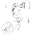
- FIGS. 1 and 2are diagrammatic illustrations of exemplary disclosed manufacturing systems
- FIGS. 3A, 3B, 4, 5A, 5B, and 6are diagrammatic illustrations of exemplary disclosed heads that may be used in conjunction with the manufacturing systems of FIGS. 1 and 2 .
- FIGS. 1 and 2illustrate different exemplary systems 10 and 12 , which may be used to continuously manufacture composite structures 14 having any desired cross-sectional shape (e.g., circular, polygonal, etc.).
- Each of systems 10 , 12may include at least a support 16 and a head 18 .
- Head 18may be coupled to and moved by support 16 .
- support 16is an overhead gantry capable of moving head 18 in multiple directions during fabrication of structure 14 , such that a resulting longitudinal axis of structure 14 is three-dimensional.
- support 16is a robotic arm also capable of moving head 18 in multiple directions during fabrication of structure 14 .
- a drivemay mechanically couple head 18 to support 16 , and may include components that cooperate to move and/or supply power or materials to head 18 .
- the Head 18may be configured to receive or otherwise contain a matrix material.
- the matrix materialmay include any type of matrix material (e.g., a liquid resin, such as a zero volatile organic compound resin; a powdered metal; etc.) that is curable.
- exemplary resinsinclude thermosets, single- or multi-part epoxy resins, polyester resins, cationic epoxies, acrylated epoxies, urethanes, esters, thermoplastics, photopolymers, polyepoxides, thiols, alkenes, thiol-enes, and more.
- the matrix material inside head 18may be pressurized, for example by an external device (e.g., an extruder or another type of pump—not shown) that is fluidly connected to head 18 via a corresponding conduit (not shown). In another embodiment, however, the pressure may be generated completely inside of head 18 by a similar type of device. In yet other embodiments, the matrix material may be gravity-fed through and/or mixed within head 18 . In some instances, the matrix material inside head 18 may need to be kept cool and/or dark to inhibit premature curing; while in other instances, the matrix material may need to be kept warm for the same reason. In either situation, head 18 may be specially configured (e.g., insulated, chilled, and/or warmed) to provide for these needs.
- an external devicee.g., an extruder or another type of pump—not shown
- the pressuremay be generated completely inside of head 18 by a similar type of device.
- the matrix materialmay be gravity-fed through and/or mixed within head 18 .
- the matrix material inside head 18may need
- the matrix materialmay be used to coat, encase, or otherwise surround any number of continuous reinforcements (e.g., separate fibers, tows, rovings, and/or sheets of material) and, together with the reinforcements, make up at least a portion (e.g., a wall) of composite structure 14 .
- the reinforcementsmay be stored within (e.g., on separate internal spools—not shown) or otherwise passed through head 18 (e.g., fed from external spools). When multiple reinforcements are simultaneously used, the reinforcements may be of the same type and have the same diameter and cross-sectional shape (e.g., circular, square, flat, etc.), or of a different type with different diameters and/or cross-sectional shapes.
- the reinforcementsmay include, for example, carbon fibers, vegetable fibers, wood fibers, mineral fibers, glass fibers, metallic wires, optical tubes, etc. It should be noted that the term “reinforcement” is meant to encompass both structural and non-structural types of continuous materials at least partially encased in the matrix material discharging from head 18 .
- the reinforcementsmay be exposed to (e.g., at least partially coated with) the matrix material while the reinforcements are inside head 18 , while the reinforcements are being passed to head 18 , and/or while the reinforcements are discharging from head 18 , as desired.
- the matrix material, dry reinforcements, and/or reinforcements that are already exposed to the matrix materialmay be transported into head 18 in any manner apparent to one skilled in the art.
- One or more cure enhancers(e.g., a UV light, an ultrasonic emitter, a laser, a heater, a catalyst dispenser, etc.) 20 may be mounted proximate (e.g., within or on) head 18 and configured to enhance a cure rate and/or quality of the matrix material as it is discharged from head 18 .
- Cure enhancer 20may be controlled to selectively expose surfaces of structure 14 to energy (e.g., UV light, electromagnetic radiation, vibrations, heat, a chemical catalyst, etc.) during the formation of structure 14 . The energy may increase a rate of chemical reaction occurring within the matrix material, sinter the material, harden the material, or otherwise cause the material to cure as it discharges from head 18 .
- cure enhancer 20includes multiple LEDs (e.g., 6 different LEDs) that are equally distributed about a center axis of head 18 .
- any number of LEDs or other energy sourcescould alternatively be utilized for the disclosed purposes and/or arranged in another manner (e.g., unequally distributed, arranged in a row or a box, etc.).
- the primary and/or auxiliary cure enhancers 20could be located on an arm (not shown) that trails behind head 18 , if desired.
- the amount of energy produced by cure enhancer 20may be sufficient to cure the matrix material before structure 14 axially grows more than a predetermined length away from head 18 . In one embodiment, structure 14 is completely cured before the axial growth length becomes equal to an external diameter of the matrix-coated reinforcement.
- the matrix material and reinforcementmay be discharged from head 18 via at least two different modes of operation.
- a first mode of operationthe matrix material and reinforcement are extruded (e.g., pushed under fluid pressure and/or mechanical force) from head 18 , as head 18 is moved by support 16 to create the 3-dimensional shape of structure 14 .
- a second mode of operationat least the reinforcement is pulled from head 18 , such that a tensile stress is created in the reinforcement during discharge.
- the matrix materialmay cling to the reinforcement and thereby also be pulled from head 18 along with the reinforcement, and/or the matrix material may be discharged from head 18 under pressure along with the pulled reinforcement.
- the resulting tension in the reinforcementmay increase a strength of structure 14 , while also allowing for a greater length of unsupported material to have a straighter trajectory (i.e., the tension may act against the force of gravity to provide free-standing support for structure 14 ).
- the reinforcementmay be pulled from head 18 as a result of head 18 moving away from an anchor point 22 .
- a length of matrix-impregnated reinforcementmay be pulled and/or pushed from head 18 , deposited onto an anchor point 22 , and cured, such that the discharged material adheres to anchor point 22 .
- head 18may be moved away from anchor point 22 , and the relative movement may cause the reinforcement to be pulled from head 18 .
- the movement of reinforcement through head 18could be assisted (e.g., via internal feed mechanisms), if desired.
- the discharge rate of reinforcement from head 18may primarily be the result of relative movement between head 18 and anchor point 22 , such that tension is created within the reinforcement.
- anchor point 22could be moved away from head 18 instead of or in addition to head 18 being moved away from anchor point 22 .
- a controller 24may be provided with system 10 and/or 12 , and is shown in FIGS. 1 and 2 as being communicatively coupled with support 16 , head 18 , and any number and type of cure enhancers 20 .
- Controller 24may embody a single processor or multiple processors that include a means for controlling an operation of system(s) 10 and/or 12 .
- Controller 24may include one or more general- or special-purpose processors or microprocessors.
- Controller 24may further include or be associated with a memory for storing data such as, for example, design limits, performance characteristics, operational instructions, matrix characteristics, reinforcement characteristics, characteristics of structure 14 , and corresponding parameters of each component of system(s) 10 and/or 12 .
- controller 24may be associated with various other known circuits, including power supply circuitry, signal-conditioning circuitry, solenoid/motor driver circuitry, communication circuitry, and other appropriate circuitry. Moreover, controller 24 may be capable of communicating with other components of system(s) 10 and/or 12 via wired and/or wireless transmission.
- One or more mapsmay be stored in the memory of controller 24 and used during fabrication of structure 14 .
- Each of these mapsmay include a collection of data in the form of lookup tables, graphs, and/or equations.
- the mapsare used by controller 24 to determine desired characteristics of cure enhancers 20 , the associated matrix, and/or the associated reinforcements at different locations within structure 14 .
- the characteristicsmay include, among others, a type, quantity, and/or configuration of reinforcement to be discharged at a particular location within structure 14 .
- Controller 24may then correlate operation of support 16 (e.g., the location and/or orientation of head 18 ) and/or the discharge of material from head 18 (a type of material, desired performance of the material, cross-linking requirements of the material, a discharge rate, starting and end locations of particular reinforcements, etc.) with the operation of cure enhancers 20 such that structure 14 is produced in a desired manner.
- support 16e.g., the location and/or orientation of head 18
- the discharge of material from head 18a type of material, desired performance of the material, cross-linking requirements of the material, a discharge rate, starting and end locations of particular reinforcements, etc.
- Controller 24may be further communicatively coupled with a cutting mechanism 26 that can be located at, on, or adjacent a nozzle end of head 18 .
- Mechanism 26may be used to selectively sever material (e.g., matrix material and/or continuous reinforcements) discharging from head 18 .
- mechanism 26includes an energy source 28 that is operatively mounted to support 16 , and a targeting prism 30 .
- Energy source 28may include one or more lasers (e.g., an Excimer laser, a Yb:tungstate laser, a CO 2 laser, a Nd:YAG laser, a DPSS laser, or another type of laser known in the art) that are configured to generate one or more energy beams 32 directed through prism 30 and onto the material discharging from head 18 at a desired location.
- Beam(s) 32may be capable of heating the material to a level sufficient to burn, melt, ablate, or otherwise cut through the material.
- various opticsmay be used to focus, redirect, and/or align beam(s) 32 . It is contemplated that energy sources other than lasers could alternatively be used to burn, melt, or ablate the material, if desired.
- Controller 24may be in communication with each of the components of mechanism 26 , and configured to selectively adjust their operation (e.g., to selectively energize source 28 , to position/orient an actuator associated with targeting prism 30 , to focus beam(s) 32 , etc.) in coordination with a position and/or status of head 18 . With this configuration, the discharging material may be selectively severed without causing disruptions in the movement of head 18 .
- cutting mechanism 26includes a rotary cutter (e.g., a router bit, a grinder blade, a saw blade, etc.) 34 that is attached to and operatively driven by head 18 (e.g., via an internal gear train, via an electric actuator, via a fluid motor, etc.).
- Rotary cutter 34may be selectively moved into place via support 16 , and driven by head 18 (e.g., rotated) to sever structure 14 .
- rotary cutter 34may be selectively plunged out of head 18 at desired locations to sever the discharging material, and then returned back at least partially into head 18 for storage.
- Controller 24may be used to control operation of support 16 , head 18 , and rotary cutter 34 during the severing operation.
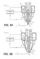
- cutting mechanism 26includes, among other things, a punch 36 having a cutting edge 38 located at a tip end and a piston 40 located at a base end inside of a control chamber 42 .
- Punch 36may be radially disposed between a nozzle 44 of head 18 and cure enhancers 20 .
- cutting edge 38 of punch 36is an annular blade, which at least partially or completely surrounds nozzle 44 of head 18 .
- Cutting edge 38may be serrated and/or include teeth 46 (shown only in FIG. 3B ).
- Controller 24may be configured to regulate movement of punch 36 , for example by selectively directing a control fluid (e.g., air, hydraulic oil, etc.) into and/or out of control chamber 42 at opposing ends of piston 40 . This may create a pressure differential across piston 40 that causes piston 40 to move punch 36 from a retracted position (shown in FIG. 3A ) to an extended position (shown in FIG. 3B ). When punch 36 is in the extended position, teeth 46 may engage and thereby sever the material discharging from head 18 .
- a control fluide.g., air, hydraulic oil, etc.
- punch 36may also be configured to rotate.
- the control fluid described abovecould be directed through a turbine (not shown) that is connected to piston 40 , thereby causing piston 40 and/or cutting edge 38 to rotate.
- another means of actuatione.g., a non-fluid driven means such as an electric motor
- punch 36could be spring-biased to the retracted or extended position, and only controllably moved in one (i.e., the opposing) axial direction.
- FIG. 4illustrates another embodiment of head 18 having one or more cutting mechanisms 26 .
- cutting mechanisms 26may be used to grasp (e.g., during anchor setting) and/or sever material discharging from head 18 .
- Each cutting mechanism 26may include, among other things, a wedge-shaped arm or blade 48 that is pivotally connected at a base end to a housing of head 18 (e.g., via a pivot pin 50 ), and an actuator 52 that is configured to engage and thereby rotate arm 48 about pivot pin 50 .
- Actuator 52may be a linear actuator (e.g., a pneumatic piston, a lead screw, or another similar device) that extends and retracts in response to a command from (e.g., when energized by) controller 24 .
- a linear actuatore.g., a pneumatic piston, a lead screw, or another similar device
- actuator 52may push a tip end (e.g., a blunted, elastomeric, roughened, and/or sharpened end) of the associated wedge-shaped arm 48 toward the discharging material. During retraction, actuator 52 may pull the tip end away from the discharging material. When multiple mechanisms 26 are simultaneously energized (e.g., in opposition to each other), the tip ends can cooperate to pinch and/or cut completely through the discharging material, depending on a force and/or pivot angle caused by the expanding actuators 52 . Controller 24 may be used to regulate operation of support 16 , head 18 , and/or actuators 52 during the severing and/or grasping operations.
- a tip ende.g., a blunted, elastomeric, roughened, and/or sharpened end
- Controller 24may be used to regulate operation of support 16 , head 18 , and/or actuators 52 during the severing and/or grasping operations.
- cutting mechanism 26includes, among other things, blade 54 that is ultrasonically vibrated and selectively moveable into engagement with the material discharging from nozzle 44 .
- blade 54is movable primarily in an axial direction
- blade 54may be axially fixed and primarily rotatable about its axis.
- an actuator 56 and a source of ultrasonic energy 58may be operatively coupled with blade 54 and configured to generate the movements and vibrations described above.
- the vibrations within blade 54may promote severing of the matrix-coated reinforcements, without requiring a significant translational or rotational force from actuator 56 . This may help to reduce diversion of the reinforcements away from a desired trajectory. It is contemplated that ultrasonic energy sources (not shown) could be similarly associated with the other cutting mechanisms 26 described in this disclose, if desired. Controller 24 may be used to regulate operation of support 16 , head 18 , actuators 56 , and/or sources 58 during the severing operations.
- FIG. 6illustrates a final embodiment of head 18 that is similar to the embodiment of FIG. 4 .
- head 18 of FIG. 6may include one or more arms 48 that are selectively moved by one or more linear actuators 52 to grasp and/or sever the material discharging from nozzle 44 .
- two sets of opposing arms 48are shown, including a grasping or inner set 48 G , and a severing or outer set 48 S .
- arms 48 G and 48 Smay not pivot about associated pins 50 .
- arms 48 G and 48 Smay be flexible and curved, and actuators 52 may be configured to engage and exert pressure on bowed midpoints of the arms, thereby causing the arms to deflect (e.g., deform, bend, elongate, stretch, etc.) radially inward toward the reinforcements.
- arms 48 Gmay have blunted, abrasive, and/or resilient (e.g., rubber) tips that engage and grasp the reinforcements; while arms 48 S may have hardened and/or sharpened tips that pierce and/or sever the reinforcements.
- different actuators 52may be independently energized by controller 24 to selectively implement grasping only, severing only, or both grasping and severing.
- a single actuator 52could be used to simultaneously move both grasping and severing arms 48 G , 48 S , if desired. In this configuration, a movement amount and/or force could be varied to implement grasping, severing, or both grasping and severing.
- the disclosed systemsmay be used to continuously manufacture composite structures having any desired cross-sectional shape, length, density, and/or strength.
- the composite structuresmay include any number of different reinforcements of the same or different types, diameters, shapes, configurations, and consists.
- the disclosed systemsmay facilitate quick and simple start of a new printing process, and clean termination of an ongoing printing process. Operation of systems 10 and 12 will now be described in detail.
- information regarding a desired structure 14may be loaded into systems 10 and 12 (e.g., into controller 24 that is responsible for regulating operations of support 16 and/or head 18 ).
- This informationmay include, among other things, a size (e.g., diameter, wall thickness, length, etc.), a contour (e.g., a trajectory), surface features (e.g., ridge size, location, thickness, length; flange size, location, thickness, length; etc.), connection geometry (e.g., locations and sizes of couplings, tees, splices, etc.), desired weave patterns, weave transition locations, location-specific matrix stipulations, location-specific reinforcement stipulations, etc.
- a sizee.g., diameter, wall thickness, length, etc.
- a contoure.g., a trajectory
- surface featurese.g., ridge size, location, thickness, length; flange size, location, thickness, length; etc.
- connection geometrye.g., locations and
- this informationmay alternatively or additionally be loaded into systems 10 and 12 at different times and/or continuously during the manufacturing event, if desired.
- one or more different reinforcements and/or matrix materialsmay be selectively installed into head 18 and/or continuously supplied to systems 10 and 12 .
- the reinforcementsmay also need to be connected to a pulling machine (not shown) and/or to a mounting fixture (e.g., to anchor point 22 ).
- Installation of the matrix materialmay include filling head 18 and/or coupling of an extruder (not shown) to head 18 .
- connection of the reinforcements to anchor point 22may be completed automatically, in some situations.
- the cutting mechanism(s) 26 of FIGS. 4 and/or 6may be caused by controller 24 to grasp the associated matrix-wetted reinforcements protruding from head 18 , and to hold onto the reinforcements during movement of head 18 toward anchor point 22 .
- Graspingmay be accomplished by actuator(s) 52 being selectively energized by controller 24 , resulting in inward pivoting or deflecting of arms 48 .
- actuator(s) 52being selectively energized by controller 24 , resulting in inward pivoting or deflecting of arms 48 .
- tips of the armsmay be caused to pinch reinforcements protruding from head 18 .
- Head 18may then be moved by support 16 under the regulation of controller 24 to cause the held reinforcements to be placed against or on a corresponding anchor point 22 .
- Cure enhancers 20may then be selectively activated to cause hardening of the matrix material surrounding the reinforcements, thereby bonding the reinforcements to anchor
- the component informationmay then be used to control operation of systems 10 and 12 .
- the reinforcementsmay be pulled and/or pushed from head 18 (along with the matrix material), while support 16 selectively moves head 18 in a desired manner, such that an axis of the resulting structure 14 follows a desired trajectory (e.g., a free-space, unsupported, 3-D trajectory).
- a desired amount of energy from cure enhancer(s) 20may be absorbed by the discharging material, thereby initiating and/or completing curing of the associated matrix.
- structure 14may be disconnected (e.g., severed) from head 18 in any desired manner.
- Severing of structure 14 from head 18may be accomplished by cutting mechanism(s) 26 of any of FIGS. 1-6 , under the regulation of controller 24 .
- controller 24may selectively activate energy source 28 (referring to FIG. 1 ), initiate rotation and/or plunging of rotary cutter 34 (referring to FIG. 2 ), cause extension of punch 36 (referring to FIG. 3 ), pivot arms 48 (referring to FIG. 4 ), vibrate and/or move blade 54 (referring to FIGS. 5A and 5B ), and/or inwardly deflect arms 48 S (referring to FIG. 6 ) to cut off any reinforcements protruding from head 18 , leaving structure 14 untethered.
- the laser/prism type cutting mechanism 26may be used in a particular situation (e.g., during metallic fiber cutting, during ribbon cutting, during sheet cutting, etc.), while another cutting mechanism 26 may be used in another situation (e.g., during non-metallic and/or single-fiber cutting). It is intended that the specification and examples be considered as exemplary only, with a true scope being indicated by the following claims and their equivalents.
Landscapes
- Engineering & Computer Science (AREA)
- Chemical & Material Sciences (AREA)
- Materials Engineering (AREA)
- Physics & Mathematics (AREA)
- Optics & Photonics (AREA)
- Mechanical Engineering (AREA)
- Manufacturing & Machinery (AREA)
- Plasma & Fusion (AREA)
- Life Sciences & Earth Sciences (AREA)
- Forests & Forestry (AREA)
- Health & Medical Sciences (AREA)
- Toxicology (AREA)
Abstract
Description
This application is based on and claims the benefit of priority from U.S. Provisional Applications Nos. 62/449,899 that was filed on Jan. 24, 2017 and 62/459,398 that was filed on Feb. 15, 2017, the contents of all of which are expressly incorporated herein by reference.
The present disclosure relates generally to a manufacturing system and, more particularly, to an additive manufacturing system having a fiber-cutting mechanism.
Extrusion manufacturing is a known process for producing continuous structures. During extrusion manufacturing, a liquid matrix (e.g., a thermoset resin or a heated thermoplastic) is pushed through a die having a desired cross-sectional shape and size. The material, upon exiting the die, cures and hardens into a final form. In some applications, UV light and/or ultrasonic vibrations are used to speed the cure of the liquid matrix as it exits the die. The structures produced by the extrusion manufacturing process can have any continuous length, with a straight or curved profile, a consistent cross-sectional shape, and excellent surface finish. Although extrusion manufacturing can be an efficient way to continuously manufacture structures, the resulting structures may lack the strength required for some applications.
Pultrusion manufacturing is a known process for producing high-strength structures. During pultrusion manufacturing, individual fiber strands, braids of strands, and/or woven fabrics are coated with or otherwise impregnated with a liquid matrix (e.g., a thermoset resin or a heated thermoplastic) and pulled through a stationary die where the liquid matrix cures and hardens into a final form. As with extrusion manufacturing, UV light and/or ultrasonic vibrations are used in some pultrusion applications to speed the cure of the liquid matrix as it exits the die. The structures produced by the pultrusion manufacturing process have many of the same attributes of extruded structures, as well as increased strength due to the integrated fibers. Although pultrusion manufacturing can be an efficient way to continuously manufacture high-strength structures, the resulting structures may lack the form (shape, size, and/or precision) required for some applications. In addition, conventional pultrusion manufacturing may lack flexibility in severing of the fibers.
The disclosed system is directed to addressing one or more of the problems set forth above and/or other problems of the prior art.
In one aspect, the present disclosure is directed to an additive manufacturing system. The additive manufacturing system may include a head having a nozzle configured to discharge a composite material, including a matrix and a continuous reinforcement. The additive manufacturing system may also include a cure enhancer configured to enhance curing of the matrix, and a support configured to move the head during discharging to create a structure having a three-dimensional trajectory. The additive manufacturing system may further include a cutting mechanism operatively mounted to at least one of the head and the support, and configured to sever the continuous reinforcement after discharge from the nozzle. The cutting mechanism may include a blade, and an ultrasonic energy source connected to the blade.
In another aspect, the present disclosure is directed to another additive manufacturing system. This additive manufacturing system may include a head having a nozzle configured to discharge a composite material, including a matrix and a continuous reinforcement. The additive manufacturing system may also include a cure enhancer configured to enhance curing of the matrix, and a support configured to move the head during discharging to create a structure having a three-dimensional trajectory. The additive manufacturing system may further include an annular punch at least partially surrounding the nozzle. The annular punch may have a piston located inside a control chamber at a base end, and a cutting blade located opposite the piston. The additive manufacturing system may additionally include a controller in communication with the support, the cure enhancer, and the annular punch. The controller may be configured to regulate operation of the support to cause the head to follow a desired trajectory during discharge of the composite material, to selectively activate the cure enhancer, and to regulate a flow of fluid through the control chamber to cause the annular punch to at least one of extend, retract, and rotate during severing of the continuous reinforcement.
In another aspect, the present disclosure is directed to yet another additive manufacturing system. This additive manufacturing system may include a head having a nozzle configured to discharge a composite material, including a matrix and a continuous reinforcement. The additive manufacturing system may also include a cure enhancer configured to enhance curing of the matrix, and a support configured to move the head during discharging to create a structure having a three-dimensional trajectory. The additive manufacturing system may additionally include a cutting mechanism configured to sever the continuous reinforcement after discharge from the nozzle. The cutting mechanism may include an arm, and an actuator connected to the head and configured to deflect the arm radially inward to engage the continuous reinforcement.
The matrix material may be used to coat, encase, or otherwise surround any number of continuous reinforcements (e.g., separate fibers, tows, rovings, and/or sheets of material) and, together with the reinforcements, make up at least a portion (e.g., a wall) ofcomposite structure 14. The reinforcements may be stored within (e.g., on separate internal spools—not shown) or otherwise passed through head18 (e.g., fed from external spools). When multiple reinforcements are simultaneously used, the reinforcements may be of the same type and have the same diameter and cross-sectional shape (e.g., circular, square, flat, etc.), or of a different type with different diameters and/or cross-sectional shapes. The reinforcements may include, for example, carbon fibers, vegetable fibers, wood fibers, mineral fibers, glass fibers, metallic wires, optical tubes, etc. It should be noted that the term “reinforcement” is meant to encompass both structural and non-structural types of continuous materials at least partially encased in the matrix material discharging fromhead 18.
The reinforcements may be exposed to (e.g., at least partially coated with) the matrix material while the reinforcements are insidehead 18, while the reinforcements are being passed tohead 18, and/or while the reinforcements are discharging fromhead 18, as desired. The matrix material, dry reinforcements, and/or reinforcements that are already exposed to the matrix material (e.g., wetted reinforcements) may be transported intohead 18 in any manner apparent to one skilled in the art.
One or more cure enhancers (e.g., a UV light, an ultrasonic emitter, a laser, a heater, a catalyst dispenser, etc.)20 may be mounted proximate (e.g., within or on)head 18 and configured to enhance a cure rate and/or quality of the matrix material as it is discharged fromhead 18.Cure enhancer 20 may be controlled to selectively expose surfaces ofstructure 14 to energy (e.g., UV light, electromagnetic radiation, vibrations, heat, a chemical catalyst, etc.) during the formation ofstructure 14. The energy may increase a rate of chemical reaction occurring within the matrix material, sinter the material, harden the material, or otherwise cause the material to cure as it discharges fromhead 18. In the depicted embodiments,cure enhancer 20 includes multiple LEDs (e.g., 6 different LEDs) that are equally distributed about a center axis ofhead 18. However, it is contemplated that any number of LEDs or other energy sources could alternatively be utilized for the disclosed purposes and/or arranged in another manner (e.g., unequally distributed, arranged in a row or a box, etc.). For example, the primary and/orauxiliary cure enhancers 20 could be located on an arm (not shown) that trails behindhead 18, if desired. The amount of energy produced bycure enhancer 20 may be sufficient to cure the matrix material beforestructure 14 axially grows more than a predetermined length away fromhead 18. In one embodiment,structure 14 is completely cured before the axial growth length becomes equal to an external diameter of the matrix-coated reinforcement.
The matrix material and reinforcement may be discharged fromhead 18 via at least two different modes of operation. In a first mode of operation, the matrix material and reinforcement are extruded (e.g., pushed under fluid pressure and/or mechanical force) fromhead 18, ashead 18 is moved bysupport 16 to create the 3-dimensional shape ofstructure 14. In a second mode of operation, at least the reinforcement is pulled fromhead 18, such that a tensile stress is created in the reinforcement during discharge. In this mode of operation, the matrix material may cling to the reinforcement and thereby also be pulled fromhead 18 along with the reinforcement, and/or the matrix material may be discharged fromhead 18 under pressure along with the pulled reinforcement. In the second mode of operation, where the matrix material is being pulled fromhead 18, the resulting tension in the reinforcement may increase a strength ofstructure 14, while also allowing for a greater length of unsupported material to have a straighter trajectory (i.e., the tension may act against the force of gravity to provide free-standing support for structure14).
The reinforcement may be pulled fromhead 18 as a result ofhead 18 moving away from ananchor point 22. In particular, at the start of structure-formation, a length of matrix-impregnated reinforcement may be pulled and/or pushed fromhead 18, deposited onto ananchor point 22, and cured, such that the discharged material adheres to anchorpoint 22. Thereafter,head 18 may be moved away fromanchor point 22, and the relative movement may cause the reinforcement to be pulled fromhead 18. It should be noted that the movement of reinforcement throughhead 18 could be assisted (e.g., via internal feed mechanisms), if desired. However, the discharge rate of reinforcement fromhead 18 may primarily be the result of relative movement betweenhead 18 andanchor point 22, such that tension is created within the reinforcement. It is contemplated thatanchor point 22 could be moved away fromhead 18 instead of or in addition tohead 18 being moved away fromanchor point 22.
Acontroller 24 may be provided withsystem 10 and/or12, and is shown inFIGS. 1 and 2 as being communicatively coupled withsupport 16,head 18, and any number and type ofcure enhancers 20.Controller 24 may embody a single processor or multiple processors that include a means for controlling an operation of system(s)10 and/or12.Controller 24 may include one or more general- or special-purpose processors or microprocessors.Controller 24 may further include or be associated with a memory for storing data such as, for example, design limits, performance characteristics, operational instructions, matrix characteristics, reinforcement characteristics, characteristics ofstructure 14, and corresponding parameters of each component of system(s)10 and/or12. Various other known circuits may be associated withcontroller 24, including power supply circuitry, signal-conditioning circuitry, solenoid/motor driver circuitry, communication circuitry, and other appropriate circuitry. Moreover,controller 24 may be capable of communicating with other components of system(s)10 and/or12 via wired and/or wireless transmission.
One or more maps may be stored in the memory ofcontroller 24 and used during fabrication ofstructure 14. Each of these maps may include a collection of data in the form of lookup tables, graphs, and/or equations. In the disclosed embodiment, the maps are used bycontroller 24 to determine desired characteristics ofcure enhancers 20, the associated matrix, and/or the associated reinforcements at different locations withinstructure 14. The characteristics may include, among others, a type, quantity, and/or configuration of reinforcement to be discharged at a particular location withinstructure 14.Controller 24 may then correlate operation of support16 (e.g., the location and/or orientation of head18) and/or the discharge of material from head18 (a type of material, desired performance of the material, cross-linking requirements of the material, a discharge rate, starting and end locations of particular reinforcements, etc.) with the operation ofcure enhancers 20 such thatstructure 14 is produced in a desired manner.
In the embodiment ofFIG. 1 ,mechanism 26 includes anenergy source 28 that is operatively mounted to support16, and a targeting prism30.Energy source 28 may include one or more lasers (e.g., an Excimer laser, a Yb:tungstate laser, a CO2laser, a Nd:YAG laser, a DPSS laser, or another type of laser known in the art) that are configured to generate one ormore energy beams 32 directed through prism30 and onto the material discharging fromhead 18 at a desired location. Beam(s)32 may be capable of heating the material to a level sufficient to burn, melt, ablate, or otherwise cut through the material. In some embodiments, various optics (e.g., lenses, mirrors, gratings, filters, etc.—not shown) may be used to focus, redirect, and/or align beam(s)32. It is contemplated that energy sources other than lasers could alternatively be used to burn, melt, or ablate the material, if desired.Controller 24 may be in communication with each of the components ofmechanism 26, and configured to selectively adjust their operation (e.g., to selectively energizesource 28, to position/orient an actuator associated with targeting prism30, to focus beam(s)32, etc.) in coordination with a position and/or status ofhead 18. With this configuration, the discharging material may be selectively severed without causing disruptions in the movement ofhead 18.
In the embodiment ofFIG. 2 ,cutting mechanism 26 includes a rotary cutter (e.g., a router bit, a grinder blade, a saw blade, etc.)34 that is attached to and operatively driven by head18 (e.g., via an internal gear train, via an electric actuator, via a fluid motor, etc.).Rotary cutter 34 may be selectively moved into place viasupport 16, and driven by head18 (e.g., rotated) to severstructure 14. In some applications, in addition to rotating,rotary cutter 34 may be selectively plunged out ofhead 18 at desired locations to sever the discharging material, and then returned back at least partially intohead 18 for storage. It is contemplated that, in order forhead 18 to move to a position that allows severing ofstructure 14 by rotary cutter34 (i.e., so that slack exists in the reinforcements), curing ofstructure 14 may need to be interrupted for a period of time prior to the severing.Controller 24 may be used to control operation ofsupport 16,head 18, androtary cutter 34 during the severing operation.
Another exemplary embodiment ofhead 18 andcutting mechanism 26 is illustrated inFIGS. 3A and 3B . In this embodiment, cuttingmechanism 26 includes, among other things, apunch 36 having a cuttingedge 38 located at a tip end and apiston 40 located at a base end inside of acontrol chamber 42.Punch 36 may be radially disposed between anozzle 44 ofhead 18 andcure enhancers 20. In the disclosed embodiment, cuttingedge 38 ofpunch 36 is an annular blade, which at least partially or completely surroundsnozzle 44 ofhead 18. Cuttingedge 38 may be serrated and/or include teeth46 (shown only inFIG. 3B ).
It is contemplated that, in some embodiments, punch36 may also be configured to rotate. For example, the control fluid described above could be directed through a turbine (not shown) that is connected topiston 40, thereby causingpiston 40 and/or cuttingedge 38 to rotate. It should be noted that another means of actuation (e.g., a non-fluid driven means such as an electric motor) could be used to move and/or rotatepunch 36. It should also be noted thatpunch 36 could be spring-biased to the retracted or extended position, and only controllably moved in one (i.e., the opposing) axial direction.
Additional exemplary embodiments ofhead 18 andcutting mechanism 26 are illustrated inFIGS. 5A and 5B . In these embodiments, cuttingmechanism 26 includes, among other things,blade 54 that is ultrasonically vibrated and selectively moveable into engagement with the material discharging fromnozzle 44. In the example ofFIG. 5A ,blade 54 is movable primarily in an axial direction, while in the example ofFIG. 5B ,blade 54 may be axially fixed and primarily rotatable about its axis. In both examples, anactuator 56 and a source ofultrasonic energy 58 may be operatively coupled withblade 54 and configured to generate the movements and vibrations described above. The vibrations withinblade 54 may promote severing of the matrix-coated reinforcements, without requiring a significant translational or rotational force fromactuator 56. This may help to reduce diversion of the reinforcements away from a desired trajectory. It is contemplated that ultrasonic energy sources (not shown) could be similarly associated with theother cutting mechanisms 26 described in this disclose, if desired.Controller 24 may be used to regulate operation ofsupport 16,head 18,actuators 56, and/orsources 58 during the severing operations.
The disclosed systems may be used to continuously manufacture composite structures having any desired cross-sectional shape, length, density, and/or strength. The composite structures may include any number of different reinforcements of the same or different types, diameters, shapes, configurations, and consists. In addition, the disclosed systems may facilitate quick and simple start of a new printing process, and clean termination of an ongoing printing process. Operation ofsystems
At a start of a manufacturing event, information regarding a desiredstructure 14 may be loaded intosystems 10 and12 (e.g., intocontroller 24 that is responsible for regulating operations ofsupport 16 and/or head18). This information may include, among other things, a size (e.g., diameter, wall thickness, length, etc.), a contour (e.g., a trajectory), surface features (e.g., ridge size, location, thickness, length; flange size, location, thickness, length; etc.), connection geometry (e.g., locations and sizes of couplings, tees, splices, etc.), desired weave patterns, weave transition locations, location-specific matrix stipulations, location-specific reinforcement stipulations, etc. It should be noted that this information may alternatively or additionally be loaded intosystems head 18 and/or continuously supplied tosystems head 18 and/or coupling of an extruder (not shown) tohead 18.
Connection of the reinforcements to anchorpoint 22 may be completed automatically, in some situations. For example, the cutting mechanism(s)26 ofFIGS. 4 and/or 6 may be caused bycontroller 24 to grasp the associated matrix-wetted reinforcements protruding fromhead 18, and to hold onto the reinforcements during movement ofhead 18 towardanchor point 22. Grasping may be accomplished by actuator(s)52 being selectively energized bycontroller 24, resulting in inward pivoting or deflecting ofarms 48. Asarms 48 move radially inward, tips of the arms may be caused to pinch reinforcements protruding fromhead 18.Head 18 may then be moved bysupport 16 under the regulation ofcontroller 24 to cause the held reinforcements to be placed against or on acorresponding anchor point 22.Cure enhancers 20 may then be selectively activated to cause hardening of the matrix material surrounding the reinforcements, thereby bonding the reinforcements to anchorpoint 22.
The component information may then be used to control operation ofsystems support 16 selectively moveshead 18 in a desired manner, such that an axis of the resultingstructure 14 follows a desired trajectory (e.g., a free-space, unsupported, 3-D trajectory). A desired amount of energy from cure enhancer(s)20 may be absorbed by the discharging material, thereby initiating and/or completing curing of the associated matrix. Oncestructure 14 has grown to a desired length,structure 14 may be disconnected (e.g., severed) fromhead 18 in any desired manner.
Severing ofstructure 14 from head18 (and vice versa) may be accomplished by cutting mechanism(s)26 of any ofFIGS. 1-6 , under the regulation ofcontroller 24. For example,controller 24 may selectively activate energy source28 (referring toFIG. 1 ), initiate rotation and/or plunging of rotary cutter34 (referring toFIG. 2 ), cause extension of punch36 (referring toFIG. 3 ), pivot arms48 (referring toFIG. 4 ), vibrate and/or move blade54 (referring toFIGS. 5A and 5B ), and/or inwardly deflect arms48S(referring toFIG. 6 ) to cut off any reinforcements protruding fromhead 18, leavingstructure 14 untethered.
It will be apparent to those skilled in the art that various modifications and variations can be made to the disclosed systems and head. Other embodiments will be apparent to those skilled in the art from consideration of the specification and practice of the disclosed systems and heads. For example, it is contemplated that any two or more of the cutting mechanisms described above could be combined and used together, if desired. For instance, cuttingmechanism 26 ofFIG. 4 and/or the grasping portion of cuttingmechanism 26 ofFIG. 6 could be used for only grasping purposes, with cutting operations being performed by the laser/prismtype cutting mechanism 26 ofFIG. 1 , if desired. Alternatively, the laser/prismtype cutting mechanism 26 may be used in a particular situation (e.g., during metallic fiber cutting, during ribbon cutting, during sheet cutting, etc.), while anothercutting mechanism 26 may be used in another situation (e.g., during non-metallic and/or single-fiber cutting). It is intended that the specification and examples be considered as exemplary only, with a true scope being indicated by the following claims and their equivalents.
Claims (7)
1. An additive manufacturing system, comprising:
a head having a nozzle configured to discharge a composite material including a matrix and a continuous reinforcement;
a cure enhancer configured to enhance curing of the matrix;
a support configured to move the head during discharging to create a structure having a three-dimensional trajectory; and
a cutting mechanism operatively mounted to at least one of the head and the support and configured to sever the continuous reinforcement after discharge from the nozzle, the cutting mechanism including a blade and an ultrasonic energy source connected to the blade, wherein:
the blade is located at a tip end of an arm;
an actuator is configured to actuate in an axial direction of the nozzle to move the blade radially inward toward the continuous reinforcement; and
the blade is deformed radially inward by actuation of the actuator.
2. The additive manufacturing system ofclaim 1 , wherein:
the arm is one of an outer set of arms configured to sever the continuous reinforcement; and
the cutting mechanism further includes an inner set of arms configured to grasp the continuous reinforcement.
3. The additive manufacturing system ofclaim 2 , wherein:
the actuator is a first actuator associated with the outer set of arms; and
the cutting mechanism further includes a second actuator associated with the inner set of arms.
4. The additive manufacturing system ofclaim 3 , wherein ends of the inner set of arms are at least one of blunted, elastomeric, and roughened.
5. An additive manufacturing system, comprising:
a head having a nozzle configured to discharge a composite material including a matrix and a continuous reinforcement;
a cure enhancer configured to enhance curing of the matrix;
a support configured to move the head during discharging to create a structure having a three-dimensional trajectory; and
a cutting mechanism configured to sever the continuous reinforcement after discharge from the nozzle, the cutting mechanism including:
an arm having a cutting end; and
an actuator connected to the head and configured to deform the arm radially inward to engage the continuous reinforcement.
6. The additive manufacturing system ofclaim 5 , wherein:
the arm is one of an outer set of arms configured to sever the continuous reinforcement; and
the cutting mechanism further includes an inner set of arms configured to grasp the continuous reinforcement.
7. The additive manufacturing system ofclaim 6 , wherein:
ends of the inner set of arms are at least one of blunted, elastomeric, and roughened; and
ends of the outer set of arms are at least one of hardened and sharpened.
Priority Applications (2)
| Application Number | Priority Date | Filing Date | Title |
|---|---|---|---|
| US15/623,881US10040240B1 (en) | 2017-01-24 | 2017-06-15 | Additive manufacturing system having fiber-cutting mechanism |
| PCT/US2017/046338WO2018140083A1 (en) | 2017-01-24 | 2017-08-10 | Additive manufacturing system having fiber-cutting mechanism |
Applications Claiming Priority (3)
| Application Number | Priority Date | Filing Date | Title |
|---|---|---|---|
| US201762449899P | 2017-01-24 | 2017-01-24 | |
| US201762459398P | 2017-02-15 | 2017-02-15 | |
| US15/623,881US10040240B1 (en) | 2017-01-24 | 2017-06-15 | Additive manufacturing system having fiber-cutting mechanism |
Publications (2)
| Publication Number | Publication Date |
|---|---|
| US20180207868A1 US20180207868A1 (en) | 2018-07-26 |
| US10040240B1true US10040240B1 (en) | 2018-08-07 |
Family
ID=62905986
Family Applications (1)
| Application Number | Title | Priority Date | Filing Date |
|---|---|---|---|
| US15/623,881Expired - Fee RelatedUS10040240B1 (en) | 2017-01-24 | 2017-06-15 | Additive manufacturing system having fiber-cutting mechanism |
Country Status (2)
| Country | Link |
|---|---|
| US (1) | US10040240B1 (en) |
| WO (1) | WO2018140083A1 (en) |
Cited By (2)
| Publication number | Priority date | Publication date | Assignee | Title |
|---|---|---|---|---|
| US11167375B2 (en) | 2018-08-10 | 2021-11-09 | The Research Foundation For The State University Of New York | Additive manufacturing processes and additively manufactured products |
| IT202200009980A1 (en) | 2022-05-13 | 2023-11-13 | Univ Della Calabria | Extrusion device and 3D printer |
Families Citing this family (8)
| Publication number | Priority date | Publication date | Assignee | Title |
|---|---|---|---|---|
| CN109130170A (en)* | 2018-07-28 | 2019-01-04 | 华中科技大学 | A kind of more materials increase and decrease material combined shaping system and methods of polymer |
| US20200086563A1 (en)* | 2018-09-13 | 2020-03-19 | Cc3D Llc | System and head for continuously manufacturing composite structure |
| CN111347161A (en)* | 2018-12-20 | 2020-06-30 | 沈阳新松机器人自动化股份有限公司 | Portable additive manufacturing system |
| US11926099B2 (en)* | 2021-04-27 | 2024-03-12 | Continuous Composites Inc. | Additive manufacturing system |
| US20230071473A1 (en)* | 2021-09-04 | 2023-03-09 | Continuous Composites Inc. | Print head and method for additive manufacturing system |
| CN114248443A (en)* | 2021-11-29 | 2022-03-29 | 康硕(德阳)智能制造有限公司 | High-efficient 3D printing device based on 3D printing material characteristic |
| CN115283790B (en)* | 2022-07-15 | 2024-06-25 | 重庆大学 | A phase-adaptive ultrasonic melt pool stirring conformal arc additive manufacturing method |
| US12358174B2 (en)* | 2022-09-01 | 2025-07-15 | GM Global Technology Operations LLC | Ultrasonic pre-surface and post-surface processing for laser brazing and laser welding |
Citations (173)
| Publication number | Priority date | Publication date | Assignee | Title |
|---|---|---|---|---|
| US3286305A (en) | 1964-09-03 | 1966-11-22 | Rexall Drug Chemical | Apparatus for continuous manufacture of hollow articles |
| US3809514A (en) | 1971-11-13 | 1974-05-07 | Castro Nunez Elem Huecos | Machine for the continuous manufacture of hollow elements |
| US3984271A (en) | 1973-06-25 | 1976-10-05 | Owens-Corning Fiberglas Corporation | Method of manufacturing large diameter tubular structures |
| US3993726A (en) | 1974-01-16 | 1976-11-23 | Hercules Incorporated | Methods of making continuous length reinforced plastic articles |
| US4373412A (en) | 1980-07-10 | 1983-02-15 | Gerber Garment Technology, Inc. | Method and apparatus for cutting sheet material with a cutting wheel |
| US4500372A (en) | 1981-12-10 | 1985-02-19 | A. Mion S.P.A. Nastrificio | Method and apparatus for cutting woven labels |
| US4643940A (en) | 1984-08-06 | 1987-02-17 | The Dow Chemical Company | Low density fiber-reinforced plastic composites |
| US4671761A (en) | 1984-06-30 | 1987-06-09 | Fried. Krupp Gesellschaft Mit Beschrankter Haftung | Apparatus for producing reinforced elongate bodies |
| US4822548A (en) | 1986-06-13 | 1989-04-18 | Firma Carl Freudenberg | Method and apparatus for manufacturing a thread-reinforced rubber hose |
| US4851065A (en) | 1986-01-17 | 1989-07-25 | Tyee Aircraft, Inc. | Construction of hollow, continuously wound filament load-bearing structure |
| US4987808A (en) | 1988-06-20 | 1991-01-29 | Bridgestone/Firestone, Inc. | Tubular sleeve handling and cut-off system |
| US5002712A (en) | 1988-10-19 | 1991-03-26 | Bayer Aktiengesellschaft | Manufacturing composite materials |
| US5037691A (en) | 1986-09-15 | 1991-08-06 | Compositech, Ltd. | Reinforced plastic laminates for use in the production of printed circuit boards and process for making such laminates and resulting products |
| DE4102257A1 (en) | 1991-01-23 | 1992-07-30 | Artos Med Produkte | Appts. for mfg. reinforced components in laser-cured polymer - has laser-curable polymer in bath, laser directed at polymer surface where fibres pass through polymer and are guided relative to laser beam angle |
| US5296335A (en) | 1993-02-22 | 1994-03-22 | E-Systems, Inc. | Method for manufacturing fiber-reinforced parts utilizing stereolithography tooling |
| US5340433A (en)* | 1989-10-30 | 1994-08-23 | Stratasys, Inc. | Modeling apparatus for three-dimensional objects |
| US5746967A (en) | 1995-06-26 | 1998-05-05 | Fox Lite, Inc. | Method of curing thermoset resin with visible light |
| US5866058A (en) | 1997-05-29 | 1999-02-02 | Stratasys Inc. | Method for rapid prototyping of solid models |
| US5936861A (en) | 1997-08-15 | 1999-08-10 | Nanotek Instruments, Inc. | Apparatus and process for producing fiber reinforced composite objects |
| US6153034A (en) | 1997-08-03 | 2000-11-28 | Micromod R.P. Ltd | Rapid prototyping |
| US20020009935A1 (en) | 1999-03-23 | 2002-01-24 | Hexcel Corporation | Core-crush resistant fabric and prepreg for fiber reinforced composite sandwich structures |
| US20020062909A1 (en) | 2000-11-29 | 2002-05-30 | Jang Bor Z. | Layer-additive method and apparatus for freeform fabrication of 3-D objects |
| US20020113331A1 (en) | 2000-12-20 | 2002-08-22 | Tan Zhang | Freeform fabrication method using extrusion of non-cross-linking reactive prepolymers |
| US6459069B1 (en) | 1996-11-22 | 2002-10-01 | Joshua E. Rabinovich | Rapid manufacturing system for metal, metal matrix composite materials and ceramics |
| US20020165304A1 (en) | 2000-12-04 | 2002-11-07 | Mulligan Anthony C. | Methods and appratus for preparation of three-dimensional bodies |
| US6501554B1 (en) | 2000-06-20 | 2002-12-31 | Ppt Vision, Inc. | 3D scanner and method for measuring heights and angles of manufactured parts |
| US20030044539A1 (en) | 2001-02-06 | 2003-03-06 | Oswald Robert S. | Process for producing photovoltaic devices |
| US20030056870A1 (en) | 2001-09-21 | 2003-03-27 | Stratasys, Inc. | High-precision modeling filament |
| US20030160970A1 (en) | 2002-01-30 | 2003-08-28 | Anup Basu | Method and apparatus for high resolution 3D scanning |
| US20030186042A1 (en) | 2002-05-07 | 2003-10-02 | Dunlap Earl N. | Process for tempering rapid prototype parts |
| US20030236588A1 (en) | 2002-03-14 | 2003-12-25 | Jang Bor Z. | Nanotube fiber reinforced composite materials and method of producing fiber reinforced composites |
| US6803003B2 (en) | 2000-12-04 | 2004-10-12 | Advanced Ceramics Research, Inc. | Compositions and methods for preparing multiple-component composite materials |
| US20050006803A1 (en) | 2001-05-17 | 2005-01-13 | Owens Charles R. | Preform for manufacturing a material having a plurality of voids and method of making the same |
| US20050061422A1 (en) | 2003-09-22 | 2005-03-24 | Martin James P. | Multiple tape laying apparatus and method |
| US20050104257A1 (en) | 2003-09-04 | 2005-05-19 | Peihua Gu | Multisource and multimaterial freeform fabrication |
| US20050109451A1 (en) | 2003-11-20 | 2005-05-26 | Hauber David E. | Composite tape laying apparatus and method |
| US20050230029A1 (en) | 2001-01-02 | 2005-10-20 | Advanced Ceramics Research, Inc. | Continuous fiber reinforced composites and methods, apparatuses, and compositions for making the same |
| US20070003650A1 (en) | 2001-03-01 | 2007-01-04 | Schroeder Ernest C | Apparatus for fabricating fiber reinforced plastic parts |
| US20070228592A1 (en) | 2006-04-03 | 2007-10-04 | Stratasys, Inc. | Auto tip calibration in an extrusion apparatus |
| EP1932636A1 (en) | 2005-10-04 | 2008-06-18 | Nihon Shoryoku Kikai Co., Ltd. | Ultrasonic trimming device |
| US20090095410A1 (en) | 2007-10-16 | 2009-04-16 | Ingersoll Machine Tools, Inc. | Fiber Placement Machine Platform System Having Interchangeable Head and Creel Assemblies |
| US7795349B2 (en) | 1999-11-05 | 2010-09-14 | Z Corporation | Material systems and methods of three-dimensional printing |
| KR100995983B1 (en) | 2008-07-04 | 2010-11-23 | 재단법인서울대학교산학협력재단 | Cross-printing method and apparatus of circuit board |
| US20110032301A1 (en) | 2004-09-21 | 2011-02-10 | Z Corporation | Apparatus and methods for servicing 3d printers |
| US20110143108A1 (en) | 2008-05-09 | 2011-06-16 | Fit Fruth Innovative Technologien Gmbh | Fibers and methods for use in solid freeform fabrication |
| US20120060468A1 (en) | 2010-09-13 | 2012-03-15 | Experimental Propulsion Lab, Llc | Additive manufactured propulsion system |
| US20120159785A1 (en) | 2009-09-04 | 2012-06-28 | BayerMaerialScience LLC | Automated processes for the production of polyurethane wind turbine blades |
| US8221669B2 (en) | 2009-09-30 | 2012-07-17 | Stratasys, Inc. | Method for building three-dimensional models in extrusion-based digital manufacturing systems using ribbon filaments |
| KR101172859B1 (en) | 2010-10-04 | 2012-08-09 | 서울대학교산학협력단 | Ultra precision machining apparatus using nano-scale three dimensional printing and method using the same |
| US20120231225A1 (en) | 2010-09-17 | 2012-09-13 | Stratasys, Inc. | Core-shell consumable materials for use in extrusion-based additive manufacturing systems |
| US20120247655A1 (en) | 2009-11-13 | 2012-10-04 | Karlsruher Institut Fuer Technologie | Method for producing a component from a fiber-reinforced material |
| WO2013017284A2 (en) | 2011-08-04 | 2013-02-07 | Arburg Gmbh + Co. Kg | Method and device for producing a three-dimensional object comprising a fiber feed |
| US20130115324A1 (en)* | 2011-11-04 | 2013-05-09 | Ralph Peter Hegler | Apparatus for the Continuous Production of a Twin Wall Pipe with an Integral Socket |
| US20130164498A1 (en) | 2011-12-21 | 2013-06-27 | Adc Acquisition Company | Thermoplastic composite prepreg for automated fiber placement |
| US20130209600A1 (en) | 2012-02-10 | 2013-08-15 | Adam Perry Tow | Multi-axis, multi-purpose robotics automation and quality adaptive additive manufacturing |
| US20130233471A1 (en) | 2012-03-08 | 2013-09-12 | Randall A. Kappesser | Small flat composite placement system |
| US20130292039A1 (en) | 2012-04-04 | 2013-11-07 | Massachusetts Institute Of Technology | Methods and Apparatus for Actuated Fabricator |
| US20130337265A1 (en) | 2012-06-19 | 2013-12-19 | EADS UK Limited British | Thermoplastic polymer powder |
| US20130337256A1 (en) | 2012-06-19 | 2013-12-19 | Eads Uk Limited | Extrusion-based additive manufacturing system |
| US20140034214A1 (en) | 2012-07-31 | 2014-02-06 | Makerbot Industries, Llc | Build material switching |
| US20140061974A1 (en) | 2012-08-29 | 2014-03-06 | Kenneth Tyler | Method and apparatus for continuous composite three-dimensional printing |
| US20140159284A1 (en) | 2012-12-07 | 2014-06-12 | Stratasys, Inc. | Liquefier assembly for use in additive manufacturing system |
| US20140232035A1 (en) | 2013-02-19 | 2014-08-21 | Hemant Bheda | Reinforced fused-deposition modeling |
| US20140268604A1 (en) | 2013-03-14 | 2014-09-18 | Board Of Regents, The University Of Texas System | Methods and Systems For Embedding Filaments in 3D Structures, Structural Components, and Structural Electronic, Electromagnetic and Electromechanical Components/Devices |
| US20140291886A1 (en) | 2013-03-22 | 2014-10-02 | Gregory Thomas Mark | Three dimensional printing |
| US8962717B2 (en) | 2012-08-20 | 2015-02-24 | Basf Se | Long-fiber-reinforced flame-retardant polyesters |
| US20150136455A1 (en) | 2013-11-15 | 2015-05-21 | Robert J. Fleming | Shape forming process and application thereof for creating structural elements and designed objects |
| US9126365B1 (en) | 2013-03-22 | 2015-09-08 | Markforged, Inc. | Methods for composite filament fabrication in three dimensional printing |
| US9126367B1 (en) | 2013-03-22 | 2015-09-08 | Markforged, Inc. | Three dimensional printer for fiber reinforced composite filament fabrication |
| US9149988B2 (en) | 2013-03-22 | 2015-10-06 | Markforged, Inc. | Three dimensional printing |
| US9156205B2 (en) | 2013-03-22 | 2015-10-13 | Markforged, Inc. | Three dimensional printer with composite filament fabrication |
| US9186846B1 (en) | 2013-03-22 | 2015-11-17 | Markforged, Inc. | Methods for composite filament threading in three dimensional printing |
| US9186848B2 (en) | 2013-03-22 | 2015-11-17 | Markforged, Inc. | Three dimensional printing of composite reinforced structures |
| US20160012935A1 (en) | 2014-07-11 | 2016-01-14 | Empire Technology Development Llc | Feedstocks for additive manufacturing and methods for their preparation and use |
| US20160031155A1 (en) | 2014-07-29 | 2016-02-04 | Cc3D Llc | Method and Apparatus for Additive Mechanical Growth of Tubular Structures |
| US20160046082A1 (en) | 2014-08-12 | 2016-02-18 | Airbus Operations Gmbh | Apparatus and method for manufacturing components from a fiber-reinforced composite material |
| US20160052208A1 (en) | 2014-08-21 | 2016-02-25 | Mosaic Manufacturing Ltd. | Series enabled multi-material extrusion technology |
| US20160082641A1 (en) | 2014-09-18 | 2016-03-24 | The Boeing Company | Extruded Deposition of Fiber Reinforced Polymers |
| US20160082659A1 (en) | 2014-09-18 | 2016-03-24 | The Boeing Company | Extruded Deposition of Polymers Having Continuous Carbon Nanotube Reinforcements |
| US20160107379A1 (en) | 2013-03-22 | 2016-04-21 | Markforged, Inc. | Composite filament 3d printing using complementary reinforcement formations |
| US20160114532A1 (en) | 2013-05-31 | 2016-04-28 | United Technologies Corporation | Continuous fiber-reinforced component fabrication |
| US20160136885A1 (en) | 2014-11-14 | 2016-05-19 | Cole Nielsen-Cole | Additive manufacturing techniques and systems to form composite materials |
| WO2016088042A1 (en) | 2014-12-01 | 2016-06-09 | Sabic Global Technologies B.V. | Additive manufacturing process automation systems and methods |
| WO2016088048A1 (en) | 2014-12-01 | 2016-06-09 | Sabic Global Technologies B.V. | Rapid nozzle cooling for additive manufacturing |
| US9370896B2 (en) | 2013-06-05 | 2016-06-21 | Markforged, Inc. | Methods for fiber reinforced additive manufacturing |
| US9381702B2 (en) | 2013-03-15 | 2016-07-05 | Seriforge Inc. | Composite preforms including three-dimensional interconnections |
| US20160192741A1 (en) | 2015-01-05 | 2016-07-07 | Markforged, Inc. | Footwear fabrication by composite filament 3d printing |
| WO2016110444A1 (en) | 2015-01-09 | 2016-07-14 | Daher Aerospace | Method for producing a complex composite part, in particular having a thermoplastic matrix, and part obtained by such a method |
| US20160243762A1 (en) | 2013-11-15 | 2016-08-25 | Fleming Robert J | Automated design, simulation, and shape forming process for creating structural elements and designed objects |
| US20160263806A1 (en) | 2013-10-30 | 2016-09-15 | Laing O'rourke Australia Pty Limited | Method for fabricating an object |
| US20160263823A1 (en) | 2015-03-09 | 2016-09-15 | Frederick Matthew Espiau | 3d printed radio frequency absorber |
| US20160263822A1 (en) | 2013-10-30 | 2016-09-15 | R. Platt Boyd, IV | Additive manufacturing of building and other structures |
| US20160271876A1 (en) | 2015-03-22 | 2016-09-22 | Robert Bruce Lower | Apparatus and method of embedding cable in 3D printed objects |
| US9458955B2 (en) | 2012-07-20 | 2016-10-04 | Mag Aerospace Industries, Llc | Composite waste and water transport elements and methods of manufacture for use on aircraft |
| US9457521B2 (en) | 2011-09-01 | 2016-10-04 | The Boeing Company | Method, apparatus and material mixture for direct digital manufacturing of fiber reinforced parts |
| WO2016159259A1 (en) | 2015-03-31 | 2016-10-06 | キョーラク株式会社 | Filament resin molding, three-dimensional object fabrication method, and filament resin molding manufacturing method |
| US20160297104A1 (en) | 2013-11-19 | 2016-10-13 | Guill Tool & Engineering | Coextruded, multilayer and multicomponent 3d printing inputs field |
| US20160311165A1 (en) | 2013-03-22 | 2016-10-27 | Markforged, Inc. | Multiaxis fiber reinforcement for 3d printing |
| US20160325491A1 (en) | 2013-12-26 | 2016-11-10 | Texas Tech University System | Microwave-induced localized heating of cnt filled polymer composites for enhanced inter-bead diffusive bonding of fused filament fabricated parts |
| US20160332369A1 (en) | 2014-02-04 | 2016-11-17 | Samir Shah | Device and method of manufacturing customizable three-dimensional objects |
| US20160339633A1 (en) | 2014-01-17 | 2016-11-24 | Graphene 3D Lab Inc. | Fused filament fabrication using multi-segment filament |
| WO2016196382A1 (en) | 2015-06-01 | 2016-12-08 | Velo3D, Inc. | Three-dimensional printing and three-dimensional objects formed using the same |
| US20160361869A1 (en) | 2013-03-22 | 2016-12-15 | Markforged, Inc. | Three dimensional printer for fiber reinforced composite filament fabrication |
| US20160368255A1 (en) | 2015-06-19 | 2016-12-22 | Airbus Operations Gmbh | Method of manufacturing components, in particular elongated profile sections from band-shaped pre-impregnated fibers (prepreg) |
| US9539762B2 (en) | 2013-03-22 | 2017-01-10 | Markforged, Inc. | 3D printing with kinematic coupling |
| US20170007368A1 (en) | 2015-07-07 | 2017-01-12 | Align Technology, Inc. | Direct fabrication of attachment templates with adhesive |
| US20170008333A1 (en) | 2015-07-07 | 2017-01-12 | Align Technology, Inc. | Dental appliance having ornamental design |
| US20170007363A1 (en) | 2015-07-07 | 2017-01-12 | Align Technology, Inc. | Direct fabrication of power arms |
| US20170007365A1 (en) | 2015-07-07 | 2017-01-12 | Align Technology, Inc. | Direct fabrication of aligners with interproximal force coupling |
| US20170007366A1 (en) | 2015-07-07 | 2017-01-12 | Align Technology, Inc. | Direct fabrication of aligners for arch expansion |
| US20170007362A1 (en) | 2015-07-07 | 2017-01-12 | Align Technology, Inc. | Dental materials using thermoset polymers |
| WO2017006178A1 (en) | 2015-07-07 | 2017-01-12 | Align Technology, Inc. | Systems, apparatuses and methods for substance delivery from dental appliances and for ornamental designs on dental appliances |
| WO2017006324A1 (en) | 2015-07-09 | 2017-01-12 | Something3D Ltd. | Method and apparatus for three dimensional printing |
| US20170015060A1 (en) | 2015-07-17 | 2017-01-19 | Lawrence Livermore National Security, Llc | Additive manufacturing continuous filament carbon fiber epoxy composites |
| US20170015059A1 (en) | 2015-07-17 | 2017-01-19 | Lawrence Livermore National Securty, Llc | High performance, rapid thermal/uv curing epoxy resin for additive manufacturing of short and continuous carbon fiber epoxy composites |
| US20170021565A1 (en) | 2014-04-30 | 2017-01-26 | Magna International Inc. | Apparatus and process for forming three-dimensional objects |
| US20170028625A1 (en) | 2015-07-31 | 2017-02-02 | The Boeing Company | Systems and methods for additively manufacturing composite parts |
| US20170028623A1 (en) | 2015-07-31 | 2017-02-02 | The Boeing Company | Systems and methods for additively manufacturing composite parts |
| US20170028635A1 (en) | 2015-07-31 | 2017-02-02 | Boeing Co | Systems and methods for additively manufacturing composite parts |
| US20170030207A1 (en) | 2015-07-28 | 2017-02-02 | General Electric Company | Ply, method for manufacturing ply, and method for manufacturing article with ply |
| US20170028638A1 (en) | 2015-07-31 | 2017-02-02 | The Boeing Company | Systems and methods for additively manufacturing composite parts |
| US20170028644A1 (en)* | 2015-07-31 | 2017-02-02 | The Boeing Company | Systems and methods for additively manufacturing composite parts |
| US20170028628A1 (en) | 2015-07-31 | 2017-02-02 | The Boeing Company | Systems and methods for additively manufacturing composite parts |
| US20170028633A1 (en) | 2015-07-31 | 2017-02-02 | The Boeing Company | Systems and methods for additively manufacturing composite parts |
| US20170036403A1 (en) | 2014-03-28 | 2017-02-09 | Ez Print, Llc | 3D Print Bed Having Permanent Coating |
| US9579851B2 (en) | 2013-03-22 | 2017-02-28 | Markforged, Inc. | Apparatus for fiber reinforced additive manufacturing |
| US20170057165A1 (en) | 2015-08-25 | 2017-03-02 | The Boeing Company | Composite feedstock strips for additive manufacturing and methods of forming thereof |
| US20170064840A1 (en) | 2015-08-24 | 2017-03-02 | Board Of Regents, The University Of Texas System | Method and apparatus for wire handling and embedding on and within 3d printed parts |
| US20170057167A1 (en) | 2015-08-25 | 2017-03-02 | University Of South Carolina | Integrated robotic 3d printing system for printing of fiber reinforced parts |
| US20170057164A1 (en) | 2015-08-31 | 2017-03-02 | Colorado School Of Mines | Hybrid additive manufacturing method and apparatus made therefrom |
| US20170057181A1 (en) | 2015-08-25 | 2017-03-02 | The Boeing Company | Composite feedstock strips for additive manufacturing and methods of forming thereof |
| WO2017051202A1 (en) | 2015-09-24 | 2017-03-30 | Victrex Manufacturing Limited | Polymeric materials |
| US20170106565A1 (en) | 2015-10-14 | 2017-04-20 | Northrop Grumman Systems Corporation | Continuous fiber filament for fused deposition modeling (fdm) additive manufactured (am) structures |
| US20170120519A1 (en)* | 2013-03-22 | 2017-05-04 | Markforged, Inc. | Embedding 3d printed fiber reinforcement in molded articles |
| US20170129182A1 (en) | 2015-11-05 | 2017-05-11 | U.S.A. As Represented By The Administrator Of The National Aeronautics And Space Administration | Cutting mechanism for carbon nanotube yarns, tapes, sheets and polymer composites thereof |
| US20170129170A1 (en) | 2015-11-06 | 2017-05-11 | U.S.A. As Represented By The Administrator Of The National Aeronautics And Space Administration | Method for the free form fabrication of articles out of electrically conductive filaments using localized heating |
| US20170129176A1 (en) | 2015-11-09 | 2017-05-11 | Nike, Inc. | Tack and Drag Printing |
| US20170129186A1 (en) | 2015-11-06 | 2017-05-11 | U.S.A. As Represented By The Administrator Of The National Aeronautics And Space Administration | Adhesion test station in an extrusion apparatus and methods for using the same |
| US20170129171A1 (en) | 2015-11-09 | 2017-05-11 | U.S.A. As Represented By The Administrator Of The National Aeronautics And Space Administration | Devices and Methods for Additive Manufacturing Using Flexible Filaments |
| WO2017081253A1 (en) | 2015-11-12 | 2017-05-18 | Fraunhofer-Gesellschaft zur Förderung der angewandten Forschung e.V. | Device for additively manufacturing a component |
| US20170144375A1 (en) | 2015-11-20 | 2017-05-25 | The Boeing Company | System and method for cutting material in continuous fiber reinforced additive manufacturing |
| WO2017087663A1 (en) | 2015-11-17 | 2017-05-26 | Zephyros, Inc. | Additive manufacturing materials system |
| WO2017085649A1 (en) | 2015-11-17 | 2017-05-26 | Politecnico Di Milano | Apparatus and method for three-dimensional printing of continuous fibre composite materials |
| US20170151728A1 (en) | 2015-11-30 | 2017-06-01 | Ut-Battelle, Llc | Machine and a Method for Additive Manufacturing with Continuous Fiber Reinforcements |
| US20170157851A1 (en) | 2015-12-08 | 2017-06-08 | Northrop Grumman Systems Corporation | Device and method for 3d printing with long-fiber reinforcement |
| US20170157844A1 (en) | 2015-12-08 | 2017-06-08 | Xerox Corporation | Extrusion printheads for three-dimensional object printers |
| US20170157831A1 (en) | 2015-12-08 | 2017-06-08 | Xerox Corporation | System and method for operation of multi-nozzle extrusion printheads in three-dimensional object printers |
| US20170157828A1 (en) | 2015-12-08 | 2017-06-08 | Xerox Corporation | Three-dimensional object printer with multi-nozzle extruders and dispensers for multi-nozzle extruders and printheads |
| US20170165908A1 (en) | 2015-12-11 | 2017-06-15 | Massachusetts Institute Of Technology | Systems, devices, and methods for deposition-based three-dimensional printing |
| US20170173868A1 (en)* | 2013-03-22 | 2017-06-22 | Markforged, Inc. | Continuous and random reinforcement in a 3d printed part |
| US9688028B2 (en) | 2013-03-22 | 2017-06-27 | Markforged, Inc. | Multilayer fiber reinforcement design for 3D printing |
| WO2017108758A1 (en) | 2015-12-22 | 2017-06-29 | Arburg Gmbh + Co Kg | Device and method for producing a three-dimensional object with a fibre feeding device |
| US20170182712A1 (en) | 2015-12-28 | 2017-06-29 | Southwest Research Institute | Reinforcement System for Additive Manufacturing, Devices and Methods Using the Same |
| US9694544B2 (en) | 2013-03-22 | 2017-07-04 | Markforged, Inc. | Methods for fiber reinforced additive manufacturing |
| WO2017124085A1 (en) | 2016-01-15 | 2017-07-20 | Markforged, Inc. | Continuous and random reinforcement in a 3d printed part |
| WO2017122942A1 (en) | 2016-01-14 | 2017-07-20 | 주식회사 키스타 | Head supply unit and head unit for controlling discharge of material comprising shapeable plastic material |
| WO2017122941A1 (en) | 2016-01-14 | 2017-07-20 | 주식회사 키스타 | Transformer for controlling movement of head unit and tension and temperature of shapeable plastic material |
| WO2017123726A1 (en) | 2016-01-12 | 2017-07-20 | Markforged, Inc. | Embedding 3d printed fiber reinforcement in molded articles |
| WO2017122943A1 (en) | 2016-01-14 | 2017-07-20 | 주식회사 키스타 | Material supply apparatus for supplying material comprising shapeable plastic material and 3d object manufacturing robot comprising same |
| US20170210074A1 (en)* | 2014-05-27 | 2017-07-27 | Nihon University | Three-dimensional printing system, three-dimensional printing method, molding device, fiber-containing object, and production method thereof |
| WO2017126476A1 (en) | 2016-01-22 | 2017-07-27 | 三菱瓦斯化学株式会社 | Method for producing three-dimensional structures, and filament for 3d printers |
| WO2017126477A1 (en) | 2016-01-22 | 2017-07-27 | 三菱瓦斯化学株式会社 | Method for producing three-dimensional structures |
| US20170217088A1 (en) | 2013-10-30 | 2017-08-03 | Branch Technology, Inc. | Cellular Fabrication and Apparatus for Additive Manufacturing |
| WO2017137851A2 (en) | 2016-02-11 | 2017-08-17 | Martin Kuster | Movable printing devices for three-dimensional printers |
| US20170232674A1 (en) | 2013-03-22 | 2017-08-17 | Markforged, Inc. | Wear resistance in 3d printing of composites |
| WO2017142867A1 (en) | 2016-02-15 | 2017-08-24 | Georgia-Pacific Chemicals Llc | Extrusion additive manufacturing of pellets or filaments of thermosetting resins |
| WO2017150186A1 (en) | 2016-02-29 | 2017-09-08 | 学校法人日本大学 | Three-dimensional printing apparatus and three-dimensional printing method |
| US20170259502A1 (en) | 2016-03-10 | 2017-09-14 | Mantis Composites Inc. | Additive manufacturing of composite materials |
| EP3219474A1 (en) | 2016-03-16 | 2017-09-20 | Airbus Operations GmbH | Method and device for 3d-printing a fiber reinforced composite component by tape-laying |
| US20170266876A1 (en) | 2014-12-01 | 2017-09-21 | Sabic Global Technologies B.V. | Nozzle tool changing for material extrusion additive manufacturing |
| US20170274585A1 (en) | 2016-03-28 | 2017-09-28 | Arevo, Inc. | Method and Apparatus for Additive Manufacturing Using Filament Shaping |
| US20170284876A1 (en) | 2016-04-04 | 2017-10-05 | Xerox Corporation | 3d printed conductive compositions anticipating or indicating structural compromise |
| US9782926B2 (en) | 2012-04-13 | 2017-10-10 | Compositence Gmbh | Laying head and apparatus and method for manufacturing a three-dimensional pre-form for a structural component from a fiber composite material |
- 2017
- 2017-06-15USUS15/623,881patent/US10040240B1/ennot_activeExpired - Fee Related
- 2017-08-10WOPCT/US2017/046338patent/WO2018140083A1/ennot_activeCeased
Patent Citations (211)
| Publication number | Priority date | Publication date | Assignee | Title |
|---|---|---|---|---|
| US3286305A (en) | 1964-09-03 | 1966-11-22 | Rexall Drug Chemical | Apparatus for continuous manufacture of hollow articles |
| US3809514A (en) | 1971-11-13 | 1974-05-07 | Castro Nunez Elem Huecos | Machine for the continuous manufacture of hollow elements |
| US3984271A (en) | 1973-06-25 | 1976-10-05 | Owens-Corning Fiberglas Corporation | Method of manufacturing large diameter tubular structures |
| US3993726A (en) | 1974-01-16 | 1976-11-23 | Hercules Incorporated | Methods of making continuous length reinforced plastic articles |
| US4373412A (en) | 1980-07-10 | 1983-02-15 | Gerber Garment Technology, Inc. | Method and apparatus for cutting sheet material with a cutting wheel |
| US4500372A (en) | 1981-12-10 | 1985-02-19 | A. Mion S.P.A. Nastrificio | Method and apparatus for cutting woven labels |
| US4671761A (en) | 1984-06-30 | 1987-06-09 | Fried. Krupp Gesellschaft Mit Beschrankter Haftung | Apparatus for producing reinforced elongate bodies |
| US4643940A (en) | 1984-08-06 | 1987-02-17 | The Dow Chemical Company | Low density fiber-reinforced plastic composites |
| US4851065A (en) | 1986-01-17 | 1989-07-25 | Tyee Aircraft, Inc. | Construction of hollow, continuously wound filament load-bearing structure |
| US4822548A (en) | 1986-06-13 | 1989-04-18 | Firma Carl Freudenberg | Method and apparatus for manufacturing a thread-reinforced rubber hose |
| US5037691A (en) | 1986-09-15 | 1991-08-06 | Compositech, Ltd. | Reinforced plastic laminates for use in the production of printed circuit boards and process for making such laminates and resulting products |
| US4987808A (en) | 1988-06-20 | 1991-01-29 | Bridgestone/Firestone, Inc. | Tubular sleeve handling and cut-off system |
| US5002712A (en) | 1988-10-19 | 1991-03-26 | Bayer Aktiengesellschaft | Manufacturing composite materials |
| US5340433A (en)* | 1989-10-30 | 1994-08-23 | Stratasys, Inc. | Modeling apparatus for three-dimensional objects |
| DE4102257A1 (en) | 1991-01-23 | 1992-07-30 | Artos Med Produkte | Appts. for mfg. reinforced components in laser-cured polymer - has laser-curable polymer in bath, laser directed at polymer surface where fibres pass through polymer and are guided relative to laser beam angle |
| US5296335A (en) | 1993-02-22 | 1994-03-22 | E-Systems, Inc. | Method for manufacturing fiber-reinforced parts utilizing stereolithography tooling |
| US5746967A (en) | 1995-06-26 | 1998-05-05 | Fox Lite, Inc. | Method of curing thermoset resin with visible light |
| US6459069B1 (en) | 1996-11-22 | 2002-10-01 | Joshua E. Rabinovich | Rapid manufacturing system for metal, metal matrix composite materials and ceramics |
| US5866058A (en) | 1997-05-29 | 1999-02-02 | Stratasys Inc. | Method for rapid prototyping of solid models |
| US6153034A (en) | 1997-08-03 | 2000-11-28 | Micromod R.P. Ltd | Rapid prototyping |
| US5936861A (en) | 1997-08-15 | 1999-08-10 | Nanotek Instruments, Inc. | Apparatus and process for producing fiber reinforced composite objects |
| US20020009935A1 (en) | 1999-03-23 | 2002-01-24 | Hexcel Corporation | Core-crush resistant fabric and prepreg for fiber reinforced composite sandwich structures |
| US7795349B2 (en) | 1999-11-05 | 2010-09-14 | Z Corporation | Material systems and methods of three-dimensional printing |
| US6501554B1 (en) | 2000-06-20 | 2002-12-31 | Ppt Vision, Inc. | 3D scanner and method for measuring heights and angles of manufactured parts |
| US20020062909A1 (en) | 2000-11-29 | 2002-05-30 | Jang Bor Z. | Layer-additive method and apparatus for freeform fabrication of 3-D objects |
| US20020165304A1 (en) | 2000-12-04 | 2002-11-07 | Mulligan Anthony C. | Methods and appratus for preparation of three-dimensional bodies |
| US6803003B2 (en) | 2000-12-04 | 2004-10-12 | Advanced Ceramics Research, Inc. | Compositions and methods for preparing multiple-component composite materials |
| US20020113331A1 (en) | 2000-12-20 | 2002-08-22 | Tan Zhang | Freeform fabrication method using extrusion of non-cross-linking reactive prepolymers |
| US20050230029A1 (en) | 2001-01-02 | 2005-10-20 | Advanced Ceramics Research, Inc. | Continuous fiber reinforced composites and methods, apparatuses, and compositions for making the same |
| US20030044539A1 (en) | 2001-02-06 | 2003-03-06 | Oswald Robert S. | Process for producing photovoltaic devices |
| US20070003650A1 (en) | 2001-03-01 | 2007-01-04 | Schroeder Ernest C | Apparatus for fabricating fiber reinforced plastic parts |
| US20080176092A1 (en) | 2001-05-17 | 2008-07-24 | Hexas Llc | Methods and systems for manufacturing a structure having organized areas |
| US20050006803A1 (en) | 2001-05-17 | 2005-01-13 | Owens Charles R. | Preform for manufacturing a material having a plurality of voids and method of making the same |
| US20030056870A1 (en) | 2001-09-21 | 2003-03-27 | Stratasys, Inc. | High-precision modeling filament |
| US20030160970A1 (en) | 2002-01-30 | 2003-08-28 | Anup Basu | Method and apparatus for high resolution 3D scanning |
| US20030236588A1 (en) | 2002-03-14 | 2003-12-25 | Jang Bor Z. | Nanotube fiber reinforced composite materials and method of producing fiber reinforced composites |
| US6934600B2 (en) | 2002-03-14 | 2005-08-23 | Auburn University | Nanotube fiber reinforced composite materials and method of producing fiber reinforced composites |
| US20030186042A1 (en) | 2002-05-07 | 2003-10-02 | Dunlap Earl N. | Process for tempering rapid prototype parts |
| US20050104257A1 (en) | 2003-09-04 | 2005-05-19 | Peihua Gu | Multisource and multimaterial freeform fabrication |
| US20050061422A1 (en) | 2003-09-22 | 2005-03-24 | Martin James P. | Multiple tape laying apparatus and method |
| US20050109451A1 (en) | 2003-11-20 | 2005-05-26 | Hauber David E. | Composite tape laying apparatus and method |
| US20110032301A1 (en) | 2004-09-21 | 2011-02-10 | Z Corporation | Apparatus and methods for servicing 3d printers |
| EP1932636A1 (en) | 2005-10-04 | 2008-06-18 | Nihon Shoryoku Kikai Co., Ltd. | Ultrasonic trimming device |
| US20100043610A1 (en)* | 2005-10-04 | 2010-02-25 | Nihon Shoryoku Kikai Co., Ltd. | Ultrasonic trimming apparatus and ultrasonic trimming method |
| US20070228592A1 (en) | 2006-04-03 | 2007-10-04 | Stratasys, Inc. | Auto tip calibration in an extrusion apparatus |
| US20090095410A1 (en) | 2007-10-16 | 2009-04-16 | Ingersoll Machine Tools, Inc. | Fiber Placement Machine Platform System Having Interchangeable Head and Creel Assemblies |
| US20110143108A1 (en) | 2008-05-09 | 2011-06-16 | Fit Fruth Innovative Technologien Gmbh | Fibers and methods for use in solid freeform fabrication |
| KR100995983B1 (en) | 2008-07-04 | 2010-11-23 | 재단법인서울대학교산학협력재단 | Cross-printing method and apparatus of circuit board |
| US20120159785A1 (en) | 2009-09-04 | 2012-06-28 | BayerMaerialScience LLC | Automated processes for the production of polyurethane wind turbine blades |
| US8221669B2 (en) | 2009-09-30 | 2012-07-17 | Stratasys, Inc. | Method for building three-dimensional models in extrusion-based digital manufacturing systems using ribbon filaments |
| US20120247655A1 (en) | 2009-11-13 | 2012-10-04 | Karlsruher Institut Fuer Technologie | Method for producing a component from a fiber-reinforced material |
| US20120060468A1 (en) | 2010-09-13 | 2012-03-15 | Experimental Propulsion Lab, Llc | Additive manufactured propulsion system |
| US20120231225A1 (en) | 2010-09-17 | 2012-09-13 | Stratasys, Inc. | Core-shell consumable materials for use in extrusion-based additive manufacturing systems |
| KR101172859B1 (en) | 2010-10-04 | 2012-08-09 | 서울대학교산학협력단 | Ultra precision machining apparatus using nano-scale three dimensional printing and method using the same |
| WO2013017284A2 (en) | 2011-08-04 | 2013-02-07 | Arburg Gmbh + Co. Kg | Method and device for producing a three-dimensional object comprising a fiber feed |
| US9457521B2 (en) | 2011-09-01 | 2016-10-04 | The Boeing Company | Method, apparatus and material mixture for direct digital manufacturing of fiber reinforced parts |
| US20130115324A1 (en)* | 2011-11-04 | 2013-05-09 | Ralph Peter Hegler | Apparatus for the Continuous Production of a Twin Wall Pipe with an Integral Socket |
| EP2589481B1 (en) | 2011-11-04 | 2016-01-20 | Ralph Peter Hegler | Device for continuously manufacturing a composite pipe with connection sleeve |
| US20130164498A1 (en) | 2011-12-21 | 2013-06-27 | Adc Acquisition Company | Thermoplastic composite prepreg for automated fiber placement |
| US20130209600A1 (en) | 2012-02-10 | 2013-08-15 | Adam Perry Tow | Multi-axis, multi-purpose robotics automation and quality adaptive additive manufacturing |
| US20130233471A1 (en) | 2012-03-08 | 2013-09-12 | Randall A. Kappesser | Small flat composite placement system |
| US20130292039A1 (en) | 2012-04-04 | 2013-11-07 | Massachusetts Institute Of Technology | Methods and Apparatus for Actuated Fabricator |
| US9764378B2 (en) | 2012-04-04 | 2017-09-19 | Massachusetts Institute Of Technology | Methods and apparatus for actuated fabricator |
| US9782926B2 (en) | 2012-04-13 | 2017-10-10 | Compositence Gmbh | Laying head and apparatus and method for manufacturing a three-dimensional pre-form for a structural component from a fiber composite material |
| US20130337265A1 (en) | 2012-06-19 | 2013-12-19 | EADS UK Limited British | Thermoplastic polymer powder |
| US9770876B2 (en) | 2012-06-19 | 2017-09-26 | Airbus Group Limited | Method of manufacturing an object |
| US20130337256A1 (en) | 2012-06-19 | 2013-12-19 | Eads Uk Limited | Extrusion-based additive manufacturing system |
| US9458955B2 (en) | 2012-07-20 | 2016-10-04 | Mag Aerospace Industries, Llc | Composite waste and water transport elements and methods of manufacture for use on aircraft |
| US20140034214A1 (en) | 2012-07-31 | 2014-02-06 | Makerbot Industries, Llc | Build material switching |
| US8962717B2 (en) | 2012-08-20 | 2015-02-24 | Basf Se | Long-fiber-reinforced flame-retardant polyesters |
| US20140061974A1 (en) | 2012-08-29 | 2014-03-06 | Kenneth Tyler | Method and apparatus for continuous composite three-dimensional printing |
| US20140159284A1 (en) | 2012-12-07 | 2014-06-12 | Stratasys, Inc. | Liquefier assembly for use in additive manufacturing system |
| US20170087768A1 (en) | 2013-02-19 | 2017-03-30 | Arevo, Inc. | Reinforced fused-deposition modeling |
| US20140232035A1 (en) | 2013-02-19 | 2014-08-21 | Hemant Bheda | Reinforced fused-deposition modeling |
| US20140268604A1 (en) | 2013-03-14 | 2014-09-18 | Board Of Regents, The University Of Texas System | Methods and Systems For Embedding Filaments in 3D Structures, Structural Components, and Structural Electronic, Electromagnetic and Electromechanical Components/Devices |
| US9527248B2 (en) | 2013-03-15 | 2016-12-27 | Seriforge Inc. | Systems for three-dimensional weaving of composite preforms and products with varying cross-sectional topology |
| US20170050340A1 (en) | 2013-03-15 | 2017-02-23 | Seriforge Inc. | Systems for three-dimensional weaving of composite preforms and products with varying cross-sectional topology |
| US9381702B2 (en) | 2013-03-15 | 2016-07-05 | Seriforge Inc. | Composite preforms including three-dimensional interconnections |
| US20140291886A1 (en) | 2013-03-22 | 2014-10-02 | Gregory Thomas Mark | Three dimensional printing |
| US9186846B1 (en) | 2013-03-22 | 2015-11-17 | Markforged, Inc. | Methods for composite filament threading in three dimensional printing |
| US20170232674A1 (en) | 2013-03-22 | 2017-08-17 | Markforged, Inc. | Wear resistance in 3d printing of composites |
| US20160361869A1 (en) | 2013-03-22 | 2016-12-15 | Markforged, Inc. | Three dimensional printer for fiber reinforced composite filament fabrication |
| US9694544B2 (en) | 2013-03-22 | 2017-07-04 | Markforged, Inc. | Methods for fiber reinforced additive manufacturing |
| US20160107379A1 (en) | 2013-03-22 | 2016-04-21 | Markforged, Inc. | Composite filament 3d printing using complementary reinforcement formations |
| US20160368213A1 (en) | 2013-03-22 | 2016-12-22 | Markforged, Inc. | Methods for fiber reinforced additive manufacturing |
| US9327452B2 (en) | 2013-03-22 | 2016-05-03 | Markforged, Inc. | Methods for composite filament fabrication in three dimensional printing |
| US9327453B2 (en) | 2013-03-22 | 2016-05-03 | Markforged, Inc. | Three dimensional printer for fiber reinforced composite filament fabrication |
| US9688028B2 (en) | 2013-03-22 | 2017-06-27 | Markforged, Inc. | Multilayer fiber reinforcement design for 3D printing |
| US20160144566A1 (en) | 2013-03-22 | 2016-05-26 | Markforged, Inc. | Three dimensional printing of composite reinforced structures |
| US20160144565A1 (en) | 2013-03-22 | 2016-05-26 | Markforged, Inc. | Methods for composite filament threading in three dimensional printing |
| US20170173868A1 (en)* | 2013-03-22 | 2017-06-22 | Markforged, Inc. | Continuous and random reinforcement in a 3d printed part |
| US20170120519A1 (en)* | 2013-03-22 | 2017-05-04 | Markforged, Inc. | Embedding 3d printed fiber reinforcement in molded articles |
| US20160311165A1 (en) | 2013-03-22 | 2016-10-27 | Markforged, Inc. | Multiaxis fiber reinforcement for 3d printing |
| US9186848B2 (en) | 2013-03-22 | 2015-11-17 | Markforged, Inc. | Three dimensional printing of composite reinforced structures |
| US9156205B2 (en) | 2013-03-22 | 2015-10-13 | Markforged, Inc. | Three dimensional printer with composite filament fabrication |
| US20170066187A1 (en) | 2013-03-22 | 2017-03-09 | Markforged, Inc. | Three dimensional printing |
| US20160200047A1 (en) | 2013-03-22 | 2016-07-14 | Markforged, Inc. | Three dimensional printer with composite filament fabrication |
| US20160346998A1 (en) | 2013-03-22 | 2016-12-01 | Markforged, Inc. | Methods for composite filament fabrication in three dimensional printing |
| US9539762B2 (en) | 2013-03-22 | 2017-01-10 | Markforged, Inc. | 3D printing with kinematic coupling |
| US9579851B2 (en) | 2013-03-22 | 2017-02-28 | Markforged, Inc. | Apparatus for fiber reinforced additive manufacturing |
| US9126365B1 (en) | 2013-03-22 | 2015-09-08 | Markforged, Inc. | Methods for composite filament fabrication in three dimensional printing |
| US9149988B2 (en) | 2013-03-22 | 2015-10-06 | Markforged, Inc. | Three dimensional printing |
| US9126367B1 (en) | 2013-03-22 | 2015-09-08 | Markforged, Inc. | Three dimensional printer for fiber reinforced composite filament fabrication |
| US20160114532A1 (en) | 2013-05-31 | 2016-04-28 | United Technologies Corporation | Continuous fiber-reinforced component fabrication |
| US9370896B2 (en) | 2013-06-05 | 2016-06-21 | Markforged, Inc. | Methods for fiber reinforced additive manufacturing |
| US20160263822A1 (en) | 2013-10-30 | 2016-09-15 | R. Platt Boyd, IV | Additive manufacturing of building and other structures |
| US20160263806A1 (en) | 2013-10-30 | 2016-09-15 | Laing O'rourke Australia Pty Limited | Method for fabricating an object |
| US20170217088A1 (en) | 2013-10-30 | 2017-08-03 | Branch Technology, Inc. | Cellular Fabrication and Apparatus for Additive Manufacturing |
| US20160243762A1 (en) | 2013-11-15 | 2016-08-25 | Fleming Robert J | Automated design, simulation, and shape forming process for creating structural elements and designed objects |
| US20150136455A1 (en) | 2013-11-15 | 2015-05-21 | Robert J. Fleming | Shape forming process and application thereof for creating structural elements and designed objects |
| US20160297104A1 (en) | 2013-11-19 | 2016-10-13 | Guill Tool & Engineering | Coextruded, multilayer and multicomponent 3d printing inputs field |
| US20160325491A1 (en) | 2013-12-26 | 2016-11-10 | Texas Tech University System | Microwave-induced localized heating of cnt filled polymer composites for enhanced inter-bead diffusive bonding of fused filament fabricated parts |
| US20160339633A1 (en) | 2014-01-17 | 2016-11-24 | Graphene 3D Lab Inc. | Fused filament fabrication using multi-segment filament |
| US20160332369A1 (en) | 2014-02-04 | 2016-11-17 | Samir Shah | Device and method of manufacturing customizable three-dimensional objects |
| US20170036403A1 (en) | 2014-03-28 | 2017-02-09 | Ez Print, Llc | 3D Print Bed Having Permanent Coating |
| US20170021565A1 (en) | 2014-04-30 | 2017-01-26 | Magna International Inc. | Apparatus and process for forming three-dimensional objects |
| US20170210074A1 (en)* | 2014-05-27 | 2017-07-27 | Nihon University | Three-dimensional printing system, three-dimensional printing method, molding device, fiber-containing object, and production method thereof |
| US20160012935A1 (en) | 2014-07-11 | 2016-01-14 | Empire Technology Development Llc | Feedstocks for additive manufacturing and methods for their preparation and use |
| US20160031155A1 (en) | 2014-07-29 | 2016-02-04 | Cc3D Llc | Method and Apparatus for Additive Mechanical Growth of Tubular Structures |
| US20160046082A1 (en) | 2014-08-12 | 2016-02-18 | Airbus Operations Gmbh | Apparatus and method for manufacturing components from a fiber-reinforced composite material |
| US20160052208A1 (en) | 2014-08-21 | 2016-02-25 | Mosaic Manufacturing Ltd. | Series enabled multi-material extrusion technology |
| US20160082659A1 (en) | 2014-09-18 | 2016-03-24 | The Boeing Company | Extruded Deposition of Polymers Having Continuous Carbon Nanotube Reinforcements |
| US20160082641A1 (en) | 2014-09-18 | 2016-03-24 | The Boeing Company | Extruded Deposition of Fiber Reinforced Polymers |
| US20160136885A1 (en) | 2014-11-14 | 2016-05-19 | Cole Nielsen-Cole | Additive manufacturing techniques and systems to form composite materials |
| WO2016088042A1 (en) | 2014-12-01 | 2016-06-09 | Sabic Global Technologies B.V. | Additive manufacturing process automation systems and methods |
| US20170266876A1 (en) | 2014-12-01 | 2017-09-21 | Sabic Global Technologies B.V. | Nozzle tool changing for material extrusion additive manufacturing |
| WO2016088048A1 (en) | 2014-12-01 | 2016-06-09 | Sabic Global Technologies B.V. | Rapid nozzle cooling for additive manufacturing |
| US20170259507A1 (en)* | 2014-12-01 | 2017-09-14 | Sabic Global Technologies B.V. | Additive manufacturing process automation systems and methods |
| US20170266887A1 (en)* | 2014-12-01 | 2017-09-21 | Sabic Global Technologies B.V. | Rapid nozzle cooling for additive manufacturing |
| US20160192741A1 (en) | 2015-01-05 | 2016-07-07 | Markforged, Inc. | Footwear fabrication by composite filament 3d printing |
| WO2016110444A1 (en) | 2015-01-09 | 2016-07-14 | Daher Aerospace | Method for producing a complex composite part, in particular having a thermoplastic matrix, and part obtained by such a method |
| US20170326817A1 (en)* | 2015-01-09 | 2017-11-16 | Daher Aerospace | Method for producing a complex composite part, in particular having a thermoplastic matrix, and part obtained by such a method |
| US20160263823A1 (en) | 2015-03-09 | 2016-09-15 | Frederick Matthew Espiau | 3d printed radio frequency absorber |
| US20160271876A1 (en) | 2015-03-22 | 2016-09-22 | Robert Bruce Lower | Apparatus and method of embedding cable in 3D printed objects |
| WO2016159259A1 (en) | 2015-03-31 | 2016-10-06 | キョーラク株式会社 | Filament resin molding, three-dimensional object fabrication method, and filament resin molding manufacturing method |
| WO2016196382A1 (en) | 2015-06-01 | 2016-12-08 | Velo3D, Inc. | Three-dimensional printing and three-dimensional objects formed using the same |
| US20160368255A1 (en) | 2015-06-19 | 2016-12-22 | Airbus Operations Gmbh | Method of manufacturing components, in particular elongated profile sections from band-shaped pre-impregnated fibers (prepreg) |
| US20170007365A1 (en) | 2015-07-07 | 2017-01-12 | Align Technology, Inc. | Direct fabrication of aligners with interproximal force coupling |
| US20170007359A1 (en) | 2015-07-07 | 2017-01-12 | Align Technology, Inc. | Direct fabrication of orthodontic appliances with variable properties |
| WO2017006178A1 (en) | 2015-07-07 | 2017-01-12 | Align Technology, Inc. | Systems, apparatuses and methods for substance delivery from dental appliances and for ornamental designs on dental appliances |
| US20170007386A1 (en)* | 2015-07-07 | 2017-01-12 | Align Technology, Inc. | Systems, apparatuses and methods for substance delivery from dental appliance |
| US20170007367A1 (en) | 2015-07-07 | 2017-01-12 | Align Technology, Inc. | Direct fabrication of aligners for palate expansion and other applications |
| US20170007362A1 (en) | 2015-07-07 | 2017-01-12 | Align Technology, Inc. | Dental materials using thermoset polymers |
| US20170007366A1 (en) | 2015-07-07 | 2017-01-12 | Align Technology, Inc. | Direct fabrication of aligners for arch expansion |
| US20170007361A1 (en) | 2015-07-07 | 2017-01-12 | Align Technology, Inc. | Multi-material aligners |
| US20170007360A1 (en) | 2015-07-07 | 2017-01-12 | Align Technology, Inc. | Systems, apparatuses and methods for dental appliances with integrally formed features |
| US20170007363A1 (en) | 2015-07-07 | 2017-01-12 | Align Technology, Inc. | Direct fabrication of power arms |
| US20170008333A1 (en) | 2015-07-07 | 2017-01-12 | Align Technology, Inc. | Dental appliance having ornamental design |
| US20170007368A1 (en) | 2015-07-07 | 2017-01-12 | Align Technology, Inc. | Direct fabrication of attachment templates with adhesive |
| US20180015668A1 (en)* | 2015-07-09 | 2018-01-18 | Something3D Ltd. | Method and apparatus for three dimensional printing |
| WO2017006324A1 (en) | 2015-07-09 | 2017-01-12 | Something3D Ltd. | Method and apparatus for three dimensional printing |
| US20170015060A1 (en) | 2015-07-17 | 2017-01-19 | Lawrence Livermore National Security, Llc | Additive manufacturing continuous filament carbon fiber epoxy composites |
| US20170015059A1 (en) | 2015-07-17 | 2017-01-19 | Lawrence Livermore National Securty, Llc | High performance, rapid thermal/uv curing epoxy resin for additive manufacturing of short and continuous carbon fiber epoxy composites |
| US20170030207A1 (en) | 2015-07-28 | 2017-02-02 | General Electric Company | Ply, method for manufacturing ply, and method for manufacturing article with ply |
| US20170028634A1 (en) | 2015-07-31 | 2017-02-02 | The Boeing Company | Systems and methods for additively manufacturing composite parts |
| US20170028637A1 (en) | 2015-07-31 | 2017-02-02 | The Boeing Company | Systems and methods for additively manufacturing composite parts |
| US20170028636A1 (en) | 2015-07-31 | 2017-02-02 | The Boeing Company | Systems and methods for additively manufacturing composite parts |
| US20170028633A1 (en) | 2015-07-31 | 2017-02-02 | The Boeing Company | Systems and methods for additively manufacturing composite parts |
| US20170028621A1 (en) | 2015-07-31 | 2017-02-02 | The Boeing Company | Systems and methods for additively manufacturing composite parts |
| US20170028620A1 (en) | 2015-07-31 | 2017-02-02 | The Boeing Company | Systems and methods for additively manufacturing composite parts |
| US20170028638A1 (en) | 2015-07-31 | 2017-02-02 | The Boeing Company | Systems and methods for additively manufacturing composite parts |
| US20170028644A1 (en)* | 2015-07-31 | 2017-02-02 | The Boeing Company | Systems and methods for additively manufacturing composite parts |
| US20170028628A1 (en) | 2015-07-31 | 2017-02-02 | The Boeing Company | Systems and methods for additively manufacturing composite parts |
| US20170028624A1 (en) | 2015-07-31 | 2017-02-02 | The Boeing Company | Systems and methods for additively manufacturing composite parts |
| US20170028635A1 (en) | 2015-07-31 | 2017-02-02 | Boeing Co | Systems and methods for additively manufacturing composite parts |
| US20170028617A1 (en) | 2015-07-31 | 2017-02-02 | The Boeing Company | Systems and methods for additively manufacturing composite parts |
| US20170028588A1 (en) | 2015-07-31 | 2017-02-02 | The Boeing Company | Systems and methods for additively manufacturing composite parts |
| US20170028434A1 (en) | 2015-07-31 | 2017-02-02 | The Boeing Company | Systems and methods for additively manufacturing composite parts |
| US20170028623A1 (en) | 2015-07-31 | 2017-02-02 | The Boeing Company | Systems and methods for additively manufacturing composite parts |
| US20170028639A1 (en) | 2015-07-31 | 2017-02-02 | The Boeing Company | Systems and methods for additively manufacturing composite parts |
| US20170028625A1 (en) | 2015-07-31 | 2017-02-02 | The Boeing Company | Systems and methods for additively manufacturing composite parts |
| US20170028619A1 (en) | 2015-07-31 | 2017-02-02 | The Boeing Company | Systems and methods for additively manufacturing composite parts |
| US20170028627A1 (en) | 2015-07-31 | 2017-02-02 | The Boeing Company | Systems and methods for additively manufacturing composite parts |
| US20170064840A1 (en) | 2015-08-24 | 2017-03-02 | Board Of Regents, The University Of Texas System | Method and apparatus for wire handling and embedding on and within 3d printed parts |
| US20170057181A1 (en) | 2015-08-25 | 2017-03-02 | The Boeing Company | Composite feedstock strips for additive manufacturing and methods of forming thereof |
| US20170057165A1 (en) | 2015-08-25 | 2017-03-02 | The Boeing Company | Composite feedstock strips for additive manufacturing and methods of forming thereof |
| US20170057167A1 (en) | 2015-08-25 | 2017-03-02 | University Of South Carolina | Integrated robotic 3d printing system for printing of fiber reinforced parts |
| US20170057164A1 (en) | 2015-08-31 | 2017-03-02 | Colorado School Of Mines | Hybrid additive manufacturing method and apparatus made therefrom |
| WO2017051202A1 (en) | 2015-09-24 | 2017-03-30 | Victrex Manufacturing Limited | Polymeric materials |
| US20170106565A1 (en) | 2015-10-14 | 2017-04-20 | Northrop Grumman Systems Corporation | Continuous fiber filament for fused deposition modeling (fdm) additive manufactured (am) structures |
| US20170129182A1 (en) | 2015-11-05 | 2017-05-11 | U.S.A. As Represented By The Administrator Of The National Aeronautics And Space Administration | Cutting mechanism for carbon nanotube yarns, tapes, sheets and polymer composites thereof |
| US20170129186A1 (en) | 2015-11-06 | 2017-05-11 | U.S.A. As Represented By The Administrator Of The National Aeronautics And Space Administration | Adhesion test station in an extrusion apparatus and methods for using the same |
| US20170129170A1 (en) | 2015-11-06 | 2017-05-11 | U.S.A. As Represented By The Administrator Of The National Aeronautics And Space Administration | Method for the free form fabrication of articles out of electrically conductive filaments using localized heating |
| US20170129176A1 (en) | 2015-11-09 | 2017-05-11 | Nike, Inc. | Tack and Drag Printing |
| US20170129171A1 (en) | 2015-11-09 | 2017-05-11 | U.S.A. As Represented By The Administrator Of The National Aeronautics And Space Administration | Devices and Methods for Additive Manufacturing Using Flexible Filaments |
| WO2017081253A1 (en) | 2015-11-12 | 2017-05-18 | Fraunhofer-Gesellschaft zur Förderung der angewandten Forschung e.V. | Device for additively manufacturing a component |
| WO2017087663A1 (en) | 2015-11-17 | 2017-05-26 | Zephyros, Inc. | Additive manufacturing materials system |
| WO2017085649A1 (en) | 2015-11-17 | 2017-05-26 | Politecnico Di Milano | Apparatus and method for three-dimensional printing of continuous fibre composite materials |
| US20170144375A1 (en) | 2015-11-20 | 2017-05-25 | The Boeing Company | System and method for cutting material in continuous fiber reinforced additive manufacturing |
| US20170151728A1 (en) | 2015-11-30 | 2017-06-01 | Ut-Battelle, Llc | Machine and a Method for Additive Manufacturing with Continuous Fiber Reinforcements |
| US20170157828A1 (en) | 2015-12-08 | 2017-06-08 | Xerox Corporation | Three-dimensional object printer with multi-nozzle extruders and dispensers for multi-nozzle extruders and printheads |
| US20170157831A1 (en) | 2015-12-08 | 2017-06-08 | Xerox Corporation | System and method for operation of multi-nozzle extrusion printheads in three-dimensional object printers |
| US20170157844A1 (en) | 2015-12-08 | 2017-06-08 | Xerox Corporation | Extrusion printheads for three-dimensional object printers |
| US20170157851A1 (en) | 2015-12-08 | 2017-06-08 | Northrop Grumman Systems Corporation | Device and method for 3d printing with long-fiber reinforcement |
| US20170165908A1 (en) | 2015-12-11 | 2017-06-15 | Massachusetts Institute Of Technology | Systems, devices, and methods for deposition-based three-dimensional printing |
| WO2017108758A1 (en) | 2015-12-22 | 2017-06-29 | Arburg Gmbh + Co Kg | Device and method for producing a three-dimensional object with a fibre feeding device |
| US20170182712A1 (en) | 2015-12-28 | 2017-06-29 | Southwest Research Institute | Reinforcement System for Additive Manufacturing, Devices and Methods Using the Same |
| WO2017123726A1 (en) | 2016-01-12 | 2017-07-20 | Markforged, Inc. | Embedding 3d printed fiber reinforcement in molded articles |
| WO2017122943A1 (en) | 2016-01-14 | 2017-07-20 | 주식회사 키스타 | Material supply apparatus for supplying material comprising shapeable plastic material and 3d object manufacturing robot comprising same |
| WO2017122941A1 (en) | 2016-01-14 | 2017-07-20 | 주식회사 키스타 | Transformer for controlling movement of head unit and tension and temperature of shapeable plastic material |
| WO2017122942A1 (en) | 2016-01-14 | 2017-07-20 | 주식회사 키스타 | Head supply unit and head unit for controlling discharge of material comprising shapeable plastic material |
| WO2017124085A1 (en) | 2016-01-15 | 2017-07-20 | Markforged, Inc. | Continuous and random reinforcement in a 3d printed part |
| WO2017126477A1 (en) | 2016-01-22 | 2017-07-27 | 三菱瓦斯化学株式会社 | Method for producing three-dimensional structures |
| WO2017126476A1 (en) | 2016-01-22 | 2017-07-27 | 三菱瓦斯化学株式会社 | Method for producing three-dimensional structures, and filament for 3d printers |
| WO2017137851A2 (en) | 2016-02-11 | 2017-08-17 | Martin Kuster | Movable printing devices for three-dimensional printers |
| WO2017142867A1 (en) | 2016-02-15 | 2017-08-24 | Georgia-Pacific Chemicals Llc | Extrusion additive manufacturing of pellets or filaments of thermosetting resins |
| WO2017150186A1 (en) | 2016-02-29 | 2017-09-08 | 学校法人日本大学 | Three-dimensional printing apparatus and three-dimensional printing method |
| US20170259502A1 (en) | 2016-03-10 | 2017-09-14 | Mantis Composites Inc. | Additive manufacturing of composite materials |
| EP3219474A1 (en) | 2016-03-16 | 2017-09-20 | Airbus Operations GmbH | Method and device for 3d-printing a fiber reinforced composite component by tape-laying |
| US20170274585A1 (en) | 2016-03-28 | 2017-09-28 | Arevo, Inc. | Method and Apparatus for Additive Manufacturing Using Filament Shaping |
| US20170284876A1 (en) | 2016-04-04 | 2017-10-05 | Xerox Corporation | 3d printed conductive compositions anticipating or indicating structural compromise |
Non-Patent Citations (14)
| Title |
|---|
| A. Di. Pietro & Paul Compston, Resin Hardness and Interlaminar Shear Strength of a Glass-Fibre/Vinylester Composite Cured with High Intensity Ultraviolet (UV) Light, Journal of Materials Science, vol. 44, pp. 4188-4190 (Apr. 2009). |
| A. Endruweit, M. S. Johnson, & A. C. Long, Curing of Composite Components by Ultraviolet Radiation: A Review, Polymer Composites, pp. 119-128 (Apr. 2006). |
| C. Fragassa, & G. Minak, Standard Characterization for Mechanical Properties of Photopolymer Resins for Rapid Prototyping, 1st Symposium on Multidisciplinary Studies of Design in Mechanical Engineering, Bertinoro, Italy (Jun. 25-28, 2008). |
| Hyouk Ryeol Choi and Se-gon Roh, In-pipe Robot with Active Steering Capability for Moving Inside of Pipelines, Bioinspiration and Robotics: Walking and Climbing Robots, Sep. 2007, p. 544, I-Tech, Vienna, Austria. |
| International Search Report dated Oct. 13, 2016 for PCT/US2016/042906 to CC3D LLC Filed Jul. 19, 2016. |
| International Search Report, dated Oct. 17, 2017 for PCT US/17/46338, filed Aug. 10, 2017 for CC3D LLC. |
| Kenneth C. Kennedy II & Robert P. Kusy, UV-Cured Pultrusion Processing of Glass-Reinforced Polymer Composites, Journal of Vinyl and Additive Technology, vol. 1, Issue 3, pp. 182-186 (Sep. 1995). |
| M. Martin-Gallego et al., Epoxy-Graphene UV-Cured Nanocomposites, Polymer, vol. 52, Issue 21, pp. 4664-4669 (Sep. 2011). |
| P. Compston, J. Schierner, & A. Cvetanovska, Mechanical Properties and Styrene Emission Levels of a UV-Cured Glass-Fibre/Vinylester Composite, Composite Structures, vol. 86, pp. 22-26 (Mar. 2008). |
| S Kumar & J.-P. Kruth, Composites by Rapid Prototyping Technology, Materials and Design, (Feb. 2009). |
| S. L. Fan, F. Y. C. Boey, & M. J. M. Abadie, UV Curing of a Liquid Based Bismaleimide-Containing Polymer System, eXPRESS Polymer Letters, vol. 1, No. 6, pp. 397-405 (2007). |
| T. M. Llewelly-Jones, Bruce W. Drinkwater, and Richard S. Trask; 3D Printed Components With Ultrasonically Arranged Microscale Structure, Smart Materials and Structures, 2016, pp. 1-6, vol. 25, IOP Publishing Ltd., UK. |
| Vincent J. Lopata et al., Electron-Beam-Curable Epoxy Resins for the Manufacture of High-Performance Composites, Radiation Physics and Chemistry, vol. 56, pp. 405-415 (1999). |
| Yugang Duan et al., Effects of Compaction and UV Exposure on Performance of Acrylate/Glass-Fiber Composites Cured Layer by Layer, Journal of Applied Polymer Science, vol. 123, Issue 6, pp. 3799-3805 (May 15, 2012). |
Cited By (3)
| Publication number | Priority date | Publication date | Assignee | Title |
|---|---|---|---|---|
| US11167375B2 (en) | 2018-08-10 | 2021-11-09 | The Research Foundation For The State University Of New York | Additive manufacturing processes and additively manufactured products |
| US11426818B2 (en) | 2018-08-10 | 2022-08-30 | The Research Foundation for the State University | Additive manufacturing processes and additively manufactured products |
| IT202200009980A1 (en) | 2022-05-13 | 2023-11-13 | Univ Della Calabria | Extrusion device and 3D printer |
Also Published As
| Publication number | Publication date |
|---|---|
| US20180207868A1 (en) | 2018-07-26 |
| WO2018140083A1 (en) | 2018-08-02 |
Similar Documents
| Publication | Publication Date | Title |
|---|---|---|
| US10040240B1 (en) | Additive manufacturing system having fiber-cutting mechanism | |
| US10919204B2 (en) | Continuous reinforcement for use in additive manufacturing | |
| US11161297B2 (en) | Control methods for additive manufacturing system | |
| US11130285B2 (en) | Print head and method for printing composite structure and temporary support | |
| US10603840B2 (en) | Additive manufacturing system having adjustable energy shroud | |
| US20220097315A1 (en) | Fiber management arrangement and method for additive manufacturing system | |
| US11052603B2 (en) | Additive manufacturing system having stowable cutting mechanism | |
| US10625467B2 (en) | Additive manufacturing system having adjustable curing | |
| US10759113B2 (en) | Additive manufacturing system having trailing cure mechanism | |
| US20220009163A1 (en) | Control methods for additive manufacturing system |
Legal Events
| Date | Code | Title | Description |
|---|---|---|---|
| AS | Assignment | Owner name:CC3D LLC, IDAHO Free format text:ASSIGNMENT OF ASSIGNORS INTEREST;ASSIGNORS:TYLER, KENNETH LYLE;BEEBOUT, JEFF;BUDGE, TREVOR DAVID;SIGNING DATES FROM 20170615 TO 20170801;REEL/FRAME:043162/0034 | |
| STCF | Information on status: patent grant | Free format text:PATENTED CASE | |
| AS | Assignment | Owner name:CONTINUOUS COMPOSITES INC., IDAHO Free format text:CHANGE OF NAME;ASSIGNOR:CC3D LLC;REEL/FRAME:049772/0013 Effective date:20190611 | |
| FEPP | Fee payment procedure | Free format text:MAINTENANCE FEE REMINDER MAILED (ORIGINAL EVENT CODE: REM.); ENTITY STATUS OF PATENT OWNER: LARGE ENTITY | |
| LAPS | Lapse for failure to pay maintenance fees | Free format text:PATENT EXPIRED FOR FAILURE TO PAY MAINTENANCE FEES (ORIGINAL EVENT CODE: EXP.); ENTITY STATUS OF PATENT OWNER: LARGE ENTITY | |
| STCH | Information on status: patent discontinuation | Free format text:PATENT EXPIRED DUE TO NONPAYMENT OF MAINTENANCE FEES UNDER 37 CFR 1.362 | |
| FP | Lapsed due to failure to pay maintenance fee | Effective date:20220807 |