US10039900B2 - Fluid delivery and treatment device and method of use - Google Patents
Fluid delivery and treatment device and method of useDownload PDFInfo
- Publication number
- US10039900B2 US10039900B2US13/226,538US201113226538AUS10039900B2US 10039900 B2US10039900 B2US 10039900B2US 201113226538 AUS201113226538 AUS 201113226538AUS 10039900 B2US10039900 B2US 10039900B2
- Authority
- US
- United States
- Prior art keywords
- expandable
- infusion
- fluid
- segment
- thrombus mass
- Prior art date
- Legal status (The legal status is an assumption and is not a legal conclusion. Google has not performed a legal analysis and makes no representation as to the accuracy of the status listed.)
- Active, expires
Links
- 239000012530fluidSubstances0.000titleclaimsabstractdescription112
- 238000000034methodMethods0.000titleclaimsabstractdescription48
- 238000011282treatmentMethods0.000titleclaimsdescription41
- 238000001802infusionMethods0.000claimsabstractdescription200
- 208000007536ThrombosisDiseases0.000claimsdescription61
- 238000004891communicationMethods0.000claimsdescription7
- 229920005570flexible polymerPolymers0.000claimsdescription5
- 239000002184metalSubstances0.000claimsdescription5
- 239000003814drugSubstances0.000description23
- 229940079593drugDrugs0.000description21
- 210000003462veinAnatomy0.000description13
- 239000000463materialSubstances0.000description11
- 230000036961partial effectEffects0.000description10
- 239000003795chemical substances by applicationSubstances0.000description9
- 210000003484anatomyAnatomy0.000description8
- 238000013461designMethods0.000description7
- 239000003229sclerosing agentSubstances0.000description6
- 206010046996Varicose veinDiseases0.000description4
- 230000017531blood circulationEffects0.000description4
- 239000006185dispersionSubstances0.000description4
- 206010028980NeoplasmDiseases0.000description3
- 238000005299abrasionMethods0.000description3
- 230000009471actionEffects0.000description3
- 238000002399angioplastyMethods0.000description3
- 239000008280bloodSubstances0.000description3
- 210000004369bloodAnatomy0.000description3
- HLXZNVUGXRDIFK-UHFFFAOYSA-Nnickel titaniumChemical compound[Ti].[Ti].[Ti].[Ti].[Ti].[Ti].[Ti].[Ti].[Ti].[Ti].[Ti].[Ni].[Ni].[Ni].[Ni].[Ni].[Ni].[Ni].[Ni].[Ni].[Ni].[Ni].[Ni].[Ni].[Ni]HLXZNVUGXRDIFK-UHFFFAOYSA-N0.000description3
- 229910001000nickel titaniumInorganic materials0.000description3
- 229920000642polymerPolymers0.000description3
- 238000002360preparation methodMethods0.000description3
- 208000027185varicose diseaseDiseases0.000description3
- 206010000269abscessDiseases0.000description2
- 210000004204blood vesselAnatomy0.000description2
- 238000012377drug deliveryMethods0.000description2
- 239000012634fragmentSubstances0.000description2
- 239000007943implantSubstances0.000description2
- 238000003780insertionMethods0.000description2
- 230000037431insertionEffects0.000description2
- 230000000670limiting effectEffects0.000description2
- RVTZCBVAJQQJTK-UHFFFAOYSA-Noxygen(2-);zirconium(4+)Chemical compound[O-2].[O-2].[Zr+4]RVTZCBVAJQQJTK-UHFFFAOYSA-N0.000description2
- 230000035699permeabilityEffects0.000description2
- 239000002861polymer materialSubstances0.000description2
- 239000013589supplementSubstances0.000description2
- 229940124597therapeutic agentDrugs0.000description2
- 230000007704transitionEffects0.000description2
- 230000002792vascularEffects0.000description2
- 239000004593EpoxySubstances0.000description1
- LFQSCWFLJHTTHZ-UHFFFAOYSA-NEthanolChemical compoundCCOLFQSCWFLJHTTHZ-UHFFFAOYSA-N0.000description1
- FAPWRFPIFSIZLT-UHFFFAOYSA-MSodium chlorideChemical compound[Na+].[Cl-]FAPWRFPIFSIZLT-UHFFFAOYSA-M0.000description1
- 239000004809TeflonSubstances0.000description1
- 229920006362Teflon®Polymers0.000description1
- 239000000853adhesiveSubstances0.000description1
- 230000001070adhesive effectEffects0.000description1
- 238000011360adjunctive therapyMethods0.000description1
- 230000002411adverseEffects0.000description1
- 230000000844anti-bacterial effectEffects0.000description1
- 210000001367arteryAnatomy0.000description1
- 230000008901benefitEffects0.000description1
- 230000003115biocidal effectEffects0.000description1
- 239000000560biocompatible materialSubstances0.000description1
- 230000015572biosynthetic processEffects0.000description1
- 239000007767bonding agentSubstances0.000description1
- 230000000973chemotherapeutic effectEffects0.000description1
- 239000011248coating agentSubstances0.000description1
- 238000000576coating methodMethods0.000description1
- 238000005520cutting processMethods0.000description1
- 230000009089cytolysisEffects0.000description1
- 230000007423decreaseEffects0.000description1
- 230000003247decreasing effectEffects0.000description1
- 239000000032diagnostic agentSubstances0.000description1
- 229940039227diagnostic agentDrugs0.000description1
- 238000000502dialysisMethods0.000description1
- 201000010099diseaseDiseases0.000description1
- 208000037265diseases, disorders, signs and symptomsDiseases0.000description1
- 238000012279drainage procedureMethods0.000description1
- 238000005553drillingMethods0.000description1
- 230000000694effectsEffects0.000description1
- 238000009760electrical discharge machiningMethods0.000description1
- 238000004520electroporationMethods0.000description1
- 210000003238esophagusAnatomy0.000description1
- 238000007667floatingMethods0.000description1
- 230000002401inhibitory effectEffects0.000description1
- 238000002347injectionMethods0.000description1
- 239000007924injectionSubstances0.000description1
- 230000002427irreversible effectEffects0.000description1
- 230000003902lesionEffects0.000description1
- 239000007788liquidSubstances0.000description1
- 230000002101lytic effectEffects0.000description1
- 238000012423maintenanceMethods0.000description1
- 210000003101oviductAnatomy0.000description1
- 230000037361pathwayEffects0.000description1
- 230000002093peripheral effectEffects0.000description1
- 230000002829reductive effectEffects0.000description1
- 238000002407reformingMethods0.000description1
- 208000037803restenosisDiseases0.000description1
- 230000000452restraining effectEffects0.000description1
- 230000000717retained effectEffects0.000description1
- 238000007632sclerotherapyMethods0.000description1
- 238000007790scrapingMethods0.000description1
- 238000007789sealingMethods0.000description1
- 239000011780sodium chlorideSubstances0.000description1
- FVEFRICMTUKAML-UHFFFAOYSA-Msodium tetradecyl sulfateChemical group[Na+].CCCCC(CC)CCC(CC(C)C)OS([O-])(=O)=OFVEFRICMTUKAML-UHFFFAOYSA-M0.000description1
- 239000007787solidSubstances0.000description1
- 229940010746sotradecolDrugs0.000description1
- 230000002966stenotic effectEffects0.000description1
- 230000001502supplementing effectEffects0.000description1
- 230000001225therapeutic effectEffects0.000description1
- 230000000472traumatic effectEffects0.000description1
- 210000005166vasculatureAnatomy0.000description1
- 238000003466weldingMethods0.000description1
Images


Classifications
- A—HUMAN NECESSITIES
- A61—MEDICAL OR VETERINARY SCIENCE; HYGIENE
- A61M—DEVICES FOR INTRODUCING MEDIA INTO, OR ONTO, THE BODY; DEVICES FOR TRANSDUCING BODY MEDIA OR FOR TAKING MEDIA FROM THE BODY; DEVICES FOR PRODUCING OR ENDING SLEEP OR STUPOR
- A61M25/00—Catheters; Hollow probes
- A61M25/0067—Catheters; Hollow probes characterised by the distal end, e.g. tips
- A61M25/0074—Dynamic characteristics of the catheter tip, e.g. openable, closable, expandable or deformable
- A—HUMAN NECESSITIES
- A61—MEDICAL OR VETERINARY SCIENCE; HYGIENE
- A61B—DIAGNOSIS; SURGERY; IDENTIFICATION
- A61B17/00—Surgical instruments, devices or methods
- A61B17/12—Surgical instruments, devices or methods for ligaturing or otherwise compressing tubular parts of the body, e.g. blood vessels or umbilical cord
- A61B17/12022—Occluding by internal devices, e.g. balloons or releasable wires
- A61B17/12131—Occluding by internal devices, e.g. balloons or releasable wires characterised by the type of occluding device
- A61B17/12181—Occluding by internal devices, e.g. balloons or releasable wires characterised by the type of occluding device formed by fluidized, gelatinous or cellular remodelable materials, e.g. embolic liquids, foams or extracellular matrices
- A61B17/12186—Occluding by internal devices, e.g. balloons or releasable wires characterised by the type of occluding device formed by fluidized, gelatinous or cellular remodelable materials, e.g. embolic liquids, foams or extracellular matrices liquid materials adapted to be injected
- A—HUMAN NECESSITIES
- A61—MEDICAL OR VETERINARY SCIENCE; HYGIENE
- A61B—DIAGNOSIS; SURGERY; IDENTIFICATION
- A61B17/00—Surgical instruments, devices or methods
- A61B17/22—Implements for squeezing-off ulcers or the like on inner organs of the body; Implements for scraping-out cavities of body organs, e.g. bones; for invasive removal or destruction of calculus using mechanical vibrations; for removing obstructions in blood vessels, not otherwise provided for
- A61B17/221—Gripping devices in the form of loops or baskets for gripping calculi or similar types of obstructions
- A—HUMAN NECESSITIES
- A61—MEDICAL OR VETERINARY SCIENCE; HYGIENE
- A61M—DEVICES FOR INTRODUCING MEDIA INTO, OR ONTO, THE BODY; DEVICES FOR TRANSDUCING BODY MEDIA OR FOR TAKING MEDIA FROM THE BODY; DEVICES FOR PRODUCING OR ENDING SLEEP OR STUPOR
- A61M25/00—Catheters; Hollow probes
- A61M25/0067—Catheters; Hollow probes characterised by the distal end, e.g. tips
- A61M25/0068—Static characteristics of the catheter tip, e.g. shape, atraumatic tip, curved tip or tip structure
- A61M25/007—Side holes, e.g. their profiles or arrangements; Provisions to keep side holes unblocked
- A—HUMAN NECESSITIES
- A61—MEDICAL OR VETERINARY SCIENCE; HYGIENE
- A61M—DEVICES FOR INTRODUCING MEDIA INTO, OR ONTO, THE BODY; DEVICES FOR TRANSDUCING BODY MEDIA OR FOR TAKING MEDIA FROM THE BODY; DEVICES FOR PRODUCING OR ENDING SLEEP OR STUPOR
- A61M5/00—Devices for bringing media into the body in a subcutaneous, intra-vascular or intramuscular way; Accessories therefor, e.g. filling or cleaning devices, arm-rests
- A61M5/14—Infusion devices, e.g. infusing by gravity; Blood infusion; Accessories therefor
- A61M5/142—Pressure infusion, e.g. using pumps
- A—HUMAN NECESSITIES
- A61—MEDICAL OR VETERINARY SCIENCE; HYGIENE
- A61M—DEVICES FOR INTRODUCING MEDIA INTO, OR ONTO, THE BODY; DEVICES FOR TRANSDUCING BODY MEDIA OR FOR TAKING MEDIA FROM THE BODY; DEVICES FOR PRODUCING OR ENDING SLEEP OR STUPOR
- A61M5/00—Devices for bringing media into the body in a subcutaneous, intra-vascular or intramuscular way; Accessories therefor, e.g. filling or cleaning devices, arm-rests
- A61M5/14—Infusion devices, e.g. infusing by gravity; Blood infusion; Accessories therefor
- A61M5/158—Needles for infusions; Accessories therefor, e.g. for inserting infusion needles, or for holding them on the body
- A—HUMAN NECESSITIES
- A61—MEDICAL OR VETERINARY SCIENCE; HYGIENE
- A61B—DIAGNOSIS; SURGERY; IDENTIFICATION
- A61B17/00—Surgical instruments, devices or methods
- A61B2017/00831—Material properties
- A61B2017/00853—Material properties low friction, hydrophobic and corrosion-resistant fluorocarbon resin coating (ptf, ptfe, polytetrafluoroethylene)
- A—HUMAN NECESSITIES
- A61—MEDICAL OR VETERINARY SCIENCE; HYGIENE
- A61B—DIAGNOSIS; SURGERY; IDENTIFICATION
- A61B17/00—Surgical instruments, devices or methods
- A61B17/22—Implements for squeezing-off ulcers or the like on inner organs of the body; Implements for scraping-out cavities of body organs, e.g. bones; for invasive removal or destruction of calculus using mechanical vibrations; for removing obstructions in blood vessels, not otherwise provided for
- A61B2017/22001—Angioplasty, e.g. PCTA
- A61B2017/22002—Angioplasty, e.g. PCTA preventing restenosis
- A—HUMAN NECESSITIES
- A61—MEDICAL OR VETERINARY SCIENCE; HYGIENE
- A61B—DIAGNOSIS; SURGERY; IDENTIFICATION
- A61B17/00—Surgical instruments, devices or methods
- A61B17/22—Implements for squeezing-off ulcers or the like on inner organs of the body; Implements for scraping-out cavities of body organs, e.g. bones; for invasive removal or destruction of calculus using mechanical vibrations; for removing obstructions in blood vessels, not otherwise provided for
- A61B17/22031—Gripping instruments, e.g. forceps, for removing or smashing calculi
- A61B2017/22034—Gripping instruments, e.g. forceps, for removing or smashing calculi for gripping the obstruction or the tissue part from inside
- A—HUMAN NECESSITIES
- A61—MEDICAL OR VETERINARY SCIENCE; HYGIENE
- A61B—DIAGNOSIS; SURGERY; IDENTIFICATION
- A61B17/00—Surgical instruments, devices or methods
- A61B17/22—Implements for squeezing-off ulcers or the like on inner organs of the body; Implements for scraping-out cavities of body organs, e.g. bones; for invasive removal or destruction of calculus using mechanical vibrations; for removing obstructions in blood vessels, not otherwise provided for
- A61B2017/22082—Implements for squeezing-off ulcers or the like on inner organs of the body; Implements for scraping-out cavities of body organs, e.g. bones; for invasive removal or destruction of calculus using mechanical vibrations; for removing obstructions in blood vessels, not otherwise provided for after introduction of a substance
- A61B2017/22084—Implements for squeezing-off ulcers or the like on inner organs of the body; Implements for scraping-out cavities of body organs, e.g. bones; for invasive removal or destruction of calculus using mechanical vibrations; for removing obstructions in blood vessels, not otherwise provided for after introduction of a substance stone- or thrombus-dissolving
- A—HUMAN NECESSITIES
- A61—MEDICAL OR VETERINARY SCIENCE; HYGIENE
- A61B—DIAGNOSIS; SURGERY; IDENTIFICATION
- A61B17/00—Surgical instruments, devices or methods
- A61B17/22—Implements for squeezing-off ulcers or the like on inner organs of the body; Implements for scraping-out cavities of body organs, e.g. bones; for invasive removal or destruction of calculus using mechanical vibrations; for removing obstructions in blood vessels, not otherwise provided for
- A61B17/221—Gripping devices in the form of loops or baskets for gripping calculi or similar types of obstructions
- A61B2017/2212—Gripping devices in the form of loops or baskets for gripping calculi or similar types of obstructions having a closed distal end, e.g. a loop
- A—HUMAN NECESSITIES
- A61—MEDICAL OR VETERINARY SCIENCE; HYGIENE
- A61M—DEVICES FOR INTRODUCING MEDIA INTO, OR ONTO, THE BODY; DEVICES FOR TRANSDUCING BODY MEDIA OR FOR TAKING MEDIA FROM THE BODY; DEVICES FOR PRODUCING OR ENDING SLEEP OR STUPOR
- A61M25/00—Catheters; Hollow probes
- A61M25/10—Balloon catheters
- A61M2025/1043—Balloon catheters with special features or adapted for special applications
- A61M2025/109—Balloon catheters with special features or adapted for special applications having balloons for removing solid matters, e.g. by grasping or scraping plaque, thrombus or other matters that obstruct the flow
Definitions
- the present inventionrelates generally to devices for delivering a fluid, drugs or other medical preparations to a site within a patient's body. More specifically, the invention relates to an elongated device that delivers fluid, drugs or other medical preparations to a site within a lumen of a blood vessel or another cavity or lumen within a patient's body to treat the targeted area. A method of use is also disclosed.
- Devices for delivering fluid to a target site within a human lumenare generally known.
- a catheter for infusing fluid to a target site within a blood vesselfor treating issues such as thrombosis or varicose veins.
- delivering fluid from a catheter to a target site such as a thrombus massrequires waiting a long time for the fluid to disseminate through the entire clot.
- Drug delivery balloonsare generally known, however they take up volume in the device and are known to force clots against the wall of the vein.
- the present inventionis directed to a device and method of delivering fluid to a target site and treating a target site within a human body.
- the device and methodare particularly useful for a method of treating a vessel and a method of treating thrombosis.
- a method of treating a hollow anatomical structure within a human bodyincludes inserting a catheter attached to an expandable infusion segment into the hollow anatomical structure, where the expandable infusion segment multiple expandable arms and multiple fluid channels, and where at least one of the plurality of fluid channels is in fluid communication with at least one infusion port.
- the expandable infusion segmentis advanced to a target site within the hollow anatomical structure and expanded to a first diameter.
- a first amount of fluidis delivered through at least one infusion port to an inner wall of the hollow anatomical structure and the expandable infusion segment is adjusted to a second diameter, where the second diameter is less than the first diameter.
- a second amount of fluidis delivered through the at least one infusion port to the inner wall of the hollow anatomical structure.
- a method of treating a varicose vein using schelerosant within a human bodyincludes inserting a catheter attached to an expandable infusion segment into the vein, where the expandable infusion segment comprises multiple expandable arms and a plurality of fluid channels, and where at least one of the multiple fluid channels is in fluid communication with at least one infusion port.
- the expandable infusion segmentis advanced to a target site within the vein and expanded to a first diameter. Fluid is then delivered fluid through at least one infusion port while simultaneously moving the expandable infusion segment along a path of the vein.
- method of treating a thrombus mass within a human bodyincludes inserting a catheter attached to an expandable infusion segment into the human body, where the expandable infusion segment comprises a plurality of expandable arms and a plurality of fluid channels, and where at least one of the plurality of fluid channels is in fluid communication with at least one infusion port.
- the expandable infusion segmentis advanced to the thrombus mass and a first amount of fluid is delivered through at least one infusion port to the thrombus mass while the expandable infusion segment is at a first diameter.
- the expandable infusion segmentis advanced to a second diameter, wherein the second diameter is different than the first diameter, and a second amount of fluid is delivered through the at least one infusion port to the thrombus mass.
- the fluid delivery and treatment deviceallows a user to deliver a desired fluid drug or treatment to the outermost edges of a clot, or directly to an inner vessel wall.
- this manner of treatmentis desired in the treatment of thrombosis because it breaks the clot away from the inner vessel wall.
- blood flowmay be obstructed, which can facilitate the formation of a new clot at the site of the obstruction. Therefore, removing the entire clot from the inner vessel wall will remove the obstruction and help to prevent the clot from reforming.
- this manner of treatmentis desired in sclerotherapy for treating varicose veins because fluid drugs can be applied directly to the inner vessel wall.
- the devicealso allows a user to deliver a desired drug to an inner core of a clot, facilitating the dissemination of the fluid through the clot.
- the amount of drug necessary for treatmentis minimized as infusion accuracy becomes more precise, further limiting the risk of fluid drugs traveling through the flowing blood to unintended target areas.
- the fluid delivery and treatment deviceallows the user to control the pressure of the fluid, the flow rate, and also the manner in which the fluid is delivered.
- the elements of the devicecan also be shaped to aid mechanical abrasion of a thrombus or inner vessel wall.
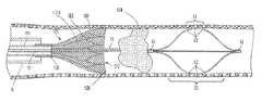
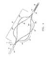
- FIG. 1is plan view of a fluid delivery device with the infusion segment in an expanded position according to an exemplary embodiment the present invention.
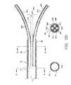
- FIG. 2Ais a partial enlarged cross-sectional view of the expanded infusion segment.
- FIG. 2Bis a partial enlarged cross-sectional view of the proximal portion of the expanded infusion segment.
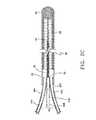
- FIG. 2Cis a partial enlarged cross-sectional view of the distal portion of the expanded infusion segment.
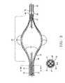
- FIG. 3is a partial cross-sectional view of an alternative embodiment of the fluid delivery device with the infusion segment in an expanded position according to the present invention.
- FIG. 4is an isometric view of the distal section of the fluid delivery device illustrating an embodiment of the infusion segment.
- FIG. 5is an isometric view of the distal section of the fluid delivery device illustrating an embodiment of the infusion segment with twisted infusion arms.
- FIGS. 6A-6Dare enlarged partial plan views of various embodiments of the infusion ports positioned along an infusion arm.
- FIGS. 7A-7Edepict the fluid delivery device within a vessel segment.
- FIG. 7Aillustrates the device prior to deployment of the infusion segment.
- FIG. 7Billustrates the device after expansion of the infusion segment.
- FIG. 7Cillustrates an alternative embodiment of the fluid delivery device having an expandable capture sheath.
- FIG. 7Dillustrates an infusion segment dragging a thrombus mass and thrombus debris into an expandable capture sheath.
- FIG. 7Eillustrates the device with the procedure sheath partially retracted.
- FIG. 8is a partial plan view of an embodiment of the fluid delivery device designed to be advanced over a standard guidewire.
- FIG. 9is photographic image of a prototype of the current invention in a deployed position.
- FIG. 10is a photographic image of prototype of FIG. 9 illustrating jets of fluid exiting from infusion ports.
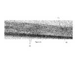
- FIG. 11is a photographic image of the prototype of FIG. 9 positioned within a gel-filled tube illustrating fluid dispersion into the gel mass.
- FIG. 12is an isometric view of an embodiment of an expandable segment having rollers.
- a fluid delivery and treatment device 1for introducing material into the vascular system or other tubular anatomical structure is provided herein.
- Device 1shown in an expanded or deployed state, includes a proximal hub 16 , an elongated hollow member 10 , an expandable infusion segment 20 and a leading flexible tip 55 .
- the expandable infusion segment 20is comprised of a plurality of infusion arms 30 which each contain at least one infusion port 35 as shown in Detail “A”.
- the expandable infusion segment 20is attached to an elongated shaft 10 by a proximal collar 40 , and to the leading flexible tip 55 by a distal collar 43 .
- the proximal-most end of the hollow member 10may be fitted with a removable hub 16 to allow attachment of an injection source or device.
- the hub 16can also be removed to allow the device 1 to be inserted through another treatment device.
- the hub 16may be removed so that a catheter can be back loaded over the proximal most end of the device, such as for the subsequent placement of another type of interventional device.
- FIG. 2Adepicts a partial enlarged longitudinal cross-sectional view of the expanded infusion segment.
- FIG. 2Billustrates a single lumen 11 of the elongated hollow member 10 transitioning into a plurality of dedicated infusion arm lumens or channels 31 A, 31 B, 31 C and 31 D (lumen 31 D is not visible in FIG. 2A or 2B ).
- the elongated hollow member 10is attached to the proximal collar 40 which extends distally over and coaxially surrounds the plurality of infusion arms 30 A-D as shown in cross-section B-B of FIG. 2B .
- the elongated hollow member 10terminates at location 45 where it abuts against the proximal end of the proximal collar 40 .
- the proximal collar 40extends distally over and coaxially surrounds the plurality of infusion arms 30 A-D.
- the proximal sections of arms 30 A-Dare held in place within the shaft 10 and the proximal collar 40 by an adhesive or bonding agent 33 .
- Other techniques known in the artsuch as welding or overmolding may be used.
- FIG. 2Cdepicts a partial enlarged longitudinal cross-sectional view of the distal portion of the expanded infusion segment 20 with the leading flexible tip 55 .
- the dedicated infusion arms 30 A-Dextend distally in a radially inward direction to meet the distal collar 43 .
- Each infusion arm 30 A-Dis held in place by the distal collar 43 which coaxially surrounds the plurality of arms.
- Each infusion lumen 31 A-Dterminates at the plug 52 .
- the plug 52also houses an internal mandrel wire 53 which extends distally through the flexible tip 55 to a weld ball 54 .
- a spring coil 56which is positioned in a spiral fashion around the mandrel wire 53 , provides a leading “floppy” tip as is known in the art.
- the flexible tip 55facilitates tracking and advancement of the device 1 through the vessel or alternatively through the lumen of a catheter or other treatment device.
- the flexible tip 55is approximately 1-2 centimeters in length.
- the coil portion and distal end weld ballmay define an outer diameter of between 0.014′′-0.045′′.
- an embodimentmay be built on a catheter platform between 3 French (0.039′′) to 20 French (0.262′′).
- the deviceis sized appropriately so that it can be inserted into a procedural catheter or sheath.
- the hollow member 10may be comprised of a flexible hollow wire material which has an outer diameter of approximately 0.034′′-0.037′′.
- the radius of the expandable infusion segment 20 in its compressed statewould be the same size as the outer diameter of the hollow member, approximately 0.034′′-0.037′′. Having the hollow member 10 and the expandable infusion segment 20 in its compressed state of approximately 0.034′′-0.037′′ allows for advancement through a standard 0.035′′-0.038′′ catheter lumen.
- the outer diameter of the hollow member 10will be less than the procedure catheter or sheath lumen which in turn allows for proper advancement of the device 1 .
- the infusion device 1may be introduced into the target vessel or other anatomical site using minimally invasive access techniques known in the art.
- the deviceis comprised of a medical grade metal such as Nitinol and dimensioned with an outer diameter of 0.035′′ so as to be capable of being introduced through a standard catheter.
- the leading flexible tip 55facilitates advancement of the device through the vessel to the targeted treatment site.
- a constraining sleeve or catheter(not shown) is retracted to deploy the infusion segment in an expanded position as shown in FIG. 1 .
- Medicinal fluidmay then be introduced through hub 16 ( FIG. 1 ).
- the fluidtravels distally through the single lumen 11 of elongated hollow member 10 to the expanded infusion segment 20 , where fluid exits through the plurality of ports 35 into the targeted treatment site. Specifically, fluid flows through the single lumen 11 and is directed into the dedicated lumens 31 A-D of expanded infusion arms 30 A-D. Fluid flows distally through each dedicated arm lumen exiting through the plurality of ports 35 so as to come in contact with a targeted thrombus, inner vessel wall, or other treatment target.
- the infusion segmentis not self-expanding when unconstrained by a sleeve, but rather is mechanically adjustable to various diameters.
- a tension wireextending through the shaft from the hub and connected to a distal portion of the infusion segment may be used to adjust the deployment diameter of the infusion segment.
- the operatormay mechanically expand the infusion segment to a desired diameter before infusing fluid.
- a self-expanding designis contemplated using a sleeve or catheter to control the expanded diameter of the infusion segment. The diameter may be adjusted by the operator using a sleeve or catheter which may be advanced over and retracted from the infusion segment to adjust the outer diameter.
- the deviceis advanced to the treatment area and the infusion segment is positioned within the thrombus mass.
- the infusion segmentis expanded to a small diameter, and fluid is dispersed through the exit ports into the inner core of the thrombus mass.
- fluidmay be delivered without expanding the infusion segment at all.
- Subsequent adjustment of the infusion segment to a larger diameter followed by re-infusion of fluid through the portswill cause the agent to be dispersed further through the clot mass.
- the therapeutic agentmay be dispersed homogenously throughout the clot mass, ultimately reaching the vessel wall.
- the infusion segmentmay be positioned within the clot and then expanded to a maximum profile or diameter for the infusion of the lytic agent to the outer clot mass first.
- the infusion segmentmay then be incrementally decreased in diameter, working its way into the inner core of the clot mass.
- the infusion delivery devicemay also be used to mechanically disrupt and/or abrade the targeted tissue by manipulating the expanded infusion segment.
- the devicemay be rotated around its longitudinal axis and/or repeatedly advanced and retracted through the targeted area to macerate or abrade the thrombus, and to further disperse the medicinal agent within the thrombus mass.
- the infusion devicecan be used to deliver a sclerosant agent for the treatment of varicose veins.
- Sclerosant agentsdamage the vessel wall, causing the vein to collapse.
- Sotradecol® sclerosantis an agent that is Sotradecol® sclerosant.
- the infusion devicemay be used to deliver sclerosant directly to the vessel wall, thereby minimizing the amount of drug that is diluted by the blood flow. The infusion device is placed at a desired treatment location within the vein.
- the infusion segmentis then expanded to its maximum profile or diameter causing the infusion arms to contact the inner wall. Fluid delivered through the device will exit from the infusion ports located on the expanded arms and come into direct contact with the vessel wall, thereby maximizing the amount of drug delivered to the vessel wall, and reducing the total fluid volume required to achieve a successful treatment.
- the outer diameter of the infusion segmentmay be reduced to accommodate the smaller vessel diameter and the drug delivery may be continued. This method may be repeated to cover longer treatment lengths of veins by segmental treatment and subsequent repositioning of the device along another segment of the vein. Alternatively, a continual pull back method may be used to deliver the drug along the course of a long vein segment. Since the infusion segment is expandable and collapsible, it can expand and collapse, maintaining contact with the inner vessel wall, based on the variable diameter of the vessel anatomy at a particular location along the course of the vein segment.
- the infusion device 1is comprised mainly of a flexible polymer tubing which transitions from a single elongated hollow member 10 to a plurality of flexible, hollow infusion arms 26 which are also comprised of a flexible polymer material.
- a leading flexible tip 55is positioned distally of the infusion segment.
- Nitinol or other shape memory metal wire support elements 27extend through each lumen 25 of the hollow infusion arms 26 . Support elements 27 are pre-formed into an expanded infusion segment profile so that when the constraining sleeve or catheter is retracted as previously described, the infusion segment expands to the pre-formed profile as shown in FIG. 3 .
- support elements 27are positioned within the lumens 25 of infusion arms 26 , which are coaxially surrounded by and held in position by the proximal collar 40 .
- the support elements 27may be formed of solid shape memory wire elements, or they can be formed by longitudinally cutting a metal cannula to form support elements with a wedge-shaped cross-sectional profile as shown in Detail A-A.
- the support elements 27may be free-floating within the lumens 25 of the arms 26 or alternatively, the elements 27 may be positioned within the wall of the infusion arms 26 .
- the fluid delivery system 1is inserted into the vasculature and advanced to the treatment site using the leading flexible tip 55 to facilitate advancement through the vessel.
- the restraining sleeve or catheteris retracted which causes the infusion segment 20 to expand radially outward as the individual support elements 27 “spring” into their unrestrained, preformed shapes as shown in FIG. 3 .
- Fluid delivered through the catheter shaft lumen 10advances through the infusion arms 26 and exits into the targeted tissue via infusion port slits 63 , as described in more detail below.
- the polymer shaft embodiment of the infusion device of the current inventionis advantageous in several respects.
- This embodimentmay be designed to be larger to treat larger vessels or ducts.
- a device as large as 20 Frenchmay be used to treat thrombus or other diseases in larger vessels and ducts.
- Smaller embodimentsmay be used to clear thrombus buildup within implanted medical devices such as dialysis catheters or grafts.
- the devicemay be used to deliver antibacterial or other treatment drugs to vascular access implants such as central or peripheral catheters.
- the flexibility of the deviceprovides a non-traumatic, exterior surface which will not damage or otherwise compromise the implanted device when clearing intraluminal obstructions.
- Using flexible material to coaxially surround the pre-formed support elementsenhances the overall structural integrity of the device.
- the use of a polymer materialallows a greater range of design choices with regarding to the infusion ports as will be described in greater detail with reference to FIG. 6A-6D .
- the elongated hollow member 10terminates at the proximal collar 40 from which four tubular infusion arms 30 A- 30 D emerge.
- the outer diameter of the elongated hollow member 10is approximately 0.035′′ with each infusion arm 30 A-D being approximately 0.010-0.012′′.
- the internal lumen of each infusion armmay be approximately 0.005-0.008′′.
- the infusion arms 30 A-Dexpand outwardly at radial segment 28 , then transition to a maximum outer diameter at segment 31 before turning radially inward along segment 29 .
- the infusion arms 30 A-Dexpand to a maximum diameter of 13-19 mm.
- the embodiment of FIG. 4is designed to allow the infusion device to be inserted through the lumen of an interventional device.
- the operatormay insert the device of the current invention through the lumen of a standard angioplasty device after the initial angioplasty procedure has been completed.
- the devicemay be advanced through the end hole of the angioplasty catheter and positioned within the previously treated vessel segment.
- the infusion segment of the devicemay then be expanded so as to contact the treated wall.
- fluidmay be delivered to the treated site through the plurality of infusion exits.
- restenosis inhibiting agents known in the artmay be delivered directly to the treated area through the infusion device.
- the infusion device described hereinmay be used to provide an adjunctive therapy during a single treatment procedure.
- FIG. 5illustrates an isometric view of yet another embodiment of the current invention.
- the individual infusion arms 30 A- 30 Dare pre-formed to form a twist-shaped infusion segment basket.
- This embodimentis advantageous when supplementing the drug with mechanical disruption of the clot.
- the twist shapewill aid in the dispersion of the drug along the entire circumference of the inner vessel wall.
- the configuration having fluid exit ports positioned along the infusion armsmay have several designs as shown in FIG. 6A-6D .
- the fluid infusion ports 35can be in the shape of holes 62 as shown in FIG. 6A , slits 63 as in 6 B, or various skive designs as shown in FIG. 6C and FIG. 6D .
- the fluid infusion portscan be oriented on an inner surface of the infusion arms 30 pointed towards the inner periphery of the expandable infusion segment to direct drugs such as clot dissolving agents towards a clot located within the lumen of a vessel.
- the fluid infusion portscan be oriented to outer surface of the infusion arms 30 pointed towards the outer periphery of the expandable infusion segment to maximize fluid contact with the inner vessel wall.
- the slits 63 as seen in FIG. 6Bcan be used with the polymer embodiment, which is described in further detail below.
- a plurality of holes 62is are positioned along infusion arm 30 .
- Holes 62may be formed using drilling, laser, electrical-discharge machining (EDM) or punch techniques known in the art.
- the hole diametermay be adjusted so as to control the rate at which the fluid exits the device. For example, the smaller the holes, the higher the velocity at which the fluid is delivered.
- the holesmay also be positioned in a pattern which optimizes dispersion of the fluid along the entire infusion segment.
- a series of infusion ports 35are in the form of pressure responsive slits 63 which evenly distribute fluid along the entire infusion length of each arm.
- the slit designsare disclosed in U.S. Pat. Nos. 5,250,034 and 5,267,979, both of which are herein incorporated by reference.
- These pressure responsive slits 63are in communication with the lumen of the infusion arms 30 and are designed to open under a predetermined pressure created by the introduction of the fluid agent. This design is particularly suited for a polymer embodiment.
- the slits 63also prevent back flow of material into the fluid delivery and treatment device 1 .
- the length of the slits 63may range from 0.005-0.030′′ inches in length and may comprise various slit patterns as is known in the art. Patterns having varying fluid infusion port densities and/or lengths are possible on the same infusion arm 30 .
- the fluid infusion portsmay be in the shape of skives 64 or 65 , as shown in FIGS. 6C-D , which can be used to direct the flow of the fluids in a particular direction.
- An additional benefit of using infusion ports in the shape of skives 64 or 65is that the infusion arms 30 will have a sharpened edge at the point where the infusion arms 30 will contact the vessel wall.
- the infusion segmentmay be used to simultaneously deliver fluids to the vessel wall while scraping or otherwise abrading the luminal wall.
- the skive shapesfacilitate and enhance the treatment of various conditions. For example, rotation of the device may cause the skives to scrape a stenotic lesion within a vessel.
- the collapse of a lumen due to mechanical abrasion of the vessel wallmay be achieved by the sharp edges of the skived holes.
- Mechanical abrasion of the wallmay be done prior to, during, or after the delivery of fluids, depending on the medical condition being treated.
- the skives 64 or 65may further be used to achieve the mechanical disruption of a thrombus within a native vessel/graft or implant lumen.
- the skivesmay also be used to cause disruption of loculated abscesses to improve complex drainage procedures.
- the device of the current inventionmay be inserted into and through the lumen of a drainage catheter. The device may then be used to deliver antibiotic or other fluid, after which the infusion segment may be rotated to disrupt or break up loculations within the abscess.
- the devicemay be used to supplement tumor treatment by the delivery of chemotherapeutic or ablative agents (such as alcohol) to the targeted tumor.
- conductive fluidsuch as saline may be delivered to the tumor volume prior to or during the delivery of either thermal energy or non-thermal electrical pulses to achieve irreversible electroporation, as is known in the art.
- the devicemay be designed so as to deliver occlusion agents and/or abrasive action to fallopian tubes for closure.
- FIGS. 7A-7Billustrate one method of using the device of the current invention.
- the device 1is shown already advanced to the target treatment site.
- the device 1will fit within the lumen of a procedure catheter or sheath 5 .
- the expandable infusion segment 20is in a collapsed or compressed position.
- the procedure sheath 5may be retracted proximally so that the entire expandable infusion segment 20 is fully exposed and expanded.
- the deviceis ready to deliver the intended fluids and/or provide mechanical treatment, as previously described.
- the procedure sheath 5can be partially retracted so that the profile or diameter of the expandable infusion segment 20 is less than the profile at full expansion.
- the expandable infusion segmentis only partially expanded, one or more holes may be exposed, allowing for the infusion of liquid drugs. This may be particularly desirable when the user wants to infuse drugs to the inner core of a thrombus mass.
- partial expansion of the expandable infusion segment 20can be achieved through the use of a tension wire.
- the tension wiremay extend from the hub 16 to a distal portion of the infusion segment, such as the distal collar 43 where it may be secured. In this fashion, the tension wire may be used to adjust the deployment profile of the infusion segment. The user may then mechanically expand the infusion segment to a desired diameter before infusing fluid.
- FIG. 7C and FIG. 7Dillustrate a method of treating a thrombus 134 using an infusion device as previously described, an expandable capture sheath 125 and a procedure sheath 5 .
- the expandable capture sheath 125consists of an elongate shaft 110 having an expandable cone member 120 disposed at a distal end thereof.
- the expandable capture sheath 125can be positioned over the infusion device when within the lumen of the procedure sheath 5 .
- the elongate shaft 110is sized to be disposed within and move independently of both the procedural sheath 5 and the elongated hollow member 10 .
- the expandable sheath 125is designed to collect and capture the thrombus and thrombus debris for removal from the vessel.
- the elongated shaft 110can be made of materials similar to those of the elongated hollow member 10 , as described above.
- the expandable cone member 120can be made from a plurality of Nitinol wire members 122 encased with a material 123 bonded thereto. Permeability of the material 123 can facilitate the maintenance of blood flow, however permeability of the material 123 is optional. In a preferred embodiment, the expandable cone member 120 is shaped like a funnel.
- the Nitinol wire members 122can be covered with an impervious material 123 or formed as a tight mesh so that the expandable cone member 120 can capture smaller pieces of thrombus debris.
- Each wire member 122 of the expandable cone member 120includes a proximal end 126 and distal end 128 . Adjacent proximal ends may come together and be welded or bonded to elongate shaft 110 using an epoxy. Adjacent distal ends 128 form a leading edge defining an open mouth 132 of expandable cone member 120 .
- the expandable cone member 120can also be made from a wire mesh encased with a permeable material bonded thereto.
- the expandable cone member 120When in use, the expandable cone member 120 is collapsed within a procedure sheath 5 and the expandable infusion segment 20 is collapsed within the elongated shaft 110 of the expandable cone member 120 (not shown).
- the expandable infusion segment 20is moved into position either distally of the thrombus as shown in FIG. 7C , or within the clot as shown in FIG. 7D .
- the expandable cone member 120is advanced distally to the thrombus 134 while the expandable infusion segment 20 is held stationary.
- the procedure sheath 5can be proximally retracted, allowing the expandable cone member 120 to self-expand or be mechanically expanded.
- the infusion devicedelivers fluids to the site of the thrombus 134 along its outer most portions using an intended drug for softening the clot and preparing it for removal.
- the expandable infusion segment 20may be manipulated as previously described to further disrupt and abrade the thrombus through mechanical action.
- the softened thrombus 134 and any fragmented thrombus debris 135 or embolimay be dragged into the expandable cone member 120 by retracting the expandable infusion segment 20 .
- the expandable infusion segment 20can be used to hold the thrombus 134 stationary while distally advancing the expandable cone member 120 to capture the thrombus 134 .
- the expandable infusion segment 20 and expandable sheath 125may be retained by the procedural sheath 5 for removal. Additionally, removal of the thrombus 134 and any thrombus debris 135 may be facilitated using standard aspiration techniques. Clot fragments can be aspirated into an annular space between the outer wall or shaft 10 and the inner wall or shaft 110 and out of the hub.
- FIG. 8illustrates another embodiment of the infusion device designed to be used with a standard guidewire.
- the leading flexible tip 55 of FIG. 1has been replaced with a distal tip section having a through lumen which allows the entire device to be backloaded over a standard guidewire 101 .
- the elongated hollow member 210extends from Y-connector 15 distally to the expandable infusion segment 20 .
- a dedicated guidewire lumen 213which extends distally from the Y-connector and terminates at the distal edge of the proximal collar 40 .
- the side arm port 17is in fluid communication with the lumen 211 of the elongated hollow member 210 , providing a fluid path from the Y-arm of the connector 15 to the infusion arm lumens 31 A- 31 D.
- the dedicated guidewire lumen 213is coaxially surrounded by infusion arms 30 A- 30 D.
- the proximal collar 40coaxially surrounds the guidwire lumen 213 and infusion arms 30 A-D.
- the Y-connector 15may include a Touhy-Borst assembly, which is a gasket assembly used for holding and sealing around guidewires or other interventional devices.
- the guidewire compatible design shown in FIG. 8may be sized to be used with guidewires of various sizes ranging from 0.014′′-0.045′′.
- coaxially-positioned guidewire tube 212may extend distally from the distal most end of the proximal collar 40 to the distal end of distal collar 43 .
- Lumen 213 of guidewire tube 212provides a pathway for the guidewire along the entire length of the device.
- the device of FIG. 8is loaded over a guidewire by first collapsing the device infusion segment inside an insertion tool (tube) and then threading the proximal most end of guidewire 101 into the distal end hole of the device at distal collar 43 .
- the guidewire 101is advanced until it exits Y-connector 15 , as shown in FIG. 8 .
- the insertion toolcan then be used to insert the collapsed distal infusion segment through the hub of a procedural catheter or sheath.
- the guidewireis placed in the vessel and positioned at the target area, then the device is threaded over the guidewire. The device is then advanced over the guidewire to the target area.
- FIGS. 9-11are photographic images of one embodiment of the current invention.
- FIG. 9shows the distal portion of the device 1 with the infusion segment 20 in an expanded or deployed position.
- the sleeve/catheter 5is shown retracted proximally away from the infusion segment.
- Four infusion arms 30are shown in a twist configuration.
- the proximal collar 40is attached to the device shaft 10 and the distal collar 43 is attached to leading flexible tip 55 .
- FIG. 10is a photographic image of the device of FIG. 9 shown with fluid 50 exiting the plurality of exit ports at a high velocity.
- FIG. 11illustrates the dispersion of the red-colored fluid 90 within a gel-filled tube 51 . As shown, the injected red fluid 90 is dispersed throughout the green gel along the infusion segment length and extending outwardly to the tube 51 wall.
- FIG. 12illustrates an alternate embodiment of an expandable segment 220 .
- the devicecomprises an expandable segment 220 that has rollers 250 on the expandable arms 230 of the expandable segment.
- the outer portion of the expandable segment 220can contain one or more roller 250 .
- the expandable arms 230can be made from Nitinol or other materials as described for the infusion segment above, and the rollers 250 can be made of Teflon tubing or some other non-stick biocompatible material.
- the expandable segment 220may also have one or more straight expandable arm segments 230 to accommodate the geometry of a tubular shaped roller 250 .
- the expandable segment 220may contain a hydrophilic coating to enhance movement across the vessel wall surface. This aids in preventing the expandable segment 220 from binding or catching on to the inner vessel wall, causing the vessel to twist.
- the proximal end of the expandable segment 220may contain a filter 260 for catching clot debris.
- the filter 260can also be used for trapping clot debris or the entire clot for removal as the expandable segment 220 is retracted into a procedure sheath.
- the distal end of the expandable segment 220can be configured to mechanically and physically break up, dislodge or remove the clot by rotating the expandable segment 220 .
- the expandable arms 230 on the distal end of the expandable segment 220may be shaped with sharpened edges or skive shaped elements for breaking up a clot.
- the distal-most tip 270 of the expandable segment 220may include a corkscrew shaped element (not shown) to help in breaking up a clot.
- the expandable segment 220can be either self-expanding or expanded by mechanical means, such as a tension wire as described above.
- Infusion ports 235could also be located on the expandable arms 230 to allow for the infusion of fluid into the vessel.
- expandable arms 230may include a flexible polymer tubing for infusing fluid into the vessel as described above.
- the fluid delivery and treatment device 1is designed to be used in a variety of body lumens, including but not limited to veins, arteries, ducts, brachial tubes, esophagus, or any other vessel that requires the delivery of drugs or fluids.
- the devicecan be used to deliver a variety of medical preparations including therapeutic agents and diagnostic agents for therapeutic or diagnostic purposes.
Landscapes
- Health & Medical Sciences (AREA)
- Life Sciences & Earth Sciences (AREA)
- Veterinary Medicine (AREA)
- Engineering & Computer Science (AREA)
- Biomedical Technology (AREA)
- Heart & Thoracic Surgery (AREA)
- Public Health (AREA)
- Animal Behavior & Ethology (AREA)
- General Health & Medical Sciences (AREA)
- Surgery (AREA)
- Vascular Medicine (AREA)
- Anesthesiology (AREA)
- Hematology (AREA)
- Molecular Biology (AREA)
- Medical Informatics (AREA)
- Nuclear Medicine, Radiotherapy & Molecular Imaging (AREA)
- Biophysics (AREA)
- Pulmonology (AREA)
- Orthopedic Medicine & Surgery (AREA)
- Reproductive Health (AREA)
- Surgical Instruments (AREA)
Abstract
Description
Claims (10)
Priority Applications (4)
| Application Number | Priority Date | Filing Date | Title |
|---|---|---|---|
| US13/226,538US10039900B2 (en) | 2010-09-07 | 2011-09-07 | Fluid delivery and treatment device and method of use |
| US13/274,163US8858497B2 (en) | 2010-09-07 | 2011-10-14 | Device and method for removing material from a hollow anatomical structure |
| US14/880,344US10350386B2 (en) | 2010-09-07 | 2015-10-12 | Fluid delivery and treatment device and method of use |
| US16/454,644US20190314606A1 (en) | 2010-09-07 | 2019-06-27 | Fluid Delivery and Treatment Device and Method of Use |
Applications Claiming Priority (4)
| Application Number | Priority Date | Filing Date | Title |
|---|---|---|---|
| US38051310P | 2010-09-07 | 2010-09-07 | |
| US38397110P | 2010-09-17 | 2010-09-17 | |
| US38866910P | 2010-10-01 | 2010-10-01 | |
| US13/226,538US10039900B2 (en) | 2010-09-07 | 2011-09-07 | Fluid delivery and treatment device and method of use |
Related Child Applications (2)
| Application Number | Title | Priority Date | Filing Date |
|---|---|---|---|
| US13/274,163Continuation-In-PartUS8858497B2 (en) | 2010-09-07 | 2011-10-14 | Device and method for removing material from a hollow anatomical structure |
| US14/880,344ContinuationUS10350386B2 (en) | 2010-09-07 | 2015-10-12 | Fluid delivery and treatment device and method of use |
Publications (2)
| Publication Number | Publication Date |
|---|---|
| US20120059309A1 US20120059309A1 (en) | 2012-03-08 |
| US10039900B2true US10039900B2 (en) | 2018-08-07 |
Family
ID=45771214
Family Applications (3)
| Application Number | Title | Priority Date | Filing Date |
|---|---|---|---|
| US13/226,538Active2032-04-24US10039900B2 (en) | 2010-09-07 | 2011-09-07 | Fluid delivery and treatment device and method of use |
| US14/880,344Active2033-04-27US10350386B2 (en) | 2010-09-07 | 2015-10-12 | Fluid delivery and treatment device and method of use |
| US16/454,644AbandonedUS20190314606A1 (en) | 2010-09-07 | 2019-06-27 | Fluid Delivery and Treatment Device and Method of Use |
Family Applications After (2)
| Application Number | Title | Priority Date | Filing Date |
|---|---|---|---|
| US14/880,344Active2033-04-27US10350386B2 (en) | 2010-09-07 | 2015-10-12 | Fluid delivery and treatment device and method of use |
| US16/454,644AbandonedUS20190314606A1 (en) | 2010-09-07 | 2019-06-27 | Fluid Delivery and Treatment Device and Method of Use |
Country Status (1)
| Country | Link |
|---|---|
| US (3) | US10039900B2 (en) |
Cited By (6)
| Publication number | Priority date | Publication date | Assignee | Title |
|---|---|---|---|---|
| CN110101451A (en)* | 2019-05-08 | 2019-08-09 | 解涛 | A kind of VR simulation traction device for neurosurgery |
| US20200164117A1 (en)* | 2007-12-20 | 2020-05-28 | Angiodynamics, Inc. | Systems and Methods for Removing Undesirable Material Within a Circulatory System |
| US11426192B2 (en)* | 2013-12-03 | 2022-08-30 | Kawasumi Laboratories, Inc. | Catheter for removing foreign body in blood vessel |
| US12178467B2 (en) | 2011-03-15 | 2024-12-31 | Angiodynamics, Inc. | Device and method for removing material from a hollow anatomical structure |
| US12245781B2 (en) | 2007-12-20 | 2025-03-11 | Angiodynamics, Inc. | Systems and methods for removing undesirable material within a circulatory system |
| US12245788B2 (en) | 2011-03-15 | 2025-03-11 | Angiodynamics, Inc. | Device and method for removing material from a hollow anatomical structure |
Families Citing this family (84)
| Publication number | Priority date | Publication date | Assignee | Title |
|---|---|---|---|---|
| US7686825B2 (en) | 2004-03-25 | 2010-03-30 | Hauser David L | Vascular filter device |
| US11589880B2 (en) | 2007-12-20 | 2023-02-28 | Angiodynamics, Inc. | System and methods for removing undesirable material within a circulatory system utilizing during a surgical procedure |
| US10039900B2 (en)* | 2010-09-07 | 2018-08-07 | Angiodynamics, Inc. | Fluid delivery and treatment device and method of use |
| US11026708B2 (en)* | 2011-07-26 | 2021-06-08 | Thrombx Medical, Inc. | Intravascular thromboembolectomy device and method using the same |
| WO2014047650A1 (en) | 2012-09-24 | 2014-03-27 | Inceptus Medical LLC | Device and method for treating vascular occlusion |
| US8784434B2 (en) | 2012-11-20 | 2014-07-22 | Inceptus Medical, Inc. | Methods and apparatus for treating embolism |
| WO2015013238A2 (en) | 2013-07-22 | 2015-01-29 | Mayo Foundation For Medical Education And Research | Device and methods for self-centering a guide catheter |
| US10238406B2 (en) | 2013-10-21 | 2019-03-26 | Inari Medical, Inc. | Methods and apparatus for treating embolism |
| EP3151904A4 (en)* | 2014-06-04 | 2018-02-14 | Nfinium Vascular Technologies, LLC | Low radial force vascular device and method of occlusion |
| CN106470728A (en) | 2014-06-09 | 2017-03-01 | 因赛普特斯医学有限责任公司 | Retraction and suction device and related systems and methods for treating embolism |
| US20160030068A1 (en)* | 2014-07-31 | 2016-02-04 | Terumo Kabushiki Kaisha | Method for treating varicose veins and intraluminal device used in such method |
| US20160030023A1 (en)* | 2014-07-31 | 2016-02-04 | Terumo Kabushiki Kaisha | Method for treating varicose veins and intraluminal device used in such method |
| PL228142B1 (en)* | 2014-10-17 | 2018-02-28 | Balton Społka Z Ograniczoną Odpowiedzialnością | Catheter containing a cutting element |
| US9981119B2 (en)* | 2014-10-29 | 2018-05-29 | Edwards Lifesciences Corporation | Bi-directional cannula |
| EP3017775A1 (en)* | 2014-11-07 | 2016-05-11 | National University of Ireland, Galway | A thrombectomy device |
| US11771446B2 (en)* | 2020-10-19 | 2023-10-03 | Anaconda Biomed, S.L. | Thrombectomy system and method of use |
| EP3639768A1 (en) | 2018-10-16 | 2020-04-22 | Anaconda Biomed, S.L. | A device for extraction of thrombus from a blood vessel and a thrombectomy apparatus |
| ES2577288B8 (en) | 2015-01-13 | 2019-01-10 | Anaconda Biomed S L | Device for thrombectomy |
| EP3344167B1 (en) | 2015-09-04 | 2021-12-01 | The Trustees of The University of Pennsylvania | Systems for percutaneous removal of objects from an internal body space |
| US12082845B2 (en) | 2015-09-04 | 2024-09-10 | The Trustees Of The University Of Pennsylvania | Systems and methods for percutaneous removal of objects from an internal body space |
| US10722256B2 (en)* | 2015-09-28 | 2020-07-28 | Gyrus Acmi, Inc. | Stone collection device |
| US10342540B2 (en)* | 2015-10-15 | 2019-07-09 | Boston Scientific Scimed, Inc. | Tissue retraction devices and related methods of use |
| US10342571B2 (en) | 2015-10-23 | 2019-07-09 | Inari Medical, Inc. | Intravascular treatment of vascular occlusion and associated devices, systems, and methods |
| US9700332B2 (en)* | 2015-10-23 | 2017-07-11 | Inari Medical, Inc. | Intravascular treatment of vascular occlusion and associated devices, systems, and methods |
| CN113796927B (en) | 2015-10-23 | 2025-03-04 | 伊纳里医疗公司 | Intravascular treatment of vascular occlusion and related devices, systems and methods |
| EP3448276B1 (en) | 2016-04-25 | 2020-03-04 | Stryker Corporation | Clot-engulfing mechanical thrombectomy apparatuses |
| US11497512B2 (en) | 2016-04-25 | 2022-11-15 | Stryker Corporation | Inverting thrombectomy apparatuses and methods |
| US11896247B2 (en) | 2016-04-25 | 2024-02-13 | Stryker Corporation | Inverting mechanical thrombectomy apparatuses |
| CN109561903B (en) | 2016-06-03 | 2021-07-27 | 斯瑞克公司 | Flip thrombectomy device |
| WO2018049317A1 (en) | 2016-09-12 | 2018-03-15 | Stryker Corporation | Self-rolling thrombectomy apparatuses and methods |
| FI3528717T3 (en) | 2016-10-24 | 2024-08-09 | Inari Medical Inc | Devices for treating vascular occlusion |
| US11166803B2 (en) | 2017-04-05 | 2021-11-09 | Boston Scientific Scimed, Inc. | Emboli-capturing centering device |
| US11690645B2 (en) | 2017-05-03 | 2023-07-04 | Medtronic Vascular, Inc. | Tissue-removing catheter |
| EP4018946A1 (en) | 2017-05-03 | 2022-06-29 | Medtronic Vascular, Inc. | Tissue-removing catheter |
| JP6996873B2 (en)* | 2017-06-13 | 2022-01-17 | Sbカワスミ株式会社 | Medical device |
| US11173281B2 (en)* | 2017-06-19 | 2021-11-16 | W. L. Gore & Associates, Inc. | Fenestration devices, systems, and methods |
| WO2019050765A1 (en) | 2017-09-06 | 2019-03-14 | Inari Medical, Inc. | Hemostasis valves and methods of use |
| EP3681418A4 (en) | 2017-09-11 | 2021-05-19 | ThrombX Medical, Inc. | DEVICE AND METHOD FOR INTRAVASCULAR THROMBEMBOLECTOMY |
| EP4176830A1 (en) | 2017-11-09 | 2023-05-10 | Stryker Corporation | Inverting thrombectomy apparatuses having enhanced tracking |
| US10105154B1 (en) | 2017-11-09 | 2018-10-23 | Pebble Hill Partners, Llc | Basket for a catheter device |
| US10874411B2 (en)* | 2018-06-22 | 2020-12-29 | Covidien Lp | Electrically enhanced retrieval of material from vessel lumens |
| US10709463B2 (en) | 2017-12-11 | 2020-07-14 | Covidien Lp | Electrically enhanced retrieval of material from vessel lumens |
| US12318126B2 (en) | 2021-06-25 | 2025-06-03 | Covidien Lp | Current generator for a medical treatment system |
| US11974752B2 (en) | 2019-12-12 | 2024-05-07 | Covidien Lp | Electrically enhanced retrieval of material from vessel lumens |
| US11058444B2 (en) | 2017-12-11 | 2021-07-13 | Covidien Lp | Electrically enhanced retrieval of material from vessel lumens |
| US12004803B2 (en) | 2021-03-15 | 2024-06-11 | Covidien Lp | Thrombectomy treatment system |
| CN111615371B (en)* | 2018-01-23 | 2024-02-27 | 波士顿科学国际有限公司 | Enhanced needle array and treatment for tumor ablation |
| US11154314B2 (en) | 2018-01-26 | 2021-10-26 | Inari Medical, Inc. | Single insertion delivery system for treating embolism and associated systems and methods |
| WO2019222117A1 (en) | 2018-05-14 | 2019-11-21 | Stryker Corporation | Inverting thrombectomy apparatuses and methods of use |
| CN108553741B (en)* | 2018-05-15 | 2021-03-16 | 西南医科大学附属医院 | Cardiovascular intervention catheter device |
| CA3114285A1 (en) | 2018-08-13 | 2020-02-20 | Inari Medical, Inc. | System for treating embolism and associated devices and methods |
| CN112969420B (en) | 2018-09-10 | 2024-12-17 | 史赛克公司 | Inverted thrombectomy device and method of using thrombectomy device |
| CN112702961A (en) | 2018-09-10 | 2021-04-23 | 斯瑞克公司 | Laser grooving and grabbing device |
| US20200085453A1 (en)* | 2018-09-17 | 2020-03-19 | Stryker Corporation | Intra-ventricular infusion and evacuation catheter for treatment of intracerebral hemorrhage (ich) |
| US11298506B2 (en) | 2018-09-17 | 2022-04-12 | Stryker Corporation | Intra-ventricular infusion and evacuation catheter for treatment of intracerebral hemorrhage (ICH) |
| WO2020087009A1 (en) | 2018-10-26 | 2020-04-30 | Progressive NEURO, Inc. | Apparatus, system, and method for vasculature obstruction removal |
| US11197685B2 (en) | 2018-11-15 | 2021-12-14 | Progressive NEURO, Inc. | Apparatus, system, and method for vasculature obstruction removal |
| US11253279B2 (en) | 2018-11-15 | 2022-02-22 | Progressive NEURO, Inc. | Apparatus, system, and method for vasculature obstruction removal |
| CN118697424A (en) | 2018-11-16 | 2024-09-27 | 美敦力瓦斯科尔勒公司 | Tissue Removal Catheter |
| EP3908211B1 (en) | 2019-01-08 | 2024-10-09 | Progressive Neuro, Inc. | System for vasculature obstruction removal |
| US11612430B2 (en) | 2019-03-19 | 2023-03-28 | Covidien Lp | Electrically enhanced retrieval of material from vessel lumens |
| US11724069B2 (en) | 2019-04-30 | 2023-08-15 | Covidien Lp | Catheter including contractible electroactive elements |
| US11819236B2 (en) | 2019-05-17 | 2023-11-21 | Medtronic Vascular, Inc. | Tissue-removing catheter |
| US11523838B2 (en) | 2019-06-12 | 2022-12-13 | Covidien Lp | Retrieval of material from corporeal lumens |
| US11191558B2 (en) | 2019-06-12 | 2021-12-07 | Covidien Lp | Retrieval of material from corporeal lumens |
| JP7638273B2 (en) | 2019-10-16 | 2025-03-03 | イナリ メディカル, インコーポレイテッド | Systems, devices and methods for treating vascular obstructions |
| US11395668B2 (en) | 2019-12-12 | 2022-07-26 | Covidien Lp | Electrically enhanced retrieval of material from vessel lumens |
| WO2021120178A1 (en)* | 2019-12-20 | 2021-06-24 | 南微医学科技股份有限公司 | Minimally invasive surgical extraction instrument |
| DE102020101456A1 (en)* | 2020-01-22 | 2021-07-22 | Andramed Gmbh | Valvulotome |
| US11648020B2 (en) | 2020-02-07 | 2023-05-16 | Angiodynamics, Inc. | Device and method for manual aspiration and removal of an undesirable material |
| US20220331555A1 (en)* | 2020-07-16 | 2022-10-20 | Intervene, Inc. | Intravascular devices and methods for delivery of fluids and therapeutic agents into blood vessel walls and intravascular structures |
| CN112120759B (en)* | 2020-10-13 | 2025-02-28 | 上海腾复医疗科技有限公司 | Drug injection stent and drug injection thrombolytic system containing the same |
| US11872359B2 (en) | 2020-11-12 | 2024-01-16 | Covidien Lp | Expandable-tip aspiration guide catheter |
| US11786388B2 (en) | 2021-03-12 | 2023-10-17 | Cook Medical Technologies Llc | Endovascular delivery systems with radial orientation mechanisms |
| US11696793B2 (en) | 2021-03-19 | 2023-07-11 | Crossfire Medical Inc | Vascular ablation |
| WO2022225721A1 (en)* | 2021-04-19 | 2022-10-27 | Excision Medical, Inc. | Excision catheter system for an aortic valve |
| US11963713B2 (en) | 2021-06-02 | 2024-04-23 | Covidien Lp | Medical treatment system |
| US11944374B2 (en) | 2021-08-30 | 2024-04-02 | Covidien Lp | Electrical signals for retrieval of material from vessel lumens |
| US12076020B2 (en) | 2021-11-18 | 2024-09-03 | Covidien Lp | Retrieval of material from corporeal lumens |
| EP4463083A1 (en) | 2022-01-11 | 2024-11-20 | Inari Medical, Inc. | Devices for removing clot material from intravascularly implanted devices, and associated systems and methods |
| EP4611658A1 (en) | 2022-11-04 | 2025-09-10 | Solvein Inc. | Catheters and related methods for aspiration and controlled delivery of closure agents |
| US20240149020A1 (en) | 2022-11-04 | 2024-05-09 | Controlled Delivery Systems, Inc. | Catheters for the aspiration controlled delivery of closure agents |
| USD1083086S1 (en) | 2022-12-20 | 2025-07-08 | Hollister Incorporated | Intermittent urinary catheter |
| CN115804629A (en)* | 2022-12-26 | 2023-03-17 | 复旦大学 | An intravascular thrombolysis device with a distal collection basket |
Citations (123)
| Publication number | Priority date | Publication date | Assignee | Title |
|---|---|---|---|---|
| US3831587A (en) | 1973-02-08 | 1974-08-27 | Mc Anally R | Multipurpose vaginal and cervical device |
| US4046150A (en)* | 1975-07-17 | 1977-09-06 | American Hospital Supply Corporation | Medical instrument for locating and removing occlusive objects |
| US4273128A (en)* | 1980-01-14 | 1981-06-16 | Lary Banning G | Coronary cutting and dilating instrument |
| US4437856A (en)* | 1981-02-09 | 1984-03-20 | Alberto Valli | Peritoneal catheter device for dialysis |
| US4445509A (en) | 1982-02-04 | 1984-05-01 | Auth David C | Method and apparatus for removal of enclosed abnormal deposits |
| US4469100A (en) | 1983-03-14 | 1984-09-04 | Hardwick Charles W | Intussuscepting balloon catheter for stone extraction |
| US4646736A (en) | 1984-09-10 | 1987-03-03 | E. R. Squibb & Sons, Inc. | Transluminal thrombectomy apparatus |
| US4664112A (en) | 1985-08-12 | 1987-05-12 | Intravascular Surgical Instruments, Inc. | Catheter based surgical methods and apparatus therefor |
| US4671796A (en)* | 1983-05-03 | 1987-06-09 | Catheter Technology Corp. | Valved two-way catheter |
| US4681564A (en)* | 1985-10-21 | 1987-07-21 | Landreneau Michael D | Catheter assembly having balloon extended flow path |
| US4693243A (en)* | 1983-01-14 | 1987-09-15 | Buras Sharon Y | Conduit system for directly administering topical anaesthesia to blocked laryngeal-tracheal areas |
| US4696667A (en) | 1986-03-20 | 1987-09-29 | Helmut Masch | Intravascular catheter and method |
| US4729763A (en) | 1986-06-06 | 1988-03-08 | Henrie Rodney A | Catheter for removing occlusive material |
| US4747821A (en) | 1986-10-22 | 1988-05-31 | Intravascular Surgical Instruments, Inc. | Catheter with high speed moving working head |
| US4749376A (en) | 1986-10-24 | 1988-06-07 | Intravascular Surgical Instruments, Inc. | Reciprocating working head catheter |
| US4790812A (en)* | 1985-11-15 | 1988-12-13 | Hawkins Jr Irvin F | Apparatus and method for removing a target object from a body passsageway |
| US4857045A (en) | 1987-04-30 | 1989-08-15 | Schneider (Usa) Inc., A Pfizer Company | Atherectomy catheter |
| US4857046A (en) | 1987-10-21 | 1989-08-15 | Cordis Corporation | Drive catheter having helical pump drive shaft |
| US4886061A (en)* | 1988-02-09 | 1989-12-12 | Medinnovations, Inc. | Expandable pullback atherectomy catheter system |
| US4895560A (en)* | 1988-03-31 | 1990-01-23 | Papantonakos Apostolos C | Angioplasty apparatus |
| US4895166A (en) | 1987-11-23 | 1990-01-23 | Interventional Technologies, Inc. | Rotatable cutter for the lumen of a blood vesel |
| US4921478A (en) | 1988-02-23 | 1990-05-01 | C. R. Bard, Inc. | Cerebral balloon angioplasty system |
| US4990151A (en) | 1988-09-28 | 1991-02-05 | Medinvent S.A. | Device for transluminal implantation or extraction |
| US4990134A (en) | 1986-01-06 | 1991-02-05 | Heart Technology, Inc. | Transluminal microdissection device |
| US5011488A (en)* | 1988-12-07 | 1991-04-30 | Robert Ginsburg | Thrombus extraction system |
| US5019089A (en) | 1989-12-07 | 1991-05-28 | Interventional Technologies Inc. | Atherectomy advancing probe and method of use |
| US5030201A (en) | 1989-11-24 | 1991-07-09 | Aubrey Palestrant | Expandable atherectomy catheter device |
| US5074841A (en) | 1990-01-30 | 1991-12-24 | Microcision, Inc. | Atherectomy device with helical cutter |
| US5084052A (en) | 1989-02-09 | 1992-01-28 | Baxter International Inc. | Surgical cutting instrument with plurality of openings |
| US5092877A (en)* | 1988-09-01 | 1992-03-03 | Corvita Corporation | Radially expandable endoprosthesis |
| US5098440A (en) | 1990-08-14 | 1992-03-24 | Cordis Corporation | Object retrieval method and apparatus |
| US5100423A (en)* | 1990-08-21 | 1992-03-31 | Medical Engineering & Development Institute, Inc. | Ablation catheter |
| US5114399A (en) | 1990-10-01 | 1992-05-19 | Intramed Laboratories | Surgical device |
| US5158564A (en)* | 1990-02-14 | 1992-10-27 | Angiomed Ag | Atherectomy apparatus |
| US5226909A (en) | 1989-09-12 | 1993-07-13 | Devices For Vascular Intervention, Inc. | Atherectomy device having helical blade and blade guide |
| US5257974A (en)* | 1992-08-19 | 1993-11-02 | Scimed Life Systems, Inc. | Performance enhancement adaptor for intravascular balloon catheter |
| US5273526A (en) | 1991-06-21 | 1993-12-28 | Lake Region Manufacturing Company, Inc. | Vascular occulusion removal devices and method |
| US5306250A (en)* | 1992-04-02 | 1994-04-26 | Indiana University Foundation | Method and apparatus for intravascular drug delivery |
| US5334208A (en) | 1990-07-09 | 1994-08-02 | Wilson-Cook Medical Inc. | Method for retrieving stents |
| US5423799A (en) | 1988-12-14 | 1995-06-13 | Medtronic, Inc. | Surgical instrument |
| US5464408A (en) | 1991-06-14 | 1995-11-07 | Duc; Jerome | Transluminal implantation or extraction device |
| US5474563A (en) | 1993-03-25 | 1995-12-12 | Myler; Richard | Cardiovascular stent and retrieval apparatus |
| US5490859A (en)* | 1992-11-13 | 1996-02-13 | Scimed Life Systems, Inc. | Expandable intravascular occlusion material removal devices and methods of use |
| US5520697A (en) | 1992-06-20 | 1996-05-28 | Angiomed Ag | Apparatus for correcting the position of a stent |
| US5540707A (en) | 1992-11-13 | 1996-07-30 | Scimed Life Systems, Inc. | Expandable intravascular occlusion material removal devices and methods of use |
| US5569275A (en) | 1991-06-11 | 1996-10-29 | Microvena Corporation | Mechanical thrombus maceration device |
| US5571086A (en)* | 1992-11-02 | 1996-11-05 | Localmed, Inc. | Method and apparatus for sequentially performing multiple intraluminal procedures |
| US5628746A (en)* | 1989-01-18 | 1997-05-13 | Applied Medical Resources Corporation | Dilatation catheter assembly with cutting element and method of using the same |
| US5632755A (en) | 1992-11-09 | 1997-05-27 | Endo Vascular Intruments, Inc. | Intra-artery obstruction clearing apparatus and methods |
| US5643309A (en) | 1993-03-25 | 1997-07-01 | Myler; Richard | Cardiovascular stent and retrieval apparatus |
| US5653684A (en) | 1992-06-26 | 1997-08-05 | Schneider (Usa), Inc. | Catheter with expandable wire mesh tip |
| US5772629A (en)* | 1995-10-23 | 1998-06-30 | Localmed, Inc. | Localized intravascular delivery of TFPI for inhibition of restenosis in recanalized blood vessels |
| US5776141A (en)* | 1995-08-28 | 1998-07-07 | Localmed, Inc. | Method and apparatus for intraluminal prosthesis delivery |
| US5785715A (en) | 1995-12-07 | 1998-07-28 | Schatz; Richard A. | Retrieval shuttle |
| US5843103A (en) | 1997-03-06 | 1998-12-01 | Scimed Life Systems, Inc. | Shaped wire rotational atherectomy device |
| US5868753A (en) | 1995-11-13 | 1999-02-09 | Schatz; Richard A. | Stent retrieval catheter |
| US5873882A (en) | 1995-03-28 | 1999-02-23 | Straub Medical Ag | Catheter for detaching abnormal deposits from blood vessels in humans |
| US5910144A (en) | 1998-01-09 | 1999-06-08 | Endovascular Technologies, Inc. | Prosthesis gripping system and method |
| US5941895A (en) | 1996-09-04 | 1999-08-24 | Hemodynamics, Inc. | Cardiovascular stent and retrieval apparatus |
| US6001112A (en) | 1998-04-10 | 1999-12-14 | Endicor Medical, Inc. | Rotational atherectomy device |
| US6106531A (en) | 1995-12-07 | 2000-08-22 | Schatz; Richard A. | Retrieval shuttle |
| US6187016B1 (en) | 1999-09-14 | 2001-02-13 | Daniel G. Hedges | Stent retrieval device |
| US6203537B1 (en) | 1999-02-04 | 2001-03-20 | Sorin Adrian | Laser-driven acoustic ablation catheter |
| US6241738B1 (en) | 1995-11-07 | 2001-06-05 | Jean-Pierre G. E. Dereume | Retrieval device for insertion into a body lumen |
| US20010011179A1 (en) | 1999-09-17 | 2001-08-02 | Scimed Life System, Inc. | Balloon with reversed cones |
| US6280413B1 (en) | 1995-06-07 | 2001-08-28 | Medtronic Ave, Inc. | Thrombolytic filtration and drug delivery catheter with a self-expanding portion |
| US6283940B1 (en)* | 1997-08-29 | 2001-09-04 | S. Grant Mulholland | Catheter |
| US20020010487A1 (en) | 2000-03-31 | 2002-01-24 | Evans Michael A. | Expansible shearing catheters for thrombus removal |
| US6394978B1 (en)* | 2000-08-09 | 2002-05-28 | Advanced Cardiovascular Systems, Inc. | Interventional procedure expandable balloon expansion enabling system and method |
| US20020072764A1 (en) | 2000-06-29 | 2002-06-13 | Concentric Medical, Inc. | Systems, method and devices for removing obstructions from a blood vessel |
| US20020120277A1 (en) | 2001-02-12 | 2002-08-29 | Hauschild Sidney F. | Foreign body retrieval device and method |
| US6451036B1 (en) | 1998-04-10 | 2002-09-17 | Endicor Medical, Inc. | Rotational atherectomy system with stationary cutting elements |
| US6454775B1 (en) | 1999-12-06 | 2002-09-24 | Bacchus Vascular Inc. | Systems and methods for clot disruption and retrieval |
| US20020143387A1 (en) | 2001-03-27 | 2002-10-03 | Soetikno Roy M. | Stent repositioning and removal |
| US20020151918A1 (en) | 2001-04-17 | 2002-10-17 | Scimed Life Systems, Inc. | In-stent ablative tool |
| US20020161427A1 (en) | 2001-04-27 | 2002-10-31 | Dmitry Rabkin | Methods for delivering, repositioning and/or retrieving self-expanding stents |
| US20020188276A1 (en) | 2000-01-25 | 2002-12-12 | Bacchus Vascular, Inc. | Apparatus and methods for clot dissolution |
| US6508782B1 (en) | 1992-05-19 | 2003-01-21 | Bacchus Vascular, Inc. | Thrombolysis device |
| US20030023204A1 (en) | 1998-03-13 | 2003-01-30 | Vo Hung Van | Catheter having a funnel-shaped occlusion balloon of uniform thickness and methods of manufacture |
| US6569181B1 (en) | 2000-12-20 | 2003-05-27 | Advanced Cardiovascular Systems, Inc. | Stent retrieval system |
| US6582396B1 (en) | 1998-05-13 | 2003-06-24 | Arteria Medical Science, Inc. | Puncture resistant balloon for use in carotid artery procedures and methods of use |
| US6602264B1 (en) | 1997-07-24 | 2003-08-05 | Rex Medical, L.P. | Rotational thrombectomy apparatus and method with standing wave |
| US20030195537A1 (en) | 1998-02-10 | 2003-10-16 | Artemis Medical, Inc. | Medical device and methods for use |
| US20030199890A1 (en) | 1998-02-10 | 2003-10-23 | Artemis Medical, Inc. | Tissue separation method |
| US20030236533A1 (en) | 2002-06-20 | 2003-12-25 | The Regents Of The University Of California | Shape memory polymer actuator and catheter |
| US6679893B1 (en) | 2000-11-16 | 2004-01-20 | Chestnut Medical Technologies, Inc. | Grasping device and method of use |
| US6702830B1 (en) | 1999-09-17 | 2004-03-09 | Bacchus Vascular, Inc. | Mechanical pump for removal of fragmented matter and methods of manufacture and use |
| US6719717B1 (en) | 2000-03-17 | 2004-04-13 | Advanced Research & Technology Institute, Inc. | Thrombectomy treatment system and method |
| US6749619B2 (en)* | 2001-11-20 | 2004-06-15 | The Cleveland Clinic Foundation | Apparatus and method for eliminating dislodged thrombus |
| US20040181237A1 (en) | 2003-03-12 | 2004-09-16 | Sean Forde | Medical device for manipulation of a medical implant |
| US20050004594A1 (en) | 2003-07-02 | 2005-01-06 | Jeffrey Nool | Devices and methods for aspirating from filters |
| US20050080431A1 (en) | 2002-12-02 | 2005-04-14 | Gi Dynamics, Inc. | Bariatric sleeve removal devices |
| US20050080480A1 (en) | 2001-06-01 | 2005-04-14 | Bolea Stephen L. | Retrievable stent and method of use thereof |
| WO2005079678A1 (en) | 2004-02-19 | 2005-09-01 | Applied Medical Resources Corporation | Embolectomy capture sheath |
| US7014913B2 (en)* | 2001-09-27 | 2006-03-21 | Advanced Cardiovascular Systems, Inc. | Rate-reducing membrane for release of an agent |
| US20060189930A1 (en) | 2000-07-21 | 2006-08-24 | Lary Banning G | Methods and Apparatus for Sclerosing the Wall of a Varicose Vein |
| US20060200191A1 (en) | 1996-05-20 | 2006-09-07 | Gholam-Reza Zadno-Azizi | Method and apparatuses for treating an intravascular occlusion |
| US7108704B2 (en)* | 1992-04-07 | 2006-09-19 | Johns Hopkins University | Percutaneous mechanical fragmentation catheter system |
| US7153320B2 (en) | 2001-12-13 | 2006-12-26 | Scimed Life Systems, Inc. | Hydraulic controlled retractable tip filter retrieval catheter |
| US20070027520A1 (en) | 2005-07-27 | 2007-02-01 | Sherburne Paul S | Stent removal from a body |
| US20070118072A1 (en) | 1996-07-26 | 2007-05-24 | Kensey Nash Corporation | System and Method of Use for Revascularizing Stenotic Bypass Grafts and Other Blood Vessels |
| US7235088B2 (en) | 1998-04-10 | 2007-06-26 | Ev3 Endovascular, Inc. | Neuro thrombectomy catheter |
| US20080033482A1 (en) | 1999-08-27 | 2008-02-07 | Ev3 Inc. | Slideable vascular filter |
| US7351255B2 (en)* | 2001-12-03 | 2008-04-01 | Xtent, Inc. | Stent delivery apparatus and method |
| US20080249558A1 (en) | 2007-04-05 | 2008-10-09 | Nmt Medical, Inc. | Implant recovery device |
| US20090099581A1 (en) | 2007-05-24 | 2009-04-16 | Kim Daniel H | Methods and apparatus for treating vascular occlusions |
| US20090222035A1 (en) | 2006-03-27 | 2009-09-03 | Tel Hashomer Medical Research Infrastructure And S | Intraluminal Mass Collector |
| US20090292307A1 (en) | 2008-05-22 | 2009-11-26 | Nasser Razack | Mechanical embolectomy device and method |
| US20090306702A1 (en)* | 2004-08-23 | 2009-12-10 | Elina Miloslavski | Device for the Removal of Thrombi |
| US7655016B2 (en) | 1999-09-17 | 2010-02-02 | Covidien | Mechanical pump for removal of fragmented matter and methods of manufacture and use |
| US20100057184A1 (en) | 2008-08-29 | 2010-03-04 | Cook Incorporated | Intraluminal system for retrieving an implantable medical device |
| US7842010B2 (en) | 2005-12-05 | 2010-11-30 | Medrad, Inc. | Pneumatically-operated thrombectomy catheter deployment system |
| US7862575B2 (en)* | 2003-05-21 | 2011-01-04 | Yale University | Vascular ablation apparatus and method |
| US7879022B2 (en) | 1998-02-06 | 2011-02-01 | Medrad, Inc. | Rapid exchange fluid jet thrombectomy device and method |
| US7892273B2 (en)* | 2001-12-03 | 2011-02-22 | Xtent, Inc. | Custom length stent apparatus |
| US7912531B1 (en)* | 2003-12-17 | 2011-03-22 | Advanced Cardiovascular Systems, Inc. | Magnetic resonance imaging coils |
| US20110190806A1 (en) | 2008-06-19 | 2011-08-04 | Angiodynamics, Inc. | Thrombectomy catheter and a device comprising the same |
| WO2011144336A1 (en) | 2010-05-18 | 2011-11-24 | Acandis Gmbh & Co. Kg | Medical device for removing concretions |
| US8075510B2 (en) | 2007-12-20 | 2011-12-13 | Vortex Medical, Inc. | Systems and methods for removing undesirable material within a circulatory system |
| US20120059309A1 (en) | 2010-09-07 | 2012-03-08 | Angiodynamics, Inc. | Fluid Delivery and Treatment Device and Method of Use |
| US8167903B2 (en) | 2008-06-04 | 2012-05-01 | Cook Medical Technologies Llc | Device for retrieving a foreign object located in a body vessel |
| US8317859B2 (en)* | 2004-06-28 | 2012-11-27 | J.W. Medical Systems Ltd. | Devices and methods for controlling expandable prostheses during deployment |
| US8734374B2 (en) | 2007-12-20 | 2014-05-27 | Angiodynamics, Inc. | Systems and methods for removing undesirable material within a circulatory system during a surgical procedure |
Family Cites Families (4)
| Publication number | Priority date | Publication date | Assignee | Title |
|---|---|---|---|---|
| US9440046B2 (en)* | 2002-04-04 | 2016-09-13 | Angiodynamics, Inc. | Venous insufficiency treatment method |
| US20060129095A1 (en)* | 2004-12-08 | 2006-06-15 | Leonard Pinchuk | Drug delivery apparatus |
| US8858497B2 (en)* | 2010-09-07 | 2014-10-14 | Angio Dynamics, Inc. | Device and method for removing material from a hollow anatomical structure |
| EP3017775A1 (en)* | 2014-11-07 | 2016-05-11 | National University of Ireland, Galway | A thrombectomy device |
- 2011
- 2011-09-07USUS13/226,538patent/US10039900B2/enactiveActive
- 2015
- 2015-10-12USUS14/880,344patent/US10350386B2/enactiveActive
- 2019
- 2019-06-27USUS16/454,644patent/US20190314606A1/ennot_activeAbandoned
Patent Citations (156)
| Publication number | Priority date | Publication date | Assignee | Title |
|---|---|---|---|---|
| US3831587A (en) | 1973-02-08 | 1974-08-27 | Mc Anally R | Multipurpose vaginal and cervical device |
| US4046150A (en)* | 1975-07-17 | 1977-09-06 | American Hospital Supply Corporation | Medical instrument for locating and removing occlusive objects |
| US4273128A (en)* | 1980-01-14 | 1981-06-16 | Lary Banning G | Coronary cutting and dilating instrument |
| US4437856A (en)* | 1981-02-09 | 1984-03-20 | Alberto Valli | Peritoneal catheter device for dialysis |
| US4445509A (en) | 1982-02-04 | 1984-05-01 | Auth David C | Method and apparatus for removal of enclosed abnormal deposits |
| US4693243A (en)* | 1983-01-14 | 1987-09-15 | Buras Sharon Y | Conduit system for directly administering topical anaesthesia to blocked laryngeal-tracheal areas |
| US4469100A (en) | 1983-03-14 | 1984-09-04 | Hardwick Charles W | Intussuscepting balloon catheter for stone extraction |
| US4671796A (en)* | 1983-05-03 | 1987-06-09 | Catheter Technology Corp. | Valved two-way catheter |
| US4646736A (en) | 1984-09-10 | 1987-03-03 | E. R. Squibb & Sons, Inc. | Transluminal thrombectomy apparatus |
| US4664112A (en) | 1985-08-12 | 1987-05-12 | Intravascular Surgical Instruments, Inc. | Catheter based surgical methods and apparatus therefor |
| US4681564A (en)* | 1985-10-21 | 1987-07-21 | Landreneau Michael D | Catheter assembly having balloon extended flow path |
| US4790812A (en)* | 1985-11-15 | 1988-12-13 | Hawkins Jr Irvin F | Apparatus and method for removing a target object from a body passsageway |
| US4990134B1 (en) | 1986-01-06 | 1996-11-05 | Heart Techn Inc | Transluminal microdissection device |
| US4990134A (en) | 1986-01-06 | 1991-02-05 | Heart Technology, Inc. | Transluminal microdissection device |
| US4696667A (en) | 1986-03-20 | 1987-09-29 | Helmut Masch | Intravascular catheter and method |
| US4729763A (en) | 1986-06-06 | 1988-03-08 | Henrie Rodney A | Catheter for removing occlusive material |
| US4747821A (en) | 1986-10-22 | 1988-05-31 | Intravascular Surgical Instruments, Inc. | Catheter with high speed moving working head |
| US4749376A (en) | 1986-10-24 | 1988-06-07 | Intravascular Surgical Instruments, Inc. | Reciprocating working head catheter |
| US4857045A (en) | 1987-04-30 | 1989-08-15 | Schneider (Usa) Inc., A Pfizer Company | Atherectomy catheter |
| US4857046A (en) | 1987-10-21 | 1989-08-15 | Cordis Corporation | Drive catheter having helical pump drive shaft |
| US4895166A (en) | 1987-11-23 | 1990-01-23 | Interventional Technologies, Inc. | Rotatable cutter for the lumen of a blood vesel |
| US4886061A (en)* | 1988-02-09 | 1989-12-12 | Medinnovations, Inc. | Expandable pullback atherectomy catheter system |
| US4921478A (en) | 1988-02-23 | 1990-05-01 | C. R. Bard, Inc. | Cerebral balloon angioplasty system |
| US4895560A (en)* | 1988-03-31 | 1990-01-23 | Papantonakos Apostolos C | Angioplasty apparatus |
| US5092877A (en)* | 1988-09-01 | 1992-03-03 | Corvita Corporation | Radially expandable endoprosthesis |
| US4990151A (en) | 1988-09-28 | 1991-02-05 | Medinvent S.A. | Device for transluminal implantation or extraction |
| US5011488A (en)* | 1988-12-07 | 1991-04-30 | Robert Ginsburg | Thrombus extraction system |
| US5423799A (en) | 1988-12-14 | 1995-06-13 | Medtronic, Inc. | Surgical instrument |
| US6443966B1 (en) | 1988-12-14 | 2002-09-03 | Intravascular Medical, Inc. | Surgical instrument |
| US5628746A (en)* | 1989-01-18 | 1997-05-13 | Applied Medical Resources Corporation | Dilatation catheter assembly with cutting element and method of using the same |
| US5084052A (en) | 1989-02-09 | 1992-01-28 | Baxter International Inc. | Surgical cutting instrument with plurality of openings |
| US5226909A (en) | 1989-09-12 | 1993-07-13 | Devices For Vascular Intervention, Inc. | Atherectomy device having helical blade and blade guide |
| US5030201A (en) | 1989-11-24 | 1991-07-09 | Aubrey Palestrant | Expandable atherectomy catheter device |
| US5019089A (en) | 1989-12-07 | 1991-05-28 | Interventional Technologies Inc. | Atherectomy advancing probe and method of use |
| US5074841A (en) | 1990-01-30 | 1991-12-24 | Microcision, Inc. | Atherectomy device with helical cutter |
| US5158564A (en)* | 1990-02-14 | 1992-10-27 | Angiomed Ag | Atherectomy apparatus |
| US5334208A (en) | 1990-07-09 | 1994-08-02 | Wilson-Cook Medical Inc. | Method for retrieving stents |
| US5098440A (en) | 1990-08-14 | 1992-03-24 | Cordis Corporation | Object retrieval method and apparatus |
| US5100423A (en)* | 1990-08-21 | 1992-03-31 | Medical Engineering & Development Institute, Inc. | Ablation catheter |
| US5114399A (en) | 1990-10-01 | 1992-05-19 | Intramed Laboratories | Surgical device |
| US5569275A (en) | 1991-06-11 | 1996-10-29 | Microvena Corporation | Mechanical thrombus maceration device |
| US5464408A (en) | 1991-06-14 | 1995-11-07 | Duc; Jerome | Transluminal implantation or extraction device |
| US5273526A (en) | 1991-06-21 | 1993-12-28 | Lake Region Manufacturing Company, Inc. | Vascular occulusion removal devices and method |
| US5306250A (en)* | 1992-04-02 | 1994-04-26 | Indiana University Foundation | Method and apparatus for intravascular drug delivery |
| US7108704B2 (en)* | 1992-04-07 | 2006-09-19 | Johns Hopkins University | Percutaneous mechanical fragmentation catheter system |
| US6508782B1 (en) | 1992-05-19 | 2003-01-21 | Bacchus Vascular, Inc. | Thrombolysis device |
| US5520697A (en) | 1992-06-20 | 1996-05-28 | Angiomed Ag | Apparatus for correcting the position of a stent |
| US5653684A (en) | 1992-06-26 | 1997-08-05 | Schneider (Usa), Inc. | Catheter with expandable wire mesh tip |
| US5257974A (en)* | 1992-08-19 | 1993-11-02 | Scimed Life Systems, Inc. | Performance enhancement adaptor for intravascular balloon catheter |
| US5571086A (en)* | 1992-11-02 | 1996-11-05 | Localmed, Inc. | Method and apparatus for sequentially performing multiple intraluminal procedures |
| US5632755A (en) | 1992-11-09 | 1997-05-27 | Endo Vascular Intruments, Inc. | Intra-artery obstruction clearing apparatus and methods |
| US5490859A (en)* | 1992-11-13 | 1996-02-13 | Scimed Life Systems, Inc. | Expandable intravascular occlusion material removal devices and methods of use |
| US5540707A (en) | 1992-11-13 | 1996-07-30 | Scimed Life Systems, Inc. | Expandable intravascular occlusion material removal devices and methods of use |
| US5643309A (en) | 1993-03-25 | 1997-07-01 | Myler; Richard | Cardiovascular stent and retrieval apparatus |
| US5733302A (en) | 1993-03-25 | 1998-03-31 | Hemodynamics, Inc. | Cardiovascular stent and retrieval apparatus |
| US5474563A (en) | 1993-03-25 | 1995-12-12 | Myler; Richard | Cardiovascular stent and retrieval apparatus |
| US6547754B1 (en) | 1993-05-19 | 2003-04-15 | Bacchus Vascular, Inc. | Thrombolysis device |
| US5873882A (en) | 1995-03-28 | 1999-02-23 | Straub Medical Ag | Catheter for detaching abnormal deposits from blood vessels in humans |
| US6280413B1 (en) | 1995-06-07 | 2001-08-28 | Medtronic Ave, Inc. | Thrombolytic filtration and drug delivery catheter with a self-expanding portion |
| US5776141A (en)* | 1995-08-28 | 1998-07-07 | Localmed, Inc. | Method and apparatus for intraluminal prosthesis delivery |
| US5772629A (en)* | 1995-10-23 | 1998-06-30 | Localmed, Inc. | Localized intravascular delivery of TFPI for inhibition of restenosis in recanalized blood vessels |
| US6241738B1 (en) | 1995-11-07 | 2001-06-05 | Jean-Pierre G. E. Dereume | Retrieval device for insertion into a body lumen |
| US5868753A (en) | 1995-11-13 | 1999-02-09 | Schatz; Richard A. | Stent retrieval catheter |
| US5785715A (en) | 1995-12-07 | 1998-07-28 | Schatz; Richard A. | Retrieval shuttle |
| US6106531A (en) | 1995-12-07 | 2000-08-22 | Schatz; Richard A. | Retrieval shuttle |
| US20060200191A1 (en) | 1996-05-20 | 2006-09-07 | Gholam-Reza Zadno-Azizi | Method and apparatuses for treating an intravascular occlusion |
| US20070118072A1 (en) | 1996-07-26 | 2007-05-24 | Kensey Nash Corporation | System and Method of Use for Revascularizing Stenotic Bypass Grafts and Other Blood Vessels |
| US5941895A (en) | 1996-09-04 | 1999-08-24 | Hemodynamics, Inc. | Cardiovascular stent and retrieval apparatus |
| US5843103A (en) | 1997-03-06 | 1998-12-01 | Scimed Life Systems, Inc. | Shaped wire rotational atherectomy device |
| US6602264B1 (en) | 1997-07-24 | 2003-08-05 | Rex Medical, L.P. | Rotational thrombectomy apparatus and method with standing wave |
| US6283940B1 (en)* | 1997-08-29 | 2001-09-04 | S. Grant Mulholland | Catheter |
| US6280464B1 (en) | 1998-01-09 | 2001-08-28 | Endovascular Technologies, Inc. | Prosthesis gripping system and method |
| US5910144A (en) | 1998-01-09 | 1999-06-08 | Endovascular Technologies, Inc. | Prosthesis gripping system and method |
| US7879022B2 (en) | 1998-02-06 | 2011-02-01 | Medrad, Inc. | Rapid exchange fluid jet thrombectomy device and method |
| US20030199890A1 (en) | 1998-02-10 | 2003-10-23 | Artemis Medical, Inc. | Tissue separation method |
| US20030195537A1 (en) | 1998-02-10 | 2003-10-16 | Artemis Medical, Inc. | Medical device and methods for use |
| US20030023204A1 (en) | 1998-03-13 | 2003-01-30 | Vo Hung Van | Catheter having a funnel-shaped occlusion balloon of uniform thickness and methods of manufacture |
| US6206898B1 (en) | 1998-04-10 | 2001-03-27 | Endicor Medical, Inc. | Rotational atherectomy device |
| US6666874B2 (en) | 1998-04-10 | 2003-12-23 | Endicor Medical, Inc. | Rotational atherectomy system with serrated cutting tip |
| US7479147B2 (en) | 1998-04-10 | 2009-01-20 | Ev3 Endovascular, Inc. | Rotational atherectomy device |
| US7771445B2 (en) | 1998-04-10 | 2010-08-10 | Ev3 Endovascular, Inc. | Rotational atherectomy system with stationary cutting elements |
| US7235088B2 (en) | 1998-04-10 | 2007-06-26 | Ev3 Endovascular, Inc. | Neuro thrombectomy catheter |
| US7842055B2 (en) | 1998-04-10 | 2010-11-30 | Ev3 Endovascular, Inc. | Neuro thrombectomy catheter |
| US7172610B2 (en) | 1998-04-10 | 2007-02-06 | Ev3 Endovascular, Inc. | Rotational atherectomy system with stationary cutting elements |
| US6451036B1 (en) | 1998-04-10 | 2002-09-17 | Endicor Medical, Inc. | Rotational atherectomy system with stationary cutting elements |
| US6454779B1 (en) | 1998-04-10 | 2002-09-24 | Endicor Medical, Inc. | Rotational atherectomy device |
| US6001112A (en) | 1998-04-10 | 1999-12-14 | Endicor Medical, Inc. | Rotational atherectomy device |
| US6582396B1 (en) | 1998-05-13 | 2003-06-24 | Arteria Medical Science, Inc. | Puncture resistant balloon for use in carotid artery procedures and methods of use |
| US6203537B1 (en) | 1999-02-04 | 2001-03-20 | Sorin Adrian | Laser-driven acoustic ablation catheter |
| US20080033482A1 (en) | 1999-08-27 | 2008-02-07 | Ev3 Inc. | Slideable vascular filter |
| US6187016B1 (en) | 1999-09-14 | 2001-02-13 | Daniel G. Hedges | Stent retrieval device |
| US20010011179A1 (en) | 1999-09-17 | 2001-08-02 | Scimed Life System, Inc. | Balloon with reversed cones |
| US7655016B2 (en) | 1999-09-17 | 2010-02-02 | Covidien | Mechanical pump for removal of fragmented matter and methods of manufacture and use |
| US6702830B1 (en) | 1999-09-17 | 2004-03-09 | Bacchus Vascular, Inc. | Mechanical pump for removal of fragmented matter and methods of manufacture and use |
| US6454775B1 (en) | 1999-12-06 | 2002-09-24 | Bacchus Vascular Inc. | Systems and methods for clot disruption and retrieval |
| US20040082962A1 (en) | 1999-12-06 | 2004-04-29 | Bacchus Vascular, Inc. | Systems and methods for clot disruption and retrieval |
| US6945977B2 (en) | 1999-12-06 | 2005-09-20 | Bacchus Vascular, Inc. | Systems and methods for clot disruption and retrieval |
| US6660014B2 (en) | 1999-12-06 | 2003-12-09 | Bacchus Vascular, Inc. | Systems and methods for clot disruption and retrieval |
| US20020188276A1 (en) | 2000-01-25 | 2002-12-12 | Bacchus Vascular, Inc. | Apparatus and methods for clot dissolution |
| US6719717B1 (en) | 2000-03-17 | 2004-04-13 | Advanced Research & Technology Institute, Inc. | Thrombectomy treatment system and method |
| US20030055445A1 (en) | 2000-03-31 | 2003-03-20 | Bacchus Vascular, Inc. | Expansible shearing catheters for thrombus and occlusive material removal |
| US20020010487A1 (en) | 2000-03-31 | 2002-01-24 | Evans Michael A. | Expansible shearing catheters for thrombus removal |
| US20020072764A1 (en) | 2000-06-29 | 2002-06-13 | Concentric Medical, Inc. | Systems, method and devices for removing obstructions from a blood vessel |
| US20060189930A1 (en) | 2000-07-21 | 2006-08-24 | Lary Banning G | Methods and Apparatus for Sclerosing the Wall of a Varicose Vein |
| US6394978B1 (en)* | 2000-08-09 | 2002-05-28 | Advanced Cardiovascular Systems, Inc. | Interventional procedure expandable balloon expansion enabling system and method |
| US6679893B1 (en) | 2000-11-16 | 2004-01-20 | Chestnut Medical Technologies, Inc. | Grasping device and method of use |
| US6569181B1 (en) | 2000-12-20 | 2003-05-27 | Advanced Cardiovascular Systems, Inc. | Stent retrieval system |
| US6802846B2 (en) | 2001-02-12 | 2004-10-12 | Ams Research Corporation | Foreign body retrieval device and method |
| US20020120277A1 (en) | 2001-02-12 | 2002-08-29 | Hauschild Sidney F. | Foreign body retrieval device and method |
| US20020143387A1 (en) | 2001-03-27 | 2002-10-03 | Soetikno Roy M. | Stent repositioning and removal |
| US20020151918A1 (en) | 2001-04-17 | 2002-10-17 | Scimed Life Systems, Inc. | In-stent ablative tool |
| US20020161377A1 (en) | 2001-04-27 | 2002-10-31 | Dmitry Rabkin | Apparatus for delivering, repositioning and/or retrieving self-expanding stents |
| US6676692B2 (en) | 2001-04-27 | 2004-01-13 | Intek Technology L.L.C. | Apparatus for delivering, repositioning and/or retrieving self-expanding stents |
| US6837901B2 (en) | 2001-04-27 | 2005-01-04 | Intek Technology L.L.C. | Methods for delivering, repositioning and/or retrieving self-expanding stents |
| US20040210298A1 (en) | 2001-04-27 | 2004-10-21 | Intek Technology, L.L.C. | Methods for delivering, repositioning and/or retrieving self-expanding stents |
| US20020161427A1 (en) | 2001-04-27 | 2002-10-31 | Dmitry Rabkin | Methods for delivering, repositioning and/or retrieving self-expanding stents |
| US7258696B2 (en) | 2001-04-27 | 2007-08-21 | Intek Technology L.L.C. | Apparatus for delivering, repositioning and/or retrieving self-expanding stents |
| US20040147939A1 (en) | 2001-04-27 | 2004-07-29 | Intek Technology, L.L.C. | Apparatus for delivering, repositioning and/or retrieving self-expanding stents |
| US20050080480A1 (en) | 2001-06-01 | 2005-04-14 | Bolea Stephen L. | Retrievable stent and method of use thereof |
| US7014913B2 (en)* | 2001-09-27 | 2006-03-21 | Advanced Cardiovascular Systems, Inc. | Rate-reducing membrane for release of an agent |
| US6749619B2 (en)* | 2001-11-20 | 2004-06-15 | The Cleveland Clinic Foundation | Apparatus and method for eliminating dislodged thrombus |
| US7351255B2 (en)* | 2001-12-03 | 2008-04-01 | Xtent, Inc. | Stent delivery apparatus and method |
| US7892273B2 (en)* | 2001-12-03 | 2011-02-22 | Xtent, Inc. | Custom length stent apparatus |
| US7153320B2 (en) | 2001-12-13 | 2006-12-26 | Scimed Life Systems, Inc. | Hydraulic controlled retractable tip filter retrieval catheter |
| US20030236533A1 (en) | 2002-06-20 | 2003-12-25 | The Regents Of The University Of California | Shape memory polymer actuator and catheter |
| US20050080431A1 (en) | 2002-12-02 | 2005-04-14 | Gi Dynamics, Inc. | Bariatric sleeve removal devices |
| US20040181237A1 (en) | 2003-03-12 | 2004-09-16 | Sean Forde | Medical device for manipulation of a medical implant |
| US7862575B2 (en)* | 2003-05-21 | 2011-01-04 | Yale University | Vascular ablation apparatus and method |
| US20050004594A1 (en) | 2003-07-02 | 2005-01-06 | Jeffrey Nool | Devices and methods for aspirating from filters |
| US7912531B1 (en)* | 2003-12-17 | 2011-03-22 | Advanced Cardiovascular Systems, Inc. | Magnetic resonance imaging coils |
| WO2005079678A1 (en) | 2004-02-19 | 2005-09-01 | Applied Medical Resources Corporation | Embolectomy capture sheath |
| US8317859B2 (en)* | 2004-06-28 | 2012-11-27 | J.W. Medical Systems Ltd. | Devices and methods for controlling expandable prostheses during deployment |
| US20090306702A1 (en)* | 2004-08-23 | 2009-12-10 | Elina Miloslavski | Device for the Removal of Thrombi |
| US20070027520A1 (en) | 2005-07-27 | 2007-02-01 | Sherburne Paul S | Stent removal from a body |
| US9351861B2 (en) | 2005-07-27 | 2016-05-31 | Angiodynamics, Inc. | Stent and other object removal from a body |
| US20120016455A1 (en) | 2005-07-27 | 2012-01-19 | Paul Sherburne | Stent and other object removal from a body |
| US8828073B2 (en) | 2005-07-27 | 2014-09-09 | Paul Sherburne | Stent and other object removal from a body |
| US20130289694A1 (en) | 2005-07-27 | 2013-10-31 | Paul Sherburne | Stent and other object removal from a body |
| US8470016B2 (en) | 2005-07-27 | 2013-06-25 | Paul Sherburne | Stent and other object removal from a body |
| US8038704B2 (en) | 2005-07-27 | 2011-10-18 | Paul S. Sherburne | Stent and other objects removal from a body |
| US20140350591A1 (en) | 2005-07-27 | 2014-11-27 | Paul Sherburne | Stent and other object removal from a body |
| US7842010B2 (en) | 2005-12-05 | 2010-11-30 | Medrad, Inc. | Pneumatically-operated thrombectomy catheter deployment system |
| US20090222035A1 (en) | 2006-03-27 | 2009-09-03 | Tel Hashomer Medical Research Infrastructure And S | Intraluminal Mass Collector |
| US20080249558A1 (en) | 2007-04-05 | 2008-10-09 | Nmt Medical, Inc. | Implant recovery device |
| US8945141B2 (en) | 2007-04-05 | 2015-02-03 | W.L. Gore & Associates, Inc. | Implant recovery device |
| US20150127044A1 (en) | 2007-04-05 | 2015-05-07 | W.L. Gore & Associates, Inc. | Implant recovery device |
| US20090099581A1 (en) | 2007-05-24 | 2009-04-16 | Kim Daniel H | Methods and apparatus for treating vascular occlusions |
| US8075510B2 (en) | 2007-12-20 | 2011-12-13 | Vortex Medical, Inc. | Systems and methods for removing undesirable material within a circulatory system |
| US8734374B2 (en) | 2007-12-20 | 2014-05-27 | Angiodynamics, Inc. | Systems and methods for removing undesirable material within a circulatory system during a surgical procedure |
| US20090292307A1 (en) | 2008-05-22 | 2009-11-26 | Nasser Razack | Mechanical embolectomy device and method |
| US8167903B2 (en) | 2008-06-04 | 2012-05-01 | Cook Medical Technologies Llc | Device for retrieving a foreign object located in a body vessel |
| US20110190806A1 (en) | 2008-06-19 | 2011-08-04 | Angiodynamics, Inc. | Thrombectomy catheter and a device comprising the same |
| US8034095B2 (en) | 2008-08-29 | 2011-10-11 | Cook Medical Technologies Llc | Intraluminal system for retrieving an implantable medical device |
| US20100057184A1 (en) | 2008-08-29 | 2010-03-04 | Cook Incorporated | Intraluminal system for retrieving an implantable medical device |
| WO2011144336A1 (en) | 2010-05-18 | 2011-11-24 | Acandis Gmbh & Co. Kg | Medical device for removing concretions |
| US20120059309A1 (en) | 2010-09-07 | 2012-03-08 | Angiodynamics, Inc. | Fluid Delivery and Treatment Device and Method of Use |
Non-Patent Citations (3)
| Title |
|---|
| International Search Report PCT-NL-08-050399 ISR dated Feb. 13, 2009. |
| Nael, et al, Endovascular Mangement of Central Thoracic Veno-Occlusive Disease in Hemodialysis Patients, J Vasc Interv Radiol 2009, pp. 46-51. |
| Valji, et al, Pulsed-Spray Thrombolysis of Arterial and Bypass Graft Occlusion, American Roentgen Ray Society, pp. 617-621 (Mar. 1991). |
Cited By (8)
| Publication number | Priority date | Publication date | Assignee | Title |
|---|---|---|---|---|
| US20200164117A1 (en)* | 2007-12-20 | 2020-05-28 | Angiodynamics, Inc. | Systems and Methods for Removing Undesirable Material Within a Circulatory System |
| US12245781B2 (en) | 2007-12-20 | 2025-03-11 | Angiodynamics, Inc. | Systems and methods for removing undesirable material within a circulatory system |
| US12318097B2 (en)* | 2007-12-20 | 2025-06-03 | Angiodynamics, Inc. | Systems and methods for removing undesirable material within a circulatory system |
| US12178467B2 (en) | 2011-03-15 | 2024-12-31 | Angiodynamics, Inc. | Device and method for removing material from a hollow anatomical structure |
| US12245788B2 (en) | 2011-03-15 | 2025-03-11 | Angiodynamics, Inc. | Device and method for removing material from a hollow anatomical structure |
| US11426192B2 (en)* | 2013-12-03 | 2022-08-30 | Kawasumi Laboratories, Inc. | Catheter for removing foreign body in blood vessel |
| CN110101451A (en)* | 2019-05-08 | 2019-08-09 | 解涛 | A kind of VR simulation traction device for neurosurgery |
| CN110101451B (en)* | 2019-05-08 | 2020-04-14 | 解涛 | VR simulation traction device for neurosurgery |
Also Published As
| Publication number | Publication date |
|---|---|
| US20160228681A1 (en) | 2016-08-11 |
| US10350386B2 (en) | 2019-07-16 |
| US20120059309A1 (en) | 2012-03-08 |
| US20190314606A1 (en) | 2019-10-17 |
Similar Documents
| Publication | Publication Date | Title |
|---|---|---|
| US20190314606A1 (en) | Fluid Delivery and Treatment Device and Method of Use | |
| US8858497B2 (en) | Device and method for removing material from a hollow anatomical structure | |
| JP4723189B2 (en) | Infusion catheter with atraumatic tip | |
| US6902540B2 (en) | Apparatus and methods for treating stroke and controlling cerebral flow characteristics | |
| AU2009202365B2 (en) | Apparatus and methods for treating stroke and controlling cerebral flow characteristics | |
| US7063714B2 (en) | Apparatus and methods for treating stroke and controlling cerebral flow characteristics | |
| CN112312847A (en) | Electrically-enhanced removal of material from the vascular lumen | |
| CN117883150A (en) | Basket for catheter device | |
| EP3505091A1 (en) | Medical device and treatment method | |
| US20050004594A1 (en) | Devices and methods for aspirating from filters | |
| CN114513995A (en) | Balloon Basket Catheter Device | |
| US12245788B2 (en) | Device and method for removing material from a hollow anatomical structure | |
| EP3932341B1 (en) | Intravascular plaque isolation, destabilization, and aspiration | |
| US20150231326A1 (en) | Site specific drug delivery device | |
| AU2012209037B2 (en) | Apparatus and methods for treating stroke and controlling cerebral flow characteristics | |
| HK1148969A (en) | Apparatus and methods for treating strokes and controlling cerebral flow characteristics | |
| HK1152261A (en) | Apparatus and methods for treating strokes and controlling cerebral flow characteristics | |
| AU2002336389A1 (en) | Apparatus and methods for treating stroke and controlling cerebral flow characteristics |
Legal Events
| Date | Code | Title | Description |
|---|---|---|---|
| AS | Assignment | Owner name:ANGIODYNAMICS, INC., NEW YORK Free format text:ASSIGNMENT OF ASSIGNORS INTEREST;ASSIGNORS:DI PALMA, GIORGIO;CARTIER, WILLIAM A.;APPLING, WILLIAM M.;SIGNING DATES FROM 20110901 TO 20110905;REEL/FRAME:026863/0265 | |
| AS | Assignment | Owner name:JPMORGAN CHASE BANK, N.A., AS ADMINISTRATIVE AGENT Free format text:SECURITY AGREEMENT;ASSIGNOR:ANGIODYNAMICS, INC.;REEL/FRAME:028260/0329 Effective date:20120522 | |
| AS | Assignment | Owner name:JPMORGAN CHASE BANK, N.A., AS ADMINISTRATIVE AGENT, ILLINOIS Free format text:SECURITY AGREEMENT;ASSIGNOR:ANGIODYNAMICS, INC.;REEL/FRAME:031315/0720 Effective date:20130919 Owner name:ANGIODYNAMICS, INC., NEW YORK Free format text:RELEASE BY SECURED PARTY;ASSIGNOR:JPMORGAN CHASE BANK N.A., AS ADMINISTRATIVE AGENT;REEL/FRAME:031315/0361 Effective date:20130919 Owner name:JPMORGAN CHASE BANK, N.A., AS ADMINISTRATIVE AGENT Free format text:SECURITY AGREEMENT;ASSIGNOR:ANGIODYNAMICS, INC.;REEL/FRAME:031315/0720 Effective date:20130919 | |
| AS | Assignment | Owner name:JPMORGAN CHASE BANK, N.A., AS ADMINISTRATIVE AGENT, ILLINOIS Free format text:SECURITY INTEREST;ASSIGNOR:ANGIODYNAMICS, INC.;REEL/FRAME:040613/0049 Effective date:20161107 Owner name:JPMORGAN CHASE BANK, N.A., AS ADMINISTRATIVE AGENT Free format text:SECURITY INTEREST;ASSIGNOR:ANGIODYNAMICS, INC.;REEL/FRAME:040613/0049 Effective date:20161107 | |
| AS | Assignment | Owner name:ANGIODYNAMICS, INC., NEW YORK Free format text:RELEASE BY SECURED PARTY;ASSIGNOR:JPMORGAN CHASE BANK, N.A., AS ADMINISTRATIVE AGENT;REEL/FRAME:040688/0540 Effective date:20161107 | |
| STCF | Information on status: patent grant | Free format text:PATENTED CASE | |
| AS | Assignment | Owner name:JPMORGAN CHASE BANK, N.A., AS ADMINISTRATIVE AGENT Free format text:CONFIRMATORY GRANT OF SECURITY INTEREST IN UNITED STATES PATENTS;ASSIGNOR:ANGIODYNAMICS, INC.;REEL/FRAME:049371/0657 Effective date:20190603 Owner name:JPMORGAN CHASE BANK, N.A., AS ADMINISTRATIVE AGENT, ILLINOIS Free format text:CONFIRMATORY GRANT OF SECURITY INTEREST IN UNITED STATES PATENTS;ASSIGNOR:ANGIODYNAMICS, INC.;REEL/FRAME:049371/0657 Effective date:20190603 | |
| MAFP | Maintenance fee payment | Free format text:PAYMENT OF MAINTENANCE FEE, 4TH YEAR, LARGE ENTITY (ORIGINAL EVENT CODE: M1551); ENTITY STATUS OF PATENT OWNER: LARGE ENTITY Year of fee payment:4 | |
| AS | Assignment | Owner name:JPMORGAN CHASE BANK, N.A., AS ADMINISTRATIVE AGENT, ILLINOIS Free format text:SECURITY INTEREST;ASSIGNOR:ANGIODYNAMICS, INC.;REEL/FRAME:061360/0668 Effective date:20220830 Owner name:ANGIODYNAMICS, INC., NEW YORK Free format text:RELEASE BY SECURED PARTY;ASSIGNOR:JPMORGAN CHASE BANK, N.A., AS ADMINISTRATIVE AGENT;REEL/FRAME:061363/0446 Effective date:20220830 | |
| AS | Assignment | Owner name:ANGIODYNAMICS, INC., NEW YORK Free format text:RELEASE BY SECURED PARTY;ASSIGNOR:JPMORGAN CHASE BANK, N.A., AS ADMINISTRATIVE AGENT;REEL/FRAME:063940/0362 Effective date:20230608 |