US10039646B2 - Laminoplasty implant, method and instrumentation - Google Patents
Laminoplasty implant, method and instrumentationDownload PDFInfo
- Publication number
- US10039646B2 US10039646B2US15/722,556US201715722556AUS10039646B2US 10039646 B2US10039646 B2US 10039646B2US 201715722556 AUS201715722556 AUS 201715722556AUS 10039646 B2US10039646 B2US 10039646B2
- Authority
- US
- United States
- Prior art keywords
- implant
- tab
- engage
- teeth
- bodies
- Prior art date
- Legal status (The legal status is an assumption and is not a legal conclusion. Google has not performed a legal analysis and makes no representation as to the accuracy of the status listed.)
- Active
Links
Images


Classifications
- A—HUMAN NECESSITIES
- A61—MEDICAL OR VETERINARY SCIENCE; HYGIENE
- A61F—FILTERS IMPLANTABLE INTO BLOOD VESSELS; PROSTHESES; DEVICES PROVIDING PATENCY TO, OR PREVENTING COLLAPSING OF, TUBULAR STRUCTURES OF THE BODY, e.g. STENTS; ORTHOPAEDIC, NURSING OR CONTRACEPTIVE DEVICES; FOMENTATION; TREATMENT OR PROTECTION OF EYES OR EARS; BANDAGES, DRESSINGS OR ABSORBENT PADS; FIRST-AID KITS
- A61F2/00—Filters implantable into blood vessels; Prostheses, i.e. artificial substitutes or replacements for parts of the body; Appliances for connecting them with the body; Devices providing patency to, or preventing collapsing of, tubular structures of the body, e.g. stents
- A61F2/02—Prostheses implantable into the body
- A61F2/30—Joints
- A61F2/44—Joints for the spine, e.g. vertebrae, spinal discs
- A—HUMAN NECESSITIES
- A61—MEDICAL OR VETERINARY SCIENCE; HYGIENE
- A61B—DIAGNOSIS; SURGERY; IDENTIFICATION
- A61B17/00—Surgical instruments, devices or methods
- A61B17/56—Surgical instruments or methods for treatment of bones or joints; Devices specially adapted therefor
- A61B17/58—Surgical instruments or methods for treatment of bones or joints; Devices specially adapted therefor for osteosynthesis, e.g. bone plates, screws or setting implements
- A61B17/68—Internal fixation devices, including fasteners and spinal fixators, even if a part thereof projects from the skin
- A61B17/70—Spinal positioners or stabilisers, e.g. stabilisers comprising fluid filler in an implant
- A61B17/7071—Implants for expanding or repairing the vertebral arch or wedged between laminae or pedicles; Tools therefor
- A—HUMAN NECESSITIES
- A61—MEDICAL OR VETERINARY SCIENCE; HYGIENE
- A61B—DIAGNOSIS; SURGERY; IDENTIFICATION
- A61B17/00—Surgical instruments, devices or methods
- A61B17/56—Surgical instruments or methods for treatment of bones or joints; Devices specially adapted therefor
- A61B17/58—Surgical instruments or methods for treatment of bones or joints; Devices specially adapted therefor for osteosynthesis, e.g. bone plates, screws or setting implements
- A61B17/68—Internal fixation devices, including fasteners and spinal fixators, even if a part thereof projects from the skin
- A61B17/80—Cortical plates, i.e. bone plates; Instruments for holding or positioning cortical plates, or for compressing bones attached to cortical plates
- A61B17/808—Instruments for holding or positioning bone plates, or for adjusting screw-to-plate locking mechanisms
Definitions
- Spinal stenosisis a narrowing of the spinal canal, through which the spinal cord passes, that causes compression of the spinal cord. Such a narrowing can be caused by numerous factors including bone spurs, degeneration of the intervertebral disks and facet joints, and thickening of the ligaments.
- spinal stenosiscan produce are pain and/or numbness in the arms, clumsiness of the hands, and gait disturbances.
- a laminoplastyIn which the targeted vertebra is cut such that the vertebra can be spread apart to increase the diameter of the spinal canal. The cut produces two lamina ends, between which a laminoplasty plate is positioned to bridge the gap formed in the vertebra. Normally, a plate of an appropriate size is selected, bent to the desired shape and then fastened to the vertebra utilizing a plurality of screw holes positioned on the plate.
- the firstis called the unilateral or “open door” laminoplasty in which one lamina (positioned to one side of the spinous process) is cut all the way through, while the other lamina (on the opposite side of the spinous process) is cut only partially through to create a hinge.
- the vertebral portion, including the spinous process,is then rotated about the hinge, and the plate is secured within the opening, maintaining the opening of the spinal canal.
- the second procedureis called the bilateral or “French door” laminoplasty in which the midline of the spinous process is cut lengthwise all the way through, and each of the lamina are cut partially through to form two hinges.
- the bisected spinous processis then spread apart, and a plate is secured within the opening, again increasing the diameter of the spinal canal.
- Such laminoplasty proceduresrelieve pressure on the spinal cord while maintaining the stabilizing effects of the posterior elements of the vertebrae. By relieving pressure on the spinal cord it is the goal of laminoplasty to stop the progression of damage to the spinal cord and allow for a degree of recovery of function.
- the laminoplasty plateis of a solid construction having a rigid length to which the lamina ends must be positioned relative thereto.
- the plate of an appropriate sizeis selected and bent to the desired shape and preferably has a plurality of screw holes, but again, such a plate has a rigid length.
- Adjustable length platesare also known in the art, though they are cumbersome and difficult to implant as they include multiple moving parts, all of which must be handled by a surgeon. Also, the accompanying instrumentation with such plates includes multiple handles which decrease the precision with which a surgeon can operate.
- a laminal implantin one embodiment, includes a first body and a second body, the first and second bodies being removeably coupled to one another and slidable relative to one another such that the implant may be expandable.
- the implantmay further include a flange on an end of both the first and second bodies for engagement with first and second lamina ends of the vertebra.
- the implantmay also include a tab on the first body and a plurality of teeth on the second body, wherein the tab and teeth may interact to allow unidirectional sliding of the first body relative to the second body.
- the teethmay be shaped such that they may pass the tab when moving in a first direction, but may be stopped from moving, by the tab, in a second direction opposite the first direction.
- the implantmay further include at least one throughhole on each of the first and second bodies, adjacent the flanges, through which a fastener may be positioned to secure the implant to the lamina ends.
- the first and second bodiesmay also include a receiving channel on one of the bodies which may receive at least a portion of the body, such as a slide portion, therein. The receiving channel and slide interaction may form a track along which the first and second bodies may slide but still remain in proper alignment to one another.
- the present inventionmay include a laminal implant including a first body including a first flange adapted to engage a first lamina end, a tab and a receiving channel; and a second body including a second flange adapted to engage a second lamina end, and a plurality of teeth adapted to engage the tab, at least a portion of the second body adapted to be positioned within the receiving channel.
- the first and second bodiesare adapted to slideably engage one another to expand or compress the implant.
- the first and second bodiesmay both also include an at least one through hole, through which a fastener may be positioned to provide further engagement, in addition to the flanges, to the lamina ends.
- the implantmay further include at least one pin hole on each of the first and second bodies capable of interacting with an insertion instrument.
- the first and second flangesmay be adapted to engage at least two sides of each of the lamina ends.
- the flange of the first bodymay be adapted to engage three sides of the first lamina end.
- the present inventionis a system for use in a laminoplasty procedure, the system including: an implant comprising a first body and a second body, the first and second bodies adapted to slide relative to one another to expand the implant; and an implantation instrument including: a shaft having a longitudinal length, a proximal end, a distal end and a hollow throughbore along at least a portion of its length; a handle positioned on the proximal end of the shaft; an actuator rod having a proximal portion and a distal portion, the actuator rod being positioned within the hollow throughbore of the shaft; a knob adapted to engage the proximal portion of the actuator rod; a first connector adapted to engage the distal portion of the actuator rod; and a second connector fixedly secured to the distal end of the shaft, wherein one of the first or second connectors is adapted to be removeably coupled to one of the first or second bodies, and the other of the first or second connectors is adapted to be removeably coupled to the other
- the knobmay be positioned adjacent to and proximal of the handle, and also the knob may be fixedly secured in a longitudinal position relative to the handle, but may be freely rotatable relative to the handle.
- the knob and actuator rodmay also be coupled together through a threaded connection, such that the actuator rod is adapted to move longitudinally through the shaft by actuation of the knob.
- the first connectormay also be adapted to actuate by the longitudinal movement of the actuator rod.
- the first connectormay include a slot within which may be positioned a tab extending from the actuator rod, wherein the tab may be adapted to travel within the slot by the longitudinal travel of the actuator rod.
- the first connectormay be pivotally connected to the shaft such that as the tab travels within the slot, the first connector pivots relative to the shaft, wherein the first connector may be adapted to pivot from an initial position substantially parallel to the second connector to a plurality of subsequent positions angled from the second connector.
- the first and second connectorseach may include an attachment tip to removeably couple to a pin hole on each of the first and second bodies. The coupling of the attachment tip and pin hole may be a friction fit.
- the actuator rodmay be coaxial with the shaft. The first connector may also be actuable, through the actuator rod, by the knob.
- an instrument for use with an implant in a laminoplasty proceduremay include a handle, shaft, trigger and first and second jaws, the shaft extending from the handle, the trigger positioned adjacent to the handle, and the first and second jaws extending from the shaft opposite the handle, wherein one of the first or second jaws is capable of being removeably coupled to one of a first or second bodies of the implant, and the other of the first or second jaws is capable of being removeably coupled to the other of the first or second bodies, wherein actuation of the trigger moves the first and second jaws relative to one another, and thus, the first and second bodies of the implant relative to one another.
- the instrumentmay include a linkage between the first and second jaws such that rotational movement of the trigger may be translated into movement of the jaws such that the jaws remain parallel as they move relative to one another.
- the present inventionmay include a method of performing a laminoplasty, the method including: removeably coupling an implant and an instrument, the implant comprising a first body and a second body, a flange on the first body and a flange on the second body, the first and second bodies being slidable relative to one another to expand the implant; advancing the implant to the laminoplasty site which includes first and second lamina ends; engaging one cut end with the flange of the first body and engaging the other cut end with the flange of the second body; expanding the implant using the instrument; decoupling the instrument from the implant; and fixedly securing the implant to the first and second lamina ends.
- the implantmay be fixedly secured to the lamina ends through further engagement of the first and second flanges to the lamina ends through the placement of at least one fastener through each of the first and second bodies and into the lamina ends.
- the implantprior to the step of expanding the implant, fixedly securing the implant to one of the first or second lamina ends.
- the implantmay be fixedly secured to one of the lamina ends through further engagement of the first or second flange to the lamina end through the placement of at least one fastener through the first or second body and into the lamina end.
- the implantmay also be secured to the other lamina end subsequent to the step of decoupling the instrument from the implant.
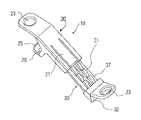
- FIG. 1illustrates a first embodiment of an implant including a first body and a second body.
- FIG. 2illustrates a close-up view of of the first body and the second body of the implant of FIG. 1 .
- FIG. 3illustrates a partial view of the second body of FIG. 1 .
- FIG. 4illustrates a perspective view of the second body of FIG. 1 .
- FIG. 5illustrates another embodiment of an implant including a first body and a second body.
- FIGS. 6A and 6Billustrate various views of the second body of the implant of FIG. 5 .
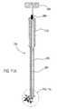
- FIGS. 7A . 7 B and 7 Cillustrate various views of the first body of the implant of FIG. 5 , including a perspective view ( 7 A) and cross-sectional views ( 7 B, 7 C).
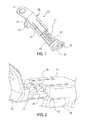
- FIGS. 8A, 8B, and 9illustrate one embodiment of an instrument of the present invention, and FIG. 9 also includes the implant of FIGS. 1-4 removeably coupled thereto.
- FIGS. 10A and 10Billustrate another embodiment of an instrument of the present invention to which an implant of the present invention may be removeably coupled thereto.
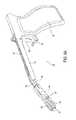
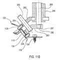
- FIGS. 11A and 11Billustrate yet another embodiment of an instrument of the present invention, also including the implant of FIGS. 5-7 removeably coupled thereto.
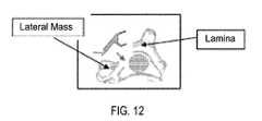
- FIG. 12illustrates one embodiment of the positioning of an implant of the present invention between lamina ends during the performance of a laminoplasty procedure.
- the present inventionincludes an implant 10 including a first body 20 and a second body 30 .
- the first and second bodies 20 , 30each have a length, and the first and second bodies are removeably coupled to one another and slidable relative to one another, along their lengths, to expand or compress the implant.
- the first body 20includes a flange, such as for example a U-shaped saddle 25 as in FIG. 1 , which engages up to three sides of one laminar cut end of the vertebra (e.g., outer side surface, inner side surface, and the cut edge surface). While the flange is sufficient to engage the implant with the laminar cut end, the flange may also include at least one through hole 23 , through which a fastener (for example, see fastener 134 in FIG. 11 b ) may be passed to further engage the flange to the laminar cut end in a fashion to fixedly secure the implant to the lamina end. Suitable fasteners may be a bone screw, tack, pin, or other suitable structure commonly used in the spine.
- a fastenerfor example, see fastener 134 in FIG. 11 b
- the flangemay also include an opening 26 , which results in the saddle 25 having less material than if saddle 25 were completely solid.
- the minimized materialallows for the saddle 25 to have greater pliability.
- the surgeonmay be able to adjust the shape of the saddle 25 , by bending the saddle or the like, to provide for a better fit onto the lamina end.
- the opening 26may optionally provide a location for placement of a bone graft or other osteogenic material, therethrough.
- the opening 26may provide a window through which bone growth may occur, as well as serve to secure the bone graft in place while such bone growth takes place.
- the second body 30also includes a flange, such as for example a shoulder 32 as in FIG. 1 , which is sized to engage up to two sides of the other lamina end of the vertebra (e.g., outer side surface and cut edge surface). While the flange is sufficient to engage the implant with the lamina end, the flange may also include at least one through hole 33 , through which a fastener (for example, see fastener 134 in FIG. 11 b ) may be passed to further engage the flange to the lamina end in a fashion to fixedly secure the implant to the lamina end.
- a fastenerfor example, see fastener 134 in FIG. 11 b
- the first and second bodies 20 , 30are slidable relative to one another, and thus each includes a structure to allow such a sliding arrangement.
- the bodiesmay include a receiving channel 27 and an at least a portion of the other body adapted to be positioned within the channel 27 , such as slide 37 .
- the channel and slidecould be transposed such that the channel is on the second body and the slide is on the first body; and likewise the first body could slide within the second body instead of the second body sliding within the first body, as illustrated.
- the first and second bodies 20 , 30further include cooperating structures which may secure the first and second bodies relative to one another to inhibit or otherwise control the sliding action.
- the first body 20includes a structure, along at least a portion of its length, for interacting with the second body such as, for example, a tab 21 .
- the second bodyincludes a structure which interacts with the structure on the first body 20 (e.g., tab 21 ), such as for example a plurality of teeth 31 .
- the tab 21 and teeth 31may interact to allow unidirectional sliding of the first body relative to the second body.
- the teeth 31may be shaped such that they may pass the tab when moving in a first direction, but may be prohibited from moving, by the tab 21 , in a second direction opposite the first direction.
- the tab 21may be biased such that the tab 21 is resting at the base of the teeth.
- the tabdeflects outwardly as an inclined face of the tooth passes under the tab, which allows the tooth to pass, but, the tab then returns to its original position once the tooth clears the tab.
- the tabwill not deflect if the tooth attempts to pass the tab in the opposite direction since the shape of the tooth is inclined at an angle on only one side, and is generally perpendicular on the other side.
- FIG. 2A detailed view of such an arrangement is illustrated in FIG. 2 .
- the first and second bodiesmay slide away from one another to expand the length of the implant and thus expand the distance between the two lamina ends, and consequently, enlarge the diameter of the spinal canal. But, this arrangement prevents compression of the length of the implant, such that, once implanted and expanded to the desired length, the implant will maintain such length, and thus such expansion of the spinal canal.
- Tab 21may be lifted or deflected manually by for example placing an appropriate instrument in access port 28 , which would clear the tab from the teeth 31 and thus allow the first and second bodies to move bi-directionally since the teeth/tab interaction would no longer limit movement to only a single sliding direction.
- Lifting the tabmay, using the embodiment illustrated, thus allow the first and second bodies to move towards one another and compress the length of the implant. This may be useful in the event of unintentional expansion of the implant prior to surgery, such that the surgeon can simply return the implant to its compressed position, using standard surgical instrumentation, in preparation for implantation into the spine. Alternatively, this may also be useful in the event of unintentional overexpansion of the implant once already implanted into the cut lamina.
- the implantmay further include a stop 22 which prevents the first and second bodies from being pulled completely apart.
- the stop 22may be useful, for example, in preventing the surgeon from unintentionally pulling apart the implant in the midst of surgery, which would delay the surgery and cause an inconvenience to the surgeon. While the stop 22 is shown in one position, for example in FIG. 4 , the stop may be positioned elsewhere on the implant so long as it substantially prevents the first and second bodies from being pulled apart (e.g., as in stop 122 in FIG. 6 a ).
- a bone graft or other bone-growth promoting (osteogenic) materialmay be positioned along at least a portion of the length of implant 10 .
- a bone graftmay be placed through opening 26 and positioned along the length of the implant such that, over time, bone growth may occur from at least one of the lamina ends and through the bone graft.
- the opening 26may stabilize the bone graft, while also allowing for uninhibited growth of bone through the opening 26 and between the lamina ends.
- the implant of the present inventionmay include, as illustrated in FIGS. 5-7 , an implant 110 having a first portion 120 and a second portion 130 .
- Implant 110is similar in many respects to implant 10 , and as such similar reference numbers (e.g., 20 vs. 120 ) refer to similar structures, except for certain differences, such as the following examples.
- implant 110may further include pin holes 129 , 139 for interaction with an instrument (such as those described below) such that the instrument may engage and removeably couple the implant thereto.
- body 130may include two through holes 133 a , 133 b for the placement of a second fastener (for example, see FIG. 11 b ) therethrough.
- stop 122may be positioned on body 130 rather than body 120 .
- the instrumentmay have a forked grasping tip, or the like, which may be used to interact with the implant.
- the implantation instrument of the present inventionmay be used for implantation of the implant, including at least holding, placement, expansion and release of the implant between lamina ends within a cut lamina of a spine.
- the present inventionincludes an implantation instrument 50 which includes a shaft 55 extending between a handle 70 at a proximal end and a distal end 80 .
- the instrumentfurther includes an actuation mechanism which allows the surgeon to manipulate the distal end 80 .
- the actuation mechanismmay include a trigger 60 and actuator rod 65 .
- the rotational movement of trigger 60when depressed or released by the surgeon's finger, is translated into linear longitudinal movement of actuator rod 65 , which then imparts this movement onto the distal end 80 .
- the handle 70may also include a trigger guard 61 to assist in preventing unintentional actuation of the trigger.
- the actuator rod 65may further include a ratchet mechanism which may provide improved control of movement as well as provide an ability of the surgeon to maintain a desired position.
- the distal end 80may include first and second jaws 82 , 83 , each having an attachment tip 84 for connection to implant 10 (as in FIG. 9 ).
- the jaws 82 , 83may be connected to one another through a linkage 81 , which is in turn connected to the shaft via a connecting link 86 and to actuator rod 65 via banana link 85 .
- Such a series of connectionsmay cause the jaws 82 , 83 , through actuation of the trigger 60 , to move towards or away from one another, and consequently, when the implant 10 is secured to the instrument 50 , to cause the first and second bodies 20 , 30 to slide relative to one another.
- the distal end 80is positioned at an angle relative to the shaft 55 .
- This anglemay be any desired angle, and may even be about 0 degrees such that the distal end is substantially linear to the shaft.
- This angle as illustrated, though,may provide improved use by the surgeon in providing a better angle of entry and line of sight to the surgical space, as well as provide better transfer of force from the trigger, to the actuator rod, to the distal end.
- Trigger 60may have a default or biased position, though such a position is not required. If a biased positioned is included, typically a spring or other mechanism may be included to tension the trigger towards one position. In FIG. 8 a , for example, the trigger 60 may be tensioned in the forward position, such that the default or biased position places the jaws 82 , 83 close together (and thus, if implant 10 is attached to the jaws, the implant would be in a default compressed configuration, as in FIG. 9 ). Biasing the trigger in this fashion may also provide for some resistance on the trigger when the surgeon depresses it, which may provide added control for the surgeon. This biasing also improves the ability of the instrument to hold the implant 10 due to the compression of the implant between the jaws.
- the trigger 60As the trigger 60 is depressed, or pulled rearwards towards the handle 70 , the trigger pivots and forces the actuator rod 65 forwards, towards the distal end 80 .
- This forward motionplaces a forward force on the banana link 85 .
- the linkage 81is held in place relative to the shaft 55 by connecting link 86 .
- the forward motion of the actuating rod 65causes the banana link 85 to rotate and expand linkage 81 , since the linkage 81 is prohibited from moving forward.
- the jaws 82 , 83move apart and expand the space between them.
- the linkage configurationmay allow the surgeon to place the implant 10 in position on the vertebra and then expand the implant 10 , while keeping it in position on the vertebra.
- the surgeondoes not have to account for additional movement of the implant as the trigger is depressed, such as rotational movement, lateral movement, or the like, because the linkage configuration translates depression of the trigger into unidirectional expansion of the implant.
- the instrument 50can act as a holder of the implant, as illustrated in FIG. 9 .
- the trigger 60may be spring biased in a closed position to provide better securement of the implant 10 .
- the instrumentcan also act as an expander for the implant in conjunction with holding the implant.
- the instrumentwill perform both an expansion of the implant and, consequently, an expansion of the space between the two lamina ends as well as an expansion of the spinal canal.
- the present inventionincludes a system including an implant 10 and an instrument 50 .
- the implant 10is expandable or compressible and includes a first body 20 and a second body 30 , the first and second bodies being slidable relative to one another to expand or compress the implant.
- the instrument 50includes a handle 70 , shaft 55 , trigger 60 and first and second jaws 82 , 83 , the shaft extending from the handle, the trigger positioned adjacent to the handle, and the first and second jaws positioned on the shaft opposite the handle, wherein one of the first or second jaws is capable of being removeably coupled to one of the first or second bodies 20 , 30 , and the other of the first or second jaws is capable of being removeably coupled to the other of the first or second bodies 20 , 30 , wherein actuation of the trigger moves the first and second jaws relative to one another. As the jaws move relative to one another, the first and second bodies of the implant may also slidably move relative to one another.
- the implant 10is press-fit, or otherwise removably connected, to the jaws 82 , 83 on attachment tips 84 .
- FIGS. 10 a and 10 billustrate a further embodiment of an implantation instrument 150 .
- instrument 150includes a shaft 155 having a length and proximal and distal ends. Shaft 155 is also hollow along at least a portion of its length to accommodate an actuator rod 165 therethrough. In the illustrative example, the shaft 155 is hollow along its entire length.
- the instrument 150also includes a handle 170 positioned along the proximal portion of the shaft 155 .
- the handle and shaftmay be fixedly secured to one another or, alternatively, the handle and the shaft may be manufactured as a single, monolithic structure.
- the actuator rod 165has a proximal portion and a distal portion, and a knob 160 is adapted to engage the proximal portion of the actuator rod.
- Knob 160may be positioned adjacent to and proximally of the handle 170 .
- Knob 160may also be fixedly secured in a longitudinal position relative to the handle 170 , but may be freely rotatable relative to the handle. This freedom of rotation permits the actuation of knob 160 , through rotation around the longitudinal length of the instrument, and thereby cause linear or longitudinal movement of the actuator rod 165 through the shaft 155 , as the actuator rod 165 and shaft 155 may be coaxial with one another.
- the translation of rotational motion of the knob 160 to longitudinal movement of the actuator rod 165may be accomplished through the coupling of the two elements by a threaded connection 168 .
- actuation of the knobslides at least one of the first or second bodies 120 , 130 of implant 110 relative to the other.
- the instrument 150also includes a first connector 183 and a second connector 182 , wherein one of the first or second connectors is adapted to be removeably coupled to one of the first or second bodies 120 , 130 , and the other of the first or second connectors is adapted to be removeably coupled to the other of the first or second bodies 120 , 130 .
- the first connector 183is adapted to engage the distal portion of the actuator rod 165
- the second connector 182is fixedly secured to the distal end of the shaft 155 .
- the first connector 183may be adapted to actuate by the longitudinal movement of the actuator rod 165 created by the actuation of knob 160 .
- the first connector 183may include a slot 187 within which may be positioned a tab 162 extending from the actuator rod 165 , wherein the tab 162 may be adapted to travel within the slot 187 as coordinated by the longitudinal travel of the actuator rod 165 through the shaft.
- the first connector 183may be pivotally connected to the shaft 155 such that as the tab 162 travels within the slot 187 , the first connector pivots relative to the shaft, wherein the first connector may be adapted to pivot from an initial position substantially parallel to the second connector 183 (as in FIGS. 10 a , 10 b ) to a plurality of subsequent positions angled from the second connector. This pivot may occur around pivot pin 163 which extends from and is fixedly secured with shaft 155 .
- the second connector 182is fixedly secured to the shaft 155 , and as such the first or second body 120 , 130 , whichever is removeably coupled to the second connector 182 , is also held in place relative to the shaft 155 .
- the first or second body 120 , 130 removeably coupled to first connector 183will likewise move with first connector 183 and slide relative to the other body 120 , 130 removeably coupled to the second connector 182 .
- Each of the first and second connectorsmay include an attachment tip 184 to removeably couple to a pin hole 129 , 139 on each of the first and second bodies 120 , 130 .
- the coupling of each attachment tip and pin holemay be a friction fit or the like.
- This embodiment of the implantation instrument 150may also be combined with an implant, such as implant 110 , to form a system including instrument 150 and at least one implant 110 .
- the systemfor use in a laminoplasty procedure, includes an implant 110 comprising a first body 120 and a second body 130 , the first and second bodies adapted to slide relative to one another to expand or compress the implant, and an implantation instrument 150 including: a shaft 155 having a longitudinal length, a proximal end, a distal end and a hollow throughbore along at least a portion of its length; a handle 170 positioned on the proximal end of the shaft; an actuator rod 165 having a proximal portion and a distal portion, the actuator rod 165 being positioned within the hollow throughbore of the shaft 155 ; a knob 160 adapted to engage the proximal portion of the actuator rod; a first connector 183 adapted to engage the distal portion of the actuator rod; and a second connector 182 fixedly secured to the distal end of the
- the knob 160may be positioned adjacent to and proximal of the handle 170 , and also the knob 160 may be fixedly secured in a longitudinal position relative to the handle 170 , but may be freely rotatable relative to the handle.
- the knob 170 and actuator rod 165may also be coupled together through a threaded connection 168 , such that the actuator rod is adapted to move longitudinally through the shaft by actuation of the knob.
- the actuator rod 165may be coaxial to the shaft 155 .
- the first connector 183may also be adapted to actuate by the longitudinal movement of the actuator rod, via the actuation of the knob 160 .
- the first connectormay include a slot 187 within which may be positioned a tab 162 extending from the actuator rod, wherein the tab may be adapted to travel within the slot by the longitudinal travel of the actuator rod.
- the first connectormay be pivotally connected to the shaft, at pivot pin 163 extending from the shaft, such that as the tab travels within the slot, the first connector pivots relative to the shaft, wherein the first connector may be adapted to pivot from an initial position substantially parallel to the second connector to a plurality of subsequent positions angled from the second connector.
- the first and second connectorseach may include an attachment tip 184 to removeably couple to a pin hole 129 , 139 on each of the first and second bodies. The coupling of the attachment tip and pin hole may be a friction fit.
- the systemis capable to adjusting the implant 110 from, for example, a compressed position (as in FIG. 5 ) to an expanded position (as implant 10 is presented in FIG. 1 ) through the actuation of the knob 160 .
- a surgeonmay, holding the handle 170 substantially steady to minimize or prevent its rotation, rotate the knob 160 which thereby rotates the knob relative to the actuator rod 165 at threaded connection 168 .
- the rotation of the knobforces the actuator rod 165 to move longitudinally which, in this embodiment, would be distally, towards the first connector 183 .
- the actuator rod 165moves distally as a result of the threaded connection 168 because the actuator rod may be inhibited from rotating along with the knob, by for example pin 162 or by another similar structure, such that the threading of the knob instead travels along the thread of the actuator rod.
- tab 162also moves distally, thereby forcing the portion of the first connector including the slot 187 also distally.
- the distal motion of the slot 187causes generally proximal movement of the other end of the first connector 183 , which includes the attachment tip 184 .
- the attachment tip 184 of the first connector 183moves proximally, it moves away from the attachment tip 184 of the second connector 182 , thereby increasing the distance between the two connectors.
- the implant 110is removeably coupled to the first and second connectors, the first and second bodies 120 , 130 of the implant also slide apart, thereby expanding the implant. Since the implant is positioned and engaged to the lamina ends, the expansion of the implant also expands the spinal canal and the distance between the lamina ends.
- FIGS. 11 a and 11 billustrate yet another embodiment of the present invention, namely, an instrument 250 including a shaft 255 having a longitudinal length, a proximal end, a distal end and a hollow throughbore along at least a portion of its length.
- the hollow throughboreaccommodates an actuator rod 265 therethrough.
- the shaft 255is hollow along its entire length.
- the instrumentalso includes a handle 270 positioned along the proximal portion of the shaft 255 .
- the handle and shaftmay be fixedly secured to one another or, alternatively, the handle and the shaft may be manufactured as a single, monolithic structure.
- the actuator rod 265has a proximal portion and a distal portion, and a knob 260 is adapted to fixedly engage the proximal portion of the actuator rod.
- Knob 160may be positioned proximally of the handle 170 .
- the knob 160 and actuator rod 265being fixedly engaged thereto, are freely rotatable relative to the handle 270 and shaft 255 .
- the actuator rod 265 and shaft/handlemay be coaxial and further coupled together via a threaded connection 268 . This freedom of rotation permits the actuation of knob 260 , through rotation around the longitudinal length of the instrument, and thereby causes linear or longitudinal movement of the actuator rod 265 relative to and through the shaft 255 .
- the threaded connection 268accomplishes the translation of rotational movement of the knob and actuator rod into longitudinal movement relative to the shaft 255 .
- actuation of the knobslides at least one of the first or second bodies 120 , 130 of implant 110 relative to the other.
- the instrument 250also includes a first connector 283 and a second connector 282 , wherein one of the first or second connectors is adapted to be removeably coupled to one of the first or second bodies 120 , 130 , and the other of the first or second connectors is adapted to be removeably coupled to the other of the first or second bodies 120 , 130 .
- the first connector 283is adapted to engage the distal portion of the actuator rod 265
- the second connector 282is fixedly secured to the distal end of the shaft 255 .
- the first connector 283may be adapted to actuate by the longitudinal movement of the actuator rod 265 created by the actuation of knob 260 .
- the first connector 283may include a bore 287 within which a tab 262 , extending from actuator rod 265 , may be rotatably coupled, such that as the actuator rod 265 rotates and moves longitudinally (and distally), the tab 262 freely rotates within bore 287 while imparting longitudinal force on the first connector 283 to move the first connector distally.
- the first connectormay be prevented from rotating by pin 263 , which prevents rotation of the first connector while still allowing the longitudinal movement of the first connector caused by the actuator rod 265 .
- the second connector 282is fixedly secured to the shaft 255 , and as such the first or second body 120 , 130 which is removeably coupled to the second connector 282 is also held in place relative to the shaft 255 .
- the first or second body 120 , 130 removeably coupled theretowill slide relative to the body 120 , 130 removeably coupled to the second connector 282 .
- Each of the first and second connectorsmay include an attachment tip 284 to removeably couple to a pin hole 129 , 139 on each of the first and second bodies 120 , 130 .
- the coupling of each attachment tip and pin holemay be a friction fit.
- this embodiment of the implantation instrument 250may also be combined with an implant, such as implant 110 , to form a system including instrument 250 and at least one implant 110 .
- the systemis capable to adjusting the implant 110 from, for example, a compressed position (as in FIG. 11 b ) to an expanded position (as implant 10 is presented in FIG. 1 ) through the actuation of the knob 260 .
- a surgeonmay, holding the handle 270 substantially steady to prevent its rotation, rotate the knob 260 which thereby rotates the actuator rod 265 relative to the shaft 255 at threaded connection 268 .
- the rotation of the knobforces the actuator rod 265 to rotate and move longitudinally (on account of the threaded connection 268 ) which, in this embodiment, would be distally, towards the first connector 283 .
- the actuator rod 265moves distally as a result of the threaded connection 268 because the actuator rod rotates relative to the shaft and handle while the shaft and handle are prevented from rotating by the surgeon (e.g., by holding the handle).
- tab 262also moves distally, thereby forcing the first connector also distally.
- tab 262rotates freely within bore 287 , and thus the first connector does not rotate along with tab 262 .
- the first connectordoes move distally, though, along with attachment tip 284 .
- first connector and attachment tip 284move distally, they move away from the second connector 282 and attachment tip 284 of the second connector, such that the distance between the two connectors, and two attachment tips, increases.
- the implant 110is removeably coupled to the first and second connectors, the first and second bodies 120 , 130 of the implant also slide apart, thereby expanding the implant. Since the implant is positioned and engaged to the lamina ends, the expansion of the implant also expands the spinal canal and the distance between the lamina ends.
- the present inventionmay include a kit including one of the above instruments and a plurality of implants which may be used on multiple vertebrae in a single patient or in multiple patients in subsequent surgeries.
- the kitmay include implants of various dimensions and sizes such that the surgeon may select the properly sized implant for the specific patient and type of vertebra. Then, the implant may be expanded, from a compressed configuration, to fine tune the implant length for the specific application.
- the various implants, instruments, systems and kits of the present inventionmay be sterilized and packaged from the manufacturer as a combined system, such that the system can be removed from the packaging and immediately used in a surgery.
- the systemmay include an individually packaged implant and an instrument which may be sold and packaged separately.
- the various instrumentsmay be sterilizable and reusable in subsequent surgeries.
- the method of performing a laminoplastyincludes removeably coupling an implant and an instrument, the implant including a first body and a second body, a flange on the first body and a flange on the second body, the first and second bodies being slidable relative to one another to expand or compress the implant.
- this stepmay include removeably coupling implant 110 to instrument 150 , by attaching attachment tips 184 to pin holes 129 , 139 , with the implant 110 in a substantially compressed configuration, such that the first and second connectors 183 , 182 may be generally parallel to one another.
- the implantis advanced to the laminoplasty site which includes first and second lamina ends, as illustrated, for example, in FIG. 12 .
- the implantis then positioned to engage one cut end with the flange of the first body and engaging the other cut end with the flange of the second body, and expanding the implant using the instrument.
- the implantis then decoupled from the instrument.
- the implantmay be substantially secured within the lamina.
- the implantmay be fixedly secured to the lamina ends through further engagement of the first and second flanges to the lamina ends through the placement of at least one fastener through each of the first and second bodies and into the lamina ends.
- the method of performing a laminoplastymay be similar to the above method however, prior to the step of expanding the implant, the implant is fixedly secured to one of the lamina ends using a fastener (such as fastener 134 of FIG. 11 b ).
- a fastenersuch as fastener 134 of FIG. 11 b
- a fastenermay be placed through at least one of throughbores 123 , 133 a or 133 b , after the flanges of the first and second bodies have engaged the lamina ends.
- the implantmay then be expanded, as necessary, using the instrument.
- the implantis then decoupled from the instrument.
- additional fastenersare applied in the other through bores of the implant (e.g., through bores 123 and the other of 133 a or 133 b ) to fixedly secure the implant to the first and second lamina ends.
- a method of the present inventionmay include steps similar to those above, however, the instrument 150 , for example, may be coupled to the implant after the implant is in place on the lamina ends.
- alternative instrumentationmay be used to place the implant onto the lamina ends.
- a pair of forceps or the likemay be used to move the implant into position.
- a second instrumentsuch as a grasper or the like may pry the cut ends of the lamina apart.
- the forcepsare used to move the implant into position onto the lamina ends.
- the grasper and forcepsare then withdrawn from the surgical site and instrument 150 is then secured to the implant, along with at least one fastener to further secure the implant to at least one of the lamina ends. The method then continues as discussed above.
Landscapes
- Health & Medical Sciences (AREA)
- Orthopedic Medicine & Surgery (AREA)
- Life Sciences & Earth Sciences (AREA)
- Surgery (AREA)
- Neurology (AREA)
- Engineering & Computer Science (AREA)
- Biomedical Technology (AREA)
- General Health & Medical Sciences (AREA)
- Veterinary Medicine (AREA)
- Heart & Thoracic Surgery (AREA)
- Public Health (AREA)
- Animal Behavior & Ethology (AREA)
- Nuclear Medicine, Radiotherapy & Molecular Imaging (AREA)
- Medical Informatics (AREA)
- Molecular Biology (AREA)
- Vascular Medicine (AREA)
- Transplantation (AREA)
- Oral & Maxillofacial Surgery (AREA)
- Cardiology (AREA)
- Prostheses (AREA)
- Surgical Instruments (AREA)
Abstract
Description
Claims (20)
Priority Applications (1)
| Application Number | Priority Date | Filing Date | Title |
|---|---|---|---|
| US15/722,556US10039646B2 (en) | 2012-01-31 | 2017-10-02 | Laminoplasty implant, method and instrumentation |
Applications Claiming Priority (3)
| Application Number | Priority Date | Filing Date | Title |
|---|---|---|---|
| US13/362,413US8562681B2 (en) | 2012-01-31 | 2012-01-31 | Laminoplasty implant, method and instrumentation |
| US14/030,496US9808350B2 (en) | 2012-01-31 | 2013-09-18 | Laminoplasty implant, method and instrumentation |
| US15/722,556US10039646B2 (en) | 2012-01-31 | 2017-10-02 | Laminoplasty implant, method and instrumentation |
Related Parent Applications (1)
| Application Number | Title | Priority Date | Filing Date |
|---|---|---|---|
| US14/030,496ContinuationUS9808350B2 (en) | 2012-01-31 | 2013-09-18 | Laminoplasty implant, method and instrumentation |
Publications (2)
| Publication Number | Publication Date |
|---|---|
| US20180085228A1 US20180085228A1 (en) | 2018-03-29 |
| US10039646B2true US10039646B2 (en) | 2018-08-07 |
Family
ID=47739206
Family Applications (3)
| Application Number | Title | Priority Date | Filing Date |
|---|---|---|---|
| US13/362,413ActiveUS8562681B2 (en) | 2012-01-31 | 2012-01-31 | Laminoplasty implant, method and instrumentation |
| US14/030,496ActiveUS9808350B2 (en) | 2012-01-31 | 2013-09-18 | Laminoplasty implant, method and instrumentation |
| US15/722,556ActiveUS10039646B2 (en) | 2012-01-31 | 2017-10-02 | Laminoplasty implant, method and instrumentation |
Family Applications Before (2)
| Application Number | Title | Priority Date | Filing Date |
|---|---|---|---|
| US13/362,413ActiveUS8562681B2 (en) | 2012-01-31 | 2012-01-31 | Laminoplasty implant, method and instrumentation |
| US14/030,496ActiveUS9808350B2 (en) | 2012-01-31 | 2013-09-18 | Laminoplasty implant, method and instrumentation |
Country Status (4)
| Country | Link |
|---|---|
| US (3) | US8562681B2 (en) |
| EP (2) | EP3069674B1 (en) |
| JP (1) | JP6302845B2 (en) |
| WO (1) | WO2013113802A1 (en) |
Cited By (2)
| Publication number | Priority date | Publication date | Assignee | Title |
|---|---|---|---|---|
| US11963704B2 (en) | 2021-09-16 | 2024-04-23 | Warsaw Orthopedic, Inc. | Surgical instrument and method |
| US12357473B2 (en) | 2022-04-25 | 2025-07-15 | Gregory Thomas Gdowski | Laminoplasty implant systems and methods |
Families Citing this family (19)
| Publication number | Priority date | Publication date | Assignee | Title |
|---|---|---|---|---|
| US8926664B1 (en)* | 2006-11-07 | 2015-01-06 | Globus Medical, Inc. | Laminoplasty fixaction devices |
| US9901455B2 (en)* | 2009-11-25 | 2018-02-27 | Nathan C. Moskowitz | Total artificial spino-laminar prosthetic replacement |
| US9358123B2 (en)* | 2011-08-09 | 2016-06-07 | Neuropro Spinal Jaxx, Inc. | Bone fusion device, apparatus and method |
| US9138325B2 (en)* | 2012-07-11 | 2015-09-22 | Globus Medical, Inc. | Lamina implant and method |
| US9295488B2 (en) | 2012-08-09 | 2016-03-29 | Wilson T. Asfora | Joint fusion |
| US9055982B2 (en)* | 2012-09-25 | 2015-06-16 | Warsaw Orthopedic, Inc. | Spinal implant system and methods of use |
| CN103549991B (en)* | 2013-11-01 | 2016-03-30 | 上海三友医疗器械有限公司 | For the bracing or strutting arrangement of vertebral plate expanding and shaping |
| US9730741B2 (en) | 2013-12-30 | 2017-08-15 | Monsour Vincent Makhlouf | Temporarily secured bone reduction clamp |
| US20150257789A1 (en)* | 2014-03-13 | 2015-09-17 | Warsaw Orthopedic, Inc. | Spinal implant system and methods of use |
| US10238434B2 (en) | 2014-03-20 | 2019-03-26 | Spinefrontier, Inc | System and method for spinal decompression |
| KR101651591B1 (en)* | 2014-11-17 | 2016-08-30 | (주)시지바이오 | Spacer for laminoplasty |
| US9717541B2 (en) | 2015-04-13 | 2017-08-01 | DePuy Synthes Products, Inc. | Lamina implants and methods for spinal decompression |
| US10695107B2 (en)* | 2015-12-03 | 2020-06-30 | Warsaw Orthopedic, Inc. | Spinal implant system and methods of use |
| US10028836B2 (en) | 2016-01-26 | 2018-07-24 | The Regents Of The University Of Colorado | System and method of osteodistraction |
| CN111281507B (en)* | 2018-12-07 | 2024-10-22 | 上海三友医疗器械股份有限公司 | Double-door fixing clamp for vertebral plate and double-door internal fixing structure |
| US11376052B2 (en) | 2020-09-02 | 2022-07-05 | Curiteva, Inc | Expandable laminoplasty device |
| US11950811B2 (en)* | 2020-09-22 | 2024-04-09 | Alphatec Spine, Inc. | Occipital plates and related methods |
| US20240188997A1 (en)* | 2022-12-12 | 2024-06-13 | Cor Medical Ventures, Inc. | Cervical laminoplasty instruments and procedures |
| CN117462310B (en)* | 2023-12-22 | 2024-04-12 | 北京理贝尔生物工程研究所有限公司 | Laminoplasty prosthesis |
Citations (105)
| Publication number | Priority date | Publication date | Assignee | Title |
|---|---|---|---|---|
| US4611582A (en) | 1983-12-27 | 1986-09-16 | Wisconsin Alumni Research Foundation | Vertebral clamp |
| JPS639434A (en) | 1986-06-30 | 1988-01-16 | 京セラ株式会社 | spinous process spacer |
| US4997432A (en) | 1988-03-23 | 1991-03-05 | Waldemar Link Gmbh & Co. | Surgical instrument set |
| US5020519A (en) | 1990-12-07 | 1991-06-04 | Zimmer, Inc. | Sagittal approximator |
| US5176702A (en) | 1991-04-04 | 1993-01-05 | Symbiosis Corporation | Ratchet locking mechanism for surgical instruments |
| JPH05103801A (en) | 1991-10-16 | 1993-04-27 | Shinsuke Takasugi | Spacer for dilating vertebral canal |
| US5209755A (en) | 1992-06-05 | 1993-05-11 | Stella Abrahan | Dermal exciser |
| US5250056A (en) | 1992-02-04 | 1993-10-05 | Hasson Harrith M | Forceps-type surgical instrument |
| US5304203A (en) | 1992-10-20 | 1994-04-19 | Numed Technologies, Inc. | Tissue extracting forceps for laparoscopic surgery |
| JPH08638A (en) | 1994-06-27 | 1996-01-09 | Asahi Optical Co Ltd | Spinous process spacer |
| WO1997009940A1 (en) | 1995-09-12 | 1997-03-20 | C G Surgical Limited | A device to stabilise the lamina |
| US5672177A (en) | 1996-01-31 | 1997-09-30 | The General Hospital Corporation | Implantable bone distraction device |
| WO1998004217A1 (en) | 1996-07-26 | 1998-02-05 | Heinrich Ulrich | Implant for bonding two adjacent vertebrae of the vertebral column |
| US5722988A (en) | 1993-12-08 | 1998-03-03 | Weisshaupt; Dieter | Surgical tubular-shafted instrument |
| JPH10179622A (en) | 1996-12-20 | 1998-07-07 | Mizuho Ika Kogyo Kk | Vertebral implant |
| US5827286A (en) | 1997-02-14 | 1998-10-27 | Incavo; Stephen J. | Incrementally adjustable tibial osteotomy fixation device and method |
| JPH114840A (en) | 1997-06-16 | 1999-01-12 | Shinsuke Takasugi | Spinal canal enlargement spacer |
| WO1999021501A1 (en) | 1997-10-27 | 1999-05-06 | Saint Francis Medical Technologies, Llc | Spine distraction implant |
| WO1999038461A2 (en) | 1998-01-30 | 1999-08-05 | Synthes Ag Chur | Allogenic intervertebral implant |
| US5941878A (en) | 1995-02-14 | 1999-08-24 | Medoff; Robert J. | Implantable, surgical buttressing device |
| US5980572A (en) | 1997-04-15 | 1999-11-09 | Asahi Kogaku Kogyo Kabushiki Kaisha | Artificial spines |
| US6045552A (en) | 1998-03-18 | 2000-04-04 | St. Francis Medical Technologies, Inc. | Spine fixation plate system |
| JP2000139970A (en) | 1998-11-04 | 2000-05-23 | Hironobu Nomura | Spacer for cervical vertebra expansion |
| JP2000175943A (en) | 1998-12-16 | 2000-06-27 | Nippon Electric Glass Co Ltd | Vertebral arch spacer for vertebral canal enlarging operation |
| WO2000044320A1 (en) | 1999-02-01 | 2000-08-03 | Lin Paul S | Intervertebral implant |
| US6126660A (en) | 1998-07-29 | 2000-10-03 | Sofamor Danek Holdings, Inc. | Spinal compression and distraction devices and surgical methods |
| US6152926A (en) | 1997-01-02 | 2000-11-28 | St. Francis Medical Technologies, Inc. | Spine distraction implant and method |
| US6183471B1 (en) | 1997-01-02 | 2001-02-06 | St. Francis Medical Technologies, Inc. | Spine distraction implant and method |
| JP2001079024A (en) | 1999-09-13 | 2001-03-27 | Kenji Ohata | Vertebral-arch spacer |
| US6238397B1 (en) | 1997-01-02 | 2001-05-29 | St. Francis Technologies, Inc. | Spine distraction implant and method |
| EP1103236A2 (en) | 1999-11-24 | 2001-05-30 | DePuy Acromed, Inc. | Anterior lumbar interbody fusion cage with locking plate |
| JP2001149392A (en) | 1999-11-25 | 2001-06-05 | Nippon Electric Glass Co Ltd | Vertebral arch spacer for expanding spinal canal |
| JP2001170092A (en) | 1999-12-21 | 2001-06-26 | Nippon Electric Glass Co Ltd | Vertebral arch spacer for enlarging operation of vertebral canal |
| WO2001049220A1 (en) | 1999-12-30 | 2001-07-12 | Osteotech, Inc. | Intervertebral implants |
| US6277124B1 (en) | 1999-10-27 | 2001-08-21 | Synthes (Usa) | Method and apparatus for ratcheting adjustment of bone segments |
| US6332882B1 (en) | 1997-01-02 | 2001-12-25 | St. Francis Medical Technologies, Inc. | Spine distraction implant |
| US6332895B1 (en) | 2000-03-08 | 2001-12-25 | Loubert Suddaby | Expandable intervertebral fusion implant having improved stability |
| US6358254B1 (en) | 2000-09-11 | 2002-03-19 | D. Greg Anderson | Method and implant for expanding a spinal canal |
| US20020072752A1 (en) | 1998-10-20 | 2002-06-13 | Zucherman James F. | Interspinous process implant sizer and distractor with a split head and size indicator and method |
| US20020120273A1 (en) | 1999-10-13 | 2002-08-29 | Needham Dusty Anna | Anterior cervical plating system and method |
| US20020120335A1 (en) | 2001-02-28 | 2002-08-29 | Angelucci Christopher M. | Laminoplasty implants and methods of use |
| US20020128654A1 (en) | 1998-02-18 | 2002-09-12 | Steger Shon D. | Method and apparatus for bone fracture fixation |
| US6451019B1 (en) | 1998-10-20 | 2002-09-17 | St. Francis Medical Technologies, Inc. | Supplemental spine fixation device and method |
| US6478800B1 (en) | 2000-05-08 | 2002-11-12 | Depuy Acromed, Inc. | Medical installation tool |
| WO2003002142A1 (en) | 2001-06-29 | 2003-01-09 | Chugai Seiyaku Kabushiki Kaisha | Cancer vaccine containing cancer antigen based on tumor suppressor gene wt1 product and cationic liposomes |
| US20030045936A1 (en) | 2001-08-29 | 2003-03-06 | Angelucci Christopher M. | Laminoplasty implants and methods of use |
| US20030050700A1 (en) | 2001-09-11 | 2003-03-13 | Asahi Kogaku Kogyo Kabushiki Kaisha | Vertebral arch spacer |
| US6551316B1 (en) | 2001-03-02 | 2003-04-22 | Beere Precision Medical Instruments, Inc. | Selective compression and distraction instrument |
| US20030125738A1 (en) | 2002-01-03 | 2003-07-03 | Khanna Rohit Kumar | Laminoplasty with laminar stabilization method and system |
| US20030199875A1 (en) | 2002-04-23 | 2003-10-23 | Citieffe S.R.L. | Stabilizing support for opening- and closing-wedge osteotomies |
| US20030225416A1 (en) | 2002-05-21 | 2003-12-04 | Bonvallet Todd C. | Instruments and techniques for separating bony structures |
| WO2003101319A2 (en) | 2002-05-30 | 2003-12-11 | Sdgi Holdings, Inc. | Laminoplasty devices and methods |
| US20040010251A1 (en) | 2001-12-10 | 2004-01-15 | Shahar Pitaru | Methods, devices, and preparations for intervertebral disc treatment |
| US6712852B1 (en) | 2002-09-30 | 2004-03-30 | Depuy Spine, Inc. | Laminoplasty cage |
| US6712825B2 (en) | 1998-10-02 | 2004-03-30 | Max Aebi | Spinal disc space distractor |
| US6796983B1 (en) | 1997-01-02 | 2004-09-28 | St. Francis Medical Technologies, Inc. | Spine distraction implant and method |
| US20040220582A1 (en) | 2001-01-12 | 2004-11-04 | Arnold Keller | Surgical instrument for inserting an intervertebral endoprosthesis |
| US20050021042A1 (en) | 2003-07-21 | 2005-01-27 | Theirry Marnay | Instruments and method for inserting an intervertebral implant |
| US6852113B2 (en) | 2001-12-14 | 2005-02-08 | Orthopaedic Designs, Llc | Internal osteotomy fixation device |
| US20050055031A1 (en) | 2003-09-10 | 2005-03-10 | Roy Lim | Devices and methods for inserting spinal implants |
| US6893464B2 (en) | 2002-03-05 | 2005-05-17 | The Regents Of The University Of California | Method and apparatus for providing an expandable spinal fusion cage |
| US20050107877A1 (en) | 2003-10-30 | 2005-05-19 | Nu Vasive, Inc. | System and methods for restoring the structural integrity of bone |
| US20050119665A1 (en) | 2001-10-29 | 2005-06-02 | Arnold Keller | Instrumentation for insertion of an inter-vertebral prosthesis |
| US20050131412A1 (en) | 2003-10-20 | 2005-06-16 | Boris Olevsky | Bone plate and method for using bone plate |
| US20050197700A1 (en) | 2004-02-18 | 2005-09-08 | Boehm Frank H.Jr. | Facet joint prosthesis and method of replacing a facet joint |
| WO2005096969A1 (en) | 2004-04-07 | 2005-10-20 | C G Surgical Limited | Devices to stablise the lamina |
| US20050273100A1 (en) | 2004-06-04 | 2005-12-08 | Taylor Brett A | Variable laminoplasty implant |
| US20060025777A1 (en) | 2004-07-28 | 2006-02-02 | Helmut Weber | Surgical instrument for the introduction of a multi-component intervertebral prosthesis |
| US20060064091A1 (en) | 2004-03-31 | 2006-03-23 | Depuy Spine, Inc. | Rod attachment for head to head cross connector |
| US20060111712A1 (en) | 2004-11-23 | 2006-05-25 | Jackson Roger P | Spinal fixation tool set and method |
| US7087055B2 (en) | 2002-06-25 | 2006-08-08 | Sdgi Holdings, Inc. | Minimally invasive expanding spacer and method |
| US7101375B2 (en) | 1997-01-02 | 2006-09-05 | St. Francis Medical Technologies, Inc. | Spine distraction implant |
| US20060200134A1 (en) | 2002-02-01 | 2006-09-07 | James Freid | Spinal plate system for stabilizing a portion of a spine |
| US7169153B2 (en) | 2002-06-10 | 2007-01-30 | Depuy Spine | Surgical instrument for inserting intervertebral prosthesis |
| US20070073185A1 (en) | 2005-03-03 | 2007-03-29 | Nakao Naomi L | Needle biopsy forceps with integral sample ejector |
| US7288103B2 (en) | 2003-06-09 | 2007-10-30 | Olympus Corporation | Link device for surgical tool and surgical tool |
| US7326216B2 (en) | 2003-04-02 | 2008-02-05 | Warsaw Orthopedic, Inc. | Methods and instrumentation for positioning implants in spinal disc space in an anterior lateral approach |
| US20080109005A1 (en) | 2006-08-10 | 2008-05-08 | Trudeau Jeffrey L | System and Methods for Inserting a Spinal Disc Device Into an Intervertebral Space |
| US20090012527A1 (en) | 2007-07-06 | 2009-01-08 | Mignucci Luis A | Anterior spinal interbody fusion delivery system |
| US7494491B2 (en) | 2002-04-10 | 2009-02-24 | Mathys Ag Bettlach | Device for implanting marking bodies |
| WO2009120861A2 (en) | 2008-03-26 | 2009-10-01 | Depuy Spine, Inc. | Instruments for expandable corpectomy spinal fusion cage |
| US20090281582A1 (en) | 2008-05-08 | 2009-11-12 | Raul Villa | Instrument for the reduction of a rod into position in a pedicle screw |
| US20090306672A1 (en) | 2008-06-05 | 2009-12-10 | Alphatec Spine,Inc. | Alif inserter/distractor |
| US7645294B2 (en) | 2004-03-31 | 2010-01-12 | Depuy Spine, Inc. | Head-to-head connector spinal fixation system |
| US7651500B2 (en) | 2002-07-05 | 2010-01-26 | Mathys Ag Bettlach | Ligament tensing device with displaceable lug |
| US20100057127A1 (en) | 2008-08-26 | 2010-03-04 | Mcguire Brian | Expandable Laminoplasty Fixation System |
| US20100063590A1 (en) | 2007-03-15 | 2010-03-11 | Blue Fury Consulting, L.L.C. | Laminoplasty implant |
| US20100082029A1 (en) | 2006-04-03 | 2010-04-01 | Ib Medical, Llc | Static Compression Device |
| US20100114100A1 (en) | 2006-12-15 | 2010-05-06 | The Adelman Research Ltd | Technique and device for laminar osteotomy and laminoplasty |
| US20100161056A1 (en) | 2008-12-19 | 2010-06-24 | Depuy Spine, Inc. | Methods and devices for expanding a spinal canal |
| US20100185285A1 (en) | 2009-01-19 | 2010-07-22 | Richard Perkins | Annular repair device and method |
| US20100185239A1 (en) | 2009-01-16 | 2010-07-22 | Chetan Patel | Laminoplasty apparatus and methods |
| US20100241230A1 (en) | 2009-03-18 | 2010-09-23 | Depuy Spine, Inc. | Laminoplasty methods and devices |
| US20100241165A1 (en) | 2009-03-18 | 2010-09-23 | Depuy Spine, Inc. | Laminoplasty methods using hinge device |
| WO2010144636A1 (en) | 2009-06-09 | 2010-12-16 | Robinson James C | Laminoplasty system and method of use |
| US7867237B2 (en) | 2005-10-31 | 2011-01-11 | Depuy Spine, Inc. | Arthroplasty revision device and method |
| WO2011010983A1 (en) | 2009-07-24 | 2011-01-27 | Jcm American Corporation | Gaming system bill validator |
| WO2011040983A1 (en) | 2009-10-03 | 2011-04-07 | Nuvasive, Inc. | Bone plate system and related methods |
| US20110106084A1 (en) | 2009-10-30 | 2011-05-05 | Thomas J Gamache | Bone Graft Loading Instruments and Methods of Connecting a Bone Graft to a Bone Plate |
| US20110106168A1 (en) | 2009-11-02 | 2011-05-05 | Bucci Kara A | Laminoplasty Rod System |
| US20110106169A1 (en) | 2009-10-30 | 2011-05-05 | Zalenski Edward B | Bone Plate Holder |
| US20110106087A1 (en) | 2009-10-30 | 2011-05-05 | Gamache Thomas J | Bone Plate Holder |
| US20110106083A1 (en) | 2009-10-30 | 2011-05-05 | Voellmicke John C | Laminoplasty Plates and Methods of Expanding the Spinal Canal |
| US20120165942A1 (en) | 2002-01-03 | 2012-06-28 | Rohit | Universal laminoplasty implant |
| US8926664B1 (en) | 2006-11-07 | 2015-01-06 | Globus Medical, Inc. | Laminoplasty fixaction devices |
- 2012
- 2012-01-31USUS13/362,413patent/US8562681B2/enactiveActive
- 2013
- 2013-01-31EPEP16157217.7Apatent/EP3069674B1/ennot_activeNot-in-force
- 2013-01-31JPJP2014555199Apatent/JP6302845B2/ennot_activeExpired - Fee Related
- 2013-01-31EPEP13704891.4Apatent/EP2797529B1/ennot_activeNot-in-force
- 2013-01-31WOPCT/EP2013/051875patent/WO2013113802A1/enactiveApplication Filing
- 2013-09-18USUS14/030,496patent/US9808350B2/enactiveActive
- 2017
- 2017-10-02USUS15/722,556patent/US10039646B2/enactiveActive
Patent Citations (153)
| Publication number | Priority date | Publication date | Assignee | Title |
|---|---|---|---|---|
| US4611582A (en) | 1983-12-27 | 1986-09-16 | Wisconsin Alumni Research Foundation | Vertebral clamp |
| JPS639434A (en) | 1986-06-30 | 1988-01-16 | 京セラ株式会社 | spinous process spacer |
| US4997432A (en) | 1988-03-23 | 1991-03-05 | Waldemar Link Gmbh & Co. | Surgical instrument set |
| US5020519A (en) | 1990-12-07 | 1991-06-04 | Zimmer, Inc. | Sagittal approximator |
| US5176702A (en) | 1991-04-04 | 1993-01-05 | Symbiosis Corporation | Ratchet locking mechanism for surgical instruments |
| JPH05103801A (en) | 1991-10-16 | 1993-04-27 | Shinsuke Takasugi | Spacer for dilating vertebral canal |
| US5250056A (en) | 1992-02-04 | 1993-10-05 | Hasson Harrith M | Forceps-type surgical instrument |
| US5209755A (en) | 1992-06-05 | 1993-05-11 | Stella Abrahan | Dermal exciser |
| US5304203A (en) | 1992-10-20 | 1994-04-19 | Numed Technologies, Inc. | Tissue extracting forceps for laparoscopic surgery |
| US5722988A (en) | 1993-12-08 | 1998-03-03 | Weisshaupt; Dieter | Surgical tubular-shafted instrument |
| JPH08638A (en) | 1994-06-27 | 1996-01-09 | Asahi Optical Co Ltd | Spinous process spacer |
| US5941878A (en) | 1995-02-14 | 1999-08-24 | Medoff; Robert J. | Implantable, surgical buttressing device |
| WO1997009940A1 (en) | 1995-09-12 | 1997-03-20 | C G Surgical Limited | A device to stabilise the lamina |
| US6080157A (en) | 1995-09-12 | 2000-06-27 | Cg Surgical Limited | Device to stabilize the lamina |
| US5672177A (en) | 1996-01-31 | 1997-09-30 | The General Hospital Corporation | Implantable bone distraction device |
| WO1998004217A1 (en) | 1996-07-26 | 1998-02-05 | Heinrich Ulrich | Implant for bonding two adjacent vertebrae of the vertebral column |
| EP0923355A1 (en) | 1996-07-26 | 1999-06-23 | ULRICH, Heinrich | Implant for bonding two adjacent vertebrae of the vertebral column |
| JPH10179622A (en) | 1996-12-20 | 1998-07-07 | Mizuho Ika Kogyo Kk | Vertebral implant |
| US6238397B1 (en) | 1997-01-02 | 2001-05-29 | St. Francis Technologies, Inc. | Spine distraction implant and method |
| US6796983B1 (en) | 1997-01-02 | 2004-09-28 | St. Francis Medical Technologies, Inc. | Spine distraction implant and method |
| US6379355B1 (en) | 1997-01-02 | 2002-04-30 | St. Francis Medical Technologies, Inc. | Spine distraction implant and method |
| US6419677B2 (en) | 1997-01-02 | 2002-07-16 | St. Francis Medical Technologies, Inc. | Spine distraction implant and method |
| US6419676B1 (en) | 1997-01-02 | 2002-07-16 | St. Francis Medical Technologies, Inc. | Spine distraction implant and method |
| US6332882B1 (en) | 1997-01-02 | 2001-12-25 | St. Francis Medical Technologies, Inc. | Spine distraction implant |
| US6332883B1 (en) | 1997-01-02 | 2001-12-25 | St. Francis Medical Technologies, Inc. | Spine distraction implant |
| US6280444B1 (en) | 1997-01-02 | 2001-08-28 | St. Francis Technologies, Inc. | Spine distraction implant and method |
| US20100042217A1 (en) | 1997-01-02 | 2010-02-18 | Kyphon Sarl | Spine distraction implant and method |
| US6500178B2 (en) | 1997-01-02 | 2002-12-31 | St. Francis Medical Technologies, Inc. | Spine distraction implant and method |
| US6451020B1 (en) | 1997-01-02 | 2002-09-17 | St. Francis Medical Technologies, Inc. | Spine distraction implant and method |
| US6152926A (en) | 1997-01-02 | 2000-11-28 | St. Francis Medical Technologies, Inc. | Spine distraction implant and method |
| US6183471B1 (en) | 1997-01-02 | 2001-02-06 | St. Francis Medical Technologies, Inc. | Spine distraction implant and method |
| US6478796B2 (en) | 1997-01-02 | 2002-11-12 | St. Francis Medical Technologies, Inc. | Spin distraction implant and method |
| US6235030B1 (en) | 1997-01-02 | 2001-05-22 | St. Francis Medical Technologies, Inc. | Spine distraction implant |
| US7101375B2 (en) | 1997-01-02 | 2006-09-05 | St. Francis Medical Technologies, Inc. | Spine distraction implant |
| US7918877B2 (en) | 1997-01-02 | 2011-04-05 | Kyphon Sarl | Lateral insertion method for spinous process spacer with deployable member |
| US5827286A (en) | 1997-02-14 | 1998-10-27 | Incavo; Stephen J. | Incrementally adjustable tibial osteotomy fixation device and method |
| US5964763A (en) | 1997-02-14 | 1999-10-12 | Incavo; Stephen J. | Incrementally adjustable tibial osteotomy fixation device and method |
| US5980572A (en) | 1997-04-15 | 1999-11-09 | Asahi Kogaku Kogyo Kabushiki Kaisha | Artificial spines |
| JPH114840A (en) | 1997-06-16 | 1999-01-12 | Shinsuke Takasugi | Spinal canal enlargement spacer |
| WO1999021501A1 (en) | 1997-10-27 | 1999-05-06 | Saint Francis Medical Technologies, Llc | Spine distraction implant |
| WO1999038461A2 (en) | 1998-01-30 | 1999-08-05 | Synthes Ag Chur | Allogenic intervertebral implant |
| US20020128654A1 (en) | 1998-02-18 | 2002-09-12 | Steger Shon D. | Method and apparatus for bone fracture fixation |
| US6045552A (en) | 1998-03-18 | 2000-04-04 | St. Francis Medical Technologies, Inc. | Spine fixation plate system |
| US6126660A (en) | 1998-07-29 | 2000-10-03 | Sofamor Danek Holdings, Inc. | Spinal compression and distraction devices and surgical methods |
| US6712825B2 (en) | 1998-10-02 | 2004-03-30 | Max Aebi | Spinal disc space distractor |
| US20020072752A1 (en) | 1998-10-20 | 2002-06-13 | Zucherman James F. | Interspinous process implant sizer and distractor with a split head and size indicator and method |
| US6451019B1 (en) | 1998-10-20 | 2002-09-17 | St. Francis Medical Technologies, Inc. | Supplemental spine fixation device and method |
| US7189234B2 (en) | 1998-10-20 | 2007-03-13 | St. Francis Medical Technologies, Inc. | Interspinous process implant sizer and distractor with a split head and size indicator and method |
| JP2000139970A (en) | 1998-11-04 | 2000-05-23 | Hironobu Nomura | Spacer for cervical vertebra expansion |
| JP2000175943A (en) | 1998-12-16 | 2000-06-27 | Nippon Electric Glass Co Ltd | Vertebral arch spacer for vertebral canal enlarging operation |
| WO2000044320A1 (en) | 1999-02-01 | 2000-08-03 | Lin Paul S | Intervertebral implant |
| JP2001079024A (en) | 1999-09-13 | 2001-03-27 | Kenji Ohata | Vertebral-arch spacer |
| US20020120273A1 (en) | 1999-10-13 | 2002-08-29 | Needham Dusty Anna | Anterior cervical plating system and method |
| JP2003530141A (en) | 1999-10-13 | 2003-10-14 | エスディージーアイ・ホールディングス・インコーポレーテッド | Apparatus and method for anterior cervical disc fixation |
| US6277124B1 (en) | 1999-10-27 | 2001-08-21 | Synthes (Usa) | Method and apparatus for ratcheting adjustment of bone segments |
| JP2003512124A (en) | 1999-10-27 | 2003-04-02 | ジンテーズ アクチエンゲゼルシャフト クール | Method and apparatus for pawl adjustment of bone segments |
| EP1103236A2 (en) | 1999-11-24 | 2001-05-30 | DePuy Acromed, Inc. | Anterior lumbar interbody fusion cage with locking plate |
| JP2001149392A (en) | 1999-11-25 | 2001-06-05 | Nippon Electric Glass Co Ltd | Vertebral arch spacer for expanding spinal canal |
| JP2001170092A (en) | 1999-12-21 | 2001-06-26 | Nippon Electric Glass Co Ltd | Vertebral arch spacer for enlarging operation of vertebral canal |
| WO2001049220A1 (en) | 1999-12-30 | 2001-07-12 | Osteotech, Inc. | Intervertebral implants |
| JP2003525698A (en) | 2000-03-08 | 2003-09-02 | スダビー,ロウバート | Expandable intervertebral fusion implant with improved stability |
| US6332895B1 (en) | 2000-03-08 | 2001-12-25 | Loubert Suddaby | Expandable intervertebral fusion implant having improved stability |
| US6478800B1 (en) | 2000-05-08 | 2002-11-12 | Depuy Acromed, Inc. | Medical installation tool |
| US6358254B1 (en) | 2000-09-11 | 2002-03-19 | D. Greg Anderson | Method and implant for expanding a spinal canal |
| US20040220582A1 (en) | 2001-01-12 | 2004-11-04 | Arnold Keller | Surgical instrument for inserting an intervertebral endoprosthesis |
| US7387635B2 (en) | 2001-01-12 | 2008-06-17 | Link Spine Group, Inc. | Surgical instrument for inserting an intervertebral endoprosthesis |
| US20040210222A1 (en) | 2001-02-28 | 2004-10-21 | Angelucci Christopher M. | Laminoplasty plates and methods of use |
| US20020120335A1 (en) | 2001-02-28 | 2002-08-29 | Angelucci Christopher M. | Laminoplasty implants and methods of use |
| US20030045935A1 (en) | 2001-02-28 | 2003-03-06 | Angelucci Christopher M. | Laminoplasty implants and methods of use |
| US6551316B1 (en) | 2001-03-02 | 2003-04-22 | Beere Precision Medical Instruments, Inc. | Selective compression and distraction instrument |
| WO2003002142A1 (en) | 2001-06-29 | 2003-01-09 | Chugai Seiyaku Kabushiki Kaisha | Cancer vaccine containing cancer antigen based on tumor suppressor gene wt1 product and cationic liposomes |
| US6635087B2 (en) | 2001-08-29 | 2003-10-21 | Christopher M. Angelucci | Laminoplasty implants and methods of use |
| US20030045936A1 (en) | 2001-08-29 | 2003-03-06 | Angelucci Christopher M. | Laminoplasty implants and methods of use |
| WO2003020141A1 (en) | 2001-08-29 | 2003-03-13 | Synthes (U.S.A.) | Captured-graft laminoplasty implants |
| US20030050700A1 (en) | 2001-09-11 | 2003-03-13 | Asahi Kogaku Kogyo Kabushiki Kaisha | Vertebral arch spacer |
| GB2381755A (en) | 2001-09-11 | 2003-05-14 | Asahi Optical Co Ltd | Vertebral arch spacer |
| US20050119665A1 (en) | 2001-10-29 | 2005-06-02 | Arnold Keller | Instrumentation for insertion of an inter-vertebral prosthesis |
| US20040010251A1 (en) | 2001-12-10 | 2004-01-15 | Shahar Pitaru | Methods, devices, and preparations for intervertebral disc treatment |
| US6852113B2 (en) | 2001-12-14 | 2005-02-08 | Orthopaedic Designs, Llc | Internal osteotomy fixation device |
| US20120165942A1 (en) | 2002-01-03 | 2012-06-28 | Rohit | Universal laminoplasty implant |
| US20110046680A1 (en) | 2002-01-03 | 2011-02-24 | Rohit Khanna | Laminoplasty System |
| US20030125738A1 (en) | 2002-01-03 | 2003-07-03 | Khanna Rohit Kumar | Laminoplasty with laminar stabilization method and system |
| US20030125740A1 (en) | 2002-01-03 | 2003-07-03 | Khanna Rohit Kumar | Laminoplasty fixation system |
| US6660007B2 (en) | 2002-01-03 | 2003-12-09 | Rohit K. Khanna | Laminoplasty fixation system |
| US20060200134A1 (en) | 2002-02-01 | 2006-09-07 | James Freid | Spinal plate system for stabilizing a portion of a spine |
| US6893464B2 (en) | 2002-03-05 | 2005-05-17 | The Regents Of The University Of California | Method and apparatus for providing an expandable spinal fusion cage |
| US7494491B2 (en) | 2002-04-10 | 2009-02-24 | Mathys Ag Bettlach | Device for implanting marking bodies |
| US20030199875A1 (en) | 2002-04-23 | 2003-10-23 | Citieffe S.R.L. | Stabilizing support for opening- and closing-wedge osteotomies |
| US7749231B2 (en) | 2002-05-21 | 2010-07-06 | Warsaw Orthopedic, Inc. | Instruments and techniques for separating bony structures |
| US20030225416A1 (en) | 2002-05-21 | 2003-12-04 | Bonvallet Todd C. | Instruments and techniques for separating bony structures |
| US20090210012A1 (en) | 2002-05-30 | 2009-08-20 | Null William B | Laminoplasty devices and methods |
| JP2005527315A (en) | 2002-05-30 | 2005-09-15 | エスディージーアイ・ホールディングス・インコーポレーテッド | Device and method for laminoplasty |
| WO2003101319A2 (en) | 2002-05-30 | 2003-12-11 | Sdgi Holdings, Inc. | Laminoplasty devices and methods |
| US8105366B2 (en)* | 2002-05-30 | 2012-01-31 | Warsaw Orthopedic, Inc. | Laminoplasty plate with flanges |
| US20040030388A1 (en) | 2002-05-30 | 2004-02-12 | Null William B. | Laminoplasty devices and methods |
| US7169153B2 (en) | 2002-06-10 | 2007-01-30 | Depuy Spine | Surgical instrument for inserting intervertebral prosthesis |
| US7087055B2 (en) | 2002-06-25 | 2006-08-08 | Sdgi Holdings, Inc. | Minimally invasive expanding spacer and method |
| US7651500B2 (en) | 2002-07-05 | 2010-01-26 | Mathys Ag Bettlach | Ligament tensing device with displaceable lug |
| US6997953B2 (en) | 2002-09-30 | 2006-02-14 | Depuy Spine, Inc. | Method for implanting a laminoplasty |
| US20040153155A1 (en) | 2002-09-30 | 2004-08-05 | Depuy Acromed, Inc. | Laminoplasty cage |
| US6712852B1 (en) | 2002-09-30 | 2004-03-30 | Depuy Spine, Inc. | Laminoplasty cage |
| US7326216B2 (en) | 2003-04-02 | 2008-02-05 | Warsaw Orthopedic, Inc. | Methods and instrumentation for positioning implants in spinal disc space in an anterior lateral approach |
| US7288103B2 (en) | 2003-06-09 | 2007-10-30 | Olympus Corporation | Link device for surgical tool and surgical tool |
| US20050021042A1 (en) | 2003-07-21 | 2005-01-27 | Theirry Marnay | Instruments and method for inserting an intervertebral implant |
| US7803162B2 (en) | 2003-07-21 | 2010-09-28 | Spine Solutions, Inc. | Instruments and method for inserting an intervertebral implant |
| US20050055031A1 (en) | 2003-09-10 | 2005-03-10 | Roy Lim | Devices and methods for inserting spinal implants |
| US7252673B2 (en) | 2003-09-10 | 2007-08-07 | Warsaw Orthopedic, Inc. | Devices and methods for inserting spinal implants |
| US20050131412A1 (en) | 2003-10-20 | 2005-06-16 | Boris Olevsky | Bone plate and method for using bone plate |
| US20050251138A1 (en) | 2003-10-20 | 2005-11-10 | Olevsky Boris | Bone plate and method for using bone plate |
| US8246660B2 (en) | 2003-10-20 | 2012-08-21 | Blackstone Medical, Inc. | Bone plate and method for using bone plate |
| US20050107877A1 (en) | 2003-10-30 | 2005-05-19 | Nu Vasive, Inc. | System and methods for restoring the structural integrity of bone |
| US20050197700A1 (en) | 2004-02-18 | 2005-09-08 | Boehm Frank H.Jr. | Facet joint prosthesis and method of replacing a facet joint |
| US7645294B2 (en) | 2004-03-31 | 2010-01-12 | Depuy Spine, Inc. | Head-to-head connector spinal fixation system |
| US20100191289A1 (en) | 2004-03-31 | 2010-07-29 | Depuy Spine, Inc. | Rod attachment for head to head cross connector |
| US20060064091A1 (en) | 2004-03-31 | 2006-03-23 | Depuy Spine, Inc. | Rod attachment for head to head cross connector |
| US7717939B2 (en) | 2004-03-31 | 2010-05-18 | Depuy Spine, Inc. | Rod attachment for head to head cross connector |
| WO2005096969A1 (en) | 2004-04-07 | 2005-10-20 | C G Surgical Limited | Devices to stablise the lamina |
| US7264620B2 (en) | 2004-06-04 | 2007-09-04 | Depuy Spine, Inc. | Variable laminoplasty implant |
| US20080009865A1 (en) | 2004-06-04 | 2008-01-10 | Depuy Spine, Inc. | Variable laminoplasty implant |
| US20050273100A1 (en) | 2004-06-04 | 2005-12-08 | Taylor Brett A | Variable laminoplasty implant |
| US8172875B2 (en) | 2004-06-04 | 2012-05-08 | Depuy Spine, Inc. | Variable laminoplasty implant |
| US20060025777A1 (en) | 2004-07-28 | 2006-02-02 | Helmut Weber | Surgical instrument for the introduction of a multi-component intervertebral prosthesis |
| US20070123907A1 (en) | 2004-07-28 | 2007-05-31 | Weber Instrumente Gmbh | Surgical instrument for the introduction of a multi-component intervertebral prosthesis |
| US7294134B2 (en) | 2004-07-28 | 2007-11-13 | Weber Instrumente Gmbh | Surgical instrument for the introduction of a multi-component intervertebral prosthesis |
| US20060111712A1 (en) | 2004-11-23 | 2006-05-25 | Jackson Roger P | Spinal fixation tool set and method |
| US20070073185A1 (en) | 2005-03-03 | 2007-03-29 | Nakao Naomi L | Needle biopsy forceps with integral sample ejector |
| US7867237B2 (en) | 2005-10-31 | 2011-01-11 | Depuy Spine, Inc. | Arthroplasty revision device and method |
| US20100114176A1 (en) | 2006-04-03 | 2010-05-06 | Ibrahim Zaki G | Static Compression Device |
| US20100082029A1 (en) | 2006-04-03 | 2010-04-01 | Ib Medical, Llc | Static Compression Device |
| US20080109005A1 (en) | 2006-08-10 | 2008-05-08 | Trudeau Jeffrey L | System and Methods for Inserting a Spinal Disc Device Into an Intervertebral Space |
| US8926664B1 (en) | 2006-11-07 | 2015-01-06 | Globus Medical, Inc. | Laminoplasty fixaction devices |
| US20100114100A1 (en) | 2006-12-15 | 2010-05-06 | The Adelman Research Ltd | Technique and device for laminar osteotomy and laminoplasty |
| US20100063590A1 (en) | 2007-03-15 | 2010-03-11 | Blue Fury Consulting, L.L.C. | Laminoplasty implant |
| US20090012527A1 (en) | 2007-07-06 | 2009-01-08 | Mignucci Luis A | Anterior spinal interbody fusion delivery system |
| JP2011517420A (en) | 2008-03-26 | 2011-06-09 | デピュイ・スパイン・インコーポレイテッド | Expandable vertebrotomy spinal fusion cage instrument |
| WO2009120861A2 (en) | 2008-03-26 | 2009-10-01 | Depuy Spine, Inc. | Instruments for expandable corpectomy spinal fusion cage |
| US20090281582A1 (en) | 2008-05-08 | 2009-11-12 | Raul Villa | Instrument for the reduction of a rod into position in a pedicle screw |
| US20090306672A1 (en) | 2008-06-05 | 2009-12-10 | Alphatec Spine,Inc. | Alif inserter/distractor |
| US20100057127A1 (en) | 2008-08-26 | 2010-03-04 | Mcguire Brian | Expandable Laminoplasty Fixation System |
| US20120143339A1 (en) | 2008-12-19 | 2012-06-07 | Depuy Spine, Inc. | Methods and devices for expanding a spinal canal |
| US20100161056A1 (en) | 2008-12-19 | 2010-06-24 | Depuy Spine, Inc. | Methods and devices for expanding a spinal canal |
| US20100185239A1 (en) | 2009-01-16 | 2010-07-22 | Chetan Patel | Laminoplasty apparatus and methods |
| US20100185285A1 (en) | 2009-01-19 | 2010-07-22 | Richard Perkins | Annular repair device and method |
| US20100241165A1 (en) | 2009-03-18 | 2010-09-23 | Depuy Spine, Inc. | Laminoplasty methods using hinge device |
| US20100241230A1 (en) | 2009-03-18 | 2010-09-23 | Depuy Spine, Inc. | Laminoplasty methods and devices |
| WO2010144636A1 (en) | 2009-06-09 | 2010-12-16 | Robinson James C | Laminoplasty system and method of use |
| WO2011010983A1 (en) | 2009-07-24 | 2011-01-27 | Jcm American Corporation | Gaming system bill validator |
| WO2011040983A1 (en) | 2009-10-03 | 2011-04-07 | Nuvasive, Inc. | Bone plate system and related methods |
| US20110106169A1 (en) | 2009-10-30 | 2011-05-05 | Zalenski Edward B | Bone Plate Holder |
| US20110106087A1 (en) | 2009-10-30 | 2011-05-05 | Gamache Thomas J | Bone Plate Holder |
| US20110106083A1 (en) | 2009-10-30 | 2011-05-05 | Voellmicke John C | Laminoplasty Plates and Methods of Expanding the Spinal Canal |
| US20110106084A1 (en) | 2009-10-30 | 2011-05-05 | Thomas J Gamache | Bone Graft Loading Instruments and Methods of Connecting a Bone Graft to a Bone Plate |
| US20110106168A1 (en) | 2009-11-02 | 2011-05-05 | Bucci Kara A | Laminoplasty Rod System |
Non-Patent Citations (6)
| Title |
|---|
| European Search Report for EP Application 16157217.7 dated Aug. 3, 2016, 8 pages. |
| Heller, J. and Wang, J., Centerpiece™ Plate Fixation System Surgical Technique, copyright 2005 Medtronic Sofamor Danek, Inc., Jan. 2005. |
| Partial Search Report for Application No. PCT/EP2013/051875 dated Apr. 15, 2013, 4 pages. |
| Patel et al., Part C Anterior Approach, Treatment of Cervical Myelopathy, Ch. 76, pp. 1071-1080, Jan. 2005. |
| Shaffrey et al., "Modified open-door laminoplasty for treatment of neurological deficits in younger patients with congenital spinal stenosis: analysis of clinical and radiographic data," J. Neurosurg (Spine 2) vol. 90, Apr. 1999, pp. 170-177. |
| Yonenobu et al., Part B Laminoplasty, Treatment of Cervical Myelopathy, Ch. 76, pp. 1057-1071, Jan. 2005. |
Cited By (2)
| Publication number | Priority date | Publication date | Assignee | Title |
|---|---|---|---|---|
| US11963704B2 (en) | 2021-09-16 | 2024-04-23 | Warsaw Orthopedic, Inc. | Surgical instrument and method |
| US12357473B2 (en) | 2022-04-25 | 2025-07-15 | Gregory Thomas Gdowski | Laminoplasty implant systems and methods |
Also Published As
| Publication number | Publication date |
|---|---|
| WO2013113802A1 (en) | 2013-08-08 |
| US20140067065A1 (en) | 2014-03-06 |
| JP6302845B2 (en) | 2018-03-28 |
| JP2015511138A (en) | 2015-04-16 |
| US8562681B2 (en) | 2013-10-22 |
| US20130197641A1 (en) | 2013-08-01 |
| EP3069674B1 (en) | 2017-12-06 |
| EP3069674A1 (en) | 2016-09-21 |
| EP2797529A1 (en) | 2014-11-05 |
| US9808350B2 (en) | 2017-11-07 |
| US20180085228A1 (en) | 2018-03-29 |
| EP2797529B1 (en) | 2016-04-06 |
Similar Documents
| Publication | Publication Date | Title |
|---|---|---|
| US10039646B2 (en) | Laminoplasty implant, method and instrumentation | |
| US12226088B2 (en) | Retractor | |
| US20220096072A1 (en) | Retractor | |
| US11439380B2 (en) | Surgical instrument connectors and related methods | |
| US9387017B2 (en) | System and method for manipulating a spinal construct | |
| US7648507B2 (en) | Pivoting implant holder | |
| US7648506B2 (en) | Pivoting implant holder | |
| US20180110506A1 (en) | Surgical instrument connectors and related methods | |
| US20170245997A1 (en) | Spinal spacing implant, spinal spacer assembly, expander and insertion instrument, kit and methods of assembly and use | |
| JP2009525804A (en) | Apparatus and method for shaping a rod in a percutaneous pedicle screw extension | |
| KR20090005316A (en) | Minimally invasive fixation system | |
| CA2884444A1 (en) | Compressor-distractor | |
| US12150636B2 (en) | Surgical instrument connectors and related methods | |
| US20250248703A1 (en) | Expandable interspinous-interlaminar stabilization systems and methods | |
| WO2024173421A2 (en) | Interspinous-interlaminar stabilization systems and methods |
Legal Events
| Date | Code | Title | Description |
|---|---|---|---|
| FEPP | Fee payment procedure | Free format text:ENTITY STATUS SET TO UNDISCOUNTED (ORIGINAL EVENT CODE: BIG.); ENTITY STATUS OF PATENT OWNER: LARGE ENTITY | |
| AS | Assignment | Owner name:STRYKER SPINE, FRANCE Free format text:ASSIGNMENT OF ASSIGNORS INTEREST;ASSIGNORS:SHEPARD, YOLANDA D.;BUSH, JR., CHARLES L.;PEDRICK, DOUGLAS G.;SIGNING DATES FROM 20120207 TO 20120418;REEL/FRAME:043780/0889 | |
| AS | Assignment | Owner name:STRYKER EUROPEAN HOLDINGS VI, LLC, MICHIGAN Free format text:NUNC PRO TUNC ASSIGNMENT;ASSIGNOR:STRYKER SPINE;REEL/FRAME:044131/0867 Effective date:20151008 | |
| AS | Assignment | Owner name:STRYKER EUROPEAN HOLDINGS I, LLC, MICHIGAN Free format text:NUNC PRO TUNC ASSIGNMENT;ASSIGNOR:STRYKER EUROPEAN HOLDINGS VI, LLC;REEL/FRAME:044941/0855 Effective date:20151008 | |
| STCF | Information on status: patent grant | Free format text:PATENTED CASE | |
| AS | Assignment | Owner name:STRYKER EUROPEAN OPERATIONS HOLDINGS LLC, MICHIGAN Free format text:CHANGE OF NAME;ASSIGNOR:STRYKER EUROPEAN HOLDINGS III, LLC;REEL/FRAME:052860/0716 Effective date:20190226 Owner name:STRYKER EUROPEAN HOLDINGS III, LLC, DELAWARE Free format text:NUNC PRO TUNC ASSIGNMENT;ASSIGNOR:STRYKER EUROPEAN HOLDINGS I, LLC;REEL/FRAME:052861/0001 Effective date:20200519 | |
| MAFP | Maintenance fee payment | Free format text:PAYMENT OF MAINTENANCE FEE, 4TH YEAR, LARGE ENTITY (ORIGINAL EVENT CODE: M1551); ENTITY STATUS OF PATENT OWNER: LARGE ENTITY Year of fee payment:4 | |
| AS | Assignment | Owner name:STRYKER EUROPEAN OPERATIONS HOLDINGS LLC, MICHIGAN Free format text:CHANGE OF ADDRESS;ASSIGNOR:STRYKER EUROPEAN OPERATIONS HOLDINGS LLC;REEL/FRAME:069730/0754 Effective date:20241217 | |
| AS | Assignment | Owner name:VB SPINE US OPCO LLC, DELAWARE Free format text:ASSIGNMENT OF ASSIGNORS INTEREST;ASSIGNOR:STRYKER EUROPEAN OPERATIONS HOLDINGS LLC;REEL/FRAME:071267/0099 Effective date:20250401 | |
| AS | Assignment | Owner name:ANKURA TRUST COMPANY, LLC, AS COLLATERAL AGENT, CONNECTICUT Free format text:PATENT SECURITY AGREEMENT;ASSIGNORS:K2M, INC.;VB SPINE US OPCO LLC;VB SPINE LLC;REEL/FRAME:071682/0116 Effective date:20250616 | |
| AS | Assignment | Owner name:TEXAS CAPITAL BANK, AS COLLATERAL AGENT, TEXAS Free format text:SECURITY INTEREST;ASSIGNORS:K2M, INC.;VB SPINE US OPCO LLC;REEL/FRAME:072340/0397 Effective date:20250401 |