US10039557B2 - Orthopedic surgical guide - Google Patents
Orthopedic surgical guideDownload PDFInfo
- Publication number
- US10039557B2 US10039557B2US15/386,747US201615386747AUS10039557B2US 10039557 B2US10039557 B2US 10039557B2US 201615386747 AUS201615386747 AUS 201615386747AUS 10039557 B2US10039557 B2US 10039557B2
- Authority
- US
- United States
- Prior art keywords
- mount
- drill guide
- tibial
- mounting member
- base plate
- Prior art date
- Legal status (The legal status is an assumption and is not a legal conclusion. Google has not performed a legal analysis and makes no representation as to the accuracy of the status listed.)
- Active
Links
Images


Classifications
- A—HUMAN NECESSITIES
- A61—MEDICAL OR VETERINARY SCIENCE; HYGIENE
- A61B—DIAGNOSIS; SURGERY; IDENTIFICATION
- A61B17/00—Surgical instruments, devices or methods
- A61B17/16—Instruments for performing osteoclasis; Drills or chisels for bones; Trepans
- A61B17/17—Guides or aligning means for drills, mills, pins or wires
- A61B17/1739—Guides or aligning means for drills, mills, pins or wires specially adapted for particular parts of the body
- A—HUMAN NECESSITIES
- A61—MEDICAL OR VETERINARY SCIENCE; HYGIENE
- A61B—DIAGNOSIS; SURGERY; IDENTIFICATION
- A61B17/00—Surgical instruments, devices or methods
- A61B17/14—Surgical saws
- A61B17/15—Guides therefor
- A—HUMAN NECESSITIES
- A61—MEDICAL OR VETERINARY SCIENCE; HYGIENE
- A61B—DIAGNOSIS; SURGERY; IDENTIFICATION
- A61B17/00—Surgical instruments, devices or methods
- A61B17/16—Instruments for performing osteoclasis; Drills or chisels for bones; Trepans
- A61B17/17—Guides or aligning means for drills, mills, pins or wires
- A61B17/1717—Guides or aligning means for drills, mills, pins or wires for applying intramedullary nails or pins
- A—HUMAN NECESSITIES
- A61—MEDICAL OR VETERINARY SCIENCE; HYGIENE
- A61B—DIAGNOSIS; SURGERY; IDENTIFICATION
- A61B17/00—Surgical instruments, devices or methods
- A61B17/16—Instruments for performing osteoclasis; Drills or chisels for bones; Trepans
- A61B17/17—Guides or aligning means for drills, mills, pins or wires
- A61B17/1739—Guides or aligning means for drills, mills, pins or wires specially adapted for particular parts of the body
- A61B17/1775—Guides or aligning means for drills, mills, pins or wires specially adapted for particular parts of the body for the foot or ankle
- A—HUMAN NECESSITIES
- A61—MEDICAL OR VETERINARY SCIENCE; HYGIENE
- A61F—FILTERS IMPLANTABLE INTO BLOOD VESSELS; PROSTHESES; DEVICES PROVIDING PATENCY TO, OR PREVENTING COLLAPSING OF, TUBULAR STRUCTURES OF THE BODY, e.g. STENTS; ORTHOPAEDIC, NURSING OR CONTRACEPTIVE DEVICES; FOMENTATION; TREATMENT OR PROTECTION OF EYES OR EARS; BANDAGES, DRESSINGS OR ABSORBENT PADS; FIRST-AID KITS
- A61F2/00—Filters implantable into blood vessels; Prostheses, i.e. artificial substitutes or replacements for parts of the body; Appliances for connecting them with the body; Devices providing patency to, or preventing collapsing of, tubular structures of the body, e.g. stents
- A61F2/02—Prostheses implantable into the body
- A61F2/30—Joints
- A61F2/42—Joints for wrists or ankles; for hands, e.g. fingers; for feet, e.g. toes
- A61F2/4202—Joints for wrists or ankles; for hands, e.g. fingers; for feet, e.g. toes for ankles
- A—HUMAN NECESSITIES
- A61—MEDICAL OR VETERINARY SCIENCE; HYGIENE
- A61B—DIAGNOSIS; SURGERY; IDENTIFICATION
- A61B17/00—Surgical instruments, devices or methods
- A61B17/56—Surgical instruments or methods for treatment of bones or joints; Devices specially adapted therefor
- A61B2017/568—Surgical instruments or methods for treatment of bones or joints; Devices specially adapted therefor produced with shape and dimensions specific for an individual patient
- A—HUMAN NECESSITIES
- A61—MEDICAL OR VETERINARY SCIENCE; HYGIENE
- A61B—DIAGNOSIS; SURGERY; IDENTIFICATION
- A61B34/00—Computer-aided surgery; Manipulators or robots specially adapted for use in surgery
- A61B34/10—Computer-aided planning, simulation or modelling of surgical operations
- A61B2034/108—Computer aided selection or customisation of medical implants or cutting guides
Definitions
- the disclosed system and methodgenerally relate to surgical guides. More specifically, the disclosed system and method relate to surgical guides for orthopedic procedures involving an ankle.
- Total joint replacement prosthesestypically include a specially designed jig or fixture to enable a surgeon to make accurate and precise bone resections in and around the joint being prepared to accept the prosthesis.
- the ultimate goal with any total joint prosthesisis to approximate the function and structure of the natural, healthy structures that the prosthesis is replacing. Should the prosthesis not be properly attached to the joint, i.e., an ankle or knee, the misalignment could result in discomfort to the patient, gait problems, or degradation of the prosthesis.
- fluoroscopyAnother drawback of fluoroscopy is exposing the patient and others in the operating room to the ionized radiation.
- the U.S. Food and Drug Administration (“FDA”)has issued several articles and public health advisories concerning the use of the fluoroscopy during surgical procedures. Consequently, even though steps are taken to protect the patient and other from the ionized radiation, it is virtually impossible to eliminate all risk associated with the ionized radiation.
- a system for establishing an intramedullary pathincludes a body sized and configured to be received within a resected bone space.
- the bodydefines a first aperture that extends through the body and is sized and configured to receive a surgical tool therethrough.
- a first bone engaging structureextends from the body in a first direction and includes a first surface that is complementary to a surface topography of a first bone. When the first surface of the bone engaging structure engages the surface topography of the first bone to which the first surface is complementary, an axis defined by the first aperture is substantially collinear with a mechanical axis of the first bone.
- a system for establishing an intramedullary paththat includes a drill guide mount having a body sized and configured to be received within a resected bone space.
- the bodydefines a first aperture that extends through the body.
- a first bone engaging structureextends from the body in a first direction and includes a first surface that is complementary to a surface topography of a first bone.
- a drill guideis sized and configured to be received within the first aperture defined by the body of the drill guide mount.
- the drill guidedefines a second aperture sized and configured to receive the surgical tool therethrough.
- a methodincludes inserting a drill guide into an aperture defined by a drill guide mount.
- the drill guide mountincludes a first bone engaging structure extending from a body of the drill guide mount in a first direction and having a first surface that is complementary to a surface topography of a first bone.
- the drill guide mount and the drill guide disposed within the first aperture of the drill guide mountare inserted into a resected bone space such that the first surface of the bone engaging structure correspondingly engages the first bone.
- a surgical toolis extended through a second aperture defined by the drill guide to establish an intramedullary channel within the first bone that is substantially collinear with a mechanical axis of the first bone.
- FIG. 1illustrates the bones of a human foot and ankle
- FIGS. 2A and 2Bare schematic representations of a scanned image of a human foot and ankle joint
- FIG. 3is a perspective view of tibial and talar resection guides located upon portions of a tibia and a talus;
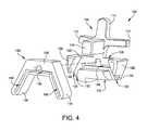
- FIG. 4is an exploded perspective view of a tibial cutting guide mount and tibial resection guide
- FIG. 5is a perspective view of a tibial cutting guide disposed within a tibial cutting guide mount located on an inferior portion of a tibia;
- FIG. 6is a front elevational view of a tibial cutting guide disposed within a tibial cutting guide mount located on an inferior portion of a tibia;
- FIG. 7is a side elevational view of a tibial cutting guide disposed within a tibial cutting guide mount located on an inferior portion of a tibia during resection of the tibia;
- FIG. 8is a schematic representation of a resected tibia following application and use of the tibial cutting guide and tibial cutting guide mount;
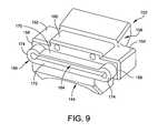
- FIG. 9is a perspective view of a talar cutting guide disposed within a talar cutting guide mount
- FIG. 10is an exploded perspective view of the talar cutting guide mount and the talar cutting guide illustrated in FIG. 9 ;
- FIG. 11is a perspective view of the talar cutting guide disposed within the talar cutting guide mount located on a superior portion of a talus;
- FIG. 12is a front elevational view of the talar cutting guide disposed within the talar cutting guide mount located on a superior portion of a talus;
- FIG. 13is a side perspective view of the talar cutting guide disposed within the talar cutting guide mount located on a superior portion of a talus during resection of the talus;
- FIG. 14is a schematic representation of a resected talus following application and use of the talar cutting guide and talar cutting guide mount;
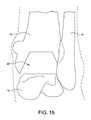
- FIG. 15is a schematic representation of a resected joint space following application and use of the talar and tibial cutting guide mounts and cutting guides;
- FIG. 16is a perspective view of one example of a custom tibial drill guide mount
- FIG. 17is a front elevational view of the tibial drill guide mount illustrated in FIG. 16 ;
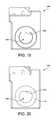
- FIG. 18is a rear elevation view of the tibial drill guide mount illustrated in FIG. 16 ;
- FIG. 19is a bottom elevational view of the tibial drill guide mount illustrated in FIG. 16 ;
- FIG. 20is a top elevational view of the tibial drill guide mount illustrated in FIG. 16 ;
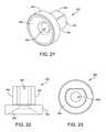
- FIG. 21is a perspective view of one example of a tibial drill guide
- FIG. 22is a side elevational view of the tibial drill guide illustrated in FIG. 21 ;
- FIG. 23is a top elevational view of the tibial drill guide illustrated in FIG. 21 ;
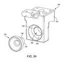
- FIG. 24is an exploded perspective view of the tibial drill guide mount and the tibial drill guide;
- FIG. 25Ais a side elevational view of the tibial drill guide disposed within the tibial drill guide mount being inserted into resected joint space;
- FIG. 25Bis a perspective view of the assemblage of the tibial drill guide mount and tibial drill guide disposed within the resected joint space;
- FIG. 25Cis a perspective view of the assembly of the tibial drill guide mount and tibial drill guide disposed and pinned within the resected joint space;
- FIG. 26is a perspective view of one example of an alignment tool
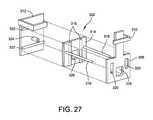
- FIG. 27is an exploded perspective view of the alignment tool illustrated in FIG. 26 ;
- FIGS. 28A and 28Billustrate the relative movement permitted between each of the components of the alignment tool illustrated in FIG. 26 ;
- FIG. 29is a perspective view of one example of an adapter bar for coupling the assemblage of the tibial drill guide mount and tibial drill guide to the alignment tool;
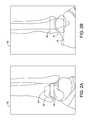
- FIG. 30is a perspective view of the adapter bar coupled to the assemblage of the tibial drill guide mount and tibial drill guide and to the alignment tool;
- FIG. 31is a top isometric view of another example of an alignment tool/foot holder assembly for use with a tibial drill guide mount and tibial drill guide;
- FIG. 32is a bottom isometric view of the alignment tool/foot holder assembly illustrated in FIG. 31 ;
- FIG. 33is an elevational front view of the alignment tool/foot holder assembly illustrated in FIG. 31 ;
- FIG. 34is an elevational side view of the alignment tool/foot holder assembly illustrated in FIG. 31 ;
- FIG. 35is a top isometric view of another example of an alignment tool/foot holder assembly for use with the tibial drill guide mount and tibial drill guide;
- FIG. 36is a top elevational view of the alignment tool/foot holder assembly illustrated in FIG. 35 ;
- FIG. 37is an elevational front view of the alignment tool/foot holder assembly illustrated in FIG. 35 ;
- FIG. 38is an elevational side view of the alignment tool/foot holder assembly illustrated in FIG. 35 ;
- FIG. 39is a perspective view of another example of a tibial cutting guide mount
- FIG. 40is a front side elevational view of the tibial cutting guide mount illustrated in FIG. 39 ;
- FIG. 41is a side elevational view of the tibial cutting guide mount illustrated in FIG. 39 ;
- FIG. 42is a top side view of the tibial cutting guide mount illustrated in FIG. 39 ;
- FIG. 43is a bottom side view of the tibial cutting guide mount illustrated in FIG. 39 ;
- FIG. 44is a perspective view of a tibial drill guide cartridge for use with the tibial drill guide mount illustrated in FIG. 39 ;
- FIG. 45is a front end view of the tibial drill guide cartridge illustrated in FIG. 44 ;
- FIG. 46is a bottom side plan view of the tibial drill guide cartridge illustrated in FIG. 44 ;
- FIG. 47is a side view of the tibial drill guide cartridge illustrated in FIG. 44 ;
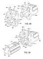
- FIG. 48is an exploded perspective view of a mounting plate and dowel pins configured to for use with the tibial drill guide mount illustrated in FIG. 39 ;
- FIG. 49is a partially exploded perspective view of a mounting plate and dowel pins configured to for use with the tibial drill guide mount illustrated in FIG. 39 ;
- FIG. 50is a partially exploded perspective view of a mounting plate, dowel pins, and tibial drill guide mount configured to receive a tibial drill guide cartridge in accordance with FIG. 44 ;
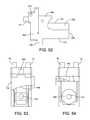
- FIG. 51is a perspective view of the tibial drill guide mount, tibial drill guide cartridge, dowel pins, and mounting plate assembled together;
- FIG. 52is a side view of the assembly illustrated in FIG. 51 ;
- FIG. 53is a top side plan view of the assembly illustrated in FIG. 51 ;
- FIG. 54is a bottom side plan view of the assembly illustrated in FIG. 51 .
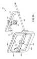
- FIG. 55is a perspective view of a foot holder assembly for use with the assembly illustrated in FIG. 51 ;
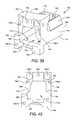
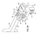
- FIG. 56is a perspective view of a pivoting arrangement used to secure the assembly illustrated in FIG. 51 to the foot holder assembly;
- FIG. 57is a top side plan view of the foot holder assembly illustrated in FIG. 55 ;
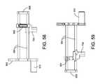
- FIG. 58is a side view of the foot holder assembly illustrated in FIG. 55 ;
- FIG. 59is an opposite side view of the foot holder assembly illustrated in FIG. 55 ;
- FIG. 60is a rear end view of the foot holder assembly illustrated in FIG. 55 ;
- FIG. 61is a front end view of the foot holder assembly illustrated in FIG. 55 ;
- FIG. 62is a perspective view of a drill being extended through the foot holder assembly and tibial drill guide.
- the disclosed systems and methodsadvantageously utilize custom manufactured surgical instruments, guides, and/or fixtures that are based upon a patient's anatomy to reduce the use of fluoroscopy during a surgical procedure. In some instances, the use of fluoroscopy during a surgical procedure may be eliminated altogether.
- the custom instruments, guides, and/or fixturesare created by imaging a patient's anatomy with a computer tomography scanner (“CT”), a magnetic resonance imaging machine (“MRI”), or like medical imaging technology prior to surgery and utilizing these images to create patient-specific instruments, guides, and/or fixtures.
- CTcomputer tomography scanner
- MRImagnetic resonance imaging machine
- a typical human foot 10includes an ankle joint 12 formed between a talus 14 , which is disposed on a calcaneus 20 , and a tibia 16 and fibula 18 .
- a CT or MRI scanned image or series of imagesmay be taken of a patient's ankle 12 (or other joint) and then converted from, e.g., a DICOM image format, to a solid computer model of the ankle including the calcaneus, talus, tibia, navicular, and fibula to determine implant alignment, type, and sizing using specialized modeling methods that are often embodied in computer software.
- Computer generated solid models that are derived from the data of the CT or MRI scan imagewill often include precise and accurate information regarding the surface contours surrounding the structures that have been imaged, e.g., the surface topography of the bones or contour of fascia that have been imaged. It will be understood that by surface topography it is meant the location, shape, size and distribution of surface features such as concavities and prominences or the like.
- imagesare made of a foot 10 , i.e., the calcaneus 20 , talus 14 , tibia 16 , and fibula 18 of a patient using a CT or MRI machine, or other digital image capturing and processing unit as is understood by one skilled in the art.
- the image datais processed in a processing unit, after which a model 50 is generated using the processed digitized image data as illustrated in FIGS. 2A and 2B .
- Interactive processing and preparation of the digitized image datais performed, which includes the manipulation and introduction of additional extrinsic digital information, such as, predefined reference locations 52 for component positioning and alignment so that adjustments to the surgical site 54 , that will require resection during surgery, may be planned and mapped onto computer model 50 ( FIGS. 2A and 2B ).
- additional extrinsic digital informationsuch as, predefined reference locations 52 for component positioning and alignment so that adjustments to the surgical site 54 , that will require resection during surgery, may be planned and mapped onto computer model 50 ( FIGS. 2A and 2B ).
- FIG. 3illustrates a pair of custom cutting guides for an ankle replacement surgery including a tibial resection guide mount 100 and a talar resection guide mount 102 , which are formed and mounted to the patient's lower tibia 16 a and upper talus 14 a .
- a custom tibial drill guide mount 200( FIGS. 16-20 ) is also formed and configured to be received within ankle space created by using the custom tibial and talar resection guide mounts 100 , 102 .
- custom cutting guidesare described for preparing a patient's talus, tibia, and femur, one skilled in the art will understand that other cutting guides may be implemented and that custom guides may be created for other joints including, but not limited to, the knee, hip, shoulder, or other joint.
- Tibial resection guide mount 100 illustrated in FIG. 3is formed from a resilient polymer material of the type that is suitable for use in connection with stereo lithography, selective laser sintering, or like manufacturing equipment.
- Resection guide mount 100includes a unitary body including a cruciform tibial yolk 104 projecting upwardly from a base 106 that further defines a guide receptacle recess 108 as best seen in FIG. 4 .
- Cruciform yolk 104includes a pair of spaced apart arms 110 , 112 that project outwardly from a central post 114 .
- Arms 110 , 112 and central post 114each have a conformal bone engaging surface 116 that is complementary to the contours of a corresponding portion of the patient's lower tibia 16 a as illustrated in FIG. 7 .
- conformal bone engaging surfaces 116 of arms 110 , 112 and central post 114are configured for complementary matching with anatomical surface features of a selected region of the patient's natural bone.
- the selected bone regioncomprises the lower surfaces of the patient's tibia 16 a.
- a pilot block 118projects outwardly from central post 114 , adjacent to the intersection of arms 110 , 112 .
- a support block 120( FIG. 4 ) is located on base 106 in spaced relation to pilot block 118 .
- Guide receptacle recess 108is defined by a pair of wings 122 , 124 that extend outwardly from either side of central post 114 in opposite directions on base 106 , with support block 120 located between them.
- Each wing 122 , 124includes a respective pylon 126 projecting outwardly from base 106 so as to provide lateral support for tibial resection guide 132 ( FIGS. 4 and 5 ).
- An elongate slot 128is defined transversely in a central portion of base 106 below pilot block 118 , but above support block 120 .
- Each wing 122 , 124also defines a respective slot 130 that is oriented at an angle relative to central post 114 .
- slots 130are disposed at a non-perpendicular angle relative to central post 114 , although one skilled in the art will understand that slots 130 may be disposed at perpendicular angles with respect to the direction in which central post 114 extends.
- Slots 128 and 130are sized and shaped to allow a typical surgical saw 60 ( FIG. 7 ) of the type often used for bone resection, to pass through from a correspondingly positioned and sized slot in resection guide 132 without contact, or with only incidental contact with resection guide mount 100 .
- tibial resection guide 132includes a pair of arms 134 that project downwardly and outwardly in diverging angular relation from the ends of a bridge beam 136 .
- the shape of tibial resection guide 132is complementary to the shape of guide receptacle recess 108 as defined by the inwardly facing surfaces of pilot block 118 , support block 120 , and pylons 126 .
- Bridge beam 136defines an elongate slot 138 that aligns with slot 128 when tibial resection guide is coupled to and supported by resection guide mount 100 .
- Arms 134each define a respective slot 140 that align with a respective slot 130 .
- the inwardly facing surfaces 142 of pilot block 118 , support block 120 , and pylons 126 , that together define guide receptacle recess 108have a shape that is complementary to the outer profile of tibial resection guide 132 .
- Guide receptacle recess 108is sized so as to accept tibial resection guide 132 with a “press-fit”.
- press-fitit should be understood that the inwardly facing surfaces 142 of pilot block 118 , support block 120 , and pylons 126 are sufficiently resilient to deflect or compress elastically so as to store elastic energy when tibial resection guide 132 is pushed into guide receptacle recess 108 .
- tibial resection guide 132will have an outer peripheral shape that is complementary to the circumferential shape of guide receptacle recess 108 , but slightly larger in size, for press-fit embodiments. Also, tibial resection guide 132 may be retained within guide receptacle recess 108 by only frictional engagement with the inwardly facing surfaces of pilot block 118 , support block 120 , and pylons 126 . In some embodiments, tibial resection guide 132 can simply slide into guide receptacle recess 108 without operative contact or only incidental engagement with the inwardly facing surfaces of pilot block 118 , support block 120 , and pylons 126 .
- a talar resection guide mount 102is formed from a resilient polymer material of the type that is suitable for use in connection with stereo lithography, selective laser sintering, or the like manufacturing equipment, e.g., a polyamide powder rapid prototype material is suitable for use in connection with selective laser sintering.
- Talar resection guide mount 102also includes a conformal bone engaging surface 144 that is complementary to the contours of a corresponding portion of the patient's upper talus 14 a ( FIGS. 11 and 13 ).
- conformal bone engaging surface 144 of talar resection guide mount 102is configured for complementary matching with anatomical surface features of a selected region of the patient's natural bone.
- the selected bone regioncomprises the outer, upper surfaces of the patient's talus.
- Talar resection guide mount 102comprises a unitary block that defines a central guide receptacle recess 146 and a pair of through-bores 148 ( FIG. 10 ).
- Guide receptacle recess 146is defined by the inwardly facing surfaces 150 of a pair of wings 152 , 154 that project outwardly, in opposite directions from a base 156 .
- Each wing 152 , 154includes a pylon 158 projecting upwardly to support guide housing 160 such that an elongate slot 162 is defined within base 156 and below guide housing 160 ( FIGS. 10 and 11 ).
- Slot 162is sized and shaped to allow a typical surgical saw 60 , of the type often used for bone resection, to pass through from a correspondingly positioned and sized slot 164 in talar resection guide 166 without contact, or with only incidental contact with talar resection guide locator 102 ( FIGS. 11 and 13 ).
- An annular wall 168having a shape that is complementary to the outer profile of talar resection guide 166 , projects outwardly in substantially perpendicular relation to a back wall and so as to further defines guide receptacle recess 146 .
- talar resection guide 166includes a pair of confronting, parallel plates 170 , 172 that define elongate slot 164 between them, and are joined to one another at their ends by wings 174 .
- the shape of talar resection guide 166is complementary to the shape of guide receptacle recess 146 as defined by the inwardly facing surfaces 150 of wings 152 , 154 , base 156 , and pylons 158 .
- Guide receptacle recess 146is sized so as to accept talar resection guide 166 with a press-fit.
- talar resection guide 166will have an outer peripheral shape that is complementary to the circumferential shape of guide receptacle recess 146 , but slightly larger in size, for press-fit embodiments. Also, talar resection guide 166 may be retained within guide receptacle recess 146 by only frictional engagement with the inwardly facing surfaces 150 of wings 152 , 154 , base 156 , and pylons 158 .
- talar resection guide 166can simply slide into guide receptacle recess 146 without operative contact or only incidental engagement with the inwardly facing surfaces 150 of wings 152 , 154 , base 156 , and pylons 158 .
- Tibial drill guide mount 200 illustrated in FIGS. 16-20also may be fabricated from a resilient polymer material of the type that is suitable for use in connection with stereo lithography, selective laser sintering, or the like manufacturing equipment, e.g., a polyamide powder repaid prototype material is suitable for use in connection with selective laser sintering.
- tibial drill guide mount 200includes a somewhat rectangular body 204 that defines an aperture 206 that extends from a top surface 208 of body 204 to a bottom surface 210 of body 204 .
- Top surface 208 of body 204may include a pair of chamfers 212 that are sized and configured to be mate against the resected surfaces of the lower tibia 16 a ( FIG. 8 ). Put another way, the top or upper surface 208 of body 204 , including chamfers 212 , is complementary to the geometry and locations of slots 138 and 140 of tibial resection guide 132 .
- Front side 214 of body 204defines one or more blind holes 216 .
- body 204may define three blind holes 216 - 1 , 216 - 2 , and 216 - 3 .
- blind holes 216 - 1 and 216 - 2may be reamed holes that are sized and configured to receive a dowel pin
- blind hole 216 - 3may also be a reamed hole for receiving a dowel pin or blind hole 216 - 3 may be threaded for engaging a screw as described below.
- Aperture 206may have a circular cross sectional area and include a shoulder 218 having a reduced diameter compared to aperture 206 and includes an anti-rotational feature 220 as best seen in FIG. 20 .
- Anti-rotational feature 220 of shoulder 218may include one or more flats or other geometric structure(s) to prevent tibial drill guide 202 from rotating with respect to tibial drill guide mount 200 when tibial drill guide 202 is disposed within aperture 206 .
- tibial engagement structure 222Extending from body 204 of tibial drill guide mount 200 are tibial engagement structure 222 and talar engagement structure 224 .
- the outer surface 226 of tibial engagement structure 222may have a rectangular shape that is substantially planar, and the internal and substantially conformal engagement surface 228 of tibial engagement structure 222 may be somewhat convex for engaging the tibia 16 of the patient.
- Tibial engagement structure 222may define one or more holes 230 for receiving a k-wire or pin as described below.
- Talar engagement structure 224may also include a substantially planar and rectangular outer surface 232 .
- the lower portion 234 of talar engagement structure 224may be a conformal surface having a geometry that matches the geometry of the talar bone 14 ( FIG. 14 ).
- Talar engagement structure 224may also define one or more holes 236 sized and configured to receive a k-wire as described below.
- Tibial drill guide 202 illustrated in FIGS. 21-23is preferably fabricated from a material having more structural integrity than tibial drill guide mount 200 to enable drill guide 202 to guide a drill bit without being damaged.
- materialsinclude, but are not limited to, metals, ceramics, or the like.
- Drill guide 202has a cylindrically shaped first portion 238 that is sized and configured to be received within the portion of aperture 206 that extends through the shoulder or reduced diameter area 218 .
- a second portion 240 of drill guide 202has a larger cross-sectional diameter than first portion 238 and is sized and configured to be received within aperture 206 of tibial drill guide mount 200 .
- a flat 242which is best seen in FIGS.
- the internal surface 248 of second portion 240 of tibial drill guide 202has a conical shape that intersects and communicates with aperture 246 such that a drill or reamer may be received through drill guide 202 .
- the anatomic surface features of the patient's lower tibiamay be complementarily mapped onto each of conformal bone engaging surfaces 116 of arms 110 , 112 , and central post 114 , i.e., the surfaces that will engage the bones unique surface topography, of tibial resection guide mount 100 .
- Each of conformal bone engaging surfaces 116 of arms 110 , 112 , and central post 114 of resection guide mount 100is redefined with a complementary, substantially mirror image of the anatomic surface features of a selected region of the patient's lower tibia 16 a .
- tibial resection guide mount 100releasably “locks” on to the complementary topography of the corresponding portion of the patient's natural tibia without the need for other external or internal guidance fixtures.
- the mating of bone surface asperities in their corresponding concavities formed in conformal bone engaging surfaces 116 of tibial resection guide mount 100ensures that little or no relative movement, e.g., slipping sideways, occurs between tibial resection guide mount 100 and the tibial surface.
- a substantially identical mappingis carried out in connection with the design of a patient specific talar resection guide mount 102 and tibial drill guide mount 200 .
- the mapping for the design of tibial drill guide mount 200is performed by extrapolating where the resections to the tibia 16 and talus 14 will be made using tibial and talar resection guide mounts 100 and 102 and mapping the tibial drill guide mount 200 onto the extrapolated geometry of the tibia and talus.
- a visual presentation of the virtual alignment results between the patient's lower tibia 16 a and resection guide mount 100 , the patient's upper talus 14 a and resection guide mount 102 , and the proposed resected area that that is to be created by resecting the talus 14 and tibia utilizing the tibial resection guide mount 100 and the talar resection guide mount 102are created and forwarded to the surgeon to obtain approval of the results prior to manufacturing.
- the surgeonmay be provided with a visual representation of the virtual alignment results between the proposed resected joint space and tibial drill guide mount 200 are created and forwarded to the surgeon to obtain approval of the results prior to manufacturing.
- resection guide mount 100 , resection guide mount 102 , and tibial drill guide mount 200are manufactured and returned to the surgeon for use in the surgery.
- the surgeonmakes an anterior incision to gain initial access to the ankle joint.
- the surgeonorients tibia resection guide mount 100 on lower tibia 16 a until the conformal bone engaging surfaces 116 of arms 110 , 112 and central post 114 of tibial resection guide mount 100 securely engage one another so as to releasably “interlock” with the topography of the exposed surface of lower tibia 16 a as best seen in FIGS. 5-7 .
- a surgeonpress-fits an appropriately configured distal resection guide 132 in guide receptacle recess 108 of tibial resection guide mount 100 . This results in the resection guide mount 100 being sandwiched between the resection guide 132 and the patient's bone tibia 16 a ( FIGS. 5 and 6 ).
- the surgeonuses a conventional surgical blade 60 and the resection slots 128 and 130 of resection guide 132 to resect the patient's bone 16 ( FIGS. 7 and 8 ).
- the anatomic surface features of the patient's upper talusmay be complementarily mapped onto conformal bone engaging surface 144 .
- complementary mapping of the digital imagesresults in localized prominences on the surface of a bone becoming localized concavities on conformal bone engaging surface 144 , while localized concavities on the surface of a bone become localized prominences on conformal bone engaging surface 144 .
- conformal bone engaging surface 144is redefined with a complementary, substantially mirror image of the anatomic surface features of a selected region of the patient's lower tibia.
- talar resection guide mount 102releasably “locks” on to the complementary topography of the corresponding portion of the patient's natural talus without the need for other external or internal guidance fixtures.
- resection guide mount 102To continue the total ankle replacement the surgeon orients resection guide mount 102 on upper talus 14 a until conformal bone engaging surface 144 of resection guide mount 102 “locks” to the topography of the exposed surface of upper talus 14 a ( FIG. 11 ). With resection guide mount 102 locked onto the patient's upper talus, a surgeon press-fits an appropriately configured distal resection guide 166 in guide receptacle recess 146 of talar resection guide mount 102 . This results in resection guide mount 102 being sandwiched between resection guide 166 and the patient's bone 14 ( FIGS. 12 and 13 ).
- the surgeonuses a conventional surgical blade 60 and the resection slot 164 of resection guide 166 to resect the patient's bone 14 ( FIGS. 13 and 14 ).
- tibial drill guide mount 200 and tibial drill guide 202are coupled together and installed into resected joint space 22 ( FIG. 15 ).
- Tibial drill guide mount 200 and tibial drill guide 202are coupled together by inserting first portion 238 of tibial drill guide 202 into aperture 206 defined by body 204 of tibial drill guide mount 200 ( FIG. 24 ).
- Flat 242 formed on the first portion 238 of tibial drill guide 202is aligned with anti-rotation feature 220 of shoulder 218 such that tibial drill guide 202 slides into aperture 206 until a lower surface 250 of second portion 240 of drill guide 202 contacts and abuts shoulder 218 of tibial drill guide mount 200 .
- Body 204 of tibial drill guide mount 200in which tibial drill guide 202 is disposed, is inserted into resected joint space 22 in an anterior posterior direction with chamfers 212 sliding along resected areas of tibia 16 formed by utilizing slots 140 of tibial resection guide 132 as best seen in FIGS. 25A and 25B .
- the assemblage of tibial drill guide mount 200 and tibial drill guide 202are slid into resected joint space 22 until talar engagement structure contacts talus 14 .
- a surgeonmay move tibial guide mount 200 within resected joint space until conformal surface 228 is appropriately secured to the patient's bone by virtue of the mating of bone surface asperities in their corresponding concavities formed in conformal bone engaging surface 228 .
- k-wires 62may be inserted into holes 230 and/or holes 236 , respectively defined by tibial engagement structure 222 and talar engagement structure 224 , to secure the assemblage of the tibial drill guide mount 200 and tibial drill guide 202 to the patient's tibia 16 and talus 14 as illustrated in FIG. 25C .
- FIGS. 26-28Billustrate one example of an alignment tool 300 , which serves the task of supporting the ankle joint during a prosthesis installation procedure.
- Alignment tool 300includes a foot holder assembly 302 and a leg rest 304 .
- Foot holder assembly 302includes a foot rest 306 , to which the foot is secured by a foot clamp 310 and heel clamps 308 during an prosthesis installation procedure.
- leg rest 304The calf of the leg is suitably secured to the leg rest 304 once the ankle joint has been resected and tibial drill guide mount 200 and tibial drill guide 200 have been installed. Together, foot holder assembly 302 and leg rest 304 hold the foot and ankle relative to the leg during an installation procedure.
- foot holder assembly 302is sized and configured for pivoting, under control of the physician, from a vertical or upright condition (shown in solid lines in FIG. 26 ) toward a more horizontal or tilted condition (shown in phantom lines in FIG. 26 ). In the upright condition, assembly 302 serves to hold the ankle joint in a desired orientation with respect to the natural anterior-to-posterior and medial-to-lateral axes.
- foot holder assembly 302includes a back plate 312 and a mid-plate 314 , which is sandwiched between foot rest 306 and back plate 312 .
- Mid-plate 314is coupled to the foot rest 306 by sliding dovetail couplings 316 for up-and-down (i.e., vertical) movement relative to foot rest 306 .
- a pair of oppositely spaced alignment rods 318is carried by the mid-plate 314 .
- Alignment rods 318are disposed in the same horizontal plane and extend from mid-plate 314 through vertically elongated slots 320 defined by foot rest 306 such that rods 318 are disposed on opposite sides of the tibia in the medial-to-lateral plane when a foot is supported by foot holder assembly 302 .
- Vertical movement of mid-plate 314moves alignment rods 318 up-and-down in unison within slots 320 on opposite sides of the foot rest 306 ( FIG. 28A ).
- Back plate 312is coupled to mid-plate 314 by sliding dovetail couplings 322 for side-to-side (i.e., horizontal) movement relative to foot rest 306 as illustrated in FIG. 28B .
- Back plate 312also carries a bushing 324 , which extends through openings 326 defined by mid-plate 314 and foot rest 306 and terminates at or near the plane of the foot rest 306 against which the bottom of the foot contacts. The center of the bushing 324 coincides with the intersection of the horizontal plane of the rods 318 .
- Adapter bar 400for coupling tibial drill guide mount 200 to alignment tool 300 is illustrated in FIG. 29 .
- Adapter bar 400includes an elongate body 402 linearly extending from a first end 404 to a second end 406 .
- Each of the ends 404 , 406includes a respective extension 408 , 410 that extends from elongate body 402 at an angle.
- extensions 408 and 410orthogonally extend from elongate body 402 , although one skilled in the art will understand that extensions 408 and 410 may diverge from elongate body 402 at other angles.
- elongate body 402may not have a linear shape, but may have a curved or arced shape as will be understood by one skilled in the art.
- Each extension 408 and 410defines a respective hole 412 , 414 that is sized and configured to slidably receive alignment rods 318 that extend from alignment tool 300 .
- Elongate body 402defines one or more holes 416 - 1 , 416 - 2 , and 416 - 3 (collectively referred to as “holes 416 ”) for coupling to adapter bar 400 to tibial drill guide mount 200 .
- the one or more holes 416align with one or more holes 216 defined by body 204 of tibial drill guide mount 200 such that a pin or other device for maintaining the alignment and engagement of adapter bar 400 and tibial drill guide mount 200 .
- holes 216 - 1 and 216 - 2 of tibial drill guide mount 200align with holes 416 - 1 and 416 - 2 of adapter bar 400
- hole 216 - 3 of drill guide mount 200aligns with hole 416 - 3 of adapter bar 400
- Dowel pins 70shown in FIG.
- 25Cmay be inserted into holes 216 - 1 and 416 - 1 as well as into holes 216 - 2 and 416 - 2 to align tibial drill guide mount 200 with adapter bar 400 in both the horizontal and vertical directions (e.g., in the x- and y-directions), and a screw (not shown) may be inserted through hole 416 - 3 into threaded hole 216 - 3 to secure tibial drill guide mount 200 to adapter bar at the proper height or depth (e.g., in the z-direction).
- foot and lower legare placed in foot rest 306 and leg rest 304 ( FIG. 30 ).
- the physicianestimates the ankle's axis of dorsi-plantar rotation and visually aligns the ankle to the axis of rotation of the alignment tool 300 .
- Foot rest 306is adjusted to rotate the foot so that the big toe is essentially pointing in a vertical direction with respect to the leg that extends in a horizontal direction.
- the forefoot and heelare secured to foot rest 306 with clamps 308 and 310 .
- Leg rest 304is adjusted to the calf so that the tibia 16 is approximately parallel to the floor.
- the foot and calfare desirably aligned so that the anterior-posterior (“A-P”) line of the talus's trochlea is essentially vertical.
- A-Panterior-posterior
- Adapter bar 400is coupled to alignment tool 300 by aligning holes 412 and 414 that are respectively defined by extensions 408 and 410 with alignment rods 318 of alignment tool 300 .
- Adapter bar 400is then slid along alignment rods 318 until holes 416 of adapter bar align with holes 216 defined by body 204 of tibial drill guide 200 ( FIG. 30 ).
- dowel pins 70are inserted into holes 416 - 1 and 416 - 2 of adapter bar 400 and holes 216 - 1 and 216 - 2 of tibial drill guide mount 200 .
- tibial drill guide mount 200is properly aligned with alignment tool 300 in the medial lateral (e.g., x-direction) and superior-inferior (e.g., y-direction) directions.
- a screwis inserted through hole 416 - 3 into threaded hole 216 - 3 , which secures tibial drill guide mount 200 to adapter bar 400 and provides proper alignment in the anterior-posterior direction (e.g., the z-direction).
- bushing 324 on back plate 312establishes alignment with the mechanical axis of tibia 16 and alignment of rods 318 .
- adapter bar 400 to align tibial drill guide mount 200 with alignment tool 300 as described abovein line drilling of the center of the ankle and tibia for introduction of a bottom foot cannula is made possible without the use of fluoroscopy since aperture 246 of tibial drill guide 202 disposed within tibial drill guide mount 200 is aligned with an axis defined by bushing 324 .
- Such arrangementenables an intramedullary channel to be formed that is substantially collinear with a mechanical axis defined by the tibia.
- bushing 324is temporarily separated from the back plate 312 (e.g., by unscrewing) to provide access to the bottom of the foot.
- the physicianuses a scalpel to make an initial incision in the bottom of the foot and replaces bushing 324 .
- a cannulated trocar loaded with a k-wire(not shown) can be inserted through bushing 324 , into the bottom of the foot, until the calcaneus 20 is contacted and the k-wire is firmly set within the calcaneus 20 .
- the trocarcan then be removed, and the k-wire lightly tapped further into the calcaneus 20 .
- the bushing 324measures 6 mm in diameter, and the cannulated trocar can be 6 mm loaded with a 2.4 mm k-wire.
- the physiciancan now operate a cannulated first reamer (e.g., 6 mm) (not shown) over the k-wire up into the calcaneus 20 and talus 14 .
- the first reameropens an access path for insertion of a bottom foot cannula.
- a bottom foot cannula 64As shown in FIG. 30 , the physician then inserts a bottom foot cannula 64 as shown in FIG. 30 .
- a second reamer 66e.g., 5 mm
- adapter bar 400is decoupled from drill guide mount 200 and alignment rods 318 .
- Drill guide mount 200is removed from resected joint space 22 to expose the resected joint space to the surgeon.
- the ankle prosthesisincludes a stem that may extend from the bottom of the calcaneus up to the top of the talus (i.e., a talo-calcaneal stem), although in some embodiment the stem is completely disposed within the talus (i.e., a talar stem).
- a convex domeis coupled to the stem and provides an articulating joint surface.
- a tibial stemmay be monolithic or include a plurality of segments that may be coupled together in situ.
- a tibial platformcouples to the tibial stem and either includes or is coupled to a convex joint surface for articulating with the articulating joint surface coupled to the talar/talo-calcaneal stem.
- Examples of such ankle prosthesis and methods of installing such prosthesisare disclosed in U.S. Pat. No. 7,534,246 issued to Reiley et al., the entirety of which is herein incorporated by reference.
- FIGS. 31-34illustrate another example of an alignment tool in the form of a foot holder assembly 500 to which tibial drill guide mount 200 may be directly coupled.
- foot holder assembly 500includes a base plate 502 defining a plurality of slots 504 and 506 and an aperture 503 .
- Slots 504are sized and configured to slidably receive a pair of heel clamps 508
- slots 506are sized and configured to slidably receive a pair of forefoot clamps or guides 510 .
- Heel clamps 508 and forefoot clamps 510cooperate to maintain a foot of a patient in a desired position with respect to base plate 502 by utilizing a locking mechanism such as, for example, a set screw or other locking device, to fix the position of heel clamps 508 and forefoot clamps 510 to base plate 502 .
- the respective foot engaging surfaces 512 and 514 of heel clamps 508 and forefoot clamps 510may have a shape that complements the medial and lateral shape of a human foot.
- a coupling bar 518is sized and configured to slidably engage alignment rods 516 as best seen in FIGS. 32 and 34 .
- Coupling bar 518includes a pair of spaced apart legs 520 that define channels 522 ( FIG. 32 ) in which alignment rods 516 are slidably received.
- legs 520include a clamp or other locking mechanism 524 for increasing the friction between coupling bar 518 and alignment rods 516 in order to releasably lock coupling bar 518 at a certain position along the length of alignment rods 516 .
- Medial-lateral cross bar 526couples together legs 520 of coupling bar 518 . Extending from medial-lateral cross bar 526 is mount coupling member 528 .
- Mount coupling member 528includes one or more holes 530 - 1 , 530 - 2 , and 530 - 3 (collectively referred to as “holes 530 ”) that are sized and configured to align with holes 216 defined by tibial drill guide mount 200 .
- a peg 532extends from medial-lateral cross bar 526 for coupling shin engaging member 534 via slot 536 defined by shin engaging member 534 .
- Shin engaging member 534includes a shelf 538 having a concave surface 540 for abutting a shin of a patient.
- a nut or other locking mechanism(not shown) for engaging peg 532 , which may be threaded, may be used to fix the position of shelf 538 relative to medial-lateral cross bar 526 .
- foot holder assembly 500in connection with the assemblage of tibial drill guide mount 200 and tibial drill guide 202 is similar to the use of alignment tool 300 described above.
- the heel of the patient's footis placed between heel clamps 508 and the patient's forefoot is placed between forefoot clamps 510 .
- the locking mechanisms of heel and forefoot clamps 508 and 510may be engaged to initially set positions of heel and forefoot clamps 508 and 510 relative to base plate 502 .
- Holes 530 of coupling member 528are aligned with holes 216 defined by tibial drill guide mount 200 by sliding legs 520 of coupling bar 518 along alignment rods 516 .
- Dowel pins 70 and/or a threaded screwmay be used to couple holes 530 of coupling member 528 to holes 216 of tibial drill guide mount 200 . The surgeon may check to ensure that the patient's foot is firmly against base plate 502 and then engage clamps 524 such that coupling bar 518 is fixed to alignment rods 516 .
- Shin engaging member 534is adjusted until concave surface 540 contacts the patient's shin.
- the adjustment of shin engaging member 534is guided by the engagement between slot 536 and peg 532 .
- the nut or other locking mechanism(not shown) locks shin engagement member 534 in place.
- the surgeonmay make final adjustments to the heel and forefoot clamps 508 and 510 and then create the intramedullary channel as described above.
- alignment tool 600for use with tibial drill guide mount 200 and tibial drill guide 202 is illustrated in FIGS. 35-38 .
- alignment tool 600includes a base plate 602 comprising a plurality of bars 602 a , 602 b , and 602 c . Although three bars 602 a , 602 b , and 602 c are illustrated, one skilled in the art will understand that fewer or more bars may be implemented.
- Bar 602 bdefines a hole 603 sized and configured to receive a surgical tool, such as, for example, a cannulated drill.
- Additional elementsincluding, but not limited to, heel clamps and/or forefoot clamps (not shown) may be coupled to the bars 602 a , 602 b , and 602 c of base plate 602 for aiding in the positioning of a patient's foot with respect to hole 603 .
- alignment rods 604Extending from base plate 602 is a pair of spaced apart alignment rods 604 .
- One of alignment rods 604may be disposed on a medial side of a patient's leg, and the other alignment rod 604 disposed on a lateral side of the patient's leg.
- Alignment rods 604like alignment rods 318 of alignment tool 300 , may be slidably receiving within holes 412 , 414 of adapter bar 400 .
- alignment tool 600in connection with the assemblage of tibial drill guide mount 200 and tibial drill guide 202 and the adapter bar 400 is similar to the use of alignment tool 300 described above.
- adapter bar 400is coupled to alignment tool 600 by aligning holes 412 and 414 that are respectively defined by extensions 408 and 410 with alignment rods 604 of alignment tool 600 .
- Adapter bar 400is slid along alignment rods 604 until holes 416 of adapter bar align with holes 216 defined by body 204 of tibial drill guide 200 .
- dowel pinsare inserted into holes 416 - 1 and 416 - 2 of adapter bar 400 and 216 - 1 and 216 - 2 of tibial drill guide mount 200 .
- tibial drill guide mount 200is properly aligned with alignment tool 600 in the medial lateral (e.g., x-direction) and superior-inferior (e.g., y-direction) directions.
- a screwis inserted through hole 416 - 3 into threaded hole 216 - 3 , which secures tibial drill guide mount 200 to adapter bar 400 and provides proper alignment in the anterior-posterior direction (e.g., the z-direction).
- the surgeonmay make final adjustments to the heel and forefoot clamps 508 and 510 and then create the intramedullary channel as described above.
- FIGS. 39-63illustrate another embodiment of a system for performing a surgical procedure.
- FIGS. 39-43illustrate a tibial drill guide mount 700 sized and configured to receive the tibial drill guide cartridge 702 illustrated in FIGS. 44-47 .
- Tibial drill guide mount 700may also receive other drill guide cartridges for use during other stages of the surgical procedures.
- tibial drill guide 700may be fabricated from a resilient polymer material of the type that is suitable for use in connection with stereo lithography, selective laser sintering, or the like manufacturing equipment, e.g., a polyamide powder repaid prototype material is suitable for use in connection with selective laser sintering.
- tibial drill guide mount 700has a somewhat rectangular body 704 having a front side 706 , a rear side 708 , top side 710 , bottom side 712 , and a pair of opposed sides 714 and 716 .
- Front side 706defines a recess 718 sized and configured to slidably receive tibial drill guide 702 therein.
- Recess 718communicates with a recess 720 ( FIGS. 39 and 43 ) defined by bottom side 712 and a recess 722 ( FIGS. 39, 42, and 43 ) defined by top side 710 such that body 704 is substantially hollow.
- sides 714 , 716have different geometries that correspond with the cross-sectional geometry of tibial drill guide cartridge 702 to ensure that tibial drill guide cartridge 702 is properly inserted into recess 718 .
- side 716includes first and second ledges 728 , 730 that inwardly extend into recess 718
- side 714has an inwardly tapered upper region 732 and an inwardly extending ledge 734 .
- sides 714 , 716may include other features for ensuring proper insertion of tibial drill cartridge 702 into recess 718 .
- sides 714 , 716may have the identical geometry and tibial drill guide cartridge may be reversibly inserted into recess 718 .
- Front side 706defines one or more dowel holes 736 - 1 , 736 - 2 (collectively referred to as “dowel holes 736 ”) sized and configured to receive a dowel pin 70 therein.
- One or more through holes 738 - 1 , 738 - 2 , 738 - 3(collectively referred to as “through holes 738 ”) extend through front side 706 , which also defines a blind hole 740 .
- Through holes 738are sized and configured to receive k-wires for pinning tibial drill guide mount to a patient's bone as described below.
- Top side 710 of tibial drill guide mount 700includes a pair of chamfers 742 that are sized and configured to be mate against and reference the resected surfaces of the lower tibia 16 a ( FIG. 8 ).
- Tibial drill guide mount 700also includes a tibial engagement structure 744 and a talar engagement structure 746 .
- Tibial engagement structure 744extends from top side 710 and includes a substantially conformal engagement surface 748 .
- Talar engagement structure 746extends from bottom side 712 and also includes a substantially conformal engagement surface 750 .
- Tibial drill guide cartridge 702has a substantially rectangular elongate body 754 that may be formed from a more substantial material than tibial drill guide mount 700 such as, for example, metals, ceramics, or the like.
- the geometry of sides 756 , 758is respectively complementary to the sides 714 , 716 of tibial drill guide mount 700 .
- side 758includes ledges 760 and 762 that respectively correspond to ledges 728 and 730
- side 756includes a ledge 764 and an angled section 766 , which respectively correspond to ledge 734 and upper region 732 of tibial drill guide mount 700 .
- Front side 768 of tibial drill guide cartridge 700defines a blind hole 770 , which may be threaded for reasons described below.
- Tibial drill guide cartridge 702defines a pair of holes 772 and 774 that extend from bottom surface 776 to top surface 778 .
- Hole 772may be a reamed hole that is sized and configured to receive a ball detent therein, and hole 774 has an internal surface 780 that tapers from a larger diameter at bottom surface 776 to a smaller surface that is sized and configured to receive a surgical tool, such as a drill and/or reamer.
- Top surface 778defines a pair of parallel slots 782 - 1 , 782 - 2 (collectively referred to as “slots 782 ”) that extend from side 756 to side 758 .
- slots 782are disposed equidistant from a central axis defined by hole 774 to provide a visual key for a physician that wants check the alignment of hole 774 with a mechanical axis of a patient's tibia using fluoroscopy.
- a mounting plate 800has a substantially rectangular body 802 that is fabricated from a material including, but not limited to, metals, ceramics, or the like.
- Body 802defines an aperture 804 the extends from front side 806 to back side 808 and has a similar geometry of recess 718 of tibial drill guide mount 700 such that tibial drill guide cartridge 702 may be received therein.
- Body 802also defines a pair of through holes 810 - 1 , 810 - 2 (collectively referred to as “holes 810 ”) that are arranged on body 802 such that they correspond to holes 738 of tibial drill guide mount 700 and are sized and configured to receive a k-wire or pin therein.
- a mounting base 812extends from front side 806 of mounting plate 800 and defines a hole 814 that extends from a first side 816 to a second side 818 .
- Mounting base 812defines a notch 820 and one or more dowel pin holes 822 - 1 , 822 - 2 (collectively referred to as “holes 822 ”) that are aligned with holes 736 of tibial drill guide mount 700 .
- Notch 820bisects hole 814 .
- Mounting base 812may also define one or more recesses 824 that correspond to one or more protrusions 784 that extends from front side 706 of tibial drill guide mount 700 .
- Recesses 824 and protrusions 784cooperate to ensure that mounting base 812 and tibial drill guide mount 700 are properly aligned.
- One skilled in the artwill understand that other geometric features may be implemented to ensure proper alignment between mounting base 812 and tibial drill guide mount 700 .
- mounting plate 800may be coupled to tibial drill guide mount 700 using dowel pins 70 , which are received through holes 822 and 734 .
- Tibial drill guide cartridge 702is received through aperture 804 and recess 718 as best seen in FIG. 51 .
- FIGS. 53 and 54illustrate that when tibial drill guide cartridge 702 is properly inserted into the assemblage of tibial drill guide mount 700 and mounting plate 800 , hole 772 aligns with hole 828 defined by mounting plate 800 , which may include a ball detent (not shown) disposed therein.
- Tibial drill guide mount 700 , tibial drill guide 702 , and mounting plate 800may be used in connection with alignment tool 300 , adapter bar 400 , foot holder assembly 500 , and alignment tool 600 as described above. Additionally, tibial drill guide mount 700 , tibial drill guide 702 , and mounting plate 800 may also be used in conjunction with foot holder assembly 900 illustrated in FIGS. 55-60 as can tibial drill guide mount 200 and tibial drill guide 202 .
- foot holder assembly 900includes a base plate 902 that extends from a first end 904 to a second end 906 .
- First and second ends 904 , 906each define a pocket 908 and a hole 910 .
- Pocket 908is sized and configured to receive a drill bushing 912 having a cylindrical body defining hole 914 that aligns with through hole 910 . Accordingly, both first end 904 and second end 906 may support an ankle or forefoot of a patient.
- Each pocket 908includes a spring loaded detent 916 communicatively coupled to it that include a finger receiving surface 918 and is configured to slide relative to base plate 902 and secure drill bushing 912 within pocket 908 .
- drill bushingmay be threaded and configured to be coupled to base plate 902 with complementary threads disposed on an inner surface of holes 910 .
- Base plate 902also includes a medial/lateral extension 920 that extends in a substantially perpendicular direction from an approximate mid-point between first end 904 and second end 906 .
- Base plate 902may also define a viewing opening 922 such that a surgeon may be able to view the bottom of a patient's foot when the foot is secured to foot holder assembly 900 .
- One or more rods 924extend from base plate 902 in a substantially perpendicular direction with respect to an upper foot holding surface 926 ( FIG. 56 ). Rods 924 may be secured to base plate 902 using screws or through other securing means as will be understood by one skilled in the art. A cap 928 is secured to an upper end of rods 924 and be secured to rods 924 using screws or other fixation means.
- a mounting member 930has an elongate body 932 that defines a pair of holes 934 , 936 at one end 938 that slidably receive rods 924 such that mounting member 930 may be slid along rods 924 in order to position tibial drill guide mount 700 with respect to base plate 902 .
- a spring loaded button 940is disposed at first end 938 of mounting member 930 and is coupled to a locking mechanism (not shown) disposed within mounting member 930 for locking mounting member 930 at a position along rods 924 .
- One or more holes 942are defined at the second end 944 of mounting member 930 and correspond to holes 716 of drill guide mount 700 for coupling drill guide mount 700 to foot holder assembly 900 .
- Second end 942also defines a slot 946 , as best seen in FIGS. 56 and 60 , that is sized and configured to receive an internally threaded rod 948 of a pivoting arrangement 950 , which includes a lower portion 952 that is received within slot 820 of mounting plate 800 and is cross-pinned through hole 814 .
- the cross-pinning of pivoting arrangement 950may pivot about an axis defined by hole 814 and is configured to receive an support tightening knob 954 .
- Bottom surface 956 ( FIG. 60 ) of knob 954has an outer dimension that is greater than slot 946 and is configured to engage mounting member 930 in order to secure the assemblage of mounting plate 800 and tibial drill guide mount 700 , which may include tibial drill cartridge 702 .
- tibial drill guide mount 700is inserted into resected joint space 22 .
- Mounting plate 800is connected to tibial drill guide mount 700 using dowel pins 70 as best seen in FIGS. 49 and 50 .
- pivoting arrangement 950cross-pinned to mounting plate 800
- the assemblage of mounting plate 800 and pivoting arrangement 948is coupled to tibial drill guide mount with dowel pins 70 , which may be press fit into holes 822 of mounting plate 800 and holes 716 of tibial drill guide mount 700 as will be understood by one skilled in the art.
- Tibial drill guide mount 700 and mounting platemay be secured within resected joint space 22 by inserting k-wires (not shown) into holes 736 , 790 defined by tibial drill guide mount 700 and holes 830 - 1 , 830 - 2 (corresponding to holes 736 - 1 , 736 - 2 ) and 832 - 1 , 832 - 2 defined by mounting plate 800 .
- pivoting arrangement 948is rotated such that it extends in a direction approximately parallel to a longitudinal axis defined by a patient's leg and the cartridge-style tibial drill guide 702 is inserted into aperture 804 of mounting plate 800 and recess 718 of tibial drill guide mount 700 .
- Tibial drill guide cartridge 702is inserted until leading end 786 of tibial drill cartridge 702 abuts rear wall 788 of tibial drill guide mount 700 at which point the ball detent disposed within hole 772 engages hole 828 defined by mounting plate 800 and the front side 768 of tibial drill guide cartridge 702 is flush with front side 806 of mounting plate 800 .
- Holes 940 of mounting member 930are aligned with, and received over, dowel pins 70 that extend from front side 806 of mounting plate to couple mounting member 930 of foot holder assembly 900 to the assemblage of mounting plate 800 , tibial drill guide mount 700 , and tibial drill guide cartridge 702 .
- pivoting arrangement 948is rotated with respect to mounting plate 800 such that rod 946 of pivoting arrangement 948 is received within slot 944 of mounting member 930 .
- Knob 952is then rotated about its axis (clockwise or counterclockwise) such that the bottom surface 954 of knob 952 contacts mounting member 930 to maintain engagement between mounting member 930 and the assemblage of tibial drill guide mount 700 and mounting plate 800 .
- Drill bushing 912is coupled to hole 910 that is aligned with the heel of a patient's foot. As described above, drill bushing 912 may be slid into pocket 908 defined by bottom plate 902 until spring loaded detents 916 releasably lock drill bushing 912 in place. In some embodiments, drill bushing 912 may be screwed into base plate 902 by way of corresponding threads disposed on an outer surface of drill bushing 912 that engage threads defined by an inner surface of pocket 908 and/or hole 910 .
- various minimally invasive surgical techniquesmay be used to introduce a bottom foot cannula into the calcaneus 20 , talus 14 , and tibia 16 as described above.
- a bottom foot cannula 64is inserted through the patient's calcaneus 20 .
- a reamer 66is operated through the cannula 64 to drill approximately another through the talus 14 and up into the tibia 16 to establish an intramedullary guide path through the calcaneus 20 and talus 14 leading into the tibia 16 .
- the conically shaped internal surface 748guides the tip 68 into hole 788 .
- An axis defined by hole 788is substantially axially aligned with a mechanical axis of tibia 16 such that as reamer 66 is extended through hole 788 , it bores an intramedullary canal within tibia 16 .
- the disclosed system and methodadvantageously utilize custom manufactured surgical instruments, guides, and/or fixtures that are based upon a patient's anatomy to reduce the use of fluoroscopy during a surgical procedure. In some instances, the use of fluoroscopy during a surgical procedure may be eliminated altogether.
- the custom instruments, guides, and/or fixturesare created by imaging a patient's anatomy with a computer tomography scanner (“CT”), a magnetic resonance imaging machine (“MRI”), or like medical imaging technology prior to surgery and utilizing these images to create patient-specific instruments, guides, and/or fixtures.
- CTcomputer tomography scanner
- MRImagnetic resonance imaging machine
Landscapes
- Health & Medical Sciences (AREA)
- Life Sciences & Earth Sciences (AREA)
- Surgery (AREA)
- Veterinary Medicine (AREA)
- Animal Behavior & Ethology (AREA)
- Public Health (AREA)
- Oral & Maxillofacial Surgery (AREA)
- Engineering & Computer Science (AREA)
- Biomedical Technology (AREA)
- Heart & Thoracic Surgery (AREA)
- General Health & Medical Sciences (AREA)
- Orthopedic Medicine & Surgery (AREA)
- Molecular Biology (AREA)
- Nuclear Medicine, Radiotherapy & Molecular Imaging (AREA)
- Medical Informatics (AREA)
- Dentistry (AREA)
- Cardiology (AREA)
- Transplantation (AREA)
- Vascular Medicine (AREA)
- Surgical Instruments (AREA)
- Prostheses (AREA)
Abstract
Description
This application is a continuation of U.S. patent application Ser. No. 14/328,395, filed on Jul. 10, 2014, which is a continuation of U.S. patent application Ser. No. 13/330,091, filed Dec. 19, 2011, which is a continuation-in-part of U.S. patent application Ser. No. 12/711,307, which was filed on Feb. 24, 2010 claiming priority to U.S. Provisional Patent Application No. 61/154,845 filed Feb. 24, 2009, and claims priority to U.S. Provisional Patent Application No. 61/425,054 filed on Dec. 20, 2010 and to U.S. Provisional Patent Application No. 61/482,657 filed on May 5, 2011, the entireties of which are herein incorporated by reference.
The disclosed system and method generally relate to surgical guides. More specifically, the disclosed system and method relate to surgical guides for orthopedic procedures involving an ankle.
Total joint replacement prostheses typically include a specially designed jig or fixture to enable a surgeon to make accurate and precise bone resections in and around the joint being prepared to accept the prosthesis. The ultimate goal with any total joint prosthesis is to approximate the function and structure of the natural, healthy structures that the prosthesis is replacing. Should the prosthesis not be properly attached to the joint, i.e., an ankle or knee, the misalignment could result in discomfort to the patient, gait problems, or degradation of the prosthesis.
Many surgical procedures employ the use of intra-operative fluoroscopy to check the alignment of the intramedullary cavities that are prepared to receive the joint replacement prosthesis. However, the use of intra-operative fluoroscopy in the operating room has several drawbacks. One such drawback is that the use of fluoroscopy to check the alignment of intramedullary cavities formed during surgery increases the overall length of the surgical procedure as time is taken to acquire and evaluate the fluoroscopic images. Long surgery times lead to increased tourniquet time forth patient and therefore may increase recovery time.
Another drawback of fluoroscopy is exposing the patient and others in the operating room to the ionized radiation. For example, the U.S. Food and Drug Administration (“FDA”) has issued several articles and public health advisories concerning the use of the fluoroscopy during surgical procedures. Consequently, even though steps are taken to protect the patient and other from the ionized radiation, it is virtually impossible to eliminate all risk associated with the ionized radiation.
A system for establishing an intramedullary path is disclosed that includes a body sized and configured to be received within a resected bone space. The body defines a first aperture that extends through the body and is sized and configured to receive a surgical tool therethrough. A first bone engaging structure extends from the body in a first direction and includes a first surface that is complementary to a surface topography of a first bone. When the first surface of the bone engaging structure engages the surface topography of the first bone to which the first surface is complementary, an axis defined by the first aperture is substantially collinear with a mechanical axis of the first bone.
Also disclosed is a system for establishing an intramedullary path that includes a drill guide mount having a body sized and configured to be received within a resected bone space. The body defines a first aperture that extends through the body. A first bone engaging structure extends from the body in a first direction and includes a first surface that is complementary to a surface topography of a first bone. A drill guide is sized and configured to be received within the first aperture defined by the body of the drill guide mount. The drill guide defines a second aperture sized and configured to receive the surgical tool therethrough. When the first surface of the bone engaging structure engages the surface topography of the bone to which the first surface is complementary, an axis defined by the second aperture is substantially collinear with a mechanical axis of the first bone.
A method is also disclosed that includes inserting a drill guide into an aperture defined by a drill guide mount. The drill guide mount includes a first bone engaging structure extending from a body of the drill guide mount in a first direction and having a first surface that is complementary to a surface topography of a first bone. The drill guide mount and the drill guide disposed within the first aperture of the drill guide mount are inserted into a resected bone space such that the first surface of the bone engaging structure correspondingly engages the first bone. A surgical tool is extended through a second aperture defined by the drill guide to establish an intramedullary channel within the first bone that is substantially collinear with a mechanical axis of the first bone.
These and other features and advantages of the present invention will be more fully disclosed in, or rendered obvious by, the following detailed description of the preferred embodiment of the invention, which is to be considered together with the accompanying drawings wherein like numbers refer to like parts and further wherein:
This description of preferred embodiments is intended to be read in connection with the accompanying drawings, which are to be considered part of the entire written description. The drawing figures are not necessarily to scale and certain features may be shown exaggerated in scale or in somewhat schematic form in the interest of clarity and conciseness. In the description, relative terms such as “horizontal,” “vertical,” “up,” “down,” “top” and “bottom” as well as derivatives thereof (e.g., “horizontally,” “downwardly,” “upwardly,” etc.) should be construed to refer to the orientation as then described or as shown in the drawing figure under discussion. These relative terms are for convenience of description and normally are not intended to require a particular orientation. Terms including “inwardly” versus “outwardly,” “longitudinal” versus “lateral” and the like are to be interpreted relative to one another or relative to an axis of elongation, or an axis or center of rotation, as appropriate. Terms concerning attachments, coupling and the like, such as “connected” and “interconnected,” refer to a relationship wherein structures are secured or attached to one another either directly or indirectly through intervening structures, as well as both movable or rigid attachments or relationships, unless expressly described otherwise. When only a single machine is illustrated, the term “machine” shall also be taken to include any collection of machines that individually or jointly execute a set (or multiple sets) of instructions to perform any one or more of the methodologies discussed herein. The term “operatively connected” is such an attachment, coupling or connection that allows the pertinent structures to operate as intended by virtue of that relationship. In the claims, means-plus-function clauses, if used, are intended to cover the structures described, suggested, or rendered obvious by the written description or drawings for performing the recited function, including not only structural equivalents but also equivalent structures.
The disclosed systems and methods advantageously utilize custom manufactured surgical instruments, guides, and/or fixtures that are based upon a patient's anatomy to reduce the use of fluoroscopy during a surgical procedure. In some instances, the use of fluoroscopy during a surgical procedure may be eliminated altogether. The custom instruments, guides, and/or fixtures are created by imaging a patient's anatomy with a computer tomography scanner (“CT”), a magnetic resonance imaging machine (“MRI”), or like medical imaging technology prior to surgery and utilizing these images to create patient-specific instruments, guides, and/or fixtures.
Although the following description of the custom patient-specific instruments are described with respect to afoot 10 and ankle12 (FIG. 1 ), one skilled in the art will understand that the systems and methods may be utilized in connection with other joints including, but not limited to, knees, hips, shoulders, and the like. As shown inFIG. 1 , a typicalhuman foot 10 includes an ankle joint12 formed between atalus 14, which is disposed on acalcaneus 20, and atibia 16 andfibula 18.
A CT or MRI scanned image or series of images may be taken of a patient's ankle12 (or other joint) and then converted from, e.g., a DICOM image format, to a solid computer model of the ankle including the calcaneus, talus, tibia, navicular, and fibula to determine implant alignment, type, and sizing using specialized modeling methods that are often embodied in computer software. Computer generated solid models that are derived from the data of the CT or MRI scan image will often include precise and accurate information regarding the surface contours surrounding the structures that have been imaged, e.g., the surface topography of the bones or contour of fascia that have been imaged. It will be understood that by surface topography it is meant the location, shape, size and distribution of surface features such as concavities and prominences or the like.
The methods disclosed in U.S. Pat. No. 5,768,134, issued to Swaelens et al., which is incorporated by reference herein in its entirety, have been found to yield adequate conversions of data of CT or MRI scan images to solid computer models. In some embodiments, images are made of afoot 10, i.e., thecalcaneus 20,talus 14,tibia 16, andfibula 18 of a patient using a CT or MRI machine, or other digital image capturing and processing unit as is understood by one skilled in the art. The image data is processed in a processing unit, after which amodel 50 is generated using the processed digitized image data as illustrated inFIGS. 2A and 2B .
Interactive processing and preparation of the digitized image data is performed, which includes the manipulation and introduction of additional extrinsic digital information, such as,predefined reference locations 52 for component positioning and alignment so that adjustments to thesurgical site 54, that will require resection during surgery, may be planned and mapped onto computer model50 (FIGS. 2A and 2B ). After the interactive processing of the digitized image data, it is possible to go back to original CAD data to obtain a higher resolution digital representation of the patient specific surgical instruments, prostheses, guides, or fixtures so as to add that digital representation to the patient's image data model.
Tibialresection guide mount 100 illustrated inFIG. 3 is formed from a resilient polymer material of the type that is suitable for use in connection with stereo lithography, selective laser sintering, or like manufacturing equipment.Resection guide mount 100 includes a unitary body including acruciform tibial yolk 104 projecting upwardly from a base106 that further defines aguide receptacle recess 108 as best seen inFIG. 4 .Cruciform yolk 104 includes a pair of spaced apartarms central post 114.Arms central post 114 each have a conformalbone engaging surface 116 that is complementary to the contours of a corresponding portion of the patient'slower tibia 16aas illustrated inFIG. 7 . Through the previously discussed imaging operations, conformalbone engaging surfaces 116 ofarms central post 114 are configured for complementary matching with anatomical surface features of a selected region of the patient's natural bone. For tibialresection guide mount 100, the selected bone region comprises the lower surfaces of the patient'stibia 16a.
As best seen inFIGS. 3-5 , apilot block 118 projects outwardly fromcentral post 114, adjacent to the intersection ofarms FIG. 4 ) is located onbase 106 in spaced relation topilot block 118.Guide receptacle recess 108 is defined by a pair ofwings central post 114 in opposite directions onbase 106, withsupport block 120 located between them. Eachwing respective pylon 126 projecting outwardly frombase 106 so as to provide lateral support for tibial resection guide132 (FIGS. 4 and 5 ). Anelongate slot 128 is defined transversely in a central portion ofbase 106 belowpilot block 118, but abovesupport block 120. Eachwing respective slot 130 that is oriented at an angle relative tocentral post 114. In some embodiments,slots 130 are disposed at a non-perpendicular angle relative tocentral post 114, although one skilled in the art will understand thatslots 130 may be disposed at perpendicular angles with respect to the direction in whichcentral post 114 extends.Slots FIG. 7 ) of the type often used for bone resection, to pass through from a correspondingly positioned and sized slot inresection guide 132 without contact, or with only incidental contact withresection guide mount 100.
Referring again toFIG. 4 ,tibial resection guide 132 includes a pair ofarms 134 that project downwardly and outwardly in diverging angular relation from the ends of abridge beam 136. The shape oftibial resection guide 132 is complementary to the shape ofguide receptacle recess 108 as defined by the inwardly facing surfaces ofpilot block 118,support block 120, andpylons 126.Bridge beam 136 defines anelongate slot 138 that aligns withslot 128 when tibial resection guide is coupled to and supported byresection guide mount 100.Arms 134 each define arespective slot 140 that align with arespective slot 130.
The inwardly facingsurfaces 142 ofpilot block 118,support block 120, andpylons 126, that together defineguide receptacle recess 108, have a shape that is complementary to the outer profile oftibial resection guide 132.Guide receptacle recess 108 is sized so as to accepttibial resection guide 132 with a “press-fit”. By press-fit it should be understood that the inwardly facingsurfaces 142 ofpilot block 118,support block 120, andpylons 126 are sufficiently resilient to deflect or compress elastically so as to store elastic energy whentibial resection guide 132 is pushed intoguide receptacle recess 108. Of course, it will also be understood thattibial resection guide 132 will have an outer peripheral shape that is complementary to the circumferential shape ofguide receptacle recess 108, but slightly larger in size, for press-fit embodiments. Also,tibial resection guide 132 may be retained withinguide receptacle recess 108 by only frictional engagement with the inwardly facing surfaces ofpilot block 118,support block 120, andpylons 126. In some embodiments,tibial resection guide 132 can simply slide intoguide receptacle recess 108 without operative contact or only incidental engagement with the inwardly facing surfaces ofpilot block 118,support block 120, andpylons 126.
Referring now toFIGS. 9 and 10 , a talarresection guide mount 102 is formed from a resilient polymer material of the type that is suitable for use in connection with stereo lithography, selective laser sintering, or the like manufacturing equipment, e.g., a polyamide powder rapid prototype material is suitable for use in connection with selective laser sintering. Talarresection guide mount 102 also includes a conformalbone engaging surface 144 that is complementary to the contours of a corresponding portion of the patient'supper talus 14a(FIGS. 11 and 13 ). Through the previously discussed imaging operations, conformalbone engaging surface 144 of talarresection guide mount 102 is configured for complementary matching with anatomical surface features of a selected region of the patient's natural bone. For talarresection guide mount 102, the selected bone region comprises the outer, upper surfaces of the patient's talus.
Talarresection guide mount 102 comprises a unitary block that defines a centralguide receptacle recess 146 and a pair of through-bores148 (FIG. 10 ).Guide receptacle recess 146 is defined by the inwardly facingsurfaces 150 of a pair ofwings base 156. Eachwing pylon 158 projecting upwardly to supportguide housing 160 such that anelongate slot 162 is defined withinbase 156 and below guide housing160 (FIGS. 10 and 11 ).Slot 162 is sized and shaped to allow a typicalsurgical saw 60, of the type often used for bone resection, to pass through from a correspondingly positioned andsized slot 164 intalar resection guide 166 without contact, or with only incidental contact with talar resection guide locator102 (FIGS. 11 and 13 ). Anannular wall 168, having a shape that is complementary to the outer profile oftalar resection guide 166, projects outwardly in substantially perpendicular relation to a back wall and so as to further definesguide receptacle recess 146.
Still referring toFIGS. 9 and 10 ,talar resection guide 166 includes a pair of confronting,parallel plates elongate slot 164 between them, and are joined to one another at their ends bywings 174. In this way, the shape oftalar resection guide 166 is complementary to the shape ofguide receptacle recess 146 as defined by the inwardly facingsurfaces 150 ofwings base 156, andpylons 158.Guide receptacle recess 146 is sized so as to accepttalar resection guide 166 with a press-fit. Of course, it will also be understood thattalar resection guide 166 will have an outer peripheral shape that is complementary to the circumferential shape ofguide receptacle recess 146, but slightly larger in size, for press-fit embodiments. Also,talar resection guide 166 may be retained withinguide receptacle recess 146 by only frictional engagement with the inwardly facingsurfaces 150 ofwings base 156, andpylons 158. In some embodiments,talar resection guide 166 can simply slide intoguide receptacle recess 146 without operative contact or only incidental engagement with the inwardly facingsurfaces 150 ofwings base 156, andpylons 158.
Tibialdrill guide mount 200 illustrated inFIGS. 16-20 also may be fabricated from a resilient polymer material of the type that is suitable for use in connection with stereo lithography, selective laser sintering, or the like manufacturing equipment, e.g., a polyamide powder repaid prototype material is suitable for use in connection with selective laser sintering. As shown inFIGS. 16-20 , tibialdrill guide mount 200 includes a somewhatrectangular body 204 that defines anaperture 206 that extends from atop surface 208 ofbody 204 to abottom surface 210 ofbody 204.Top surface 208 ofbody 204 may include a pair ofchamfers 212 that are sized and configured to be mate against the resected surfaces of thelower tibia 16a(FIG. 8 ). Put another way, the top orupper surface 208 ofbody 204, includingchamfers 212, is complementary to the geometry and locations ofslots tibial resection guide 132.
Extending frombody 204 of tibialdrill guide mount 200 aretibial engagement structure 222 andtalar engagement structure 224. Theouter surface 226 oftibial engagement structure 222 may have a rectangular shape that is substantially planar, and the internal and substantiallyconformal engagement surface 228 oftibial engagement structure 222 may be somewhat convex for engaging thetibia 16 of the patient.Tibial engagement structure 222 may define one ormore holes 230 for receiving a k-wire or pin as described below.
As with thedigital image models 50 disclosed above, and considering a generalized digital model of a tibialresection guide mount 100 added to the patient's lower tibia image data, the anatomic surface features of the patient's lower tibia, e.g., the surface topography, may be complementarily mapped onto each of conformalbone engaging surfaces 116 ofarms central post 114, i.e., the surfaces that will engage the bones unique surface topography, of tibialresection guide mount 100. It will be understood that complementary mapping of the digital images results in localized prominences on the surface of a bone becoming localized concavities on conformalbone engaging surfaces 116 ofarms central post 114 of tibialresection guide mount 100, while localized concavities on the surface of a bone become localized prominences on conformalbone engaging surfaces 116 ofarms central post 114.
Each of conformalbone engaging surfaces 116 ofarms central post 114 ofresection guide mount 100 is redefined with a complementary, substantially mirror image of the anatomic surface features of a selected region of the patient'slower tibia 16a. As a consequence of this complementary bone surface mapping, tibialresection guide mount 100 releasably “locks” on to the complementary topography of the corresponding portion of the patient's natural tibia without the need for other external or internal guidance fixtures. In other words, the mating of bone surface asperities in their corresponding concavities formed in conformalbone engaging surfaces 116 of tibialresection guide mount 100 ensures that little or no relative movement, e.g., slipping sideways, occurs between tibialresection guide mount 100 and the tibial surface.
A substantially identical mapping is carried out in connection with the design of a patient specific talarresection guide mount 102 and tibialdrill guide mount 200. Notably, the mapping for the design of tibialdrill guide mount 200 is performed by extrapolating where the resections to thetibia 16 andtalus 14 will be made using tibial and talar resection guide mounts100 and102 and mapping the tibialdrill guide mount 200 onto the extrapolated geometry of the tibia and talus.
A visual presentation of the virtual alignment results between the patient'slower tibia 16aandresection guide mount 100, the patient'supper talus 14aandresection guide mount 102, and the proposed resected area that that is to be created by resecting thetalus 14 and tibia utilizing the tibialresection guide mount 100 and the talarresection guide mount 102 are created and forwarded to the surgeon to obtain approval of the results prior to manufacturing. Additionally, the surgeon may be provided with a visual representation of the virtual alignment results between the proposed resected joint space and tibialdrill guide mount 200 are created and forwarded to the surgeon to obtain approval of the results prior to manufacturing. Upon receipt of the surgeon's approval,resection guide mount 100,resection guide mount 102, and tibialdrill guide mount 200 are manufactured and returned to the surgeon for use in the surgery.
During a total ankle replacement, for example, the surgeon makes an anterior incision to gain initial access to the ankle joint. The surgeon orients tibiaresection guide mount 100 onlower tibia 16auntil the conformalbone engaging surfaces 116 ofarms central post 114 of tibialresection guide mount 100 securely engage one another so as to releasably “interlock” with the topography of the exposed surface oflower tibia 16aas best seen inFIGS. 5-7 . With tibialresection guide mount 100 locked onto the patient'slower tibia 16a, a surgeon press-fits an appropriately configureddistal resection guide 132 inguide receptacle recess 108 of tibialresection guide mount 100. This results in theresection guide mount 100 being sandwiched between theresection guide 132 and the patient'sbone tibia 16a(FIGS. 5 and 6 ). With theresection guide mount 100 accurately positioned with respect to the selected bone region andresection guide mount 100 construct appropriately secured to the patient's bone by virtue of the mating of bone surface asperities in their corresponding concavities formed in conformalbone engaging surfaces 116, the surgeon uses a conventionalsurgical blade 60 and theresection slots resection guide 132 to resect the patient's bone16 (FIGS. 7 and 8 ).
In a similar fashion, when talarresection guide mount 102 is added to the patient's talar image data, the anatomic surface features of the patient's upper talus, e.g., the surface topography, may be complementarily mapped onto conformalbone engaging surface 144. It will again be understood that complementary mapping of the digital images results in localized prominences on the surface of a bone becoming localized concavities on conformalbone engaging surface 144, while localized concavities on the surface of a bone become localized prominences on conformalbone engaging surface 144. In this way, conformalbone engaging surface 144 is redefined with a complementary, substantially mirror image of the anatomic surface features of a selected region of the patient's lower tibia. As a consequence of this complementary bone surface mapping, talarresection guide mount 102 releasably “locks” on to the complementary topography of the corresponding portion of the patient's natural talus without the need for other external or internal guidance fixtures.
To continue the total ankle replacement the surgeon orientsresection guide mount 102 onupper talus 14auntil conformalbone engaging surface 144 ofresection guide mount 102 “locks” to the topography of the exposed surface ofupper talus 14a(FIG. 11 ). Withresection guide mount 102 locked onto the patient's upper talus, a surgeon press-fits an appropriately configureddistal resection guide 166 inguide receptacle recess 146 of talarresection guide mount 102. This results inresection guide mount 102 being sandwiched betweenresection guide 166 and the patient's bone14 (FIGS. 12 and 13 ). With theresection guide mount 102 accurately positioned with respect to the selected bone region andresection guide 166 and guidemount 102 appropriately constructed and secured to the patient's bone, by virtue of the mating of bone surface asperities in their corresponding concavities formed in conformalbone engaging surfaces 144, the surgeon uses a conventionalsurgical blade 60 and theresection slot 164 ofresection guide 166 to resect the patient's bone14 (FIGS. 13 and 14 ).
Once thetibia 16 andtalus 14 have been resected, tibialdrill guide mount 200 andtibial drill guide 202 are coupled together and installed into resected joint space22 (FIG. 15 ). Tibialdrill guide mount 200 andtibial drill guide 202 are coupled together by insertingfirst portion 238 oftibial drill guide 202 intoaperture 206 defined bybody 204 of tibial drill guide mount200 (FIG. 24 ). Flat242 formed on thefirst portion 238 oftibial drill guide 202 is aligned withanti-rotation feature 220 ofshoulder 218 such thattibial drill guide 202 slides intoaperture 206 until a lower surface250 ofsecond portion 240 ofdrill guide 202 contacts and abutsshoulder 218 of tibialdrill guide mount 200.
With tibialdrill guide mount 200 andtibial drill guide 202 secured within resectedjoint space 22, the patient's leg is inserted into a foot holder andalignment tool 300.FIGS. 26-28B illustrate one example of analignment tool 300, which serves the task of supporting the ankle joint during a prosthesis installation procedure.Alignment tool 300 includes afoot holder assembly 302 and aleg rest 304.Foot holder assembly 302 includes afoot rest 306, to which the foot is secured by afoot clamp 310 and heel clamps308 during an prosthesis installation procedure. The calf of the leg is suitably secured to theleg rest 304 once the ankle joint has been resected and tibialdrill guide mount 200 andtibial drill guide 200 have been installed. Together,foot holder assembly 302 andleg rest 304 hold the foot and ankle relative to the leg during an installation procedure.
As shown inFIG. 26 ,foot holder assembly 302 is sized and configured for pivoting, under control of the physician, from a vertical or upright condition (shown in solid lines inFIG. 26 ) toward a more horizontal or tilted condition (shown in phantom lines inFIG. 26 ). In the upright condition,assembly 302 serves to hold the ankle joint in a desired orientation with respect to the natural anterior-to-posterior and medial-to-lateral axes.
As best seen inFIG. 27 ,foot holder assembly 302 includes aback plate 312 and a mid-plate314, which is sandwiched betweenfoot rest 306 andback plate 312.Mid-plate 314 is coupled to thefoot rest 306 by slidingdovetail couplings 316 for up-and-down (i.e., vertical) movement relative tofoot rest 306. A pair of oppositely spacedalignment rods 318 is carried by the mid-plate314.
Anadapter bar 400 for coupling tibialdrill guide mount 200 toalignment tool 300 is illustrated inFIG. 29 .Adapter bar 400 includes anelongate body 402 linearly extending from afirst end 404 to asecond end 406. Each of theends respective extension elongate body 402 at an angle. In some embodiments,extensions elongate body 402, although one skilled in the art will understand thatextensions elongate body 402 at other angles. In some embodiments,elongate body 402 may not have a linear shape, but may have a curved or arced shape as will be understood by one skilled in the art.
Eachextension respective hole alignment rods 318 that extend fromalignment tool 300.Elongate body 402 defines one or more holes416-1,416-2, and416-3 (collectively referred to as “holes416”) for coupling toadapter bar 400 to tibialdrill guide mount 200. In some embodiments, the one or more holes416 align with one or more holes216 defined bybody 204 of tibialdrill guide mount 200 such that a pin or other device for maintaining the alignment and engagement ofadapter bar 400 and tibialdrill guide mount 200. For example, holes216-1 and216-2 of tibialdrill guide mount 200 align with holes416-1 and416-2 ofadapter bar 400, and hole216-3 ofdrill guide mount 200 aligns with hole416-3 ofadapter bar 400. Dowel pins70 (shown inFIG. 25C ) may be inserted into holes216-1 and416-1 as well as into holes216-2 and416-2 to align tibialdrill guide mount 200 withadapter bar 400 in both the horizontal and vertical directions (e.g., in the x- and y-directions), and a screw (not shown) may be inserted through hole416-3 into threaded hole216-3 to secure tibialdrill guide mount 200 to adapter bar at the proper height or depth (e.g., in the z-direction).
With tibialdrill guide mount 200 andtibial drill guide 202 disposed within the resectedankle space 22, the foot and lower leg are placed infoot rest 306 and leg rest304 (FIG. 30 ). The physician estimates the ankle's axis of dorsi-plantar rotation and visually aligns the ankle to the axis of rotation of thealignment tool 300.Foot rest 306 is adjusted to rotate the foot so that the big toe is essentially pointing in a vertical direction with respect to the leg that extends in a horizontal direction. The forefoot and heel are secured tofoot rest 306 withclamps Leg rest 304 is adjusted to the calf so that thetibia 16 is approximately parallel to the floor. The foot and calf are desirably aligned so that the anterior-posterior (“A-P”) line of the talus's trochlea is essentially vertical.
With the patient's foot disposed withinalignment tool 300, bushing324 onback plate 312 establishes alignment with the mechanical axis oftibia 16 and alignment ofrods 318. Thus, after usingadapter bar 400 to align tibialdrill guide mount 200 withalignment tool 300 as described above, in line drilling of the center of the ankle and tibia for introduction of a bottom foot cannula is made possible without the use of fluoroscopy sinceaperture 246 oftibial drill guide 202 disposed within tibialdrill guide mount 200 is aligned with an axis defined bybushing 324. Such arrangement enables an intramedullary channel to be formed that is substantially collinear with a mechanical axis defined by the tibia.
Various minimally invasive surgical techniques may be used to introduce a bottom foot cannula into thecalcaneus 20,talus 14, andtibia 16. In one representative embodiment,bushing 324 is temporarily separated from the back plate312 (e.g., by unscrewing) to provide access to the bottom of the foot. The physician uses a scalpel to make an initial incision in the bottom of the foot and replacesbushing 324. A cannulated trocar loaded with a k-wire (not shown) can be inserted throughbushing 324, into the bottom of the foot, until thecalcaneus 20 is contacted and the k-wire is firmly set within thecalcaneus 20. The trocar can then be removed, and the k-wire lightly tapped further into thecalcaneus 20. In a representative embodiment, thebushing 324 measures 6 mm in diameter, and the cannulated trocar can be 6 mm loaded with a 2.4 mm k-wire. The physician can now operate a cannulated first reamer (e.g., 6 mm) (not shown) over the k-wire up into thecalcaneus 20 andtalus 14. The first reamer opens an access path for insertion of a bottom foot cannula.
After withdrawing the first reamer andbushing 324, the physician then inserts abottom foot cannula 64 as shown inFIG. 30 . With thebottom foot cannula 64 in place, a second reamer66 (e.g., 5 mm) can be operated through thecannula 64 to drill approximately another 100 mm through thetalus 14 and up into thetibia 16 to establish an intramedullary guide path through thecalcaneus 20 andtalus 14 leading into the tibia16 (FIG. 30 ). Assecond reamer 66 is advanced towardstibia 16, thetip 68 ofreamer 66 is guided by the conicalinterior surface 248 oftibial drill guide 204, which is aligned withbushing 324 ofalignment tool 300.
Once an intramedullary channel through thecalcaneus 20,talus 14, andtibia 16 has been established,adapter bar 400 is decoupled fromdrill guide mount 200 andalignment rods 318.Drill guide mount 200 is removed from resectedjoint space 22 to expose the resected joint space to the surgeon.
With the resected anklejoint space 22 exposed to the surgeon, an ankle prosthesis is then installed. In one example, the ankle prosthesis includes a stem that may extend from the bottom of the calcaneus up to the top of the talus (i.e., a talo-calcaneal stem), although in some embodiment the stem is completely disposed within the talus (i.e., a talar stem). A convex dome is coupled to the stem and provides an articulating joint surface. A tibial stem may be monolithic or include a plurality of segments that may be coupled together in situ. A tibial platform couples to the tibial stem and either includes or is coupled to a convex joint surface for articulating with the articulating joint surface coupled to the talar/talo-calcaneal stem. Examples of such ankle prosthesis and methods of installing such prosthesis are disclosed in U.S. Pat. No. 7,534,246 issued to Reiley et al., the entirety of which is herein incorporated by reference.
The disclosed tibialdrill guide mount 200 anddrill guide 202 may be used with a variety of alternative alignment tools. For example,FIGS. 31-34 illustrate another example of an alignment tool in the form of afoot holder assembly 500 to which tibialdrill guide mount 200 may be directly coupled. As shown inFIGS. 31 and 32 ,foot holder assembly 500 includes abase plate 502 defining a plurality ofslots aperture 503.
Extending frombase plate 502 are a pair ofalignment rods 516 that are arranged onbase plate 502 such that one alignment rod is disposed on a medial side of a patient's foot and the other alignment rod is disposed on a lateral side of a patient's foot. Acoupling bar 518 is sized and configured to slidably engagealignment rods 516 as best seen inFIGS. 32 and 34 . Couplingbar 518 includes a pair of spaced apartlegs 520 that define channels522 (FIG. 32 ) in whichalignment rods 516 are slidably received. One or both oflegs 520 include a clamp orother locking mechanism 524 for increasing the friction betweencoupling bar 518 andalignment rods 516 in order to releasablylock coupling bar 518 at a certain position along the length ofalignment rods 516.
Medial-lateral cross bar 526 couples togetherlegs 520 ofcoupling bar 518. Extending from medial-lateral cross bar 526 ismount coupling member 528.Mount coupling member 528 includes one or more holes530-1,530-2, and530-3 (collectively referred to as “holes530”) that are sized and configured to align with holes216 defined by tibialdrill guide mount 200.
A peg532 (FIG. 33 ) extends from medial-lateral cross bar 526 for couplingshin engaging member 534 viaslot 536 defined byshin engaging member 534.Shin engaging member 534 includes ashelf 538 having aconcave surface 540 for abutting a shin of a patient. A nut or other locking mechanism (not shown) for engagingpeg 532, which may be threaded, may be used to fix the position ofshelf 538 relative to medial-lateral cross bar 526.
The use offoot holder assembly 500 in connection with the assemblage of tibialdrill guide mount 200 andtibial drill guide 202 is similar to the use ofalignment tool 300 described above. For example, once the assembly of tibialdrill guide mount 200 andtibial drill guide 202 are disposed within resectedjoint space 22, the heel of the patient's foot is placed between heel clamps508 and the patient's forefoot is placed between forefoot clamps510. The locking mechanisms of heel and forefoot clamps508 and510 may be engaged to initially set positions of heel and forefoot clamps508 and510 relative tobase plate 502.
Holes530 ofcoupling member 528 are aligned with holes216 defined by tibialdrill guide mount 200 by slidinglegs 520 ofcoupling bar 518 alongalignment rods 516. Dowel pins70 and/or a threaded screw (not shown) may be used to couple holes530 ofcoupling member 528 to holes216 of tibialdrill guide mount 200. The surgeon may check to ensure that the patient's foot is firmly againstbase plate 502 and then engageclamps 524 such thatcoupling bar 518 is fixed toalignment rods 516.
Another example of analignment tool 600 for use with tibialdrill guide mount 200 andtibial drill guide 202 is illustrated inFIGS. 35-38 . As shown inFIG. 35 ,alignment tool 600 includes abase plate 602 comprising a plurality ofbars bars hole 603 sized and configured to receive a surgical tool, such as, for example, a cannulated drill. Additional elements including, but not limited to, heel clamps and/or forefoot clamps (not shown) may be coupled to thebars base plate 602 for aiding in the positioning of a patient's foot with respect tohole 603.
Extending frombase plate 602 is a pair of spaced apartalignment rods 604. One ofalignment rods 604 may be disposed on a medial side of a patient's leg, and theother alignment rod 604 disposed on a lateral side of the patient's leg.Alignment rods 604, likealignment rods 318 ofalignment tool 300, may be slidably receiving withinholes adapter bar 400.
The use ofalignment tool 600 in connection with the assemblage of tibialdrill guide mount 200 andtibial drill guide 202 and theadapter bar 400 is similar to the use ofalignment tool 300 described above. For example, once the assembly of tibialdrill guide mount 200 andtibial drill guide 202 are disposed within resectedjoint space 22,adapter bar 400 is coupled toalignment tool 600 by aligningholes extensions alignment rods 604 ofalignment tool 600.Adapter bar 400 is slid alongalignment rods 604 until holes416 of adapter bar align with holes216 defined bybody 204 oftibial drill guide 200. As described above, dowel pins are inserted into holes416-1 and416-2 ofadapter bar 400 and216-1 and216-2 of tibialdrill guide mount 200. With dowels disposed within holes216-1,216-2,416-1, and416-2, tibialdrill guide mount 200 is properly aligned withalignment tool 600 in the medial lateral (e.g., x-direction) and superior-inferior (e.g., y-direction) directions. A screw is inserted through hole416-3 into threaded hole216-3, which secures tibialdrill guide mount 200 toadapter bar 400 and provides proper alignment in the anterior-posterior direction (e.g., the z-direction). The surgeon may make final adjustments to the heel and forefoot clamps508 and510 and then create the intramedullary channel as described above.
As shown inFIGS. 39-43 , tibialdrill guide mount 700 has a somewhatrectangular body 704 having afront side 706, arear side 708,top side 710,bottom side 712, and a pair ofopposed sides Front side 706 defines arecess 718 sized and configured to slidably receivetibial drill guide 702 therein.Recess 718 communicates with a recess720 (FIGS. 39 and 43 ) defined bybottom side 712 and a recess722 (FIGS. 39, 42, and 43 ) defined bytop side 710 such thatbody 704 is substantially hollow.
The respectiveinner surfaces sides drill guide cartridge 702 to ensure that tibialdrill guide cartridge 702 is properly inserted intorecess 718. In the embodiment illustrated inFIGS. 39-43 ,side 716 includes first andsecond ledges recess 718, andside 714 has an inwardly taperedupper region 732 and an inwardly extendingledge 734. One skilled in the art will understand thatsides tibial drill cartridge 702 intorecess 718. In some embodiments,sides recess 718.
Tibialdrill guide cartridge 702 has a substantially rectangularelongate body 754 that may be formed from a more substantial material than tibialdrill guide mount 700 such as, for example, metals, ceramics, or the like. As best seen inFIGS. 44 and 45 , the geometry ofsides sides drill guide mount 700. For example,side 758 includesledges ledges side 756 includes aledge 764 and anangled section 766, which respectively correspond toledge 734 andupper region 732 of tibialdrill guide mount 700.
As illustrated inFIG. 48 , a mountingplate 800 has a substantiallyrectangular body 802 that is fabricated from a material including, but not limited to, metals, ceramics, or the like.Body 802 defines anaperture 804 the extends fromfront side 806 toback side 808 and has a similar geometry ofrecess 718 of tibialdrill guide mount 700 such that tibialdrill guide cartridge 702 may be received therein.Body 802 also defines a pair of through holes810-1,810-2 (collectively referred to as “holes810”) that are arranged onbody 802 such that they correspond to holes738 of tibialdrill guide mount 700 and are sized and configured to receive a k-wire or pin therein.
A mountingbase 812 extends fromfront side 806 of mountingplate 800 and defines ahole 814 that extends from afirst side 816 to asecond side 818. Mountingbase 812 defines anotch 820 and one or more dowel pin holes822-1,822-2 (collectively referred to as “holes822”) that are aligned with holes736 of tibialdrill guide mount 700.Notch 820 bisectshole 814. Mountingbase 812 may also define one ormore recesses 824 that correspond to one ormore protrusions 784 that extends fromfront side 706 of tibialdrill guide mount 700.Recesses 824 andprotrusions 784 cooperate to ensure that mountingbase 812 and tibialdrill guide mount 700 are properly aligned. One skilled in the art will understand that other geometric features may be implemented to ensure proper alignment between mountingbase 812 and tibialdrill guide mount 700.
As illustrated inFIGS. 49-54 , mountingplate 800 may be coupled to tibialdrill guide mount 700 using dowel pins70, which are received throughholes 822 and734. Tibialdrill guide cartridge 702 is received throughaperture 804 andrecess 718 as best seen inFIG. 51 .FIGS. 53 and 54 illustrate that when tibialdrill guide cartridge 702 is properly inserted into the assemblage of tibialdrill guide mount 700 and mountingplate 800,hole 772 aligns withhole 828 defined by mountingplate 800, which may include a ball detent (not shown) disposed therein. Consequently, the ball detent is received withinhole 772 to retain tibialdrill guide cartridge 702 disposed withinaperture 804 andrecess 718 such thathole 774 is disposed withinrecesses hole 770 and then pulled to remove tibialdrill guide cartridge 702 fromaperture 804 andrecess 718 as illustrated inFIGS. 53 and 54 .
Tibialdrill guide mount 700,tibial drill guide 702, and mountingplate 800 may be used in connection withalignment tool 300,adapter bar 400,foot holder assembly 500, andalignment tool 600 as described above. Additionally, tibialdrill guide mount 700,tibial drill guide 702, and mountingplate 800 may also be used in conjunction withfoot holder assembly 900 illustrated inFIGS. 55-60 as can tibial drillguide mount 200 andtibial drill guide 202.
As shown inFIG. 55 ,foot holder assembly 900 includes abase plate 902 that extends from a first end904 to asecond end 906. First and second ends904,906 each define apocket 908 and ahole 910.Pocket 908 is sized and configured to receive adrill bushing 912 having a cylindricalbody defining hole 914 that aligns with throughhole 910. Accordingly, both first end904 andsecond end 906 may support an ankle or forefoot of a patient. Eachpocket 908 includes a spring loadeddetent 916 communicatively coupled to it that include afinger receiving surface 918 and is configured to slide relative tobase plate 902 andsecure drill bushing 912 withinpocket 908. In some embodiments, drill bushing may be threaded and configured to be coupled tobase plate 902 with complementary threads disposed on an inner surface ofholes 910.
One ormore rods 924 extend frombase plate 902 in a substantially perpendicular direction with respect to an upper foot holding surface926 (FIG. 56 ).Rods 924 may be secured tobase plate 902 using screws or through other securing means as will be understood by one skilled in the art. Acap 928 is secured to an upper end ofrods 924 and be secured torods 924 using screws or other fixation means.
A mountingmember 930 has anelongate body 932 that defines a pair ofholes end 938 that slidably receiverods 924 such that mountingmember 930 may be slid alongrods 924 in order to position tibialdrill guide mount 700 with respect tobase plate 902. A spring loadedbutton 940 is disposed atfirst end 938 of mountingmember 930 and is coupled to a locking mechanism (not shown) disposed within mountingmember 930 for locking mountingmember 930 at a position alongrods 924.
One ormore holes 942 are defined at thesecond end 944 of mountingmember 930 and correspond toholes 716 ofdrill guide mount 700 for couplingdrill guide mount 700 tofoot holder assembly 900.Second end 942 also defines aslot 946, as best seen inFIGS. 56 and 60 , that is sized and configured to receive an internally threadedrod 948 of apivoting arrangement 950, which includes alower portion 952 that is received withinslot 820 of mountingplate 800 and is cross-pinned throughhole 814. The cross-pinning of pivotingarrangement 950 may pivot about an axis defined byhole 814 and is configured to receive ansupport tightening knob 954. Bottom surface956 (FIG. 60 ) ofknob 954 has an outer dimension that is greater thanslot 946 and is configured to engage mountingmember 930 in order to secure the assemblage of mountingplate 800 and tibialdrill guide mount 700, which may includetibial drill cartridge 702.
In operation, tibialdrill guide mount 700 is inserted into resectedjoint space 22. Mountingplate 800 is connected to tibialdrill guide mount 700 using dowel pins70 as best seen inFIGS. 49 and 50 . With pivotingarrangement 950 cross-pinned to mountingplate 800, the assemblage of mountingplate 800 and pivotingarrangement 948 is coupled to tibial drill guide mount with dowel pins70, which may be press fit into holes822 of mountingplate 800 andholes 716 of tibialdrill guide mount 700 as will be understood by one skilled in the art. Tibialdrill guide mount 700 and mounting plate may be secured within resectedjoint space 22 by inserting k-wires (not shown) into holes736,790 defined by tibialdrill guide mount 700 and holes830-1,830-2 (corresponding to holes736-1,736-2) and832-1,832-2 defined by mountingplate 800.
With mountingplate 800 coupled to tibialdrill guide mount 700 that is disposed within resectedjoint space 22, pivotingarrangement 948 is rotated such that it extends in a direction approximately parallel to a longitudinal axis defined by a patient's leg and the cartridge-styletibial drill guide 702 is inserted intoaperture 804 of mountingplate 800 andrecess 718 of tibialdrill guide mount 700. Tibialdrill guide cartridge 702 is inserted until leading end786 oftibial drill cartridge 702 abuts rear wall788 of tibialdrill guide mount 700 at which point the ball detent disposed withinhole 772 engageshole 828 defined by mountingplate 800 and thefront side 768 of tibialdrill guide cartridge 702 is flush withfront side 806 of mountingplate 800.
Once access to the patent's calcaneus has been achieved, abottom foot cannula 64 is inserted through the patient'scalcaneus 20. Areamer 66 is operated through thecannula 64 to drill approximately another through thetalus 14 and up into thetibia 16 to establish an intramedullary guide path through thecalcaneus 20 andtalus 14 leading into thetibia 16. Asreamer 66 exitstalus 14, the conically shapedinternal surface 748 guides thetip 68 into hole788. An axis defined by hole788 is substantially axially aligned with a mechanical axis oftibia 16 such that asreamer 66 is extended through hole788, it bores an intramedullary canal withintibia 16.
The disclosed system and method advantageously utilize custom manufactured surgical instruments, guides, and/or fixtures that are based upon a patient's anatomy to reduce the use of fluoroscopy during a surgical procedure. In some instances, the use of fluoroscopy during a surgical procedure may be eliminated altogether. The custom instruments, guides, and/or fixtures are created by imaging a patient's anatomy with a computer tomography scanner (“CT”), a magnetic resonance imaging machine (“MRI”), or like medical imaging technology prior to surgery and utilizing these images to create patient-specific instruments, guides, and/or fixtures.
Although the invention has been described in terms of exemplary embodiments, it is not limited thereto. Rather, the appended claims should be construed broadly, to include other variants and embodiments of the invention, which may be made by those skilled in the art without departing from the scope and range of equivalents of the invention.
Claims (19)
1. A system, comprising:
a foot holder assembly, comprising:
a base plate;
at least one rod extending from the base plate; and
a mounting member defining at least one hole at a first end sized and configured to receive the at least one rod therethrough, the mounting member configured to position a drill guide with respect to the base plate, and further comprising:
a mount having a hollow interior and including:
a first side, a second side, a third side, and a fourth side, the first side being spaced apart from the second side, the third side being spaced apart from the fourth side, and the third and fourth sides each extending between the first and second sides;
an engagement structure extending from the third side and including a conformal engagement surface for mating to a surface topography of at least a portion of a bone,
wherein each of the first, third, and fourth sides of the surgical mount define a respective aperture that communicates with the hollow interior, and
wherein the mount is configured to be coupled to the mounting member of the foot holder assembly.
2. The system ofclaim 1 wherein the base plate extends between a first end and a second end, and wherein at least one of the first end or the second end define a hole.
3. The system ofclaim 1 wherein the hole is sized and configured to removably couple a drill bushing to the base plate.
4. The system ofclaim 1 wherein each of the first end and the second end define a hole.
5. The system ofclaim 1 wherein the base plate comprises an extension coupled to the first end and the second end extending in a substantially perpendicular direction to the first end and the second end.
6. The system ofclaim 5 , wherein the extension is coupled to an approximate mid-point between the first end and the second end.
7. The system ofclaim 1 wherein the mounting member defines one or more holes at a second end configured to correspond to one or more holes formed in the drill guide.
8. The system ofclaim 1 , wherein the second end of the mounting member defines a slot sized and configured to receive a rod in a pivoting arrangement with respect to the mounting member, and wherein the rod is configured to couple the mounting plate to the mount.
9. The system ofclaim 1 wherein comprising a first rod and a second rod extending substantially perpendicular to the base plate in a predetermined spaced relationship, and wherein the first end of the mounting plate defines a first hole sized and configured to receive the first rod and a second hole sized and configured to receive the second rod.
10. The system ofclaim 1 wherein the first end of mounting member includes a locking mechanism configured to lock the mounting member at a selected position along the first and second rods.
11. A system, comprising:
a foot holder assembly, comprising:
a base plate;
a first rod and a second rod extending substantially perpendicular to the base plate in a predetermined spaced relationship; and
a mounting member extending between a first end and a second end, the first end defining a first hole sized and configured to receive the first rod therethrough and a second hole sized and configured to receive the second rod therethrough; and
a mount configured to releasably couple a drill guide to the mounting member, wherein the mount has a hollow interior and includes:
a first side, a second side, a third side, and a fourth side, the first side being spaced apart from the second side, the third side being spaced apart from the fourth side, and the third and fourth sides each extending between the first and second sides;
an engagement structure extending from the third side and including a conformal engagement surface for mating to a surface topography of at least a portion of a bone,
wherein each of the first, third, and fourth sides of the surgical mount define a respective aperture that communicates with the hollow interior, and
wherein the mount is configured to be coupled to the mounting member of the foot holder assembly.
12. The system ofclaim 11 wherein the mounting plate is configured to releasably couple to the mount, wherein a guide hole formed through a drill guide coupled to the mount is substantially aligned with the hole configured to removably couple a drill bushing to the base plate when the mount is coupled to the mounting plate.
13. The system ofclaim 11 wherein the first end of mounting member includes a locking mechanism configured to lock the mounting member at a selected position along the first and second rods.
14. The system ofclaim 11 wherein the base plate extends between a first end and a second end, and wherein at least one of the first end or the second end define a hole sized and configured to removably couple a drill bushing to the base plate.
15. The system ofclaim 11 , wherein the second end of the mounting member defines a slot sized and configured to receive a rod in a pivoting arrangement with respect to the mounting member, and wherein the rod is configured to couple the mounting plate to the mount.
16. The system ofclaim 11 , comprising a cartridge defining at least one slot extending perpendicular with respect to a longitudinal axis of the cartridge, wherein the cartridge is sized and configured to be received within the hollow interior of the mount.
17. A method, comprising:
inserting a drill guide into a space defined between a first bone and a second bone;
coupling a mount to the drill guide; and
coupling the mount to a foot holder assembly, the foot holder assembly comprising a base plate, a first rod and a second rod extending substantially perpendicular to the base plate in a predetermined spaced relationship, and a mounting member extending between a first end and a second end, the first end defining a first hole sized and configured to receive the first rod therethrough and a second hole sized and configured to receive the second rod therethrough, and the second end defining at least one hole configured to releasably couple the mounting member to the mount.
18. The method ofclaim 17 , comprising coupling a drill bushing to the base plate of the foot holder assembly, wherein drill bushing is positioned substantially in alignment with a guide hole formed in the drill guide.
19. The method ofclaim 18 , comprising inserting a surgical instrument through the drill bushing and the guide hole formed in the drill guide.
Priority Applications (3)
| Application Number | Priority Date | Filing Date | Title |
|---|---|---|---|
| US15/386,747US10039557B2 (en) | 2009-02-24 | 2016-12-21 | Orthopedic surgical guide |
| US16/032,280US10973536B2 (en) | 2009-02-24 | 2018-07-11 | Orthopedic surgical guide |
| US17/191,929US11779356B2 (en) | 2009-02-24 | 2021-03-04 | Orthopedic surgical guide |
Applications Claiming Priority (7)
| Application Number | Priority Date | Filing Date | Title |
|---|---|---|---|
| US15484509P | 2009-02-24 | 2009-02-24 | |
| US12/711,307US9113914B2 (en) | 2009-02-24 | 2010-02-24 | Method for forming a patient specific surgical guide mount |
| US201061425054P | 2010-12-20 | 2010-12-20 | |
| US201161482657P | 2011-05-05 | 2011-05-05 | |
| US13/330,091US8808303B2 (en) | 2009-02-24 | 2011-12-19 | Orthopedic surgical guide |
| US14/328,395US9642632B2 (en) | 2009-02-24 | 2014-07-10 | Orthopedic surgical guide |
| US15/386,747US10039557B2 (en) | 2009-02-24 | 2016-12-21 | Orthopedic surgical guide |
Related Parent Applications (1)
| Application Number | Title | Priority Date | Filing Date |
|---|---|---|---|
| US14/328,395ContinuationUS9642632B2 (en) | 2009-02-24 | 2014-07-10 | Orthopedic surgical guide |
Related Child Applications (1)
| Application Number | Title | Priority Date | Filing Date |
|---|---|---|---|
| US16/032,280ContinuationUS10973536B2 (en) | 2009-02-24 | 2018-07-11 | Orthopedic surgical guide |
Publications (2)
| Publication Number | Publication Date |
|---|---|
| US20170100140A1 US20170100140A1 (en) | 2017-04-13 |
| US10039557B2true US10039557B2 (en) | 2018-08-07 |
Family
ID=45464129
Family Applications (5)
| Application Number | Title | Priority Date | Filing Date |
|---|---|---|---|
| US13/330,091Active2030-11-25US8808303B2 (en) | 2009-02-24 | 2011-12-19 | Orthopedic surgical guide |
| US14/328,395ActiveUS9642632B2 (en) | 2009-02-24 | 2014-07-10 | Orthopedic surgical guide |
| US15/386,747ActiveUS10039557B2 (en) | 2009-02-24 | 2016-12-21 | Orthopedic surgical guide |
| US16/032,280Active2030-08-27US10973536B2 (en) | 2009-02-24 | 2018-07-11 | Orthopedic surgical guide |
| US17/191,929Active2031-01-03US11779356B2 (en) | 2009-02-24 | 2021-03-04 | Orthopedic surgical guide |
Family Applications Before (2)
| Application Number | Title | Priority Date | Filing Date |
|---|---|---|---|
| US13/330,091Active2030-11-25US8808303B2 (en) | 2009-02-24 | 2011-12-19 | Orthopedic surgical guide |
| US14/328,395ActiveUS9642632B2 (en) | 2009-02-24 | 2014-07-10 | Orthopedic surgical guide |
Family Applications After (2)
| Application Number | Title | Priority Date | Filing Date |
|---|---|---|---|
| US16/032,280Active2030-08-27US10973536B2 (en) | 2009-02-24 | 2018-07-11 | Orthopedic surgical guide |
| US17/191,929Active2031-01-03US11779356B2 (en) | 2009-02-24 | 2021-03-04 | Orthopedic surgical guide |
Country Status (13)
| Country | Link |
|---|---|
| US (5) | US8808303B2 (en) |
| EP (1) | EP2654580B1 (en) |
| JP (2) | JP5723460B2 (en) |
| KR (1) | KR101534181B1 (en) |
| CN (1) | CN103379868B (en) |
| AU (1) | AU2011349425B2 (en) |
| BR (1) | BR112013015526B1 (en) |
| CA (1) | CA2822081C (en) |
| CO (1) | CO6781546A2 (en) |
| MX (1) | MX338956B (en) |
| PE (1) | PE20141362A1 (en) |
| RU (2) | RU2559221C2 (en) |
| WO (1) | WO2012088036A1 (en) |
Cited By (2)
| Publication number | Priority date | Publication date | Assignee | Title |
|---|---|---|---|---|
| US10517737B2 (en) | 2015-05-22 | 2019-12-31 | Stryker European Operations Limited | Joint or segmental bone implant for deformity correction |
| EP4371504A1 (en)* | 2022-11-18 | 2024-05-22 | Karl Leibinger Medizintechnik Gmbh & Co. Kg | Resection template for resecting a bone |
Families Citing this family (139)
| Publication number | Priority date | Publication date | Assignee | Title |
|---|---|---|---|---|
| KR20100086066A (en) | 2003-08-27 | 2010-07-29 | 링크 아메리카, 인코포레이티드 | Ankle-joint endoprosthesis |
| US10758283B2 (en) | 2016-08-11 | 2020-09-01 | Mighty Oak Medical, Inc. | Fixation devices having fenestrations and methods for using the same |
| US8311306B2 (en) | 2008-04-30 | 2012-11-13 | Otismed Corporation | System and method for image segmentation in generating computer models of a joint to undergo arthroplasty |
| US8737700B2 (en) | 2007-12-18 | 2014-05-27 | Otismed Corporation | Preoperatively planning an arthroplasty procedure and generating a corresponding patient specific arthroplasty resection guide |
| US8160345B2 (en) | 2008-04-30 | 2012-04-17 | Otismed Corporation | System and method for image segmentation in generating computer models of a joint to undergo arthroplasty |
| US8777875B2 (en) | 2008-07-23 | 2014-07-15 | Otismed Corporation | System and method for manufacturing arthroplasty jigs having improved mating accuracy |
| US8715291B2 (en) | 2007-12-18 | 2014-05-06 | Otismed Corporation | Arthroplasty system and related methods |
| US8617171B2 (en) | 2007-12-18 | 2013-12-31 | Otismed Corporation | Preoperatively planning an arthroplasty procedure and generating a corresponding patient specific arthroplasty resection guide |
| US8734455B2 (en) | 2008-02-29 | 2014-05-27 | Otismed Corporation | Hip resurfacing surgical guide tool |
| FR2932674B1 (en) | 2008-06-20 | 2011-11-18 | Tornier Sa | METHOD FOR MODELING A GLENOIDAL SURFACE OF AN OMOPLATE, DEVICE FOR IMPLANTING A GLENOIDAL COMPONENT OF A SHOULDER PROSTHESIS, AND METHOD FOR MANUFACTURING SUCH COMPOUND |
| EP2337510B1 (en) | 2008-06-25 | 2018-10-31 | Stryker European Holdings I, LLC | Surgical instrumentation for implanting a prothesis |
| US8617175B2 (en) | 2008-12-16 | 2013-12-31 | Otismed Corporation | Unicompartmental customized arthroplasty cutting jigs and methods of making the same |
| US8808303B2 (en)* | 2009-02-24 | 2014-08-19 | Microport Orthopedics Holdings Inc. | Orthopedic surgical guide |
| US8475463B2 (en)* | 2009-04-13 | 2013-07-02 | George J. Lian | Systems and instrumentalities for use in total ankle replacement surgery |
| US8337503B2 (en)* | 2009-04-13 | 2012-12-25 | George John Lian | Custom radiographically designed cutting guides and instruments for use in total ankle replacement surgery |
| GB2479899A (en)* | 2010-04-28 | 2011-11-02 | Biomet Uk Ltd | Alignment tool for use in joint replacement |
| WO2017066518A1 (en) | 2010-06-29 | 2017-04-20 | Mighty Oak Medical, Inc. | Patient-matched apparatus and methods for performing surgical procedures |
| US11376073B2 (en) | 2010-06-29 | 2022-07-05 | Mighty Oak Medical Inc. | Patient-matched apparatus and methods for performing surgical procedures |
| US11806197B2 (en) | 2010-06-29 | 2023-11-07 | Mighty Oak Medical, Inc. | Patient-matched apparatus for use in spine related surgical procedures and methods for using the same |
| US12357413B2 (en) | 2010-06-29 | 2025-07-15 | Mighty Oak Medical, Inc. | Patient-matched apparatus for use in spine related surgical procedures and methods for using the same |
| US11039889B2 (en) | 2010-06-29 | 2021-06-22 | Mighty Oak Medical, Inc. | Patient-matched apparatus and methods for performing surgical procedures |
| KR101859932B1 (en) | 2010-06-29 | 2018-05-21 | 조지 프레이 | Patient matching surgical guide and method for using the same |
| US8870889B2 (en) | 2010-06-29 | 2014-10-28 | George Frey | Patient matching surgical guide and method for using the same |
| US9642633B2 (en) | 2010-06-29 | 2017-05-09 | Mighty Oak Medical, Inc. | Patient-matched apparatus and methods for performing surgical procedures |
| USD745672S1 (en) | 2012-09-18 | 2015-12-15 | George Frey | Thoracic surgical guide |
| USD705929S1 (en) | 2011-06-29 | 2014-05-27 | George A. Frey | Surgical guide |
| USD672038S1 (en)* | 2011-06-29 | 2012-12-04 | George Frey | Surgical guide |
| USD738498S1 (en) | 2013-12-16 | 2015-09-08 | George Frey | Sacroiliac surgical guide |
| USD775335S1 (en) | 2011-06-29 | 2016-12-27 | Mighty Oak Medical, Inc. | Multi-level surgical guide |
| FR2986415A1 (en)* | 2012-02-06 | 2013-08-09 | Tornier Sa | SURGICAL INSTRUMENTATION ASSEMBLY FOR POSTING AN ANKLE PROSTHESIS |
| ES2656974T3 (en)* | 2012-01-19 | 2018-03-01 | Stryker European Holdings I, Llc | Cuff for suprarrotulian surgery |
| WO2014020561A1 (en)* | 2012-08-01 | 2014-02-06 | Custom Med Orthopaedics Proprietary Limited | A surgical tool guide |
| WO2014020562A1 (en)* | 2012-08-01 | 2014-02-06 | Custom Med Orthopaedics Proprietary Limited | A surgical tool guide |
| USD745673S1 (en) | 2012-09-18 | 2015-12-15 | George Frey | Lumbar surgical guide |
| USD745671S1 (en) | 2012-09-18 | 2015-12-15 | George Frey | Transitional surgical guide |
| US9402637B2 (en) | 2012-10-11 | 2016-08-02 | Howmedica Osteonics Corporation | Customized arthroplasty cutting guides and surgical methods using the same |
| MX2012014311A (en)* | 2012-12-06 | 2014-06-25 | Mauricio Villarreal Garza | Surgical supporting device for alignment of the foot, ankle, lower leg, knee, thigh and full leg. |
| US9402640B2 (en) | 2012-12-12 | 2016-08-02 | Wright Medical Technology, Inc. | Alignment guide with embedded features for intra-operative fluoro-checks |
| US10105151B2 (en) | 2012-12-12 | 2018-10-23 | Wright Medical Technology, Inc. | Instrument for intra-operative implant templating using fluoroscopy |
| US9918724B2 (en) | 2012-12-27 | 2018-03-20 | Wright Medical Technology, Inc. | Ankle replacement system and method |
| CA2836651C (en)* | 2012-12-27 | 2016-03-22 | Wright Medical Technology, Inc. | Ankle replacement system and method |
| US9480571B2 (en) | 2012-12-27 | 2016-11-01 | Wright Medical Technology, Inc. | Ankle replacement system and method |
| US10080573B2 (en) | 2012-12-27 | 2018-09-25 | Wright Medical Technology, Inc. | Ankle replacement system and method |
| US9974588B2 (en) | 2012-12-27 | 2018-05-22 | Wright Medical Technology, Inc. | Ankle replacement system and method |
| BR112015022274A2 (en) | 2013-03-14 | 2017-07-18 | Wright Medical Tech Inc | ankle replacement system and method |
| JP6259513B2 (en) | 2013-06-07 | 2018-01-10 | フライ, ジョージFREY, George | Patient-compatible instruments and methods for performing surgical procedures |
| US10405993B2 (en) | 2013-11-13 | 2019-09-10 | Tornier Sas | Shoulder patient specific instrument |
| JP6687595B2 (en)* | 2014-07-15 | 2020-04-22 | オーティ メディツィンテヒニック ゲーエムベーハー | Positioning device for fixing intramedullary nail to long bone |
| US20160015426A1 (en) | 2014-07-15 | 2016-01-21 | Treace Medical Concepts, Inc. | Bone positioning and cutting system and method |
| US9414846B2 (en)* | 2014-10-22 | 2016-08-16 | Bullseye Hip Replacement, Llc | Devices and methods for knee replacement |
| CN107106299A (en) | 2015-01-07 | 2017-08-29 | 瑞特医疗技术公司 | Fixed mechanism for implantation piece |
| US9687250B2 (en) | 2015-01-07 | 2017-06-27 | Treace Medical Concepts, Inc. | Bone cutting guide systems and methods |
| WO2016134154A1 (en) | 2015-02-18 | 2016-08-25 | Treace Medical Concepts, Inc. | Pivotable bone cutting guide useful for bone realignment and compression techniques |
| US10517741B2 (en) | 2015-03-06 | 2019-12-31 | Tornier, Inc. | Surgical method and instrumentation assembly for positioning an ankle prosthesis |
| CA2896958C (en) | 2015-03-13 | 2017-10-24 | Wright Medical Technology, Inc. | Patient-specific surgical devices, systems, and methods |
| US10653467B2 (en) | 2015-05-06 | 2020-05-19 | Treace Medical Concepts, Inc. | Intra-osseous plate system and method |
| CN108472049B (en) | 2015-06-09 | 2021-09-14 | 捷迈有限公司 | Patient specific instruments and methods for total ankle replacement |
| AU2016290962B2 (en)* | 2015-07-08 | 2021-04-08 | Zimmer, Inc. | Patient-specific instrumentation for implant revision surgery |
| US9622805B2 (en) | 2015-08-14 | 2017-04-18 | Treace Medical Concepts, Inc. | Bone positioning and preparing guide systems and methods |
| EP4483824A3 (en) | 2015-07-14 | 2025-03-05 | Treace Medical Concepts, Inc. | Bone positioning guide |
| US10849663B2 (en) | 2015-07-14 | 2020-12-01 | Treace Medical Concepts, Inc. | Bone cutting guide systems and methods |
| EP4494582A3 (en) | 2015-08-14 | 2025-04-16 | Treace Medical Concepts, Inc. | Tarsal-metatarsal joint procedure utilizing fulcrum |
| WO2017031020A1 (en) | 2015-08-14 | 2017-02-23 | Treace Medical Concepts, Inc. | Tarsal-metatarsal joint procedure utilizing fulcrum |
| CA2998481C (en) | 2015-09-18 | 2024-05-14 | Treace Medical Concepts, Inc. | Joint spacer systems and methods |
| EP3389513A1 (en)* | 2015-12-16 | 2018-10-24 | Tornier, Inc. | Patient specific instruments and methods for joint prosthesis |
| ITUA20161716A1 (en)* | 2016-03-16 | 2017-09-16 | Medacta Int Sa | BONE RESECTION INSTRUMENT |
| EP4353160A3 (en) | 2016-03-23 | 2024-06-12 | Wright Medical Technology, Inc. | Fixation apparatus and method for total ankle replacement |
| US10743890B2 (en) | 2016-08-11 | 2020-08-18 | Mighty Oak Medical, Inc. | Drill apparatus and surgical fixation devices and methods for using the same |
| US12016573B2 (en) | 2016-08-11 | 2024-06-25 | Mighty Oak Medical, Inc. | Drill apparatus and surgical fixation devices and methods for using the same |
| US10512470B1 (en) | 2016-08-26 | 2019-12-24 | Treace Medical Concepts, Inc. | Osteotomy procedure for correcting bone misalignment |
| KR102491431B1 (en)* | 2016-09-26 | 2023-01-20 | 씽크 써지컬, 인크. | Pin installation holder for surgical pin driver |
| US10524808B1 (en) | 2016-11-11 | 2020-01-07 | Treace Medical Concepts, Inc. | Devices and techniques for performing an osteotomy procedure on a first metatarsal to correct a bone misalignment |
| US10939939B1 (en) | 2017-02-26 | 2021-03-09 | Treace Medical Concepts, Inc. | Fulcrum for tarsal-metatarsal joint procedure |
| US11033333B2 (en) | 2017-04-06 | 2021-06-15 | Stryker European Holdings I, Llc | Plate selection user interface and design tool with database |
| EP3424452B1 (en) | 2017-06-16 | 2024-03-13 | Stryker European Operations Holdings LLC | Patient-specific bridging plates |
| EP3651664A1 (en) | 2017-07-11 | 2020-05-20 | Tornier, Inc. | Guides and instruments for improving accuracy of glenoid implant placement |
| US10959742B2 (en) | 2017-07-11 | 2021-03-30 | Tornier, Inc. | Patient specific humeral cutting guides |
| JP6998393B2 (en) | 2017-07-28 | 2022-02-04 | ライト メディカル テクノロジー インコーポレイテッド | Joint osteotomy system and method |
| US10485561B2 (en) | 2017-08-24 | 2019-11-26 | Limacorporate S.P.A. | Ankle arthroplasty system and methods |
| US10517612B2 (en)* | 2017-09-19 | 2019-12-31 | Biosense Webster (Israel) Ltd. | Nail hole guiding system |
| US11013607B2 (en) | 2017-09-22 | 2021-05-25 | Encore Medical, L.P. | Talar ankle implant |
| USD857893S1 (en) | 2017-10-26 | 2019-08-27 | Mighty Oak Medical, Inc. | Cortical surgical guide |
| USD858765S1 (en) | 2017-10-26 | 2019-09-03 | Mighty Oak Medical, Inc. | Cortical surgical guide |
| EP3501432A1 (en) | 2017-12-20 | 2019-06-26 | Stryker European Holdings I, LLC | Joint instrumentation |
| CA3087066A1 (en) | 2017-12-29 | 2019-07-04 | Tornier, Inc. | Patient specific humeral implant components |
| TWI655926B (en)* | 2018-05-25 | 2019-04-11 | 光原科技股份有限公司 | Fixture for osteotomy |
| USD895111S1 (en) | 2018-06-04 | 2020-09-01 | Mighty Oak Medical, Inc. | Sacro-iliac guide |
| USD948717S1 (en) | 2018-06-04 | 2022-04-12 | Mighty Oak Medical, Inc. | Sacro-iliac guide |
| WO2019245865A1 (en) | 2018-06-19 | 2019-12-26 | Tornier, Inc. | Mixed reality indication of points at which 3d bone and implant models collide |
| US11596443B2 (en) | 2018-07-11 | 2023-03-07 | Treace Medical Concepts, Inc. | Compressor-distractor for angularly realigning bone portions |
| US11583323B2 (en) | 2018-07-12 | 2023-02-21 | Treace Medical Concepts, Inc. | Multi-diameter bone pin for installing and aligning bone fixation plate while minimizing bone damage |
| US11653938B2 (en)* | 2018-09-14 | 2023-05-23 | Drexel University | Patient-specific template for total ankle replacement |
| US10849665B2 (en) | 2018-10-29 | 2020-12-01 | Stryker European Operations Holdings Llc | Snap-fit cutting guides and plating systems |
| CN109493395A (en)* | 2018-10-31 | 2019-03-19 | 天津大学 | Open electrical impedance tomography image rebuilding method based on conformal transformation |
| US12295628B2 (en) | 2018-11-01 | 2025-05-13 | Howmedica Osteonics Corp. | Device for fixating orthopedic injury |
| WO2020124055A1 (en)* | 2018-12-13 | 2020-06-18 | Paragon 28, Inc. | Joint replacement alignment guides, systems and methods of use and assembly |
| AU2019398470B2 (en) | 2018-12-13 | 2025-09-25 | Paragon 28, Inc. | Distractors having attachable paddles, impaction devices, and methods for use in total ankle replacement |
| EP3893772A4 (en) | 2018-12-13 | 2022-11-23 | Paragon 28, Inc. | RESECTION GUIDES, SCAN REAMERS AND METHODS FOR USE IN TOTAL ANKLE REPLACEMENT |
| EP3893765A4 (en) | 2018-12-13 | 2023-03-29 | Paragon 28, Inc. | Total ankle replacement surgical method |
| WO2020123899A1 (en) | 2018-12-13 | 2020-06-18 | Paragon 28, Inc. | Alignment instruments and methods for use in total ankle replacement |
| WO2020124052A1 (en)* | 2018-12-13 | 2020-06-18 | Paragon 28, Inc. | Instruments, guides and related methods for total ankle replacement |
| US11607250B2 (en) | 2019-02-13 | 2023-03-21 | Treace Medical Concepts, Inc. | Tarsal-metatarsal joint procedure utilizing compressor-distractor and instrument providing sliding surface |
| JP7487222B2 (en) | 2019-03-26 | 2024-05-20 | マイティ オーク メディカル、インコーポレイテッド | Patient-adapted device for use in augmented reality assisted surgery and method for using same - Patents.com |
| EP3975939B1 (en) | 2019-05-29 | 2024-11-13 | Wright Medical Technology, Inc. | Device for preparing a tibia for receiving tibial implant component of a replacement ankle |
| CA3146564A1 (en) | 2019-08-07 | 2021-02-11 | Jason May | Bi-planar instrument for bone cutting and joint realignment procedure |
| US11889998B1 (en) | 2019-09-12 | 2024-02-06 | Treace Medical Concepts, Inc. | Surgical pin positioning lock |
| US11890039B1 (en) | 2019-09-13 | 2024-02-06 | Treace Medical Concepts, Inc. | Multi-diameter K-wire for orthopedic applications |
| US11986251B2 (en) | 2019-09-13 | 2024-05-21 | Treace Medical Concepts, Inc. | Patient-specific osteotomy instrumentation |
| EP4027922A4 (en)* | 2019-09-13 | 2023-10-04 | MIOS Marketing LLC, DBA RedPoint Medical 3D | Patient-specific surgical methods and instrumentation |
| EP4044940A4 (en)* | 2019-10-18 | 2023-11-01 | Orthosoft ULC | PATIENT-SPECIFIC INSTRUMENTS AND PROCEDURES FOR ARTHROPLASTY OF THE ANKLE JOINT |
| RU2735214C1 (en)* | 2019-11-18 | 2020-10-28 | Общество с ограниченной ответственностью "ТИОС" | Method for performing calcaneal osteotomy and h-shaped reconstructive plate used for implementation of said method |
| WO2021146015A1 (en) | 2020-01-17 | 2021-07-22 | Wright Medical Technology, Inc. | Guidance tools, systems, and methods |
| WO2021155269A1 (en) | 2020-01-31 | 2021-08-05 | Treace Medical Concepts, Inc. | Metatarsophalangeal joint preparation and metatarsal realignment for fusion |
| US12396737B2 (en) | 2020-04-16 | 2025-08-26 | Wright Medical Technology, Inc. | Chamfer guidance systems and methods |
| AU2021275140A1 (en) | 2020-05-19 | 2023-02-02 | Treace Medical Concepts, Inc. | Devices and techniques for treating metatarsus adductus |
| JP6989668B1 (en)* | 2020-08-24 | 2022-01-05 | HOYA Technosurgical株式会社 | Bone cutting guide |
| US12161371B2 (en) | 2021-01-18 | 2024-12-10 | Treace Medical Concepts, Inc. | Contoured bone plate with locking screw for bone compression, particularly across a tarsometatarsal joint |
| US12310603B2 (en) | 2021-02-18 | 2025-05-27 | Treace Medical Concepts, Inc. | System and technique for metatarsal realignment with reduced incision length |
| US12114872B2 (en) | 2021-03-30 | 2024-10-15 | Wright Medical Technology, Inc. | Alignment guide, systems, and methods |
| US20220370083A1 (en) | 2021-05-20 | 2022-11-24 | Wright Medical Technology, Inc. | Multi-modal patient-specific surgical guides |
| AU2022276540A1 (en) | 2021-05-20 | 2023-11-30 | Treace Medical Concepts, Inc. | Cut guide with integrated joint realignment features |
| US12239539B2 (en) | 2021-06-07 | 2025-03-04 | Wright Medical Technology, Inc. | Joint replacement prosthesis with trans-cortical stems |
| US12350160B2 (en) | 2021-06-08 | 2025-07-08 | Wright Medical Technology, Inc. | Modular implant with external fixation |
| US12196856B2 (en) | 2021-06-09 | 2025-01-14 | Wright Medical Technology | Alignment systems and methods |
| US11872137B2 (en) | 2021-06-15 | 2024-01-16 | Wright Medical Technology, Inc. | Unicompartmental ankle prosthesis |
| US12201538B2 (en) | 2021-09-21 | 2025-01-21 | Wright Medical Technology, Inc. | Expanding tibial stem |
| US12396755B2 (en) | 2022-01-28 | 2025-08-26 | Wright Medical Technology, Inc. | Methods and apparatus for joint repair |
| USD1011524S1 (en) | 2022-02-23 | 2024-01-16 | Treace Medical Concepts, Inc. | Compressor-distractor for the foot |
| USD1057155S1 (en) | 2022-02-23 | 2025-01-07 | Treace Medical Concepts, Inc. | Lesser metatarsal cut guide with parallel cut faces |
| USD1075012S1 (en) | 2022-02-23 | 2025-05-13 | Treace Medical Concepts, Inc. | Metatarsal lateral release instrument |
| USD1079011S1 (en) | 2022-02-23 | 2025-06-10 | Treace Medical Concepts, Inc. | Metatarsal cut guide with parallel cut faces |
| USD1051382S1 (en) | 2022-02-23 | 2024-11-12 | Treace Medical Concepts, Inc. | Lesser metatarsal cut guide |
| US20230346395A1 (en)* | 2022-04-27 | 2023-11-02 | Wright Medical Technology, Inc. | Methods and system for extramedullary guidance |
| US20230363794A1 (en) | 2022-05-13 | 2023-11-16 | Wright Medical Technology, Inc. | Intraoperative adjustable guides, systems, and methods |
| US12433532B2 (en) | 2022-06-02 | 2025-10-07 | Wright Medical Technology, Inc. | Flexion/extension surgical guides and methods of using the same |
| US20240008880A1 (en)* | 2022-07-11 | 2024-01-11 | Treace Medical Concepts, Inc. | Apparatus, system, and method for patient-specific systems, methods, and instrumentation |
| US20240050164A1 (en) | 2022-08-11 | 2024-02-15 | Wright Medical Technology, Inc. | Devices, systems and methods for user guidance in surgical navigation |
| USD1068077S1 (en) | 2023-02-08 | 2025-03-25 | Treace Medical Concepts, Inc. | Orthopedic rasp for preparing an intercuneiform joint |
| USD1068078S1 (en) | 2023-02-08 | 2025-03-25 | Treace Medical Concepts, Inc. | Handle for an orthopedic instrument |
Citations (377)
| Publication number | Priority date | Publication date | Assignee | Title |
|---|---|---|---|---|
| US3314420A (en) | 1961-10-23 | 1967-04-18 | Haeger Potteries Inc | Prosthetic parts and methods of making the same |
| US3605123A (en) | 1969-04-29 | 1971-09-20 | Melpar Inc | Bone implant |
| US3798679A (en) | 1971-07-09 | 1974-03-26 | Ewald Frederick | Joint prostheses |
| US3808606A (en) | 1972-02-22 | 1974-05-07 | R Tronzo | Bone implant with porous exterior surface |
| DE2306552A1 (en) | 1973-02-10 | 1974-08-15 | Friedrichsfeld Gmbh | ARTICULATED PROSTHESES |
| US3843975A (en) | 1973-04-09 | 1974-10-29 | R Tronzo | Prosthesis for femoral shaft |
| US3855638A (en) | 1970-06-04 | 1974-12-24 | Ontario Research Foundation | Surgical prosthetic device with porous metal coating |
| US3938198A (en) | 1970-08-04 | 1976-02-17 | Cutter Laboratories, Inc. | Hip joint prosthesis |
| US3987499A (en) | 1973-08-10 | 1976-10-26 | Sybron Corporation | Surgical implant and method for its production |
| US4052753A (en) | 1976-08-02 | 1977-10-11 | Dedo Richard G | Knee spacer and method of reforming sliding body surfaces |
| US4055862A (en) | 1976-01-23 | 1977-11-01 | Zimmer Usa, Inc. | Human body implant of graphitic carbon fiber reinforced ultra-high molecular weight polyethylene |
| US4085466A (en) | 1974-11-18 | 1978-04-25 | National Research Development Corporation | Prosthetic joint device |
| US4098626A (en) | 1976-11-15 | 1978-07-04 | Thiokol Corporation | Hydroxy terminated polybutadiene based polyurethane bound propellant grains |
| US4203444A (en) | 1977-11-07 | 1980-05-20 | Dyonics, Inc. | Surgical instrument suitable for closed surgery such as of the knee |
| US4213816A (en) | 1978-06-12 | 1980-07-22 | Glasrock Products, Inc. | Method for bonding porous coating to rigid structural member |
| US4340978A (en) | 1979-07-02 | 1982-07-27 | Biomedical Engineering Corp. | New Jersey meniscal bearing knee replacement |
| US4368040A (en) | 1981-06-01 | 1983-01-11 | Ipco Corporation | Dental impression tray for forming a dental prosthesis in situ |
| US4436684A (en) | 1982-06-03 | 1984-03-13 | Contour Med Partners, Ltd. | Method of forming implantable prostheses for reconstructive surgery |
| US4501266A (en) | 1983-03-04 | 1985-02-26 | Biomet, Inc. | Knee distraction device |
| US4502161A (en) | 1981-09-21 | 1985-03-05 | Wall W H | Prosthetic meniscus for the repair of joints |
| US4586496A (en) | 1984-03-05 | 1986-05-06 | Waldemar Link Gmbh & Co. | Surgical chisel |
| US4594380A (en) | 1985-05-01 | 1986-06-10 | At&T Bell Laboratories | Elastomeric controlled release formulation and article comprising same |
| US4601290A (en) | 1983-10-11 | 1986-07-22 | Cabot Medical Corporation | Surgical instrument for cutting body tissue from a body area having a restricted space |
| US4609551A (en) | 1984-03-20 | 1986-09-02 | Arnold Caplan | Process of and material for stimulating growth of cartilage and bony tissue at anatomical sites |
| DE3516743A1 (en) | 1985-05-09 | 1986-11-13 | orthoplant Endoprothetik GmbH, 2800 Bremen | Endoprosthesis for a femoral head |
| US4627853A (en) | 1985-05-29 | 1986-12-09 | American Hospital Supply Corporation | Method of producing prostheses for replacement of articular cartilage and prostheses so produced |
| WO1987002882A1 (en) | 1985-11-14 | 1987-05-21 | Jean Manuel Aubaniac | Prosthetic assembly for the knee joint |
| US4704686A (en) | 1982-04-10 | 1987-11-03 | Aldinger Guenther | Method of manufacturing of individually formed prothesis or implant |
| US4703751A (en) | 1986-03-27 | 1987-11-03 | Pohl Kenneth P | Method and apparatus for resecting a distal femoral surface |
| US4715860A (en) | 1985-08-23 | 1987-12-29 | The Regents Of The University Of California | Porous acetabular hip resurfacing |
| US4721104A (en) | 1985-12-02 | 1988-01-26 | Dow Corning Wright Corporation | Femoral surface shaping apparatus for posterior-stabilized knee implants |
| US4759350A (en) | 1986-10-17 | 1988-07-26 | Dunn Harold K | Instruments for shaping distal femoral and proximal tibial surfaces |
| US4769040A (en) | 1986-11-18 | 1988-09-06 | Queen's University At Kingston | Tibial prosthesis |
| US4841975A (en) | 1987-04-15 | 1989-06-27 | Cemax, Inc. | Preoperative planning of bone cuts and joint replacement using radiant energy scan imaging |
| US4846835A (en) | 1987-06-15 | 1989-07-11 | Grande Daniel A | Technique for healing lesions in cartilage |
| US4865607A (en) | 1985-10-02 | 1989-09-12 | Ulrich Witzel | Tibial plate for a knee-joint endoprosthesis |
| US4880429A (en) | 1987-07-20 | 1989-11-14 | Stone Kevin R | Prosthetic meniscus |
| US4936862A (en) | 1986-05-30 | 1990-06-26 | Walker Peter S | Method of designing and manufacturing a human joint prosthesis |
| EP0377901A1 (en) | 1989-01-10 | 1990-07-18 | Kabushiki Kaisha Toshiba | Shock-wave curative apparatus |
| WO1990009769A1 (en) | 1989-03-02 | 1990-09-07 | Regen Corporation | Prosthetic meniscus |
| US4979949A (en) | 1988-04-26 | 1990-12-25 | The Board Of Regents Of The University Of Washington | Robot-aided system for surgery |
| US5002547A (en) | 1987-02-07 | 1991-03-26 | Pfizer Hospital Products Group, Inc. | Apparatus for knee prosthesis |
| US5041138A (en) | 1986-11-20 | 1991-08-20 | Massachusetts Institute Of Technology | Neomorphogenesis of cartilage in vivo from cell culture |
| SU1678351A1 (en) | 1989-10-06 | 1991-09-23 | Московский медицинский стоматологический институт им.Н.А.Семашко | Guiding device |
| US5059216A (en) | 1989-09-29 | 1991-10-22 | Winters Thomas F | Knee joint replacement apparatus |
| US5067964A (en) | 1989-12-13 | 1991-11-26 | Stryker Corporation | Articular surface repair |
| US5122144A (en) | 1989-09-26 | 1992-06-16 | Kirschner Medical Corporation | Method and instrumentation for unicompartmental total knee arthroplasty |
| US5129908A (en) | 1990-01-23 | 1992-07-14 | Petersen Thomas D | Method and instruments for resection of the patella |
| US5133759A (en) | 1991-05-24 | 1992-07-28 | Turner Richard H | Asymmetrical femoral condye total knee arthroplasty prosthesis |
| US5162430A (en) | 1988-11-21 | 1992-11-10 | Collagen Corporation | Collagen-polymer conjugates |
| US5171322A (en) | 1990-02-13 | 1992-12-15 | Kenny Charles H | Stabilized meniscus prosthesis |
| EP0528080A1 (en) | 1989-12-13 | 1993-02-24 | Stryker Corporation | Articular cartilage repair piece |
| EP0530804A1 (en) | 1991-09-06 | 1993-03-10 | Shaw, Robert Francis | Kits and compositions for the treatment and repair of defects or lesions in cartilage or bone |
| US5197985A (en) | 1990-11-16 | 1993-03-30 | Caplan Arnold I | Method for enhancing the implantation and differentiation of marrow-derived mesenchymal cells |
| US5206023A (en) | 1991-01-31 | 1993-04-27 | Robert F. Shaw | Method and compositions for the treatment and repair of defects or lesions in cartilage |
| WO1993009819A1 (en) | 1991-11-18 | 1993-05-27 | Michael Braden | The use of biomaterials for tissue repair |
| US5226914A (en) | 1990-11-16 | 1993-07-13 | Caplan Arnold I | Method for treating connective tissue disorders |
| US5234433A (en) | 1989-09-26 | 1993-08-10 | Kirschner Medical Corporation | Method and instrumentation for unicompartmental total knee arthroplasty |
| US5250050A (en) | 1987-02-07 | 1993-10-05 | Pfizer Hospital Products Group, Inc. | Apparatus for knee prosthesis |
| US5258032A (en) | 1992-04-03 | 1993-11-02 | Bertin Kim C | Knee prosthesis provisional apparatus and resection guide and method of use in knee replacement surgery |
| WO1993025157A1 (en) | 1992-06-18 | 1993-12-23 | Klaus Radermacher | Template for treatment tools and method for the treatment of osseous structures |
| US5288797A (en) | 1991-04-30 | 1994-02-22 | Tremco Ltd. | Moisture curable polyurethane composition |
| US5303148A (en) | 1987-11-27 | 1994-04-12 | Picker International, Inc. | Voice actuated volume image controller and display controller |
| US5306311A (en) | 1987-07-20 | 1994-04-26 | Regen Corporation | Prosthetic articular cartilage |
| US5314482A (en) | 1988-02-05 | 1994-05-24 | British Technology Group Ltd. | Femoral component, tool and method |
| US5344459A (en) | 1991-12-03 | 1994-09-06 | Swartz Stephen J | Arthroscopically implantable prosthesis |
| US5360446A (en) | 1992-12-18 | 1994-11-01 | Zimmer, Inc. | Interactive prosthesis design system for implantable prosthesis |
| US5365996A (en) | 1992-06-10 | 1994-11-22 | Amei Technologies Inc. | Method and apparatus for making customized fixation devices |
| EP0626156A2 (en) | 1991-02-04 | 1994-11-30 | WALKER, Peter Stanley, The Institute of Orthopaedics Department of Biomedical Engineering | Prosthesis for knee replacement |
| US5370692A (en) | 1992-08-14 | 1994-12-06 | Guild Associates, Inc. | Rapid, customized bone prosthesis |
| US5380332A (en) | 1992-11-16 | 1995-01-10 | Wright Medical Technology, Inc. | System and method for profiling an anatomic patella |
| US5387216A (en) | 1993-02-18 | 1995-02-07 | Thornhill; Thomas S. | Intramedullary based instrument systems for total knee revision |
| US5454816A (en) | 1992-02-07 | 1995-10-03 | Howmedica International Inc. | Femoral cutting guide |
| WO1995027450A1 (en) | 1994-04-11 | 1995-10-19 | Corin Medical Limited | Unicompartmental knee prosthesis________________________________ |
| WO1995028688A1 (en) | 1994-04-19 | 1995-10-26 | Materialise, Naamloze Vennootschap | Method for making a perfected medical model on the basis of digital image information of a part of the body |
| US5462550A (en) | 1992-08-13 | 1995-10-31 | Zimmer, Inc. | Alignment guide and method |
| WO1995030390A1 (en) | 1994-05-04 | 1995-11-16 | Ysebaert S.A. | Knee prosthesis with a movable meniscus |
| WO1995032623A1 (en) | 1994-05-27 | 1995-12-07 | Regen Biologics, Inc. | Meniscal augmentation device |
| US5474559A (en) | 1993-07-06 | 1995-12-12 | Zimmer, Inc. | Femoral milling instrumentation for use in total knee arthroplasty with optional cutting guide attachment |
| US5478739A (en) | 1992-10-23 | 1995-12-26 | Advanced Tissue Sciences, Inc. | Three-dimensional stromal cell and tissue culture system |
| US5486180A (en) | 1992-02-06 | 1996-01-23 | Zimmer, Inc. | Apparatus for milling bone |
| GB2291355A (en) | 1994-07-06 | 1996-01-24 | British Tech Group | Endoprosthetic knee joint device |
| US5501687A (en) | 1992-11-20 | 1996-03-26 | Sulzer Medizinaltechnik Ag | Body for distributing bone cement for the anchoring of implants |
| US5503162A (en) | 1992-04-21 | 1996-04-02 | Board Of Regents, University Of Texas System | Arthroscopic cartilage evaluator and method for using the same |
| EP0704193A1 (en) | 1994-09-27 | 1996-04-03 | Schuster, Luis, Dr.med. | Process for making an endoprosthesis suited for knee joint replacement |
| US5523843A (en) | 1990-07-09 | 1996-06-04 | Canon Kabushiki Kaisha | Position detecting system |
| JPH08173465A (en) | 1994-12-26 | 1996-07-09 | Kyocera Corp | Artificial knee joint |
| US5540696A (en) | 1995-01-06 | 1996-07-30 | Zimmer, Inc. | Instrumentation for use in orthopaedic surgery |
| US5542947A (en) | 1995-05-12 | 1996-08-06 | Huwmedica Inc. | Slotted patella resection guide and stylus |
| WO1996024302A1 (en) | 1995-02-07 | 1996-08-15 | Matrix Biotechnologies, Inc. | Surgical implantation of cartilage repair unit |
| US5554190A (en) | 1992-04-24 | 1996-09-10 | Draenert; Klaus | Prosthesis component and a method of producing it |
| US5556432A (en) | 1991-12-11 | 1996-09-17 | Joachim Theusner | Artificial joint |
| US5571205A (en) | 1991-12-05 | 1996-11-05 | James; Kelvin B. | System for controlling artificial knee joint action in an above knee prosthesis |
| US5575793A (en) | 1995-02-15 | 1996-11-19 | Smith & Nephew Richards Inc. | Patella clamp apparatus |
| US5578037A (en) | 1994-11-14 | 1996-11-26 | Johnson & Johnson Professional, Inc. | Surgical guide for femoral resection |
| US5593450A (en) | 1995-02-27 | 1997-01-14 | Johnson & Johnson Professional, Inc. | Oval domed shaped patella prosthesis |
| US5597379A (en) | 1994-09-02 | 1997-01-28 | Hudson Surgical Design, Inc. | Method and apparatus for femoral resection alignment |
| US5601563A (en) | 1995-08-25 | 1997-02-11 | Zimmer, Inc. | Orthopaedic milling template with attachable cutting guide |
| US5613970A (en) | 1995-07-06 | 1997-03-25 | Zimmer, Inc. | Orthopaedic instrumentation assembly having an offset bushing |
| US5616146A (en) | 1994-05-16 | 1997-04-01 | Murray; William M. | Method and apparatus for machining bone to fit an orthopedic surgical implant |
| US5630820A (en) | 1994-12-05 | 1997-05-20 | Sulzer Orthopedics Inc. | Surgical bicompartmental tensiometer for revision knee surgery |
| US5649929A (en) | 1995-07-10 | 1997-07-22 | Callaway; George Hadley | Knee joint flexion-gap distraction device |
| WO1997026847A1 (en) | 1996-01-23 | 1997-07-31 | Advanced Bio Surfaces, Inc. | Articulating joint repair |
| WO1997027885A1 (en) | 1996-01-29 | 1997-08-07 | John Michael Lee | Preparation of biological material for implants |
| JPH09206322A (en) | 1996-02-02 | 1997-08-12 | Naohide Tomita | Artificial knee articulation |
| US5658290A (en) | 1994-09-28 | 1997-08-19 | Precifar S.A. | Assembly comprising reamer spindle and reamer for surgery |
| US5671741A (en) | 1995-08-04 | 1997-09-30 | The Regents Of The University Of California | Magnetic resonance imaging technique for tissue characterization |
| WO1997038676A1 (en) | 1996-04-16 | 1997-10-23 | Depuy Orthopaedics, Inc. | Bioerodable polymeric adhesives for tissue repair |
| US5682886A (en) | 1995-12-26 | 1997-11-04 | Musculographics Inc | Computer-assisted surgical system |
| US5684562A (en) | 1994-12-12 | 1997-11-04 | Nidek Company, Ltd. | Ophthalmic apparatus |
| US5683466A (en) | 1996-03-26 | 1997-11-04 | Vitale; Glenn C. | Joint surface replacement system |
| US5688282A (en) | 1995-08-24 | 1997-11-18 | Benois & Girard & Cie | Distraction apparatus for a knee |
| US5728162A (en) | 1993-01-28 | 1998-03-17 | Board Of Regents Of University Of Colorado | Asymmetric condylar and trochlear femoral knee component |
| WO1998012994A1 (en) | 1996-09-27 | 1998-04-02 | Ingvar Eriksson | Orthopedic device |
| US5749876A (en) | 1994-07-12 | 1998-05-12 | Biomicron | Apparatus for resection of the condyles of the knee for putting a prosthesis into place, and method for putting such an apparatus into position |
| US5749874A (en) | 1995-02-07 | 1998-05-12 | Matrix Biotechnologies, Inc. | Cartilage repair unit and method of assembling same |
| WO1998020816A1 (en) | 1996-11-13 | 1998-05-22 | Theusner, Joachim | Artificial joint, in particular endoprosthesis for replacing natural joints |
| US5765561A (en) | 1994-10-07 | 1998-06-16 | Medical Media Systems | Video-based surgical targeting system |
| US5766259A (en) | 1995-03-14 | 1998-06-16 | Sammarco; Giacomo J. | Total ankle prosthesis and method |
| US5769899A (en) | 1994-08-12 | 1998-06-23 | Matrix Biotechnologies, Inc. | Cartilage repair unit |
| WO1998030617A1 (en) | 1997-01-11 | 1998-07-16 | Smith & Nephew Plc | Hydrogels |
| US5786217A (en) | 1994-05-05 | 1998-07-28 | Genzyme Corporation | Methods and compositions for the repair of articular cartilage defects in mammals |
| WO1998032384A1 (en) | 1997-01-28 | 1998-07-30 | New York Society For The Relief Of The Ruptured And Crippled Maintaining The Hospital For Special Surgery | Method and apparatus for femoral resection |
| US5798924A (en) | 1993-12-04 | 1998-08-25 | Eufinger; Harald | Process for producing endoprostheses |
| US5800438A (en) | 1995-10-23 | 1998-09-01 | Finsbury (Instruments) Limited | Surgical tool |
| US5824083A (en) | 1992-04-24 | 1998-10-20 | Draenert; Klaus | Cement-free femoral prosthesis component and method of producing it |
| US5827289A (en) | 1994-01-26 | 1998-10-27 | Reiley; Mark A. | Inflatable device for use in surgical protocols relating to treatment of fractured or diseased bones |
| US5830216A (en) | 1996-10-30 | 1998-11-03 | Bristol-Myers Squibb Company | Apparatus and method for knee implantation |
| US5835619A (en) | 1996-03-29 | 1998-11-10 | Teijin Limited | Method of processing a sectional image of a sample bone including a cortical bone portion and a cancellous bone portion |
| US5842477A (en) | 1996-02-21 | 1998-12-01 | Advanced Tissue Sciences, Inc. | Method for repairing cartilage |
| US5847804A (en) | 1994-10-28 | 1998-12-08 | Eyesys Technologies, Inc. | Multi-camera corneal analysis system |
| US5853746A (en) | 1991-01-31 | 1998-12-29 | Robert Francis Shaw | Methods and compositions for the treatment and repair of defects or lesions in cartilage or bone using functional barrier |
| US5860981A (en) | 1993-07-06 | 1999-01-19 | Dennis W. Burke | Guide for femoral milling instrumention for use in total knee arthroplasty |
| WO1999002654A1 (en) | 1997-07-14 | 1999-01-21 | Depuy Orthopaedics, Inc. | Isolation of bone and cartilage precursor cells |
| US5871546A (en) | 1995-09-29 | 1999-02-16 | Johnson & Johnson Professional, Inc. | Femoral component condyle design for knee prosthesis |
| EP0896825A1 (en) | 1997-08-14 | 1999-02-17 | Sulzer Innotec Ag | Composition and device for in vivo cartilage repair comprising nanocapsules with osteoinductive and/or chondroinductive factors |
| WO1999008598A1 (en) | 1997-08-19 | 1999-02-25 | Mendlein John D | Ultrasonic transmission films and devices, particularly for hygienic transducer surfaces |
| US5880976A (en) | 1997-02-21 | 1999-03-09 | Carnegie Mellon University | Apparatus and method for facilitating the implantation of artificial components in joints |
| US5885298A (en) | 1994-02-23 | 1999-03-23 | Biomet, Inc. | Patellar clamp and reamer with adjustable stop |
| US5885296A (en) | 1995-11-02 | 1999-03-23 | Medidea, Llc | Bone cutting guides with removable housings for use in the implantation of prosthetic joint components |
| US5885297A (en) | 1996-06-21 | 1999-03-23 | Matsen, Iii; Frederick A. | Joint replacement method and apparatus |
| US5899859A (en) | 1993-04-06 | 1999-05-04 | Fonar Corporation | Multipositional MRI for kinematic studies of movable joints |
| US5900245A (en) | 1996-03-22 | 1999-05-04 | Focal, Inc. | Compliant tissue sealants |
| US5906934A (en) | 1995-03-14 | 1999-05-25 | Morphogen Pharmaceuticals, Inc. | Mesenchymal stem cells for cartilage repair |
| US5911723A (en) | 1996-05-28 | 1999-06-15 | Howmedice International Inc. | Surgical apparatus |
| US5916220A (en) | 1998-02-02 | 1999-06-29 | Medidea, Llc | Bone cutting guide and method to accommodate different-sized implants |
| US5939323A (en) | 1996-05-28 | 1999-08-17 | Brown University | Hyaluronan based biodegradable scaffolds for tissue repair |
| WO1999042061A1 (en) | 1998-02-17 | 1999-08-26 | Krehl Frieder W | Method for guiding external air from the outside through a window in a forced ventilated space and window for the same |
| WO1999047186A1 (en) | 1998-03-18 | 1999-09-23 | University Of Pittsburgh | Chitosan-based composite materials containing glycosaminoglycan for cartilage repair |
| WO1999051719A1 (en) | 1998-04-07 | 1999-10-14 | Tissue Engineering, Inc. | Methods and apparatus for the conditioning of cartilage replacement tissue |
| US5968051A (en) | 1995-07-27 | 1999-10-19 | Johnson & Johnson Professional, Inc. | Patella clamping device |
| US5972385A (en) | 1997-01-15 | 1999-10-26 | Orquest, Inc. | Collagen-polysaccharide matrix for bone and cartilage repair |
| WO1999056674A1 (en) | 1998-05-01 | 1999-11-11 | Weiss James M | Hip replacement methods and apparatus |
| US6001895A (en) | 1993-03-22 | 1999-12-14 | Johnson & Johnson Medical, Inc. | Composite surgical material |
| US6006126A (en) | 1991-01-28 | 1999-12-21 | Cosman; Eric R. | System and method for stereotactic registration of image scan data |
| US6007537A (en) | 1998-06-15 | 1999-12-28 | Sulzer Orthopedics Inc. | Nested cutting block |
| US6010509A (en) | 1998-07-01 | 2000-01-04 | The Dana Center For Orthopaedic Implants | Patella resection drill and prosthesis implantation device |
| US6013081A (en) | 1998-09-09 | 2000-01-11 | Sulzer Orthopedics Inc. | Apparatus and method for anterior and posterior referenced sizing and distal femur resection |
| US6013103A (en) | 1996-07-11 | 2000-01-11 | Wright Medical Technology, Inc. | Medial pivot knee prosthesis |
| WO2000009179A2 (en) | 1998-08-14 | 2000-02-24 | Verigen Transplantation Service International (Vtsi) Ag | Methods, instruments and materials for chondrocyte cell transplantation |
| WO2000015153A1 (en) | 1998-09-10 | 2000-03-23 | Mansmann Kevin A | Arthroscopic replacement of cartilage using flexible inflatable envelopes |
| US6046379A (en) | 1995-06-07 | 2000-04-04 | Stone; Kevin R. | Meniscal xenografts |
| EP0993807A1 (en) | 1998-10-13 | 2000-04-19 | Stryker Technologies Corporation | Tibial intramedullary revision surgery components and tools |
| US6057927A (en) | 1998-02-25 | 2000-05-02 | American Iron And Steel Institute | Laser-ultrasound spectroscopy apparatus and method with detection of shear resonances for measuring anisotropy, thickness, and other properties |
| US6056756A (en) | 1998-08-11 | 2000-05-02 | Johnson & Johnson Professional, Inc. | Femoral tensing and sizing device |
| US6056754A (en) | 1994-09-02 | 2000-05-02 | Hudson Surgical Design, Inc. | Method and apparatus for patella resection and guide handle |
| US6077270A (en) | 1995-05-31 | 2000-06-20 | Katz; Lawrence | Method and apparatus for locating bone cuts at the distal condylar femur region to receive a femoral prothesis and to coordinate tibial and patellar resection and replacement with femoral resection and replacement |
| WO2000035346A2 (en) | 1998-09-14 | 2000-06-22 | Stanford University | Assessing the condition of a joint and preventing damage |
| US6082364A (en) | 1997-12-15 | 2000-07-04 | Musculoskeletal Development Enterprises, Llc | Pluripotential bone marrow cell line and methods of using the same |
| US6090144A (en) | 1998-05-12 | 2000-07-18 | Letot; Patrick | Synthetic knee system |
| US6093204A (en) | 1995-06-07 | 2000-07-25 | Crosscart, Inc. | Meniscal heterografts |
| US6096043A (en) | 1998-12-18 | 2000-08-01 | Depuy Orthopaedics, Inc. | Epicondylar axis alignment-femoral positioning drill guide |
| US6106529A (en) | 1998-12-18 | 2000-08-22 | Johnson & Johnson Professional, Inc. | Epicondylar axis referencing drill guide |
| WO2000048550A2 (en) | 1999-02-16 | 2000-08-24 | Sulzer Biologics, Inc. | Device and method for regeneration and repair of cartilage lesions |
| US6110209A (en) | 1997-08-07 | 2000-08-29 | Stone; Kevin R. | Method and paste for articular cartilage transplantation |
| US6120541A (en) | 1999-03-23 | 2000-09-19 | Johnson; Lanny L. | Apparatus for use in grafting articular cartilage |
| US6126690A (en) | 1996-07-03 | 2000-10-03 | The Trustees Of Columbia University In The City Of New York | Anatomically correct prosthesis and method and apparatus for manufacturing prosthesis |
| GB2348373A (en) | 1999-03-09 | 2000-10-04 | Corin Medical Ltd | A knee prosthesis |
| WO2000059411A1 (en) | 1999-04-02 | 2000-10-12 | Fell Barry M | Surgically implantable knee prosthesis |
| US6139578A (en) | 1995-05-19 | 2000-10-31 | Etex Corporation | Preparation of cell seeded ceramic compositions |
| US6156069A (en) | 1999-02-04 | 2000-12-05 | Amstutz; Harlan C. | Precision hip joint replacement method |
| US6161080A (en) | 1997-11-17 | 2000-12-12 | The Trustees Of Columbia University In The City Of New York | Three dimensional multibody modeling of anatomical joints |
| WO2000074554A2 (en) | 1999-06-04 | 2000-12-14 | Depuy Orthopaedics, Inc. | Cartilage repair unit |
| EP1074229A2 (en) | 1999-08-04 | 2001-02-07 | Schuster, Luis, Dr.med. | Method of manufacturing a knee joint replacing endoprosthesis |
| WO2001010356A2 (en) | 1999-08-10 | 2001-02-15 | Novarticulate Holdings Limited | Method and apparatus for delivering cement to bones and/or positioning components |
| EP1077253A1 (en) | 1999-08-19 | 2001-02-21 | Zen Bio, Inc. | Use of adipose tissue-derived stromal cells for chondrocyte differentiation and cartilage repair |
| WO2001017463A1 (en) | 1999-09-10 | 2001-03-15 | Mansmann Kevin A | Improved resorbable scaffolds to promote cartilage regeneration |
| US6203576B1 (en) | 1996-12-09 | 2001-03-20 | Groupe Controle Dedienne Gcd Societe De Droit Francais | Complete knee joint prosthesis |
| US6203546B1 (en) | 1999-07-27 | 2001-03-20 | Macmahon Edward B | Method and apparatus for medial tibial osteotomy |
| US6205411B1 (en) | 1997-02-21 | 2001-03-20 | Carnegie Mellon University | Computer-assisted surgery planner and intra-operative guidance system |
| WO2001019254A2 (en) | 1999-09-17 | 2001-03-22 | Genzyme Corporation | Surgical fastener and device and method for applying it |
| US6206927B1 (en) | 1999-04-02 | 2001-03-27 | Barry M. Fell | Surgically implantable knee prothesis |
| US6219571B1 (en) | 1998-04-06 | 2001-04-17 | Board Of Trustees Of The Leland Stanford Junior University | Magnetic resonance imaging using driven equilibrium fourier transform |
| US6224632B1 (en) | 1994-10-27 | 2001-05-01 | Biomedical Engineering Trust I | Prosthesis fixturing device |
| WO2001035968A1 (en) | 1999-11-19 | 2001-05-25 | Children's Medical Center Corporation | Methods for inducing chondrogenesis and producing de novo cartilage in vitro |
| WO2001045764A1 (en) | 1999-12-20 | 2001-06-28 | Verigen Transplantation Service International Ag | Cellular matrix |
| US6254639B1 (en) | 1996-09-25 | 2001-07-03 | Ninian Peckitt | Prosthetic implants |
| EP1120087A2 (en) | 2000-01-28 | 2001-08-01 | Depuy Orthopaedics, Inc. | Apparatus for affixing tissue repair material to bone |
| US6281195B1 (en) | 1997-02-07 | 2001-08-28 | Stryker Corporation | Matrix-free osteogenic devices, implants and methods of use thereof |
| US6283980B1 (en) | 1996-08-30 | 2001-09-04 | Verigen Transplantation Services Internt'l | Method, instruments, and kit for autologous transplantation |
| EP1129675A2 (en) | 2000-03-02 | 2001-09-05 | Ethicon, Inc. | Scaffold fixation device for use in articular cartilage repair |
| EP1132061A2 (en) | 2000-03-07 | 2001-09-12 | Bristol-Myers Squibb Company | Polymer filled spinal fusion cage |
| WO2001068800A1 (en) | 2000-03-11 | 2001-09-20 | The Trustees Of Columbia University In The City Of New York | Bioreactor for generating functional cartilaginous tissue |
| WO2001070142A1 (en) | 2000-03-17 | 2001-09-27 | Kinamed, Inc. | A custom replacement device for resurfacing a femur and method of making the same |
| US6296646B1 (en) | 2000-06-29 | 2001-10-02 | Richard V. Williamson | Instruments and methods for use in performing knee surgery |
| US20010039455A1 (en) | 2000-03-14 | 2001-11-08 | Timothy Simon | Cartilage repair plug |
| US6322588B1 (en) | 1999-08-17 | 2001-11-27 | St. Jude Medical, Inc. | Medical devices with metal/polymer composites |
| US6327491B1 (en) | 1998-07-06 | 2001-12-04 | Neutar, Llc | Customized surgical fixture |
| EP0732091B1 (en) | 1995-03-13 | 2001-12-05 | Michael J. Pappas | Mobile bearing total joint replacement |
| US6328765B1 (en) | 1998-12-03 | 2001-12-11 | Gore Enterprise Holdings, Inc. | Methods and articles for regenerating living tissue |
| WO2002000270A1 (en) | 2000-06-24 | 2002-01-03 | Victrex Manufacturing Limited | Bio-compatible polymeric materials |
| WO2002000275A1 (en) | 2000-06-24 | 2002-01-03 | Victrex Manufacturing Limited | Bio-compatible polymeric materials |
| WO2002002158A1 (en) | 2000-06-24 | 2002-01-10 | Victrex Manufacturing Limited | Bio-compatible polymeric materials |
| US20020013626A1 (en) | 2000-07-19 | 2002-01-31 | Peter Geistlich | Bone material and collagen combination for repair of injured joints |
| US6344043B1 (en) | 1997-11-18 | 2002-02-05 | Michael J. Pappas | Anterior-posterior femoral resection guide with set of detachable collets |
| US6344059B1 (en) | 1996-02-26 | 2002-02-05 | Gabor Krakovits | Knee surface replacement prosthesis |
| US6352558B1 (en) | 1996-02-22 | 2002-03-05 | Ed. Geistlich Soehne Ag Fuer Chemische Industrie | Method for promoting regeneration of surface cartilage in a damage joint |
| US20020029038A1 (en) | 1994-09-02 | 2002-03-07 | Haines Timothy G. | Methods and apparatus for femoral and tibial resection |
| US6358253B1 (en) | 1997-02-11 | 2002-03-19 | Smith & Newhew Inc | Repairing cartilage |
| WO2002023483A2 (en) | 2000-09-14 | 2002-03-21 | Leland Stanford Junior University | Technique for manipulating medical images |
| WO2002022013A1 (en) | 2000-09-14 | 2002-03-21 | The Board Of Trustees Of The Leland Stanford Junior University | Assessing condition of a joint and cartilage loss |
| WO2002022014A1 (en) | 2000-09-14 | 2002-03-21 | The Board Of Trustees Of The Leland Stanford Junior University | Assessing the condition of a joint and devising treatment |
| US6365405B1 (en) | 1999-09-16 | 2002-04-02 | Universite Pierre Et Marie Curie (Paris Iv) | Compositions of chondrocytes, preparation and utilization |
| JP2002102236A (en) | 2000-10-02 | 2002-04-09 | Koseki Ika Kk | Drill guide for patella |
| US6373250B1 (en) | 2000-05-19 | 2002-04-16 | Ramot University Authority For Applied Research And Industrial Development Ltd. | Method of magnetic resonance imaging |
| US6375658B1 (en) | 2000-04-28 | 2002-04-23 | Smith & Nephew, Inc. | Cartilage grafting |
| WO2002034310A2 (en) | 2000-10-25 | 2002-05-02 | Sdgi Holdings, Inc. | Self-forming orthopedic implants |
| US6382028B1 (en) | 2000-02-23 | 2002-05-07 | Massachusetts Institute Of Technology | Ultrasonic defect detection system |
| US6383228B1 (en) | 1998-02-11 | 2002-05-07 | Plus Endoprothetik Ag | Femoral hip-joint prosthesis with a logarithmically extending curvature |
| WO2002036147A1 (en) | 2000-10-31 | 2002-05-10 | Orquest, Inc. | Mineralized collagen-polysaccharide matrix for bone and cartilage repair |
| US6387131B1 (en) | 1997-10-21 | 2002-05-14 | Aesculap | Knee prosthesis comprising a tibial wedge |
| US20020059049A1 (en) | 2000-04-05 | 2002-05-16 | Therics, Inc | System and method for rapidly customizing design, manufacture and/or selection of biomedical devices |
| US20020068979A1 (en) | 2000-12-05 | 2002-06-06 | Brown David Ray | Unicondylar femoral prosthesis and instruments |
| US20020068977A1 (en) | 2000-12-05 | 2002-06-06 | Jackson Roger P. | Anterior variable expandable fusion cage |
| US20020072821A1 (en) | 2000-12-11 | 2002-06-13 | Baker Gregg S. | Parametric input to a design and production system |
| US20020079601A1 (en) | 1996-12-20 | 2002-06-27 | Z Corporation | Method and apparatus for prototyping a three-dimensional object |
| US20020082703A1 (en) | 2000-12-26 | 2002-06-27 | Repicci John A. | Prosthetic knee |
| FR2819714A1 (en) | 2001-01-19 | 2002-07-26 | Frederic Fortin | Intervertebral disc prosthesis comprises closed casing, inlet tube, packing material and venting tube or opening |
| US20020106625A1 (en) | 2002-02-07 | 2002-08-08 | Hung Clark T. | Bioreactor for generating functional cartilaginous tissue |
| EP1234555A2 (en) | 2001-02-26 | 2002-08-28 | Ethicon, Inc. | Tissue scaffold anchor for cartilage repair |
| US20020120281A1 (en) | 2001-02-26 | 2002-08-29 | Ethicon, Inc. | Scaffold fixation device for use in articular cartilage repair |
| US6443991B1 (en) | 1998-09-21 | 2002-09-03 | Depuy Orthopaedics, Inc. | Posterior stabilized mobile bearing knee |
| US6443988B2 (en) | 1994-05-06 | 2002-09-03 | Disc Dynamics, Inc. | Mold apparatus and kit for in situ tissue repair |
| US6444222B1 (en) | 2001-05-08 | 2002-09-03 | Verigen Transplantation Services International Ag | Reinforced matrices |
| US20020123817A1 (en) | 2000-12-21 | 2002-09-05 | Bernhard Clasbrummel | Method and apparatus for preparing an anatomical implant |
| US20020127264A1 (en) | 2000-08-28 | 2002-09-12 | Felt Jeffrey C. | Method and system for mammalian joint resurfacing |
| US6459927B1 (en) | 1999-07-06 | 2002-10-01 | Neutar, Llc | Customizable fixture for patient positioning |
| US20020143402A1 (en) | 1995-09-04 | 2002-10-03 | Limber Ltd. | Hip joint prostheses |
| EP0809987B1 (en) | 1996-05-28 | 2002-10-09 | Howmedica International S. De R.L. | Tibial element for a replacement knee prosthesis |
| EP0833620B1 (en) | 1995-06-12 | 2002-10-09 | Yeda Research And Development Co. Ltd. | Fgfr3 as a marker for mesenchymal skeletal progenitor cells |
| US20020151986A1 (en) | 1996-08-30 | 2002-10-17 | Asculai Samuel S. | Method, Instruments,and kit for autologous tansplantation |
| US20020156479A1 (en) | 2001-04-23 | 2002-10-24 | Schulzki Michael J. | Methods and tools for femoral intermedullary revision surgery |
| US20020156150A1 (en) | 1999-03-25 | 2002-10-24 | Metabolix, Inc. | Medical devices and applications of polyhydroxyalkanoate polymers |
| US6478799B1 (en) | 2000-06-29 | 2002-11-12 | Richard V. Williamson | Instruments and methods for use in performing knee surgery |
| US6479996B1 (en) | 2000-07-10 | 2002-11-12 | Koninklijke Philips Electronics | Magnetic resonance imaging of several volumes |
| WO2002096268A2 (en) | 2001-05-25 | 2002-12-05 | Imaging Therapeutics, Inc. | Methods and compositions for articular resurfacing |
| US20020198531A1 (en) | 2001-06-25 | 2002-12-26 | Thierry Millard | Apparatus for positioning the angle of a bone cutting guide |
| US6510334B1 (en) | 2000-11-14 | 2003-01-21 | Luis Schuster | Method of producing an endoprosthesis as a joint substitute for a knee joint |
| WO2003007788A2 (en) | 2001-07-16 | 2003-01-30 | Depuy Products, Inc. | Unitary surgical device and method |
| US20030028196A1 (en) | 2000-01-14 | 2003-02-06 | Bonutti Peter M. | Method of performing surgery |
| US6520964B2 (en) | 2000-05-01 | 2003-02-18 | Std Manufacturing, Inc. | System and method for joint resurface repair |
| US20030055501A1 (en) | 1999-05-10 | 2003-03-20 | Fell Barry M. | Surgically implantable knee prosthesis having different tibial and femoral surface profiles |
| US20030055500A1 (en) | 1999-05-10 | 2003-03-20 | Fell Barry M. | Surgically implantable knee prosthesis having two-piece keyed components |
| US20030060885A1 (en) | 1999-05-10 | 2003-03-27 | Fell Barry M. | Surgically implantable knee prosthesis having enlarged femoral surface |
| US20030060884A1 (en) | 1999-05-10 | 2003-03-27 | Fell Barry M. | Surgically implantable knee prosthesis having keels |
| US20030060883A1 (en) | 1999-05-10 | 2003-03-27 | Fell Barry M. | Surgically implantable knee prosthesis having attachment apertures |
| US20030060882A1 (en) | 1999-05-10 | 2003-03-27 | Fell Barry M. | Surgically implantable knee prosthesis having medially shifted tibial surface |
| US6558421B1 (en) | 2000-09-19 | 2003-05-06 | Barry M. Fell | Surgically implantable knee prosthesis |
| US6560476B1 (en) | 1999-11-01 | 2003-05-06 | Arthrovision, Inc. | Evaluating disease progression using magnetic resonance imaging |
| WO2003037192A1 (en) | 2001-11-02 | 2003-05-08 | Eugene Sherry | Apparatus and methods for bone surgery |
| US20030100953A1 (en) | 2001-11-28 | 2003-05-29 | Rosa Richard A. | Knee joint prostheses |
| US20030100907A1 (en) | 2001-11-28 | 2003-05-29 | Rosa Richard A. | Instrumentation for minimally invasive unicompartmental knee replacement |
| WO2003047470A2 (en) | 2001-12-04 | 2003-06-12 | Discure Ltd. | Cushion bearing implants for load bearing applications |
| WO2003051210A2 (en) | 2000-05-01 | 2003-06-26 | Arthrosurface, Incorporated | System and method for joint resurface repair |
| DE20303498U1 (en) | 2003-02-26 | 2003-07-03 | Aesculap AG & Co. KG, 78532 Tuttlingen | Surgical adjusting and holding device for tool guiding arrangement, in particular for performance of operation at femur or tibia |
| WO2003055400A1 (en) | 2001-12-29 | 2003-07-10 | Benwen Qian | An apparatus for fitting the protecting femoral neck device |
| US20030158606A1 (en) | 2002-02-20 | 2003-08-21 | Coon Thomas M. | Knee arthroplasty prosthesis and method |
| US20030158558A1 (en) | 2002-02-15 | 2003-08-21 | Horn Paul C | Long oblique ulna shortening osteotomy jig |
| US20030163137A1 (en) | 2002-02-26 | 2003-08-28 | Smucker Donald M. | Patella resection guide |
| US20030173695A1 (en) | 1999-11-12 | 2003-09-18 | Therics, Inc. | Rapid prototyping and manufacturing process |
| US6626948B2 (en) | 2000-03-27 | 2003-09-30 | Benoist Girard Sas | Femoral hip prosthesis |
| US6632235B2 (en) | 2001-04-19 | 2003-10-14 | Synthes (U.S.A.) | Inflatable device and method for reducing fractures in bone and in treating the spine |
| US6632225B2 (en) | 2001-06-20 | 2003-10-14 | Zimmer, Inc. | Method and apparatus for resecting a distal femur and a proximal tibia in preparation for implanting a partial knee prosthesis |
| US20030216669A1 (en) | 2001-05-25 | 2003-11-20 | Imaging Therapeutics, Inc. | Methods and compositions for articular repair |
| US20030225457A1 (en) | 2002-05-24 | 2003-12-04 | Justin Daniel F. | Femoral components for knee arthroplasty |
| US20030236521A1 (en) | 2002-06-21 | 2003-12-25 | Scott Brown | Prosthesis cutting guide, cutting tool and method |
| US6679917B2 (en) | 2000-05-01 | 2004-01-20 | Arthrosurface, Incorporated | System and method for joint resurface repair |
| WO2004043305A1 (en) | 2002-11-07 | 2004-05-27 | Conformis, Inc. | Methods for determing meniscal size and shape and for devising treatment |
| US20040102852A1 (en) | 2002-11-22 | 2004-05-27 | Johnson Erin M. | Modular knee prosthesis |
| US20040122521A1 (en) | 2002-12-20 | 2004-06-24 | Lee Chelynne Nicole | Prosthetic knee implant with modular augment |
| US20040133276A1 (en) | 2002-10-07 | 2004-07-08 | Imaging Therapeutics, Inc. | Minimally invasive joint implant with 3-Dimensional geometry matching the articular surfaces |
| US20040153162A1 (en) | 2003-02-04 | 2004-08-05 | Sanford Adam H. | Provisional orthopedic prosthesis for partially resected bone |
| US20040153164A1 (en) | 2003-02-03 | 2004-08-05 | Adam Sanford | Mobile bearing unicompartmental knee |
| US20040167630A1 (en) | 2003-02-20 | 2004-08-26 | Rolston Lindsey R. | Device and method for bicompartmental arthroplasty |
| US20040167390A1 (en) | 1998-09-14 | 2004-08-26 | Alexander Eugene J. | Assessing the condition of a joint and devising treatment |
| US20040193280A1 (en) | 2003-02-03 | 2004-09-30 | Webster Vincent A. | Mobile bearing unicondylar tibial knee prosthesis |
| US20040204760A1 (en) | 2001-05-25 | 2004-10-14 | Imaging Therapeutics, Inc. | Patient selectable knee arthroplasty devices |
| US20040204644A1 (en) | 2002-12-04 | 2004-10-14 | Imaging Therapeutics, Inc. | Fusion of multiple imaging planes for isotropic imaging in MRI and quantitative image analysis using isotropic or near-isotropic imaging |
| US20040236424A1 (en) | 2001-05-25 | 2004-11-25 | Imaging Therapeutics, Inc. | Patient selectable joint arthroplasty devices and surgical tools facilitating increased accuracy, speed and simplicity in performing total and partial joint arthroplasty |
| US20040249386A1 (en) | 2003-04-25 | 2004-12-09 | Francisco Faoro | Apparatus for the preparation of a femoral condyle |
| US20050015153A1 (en) | 2002-05-24 | 2005-01-20 | Medicine Lodge, Inc. | Implants and related methods and apparatus for securing an implant on an articulating surface of an orthopedic joint |
| US20050021039A1 (en) | 2003-02-04 | 2005-01-27 | Howmedica Osteonics Corp. | Apparatus for aligning an instrument during a surgical procedure |
| US20050043807A1 (en) | 2003-08-18 | 2005-02-24 | Wood David John | Two-thirds prosthetic arthroplasty |
| US20050049603A1 (en) | 2002-07-23 | 2005-03-03 | Ortho Development Corporation | Knee balancing block |
| US20050107883A1 (en) | 2003-11-18 | 2005-05-19 | Goodfried Gary P. | Modular implant system with fully porous coated sleeve |
| US20050143745A1 (en) | 2003-12-30 | 2005-06-30 | Medicinelodge, Inc. | Instruments and methods for preparing a joint articulation surface for an implant |
| US20050148843A1 (en) | 2003-12-30 | 2005-07-07 | Roose Jeffrey R. | System and method of designing and manufacturing customized instrumentation for accurate implantation of prosthesis by utilizing computed tomography data |
| US20050171545A1 (en) | 2004-01-30 | 2005-08-04 | Howmedica Osteonics Corp. | Knee computer-aided navigation instruments |
| US6928742B2 (en) | 2000-08-31 | 2005-08-16 | Plus Orthopedics Ag | Method and apparatus for finding the position of a mechanical axis of a limb |
| US6932842B1 (en) | 1999-05-11 | 2005-08-23 | 3Di Gmbh | Method for generating patient-specific implants |
| US20050192588A1 (en) | 2004-02-27 | 2005-09-01 | Garcia Daniel X. | Instrumentation and method for prosthetic knee |
| US6944518B2 (en) | 2003-09-18 | 2005-09-13 | Depuy Products, Inc. | Customized prosthesis and method of designing and manufacturing a customized prosthesis by utilizing computed tomography data |
| US6942667B1 (en) | 2002-04-02 | 2005-09-13 | Vanderbilt University | Bone anchor |
| US20050216305A1 (en) | 2002-02-08 | 2005-09-29 | Are Funderud | System for preparation and transmission of specification for customized prostheses |
| US20050234461A1 (en) | 2001-05-25 | 2005-10-20 | Burdulis Albert G Jr | Surgical tools facilitating increased accuracy, speed and simplicity in performing joint arthroplasty |
| US6969393B2 (en) | 2000-03-10 | 2005-11-29 | Smith & Nephew, Inc. | Apparatus for use in arthroplasty of the knees |
| US20050267584A1 (en) | 2001-05-25 | 2005-12-01 | Burdulis Albert G Jr | Patient selectable knee joint arthroplasty devices |
| US6980849B2 (en) | 2002-04-17 | 2005-12-27 | Ricardo Sasso | Instrumentation and method for performing image-guided spinal surgery using an anterior surgical approach |
| US6988015B1 (en) | 1999-11-02 | 2006-01-17 | Tutogen Medical Gmbh | Bone implant |
| US6993374B2 (en) | 2002-04-17 | 2006-01-31 | Ricardo Sasso | Instrumentation and method for mounting a surgical navigation reference device to a patient |
| US7008430B2 (en) | 2003-01-31 | 2006-03-07 | Howmedica Osteonics Corp. | Adjustable reamer with tip tracker linkage |
| US20060052795A1 (en) | 2003-09-03 | 2006-03-09 | White Ralph R | Extracapsular surgical procedure and surgical referencing instrument therefor |
| US20060111722A1 (en) | 2004-11-19 | 2006-05-25 | Hacene Bouadi | Surgical cutting tool |
| US7058439B2 (en) | 2002-05-03 | 2006-06-06 | Contourmed, Inc. | Methods of forming prostheses |
| US7056322B2 (en)* | 2002-03-28 | 2006-06-06 | Depuy Orthopaedics, Inc. | Bone fastener targeting and compression/distraction device for an intramedullary nail and method of use |
| US20060149283A1 (en) | 2004-12-21 | 2006-07-06 | May Thomas C | Method of replacing an anterior cruciate ligament in the knee |
| US20060200162A1 (en) | 2005-02-21 | 2006-09-07 | Zimmer Technology, Inc. | Total knee arthroplasty instruments |
| US7104997B2 (en) | 2003-06-19 | 2006-09-12 | Lionberger Jr David R | Cutting guide apparatus and surgical method for use in knee arthroplasty |
| US7115131B2 (en) | 2001-06-14 | 2006-10-03 | Alexandria Research Technologies, Llc | Apparatus and method for sculpting the surface of a joint |
| US7117027B2 (en) | 2001-02-07 | 2006-10-03 | Synthes (Usa) | Method for establishing a three-dimensional representation of a bone from image data |
| US7141053B2 (en) | 2001-11-28 | 2006-11-28 | Wright Medical Technology, Inc. | Methods of minimally invasive unicompartmental knee replacement |
| WO2006127283A2 (en) | 2005-05-26 | 2006-11-30 | Zimmer Technology, Inc. | Milling system for resecting a joint articulation surface |
| US20070015995A1 (en) | 1998-09-14 | 2007-01-18 | Philipp Lang | Joint and cartilage diagnosis, assessment and modeling |
| US7201762B2 (en) | 1998-07-06 | 2007-04-10 | Microvention, Inc. | Vascular embolization with an expansible implant |
| WO2007041375A2 (en) | 2005-09-30 | 2007-04-12 | Conformis, Inc. | Joint arthroplasty devices |
| US7217276B2 (en) | 1999-04-20 | 2007-05-15 | Surgical Navigational Technologies, Inc. | Instrument guidance method and system for image guided surgery |
| US20070118141A1 (en) | 2003-02-13 | 2007-05-24 | Howmedica Osteonics Corp. | Modular patella instrument |
| WO2007061983A2 (en) | 2005-11-18 | 2007-05-31 | Small Bone Innovations, Inc. | Instrument for implanting a wrist prosthesis |
| US7245697B2 (en) | 2000-08-29 | 2007-07-17 | Imaging Therapeutics, Inc. | Methods and devices for quantitative analysis of x-ray images |
| WO2007092841A2 (en) | 2006-02-06 | 2007-08-16 | Conformis, Inc. | Patient selectable joint arthroplasty devices and surgical tools |
| US20070233156A1 (en) | 2006-02-16 | 2007-10-04 | Robert Metzger | Surgical instrument |
| US20070233151A1 (en) | 2006-02-02 | 2007-10-04 | Chudik Steven C | Universal anterior cruciate ligament repair and reconstruction system |
| US7282054B2 (en) | 2003-12-26 | 2007-10-16 | Zimmer Technology, Inc. | Adjustable cut block |
| US7292674B2 (en) | 2000-08-29 | 2007-11-06 | Imaging Therapeutics, Inc. | Methods and devices for quantitative analysis of x-ray images |
| US20070293868A1 (en) | 2004-10-19 | 2007-12-20 | Daniel Delfosse | Ligament-Tentioning Device, Section Template and Osteotomy Method |
| US20080004709A1 (en) | 2005-12-30 | 2008-01-03 | Howmedica Osteonics Corp. | Laser-produced implants |
| US20080031412A1 (en) | 2003-09-19 | 2008-02-07 | Imaging Therapeutics, Inc. | Method for Bone Structure Prognosis and Simulated Bone Remodeling |
| US20080058945A1 (en) | 2006-03-13 | 2008-03-06 | Mako Surgical Corp. | Prosthetic device and system and method for implanting prosthetic device |
| US20080058613A1 (en) | 2003-09-19 | 2008-03-06 | Imaging Therapeutics, Inc. | Method and System for Providing Fracture/No Fracture Classification |
| US7347690B2 (en) | 1997-09-22 | 2008-03-25 | Russell A Jordan | Methods for use in dental articulation |
| US7364581B2 (en) | 2004-01-14 | 2008-04-29 | Howmedica Osteonics Corp. | Variable angle cutting block |
| US20080114370A1 (en) | 2006-06-09 | 2008-05-15 | Biomet Manufacturing Corp. | Patient-Specific Alignment Guide For Multiple Incisions |
| US7377924B2 (en) | 2004-09-09 | 2008-05-27 | Howmedica Osteonics Corp. | Navigated drill guided resection block |
| US20080170659A1 (en) | 2000-08-29 | 2008-07-17 | Imaging Therapeutics, Inc. | Calibration Devices and Methods of use Thereof |
| US20080195216A1 (en) | 2001-05-25 | 2008-08-14 | Conformis, Inc. | Implant Device and Method for Manufacture |
| WO2008112996A1 (en) | 2007-03-14 | 2008-09-18 | Conformis, Inc. | Surgical tools for arthroplasty |
| JP2008537689A (en) | 2005-03-14 | 2008-09-25 | トペズ オーソペディックス, インコーポレイテッド | Ankle replacement prosthesis |
| US20080243127A1 (en) | 2001-05-25 | 2008-10-02 | Conformis, Inc. | Surgical Tools for Arthroplasty |
| US20080275452A1 (en) | 2001-05-25 | 2008-11-06 | Conformis, Inc. | Surgical Cutting Guide |
| US20080287953A1 (en) | 2004-05-04 | 2008-11-20 | Laurent Sers | Custom-Fit Implantable Surgical Guide and Associated Milling Tool, Method for the Production and Use Thereof |
| WO2009001083A1 (en) | 2007-06-25 | 2008-12-31 | Depuy International Ltd | Surgical instrument |
| US20090024131A1 (en) | 2006-02-27 | 2009-01-22 | Biomet Manufacturing Corp. | Patient specific guides |
| US20090088753A1 (en) | 2007-09-30 | 2009-04-02 | Aram Luke J | Customized Patient-Specific Instrumentation for Use in Orthopaedic Surgical Procedures |
| US20090131941A1 (en) | 2002-05-15 | 2009-05-21 | Ilwhan Park | Total joint arthroplasty system |
| US20090222014A1 (en) | 2001-05-25 | 2009-09-03 | Conformis, Inc. | Patient Selectable Joint Arthroplasty Devices and Surgical Tools |
| WO2009111639A1 (en) | 2008-03-05 | 2009-09-11 | Conformis, Inc. | Patient selectable joint arthroplasty devices and surgical tools |
| WO2009158522A1 (en) | 2008-06-25 | 2009-12-30 | Small Bone Innovations, Inc. | Surgical instrumentation and methods of use for implanting a prothesis |
| US20100094300A1 (en)* | 2003-02-03 | 2010-04-15 | Zimmer, Inc. | Apparatus for knee surgery and method of use |
| US7747305B2 (en) | 2003-06-11 | 2010-06-29 | Case Western Reserve University | Computer-aided-design of skeletal implants |
| WO2010099142A1 (en) | 2009-02-24 | 2010-09-02 | Wright Medical Technology, Inc. | Patient specific surgical guide locator and mount |
| US7806896B1 (en) | 2000-01-14 | 2010-10-05 | Marctec, Llc | Knee arthroplasty method |
| US20100262150A1 (en) | 2009-04-13 | 2010-10-14 | George John Lian | Custom radiographically designed cutting guides and instruments for use in total ankle replacement surgery |
| WO2010121147A1 (en) | 2009-04-16 | 2010-10-21 | Conformis, Inc. | Patient-specific joint arthroplasty devices for ligament repair |
| US7983777B2 (en) | 2005-08-19 | 2011-07-19 | Mark Melton | System for biomedical implant creation and procurement |
| WO2011110374A1 (en) | 2010-03-10 | 2011-09-15 | Depuy Orthopadie Gmbh | Orthopaedic instrument |
| US20120041446A1 (en) | 2006-02-06 | 2012-02-16 | Conformis, Inc. | Patient Selectable Joint Arthroplasty Devices and Surgical Tools Incorporating Anatomical Relief |
| US8122592B2 (en) | 2006-10-30 | 2012-02-28 | Valeo Securite Habitacle | Method for producing a low-current switch module comprising electrical components |
Family Cites Families (26)
| Publication number | Priority date | Publication date | Assignee | Title |
|---|---|---|---|---|
| FR2629339B1 (en) | 1988-04-01 | 1997-09-12 | Broc Christian | LAYING MATERIAL FOR PARTICULARLY A TIBIAL AND / OR FEMORAL ELEMENT OF A BI-COMPARTMENTAL KNEE JOINT PROSTHESIS |
| US5520695A (en) | 1992-02-14 | 1996-05-28 | Johnson & Johnson Professional, Inc. | Instruments for use in knee replacement surgery |
| US5643272A (en)* | 1994-09-02 | 1997-07-01 | Hudson Surgical Design, Inc. | Method and apparatus for tibial resection |
| US5578039A (en)* | 1995-02-15 | 1996-11-26 | Smith & Nephew Richards Inc. | Tibial resection instrumentation and surgical method |
| US5658291A (en) | 1995-09-29 | 1997-08-19 | Johnson & Johnson Medical, Inc. | Median ridge referencing patella cutting system |
| GB9804281D0 (en) | 1998-02-27 | 1998-04-22 | Johnson & Johnson Medical Ltd | Handle assembly |
| FR2797178B1 (en) | 1999-08-05 | 2002-02-22 | Tornier Sa | MALLEOLAR IMPLANT FOR PARTIAL OR TOTAL ANKLE PROSTHESIS AND ANCILLARY MATERIAL FOR PLACING SUCH AN IMPLANT |
| US6673116B2 (en)* | 1999-10-22 | 2004-01-06 | Mark A. Reiley | Intramedullary guidance systems and methods for installing ankle replacement prostheses |
| IL148074A0 (en) | 2002-02-10 | 2002-09-12 | Hadasit Med Res Service | Adjustable drilling jig for targeting locking screws for intramedullary nails |
| US6755839B2 (en) | 2002-06-19 | 2004-06-29 | Sdgi Holdings, Inc. | Adjustable surgical guide and method of treating vertebral members |
| US6712852B1 (en)* | 2002-09-30 | 2004-03-30 | Depuy Spine, Inc. | Laminoplasty cage |
| US7241298B2 (en)* | 2003-01-31 | 2007-07-10 | Howmedica Osteonics Corp. | Universal alignment guide |
| JP4923041B2 (en)* | 2005-04-01 | 2012-04-25 | アースレックス,インコーポレーテッド | Method and apparatus for performing wedge-opening high tibial osteotomy |
| US7214008B1 (en)* | 2005-11-01 | 2007-05-08 | The Boeing Company | Adjustable drill template |
| JP5406022B2 (en)* | 2006-06-12 | 2014-02-05 | スミス アンド ネフュー インコーポレーテッド | Tibial resection system, method and apparatus |
| US20080015602A1 (en)* | 2006-06-22 | 2008-01-17 | Howmedica Osteonics Corp. | Cutting block for bone resection |
| FR2907657B1 (en)* | 2006-10-26 | 2009-07-10 | Newdeal Soc Par Actions Simpli | ANKLE PROSTHESIS WITH NEUTRAL POSITION ADJUSTMENT |
| US20080255565A1 (en) | 2006-11-20 | 2008-10-16 | Fletcher Henry H | Broach handle for minimally invasive hip replacement surgery |
| US8562616B2 (en) | 2007-10-10 | 2013-10-22 | Biomet Manufacturing, Llc | Knee joint prosthesis system and method for implantation |
| US8814874B2 (en) | 2007-02-13 | 2014-08-26 | Medtronic Navigation, Inc. | Navigated cut guide for total knee reconstruction |
| CN101742972B (en)* | 2007-05-14 | 2015-01-07 | 金斯顿女王大学 | Patient-specific surgical guidance tool and method of use |
| DE102008039241A1 (en) | 2007-11-10 | 2009-05-14 | Waldemar Link Gmbh & Co. Kg | Instrumentarium for performing a surgical procedure on a joint |
| US20100121325A1 (en) | 2008-06-24 | 2010-05-13 | Jeff Tyber | Hybrid intramedullary fixation assembly and method of use |
| DE202008017200U1 (en) | 2008-12-22 | 2009-03-05 | Aesculap Ag | Surgical rasp handle and surgical rasp |
| DE202008017199U1 (en) | 2008-12-22 | 2009-03-12 | Aesculap Ag | Surgical rasp handle and surgical rasp |
| US8808303B2 (en)* | 2009-02-24 | 2014-08-19 | Microport Orthopedics Holdings Inc. | Orthopedic surgical guide |
- 2011
- 2011-12-19USUS13/330,091patent/US8808303B2/enactiveActive
- 2011-12-20WOPCT/US2011/066025patent/WO2012088036A1/enactiveApplication Filing
- 2011-12-20AUAU2011349425Apatent/AU2011349425B2/enactiveActive
- 2011-12-20PEPE2013001455Apatent/PE20141362A1/ennot_activeApplication Discontinuation
- 2011-12-20JPJP2013544878Apatent/JP5723460B2/enactiveActive
- 2011-12-20RURU2013128272/14Apatent/RU2559221C2/ennot_activeIP Right Cessation
- 2011-12-20EPEP11805730.6Apatent/EP2654580B1/enactiveActive
- 2011-12-20CACA2822081Apatent/CA2822081C/enactiveActive
- 2011-12-20CNCN201180061724.1Apatent/CN103379868B/enactiveActive
- 2011-12-20KRKR1020137019255Apatent/KR101534181B1/ennot_activeExpired - Fee Related
- 2011-12-20MXMX2013007207Apatent/MX338956B/enactiveIP Right Grant
- 2011-12-20BRBR112013015526-4Apatent/BR112013015526B1/ennot_activeIP Right Cessation
- 2013
- 2013-06-20COCO13147384Apatent/CO6781546A2/enunknown
- 2013-06-20RURU2015125992/14Apatent/RU2015125992A/ennot_activeApplication Discontinuation
- 2014
- 2014-07-10USUS14/328,395patent/US9642632B2/enactiveActive
- 2015
- 2015-03-28JPJP2015067780Apatent/JP6077584B2/enactiveActive
- 2016
- 2016-12-21USUS15/386,747patent/US10039557B2/enactiveActive
- 2018
- 2018-07-11USUS16/032,280patent/US10973536B2/enactiveActive
- 2021
- 2021-03-04USUS17/191,929patent/US11779356B2/enactiveActive
Patent Citations (519)
| Publication number | Priority date | Publication date | Assignee | Title |
|---|---|---|---|---|
| US3314420A (en) | 1961-10-23 | 1967-04-18 | Haeger Potteries Inc | Prosthetic parts and methods of making the same |
| US3605123A (en) | 1969-04-29 | 1971-09-20 | Melpar Inc | Bone implant |
| US3855638A (en) | 1970-06-04 | 1974-12-24 | Ontario Research Foundation | Surgical prosthetic device with porous metal coating |
| US3938198A (en) | 1970-08-04 | 1976-02-17 | Cutter Laboratories, Inc. | Hip joint prosthesis |
| US3798679A (en) | 1971-07-09 | 1974-03-26 | Ewald Frederick | Joint prostheses |
| US3808606A (en) | 1972-02-22 | 1974-05-07 | R Tronzo | Bone implant with porous exterior surface |
| GB1451283A (en) | 1973-02-10 | 1976-09-29 | Friedrichsfeld Gmbh | Joint endoprostheses |
| DE2306552A1 (en) | 1973-02-10 | 1974-08-15 | Friedrichsfeld Gmbh | ARTICULATED PROSTHESES |
| US3843975A (en) | 1973-04-09 | 1974-10-29 | R Tronzo | Prosthesis for femoral shaft |
| US3987499A (en) | 1973-08-10 | 1976-10-26 | Sybron Corporation | Surgical implant and method for its production |
| US4085466A (en) | 1974-11-18 | 1978-04-25 | National Research Development Corporation | Prosthetic joint device |
| US4055862A (en) | 1976-01-23 | 1977-11-01 | Zimmer Usa, Inc. | Human body implant of graphitic carbon fiber reinforced ultra-high molecular weight polyethylene |
| US4052753A (en) | 1976-08-02 | 1977-10-11 | Dedo Richard G | Knee spacer and method of reforming sliding body surfaces |
| US4098626A (en) | 1976-11-15 | 1978-07-04 | Thiokol Corporation | Hydroxy terminated polybutadiene based polyurethane bound propellant grains |
| US4203444B1 (en) | 1977-11-07 | 1987-07-21 | ||
| US4203444A (en) | 1977-11-07 | 1980-05-20 | Dyonics, Inc. | Surgical instrument suitable for closed surgery such as of the knee |
| US4213816A (en) | 1978-06-12 | 1980-07-22 | Glasrock Products, Inc. | Method for bonding porous coating to rigid structural member |
| US4340978A (en) | 1979-07-02 | 1982-07-27 | Biomedical Engineering Corp. | New Jersey meniscal bearing knee replacement |
| US4368040A (en) | 1981-06-01 | 1983-01-11 | Ipco Corporation | Dental impression tray for forming a dental prosthesis in situ |
| US4502161A (en) | 1981-09-21 | 1985-03-05 | Wall W H | Prosthetic meniscus for the repair of joints |
| US4502161B1 (en) | 1981-09-21 | 1989-07-25 | ||
| US4704686A (en) | 1982-04-10 | 1987-11-03 | Aldinger Guenther | Method of manufacturing of individually formed prothesis or implant |
| US4436684B1 (en) | 1982-06-03 | 1988-05-31 | ||
| US4436684A (en) | 1982-06-03 | 1984-03-13 | Contour Med Partners, Ltd. | Method of forming implantable prostheses for reconstructive surgery |
| US4501266A (en) | 1983-03-04 | 1985-02-26 | Biomet, Inc. | Knee distraction device |
| US4601290A (en) | 1983-10-11 | 1986-07-22 | Cabot Medical Corporation | Surgical instrument for cutting body tissue from a body area having a restricted space |
| US4586496A (en) | 1984-03-05 | 1986-05-06 | Waldemar Link Gmbh & Co. | Surgical chisel |
| US4609551A (en) | 1984-03-20 | 1986-09-02 | Arnold Caplan | Process of and material for stimulating growth of cartilage and bony tissue at anatomical sites |
| US4594380A (en) | 1985-05-01 | 1986-06-10 | At&T Bell Laboratories | Elastomeric controlled release formulation and article comprising same |
| DE3516743A1 (en) | 1985-05-09 | 1986-11-13 | orthoplant Endoprothetik GmbH, 2800 Bremen | Endoprosthesis for a femoral head |
| US4627853A (en) | 1985-05-29 | 1986-12-09 | American Hospital Supply Corporation | Method of producing prostheses for replacement of articular cartilage and prostheses so produced |
| US4715860A (en) | 1985-08-23 | 1987-12-29 | The Regents Of The University Of California | Porous acetabular hip resurfacing |
| US4865607A (en) | 1985-10-02 | 1989-09-12 | Ulrich Witzel | Tibial plate for a knee-joint endoprosthesis |
| WO1987002882A1 (en) | 1985-11-14 | 1987-05-21 | Jean Manuel Aubaniac | Prosthetic assembly for the knee joint |
| US4721104A (en) | 1985-12-02 | 1988-01-26 | Dow Corning Wright Corporation | Femoral surface shaping apparatus for posterior-stabilized knee implants |
| US4703751A (en) | 1986-03-27 | 1987-11-03 | Pohl Kenneth P | Method and apparatus for resecting a distal femoral surface |
| US4936862A (en) | 1986-05-30 | 1990-06-26 | Walker Peter S | Method of designing and manufacturing a human joint prosthesis |
| US4759350A (en) | 1986-10-17 | 1988-07-26 | Dunn Harold K | Instruments for shaping distal femoral and proximal tibial surfaces |
| US4769040A (en) | 1986-11-18 | 1988-09-06 | Queen's University At Kingston | Tibial prosthesis |
| US5041138A (en) | 1986-11-20 | 1991-08-20 | Massachusetts Institute Of Technology | Neomorphogenesis of cartilage in vivo from cell culture |
| US5002547A (en) | 1987-02-07 | 1991-03-26 | Pfizer Hospital Products Group, Inc. | Apparatus for knee prosthesis |
| US5250050A (en) | 1987-02-07 | 1993-10-05 | Pfizer Hospital Products Group, Inc. | Apparatus for knee prosthesis |
| US4841975A (en) | 1987-04-15 | 1989-06-27 | Cemax, Inc. | Preoperative planning of bone cuts and joint replacement using radiant energy scan imaging |
| US4846835A (en) | 1987-06-15 | 1989-07-11 | Grande Daniel A | Technique for healing lesions in cartilage |
| US4880429A (en) | 1987-07-20 | 1989-11-14 | Stone Kevin R | Prosthetic meniscus |
| US5306311A (en) | 1987-07-20 | 1994-04-26 | Regen Corporation | Prosthetic articular cartilage |
| US5303148A (en) | 1987-11-27 | 1994-04-12 | Picker International, Inc. | Voice actuated volume image controller and display controller |
| US5314482A (en) | 1988-02-05 | 1994-05-24 | British Technology Group Ltd. | Femoral component, tool and method |
| US4979949A (en) | 1988-04-26 | 1990-12-25 | The Board Of Regents Of The University Of Washington | Robot-aided system for surgery |
| US5154717A (en) | 1988-04-26 | 1992-10-13 | The Board Of Regents Of The University Of Washington | Robot-aided system for surgery |
| US5162430A (en) | 1988-11-21 | 1992-11-10 | Collagen Corporation | Collagen-polymer conjugates |
| EP0377901A1 (en) | 1989-01-10 | 1990-07-18 | Kabushiki Kaisha Toshiba | Shock-wave curative apparatus |
| WO1990009769A1 (en) | 1989-03-02 | 1990-09-07 | Regen Corporation | Prosthetic meniscus |
| US5122144A (en) | 1989-09-26 | 1992-06-16 | Kirschner Medical Corporation | Method and instrumentation for unicompartmental total knee arthroplasty |
| US5234433A (en) | 1989-09-26 | 1993-08-10 | Kirschner Medical Corporation | Method and instrumentation for unicompartmental total knee arthroplasty |
| US5059216A (en) | 1989-09-29 | 1991-10-22 | Winters Thomas F | Knee joint replacement apparatus |
| SU1678351A1 (en) | 1989-10-06 | 1991-09-23 | Московский медицинский стоматологический институт им.Н.А.Семашко | Guiding device |
| EP0528080A1 (en) | 1989-12-13 | 1993-02-24 | Stryker Corporation | Articular cartilage repair piece |
| US5067964A (en) | 1989-12-13 | 1991-11-26 | Stryker Corporation | Articular surface repair |
| US5129908A (en) | 1990-01-23 | 1992-07-14 | Petersen Thomas D | Method and instruments for resection of the patella |
| US5171322A (en) | 1990-02-13 | 1992-12-15 | Kenny Charles H | Stabilized meniscus prosthesis |
| US5523843A (en) | 1990-07-09 | 1996-06-04 | Canon Kabushiki Kaisha | Position detecting system |
| US5197985A (en) | 1990-11-16 | 1993-03-30 | Caplan Arnold I | Method for enhancing the implantation and differentiation of marrow-derived mesenchymal cells |
| US5226914A (en) | 1990-11-16 | 1993-07-13 | Caplan Arnold I | Method for treating connective tissue disorders |
| US6006126A (en) | 1991-01-28 | 1999-12-21 | Cosman; Eric R. | System and method for stereotactic registration of image scan data |
| US5853746A (en) | 1991-01-31 | 1998-12-29 | Robert Francis Shaw | Methods and compositions for the treatment and repair of defects or lesions in cartilage or bone using functional barrier |
| US5206023A (en) | 1991-01-31 | 1993-04-27 | Robert F. Shaw | Method and compositions for the treatment and repair of defects or lesions in cartilage |
| US5368858A (en) | 1991-01-31 | 1994-11-29 | Robert F. Shaw | Methods and compositions for the treatment and repair of defects or lesions in cartilage |
| EP0626156A2 (en) | 1991-02-04 | 1994-11-30 | WALKER, Peter Stanley, The Institute of Orthopaedics Department of Biomedical Engineering | Prosthesis for knee replacement |
| US5288797A (en) | 1991-04-30 | 1994-02-22 | Tremco Ltd. | Moisture curable polyurethane composition |
| US5133759A (en) | 1991-05-24 | 1992-07-28 | Turner Richard H | Asymmetrical femoral condye total knee arthroplasty prosthesis |
| WO1993004710A2 (en) | 1991-09-06 | 1993-03-18 | Shaw, Robert, Francis | Methods and compositions for the treatment and repair of defects or lesions in cartilage or bone |
| US5270300A (en) | 1991-09-06 | 1993-12-14 | Robert Francis Shaw | Methods and compositions for the treatment and repair of defects or lesions in cartilage or bone |
| EP0530804A1 (en) | 1991-09-06 | 1993-03-10 | Shaw, Robert Francis | Kits and compositions for the treatment and repair of defects or lesions in cartilage or bone |
| EP0613380B1 (en) | 1991-11-18 | 1999-12-29 | BRADEN, Michael | The use of monomeric/polymeric materials in the preparation of a curable composition for cartilage repair |
| WO1993009819A1 (en) | 1991-11-18 | 1993-05-27 | Michael Braden | The use of biomaterials for tissue repair |
| US5468787A (en) | 1991-11-18 | 1995-11-21 | Braden; Michael | Biomaterials for tissue repair |
| US5344459A (en) | 1991-12-03 | 1994-09-06 | Swartz Stephen J | Arthroscopically implantable prosthesis |
| US5571205A (en) | 1991-12-05 | 1996-11-05 | James; Kelvin B. | System for controlling artificial knee joint action in an above knee prosthesis |
| US5556432A (en) | 1991-12-11 | 1996-09-17 | Joachim Theusner | Artificial joint |
| US5879390A (en) | 1991-12-11 | 1999-03-09 | Joachim Theusner | Artificial joint |
| US5486180A (en) | 1992-02-06 | 1996-01-23 | Zimmer, Inc. | Apparatus for milling bone |
| US5454816A (en) | 1992-02-07 | 1995-10-03 | Howmedica International Inc. | Femoral cutting guide |
| US5258032A (en) | 1992-04-03 | 1993-11-02 | Bertin Kim C | Knee prosthesis provisional apparatus and resection guide and method of use in knee replacement surgery |
| US5503162A (en) | 1992-04-21 | 1996-04-02 | Board Of Regents, University Of Texas System | Arthroscopic cartilage evaluator and method for using the same |
| US5824083A (en) | 1992-04-24 | 1998-10-20 | Draenert; Klaus | Cement-free femoral prosthesis component and method of producing it |
| US5554190A (en) | 1992-04-24 | 1996-09-10 | Draenert; Klaus | Prosthesis component and a method of producing it |
| US5365996A (en) | 1992-06-10 | 1994-11-22 | Amei Technologies Inc. | Method and apparatus for making customized fixation devices |
| WO1993025157A1 (en) | 1992-06-18 | 1993-12-23 | Klaus Radermacher | Template for treatment tools and method for the treatment of osseous structures |
| US5462550A (en) | 1992-08-13 | 1995-10-31 | Zimmer, Inc. | Alignment guide and method |
| US5370692A (en) | 1992-08-14 | 1994-12-06 | Guild Associates, Inc. | Rapid, customized bone prosthesis |
| US5478739A (en) | 1992-10-23 | 1995-12-26 | Advanced Tissue Sciences, Inc. | Three-dimensional stromal cell and tissue culture system |
| US5380332A (en) | 1992-11-16 | 1995-01-10 | Wright Medical Technology, Inc. | System and method for profiling an anatomic patella |
| US5501687A (en) | 1992-11-20 | 1996-03-26 | Sulzer Medizinaltechnik Ag | Body for distributing bone cement for the anchoring of implants |
| US5360446A (en) | 1992-12-18 | 1994-11-01 | Zimmer, Inc. | Interactive prosthesis design system for implantable prosthesis |
| US5728162A (en) | 1993-01-28 | 1998-03-17 | Board Of Regents Of University Of Colorado | Asymmetric condylar and trochlear femoral knee component |
| US5387216A (en) | 1993-02-18 | 1995-02-07 | Thornhill; Thomas S. | Intramedullary based instrument systems for total knee revision |
| US6001895A (en) | 1993-03-22 | 1999-12-14 | Johnson & Johnson Medical, Inc. | Composite surgical material |
| US5899859A (en) | 1993-04-06 | 1999-05-04 | Fonar Corporation | Multipositional MRI for kinematic studies of movable joints |
| US5474559A (en) | 1993-07-06 | 1995-12-12 | Zimmer, Inc. | Femoral milling instrumentation for use in total knee arthroplasty with optional cutting guide attachment |
| US5860981A (en) | 1993-07-06 | 1999-01-19 | Dennis W. Burke | Guide for femoral milling instrumention for use in total knee arthroplasty |
| US5798924A (en) | 1993-12-04 | 1998-08-25 | Eufinger; Harald | Process for producing endoprostheses |
| US5827289A (en) | 1994-01-26 | 1998-10-27 | Reiley; Mark A. | Inflatable device for use in surgical protocols relating to treatment of fractured or diseased bones |
| US5885298A (en) | 1994-02-23 | 1999-03-23 | Biomet, Inc. | Patellar clamp and reamer with adjustable stop |
| WO1995027450A1 (en) | 1994-04-11 | 1995-10-19 | Corin Medical Limited | Unicompartmental knee prosthesis________________________________ |
| US5768134A (en) | 1994-04-19 | 1998-06-16 | Materialise, Naamloze Vennootschap | Method for making a perfected medical model on the basis of digital image information of a part of the body |
| WO1995028688A1 (en) | 1994-04-19 | 1995-10-26 | Materialise, Naamloze Vennootschap | Method for making a perfected medical model on the basis of digital image information of a part of the body |
| WO1995030390A1 (en) | 1994-05-04 | 1995-11-16 | Ysebaert S.A. | Knee prosthesis with a movable meniscus |
| US5786217A (en) | 1994-05-05 | 1998-07-28 | Genzyme Corporation | Methods and compositions for the repair of articular cartilage defects in mammals |
| US6443988B2 (en) | 1994-05-06 | 2002-09-03 | Disc Dynamics, Inc. | Mold apparatus and kit for in situ tissue repair |
| US5616146A (en) | 1994-05-16 | 1997-04-01 | Murray; William M. | Method and apparatus for machining bone to fit an orthopedic surgical implant |
| WO1995032623A1 (en) | 1994-05-27 | 1995-12-07 | Regen Biologics, Inc. | Meniscal augmentation device |
| US5871542A (en) | 1994-07-06 | 1999-02-16 | British Technology Group Limited | Endoprosthetic knee joint device |
| GB2291355A (en) | 1994-07-06 | 1996-01-24 | British Tech Group | Endoprosthetic knee joint device |
| US5749876A (en) | 1994-07-12 | 1998-05-12 | Biomicron | Apparatus for resection of the condyles of the knee for putting a prosthesis into place, and method for putting such an apparatus into position |
| US5769899A (en) | 1994-08-12 | 1998-06-23 | Matrix Biotechnologies, Inc. | Cartilage repair unit |
| US5597379A (en) | 1994-09-02 | 1997-01-28 | Hudson Surgical Design, Inc. | Method and apparatus for femoral resection alignment |
| US20020029038A1 (en) | 1994-09-02 | 2002-03-07 | Haines Timothy G. | Methods and apparatus for femoral and tibial resection |
| US6056754A (en) | 1994-09-02 | 2000-05-02 | Hudson Surgical Design, Inc. | Method and apparatus for patella resection and guide handle |
| US20050055028A1 (en) | 1994-09-02 | 2005-03-10 | Hudson Surgical Design, Inc. | Methods and apparatus for femoral and tibial resection |
| EP0704193A1 (en) | 1994-09-27 | 1996-04-03 | Schuster, Luis, Dr.med. | Process for making an endoprosthesis suited for knee joint replacement |
| US5735277A (en) | 1994-09-27 | 1998-04-07 | Schuster; Luis | Method of producing an endoprosthesis as a joint substitute for knee-joints |
| DE4434539A1 (en) | 1994-09-27 | 1996-04-25 | Luis Dr Med Schuster | Process for the production of an endoprosthesis as a joint replacement for knee joints |
| US5658290A (en) | 1994-09-28 | 1997-08-19 | Precifar S.A. | Assembly comprising reamer spindle and reamer for surgery |
| US5765561A (en) | 1994-10-07 | 1998-06-16 | Medical Media Systems | Video-based surgical targeting system |
| US6224632B1 (en) | 1994-10-27 | 2001-05-01 | Biomedical Engineering Trust I | Prosthesis fixturing device |
| US5847804A (en) | 1994-10-28 | 1998-12-08 | Eyesys Technologies, Inc. | Multi-camera corneal analysis system |
| US5578037A (en) | 1994-11-14 | 1996-11-26 | Johnson & Johnson Professional, Inc. | Surgical guide for femoral resection |
| US5630820A (en) | 1994-12-05 | 1997-05-20 | Sulzer Orthopedics Inc. | Surgical bicompartmental tensiometer for revision knee surgery |
| US5684562A (en) | 1994-12-12 | 1997-11-04 | Nidek Company, Ltd. | Ophthalmic apparatus |
| JPH08173465A (en) | 1994-12-26 | 1996-07-09 | Kyocera Corp | Artificial knee joint |
| US5540696A (en) | 1995-01-06 | 1996-07-30 | Zimmer, Inc. | Instrumentation for use in orthopaedic surgery |
| WO1996024302A1 (en) | 1995-02-07 | 1996-08-15 | Matrix Biotechnologies, Inc. | Surgical implantation of cartilage repair unit |
| US5632745A (en) | 1995-02-07 | 1997-05-27 | R&D Biologicals, Inc. | Surgical implantation of cartilage repair unit |
| WO1997025942A1 (en) | 1995-02-07 | 1997-07-24 | Matrix Biotechnologies, Inc. | Cartilage repair unit |
| EP0814731B1 (en) | 1995-02-07 | 2002-08-21 | Matrix Biotechnologies, Inc. | Cartilage repair unit |
| US5749874A (en) | 1995-02-07 | 1998-05-12 | Matrix Biotechnologies, Inc. | Cartilage repair unit and method of assembling same |
| US5575793A (en) | 1995-02-15 | 1996-11-19 | Smith & Nephew Richards Inc. | Patella clamp apparatus |
| US5593450A (en) | 1995-02-27 | 1997-01-14 | Johnson & Johnson Professional, Inc. | Oval domed shaped patella prosthesis |
| EP0732091B1 (en) | 1995-03-13 | 2001-12-05 | Michael J. Pappas | Mobile bearing total joint replacement |
| US6214369B1 (en) | 1995-03-14 | 2001-04-10 | Morphogen Pharmaceuticals, Inc. | Mesenchymal stem cells for cartilage repair |
| US5766259A (en) | 1995-03-14 | 1998-06-16 | Sammarco; Giacomo J. | Total ankle prosthesis and method |
| US5906934A (en) | 1995-03-14 | 1999-05-25 | Morphogen Pharmaceuticals, Inc. | Mesenchymal stem cells for cartilage repair |
| US5542947A (en) | 1995-05-12 | 1996-08-06 | Huwmedica Inc. | Slotted patella resection guide and stylus |
| US6139578A (en) | 1995-05-19 | 2000-10-31 | Etex Corporation | Preparation of cell seeded ceramic compositions |
| US6277151B1 (en) | 1995-05-19 | 2001-08-21 | Etex Corporation | Cartilage growth from cell seeded ceramic compositions |
| US6077270A (en) | 1995-05-31 | 2000-06-20 | Katz; Lawrence | Method and apparatus for locating bone cuts at the distal condylar femur region to receive a femoral prothesis and to coordinate tibial and patellar resection and replacement with femoral resection and replacement |
| US6673077B1 (en) | 1995-05-31 | 2004-01-06 | Lawrence Katz | Apparatus for guiding a resection of a proximal tibia |
| US6093204A (en) | 1995-06-07 | 2000-07-25 | Crosscart, Inc. | Meniscal heterografts |
| US6046379A (en) | 1995-06-07 | 2000-04-04 | Stone; Kevin R. | Meniscal xenografts |
| EP0833620B1 (en) | 1995-06-12 | 2002-10-09 | Yeda Research And Development Co. Ltd. | Fgfr3 as a marker for mesenchymal skeletal progenitor cells |
| US5613970A (en) | 1995-07-06 | 1997-03-25 | Zimmer, Inc. | Orthopaedic instrumentation assembly having an offset bushing |
| US5649929A (en) | 1995-07-10 | 1997-07-22 | Callaway; George Hadley | Knee joint flexion-gap distraction device |
| US5968051A (en) | 1995-07-27 | 1999-10-19 | Johnson & Johnson Professional, Inc. | Patella clamping device |
| US5671741A (en) | 1995-08-04 | 1997-09-30 | The Regents Of The University Of California | Magnetic resonance imaging technique for tissue characterization |
| US5688282A (en) | 1995-08-24 | 1997-11-18 | Benois & Girard & Cie | Distraction apparatus for a knee |
| US5601563A (en) | 1995-08-25 | 1997-02-11 | Zimmer, Inc. | Orthopaedic milling template with attachable cutting guide |
| US20020143402A1 (en) | 1995-09-04 | 2002-10-03 | Limber Ltd. | Hip joint prostheses |
| US20030120347A1 (en) | 1995-09-04 | 2003-06-26 | Limber Ltd. | Joint prostheses |
| US5871546A (en) | 1995-09-29 | 1999-02-16 | Johnson & Johnson Professional, Inc. | Femoral component condyle design for knee prosthesis |
| US5800438A (en) | 1995-10-23 | 1998-09-01 | Finsbury (Instruments) Limited | Surgical tool |
| US5885296A (en) | 1995-11-02 | 1999-03-23 | Medidea, Llc | Bone cutting guides with removable housings for use in the implantation of prosthetic joint components |
| US6187010B1 (en) | 1995-11-02 | 2001-02-13 | Medidea, Llc | Bone cutting guides for use in the implantation of prosthetic joint components |
| US5897559A (en) | 1995-11-02 | 1999-04-27 | Medidea, Llc | Bone cutting guides for use in the implantation of prosthetic joint components |
| US6102916A (en) | 1995-11-02 | 2000-08-15 | Medidea, Llc | Bone cutting guides with removable housings for use in the implantation of prosthetic joint components |
| US5961523A (en) | 1995-11-02 | 1999-10-05 | Medidea, Llc | Bone cutting guides to accommodate variable thicknesses of augmentation for use in the implantation of prosthetic joint components |
| US20010001120A1 (en) | 1995-11-02 | 2001-05-10 | Medldea, Llc | Apparatus and method for preparing box cuts in a distal femur with a cutting guide attached to an intramedullary stem |
| US5682886A (en) | 1995-12-26 | 1997-11-04 | Musculographics Inc | Computer-assisted surgical system |
| US5871018A (en) | 1995-12-26 | 1999-02-16 | Delp; Scott L. | Computer-assisted surgical method |
| US6200606B1 (en) | 1996-01-16 | 2001-03-13 | Depuy Orthopaedics, Inc. | Isolation of precursor cells from hematopoietic and nonhematopoietic tissues and their use in vivo bone and cartilage regeneration |
| WO1997026847A1 (en) | 1996-01-23 | 1997-07-31 | Advanced Bio Surfaces, Inc. | Articulating joint repair |
| WO1997027885A1 (en) | 1996-01-29 | 1997-08-07 | John Michael Lee | Preparation of biological material for implants |
| JPH09206322A (en) | 1996-02-02 | 1997-08-12 | Naohide Tomita | Artificial knee articulation |
| US5842477A (en) | 1996-02-21 | 1998-12-01 | Advanced Tissue Sciences, Inc. | Method for repairing cartilage |
| US6352558B1 (en) | 1996-02-22 | 2002-03-05 | Ed. Geistlich Soehne Ag Fuer Chemische Industrie | Method for promoting regeneration of surface cartilage in a damage joint |
| US6344059B1 (en) | 1996-02-26 | 2002-02-05 | Gabor Krakovits | Knee surface replacement prosthesis |
| US5900245A (en) | 1996-03-22 | 1999-05-04 | Focal, Inc. | Compliant tissue sealants |
| US6217894B1 (en) | 1996-03-22 | 2001-04-17 | Focal, Inc. | Compliant tissue sealants |
| US5683466A (en) | 1996-03-26 | 1997-11-04 | Vitale; Glenn C. | Joint surface replacement system |
| US5835619A (en) | 1996-03-29 | 1998-11-10 | Teijin Limited | Method of processing a sectional image of a sample bone including a cortical bone portion and a cancellous bone portion |
| US6299905B1 (en) | 1996-04-16 | 2001-10-09 | Depuy Orthopaedics, Inc. | Bioerodable polymeric adhesives for tissue repair |
| WO1997038676A1 (en) | 1996-04-16 | 1997-10-23 | Depuy Orthopaedics, Inc. | Bioerodable polymeric adhesives for tissue repair |
| US5911723A (en) | 1996-05-28 | 1999-06-15 | Howmedice International Inc. | Surgical apparatus |
| EP0809987B1 (en) | 1996-05-28 | 2002-10-09 | Howmedica International S. De R.L. | Tibial element for a replacement knee prosthesis |
| US5939323A (en) | 1996-05-28 | 1999-08-17 | Brown University | Hyaluronan based biodegradable scaffolds for tissue repair |
| US5885297A (en) | 1996-06-21 | 1999-03-23 | Matsen, Iii; Frederick A. | Joint replacement method and apparatus |
| US6459948B1 (en) | 1996-07-03 | 2002-10-01 | The Trustees Of Columbia University In The City Of New York | Anatomically correct prosthesis and method and apparatus for manufacturing prosthesis |
| US6126690A (en) | 1996-07-03 | 2000-10-03 | The Trustees Of Columbia University In The City Of New York | Anatomically correct prosthesis and method and apparatus for manufacturing prosthesis |
| US6013103A (en) | 1996-07-11 | 2000-01-11 | Wright Medical Technology, Inc. | Medial pivot knee prosthesis |
| US6379367B1 (en) | 1996-08-30 | 2002-04-30 | Verigen Transplantation Service International (Vtsi) Ag | Method instruments and kit for autologous transplantation |
| US20020151986A1 (en) | 1996-08-30 | 2002-10-17 | Asculai Samuel S. | Method, Instruments,and kit for autologous tansplantation |
| US6283980B1 (en) | 1996-08-30 | 2001-09-04 | Verigen Transplantation Services Internt'l | Method, instruments, and kit for autologous transplantation |
| US6254639B1 (en) | 1996-09-25 | 2001-07-03 | Ninian Peckitt | Prosthetic implants |
| WO1998012994A1 (en) | 1996-09-27 | 1998-04-02 | Ingvar Eriksson | Orthopedic device |
| US5830216A (en) | 1996-10-30 | 1998-11-03 | Bristol-Myers Squibb Company | Apparatus and method for knee implantation |
| US6235060B1 (en) | 1996-11-13 | 2001-05-22 | Hjs Gelenk System Gmbh | Artificial joint, in particular endoprosthesis for replacing natural joints |
| WO1998020816A1 (en) | 1996-11-13 | 1998-05-22 | Theusner, Joachim | Artificial joint, in particular endoprosthesis for replacing natural joints |
| US6203576B1 (en) | 1996-12-09 | 2001-03-20 | Groupe Controle Dedienne Gcd Societe De Droit Francais | Complete knee joint prosthesis |
| US20020079601A1 (en) | 1996-12-20 | 2002-06-27 | Z Corporation | Method and apparatus for prototyping a three-dimensional object |
| WO1998030617A1 (en) | 1997-01-11 | 1998-07-16 | Smith & Nephew Plc | Hydrogels |
| US5972385A (en) | 1997-01-15 | 1999-10-26 | Orquest, Inc. | Collagen-polysaccharide matrix for bone and cartilage repair |
| US6575980B1 (en) | 1997-01-28 | 2003-06-10 | New York Society For The Ruptured And Crippled Maintaining The Hospital For Special Surgery | Method and apparatus for femoral resection |
| WO1998032384A1 (en) | 1997-01-28 | 1998-07-30 | New York Society For The Relief Of The Ruptured And Crippled Maintaining The Hospital For Special Surgery | Method and apparatus for femoral resection |
| US6281195B1 (en) | 1997-02-07 | 2001-08-28 | Stryker Corporation | Matrix-free osteogenic devices, implants and methods of use thereof |
| US6358253B1 (en) | 1997-02-11 | 2002-03-19 | Smith & Newhew Inc | Repairing cartilage |
| US6205411B1 (en) | 1997-02-21 | 2001-03-20 | Carnegie Mellon University | Computer-assisted surgery planner and intra-operative guidance system |
| US5995738A (en) | 1997-02-21 | 1999-11-30 | Carnegie Mellon University | Apparatus and method for facilitating the implantation of artificial components in joints |
| US6002859A (en) | 1997-02-21 | 1999-12-14 | Carnegie Mellon University | Apparatus and method facilitating the implantation of artificial components in joints |
| US5880976A (en) | 1997-02-21 | 1999-03-09 | Carnegie Mellon University | Apparatus and method for facilitating the implantation of artificial components in joints |
| WO1999002654A1 (en) | 1997-07-14 | 1999-01-21 | Depuy Orthopaedics, Inc. | Isolation of bone and cartilage precursor cells |
| US6110209A (en) | 1997-08-07 | 2000-08-29 | Stone; Kevin R. | Method and paste for articular cartilage transplantation |
| WO1999008728A1 (en) | 1997-08-14 | 1999-02-25 | Sulzer Innotec Ag | Composition and device for in vivo cartilage repair |
| EP0896825A1 (en) | 1997-08-14 | 1999-02-17 | Sulzer Innotec Ag | Composition and device for in vivo cartilage repair comprising nanocapsules with osteoinductive and/or chondroinductive factors |
| WO1999008598A1 (en) | 1997-08-19 | 1999-02-25 | Mendlein John D | Ultrasonic transmission films and devices, particularly for hygienic transducer surfaces |
| US7347690B2 (en) | 1997-09-22 | 2008-03-25 | Russell A Jordan | Methods for use in dental articulation |
| US6387131B1 (en) | 1997-10-21 | 2002-05-14 | Aesculap | Knee prosthesis comprising a tibial wedge |
| US6161080A (en) | 1997-11-17 | 2000-12-12 | The Trustees Of Columbia University In The City Of New York | Three dimensional multibody modeling of anatomical joints |
| US6344043B1 (en) | 1997-11-18 | 2002-02-05 | Michael J. Pappas | Anterior-posterior femoral resection guide with set of detachable collets |
| US6082364A (en) | 1997-12-15 | 2000-07-04 | Musculoskeletal Development Enterprises, Llc | Pluripotential bone marrow cell line and methods of using the same |
| US5916220A (en) | 1998-02-02 | 1999-06-29 | Medidea, Llc | Bone cutting guide and method to accommodate different-sized implants |
| US6383228B1 (en) | 1998-02-11 | 2002-05-07 | Plus Endoprothetik Ag | Femoral hip-joint prosthesis with a logarithmically extending curvature |
| WO1999042061A1 (en) | 1998-02-17 | 1999-08-26 | Krehl Frieder W | Method for guiding external air from the outside through a window in a forced ventilated space and window for the same |
| US6057927A (en) | 1998-02-25 | 2000-05-02 | American Iron And Steel Institute | Laser-ultrasound spectroscopy apparatus and method with detection of shear resonances for measuring anisotropy, thickness, and other properties |
| WO1999047186A1 (en) | 1998-03-18 | 1999-09-23 | University Of Pittsburgh | Chitosan-based composite materials containing glycosaminoglycan for cartilage repair |
| US6219571B1 (en) | 1998-04-06 | 2001-04-17 | Board Of Trustees Of The Leland Stanford Junior University | Magnetic resonance imaging using driven equilibrium fourier transform |
| WO1999051719A1 (en) | 1998-04-07 | 1999-10-14 | Tissue Engineering, Inc. | Methods and apparatus for the conditioning of cartilage replacement tissue |
| WO1999056674A1 (en) | 1998-05-01 | 1999-11-11 | Weiss James M | Hip replacement methods and apparatus |
| US6090144A (en) | 1998-05-12 | 2000-07-18 | Letot; Patrick | Synthetic knee system |
| US6007537A (en) | 1998-06-15 | 1999-12-28 | Sulzer Orthopedics Inc. | Nested cutting block |
| US6010509A (en) | 1998-07-01 | 2000-01-04 | The Dana Center For Orthopaedic Implants | Patella resection drill and prosthesis implantation device |
| US7201762B2 (en) | 1998-07-06 | 2007-04-10 | Microvention, Inc. | Vascular embolization with an expansible implant |
| US6738657B1 (en) | 1998-07-06 | 2004-05-18 | Neutar L.L.C. | Customized surgical fixture |
| US6327491B1 (en) | 1998-07-06 | 2001-12-04 | Neutar, Llc | Customized surgical fixture |
| US6056756A (en) | 1998-08-11 | 2000-05-02 | Johnson & Johnson Professional, Inc. | Femoral tensing and sizing device |
| US20020045940A1 (en) | 1998-08-14 | 2002-04-18 | Bruno Giannetti | Methods, instruments and materials for chondrocyte cell transplantation |
| WO2000009179A2 (en) | 1998-08-14 | 2000-02-24 | Verigen Transplantation Service International (Vtsi) Ag | Methods, instruments and materials for chondrocyte cell transplantation |
| US6013081A (en) | 1998-09-09 | 2000-01-11 | Sulzer Orthopedics Inc. | Apparatus and method for anterior and posterior referenced sizing and distal femur resection |
| WO2000015153A1 (en) | 1998-09-10 | 2000-03-23 | Mansmann Kevin A | Arthroscopic replacement of cartilage using flexible inflatable envelopes |
| US20080015433A1 (en) | 1998-09-14 | 2008-01-17 | The Board Of Trustees Of The Leland Stanford Junior University | Assessing the Condition of a Joint and Devising Treatment |
| US20070203430A1 (en) | 1998-09-14 | 2007-08-30 | The Board Of Trustees Of The Leland Stanford Junior University | Assessing the Condition of a Joint and Assessing Cartilage Loss |
| US8112142B2 (en) | 1998-09-14 | 2012-02-07 | The Board Of Trustees Of The Leland Stanford Junior University | Assessing the condition of a joint and devising treatment |
| USRE43282E1 (en) | 1998-09-14 | 2012-03-27 | The Board Of Trustees Of The Leland Stanford Junior University | Assessing the condition of a joint and devising treatment |
| WO2000035346A2 (en) | 1998-09-14 | 2000-06-22 | Stanford University | Assessing the condition of a joint and preventing damage |
| US20020087274A1 (en) | 1998-09-14 | 2002-07-04 | Alexander Eugene J. | Assessing the condition of a joint and preventing damage |
| US7184814B2 (en) | 1998-09-14 | 2007-02-27 | The Board Of Trustees Of The Leland Stanford Junior University | Assessing the condition of a joint and assessing cartilage loss |
| US20070015995A1 (en) | 1998-09-14 | 2007-01-18 | Philipp Lang | Joint and cartilage diagnosis, assessment and modeling |
| US20070276224A1 (en) | 1998-09-14 | 2007-11-29 | The Board Of Trustees Of The Leland Stanford Junior University | Assessing the Condition of a Joint and Devising Treatment |
| US20090076371A1 (en) | 1998-09-14 | 2009-03-19 | The Board Of Trustees Of The Leland Stanford Junior University | Joint and Cartilage Diagnosis, Assessment and Modeling |
| US7239908B1 (en) | 1998-09-14 | 2007-07-03 | The Board Of Trustees Of The Leland Stanford Junior University | Assessing the condition of a joint and devising treatment |
| US7881768B2 (en) | 1998-09-14 | 2011-02-01 | The Board Of Trustees Of The Leland Stanford Junior University | Assessing the condition of a joint and devising treatment |
| US8036729B2 (en) | 1998-09-14 | 2011-10-11 | The Board Of Trustees Of The Leland Stanford Junior University | Assessing the condition of a joint and devising treatment |
| US20040167390A1 (en) | 1998-09-14 | 2004-08-26 | Alexander Eugene J. | Assessing the condition of a joint and devising treatment |
| US6443991B1 (en) | 1998-09-21 | 2002-09-03 | Depuy Orthopaedics, Inc. | Posterior stabilized mobile bearing knee |
| EP0993807A1 (en) | 1998-10-13 | 2000-04-19 | Stryker Technologies Corporation | Tibial intramedullary revision surgery components and tools |
| US6620168B1 (en) | 1998-10-13 | 2003-09-16 | Stryker Technologies Corporation | Methods and tools for tibial intermedullary revision surgery and associated tibial components |
| US6328765B1 (en) | 1998-12-03 | 2001-12-11 | Gore Enterprise Holdings, Inc. | Methods and articles for regenerating living tissue |
| US6096043A (en) | 1998-12-18 | 2000-08-01 | Depuy Orthopaedics, Inc. | Epicondylar axis alignment-femoral positioning drill guide |
| US6106529A (en) | 1998-12-18 | 2000-08-22 | Johnson & Johnson Professional, Inc. | Epicondylar axis referencing drill guide |
| US6156069A (en) | 1999-02-04 | 2000-12-05 | Amstutz; Harlan C. | Precision hip joint replacement method |
| WO2000048550A2 (en) | 1999-02-16 | 2000-08-24 | Sulzer Biologics, Inc. | Device and method for regeneration and repair of cartilage lesions |
| GB2348373A (en) | 1999-03-09 | 2000-10-04 | Corin Medical Ltd | A knee prosthesis |
| US6120541A (en) | 1999-03-23 | 2000-09-19 | Johnson; Lanny L. | Apparatus for use in grafting articular cartilage |
| US20020156150A1 (en) | 1999-03-25 | 2002-10-24 | Metabolix, Inc. | Medical devices and applications of polyhydroxyalkanoate polymers |
| WO2000059411A1 (en) | 1999-04-02 | 2000-10-12 | Fell Barry M | Surgically implantable knee prosthesis |
| US6206927B1 (en) | 1999-04-02 | 2001-03-27 | Barry M. Fell | Surgically implantable knee prothesis |
| US7217276B2 (en) | 1999-04-20 | 2007-05-15 | Surgical Navigational Technologies, Inc. | Instrument guidance method and system for image guided surgery |
| US20030060885A1 (en) | 1999-05-10 | 2003-03-27 | Fell Barry M. | Surgically implantable knee prosthesis having enlarged femoral surface |
| US20030060882A1 (en) | 1999-05-10 | 2003-03-27 | Fell Barry M. | Surgically implantable knee prosthesis having medially shifted tibial surface |
| US20030060883A1 (en) | 1999-05-10 | 2003-03-27 | Fell Barry M. | Surgically implantable knee prosthesis having attachment apertures |
| US20030055501A1 (en) | 1999-05-10 | 2003-03-20 | Fell Barry M. | Surgically implantable knee prosthesis having different tibial and femoral surface profiles |
| US20030055500A1 (en) | 1999-05-10 | 2003-03-20 | Fell Barry M. | Surgically implantable knee prosthesis having two-piece keyed components |
| US20030060884A1 (en) | 1999-05-10 | 2003-03-27 | Fell Barry M. | Surgically implantable knee prosthesis having keels |
| US6932842B1 (en) | 1999-05-11 | 2005-08-23 | 3Di Gmbh | Method for generating patient-specific implants |
| US6251143B1 (en) | 1999-06-04 | 2001-06-26 | Depuy Orthopaedics, Inc. | Cartilage repair unit |
| US20010010023A1 (en) | 1999-06-04 | 2001-07-26 | Schwartz Robert E. | Cartilage repair unit |
| US6468314B2 (en) | 1999-06-04 | 2002-10-22 | Depuy Orthopaedics, Inc. | Cartilage repair unit |
| WO2000074554A2 (en) | 1999-06-04 | 2000-12-14 | Depuy Orthopaedics, Inc. | Cartilage repair unit |
| US6459927B1 (en) | 1999-07-06 | 2002-10-01 | Neutar, Llc | Customizable fixture for patient positioning |
| US6203546B1 (en) | 1999-07-27 | 2001-03-20 | Macmahon Edward B | Method and apparatus for medial tibial osteotomy |
| EP1074229A2 (en) | 1999-08-04 | 2001-02-07 | Schuster, Luis, Dr.med. | Method of manufacturing a knee joint replacing endoprosthesis |
| WO2001010356A2 (en) | 1999-08-10 | 2001-02-15 | Novarticulate Holdings Limited | Method and apparatus for delivering cement to bones and/or positioning components |
| US6322588B1 (en) | 1999-08-17 | 2001-11-27 | St. Jude Medical, Inc. | Medical devices with metal/polymer composites |
| US6429013B1 (en) | 1999-08-19 | 2002-08-06 | Artecel Science, Inc. | Use of adipose tissue-derived stromal cells for chondrocyte differentiation and cartilage repair |
| EP1077253A1 (en) | 1999-08-19 | 2001-02-21 | Zen Bio, Inc. | Use of adipose tissue-derived stromal cells for chondrocyte differentiation and cartilage repair |
| US20020115647A1 (en) | 1999-08-19 | 2002-08-22 | Halvorsen Yuan-Di C. | Use of adipose tissue-derived stromal cells for chondrocyte differentiation and cartilage repair |
| WO2001017463A1 (en) | 1999-09-10 | 2001-03-15 | Mansmann Kevin A | Improved resorbable scaffolds to promote cartilage regeneration |
| US6365405B1 (en) | 1999-09-16 | 2002-04-02 | Universite Pierre Et Marie Curie (Paris Iv) | Compositions of chondrocytes, preparation and utilization |
| WO2001019254A2 (en) | 1999-09-17 | 2001-03-22 | Genzyme Corporation | Surgical fastener and device and method for applying it |
| US6560476B1 (en) | 1999-11-01 | 2003-05-06 | Arthrovision, Inc. | Evaluating disease progression using magnetic resonance imaging |
| US6988015B1 (en) | 1999-11-02 | 2006-01-17 | Tutogen Medical Gmbh | Bone implant |
| US20030173695A1 (en) | 1999-11-12 | 2003-09-18 | Therics, Inc. | Rapid prototyping and manufacturing process |
| WO2001035968A1 (en) | 1999-11-19 | 2001-05-25 | Children's Medical Center Corporation | Methods for inducing chondrogenesis and producing de novo cartilage in vitro |
| WO2001045764A1 (en) | 1999-12-20 | 2001-06-28 | Verigen Transplantation Service International Ag | Cellular matrix |
| US20030028196A1 (en) | 2000-01-14 | 2003-02-06 | Bonutti Peter M. | Method of performing surgery |
| US7806896B1 (en) | 2000-01-14 | 2010-10-05 | Marctec, Llc | Knee arthroplasty method |
| EP1120087A2 (en) | 2000-01-28 | 2001-08-01 | Depuy Orthopaedics, Inc. | Apparatus for affixing tissue repair material to bone |
| US6382028B1 (en) | 2000-02-23 | 2002-05-07 | Massachusetts Institute Of Technology | Ultrasonic defect detection system |
| US6371958B1 (en) | 2000-03-02 | 2002-04-16 | Ethicon, Inc. | Scaffold fixation device for use in articular cartilage repair |
| EP1129675A2 (en) | 2000-03-02 | 2001-09-05 | Ethicon, Inc. | Scaffold fixation device for use in articular cartilage repair |
| EP1132061A2 (en) | 2000-03-07 | 2001-09-12 | Bristol-Myers Squibb Company | Polymer filled spinal fusion cage |
| US6969393B2 (en) | 2000-03-10 | 2005-11-29 | Smith & Nephew, Inc. | Apparatus for use in arthroplasty of the knees |
| WO2001068800A1 (en) | 2000-03-11 | 2001-09-20 | The Trustees Of Columbia University In The City Of New York | Bioreactor for generating functional cartilaginous tissue |
| US6626945B2 (en) | 2000-03-14 | 2003-09-30 | Chondrosite, Llc | Cartilage repair plug |
| WO2001091672A1 (en) | 2000-03-14 | 2001-12-06 | Timothy Simon | Cartilage repair plug |
| US20010039455A1 (en) | 2000-03-14 | 2001-11-08 | Timothy Simon | Cartilage repair plug |
| US6905514B2 (en) | 2000-03-17 | 2005-06-14 | Kinamed, Inc. | Custom replacement device for resurfacing a femur and method of making the same |
| US20050119664A1 (en) | 2000-03-17 | 2005-06-02 | Kinamed, Inc. | Marking template for installing a custom replacement device for resurfacing a femur and associated installation method |
| US20040098133A1 (en) | 2000-03-17 | 2004-05-20 | Roger Carignan | Custom replacement device for resurfacing a femur and method of making the same |
| WO2001070142A1 (en) | 2000-03-17 | 2001-09-27 | Kinamed, Inc. | A custom replacement device for resurfacing a femur and method of making the same |
| US6712856B1 (en) | 2000-03-17 | 2004-03-30 | Kinamed, Inc. | Custom replacement device for resurfacing a femur and method of making the same |
| US6626948B2 (en) | 2000-03-27 | 2003-09-30 | Benoist Girard Sas | Femoral hip prosthesis |
| US20020059049A1 (en) | 2000-04-05 | 2002-05-16 | Therics, Inc | System and method for rapidly customizing design, manufacture and/or selection of biomedical devices |
| US6375658B1 (en) | 2000-04-28 | 2002-04-23 | Smith & Nephew, Inc. | Cartilage grafting |
| US6520964B2 (en) | 2000-05-01 | 2003-02-18 | Std Manufacturing, Inc. | System and method for joint resurface repair |
| US6679917B2 (en) | 2000-05-01 | 2004-01-20 | Arthrosurface, Incorporated | System and method for joint resurface repair |
| WO2003051210A2 (en) | 2000-05-01 | 2003-06-26 | Arthrosurface, Incorporated | System and method for joint resurface repair |
| US6373250B1 (en) | 2000-05-19 | 2002-04-16 | Ramot University Authority For Applied Research And Industrial Development Ltd. | Method of magnetic resonance imaging |
| WO2002000270A1 (en) | 2000-06-24 | 2002-01-03 | Victrex Manufacturing Limited | Bio-compatible polymeric materials |
| WO2002000275A1 (en) | 2000-06-24 | 2002-01-03 | Victrex Manufacturing Limited | Bio-compatible polymeric materials |
| WO2002002158A1 (en) | 2000-06-24 | 2002-01-10 | Victrex Manufacturing Limited | Bio-compatible polymeric materials |
| US6296646B1 (en) | 2000-06-29 | 2001-10-02 | Richard V. Williamson | Instruments and methods for use in performing knee surgery |
| US20050085920A1 (en) | 2000-06-29 | 2005-04-21 | Williamson Richard V. | Instruments and methods for use in performing knee surgery |
| US6478799B1 (en) | 2000-06-29 | 2002-11-12 | Richard V. Williamson | Instruments and methods for use in performing knee surgery |
| US6479996B1 (en) | 2000-07-10 | 2002-11-12 | Koninklijke Philips Electronics | Magnetic resonance imaging of several volumes |
| US20020013626A1 (en) | 2000-07-19 | 2002-01-31 | Peter Geistlich | Bone material and collagen combination for repair of injured joints |
| US20020173852A1 (en) | 2000-08-28 | 2002-11-21 | Felt Jeffrey C. | Method and system for mammalian joint resurfacing |
| US20020183850A1 (en) | 2000-08-28 | 2002-12-05 | Felt Jeffrey C. | Method and system for mammalian joint resurfacing |
| US20020127264A1 (en) | 2000-08-28 | 2002-09-12 | Felt Jeffrey C. | Method and system for mammalian joint resurfacing |
| US6652587B2 (en) | 2000-08-28 | 2003-11-25 | Advanced Bio Surfaces, Inc. | Method and system for mammalian joint resurfacing |
| US20080025463A1 (en) | 2000-08-29 | 2008-01-31 | Imaging Therapeutics, Inc. | Methods and Devices for Quantitative Analysis of X-Ray Images |
| US7379529B2 (en) | 2000-08-29 | 2008-05-27 | Imaging Therapeutics, Inc. | Methods and devices for quantitative analysis of x-ray images |
| US7467892B2 (en) | 2000-08-29 | 2008-12-23 | Imaging Therapeutics, Inc. | Calibration devices and methods of use thereof |
| US20080219412A1 (en) | 2000-08-29 | 2008-09-11 | Imaging Therapeutics, Inc. | Methods and Devices for Quantitative Analysis of X-Ray Images |
| US7292674B2 (en) | 2000-08-29 | 2007-11-06 | Imaging Therapeutics, Inc. | Methods and devices for quantitative analysis of x-ray images |
| US20080170659A1 (en) | 2000-08-29 | 2008-07-17 | Imaging Therapeutics, Inc. | Calibration Devices and Methods of use Thereof |
| US7245697B2 (en) | 2000-08-29 | 2007-07-17 | Imaging Therapeutics, Inc. | Methods and devices for quantitative analysis of x-ray images |
| US6928742B2 (en) | 2000-08-31 | 2005-08-16 | Plus Orthopedics Ag | Method and apparatus for finding the position of a mechanical axis of a limb |
| WO2002022014A1 (en) | 2000-09-14 | 2002-03-21 | The Board Of Trustees Of The Leland Stanford Junior University | Assessing the condition of a joint and devising treatment |
| WO2002022013A1 (en) | 2000-09-14 | 2002-03-21 | The Board Of Trustees Of The Leland Stanford Junior University | Assessing condition of a joint and cartilage loss |
| WO2002023483A2 (en) | 2000-09-14 | 2002-03-21 | Leland Stanford Junior University | Technique for manipulating medical images |
| US6558421B1 (en) | 2000-09-19 | 2003-05-06 | Barry M. Fell | Surgically implantable knee prosthesis |
| JP2002102236A (en) | 2000-10-02 | 2002-04-09 | Koseki Ika Kk | Drill guide for patella |
| WO2002034310A2 (en) | 2000-10-25 | 2002-05-02 | Sdgi Holdings, Inc. | Self-forming orthopedic implants |
| WO2002036147A1 (en) | 2000-10-31 | 2002-05-10 | Orquest, Inc. | Mineralized collagen-polysaccharide matrix for bone and cartilage repair |
| US6510334B1 (en) | 2000-11-14 | 2003-01-21 | Luis Schuster | Method of producing an endoprosthesis as a joint substitute for a knee joint |
| US20020068979A1 (en) | 2000-12-05 | 2002-06-06 | Brown David Ray | Unicondylar femoral prosthesis and instruments |
| US20020068977A1 (en) | 2000-12-05 | 2002-06-06 | Jackson Roger P. | Anterior variable expandable fusion cage |
| US20020072821A1 (en) | 2000-12-11 | 2002-06-13 | Baker Gregg S. | Parametric input to a design and production system |
| US20020123817A1 (en) | 2000-12-21 | 2002-09-05 | Bernhard Clasbrummel | Method and apparatus for preparing an anatomical implant |
| US20020133230A1 (en) | 2000-12-26 | 2002-09-19 | Repicci John A. | Prosthetic knee |
| US20020082703A1 (en) | 2000-12-26 | 2002-06-27 | Repicci John A. | Prosthetic knee |
| FR2819714A1 (en) | 2001-01-19 | 2002-07-26 | Frederic Fortin | Intervertebral disc prosthesis comprises closed casing, inlet tube, packing material and venting tube or opening |
| US7117027B2 (en) | 2001-02-07 | 2006-10-03 | Synthes (Usa) | Method for establishing a three-dimensional representation of a bone from image data |
| EP1234555A2 (en) | 2001-02-26 | 2002-08-28 | Ethicon, Inc. | Tissue scaffold anchor for cartilage repair |
| US20020120281A1 (en) | 2001-02-26 | 2002-08-29 | Ethicon, Inc. | Scaffold fixation device for use in articular cartilage repair |
| US20020120274A1 (en) | 2001-02-26 | 2002-08-29 | Ethicon, Inc. | Tissue scaffold anchor for cartilage repair |
| US6632235B2 (en) | 2001-04-19 | 2003-10-14 | Synthes (U.S.A.) | Inflatable device and method for reducing fractures in bone and in treating the spine |
| US20020156479A1 (en) | 2001-04-23 | 2002-10-24 | Schulzki Michael J. | Methods and tools for femoral intermedullary revision surgery |
| US6444222B1 (en) | 2001-05-08 | 2002-09-03 | Verigen Transplantation Services International Ag | Reinforced matrices |
| US20090307893A1 (en) | 2001-05-25 | 2009-12-17 | Conformis, Inc. | Surgical Tools Facilitating Increased Accuracy, Speed and Simplicity in Performing Joint Arthroplasty |
| US20080281328A1 (en) | 2001-05-25 | 2008-11-13 | Conformis, Inc. | Surgical Tools for Arthroplasty |
| US20120151730A1 (en) | 2001-05-25 | 2012-06-21 | Conformis, Inc. | Joint arthroplasty devices and surgical tools |
| US20120158001A1 (en) | 2001-05-25 | 2012-06-21 | Conformis, Inc. | Surgical Tools Facilitating Increased Accuracy, Speed and Simplicity in Performing Joint Arthroplasty |
| US20120143197A1 (en) | 2001-05-25 | 2012-06-07 | Conformis, Inc. | Surgical Tools for Arthroplasty |
| US20120101503A1 (en) | 2001-05-25 | 2012-04-26 | Conformis, Inc. | Surgical Tools for Arthroplasty |
| WO2002096268A2 (en) | 2001-05-25 | 2002-12-05 | Imaging Therapeutics, Inc. | Methods and compositions for articular resurfacing |
| US20120071881A1 (en) | 2001-05-25 | 2012-03-22 | Conformis, Inc. | Patient selectable joint arthroplasty devices and surgical tools |
| US20040204760A1 (en) | 2001-05-25 | 2004-10-14 | Imaging Therapeutics, Inc. | Patient selectable knee arthroplasty devices |
| US20120071883A1 (en) | 2001-05-25 | 2012-03-22 | Conformis, Inc. | Patient selectable joint arthroplasty devices and surgical tools |
| US20120071882A1 (en) | 2001-05-25 | 2012-03-22 | Conformis, Inc. | Patient selectable joint arthroplasty devices and surgical tools |
| US20120066892A1 (en) | 2001-05-25 | 2012-03-22 | Conformis, Inc. | Patient selectable joint arthroplasty devices and surgical tools |
| US20120072185A1 (en) | 2001-05-25 | 2012-03-22 | Conformis, Inc. | Patient selectable joint arthroplasty devices and surgical tools |
| US20030216669A1 (en) | 2001-05-25 | 2003-11-20 | Imaging Therapeutics, Inc. | Methods and compositions for articular repair |
| US8105330B2 (en) | 2001-05-25 | 2012-01-31 | Conformis, Inc. | Patient selectable joint arthroplasty devices and surgical tools |
| US8083745B2 (en) | 2001-05-25 | 2011-12-27 | Conformis, Inc. | Surgical tools for arthroplasty |
| US8066708B2 (en) | 2001-05-25 | 2011-11-29 | Conformis, Inc. | Patient selectable joint arthroplasty devices and surgical tools |
| US8062302B2 (en) | 2001-05-25 | 2011-11-22 | Conformis, Inc. | Surgical tools for arthroplasty |
| US20080195216A1 (en) | 2001-05-25 | 2008-08-14 | Conformis, Inc. | Implant Device and Method for Manufacture |
| US7981158B2 (en) | 2001-05-25 | 2011-07-19 | Conformis, Inc. | Patient selectable joint arthroplasty devices and surgical tools |
| US20110071581A1 (en) | 2001-05-25 | 2011-03-24 | Conformis, Inc. | Surgical Tools for Arthroplasty |
| US20110066193A1 (en) | 2001-05-25 | 2011-03-17 | Conformis, Inc. | Surgical Tools for Arthroplasty |
| US20030055502A1 (en) | 2001-05-25 | 2003-03-20 | Philipp Lang | Methods and compositions for articular resurfacing |
| US20100305574A1 (en) | 2001-05-25 | 2010-12-02 | Conformis, Inc. | Patient Selectable Joint Arthroplasty Devices and Surgical Tools |
| US20100305573A1 (en) | 2001-05-25 | 2010-12-02 | Conformis, Inc. | Patient Selectable Joint Arthroplasty Devices and Surgical Tools |
| US20100281678A1 (en) | 2001-05-25 | 2010-11-11 | Conformis, Inc. | Surgical Tools Facilitating Increased Accuracy, Speed and Simplicity in Performing Joint Arthroplasty |
| US20050234461A1 (en) | 2001-05-25 | 2005-10-20 | Burdulis Albert G Jr | Surgical tools facilitating increased accuracy, speed and simplicity in performing joint arthroplasty |
| US20100160917A1 (en) | 2001-05-25 | 2010-06-24 | Conformis, Inc. | Joint Arthroplasty Devices and Surgical Tools |
| US20050267584A1 (en) | 2001-05-25 | 2005-12-01 | Burdulis Albert G Jr | Patient selectable knee joint arthroplasty devices |
| US20040236424A1 (en) | 2001-05-25 | 2004-11-25 | Imaging Therapeutics, Inc. | Patient selectable joint arthroplasty devices and surgical tools facilitating increased accuracy, speed and simplicity in performing total and partial joint arthroplasty |
| US7618451B2 (en) | 2001-05-25 | 2009-11-17 | Conformis, Inc. | Patient selectable joint arthroplasty devices and surgical tools facilitating increased accuracy, speed and simplicity in performing total and partial joint arthroplasty |
| US20090222014A1 (en) | 2001-05-25 | 2009-09-03 | Conformis, Inc. | Patient Selectable Joint Arthroplasty Devices and Surgical Tools |
| US7534263B2 (en) | 2001-05-25 | 2009-05-19 | Conformis, Inc. | Surgical tools facilitating increased accuracy, speed and simplicity in performing joint arthroplasty |
| US20080243127A1 (en) | 2001-05-25 | 2008-10-02 | Conformis, Inc. | Surgical Tools for Arthroplasty |
| US7468075B2 (en) | 2001-05-25 | 2008-12-23 | Conformis, Inc. | Methods and compositions for articular repair |
| US20080275452A1 (en) | 2001-05-25 | 2008-11-06 | Conformis, Inc. | Surgical Cutting Guide |
| US20080281426A1 (en) | 2001-05-25 | 2008-11-13 | Conformis, Inc. | Patient Selectable Joint Arthroplasty Devices and Surgical Tools |
| US20070198022A1 (en) | 2001-05-25 | 2007-08-23 | Conformis, Inc. | Patient Selectable Joint Arthroplasty Devices and Surgical Tools |
| US20080281329A1 (en) | 2001-05-25 | 2008-11-13 | Conformis, Inc. | Patient Selectable Joint Arthroplasty Devices and Surgical Tools |
| US7115131B2 (en) | 2001-06-14 | 2006-10-03 | Alexandria Research Technologies, Llc | Apparatus and method for sculpting the surface of a joint |
| US6632225B2 (en) | 2001-06-20 | 2003-10-14 | Zimmer, Inc. | Method and apparatus for resecting a distal femur and a proximal tibia in preparation for implanting a partial knee prosthesis |
| US20020198531A1 (en) | 2001-06-25 | 2002-12-26 | Thierry Millard | Apparatus for positioning the angle of a bone cutting guide |
| WO2003007788A2 (en) | 2001-07-16 | 2003-01-30 | Depuy Products, Inc. | Unitary surgical device and method |
| WO2003037192A1 (en) | 2001-11-02 | 2003-05-08 | Eugene Sherry | Apparatus and methods for bone surgery |
| US7060074B2 (en) | 2001-11-28 | 2006-06-13 | Wright Medical Technology, Inc. | Instrumentation for minimally invasive unicompartmental knee replacement |
| US20030100907A1 (en) | 2001-11-28 | 2003-05-29 | Rosa Richard A. | Instrumentation for minimally invasive unicompartmental knee replacement |
| US20030100953A1 (en) | 2001-11-28 | 2003-05-29 | Rosa Richard A. | Knee joint prostheses |
| US20060235421A1 (en) | 2001-11-28 | 2006-10-19 | Wright Medical Technology, Inc. | Instrumentation for Minimally Invasive Unicompartmental Knee Replacement |
| US7141053B2 (en) | 2001-11-28 | 2006-11-28 | Wright Medical Technology, Inc. | Methods of minimally invasive unicompartmental knee replacement |
| WO2003047470A2 (en) | 2001-12-04 | 2003-06-12 | Discure Ltd. | Cushion bearing implants for load bearing applications |
| WO2003055400A1 (en) | 2001-12-29 | 2003-07-10 | Benwen Qian | An apparatus for fitting the protecting femoral neck device |
| US20020106625A1 (en) | 2002-02-07 | 2002-08-08 | Hung Clark T. | Bioreactor for generating functional cartilaginous tissue |
| US20050216305A1 (en) | 2002-02-08 | 2005-09-29 | Are Funderud | System for preparation and transmission of specification for customized prostheses |
| US20030158558A1 (en) | 2002-02-15 | 2003-08-21 | Horn Paul C | Long oblique ulna shortening osteotomy jig |
| US20030158606A1 (en) | 2002-02-20 | 2003-08-21 | Coon Thomas M. | Knee arthroplasty prosthesis and method |
| US20030163137A1 (en) | 2002-02-26 | 2003-08-28 | Smucker Donald M. | Patella resection guide |
| US7056322B2 (en)* | 2002-03-28 | 2006-06-06 | Depuy Orthopaedics, Inc. | Bone fastener targeting and compression/distraction device for an intramedullary nail and method of use |
| US6942667B1 (en) | 2002-04-02 | 2005-09-13 | Vanderbilt University | Bone anchor |
| US6993374B2 (en) | 2002-04-17 | 2006-01-31 | Ricardo Sasso | Instrumentation and method for mounting a surgical navigation reference device to a patient |
| US6980849B2 (en) | 2002-04-17 | 2005-12-27 | Ricardo Sasso | Instrumentation and method for performing image-guided spinal surgery using an anterior surgical approach |
| US7058439B2 (en) | 2002-05-03 | 2006-06-06 | Contourmed, Inc. | Methods of forming prostheses |
| US20090131941A1 (en) | 2002-05-15 | 2009-05-21 | Ilwhan Park | Total joint arthroplasty system |
| US20030225457A1 (en) | 2002-05-24 | 2003-12-04 | Justin Daniel F. | Femoral components for knee arthroplasty |
| US20050015153A1 (en) | 2002-05-24 | 2005-01-20 | Medicine Lodge, Inc. | Implants and related methods and apparatus for securing an implant on an articulating surface of an orthopedic joint |
| US20030236521A1 (en) | 2002-06-21 | 2003-12-25 | Scott Brown | Prosthesis cutting guide, cutting tool and method |
| US20050049603A1 (en) | 2002-07-23 | 2005-03-03 | Ortho Development Corporation | Knee balancing block |
| US20040133276A1 (en) | 2002-10-07 | 2004-07-08 | Imaging Therapeutics, Inc. | Minimally invasive joint implant with 3-Dimensional geometry matching the articular surfaces |
| US20040138754A1 (en) | 2002-10-07 | 2004-07-15 | Imaging Therapeutics, Inc. | Minimally invasive joint implant with 3-Dimensional geometry matching the articular surfaces |
| US20040147927A1 (en) | 2002-11-07 | 2004-07-29 | Imaging Therapeutics, Inc. | Methods for determining meniscal size and shape and for devising treatment |
| WO2004043305A1 (en) | 2002-11-07 | 2004-05-27 | Conformis, Inc. | Methods for determing meniscal size and shape and for devising treatment |
| US20040153079A1 (en) | 2002-11-07 | 2004-08-05 | Imaging Therapeutics, Inc. | Methods for determining meniscal size and shape and for devising treatment |
| US20040102852A1 (en) | 2002-11-22 | 2004-05-27 | Johnson Erin M. | Modular knee prosthesis |
| US20050107884A1 (en) | 2002-11-22 | 2005-05-19 | Johnson Erin M. | Modular knee prosthesis |
| WO2004049981A2 (en) | 2002-11-27 | 2004-06-17 | Conformis, Inc. | Patient selectable joint arthroplasty devices and surgical tools facilitating increased accuracy, speed and simplicity in performing total and partial joint arthroplasty |
| US20040204644A1 (en) | 2002-12-04 | 2004-10-14 | Imaging Therapeutics, Inc. | Fusion of multiple imaging planes for isotropic imaging in MRI and quantitative image analysis using isotropic or near-isotropic imaging |
| US20040122521A1 (en) | 2002-12-20 | 2004-06-24 | Lee Chelynne Nicole | Prosthetic knee implant with modular augment |
| US7008430B2 (en) | 2003-01-31 | 2006-03-07 | Howmedica Osteonics Corp. | Adjustable reamer with tip tracker linkage |
| US20100094300A1 (en)* | 2003-02-03 | 2010-04-15 | Zimmer, Inc. | Apparatus for knee surgery and method of use |
| US20040193280A1 (en) | 2003-02-03 | 2004-09-30 | Webster Vincent A. | Mobile bearing unicondylar tibial knee prosthesis |
| US20040153164A1 (en) | 2003-02-03 | 2004-08-05 | Adam Sanford | Mobile bearing unicompartmental knee |
| US20040153162A1 (en) | 2003-02-04 | 2004-08-05 | Sanford Adam H. | Provisional orthopedic prosthesis for partially resected bone |
| US20050021039A1 (en) | 2003-02-04 | 2005-01-27 | Howmedica Osteonics Corp. | Apparatus for aligning an instrument during a surgical procedure |
| US20070118141A1 (en) | 2003-02-13 | 2007-05-24 | Howmedica Osteonics Corp. | Modular patella instrument |
| US20040167630A1 (en) | 2003-02-20 | 2004-08-26 | Rolston Lindsey R. | Device and method for bicompartmental arthroplasty |
| US20050171612A1 (en) | 2003-02-20 | 2005-08-04 | Rolston Lindsey R. | Device and method for bicompartmental arthroplasty |
| US6916341B2 (en) | 2003-02-20 | 2005-07-12 | Lindsey R. Rolston | Device and method for bicompartmental arthroplasty |
| DE20303498U1 (en) | 2003-02-26 | 2003-07-03 | Aesculap AG & Co. KG, 78532 Tuttlingen | Surgical adjusting and holding device for tool guiding arrangement, in particular for performance of operation at femur or tibia |
| US20040249386A1 (en) | 2003-04-25 | 2004-12-09 | Francisco Faoro | Apparatus for the preparation of a femoral condyle |
| US7747305B2 (en) | 2003-06-11 | 2010-06-29 | Case Western Reserve University | Computer-aided-design of skeletal implants |
| US20070073305A1 (en) | 2003-06-19 | 2007-03-29 | Lionberger David R | Cutting guide apparatus and surgical method for use in knee arthroplasty |
| US7104997B2 (en) | 2003-06-19 | 2006-09-12 | Lionberger Jr David R | Cutting guide apparatus and surgical method for use in knee arthroplasty |
| US20050043807A1 (en) | 2003-08-18 | 2005-02-24 | Wood David John | Two-thirds prosthetic arthroplasty |
| US20060052795A1 (en) | 2003-09-03 | 2006-03-09 | White Ralph R | Extracapsular surgical procedure and surgical referencing instrument therefor |
| US6944518B2 (en) | 2003-09-18 | 2005-09-13 | Depuy Products, Inc. | Customized prosthesis and method of designing and manufacturing a customized prosthesis by utilizing computed tomography data |
| US20080031412A1 (en) | 2003-09-19 | 2008-02-07 | Imaging Therapeutics, Inc. | Method for Bone Structure Prognosis and Simulated Bone Remodeling |
| US20080058613A1 (en) | 2003-09-19 | 2008-03-06 | Imaging Therapeutics, Inc. | Method and System for Providing Fracture/No Fracture Classification |
| US20050107883A1 (en) | 2003-11-18 | 2005-05-19 | Goodfried Gary P. | Modular implant system with fully porous coated sleeve |
| US20110213427A1 (en) | 2003-11-25 | 2011-09-01 | Conformis, Inc. | Patient Selectable Joint Arthroplasty Devices and Surgical Tools |
| US20120029520A1 (en) | 2003-11-25 | 2012-02-02 | Conformis, Inc. | Patient Selectable Joint Arthroplasty Devices and Surgical Tools |
| US20110213374A1 (en) | 2003-11-25 | 2011-09-01 | Conformis, Inc. | Patient Selectable Joint Arthroplasty Devices and Surgical Tools |
| US20110213377A1 (en) | 2003-11-25 | 2011-09-01 | Conformis, Inc. | Patient Selectable Joint Arthroplasty Devices and Surgical Tools |
| US20110213368A1 (en) | 2003-11-25 | 2011-09-01 | Conformis, Inc. | Patient Selectable Joint Arthroplasty Devices and Surgical Tools |
| US20110213430A1 (en) | 2003-11-25 | 2011-09-01 | Conformis, Inc. | Patient Selectable Joint Arthroplasty Devices and Surgical Tools |
| WO2005051239A1 (en) | 2003-11-25 | 2005-06-09 | Conformis, Inc. | Joint arthroplasty devices formed in situ |
| WO2005051240A1 (en) | 2003-11-25 | 2005-06-09 | Conformis, Inc. | Patient selectable knee joint arthroplasty devices |
| US20110213373A1 (en) | 2003-11-25 | 2011-09-01 | Conformis, Inc. | Patient Selectable Joint Arthroplasty Devices and Surgical Tools |
| US20110213429A1 (en) | 2003-11-25 | 2011-09-01 | Conformis, Inc. | Patient Selectable Joint Arthroplasty Devices and Surgical Tools |
| US20110213428A1 (en) | 2003-11-25 | 2011-09-01 | Conformis, Inc. | Patient Selectable Joint Arthroplasty Devices and Surgical Tools |
| US20110238073A1 (en) | 2003-11-25 | 2011-09-29 | Conformis, Inc. | Patient Selectable Joint Arthroplasty Devices and Surgical Tools |
| US20110218539A1 (en) | 2003-11-25 | 2011-09-08 | Conformis, Inc. | Patient Selectable Joint Arthroplasty Devices and Surgical Tools |
| US20110218584A1 (en) | 2003-11-25 | 2011-09-08 | Conformis, Inc. | Patient Selectable Joint Arthroplasty Devices and Surgical Tools |
| US20110230888A1 (en) | 2003-11-25 | 2011-09-22 | Conformis, Inc. | Patient Selectable Joint Arthroplasty Devices and Surgical Tools |
| US20110213431A1 (en) | 2003-11-25 | 2011-09-01 | Conformis, Inc. | Patient Selectable Joint Arthroplasty Devices and Surgical Tools |
| US7282054B2 (en) | 2003-12-26 | 2007-10-16 | Zimmer Technology, Inc. | Adjustable cut block |
| US20050148843A1 (en) | 2003-12-30 | 2005-07-07 | Roose Jeffrey R. | System and method of designing and manufacturing customized instrumentation for accurate implantation of prosthesis by utilizing computed tomography data |
| US20050143745A1 (en) | 2003-12-30 | 2005-06-30 | Medicinelodge, Inc. | Instruments and methods for preparing a joint articulation surface for an implant |
| US7364581B2 (en) | 2004-01-14 | 2008-04-29 | Howmedica Osteonics Corp. | Variable angle cutting block |
| US20050171545A1 (en) | 2004-01-30 | 2005-08-04 | Howmedica Osteonics Corp. | Knee computer-aided navigation instruments |
| US20050192588A1 (en) | 2004-02-27 | 2005-09-01 | Garcia Daniel X. | Instrumentation and method for prosthetic knee |
| US20080287953A1 (en) | 2004-05-04 | 2008-11-20 | Laurent Sers | Custom-Fit Implantable Surgical Guide and Associated Milling Tool, Method for the Production and Use Thereof |
| US7377924B2 (en) | 2004-09-09 | 2008-05-27 | Howmedica Osteonics Corp. | Navigated drill guided resection block |
| US20070293868A1 (en) | 2004-10-19 | 2007-12-20 | Daniel Delfosse | Ligament-Tentioning Device, Section Template and Osteotomy Method |
| US20060111722A1 (en) | 2004-11-19 | 2006-05-25 | Hacene Bouadi | Surgical cutting tool |
| CN101111197A (en) | 2004-12-02 | 2008-01-23 | 肯弗默斯股份有限公司 | Surgical Tools Favoring Accuracy, Speed, and Simplicity in Arthroplasty |
| WO2006060795A1 (en) | 2004-12-02 | 2006-06-08 | Conformis, Inc. | Surgical tools facilitating increased accuracy, speed and simplicity in performing joint arthroplasty |
| US20060149283A1 (en) | 2004-12-21 | 2006-07-06 | May Thomas C | Method of replacing an anterior cruciate ligament in the knee |
| US20060200162A1 (en) | 2005-02-21 | 2006-09-07 | Zimmer Technology, Inc. | Total knee arthroplasty instruments |
| US8715362B2 (en) | 2005-03-14 | 2014-05-06 | Inbone Technologies, Inc. | Ankle replacement system |
| JP2008537689A (en) | 2005-03-14 | 2008-09-25 | トペズ オーソペディックス, インコーポレイテッド | Ankle replacement prosthesis |
| WO2006127283A2 (en) | 2005-05-26 | 2006-11-30 | Zimmer Technology, Inc. | Milling system for resecting a joint articulation surface |
| US7983777B2 (en) | 2005-08-19 | 2011-07-19 | Mark Melton | System for biomedical implant creation and procurement |
| WO2007041375A2 (en) | 2005-09-30 | 2007-04-12 | Conformis, Inc. | Joint arthroplasty devices |
| WO2007061983A2 (en) | 2005-11-18 | 2007-05-31 | Small Bone Innovations, Inc. | Instrument for implanting a wrist prosthesis |
| US20080004709A1 (en) | 2005-12-30 | 2008-01-03 | Howmedica Osteonics Corp. | Laser-produced implants |
| US20070233151A1 (en) | 2006-02-02 | 2007-10-04 | Chudik Steven C | Universal anterior cruciate ligament repair and reconstruction system |
| US20110313423A1 (en) | 2006-02-06 | 2011-12-22 | Conformis, Inc. | Patient Selectable Joint Arthroplasty Devices and Surgical Tools |
| WO2007092841A2 (en) | 2006-02-06 | 2007-08-16 | Conformis, Inc. | Patient selectable joint arthroplasty devices and surgical tools |
| US20120041446A1 (en) | 2006-02-06 | 2012-02-16 | Conformis, Inc. | Patient Selectable Joint Arthroplasty Devices and Surgical Tools Incorporating Anatomical Relief |
| US20100298894A1 (en) | 2006-02-06 | 2010-11-25 | Conformis, Inc. | Patient-Specific Joint Arthroplasty Devices for Ligament Repair |
| US20110319900A1 (en) | 2006-02-06 | 2011-12-29 | Conformis, Inc. | Patient Selectable Joint Arthroplasty Devices and Surgical Tools |
| US20110319897A1 (en) | 2006-02-06 | 2011-12-29 | Conformis, Inc. | Patient Selectable Joint Arthroplasty Devices and Surgical Tools |
| US20070233156A1 (en) | 2006-02-16 | 2007-10-04 | Robert Metzger | Surgical instrument |
| US20090024131A1 (en) | 2006-02-27 | 2009-01-22 | Biomet Manufacturing Corp. | Patient specific guides |
| US20080058945A1 (en) | 2006-03-13 | 2008-03-06 | Mako Surgical Corp. | Prosthetic device and system and method for implanting prosthetic device |
| US20080114370A1 (en) | 2006-06-09 | 2008-05-15 | Biomet Manufacturing Corp. | Patient-Specific Alignment Guide For Multiple Incisions |
| US8122592B2 (en) | 2006-10-30 | 2012-02-28 | Valeo Securite Habitacle | Method for producing a low-current switch module comprising electrical components |
| WO2008112996A1 (en) | 2007-03-14 | 2008-09-18 | Conformis, Inc. | Surgical tools for arthroplasty |
| WO2008157412A2 (en) | 2007-06-13 | 2008-12-24 | Conformis, Inc. | Surgical cutting guide |
| WO2009001083A1 (en) | 2007-06-25 | 2008-12-31 | Depuy International Ltd | Surgical instrument |
| US20090087276A1 (en) | 2007-09-30 | 2009-04-02 | Bryan Rose | Apparatus and Method for Fabricating a Customized Patient-Specific Orthopaedic Instrument |
| US20090088753A1 (en) | 2007-09-30 | 2009-04-02 | Aram Luke J | Customized Patient-Specific Instrumentation for Use in Orthopaedic Surgical Procedures |
| US20090131942A1 (en) | 2007-09-30 | 2009-05-21 | Chris Aker | Femoral Tibial Customized Patient-Specific Orthopaedic Surgical Instrumentation |
| US20090099567A1 (en) | 2007-09-30 | 2009-04-16 | Eric Zajac | Customized Patient-Specific Bone Cutting Blocks |
| US20090088758A1 (en) | 2007-09-30 | 2009-04-02 | Travis Bennett | Orthopaedic Bone Saw and Method of Use Thereof |
| WO2009111639A1 (en) | 2008-03-05 | 2009-09-11 | Conformis, Inc. | Patient selectable joint arthroplasty devices and surgical tools |
| WO2009158522A1 (en) | 2008-06-25 | 2009-12-30 | Small Bone Innovations, Inc. | Surgical instrumentation and methods of use for implanting a prothesis |
| WO2010099142A1 (en) | 2009-02-24 | 2010-09-02 | Wright Medical Technology, Inc. | Patient specific surgical guide locator and mount |
| US20100262150A1 (en) | 2009-04-13 | 2010-10-14 | George John Lian | Custom radiographically designed cutting guides and instruments for use in total ankle replacement surgery |
| WO2010121147A1 (en) | 2009-04-16 | 2010-10-21 | Conformis, Inc. | Patient-specific joint arthroplasty devices for ligament repair |
| WO2011110374A1 (en) | 2010-03-10 | 2011-09-15 | Depuy Orthopadie Gmbh | Orthopaedic instrument |
Non-Patent Citations (52)
| Title |
|---|
| Andersson, et al., "Macintosh Arthroplasty in Rheumatoid Arthritis," Acta. Orthrop. Scand., 1974, pp. 245-259, 45(2). |
| Argenson, et al., "Is There a Place for Patellofemoral Arthroplasty?," Clinical Orthopaedics and Related Research No. 321, 1995, pp. 162-167. |
| Birnbaum, et al., "Computer-Assisted Orthopedic Surgery with Individual Templates and Comparison to Conventional Operation Method," Spine, Feb. 2001, pp. 365-369, vol. 26, No. 4. |
| Chelule, et al., "Computer Aided Design of Personalized Jigs in Total Knee Replacement," 3rd Annual Meeting of CAOS Int'l Proc., Jun. 18-21, 2003, pp. 58-59, Spain. |
| Dare, S., Bobyn, J., Drouin, G., Dussault, R., Gariepy, R., "Use of Computerized Tomography and Numerical Control Machining for the Fabrication of Custom Arthroplasty Prostheses." Second World Congress on Biomaterials, 10th Annual Meeting of the Society for Biomaterials, p. 233, Washington, D.C., Apr. 27-May 1, 1984. |
| De Winter, et al., "The Richards Type II Patellofemoral Arthroplasty," Acta Orthop Scand, 2001, pp. 487-490, 72(5). |
| Delp, et al., "A Graphics-Based Software System to Develop and Analyze Models of Musculoskeletal Structures," Comput. Biol. Med., 1995, pp. 21-34, vol. 25, No. 1. |
| Farrar, et al., "Computed Tomography Scan Scout Film for Measurement of Femoral Axis in Knee Arthroplasty," J. Arthroplasty, 1999, pp. 1030-1031, vol. 14, No. 8. |
| Final Official Action for U.S. Appl. No. 13/465,547, dated Feb. 26, 2014. |
| First Office Action for Japanese Patent Appln. No. 2011-552091, dated Oct. 25, 2013. |
| Froemel, et al., "Computer Assisted Template Based Navigation for Total Knee Replacement," Documents presented at CAOS dated Jun. 17, 2001, 4 pages. |
| Hafez, et al., "Computer Assisted Total Knee Replacement: Could a Two-Piece Custom Template Replace the Complex Conventional Instrumentations?", 4th Annual Meeting of CAOS Int'l Proc., Jun. 16-19, 2004, pp. 63-64, Chicago. |
| Hafez, et al., "Computer-Assisted Total Hip Arthroplasty: The Present and the Future," Future Rheumatol., 2006, pp. 121-131, vol. 1. |
| Kim, et al., "Measurement of Femoral Neck Anteversion in 3D. Part 1: 3D Imaging Method," Med. and Biol. Eng. and Computing, 2000, pp. 603-609, vol. 38, No. 6. |
| Lam, et al., "X-Ray Diagnosis: A Physician's Approach," 1998, Title page and Table of Contents pages Only, ISBN 9813083247, Springer-Verlag publishers. |
| Lam. et al.. "VarusNalgus Alignment of the Femoral Component in Total Knee Arthroplasty," The Knee, 2003, pp. 237-241, vol. 10. |
| Lu, et al., "In Vitro Degradation of Porous poly(L-lactic acid) Foams," Biomaterials, Aug. 2000, pp. 1595-1605, 21(15). |
| Marler, et al., "Soft-Tissue Augmentation with Injectable Alginate and Synegeneic Fibroblasts," Plastic & Reconstructive Surgery, May 2000 pp. 2049-2058, 105(6). |
| PCT/US2010/025143, International Preliminary Report on Patentability and Written Opinion, Sep. 9, 2011. |
| Portheine, "Model-Based Operation Planning in Orthopedic Surgery," Thesis, Apr. 22, 2004, 170 pages, RWTH Aachen University, English Translation with Certification. |
| Portheine, "Model-Based Operation Planning in Orthopedic Surgery," Thesis, Apr. 22, 2004, 90 pages, RWTH Aachen University, in German. |
| Portheine, et al., "Potentials of CT-based Planning and Template-based Procedure in Hip and Knee Surgery," Orth. Prac., 2000, pp. 786-791, vol. 36, English Translation with Certification. |
| Portheine. et al.. "Potentials of CT-based Planning and Template-based Procedure in Hip and Knee Surgery," Orth. Prac., 2000, pp. 786-791, vol. 36, in German. |
| Radermacher, "Computer Assisted Matching of Planning and Execution in Orthopedic Surgery," Slide Presentation, Nov. 29, 1993, 22 pages. |
| Radermacher, "Computer-Based Decision Support in the Selection and Evaluation of Contact Surfaces for Manual Referencing," Lecture presented at Helmholtz Meeting '98 and OSS '98, 7 pages, in German. |
| Radermacher, "Computer-Based Decision Support in the Selection and Evaluation of Contact Surfaces for Manual Referencing," Lecture presented at Helmholtz Meeting '98 and OSS '98, 8 pages, English Translation with Certifications. |
| Radermacher, "Image Guided Orthopedic Surgery with Individual Templates," Helmholtz-Institute for Biomed. Eng., 1997, 2 pages. |
| Radermacher, "Template Based Navigation—An Efficient Technique for Hip and Knee Surgery," CAOS First Asian Meet, Mar. 27-28, 2004, pp. 45-50, India. |
| Radermacher, et al., "Computer Assisted Matching of Planning and Execution in Orthopedic Surgery," IEEE, EMBS, 1993, pp. 946-947, San Diego. |
| Radermacher, et al., "Computer Integrated Advanced Orthopedics (CIAO)," 2nd European Conference on Eng. and Med., Apr. 26, 1993, 12 pages. |
| Radermacher, et al., "Computer Integrated Surgery—Connecting Planning and Execution of Surgical Intervention in Orthopedics," Surgical Therapy Technology, Helmholtz-Institut Aachen Research Report, 1991-1992, pp. 187, 196-202. |
| Radermacher, et al., "Computer-Assisted Operative Interventions in Orthopedics—Are There Prospects for Endoprosthetics As Well?", Prac. Ortho., 1997, pp. 149-164, vol. 27, in German. |
| Radermacher, et al., "Computer-Assisted Planning and Operation in Orthopedics," Orth. Prac. 36th Year, Dec. 2000, pp. 731-737, English Translation with Certification. |
| Radermacher, et al., "Surgical Therapy Technology," Helmholtz-Institut Aaachen Research Report, 1993-1994, pp. 189-219. |
| Radermacher. et al.. "Computer-Assisted Operative Interventions in Orthopedics—Are There Prospects for Endoprosthetics as Well?". Prac. Ortho., 1997, pp. 1-17, vol. 27, English Translation with Certification. |
| Radermacher. et al.. "Computer-Assisted Planning and Operation in Orthopedics," Orth. Prac. 36th Year, Dec. 2000, pp. 731-737, in German. |
| Rau, et al., "Small and Neat," Medical Tech. Int'l, 1993-94, pp. 65, 67 and 69. |
| Schkommadau, et al., "Clinical Application of Individual Templates for Pedicle Screw Placement in Comparison to Computer Navigation," Poster presented at CAOS, Feb. 18, 2000, 1 page. |
| Schkommadau, et al., "Clinical Experience With the Individual Template Technique," Orth. Prac., 2001, pp. 19-22, vol. 37, No. 1, English Translation with Certification. |
| Schkommadau, et al., "Clinical Experience With the Individual Template Technique," Orth. Prac., 2001, pp. 19-22, vol. 37, No. 1, in German. |
| Seel, et al., "Three-Dimensional Planning and Virtual Radiographs in Revision Total Hip Arthroplasty for Instability," Clinical Orthopaedics and Related Research, Jan. 2006, pp. 35-38, No. 442. |
| Slone, et al., "Body CT: A Practical Approach," 1999, Title page and Table of Contents pages. Only, ISBN 007058219, McGraw-Hill. |
| Staudte, et al., "Computer-Assisted Operation Planning and Technique in Orthopedics," North Rhine-Westphalia Acad. for Sciences, Lecture N.444, 2000, 17 pages, ISSN 0944-8799, in German. |
| Staudte, et al., "Computer-Assisted Operation Planning and Technique in Orthopedics," North Rhine-Westphalia Acad. for Sciences, Lecture N.444, 2000, 34 pages, ISSN 0944-8799, English Translation with Certification. |
| Stauffer, et al., "The Macintosh Prosthesis. Prospective Clinical and Gait Evaluation," Arch. Surg., 1975, pp. 717-720, 110(6). |
| Stout, et al., "X-Ray Structure Determination: A Practical Guide," 1989, Title page and Table of Contents pages Only, ISBN 0471607118, John Wiley & Sons. |
| Tamez-Pena, et al., "MRIIsotropic Resolution Reconstruction from Two Orthogonal Scans," Proceedings of the SPIE—The International Society for Optical Engineering Soie-OMT, 2001, pp. 87-97, vol. 4322. |
| Testi, et al., "Border Tracing Algorithm Implementation for the Femoral Geometry Reconstruction," Camp. Meth. and Programs in Biomed., 2001, pp. 175-182, vol. 65. |
| Vandeberg, et al., "Assessment of Knee Cartilage in Cadavers with Dual-Detector Spiral CT Arthrography and MR Imaging," Radiology, Feb. 2002, pp. 430-435, 222(2). |
| Wiese, et al., "Biomaterial Properties and Biocompatibility in Cell Culture of a Novel Self-Inflating Hydrogel Tissue Expander," J. Biomedical Materials Research Part A, Nov. 2000, pp. 179-188, 54(2). |
| Woolson, S., Fellingham, L., Dev, P., and Vassiliadis, A., "Three Dimensional Imaging of Bone from Analysis of Computed Tomography Data." Orthopedics, vol. 8, No. 10, pp. 1269-1273, Oct. 1985. |
| Yusof, et al., "Preparation and Characterization of Chitin Beads as a Wound Dressing Precursor," J. Biomedical Materials Research Part A, Oct. 2000, pp. 59-68, 54(1). |
Cited By (4)
| Publication number | Priority date | Publication date | Assignee | Title |
|---|---|---|---|---|
| US10517737B2 (en) | 2015-05-22 | 2019-12-31 | Stryker European Operations Limited | Joint or segmental bone implant for deformity correction |
| US11395747B2 (en) | 2015-05-22 | 2022-07-26 | Stryker European Operations Limited | Joint or segmental bone implant for deformity correction |
| US11759332B2 (en) | 2015-05-22 | 2023-09-19 | Stryker European Operations Limited | Joint or segmental bone implant for deformity correction |
| EP4371504A1 (en)* | 2022-11-18 | 2024-05-22 | Karl Leibinger Medizintechnik Gmbh & Co. Kg | Resection template for resecting a bone |
Also Published As
| Publication number | Publication date |
|---|---|
| EP2654580B1 (en) | 2016-05-18 |
| AU2011349425A1 (en) | 2013-07-04 |
| US10973536B2 (en) | 2021-04-13 |
| JP6077584B2 (en) | 2017-02-08 |
| KR20130101579A (en) | 2013-09-13 |
| MX338956B (en) | 2016-05-06 |
| JP5723460B2 (en) | 2015-05-27 |
| BR112013015526B1 (en) | 2021-03-23 |
| KR101534181B1 (en) | 2015-07-06 |
| JP2014505523A (en) | 2014-03-06 |
| US20140324059A1 (en) | 2014-10-30 |
| RU2015125992A (en) | 2015-10-27 |
| AU2011349425B2 (en) | 2014-10-30 |
| JP2015144854A (en) | 2015-08-13 |
| US20210186530A1 (en) | 2021-06-24 |
| US20170100140A1 (en) | 2017-04-13 |
| CO6781546A2 (en) | 2013-10-31 |
| US8808303B2 (en) | 2014-08-19 |
| RU2013128272A (en) | 2015-01-27 |
| CA2822081A1 (en) | 2012-06-28 |
| US20180317940A1 (en) | 2018-11-08 |
| MX2013007207A (en) | 2014-02-17 |
| US20120130434A1 (en) | 2012-05-24 |
| CN103379868B (en) | 2015-12-16 |
| CN103379868A (en) | 2013-10-30 |
| CA2822081C (en) | 2016-02-02 |
| BR112013015526A2 (en) | 2017-07-18 |
| WO2012088036A1 (en) | 2012-06-28 |
| US9642632B2 (en) | 2017-05-09 |
| RU2559221C2 (en) | 2015-08-10 |
| US11779356B2 (en) | 2023-10-10 |
| EP2654580A1 (en) | 2013-10-30 |
| PE20141362A1 (en) | 2014-09-27 |
Similar Documents
| Publication | Publication Date | Title |
|---|---|---|
| US11779356B2 (en) | Orthopedic surgical guide | |
| US11464527B2 (en) | Systems and methods for installing an orthopedic implant | |
| EP2704648B1 (en) | Orthopedic surgical guide | |
| AU2019261830B2 (en) | Orthopedic surgical guide | |
| US12383287B2 (en) | Systems and methods for installing an orthopedic implant | |
| AU2022200969B2 (en) | Orthopedic surgical guide |
Legal Events
| Date | Code | Title | Description |
|---|---|---|---|
| AS | Assignment | Owner name:MICROPORT ORTHOPEDICS HOLDINGS INC., TENNESSEE Free format text:RELEASE BY SECURED PARTY;ASSIGNOR:OTSUKA MEDICAL DEVICES CO., LTD.;REEL/FRAME:044772/0708 Effective date:20170810 | |
| STCF | Information on status: patent grant | Free format text:PATENTED CASE | |
| MAFP | Maintenance fee payment | Free format text:PAYMENT OF MAINTENANCE FEE, 4TH YEAR, LARGE ENTITY (ORIGINAL EVENT CODE: M1551); ENTITY STATUS OF PATENT OWNER: LARGE ENTITY Year of fee payment:4 |