US10036891B2 - Variable transparency heads up displays - Google Patents
Variable transparency heads up displaysDownload PDFInfo
- Publication number
- US10036891B2 US10036891B2US12/902,320US90232010AUS10036891B2US 10036891 B2US10036891 B2US 10036891B2US 90232010 AUS90232010 AUS 90232010AUS 10036891 B2US10036891 B2US 10036891B2
- Authority
- US
- United States
- Prior art keywords
- image
- background
- display
- images
- transparency
- Prior art date
- Legal status (The legal status is an assumption and is not a legal conclusion. Google has not performed a legal analysis and makes no representation as to the accuracy of the status listed.)
- Active, expires
Links
Images


Classifications
- G—PHYSICS
- G02—OPTICS
- G02B—OPTICAL ELEMENTS, SYSTEMS OR APPARATUS
- G02B27/00—Optical systems or apparatus not provided for by any of the groups G02B1/00 - G02B26/00, G02B30/00
- G02B27/01—Head-up displays
- G02B27/017—Head mounted
- G—PHYSICS
- G02—OPTICS
- G02B—OPTICAL ELEMENTS, SYSTEMS OR APPARATUS
- G02B27/00—Optical systems or apparatus not provided for by any of the groups G02B1/00 - G02B26/00, G02B30/00
- G02B27/01—Head-up displays
- G02B27/0101—Head-up displays characterised by optical features
- G02B2027/0118—Head-up displays characterised by optical features comprising devices for improving the contrast of the display / brillance control visibility
- G—PHYSICS
- G02—OPTICS
- G02B—OPTICAL ELEMENTS, SYSTEMS OR APPARATUS
- G02B27/00—Optical systems or apparatus not provided for by any of the groups G02B1/00 - G02B26/00, G02B30/00
- G02B27/01—Head-up displays
- G02B27/0101—Head-up displays characterised by optical features
- G02B2027/0138—Head-up displays characterised by optical features comprising image capture systems, e.g. camera
- G—PHYSICS
- G02—OPTICS
- G02B—OPTICAL ELEMENTS, SYSTEMS OR APPARATUS
- G02B27/00—Optical systems or apparatus not provided for by any of the groups G02B1/00 - G02B26/00, G02B30/00
- G02B27/01—Head-up displays
- G02B27/0101—Head-up displays characterised by optical features
- G02B2027/014—Head-up displays characterised by optical features comprising information/image processing systems
Definitions
- This disclosurerelates generally to heads up displays, and more specifically to heads up displays that present content with variable transparency to allow users to focus on the content, a background or both at a given time.
- a heads up displaypresents one or more images to the eyes of a user.
- a backgroundis located behind the heads up display opposite the user.
- the heads up displayis operable to vary the transparency of the images such that either the images are non-transparent and opaque such that the images alone are viewable by the user, the images are partially transparent such that the background is viewable by the user through the images, or the images are completely transparent such that the background is viewable by the user and the images are not viewable.
- the heads up displaymay vary the transparency of the images in response to input received from the user. As such, the user may efficiently and simply operate the heads up display to switch between viewing presented content, the background, and/or combinations thereof without removing the head mountable viewing device and possibly without pausing or stopping the content if the user so desires.
- the heads up displaymay vary the transparency of the images by varying the transparency of a display screen.
- the backgroundmay be viewable to the user by enabling the user to see through the display screen.
- the heads up displaymay record the background using a visual recording element and may combine the recorded background with the images such that the images are overlaid over the recorded background.
- whether or not the background is viewable, partly viewable (partly obscured by the images), or not viewable (fully obscured by the images)depends on the transparency of the images overlaid over the recorded background.
- the background recorded utilizing the visual recording elementmaybe a combination of background images recorded multiple visual recording elements such that the viewing area of the combination is greater than the viewing area than any of the individual background images.
- the display screenmay display the images.
- the display screenmay comprise a display device such as a liquid crystal display (LCD) device.
- the display screenmay be a projection screen upon which an image projector projects the images.
- the heads up displaymay also include an illumination element that is operable to illuminate the background.
- the illumination elementmay be controlled by a light sensor such that the illumination element only illuminates the background when the background is insufficiently illuminated for viewing, such as when an illumination level of the background is below a threshold value.
- the illumination elementmay be an infra red illumination element.
- FIG. 1is an environmental diagram illustrating a user utilizing an example heads up display device and a background.
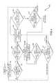
- FIG. 2is a block diagram illustrating a system for variable transparency in a heads up display.
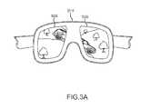
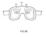
- FIGS. 3A-3Cillustrate sample views that a user may view utilizing a heads up display.
- a usermay view the sample views utilizing the heads up display of FIG. 2 .
- FIG. 4is a flow chart illustrating a method for varying transparency of a heads up display. This method may be performed by the system of FIG. 2 .
- Heads up display devicesgenerally present an individual content viewing environment for users.
- Such heads up display devicesmay include a viewing apparatus (such as glasses, goggles, and so on including) that a user may mount to his head.
- the viewing apparatusincludes one or more display elements which are configured to present visual content focused at such a distance that the visual content is comfortably viewable by a user despite the close proximity of the display element(s) to the user's eyes.
- the viewing apparatusmay also include auditory elements which may present audio content to the user that corresponds to the visual content presented by the display element(s).
- the content presentable by such a heads up display devicemay include television programs, movies, screens for a computing device, and so on.
- Heads up display devicesmay include components for receiving and playing content from one or more content providers (such as a satellite or cable television provider, the Internet, and so on), one or more content players (such as a digital video recorder, a television receiver, a personal computer, and so on), and so on.
- Heads up display devicesmay also include components for playing content stored in various non-transitory storage media (such as digital video discs, digital video files, and so on).
- a usermay utilize such a heads up display device as an individual environment in which the user may view content regardless of the user's surroundings (such as on a plane, in a public park, in a shopping line, and so on) without the inconvenience of forcing others in the user's environment to also view the content.
- the usermay utilize such a heads up display without exposing the content to view by an unauthorized party who happens to be in proximity to the user.
- heads up display devicesIn order to avoid distracting the user from content which they have chosen to view, heads up display devices typically display visual content via the display element(s) in a non-transparent fashion such that the user views the content and not the background environment located around the heads up display device. This enables the user to concentrate on the content without being distracted by the background.
- a usermay need to interact with his environment at various times while viewing content, or at least be aware of it.
- the useris required to stop the content presented by the heads up display device and remove the head mountable viewing apparatus in order to view the background environment. Once the user is done viewing the background, the user is then required to remount the head mountable viewing apparatus and restart the content.
- the usermay view either the content or the background at a given time and switching between the two is not particularly efficient or convenient.
- the present disclosurediscloses systems and methods for providing variable transparency heads up display devices.
- One or more imagesare transmitted to one or more display screens of a head mountable viewing device.
- the one or more imagesmay be non-transparent, or opaque.
- An inputmay be received that specifies to alter the transparency of a displayed image.
- the inputmay be received from a user.
- the transparency of the imagemay be altered such that a background may be viewable through the image. The transparency may even be completely reduced such that the background is viewable and the image is not.
- the transparency of the imagemay again be altered to render the image opaque such that the background is not visible through the image, render the image to a particular transparency such that the background is viewable through the image, render the image completely transparent such that the background is viewable but the image is not, and so on.
- a usermay efficiently and simply switch between viewing presented content, the background, and/or combinations thereof without removing the head mountable viewing device and possibly without pausing or stopping the content if the user so desires.
- FIG. 1is a environmental diagram illustrating an user 102 utilizing an example heads up display device 100 and a background 103 which includes a person.
- the heads up display deviceconstitutes a head mounted viewing apparatus that includes a pair of display screens 104 for displaying content to the user.
- the head mounted viewing apparatushas a first surface 105 located on a side of the head mounted viewing apparatus facing the user's eyes and a second surface 106 located on a side of the head mounted viewing apparatus opposite the user's eyes and facing the background.
- the display screensare disposed such that they project through both the first and second surfaces of the head mounted viewing apparatus.
- the display screensmay be LCD devices which utilize LCD shutter technology.
- the heads up display devicemay control the display screens to render them opaque and display visual content for the user on the surfaces of the display screens corresponding to the first surface.
- the heads up display devicemay control the display screens to render them partially transparent such that the user can still view the content, but can also see through the content and display screens to view the background.
- the heads up display devicemay control the screens to various levels of transparency.
- the heads up display devicemay control the display screens to render them completely transparent such that the content is completely transparent.
- the example heads up display devicemay also include one or more illumination elements 107 which may function to illuminate the background.
- the illumination elementsmay be activated by one or more light sensors 108 such that the illumination elements only illuminate the background when the illumination is below a threshold value (such as when the background is dark, dimly illuminated, and so on).
- FIG. 2is a block diagram illustrating a system 200 for variable transparency in a heads up display.
- the system 200includes a heads up display 201 and one or more input devices 206 (such as one or more keyboards, buttons, mice, joysticks, and so on). Although the input devices are illustrated as separate from the heads up display, it should be understood that in some implementations the input devices may be incorporated into the heads up display.
- the systemmay also include one or more content providers and/or content players 209 coupled to the heads up display via one or more wired and/or wireless transmission media 210 .
- the heads up display 201may include one or more processing units 202 , storage media 203 (which may be any non-transitory machine-readable storage media), and one or more displays 204 .
- the heads up displaymay be configured in an arrangement like that illustrated in FIG. 1 .
- the processing unit 202may execute instructions stored in the storage medium to transmit one or more images to the display.
- the displaymay present the image to a user as opaque or non-transparent so that the user cannot see a background located on the opposite side of the heads up display from where the image is presented.
- the processing unitmay receive input that specifies to alter the transparency of the image. The input may be received from a user via the input device 206 and a user interface component 205 .
- the processing unitmay alter the transparency of the image transmitted to the display.
- the processing unitmay alter the transparency of the image such that the background is viewable through the image.
- the processing unitmay also alter the transparency of the image to be completely transparent such that the background is viewable but the image is not.
- the processing unitmay receive input to again alter the transparency of the image and in response the processing unit may render the image opaque or non-transparent, partially transparent such that the background is viewable through the image, completely transparent such that the background is viewable and the image is not, and so on.
- the heads up display 201may also include one or more illumination elements 207 (sight as incandescent bulbs, light emitting diodes, organic light emitting diodes, and so on) which may function to illuminate the background.
- the illumination elementsmay include infra red illumination elements.
- the illumination elementsmay be activated by one or more light sensors 208 (such as one or more photoelectric sensors and so on) such that the illumination elements only illuminate the background when the illumination is below a threshold value (such as when the background is dark, dimly illuminated, and so on).
- FIGS. 3A-3Cillustrate sample views that a user may view utilizing a heads up display device 301 A- 301 C such as the heads up display 201 of FIG. 2 .
- the usermay be utilizing the heads up display device 301 A- 301 C while seated on an airplane.
- FIG. 3Aillustrates the heads up display device 301 A displaying images of a movie on screens 302 A. As illustrated, no background is viewable through the images displayed by screens 302 A.
- FIG. 3Billustrates the heads up display device 301 B displaying the background behind screens 302 B. As illustrated, the background is viewable through screens 302 B but the images previously displayed are not.
- FIG. 3Cillustrates the heads up display device 301 C displaying images of a movie on screens 302 AC and the background behind screens 302 C.
- the imagesare partially transparent such that the background is viewable through the images and screens 302 C.
- the usermay be able to still watch the movie while simultaneously interacting with the flight attendant.
- FIG. 4illustrates a method 400 for varying transparency of a heads up display.
- the method 400may be performed by the heads up display 201 of FIG. 2 .
- the flowbegins at block 401 and proceeds to block 402 where the heads up display displays images as non-transparent or opaque.
- the flowthen proceeds to block 403 where the heads up display determines whether input has been received specifying to alter the transparency of the images. If so, the flow proceeds to block 404 . Otherwise, the flow returns to block 402 where the heads up display continues displaying the images as non-transparent or opaque.
- the heads up displaydetermines whether the input specifies to alter the transparency such that both the images and the background are viewable or just the background. If the input specifies both the images and the background, the flow proceeds to block 405 . However, if the input specifies just the background, the flow proceeds to block 408 .
- the heads up displaydisplays the images as partially transparent such that the background is viewable through the images.
- the heads up displaymay display the images at a level of transparency specified by the input.
- the flowthen proceeds to block 406 where the heads up display determines whether input has been received specifying to alter the transparency of the images. If so, the flow proceeds to block 407 . Otherwise, the flow returns to block 405 where the heads up display continues displaying the images as partially transparent.
- the heads up displaydetermines whether the input specified to alter the transparency such that the images or the background are viewable. If the input specifies the images, the flow proceeds to block 402 where the heads up display displays images as non-transparent or opaque. Otherwise, if the input specifies the background, the flow proceeds to block 408 .
- the heads up displaydisplays images as completely transparent such that the background is viewable and the images are not.
- the flowthen proceeds to block 409 where the heads up display determines whether input has been received specifying to alter the transparency of the images. If so, the flow proceeds to block 410 . Otherwise, the flow returns to block 408 where the heads up display continues displaying the images as completely transparent.
- the heads up displaydetermines whether the input specified to alter the transparency such that such that both the images and the background are viewable or just the images. If the input specifies the images, the flow proceeds to block 402 where the heads up display displays images as non-transparent or opaque. Otherwise, the flow proceeds to block 405 where the heads up display displays the images as partially transparent such that the background is viewable through the images.
- the display 204may include one or more LCD devices which utilize LCD shutter technology and display the images transmitted by the processing unit 202 .
- the processing unitmay transmit the images to the LCD devices and control the transparency of the LCD devices.
- the processing unitmay control the transparency of the LCD devices such that the LCD devices are non-transparent or opaque and thus the images are non-transparent or opaque, partially transparent such that the images and a background behind the LCD devices are visible through the images and the LCD devices, and fully transparent such that the background and not the images is visible through the LCD devices.
- the display 204may include one or more LCD devices which utilize LCD shutter technology and one or more image projectors (such as one or more LCD projectors and so on) (not shown) that project the images transmitted by the processing unit 202 onto the LCD devices.
- image projectorsmay be arranged on the heads up display 201 such that the project the images onto a surface of the LCD screens facing the user's eyes (such as a surface corresponding to first surface 105 in FIG. 1 ).
- the processing unitmay control the transparency of the LCD devices that operate as projection screens for the images projected by the image projectors.
- the processing unitmay control the transparency of the LCD devices such that the images are projected onto the non-transparent or opaque LCD devices and thus the images are non-transparent or opaque, partially transparent such that the images are projected onto the partially transparent LCD devices and a background behind the LCD devices is visible through the resulting partially transparent images and the partially transparent LCD devices, and fully transparent such that the images are projected through the fully transparent LCD devices and the background without the images is visible through the fully transparent LCD devices.
- the heads up display 201may be configured differently than the heads up display 100 shown in FIG. 1 such that the display 204 does not project through the heads up display from a surface facing the user's eyes (such as first surface 105 illustrated in FIG. 1 ) to an opposing surface facing the background (such as second surface 106 illustrated in FIG. 1 ).
- the display 204may be a display device that is disposed only on a surface of the heads up display facing the user's eyes and displays images transmitted by the processing unit 202 .
- the usercannot physically look through the display device at a background behind the display device, regardless of any transparency of any images or the display device.
- the heads up display 201may also include one or more visual recording devices 211 (such as one or more digital video recorders, one or more digital cameras, one or more charge-coupled devices, and so on).
- the visual recording devicemay be disposed on the heads up display such that they record images of the background, such as on the surface of the heads up display facing the background (similar to the second surface 106 illustrated in FIG. 1 ).
- the processing unit 202may receive the background images from the visual recording device and combine it with the images to transmit to the display. If multiple visual recording devices are utilized, the processing unit may combine the background images recorded by each of the visual recording devices to allow for a larger field of view than is each individual visual recording device is capable of. The processing unit 202 may combine the background images with the images to transmit to the display such that the background image is not viewable in the combination if the images to transmit are non-transparent or opaque, the background image is viewable through the images to transmit if the images to transmit are partially transparent, or the background image is viewable and the images to transmit are not if the images to transmit are fully transparent.
- the illumination element 207may be an infra red illumination element, such as an infra red light emitting diode.
- the visual recording elementmay perceive the infra red light emitted by the illumination element, illuminating the recorded background images, even if the light is not perceptible to other people in the background area.
- the background imagesmay be illuminated without disturbing other people in the background.
- the heads up display 201may be configured similar to the third implementation discussed above in that one or more projection screens are disposed on a surface of the heads up display facing the user's eyes. Further, the heads up display may include one or more image projectors (similar to those discussed above with respect to the second implementation) that project the images transmitted by the processing unit 202 onto the projection screens facing the user's eyes. Thus, the user cannot physically look through the projection screens at a background behind the projection screens, regardless of any transparency of any images or the projection screens. However, as discussed in the third implementation discussed above, the heads up display may include one or more visual recording devices 211 (such as one or more digital video recorders, one or more digital cameras, one or more charge-coupled devices, and so on). The visual recording device may be disposed on the heads up display such that they record images of the background, such as on the surface of the heads up display facing the background (similar to the second surface 106 illustrated in FIG. 1 ).
- the visual recording devicemay be disposed on the heads up display such that they record images of the background, such
- the processing unit 202may receive the background images from the visual recording device and combine it with the images to transmit to the display.
- the processing unitmay combine the background images with the images to transmit to the display such that the background image is not viewable in the combination if the images to transmit are non-transparent or opaque, the background image is viewable through the images to transmit if the images to transmit are partially transparent, or the background image is viewable and the images to transmit are not if the images to transmit are fully transparent.
- the illumination element 207may be an infra red illumination element, such as an infra red light emitting diode.
- the visual recording elementmay perceive the infra red light emitted by the illumination element, illuminating the recorded background images, even if the light is not perceptible to other people in the background area.
- the background imagesmay be illuminated without disturbing other people in the background.
- the heads up displaymay include a communication component 212 that is operable to receive content from one or more content providers (such as a satellite or cable television provider, the Internet, and so on), content players (such as a digital video recorder, a television receiver, a personal computer, and so on), and so on 209 via one or more transmission media 210 .
- the processing unit 202may transmit images to the display 204 as part of playing content received from the one or more content providers, content players, and so on as well as playing content stored in the storage medium 203 .
- the processing unit 202may transmit audio to one or more audio output devices (such as speakers) (not shown).
- the transmission mediummay be an kind of wired or wireless transmission medium such as the Internet, a satellite connection, a coaxial cable connection, an Ethernet connection, a cellular connection, a WiFi connection, and so on.
- the transmission mediummay also include a physical medium (such as digital video disc (DVD), video cassette, compact disc (CD), CD-ROM, DVD-ROM, and so on) distribution system such as mail distribution, mail distribution, and so on.
- DVDdigital video disc
- CDcompact disc
- DVD-ROMdigital versatile disc
- DVD-ROMdigital versatile disc
- DVD-ROMdigital versatile disc
- the methods disclosedmay be implemented as sets of instructions or software readable by a device. Further, it is understood that the specific order or hierarchy of steps in the methods disclosed are examples of sample approaches. In other embodiments, the specific order or hierarchy of steps in the method can be rearranged while remaining within the disclosed subject matter.
- the accompanying method claimspresent elements of the various steps in a sample order, and are not necessarily meant to be limited to the specific order or hierarchy presented.
- the described disclosuremay be provided as a computer program product, or software, that may include a non-transitory machine-readable medium having stored thereon instructions, which may be used to program a computer system (or other electronic devices) to perform a process according to the present disclosure.
- a non-transitory machine-readable mediumincludes any mechanism for storing information in a form (e.g., software, processing application) readable by a machine (e.g., a computer).
- the non-transitory machine-readable mediummay take the form of, but is not limited to, a: magnetic storage medium (e.g., floppy diskette, video cassette, and so on); optical storage medium (e.g., CD-ROM); magneto-optical storage medium; read only memory (ROM); random access memory (RAM); erasable programmable memory (e.g., EPROM and EEPROM); flash memory; and so on.
- magnetic storage mediume.g., floppy diskette, video cassette, and so on
- optical storage mediume.g., CD-ROM
- magneto-optical storage mediume.g., magneto-optical storage medium
- ROMread only memory
- RAMrandom access memory
- EPROM and EEPROMerasable programmable memory
- flash memoryand so on.
Landscapes
- Physics & Mathematics (AREA)
- General Physics & Mathematics (AREA)
- Optics & Photonics (AREA)
- Controls And Circuits For Display Device (AREA)
- Control Of Indicators Other Than Cathode Ray Tubes (AREA)
- Transforming Electric Information Into Light Information (AREA)
Abstract
Description
Claims (19)
Priority Applications (5)
| Application Number | Priority Date | Filing Date | Title |
|---|---|---|---|
| US12/902,320US10036891B2 (en) | 2010-10-12 | 2010-10-12 | Variable transparency heads up displays |
| EP11778819.0AEP2628042B1 (en) | 2010-10-12 | 2011-10-11 | Variable transparency heads up displays |
| MX2013003899AMX2013003899A (en) | 2010-10-12 | 2011-10-11 | Variable transparency heads up displays. |
| PCT/EP2011/067751WO2012049189A1 (en) | 2010-10-12 | 2011-10-11 | Variable transparency heads up displays |
| CA2813512ACA2813512C (en) | 2010-10-12 | 2011-10-11 | Variable transparency heads up displays |
Applications Claiming Priority (1)
| Application Number | Priority Date | Filing Date | Title |
|---|---|---|---|
| US12/902,320US10036891B2 (en) | 2010-10-12 | 2010-10-12 | Variable transparency heads up displays |
Publications (2)
| Publication Number | Publication Date |
|---|---|
| US20120086624A1 US20120086624A1 (en) | 2012-04-12 |
| US10036891B2true US10036891B2 (en) | 2018-07-31 |
Family
ID=44906035
Family Applications (1)
| Application Number | Title | Priority Date | Filing Date |
|---|---|---|---|
| US12/902,320Active2032-12-29US10036891B2 (en) | 2010-10-12 | 2010-10-12 | Variable transparency heads up displays |
Country Status (5)
| Country | Link |
|---|---|
| US (1) | US10036891B2 (en) |
| EP (1) | EP2628042B1 (en) |
| CA (1) | CA2813512C (en) |
| MX (1) | MX2013003899A (en) |
| WO (1) | WO2012049189A1 (en) |
Families Citing this family (49)
| Publication number | Priority date | Publication date | Assignee | Title |
|---|---|---|---|---|
| US8427424B2 (en) | 2008-09-30 | 2013-04-23 | Microsoft Corporation | Using physical objects in conjunction with an interactive surface |
| US8730309B2 (en) | 2010-02-23 | 2014-05-20 | Microsoft Corporation | Projectors and depth cameras for deviceless augmented reality and interaction |
| US10036891B2 (en) | 2010-10-12 | 2018-07-31 | DISH Technologies L.L.C. | Variable transparency heads up displays |
| US9329469B2 (en) | 2011-02-17 | 2016-05-03 | Microsoft Technology Licensing, Llc | Providing an interactive experience using a 3D depth camera and a 3D projector |
| US9480907B2 (en) | 2011-03-02 | 2016-11-01 | Microsoft Technology Licensing, Llc | Immersive display with peripheral illusions |
| US8749573B2 (en)* | 2011-05-26 | 2014-06-10 | Nokia Corporation | Method and apparatus for providing input through an apparatus configured to provide for display of an image |
| US9597587B2 (en) | 2011-06-08 | 2017-03-21 | Microsoft Technology Licensing, Llc | Locational node device |
| US20130147686A1 (en)* | 2011-12-12 | 2013-06-13 | John Clavin | Connecting Head Mounted Displays To External Displays And Other Communication Networks |
| EP2661091B1 (en)* | 2012-05-04 | 2015-10-14 | Novabase Digital TV Technologies GmbH | Controlling a graphical user interface |
| US9219901B2 (en)* | 2012-06-19 | 2015-12-22 | Qualcomm Incorporated | Reactive user interface for head-mounted display |
| US9494797B2 (en)* | 2012-07-02 | 2016-11-15 | Nvidia Corporation | Near-eye parallax barrier displays |
| USRE47984E1 (en) | 2012-07-02 | 2020-05-12 | Nvidia Corporation | Near-eye optical deconvolution displays |
| US9841537B2 (en) | 2012-07-02 | 2017-12-12 | Nvidia Corporation | Near-eye microlens array displays |
| KR20140025930A (en)* | 2012-08-23 | 2014-03-05 | 삼성전자주식회사 | Head-mount type display apparatus and control method thereof |
| TWI528823B (en)* | 2012-08-28 | 2016-04-01 | 緯創資通股份有限公司 | Device and method for displaying and adjusting image information |
| US10019057B2 (en)* | 2013-06-07 | 2018-07-10 | Sony Interactive Entertainment Inc. | Switching mode of operation in a head mounted display |
| KR20150004192A (en)* | 2013-07-02 | 2015-01-12 | 엘지전자 주식회사 | Display device and control method thereof |
| GB2517143A (en)* | 2013-08-07 | 2015-02-18 | Nokia Corp | Apparatus, method, computer program and system for a near eye display |
| US9880325B2 (en) | 2013-08-14 | 2018-01-30 | Nvidia Corporation | Hybrid optics for near-eye displays |
| US9158115B1 (en)* | 2013-09-16 | 2015-10-13 | Amazon Technologies, Inc. | Touch control for immersion in a tablet goggles accessory |
| US9733478B2 (en) | 2014-04-03 | 2017-08-15 | Thomson Licensing | Ambient light management for virtual reality glasses |
| US9741169B1 (en)* | 2014-05-20 | 2017-08-22 | Leap Motion, Inc. | Wearable augmented reality devices with object detection and tracking |
| CN204480228U (en) | 2014-08-08 | 2015-07-15 | 厉动公司 | motion sensing and imaging device |
| US20160170206A1 (en)* | 2014-12-12 | 2016-06-16 | Lenovo (Singapore) Pte. Ltd. | Glass opacity shift based on determined characteristics |
| US10656720B1 (en) | 2015-01-16 | 2020-05-19 | Ultrahaptics IP Two Limited | Mode switching for integrated gestural interaction and multi-user collaboration in immersive virtual reality environments |
| JP6501035B2 (en)* | 2016-03-23 | 2019-04-17 | 日本電気株式会社 | Glasses-type wearable information terminal, control method thereof and control program |
| WO2018057050A1 (en)* | 2016-09-23 | 2018-03-29 | Bao Sheng | Selectably opaque displays |
| US10437070B2 (en)* | 2016-12-23 | 2019-10-08 | Realwear, Inc. | Interchangeable optics for a head-mounted display |
| US11099716B2 (en) | 2016-12-23 | 2021-08-24 | Realwear, Inc. | Context based content navigation for wearable display |
| US11507216B2 (en) | 2016-12-23 | 2022-11-22 | Realwear, Inc. | Customizing user interfaces of binary applications |
| US10936872B2 (en) | 2016-12-23 | 2021-03-02 | Realwear, Inc. | Hands-free contextually aware object interaction for wearable display |
| US10393312B2 (en) | 2016-12-23 | 2019-08-27 | Realwear, Inc. | Articulating components for a head-mounted display |
| US10365493B2 (en) | 2016-12-23 | 2019-07-30 | Realwear, Incorporated | Modular components for a head-mounted display |
| US10620910B2 (en) | 2016-12-23 | 2020-04-14 | Realwear, Inc. | Hands-free navigation of touch-based operating systems |
| DE102017108551B4 (en) | 2017-04-21 | 2025-09-04 | Carl Zeiss Meditec Ag | Head-mounted display device, method for operating the same and medical optical observation system |
| DE102017123894B3 (en) | 2017-10-13 | 2019-02-07 | Carl Zeiss Meditec Ag | Disc for HMD and HMD with at least one disc |
| DE112019002353T5 (en) | 2018-05-08 | 2021-05-06 | Apple Inc. | TECHNIQUES FOR SWITCHING BETWEEN IMMERSION LEVELS |
| EP3839699A1 (en)* | 2019-12-19 | 2021-06-23 | Koninklijke KPN N.V. | Augmented virtuality self view |
| JP2023543799A (en) | 2020-09-25 | 2023-10-18 | アップル インコーポレイテッド | How to navigate the user interface |
| CN117555417B (en)* | 2020-09-25 | 2024-07-19 | 苹果公司 | Method for adjusting and/or controlling immersion associated with a user interface |
| AU2021347112B2 (en) | 2020-09-25 | 2023-11-23 | Apple Inc. | Methods for manipulating objects in an environment |
| CN116670627A (en) | 2020-12-31 | 2023-08-29 | 苹果公司 | Methods for Grouping User Interfaces in Environments |
| US11796801B2 (en)* | 2021-05-24 | 2023-10-24 | Google Llc | Reducing light leakage via external gaze detection |
| EP4388397A1 (en) | 2021-09-25 | 2024-06-26 | Apple Inc. | Devices, methods, and graphical user interfaces for presenting virtual objects in virtual environments |
| US12272005B2 (en) | 2022-02-28 | 2025-04-08 | Apple Inc. | System and method of three-dimensional immersive applications in multi-user communication sessions |
| WO2023196258A1 (en) | 2022-04-04 | 2023-10-12 | Apple Inc. | Methods for quick message response and dictation in a three-dimensional environment |
| US12394167B1 (en) | 2022-06-30 | 2025-08-19 | Apple Inc. | Window resizing and virtual object rearrangement in 3D environments |
| US12405704B1 (en) | 2022-09-23 | 2025-09-02 | Apple Inc. | Interpreting user movement as direct touch user interface interactions |
| US12113948B1 (en) | 2023-06-04 | 2024-10-08 | Apple Inc. | Systems and methods of managing spatial groups in multi-user communication sessions |
Citations (16)
| Publication number | Priority date | Publication date | Assignee | Title |
|---|---|---|---|---|
| US4805988A (en) | 1987-07-24 | 1989-02-21 | Nelson Dones | Personal video viewing device |
| US20020044152A1 (en)* | 2000-10-16 | 2002-04-18 | Abbott Kenneth H. | Dynamic integration of computer generated and real world images |
| US6456438B1 (en)* | 1999-08-12 | 2002-09-24 | Honeywell Inc. | Variable immersion vignetting display |
| US20040042086A1 (en) | 2002-06-05 | 2004-03-04 | Litton Systems, Inc. | Enhanced night vision goggle assembly |
| US20070243863A1 (en)* | 2006-04-17 | 2007-10-18 | Samsung Electronics Co., Ltd | System for using mobile communication terminal as pointer and method and medium thereof |
| US20080218436A1 (en) | 2007-03-08 | 2008-09-11 | Lockheed Martin Corporation | Zero-lag image response to pilot head mounted display control |
| US20080218434A1 (en)* | 2007-03-05 | 2008-09-11 | The Boeing Company | Electrically Dimmable Combiner Optics for Head-Up Display |
| US20100014155A1 (en)* | 2008-07-17 | 2010-01-21 | Olympus Corporation | Laser scanning microscope |
| US20100067118A1 (en)* | 2006-11-27 | 2010-03-18 | Nippon Seiki Co. Ltd. | Head-up display apparatus |
| US20100141555A1 (en)* | 2005-12-25 | 2010-06-10 | Elbit Systems Ltd. | Real-time image scanning and processing |
| US20100295946A1 (en)* | 2009-05-20 | 2010-11-25 | Reed William G | Long-range motion detection for illumination control |
| US20110025702A1 (en)* | 2009-07-31 | 2011-02-03 | Thales | Method of Constructing Images for an Imaging Appliance |
| US20120062445A1 (en)* | 2010-02-28 | 2012-03-15 | Osterhout Group, Inc. | Adjustable wrap around extendable arm for a head-mounted display |
| US20120062444A1 (en)* | 2010-09-09 | 2012-03-15 | Cok Ronald S | Switchable head-mounted display transition |
| US20120187838A1 (en)* | 2008-06-26 | 2012-07-26 | Global Rainmakers, Inc. | Method of Reducing Visibility of Pulsed Illumination While Acquiring High Quality Imagery |
| EP2628042B1 (en) | 2010-10-12 | 2014-10-01 | Eldon Technology Limited | Variable transparency heads up displays |
- 2010
- 2010-10-12USUS12/902,320patent/US10036891B2/enactiveActive
- 2011
- 2011-10-11WOPCT/EP2011/067751patent/WO2012049189A1/enactiveApplication Filing
- 2011-10-11EPEP11778819.0Apatent/EP2628042B1/enactiveActive
- 2011-10-11MXMX2013003899Apatent/MX2013003899A/enactiveIP Right Grant
- 2011-10-11CACA2813512Apatent/CA2813512C/enactiveActive
Patent Citations (16)
| Publication number | Priority date | Publication date | Assignee | Title |
|---|---|---|---|---|
| US4805988A (en) | 1987-07-24 | 1989-02-21 | Nelson Dones | Personal video viewing device |
| US6456438B1 (en)* | 1999-08-12 | 2002-09-24 | Honeywell Inc. | Variable immersion vignetting display |
| US20020044152A1 (en)* | 2000-10-16 | 2002-04-18 | Abbott Kenneth H. | Dynamic integration of computer generated and real world images |
| US20040042086A1 (en) | 2002-06-05 | 2004-03-04 | Litton Systems, Inc. | Enhanced night vision goggle assembly |
| US20100141555A1 (en)* | 2005-12-25 | 2010-06-10 | Elbit Systems Ltd. | Real-time image scanning and processing |
| US20070243863A1 (en)* | 2006-04-17 | 2007-10-18 | Samsung Electronics Co., Ltd | System for using mobile communication terminal as pointer and method and medium thereof |
| US20100067118A1 (en)* | 2006-11-27 | 2010-03-18 | Nippon Seiki Co. Ltd. | Head-up display apparatus |
| US20080218434A1 (en)* | 2007-03-05 | 2008-09-11 | The Boeing Company | Electrically Dimmable Combiner Optics for Head-Up Display |
| US20080218436A1 (en) | 2007-03-08 | 2008-09-11 | Lockheed Martin Corporation | Zero-lag image response to pilot head mounted display control |
| US20120187838A1 (en)* | 2008-06-26 | 2012-07-26 | Global Rainmakers, Inc. | Method of Reducing Visibility of Pulsed Illumination While Acquiring High Quality Imagery |
| US20100014155A1 (en)* | 2008-07-17 | 2010-01-21 | Olympus Corporation | Laser scanning microscope |
| US20100295946A1 (en)* | 2009-05-20 | 2010-11-25 | Reed William G | Long-range motion detection for illumination control |
| US20110025702A1 (en)* | 2009-07-31 | 2011-02-03 | Thales | Method of Constructing Images for an Imaging Appliance |
| US20120062445A1 (en)* | 2010-02-28 | 2012-03-15 | Osterhout Group, Inc. | Adjustable wrap around extendable arm for a head-mounted display |
| US20120062444A1 (en)* | 2010-09-09 | 2012-03-15 | Cok Ronald S | Switchable head-mounted display transition |
| EP2628042B1 (en) | 2010-10-12 | 2014-10-01 | Eldon Technology Limited | Variable transparency heads up displays |
Non-Patent Citations (4)
| Title |
|---|
| Canadian Office Action for corresponding Canadian Application 2,813,512; dated Jul. 22, 2014; 2 pages. |
| Canadian Office Action for corresponding Canadian Application 2,813,512; dated Mar. 31, 2015; 4 pages, dated Jun. 26, 2015. |
| Imagine: Your Direction and location, Video, Gaming, E-mail, the Internet and Nght Vision right in "Front of Your Eyes" Acoustic Vision: THe Multi-Billion Dollar Head WOrn Display Market Oppurtunity that Can DOminante by working with Phones, Media players, Net Book and Laptops filed Feb. 28, 2010 with U.S. Appl. No. 61/308,973.* |
| International Search Report and Written Opinion for corresponding International Application No. PCT/EP2011/067751, dated Feb. 2, 2012, 22 pages. |
Also Published As
| Publication number | Publication date |
|---|---|
| US20120086624A1 (en) | 2012-04-12 |
| CA2813512C (en) | 2016-06-14 |
| EP2628042B1 (en) | 2014-10-01 |
| MX2013003899A (en) | 2013-12-02 |
| EP2628042A1 (en) | 2013-08-21 |
| WO2012049189A1 (en) | 2012-04-19 |
| CA2813512A1 (en) | 2012-04-19 |
Similar Documents
| Publication | Publication Date | Title |
|---|---|---|
| US10036891B2 (en) | Variable transparency heads up displays | |
| US11087135B2 (en) | Virtual trading card and augmented reality movie system | |
| US8730354B2 (en) | Overlay video content on a mobile device | |
| US8797451B2 (en) | Embedded camera with privacy filter | |
| US10042420B2 (en) | Gaze-aware control of multi-screen experience | |
| KR101482025B1 (en) | Augmented reality presentations | |
| US20170142486A1 (en) | Information processing device, display device, information processing method, program, and information processing system | |
| US10453263B2 (en) | Methods and systems for displaying augmented reality content associated with a media content instance | |
| EP1843591A1 (en) | Intelligent media content playing device with user attention detection, corresponding method and carrier medium | |
| CN102346898A (en) | Automatic customized advertisement generation system | |
| US9232145B2 (en) | Hand-held electronic device and display method | |
| US9060162B2 (en) | Providing multiple viewer preferences on a display device | |
| US10284902B2 (en) | Apparatus and method for playing back multimedia content | |
| CN108417171A (en) | Display device and display parameter adjusting method thereof | |
| US10394336B2 (en) | Ocular focus sharing for digital content | |
| US20050001920A1 (en) | Methods and apparatuses for managing and presenting content through a spherical display device | |
| CN113228691A (en) | Display system, display method, and program | |
| US7480001B2 (en) | Digital camera with a spherical display | |
| JP2012088497A (en) | Three-dimensional video display device | |
| JP7061190B2 (en) | Display system, display method and program | |
| KR20050091788A (en) | Method of and system for augmenting presentation of content | |
| KR102553258B1 (en) | Apparatus and method for playbacking multimedia content | |
| JP2015038537A (en) | Video display device and its control method | |
| US20240223834A1 (en) | Method and means for providing multi-content media | |
| US20210029306A1 (en) | Magnification enhancement of video for visually impaired viewers |
Legal Events
| Date | Code | Title | Description |
|---|---|---|---|
| AS | Assignment | Owner name:ELDON TECHNOLOGY LIMITED, UNITED KINGDOM Free format text:ASSIGNMENT OF ASSIGNORS INTEREST;ASSIGNORS:THOMPSON, PETER;DOVE, ANTONY MICHAEL;REEL/FRAME:025123/0366 Effective date:20101007 | |
| AS | Assignment | Owner name:ECHOSTAR UK HOLDINGS LIMITED, UNITED KINGDOM Free format text:ASSIGNMENT OF ASSIGNORS INTEREST;ASSIGNOR:ELDON TECHNOLOGY LIMITED;REEL/FRAME:034650/0050 Effective date:20141029 | |
| AS | Assignment | Owner name:ECHOSTAR TECHNOLOGIES INTERNATIONAL CORPORATION, C Free format text:ASSIGNMENT OF ASSIGNORS INTEREST;ASSIGNOR:ECHOSTAR UK HOLDINGS LIMITED;REEL/FRAME:041672/0080 Effective date:20170207 Owner name:ECHOSTAR TECHNOLOGIES L.L.C., COLORADO Free format text:ASSIGNMENT OF ASSIGNORS INTEREST;ASSIGNOR:ECHOSTAR TECHNOLOGIES INTERNATIONAL CORPORATION;REEL/FRAME:041674/0954 Effective date:20170207 | |
| AS | Assignment | Owner name:DISH TECHNOLOGIES L.L.C., COLORADO Free format text:CHANGE OF NAME;ASSIGNOR:ECHOSTAR TECHNOLOGIES L.L.C.;REEL/FRAME:046409/0814 Effective date:20180202 | |
| STCF | Information on status: patent grant | Free format text:PATENTED CASE | |
| AS | Assignment | Owner name:U.S. BANK, NATIONAL ASSOCIATION, AS COLLATERAL AGENT, MINNESOTA Free format text:SECURITY INTEREST;ASSIGNORS:DISH BROADCASTING CORPORATION;DISH NETWORK L.L.C.;DISH TECHNOLOGIES L.L.C.;REEL/FRAME:058295/0293 Effective date:20211126 | |
| MAFP | Maintenance fee payment | Free format text:PAYMENT OF MAINTENANCE FEE, 4TH YEAR, LARGE ENTITY (ORIGINAL EVENT CODE: M1551); ENTITY STATUS OF PATENT OWNER: LARGE ENTITY Year of fee payment:4 |