US10036443B2 - Methods and apparatus for suspension adjustment - Google Patents
Methods and apparatus for suspension adjustmentDownload PDFInfo
- Publication number
- US10036443B2 US10036443B2US13/022,346US201113022346AUS10036443B2US 10036443 B2US10036443 B2US 10036443B2US 201113022346 AUS201113022346 AUS 201113022346AUS 10036443 B2US10036443 B2US 10036443B2
- Authority
- US
- United States
- Prior art keywords
- sensor
- suspension
- vehicle suspension
- data
- processor
- Prior art date
- Legal status (The legal status is an assumption and is not a legal conclusion. Google has not performed a legal analysis and makes no representation as to the accuracy of the status listed.)
- Active, expires
Links
Images


Classifications
- F—MECHANICAL ENGINEERING; LIGHTING; HEATING; WEAPONS; BLASTING
- F16—ENGINEERING ELEMENTS AND UNITS; GENERAL MEASURES FOR PRODUCING AND MAINTAINING EFFECTIVE FUNCTIONING OF MACHINES OR INSTALLATIONS; THERMAL INSULATION IN GENERAL
- F16F—SPRINGS; SHOCK-ABSORBERS; MEANS FOR DAMPING VIBRATION
- F16F9/00—Springs, vibration-dampers, shock-absorbers, or similarly-constructed movement-dampers using a fluid or the equivalent as damping medium
- F16F9/32—Details
- F16F9/3264—Arrangements for indicating, e.g. fluid level; Arrangements for checking dampers
- B—PERFORMING OPERATIONS; TRANSPORTING
- B62—LAND VEHICLES FOR TRAVELLING OTHERWISE THAN ON RAILS
- B62K—CYCLES; CYCLE FRAMES; CYCLE STEERING DEVICES; RIDER-OPERATED TERMINAL CONTROLS SPECIALLY ADAPTED FOR CYCLES; CYCLE AXLE SUSPENSIONS; CYCLE SIDE-CARS, FORECARS, OR THE LIKE
- B62K25/00—Axle suspensions
- B62K25/04—Axle suspensions for mounting axles resiliently on cycle frame or fork
- B62K25/28—Axle suspensions for mounting axles resiliently on cycle frame or fork with pivoted chain-stay
- B62K25/286—Axle suspensions for mounting axles resiliently on cycle frame or fork with pivoted chain-stay the shock absorber being connected to the chain-stay via a linkage mechanism
- F—MECHANICAL ENGINEERING; LIGHTING; HEATING; WEAPONS; BLASTING
- F16—ENGINEERING ELEMENTS AND UNITS; GENERAL MEASURES FOR PRODUCING AND MAINTAINING EFFECTIVE FUNCTIONING OF MACHINES OR INSTALLATIONS; THERMAL INSULATION IN GENERAL
- F16F—SPRINGS; SHOCK-ABSORBERS; MEANS FOR DAMPING VIBRATION
- F16F2228/00—Functional characteristics, e.g. variability, frequency-dependence
- F16F2228/08—Functional characteristics, e.g. variability, frequency-dependence pre-stressed
Definitions
- the inventiongenerally relates to methods and apparatus of an integrated adjustment system for vehicles.
- Embodimentsgenerally relate to methods and apparatus for use with vehicle suspension system.
- embodimentsrelate to a system for adjusting operational characteristics of a vehicle suspension system.
- suspension sagis the measured distance a shock absorber compresses while the rider, wearing intended riding gear, is seated on (for example) a bicycle or motorcycle (or four wheeled vehicle) in a riding position, versus a fully extended suspension position (sag also applies to ATVs, trucks, and other suspension equipped vehicles).
- Rebound dampingdissipates stored system spring energy after a suspension compression event and results in a controlled rate of return of the suspension to a more extended condition. It is important for the suspension not to rebound too quickly. In the case of rear suspension, this can result in the rear of the vehicle kicking off the ground and pitching the rider forward after encountering a bump or sharp compression obstacle (“bucking”). In the case of front suspension, it can cause impact to the rider's hands as the front suspension kicks back directly towards the rider in the case of quick rebound. It is also important for the suspension not to rebound too slowly.
- suspensionThis can result in the suspension not returning quickly enough to respond to the next bump in a series of bumps, ultimately causing the suspension to “ratchet” itself down into a compressed state.
- a “ratchet” sequenceis commonly referred to as suspension “packing.” Packing can result in the suspension being overly stiff (due to retained compression) through the middle to the end of a series of bumps, causing the back of the vehicle kicking off the ground and pitching the rider forward in the case of the rear suspension and causing the suspension to get overly stiff and steering geometry to get steep and unstable in the case of the front suspension. Compression damping setting is similarly important.
- a system for a vehiclemay comprise a vehicle suspension; a sensor operable to measure an operational characteristic of the vehicle suspension; and a processor in communication with the sensor and operable to suggest an operational setting of the vehicle suspension in response to an input from the sensor corresponding to the operational characteristic.
- a system for a vehiclemay comprise a sensor operable to measure an operational characteristic of the vehicle; a processor operable to receive data from the sensor corresponding to the operational characteristic; and a communication device operable to receive data from the processor and display information regarding the operational characteristic of the vehicle.
- a method for adjusting a suspension of a vehiclemay comprise receiving suspension data with a processor; calculating a suspension setting suggestion with the processor; communicating the suspension setting suggestion to a user interface device; and adjusting the suspension based on the suspension setting suggestion.
- a suspension systemmay comprise a vehicle suspension; a sensor positioned to sense a feature of the suspension; a computer readable medium having an operative communication link with the sensor; a processor having an operative communication link with the computer readable medium; a transmitter having an operative communication link with the processor; and a graphical user interface having an operative communication link with the transmitter.
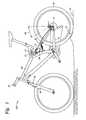
- FIG. 1illustrates a schematic side view of a vehicle according to one embodiment.
- FIG. 2Aillustrates a side view in cross section of a damper assembly according to one embodiment.
- FIG. 2Billustrates an enlarged view of part of the damper assembly of FIG. 2A according to one embodiment.
- FIG. 3illustrates a schematic block diagram of components of one embodiment of an electric lock out apparatus.
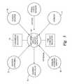
- FIG. 4illustrates a block diagram of a system according to one embodiment.
- FIG. 5illustrates a block diagram of a controller of the system according to one embodiment.
- FIG. 6illustrates a block diagram of a program method for use with the system according to one embodiment.
- FIGS. 7-11illustrate examples of the program method steps according to one embodiment.
- FIG. 12illustrates a block diagram of a process of use with the system according to one embodiment.
- Integrated damper/spring vehicle shock absorbersoften include a damper body surrounded by a mechanical spring or constructed in conjunction with an air spring.
- the damperoften consists of a piston and shaft telescopically mounted in a fluid filled cylinder.
- a mechanical springmay be a helically wound spring that surrounds the damper body.
- FIGS. 1 and 2 of U.S. Pat. No. 5,044,614show a damper body carrying a thread 42.
- a helical spring 18surrounds the damper body.
- the compression in the helical spring 18may be pre-set by means of a nut 48 and a lock nut 50.
- the nut 48may be translated axially relative to the body (“tube”) 16 and thread 42 by rotating the nut 48 around the threaded sleeve 42.
- Rotation of the nut 48 in a given directione.g. clockwise as viewed from end 44 for a right hand thread 42
- lock nut 50is rotated, using a wrench, up against nut 48 and tightened in a binding relation therewith.
- shock absorbersutilize gas as a spring medium in place of, or in addition to, mechanical springs.
- Gas spring type shock absorberssuch as for example those having integral dampers, are described in U.S. Pat. Nos. 6,135,434; 6,360,857 and 6,311,962; each of which is herein incorporated, in its entirety, by reference.
- U.S. Pat. No. 6,360,857shows a shock absorber having selectively adjustable damping characteristics.
- U.S. Pat. No. 7,163,222which is incorporated herein, in its entirety, by reference, describes a gas sprung front shock absorber for a bicycle (a “fork”) having a selective “lock out” and adjustable “blow off” function.
- the spring mechanism (gas or mechanical) of some shock absorbersis adjustable so that it can be preset to varying initial states of compression.
- the shock spring (gas or mechanical)may comprise different stages having varying spring rates thereby giving the overall shock absorber a compound spring rate varying through the stroke length. In that way the shock absorber can be adjusted to accommodate heavier or lighter carried weight, or greater or lesser anticipated impact loads.
- shock absorbersare pre-adjusted to account for varying terrain and anticipated speeds and jumps. Shocks are also adjusted according to certain rider preferences (e.g. soft—firm).
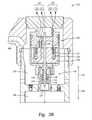
- FIG. 28A type of integrated damper/spring shock absorber, having a gas spring, is shown in FIG. 28, for example, of U.S. Pat. No. 7,374,028 (“'028 patent”), which is incorporated herein, in its entirety, by reference.
- the shock absorber of FIG. 28also includes an “adjustable intensifier assembly 510.” That intensifier or “reservoir” accepts damping fluid from chamber 170 as the fluid is displaced from that chamber by the incursion of rod 620 into chamber 170 during a compression stroke of the shock.
- the intensifier valve assemblyregulates flow of damping fluid into and out of the reservoir, and an embodiment of the valve assembly is shown in FIG. 17 of the '028 patent.
- damping fluidis excluded from entering the reservoir and, the damping fluid being a relatively incompressible liquid, such exclusion prevents the volume of chamber 170 from being reduced and thereby prevents the shock absorber from compressing telescopically.
- damping fluidmay be selectively provided via an external manual adjuster, such as for example knob 512 of FIG. 17, or it may be provided automatically in response to some predetermined and sensed vehicle operation condition (e.g. smooth terrain).
- a “lock out” conditionmay be the default mode for the suspension whereby the suspension becomes active only upon some predetermined and sensed vehicle operation condition (e.g. rough terrain) wherein a sensor senses the condition and opens the “lock out” so that the suspension may operate for a prescribed period of time or terrain input.
- FIGS. 1-11 hereinmay be used with any type of suspended vehicle, as well as other types of suspension or damping systems.
- the frame 40has a suspension system comprising a swing arm assembly 10 that, in use, is able to move relative to the rest of the frame; this movement is permitted by, inter alia, a rear shock absorber and/or damping assembly 25 .
- the front forks 80also provide a suspension function via a damping assembly in at least one fork leg; as such the bicycle 100 is a full suspension bicycle (such as an ATB or mountain bike), although the embodiments described herein are not limited to use on full suspension bicycles.
- the term “suspension system”is intended to include vehicles having front suspension or rear suspension only, or both and other systems wherein motion damping is included (such as for example vehicle steering dampeners or machine part motion dampeners).
- a sensor 5may be positioned proximate a rear axle 15 of the bicycle 100 for sensing changes in terrain. As shown in FIG. 1 , the sensor 5 is mounted on swing arm assembly 10 proximate the rear axle 15 of the bicycle 100 . In one embodiment the angular orientation of a sensor 5 sensing axis is movable through a range or angle 20 (and is shown in each of two positions of many possible positions), thereby allowing alteration of a force component sensed by the sensor in relation to a force (vector) input into the rear swing arm 10 . It is understood that the sensor 5 may be moved or mounted in any suitable configuration and allowing for any suitable range of adjustment as may be desirable.
- the senormay include one, two, three or more sensing axis'. That is useful for adjusting the sensitivity of the sensor 5 to various anticipated terrain and bicycle speed conditions.
- the bicycle speedaffects the vector direction of a force input to the bicycle wheel for constant amplitude terrain 45 disparity 55 or “bump/dip.” Varying size bumps and dips also affect the vector input angle to the wheel for constant bicycle speed.
- the movement of the swing armis however limited to a mechanically determined trajectory.
- a sensor 5 b(also illustrated in FIG. 2A ) may be coupled to the rear suspension, such as shock absorber and/or damper assembly 25 , for measuring the operational characteristics of the rear suspension.
- a sensor 5 cmay be coupled to the front suspension, such as front forks 80 , for measuring the operational characteristics of the front suspension.
- the operational characteristicsmay include at least one of position, velocity, acceleration, stroke, sag, compression, rebound, pressure, and temperature of the vehicle suspension.
- the sensor 5(and sensors 5 b , 5 c , 35 , 65 and a pedal force sensor (not shown)) may be any suitable force or acceleration transducer (e.g. strain gage, wheatstone bridge, accelerometer, hydraulic cylinder, interferometer based, optical, thermal, acoustic or any suitable combination thereof).
- the sensor 5may utilize solid state electronics, electro-mechanical principles, or any other suitable mechanisms.
- the sensor 5comprises a single axis self powered accelerometer, such as for example ENDEVCO Model 2229C.
- the 2229Cis a comparatively small device with overall dimensions of about 15 mm height by 10 mm diameter, and weighs about 4.9 g.
- the single axis accelerometercomprises the ENDEVCO 12M1A, which is of the surface-mount type.
- the 12M1Ais a single axis accelerometer comprising a bimorph sending element which operates in the bender mode. This accelerometer is particularly small and light, measuring about 4.5 mm by 3.8 mm by 0.85 mm, and weighs about 0.12 g.
- the sensor 5may be a tri-axial accelerometer such as the ENDEVCO 67-100. This device has overall dimensions of about 23 mm length and 15 mm width, and weighs about 14 g. Other sensors known in the art may be used with the embodiments described herein.
- the senor 5may be attached to the swing arm 10 directly, to any link thereof, to an intermediate mounting member or to any other portion or portions of the bicycle 100 as may be useful for purposes disclosed herein.
- the sensor 5is fixed to an unsprung portion of the bicycle 100 , such as for example the swing arm 10
- another sensor 35(such as an accelerometer as described above) is fixed to a sprung portion of the bicycle 100 , such as for example the frame 40 .
- Data from each sensorcan, by a processor, be overlayed on a common time datum and suspension damping and/or spring effectiveness can be evaluated by comparing the data from the sensors on either “side” of the suspension unit.
- Sensorsmay be integrated with the vehicle structure and data processing system as described in U.S. Pat. Nos.
- Sensors and valve actuatorse.g. electric solenoid or linear motor type—note that a rotary motor may also be used with a rotary actuated valve
- Sensors and valve actuatorsmay be integrated herein utilizing principles outlined in SP-861-Vehicle Dynamics and Electronic Controlled Suspensions SAE Technical Paper Series no. 910661 by Shiozaki et al. for the International Congress and Exposition, Detroit, Mich., Feb. 25-Mar. 1, 1991 which paper is incorporated herein, in its entirety, by reference.
- sensors and valves, or principles, of patents and other documents incorporated herein by referencemay be integrated into embodiments hereof, individually or in combination, as disclosed herein.
- the shock absorber 25is operatively mounted between an unsprung portion of the bicycle 100 , such as the swing arm 10 and rear axle 15 , and a sprung portion of the bicycle 100 such as the frame 40 .
- a representative example embodiment of the shock absorber 25derives from a modification, as disclosed herein, of the shock absorber shown in FIG. 28 of, and elsewhere in, U.S. Pat. No. 7,374,028 (the “'028” patent) which is incorporated herein by reference.
- an intensifier assembly 510is shown in conjunction with a damper assembly 630 .
- the damper assembly 630is disclosed in FIG. 28 of the '028 patent and includes similar reference numerals.
- FIG. 2Bshows an embodiment of a valve assembly 511 , such as an intensifier valve, for use with the embodiments disclosed herein.
- the valve assembly 511 of FIG. 2Breplaces or may be used with the “adjustable intensifier assembly” 510 , as shown in FIGS. 16, 17, 28 and elsewhere in the '028 patent.
- the valve assembly 511is operable in response to electric current and is capable of being modulated or throttled for selective full opening, closing and intermediate opening or “throttle” positions.
- the valve assembly 511comprises a valve portion 110 and an actuator portion 120 .
- the valve portion 110may include a cylinder 112 with one or more variable orifices 114 and a member (e.g. piston) 116 that moves within the cylinder 112 to control the opening of the orifice(s) 114 .
- the valve assembly 511is in a closed position when the piston 116 is covering the orifice(s) 114 .
- the valve assembly 511is in an open position when the piston 116 moves away from the orifice(s) 114 such that at least a portion of the orifice(s) 114 is opened. In the open position, fluid may flow into the valve portion 110 and may flow out of the valve portion 110 .
- the position of the piston 116 relative to the orifice(s) 114varies the orifice opening and the flow through the valve portion 110 .
- the valve assembly 511may thus provide an output pressure in response to an input flow.
- the valve portion 110may also include a spring 118 that applies a force against the piston 116 to bias the piston 116 toward the closed position. Fluid pressure against the piston 116 may result in a force that exceeds the spring force causing the piston 116 to move and open the orifice(s) 114 .
- the actuator portion 120may also apply a force to the piston 116 .
- the actuator portion 120may advantageously be back drivable to permit the pressure term to push open the valve, for example, during the onset of a high shock event.
- One embodiment of the actuator portion 120is a voice coil type linear actuator including a voice coil 122 , a magnet 124 , and a back iron 126 .
- the back iron 126is coupled to the piston 116 such that linear movement of the back iron 126 causes linear movement of the piston 116 .
- the actuator portion 120may be controlled using a command such as a voltage command, for example, provided by drive electronics.
- a voltage command or signal to the actuator portion 120causes current to flow through the coil 122 , creating a magnetic field that applies a force to the magnet 124 and back iron 126 .
- Different voltage commandsmay thus correspond to different amounts of force applied to the piston 116 in the valve assembly 511 .
- the signals and actuatorare configured to move the valve completely between a full open (“unlocked”) and a full closed position (“locked”) thereby allowing the damper to move or substantially locking it, i.e. adjusting the damping rate of the damping assembly 630 between minimum and maximum respectively.
- the exemplary actuator 120is a voice coil type linear actuator, those skilled in the art will recognize that other types of actuator technologies may be used.
- the sensors, switches, controllers, actuators and other operative elements hereofmay comprise optical circuitry and as such the power source may comprises an optical (or other electromagnetic) generator such as a “LASER” and wiring and circuits used herein may comprises fiber optic and optic circuitry including Bragg grating technology and other suitable “electrical equivalents.”
- the elements hereofmay be operable in whole or in part based on sonic wave or microwave transmission and suitable waveguide technology may be employed.
- An operation of an intensifier valvethat may be used with the embodiments described herein is disclosed in U.S. Pat. No. 7,299,112 which is incorporated herein by reference in its entirety.
- 122 and 124are interchangeable such that the voice coil may be either 122 or 124 and the magnet may be the other of 122 and 124 respectively.
- the voice coil 122 or 124responds to input current from the power circuit (e.g. position control circuit or other suitable electrical input as described herein). As such input wiring is desirable.
- the input wiring and terminals for the 122 version of the voice coilis shown at 150 .
- the input wiring and terminals for the 124 version of the voice coilis shown at 151 and includes windings 152 to accommodate extension and contraction of the throughput wires 152 during operation of the valve assembly 511 .
- the valve assembly 511is shown in a closed or downward 156 , position. As such, piston 116 fully obstructs orifices 114 thereby preventing fluid from flowing from damper assembly 630 , through channel 636 , into upper chamber 153 , through orifice 114 , through valve outlet 157 and into floating piston compensator chamber 154 .
- the magnet electromagnet combination of 122 and 124causes the back iron 126 , and correspondingly the valve piston 116 , to move upward 155 in an amount proportional to the voice coil input.
- Such upward 155 movementis against spring 118 , which biases the valve piston 116 downward 156 (i.e. toward closed), and therefore when the voice coil input balances with the force of spring 118 , movement of the piston 116 will stop and the valve assembly 511 will be correspondingly throttled.
- the senor 5puts out a voltage change corresponding to an input force (for example the outputs from both sensors 5 , 5 b , 5 c , 35 may be reconciled in a controller or processor 65 (described in greater detail below), such as a microprocessor, having an algorithm for weighting their respective inputs and generating a resulting singular command or signal based on a predetermined logic).
- a controller or processor 65such as a microprocessor, having an algorithm for weighting their respective inputs and generating a resulting singular command or signal based on a predetermined logic.
- the sensor 5senses an input force along the prescribed range or axis 20 .
- a bump in the terrain 45typically exerts a force 55 on a tire/wheel 60 of the bicycle 100 .
- the angle of the resolved force 55 relative to the tire/wheel 60is typically normal (substantially) to the tire/wheel 60 at the point of impact. That force 55 then imparts a component of the impact 55 to the axle 15 as dictated by the trajectory of the swing arm linkage 10 . That component can be sensed by the sensor 5 at a magnitude corresponding to the orientation of the sensor range or angle 20 .
- the sensor axis orientationcan be adjusted to make the sensor 5 more or less sensitive (by imparting more or less of the impact 55 to the sensor range or axis 20 ) to bumps and dips in the terrain.
- remote lock/unlock function of the rear shock absorber 25 and/or front shock absorber 80may be provided on the bicycle 100 .
- remote lock/unlockmay be entirely automatically controlled by a controller 65 in response to the input from the sensors 5 , 5 b , 5 c and/or 35 when the bicycle 100 is in use.
- the usermay be able to override and/or adjust this automatic control using a device 50 .
- the remote lock/unlock of the rear shock absorber 25 and/or front shock absorber 80may be entirely controlled at the user's discretion using the device 50 ; in such an embodiment the sensors 5 , 5 b , 5 c and/or 35 need not be provided on the bicycle 100 and the user locks and unlocks the suspension system according to his or her own preferences at the time.
- the shock absorber 25is responsive to signals and power transmitted from the controller or processor 65 .
- the valve assembly 511is default in the closed position and will throttle open corresponding to power input received at terminals 150 .
- the processor or controller 65compares the output voltage of sensor 5 to a preset (by means of threshold adjuster 75 such as, for example, a potentiometer) value and if that value is exceeded, the controller routes a predetermined amount of power from the power source 70 (e.g. suitable battery, capacitor, photovoltaic generator or other suitable mechanism or combination thereof) to the valve assembly 511 .
- the controller 65compares the output voltage to a magnitude comparator value over time (the time constant is also user adjustable). In that option the magnitude of the output voltage must remain above a given threshold value for a predetermined amount of time before the controller 65 will route power to the valve assembly 511 . When the output voltage falls below the threshold value, power to the valve assembly 511 is shut off.
- the controller 65may taper power off over a selectable period of time as part of the shut off function.
- multiple threshold valuesmay be set in the controller 65 . At each threshold value may direct a differing amount of power from the source 70 to the valve assembly 511 . If, for example, only a lower threshold is met, the controller 65 may direct an amount of power only corresponding to a partial opening of the valve assembly 511 . If a higher threshold is met the directed amount of power may correspond to a full open valve assembly 511 . Multiple time constants may also (independently or additionally) be preset for different corresponding valve assembly 511 function levels.
- the valve assembly 511may be of a type described in U.S. Pat. No. 6,073,736.
- valve control/power circuitmay be configured and operable in a manner such as disclosed in U.S. Pat. Nos. 5,971,116 and 6,073,736 each of which is herein incorporated, in its entirety, by reference, or by any other means or method disclosed herein or any suitable combinations or portions thereof.
- a device 50is provided in a location convenient for user manipulation during vehicle operation.
- the device 50may be a manual lock out (or unlock or both) switch.
- the device 50is provided on the handlebar of the bicycle 100 (or other part of the bicycle 100 that is reachable during use).
- the device 50includes the functions of locking and unlocking valve assembly 511 , adjusting threshold(s) 75 and adjusting time constant(s) all as shown in FIG. 3 .
- the device 50such as a manually operated button, trigger or lever, allows the user to remotely lock/unlock the rear shock absorber 25 (and/or the front shock 80 ) at will.
- the device 50may cause both front and rear shocks to lock/unlock together, or it may permit the user to lock/unlock each shock independently.
- the device 50comprises a lever that is shiftable by the user of the vehicle 100 .
- the levermay shift between first and second positions (each corresponding to a “lock” and “unlock” command to the damping assembly).
- the levermay move away from a first position and then return to that position having switched between locked and unlocked during the movement; such movement may be similar to the way indexed (e.g. ratcheted) gear shifters operate.
- the device 50comprises a digital user interface device provided with buttons and/or a touch screen enabling the user to lock and unlock the damping assembly at will.
- the device 50may comprise a suitable GPS unit, bicycle computer, heart rate monitor, smart phone, personal computer, cloud connected computer and may further comprise connectivity to the internet.
- the device 50may send and receive data via cell phone bands, satellite bands or other suitable electromagnetic frequencies to connect with other computer networks for the sending and or receiving of data wherein the data may be received by and transformed by an outside computing machine and transmitted to the device 50 in an altered form or in a new form corresponding to the result of the outside machine transformation.
- the functionality of the device 50may be incorporated into performance recording devices and/or digital user interfaces, such as, but not limited to, the GARMIN EDGE series of devices, and smart phones such as the Apple iPhone or Motorola with Droid.
- the device 50may provide additional functionality to enable to user to remotely control the rear and/or front shock more finely.
- the device 50may permit the user to remotely set a shock (i.e. the amount that the valve assembly 511 is open/closed) at one of a number of predefined (e.g. indexed) positions in transition between locked and unlocked, or may permit the user set the shock at substantially any (“infinite” or “continuous” adjustment) position between those two limits.
- the position of the valve assembly 511may correspond with a position of an indicator on the device 50 .
- the indicatormay be a visual indication (e.g. digital or graphical indicator), or a physical indicator (e.g. position of a lever between two limit positions).
- the default or pre-biased position of the valve assembly 511may be either open or closed, or somewhere in between.
- the valve assembly 511is default set open.
- the actuator portion 120moves the valve portion 110 in one direction from its default or bias and it returns to bias by means of the spring 118 or other suitable biasing mechanism when the actuator portion 120 ceases to function.
- Controller or processor 65monitors sensor 5 and/or 35 and after a time period of input corresponding to below threshold sensor output the controller 65 directs power to valve assembly 511 sufficient to close the valve portion 110 (the electromagnetic or voice coil being reversed by power input and the spring 118 set as a tensile spring to hold the valve portion 110 open by default).
- the device 50communicates a signal to the controller 65 and the controller 65 correspondingly directs power from source 70 to the valve assembly 511 thereby closing the valve assembly 511 completely or partially as desired.
- a rider of the bicycle 100may manipulate the device 50 to cause the valve assembly 511 to close, to open, to throttle at intermediate positions, as desired while operating the bicycle 100 on varying terrain (to eliminate pedal bob or maximize ride comfort or traction).
- Some or all of components of embodiments herein including sensors and switches, processor or controller 65 , shock absorber 25 , intensifier assembly 510 , and/or valve assembly 511 at terminals 150 or 151 ,may be interconnected or connected by wire 30 , wireless, WAN, LAN, Bluetooth, Wi-Fi, ANT (i.e. GARMIN low power usage protocol), or any suitable power or signal transmitting mechanism. It is particularly desirable in certain embodiments that the device 50 communicate wirelessly with the controller 65 . An output electric signal from the device 50 is transmitted to the controller 65 . The controller 65 responds to that signal by adjusting the damping rate of the damping assembly 630 to lock or unlock, and/or set at some intermediate level according to the output electric signal.
- the shock absorber 25including damper assembly 630 , intensifier assembly 510 , and/or valve assembly 511 , further operates with mechanically variable damping and/or spring features when the valve assembly 511 is open or partially open.
- the valve assembly 511is positioned in series with the “adjustable intensifier assembly” 510 valve of U.S. Pat. No. 7,374,028 so that fluid must traverse both valves between the damper channel 636 and the compensator chamber 154 . In operation, the damping function of the shock absorber 25 is consistent with the operation of the intensifier assembly 510 when the valve assembly 511 is open.
- shock absorber 25is highly versatile and functional when valve assembly 511 is open.
- Such featuresare disclosed for example in U.S. Provisional Patent Application Ser. No. 61/157,541, and any individual or combination of features disclosed therein is suitable for combination with embodiments of this present disclosure. In one embodiment of operation, it is desirable to have the features of a highly versatile yet robust mechanically adjustable shock absorber in combination with the electric lock out presently disclosed.
- the controller 65takes a derivative (differentiation) of the acceleration to determine the rate of change of acceleration for forecasting and implementing adjustment of valve assembly 511 (rebound issue is a big deal) or for determining a data rate or density required to adequately represent current suspension behavior (to for example to cull high rate raw data into more manageable yet representative data streams or sets). For example, if a bump is encountered followed immediately by a dip, it may be desirable to have the rebound of the tire into the dip (terrain following for traction advantage) occur very rapidly.
- valve assembly 511were opened to an intermediate state as determined by the controller 65 , for the bump an immediately following large magnitude reversal of the derivative of the acceleration (as input from the sensor 5 ) may indicate that the controller 65 direct the power source to full opening of the valve assembly 511 to allow maximum rebound velocity.
- the controller 65may also compare input from sensors 5 and 35 to determine optimum setting position for the valve assembly 511 . For example, if input from sensor 35 is relatively low in magnitude the controller 65 may open the valve assembly 511 gradually until some increase in sensor 35 is noted and then close the valve assembly 511 back slightly from that. In one embodiment, if input from sensor 35 is consistent in frequency with input from a pedal force sensor (e.g. U.S. Pat. No. 5,027,303 which is incorporated herein by reference), the controller 65 may direct a closure of the valve assembly 511 until such synchronization is eliminated or reduced.
- a pedal force sensore.g. U.S. Pat. No. 5,027,303 which is incorporated herein by reference
- shock absorber 25 and related systemsare equally applicable to the vehicle, such as bicycle 100 , front forks 80 . Further, it is contemplated that the bicycle 100 may include both shock absorber 25 and forks 80 , both of which having some or all of the features disclosed herein.
- FIG. 4illustrates a system 1000 according to one embodiment.
- the system 1000may include a vehicle 100 (such as vehicle 100 described above), one or more sensors 200 (such as sensors 5 , 5 b , 5 c , 35 described above), a processor or controller 300 (such as processor or controller 65 described above), a computer system 400 , and a communication device 500 (such as device 50 described above).
- An operator or user 600such as a rider of the vehicle 100 , may use the system 1000 according to the embodiments described herein.
- the vehicle 100such as a bicycle
- the processor 300such as a suspension setup microcomputer device comprising at least one memory, program having an algorithm and computer for executing the program, which captures data in the memory from the sensors 200 that are coupled to one or more vehicle 100 suspension components (such as a fork and rear shock on a bicycle or motorcycle).
- the datamay include suspension component relative position data (e.g. inches of compression or full extension or full compression or any suitable combination of such data) and/or other operational characteristics/features of the vehicle 100 that are measured by the sensors 200 .
- the datamay be communicated to the controller 300 via wired and/or wireless communication, and the controller 300 may process the data and communicate the data via for example an industry standard, low power wireless protocol to the communication device 500 , such as an external 3rd party device with a display, to instruct the user 600 on what adjustments to make to improve the vehicle 100 suspension setup and/or to describe the current performance of the vehicle 100 suspension system.
- the user 600may use the computer system 400 and/or the communication device 500 to adjust one or more components of the vehicle 100 , automatically, manually and/or remotely, wired and/or wirelessly, directly, manually and/or indirectly (such as via the controller 300 ) during and/or after operation of the vehicle 100 .
- the senor 200is mounted to a vehicle suspension component, such as front forks 80 of bicycle 100 illustrated in FIG. 1 .
- the sensor 200may be coupled to the vehicle 100 and may be operable to measure an operational characteristic of a vehicle component, such as the vehicle suspension.
- the sensor 200may be directly coupled to the vehicle component for direct measurement of that component's operational characteristics.
- the sensor 200may be coupled to a portion of the vehicle 100 apart from the vehicle component and may be operable for indirect measurement of that component's operational characteristics.
- the sensor 200may be positioned at any location relative to the vehicle 100 and may be operable to measure an operational characteristic of the vehicle 100 directly or indirectly (e.g.
- the sensor 200is used to determine the position, velocity, and/or acceleration of the suspension component (raw sensor data is used to calculate such parameters within the processor).
- the sensor 200may be a linear potentiometer, a string potentiometer, a contact or non-contact membrane potentiometer, a rotary potentiometer (such as if used on a linkage fork or a rear suspension linkage), an accelerometer or accelerometers, a 3D global position sensor (“GPS”), a pressure sensor (for measuring the air spring or coil spring compression), and/or other type of sensor from which a damper assembly position of the vehicle 100 can be determined.
- GPSglobal position sensor
- pressure sensorfor measuring the air spring or coil spring compression
- These sensors 200may communicate either wired or wirelessly to the controller 300 , such as a microcomputer device, to communicate the sag position or any other suitable data. Due to potentially high sampling rate requirements associated with suspension movement and power considerations (e.g. economy), it is preferable at this time to communicate from the vehicle suspension sensors 200 to the controller 300 via one or more wires (which can for example carry more data than wireless), including electrical and fiber optical wires, for example. It is expected that in the future wireless protocols and battery life may be such that wireless high speed communication (although possible today) between the sensors 200 and the controller 300 will become more practical and is therefore contemplated hereby. In one embodiment, the data sampling rate is about 500 Hz to allow sufficient sampling and resolution of the vehicle suspension movement during operation.
- the controller 300is relatively small (about 2′′ ⁇ 3-3.5′′ ⁇ 0.5-0.625′′) and lightweight so as to not negatively impact the user 600 of the vehicle 100 . In one embodiment the controller 300 need not literally “control” anything but rather may cull data and send the result to the device 50 or 500 .
- the controller 300may contain one or more of the following major components: a low power microprocessor, a wireless communication chip (such as ANT+, Bluetooth, and/or Wi-Fi 802.11 n), a battery, and flash memory.
- the controller 300may also have other sensors on board such as a GPS, a compass, an accelerometer, an altimeter, and/or an air temperature sensor.
- the controller 300may also have one or more external features such as multi-color LED's to communicate basic state of operation and battery charge to the user 600 , and buttons to toggle power and start/stop data logging.
- the controller 300may also have an external mini USB connector to connect to a computer, such as the computer system 400 , for uploading of data and charging the battery.
- the controller 300may also have external connectors to connect to any wired sensors 200 .
- the controller 300may record and evaluate the typically high frequency vehicle 100 suspension data in real time.
- the controller 300may analyze parameters like sag (static ride height), rebound and compression speed, top out and bottom out events. Then, after analysis is complete, the controller 300 may communicate to the communication device 500 , such as an external 3 rd party user interface device (e.g. 50 or 500 ), via an industry-standard, lower power wireless communication protocol in simple and small data packets at about 1 Hz to about 10 Hz.
- the communication device 500such as an external 3 rd party user interface device (e.g. 50 or 500 )
- an industry-standard, lower power wireless communication protocolin simple and small data packets at about 1 Hz to about 10 Hz. Because there are many user interface devices that already have ANT+ and/or Bluetooth built in (e.g. Garmin GPS, power meters, iPhone and iPod, etc.) it is contemplated that certain embodiments hereof will be so compatible.
- the device 500is programmed with a data template or templates suitable for filling with data and/or calculations/suggestions from the controller 300 .
- the device 500is programmed with input templates for facilitating user input of suspension model, user weight, vehicle type, etc. as may be useful in aiding the controller to look up corresponding parameters.
- the controller 300will communicate to the communication device 500 selected data or calculations (e.g. graphical, tabular, textual or other suitable format) to display to the user 600 , such as suggestions for adjusting spring preload, air spring pressure (to adjust sag), rebound damping setting, compression damping setting, bottom out damper setting, etc. Communication will also work in reverse to allow the user 600 to enter data, such as model of suspension, rider weight, etc., in the communication device 500 which will relay the information to the controller 300 . From such model information the controller 300 will look up model relevant parameters and use those to aid in calculating suggestions.
- data or calculationse.g. graphical, tabular, textual or other suitable format
- Communicationwill also work in reverse to allow the user 600 to enter data, such as model of suspension, rider weight, etc., in the communication device 500 which will relay the information to the controller 300 . From such model information the controller 300 will look up model relevant parameters and use those to aid in calculating suggestions.
- the controller 300functions as a data receiver, processor, memory and data filter.
- the controller 300receives high frequency (high sampling rate) data from the suspension sensor(s) 200 .
- the controllermay act as a high data rate intermediary between the suspension sensors 200 and the communication device 500 .
- the controller 300is configured to prompt and accept high sampling rate data from the suspension sensors 200 .
- the controller 300then stores the data and processes selected data at selected intervals for transmission to a user interface of the communication device 500 , for example. In other words the controller 300 pares the effective data rate and makes that pared data transmission to the user interface in real time.
- the controller 300stores all un-transmitted data for later analysis if desired.
- the controller 300can later be plugged into the computer system 400 , such as a home computing device or laptop via a USB pigtail or dongle device.
- the controller 300may also preprocess data and generate user friendly viewing formats for transmission to the user interface of the communication device 500 .
- the controller 300may calculate data trends of other useful data derivatives for periodic “real time” (effectively real time although not exact) display on the user interface of the communication device 500 .
- each vehicle 100 suspension componentis equipped with a position sensor 200 for indicating the magnitude (or state) of extension or compression existing in the vehicle 100 suspension at any given moment. As the suspension is used over terrain, such a sensor 200 will generate a tremendous amount of data. Relatively high sampling rates are needed to capture meaningful information in devices operating at such high frequencies.
- a suitable telescopic tube of the vehicle 100 suspensionis equipped or fitted with two piezoelectric sensors 200 .
- one of the piezoelectric sensors 200is a high frequency exciter which is configured on the tube such that it (substantially) continuously induces impacts to a wall of the tube. In lay terms, the sensor 200 thumps or pings the tube wall on a continual basis.
- the second piezoelectric sensor 200is an accelerometer fixed or configured with the tube wall so as to monitor vibration of the tube wall.
- the exciter and the monitorare vibration ally isolated so as not to directly influence each other.
- the frequency of the exciteris intentionally set well outside any resonant mode of the suspension tube as it travels through its operational suspension stroke.
- a sensing frequency of the monitoris selected to coincide (substantially) with at least one resonant mode range of the tube as it travels through its operational stroke.
- the aforementioned exciter and monitorare calibrated, in conjunction with the controller 300 , so that values for resonant frequencies (in a selected mode or modes) of the suspension tube (or other suitable and variably “ringing” suspension component) are correlated with axial extension/compression of the suspension containing or including the tube.
- Such correlation datais stored with the controller 300 for use in real time calculation of axial suspension position based on real time input from the suspension resonant frequency monitor.
- the tubewill tend to resonate regardless of the exciter frequency so by monitoring the change in resonant frequency or tube “ringing”, with the monitor, the axial position of the suspension can be derived within the controller 300 .
- the exciter and monitoract on and measure resonance with a cavity of the vehicle 100 suspension wherein cavity resonance versus axial suspension displacement is calibrated and correlated for use in the controller 300 .
- magnetic flux leakage of a suspension component, or magnetic imposition of current in a surrounding conductive structureis correlated with axial suspension displacement.
- opticsare used (e.g. Doppler effect).
- a magnetis affixed to one portion of the suspension and a conductor is affixed to a relatively movable portion of the suspension so that when the suspension moves axially the relative movement between the magnet and the conductor generates a changing current of flux in the arrangement (and that can be correlated with axial movement).
- sonic or ultrasonic wavesare used to excite a portion of the suspension and the changing reflective sonic signals are monitored to determine axial disposition of the suspension.
- vehicle 100 suspension componentsinclude scan compatible identification codes specifying at least model type and possibly including details including performance specifications (also including manufacture details such as lot, factory source, build date, inventory numbers, invoice or tracking numbers, subassembly/assembly numbers, etc).
- the codes and/or dataare included on a chip embedded in the suspension.
- the chipis an active or passive radio frequency identification (“RFID”) (optionally including data) chip.
- RFIDradio frequency identification
- the controller 300detects the chip and based on the data received there from proceeds to configure, or suggest configuration for, the suspension.
- the controller 300operates in set up mode where it uses rider input weight and suspension product data to suggest initial spring preload and damper settings for the vehicle 100 suspension. In one embodiment, the controller 300 operates in a ride mode wherein it monitors suspension movement (e.g. average travel used versus available, portion or range of travel used, number and severity of bottom out or top out events) and then uses that data in conjunction with the rider and suspension data to suggest changes to the suspension set up that better utilize or maximize usage of the suspension capabilities. In one embodiment the controller monitors compression range of the suspension to determine whether or not the suspension is set up for optimal use of its range over a given terrain.
- suspension movemente.g. average travel used versus available, portion or range of travel used, number and severity of bottom out or top out events
- the controllermonitors compression range of the suspension to determine whether or not the suspension is set up for optimal use of its range over a given terrain.
- a GPS unit of, for example the devicetransmits real time GPS data to the controller 300 and such data is overlayed or paired with corresponding suspension data along an elapsed (or relative sequence) time (or other suitable common data marker or “datum” type) synchronous data marker.
- rebound settingcan be automatically achieved by utilizing the air spring pressure or coil spring preload needed to achieve proper sag.
- the rebound settingis then achieved via feeding the air spring pressure for an air shock, or an oil pressure signal for a coil shock, down the damper shaft to a pressure sensitive damping valve at the damper shaft piston.
- initial sagcan be automatically set and facilitated by having a position valve within the shock for a given length bleed off air pressure until a specific sag level is achieved.
- Each shock strokewould have a specific length of sag/position valve.
- the user 600would pressurize their shock to a maximum shock pressure of, for example, 300 psi or so. The actual max number is not important at this point. The idea is to over pressurize the shock beyond any reasonable properly set sag pressure.
- the user 600then switches the shock to be in setup or sag mode.
- the user 600then sits on the bike.
- the shockwill bleed air from the air spring until the position valve encounters a shut off abutment which thereby shuts the bleed valve.
- the shockhaving an axial position sensor 200 and a controller 300 , to measure that compression of the shock from full extension (or any selected set “zero” position datum), “knows” it is extended beyond a proper sag level and a an electrically actuated valve is opened to bleed air pressure from the air spring in a controlled manner until the proper predetermined sag level is reached, at which point the valve automatically closes and the shock opts itself out of sag mode.
- the user 600can switch the sag set up mode off upon reaching a proper sag setting.
- the controller 300in normal ride mode the user 600 /vehicle 100 will now be in a proper starting point for their sag measurement.
- This auto sag featurecan be achieved electronically as well, by having a position sensor 200 in the shock, and the shock model data allowing the controller 300 to adjust spring preload (e.g. air pressure) appropriately for the given model (as determined by the controller 300 in a query) what sag measurement it should achieve.
- spring preloade.g. air pressure
- An electronically controlled pressure relief valveis utilized to bleed off air spring pressure until the sensor 200 determines the shock is at its' proper sag. The pressure relief valve is then directed to close. Proper sag is achieved.
- the system 1000can be utilized by integrating certain data collection sensors 200 to both aid in initial set up and to provide hints on how to tweak the vehicle 100 suspension system beyond an initial set up. At least position sensors 200 would be incorporated into the shock or the fork.
- the sensors 200communicate with the controller 300 .
- the sensor 200 /controller 300 interfacewould be wireless. A wired connection would still be acceptable.
- Datae.g. model, specifications
- corresponding to all possible suspension products that may interface with the controller 300would be stored in the controller 300 so when one or another of those products is plugged in, or booted up if wirelessly connected, the controller 300 would know lengths, travels, external adjustment features etc.
- the controller 300would then walk the user 600 through a proper set up routine, starting with sag for example.
- the user 600would sit on the bike and the rider sag measurement for the fork and shock would be displayed on the communication device 500 for example.
- the controller 300will know what product it is trying to get adjusted properly and will make pressure recommendations for the user 600 to input to the shock or fork.
- the user 600will then sit on the bike again, and in this iterative and interactive process, arrive at a perfect sag setting for the fork and shock product being used.
- the controller 300will “know” what pressure is in the fork and shock, and will make rebound recommendations based on those settings.
- the controller 300will ask the user 600 to input their final sag attaining pressures and will then make rebound recommendations based on the product and pressures.
- the controller 300will also make compression damping setting recommendations based on the product it knows it is communicating with.
- the user 600will then go out and ride the product.
- the controller 300will transfer to data logging mode once the bike is being ridden or in a simpler form when the user 600 puts the system into ride mode.
- the controller 300will log and save bottom out events, average travel used, identify too quick or too slow rebound events, etc. If average travel is more than a specified amount, the controller 300 will make recommendations on settings to have the system hold itself up better in the stroke. If the average travel used in less than a specified amount the controller 300 will make recommendations on settings to utilize more travel.
- Full travel eventswill be evaluated versus the average travel used data and make recommendations on how to reduce or increase the amount of full travel events.
- Computer (PC/laptop) softwarewill be developed so the data logged can be downloaded to the computer system 400 for further evaluation.
- a websitesuch as the FOX RACING SHOX website, can be utilized as a place for riders to go to check out settings other riders are using and why, and to provide a way to “geek out” and spend time in a community, such as a FOX RACING SHOX community.
- the controller 300will log ridden hours and will prompt the user 600 to perform certain maintenance operations, and when data is downloaded to the computer system 400 , such as a desktop/laptop machine, a link to the service procedure for the particular recommended service will pop up.
- the linkwill be to a video guild on how to perform the service, tools needed etc., if a user 600 is at the max of a particular adjustment feature on the closed or open side, the controller 300 will make a recommendation to have a service provider, such as FOX RACING SHOX, re-valve their system to get that particular adjustment feature into the middle of its' range again, and will make recommendations to a service technician, such as a FOX RACING SHOX service tech, on what direction to make the valving changes, etc.
- a service providersuch as FOX RACING SHOX
- the electronically adjustable damping as described herein and in U.S. provisional patent application Ser. No. 61/175,422may be integrated with the controller 300 and associated features described herein such that in one embodiment the controller 300 calculates needed changes based on sensor 200 input and facilitates those changes to dampers, air springs or other suitably adjustable suspension portions.
- the system 1000may include one or more of the following features: electric (or electronic) sensor(s) (accelerometer) that senses upward acceleration of the wheel; electric (or electronic) valve(s) that has the same response time or faster as a mechanical (BrassMass) inertia valve fork cartridge; a lightweight, small form factor, fast charging battery that provides 30 hours of ride time (enough to race a 24 hour event); a fixed blow off; and a velocity sensitive shimmed damping.
- electric (or electronic) sensor(s)accelerelerometer
- electric (or electronic) valve(s)that has the same response time or faster as a mechanical (BrassMass) inertia valve fork cartridge
- a lightweight, small form factor, fast charging batterythat provides 30 hours of ride time (enough to race a 24 hour event); a fixed blow off; and a velocity sensitive shimmed damping.
- the system 1000may include one or more of the following features: a processor to actively process sensor data and adjust opening of valve accordingly; a wireless communication to vehicle handlebar mounted control console (also rear shock compatible); an adjustable manual mechanical blow-off; an electronic wirelessly adjustable blow-off; an adjustable “g” threshold to open valve; an adjustable “timer” to dose valve; an adjustable low speed bleed (which could be a separate adjustment, or a trim adjustment of the main on-off valve); a program mode where it automatically alters open and closing parameters based on sensor input (for example sensing a rock garden); auto (Inertia sensing)/On (always lockout)/Off (no lockout) modes; a wheel speed sensor that can also dictate how the fork responded; a travel sensor either for bottom out, or discrete travel points (to aid in proper sag); and a data storage.
- a processorto actively process sensor data and adjust opening of valve accordingly
- a wireless communication to vehicle handlebar mounted control consolealso rear shock compatible
- an adjustable manual mechanical blow-off
- the system 1000may include one or more of the following features: battery charging via base stud with cap (similar to 36/40); all battery/sensing/actuation at bottom of cartridge; manual mechanical rebound adjust on top; on/off and/or auto on/off switch or system; a GPS could be incorporated to program in sections for race courses, either ahead of time, or on the fly for multi lap races (this could even be used for a DH course with a prolonged pedaling section).
- FIG. 5illustrates a block diagram of the controller 300 according to one embodiment.
- the controller 300may include a water-proof housing (and shock resistant components or potting) having a front panel 310 and a rear panel 320 .
- the front panel 310may comprise a connection assembly 311 , such as a universal serial bus (“USB”) port, for data read-out and/or power or battery charging; a switch 312 , such as a momentary contact switch for turning the controller 300 on and off; and an indicator 313 , such as a light emitting diode (“LED”) for on/off and power or battery status.
- USBuniversal serial bus
- LEDlight emitting diode
- the rear panel 320may comprise one or more analog inputs 321 , such as eight analog inputs each having 10 bit, 500 Hz SR, and 5V ratio-metric communication features; and one or more digital inputs 322 , such as eight digital inputs for communication with Reed/Hall-type switches.
- the analog and digital sensor signals received by the inputs 322 , 321may be communicated to one or more ESD and/or signal conditioning devices 330 .
- the rear panel 320may comprise a serial port 323 / 324 for communication with one or more serial devices, such as GPS and Bluetooth; and a power output 325 for transmitting a 5V and/or 20 mA signal.
- Each of the components and/or devices in communication with the controller 300 via the front and rear panelsmay also communicate with a processor 340 of the controller 300 .
- the processor 340may communicate with a ANT radio frequency transceiver 343 (e.g. ANT AP2 module, 20 ⁇ 20 ⁇ 3 mm surface-mount), a memory card socket 342 (for communication with a SD card (2 GB), for example), a debug serial interface 341 , and one or more analog inputs 344 , such as four analog inputs for self-test including Li-polymer battery voltage, +3.3V logic power supply, +5.0V sensor supply, and internal temperature sensor (e.g. LM34-type).
- a ANT radio frequency transceiver 343e.g. ANT AP2 module, 20 ⁇ 20 ⁇ 3 mm surface-mount
- a memory card socket 342for communication with a SD card (2 GB), for example
- a debug serial interface 341for communication with a SD card (2 GB), for example
- analog inputs 344such as four analog inputs for self-test including Li-polymer battery voltage, +3.3V logic power supply, +5.0V sensor supply, and internal
- the controller 300may also include a power system 350 including a battery 351 , a battery charger 352 , and one or more converters 353 , 354 , such as voltage converters.
- the battery 351may be a Li-polymer battery with the following features: 850 mA-hr charge, about 36 mm ⁇ 62 mm ⁇ 3.9 mm dimensions, and a 90 minute charge from USB with about an 8-plus hour operating life.
- the converter 353may be a voltage converter operable to provide a +5.0V power signal to one or more sensors in communication with the controller 300 .
- the converter 354may be a voltage converter operable to provide a +3.3V power signal to processor 340 and one or more components in communication with the processor.
- the components of the controller 300may provided on a printed circuit assembly size of about 1.6′′ ⁇ 3.0′′ ⁇ 0.3′′ in dimension, including a 0.062′′ thick circuit 6-layer circuit board, a 0.200′′ top-side max component height, and/or a 0.040′′ bottom-side max component height.
- the processor 340may be configured to send and/or receive one or more signals to and from the other components of the controller 300 for use with the embodiments described herein.
- FIG. 6illustrates a block diagram of a software program 605 that may be used with the system 1000 , according to one embodiment.
- FIGS. 7-11illustrate a block diagram example of each step of the software program 605 process. The steps used with the software program 605 may be performed and/or repeated in any order.
- a first step 610may include creating a profile.
- data about the vehicle 100 and the user 600may be entered by the user 600 on the computer system 400 (e.g. PC, laptop, etc.) and/or on the communication device 500 (e.g. iPhone, iPod, Garmin, other interface devices, etc.).
- the computer system 400may be configured with the full features of the software program, and may include a hard drive to store the vehicle 100 and user 600 data, which data may also be saved to the controller 300 .
- the communication device 500may include a minimal set of essential questions to be answered by the user 600 , the responses to which may be communicated to the controller 300 .
- the datamay be stored on the computer system 400 and/or the communication device 500 , and may also be sent and stored on the controller 300 .
- the controller 300may include a storage directory that can transfer and/or receive data from the computer system 400 and/or the communication device 500 .
- Data regarding the basic and advanced setupmay be stored in the controller 300 in an alternate location on a memory card to be used internally.
- Several profilescan be stored on the controller 300 for use with different vehicles 100 .
- the computer system 400 and/or communication device 500can be used to select the profile to activate on the controller 300 .
- a second step 620may include setting up basic vehicle 100 parameters.
- the software program for use with the system 1000may assist shops and individuals with basic setup parameters of their vehicle 100 components, such as the vehicle suspension.
- the software programmay run on all interface platforms, and may bring the user 600 through a step by step structured procedure to set up the vehicle 100 component based on the data of the vehicle 100 and the user 600 from the profile, as well as specific riding conditions and style anticipated.
- the software programmay work without the controller 300 , but without automatic measurement and some limitations.
- FIG. 8illustrates a procedural example 800 of the second step 620 used to set up basic vehicle 100 suspension system parameters.
- the user 600communicates with the computer system 400 and/or the communication device 500 as described in the first step 610 to provide user 600 and vehicle 100 data, which the software program may then use to guide the user 600 through a set up procedure.
- the datamay be manually entered if no controller 300 is present.
- a first command prompt 815may instruct the user 600 to set shock absorber pressures and spring rates based on vehicle type, user weight and style.
- a second command prompt 820may instruct the user 600 to open the vehicle 100 damper adjustment. If the controller 300 is not available, a third command prompt 825 may instruct the user 600 to get on the vehicle 100 , bounce, and measure the sag.
- a fourth command prompt 830may instruct the user 600 to get on the vehicle 100 and bounce, so that the controller 300 can acquire the sag.
- a fifth command prompt 835may instruct the user 600 to read the percentage sag, and if the sag is bad, the user 600 may be directed to the first prompt 815 to repeat the procedure. However, if the sag reading is good, then a sixth prompt 840 may instruct the user 600 to set the shock absorber and damper at recommended settings. If the controller 300 is not available, a seventh command prompt 845 may notify the user 600 that the basic set up procedure is complete.
- an eighth command prompt 850may instruct the user 600 to compress the vehicle's 100 front and rear suspension against the ground and then pick the vehicle 100 up off the ground quickly to acquire/check rebound settings.
- a ninth prompt 855may instruct the user 600 to refine the rebound to a recommended setting.
- a final prompt 860may notify the user 600 that the basic set up procedure is complete and/or that the final set up parameters have been saved and stored.
- a third step 630may include setting up advanced vehicle 100 parameters.
- the user 600may set the controller 300 via the computer system 400 and/or communication system 500 into an advanced setup mode where it collects data from the sensors 300 and processes the data.
- the controller 300may collect data while riding the vehicle 100 and process the data with parameters from the profile created in the first step 610 .
- the controller 300collects data from front and rear position, as well as the wheel speed sensors 300 (and any additional sensors that are used) for example during the operation of the vehicle 100 .
- the datais processed to collect significant metrics such as maximum compression and rebound velocities, number of bottom outs, average ride height, and/or pedal bob detection.
- the data resultsare updated and stored in an onboard memory device.
- a series of questionsmay be prompted by the controller 300 to the user 600 .
- the questionsmay be displayed in a fixed format on a user interface or display of the computer system 400 and/or the communication device 500 .
- suggestionswill be made to the user 600 as how to further refine the vehicle 100 setup. This is an interactive process so the process can be repeated to continue to develop the vehicle 100 setup.
- a fourth step 640may include acquiring data from the sensor(s) 200 about the operation of the vehicle 100 .
- the user 600may set the controller 300 via the computer system 400 and/or communication system 500 into a data acquisition mode where it collects and stores raw data from the sensors 300 .
- the controller 300collects data from front and rear position, as well as the wheel speed sensors 300 (and any additional sensors that are used) for example during the operation of the vehicle 100 .
- the controller 300may collect the data while riding the vehicle 100 and store the data on the memory card without processing the data.
- the datacan be downloaded thereto and analyzed.
- Additional post processingmay be performed on the data once downloaded to assist in the analyzing of the data.
- the computer system 400 and/or communication device 500can be used to graphically display the data and allow for manipulation, such as through math channels and overlaying data.
- the software program on the computer system 400 and/or communication device 500may generate reports, such as histograms of travel, damper speeds, and pedal bob detection.
- the data acquisitionmay be thought of as an advanced function, so it is left to the user 600 to interpolate the data and decide on changes to make.
- An instructional guidemay be provided.
- a fifth step 650may include setting up an electronic file, such as an electronic notebook.
- the user 600may create, edit, and view the electronic notebook using the computer system 400 and/or the communication device 500 .
- the electronic notebookcan be used to track vehicle 100 setups and user 600 notes about the vehicle handling, as well as general notes about races, rides, and conditions. Vehicle setups will be able to be saved to the electronic notebook from the profile created in the first step 610 described above.
- the vehicle setupscan be transferred back to the controller 300 , the computer system 400 , and/or the communication device 500 to run the basic and/or advance set up procedures for different events and/or vehicles.
- Tracking changes to the vehiclewill be one of the key features of the software program so that a history/database of what changes were made to the vehicle 100 and what effect they had will be compiled.
- the electronic notebookcan be searchable so that a symptom can be searched and possible past solutions can be easily found.
- the system 1000may be used to acquire performance data, including the operation of one or more components of the vehicle 100 and the location of the vehicle 100 , during operation of the vehicle 100 .
- the performance datamay be associated with a time maker to track the actual time when the performance data was measured.
- the user 600can utilize the performance data to correlate the actual location of the vehicle 100 at a specific time to a specific operational characteristic of a component of the vehicle 100 . In this manner, the user 600 may be able to plot a course over which the vehicle 100 can be operated, and adjust the vehicle 100 components to an optimum setting as the vehicle 100 is operated along the course.
- the user 600may be able to view the data acquired by the controller 300 during operation of the vehicle 100 via the communication device 500 , which may be coupled to the vehicle 100 in any manner for ease of viewing. In one embodiment, the user 600 may be able to view the data acquired by the controller 300 during and/or after operation of the vehicle 100 via the computer system 400 and/or the communication device 500 . In one embodiment, the controller 300 may be operable to acquire data from the sensors 200 coupled to the vehicle 100 at pre-determined intervals. In one embodiment, the controller 300 may be operable to automatically adjust (increase, decrease, maintain) the intervals at which to acquire data from the sensors 200 based on the operating performance of the components of the vehicle 100 .
- FIG. 12illustrates a block diagram of one process of use with the system 1000 according to the embodiments described herein.
- the sensor 200may measure an operational feature of one or more components of the vehicle 100 , such as the travel of the vehicle suspension.
- the processor or controller 300may be operable to receive the measurement data from the sensor 200 via wired and/or wireless communication.
- the processor or controller 300may analyze the data and compare the data to pre-programmed vehicle suspension operational settings that are stored on the processor or controller 300 . Based on the analysis, the processor or controller 300 may output a suggested vehicle setting 310 to the computer system 400 and/or communication device 500 via wired and/or wireless communication.
- the suggested vehicle setting 310may be displayed on the computer system 400 and/or communication device 500 , and may be in the form of an instruction regarding an adjustable feature of the vehicle 100 suspension and/or a rendition of the measurement data that will aid the user 600 in evaluating the setting of an adjustable feature of the vehicle 100 suspension.
- aspects of the inventionmay be embodied as a system, method or computer program product. Accordingly, aspects of the invention may take the form of an entirely hardware embodiment, an entirely software embodiment (including firmware, resident software, micro-code, etc.) or an embodiment combining software and hardware aspects that may all generally be referred to herein as a “device,” “sensor,” “processor,” “controller,” or “system,” such as system 1000 .
- aspects of the inventionmay take the form of a computer program product embodied in one or more computer readable medium(s) having computer readable program code embodied thereon.
- the computer readable mediummay be a computer readable signal medium or a computer readable storage medium.
- a computer readable storage mediummay be, for example, but not limited to, an electronic, magnetic, optical, electromagnetic, infrared, or semiconductor system, apparatus, or device, or any suitable combination of the foregoing.
- a computer readable storage mediummay be any tangible medium that can contain, or store a program for use by or in connection with an instruction execution system, apparatus, or device.
- a computer readable signal mediummay include a propagated data signal with computer readable program code embodied therein, for example, in baseband or as part of a carrier wave. Such a propagated signal may take any of a variety of forms, including, but not limited to, electro-magnetic, optical, or any suitable combination thereof.
- a computer readable signal mediummay be any computer readable medium that is not a computer readable storage medium and that can communicate, propagate, or transport a program for use by or in connection with an instruction execution system, apparatus, or device.
- Program code embodied on a computer readable mediummay be transmitted using any appropriate medium, including but not limited to wireless, wireline, optical fiber cable, RF, etc., or any suitable combination of the foregoing.
- Computer program code for carrying out operations for aspects of the inventionmay be written in any combination of one or more programming languages, including an object oriented programming language such as Java, Smalltalk, C++ or the like and conventional procedural programming languages, such as the “C” programming language or similar programming languages.
- the program codemay execute entirely on the user's computer, partly on the user's computer, as a stand-alone software package, partly on the user's computer and partly on a remote computer or entirely on the remote computer or server.
- the remote computermay be connected to the user's computer through any type of network, including a local area network (LAN) or a wide area network (WAN), or the connection may be made to an external computer (for example, through the Internet using an Internet Service Provider).
- LANlocal area network
- WANwide area network
- Internet Service Provideran Internet Service Provider
- These computer program instructionsmay also be stored in a computer readable medium that can direct a computer, other programmable data processing apparatus, or other devices to function in a particular manner, such that the instructions stored in the computer readable medium produce an article of manufacture including instructions which implement the function/act specified in the flowchart and/or block diagram block or blocks illustrated in one or more of FIGS. 1-12 .
- the computer program instructionsmay also be loaded onto a computer, other programmable data processing apparatus, or other devices to cause a series of operational steps to be performed on the computer, other programmable apparatus or other devices to produce a computer implemented process such that the instructions which execute on the computer or other programmable apparatus provide processes for implementing the functions/acts specified in the flowchart and/or block diagram block or blocks illustrated in one or more of FIGS. 1-12 .
- a suspension systemmay comprise a vehicle suspension, a sensor, a computer readable medium, a processor, a transmitter, and a graphical user interface.
- the sensormay be positioned to sense a feature of the suspension.
- the computer readable mediummay have an operative communication link with the sensor.
- the processormay have an operative communication link with the computer readable medium.
- the transmittermay have an operative communication link with the processor.
- the graphical user interfacemay have an operative communication link with the transmitter.
- a suspension systemmay comprise a vehicle suspension, a sensor, a processor, a transmitter, and a graphical user interface.
- the sensormay be positioned to sense a feature of the suspension.
- the processormay have an operative communication link with the sensor, and an operative communication link with a computer readable medium.
- the transmittermay have an operative communication link with the processor.
- the graphical user interfacemay have an operative communication link with the transmitter.
- the operative communication link with the sensorcomprises a wire. In one embodiment, the operative communication with the transmitter comprises a wireless protocol. The operative communication link with the sensor may transfer information at a first data rate, and the operative communication link with the transmitter may transfer information at a second data rate. The first data rate may be greater than the second data rate.
- the feature of the suspensionmay comprise at least one of state of compression, velocity, internal pressure and temperature.
- the computer readable mediumstores a first amount of information related to real time performance of the suspension
- the graphical user interfacereceives a second amount of information related to the suspension performance.
- the first amount of informationmay be greater than the second amount of information.
- At least some of the information related to real time performancemay be retrieved by the processor, via the operative communication link with the computer readable medium, and may be transformed by the processor into the information related to the suspension performance.
- the transmittermay transmit at least some of the information related to the suspension performance to the graphical user interface via the operative communication link with the transmitter.
- the graphical user interfacemay include a program for receiving information via the operative communication link with the transmitter.
- the programmay include a template format for the graphical user interface into which format received data may be displayed.
- the graphical user interfacemay further process at least some of the information related to the suspension performance and may display a result within the template format.
- the resultmay comprise a suggestion to alter a set up condition of the suspension.
- the resultmay comprise suspension usage efficiency data that illustrates the adequacy, or lack thereof, of the state of at least one initial set up condition.
- the processormay have an operative communication link with a feature controller of the suspension, and the feature controller may comprise a damping adjuster.
- the processormay comprise a receiver
- the graphical user interfacemay comprise a GUI transmitter having an operative communication link with the receiver
- a vehicle suspension systemmay comprise a first portion having a second portion movably engaged therewith.
- a sensormay be positioned to measure an operational characteristic of the first portion relative to the second portion.
- a processormay be in communication with the sensor and may have a program to calculate data representative of the operational characteristic.
- a user interfacemay be used for displaying a rendition of the data.
Landscapes
- Engineering & Computer Science (AREA)
- Mechanical Engineering (AREA)
- General Engineering & Computer Science (AREA)
- Axle Suspensions And Sidecars For Cycles (AREA)
- Vehicle Body Suspensions (AREA)
Abstract
Description
Claims (39)
Priority Applications (19)
| Application Number | Priority Date | Filing Date | Title |
|---|---|---|---|
| US13/022,346US10036443B2 (en) | 2009-03-19 | 2011-02-07 | Methods and apparatus for suspension adjustment |
| US13/292,949US20120080279A1 (en) | 2009-03-19 | 2011-11-09 | Methods and apparatus for sag adjustment |
| EP11188520.8AEP2450591A3 (en) | 2010-11-09 | 2011-11-09 | Methods and apparatus for sag adjustment |
| US13/338,047US8936139B2 (en) | 2009-03-19 | 2011-12-27 | Methods and apparatus for suspension adjustment |
| US13/844,516US9422018B2 (en) | 2008-11-25 | 2013-03-15 | Seat post |
| US14/569,419US9186949B2 (en) | 2009-03-19 | 2014-12-12 | Methods and apparatus for suspension adjustment |
| US14/940,839US9523406B2 (en) | 2009-03-19 | 2015-11-13 | Methods and apparatus for suspension adjustment |
| US15/211,670US10145435B2 (en) | 2009-03-19 | 2016-07-15 | Methods and apparatus for suspension adjustment |
| US15/241,964US10472013B2 (en) | 2008-11-25 | 2016-08-19 | Seat post |
| US16/043,826US11619278B2 (en) | 2009-03-19 | 2018-07-24 | Methods and apparatus for suspension adjustment |
| US16/201,816US10591015B2 (en) | 2009-03-19 | 2018-11-27 | Methods and apparatus for suspension adjustment |
| US16/677,329US11021204B2 (en) | 2008-11-25 | 2019-11-07 | Seat post |
| US16/821,999US11655873B2 (en) | 2009-03-19 | 2020-03-17 | Methods and apparatus for suspension adjustment |
| US16/902,907US11920655B2 (en) | 2009-03-19 | 2020-06-16 | Methods and apparatus for suspension adjustment |
| US17/332,685US11897571B2 (en) | 2008-11-25 | 2021-05-27 | Seat post |
| US18/124,523US12163569B2 (en) | 2009-03-19 | 2023-03-21 | Methods and apparatus for suspension adjustment |
| US18/135,610US20240125371A1 (en) | 2009-03-19 | 2023-04-17 | Methods and apparatus for suspension adjustment |
| US18/437,248US20240182131A1 (en) | 2008-11-25 | 2024-02-09 | Seat post |
| US18/592,395US20240318703A1 (en) | 2009-03-19 | 2024-02-29 | Methods and apparatus for suspension adjustment |
Applications Claiming Priority (7)
| Application Number | Priority Date | Filing Date | Title |
|---|---|---|---|
| US16155209P | 2009-03-19 | 2009-03-19 | |
| US16162009P | 2009-03-19 | 2009-03-19 | |
| US17542209P | 2009-05-04 | 2009-05-04 | |
| US30207010P | 2010-02-05 | 2010-02-05 | |
| US12/727,915US9140325B2 (en) | 2009-03-19 | 2010-03-19 | Methods and apparatus for selective spring pre-load adjustment |
| US12/773,671US20100276906A1 (en) | 2009-05-04 | 2010-05-04 | Suspension system for a vehicle |
| US13/022,346US10036443B2 (en) | 2009-03-19 | 2011-02-07 | Methods and apparatus for suspension adjustment |
Related Parent Applications (2)
| Application Number | Title | Priority Date | Filing Date |
|---|---|---|---|
| US12/727,915Continuation-In-PartUS9140325B2 (en) | 2008-11-25 | 2010-03-19 | Methods and apparatus for selective spring pre-load adjustment |
| US12/773,671Continuation-In-PartUS20100276906A1 (en) | 2008-11-25 | 2010-05-04 | Suspension system for a vehicle |
Related Child Applications (5)
| Application Number | Title | Priority Date | Filing Date |
|---|---|---|---|
| US13/176,336Continuation-In-PartUS8814109B2 (en) | 2008-11-25 | 2011-07-05 | Positive lock adjustable seat post |
| US13/292,949Continuation-In-PartUS20120080279A1 (en) | 2008-11-25 | 2011-11-09 | Methods and apparatus for sag adjustment |
| US13/338,047Continuation-In-PartUS8936139B2 (en) | 2009-03-19 | 2011-12-27 | Methods and apparatus for suspension adjustment |
| US13/844,516Continuation-In-PartUS9422018B2 (en) | 2008-11-25 | 2013-03-15 | Seat post |
| US16/043,826ContinuationUS11619278B2 (en) | 2009-03-19 | 2018-07-24 | Methods and apparatus for suspension adjustment |
Publications (2)
| Publication Number | Publication Date |
|---|---|
| US20110202236A1 US20110202236A1 (en) | 2011-08-18 |
| US10036443B2true US10036443B2 (en) | 2018-07-31 |
Family
ID=44370227
Family Applications (5)
| Application Number | Title | Priority Date | Filing Date |
|---|---|---|---|
| US13/022,346Active2030-10-28US10036443B2 (en) | 2008-11-25 | 2011-02-07 | Methods and apparatus for suspension adjustment |
| US16/043,826ActiveUS11619278B2 (en) | 2009-03-19 | 2018-07-24 | Methods and apparatus for suspension adjustment |
| US16/902,907Active2031-04-20US11920655B2 (en) | 2009-03-19 | 2020-06-16 | Methods and apparatus for suspension adjustment |
| US18/124,523ActiveUS12163569B2 (en) | 2009-03-19 | 2023-03-21 | Methods and apparatus for suspension adjustment |
| US18/592,395PendingUS20240318703A1 (en) | 2009-03-19 | 2024-02-29 | Methods and apparatus for suspension adjustment |
Family Applications After (4)
| Application Number | Title | Priority Date | Filing Date |
|---|---|---|---|
| US16/043,826ActiveUS11619278B2 (en) | 2009-03-19 | 2018-07-24 | Methods and apparatus for suspension adjustment |
| US16/902,907Active2031-04-20US11920655B2 (en) | 2009-03-19 | 2020-06-16 | Methods and apparatus for suspension adjustment |
| US18/124,523ActiveUS12163569B2 (en) | 2009-03-19 | 2023-03-21 | Methods and apparatus for suspension adjustment |
| US18/592,395PendingUS20240318703A1 (en) | 2009-03-19 | 2024-02-29 | Methods and apparatus for suspension adjustment |
Country Status (1)
| Country | Link |
|---|---|
| US (5) | US10036443B2 (en) |
Cited By (78)
| Publication number | Priority date | Publication date | Assignee | Title |
|---|---|---|---|---|
| US10094443B2 (en) | 2009-01-07 | 2018-10-09 | Fox Factory, Inc. | Bypass for a suspension damper |
| US10145435B2 (en) | 2009-03-19 | 2018-12-04 | Fox Factory, Inc. | Methods and apparatus for suspension adjustment |
| US10160511B2 (en) | 2009-01-07 | 2018-12-25 | Fox Factory, Inc. | Method and apparatus for an adjustable damper |
| US10279212B2 (en) | 2013-03-14 | 2019-05-07 | Icon Health & Fitness, Inc. | Strength training apparatus with flywheel and related methods |
| US10330171B2 (en) | 2012-05-10 | 2019-06-25 | Fox Factory, Inc. | Method and apparatus for an adjustable damper |
| US10336149B2 (en) | 2009-01-07 | 2019-07-02 | Fox Factory, Inc. | Method and apparatus for an adjustable damper |
| USD859125S1 (en)* | 2018-02-08 | 2019-09-10 | Trvstper, Inc. | Cycle suspension rebound knob |
| US10406883B2 (en) | 2009-10-13 | 2019-09-10 | Fox Factory, Inc. | Methods and apparatus for controlling a fluid damper |
| US10415662B2 (en) | 2009-01-07 | 2019-09-17 | Fox Factory, Inc. | Remotely operated bypass for a suspension damper |
| US10414236B2 (en) | 2009-03-19 | 2019-09-17 | Fox Factory, Inc. | Methods and apparatus for selective spring pre-load adjustment |
| US10443671B2 (en) | 2009-01-07 | 2019-10-15 | Fox Factory, Inc. | Remotely operated bypass for a suspension damper |
| US10471299B2 (en) | 2016-07-01 | 2019-11-12 | Icon Health & Fitness, Inc. | Systems and methods for cooling internal exercise equipment components |
| US10472013B2 (en) | 2008-11-25 | 2019-11-12 | Fox Factory, Inc. | Seat post |
| US10500473B2 (en) | 2016-10-10 | 2019-12-10 | Icon Health & Fitness, Inc. | Console positioning |
| US10550909B2 (en) | 2008-08-25 | 2020-02-04 | Fox Factory, Inc. | Methods and apparatus for suspension lock out and signal generation |
| US10561894B2 (en) | 2016-03-18 | 2020-02-18 | Icon Health & Fitness, Inc. | Treadmill with removable supports |
| US10661114B2 (en) | 2016-11-01 | 2020-05-26 | Icon Health & Fitness, Inc. | Body weight lift mechanism on treadmill |
| US10670106B2 (en) | 2009-01-07 | 2020-06-02 | Fox Factory, Inc. | Method and apparatus for an adjustable damper |
| US10677309B2 (en) | 2011-05-31 | 2020-06-09 | Fox Factory, Inc. | Methods and apparatus for position sensitive suspension damping |
| US10697514B2 (en) | 2010-01-20 | 2020-06-30 | Fox Factory, Inc. | Remotely operated bypass for a suspension damper |
| US10729965B2 (en) | 2017-12-22 | 2020-08-04 | Icon Health & Fitness, Inc. | Audible belt guide in a treadmill |
| US10731724B2 (en) | 2009-10-13 | 2020-08-04 | Fox Factory, Inc. | Suspension system |
| US10737546B2 (en) | 2016-04-08 | 2020-08-11 | Fox Factory, Inc. | Electronic compression and rebound control |
| US10759247B2 (en) | 2011-09-12 | 2020-09-01 | Fox Factory, Inc. | Methods and apparatus for suspension set up |
| US10821795B2 (en) | 2009-01-07 | 2020-11-03 | Fox Factory, Inc. | Method and apparatus for an adjustable damper |
| US10843753B2 (en) | 2010-07-02 | 2020-11-24 | Fox Factory, Inc. | Lever assembly for positive lock adjustable seat post |
| US10953305B2 (en) | 2015-08-26 | 2021-03-23 | Icon Health & Fitness, Inc. | Strength exercise mechanisms |
| US11035430B2 (en)* | 2018-10-22 | 2021-06-15 | Maryam Ghassabzadeh Saryazdi | Rotary damping |
| US11168758B2 (en) | 2009-01-07 | 2021-11-09 | Fox Factory, Inc. | Method and apparatus for an adjustable damper |
| US11180134B2 (en) | 2019-06-04 | 2021-11-23 | Pony Ai Inc. | Systems and methods for implementing a preemptive suspension control for an autonomous vehicle to improve ride quality |
| US20220081061A1 (en)* | 2019-03-22 | 2022-03-17 | Decathlon | Adjustable suspension comprising a fluid distribution device |
| US11279199B2 (en) | 2012-01-25 | 2022-03-22 | Fox Factory, Inc. | Suspension damper with by-pass valves |
| US11299233B2 (en) | 2009-01-07 | 2022-04-12 | Fox Factory, Inc. | Method and apparatus for an adjustable damper |
| US11306798B2 (en) | 2008-05-09 | 2022-04-19 | Fox Factory, Inc. | Position sensitive suspension damping with an active valve |
| EP3995717A1 (en) | 2020-11-04 | 2022-05-11 | Fox Factory, Inc. | Self-contained airshock assembly |
| EP4001081A1 (en) | 2020-11-20 | 2022-05-25 | Fox Factory, Inc. | Undercut inserts |
| US20220163086A1 (en)* | 2020-11-25 | 2022-05-26 | Hitachi Astemo, Ltd. | Shock absorber |
| EP4015264A1 (en) | 2020-12-17 | 2022-06-22 | Fox Factory, Inc. | Sway bar system |
| EP4019304A1 (en) | 2020-12-28 | 2022-06-29 | Fox Factory, Inc. | Wireless active suspension system |
| EP4021029A1 (en) | 2020-12-28 | 2022-06-29 | Fox Factory, Inc. | Wireless switch for an active component |
| EP4035982A1 (en) | 2021-01-27 | 2022-08-03 | Fox Factory, Inc. | Bicycle handlebar with directional performance characteristics |
| EP4036436A1 (en) | 2021-02-01 | 2022-08-03 | Fox Factory, Inc. | Three-port adjuster |
| EP4040024A1 (en) | 2021-02-05 | 2022-08-10 | Fox Factory, Inc. | A rotary flow control valve |
| EP4040011A1 (en) | 2021-01-28 | 2022-08-10 | Fox Factory, Inc. | A damper with an annular base valve flow system |
| EP4046833A1 (en) | 2021-02-23 | 2022-08-24 | Fox Factory, Inc. | Vehicle and bump sensor |
| US11459050B2 (en)* | 2019-09-03 | 2022-10-04 | Fox Factory, Inc. | Connected component platform |
| US11505024B2 (en) | 2019-10-08 | 2022-11-22 | Off-Road Research LLC | Electronically controlled external damper reservoir |
| EP4095028A1 (en) | 2021-05-25 | 2022-11-30 | Fox Factory, Inc. | Bicycle crank arm |
| US11519477B2 (en) | 2009-01-07 | 2022-12-06 | Fox Factory, Inc. | Compression isolator for a suspension damper |
| US20220403909A1 (en)* | 2021-06-16 | 2022-12-22 | Fox Factory, Inc. | Adjustable shock assembly |
| EP4108557A1 (en) | 2021-06-24 | 2022-12-28 | Fox Factory, Inc. | Electronically actuated dropper seatpost |
| EP4116599A1 (en) | 2021-06-28 | 2023-01-11 | Fox Factory, Inc. | Electronic modal base valve |
| EP4119901A1 (en) | 2021-07-14 | 2023-01-18 | Fox Factory, Inc. | Timely component movement measuring system for a vehicle |
| EP4148297A1 (en) | 2021-09-14 | 2023-03-15 | Fox Factory, Inc. | Bypass port piston |
| EP4147890A1 (en) | 2021-09-14 | 2023-03-15 | Fox Factory, Inc. | Vehicle and wireless active suspension system |
| US11619278B2 (en) | 2009-03-19 | 2023-04-04 | Fox Factory, Inc. | Methods and apparatus for suspension adjustment |
| EP4183604A1 (en) | 2021-11-18 | 2023-05-24 | Fox Factory, Inc. | Plug and play suspension system |
| EP4272983A1 (en) | 2022-05-06 | 2023-11-08 | Fox Factory, Inc. | Spring preload system |
| EP4290090A1 (en) | 2022-06-10 | 2023-12-13 | Fox Factory, Inc. | Integrated bearing hardware for shock assembly |
| US20240051638A1 (en)* | 2022-08-09 | 2024-02-15 | Ming-Ta Tsai | Bicycle automatic shock absorbing device |
| US11926189B2 (en) | 2017-09-29 | 2024-03-12 | Fox Factory, Inc. | Electronically controlled sway bar damping link |
| EP4336064A2 (en) | 2022-09-08 | 2024-03-13 | Fox Factory, Inc. | Damper for a shock absorber |
| EP4357229A1 (en) | 2022-10-19 | 2024-04-24 | Fox Factory, Inc. | Suspension component |
| EP4400399A1 (en) | 2022-12-13 | 2024-07-17 | Fox Factory, Inc. | Air spring assembly |
| EP4403793A1 (en) | 2023-01-11 | 2024-07-24 | Fox Factory, Inc. | Tuned mass damper |
| EP4407208A1 (en) | 2023-01-24 | 2024-07-31 | Fox Factory, Inc. | Live valve assembly |
| EP4414583A2 (en) | 2022-12-14 | 2024-08-14 | Fox Factory, Inc. | Reduced friction valve assembly |
| US12071193B2 (en) | 2018-10-03 | 2024-08-27 | Motion Instruments Inc. | System for balancing dampening forces on a suspension system |
| US12083850B2 (en) | 2021-12-20 | 2024-09-10 | Fox Factory, Inc. | Electronically controlled sway bar damping link |
| US12112579B2 (en) | 2019-09-03 | 2024-10-08 | Fox Factory, Inc. | Connected component platform |
| US20240343337A1 (en)* | 2022-08-09 | 2024-10-17 | Ming-Ta Tsai | Control device and method of a bicycle automatic shock absorber |
| US12122205B2 (en) | 2009-01-07 | 2024-10-22 | Fox Factory, Inc. | Active valve for an internal bypass |
| US12138977B2 (en) | 2020-11-19 | 2024-11-12 | Fox Factory, Inc. | Energy harvesting switch |
| US12168379B2 (en) | 2020-11-19 | 2024-12-17 | Fox Factory, Inc. | Shock absorber with a bearing housing bypass assembly |
| US12270062B2 (en) | 2017-09-08 | 2025-04-08 | Fox Factory, Inc. | Electronically controlled sway bar damping link |
| US12311720B2 (en) | 2022-02-23 | 2025-05-27 | Fox Factory, Inc. | Hydraulic cross-linked suspension |
| US12330734B2 (en) | 2022-04-15 | 2025-06-17 | Fox Factory, Inc. | Active suspension and body wearable device integration |
| US12384213B2 (en) | 2023-08-25 | 2025-08-12 | Fox Factory, Inc. | Hot-start suspension tune |
Families Citing this family (74)
| Publication number | Priority date | Publication date | Assignee | Title |
|---|---|---|---|---|
| US8328454B2 (en) | 2008-06-30 | 2012-12-11 | Specialized Bicycle Components, Inc. | Vertically adjustable bicycle assembly |
| US20240182131A1 (en)* | 2008-11-25 | 2024-06-06 | Fox Factory, Inc. | Seat post |
| EP3666347B1 (en) | 2008-11-25 | 2021-10-20 | Fox Factory, Inc. | Computer usable storage medium for virtual competition |
| WO2011021164A2 (en)* | 2009-08-20 | 2011-02-24 | James Buchheim | Electric motorized bicycle components and a wireless control system including such |
| US9027681B2 (en)* | 2009-12-04 | 2015-05-12 | Massachusetts Institute Of Technology | Hybrid sensor-enabled electric wheel and associated systems, multi-hub wheel spoking systems, and methods of manufacturing and installing wheel spokes |
| US8513824B2 (en)* | 2010-03-16 | 2013-08-20 | Chun Shig SOHN | Suspension system for vehicle |
| WO2012006294A1 (en) | 2010-07-05 | 2012-01-12 | Fluid Ride Ltd. | Suspension strut for a vehicle |
| US8480064B2 (en) | 2010-07-09 | 2013-07-09 | Specialized Bicycle Components, Inc. | Bicycle with suspension |
| JP2012179974A (en)* | 2011-02-28 | 2012-09-20 | Shimano Inc | Suspension control device for bicycle |
| EP2683599B1 (en) | 2011-03-11 | 2019-04-24 | Specialized Bicycle Components, Inc. | Adjustable assembly for a bicycle |
| US10246155B2 (en) | 2011-03-11 | 2019-04-02 | Specialized Bicycle Components, Inc. | Adjustable assembly for a bicycle |
| US9216791B2 (en)* | 2011-03-14 | 2015-12-22 | Christopher Hudec | Bicycle suspension system |
| US10086708B2 (en)* | 2011-03-31 | 2018-10-02 | Shimano Inc. | Bicycle component control apparatus |
| US9284016B2 (en)* | 2011-03-31 | 2016-03-15 | Shimano Inc. | Bicycle component control apparatus |
| FR2977833B1 (en)* | 2011-07-11 | 2014-02-28 | Bianchi Mauro Sa | SUSPENSION METHOD AND SHOCK ABSORBER ASSEMBLY FOR A MOTOR VEHICLE |
| DE202011104974U1 (en)* | 2011-08-30 | 2012-12-03 | Canyon Bicycles Gmbh | bicycle frame |
| US8740237B2 (en) | 2011-09-23 | 2014-06-03 | Specialized Bicycle Components, Inc. | Bicycle with suspension |
| US9339691B2 (en) | 2012-01-05 | 2016-05-17 | Icon Health & Fitness, Inc. | System and method for controlling an exercise device |
| US9574582B2 (en) | 2012-04-23 | 2017-02-21 | Fluid Ride, Ltd. | Hydraulic pump system and method of operation |
| EP3192731B1 (en)* | 2012-08-21 | 2019-11-20 | Gustav Magenwirth GmbH & Co. KG | Electronically controlled suspension system, method and computer program |
| JP6076659B2 (en)* | 2012-09-18 | 2017-02-08 | 株式会社ショーワ | Motorcycle |
| US8843273B2 (en)* | 2012-09-24 | 2014-09-23 | Sram, Llc | Bicycle suspension |
| IE86523B1 (en)* | 2012-12-19 | 2015-04-08 | Robert Rae | Suspension system for the front wheel of single-track two-wheeled vehicles namely motorcycles and bicycles |
| FR3006986B1 (en)* | 2013-06-17 | 2016-12-30 | Cycles Lapierre | IMPROVEMENT TO A SUSPENSION SYSTEM FOR A BICYCLE |
| US9676441B2 (en)* | 2013-11-12 | 2017-06-13 | Giant Manufacturing Co. Ltd | Automatic shock absorber system for bicycle |
| TW201520980A (en)* | 2013-11-26 | 2015-06-01 | Nat Univ Chung Cheng | Video device with immediate estimation of the pedaling frequency |
| CN105848733B (en) | 2013-12-26 | 2018-02-13 | 爱康保健健身有限公司 | Magnetic resistance mechanism in hawser apparatus |
| US9428242B2 (en) | 2014-02-24 | 2016-08-30 | Harley-Davidson Motor Company Group, LLC | Variable ride height systems and methods |
| WO2015191445A1 (en) | 2014-06-09 | 2015-12-17 | Icon Health & Fitness, Inc. | Cable system incorporated into a treadmill |
| WO2015195965A1 (en) | 2014-06-20 | 2015-12-23 | Icon Health & Fitness, Inc. | Post workout massage device |
| US10258828B2 (en) | 2015-01-16 | 2019-04-16 | Icon Health & Fitness, Inc. | Controls for an exercise device |
| US10391361B2 (en) | 2015-02-27 | 2019-08-27 | Icon Health & Fitness, Inc. | Simulating real-world terrain on an exercise device |
| JP6404763B2 (en)* | 2015-03-31 | 2018-10-17 | 株式会社ショーワ | Reaction force adjustment support device, program, and reaction force adjustment support method |
| US10293211B2 (en) | 2016-03-18 | 2019-05-21 | Icon Health & Fitness, Inc. | Coordinated weight selection |
| US10493349B2 (en) | 2016-03-18 | 2019-12-03 | Icon Health & Fitness, Inc. | Display on exercise device |
| US10272317B2 (en) | 2016-03-18 | 2019-04-30 | Icon Health & Fitness, Inc. | Lighted pace feature in a treadmill |
| US10625137B2 (en) | 2016-03-18 | 2020-04-21 | Icon Health & Fitness, Inc. | Coordinated displays in an exercise device |
| US10252109B2 (en) | 2016-05-13 | 2019-04-09 | Icon Health & Fitness, Inc. | Weight platform treadmill |
| US10441844B2 (en) | 2016-07-01 | 2019-10-15 | Icon Health & Fitness, Inc. | Cooling systems and methods for exercise equipment |
| US10671705B2 (en) | 2016-09-28 | 2020-06-02 | Icon Health & Fitness, Inc. | Customizing recipe recommendations |
| US10207148B2 (en) | 2016-10-12 | 2019-02-19 | Icon Health & Fitness, Inc. | Systems and methods for reducing runaway resistance on an exercise device |
| US10376736B2 (en) | 2016-10-12 | 2019-08-13 | Icon Health & Fitness, Inc. | Cooling an exercise device during a dive motor runway condition |
| TWI646997B (en) | 2016-11-01 | 2019-01-11 | 美商愛康運動與健康公司 | Distance sensor for console positioning |
| US11393265B2 (en) | 2016-11-03 | 2022-07-19 | Smedley's Engineers Pty Ltd | Method and apparatus for measuring and logging the performance of a vehicle suspension system |
| TWI680782B (en) | 2016-12-05 | 2020-01-01 | 美商愛康運動與健康公司 | Offsetting treadmill deck weight during operation |
| US10358180B2 (en) | 2017-01-05 | 2019-07-23 | Sram, Llc | Adjustable seatpost |
| KR102627181B1 (en)* | 2017-02-27 | 2024-01-19 | 에이치엘만도 주식회사 | Damping force controlling shock absorber |
| US10807670B2 (en)* | 2017-04-21 | 2020-10-20 | Sram, Llc | Bicycle suspension component and analysis device |
| TWI816222B (en)* | 2017-04-21 | 2023-09-21 | 美商速聯有限責任公司 | Bicycle suspension component and analysis device |
| US10707869B2 (en)* | 2017-05-18 | 2020-07-07 | Altec Industries, Inc. | Insulated joystick |
| EP3409972A1 (en)* | 2017-06-01 | 2018-12-05 | Öhlins Racing AB | Pressurized telescopic front fork leg, front fork and vehicle |
| US11451108B2 (en) | 2017-08-16 | 2022-09-20 | Ifit Inc. | Systems and methods for axial impact resistance in electric motors |
| EP3687841A1 (en)* | 2017-09-28 | 2020-08-05 | Saint-Gobain Performance Plastics Pampus GmbH | Suspension assembly and method of making and using the same |
| US10933709B2 (en) | 2017-12-19 | 2021-03-02 | Ronald D. Shaw | Off-road vehicle suspension monitoring and adjustment system |
| US10882582B2 (en) | 2018-07-13 | 2021-01-05 | Shimano Inc. | Suspension control device for a human-powered vehicle |
| US11584473B2 (en)* | 2018-07-18 | 2023-02-21 | Shimano Inc. | Suspension control device for a human-powered vehicle |
| TWI821553B (en)* | 2019-04-10 | 2023-11-11 | 美商賀氏精密機械 | Suspension assembly |
| US11390397B2 (en)* | 2019-04-11 | 2022-07-19 | Goodrich Corporation | Dual stage stroke activated shock strut service monitoring using sensors and physical strut measurement |
| EP3760893A1 (en)* | 2019-07-03 | 2021-01-06 | Soletanche Freyssinet | System for monitoring a damping device |
| US11422067B2 (en)* | 2019-07-29 | 2022-08-23 | GM Global Technology Operations LLC | Method and system for quantifying dynamic response characteristics of a real-time damper |
| JP2021028795A (en)* | 2019-08-09 | 2021-02-25 | トヨタ自動車株式会社 | Proposal method and proposal system |
| US11713093B2 (en) | 2019-08-29 | 2023-08-01 | Fox Factory, Inc. | Smart device application with customizable tunes for active valve control |
| US20210131520A1 (en)* | 2019-11-01 | 2021-05-06 | Suspension Direct Inc. | Integrated electronic valving control for shock absorber |
| US11724769B2 (en) | 2019-12-17 | 2023-08-15 | Sram, Llc | Bicycle suspension components and electronic control devices |
| US11891146B2 (en) | 2019-12-17 | 2024-02-06 | Sram, Llc | Bicycle suspension components and electronic monitoring devices |
| US12134296B2 (en)* | 2020-04-24 | 2024-11-05 | Sram, Llc | Adjustable suspension components for bicycles |
| EP4165320A4 (en)* | 2020-06-10 | 2024-05-01 | Barnes Group Inc. | ELECTROMECHANICAL SPRING SYSTEM |
| US11833876B2 (en) | 2020-07-15 | 2023-12-05 | Fox Factory, Inc. | Rough road detection |
| PT3943374T (en)* | 2020-07-24 | 2022-12-26 | Sanchez Soler Francisco | Rear suspension device, system and method for a bicycle |
| EP4125068A1 (en)* | 2021-07-29 | 2023-02-01 | Fox Factory, Inc. | Connected component platform |
| US11822356B1 (en) | 2023-01-30 | 2023-11-21 | Altec Industries, Inc. | Aerial lift systems and control input apparatuses with high electrical resistance for use with aerial lift systems |
| US11904978B1 (en)* | 2023-09-07 | 2024-02-20 | Manoj Apte | Hybridized mountain bike suspension |
| US20250108819A1 (en)* | 2023-09-28 | 2025-04-03 | Toyota Research Institute, Inc. | Customizable car setup optimization and strategy based on individual driving style and preferences |
| DE102024107083A1 (en)* | 2024-03-13 | 2025-09-18 | Bayerische Motoren Werke Aktiengesellschaft | Method for adjusting a chassis of a vehicle and system |
Citations (473)
| Publication number | Priority date | Publication date | Assignee | Title |
|---|---|---|---|---|
| US1492731A (en) | 1922-12-14 | 1924-05-06 | Kerr Benjamin | Shock absorber |
| US1575973A (en) | 1926-03-09 | Shock absorber | ||
| US1923011A (en) | 1928-07-05 | 1933-08-15 | Rollin H Moulton | Shock absorber |
| US1948600A (en) | 1931-08-15 | 1934-02-27 | Walter B Templeton | Adjustable dance floor support |
| US2018312A (en) | 1930-08-20 | 1935-10-22 | Rollin H Moulton | Shock absorber |
| US2115072A (en) | 1937-01-25 | 1938-04-26 | Gen Motors Corp | Pneumatic suspension device |
| US2259437A (en) | 1939-03-01 | 1941-10-21 | Peter P Dean | Control apparatus |
| US2492331A (en) | 1947-03-27 | 1949-12-27 | Spring Russell Mason | Shock absorber valve regulator |
| US2540525A (en) | 1947-05-09 | 1951-02-06 | Grinnell Corp | Spring support |
| US2697600A (en) | 1949-07-20 | 1954-12-21 | Jean A Gregoire | Suspension means for vehicles |
| US2725076A (en) | 1953-07-03 | 1955-11-29 | Crane Co | Guided closure unit for check valves and the like |
| US2729308A (en) | 1952-01-05 | 1956-01-03 | Gabriel Co | Multiple stage shock absorber |
| US2784962A (en) | 1954-05-04 | 1957-03-12 | Grinnell Corp | Adjustment scales for spring devices |
| US2809722A (en) | 1953-09-09 | 1957-10-15 | Pullman Standard Car Mfg Co | Pneumatic shock absorber with rebound control |
| US2838140A (en) | 1955-11-03 | 1958-06-10 | Marlin B Rasmusson | Hydraulic dash-pot controller for an actuator |
| US2846028A (en) | 1955-03-30 | 1958-08-05 | Gunther Roland Eric | Magnetic fluid damping device |
| US2879971A (en) | 1954-10-20 | 1959-03-31 | Honeywell Regulator Co | Valve apparatus |
| US2897613A (en) | 1956-04-25 | 1959-08-04 | Int Harvester Co | Hydraulic carrying-lock for earth-working scrapers |
| US2941629A (en) | 1954-12-06 | 1960-06-21 | Rohacs Etienne | Valves |
| US2967065A (en) | 1957-12-09 | 1961-01-03 | Ford Motor Co | Vehicle air suspension system control valve means |
| US2991804A (en) | 1959-05-27 | 1961-07-11 | Gen Motors Corp | Air suspension and control apparatus therefor |
| US3074709A (en) | 1959-08-28 | 1963-01-22 | Clayton Deuandre Company Ltd | Air suspension systems for vehicles |
| US3085530A (en) | 1958-10-22 | 1963-04-16 | Floyd M Williamson | Hydraulic press ram cushion |
| US3087583A (en) | 1959-10-07 | 1963-04-30 | Otis Elevator Co | Extended roller guide for elevators |
| US3202413A (en) | 1962-04-13 | 1965-08-24 | Hoesch Ag | Fluid-pressure devices for vehicle suspensions or the like |
| US3206153A (en) | 1963-02-25 | 1965-09-14 | Bjorgensen Designs Ltd | Tilt swivel mechanism for chairs |
| US3284076A (en) | 1964-07-20 | 1966-11-08 | Thomas & Betts Corp | Adjustable tensioning means for tools |
| US3286797A (en) | 1964-06-29 | 1966-11-22 | Parker Hannifin Corp | Hydraulic control unit |
| US3405625A (en) | 1966-04-28 | 1968-10-15 | Speed O Print Business Machine | Photocopy machine with fluid bath and liquid reservoir package elevator |
| US3419849A (en) | 1962-11-30 | 1968-12-31 | Burroughs Corp | Modular computer system |
| US3420493A (en) | 1965-12-13 | 1969-01-07 | Wilbur P Kraft | Combination metering,check and shut-off valve |
| US3528700A (en) | 1968-03-27 | 1970-09-15 | Albert Kamin | Adjustable clamp and spring arrangement for seat support |
| US3556137A (en) | 1969-05-15 | 1971-01-19 | Sloan Valve Co | Control valves |
| US3559027A (en) | 1967-09-27 | 1971-01-26 | Harold B Arsem | Electric shock absorber |
| US3575442A (en) | 1969-07-14 | 1971-04-20 | Gen Motors Corp | Semiautomatic door actuated vehicle leveling system |
| US3584331A (en) | 1969-06-13 | 1971-06-15 | Rixson Inc | Hydraulic door checking mechanism |
| US3603575A (en) | 1969-07-07 | 1971-09-07 | Chapman Performance Products I | Adjustable vehicle-stabilizing unit |
| US3605960A (en) | 1969-05-27 | 1971-09-20 | Jerome R Singer | Automatically adjustable shock absorbers |
| US3701544A (en) | 1970-10-13 | 1972-10-31 | Frank M Stankovich | Motorcycle front end assembly |
| US3714953A (en) | 1971-10-20 | 1973-02-06 | Nat Water Blast Inc | Pressure relief valve |
| US3750856A (en) | 1971-12-09 | 1973-08-07 | G Kenworthy | Adjustable, pressure compensating shock absorber/buffer |
| US3784228A (en) | 1971-10-22 | 1974-01-08 | Hoesch Ag | Regulating apparatus for a fluid controlled car suspension |
| US3791408A (en) | 1972-05-31 | 1974-02-12 | Yuken Kogyo Co Ltd | Electromagnetic pressure-telecontrolling valve |
| US3830482A (en) | 1972-10-17 | 1974-08-20 | K Norris | Adjustable coil spring lifter |
| US3842753A (en) | 1973-08-03 | 1974-10-22 | Rohr Industries Inc | Suspension dampening for a surface support vehicle by magnetic means |
| US3861487A (en) | 1973-05-16 | 1975-01-21 | Walter L Gill | Electric power means for vehicles |
| US3941402A (en) | 1975-03-03 | 1976-03-02 | Yankowski Anthony P | Electromagnetic shock absorber |
| US3981204A (en) | 1975-01-06 | 1976-09-21 | Starbard Raymond Edward | Shock absorber drive unit |
| US3986118A (en) | 1975-05-02 | 1976-10-12 | Goodyear Aerospace Corporation | Simplified wheel speed transducer |
| US4022113A (en) | 1975-12-10 | 1977-05-10 | Blatt Leland F | Flow control valve |
| US4032829A (en) | 1975-08-22 | 1977-06-28 | Schenavar Harold E | Road shock energy converter for charging vehicle batteries |
| US4036335A (en) | 1971-09-13 | 1977-07-19 | Arnold A. Cowan | Adjustable shock absorber |
| US4072087A (en) | 1975-09-17 | 1978-02-07 | Caterpillar Tractor Co. | Digital positioner for remote actuation of a control valve |
| US4103881A (en) | 1976-09-13 | 1978-08-01 | Simich Irene C | Load regulator |
| US4131657A (en) | 1977-03-10 | 1978-12-26 | Gte Sylvania Incorporated | Electric automotive choke |
| US4139186A (en) | 1976-11-26 | 1979-02-13 | Itt Industries, Inc. | Retractable shock absorber |
| US4159106A (en) | 1977-11-10 | 1979-06-26 | Nyman Bengt E | Vehicular suspension unit |
| US4174098A (en) | 1978-07-03 | 1979-11-13 | Ace Controls, Inc. | Shock absorber and mounting means therefor |
| US4183509A (en) | 1977-03-22 | 1980-01-15 | Honda Giken Kogyo Kabushiki Kaisha | Shock absorber for vehicle use |
| US4305566A (en) | 1979-10-31 | 1981-12-15 | Fluid Controls, Inc. | Fluid control valve |
| US4333668A (en) | 1979-12-17 | 1982-06-08 | The Bendix Corporation | Electronic adaptive ride control system |
| US4334711A (en) | 1980-10-27 | 1982-06-15 | American Standard Inc. | System for automatically delaying application of a snow brake for a railway vehicle |
| US4337850A (en) | 1978-02-06 | 1982-07-06 | Tokico Ltd. | Hydraulic damper |
| US4348016A (en) | 1978-09-06 | 1982-09-07 | Lucien Milly | Process and device for suspension of vehicle wheels |
| JPS57173632A (en) | 1981-04-21 | 1982-10-26 | Kayaba Ind Co Ltd | Hydraulic buffer |
| JPS57173632U (en) | 1981-04-28 | 1982-11-01 | ||
| JPS57182506A (en) | 1981-05-01 | 1982-11-10 | Kayaba Ind Co Ltd | Damping force controller of hydraulic pressure buffer |
| US4366969A (en) | 1981-07-21 | 1983-01-04 | Moog Automotive, Inc. | Adjustable leveling suspension unit for vehicles |
| US4387781A (en) | 1981-02-02 | 1983-06-14 | Ezell Harry E | Electrical generating system for vehicles |
| US4465299A (en) | 1982-11-30 | 1984-08-14 | Paccar Inc. | Vehicle suspension with load-controlled damping and load-controlled damper |
| US4474363A (en) | 1982-03-20 | 1984-10-02 | Toyota Jidosha Kabushiki Kaisha | Suspension for automobile |
| US4491207A (en) | 1983-07-15 | 1985-01-01 | Lord Corporation | Fluid control means for vehicle suspension system |
| US4500827A (en) | 1984-06-11 | 1985-02-19 | Merritt Thomas D | Linear reciprocating electrical generator |
| US4502673A (en) | 1982-02-11 | 1985-03-05 | Applied Power Inc. | Integral shock absorber and spring assembly |
| US4548233A (en) | 1983-04-27 | 1985-10-22 | Mannesmann Rexroth Gmbh | Electrically controlled pressure relief valve including a hydraulic bias |
| US4570851A (en) | 1984-05-07 | 1986-02-18 | Cirillo John R | Temperature regulating, pressure relief flow valves employing shaped memory alloys |
| US4620619A (en) | 1982-05-20 | 1986-11-04 | Atsugi Motor Parts Co., Ltd. | Variable-damping-force shock absorber |
| US4630818A (en) | 1985-06-27 | 1986-12-23 | Tunturipyora Oy | Torque metering device for a bicycle-type ergometer |
| US4634142A (en) | 1983-08-15 | 1987-01-06 | C & K Venture Income I-Coast | Computer optimized adaptive suspension system |
| EP0207409A2 (en) | 1985-07-02 | 1987-01-07 | Bayerische Motoren Werke Aktiengesellschaft, Patentabteilung AJ-3 | Valve system for an adjustable hydraulic damper |
| US4647068A (en) | 1985-01-16 | 1987-03-03 | Toyota Jidosha Kabushiki Kaisha | Rear suspension controller |
| US4655440A (en) | 1984-04-14 | 1987-04-07 | Robert Bosch Gmbh | Apparatus for controlling vehicle spring firmness |
| US4657280A (en) | 1983-10-27 | 1987-04-14 | Honda Giken Kogyo Kabushiki Kaisha | System for controlling the damping rate of a vehicle suspension |
| US4659104A (en) | 1984-12-20 | 1987-04-21 | Nissan Motor Company, Limited | Automatic level control system for automotive vehicle with fail-safe system therefor |
| US4660689A (en) | 1985-03-22 | 1987-04-28 | Toyota Jidosha Kabushiki Kaisha | Hydraulic buffer |
| US4673194A (en) | 1985-06-14 | 1987-06-16 | Nissan Motor Company, Limited | Automotive suspension control system with self-adjustment feature |
| US4709779A (en) | 1985-02-20 | 1987-12-01 | Nissan Motor Co., Ltd. | Vibration damping system for power unit |
| US4729459A (en) | 1984-10-01 | 1988-03-08 | Nippon Soken, Inc. | Adjustable damping force type shock absorber |
| US4732244A (en) | 1986-01-30 | 1988-03-22 | White Power Production B.V. | Hydraulic shock damper assembly for use in vehicles |
| US4744444A (en) | 1978-04-12 | 1988-05-17 | Craig L. Gillingham | Shock absorber |
| US4750735A (en) | 1986-10-09 | 1988-06-14 | M & R Industries, Inc. | Adjustable hydraulic load-resisting mechanisms for exercise machines |
| US4765648A (en) | 1986-05-02 | 1988-08-23 | Gaydon Technology Limited | Suspension system for a motor vehicle |
| US4773671A (en) | 1986-02-21 | 1988-09-27 | Honda Giken Kogyo Kabushiki Kaisha | Method of controlling damping force of damper |
| DE3709447A1 (en) | 1987-03-23 | 1988-10-13 | Bilstein August Gmbh Co Kg | ADJUSTABLE SHOCK ABSORBER, ESPECIALLY FOR MOTOR VEHICLES |
| DE3711442A1 (en) | 1987-04-04 | 1988-10-20 | Boge Ag | Hydraulic, adjustable vibration damper |
| US4786034A (en) | 1986-04-02 | 1988-11-22 | Robert Bosch Gmbh | Apparatus for damping courses of movement |
| EP0304801A2 (en) | 1987-08-25 | 1989-03-01 | Trw Inc. | Strut with controlled variable damping rate |
| US4815575A (en) | 1988-04-04 | 1989-03-28 | General Motors Corporation | Electric, variable damping vehicle suspension |
| JPH0193637A (en) | 1987-10-05 | 1989-04-12 | Nhk Spring Co Ltd | Suspension for vehicle |
| US4821852A (en) | 1986-07-25 | 1989-04-18 | Toyota Jidosha Kabushiki Kaisha | Shock absorber |
| JPH01106721A (en) | 1987-10-20 | 1989-04-24 | Tokico Ltd | Shock absorber |
| US4826207A (en) | 1987-01-16 | 1989-05-02 | Honda Giken Kogyo Kabushiki Kaisha | Compound suspension system |
| US4830395A (en) | 1988-02-22 | 1989-05-16 | Foley Jimmy D | Stabilizer system for racing cars |
| DE3738048A1 (en) | 1987-11-09 | 1989-05-18 | Rexroth Mannesmann Gmbh | Device for damping the self-movements of the masses of a linear two-mass oscillator |
| US4836578A (en)* | 1987-12-28 | 1989-06-06 | Ford Motor Company | High resolution digital suspension position sensor for automotive vehicle |
| US4838394A (en) | 1988-09-06 | 1989-06-13 | Lemme Charles D | Adjustable shock absorber and system |
| US4858733A (en) | 1986-12-29 | 1989-08-22 | Bridgestone Corporation | Electroviscous liquid-filled suspension device and control damping device therefor |
| US4919166A (en) | 1988-07-05 | 1990-04-24 | Sims Anthony M | Two-way flow valve |
| US4936424A (en) | 1989-05-09 | 1990-06-26 | Costa Vince F | Hydraulic shock absorber with pressure sensitive external valving |
| US4938228A (en) | 1989-02-15 | 1990-07-03 | Righter William H | Wrist worn heart rate monitor |
| US4949262A (en) | 1987-09-03 | 1990-08-14 | Kabushiki Kaisha Toyota Chuo Kenkyusho | Electronic controlled fluid suspension system with an advance control and a feedback control of a vehicle attitude |
| US4949989A (en) | 1988-04-19 | 1990-08-21 | Atsugi Motor Parts Co., Ltd. | Automotive suspension system with variable suspension characteristics and variable damping force shock absorber therefor |
| US4975849A (en) | 1986-06-20 | 1990-12-04 | Tokico Ltd. | Suspension controller for vehicle |
| US4984819A (en) | 1988-04-14 | 1991-01-15 | Atsugi Motor Parts Company, Limited | Automotive suspension system and shock absorber therefor |
| DE3924166C1 (en) | 1989-07-21 | 1991-02-28 | Boge Ag, 5208 Eitorf, De | Hydraulic vibration damper with valved piston - has changeover control rod with several surface recesses with different widths |
| JPH03113139A (en) | 1989-09-25 | 1991-05-14 | Tokico Ltd | Hydraulic buffer |
| US5027303A (en) | 1989-07-17 | 1991-06-25 | Witte Don C | Measuring apparatus for pedal-crank assembly |
| US5036934A (en) | 1989-03-30 | 1991-08-06 | Nishina Edward T | Electro motor car |
| US5040381A (en) | 1990-04-19 | 1991-08-20 | Prime Computer, Inc. | Apparatus for cooling circuits |
| US5044614A (en) | 1990-02-22 | 1991-09-03 | Rau John A | Shock absorber spring adjuster |
| US5060959A (en) | 1988-10-05 | 1991-10-29 | Ford Motor Company | Electrically powered active suspension for a vehicle |
| US5074624A (en) | 1988-10-05 | 1991-12-24 | Knorr-Bremse Ag | Bogie vehicle with electrohydraulic brakes and hydropneumatic suspension |
| US5076404A (en) | 1989-06-02 | 1991-12-31 | Stromsholmens Mekaniska Verkstad Ab | Time delay device for a gas spring |
| US5080392A (en) | 1990-04-26 | 1992-01-14 | Cb Auto Design Inc. | Suspension unit |
| US5094325A (en) | 1990-06-21 | 1992-03-10 | Smith J Marlow | Vehicle shock absorber assembly |
| DE4029090A1 (en) | 1990-09-13 | 1992-03-19 | Hilti Ag | Sound damping pipe-clip insert - has portion on protrusion towards pipe allowing slide movement |
| US5105918A (en) | 1989-10-23 | 1992-04-21 | Nippondenso Co., Ltd. | Detection of damping force for shock absorber control |
| US5113980A (en) | 1990-09-11 | 1992-05-19 | Hyrad Corporation | Quick response adjustable shock absorber and system |
| JPH04203540A (en) | 1990-11-29 | 1992-07-24 | Mazda Motor Corp | Damping force adjusting type hydraulic buffer |
| US5152547A (en) | 1990-11-02 | 1992-10-06 | Davis Leo W | Dual piston strut |
| US5161653A (en) | 1989-04-18 | 1992-11-10 | Hare Sr Nicholas S | Electro-rheological shock absorber |
| US5163742A (en) | 1990-03-08 | 1992-11-17 | Mercedes-Benz Ag | Method of distributing brake pressure to the axles of a motor vehicle with an abs pressure-medium brake |
| US5178242A (en) | 1990-11-19 | 1993-01-12 | Atsugi Unisia Corporation | Hydraulic damper |
| US5186481A (en) | 1991-04-03 | 1993-02-16 | Rockshox, Inc. | Bicycle with improved front fork wheel suspension |
| US5203584A (en) | 1990-04-17 | 1993-04-20 | Mazada Motor Corporation | Suspension system for a vehicle |
| US5207774A (en) | 1991-11-27 | 1993-05-04 | Lord Corporation | Valving for a controllable shock absorber |
| JPH05149364A (en) | 1991-11-30 | 1993-06-15 | Tokico Ltd | Damping force adjustable hydraulic shock absorber |
| US5230364A (en) | 1991-04-06 | 1993-07-27 | Vickers, Incorporated | Pressure relief valve |
| US5236169A (en) | 1991-08-12 | 1993-08-17 | T.J.S.W. Inc. | Adjustable height shock absorbing bicycle seat mounting post assembly |
| US5248014A (en) | 1990-10-19 | 1993-09-28 | Tokico Ltd. | Hydraulic shock absorber |
| US5259487A (en) | 1992-07-14 | 1993-11-09 | The Lubrizol Corporation | Adjustable dampers using electrorheological fluids |
| US5263559A (en) | 1989-09-23 | 1993-11-23 | Robert Bosch Gmbh | Damping system for a shock absorber having a one-way check valve |
| US5265902A (en) | 1992-02-25 | 1993-11-30 | Lewis Roy A | Vehicle suspension member |
| US5277283A (en) | 1988-09-19 | 1994-01-11 | Atsugi Unisia Corporation | Variable damping-characteristics shock absorber with adjustable orifice construction variable of fluid flow restriction depending upon fluid pressure difference |
| US5284330A (en) | 1992-06-18 | 1994-02-08 | Lord Corporation | Magnetorheological fluid devices |
| US5293971A (en) | 1988-08-02 | 1994-03-15 | Atsugi Unisia Corporation | Shock absorber with damping valve structure having wide range variable damping characteristics |
| US5307907A (en) | 1991-06-11 | 1994-05-03 | Atsugi Unisia Corporation | Hydraulic damper |
| US5318066A (en) | 1990-09-07 | 1994-06-07 | Alfred Teves Gmbh | Solenoid valve for hydraulic brake units with slip control |
| US5347186A (en) | 1992-05-26 | 1994-09-13 | Mcq Associates, Inc. | Linear motion electric power generator |
| US5348112A (en) | 1993-02-19 | 1994-09-20 | Works Performance Products, Inc. | Motorcycle height adjuster |
| DE4406918A1 (en) | 1993-03-18 | 1994-09-22 | Fichtel & Sachs Ag | Damping valve device |
| US5372224A (en) | 1992-02-07 | 1994-12-13 | Fichtel & Sachs Ag | Oscillation damper |
| US5381952A (en) | 1993-10-15 | 1995-01-17 | Standard-Thomson Corporation | Fail-safe thermostat |
| US5390949A (en) | 1993-03-08 | 1995-02-21 | The University Of Toledo | Active suspension systems and components using piezoelectric sensing and actuation devices |
| US5396973A (en) | 1991-11-15 | 1995-03-14 | Lord Corporation | Variable shock absorber with integrated controller, actuator and sensors |
| US5398787A (en) | 1991-02-11 | 1995-03-21 | Fichtel & Sachs Ag | Damping pilot valve having vibration damper-related characteristic curves |
| US5413196A (en) | 1992-03-19 | 1995-05-09 | Fichtel & Sachs Ag | Oscillation damper |
| EP0652568A1 (en) | 1993-11-10 | 1995-05-10 | International Business Machines Corporation | Memory card tester |
| GB2289111A (en) | 1994-05-02 | 1995-11-08 | Fichtel & Sachs Ag | Vehicle suspension damper control system with a single acceleration sensor |
| US5467280A (en) | 1992-08-04 | 1995-11-14 | Unisia Jecs Corporation | Vehicular suspension system utilizing variable damping force shock absorber |
| US5480011A (en) | 1992-09-29 | 1996-01-02 | Showa Corp. | Hydraulic damper |
| JPH084818A (en) | 1994-06-15 | 1996-01-12 | Tokico Ltd | Damping force adjustable hydraulic shock absorber |
| US5503258A (en) | 1994-08-16 | 1996-04-02 | Ford Motor Co. | Hydraulic shock absorber |
| US5551674A (en) | 1994-07-06 | 1996-09-03 | Johnsen; Thore K. | Adjustable resilient support device |
| US5553836A (en) | 1995-05-11 | 1996-09-10 | Patentials Incorporated | Adjustable suspension system |
| US5578877A (en) | 1994-06-13 | 1996-11-26 | General Electric Company | Apparatus for converting vibratory motion to electrical energy |
| US5588510A (en) | 1995-09-25 | 1996-12-31 | Husco International, Inc. | Variable damping force shock absorber |
| US5597180A (en) | 1994-08-15 | 1997-01-28 | Ganzel; Blaise J. | Vehicle roll control apparatus |
| US5598337A (en) | 1992-09-30 | 1997-01-28 | Mazda Motor Corporation | Suspension apparatus with driving state feedback for vehicles |
| US5601164A (en) | 1993-11-11 | 1997-02-11 | Bridgestone Corporation | Device using electrorheological fluid |
| US5651433A (en) | 1992-07-15 | 1997-07-29 | Fichtel & Sachs Ag | Fluid operated oscillation damper |
| US5657840A (en) | 1986-06-05 | 1997-08-19 | Lizell; Magnus B. | Method and apparatus for absorbing mechanical shock |
| US5687575A (en) | 1996-04-29 | 1997-11-18 | Regents Of The University Of California | Miniature thermo-electric cooled cryogenic pump |
| US5697477A (en) | 1994-10-07 | 1997-12-16 | Nifco Inc. | Air damper |
| US5699885A (en) | 1993-03-18 | 1997-12-23 | Fichtel & Sachs Ag | Vibration damper with adjustable damping force |
| US5722645A (en) | 1995-06-16 | 1998-03-03 | Dr. Ing. H. C. F. Porsche Ag | Arrangement for influencing coil spring travel |
| US5803443A (en) | 1997-09-24 | 1998-09-08 | Chang; Wu-Sung | Shock absorber for motor vehicles |
| US5806159A (en) | 1994-07-26 | 1998-09-15 | Nec Corporation | Piezoelectric ceramic transformer |
| WO1998040231A2 (en) | 1997-03-13 | 1998-09-17 | Cannondale Corporation | Electronic suspension system for a wheeled vehicle |
| US5810128A (en) | 1995-05-18 | 1998-09-22 | Yamaha Hatsudoki Kabushiki Kaisha | Shock absorber |
| US5813456A (en) | 1996-11-12 | 1998-09-29 | Milner; John E. | Retrievable bridge plug and retrieving tool |
| US5813731A (en) | 1996-06-17 | 1998-09-29 | Hhb Limited, L.L.C. | Hydraulic parking brake system for railway vehicles |
| US5818132A (en) | 1997-01-13 | 1998-10-06 | Konotchick; John A. | Linear motion electric power generator |
| US5816281A (en) | 1997-02-21 | 1998-10-06 | Mixon; Charles S. | Brake bleeding tool |
| US5826935A (en) | 1997-11-19 | 1998-10-27 | Defreitas; Renato J. | Automatic bicycle seat adjuster |
| US5853071A (en) | 1997-07-10 | 1998-12-29 | Mcdonnell Douglas Corporation | Bleed valve for bleeding fluid from a hydraulic circuit |
| WO1999006231A1 (en) | 1997-07-31 | 1999-02-11 | Outback Bicycles, Inc. | Continuosly compensating bicycle suspension system |
| US5872418A (en) | 1994-10-31 | 1999-02-16 | Pi Ceramic Gmbh | Piezoelectric motor |
| US5884921A (en) | 1996-08-29 | 1999-03-23 | Toyota Jidosha Kabushiki Kaisha | Electric control apparatus for damper device in suspension system of automotive vehicle |
| US5937975A (en) | 1996-06-21 | 1999-08-17 | Fichtel & Sachs Ag | Vibration damper for a motor vehicle and a vibration damper having a damping valve with adjustable damping force for a motor vehicle |
| US5947238A (en) | 1997-03-05 | 1999-09-07 | Lord Corporation | Passive magnetorheological fluid device with excursion dependent characteristic |
| US5952823A (en) | 1996-03-22 | 1999-09-14 | Mts Systems Corporation | Magnetostrictive linear displacement transducer for a shock absorber |
| US5954318A (en) | 1997-05-01 | 1999-09-21 | Kluhsman Machine, Inc. | Suspension assembly having detent nut adjustment |
| US5956951A (en) | 1996-09-20 | 1999-09-28 | Mr Technologies | Adjustable magneto-rheological fluid device |
| US5992450A (en) | 1998-06-30 | 1999-11-30 | Eaton Corporation | Cartridge valve having solenoid bypass and integral relief valve |
| US5999868A (en) | 1996-02-26 | 1999-12-07 | Board Of Regents The University Of Texas System | Constant force suspension, near constant force suspension, and associated control algorithms |
| US5996746A (en) | 1997-07-03 | 1999-12-07 | Rockshox, Inc. | Adjustable twin tube shock absorber |
| US5996745A (en) | 1997-05-15 | 1999-12-07 | K-2 Corporation | Piezoelectric shock absorber valve |
| US6000702A (en) | 1996-04-20 | 1999-12-14 | Daimlerchrysler Ag | Active vehicle suspension system |
| US6017047A (en) | 1997-04-28 | 2000-01-25 | Hoose; Howard | Vehicle suspension |
| US6035979A (en) | 1996-06-21 | 2000-03-14 | Fichtel & Sachs Ag | Vibration damper and a vibration damper with a damping valve having an adjustable damping force |
| US6058340A (en) | 1993-12-28 | 2000-05-02 | Tokico Ltd. | Suspension control apparatus |
| WO2000027658A1 (en) | 1998-11-11 | 2000-05-18 | Kenmar Company Trust | Suspension control unit and control valve |
| US6067490A (en) | 1997-03-18 | 2000-05-23 | Tokico, Ltd. | Suspension control apparatus utilizing a PWM type proportional solenoid valve |
| US6073700A (en) | 1997-07-25 | 2000-06-13 | Hochiki Kabushiki Kaisha | Sprinkler head |
| US6073536A (en) | 1998-03-02 | 2000-06-13 | Campbell; A. Keith | Automotive hydraulic system and method for driving a hydraulic accessory in parallel with a power steering unit |
| US6092011A (en) | 1997-04-08 | 2000-07-18 | Unisia Jecs Corporation | Apparatus and method for controlling damping force characteristic of vehicular shock absorber |
| US6105988A (en) | 1997-07-16 | 2000-08-22 | Rockshox, Inc. | Adjustable suspension system having positive and negative springs |
| US6131709A (en) | 1997-11-25 | 2000-10-17 | Lord Corporation | Adjustable valve and vibration damper utilizing same |
| US6135434A (en) | 1998-02-03 | 2000-10-24 | Fox Factory, Inc. | Shock absorber with positive and negative gas spring chambers |
| US6141969A (en) | 1998-03-10 | 2000-11-07 | Rover Group Limited | Beverage vessel holder |
| US6151930A (en) | 1997-10-29 | 2000-11-28 | Lord Corporation | Washing machine having a controllable field responsive damper |
| US6179098B1 (en) | 1998-04-24 | 2001-01-30 | Honda Giken Kogyo Kabushiki Kaisha | Vehicular damper with vehicle height adjusting function having an internal heat source |
| US6196555B1 (en) | 1998-01-27 | 2001-03-06 | Atlas Copco Wagner, Inc. | Roll-resistant hydraulic suspension system, kit and method for load handling vehicles |
| US6199669B1 (en) | 1999-06-02 | 2001-03-13 | Bill Huang | Brake caliper for a bicycle disk brake |
| US6203026B1 (en) | 1999-09-22 | 2001-03-20 | Marcus Jones | Air suspension override system |
| US6213263B1 (en) | 1996-07-24 | 2001-04-10 | Donerre Amortisseur | Oil damper system |
| US6215217B1 (en) | 1999-01-06 | 2001-04-10 | Kabushiki Kaisha Sankyo Seiki Seisakusho | Dynamic pressure bearing motor |
| US6217049B1 (en) | 1997-07-03 | 2001-04-17 | Rockshox, Inc. | Bicycle suspension system with spring preload adjuster and hydraulic lockout device |
| US6244398B1 (en) | 1997-05-15 | 2001-06-12 | K2 Bike Inc. | Shock absorber with variable bypass damping |
| US6254067B1 (en) | 1999-08-02 | 2001-07-03 | Giant Manufacturing Co., Ltd. | Fluid regulating device for use with a hydraulic cylinder to obtain a variable shock absorbing effect |
| US6279702B1 (en) | 2001-01-05 | 2001-08-28 | Mando Corporation | Shock absorber using a hydraulic fluid and a magnetorheological fluid |
| US20010017334A1 (en) | 2000-02-29 | 2001-08-30 | Vincent Alan Henry | Vibration damping apparatus |
| US6293530B1 (en) | 1995-01-10 | 2001-09-25 | Liquidspring Technologies, Inc. | Compressible liquid vibration control system |
| US6296092B1 (en) | 1998-10-28 | 2001-10-02 | Fox Factory, Inc. | Position-sensitive shock absorber |
| EP1138530A2 (en) | 2000-03-27 | 2001-10-04 | Bose Corporation | Surface vehicle vertical trajectory planning |
| US6311962B1 (en) | 1998-02-03 | 2001-11-06 | Fox Factory, Inc. | Shock absorber with external air cylinder spring |
| US6318525B1 (en) | 1999-05-07 | 2001-11-20 | Marzocchi, S.P.A. | Shock absorber with improved damping |
| US6322468B1 (en) | 1999-11-17 | 2001-11-27 | Borgwarner Inc. | Pressure relief valve and dual path vent disc for hydraulic tensioner |
| US20020000352A1 (en) | 2000-05-31 | 2002-01-03 | Takuya Matsumoto | Damping force control type hydraulic shock absorber |
| US6343807B1 (en) | 2001-01-19 | 2002-02-05 | Answer Products, Inc. | Multi-travel suspension fork for cycles |
| US20020032508A1 (en) | 2000-07-31 | 2002-03-14 | Toru Uchino | Suspension control system |
| US6360857B1 (en) | 1999-03-19 | 2002-03-26 | Fox Factory, Inc. | Damping adjuster for shock absorber |
| US6371267B1 (en) | 2000-11-06 | 2002-04-16 | General Motors Corporation | Liquid cooled magnetorheological fluid clutch for automotive transmissions |
| US6371262B1 (en) | 1999-04-28 | 2002-04-16 | Tokico Ltd. | Damping force control type hydraulic shock absorber |
| US6378885B1 (en) | 1998-03-02 | 2002-04-30 | Anthony S. Ellsworth | Bicycle suspension apparatus and related method |
| US20020050518A1 (en) | 1997-12-08 | 2002-05-02 | Roustaei Alexander R. | Sensor array |
| US6389341B1 (en)* | 2001-01-12 | 2002-05-14 | Davis Family Irrevocable Trust | Control system for a vehicle suspension |
| US6390747B1 (en) | 1999-09-24 | 2002-05-21 | Alfred Commins | Shrinkage compensator for building tiedowns |
| US20020063469A1 (en) | 2000-11-17 | 2002-05-30 | Akitaka Nishio | Vehicle motion control device |
| US6401883B1 (en) | 1999-09-22 | 2002-06-11 | Mts Systems Corporation | Vehicle suspension strut having a continuous position sensor |
| US6412788B1 (en) | 1999-03-31 | 2002-07-02 | Tokico Ltd. | Suspension control system |
| US6418360B1 (en) | 1999-01-08 | 2002-07-09 | Shockware | Sensor structure for measuring vehicle suspension related information |
| US20020089107A1 (en) | 2000-12-29 | 2002-07-11 | You-Seok Koh | Motor controlled suspension system for adjusting the height of a vehicle body and a damping force |
| US6427812B2 (en) | 1997-07-08 | 2002-08-06 | Active Control Experts, Inc. | Damper and valve |
| US20020113347A1 (en) | 2000-05-08 | 2002-08-22 | Lorin Robbins | Adjustable shock absorber |
| US20020121416A1 (en) | 2001-02-19 | 2002-09-05 | Yohei Katayama | Hydraulic cylinder apparatus |
| US6446771B1 (en) | 1998-12-02 | 2002-09-10 | öHLINS RACING AB | Shock absorber |
| EP1241087A1 (en) | 2001-03-13 | 2002-09-18 | Shimano Inc. | Bicycle suspension |
| US20020130003A1 (en) | 2001-03-16 | 2002-09-19 | Delphi Technologies, Inc. | Magnetorheological dampers with improved wear resistance |
| US20020130000A1 (en) | 2001-03-14 | 2002-09-19 | Delphi Technologies, Inc. | Magneto-rheological damper with ferromagnetic housing insert |
| US6474753B1 (en) | 1996-08-21 | 2002-11-05 | Continental Teves Ag & Co., Ohg | Automatically actuated braking system |
| US20020185581A1 (en) | 2001-06-11 | 2002-12-12 | Trask Brian C. | Bicycle seat elevation adjuster |
| US6501554B1 (en) | 2000-06-20 | 2002-12-31 | Ppt Vision, Inc. | 3D scanner and method for measuring heights and angles of manufactured parts |
| US20030001358A1 (en) | 2001-07-02 | 2003-01-02 | Becker William M. | Bicycle fork cartridge assembly |
| US6510929B1 (en) | 1999-11-29 | 2003-01-28 | The Board Of Regents Of The University And Community College System Of Nevada | Controllable magneto-rheological fluid damper |
| US6520297B1 (en) | 2000-04-06 | 2003-02-18 | Avid, L.L.C. | Cable feed for a mechanical ball bearing disc brake |
| US20030034697A1 (en) | 2001-05-07 | 2003-02-20 | Goldner Ronald B. | Electromagnetic linear generator and shock absorber |
| US20030051954A1 (en) | 2001-09-18 | 2003-03-20 | Darryl Sendrea | Temperature compensating shock absorber |
| US20030065430A1 (en)* | 2001-10-01 | 2003-04-03 | Jianbo Lu | Attitude sensing system for an automotive vehicle |
| US20030075403A1 (en) | 1999-08-10 | 2003-04-24 | Lars Dernebo | Arrangement for a piston and cylinder device |
| US20030103651A1 (en) | 2001-12-03 | 2003-06-05 | Kurt Novak | Photogrammetric apparatus |
| US20030160369A1 (en)* | 2002-01-11 | 2003-08-28 | Laplante John A. | Semi-active shock absorber control system |
| US6619615B1 (en) | 1999-02-06 | 2003-09-16 | Zf Friedrichshafen Ag | Propotional control pressure valve |
| EP1355209A1 (en) | 2002-04-18 | 2003-10-22 | Ford Global Technologies, LLC | Vehicle control system |
| US6648109B2 (en) | 2001-09-13 | 2003-11-18 | Meritor Heavy Vehicle Technology, Llc | Adjustable shock absorber |
| US20040017455A1 (en) | 2002-07-05 | 2004-01-29 | Kremers Martinus Antonius | Method of printing a receiving material with hot melt ink and an inkjet printer suitable for applying such a method |
| US20040021754A1 (en) | 2002-07-05 | 2004-02-05 | Kremers Martinus Antonius | Meltable ink for an inkjet printer and a method of selecting such an ink |
| EP1394439A1 (en) | 2002-08-29 | 2004-03-03 | Fludicon GmbH | Shock absorbing system for cycles |
| US20040075350A1 (en) | 2002-08-13 | 2004-04-22 | Zf Sachs Ag | Spring support having a height-adjustable spring plate |
| US20040099312A1 (en) | 2002-11-22 | 2004-05-27 | Victor Equipment Company | Gas pressure regulator |
| EP1449688A2 (en) | 2003-02-18 | 2004-08-25 | Bose Corporation | Surface vehicle vertical trajectory planning |
| US6782980B2 (en) | 2001-11-29 | 2004-08-31 | Tokico Ltd. | Controllable damping force hydraulic shock absorber |
| US20040208687A1 (en) | 2003-04-18 | 2004-10-21 | Wayne Sicz | Adjustable bicycle seat post assembly |
| US20040222056A1 (en) | 2001-08-30 | 2004-11-11 | Fox Robert C. | Inertia valve shock absorber |
| US6817454B2 (en) | 2001-12-12 | 2004-11-16 | Tokico Ltd. | Damping force control type hydraulic shock absorber |
| US20040256778A1 (en) | 2003-06-17 | 2004-12-23 | Frank Verriet | ATV coil spring preload equalizing adjuster |
| DE10326675A1 (en) | 2003-06-13 | 2004-12-30 | Zf Friedrichshafen Ag | Control device for a motor vehicle's chassis has an electronic control device, a vibration generator, an electronic module and a sensor and/or actuator |
| US6840257B2 (en) | 2001-05-08 | 2005-01-11 | Alberto Arena | Proportional valve with shape memory alloy actuator |
| US6857625B2 (en) | 2001-01-15 | 2005-02-22 | Thyssenkrupp Automotive Ag | Spring carrier |
| US6863291B2 (en)* | 2000-01-13 | 2005-03-08 | Shimano, Inc. | Bicycle suspension |
| US20050077131A1 (en) | 2003-10-08 | 2005-04-14 | Peter Russell | Shock absorber apparatus |
| JP2005119548A (en) | 2003-10-17 | 2005-05-12 | Nissan Motor Co Ltd | Electric vehicle suspension system |
| US20050110229A1 (en) | 2003-10-16 | 2005-05-26 | Ryoji Kimura | Vehicle height adjusting apparatus |
| US20050121269A1 (en) | 2003-12-08 | 2005-06-09 | Namuduri Chandra S. | Fluid damper having continuously variable damping response |
| US6920951B2 (en) | 2003-04-17 | 2005-07-26 | Visteon Global Technologies, Inc. | Regenerative damping method and apparatus |
| US20050173849A1 (en) | 2004-02-10 | 2005-08-11 | Bart Vandewal | Electronically controlled frequency dependent damping |
| US6935157B2 (en)* | 2002-10-11 | 2005-08-30 | Larry D. Miller | Anti-bob system for cycles |
| US20050199455A1 (en) | 2004-03-12 | 2005-09-15 | Browne Alan L. | Customizable strut assemblies and articles that employ the same |
| US20050227798A1 (en) | 2004-04-08 | 2005-10-13 | Shimano, Inc. | Apparatus for adjusting a position of a bicycle derailleur |
| US6959921B2 (en) | 2003-01-13 | 2005-11-01 | Arvinmeritor Technology, Llc | Temperature responsive valve assembly for a pneumatic spring |
| US6966412B2 (en) | 2003-02-24 | 2005-11-22 | Arctic Cat Inc. | Position-sensitive shock absorber |
| US6978871B2 (en) | 2003-09-17 | 2005-12-27 | Tenneco Automotive Operating Company Inc. | Adjustable damper with control valve, mounted in an external collar |
| US6978872B2 (en) | 2002-05-29 | 2005-12-27 | Progressive Suspension Inc. | Hydraulic dampers with pressure regulated control valve |
| US6991076B2 (en) | 1999-04-06 | 2006-01-31 | Specialized Bicycle Components, Inc. | Bicycle damping enhancement system |
| EP1623856A2 (en) | 2004-08-06 | 2006-02-08 | Honda Motor Co., Ltd. | Suspension control system |
| US20060064223A1 (en)* | 2004-09-20 | 2006-03-23 | Darrell Voss | Vehicle systems and method |
| US20060066074A1 (en) | 2004-09-29 | 2006-03-30 | Maverick American Llc | Adjustable bicycle seat assemblies and methods of use |
| US20060065496A1 (en) | 2001-08-30 | 2006-03-30 | Fox Factory, Inc. | Inertia valve shock absorber |
| US7025367B2 (en) | 2002-10-08 | 2006-04-11 | Mckinnon Paul G | Adjustable air cushion bicycle seat |
| US20060076757A1 (en) | 2004-10-07 | 2006-04-13 | Arvinmeritor Technology, Llc | Ride height control system for walking beam suspension |
| US20060081431A1 (en) | 2004-10-14 | 2006-04-20 | Tenneco Automotive Operating Company, Inc. | Amplitude controlled orifice valving |
| US20060096817A1 (en) | 2004-11-08 | 2006-05-11 | Norgaard Bret M | Fluid flow regulation of a vehicle shock absorber/damper |
| US20060113834A1 (en) | 2004-11-30 | 2006-06-01 | Nobumichi Hanawa | Damping valve and shock absorber using same |
| US20060124414A1 (en) | 2004-12-09 | 2006-06-15 | Nobumichi Hanawa | Front fork |
| US20060163551A1 (en) | 2005-01-27 | 2006-07-27 | Duane Coenen | Hydraulic vehicle jack system |
| US20060163787A1 (en) | 2005-01-14 | 2006-07-27 | Zf Friedrichshafen Ag | Spring carrier with adjustable spring collar |
| US20060175792A1 (en) | 2004-04-13 | 2006-08-10 | Kimir Seatpost | Adjustable Bicycle Seat Post Assembly |
| US20060185951A1 (en) | 2003-10-20 | 2006-08-24 | Akira Tanaka | Hydraulic shock absorber system for a vehicle |
| US20060213082A1 (en) | 2005-03-23 | 2006-09-28 | Meschan David F | Athletic shoe with removable resilient element |
| US20060219503A1 (en) | 2005-03-29 | 2006-10-05 | Mando Corporation | Air suspension and electronically controlled suspension system |
| US20060225976A1 (en) | 2005-04-12 | 2006-10-12 | Takao Nakadate | Controllable damping force hydraulic shock absorber |
| US20060237272A1 (en) | 2004-06-04 | 2006-10-26 | Tan-Cheng Huang | Shock absorber |
| DE102005025811A1 (en) | 2005-06-02 | 2006-12-07 | Kamm, Thomas, Dipl.-Wirtsch.-Ing. (FH) | Electronically controlled/regulated chassis for e.g. bicycle, has sensors measuring front wheel oscillating systems acceleration and chassis`s body acceleration, and adjusting damping coefficients of wheel damping unit or rear damper |
| US7147207B2 (en) | 2004-11-04 | 2006-12-12 | Sram Corporation | Actuator apparatus for controlling a valve mechanism of a suspension system |
| US20060289258A1 (en) | 2003-07-08 | 2006-12-28 | Fox Robert C | Damper with pressure-sensitive compression damping |
| US20070008096A1 (en) | 2005-05-14 | 2007-01-11 | Tracy Randy L | Reversibly mountable acceleration/de-acceleration warning light |
| US20070034464A1 (en) | 2005-08-11 | 2007-02-15 | Barefoot Darek C | Magnetic valve for shock absorbers |
| US20070039790A1 (en) | 2005-08-22 | 2007-02-22 | Technology Investments Limited | Vehicle suspension spring system |
| US20070051573A1 (en) | 2004-11-08 | 2007-03-08 | Norgaard Bret M | Fluid flow regulation of a vehicle shock absorber/damper |
| US20070088475A1 (en) | 2005-10-17 | 2007-04-19 | John Nordgren | Method and apparatus for controlling damping of a vehicle suspension |
| US7208845B2 (en) | 2004-04-15 | 2007-04-24 | Halliburton Energy Services, Inc. | Vibration based power generator |
| US20070090518A1 (en) | 2005-10-20 | 2007-04-26 | Ioan Sauciuc | Microelectronic cooling apparatus and associated method |
| US20070119669A1 (en) | 2003-04-04 | 2007-05-31 | Anderfaas Eric N | Magnetorheological damper system |
| US7234680B2 (en) | 2001-05-31 | 2007-06-26 | Wendell Hull | Combination valve and regulator with vented seat for use with pressurized gas cylinders, particularly oxygen cylinders |
| US7243763B2 (en) | 2000-03-29 | 2007-07-17 | Lord Corporation | System comprising magnetically actuated motion control device |
| KR20070076226A (en) | 2006-01-18 | 2007-07-24 | 주식회사 만도 | Electronically controlled suspension device and anti-squat control method using the same |
| US7255210B2 (en) | 2004-03-24 | 2007-08-14 | Ohlins Racing Ab | Telescopic fork leg for a vehicle, preferably a motorcycle |
| US7287760B1 (en) | 2006-08-21 | 2007-10-30 | Bfs Diversified Products, Llc | Vehicle suspension system and method |
| US7293764B2 (en) | 2006-02-03 | 2007-11-13 | Neotek Co., Ltd. | Adjusting mechanism with a helical spring of large diameter |
| US7299112B2 (en) | 2004-11-03 | 2007-11-20 | Activeshock, Inc. | Electrically controlled pressure relief valve and system and method for controlling same |
| JP2007302211A (en) | 2006-05-15 | 2007-11-22 | Toyota Motor Corp | Suspension system |
| US20070272458A1 (en) | 2004-12-09 | 2007-11-29 | Kabushikikaisha Equos Research | Wheel Supporting and Driving Device |
| US20080009992A1 (en) | 2006-06-07 | 2008-01-10 | Honda Motor Co., Ltd. | Control device of variable damping force damper |
| US20080018065A1 (en) | 2004-04-28 | 2008-01-24 | Isuzu Motors Limited | Vehicle Height Adjustment Device And Vehicle Height Adjustment Method |
| US20080029730A1 (en) | 2006-08-07 | 2008-02-07 | Kayaba Industry Co., Ltd. | Rotary valve |
| US20080041677A1 (en) | 2004-12-09 | 2008-02-21 | Namuduri Chandra S | Magnetorheological device and system and method for using the same |
| US20080059025A1 (en) | 2006-08-29 | 2008-03-06 | Honda Motor Co., Ltd. | Vehicle state estimation system |
| US20080067019A1 (en) | 2006-09-19 | 2008-03-20 | Delphi Technologies, Inc. | Magnetorheological damper |
| US7363129B1 (en)* | 2007-01-05 | 2008-04-22 | Moon Valley Software | Apparatus, system and method that interfaces with an automobile engine control unit |
| US20080099968A1 (en) | 2006-10-27 | 2008-05-01 | Answer Products, Inc. | Adjustable and progressive coil spring system for two wheeled vehicles |
| US20080116622A1 (en) | 2006-11-16 | 2008-05-22 | Fox Factory, Inc. | Gas spring curve control in an adjustable-volume gas-pressurized device |
| US20080185244A1 (en) | 2007-02-07 | 2008-08-07 | Atsushi Maeda | Hydraulic shock absorber |
| US7413063B1 (en) | 2003-02-24 | 2008-08-19 | Davis Family Irrevocable Trust | Compressible fluid magnetorheological suspension strut |
| US7422092B2 (en) | 2003-07-07 | 2008-09-09 | Gregory Hitchcock | Controllable compressible fluid damper |
| JP2008238921A (en) | 2007-03-27 | 2008-10-09 | Honda Motor Co Ltd | Control device for damping force variable damper |
| US20080250844A1 (en) | 2007-04-02 | 2008-10-16 | Gartner Bill J | Methods and Apparatus for Developing a Vehicle Suspension |
| US20080303320A1 (en) | 2007-06-06 | 2008-12-11 | Paul Steven Schranz | Adjustable seat support |
| US20080314706A1 (en) | 2007-06-20 | 2008-12-25 | Saiman Lun | Gas cup assembly and damper having same |
| US20090001684A1 (en) | 2007-06-29 | 2009-01-01 | Specialized Bicycle Components, Inc. | Bicycle suspension assembly |
| US20090020382A1 (en) | 2007-07-19 | 2009-01-22 | Van Weelden Curtis L | Piston With An Integral Electrically Operated Adjustment Valve For A Hydraulic Vibration Damper |
| US20090071773A1 (en) | 2007-09-13 | 2009-03-19 | Saiman Lun | Magnetorheological (MR) piston, MR piston assembly, and MR damper system |
| US7523617B2 (en) | 2004-10-22 | 2009-04-28 | Nextreme Thermal Solutions, Inc. | Thin film thermoelectric devices for hot-spot thermal management in microprocessors and other electronics |
| US20090121398A1 (en) | 2005-10-07 | 2009-05-14 | Toyota Jidosha Kabushiki Kaisha | Electromagnetic shock absorber for vehicle |
| US20090171532A1 (en) | 2007-12-31 | 2009-07-02 | Jri Development Group, Llc | Method, system, and device for optimizing a vehicle's suspension |
| US20090192673A1 (en) | 2008-01-24 | 2009-07-30 | Cannondale Bicycle Corporation | Bicycle user interface system and method of operation thereof |
| US7569952B1 (en) | 2003-04-18 | 2009-08-04 | Ferro Solutions, Inc. | High efficiency, inductive vibration energy harvester |
| US20090200126A1 (en) | 2008-02-12 | 2009-08-13 | Honda Motor Co., Ltd. | Variable damping-force damper and manufacturing method of the same |
| US7581743B2 (en)* | 2005-11-14 | 2009-09-01 | Santa Cruz Bicycles, Inc. | Bicycle rear wheel suspension system with controlled variable shock rate |
| US20090236807A1 (en) | 2008-03-19 | 2009-09-24 | Wootten Dennis K | Methods and apparatus for suspending vehicles |
| US20090261542A1 (en) | 2008-03-19 | 2009-10-22 | Mcintyre Kevin Joseph | Suspension height adjustment mechanism |
| US20090277736A1 (en) | 2008-05-09 | 2009-11-12 | Specialized Bicycle Components, Inc. | Bicycle damper |
| US20090288924A1 (en) | 2008-05-20 | 2009-11-26 | Todd Michael Murray | Hydraulic vibration damper piston with an integral electrically operated adjustment valve |
| US20090294231A1 (en) | 2008-06-02 | 2009-12-03 | Lord Corporation | Magneto-rheological fluid damper having enhanced on-state yield strength |
| US20090302558A1 (en) | 2008-06-06 | 2009-12-10 | Shimano Inc. | Bicycle suspension system |
| US20090324327A1 (en) | 2008-06-30 | 2009-12-31 | Specialized Bicycle Components, Inc. | Vertically adjustable bicycle assembly |
| US20100010709A1 (en) | 2008-01-24 | 2010-01-14 | Cannondale Bicycle Corporation | Bicycle distributed computing arrangement and method of operation |
| US20100044975A1 (en) | 2008-07-24 | 2010-02-25 | Joshua Benjamin Yablon | Vehicle suspension damper |
| US7673936B2 (en) | 2007-10-25 | 2010-03-09 | Jung Yu Hsu | Adjustable bicycle seat assembly |
| US20100059964A1 (en) | 2008-09-05 | 2010-03-11 | Sram Corporation | Bicycle Suspension System |
| US20100066051A1 (en) | 2008-08-25 | 2010-03-18 | Haugen David M | Methods and apparatus for suspension lock out and signal generation |
| US7684911B2 (en) | 2005-06-20 | 2010-03-23 | Gm Global Technology Operations, Inc. | Suspension control calibration integrity |
| US7703585B2 (en) | 2002-06-25 | 2010-04-27 | Fox Factory, Inc. | Integrated and self-contained suspension assembly having an on-the-fly adjustable air spring |
| US20100109277A1 (en) | 2008-11-06 | 2010-05-06 | Furrer Fredrick J | Adjustable Monotube Shock Absorber |
| US7722056B2 (en) | 2005-04-15 | 2010-05-25 | Toyota Jidosha Kabushiki Kaisha | Damping force generation system and vehicle suspension system constructed by including the same |
| US20100133764A1 (en) | 2008-12-02 | 2010-06-03 | Watson & Chalin Manufacturing, Inc. | Suspension system run height adjustment |
| US7730906B2 (en) | 2005-06-15 | 2010-06-08 | Dipl.-Ing. Wolfgang E. Schultz | Solenoid with path converter |
| US20100170760A1 (en) | 2009-01-07 | 2010-07-08 | John Marking | Remotely Operated Bypass for a Suspension Damper |
| US7764990B2 (en) | 2004-07-01 | 2010-07-27 | Suunto Oy | Method and device for measuring exercise level during exercise and for measuring fatigue |
| US20100186836A1 (en) | 2007-07-26 | 2010-07-29 | Toyo Seikan Kaisha Ltd. | Coupler |
| US7775128B2 (en) | 2008-09-04 | 2010-08-17 | Saris Cycling Group, Inc. | Cassette-based power meter |
| US20100207351A1 (en) | 2009-02-19 | 2010-08-19 | Jochen Klieber | Adjustable-Length Seat Post |
| US20100244340A1 (en) | 2008-03-19 | 2010-09-30 | Wootten Dennis K | Methods and apparatus for combined variable damping and variable spring rate suspension |
| US20100252972A1 (en) | 2009-03-19 | 2010-10-07 | Christopher Paul Cox | Methods and apparatus for selective spring pre-load adjustment |
| US20100276238A1 (en) | 2007-10-09 | 2010-11-04 | Dominique Crasset | Device for controlling a hydraulic suspension shock-absorbing device |
| US20100276906A1 (en) | 2009-05-04 | 2010-11-04 | Mario Galasso | Suspension system for a vehicle |
| US7837213B2 (en)* | 2007-04-16 | 2010-11-23 | Trek Bicycle Corporation | Bicycle rear wheel suspension system |
| DE202010012738U1 (en) | 2009-09-21 | 2010-11-25 | Shimano Inc., Sakai | Electronic control device for a height-adjustable seat post assembly of a bicycle |
| US20100308628A1 (en) | 2009-06-05 | 2010-12-09 | Jung Yu Hsu | Adjustment device for bicycle seat |
| US20100314917A1 (en) | 2009-06-16 | 2010-12-16 | Hsieh Shu-Erh | Saddle Adjusting Device |
| US7857325B2 (en) | 2005-12-16 | 2010-12-28 | Srats, Inc. | Adjustable-height suspension system |
| US20100327542A1 (en) | 2009-06-29 | 2010-12-30 | Shimano, Inc. | Apparatus for controlling a bicycle suspension element |
| US7872764B2 (en) | 2007-10-16 | 2011-01-18 | Magna Electronics Inc. | Machine vision for predictive suspension |
| US7874567B2 (en) | 2009-03-02 | 2011-01-25 | Shimano Inc. | Bicycle shifting control apparatus |
| US20110086686A1 (en) | 2009-10-08 | 2011-04-14 | Jason Avent | Interactive computer game |
| US7927253B2 (en) | 2007-08-17 | 2011-04-19 | Adidas International Marketing B.V. | Sports electronic training system with electronic gaming features, and applications thereof |
| US7931132B2 (en) | 2006-04-26 | 2011-04-26 | Robert Bosch Gmbh | Damper |
| US20110097139A1 (en) | 2009-10-22 | 2011-04-28 | Jung-Yu Hsu | Longitudinally adjustable assembly for a bicycle seat |
| US20110095507A1 (en)* | 2008-04-02 | 2011-04-28 | Pierre-Geoffroy Plantet | Bicycle suspension system |
| US20110109060A1 (en)* | 2009-08-31 | 2011-05-12 | Praxis Works LLC | Active shock-damping system |
| US20110127706A1 (en) | 2008-07-16 | 2011-06-02 | The University Of Sheffield | Dampers for mountain bikes |
| US20110174582A1 (en) | 2010-01-20 | 2011-07-21 | Wootten Dennis K | Methods and apparatus for variable damping adjuster |
| EP2357098A2 (en) | 2010-02-05 | 2011-08-17 | Fox Factory, Inc. | Method and apparatus for suspension adjustment |
| US20110202236A1 (en) | 2009-03-19 | 2011-08-18 | Mario Galasso | Methods and apparatus for suspension adjustment |
| US20110204201A1 (en) | 2010-02-23 | 2011-08-25 | Shimano Inc. | Height adjustable seatpost assembly |
| US20110214956A1 (en) | 2009-01-07 | 2011-09-08 | John Marking | Remotely operated bypass for a suspension damper |
| US8016349B2 (en) | 2009-08-28 | 2011-09-13 | Shimano Inc. | Motorized bicycle seatpost assembly |
| US20110257848A1 (en) | 2010-04-16 | 2011-10-20 | Shimano Inc. | Bicycle seat height adjustment method |
| US20110284333A1 (en) | 2010-05-20 | 2011-11-24 | Suspa Gmbh | Damper |
| US20110315494A1 (en) | 2009-01-07 | 2011-12-29 | John Marking | Bypass for a suspension damper |
| US20120006949A1 (en) | 2010-07-02 | 2012-01-12 | Andrew Laird | Positive lock adjustable seat post |
| US20120007327A1 (en) | 2010-07-09 | 2012-01-12 | Specialized Bicycle Components, Inc. | Bicycle with suspension |
| EP2410203A2 (en) | 2010-07-22 | 2012-01-25 | Fox Factory, Inc. | Suspension Damper with Remotely-Operable Valve |
| US20120018263A1 (en) | 2009-01-07 | 2012-01-26 | John Marking | Suspension damper with remotely-operable valve |
| US20120018264A1 (en) | 2010-07-21 | 2012-01-26 | King Shock Technology, Inc. | Adjustable internal bypass shock absorber featuring a fluid flow regulator |
| US20120048665A1 (en) | 2009-01-07 | 2012-03-01 | John Marking | Compression isolator for a suspension damper |
| US8136877B2 (en) | 2010-02-03 | 2012-03-20 | Austin A. Walsh | Bicycle seat height adjusting assembly |
| US20120080279A1 (en) | 2009-03-19 | 2012-04-05 | Fox Factory, Inc. | Methods and apparatus for sag adjustment |
| US8151952B2 (en) | 2006-11-02 | 2012-04-10 | Continental Teves Ag & Co. Ohg | Proportional control valve |
| US8210106B2 (en) | 2008-02-26 | 2012-07-03 | Electro-Motive Diesel, Inc. | Adjustable cab isolator bracket |
| US20120181126A1 (en) | 2009-09-29 | 2012-07-19 | Koni B.V. | Adjustable shock absorber |
| EP2479095A2 (en) | 2011-01-25 | 2012-07-25 | DT Swiss AG | Shock absorber for a bicycle |
| US8256587B2 (en) | 2007-07-18 | 2012-09-04 | Eab Engineering As | Shock absorber |
| EP2495472A2 (en) | 2011-03-03 | 2012-09-05 | Fox Factory, Inc. | Cooler for a suspension damper |
| US8262100B2 (en) | 2010-09-28 | 2012-09-11 | Georges Thomas | Vehicle height adjustment suspension device |
| US20120228906A1 (en) | 2011-03-11 | 2012-09-13 | Specialized Bicycle Components, Inc. | Adjustable assembly for a bicycle |
| US20120253600A1 (en) | 2011-03-31 | 2012-10-04 | Shimano Inc. | Bicycle component control apparatus |
| US20120253599A1 (en) | 2011-03-30 | 2012-10-04 | Shimano Inc. | Bicycle suspension control apparatus |
| US8285447B2 (en) | 2007-03-20 | 2012-10-09 | Enpulz, L.L.C. | Look ahead vehicle suspension system |
| US8291889B2 (en) | 2009-05-07 | 2012-10-23 | Caterpillar Inc. | Pressure control in low static leak fuel system |
| US8292274B2 (en) | 2003-01-10 | 2012-10-23 | Barnes Group Inc. | Dampened compression spring rod |
| US20120274043A1 (en) | 2009-11-26 | 2012-11-01 | Lee Chang-Yong | Apparatus for adjusting the height of a saddle for a bicycle |
| US8307965B2 (en) | 2005-10-13 | 2012-11-13 | Zf Friedrichshafen Ag | Vibration damper with adjustable damping force |
| US8308124B2 (en) | 2010-10-28 | 2012-11-13 | Jung Yu Hsu | Control device for adjustable bicycle seat |
| US8317261B2 (en) | 2010-11-03 | 2012-11-27 | Austin A. Walsh | Bicycle seat height adjusting assembly |
| US20120305350A1 (en) | 2011-05-31 | 2012-12-06 | Ericksen Everet O | Methods and apparatus for position sensitive suspension damping |
| US20120312648A1 (en) | 2011-06-09 | 2012-12-13 | Mando Corporation | Valve structure of shock absorber having variable flow channel |
| US20130001030A1 (en) | 2009-11-23 | 2013-01-03 | Beijingwest Industries Co., Ltd | Bi-stable shock absorber assembly |
| US20130037361A1 (en) | 2011-08-11 | 2013-02-14 | Mando Corporation | Piston assembly of shock absorber |
| US20130090195A1 (en) | 2011-10-05 | 2013-04-11 | Shimano, Inc. | Apparatus for controlling multiple bicycle operating characteristics |
| US8423244B2 (en) | 2009-05-16 | 2013-04-16 | Bayerische Motoren Werke Aktiengesellschaft | Device and method for controlled damping of a vehicle |
| US20130119634A1 (en) | 2011-08-24 | 2013-05-16 | Trek Bicycle Corp. | Automatic drop seatpost |
| US20130144489A1 (en) | 2011-09-12 | 2013-06-06 | Fox Factory, Inc. | Methods and apparatus for suspension set up |
| US20130168195A1 (en) | 2011-12-30 | 2013-07-04 | Mando Corporation | Piston assembly of shock absorber |
| US8556049B2 (en) | 2010-11-08 | 2013-10-15 | Mando Corporation | Damping force controlling valve assembly for shock absorber |
| US20130292218A1 (en) | 2009-01-07 | 2013-11-07 | Fox Factory, Inc. | Method and apparatus for an adjustable damper |
| US8596663B2 (en) | 2011-03-29 | 2013-12-03 | Shimano Inc. | Fluid flow control structure |
| US20130333993A1 (en) | 2012-06-13 | 2013-12-19 | Mando Corporation | Piston assembly of shock absorber |
| US20140048365A1 (en) | 2012-08-14 | 2014-02-20 | Mando Corporation | Valve assembly of shock absorber |
| US20140061419A1 (en) | 2012-08-30 | 2014-03-06 | Tien Hsin Industries Co., Ltd. | Multi-position adjustable height seat post |
| US8781690B2 (en) | 2011-11-28 | 2014-07-15 | Shimano Inc. | Bicycle seat position indicator |
| US8781680B2 (en) | 2011-02-28 | 2014-07-15 | Shimano Inc. | Bicycle suspension control setting device |
| US8868253B2 (en) | 2011-07-29 | 2014-10-21 | Shimano Inc. | Bicycle communication adapter |
| US8888115B2 (en) | 2010-04-07 | 2014-11-18 | Specialized Bicycle Components, Inc. | Bicycle seat tube |
| US8936139B2 (en) | 2009-03-19 | 2015-01-20 | Fox Factory, Inc. | Methods and apparatus for suspension adjustment |
| US8950771B2 (en) | 2010-06-05 | 2015-02-10 | B-Labs Ag | Bicycle frame having a height-adjustable saddle pillar |
| US8955653B2 (en) | 2009-10-13 | 2015-02-17 | Fox Factory, Incorporated | Methods and apparatus for controlling a fluid damper |
| EP2848582A1 (en) | 2013-09-12 | 2015-03-18 | Micro Matic A/S | A safety relief valve |
| US20150081171A1 (en) | 2009-01-07 | 2015-03-19 | Fox Factory, Inc. | Method and apparatus for an adjustable damper |
| US8991571B2 (en) | 2011-03-30 | 2015-03-31 | Showa Corporation | Hydraulic shock absorber |
| US9033122B2 (en) | 2009-01-07 | 2015-05-19 | Fox Factory, Inc. | Method and apparatus for an adjustable damper |
| US9073592B2 (en) | 2011-10-12 | 2015-07-07 | Jung Yu Hsu | Height adjustable seat tube with oil storage unit |
| US20150197308A1 (en) | 2012-08-21 | 2015-07-16 | Befra Electronic, S.R.O | Electronically Controlled Suspension System, Method for Controlling a Suspension System and Computer Program |
| US9103400B2 (en) | 2012-05-09 | 2015-08-11 | Fox Factory, Inc. | Method and apparatus for an adjustable damper |
| US9126647B2 (en) | 2013-01-30 | 2015-09-08 | Taiwan Hodaka Industrial Co., Ltd. | Bicycle seat post structure |
| US9157523B2 (en) | 2013-05-27 | 2015-10-13 | Shimano Inc. | Bicycle component actuation apparatus |
| US9194456B2 (en) | 2009-10-13 | 2015-11-24 | Fox Factory, Inc. | Suspension system |
| US9199690B2 (en) | 2013-12-27 | 2015-12-01 | Shimano Inc. | Bicycle suspension system |
| US9229712B2 (en) | 2013-09-10 | 2016-01-05 | Shimano Inc. | Bicycle component control apparatus |
| US9422018B2 (en) | 2008-11-25 | 2016-08-23 | Fox Factory, Inc. | Seat post |
| US9556925B2 (en) | 2009-01-07 | 2017-01-31 | Fox Factory, Inc. | Suspension damper with by-pass valves |
| US20170291466A1 (en) | 2016-04-08 | 2017-10-12 | Fox Factory, Inc. | Electronic compression and rebound control |
| US20180010666A1 (en) | 2010-01-20 | 2018-01-11 | Fox Factory, Inc. | Remotely operated bypass for a suspension damper |
Family Cites Families (452)
| Publication number | Priority date | Publication date | Assignee | Title |
|---|---|---|---|---|
| US1307502A (en) | 1919-06-24 | Spuing control and shock-absorber for automobiles | ||
| US1409849A (en) | 1922-03-14 | Check valve fob dashpots and the like | ||
| US1313763A (en) | 1919-08-19 | Shock-ajsojbes | ||
| US435995A (en) | 1890-09-09 | John boyd dunlop | ||
| US1078060A (en) | 1912-09-14 | 1913-11-11 | Edmund W Newman | Shock-absorber. |
| US1468652A (en) | 1918-10-11 | 1923-09-25 | William J Storey | Shock absorber |
| US1560477A (en) | 1923-06-23 | 1925-11-03 | John W Kessler | Shock absorber |
| US1655786A (en) | 1924-07-09 | 1928-01-10 | Guerritore Orazio | Vehicle spring suspension |
| US1571788A (en) | 1925-04-23 | 1926-02-02 | J C Craig | Shock absorber |
| US1970239A (en) | 1931-01-21 | 1934-08-14 | Landeweer Klaas | Shock absorber for motor vehicles and the like |
| US2186266A (en) | 1936-08-20 | 1940-01-09 | Onions John Henry | Shock absorber for aircraft |
| US2098119A (en) | 1936-10-19 | 1937-11-02 | Southern Steel Co | Combination fitting for gas dispensing systems |
| US2122407A (en) | 1937-03-15 | 1938-07-05 | Houde Eng Corp | Hydraulic shock absorber |
| US2354340A (en) | 1943-05-07 | 1944-07-25 | Gustaf E Utter | Loom picker check |
| US2379750A (en) | 1943-09-22 | 1945-07-03 | Gen Motors Corp | Shock absorber |
| US2363867A (en) | 1944-02-08 | 1944-11-28 | Malcolm D Isely | Hydraulic snubber |
| US2518553A (en) | 1945-10-18 | 1950-08-15 | Gabriel Co | Closure plate and valve assembly for shock absorbers |
| US2588520A (en) | 1946-10-12 | 1952-03-11 | Minneapolis Moline Co | Hydraulically operated check valve mechanism |
| NL81370C (en) | 1947-12-31 | |||
| US2705119A (en) | 1949-12-06 | 1955-03-29 | Ridge Tool Co | Pipe support stand |
| US2778378A (en) | 1952-07-28 | 1957-01-22 | Bendix Aviat Corp | Combination sequence and locking valve |
| GB806307A (en) | 1955-06-02 | 1958-12-23 | William Kenneth Wasdell | Improvements in or relating to hydraulic shock absorbers |
| US2853974A (en) | 1955-10-31 | 1958-09-30 | Westinghouse Air Brake Co | Piston cushioning arrangement for cylinders |
| US2883181A (en) | 1955-11-14 | 1959-04-21 | Cleveland Pneumatic Ind Inc | Landing gear construction |
| US2924304A (en) | 1957-05-23 | 1960-02-09 | Gabriel Co | Shock absorber with recoil cushion |
| US3056598A (en) | 1958-04-18 | 1962-10-02 | Short Brothers & Harland Ltd | Under-carriage shock absorbers for aircraft |
| US3003595A (en) | 1959-03-06 | 1961-10-10 | Gabriel Co | Shock absorbers |
| US3073586A (en) | 1959-09-03 | 1963-01-15 | Cleveland Pneumatic Ind Inc | Aircraft landing gear |
| US2973744A (en) | 1960-03-09 | 1961-03-07 | W E Hennells Company | Cushioning structure for fluid actuated cylinder |
| US3071394A (en) | 1960-10-21 | 1963-01-01 | Weatherhead Co | Control valve for vehicle suspension |
| US3107753A (en) | 1961-02-24 | 1963-10-22 | Georgette Daniel | Pneumatic motion regulator |
| US3127958A (en) | 1961-06-30 | 1964-04-07 | Ford Motor Co | Shock absorber with improved relief valve structure |
| US3175645A (en) | 1962-09-13 | 1965-03-30 | Stabilus Ind Handels Gmbh | Shock absorber with primary and secondary damping chambers |
| FR1343760A (en) | 1962-10-13 | 1963-11-22 | Cie Parisienne Outil Air Compr | Damping cylinders |
| US3216535A (en) | 1963-08-19 | 1965-11-09 | Gen Motors Corp | Shock absorber of the rod metered type |
| NL132645C (en) | 1964-08-31 | 1900-01-01 | ||
| GB1132038A (en) | 1966-03-17 | 1968-10-30 | Woodhead Mfg Company Ltd | Vibration dampers |
| DE1263407B (en) | 1966-03-30 | 1968-03-14 | Siegfried Haenchen | Hydraulic buffer |
| DE1555311A1 (en) | 1966-04-16 | 1970-08-20 | Fichtel & Sachs Ag | Vibration damper that is automatically adjustable depending on the spring load |
| DE1755810B2 (en) | 1967-06-22 | 1976-07-01 | Moulton Developments Ltd., Bradfordon-Avon, Wiltshire (Grossbritannien) | CHASSIS FOR MULTI-AXLE COMMERCIAL VEHICLES WITH TORSION-RESISTANT VEHICLE FRAME, SINGLE-WHEEL SUSPENSION AND HYDRAULIC WHEEL PRESSURE COMPENSATION |
| DE1775415A1 (en) | 1968-08-08 | 1971-07-01 | Fichtel & Sachs Ag | Vibration damper, strut or hydropneumatic suspension with load-dependent vibration damping |
| DE1805483A1 (en) | 1968-10-26 | 1970-05-14 | Siemens Ag | Dental equipment stand with horizontal arm |
| US3560033A (en) | 1969-02-25 | 1971-02-02 | Homer A Barkus | Telescopic positive lock strut |
| US3618972A (en) | 1970-03-05 | 1971-11-09 | Walter T Buhl | Valve for a pneumatic leveling system |
| JPS4837572A (en) | 1971-09-17 | 1973-06-02 | ||
| US3792644A (en) | 1973-05-14 | 1974-02-19 | Stanley Works | Hydraulic operator and circuit therefor |
| US3995883A (en) | 1973-11-21 | 1976-12-07 | Lucas Aerospace Limited | Land vehicle wheel suspension arrangements |
| US3903613A (en) | 1974-02-07 | 1975-09-09 | Aaron M Bisberg | Bicycle training device for simulating the movement of a bicycle equipped with gears |
| US3981479A (en) | 1974-06-14 | 1976-09-21 | Snap-Tite, Inc. | Check valve |
| US3974910A (en) | 1975-02-28 | 1976-08-17 | Papai Imre F | Fluid cylinder decelerating means |
| US4007855A (en) | 1975-03-24 | 1977-02-15 | Joseph M. Magrath | Liquid dispenser of the metering type |
| DE2516478C3 (en) | 1975-04-15 | 1978-12-07 | Suspa-Federungstechnik Fritz Bauer & Soehne Ohg, 8503 Altdorf | Gas spring |
| US4121610A (en) | 1976-02-02 | 1978-10-24 | Ambac Industries Incorporated | Electrically operated proportional flow control hydraulic valve and manually operable remote control device therefor |
| FR2343179A1 (en) | 1976-03-05 | 1977-09-30 | Poclain Sa | TARE DISCHARGE VALVE AND REMOTE TARGET ADJUSTMENT DEVICE |
| US4114735A (en) | 1976-03-15 | 1978-09-19 | Tokico Ltd. | Hydraulic damper and valve structure |
| DE2619176C2 (en) | 1976-04-30 | 1982-10-21 | Stabilus Gmbh, 5400 Koblenz | Gas spring with no extension force when the piston rod is retracted |
| US4192346A (en) | 1976-08-25 | 1980-03-11 | Shoketsu Kinzoku Kogyo Kabushiki Kaisha | Control valve |
| US4153237A (en) | 1976-11-01 | 1979-05-08 | Supalla Steven A | Hydrapneumatic suspension unit and valving structure |
| NL185595C (en) | 1977-05-09 | 1990-06-01 | Lely Nv C Van Der | COUPLING ELEMENT IN THE LIFTING ATTACHMENT OF AN IMPLEMENT TO A TRACTOR OR SIMILAR VEHICLE. |
| FR2432424A1 (en) | 1978-08-02 | 1980-02-29 | Micmo | Lock for bicycle saddle post - has eccentric spindle working in transverse bore in pull rod which has locking member at one end |
| DE2855561A1 (en) | 1978-12-22 | 1980-07-10 | Fichtel & Sachs Ag | SHOCK ABSORBER OR SHOCK ABSORBER FOR VEHICLES WITH PRESSURE STOP |
| FR2449236A1 (en) | 1979-02-16 | 1980-09-12 | Brochot Maurice | Hydraulic two=way ram shock absorber for car - has remote controlled pneumatic bellows to vary resistance valves to transfer feed |
| US4291850A (en) | 1979-03-19 | 1981-09-29 | Lockheed Corporation | Contractable shock absorber strut |
| JPS5610844A (en) | 1979-07-02 | 1981-02-03 | Toyota Motor Corp | Feedback control system vibration absorbing suspension |
| FR2529002A2 (en) | 1979-10-10 | 1983-12-23 | Laporte Yves | Autonomous multi-facet road sign with remote control - uses photo-voltaic cell array to provide energy for rechargeable battery driving motor which can act directly or pressurise fluid |
| JPS6028826Y2 (en) | 1980-03-12 | 1985-09-02 | トキコ株式会社 | hydraulic shock absorber |
| CA1152116A (en) | 1980-07-10 | 1983-08-16 | Showa Manufacturing Co., Ltd. | Hydraulic shock absorber |
| US4550899A (en) | 1980-08-21 | 1985-11-05 | Power Components Inc. | Pneumatic spring |
| JPS57202035U (en) | 1981-06-18 | 1982-12-22 | ||
| JPS58172142A (en) | 1982-03-30 | 1983-10-08 | Fujitsu Ltd | Form aligning device |
| JPS5981290A (en) | 1982-11-01 | 1984-05-10 | 本田技研工業株式会社 | Attitude controller on braking of motorcycle |
| DE3241901C2 (en) | 1982-11-12 | 1987-02-12 | Daimler-Benz Ag, 7000 Stuttgart | Hydro-pneumatic suspension strut for vehicles, especially motor vehicles |
| FR2549557B1 (en) | 1983-07-20 | 1987-10-16 | Mte | MULTI-RATE HYDRAULIC ENERGY DISSIPATOR |
| US4529180A (en) | 1984-01-30 | 1985-07-16 | Menasco Inc. | Thermally efficient shock absorber |
| GB8411319D0 (en) | 1984-05-03 | 1984-06-06 | Armstrong Patents Co Ltd | Shock absorbers |
| DE3418262A1 (en) | 1984-05-17 | 1985-11-21 | Boge Gmbh, 5208 Eitorf | HYDRAULIC, ADJUSTABLE SHOCK ABSORBER |
| DE3419879C2 (en) | 1984-05-28 | 1987-01-02 | Boge Gmbh, 5208 Eitorf | Hydraulic, adjustable twin-tube vibration damper |
| JPS61163011A (en) | 1985-01-14 | 1986-07-23 | Nissan Motor Co Ltd | Electronically controlled shock absorber device |
| US4616810A (en) | 1985-03-28 | 1986-10-14 | Richardson Wayne U | Liquid cooled shock absorber |
| DE3524863A1 (en) | 1985-04-12 | 1986-10-30 | Robert Bosch Gmbh, 7000 Stuttgart | METHOD AND DEVICE FOR CONTROLLING THE SUSPENSION, IN PARTICULAR FOR VEHICLES |
| DE3524862A1 (en) | 1985-04-12 | 1986-10-30 | Robert Bosch Gmbh, 7000 Stuttgart | DEVICE FOR DAMPING MOTION PROCESSES |
| JPS61175641U (en) | 1985-04-20 | 1986-11-01 | ||
| US4662616A (en) | 1985-07-23 | 1987-05-05 | Rantom, Inc. | Combined check and exhaust valve for high pressure gas spring |
| DE3532292C2 (en) | 1985-09-11 | 1994-05-11 | Fichtel & Sachs Ag | Vibration damper with adjustable damping force |
| DE3532293C2 (en) | 1985-09-11 | 1994-09-22 | Fichtel & Sachs Ag | Vibration damper with adjustable damping force |
| DE8529250U1 (en) | 1985-10-15 | 1990-03-15 | Festo KG, 7300 Esslingen | Pneumatic or hydraulic shock absorber |
| JPS62124378A (en) | 1985-11-19 | 1987-06-05 | Mitsubishi Electric Corp | flow control valve device |
| DE3609862A1 (en) | 1986-03-22 | 1987-10-01 | Boge Gmbh | ADJUSTABLE SHOCK ABSORBER |
| FR2617928A1 (en) | 1986-12-09 | 1989-01-13 | Renault | Shock absorber including materials with shape memory |
| DE3738284A1 (en) | 1986-12-09 | 1988-06-30 | Bosch Gmbh Robert | DEVICE FOR ACTIVE CHASSIS CONTROL IN MOTOR VEHICLES |
| US4838527A (en) | 1987-03-03 | 1989-06-13 | Power Components, Inc. | Convertible gas spring |
| FR2618507B1 (en) | 1987-07-21 | 1993-12-03 | Sirven Jacques | HYDRAULIC SHOCK ABSORBER PROVIDED WITH MEANS FOR VARYING THE OPERATING CHARACTERISTICS |
| US4838306A (en) | 1987-08-10 | 1989-06-13 | Aladdin Engineering & Mfg., Inc. | Pneumatic locking valve with manual override |
| US4806082A (en) | 1987-11-09 | 1989-02-21 | Pennwalt Corporation | Fluid actuated pump with improved flow-limiting fluid refill valve |
| DE3803888A1 (en) | 1988-02-09 | 1989-08-17 | Boge Ag | ADJUSTABLE VIBRATION DAMPER |
| US4892328A (en) | 1988-05-27 | 1990-01-09 | Aura Systems, Inc. | Electromagnetic strut assembly |
| FR2636390B1 (en) | 1988-09-14 | 1994-02-18 | Peugeot Automobiles | HYDROPNEUMATIC SUSPENSION JACK FOR VEHICLE |
| JPH02168038A (en) | 1988-09-30 | 1990-06-28 | Tokico Ltd | Hydraulic shock absorber |
| US4958706A (en) | 1988-11-14 | 1990-09-25 | Richardson Donald G | Adjustable shock absorbers |
| DE3937841A1 (en) | 1988-11-14 | 1990-05-17 | Atsugi Unisia Corp | ROAD RUNNING SYSTEM FOR A SUSPENSION CONTROL AND MOTOR VEHICLE SUSPENSION CONTROL SYSTEM USING THE DETECTED ROAD RUNNESS AS A CONTROL PARAMETER |
| JPH0292154U (en) | 1989-01-10 | 1990-07-23 | ||
| GB8909073D0 (en) | 1989-04-21 | 1989-06-07 | Lotus Group Plc | Vehicle suspension system |
| GB8910392D0 (en) | 1989-05-05 | 1989-06-21 | Lotus Group Plc | A vehicle suspension control system |
| EP0403803B1 (en) | 1989-06-20 | 1992-07-01 | AUGUST BILSTEIN GMBH & CO. KG | Semi-active suspension |
| US5031455A (en) | 1989-09-05 | 1991-07-16 | Cline David J | Bicycle power meter |
| DE59006499D1 (en) | 1989-10-28 | 1994-08-25 | Hemscheidt Fahrwerktech Gmbh | Hydropneumatic suspension system. |
| JP2503930Y2 (en) | 1990-03-15 | 1996-07-03 | 愛三工業株式会社 | Idle speed control device |
| US5059158A (en) | 1990-05-08 | 1991-10-22 | E.B.T., Inc. | Electronic transmission control system for a bicycle |
| US5231583A (en) | 1990-06-08 | 1993-07-27 | Monroe Auto Equipment Company | Method and apparatus for dynamic leveling of a vehicle using an active suspension system |
| US5207300A (en) | 1990-06-29 | 1993-05-04 | Boge Aktiengesellschaft | Hydraulic, adjustable vibration damper for motor vehicles |
| DE4022099C1 (en) | 1990-07-11 | 1991-12-12 | Boge Ag, 5208 Eitorf, De | Adjustable hydraulic car shock absorber - uses atmos pressure as low one, and has seal between low pressure side and valve plug |
| US5161817A (en) | 1990-10-16 | 1992-11-10 | Imo Industries Inc. | Fluid-operated leveling valve systems |
| JP2644375B2 (en) | 1990-11-30 | 1997-08-25 | ミルトン ドラモンド、ジェームソン | Liquid cooling buffer |
| NL9002878A (en) | 1990-12-27 | 1992-07-16 | Koni Bv | TWO-PIPE SHOCK ABSORBER. |
| DE4136224A1 (en) | 1991-01-31 | 1992-08-06 | Fichtel & Sachs Ag | METHOD AND DEVICE FOR CONTROLLING A VIBRATION DAMPER |
| DE4105771A1 (en) | 1991-02-23 | 1992-08-27 | Boge Ag | Hydraulic adjustable vibration damper for vehicle - involves controlling pressure forces in damping valve |
| GB2255056B (en) | 1991-04-23 | 1994-12-14 | Lotus Car | A vehicle suspension system |
| DE4129581C2 (en) | 1991-09-06 | 2000-10-05 | Continental Teves Ag & Co Ohg | Controllable valve arrangement for controllable two-pipe vibration dampers |
| DE4137821A1 (en) | 1991-11-16 | 1993-05-19 | Boge Ag | HYDRAULIC, ADJUSTABLE VIBRATION DAMPER |
| IT1252262B (en) | 1991-11-18 | 1995-06-08 | Catene Calibrate Regina | AUTOMATED TRANSMISSION FOR BICYCLE |
| US5295916A (en) | 1991-12-12 | 1994-03-22 | Chattin Jessie R | Automatic transmission for multispeed bicycle |
| JP2603391B2 (en) | 1991-12-25 | 1997-04-23 | 鹿島建設株式会社 | Variable damping device for damping structures |
| EP0552568B1 (en) | 1991-12-27 | 1997-07-16 | Bridgestone Corporation | A process and an apparatus for controlling vibration damping force in a vibration damping device |
| US5213548A (en) | 1992-03-02 | 1993-05-25 | Colbert Ralph G | Gear shifting system for derailleur equipped bicycle |
| US5283733A (en) | 1992-03-24 | 1994-02-01 | Colley Russell H | Computer on-line golf scoring device |
| JPH05319054A (en) | 1992-05-15 | 1993-12-03 | Nissan Motor Co Ltd | Suspension control device |
| US5261858A (en) | 1992-06-19 | 1993-11-16 | Browning Automatic Transmission | Method and system for computer-controlled bicycle gear shifting |
| US5328004A (en) | 1992-08-21 | 1994-07-12 | General Motors Corporation | Bypass valve assembly for a hydraulic damper |
| US5275086A (en) | 1992-08-27 | 1994-01-04 | Unlimited Solutions, Inc. | Fluid actuator with internal pressure relief valve |
| JPH06101735A (en) | 1992-09-17 | 1994-04-12 | Tokico Ltd | Hydraulic shock absorber |
| US5310203A (en) | 1992-12-03 | 1994-05-10 | Chen Tsai L | Bicycle shock-absorbing apparatus |
| JPH06185562A (en) | 1992-12-18 | 1994-07-05 | Tokico Ltd | Hydraulic shock absorber |
| US5295563A (en) | 1993-03-01 | 1994-03-22 | General Motors Corporation | Active suspension actuator with control flow through the piston rod |
| US5390121A (en) | 1993-08-19 | 1995-02-14 | Lord Corporation | Banded on-off control method for semi-active dampers |
| DE4424991A1 (en) | 1993-10-15 | 1995-04-20 | Fichtel & Sachs Ag | Vibration damper with load-dependent damping |
| EP0659598A1 (en) | 1993-12-21 | 1995-06-28 | Unisia Jecs Corporation | Apparatus and method for controlling damping force characteristic of vehicular shock absorber |
| JPH07208532A (en) | 1994-01-11 | 1995-08-11 | H K S:Kk | Damping force adjusting device for hydraulic shock absorber |
| US5474454A (en) | 1994-02-10 | 1995-12-12 | The United States Of America As Represented By The Secretary Of The Navy | Own ship sensor system simulator |
| US5586637A (en) | 1994-02-22 | 1996-12-24 | Aidlin; Samuel S. | Variable angle conveyor assembly with stepped cleat |
| US5445366A (en) | 1994-06-08 | 1995-08-29 | Industrial Technology Research Corporation | Hydraulic shock absorbing device for a bicycle front fork |
| US5529152A (en) | 1994-07-08 | 1996-06-25 | Aimrite Systems International, Inc. | Variable constant force hydraulic components and systems |
| US5542150A (en) | 1994-08-30 | 1996-08-06 | Tu; A-Shih | Simple push button type link control structure |
| US5566794A (en) | 1994-09-02 | 1996-10-22 | Ace Controls, Inc. | Shock absorber having nonadjustable metering |
| JP3285302B2 (en) | 1994-10-21 | 2002-05-27 | ヤマハ発動機株式会社 | Attenuator |
| US6112868A (en) | 1994-10-31 | 2000-09-05 | Gabriel Ride Control Products, Inc. | Externally adjustable dampening control for a shock absorber |
| US6539336B1 (en) | 1996-12-12 | 2003-03-25 | Phatrat Technologies, Inc. | Sport monitoring system for determining airtime, speed, power absorbed and other factors such as drop distance |
| US5592401A (en) | 1995-02-28 | 1997-01-07 | Virtual Technologies, Inc. | Accurate, rapid, reliable position sensing using multiple sensing technologies |
| KR0166223B1 (en) | 1995-03-29 | 1998-12-01 | 서상기 | Pneumatic cylinder |
| US5850352A (en) | 1995-03-31 | 1998-12-15 | The Regents Of The University Of California | Immersive video, including video hypermosaicing to generate from multiple video views of a scene a three-dimensional video mosaic from which diverse virtual video scene images are synthesized, including panoramic, scene interactive and stereoscopic images |
| US20020055422A1 (en) | 1995-05-18 | 2002-05-09 | Matthew Airmet | Stationary exercise apparatus adaptable for use with video games and including springed tilting features |
| US5599244A (en) | 1995-08-14 | 1997-02-04 | Ethington; Russell A. | Automatic transmission shifter for velocipedes |
| US5558190A (en) | 1995-10-06 | 1996-09-24 | Chang; John | Damping device adapted for use in exercise apparatus |
| US6219045B1 (en) | 1995-11-13 | 2001-04-17 | Worlds, Inc. | Scalable virtual world chat client-server system |
| US5634563A (en) | 1995-11-28 | 1997-06-03 | Peng; Jung-Ching | CD storage rack |
| JP3733495B2 (en) | 1995-12-20 | 2006-01-11 | 株式会社日立製作所 | Damping force adjustable hydraulic shock absorber |
| JP4288430B2 (en) | 1995-12-26 | 2009-07-01 | 株式会社日立製作所 | Damping force adjustable hydraulic shock absorber |
| US5833036A (en) | 1996-03-20 | 1998-11-10 | Pro-Formance Shocks, Inc. | Rebound adjustable shock absorber |
| AU2343097A (en) | 1996-03-21 | 1997-10-10 | Mpath Interactive, Inc. | Network match maker for selecting clients based on attributes of servers and communication links |
| DE19618055C1 (en) | 1996-05-06 | 1998-01-15 | Mannesmann Sachs Ag | Piston-cylinder unit with path-dependent damping force field |
| EP0958002A4 (en) | 1996-05-08 | 2001-03-28 | Real Vision Corp | Real time simulation using position sensing |
| JP3118414B2 (en) | 1996-05-22 | 2000-12-18 | 株式会社豊田中央研究所 | Vehicle sprung unsprung relative speed calculation device |
| SE9602507L (en) | 1996-06-25 | 1997-12-26 | Oehlins Racing Ab | Shock |
| US5957252A (en) | 1996-08-02 | 1999-09-28 | Berthold; Brian D. | Hydraulic suspension unit |
| JP3689829B2 (en) | 1996-10-04 | 2005-08-31 | 株式会社日立製作所 | Suspension control device |
| JP3700958B2 (en) | 1996-11-08 | 2005-09-28 | カヤバ工業株式会社 | Vehicle height adjustment device |
| WO1998022727A1 (en) | 1996-11-21 | 1998-05-28 | Advanced Fluid Systems Limited | Flow-control valve and damper |
| US5829733A (en) | 1996-11-29 | 1998-11-03 | Becker; William R. | Adjustable height shock absorbing bicycle seat mounting assembly |
| US6199001B1 (en)* | 1996-12-19 | 2001-03-06 | Toyota Jidosha Kabushiki Kaisha | Control system for controlling the behavior of a vehicle based on accurately detected route information |
| JP3321045B2 (en) | 1996-12-20 | 2002-09-03 | 株式会社シマノ | Bicycle electrical operating device |
| KR19980043226U (en) | 1996-12-24 | 1998-09-25 | 추호석 | Hydraulic and Pneumatic Dampers |
| US6050583A (en) | 1997-01-13 | 2000-04-18 | Bohn; David D. | Electronically controlled bicycle suspension apparatus |
| US6047230A (en) | 1997-02-27 | 2000-04-04 | Spencer; Marc D. | Automatic bicycle transmission |
| JPH10338017A (en) | 1997-04-11 | 1998-12-22 | Tokico Ltd | Cylinder device and vehicle height adjustment device |
| US5988330A (en) | 1997-07-03 | 1999-11-23 | Morris; Jay | Adjustable shock absorber |
| IT1293261B1 (en) | 1997-07-23 | 1999-02-16 | Marzocchi Spa | HYDRAULIC SHOCK ABSORBER, WITH ADJUSTABLE POSITION EXTERNAL COMPENSATOR |
| US6336648B1 (en) | 1997-12-15 | 2002-01-08 | David D. Bohn | Electronically controlled anti-dive suspension apparatus for two-wheeled vehicles |
| DE19757276B4 (en) | 1997-12-22 | 2009-10-08 | Zf Sachs Ag | Hydraulic, adjustable vibration damper |
| DE19901639B4 (en) | 1998-02-14 | 2009-04-02 | Zf Sachs Ag | Pressure-responsive valve, especially for a vibration damper |
| JP3442643B2 (en) | 1998-02-27 | 2003-09-02 | 三菱電機株式会社 | Step motor |
| US6013007A (en) | 1998-03-26 | 2000-01-11 | Liquid Spark, Llc | Athlete's GPS-based performance monitor |
| JP4147502B2 (en) | 1998-06-26 | 2008-09-10 | 株式会社日立製作所 | Damping force adjustable hydraulic shock absorber |
| US7593481B2 (en) | 1998-08-31 | 2009-09-22 | Kamilo Feher | CDMA, W-CDMA, 3rd generation interoperable modem format selectable (MFS) systems with GMSK modulated systems |
| US6120049A (en) | 1998-10-29 | 2000-09-19 | Answer Products, Inc. | Bicycle shock absorber including lockout means |
| DE19853854A1 (en) | 1998-11-23 | 2000-05-25 | Anton Pfeifer | Foot valve has bypass valve with control hole and acting as excess pressure valve, and pressure damping valve |
| JP4086397B2 (en) | 1999-01-22 | 2008-05-14 | 横浜ゴム株式会社 | Wheel dynamic load characteristic measurement device |
| GB2347479B (en) | 1999-03-02 | 2001-01-17 | Atb Sales Ltd | Damper |
| IT1309693B1 (en) | 1999-05-04 | 2002-01-30 | Paioli Spa | DOUBLE PISTON SHOCK ABSORBER PARTICULARLY FOR VEHICLE SUSPENSIONS |
| US6321888B1 (en) | 1999-05-25 | 2001-11-27 | Tenneco Automotive Inc. | Damper with externally mounted semi-active system |
| US6378816B1 (en) | 1999-06-04 | 2002-04-30 | Joel W. Pfister | Linear motion table leg |
| US6359837B1 (en) | 1999-06-30 | 2002-03-19 | Casio Computer Co., Ltd. | Camera, camera system, information recording system, timepiece, and link system for camera and timepiece |
| US7166064B2 (en) | 1999-07-08 | 2007-01-23 | Icon Ip, Inc. | Systems and methods for enabling two-way communication between one or more exercise devices and computer devices and for enabling users of the one or more exercise devices to competitively exercise |
| US7166062B1 (en) | 1999-07-08 | 2007-01-23 | Icon Ip, Inc. | System for interaction with exercise device |
| US6458060B1 (en) | 1999-07-08 | 2002-10-01 | Icon Ip, Inc. | Systems and methods for interaction with exercise device |
| US7260369B2 (en) | 2005-08-03 | 2007-08-21 | Kamilo Feher | Location finder, tracker, communication and remote control system |
| US6382370B1 (en) | 1999-09-01 | 2002-05-07 | K2 Bike, Inc. | Shock absorber with an adjustable lock-out value and two-stage flow restriction |
| IT1309773B1 (en) | 1999-09-30 | 2002-01-30 | Mauro Corradini | PROGRESSIVE BRAKING HYDRAULIC SHOCK ABSORBER. |
| US6283462B1 (en) | 1999-11-02 | 2001-09-04 | Raymond L. Emmert | Helical spring tension adjuster |
| IT1310731B1 (en) | 1999-11-23 | 2002-02-22 | Campagnolo Srl | SPEED CHANGE DEVICE FOR BICYCLES. |
| US6460567B1 (en) | 1999-11-24 | 2002-10-08 | Hansen Technologies Corpporation | Sealed motor driven valve |
| GB2360658B (en) | 2000-03-20 | 2004-09-08 | Hewlett Packard Co | Camera with user identity data |
| US6746371B1 (en) | 2000-04-28 | 2004-06-08 | International Business Machines Corporation | Managing fitness activity across diverse exercise machines utilizing a portable computer system |
| US6394238B1 (en) | 2000-05-25 | 2002-05-28 | Husco International, Inc. | Regenerative suspension for an off-road vehicle |
| JP3513084B2 (en) | 2000-06-14 | 2004-03-31 | 株式会社東芝 | Information processing system, information equipment and information processing method |
| US8225370B2 (en) | 2000-07-13 | 2012-07-17 | Sony Corporation | Digital broadcast signal processing apparatus and digital broadcast signal processing method |
| US6367833B1 (en) | 2000-09-13 | 2002-04-09 | Shimano, Inc. | Automatic shifting control device for a bicycle |
| DE10054236A1 (en) | 2000-11-02 | 2002-07-25 | Okin Ges Fuer Antriebstechnik | telescopic arm |
| DE10062999C5 (en) | 2000-12-16 | 2009-05-28 | Thyssenkrupp Bilstein Suspension Gmbh | Adjustable vibration damper with a damping force control |
| US6431573B1 (en) | 2000-12-29 | 2002-08-13 | Massachusetts Institute Of Technology | Automatic transmission for a cycle, such as a bicycle, and a cycle having such as transmission |
| US6527093B2 (en) | 2001-02-09 | 2003-03-04 | Delphi Technologies, Inc. | Pressure controlled suspension damper |
| JP3522226B2 (en) | 2001-03-07 | 2004-04-26 | 株式会社シマノ | Gear change control device for bicycle |
| US7350787B2 (en) | 2001-04-03 | 2008-04-01 | Voss Darrell W | Vehicles and methods using center of gravity and mass shift control system |
| DE10123491A1 (en) | 2001-05-15 | 2002-11-21 | Porsche Ag | Adjustable shock absorber for a motor vehicle |
| US7032475B2 (en) | 2001-06-07 | 2006-04-25 | Shimano Inc. | Hydraulic gear shift mechanism |
| US7736272B2 (en) | 2001-08-21 | 2010-06-15 | Pantometrics, Ltd. | Exercise system with graphical feedback and method of gauging fitness progress |
| US20030040348A1 (en) | 2001-08-21 | 2003-02-27 | Martens Mark Hugo | Graphical workout feedback system |
| US6659241B2 (en) | 2001-08-22 | 2003-12-09 | Meritor Heavy Vehicle Technology, Llc | Shock absorber compression damping adjustment |
| US6604751B2 (en) | 2001-08-30 | 2003-08-12 | Fox Factory, Inc. | Inertia valve shock absorber |
| US20030054327A1 (en) | 2001-09-20 | 2003-03-20 | Evensen Mark H. | Repetitive motion feedback system and method of practicing a repetitive motion |
| JP2003120799A (en) | 2001-10-15 | 2003-04-23 | Shimano Inc | Speed change control device for bicycle |
| US6701234B1 (en) | 2001-10-18 | 2004-03-02 | Andrew John Vogelsang | Portable motion recording device for motor vehicles |
| US6921351B1 (en) | 2001-10-19 | 2005-07-26 | Cybergym, Inc. | Method and apparatus for remote interactive exercise and health equipment |
| US20030100392A1 (en) | 2001-11-23 | 2003-05-29 | Tadashi Ichida | Method and apparatus for shifting a bicycle transmission |
| AU2002350435A1 (en) | 2001-11-30 | 2003-06-10 | Aws Technology Aps | An apparatus for training on a bicycle connected to the apparatus |
| US6850269B2 (en) | 2001-12-03 | 2005-02-01 | James F. Maguire | Mobile traffic camera system |
| US6609686B2 (en) | 2002-01-18 | 2003-08-26 | Tam Srl | Adjustable support apparatus |
| WO2003070546A1 (en) | 2002-02-22 | 2003-08-28 | Noboru Iwayama | Elevating mechanism of saddle and bicycle having that mechanism |
| EP1485635A4 (en) | 2002-03-18 | 2005-09-14 | S Gregory Smith | Variable response bushing |
| US6902513B1 (en) | 2002-04-02 | 2005-06-07 | Mcclure Daniel R. | Interactive fitness equipment |
| US6836711B2 (en) | 2002-04-05 | 2004-12-28 | Michael Leonard Gentilcore | Bicycle data acquisition |
| US20030216845A1 (en) | 2002-05-15 | 2003-11-20 | Williston Scott Lawton | Automatic tire inflation based on vehicle loading conditions |
| US7289138B2 (en) | 2002-07-02 | 2007-10-30 | Fuji Xerox Co., Ltd. | Intersection detection in panoramic video |
| US7840322B2 (en)* | 2002-07-12 | 2010-11-23 | General Motors Llc | Method and system for implementing vehicle personalization |
| US20040091111A1 (en) | 2002-07-16 | 2004-05-13 | Levy Kenneth L. | Digital watermarking and fingerprinting applications |
| US6755113B2 (en) | 2002-07-30 | 2004-06-29 | Ha Wse Company Limited | Accumulated semi-active hydraulic damper |
| NZ538804A (en) | 2002-08-14 | 2007-10-26 | Heyring Technologies Pty Ltd | A water craft |
| US6931958B2 (en) | 2002-08-23 | 2005-08-23 | Shimaro, Inc. | Apparatus for controlling first and second bicycle transmissions |
| US6835148B2 (en) | 2002-08-29 | 2004-12-28 | Shimano, Inc. | Method and apparatus for preventing improper shifting of a bicycle transmission |
| AU2006222730B2 (en) | 2002-11-01 | 2008-05-08 | Catapult Innovations Pty Ltd | Monitoring Sports and Swimming |
| US6883650B2 (en) | 2002-11-15 | 2005-04-26 | Arvinmeritor Technology, Llc. | Adjustable shock absorber |
| US20040103146A1 (en) | 2002-11-26 | 2004-05-27 | Seung-Hun Park | Method and system for physically exercising with plurality of participants using network |
| US6853955B1 (en) | 2002-12-13 | 2005-02-08 | Garmin Ltd. | Portable apparatus with performance monitoring and audio entertainment features |
| US6868320B1 (en) | 2002-12-23 | 2005-03-15 | Garmin Ltd. | Methods, devices, and systems for automatic flight logs |
| US7292867B2 (en) | 2003-01-16 | 2007-11-06 | Bones In Motion, Inc. | Location-aware fitness training device, methods, and program products that support real-time interactive communication and automated route generation |
| US7143875B2 (en) | 2003-02-05 | 2006-12-05 | Kajima Corporation | Attenuation coefficient switching type hydraulic damper |
| DE10305386B3 (en) | 2003-02-11 | 2004-09-02 | Thyssenkrupp Bilstein Gmbh | Blow-off valve for a hydraulic shock absorber |
| JP3770394B2 (en) | 2003-02-25 | 2006-04-26 | 株式会社シマノ | Bicycle shift control device |
| JP3703810B2 (en) | 2003-02-25 | 2005-10-05 | 株式会社シマノ | Bicycle automatic transmission control device |
| JP2004256047A (en)* | 2003-02-27 | 2004-09-16 | Shimano Inc | Distance display system for bicycle and its device |
| US6691991B1 (en) | 2003-03-18 | 2004-02-17 | Tan-Cheng Huang | Shock absorber |
| EP1459975A1 (en) | 2003-03-21 | 2004-09-22 | Campagnolo S.R.L. | System and method for controlling the operating functions of a cycle |
| JP3777360B2 (en)* | 2003-03-27 | 2006-05-24 | 株式会社シマノ | Bicycle information processing device |
| DE10315089A1 (en) | 2003-04-02 | 2004-10-14 | Gustav Magenwirth Gmbh & Co. | Shock absorber for bicycle, comprising locking element for opening and closing connecting duct between main and auxiliary chamber |
| US6902045B2 (en) | 2003-04-03 | 2005-06-07 | Delphi Technologies, Inc. | Apparatus, system and method for a vehicle suspension system |
| US6837827B1 (en) | 2003-06-17 | 2005-01-04 | Garmin Ltd. | Personal training device using GPS data |
| US8205730B2 (en) | 2003-07-08 | 2012-06-26 | Fox Factory, Inc. | Shock absorber with pressure-controlled damping |
| US20070213126A1 (en) | 2003-07-14 | 2007-09-13 | Fusion Sport International Pty Ltd | Sports Training And Testing Methods, Appartaus And System |
| US6827184B1 (en) | 2003-07-18 | 2004-12-07 | Wei-Li Lin | Shock-absorbing device of an automobile |
| DE60302782T2 (en) | 2003-07-24 | 2006-07-13 | Campagnolo S.R.L. | Method for shifting a bicycle transmission with electric auxiliary drive and switching device |
| WO2005015384A1 (en) | 2003-08-12 | 2005-02-17 | Robertson Graeme K | Shock absorber assembly |
| US7217224B2 (en) | 2003-08-14 | 2007-05-15 | Tom Thomas | Virtual exercise system and method |
| US7330511B2 (en) | 2003-08-18 | 2008-02-12 | Koplar Interactive Systems International, L.L.C. | Method and system for embedding device positional data in video signals |
| EP1658217B1 (en)* | 2003-08-19 | 2017-10-04 | Tramanco Pty Ltd | A method for logging the performance of a vehicle suspension system |
| US20050056507A1 (en) | 2003-09-15 | 2005-03-17 | Molina Simon Anne De | Shock absorber staged valving system |
| JP4054739B2 (en) | 2003-09-24 | 2008-03-05 | 株式会社シマノ | Bicycle shift control device |
| JP2005119549A (en) | 2003-10-17 | 2005-05-12 | Suzuki Motor Corp | Information exchange system, motorcycle, and device, method and computer program for providing information |
| US7163223B2 (en) | 2003-11-19 | 2007-01-16 | Sram Corporation | Lockout mechanism for a suspension system |
| DE10360881A1 (en)* | 2003-12-23 | 2005-07-28 | Knorr-Bremse Systeme für Nutzfahrzeuge GmbH | Integration of air suspension electronics in an electronic air treatment system |
| WO2005074542A2 (en) | 2004-01-30 | 2005-08-18 | Carl Daikeler | Method and apparatus for creating a virtual workout community |
| US20060120080A1 (en) | 2004-02-03 | 2006-06-08 | Gene Sipinski | Control and an integrated circuit for a multisensory apparatus |
| US20050195094A1 (en) | 2004-03-05 | 2005-09-08 | White Russell W. | System and method for utilizing a bicycle computer to monitor athletic performance |
| US7270222B1 (en) | 2004-03-23 | 2007-09-18 | Brandon Aymar | Externally adjustable internal bypass shock absorber |
| US7155336B2 (en) | 2004-03-24 | 2006-12-26 | A9.Com, Inc. | System and method for automatically collecting images of objects at geographic locations and displaying same in online directories |
| US7901292B1 (en) | 2004-04-15 | 2011-03-08 | Navteq North America, Llc | Method for comparing performances on remotely located courses |
| JP2005313748A (en) | 2004-04-28 | 2005-11-10 | Shimano Inc | Speed-change controller for cycles |
| US7050795B2 (en)* | 2004-06-24 | 2006-05-23 | Denso International America, Inc. | System for programming customizable vehicle features |
| US7139660B2 (en)* | 2004-07-14 | 2006-11-21 | General Motors Corporation | System and method for changing motor vehicle personalization settings |
| US7628414B2 (en) | 2004-08-06 | 2009-12-08 | Illinois Tool Works Inc. | Vehicle roll stabilizing damper system |
| US8321177B2 (en)* | 2004-08-19 | 2012-11-27 | Tramanco Pty Ltd. | Method for logging the performance of a vehicle suspension system |
| US7302961B2 (en) | 2004-09-01 | 2007-12-04 | Flow-Safe, Inc. | Surge relief valve |
| US20060176216A1 (en) | 2004-11-17 | 2006-08-10 | Hipskind Jason C | Tracking and timing system |
| EP1662167A1 (en) | 2004-11-30 | 2006-05-31 | Jean-Joseph Willé | Pneumatic spring and damper with pneumatic spring |
| US7254516B2 (en) | 2004-12-17 | 2007-08-07 | Nike, Inc. | Multi-sensor monitoring of athletic performance |
| US7401680B2 (en) | 2004-12-23 | 2008-07-22 | Phonak Ag | Hearing protection earplug and use of the same |
| JP2006183691A (en) | 2004-12-24 | 2006-07-13 | Showa Corp | Front forks such as motorcycles |
| WO2006070842A1 (en) | 2004-12-27 | 2006-07-06 | Equos Research Co., Ltd. | Wheel control device and control device |
| US7416189B2 (en) | 2005-02-17 | 2008-08-26 | Spartan Motors Chassis, Inc. | Vehicle ride control system |
| CN101238003A (en) | 2005-03-01 | 2008-08-06 | 凯耐提克控股有限公司 | Hydraulic system for a vehicle suspension |
| US7204466B2 (en) | 2005-03-11 | 2007-04-17 | Wu-Hong Hsieh | Quick-acting telescopic tube |
| US20060253210A1 (en) | 2005-03-26 | 2006-11-09 | Outland Research, Llc | Intelligent Pace-Setting Portable Media Player |
| US7320387B2 (en) | 2005-04-06 | 2008-01-22 | Arvinmeritor Technology, Llc | Load adaptive damper with transient air signal restrictor |
| US7963377B2 (en) | 2005-04-06 | 2011-06-21 | GM Global Technology Operations LLC | Dual stage dampers for vehicles suspensions |
| US7395167B2 (en) | 2005-04-29 | 2008-07-01 | The University Of Vermont And State Agricultural College | Method of making a decision on the status of a mechanical system using input and response data acquired in situ |
| US7591187B2 (en) | 2005-05-10 | 2009-09-22 | Microstrain, Inc. | Wireless vibrating strain gauge for smart civil structures |
| US20070006489A1 (en) | 2005-07-11 | 2007-01-11 | Nike, Inc. | Control systems and foot-receiving device products containing such systems |
| JP4852919B2 (en)* | 2005-07-25 | 2012-01-11 | アイシン・エィ・ダブリュ株式会社 | Vehicle ride control system and vehicle ride control method |
| US20070021885A1 (en) | 2005-07-25 | 2007-01-25 | Honeywell International Inc. | System and method for personalizing motor vehicle ride or handling characteristics |
| WO2007016584A2 (en) | 2005-08-01 | 2007-02-08 | Merkel Carolyn M | Wearable fitness device and fitness device interchangeable with plural wearable articles |
| EP1919573B1 (en) | 2005-08-08 | 2012-08-01 | Dayton Technologies Limited | Performance monitoring apparatus |
| US7690666B2 (en) | 2005-08-18 | 2010-04-06 | Specialized Bicycle Components, Inc. | Position sensitive shock absorber |
| SE528985C2 (en) | 2005-08-19 | 2007-04-03 | Oehlins Racing Ab | Method of applying partition plunger in space and device at such partition plunger |
| US20070070069A1 (en) | 2005-09-26 | 2007-03-29 | Supun Samarasekera | System and method for enhanced situation awareness and visualization of environments |
| DE202006008605U1 (en) | 2005-12-01 | 2006-10-26 | Shimano Inc., Sakai | Bicycle movement controlling unit, has two levers independent of each other, where one lever can be actuated from starting position to control position by exertion of pressure on one of the actuation areas of respective lever |
| US20070170688A1 (en) | 2006-01-25 | 2007-07-26 | Watson Edward M | Real-Time Bicycle-Mounted Pedal Stroke Power Analysis System |
| US20070213150A1 (en) | 2006-02-03 | 2007-09-13 | Jesse Chattin | Automatic transmission for multi-speed bicycle |
| US7704173B2 (en) | 2006-02-08 | 2010-04-27 | Shimano Inc. | Motorized bicycle derailleur assembly |
| US7845602B1 (en) | 2006-02-09 | 2010-12-07 | Primos, Inc. | Telescoping support stand apparatus |
| US8146876B1 (en) | 2006-02-09 | 2012-04-03 | Primos, Inc. | Telescoping support stand apparatus |
| US8042427B2 (en) | 2006-02-16 | 2011-10-25 | Shimano Inc. | Bicycle shifter |
| SE531628C2 (en) | 2006-03-20 | 2009-06-09 | Oehlins Racing Ab | Attenuator device and manufacture of such attenuator device |
| US7717025B2 (en) | 2006-03-27 | 2010-05-18 | Timothy David Webster | Fluid actuator with limit sensors and fluid limit valves |
| US8845496B2 (en) | 2006-03-29 | 2014-09-30 | Nokia Corporation | System and method for gaming |
| JP4768503B2 (en) | 2006-04-26 | 2011-09-07 | カヤバ工業株式会社 | Rear wheel suspension system for motorcycles |
| US8322497B2 (en) | 2006-05-01 | 2012-12-04 | Lord Corporation | Magneto-rheological dampers for semi-active suspension systems |
| US20070260372A1 (en) | 2006-05-08 | 2007-11-08 | Langer William J | Dynamic vehicle suspension system testing and simulation |
| US7874957B2 (en) | 2006-07-06 | 2011-01-25 | Artis, Llc | Apparatus for measuring exercise performance |
| US7878310B2 (en) | 2006-08-07 | 2011-02-01 | Specialized Bicycle Components, Inc. | Bicycle damper |
| US7771320B2 (en) | 2006-09-07 | 2010-08-10 | Nike, Inc. | Athletic performance sensing and/or tracking systems and methods |
| JP2008062895A (en) | 2006-09-11 | 2008-03-21 | Honda Motor Co Ltd | Electrical device control system |
| JP4519113B2 (en) | 2006-09-12 | 2010-08-04 | トヨタ自動車株式会社 | Vehicle suspension system |
| US8430770B2 (en) | 2006-10-07 | 2013-04-30 | Brian M. Dugan | Systems and methods for measuring and/or analyzing swing information |
| US7840346B2 (en) | 2006-11-02 | 2010-11-23 | Nokia Corporation | Real time performance comparison |
| US8079263B2 (en) | 2006-11-10 | 2011-12-20 | Penrith Corporation | Transducer array imaging system |
| US20080119330A1 (en)* | 2006-11-22 | 2008-05-22 | Boson Technology Co., Ltd. | Intelligent vehicle meter |
| US20080163718A1 (en) | 2007-01-05 | 2008-07-10 | Chiang Cheng Hsun | Ergonomic Road Bicycle Handlebar |
| US8964014B2 (en) | 2007-01-10 | 2015-02-24 | V.I.O. Inc. | Point-of-view integrated video system having tagging and loop mode features |
| US20100059321A1 (en) | 2007-01-16 | 2010-03-11 | Denis Boivin | Position sensitive damper |
| US8727947B2 (en) | 2007-02-16 | 2014-05-20 | Nike, Inc. | Real-time comparison of athletic information |
| US7931563B2 (en) | 2007-03-08 | 2011-04-26 | Health Hero Network, Inc. | Virtual trainer system and method |
| WO2008114445A1 (en) | 2007-03-20 | 2008-09-25 | Pioneer Corporation | Training device, training method, training program, and recording medium |
| US20080254944A1 (en) | 2007-04-14 | 2008-10-16 | Muri John I | Monitoring of a Wearable Athletic Device |
| US7725129B2 (en)* | 2007-05-16 | 2010-05-25 | Oliver David Grunhold | Cell phone based vehicle control system |
| ITMI20071181A1 (en) | 2007-06-12 | 2008-12-13 | Campagnolo Srl | ELECTRONIC CONTROL METHOD OF A BICYCLE CHANGE AND ELECTRONIC BICYCLE SYSTEM |
| US8069964B2 (en) | 2007-06-21 | 2011-12-06 | Tenneco Automotive Operating Company Inc. | Junction bleed |
| JP2009014019A (en) | 2007-06-29 | 2009-01-22 | Hitachi Ltd | Shock absorber |
| US8393244B2 (en) | 2007-08-06 | 2013-03-12 | Shimano Inc. | Bicycle operating device |
| US8121785B2 (en) | 2007-08-28 | 2012-02-21 | Garmin Switzerland Gmbh | Bicycle computer having position-determining functionality |
| DE102007040734B4 (en) | 2007-08-29 | 2009-05-07 | Audi Ag | Suspension strut for a suspension of motor vehicles |
| US8121784B2 (en) | 2007-09-07 | 2012-02-21 | Maritz, Inc. | GPS triggered narration and recording for drive events |
| US8010286B2 (en) | 2007-09-07 | 2011-08-30 | Maritz Inc. | Automated narration and recording for drive events |
| EP2036746B1 (en) | 2007-09-17 | 2014-07-23 | S & T Daewoo Co., Ltd. | Sensor module comprising acceleration sensor and relative displacement sensor, damper and electronically controllable suspension system comprising the same, and method of controlling vehicle movement using the same |
| US20090098981A1 (en) | 2007-10-11 | 2009-04-16 | Del Giorno Ralph J | Virtual Trainer |
| US7902967B2 (en) | 2007-10-23 | 2011-03-08 | Shimano Inc. | Bicycle control system |
| US7766794B2 (en) | 2007-11-02 | 2010-08-03 | Microsoft Corporation | Mobile exercise enhancement with virtual competition |
| SE532590C2 (en) | 2007-11-09 | 2010-03-02 | Bae Systems Haegglunds Ab | Suspension device and method of suspension and / or damping of vehicles |
| DE102007056313A1 (en) | 2007-11-22 | 2009-05-28 | Canyon Bicycles Gmbh | Valve device for bicycle suspension strut for removing excess pressure, comprises closing element, which is arranged in valve outlet channel, where closing element seals outlet channel up to threshold pressure |
| DE102007056700B4 (en) | 2007-11-24 | 2012-03-29 | Grammer Aktiengesellschaft | Device with a suspension system and method for adjusting a suspension system |
| JP4930346B2 (en) | 2007-11-29 | 2012-05-16 | トヨタ自動車株式会社 | Suspension system |
| DE102007063365A1 (en) | 2007-12-29 | 2009-07-02 | Marzell Maier | Device for adjusting the height of a seat post |
| US8403115B2 (en) | 2008-01-11 | 2013-03-26 | Penske Racing Shocks | Dual rate gas spring shock absorber |
| US20090181826A1 (en) | 2008-01-14 | 2009-07-16 | Turner James R | Electric bicycle with personal digital assistant |
| ITTO20080168A1 (en) | 2008-03-05 | 2009-09-06 | Sistemi Sospensioni Spa | DYNAMIC CONTROL SYSTEM OF A VEHICLE, WITH ADJUSTMENT CHARACTERISTICS OF THE CONTROL PARAMETERS CALIBRATED BY THE USER. |
| US8157629B2 (en) | 2008-03-14 | 2012-04-17 | Deere & Company | Concave suspension for a threshing section in a harvesting machine |
| JP2011516210A (en) | 2008-04-09 | 2011-05-26 | ナイキ インターナショナル リミテッド | System and method for athletic performance racing |
| US8960389B2 (en) | 2009-09-18 | 2015-02-24 | Specialized Bicycle Components, Inc. | Bicycle shock absorber with slidable inertia mass |
| EP2116739B1 (en) | 2008-05-09 | 2020-02-26 | Fox Factory, Inc. | Methods and apparatus for position sensitive suspension dampening |
| US11306798B2 (en) | 2008-05-09 | 2022-04-19 | Fox Factory, Inc. | Position sensitive suspension damping with an active valve |
| US10047817B2 (en) | 2009-01-07 | 2018-08-14 | Fox Factory, Inc. | Method and apparatus for an adjustable damper |
| US20130081273A1 (en) | 2008-05-09 | 2013-04-04 | Specialized Bicycle Components, Inc. | Bicycle shock absorber |
| US8812212B2 (en)* | 2008-06-30 | 2014-08-19 | GM Global Technology Operations LLC | System and method for correcting brake knockback in a vehicle |
| US8021270B2 (en) | 2008-07-03 | 2011-09-20 | D Eredita Michael | Online sporting system |
| US8262058B2 (en) | 2008-08-28 | 2012-09-11 | Kot Norbert J | Balanced pilot operated check valve |
| US20100271191A1 (en) | 2008-10-07 | 2010-10-28 | De Graff Bassel | Systems, devices, and methods utilizing stretchable electronics to measure tire or road surface conditions |
| CN102037317A (en) | 2008-10-08 | 2011-04-27 | 通腾科技股份有限公司 | Improvements relating to navigation apparatus used in-vehicle |
| DE102008042822A1 (en) | 2008-10-14 | 2010-04-15 | Robert Bosch Gmbh | Damper i.e. shock damper, for commercial motor vehicle, has valve arranged within piston plunger, and rotatably supported folding top disk adjusting effective cross section of fluid channel for parameter of characteristic damper values |
| EP3666347B1 (en) | 2008-11-25 | 2021-10-20 | Fox Factory, Inc. | Computer usable storage medium for virtual competition |
| DE202008015968U1 (en) | 2008-12-03 | 2010-04-29 | Rose Versand Gmbh | Retractable seat post |
| US8201476B2 (en) | 2008-12-09 | 2012-06-19 | Shimano Inc. | Bicycle operating device |
| US9051710B2 (en) | 2008-12-15 | 2015-06-09 | Caterpillar Inc. | Machine employing cab mounts and method for controlling cab mounts based on operator input |
| US8742912B2 (en) | 2008-12-31 | 2014-06-03 | Stmicroelectronics, Inc. | Self-powered sensor system for monitoring tire pressure |
| US10821795B2 (en) | 2009-01-07 | 2020-11-03 | Fox Factory, Inc. | Method and apparatus for an adjustable damper |
| US9528565B2 (en) | 2014-09-16 | 2016-12-27 | Fox Factory, Inc. | Adjustable internal bypass |
| US11299233B2 (en) | 2009-01-07 | 2022-04-12 | Fox Factory, Inc. | Method and apparatus for an adjustable damper |
| US12122205B2 (en) | 2009-01-07 | 2024-10-22 | Fox Factory, Inc. | Active valve for an internal bypass |
| US8364389B2 (en) | 2009-02-02 | 2013-01-29 | Apple Inc. | Systems and methods for integrating a portable electronic device with a bicycle |
| US20100224454A1 (en) | 2009-03-03 | 2010-09-09 | Chen-Hsieh Chen | Stepless pressure-varying shock absorber |
| WO2010117762A2 (en)* | 2009-03-30 | 2010-10-14 | Lord Corporation | Land vehicles and systems with controllable suspension systems |
| US8807542B2 (en) | 2009-06-05 | 2014-08-19 | Fox Factory, Inc. | Apparatus and methods for a vehicle shock absorber |
| US8260496B2 (en) | 2009-06-18 | 2012-09-04 | Honda Motor Co., Ltd. | Adaptive active suspension and aware vehicle network system and method |
| JP5246509B2 (en) | 2009-06-30 | 2013-07-24 | 日立オートモティブシステムズ株式会社 | Hydraulic cylinder |
| JP5426431B2 (en) | 2009-06-30 | 2014-02-26 | 株式会社ショーワ | Hydraulic shock absorber |
| WO2011021084A2 (en) | 2009-08-18 | 2011-02-24 | Toyota Jidosha Kabushiki Kaisha | Vehicle control system |
| US8616351B2 (en) | 2009-10-06 | 2013-12-31 | Tenneco Automotive Operating Company Inc. | Damper with digital valve |
| FR2952031B1 (en) | 2009-10-29 | 2011-11-18 | Michel Georges Isnard | TELESCOPIC SEAT POST FOR BICYCLE |
| JP2011136639A (en) | 2009-12-28 | 2011-07-14 | Shimano Inc | Bicycle gear shift operating device and set thereof |
| US9050874B2 (en) | 2010-01-04 | 2015-06-09 | Magna Steyr Fahrzeugtechnik Ag & Co Kg | Spring damper unit |
| DE102010015951A1 (en) | 2010-03-12 | 2011-09-15 | Muhr Und Bender Kg | Leaf spring for motor vehicles |
| US20110232147A1 (en) | 2010-03-23 | 2011-09-29 | Michael Daniel Zoellner | Pressure measuring device for bullet seating |
| CN102039791B (en) | 2010-06-13 | 2012-07-25 | 中联重科股份有限公司 | Vehicle body inclination angle adjusting unit, oil-gas suspension mechanism and mobile crane |
| US9047778B1 (en) | 2010-06-25 | 2015-06-02 | Cellco Partnership | Collision avoidance system using telematics unit |
| US8459619B2 (en) | 2010-10-24 | 2013-06-11 | Oshkosh Corporation | Gas spring control system and method |
| DE102010055828A1 (en) | 2010-12-23 | 2012-06-28 | Dt Swiss Ag | Suspension control for a bicycle |
| US10207772B2 (en) | 2011-01-28 | 2019-02-19 | Paha Designs, Llc | Gear transmission and derailleur system |
| TW201240872A (en) | 2011-04-13 | 2012-10-16 | J D Components Co Ltd | Gearshift control system of power assisting bicycle |
| RU2469224C1 (en) | 2011-06-10 | 2012-12-10 | Государственное образовательное учреждение высшего профессионального образования "Южно-Уральский государственный университет" | Automotive suspension adaptive damper |
| US8246065B1 (en) | 2011-07-05 | 2012-08-21 | Shimano Inc. | Height adjustable seatpost assembly |
| US8886417B2 (en) | 2011-09-09 | 2014-11-11 | Sram, Llc | Bicycles with electronic shifting systems and methods |
| TW201317161A (en) | 2011-10-18 | 2013-05-01 | J D Components Co Ltd | Bicycle gear shift control system capable of avoiding frequent gear shifting |
| NL2007728C2 (en) | 2011-11-06 | 2013-05-08 | Tractive Suspension B V | Adjustable telescopic fork for a motorcycle, externally adjustable fork tube assembly, suspension system and motorcycle comprising the same. |
| JP5733426B2 (en) | 2012-01-11 | 2015-06-10 | トヨタ自動車株式会社 | vehicle |
| JP5733431B2 (en) | 2012-01-25 | 2015-06-10 | 日産自動車株式会社 | Vehicle control apparatus and vehicle control method |
| DE102013203189A1 (en)* | 2012-03-06 | 2013-09-12 | Continental Teves Ag & Co. Ohg | Method for determining a pressure-volume characteristic of a wheel brake |
| US10330171B2 (en) | 2012-05-10 | 2019-06-25 | Fox Factory, Inc. | Method and apparatus for an adjustable damper |
| GB2505945B (en)* | 2012-09-17 | 2019-08-28 | Knorr Bremse Systems For Commercial Vehicles Ltd | A trailer automatic level control |
| JP5936271B2 (en) | 2012-10-09 | 2016-06-22 | Kyb株式会社 | Suspension device |
| US8909424B2 (en) | 2012-10-11 | 2014-12-09 | Sram, Llc | Electronic shifting systems and methods |
| ITAN20120145A1 (en) | 2012-11-08 | 2014-05-09 | Tenneco Marzocchi S R L | FORK WITH SOLENOID VALVE. |
| US10982751B2 (en) | 2013-01-25 | 2021-04-20 | Sram, Llc | Control device for bicycle and methods |
| JP6130684B2 (en) | 2013-02-15 | 2017-05-17 | Kyb株式会社 | Solenoid valve |
| JP5952760B2 (en) | 2013-03-13 | 2016-07-13 | Kyb株式会社 | Damping valve |
| US8991840B2 (en) | 2013-03-14 | 2015-03-31 | Oshkosh Defense, Llc | Load dependent damper for a vehicle suspension system |
| US8935036B1 (en) | 2013-09-06 | 2015-01-13 | State Farm Mutual Automobile Insurance Company | Systems and methods for updating a driving tip model using telematics data |
| DE112014004495T5 (en) | 2013-09-30 | 2016-07-21 | Showa Corporation | Pressure damper and damping force generating mechanism |
| DE102013112739B4 (en) | 2013-11-19 | 2018-10-04 | Thomas Ripa | Traversing stage for a hydraulic shock absorber and shock absorber with the travel stage |
| US9672240B2 (en) | 2013-11-21 | 2017-06-06 | Here Global B.V. | Apparatus and method to update geographic database |
| US9435652B2 (en) | 2013-12-19 | 2016-09-06 | Novatel Wireless, Inc. | Dynamic routing intelligent vehicle enhancement system |
| DE102013021892A1 (en) | 2013-12-23 | 2015-06-25 | Dt Swiss Ag | Suspension control for a two-wheeler and method |
| DE102014207055B4 (en) | 2014-03-04 | 2016-05-12 | Zf Friedrichshafen Ag | Vibration damper with level control |
| JP6351336B2 (en) | 2014-03-31 | 2018-07-04 | 日立オートモティブシステムズ株式会社 | Shock absorber |
| US9950764B2 (en) | 2014-04-09 | 2018-04-24 | Shimano Inc. | Bicycle operating device |
| GB201512713D0 (en)* | 2014-08-01 | 2015-08-26 | Ford Global Tech Llc | Electric bicycle |
| DE102014216230A1 (en)* | 2014-08-14 | 2016-02-18 | Continental Teves Ag & Co. Ohg | Method for determining a position and / or positional change of a hydraulic pump of a motor vehicle brake system and motor vehicle brake system |
| JP6378618B2 (en) | 2014-11-25 | 2018-08-22 | Kyb株式会社 | Damping valve and shock absorber |
| US20160153515A1 (en) | 2014-12-02 | 2016-06-02 | Cycling Sports Group, Inc. | Valve Assembly For Bicycle Suspension System |
| JP6194902B2 (en) | 2015-01-13 | 2017-09-13 | トヨタ自動車株式会社 | Stabilizer device |
| US10354333B1 (en) | 2015-01-20 | 2019-07-16 | State Farm Mutual Automobile Insurance Company | Providing insurance discounts based upon usage of telematics data-based risk mitigation and prevention functionality |
| US20180174446A1 (en) | 2015-02-09 | 2018-06-21 | Kevin Sunlin Wang | System and method for traffic violation avoidance |
| US10453348B2 (en) | 2015-06-15 | 2019-10-22 | ImageKeeper LLC | Unmanned aerial vehicle management |
| CN106467152B (en) | 2015-08-19 | 2019-03-15 | 小米科技有限责任公司 | The shift reminding method and device of bicycle |
| US10589819B2 (en) | 2015-09-30 | 2020-03-17 | Shimano Inc. | Bicycle operating device |
| US9963181B2 (en) | 2015-10-19 | 2018-05-08 | Fox Factory, Inc. | Infinite adjust seat post with pressure relief valve |
| KR102528065B1 (en)* | 2016-04-15 | 2023-05-03 | 에이치엘만도 주식회사 | Apparatus and method for pressure control for powered booster break system |
| US10336335B2 (en)* | 2016-10-21 | 2019-07-02 | Ford Global Technologies, Llc | System and method of automatic application of electronic park brake |
| US11194846B2 (en) | 2016-11-28 | 2021-12-07 | Here Global B.V. | Method and apparatus for providing automated generation of parking restriction data using machine learning |
| JP6838372B2 (en) | 2016-12-02 | 2021-03-03 | アイシン精機株式会社 | Damping force adjustment mechanism |
| US10029533B1 (en) | 2017-01-23 | 2018-07-24 | Caterpillar Underground Mining Pty Ltd | Vehicle suspension control system |
| US20190154100A1 (en) | 2017-01-30 | 2019-05-23 | Fox Factory, Inc. | Twin tube shock with adjustable pressure regulation |
| US10578179B2 (en) | 2017-04-26 | 2020-03-03 | Fox Factory, Inc. | Multi-mode air shock |
| US10745081B2 (en) | 2017-07-28 | 2020-08-18 | Shimano Inc. | Bicycle rear derailleur and bicycle shifting control apparatus |
| EP3687841A1 (en) | 2017-09-28 | 2020-08-05 | Saint-Gobain Performance Plastics Pampus GmbH | Suspension assembly and method of making and using the same |
| US10933709B2 (en) | 2017-12-19 | 2021-03-02 | Ronald D. Shaw | Off-road vehicle suspension monitoring and adjustment system |
| DE102018201091A1 (en) | 2018-01-24 | 2019-07-25 | Thyssenkrupp Ag | Piston damper tube assembly, vibration damper and a method for operating a compression stage of a vibration damper |
| US10752230B2 (en)* | 2018-01-30 | 2020-08-25 | Goodrich Corporation | Prognostics for pressure sensors of hydraulic brake systems |
| US10604207B2 (en) | 2018-02-12 | 2020-03-31 | Carl Winefordner | System and method for adjusting spring rate of a coil spring in a bike suspension |
| US10941857B2 (en) | 2018-03-28 | 2021-03-09 | Avraham Sonenthal | Self-shifting bicycle that shifts as a function of power output |
| US10472015B1 (en) | 2018-06-28 | 2019-11-12 | Specialized Bicycle Components, Inc. | In-frame mounted bicycle monitoring device |
| KR102586489B1 (en)* | 2018-10-15 | 2023-10-06 | 현대자동차주식회사 | Brake system of vehicle and method for controlling the same |
| US10569836B2 (en) | 2019-03-25 | 2020-02-25 | Hazem Nihad Hamed | Automatic bicycle shifter and chain driver |
| US10640171B2 (en) | 2019-03-25 | 2020-05-05 | Hazem Nihad Hamed | Automatic bicycle shifter and user interface |
| WO2021066819A1 (en) | 2019-10-02 | 2021-04-08 | Motion Instruments Inc. | System for balancing dampening forces on a suspension system |
| EP3809012B1 (en) | 2019-10-18 | 2025-06-11 | Öhlins Racing AB | Front fork position-dependent damping for bicycles and motorcycles |
| US11548586B2 (en) | 2019-11-13 | 2023-01-10 | Shimano Inc. | Operating device for human-powered vehicle |
| US12330459B2 (en) | 2021-02-01 | 2025-06-17 | Fox Factory, Inc. | Three-port adjuster |
- 2011
- 2011-02-07USUS13/022,346patent/US10036443B2/enactiveActive
- 2018
- 2018-07-24USUS16/043,826patent/US11619278B2/enactiveActive
- 2020
- 2020-06-16USUS16/902,907patent/US11920655B2/enactiveActive
- 2023
- 2023-03-21USUS18/124,523patent/US12163569B2/enactiveActive
- 2024
- 2024-02-29USUS18/592,395patent/US20240318703A1/enactivePending
Patent Citations (586)
| Publication number | Priority date | Publication date | Assignee | Title |
|---|---|---|---|---|
| US1575973A (en) | 1926-03-09 | Shock absorber | ||
| US1492731A (en) | 1922-12-14 | 1924-05-06 | Kerr Benjamin | Shock absorber |
| US1923011A (en) | 1928-07-05 | 1933-08-15 | Rollin H Moulton | Shock absorber |
| US2018312A (en) | 1930-08-20 | 1935-10-22 | Rollin H Moulton | Shock absorber |
| US1948600A (en) | 1931-08-15 | 1934-02-27 | Walter B Templeton | Adjustable dance floor support |
| US2115072A (en) | 1937-01-25 | 1938-04-26 | Gen Motors Corp | Pneumatic suspension device |
| US2259437A (en) | 1939-03-01 | 1941-10-21 | Peter P Dean | Control apparatus |
| US2492331A (en) | 1947-03-27 | 1949-12-27 | Spring Russell Mason | Shock absorber valve regulator |
| US2540525A (en) | 1947-05-09 | 1951-02-06 | Grinnell Corp | Spring support |
| US2697600A (en) | 1949-07-20 | 1954-12-21 | Jean A Gregoire | Suspension means for vehicles |
| US2729308A (en) | 1952-01-05 | 1956-01-03 | Gabriel Co | Multiple stage shock absorber |
| US2725076A (en) | 1953-07-03 | 1955-11-29 | Crane Co | Guided closure unit for check valves and the like |
| US2809722A (en) | 1953-09-09 | 1957-10-15 | Pullman Standard Car Mfg Co | Pneumatic shock absorber with rebound control |
| US2784962A (en) | 1954-05-04 | 1957-03-12 | Grinnell Corp | Adjustment scales for spring devices |
| US2879971A (en) | 1954-10-20 | 1959-03-31 | Honeywell Regulator Co | Valve apparatus |
| US2941629A (en) | 1954-12-06 | 1960-06-21 | Rohacs Etienne | Valves |
| US2846028A (en) | 1955-03-30 | 1958-08-05 | Gunther Roland Eric | Magnetic fluid damping device |
| US2838140A (en) | 1955-11-03 | 1958-06-10 | Marlin B Rasmusson | Hydraulic dash-pot controller for an actuator |
| US2897613A (en) | 1956-04-25 | 1959-08-04 | Int Harvester Co | Hydraulic carrying-lock for earth-working scrapers |
| US2967065A (en) | 1957-12-09 | 1961-01-03 | Ford Motor Co | Vehicle air suspension system control valve means |
| US3085530A (en) | 1958-10-22 | 1963-04-16 | Floyd M Williamson | Hydraulic press ram cushion |
| US2991804A (en) | 1959-05-27 | 1961-07-11 | Gen Motors Corp | Air suspension and control apparatus therefor |
| US3074709A (en) | 1959-08-28 | 1963-01-22 | Clayton Deuandre Company Ltd | Air suspension systems for vehicles |
| US3087583A (en) | 1959-10-07 | 1963-04-30 | Otis Elevator Co | Extended roller guide for elevators |
| US3202413A (en) | 1962-04-13 | 1965-08-24 | Hoesch Ag | Fluid-pressure devices for vehicle suspensions or the like |
| US3419849A (en) | 1962-11-30 | 1968-12-31 | Burroughs Corp | Modular computer system |
| US3206153A (en) | 1963-02-25 | 1965-09-14 | Bjorgensen Designs Ltd | Tilt swivel mechanism for chairs |
| US3286797A (en) | 1964-06-29 | 1966-11-22 | Parker Hannifin Corp | Hydraulic control unit |
| US3284076A (en) | 1964-07-20 | 1966-11-08 | Thomas & Betts Corp | Adjustable tensioning means for tools |
| US3420493A (en) | 1965-12-13 | 1969-01-07 | Wilbur P Kraft | Combination metering,check and shut-off valve |
| US3405625A (en) | 1966-04-28 | 1968-10-15 | Speed O Print Business Machine | Photocopy machine with fluid bath and liquid reservoir package elevator |
| US3559027A (en) | 1967-09-27 | 1971-01-26 | Harold B Arsem | Electric shock absorber |
| US3528700A (en) | 1968-03-27 | 1970-09-15 | Albert Kamin | Adjustable clamp and spring arrangement for seat support |
| US3556137A (en) | 1969-05-15 | 1971-01-19 | Sloan Valve Co | Control valves |
| US3605960A (en) | 1969-05-27 | 1971-09-20 | Jerome R Singer | Automatically adjustable shock absorbers |
| US3584331A (en) | 1969-06-13 | 1971-06-15 | Rixson Inc | Hydraulic door checking mechanism |
| US3603575A (en) | 1969-07-07 | 1971-09-07 | Chapman Performance Products I | Adjustable vehicle-stabilizing unit |
| US3575442A (en) | 1969-07-14 | 1971-04-20 | Gen Motors Corp | Semiautomatic door actuated vehicle leveling system |
| US3701544A (en) | 1970-10-13 | 1972-10-31 | Frank M Stankovich | Motorcycle front end assembly |
| US4036335A (en) | 1971-09-13 | 1977-07-19 | Arnold A. Cowan | Adjustable shock absorber |
| US3714953A (en) | 1971-10-20 | 1973-02-06 | Nat Water Blast Inc | Pressure relief valve |
| US3784228A (en) | 1971-10-22 | 1974-01-08 | Hoesch Ag | Regulating apparatus for a fluid controlled car suspension |
| US3750856A (en) | 1971-12-09 | 1973-08-07 | G Kenworthy | Adjustable, pressure compensating shock absorber/buffer |
| US3791408A (en) | 1972-05-31 | 1974-02-12 | Yuken Kogyo Co Ltd | Electromagnetic pressure-telecontrolling valve |
| US3830482A (en) | 1972-10-17 | 1974-08-20 | K Norris | Adjustable coil spring lifter |
| US3861487A (en) | 1973-05-16 | 1975-01-21 | Walter L Gill | Electric power means for vehicles |
| US3842753A (en) | 1973-08-03 | 1974-10-22 | Rohr Industries Inc | Suspension dampening for a surface support vehicle by magnetic means |
| US3981204A (en) | 1975-01-06 | 1976-09-21 | Starbard Raymond Edward | Shock absorber drive unit |
| US3941402A (en) | 1975-03-03 | 1976-03-02 | Yankowski Anthony P | Electromagnetic shock absorber |
| US3986118A (en) | 1975-05-02 | 1976-10-12 | Goodyear Aerospace Corporation | Simplified wheel speed transducer |
| US4032829A (en) | 1975-08-22 | 1977-06-28 | Schenavar Harold E | Road shock energy converter for charging vehicle batteries |
| US4072087A (en) | 1975-09-17 | 1978-02-07 | Caterpillar Tractor Co. | Digital positioner for remote actuation of a control valve |
| US4022113A (en) | 1975-12-10 | 1977-05-10 | Blatt Leland F | Flow control valve |
| US4103881A (en) | 1976-09-13 | 1978-08-01 | Simich Irene C | Load regulator |
| US4139186A (en) | 1976-11-26 | 1979-02-13 | Itt Industries, Inc. | Retractable shock absorber |
| US4131657A (en) | 1977-03-10 | 1978-12-26 | Gte Sylvania Incorporated | Electric automotive choke |
| US4183509A (en) | 1977-03-22 | 1980-01-15 | Honda Giken Kogyo Kabushiki Kaisha | Shock absorber for vehicle use |
| US4159106A (en) | 1977-11-10 | 1979-06-26 | Nyman Bengt E | Vehicular suspension unit |
| US4337850A (en) | 1978-02-06 | 1982-07-06 | Tokico Ltd. | Hydraulic damper |
| US4744444A (en) | 1978-04-12 | 1988-05-17 | Craig L. Gillingham | Shock absorber |
| US4174098A (en) | 1978-07-03 | 1979-11-13 | Ace Controls, Inc. | Shock absorber and mounting means therefor |
| US4348016A (en) | 1978-09-06 | 1982-09-07 | Lucien Milly | Process and device for suspension of vehicle wheels |
| US4305566A (en) | 1979-10-31 | 1981-12-15 | Fluid Controls, Inc. | Fluid control valve |
| US4333668A (en) | 1979-12-17 | 1982-06-08 | The Bendix Corporation | Electronic adaptive ride control system |
| US4334711A (en) | 1980-10-27 | 1982-06-15 | American Standard Inc. | System for automatically delaying application of a snow brake for a railway vehicle |
| US4387781A (en) | 1981-02-02 | 1983-06-14 | Ezell Harry E | Electrical generating system for vehicles |
| JPS57173632A (en) | 1981-04-21 | 1982-10-26 | Kayaba Ind Co Ltd | Hydraulic buffer |
| JPS57173632U (en) | 1981-04-28 | 1982-11-01 | ||
| JPS57182506A (en) | 1981-05-01 | 1982-11-10 | Kayaba Ind Co Ltd | Damping force controller of hydraulic pressure buffer |
| US4366969A (en) | 1981-07-21 | 1983-01-04 | Moog Automotive, Inc. | Adjustable leveling suspension unit for vehicles |
| US4502673A (en) | 1982-02-11 | 1985-03-05 | Applied Power Inc. | Integral shock absorber and spring assembly |
| US4474363A (en) | 1982-03-20 | 1984-10-02 | Toyota Jidosha Kabushiki Kaisha | Suspension for automobile |
| US4620619A (en) | 1982-05-20 | 1986-11-04 | Atsugi Motor Parts Co., Ltd. | Variable-damping-force shock absorber |
| US4465299A (en) | 1982-11-30 | 1984-08-14 | Paccar Inc. | Vehicle suspension with load-controlled damping and load-controlled damper |
| US4548233A (en) | 1983-04-27 | 1985-10-22 | Mannesmann Rexroth Gmbh | Electrically controlled pressure relief valve including a hydraulic bias |
| US4491207A (en) | 1983-07-15 | 1985-01-01 | Lord Corporation | Fluid control means for vehicle suspension system |
| US4634142A (en) | 1983-08-15 | 1987-01-06 | C & K Venture Income I-Coast | Computer optimized adaptive suspension system |
| US4657280A (en) | 1983-10-27 | 1987-04-14 | Honda Giken Kogyo Kabushiki Kaisha | System for controlling the damping rate of a vehicle suspension |
| US4655440A (en) | 1984-04-14 | 1987-04-07 | Robert Bosch Gmbh | Apparatus for controlling vehicle spring firmness |
| US4570851A (en) | 1984-05-07 | 1986-02-18 | Cirillo John R | Temperature regulating, pressure relief flow valves employing shaped memory alloys |
| US4500827A (en) | 1984-06-11 | 1985-02-19 | Merritt Thomas D | Linear reciprocating electrical generator |
| US4729459A (en) | 1984-10-01 | 1988-03-08 | Nippon Soken, Inc. | Adjustable damping force type shock absorber |
| US4659104A (en) | 1984-12-20 | 1987-04-21 | Nissan Motor Company, Limited | Automatic level control system for automotive vehicle with fail-safe system therefor |
| US4647068A (en) | 1985-01-16 | 1987-03-03 | Toyota Jidosha Kabushiki Kaisha | Rear suspension controller |
| US4709779A (en) | 1985-02-20 | 1987-12-01 | Nissan Motor Co., Ltd. | Vibration damping system for power unit |
| US4660689A (en) | 1985-03-22 | 1987-04-28 | Toyota Jidosha Kabushiki Kaisha | Hydraulic buffer |
| US4673194A (en) | 1985-06-14 | 1987-06-16 | Nissan Motor Company, Limited | Automotive suspension control system with self-adjustment feature |
| US4630818A (en) | 1985-06-27 | 1986-12-23 | Tunturipyora Oy | Torque metering device for a bicycle-type ergometer |
| EP0207409A2 (en) | 1985-07-02 | 1987-01-07 | Bayerische Motoren Werke Aktiengesellschaft, Patentabteilung AJ-3 | Valve system for an adjustable hydraulic damper |
| US4732244A (en) | 1986-01-30 | 1988-03-22 | White Power Production B.V. | Hydraulic shock damper assembly for use in vehicles |
| US4773671A (en) | 1986-02-21 | 1988-09-27 | Honda Giken Kogyo Kabushiki Kaisha | Method of controlling damping force of damper |
| US4786034A (en) | 1986-04-02 | 1988-11-22 | Robert Bosch Gmbh | Apparatus for damping courses of movement |
| US4765648A (en) | 1986-05-02 | 1988-08-23 | Gaydon Technology Limited | Suspension system for a motor vehicle |
| US5657840A (en) | 1986-06-05 | 1997-08-19 | Lizell; Magnus B. | Method and apparatus for absorbing mechanical shock |
| US4975849A (en) | 1986-06-20 | 1990-12-04 | Tokico Ltd. | Suspension controller for vehicle |
| US4821852A (en) | 1986-07-25 | 1989-04-18 | Toyota Jidosha Kabushiki Kaisha | Shock absorber |
| US4750735A (en) | 1986-10-09 | 1988-06-14 | M & R Industries, Inc. | Adjustable hydraulic load-resisting mechanisms for exercise machines |
| US4858733A (en) | 1986-12-29 | 1989-08-22 | Bridgestone Corporation | Electroviscous liquid-filled suspension device and control damping device therefor |
| US4826207A (en) | 1987-01-16 | 1989-05-02 | Honda Giken Kogyo Kabushiki Kaisha | Compound suspension system |
| DE3709447A1 (en) | 1987-03-23 | 1988-10-13 | Bilstein August Gmbh Co Kg | ADJUSTABLE SHOCK ABSORBER, ESPECIALLY FOR MOTOR VEHICLES |
| DE3711442A1 (en) | 1987-04-04 | 1988-10-20 | Boge Ag | Hydraulic, adjustable vibration damper |
| EP0304801A2 (en) | 1987-08-25 | 1989-03-01 | Trw Inc. | Strut with controlled variable damping rate |
| US4846317A (en) | 1987-08-25 | 1989-07-11 | Trw Inc. | Strut with controlled variable damping rate |
| US4949262A (en) | 1987-09-03 | 1990-08-14 | Kabushiki Kaisha Toyota Chuo Kenkyusho | Electronic controlled fluid suspension system with an advance control and a feedback control of a vehicle attitude |
| JPH0193637A (en) | 1987-10-05 | 1989-04-12 | Nhk Spring Co Ltd | Suspension for vehicle |
| JPH01106721A (en) | 1987-10-20 | 1989-04-24 | Tokico Ltd | Shock absorber |
| DE3738048A1 (en) | 1987-11-09 | 1989-05-18 | Rexroth Mannesmann Gmbh | Device for damping the self-movements of the masses of a linear two-mass oscillator |
| US4836578A (en)* | 1987-12-28 | 1989-06-06 | Ford Motor Company | High resolution digital suspension position sensor for automotive vehicle |
| US4830395A (en) | 1988-02-22 | 1989-05-16 | Foley Jimmy D | Stabilizer system for racing cars |
| US4815575A (en) | 1988-04-04 | 1989-03-28 | General Motors Corporation | Electric, variable damping vehicle suspension |
| US4984819A (en) | 1988-04-14 | 1991-01-15 | Atsugi Motor Parts Company, Limited | Automotive suspension system and shock absorber therefor |
| US4949989A (en) | 1988-04-19 | 1990-08-21 | Atsugi Motor Parts Co., Ltd. | Automotive suspension system with variable suspension characteristics and variable damping force shock absorber therefor |
| US4919166A (en) | 1988-07-05 | 1990-04-24 | Sims Anthony M | Two-way flow valve |
| US5293971A (en) | 1988-08-02 | 1994-03-15 | Atsugi Unisia Corporation | Shock absorber with damping valve structure having wide range variable damping characteristics |
| US4838394A (en) | 1988-09-06 | 1989-06-13 | Lemme Charles D | Adjustable shock absorber and system |
| US4838394B1 (en) | 1988-09-06 | 1992-12-01 | D Lemme Charles | |
| US5277283A (en) | 1988-09-19 | 1994-01-11 | Atsugi Unisia Corporation | Variable damping-characteristics shock absorber with adjustable orifice construction variable of fluid flow restriction depending upon fluid pressure difference |
| US5060959A (en) | 1988-10-05 | 1991-10-29 | Ford Motor Company | Electrically powered active suspension for a vehicle |
| US5074624A (en) | 1988-10-05 | 1991-12-24 | Knorr-Bremse Ag | Bogie vehicle with electrohydraulic brakes and hydropneumatic suspension |
| US4938228A (en) | 1989-02-15 | 1990-07-03 | Righter William H | Wrist worn heart rate monitor |
| US5036934A (en) | 1989-03-30 | 1991-08-06 | Nishina Edward T | Electro motor car |
| US5161653A (en) | 1989-04-18 | 1992-11-10 | Hare Sr Nicholas S | Electro-rheological shock absorber |
| US4936424A (en) | 1989-05-09 | 1990-06-26 | Costa Vince F | Hydraulic shock absorber with pressure sensitive external valving |
| US5076404A (en) | 1989-06-02 | 1991-12-31 | Stromsholmens Mekaniska Verkstad Ab | Time delay device for a gas spring |
| US5027303A (en) | 1989-07-17 | 1991-06-25 | Witte Don C | Measuring apparatus for pedal-crank assembly |
| DE3924166C1 (en) | 1989-07-21 | 1991-02-28 | Boge Ag, 5208 Eitorf, De | Hydraulic vibration damper with valved piston - has changeover control rod with several surface recesses with different widths |
| US5263559A (en) | 1989-09-23 | 1993-11-23 | Robert Bosch Gmbh | Damping system for a shock absorber having a one-way check valve |
| JPH03113139A (en) | 1989-09-25 | 1991-05-14 | Tokico Ltd | Hydraulic buffer |
| US5105918A (en) | 1989-10-23 | 1992-04-21 | Nippondenso Co., Ltd. | Detection of damping force for shock absorber control |
| US5044614A (en) | 1990-02-22 | 1991-09-03 | Rau John A | Shock absorber spring adjuster |
| US5163742A (en) | 1990-03-08 | 1992-11-17 | Mercedes-Benz Ag | Method of distributing brake pressure to the axles of a motor vehicle with an abs pressure-medium brake |
| US5203584A (en) | 1990-04-17 | 1993-04-20 | Mazada Motor Corporation | Suspension system for a vehicle |
| US5040381A (en) | 1990-04-19 | 1991-08-20 | Prime Computer, Inc. | Apparatus for cooling circuits |
| US5080392A (en) | 1990-04-26 | 1992-01-14 | Cb Auto Design Inc. | Suspension unit |
| US5094325A (en) | 1990-06-21 | 1992-03-10 | Smith J Marlow | Vehicle shock absorber assembly |
| US5318066A (en) | 1990-09-07 | 1994-06-07 | Alfred Teves Gmbh | Solenoid valve for hydraulic brake units with slip control |
| US5113980A (en) | 1990-09-11 | 1992-05-19 | Hyrad Corporation | Quick response adjustable shock absorber and system |
| DE4029090A1 (en) | 1990-09-13 | 1992-03-19 | Hilti Ag | Sound damping pipe-clip insert - has portion on protrusion towards pipe allowing slide movement |
| US5248014A (en) | 1990-10-19 | 1993-09-28 | Tokico Ltd. | Hydraulic shock absorber |
| US5152547A (en) | 1990-11-02 | 1992-10-06 | Davis Leo W | Dual piston strut |
| US5178242A (en) | 1990-11-19 | 1993-01-12 | Atsugi Unisia Corporation | Hydraulic damper |
| JPH04203540A (en) | 1990-11-29 | 1992-07-24 | Mazda Motor Corp | Damping force adjusting type hydraulic buffer |
| US5398787A (en) | 1991-02-11 | 1995-03-21 | Fichtel & Sachs Ag | Damping pilot valve having vibration damper-related characteristic curves |
| US5186481A (en) | 1991-04-03 | 1993-02-16 | Rockshox, Inc. | Bicycle with improved front fork wheel suspension |
| US5230364A (en) | 1991-04-06 | 1993-07-27 | Vickers, Incorporated | Pressure relief valve |
| US5307907A (en) | 1991-06-11 | 1994-05-03 | Atsugi Unisia Corporation | Hydraulic damper |
| US5236169A (en) | 1991-08-12 | 1993-08-17 | T.J.S.W. Inc. | Adjustable height shock absorbing bicycle seat mounting post assembly |
| US5396973A (en) | 1991-11-15 | 1995-03-14 | Lord Corporation | Variable shock absorber with integrated controller, actuator and sensors |
| US5207774A (en) | 1991-11-27 | 1993-05-04 | Lord Corporation | Valving for a controllable shock absorber |
| JPH05149364A (en) | 1991-11-30 | 1993-06-15 | Tokico Ltd | Damping force adjustable hydraulic shock absorber |
| US5372224A (en) | 1992-02-07 | 1994-12-13 | Fichtel & Sachs Ag | Oscillation damper |
| US5265902A (en) | 1992-02-25 | 1993-11-30 | Lewis Roy A | Vehicle suspension member |
| US5413196A (en) | 1992-03-19 | 1995-05-09 | Fichtel & Sachs Ag | Oscillation damper |
| US5347186A (en) | 1992-05-26 | 1994-09-13 | Mcq Associates, Inc. | Linear motion electric power generator |
| US5284330A (en) | 1992-06-18 | 1994-02-08 | Lord Corporation | Magnetorheological fluid devices |
| US5259487A (en) | 1992-07-14 | 1993-11-09 | The Lubrizol Corporation | Adjustable dampers using electrorheological fluids |
| US5651433A (en) | 1992-07-15 | 1997-07-29 | Fichtel & Sachs Ag | Fluid operated oscillation damper |
| US5467280A (en) | 1992-08-04 | 1995-11-14 | Unisia Jecs Corporation | Vehicular suspension system utilizing variable damping force shock absorber |
| US5480011A (en) | 1992-09-29 | 1996-01-02 | Showa Corp. | Hydraulic damper |
| US5598337A (en) | 1992-09-30 | 1997-01-28 | Mazda Motor Corporation | Suspension apparatus with driving state feedback for vehicles |
| US5348112A (en) | 1993-02-19 | 1994-09-20 | Works Performance Products, Inc. | Motorcycle height adjuster |
| US5390949A (en) | 1993-03-08 | 1995-02-21 | The University Of Toledo | Active suspension systems and components using piezoelectric sensing and actuation devices |
| US5699885A (en) | 1993-03-18 | 1997-12-23 | Fichtel & Sachs Ag | Vibration damper with adjustable damping force |
| DE4406918A1 (en) | 1993-03-18 | 1994-09-22 | Fichtel & Sachs Ag | Damping valve device |
| US5381952A (en) | 1993-10-15 | 1995-01-17 | Standard-Thomson Corporation | Fail-safe thermostat |
| EP0652568A1 (en) | 1993-11-10 | 1995-05-10 | International Business Machines Corporation | Memory card tester |
| US5601164A (en) | 1993-11-11 | 1997-02-11 | Bridgestone Corporation | Device using electrorheological fluid |
| US6058340A (en) | 1993-12-28 | 2000-05-02 | Tokico Ltd. | Suspension control apparatus |
| GB2289111A (en) | 1994-05-02 | 1995-11-08 | Fichtel & Sachs Ag | Vehicle suspension damper control system with a single acceleration sensor |
| US5578877A (en) | 1994-06-13 | 1996-11-26 | General Electric Company | Apparatus for converting vibratory motion to electrical energy |
| JPH084818A (en) | 1994-06-15 | 1996-01-12 | Tokico Ltd | Damping force adjustable hydraulic shock absorber |
| US5551674A (en) | 1994-07-06 | 1996-09-03 | Johnsen; Thore K. | Adjustable resilient support device |
| US5806159A (en) | 1994-07-26 | 1998-09-15 | Nec Corporation | Piezoelectric ceramic transformer |
| US5597180A (en) | 1994-08-15 | 1997-01-28 | Ganzel; Blaise J. | Vehicle roll control apparatus |
| US5503258A (en) | 1994-08-16 | 1996-04-02 | Ford Motor Co. | Hydraulic shock absorber |
| US5697477A (en) | 1994-10-07 | 1997-12-16 | Nifco Inc. | Air damper |
| US5872418A (en) | 1994-10-31 | 1999-02-16 | Pi Ceramic Gmbh | Piezoelectric motor |
| US6293530B1 (en) | 1995-01-10 | 2001-09-25 | Liquidspring Technologies, Inc. | Compressible liquid vibration control system |
| US5553836A (en) | 1995-05-11 | 1996-09-10 | Patentials Incorporated | Adjustable suspension system |
| US5810128A (en) | 1995-05-18 | 1998-09-22 | Yamaha Hatsudoki Kabushiki Kaisha | Shock absorber |
| US5722645A (en) | 1995-06-16 | 1998-03-03 | Dr. Ing. H. C. F. Porsche Ag | Arrangement for influencing coil spring travel |
| US5588510A (en) | 1995-09-25 | 1996-12-31 | Husco International, Inc. | Variable damping force shock absorber |
| US5999868A (en) | 1996-02-26 | 1999-12-07 | Board Of Regents The University Of Texas System | Constant force suspension, near constant force suspension, and associated control algorithms |
| US5952823A (en) | 1996-03-22 | 1999-09-14 | Mts Systems Corporation | Magnetostrictive linear displacement transducer for a shock absorber |
| US6000702A (en) | 1996-04-20 | 1999-12-14 | Daimlerchrysler Ag | Active vehicle suspension system |
| US5687575A (en) | 1996-04-29 | 1997-11-18 | Regents Of The University Of California | Miniature thermo-electric cooled cryogenic pump |
| US5813731A (en) | 1996-06-17 | 1998-09-29 | Hhb Limited, L.L.C. | Hydraulic parking brake system for railway vehicles |
| US6035979A (en) | 1996-06-21 | 2000-03-14 | Fichtel & Sachs Ag | Vibration damper and a vibration damper with a damping valve having an adjustable damping force |
| US5937975A (en) | 1996-06-21 | 1999-08-17 | Fichtel & Sachs Ag | Vibration damper for a motor vehicle and a vibration damper having a damping valve with adjustable damping force for a motor vehicle |
| US6213263B1 (en) | 1996-07-24 | 2001-04-10 | Donerre Amortisseur | Oil damper system |
| US6474753B1 (en) | 1996-08-21 | 2002-11-05 | Continental Teves Ag & Co., Ohg | Automatically actuated braking system |
| US5884921A (en) | 1996-08-29 | 1999-03-23 | Toyota Jidosha Kabushiki Kaisha | Electric control apparatus for damper device in suspension system of automotive vehicle |
| US5956951A (en) | 1996-09-20 | 1999-09-28 | Mr Technologies | Adjustable magneto-rheological fluid device |
| US5813456A (en) | 1996-11-12 | 1998-09-29 | Milner; John E. | Retrievable bridge plug and retrieving tool |
| US5818132A (en) | 1997-01-13 | 1998-10-06 | Konotchick; John A. | Linear motion electric power generator |
| US5816281A (en) | 1997-02-21 | 1998-10-06 | Mixon; Charles S. | Brake bleeding tool |
| US5947238A (en) | 1997-03-05 | 1999-09-07 | Lord Corporation | Passive magnetorheological fluid device with excursion dependent characteristic |
| US5971116A (en)* | 1997-03-13 | 1999-10-26 | Cannondale Corporation | Electronic suspension system for a wheeled vehicle |
| US6073736A (en) | 1997-03-13 | 2000-06-13 | Cannondale Corporation | Valve assembly for a suspension system for a wheeled vehicle |
| WO1998040231A2 (en) | 1997-03-13 | 1998-09-17 | Cannondale Corporation | Electronic suspension system for a wheeled vehicle |
| US6067490A (en) | 1997-03-18 | 2000-05-23 | Tokico, Ltd. | Suspension control apparatus utilizing a PWM type proportional solenoid valve |
| US6092011A (en) | 1997-04-08 | 2000-07-18 | Unisia Jecs Corporation | Apparatus and method for controlling damping force characteristic of vehicular shock absorber |
| US6017047A (en) | 1997-04-28 | 2000-01-25 | Hoose; Howard | Vehicle suspension |
| US5954318A (en) | 1997-05-01 | 1999-09-21 | Kluhsman Machine, Inc. | Suspension assembly having detent nut adjustment |
| US6244398B1 (en) | 1997-05-15 | 2001-06-12 | K2 Bike Inc. | Shock absorber with variable bypass damping |
| US5996745A (en) | 1997-05-15 | 1999-12-07 | K-2 Corporation | Piezoelectric shock absorber valve |
| US6217049B1 (en) | 1997-07-03 | 2001-04-17 | Rockshox, Inc. | Bicycle suspension system with spring preload adjuster and hydraulic lockout device |
| US5996746A (en) | 1997-07-03 | 1999-12-07 | Rockshox, Inc. | Adjustable twin tube shock absorber |
| US6427812B2 (en) | 1997-07-08 | 2002-08-06 | Active Control Experts, Inc. | Damper and valve |
| US5853071A (en) | 1997-07-10 | 1998-12-29 | Mcdonnell Douglas Corporation | Bleed valve for bleeding fluid from a hydraulic circuit |
| US6105988A (en) | 1997-07-16 | 2000-08-22 | Rockshox, Inc. | Adjustable suspension system having positive and negative springs |
| US6073700A (en) | 1997-07-25 | 2000-06-13 | Hochiki Kabushiki Kaisha | Sprinkler head |
| WO1999006231A1 (en) | 1997-07-31 | 1999-02-11 | Outback Bicycles, Inc. | Continuosly compensating bicycle suspension system |
| US5803443A (en) | 1997-09-24 | 1998-09-08 | Chang; Wu-Sung | Shock absorber for motor vehicles |
| US6151930A (en) | 1997-10-29 | 2000-11-28 | Lord Corporation | Washing machine having a controllable field responsive damper |
| US5826935A (en) | 1997-11-19 | 1998-10-27 | Defreitas; Renato J. | Automatic bicycle seat adjuster |
| US6131709A (en) | 1997-11-25 | 2000-10-17 | Lord Corporation | Adjustable valve and vibration damper utilizing same |
| US20020050518A1 (en) | 1997-12-08 | 2002-05-02 | Roustaei Alexander R. | Sensor array |
| US6196555B1 (en) | 1998-01-27 | 2001-03-06 | Atlas Copco Wagner, Inc. | Roll-resistant hydraulic suspension system, kit and method for load handling vehicles |
| US6311962B1 (en) | 1998-02-03 | 2001-11-06 | Fox Factory, Inc. | Shock absorber with external air cylinder spring |
| US6135434A (en) | 1998-02-03 | 2000-10-24 | Fox Factory, Inc. | Shock absorber with positive and negative gas spring chambers |
| US6378885B1 (en) | 1998-03-02 | 2002-04-30 | Anthony S. Ellsworth | Bicycle suspension apparatus and related method |
| US6073536A (en) | 1998-03-02 | 2000-06-13 | Campbell; A. Keith | Automotive hydraulic system and method for driving a hydraulic accessory in parallel with a power steering unit |
| US6141969A (en) | 1998-03-10 | 2000-11-07 | Rover Group Limited | Beverage vessel holder |
| US6179098B1 (en) | 1998-04-24 | 2001-01-30 | Honda Giken Kogyo Kabushiki Kaisha | Vehicular damper with vehicle height adjusting function having an internal heat source |
| US5992450A (en) | 1998-06-30 | 1999-11-30 | Eaton Corporation | Cartridge valve having solenoid bypass and integral relief valve |
| US6415895B2 (en) | 1998-10-28 | 2002-07-09 | Fox Factory, Inc. | Position-sensitive shock absorber |
| US20010042663A1 (en) | 1998-10-28 | 2001-11-22 | Fox Factory, Inc. | Position-sensitive shock absorber |
| US6296092B1 (en) | 1998-10-28 | 2001-10-02 | Fox Factory, Inc. | Position-sensitive shock absorber |
| US20050098401A1 (en) | 1998-11-11 | 2005-05-12 | Hamilton James M. | Enhanced computer optimized adaptive suspension system and method |
| US20030001346A1 (en) | 1998-11-11 | 2003-01-02 | Hamilton James M. | Enhanced computer optimized adaptive suspension system and method |
| US6502837B1 (en) | 1998-11-11 | 2003-01-07 | Kenmar Company Trust | Enhanced computer optimized adaptive suspension system and method |
| US7076351B2 (en)* | 1998-11-11 | 2006-07-11 | Great Northern Technologies, Llc | Enhanced computer optimized adaptive suspension system and method |
| WO2000027658A1 (en) | 1998-11-11 | 2000-05-18 | Kenmar Company Trust | Suspension control unit and control valve |
| US6446771B1 (en) | 1998-12-02 | 2002-09-10 | öHLINS RACING AB | Shock absorber |
| US6215217B1 (en) | 1999-01-06 | 2001-04-10 | Kabushiki Kaisha Sankyo Seiki Seisakusho | Dynamic pressure bearing motor |
| US6418360B1 (en) | 1999-01-08 | 2002-07-09 | Shockware | Sensor structure for measuring vehicle suspension related information |
| US6619615B1 (en) | 1999-02-06 | 2003-09-16 | Zf Friedrichshafen Ag | Propotional control pressure valve |
| US6360857B1 (en) | 1999-03-19 | 2002-03-26 | Fox Factory, Inc. | Damping adjuster for shock absorber |
| US6412788B1 (en) | 1999-03-31 | 2002-07-02 | Tokico Ltd. | Suspension control system |
| US20080093820A1 (en) | 1999-04-06 | 2008-04-24 | Specialized Bicycle Components, Inc. | Bicycle damping enhancement system |
| US6991076B2 (en) | 1999-04-06 | 2006-01-31 | Specialized Bicycle Components, Inc. | Bicycle damping enhancement system |
| US7270221B2 (en) | 1999-04-06 | 2007-09-18 | Specialized Bicycle Components, Inc. | Bicycle damping enhancement system |
| US7694987B2 (en) | 1999-04-06 | 2010-04-13 | Specialized Bicycle Components, Inc. | Bicycle damping enhancement system |
| US6371262B1 (en) | 1999-04-28 | 2002-04-16 | Tokico Ltd. | Damping force control type hydraulic shock absorber |
| US6318525B1 (en) | 1999-05-07 | 2001-11-20 | Marzocchi, S.P.A. | Shock absorber with improved damping |
| US6199669B1 (en) | 1999-06-02 | 2001-03-13 | Bill Huang | Brake caliper for a bicycle disk brake |
| US6254067B1 (en) | 1999-08-02 | 2001-07-03 | Giant Manufacturing Co., Ltd. | Fluid regulating device for use with a hydraulic cylinder to obtain a variable shock absorbing effect |
| US6659240B2 (en) | 1999-08-10 | 2003-12-09 | Lars Dernebo | Arrangement for a piston and cylinder device |
| US20030075403A1 (en) | 1999-08-10 | 2003-04-24 | Lars Dernebo | Arrangement for a piston and cylinder device |
| US6401883B1 (en) | 1999-09-22 | 2002-06-11 | Mts Systems Corporation | Vehicle suspension strut having a continuous position sensor |
| US6203026B1 (en) | 1999-09-22 | 2001-03-20 | Marcus Jones | Air suspension override system |
| US6390747B1 (en) | 1999-09-24 | 2002-05-21 | Alfred Commins | Shrinkage compensator for building tiedowns |
| US6322468B1 (en) | 1999-11-17 | 2001-11-27 | Borgwarner Inc. | Pressure relief valve and dual path vent disc for hydraulic tensioner |
| US6510929B1 (en) | 1999-11-29 | 2003-01-28 | The Board Of Regents Of The University And Community College System Of Nevada | Controllable magneto-rheological fluid damper |
| US6863291B2 (en)* | 2000-01-13 | 2005-03-08 | Shimano, Inc. | Bicycle suspension |
| US20010017334A1 (en) | 2000-02-29 | 2001-08-30 | Vincent Alan Henry | Vibration damping apparatus |
| EP1138530A2 (en) | 2000-03-27 | 2001-10-04 | Bose Corporation | Surface vehicle vertical trajectory planning |
| US7243763B2 (en) | 2000-03-29 | 2007-07-17 | Lord Corporation | System comprising magnetically actuated motion control device |
| US6520297B1 (en) | 2000-04-06 | 2003-02-18 | Avid, L.L.C. | Cable feed for a mechanical ball bearing disc brake |
| US20020113347A1 (en) | 2000-05-08 | 2002-08-22 | Lorin Robbins | Adjustable shock absorber |
| US20020000352A1 (en) | 2000-05-31 | 2002-01-03 | Takuya Matsumoto | Damping force control type hydraulic shock absorber |
| US6474454B2 (en) | 2000-05-31 | 2002-11-05 | Tokico Ltd. | Damping force control type hydraulic shock absorber |
| US6501554B1 (en) | 2000-06-20 | 2002-12-31 | Ppt Vision, Inc. | 3D scanner and method for measuring heights and angles of manufactured parts |
| US6434460B1 (en) | 2000-07-31 | 2002-08-13 | Tokico Ltd. | Suspension control system |
| US20020032508A1 (en) | 2000-07-31 | 2002-03-14 | Toru Uchino | Suspension control system |
| US6371267B1 (en) | 2000-11-06 | 2002-04-16 | General Motors Corporation | Liquid cooled magnetorheological fluid clutch for automotive transmissions |
| US20020063469A1 (en) | 2000-11-17 | 2002-05-30 | Akitaka Nishio | Vehicle motion control device |
| US6672687B2 (en) | 2000-11-17 | 2004-01-06 | Aisin Seiki Kabushiki Kaisha | Vehicle motion control device |
| US20020089107A1 (en) | 2000-12-29 | 2002-07-11 | You-Seok Koh | Motor controlled suspension system for adjusting the height of a vehicle body and a damping force |
| US6279702B1 (en) | 2001-01-05 | 2001-08-28 | Mando Corporation | Shock absorber using a hydraulic fluid and a magnetorheological fluid |
| US6389341B1 (en)* | 2001-01-12 | 2002-05-14 | Davis Family Irrevocable Trust | Control system for a vehicle suspension |
| US6857625B2 (en) | 2001-01-15 | 2005-02-22 | Thyssenkrupp Automotive Ag | Spring carrier |
| US6343807B1 (en) | 2001-01-19 | 2002-02-05 | Answer Products, Inc. | Multi-travel suspension fork for cycles |
| US20020121416A1 (en) | 2001-02-19 | 2002-09-05 | Yohei Katayama | Hydraulic cylinder apparatus |
| EP1241087A1 (en) | 2001-03-13 | 2002-09-18 | Shimano Inc. | Bicycle suspension |
| US20020130000A1 (en) | 2001-03-14 | 2002-09-19 | Delphi Technologies, Inc. | Magneto-rheological damper with ferromagnetic housing insert |
| US20020130003A1 (en) | 2001-03-16 | 2002-09-19 | Delphi Technologies, Inc. | Magnetorheological dampers with improved wear resistance |
| US20030034697A1 (en) | 2001-05-07 | 2003-02-20 | Goldner Ronald B. | Electromagnetic linear generator and shock absorber |
| US6952060B2 (en) | 2001-05-07 | 2005-10-04 | Trustees Of Tufts College | Electromagnetic linear generator and shock absorber |
| US6840257B2 (en) | 2001-05-08 | 2005-01-11 | Alberto Arena | Proportional valve with shape memory alloy actuator |
| US7234680B2 (en) | 2001-05-31 | 2007-06-26 | Wendell Hull | Combination valve and regulator with vented seat for use with pressurized gas cylinders, particularly oxygen cylinders |
| US20020185581A1 (en) | 2001-06-11 | 2002-12-12 | Trask Brian C. | Bicycle seat elevation adjuster |
| US20070007743A1 (en) | 2001-07-02 | 2007-01-11 | Fox Factory, Inc. | Bicycle Fork Having Lock-out, Blow-off, and Adjustable Blow-off Threshold |
| US7163222B2 (en) | 2001-07-02 | 2007-01-16 | Fox Factory, Inc. | Bicycle fork having lock-out, blow-off, and adjustable blow-off threshold |
| US6592136B2 (en) | 2001-07-02 | 2003-07-15 | Fox Factory, Inc. | Bicycle fork cartridge assembly |
| US20030001358A1 (en) | 2001-07-02 | 2003-01-02 | Becker William M. | Bicycle fork cartridge assembly |
| US7490705B2 (en)* | 2001-08-30 | 2009-02-17 | Fox Factory, Inc. | Bicycle suspension assembly including inertia valve and gas spring |
| US7484603B2 (en)* | 2001-08-30 | 2009-02-03 | Fox Factory, Inc. | Shock absorber with electronic control |
| US7128192B2 (en) | 2001-08-30 | 2006-10-31 | Fox Factory, Inc. | Inertia valve shock absorber |
| US20060065496A1 (en) | 2001-08-30 | 2006-03-30 | Fox Factory, Inc. | Inertia valve shock absorber |
| US20040222056A1 (en) | 2001-08-30 | 2004-11-11 | Fox Robert C. | Inertia valve shock absorber |
| US6648109B2 (en) | 2001-09-13 | 2003-11-18 | Meritor Heavy Vehicle Technology, Llc | Adjustable shock absorber |
| US20030051954A1 (en) | 2001-09-18 | 2003-03-20 | Darryl Sendrea | Temperature compensating shock absorber |
| US20030065430A1 (en)* | 2001-10-01 | 2003-04-03 | Jianbo Lu | Attitude sensing system for an automotive vehicle |
| US6782980B2 (en) | 2001-11-29 | 2004-08-31 | Tokico Ltd. | Controllable damping force hydraulic shock absorber |
| US20030103651A1 (en) | 2001-12-03 | 2003-06-05 | Kurt Novak | Photogrammetric apparatus |
| US6817454B2 (en) | 2001-12-12 | 2004-11-16 | Tokico Ltd. | Damping force control type hydraulic shock absorber |
| US20030160369A1 (en)* | 2002-01-11 | 2003-08-28 | Laplante John A. | Semi-active shock absorber control system |
| US6732033B2 (en) | 2002-01-11 | 2004-05-04 | Active Shock, Inc. | Semi-active shock absorber control system |
| EP1355209A1 (en) | 2002-04-18 | 2003-10-22 | Ford Global Technologies, LLC | Vehicle control system |
| US6978872B2 (en) | 2002-05-29 | 2005-12-27 | Progressive Suspension Inc. | Hydraulic dampers with pressure regulated control valve |
| US7703585B2 (en) | 2002-06-25 | 2010-04-27 | Fox Factory, Inc. | Integrated and self-contained suspension assembly having an on-the-fly adjustable air spring |
| US6905203B2 (en) | 2002-07-05 | 2005-06-14 | Océ-Technologies B.V. | Method of printing a receiving material with hot melt ink and an inkjet printer suitable for applying such a method |
| US6923853B2 (en) | 2002-07-05 | 2005-08-02 | Oce Technologies, B.V. | Meltable ink for an inkjet printer and a method of selecting such an ink |
| US20040021754A1 (en) | 2002-07-05 | 2004-02-05 | Kremers Martinus Antonius | Meltable ink for an inkjet printer and a method of selecting such an ink |
| US20040017455A1 (en) | 2002-07-05 | 2004-01-29 | Kremers Martinus Antonius | Method of printing a receiving material with hot melt ink and an inkjet printer suitable for applying such a method |
| US20040075350A1 (en) | 2002-08-13 | 2004-04-22 | Zf Sachs Ag | Spring support having a height-adjustable spring plate |
| US7135794B2 (en) | 2002-08-13 | 2006-11-14 | Zf Sachs Ag | Spring support having a height-adjustable spring plate |
| EP1394439A1 (en) | 2002-08-29 | 2004-03-03 | Fludicon GmbH | Shock absorbing system for cycles |
| US7025367B2 (en) | 2002-10-08 | 2006-04-11 | Mckinnon Paul G | Adjustable air cushion bicycle seat |
| US6935157B2 (en)* | 2002-10-11 | 2005-08-30 | Larry D. Miller | Anti-bob system for cycles |
| US20040099312A1 (en) | 2002-11-22 | 2004-05-27 | Victor Equipment Company | Gas pressure regulator |
| US8292274B2 (en) | 2003-01-10 | 2012-10-23 | Barnes Group Inc. | Dampened compression spring rod |
| US6959921B2 (en) | 2003-01-13 | 2005-11-01 | Arvinmeritor Technology, Llc | Temperature responsive valve assembly for a pneumatic spring |
| EP1449688A2 (en) | 2003-02-18 | 2004-08-25 | Bose Corporation | Surface vehicle vertical trajectory planning |
| US6966412B2 (en) | 2003-02-24 | 2005-11-22 | Arctic Cat Inc. | Position-sensitive shock absorber |
| US7413063B1 (en) | 2003-02-24 | 2008-08-19 | Davis Family Irrevocable Trust | Compressible fluid magnetorheological suspension strut |
| US7770701B1 (en) | 2003-02-24 | 2010-08-10 | Horstman, Inc. | Suspension strut for use with a compressible magnetorheological fluid |
| US8413773B2 (en) | 2003-04-04 | 2013-04-09 | Millenworks | Magnetorheological damper system |
| US7600616B2 (en) | 2003-04-04 | 2009-10-13 | Millenworks | Magnetorheological damper system |
| US20100032254A1 (en) | 2003-04-04 | 2010-02-11 | Anderfaas Eric N | Magnetorheological Damper System |
| US20070119669A1 (en) | 2003-04-04 | 2007-05-31 | Anderfaas Eric N | Magnetorheological damper system |
| US7234575B2 (en) | 2003-04-04 | 2007-06-26 | Millenworks | Magnetorheological damper system |
| US6920951B2 (en) | 2003-04-17 | 2005-07-26 | Visteon Global Technologies, Inc. | Regenerative damping method and apparatus |
| US7569952B1 (en) | 2003-04-18 | 2009-08-04 | Ferro Solutions, Inc. | High efficiency, inductive vibration energy harvester |
| US20040208687A1 (en) | 2003-04-18 | 2004-10-21 | Wayne Sicz | Adjustable bicycle seat post assembly |
| DE10326675A1 (en) | 2003-06-13 | 2004-12-30 | Zf Friedrichshafen Ag | Control device for a motor vehicle's chassis has an electronic control device, a vibration generator, an electronic module and a sensor and/or actuator |
| US20040256778A1 (en) | 2003-06-17 | 2004-12-23 | Frank Verriet | ATV coil spring preload equalizing adjuster |
| US7422092B2 (en) | 2003-07-07 | 2008-09-09 | Gregory Hitchcock | Controllable compressible fluid damper |
| US20060289258A1 (en) | 2003-07-08 | 2006-12-28 | Fox Robert C | Damper with pressure-sensitive compression damping |
| US7374028B2 (en) | 2003-07-08 | 2008-05-20 | Fox Factory, Inc. | Damper with pressure-sensitive compression damping |
| US6978871B2 (en) | 2003-09-17 | 2005-12-27 | Tenneco Automotive Operating Company Inc. | Adjustable damper with control valve, mounted in an external collar |
| US20050077131A1 (en) | 2003-10-08 | 2005-04-14 | Peter Russell | Shock absorber apparatus |
| US20050110229A1 (en) | 2003-10-16 | 2005-05-26 | Ryoji Kimura | Vehicle height adjusting apparatus |
| US7316406B2 (en) | 2003-10-16 | 2008-01-08 | Mitsubishi Fuso Truck And Bus Corporation | Vehicle height adjusting apparatus |
| JP2005119548A (en) | 2003-10-17 | 2005-05-12 | Nissan Motor Co Ltd | Electric vehicle suspension system |
| US20060185951A1 (en) | 2003-10-20 | 2006-08-24 | Akira Tanaka | Hydraulic shock absorber system for a vehicle |
| US20050121269A1 (en) | 2003-12-08 | 2005-06-09 | Namuduri Chandra S. | Fluid damper having continuously variable damping response |
| US8210330B2 (en) | 2004-02-10 | 2012-07-03 | Tenneco Automotive Operating Company Inc. | Electronically controlled frequency dependent damping |
| US20080006494A1 (en) | 2004-02-10 | 2008-01-10 | Bart Vandewal | Electronically controlled frequency dependent damping |
| US20050173849A1 (en) | 2004-02-10 | 2005-08-11 | Bart Vandewal | Electronically controlled frequency dependent damping |
| US20050199455A1 (en) | 2004-03-12 | 2005-09-15 | Browne Alan L. | Customizable strut assemblies and articles that employ the same |
| US7255210B2 (en) | 2004-03-24 | 2007-08-14 | Ohlins Racing Ab | Telescopic fork leg for a vehicle, preferably a motorcycle |
| US20050227798A1 (en) | 2004-04-08 | 2005-10-13 | Shimano, Inc. | Apparatus for adjusting a position of a bicycle derailleur |
| US20060175792A1 (en) | 2004-04-13 | 2006-08-10 | Kimir Seatpost | Adjustable Bicycle Seat Post Assembly |
| US7208845B2 (en) | 2004-04-15 | 2007-04-24 | Halliburton Energy Services, Inc. | Vibration based power generator |
| US20080018065A1 (en) | 2004-04-28 | 2008-01-24 | Isuzu Motors Limited | Vehicle Height Adjustment Device And Vehicle Height Adjustment Method |
| US7631882B2 (en) | 2004-04-28 | 2009-12-15 | Isuzu Motors Limited | Vehicle height adjustment device and vehicle height adjustment method |
| US20060237272A1 (en) | 2004-06-04 | 2006-10-26 | Tan-Cheng Huang | Shock absorber |
| US7764990B2 (en) | 2004-07-01 | 2010-07-27 | Suunto Oy | Method and device for measuring exercise level during exercise and for measuring fatigue |
| EP1623856A2 (en) | 2004-08-06 | 2006-02-08 | Honda Motor Co., Ltd. | Suspension control system |
| US20060064223A1 (en)* | 2004-09-20 | 2006-03-23 | Darrell Voss | Vehicle systems and method |
| US20060066074A1 (en) | 2004-09-29 | 2006-03-30 | Maverick American Llc | Adjustable bicycle seat assemblies and methods of use |
| US20060076757A1 (en) | 2004-10-07 | 2006-04-13 | Arvinmeritor Technology, Llc | Ride height control system for walking beam suspension |
| US20060081431A1 (en) | 2004-10-14 | 2006-04-20 | Tenneco Automotive Operating Company, Inc. | Amplitude controlled orifice valving |
| US7523617B2 (en) | 2004-10-22 | 2009-04-28 | Nextreme Thermal Solutions, Inc. | Thin film thermoelectric devices for hot-spot thermal management in microprocessors and other electronics |
| US7299112B2 (en) | 2004-11-03 | 2007-11-20 | Activeshock, Inc. | Electrically controlled pressure relief valve and system and method for controlling same |
| US7147207B2 (en) | 2004-11-04 | 2006-12-12 | Sram Corporation | Actuator apparatus for controlling a valve mechanism of a suspension system |
| US7628259B2 (en) | 2004-11-08 | 2009-12-08 | Thyssenkrupp Bilstein Of America, Inc. | Fluid flow regulation of a vehicle shock absorber/damper |
| US20060096817A1 (en) | 2004-11-08 | 2006-05-11 | Norgaard Bret M | Fluid flow regulation of a vehicle shock absorber/damper |
| US20070051573A1 (en) | 2004-11-08 | 2007-03-08 | Norgaard Bret M | Fluid flow regulation of a vehicle shock absorber/damper |
| US7325660B2 (en) | 2004-11-08 | 2008-02-05 | Thyssenkrupp Bilstein Of America, Inc. | Fluid flow regulation of a vehicle shock absorber/damper |
| US7591352B2 (en) | 2004-11-30 | 2009-09-22 | Kayaba Industry Co., Ltd. | Damping valve and shock absorber using same |
| US20060113834A1 (en) | 2004-11-30 | 2006-06-01 | Nobumichi Hanawa | Damping valve and shock absorber using same |
| US20070272458A1 (en) | 2004-12-09 | 2007-11-29 | Kabushikikaisha Equos Research | Wheel Supporting and Driving Device |
| US20060124414A1 (en) | 2004-12-09 | 2006-06-15 | Nobumichi Hanawa | Front fork |
| US20080041677A1 (en) | 2004-12-09 | 2008-02-21 | Namuduri Chandra S | Magnetorheological device and system and method for using the same |
| US7441638B2 (en) | 2004-12-09 | 2008-10-28 | Kayaba Industry Co., Ltd. | Front fork |
| US20060163787A1 (en) | 2005-01-14 | 2006-07-27 | Zf Friedrichshafen Ag | Spring carrier with adjustable spring collar |
| US7469910B2 (en) | 2005-01-14 | 2008-12-30 | Zf Friedrichshafen Ag | Spring carrier with adustable spring collar |
| US20060163551A1 (en) | 2005-01-27 | 2006-07-27 | Duane Coenen | Hydraulic vehicle jack system |
| US20060213082A1 (en) | 2005-03-23 | 2006-09-28 | Meschan David F | Athletic shoe with removable resilient element |
| US7726042B2 (en) | 2005-03-23 | 2010-06-01 | Meschan David F | Athletic shoe with removable resilient element |
| US20060219503A1 (en) | 2005-03-29 | 2006-10-05 | Mando Corporation | Air suspension and electronically controlled suspension system |
| US7694785B2 (en) | 2005-04-12 | 2010-04-13 | Hitachi, Ltd. | Controllable damping force hydraulic shock absorber |
| US20060225976A1 (en) | 2005-04-12 | 2006-10-12 | Takao Nakadate | Controllable damping force hydraulic shock absorber |
| US7722056B2 (en) | 2005-04-15 | 2010-05-25 | Toyota Jidosha Kabushiki Kaisha | Damping force generation system and vehicle suspension system constructed by including the same |
| US7397355B2 (en) | 2005-05-14 | 2008-07-08 | Randy Lee Tracy | Reversibly mountable acceleration/de-acceleration warning light |
| US20070008096A1 (en) | 2005-05-14 | 2007-01-11 | Tracy Randy L | Reversibly mountable acceleration/de-acceleration warning light |
| DE102005025811A1 (en) | 2005-06-02 | 2006-12-07 | Kamm, Thomas, Dipl.-Wirtsch.-Ing. (FH) | Electronically controlled/regulated chassis for e.g. bicycle, has sensors measuring front wheel oscillating systems acceleration and chassis`s body acceleration, and adjusting damping coefficients of wheel damping unit or rear damper |
| US7730906B2 (en) | 2005-06-15 | 2010-06-08 | Dipl.-Ing. Wolfgang E. Schultz | Solenoid with path converter |
| US7684911B2 (en) | 2005-06-20 | 2010-03-23 | Gm Global Technology Operations, Inc. | Suspension control calibration integrity |
| US8104591B2 (en) | 2005-08-11 | 2012-01-31 | Eko Sport, Inc. | Magnetic valve for shock absorbers |
| US20070034464A1 (en) | 2005-08-11 | 2007-02-15 | Barefoot Darek C | Magnetic valve for shock absorbers |
| US20070039790A1 (en) | 2005-08-22 | 2007-02-22 | Technology Investments Limited | Vehicle suspension spring system |
| US7779974B2 (en) | 2005-08-22 | 2010-08-24 | Technology Investments Limited | Vehicle suspension spring system |
| EP1757473A2 (en) | 2005-08-22 | 2007-02-28 | Technology Investments Limited | Vehicle suspension spring system |
| US8127900B2 (en) | 2005-10-07 | 2012-03-06 | Toyota Jidosha Kabushiki Kaisha | Electromagnetic shock absorber for vehicle |
| US20090121398A1 (en) | 2005-10-07 | 2009-05-14 | Toyota Jidosha Kabushiki Kaisha | Electromagnetic shock absorber for vehicle |
| US8307965B2 (en) | 2005-10-13 | 2012-11-13 | Zf Friedrichshafen Ag | Vibration damper with adjustable damping force |
| US20070088475A1 (en) | 2005-10-17 | 2007-04-19 | John Nordgren | Method and apparatus for controlling damping of a vehicle suspension |
| US20070090518A1 (en) | 2005-10-20 | 2007-04-26 | Ioan Sauciuc | Microelectronic cooling apparatus and associated method |
| US7795711B2 (en) | 2005-10-20 | 2010-09-14 | Intel Corporation | Microelectronic cooling apparatus and associated method |
| US7581743B2 (en)* | 2005-11-14 | 2009-09-01 | Santa Cruz Bicycles, Inc. | Bicycle rear wheel suspension system with controlled variable shock rate |
| US7857325B2 (en) | 2005-12-16 | 2010-12-28 | Srats, Inc. | Adjustable-height suspension system |
| KR20070076226A (en) | 2006-01-18 | 2007-07-24 | 주식회사 만도 | Electronically controlled suspension device and anti-squat control method using the same |
| US7293764B2 (en) | 2006-02-03 | 2007-11-13 | Neotek Co., Ltd. | Adjusting mechanism with a helical spring of large diameter |
| US7931132B2 (en) | 2006-04-26 | 2011-04-26 | Robert Bosch Gmbh | Damper |
| JP2007302211A (en) | 2006-05-15 | 2007-11-22 | Toyota Motor Corp | Suspension system |
| US20080009992A1 (en) | 2006-06-07 | 2008-01-10 | Honda Motor Co., Ltd. | Control device of variable damping force damper |
| US8262062B2 (en) | 2006-08-07 | 2012-09-11 | Kayaba Industry Co., Ltd. | Rotary valve |
| US20080029730A1 (en) | 2006-08-07 | 2008-02-07 | Kayaba Industry Co., Ltd. | Rotary valve |
| US7287760B1 (en) | 2006-08-21 | 2007-10-30 | Bfs Diversified Products, Llc | Vehicle suspension system and method |
| US20080059025A1 (en) | 2006-08-29 | 2008-03-06 | Honda Motor Co., Ltd. | Vehicle state estimation system |
| US20080067019A1 (en) | 2006-09-19 | 2008-03-20 | Delphi Technologies, Inc. | Magnetorheological damper |
| US20080099968A1 (en) | 2006-10-27 | 2008-05-01 | Answer Products, Inc. | Adjustable and progressive coil spring system for two wheeled vehicles |
| US8151952B2 (en) | 2006-11-02 | 2012-04-10 | Continental Teves Ag & Co. Ohg | Proportional control valve |
| US20080116622A1 (en) | 2006-11-16 | 2008-05-22 | Fox Factory, Inc. | Gas spring curve control in an adjustable-volume gas-pressurized device |
| US7363129B1 (en)* | 2007-01-05 | 2008-04-22 | Moon Valley Software | Apparatus, system and method that interfaces with an automobile engine control unit |
| US8556048B2 (en) | 2007-02-07 | 2013-10-15 | Hitachi, Ltd. | Hydraulic shock absorber |
| US20080185244A1 (en) | 2007-02-07 | 2008-08-07 | Atsushi Maeda | Hydraulic shock absorber |
| US8285447B2 (en) | 2007-03-20 | 2012-10-09 | Enpulz, L.L.C. | Look ahead vehicle suspension system |
| JP2008238921A (en) | 2007-03-27 | 2008-10-09 | Honda Motor Co Ltd | Control device for damping force variable damper |
| US7946163B2 (en) | 2007-04-02 | 2011-05-24 | Penske Racing Shocks | Methods and apparatus for developing a vehicle suspension |
| US20080250844A1 (en) | 2007-04-02 | 2008-10-16 | Gartner Bill J | Methods and Apparatus for Developing a Vehicle Suspension |
| US7837213B2 (en)* | 2007-04-16 | 2010-11-23 | Trek Bicycle Corporation | Bicycle rear wheel suspension system |
| US20080303320A1 (en) | 2007-06-06 | 2008-12-11 | Paul Steven Schranz | Adjustable seat support |
| US20080314706A1 (en) | 2007-06-20 | 2008-12-25 | Saiman Lun | Gas cup assembly and damper having same |
| US20090001684A1 (en) | 2007-06-29 | 2009-01-01 | Specialized Bicycle Components, Inc. | Bicycle suspension assembly |
| US8256587B2 (en) | 2007-07-18 | 2012-09-04 | Eab Engineering As | Shock absorber |
| US20090020382A1 (en) | 2007-07-19 | 2009-01-22 | Van Weelden Curtis L | Piston With An Integral Electrically Operated Adjustment Valve For A Hydraulic Vibration Damper |
| US20100186836A1 (en) | 2007-07-26 | 2010-07-29 | Toyo Seikan Kaisha Ltd. | Coupler |
| US7927253B2 (en) | 2007-08-17 | 2011-04-19 | Adidas International Marketing B.V. | Sports electronic training system with electronic gaming features, and applications thereof |
| US20090071773A1 (en) | 2007-09-13 | 2009-03-19 | Saiman Lun | Magnetorheological (MR) piston, MR piston assembly, and MR damper system |
| US20100276238A1 (en) | 2007-10-09 | 2010-11-04 | Dominique Crasset | Device for controlling a hydraulic suspension shock-absorbing device |
| US7872764B2 (en) | 2007-10-16 | 2011-01-18 | Magna Electronics Inc. | Machine vision for predictive suspension |
| US7673936B2 (en) | 2007-10-25 | 2010-03-09 | Jung Yu Hsu | Adjustable bicycle seat assembly |
| US8056392B2 (en) | 2007-12-31 | 2011-11-15 | Jri Development Group, Llc | Method, system, and device for optimizing a vehicle's suspension |
| US20090171532A1 (en) | 2007-12-31 | 2009-07-02 | Jri Development Group, Llc | Method, system, and device for optimizing a vehicle's suspension |
| EP2103512A2 (en) | 2008-01-24 | 2009-09-23 | Cannondale Bicycle Corporation | Bicycle user interface system and method of operation thereof |
| US20090192673A1 (en) | 2008-01-24 | 2009-07-30 | Cannondale Bicycle Corporation | Bicycle user interface system and method of operation thereof |
| US20100010709A1 (en) | 2008-01-24 | 2010-01-14 | Cannondale Bicycle Corporation | Bicycle distributed computing arrangement and method of operation |
| US20090200126A1 (en) | 2008-02-12 | 2009-08-13 | Honda Motor Co., Ltd. | Variable damping-force damper and manufacturing method of the same |
| US8210106B2 (en) | 2008-02-26 | 2012-07-03 | Electro-Motive Diesel, Inc. | Adjustable cab isolator bracket |
| US20100244340A1 (en) | 2008-03-19 | 2010-09-30 | Wootten Dennis K | Methods and apparatus for combined variable damping and variable spring rate suspension |
| US8087676B2 (en) | 2008-03-19 | 2012-01-03 | Mcintyre Kevin Joseph | Suspension height adjustment mechanism |
| US20090236807A1 (en) | 2008-03-19 | 2009-09-24 | Wootten Dennis K | Methods and apparatus for suspending vehicles |
| US20090261542A1 (en) | 2008-03-19 | 2009-10-22 | Mcintyre Kevin Joseph | Suspension height adjustment mechanism |
| US20110095507A1 (en)* | 2008-04-02 | 2011-04-28 | Pierre-Geoffroy Plantet | Bicycle suspension system |
| US8286982B2 (en)* | 2008-04-02 | 2012-10-16 | Cycles Lapierre | Bicycle suspension system |
| US8336683B2 (en) | 2008-05-09 | 2012-12-25 | Specialized Bicycle Components, Inc. | Bicycle damper |
| US20090277736A1 (en) | 2008-05-09 | 2009-11-12 | Specialized Bicycle Components, Inc. | Bicycle damper |
| US20090288924A1 (en) | 2008-05-20 | 2009-11-26 | Todd Michael Murray | Hydraulic vibration damper piston with an integral electrically operated adjustment valve |
| US7654369B2 (en) | 2008-05-20 | 2010-02-02 | Husco International, Inc. | Hydraulic vibration damper piston with an integral electrically operated adjustment valve |
| US20090294231A1 (en) | 2008-06-02 | 2009-12-03 | Lord Corporation | Magneto-rheological fluid damper having enhanced on-state yield strength |
| US7722069B2 (en) | 2008-06-06 | 2010-05-25 | Shimano Inc. | Bicycle suspension system |
| US20090302558A1 (en) | 2008-06-06 | 2009-12-10 | Shimano Inc. | Bicycle suspension system |
| US20090324327A1 (en) | 2008-06-30 | 2009-12-31 | Specialized Bicycle Components, Inc. | Vertically adjustable bicycle assembly |
| US20110127706A1 (en) | 2008-07-16 | 2011-06-02 | The University Of Sheffield | Dampers for mountain bikes |
| US8770357B2 (en) | 2008-07-16 | 2014-07-08 | University Of Sheffield | Dampers for mountain bikes |
| US20100044975A1 (en) | 2008-07-24 | 2010-02-25 | Joshua Benjamin Yablon | Vehicle suspension damper |
| US8393446B2 (en) | 2008-08-25 | 2013-03-12 | David M Haugen | Methods and apparatus for suspension lock out and signal generation |
| US20100066051A1 (en) | 2008-08-25 | 2010-03-18 | Haugen David M | Methods and apparatus for suspension lock out and signal generation |
| US7775128B2 (en) | 2008-09-04 | 2010-08-17 | Saris Cycling Group, Inc. | Cassette-based power meter |
| US8141438B2 (en) | 2008-09-04 | 2012-03-27 | Saris Cycling Group, Inc. | Cassette-based power meter |
| US20100059964A1 (en) | 2008-09-05 | 2010-03-11 | Sram Corporation | Bicycle Suspension System |
| US20100109277A1 (en) | 2008-11-06 | 2010-05-06 | Furrer Fredrick J | Adjustable Monotube Shock Absorber |
| US9422018B2 (en) | 2008-11-25 | 2016-08-23 | Fox Factory, Inc. | Seat post |
| US20160355226A1 (en) | 2008-11-25 | 2016-12-08 | Fox Factory, Inc. | Seat post |
| US20100133764A1 (en) | 2008-12-02 | 2010-06-03 | Watson & Chalin Manufacturing, Inc. | Suspension system run height adjustment |
| US9038791B2 (en) | 2009-01-07 | 2015-05-26 | Fox Factory, Inc. | Compression isolator for a suspension damper |
| US9452654B2 (en) | 2009-01-07 | 2016-09-27 | Fox Factory, Inc. | Method and apparatus for an adjustable damper |
| US20110315494A1 (en) | 2009-01-07 | 2011-12-29 | John Marking | Bypass for a suspension damper |
| US9353818B2 (en) | 2009-01-07 | 2016-05-31 | Fox Factory, Inc. | Remotely operated bypass for a suspension damper |
| US9120362B2 (en) | 2009-01-07 | 2015-09-01 | Fox Factory, Inc. | Bypass for a suspension damper |
| US20160153516A1 (en) | 2009-01-07 | 2016-06-02 | Fox Factory, Inc. | Suspension damper with remotely-operable valve |
| US9366307B2 (en) | 2009-01-07 | 2016-06-14 | Fox Factory, Inc. | Compression isolator for a suspension damper |
| US9033122B2 (en) | 2009-01-07 | 2015-05-19 | Fox Factory, Inc. | Method and apparatus for an adjustable damper |
| US20120018263A1 (en) | 2009-01-07 | 2012-01-26 | John Marking | Suspension damper with remotely-operable valve |
| US20150081171A1 (en) | 2009-01-07 | 2015-03-19 | Fox Factory, Inc. | Method and apparatus for an adjustable damper |
| US20160265615A1 (en) | 2009-01-07 | 2016-09-15 | Fox Factory, Inc. | Remotely operated bypass for a suspension damper |
| US20120048665A1 (en) | 2009-01-07 | 2012-03-01 | John Marking | Compression isolator for a suspension damper |
| US20110214956A1 (en) | 2009-01-07 | 2011-09-08 | John Marking | Remotely operated bypass for a suspension damper |
| US8857580B2 (en) | 2009-01-07 | 2014-10-14 | Fox Factory, Inc. | Remotely operated bypass for a suspension damper |
| US9239090B2 (en) | 2009-01-07 | 2016-01-19 | Fox Factory, Inc. | Suspension damper with remotely-operable valve |
| US20160290431A1 (en) | 2009-01-07 | 2016-10-06 | Fox Factory, Inc. | Compression isolator for a suspension damper |
| US20170008363A1 (en) | 2009-01-07 | 2017-01-12 | Fox Factory, Inc. | Method and apparatus for an adjustable damper |
| US20140027219A1 (en) | 2009-01-07 | 2014-01-30 | Fox Factory, Inc. | Remotely operated bypass for a suspension damper |
| US8627932B2 (en) | 2009-01-07 | 2014-01-14 | Fox Factory, Inc. | Bypass for a suspension damper |
| US20140008160A1 (en) | 2009-01-07 | 2014-01-09 | Fox Factory, Inc. | Remotely operated bypass for a suspension damper |
| US9556925B2 (en) | 2009-01-07 | 2017-01-31 | Fox Factory, Inc. | Suspension damper with by-pass valves |
| US20130292218A1 (en) | 2009-01-07 | 2013-11-07 | Fox Factory, Inc. | Method and apparatus for an adjustable damper |
| US9616728B2 (en) | 2009-01-07 | 2017-04-11 | Fox Factory, Inc. | Bypass for a suspension damper |
| US20170136843A1 (en) | 2009-01-07 | 2017-05-18 | Fox Factory, Inc. | Suspension damper with by-pass valves |
| US9663181B2 (en) | 2009-01-07 | 2017-05-30 | Fox Factory, Inc. | Method and apparatus for an adjustable damper |
| US20170184174A1 (en) | 2009-01-07 | 2017-06-29 | Fox Factory, Inc. | Bypass for a suspension damper |
| US20170259876A1 (en) | 2009-01-07 | 2017-09-14 | Fox Factory, Inc. | Method and apparatus for an adjustable damper |
| US20100170760A1 (en) | 2009-01-07 | 2010-07-08 | John Marking | Remotely Operated Bypass for a Suspension Damper |
| US7909348B2 (en) | 2009-02-19 | 2011-03-22 | Jochen Klieber | Adjustable-length seat post |
| US20100207351A1 (en) | 2009-02-19 | 2010-08-19 | Jochen Klieber | Adjustable-Length Seat Post |
| US7874567B2 (en) | 2009-03-02 | 2011-01-25 | Shimano Inc. | Bicycle shifting control apparatus |
| US20100252972A1 (en) | 2009-03-19 | 2010-10-07 | Christopher Paul Cox | Methods and apparatus for selective spring pre-load adjustment |
| US20120080279A1 (en) | 2009-03-19 | 2012-04-05 | Fox Factory, Inc. | Methods and apparatus for sag adjustment |
| US20110202236A1 (en) | 2009-03-19 | 2011-08-18 | Mario Galasso | Methods and apparatus for suspension adjustment |
| US9278598B2 (en) | 2009-03-19 | 2016-03-08 | Fox Factory, Inc. | Methods and apparatus for suspension set up |
| US9186949B2 (en) | 2009-03-19 | 2015-11-17 | Fox Factory, Inc. | Methods and apparatus for suspension adjustment |
| US9140325B2 (en) | 2009-03-19 | 2015-09-22 | Fox Factory, Inc. | Methods and apparatus for selective spring pre-load adjustment |
| US9523406B2 (en) | 2009-03-19 | 2016-12-20 | Fox Factory, Inc. | Methods and apparatus for suspension adjustment |
| US20170282669A1 (en) | 2009-03-19 | 2017-10-05 | Fox Factory, Inc. | Methods and apparatus for selective spring pre-load adjustment |
| US20160185178A1 (en) | 2009-03-19 | 2016-06-30 | Fox Factory, Inc. | Methods and apparatus for suspension set up |
| US20160319899A1 (en) | 2009-03-19 | 2016-11-03 | Fox Factory, Inc. | Methods and apparatus for suspension adjustment |
| US9682604B2 (en) | 2009-03-19 | 2017-06-20 | Fox Factory, Inc. | Methods and apparatus for selective spring pre-load adjustment |
| US8936139B2 (en) | 2009-03-19 | 2015-01-20 | Fox Factory, Inc. | Methods and apparatus for suspension adjustment |
| EP2248691A1 (en) | 2009-05-04 | 2010-11-10 | Fox Factory, Inc. | Suspension system for a vehicle |
| US20100276906A1 (en) | 2009-05-04 | 2010-11-04 | Mario Galasso | Suspension system for a vehicle |
| US8291889B2 (en) | 2009-05-07 | 2012-10-23 | Caterpillar Inc. | Pressure control in low static leak fuel system |
| US8423244B2 (en) | 2009-05-16 | 2013-04-16 | Bayerische Motoren Werke Aktiengesellschaft | Device and method for controlled damping of a vehicle |
| US8191964B2 (en) | 2009-06-05 | 2012-06-05 | Jung Yu Hsu | Adjustment device for bicycle seat |
| US20100308628A1 (en) | 2009-06-05 | 2010-12-09 | Jung Yu Hsu | Adjustment device for bicycle seat |
| US20100314917A1 (en) | 2009-06-16 | 2010-12-16 | Hsieh Shu-Erh | Saddle Adjusting Device |
| US20100327542A1 (en) | 2009-06-29 | 2010-12-30 | Shimano, Inc. | Apparatus for controlling a bicycle suspension element |
| US8091910B2 (en) | 2009-06-29 | 2012-01-10 | Shimano, Inc. | Apparatus for controlling a bicycle suspension element |
| US8016349B2 (en) | 2009-08-28 | 2011-09-13 | Shimano Inc. | Motorized bicycle seatpost assembly |
| US20110109060A1 (en)* | 2009-08-31 | 2011-05-12 | Praxis Works LLC | Active shock-damping system |
| DE202010012738U1 (en) | 2009-09-21 | 2010-11-25 | Shimano Inc., Sakai | Electronic control device for a height-adjustable seat post assembly of a bicycle |
| US20120181126A1 (en) | 2009-09-29 | 2012-07-19 | Koni B.V. | Adjustable shock absorber |
| US20110086686A1 (en) | 2009-10-08 | 2011-04-14 | Jason Avent | Interactive computer game |
| US8955653B2 (en) | 2009-10-13 | 2015-02-17 | Fox Factory, Incorporated | Methods and apparatus for controlling a fluid damper |
| US9194456B2 (en) | 2009-10-13 | 2015-11-24 | Fox Factory, Inc. | Suspension system |
| US9550405B2 (en) | 2009-10-13 | 2017-01-24 | Fox Factory, Inc. | Methods and apparatus for controlling a fluid damper |
| US20110097139A1 (en) | 2009-10-22 | 2011-04-28 | Jung-Yu Hsu | Longitudinally adjustable assembly for a bicycle seat |
| US20130001030A1 (en) | 2009-11-23 | 2013-01-03 | Beijingwest Industries Co., Ltd | Bi-stable shock absorber assembly |
| US8641073B2 (en) | 2009-11-26 | 2014-02-04 | Chang-yong Lee | Apparatus for adjusting the height of a saddle for a bicycle |
| US20120274043A1 (en) | 2009-11-26 | 2012-11-01 | Lee Chang-Yong | Apparatus for adjusting the height of a saddle for a bicycle |
| US20180010666A1 (en) | 2010-01-20 | 2018-01-11 | Fox Factory, Inc. | Remotely operated bypass for a suspension damper |
| US20110174582A1 (en) | 2010-01-20 | 2011-07-21 | Wootten Dennis K | Methods and apparatus for variable damping adjuster |
| US8622180B2 (en) | 2010-01-20 | 2014-01-07 | Fox Factory, Inc. | Methods and apparatus for variable damping adjuster |
| US8136877B2 (en) | 2010-02-03 | 2012-03-20 | Austin A. Walsh | Bicycle seat height adjusting assembly |
| EP2357098A2 (en) | 2010-02-05 | 2011-08-17 | Fox Factory, Inc. | Method and apparatus for suspension adjustment |
| EP2357098B1 (en) | 2010-02-05 | 2014-10-29 | Fox Factory, Inc. | Method and apparatus for suspension adjustment |
| US20110204201A1 (en) | 2010-02-23 | 2011-08-25 | Shimano Inc. | Height adjustable seatpost assembly |
| US8888115B2 (en) | 2010-04-07 | 2014-11-18 | Specialized Bicycle Components, Inc. | Bicycle seat tube |
| US20110257848A1 (en) | 2010-04-16 | 2011-10-20 | Shimano Inc. | Bicycle seat height adjustment method |
| US8550551B2 (en) | 2010-04-16 | 2013-10-08 | Shimano Inc. | Bicycle seat height adjustment method |
| US20110284333A1 (en) | 2010-05-20 | 2011-11-24 | Suspa Gmbh | Damper |
| US8950771B2 (en) | 2010-06-05 | 2015-02-10 | B-Labs Ag | Bicycle frame having a height-adjustable saddle pillar |
| US8814109B2 (en) | 2010-07-02 | 2014-08-26 | Fox Factory, Inc. | Positive lock adjustable seat post |
| US20120006949A1 (en) | 2010-07-02 | 2012-01-12 | Andrew Laird | Positive lock adjustable seat post |
| US9057416B2 (en) | 2010-07-09 | 2015-06-16 | Specialized Bicycle Components, Inc. | Bicycle with suspension |
| US20120007327A1 (en) | 2010-07-09 | 2012-01-12 | Specialized Bicycle Components, Inc. | Bicycle with suspension |
| US8480064B2 (en) | 2010-07-09 | 2013-07-09 | Specialized Bicycle Components, Inc. | Bicycle with suspension |
| US20120018264A1 (en) | 2010-07-21 | 2012-01-26 | King Shock Technology, Inc. | Adjustable internal bypass shock absorber featuring a fluid flow regulator |
| EP2410203A2 (en) | 2010-07-22 | 2012-01-25 | Fox Factory, Inc. | Suspension Damper with Remotely-Operable Valve |
| US8262100B2 (en) | 2010-09-28 | 2012-09-11 | Georges Thomas | Vehicle height adjustment suspension device |
| US8308124B2 (en) | 2010-10-28 | 2012-11-13 | Jung Yu Hsu | Control device for adjustable bicycle seat |
| US8317261B2 (en) | 2010-11-03 | 2012-11-27 | Austin A. Walsh | Bicycle seat height adjusting assembly |
| US8556049B2 (en) | 2010-11-08 | 2013-10-15 | Mando Corporation | Damping force controlling valve assembly for shock absorber |
| US8967343B2 (en) | 2011-01-25 | 2015-03-03 | Dt Swiss Inc. | Shock absorber for a bicycle |
| EP2479095A2 (en) | 2011-01-25 | 2012-07-25 | DT Swiss AG | Shock absorber for a bicycle |
| US8781680B2 (en) | 2011-02-28 | 2014-07-15 | Shimano Inc. | Bicycle suspension control setting device |
| US20120222927A1 (en) | 2011-03-03 | 2012-09-06 | John Marking | Cooler for a suspension damper |
| EP2495472A2 (en) | 2011-03-03 | 2012-09-05 | Fox Factory, Inc. | Cooler for a suspension damper |
| US8763770B2 (en) | 2011-03-03 | 2014-07-01 | Fox Factory, Inc. | Cooler for a suspension damper |
| US20120228906A1 (en) | 2011-03-11 | 2012-09-13 | Specialized Bicycle Components, Inc. | Adjustable assembly for a bicycle |
| US8596663B2 (en) | 2011-03-29 | 2013-12-03 | Shimano Inc. | Fluid flow control structure |
| US8991571B2 (en) | 2011-03-30 | 2015-03-31 | Showa Corporation | Hydraulic shock absorber |
| US8458080B2 (en) | 2011-03-30 | 2013-06-04 | Shimano Inc. | Bicycle suspension control apparatus |
| US20120253599A1 (en) | 2011-03-30 | 2012-10-04 | Shimano Inc. | Bicycle suspension control apparatus |
| US8655548B2 (en) | 2011-03-31 | 2014-02-18 | Shimano Inc. | Bicycle component control apparatus |
| US20120253600A1 (en) | 2011-03-31 | 2012-10-04 | Shimano Inc. | Bicycle component control apparatus |
| US20120305350A1 (en) | 2011-05-31 | 2012-12-06 | Ericksen Everet O | Methods and apparatus for position sensitive suspension damping |
| US20120312648A1 (en) | 2011-06-09 | 2012-12-13 | Mando Corporation | Valve structure of shock absorber having variable flow channel |
| US8868253B2 (en) | 2011-07-29 | 2014-10-21 | Shimano Inc. | Bicycle communication adapter |
| US20130037361A1 (en) | 2011-08-11 | 2013-02-14 | Mando Corporation | Piston assembly of shock absorber |
| US8752682B2 (en) | 2011-08-11 | 2014-06-17 | Mando Corporation | Piston assembly of shock absorber |
| US20130119634A1 (en) | 2011-08-24 | 2013-05-16 | Trek Bicycle Corp. | Automatic drop seatpost |
| US8833786B2 (en) | 2011-08-24 | 2014-09-16 | Trek Bicycle Corporation | Automatic drop seatpost |
| US20130144489A1 (en) | 2011-09-12 | 2013-06-06 | Fox Factory, Inc. | Methods and apparatus for suspension set up |
| US8838335B2 (en) | 2011-09-12 | 2014-09-16 | Fox Factory, Inc. | Methods and apparatus for suspension set up |
| US20130090195A1 (en) | 2011-10-05 | 2013-04-11 | Shimano, Inc. | Apparatus for controlling multiple bicycle operating characteristics |
| US8744699B2 (en) | 2011-10-05 | 2014-06-03 | Shimano, Inc. | Apparatus for controlling multiple bicycle operating characteristics |
| US9073592B2 (en) | 2011-10-12 | 2015-07-07 | Jung Yu Hsu | Height adjustable seat tube with oil storage unit |
| US8781690B2 (en) | 2011-11-28 | 2014-07-15 | Shimano Inc. | Bicycle seat position indicator |
| US20130168195A1 (en) | 2011-12-30 | 2013-07-04 | Mando Corporation | Piston assembly of shock absorber |
| US9103400B2 (en) | 2012-05-09 | 2015-08-11 | Fox Factory, Inc. | Method and apparatus for an adjustable damper |
| US20130333993A1 (en) | 2012-06-13 | 2013-12-19 | Mando Corporation | Piston assembly of shock absorber |
| US20140048365A1 (en) | 2012-08-14 | 2014-02-20 | Mando Corporation | Valve assembly of shock absorber |
| US20150197308A1 (en) | 2012-08-21 | 2015-07-16 | Befra Electronic, S.R.O | Electronically Controlled Suspension System, Method for Controlling a Suspension System and Computer Program |
| US20140061419A1 (en) | 2012-08-30 | 2014-03-06 | Tien Hsin Industries Co., Ltd. | Multi-position adjustable height seat post |
| US9126647B2 (en) | 2013-01-30 | 2015-09-08 | Taiwan Hodaka Industrial Co., Ltd. | Bicycle seat post structure |
| US9157523B2 (en) | 2013-05-27 | 2015-10-13 | Shimano Inc. | Bicycle component actuation apparatus |
| US9229712B2 (en) | 2013-09-10 | 2016-01-05 | Shimano Inc. | Bicycle component control apparatus |
| EP2848582A1 (en) | 2013-09-12 | 2015-03-18 | Micro Matic A/S | A safety relief valve |
| US9199690B2 (en) | 2013-12-27 | 2015-12-01 | Shimano Inc. | Bicycle suspension system |
| US20170291466A1 (en) | 2016-04-08 | 2017-10-12 | Fox Factory, Inc. | Electronic compression and rebound control |
Non-Patent Citations (26)
Cited By (140)
| Publication number | Priority date | Publication date | Assignee | Title |
|---|---|---|---|---|
| US11306798B2 (en) | 2008-05-09 | 2022-04-19 | Fox Factory, Inc. | Position sensitive suspension damping with an active valve |
| US11162555B2 (en) | 2008-08-25 | 2021-11-02 | Fox Factory, Inc. | Methods and apparatus for suspension lock out and signal generation |
| US10550909B2 (en) | 2008-08-25 | 2020-02-04 | Fox Factory, Inc. | Methods and apparatus for suspension lock out and signal generation |
| US11897571B2 (en) | 2008-11-25 | 2024-02-13 | Fox Factory, Inc. | Seat post |
| US11021204B2 (en) | 2008-11-25 | 2021-06-01 | Fox Factory, Inc. | Seat post |
| US10472013B2 (en) | 2008-11-25 | 2019-11-12 | Fox Factory, Inc. | Seat post |
| US10807433B2 (en) | 2009-01-07 | 2020-10-20 | Fox Factory, Inc. | Method and apparatus for an adjustable damper |
| US10723409B2 (en) | 2009-01-07 | 2020-07-28 | Fox Factory, Inc. | Method and apparatus for an adjustable damper |
| US10415662B2 (en) | 2009-01-07 | 2019-09-17 | Fox Factory, Inc. | Remotely operated bypass for a suspension damper |
| US11499601B2 (en) | 2009-01-07 | 2022-11-15 | Fox Factory, Inc. | Remotely operated bypass for a suspension damper |
| US10443671B2 (en) | 2009-01-07 | 2019-10-15 | Fox Factory, Inc. | Remotely operated bypass for a suspension damper |
| US12044286B2 (en) | 2009-01-07 | 2024-07-23 | Fox Factory, Inc. | Compression isolator for a suspension damper |
| US10336149B2 (en) | 2009-01-07 | 2019-07-02 | Fox Factory, Inc. | Method and apparatus for an adjustable damper |
| US11890908B2 (en) | 2009-01-07 | 2024-02-06 | Fox Factory, Inc. | Method and apparatus for an adjustable damper |
| US12257871B2 (en) | 2009-01-07 | 2025-03-25 | Fox Factory, Inc. | Method and apparatus for an adjustable damper |
| US11866120B2 (en) | 2009-01-07 | 2024-01-09 | Fox Factory, Inc. | Method and apparatus for an adjustable damper |
| US11408482B2 (en) | 2009-01-07 | 2022-08-09 | Fox Factory, Inc. | Bypass for a suspension damper |
| US11519477B2 (en) | 2009-01-07 | 2022-12-06 | Fox Factory, Inc. | Compression isolator for a suspension damper |
| US10670106B2 (en) | 2009-01-07 | 2020-06-02 | Fox Factory, Inc. | Method and apparatus for an adjustable damper |
| US12371122B2 (en) | 2009-01-07 | 2025-07-29 | Fox Factory, Inc. | Method and apparatus for an adjustable damper |
| US12134293B2 (en) | 2009-01-07 | 2024-11-05 | Fox Factory, Inc. | Method and apparatus for an adjustable damper |
| US10160511B2 (en) | 2009-01-07 | 2018-12-25 | Fox Factory, Inc. | Method and apparatus for an adjustable damper |
| US11549565B2 (en) | 2009-01-07 | 2023-01-10 | Fox Factory, Inc. | Method and apparatus for an adjustable damper |
| US12122205B2 (en) | 2009-01-07 | 2024-10-22 | Fox Factory, Inc. | Active valve for an internal bypass |
| US10094443B2 (en) | 2009-01-07 | 2018-10-09 | Fox Factory, Inc. | Bypass for a suspension damper |
| US11976706B2 (en) | 2009-01-07 | 2024-05-07 | Fox Factory, Inc. | Remotely operated bypass for a suspension damper |
| US10781879B2 (en) | 2009-01-07 | 2020-09-22 | Fox Factory, Inc. | Bypass for a suspension damper |
| US10800220B2 (en) | 2009-01-07 | 2020-10-13 | Fox Factory, Inc. | Method and apparatus for an adjustable damper |
| US11299233B2 (en) | 2009-01-07 | 2022-04-12 | Fox Factory, Inc. | Method and apparatus for an adjustable damper |
| US10814689B2 (en) | 2009-01-07 | 2020-10-27 | Fox Factory, Inc. | Method and apparatus for an adjustable damper |
| US12091122B2 (en) | 2009-01-07 | 2024-09-17 | Fox Factory, Inc. | Method and apparatus for an adjustable damper |
| US12377699B2 (en) | 2009-01-07 | 2025-08-05 | Fox Factory, Inc. | Method and apparatus for an adjustable damper |
| US10821795B2 (en) | 2009-01-07 | 2020-11-03 | Fox Factory, Inc. | Method and apparatus for an adjustable damper |
| US11794543B2 (en) | 2009-01-07 | 2023-10-24 | Fox Factory, Inc. | Method and apparatus for an adjustable damper |
| US11173765B2 (en) | 2009-01-07 | 2021-11-16 | Fox Factory, Inc. | Method and apparatus for an adjustable damper |
| US11168758B2 (en) | 2009-01-07 | 2021-11-09 | Fox Factory, Inc. | Method and apparatus for an adjustable damper |
| US11660924B2 (en) | 2009-01-07 | 2023-05-30 | Fox Factory, Inc. | Method and apparatus for an adjustable damper |
| US11619278B2 (en) | 2009-03-19 | 2023-04-04 | Fox Factory, Inc. | Methods and apparatus for suspension adjustment |
| US12103349B2 (en) | 2009-03-19 | 2024-10-01 | Fox Factory, Inc. | Methods and apparatus for selective spring pre-load adjustment |
| US10414236B2 (en) | 2009-03-19 | 2019-09-17 | Fox Factory, Inc. | Methods and apparatus for selective spring pre-load adjustment |
| US11655873B2 (en) | 2009-03-19 | 2023-05-23 | Fox Factory, Inc. | Methods and apparatus for suspension adjustment |
| US11920655B2 (en) | 2009-03-19 | 2024-03-05 | Fox Factory, Inc. | Methods and apparatus for suspension adjustment |
| US10591015B2 (en) | 2009-03-19 | 2020-03-17 | Fox Factory, Inc. | Methods and apparatus for suspension adjustment |
| US12163569B2 (en) | 2009-03-19 | 2024-12-10 | Fox Factory, Inc. | Methods and apparatus for suspension adjustment |
| US11413924B2 (en) | 2009-03-19 | 2022-08-16 | Fox Factory, Inc. | Methods and apparatus for selective spring pre-load adjustment |
| US10145435B2 (en) | 2009-03-19 | 2018-12-04 | Fox Factory, Inc. | Methods and apparatus for suspension adjustment |
| US11279198B2 (en) | 2009-10-13 | 2022-03-22 | Fox Factory, Inc. | Methods and apparatus for controlling a fluid damper |
| US10731724B2 (en) | 2009-10-13 | 2020-08-04 | Fox Factory, Inc. | Suspension system |
| US11859690B2 (en) | 2009-10-13 | 2024-01-02 | Fox Factory, Inc. | Suspension system |
| US10406883B2 (en) | 2009-10-13 | 2019-09-10 | Fox Factory, Inc. | Methods and apparatus for controlling a fluid damper |
| US12005755B2 (en) | 2009-10-13 | 2024-06-11 | Fox Factory, Inc. | Methods and apparatus for controlling a fluid damper |
| US10697514B2 (en) | 2010-01-20 | 2020-06-30 | Fox Factory, Inc. | Remotely operated bypass for a suspension damper |
| US11708878B2 (en) | 2010-01-20 | 2023-07-25 | Fox Factory, Inc. | Remotely operated bypass for a suspension damper |
| US10843753B2 (en) | 2010-07-02 | 2020-11-24 | Fox Factory, Inc. | Lever assembly for positive lock adjustable seat post |
| US11866110B2 (en) | 2010-07-02 | 2024-01-09 | Fox Factory, Inc. | Lever assembly for positive lock adjustable seat post |
| US10677309B2 (en) | 2011-05-31 | 2020-06-09 | Fox Factory, Inc. | Methods and apparatus for position sensitive suspension damping |
| US11796028B2 (en) | 2011-05-31 | 2023-10-24 | Fox Factory, Inc. | Methods and apparatus for position sensitive suspension damping |
| US10759247B2 (en) | 2011-09-12 | 2020-09-01 | Fox Factory, Inc. | Methods and apparatus for suspension set up |
| US11958328B2 (en)* | 2011-09-12 | 2024-04-16 | Fox Factory, Inc. | Methods and apparatus for suspension set up |
| US20210023901A1 (en)* | 2011-09-12 | 2021-01-28 | Fox Factory, Inc. | Methods and apparatus for suspension set up |
| US11760150B2 (en) | 2012-01-25 | 2023-09-19 | Fox Factory, Inc. | Suspension damper with by-pass valves |
| US11279199B2 (en) | 2012-01-25 | 2022-03-22 | Fox Factory, Inc. | Suspension damper with by-pass valves |
| US10859133B2 (en) | 2012-05-10 | 2020-12-08 | Fox Factory, Inc. | Method and apparatus for an adjustable damper |
| US12038062B2 (en) | 2012-05-10 | 2024-07-16 | Fox Factory, Inc. | Method and apparatus for an adjustable damper |
| US10330171B2 (en) | 2012-05-10 | 2019-06-25 | Fox Factory, Inc. | Method and apparatus for an adjustable damper |
| US11629774B2 (en) | 2012-05-10 | 2023-04-18 | Fox Factory, Inc. | Method and apparatus for an adjustable damper |
| US10279212B2 (en) | 2013-03-14 | 2019-05-07 | Icon Health & Fitness, Inc. | Strength training apparatus with flywheel and related methods |
| US10953305B2 (en) | 2015-08-26 | 2021-03-23 | Icon Health & Fitness, Inc. | Strength exercise mechanisms |
| US10561894B2 (en) | 2016-03-18 | 2020-02-18 | Icon Health & Fitness, Inc. | Treadmill with removable supports |
| US11472252B2 (en) | 2016-04-08 | 2022-10-18 | Fox Factory, Inc. | Electronic compression and rebound control |
| US10737546B2 (en) | 2016-04-08 | 2020-08-11 | Fox Factory, Inc. | Electronic compression and rebound control |
| US10471299B2 (en) | 2016-07-01 | 2019-11-12 | Icon Health & Fitness, Inc. | Systems and methods for cooling internal exercise equipment components |
| US10500473B2 (en) | 2016-10-10 | 2019-12-10 | Icon Health & Fitness, Inc. | Console positioning |
| US10661114B2 (en) | 2016-11-01 | 2020-05-26 | Icon Health & Fitness, Inc. | Body weight lift mechanism on treadmill |
| US12270062B2 (en) | 2017-09-08 | 2025-04-08 | Fox Factory, Inc. | Electronically controlled sway bar damping link |
| US11926189B2 (en) | 2017-09-29 | 2024-03-12 | Fox Factory, Inc. | Electronically controlled sway bar damping link |
| US10729965B2 (en) | 2017-12-22 | 2020-08-04 | Icon Health & Fitness, Inc. | Audible belt guide in a treadmill |
| USD859125S1 (en)* | 2018-02-08 | 2019-09-10 | Trvstper, Inc. | Cycle suspension rebound knob |
| US12071193B2 (en) | 2018-10-03 | 2024-08-27 | Motion Instruments Inc. | System for balancing dampening forces on a suspension system |
| US11035430B2 (en)* | 2018-10-22 | 2021-06-15 | Maryam Ghassabzadeh Saryazdi | Rotary damping |
| US20220081061A1 (en)* | 2019-03-22 | 2022-03-17 | Decathlon | Adjustable suspension comprising a fluid distribution device |
| US12172728B2 (en)* | 2019-03-22 | 2024-12-24 | Decathlon | Adjustable suspension comprising a fluid distribution device |
| US11180134B2 (en) | 2019-06-04 | 2021-11-23 | Pony Ai Inc. | Systems and methods for implementing a preemptive suspension control for an autonomous vehicle to improve ride quality |
| US12112579B2 (en) | 2019-09-03 | 2024-10-08 | Fox Factory, Inc. | Connected component platform |
| US12195130B2 (en) | 2019-09-03 | 2025-01-14 | Fox Factory, Inc. | Connected component platform |
| US11459050B2 (en)* | 2019-09-03 | 2022-10-04 | Fox Factory, Inc. | Connected component platform |
| US11529835B2 (en) | 2019-10-08 | 2022-12-20 | Off-Road Research LLC | Electronically controlled external damper reservoir |
| US11505024B2 (en) | 2019-10-08 | 2022-11-22 | Off-Road Research LLC | Electronically controlled external damper reservoir |
| EP3995717A1 (en) | 2020-11-04 | 2022-05-11 | Fox Factory, Inc. | Self-contained airshock assembly |
| US12138977B2 (en) | 2020-11-19 | 2024-11-12 | Fox Factory, Inc. | Energy harvesting switch |
| US12168379B2 (en) | 2020-11-19 | 2024-12-17 | Fox Factory, Inc. | Shock absorber with a bearing housing bypass assembly |
| US12091131B2 (en) | 2020-11-20 | 2024-09-17 | Fox Factory, Inc. | Insert undercut |
| EP4001081A1 (en) | 2020-11-20 | 2022-05-25 | Fox Factory, Inc. | Undercut inserts |
| US20220163086A1 (en)* | 2020-11-25 | 2022-05-26 | Hitachi Astemo, Ltd. | Shock absorber |
| US11634003B2 (en) | 2020-12-17 | 2023-04-25 | Fox Factory, Inc. | Automated control system for an electronically controlled sway bar link |
| EP4015264A1 (en) | 2020-12-17 | 2022-06-22 | Fox Factory, Inc. | Sway bar system |
| US12263711B2 (en) | 2020-12-17 | 2025-04-01 | Fox Factory, Inc. | Automated control system for an electronically controlled sway bar link |
| US12065214B2 (en) | 2020-12-28 | 2024-08-20 | Fox Factory, Inc. | Wireless active suspension system |
| US12428098B2 (en) | 2020-12-28 | 2025-09-30 | Fox Factory, Inc. | Wireless active suspension system |
| EP4019304A1 (en) | 2020-12-28 | 2022-06-29 | Fox Factory, Inc. | Wireless active suspension system |
| EP4021029A1 (en) | 2020-12-28 | 2022-06-29 | Fox Factory, Inc. | Wireless switch for an active component |
| EP4588771A2 (en) | 2020-12-28 | 2025-07-23 | Fox Factory, Inc. | Wireless active suspension system |
| US12077240B2 (en) | 2021-01-27 | 2024-09-03 | Fox Factory, Inc. | Handlebar with directional performance characteristics |
| EP4035982A1 (en) | 2021-01-27 | 2022-08-03 | Fox Factory, Inc. | Bicycle handlebar with directional performance characteristics |
| EP4040011A1 (en) | 2021-01-28 | 2022-08-10 | Fox Factory, Inc. | A damper with an annular base valve flow system |
| US12330459B2 (en) | 2021-02-01 | 2025-06-17 | Fox Factory, Inc. | Three-port adjuster |
| EP4036436A1 (en) | 2021-02-01 | 2022-08-03 | Fox Factory, Inc. | Three-port adjuster |
| EP4040024A1 (en) | 2021-02-05 | 2022-08-10 | Fox Factory, Inc. | A rotary flow control valve |
| US12410868B2 (en) | 2021-02-05 | 2025-09-09 | Fox Factory, Inc. | Rotary flow control valve that requires no linear motion |
| EP4046833A1 (en) | 2021-02-23 | 2022-08-24 | Fox Factory, Inc. | Vehicle and bump sensor |
| EP4095028A1 (en) | 2021-05-25 | 2022-11-30 | Fox Factory, Inc. | Bicycle crank arm |
| US12145691B2 (en) | 2021-05-25 | 2024-11-19 | Fox Factory, Inc. | Crank impact and wear protection article |
| EP4112969A1 (en) | 2021-06-16 | 2023-01-04 | Fox Factory, Inc. | Adjustable shock assembly |
| US20220403909A1 (en)* | 2021-06-16 | 2022-12-22 | Fox Factory, Inc. | Adjustable shock assembly |
| US12305733B2 (en)* | 2021-06-16 | 2025-05-20 | Fox Factory, Inc. | Adjustable shock assembly |
| EP4108557A1 (en) | 2021-06-24 | 2022-12-28 | Fox Factory, Inc. | Electronically actuated dropper seatpost |
| EP4588766A2 (en) | 2021-06-24 | 2025-07-23 | Fox Factory, Inc. | Electronically actuated dropper seatpost |
| EP4116599A1 (en) | 2021-06-28 | 2023-01-11 | Fox Factory, Inc. | Electronic modal base valve |
| US12379011B2 (en) | 2021-06-28 | 2025-08-05 | Fox Factory, Inc. | Electronic modal base valve |
| EP4119901A1 (en) | 2021-07-14 | 2023-01-18 | Fox Factory, Inc. | Timely component movement measuring system for a vehicle |
| EP4148297A1 (en) | 2021-09-14 | 2023-03-15 | Fox Factory, Inc. | Bypass port piston |
| EP4147890A1 (en) | 2021-09-14 | 2023-03-15 | Fox Factory, Inc. | Vehicle and wireless active suspension system |
| US12429106B2 (en) | 2021-09-14 | 2025-09-30 | Fox Factory, Inc. | Wireless active suspension system with at least one wireless sensor coupled with at least one unsprung mass |
| EP4183604A1 (en) | 2021-11-18 | 2023-05-24 | Fox Factory, Inc. | Plug and play suspension system |
| US12350991B2 (en) | 2021-11-18 | 2025-07-08 | Fox Factory, Inc. | Plug and play suspension |
| US12083850B2 (en) | 2021-12-20 | 2024-09-10 | Fox Factory, Inc. | Electronically controlled sway bar damping link |
| US12311720B2 (en) | 2022-02-23 | 2025-05-27 | Fox Factory, Inc. | Hydraulic cross-linked suspension |
| US12330734B2 (en) | 2022-04-15 | 2025-06-17 | Fox Factory, Inc. | Active suspension and body wearable device integration |
| US12409697B2 (en) | 2022-05-06 | 2025-09-09 | Fox Factory, Inc. | Self-pumping spring preload system |
| EP4272983A1 (en) | 2022-05-06 | 2023-11-08 | Fox Factory, Inc. | Spring preload system |
| EP4290090A1 (en) | 2022-06-10 | 2023-12-13 | Fox Factory, Inc. | Integrated bearing hardware for shock assembly |
| US20240343337A1 (en)* | 2022-08-09 | 2024-10-17 | Ming-Ta Tsai | Control device and method of a bicycle automatic shock absorber |
| US20240051638A1 (en)* | 2022-08-09 | 2024-02-15 | Ming-Ta Tsai | Bicycle automatic shock absorbing device |
| EP4336064A2 (en) | 2022-09-08 | 2024-03-13 | Fox Factory, Inc. | Damper for a shock absorber |
| EP4357229A1 (en) | 2022-10-19 | 2024-04-24 | Fox Factory, Inc. | Suspension component |
| EP4400399A1 (en) | 2022-12-13 | 2024-07-17 | Fox Factory, Inc. | Air spring assembly |
| EP4414583A2 (en) | 2022-12-14 | 2024-08-14 | Fox Factory, Inc. | Reduced friction valve assembly |
| EP4403793A1 (en) | 2023-01-11 | 2024-07-24 | Fox Factory, Inc. | Tuned mass damper |
| EP4407208A1 (en) | 2023-01-24 | 2024-07-31 | Fox Factory, Inc. | Live valve assembly |
| US12384213B2 (en) | 2023-08-25 | 2025-08-12 | Fox Factory, Inc. | Hot-start suspension tune |
Also Published As
| Publication number | Publication date |
|---|---|
| US12163569B2 (en) | 2024-12-10 |
| US11920655B2 (en) | 2024-03-05 |
| US20230332663A1 (en) | 2023-10-19 |
| US20240318703A1 (en) | 2024-09-26 |
| US11619278B2 (en) | 2023-04-04 |
| US20200309229A1 (en) | 2020-10-01 |
| US20180328442A1 (en) | 2018-11-15 |
| US20110202236A1 (en) | 2011-08-18 |
Similar Documents
| Publication | Publication Date | Title |
|---|---|---|
| US12163569B2 (en) | Methods and apparatus for suspension adjustment | |
| EP2905157B1 (en) | Apparatus for suspension adjustment | |
| US20240375473A1 (en) | Methods and apparatus for suspension set up | |
| US12112579B2 (en) | Connected component platform | |
| US20190092116A1 (en) | Suspension assembly and method of making and using the same | |
| US12151771B2 (en) | Smart device application with customizable tunes for active valve control | |
| US11459050B2 (en) | Connected component platform | |
| EP3828016A1 (en) | Selecting different suspension tunes via a manually operated switch | |
| EP4125068A1 (en) | Connected component platform |
Legal Events
| Date | Code | Title | Description |
|---|---|---|---|
| AS | Assignment | Owner name:FOX FACTORY, INC., CALIFORNIA Free format text:ASSIGNMENT OF ASSIGNORS INTEREST;ASSIGNORS:GALASSO, MARIO;FRANKLIN, JOSEPH;LAIRD, ANDREW;AND OTHERS;SIGNING DATES FROM 20110324 TO 20110414;REEL/FRAME:026228/0447 | |
| AS | Assignment | Owner name:COMPASS GROUP DIVERSIFIED HOLDINGS LLC, CONNECTICU Free format text:FIRST AMENDMENT TO INTELLECTUAL PROPERTY SECURITY AGREEMENT;ASSIGNOR:FOX FACTORY, INC.;REEL/FRAME:027124/0088 Effective date:20111025 | |
| AS | Assignment | Owner name:FOX FACTORY, INC., CALIFORNIA Free format text:RELEASE BY SECURED PARTY;ASSIGNOR:COMPASS DIVERSIFIED HOLDINGS LLC;REEL/FRAME:031007/0958 Effective date:20130813 | |
| AS | Assignment | Owner name:SUNTRUST BANK, AS ADMINISTRATIVE AGENT, GEORGIA Free format text:SECURITY AGREEMENT;ASSIGNOR:FOX FACTORY, INC.;REEL/FRAME:031015/0255 Effective date:20130813 | |
| AS | Assignment | Owner name:FOX FACTORY, INC., CALIFORNIA Free format text:CORRECTIVE ASSIGNMENT TO CORRECT THE ASSIGNOR'S NAME PREVIOUSLY RECORDED ON REEL 031007 FRAME 0958. ASSIGNOR(S) HEREBY CONFIRMS THE RELEASE OF TRADEMARK SECURITY INTEREST;ASSIGNOR:COMPASS GROUP DIVERSIFIED HOLDINGS LLC;REEL/FRAME:031059/0649 Effective date:20130813 | |
| STCF | Information on status: patent grant | Free format text:PATENTED CASE | |
| AS | Assignment | Owner name:FOX FACTORY, INC., GEORGIA Free format text:RELEASE OF PATENT SECURITY INTEREST;ASSIGNOR:SUNTRUST BANK, AS ADMINISTRATIVE AGENT;REEL/FRAME:049371/0573 Effective date:20190603 | |
| AS | Assignment | Owner name:BANK OF AMERICA, N.A., AS ADMINISTRATIVE AGENT, CA Free format text:PATENT SECURITY AGREEMENT;ASSIGNOR:FOX FACTORY, INC.;REEL/FRAME:049388/0585 Effective date:20190603 Owner name:BANK OF AMERICA, N.A., AS ADMINISTRATIVE AGENT, CALIFORNIA Free format text:PATENT SECURITY AGREEMENT;ASSIGNOR:FOX FACTORY, INC.;REEL/FRAME:049388/0585 Effective date:20190603 | |
| MAFP | Maintenance fee payment | Free format text:PAYMENT OF MAINTENANCE FEE, 4TH YEAR, LARGE ENTITY (ORIGINAL EVENT CODE: M1551); ENTITY STATUS OF PATENT OWNER: LARGE ENTITY Year of fee payment:4 | |
| AS | Assignment | Owner name:WELLS FARGO BANK, NATIONAL ASSOCIATION, NORTH CAROLINA Free format text:SECURITY INTEREST;ASSIGNOR:FOX FACTORY, INC.;REEL/FRAME:059616/0435 Effective date:20220405 | |
| AS | Assignment | Owner name:FOX FACTORY, INC., GEORGIA Free format text:RELEASE BY SECURED PARTY;ASSIGNOR:BANK OF AMERICA, N.A.;REEL/FRAME:059704/0224 Effective date:20220405 |