US10035174B2 - Open-cell reticulated foam - Google Patents
Open-cell reticulated foamDownload PDFInfo
- Publication number
- US10035174B2 US10035174B2US14/617,291US201514617291AUS10035174B2US 10035174 B2US10035174 B2US 10035174B2US 201514617291 AUS201514617291 AUS 201514617291AUS 10035174 B2US10035174 B2US 10035174B2
- Authority
- US
- United States
- Prior art keywords
- foam
- polymer
- powder
- adhesive
- ninety
- Prior art date
- Legal status (The legal status is an assumption and is not a legal conclusion. Google has not performed a legal analysis and makes no representation as to the accuracy of the status listed.)
- Active, expires
Links
- 229920001247Reticulated foamPolymers0.000titledescription7
- 239000006260foamSubstances0.000claimsabstractdescription185
- 229920000642polymerPolymers0.000claimsabstractdescription162
- 239000011800void materialSubstances0.000claimsabstractdescription61
- 238000000034methodMethods0.000claimsabstractdescription54
- 239000000853adhesiveSubstances0.000claimsabstractdescription43
- 230000001070adhesive effectEffects0.000claimsabstractdescription43
- 239000011236particulate materialSubstances0.000claimsabstractdescription38
- 238000004519manufacturing processMethods0.000claimsabstractdescription34
- 239000000843powderSubstances0.000claimsdescription81
- -1polyethylenePolymers0.000claimsdescription31
- 239000006262metallic foamSubstances0.000claimsdescription27
- 229910052751metalInorganic materials0.000claimsdescription19
- 239000002184metalSubstances0.000claimsdescription19
- 229910001092metal group alloyInorganic materials0.000claimsdescription19
- 239000000463materialSubstances0.000claimsdescription17
- 239000000835fiberSubstances0.000claimsdescription16
- 229920000915polyvinyl chloridePolymers0.000claimsdescription16
- 239000004800polyvinyl chlorideSubstances0.000claimsdescription16
- 239000002998adhesive polymerSubstances0.000claimsdescription15
- 239000004698PolyethyleneSubstances0.000claimsdescription13
- XTXRWKRVRITETP-UHFFFAOYSA-NVinyl acetateChemical compoundCC(=O)OC=CXTXRWKRVRITETP-UHFFFAOYSA-N0.000claimsdescription13
- 229920000573polyethylenePolymers0.000claimsdescription13
- 229920002635polyurethanePolymers0.000claimsdescription13
- 239000004814polyurethaneSubstances0.000claimsdescription13
- 239000002131composite materialSubstances0.000claimsdescription12
- 239000004642PolyimideSubstances0.000claimsdescription11
- 239000004793PolystyreneSubstances0.000claimsdescription11
- 229920000728polyesterPolymers0.000claimsdescription11
- 229920001721polyimidePolymers0.000claimsdescription11
- 229920002223polystyrenePolymers0.000claimsdescription11
- 125000000391vinyl groupChemical group[H]C([*])=C([H])[H]0.000claimsdescription11
- 229920002554vinyl polymerPolymers0.000claimsdescription11
- PXHVJJICTQNCMI-UHFFFAOYSA-NNickelChemical compound[Ni]PXHVJJICTQNCMI-UHFFFAOYSA-N0.000claimsdescription10
- 229910052782aluminiumInorganic materials0.000claimsdescription10
- XAGFODPZIPBFFR-UHFFFAOYSA-NaluminiumChemical group[Al]XAGFODPZIPBFFR-UHFFFAOYSA-N0.000claimsdescription10
- 229920000058polyacrylatePolymers0.000claimsdescription10
- 239000001993waxSubstances0.000claimsdescription10
- 239000004743PolypropyleneSubstances0.000claimsdescription9
- 239000011248coating agentSubstances0.000claimsdescription9
- 238000000576coating methodMethods0.000claimsdescription9
- 229920001155polypropylenePolymers0.000claimsdescription9
- 239000011819refractory materialSubstances0.000claimsdescription9
- 238000002844meltingMethods0.000claimsdescription8
- 230000008018meltingEffects0.000claimsdescription8
- 229910001069Ti alloyInorganic materials0.000claimsdescription7
- 229910000838Al alloyInorganic materials0.000claimsdescription6
- 229910000990Ni alloyInorganic materials0.000claimsdescription6
- RTAQQCXQSZGOHL-UHFFFAOYSA-NTitaniumChemical compound[Ti]RTAQQCXQSZGOHL-UHFFFAOYSA-N0.000claimsdescription6
- 239000000839emulsionSubstances0.000claimsdescription6
- 229920005989resinPolymers0.000claimsdescription6
- 239000011347resinSubstances0.000claimsdescription6
- 239000002904solventSubstances0.000claimsdescription6
- 239000010959steelSubstances0.000claimsdescription6
- 229910052719titaniumInorganic materials0.000claimsdescription6
- 239000010936titaniumSubstances0.000claimsdescription6
- GXSSZJREKCITAD-ARJAWSKDSA-N(z)-4-ethenoxy-4-oxobut-2-enoic acidChemical compoundOC(=O)\C=C/C(=O)OC=CGXSSZJREKCITAD-ARJAWSKDSA-N0.000claimsdescription5
- 229910000831SteelInorganic materials0.000claimsdescription5
- 239000002174Styrene-butadieneSubstances0.000claimsdescription5
- 229920000180alkydPolymers0.000claimsdescription5
- 239000012164animal waxSubstances0.000claimsdescription5
- MTAZNLWOLGHBHU-UHFFFAOYSA-Nbutadiene-styrene rubberChemical compoundC=CC=C.C=CC1=CC=CC=C1MTAZNLWOLGHBHU-UHFFFAOYSA-N0.000claimsdescription5
- 239000005018caseinSubstances0.000claimsdescription5
- BECPQYXYKAMYBN-UHFFFAOYSA-Ncasein, tech.Chemical compoundNCCCCC(C(O)=O)N=C(O)C(CC(O)=O)N=C(O)C(CCC(O)=N)N=C(O)C(CC(C)C)N=C(O)C(CCC(O)=O)N=C(O)C(CC(O)=O)N=C(O)C(CCC(O)=O)N=C(O)C(C(C)O)N=C(O)C(CCC(O)=N)N=C(O)C(CCC(O)=N)N=C(O)C(CCC(O)=N)N=C(O)C(CCC(O)=O)N=C(O)C(CCC(O)=O)N=C(O)C(COP(O)(O)=O)N=C(O)C(CCC(O)=N)N=C(O)C(N)CC1=CC=CC=C1BECPQYXYKAMYBN-UHFFFAOYSA-N0.000claimsdescription5
- 235000021240caseinsNutrition0.000claimsdescription5
- 238000001816coolingMethods0.000claimsdescription5
- 235000013312flourNutrition0.000claimsdescription5
- 229920001519homopolymerPolymers0.000claimsdescription5
- 239000012184mineral waxSubstances0.000claimsdescription5
- 229910052759nickelInorganic materials0.000claimsdescription5
- 239000012169petroleum derived waxSubstances0.000claimsdescription5
- 235000019381petroleum waxNutrition0.000claimsdescription5
- 229920002451polyvinyl alcoholPolymers0.000claimsdescription5
- 229920000036polyvinylpyrrolidonePolymers0.000claimsdescription5
- 235000013855polyvinylpyrrolidoneNutrition0.000claimsdescription5
- 239000001267polyvinylpyrrolidoneSubstances0.000claimsdescription5
- 229920005573silicon-containing polymerPolymers0.000claimsdescription5
- 239000011115styrene butadieneSubstances0.000claimsdescription5
- 229920003048styrene butadiene rubberPolymers0.000claimsdescription5
- 229920001909styrene-acrylic polymerPolymers0.000claimsdescription5
- 239000012178vegetable waxSubstances0.000claimsdescription5
- 239000002023woodSubstances0.000claimsdescription5
- 238000009835boilingMethods0.000claimsdescription3
- 238000010438heat treatmentMethods0.000claimsdescription3
- 238000010114lost-foam castingMethods0.000abstractdescription26
- 239000007789gasSubstances0.000description24
- 210000003041ligamentAnatomy0.000description8
- 239000004593EpoxySubstances0.000description6
- 239000013618particulate matterSubstances0.000description5
- 229910000816inconels 718Inorganic materials0.000description4
- 229910001220stainless steelInorganic materials0.000description4
- 239000000446fuelSubstances0.000description3
- 150000002739metalsChemical class0.000description3
- 230000004048modificationEffects0.000description3
- 238000012986modificationMethods0.000description3
- 229910000883Ti6Al4VInorganic materials0.000description2
- IISBACLAFKSPIT-UHFFFAOYSA-Nbisphenol AChemical compoundC=1C=C(O)C=CC=1C(C)(C)C1=CC=C(O)C=C1IISBACLAFKSPIT-UHFFFAOYSA-N0.000description2
- PXKLMJQFEQBVLD-UHFFFAOYSA-Nbisphenol FChemical compoundC1=CC(O)=CC=C1CC1=CC=C(O)C=C1PXKLMJQFEQBVLD-UHFFFAOYSA-N0.000description2
- 229910001284inconels 939Inorganic materials0.000description2
- 238000001556precipitationMethods0.000description2
- 230000003068static effectEffects0.000description2
- 229910001247waspaloyInorganic materials0.000description2
- QYEXBYZXHDUPRC-UHFFFAOYSA-NB#[Ti]#BChemical compoundB#[Ti]#BQYEXBYZXHDUPRC-UHFFFAOYSA-N0.000description1
- 229910052580B4CInorganic materials0.000description1
- 229910052582BNInorganic materials0.000description1
- ZOXJGFHDIHLPTG-UHFFFAOYSA-NBoronChemical compound[B]ZOXJGFHDIHLPTG-UHFFFAOYSA-N0.000description1
- PZNSFCLAULLKQX-UHFFFAOYSA-NBoron nitrideChemical compoundN#BPZNSFCLAULLKQX-UHFFFAOYSA-N0.000description1
- 229920000049Carbon (fiber)Polymers0.000description1
- RYGMFSIKBFXOCR-UHFFFAOYSA-NCopperChemical compound[Cu]RYGMFSIKBFXOCR-UHFFFAOYSA-N0.000description1
- JOYRKODLDBILNP-UHFFFAOYSA-NEthyl urethaneChemical compoundCCOC(N)=OJOYRKODLDBILNP-UHFFFAOYSA-N0.000description1
- 229910001200FerrotitaniumInorganic materials0.000description1
- 229920000877Melamine resinPolymers0.000description1
- ZOKXTWBITQBERF-UHFFFAOYSA-NMolybdenumChemical compound[Mo]ZOKXTWBITQBERF-UHFFFAOYSA-N0.000description1
- 239000004677NylonSubstances0.000description1
- 229930040373ParaformaldehydeNatural products0.000description1
- 239000004696Poly ether ether ketoneSubstances0.000description1
- 239000004952PolyamideSubstances0.000description1
- 239000004693PolybenzimidazoleSubstances0.000description1
- 239000004697PolyetherimideSubstances0.000description1
- 239000004734Polyphenylene sulfideSubstances0.000description1
- 229910052581Si3N4Inorganic materials0.000description1
- 229910033181TiB2Inorganic materials0.000description1
- ATJFFYVFTNAWJD-UHFFFAOYSA-NTinChemical compound[Sn]ATJFFYVFTNAWJD-UHFFFAOYSA-N0.000description1
- 239000004699Ultra-high molecular weight polyethyleneSubstances0.000description1
- HCHKCACWOHOZIP-UHFFFAOYSA-NZincChemical compound[Zn]HCHKCACWOHOZIP-UHFFFAOYSA-N0.000description1
- QCWXUUIWCKQGHC-UHFFFAOYSA-NZirconiumChemical compound[Zr]QCWXUUIWCKQGHC-UHFFFAOYSA-N0.000description1
- 229920002877acrylic styrene acrylonitrilePolymers0.000description1
- XECAHXYUAAWDEL-UHFFFAOYSA-Nacrylonitrile butadiene styreneChemical compoundC=CC=C.C=CC#N.C=CC1=CC=CC=C1XECAHXYUAAWDEL-UHFFFAOYSA-N0.000description1
- 239000004676acrylonitrile butadiene styreneSubstances0.000description1
- 229920000122acrylonitrile butadiene styrenePolymers0.000description1
- PNEYBMLMFCGWSK-UHFFFAOYSA-Naluminium oxideInorganic materials[O-2].[O-2].[O-2].[Al+3].[Al+3]PNEYBMLMFCGWSK-UHFFFAOYSA-N0.000description1
- 229910052796boronInorganic materials0.000description1
- INAHAJYZKVIDIZ-UHFFFAOYSA-Nboron carbideChemical compoundB12B3B4C32B41INAHAJYZKVIDIZ-UHFFFAOYSA-N0.000description1
- 239000004917carbon fiberSubstances0.000description1
- 239000000567combustion gasSubstances0.000description1
- 238000002485combustion reactionMethods0.000description1
- 238000004891communicationMethods0.000description1
- 230000006835compressionEffects0.000description1
- 238000007906compressionMethods0.000description1
- 229910052802copperInorganic materials0.000description1
- 239000010949copperSubstances0.000description1
- 239000004643cyanate esterSubstances0.000description1
- KZHJGOXRZJKJNY-UHFFFAOYSA-Ndioxosilane;oxo(oxoalumanyloxy)alumaneChemical compoundO=[Si]=O.O=[Si]=O.O=[Al]O[Al]=O.O=[Al]O[Al]=O.O=[Al]O[Al]=OKZHJGOXRZJKJNY-UHFFFAOYSA-N0.000description1
- SLGWESQGEUXWJQ-UHFFFAOYSA-Nformaldehyde;phenolChemical compoundO=C.OC1=CC=CC=C1SLGWESQGEUXWJQ-UHFFFAOYSA-N0.000description1
- 239000003365glass fiberSubstances0.000description1
- 125000003055glycidyl groupChemical groupC(C1CO1)*0.000description1
- 229920001903high density polyethylenePolymers0.000description1
- 239000004700high-density polyethyleneSubstances0.000description1
- 238000005495investment castingMethods0.000description1
- 239000011133leadSubstances0.000description1
- 229920001684low density polyethylenePolymers0.000description1
- 239000004702low-density polyethyleneSubstances0.000description1
- 229920001179medium density polyethylenePolymers0.000description1
- 239000004701medium-density polyethyleneSubstances0.000description1
- JDSHMPZPIAZGSV-UHFFFAOYSA-NmelamineChemical compoundNC1=NC(N)=NC(N)=N1JDSHMPZPIAZGSV-UHFFFAOYSA-N0.000description1
- 239000000155meltSubstances0.000description1
- VNWKTOKETHGBQD-UHFFFAOYSA-NmethaneChemical compoundCVNWKTOKETHGBQD-UHFFFAOYSA-N0.000description1
- 229910052750molybdenumInorganic materials0.000description1
- 239000011733molybdenumSubstances0.000description1
- 229910052863mulliteInorganic materials0.000description1
- 229920003986novolacPolymers0.000description1
- 229920001778nylonPolymers0.000description1
- AFEQENGXSMURHA-UHFFFAOYSA-Noxiran-2-ylmethanamineChemical compoundNCC1CO1AFEQENGXSMURHA-UHFFFAOYSA-N0.000description1
- 229920001568phenolic resinPolymers0.000description1
- 229920001643poly(ether ketone)Polymers0.000description1
- 229920003229poly(methyl methacrylate)Polymers0.000description1
- 229920002492poly(sulfone)Polymers0.000description1
- 229920002647polyamidePolymers0.000description1
- 229920006260polyaryletherketonePolymers0.000description1
- 229920002480polybenzimidazolePolymers0.000description1
- 229920001707polybutylene terephthalatePolymers0.000description1
- 229920000515polycarbonatePolymers0.000description1
- 239000004417polycarbonateSubstances0.000description1
- 229920002530polyetherether ketonePolymers0.000description1
- 229920001601polyetherimidePolymers0.000description1
- 229920000139polyethylene terephthalatePolymers0.000description1
- 239000005020polyethylene terephthalateSubstances0.000description1
- 239000004926polymethyl methacrylateSubstances0.000description1
- 229920006324polyoxymethylenePolymers0.000description1
- 229920001955polyphenylene etherPolymers0.000description1
- 229920000069polyphenylene sulfidePolymers0.000description1
- 229920001343polytetrafluoroethylenePolymers0.000description1
- 239000002243precursorSubstances0.000description1
- QMRNDFMLWNAFQR-UHFFFAOYSA-Nprop-2-enenitrile;prop-2-enoic acid;styreneChemical compoundC=CC#N.OC(=O)C=C.C=CC1=CC=CC=C1QMRNDFMLWNAFQR-UHFFFAOYSA-N0.000description1
- SCUZVMOVTVSBLE-UHFFFAOYSA-Nprop-2-enenitrile;styreneChemical compoundC=CC#N.C=CC1=CC=CC=C1SCUZVMOVTVSBLE-UHFFFAOYSA-N0.000description1
- 229910010271silicon carbideInorganic materials0.000description1
- HBMJWWWQQXIZIP-UHFFFAOYSA-Nsilicon carbideChemical compound[Si+]#[C-]HBMJWWWQQXIZIP-UHFFFAOYSA-N0.000description1
- HQVNEWCFYHHQES-UHFFFAOYSA-Nsilicon nitrideChemical compoundN12[Si]34N5[Si]62N3[Si]51N64HQVNEWCFYHHQES-UHFFFAOYSA-N0.000description1
- 229920000638styrene acrylonitrilePolymers0.000description1
- 229920005992thermoplastic resinPolymers0.000description1
- 229920001187thermosetting polymerPolymers0.000description1
- 239000004634thermosetting polymerSubstances0.000description1
- 229910052718tinInorganic materials0.000description1
- 239000011135tinSubstances0.000description1
- 229920000785ultra high molecular weight polyethylenePolymers0.000description1
- 229920001567vinyl ester resinPolymers0.000description1
- RUDFQVOCFDJEEF-UHFFFAOYSA-Nyttrium(III) oxideInorganic materials[O-2].[O-2].[O-2].[Y+3].[Y+3]RUDFQVOCFDJEEF-UHFFFAOYSA-N0.000description1
- 229910052725zincInorganic materials0.000description1
- 239000011701zincSubstances0.000description1
- 229910052726zirconiumInorganic materials0.000description1
Images


Classifications
- F—MECHANICAL ENGINEERING; LIGHTING; HEATING; WEAPONS; BLASTING
- F04—POSITIVE - DISPLACEMENT MACHINES FOR LIQUIDS; PUMPS FOR LIQUIDS OR ELASTIC FLUIDS
- F04D—NON-POSITIVE-DISPLACEMENT PUMPS
- F04D29/00—Details, component parts, or accessories
- F04D29/26—Rotors specially for elastic fluids
- F04D29/32—Rotors specially for elastic fluids for axial flow pumps
- F04D29/321—Rotors specially for elastic fluids for axial flow pumps for axial flow compressors
- F04D29/324—Blades
- B—PERFORMING OPERATIONS; TRANSPORTING
- B05—SPRAYING OR ATOMISING IN GENERAL; APPLYING FLUENT MATERIALS TO SURFACES, IN GENERAL
- B05D—PROCESSES FOR APPLYING FLUENT MATERIALS TO SURFACES, IN GENERAL
- B05D1/00—Processes for applying liquids or other fluent materials
- B05D1/18—Processes for applying liquids or other fluent materials performed by dipping
- B05D1/22—Processes for applying liquids or other fluent materials performed by dipping using fluidised-bed technique
- B05D1/24—Applying particulate materials
- B—PERFORMING OPERATIONS; TRANSPORTING
- B05—SPRAYING OR ATOMISING IN GENERAL; APPLYING FLUENT MATERIALS TO SURFACES, IN GENERAL
- B05D—PROCESSES FOR APPLYING FLUENT MATERIALS TO SURFACES, IN GENERAL
- B05D3/00—Pretreatment of surfaces to which liquids or other fluent materials are to be applied; After-treatment of applied coatings, e.g. intermediate treating of an applied coating preparatory to subsequent applications of liquids or other fluent materials
- B05D3/007—After-treatment
- B—PERFORMING OPERATIONS; TRANSPORTING
- B22—CASTING; POWDER METALLURGY
- B22C—FOUNDRY MOULDING
- B22C7/00—Patterns; Manufacture thereof so far as not provided for in other classes
- B22C7/02—Lost patterns
- B22C7/023—Patterns made from expanded plastic materials
- B—PERFORMING OPERATIONS; TRANSPORTING
- B22—CASTING; POWDER METALLURGY
- B22C—FOUNDRY MOULDING
- B22C9/00—Moulds or cores; Moulding processes
- B22C9/02—Sand moulds or like moulds for shaped castings
- B22C9/04—Use of lost patterns
- B22C9/046—Use of patterns which are eliminated by the liquid metal in the mould
- C—CHEMISTRY; METALLURGY
- C08—ORGANIC MACROMOLECULAR COMPOUNDS; THEIR PREPARATION OR CHEMICAL WORKING-UP; COMPOSITIONS BASED THEREON
- C08J—WORKING-UP; GENERAL PROCESSES OF COMPOUNDING; AFTER-TREATMENT NOT COVERED BY SUBCLASSES C08B, C08C, C08F, C08G or C08H
- C08J9/00—Working-up of macromolecular substances to porous or cellular articles or materials; After-treatment thereof
- C08J9/36—After-treatment
- F—MECHANICAL ENGINEERING; LIGHTING; HEATING; WEAPONS; BLASTING
- F01—MACHINES OR ENGINES IN GENERAL; ENGINE PLANTS IN GENERAL; STEAM ENGINES
- F01D—NON-POSITIVE DISPLACEMENT MACHINES OR ENGINES, e.g. STEAM TURBINES
- F01D5/00—Blades; Blade-carrying members; Heating, heat-insulating, cooling or antivibration means on the blades or the members
- F01D5/12—Blades
- F01D5/28—Selecting particular materials; Particular measures relating thereto; Measures against erosion or corrosion
- F01D5/288—Protective coatings for blades
- F—MECHANICAL ENGINEERING; LIGHTING; HEATING; WEAPONS; BLASTING
- F05—INDEXING SCHEMES RELATING TO ENGINES OR PUMPS IN VARIOUS SUBCLASSES OF CLASSES F01-F04
- F05D—INDEXING SCHEME FOR ASPECTS RELATING TO NON-POSITIVE-DISPLACEMENT MACHINES OR ENGINES, GAS-TURBINES OR JET-PROPULSION PLANTS
- F05D2220/00—Application
- F05D2220/30—Application in turbines
- F05D2220/36—Application in turbines specially adapted for the fan of turbofan engines
- F—MECHANICAL ENGINEERING; LIGHTING; HEATING; WEAPONS; BLASTING
- F05—INDEXING SCHEMES RELATING TO ENGINES OR PUMPS IN VARIOUS SUBCLASSES OF CLASSES F01-F04
- F05D—INDEXING SCHEME FOR ASPECTS RELATING TO NON-POSITIVE-DISPLACEMENT MACHINES OR ENGINES, GAS-TURBINES OR JET-PROPULSION PLANTS
- F05D2230/00—Manufacture
- F05D2230/30—Manufacture with deposition of material
- F05D2230/31—Layer deposition
- F—MECHANICAL ENGINEERING; LIGHTING; HEATING; WEAPONS; BLASTING
- F05—INDEXING SCHEMES RELATING TO ENGINES OR PUMPS IN VARIOUS SUBCLASSES OF CLASSES F01-F04
- F05D—INDEXING SCHEME FOR ASPECTS RELATING TO NON-POSITIVE-DISPLACEMENT MACHINES OR ENGINES, GAS-TURBINES OR JET-PROPULSION PLANTS
- F05D2240/00—Components
- F05D2240/20—Rotors
- F05D2240/30—Characteristics of rotor blades, i.e. of any element transforming dynamic fluid energy to or from rotational energy and being attached to a rotor
- F05D2240/303—Characteristics of rotor blades, i.e. of any element transforming dynamic fluid energy to or from rotational energy and being attached to a rotor related to the leading edge of a rotor blade
- F—MECHANICAL ENGINEERING; LIGHTING; HEATING; WEAPONS; BLASTING
- F05—INDEXING SCHEMES RELATING TO ENGINES OR PUMPS IN VARIOUS SUBCLASSES OF CLASSES F01-F04
- F05D—INDEXING SCHEME FOR ASPECTS RELATING TO NON-POSITIVE-DISPLACEMENT MACHINES OR ENGINES, GAS-TURBINES OR JET-PROPULSION PLANTS
- F05D2300/00—Materials; Properties thereof
- F05D2300/40—Organic materials
- F05D2300/43—Synthetic polymers, e.g. plastics; Rubber
- F—MECHANICAL ENGINEERING; LIGHTING; HEATING; WEAPONS; BLASTING
- F05—INDEXING SCHEMES RELATING TO ENGINES OR PUMPS IN VARIOUS SUBCLASSES OF CLASSES F01-F04
- F05D—INDEXING SCHEME FOR ASPECTS RELATING TO NON-POSITIVE-DISPLACEMENT MACHINES OR ENGINES, GAS-TURBINES OR JET-PROPULSION PLANTS
- F05D2300/00—Materials; Properties thereof
- F05D2300/60—Properties or characteristics given to material by treatment or manufacturing
- F05D2300/603—Composites; e.g. fibre-reinforced
- F—MECHANICAL ENGINEERING; LIGHTING; HEATING; WEAPONS; BLASTING
- F05—INDEXING SCHEMES RELATING TO ENGINES OR PUMPS IN VARIOUS SUBCLASSES OF CLASSES F01-F04
- F05D—INDEXING SCHEME FOR ASPECTS RELATING TO NON-POSITIVE-DISPLACEMENT MACHINES OR ENGINES, GAS-TURBINES OR JET-PROPULSION PLANTS
- F05D2300/00—Materials; Properties thereof
- F05D2300/60—Properties or characteristics given to material by treatment or manufacturing
- F05D2300/612—Foam
- Y—GENERAL TAGGING OF NEW TECHNOLOGICAL DEVELOPMENTS; GENERAL TAGGING OF CROSS-SECTIONAL TECHNOLOGIES SPANNING OVER SEVERAL SECTIONS OF THE IPC; TECHNICAL SUBJECTS COVERED BY FORMER USPC CROSS-REFERENCE ART COLLECTIONS [XRACs] AND DIGESTS
- Y02—TECHNOLOGIES OR APPLICATIONS FOR MITIGATION OR ADAPTATION AGAINST CLIMATE CHANGE
- Y02T—CLIMATE CHANGE MITIGATION TECHNOLOGIES RELATED TO TRANSPORTATION
- Y02T50/00—Aeronautics or air transport
- Y02T50/60—Efficient propulsion technologies, e.g. for aircraft
- Y02T50/672—
Definitions
- This disclosuregenerally relates to open-cell reticulated foam and, more specifically, to open-cell reticulated foam for use in the creation of gas turbine engine fan blades.
- One way gas turbine engine designers have utilized to reduce fan blade weightis by employing an open-cell reticulated metal foam core enveloped by an outer shell of a resilient second material that forms the airfoil.
- the outer shellis manufactured from a metal or metal alloy.
- the outer shellis comprised of one or more layers of composite material.
- a foam for use in a lost-foam casting processhaving a void fraction less than or equal to ninety five percent.
- the foammay comprise a first layer made of polymer foam having an open-cell structure and a void fraction greater than ninety five percent.
- the foammay further include a second layer of an adhesive adhered to the first layer.
- the foammay include a third layer comprising a particulate material adhered to the second layer.
- the polymer foammay be selected from the group consisting of polyurethane polymer foam, polyvinyl chloride polymer foam, polystyrene polymer foam, polyimide polymer foam, silicone polymer foam, polyethylene polymer foam, polyester polymer foam and combinations thereof.
- the adhesivemay be an adhesive polymer selected from the group consisting of acrylic polymer, alkyd polymer, styrene acrylic polymer, styrene butadiene polymer, vinyl acetate polymer, vinyl acetate homopolymer polymer, vinyl acrylic polymer, vinyl maleate polymer, vinyl versatate polymer, vinyl alcohol polymer, polyvinyl chloride polymer, polyvinylpyrrolidone polymer, casein and combinations thereof.
- the particulate materialmay be selected from the group consisting of wax powder, wood flour, polymer powder and combinations thereof.
- the wax powdermay be selected from the group consisting of animal wax powder, vegetable wax powder, mineral wax powder, petroleum wax powder and combinations thereof.
- the polymer powdermay be selected from the group consisting of polyurethane polymer powder, polyvinyl chloride polymer powder, polystyrene polymer powder, polyimide polymer powder, polyethylene polymer powder, polyester polymer powder, polypropylene polymer powder and combinations thereof.
- a method for manufacturing foam for use in a lost-foam casting processthe foam having a void fraction less than or equal to ninety five percent.
- the methodmay include providing polymer foam having an open-cell structure and a void fraction greater than ninety five percent. Then, the polymer foam may be coated with an adhesive. Finally, particulate matter may be applied to the adhesive.
- the polymer foammay be selected from the group consisting of polyurethane polymer foam, polyvinyl chloride polymer foam, polystyrene polymer foam, polyimide polymer foam, silicone polymer foam, polyethylene polymer foam, polyester polymer foam and combinations thereof.
- the adhesivemay comprise an adhesive polymer, and the adhesive polymer may be selected from the group consisting of acrylic polymer, alkyd polymer, styrene acrylic polymer, styrene butadiene polymer, vinyl acetate polymer, vinyl acetate homopolymer polymer, vinyl acrylic polymer, vinyl maleate polymer, vinyl versatate polymer, vinyl alcohol polymer, polyvinyl chloride polymer, polyvinylpyrrolidone polymer, casein and combinations thereof.
- the particulate materialmay be selected from the group consisting of wax powder, wood flour, polymer powder and combinations thereof.
- the wax powdermay be selected from the group consisting of animal wax powder, vegetable wax powder, mineral wax powder, petroleum wax powder and combinations thereof.
- the polymer powdermay be selected from the group consisting of polyurethane polymer powder, polyvinyl chloride polymer powder, polystyrene polymer powder, polyimide polymer powder, polyethylene polymer powder, polyester polymer powder, polypropylene polymer powder and combinations thereof.
- the coating the polymer foam with an adhesive stepmay comprise applying an emulsion to the polymer foam, and the emulsion may comprise an adhesive polymer and solvent.
- the methodmay further include the process of removing excess solvent from the polymer foam before applying a particulate material to the adhesive.
- the methodmay further include wherein the polymer foam comprises ligaments positioned between nodes, and further comprising heating the foam to a temperature above the melting temperature of the particulate material, followed by cooling the foam to a temperature below the melting temperature of the particulate material to form a substantially continuous coating of particulate material over the ligaments.
- the applying a particulate material to the adhesivemay include passing the adhesive coated polymer foam through a fluidized bed of particulate material.
- a method for manufacturing a fan blade for a gas turbine enginemay include, providing polymer foam having an open-cell structure and a void fraction greater than ninety five percent, followed by coating the polymer foam with an adhesive to create adhesive coated foam.
- a particulate materialmay be applied to the adhesive coated foam to make a modified foam having a void fraction less than or equal to ninety five percent.
- the modified foam having a void fraction less than or equal to ninety five percentmay be covered with a refractory material, and then this refractory material may be cured until it hardens to form an investment.
- the investment castingmay be heated to a temperature above the boiling point of the modified foam having avoid fraction less than or equal to ninety five percent to form a negative of modified foam.
- molten metal or metal alloymay be added to the negative, and the negative may be cooled to a temperature below the melting temperature of the metal or metal alloy to form a positive of the modified foam.
- the refractory materialmay be removed to form an open-cell metal foam having a void fraction less than or equal to ninety five percent.
- the open cell metal foam having a void fraction less than or equal to ninety five percentmay be enveloped with an outer shell of first material, the outer shell having the shape of an airfoil, to form a fan blade for a gas turbine engine.
- the polymer foammay be polyurethane polymer foam
- the adhesivemay be vinyl acetate
- the particulate materialmay be polyethylene polymer powder
- the metal or metal alloymay be aluminum.
- the outer shell of a first materialmay be made of a metal or metal alloy selected from the group consisting of aluminum, titanium and nickel, aluminum alloys, steel, nickel alloys and titanium alloys.
- the outer shell of a first materialmay be made of a composite material, and the composite material may be made fiber embedded in resin.
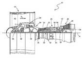
- FIG. 1is a side, partially cross-sectional view of a gas turbine engine constructed in accordance with the present disclosure.
- FIG. 2is a perspective view of an exemplary gas turbine engine fan blade assembly that may be used in conjunction with the gas turbine engine of FIG. 1 .
- FIG. 3is a perspective view of an exemplary fan blade that may be used in conjunction with the fan blade assembly of FIG. 2 .
- FIG. 4is a cross-sectional view of the exemplary fan blade that may be used in conjunction with the fan blade assembly of FIG. 2 taken along line 3 - 3 of FIG. 3 .
- FIG. 5is a schematic illustration depicting open-cell polymer foam for use in the manufacture of open-cell reticulated metal foam, the open-celled reticulated metal foam able to be used in the manufacture of the exemplary fan blade depicted in FIGS. 3-4 .
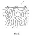
- FIGS. 6 ( a - b )are schematic illustrations depicting two modified, open-cell polymer foams for use in the manufacture of open-cell reticulated metal foam, the open-cell reticulated metal foam able to be used in the manufacture of the exemplary fan blade depicted in FIGS. 3-4 .
- FIG. 7is a flowchart depicting an exemplary method for preparing a modified, open-cell reticulated foam for use in the manufacture of an open-cell reticulated metal foam, the open-cell reticulated metal foam able to be used in the manufacture of the exemplary fan blade depicted in FIGS. 3-4 .
- FIG. 8is a flowchart depicting an exemplary method for preparing the exemplary fan blade depicted in FIGS. 3-4 utilizing the open-cell polymer foams of FIGS. 5-6 in a lost-foam casting process.
- a gas turbine engineis shown and generally referred to be reference numeral 20 .
- the gas turbine engine 20disclosed herein as a two-spool turbofan that generally incorporates a fan section 22 , a compressor section 24 , a combustor section 26 and a turbine section 28 .
- Alternative enginesmight include an augmentor section (not shown) among other systems or features.
- the fan section 22drives air along a bypass flowpath B, while the compressor section 24 drives air along a core flowpath C for compression and communication into the combustor section 26 .
- the compressor airis mixed with fuel and ignited, with the resulting combustion gases then expanding in turbine section 28 .
- turbofan gas turbine enginedepicted as a turbofan gas turbine engine in the disclosed non-limiting embodiment, it should be understood that the concepts described herein are not limited to use with turbofans as the teachings may be applied to other types of turbine engines including, but not limited to, three-spool architectures as well.
- the engine 20generally includes a low speed spool 30 and a high speed spool 32 mounted for rotation about an engine central longitudinal axis A relative to an engine static structure 36 via several bearing systems 38 . It should be understood that various bearing systems 38 at various locations may alternatively or additionally be provided.
- the low speed spool 30generally includes an inner shaft 40 that interconnects a fan blade assembly 42 , a low pressure (or first) compressor section 44 and a low pressure (or first) turbine section 46 .
- the inner shaft 40is connected to the fan blade assembly 42 through a geared architecture 48 to drive the fan assembly 42 at a lower speed than the low speed spool 30 .
- the high speed spool 32includes an outer shaft 50 that interconnects a high pressure (or second) compressor section 52 and high pressure (or second) turbine section 54 .
- the outer shaft 50is typically concentric with and radially outward from the inner shaft 50 .
- a combustor 56is arranged between the high pressure compressor 52 and the high pressure turbine 54 .
- a mid-turbine frame 57 of the engine static structure 36is arranged generally between the high pressure turbine 54 and the low pressure turbine 46 .
- the mid-turbine frame 57supports one or more bearing systems 38 in the turbine section 28 .
- the inner shaft 40 and the outer shaft 50are concentric and rotate via bearing systems 38 about the engine central longitudinal axis A, which is collinear with their longitudinal axes.
- a “high pressure” compressor or turbineexperiences a higher pressure than a corresponding “low pressure” compressor or turbine.
- the core airflow Cis compressed first by the low pressure compressor 44 , and then by the high pressure compressor 52 , before being mixed and burned with fuel in the combustor 56 , and lastly expanded over the high pressure turbine 54 and low pressure turbine 46 .
- the mid-turbine frame 57includes airfoils 59 which are in the core airflow path.
- the turbines 46 , 54rotationally drive the respective low speed spool 30 and high speed spool 32 in response to the expansion.
- the engine 20 in one exampleis a high-bypass geared aircraft engine.
- a high-bypass enginea greater volume of air moves along a bypass flowpath B than through core airflow C.
- the ratio of the mass of air moving through bypass flowpath B to core airflow Cis known as the bypass ratio.
- the engine 20 bypass ratiois greater than about six (6), with an example embodiment being greater than ten (10)
- the geared architecture 48is an epicyclic gear train, such as a star gear system or other gear system, with a gear reduction ratio of greater than about 2.3 and the low pressure turbine 46 has a pressure ratio that is greater than about 5.
- the engine 20 bypass ratiois greater than about ten (10:1)
- the fan diameteris significantly larger than that of the low pressure compressor 44
- the low pressure turbine 46has a pressure ratio that is greater than about 5:1.
- Low pressure turbine 46 pressure ratiois pressure measured prior to inlet of low pressure turbine 46 as related to the pressure at the outlet of the low pressure turbine 46 prior to an exhaust nozzle. It should be understood, however, that the above parameters are only exemplary of one embodiment of a geared architecture engine and that the present invention is applicable to other gas turbine engines including direct drive turbofans.
- a fan blade 60 of the fan blade assembly 42may include a root 62 supporting a platform 64 .
- An airfoil 66may extend from the platform 64 to a tip 68 .
- the airfoil 66includes spaced apart leading and trailing edges 70 , 72 .
- Pressure and suction sides 74 , 76adjoin the leading and trailing edges 70 , 72 to provide a fan blade contour 78 .
- the fan bladeincludes a leading edge sheath 80 .
- the sheath 80is secured to the fan blade 60 over the edge 82 .
- the sheath 80is constructed from titanium.
- the sheath 80is made from titanium alloy. It should be understood that other metals or materials may be used for sheath 80 .
- the fan blade 60may include a core 84 of open-cell reticulated metal foam enveloped by an outer shell 86 of a first material.
- the core 84may extend from the about the tip 68 to about the root 62 .
- the core 84may extend from about the leading edge 70 to about the trailing edge 72 .
- the fan blademay include a second core (not shown) being made of the first material surrounded by the shell 86 .
- the open-cell reticulated metal foam of the core 84may be made of a metal or a metal alloy. Although other metals are certainly possible, some metals from which the open-cell reticulated metal foam core 84 may be made consists of aluminum, titanium, nickel, copper, lead, molybdenum, tin, zinc and combinations thereof. Some metal alloys from which open-cell metal foam of the core 84 may be made includes aluminum alloy, nickel alloy, titanium alloy, steel and combinations thereof.
- metal alloys from which the core 84 may be selectedincludes aluminum alloys, steel, nickel alloys and titanium alloys, such as series 2000, 6000 or 7000 aluminum, 300 and 400 series stainless steels, precipitation hardenable stainless steels, Ti-6Al-4V, Ti-6Al-2Sn-4Zr-2Mo, WASPALOY®, INCONEL 718®, INCONEL 718+®, INCONEL 939® or HAYNES 282®. Other metal alloys are certainly possible.
- the first material comprising the outer shell 86may be a metal or a metal alloy. While the following list is not meant to be exhaustive, the metal from which outer shell 86 may be made includes, but is not limited to, aluminum, titanium and nickel. Some examples of metal alloys from which the outer shell 86 may be selected includes aluminum alloys, steel, nickel alloys and titanium alloys, such as series 2000, 6000 or 7000 aluminum, 300 and 400 series stainless steels, precipitation hardenable stainless steels, Ti-6Al-4V, Ti-6Al-2Sn-4Zr-2Mo, WASPALOY®, INCONEL 718®, INCONEL 718+®, INCONEL 939® or HAYNES 282®.
- the first material comprising the outer shell 86may be a composite material.
- Such composite materialmay be made of fiber embedded in resin.
- the fibers from which the composite material may be madeinclude, carbon-fiber, poly(p-phenylene-2,6-benzobisoxazole) fiber, mullite fiber, alumina fiber, silicon nitride fiber, silicon carbide fiber, boron fiber, boron nitride fiber, boron carbide fiber, glass fiber, titanium diboride fiber, yttria stabilized zirconium fiber and combinations thereof.
- Other fibersare certainly possible.
- the resin of such composite materialmay be a thermoset resin or a thermoplastic resin.
- resins from which the composite material may be madeincludes, but is not limited to, polyester, thermoset urethane, cyanate ester, vinyl ester, polyimide, bisphenol A epoxy, bisphenol F epoxy, novolac epoxy, glycidyl epoxy, cycloaliphatic epoxy, glycidylamine epoxy, melamine, phenol formaldehyde, polyhexahydrotriazine, low density polyethylene, medium density polyethylene, high density polyethylene, ultra-high molecular weight polyethylene, polyvinyl chloride, polyethylene terephthalate, vinyl, polypropylene, poly(methyl methacrylate), nylon, polybenzimidazole, polystyrene, polytetrafluroethylene, polyetherimide, polyether ketone, polyether ether ketone, acrylonitrile butadiene styrene, styrene acrylonitrile,
- foam for use in a lost-foam casting processsuch as during the creation of open-cell reticulated metal foam for gas turbine engine fan blades 60 , for example, is generally referred to by the reference number 88 .
- foam 88may have a reticulated three-dimensional structure comprising one or more ligaments 90 extending between two or more nodes 92 .
- a ligament 90may extend between two or more nodes 92 out of the same plane.
- such foam 88may comprise a first layer 94 made of polymer foam having a void fraction greater than or equal to ninety five (95) percent. While other polymer foams are certainly possible, some polymer foams from which the first layer 94 may be made includes polyurethane polymer foam, polyvinyl chloride polymer foam, polystyrene polymer foam, polyimide polymer foam, silicone polymer foam, polyethylene polymer foam, polyester polymer foam, polypropylene foam and combinations thereof. While such first layer 94 may have a void fraction of ninety five (95) percent or greater, in another instance such layer 94 may have a void fraction greater than ninety six (96) percent. In further instances, the first layer may have a void fraction greater than ninety seven (97) percent, or even ninety eight (98) percent.
- such foammay further include a second layer 96 , and such second layer 96 may be adhered to the first layer 94 .
- Such second layer 96may be an adhesive, such as an adhesive polymer.
- Some adhesive polymers from which the second layer may be madeincludes, but is certainly not limited to, acrylic polymer, alkyd polymer, styrene acrylic polymer, styrene butadiene polymer, vinyl acetate polymer, vinyl acetate homopolymer polymer, vinyl acrylic polymer, vinyl maleate polymer, vinyl versatate polymer, vinyl alcohol polymer, polyvinyl chloride polymer, polyvinylpyrrolidone polymer, casein and combinations thereof.
- Such foam 88may additionally include a third layer 98 adhered to the second layer 96 as depicted in FIGS. 6 ( a - b ). While specifically referring to FIG. 6 a , it is seen that such third layer 98 may be comprised of a particulate material.
- Such particulate material from which the third layer 98 may be madeincludes wax powder, wood flour, polymer powder and combinations thereof.
- Some wax powders from which the third layer 98 may be manufacturedincludes, animal wax powder, vegetable wax powder, mineral wax powder, petroleum wax powder and combinations thereof.
- Polymer powders from which the third layer 98 may be madeincludes polyurethane polymer powder, polyvinyl chloride polymer powder, polystyrene polymer powder, polyimide polymer powder, polyethylene polymer powder, polyester polymer powder, polypropylene polymer powder and combinations thereof.
- polyurethane polymer powderpolyvinyl chloride polymer powder
- polystyrene polymer powderpolystyrene polymer powder
- polyimide polymer powderpolyethylene polymer powder
- polyester polymer powderpolypropylene polymer powder and combinations thereof.
- other polymer powdersmay be utilized to manufacture the third layer 98 of the foam 88 for use in the creation of the open-celled metal foam for gas turbine engine fan blades 60 .
- Such foam 88comprising the first layer 94 , second layer 96 adhered to the first layer 94 and third layer 98 adhered to the second layer 94 may have void fraction less than or equal to ninety five (95) percent. In another instance, such foam 88 may have void fraction less than or equal to ninety four (94) percent. In a further instance, such foam 88 may have void fraction less than or equal to ninety three (93) percent. In further instances, such foam 88 comprising the first layer 94 , second layer 96 adhered to the first layer 94 and third layer 98 adhered to the second layer 94 may have void fraction less than or equal to ninety two (92) percent, ninety one (91) percent or even ninety (90) percent.
- the third layer 98may be characterized as being a substantially more continuous, non-particulate, shaped coating.
- This third layer 98may take on such continuous, non-particulate, shaped characteristic upon the exposing the particulate matter of the third layer 98 to heat energy that is at or above the melting temperature of the particulate matter. That is, the particulate matter melts, and subsequently upon cooling, forms a substantially continuous coating of melted particulate matter over the ligaments 90 and nodes 92 of the foam 88 .
- this foam 88 with a more continuous third layer 98may have a void fraction less than or equal to ninety five (95) percent.
- such foam 88may have void fraction less than or equal to ninety four (94) percent.
- such foam 88may have void fraction less than or equal to ninety three (93) percent.
- such foam 88 comprising the first layer 94 , second layer 96 adhered to the first layer 94 and third layer 98 adhered to the second layer 94may have void fraction less than or equal to two percent (92), ninety one (91) percent or even ninety (90) percent.
- such foam 88may additionally include a fourth layer comprising an adhesive adhered to the third layer.
- adhesivemay be an adhesive polymer and may be selected from the list of adhesives described above. Alternatively, such adhesive may be a different adhesive polymer altogether.
- foam 88may additionally comprise a fifth layer adhered to the fourth layer.
- Such fifth layermay be a particulate material and the particulate material may be a powder selected from such materials described of this application. Certainly other particulate materials are possible. Additional adhesive and particulate material layers may be added as needed so that the void fraction of the foam 88 for use in a lost foam casting process is less than or equal to ninety five (95) percent.
- polymer foam having an open-cell structure and a void fraction greater than ninety five (95) percentmay be provided.
- Such polymer foammay be selected, for example, from the group consisting of polyurethane polymer foam, polyvinyl chloride polymer foam, polystyrene polymer foam, polyimide polymer foam, silicone polymer foam, polyethylene polymer foam, polyester polymer foam, polypropylene foam and combinations thereof.
- the polymer foammay be coated with an adhesive.
- Such adhesivemay be an adhesive polymer, for instance, and may be selected from the group consisting of acrylic polymer, alkyd polymer, styrene acrylic polymer, styrene butadiene polymer, vinyl acetate polymer, vinyl acetate homopolymer polymer, vinyl acrylic polymer, vinyl maleate polymer, vinyl versatate polymer, vinyl alcohol polymer, polyvinyl chloride polymer, polyvinylpyrrolidone polymer, casein and combinations thereof.
- a particulate materialmay be applied to the adhesive, and the particulate material may be chosen from the group consisting of wax powder, wood flour, polymer powder and combinations thereof.
- the wax powdermay be selected from the group consisting of animal wax powder, vegetable wax powder, mineral wax powder, petroleum wax powder and combinations thereof. If a polymer powder is chosen, it may be selected from the group consisting of polyurethane polymer powder, polyvinyl chloride polymer powder, polystyrene polymer powder, polyimide polymer powder, polyethylene polymer powder, polyester polymer powder, polypropylene polymer powder and combinations thereof. Additionally, such particulate material may be applied by passing the adhesive coated polymer foam through a fluidized bed of particulate material.
- such stepmay comprise applying an emulsion to the polymer foam.
- emulsionmay comprise any of the foregoing described adhesive polymers dispersed in a solvent.
- stepmay further include removing the excess solvent from the polymer foam before applying a particulate material to the adhesive.
- the polymer foamcomprises ligaments positioned between nodes, and may further comprise heating the foam to a temperature above the melting temperature of the particulate material, followed by cooling the foam to a temperature below the melting temperature of the particulate material, to form a substantially continuous coating of particulate material over the ligaments.
- the third layermay be coated with a fourth layer, the fourth layer comprising an adhesive.
- adhesivemay be an adhesive polymer selected from the list described above, but other adhesive polymers are certainly possible.
- fourth layermay be coated with a fifth layer comprising particulate material.
- particulate materialmay be a powder chosen from those described above, although other materials are possible.
- foam 88may be coated with additional adhesive and particulate material layers beyond the fourth and fifth layer until the void fraction of the foam 88 for use in a lost-foam casting process is less than or equal to ninety five (95) percent.
- steps to a method of manufacturing a fan blade 60 for a gas turbine engine 20are depicted.
- polymer foam having an open-cell structure and a void fraction greater than ninety five (95) percentmay be provided.
- the polymer foammay be coated with an adhesive to create adhesive coated foam.
- particulate materialmay be applied to the adhesive coated foam to make a modified foam having a void fraction less than or equal to ninety five (95) percent.
- the modified foam having a void fraction less than or equal to ninety five (95) percentmay covered with a refractory material.
- the refractory materialmay be cured until it hardens and forms an investment.
- the investmentmay be heated to a temperature above the boiling point of the modified foam having a void fraction less than or equal to ninety five (95) percent to form a negative of the modified foam.
- molten metal or metal alloymay be added adding to the negative, followed by cooling the negative to a temperature below the melting temperature of the metal or metal alloy to form a positive of the modified foam.
- the refractory materialmay be removed to form an open-cell metal foam having a void fraction less than or equal to ninety five (95) percent.
- the open-cells metal foam having a void fraction less than or equal to ninety five (95) percentmay be enveloped with an outer shell of a first material, the out shell having the shape of an airfoil, to form a fan blade for a gas turbine engine.
- the polymer foamis polyurethane polymer foam
- the adhesiveis vinyl acetate
- the particulate materialis polyethylene polymer powder
- the metal or metal alloyis aluminum.
- the outer shell of first materialmay be made of a metal or metal alloy that is from the group consisting of aluminum, titanium and nickel, aluminum alloys, steel, nickel alloys and titanium alloys.
- the outer shell of first materialmay be made of a composite material and this composite material may comprise fiber embedded in resin.
- foam for use in a lost-foam casting processcan find use in many industrial applications, such as in the creation of open-cell reticulated metal foams for use in gas turbine engine fan blades. More specifically, the foam may find use as a positive in the lost-foam casting process for open-cell reticulated metal foams.
- the void fraction of foam utilized in such processis typically ninety seven (97) percent. While not conclusive, data suggests that gas turbine engine fan blades comprising open-cell reticulated metal foam manufactured from the above-described foams lack the resilience necessary for use in such fan blades.
- foamthat can be used in a lost-foam casting process to create open-cell reticulated metal foam with a lesser void fraction.
- foammay include a first layer comprising a polymer foam having a void fraction greater than ninety five (95) percent, a second layer comprising an adhesive adhered to the first layer and a third layer of particulate material adhered to the third layer.
- foamhaving these three layers, has a void fraction that is less than or equal to ninety five (95) percent and therefore may be used in a lost-foam casting process to create an open-cell reticulated metal foam having the necessary resilience to be used in gas turbine engine fan blades.
- methodsare described to manufacture such foam having three layers with the necessary void fraction. Further, methods are described to create a fan blade for a gas turbine engine utilizing the afore-described foam having three layers with the necessary void fraction.
Landscapes
- Engineering & Computer Science (AREA)
- Chemical & Material Sciences (AREA)
- Mechanical Engineering (AREA)
- Materials Engineering (AREA)
- General Engineering & Computer Science (AREA)
- Health & Medical Sciences (AREA)
- Chemical Kinetics & Catalysis (AREA)
- Medicinal Chemistry (AREA)
- Polymers & Plastics (AREA)
- Organic Chemistry (AREA)
- Structures Of Non-Positive Displacement Pumps (AREA)
- Powder Metallurgy (AREA)
Abstract
Description
Claims (12)
Priority Applications (3)
| Application Number | Priority Date | Filing Date | Title |
|---|---|---|---|
| US14/617,291US10035174B2 (en) | 2015-02-09 | 2015-02-09 | Open-cell reticulated foam |
| EP16154399.6AEP3053953B1 (en) | 2015-02-09 | 2016-02-05 | Open-cell reticulated foam |
| US16/037,917US20180318873A1 (en) | 2015-02-09 | 2018-07-17 | Open-cell reticulated foam |
Applications Claiming Priority (1)
| Application Number | Priority Date | Filing Date | Title |
|---|---|---|---|
| US14/617,291US10035174B2 (en) | 2015-02-09 | 2015-02-09 | Open-cell reticulated foam |
Related Child Applications (1)
| Application Number | Title | Priority Date | Filing Date |
|---|---|---|---|
| US16/037,917ContinuationUS20180318873A1 (en) | 2015-02-09 | 2018-07-17 | Open-cell reticulated foam |
Publications (2)
| Publication Number | Publication Date |
|---|---|
| US20160228913A1 US20160228913A1 (en) | 2016-08-11 |
| US10035174B2true US10035174B2 (en) | 2018-07-31 |
Family
ID=55650018
Family Applications (2)
| Application Number | Title | Priority Date | Filing Date |
|---|---|---|---|
| US14/617,291Active2035-07-15US10035174B2 (en) | 2015-02-09 | 2015-02-09 | Open-cell reticulated foam |
| US16/037,917AbandonedUS20180318873A1 (en) | 2015-02-09 | 2018-07-17 | Open-cell reticulated foam |
Family Applications After (1)
| Application Number | Title | Priority Date | Filing Date |
|---|---|---|---|
| US16/037,917AbandonedUS20180318873A1 (en) | 2015-02-09 | 2018-07-17 | Open-cell reticulated foam |
Country Status (2)
| Country | Link |
|---|---|
| US (2) | US10035174B2 (en) |
| EP (1) | EP3053953B1 (en) |
Families Citing this family (4)
| Publication number | Priority date | Publication date | Assignee | Title |
|---|---|---|---|---|
| JP2018066289A (en)* | 2016-10-18 | 2018-04-26 | 株式会社Ihi | Fan rotor blade and method for manufacturing the same |
| CN109550890B (en)* | 2017-09-25 | 2024-06-28 | 南京龙宁机床装备有限公司 | Sliding seat lost foam and method for casting sliding seat by using same |
| US11988103B2 (en)* | 2021-10-27 | 2024-05-21 | General Electric Company | Airfoils for a fan section of a turbine engine |
| US20230392504A1 (en)* | 2022-06-03 | 2023-12-07 | Raytheon Technologies Corporation | Polymeric foams for hollow cavities |
Citations (64)
| Publication number | Priority date | Publication date | Assignee | Title |
|---|---|---|---|---|
| US3946039A (en) | 1967-10-30 | 1976-03-23 | Energy Research & Generation, Inc. | Reticulated foam structure |
| US4106548A (en) | 1976-11-03 | 1978-08-15 | Politechnika Warszawska | Mass for production of cores and casting moulds |
| US4235277A (en) | 1977-12-16 | 1980-11-25 | Hitachi, Ltd. | Method of forming three-dimensional network porous metallic structure having continuous internal cavity |
| US4285385A (en) | 1978-06-28 | 1981-08-25 | Hitachi, Ltd. | Method for the production of heat exchangers |
| US4537823A (en) | 1983-11-18 | 1985-08-27 | Allied Corporation | Method of manufacturing a friction article |
| EP0157974A1 (en) | 1983-06-08 | 1985-10-16 | Stemcor Corporation | Composite refractory foams |
| US4568595A (en) | 1984-04-26 | 1986-02-04 | Morris Jeffrey R | Coated ceramic structure and method of making same |
| US4714586A (en) | 1986-01-29 | 1987-12-22 | The United States Of America As Represented By The United States Department Of Energy | Method of preparing a dimensionally stable electrode for use in a MCFC |
| US4756251A (en) | 1986-09-18 | 1988-07-12 | Morton Thiokol, Inc. | Solid rocket motor propellants with reticulated structures embedded therein to provide variable burn rate characteristics |
| US4764319A (en) | 1986-09-18 | 1988-08-16 | Morton Thiokol, Inc. | High solids ratio solid rocket motor propellant grains and method of construction thereof |
| US4798142A (en) | 1986-08-18 | 1989-01-17 | Morton Thiokol, Inc. | Rapid buring propellant charge for automobile air bag inflators, rocket motors, and igniters therefor |
| US4808360A (en) | 1986-07-28 | 1989-02-28 | Hitachi, Ltd. | Method of producing mold for slip casting and method of molding slip casting |
| US4822694A (en) | 1986-11-03 | 1989-04-18 | Asulab S.A. | Composite material |
| GB2214275A (en) | 1986-09-18 | 1989-08-31 | Thiokol Morton Inc | Propellant grain |
| GB2214617A (en) | 1988-01-25 | 1989-09-06 | Thiokol Morton Inc | Rocket motors and igniters |
| EP0333944A1 (en) | 1988-03-24 | 1989-09-27 | Thiokol Corporation | Solid rocket motor propellants with reticulated structures embedded therein to provide variable burn rate characteristics |
| EP0336023A1 (en) | 1988-03-24 | 1989-10-11 | Thiokol Corporation | Solid rocket motor propellant with imbedded reticulated structures |
| US4923830A (en) | 1989-09-18 | 1990-05-08 | Swiss Aluminum Ltd. | Ceramic bodies formed from partially stabilized zirconia |
| US5016702A (en) | 1989-08-28 | 1991-05-21 | Eska Medical Lubeck Medizintechnik Gmbh & Co. | Method of producing open-celled metal structures |
| US5024160A (en) | 1986-08-18 | 1991-06-18 | Thiokol Corporation | Rapid burning propellant charge for automobile air bag inflators, rocket motors, and igniters therefor |
| US5042560A (en) | 1989-05-26 | 1991-08-27 | Eska Medical Lubeck Medizintechnik Gmbh & Co. | Method of producing open-celled metal structures |
| US5062365A (en) | 1986-08-18 | 1991-11-05 | Thiokol Corporation | Rapid burning propellent charge for automobile air bag inflators, rocket motors, and igniters therefor |
| US5066622A (en) | 1987-12-23 | 1991-11-19 | Lanxide Technology Company, Lp | Method of producing and modifying the properties of ceramic composite bodies |
| US5093678A (en) | 1990-12-17 | 1992-03-03 | Eastman Kodak Company | Processor with laminar fluid flow wick |
| US5127223A (en) | 1986-09-18 | 1992-07-07 | Thiokol Corporation | Solid rocket motor propellants with reticulated structures embedded therein and method of manufacture thereof |
| GB2260538A (en) | 1991-10-15 | 1993-04-21 | Peter Gant | Porous ceramics |
| US5231968A (en) | 1992-07-27 | 1993-08-03 | Donald Siefkes | Foamed metal heat device |
| US5403790A (en) | 1987-12-23 | 1995-04-04 | Lanxide Technology Company, Lp | Additives for property modification in ceramic composite bodies |
| WO1995011752A1 (en) | 1993-10-27 | 1995-05-04 | Scientific Dimensions Usa, Inc. | Open cell foam structures, catalysts supported thereby and method of producing the same |
| US5520861A (en) | 1993-12-20 | 1996-05-28 | General Motors Corporation | Method of making a reinforcement preform and a reinforced composite therefrom |
| US5575871A (en) | 1993-07-19 | 1996-11-19 | Takeda Chemical Industries, Ltd. | Heat insulating material and method for producing same |
| US5668188A (en) | 1996-01-16 | 1997-09-16 | Sandia Corporation | Process for preparing silicon carbide foam |
| US5848351A (en) | 1995-04-03 | 1998-12-08 | Mitsubishi Materials Corporation | Porous metallic material having high specific surface area, method of producing the same, porous metallic plate material and electrode for alkaline secondary battery |
| US5881353A (en)* | 1994-03-31 | 1999-03-09 | Hitachi Chemical Company, Ltd. | Method for producing porous bodies |
| US5951791A (en) | 1997-12-01 | 1999-09-14 | Inco Limited | Method of preparing porous nickel-aluminum structures |
| US6080493A (en) | 1998-03-20 | 2000-06-27 | Kent; Howard Daniel | Rubber to metal bonding method |
| US6087024A (en) | 1996-12-17 | 2000-07-11 | Whinnery; Leroy Louis | Method for forming porous sintered bodies with controlled pore structure |
| US6189598B1 (en) | 1998-10-05 | 2001-02-20 | General Motors Corporation | Lost foam casting without fold defects |
| US6424531B1 (en) | 2001-03-13 | 2002-07-23 | Delphi Technologies, Inc. | High performance heat sink for electronics cooling |
| US6424529B2 (en) | 2000-03-14 | 2002-07-23 | Delphi Technologies, Inc. | High performance heat exchange assembly |
| US6591897B1 (en) | 2002-02-20 | 2003-07-15 | Delphi Technologies, Inc. | High performance pin fin heat sink for electronics cooling |
| US6660224B2 (en) | 2001-08-16 | 2003-12-09 | National Research Council Of Canada | Method of making open cell material |
| US6673285B2 (en) | 2000-05-12 | 2004-01-06 | The Regents Of The University Of Michigan | Reverse fabrication of porous materials |
| US6840307B2 (en) | 2000-03-14 | 2005-01-11 | Delphi Technologies, Inc. | High performance heat exchange assembly |
| US6857461B2 (en) | 1999-08-20 | 2005-02-22 | Dieter Girlich | Method and device for the production of reticular structures |
| DE102004016874A1 (en) | 2004-03-29 | 2005-10-20 | Fraunhofer Ges Forschung | Composite product for use e.g. in grinding devices or implants comprises a non-metallic inorganic matrix and a 3-dimensional, repeating, firmly-bonded metal network |
| EP1604756A2 (en) | 2004-06-02 | 2005-12-14 | Dieter Dr. Girlich | method for producing metallic reticular structures |
| US7106777B2 (en) | 2003-01-07 | 2006-09-12 | The Boeing Company | Phase-change heat exchanger |
| US7108828B2 (en) | 2001-08-27 | 2006-09-19 | National Research Council Of Canada | Method of making open cell material |
| US7182121B1 (en) | 2004-06-28 | 2007-02-27 | Viel David W | Investment casting method and materials |
| US7401643B2 (en) | 2000-07-14 | 2008-07-22 | University Of Virginia Patent Foundation | Heat exchange foam |
| US7416667B2 (en) | 2000-09-07 | 2008-08-26 | Prosep Inc. | Polyurethane oil de-emulsification unit |
| US7615184B2 (en) | 2006-01-25 | 2009-11-10 | Alexander Lobovsky | Metal, ceramic and cermet articles formed from low viscosity aqueous slurries |
| WO2010117476A1 (en) | 2009-04-08 | 2010-10-14 | Lockheed Martin Corporation | Nanoporous coating synthesis and apparatus |
| US7875342B2 (en) | 2001-09-24 | 2011-01-25 | Warsaw Orthopedic, Inc. | Porous ceramic composite bone grafts |
| WO2011051106A1 (en) | 2009-10-29 | 2011-05-05 | Nv Bekaert Sa | Manufacturing heat exchanger from porous medium and conduits |
| US8225841B1 (en) | 2011-01-03 | 2012-07-24 | James Avery Craftsman, Inc. | Central sprue for investment casting |
| US20120196147A1 (en)* | 2004-11-29 | 2012-08-02 | North Carolina State University | Composite metal foam and methods of preparation thereof |
| US20120225236A1 (en) | 2011-03-03 | 2012-09-06 | James Edward Cox | Composite Building Panel and Method |
| US20130040046A1 (en) | 2011-02-18 | 2013-02-14 | Sumitomo Electric Toyama Co., Ltd. | Method for producing electrode for electrochemical element |
| US8424585B2 (en) | 2011-01-21 | 2013-04-23 | James Avery Craftsman, Inc. | Method and apparatus for creating a pattern |
| EP2653379A2 (en) | 2012-04-18 | 2013-10-23 | Hamilton Sundstrand Corporation | Propeller blade with metallic foam spar core |
| US20140039082A1 (en) | 2010-02-26 | 2014-02-06 | Peterson Chemical Technology, Inc. | Enhanced Thermally Conductive Cushioning Foams by Addition of Metal Materials |
| WO2015009446A1 (en) | 2013-07-15 | 2015-01-22 | United Technologies Corporation | Nanocellular and nanocellular particle filled polymer composite coating for erosion protection |
- 2015
- 2015-02-09USUS14/617,291patent/US10035174B2/enactiveActive
- 2016
- 2016-02-05EPEP16154399.6Apatent/EP3053953B1/enactiveActive
- 2018
- 2018-07-17USUS16/037,917patent/US20180318873A1/ennot_activeAbandoned
Patent Citations (79)
| Publication number | Priority date | Publication date | Assignee | Title |
|---|---|---|---|---|
| US3946039A (en) | 1967-10-30 | 1976-03-23 | Energy Research & Generation, Inc. | Reticulated foam structure |
| US4106548A (en) | 1976-11-03 | 1978-08-15 | Politechnika Warszawska | Mass for production of cores and casting moulds |
| US4235277A (en) | 1977-12-16 | 1980-11-25 | Hitachi, Ltd. | Method of forming three-dimensional network porous metallic structure having continuous internal cavity |
| US4285385A (en) | 1978-06-28 | 1981-08-25 | Hitachi, Ltd. | Method for the production of heat exchangers |
| EP0157974A1 (en) | 1983-06-08 | 1985-10-16 | Stemcor Corporation | Composite refractory foams |
| EP0157974B1 (en) | 1983-06-08 | 1989-09-06 | Stemcor Corporation | Composite refractory foams |
| US4537823A (en) | 1983-11-18 | 1985-08-27 | Allied Corporation | Method of manufacturing a friction article |
| US4568595A (en) | 1984-04-26 | 1986-02-04 | Morris Jeffrey R | Coated ceramic structure and method of making same |
| US4714586A (en) | 1986-01-29 | 1987-12-22 | The United States Of America As Represented By The United States Department Of Energy | Method of preparing a dimensionally stable electrode for use in a MCFC |
| US4808360A (en) | 1986-07-28 | 1989-02-28 | Hitachi, Ltd. | Method of producing mold for slip casting and method of molding slip casting |
| EP0333945B1 (en) | 1986-08-18 | 1992-02-26 | Thiokol Corporation | Rapid burning propellant charge for automobile air bag inflators, rocket motors and ignitors therefor |
| US4798142A (en) | 1986-08-18 | 1989-01-17 | Morton Thiokol, Inc. | Rapid buring propellant charge for automobile air bag inflators, rocket motors, and igniters therefor |
| GB2214277B (en) | 1986-08-18 | 1992-01-22 | Thiokol Morton Inc | Rapid burning propellant charge for automobile air bag inflators,rocket motors,and igniters therefor |
| GB2214277A (en) | 1986-08-18 | 1989-08-31 | Thiokol Morton Inc | Propellant charge |
| US5062365A (en) | 1986-08-18 | 1991-11-05 | Thiokol Corporation | Rapid burning propellent charge for automobile air bag inflators, rocket motors, and igniters therefor |
| US4798142B1 (en) | 1986-08-18 | 1990-12-04 | Thiokol Morton Inc | |
| US5024160A (en) | 1986-08-18 | 1991-06-18 | Thiokol Corporation | Rapid burning propellant charge for automobile air bag inflators, rocket motors, and igniters therefor |
| EP0333945A1 (en) | 1986-08-18 | 1989-09-27 | Thiokol Corporation | Rapid burning propellant charge for automobile air bag inflators, rocket motors and ignitors therefor |
| US4764319A (en) | 1986-09-18 | 1988-08-16 | Morton Thiokol, Inc. | High solids ratio solid rocket motor propellant grains and method of construction thereof |
| GB2214275A (en) | 1986-09-18 | 1989-08-31 | Thiokol Morton Inc | Propellant grain |
| US4756251A (en) | 1986-09-18 | 1988-07-12 | Morton Thiokol, Inc. | Solid rocket motor propellants with reticulated structures embedded therein to provide variable burn rate characteristics |
| US5127223A (en) | 1986-09-18 | 1992-07-07 | Thiokol Corporation | Solid rocket motor propellants with reticulated structures embedded therein and method of manufacture thereof |
| US4822694A (en) | 1986-11-03 | 1989-04-18 | Asulab S.A. | Composite material |
| US5403790A (en) | 1987-12-23 | 1995-04-04 | Lanxide Technology Company, Lp | Additives for property modification in ceramic composite bodies |
| US5066622A (en) | 1987-12-23 | 1991-11-19 | Lanxide Technology Company, Lp | Method of producing and modifying the properties of ceramic composite bodies |
| GB2214617A (en) | 1988-01-25 | 1989-09-06 | Thiokol Morton Inc | Rocket motors and igniters |
| EP0333944A1 (en) | 1988-03-24 | 1989-09-27 | Thiokol Corporation | Solid rocket motor propellants with reticulated structures embedded therein to provide variable burn rate characteristics |
| EP0336023A1 (en) | 1988-03-24 | 1989-10-11 | Thiokol Corporation | Solid rocket motor propellant with imbedded reticulated structures |
| US5042560A (en) | 1989-05-26 | 1991-08-27 | Eska Medical Lubeck Medizintechnik Gmbh & Co. | Method of producing open-celled metal structures |
| US5016702A (en) | 1989-08-28 | 1991-05-21 | Eska Medical Lubeck Medizintechnik Gmbh & Co. | Method of producing open-celled metal structures |
| US4923830A (en) | 1989-09-18 | 1990-05-08 | Swiss Aluminum Ltd. | Ceramic bodies formed from partially stabilized zirconia |
| US5093678A (en) | 1990-12-17 | 1992-03-03 | Eastman Kodak Company | Processor with laminar fluid flow wick |
| GB2260538A (en) | 1991-10-15 | 1993-04-21 | Peter Gant | Porous ceramics |
| GB2260538B (en) | 1991-10-15 | 1995-08-16 | Peter Gant | Ceramic block for liquid retention |
| US5231968A (en) | 1992-07-27 | 1993-08-03 | Donald Siefkes | Foamed metal heat device |
| US5575871A (en) | 1993-07-19 | 1996-11-19 | Takeda Chemical Industries, Ltd. | Heat insulating material and method for producing same |
| WO1995011752A1 (en) | 1993-10-27 | 1995-05-04 | Scientific Dimensions Usa, Inc. | Open cell foam structures, catalysts supported thereby and method of producing the same |
| US5520861A (en) | 1993-12-20 | 1996-05-28 | General Motors Corporation | Method of making a reinforcement preform and a reinforced composite therefrom |
| US5881353A (en)* | 1994-03-31 | 1999-03-09 | Hitachi Chemical Company, Ltd. | Method for producing porous bodies |
| US5848351A (en) | 1995-04-03 | 1998-12-08 | Mitsubishi Materials Corporation | Porous metallic material having high specific surface area, method of producing the same, porous metallic plate material and electrode for alkaline secondary battery |
| US6117592A (en) | 1995-04-03 | 2000-09-12 | Mitsubishi Materials Corporation | Porus metallic material having high specific surface area, method of producing the same, porus metallic plate material and electrode for alkaline secondary battery |
| US5668188A (en) | 1996-01-16 | 1997-09-16 | Sandia Corporation | Process for preparing silicon carbide foam |
| US6087024A (en) | 1996-12-17 | 2000-07-11 | Whinnery; Leroy Louis | Method for forming porous sintered bodies with controlled pore structure |
| US5951791A (en) | 1997-12-01 | 1999-09-14 | Inco Limited | Method of preparing porous nickel-aluminum structures |
| US6843876B1 (en) | 1998-03-20 | 2005-01-18 | Howard Daniel Kent | Rubber to metal bonding method |
| US6080493A (en) | 1998-03-20 | 2000-06-27 | Kent; Howard Daniel | Rubber to metal bonding method |
| US6189598B1 (en) | 1998-10-05 | 2001-02-20 | General Motors Corporation | Lost foam casting without fold defects |
| US6857461B2 (en) | 1999-08-20 | 2005-02-22 | Dieter Girlich | Method and device for the production of reticular structures |
| US6424529B2 (en) | 2000-03-14 | 2002-07-23 | Delphi Technologies, Inc. | High performance heat exchange assembly |
| US6840307B2 (en) | 2000-03-14 | 2005-01-11 | Delphi Technologies, Inc. | High performance heat exchange assembly |
| US6673285B2 (en) | 2000-05-12 | 2004-01-06 | The Regents Of The University Of Michigan | Reverse fabrication of porous materials |
| US7401643B2 (en) | 2000-07-14 | 2008-07-22 | University Of Virginia Patent Foundation | Heat exchange foam |
| US7416667B2 (en) | 2000-09-07 | 2008-08-26 | Prosep Inc. | Polyurethane oil de-emulsification unit |
| US6424531B1 (en) | 2001-03-13 | 2002-07-23 | Delphi Technologies, Inc. | High performance heat sink for electronics cooling |
| US6660224B2 (en) | 2001-08-16 | 2003-12-09 | National Research Council Of Canada | Method of making open cell material |
| US7108828B2 (en) | 2001-08-27 | 2006-09-19 | National Research Council Of Canada | Method of making open cell material |
| US7875342B2 (en) | 2001-09-24 | 2011-01-25 | Warsaw Orthopedic, Inc. | Porous ceramic composite bone grafts |
| US6591897B1 (en) | 2002-02-20 | 2003-07-15 | Delphi Technologies, Inc. | High performance pin fin heat sink for electronics cooling |
| US7106777B2 (en) | 2003-01-07 | 2006-09-12 | The Boeing Company | Phase-change heat exchanger |
| DE102004016874B4 (en) | 2004-03-29 | 2007-04-12 | Fraunhofer-Gesellschaft zur Förderung der angewandten Forschung e.V. | Composite material, process for its preparation and its use |
| DE102004016874C5 (en) | 2004-03-29 | 2008-11-27 | Fraunhofer-Gesellschaft zur Förderung der angewandten Forschung e.V. | Composite material, process for its preparation and its use |
| DE102004016874A1 (en) | 2004-03-29 | 2005-10-20 | Fraunhofer Ges Forschung | Composite product for use e.g. in grinding devices or implants comprises a non-metallic inorganic matrix and a 3-dimensional, repeating, firmly-bonded metal network |
| EP1604756B1 (en) | 2004-06-02 | 2007-03-21 | Dieter Dr. Girlich | method for producing metallic reticular structures |
| EP1604756A3 (en) | 2004-06-02 | 2005-12-28 | Dieter Dr. Girlich | method for producing metallic reticular structures |
| EP1604756A2 (en) | 2004-06-02 | 2005-12-14 | Dieter Dr. Girlich | method for producing metallic reticular structures |
| DE102004026959B3 (en) | 2004-06-02 | 2006-02-16 | Girlich, Dieter, Dr. | Process for producing metallic lattice structures |
| US7182121B1 (en) | 2004-06-28 | 2007-02-27 | Viel David W | Investment casting method and materials |
| US20120196147A1 (en)* | 2004-11-29 | 2012-08-02 | North Carolina State University | Composite metal foam and methods of preparation thereof |
| US7615184B2 (en) | 2006-01-25 | 2009-11-10 | Alexander Lobovsky | Metal, ceramic and cermet articles formed from low viscosity aqueous slurries |
| WO2010117476A1 (en) | 2009-04-08 | 2010-10-14 | Lockheed Martin Corporation | Nanoporous coating synthesis and apparatus |
| US8257826B1 (en) | 2009-04-08 | 2012-09-04 | Lockheed Martin Corporation | Nanoporous coating synthesis and apparatus |
| WO2011051106A1 (en) | 2009-10-29 | 2011-05-05 | Nv Bekaert Sa | Manufacturing heat exchanger from porous medium and conduits |
| US20140039082A1 (en) | 2010-02-26 | 2014-02-06 | Peterson Chemical Technology, Inc. | Enhanced Thermally Conductive Cushioning Foams by Addition of Metal Materials |
| US8225841B1 (en) | 2011-01-03 | 2012-07-24 | James Avery Craftsman, Inc. | Central sprue for investment casting |
| US8424585B2 (en) | 2011-01-21 | 2013-04-23 | James Avery Craftsman, Inc. | Method and apparatus for creating a pattern |
| US20130040046A1 (en) | 2011-02-18 | 2013-02-14 | Sumitomo Electric Toyama Co., Ltd. | Method for producing electrode for electrochemical element |
| US20120225236A1 (en) | 2011-03-03 | 2012-09-06 | James Edward Cox | Composite Building Panel and Method |
| EP2653379A2 (en) | 2012-04-18 | 2013-10-23 | Hamilton Sundstrand Corporation | Propeller blade with metallic foam spar core |
| WO2015009446A1 (en) | 2013-07-15 | 2015-01-22 | United Technologies Corporation | Nanocellular and nanocellular particle filled polymer composite coating for erosion protection |
Non-Patent Citations (2)
| Title |
|---|
| European Search Report for Application No. 16154399.6; dated May 31, 2016. |
| Note: Only the abstracts for GB2214277B and GB2260538B are publically available, which is submitted herewith for your use; however the patent's published application is also submitted herewith for your review. |
Also Published As
| Publication number | Publication date |
|---|---|
| EP3053953B1 (en) | 2018-08-01 |
| US20180318873A1 (en) | 2018-11-08 |
| US20160228913A1 (en) | 2016-08-11 |
| EP3053953A1 (en) | 2016-08-10 |
Similar Documents
| Publication | Publication Date | Title |
|---|---|---|
| US11168568B2 (en) | Composite gas turbine engine component with lattice | |
| US10107302B2 (en) | Durable riblets for engine environment | |
| US20180318873A1 (en) | Open-cell reticulated foam | |
| US20180038654A1 (en) | System for fault tolerant passage arrangements for heat exchanger applications | |
| US11181074B2 (en) | Variable area fan nozzle with wall thickness distribution | |
| WO2013172894A2 (en) | Leading edge protection and method of making | |
| US9752442B2 (en) | Airfoil with variable profile responsive to thermal conditions | |
| EP4166756B1 (en) | Vibration mitigation coating for an integrally bladed rotor and process of vibration mitigation through coating of an integrally bladed rotor | |
| EP2943657B1 (en) | Organic matrix composite structural inlet guide vane for a turbine engine | |
| US20200355082A1 (en) | Fan platform with core and skin | |
| EP3029297B1 (en) | Gas turbine engine spinner | |
| US20130280082A1 (en) | Airfoil with powder damper | |
| US12055065B1 (en) | Airfoil for a gas turbine engine having an inner core structure formed of meta-structures and isogrids | |
| EP3020921B1 (en) | Gas turbine engine structural guide vanes, guide vane assembly and gas turbine engine | |
| US11879355B1 (en) | Airfoil assembly with an internal reinforcement structure | |
| EP2971595B1 (en) | Variable area fan nozzle with wall thickness distribution | |
| US11781437B2 (en) | Cold spray duct for a gas turbine engine |
Legal Events
| Date | Code | Title | Description |
|---|---|---|---|
| AS | Assignment | Owner name:UNITED TECHNOLOGIES CORPORATION, CONNECTICUT Free format text:ASSIGNMENT OF ASSIGNORS INTEREST;ASSIGNORS:NORAAS, RYAN B.;BULLIED, STEVEN J.;REEL/FRAME:034924/0400 Effective date:20150204 | |
| STCF | Information on status: patent grant | Free format text:PATENTED CASE | |
| AS | Assignment | Owner name:RAYTHEON TECHNOLOGIES CORPORATION, MASSACHUSETTS Free format text:CHANGE OF NAME;ASSIGNOR:UNITED TECHNOLOGIES CORPORATION;REEL/FRAME:054062/0001 Effective date:20200403 | |
| CC | Certificate of correction | ||
| AS | Assignment | Owner name:RAYTHEON TECHNOLOGIES CORPORATION, CONNECTICUT Free format text:CORRECTIVE ASSIGNMENT TO CORRECT THE AND REMOVE PATENT APPLICATION NUMBER 11886281 AND ADD PATENT APPLICATION NUMBER 14846874. TO CORRECT THE RECEIVING PARTY ADDRESS PREVIOUSLY RECORDED AT REEL: 054062 FRAME: 0001. ASSIGNOR(S) HEREBY CONFIRMS THE CHANGE OF ADDRESS;ASSIGNOR:UNITED TECHNOLOGIES CORPORATION;REEL/FRAME:055659/0001 Effective date:20200403 | |
| MAFP | Maintenance fee payment | Free format text:PAYMENT OF MAINTENANCE FEE, 4TH YEAR, LARGE ENTITY (ORIGINAL EVENT CODE: M1551); ENTITY STATUS OF PATENT OWNER: LARGE ENTITY Year of fee payment:4 | |
| AS | Assignment | Owner name:RTX CORPORATION, CONNECTICUT Free format text:CHANGE OF NAME;ASSIGNOR:RAYTHEON TECHNOLOGIES CORPORATION;REEL/FRAME:064714/0001 Effective date:20230714 |