US10035008B2 - System and method for tool feedback sensing - Google Patents
System and method for tool feedback sensingDownload PDFInfo
- Publication number
- US10035008B2 US10035008B2US11/910,173US91017306AUS10035008B2US 10035008 B2US10035008 B2US 10035008B2US 91017306 AUS91017306 AUS 91017306AUS 10035008 B2US10035008 B2US 10035008B2
- Authority
- US
- United States
- Prior art keywords
- microneedle
- application
- force
- sensor
- application device
- Prior art date
- Legal status (The legal status is an assumption and is not a legal conclusion. Google has not performed a legal analysis and makes no representation as to the accuracy of the status listed.)
- Active, expires
Links
Images


Classifications
- A—HUMAN NECESSITIES
- A61—MEDICAL OR VETERINARY SCIENCE; HYGIENE
- A61M—DEVICES FOR INTRODUCING MEDIA INTO, OR ONTO, THE BODY; DEVICES FOR TRANSDUCING BODY MEDIA OR FOR TAKING MEDIA FROM THE BODY; DEVICES FOR PRODUCING OR ENDING SLEEP OR STUPOR
- A61M37/00—Other apparatus for introducing media into the body; Percutany, i.e. introducing medicines into the body by diffusion through the skin
- A61M37/0015—Other apparatus for introducing media into the body; Percutany, i.e. introducing medicines into the body by diffusion through the skin by using microneedles
- A—HUMAN NECESSITIES
- A61—MEDICAL OR VETERINARY SCIENCE; HYGIENE
- A61B—DIAGNOSIS; SURGERY; IDENTIFICATION
- A61B5/00—Measuring for diagnostic purposes; Identification of persons
- A61B5/145—Measuring characteristics of blood in vivo, e.g. gas concentration or pH-value ; Measuring characteristics of body fluids or tissues, e.g. interstitial fluid or cerebral tissue
- A61B5/14507—Measuring characteristics of blood in vivo, e.g. gas concentration or pH-value ; Measuring characteristics of body fluids or tissues, e.g. interstitial fluid or cerebral tissue specially adapted for measuring characteristics of body fluids other than blood
- A61B5/1451—Measuring characteristics of blood in vivo, e.g. gas concentration or pH-value ; Measuring characteristics of body fluids or tissues, e.g. interstitial fluid or cerebral tissue specially adapted for measuring characteristics of body fluids other than blood for interstitial fluid
- A61B5/14514—Measuring characteristics of blood in vivo, e.g. gas concentration or pH-value ; Measuring characteristics of body fluids or tissues, e.g. interstitial fluid or cerebral tissue specially adapted for measuring characteristics of body fluids other than blood for interstitial fluid using means for aiding extraction of interstitial fluid, e.g. microneedles or suction
- A—HUMAN NECESSITIES
- A61—MEDICAL OR VETERINARY SCIENCE; HYGIENE
- A61M—DEVICES FOR INTRODUCING MEDIA INTO, OR ONTO, THE BODY; DEVICES FOR TRANSDUCING BODY MEDIA OR FOR TAKING MEDIA FROM THE BODY; DEVICES FOR PRODUCING OR ENDING SLEEP OR STUPOR
- A61M37/00—Other apparatus for introducing media into the body; Percutany, i.e. introducing medicines into the body by diffusion through the skin
- A61M37/0015—Other apparatus for introducing media into the body; Percutany, i.e. introducing medicines into the body by diffusion through the skin by using microneedles
- A61M2037/0023—Drug applicators using microneedles
Definitions
- the present inventionrelates to a system and method for tool feedback sensing. More particularly, the present invention relates to feedback sensing provided with tools for assisting with microneedle application procedures.
- stratum corneumthe outermost layer of the skin.
- Devices including arrays of relatively small structureshave been disclosed for use in connection with the delivery of therapeutic agents and other substances through the skin and other surfaces.
- the devicesare typically pressed against the skin in an effort to pierce the stratum corneum such that the therapeutic agents and other substances can pass through that layer and into the tissues below.
- Microneedle arrayscan be used in conjunction with an applicator device capable of being used a number of different times.
- the applicator devicecan include a removable collar for holding the microneedle array prior to deployment.
- the collarcan be reusable or disposable.
- the microneedle arraysare generally used once and then discarded.
- the arraysare typically manufactured in a flat sheet-like configuration and temporarily attached to the applicator device using, for example, an adhesive.
- Cutometersskin elasticity
- Reviscometersskin construction
- Tonometerstime to rebound from a given deflection
- microneedle applicationmay be conducted at application sites on different skin surfaces. For instance, tests may be performed involving microneedle arrays applied to particular skin target areas (e.g., forearms, buttocks, biceps, etc.) of a selected sample of like persons or to persons differing in some way (e.g., by age, race, gender, etc.) or to the skin of different species of test subjects.
- skin target arease.g., forearms, buttocks, biceps, etc.
- microneedle applicator devicesby operators, such as healthcare providers, can be problematic. Operator error, for example, can result in improper microneedle array deployment, which can undermine desired molecule transport. It is believed that proper applicator device positioning can affect microneedle array deployment. However, it is difficult to help ensure proper applicator device positioning. Additional problems are faced in research contexts. Variations across different application sites present difficulties in gathering reliable data from research tests, and in reliably applying collected research data to other contexts.
- the present inventionrelates to a microneedle application device for moving a microneedle array toward a target skin location includes a feedback sensor.
- the feedback sensoris operably connected to the microneedle application device, and is capable of generating an output corresponding to forces between the target skin location and the microneedle application device.
- the present inventionrelates to a method of microneedle application.
- the methodcomprises providing a microneedle applicator device, providing a microneedle array that is initially mounted to the microneedle applicator device, positioning a locating portion of the microneedle applicator device in contact with skin to substantially define a target application site on the skin for application of the microneedle array, sensing a force between the target application site and a first portion of the microneedle applicator device, positioning the microneedle applicator device such that the microneedle array can be moved into contact with the skin along a path that is substantially orthogonal relative to the target application site, and moving the microneedle array toward the target application site.
- the present inventionrelates to a method of positioning a tool for assisting with microneedle application procedures.
- the methodcomprises placing the tool in contact with a target site, and sensing a pushback force of the target site against the tool.
- the present inventionrelates to an applicator system including a microneedle application device and a force sensing element.
- the microneedle application devicehas a portion adapted for skin contact at least prior to microneedle application.
- the force sensing elementis capable of sensing force between the portion of the microneedle applicator adapted for skin contact and a target application site.
- the present inventionrelates to a tool for sensing forces between the tool and a skin surface.
- the toolincludes a housing having a force application portion, a contact portion, a support, and a sensor.
- the contact portionis supported by the housing, and is capable of contacting the skin surface to substantially define a target location.
- the supportis supported by the housing, and is capable of reaching the target location.
- the sensoris disposed between the target location and a first portion of the tool, and is capable of sensing force.
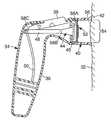
- FIG. 1is a perspective view of a microneedle application device and a target skin surface.
- FIG. 2is a cross sectional side view of the microneedle application device and a microneedle array patch, where the microneedle application device is positioned against the target skin surface.
- FIG. 3is an enlarged cross sectional side view of a portion of the microneedle application device positioned against the target skin surface.
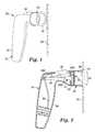
- FIG. 4Ais a cross sectional side view of a portion of the microneedle application device.
- FIG. 4Bis a schematic side view of a portion of an alternative embodiment of the microneedle application device.
- FIGS. 5A-5Care schematic representations of force sensitive regions at a target application site for alternative collar sensor arrangements.
- FIG. 6is a cross sectional side view of a diagnostic tool.
- FIGS. 7A-7Care schematic representations of force sensitive regions at a target site for alternative sensor arrangements.
- FIG. 8Ais a block diagram of a digital feedback system.
- FIG. 8Bis a block diagram of an analog feedback system.
- FIGS. 9A-9Cillustrate alternative indicators for displaying sensed force and/or tool orientation data according to the present invention.
- FIG. 10Ais a graph of force sensed at a single sensor coupled to a collar of a tool versus time as the collar is positioned and adjusted against a skin surface, and a range of forces acceptable for microneedle application.
- FIG. 10Bis a graph of force sensed at four sensors coupled to a collar of a tool versus time as the collar is positioned and adjusted against a skin surface, and a range of forces acceptable for microneedle application.
- FIG. 11Ais a graph of force sensed at a single sensor at a collar versus time as the collar is positioned and adjusted against a skin surface, and where no piston is actuated.
- FIG. 11Bis a graph of force sensed at a collar versus time as the collar is positioned and adjusted against a skin surface, and where a piston is actuated to eventually reach the skin surface.
- FIG. 11Cis a graph of force sensed at a pad of the piston versus time as the collar is positioned against the skin surface, and where the piston is actuated to eventually reach the skin surface as in FIG. 11B .
- FIG. 12Ais a graph of force sensed by four sensors coupled to a collar versus time, when the collar is positioned and adjusted against a skin surface, and where no piston is actuated.
- FIG. 12Bis a graph of force sensed at a pad of a piston versus time when the collar is positioned against the skin surface, and where the piston is actuated to eventually reach the skin surface.
- FIG. 12Cis a graph of a sum of forces at the collar and the pad of the piston, as depicted in FIGS. 12A and 12B , versus time.
- FIG. 12Dis a graph of the force at the collar, as depicted in FIG. 12A , minus the force at the pad of the piston, as depicted in FIG. 12B , versus time.
- the present inventionrelates to providing feedback for tools such as microneedle array application devices, as well as diagnostic instruments used in microneedle array application research and training (which may be configured to mimic or simulate typical microneedle application devices).
- One or more sensorsare provided on the tool for sensing forces between the tool and a surface (such as a target skin surface) against which the tool is positioned. An output of the sensed forces can be provided.
- feedback provided according to the present inventionpermits an indication of how desirably orientated the tool is relative to the surface against which it is positioned.
- the present inventioncan be used for determining ideal locations on the body for application of microneedles.
- Patchescan be used for transdermal delivery of molecules, and can carry microneedle arrays, which have utility for the delivery of large molecules that are ordinarily difficult to deliver by passive transdermal delivery.
- arrayrefers to the medical devices described herein that include one or more structures capable of piercing the stratum corneum to facilitate the transdermal delivery of therapeutic agents or the sampling of fluids through or to the skin.
- Microstructurerefers to the specific microscopic structures associated with the array that are capable of piercing the stratum corneum to facilitate the transdermal delivery of therapeutic agents or the sampling of fluids through the skin.
- microstructurescan include needle or needle-like structures as well as other structures capable of piercing the stratum corneum.
- the height of the microneedlesis preferably sufficient to pass through the stratum corneum. It is also, however, preferable that the height of the microneedles is not sufficiently large to cause significant pain when inserted at a delivery site.
- microneedles of the present inventionmay have a height of about 250 micrometers or less. In some instances, microneedles of the present invention may have a height of about 100 micrometers or more.
- FIG. 1is a perspective view of a microneedle application device 30 and a skin surface 32 .
- the microneedle application device 30can be used to deploy patches that include a microneedle array to a surface, such as to the skin surface 32 .
- the device 30has a housing 34 with a gripping portion 36 , a trigger 38 , and a collar 40 .
- One embodiment of a microneedle application device 30is disclosed in U.S. Provisional Patent Application Ser. No. 60/578,651, which is hereby incorporated by reference in its entirety.
- the collar 40defines an outward-facing contact portion 42 .
- the collar 40is detachable from the housing 34 , and can be disposable or reusable.
- the collar 40is a unitary member of generally cylindrical shape, and contact portion 42 is generally annular in shape.
- the collar 40can have nearly any shape and configuration.
- the collar 40can have a rectangular, triangular, oval, or other shape or combination of shapes.
- the contact portion 42will typically have a shape corresponding to the shape of the collar 40 .
- the collar 40need not be unitary, and can be configured to form a number of discrete feet or supports that collectively define the contact portion 42 .
- FIG. 2is a cross sectional view of the microneedle application device 30 and a microneedle array patch 52 , where the device 30 is positioned against the skin surface 32 .
- the device 30includes a support member or actuator.
- the support member or actuatoris a piston 44 having a pad 46 and a shaft 48 .
- any type of mechanical, electromechanical, pneumatic, or other type of support member or actuatorcan be used.
- a driver 50 capable of storing energyengages the shaft 48 of the piston 44 , and can accelerate the piston 44 to a desired velocity.
- the driver 50may be in the form of a mechanical spring (e.g., a coil spring, leaf spring, etc.), compressed resilient member (e.g., rubber, etc.), compressed fluids (e.g., air, liquids, etc.), piezoelectric structure, electromagnetic structure, etc.
- the collar 40can hold a patch 52 , carrying a microneedle array, prior to patch application.
- the microneedle application device 30is positioned with the collar 40 near a desired application site.
- the contact portion 42 of the collar 40is placed in contact with the skin surface 32 , and the contact portion 42 defines a target patch application site 54 on the skin surface 32 .
- a userwill typically apply some force to the microneedle application device 30 at the gripping portion 36 of the housing 34 . At least a portion of that force is generally transmitted through the collar 40 to the skin 32 , and that force is referred to as a “pushdown force”.
- a “dome” 56is generally created at the target site 54 , as the skin 32 responds to the pushdown force.
- This “dome”has parameters of height and firmness. Both of these parameters of the dome are dependent upon the force applied to the applicator during microneedle application device 30 positioning. It is believed that the depth of penetration of a microneedle array is related to the application site, i.e., soft and fatty areas of a body vs. firm muscular areas of a body. Skin characteristics vary across species, and it is believed that particular characteristics of skin will vary across individual test subjects and across selected application sites on individual test subjects. Such variations can affect characteristics of the dome 56 .
- a “pushback force”is exerted by the skin 32 in response to the pushdown force. The pushback force is generally directed in a direction directly opposed to the direction of the pushdown force, although specific relationships can be complex and will vary depending on the particular application site.
- a force sensoris coupled to the piston 44 at either end or anywhere along the length of piston 44 , for example, at location 58 A, 58 B and/or 58 C (jointly referred to as sensor 58 ).
- the sensor 58is capable of sensing applied mechanical forces, such as pushback force at the piston 44 .
- the sensor 58can be a strain gauge, variable capacitance sensor, or variable resistance sensor.
- the sensor 58comprises a variable resistance member having a semi-conducting polymer disposed between conductive layers or grids, where the resistance of the variable resistance member varies according to applied force.
- variable resistance memberis further configured in a voltage divider, which converts the resistance of the member into a voltage signal output that can be measured to detect force applied to the sensor 58 .
- a voltage dividerwhich converts the resistance of the member into a voltage signal output that can be measured to detect force applied to the sensor 58 .
- An example of such a variable resistance memberis disclosed in U.S. Pat. No. 5,209,967, which is hereby incorporated by reference in its entirety. Other examples of aspects of such a variable resistance member are disclosed in U.S. Pat. Nos. 5,904,978 and 5,573,626.
- Another variable resistance memberis commercially available as an Interlink FSRTM force sensing device available from Interlink Electronics, Inc., Camarillo, Calif.
- the piston 44is moveable between a stored position and an extended position. In the stored position, energy is stored in the driver 50 , and an actuator 38 secures the piston 44 in its stored position.
- the actuator 38allows an operator to trigger the release of energy stored in the driver 50 to accelerate the piston 44 through the collar 40 and toward the patch 52
- the microneedle application device 30can be used to deliver the microneedle array patch 52 to the skin surface 32 , in order to pierce the stratum corneum at the target application site 54 on a patient's skin.
- the patch application devicemay be used to deliver drugs (including any pharmacological agent or agents) through the skin in a variation on transdermal delivery, or to the skin for intradermal or topical treatment, such as vaccination.
- the microneedle array patch 52may be used to pierce the stratum corneum before or after a pharmacological agent is applied to the skin surface in a separate step, thus being used as a pre- or post-treatment step.
- FIG. 3is an enlarged cross sectional view of the collar 40 of the microneedle application device 30 positioned against the skin surface 32 .
- the collar 40includes obstructions 70 on an interior portion thereof.
- the obstructions 70are configured to retain patches, such as the patch 52 .
- Patch 52includes a backing 72 , an adhesive 74 (e.g., a pressure sensitive adhesive), and a microneedle array 76 .
- a desired patch application path 78is defined through the collar 40 .
- the path 78is substantially perpendicular to a plane in which the microneedle array 76 is retained by the obstructions 70 within the collar 40 , and is generally perpendicular to the target application site 54 . It is desired that the patch 52 contact the target application site 54 with the patch 52 as close to parallel with the skin surface 32 as possible in order to promote proper microneedle array deployment and proper microneedle penetration of the stratum corneum.
- the patch 52is moved along the patch application path 78 .
- This patch movementcan be accomplished by mechanically pushing the patch 52 with the piston 44 .
- the microneedle application device 30can use other means for moving the patch 52 .
- the patch 52can be moved pneumatically, without contacting a piston.
- FIG. 4Ais a cross sectional side view of the collar 40 of the microneedle application device 30 .
- at least one sensoris coupled to a portion of the collar 40 at either end or anywhere along the length of the collar, for example, at location 80 A, 80 B and/or 80 C (jointly referred to as sensor 80 ).
- An axis 82is defined through the interior of the collar 40 .
- the axis 82is generally aligned with a central axis of the piston 44 .
- a sensor arranged relative to any of locations 80 A- 80 Cwill sense forces applied to the collar 40 , such as pushback force.
- the sensorcan be positioned adjacent one or more actuator structures, such as set screws, feet, struts, etc., that are used to contact and compress the variable resistance member of the sensor 80 .
- FIG. 4Bis a schematic side view of portions of a housing 34 and a collar 40 of an alternative embodiment of the microneedle application device.
- the housing 34has an annular protrusion 300 and the collar 40 has an annular protrusion 302 .
- the annular protrusions 300 and 302are generally positioned adjacent each other in a spaced relationship.
- a sensor 80 for sensing force at the collar 40is positioned on annular protrusion 300 .
- the sensor 80includes a variable resistance layer 304 disposed between a pair of conductive layers 306 and 308 .
- a set screw 310is disposed in annular protrusion 302 and has a generally hemispherical contact surface 312 located at one end of the set screw 310 .
- the contact surface 312which can be formed of a polymer material, is arranged to face the sensor 80 . Adjustment of the set screw 310 allows the contact surface 312 to be positioned in contact with or spaced as much as desired to the sensor 80 . Relative movement between the annular protrusions 300 and 302 allows force to be transmitted from the contact portion 312 to the sensor 80 located at a perimeter of the collar 40 , which senses associated forces. It will be recognized that additional sensors can be incorporated along the annular protrusions 300 and 302 .
- FIGS. 5A-5Care schematic representations of force sensitive regions for alternative sensor arrangements at the contact portion 42 of the collar 40 . While FIGS. 5A-5C depict arrangements of sensors along the contact portion 42 , corresponding to sensor location 80 A in FIG. 4A , similar sensor arrangements are possible regardless of what axial location on the collar 40 the sensors are located. Moreover, further sensor arrangements are contemplated within the scope of the present invention, and can include any number of individual sensors and/or sensor regions.
- FIG. 5Ais a representation of a single sensor region 84 A extending in a generally circular shape around the axis 82 .
- FIG. 5Bis a four-sensor configuration, with sensor regions 84 B- 84 E arranged in a generally circular shape around the axis 82 .
- the sensor regions 84 B- 84 Eare arranged in four generally equal segments that are substantially equally spaced apart, with each sensor region arranged at approximately 90 degree increments around the axis 82 .
- FIG. 5Cis a three-sensor configuration, with sensor regions 84 F- 84 H arranged in three generally equal segments that are substantially equally spaced apart, with each sensor region arranged at approximately 120 degree increments around the axis 82 .
- the sensor regions 84 B- 84 Hcan correspond to discrete sensor elements or to discretely sensitive regions of one or more sensors. That is, a single sensor may have one or more force sensing elements or discretely sensitive regions.
- the force sensitive regions 84 F- 84 Hmay be small circular sensors that are partially recessed in and evenly spaced around the contact portion 42 of the collar 40 .
- Embodiments of a microneedle application device 30 with one or more sensors positioned on the collar 40permit detection of an orientation of the device 30 relative to the skin surface 32 . This, in turn, permits feedback generation as to the orientation of the patch 52 relative to the target application site 54 , which can be used to predict and characterize the patch application path 78 .
- FIG. 6is a cross sectional view of a diagnostic tool 100 .
- the housing 34 and many other components of the diagnostic tool 100are shaped to simulate a microneedle application device, such as the microneedle application device 30 of FIGS. 1 and 2 . Similarities permit the diagnostic tool 100 to be used in training and research procedures applicable to use of microneedle application devices.
- the diagnostic tool 100includes a support structure 102 having a shaft 104 fixed within the housing 34 and a pad 106 that extends up to or beyond the contact portion 42 of the collar 40 .
- the support structure 102is generally shaped to simulate a microneedle application piston in an extended position.
- the diagnostic tool 100includes a movable piston.
- the diagnostic tool 100further includes a sensor 58 positioned at an interior portion along the support structure 102 and at least one sensor 80 positioned at the contact portion 42 of the collar 40 .
- Sensor locations shown in FIG. 6are exemplary, and other sensor arrangements are possible. Moreover, either sensor 58 or 80 could be omitted, and additional sensors at other locations (e.g., on portions of the housing 34 ) could be included.
- FIGS. 7A-7Care schematic representations of force sensitive regions at a target site for alternative sensor arrangements.
- FIG. 7Ashows a pad sensor region 108 , corresponding to sensor 58 on support structure 102 in FIG. 6 , and a single collar sensor region 110 A generally surrounding the pad sensor region 108 .
- FIG. 7Bshows the pad sensor region 108 and four collar sensor regions 110 B- 110 E generally surrounding the pad sensor region 108 .
- the collar sensor regions 110 B- 110 Eare arranged in four generally equal segments that are substantially equally spaced apart, with each sensor region arranged at approximately 90 degree increments around the pad sensor region 108 .
- FIG. 7Cshows the pad sensor region 108 and three collar sensor regions 110 F- 110 H generally surrounding the pad sensor region 108 .
- the collar sensor regions 110 F- 110 Hare arranged in three generally equal segments that are substantially equally spaced apart, with each sensor region arranged at approximately 120 degree increments around the pad sensor region 108 . While the sensor arrangements in FIGS. 7A-7C have been described with respect to the diagnostic tool 100 of FIG. 6 , the sensor arrangements can be equally applied with a microneedle application device, such as that shown and described with respect to FIGS. 1 and 2 .
- any suitable microneedle application devicemay be configured with force sensors as described above.
- suitable microneedle application devicesinclude those described in U.S. Patent Application Publications Nos. US 2002/0091357 A1, US 2002/0123675 A1, and US 2002/0087182; International Patent Application Nos. PCT/US2005/041870 and PCT/US2005/041854, both filed on Nov. 18, 2005, and U.S. Patent Application Ser. No. 60/694,447 filed on Jun. 27, 2005.
- FIG. 8Ais a block diagram of a digital feedback system 118 .
- FIG. 8Ais simplified for clarity. It will be recognized that other components and circuitry can be included, as needed and desired.
- Digital feedback system 118senses forces using piston sensor 58 and one or more collar sensors 80 . Signals from the sensors 58 and 80 are supplied through appropriate circuitry to an analog/digital (A/D) converter 120 .
- the A/D converter 120is operably connected to a processor 122 .
- the processor 122can communicate with memory 124 , which can include a database for storing sensed data, and an indicator 126 .
- the processorcan be located in a computer that is operably connected to sensors 58 and 80 .
- the processor 122can adjust and manipulate raw data sensed by the sensors 58 and 80 as desired for output display or storage in a database.
- the indicator 126can, for instance, inform an operator regarding the relative orientation of the device or tool, and the indication provided can incorporate data from multiple sensors.
- the indicator 126can provide an indication in numerous forms, be they visual, audible, tactile, etc.
- the system 118can include a lockout mechanism, such as lockout 128 .
- the lockout 128can prevent an operator from applying a patch unless magnitude of a sensed applied force is within a preferred range. Such a preferred range can consist of a single force value for sensor configurations such as that shown and described with respect to FIG. 5A or with respect to multiple force values obtained from multiple sensor arrangements such as those shown and described with respect to FIGS. 5B, 5C, 7A, 7B and 7C .
- the lockout 128can permit patch application only when the device or tool is in a particular desired position.
- the lockout 128can prevent patch application by preventing the trigger 38 (shown in FIGS. 1 and 2 ) from being actuated.
- the sensor(s)can provide direct feedback to the trigger 38 , thereby activating the trigger only when the tool has been placed into a particular desired position.
- components of the system 118can be wholly contained on or within a tool, or one or more components can be located externally.
- Components of the system 118can be connected by a physical or wireless (e.g., radio wave) connection, and can include transmission of data and signals over a network or the Internet.
- FIG. 8Bis a block diagram of an analog feedback system 130 , which includes a piston sensor 58 electrically connected to a limiter/filter 132 , and an indicator 126 .
- the limiter/filter 132can provide bandwidth limiting (e.g., with low and/or high pass filters), linearization of sensed force responses, and gain adjustment.
- the analog feedback system 130can include other components and circuitry, not shown in FIG. 8B for clarity, as needed and desired.
- one or more additional sensorse.g., collar sensors 80 as shown in FIG. 8A
- components of the system 130can be wholly contained on or within a tool, or one or more components can be located externally.
- any combination of analog and digital circuitrycan be implemented as desired.
- FIGS. 9A-9Cillustrate exemplary indicators for displaying sensed force and/or tool orientation data according to the present invention.
- FIG. 9Ashows an indicator 126 A having a readout display 150 for showing quantitative force output sensed, and a pair of visual meters 152 and 154 .
- the indicator 126 Acould indicate an output derived from any sensor on a tool, such as sensors 58 and 80 shown and described above.
- the readout display 150is a digital display, such as a 31 ⁇ 2 digit liquid crystal display (LCD).
- the readout display 150can be any type of digital or analog display, such as a dial.
- FIG. 9Ashows an indicator 126 A having a readout display 150 for showing quantitative force output sensed, and a pair of visual meters 152 and 154 .
- the indicator 126 Acould indicate an output derived from any sensor on a tool, such as sensors 58 and 80 shown and described above.
- the readout display 150is a digital display, such as a 31 ⁇ 2 digit liquid crystal display
- the pair of visual meters 152 and 154are two rows of light emitting diodes (LEDs), with each row having three color regions 156 , 158 and 160 .
- the color regions 156 , 158 and 160can correspond to green, yellow and red LEDs, respectively.
- One meter, for example meter 152can provide a dynamic indication of force sensed at a collar of a tool (see, e.g., FIG. 5A ), with more LEDs lighting from left to right to indicate greater force sensed.
- Meter 152can also hold a maximum value for a desire period and then decay.
- the other meteri.e., meter 154
- the readout display 150 and the visual meters 152 and 154can be used on a real-time basis to assess the positioning of a tool relative to a target surface (e.g., the pushdown force applied by an operator), as well as to assess the suitability of a selected target site for microneedle application.
- a target surfacee.g., the pushdown force applied by an operator
- the indicator 126 Acan provide an indication of force sensed at multiple locations.
- meter 152can indicate force sensed at a collar of a tool (see, e.g., sensor region 108 of FIG. 7A ) and meter 154 can indicate force sensed at a support member or actuator of a tool (see, e.g., sensor region 110 A of FIG. 7A ).
- the visual meterscan have other shapes and arrangements (e.g., starburst shape, etc.) as desired for the particular context.
- additional readout displayscan be included with the indicator 126 A. Each readout display can correspond to data for a particular sensor, or can correspond to processed data (e.g., averages, multiple sensor data trend data, etc.).
- FIG. 9Bshows an indicator 126 B having four visual meters 162 , 164 , 166 , and 168 generally arranged in an “X” shape.
- Each visual meter 162 - 68can be color coded into multiple regions, with each region having nearly any color.
- Visual meter 162is shown with a green region 170 , a yellow region 172 and a red region 174 , and the other visual meters 164 , 166 and 168 can be color coded in the same manner.
- the visual meters 164 , 166 and 168can operate much in the same manner as described with respect to indicator 126 A above.
- the X-shaped arrangement of the visual meters 162 , 164 , 166 and 168can indicate force sensed from multiple sensors, for instance, each visual meter 162 , 164 , 166 and 168 can correspond to a sensing region 84 B- 84 E as shown in FIG. 5B .
- Other arrangements of the visual meters 162 , 164 , 166 and 168are contemplated, and will vary according to preference and factors such as the number and arrangement of sensors on the corresponding tool.
- Indicator 126 Bcan be used to indicate the orientation of a tool relative to a surface, by indicating whether forces are evenly distributed about a portion of the tool (e.g., about the collar of a microneedle application device or, more specifically, about an annular collar of such a device). When provided on a real-time basis, such an indication can be used, by an operator, to adjust the orientation of the tool. In addition, as with indicator 126 A described above, the indicator 126 B can be used to adjust the magnitude of force applied to the tool by the operator.
- FIG. 9Cshows an indicator 126 C having a binary display 172 and three visual meters 174 , 176 and 178 located around the binary display 172 .
- the arrangement of the visual meters 174 , 176 and 178can indicate force sensed from multiple sensors, for instance, each visual meter 174 , 176 and 178 can correspond to sensor arrangements shown in FIGS. 5C and 7C .
- Each visual meter 174 , 176 and 178can have color coded regions 180 , 182 , 184 , 186 and 188 that are, from the innermost region to the outermost region, red ( 180 ), yellow ( 182 ), green ( 184 ), yellow ( 186 ), and red ( 188 ).
- the green region 184can indicate that force sensed is in a desirable range for microneedle application.
- the inner regions 180 (red) and 182 (yellow)can indicate insufficient force, and the outer regions 186 (yellow) and 188 (red) can indicate excessive force.
- the binary display 172can indicate whether the force and/or orientation of a tool is proper or improper for microneedle application, and the ultimate binary output can accompany an analysis of a number of different force and orientation factors.
- indicatorscan provide auditory output, such as from a sound generator (buzz, squeal, click, etc.) or enunciator (e.g., a voice output).
- the indicatorcan also provide an indication of force by varying the intensity of an output (e.g., light or sound intensity).
- the indicatorcan be directly connected to the tool, or can be remotely located.
- the indicatorcan be a display on a computer.
- outputscan be processed for display by software, such as commercially available software packages like EXCEL spreadsheet software from Microsoft Corp., Redmond, Wash., MATLAB software from The MathWorks, Inc., Natick, Mass., and data acquisition and analysis software (e.g., LabVIEW) from National Instruments Corporation, Austin, Tex.
- the ranges and limits of indicatorscan be set according to a value meaningful for the particular application, for instance, at a value that ensures a high degree of confidence for drug delivery by microneedle arrays. Specific values will vary depending on factors such as application device configuration, microneedle array configuration, molecules to be delivered, etc.
- FIG. 10Ais a graph 200 with a curve 202 of force sensed at a single sensor located at a collar of a tool (see, e.g., FIG. 5A ) versus time as the collar is positioned against a skin surface (see, e.g., FIG. 2 ), and a range 204 of forces acceptable for microneedle application.
- sensed forceincreases initially, then produces a dynamic response as an operator adjusts applied force while observing feedback indication(s), and then drop as the collar is moved away from the skin surface.
- Regions 206 , 208 and 210represent time periods when the curve 202 falls within the range 204 , and correspond to one or more proper conditions for microneedle application.
- FIG. 10Bis a graph 220 with four curves 222 , 224 , 226 and 228 representing force sensed at four sensors located at a collar of a tool (see, e.g., FIG. 5B ) versus time as the collar is positioned and adjusted against a skin surface (see, e.g., FIG. 2 ), and a range 230 of forces acceptable for microneedle application. As shown in FIG.
- a region 232represents a time period when all of the curves 222 , 224 , 226 and 228 fall within the range 230 , and corresponds to one or more proper conditions for microneedle application.
- FIG. 11Ais a graph 240 with a curve 242 representing force sensed at a single sensor located at a collar of a tool (see, e.g., sensor region 110 A in FIG. 7A ) versus time as the collar is positioned and adjusted against a skin surface (see, e.g., FIG. 2 ), and where no piston is actuated.
- a range 204 of forces acceptable for microneedle applicationis shown.
- FIG. 11Bis a graph 246 with a curve 248 representing force sensed at a collar (see, e.g., sensor region 110 A in FIG. 7A ) versus time as the collar is positioned and adjusted against a skin surface.
- Patch applicationis triggered at time 250 , while the curve 248 falls in the range 244 , and then a pad of a piston of the applicator reaches the skin surface at time 252 .
- the collar and the pistonare sharing forces between the applicator device and the skin surface.
- time 256the forces between the applicator device and the skin surface are approaching equilibrium. As shown in FIG.
- FIG. 11Cis a graph 260 with a curve 262 representing force sensed at the pad of the piston (see, e.g., sensor region 108 in FIG. 7A ) versus time during the operation shown in FIG. 11B .
- the curve 262increases from time 252 to time 254 after the pad initially reaches the skin surface, and then decreases from time 254 to time 256 as forces are shared between the piston and the collar.
- FIG. 12Ais a graph 270 with four curves 272 , 274 , 276 and 278 representing force sensed by four sensors located at a collar (see, e.g., sensor regions 110 B, 110 C, 110 D and 110 E in FIG. 7B ) versus time as the collar is positioned and adjusted against a skin surface beginning at time 279 , and where no piston is actuated.
- a range 280 of forces acceptable for microneedle applicationis shown.
- a region 282represents a time period when all of the curves 272 , 274 , 276 and 278 fall within the range 280 , and corresponds to one or more proper conditions for microneedle application.
- FIG. 12Bis a graph 284 with a curve 286 representing force sensed at a pad of a piston (see, e.g., sensor region 108 in FIG. 7B ) versus time when the collar is positioned and adjusted against the skin surface. Patch application is triggered and the pad of the piston reaches the skin surface at time 288 . Force sensed at the pad approaches equilibrium at time 290 . An area 291 is created under curve 286 between times 288 and 290 .
- FIG. 12Cis a graph 292 with a curve 294 representing a sum ( ⁇ ) of an average force at the collar (e.g., the sum of curves 272 , 274 , 276 and 278 divided by four) and the force at the pad of the piston (curve 286 ), as depicted in FIGS. 12A and 12B , versus time.
- ⁇an average force at the collar
- curve 286the force at the pad of the piston
- FIG. 12Dis a graph 296 with a curve 298 representing a force difference ( ⁇ ) between the average force at the collar (e.g., the sum of curves 272 , 274 , 276 and 278 divided by four), minus the force at the pad of the piston, as depicted by curve 286 in FIG. 12B , versus time.
- the values of curve 298are negative, and reach a peak negative value 302 . It is possible to correlate a time interval (e.g., the time interval 300 ) where the force difference ⁇ of graph 296 is negative with a particular assessment of patch application.
- a particular time interval where the force differential is negativemay be correlated with a “good”, desirable or proper patch application procedure and an appropriate output produced for recordation or indication to an operator. Further analysis of sensed data can be based upon magnitude, time (duration), area above or below curves, and other criteria.
- the particular ranges 204 , 230 , 244 , 280 of acceptable forces for microneedle applicationmay vary and might depend on a number of factors including, but not limited to, the size, number, and shape of the microneedles, the type and amount, if any, of pharmacological agent being applied, the type and location of the skin surface, and the desired therapeutic response.
- the present inventionpermits more consistent microneedle array application by providing feedback as to application parameters. For instance, where sensors are provided on both a collar and a piston of a microneedle application device, pushback force can be sensed and measured in relation to skin doming at a specific target site. In addition, for example, the recoil effect, if any, during patch application can be sensed and assessed.
- Sensed datacan assist in real-time site selection and patch application procedures. Real-time feedback allows an operator to obtain reliable characterizations of application procedure parameters without relying on muscle memory or other training-dependent factors for consistent and reliable patch application. Sensed data can also be used, in some situation, to adjust forces applied to move a patch toward a target application site, such as by selecting an appropriate applicator or in conjunction with adjusting a variable force driver.
- the present inventionprovides the ability to measure and diagnose parameters associated with a particular target site for microneedle application as they directly apply to the chosen application device (or tool). This is advantageous over other devices as it allows for characterization of an application site by determining the specific site variable of skin pushback force relative to applied force.
- the present inventioncan also be used to assess the angle of application, i.e., the orientation of the tool, to assist the user in positioning the tool perpendicular to the target site by assuring that generally even pressure is applied over three or more force sensor regions at a contact portion of the tool.
- the present inventionhas advantages for use in pre-clinical testing on non-human animals in order to better correlate research data to human testing and other subsequent application contexts.
- the present inventionhas advantages over current technology in its ability to assess a site specifically for microneedle application.
- the specified advantagesshould not be considered limiting in any way to the overall scope or utility of the invention.
- tools contemplated for use with the system and method of feedback sensing of the present inventioncan include a variety of applicators, such as applicators of any type of patch.
- all the graphs of FIGS. 10A-12Dare merely exemplary, and graphs having other shapes and characteristics, and describing different parameters can be obtained according to the present invention.
Landscapes
- Health & Medical Sciences (AREA)
- Life Sciences & Earth Sciences (AREA)
- Engineering & Computer Science (AREA)
- General Health & Medical Sciences (AREA)
- Veterinary Medicine (AREA)
- Biomedical Technology (AREA)
- Heart & Thoracic Surgery (AREA)
- Physics & Mathematics (AREA)
- Medical Informatics (AREA)
- Animal Behavior & Ethology (AREA)
- Public Health (AREA)
- Dermatology (AREA)
- Anesthesiology (AREA)
- Hematology (AREA)
- Optics & Photonics (AREA)
- Biophysics (AREA)
- Pathology (AREA)
- Molecular Biology (AREA)
- Surgery (AREA)
- Media Introduction/Drainage Providing Device (AREA)
Abstract
Description
Claims (17)
Priority Applications (1)
| Application Number | Priority Date | Filing Date | Title |
|---|---|---|---|
| US11/910,173US10035008B2 (en) | 2005-04-07 | 2006-04-07 | System and method for tool feedback sensing |
Applications Claiming Priority (3)
| Application Number | Priority Date | Filing Date | Title |
|---|---|---|---|
| US66913305P | 2005-04-07 | 2005-04-07 | |
| PCT/US2006/013608WO2006108185A1 (en) | 2005-04-07 | 2006-04-07 | System and method for tool feedback sensing |
| US11/910,173US10035008B2 (en) | 2005-04-07 | 2006-04-07 | System and method for tool feedback sensing |
Publications (2)
| Publication Number | Publication Date |
|---|---|
| US20080208146A1 US20080208146A1 (en) | 2008-08-28 |
| US10035008B2true US10035008B2 (en) | 2018-07-31 |
Family
ID=36691805
Family Applications (1)
| Application Number | Title | Priority Date | Filing Date |
|---|---|---|---|
| US11/910,173Active2030-12-11US10035008B2 (en) | 2005-04-07 | 2006-04-07 | System and method for tool feedback sensing |
Country Status (4)
| Country | Link |
|---|---|
| US (1) | US10035008B2 (en) |
| EP (1) | EP1871459B1 (en) |
| JP (1) | JP5301985B2 (en) |
| WO (1) | WO2006108185A1 (en) |
Cited By (14)
| Publication number | Priority date | Publication date | Assignee | Title |
|---|---|---|---|---|
| US11185673B2 (en) | 2017-05-15 | 2021-11-30 | Fujifilm Corporation | Micro-needle array unit and container |
| KR102416062B1 (en) | 2021-12-13 | 2022-07-05 | 쥬빌리바이오텍 주식회사 | Microneedle Applicator |
| KR20230095744A (en) | 2021-12-22 | 2023-06-29 | 쥬빌리바이오텍 주식회사 | Strap For Microneedle Applicator |
| US11877848B2 (en) | 2021-11-08 | 2024-01-23 | Satio, Inc. | Dermal patch for collecting a physiological sample |
| US11896261B2 (en) | 2014-11-14 | 2024-02-13 | Cytrellis Biosystems, Inc. | Devices and methods for ablation of the skin |
| US11964121B2 (en) | 2021-10-13 | 2024-04-23 | Satio, Inc. | Mono dose dermal patch for pharmaceutical delivery |
| US12023156B2 (en) | 2021-10-13 | 2024-07-02 | Satio, Inc. | Dermal patch for collecting a physiological sample |
| US12023226B2 (en) | 2013-02-20 | 2024-07-02 | Cytrellis Biosystems, Inc. | Methods and devices for skin tightening |
| US12029562B2 (en) | 2021-04-14 | 2024-07-09 | Satio, Inc. | Dermal patch system |
| US12048543B2 (en) | 2021-11-08 | 2024-07-30 | Satio, Inc. | Dermal patch for collecting a physiological sample with removable vial |
| US12053284B2 (en) | 2021-11-08 | 2024-08-06 | Satio, Inc. | Dermal patch for collecting a physiological sample |
| US12178979B2 (en) | 2021-10-13 | 2024-12-31 | Satio, Inc. | Dermal patch for delivering a pharmaceutical |
| US12214346B2 (en) | 2021-10-13 | 2025-02-04 | Satio, Inc. | Dermal patch with a diagnostic test strip |
| US12440133B2 (en) | 2024-03-29 | 2025-10-14 | Satio, Inc. | Dermal patch for collecting a physiological sample |
Families Citing this family (74)
| Publication number | Priority date | Publication date | Assignee | Title |
|---|---|---|---|---|
| US6641591B1 (en) | 1999-08-26 | 2003-11-04 | John H. Shadduck | Instruments and techniques for controlled removal of epidermal layers |
| GB0402131D0 (en) | 2004-01-30 | 2004-03-03 | Isis Innovation | Delivery method |
| EP1871459B1 (en) | 2005-04-07 | 2019-06-19 | 3M Innovative Properties Company | System for tool feedback sensing |
| US8048089B2 (en) | 2005-12-30 | 2011-11-01 | Edge Systems Corporation | Apparatus and methods for treating the skin |
| US9566088B2 (en) | 2006-03-29 | 2017-02-14 | Edge Systems Llc | Devices, systems and methods for treating the skin |
| US10172644B2 (en) | 2006-03-29 | 2019-01-08 | Edge Systems Llc | Devices, systems and methods for treating the skin |
| ATE477011T1 (en) | 2007-03-14 | 2010-08-15 | Hoffmann La Roche | INSERTION DEVICE FOR AN INSERTION HEAD, IN PARTICULAR FOR AN INFUSION SET |
| ATE485858T1 (en) | 2007-03-14 | 2010-11-15 | Hoffmann La Roche | INSERTION HEAD FOR MEDICAL OR PHARMACEUTICAL APPLICATIONS |
| DK1970083T3 (en) | 2007-03-14 | 2017-09-11 | Hoffmann La Roche | Insertion device for an insertion head, especially for an infusion set |
| ES2820335T3 (en) | 2007-04-16 | 2021-04-20 | Corium Inc | Solvent Cast Microneedle Arrays Containing Active Agent |
| WO2009048607A1 (en) | 2007-10-10 | 2009-04-16 | Corium International, Inc. | Vaccine delivery via microneedle arrays |
| US9220678B2 (en) | 2007-12-24 | 2015-12-29 | The University Of Queensland | Coating method |
| KR20100129269A (en) | 2008-01-04 | 2010-12-08 | 엣지 시스템즈 코포레이션 | Skin treatment device and method |
| US9056193B2 (en) | 2008-01-29 | 2015-06-16 | Edge Systems Llc | Apparatus and method for treating the skin |
| US8814836B2 (en) | 2008-01-29 | 2014-08-26 | Edge Systems Llc | Devices, systems and methods for treating the skin using time-release substances |
| WO2009097660A1 (en) | 2008-02-07 | 2009-08-13 | The University Of Queensland | Patch production |
| AU2009250341A1 (en) | 2008-05-23 | 2009-11-26 | The University Of Queensland | Analyte detection using a needle projection patch |
| RU2494769C2 (en) | 2008-11-18 | 2013-10-10 | 3М Инновейтив Пропертиз Компани | Package of hollow microneedles and method of using it |
| US20120184916A1 (en)* | 2009-08-07 | 2012-07-19 | Medrx Co., Ltd. | Applicator device of pinholder type microneedle |
| WO2011140274A2 (en) | 2010-05-04 | 2011-11-10 | Corium International, Inc. | Method and device for transdermal delivery of parathyroid hormone using a microprojection array |
| KR101999730B1 (en) | 2010-05-07 | 2019-07-12 | 더 제너럴 하스피탈 코포레이션 | Method and apparatus for tissue grafting and copying |
| WO2012006677A1 (en) | 2010-07-14 | 2012-01-19 | The University Of Queensland | Patch applying apparatus |
| AU2011349277A1 (en) | 2010-12-22 | 2013-06-27 | Valeritas, Inc. | Microneedle patch applicator |
| CA2851606C (en)* | 2011-10-12 | 2020-08-04 | 3M Innovative Properties Company | Integrated microneedle array delivery system |
| EP2765927B1 (en) | 2011-10-12 | 2021-02-24 | Vaxxas Pty Limited | Delivery device |
| EP4501260A3 (en) | 2012-08-14 | 2025-03-19 | The General Hospital Corporation | Apparatus for tissue harvesting |
| BR112015014969B1 (en) | 2012-12-21 | 2021-12-07 | Corium, Inc | MICROSTRUCTURE APPARATUS AND METHOD OF MANUFACTURING A MICROSTRUCTURE APPARATUS |
| CN104870049B (en) | 2012-12-21 | 2018-06-08 | 3M创新有限公司 | Adhesive assembly and the micropin injection device including the adhesive assembly |
| CN104955517B (en) | 2012-12-21 | 2017-09-26 | 久光制药株式会社 | Applicator |
| CN104884119B (en) | 2012-12-27 | 2018-04-20 | 3M创新有限公司 | Product with hollow microneedles and preparation method thereof |
| KR102244475B1 (en)* | 2013-01-08 | 2021-04-23 | 쓰리엠 이노베이티브 프로퍼티즈 컴파니 | Applicator for applying a microneedle device to skin |
| EP2968887B1 (en) | 2013-03-12 | 2022-05-04 | Corium, Inc. | Microprojection applicators |
| US20140276413A1 (en)* | 2013-03-15 | 2014-09-18 | Jeff Baker | Medicament delivery and simulation system with a removable disposable container for medicament and a rotatable actuation component |
| AU2014233541B2 (en) | 2013-03-15 | 2018-11-22 | Corium Pharma Solutions, Inc. | Microarray for delivery of therapeutic agent, methods of use, and methods of making |
| ES2939317T3 (en) | 2013-03-15 | 2023-04-20 | Corium Pharma Solutions Inc | Multi-impact micro-spray applicators |
| US10238812B2 (en)* | 2013-03-15 | 2019-03-26 | Edge Systems Llc | Skin treatment systems and methods using needles |
| EP3437575B1 (en) | 2013-03-15 | 2021-04-21 | Edge Systems LLC | Devices and systems for treating the skin |
| BR112015022625B1 (en) | 2013-03-15 | 2023-01-31 | Corium, Inc | MICROSTRUCTURE DEVICE FOR DELIVERY OF THERAPEUTIC AGENT |
| WO2014153447A2 (en)* | 2013-03-22 | 2014-09-25 | 3M Innovative Properties Company | Microneedle applicator comprising a counter assembly |
| AU2014306273B2 (en) | 2013-08-09 | 2019-07-11 | Cytrellis Biosystems, Inc. | Methods and apparatuses for skin treatment using non-thermal tissue ablation |
| JP6215343B2 (en)* | 2013-11-05 | 2017-10-18 | 久光製薬株式会社 | applicator |
| JP6199702B2 (en)* | 2013-11-06 | 2017-09-20 | 久光製薬株式会社 | applicator |
| US10953143B2 (en) | 2013-12-19 | 2021-03-23 | Cytrellis Biosystems, Inc. | Methods and devices for manipulating subdermal fat |
| EP3169261B1 (en) | 2014-07-15 | 2021-11-10 | The General Hospital Corporation | Apparatus for tissue copying and grafting |
| US10624843B2 (en) | 2014-09-04 | 2020-04-21 | Corium, Inc. | Microstructure array, methods of making, and methods of use |
| EP4324414A3 (en) | 2014-12-23 | 2024-05-01 | HydraFacial LLC | Devices and methods for treating the skin using a rollerball or a wicking member |
| US10179229B2 (en) | 2014-12-23 | 2019-01-15 | Edge Systems Llc | Devices and methods for treating the skin using a porous member |
| US11147954B2 (en) | 2015-02-02 | 2021-10-19 | Vaxxas Pty Limited | Microprojection array applicator and method |
| CN106456954A (en) | 2015-02-13 | 2017-02-22 | 美德阿利克斯株式会社 | Microneedle insertion device and microneedle patch application device |
| US10004887B2 (en)* | 2015-02-18 | 2018-06-26 | Alma Therapeutics Ltd. | Transdermal delivery assembly |
| US11147955B2 (en) | 2015-02-18 | 2021-10-19 | Alma Therapeutics Ltd. | Regulator device for drug patch |
| US9743949B2 (en) | 2015-04-22 | 2017-08-29 | Medline Industries, Inc. | Two-dimensional needle array device and method of use |
| WO2017004067A1 (en) | 2015-06-29 | 2017-01-05 | Corium International, Inc. | Microarray for delivery of therapeutic agent, methods of use, and methods of making |
| JP2018527052A (en) | 2015-07-08 | 2018-09-20 | エッジ システムズ エルエルシー | Apparatus, system and method for promoting hair growth |
| EP3345648A4 (en) | 2015-09-02 | 2019-04-17 | Hisamitsu Pharmaceutical Co., Inc. | APPLICATOR |
| WO2017045031A1 (en) | 2015-09-18 | 2017-03-23 | Vaxxas Pty Limited | Microprojection arrays with microprojections having large surface area profiles |
| EP3355981A4 (en) | 2015-09-28 | 2019-05-22 | Vaxxas Pty Limited | MICROAILLY NETWORK HAVING IMPROVED SKIN PENETRATION PROPERTIES AND ASSOCIATED METHODS |
| US11167119B2 (en) | 2015-12-21 | 2021-11-09 | Medrx Co., Ltd. | Microneedle patch applicator and housing for same |
| WO2017141255A1 (en) | 2016-02-18 | 2017-08-24 | Alma Therapeutics Ltd. | Regulator device for drug patch |
| KR102561605B1 (en) | 2016-03-29 | 2023-08-01 | 사이트렐리스 바이오시스템즈, 인크. | Device and method for cosmetic skin resurfacing |
| CN109922740B (en) | 2016-09-21 | 2022-08-23 | 希特利斯生物系统有限公司 | Device and method for cosmetic skin reconstruction |
| US20190351207A1 (en)* | 2017-01-25 | 2019-11-21 | Cosmed Pharmaceutical Co., Ltd. | Microneedle patch applying device |
| WO2018176102A1 (en) | 2017-03-31 | 2018-10-04 | Vaxxas Pty Limited | Device and method for coating surfaces |
| WO2018227246A1 (en) | 2017-06-13 | 2018-12-20 | Vaxxas Pty Limited | Quality control of substrate coatings |
| CA3071680A1 (en) | 2017-08-04 | 2019-02-07 | Vaxxas Pty Limited | Compact high mechanical energy storage and low trigger force actuator for the delivery of microprojection array patches (map) |
| JP7069973B2 (en)* | 2018-03-30 | 2022-05-18 | 凸版印刷株式会社 | Lancing device |
| JP1632957S (en) | 2018-10-30 | 2019-06-03 | ||
| US11957413B2 (en)* | 2019-08-06 | 2024-04-16 | University of Pittsburgh—of the Commonwealth System of Higher Education | Solitary wave-based trans-lid tonometer |
| US11291474B2 (en) | 2020-01-06 | 2022-04-05 | Ed F. Nicolas | Skin treatment tool applicator tip |
| DE102021121528A1 (en) | 2021-08-19 | 2023-02-23 | Lts Lohmann Therapie-Systeme Ag. | Microneedle device and method for detecting at least one force acting on a microneedle array |
| USD1065551S1 (en) | 2021-09-10 | 2025-03-04 | Hydrafacial Llc | Skin treatment device |
| USD1016615S1 (en) | 2021-09-10 | 2024-03-05 | Hydrafacial Llc | Container for a skin treatment device |
| USD1042807S1 (en) | 2021-10-11 | 2024-09-17 | Hydrafacial Llc | Skin treatment tip |
| USD1084369S1 (en) | 2023-02-10 | 2025-07-15 | Hydrafacial Llc | Skin treatment tip |
Citations (111)
| Publication number | Priority date | Publication date | Assignee | Title |
|---|---|---|---|---|
| US3034507A (en) | 1960-05-10 | 1962-05-15 | American Cyanamid Co | Intracutaneous injection device |
| US3072122A (en) | 1959-01-15 | 1963-01-08 | Rosenthal Sol Roy | Package for transcutaneous injection |
| US3123212A (en) | 1964-03-03 | Multiple disposable intracutaneous injector package | ||
| US3136314A (en) | 1960-08-01 | 1964-06-09 | Kravitz Harvey | Vaccinating devices |
| USRE25637E (en) | 1964-09-08 | Means for vaccinating | ||
| US3221740A (en) | 1962-08-31 | 1965-12-07 | Rosenthal Sol Roy | Injection device |
| US3246647A (en) | 1962-07-23 | 1966-04-19 | American Cyanamid Co | Disposable intracutaneous injector |
| US3322121A (en) | 1965-11-26 | 1967-05-30 | Oscar H Banker | Skin-puncturing unit with a collapsible protective cover |
| GB1080986A (en) | 1964-09-02 | 1967-08-31 | Allen And Hanburys Surgical En | Multiple puncture apparatus |
| US3466131A (en) | 1967-09-07 | 1969-09-09 | Becton Dickinson Co | Dispensing applicator package |
| US3510933A (en) | 1967-05-26 | 1970-05-12 | American Cyanamid Co | Apparatus and method for continuously forming intracutaneous injectors |
| US3512520A (en) | 1967-11-01 | 1970-05-19 | Michael N Cowan | Antigenic test applicator |
| US3596660A (en) | 1969-05-12 | 1971-08-03 | Illinois Tool Works | Injection device |
| US3675766A (en) | 1970-02-04 | 1972-07-11 | Sol Roy Rosenthal | Multiple puncture injector device |
| US3678150A (en) | 1971-07-27 | 1972-07-18 | American Cyanamid Co | Process for improving the stability of ppd, qt and histoplasmin on tine applicators |
| US3688764A (en) | 1970-08-20 | 1972-09-05 | Bard Hamilton Co Inc | Intracutaneous injection system |
| US3905371A (en) | 1972-10-13 | 1975-09-16 | Helmut Stickl | Inoculating tools for cutaneous vaccination using a dry vaccine |
| US3964482A (en) | 1971-05-17 | 1976-06-22 | Alza Corporation | Drug delivery device |
| US4109655A (en) | 1975-10-16 | 1978-08-29 | Manufacture Francaise d'Armes et Cycles de Saint-Etienne Manufrance | Multi-penetration vaccination apparatus |
| US4237906A (en) | 1978-12-06 | 1980-12-09 | Havstad Harold R | Antigen injection assembly |
| GB2064329A (en) | 1979-11-01 | 1981-06-17 | Matburn Holdings Ltd | Multiple puncture apparatus |
| US4304241A (en) | 1978-09-05 | 1981-12-08 | Aller-Screen, Inc. | Skin testing device |
| US4360016A (en) | 1980-07-01 | 1982-11-23 | Transidyne General Corp. | Blood collecting device |
| US4453926A (en) | 1980-01-31 | 1984-06-12 | Institut Merieux, Societe Anonyme | Scarifier |
| US4503856A (en) | 1981-06-29 | 1985-03-12 | Sherwood Medical Company | Lancet injector |
| US4517978A (en) | 1983-01-13 | 1985-05-21 | Levin Paul D | Blood sampling instrument |
| US4637403A (en) | 1985-04-08 | 1987-01-20 | Garid, Inc. | Glucose medical monitoring system |
| US4858607A (en) | 1987-10-16 | 1989-08-22 | Pavel Jordan & Associates | Plastic device for injection and obtaining blood samples |
| US4869249A (en) | 1987-05-01 | 1989-09-26 | Owen Mumford Limited | Blood sampling devices |
| GB2221394A (en) | 1988-08-05 | 1990-02-07 | Eilert Eilertsen | An injection device |
| US4920977A (en) | 1988-10-25 | 1990-05-01 | Becton, Dickinson And Company | Blood collection assembly with lancet and microcollection tube |
| US4924879A (en) | 1988-10-07 | 1990-05-15 | Brien Walter J O | Blood lancet device |
| EP0407063A1 (en) | 1989-07-06 | 1991-01-09 | Connaught Laboratories Limited | Tines structure of clinical applicator |
| US5209967A (en) | 1992-01-31 | 1993-05-11 | Minnesota Mining And Manufacturing Company | Pressure sensitive membrane and method therefor |
| US5250023A (en) | 1989-10-27 | 1993-10-05 | Korean Research Institute on Chemical Technology | Transdermal administration method of protein or peptide drug and its administration device thereof |
| US5318584A (en) | 1992-04-13 | 1994-06-07 | Boehringer Mannheim Gmbh | Blood lancet device for withdrawing blood for diagnostic purposes |
| US5368047A (en) | 1993-04-28 | 1994-11-29 | Nissho Corporation | Suction-type blood sampler |
| US5402798A (en) | 1991-07-18 | 1995-04-04 | Swierczek; Remi | Disposable skin perforator and blood testing device |
| US5487726A (en) | 1994-06-16 | 1996-01-30 | Ryder International Corporation | Vaccine applicator system |
| WO1996010630A1 (en) | 1994-09-30 | 1996-04-11 | Rutgers, The State University | Direct introduction of foreign materials into cells |
| US5573626A (en) | 1993-05-26 | 1996-11-12 | Minnesota Mining And Manufacturing Company | Tape supply and applicator system including a tape splicing mechanism |
| US5611806A (en) | 1994-05-23 | 1997-03-18 | Samsung Electro-Mechanics Co., Ltd. | Skin perforating device for transdermal medication |
| US5879326A (en) | 1995-05-22 | 1999-03-09 | Godshall; Ned Allen | Method and apparatus for disruption of the epidermis |
| US5904978A (en) | 1995-12-15 | 1999-05-18 | W. L. Gore & Associates, Inc. | Electrically conductive polytetrafluoroethylene article |
| US5983136A (en) | 1996-09-17 | 1999-11-09 | Deka Products Limited Partnership | System for delivery of drugs by transport |
| US6050988A (en) | 1997-12-11 | 2000-04-18 | Alza Corporation | Device for enhancing transdermal agent flux |
| WO2000056213A1 (en) | 1999-03-24 | 2000-09-28 | Imperial College Of Science, Technology And Medicine | Locating and insertion device |
| US6132755A (en) | 1995-07-14 | 2000-10-17 | Boehringer Ingelheim Kg | Transcorneal drug-release system |
| WO2001036037A2 (en) | 1999-11-15 | 2001-05-25 | Velcro Industries B.V. | Skin attachment member |
| US6256533B1 (en) | 1999-06-09 | 2001-07-03 | The Procter & Gamble Company | Apparatus and method for using an intracutaneous microneedle array |
| US6293925B1 (en) | 1997-12-31 | 2001-09-25 | Minimed Inc. | Insertion device for an insertion set and method of using the same |
| US6312612B1 (en) | 1999-06-09 | 2001-11-06 | The Procter & Gamble Company | Apparatus and method for manufacturing an intracutaneous microneedle array |
| US6322808B1 (en) | 1997-12-11 | 2001-11-27 | Alza Corporation | Device for enhancing transdermal agent flux |
| US6334856B1 (en) | 1998-06-10 | 2002-01-01 | Georgia Tech Research Corporation | Microneedle devices and methods of manufacture and use thereof |
| US20020032415A1 (en) | 1999-12-10 | 2002-03-14 | Trautman Joseph C. | Device and method for enhancing skin piercing by microprotrusions |
| US20020058902A1 (en)* | 2000-05-01 | 2002-05-16 | Nikiforos Kollias | Tissue ablation by shear force for sampling biological fluids and delivering active agents |
| US20020082543A1 (en) | 2000-12-14 | 2002-06-27 | Jung-Hwan Park | Microneedle devices and production thereof |
| US20020087182A1 (en) | 2000-10-13 | 2002-07-04 | Trautman Joseph C. | Microblade array impact applicator |
| US20020091357A1 (en) | 2000-10-13 | 2002-07-11 | Trautman Joseph C. | Microprotrusion member retainer for impact applicator |
| US20020095134A1 (en) | 1999-10-14 | 2002-07-18 | Pettis Ronald J. | Method for altering drug pharmacokinetics based on medical delivery platform |
| US20020111600A1 (en) | 1999-12-10 | 2002-08-15 | Cormier Michel J.N. | Skin treatment method and apparatus for sustained transdermal drug delivery |
| US6440096B1 (en) | 2000-07-14 | 2002-08-27 | Becton, Dickinson And Co. | Microdevice and method of manufacturing a microdevice |
| US20020123675A1 (en) | 2000-10-13 | 2002-09-05 | Trautman Joseph C. | Apparatus and method for piercing skin with microprotrusions |
| US6454755B1 (en) | 1995-05-22 | 2002-09-24 | Silicon Microdevices | Method and apparatus for transdermal delivery of compounds utilizing disruption of the epidermis |
| US20020138049A1 (en) | 1998-06-10 | 2002-09-26 | Allen Mark G. | Microneedle devices and methods of manufacture and use thereof |
| US20020169416A1 (en) | 2000-11-30 | 2002-11-14 | Gonnelli Robert R. | Fluid delivery and measurement systems and methods |
| US20020177858A1 (en) | 2000-10-16 | 2002-11-28 | Sherman Faiz Feisal | Microstructures and method for treating and conditioning skin which cause less irritation during exfoliation |
| US20020188245A1 (en) | 2001-06-08 | 2002-12-12 | Martin Frank E. | Device for manipulating a needle or abrader array and method of use |
| US20020198509A1 (en) | 1999-10-14 | 2002-12-26 | Mikszta John A. | Intradermal delivery of vaccines and gene therapeutic agents via microcannula |
| US6532386B2 (en)* | 1998-08-31 | 2003-03-11 | Johnson & Johnson Consumer Companies, Inc. | Electrotransort device comprising blades |
| US20030050602A1 (en) | 2001-09-12 | 2003-03-13 | Pettis Ronald J. | Microneedle-based pen device for drug delivery and method for using same |
| US6537242B1 (en) | 2000-06-06 | 2003-03-25 | Becton, Dickinson And Company | Method and apparatus for enhancing penetration of a member for the intradermal sampling or administration of a substance |
| US6547755B1 (en)* | 1997-08-06 | 2003-04-15 | Pharmacia Ab | Automated delivery device and method for its operation |
| US20030083641A1 (en)* | 2001-10-26 | 2003-05-01 | Massachusetts Institute Of Technology | Impedance sensor |
| US6591124B2 (en) | 2001-05-11 | 2003-07-08 | The Procter & Gamble Company | Portable interstitial fluid monitoring system |
| US6589202B1 (en) | 2000-06-29 | 2003-07-08 | Becton Dickinson And Company | Method and apparatus for transdermally sampling or administering a substance to a patient |
| US20030135158A1 (en) | 2001-09-21 | 2003-07-17 | Gonnelli Robert R. | Gas pressure actuated microneedle arrays, and systems and methods relating to same |
| US6595947B1 (en) | 2000-05-22 | 2003-07-22 | Becton, Dickinson And Company | Topical delivery of vaccines |
| US6603998B1 (en) | 1999-01-28 | 2003-08-05 | Cyto Pulse Sciences, Inc. | Delivery of macromolecules into cells |
| US6623457B1 (en) | 1999-09-22 | 2003-09-23 | Becton, Dickinson And Company | Method and apparatus for the transdermal administration of a substance |
| US20030181863A1 (en) | 2000-11-09 | 2003-09-25 | Ackley Donald E. | Microneedle adapter |
| US20030199823A1 (en) | 1997-12-31 | 2003-10-23 | Minimed Inc. | Insertion device for an insertion set and method of using the same |
| US20030208167A1 (en) | 1999-06-04 | 2003-11-06 | Prausnitz Mark R. | Microneedle drug delivery device |
| US6656147B1 (en)* | 2000-07-17 | 2003-12-02 | Becton, Dickinson And Company | Method and delivery device for the transdermal administration of a substance |
| WO2004020034A2 (en) | 2002-08-29 | 2004-03-11 | Becton Dickinson And Company | Microabrader with controlled abrasion features |
| US20040049150A1 (en) | 2000-07-21 | 2004-03-11 | Dalton Colin Cave | Vaccines |
| WO2004021882A2 (en) | 2002-09-06 | 2004-03-18 | Massachusetts Institute Of Technology | Measuring properties of an anatomical body |
| US6713291B2 (en) | 1999-01-28 | 2004-03-30 | Alan D. King | Electrodes coated with treating agent and uses thereof |
| US6743211B1 (en) | 1999-11-23 | 2004-06-01 | Georgia Tech Research Corporation | Devices and methods for enhanced microneedle penetration of biological barriers |
| US20040138612A1 (en) | 2002-07-22 | 2004-07-15 | Shermer Charles D. | Patch-like infusion device |
| US20040176732A1 (en) | 2000-06-02 | 2004-09-09 | Frazier A Bruno | Active needle devices with integrated functionality |
| US6797276B1 (en) | 1996-11-14 | 2004-09-28 | The United States Of America As Represented By The Secretary Of The Army | Use of penetration enhancers and barrier disruption agents to enhance the transcutaneous immune response |
| US20050025778A1 (en) | 2003-07-02 | 2005-02-03 | Cormier Michel J.N. | Microprojection array immunization patch and method |
| US20050027242A1 (en) | 2002-04-02 | 2005-02-03 | Becton, Dickinson And Company | Intradermal delivery device |
| US20050065472A1 (en) | 2003-07-22 | 2005-03-24 | Cindrich Chris N. | Patch-like infusion device |
| US20050065463A1 (en) | 2003-09-18 | 2005-03-24 | Nano Device And System Research Inc. | Applicator for applying functional substances into human skin |
| US6881203B2 (en) | 2001-09-05 | 2005-04-19 | 3M Innovative Properties Company | Microneedle arrays and methods of manufacturing the same |
| US20050096586A1 (en) | 2003-10-31 | 2005-05-05 | Trautman Joseph C. | Self-actuating applicator for microprojection array |
| US6890319B1 (en) | 1998-08-13 | 2005-05-10 | Imprint Pharmaceuticals Ltd. | Apparatus for delivering a substance having one or more needles driven at high velocity |
| US20050106226A1 (en) | 2003-10-24 | 2005-05-19 | Cormier Michel J. | Pretreatment method and system for enhancing transdermal drug delivery |
| WO2005051455A2 (en) | 2003-11-21 | 2005-06-09 | Alza Corporation | Ultrasound assisted transdermal vaccine delivery method and system |
| WO2005051476A1 (en) | 2003-11-28 | 2005-06-09 | Acrux Dds Pty Ltd | Method and system for rapid transdermal administration |
| US6908453B2 (en) | 2002-01-15 | 2005-06-21 | 3M Innovative Properties Company | Microneedle devices and methods of manufacture |
| US20050137525A1 (en) | 2003-06-04 | 2005-06-23 | Georgia Tech Research Corporation | Drilling microneedle device |
| WO2005065765A1 (en) | 2003-12-29 | 2005-07-21 | 3M Innovative Properties Company | Medical devices and kits including same |
| US20050261631A1 (en) | 2002-07-19 | 2005-11-24 | 3M Innovative Properties Company | Microneedle devices and microneedle delivery apparatus |
| WO2005123173A1 (en) | 2004-06-10 | 2005-12-29 | 3M Innovative Properties Company | Patch application device and kit |
| WO2006055802A1 (en) | 2004-11-18 | 2006-05-26 | 3M Innovative Properties Company | Microneedle array applicator and retainer |
| WO2006055795A1 (en) | 2004-11-18 | 2006-05-26 | 3M Innovative Properties Company | Low-profile microneedle array applicator |
| WO2006108185A1 (en) | 2005-04-07 | 2006-10-12 | 3M Innovative Properties Company | System and method for tool feedback sensing |
| WO2007002521A2 (en) | 2005-06-27 | 2007-01-04 | 3M Innovative Properties Company | Microneedle array applicator device |
- 2006
- 2006-04-07EPEP06749852.7Apatent/EP1871459B1/enactiveActive
- 2006-04-07WOPCT/US2006/013608patent/WO2006108185A1/enactiveApplication Filing
- 2006-04-07JPJP2008505662Apatent/JP5301985B2/ennot_activeExpired - Fee Related
- 2006-04-07USUS11/910,173patent/US10035008B2/enactiveActive
Patent Citations (118)
| Publication number | Priority date | Publication date | Assignee | Title |
|---|---|---|---|---|
| US3123212A (en) | 1964-03-03 | Multiple disposable intracutaneous injector package | ||
| USRE25637E (en) | 1964-09-08 | Means for vaccinating | ||
| US3072122A (en) | 1959-01-15 | 1963-01-08 | Rosenthal Sol Roy | Package for transcutaneous injection |
| US3034507A (en) | 1960-05-10 | 1962-05-15 | American Cyanamid Co | Intracutaneous injection device |
| US3136314A (en) | 1960-08-01 | 1964-06-09 | Kravitz Harvey | Vaccinating devices |
| US3246647A (en) | 1962-07-23 | 1966-04-19 | American Cyanamid Co | Disposable intracutaneous injector |
| US3221740A (en) | 1962-08-31 | 1965-12-07 | Rosenthal Sol Roy | Injection device |
| GB1080986A (en) | 1964-09-02 | 1967-08-31 | Allen And Hanburys Surgical En | Multiple puncture apparatus |
| US3322121A (en) | 1965-11-26 | 1967-05-30 | Oscar H Banker | Skin-puncturing unit with a collapsible protective cover |
| US3510933A (en) | 1967-05-26 | 1970-05-12 | American Cyanamid Co | Apparatus and method for continuously forming intracutaneous injectors |
| US3466131A (en) | 1967-09-07 | 1969-09-09 | Becton Dickinson Co | Dispensing applicator package |
| US3512520A (en) | 1967-11-01 | 1970-05-19 | Michael N Cowan | Antigenic test applicator |
| US3596660A (en) | 1969-05-12 | 1971-08-03 | Illinois Tool Works | Injection device |
| US3675766A (en) | 1970-02-04 | 1972-07-11 | Sol Roy Rosenthal | Multiple puncture injector device |
| US3688764A (en) | 1970-08-20 | 1972-09-05 | Bard Hamilton Co Inc | Intracutaneous injection system |
| US3964482A (en) | 1971-05-17 | 1976-06-22 | Alza Corporation | Drug delivery device |
| US3678150A (en) | 1971-07-27 | 1972-07-18 | American Cyanamid Co | Process for improving the stability of ppd, qt and histoplasmin on tine applicators |
| US3905371A (en) | 1972-10-13 | 1975-09-16 | Helmut Stickl | Inoculating tools for cutaneous vaccination using a dry vaccine |
| US4109655A (en) | 1975-10-16 | 1978-08-29 | Manufacture Francaise d'Armes et Cycles de Saint-Etienne Manufrance | Multi-penetration vaccination apparatus |
| US4304241A (en) | 1978-09-05 | 1981-12-08 | Aller-Screen, Inc. | Skin testing device |
| US4237906A (en) | 1978-12-06 | 1980-12-09 | Havstad Harold R | Antigen injection assembly |
| GB2064329A (en) | 1979-11-01 | 1981-06-17 | Matburn Holdings Ltd | Multiple puncture apparatus |
| US4453926A (en) | 1980-01-31 | 1984-06-12 | Institut Merieux, Societe Anonyme | Scarifier |
| US4360016A (en) | 1980-07-01 | 1982-11-23 | Transidyne General Corp. | Blood collecting device |
| US4503856A (en) | 1981-06-29 | 1985-03-12 | Sherwood Medical Company | Lancet injector |
| US4517978A (en) | 1983-01-13 | 1985-05-21 | Levin Paul D | Blood sampling instrument |
| US4637403A (en) | 1985-04-08 | 1987-01-20 | Garid, Inc. | Glucose medical monitoring system |
| US4869249A (en) | 1987-05-01 | 1989-09-26 | Owen Mumford Limited | Blood sampling devices |
| US4858607A (en) | 1987-10-16 | 1989-08-22 | Pavel Jordan & Associates | Plastic device for injection and obtaining blood samples |
| GB2221394A (en) | 1988-08-05 | 1990-02-07 | Eilert Eilertsen | An injection device |
| US4924879A (en) | 1988-10-07 | 1990-05-15 | Brien Walter J O | Blood lancet device |
| US4920977A (en) | 1988-10-25 | 1990-05-01 | Becton, Dickinson And Company | Blood collection assembly with lancet and microcollection tube |
| EP0407063A1 (en) | 1989-07-06 | 1991-01-09 | Connaught Laboratories Limited | Tines structure of clinical applicator |
| US5250023A (en) | 1989-10-27 | 1993-10-05 | Korean Research Institute on Chemical Technology | Transdermal administration method of protein or peptide drug and its administration device thereof |
| US5402798A (en) | 1991-07-18 | 1995-04-04 | Swierczek; Remi | Disposable skin perforator and blood testing device |
| US5209967A (en) | 1992-01-31 | 1993-05-11 | Minnesota Mining And Manufacturing Company | Pressure sensitive membrane and method therefor |
| US5318584A (en) | 1992-04-13 | 1994-06-07 | Boehringer Mannheim Gmbh | Blood lancet device for withdrawing blood for diagnostic purposes |
| US5368047A (en) | 1993-04-28 | 1994-11-29 | Nissho Corporation | Suction-type blood sampler |
| US5573626A (en) | 1993-05-26 | 1996-11-12 | Minnesota Mining And Manufacturing Company | Tape supply and applicator system including a tape splicing mechanism |
| US5611806A (en) | 1994-05-23 | 1997-03-18 | Samsung Electro-Mechanics Co., Ltd. | Skin perforating device for transdermal medication |
| US5487726A (en) | 1994-06-16 | 1996-01-30 | Ryder International Corporation | Vaccine applicator system |
| WO1996010630A1 (en) | 1994-09-30 | 1996-04-11 | Rutgers, The State University | Direct introduction of foreign materials into cells |
| US6454755B1 (en) | 1995-05-22 | 2002-09-24 | Silicon Microdevices | Method and apparatus for transdermal delivery of compounds utilizing disruption of the epidermis |
| US5879326A (en) | 1995-05-22 | 1999-03-09 | Godshall; Ned Allen | Method and apparatus for disruption of the epidermis |
| US6132755A (en) | 1995-07-14 | 2000-10-17 | Boehringer Ingelheim Kg | Transcorneal drug-release system |
| US5904978A (en) | 1995-12-15 | 1999-05-18 | W. L. Gore & Associates, Inc. | Electrically conductive polytetrafluoroethylene article |
| US5983136A (en) | 1996-09-17 | 1999-11-09 | Deka Products Limited Partnership | System for delivery of drugs by transport |
| US6797276B1 (en) | 1996-11-14 | 2004-09-28 | The United States Of America As Represented By The Secretary Of The Army | Use of penetration enhancers and barrier disruption agents to enhance the transcutaneous immune response |
| US6547755B1 (en)* | 1997-08-06 | 2003-04-15 | Pharmacia Ab | Automated delivery device and method for its operation |
| US6050988A (en) | 1997-12-11 | 2000-04-18 | Alza Corporation | Device for enhancing transdermal agent flux |
| US6322808B1 (en) | 1997-12-11 | 2001-11-27 | Alza Corporation | Device for enhancing transdermal agent flux |
| US6293925B1 (en) | 1997-12-31 | 2001-09-25 | Minimed Inc. | Insertion device for an insertion set and method of using the same |
| US20030199823A1 (en) | 1997-12-31 | 2003-10-23 | Minimed Inc. | Insertion device for an insertion set and method of using the same |
| US6503231B1 (en) | 1998-06-10 | 2003-01-07 | Georgia Tech Research Corporation | Microneedle device for transport of molecules across tissue |
| US20020138049A1 (en) | 1998-06-10 | 2002-09-26 | Allen Mark G. | Microneedle devices and methods of manufacture and use thereof |
| US6334856B1 (en) | 1998-06-10 | 2002-01-01 | Georgia Tech Research Corporation | Microneedle devices and methods of manufacture and use thereof |
| US6890319B1 (en) | 1998-08-13 | 2005-05-10 | Imprint Pharmaceuticals Ltd. | Apparatus for delivering a substance having one or more needles driven at high velocity |
| US6532386B2 (en)* | 1998-08-31 | 2003-03-11 | Johnson & Johnson Consumer Companies, Inc. | Electrotransort device comprising blades |
| US6603998B1 (en) | 1999-01-28 | 2003-08-05 | Cyto Pulse Sciences, Inc. | Delivery of macromolecules into cells |
| US6713291B2 (en) | 1999-01-28 | 2004-03-30 | Alan D. King | Electrodes coated with treating agent and uses thereof |
| WO2000056213A1 (en) | 1999-03-24 | 2000-09-28 | Imperial College Of Science, Technology And Medicine | Locating and insertion device |
| US20030208167A1 (en) | 1999-06-04 | 2003-11-06 | Prausnitz Mark R. | Microneedle drug delivery device |
| US6256533B1 (en) | 1999-06-09 | 2001-07-03 | The Procter & Gamble Company | Apparatus and method for using an intracutaneous microneedle array |
| US6312612B1 (en) | 1999-06-09 | 2001-11-06 | The Procter & Gamble Company | Apparatus and method for manufacturing an intracutaneous microneedle array |
| US6931277B1 (en) | 1999-06-09 | 2005-08-16 | The Procter & Gamble Company | Intracutaneous microneedle array apparatus |
| US20030199812A1 (en) | 1999-09-22 | 2003-10-23 | Becton, Dickinson And Company | Method and apparatus for the transdermal administration of a substance |
| US6623457B1 (en) | 1999-09-22 | 2003-09-23 | Becton, Dickinson And Company | Method and apparatus for the transdermal administration of a substance |
| US20020095134A1 (en) | 1999-10-14 | 2002-07-18 | Pettis Ronald J. | Method for altering drug pharmacokinetics based on medical delivery platform |
| US20020198509A1 (en) | 1999-10-14 | 2002-12-26 | Mikszta John A. | Intradermal delivery of vaccines and gene therapeutic agents via microcannula |
| WO2001036037A2 (en) | 1999-11-15 | 2001-05-25 | Velcro Industries B.V. | Skin attachment member |
| US6743211B1 (en) | 1999-11-23 | 2004-06-01 | Georgia Tech Research Corporation | Devices and methods for enhanced microneedle penetration of biological barriers |
| US20040181203A1 (en) | 1999-12-10 | 2004-09-16 | Cormier Michel J.N. | Skin treatment method and apparatus for sustained transdermal drug delivery |
| US20020032415A1 (en) | 1999-12-10 | 2002-03-14 | Trautman Joseph C. | Device and method for enhancing skin piercing by microprotrusions |
| US20020111600A1 (en) | 1999-12-10 | 2002-08-15 | Cormier Michel J.N. | Skin treatment method and apparatus for sustained transdermal drug delivery |
| US20020058902A1 (en)* | 2000-05-01 | 2002-05-16 | Nikiforos Kollias | Tissue ablation by shear force for sampling biological fluids and delivering active agents |
| US6595947B1 (en) | 2000-05-22 | 2003-07-22 | Becton, Dickinson And Company | Topical delivery of vaccines |
| US20040176732A1 (en) | 2000-06-02 | 2004-09-09 | Frazier A Bruno | Active needle devices with integrated functionality |
| US6537242B1 (en) | 2000-06-06 | 2003-03-25 | Becton, Dickinson And Company | Method and apparatus for enhancing penetration of a member for the intradermal sampling or administration of a substance |
| US6589202B1 (en) | 2000-06-29 | 2003-07-08 | Becton Dickinson And Company | Method and apparatus for transdermally sampling or administering a substance to a patient |
| US6440096B1 (en) | 2000-07-14 | 2002-08-27 | Becton, Dickinson And Co. | Microdevice and method of manufacturing a microdevice |
| US6656147B1 (en)* | 2000-07-17 | 2003-12-02 | Becton, Dickinson And Company | Method and delivery device for the transdermal administration of a substance |
| US20040049150A1 (en) | 2000-07-21 | 2004-03-11 | Dalton Colin Cave | Vaccines |
| US20020087182A1 (en) | 2000-10-13 | 2002-07-04 | Trautman Joseph C. | Microblade array impact applicator |
| US20020123675A1 (en) | 2000-10-13 | 2002-09-05 | Trautman Joseph C. | Apparatus and method for piercing skin with microprotrusions |
| US20020091357A1 (en) | 2000-10-13 | 2002-07-11 | Trautman Joseph C. | Microprotrusion member retainer for impact applicator |
| US6855131B2 (en) | 2000-10-13 | 2005-02-15 | Alza Corporation | Microprotrusion member retainer for impact applicator |
| US20020177858A1 (en) | 2000-10-16 | 2002-11-28 | Sherman Faiz Feisal | Microstructures and method for treating and conditioning skin which cause less irritation during exfoliation |
| US20030181863A1 (en) | 2000-11-09 | 2003-09-25 | Ackley Donald E. | Microneedle adapter |
| US20020169416A1 (en) | 2000-11-30 | 2002-11-14 | Gonnelli Robert R. | Fluid delivery and measurement systems and methods |
| US20020082543A1 (en) | 2000-12-14 | 2002-06-27 | Jung-Hwan Park | Microneedle devices and production thereof |
| US6591124B2 (en) | 2001-05-11 | 2003-07-08 | The Procter & Gamble Company | Portable interstitial fluid monitoring system |
| US20020188245A1 (en) | 2001-06-08 | 2002-12-12 | Martin Frank E. | Device for manipulating a needle or abrader array and method of use |
| US6881203B2 (en) | 2001-09-05 | 2005-04-19 | 3M Innovative Properties Company | Microneedle arrays and methods of manufacturing the same |
| US20030050602A1 (en) | 2001-09-12 | 2003-03-13 | Pettis Ronald J. | Microneedle-based pen device for drug delivery and method for using same |
| US20030135158A1 (en) | 2001-09-21 | 2003-07-17 | Gonnelli Robert R. | Gas pressure actuated microneedle arrays, and systems and methods relating to same |
| US20030083641A1 (en)* | 2001-10-26 | 2003-05-01 | Massachusetts Institute Of Technology | Impedance sensor |
| US6908453B2 (en) | 2002-01-15 | 2005-06-21 | 3M Innovative Properties Company | Microneedle devices and methods of manufacture |
| US20050027242A1 (en) | 2002-04-02 | 2005-02-03 | Becton, Dickinson And Company | Intradermal delivery device |
| US20050261631A1 (en) | 2002-07-19 | 2005-11-24 | 3M Innovative Properties Company | Microneedle devices and microneedle delivery apparatus |
| US20040138612A1 (en) | 2002-07-22 | 2004-07-15 | Shermer Charles D. | Patch-like infusion device |
| US20040077994A1 (en) | 2002-08-29 | 2004-04-22 | Lastovich Alexander G. | Microprotrusion arrays and methods for using same to deliver substances into tissue |
| WO2004020034A2 (en) | 2002-08-29 | 2004-03-11 | Becton Dickinson And Company | Microabrader with controlled abrasion features |
| WO2004021882A2 (en) | 2002-09-06 | 2004-03-18 | Massachusetts Institute Of Technology | Measuring properties of an anatomical body |
| US20050137525A1 (en) | 2003-06-04 | 2005-06-23 | Georgia Tech Research Corporation | Drilling microneedle device |
| US20050025778A1 (en) | 2003-07-02 | 2005-02-03 | Cormier Michel J.N. | Microprojection array immunization patch and method |
| US20050065472A1 (en) | 2003-07-22 | 2005-03-24 | Cindrich Chris N. | Patch-like infusion device |
| US20050065466A1 (en) | 2003-08-12 | 2005-03-24 | Becton, Dickinson And Company | Patch-like infusion device |
| US20050065463A1 (en) | 2003-09-18 | 2005-03-24 | Nano Device And System Research Inc. | Applicator for applying functional substances into human skin |
| US20050106226A1 (en) | 2003-10-24 | 2005-05-19 | Cormier Michel J. | Pretreatment method and system for enhancing transdermal drug delivery |
| US20050096586A1 (en) | 2003-10-31 | 2005-05-05 | Trautman Joseph C. | Self-actuating applicator for microprojection array |
| WO2005051455A2 (en) | 2003-11-21 | 2005-06-09 | Alza Corporation | Ultrasound assisted transdermal vaccine delivery method and system |
| WO2005051476A1 (en) | 2003-11-28 | 2005-06-09 | Acrux Dds Pty Ltd | Method and system for rapid transdermal administration |
| WO2005065765A1 (en) | 2003-12-29 | 2005-07-21 | 3M Innovative Properties Company | Medical devices and kits including same |
| WO2005123173A1 (en) | 2004-06-10 | 2005-12-29 | 3M Innovative Properties Company | Patch application device and kit |
| WO2006055802A1 (en) | 2004-11-18 | 2006-05-26 | 3M Innovative Properties Company | Microneedle array applicator and retainer |
| WO2006055795A1 (en) | 2004-11-18 | 2006-05-26 | 3M Innovative Properties Company | Low-profile microneedle array applicator |
| WO2006108185A1 (en) | 2005-04-07 | 2006-10-12 | 3M Innovative Properties Company | System and method for tool feedback sensing |
| WO2007002521A2 (en) | 2005-06-27 | 2007-01-04 | 3M Innovative Properties Company | Microneedle array applicator device |
Non-Patent Citations (5)
| Title |
|---|
| Daddona, Current Opinion in Drug Discovery and Development 1999 2(2);168-171. |
| Henry et al. J. Pharm.Sci., 1998, 87,8,922-925. |
| Kaushik et al. Anesthesia Analg., 2001, 92, 502-504. |
| McAllister et al. Annual Review of Biomedical Engineering, 2000, 2, 289-313. |
| McAllister et al. Proceed. Int'l. Symp. Control Release of Bioactive Material, 26, (1999), CRS, 192-193. |
Cited By (15)
| Publication number | Priority date | Publication date | Assignee | Title |
|---|---|---|---|---|
| US12023226B2 (en) | 2013-02-20 | 2024-07-02 | Cytrellis Biosystems, Inc. | Methods and devices for skin tightening |
| US12256957B2 (en) | 2014-11-14 | 2025-03-25 | Cytrellis Biosystems, Inc. | Devices and methods for ablation of the skin |
| US11896261B2 (en) | 2014-11-14 | 2024-02-13 | Cytrellis Biosystems, Inc. | Devices and methods for ablation of the skin |
| US11185673B2 (en) | 2017-05-15 | 2021-11-30 | Fujifilm Corporation | Micro-needle array unit and container |
| US12029562B2 (en) | 2021-04-14 | 2024-07-09 | Satio, Inc. | Dermal patch system |
| US12178979B2 (en) | 2021-10-13 | 2024-12-31 | Satio, Inc. | Dermal patch for delivering a pharmaceutical |
| US12214346B2 (en) | 2021-10-13 | 2025-02-04 | Satio, Inc. | Dermal patch with a diagnostic test strip |
| US11964121B2 (en) | 2021-10-13 | 2024-04-23 | Satio, Inc. | Mono dose dermal patch for pharmaceutical delivery |
| US12023156B2 (en) | 2021-10-13 | 2024-07-02 | Satio, Inc. | Dermal patch for collecting a physiological sample |
| US11877848B2 (en) | 2021-11-08 | 2024-01-23 | Satio, Inc. | Dermal patch for collecting a physiological sample |
| US12053284B2 (en) | 2021-11-08 | 2024-08-06 | Satio, Inc. | Dermal patch for collecting a physiological sample |
| US12048543B2 (en) | 2021-11-08 | 2024-07-30 | Satio, Inc. | Dermal patch for collecting a physiological sample with removable vial |
| KR102416062B1 (en) | 2021-12-13 | 2022-07-05 | 쥬빌리바이오텍 주식회사 | Microneedle Applicator |
| KR20230095744A (en) | 2021-12-22 | 2023-06-29 | 쥬빌리바이오텍 주식회사 | Strap For Microneedle Applicator |
| US12440133B2 (en) | 2024-03-29 | 2025-10-14 | Satio, Inc. | Dermal patch for collecting a physiological sample |
Also Published As
| Publication number | Publication date |
|---|---|
| EP1871459B1 (en) | 2019-06-19 |
| US20080208146A1 (en) | 2008-08-28 |
| JP5301985B2 (en) | 2013-09-25 |
| WO2006108185A1 (en) | 2006-10-12 |
| JP2008535587A (en) | 2008-09-04 |
| EP1871459A1 (en) | 2008-01-02 |
Similar Documents
| Publication | Publication Date | Title |
|---|---|---|
| US10035008B2 (en) | System and method for tool feedback sensing | |
| Vecchi et al. | Experimental evaluation of two commercial force sensors for applications in biomechanics and motor control | |
| US10478096B2 (en) | Neural event detection | |
| US20130018277A1 (en) | Non-invasive intracranial pressure monitor | |
| CN103957776B (en) | Allergy testing device and test method for allergy | |
| US20140073986A1 (en) | System and method for assessing neural health | |
| Elsner | Skin elasticity | |
| US9636035B2 (en) | Medical apparatus for determination of biological conditions using impedance measurements | |
| EP1959828A2 (en) | Diagnosing of a diseased condition of the skin using impedance | |
| US10478097B2 (en) | Neural event detection | |
| CA2930020A1 (en) | Medicine injection device with a pain-reduction member | |
| US20220400969A1 (en) | Devices, systems and methods for controlling a spring force exerted on a sensor for obtaining bio-conductance readings using a linear actuator | |
| US9763618B2 (en) | Palpometer | |
| Scheepens et al. | The compressiometer: toward a new skin tensiometer for research and surgical planning | |
| US20110313313A1 (en) | Device for Detecting Skin Sensitivity and Use of the Same | |
| WO2018099437A1 (en) | Microneedle array chip | |
| US20240102903A1 (en) | A Modulus Sensor | |
| US20250121167A1 (en) | Microneedle Device and Method for Detecting At Least One Force Acting on a Microneedle Array | |
| SI20846A (en) | Procedure and device for selective and uninvasive measurement of timecourses of contraction of cross-striated muscles | |
| US9155467B1 (en) | Contoured facial mask with multiple contact probes for use with tactile tonometer | |
| WO2015148669A1 (en) | Tissue tonometer and associated devices, systems and methods | |
| WO2020076955A1 (en) | A probe having multiple tips and an indicator for obtaining bioelectrical signals | |
| Vavrinsky et al. | Monitoring of Psychosomatic Properties of Human Body by Skin Conductivity Measurements using Thin Film Microelectrode Arrays | |
| WO2017034468A1 (en) | Device and method for generating sensory stimuli for the evaluation of neuropathy | |
| Kaewkannte et al. | A Comparison of Electrode Characteristics for Reverse Iontophoresis of Measurement |
Legal Events
| Date | Code | Title | Description |
|---|---|---|---|
| AS | Assignment | Owner name:3M INNOVATIVE PROPERTIES COMPANY,MINNESOTA Free format text:ASSIGNMENT OF ASSIGNORS INTEREST;ASSIGNORS:BRANDWEIN, DAVID W.;FREDERICKSON, FRANKLYN L.;KROPP, KARL M.;SIGNING DATES FROM 20070921 TO 20070924;REEL/FRAME:019902/0591 Owner name:3M INNOVATIVE PROPERTIES COMPANY, MINNESOTA Free format text:ASSIGNMENT OF ASSIGNORS INTEREST;ASSIGNORS:BRANDWEIN, DAVID W.;FREDERICKSON, FRANKLYN L.;KROPP, KARL M.;SIGNING DATES FROM 20070921 TO 20070924;REEL/FRAME:019902/0591 | |
| AS | Assignment | Owner name:3M INNOVATIVE PROPERTIES COMPANY, MINNESOTA Free format text:RE-RECORD TO CORRECT THE MIDDLE INITIAL OF THE FIRST ASSIGNOR'S NAME PREVIOUSLY RECORDED ON R/F 019902/0591;ASSIGNORS:BRANDWEIN, DAVID H.;FREDERICKSON, FRANKLYN L.;KROPP, KARL M.;SIGNING DATES FROM 20070921 TO 20070924;REEL/FRAME:026731/0951 | |
| STCF | Information on status: patent grant | Free format text:PATENTED CASE | |
| AS | Assignment | Owner name:KINDEVA DRUG DELIVERY L.P., MINNESOTA Free format text:ASSIGNMENT OF ASSIGNORS INTEREST;ASSIGNORS:3M COMPANY;3M INNOVATIVE PROPERTIES COMPANY;REEL/FRAME:052818/0234 Effective date:20200422 | |
| AS | Assignment | Owner name:MIDCAP FINANCIAL TRUST, AS ADMINISTRATIVE AGENT, MARYLAND Free format text:SECURITY INTEREST;ASSIGNOR:KINDEVA DRUG DELIVERY L.P.;REEL/FRAME:053586/0715 Effective date:20200501 | |
| MAFP | Maintenance fee payment | Free format text:PAYMENT OF MAINTENANCE FEE, 4TH YEAR, LARGE ENTITY (ORIGINAL EVENT CODE: M1551); ENTITY STATUS OF PATENT OWNER: LARGE ENTITY Year of fee payment:4 | |
| AS | Assignment | Owner name:KINDEVA DRUG DELIVERY L.P., MINNESOTA Free format text:TERMINATION AND RELEASE OF SECURITY INTEREST IN PATENT COLLATERAL RECORDED AT R/F 053586/0715;ASSIGNOR:MIDCAP FINANCIAL TRUST, AS ADMINISTRATIVE AGENT;REEL/FRAME:062115/0707 Effective date:20221212 | |
| AS | Assignment | Owner name:JPMORGAN CHASE BANK, N.A., AS COLLATERAL AGENT, ILLINOIS Free format text:SECURITY INTEREST;ASSIGNOR:KINDEVA DRUG DELIVERY L.P.;REEL/FRAME:062122/0618 Effective date:20221212 |