US10034690B2 - Spine alignment system - Google Patents
Spine alignment systemDownload PDFInfo
- Publication number
- US10034690B2 US10034690B2US14/964,490US201514964490AUS10034690B2US 10034690 B2US10034690 B2US 10034690B2US 201514964490 AUS201514964490 AUS 201514964490AUS 10034690 B2US10034690 B2US 10034690B2
- Authority
- US
- United States
- Prior art keywords
- extension shaft
- pedicle screw
- cap
- longitudinal axis
- alignment rod
- Prior art date
- Legal status (The legal status is an assumption and is not a legal conclusion. Google has not performed a legal analysis and makes no representation as to the accuracy of the status listed.)
- Active
Links
- 238000000034methodMethods0.000claimsdescription21
- 230000008901benefitEffects0.000description9
- 238000013519translationMethods0.000description7
- 238000001356surgical procedureMethods0.000description6
- 230000004927fusionEffects0.000description4
- 238000012986modificationMethods0.000description4
- 230000004048modificationEffects0.000description4
- 230000009467reductionEffects0.000description4
- 230000009286beneficial effectEffects0.000description3
- 230000003247decreasing effectEffects0.000description3
- 238000009434installationMethods0.000description3
- 239000000463materialSubstances0.000description3
- 210000000988bone and boneAnatomy0.000description2
- 238000003780insertionMethods0.000description2
- 230000037431insertionEffects0.000description2
- 229910000684Cobalt-chromeInorganic materials0.000description1
- 229910001069Ti alloyInorganic materials0.000description1
- RTAQQCXQSZGOHL-UHFFFAOYSA-NTitaniumChemical compound[Ti]RTAQQCXQSZGOHL-UHFFFAOYSA-N0.000description1
- 230000004075alterationEffects0.000description1
- 239000010952cobalt-chromeSubstances0.000description1
- 238000011161developmentMethods0.000description1
- 230000006870functionEffects0.000description1
- 230000035876healingEffects0.000description1
- 230000036541healthEffects0.000description1
- 238000010348incorporationMethods0.000description1
- 230000008569processEffects0.000description1
- 230000001737promoting effectEffects0.000description1
- 238000011160researchMethods0.000description1
- 230000006641stabilisationEffects0.000description1
- 238000011105stabilizationMethods0.000description1
- 230000000087stabilizing effectEffects0.000description1
- 239000010935stainless steelSubstances0.000description1
- 229910001220stainless steelInorganic materials0.000description1
- 239000010936titaniumSubstances0.000description1
- 229910052719titaniumInorganic materials0.000description1
- 230000007704transitionEffects0.000description1
Images


Classifications
- A—HUMAN NECESSITIES
- A61—MEDICAL OR VETERINARY SCIENCE; HYGIENE
- A61B—DIAGNOSIS; SURGERY; IDENTIFICATION
- A61B17/00—Surgical instruments, devices or methods
- A61B17/56—Surgical instruments or methods for treatment of bones or joints; Devices specially adapted therefor
- A61B17/58—Surgical instruments or methods for treatment of bones or joints; Devices specially adapted therefor for osteosynthesis, e.g. bone plates, screws or setting implements
- A61B17/68—Internal fixation devices, including fasteners and spinal fixators, even if a part thereof projects from the skin
- A61B17/70—Spinal positioners or stabilisers, e.g. stabilisers comprising fluid filler in an implant
- A61B17/7001—Screws or hooks combined with longitudinal elements which do not contact vertebrae
- A61B17/7032—Screws or hooks with U-shaped head or back through which longitudinal rods pass
- A61B17/7034—Screws or hooks with U-shaped head or back through which longitudinal rods pass characterised by a lateral opening
- A—HUMAN NECESSITIES
- A61—MEDICAL OR VETERINARY SCIENCE; HYGIENE
- A61B—DIAGNOSIS; SURGERY; IDENTIFICATION
- A61B17/00—Surgical instruments, devices or methods
- A61B17/56—Surgical instruments or methods for treatment of bones or joints; Devices specially adapted therefor
- A61B17/58—Surgical instruments or methods for treatment of bones or joints; Devices specially adapted therefor for osteosynthesis, e.g. bone plates, screws or setting implements
- A61B17/68—Internal fixation devices, including fasteners and spinal fixators, even if a part thereof projects from the skin
- A61B17/70—Spinal positioners or stabilisers, e.g. stabilisers comprising fluid filler in an implant
- A61B17/7001—Screws or hooks combined with longitudinal elements which do not contact vertebrae
- A61B17/7035—Screws or hooks, wherein a rod-clamping part and a bone-anchoring part can pivot relative to each other
- A61B17/7037—Screws or hooks, wherein a rod-clamping part and a bone-anchoring part can pivot relative to each other wherein pivoting is blocked when the rod is clamped
- A—HUMAN NECESSITIES
- A61—MEDICAL OR VETERINARY SCIENCE; HYGIENE
- A61B—DIAGNOSIS; SURGERY; IDENTIFICATION
- A61B17/00—Surgical instruments, devices or methods
- A61B17/56—Surgical instruments or methods for treatment of bones or joints; Devices specially adapted therefor
- A61B17/58—Surgical instruments or methods for treatment of bones or joints; Devices specially adapted therefor for osteosynthesis, e.g. bone plates, screws or setting implements
- A61B17/68—Internal fixation devices, including fasteners and spinal fixators, even if a part thereof projects from the skin
- A61B17/70—Spinal positioners or stabilisers, e.g. stabilisers comprising fluid filler in an implant
- A61B17/7001—Screws or hooks combined with longitudinal elements which do not contact vertebrae
- A61B17/7041—Screws or hooks combined with longitudinal elements which do not contact vertebrae with single longitudinal rod offset laterally from single row of screws or hooks
- A—HUMAN NECESSITIES
- A61—MEDICAL OR VETERINARY SCIENCE; HYGIENE
- A61B—DIAGNOSIS; SURGERY; IDENTIFICATION
- A61B17/00—Surgical instruments, devices or methods
- A61B17/56—Surgical instruments or methods for treatment of bones or joints; Devices specially adapted therefor
- A61B17/58—Surgical instruments or methods for treatment of bones or joints; Devices specially adapted therefor for osteosynthesis, e.g. bone plates, screws or setting implements
- A61B17/68—Internal fixation devices, including fasteners and spinal fixators, even if a part thereof projects from the skin
- A61B17/70—Spinal positioners or stabilisers, e.g. stabilisers comprising fluid filler in an implant
- A61B17/7074—Tools specially adapted for spinal fixation operations other than for bone removal or filler handling
- A61B17/7083—Tools for guidance or insertion of tethers, rod-to-anchor connectors, rod-to-rod connectors, or longitudinal elements
- A61B17/7086—Rod reducers, i.e. devices providing a mechanical advantage to allow a user to force a rod into or onto an anchor head other than by means of a rod-to-bone anchor locking element; rod removers
- A—HUMAN NECESSITIES
- A61—MEDICAL OR VETERINARY SCIENCE; HYGIENE
- A61B—DIAGNOSIS; SURGERY; IDENTIFICATION
- A61B17/00—Surgical instruments, devices or methods
- A61B17/56—Surgical instruments or methods for treatment of bones or joints; Devices specially adapted therefor
- A61B17/58—Surgical instruments or methods for treatment of bones or joints; Devices specially adapted therefor for osteosynthesis, e.g. bone plates, screws or setting implements
- A61B17/68—Internal fixation devices, including fasteners and spinal fixators, even if a part thereof projects from the skin
- A61B2017/681—Alignment, compression, or distraction mechanisms
- A—HUMAN NECESSITIES
- A61—MEDICAL OR VETERINARY SCIENCE; HYGIENE
- A61B—DIAGNOSIS; SURGERY; IDENTIFICATION
- A61B90/00—Instruments, implements or accessories specially adapted for surgery or diagnosis and not covered by any of the groups A61B1/00 - A61B50/00, e.g. for luxation treatment or for protecting wound edges
- A61B90/03—Automatic limiting or abutting means, e.g. for safety
- A61B2090/037—Automatic limiting or abutting means, e.g. for safety with a frangible part, e.g. by reduced diameter
Definitions
- the present disclosurerelates generally to spinal alignment and stabilization devices.
- Curvature and deformities of the spineimpact many people and can have serious, and even life-threatening, health consequences.
- curvature and deformities of the spinecan often be treated various procedures, including spinal fusion surgery, which permanently connects two or more vertebrae in a spine, eliminating motion between them.
- spinal fusioncan improve stability of the spine while also correcting deformities, reducing pain and improving the life qualify of a patient.
- Spinal fusionoften involves placing a bone graft in the space between two spinal vertebrae.
- a surgeonmay use plates, screws or rods to hold the vertebrae and graft in place to promote healing after spinal fusion. Once the bone graft heals, the vertebrae are permanently connected.
- Bony anchors or screwsare commonly used to secure the vertebrae to a longitudinal alignment rod. These may connect multiple level anchors. Typically, two alignment rods are utilized between each level, one on each side of the spinous process.
- conventional spine alignment devicesare characterized by being overly complex, needing numerous individual parts and tools for assembly and installation.
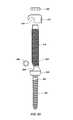
- FIG. 1is an exploded perspective view of a mono-axial embodiment of the present disclosure
- FIG. 2is an exploded front view of the embodiment of FIG. 1 ;
- FIG. 3is an exploded side view of the embodiment of FIG. 1 ;
- FIG. 4is a cross-sectional view of a mono-axial pedicle screw of the embodiment of FIG. 1 ;
- FIG. 5is a top view of a cap of the embodiment of FIG. 1 ;
- FIG. 5 ais a side view of the cap if the embodiment of FIG. 1 ;
- FIG. 6is an assembled perspective view of the embodiment of FIG. 1 ;
- FIG. 7is an assembled front view of the embodiment of FIG. 1 ;
- FIG. 8is an assembled side view of the embodiment of FIG. 1 ;
- FIG. 9is an assembled, cross-sectional side view of the embodiment of FIG. 1 ;
- FIG. 10is an assembled perspective view of the embodiment of FIG. 1 , as illustrated in FIG. 9 , shown without an alignment rod;
- FIG. 11is an assembled side view of the embodiment of FIG. 1 without an alignment rod
- FIG. 12is a perspective view of an inner rod of the embodiment of FIG. 1 ;
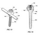
- FIG. 13is an assembled side view of the embodiment of FIG. 1 without an extension shaft
- FIG. 14is an assembled, cross-sectional side view of the embodiment of FIG. 1 without an extension shaft;
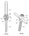
- FIG. 15is an exploded side view of a poly-axial embodiment of the present disclosure.
- FIG. 16is an exploded cross-sectional view of the embodiment of FIG. 15 ;
- FIG. 17is an assembled cross-sectional view of the embodiment of FIG. 15 ;
- FIG. 18is an assembled front view of the embodiment of FIG. 15 ;
- FIG. 19is an assembled perspective view of the embodiment of FIG. 15 ;
- FIG. 20is an assembled side view of the embodiment of FIG. 15 ;
- FIG. 21is an exploded perspective view of the embodiment of FIG. 15 , including a cap and an alignment rod;
- FIG. 22is an exploded front view of the embodiment of FIG. 21 and as illustrated in FIG. 21 ;
- FIG. 23is an exploded side view of the embodiment of FIG. 21 ;
- FIG. 24is an assembled, perspective view of the embodiment of FIG. 21 ;
- FIG. 25is an assembled cross-sectional view of the embodiment of FIG. 21 ;
- FIG. 26is an assembled perspective view of the embodiment of FIG. 21 without an extension shaft
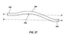
- FIG. 27is an embodiment of a contoured alignment rod
- FIG. 28is top view of an embodiment of the disclosed spine alignment system
- FIG. 29is top view of the embodiment of FIG. 28 before alignment rods are secured
- FIG. 30is an exploded view of the embodiment of FIG. 28 ;
- FIG. 31is a partially assembled view of the embodiment of FIG. 28 ;
- FIG. 32is a further assembled view of view of the embodiment of FIG. 28 ;
- FIG. 33is side view of a fully assembled embodiment of FIG. 28 .
- Applicanthas discovered a novel apparatus and method for aligning, stabilizing and securing adjacent spinal vertebrae using a spine alignment system utilizing side loading and incremental reduction of adjacent spinal vertebrae to an alignment rod. This means that an alignment rod can be captured into a side of the a corresponding pedicle screw, as opposed to capturing the alignment rod on top of the pedicle screw.
- FIGS. 1-14illustrate an spine alignment system 100 according to a first embodiment of the current disclosure.
- the spine alignment system 100includes a mono-axial, or fixed axis, pedicle screw 102 .
- the pedicle screw 102includes a threaded shaft 104 which facilitates insertion and fixation into the bony pedicle of a vertebral body.
- the threaded shaft 104may have a fixed or tapered diameter, with single or multiple start threads which may be spaced between 1 mm and 3 mm apart, for example.
- the pedicle screw 102includes a head 106 having a generally conical shape.
- the head 106includes an approximately C-shaped cut-out portion 108 , or slot, located substantially on a side of the head 106 .
- the slot 108includes a longitudinal axis that is substantially perpendicular to the longitudinal axis of the pedicle screw 102 .
- the conical shape of the head 106converts to a cylindrical shape above the slot 108 , resulting in a cylindrical portion 110 .
- the cylindrical portion 110includes an exterior thread configured to receive a locking nut 112 .
- the cylindrical portion 110 of the head 106can also include a key slot 114 configured to receive a key 116 of an extension shaft 118 .
- the extension shaft 118includes external threads that are formed to match the threads on the cylindrical portion 110 of the head 106 .
- the threads of the extension shaft 118will perfectly match the threads of the cylindrical portion 110 of the head 106 , such that the locking nut 112 can threadedly engage the extension shaft 118 and the cylindrical portion 110 of the head 106 .
- An inner rod 120is substantially cylindrical in shape and is configured to be received within a longitudinal through-hole 122 in the extension rod 118 , as shown in FIG. 10 .
- the inner rod 120includes a threaded distal end 124 and a stepped portion 126 near the proximal portion of the inner rod 120 .
- the threaded distal end 124is configured to threadedly engage a threaded bore 128 within the head 106 of the pedicle screw 102 .
- the stepped portion 126 of the inner rod 120is configured to abut against the proximal end of the extension shaft 118 , which thereby secures the extension shaft 118 to the head 106 of the pedicle screw 102 .
- the extension shaft 118can be integrated with the head 106 of the pedicle crew 102 with a fracture groove cut into a distal end of the extension shaft 118 , which can enable the extension shaft 118 to break-away from the head 106 of the pedicle screw 102 after installation of the spine alignment system 100 .
- the inner rod 120includes a head 130 , which can be configured to receive a drill attachment, or manual driver attachment, which can help facilitate the driving or screwing of the pedicle screw 102 into the bony pedicle of a vertebra.
- the extension shaft 118is configured to receive a cap 132 .
- the cap 132includes an oblong through-hole 134 that includes a substantially flat side surface 136 that is configured to lie flat against a flat side surface 138 of the extension shaft 118 .
- the extension shaft 118includes a pair of opposing flat side surfaces 138 , one of the pair of flat surfaces 138 faces the same direction as the slot 108 of the pedicle screw 102 . These flat side surfaces 138 serve as a guide for the cap 132 after capturing an alignment rod 140 and translating down the length of the extension shaft 118 .
- the alignment rod 140is captured by the cap 132 within an approximately C-shaped cutout 142 , or slot, that is formed and dimensioned to substantially the same diameter as the alignment rod 140 .
- One of the pair of flat surfaces 138engages the alignment rod 140 , pressing against the alignment rod 140 while the alignment rod is engaged within the slot 142 , helping secure the alignment rod 140 in place during axial translation of the cap 132 .
- the opposing flat surface 138 of the extension shaftwill engage the flat surface 136 within the cap 132 , creating substantially co-planar contact between the two surfaces resulting a rotationally locked engagement, helping to prevent unwanted rotation of the cap 132 during axial translation down the extension shaft 118 .
- the cap 132may also be configured to form the slot 142 with an arc length angle of ⁇ , where ⁇ may be greater than 180 degrees.
- the slot 142 having an arc length angle of greater that 180 degreesenables the slot to receive the alignment rod 140 with a snap-fit engagement.
- the small flexibility of the cap materialallows the slot 142 to deform enough to allow the alignment rod to be received therein, then retain the alignment rod 140 within the slot 140 .
- Alternative cap embodimentsmay also include a slot having an arc length angle that is 180 degree, or less than 180 degrees.
- a surgeon or userwill insert and secure the pedicle screw 102 , with the adjoined extension shaft 118 , to the bony pedicle of a desired vertebra. Once the pedicle screw 102 is secured, the surgeon or user can then place the cap 132 onto the proximal portion of the extension shaft 118 .
- the surgeoncan then capture the alignment rod 140 with the slot 142 of the cap 132 .
- the cap 132can then carry the alignment rod 140 down the length of the extension shaft 118 until the alignment rod 140 is captured and secured between the slot 142 of the cap 132 and the slot 108 of the head 106 of the pedicle screw 102 .
- the cap 132is pushed down the length of the extension shaft 118 by the locking nut 112 .
- the locking nut 112is threadedly engaged with the extension shaft 118 above the cap 132 , such that as the surgeon drives the locking nut 112 , the locking nut 112 pushes the cap 132 toward the head 106 of the pedicle screw 102 .
- the surgeoncan then drive the locking nut 112 until the cap 132 secures the alignment rod 140 to the head 106 .
- the slot 142 of the cap 132 and the slot 108 of the head 106 of the pedicle screw 102will surround the circumference of the alignment rod, although not fully, enough to prevent the alignment rod 140 from breaking away from the pedicle screw 102 in a lateral direction.
- the cap 132deforms around the slot 142 as the nut 112 tightens the cap 132 against the head 106 of the pedicle screw 102 . Due to the deformation of the cap 132 , the cap 132 cannot be used again after it has been fully secured to the head.
- the cylindrical portion 110 of the head 106has sufficient length to accommodate both the cap 132 and the locking nut 112 when fully secured, such that, the extension shaft 118 can then be removed from engagement with the pedicle screw 102 .
- the extension shaft 118can then be disengaged from the pedicle screw 102 by unscrewing the inner rod 120 from the threaded bore 128 within the head 106 of the pedicle screw 102 , which will then release the extension shaft 118 from engagement with the pedicle screw 102 .
- Multiple spine alignment systems 100can be secured to corresponding vertebra that a surgeon is attempting to set in alignment. Once all of the desired pedicle screws 102 are secured to the corresponding vertebra, caps 132 capturing the alignment rod 140 can be incrementally translated down their corresponding extension shafts 118 until the alignment rod 140 is secured to each of the heads 106 of the pedicle screws 102 .
- This incremental translation of the caps 132 and alignment rod 140can provide load sharing across the entire series of pedicle screws 102 , decreasing the stress at individual bone-screw interfaces. Additionally, the incremental securement of the alignment rod 140 to the pedicle screws 102 can serve as a reduction tool, bringing all of the desired vertebrae into alignment with the alignment rod 140 , thereby reducing the number of tools and steps during a surgical procedure.
- Another advantage of the spine alignment systemis that a surgeon can drive the pedicle screw 102 and the locking nut 112 with a powered driving instrument, thus removing the need for manual and often laborious tightening and alignment of the alignment rod 140 to the corresponding pedicle screws 102 . It will be appreciated that the use of a powered driving instrument, whatever the source of the power, can greatly improve the efficiency of the surgical procedure and thus beneficially reduce the time required to complete the procedure.
- FIGS. 15-26illustrate another embodiment of a spine alignment system 200 of the current disclosure.
- FIGS. 15-20illustrate a pedicle screw 202 and extension shaft 218 assembly of the spine alignment system 200 .
- the spine alignment system 200includes a poly-axial, pedicle screw 202 .
- the pedicle screw 202includes a threaded shaft which facilitates insertion and fixation into the bony pedicle of a vertebral body.
- the threaded shaft 204may have a fixed or tapered diameter, with single or multiple start threads which may be spaced from about 1 mm to about 3 mm apart, for example.
- the pedicle screw 102includes a head 206 having a generally spherical shape.
- the head 206is configured to receive a collet 207 .
- the colletis also configured to be received within the bottom, or distal end, of the extension shaft 218 .
- the collet 207includes an approximately C-shaped cut-out portion 208 , or slot, located substantially on a side of the collet 206 .
- the slot 208includes a longitudinal axis that is substantially perpendicular to the longitudinal axis of the pedicle screw 202 .
- the collet 207includes a conical-shaped receiving bore 209 that is configured to receive the head 206 of the pedicle screw 202 .
- the collet 207includes a cylindrical portion 210 above, or proximal to, the receiving bore 209 .
- the cylindrical portion 210includes the slot 208 in a side portion thereof.
- the spine alignment system 200also includes a spindle 212 that includes a threaded distal end 214 and a proximal head 216 .
- the collet 207includes an interior threaded surface 220 within the cylindrical portion 210 .
- the interior threaded surface 220is configured to threadedly engage with the threaded distal end 214 of the spindle 212 .
- the pedicle screw 202can be inserted and secured to the bony pedicle of a desired vertebrae. Then the collet 207 can be placed over the head 206 of the pedicle screw 202 . The collet 207 can then be inserted into the distal end of the extension shaft 218 . The spindle 212 can then be inserted into the proximal end of the extension shaft 118 until the spindle 212 is threadedly engaged with the collet 207 .
- the spindle 212can rest against an interior flange 222 of the extension shaft 218 such that as the spindle 212 drives into the collet 207 , the collet 207 is pulled further and further into the extension shaft 218 until the cylindrical portion 210 of the collet 207 abuts the interior flange 222 , opposite to the spindle 212 .
- the head 216 of the spindle 212is configured to receive and be driven by a power or manual driver.
- the receiving bore 209is tightened by contact with the distal end of the extension shaft 218 .
- the receiving bore 209is rigidly secured to the head 206 of the pedicle screw 202 , such that the pedicle screw will not be able to translate or rotate with respect to the collet 207 .
- the extension shaft 218also includes a head 224 having a generally conical shape.
- the head 206includes an approximately C-shaped cut-out portion 226 , or slot, located substantially on a side of the head 224 .
- the slot 226includes a longitudinal axis that is substantially perpendicular to the longitudinal axis of the pedicle screw 202 .
- the slot 226is substantially coaxial with slot 208 of the collet 207 when fully assembled.
- the conical shape of the head 224transitions to a cylindrical shape above the slot 226 , resulting in a cylindrical portion 228 .
- the cylindrical portion 228includes an exterior thread configured to receive a locking nut 230 .
- the extension shaft 218includes external threads that are formed to match the threads on the cylindrical portion 228 of the head 224 such that the locking nut 230 can threadedly engage the extension shaft 218 and the cylindrical portion 228 of the head 224 .
- the extension shaft 118can be integrated with the head 224 with a fracture groove cut 223 between the extension shaft 218 and the head 224 , which can enable the extension shaft 218 to break-away from the head 224 after installation of the spine alignment system 200 .
- the extension shaft 218is configured to receive a cap 232 .
- the cap 232includes an approximately shaped oblong through hole 234 , substantially similar as that provided in cap 132 discussed above, which includes a substantially flat side surface 236 that is configured to lie flat against a flat side surface 238 of the extension shaft 218 .
- the extension shaft 218includes a pair of opposing flat side surfaces 238 , one of the pair of flat surfaces 238 faces the same direction as the slot 226 of the head 224 . These flat side surfaces 238 serve as a guide for the cap 232 after capturing an alignment rod 240 and translating down the length of the extension shaft 218 .
- the alignment rod 240is captured by the cap 232 within an approximately C-shaped cutout 242 , or slot, which is formed and dimensioned to substantially the same diameter as the alignment rod 240 so as to securely capture the alignment rod 240 .
- One of the pair of flat surfaces 238engages the alignment rod 240 , helping secure the alignment rod 240 in place during axial translation of the cap 232 and the opposing flat surface 238 can engage the flat surface 236 within the cap 232 , helping to prevent unwanted rotation of the cap 232 during axial translation down the extension shaft 218 .
- a surgeon or usercan place the cap 232 onto the proximal portion of the extension shaft 218 . After the cap 232 is engaged to the extension shaft 218 , the surgeon can then capture the alignment rod 240 with the slot 242 of the cap 232 . The cap 232 can then carry the alignment rod 240 down the length of the extension shaft 218 until the alignment rod 240 is captured and secured between the slot 242 of the cap 232 and the slot 226 of the head 224 .
- the cap 232can be pushed down the length of the extension shaft 218 by the locking nut 230 .
- the locking nut 230is threadedly engaged with the extension shaft 218 above the cap 232 , such that as the surgeon drives the locking nut 230 , the locking nut 230 pushes the cap 232 toward the head 224 .
- the surgeoncan then drive the locking screw until the cap 232 secures the alignment rod 240 to the head 224 .
- the slot 242 of the cap 232 and the slot 226 of the head 224will surround the circumference of the alignment rod 240 , although not fully, enough to prevent the alignment rod 240 from breaking away from the pedicle screw 202 in a lateral direction.
- the cylindrical portion 228 of the head 224has sufficient length to accommodate both the cap 232 and the locking nut 230 when fully secured, such that, the extension shaft 218 can then be removed or broken from engagement with the head 224 , as shown in FIG. 26 .
- multiple spine alignment systems 200can be secured to corresponding vertebra that a surgeon is attempting to set in alignment. Once all of the desired pedicle screws 202 are secured to the corresponding vertebra and corresponding extension shafts 218 are secured to the pedicle screws 202 , caps 232 capturing the alignment rod 240 can be incrementally translated down their corresponding extension shafts 218 until the alignment rod 240 is secured to each of the heads 224 and pedicle screws 202 . This incremental translation of the caps 232 and alignment rod 240 can provide load sharing across the entire series of pedicle screws 202 , decreasing the stress at individual bone-screw interfaces.
- the incremental securement of the alignment rod 240 to the pedicle screws 202can serve as a reduction tool, bringing all of the desired vertebrae into alignment with the alignment rod 240 , thereby reducing the number of tools, steps and duration of a surgical procedure.
- Another exemplary advantage of the spine alignment system 200is that a surgeon can drive the pedicle screw 202 , spindle 212 , and the locking nut 230 with a power driven instrument, thus removing the need for manual and often laborious tightening and alignment of the alignment rod 240 to the corresponding pedicle screws 202 .
- an alignment rod 300can be contoured.
- the alignment rod 300is not linear, having a first end 302 and a second end 304 , where the first end 302 and the second end 304 are not co-linear. Instead, the alignment rod 300 is contoured, having at least one curvature 306 . In alternative embodiments the alignment rod 306 may include any desired number of curvatures, having varying or identical dimensions.
- a longitudinal axis A of the first end 302is not coaxial with the longitudinal axis B of the second end 304 .
- the longitudinal axis Amay be substantially parallel to the Longitudinal axis B, as shown in FIG. 27 , or the longitudinal axis A may intersect with the longitudinal axis B.
- the curvature 306can be of custom size and dimension depending on the specific needs of the patient. For example, a surgeon can decide that the alignment of a spine should occur in multiple stages, thus utilizing the contoured alignment rod 300 can be a beneficial intermediate step toward straightening the alignment of a spine.
- Each of the components of the spine alignment systems 100 and 200can be fabricated from titanium or a titanium alloy, cobalt chrome, or stainless steel or other materials known to those skilled in the art.
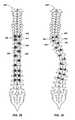
- FIGS. 28-33illustrate how multiple spine alignment systems 100 can be secured to corresponding vertebra 402 of a spine 400 that a surgeon is attempting to align.
- Systems 100are identified by references numerals in only a representative number, however, it can be assumed that the systems or other corresponding elements that are not specifically identified by a reference numeral, are identical or substantially similar to the corresponding enumerated elements.
- each of the pedicle screws 102are first secured to corresponding vertebra 402 .
- caps 132can be used to capture and secure the alignment rod 140 .
- the caps 132can be incrementally translated down their corresponding extension shafts 118 until the alignment rod 300 is secured to each of the heads 106 of the pedicle screws 102 .
- a surgeon or usercan insert and secure the pedicle screws 102 (included in system 100 ), with the adjoined extension shaft 118 , to the bony pedicle of a desired vertebra 402 . Once the pedicle screw 102 is secured, the surgeon can then place the cap 132 onto the proximal portion of the extension shaft 118 .
- the surgeon or usercan then capture the alignment rod 140 with the slot 142 of the cap 132 , as discussed in more detail previously.
- the cap 132can then carry the alignment rod 300 down the length of the extension shaft 118 until the alignment rod 300 is captured and secured between the slot 142 of the cap 132 and the slot 108 of the head 106 of the pedicle screw 102 , as discussed above.
- the series of caps 132are incrementally translated down the length of the extension shafts 118 by corresponding locking nuts 112 .
- the locking nuts 112are threadedly engaged with the extension shafts 118 above the caps 132 , such that as the surgeon drives the locking nuts 112 , the locking nuts 112 push the cap 132 toward the head 106 of the pedicle screw 102 .
- the surgeoncan then drive the locking nuts 112 until the caps 132 secure the alignment rod 300 to the heads 106 of the pedicle screws 102 .
- the extension shafts 118can then be removed from engagement with the pedicle screw 102 , as discussed in more detail above.
- the incremental translation of the caps 132 and alignment rods 300can provide load sharing across the entire series of pedicle screws 102 , decreasing the stress at individual bone-screw interfaces. Additionally, the incremental securement of the alignment rod 140 to the corresponding pedicle screws 102 can serve as a reduction tool, as shown in FIG. 28 , bringing all of the desired vertebrae into alignment with the alignment rod 300 , thereby reducing the number of tools and steps during a surgical procedure. As also shown in FIG. 28 , two alignment rods 300 can be used, substantially parallel to one another and also parallel with the aligned spine 400 , to provide sufficient support for the aligned spine 400 and reduce the stress on any specific vertebra 402 or side of the vertebra 402 .
- Another advantage of the spine alignment systemis that a surgeon can drive the pedicle screw 102 and the locking nut 112 with a powered driving instrument, thus removing the need for manual and often laborious tightening and alignment of the alignment rod 140 to the corresponding pedicle screws 102 . It will be appreciated that the use of a such a driver, whatever the source of the power, can greatly improve the efficiency of the surgical procedure and thus beneficially reduce the time required to complete the procedure.
- the disclosed spine alignment systemoccurs during use with patients that have a substantial amount of fat around the area of the spine 400 .
- the disclosed spine alignment systemprovides that the extension shafts 118 extend well above the spine 400 allowing the surgeon to readily manipulate the vertebrae 402 and the alignment rod 300 in such patients which increases the ease and efficiency which a surgeon can secure the spine alignment system in place with respect to the spine 400 .
Landscapes
- Health & Medical Sciences (AREA)
- Orthopedic Medicine & Surgery (AREA)
- Neurology (AREA)
- Life Sciences & Earth Sciences (AREA)
- Surgery (AREA)
- Heart & Thoracic Surgery (AREA)
- Engineering & Computer Science (AREA)
- Biomedical Technology (AREA)
- Nuclear Medicine, Radiotherapy & Molecular Imaging (AREA)
- Medical Informatics (AREA)
- Molecular Biology (AREA)
- Animal Behavior & Ethology (AREA)
- General Health & Medical Sciences (AREA)
- Public Health (AREA)
- Veterinary Medicine (AREA)
- Surgical Instruments (AREA)
Abstract
Description
This application claims the benefit of U.S. Provisional Application No. 62/089,725, filed Dec. 9, 2014, and U.S. Provisional Application No. 62/180,870, filed Jun. 17, 2015, which are hereby incorporated by reference herein in their entirety, including but not limited to those portions that specifically appear hereinafter, the incorporation by reference being made with the following exception: in the event that any portion of the above-referenced applications are inconsistent with this application, this application supercedes said above-referenced applications.
The Field of the Present Disclosure
The present disclosure relates generally to spinal alignment and stabilization devices.
Description of Related Art
Curvature and deformities of the spine impact many people and can have serious, and even life-threatening, health consequences. Beneficially, curvature and deformities of the spine can often be treated various procedures, including spinal fusion surgery, which permanently connects two or more vertebrae in a spine, eliminating motion between them. This type of spinal fusion can improve stability of the spine while also correcting deformities, reducing pain and improving the life qualify of a patient. Spinal fusion often involves placing a bone graft in the space between two spinal vertebrae.
A surgeon may use plates, screws or rods to hold the vertebrae and graft in place to promote healing after spinal fusion. Once the bone graft heals, the vertebrae are permanently connected.
Bony anchors or screws are commonly used to secure the vertebrae to a longitudinal alignment rod. These may connect multiple level anchors. Typically, two alignment rods are utilized between each level, one on each side of the spinous process. However, conventional spine alignment devices are characterized by being overly complex, needing numerous individual parts and tools for assembly and installation.
Conventional alignment devices are thus characterized by several disadvantages that are addressed by the present disclosure. The present disclosure minimizes, and in some aspects eliminates, the above-mentioned failures, and other problems, by utilizing the methods and structural features described herein.
The features and advantages of the present disclosure will be set forth in the description which follows, and in part will be apparent from the description, or may be learned by the practice of the present disclosure without undue experimentation. The features and advantages of the present disclosure may be realized and obtained by means of the instruments and combinations particularly pointed out in the appended claims. An understanding of the present disclosure will provide an appreciation of the unique and beneficial combination of the engineering sciences and the medical sciences which result in heretofore unavailable advantages.
The features and advantages of the disclosure will become apparent from a consideration of the subsequent detailed description presented in connection with the accompanying drawings in which:
For the purposes of promoting an understanding of the principles in accordance with the disclosure, reference will now be made to the embodiments illustrated in the drawings and specific language will be used to describe the same. It will nevertheless be understood that no limitation of the scope of the disclosure is thereby intended. Any alterations and further modifications of the inventive features illustrated herein, and any additional applications of the principles of the disclosure as illustrated herein, which would normally occur to one skilled in the relevant art and having possession of this disclosure, are to be considered within the scope of the disclosure claimed.
It must be noted that, as used in this specification and the appended claims, the singular forms “a,” “an,” and “the” include plural referents unless the context clearly dictates otherwise.
In describing and claiming the present disclosure, the following terminology will be used in accordance with the definitions set out below.
As used herein, the terms “comprising,” “including,” “containing,” “characterized by,” and grammatical equivalents thereof are inclusive or open-ended terms that do not exclude additional, unrecited elements or method steps.
Applicant has discovered a novel apparatus and method for aligning, stabilizing and securing adjacent spinal vertebrae using a spine alignment system utilizing side loading and incremental reduction of adjacent spinal vertebrae to an alignment rod. This means that an alignment rod can be captured into a side of the a corresponding pedicle screw, as opposed to capturing the alignment rod on top of the pedicle screw.
Thepedicle screw 102 includes ahead 106 having a generally conical shape. Thehead 106 includes an approximately C-shaped cut-outportion 108, or slot, located substantially on a side of thehead 106. Theslot 108 includes a longitudinal axis that is substantially perpendicular to the longitudinal axis of thepedicle screw 102. The conical shape of thehead 106 converts to a cylindrical shape above theslot 108, resulting in acylindrical portion 110. Thecylindrical portion 110 includes an exterior thread configured to receive a lockingnut 112.
Thecylindrical portion 110 of thehead 106 can also include akey slot 114 configured to receive a key116 of anextension shaft 118. Theextension shaft 118 includes external threads that are formed to match the threads on thecylindrical portion 110 of thehead 106. When the key116 of theextension shaft 118 is received into thekey slot 114, the threads of theextension shaft 118 will perfectly match the threads of thecylindrical portion 110 of thehead 106, such that the lockingnut 112 can threadedly engage theextension shaft 118 and thecylindrical portion 110 of thehead 106.
Aninner rod 120 is substantially cylindrical in shape and is configured to be received within a longitudinal through-hole 122 in theextension rod 118, as shown inFIG. 10 . Theinner rod 120 includes a threadeddistal end 124 and a steppedportion 126 near the proximal portion of theinner rod 120. The threadeddistal end 124 is configured to threadedly engage a threadedbore 128 within thehead 106 of thepedicle screw 102. The steppedportion 126 of theinner rod 120 is configured to abut against the proximal end of theextension shaft 118, which thereby secures theextension shaft 118 to thehead 106 of thepedicle screw 102.
In another embodiment, theextension shaft 118 can be integrated with thehead 106 of thepedicle crew 102 with a fracture groove cut into a distal end of theextension shaft 118, which can enable theextension shaft 118 to break-away from thehead 106 of thepedicle screw 102 after installation of thespine alignment system 100.
Once theinner rod 120 has secured theextension shaft 118 to thepedicle screw 102, a surgeon or user can insert or screw thepedicle screw 102 into the bony pedicle of a vertebra. Theinner rod 120 includes ahead 130, which can be configured to receive a drill attachment, or manual driver attachment, which can help facilitate the driving or screwing of thepedicle screw 102 into the bony pedicle of a vertebra.
Theextension shaft 118 is configured to receive acap 132. Thecap 132 includes an oblong through-hole 134 that includes a substantiallyflat side surface 136 that is configured to lie flat against aflat side surface 138 of theextension shaft 118. Theextension shaft 118 includes a pair of opposing flat side surfaces138, one of the pair offlat surfaces 138 faces the same direction as theslot 108 of thepedicle screw 102. These flat side surfaces138 serve as a guide for thecap 132 after capturing analignment rod 140 and translating down the length of theextension shaft 118. Thealignment rod 140 is captured by thecap 132 within an approximately C-shapedcutout 142, or slot, that is formed and dimensioned to substantially the same diameter as thealignment rod 140.
One of the pair offlat surfaces 138 engages thealignment rod 140, pressing against thealignment rod 140 while the alignment rod is engaged within theslot 142, helping secure thealignment rod 140 in place during axial translation of thecap 132. The opposingflat surface 138 of the extension shaft will engage theflat surface 136 within thecap 132, creating substantially co-planar contact between the two surfaces resulting a rotationally locked engagement, helping to prevent unwanted rotation of thecap 132 during axial translation down theextension shaft 118.
Thecap 132 may also be configured to form theslot 142 with an arc length angle of θ, where θ may be greater than 180 degrees. Theslot 142 having an arc length angle of greater that 180 degrees enables the slot to receive thealignment rod 140 with a snap-fit engagement. The small flexibility of the cap material allows theslot 142 to deform enough to allow the alignment rod to be received therein, then retain thealignment rod 140 within theslot 140. Alternative cap embodiments may also include a slot having an arc length angle that is 180 degree, or less than 180 degrees.
During assembly and use, a surgeon or user will insert and secure thepedicle screw 102, with the adjoinedextension shaft 118, to the bony pedicle of a desired vertebra. Once thepedicle screw 102 is secured, the surgeon or user can then place thecap 132 onto the proximal portion of theextension shaft 118.
After thecap 132 is engaged to theextension shaft 118, the surgeon can then capture thealignment rod 140 with theslot 142 of thecap 132. Thecap 132 can then carry thealignment rod 140 down the length of theextension shaft 118 until thealignment rod 140 is captured and secured between theslot 142 of thecap 132 and theslot 108 of thehead 106 of thepedicle screw 102.
Thecap 132 is pushed down the length of theextension shaft 118 by the lockingnut 112. The lockingnut 112 is threadedly engaged with theextension shaft 118 above thecap 132, such that as the surgeon drives the lockingnut 112, the lockingnut 112 pushes thecap 132 toward thehead 106 of thepedicle screw 102. The surgeon can then drive the lockingnut 112 until thecap 132 secures thealignment rod 140 to thehead 106.
Once fully secured, as shown inFIGS. 6-9 , theslot 142 of thecap 132 and theslot 108 of thehead 106 of thepedicle screw 102 will surround the circumference of the alignment rod, although not fully, enough to prevent thealignment rod 140 from breaking away from thepedicle screw 102 in a lateral direction. In an embodiment, thecap 132 deforms around theslot 142 as thenut 112 tightens thecap 132 against thehead 106 of thepedicle screw 102. Due to the deformation of thecap 132, thecap 132 cannot be used again after it has been fully secured to the head.
Thecylindrical portion 110 of thehead 106 has sufficient length to accommodate both thecap 132 and the lockingnut 112 when fully secured, such that, theextension shaft 118 can then be removed from engagement with thepedicle screw 102.
As shown inFIGS. 13 and 14 , theextension shaft 118 can then be disengaged from thepedicle screw 102 by unscrewing theinner rod 120 from the threadedbore 128 within thehead 106 of thepedicle screw 102, which will then release theextension shaft 118 from engagement with thepedicle screw 102.
Multiplespine alignment systems 100 can be secured to corresponding vertebra that a surgeon is attempting to set in alignment. Once all of the desired pedicle screws102 are secured to the corresponding vertebra, caps132 capturing thealignment rod 140 can be incrementally translated down theircorresponding extension shafts 118 until thealignment rod 140 is secured to each of theheads 106 of the pedicle screws102.
This incremental translation of thecaps 132 andalignment rod 140 can provide load sharing across the entire series of pedicle screws102, decreasing the stress at individual bone-screw interfaces. Additionally, the incremental securement of thealignment rod 140 to the pedicle screws102 can serve as a reduction tool, bringing all of the desired vertebrae into alignment with thealignment rod 140, thereby reducing the number of tools and steps during a surgical procedure.
Another advantage of the spine alignment system is that a surgeon can drive thepedicle screw 102 and the lockingnut 112 with a powered driving instrument, thus removing the need for manual and often laborious tightening and alignment of thealignment rod 140 to the corresponding pedicle screws102. It will be appreciated that the use of a powered driving instrument, whatever the source of the power, can greatly improve the efficiency of the surgical procedure and thus beneficially reduce the time required to complete the procedure.
Thepedicle screw 102 includes ahead 206 having a generally spherical shape. Thehead 206 is configured to receive acollet 207. The collet is also configured to be received within the bottom, or distal end, of theextension shaft 218. Thecollet 207 includes an approximately C-shaped cut-outportion 208, or slot, located substantially on a side of thecollet 206. Theslot 208 includes a longitudinal axis that is substantially perpendicular to the longitudinal axis of thepedicle screw 202.
Thecollet 207 includes a conical-shaped receiving bore209 that is configured to receive thehead 206 of thepedicle screw 202. Thecollet 207 includes acylindrical portion 210 above, or proximal to, the receivingbore 209. Thecylindrical portion 210 includes theslot 208 in a side portion thereof.
Thespine alignment system 200 also includes aspindle 212 that includes a threadeddistal end 214 and aproximal head 216. As shown inFIG. 16 , thecollet 207 includes an interior threadedsurface 220 within thecylindrical portion 210. The interior threadedsurface 220 is configured to threadedly engage with the threadeddistal end 214 of thespindle 212.
During use and assembly, thepedicle screw 202 can be inserted and secured to the bony pedicle of a desired vertebrae. Then thecollet 207 can be placed over thehead 206 of thepedicle screw 202. Thecollet 207 can then be inserted into the distal end of theextension shaft 218. Thespindle 212 can then be inserted into the proximal end of theextension shaft 118 until thespindle 212 is threadedly engaged with thecollet 207.
As shown inFIG. 17 , thespindle 212 can rest against aninterior flange 222 of theextension shaft 218 such that as thespindle 212 drives into thecollet 207, thecollet 207 is pulled further and further into theextension shaft 218 until thecylindrical portion 210 of thecollet 207 abuts theinterior flange 222, opposite to thespindle 212. Thehead 216 of thespindle 212 is configured to receive and be driven by a power or manual driver.
As thecollet 207 is pulled into theextension shaft 218, the receivingbore 209 is tightened by contact with the distal end of theextension shaft 218. As the receiving bore209 is tightened, the receivingbore 209 is rigidly secured to thehead 206 of thepedicle screw 202, such that the pedicle screw will not be able to translate or rotate with respect to thecollet 207.
Theextension shaft 218 also includes ahead 224 having a generally conical shape. Thehead 206 includes an approximately C-shaped cut-outportion 226, or slot, located substantially on a side of thehead 224. Theslot 226 includes a longitudinal axis that is substantially perpendicular to the longitudinal axis of thepedicle screw 202. Theslot 226 is substantially coaxial withslot 208 of thecollet 207 when fully assembled. The conical shape of thehead 224 transitions to a cylindrical shape above theslot 226, resulting in acylindrical portion 228. Thecylindrical portion 228 includes an exterior thread configured to receive a lockingnut 230.
Theextension shaft 218 includes external threads that are formed to match the threads on thecylindrical portion 228 of thehead 224 such that the lockingnut 230 can threadedly engage theextension shaft 218 and thecylindrical portion 228 of thehead 224.
Theextension shaft 118 can be integrated with thehead 224 with a fracture groove cut223 between theextension shaft 218 and thehead 224, which can enable theextension shaft 218 to break-away from thehead 224 after installation of thespine alignment system 200.
As shown inFIGS. 21-25 , theextension shaft 218 is configured to receive acap 232. Thecap 232 includes an approximately shaped oblong through hole234, substantially similar as that provided incap 132 discussed above, which includes a substantiallyflat side surface 236 that is configured to lie flat against aflat side surface 238 of theextension shaft 218. Theextension shaft 218 includes a pair of opposing flat side surfaces238, one of the pair offlat surfaces 238 faces the same direction as theslot 226 of thehead 224. These flat side surfaces238 serve as a guide for thecap 232 after capturing analignment rod 240 and translating down the length of theextension shaft 218. Thealignment rod 240 is captured by thecap 232 within an approximately C-shapedcutout 242, or slot, which is formed and dimensioned to substantially the same diameter as thealignment rod 240 so as to securely capture thealignment rod 240.
One of the pair offlat surfaces 238 engages thealignment rod 240, helping secure thealignment rod 240 in place during axial translation of thecap 232 and the opposingflat surface 238 can engage theflat surface 236 within thecap 232, helping to prevent unwanted rotation of thecap 232 during axial translation down theextension shaft 218.
During assembly or use, a surgeon or user can place thecap 232 onto the proximal portion of theextension shaft 218. After thecap 232 is engaged to theextension shaft 218, the surgeon can then capture thealignment rod 240 with theslot 242 of thecap 232. Thecap 232 can then carry thealignment rod 240 down the length of theextension shaft 218 until thealignment rod 240 is captured and secured between theslot 242 of thecap 232 and theslot 226 of thehead 224.
Thecap 232 can be pushed down the length of theextension shaft 218 by the lockingnut 230. The lockingnut 230 is threadedly engaged with theextension shaft 218 above thecap 232, such that as the surgeon drives the lockingnut 230, the lockingnut 230 pushes thecap 232 toward thehead 224. The surgeon can then drive the locking screw until thecap 232 secures thealignment rod 240 to thehead 224. Once fulled secured, theslot 242 of thecap 232 and theslot 226 of thehead 224 will surround the circumference of thealignment rod 240, although not fully, enough to prevent thealignment rod 240 from breaking away from thepedicle screw 202 in a lateral direction. Thecylindrical portion 228 of thehead 224 has sufficient length to accommodate both thecap 232 and the lockingnut 230 when fully secured, such that, theextension shaft 218 can then be removed or broken from engagement with thehead 224, as shown inFIG. 26 .
In accordance with a beneficial methods in accordance with the present disclosure, multiplespine alignment systems 200 can be secured to corresponding vertebra that a surgeon is attempting to set in alignment. Once all of the desired pedicle screws202 are secured to the corresponding vertebra andcorresponding extension shafts 218 are secured to the pedicle screws202, caps232 capturing thealignment rod 240 can be incrementally translated down theircorresponding extension shafts 218 until thealignment rod 240 is secured to each of theheads 224 and pedicle screws202. This incremental translation of thecaps 232 andalignment rod 240 can provide load sharing across the entire series of pedicle screws202, decreasing the stress at individual bone-screw interfaces. Additionally, the incremental securement of thealignment rod 240 to the pedicle screws202 can serve as a reduction tool, bringing all of the desired vertebrae into alignment with thealignment rod 240, thereby reducing the number of tools, steps and duration of a surgical procedure.
Another exemplary advantage of thespine alignment system 200 is that a surgeon can drive thepedicle screw 202,spindle 212, and the lockingnut 230 with a power driven instrument, thus removing the need for manual and often laborious tightening and alignment of thealignment rod 240 to the corresponding pedicle screws202.
In an alternative embodiment, as shown inFIG. 27 , analignment rod 300 can be contoured. Thealignment rod 300 is not linear, having afirst end 302 and asecond end 304, where thefirst end 302 and thesecond end 304 are not co-linear. Instead, thealignment rod 300 is contoured, having at least onecurvature 306. In alternative embodiments thealignment rod 306 may include any desired number of curvatures, having varying or identical dimensions.
Additionally, a longitudinal axis A of thefirst end 302 is not coaxial with the longitudinal axis B of thesecond end 304. However, the longitudinal axis A may be substantially parallel to the Longitudinal axis B, as shown inFIG. 27 , or the longitudinal axis A may intersect with the longitudinal axis B.
Thecurvature 306 can be of custom size and dimension depending on the specific needs of the patient. For example, a surgeon can decide that the alignment of a spine should occur in multiple stages, thus utilizing the contouredalignment rod 300 can be a beneficial intermediate step toward straightening the alignment of a spine.
Each of the components of thespine alignment systems
As shown inFIG. 29 , each of the pedicle screws102 are first secured tocorresponding vertebra 402. As shown inFIG. 30-31 , caps132 can be used to capture and secure thealignment rod 140. As thealignment rod 300 is aligned and brought into contact with theextension shafts 118 of thesystems 100, thecaps 132 can be incrementally translated down theircorresponding extension shafts 118 until thealignment rod 300 is secured to each of theheads 106 of the pedicle screws102.
A surgeon or user can insert and secure the pedicle screws102 (included in system100), with the adjoinedextension shaft 118, to the bony pedicle of a desiredvertebra 402. Once thepedicle screw 102 is secured, the surgeon can then place thecap 132 onto the proximal portion of theextension shaft 118.
After thecap 132 is engaged to theextension shaft 118, the surgeon or user can then capture thealignment rod 140 with theslot 142 of thecap 132, as discussed in more detail previously. Thecap 132 can then carry thealignment rod 300 down the length of theextension shaft 118 until thealignment rod 300 is captured and secured between theslot 142 of thecap 132 and theslot 108 of thehead 106 of thepedicle screw 102, as discussed above.
The series ofcaps 132, included insystems 100 inFIGS. 28-33 , are incrementally translated down the length of theextension shafts 118 by corresponding locking nuts112. The lockingnuts 112 are threadedly engaged with theextension shafts 118 above thecaps 132, such that as the surgeon drives the lockingnuts 112, the lockingnuts 112 push thecap 132 toward thehead 106 of thepedicle screw 102. The surgeon can then drive the lockingnuts 112 until thecaps 132 secure thealignment rod 300 to theheads 106 of the pedicle screws102.
As shown inFIG. 33 , once thealignment rods 300 are fully secured, theextension shafts 118 can then be removed from engagement with thepedicle screw 102, as discussed in more detail above.
The incremental translation of thecaps 132 andalignment rods 300 can provide load sharing across the entire series of pedicle screws102, decreasing the stress at individual bone-screw interfaces. Additionally, the incremental securement of thealignment rod 140 to the corresponding pedicle screws102 can serve as a reduction tool, as shown inFIG. 28 , bringing all of the desired vertebrae into alignment with thealignment rod 300, thereby reducing the number of tools and steps during a surgical procedure. As also shown inFIG. 28 , twoalignment rods 300 can be used, substantially parallel to one another and also parallel with the alignedspine 400, to provide sufficient support for the alignedspine 400 and reduce the stress on anyspecific vertebra 402 or side of thevertebra 402.
Another advantage of the spine alignment system is that a surgeon can drive thepedicle screw 102 and the lockingnut 112 with a powered driving instrument, thus removing the need for manual and often laborious tightening and alignment of thealignment rod 140 to the corresponding pedicle screws102. It will be appreciated that the use of a such a driver, whatever the source of the power, can greatly improve the efficiency of the surgical procedure and thus beneficially reduce the time required to complete the procedure.
And yet another advantage of the disclosed spine alignment system occurs during use with patients that have a substantial amount of fat around the area of thespine 400. Conventionally, when dealing with such patients it can be very difficult for a surgeon to access and manipulate the components of a convention spine alignment system because of the depth of the spine with respect to the exterior of the patient's back, requiring a deeper access cavity to be cut into the patient's back. The disclosed spine alignment system, however, provides that theextension shafts 118 extend well above thespine 400 allowing the surgeon to readily manipulate thevertebrae 402 and thealignment rod 300 in such patients which increases the ease and efficiency which a surgeon can secure the spine alignment system in place with respect to thespine 400.
It is to be understood that the above-described arrangements are only illustrative of the application of the principles of the present disclosure. Numerous modifications and alternative arrangements may be devised by those skilled in the art without departing from the spirit and scope of the present disclosure are intended to cover such modifications and arrangements. Thus, while the present disclosure has been shown in the drawings and described above with particularity and detail, it will be apparent to those of ordinary skill in the art that numerous modifications, including, but not limited to, variations in size, materials, shape, form, function and manner of operation, assembly and use may be made without departing from the principles and concepts set forth herein.
Claims (38)
1. A spine alignment system, comprising:
a pedicle screw having a longitudinal axis, the pedicle screw having a screw head, wherein the screw head includes a slot having a longitudinal axis that is substantially perpendicular to the longitudinal axis of the pedicle screw, and a key slot also extending substantially perpendicular to the longitudinal axis of the pedicle screw;
an extension shaft secured to the pedicle screw, such that a longitudinal axis of the extension shaft is substantially coaxial with the longitudinal axis of the pedicle screw, wherein the extension shaft includes a key that is received within the key slot of the screw head, and the wherein the extension shaft is generally cylindrical in shape and includes at least one substantially flat exterior surface parallel with the longitudinal axis of the extension shaft;
a cap having a through-hole configured to receive the extension shaft, the through-hole having a longitudinal axis, wherein the cap includes a slot having a longitudinal axis that is substantially perpendicular to the longitudinal axis of the through-hole, and wherein the slot of the screw head and the slot of the cap, together, form a substantially cylindrical passage configured to receive an alignment rod; and,
a nut configured to receive the extension shaft and facilitate movement of the cap along the extension shaft.
2. The system ofclaim 1 , wherein the pedicle screw is mono-axial.
3. The system ofclaim 1 , wherein the head of the pedicle screw includes an exterior thread that threadedly engages the nut, wherein the nut secures the cap to the head of the pedicle screw.
4. The system ofclaim 1 , further comprising:
an alignment rod, wherein the alignment rod is received by the substantially cylindrical passage formed by the pedicle screw head and the cap, such that the alignment rod is laterally fixed within the substantially cylindrical passage.
5. The system ofclaim 4 , wherein the alignment rod is substantially linear.
6. The system ofclaim 4 , wherein the alignment rod is curved along a longitudinal axis.
7. The system ofclaim 4 , wherein the slot of the cap is configured to retain the alignment rod in a snap-fit engagement.
8. The system ofclaim 1 , wherein the cap includes a substantially planar surface within the through-hole.
9. The system ofclaim 8 , wherein the substantially planar surface of the cap is located on an opposite side of the through-hole from the slot of the cap.
10. The system ofclaim 1 , wherein the slot of the cap extends more than 180 degrees in circumference.
11. A spine alignment system, comprising:
a pedicle screw having a longitudinal axis, the pedicle screw having a screw head, wherein the screw head includes a slot having a longitudinal axis that is substantially perpendicular to the longitudinal axis of the pedicle screw, and a key slot also extending substantially perpendicular to the longitudinal axis of the pedicle screw;
an extension shaft secured to the pedicle screw, such that a longitudinal axis of the extension shaft is substantially coaxial with the longitudinal axis of the pedicle screw, wherein the extension shaft also includes a head, wherein the head includes a slot having a longitudinal axis that is substantially perpendicular to the longitudinal axis of the pedicle screw, wherein the extension shaft includes a key that is received within the key slot of the screw head, and wherein the extension shaft is generally cylindrical in shape and includes at least one substantially flat exterior surface parallel with the longitudinal axis of the extension shaft;
a cap having a through-hole configured to receive the extension shaft, the through-hole having a longitudinal axis, wherein the cap includes a slot having a longitudinal axis that is substantially perpendicular to the longitudinal axis of the through-hole, and wherein the slot of the head and the slot of the cap, together, form a substantially cylindrical passage configured to receive an alignment rod; and,
a nut configured to receive the extension shaft and facilitate movement of the cap along the extension shaft.
12. The system ofclaim 11 , wherein the head of the extension shaft includes a exterior thread that threadedly engages the nut, wherein the nut secures the cap to the head of the pedicle screw.
13. The system ofclaim 11 , wherein the pedicle screw is poly-axial.
14. The system ofclaim 11 , further comprising:
an alignment rod, wherein the alignment rod is received by the substantially cylindrical passage formed by the pedicle screw head and the cap, such that the alignment rod is laterally fixed within the substantially cylindrical passage.
15. The system ofclaim 14 , wherein the alignment rod is substantially linear.
16. The system ofclaim 14 , wherein the alignment rod is curved along a longitudinal axis.
17. The system ofclaim 14 , wherein the slot of the cap is configured to retain the alignment rod in a snap-fit engagement.
18. The system ofclaim 11 , wherein the cap includes a substantially planar surface within the through-hole.
19. The system ofclaim 18 , wherein the substantially planar surface of the cap is located on an opposite side of the through-hole from the slot of the cap.
20. The system ofclaim 11 , wherein the slot of the cap extends more than 180 degrees in circumference.
21. A method of assembling a spine alignment system, comprising:
securing a pedicle screw, having a head, to a bony pedicle of a vertebra, wherein the pedicle screw includes a key slot extending substantially perpendicular to a longitudinal axis of the pedicle screw;
securing an extension shaft to a pedicle screw, wherein the extension shaft includes a key that is received within the key slot of the screw head, and wherein the extension shaft is generally cylindrical in shape and includes at least one substantially flat exterior surface parallel with the longitudinal axis of the extension shaft;
engaging a cap about the extension shaft such that the cap can translate axially over a length of the extension shaft, the cap having a slot having a longitudinal axis that is substantially perpendicular to a longitudinal axis of the extension shaft when the cap is engaged with the extension shaft;
capturing an alignment rod with the slot of the cap;
incrementally translating the cap and alignment rod axially down the extension shaft; and,
securing the alignment rod to the pedicle screw such that the alignment rod cannot be moved laterally with respect to the pedicle screw.
22. The method ofclaim 21 , further comprising:
aligning a plurality of vertebra along the alignment rod as the alignment rod is incrementally translated down the extension shaft.
23. The method ofclaim 21 , wherein the head of the pedicle screw includes an exterior thread that threadedly engages a nut, wherein the nut secures the cap to the head of the pedicle screw.
24. The method ofclaim 21 , wherein the pedicle screw is poly-axial.
25. The method ofclaim 21 , wherein the alignment rod is substantially linear.
26. The method ofclaim 21 , wherein the alignment rod is curved along a longitudinal axis.
27. The method ofclaim 21 , wherein the pedicle screw is mono-axial.
28. A method of assembling a spine alignment system, comprising:
securing a pedicle screw, having a head, to a bony pedicle of a vertebra, wherein the pedicle screw includes a key slot extending substantially perpendicular to a longitudinal axis of the pedicle screw;
securing an extension shaft to a pedicle screw, wherein the extension shaft includes a key that is received within the key slot of the screw head, and wherein the extension shaft is generally cylindrical in shape and includes at least one substantially flat exterior surface parallel with the longitudinal axis of the extension shaft;
engaging an alignment rod with the extension shaft such that the alignment rod can translate over a length of the extension shaft,
incrementally translating alignment rod axially down the extension shaft; and,
securing the alignment rod to the pedicle screw such that the alignment rod cannot be moved laterally with respect to the pedicle screw.
29. The method ofclaim 28 , further comprising:
engaging a cap about the extension shaft such that the cap can translate axially over a length of the extension shaft, the cap having a slot having a longitudinal axis that is substantially perpendicular to a longitudinal axis of the extension shaft when the cap is engaged with the extension shaft; and
capturing the alignment rod with the slot of the cap.
30. The method ofclaim 29 , further comprising:
incrementally translating the cap and the alignment rod axially down the extension shaft.
31. The method ofclaim 29 , wherein the head of the pedicle screw includes an exterior thread that threadedly engages a nut, wherein the nut secures the cap to the head of the pedicle screw.
32. The method ofclaim 28 , further comprising:
aligning a plurality of vertebra along the alignment rod as the alignment rod is incrementally translated down the extension shaft.
33. The method ofclaim 28 , wherein securing of the pedicle screw and extension shaft is performed by a power driving instrument.
34. A spine alignment system, comprising:
a pedicle screw having a longitudinal axis, the pedicle screw having a screw head, wherein the screw head includes a slot having a longitudinal axis that is substantially perpendicular to the longitudinal axis of the pedicle screw, and the pedicle screw includes a key slot extending substantially perpendicular to a longitudinal axis of the pedicle screw;
an extension shaft secured to the pedicle screw, such that a longitudinal axis of the extension shaft is substantially coaxial with the longitudinal axis of the pedicle screw, wherein the extension shaft is detachable from the pedicle screw, and the extension shaft includes a key that is received within the key slot of the screw head, and wherein the extension shaft is generally cylindrical in shape and includes at least one substantially flat exterior surface parallel with the longitudinal axis of the extension shaft; and
an alignment rod configured to engage with the extension shaft such that the alignment rod is configured to translate axially along the extension shaft.
35. The system ofclaim 34 , further comprising:
a cap having a through-hole configured to receive the extension shaft, the through-hole having a longitudinal axis, wherein the cap includes a slot having a longitudinal axis that is substantially perpendicular to the longitudinal axis of the through-hole, and wherein the slot of the screw head and the slot of the cap, together, form a substantially cylindrical passage configured to receive the alignment rod.
36. The system ofclaim 35 , further comprising:
a nut configured to receive the extension shaft and facilitate movement of the cap along the extension shaft.
37. The system ofclaim 35 , wherein the alignment rod is received by the substantially cylindrical passage formed by the pedicle screw head and the cap, such that the alignment rod is laterally fixed within the substantially cylindrical passage.
38. The system ofclaim 34 , wherein the extension shaft is configured to receive a power driving instrument, to facilitate the powered driving of the extension shaft and the pedicle screw.
Priority Applications (4)
| Application Number | Priority Date | Filing Date | Title |
|---|---|---|---|
| US14/964,490US10034690B2 (en) | 2014-12-09 | 2015-12-09 | Spine alignment system |
| US16/049,244US10736668B2 (en) | 2014-12-09 | 2018-07-30 | Spine alignment system |
| US16/987,701US11419637B2 (en) | 2014-12-09 | 2020-08-07 | Spine alignment system |
| US17/870,672US20230059438A1 (en) | 2014-12-09 | 2022-07-21 | Spine alignment system |
Applications Claiming Priority (3)
| Application Number | Priority Date | Filing Date | Title |
|---|---|---|---|
| US201462089725P | 2014-12-09 | 2014-12-09 | |
| US201562180870P | 2015-06-17 | 2015-06-17 | |
| US14/964,490US10034690B2 (en) | 2014-12-09 | 2015-12-09 | Spine alignment system |
Related Child Applications (1)
| Application Number | Title | Priority Date | Filing Date |
|---|---|---|---|
| US16/049,244ContinuationUS10736668B2 (en) | 2014-12-09 | 2018-07-30 | Spine alignment system |
Publications (2)
| Publication Number | Publication Date |
|---|---|
| US20160183983A1 US20160183983A1 (en) | 2016-06-30 |
| US10034690B2true US10034690B2 (en) | 2018-07-31 |
Family
ID=56108367
Family Applications (4)
| Application Number | Title | Priority Date | Filing Date |
|---|---|---|---|
| US14/964,490ActiveUS10034690B2 (en) | 2014-12-09 | 2015-12-09 | Spine alignment system |
| US16/049,244ActiveUS10736668B2 (en) | 2014-12-09 | 2018-07-30 | Spine alignment system |
| US16/987,701ActiveUS11419637B2 (en) | 2014-12-09 | 2020-08-07 | Spine alignment system |
| US17/870,672PendingUS20230059438A1 (en) | 2014-12-09 | 2022-07-21 | Spine alignment system |
Family Applications After (3)
| Application Number | Title | Priority Date | Filing Date |
|---|---|---|---|
| US16/049,244ActiveUS10736668B2 (en) | 2014-12-09 | 2018-07-30 | Spine alignment system |
| US16/987,701ActiveUS11419637B2 (en) | 2014-12-09 | 2020-08-07 | Spine alignment system |
| US17/870,672PendingUS20230059438A1 (en) | 2014-12-09 | 2022-07-21 | Spine alignment system |
Country Status (4)
| Country | Link |
|---|---|
| US (4) | US10034690B2 (en) |
| EP (1) | EP3229714B1 (en) |
| CA (1) | CA3008161C (en) |
| WO (1) | WO2016094588A2 (en) |
Cited By (2)
| Publication number | Priority date | Publication date | Assignee | Title |
|---|---|---|---|---|
| US20180070987A1 (en)* | 2016-09-12 | 2018-03-15 | Wiltrom Co., Ltd. | Spinal surgical instrument, method of guiding thereof and system for bone stabilization |
| US10736668B2 (en) | 2014-12-09 | 2020-08-11 | John A. Heflin | Spine alignment system |
Families Citing this family (7)
| Publication number | Priority date | Publication date | Assignee | Title |
|---|---|---|---|---|
| WO2013040456A1 (en) | 2011-09-14 | 2013-03-21 | Band-Lok, Llc | Tether clamp and implantation system |
| FR3019981B1 (en)* | 2014-04-17 | 2020-12-11 | Medicrea Int | VERTEBRAL OSTEOSYNTHESIS MATERIAL |
| EP3490474A4 (en) | 2016-07-26 | 2019-08-28 | Band-lok, LLC | ORTHOPEDIC IMPLANTS. |
| FR3061648B1 (en)* | 2017-01-09 | 2021-01-08 | Kisco Int | BONE SCREW FOR OSTEOSYNTHESIS DEVICE, ASSEMBLY FORMED BY A SCREW, CONNECTOR AND NUT, AND KIT CONTAINING AT LEAST ONE SUCH ASSEMBLY |
| CN110353792B (en)* | 2019-07-24 | 2022-07-08 | 上海锐植医疗器械有限公司 | A multifunctional spinal internal fixation tool |
| CN111902098B (en)* | 2019-08-20 | 2023-09-01 | 董谢平 | Split dynamic and static two-purpose pedicle screw and mounting tool thereof |
| FR3124692B1 (en)* | 2021-07-01 | 2023-12-08 | Distimp | Bone anchoring screw for osteosynthesis device, surgical assembly for connecting said screw to said osteosynthesis device, and set of instruments for installing said surgical assembly. |
Citations (278)
| Publication number | Priority date | Publication date | Assignee | Title |
|---|---|---|---|---|
| AT135551B (en) | 1930-09-04 | 1933-11-25 | Oesterr Glasdachwerkstaette J | Plaster corner strip. |
| AT166217B (en) | 1946-04-26 | 1950-06-26 | Compound Electro Metals Ltd | Material for the manufacture of bearings, rotating seals, etc. like |
| AT169811B (en) | 1949-12-14 | 1951-12-27 | Unitherm Oesterreich Gmbh | Low-dispersion, iron-enclosed induction furnace |
| AT173600B (en) | 1948-01-09 | 1953-01-10 | Elin Ag Elek Ind Wien | Electrode sheathing parts for automatic arc welding |
| ES212421A1 (en) | 1953-11-28 | 1955-03-01 | Boge Gmbh | A telescope hydraulic shock absorber (Machine-translation by Google Translate, not legally binding) |
| AT185062B (en) | 1955-04-08 | 1956-03-26 | Richard Meier | Add-on furniture |
| US3788318A (en) | 1972-06-12 | 1974-01-29 | S Kim | Expandable cannular, especially for medical purposes |
| US3789852A (en) | 1972-06-12 | 1974-02-05 | S Kim | Expandable trochar, especially for medical purposes |
| US3892232A (en) | 1973-09-24 | 1975-07-01 | Alonzo J Neufeld | Method and apparatus for performing percutaneous bone surgery |
| US4083370A (en) | 1976-11-03 | 1978-04-11 | Taylor John D | Bloat relief tube and holder |
| SU839513A1 (en) | 1979-09-14 | 1981-06-23 | Центральный Ордена Трудовогокрасного Знамени Научно-Исследова-Тельский Институт Травматологии Иортопедии Им. H.H.Приорова | Device for guiding wires |
| US4350151A (en) | 1981-03-12 | 1982-09-21 | Lone Star Medical Products, Inc. | Expanding dilator |
| US4409968A (en) | 1980-02-04 | 1983-10-18 | Drummond Denis S | Method and apparatus for engaging a hook assembly to a spinal column |
| US4411259A (en) | 1980-02-04 | 1983-10-25 | Drummond Denis S | Apparatus for engaging a hook assembly to a spinal column |
| US4448191A (en) | 1981-07-07 | 1984-05-15 | Rodnyansky Lazar I | Implantable correctant of a spinal curvature and a method for treatment of a spinal curvature |
| US4449532A (en) | 1980-07-08 | 1984-05-22 | Karl Storz | Dilator to facilitate endoscope insertion into the body |
| US4474046A (en) | 1982-06-18 | 1984-10-02 | Zimmer, Inc. | Rod bender |
| DK441084A (en) | 1983-09-17 | 1985-03-18 | Bayer Ag | SOLUTIONS OF Lactic Acid SALTS OF PIPERAZINYL-QUINOLON AND PIPERAZINYL-AZAQUINOLON CARBOXYL ACIDS, THEIR PREPARATION AND USE |
| US4545374A (en) | 1982-09-03 | 1985-10-08 | Jacobson Robert E | Method and instruments for performing a percutaneous lumbar diskectomy |
| US4611581A (en) | 1983-12-16 | 1986-09-16 | Acromed Corporation | Apparatus for straightening spinal columns |
| US4653481A (en) | 1985-07-24 | 1987-03-31 | Howland Robert S | Advanced spine fixation system and method |
| DE3711091A1 (en) | 1987-04-02 | 1988-10-13 | Kluger Patrick | DEVICE FOR SETTING UP A SPINE WITH A DAMAGED SPINE |
| US4790297A (en) | 1987-07-24 | 1988-12-13 | Biotechnology, Inc. | Spinal fixation method and system |
| US4817587A (en) | 1987-08-31 | 1989-04-04 | Janese Woodrow W | Ring para-spinal retractor |
| US4862891A (en) | 1988-03-14 | 1989-09-05 | Canyon Medical Products | Device for sequential percutaneous dilation |
| US4887595A (en) | 1987-07-29 | 1989-12-19 | Acromed Corporation | Surgically implantable device for spinal columns |
| WO1989012431A1 (en) | 1988-06-13 | 1989-12-28 | Michelson Gary K | Threaded spinal implant |
| JPH0214927A (en) | 1988-07-01 | 1990-01-18 | Kubota Ltd | Four-wheel drive type farm working vehicle |
| US4899729A (en) | 1985-05-30 | 1990-02-13 | Gill Steven S | Expansible cannula |
| JPH0255167A (en) | 1988-08-22 | 1990-02-23 | Matsushita Electric Ind Co Ltd | printing device |
| US4913134A (en) | 1987-07-24 | 1990-04-03 | Biotechnology, Inc. | Spinal fixation system |
| EP0369603A1 (en) | 1988-10-17 | 1990-05-23 | Surgical Dynamics, Inc. | Fusion cage for bone joints |
| US5010879A (en) | 1989-03-31 | 1991-04-30 | Tanaka Medical Instrument Manufacturing Co. | Device for correcting spinal deformities |
| WO1991006261A1 (en) | 1989-11-06 | 1991-05-16 | Surgical Dynamics, Inc. | Surgical method and apparatus for fusing adjacent bone structures |
| US5027793A (en) | 1990-03-30 | 1991-07-02 | Boehringer Mannheim Corp. | Surgical retractor |
| CA2051408A1 (en) | 1990-02-08 | 1991-08-09 | Jean-Louis Vignaud | Multifunctional device for rachis osteosynthesis |
| WO1991016020A1 (en) | 1990-04-26 | 1991-10-31 | Danninger Medical Technology, Inc. | Transpedicular screw system and method of use |
| US5125396A (en) | 1990-10-05 | 1992-06-30 | Ray R Charles | Surgical retractor |
| NO921773L (en) | 1989-11-06 | 1992-07-03 | Surgical Dynamics Inc | SURGICAL PROCEDURE AND APPARATUS FOR ASSOCIATION WITH ADDITIONAL BONE STRUCTURES |
| US5129899A (en) | 1991-03-27 | 1992-07-14 | Smith & Nephew Richards Inc. | Bone fixation apparatus |
| CA2064277A1 (en) | 1991-03-27 | 1992-09-28 | Laura C. Small | Bone fixation apparatus |
| FR2677242A1 (en)* | 1991-06-05 | 1992-12-11 | Jeanson Jean Francois | Push-bar device for spinal support |
| US5171279A (en) | 1992-03-17 | 1992-12-15 | Danek Medical | Method for subcutaneous suprafascial pedicular internal fixation |
| JPH051507A (en) | 1991-06-25 | 1993-01-08 | Toshiba Corp | Pressure control device for combined cycle power plant |
| US5183464A (en) | 1991-05-17 | 1993-02-02 | Interventional Thermodynamics, Inc. | Radially expandable dilator |
| EP0528177A2 (en) | 1991-08-17 | 1993-02-24 | Aesculap Ag | Internal fixator for the correction of a lumbar spondyldisthesis |
| US5195541A (en) | 1991-10-18 | 1993-03-23 | Obenchain Theodore G | Method of performing laparoscopic lumbar discectomy |
| US5242443A (en) | 1991-08-15 | 1993-09-07 | Smith & Nephew Dyonics, Inc. | Percutaneous fixation of vertebrae |
| US5290288A (en) | 1990-02-08 | 1994-03-01 | Vignaud Jean Louis | Multi-function device for the osteosynthesis of rachis |
| US5295994A (en) | 1991-11-15 | 1994-03-22 | Bonutti Peter M | Active cannulas |
| USD346217S (en) | 1992-07-13 | 1994-04-19 | Acromed Corporation | Combined hook holder and rod mover for spinal surgery |
| WO1994009726A1 (en) | 1992-10-23 | 1994-05-11 | Smith & Nephew Richards Inc. | Internal fixators |
| DE4238339A1 (en) | 1992-11-13 | 1994-05-19 | Peter Brehm | Fastening screw for spinal column support rod - has hollow slotted head with female thread to accommodate grub-screw to firmly clamp rod in place |
| WO1994017759A1 (en) | 1993-02-10 | 1994-08-18 | Spine-Tech, Inc. | Spinal stabilization surgical tool set |
| US5373860A (en) | 1992-08-25 | 1994-12-20 | Catone; Guy A. | Apparatus for and method of contouring plates for bone fixation |
| US5395317A (en) | 1991-10-30 | 1995-03-07 | Smith & Nephew Dyonics, Inc. | Unilateral biportal percutaneous surgical procedure |
| US5409488A (en) | 1992-01-16 | 1995-04-25 | Ulrich; Heinrich | Spondylodesis implant |
| WO1995014437A1 (en) | 1993-11-25 | 1995-06-01 | Sofamor Danek Group, Inc. | Implant for an osteosynthesis device, particularly for the spine, and positioning instrument therefor |
| US5425490A (en) | 1994-01-18 | 1995-06-20 | Goble; E. Marlowe | Instrument with dual holding feature |
| US5425732A (en) | 1992-01-16 | 1995-06-20 | Ulrich; Heinrich | Implant for internal fixation, particularly spondylodesis implant |
| US5439464A (en) | 1993-03-09 | 1995-08-08 | Shapiro Partners Limited | Method and instruments for performing arthroscopic spinal surgery |
| US5464406A (en) | 1992-12-09 | 1995-11-07 | Ritter; Merrill A. | Instrumentation for revision surgery |
| US5480440A (en) | 1991-08-15 | 1996-01-02 | Smith & Nephew Richards, Inc. | Open surgical technique for vertebral fixation with subcutaneous fixators positioned between the skin and the lumbar fascia of a patient |
| US5484437A (en) | 1988-06-13 | 1996-01-16 | Michelson; Gary K. | Apparatus and method of inserting spinal implants |
| US5486176A (en) | 1991-03-27 | 1996-01-23 | Smith & Nephew Richards, Inc. | Angled bone fixation apparatus |
| US5490409A (en) | 1994-11-07 | 1996-02-13 | K-Medic, Inc. | Adjustable cam action rod bender for surgical rods |
| US5534001A (en)* | 1993-05-11 | 1996-07-09 | Synthes (U.S.A.) | Osteosynthetic fixation element and manipulation device |
| US5545228A (en) | 1991-08-15 | 1996-08-13 | Smith & Nephew Richards Inc. | Offset bone bolt |
| US5569290A (en) | 1995-01-30 | 1996-10-29 | Paul C. McAfee | Method of and apparatus for laparoscopic or endoscopic spinal surgery using an unsealed anteriorly inserted transparent trochar |
| US5591165A (en) | 1992-11-09 | 1997-01-07 | Sofamor, S.N.C. | Apparatus and method for spinal fixation and correction of spinal deformities |
| US5593409A (en) | 1988-06-13 | 1997-01-14 | Sofamor Danek Group, Inc. | Interbody spinal fusion implants |
| US5601590A (en) | 1993-02-04 | 1997-02-11 | General Surgical Innovations, Inc. | Expandable cannulas |
| WO1997007743A1 (en) | 1995-08-25 | 1997-03-06 | Grotz R Thomas | Stabilizer for human joints |
| WO1997014457A1 (en) | 1995-10-18 | 1997-04-24 | Stouder Albert E Jr | Adjustable length cannula and trocar |
| US5658286A (en) | 1996-02-05 | 1997-08-19 | Sava; Garard A. | Fabrication of implantable bone fixation elements |
| DE29710979U1 (en) | 1997-06-24 | 1997-08-21 | Aesculap AG & Co. KG, 78532 Tuttlingen | Implant for fixing bone parts and tool for this implant |
| JP2551670Y2 (en) | 1992-12-29 | 1997-10-27 | 株式会社オーエス | Projection screen equipment |
| JP2554298Y2 (en) | 1991-04-23 | 1997-11-17 | 東亞医用電子株式会社 | Liquid temperature controller |
| US5720751A (en) | 1996-11-27 | 1998-02-24 | Jackson; Roger P. | Tools for use in seating spinal rods in open ended implants |
| US5741261A (en) | 1996-06-25 | 1998-04-21 | Sdgi Holdings, Inc. | Minimally invasive spinal surgical methods and instruments |
| US5746720A (en) | 1995-10-18 | 1998-05-05 | Stouder, Jr.; Albert E. | Method and apparatus for insertion of a cannula and trocar |
| WO1998022030A1 (en) | 1996-11-18 | 1998-05-28 | University Of Massachusetts | Systems, methods, and instruments for minimally invasive surgery |
| US5762629A (en) | 1991-10-30 | 1998-06-09 | Smith & Nephew, Inc. | Oval cannula assembly and method of use |
| US5772661A (en) | 1988-06-13 | 1998-06-30 | Michelson; Gary Karlin | Methods and instrumentation for the surgical correction of human thoracic and lumbar spinal disease from the antero-lateral aspect of the spine |
| US5792044A (en) | 1996-03-22 | 1998-08-11 | Danek Medical, Inc. | Devices and methods for percutaneous surgery |
| US5797909A (en) | 1988-06-13 | 1998-08-25 | Michelson; Gary Karlin | Apparatus for inserting spinal implants |
| US5814046A (en) | 1992-11-13 | 1998-09-29 | Sofamor S.N.C. | Pedicular screw and posterior spinal instrumentation |
| DE68928675T2 (en) | 1988-10-17 | 1998-10-29 | Surgical Dynamics Inc | Fusion cage for bone joints |
| US5882344A (en) | 1995-10-18 | 1999-03-16 | Stouder, Jr.; Albert E. | Adjustable length cannula and trocar |
| USRE36221E (en) | 1989-02-03 | 1999-06-01 | Breard; Francis Henri | Flexible inter-vertebral stabilizer as well as process and apparatus for determining or verifying its tension before installation on the spinal column |
| US5928139A (en) | 1998-04-24 | 1999-07-27 | Koros; Tibor B. | Retractor with adjustable length blades and light pipe guides |
| US5938662A (en) | 1998-02-24 | 1999-08-17 | Beere Precision Medical Instruments, Inc. | Human spine fixation template and method of making same |
| US5944658A (en) | 1997-09-23 | 1999-08-31 | Koros; Tibor B. | Lumbar spinal fusion retractor and distractor system |
| US5957888A (en) | 1995-10-10 | 1999-09-28 | United States Surgical Corporation | Surgical cannula having a variable length |
| US5961499A (en) | 1993-02-04 | 1999-10-05 | Peter M. Bonutti | Expandable cannula |
| US5964761A (en) | 1997-07-15 | 1999-10-12 | Kambin; Parviz | Method and instruments for percutaneous arthroscopic disc removal, bone biopsy and fixation of vertebrae |
| US5976146A (en) | 1997-07-11 | 1999-11-02 | Olympus Optical Co., Ltd. | Surgical operation system and method of securing working space for surgical operation in body |
| US6015409A (en) | 1994-05-25 | 2000-01-18 | Sdgi Holdings, Inc. | Apparatus and method for spinal fixation and correction of spinal deformities |
| US6035691A (en) | 1999-08-10 | 2000-03-14 | Lin; Ruey-Mo | Adjustable rod bending device for a corrective spinal rod which is used in a surgical operation |
| US6090113A (en) | 1996-12-27 | 2000-07-18 | Stryker France S.A. | Adjustable osteosynthesis system of the rachis |
| WO2000045720A1 (en) | 1999-02-08 | 2000-08-10 | Phillips Plastics Corporation | Laparoscopic tool and method |
| US6120502A (en) | 1988-06-13 | 2000-09-19 | Michelson; Gary Karlin | Apparatus and method for the delivery of electrical current for interbody spinal arthrodesis |
| US6123707A (en) | 1999-01-13 | 2000-09-26 | Spinal Concepts, Inc. | Reduction instrument |
| US6123705A (en) | 1988-06-13 | 2000-09-26 | Sdgi Holdings, Inc. | Interbody spinal fusion implants |
| US6127597A (en) | 1997-03-07 | 2000-10-03 | Discotech N.V. | Systems for percutaneous bone and spinal stabilization, fixation and repair |
| US6149650A (en) | 1988-06-13 | 2000-11-21 | Michelson; Gary Karlin | Threaded spinal implant |
| US6152871A (en) | 1996-03-22 | 2000-11-28 | Sdgi Holdings, Inc. | Apparatus for percutaneous surgery |
| US6159179A (en) | 1999-03-12 | 2000-12-12 | Simonson; Robert E. | Cannula and sizing and insertion method |
| US6162170A (en) | 1996-03-22 | 2000-12-19 | Sdgi Holdings, Inc. | Devices and methods for percutaneous surgery |
| US6175758B1 (en) | 1997-07-15 | 2001-01-16 | Parviz Kambin | Method for percutaneous arthroscopic disc removal, bone biopsy and fixation of the vertebrae |
| US6183472B1 (en) | 1998-04-09 | 2001-02-06 | Howmedica Gmbh | Pedicle screw and an assembly aid therefor |
| US6187000B1 (en) | 1998-08-20 | 2001-02-13 | Endius Incorporated | Cannula for receiving surgical instruments |
| WO2001012080A1 (en) | 1999-08-13 | 2001-02-22 | Sdgi Holdings, Inc. | Minimal exposure posterior spinal interbody instrumentation and technique |
| US6206826B1 (en) | 1997-12-18 | 2001-03-27 | Sdgi Holdings, Inc. | Devices and methods for percutaneous surgery |
| US6210412B1 (en) | 1988-06-13 | 2001-04-03 | Gary Karlin Michelson | Method for inserting frusto-conical interbody spinal fusion implants |
| US6226548B1 (en) | 1997-09-24 | 2001-05-01 | Surgical Navigation Technologies, Inc. | Percutaneous registration apparatus and method for use in computer-assisted surgical navigation |
| US6235028B1 (en) | 2000-02-14 | 2001-05-22 | Sdgi Holdings, Inc. | Surgical guide rod |
| WO2001037744A2 (en) | 1999-11-23 | 2001-05-31 | Sdgi Holdings, Inc. | Surgical screw delivery system and method |
| WO2001041681A1 (en) | 1999-12-10 | 2001-06-14 | Nuvasive, Inc. | Facet screw and bone allograft intervertebral support and fusion system |
| US6248104B1 (en)* | 1997-04-01 | 2001-06-19 | Daniel Chopin | Apparatus for osteosynthesis comprising a connector of the spinal pin and the anchoring elements |
| WO2001060263A1 (en) | 2000-02-16 | 2001-08-23 | Axiamed, Inc. | Apparatus for providing posterior or anterior trans-sacral access to spinal vertebrae |
| WO2001060270A1 (en) | 2000-02-16 | 2001-08-23 | Axiamed, Inc. | Axial spinal implant and apparatus for implanting an axial spinal implant within the vertebrae of the spine |
| WO2001060234A2 (en) | 2000-02-16 | 2001-08-23 | Axiamed, Inc. | Apparatus for performing therapeutic procedures in the spine |
| US20010049498A1 (en) | 1998-08-20 | 2001-12-06 | Endius Incorporated | Sugical tool for use in expanding a cannula |
| WO2001095823A1 (en) | 2000-06-13 | 2001-12-20 | Sdgi Holdings, Inc. | Percutaneous needle alignment system |
| US6332780B1 (en) | 1997-11-21 | 2001-12-25 | Synthes (U.S.A.) | Implant simulating device |
| DE10027988A1 (en) | 2000-06-06 | 2002-01-10 | Arkadiusz Kosmala | Appliance for percutaneous insertion of connection of pedicle screws has two arms of equal length with transverse connection, circular arm and circular support, |
| US20020016583A1 (en) | 2000-02-16 | 2002-02-07 | Cragg Andrew H. | Methods of performing procedures in the spine |
| WO2002028299A1 (en) | 2000-10-05 | 2002-04-11 | Jesus Burgos Flores | Method and apparatus for surgical treatment of diseases of the vertebral column, especially scoliosis, using anterior endoscopic technique |
| US6371957B1 (en)* | 1997-01-22 | 2002-04-16 | Synthes (Usa) | Device for connecting a longitudinal bar to a pedicle screw |
| US6371968B1 (en) | 1996-05-09 | 2002-04-16 | Olympus Optical Co., Ltd. | Cavity retaining tool for bone surgery, a cavity retaining tool for general surgery, an endoscopic surgery system involving the use of a cavity retaining tool, and a procedure for surgery |
| US20020045904A1 (en) | 1999-01-30 | 2002-04-18 | Aesculap Ag & Co. Kg | Surgical instrument for introducing intervertebral implants |
| US20020068975A1 (en) | 2000-06-23 | 2002-06-06 | Teitelbaum George P. | Formable orthopedic fixation system with cross linking |
| US20020082600A1 (en) | 2000-06-23 | 2002-06-27 | Shaolian Samuel M. | Formable orthopedic fixation system |
| US20020082598A1 (en) | 2000-06-23 | 2002-06-27 | Teitelbaum George P. | Percutaneous vertebral fusion system |
| US20020107519A1 (en) | 2001-02-05 | 2002-08-08 | Dixon Robert A. | Dual spreader flange-tube vertebral stabilizer |
| US20020116006A1 (en) | 2001-02-21 | 2002-08-22 | Herb Cohen | Instrumentation and method for implant insertion |
| US20020161367A1 (en) | 2001-03-27 | 2002-10-31 | Ferree Bret A. | Anatomic posterior lumbar plate |
| US20020161368A1 (en) | 1999-10-20 | 2002-10-31 | Foley Kevin T. | Instruments and methods for stabilization of bony structures |
| US20020169450A1 (en)* | 2001-04-24 | 2002-11-14 | Co-Ligne Ag | Instrumentation for stabilizing certain vertebrae of the spine |
| US20020173796A1 (en) | 2000-02-16 | 2002-11-21 | Cragg Andrew H. | Method and apparatus for spinal augmentation |
| US20020198526A1 (en) | 2000-06-23 | 2002-12-26 | Shaolian Samuel M. | Formed in place fixation system with thermal acceleration |
| US6506151B2 (en) | 1998-04-09 | 2003-01-14 | Sdgi Holdings, Inc. | Method and instrumentation for posterior interbody fusion |
| US6524320B2 (en) | 2001-05-15 | 2003-02-25 | Endius Incorporated | Cannula for receiving surgical instruments |
| US6530926B1 (en) | 2000-08-01 | 2003-03-11 | Endius Incorporated | Method of securing vertebrae |
| US20030060824A1 (en) | 2000-01-18 | 2003-03-27 | Guy Viart | Linking rod for spinal instrumentation |
| WO2003028566A1 (en) | 2001-10-04 | 2003-04-10 | Stryker Spine | Spinal osteosynthesis assembly comprising the head of an anchoring member and a tool for fixing said head |
| US20030073998A1 (en) | 2000-08-01 | 2003-04-17 | Endius Incorporated | Method of securing vertebrae |
| US20030083688A1 (en) | 2001-10-30 | 2003-05-01 | Simonson Robert E. | Configured and sized cannula |
| WO2003037170A2 (en) | 2001-10-30 | 2003-05-08 | Nuvasive, Inc. | System and methods for performing percutaneous pedicle integrity assessments |
| WO2003057055A1 (en) | 2001-12-27 | 2003-07-17 | Osteotech Inc. | Orthopedic/neurosurgical system and method for securing vertebral bone facets |
| US20030144664A1 (en)* | 1999-12-24 | 2003-07-31 | Remi Cavagna | Pedicle screws with inclined channels to hold support rods |
| US6607530B1 (en) | 1999-05-10 | 2003-08-19 | Highgate Orthopedics, Inc. | Systems and methods for spinal fixation |
| US6610063B2 (en)* | 2000-07-28 | 2003-08-26 | Synthes (Usa) | Spinal fixation system |
| WO2003079914A1 (en) | 2002-03-19 | 2003-10-02 | Depuy Acromed, Inc. | Percutaneous technique and implant for expanding the spinal canal |
| US20030199872A1 (en) | 2002-04-17 | 2003-10-23 | Stryker Spine | Rod persuader |
| WO2003088810A2 (en) | 2002-04-17 | 2003-10-30 | Ricardo Sasso | Navigation instrumentation and method for surgical device |
| US20030208202A1 (en) | 2002-05-04 | 2003-11-06 | Falahee Mark H. | Percutaneous screw fixation system |
| US20030225408A1 (en) | 2002-06-04 | 2003-12-04 | Howmedica Osteonics Corp. | Apparatus for securing a spinal rod system |
| US20040006341A1 (en) | 2000-06-23 | 2004-01-08 | Shaolian Samuel M. | Curable media for implantable medical device |
| US20040006344A1 (en) | 2002-07-02 | 2004-01-08 | Nguyen Thanh Van | Expandable percutaneous sheath |
| US20040034351A1 (en) | 2002-08-14 | 2004-02-19 | Sherman Michael C. | Techniques for spinal surgery and attaching constructs to vertebral elements |
| US20040039384A1 (en) | 2002-08-21 | 2004-02-26 | Boehm Frank H. | Device and method for pertcutaneous placement of lumbar pedicle screws and connecting rods |
| WO2004021899A1 (en) | 2002-09-05 | 2004-03-18 | Endius Incorporated | System and methods for performing minimally-invasive surgical procedures |
| WO2004028382A2 (en) | 2002-09-19 | 2004-04-08 | Sdgi Holdings, Inc. | Oval dilator and retractor set and method |
| US6723095B2 (en) | 2001-12-28 | 2004-04-20 | Hemodynamics, Inc. | Method of spinal fixation using adhesive media |
| WO2004037070A2 (en) | 2002-10-25 | 2004-05-06 | Hamada James S | Minimal access lumbar diskectomy instrumentation and method |
| US20040092934A1 (en) | 2002-04-24 | 2004-05-13 | Howland Robert S. | Multi selective axis spinal fixation system |
| WO2004041100A1 (en) | 2002-10-30 | 2004-05-21 | Spinal Concepts, Inc. | Spinal stabilization system insertion and methods |
| US6740089B2 (en) | 2002-01-10 | 2004-05-25 | Thomas T. Haider | Orthopedic hook system |
| US20040133201A1 (en) | 2000-08-01 | 2004-07-08 | Alan Shluzas | Methods and apparatuses for treating the spine through an access device |
| US20040143268A1 (en) | 2002-10-10 | 2004-07-22 | Falahee Mark H. | Percutaneous facet fixation system |
| US20040147928A1 (en) | 2002-10-30 | 2004-07-29 | Landry Michael E. | Spinal stabilization system using flexible members |
| US20040147936A1 (en) | 2003-01-28 | 2004-07-29 | Rosenberg William S. | Spinal rod approximator |
| US6770074B2 (en) | 1988-06-13 | 2004-08-03 | Gary Karlin Michelson | Apparatus for use in inserting spinal implants |
| US20040176763A1 (en) | 1996-03-22 | 2004-09-09 | Foley Kevin T. | Methods for percutaneous surgery |
| WO2004080318A1 (en) | 2003-03-10 | 2004-09-23 | Sdgi Holdings Inc. | Posterior pedicle screw and plate system and methods |
| US20040194791A1 (en) | 1992-12-03 | 2004-10-07 | Sterman Wesley D. | Methods and systems for performing thoracoscopic coronary bypass and other procedures |
| EP1468652A1 (en) | 2003-04-16 | 2004-10-20 | Paul M. Tsou | Apparatus for endoscopic spinal surgery |
| US20040215190A1 (en) | 2003-04-25 | 2004-10-28 | Nguyen Thanh V. | System and method for minimally invasive posterior fixation |
| US20040254576A1 (en) | 2003-06-16 | 2004-12-16 | Depuy Acromed, Inc. | Rod reduction nut and driver tool |
| US20040260287A1 (en) | 2001-03-26 | 2004-12-23 | Nuvasive, Inc. | Spinal alignment system and related methods |
| US20040267279A1 (en) | 2003-04-24 | 2004-12-30 | Simon Casutt | Distance measuring instrument for pedicle screws |
| US20050010221A1 (en) | 2003-07-07 | 2005-01-13 | Dalton Brian E. | Spinal stabilization implant and method of application |
| US20050010220A1 (en) | 2003-04-24 | 2005-01-13 | Simon Casutt | Instrument system for pedicle screws |
| US20050043741A1 (en) | 2001-03-01 | 2005-02-24 | Michelson Gary K. | Retractor for percutaneous surgery in a patient and method for use thereof |
| US20050043742A1 (en) | 2003-08-21 | 2005-02-24 | Aurelian Bruneau | Systems and methods for positioning implants relative to bone anchors in surgical approaches to the spine |
| WO2005018466A2 (en) | 2003-08-26 | 2005-03-03 | Endius, Inc. | Access systems and methods for minimally invasive surgery |
| US20050059969A1 (en) | 2003-09-17 | 2005-03-17 | Depuy Acromed, Inc. | Rod approximator |
| US20050065515A1 (en) | 2003-09-24 | 2005-03-24 | Tae-Ahn Jahng | Marking and guidance method and system for flexible fixation of a spine |
| US20050065517A1 (en) | 2003-09-24 | 2005-03-24 | Chin Kingsley Richard | Methods and devices for improving percutaneous access in minimally invasive surgeries |
| US20050070917A1 (en) | 2003-09-29 | 2005-03-31 | Justis Jeff R. | Instruments and methods for securing a connecting element along a bony segment |
| US20050080418A1 (en) | 2001-10-30 | 2005-04-14 | Simonson Robert E. | Instruments and methods for minimally invasive spine surgery |
| WO2005032358A2 (en) | 2003-10-02 | 2005-04-14 | Endius, Inc. | Methods, systems and apparatuses for performing minimally invasive spinal procedures |
| US20050085813A1 (en) | 2003-10-21 | 2005-04-21 | Innovative Spinal Technologies | System and method for stabilizing of internal structures |
| US20050090833A1 (en) | 2003-10-24 | 2005-04-28 | Dipoto Gene | Methods and apparatuses for fixation of the spine through an access device |
| US20050090822A1 (en) | 2003-10-24 | 2005-04-28 | Dipoto Gene | Methods and apparatus for stabilizing the spine through an access device |
| US20050124991A1 (en) | 2003-12-05 | 2005-06-09 | Tae-Ahn Jahng | Method and apparatus for flexible fixation of a spine |
| US20050131407A1 (en) | 2003-12-16 | 2005-06-16 | Sicvol Christopher W. | Flexible spinal fixation elements |
| US20050131421A1 (en) | 2003-12-16 | 2005-06-16 | Anderson David G. | Methods and devices for minimally invasive spinal fixation element placement |
| US20050131422A1 (en) | 2003-12-16 | 2005-06-16 | Anderson David G. | Methods and devices for spinal fixation element placement |
| US20050131408A1 (en) | 2003-12-16 | 2005-06-16 | Sicvol Christopher W. | Percutaneous access devices and bone anchor assemblies |
| US20050137593A1 (en) | 2000-10-02 | 2005-06-23 | Sulzer Spine-Tech Inc. | Temporary spinal fixation apparatuses and methods |
| US20050137461A1 (en) | 2003-12-18 | 2005-06-23 | Depuy Spine, Inc. | Telescoping blade assembly and instruments for adjusting an adjustable blade |
| WO2005060534A2 (en) | 2003-12-16 | 2005-07-07 | Depuy Spine, Inc. | Methods and devices for minimally invasive spinal fixation element placement |
| US20050149035A1 (en) | 2003-10-17 | 2005-07-07 | Nuvasive, Inc. | Surgical access system and related methods |
| US20050171540A1 (en) | 2004-01-30 | 2005-08-04 | Roy Lim | Instruments and methods for minimally invasive spinal stabilization |
| US20050182410A1 (en) | 2002-09-06 | 2005-08-18 | Jackson Roger P. | Helical guide and advancement flange with radially loaded lip |
| US20050192570A1 (en) | 2004-02-27 | 2005-09-01 | Jackson Roger P. | Orthopedic implant rod reduction tool set and method |
| US20050228382A1 (en)* | 2004-04-12 | 2005-10-13 | Marc Richelsoph | Screw and rod fixation assembly and device |
| US20050245928A1 (en) | 2004-05-03 | 2005-11-03 | Innovative Spinal Technologies | System and method for displacement of bony structures |
| US20050251139A1 (en) | 2004-05-07 | 2005-11-10 | Roh Jeffrey S | Systems and methods that facilitate minimally invasive spine surgery |
| US20050277942A1 (en) | 2004-05-27 | 2005-12-15 | Kullas Karen E | Method and apparatus for delivering a prosthetic fabric into a patient |
| US20050277934A1 (en) | 2004-06-10 | 2005-12-15 | Vardiman Arnold B | Rod delivery device and method |
| CA2571467A1 (en)* | 2004-07-06 | 2006-01-06 | Synthes (U.S.A.) | Spinal rod insertion instrument |
| US20060030858A1 (en) | 2004-07-21 | 2006-02-09 | Simonson Robert E | Methods and devices for retracting tissue in minimally invasive surgery |
| US20060030839A1 (en) | 2004-07-21 | 2006-02-09 | Solco Biomedical Co., Ltd. | Pedicle screw and operating device thereof |
| US20060111713A1 (en) | 2004-11-23 | 2006-05-25 | Jackson Roger P | Spinal fixation tool set and method |
| WO2006057837A1 (en)* | 2004-11-23 | 2006-06-01 | Jackson Roger P | Spinal fixation tool attachment structure |
| US20060217735A1 (en) | 2005-03-11 | 2006-09-28 | Macdonald Joel | Bone repair device and method |
| US7121755B2 (en)* | 2001-12-31 | 2006-10-17 | Synthes (U.S.A.) | Device for a ball-and-socket joint type connection of two members |
| WO2006116662A1 (en) | 2005-04-28 | 2006-11-02 | Warsaw Orthopedic, Inc. | Instrument and method for guiding surgical implants and instruments during surgery |
| US20060264962A1 (en) | 2003-09-24 | 2006-11-23 | Chin Kingsley R | System and method for spinal implant placement |
| WO2006125029A2 (en) | 2005-05-18 | 2006-11-23 | Stryker Spine | System and method for orthopedic implant configuration |
| US20060293680A1 (en) | 2004-02-27 | 2006-12-28 | Jackson Roger P | Orthopedic implant rod reduction tool set and method |
| US20070043359A1 (en) | 2005-07-22 | 2007-02-22 | Moti Altarac | Systems and methods for stabilization of bone structures |
| US20070083210A1 (en) | 2005-09-16 | 2007-04-12 | Zimmer Spine, Inc. | Apparatus and method for minimally invasive spine surgery |
| US20070093824A1 (en) | 2005-09-22 | 2007-04-26 | Hestad Hugh D | Pedicle fixation rod alignment system |
| US20070288026A1 (en)* | 2006-06-09 | 2007-12-13 | Endius, Inc. | Methods and apparatus for access to and/or treatment of the spine |
| US20080009864A1 (en) | 2002-10-30 | 2008-01-10 | Charlie Forton | Instruments and methods for reduction of vertebral bodies |
| KR20080035999A (en)* | 2007-02-06 | 2008-04-24 | 신세스 게엠바하 | Spinal rod insertion device |
| US7404818B2 (en)* | 2004-11-30 | 2008-07-29 | Warsaw Orthopedic, Inc. | Side-loading adjustable bone anchor |
| US20080312696A1 (en)* | 2007-06-15 | 2008-12-18 | Robert Reid, Inc. | System and Method for Polyaxially Adjustable Bone Anchorage |
| US20090062858A1 (en)* | 2007-08-31 | 2009-03-05 | Sara Dziedzic | Methods and instruments for approximating misaligned |
| US20090062864A1 (en)* | 2007-08-31 | 2009-03-05 | Steven Ludwig | Offset connection bone anchor assembly |
| US7507248B2 (en)* | 2001-04-06 | 2009-03-24 | Ldr Medical | Spinal osteosynthesis device and preparation method |
| US20090216328A1 (en) | 2004-03-19 | 2009-08-27 | Depuy Spine, Inc. | Spinal fixation element and methods |
| US20090222044A1 (en)* | 2008-02-28 | 2009-09-03 | K2M, Inc. | Minimally Invasive Retractor Screw and Methods of Use |
| US20090270916A1 (en)* | 2008-04-28 | 2009-10-29 | Ramsay Christopher L | Implants for securing spinal fixation elements |
| US7713289B2 (en)* | 2003-07-29 | 2010-05-11 | Synthes Usa, Llc | Device for fixing a longitudinal carrier to a bone fixing element |
| US20100168796A1 (en)* | 2008-07-29 | 2010-07-01 | Kenneth Arden Eliasen | Bone anchoring member with clamp mechanism |
| US7758617B2 (en) | 2005-04-27 | 2010-07-20 | Globus Medical, Inc. | Percutaneous vertebral stabilization system |
| US20100211100A1 (en)* | 2009-02-19 | 2010-08-19 | Mack Claudia | Apparatus for spinal-column stabilization |
| US20100241172A1 (en)* | 2009-03-23 | 2010-09-23 | Ashok Biyani | Pedicle screw including stationary and movable members for facilitating the surgical correction of spinal deformities |
| US20100249844A1 (en)* | 2005-07-15 | 2010-09-30 | Muhammad Abubakar Atiq Durrani | Apparatus for minimally invasive posterior correction of spinal deformity |
| US7811288B2 (en) | 2004-12-02 | 2010-10-12 | Zimmer Spine, Inc. | Instruments and methods for adjusting separation distance of vertebral bodies with a minimally invasive spinal stabilization procedure |
| US20100292739A1 (en)* | 2009-05-15 | 2010-11-18 | Warsaw Orthopedic, Inc. | Bone Screws With Improved Locking Mechanisms |
| US20110015678A1 (en) | 2004-11-23 | 2011-01-20 | Jackson Roger P | Spinal fixation tool set and method |
| US20110077692A1 (en) | 2004-02-27 | 2011-03-31 | Jackson Roger P | Dynamic spinal stabilization assemblies, tool set and method |
| US7927360B2 (en) | 2006-01-26 | 2011-04-19 | Warsaw Orthopedic, Inc. | Spinal anchor assemblies having extended receivers |
| US7942906B2 (en)* | 2007-02-12 | 2011-05-17 | Neurospine Innovations And Solutions, Llc | Spinal stabilization system for the stabilization and fixation of the lumbar spine and method for using same |
| US20110152940A1 (en) | 2005-08-25 | 2011-06-23 | Robert Frigg | Methods of spinal fixation and instrumentation |
| US8025682B2 (en)* | 2007-08-31 | 2011-09-27 | Depuy Spine, Inc. | Method and system for securing a rod to a bone anchor with a connector |
| US20110245877A1 (en)* | 2008-04-15 | 2011-10-06 | Madhavan Pisharodi | Rod and plate system for incremental reduction of the spine |
| US20110245884A9 (en) | 2005-01-26 | 2011-10-06 | Warsaw Orthopedic, Inc. | Reducing Instrument for Spinal Surgery |
| US8057518B2 (en)* | 2007-08-31 | 2011-11-15 | Depuy Spine, Inc. | Spanning connector for connecting a spinal fixation element and an offset bone anchor |
| US20120089191A1 (en) | 2005-07-22 | 2012-04-12 | Exactech, Inc. | Methods for stabilizing bone structures |
| US8157809B2 (en) | 2006-09-25 | 2012-04-17 | Stryker Spine | Percutaneous compression and distraction system |
| US8162988B2 (en)* | 2001-10-18 | 2012-04-24 | Ldr Medical | Plate for osteosynthesis device and method of preassembling such device |
| US8221457B2 (en)* | 2001-10-18 | 2012-07-17 | Ldr Medical | Progressive approach osteosynthesis device and preassembly method |
| US20120209332A1 (en)* | 2011-02-14 | 2012-08-16 | Pioneer Surgical Technology, Inc. | Spinal Fixation System And Method |
| US8398684B2 (en)* | 2008-07-29 | 2013-03-19 | Aflatoon Kamran | Bone anchoring member |
| US20130072991A1 (en)* | 2011-09-19 | 2013-03-21 | Synthes Usa, Llc | Snap fit rod and fastener system |
| US20130079827A1 (en)* | 2011-09-27 | 2013-03-28 | Douglas Wayne Neary | Spinal rod persuader |
| US20130090691A1 (en)* | 2008-02-02 | 2013-04-11 | Texas Scottish Rite Hospital For Children | Pedicle screw having a removable rod coupling |
| CA2859280A1 (en)* | 2011-12-14 | 2013-06-20 | Spinicity, Inc. | Minimally invasive method and apparatus for stabilizing the spinal column |
| US8663287B2 (en)* | 2006-01-10 | 2014-03-04 | Life Spine, Inc. | Pedicle screw constructs and spinal rod attachment assemblies |
| US20140107706A1 (en)* | 2012-10-15 | 2014-04-17 | K2M | Universal rod holder |
| US8951289B2 (en)* | 2008-10-09 | 2015-02-10 | Total Connect Spine, Llc | Spinal connection assembly |
| US8979851B2 (en) | 2006-02-06 | 2015-03-17 | Stryker Spine | Rod contouring apparatus for percutaneous pedicle screw extension |
| US9011447B2 (en) | 2006-09-25 | 2015-04-21 | Stryker Spine | Rod contouring alignment linkage |
| US9078702B1 (en)* | 2014-03-20 | 2015-07-14 | Amendia, Inc. | Spinal alignment correction system and methods of use |
| US9314274B2 (en)* | 2011-05-27 | 2016-04-19 | DePuy Synthes Products, Inc. | Minimally invasive spinal fixation system including vertebral alignment features |
| US9326795B2 (en)* | 2001-12-12 | 2016-05-03 | Ldr Medical | Implant for osseous anchoring with polyaxial head |
| US9358132B2 (en) | 2003-12-10 | 2016-06-07 | Globus Medical, Inc. | Linked bilateral spinal facet implants and methods of use |
| WO2016094588A2 (en)* | 2014-12-09 | 2016-06-16 | Heflin John A | Spine alignment system |
| US9408642B2 (en)* | 2010-09-01 | 2016-08-09 | Medicrea International | Vertebral osteosynthesis assembly formed by a vertebral osteosynthesis material and instruments for placing said material |
| US9486256B1 (en)* | 2013-03-15 | 2016-11-08 | Nuvasive, Inc. | Rod reduction assemblies and related methods |
Family Cites Families (13)
| Publication number | Priority date | Publication date | Assignee | Title |
|---|---|---|---|---|
| DE3418469A1 (en) | 1984-05-18 | 1985-11-21 | Hoechst Ag, 6230 Frankfurt | LIGHT-SENSITIVE MIXTURE AND TWO-COMPONENT DIAZOTYPE MATERIAL PRODUCED WITH IT |
| US5437670A (en)* | 1993-08-19 | 1995-08-01 | Danek Medical, Inc. | Attachment plate for top-tightening clamp assembly in a spinal fixation system |
| KR970009551A (en) | 1995-08-25 | 1997-03-27 | 이효진 | Folding fishing pedestal |
| ES2166258B1 (en) | 1999-05-11 | 2004-11-16 | Jesus Burgos Flores | PROCEDURE AND APPLIANCES USED FOR SURGICAL TREATMENT BY PREVIOUS ENDOSCOPIC TECHNIQUE OF DISEASES OF THE VERTEBRAL COLUMN, ESPECIALLY SCHOLIOSIS. |
| US8308772B2 (en)* | 2003-06-27 | 2012-11-13 | Medicrea Technologies | Vertebral osteosynthesis equipment |
| US7799031B2 (en)* | 2005-02-09 | 2010-09-21 | Warsaw Orthopedic, Inc. | Reducing instrument for spinal surgery |
| WO2006125027A1 (en) | 2005-05-16 | 2006-11-23 | West Services Inc. | User interface for search and document production |
| US20080200918A1 (en)* | 2007-02-12 | 2008-08-21 | James Spitler | Pedicle screw driver |
| US9277940B2 (en)* | 2008-02-05 | 2016-03-08 | Zimmer Spine, Inc. | System and method for insertion of flexible spinal stabilization element |
| EP2293727A1 (en) | 2008-05-28 | 2011-03-16 | Kerflin Orthopedic Innovations, Llc | Fluid-powered elongation instrumentation for correcting orthopedic deformities |
| US20150105831A1 (en)* | 2009-10-09 | 2015-04-16 | Synthes Usa, Lla | Tightening device for spine surgery |
| WO2012045070A1 (en)* | 2010-10-01 | 2012-04-05 | K2M, Inc. | Devices, systems, and methods for performing spinal surgery |
| US20120197309A1 (en)* | 2011-01-28 | 2012-08-02 | Warsaw Orthopedic, Inc. | Bone Anchor Including an Elongate Post With Break-Off Features |
- 2015
- 2015-12-09CACA3008161Apatent/CA3008161C/enactiveActive
- 2015-12-09EPEP15866978.8Apatent/EP3229714B1/enactiveActive
- 2015-12-09WOPCT/US2015/064842patent/WO2016094588A2/enactiveApplication Filing
- 2015-12-09USUS14/964,490patent/US10034690B2/enactiveActive
- 2018
- 2018-07-30USUS16/049,244patent/US10736668B2/enactiveActive
- 2020
- 2020-08-07USUS16/987,701patent/US11419637B2/enactiveActive
- 2022
- 2022-07-21USUS17/870,672patent/US20230059438A1/enactivePending
Patent Citations (461)
| Publication number | Priority date | Publication date | Assignee | Title |
|---|---|---|---|---|
| AT135551B (en) | 1930-09-04 | 1933-11-25 | Oesterr Glasdachwerkstaette J | Plaster corner strip. |
| AT166217B (en) | 1946-04-26 | 1950-06-26 | Compound Electro Metals Ltd | Material for the manufacture of bearings, rotating seals, etc. like |
| AT173600B (en) | 1948-01-09 | 1953-01-10 | Elin Ag Elek Ind Wien | Electrode sheathing parts for automatic arc welding |
| AT169811B (en) | 1949-12-14 | 1951-12-27 | Unitherm Oesterreich Gmbh | Low-dispersion, iron-enclosed induction furnace |
| ES212421A1 (en) | 1953-11-28 | 1955-03-01 | Boge Gmbh | A telescope hydraulic shock absorber (Machine-translation by Google Translate, not legally binding) |
| AT185062B (en) | 1955-04-08 | 1956-03-26 | Richard Meier | Add-on furniture |
| US3789852A (en) | 1972-06-12 | 1974-02-05 | S Kim | Expandable trochar, especially for medical purposes |
| US3788318A (en) | 1972-06-12 | 1974-01-29 | S Kim | Expandable cannular, especially for medical purposes |
| US3892232A (en) | 1973-09-24 | 1975-07-01 | Alonzo J Neufeld | Method and apparatus for performing percutaneous bone surgery |
| US4083370A (en) | 1976-11-03 | 1978-04-11 | Taylor John D | Bloat relief tube and holder |
| SU839513A1 (en) | 1979-09-14 | 1981-06-23 | Центральный Ордена Трудовогокрасного Знамени Научно-Исследова-Тельский Институт Травматологии Иортопедии Им. H.H.Приорова | Device for guiding wires |
| US4409968A (en) | 1980-02-04 | 1983-10-18 | Drummond Denis S | Method and apparatus for engaging a hook assembly to a spinal column |
| US4411259A (en) | 1980-02-04 | 1983-10-25 | Drummond Denis S | Apparatus for engaging a hook assembly to a spinal column |
| US4449532A (en) | 1980-07-08 | 1984-05-22 | Karl Storz | Dilator to facilitate endoscope insertion into the body |
| US4350151A (en) | 1981-03-12 | 1982-09-21 | Lone Star Medical Products, Inc. | Expanding dilator |
| US4448191A (en) | 1981-07-07 | 1984-05-15 | Rodnyansky Lazar I | Implantable correctant of a spinal curvature and a method for treatment of a spinal curvature |
| US4474046A (en) | 1982-06-18 | 1984-10-02 | Zimmer, Inc. | Rod bender |
| US4545374A (en) | 1982-09-03 | 1985-10-08 | Jacobson Robert E | Method and instruments for performing a percutaneous lumbar diskectomy |
| DK441084A (en) | 1983-09-17 | 1985-03-18 | Bayer Ag | SOLUTIONS OF Lactic Acid SALTS OF PIPERAZINYL-QUINOLON AND PIPERAZINYL-AZAQUINOLON CARBOXYL ACIDS, THEIR PREPARATION AND USE |
| US4611581A (en) | 1983-12-16 | 1986-09-16 | Acromed Corporation | Apparatus for straightening spinal columns |
| US4899729A (en) | 1985-05-30 | 1990-02-13 | Gill Steven S | Expansible cannula |
| US4653481A (en) | 1985-07-24 | 1987-03-31 | Howland Robert S | Advanced spine fixation system and method |
| US4957495A (en) | 1987-04-01 | 1990-09-18 | Patrick Kluger | Device for setting the spinal column |
| DE3711091A1 (en) | 1987-04-02 | 1988-10-13 | Kluger Patrick | DEVICE FOR SETTING UP A SPINE WITH A DAMAGED SPINE |
| US4790297A (en) | 1987-07-24 | 1988-12-13 | Biotechnology, Inc. | Spinal fixation method and system |
| US4913134A (en) | 1987-07-24 | 1990-04-03 | Biotechnology, Inc. | Spinal fixation system |
| US4887595A (en) | 1987-07-29 | 1989-12-19 | Acromed Corporation | Surgically implantable device for spinal columns |
| US4817587A (en) | 1987-08-31 | 1989-04-04 | Janese Woodrow W | Ring para-spinal retractor |
| US4862891A (en) | 1988-03-14 | 1989-09-05 | Canyon Medical Products | Device for sequential percutaneous dilation |
| WO1989012431A1 (en) | 1988-06-13 | 1989-12-28 | Michelson Gary K | Threaded spinal implant |
| US5593409A (en) | 1988-06-13 | 1997-01-14 | Sofamor Danek Group, Inc. | Interbody spinal fusion implants |
| CA1332999C (en) | 1988-06-13 | 1994-11-15 | Gary Karlin Michelson | Threaded spinal implant |
| US5785710A (en) | 1988-06-13 | 1998-07-28 | Sofamor Danek Group, Inc. | Interbody spinal fusion implants |
| US5797909A (en) | 1988-06-13 | 1998-08-25 | Michelson; Gary Karlin | Apparatus for inserting spinal implants |
| AU3838789A (en) | 1988-06-13 | 1990-01-12 | Gary Karlin Michelson | Threaded spinal implant |
| US5772661A (en) | 1988-06-13 | 1998-06-30 | Michelson; Gary Karlin | Methods and instrumentation for the surgical correction of human thoracic and lumbar spinal disease from the antero-lateral aspect of the spine |
| EP0419564A1 (en) | 1988-06-13 | 1991-04-03 | MICHELSON, Gary Karlin | Threaded spinal implant |
| US5741253A (en) | 1988-06-13 | 1998-04-21 | Michelson; Gary Karlin | Method for inserting spinal implants |
| DE68928790T2 (en) | 1988-06-13 | 1999-03-25 | Gary Karlin Venice Calif. Michelson | BACK IMPLANT WITH THREAD |
| US5015247A (en) | 1988-06-13 | 1991-05-14 | Michelson Gary K | Threaded spinal implant |
| US6770074B2 (en) | 1988-06-13 | 2004-08-03 | Gary Karlin Michelson | Apparatus for use in inserting spinal implants |
| US6080155A (en) | 1988-06-13 | 2000-06-27 | Michelson; Gary Karlin | Method of inserting and preloading spinal implants |
| US6096038A (en) | 1988-06-13 | 2000-08-01 | Michelson; Gary Karlin | Apparatus for inserting spinal implants |
| EP0712607A2 (en) | 1988-06-13 | 1996-05-22 | MICHELSON, Gary Karlin | Apparatus for use in spinal surgery |
| US5505732A (en) | 1988-06-13 | 1996-04-09 | Michelson; Gary K. | Apparatus and method of inserting spinal implants |
| US6120502A (en) | 1988-06-13 | 2000-09-19 | Michelson; Gary Karlin | Apparatus and method for the delivery of electrical current for interbody spinal arthrodesis |
| US6123705A (en) | 1988-06-13 | 2000-09-26 | Sdgi Holdings, Inc. | Interbody spinal fusion implants |
| US5484437A (en) | 1988-06-13 | 1996-01-16 | Michelson; Gary K. | Apparatus and method of inserting spinal implants |
| US6149650A (en) | 1988-06-13 | 2000-11-21 | Michelson; Gary Karlin | Threaded spinal implant |
| US6210412B1 (en) | 1988-06-13 | 2001-04-03 | Gary Karlin Michelson | Method for inserting frusto-conical interbody spinal fusion implants |
| JPH0214927A (en) | 1988-07-01 | 1990-01-18 | Kubota Ltd | Four-wheel drive type farm working vehicle |
| JPH0255167A (en) | 1988-08-22 | 1990-02-23 | Matsushita Electric Ind Co Ltd | printing device |
| US4961740A (en) | 1988-10-17 | 1990-10-09 | Surgical Dynamics, Inc. | V-thread fusion cage and method of fusing a bone joint |
| US5026373A (en) | 1988-10-17 | 1991-06-25 | Surgical Dynamics, Inc. | Surgical method and apparatus for fusing adjacent bone structures |
| EP0369603A1 (en) | 1988-10-17 | 1990-05-23 | Surgical Dynamics, Inc. | Fusion cage for bone joints |
| EP0498816A1 (en) | 1988-10-17 | 1992-08-19 | Surgical Dynamics, Inc. | Surgical method and apparatus for fusing adjacent bone structures |
| CA1306913C (en) | 1988-10-17 | 1992-09-01 | Charles D. Ray | V-thread fusion basket and method of fusing a bone joint |
| AU6534790A (en) | 1988-10-17 | 1991-05-31 | Howmedica Osteonics Corp. | Surgical method and apparatus for fusing adjacent bone structures |
| JPH02149271A (en) | 1988-10-17 | 1990-06-07 | Cedar Surgical Inc | V screw connecting basket for connecting bone joint |
| AU648047B2 (en) | 1988-10-17 | 1994-04-14 | Howmedica Osteonics Corp. | Surgical method and apparatus for fusing adjacent bone structures |
| US4961740B1 (en) | 1988-10-17 | 1997-01-14 | Surgical Dynamics Inc | V-thread fusion cage and method of fusing a bone joint |
| DE68928675T2 (en) | 1988-10-17 | 1998-10-29 | Surgical Dynamics Inc | Fusion cage for bone joints |
| JPH05501507A (en) | 1988-10-17 | 1993-03-25 | サージカル ダイナミックス インコーポレイテッド | Device for fusing adjacent bony structures |
| KR970009551B1 (en) | 1988-10-17 | 1997-06-14 | Surrgical Dynamics Inc | Surgical method and apparatus for fusing adjacent bone structures |
| CA2072992A1 (en) | 1988-10-17 | 1991-05-07 | Charles D. Ray | Surgical method and apparatus for fusing adjacent bone structures |
| USRE36221E (en) | 1989-02-03 | 1999-06-01 | Breard; Francis Henri | Flexible inter-vertebral stabilizer as well as process and apparatus for determining or verifying its tension before installation on the spinal column |
| US5010879A (en) | 1989-03-31 | 1991-04-30 | Tanaka Medical Instrument Manufacturing Co. | Device for correcting spinal deformities |
| ES2124217T3 (en) | 1989-11-06 | 1999-02-01 | Surgical Dynamics Inc | APPARATUS FOR MELTING TWO ADJACENT BONE STRUCTURES. |
| NO921773L (en) | 1989-11-06 | 1992-07-03 | Surgical Dynamics Inc | SURGICAL PROCEDURE AND APPARATUS FOR ASSOCIATION WITH ADDITIONAL BONE STRUCTURES |
| DE69032788T2 (en) | 1989-11-06 | 1999-05-20 | Surgical Dynamics, Inc., Alameda, Calif. | DEVICE FOR UNITING BUTTING BONE STRUCTURES |
| WO1991006261A1 (en) | 1989-11-06 | 1991-05-16 | Surgical Dynamics, Inc. | Surgical method and apparatus for fusing adjacent bone structures |
| GR3020170T3 (en) | 1990-02-08 | 1996-09-30 | Stryker Corp | Multifunctional spinal osteosynthesis device |
| TR25016A (en) | 1990-02-08 | 1992-09-01 | Jean Louis Vignaud 2 Patrick H | A VERY FUNCTIONAL TOOL FOR THE OSTEOCYSTHESIS OF THE SPINE |
| JPH04506923A (en) | 1990-02-08 | 1992-12-03 | ビグノウ.ジャン―ルイ | Multifunctional device for osteosynthesis of the dorsal column |
| AU645780B2 (en) | 1990-02-08 | 1994-01-27 | Patrick Henry | Multifunctional rachis osteosynthesis device |
| RO107081B1 (en) | 1990-02-08 | 1993-09-30 | Wignaud Jean Louis | MULTIFUNCTIONAL DEVICE FOR VERTEBRAL COLLECTION OSTEOSINTSIS |
| BG60286B2 (en) | 1990-02-08 | 1994-04-29 | Jean-Lous Vignaud | MULTI-FUNCTIONAL SPEAKER OSTEOSYNTHESIS DEVICE |
| NO180322B (en) | 1990-02-08 | 1996-12-23 | Vignaud Jean Louis | Multifunctional device for spinal column osteosynthesis |
| DE69026067T2 (en) | 1990-02-08 | 1996-10-02 | Patrick Henry | Multifunctional spine osteosynthesis device |
| IE74188B1 (en) | 1990-02-08 | 1997-07-16 | Vignaud Jean Louis | Multifunctional spinal osteosynthesis device |
| HU209422B (en) | 1990-02-08 | 1994-06-28 | Henry | Spine-fixture |
| DK0441084T3 (en) | 1990-02-08 | 1996-07-22 | Patrick Henry | Multifunctional device for spinal osteosynthesis |
| US5290288A (en) | 1990-02-08 | 1994-03-01 | Vignaud Jean Louis | Multi-function device for the osteosynthesis of rachis |
| RU2043081C1 (en) | 1990-02-08 | 1995-09-10 | Виньо Жан-Луи | Device for spinal column osteosynthesis |
| ES2086391T3 (en) | 1990-02-08 | 1996-07-01 | Stryker Corp | MULTIFUNCTIONAL OSTEOSYNTHESIS DEVICE OF THE RAQUIS. |
| AU7251191A (en) | 1990-02-08 | 1991-09-03 | Patrick Henry | Multifunctional rachis osteosynthesis device |
| CA2051408A1 (en) | 1990-02-08 | 1991-08-09 | Jean-Louis Vignaud | Multifunctional device for rachis osteosynthesis |
| EP0441084B1 (en) | 1990-02-08 | 1996-03-20 | STRYKER CORPORATION (a Michigan corporation) | Multifunctional spinal osteosynthesis device |
| FI906130L (en) | 1990-02-08 | 1991-08-09 | Vignaud Jean Louis | FLERFUNKTIONSANORDNING FOER SAMMANFOGNING AV RYGGRADENS BENDELAR. |
| FR2657775A1 (en) | 1990-02-08 | 1991-08-09 | Henry Patrick | MULTIFUNCTIONAL ROD SPIDER OR PLATE INSTRUMENTATION. |
| IE904456A1 (en) | 1990-02-08 | 1991-08-14 | Vignaud Jean Louis | Multifunctional spinal osteosynthesis device |
| FI102512B (en) | 1990-02-08 | 1998-12-31 | Jean-Louis Vignaud | Multifunctional device for joining the leg parts of the spine |
| PT96202A (en) | 1990-02-08 | 1991-09-30 | Vignaud Jean Louis | MULTIFUNCTIONAL DEVICE FOR OSTEOSSINTESE OF RAQUIS |
| WO1991011967A1 (en) | 1990-02-08 | 1991-08-22 | Vignaud Jean Louis | Multifunctional rachis osteosynthesis device |
| US5027793A (en) | 1990-03-30 | 1991-07-02 | Boehringer Mannheim Corp. | Surgical retractor |
| US5474555A (en) | 1990-04-26 | 1995-12-12 | Cross Medical Products | Spinal implant system |
| WO1991016020A1 (en) | 1990-04-26 | 1991-10-31 | Danninger Medical Technology, Inc. | Transpedicular screw system and method of use |
| US5624442A (en) | 1990-04-26 | 1997-04-29 | Cross Medical Products, Inc. | Transverse link for use with a spinal implant system |
| US5360431A (en) | 1990-04-26 | 1994-11-01 | Cross Medical Products | Transpedicular screw system and method of use |
| US5125396A (en) | 1990-10-05 | 1992-06-30 | Ray R Charles | Surgical retractor |
| DK0506420T3 (en) | 1991-03-27 | 1999-03-01 | Smith & Nephew Inc | Bone Fixation Device |
| AU1384192A (en) | 1991-03-27 | 1992-10-01 | Smith & Nephew Richards Inc. | Bone fixation apparatus |
| US5486176A (en) | 1991-03-27 | 1996-01-23 | Smith & Nephew Richards, Inc. | Angled bone fixation apparatus |
| DE69225521T2 (en) | 1991-03-27 | 1998-10-01 | Smith & Nephew Inc | Bone fixation device |
| ES2117968T3 (en) | 1991-03-27 | 1998-09-01 | Smith & Nephew Inc | DEVICE FOR THE FIXATION OF BONES. |
| CA2064277A1 (en) | 1991-03-27 | 1992-09-28 | Laura C. Small | Bone fixation apparatus |
| JPH06142115A (en) | 1991-03-27 | 1994-05-24 | Smith & Nephew Richards Inc | Bone fixation device |
| AU653997B2 (en) | 1991-03-27 | 1994-10-20 | Smith & Nephew Richards Inc. | Bone fixation apparatus |
| EP0506420B1 (en) | 1991-03-27 | 1998-05-20 | Smith & Nephew, Inc. | Bone fixation apparatus |
| US5129899A (en) | 1991-03-27 | 1992-07-14 | Smith & Nephew Richards Inc. | Bone fixation apparatus |
| JP2554298Y2 (en) | 1991-04-23 | 1997-11-17 | 東亞医用電子株式会社 | Liquid temperature controller |
| US5183464A (en) | 1991-05-17 | 1993-02-02 | Interventional Thermodynamics, Inc. | Radially expandable dilator |
| FR2677242A1 (en)* | 1991-06-05 | 1992-12-11 | Jeanson Jean Francois | Push-bar device for spinal support |
| JPH051507A (en) | 1991-06-25 | 1993-01-08 | Toshiba Corp | Pressure control device for combined cycle power plant |
| US5584887A (en) | 1991-08-15 | 1996-12-17 | Smith & Nephew Richards, Inc. | Percutaneous screw adapter |
| US5480440A (en) | 1991-08-15 | 1996-01-02 | Smith & Nephew Richards, Inc. | Open surgical technique for vertebral fixation with subcutaneous fixators positioned between the skin and the lumbar fascia of a patient |
| US5242443A (en) | 1991-08-15 | 1993-09-07 | Smith & Nephew Dyonics, Inc. | Percutaneous fixation of vertebrae |
| US5545228A (en) | 1991-08-15 | 1996-08-13 | Smith & Nephew Richards Inc. | Offset bone bolt |
| EP0528177A2 (en) | 1991-08-17 | 1993-02-24 | Aesculap Ag | Internal fixator for the correction of a lumbar spondyldisthesis |
| US5195541A (en) | 1991-10-18 | 1993-03-23 | Obenchain Theodore G | Method of performing laparoscopic lumbar discectomy |
| US5395317A (en) | 1991-10-30 | 1995-03-07 | Smith & Nephew Dyonics, Inc. | Unilateral biportal percutaneous surgical procedure |
| US5762629A (en) | 1991-10-30 | 1998-06-09 | Smith & Nephew, Inc. | Oval cannula assembly and method of use |
| US5295994A (en) | 1991-11-15 | 1994-03-22 | Bonutti Peter M | Active cannulas |
| US5409488A (en) | 1992-01-16 | 1995-04-25 | Ulrich; Heinrich | Spondylodesis implant |
| US5425732A (en) | 1992-01-16 | 1995-06-20 | Ulrich; Heinrich | Implant for internal fixation, particularly spondylodesis implant |
| US6793656B1 (en) | 1992-03-17 | 2004-09-21 | Sdgi Holdings, Inc. | Systems and methods for fixation of adjacent vertebrae |
| US6033406A (en) | 1992-03-17 | 2000-03-07 | Sdgi Holdings, Inc. | Method for subcutaneous suprafascial pedicular internal fixation |
| US5569248A (en) | 1992-03-17 | 1996-10-29 | Danek Medical, Inc. | Apparatus for subcutaneous suprafascial pedicular internal fixation |
| WO1993018722A1 (en) | 1992-03-17 | 1993-09-30 | Danek Medical, Inc. | Method for subcutaneous suprafascial pedicular internal fixation |
| US20050038434A1 (en) | 1992-03-17 | 2005-02-17 | Mathews Hallett H. | Systems and methods for fixation of adjacent vertebrae |
| US5357983A (en) | 1992-03-17 | 1994-10-25 | Danek Medical, Inc. | Method for subcutaneous suprafascial pedicular internal fixation |
| US5728097A (en) | 1992-03-17 | 1998-03-17 | Sdgi Holding, Inc. | Method for subcutaneous suprafascial internal fixation |
| US5171279A (en) | 1992-03-17 | 1992-12-15 | Danek Medical | Method for subcutaneous suprafascial pedicular internal fixation |
| US5496322A (en) | 1992-03-17 | 1996-03-05 | Danek Medical Inc. | Method for subcutaneous suprafascial pedicular internal fixation |
| USD346217S (en) | 1992-07-13 | 1994-04-19 | Acromed Corporation | Combined hook holder and rod mover for spinal surgery |
| US5373860A (en) | 1992-08-25 | 1994-12-20 | Catone; Guy A. | Apparatus for and method of contouring plates for bone fixation |
| EP0665731A1 (en) | 1992-10-23 | 1995-08-09 | Smith & Nephew, Inc. | Internal fixators |
| WO1994009726A1 (en) | 1992-10-23 | 1994-05-11 | Smith & Nephew Richards Inc. | Internal fixators |
| US5591165A (en) | 1992-11-09 | 1997-01-07 | Sofamor, S.N.C. | Apparatus and method for spinal fixation and correction of spinal deformities |
| US5814046A (en) | 1992-11-13 | 1998-09-29 | Sofamor S.N.C. | Pedicular screw and posterior spinal instrumentation |
| DE4238339A1 (en) | 1992-11-13 | 1994-05-19 | Peter Brehm | Fastening screw for spinal column support rod - has hollow slotted head with female thread to accommodate grub-screw to firmly clamp rod in place |
| US20040194791A1 (en) | 1992-12-03 | 2004-10-07 | Sterman Wesley D. | Methods and systems for performing thoracoscopic coronary bypass and other procedures |
| US5464406A (en) | 1992-12-09 | 1995-11-07 | Ritter; Merrill A. | Instrumentation for revision surgery |
| JP2551670Y2 (en) | 1992-12-29 | 1997-10-27 | 株式会社オーエス | Projection screen equipment |
| US5961499A (en) | 1993-02-04 | 1999-10-05 | Peter M. Bonutti | Expandable cannula |
| US5601590A (en) | 1993-02-04 | 1997-02-11 | General Surgical Innovations, Inc. | Expandable cannulas |
| AU2877297A (en) | 1993-02-10 | 1997-10-02 | Zimmer Spine, Inc. | Spinal stabilization surgical tool set |
| US5720748A (en) | 1993-02-10 | 1998-02-24 | Spine-Tech, Inc. | Spinal stabilization surgical apparatus |
| WO1994017759A1 (en) | 1993-02-10 | 1994-08-18 | Spine-Tech, Inc. | Spinal stabilization surgical tool set |
| AU695006B2 (en) | 1993-02-10 | 1998-08-06 | Zimmer Spine, Inc. | Spinal stabilization surgical tool set |
| AU6089394A (en) | 1993-02-10 | 1994-08-29 | Zimmer Spine, Inc. | Spinal stabilization surgical tool set |
| CA2155422A1 (en) | 1993-02-10 | 1994-08-18 | Stephen D. Kuslich | Spinal stabilization surgical method |
| US5928242A (en) | 1993-02-10 | 1999-07-27 | Sulzer Spine-Tech Inc. | Laparoscopic spinal stabilization method |
| US5489307A (en) | 1993-02-10 | 1996-02-06 | Spine-Tech, Inc. | Spinal stabilization surgical method |
| US5947971A (en) | 1993-02-10 | 1999-09-07 | Sulzer Spine-Tech Inc. | Spinal stabilization surgical apparatus |
| EP0683651A1 (en) | 1993-02-10 | 1995-11-29 | Spine-Tech, Inc. | Spinal stabilization surgical tool set |
| US5700291A (en) | 1993-02-10 | 1997-12-23 | Spine-Tech, Inc. | Laparoscopic spinal stabilization method |
| AU683243B2 (en) | 1993-02-10 | 1997-11-06 | Zimmer Spine, Inc. | Spinal stabilization surgical tool set |
| HK1005540A1 (en) | 1993-02-10 | 1999-01-15 | Zimmer Spine, Inc. | Spinal stabilization surgical tool set |
| JPH08506501A (en) | 1993-02-10 | 1996-07-16 | スパイン−テック インク | Spinal fusion surgery tool kit |
| DE69420947T2 (en) | 1993-02-10 | 2000-05-18 | Sulzer Spine Tech Inc | TOOL SET TO STABILIZE THE SPINE |
| ES2141217T3 (en) | 1993-02-10 | 2000-03-16 | Sulzer Spine Tech Inc | SURGICAL TOOL SET FOR STABILIZATION OF THE SPINE. |
| US5899908A (en) | 1993-02-10 | 1999-05-04 | Sulzer Spine-Tech Inc. | Spinal drill tube guide |
| US5439464A (en) | 1993-03-09 | 1995-08-08 | Shapiro Partners Limited | Method and instruments for performing arthroscopic spinal surgery |
| US5534001A (en)* | 1993-05-11 | 1996-07-09 | Synthes (U.S.A.) | Osteosynthetic fixation element and manipulation device |
| WO1995014437A1 (en) | 1993-11-25 | 1995-06-01 | Sofamor Danek Group, Inc. | Implant for an osteosynthesis device, particularly for the spine, and positioning instrument therefor |
| US5425490A (en) | 1994-01-18 | 1995-06-20 | Goble; E. Marlowe | Instrument with dual holding feature |
| US6015409A (en) | 1994-05-25 | 2000-01-18 | Sdgi Holdings, Inc. | Apparatus and method for spinal fixation and correction of spinal deformities |
| US5490409A (en) | 1994-11-07 | 1996-02-13 | K-Medic, Inc. | Adjustable cam action rod bender for surgical rods |
| US5569290A (en) | 1995-01-30 | 1996-10-29 | Paul C. McAfee | Method of and apparatus for laparoscopic or endoscopic spinal surgery using an unsealed anteriorly inserted transparent trochar |
| EP0955894A1 (en) | 1995-08-25 | 1999-11-17 | R. Thomas Grotz | Stabilizer for human joints |
| AU6899996A (en) | 1995-08-25 | 1997-03-19 | R. Thomas Grotz | Stabilizer for human joints |
| US5782865A (en) | 1995-08-25 | 1998-07-21 | Grotz; Robert Thomas | Stabilizer for human joints |
| JPH11511357A (en) | 1995-08-25 | 1999-10-05 | グロッツ,アール・トーマス | Stabilizer for human joints |
| WO1997007743A1 (en) | 1995-08-25 | 1997-03-06 | Grotz R Thomas | Stabilizer for human joints |
| US5968078A (en) | 1995-08-25 | 1999-10-19 | Ultraortho, Inc. | Stabilizer for human joints |
| US5957888A (en) | 1995-10-10 | 1999-09-28 | United States Surgical Corporation | Surgical cannula having a variable length |
| US5746720A (en) | 1995-10-18 | 1998-05-05 | Stouder, Jr.; Albert E. | Method and apparatus for insertion of a cannula and trocar |
| WO1997014457A1 (en) | 1995-10-18 | 1997-04-24 | Stouder Albert E Jr | Adjustable length cannula and trocar |
| US5882344A (en) | 1995-10-18 | 1999-03-16 | Stouder, Jr.; Albert E. | Adjustable length cannula and trocar |
| WO1998036785A1 (en) | 1995-12-18 | 1998-08-27 | Stouder Albert E Jr | Method and apparatus for insertion of a cannula and trocar |
| US5658286A (en) | 1996-02-05 | 1997-08-19 | Sava; Garard A. | Fabrication of implantable bone fixation elements |
| US6520907B1 (en) | 1996-03-22 | 2003-02-18 | Sdgi Holdings, Inc. | Methods for accessing the spinal column |
| US6425859B1 (en) | 1996-03-22 | 2002-07-30 | Sdgi Holdings, Inc. | Cannula and a retractor for percutaneous surgery |
| US6007487A (en) | 1996-03-22 | 1999-12-28 | Sdgi Holdings, Inc. | Tissue retractor for use through a cannula |
| US6152871A (en) | 1996-03-22 | 2000-11-28 | Sdgi Holdings, Inc. | Apparatus for percutaneous surgery |
| US20040176763A1 (en) | 1996-03-22 | 2004-09-09 | Foley Kevin T. | Methods for percutaneous surgery |
| US5954635A (en) | 1996-03-22 | 1999-09-21 | Sdgi Holdings Inc. | Devices and methods for percutaneous surgery |
| US6206822B1 (en) | 1996-03-22 | 2001-03-27 | Sdgi Holdings, Inc. | Devices and methods for percutaneous surgery |
| US20030139648A1 (en) | 1996-03-22 | 2003-07-24 | Foley Kevin Thomas | Devices and methods for percutaneous surgery |
| US6217509B1 (en) | 1996-03-22 | 2001-04-17 | Sdgi Holdings, Inc. | Devices and methods for percutaneous surgery |
| US5902231A (en) | 1996-03-22 | 1999-05-11 | Sdgi Holdings, Inc. | Devices and methods for percutaneous surgery |
| US6162170A (en) | 1996-03-22 | 2000-12-19 | Sdgi Holdings, Inc. | Devices and methods for percutaneous surgery |
| US5792044A (en) | 1996-03-22 | 1998-08-11 | Danek Medical, Inc. | Devices and methods for percutaneous surgery |
| US6371968B1 (en) | 1996-05-09 | 2002-04-16 | Olympus Optical Co., Ltd. | Cavity retaining tool for bone surgery, a cavity retaining tool for general surgery, an endoscopic surgery system involving the use of a cavity retaining tool, and a procedure for surgery |
| US5885292A (en) | 1996-06-25 | 1999-03-23 | Sdgi Holdings, Inc. | Minimally invasive spinal surgical methods and instruments |
| US5741261A (en) | 1996-06-25 | 1998-04-21 | Sdgi Holdings, Inc. | Minimally invasive spinal surgical methods and instruments |
| US5891147A (en) | 1996-06-25 | 1999-04-06 | Sdgi Holdings, Inc. | Minimally invasive spinal surgical methods & instruments |
| US5885291A (en) | 1996-06-25 | 1999-03-23 | Sdgi Holdings, Inc. | Minimally invasive spinal surgical methods and instruments |
| WO1998022030A1 (en) | 1996-11-18 | 1998-05-28 | University Of Massachusetts | Systems, methods, and instruments for minimally invasive surgery |
| US5720751A (en) | 1996-11-27 | 1998-02-24 | Jackson; Roger P. | Tools for use in seating spinal rods in open ended implants |
| US6090113A (en) | 1996-12-27 | 2000-07-18 | Stryker France S.A. | Adjustable osteosynthesis system of the rachis |
| US6371957B1 (en)* | 1997-01-22 | 2002-04-16 | Synthes (Usa) | Device for connecting a longitudinal bar to a pedicle screw |
| US6127597A (en) | 1997-03-07 | 2000-10-03 | Discotech N.V. | Systems for percutaneous bone and spinal stabilization, fixation and repair |
| US6248104B1 (en)* | 1997-04-01 | 2001-06-19 | Daniel Chopin | Apparatus for osteosynthesis comprising a connector of the spinal pin and the anchoring elements |
| DE29710979U1 (en) | 1997-06-24 | 1997-08-21 | Aesculap AG & Co. KG, 78532 Tuttlingen | Implant for fixing bone parts and tool for this implant |
| DE19726754A1 (en) | 1997-06-24 | 1999-02-04 | Aesculap Ag & Co Kg | Implant for fixing parts of bones in particular at spine |
| US5976146A (en) | 1997-07-11 | 1999-11-02 | Olympus Optical Co., Ltd. | Surgical operation system and method of securing working space for surgical operation in body |
| US6175758B1 (en) | 1997-07-15 | 2001-01-16 | Parviz Kambin | Method for percutaneous arthroscopic disc removal, bone biopsy and fixation of the vertebrae |
| US6596008B1 (en) | 1997-07-15 | 2003-07-22 | Parviz Kambin | Method and instruments for percutaneous arthroscopic disc removal, bone biopsy and fixation of the vertebral |
| US5964761A (en) | 1997-07-15 | 1999-10-12 | Kambin; Parviz | Method and instruments for percutaneous arthroscopic disc removal, bone biopsy and fixation of vertebrae |
| US5944658A (en) | 1997-09-23 | 1999-08-31 | Koros; Tibor B. | Lumbar spinal fusion retractor and distractor system |
| US6226548B1 (en) | 1997-09-24 | 2001-05-01 | Surgical Navigation Technologies, Inc. | Percutaneous registration apparatus and method for use in computer-assisted surgical navigation |
| US6332780B1 (en) | 1997-11-21 | 2001-12-25 | Synthes (U.S.A.) | Implant simulating device |
| US6197002B1 (en) | 1997-12-10 | 2001-03-06 | Phillips Plastics Corporation | Laparoscopic tool and method |
| US6206826B1 (en) | 1997-12-18 | 2001-03-27 | Sdgi Holdings, Inc. | Devices and methods for percutaneous surgery |
| US5938662A (en) | 1998-02-24 | 1999-08-17 | Beere Precision Medical Instruments, Inc. | Human spine fixation template and method of making same |
| US6183472B1 (en) | 1998-04-09 | 2001-02-06 | Howmedica Gmbh | Pedicle screw and an assembly aid therefor |
| US6506151B2 (en) | 1998-04-09 | 2003-01-14 | Sdgi Holdings, Inc. | Method and instrumentation for posterior interbody fusion |
| US5928139A (en) | 1998-04-24 | 1999-07-27 | Koros; Tibor B. | Retractor with adjustable length blades and light pipe guides |
| US20030199884A1 (en) | 1998-08-20 | 2003-10-23 | Endius Incorporated | Method for performing a surgical procedure and a cannula for use in performing the surgical procedure |
| US6837891B2 (en) | 1998-08-20 | 2005-01-04 | Endius Incorporated | Cannula for receiving surgical instruments |
| US20010011170A1 (en) | 1998-08-20 | 2001-08-02 | Endius Incorporated | Method for performing a surgical procedure and a cannula for use in performing the surgical procedure |
| US20010049498A1 (en) | 1998-08-20 | 2001-12-06 | Endius Incorporated | Sugical tool for use in expanding a cannula |
| US6811558B2 (en) | 1998-08-20 | 2004-11-02 | Endius Incorporated | Method for performing a surgical procedure and a cannula for use in performing the surgical procedure |
| US6187000B1 (en) | 1998-08-20 | 2001-02-13 | Endius Incorporated | Cannula for receiving surgical instruments |
| US6800084B2 (en) | 1998-08-20 | 2004-10-05 | Endius Incorporated | Method for performing a surgical procedure and a cannula for use in performing the surgical procedure |
| US6123707A (en) | 1999-01-13 | 2000-09-26 | Spinal Concepts, Inc. | Reduction instrument |
| US20020045904A1 (en) | 1999-01-30 | 2002-04-18 | Aesculap Ag & Co. Kg | Surgical instrument for introducing intervertebral implants |
| WO2000045720A1 (en) | 1999-02-08 | 2000-08-10 | Phillips Plastics Corporation | Laparoscopic tool and method |
| US20010029353A1 (en) | 1999-02-08 | 2001-10-11 | Phillips Plastics, Inc. | Laparoscopic tool and method |
| US6159179A (en) | 1999-03-12 | 2000-12-12 | Simonson; Robert E. | Cannula and sizing and insertion method |
| US20040059333A1 (en) | 1999-05-10 | 2004-03-25 | Allen Carl | Systems, methods, devices and device kits for fixation of bones and spinal vertebrae |
| US6607530B1 (en) | 1999-05-10 | 2003-08-19 | Highgate Orthopedics, Inc. | Systems and methods for spinal fixation |
| US6923811B1 (en) | 1999-05-10 | 2005-08-02 | Spray Venture Partners | Systems and methods for spinal fixation |
| US6035691A (en) | 1999-08-10 | 2000-03-14 | Lin; Ruey-Mo | Adjustable rod bending device for a corrective spinal rod which is used in a surgical operation |
| US6200322B1 (en) | 1999-08-13 | 2001-03-13 | Sdgi Holdings, Inc. | Minimal exposure posterior spinal interbody instrumentation and technique |
| WO2001012080A1 (en) | 1999-08-13 | 2001-02-22 | Sdgi Holdings, Inc. | Minimal exposure posterior spinal interbody instrumentation and technique |
| US6530929B1 (en) | 1999-10-20 | 2003-03-11 | Sdgi Holdings, Inc. | Instruments for stabilization of bony structures |
| US20050021031A1 (en) | 1999-10-20 | 2005-01-27 | Foley Kevin T. | Instruments and methods for stabilization of bony structures |
| US7011660B2 (en) | 1999-10-20 | 2006-03-14 | Sdgi Holdings, Inc. | Instruments and methods for stabilization of bony structures |
| US20020161368A1 (en) | 1999-10-20 | 2002-10-31 | Foley Kevin T. | Instruments and methods for stabilization of bony structures |
| US20060111714A1 (en) | 1999-10-20 | 2006-05-25 | Foley Kevin T | Instruments and methods for stabilization of bony structures |
| JP2003511190A (en) | 1999-10-20 | 2003-03-25 | エスディージーアイ・ホールディングス・インコーポレーテッド | Instruments and methods for stabilizing bone structures |
| US7008422B2 (en) | 1999-10-20 | 2006-03-07 | Sdgi Holdings, Inc. | Instruments and methods for stabilization of bony structures |
| US20060200135A1 (en) | 1999-10-20 | 2006-09-07 | Sherman Michael C | Instruments and methods for stabilization of bony structures |
| US7188626B2 (en) | 1999-10-20 | 2007-03-13 | Warsaw Orthopedic, Inc. | Instruments and methods for stabilization of bony structures |
| US6287313B1 (en) | 1999-11-23 | 2001-09-11 | Sdgi Holdings, Inc. | Screw delivery system and method |
| US20010027320A1 (en) | 1999-11-23 | 2001-10-04 | Rick Sasso | Screw delivery system and method |
| US6562046B2 (en) | 1999-11-23 | 2003-05-13 | Sdgi Holdings, Inc. | Screw delivery system and method |
| WO2001037744A2 (en) | 1999-11-23 | 2001-05-31 | Sdgi Holdings, Inc. | Surgical screw delivery system and method |
| WO2001041681A1 (en) | 1999-12-10 | 2001-06-14 | Nuvasive, Inc. | Facet screw and bone allograft intervertebral support and fusion system |
| US6485518B1 (en) | 1999-12-10 | 2002-11-26 | Nuvasive | Facet screw and bone allograft intervertebral support and fusion system |
| US20030144664A1 (en)* | 1999-12-24 | 2003-07-31 | Remi Cavagna | Pedicle screws with inclined channels to hold support rods |
| US20030060824A1 (en) | 2000-01-18 | 2003-03-27 | Guy Viart | Linking rod for spinal instrumentation |
| US6235028B1 (en) | 2000-02-14 | 2001-05-22 | Sdgi Holdings, Inc. | Surgical guide rod |
| US20020016583A1 (en) | 2000-02-16 | 2002-02-07 | Cragg Andrew H. | Methods of performing procedures in the spine |
| US20030229353A1 (en) | 2000-02-16 | 2003-12-11 | Cragg Andrew H. | Method and apparatus for providing posterior or anterior trans-sacral access to spinal vertebrae |
| WO2003088878A1 (en) | 2000-02-16 | 2003-10-30 | Trans1 Inc. | Method and apparatus for spinal augmentation |
| US20010049527A1 (en) | 2000-02-16 | 2001-12-06 | Cragg Andrew H. | Methods and apparatus for performing therapeutic procedures in the spine |
| US6575979B1 (en) | 2000-02-16 | 2003-06-10 | Axiamed, Inc. | Method and apparatus for providing posterior or anterior trans-sacral access to spinal vertebrae |
| US20030204189A1 (en) | 2000-02-16 | 2003-10-30 | Cragg Andrew H. | Axial spinal implant and method and apparatus for implanting an axial spinal implant within the vertebrae of the spine |
| WO2001060234A2 (en) | 2000-02-16 | 2001-08-23 | Axiamed, Inc. | Apparatus for performing therapeutic procedures in the spine |
| US20030195518A1 (en) | 2000-02-16 | 2003-10-16 | Cragg Andrew H. | Methods and apparatus for performing therapeutic procedures in the spine |
| US20020173796A1 (en) | 2000-02-16 | 2002-11-21 | Cragg Andrew H. | Method and apparatus for spinal augmentation |
| WO2001060270A1 (en) | 2000-02-16 | 2001-08-23 | Axiamed, Inc. | Axial spinal implant and apparatus for implanting an axial spinal implant within the vertebrae of the spine |
| WO2001060263A1 (en) | 2000-02-16 | 2001-08-23 | Axiamed, Inc. | Apparatus for providing posterior or anterior trans-sacral access to spinal vertebrae |
| DE10027988A1 (en) | 2000-06-06 | 2002-01-10 | Arkadiusz Kosmala | Appliance for percutaneous insertion of connection of pedicle screws has two arms of equal length with transverse connection, circular arm and circular support, |
| WO2001095823A1 (en) | 2000-06-13 | 2001-12-20 | Sdgi Holdings, Inc. | Percutaneous needle alignment system |
| US20010053915A1 (en) | 2000-06-13 | 2001-12-20 | Jeffrey Grossman | Percutaneous needle alignment system |
| US20040106934A1 (en) | 2000-06-13 | 2004-06-03 | Sdgi Holdings, Inc. | Percutaneous Needle Alignment System |
| US6605095B2 (en) | 2000-06-13 | 2003-08-12 | Sdgi Holdings, Inc. | Percutaneous needle alignment system and associated method |
| US20020082598A1 (en) | 2000-06-23 | 2002-06-27 | Teitelbaum George P. | Percutaneous vertebral fusion system |
| US20020082600A1 (en) | 2000-06-23 | 2002-06-27 | Shaolian Samuel M. | Formable orthopedic fixation system |
| US6875212B2 (en) | 2000-06-23 | 2005-04-05 | Vertelink Corporation | Curable media for implantable medical device |
| US6821277B2 (en) | 2000-06-23 | 2004-11-23 | University Of Southern California Patent And Copyright Administration | Percutaneous vertebral fusion system |
| US20040215193A1 (en) | 2000-06-23 | 2004-10-28 | Shaolian Samuel M. | Formable orthopedic fixation system |
| US20020198526A1 (en) | 2000-06-23 | 2002-12-26 | Shaolian Samuel M. | Formed in place fixation system with thermal acceleration |
| US6964667B2 (en) | 2000-06-23 | 2005-11-15 | Sdgi Holdings, Inc. | Formed in place fixation system with thermal acceleration |
| US20040006341A1 (en) | 2000-06-23 | 2004-01-08 | Shaolian Samuel M. | Curable media for implantable medical device |
| US20050149022A1 (en) | 2000-06-23 | 2005-07-07 | Shaolian Samuel M. | Curable media for implantable medical device |
| US20040082954A1 (en) | 2000-06-23 | 2004-04-29 | Teitelbaum George P. | Formable orthopedic fixation system with cross linking |
| US6749614B2 (en) | 2000-06-23 | 2004-06-15 | Vertelink Corporation | Formable orthopedic fixation system with cross linking |
| US6899713B2 (en) | 2000-06-23 | 2005-05-31 | Vertelink Corporation | Formable orthopedic fixation system |
| US7008424B2 (en) | 2000-06-23 | 2006-03-07 | University Of Southern California | Percutaneous vertebral fusion system |
| US20020068975A1 (en) | 2000-06-23 | 2002-06-06 | Teitelbaum George P. | Formable orthopedic fixation system with cross linking |
| US20040082961A1 (en) | 2000-06-23 | 2004-04-29 | Teitelbaum George P. | Percutaneous vertebral fusion system |
| US20040087950A1 (en) | 2000-06-23 | 2004-05-06 | Teitelbaum George P. | Percutaneous vertebral fusion system |
| US6610063B2 (en)* | 2000-07-28 | 2003-08-26 | Synthes (Usa) | Spinal fixation system |
| US20040236317A1 (en) | 2000-08-01 | 2004-11-25 | Davison Thomas W. | Method of securing vertebrae |
| US20040082960A1 (en) | 2000-08-01 | 2004-04-29 | Davison Thomas W. | Method of securing vertebrae |
| US20050113833A1 (en) | 2000-08-01 | 2005-05-26 | Davison Thomas W. | Method of securing vertebrae |
| US20030073998A1 (en) | 2000-08-01 | 2003-04-17 | Endius Incorporated | Method of securing vertebrae |
| US6530926B1 (en) | 2000-08-01 | 2003-03-11 | Endius Incorporated | Method of securing vertebrae |
| US20050033297A1 (en) | 2000-08-01 | 2005-02-10 | Davison Thomas W. | Method of securing vertebrae |
| US20050021030A1 (en) | 2000-08-01 | 2005-01-27 | Endius Incorporated | Method of securing vertebrae |
| US20040133201A1 (en) | 2000-08-01 | 2004-07-08 | Alan Shluzas | Methods and apparatuses for treating the spine through an access device |
| US20050137593A1 (en) | 2000-10-02 | 2005-06-23 | Sulzer Spine-Tech Inc. | Temporary spinal fixation apparatuses and methods |
| WO2002028299A1 (en) | 2000-10-05 | 2002-04-11 | Jesus Burgos Flores | Method and apparatus for surgical treatment of diseases of the vertebral column, especially scoliosis, using anterior endoscopic technique |
| US20020107519A1 (en) | 2001-02-05 | 2002-08-08 | Dixon Robert A. | Dual spreader flange-tube vertebral stabilizer |
| US20020116006A1 (en) | 2001-02-21 | 2002-08-22 | Herb Cohen | Instrumentation and method for implant insertion |
| US6929647B2 (en) | 2001-02-21 | 2005-08-16 | Howmedica Osteonics Corp. | Instrumentation and method for implant insertion |
| US20050043741A1 (en) | 2001-03-01 | 2005-02-24 | Michelson Gary K. | Retractor for percutaneous surgery in a patient and method for use thereof |
| US20040260287A1 (en) | 2001-03-26 | 2004-12-23 | Nuvasive, Inc. | Spinal alignment system and related methods |
| US20020161367A1 (en) | 2001-03-27 | 2002-10-31 | Ferree Bret A. | Anatomic posterior lumbar plate |
| US7507248B2 (en)* | 2001-04-06 | 2009-03-24 | Ldr Medical | Spinal osteosynthesis device and preparation method |
| US20020169450A1 (en)* | 2001-04-24 | 2002-11-14 | Co-Ligne Ag | Instrumentation for stabilizing certain vertebrae of the spine |
| US6524320B2 (en) | 2001-05-15 | 2003-02-25 | Endius Incorporated | Cannula for receiving surgical instruments |
| WO2003020110A2 (en) | 2001-08-29 | 2003-03-13 | Vertelink Corporation | Formed in place fixation system with thermal acceleration |
| WO2003028566A1 (en) | 2001-10-04 | 2003-04-10 | Stryker Spine | Spinal osteosynthesis assembly comprising the head of an anchoring member and a tool for fixing said head |
| US8162988B2 (en)* | 2001-10-18 | 2012-04-24 | Ldr Medical | Plate for osteosynthesis device and method of preassembling such device |
| US8221457B2 (en)* | 2001-10-18 | 2012-07-17 | Ldr Medical | Progressive approach osteosynthesis device and preassembly method |
| US20030083688A1 (en) | 2001-10-30 | 2003-05-01 | Simonson Robert E. | Configured and sized cannula |
| US20050080418A1 (en) | 2001-10-30 | 2005-04-14 | Simonson Robert E. | Instruments and methods for minimally invasive spine surgery |
| WO2003037170A2 (en) | 2001-10-30 | 2003-05-08 | Nuvasive, Inc. | System and methods for performing percutaneous pedicle integrity assessments |
| US9326795B2 (en)* | 2001-12-12 | 2016-05-03 | Ldr Medical | Implant for osseous anchoring with polyaxial head |
| WO2003057055A1 (en) | 2001-12-27 | 2003-07-17 | Osteotech Inc. | Orthopedic/neurosurgical system and method for securing vertebral bone facets |
| US6723095B2 (en) | 2001-12-28 | 2004-04-20 | Hemodynamics, Inc. | Method of spinal fixation using adhesive media |
| US7121755B2 (en)* | 2001-12-31 | 2006-10-17 | Synthes (U.S.A.) | Device for a ball-and-socket joint type connection of two members |
| US6740089B2 (en) | 2002-01-10 | 2004-05-25 | Thomas T. Haider | Orthopedic hook system |
| WO2003079914A1 (en) | 2002-03-19 | 2003-10-02 | Depuy Acromed, Inc. | Percutaneous technique and implant for expanding the spinal canal |
| US20030199872A1 (en) | 2002-04-17 | 2003-10-23 | Stryker Spine | Rod persuader |
| WO2003088810A2 (en) | 2002-04-17 | 2003-10-30 | Ricardo Sasso | Navigation instrumentation and method for surgical device |
| US20040092934A1 (en) | 2002-04-24 | 2004-05-13 | Howland Robert S. | Multi selective axis spinal fixation system |
| US20030208202A1 (en) | 2002-05-04 | 2003-11-06 | Falahee Mark H. | Percutaneous screw fixation system |
| EP1374786A2 (en) | 2002-06-04 | 2004-01-02 | Howmedica Osteonics Corp. | Apparatus for securing a spinal rod system |
| US20030225408A1 (en) | 2002-06-04 | 2003-12-04 | Howmedica Osteonics Corp. | Apparatus for securing a spinal rod system |
| WO2004004584A1 (en) | 2002-07-02 | 2004-01-15 | Vertelink Corporation | Expandable percutaneous sheath |
| US20040006344A1 (en) | 2002-07-02 | 2004-01-08 | Nguyen Thanh Van | Expandable percutaneous sheath |
| US20040034351A1 (en) | 2002-08-14 | 2004-02-19 | Sherman Michael C. | Techniques for spinal surgery and attaching constructs to vertebral elements |
| US7306603B2 (en) | 2002-08-21 | 2007-12-11 | Innovative Spinal Technologies | Device and method for percutaneous placement of lumbar pedicle screws and connecting rods |
| WO2004017847A2 (en) | 2002-08-21 | 2004-03-04 | Boehm Frank H Jr | Device and method for percutaneous placement of lumbar pedicle screws and connecting rods |
| EP1545355B1 (en) | 2002-08-21 | 2008-12-10 | Boehm, Frank H. | Device for percutaneous placement of lumbar pedicle screws and connecting rods |
| US20040039384A1 (en) | 2002-08-21 | 2004-02-26 | Boehm Frank H. | Device and method for pertcutaneous placement of lumbar pedicle screws and connecting rods |
| WO2004021899A1 (en) | 2002-09-05 | 2004-03-18 | Endius Incorporated | System and methods for performing minimally-invasive surgical procedures |
| US20050182410A1 (en) | 2002-09-06 | 2005-08-18 | Jackson Roger P. | Helical guide and advancement flange with radially loaded lip |
| WO2004028382A2 (en) | 2002-09-19 | 2004-04-08 | Sdgi Holdings, Inc. | Oval dilator and retractor set and method |
| US20040143268A1 (en) | 2002-10-10 | 2004-07-22 | Falahee Mark H. | Percutaneous facet fixation system |
| US20040093001A1 (en) | 2002-10-25 | 2004-05-13 | Hamada James S. | Minimal access lumbar diskectomy instrumentation and method |
| US6849064B2 (en) | 2002-10-25 | 2005-02-01 | James S. Hamada | Minimal access lumbar diskectomy instrumentation and method |
| WO2004037074A2 (en) | 2002-10-25 | 2004-05-06 | Endius Incorporated | Method of securing vertebrae |
| WO2004037070A2 (en) | 2002-10-25 | 2004-05-06 | Hamada James S | Minimal access lumbar diskectomy instrumentation and method |
| US20120123477A1 (en) | 2002-10-30 | 2012-05-17 | Zimmer Spine, Inc. | Spinal stabilization systems and methods |
| US20040172022A1 (en) | 2002-10-30 | 2004-09-02 | Landry Michael E. | Bone fastener assembly for a spinal stabilization system |
| WO2004041100A1 (en) | 2002-10-30 | 2004-05-21 | Spinal Concepts, Inc. | Spinal stabilization system insertion and methods |
| US20040138662A1 (en) | 2002-10-30 | 2004-07-15 | Landry Michael E. | Spinal stabilization systems and methods |
| US20080009864A1 (en) | 2002-10-30 | 2008-01-10 | Charlie Forton | Instruments and methods for reduction of vertebral bodies |
| US20040147928A1 (en) | 2002-10-30 | 2004-07-29 | Landry Michael E. | Spinal stabilization system using flexible members |
| JP2006504505A (en) | 2002-10-30 | 2006-02-09 | スパイナル・コンセプツ・インコーポレーテッド | Insertion and method of spinal stabilization system |
| US20040143265A1 (en) | 2002-10-30 | 2004-07-22 | Landry Michael E. | Spinal stabilization systems and methods using minimally invasive surgical procedures |
| US7250052B2 (en) | 2002-10-30 | 2007-07-31 | Abbott Spine Inc. | Spinal stabilization systems and methods |
| WO2004058045A2 (en) | 2002-12-20 | 2004-07-15 | Vertelink Corporation | Curable media for implantable medical device |
| US20040147936A1 (en) | 2003-01-28 | 2004-07-29 | Rosenberg William S. | Spinal rod approximator |
| WO2004080318A1 (en) | 2003-03-10 | 2004-09-23 | Sdgi Holdings Inc. | Posterior pedicle screw and plate system and methods |
| EP1468652A1 (en) | 2003-04-16 | 2004-10-20 | Paul M. Tsou | Apparatus for endoscopic spinal surgery |
| US20050010220A1 (en) | 2003-04-24 | 2005-01-13 | Simon Casutt | Instrument system for pedicle screws |
| US20040267279A1 (en) | 2003-04-24 | 2004-12-30 | Simon Casutt | Distance measuring instrument for pedicle screws |
| US20040215190A1 (en) | 2003-04-25 | 2004-10-28 | Nguyen Thanh V. | System and method for minimally invasive posterior fixation |
| US20050038432A1 (en) | 2003-04-25 | 2005-02-17 | Shaolian Samuel M. | Articulating spinal fixation rod and system |
| US7083621B2 (en) | 2003-04-25 | 2006-08-01 | Sdgi Holdings, Inc. | Articulating spinal fixation rod and system |
| US20040254576A1 (en) | 2003-06-16 | 2004-12-16 | Depuy Acromed, Inc. | Rod reduction nut and driver tool |
| US20050010221A1 (en) | 2003-07-07 | 2005-01-13 | Dalton Brian E. | Spinal stabilization implant and method of application |
| US7713289B2 (en)* | 2003-07-29 | 2010-05-11 | Synthes Usa, Llc | Device for fixing a longitudinal carrier to a bone fixing element |
| US20050043742A1 (en) | 2003-08-21 | 2005-02-24 | Aurelian Bruneau | Systems and methods for positioning implants relative to bone anchors in surgical approaches to the spine |
| WO2005018466A2 (en) | 2003-08-26 | 2005-03-03 | Endius, Inc. | Access systems and methods for minimally invasive surgery |
| WO2005023123A1 (en) | 2003-09-09 | 2005-03-17 | Endius, Inc. | Apparatuses and methods for treating the spine through an access device |
| US20050059969A1 (en) | 2003-09-17 | 2005-03-17 | Depuy Acromed, Inc. | Rod approximator |
| US8002798B2 (en) | 2003-09-24 | 2011-08-23 | Stryker Spine | System and method for spinal implant placement |
| US7955355B2 (en) | 2003-09-24 | 2011-06-07 | Stryker Spine | Methods and devices for improving percutaneous access in minimally invasive surgeries |
| US20050065517A1 (en) | 2003-09-24 | 2005-03-24 | Chin Kingsley Richard | Methods and devices for improving percutaneous access in minimally invasive surgeries |
| US20110238120A1 (en) | 2003-09-24 | 2011-09-29 | Stryker Spine | Methods and devices for improving percutaneous access in minimally invasive surgeries |
| US20060264962A1 (en) | 2003-09-24 | 2006-11-23 | Chin Kingsley R | System and method for spinal implant placement |
| US20050065515A1 (en) | 2003-09-24 | 2005-03-24 | Tae-Ahn Jahng | Marking and guidance method and system for flexible fixation of a spine |
| US20050070917A1 (en) | 2003-09-29 | 2005-03-31 | Justis Jeff R. | Instruments and methods for securing a connecting element along a bony segment |
| WO2005032358A2 (en) | 2003-10-02 | 2005-04-14 | Endius, Inc. | Methods, systems and apparatuses for performing minimally invasive spinal procedures |
| US20050149035A1 (en) | 2003-10-17 | 2005-07-07 | Nuvasive, Inc. | Surgical access system and related methods |
| US20050085813A1 (en) | 2003-10-21 | 2005-04-21 | Innovative Spinal Technologies | System and method for stabilizing of internal structures |
| US20050090833A1 (en) | 2003-10-24 | 2005-04-28 | Dipoto Gene | Methods and apparatuses for fixation of the spine through an access device |
| US20050090822A1 (en) | 2003-10-24 | 2005-04-28 | Dipoto Gene | Methods and apparatus for stabilizing the spine through an access device |
| US20050124991A1 (en) | 2003-12-05 | 2005-06-09 | Tae-Ahn Jahng | Method and apparatus for flexible fixation of a spine |
| US9358132B2 (en) | 2003-12-10 | 2016-06-07 | Globus Medical, Inc. | Linked bilateral spinal facet implants and methods of use |
| US20100137915A1 (en) | 2003-12-16 | 2010-06-03 | Depuy Spine, Inc. | Methods and devices for spinal fixation element placement |
| US20050131408A1 (en) | 2003-12-16 | 2005-06-16 | Sicvol Christopher W. | Percutaneous access devices and bone anchor assemblies |
| US20050131407A1 (en) | 2003-12-16 | 2005-06-16 | Sicvol Christopher W. | Flexible spinal fixation elements |
| US20050154389A1 (en) | 2003-12-16 | 2005-07-14 | Depuy Spine, Inc. | Methods and devices for minimally invasive spinal fixation element placement |
| US20050131421A1 (en) | 2003-12-16 | 2005-06-16 | Anderson David G. | Methods and devices for minimally invasive spinal fixation element placement |
| US20050131422A1 (en) | 2003-12-16 | 2005-06-16 | Anderson David G. | Methods and devices for spinal fixation element placement |
| WO2005060534A2 (en) | 2003-12-16 | 2005-07-07 | Depuy Spine, Inc. | Methods and devices for minimally invasive spinal fixation element placement |
| US20050137461A1 (en) | 2003-12-18 | 2005-06-23 | Depuy Spine, Inc. | Telescoping blade assembly and instruments for adjusting an adjustable blade |
| US20050171540A1 (en) | 2004-01-30 | 2005-08-04 | Roy Lim | Instruments and methods for minimally invasive spinal stabilization |
| US7160300B2 (en) | 2004-02-27 | 2007-01-09 | Jackson Roger P | Orthopedic implant rod reduction tool set and method |
| US20060293680A1 (en) | 2004-02-27 | 2006-12-28 | Jackson Roger P | Orthopedic implant rod reduction tool set and method |
| US20120158070A1 (en) | 2004-02-27 | 2012-06-21 | Jackson Roger P | Orthopedic implant rod reductiion tool set and method |
| US20090228056A1 (en) | 2004-02-27 | 2009-09-10 | Jackson Roger P | Orthopedic implant rod reduction tool set and method |
| US20110077692A1 (en) | 2004-02-27 | 2011-03-31 | Jackson Roger P | Dynamic spinal stabilization assemblies, tool set and method |
| US20050192570A1 (en) | 2004-02-27 | 2005-09-01 | Jackson Roger P. | Orthopedic implant rod reduction tool set and method |
| US20090216328A1 (en) | 2004-03-19 | 2009-08-27 | Depuy Spine, Inc. | Spinal fixation element and methods |
| US20050228382A1 (en)* | 2004-04-12 | 2005-10-13 | Marc Richelsoph | Screw and rod fixation assembly and device |
| US20050245928A1 (en) | 2004-05-03 | 2005-11-03 | Innovative Spinal Technologies | System and method for displacement of bony structures |
| US20050251139A1 (en) | 2004-05-07 | 2005-11-10 | Roh Jeffrey S | Systems and methods that facilitate minimally invasive spine surgery |
| US20050277942A1 (en) | 2004-05-27 | 2005-12-15 | Kullas Karen E | Method and apparatus for delivering a prosthetic fabric into a patient |
| US20050277934A1 (en) | 2004-06-10 | 2005-12-15 | Vardiman Arnold B | Rod delivery device and method |
| CA2571467A1 (en)* | 2004-07-06 | 2006-01-06 | Synthes (U.S.A.) | Spinal rod insertion instrument |
| US20060030839A1 (en) | 2004-07-21 | 2006-02-09 | Solco Biomedical Co., Ltd. | Pedicle screw and operating device thereof |
| US20060030858A1 (en) | 2004-07-21 | 2006-02-09 | Simonson Robert E | Methods and devices for retracting tissue in minimally invasive surgery |
| US20060030861A1 (en) | 2004-07-21 | 2006-02-09 | Simonson Robert E | Methods and devices for retracting tissue in minimally invasive surgery |
| US20110015678A1 (en) | 2004-11-23 | 2011-01-20 | Jackson Roger P | Spinal fixation tool set and method |
| WO2006057837A1 (en)* | 2004-11-23 | 2006-06-01 | Jackson Roger P | Spinal fixation tool attachment structure |
| US20060111713A1 (en) | 2004-11-23 | 2006-05-25 | Jackson Roger P | Spinal fixation tool set and method |
| US7404818B2 (en)* | 2004-11-30 | 2008-07-29 | Warsaw Orthopedic, Inc. | Side-loading adjustable bone anchor |
| US8192440B2 (en) | 2004-12-02 | 2012-06-05 | Zimmer Spine, Inc. | Instruments and methods for adjusting separation distance of vertebral bodies with a minimally invasive spinal stabilization procedure |
| US7811288B2 (en) | 2004-12-02 | 2010-10-12 | Zimmer Spine, Inc. | Instruments and methods for adjusting separation distance of vertebral bodies with a minimally invasive spinal stabilization procedure |
| US20110245884A9 (en) | 2005-01-26 | 2011-10-06 | Warsaw Orthopedic, Inc. | Reducing Instrument for Spinal Surgery |
| US20060217735A1 (en) | 2005-03-11 | 2006-09-28 | Macdonald Joel | Bone repair device and method |
| US7758617B2 (en) | 2005-04-27 | 2010-07-20 | Globus Medical, Inc. | Percutaneous vertebral stabilization system |
| US20100331901A1 (en) | 2005-04-27 | 2010-12-30 | Andrew Iott | Percutaneous Vertebral Stabilization System |
| WO2006116662A1 (en) | 2005-04-28 | 2006-11-02 | Warsaw Orthopedic, Inc. | Instrument and method for guiding surgical implants and instruments during surgery |
| US20060247658A1 (en) | 2005-04-28 | 2006-11-02 | Pond John D Jr | Instrument and method for guiding surgical implants and instruments during surgery |
| WO2006125029A2 (en) | 2005-05-18 | 2006-11-23 | Stryker Spine | System and method for orthopedic implant configuration |
| US20060264934A1 (en) | 2005-05-18 | 2006-11-23 | Medicinelodge, Inc. | System and method for orthopedic implant configuration |
| US8177817B2 (en) | 2005-05-18 | 2012-05-15 | Stryker Spine | System and method for orthopedic implant configuration |
| US20120197302A1 (en) | 2005-05-18 | 2012-08-02 | Stryker Spine | System and method for orthopedic implant configuration |
| US20100249844A1 (en)* | 2005-07-15 | 2010-09-30 | Muhammad Abubakar Atiq Durrani | Apparatus for minimally invasive posterior correction of spinal deformity |
| US20070043359A1 (en) | 2005-07-22 | 2007-02-22 | Moti Altarac | Systems and methods for stabilization of bone structures |
| US20120089191A1 (en) | 2005-07-22 | 2012-04-12 | Exactech, Inc. | Methods for stabilizing bone structures |
| US20110152940A1 (en) | 2005-08-25 | 2011-06-23 | Robert Frigg | Methods of spinal fixation and instrumentation |
| US20070083210A1 (en) | 2005-09-16 | 2007-04-12 | Zimmer Spine, Inc. | Apparatus and method for minimally invasive spine surgery |
| US20070093824A1 (en) | 2005-09-22 | 2007-04-26 | Hestad Hugh D | Pedicle fixation rod alignment system |
| US8663287B2 (en)* | 2006-01-10 | 2014-03-04 | Life Spine, Inc. | Pedicle screw constructs and spinal rod attachment assemblies |
| US7927360B2 (en) | 2006-01-26 | 2011-04-19 | Warsaw Orthopedic, Inc. | Spinal anchor assemblies having extended receivers |
| US8979851B2 (en) | 2006-02-06 | 2015-03-17 | Stryker Spine | Rod contouring apparatus for percutaneous pedicle screw extension |
| US20070288026A1 (en)* | 2006-06-09 | 2007-12-13 | Endius, Inc. | Methods and apparatus for access to and/or treatment of the spine |
| US9011447B2 (en) | 2006-09-25 | 2015-04-21 | Stryker Spine | Rod contouring alignment linkage |
| US8157809B2 (en) | 2006-09-25 | 2012-04-17 | Stryker Spine | Percutaneous compression and distraction system |
| KR20080035999A (en)* | 2007-02-06 | 2008-04-24 | 신세스 게엠바하 | Spinal rod insertion device |
| US7942906B2 (en)* | 2007-02-12 | 2011-05-17 | Neurospine Innovations And Solutions, Llc | Spinal stabilization system for the stabilization and fixation of the lumbar spine and method for using same |
| US20080312696A1 (en)* | 2007-06-15 | 2008-12-18 | Robert Reid, Inc. | System and Method for Polyaxially Adjustable Bone Anchorage |
| US8057518B2 (en)* | 2007-08-31 | 2011-11-15 | Depuy Spine, Inc. | Spanning connector for connecting a spinal fixation element and an offset bone anchor |
| US20090062864A1 (en)* | 2007-08-31 | 2009-03-05 | Steven Ludwig | Offset connection bone anchor assembly |
| US8025682B2 (en)* | 2007-08-31 | 2011-09-27 | Depuy Spine, Inc. | Method and system for securing a rod to a bone anchor with a connector |
| US20090062858A1 (en)* | 2007-08-31 | 2009-03-05 | Sara Dziedzic | Methods and instruments for approximating misaligned |
| US20130090691A1 (en)* | 2008-02-02 | 2013-04-11 | Texas Scottish Rite Hospital For Children | Pedicle screw having a removable rod coupling |
| US20090222044A1 (en)* | 2008-02-28 | 2009-09-03 | K2M, Inc. | Minimally Invasive Retractor Screw and Methods of Use |
| US20110245877A1 (en)* | 2008-04-15 | 2011-10-06 | Madhavan Pisharodi | Rod and plate system for incremental reduction of the spine |
| US20090270916A1 (en)* | 2008-04-28 | 2009-10-29 | Ramsay Christopher L | Implants for securing spinal fixation elements |
| US8398684B2 (en)* | 2008-07-29 | 2013-03-19 | Aflatoon Kamran | Bone anchoring member |
| US20100168796A1 (en)* | 2008-07-29 | 2010-07-01 | Kenneth Arden Eliasen | Bone anchoring member with clamp mechanism |
| US8951289B2 (en)* | 2008-10-09 | 2015-02-10 | Total Connect Spine, Llc | Spinal connection assembly |
| US20100211100A1 (en)* | 2009-02-19 | 2010-08-19 | Mack Claudia | Apparatus for spinal-column stabilization |
| US20100241172A1 (en)* | 2009-03-23 | 2010-09-23 | Ashok Biyani | Pedicle screw including stationary and movable members for facilitating the surgical correction of spinal deformities |
| US20100292739A1 (en)* | 2009-05-15 | 2010-11-18 | Warsaw Orthopedic, Inc. | Bone Screws With Improved Locking Mechanisms |
| US9408642B2 (en)* | 2010-09-01 | 2016-08-09 | Medicrea International | Vertebral osteosynthesis assembly formed by a vertebral osteosynthesis material and instruments for placing said material |
| US20120209332A1 (en)* | 2011-02-14 | 2012-08-16 | Pioneer Surgical Technology, Inc. | Spinal Fixation System And Method |
| US9314274B2 (en)* | 2011-05-27 | 2016-04-19 | DePuy Synthes Products, Inc. | Minimally invasive spinal fixation system including vertebral alignment features |
| US20130072991A1 (en)* | 2011-09-19 | 2013-03-21 | Synthes Usa, Llc | Snap fit rod and fastener system |
| US20130079827A1 (en)* | 2011-09-27 | 2013-03-28 | Douglas Wayne Neary | Spinal rod persuader |
| CA2859280A1 (en)* | 2011-12-14 | 2013-06-20 | Spinicity, Inc. | Minimally invasive method and apparatus for stabilizing the spinal column |
| US20140107706A1 (en)* | 2012-10-15 | 2014-04-17 | K2M | Universal rod holder |
| US9486256B1 (en)* | 2013-03-15 | 2016-11-08 | Nuvasive, Inc. | Rod reduction assemblies and related methods |
| US9078702B1 (en)* | 2014-03-20 | 2015-07-14 | Amendia, Inc. | Spinal alignment correction system and methods of use |
| WO2016094588A2 (en)* | 2014-12-09 | 2016-06-16 | Heflin John A | Spine alignment system |
Non-Patent Citations (10)
| Title |
|---|
| Office Action from U.S. Appl. No. 10/868,075, dated Mar. 24, 2008. |
| Office Action from U.S. Appl. No. 10/868,075, dated Mar. 9, 2009. |
| Office Action from U.S. Appl. No. 10/868,075, dated Oct. 12, 2007. |
| Office Action from U.S. Appl. No. 11/178,035, dated Mar. 4, 2009. |
| Office Action from U.S. Appl. No. 11/178,035, dated May 1, 2008. |
| Office Action from U.S. Appl. No. 11/178,035, dated Nov. 13, 2009. |
| Office Action from U.S. Appl. No. 11/178,035, dated Sep. 5, 2008. |
| Office Action from U.S. Appl. No. 11/202,487, dated Aug. 5, 2009. |
| Office Action from U.S. Appl. No. 11/202,487, dated Dec. 9, 2008. |
| Office Action from U.S. Appl. No. 12/316,637, dated Oct. 17, 2011. |
Cited By (5)
| Publication number | Priority date | Publication date | Assignee | Title |
|---|---|---|---|---|
| US10736668B2 (en) | 2014-12-09 | 2020-08-11 | John A. Heflin | Spine alignment system |
| US11419637B2 (en)* | 2014-12-09 | 2022-08-23 | John A. Heflin | Spine alignment system |
| US20230059438A1 (en)* | 2014-12-09 | 2023-02-23 | John A. Heflin | Spine alignment system |
| US20180070987A1 (en)* | 2016-09-12 | 2018-03-15 | Wiltrom Co., Ltd. | Spinal surgical instrument, method of guiding thereof and system for bone stabilization |
| US10568663B2 (en)* | 2016-09-12 | 2020-02-25 | Wiltrom Co., Ltd. | Spinal surgical instrument, method of guiding thereof and system for bone stabilization |
Also Published As
| Publication number | Publication date |
|---|---|
| EP3229714A4 (en) | 2018-08-15 |
| CA3008161C (en) | 2023-09-26 |
| US10736668B2 (en) | 2020-08-11 |
| US11419637B2 (en) | 2022-08-23 |
| US20210068871A1 (en) | 2021-03-11 |
| WO2016094588A2 (en) | 2016-06-16 |
| US20160183983A1 (en) | 2016-06-30 |
| EP3229714A2 (en) | 2017-10-18 |
| CA3008161A1 (en) | 2017-06-16 |
| US20230059438A1 (en) | 2023-02-23 |
| US20190239928A1 (en) | 2019-08-08 |
| WO2016094588A3 (en) | 2016-11-03 |
| EP3229714B1 (en) | 2022-03-02 |
Similar Documents
| Publication | Publication Date | Title |
|---|---|---|
| US11419637B2 (en) | Spine alignment system | |
| US12076060B2 (en) | Derotation apparatus for treating spinal irregularities | |
| US20240206925A1 (en) | Rod reducing apparatus and associated methods | |
| US9211149B2 (en) | Surgical apparatus | |
| US11096727B2 (en) | Modular spinal fixation device | |
| US20070123870A1 (en) | Bi-polar screw assembly | |
| US20050277935A1 (en) | Variable angle adaptive plate | |
| US20080183223A1 (en) | Hybrid jointed bone screw system | |
| WO2007114834A1 (en) | Multi-axial, double locking bone screw assembly | |
| US10368914B2 (en) | Fusion systems and methods of assembly and use | |
| US20170348029A1 (en) | RCDF Instrument, Apparatus and Procedures | |
| US11395685B2 (en) | Orthopedic kit | |
| US11179144B2 (en) | Minimally invasive surgical system, apparatus and method | |
| AU2013373795B2 (en) | MTV implantation set | |
| WO2007011407A1 (en) | Universal link bone screw system |
Legal Events
| Date | Code | Title | Description |
|---|---|---|---|
| STCF | Information on status: patent grant | Free format text:PATENTED CASE | |
| MAFP | Maintenance fee payment | Free format text:PAYMENT OF MAINTENANCE FEE, 4TH YR, SMALL ENTITY (ORIGINAL EVENT CODE: M2551); ENTITY STATUS OF PATENT OWNER: SMALL ENTITY Year of fee payment:4 |