US10034615B2 - Method for implanting an implantable device in body tissue - Google Patents
Method for implanting an implantable device in body tissueDownload PDFInfo
- Publication number
- US10034615B2 US10034615B2US14/623,747US201514623747AUS10034615B2US 10034615 B2US10034615 B2US 10034615B2US 201514623747 AUS201514623747 AUS 201514623747AUS 10034615 B2US10034615 B2US 10034615B2
- Authority
- US
- United States
- Prior art keywords
- carrier
- electrode
- neural
- electrode substrate
- body tissue
- Prior art date
- Legal status (The legal status is an assumption and is not a legal conclusion. Google has not performed a legal analysis and makes no representation as to the accuracy of the status listed.)
- Active, expires
Links
Images


Classifications
- A—HUMAN NECESSITIES
- A61—MEDICAL OR VETERINARY SCIENCE; HYGIENE
- A61B—DIAGNOSIS; SURGERY; IDENTIFICATION
- A61B5/00—Measuring for diagnostic purposes; Identification of persons
- A61B5/24—Detecting, measuring or recording bioelectric or biomagnetic signals of the body or parts thereof
- A61B5/04001—
- A—HUMAN NECESSITIES
- A61—MEDICAL OR VETERINARY SCIENCE; HYGIENE
- A61B—DIAGNOSIS; SURGERY; IDENTIFICATION
- A61B5/00—Measuring for diagnostic purposes; Identification of persons
- A61B5/40—Detecting, measuring or recording for evaluating the nervous system
- A61B5/4029—Detecting, measuring or recording for evaluating the nervous system for evaluating the peripheral nervous systems
- A61B5/4041—Evaluating nerves condition
- A—HUMAN NECESSITIES
- A61—MEDICAL OR VETERINARY SCIENCE; HYGIENE
- A61B—DIAGNOSIS; SURGERY; IDENTIFICATION
- A61B5/00—Measuring for diagnostic purposes; Identification of persons
- A61B5/68—Arrangements of detecting, measuring or recording means, e.g. sensors, in relation to patient
- A61B5/6846—Arrangements of detecting, measuring or recording means, e.g. sensors, in relation to patient specially adapted to be brought in contact with an internal body part, i.e. invasive
- A61B5/6867—Arrangements of detecting, measuring or recording means, e.g. sensors, in relation to patient specially adapted to be brought in contact with an internal body part, i.e. invasive specially adapted to be attached or implanted in a specific body part
- A61B5/6877—Nerve
- A—HUMAN NECESSITIES
- A61—MEDICAL OR VETERINARY SCIENCE; HYGIENE
- A61N—ELECTROTHERAPY; MAGNETOTHERAPY; RADIATION THERAPY; ULTRASOUND THERAPY
- A61N1/00—Electrotherapy; Circuits therefor
- A61N1/02—Details
- A61N1/04—Electrodes
- A61N1/05—Electrodes for implantation or insertion into the body, e.g. heart electrode
- A61N1/0551—Spinal or peripheral nerve electrodes
- A—HUMAN NECESSITIES
- A61—MEDICAL OR VETERINARY SCIENCE; HYGIENE
- A61B—DIAGNOSIS; SURGERY; IDENTIFICATION
- A61B17/00—Surgical instruments, devices or methods
- A61B2017/00004—(bio)absorbable, (bio)resorbable or resorptive
- A—HUMAN NECESSITIES
- A61—MEDICAL OR VETERINARY SCIENCE; HYGIENE
- A61B—DIAGNOSIS; SURGERY; IDENTIFICATION
- A61B2562/00—Details of sensors; Constructional details of sensor housings or probes; Accessories for sensors
- A61B2562/02—Details of sensors specially adapted for in-vivo measurements
- A61B2562/0209—Special features of electrodes classified in A61B5/24, A61B5/25, A61B5/283, A61B5/291, A61B5/296, A61B5/053
- A—HUMAN NECESSITIES
- A61—MEDICAL OR VETERINARY SCIENCE; HYGIENE
- A61B—DIAGNOSIS; SURGERY; IDENTIFICATION
- A61B2562/00—Details of sensors; Constructional details of sensor housings or probes; Accessories for sensors
- A61B2562/02—Details of sensors specially adapted for in-vivo measurements
- A61B2562/028—Microscale sensors, e.g. electromechanical sensors [MEMS]
- A—HUMAN NECESSITIES
- A61—MEDICAL OR VETERINARY SCIENCE; HYGIENE
- A61B—DIAGNOSIS; SURGERY; IDENTIFICATION
- A61B2562/00—Details of sensors; Constructional details of sensor housings or probes; Accessories for sensors
- A61B2562/04—Arrangements of multiple sensors of the same type
- A61B2562/046—Arrangements of multiple sensors of the same type in a matrix array
- A—HUMAN NECESSITIES
- A61—MEDICAL OR VETERINARY SCIENCE; HYGIENE
- A61B—DIAGNOSIS; SURGERY; IDENTIFICATION
- A61B2562/00—Details of sensors; Constructional details of sensor housings or probes; Accessories for sensors
- A61B2562/16—Details of sensor housings or probes; Details of structural supports for sensors
- A61B2562/164—Details of sensor housings or probes; Details of structural supports for sensors the sensor is mounted in or on a conformable substrate or carrier
Definitions
- This inventionrelates generally to the implantable device field, and more specifically to an implantable device including a resorbable carrier.
- FIG. 1Ais a representation of the device of the preferred embodiments of the invention
- FIGS. 1B-1Dare detailed views of FIG. 1A , showing a connector, a more detailed view of the connector, and a proximal end of the system, respectively.
- FIG. 2is a representation of the device of FIG. 1 , shown with two cross-sectional views.
- FIG. 3is a representation of the device of a second version of the preferred embodiments of the invention, shown in an exploded, pre-assembled view.
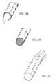
- FIGS. 4A-Care representations of the method of the preferred embodiments of the invention, shown with the three major steps.
- the implantable device of the preferred embodimentsincludes a carrier 10 and an electrical subsystem 12 coupled to the carrier 10 .
- the carrier 10functions to facilitate the insertion of the electrical subsystem 12 and is adapted to allow the electrical subsystem 12 to move freely in the tissue.
- the implantable deviceis preferably designed to be implanted into the brain, spinal cord, peripheral nerve, muscle, or any other suitable anatomical location. The implantable device, however, may be alternatively used in any suitable environment and for any suitable reason.
- the carrier 10functions to facilitate the insertion of the electrical subsystem 12 and is adapted to allow the electrical subsystem 12 to move freely in the tissue or other substances.
- the electrical subsystem 12is preferably attached to the carrier 10 such that the carrier functions to provide structural support.
- the carriermay include a sharpened end adapted to penetrate the tissue and aid in the insertion of the carrier and electrical subsystems into the tissue.
- the carrier 10may also include alignment and or fixation features to facilitate positioning and stabilizing the electrical subsystem 12 in the tissue.
- the carrier 10 of the preferred embodimentsis resorbable into tissue after a period of time. Upon resorption of the carrier 10 , the electrical subsystem 12 supported by the carrier will be left to float freely in the brain or other suitable tissue or material.
- the resorbable carrieris preferably made of a material that demonstrates at least one of the following characteristics: minimal foreign body reaction, biocompatibility, biodegradability, long-term mechanical and chemical stability, sterilizability, and sufficient porosity.
- the materialis preferably adapted to undergo a controlled action and reaction to the surrounding tissue, a controlled chemical breakdown and resorption, replacement by regenerating tissue, stimulation of regeneration of living tissues, or any combination thereof.
- the resorbable carrieris preferably made from a bioresorbable polymer.
- the bioresorbable polymeris preferably polyglycolide or polylactide, but may alternatively be made from any suitable bioresorbable material such as a biodegradable magnesium alloy or a corrodible iron alloy. If the bioresorbable polymer is polyglycolide (or any other material that absorbs into the body after approximately one month), the carrier absorbs into the body at about the same time the body heals around the implanted device, which may be advantageous in some situations. If the bioresorbable polymer is polylactide (or any other material that absorbs into the body after approximately one year), the carrier absorbs into the body much after the body heals around the implanted device, which may be advantageous in other situations.
- any suitable bioresorbable materialsuch as a biodegradable magnesium alloy or a corrodible iron alloy.
- the carrier 10may further extend the functionality of the device by providing fluidic channels through which therapeutic drugs, drugs to inhibit biologic response to the implant, or any other suitable fluid or substance may be transmitted.
- the fluidic channelsare preferably channels defined by the geometry of the carrier 10 , but may alternatively be separate microtubes molded, inserted, woven, knitted, or otherwise disposed into the carrier 10 .
- the channelspreferably provide for the precise delivery of specific pharmaceutical compounds to localized regions of the body, such as the nervous system, and could facilitate, for example, intraoperative mapping procedures or long-term therapeutic implant devices.
- the fluidic channelsmay also provide a location through which a stiffener (or even a shape-memory alloy such as Nitinol) may be inserted to aid with the implantation or to facilitate post-implantation navigation of the device.
- the shape of the carrieris preferably tubular with about a 1-mm diameter, but may alternatively be solid or any other suitable shape of any suitable diameter for the desired functions.
- the carrier 10is preferably made from a material that is woven or knitted, but may alternative be made from a material that is cast, molded, or machined.
- the carrier 10is preferably flexible, but may alternatively be rigid or semi rigid.
- the materialmay be uniformly rigid, or rigid only in a particular direction (such as the axial direction).
- the resorbable carriermay also be impregnated with fluids and/or deliver the fluids such as drugs and/or neurotrophins, similar to the “Stent Device and Method” of U.S. Pat. No. 7,001,680, which is incorporated in its entirety by this reference.
- the carrier 10may be further adapted to act as a template for tissue regeneration and/or as a matrix for autologous or analogous cells or stem cells.
- the carrier 10may be made from a combination of materials.
- the layers or portions of distinct materialsmay have distinct absorption, degradation, or incorporation times.
- the distinct materialsmay further include distinct particles, agents, and/or cells that they deliver or release into the tissue.
- the carrier 10may further include scaffolding for structural support and/or for drug or cell delivery.
- the scaffoldingis preferably bioresorbable, but may alternatively remain implanted with the device.
- the carrier 10may be manufactured in one of several variations.
- the carriermay be manufactured such that the weave of the material is large enough to accept “weaving” of the electrical subsystem 12 directly into the fabric.
- the electrical subsystemcan be adapted to be woven in and out of the resorbable carrier to secure the electrical subsystem 12 to the carrier 10 .
- a single electrical subsystem 12could be woven into the fabric or multiple subsystems could be incorporated, resulting in a three-dimensional system of electrical subsystems.
- the electrical subsystemcould be coupled directly to the surface of the carrier using a biocompatible adhesive such as epoxy or silicone.
- the weave of the resorbable carriermay be tighter and/or the porosity of the carrier may be smaller as the electrical subsystem 12 is not woven into the material in this variation.
- the resorbable carriermay be manufactured as a concentric, multi-lumen structure.
- the electrical subsystem 12may be coupled to the carrier between the inner and outer lumens of the electrical subsystem.
- the carrier 10is preferably one of these several variations, of several various materials, manufactured in several variations, the carrier may be any suitable element, material, manufactured in any suitable fashion to facilitate the insertion of the electrical subsystem 12 and to allow the electrical subsystem 12 to move freely in the tissue or other substances.
- the electrical subsystem 12 of the preferred embodimentsfunctions to interface with the tissue, or any other suitable substance, within which it has been implanted.
- the electrical subsystem 12may include multiple different electrical subsystems or a plurality of the same subsystems.
- the electrical subsystem 12is preferably at least one of several versions or any combination thereof.
- the electrical subsystem 12is preferably a neural interface electrode array.
- the electrode arraypreferably has a plurality of electrode sites, and more preferably both stimulation sites 20 and recording sites 22 .
- the neural interface electrode arrayis adapted to provide dynamic tunable electrical stimulation ranging from stimulation with macroscale specificity to microscale directional patterning.
- the electrode arrayis preferably adapted to optimally sample (record) and/or selectively activate (stimulate) neural populations.
- the plurality of electrode sitescan be tuned for recording, stimulation, or any combination thereof. Additionally, at least two electrode sites may be grouped to form a larger composite site that enables tuning the neural interface region for recording and/or stimulation.
- the neural interface electrode arrayis preferably made from a thin-film polymer substrate, such as parylene or some combination of parylene and inorganic dielectrics, but may alternatively be made out of any suitable material including, for example, silicon.
- the neural interface electrode arrayis preferably made such that there is high density of electrode sites at a first end of the array the distal end) and bonding regions at a second end of the array (the proximal end).
- the distal end of the arrayis preferably coupled to the carrier 10 to provide structural support.
- the electrode arraymay further include fluidic channels providing the capability to deliver therapeutic drugs, drugs to inhibit biologic response to the implant, or any other suitable fluid.
- the neural interface electrode array in this variationis preferably a composite assembly that includes the neural interface electrode array and the carrier 10 .
- the neural interface electrode arrayincludes two pieces, a distal element and a proximal element.
- the distal elementwraps or is woven around the circumference of the carrier 10 .
- Ascending from the distal elementare preferably interconnects that transition from the outer surface of the carrier 10 into a single connector 14 , such that the entire proximal element is imbedded in silicone.
- small non-homogeneous perforationsare preferably micromachined in the neural interface electrode array to allow for the material of the carrier 10 to form a robust anchor with the electrode array.
- the neural interface electrode arraypreferably defines series of “cut-aways” or perforations 18 that axially extend in a discontinuous manner along the length of the neural interface electrode array.
- the neural interface electrode arraypreferably has adequate flexibility to allow bending and flowing of the device within body tissue after implantation of the device.
- the perforations 18preferably extend in a radial direction completely through the neural interface electrode array, and preferably extend in a circumferential direction approximately 45-90 degrees.
- the neural interface electrode arraypreferably includes two perforation series, and thus the neural interface electrode array preferably extends 180-270 degrees in the areas with perforations.
- the perforation seriesis preferably discontinuous (i.e., the neural interface electrode array extends completely in the circumferential direction at particular points along the length of the neural interface electrode array). While the neural interface electrode array has been described as having perforations, it is also possible for the neural interface electrode array to be described as being one or more strips that are circumferentially connected by several “bridges”.
- the neural interface electrode arrayomits the “bridges” and is merely one or more rectangular and generally planar (i.e., either flat or slightly curved) “strips”.
- the carrierprovides structural support for these “strips” to be placed onto a stylet and implanted into body tissue.
- the electrical subsystem 12is preferably one of these three versions, the electrical subsystem 12 may be any suitable element or combination of elements to perform the desired functions.
- the device of the preferred embodimentsmay further include an additional electrical subsystem that functions to operate with the electrical subsystem 12 .
- the additional electrical subsystemmay include multiple different, electrical subsystems or a plurality of the same subsystems.
- the additional electrical subsystemis preferably at least one of several versions or any combination thereof. In a first version, the additional electrical subsystem is a suitable electronic subsystem to operate with an implantable neural interface.
- the additional electrical subsystemmay be a printed circuit board with or without on-board integrated circuits and/or on-chip circuitry for signal conditioning and/or stimulus generation, an Application Specific Integrated Circuit (ASIC), a multiplexer chip, a buffer amplifier, an electronics interface, an implantable pulse generator, an implantable rechargeable battery, integrated electronics for either real-time signal processing of the input (recorded) or output (stimulation) signals, integrated electronics for control of the fluidic components, any other suitable electrical subsystem, or any combination thereof.
- ASICApplication Specific Integrated Circuit
- ASICApplication Specific Integrated Circuit
- multiplexer chipa buffer amplifier
- an electronics interfacean electronics interface
- an implantable pulse generatoran implantable rechargeable battery
- integrated electronicsfor either real-time signal processing of the input (recorded) or output (stimulation) signals
- integrated electronicsfor control of the fluidic components, any other suitable electrical subsystem, or any combination thereof.
- the device of the preferred embodimentsmay further include a connector 14 that functions to couple the electrical subsystem 12 to the additional electrical subsystem.
- the connector 14is preferably one of several versions. As shown in FIGS. 1 and 2 , the cable is preferably a flexible ribbon cable.
- the ribbon cableis preferably polymer ribbon cable, but may alternatively be any other suitable ribbon cable.
- the connector 14may alternatively be any suitable element to couple the electrical subsystem 12 to the additional electrical subsystem, such as wires, conductive interconnects, etc.
- the ribbon cablemay be encased in silicone or any other suitable material.
- the electrical subsystemmay have multiple ribbon cables. Preferably, multiple ribbon cables would be physically attached along their entire length, using a suitable adhesive such as medical grade adhesive or any other suitable connection mechanism.
- the cableis preferably connected to the electrical subsystems through ball bonds or any other suitable connection mechanisms.
- the connector 14may alternatively be seamlessly manufactured with the first and or additional electrical subsystem.
- the connector 14may further include fluidic channels adapted to deliver therapeutic drugs, drugs to inhibit biologic response to the implant, or any other suitable fluid.
- the device of the preferred embodimentsmay further include a stylet 16 .
- the stylet 16 of the preferred embodimentsfunctions to penetrate the tissue or other material and/or functions to provide structural support to the device during implantation of the device.
- the stylet 16is preferably inserted into a lumen of the carrier 10 , but may alternatively be located and inserted into any suitable component of the device in any suitable manner.
- the stylet 16may include a sharpened end adapted to penetrate the tissue and aid in the insertion of the stylet, the carrier 10 , and/or the electrical subsystems into the tissue.
- the stylet 16is preferably removed from the tissue following the placement of an electrical subsystem, but may alternatively be adapted to remain in the tissue while still allowing the implanted electrical subsystem 12 to float freely in the brain. This may be accomplished by the stylet being selectively flexible (through electrical stimulus or other suitable method) or by being resorbable into the tissue after a period of time.
- the stylet 16is preferably made from a stiff material such as metal, but may alternatively be made from any suitable material.
- the metalis an insulated metal wire.
- the insulated metal wiremay not have insulation covering a sharpened tip, and thus can be used as a conventional single-channel microelectrode.
- a method of implanting and using the implantable device and its corresponding electrical componentspreferably includes the following steps: (a) providing an electrical subsystem and a carrier that provides structural support for the electrical subsystem; (b) implanting the electrical subsystem and the carrier into the body tissue; and (c) dissolving the carrier into the body tissue and allowing the electrical subsystem to flex within and interface with the body tissue.
- Step (c)may include dissolving the carrier into the body tissue at a rate approximately equal to the healing process of the body tissue, or may include dissolving the carrier into the body tissue at a rate much slower than the healing process of the body tissue.
- the methodmay also include providing a stylet, placing the electrical subsystem and the carrier onto the stylet, and penetrating the body tissue with the stylet.
- the preferred embodimentsinclude every combination and permutation of the various carriers 10 , the various electrical subsystems, the various connectors, the various stylets, and the various methods of use.
Landscapes
- Health & Medical Sciences (AREA)
- Life Sciences & Earth Sciences (AREA)
- Public Health (AREA)
- Heart & Thoracic Surgery (AREA)
- Engineering & Computer Science (AREA)
- Biomedical Technology (AREA)
- Veterinary Medicine (AREA)
- Animal Behavior & Ethology (AREA)
- General Health & Medical Sciences (AREA)
- Neurology (AREA)
- Neurosurgery (AREA)
- Surgery (AREA)
- Physics & Mathematics (AREA)
- Biophysics (AREA)
- Pathology (AREA)
- Medical Informatics (AREA)
- Molecular Biology (AREA)
- Radiology & Medical Imaging (AREA)
- Nuclear Medicine, Radiotherapy & Molecular Imaging (AREA)
- Cardiology (AREA)
- Orthopedic Medicine & Surgery (AREA)
- Physiology (AREA)
- Electrotherapy Devices (AREA)
- Prostheses (AREA)
Abstract
Description
Claims (24)
Priority Applications (2)
| Application Number | Priority Date | Filing Date | Title |
|---|---|---|---|
| US14/623,747US10034615B2 (en) | 2007-10-17 | 2015-02-17 | Method for implanting an implantable device in body tissue |
| US16/048,948US11690548B2 (en) | 2007-10-17 | 2018-07-30 | Method for implanting an implantable device in body tissue |
Applications Claiming Priority (3)
| Application Number | Priority Date | Filing Date | Title |
|---|---|---|---|
| US98065907P | 2007-10-17 | 2007-10-17 | |
| US12/253,813US8958862B2 (en) | 2007-10-17 | 2008-10-17 | Implantable device including a resorbable carrier |
| US14/623,747US10034615B2 (en) | 2007-10-17 | 2015-02-17 | Method for implanting an implantable device in body tissue |
Related Parent Applications (1)
| Application Number | Title | Priority Date | Filing Date |
|---|---|---|---|
| US12/253,813ContinuationUS8958862B2 (en) | 2007-10-17 | 2008-10-17 | Implantable device including a resorbable carrier |
Related Child Applications (1)
| Application Number | Title | Priority Date | Filing Date |
|---|---|---|---|
| US16/048,948ContinuationUS11690548B2 (en) | 2007-10-17 | 2018-07-30 | Method for implanting an implantable device in body tissue |
Publications (2)
| Publication Number | Publication Date |
|---|---|
| US20150157854A1 US20150157854A1 (en) | 2015-06-11 |
| US10034615B2true US10034615B2 (en) | 2018-07-31 |
Family
ID=40567807
Family Applications (3)
| Application Number | Title | Priority Date | Filing Date |
|---|---|---|---|
| US12/253,813Active2032-09-22US8958862B2 (en) | 2007-10-17 | 2008-10-17 | Implantable device including a resorbable carrier |
| US14/623,747Active2030-09-18US10034615B2 (en) | 2007-10-17 | 2015-02-17 | Method for implanting an implantable device in body tissue |
| US16/048,948Active2032-04-23US11690548B2 (en) | 2007-10-17 | 2018-07-30 | Method for implanting an implantable device in body tissue |
Family Applications Before (1)
| Application Number | Title | Priority Date | Filing Date |
|---|---|---|---|
| US12/253,813Active2032-09-22US8958862B2 (en) | 2007-10-17 | 2008-10-17 | Implantable device including a resorbable carrier |
Family Applications After (1)
| Application Number | Title | Priority Date | Filing Date |
|---|---|---|---|
| US16/048,948Active2032-04-23US11690548B2 (en) | 2007-10-17 | 2018-07-30 | Method for implanting an implantable device in body tissue |
Country Status (2)
| Country | Link |
|---|---|
| US (3) | US8958862B2 (en) |
| WO (1) | WO2009052425A1 (en) |
Cited By (1)
| Publication number | Priority date | Publication date | Assignee | Title |
|---|---|---|---|---|
| US11690548B2 (en) | 2007-10-17 | 2023-07-04 | Neuronexus Technologies, Inc. | Method for implanting an implantable device in body tissue |
Families Citing this family (49)
| Publication number | Priority date | Publication date | Assignee | Title |
|---|---|---|---|---|
| WO2005039696A1 (en)* | 2003-10-21 | 2005-05-06 | The Regents Of The University Of Michigan | Intracranial neural interface system |
| WO2006138358A2 (en) | 2005-06-14 | 2006-12-28 | The Regents Of The University Of Michigan Technology Management Office | Flexible polymer microelectrode with fluid delivery capability and methods for making same |
| WO2007042999A2 (en) | 2005-10-07 | 2007-04-19 | Neuronexus Technologies | Modular multichannel microelectrode array and methods of making same |
| WO2007089738A2 (en)* | 2006-01-26 | 2007-08-09 | The Regents Of The University Of Michigan | Microelectrode with laterally extending platform for reduction of tissue encapsulation |
| US8731673B2 (en)* | 2007-02-26 | 2014-05-20 | Sapiens Steering Brain Stimulation B.V. | Neural interface system |
| US8565894B2 (en)* | 2007-10-17 | 2013-10-22 | Neuronexus Technologies, Inc. | Three-dimensional system of electrode leads |
| US8224417B2 (en)* | 2007-10-17 | 2012-07-17 | Neuronexus Technologies, Inc. | Guide tube for an implantable device system |
| US8498720B2 (en) | 2008-02-29 | 2013-07-30 | Neuronexus Technologies, Inc. | Implantable electrode and method of making the same |
| US9289142B2 (en) | 2008-03-24 | 2016-03-22 | Neuronexus Technologies, Inc. | Implantable electrode lead system with a three dimensional arrangement and method of making the same |
| US20090240314A1 (en)* | 2008-03-24 | 2009-09-24 | Kong K C | Implantable electrode lead system with a three dimensional arrangement and method of making the same |
| CA2732309C (en) | 2008-07-30 | 2018-04-10 | Ecole Polytechnique Federale De Lausanne (Epfl) | Apparatus and method for optimized stimulation of a neurological target |
| JP5667987B2 (en) | 2008-11-12 | 2015-02-12 | エコーレ ポリテクニーク フェデラーレ デ ローザンヌ (イーピーエフエル) | Micromachined nerve stimulation device |
| EP2440283B1 (en) | 2009-06-09 | 2018-08-01 | Neuronano AB | Microelectrode and multiple microelectrodes comprising means for releasing drugs into the tissue |
| AU2014240349B2 (en)* | 2009-06-09 | 2015-11-05 | Neuronano Ab | Microelectrode and multiple microelectrodes comprising means for releasing drugs into the tissue |
| US8332046B2 (en)* | 2009-10-16 | 2012-12-11 | Neuronexus Technologies, Inc. | Neural interface system |
| CN102686147B (en)* | 2009-11-05 | 2016-01-20 | 格雷特巴奇有限公司 | waveguide neural interface device |
| CA2782710C (en) | 2009-12-01 | 2019-01-22 | Ecole Polytechnique Federale De Lausanne | Microfabricated neurostimulation device and methods of making and using the same |
| CA2795159C (en) | 2010-04-01 | 2020-11-03 | Ecole Polytechnique Federale De Lausanne | Device for interacting with neurological tissue and methods of making and using the same |
| US9155861B2 (en) | 2010-09-20 | 2015-10-13 | Neuronexus Technologies, Inc. | Neural drug delivery system with fluidic threads |
| WO2012114501A1 (en)* | 2011-02-25 | 2012-08-30 | 東北マイクロテック株式会社 | Brain probe and method for manufacturing same |
| WO2012158834A1 (en)* | 2011-05-16 | 2012-11-22 | Second Sight Medical Products, Inc. | Cortical interface with an electrode array divided into separate fingers and/or with a wireless transceiver |
| WO2012167096A2 (en) | 2011-06-03 | 2012-12-06 | The Board Of Trustees Of The University Of Illinois | Conformable actively multiplexed high-density surface electrode array for brain interfacing |
| US8688232B2 (en) | 2011-06-21 | 2014-04-01 | Greatbatch Ltd. | Multi-durometer reinforced suture sleeve |
| US8676341B2 (en)* | 2011-06-21 | 2014-03-18 | Greatbatch Ltd. | Multi durometer reinforced suture sleeve |
| WO2013016343A1 (en)* | 2011-07-25 | 2013-01-31 | Kipke Daryl R | Distributed neural stimulation array system |
| WO2013173551A1 (en)* | 2012-05-16 | 2013-11-21 | University Of Utah Research Foundation | Charge steering high density electrode array |
| US10246763B2 (en) | 2012-08-24 | 2019-04-02 | The Regents Of The University Of California | Magnesium-zinc-strontium alloys for medical implants and devices |
| US11229789B2 (en) | 2013-05-30 | 2022-01-25 | Neurostim Oab, Inc. | Neuro activator with controller |
| CA2913074C (en) | 2013-05-30 | 2023-09-12 | Graham H. Creasey | Topical neurological stimulation |
| US20150140289A1 (en) | 2013-11-19 | 2015-05-21 | Bioflex Devices | Method of patterning a bioresorbable material |
| US11311718B2 (en) | 2014-05-16 | 2022-04-26 | Aleva Neurotherapeutics Sa | Device for interacting with neurological tissue and methods of making and using the same |
| WO2015173787A1 (en) | 2014-05-16 | 2015-11-19 | Aleva Neurotherapeutics Sa | Device for interacting with neurological tissue and methods of making and using the same |
| US9474894B2 (en) | 2014-08-27 | 2016-10-25 | Aleva Neurotherapeutics | Deep brain stimulation lead |
| DK3341070T3 (en)* | 2014-08-27 | 2020-03-16 | Neuronano Ab | DEVICE FOR IMPLANTING A MEDICAL DEVICE IN NEURAL Tissue |
| US9403011B2 (en) | 2014-08-27 | 2016-08-02 | Aleva Neurotherapeutics | Leadless neurostimulator |
| US9925376B2 (en) | 2014-08-27 | 2018-03-27 | Aleva Neurotherapeutics | Treatment of autoimmune diseases with deep brain stimulation |
| US11077301B2 (en) | 2015-02-21 | 2021-08-03 | NeurostimOAB, Inc. | Topical nerve stimulator and sensor for bladder control |
| WO2016201151A1 (en)* | 2015-06-09 | 2016-12-15 | Lawrence Livermore National Security, Llc | Cylindrical microelectrode array for neural stimulation and recording |
| CA3041999A1 (en) | 2016-10-31 | 2018-05-03 | The Alfred E. Mann Foundation For Scientific Research | Nerve cuff electrodes fabricated using over-molded lcp substrates |
| CN111601636A (en) | 2017-11-07 | 2020-08-28 | Oab神经电疗科技公司 | Non-invasive neural activator with adaptive circuit |
| US20210045690A1 (en)* | 2018-03-01 | 2021-02-18 | Universitat Basel Vizerektorat Forschung | Neural probe for electrostimulation or recording and fabrication process for such a probe |
| US10702692B2 (en) | 2018-03-02 | 2020-07-07 | Aleva Neurotherapeutics | Neurostimulation device |
| WO2020264214A1 (en) | 2019-06-26 | 2020-12-30 | Neurostim Technologies Llc | Non-invasive nerve activator with adaptive circuit |
| EP4065211A1 (en)* | 2019-11-27 | 2022-10-05 | Galvani Bioelectronics Limited | System and methods for laparoscopic delivery and deployment of a neural interface |
| CN114728161A (en) | 2019-12-16 | 2022-07-08 | 神经科学技术有限责任公司 | Non-invasive neural activator with boosted charge delivery |
| CA3193733A1 (en) | 2020-09-02 | 2022-03-10 | The Alfred E. Mann Foundation For Scientific Research | Electrode leads having multi-application nerve cuffs and associated systems and methods |
| AU2022249112A1 (en) | 2021-03-30 | 2023-10-12 | The Alfred E. Mann Foundation For Scientific Research | Electrode leads having nerve cuffs and associated systems |
| EP4366818A1 (en) | 2021-07-09 | 2024-05-15 | The Alfred E. Mann Foundation for Scientific Research | Electrode leads having multi-application helical nerve cuffs and associated systems and methods |
| US12296172B2 (en) | 2022-02-01 | 2025-05-13 | The Alfred E. Mann Foundation For Scientific Research | Electrode leads having nerve contact elements with coil contacts and associated systems and methods |
Citations (120)
| Publication number | Priority date | Publication date | Assignee | Title |
|---|---|---|---|---|
| CA942A (en) | 1871-04-20 | J. Broughton | Machine for pruning | |
| US3847687A (en) | 1972-11-15 | 1974-11-12 | Motorola Inc | Methods of forming self aligned transistor structure having polycrystalline contacts |
| US3921916A (en) | 1974-12-31 | 1975-11-25 | Ibm | Nozzles formed in monocrystalline silicon |
| US4141365A (en) | 1977-02-24 | 1979-02-27 | The Johns Hopkins University | Epidural lead electrode and insertion needle |
| US4166469A (en) | 1977-12-13 | 1979-09-04 | Littleford Philip O | Apparatus and method for inserting an electrode |
| EP0010775A1 (en) | 1978-11-06 | 1980-05-14 | BASF Aktiengesellschaft | Methods and devices for converting colour video signals into a special colour subcarrier signal which can be decoded in PAL colour television receivers |
| US4306562A (en) | 1978-12-01 | 1981-12-22 | Cook, Inc. | Tear apart cannula |
| US4455192A (en) | 1981-05-07 | 1984-06-19 | Fuji Xerox Company, Ltd. | Formation of a multi-nozzle ink jet |
| US4461304A (en) | 1979-11-05 | 1984-07-24 | Massachusetts Institute Of Technology | Microelectrode and assembly for parallel recording of neurol groups |
| US4465482A (en) | 1979-03-07 | 1984-08-14 | Gerhard Hug Gmbh | Suction drainage tube |
| US4762135A (en) | 1985-08-30 | 1988-08-09 | Puije P D V D | Cochlea implant |
| US4886065A (en) | 1988-08-08 | 1989-12-12 | California Institute Of Technology | In vivo electrode implanting system |
| US4904237A (en) | 1988-05-16 | 1990-02-27 | Janese Woodrow W | Apparatus for the exchange of cerebrospinal fluid and a method of treating brain and spinal cord injuries |
| US5108819A (en) | 1990-02-14 | 1992-04-28 | Eli Lilly And Company | Thin film electrical component |
| US5180376A (en) | 1990-05-01 | 1993-01-19 | Cathco, Inc. | Non-buckling thin-walled sheath for the percutaneous insertion of intraluminal catheters |
| US5207709A (en) | 1991-11-13 | 1993-05-04 | Picha George J | Implant with textured surface |
| US5215088A (en) | 1989-11-07 | 1993-06-01 | The University Of Utah | Three-dimensional electrode device |
| US5263977A (en) | 1992-10-26 | 1993-11-23 | Angeion Corporation | Electrode spacing device |
| US5308442A (en) | 1993-01-25 | 1994-05-03 | Hewlett-Packard Company | Anisotropically etched ink fill slots in silicon |
| US5322064A (en) | 1991-02-15 | 1994-06-21 | Lundquist Ingemar H | Torquable catheter and method |
| US5385635A (en) | 1993-11-01 | 1995-01-31 | Xerox Corporation | Process for fabricating silicon channel structures with variable cross-sectional areas |
| US5390671A (en) | 1994-03-15 | 1995-02-21 | Minimed Inc. | Transcutaneous sensor insertion set |
| US5409469A (en) | 1993-11-04 | 1995-04-25 | Medtronic, Inc. | Introducer system having kink resistant splittable sheath |
| US5496360A (en) | 1994-04-12 | 1996-03-05 | Ventritex, Inc. | Implantable cardiac electrode with rate controlled drug delivery |
| US5515848A (en) | 1991-10-22 | 1996-05-14 | Pi Medical Corporation | Implantable microelectrode |
| US5573520A (en) | 1991-09-05 | 1996-11-12 | Mayo Foundation For Medical Education And Research | Flexible tubular device for use in medical applications |
| US5585827A (en) | 1993-10-29 | 1996-12-17 | Sony Corporation | Printer head |
| US5588597A (en) | 1993-09-03 | 1996-12-31 | Microparts Gmbh | Nozzle plate for a liquid jet print head |
| US5653742A (en) | 1995-09-20 | 1997-08-05 | Cochlear Pty. Ltd. | Use of bioresorbable polymers in cochlear implants and other implantable devices |
| US5716391A (en) | 1995-08-23 | 1998-02-10 | Medtronic, Inc. | Medical electrical lead having temporarily rigid fixation |
| US5720099A (en) | 1996-01-31 | 1998-02-24 | Cochlear Limited | Thin film fabrication technique for implantable electrodes |
| US5744958A (en) | 1995-11-07 | 1998-04-28 | Iti Medical Technologies, Inc. | Instrument having ultra-thin conductive coating and method for magnetic resonance imaging of such instrument |
| US5800535A (en) | 1994-02-09 | 1998-09-01 | The University Of Iowa Research Foundation | Wireless prosthetic electrode for the brain |
| US5843150A (en) | 1997-10-08 | 1998-12-01 | Medtronic, Inc. | System and method for providing electrical and/or fluid treatment within a patient's brain |
| US5927277A (en) | 1995-04-28 | 1999-07-27 | Medtronic, Inc. | Method and apparatus for securing probes within a burr hole |
| US5938694A (en) | 1993-11-10 | 1999-08-17 | Medtronic Cardiorhythm | Electrode array catheter |
| US5975085A (en) | 1997-05-01 | 1999-11-02 | Medtronic, Inc. | Method of treating schizophrenia by brain stimulation and drug infusion |
| US5989445A (en) | 1995-06-09 | 1999-11-23 | The Regents Of The University Of Michigan | Microchannel system for fluid delivery |
| US6006124A (en) | 1998-05-01 | 1999-12-21 | Neuropace, Inc. | Means and method for the placement of brain electrodes |
| US6016449A (en) | 1997-10-27 | 2000-01-18 | Neuropace, Inc. | System for treatment of neurological disorders |
| US6044304A (en) | 1998-04-29 | 2000-03-28 | Medtronic, Inc. | Burr ring with integral lead/catheter fixation device |
| US6091979A (en) | 1998-07-07 | 2000-07-18 | Children's Medical Center Corporation | Subdural electrode arrays for monitoring cortical electrical activity |
| US6119044A (en) | 1997-06-02 | 2000-09-12 | Advanced Bionics Corporation | Cochlear electrode array with positioning stylet |
| US6132456A (en) | 1998-03-10 | 2000-10-17 | Medtronic, Inc. | Arrangement for implanting an endocardial cardiac lead |
| US6181569B1 (en) | 1999-06-07 | 2001-01-30 | Kishore K. Chakravorty | Low cost chip size package and method of fabricating the same |
| WO2001012115A1 (en) | 1999-08-18 | 2001-02-22 | Epic Biosonics Inc. | Modiolar hugging electrode array |
| US6205361B1 (en) | 1998-02-10 | 2001-03-20 | Advanced Bionics Corporation | Implantable expandable multicontact electrodes |
| US6228111B1 (en) | 1995-09-27 | 2001-05-08 | Bionx Implants Oy | Biodegradable implant manufactured of polymer-based material and a method for manufacturing the same |
| US6296630B1 (en) | 1998-04-08 | 2001-10-02 | Biocardia, Inc. | Device and method to slow or stop the heart temporarily |
| US6324433B1 (en) | 2000-01-20 | 2001-11-27 | Electrocare Technologies, Llc | Electrode-lead coupling skull mounted port assembly |
| US6325797B1 (en) | 1999-04-05 | 2001-12-04 | Medtronic, Inc. | Ablation catheter and method for isolating a pulmonary vein |
| US20010049499A1 (en) | 1999-12-30 | 2001-12-06 | Lui Chun Kee | Splittable medical valve |
| US20020052610A1 (en) | 2000-04-07 | 2002-05-02 | Skakoon James G. | Deep organ access device and method |
| WO2002036002A1 (en) | 2000-11-01 | 2002-05-10 | 3M Innovative Properties Company | Electrical sensing and/or signal application device |
| WO2002041666A1 (en) | 2000-11-14 | 2002-05-23 | Cochlear Limited | Apparatus for delivery of pharmaceuticals to the cochlea |
| US6430443B1 (en) | 2000-03-21 | 2002-08-06 | Manuel L. Karell | Method and apparatus for treating auditory hallucinations |
| US20020183817A1 (en) | 2000-12-07 | 2002-12-05 | Paul Van Venrooij | Directional brain stimulation and recording leads |
| US20020198446A1 (en) | 2001-06-21 | 2002-12-26 | Hill Norman M. | Multi-channel structurally robust brain probe and method of making the same |
| US20030093104A1 (en) | 1999-10-29 | 2003-05-15 | Bonner Matthew D. | Methods and apparatus for providing intra-pericardial access |
| US20030093129A1 (en) | 2001-10-29 | 2003-05-15 | Nicolelis Miguel A.L. | Closed loop brain machine interface |
| US20030100823A1 (en) | 2000-03-29 | 2003-05-29 | Daryl Kipke | Device for creating a neural interface and method for making same |
| US20030114906A1 (en) | 2001-12-17 | 2003-06-19 | Theracardia, Inc. | Apparatus and methods for deploying cardiac electrodes |
| US6600231B2 (en) | 2000-05-11 | 2003-07-29 | Mitutoyo Corporation | Functional device unit and method of producing the same |
| US6618623B1 (en) | 2000-11-28 | 2003-09-09 | Neuropace, Inc. | Ferrule for cranial implant |
| US20030187461A1 (en) | 1999-08-10 | 2003-10-02 | Chin Albert K. | Releasable guide and method for endoscopic cardiac lead placement |
| US20040006264A1 (en) | 2001-11-20 | 2004-01-08 | Mojarradi Mohammad M. | Neural prosthetic micro system |
| US20040102828A1 (en) | 2002-11-27 | 2004-05-27 | Lowry David Warren | Methods and systems employing intracranial electrodes for neurostimulation and/or electroencephalography |
| US20040106169A1 (en) | 2002-12-02 | 2004-06-03 | Evans Daron G. | System and method for metabolyte neuronal network analysis |
| US20040122501A1 (en) | 2000-10-04 | 2004-06-24 | Fysh Dadd | Cochlear implant electrode array |
| US20040199235A1 (en) | 2001-09-30 | 2004-10-07 | Imad Younis | Electrode system for neural applications |
| US6834200B2 (en) | 2000-10-19 | 2004-12-21 | Philadelphia, Health & Education Corporation | Ceramic based multi-site electrode arrays and methods for their production |
| US20050004627A1 (en) | 2001-10-26 | 2005-01-06 | Peter Gibson | Auditory midbrain implant |
| US20050021116A1 (en) | 2003-07-21 | 2005-01-27 | Jiping He | Electrode for implant in live tissue with flexible region to accommodate micro-movement |
| US20050021117A1 (en) | 2003-07-21 | 2005-01-27 | Jiping He | Flexible integrated head-stage for neural interface |
| US6878643B2 (en) | 2002-12-18 | 2005-04-12 | The Regents Of The University Of California | Electronic unit integrated into a flexible polymer body |
| US20050118236A1 (en)* | 2002-12-03 | 2005-06-02 | Gentis Inc. | Bioactive, resorbable scaffolds for tissue engineering |
| US20050137647A1 (en) | 2003-12-22 | 2005-06-23 | Scimed Life Systems, Inc. | Method of intravascularly delivering stimulation leads into direct contact with tissue |
| US20050222647A1 (en) | 2004-03-30 | 2005-10-06 | Wahlstrand Carl D | Lead electrode for use in an MRI-safe implantable medical device |
| US7006859B1 (en) | 2002-07-20 | 2006-02-28 | Flint Hills Scientific, L.L.C. | Unitized electrode with three-dimensional multi-site, multi-modal capabilities for detection and control of brain state changes |
| US7004948B1 (en) | 2001-01-31 | 2006-02-28 | Advanced Bionics Corporation | Cranial sealing plug |
| US7010356B2 (en) | 2001-10-31 | 2006-03-07 | London Health Sciences Centre Research Inc. | Multichannel electrode and methods of using same |
| US7011680B2 (en) | 2001-05-02 | 2006-03-14 | Inflow Dynamics Inc. | Stent device and method |
| US20060122677A1 (en) | 2004-10-21 | 2006-06-08 | Vardiman Arnold B | Various apparatus and methods for deep brain stimulating electrodes |
| US20060173263A1 (en) | 2003-02-04 | 2006-08-03 | Jiping He | Neural interface assembly and method for making and implanting the same |
| US7089059B1 (en) | 2000-11-03 | 2006-08-08 | Pless Benjamin D | Predicting susceptibility to neurological dysfunction based on measured neural electrophysiology |
| US20060247749A1 (en) | 2005-05-02 | 2006-11-02 | Advanced Bionics Corporation | Compliant stimulating electrodes and leads and methods of manufacture and use |
| US20060258951A1 (en) | 2005-05-16 | 2006-11-16 | Baxano, Inc. | Spinal Access and Neural Localization |
| US20060276866A1 (en) | 2005-06-02 | 2006-12-07 | Mccreery Douglas B | Microelectrode array for chronic deep-brain microstimulation for recording |
| US20060282014A1 (en) | 2005-06-14 | 2006-12-14 | The Regents Of The University Of Michigan | Flexible polymer microelectrode with fluid delivery capability and methods for making same |
| US7181288B1 (en) | 2002-06-24 | 2007-02-20 | The Cleveland Clinic Foundation | Neuromodulation device and method of using the same |
| US20070073130A1 (en) | 2003-11-06 | 2007-03-29 | Dudley Finch | Shape-memory polymer coated electrodes |
| WO2007042999A2 (en) | 2005-10-07 | 2007-04-19 | Neuronexus Technologies | Modular multichannel microelectrode array and methods of making same |
| US20070135885A1 (en) | 2005-12-08 | 2007-06-14 | Cochlear Limited | Flexible electrode assembly having variable pitch electrodes for a stimulating medical device |
| WO2007089738A2 (en) | 2006-01-26 | 2007-08-09 | The Regents Of The University Of Michigan | Microelectrode with laterally extending platform for reduction of tissue encapsulation |
| WO2008011721A1 (en) | 2006-07-28 | 2008-01-31 | Med-El Elektro-Medizinische Geräte Gesellschaft M.B.H. | Layered electrode array and cable |
| US7343205B1 (en) | 2002-08-20 | 2008-03-11 | Boston Scientific Neuromodulation Corp. | System and method for insertion of a device into the brain |
| WO2008038208A2 (en) | 2006-09-26 | 2008-04-03 | Koninklijke Philips Electronics, N.V. | Tissue stimulation method and apparatus |
| US20080132970A1 (en) | 2006-12-05 | 2008-06-05 | Giancarlo Barolat | Method and system for treatment of intractable scrotal and/or testicular pain |
| WO2008072125A1 (en) | 2006-12-13 | 2008-06-19 | Koninklijke Philips Electronics, N.V. | First time right placement of a dbs lead |
| US20080208283A1 (en) | 2007-02-26 | 2008-08-28 | Rio Vetter | Neural Interface System |
| US20080255439A1 (en) | 2004-06-01 | 2008-10-16 | California Institute Of Technology | Microfabricated Neural Probes and Methods of Making Same |
| US20080262584A1 (en) | 2007-03-19 | 2008-10-23 | Bottomley Paul A | Methods and apparatus for fabricating leads with conductors and related flexible lead configurations |
| US20090099555A1 (en) | 2007-10-11 | 2009-04-16 | Ingmar Viohl | Reduction of rf induced tissue heating using conductive surface pattern |
| US20090099441A1 (en) | 2005-09-08 | 2009-04-16 | Drexel University | Braided electrodes |
| WO2009052425A1 (en) | 2007-10-17 | 2009-04-23 | Neuronexus Technologies | Implantable device including a resorbable carrier |
| US20090102068A1 (en) | 2007-10-17 | 2009-04-23 | Pellinen David S | System and method to manufacture an implantable electrode |
| WO2009052423A1 (en) | 2007-10-17 | 2009-04-23 | Neuronexus Technologies | Three-dimensional system of electrode leads |
| US20090149934A1 (en) | 2007-12-06 | 2009-06-11 | Cardiac Pacemakers, Inc. | Implantable lead with shielding |
| US7548775B2 (en) | 2003-10-21 | 2009-06-16 | The Regents Of The University Of Michigan | Intracranial neural interface system |
| US20090171421A1 (en) | 2005-10-21 | 2009-07-02 | Ergin Atalar | Mri-safe high impedance lead systems |
| US20090187196A1 (en) | 2007-10-17 | 2009-07-23 | Vetter Rio J | Guide tube for an implantable device system |
| US20090234426A1 (en) | 2008-02-29 | 2009-09-17 | Pellinen David S | Implantable electrode and method of making the same |
| US20090240314A1 (en) | 2008-03-24 | 2009-09-24 | Kong K C | Implantable electrode lead system with a three dimensional arrangement and method of making the same |
| US20090248118A1 (en) | 2001-12-04 | 2009-10-01 | Boston Scientific Neuromodulation Corporation | Apparatus and method for determining the relative position and orientation of neurostimulation leads |
| US20090312770A1 (en) | 2008-06-12 | 2009-12-17 | Takashi Daniel Yoshida Kozai | Probe insertion device for implanting a probe into tissue |
| WO2010057095A2 (en) | 2008-11-14 | 2010-05-20 | The Regents Of The University Of Michigan | Method for manufacturing an implantable electronic device |
| US7871707B2 (en) | 2005-11-10 | 2011-01-18 | Second Sight Medical Products, Inc. | Polymer comprising silicone and metal trace |
| WO2011010257A1 (en) | 2009-07-24 | 2011-01-27 | Koninklijke Philips Electronics N.V. | Medical device for electrical stimulation |
| US7914842B1 (en) | 2006-02-10 | 2011-03-29 | Second Sight Medical Products, Inc | Method of manufacturing a flexible circuit electrode array |
| WO2011046665A1 (en) | 2009-10-16 | 2011-04-21 | Neuronexus Technologies | Neural interface system |
Family Cites Families (31)
| Publication number | Priority date | Publication date | Assignee | Title |
|---|---|---|---|---|
| US3752939A (en) | 1972-02-04 | 1973-08-14 | Beckman Instruments Inc | Prosthetic device for the deaf |
| DK141034B (en) | 1977-11-22 | 1979-12-31 | C C Hansen | ELECTRODE FOR INSERTING IN THE SNAIL OF THE CITY (COCHLEA) |
| US4357497A (en) | 1979-09-24 | 1982-11-02 | Hochmair Ingeborg | System for enhancing auditory stimulation and the like |
| US4532930A (en) | 1983-04-11 | 1985-08-06 | Commonwealth Of Australia, Dept. Of Science & Technology | Cochlear implant system for an auditory prosthesis |
| US4686765A (en) | 1984-05-03 | 1987-08-18 | Regents Of The University Of California | Method for making an intracochlear electrode array |
| US4819647A (en) | 1984-05-03 | 1989-04-11 | The Regents Of The University Of California | Intracochlear electrode array |
| US4541440A (en) | 1984-11-14 | 1985-09-17 | Cordis Corporation | Bipolar epicardial temporary pacing lead |
| US4593696A (en) | 1985-01-17 | 1986-06-10 | Hochmair Ingeborg | Auditory stimulation using CW and pulsed signals |
| US4969468A (en) | 1986-06-17 | 1990-11-13 | Alfred E. Mann Foundation For Scientific Research | Electrode array for use in connection with a living body and method of manufacture |
| US5182111A (en) | 1987-11-17 | 1993-01-26 | Boston University Research Foundation | In vivo delivery of active factors by co-cultured cell implants |
| FR2629710B1 (en) | 1988-04-08 | 1997-10-24 | Mxm | ELECTRODE HOLDER DEVICES IMPLANTABLE IN THE COCHLEE FOR ELECTRICALLY STIMULATING THE HEARING NERVE |
| US4961434A (en) | 1988-08-30 | 1990-10-09 | Stypulkowski Paul H | Array of recessed radially oriented bipolar electrodes |
| WO1994000088A1 (en) | 1992-06-22 | 1994-01-06 | The University Of Melbourne | Curved electrode array |
| US5447533A (en) | 1992-09-03 | 1995-09-05 | Pacesetter, Inc. | Implantable stimulation lead having an advanceable therapeutic drug delivery system |
| US5620883A (en) | 1994-04-01 | 1997-04-15 | The Johns Hopkins University | Living cells microencapsulated in a polymeric membrane having two layers |
| EP0928212B1 (en) | 1994-07-13 | 2002-10-02 | Fraunhofer-Gesellschaft zur Förderung der angewandten Forschung e.V. | Flexible artificial nerve plate |
| US5928458A (en) | 1994-08-12 | 1999-07-27 | Fraunhofer-Gesellschaft Zur Forderung Der Angewandten Forschung E.V. | Flip chip bonding with non conductive adhesive |
| US5683422A (en) | 1996-04-25 | 1997-11-04 | Medtronic, Inc. | Method and apparatus for treating neurodegenerative disorders by electrical brain stimulation |
| US5843148A (en) | 1996-09-27 | 1998-12-01 | Medtronic, Inc. | High resolution brain stimulation lead and method of use |
| US6078841A (en) | 1998-03-27 | 2000-06-20 | Advanced Bionics Corporation | Flexible positioner for use with implantable cochlear electrode array |
| WO1999055360A1 (en) | 1998-04-30 | 1999-11-04 | Medtronic, Inc. | Implantable system with drug-eluting cells for on-demand local drug delivery |
| US6128521A (en) | 1998-07-10 | 2000-10-03 | Physiometrix, Inc. | Self adjusting headgear appliance using reservoir electrodes |
| US6611715B1 (en) | 1998-10-26 | 2003-08-26 | Birinder R. Boveja | Apparatus and method for neuromodulation therapy for obesity and compulsive eating disorders using an implantable lead-receiver and an external stimulator |
| DE10032000A1 (en) | 1999-07-01 | 2001-01-25 | Medtronic Inc | System for electrophoretic delivery of therapeutic substance to internal bodily tissues, includes electrode with insulation, biocompatible matrix and second electrode |
| WO2001097906A2 (en) | 2000-06-20 | 2001-12-27 | Advanced Bionics Corporation | Apparatus for treatment of mood and/or anxiety disorders by electrical brain stimulation and/or drug infusion |
| GB0104982D0 (en) | 2001-02-28 | 2001-04-18 | Gill Steven | Electrode |
| CA2448912C (en) | 2001-05-30 | 2012-01-03 | Innersa Technology | Implantable devices having a liquid crystal polymer substrate |
| US7991479B2 (en) | 2003-10-02 | 2011-08-02 | Medtronic, Inc. | Neurostimulator programmer with clothing attachable antenna |
| US7413846B2 (en) | 2004-11-15 | 2008-08-19 | Microchips, Inc. | Fabrication methods and structures for micro-reservoir devices |
| EP1723983B1 (en) | 2005-05-20 | 2013-07-10 | Imec | Probe device for electrical stimulation and recording of the activity of excitable cells |
| GB2452699B (en) | 2007-08-24 | 2012-08-01 | King S College London | Mobility and quality of service |
- 2008
- 2008-10-17WOPCT/US2008/080366patent/WO2009052425A1/enactiveApplication Filing
- 2008-10-17USUS12/253,813patent/US8958862B2/enactiveActive
- 2015
- 2015-02-17USUS14/623,747patent/US10034615B2/enactiveActive
- 2018
- 2018-07-30USUS16/048,948patent/US11690548B2/enactiveActive
Patent Citations (137)
| Publication number | Priority date | Publication date | Assignee | Title |
|---|---|---|---|---|
| CA942A (en) | 1871-04-20 | J. Broughton | Machine for pruning | |
| US3847687A (en) | 1972-11-15 | 1974-11-12 | Motorola Inc | Methods of forming self aligned transistor structure having polycrystalline contacts |
| US3921916A (en) | 1974-12-31 | 1975-11-25 | Ibm | Nozzles formed in monocrystalline silicon |
| US4141365A (en) | 1977-02-24 | 1979-02-27 | The Johns Hopkins University | Epidural lead electrode and insertion needle |
| US4166469A (en) | 1977-12-13 | 1979-09-04 | Littleford Philip O | Apparatus and method for inserting an electrode |
| EP0010775A1 (en) | 1978-11-06 | 1980-05-14 | BASF Aktiengesellschaft | Methods and devices for converting colour video signals into a special colour subcarrier signal which can be decoded in PAL colour television receivers |
| US4306562A (en) | 1978-12-01 | 1981-12-22 | Cook, Inc. | Tear apart cannula |
| US4465482A (en) | 1979-03-07 | 1984-08-14 | Gerhard Hug Gmbh | Suction drainage tube |
| US4461304A (en) | 1979-11-05 | 1984-07-24 | Massachusetts Institute Of Technology | Microelectrode and assembly for parallel recording of neurol groups |
| US4455192A (en) | 1981-05-07 | 1984-06-19 | Fuji Xerox Company, Ltd. | Formation of a multi-nozzle ink jet |
| US4762135A (en) | 1985-08-30 | 1988-08-09 | Puije P D V D | Cochlea implant |
| US4904237A (en) | 1988-05-16 | 1990-02-27 | Janese Woodrow W | Apparatus for the exchange of cerebrospinal fluid and a method of treating brain and spinal cord injuries |
| US4886065A (en) | 1988-08-08 | 1989-12-12 | California Institute Of Technology | In vivo electrode implanting system |
| US5215088A (en) | 1989-11-07 | 1993-06-01 | The University Of Utah | Three-dimensional electrode device |
| US5108819A (en) | 1990-02-14 | 1992-04-28 | Eli Lilly And Company | Thin film electrical component |
| US5180376A (en) | 1990-05-01 | 1993-01-19 | Cathco, Inc. | Non-buckling thin-walled sheath for the percutaneous insertion of intraluminal catheters |
| US5322064A (en) | 1991-02-15 | 1994-06-21 | Lundquist Ingemar H | Torquable catheter and method |
| US5573520A (en) | 1991-09-05 | 1996-11-12 | Mayo Foundation For Medical Education And Research | Flexible tubular device for use in medical applications |
| US5515848A (en) | 1991-10-22 | 1996-05-14 | Pi Medical Corporation | Implantable microelectrode |
| US5524338A (en) | 1991-10-22 | 1996-06-11 | Pi Medical Corporation | Method of making implantable microelectrode |
| US5207709A (en) | 1991-11-13 | 1993-05-04 | Picha George J | Implant with textured surface |
| US5263977A (en) | 1992-10-26 | 1993-11-23 | Angeion Corporation | Electrode spacing device |
| US5308442A (en) | 1993-01-25 | 1994-05-03 | Hewlett-Packard Company | Anisotropically etched ink fill slots in silicon |
| US5588597A (en) | 1993-09-03 | 1996-12-31 | Microparts Gmbh | Nozzle plate for a liquid jet print head |
| US5585827A (en) | 1993-10-29 | 1996-12-17 | Sony Corporation | Printer head |
| US5385635A (en) | 1993-11-01 | 1995-01-31 | Xerox Corporation | Process for fabricating silicon channel structures with variable cross-sectional areas |
| US5409469A (en) | 1993-11-04 | 1995-04-25 | Medtronic, Inc. | Introducer system having kink resistant splittable sheath |
| US5938694A (en) | 1993-11-10 | 1999-08-17 | Medtronic Cardiorhythm | Electrode array catheter |
| US5800535A (en) | 1994-02-09 | 1998-09-01 | The University Of Iowa Research Foundation | Wireless prosthetic electrode for the brain |
| US5390671A (en) | 1994-03-15 | 1995-02-21 | Minimed Inc. | Transcutaneous sensor insertion set |
| US5496360A (en) | 1994-04-12 | 1996-03-05 | Ventritex, Inc. | Implantable cardiac electrode with rate controlled drug delivery |
| US5927277A (en) | 1995-04-28 | 1999-07-27 | Medtronic, Inc. | Method and apparatus for securing probes within a burr hole |
| US5992769A (en) | 1995-06-09 | 1999-11-30 | The Regents Of The University Of Michigan | Microchannel system for fluid delivery |
| US5989445A (en) | 1995-06-09 | 1999-11-23 | The Regents Of The University Of Michigan | Microchannel system for fluid delivery |
| US5716391A (en) | 1995-08-23 | 1998-02-10 | Medtronic, Inc. | Medical electrical lead having temporarily rigid fixation |
| US5653742A (en) | 1995-09-20 | 1997-08-05 | Cochlear Pty. Ltd. | Use of bioresorbable polymers in cochlear implants and other implantable devices |
| US6228111B1 (en) | 1995-09-27 | 2001-05-08 | Bionx Implants Oy | Biodegradable implant manufactured of polymer-based material and a method for manufacturing the same |
| US5744958A (en) | 1995-11-07 | 1998-04-28 | Iti Medical Technologies, Inc. | Instrument having ultra-thin conductive coating and method for magnetic resonance imaging of such instrument |
| US5720099A (en) | 1996-01-31 | 1998-02-24 | Cochlear Limited | Thin film fabrication technique for implantable electrodes |
| US5975085A (en) | 1997-05-01 | 1999-11-02 | Medtronic, Inc. | Method of treating schizophrenia by brain stimulation and drug infusion |
| US6119044A (en) | 1997-06-02 | 2000-09-12 | Advanced Bionics Corporation | Cochlear electrode array with positioning stylet |
| US5843150A (en) | 1997-10-08 | 1998-12-01 | Medtronic, Inc. | System and method for providing electrical and/or fluid treatment within a patient's brain |
| US6016449A (en) | 1997-10-27 | 2000-01-18 | Neuropace, Inc. | System for treatment of neurological disorders |
| US6205361B1 (en) | 1998-02-10 | 2001-03-20 | Advanced Bionics Corporation | Implantable expandable multicontact electrodes |
| US6132456A (en) | 1998-03-10 | 2000-10-17 | Medtronic, Inc. | Arrangement for implanting an endocardial cardiac lead |
| US6296630B1 (en) | 1998-04-08 | 2001-10-02 | Biocardia, Inc. | Device and method to slow or stop the heart temporarily |
| US6044304A (en) | 1998-04-29 | 2000-03-28 | Medtronic, Inc. | Burr ring with integral lead/catheter fixation device |
| US6006124A (en) | 1998-05-01 | 1999-12-21 | Neuropace, Inc. | Means and method for the placement of brain electrodes |
| US6091979A (en) | 1998-07-07 | 2000-07-18 | Children's Medical Center Corporation | Subdural electrode arrays for monitoring cortical electrical activity |
| US6325797B1 (en) | 1999-04-05 | 2001-12-04 | Medtronic, Inc. | Ablation catheter and method for isolating a pulmonary vein |
| US6181569B1 (en) | 1999-06-07 | 2001-01-30 | Kishore K. Chakravorty | Low cost chip size package and method of fabricating the same |
| US20030187461A1 (en) | 1999-08-10 | 2003-10-02 | Chin Albert K. | Releasable guide and method for endoscopic cardiac lead placement |
| WO2001012115A1 (en) | 1999-08-18 | 2001-02-22 | Epic Biosonics Inc. | Modiolar hugging electrode array |
| US6374143B1 (en) | 1999-08-18 | 2002-04-16 | Epic Biosonics, Inc. | Modiolar hugging electrode array |
| US20030093104A1 (en) | 1999-10-29 | 2003-05-15 | Bonner Matthew D. | Methods and apparatus for providing intra-pericardial access |
| US20010049499A1 (en) | 1999-12-30 | 2001-12-06 | Lui Chun Kee | Splittable medical valve |
| US6324433B1 (en) | 2000-01-20 | 2001-11-27 | Electrocare Technologies, Llc | Electrode-lead coupling skull mounted port assembly |
| US6430443B1 (en) | 2000-03-21 | 2002-08-06 | Manuel L. Karell | Method and apparatus for treating auditory hallucinations |
| US20030100823A1 (en) | 2000-03-29 | 2003-05-29 | Daryl Kipke | Device for creating a neural interface and method for making same |
| US6829498B2 (en) | 2000-03-29 | 2004-12-07 | Arizona Board Of Regents | Device for creating a neural interface and method for making same |
| US20020052610A1 (en) | 2000-04-07 | 2002-05-02 | Skakoon James G. | Deep organ access device and method |
| US6600231B2 (en) | 2000-05-11 | 2003-07-29 | Mitutoyo Corporation | Functional device unit and method of producing the same |
| US20040122501A1 (en) | 2000-10-04 | 2004-06-24 | Fysh Dadd | Cochlear implant electrode array |
| US6834200B2 (en) | 2000-10-19 | 2004-12-21 | Philadelphia, Health & Education Corporation | Ceramic based multi-site electrode arrays and methods for their production |
| WO2002036002A1 (en) | 2000-11-01 | 2002-05-10 | 3M Innovative Properties Company | Electrical sensing and/or signal application device |
| US7089059B1 (en) | 2000-11-03 | 2006-08-08 | Pless Benjamin D | Predicting susceptibility to neurological dysfunction based on measured neural electrophysiology |
| WO2002041666A1 (en) | 2000-11-14 | 2002-05-23 | Cochlear Limited | Apparatus for delivery of pharmaceuticals to the cochlea |
| US6618623B1 (en) | 2000-11-28 | 2003-09-09 | Neuropace, Inc. | Ferrule for cranial implant |
| US20020183817A1 (en) | 2000-12-07 | 2002-12-05 | Paul Van Venrooij | Directional brain stimulation and recording leads |
| US7004948B1 (en) | 2001-01-31 | 2006-02-28 | Advanced Bionics Corporation | Cranial sealing plug |
| US7011680B2 (en) | 2001-05-02 | 2006-03-14 | Inflow Dynamics Inc. | Stent device and method |
| US20020198446A1 (en) | 2001-06-21 | 2002-12-26 | Hill Norman M. | Multi-channel structurally robust brain probe and method of making the same |
| US20040199235A1 (en) | 2001-09-30 | 2004-10-07 | Imad Younis | Electrode system for neural applications |
| US20050004627A1 (en) | 2001-10-26 | 2005-01-06 | Peter Gibson | Auditory midbrain implant |
| US20030093129A1 (en) | 2001-10-29 | 2003-05-15 | Nicolelis Miguel A.L. | Closed loop brain machine interface |
| US7010356B2 (en) | 2001-10-31 | 2006-03-07 | London Health Sciences Centre Research Inc. | Multichannel electrode and methods of using same |
| US20040006264A1 (en) | 2001-11-20 | 2004-01-08 | Mojarradi Mohammad M. | Neural prosthetic micro system |
| US20090248118A1 (en) | 2001-12-04 | 2009-10-01 | Boston Scientific Neuromodulation Corporation | Apparatus and method for determining the relative position and orientation of neurostimulation leads |
| US20030114906A1 (en) | 2001-12-17 | 2003-06-19 | Theracardia, Inc. | Apparatus and methods for deploying cardiac electrodes |
| US7181288B1 (en) | 2002-06-24 | 2007-02-20 | The Cleveland Clinic Foundation | Neuromodulation device and method of using the same |
| US7006859B1 (en) | 2002-07-20 | 2006-02-28 | Flint Hills Scientific, L.L.C. | Unitized electrode with three-dimensional multi-site, multi-modal capabilities for detection and control of brain state changes |
| US7343205B1 (en) | 2002-08-20 | 2008-03-11 | Boston Scientific Neuromodulation Corp. | System and method for insertion of a device into the brain |
| US20040102828A1 (en) | 2002-11-27 | 2004-05-27 | Lowry David Warren | Methods and systems employing intracranial electrodes for neurostimulation and/or electroencephalography |
| US20040106169A1 (en) | 2002-12-02 | 2004-06-03 | Evans Daron G. | System and method for metabolyte neuronal network analysis |
| US20050118236A1 (en)* | 2002-12-03 | 2005-06-02 | Gentis Inc. | Bioactive, resorbable scaffolds for tissue engineering |
| US6878643B2 (en) | 2002-12-18 | 2005-04-12 | The Regents Of The University Of California | Electronic unit integrated into a flexible polymer body |
| US20060173263A1 (en) | 2003-02-04 | 2006-08-03 | Jiping He | Neural interface assembly and method for making and implanting the same |
| US20100145216A1 (en) | 2003-02-04 | 2010-06-10 | Arizona Board Of Regents For And On Behalf Of Arizona State University | Neural Interface Assembly and Method For Making and Implanting The Same |
| US20050021117A1 (en) | 2003-07-21 | 2005-01-27 | Jiping He | Flexible integrated head-stage for neural interface |
| US20050021116A1 (en) | 2003-07-21 | 2005-01-27 | Jiping He | Electrode for implant in live tissue with flexible region to accommodate micro-movement |
| US20090253977A1 (en) | 2003-10-21 | 2009-10-08 | Kipke Daryl R | Intracranial neural interface system |
| US7548775B2 (en) | 2003-10-21 | 2009-06-16 | The Regents Of The University Of Michigan | Intracranial neural interface system |
| US20070073130A1 (en) | 2003-11-06 | 2007-03-29 | Dudley Finch | Shape-memory polymer coated electrodes |
| US20050137647A1 (en) | 2003-12-22 | 2005-06-23 | Scimed Life Systems, Inc. | Method of intravascularly delivering stimulation leads into direct contact with tissue |
| US20050222647A1 (en) | 2004-03-30 | 2005-10-06 | Wahlstrand Carl D | Lead electrode for use in an MRI-safe implantable medical device |
| US20080255439A1 (en) | 2004-06-01 | 2008-10-16 | California Institute Of Technology | Microfabricated Neural Probes and Methods of Making Same |
| US20060122677A1 (en) | 2004-10-21 | 2006-06-08 | Vardiman Arnold B | Various apparatus and methods for deep brain stimulating electrodes |
| US20060247749A1 (en) | 2005-05-02 | 2006-11-02 | Advanced Bionics Corporation | Compliant stimulating electrodes and leads and methods of manufacture and use |
| US20060258951A1 (en) | 2005-05-16 | 2006-11-16 | Baxano, Inc. | Spinal Access and Neural Localization |
| US20060276866A1 (en) | 2005-06-02 | 2006-12-07 | Mccreery Douglas B | Microelectrode array for chronic deep-brain microstimulation for recording |
| US20060282014A1 (en) | 2005-06-14 | 2006-12-14 | The Regents Of The University Of Michigan | Flexible polymer microelectrode with fluid delivery capability and methods for making same |
| WO2006138358A2 (en) | 2005-06-14 | 2006-12-28 | The Regents Of The University Of Michigan Technology Management Office | Flexible polymer microelectrode with fluid delivery capability and methods for making same |
| US20090099441A1 (en) | 2005-09-08 | 2009-04-16 | Drexel University | Braided electrodes |
| WO2007042999A2 (en) | 2005-10-07 | 2007-04-19 | Neuronexus Technologies | Modular multichannel microelectrode array and methods of making same |
| US20070123765A1 (en) | 2005-10-07 | 2007-05-31 | Hetke Jamille F | Modular multichannel microelectrode array and methods of making same |
| US20110154655A1 (en) | 2005-10-07 | 2011-06-30 | Hetke Jamille F | Modular multichannel microelectrode array and methods of making same |
| US7941202B2 (en) | 2005-10-07 | 2011-05-10 | Neuronexus Technologies | Modular multichannel microelectrode array and methods of making same |
| US20090171421A1 (en) | 2005-10-21 | 2009-07-02 | Ergin Atalar | Mri-safe high impedance lead systems |
| US7871707B2 (en) | 2005-11-10 | 2011-01-18 | Second Sight Medical Products, Inc. | Polymer comprising silicone and metal trace |
| US20070135885A1 (en) | 2005-12-08 | 2007-06-14 | Cochlear Limited | Flexible electrode assembly having variable pitch electrodes for a stimulating medical device |
| WO2007089738A2 (en) | 2006-01-26 | 2007-08-09 | The Regents Of The University Of Michigan | Microelectrode with laterally extending platform for reduction of tissue encapsulation |
| US20090299167A1 (en) | 2006-01-26 | 2009-12-03 | Seymour John P | Microelectrode with laterally extending platform for reduction of tissue encapsulation |
| US7914842B1 (en) | 2006-02-10 | 2011-03-29 | Second Sight Medical Products, Inc | Method of manufacturing a flexible circuit electrode array |
| WO2008011721A1 (en) | 2006-07-28 | 2008-01-31 | Med-El Elektro-Medizinische Geräte Gesellschaft M.B.H. | Layered electrode array and cable |
| US20100030298A1 (en) | 2006-09-26 | 2010-02-04 | Koninklijke Philips Electronics N.V. | Tissue stimulation method and apparatus |
| WO2008038208A2 (en) | 2006-09-26 | 2008-04-03 | Koninklijke Philips Electronics, N.V. | Tissue stimulation method and apparatus |
| US20080132970A1 (en) | 2006-12-05 | 2008-06-05 | Giancarlo Barolat | Method and system for treatment of intractable scrotal and/or testicular pain |
| WO2008072125A1 (en) | 2006-12-13 | 2008-06-19 | Koninklijke Philips Electronics, N.V. | First time right placement of a dbs lead |
| WO2008109298A2 (en) | 2007-02-26 | 2008-09-12 | Neuronexus Technologies, Inc. | Neural interface system |
| US20080208283A1 (en) | 2007-02-26 | 2008-08-28 | Rio Vetter | Neural Interface System |
| US8731673B2 (en) | 2007-02-26 | 2014-05-20 | Sapiens Steering Brain Stimulation B.V. | Neural interface system |
| US20080262584A1 (en) | 2007-03-19 | 2008-10-23 | Bottomley Paul A | Methods and apparatus for fabricating leads with conductors and related flexible lead configurations |
| US20090099555A1 (en) | 2007-10-11 | 2009-04-16 | Ingmar Viohl | Reduction of rf induced tissue heating using conductive surface pattern |
| US20090187196A1 (en) | 2007-10-17 | 2009-07-23 | Vetter Rio J | Guide tube for an implantable device system |
| US20090118806A1 (en) | 2007-10-17 | 2009-05-07 | Vetter Rio J | Three-dimensional system of electrode leads |
| WO2009052423A1 (en) | 2007-10-17 | 2009-04-23 | Neuronexus Technologies | Three-dimensional system of electrode leads |
| US20090102068A1 (en) | 2007-10-17 | 2009-04-23 | Pellinen David S | System and method to manufacture an implantable electrode |
| WO2009052425A1 (en) | 2007-10-17 | 2009-04-23 | Neuronexus Technologies | Implantable device including a resorbable carrier |
| US20090149934A1 (en) | 2007-12-06 | 2009-06-11 | Cardiac Pacemakers, Inc. | Implantable lead with shielding |
| US20090234426A1 (en) | 2008-02-29 | 2009-09-17 | Pellinen David S | Implantable electrode and method of making the same |
| US20090240314A1 (en) | 2008-03-24 | 2009-09-24 | Kong K C | Implantable electrode lead system with a three dimensional arrangement and method of making the same |
| US20090312770A1 (en) | 2008-06-12 | 2009-12-17 | Takashi Daniel Yoshida Kozai | Probe insertion device for implanting a probe into tissue |
| US20100145422A1 (en) | 2008-11-14 | 2010-06-10 | The Regents Of The University Of Michigan | Method for manufacturing an implantable electronic device |
| WO2010057095A2 (en) | 2008-11-14 | 2010-05-20 | The Regents Of The University Of Michigan | Method for manufacturing an implantable electronic device |
| WO2011010257A1 (en) | 2009-07-24 | 2011-01-27 | Koninklijke Philips Electronics N.V. | Medical device for electrical stimulation |
| WO2011046665A1 (en) | 2009-10-16 | 2011-04-21 | Neuronexus Technologies | Neural interface system |
| US20110093052A1 (en) | 2009-10-16 | 2011-04-21 | Anderson David J | Neural interface system |
Non-Patent Citations (14)
| Title |
|---|
| IntSearch, "PCT/IB06/53700", dated Nov. 21, 2008, Nov. 21, 2008. |
| IntSearch, "PCT/IB10/53250", dated Oct. 4, 2010, Oct. 4, 2010. |
| IntSearch, "PCT/US04/35030", dated Feb. 21, 2005, Feb. 21, 2005. |
| IntSearch, "PCT/US06/23139", dated Aug. 2, 2007, Aug. 2, 2007. |
| IntSearch, "PCT/US07/02465", dated Feb. 13, 2008, Feb. 13, 2008. |
| IntSearch, "PCT/US08/55025", dated Oct. 27, 2008, Oct. 27, 2008. |
| IntSearch, "PCT/US08/80364", dated Dec. 16, 2008, Dec. 16, 2008. |
| IntSearch, "PCT/US08/80366", dated Dec. 10, 2008, Dec. 10, 2008. |
| IntSearch, "PCT/US09/64591", dated Jul. 21, 2010, Jul. 21, 2010. |
| IntSearch, "PCT/US10/44167", dated Sep. 27, 2010, Sep. 27, 2010. |
| Kaplan, et al., "A Novel Fabrication Method of Capillary Tubes on Quartz for Chemical Analysis Application", Industrial Microelectronics Center, PO Box 1084, S-164 21 Kista, Sweden, Fax +46 8 7505430, 1994. |
| Lin, et al., "Silicon-Processed Microneedles", IEEE Journal of Microelectromehani al Systems vol. 8, No. 1, Mar. 1999. |
| Seymour, et al., "Neural Probe Design for Reduced Tissue Encapsulation in CNS", Science Direct Biomaterials 28 (2007) 3594-3607 Department of Biomedical Engineering, University of Michigan, 2212 Lurie Biomedical Engineering Building, 1101 Avenue, Ann Arbor, MI 48109-2099, USA, Mar. 27, 2007. |
| Seymour, et al., "The Insulation Performance of Reactibe Parylene Films in Implantable Electronic Devices", Biomaterials 30 (2006=9) 6158-6167 Contents lists available at Science Direct, 2009. |
Cited By (1)
| Publication number | Priority date | Publication date | Assignee | Title |
|---|---|---|---|---|
| US11690548B2 (en) | 2007-10-17 | 2023-07-04 | Neuronexus Technologies, Inc. | Method for implanting an implantable device in body tissue |
Also Published As
| Publication number | Publication date |
|---|---|
| US11690548B2 (en) | 2023-07-04 |
| WO2009052425A1 (en) | 2009-04-23 |
| US20150157854A1 (en) | 2015-06-11 |
| US20190021618A1 (en) | 2019-01-24 |
| US20090132042A1 (en) | 2009-05-21 |
| US8958862B2 (en) | 2015-02-17 |
Similar Documents
| Publication | Publication Date | Title |
|---|---|---|
| US11690548B2 (en) | Method for implanting an implantable device in body tissue | |
| US8805468B2 (en) | Guide tube for an implantable device system | |
| US11324945B2 (en) | Neural interface system | |
| US8565894B2 (en) | Three-dimensional system of electrode leads | |
| EP2617458B1 (en) | Implantable neural interface device with a connector having a slitted deformable section | |
| KR101841055B1 (en) | Displacement resistant microelectrode, microelectrode bundle and microelectrode array | |
| KR101327762B1 (en) | Neuro device having nano wire and supporting layer | |
| US11547849B2 (en) | Systems and methods for ruggedized penetrating medical electrode arrays | |
| JPH10502552A (en) | Soft artificial neural plate | |
| EP2582289A1 (en) | Pdms-based stretchable multi-electrode and chemotrode array for epidural and subdural neuronal recording, electrical stimulation and drug delivery | |
| JP7248581B2 (en) | surgical implant system | |
| US20160030735A1 (en) | A lead, especially a lead for neural applications | |
| US20180229025A1 (en) | Electrode array for surface and intratissue recording and stimulation | |
| EP3924033B1 (en) | Implantable restraint and stimulation device configured for explantation | |
| US10022533B2 (en) | Reinforcement member for a medical lead | |
| Stieglitz | Manufacturing, assembling and packaging of miniaturized implants for neural prostheses and brain-machine interfaces |
Legal Events
| Date | Code | Title | Description |
|---|---|---|---|
| AS | Assignment | Owner name:NEURONEXUS TECHNOLOGIES, INC., MICHIGAN Free format text:ASSIGNMENT OF ASSIGNORS INTEREST;ASSIGNORS:HETKE, JAMILLE FARRAYE;KIPKE, DARYL R.;VETTER, RIO J.;REEL/FRAME:034970/0654 Effective date:20141229 | |
| AS | Assignment | Owner name:GREATBATCH LTD., NEW YORK Free format text:ASSIGNMENT OF ASSIGNORS INTEREST;ASSIGNOR:NEURONEXUS TECHNOLOGIES, INC.;REEL/FRAME:036701/0156 Effective date:20151001 | |
| AS | Assignment | Owner name:MANUFACTURERS AND TRADERS TRUST COMPANY, NEW YORK Free format text:SECURITY INTEREST;ASSIGNORS:GREATBATCH, INC.;GREATBATCH LTD.;ELECTROCHEM SOLUTIONS, INC.;AND OTHERS;REEL/FRAME:036980/0482 Effective date:20151027 | |
| AS | Assignment | Owner name:NEURONEXUS TECHNOLOGIES, INC., MICHIGAN Free format text:ASSIGNMENT OF ASSIGNORS INTEREST;ASSIGNOR:GREATBATCH, LTD.;REEL/FRAME:037435/0512 Effective date:20160108 | |
| AS | Assignment | Owner name:NEURONEXUS TECHNOLOGIES, INC., MICHIGAN Free format text:CORRECTIVE ASSIGNMENT TO CORRECT THE ASSIGNORS NAME PREVIOUSLY RECORDED ON REEL 037435 FRAME 0512. ASSIGNOR(S) HEREBY CONFIRMS THE ASSIGNMENT;ASSIGNOR:GREATBATCH LTD.;REEL/FRAME:037579/0177 Effective date:20160108 | |
| AS | Assignment | Owner name:GREATBATCH LTD., NEW YORK Free format text:RELEASE BY SECURED PARTY;ASSIGNOR:MANUFACTURERS AND TRADERS TRUST COMPANY;REEL/FRAME:039132/0773 Effective date:20160418 Owner name:MICRO POWER ELECTRONICS, INC., OREGON Free format text:RELEASE BY SECURED PARTY;ASSIGNOR:MANUFACTURERS AND TRADERS TRUST COMPANY;REEL/FRAME:039132/0773 Effective date:20160418 Owner name:QIG GROUP LLC, TEXAS Free format text:RELEASE BY SECURED PARTY;ASSIGNOR:MANUFACTURERS AND TRADERS TRUST COMPANY;REEL/FRAME:039132/0773 Effective date:20160418 Owner name:GREATBATCH INC., NEW YORK Free format text:RELEASE BY SECURED PARTY;ASSIGNOR:MANUFACTURERS AND TRADERS TRUST COMPANY;REEL/FRAME:039132/0773 Effective date:20160418 Owner name:ELECTROCHEM SOLUTIONS, INC., NEW YORK Free format text:RELEASE BY SECURED PARTY;ASSIGNOR:MANUFACTURERS AND TRADERS TRUST COMPANY;REEL/FRAME:039132/0773 Effective date:20160418 Owner name:NEURONEXUS TECHNOLOGIES, INC., MICHIGAN Free format text:RELEASE BY SECURED PARTY;ASSIGNOR:MANUFACTURERS AND TRADERS TRUST COMPANY;REEL/FRAME:039132/0773 Effective date:20160418 | |
| STCF | Information on status: patent grant | Free format text:PATENTED CASE | |
| AS | Assignment | Owner name:MICRO POWER ELECTRONICS, INC., NEW YORK Free format text:RELEASE BY SECURED PARTY;ASSIGNOR:MANUFACTURERS AND TRADERS TRUST COMPANY (AS ADMINISTRATIVE AGENT);REEL/FRAME:060938/0069 Effective date:20210903 Owner name:PRECIMED INC., NEW YORK Free format text:RELEASE BY SECURED PARTY;ASSIGNOR:MANUFACTURERS AND TRADERS TRUST COMPANY (AS ADMINISTRATIVE AGENT);REEL/FRAME:060938/0069 Effective date:20210903 Owner name:GREATBATCH-GLOBE TOOL, INC., NEW YORK Free format text:RELEASE BY SECURED PARTY;ASSIGNOR:MANUFACTURERS AND TRADERS TRUST COMPANY (AS ADMINISTRATIVE AGENT);REEL/FRAME:060938/0069 Effective date:20210903 Owner name:NEURONEXUS TECHNOLOGIES, INC., NEW YORK Free format text:RELEASE BY SECURED PARTY;ASSIGNOR:MANUFACTURERS AND TRADERS TRUST COMPANY (AS ADMINISTRATIVE AGENT);REEL/FRAME:060938/0069 Effective date:20210903 Owner name:ELECTROCHEM SOLUTIONS, INC., NEW YORK Free format text:RELEASE BY SECURED PARTY;ASSIGNOR:MANUFACTURERS AND TRADERS TRUST COMPANY (AS ADMINISTRATIVE AGENT);REEL/FRAME:060938/0069 Effective date:20210903 Owner name:GREATBATCH LTD., NEW YORK Free format text:RELEASE BY SECURED PARTY;ASSIGNOR:MANUFACTURERS AND TRADERS TRUST COMPANY (AS ADMINISTRATIVE AGENT);REEL/FRAME:060938/0069 Effective date:20210903 Owner name:GREATBATCH, INC., NEW YORK Free format text:RELEASE BY SECURED PARTY;ASSIGNOR:MANUFACTURERS AND TRADERS TRUST COMPANY (AS ADMINISTRATIVE AGENT);REEL/FRAME:060938/0069 Effective date:20210903 | |
| MAFP | Maintenance fee payment | Free format text:PAYMENT OF MAINTENANCE FEE, 4TH YEAR, LARGE ENTITY (ORIGINAL EVENT CODE: M1551); ENTITY STATUS OF PATENT OWNER: LARGE ENTITY Year of fee payment:4 | |
| AS | Assignment | Owner name:MICRO POWER ELECTRONICS, INC., NEW YORK Free format text:RELEASE BY SECURED PARTY;ASSIGNOR:MANUFACTURERS AND TRADERS TRUST COMPANY (AS ADMINISTRATIVE AGENT);REEL/FRAME:061659/0858 Effective date:20210903 Owner name:PRECIMED INC., NEW YORK Free format text:RELEASE BY SECURED PARTY;ASSIGNOR:MANUFACTURERS AND TRADERS TRUST COMPANY (AS ADMINISTRATIVE AGENT);REEL/FRAME:061659/0858 Effective date:20210903 Owner name:GREATBATCH-GLOBE TOOL, INC., NEW YORK Free format text:RELEASE BY SECURED PARTY;ASSIGNOR:MANUFACTURERS AND TRADERS TRUST COMPANY (AS ADMINISTRATIVE AGENT);REEL/FRAME:061659/0858 Effective date:20210903 Owner name:NEURONEXUS TECHNOLOGIES, INC., NEW YORK Free format text:RELEASE BY SECURED PARTY;ASSIGNOR:MANUFACTURERS AND TRADERS TRUST COMPANY (AS ADMINISTRATIVE AGENT);REEL/FRAME:061659/0858 Effective date:20210903 Owner name:ELECTROCHEM SOLUTIONS, INC., NEW YORK Free format text:RELEASE BY SECURED PARTY;ASSIGNOR:MANUFACTURERS AND TRADERS TRUST COMPANY (AS ADMINISTRATIVE AGENT);REEL/FRAME:061659/0858 Effective date:20210903 Owner name:GREATBATCH LTD., NEW YORK Free format text:RELEASE BY SECURED PARTY;ASSIGNOR:MANUFACTURERS AND TRADERS TRUST COMPANY (AS ADMINISTRATIVE AGENT);REEL/FRAME:061659/0858 Effective date:20210903 Owner name:GREATBATCH, INC., NEW YORK Free format text:RELEASE BY SECURED PARTY;ASSIGNOR:MANUFACTURERS AND TRADERS TRUST COMPANY (AS ADMINISTRATIVE AGENT);REEL/FRAME:061659/0858 Effective date:20210903 |