US10030748B2 - Continuously variable transmission - Google Patents
Continuously variable transmissionDownload PDFInfo
- Publication number
- US10030748B2 US10030748B2US14/442,580US201314442580AUS10030748B2US 10030748 B2US10030748 B2US 10030748B2US 201314442580 AUS201314442580 AUS 201314442580AUS 10030748 B2US10030748 B2US 10030748B2
- Authority
- US
- United States
- Prior art keywords
- gear
- disk
- variator
- continuously variable
- clutch
- Prior art date
- Legal status (The legal status is an assumption and is not a legal conclusion. Google has not performed a legal analysis and makes no representation as to the accuracy of the status listed.)
- Expired - Fee Related, expires
Links
- 230000005540biological transmissionEffects0.000titleclaimsabstractdescription102
- 230000001360synchronised effectEffects0.000claimsabstractdescription17
- 238000011144upstream manufacturingMethods0.000claimsdescription10
- 239000012530fluidSubstances0.000claimsdescription8
- 238000000034methodMethods0.000claimsdescription8
- 230000004044responseEffects0.000claimsdescription3
- 238000005461lubricationMethods0.000claimsdescription2
- 238000009987spinningMethods0.000description6
- 230000008859changeEffects0.000description4
- 230000007704transitionEffects0.000description4
- 230000008901benefitEffects0.000description3
- 238000005096rolling processMethods0.000description3
- 239000007787solidSubstances0.000description2
- 241001124569LycaenidaeSpecies0.000description1
- 230000009286beneficial effectEffects0.000description1
- 230000008878couplingEffects0.000description1
- 238000010168coupling processMethods0.000description1
- 238000005859coupling reactionMethods0.000description1
- 230000007423decreaseEffects0.000description1
- 230000003247decreasing effectEffects0.000description1
- 238000005516engineering processMethods0.000description1
- 230000002706hydrostatic effectEffects0.000description1
- 238000010348incorporationMethods0.000description1
- 230000007246mechanismEffects0.000description1
- 238000006467substitution reactionMethods0.000description1
Images


Classifications
- F—MECHANICAL ENGINEERING; LIGHTING; HEATING; WEAPONS; BLASTING
- F16—ENGINEERING ELEMENTS AND UNITS; GENERAL MEASURES FOR PRODUCING AND MAINTAINING EFFECTIVE FUNCTIONING OF MACHINES OR INSTALLATIONS; THERMAL INSULATION IN GENERAL
- F16H—GEARING
- F16H37/00—Combinations of mechanical gearings, not provided for in groups F16H1/00 - F16H35/00
- F16H37/02—Combinations of mechanical gearings, not provided for in groups F16H1/00 - F16H35/00 comprising essentially only toothed or friction gearings
- F16H37/021—Combinations of mechanical gearings, not provided for in groups F16H1/00 - F16H35/00 comprising essentially only toothed or friction gearings toothed gearing combined with continuously variable friction gearing
- F—MECHANICAL ENGINEERING; LIGHTING; HEATING; WEAPONS; BLASTING
- F16—ENGINEERING ELEMENTS AND UNITS; GENERAL MEASURES FOR PRODUCING AND MAINTAINING EFFECTIVE FUNCTIONING OF MACHINES OR INSTALLATIONS; THERMAL INSULATION IN GENERAL
- F16H—GEARING
- F16H15/00—Gearings for conveying rotary motion with variable gear ratio, or for reversing rotary motion, by friction between rotary members
- F16H15/02—Gearings for conveying rotary motion with variable gear ratio, or for reversing rotary motion, by friction between rotary members without members having orbital motion
- F16H15/04—Gearings providing a continuous range of gear ratios
- F16H15/06—Gearings providing a continuous range of gear ratios in which a member A of uniform effective diameter mounted on a shaft may co-operate with different parts of a member B
- F16H15/26—Gearings providing a continuous range of gear ratios in which a member A of uniform effective diameter mounted on a shaft may co-operate with different parts of a member B in which the member B has a spherical friction surface centered on its axis of revolution
- F16H15/28—Gearings providing a continuous range of gear ratios in which a member A of uniform effective diameter mounted on a shaft may co-operate with different parts of a member B in which the member B has a spherical friction surface centered on its axis of revolution with external friction surface
- F—MECHANICAL ENGINEERING; LIGHTING; HEATING; WEAPONS; BLASTING
- F16—ENGINEERING ELEMENTS AND UNITS; GENERAL MEASURES FOR PRODUCING AND MAINTAINING EFFECTIVE FUNCTIONING OF MACHINES OR INSTALLATIONS; THERMAL INSULATION IN GENERAL
- F16H—GEARING
- F16H37/00—Combinations of mechanical gearings, not provided for in groups F16H1/00 - F16H35/00
- F16H37/02—Combinations of mechanical gearings, not provided for in groups F16H1/00 - F16H35/00 comprising essentially only toothed or friction gearings
- F16H37/021—Combinations of mechanical gearings, not provided for in groups F16H1/00 - F16H35/00 comprising essentially only toothed or friction gearings toothed gearing combined with continuously variable friction gearing
- F16H2037/025—Combinations of mechanical gearings, not provided for in groups F16H1/00 - F16H35/00 comprising essentially only toothed or friction gearings toothed gearing combined with continuously variable friction gearing having continuously variable friction gearing, i.e. CVT, in which the ratio coverage is used more than once to produce the overall transmission ratio coverage, e.g. by shift to end of range, then change ratio in sub-transmission and shift CVT through range once again
Definitions
- Transmissionscan be used to vary the ratio of rotation of an input shaft to an output shaft. This variation of input rotation to output rotation can provide increased performance.
- the transmission speed ratio of at least some prior transmissioncan be discrete, for example with fixed gear ratios, which can make switching gears less than desirable.
- continuously variable transmissionshave been proposed to provide a continuously variable transition speed ratio.
- the continuously variable transmission speed ratiocan have the advantage of providing a smoother and continuous transition from a low speed ratio to a high speed ratio.
- the prior continuously variable transmissionscan be more complex than would be ideal.
- Embodiments of the present inventionprovide an improved continuously variable transmission.
- the continuously variable transmissionprovides an increased transmission speed ratio with fewer parts.
- a kinematic arrangementcan provide a CVT speed ratio greater than the variator speed ratio based on a change in direction of a power flow through the variator at each mode change, and the input shaft of the variator can be coaxial with the output shaft of the variator, or non-coaxial with the output shaft of the variator.
- a squared kinematic arrangement of the variatorcan provide an increased range transmission speed ratio, such that the transmission overall ratio corresponds to the variator ratio squared.
- a cubed kinematic arrangement of the variator for three modescan provide an increased range transmission speed ratio, such that the transmission overall ratio corresponds to the variator ratio cubed.
- additional modescan be provided to increase the overall ratio of the transmission even further so as to correspond to the variator ratio raised to a power equal to the number of modes.
- the continuously variable transmissionprovides synchronous gear ratios and a continuously variable speed ratio.
- a continuously variable transmissioncomprises an input shaft, an output shaft and a variator comprising a first disk and a second disk.
- the first diskis coaxial with the second disk.
- One or more shafts and a plurality of gearsare configured to operatively engage the input shaft and the output shaft.
- a first clutchis connected to the input shaft to engage the first disk.
- a third clutchis connected to the output shaft to engage the second disk. In a first configuration, the first clutch engages the first disk and the third clutch engages the second disk to transmit rotational energy across the variator in a first direction from the first disk to the second disk in order to connect the input shaft to the output shaft.
- the one or more shafts and the plurality of gearsoperatively engages the input shaft and the output shaft to transmit rotational energy across the variator in a second direction from the second disk to the first disk in order to connect the input shaft to the output shaft, the first direction opposite the second direction.
- a continuously variable transmissioncomprises an input shaft, an output shaft, a variator comprising a first disk and a second disk, the first disk coaxial with the second disk, one or more shafts and a plurality of gears configured to operatively engage the input shaft and the output shaft, a first clutch connected to the input shaft to engage the first disk and a third clutch connected to the output shaft to engage the second disk, wherein in a first configuration the first clutch engages the first disk and the third clutch engages the second disk to transmit rotational energy across the variator in a first direction from the first disk to the second disk in order to connect the input shaft to the output shaft.
- a continuously variable transmissioncomprises an input shaft, an output shaft, a variator comprising a first disk and a second disk, the first disk coaxial with the second disk, one or more shafts and a plurality of gears configured to operatively engage the input shaft and the output shaft, a fourth clutch and a second clutch, and the plurality of gears operatively engages the output shaft and the input shaft to transmit rotational energy across the variator in a second direction from the second disk to the first disk in order to connect the output shaft to the input shaft, the second direction opposite the first direction.
- a continuously variable transmissionwherein the input shaft, the output shaft and the variator extend along a common axis, the first disk located along the axis toward the input shaft, the second disk located along the axis toward the output shaft and wherein the first configuration comprises a direct configuration such that rotational energy is transmitted along the axis in the first direction from the input shaft to the output path.
- the continuously variable transmissionis disclosed wherein the one or more shafts comprises a first countershaft connected to a first plurality of gears and a second countershaft connected to a second plurality of gears and wherein rotational energy is transmitted from the input shaft to the second disk with the first countershaft connected to the first plurality of gears and wherein rotational energy is transmitted from the first disk to the output shaft with the second countershaft connected to the second plurality of gears.
- the first configurationcomprises a low mode and the second configuration comprises a high mode. In other embodiments, of the continuously variable transmission the first configuration comprises a high mode and the second configuration comprises a low mode.
- the variatorcomprises a speed ratio and wherein the one or more shafts and the plurality of gears are configured to provide a synchronous shift when the variator comprises a maximum speed ratio.
- the first configuration and the second configurationare configured to provide synchronous gear ratios when the variator provides the maximum speed ratio or a minimum speed ratio and wherein a third clutch is configured to operatively engage the first ring and a fourth clutch is configured to engage the second ring and wherein the third clutch is configured to operatively connect to a gear on a downstream end of the second shaft and the fourth clutch is configured to connected to a gear on an upstream end of the second shaft to transmit energy in the second direction from second ring to the first ring.
- the continuously variable transmissionthe gear tooth counts have been selected so that a product of a gear on a downstream end of the second shaft times a gear on the input shaft divided by a product of a gear on an upstream end of the second shaft times a gear operatively connected to a fourth clutch is equal to a variator overdrive ratio and a product of a gear on a downstream end of the first shaft times a gear operatively connected to a third clutch divided by the product of a gear on the output shaft times a gear on an upstream end of the first shaft is equal to the variator overdrive ratio in order to provide the synchronous shift.
- the transmissionis configured to make a synchronous shift at an underdrive ratio and wherein a product of a gear on a downstream end of the second shaft times a gear on the input shaft divided by a product of a gear on an upstream end of the second shaft times a gear operatively connected to a third clutch is equal to a variator underdrive ratio and a product of a gear on a downstream end of the first shaft times a gear operatively connected to a third clutch divided by a product of a gear on the output shaft times a gear on an upstream end of the first shaft is equal to the variator underdrive ratio in order to provide the synchronous shift at the underdrive ratio.
- a continuously variable transmissionwherein the variator comprises a plurality of rotatable balls configured to provide a continuously variable ratio of rotation of the input to the output disk in response to tilt angle of the plurality of rotatable balls.
- a method for providing a continuously variable transmissioncomprising an input shaft, an output shaft, a variator comprising a first disk and a second disk, the first disk coaxial with the second disk, one or more shafts and a plurality of gears configured to operatively engage the input shaft and the output shaft, a first clutch connected to the input shaft to engage the first disk, and a second clutch connected to the output shaft to engage the second disk, wherein in a first configuration the first clutch engages the first disk and the second clutch engages the second disk to transmit rotational energy across the variator in a first direction from the first disk to the second disk in order to connect the input shaft to the output shaft.
- the one or more shafts and the plurality of gearsoperatively engages the input shaft and the output shaft to transmit rotational energy across the variator in a second direction from the second disk to the first disk in order to connect the input shaft to the output shaft, the first direction opposite the first direction.
- the transmissionalso has a reverse mode.
- the reverse modethe power from the launch device will be taken off the input shaft and transferred to the lower counter shaft. This results in the lower counter shaft spinning backwards at half of the input shaft speed.
- Poweris taken off the lower counter shaft by applying the reverse clutch which directs power to a reverse gear in mesh with the axle shaft rotation gear in specific embodiments.
- the reverse ratioshould generally be the same ratio as maximum underdrive but in the opposite direction.
- powerdoes not go through the variator in the reverse mode.
- FIG. 1Ashows a square arrangement of a continuously variable transmission with power flow through the variator in a first direction, in accordance with embodiments
- FIG. 1Bshows a high mode of the continuously variable transmission of FIG. 1A with power flow through the variator in a second direction opposite the first direction, in accordance with embodiments;
- FIG. 1Cshows a reverse mode of a continuously variable transmission of FIG. 1A with power flow bypassing the variator in a first direction through a lower counter shaft, in accordance with embodiments;
- FIG. 2Adepicts certain elements of an embodiment CVP in accordance with embodiments
- FIG. 2Bdepicts a ratio change mechanism in an embodiment CVP in accordance with embodiments
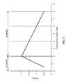
- FIG. 3shows a graph of the transmission speed ratio on the X axis and the variator speed ratio on the Y axis, in accordance with embodiments
- Continuously variable transmissionstypically incorporate a variator that is capable of producing a limited speed ratio in only one direction.
- Some prior continuously variable transmissionshave less than ideal speed ratio ranges and more parts than would be ideal. At least some of the prior continuously variable transmissions rely on more modes and more gears than would be ideal to provide a beneficial range of the continuously variable speed ratio.
- some prior continuously variable transmissionsmay be configured in a manner that results in a variator which has a 4:1 overall ratio to perform as a 2:1 overall transmission ratio.
- at least some of the prior continuously variable transmissionsmay have reduced input torque capacity and additional modes and gears to counteract the reduced variator overall ratio range.
- prior continuously variable transmissionshave less than ideal sizes and form factors which can make the prior continuously variable transmissions difficult to use.
- motor vehicles and bicyclescan provide limited amounts of space for placement of a transmission.
- weightcan be an important consideration and the prior continuously variable transmissions may be larger and heavier than would be ideal.
- FIGS. 1A-Bdepicts some embodiments, other embodiments are possible. While FIGS. 1A-B will be used to describe the operation of the invention in accordance with embodiments, a person of ordinary skill in the art will recognize many embodiments in accordance with the present disclosure.
- the embodiments depicted in FIGS. 1A-Buse a variator.
- the variatorcan be coaxial, or a non-coaxial variator.
- the variatormay comprise one or more components of a commercially available coaxial variator tilting ball variator, for example one or more components of a variator commercially from the Fallbrook Technologies, Inc.
- variatormay comprise one or more components of a commercially available non-coaxial variator, for example commercially available from Van Dorne.
- This CVTcomprises of a certain number of balls 997 (for example, 3-15 balls) to transfer torque through multiple fluid patches, depending on the application, two discs 995 , 996 or annular rings each having an engagement portion that engages the variator balls as input and output as shown on FIG. 2A .
- the ballsare placed in a circular array around a central idler (sun) and contact separate input and output traction rings.
- the engagement portionsmay be in a conical or toroidal convex or concave surface contact with the variator balls, as input and output.
- the CVTmay include an idler 999 contacting the balls as well as shown on FIG. 2A .
- the variator ballsare mounted on axes 998 , themselves held in a cage or carrier allowing changing the ratio by tilting the variator balls' axes.
- This configurationallows the input and output to be concentric and compact. The result is the ability to sweep the transmission through the entire ratio range smoothly, while in motion, under load, or stopped.
- a variatoris a system that uses a set of rotating and tilting balls in a carrier that is positioned between input and output rings. Tilting the balls changes their contact diameters and varies the speed ratio. As a result, the variator system offers continuous transition to any ratio within its range. The gear ratio is shifted by tilting the axes of the spheres in a continuous fashion, to provide different contact radii, which in turn drive the input and output rings, or discs. The multiple balls transfer torque through multiple fluid patches.
- the ballsare placed in a circular array around a central idler (sun) and contact separate input and output traction rings.
- This configurationallows the input and output to be concentric and compact. The result is the ability to sweep the transmission through the entire ratio range smoothly, while in motion, under load, or stopped.
- a traction fluidis optionally located in the variator for lubrication and traction.
- this fluidundergoes high contact pressures under rolling contact between the two rolling elements, the balls and the rings, the fluid undergoes a near-instantaneous phase transition to an elastic solid.
- the molecules of the fluidstack up and link to form a solid, through which shear force and thus torque can be transferred. Note that the rolling elements are actually not in physical contact when rotating.
- the transmissionis depicted with the input side on the right hand side and the output side on the left hand side of the page.
- a power sourcesuch as an engine or motor
- the power sourceis not depicted and not necessary to an understanding of the present disclosure.
- a launching devicewould be connected between the power source and the transmission.
- the launching devicemight be such as a clutch, torque converter, or fluid coupling.
- the launching deviceis not depicted.
- the launching devicewould be connected to the input shaft, which is depicted on the right hand side of the transmission.
- the depicted transmissionmay have two or more modes, a high mode and a low mode; the low mode is depicted in FIG. 1A and the high mode is depicted in FIG. 1B .
- the low modepower flows along a first path and through the variator in a first direction.
- the high modepower flows along a second path and through the variator in a second direction opposite the first direction.
- the rings of the variatorare coaxial and concentrically arranged.
- the input shaft, the output shaft, and the variator ringsmay comprise a coaxial arrangement although other arrangements are possible.
- the low mode in FIG. 1Awill be described first.
- the transmissioncomprises an input shaft 110 coupled to a power source (not shown).
- the input shaft 110is coupled to a first clutch 120 (Clutch W) that can be coupled to an input shaft of the variator 130 when the clutch is engaged.
- the variatorcomprises an output shaft coupled to a third clutch 140 (Clutch X).
- the third clutchcan be coupled to an output shaft of the transmission 150 .
- the variator 130can be connected to a structure to vary the ratio of the variator.
- the variator 130comprises a transmission speed ratio (hereinafter “SR”).
- the transmission speed rationcan be continuously varied and can be varied from about 0.5 to 2.0, for example, although many ranges can be achieved.
- Ring 2 (R 2 ) 133will be connected to the output shaft 150 by applying third Clutch (X) 140 (located to the left of the variator in FIG. 1A ).
- the powerwill then be connected to Gear (S) 160 , which may be a tooth gear, such as a 30 tooth for example in some embodiments.
- Gear (S) 160is located on the output shaft 150 .
- Gear (S) 160is engaged with a Gear (T) 170 , which may be final drive gear, for example a 120 tooth final drive gear in some embodiments.
- Gear (T) 170is connected to the differential and axle shafts (not shown).
- FIGS. 1A and 1Bshow the end view of the gears (G), (R), (S), and (T) and how the gears mesh.
- the Gears (G), (S), and (R)are shown in both the cross sectional view and the end view on the left of FIG. 1A .
- Gear (T)is in constant mesh with Gears (S) and (R) as shown in the end view. This low mode results in the power flowing in a first direction from right to left in the FIG. 1A directly through the variator to the final drive Gears (S) and (T).
- This kinematic arrangement shown in FIG. 1Acan be referred to as a “square” kinematic arrangement.
- the embodiments as described hereinprovide a squared kinematic arrangement for two or more modes, for example, and can provide an increased range transmission speed ratio with fewer moving parts.
- the term “square”comes from the two mode arrangement resulting in the transmission overall ratio being equal to the variator overall ratio squared, i.e. a 3:1 overall ratio variator with two modes results in a 9:1 overall ratio transmission. Adding additional modes will increase the overall transmission ratio range by the raising the variator ratio range to a power which is equal to the number of ranges.
- a 3:1 overall ratio variator with three modesresults in a 27:1 overall ratio transmission.
- a 4:1 overall ratio variator with two modeswill result in a 16:1 ratio.
- a person of ordinary skill in the artcan configure the transmission as described herein in many ways, for example with many combinations of variator ratios and numbers of ranges.
- the square arrangement shown in FIG. 1Areverses the direction of power from one mode to the next (i.e. the input element of the variator for one mode becomes the output element for the second mode).
- the square arrangement of FIG. 1Aprovides a coaxial arrangement of the input disk 132 and the output disk 133 .
- FIG. 1Bdepicts the transmission 200 operating in the high mode.
- the powerflows along Path 2 and through the variator 230 in a direction opposite the low mode.
- first and second counter shafts 251 , 252are coupled to the input shaft 210 and output shaft 250 respectively so that power flows in the second direction through the variator 230 .
- a first shaftis coupled to a first plurality of gears to operatively engage the second ring of the variator.
- a second shaftis coupled to a second plurality of gears to operatively engage the first ring of the variator. This operative engagement allows the power to flow along the second path opposite the first path.
- Gear (A) 211In the high mode 200 , the power from the launch device (not shown) will be taken off the input shaft 210 by Gear (A) 211 , which may be such as a 30 tooth gear in specific embodiments.
- Gear (A) 211is located on the right side of the variator 230 in FIG. 1B .
- Gear (A)transfers power to the lower counter shaft 251 which has Gear (B) 212 .
- Gear (B)may be a 60 tooth gear in specific embodiments.
- Gear (A) 211is shown engaged with Gear (B) 212 .
- Gear (A) and (B)results in the lower counter shaft 251 spinning backwards at a lower speed than the input shaft speed 210 , for the speed ratios and gear tooth counts described earlier, the counter shaft spins backward at half of the input shaft speed.
- Poweris taken off the lower counter shaft 251 by Gear (C) 213 , which may be a 60 tooth gear in specific embodiments.
- Gear (C) 213is shown in driving connection with Gear (D) 214 .
- Gear (D)may comprise a 15 tooth gear in specific embodiments, for example.
- the variator 230will output the power to the right in Ring 1 (R 1 ) 232 , which is connected to the clutch housing located to the right of the variator.
- Second clutch (Z) 225will be applied thus connecting Ring 1 (R 1 ) 232 to Gear (E) 216 , which may comprise a 45 tooth gear in specific embodiments.
- Poweris then transferred from Gear (E) 216 to the Gear (F) 217 , which may comprise a 45 tooth gear in specific embodiments.
- Gear (F) 217is connected to the upper counter shaft 252 .
- Gear (E) 216 and Gear (F) 217results in the upper counter shaft 252 spinning backwards at the same speed as Ring 1 (R 1 ) 232 .
- the poweris then taken off the upper counter shaft 252 by Gear (G) 218 , which may comprise a 60 tooth gear in specific embodiments.
- Gear (G) 218is located on the left end of the upper counter shaft 252 in FIG. 1B .
- Gear (G) 218is meshed with Gear (S) 260 , which may comprise a 30 tooth gear in specific embodiments.
- Gear (S) 260will now be spinning forward at twice the speed of Ring 1 (R 1 ) 232 which is now functioning as the output of the variator 230 .
- Gear (T) 270the axle shaft rotation gear, is in constant mesh with Gear (S) 260 as shown in the end view.
- the high mode 200 powerflows through four additional gear meshes and the direction of power flow through the variator (left to right) is backwards relative to the low mode (right to left).
- the transmission arrangementhas the upper and lower counter shafts oriented parallel to each other and the input and outputs shafts of the transmission.
- the input shaft, the output shaft, and the variatorare aligned along a common axis, and power flow Path 1 can extend along the axis through the input shaft, the variator, and the output shaft in the first direction.
- Path 1is shown in the low mode, a person of ordinary skill in the art will recognize that the gear ratios can be changed so that energy flows along Path 1 in the high mode and along Path 2 in the low mode, by changing the ratios of the gears on the shafts as described herein.
- gears with a particular gear tooth countare mentioned, the present disclosure is not limited to these mentioned gear tooth counts, and may be different, for example greater or less than the values provided.
- the transmissionalso has a reverse mode 300 in many embodiments.
- the reverse mode 300can be readily appreciated based on the following description with reference to FIG. 1C .
- the power from the launch devicewill be taken off the input shaft 310 by Gear (A) 311 (a 30 tooth gear in specific embodiments) and transferred to the lower counter shaft 351 through Gear (B) 312 (a 60 tooth gear in specific embodiments), which is meshed with Gear A 311 .
- Gear (B) 312a 60 tooth gear in specific embodiments
- Poweris taken off the lower counter shaft 351 by applying the reverse clutch (Rev) 347 which directs power to Gear (R) 365 , which may comprise a 30 tooth gear in specific embodiments.
- Gear (R) 365is in mesh with Gear (T) 370 , the axle shaft rotation gear, which may comprise a 120 tooth final drive gear in specific embodiments.
- the reverse ratioshould generally be the same ratio as maximum underdrive but in the opposite direction. In many embodiments, power does not go through the variator in the reverse mode.
- the gear arrangement shown in FIGS. 1A and 1Bresults in the axle shaft rotation [Gear (T)] being in the opposite direction as the input shaft when directing power through the variator.
- This reverse directionis helpful for a transverse mount front wheel drive vehicles that mount the transmission on the right side of the vehicle with conventional direction of engine rotation.
- For vehicles that utilize conventional engine rotation and place the transmission on the left side of the engineit is helpful to have the axle shaft rotation in the same direction as the input shaft direction when directing power through the variator.
- a solution to providing the required direction reversalis to add an extra pair of external gears in series with the input or output, in specific embodiments.
- An alternative solution with fewer moving partswould be to attach the launch device output to the lower counter shaft rather than the input shaft with the required change in the gear tooth counts to return to the desired overall transmission speed ratio.
- the reverse Gear (R)may have its tooth count adjusted in order to provide the desired overall reverse gear ratio with only Gears (R) and (T). In some embodiments, the other gear tooth counts remain the same and the variator functions at twice engine speed. In alternative embodiments, Gears (A) and (B) have identical tooth counts and Gears (C) and (D) have a tooth count ratio equal to the variator overdrive ratio in order to achieve a synchronous shift.
- the gear tooth countshave been selected so that the product of Gear (C) times Gear (A) divided by the product of Gear (B) times Gear (D) is equal to the variator overdrive ratio and the product of Gear (G) times Gear (E) divided by the product of Gear (S) times Gear (F) is also equal to the variator overdrive ratio.
- gear ratiosit is possible to make the low-high shift synchronous in that all of the internal components spin at the same speed before, during, and after the shift. This allows a high quality shift to be made by delivering the synchronous speed ratio in the variator (2.0:1 in this specific embodiment) and then fully applying both oncoming clutches prior to releasing either of the off going clutches.
- the gear tooth counts provided in this disclosureallow a synchronous shift (both low to high and high to low) when the variator provides a 2.0:1 overdrive ratio, although other ratios can be provided.
- FIG. 3depicts a graph of the transmission speed ratio (hereinafter “SR”) on the X axis and the variator speed ratio on the Y axis.
- the low modeis depicted as starting at a transmission speed ratio of 0.5:1 and increasing to 2.0:1 while the variator speed ratio increases from 0.5:1 to 2.0:1.
- the transmission speed ratioincreases while the variator speed ratio decreases from 2.0:1 to 0.5:1.
- FIGS. 1A and 1Bcan be configured with reverse rotation such as illustrated in the embodiment shown in FIG. 1C , or alternative rotation configurations that will be readily apparent to a person of ordinary skill in the art based on the disclosure provide herewith.
- variable transmissions disclosed hereinmay be used in bicycles, mopeds, scooters, motorcycles, automobiles, electric automobiles, trucks, sport utility vehicles (SUV's), lawn mowers, tractors, harvesters, agricultural machinery, all terrain vehicles (ATV's), jet skis, personal watercraft vehicles, airplanes, trains, helicopters, buses, forklifts, golf carts, motorships, steam powered ships, submarines, or space craft.
- SUV'ssport utility vehicles
- ATV'sall terrain vehicles
- jet skispersonal watercraft vehicles, airplanes, trains, helicopters, buses, forklifts, golf carts, motorships, steam powered ships, submarines, or space craft.
- CVTball-type variators
- VDPVariable-diameter pulley
- Reeves drivea toroidal or roller-based CVT (Extroid CVT)
- a Magnetic CVT or mCVTRatcheting CVT
- Hydrostatic CVTsNaudic Incremental CVT (iCVT)
- Cone CVTsRadial roller CVT, Planetary CVT, or any other version CVT.
Landscapes
- Engineering & Computer Science (AREA)
- General Engineering & Computer Science (AREA)
- Mechanical Engineering (AREA)
- Transmission Devices (AREA)
Abstract
Description
Transmission overall ratio=Variator overall ratioNumber of ranges
Claims (19)
Priority Applications (1)
| Application Number | Priority Date | Filing Date | Title |
|---|---|---|---|
| US14/442,580US10030748B2 (en) | 2012-11-17 | 2013-11-14 | Continuously variable transmission |
Applications Claiming Priority (4)
| Application Number | Priority Date | Filing Date | Title |
|---|---|---|---|
| US201261727689P | 2012-11-17 | 2012-11-17 | |
| US201361779579P | 2013-03-13 | 2013-03-13 | |
| PCT/US2013/070177WO2014078583A1 (en) | 2012-11-17 | 2013-11-14 | Continuously variable transmission |
| US14/442,580US10030748B2 (en) | 2012-11-17 | 2013-11-14 | Continuously variable transmission |
Publications (2)
| Publication Number | Publication Date |
|---|---|
| US20160281828A1 US20160281828A1 (en) | 2016-09-29 |
| US10030748B2true US10030748B2 (en) | 2018-07-24 |
Family
ID=50731699
Family Applications (1)
| Application Number | Title | Priority Date | Filing Date |
|---|---|---|---|
| US14/442,580Expired - Fee RelatedUS10030748B2 (en) | 2012-11-17 | 2013-11-14 | Continuously variable transmission |
Country Status (3)
| Country | Link |
|---|---|
| US (1) | US10030748B2 (en) |
| IN (1) | IN2015DN05161A (en) |
| WO (1) | WO2014078583A1 (en) |
Cited By (5)
| Publication number | Priority date | Publication date | Assignee | Title |
|---|---|---|---|---|
| US11014634B2 (en)* | 2016-09-09 | 2021-05-25 | Richard L. Hartman | Hydraulic power sources for watercraft and methods for providing hydraulic power aboard a watercraft |
| US11014635B2 (en)* | 2016-09-09 | 2021-05-25 | Richard L. Hartman | Power source assemblies and methods for distributing power aboard a watercraft |
| US20210262556A1 (en)* | 2018-09-18 | 2021-08-26 | Robert Bosch Gmbh | Powertrain with a continuously variable transmission for an electric vehicle and method for operating such powertrain |
| US11254395B2 (en) | 2016-09-09 | 2022-02-22 | Richard L. Hartman | Aquatic invasive species control apparatuses and methods for watercraft |
| US11505289B2 (en) | 2016-09-09 | 2022-11-22 | Richard L. Hartman | Wakeboat bilge measurement assemblies and methods |
Families Citing this family (20)
| Publication number | Priority date | Publication date | Assignee | Title |
|---|---|---|---|---|
| US9347532B2 (en) | 2012-01-19 | 2016-05-24 | Dana Limited | Tilting ball variator continuously variable transmission torque vectoring device |
| CN104204615B (en) | 2012-02-15 | 2017-10-24 | 德纳有限公司 | Transmission device and the power train with tilt ball speed changer infinitely variable speed transmission |
| EP2893219A4 (en) | 2012-09-06 | 2016-12-28 | Dana Ltd | Transmission having a continuously or infinitely variable variator drive |
| US9599204B2 (en) | 2012-09-07 | 2017-03-21 | Dana Limited | Ball type CVT with output coupled powerpaths |
| WO2014039708A1 (en) | 2012-09-07 | 2014-03-13 | Dana Limited | Ball type cvt including a direct drive mode |
| WO2014039713A1 (en) | 2012-09-07 | 2014-03-13 | Dana Limited | Ivt based on a ball type cvp including powersplit paths |
| CN104768787A (en) | 2012-09-07 | 2015-07-08 | 德纳有限公司 | Ball type CVT with powersplit paths |
| US9689477B2 (en) | 2012-09-07 | 2017-06-27 | Dana Limited | Ball type continuously variable transmission/infinitely variable transmission |
| JP6320386B2 (en) | 2012-09-07 | 2018-05-09 | デーナ リミテッド | Ball type CVT / IVT including planetary gear set |
| US10030748B2 (en) | 2012-11-17 | 2018-07-24 | Dana Limited | Continuously variable transmission |
| WO2014124063A1 (en) | 2013-02-08 | 2014-08-14 | Microsoft Corporation | Pervasive service providing device-specific updates |
| CN105121905A (en) | 2013-03-14 | 2015-12-02 | 德纳有限公司 | Ball type continuously variable transmission |
| US9551404B2 (en) | 2013-03-14 | 2017-01-24 | Dana Limited | Continuously variable transmission and an infinitely variable transmission variator drive |
| EP3004686B1 (en) | 2013-06-06 | 2018-08-08 | Dana Limited | 3-mode front wheel drive and rear wheel drive continuously variable planetary transmission |
| US10030751B2 (en) | 2013-11-18 | 2018-07-24 | Dana Limited | Infinite variable transmission with planetary gear set |
| WO2015073948A2 (en) | 2013-11-18 | 2015-05-21 | Dana Limited | Torque peak detection and control mechanism for cvp |
| CN106536987A (en) | 2014-06-17 | 2017-03-22 | 德纳有限公司 | Off-highway continuously variable planetary-based multimore transmission including infinite variable transmission and direct continuously variable tranmission |
| US10864811B2 (en) | 2015-04-10 | 2020-12-15 | Atul A. Ranade | Toroidal transmission system for hybrid vehicles |
| US10030594B2 (en) | 2015-09-18 | 2018-07-24 | Dana Limited | Abuse mode torque limiting control method for a ball-type continuously variable transmission |
| JP6606518B2 (en)* | 2017-01-31 | 2019-11-13 | 日東電工株式会社 | Optical sheet for light guide plate type liquid crystal display, backlight unit for light guide plate type liquid crystal display, and light guide plate type liquid crystal display |
Citations (280)
| Publication number | Priority date | Publication date | Assignee | Title |
|---|---|---|---|---|
| US1063244A (en) | 1908-03-18 | 1913-06-03 | Ludwig Maria Dieterich | Variable-power transmitting and controlling mechanism. |
| US1215969A (en) | 1916-12-14 | 1917-02-13 | Thomas E Murray | Sheet-metal piston. |
| US1526140A (en) | 1921-10-03 | 1925-02-10 | Hollow Ball Company Inc | Manufacture of hollow metal balls |
| US2019006A (en) | 1934-02-01 | 1935-10-29 | Ferrarl Lorenzo | Change speed gear |
| FR796188A (en) | 1935-10-04 | 1936-03-31 | Friction shifting | |
| US2060884A (en) | 1933-09-19 | 1936-11-17 | Erban Operating Corp | Power transmission mechanism |
| US2148759A (en) | 1938-02-10 | 1939-02-28 | Grand Cecil W Le | Variable transmission unit |
| US2405201A (en) | 1942-08-29 | 1946-08-06 | Imp Brass Mfg Co | Method of forming closed metal capsules |
| FR1030702A (en) | 1950-12-06 | 1953-06-16 | Tiltman Langley Lab Ltd | Improvements to variable speed ratio transmission mechanisms in a continuous range |
| US2660897A (en) | 1950-09-20 | 1953-12-01 | Dabo Ltd | Infinitely-variable change-speed gear |
| US2729118A (en) | 1955-04-25 | 1956-01-03 | Lyell M Emslie | Gearless differential |
| US2931235A (en) | 1957-11-12 | 1960-04-05 | George Cohen 600 Group Ltd | Variable speed friction drive transmissions |
| US3203278A (en) | 1963-01-02 | 1965-08-31 | Ford Motor Co | Variable speed friction drive transmission |
| US3246531A (en)* | 1960-11-04 | 1966-04-19 | Kashihara Manabu | Infinitely variable speed change gear |
| FR1472282A (en) | 1966-02-24 | 1967-03-10 | Chambre Syndicale Des Fabrican | Method and apparatus for transforming a section of metal tube into a sphere, and application of the sphere thus obtained to the production of assembly nodes, in particular for tubular frames |
| DE1237380B (en) | 1958-08-13 | 1967-03-23 | Differential Diesel Engines Es | Supercharged internal combustion engine with a supercharging system with two drives |
| US3376633A (en) | 1966-04-20 | 1968-04-09 | Richard H. Wesley | Ball joint forming methods |
| GB1127825A (en) | 1966-06-15 | 1968-09-18 | Filden Engineering Ltd | Improvements relating to the manufacture of spherical and spheroidal objects |
| US3407687A (en) | 1967-03-27 | 1968-10-29 | Hayashi Tadashi | Variable ratio power transmission device |
| US3470720A (en) | 1967-09-01 | 1969-10-07 | Phillip R Eklund | Method of making hollow balls for use in ball bearing and/or similar rolling operations |
| US3505718A (en) | 1968-01-15 | 1970-04-14 | Gen Ind Inc | One-piece sheet metal hollow ball for ball valves |
| US3583060A (en) | 1968-12-30 | 1971-06-08 | Ametek Inc | Method of swaging a metal fitting on a steel wire |
| US3688600A (en) | 1971-04-26 | 1972-09-05 | Ford Motor Co | Infinitely variable overdrive transmission mechanism |
| US3765270A (en) | 1971-04-26 | 1973-10-16 | Ford Motor Co | Multiple ratio power transmission mechanism with an infinitely variable overdrive range |
| US3774280A (en) | 1972-07-18 | 1973-11-27 | Us Air Force | Method of fabricating hollow balls for use in rolling contact bearing applications |
| FR2185076A5 (en) | 1972-05-16 | 1973-12-28 | Burke John | |
| US3831245A (en) | 1973-03-01 | 1974-08-27 | Columbus Auto Parts | Method of producing ball joints |
| US3894559A (en) | 1974-03-28 | 1975-07-15 | Leland Q Depuy | Manifold valve |
| FR2280451A1 (en) | 1974-08-01 | 1976-02-27 | Roche Jean | Hollow spherical body mfr - with tubing hot or cold spun between hemispherical dies |
| US4046988A (en) | 1976-03-05 | 1977-09-06 | Kobe Steel Ltd. | Method of preventing base metal end crack in arc welding and end tab used therefor |
| US4187709A (en) | 1976-08-23 | 1980-02-12 | Kevin Strickland | Explosive forming |
| US4226140A (en) | 1976-12-14 | 1980-10-07 | Gaasenbeek Johannes L | Self-propelled vehicle |
| US4333358A (en) | 1979-12-18 | 1982-06-08 | Fiat-Allis Macchine Movimento Terra S.P.A. | Power-shift countershaft type transmission |
| US4344336A (en) | 1979-07-23 | 1982-08-17 | Ford Motor Company | Differential traction drive with extreme overall torque ratios for use in a gas turbine engine driveline |
| US4360090A (en) | 1980-10-20 | 1982-11-23 | General Motors Corporation | Torque reversal control valve for a torque converter clutch |
| US4368572A (en) | 1979-10-15 | 1983-01-18 | Toyo Kogyo Co., Ltd. | Method of manufacturing a shaft structure having a spherical bulb |
| DE3245045A1 (en) | 1982-12-06 | 1984-06-07 | Adam Opel AG, 6090 Rüsselsheim | Motor vehicle hybrid drive arrangement |
| US4458558A (en)* | 1981-08-05 | 1984-07-10 | Aisin Seiki Kabushiki Kaisha | Variable V-belt type continuously variable transmission for vehicles |
| US4464952A (en) | 1980-05-31 | 1984-08-14 | Bl Technology Limited | Control systems for continuously variable ratio transmissions (CVT) |
| US4539866A (en)* | 1983-11-03 | 1985-09-10 | General Motors Corporation | Continuously variable transmission |
| EP0156936A1 (en) | 1984-04-03 | 1985-10-09 | Klinger AG | Process for producing a spherical plug for a fluid valve |
| US4630504A (en)* | 1985-08-22 | 1986-12-23 | Borg-Warner Corporation | Dual-pass continuously variable transmission |
| EP0210053A2 (en) | 1985-07-22 | 1987-01-28 | Borg-Warner Corporation | Dual-pass continuously variable transmission with asymetric variator |
| US4693134A (en) | 1985-06-20 | 1987-09-15 | Excelermatic Inc. | High-powered vehicle drive train |
| US4731044A (en) | 1985-12-18 | 1988-03-15 | Borg-Warner Automotive, Inc. | Tension sensor and control arrangement for a continuously variable transmission |
| GB2196892A (en) | 1986-11-05 | 1988-05-11 | Concentric Pumps Ltd | Fixing components on shafts |
| US4756211A (en) | 1985-09-13 | 1988-07-12 | Fellows Thomas G | Continuously-variable ratio transmission for an automobile vehicle |
| US4784017A (en) | 1986-07-03 | 1988-11-15 | Johnshoy Edward W | Continuously variable transmission and torque retaining differential |
| US4856374A (en) | 1987-03-02 | 1989-08-15 | Planetroll Antriebe Gmbh | Adjustable transmission |
| US4856371A (en) | 1987-03-12 | 1989-08-15 | Tractiontec Corporation | Traction drive transmission system |
| US4885955A (en)* | 1989-03-27 | 1989-12-12 | Excelermatic Inc. | Multimode infinitely variable transmission |
| US4950208A (en) | 1988-06-17 | 1990-08-21 | Malcolm Tomlinson | Variable ratio power transmission |
| US4963122A (en) | 1987-06-04 | 1990-10-16 | The Gleason Works | Continuously variable differential |
| US4963124A (en) | 1988-10-26 | 1990-10-16 | Toyota Jidosha Kabushiski Kaisha | Planetary gear transmission for motor vehicle |
| GB2248895A (en) | 1990-09-12 | 1992-04-22 | Malcolm Tomlinson | Double toroidal race variator with two variable outputs |
| US5109962A (en) | 1989-12-28 | 1992-05-05 | Fuji Jukogyo Kabushiki Kaisha | Transmission ratio control system for a continuously variable transmission |
| US5168778A (en) | 1991-08-29 | 1992-12-08 | Borg-Warner Automotive, Inc. | CVT downshift control strategy to minimize slip at the drive pulley |
| US5217412A (en) | 1990-10-20 | 1993-06-08 | Luk Lamellen Und Kupplungsbau Gmbh | Continuously variable speed transmission |
| US5230670A (en) | 1990-12-25 | 1993-07-27 | Nissan Motor Co., Ltd. | Friction roller type continuously variable transmission |
| US5238460A (en) | 1991-02-28 | 1993-08-24 | Mazda Motor Corporation | Power transmission system for vehicle |
| US5318486A (en) | 1991-08-16 | 1994-06-07 | Fichtel & Sachs Ag | Driving hub for a vehicle, particularly a bicycle, with an infinitely adjustable transmission ratio |
| US5390759A (en) | 1992-08-10 | 1995-02-21 | Sauer Inc. | Driving mechanism for an automotive propel drive |
| US5401221A (en) | 1990-08-17 | 1995-03-28 | Torotrak (Development) Limited | Transmission of the toroidal-race, rolling-traction type having a mixer and a reducer epicyclic type gearing with clutches brakes |
| US5520588A (en) | 1995-05-03 | 1996-05-28 | General Motors Corporation | Power transmission |
| US5527231A (en) | 1991-06-21 | 1996-06-18 | Dr. Ing. H.C.F. Porsche Ag | Method for controlling a continuously variable transmission of a motor vehicle |
| US5577423A (en) | 1994-03-04 | 1996-11-26 | Mimura; Kenji | Differential gear |
| US5599251A (en) | 1995-09-27 | 1997-02-04 | Ford Motor Company | Six speed automatic transmission for automotive vehicles |
| JPH09119506A (en) | 1995-10-23 | 1997-05-06 | Toyota Motor Corp | Differential device |
| US5659956A (en) | 1996-02-12 | 1997-08-26 | Braginsky; Mikhail | Process for the production of hollow ball bearings |
| US5683322A (en) | 1993-04-21 | 1997-11-04 | Meyerle; Michael | Continuous hydrostatic-mechanical branch power split transmission particularly for power vehicles |
| US5726353A (en) | 1995-11-21 | 1998-03-10 | Honda Giken Kogyo Kabushiki Kaisha | System for detecting torque of automatic vehicle transmission and controlling the same based on detected torque |
| US5730678A (en) | 1996-02-28 | 1998-03-24 | Gen Dynamics Defense Syst Inc | Multi-range, hydromechanical transmission for motor vehicles |
| US5766105A (en) | 1993-12-20 | 1998-06-16 | Torotrak (Development) Limited | Continuously variable transmission capable of torque control |
| US5776028A (en) | 1995-09-01 | 1998-07-07 | Honda Giken Kogyo Kabushiki Kaisha | Belt-type continuously variable transmission |
| US5800303A (en) | 1994-11-28 | 1998-09-01 | Chrysler Corporation | Four-speed automatic transmission |
| US5860888A (en) | 1996-06-18 | 1999-01-19 | Hyundai Motor Co. | Automatic transmission with a toroidal CVT and a belt type CVT for vehicle |
| US5915801A (en) | 1995-07-18 | 1999-06-29 | Toyota Jidosha Kabushiki Kaisha | Regenerative brake controller for controlling value of regenerative braking torque simulating engine braking torque |
| US5961415A (en) | 1998-09-17 | 1999-10-05 | Ford Global Technologies, Inc. | Single cavity toroidal traction drive continually variable transmission |
| US5971883A (en) | 1998-03-13 | 1999-10-26 | General Motors Corporation | Multi-speed power transmission |
| US5996226A (en) | 1997-12-23 | 1999-12-07 | Itt Manufacturing Enterprises, Inc. | Method of manufacturing push rod balls |
| US6009365A (en) | 1997-12-25 | 1999-12-28 | Nissan Motor Co., Ltd. | Vehicle drive system controller and control method |
| US6036616A (en) | 1998-03-19 | 2000-03-14 | Ford Global Technologies, Inc. | All wheel drive continously variable transmission having dual mode operation |
| US6045477A (en) | 1999-06-14 | 2000-04-04 | General Motors Corporation | Continuously variable multi-range powertrain with a geared neutral |
| US6053839A (en) | 1999-06-18 | 2000-04-25 | Ford Global Technologies, Inc. | Multiple speed overdrive transmission for a motor vehicle |
| US6059685A (en) | 1999-05-06 | 2000-05-09 | Ford Global Technologies, Inc. | Coaxial traction drive automatic transmission for automotive vehicles |
| US6071208A (en) | 1998-06-22 | 2000-06-06 | Koivunen; Erkki | Compact multi-ratio automatic transmission |
| US6080080A (en) | 1997-09-30 | 2000-06-27 | Robert Bosch Gmbh | Device and method for adjusting the transmission ratio of a CVT |
| US6083135A (en) | 1999-06-18 | 2000-07-04 | Ford Global Technologies, Inc. | Multiple speed overdrive transmission for a motor vehicle |
| US6086504A (en) | 1996-04-22 | 2000-07-11 | Zf Friedrichshafen Ag | Planetary gear and clutch-brake arrangement |
| US6089287A (en) | 1995-07-20 | 2000-07-18 | Black & Decker Inc. | Portable wood planing machine |
| US6095942A (en) | 1998-08-18 | 2000-08-01 | Honda Giken Kogyo Kabushiki Kaisha | Speed change control device for vehicular continuously variable transmission |
| US6155951A (en) | 1997-01-31 | 2000-12-05 | Zf Friedrichshafen Ag | Toroidal drive |
| US6217474B1 (en) | 1999-10-22 | 2001-04-17 | General Motors Corporation | Multi speed power transmission |
| US6251038B1 (en) | 1998-10-21 | 2001-06-26 | Nsk Ltd. | Continuously variable transmission unit |
| US6273838B1 (en) | 1999-07-08 | 2001-08-14 | Hyundai Motor Company | Gear train for vehicle automatic transmissions |
| US20020004438A1 (en) | 2000-07-10 | 2002-01-10 | Nissan Motor Co., Ltd. | Input torque limiting device for an infinitely variable transmission |
| US6342026B1 (en) | 1999-07-29 | 2002-01-29 | Aisin Seiki Kabushiki Kaisha | Automatic transmission for vehicles |
| US6358178B1 (en) | 2000-07-07 | 2002-03-19 | General Motors Corporation | Planetary gearing for a geared neutral traction drive |
| US6371880B1 (en) | 1999-06-03 | 2002-04-16 | Hyundai Motor Company | Limited slip differential |
| US20020094911A1 (en) | 2001-01-16 | 2002-07-18 | Haka Raymond James | Dual mode, geared neutral continuously variable transmission |
| US20020169048A1 (en) | 2001-04-28 | 2002-11-14 | Steffen Henzler | Speed change transmission arrangement including a continuously variable toriodal transmission |
| US6481258B1 (en) | 1997-06-18 | 2002-11-19 | Jacob S. Belinky | Removable trailer hitch ball |
| US20030060318A1 (en) | 2001-09-27 | 2003-03-27 | Jatco Ltd | Torque split infinitely variable transmission |
| US6554735B2 (en) | 2000-09-28 | 2003-04-29 | Fuji Jukogyo Kabushiki Kaisha | Planetary gear type differential apparatus |
| US6558285B1 (en) | 1999-06-26 | 2003-05-06 | Robert Bosch Gmbh | Friction-wheel planetary gear with bevel gears |
| US6585619B2 (en) | 2000-08-11 | 2003-07-01 | Daimler Chrysler Ag | Transmission arrangement |
| US6609994B2 (en) | 2001-03-16 | 2003-08-26 | Nissan Motor Co., Ltd. | Braking/driving control apparatus and method for automotive vehicle |
| US20030181280A1 (en) | 2002-02-15 | 2003-09-25 | Daimlerchrysler Ag | Motor vehicle transmission with a toroidal variable-speed drive unit |
| US6632157B1 (en) | 1998-09-29 | 2003-10-14 | Zf Batavia L.L.C. | Method for reducing the thermal load on an automatic transmission for a motor vehicle in emergency operating mode |
| US20030200783A1 (en) | 2002-04-26 | 2003-10-30 | Dean Shai | Hollow tubular blank provided in wall thereof with one or more reinforcing ribs |
| US6641497B2 (en) | 2001-12-07 | 2003-11-04 | Murray, Inc. | Epicyclic transmission for zero turning radius vehicles |
| US6645106B2 (en) | 2000-08-22 | 2003-11-11 | Teak-Seo Goo | Transmission for performing reliable continuously-variable-speed operation through gear meshing, and vehicle-use continuously-variable transmission device using it |
| US20030216121A1 (en) | 2001-10-11 | 2003-11-20 | Mark Yarkosky | Method for in-building distribution using wireless access technology |
| US20030213125A1 (en) | 2002-05-20 | 2003-11-20 | Su-Yueh Chiuchang | Ball valve body manufacturing method |
| US20030228952A1 (en) | 2002-06-05 | 2003-12-11 | Nissan Motor Co., Ltd. | Toroidal continuously variable transmission control apparatus |
| US6689012B2 (en) | 2001-04-26 | 2004-02-10 | Motion Technologies, Llc | Continuously variable transmission |
| US6705964B2 (en) | 2001-12-11 | 2004-03-16 | Jatco Ltd | Power transmission system |
| US20040058769A1 (en) | 2002-09-23 | 2004-03-25 | Larkin Robert P. | Multi-range parallel-hybrid continuously variable transmission |
| US20040061639A1 (en) | 2000-11-11 | 2004-04-01 | Klaus Voigtlaender | Radar device and method for operating a radar device |
| US6719659B2 (en) | 2000-05-05 | 2004-04-13 | Daimlerchrysler Ag | Continuously variable vehicle transmission |
| US6733412B2 (en) | 2001-05-21 | 2004-05-11 | Honda Giken Kogyo Kabushiki Kaisha | Automotive automatic transmission |
| US6752696B2 (en) | 2001-03-12 | 2004-06-22 | Nsk Ltd. | Rolling elements for rolling bearing, method of producing the same, and rolling bearing |
| US20040166984A1 (en) | 2002-12-05 | 2004-08-26 | Nsk Ltd. | Continuously variable transmission apparatus |
| US20040167391A1 (en) | 2003-02-25 | 2004-08-26 | Solar Matthew S. | Fiducial marker devices, tools, and methods |
| US20040171452A1 (en) | 2003-02-28 | 2004-09-02 | Miller Donald C. | Continuously variable transmission |
| US6793603B2 (en) | 2001-10-25 | 2004-09-21 | Tochigi Fuji Sangyo Kabushiki Kaisha | Power transmission system with sub transmission mechanism |
| US6849020B2 (en) | 2002-08-07 | 2005-02-01 | Jatco Ltd | Continuously variable power-split transmission |
| US6866606B2 (en) | 2001-10-25 | 2005-03-15 | Honda Giken Kogyo Kabushiki Kaisha | Continuously variable transmission system for vehicles |
| US20050102082A1 (en) | 2003-11-12 | 2005-05-12 | Nissan Motor Co., Ltd. | Shift control system of hybrid transmission |
| US20050137046A1 (en) | 2003-08-11 | 2005-06-23 | Miller Donald C. | Continuously variable planetary gear set |
| US6949045B2 (en) | 2002-10-24 | 2005-09-27 | Zf Friedrichshafen Ag | Power distributed 2-range transmission |
| US6979275B2 (en) | 2001-05-14 | 2005-12-27 | Nissan Motor Co., Ltd. | Auxiliary transmission in transmission system |
| WO2006002457A1 (en) | 2004-07-06 | 2006-01-12 | Bruce Winston Brockhoff | Solar collector |
| US6986725B2 (en) | 2002-11-01 | 2006-01-17 | Eaton Corporation | Continuously variable stepped transmission |
| WO2006041718A2 (en) | 2004-10-05 | 2006-04-20 | Fallbrook Technologies, Inc. | Continuously variable transmission |
| US7033298B2 (en) | 2002-12-18 | 2006-04-25 | General Motors Corporation | Family of five-speed dual-clutch transmissions having three planetary gear sets |
| US20060094515A1 (en) | 2004-10-29 | 2006-05-04 | Joseph Szuba | Universal joint assembly for an automotive driveline system |
| US7074154B2 (en) | 1998-08-12 | 2006-07-11 | Fallbrook Technologies Inc. | Continuously variable transmission |
| US7086981B2 (en) | 2004-02-18 | 2006-08-08 | The Gates Corporation | Transmission and constant speed accessory drive |
| US7104917B2 (en) | 2004-09-28 | 2006-09-12 | General Motors Corporation | Countershaft planetary transmissions |
| DE102005010751A1 (en) | 2005-03-09 | 2006-09-14 | Zf Friedrichshafen Ag | Differential transmission unit for four-wheel drive vehicle, employs variator drive principle to distribute input power between front and rear wheels |
| US20060234822A1 (en) | 2005-04-15 | 2006-10-19 | Eaton Corporation | Continuously variable dual mode transmission |
| US7128681B2 (en) | 2003-11-12 | 2006-10-31 | Honda Motor Co., Ltd. | Transmission |
| JP2006322482A (en)* | 2005-05-17 | 2006-11-30 | Nsk Ltd | Continuously variable transmission |
| US20060276294A1 (en) | 2005-06-03 | 2006-12-07 | Dan Coffey | Three-mode continuously variable transmission with a direct low mode and two split path high modes |
| US7160220B2 (en) | 2003-07-14 | 2007-01-09 | Nsk Ltd. | Continuously variable transmission apparatus |
| US20070021259A1 (en) | 2005-07-23 | 2007-01-25 | Luk Lamellen Und Kupplungsbau Beteiligungs Kg | Power-branched transmission having a plurality of transmission ratio ranges with continuously variable transmission ratio |
| US20070032327A1 (en) | 2005-08-03 | 2007-02-08 | Madhusudan Raghavan | Electrically variable transmission having two or three planetary gear sets with two or three fixed interconnections |
| US20070042856A1 (en) | 2003-07-01 | 2007-02-22 | Greenwood Christopher J | Continuously variable ratio transmission system |
| US7186199B1 (en) | 2004-10-29 | 2007-03-06 | Torque-Traction Technologies. Llc. | Torque vectoring gear drive apparatus |
| US20070072732A1 (en) | 2005-09-23 | 2007-03-29 | Donald Klemen | Nine speed automatic transmission with six torque-transmitting mechanisms |
| WO2007046722A1 (en) | 2005-10-18 | 2007-04-26 | Champlon Joao Armando Soledade | Continuously variable transmission (cvt) through gears |
| US20070096556A1 (en) | 2005-10-28 | 2007-05-03 | Koichi Kokubo | Automatic braking apparatus for a vehicle |
| WO2007051827A1 (en) | 2005-11-02 | 2007-05-10 | Infinitrak, Llc | Continuously variable ratio transmission drive |
| US7234543B2 (en) | 2003-04-25 | 2007-06-26 | Intersyn Ip Holdings, Llc | Systems and methods for directionally drilling a borehole using a continuously variable transmission |
| US7288044B2 (en) | 2003-04-04 | 2007-10-30 | Zf Friedrichshafen Ag | Transmission, in particular an automated power-branched multi-speed gearing |
| US20070275808A1 (en) | 2006-05-25 | 2007-11-29 | Aisin Aw Co., Ltd. | Hybrid drive device |
| US7311634B2 (en) | 2005-09-28 | 2007-12-25 | Hyundai Motor Company | Seven-speed powertrain of an automatic transmission for vehicles |
| US7335126B2 (en) | 2005-02-23 | 2008-02-26 | Kabushikikaisha Equos Research | Continuously variable transmission |
| US7347801B2 (en) | 2004-04-30 | 2008-03-25 | Getrag Getriebe-Und Zahnradfabrik Hermann Hagenmeyer Gmbh & Cie Kg | Toroidal transmission |
| US20080103002A1 (en) | 2006-10-25 | 2008-05-01 | Holmes Alan G | Hybrid electrically variable transmission with dual power paths and selective motor connection |
| US7396309B2 (en) | 2005-05-31 | 2008-07-08 | Zf Friedrichshafen Ag | Split power transmission to include a variable drive |
| US20080185201A1 (en) | 2004-12-22 | 2008-08-07 | Timothy Bishop | Spring Hybrid Drive |
| JP2008180214A (en) | 2006-12-28 | 2008-08-07 | Toyota Motor Corp | Camshaft torque reduction mechanism for internal combustion engine |
| WO2008103543A1 (en) | 2007-02-23 | 2008-08-28 | Gm Global Technology Operations, Inc. | Low cost torque vectoring system |
| FR2918433A1 (en) | 2007-07-05 | 2009-01-09 | Peugeot Citroen Automobiles Sa | Transmission component for e.g. automobile, has hydraulic control system for controlling inclination of pivoting axis of each roller to control distribution of engine torques transmitted to disks |
| US20090017959A1 (en) | 2007-06-21 | 2009-01-15 | Luk Lamellen Und Kupplungsbau Beteiligungs Kg | Vehicle transmission with continuously variable transmission ratio |
| US7485069B2 (en) | 2006-07-20 | 2009-02-03 | Hyundai Motor Company | Power train of automatic transmission |
| US20090048054A1 (en) | 2005-03-31 | 2009-02-19 | Torotrak (Development ) Ltd. | Continuously variable transmission |
| US7497798B2 (en) | 2006-09-21 | 2009-03-03 | Hyundai Motor Company | Hybrid power train structure using toroidal variator |
| US20090062064A1 (en) | 2007-08-31 | 2009-03-05 | Toyota Jidosha Kabushiki Kaisha | Shift control apparatus |
| CN101392825A (en) | 2002-12-23 | 2009-03-25 | 卢克摩擦片和离合器两合公司 | Transmission with a steplessly adjustable transmission ratio, with or without branched power and with or without an electrical machine |
| US20090132135A1 (en) | 2007-11-16 | 2009-05-21 | Fallbrook Technologies Inc. | Controller for variable transmission |
| US20090221393A1 (en) | 2005-09-29 | 2009-09-03 | Magna Steyr Fahrzeugtechnik Ag & Co Kg | Differential Gearing Unit For Motor Vehicles With Active Control Of The Drive Force Distribution |
| US20090221391A1 (en) | 2008-02-29 | 2009-09-03 | Fallbrook Technologies Inc. | Continuously and/or infinitely variable transmissions and methods therefor |
| US7588514B2 (en) | 2005-12-27 | 2009-09-15 | Eaton Corporation | Method for controlling engine braking in a vehicle powertrain |
| US20090286651A1 (en) | 2008-05-13 | 2009-11-19 | Kawasaki Jukogyo Kabushiki Kaisha | Starting and generating apparatus for engine |
| US20090312137A1 (en) | 2002-09-30 | 2009-12-17 | Ulrich Rohs | Transmission |
| US7637838B2 (en) | 2006-02-14 | 2009-12-29 | Zf Friedrichshafen Ag | Multi-speed transmission |
| CN101617146A (en) | 2007-02-21 | 2009-12-30 | 托罗特拉克(开发)有限公司 | Stepless speed change transmission device |
| US7672770B2 (en) | 2005-06-15 | 2010-03-02 | Toyota Jidosha Kabushiki Kaisha | Deceleration control apparatus for a vehicle |
| US20100056322A1 (en) | 2008-08-26 | 2010-03-04 | Fallbrook Technologies Inc. | Continuously variable transmission |
| US20100093476A1 (en) | 2007-02-16 | 2010-04-15 | Fallbrook Technologies Inc. | Infinitely variable transmissions, continuously variable transmissions, methods, assemblies, subassemblies, and components therefor |
| US20100093479A1 (en) | 2007-02-12 | 2010-04-15 | Fallbrook Technologies Inc. | Continuously variable transmissions and methods therefor |
| US20100106386A1 (en) | 2006-12-18 | 2010-04-29 | Peugeot Citroen Automobiles S.A. | Method for braking a hybrid vehicle and method for improving a hybrid vehicle implementing said method |
| US20100113211A1 (en) | 2007-02-26 | 2010-05-06 | Gif Gesellschaft Fur Industrieforschung Mbh | Drive arrangement with an infinitely variable sub-gear box |
| US20100137094A1 (en) | 2007-04-24 | 2010-06-03 | Fallbrook Technologies Inc. | Electric traction drives |
| US20100141193A1 (en) | 2008-12-04 | 2010-06-10 | Paola Rotondo | Torsional mode damping apparatus |
| US7780566B2 (en) | 2007-05-08 | 2010-08-24 | Hyundai Motor Company | 8-speed automatic transmission for a vehicle |
| US20100244755A1 (en) | 2009-03-30 | 2010-09-30 | Aisin Aw Co., Ltd. | Rotary electric machine control device |
| US20100267510A1 (en) | 2009-04-16 | 2010-10-21 | Fallbrook Technologies Inc. | Continuously variable transmission |
| US20100282020A1 (en) | 2007-09-04 | 2010-11-11 | Christopher John Greenwood | Continuously variable transmission |
| US20100304915A1 (en) | 2006-04-10 | 2010-12-02 | Derek Lahr | Cam-based infinitely variable transmission |
| US20100310815A1 (en) | 2008-02-01 | 2010-12-09 | Omnidea, Lda. | Plastic deformation technological process for production of thin wall revolution shells from tubular billets |
| US20110015021A1 (en) | 2009-07-16 | 2011-01-20 | Gm Global Technology Operations, Inc. | Clutch arrangements for an electrically-variable transmission |
| US7874153B2 (en) | 2005-12-16 | 2011-01-25 | Bosch Rexroth Ag | Hydrostatic drive and method of braking a hydrostatic drive |
| US7878935B2 (en) | 2007-11-26 | 2011-02-01 | Derek Lahr | Continuously variable transmission with external cam |
| WO2011011991A1 (en) | 2009-07-31 | 2011-02-03 | 中兴通讯股份有限公司 | Method and apparatus for network elements in lan to obtain service content |
| US20110034284A1 (en) | 2005-12-30 | 2011-02-10 | Fallbrook Technologies Inc. | Continuously variable transmission |
| US7951035B2 (en) | 2008-02-07 | 2011-05-31 | American Axle & Manufacturing, Inc. | Continuously variable torque vectoring axle assembly |
| US20110152031A1 (en) | 2009-12-16 | 2011-06-23 | Brian Schoolcraft | System and method for controlling endload force of a variator |
| US20110165986A1 (en) | 2010-07-19 | 2011-07-07 | Ford Global Technologies, Llc | Transmission Producing Continuously Speed Ratios |
| US20110165982A1 (en) | 2010-07-22 | 2011-07-07 | Ford Global Technologies, Llc | Accessory Drive and Engine Restarting System |
| US20110165985A1 (en) | 2010-12-07 | 2011-07-07 | Ford Global Technologies, Llc | Transmission Producing Continuously Variable Speed Ratios |
| US7980972B1 (en) | 2006-05-01 | 2011-07-19 | Purdue Research Foundation | Roller variator for actuating continuously variable transmissions |
| JP2011153583A (en) | 2010-01-28 | 2011-08-11 | Toyota Central R&D Labs Inc | Supercharger |
| US20110230297A1 (en) | 2010-03-18 | 2011-09-22 | Toyota Jidosha Kabushiki Kaisha | Continuously variable transmission |
| US8029401B2 (en) | 2008-10-31 | 2011-10-04 | Deere & Company | Split path power shift transmission |
| AU2011224083A1 (en) | 2004-10-05 | 2011-10-06 | Fallbrook Intellectual Property Company Llc | Continuously Variable Transmission |
| US8052569B2 (en) | 2005-10-26 | 2011-11-08 | Toyota Jidosha Kabushiki Kaisha | Controller of power transmission |
| US8062175B2 (en) | 2008-11-04 | 2011-11-22 | GM Global Technology Operations LLC | Method and apparatus for optimizing braking control during a threshold braking event |
| US20110300954A1 (en) | 2004-10-29 | 2011-12-08 | Value Extraction Llc | Universal joint assembly for an automotive driveline system |
| US20110319222A1 (en) | 2009-02-10 | 2011-12-29 | Toyota Jidosha Kabushiki Kaisha | Continuously variable transmission mechanism and transmission using the same |
| WO2012008884A1 (en) | 2010-07-16 | 2012-01-19 | Volvo Construction Equipment Ab | Continuously variable transmission and a working maching including a continuously variable transmission |
| US20120024991A1 (en) | 2010-08-02 | 2012-02-02 | Techtronic Floor Care Technology Limited | Force responsive shredder |
| US20120040794A1 (en) | 2010-08-16 | 2012-02-16 | Brian Schoolcraft | Gear scheme for infinitely variable transmission |
| CN202165536U (en) | 2011-06-30 | 2012-03-14 | 长城汽车股份有限公司 | Automatic transmission with six forward gears and reverse gear |
| US20120122624A1 (en) | 2010-11-15 | 2012-05-17 | Hawkins Jr Glen S | Input Clutch Assembly For Infinitely Variable Transmission |
| US20120142477A1 (en) | 2009-05-19 | 2012-06-07 | Torotrak (Development) Limited | Continuously variable ratio transmission |
| US20120165154A1 (en) | 2010-12-22 | 2012-06-28 | GM Global Technology Operations LLC | Planetary layshaft transmission |
| US8226518B2 (en) | 2005-06-06 | 2012-07-24 | Power Gear S.L. | Continually variable transmission |
| US8257216B2 (en) | 2010-01-14 | 2012-09-04 | Ford Global Technologies, Llc | Infinitely variable transmission |
| US8257217B2 (en) | 2009-02-03 | 2012-09-04 | Ford Global Technologies, Llc | Infinitely variable transmission with offset output shaft |
| US20120231925A1 (en) | 2009-12-02 | 2012-09-13 | Toyota Jidosha Kabushiki Kaisha | Continuously variable transmission |
| US20120244990A1 (en) | 2009-12-02 | 2012-09-27 | Toyota Jidosha Kabushiki Kaisha | Continuously variable transmission |
| US8287414B2 (en) | 2007-10-02 | 2012-10-16 | Zf Friedrichshafen Ag | Transmission device having a variator |
| WO2012177187A1 (en) | 2011-06-21 | 2012-12-27 | Volvo Construction Equipment Ab | A method for controlling a power split continuously variable transmission and a power split continuously variable transmission |
| US8376903B2 (en) | 2006-11-08 | 2013-02-19 | Fallbrook Intellectual Property Company Llc | Clamping force generator |
| US8447480B2 (en) | 2008-01-31 | 2013-05-21 | Honda Motor Co., Ltd. | Transmission control method for continuously variable transmission |
| US20130130859A1 (en) | 2011-11-21 | 2013-05-23 | GM Global Technology Operations LLC | Two-mode continuously variable transmission |
| US20130133965A1 (en) | 2011-11-30 | 2013-05-30 | Martin T. Books | Vehicle braking management for a hybrid power train system |
| US20130184115A1 (en) | 2012-01-12 | 2013-07-18 | Shimano Inc. | Continuously variable bicycle transmission |
| US20130190131A1 (en) | 2012-01-19 | 2013-07-25 | Dana Limited | Tilting ball variator continuously variable transmission torque vectoring device |
| WO2013123117A1 (en) | 2012-02-15 | 2013-08-22 | Dana Limited | Transmission and driveline having a tilting ball variator continuously variable transmission |
| US20130226416A1 (en) | 2012-02-28 | 2013-08-29 | Caterpillar Inc. | Multi-range hydro-mechanical transmission |
| US8545368B1 (en) | 2012-11-01 | 2013-10-01 | Caterpillar Inc. | Regulation of a machine with a continuously variable transmission and service brakes |
| US20130304344A1 (en) | 2011-01-21 | 2013-11-14 | Toyota Jidosha Kabushiki Kaisha | Vehicle control apparatus |
| US20130303325A1 (en) | 2012-05-09 | 2013-11-14 | GM Global Technology Operations LLC | Toroidal traction drive transmission |
| US8594867B2 (en) | 2007-11-04 | 2013-11-26 | GM Global Technology Operations LLC | System architecture for a blended braking system in a hybrid powertrain system |
| US20130338888A1 (en) | 2012-06-15 | 2013-12-19 | Charles F. Long | Variator control with torque protection |
| US8622871B2 (en) | 2010-12-20 | 2014-01-07 | Caterpillar Inc. | Control arrangement and method of controlling a transmission in a machine |
| US8639419B2 (en) | 2008-09-19 | 2014-01-28 | Cnh America Llc | Agricultural vehicle with a continuously variable transmission |
| US8668614B2 (en) | 2011-01-19 | 2014-03-11 | Vandyne Superturbo, Inc. | High torque traction drive |
| WO2014039713A1 (en) | 2012-09-07 | 2014-03-13 | Dana Limited | Ivt based on a ball type cvp including powersplit paths |
| WO2014039901A1 (en) | 2012-09-07 | 2014-03-13 | Dana Limited | Ball type continuously variable transmission/ infinitely variable transmission |
| WO2014039448A2 (en) | 2012-09-07 | 2014-03-13 | Dana Limited | Ball type cvt with output coupled powerpaths |
| WO2014039440A1 (en) | 2012-09-07 | 2014-03-13 | Dana Limited | Cvt based on a ball type cvp including powersplit paths through a bevel gear |
| WO2014039900A1 (en) | 2012-09-07 | 2014-03-13 | Dana Limited | Ball type cvt with powersplit paths |
| WO2014039846A2 (en) | 2012-09-07 | 2014-03-13 | Dana Limited | Active torque ripple rectifier |
| WO2014039439A1 (en) | 2012-09-07 | 2014-03-13 | Dana Limited | Ball type cvt/ivt including planetary gear sets |
| WO2014039447A1 (en) | 2012-09-06 | 2014-03-13 | Dana Limited | Transmission having a continuously or infinitely variable variator drive |
| WO2014039708A1 (en) | 2012-09-07 | 2014-03-13 | Dana Limited | Ball type cvt including a direct drive mode |
| WO2014039438A2 (en) | 2012-09-06 | 2014-03-13 | Dana Limited | Cvt variator ball and method of construction thereof |
| US8678975B2 (en) | 2010-08-05 | 2014-03-25 | Honda Motor Co., Ltd. | Vehicle braking system |
| WO2014078583A1 (en) | 2012-11-17 | 2014-05-22 | Dana Limited | Continuously variable transmission |
| US20140223901A1 (en) | 2013-02-08 | 2014-08-14 | Dana Limited | Internal combustion engine coupled turbocharger with an infinitely variable transmission |
| US20140274540A1 (en) | 2013-03-15 | 2014-09-18 | Allison Transmission, Inc. | Split power infinitely variable transmission architecture |
| US20140274552A1 (en) | 2013-03-14 | 2014-09-18 | Dana Limited | Cvt variator ball and method of construction thereof |
| US20140274536A1 (en) | 2013-03-14 | 2014-09-18 | Dana Limited | Ball type continuously variable transmission |
| WO2014159756A2 (en) | 2013-03-14 | 2014-10-02 | Dana Limited | Continuously variable transmission and an infinitely variable transmission variatory drive |
| WO2014165259A1 (en) | 2013-03-13 | 2014-10-09 | Dana Limited | Transmission with cvt and ivt variator drive |
| US8870711B2 (en) | 2008-10-14 | 2014-10-28 | Fallbrook Intellectual Property Company Llc | Continuously variable transmission |
| US20140329637A1 (en) | 2012-01-23 | 2014-11-06 | Fallbrook Intellectual Property Company Llc | Infinitely variable transmissions, continuously variable transmissions, methods, assemblies, subassemblies, and components therefor |
| WO2014179719A1 (en) | 2013-05-03 | 2014-11-06 | Dana Limited | 4-mode rear wheel drive continuously variable planetary transmission |
| WO2014179717A1 (en) | 2013-05-03 | 2014-11-06 | Dana Limited | Dual-mode synchronous shift continuousley variable transmission |
| US8888643B2 (en) | 2010-11-10 | 2014-11-18 | Fallbrook Intellectual Property Company Llc | Continuously variable transmission |
| WO2014186732A1 (en) | 2013-05-17 | 2014-11-20 | Dana Limited | 3-mode front-wheel drive continuously variable planetary transmission with stacked gearsets |
| WO2014197711A1 (en) | 2013-06-06 | 2014-12-11 | Dana Limited | 3-mode front wheel drive and rear wheel drive continuously variable planetary transmission |
| US20150024899A1 (en) | 2013-07-18 | 2015-01-22 | Dana Limited | Variable-radius contact geometry for traction drives |
| WO2015059601A1 (en) | 2013-10-21 | 2015-04-30 | Rubinetterie Utensilerie Bonomi S.R.L. | Assembly, precursor and process for forming hollow bodies |
| WO2015073887A1 (en) | 2013-11-18 | 2015-05-21 | Dana Limited | Infinite variable transmission with planetary gear set |
| US20150142281A1 (en) | 2013-11-18 | 2015-05-21 | Dana Limited | Braking management system for a transmission incorporating a cvp |
| WO2015073948A2 (en) | 2013-11-18 | 2015-05-21 | Dana Limited | Torque peak detection and control mechanism for cvp |
| US9114799B2 (en) | 2012-10-09 | 2015-08-25 | Kanzaki Kokyukoki Mfg. Co., Ltd. | Brake system for vehicle including continuously variable belt transmission |
| US9156463B2 (en) | 2011-05-18 | 2015-10-13 | Zf Friedrichshafen Ag | Vehicle and method for operating a vehicle |
| WO2015195759A2 (en) | 2014-06-17 | 2015-12-23 | Dana Limited | Off-highway continuously variable planetary-based multimore transmission including infinite variable transmission and direct continuously variable tranmission |
| WO2015200769A1 (en) | 2014-06-27 | 2015-12-30 | Dana Limited | 4-mode powersplit transmission based on continuously variable planetary technology |
| US20160109001A1 (en) | 2014-10-17 | 2016-04-21 | Allison Transmission, Inc. | Split power infinitely variable transmission architecture incorporating a planetary type ball variator with multiple fixed ranges and low variator load at vehicle launch |
| WO2016094254A1 (en) | 2014-12-08 | 2016-06-16 | Dana Limited | 3-mode front wheel drive and rear wheel drive continuously variable planetary transmission |
| US20160185353A1 (en) | 2013-08-08 | 2016-06-30 | Jatco Ltd | Transmission control device for continuously variable transmission |
- 2013
- 2013-11-14USUS14/442,580patent/US10030748B2/ennot_activeExpired - Fee Related
- 2013-11-14WOPCT/US2013/070177patent/WO2014078583A1/enactiveApplication Filing
- 2015
- 2015-06-13ININ5161DEN2015patent/IN2015DN05161A/enunknown
Patent Citations (327)
| Publication number | Priority date | Publication date | Assignee | Title |
|---|---|---|---|---|
| US1063244A (en) | 1908-03-18 | 1913-06-03 | Ludwig Maria Dieterich | Variable-power transmitting and controlling mechanism. |
| US1215969A (en) | 1916-12-14 | 1917-02-13 | Thomas E Murray | Sheet-metal piston. |
| US1526140A (en) | 1921-10-03 | 1925-02-10 | Hollow Ball Company Inc | Manufacture of hollow metal balls |
| US2060884A (en) | 1933-09-19 | 1936-11-17 | Erban Operating Corp | Power transmission mechanism |
| US2019006A (en) | 1934-02-01 | 1935-10-29 | Ferrarl Lorenzo | Change speed gear |
| FR796188A (en) | 1935-10-04 | 1936-03-31 | Friction shifting | |
| US2148759A (en) | 1938-02-10 | 1939-02-28 | Grand Cecil W Le | Variable transmission unit |
| US2405201A (en) | 1942-08-29 | 1946-08-06 | Imp Brass Mfg Co | Method of forming closed metal capsules |
| US2660897A (en) | 1950-09-20 | 1953-12-01 | Dabo Ltd | Infinitely-variable change-speed gear |
| FR1030702A (en) | 1950-12-06 | 1953-06-16 | Tiltman Langley Lab Ltd | Improvements to variable speed ratio transmission mechanisms in a continuous range |
| US2729118A (en) | 1955-04-25 | 1956-01-03 | Lyell M Emslie | Gearless differential |
| US2931235A (en) | 1957-11-12 | 1960-04-05 | George Cohen 600 Group Ltd | Variable speed friction drive transmissions |
| DE1237380B (en) | 1958-08-13 | 1967-03-23 | Differential Diesel Engines Es | Supercharged internal combustion engine with a supercharging system with two drives |
| US3246531A (en)* | 1960-11-04 | 1966-04-19 | Kashihara Manabu | Infinitely variable speed change gear |
| US3203278A (en) | 1963-01-02 | 1965-08-31 | Ford Motor Co | Variable speed friction drive transmission |
| FR1472282A (en) | 1966-02-24 | 1967-03-10 | Chambre Syndicale Des Fabrican | Method and apparatus for transforming a section of metal tube into a sphere, and application of the sphere thus obtained to the production of assembly nodes, in particular for tubular frames |
| US3376633A (en) | 1966-04-20 | 1968-04-09 | Richard H. Wesley | Ball joint forming methods |
| GB1127825A (en) | 1966-06-15 | 1968-09-18 | Filden Engineering Ltd | Improvements relating to the manufacture of spherical and spheroidal objects |
| US3407687A (en) | 1967-03-27 | 1968-10-29 | Hayashi Tadashi | Variable ratio power transmission device |
| US3470720A (en) | 1967-09-01 | 1969-10-07 | Phillip R Eklund | Method of making hollow balls for use in ball bearing and/or similar rolling operations |
| US3505718A (en) | 1968-01-15 | 1970-04-14 | Gen Ind Inc | One-piece sheet metal hollow ball for ball valves |
| US3583060A (en) | 1968-12-30 | 1971-06-08 | Ametek Inc | Method of swaging a metal fitting on a steel wire |
| US3688600A (en) | 1971-04-26 | 1972-09-05 | Ford Motor Co | Infinitely variable overdrive transmission mechanism |
| US3765270A (en) | 1971-04-26 | 1973-10-16 | Ford Motor Co | Multiple ratio power transmission mechanism with an infinitely variable overdrive range |
| FR2185076A5 (en) | 1972-05-16 | 1973-12-28 | Burke John | |
| US3774280A (en) | 1972-07-18 | 1973-11-27 | Us Air Force | Method of fabricating hollow balls for use in rolling contact bearing applications |
| US3831245A (en) | 1973-03-01 | 1974-08-27 | Columbus Auto Parts | Method of producing ball joints |
| US3894559A (en) | 1974-03-28 | 1975-07-15 | Leland Q Depuy | Manifold valve |
| FR2280451A1 (en) | 1974-08-01 | 1976-02-27 | Roche Jean | Hollow spherical body mfr - with tubing hot or cold spun between hemispherical dies |
| US4046988A (en) | 1976-03-05 | 1977-09-06 | Kobe Steel Ltd. | Method of preventing base metal end crack in arc welding and end tab used therefor |
| US4187709A (en) | 1976-08-23 | 1980-02-12 | Kevin Strickland | Explosive forming |
| US4226140A (en) | 1976-12-14 | 1980-10-07 | Gaasenbeek Johannes L | Self-propelled vehicle |
| US4344336A (en) | 1979-07-23 | 1982-08-17 | Ford Motor Company | Differential traction drive with extreme overall torque ratios for use in a gas turbine engine driveline |
| US4368572A (en) | 1979-10-15 | 1983-01-18 | Toyo Kogyo Co., Ltd. | Method of manufacturing a shaft structure having a spherical bulb |
| US4333358A (en) | 1979-12-18 | 1982-06-08 | Fiat-Allis Macchine Movimento Terra S.P.A. | Power-shift countershaft type transmission |
| US4464952A (en) | 1980-05-31 | 1984-08-14 | Bl Technology Limited | Control systems for continuously variable ratio transmissions (CVT) |
| US4360090A (en) | 1980-10-20 | 1982-11-23 | General Motors Corporation | Torque reversal control valve for a torque converter clutch |
| US4458558A (en)* | 1981-08-05 | 1984-07-10 | Aisin Seiki Kabushiki Kaisha | Variable V-belt type continuously variable transmission for vehicles |
| DE3245045A1 (en) | 1982-12-06 | 1984-06-07 | Adam Opel AG, 6090 Rüsselsheim | Motor vehicle hybrid drive arrangement |
| US4539866A (en)* | 1983-11-03 | 1985-09-10 | General Motors Corporation | Continuously variable transmission |
| EP0156936A1 (en) | 1984-04-03 | 1985-10-09 | Klinger AG | Process for producing a spherical plug for a fluid valve |
| US4693134A (en) | 1985-06-20 | 1987-09-15 | Excelermatic Inc. | High-powered vehicle drive train |
| EP0210053A2 (en) | 1985-07-22 | 1987-01-28 | Borg-Warner Corporation | Dual-pass continuously variable transmission with asymetric variator |
| US4630504A (en)* | 1985-08-22 | 1986-12-23 | Borg-Warner Corporation | Dual-pass continuously variable transmission |
| US4756211A (en) | 1985-09-13 | 1988-07-12 | Fellows Thomas G | Continuously-variable ratio transmission for an automobile vehicle |
| US4731044A (en) | 1985-12-18 | 1988-03-15 | Borg-Warner Automotive, Inc. | Tension sensor and control arrangement for a continuously variable transmission |
| US4784017A (en) | 1986-07-03 | 1988-11-15 | Johnshoy Edward W | Continuously variable transmission and torque retaining differential |
| GB2196892A (en) | 1986-11-05 | 1988-05-11 | Concentric Pumps Ltd | Fixing components on shafts |
| US4856374A (en) | 1987-03-02 | 1989-08-15 | Planetroll Antriebe Gmbh | Adjustable transmission |
| US4856371A (en) | 1987-03-12 | 1989-08-15 | Tractiontec Corporation | Traction drive transmission system |
| US4963122A (en) | 1987-06-04 | 1990-10-16 | The Gleason Works | Continuously variable differential |
| US4950208A (en) | 1988-06-17 | 1990-08-21 | Malcolm Tomlinson | Variable ratio power transmission |
| US4963124A (en) | 1988-10-26 | 1990-10-16 | Toyota Jidosha Kabushiski Kaisha | Planetary gear transmission for motor vehicle |
| US4885955A (en)* | 1989-03-27 | 1989-12-12 | Excelermatic Inc. | Multimode infinitely variable transmission |
| US5109962A (en) | 1989-12-28 | 1992-05-05 | Fuji Jukogyo Kabushiki Kaisha | Transmission ratio control system for a continuously variable transmission |
| US5401221A (en) | 1990-08-17 | 1995-03-28 | Torotrak (Development) Limited | Transmission of the toroidal-race, rolling-traction type having a mixer and a reducer epicyclic type gearing with clutches brakes |
| GB2248895A (en) | 1990-09-12 | 1992-04-22 | Malcolm Tomlinson | Double toroidal race variator with two variable outputs |
| US5217412A (en) | 1990-10-20 | 1993-06-08 | Luk Lamellen Und Kupplungsbau Gmbh | Continuously variable speed transmission |
| US5230670A (en) | 1990-12-25 | 1993-07-27 | Nissan Motor Co., Ltd. | Friction roller type continuously variable transmission |
| US5238460A (en) | 1991-02-28 | 1993-08-24 | Mazda Motor Corporation | Power transmission system for vehicle |
| US5527231A (en) | 1991-06-21 | 1996-06-18 | Dr. Ing. H.C.F. Porsche Ag | Method for controlling a continuously variable transmission of a motor vehicle |
| US5318486A (en) | 1991-08-16 | 1994-06-07 | Fichtel & Sachs Ag | Driving hub for a vehicle, particularly a bicycle, with an infinitely adjustable transmission ratio |
| US5168778A (en) | 1991-08-29 | 1992-12-08 | Borg-Warner Automotive, Inc. | CVT downshift control strategy to minimize slip at the drive pulley |
| US5390759A (en) | 1992-08-10 | 1995-02-21 | Sauer Inc. | Driving mechanism for an automotive propel drive |
| US5683322A (en) | 1993-04-21 | 1997-11-04 | Meyerle; Michael | Continuous hydrostatic-mechanical branch power split transmission particularly for power vehicles |
| US5766105A (en) | 1993-12-20 | 1998-06-16 | Torotrak (Development) Limited | Continuously variable transmission capable of torque control |
| US5577423A (en) | 1994-03-04 | 1996-11-26 | Mimura; Kenji | Differential gear |
| US5800303A (en) | 1994-11-28 | 1998-09-01 | Chrysler Corporation | Four-speed automatic transmission |
| US5520588A (en) | 1995-05-03 | 1996-05-28 | General Motors Corporation | Power transmission |
| US5915801A (en) | 1995-07-18 | 1999-06-29 | Toyota Jidosha Kabushiki Kaisha | Regenerative brake controller for controlling value of regenerative braking torque simulating engine braking torque |
| US6089287A (en) | 1995-07-20 | 2000-07-18 | Black & Decker Inc. | Portable wood planing machine |
| US5776028A (en) | 1995-09-01 | 1998-07-07 | Honda Giken Kogyo Kabushiki Kaisha | Belt-type continuously variable transmission |
| US5599251A (en) | 1995-09-27 | 1997-02-04 | Ford Motor Company | Six speed automatic transmission for automotive vehicles |
| JPH09119506A (en) | 1995-10-23 | 1997-05-06 | Toyota Motor Corp | Differential device |
| US5726353A (en) | 1995-11-21 | 1998-03-10 | Honda Giken Kogyo Kabushiki Kaisha | System for detecting torque of automatic vehicle transmission and controlling the same based on detected torque |
| US5659956A (en) | 1996-02-12 | 1997-08-26 | Braginsky; Mikhail | Process for the production of hollow ball bearings |
| US5730678A (en) | 1996-02-28 | 1998-03-24 | Gen Dynamics Defense Syst Inc | Multi-range, hydromechanical transmission for motor vehicles |
| US6086504A (en) | 1996-04-22 | 2000-07-11 | Zf Friedrichshafen Ag | Planetary gear and clutch-brake arrangement |
| US5860888A (en) | 1996-06-18 | 1999-01-19 | Hyundai Motor Co. | Automatic transmission with a toroidal CVT and a belt type CVT for vehicle |
| US6155951A (en) | 1997-01-31 | 2000-12-05 | Zf Friedrichshafen Ag | Toroidal drive |
| US6481258B1 (en) | 1997-06-18 | 2002-11-19 | Jacob S. Belinky | Removable trailer hitch ball |
| US7727107B2 (en) | 1997-09-02 | 2010-06-01 | Fallbrook Technologies Inc. | Continuously variable transmission |
| US6080080A (en) | 1997-09-30 | 2000-06-27 | Robert Bosch Gmbh | Device and method for adjusting the transmission ratio of a CVT |
| US5996226A (en) | 1997-12-23 | 1999-12-07 | Itt Manufacturing Enterprises, Inc. | Method of manufacturing push rod balls |
| US6009365A (en) | 1997-12-25 | 1999-12-28 | Nissan Motor Co., Ltd. | Vehicle drive system controller and control method |
| US5971883A (en) | 1998-03-13 | 1999-10-26 | General Motors Corporation | Multi-speed power transmission |
| US6036616A (en) | 1998-03-19 | 2000-03-14 | Ford Global Technologies, Inc. | All wheel drive continously variable transmission having dual mode operation |
| US6071208A (en) | 1998-06-22 | 2000-06-06 | Koivunen; Erkki | Compact multi-ratio automatic transmission |
| US7074154B2 (en) | 1998-08-12 | 2006-07-11 | Fallbrook Technologies Inc. | Continuously variable transmission |
| US6095942A (en) | 1998-08-18 | 2000-08-01 | Honda Giken Kogyo Kabushiki Kaisha | Speed change control device for vehicular continuously variable transmission |
| US5961415A (en) | 1998-09-17 | 1999-10-05 | Ford Global Technologies, Inc. | Single cavity toroidal traction drive continually variable transmission |
| US6632157B1 (en) | 1998-09-29 | 2003-10-14 | Zf Batavia L.L.C. | Method for reducing the thermal load on an automatic transmission for a motor vehicle in emergency operating mode |
| US6251038B1 (en) | 1998-10-21 | 2001-06-26 | Nsk Ltd. | Continuously variable transmission unit |
| US6059685A (en) | 1999-05-06 | 2000-05-09 | Ford Global Technologies, Inc. | Coaxial traction drive automatic transmission for automotive vehicles |
| US6371880B1 (en) | 1999-06-03 | 2002-04-16 | Hyundai Motor Company | Limited slip differential |
| EP1061288A2 (en) | 1999-06-14 | 2000-12-20 | General Motors Corporation | A continuously variable multi-range powertrain with a geared neutral |
| US6045477A (en) | 1999-06-14 | 2000-04-04 | General Motors Corporation | Continuously variable multi-range powertrain with a geared neutral |
| US6083135A (en) | 1999-06-18 | 2000-07-04 | Ford Global Technologies, Inc. | Multiple speed overdrive transmission for a motor vehicle |
| US6053839A (en) | 1999-06-18 | 2000-04-25 | Ford Global Technologies, Inc. | Multiple speed overdrive transmission for a motor vehicle |
| US6558285B1 (en) | 1999-06-26 | 2003-05-06 | Robert Bosch Gmbh | Friction-wheel planetary gear with bevel gears |
| US6273838B1 (en) | 1999-07-08 | 2001-08-14 | Hyundai Motor Company | Gear train for vehicle automatic transmissions |
| US6342026B1 (en) | 1999-07-29 | 2002-01-29 | Aisin Seiki Kabushiki Kaisha | Automatic transmission for vehicles |
| US6217474B1 (en) | 1999-10-22 | 2001-04-17 | General Motors Corporation | Multi speed power transmission |
| US6719659B2 (en) | 2000-05-05 | 2004-04-13 | Daimlerchrysler Ag | Continuously variable vehicle transmission |
| US6358178B1 (en) | 2000-07-07 | 2002-03-19 | General Motors Corporation | Planetary gearing for a geared neutral traction drive |
| US20020004438A1 (en) | 2000-07-10 | 2002-01-10 | Nissan Motor Co., Ltd. | Input torque limiting device for an infinitely variable transmission |
| US6585619B2 (en) | 2000-08-11 | 2003-07-01 | Daimler Chrysler Ag | Transmission arrangement |
| US6645106B2 (en) | 2000-08-22 | 2003-11-11 | Teak-Seo Goo | Transmission for performing reliable continuously-variable-speed operation through gear meshing, and vehicle-use continuously-variable transmission device using it |
| US6554735B2 (en) | 2000-09-28 | 2003-04-29 | Fuji Jukogyo Kabushiki Kaisha | Planetary gear type differential apparatus |
| US20040061639A1 (en) | 2000-11-11 | 2004-04-01 | Klaus Voigtlaender | Radar device and method for operating a radar device |
| US20020094911A1 (en) | 2001-01-16 | 2002-07-18 | Haka Raymond James | Dual mode, geared neutral continuously variable transmission |
| US6752696B2 (en) | 2001-03-12 | 2004-06-22 | Nsk Ltd. | Rolling elements for rolling bearing, method of producing the same, and rolling bearing |
| US6609994B2 (en) | 2001-03-16 | 2003-08-26 | Nissan Motor Co., Ltd. | Braking/driving control apparatus and method for automotive vehicle |
| US6689012B2 (en) | 2001-04-26 | 2004-02-10 | Motion Technologies, Llc | Continuously variable transmission |
| US20020169048A1 (en) | 2001-04-28 | 2002-11-14 | Steffen Henzler | Speed change transmission arrangement including a continuously variable toriodal transmission |
| US6726590B2 (en) | 2001-04-28 | 2004-04-27 | Daimlerchrysler Ag | Speed change transmission arrangement including a continuously variable toroidal transmission |
| US6979275B2 (en) | 2001-05-14 | 2005-12-27 | Nissan Motor Co., Ltd. | Auxiliary transmission in transmission system |
| US6733412B2 (en) | 2001-05-21 | 2004-05-11 | Honda Giken Kogyo Kabushiki Kaisha | Automotive automatic transmission |
| US6723016B2 (en) | 2001-09-27 | 2004-04-20 | Jatco Ltd | Torque split infinitely variable transmission |
| US20030060318A1 (en) | 2001-09-27 | 2003-03-27 | Jatco Ltd | Torque split infinitely variable transmission |
| US20030216121A1 (en) | 2001-10-11 | 2003-11-20 | Mark Yarkosky | Method for in-building distribution using wireless access technology |
| US6866606B2 (en) | 2001-10-25 | 2005-03-15 | Honda Giken Kogyo Kabushiki Kaisha | Continuously variable transmission system for vehicles |
| US6793603B2 (en) | 2001-10-25 | 2004-09-21 | Tochigi Fuji Sangyo Kabushiki Kaisha | Power transmission system with sub transmission mechanism |
| US6641497B2 (en) | 2001-12-07 | 2003-11-04 | Murray, Inc. | Epicyclic transmission for zero turning radius vehicles |
| US6705964B2 (en) | 2001-12-11 | 2004-03-16 | Jatco Ltd | Power transmission system |
| US20030181280A1 (en) | 2002-02-15 | 2003-09-25 | Daimlerchrysler Ag | Motor vehicle transmission with a toroidal variable-speed drive unit |
| US20030200783A1 (en) | 2002-04-26 | 2003-10-30 | Dean Shai | Hollow tubular blank provided in wall thereof with one or more reinforcing ribs |
| US20030213125A1 (en) | 2002-05-20 | 2003-11-20 | Su-Yueh Chiuchang | Ball valve body manufacturing method |
| US20030228952A1 (en) | 2002-06-05 | 2003-12-11 | Nissan Motor Co., Ltd. | Toroidal continuously variable transmission control apparatus |
| US6849020B2 (en) | 2002-08-07 | 2005-02-01 | Jatco Ltd | Continuously variable power-split transmission |
| US20040058769A1 (en) | 2002-09-23 | 2004-03-25 | Larkin Robert P. | Multi-range parallel-hybrid continuously variable transmission |
| US20090312137A1 (en) | 2002-09-30 | 2009-12-17 | Ulrich Rohs | Transmission |
| US6949045B2 (en) | 2002-10-24 | 2005-09-27 | Zf Friedrichshafen Ag | Power distributed 2-range transmission |
| US7217214B2 (en) | 2002-11-01 | 2007-05-15 | Eaton Corporation | Continuously variable stepped transmission |
| US6986725B2 (en) | 2002-11-01 | 2006-01-17 | Eaton Corporation | Continuously variable stepped transmission |
| US20040166984A1 (en) | 2002-12-05 | 2004-08-26 | Nsk Ltd. | Continuously variable transmission apparatus |
| US7033298B2 (en) | 2002-12-18 | 2006-04-25 | General Motors Corporation | Family of five-speed dual-clutch transmissions having three planetary gear sets |
| CN101392825A (en) | 2002-12-23 | 2009-03-25 | 卢克摩擦片和离合器两合公司 | Transmission with a steplessly adjustable transmission ratio, with or without branched power and with or without an electrical machine |
| US20040167391A1 (en) | 2003-02-25 | 2004-08-26 | Solar Matthew S. | Fiducial marker devices, tools, and methods |
| US20080121487A1 (en) | 2003-02-28 | 2008-05-29 | Fallbrook Technologies Inc. | Continuously variable transmission |
| US20120035016A1 (en) | 2003-02-28 | 2012-02-09 | Fallbrook Technologies Inc. | Continuously variable transmission |
| US20040171452A1 (en) | 2003-02-28 | 2004-09-02 | Miller Donald C. | Continuously variable transmission |
| US7686729B2 (en) | 2003-02-28 | 2010-03-30 | Fallbrook Technologies Inc. | Continuously variable transmission |
| US20120309579A1 (en) | 2003-02-28 | 2012-12-06 | Fallbrook Intellectual Property Company Llc | Continuously variable transmission |
| US8066614B2 (en) | 2003-02-28 | 2011-11-29 | Fallbrook Technologies, Inc. | Continuously variable transmission |
| US7288044B2 (en) | 2003-04-04 | 2007-10-30 | Zf Friedrichshafen Ag | Transmission, in particular an automated power-branched multi-speed gearing |
| US7234543B2 (en) | 2003-04-25 | 2007-06-26 | Intersyn Ip Holdings, Llc | Systems and methods for directionally drilling a borehole using a continuously variable transmission |
| US20070042856A1 (en) | 2003-07-01 | 2007-02-22 | Greenwood Christopher J | Continuously variable ratio transmission system |
| US7160220B2 (en) | 2003-07-14 | 2007-01-09 | Nsk Ltd. | Continuously variable transmission apparatus |
| US20050137046A1 (en) | 2003-08-11 | 2005-06-23 | Miller Donald C. | Continuously variable planetary gear set |
| US7470210B2 (en) | 2003-08-11 | 2008-12-30 | Fallbrook Technologies Inc. | Continuously variable planetary gear set |
| US7431677B2 (en) | 2003-08-11 | 2008-10-07 | Fallbrook Technologies Inc. | Continuously variable planetary gear set |
| US20050153810A1 (en) | 2003-08-11 | 2005-07-14 | Miller Donald C. | Continuously variable planetary gear set |
| US20070270270A1 (en) | 2003-08-11 | 2007-11-22 | Fallbrook Technologies Inc. | Continuously variable planetary gear set |
| US20050102082A1 (en) | 2003-11-12 | 2005-05-12 | Nissan Motor Co., Ltd. | Shift control system of hybrid transmission |
| US7128681B2 (en) | 2003-11-12 | 2006-10-31 | Honda Motor Co., Ltd. | Transmission |
| US7086981B2 (en) | 2004-02-18 | 2006-08-08 | The Gates Corporation | Transmission and constant speed accessory drive |
| US7347801B2 (en) | 2004-04-30 | 2008-03-25 | Getrag Getriebe-Und Zahnradfabrik Hermann Hagenmeyer Gmbh & Cie Kg | Toroidal transmission |
| WO2006002457A1 (en) | 2004-07-06 | 2006-01-12 | Bruce Winston Brockhoff | Solar collector |
| US7104917B2 (en) | 2004-09-28 | 2006-09-12 | General Motors Corporation | Countershaft planetary transmissions |
| WO2006041718A2 (en) | 2004-10-05 | 2006-04-20 | Fallbrook Technologies, Inc. | Continuously variable transmission |
| AU2011224083A1 (en) | 2004-10-05 | 2011-10-06 | Fallbrook Intellectual Property Company Llc | Continuously Variable Transmission |
| US20080039273A1 (en) | 2004-10-05 | 2008-02-14 | Fallbrook Technologies Inc. | Continuously variable transmission |
| US20060094515A1 (en) | 2004-10-29 | 2006-05-04 | Joseph Szuba | Universal joint assembly for an automotive driveline system |
| US7186199B1 (en) | 2004-10-29 | 2007-03-06 | Torque-Traction Technologies. Llc. | Torque vectoring gear drive apparatus |
| US20110300954A1 (en) | 2004-10-29 | 2011-12-08 | Value Extraction Llc | Universal joint assembly for an automotive driveline system |
| US20080185201A1 (en) | 2004-12-22 | 2008-08-07 | Timothy Bishop | Spring Hybrid Drive |
| US7335126B2 (en) | 2005-02-23 | 2008-02-26 | Kabushikikaisha Equos Research | Continuously variable transmission |
| DE102005010751A1 (en) | 2005-03-09 | 2006-09-14 | Zf Friedrichshafen Ag | Differential transmission unit for four-wheel drive vehicle, employs variator drive principle to distribute input power between front and rear wheels |
| US8142323B2 (en) | 2005-03-31 | 2012-03-27 | Torotrak (Development) Limited | Continuously variable transmission |
| US20090048054A1 (en) | 2005-03-31 | 2009-02-19 | Torotrak (Development ) Ltd. | Continuously variable transmission |
| US20060234822A1 (en) | 2005-04-15 | 2006-10-19 | Eaton Corporation | Continuously variable dual mode transmission |
| US7473202B2 (en) | 2005-04-15 | 2009-01-06 | Eaton Corporation | Continuously variable dual mode transmission |
| JP2006322482A (en)* | 2005-05-17 | 2006-11-30 | Nsk Ltd | Continuously variable transmission |
| US7396309B2 (en) | 2005-05-31 | 2008-07-08 | Zf Friedrichshafen Ag | Split power transmission to include a variable drive |
| US20060276294A1 (en) | 2005-06-03 | 2006-12-07 | Dan Coffey | Three-mode continuously variable transmission with a direct low mode and two split path high modes |
| US8226518B2 (en) | 2005-06-06 | 2012-07-24 | Power Gear S.L. | Continually variable transmission |
| US7672770B2 (en) | 2005-06-15 | 2010-03-02 | Toyota Jidosha Kabushiki Kaisha | Deceleration control apparatus for a vehicle |
| US7717815B2 (en) | 2005-07-23 | 2010-05-18 | Luk Lamellen Und Kupplungsbau Beteiligings Kg | Power-branched transmission having a plurality of transmission ration ranges with continuously variable transmission ratio |
| US20070021259A1 (en) | 2005-07-23 | 2007-01-25 | Luk Lamellen Und Kupplungsbau Beteiligungs Kg | Power-branched transmission having a plurality of transmission ratio ranges with continuously variable transmission ratio |
| US20070032327A1 (en) | 2005-08-03 | 2007-02-08 | Madhusudan Raghavan | Electrically variable transmission having two or three planetary gear sets with two or three fixed interconnections |
| US20070072732A1 (en) | 2005-09-23 | 2007-03-29 | Donald Klemen | Nine speed automatic transmission with six torque-transmitting mechanisms |
| US7311634B2 (en) | 2005-09-28 | 2007-12-25 | Hyundai Motor Company | Seven-speed powertrain of an automatic transmission for vehicles |
| US20090221393A1 (en) | 2005-09-29 | 2009-09-03 | Magna Steyr Fahrzeugtechnik Ag & Co Kg | Differential Gearing Unit For Motor Vehicles With Active Control Of The Drive Force Distribution |
| WO2007046722A1 (en) | 2005-10-18 | 2007-04-26 | Champlon Joao Armando Soledade | Continuously variable transmission (cvt) through gears |
| US8052569B2 (en) | 2005-10-26 | 2011-11-08 | Toyota Jidosha Kabushiki Kaisha | Controller of power transmission |
| US20070096556A1 (en) | 2005-10-28 | 2007-05-03 | Koichi Kokubo | Automatic braking apparatus for a vehicle |
| WO2007051827A1 (en) | 2005-11-02 | 2007-05-10 | Infinitrak, Llc | Continuously variable ratio transmission drive |
| US7874153B2 (en) | 2005-12-16 | 2011-01-25 | Bosch Rexroth Ag | Hydrostatic drive and method of braking a hydrostatic drive |
| US7588514B2 (en) | 2005-12-27 | 2009-09-15 | Eaton Corporation | Method for controlling engine braking in a vehicle powertrain |
| US20110034284A1 (en) | 2005-12-30 | 2011-02-10 | Fallbrook Technologies Inc. | Continuously variable transmission |
| US7637838B2 (en) | 2006-02-14 | 2009-12-29 | Zf Friedrichshafen Ag | Multi-speed transmission |
| US20100304915A1 (en) | 2006-04-10 | 2010-12-02 | Derek Lahr | Cam-based infinitely variable transmission |
| US7980972B1 (en) | 2006-05-01 | 2011-07-19 | Purdue Research Foundation | Roller variator for actuating continuously variable transmissions |
| US20070275808A1 (en) | 2006-05-25 | 2007-11-29 | Aisin Aw Co., Ltd. | Hybrid drive device |
| US7485069B2 (en) | 2006-07-20 | 2009-02-03 | Hyundai Motor Company | Power train of automatic transmission |
| US7497798B2 (en) | 2006-09-21 | 2009-03-03 | Hyundai Motor Company | Hybrid power train structure using toroidal variator |
| US20080103002A1 (en) | 2006-10-25 | 2008-05-01 | Holmes Alan G | Hybrid electrically variable transmission with dual power paths and selective motor connection |
| US8376903B2 (en) | 2006-11-08 | 2013-02-19 | Fallbrook Intellectual Property Company Llc | Clamping force generator |
| US20100106386A1 (en) | 2006-12-18 | 2010-04-29 | Peugeot Citroen Automobiles S.A. | Method for braking a hybrid vehicle and method for improving a hybrid vehicle implementing said method |
| JP2008180214A (en) | 2006-12-28 | 2008-08-07 | Toyota Motor Corp | Camshaft torque reduction mechanism for internal combustion engine |
| US20100093479A1 (en) | 2007-02-12 | 2010-04-15 | Fallbrook Technologies Inc. | Continuously variable transmissions and methods therefor |
| US20100093476A1 (en) | 2007-02-16 | 2010-04-15 | Fallbrook Technologies Inc. | Infinitely variable transmissions, continuously variable transmissions, methods, assemblies, subassemblies, and components therefor |
| US8313404B2 (en) | 2007-02-16 | 2012-11-20 | Fallbrook Intellectual Property Company Llc | Infinitely variable transmissions, continuously variable transmissions, methods, assemblies, subassemblies, and components therefor |
| CN101617146A (en) | 2007-02-21 | 2009-12-30 | 托罗特拉克(开发)有限公司 | Stepless speed change transmission device |
| EP2113056B1 (en) | 2007-02-21 | 2012-07-18 | Torotrak (Development) Limited | Continuously variable transmission |
| WO2008103543A1 (en) | 2007-02-23 | 2008-08-28 | Gm Global Technology Operations, Inc. | Low cost torque vectoring system |
| US20100113211A1 (en) | 2007-02-26 | 2010-05-06 | Gif Gesellschaft Fur Industrieforschung Mbh | Drive arrangement with an infinitely variable sub-gear box |
| US20100137094A1 (en) | 2007-04-24 | 2010-06-03 | Fallbrook Technologies Inc. | Electric traction drives |
| US7780566B2 (en) | 2007-05-08 | 2010-08-24 | Hyundai Motor Company | 8-speed automatic transmission for a vehicle |
| US20090017959A1 (en) | 2007-06-21 | 2009-01-15 | Luk Lamellen Und Kupplungsbau Beteiligungs Kg | Vehicle transmission with continuously variable transmission ratio |
| FR2918433A1 (en) | 2007-07-05 | 2009-01-09 | Peugeot Citroen Automobiles Sa | Transmission component for e.g. automobile, has hydraulic control system for controlling inclination of pivoting axis of each roller to control distribution of engine torques transmitted to disks |
| JP2009058085A (en) | 2007-08-31 | 2009-03-19 | Toyota Motor Corp | Shift control device |
| US20090062064A1 (en) | 2007-08-31 | 2009-03-05 | Toyota Jidosha Kabushiki Kaisha | Shift control apparatus |
| US20100282020A1 (en) | 2007-09-04 | 2010-11-11 | Christopher John Greenwood | Continuously variable transmission |
| US8287414B2 (en) | 2007-10-02 | 2012-10-16 | Zf Friedrichshafen Ag | Transmission device having a variator |
| US8594867B2 (en) | 2007-11-04 | 2013-11-26 | GM Global Technology Operations LLC | System architecture for a blended braking system in a hybrid powertrain system |
| US20150051801A1 (en) | 2007-11-16 | 2015-02-19 | Fallbrook Intellectual Property Company Llc | Controller for variable transmission |
| US20090132135A1 (en) | 2007-11-16 | 2009-05-21 | Fallbrook Technologies Inc. | Controller for variable transmission |
| US7878935B2 (en) | 2007-11-26 | 2011-02-01 | Derek Lahr | Continuously variable transmission with external cam |
| US8447480B2 (en) | 2008-01-31 | 2013-05-21 | Honda Motor Co., Ltd. | Transmission control method for continuously variable transmission |
| US20100310815A1 (en) | 2008-02-01 | 2010-12-09 | Omnidea, Lda. | Plastic deformation technological process for production of thin wall revolution shells from tubular billets |
| US7951035B2 (en) | 2008-02-07 | 2011-05-31 | American Axle & Manufacturing, Inc. | Continuously variable torque vectoring axle assembly |
| US20090221391A1 (en) | 2008-02-29 | 2009-09-03 | Fallbrook Technologies Inc. | Continuously and/or infinitely variable transmissions and methods therefor |
| US20090286651A1 (en) | 2008-05-13 | 2009-11-19 | Kawasaki Jukogyo Kabushiki Kaisha | Starting and generating apparatus for engine |
| US8469856B2 (en) | 2008-08-26 | 2013-06-25 | Fallbrook Intellectual Property Company Llc | Continuously variable transmission |
| US20100056322A1 (en) | 2008-08-26 | 2010-03-04 | Fallbrook Technologies Inc. | Continuously variable transmission |
| US8639419B2 (en) | 2008-09-19 | 2014-01-28 | Cnh America Llc | Agricultural vehicle with a continuously variable transmission |
| US8870711B2 (en) | 2008-10-14 | 2014-10-28 | Fallbrook Intellectual Property Company Llc | Continuously variable transmission |
| US8029401B2 (en) | 2008-10-31 | 2011-10-04 | Deere & Company | Split path power shift transmission |
| US8062175B2 (en) | 2008-11-04 | 2011-11-22 | GM Global Technology Operations LLC | Method and apparatus for optimizing braking control during a threshold braking event |
| US20100141193A1 (en) | 2008-12-04 | 2010-06-10 | Paola Rotondo | Torsional mode damping apparatus |
| US8257217B2 (en) | 2009-02-03 | 2012-09-04 | Ford Global Technologies, Llc | Infinitely variable transmission with offset output shaft |
| US20110319222A1 (en) | 2009-02-10 | 2011-12-29 | Toyota Jidosha Kabushiki Kaisha | Continuously variable transmission mechanism and transmission using the same |
| US20100244755A1 (en) | 2009-03-30 | 2010-09-30 | Aisin Aw Co., Ltd. | Rotary electric machine control device |
| US20100267510A1 (en) | 2009-04-16 | 2010-10-21 | Fallbrook Technologies Inc. | Continuously variable transmission |
| US20120142477A1 (en) | 2009-05-19 | 2012-06-07 | Torotrak (Development) Limited | Continuously variable ratio transmission |
| US20110015021A1 (en) | 2009-07-16 | 2011-01-20 | Gm Global Technology Operations, Inc. | Clutch arrangements for an electrically-variable transmission |
| WO2011011991A1 (en) | 2009-07-31 | 2011-02-03 | 中兴通讯股份有限公司 | Method and apparatus for network elements in lan to obtain service content |
| US20120244990A1 (en) | 2009-12-02 | 2012-09-27 | Toyota Jidosha Kabushiki Kaisha | Continuously variable transmission |
| US8382636B2 (en) | 2009-12-02 | 2013-02-26 | Toyota Jidosha Kabushiki Kaisha | Continuously variable transmission |
| US20120231925A1 (en) | 2009-12-02 | 2012-09-13 | Toyota Jidosha Kabushiki Kaisha | Continuously variable transmission |
| US20110152031A1 (en) | 2009-12-16 | 2011-06-23 | Brian Schoolcraft | System and method for controlling endload force of a variator |
| US8257216B2 (en) | 2010-01-14 | 2012-09-04 | Ford Global Technologies, Llc | Infinitely variable transmission |
| JP2011153583A (en) | 2010-01-28 | 2011-08-11 | Toyota Central R&D Labs Inc | Supercharger |
| US20110230297A1 (en) | 2010-03-18 | 2011-09-22 | Toyota Jidosha Kabushiki Kaisha | Continuously variable transmission |
| WO2012008884A1 (en) | 2010-07-16 | 2012-01-19 | Volvo Construction Equipment Ab | Continuously variable transmission and a working maching including a continuously variable transmission |
| US20110165986A1 (en) | 2010-07-19 | 2011-07-07 | Ford Global Technologies, Llc | Transmission Producing Continuously Speed Ratios |
| US20110165982A1 (en) | 2010-07-22 | 2011-07-07 | Ford Global Technologies, Llc | Accessory Drive and Engine Restarting System |
| US20120024991A1 (en) | 2010-08-02 | 2012-02-02 | Techtronic Floor Care Technology Limited | Force responsive shredder |
| US8678975B2 (en) | 2010-08-05 | 2014-03-25 | Honda Motor Co., Ltd. | Vehicle braking system |
| US20120040794A1 (en) | 2010-08-16 | 2012-02-16 | Brian Schoolcraft | Gear scheme for infinitely variable transmission |
| US8888643B2 (en) | 2010-11-10 | 2014-11-18 | Fallbrook Intellectual Property Company Llc | Continuously variable transmission |
| US20120122624A1 (en) | 2010-11-15 | 2012-05-17 | Hawkins Jr Glen S | Input Clutch Assembly For Infinitely Variable Transmission |
| US20110165985A1 (en) | 2010-12-07 | 2011-07-07 | Ford Global Technologies, Llc | Transmission Producing Continuously Variable Speed Ratios |
| US8622871B2 (en) | 2010-12-20 | 2014-01-07 | Caterpillar Inc. | Control arrangement and method of controlling a transmission in a machine |
| US20120165154A1 (en) | 2010-12-22 | 2012-06-28 | GM Global Technology Operations LLC | Planetary layshaft transmission |
| US8668614B2 (en) | 2011-01-19 | 2014-03-11 | Vandyne Superturbo, Inc. | High torque traction drive |
| US20130304344A1 (en) | 2011-01-21 | 2013-11-14 | Toyota Jidosha Kabushiki Kaisha | Vehicle control apparatus |
| US9156463B2 (en) | 2011-05-18 | 2015-10-13 | Zf Friedrichshafen Ag | Vehicle and method for operating a vehicle |
| WO2012177187A1 (en) | 2011-06-21 | 2012-12-27 | Volvo Construction Equipment Ab | A method for controlling a power split continuously variable transmission and a power split continuously variable transmission |
| CN202165536U (en) | 2011-06-30 | 2012-03-14 | 长城汽车股份有限公司 | Automatic transmission with six forward gears and reverse gear |
| US20130130859A1 (en) | 2011-11-21 | 2013-05-23 | GM Global Technology Operations LLC | Two-mode continuously variable transmission |
| US20130133965A1 (en) | 2011-11-30 | 2013-05-30 | Martin T. Books | Vehicle braking management for a hybrid power train system |
| US20130184115A1 (en) | 2012-01-12 | 2013-07-18 | Shimano Inc. | Continuously variable bicycle transmission |
| US20130190131A1 (en) | 2012-01-19 | 2013-07-25 | Dana Limited | Tilting ball variator continuously variable transmission torque vectoring device |
| WO2013109723A1 (en) | 2012-01-19 | 2013-07-25 | Dana Limited | Tilting ball variator continuously variable transmission torque vectoring device |
| US20140329637A1 (en) | 2012-01-23 | 2014-11-06 | Fallbrook Intellectual Property Company Llc | Infinitely variable transmissions, continuously variable transmissions, methods, assemblies, subassemblies, and components therefor |
| WO2013123117A1 (en) | 2012-02-15 | 2013-08-22 | Dana Limited | Transmission and driveline having a tilting ball variator continuously variable transmission |
| US20160033021A1 (en) | 2012-02-15 | 2016-02-04 | Kenneth E. Cooper | Transmission and driveline having a tilting ball variator continuously variable transmission |
| US20130226416A1 (en) | 2012-02-28 | 2013-08-29 | Caterpillar Inc. | Multi-range hydro-mechanical transmission |
| US20130303325A1 (en) | 2012-05-09 | 2013-11-14 | GM Global Technology Operations LLC | Toroidal traction drive transmission |
| US20130338888A1 (en) | 2012-06-15 | 2013-12-19 | Charles F. Long | Variator control with torque protection |
| US20150226294A1 (en) | 2012-09-06 | 2015-08-13 | Dana Limited | Transmission Having a Continuously or Infinitely Variable Variator Drive |
| WO2014039438A2 (en) | 2012-09-06 | 2014-03-13 | Dana Limited | Cvt variator ball and method of construction thereof |
| WO2014039447A1 (en) | 2012-09-06 | 2014-03-13 | Dana Limited | Transmission having a continuously or infinitely variable variator drive |
| US20150252881A1 (en) | 2012-09-07 | 2015-09-10 | Dana Limited | Ivt based on a ball-type cvp including powersplit paths |
| WO2014039448A2 (en) | 2012-09-07 | 2014-03-13 | Dana Limited | Ball type cvt with output coupled powerpaths |
| US8986150B2 (en) | 2012-09-07 | 2015-03-24 | Dana Limited | Ball type continuously variable transmission/infinitely variable transmission |
| US20140194243A1 (en) | 2012-09-07 | 2014-07-10 | Dana Limited | Ball type continuously variable transmission/infinitely variable transmission |
| WO2014039846A2 (en) | 2012-09-07 | 2014-03-13 | Dana Limited | Active torque ripple rectifier |
| WO2014039900A1 (en) | 2012-09-07 | 2014-03-13 | Dana Limited | Ball type cvt with powersplit paths |
| US20150354676A1 (en) | 2012-09-07 | 2015-12-10 | Dana Limited | Ball type cvt including a direct drive mode |
| WO2014039440A1 (en) | 2012-09-07 | 2014-03-13 | Dana Limited | Cvt based on a ball type cvp including powersplit paths through a bevel gear |
| WO2014039708A1 (en) | 2012-09-07 | 2014-03-13 | Dana Limited | Ball type cvt including a direct drive mode |
| US9052000B2 (en) | 2012-09-07 | 2015-06-09 | Dana Limited | Ball type CVT/IVT including planetary gear sets |
| US20150226299A1 (en) | 2012-09-07 | 2015-08-13 | Dana Limited | Ball type cvt/ivt including planetary gear sets |
| WO2014039439A1 (en) | 2012-09-07 | 2014-03-13 | Dana Limited | Ball type cvt/ivt including planetary gear sets |
| US20150226298A1 (en) | 2012-09-07 | 2015-08-13 | Dana Limited | Ball type continuously variable transmission/infinitely variable transmission |
| US20150159741A1 (en) | 2012-09-07 | 2015-06-11 | Dana Limited | Ball Type Continuously Variable Transmission/Infinitely Variable Transmission |
| WO2014039901A1 (en) | 2012-09-07 | 2014-03-13 | Dana Limited | Ball type continuously variable transmission/ infinitely variable transmission |
| US20150204429A1 (en) | 2012-09-07 | 2015-07-23 | Dana Limited | Ball type cvt with output coupled powerpaths |
| US20150204430A1 (en) | 2012-09-07 | 2015-07-23 | Dana Limited | Ball type cvt with powersplit paths |
| WO2014039713A1 (en) | 2012-09-07 | 2014-03-13 | Dana Limited | Ivt based on a ball type cvp including powersplit paths |
| US9114799B2 (en) | 2012-10-09 | 2015-08-25 | Kanzaki Kokyukoki Mfg. Co., Ltd. | Brake system for vehicle including continuously variable belt transmission |
| US8545368B1 (en) | 2012-11-01 | 2013-10-01 | Caterpillar Inc. | Regulation of a machine with a continuously variable transmission and service brakes |
| WO2014078583A1 (en) | 2012-11-17 | 2014-05-22 | Dana Limited | Continuously variable transmission |
| WO2014124291A1 (en) | 2013-02-08 | 2014-08-14 | Dana Limited | Internal combustion engine coupled turbocharger with an infinitely variable transmission |
| US20140223901A1 (en) | 2013-02-08 | 2014-08-14 | Dana Limited | Internal combustion engine coupled turbocharger with an infinitely variable transmission |
| WO2014165259A1 (en) | 2013-03-13 | 2014-10-09 | Dana Limited | Transmission with cvt and ivt variator drive |
| WO2014159756A2 (en) | 2013-03-14 | 2014-10-02 | Dana Limited | Continuously variable transmission and an infinitely variable transmission variatory drive |
| WO2014159755A2 (en) | 2013-03-14 | 2014-10-02 | Dana Limited | Ball type continuously variable transmission |
| WO2014151889A2 (en) | 2013-03-14 | 2014-09-25 | Dana Limited | Cvt variator ball and method of construction thereof |
| US20160123438A1 (en) | 2013-03-14 | 2016-05-05 | Dana Limited | Continuously variable transmission and an infinitely variable transmission variator drive |
| US20160047448A1 (en) | 2013-03-14 | 2016-02-18 | Dana Limited | Ball type continuously variable transmission |
| US8926468B2 (en) | 2013-03-14 | 2015-01-06 | Dana Limited | Ball type continuously variable transmission |
| US20140274552A1 (en) | 2013-03-14 | 2014-09-18 | Dana Limited | Cvt variator ball and method of construction thereof |
| US20150111683A1 (en) | 2013-03-14 | 2015-04-23 | Dana Limited | Ball type continuously variable transmission |
| US20140274536A1 (en) | 2013-03-14 | 2014-09-18 | Dana Limited | Ball type continuously variable transmission |
| US20140274540A1 (en) | 2013-03-15 | 2014-09-18 | Allison Transmission, Inc. | Split power infinitely variable transmission architecture |
| WO2014179717A1 (en) | 2013-05-03 | 2014-11-06 | Dana Limited | Dual-mode synchronous shift continuousley variable transmission |
| WO2014179719A1 (en) | 2013-05-03 | 2014-11-06 | Dana Limited | 4-mode rear wheel drive continuously variable planetary transmission |
| WO2014186732A1 (en) | 2013-05-17 | 2014-11-20 | Dana Limited | 3-mode front-wheel drive continuously variable planetary transmission with stacked gearsets |
| US20160131235A1 (en) | 2013-06-06 | 2016-05-12 | Dana Limited | 3-mode front wheel drive and rear wheel drive continuously variable planetary transmission |
| WO2014197711A1 (en) | 2013-06-06 | 2014-12-11 | Dana Limited | 3-mode front wheel drive and rear wheel drive continuously variable planetary transmission |
| US20150024899A1 (en) | 2013-07-18 | 2015-01-22 | Dana Limited | Variable-radius contact geometry for traction drives |
| US20160185353A1 (en) | 2013-08-08 | 2016-06-30 | Jatco Ltd | Transmission control device for continuously variable transmission |
| WO2015059601A1 (en) | 2013-10-21 | 2015-04-30 | Rubinetterie Utensilerie Bonomi S.R.L. | Assembly, precursor and process for forming hollow bodies |
| WO2015073883A1 (en) | 2013-11-18 | 2015-05-21 | Dana Limited | Infinite variable transmission with planetary gear set |
| WO2015073948A2 (en) | 2013-11-18 | 2015-05-21 | Dana Limited | Torque peak detection and control mechanism for cvp |
| US20150142281A1 (en) | 2013-11-18 | 2015-05-21 | Dana Limited | Braking management system for a transmission incorporating a cvp |
| WO2015073887A1 (en) | 2013-11-18 | 2015-05-21 | Dana Limited | Infinite variable transmission with planetary gear set |
| US20160290458A1 (en) | 2013-11-18 | 2016-10-06 | Evrim Taskiran | Infinitely variable transmission with planetary gear set |
| WO2015195759A2 (en) | 2014-06-17 | 2015-12-23 | Dana Limited | Off-highway continuously variable planetary-based multimore transmission including infinite variable transmission and direct continuously variable tranmission |
| WO2015200769A1 (en) | 2014-06-27 | 2015-12-30 | Dana Limited | 4-mode powersplit transmission based on continuously variable planetary technology |
| US20160109001A1 (en) | 2014-10-17 | 2016-04-21 | Allison Transmission, Inc. | Split power infinitely variable transmission architecture incorporating a planetary type ball variator with multiple fixed ranges and low variator load at vehicle launch |
| WO2016094254A1 (en) | 2014-12-08 | 2016-06-16 | Dana Limited | 3-mode front wheel drive and rear wheel drive continuously variable planetary transmission |
Non-Patent Citations (93)
| Title |
|---|
| Co-pending U.S. Appl. No. 14/925,813, filed Oct. 28, 2015. |
| Co-pending U.S. Appl. No. 15/067,427, filed Mar. 11, 2016. |
| Co-pending U.S. Appl. No. 15/067,752, filed Mar. 11, 2016. |
| Co-pending U.S. Appl. No. 15/209,487, filed Jul. 13, 2016. |
| Co-pending U.S. Appl. No. 15/215,179, filed Jul. 20, 2016. |
| Co-pending U.S. Appl. No. 15/260,472, filed Sep. 9, 2016. |
| Co-pending U.S. Appl. No. 15/265,163, filed Sep. 14, 2016. |
| Co-pending U.S. Appl. No. 15/265,226, filed Sep. 14, 2016. |
| Co-pending U.S. Appl. No. 15/272,774, filed Sep. 22, 2016. |
| Co-pending U.S. Appl. No. 15/284,940, filed Oct. 4, 2016. |
| Fallbrook Technologies. ‘NuVinci® Technology’, Feb. 26, 2013; [retrieved on Jun. 5, 2014]. Retrieved from internet: <URL: https://web.archive.org/web/20130226233109/http://www.fallbrooktech.com/nuvinci-technology. |
| Fallbrook Technologies. 'NuVinci® Technology', Feb. 26, 2013; [retrieved on Jun. 5, 2014]. Retrieved from internet: <URL: https://web.archive.org/web/20130226233109/http://www.fallbrooktech.com/nuvinci-technology. |
| Moore et al. A Three Revolute Cobot Using CVTs in Parallel, Proceedings of IMECE, 1999, 6 pgs. |
| PCT/US2013/021890 International Preliminary Report on Patentability dated Jul. 31, 2014. |
| PCT/US2013/021890 International Search Report dated Apr. 10, 2013. |
| PCT/US2013/026037 International Preliminary Report on Patentability dated Aug. 28, 2014. |
| PCT/US2013/026037 International Search Report dated Jul. 15, 2013. |
| PCT/US2013/057837 International Preliminary Report on Patentability dated Mar. 19, 2015. |
| PCT/US2013/057837 International Search Report and Written Opinion dated Mar. 31, 2014. |
| PCT/US2013/057838 International Preliminary Report on Patentability dated Mar. 19, 2015. |
| PCT/US2013/057838 International Search Report and Written Opinion dated Jan. 17, 2014. |
| PCT/US2013/057839 International Preliminary Report on Patentability dated Mar. 19, 2015. |
| PCT/US2013/057839 International Search Report and Written Opinion dated Feb. 6, 2014. |
| PCT/US2013/057866 International Preliminary Report on Patentability dated Mar. 19, 2015. |
| PCT/US2013/057866 International Search Report dated Feb. 11, 2014. |
| PCT/US2013/057868 International Preliminary Report on Patentability dated Mar. 19, 2015. |
| PCT/US2013/057868 International Search Report and Written Opinion dated Apr. 9, 2014. |
| PCT/US2013/058309 International Preliminary Report on Patentability dated Mar. 19, 2015. |
| PCT/US2013/058309 International Search Report and Written Opinion dated Feb. 11, 2014. |
| PCT/US2013/058318 International Preliminary Report on Patentability dated Mar. 19, 2015. |
| PCT/US2013/058318 International Search Report and Written Opinion dated Feb. 11, 2014. |
| PCT/US2013/058545 International Preliminary Report on Patentability dated Mar. 19, 2015. |
| PCT/US2013/058545 International Search Report and Written Opinion dated Feb. 19, 2014. |
| PCT/US2013/058615 International Preliminary Report on Patentability dated Mar. 19, 2015. |
| PCT/US2013/058615 International Search Report and Written Opinion dated Feb. 11, 2014. |
| PCT/US2013/058616 International Preliminary Report on Patentability dated Mar. 19, 2015. |
| PCT/US2013/058616 International Search Report and Written Opinion dated Feb. 11, 2014. |
| PCT/US2013/070177 International Preliminary Report on Patentability dated May 28, 2015. |
| PCT/US2013/070177 International Search Report and Written Opinion dated Apr. 14, 2014. |
| PCT/US2014/015352 International Search Report and Written Opinion dated May 27, 2014. |
| PCT/US2014/025001 International Preliminary Report on Patent ability dated Sep. 24, 2015. |
| PCT/US2014/025001 International Search Report and Written Opinion dated Jul. 14, 2014. |
| PCT/US2014/025004 International Preliminary Report on Patentability dated Oct. 1, 2015. |
| PCT/US2014/025004 International Search Report and Written Opinion dated Jul. 14, 2014. |
| PCT/US2014/025005 International Preliminary Report on Patentability dated Oct. 1, 2015. |
| PCT/US2014/025005 International Search Report and Written Opinion dated Jul. 14, 2014. |
| PCT/US2014/026619 International Preliminary Report on Patentability dated Sep. 24, 2015. |
| PCT/US2014/026619 International Search Report and Written Opinion dated Sep. 9, 2014. |
| PCT/US2014/036621 International Preliminary Report on Patentability dated Nov. 12, 2015. |
| PCT/US2014/036621 International Search Report and Written Opinion dated Sep. 4, 2014. |
| PCT/US2014/036623 International Preliminary Report on Patentability dated Nov. 12, 2015. |
| PCT/US2014/036623 International Search Report and Written Opinion dated Sep. 4, 2014. |
| PCT/US2014/038439 International Preliminary Report on Patentability dated Nov. 26, 2015. |
| PCT/US2014/038439 International Search Report and Written Opinion dated Sep. 30, 2014. |
| PCT/US2014/041124 International Preliminary Report on Patentability dated Dec. 17, 2015. |
| PCT/US2014/041124 International Search Report and Written Opinion dated Oct. 15, 2014. |
| PCT/US2014/065792 International Preliminary Report on Patentability dated Jun. 2, 2016. |
| PCT/US2014/065792 International Search Report and Written Opinion dated Apr. 9, 2015. |
| PCT/US2014/065796 International Preliminary Report on Patentability dated Nov. 6, 2015. |
| PCT/US2014/065796 International Search Report and Written Opinion dated Apr. 9, 2015. |
| PCT/US2014/065909 International Search Report and Written Opinion dated Feb. 19, 2015. |
| PCT/US2014/065909 Written Opinion dated Dec. 11, 2015. |
| PCT/US2014/065909 Written Opinion dated Jun. 6, 2016. |
| PCT/US2015/36170 International Search Report and Written Opinion dated Dec. 17, 2015. |
| PCT/US2015/37916 International Search Report and Written Opinion dated Sep. 29, 2015. |
| PCT/US2015/64087 International Search Report and Written Opinion dated Feb. 11, 2016. |
| PCT/US2016/027496 International Search Report and Written Opinion dated Jul. 8, 2016. |
| PCT/US2016/029853 International Search Report and Written Opinion dated Aug. 8, 2016. |
| PCT/US2016/030930 International Search Report and Written Opinion dated Sep. 23, 2016. |
| PCT/US2016/038064 International Search Report and Written Opinion dated Sep. 7, 2016. |
| PCT/US2016/29853 International Search Report and Written Opinion dated Aug. 8, 2016. |
| U.S. Appl. No. 13/743,951 Office Action dated Aug. 19, 2015. |
| U.S. Appl. No. 13/743,951 Office Action dated Jan. 21, 2016. |
| U.S. Appl. No. 13/743,951 Office Action dated Mar. 18, 2015. |
| U.S. Appl. No. 14/017,054 Office Action dated Aug. 27, 2014. |
| U.S. Appl. No. 14/017,054 Office Action dated Dec. 12, 2014. |
| U.S. Appl. No. 14/175,584 Office Action dated Apr. 2, 2015. |
| U.S. Appl. No. 14/175,584 Office Action dated Dec. 3, 2015. |
| U.S. Appl. No. 14/210,130 Office Action dated Jun. 7, 2016. |
| U.S. Appl. No. 14/210,130 Office Action dated Nov. 20, 2015. |
| U.S. Appl. No. 14/334,538 Office Action dated Jul. 29, 2016. |
| U.S. Appl. No. 14/378,750 Office Action dated Apr. 8, 2016. |
| U.S. Appl. No. 14/425,598 Office Action dated Jun. 14, 2016. |
| U.S. Appl. No. 14/425,600 Office Action dated May 16, 2016. |
| U.S. Appl. No. 14/425,600 Office Action dated Sep. 23, 2016. |
| U.S. Appl. No. 14/425,842 Office Action dated Jul. 1, 2016. |
| U.S. Appl. No. 14/426,139 Office Action dated Oct. 6, 2015. |
| U.S. Appl. No. 14/542,336 Office Action dated Nov. 25, 2015. |
| U.S. Appl. No. 15/067,752 Office Action dated Jun. 30, 2016. |
| U.S. Appl. No. 60/616,399, filed Oct. 5, 2004. |
| U.S. Appl. No. 61/819,414, filed May 3, 2013. |
| U.S. Appl. No. 62/158,847, filed May 8, 2015. |
| Wong. The Temple of VTEC Asia Special Focus on the Multimatic Transmission. Temple of VTEC Asia. 2000. |
Cited By (6)
| Publication number | Priority date | Publication date | Assignee | Title |
|---|---|---|---|---|
| US11014634B2 (en)* | 2016-09-09 | 2021-05-25 | Richard L. Hartman | Hydraulic power sources for watercraft and methods for providing hydraulic power aboard a watercraft |
| US11014635B2 (en)* | 2016-09-09 | 2021-05-25 | Richard L. Hartman | Power source assemblies and methods for distributing power aboard a watercraft |
| US11254395B2 (en) | 2016-09-09 | 2022-02-22 | Richard L. Hartman | Aquatic invasive species control apparatuses and methods for watercraft |
| US11492081B2 (en) | 2016-09-09 | 2022-11-08 | Richard L. Hartman | Aquatic invasive species control apparatuses and methods for watercraft |
| US11505289B2 (en) | 2016-09-09 | 2022-11-22 | Richard L. Hartman | Wakeboat bilge measurement assemblies and methods |
| US20210262556A1 (en)* | 2018-09-18 | 2021-08-26 | Robert Bosch Gmbh | Powertrain with a continuously variable transmission for an electric vehicle and method for operating such powertrain |
Also Published As
| Publication number | Publication date |
|---|---|
| WO2014078583A1 (en) | 2014-05-22 |
| IN2015DN05161A (en) | 2015-10-16 |
| US20160281828A1 (en) | 2016-09-29 |
Similar Documents
| Publication | Publication Date | Title |
|---|---|---|
| US10030748B2 (en) | Continuously variable transmission | |
| US9052000B2 (en) | Ball type CVT/IVT including planetary gear sets | |
| US10088026B2 (en) | Ball type CVT with output coupled powerpaths | |
| EP3004686B1 (en) | 3-mode front wheel drive and rear wheel drive continuously variable planetary transmission | |
| US10006527B2 (en) | Ball type continuously variable transmission/infinitely variable transmission | |
| US9689482B2 (en) | Ball type continuously variable transmission | |
| US9353842B2 (en) | Ball type CVT with powersplit paths | |
| US9638296B2 (en) | Ball type CVT including a direct drive mode | |
| US20170152928A1 (en) | 4-mode powersplit transmission based on continuously variable planetary technology | |
| WO2014186732A1 (en) | 3-mode front-wheel drive continuously variable planetary transmission with stacked gearsets |
Legal Events
| Date | Code | Title | Description |
|---|---|---|---|
| AS | Assignment | Owner name:DANA LIMITED, OHIO Free format text:ASSIGNMENT OF ASSIGNORS INTEREST;ASSIGNOR:HAKA, RAYMOND JAMES;REEL/FRAME:033594/0847 Effective date:20140812 | |
| AS | Assignment | Owner name:DANA LIMITED, OHIO Free format text:ASSIGNMENT OF ASSIGNORS INTEREST;ASSIGNOR:HAKA, RAYMOND JAMES;REEL/FRAME:033599/0802 Effective date:20140812 | |
| STCF | Information on status: patent grant | Free format text:PATENTED CASE | |
| CC | Certificate of correction | ||
| AS | Assignment | Owner name:CITIBANK, N.A., NEW YORK Free format text:SECURITY AGREEMENT SUPPLEMENT;ASSIGNORS:DANA HEAVY VEHICLE SYSTEMS GROUP, LLC;DANA LIMITED;DANA AUTOMOTIVE SYSTEMS GROUP, LLC;AND OTHERS;REEL/FRAME:052459/0224 Effective date:20200416 Owner name:CITIBANK, N.A., NEW YORK Free format text:SECURITY AGREEMENT (BRIDGE);ASSIGNORS:DANA HEAVY VEHICLE SYSTEMS GROUP, LLC;DANA LIMITED;DANA AUTOMOTIVE SYSTEMS GROUP, LLC;AND OTHERS;REEL/FRAME:052459/0001 Effective date:20200416 | |
| AS | Assignment | Owner name:DANA LIMITED, OHIO Free format text:RELEASE BY SECURED PARTY;ASSIGNOR:CITIBANK, N.A.;REEL/FRAME:053309/0686 Effective date:20200619 Owner name:DANA HEAVY VEHICLE SYSTEMS GROUP, LLC, OHIO Free format text:RELEASE BY SECURED PARTY;ASSIGNOR:CITIBANK, N.A.;REEL/FRAME:053309/0686 Effective date:20200619 Owner name:DANA AUTOMOTIVE SYSTEMS GROUP, LLC, OHIO Free format text:RELEASE BY SECURED PARTY;ASSIGNOR:CITIBANK, N.A.;REEL/FRAME:053309/0686 Effective date:20200619 Owner name:FAIRFIELD MANUFACTURING COMPANY, INC., OHIO Free format text:RELEASE BY SECURED PARTY;ASSIGNOR:CITIBANK, N.A.;REEL/FRAME:053309/0686 Effective date:20200619 | |
| FEPP | Fee payment procedure | Free format text:MAINTENANCE FEE REMINDER MAILED (ORIGINAL EVENT CODE: REM.); ENTITY STATUS OF PATENT OWNER: LARGE ENTITY | |
| LAPS | Lapse for failure to pay maintenance fees | Free format text:PATENT EXPIRED FOR FAILURE TO PAY MAINTENANCE FEES (ORIGINAL EVENT CODE: EXP.); ENTITY STATUS OF PATENT OWNER: LARGE ENTITY | |
| STCH | Information on status: patent discontinuation | Free format text:PATENT EXPIRED DUE TO NONPAYMENT OF MAINTENANCE FEES UNDER 37 CFR 1.362 | |
| FP | Lapsed due to failure to pay maintenance fee | Effective date:20220724 |