US10029322B2 - Housing of a cutting tool including blade storage, integral blade guard and motor ventilation pathway - Google Patents
Housing of a cutting tool including blade storage, integral blade guard and motor ventilation pathwayDownload PDFInfo
- Publication number
- US10029322B2 US10029322B2US11/859,261US85926107AUS10029322B2US 10029322 B2US10029322 B2US 10029322B2US 85926107 AUS85926107 AUS 85926107AUS 10029322 B2US10029322 B2US 10029322B2
- Authority
- US
- United States
- Prior art keywords
- housing
- jigsaw
- blade
- storage compartment
- cutting
- Prior art date
- Legal status (The legal status is an assumption and is not a legal conclusion. Google has not performed a legal analysis and makes no representation as to the accuracy of the status listed.)
- Active, expires
Links
Images


Classifications
- B—PERFORMING OPERATIONS; TRANSPORTING
- B23—MACHINE TOOLS; METAL-WORKING NOT OTHERWISE PROVIDED FOR
- B23D—PLANING; SLOTTING; SHEARING; BROACHING; SAWING; FILING; SCRAPING; LIKE OPERATIONS FOR WORKING METAL BY REMOVING MATERIAL, NOT OTHERWISE PROVIDED FOR
- B23D51/00—Sawing machines or sawing devices working with straight blades, characterised only by constructional features of particular parts; Carrying or attaching means for tools, covered by this subclass, which are connected to a carrier at both ends
- B23D51/02—Sawing machines or sawing devices working with straight blades, characterised only by constructional features of particular parts; Carrying or attaching means for tools, covered by this subclass, which are connected to a carrier at both ends of beds; of guiding arrangements for work-tables or saw carriers; of frames
- B23D51/03—Sawing machines or sawing devices working with straight blades, characterised only by constructional features of particular parts; Carrying or attaching means for tools, covered by this subclass, which are connected to a carrier at both ends of beds; of guiding arrangements for work-tables or saw carriers; of frames with extensible or collapsible frames ; Frames with spare blade storage means
- B—PERFORMING OPERATIONS; TRANSPORTING
- B23—MACHINE TOOLS; METAL-WORKING NOT OTHERWISE PROVIDED FOR
- B23D—PLANING; SLOTTING; SHEARING; BROACHING; SAWING; FILING; SCRAPING; LIKE OPERATIONS FOR WORKING METAL BY REMOVING MATERIAL, NOT OTHERWISE PROVIDED FOR
- B23D49/00—Machines or devices for sawing with straight reciprocating saw blades, e.g. hacksaws
- B23D49/10—Hand-held or hand-operated sawing devices with straight saw blades
- B23D49/16—Hand-held or hand-operated sawing devices with straight saw blades actuated by electric or magnetic power or prime movers
- B23D49/162—Pad sawing devices
- B—PERFORMING OPERATIONS; TRANSPORTING
- B23—MACHINE TOOLS; METAL-WORKING NOT OTHERWISE PROVIDED FOR
- B23D—PLANING; SLOTTING; SHEARING; BROACHING; SAWING; FILING; SCRAPING; LIKE OPERATIONS FOR WORKING METAL BY REMOVING MATERIAL, NOT OTHERWISE PROVIDED FOR
- B23D51/00—Sawing machines or sawing devices working with straight blades, characterised only by constructional features of particular parts; Carrying or attaching means for tools, covered by this subclass, which are connected to a carrier at both ends
- B23D51/02—Sawing machines or sawing devices working with straight blades, characterised only by constructional features of particular parts; Carrying or attaching means for tools, covered by this subclass, which are connected to a carrier at both ends of beds; of guiding arrangements for work-tables or saw carriers; of frames
- B—PERFORMING OPERATIONS; TRANSPORTING
- B25—HAND TOOLS; PORTABLE POWER-DRIVEN TOOLS; MANIPULATORS
- B25F—COMBINATION OR MULTI-PURPOSE TOOLS NOT OTHERWISE PROVIDED FOR; DETAILS OR COMPONENTS OF PORTABLE POWER-DRIVEN TOOLS NOT PARTICULARLY RELATED TO THE OPERATIONS PERFORMED AND NOT OTHERWISE PROVIDED FOR
- B25F5/00—Details or components of portable power-driven tools not particularly related to the operations performed and not otherwise provided for
- B25F5/008—Cooling means
- B—PERFORMING OPERATIONS; TRANSPORTING
- B25—HAND TOOLS; PORTABLE POWER-DRIVEN TOOLS; MANIPULATORS
- B25F—COMBINATION OR MULTI-PURPOSE TOOLS NOT OTHERWISE PROVIDED FOR; DETAILS OR COMPONENTS OF PORTABLE POWER-DRIVEN TOOLS NOT PARTICULARLY RELATED TO THE OPERATIONS PERFORMED AND NOT OTHERWISE PROVIDED FOR
- B25F5/00—Details or components of portable power-driven tools not particularly related to the operations performed and not otherwise provided for
- B25F5/02—Construction of casings, bodies or handles
- B25F5/029—Construction of casings, bodies or handles with storage compartments
- B—PERFORMING OPERATIONS; TRANSPORTING
- B27—WORKING OR PRESERVING WOOD OR SIMILAR MATERIAL; NAILING OR STAPLING MACHINES IN GENERAL
- B27G—ACCESSORY MACHINES OR APPARATUS FOR WORKING WOOD OR SIMILAR MATERIALS; TOOLS FOR WORKING WOOD OR SIMILAR MATERIALS; SAFETY DEVICES FOR WOOD WORKING MACHINES OR TOOLS
- B27G19/00—Safety guards or devices specially adapted for wood saws; Auxiliary devices facilitating proper operation of wood saws
- B27G19/006—Safety guards or devices specially adapted for wood saws; Auxiliary devices facilitating proper operation of wood saws for reciprocating saws
Definitions
- the present teachingsrelate to a housing of a cutting tool and more particularly relate to a blade storage compartment, a blade guard and an additional motor ventilation pathway through a cord protector in the housing of the cutting tool.
- a jigsaw bladeis replaceable, as the blade can wear and break. Multiple blades can be carried to provide replacements for worn or broken blades and to provide additional blades for other tasks that can require, for example, a different tooth profile and a different blade length.
- the present teachingsgenerally include a jigsaw that uses a cutting blade.
- the jigsawgenerally includes a housing containing a motor activated by a trigger assembly.
- a blade storage compartmentis recessed in the housing.
- a platformis provided in the blade storage compartment having a first edge that at least partially defines a first recess that extends further into the housing beyond the platform.
- a memberis connected to the platform that produces a magnetic field that releasably secures the cutting blade to the platform.
- the magnetic fieldis configured to permit a user to tilt the cutting blade about the first edge of the platform into the first recess to overcome the magnetic field and remove the cutting blade from the storage compartment.
- FIG. 1is a perspective view of an example of a jigsaw having a blade storage container contained within a housing of the jigsaw and an integral blade guard member that extends from the fascias coupled to the housing in accordance with the present teachings.
- the jigsawalso includes dust extraction from a cutting area, through the housing and out of a vacuum port.
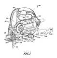
- FIG. 2is a perspective view of another example of a jigsaw similar to the jigsaw of FIG. 1 that includes dust extraction from a cutting area, through a shoe member and out of a vacuum port that extends from the shoe member in accordance with the present teachings.
- FIG. 3is a perspective view of a further example of a jigsaw similar to the jigsaw illustrated in FIG. 2 including a laser module connected to a front of the housing of the jigsaw in accordance with the present teachings.
- FIG. 4is a perspective view of yet another example of a jigsaw having a blade guard that is an integral extension from the housing half shells in accordance with the present teachings.
- FIG. 5is a perspective view of a further example of a jigsaw similar to the jigsaw of FIG. 4 including a storage compartment formed in the housing in accordance with the present teachings.
- FIG. 6is a front view of the jigsaw of FIG. 3 showing the laser module attached to the housing that can be pivoted relative to a shoe member in accordance with the present teachings.
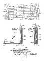
- FIG. 7is a partial side view of the blade storage compartment with a cover open in accordance with the present teachings.
- FIG. 8is a partial cross-sectional view of the blade storage compartment of FIG. 7 showing one or more members that can provide a magnetic field to hold the cutting blades within the blade storage compartment in accordance with the present teachings.
- FIG. 9is a partial cross-sectional view of the blade storage compartment showing a locking member that can secure the cover to the blade storage compartment in accordance with the present teachings.
- FIG. 10is a partial cross-sectional view of the blade storage compartment showing a user tilting the cutting blade into a recess to remove the cutting blade from the blade storage compartment in accordance with the present teachings.
- FIG. 11is a flow chart showing an exemplary method of removing the cutting blades from the blade storage compartment in accordance with the present teachings.
- FIG. 12is an exploded assembly view of a jigsaw having housing half shells and fascia half shells similar to the jigsaw of FIG. 1 having an integrally extending blade guard member from the fascia half shells in accordance with the present teachings.
- FIG. 13is an exploded assembly view of a jigsaw having housing half shells similar to that of the jigsaw in FIG. 4 showing an integrally extending blade guard member from the housing half shells in accordance with the present teachings.
- FIG. 14is a partial rear view of the jigsaw housings of FIG. 1 showing the cooling passageways formed in a flexible member that also serves as a cord protector to provide additional cooling to a motor within a housing of the jigsaw in accordance with the present teachings.
- FIG. 15is a diagram of a cross-sectional view of the jigsaw housing of FIG. 14 showing an airflow along a cooling pathway from the cooling passageways formed in the flexible member in accordance with the present teachings.
- a jigsaw 100generally includes a housing 102 that can be formed of two half shells 104 , 106 .
- the housing 102can contain a motor 108 .
- the motor 108can provide a reciprocating and/or an orbital (pendulum) motion to a conventional combination of a cutting blade holder 112 on an end of a reciprocating shaft (not shown) to drive a cutting blade 114 at a cutting angle 116 ( FIG. 6 ).
- a single control member 118 on a side of the housing 102can control a rate of reciprocation and/or a magnitude of the orbital motion of the cutting blade 114 .
- a shoe member 120can be coupled to a bottom 122 of the housing 102 in such a way as to permit the shoe member 120 to pivot relative to the housing 102 .
- the cutting blade 114can be orientated at various angles (i.e., one or more of the cutting angles 116 ( FIG. 6 )) relative to the shoe member 120 .
- a bottom surface 124 of the shoe member 120can abut a workpiece 126 , which can be wood, plastic, metal, other suitable materials and one or more combinations thereof and can be in the form of pipe, sheet material, stock material, other suitable forms and/or materials and one or more combinations thereof.
- the shoe member 120can be pivoted relative to the housing 102 to adjust the cutting angle 116 ( FIG. 6 ) of the jigsaw 100 , e.g., at a forty-five degree cutting angle.
- an angle indicator wheel 128can indicate the cutting angle 116 of the jigsaw 100 .
- a locking mechanism 130can include a bevel lever 132 that can be adjusted between an unlocked condition (phantom line) and a locked condition, as shown in FIG. 1 .
- the locking mechanism 130In the unlocked condition, the locking mechanism 130 can permit the shoe member 120 to pivot relative to the housing 102 .
- the locked conditionthe locking mechanism 130 can prevent the shoe member 120 from pivoting relative to the housing 102 .
- the cutting angle 116FIG. 6
- the locking mechanism 130when the locking mechanism 130 is in the unlocked condition, can be indicated by the angle indicator wheel 128 .
- a dust extraction port 134can be formed on a rear portion 136 of the housing 102 such that a vacuum source 138 can be connected with various suitable connections to the dust extraction port 134 .
- a dust extraction airflow 140can be extracted from a cutting area 142 . From the cutting area 142 , the dust extraction airflow 140 can move into the housing 102 near a rear edge 144 of the cutting blade 114 , through an airflow pathway in the housing 102 and out through the dust extraction port 134 .
- the dust extraction airflow 140can travel through the airflow pathway in the housing 102 and can be routed through an inner periphery of the angle indicator wheel 128 .
- the dust extraction airflow 140can also exit the cutting area 142 through a scoop member 148 that extends from the housing 102 .
- the shoe member 120can be pivoted relative to the housing 102 ( FIG. 6 ) without interrupting the dust extraction airflow 140 through the housing 102 and through the angle indicator wheel 128 .
- a jigsaw 200includes a housing 202 that can be formed of two half shells 204 , 206 .
- the housing 202can contain a motor 208 .
- the motor 208can provide the reciprocating and/or the orbital (pendulum) motion to the reciprocating shaft to drive a cutting blade 114 at one or more of the cutting angles 116 ( FIG. 6 ).
- a single control member 216 on a side of the housing 202can control the rate of reciprocation and/or the magnitude of the orbital motion of the cutting blade 114 .
- a shoe member 218can be coupled to a bottom 220 of the housing 202 in such a way as to permit the shoe member 218 to pivot relative to the housing 202 .
- the cutting blade 114can be orientated at the various cutting angles 116 ( FIG. 6 ) relative to the shoe member 218 .
- a bottom surface 222 of the shoe member 218can abut the workpiece 126 ( FIG. 1 ).
- an angle indicator wheel 224can indicate the cutting angle 116 ( FIG. 6 ) of the jigsaw 200 .
- a locking mechanism 226can include a bevel lever 228 that can be adjusted between an unlocked condition and a locked condition.
- the cutting angle 116 ( FIG. 6 ) to which the shoe member 218 can be pivoted relative to the housing 202 , when the locking mechanism 226 is in the unlocked condition,can be indicated by the angle indicator wheel 224 .
- a dust extraction port 230can be formed on a rear portion 232 of the shoe member 218 , in contrast to the dust extraction airflow 140 through the housing 102 ( FIG. 1 ).
- a vacuum source 234can be connected to the dust extraction port 230 .
- a dust extraction airflow 236can be extracted from a cutting area 238 . From the cutting area 238 , the dust extraction airflow 236 can move through an airflow pathway in the shoe member 218 and out through the dust extraction port 230 that extends therefrom.
- a vacuum source adapter 240can be connected to the dust extraction port 230 formed in the shoe member 218 and can be used to connect to the vacuum source 234 .
- Inlets 242can be formed at one or more locations on the shoe member 218 adjacent the cutting area 238 . From the inlets 242 , the dust extraction airflow 236 can be routed through channels in the shoe member 218 to the dust extraction port 230 .
- a jigsaw 300can be similar to the exemplary jigsaw 200 ( FIG. 2 ) and can also include a keel assembly 302 and/or a laser module 304 that can be connected to a housing 306 having two housing half shells 308 , 310 implemented in a similar fashion to the jigsaw 200 .
- the jigsaw 300can further include a dust extraction airflow 312 through a shoe member 314 .
- the dust extraction airflow 312can exit from a dust extraction port 316 that can extend therefrom.
- the laser module 304can project a laser light 318 and can produce a laser light pattern 320 .
- the laser light pattern 320can produce, for example, a sequence of dashes and/or dots beyond a front side 322 of the cutting blade 114 and can highlight a path of the cutting blade 114 through the workpiece 126 .
- the keel assembly 302can provide additional straight-line accuracy when cutting a straight line in the workpiece 126 (e.g., can help avoid wandering of the jigsaw cutting line).
- the keel assembly 302can be pivoted with the housing 306 when the shoe member 314 is moved at an angle (i.e., one or more cutting angles 116 ( FIG. 6 )) relative to the housing 306 .
- the shoe member 314can be pivoted relative to the housing 306 but the keel assembly 302 can remain generally in line with the housing 306 so as to provide, for example, a straight bevel cut through the workpiece 126 .
- a jigsaw 400includes a housing 402 that can be formed of two half shells 404 , 406 .
- the housing 402can contain a motor 408 .
- the motor 408can provide a reciprocating and/or pendulum motion to the reciprocating shaft to drive the cutting blade 114 at one of the cutting angles 116 ( FIG. 6 ).
- a shoe member 412can be coupled to a bottom 414 of the housing 402 in such a way as to permit the shoe member 412 to pivot relative to the housing 402 .
- the cutting blade 114can be orientated at various angles (i.e., one or more of the cutting angles 116 ( FIG. 6 )) relative to the shoe member 412 .
- a bottom surface 416 of the shoe member 412can abut the workpiece 126 ( FIG. 1 ).
- a locking mechanism 418can be adjusted between an unlocked condition that can permit the shoe member 412 to pivot relative to the housing 402 and a locked condition that can prevent the shoe member 412 from pivoting relative to the housing 402 .
- the locking mechanism 418can include one or more fasteners (not shown) that can secure the shoe member 412 to the bottom 414 of the housing 402 . The fasteners can be partially removed to permit the shoe member 412 to pivot relative to the housing 402 .
- a dust extraction port 420can be formed on a rear portion 422 of the housing 402 such that a vacuum source 424 can be connected to the dust extraction port 420 .
- a dust extraction airflow 426can be extracted from a cutting area 428 . From the cutting area 428 , the dust extraction airflow 426 can move into the housing 402 near a rear side 430 of a cutting blade 114 , through an airflow pathway in the housing 402 and out through the dust extraction port 420 .
- a jigsaw 500generally includes a housing 502 that can be formed of two half shells 504 , 506 .
- the housing 502can contain a motor 508 .
- the motor 508can provide a reciprocating and/or pendulum motion to the reciprocating shaft to drive the cutting blade 114 at one or more of the cutting angles 116 ( FIG. 6 ).
- a shoe member 514can be coupled to a bottom 516 of the housing 502 in such a way as to permit the shoe member 514 to pivot relative to the housing 502 in a fashion that is similar to the jigsaw 400 ( FIG. 4 ).
- a bottom surface 518 of the shoe member 514can abut the workpiece 126 ( FIG. 1 ).
- a locking mechanism 520can be adjusted between an unlocked condition that can permit the shoe member 514 to pivot relative to the housing 502 and a locked condition that can prevent the shoe member 514 from pivoting relative to the housing 502 .
- the locking mechanism 520can include one or more fasteners (not shown) that can secure the shoe member 514 to the bottom 516 of the housing 502 . The fasteners can be partially removed (i.e., the unlocked condition) to permit the shoe member 514 to pivot relative to the housing 502 .
- a storage container 530can be formed on a rear portion 532 of the housing 502 such that blades, tools, etc. can be stored within the storage container 530 .
- a storage container cover 534illustrated in an open condition, can be closed (shown in phantom line) to contain whatever may be placed within the storage container 530 .
- the cutting angle 116 of the cutting blade 114 of the jigsaw 300is shown relative to the shoe member 314 of the jigsaw 300 .
- the keel assembly 302is also attached to the housing 306 .
- the cutting angle 116can be positioned at the zero degree cutting angle, i.e., a perpendicular cutting angle relative to the shoe member 314 .
- the cutting angle 116can also be positioned at one or more cutting angles such as a cutting angle 352 (phantom line) that can be positioned at about positive fifteen degrees, while a cutting angle 354 (phantom line) can be positioned at about negative thirty degrees.
- a cutting angle 356 (phantom line)can be positioned at about positive forty five degrees.
- a housing 600 of a jigsaw 602can provide a blade storage compartment 604 that can contain one or more cutting blades 606 to be used with the jigsaw 602 .
- the blade storage compartment 604can define one or more platforms 608 on which each of the cutting blades 606 for the jigsaw 602 can be stored.
- the blade storage compartment 604can be implemented within the housing of various power tools.
- the blade storage compartment 604can be implemented on the housing 102 , 202 , 302 , 402 , 502 of the jigsaw 100 , 200 , 300 , 400 , 500 , respectively.
- the blade storage compartment 604can be implemented in one or both of the half shells 104 , 106 , 204 , 206 , 304 , 306 , 404 , 406 , 504 , 506 of the housing 100 , 200 , 300 , 400 , 500 , respectively.
- One or more members 620 that can emit a magnetic field 622can be connected to the blade storage compartment 604 .
- the one or more members 620 that provide the magnetic field 622can be secured to a side 624 of the blade storage compartment 604 .
- the one or more members 620can be exposed to the blade storage compartment 604 and can be in an area accessible by the user.
- the one or more members 620can be contained within a wall of the blade storage compartment 604 and, therefore, cannot be in an area accessible by the user.
- the one or more members 620can include one or more magnets and/or any such material or device that can provide the one or more magnetic fields 622 .
- a cover 630 of the blade storage compartment 604can be hinged at one end 632 .
- the cover 630can open or close about an axis of rotation 634 that is generally parallel to a cutting direction 636 ( FIG. 1 ) of the jigsaw 602 .
- the cover 630can swing downward and, in this arrangement, the cover 630 can be configured to catch anything that might fall from the blade storage compartment 604 .
- the cover 630can swing upward.
- the cover 630can be hinged to open in other directions such as a sideways open and closed configuration.
- the cover 630 of the blade storage compartment 604can include a locking member 640 that can be deflected by hand so the user can open the blade storage compartment 604 without the need for tools.
- the locking member 640can keep the cover 630 of the blade storage compartment 604 closed during use of the jigsaw 602 by holding onto a portion of the blade storage compartment 604 .
- the usercan insert, for example, a finger to flex the locking member 640 so as to lift a flange 642 out of engagement (or at least out of an interfering path) with a surface 644 ( FIG. 8 ) of the blade storage compartment 604 or the housing 602 . By doing so, the locking member 640 can no longer prevent the opening of the cover 630 .
- the cover 630 of the blade storage compartment 604can be translucent or transparent to provide the user with the ability to determine what is contained within the blade storage compartment without opening the cover 630 .
- the cover 630 of the blade storage compartment 604can be configured so as to continue the general contours of the housing 600 of the jigsaw 602 . In this regard, when the cover 630 of the blade storage compartment 604 is closed, the contours of the housing 600 and the cover 630 appear to be generally uniform in the area of the blade storage compartment 604 .
- the blade storage compartment 604can be formed with one or more recesses at one or both edges of the platform 608 that can hold the cutting blades 606 .
- a first recess 650can be formed at a first edge 652 of the platform 608 .
- a second recess 656can be formed in the blade storage compartment 604 .
- the first recess 650 and the second recess 656can be configured so that the respective ends of the cutting blades 606 can be pressed into the recess 650 , 656 .
- one or more of the cutting blades 606can be tilted about an edge 652 , 654 of the platform 608 so as to tilt the other end of the blade 608 out of and away from the blade storage compartments 604 .
- the usercan grasp that end of the cutting blade 606 and remove it from the blade storage compartment 604 .
- the one or more members 620can provide the magnetic field 622 that can retain the one or more cutting blades 606 in the blade storage compartment 604 using a magnetic force established by the magnetic field 622 .
- the one or more cutting blades 606can tilt on the first edge 652 (or on the second edge 654 ) of the blade storage compartment 604 to overcome a force of the magnetic field 622 . In doing so, the user can tilt a second end 662 of the cutting blade 606 (about the first edge 652 ) out of the blade storage compartment 604 .
- the magnetic field 622can still exert sufficient force to retain the one or more cutting blades 606 in position.
- the cutting blades 606do not completely overcome the magnetic field 622 when tilted but are still sufficiently held in place until ultimate removal from the blade storage compartment 604 .
- the blade storage compartment 604can be configured with one platform between two recess or multiple platforms each between two recesses.
- an exemplary method of obtaining one of the cutting blades 606 from the blade storage compartment 604generally includes opening the cover 630 of the blade storage compartment 604 with a one-handed operation at 670 .
- the usercan select a blade.
- the usercan urge an end of one or more of the cutting blades 606 into the first recess 650 (or the second recess 656 ) provided adjacent to the platform 608 in which one or more of the cutting blades 606 reside in the blade storage compartment 604 .
- the usercan tilt the one or more cutting blades 606 into the recess 650 , 656 so as to tilt the opposite side (i.e., the second side 662 ) of the cutting blade 606 , as applicable, out from the platform 608 .
- the cutting blade 606can be tilted outward from the platform 608 to overcome the magnetic field 622 that can keep the cutting blade 606 in contact with the platform 608 .
- the usercan remove the one or more cutting blades 606 from the platform 608 . From 680 , the exemplary method can end.
- the cutting blade 606can be removed from the blade storage compartment 604 and can necessarily overcome the magnetic field 622 of the member 620 without tilting the one or more cutting blades 606 about the edge of either the first recess or the second recess.
- a jigsaw 700can have a housing 702 that can be formed of a right half shell 704 and a left half shell 706 .
- the half shells 704 , 706can establish together, when assembled, a blade guard member 710 that can be, in some examples, an integral extension of the housing 702 of the jigsaw 700 .
- a jigsaw 740can have a housing 742 formed of right half shell 744 and a left half shell 746 .
- a shoe member 748can pivotally connect to the housing 742 .
- a blade guard member 750can be an integral extension of a fascia member 752 that can be formed of a right fascia half shell 754 and a left fascia half shell 756 .
- the blade guard member 710 , 750can provide, in some instances, protection from the cutting blade by preventing contact with it.
- the blade guard member 710can include a right arm portion 712 that can extend from the right half shell 704 .
- a left arm portion 714can extend from the left half shell 706 .
- the blade guard member 750can include a right arm portion 760 that can extend from the right fascia half shell 754 .
- a left arm portion 762can extend from the left fascia half shell 756 .
- the right arm portion 712 , 760 and the left arm portion 714 , 762can each define a portion of a bottom portion 720 of the blade guard member 710 , 750 , i.e., a right bottom portion 722 and a left bottom portion 724 .
- the right and left bottom portions 722 , 724 of the blade guard member 710 , 750can unite in an abutting relationship to form the entirety of the bottom portion 720 .
- the bottom portion 720 of the blade guard member 710 , 750can be fastened together and, in doing so, can be shown to improve the rigidity of the blade guard member 710 , 750 and the housing 702 near the blade guard member 710 , 750 .
- the blade guard member 710 , 750can be configured with a plurality of apertures 730 so that a view through the blade guard member 710 , 750 (e.g., toward the cutting area) can be improved for the user.
- one or more cooling passageways 800can be formed through a flexible member 802 that can also include a cord protector 804 .
- the flexible member 802can be contained between the housing 806 and specifically can be secured between an inner periphery 808 formed by the assembly of the housing half shells 810 , 812 .
- the flexible member 802can be a separately formed component that can be of a molded plastic which can be more flexible than the material used to form the half shells 810 , 812 of the housing 806 .
- the flexible member 802can be held within the inner periphery 808 of the housing 806 with fasteners, bonding, etc. and/or with a portion of the housing 806 holding an outer periphery of the flexible member 802 .
- the cord protector 804can be flexible, the cord protector 804 can provide strain relief on the connection between the power source (i.e., a plug in a receptacle) of a cutting tool 820 and a motor 822 within the cutting tool 820 .
- the one or more cooling passageways 800 formed in the flexible member 802can increase the overall capacity of air capable of being drawn from the outside (i.e., outside the cutting tool 820 ) through portions of the housing 806 to cool the motor 822 .
- a cooling pathway 840can start from the outside of the flexible member 802 and enter the one or more cooling passageways 800 formed therethrough.
- the cooling passageways 800can continue through the housing 806 toward the motor 822 .
- a fan 842 that rotates with the motor 822can establish an airflow along the cooling pathway 840 such that cooling air is additionally drawn through the flexible member 802 to help cool the motor 822 .
- the flexible member 802can be formed as a monolithic component that can include a passageway for the power cord, (i.e., strain relief).
- the monolithic componentcan also define the one or more cooling passageways 800 through which the cooling air can pass into the housing and cool the motor.
- the four cooling passageways 800can generally be equally spaced around the cord protector 804 .
- One or more of the cooling passageways 800can have an L-shape 850 .
- a corner 852 established by the L-shape 850can be closer to a passageway 854 (i.e., the cord protector 804 ) through which a power cord 864 can be disposed.
- the ends 856 , 858 of the L-shape 850 distal from the corner 852 of the L-shape 850can be closer to the power cord 864 .
- each of the cooling passagewayscan define a longitudinal axis 860 that can be generally parallel to a longitudinal axis 862 of a portion of the power cord 864 that is disposed in said cord protector 804 .
Landscapes
- Engineering & Computer Science (AREA)
- Mechanical Engineering (AREA)
- Life Sciences & Earth Sciences (AREA)
- Wood Science & Technology (AREA)
- Forests & Forestry (AREA)
- Sawing (AREA)
Abstract
Description
The present teachings relate to a housing of a cutting tool and more particularly relate to a blade storage compartment, a blade guard and an additional motor ventilation pathway through a cord protector in the housing of the cutting tool.
Typically, a jigsaw blade is replaceable, as the blade can wear and break. Multiple blades can be carried to provide replacements for worn or broken blades and to provide additional blades for other tasks that can require, for example, a different tooth profile and a different blade length.
Users may have to carry blades in separate containers and bring these blades along with the jigsaw. Having to carry the jigsaw blades in separate and sometimes bulky containers may not always provide the user with the jigsaw blade needed for replacement or for a different application.
The present teachings generally include a jigsaw that uses a cutting blade. The jigsaw generally includes a housing containing a motor activated by a trigger assembly. A blade storage compartment is recessed in the housing. A platform is provided in the blade storage compartment having a first edge that at least partially defines a first recess that extends further into the housing beyond the platform. A member is connected to the platform that produces a magnetic field that releasably secures the cutting blade to the platform. The magnetic field is configured to permit a user to tilt the cutting blade about the first edge of the platform into the first recess to overcome the magnetic field and remove the cutting blade from the storage compartment.
Further areas of applicability will become apparent from the description provided herein. It should be understood that the description and specific examples are intended for purposes of illustration only and are not intended to limit the scope of the present teachings.
The drawings described herein are for illustration purposes only and are not intended to limit the scope of the present teachings in any way.
The following description is merely exemplary in nature and is not intended to limit the present teachings, their application or uses. It should be understood that throughout the drawings, corresponding reference numerals can indicate like or corresponding parts and features.
Moreover, certain terminology can be used for the purpose of reference only and do not limit the present teachings. For example, terms such as “upper,” “lower,” “above” and “below” can refer to directions in the drawings to which reference is made. Terms such as “front,” “back,” “rear” and “side” can describe the orientation of portions of the component, function, system, etc. within a consistent but arbitrary frame of reference which can be made more clear by reference to the text and the associated drawings describing the component, function, system, etc. under discussion. Such terminology may include the words specifically mentioned above, derivatives thereof and words of similar import. Similarly, the terms “first,” “second” and other such numerical terms referring to structures, systems and/or methods do not imply a sequence or order unless clearly indicated by the context.
With reference toFIG. 1 , ajigsaw 100 generally includes ahousing 102 that can be formed of twohalf shells housing 102 can contain amotor 108. When activated by atrigger assembly 110, themotor 108 can provide a reciprocating and/or an orbital (pendulum) motion to a conventional combination of acutting blade holder 112 on an end of a reciprocating shaft (not shown) to drive acutting blade 114 at a cutting angle116 (FIG. 6 ). Asingle control member 118 on a side of thehousing 102 can control a rate of reciprocation and/or a magnitude of the orbital motion of thecutting blade 114.
Ashoe member 120 can be coupled to abottom 122 of thehousing 102 in such a way as to permit theshoe member 120 to pivot relative to thehousing 102. As theshoe member 120 pivots relative to thehousing 102, thecutting blade 114 can be orientated at various angles (i.e., one or more of the cutting angles116 (FIG. 6 )) relative to theshoe member 120.
Abottom surface 124 of theshoe member 120 can abut aworkpiece 126, which can be wood, plastic, metal, other suitable materials and one or more combinations thereof and can be in the form of pipe, sheet material, stock material, other suitable forms and/or materials and one or more combinations thereof. Theshoe member 120 can be pivoted relative to thehousing 102 to adjust the cutting angle116 (FIG. 6 ) of thejigsaw 100, e.g., at a forty-five degree cutting angle. As theshoe member 120 is moved relative to thehousing 102, anangle indicator wheel 128 can indicate thecutting angle 116 of thejigsaw 100.
Further, alocking mechanism 130 can include abevel lever 132 that can be adjusted between an unlocked condition (phantom line) and a locked condition, as shown inFIG. 1 . In the unlocked condition, thelocking mechanism 130 can permit theshoe member 120 to pivot relative to thehousing 102. In the locked condition, thelocking mechanism 130 can prevent theshoe member 120 from pivoting relative to thehousing 102. In this regard, the cutting angle116 (FIG. 6 ) to which theshoe member 120 can be pivoted relative to thehousing 102, when thelocking mechanism 130 is in the unlocked condition, can be indicated by theangle indicator wheel 128.
Adust extraction port 134 can be formed on arear portion 136 of thehousing 102 such that avacuum source 138 can be connected with various suitable connections to thedust extraction port 134. Adust extraction airflow 140 can be extracted from acutting area 142. From thecutting area 142, thedust extraction airflow 140 can move into thehousing 102 near arear edge 144 of thecutting blade 114, through an airflow pathway in thehousing 102 and out through thedust extraction port 134.
Thedust extraction airflow 140 can travel through the airflow pathway in thehousing 102 and can be routed through an inner periphery of theangle indicator wheel 128. Thedust extraction airflow 140 can also exit thecutting area 142 through ascoop member 148 that extends from thehousing 102. In the above examples, theshoe member 120 can be pivoted relative to the housing102 (FIG. 6 ) without interrupting thedust extraction airflow 140 through thehousing 102 and through theangle indicator wheel 128.
With reference toFIG. 2 , ajigsaw 200 includes ahousing 202 that can be formed of twohalf shells housing 202 can contain amotor 208. When activated by atrigger assembly 210, themotor 208 can provide the reciprocating and/or the orbital (pendulum) motion to the reciprocating shaft to drive acutting blade 114 at one or more of the cutting angles116 (FIG. 6 ). Asingle control member 216 on a side of thehousing 202 can control the rate of reciprocation and/or the magnitude of the orbital motion of thecutting blade 114.
Ashoe member 218 can be coupled to abottom 220 of thehousing 202 in such a way as to permit theshoe member 218 to pivot relative to thehousing 202. As theshoe member 218 pivots relative to thehousing 202, thecutting blade 114 can be orientated at the various cutting angles116 (FIG. 6 ) relative to theshoe member 218. Abottom surface 222 of theshoe member 218 can abut the workpiece126 (FIG. 1 ).
As theshoe member 218 is moved relative to thehousing 202, anangle indicator wheel 224 can indicate the cutting angle116 (FIG. 6 ) of thejigsaw 200. Further, alocking mechanism 226 can include abevel lever 228 that can be adjusted between an unlocked condition and a locked condition. The cutting angle116 (FIG. 6 ) to which theshoe member 218 can be pivoted relative to thehousing 202, when thelocking mechanism 226 is in the unlocked condition, can be indicated by theangle indicator wheel 224.
Adust extraction port 230 can be formed on arear portion 232 of theshoe member 218, in contrast to thedust extraction airflow 140 through the housing102 (FIG. 1 ). Avacuum source 234 can be connected to thedust extraction port 230. Adust extraction airflow 236 can be extracted from acutting area 238. From thecutting area 238, thedust extraction airflow 236 can move through an airflow pathway in theshoe member 218 and out through thedust extraction port 230 that extends therefrom. Avacuum source adapter 240 can be connected to thedust extraction port 230 formed in theshoe member 218 and can be used to connect to thevacuum source 234.Inlets 242 can be formed at one or more locations on theshoe member 218 adjacent thecutting area 238. From theinlets 242, thedust extraction airflow 236 can be routed through channels in theshoe member 218 to thedust extraction port 230.
With reference toFIG. 3 , ajigsaw 300 can be similar to the exemplary jigsaw200 (FIG. 2 ) and can also include akeel assembly 302 and/or alaser module 304 that can be connected to ahousing 306 having twohousing half shells jigsaw 200. Thejigsaw 300 can further include adust extraction airflow 312 through ashoe member 314. Thedust extraction airflow 312 can exit from adust extraction port 316 that can extend therefrom. Thelaser module 304 can project alaser light 318 and can produce alaser light pattern 320. Thelaser light pattern 320 can produce, for example, a sequence of dashes and/or dots beyond afront side 322 of thecutting blade 114 and can highlight a path of thecutting blade 114 through theworkpiece 126.
Thekeel assembly 302 can provide additional straight-line accuracy when cutting a straight line in the workpiece126 (e.g., can help avoid wandering of the jigsaw cutting line). Thekeel assembly 302 can be pivoted with thehousing 306 when theshoe member 314 is moved at an angle (i.e., one or more cutting angles116 (FIG. 6 )) relative to thehousing 306. In this regard, theshoe member 314 can be pivoted relative to thehousing 306 but thekeel assembly 302 can remain generally in line with thehousing 306 so as to provide, for example, a straight bevel cut through theworkpiece 126.
With reference toFIG. 4 , ajigsaw 400 includes ahousing 402 that can be formed of twohalf shells housing 402 can contain amotor 408. When activated by atrigger assembly 410, themotor 408 can provide a reciprocating and/or pendulum motion to the reciprocating shaft to drive thecutting blade 114 at one of the cutting angles116 (FIG. 6 ).
Ashoe member 412 can be coupled to abottom 414 of thehousing 402 in such a way as to permit theshoe member 412 to pivot relative to thehousing 402. As theshoe member 412 pivots relative to thehousing 402, thecutting blade 114, can be orientated at various angles (i.e., one or more of the cutting angles116 (FIG. 6 )) relative to theshoe member 412. As is known in the art, abottom surface 416 of theshoe member 412 can abut the workpiece126 (FIG. 1 ).
Alocking mechanism 418 can be adjusted between an unlocked condition that can permit theshoe member 412 to pivot relative to thehousing 402 and a locked condition that can prevent theshoe member 412 from pivoting relative to thehousing 402. In one example, thelocking mechanism 418 can include one or more fasteners (not shown) that can secure theshoe member 412 to thebottom 414 of thehousing 402. The fasteners can be partially removed to permit theshoe member 412 to pivot relative to thehousing 402.
A dust extraction port420 can be formed on arear portion 422 of thehousing 402 such that avacuum source 424 can be connected to the dust extraction port420. Adust extraction airflow 426 can be extracted from acutting area 428. From thecutting area 428, thedust extraction airflow 426 can move into thehousing 402 near arear side 430 of acutting blade 114, through an airflow pathway in thehousing 402 and out through the dust extraction port420.
With reference toFIG. 5 , ajigsaw 500 generally includes ahousing 502 that can be formed of twohalf shells housing 502 can contain amotor 508. When activated by atrigger assembly 510, themotor 508 can provide a reciprocating and/or pendulum motion to the reciprocating shaft to drive thecutting blade 114 at one or more of the cutting angles116 (FIG. 6 ).
Ashoe member 514 can be coupled to abottom 516 of thehousing 502 in such a way as to permit theshoe member 514 to pivot relative to thehousing 502 in a fashion that is similar to the jigsaw400 (FIG. 4 ). Abottom surface 518 of theshoe member 514 can abut the workpiece126 (FIG. 1 ). In addition, alocking mechanism 520 can be adjusted between an unlocked condition that can permit theshoe member 514 to pivot relative to thehousing 502 and a locked condition that can prevent theshoe member 514 from pivoting relative to thehousing 502. Thelocking mechanism 520 can include one or more fasteners (not shown) that can secure theshoe member 514 to thebottom 516 of thehousing 502. The fasteners can be partially removed (i.e., the unlocked condition) to permit theshoe member 514 to pivot relative to thehousing 502.
Astorage container 530 can be formed on arear portion 532 of thehousing 502 such that blades, tools, etc. can be stored within thestorage container 530. Astorage container cover 534, illustrated in an open condition, can be closed (shown in phantom line) to contain whatever may be placed within thestorage container 530.
With reference toFIG. 6 , the cuttingangle 116 of thecutting blade 114 of thejigsaw 300 is shown relative to theshoe member 314 of thejigsaw 300. Thekeel assembly 302 is also attached to thehousing 306. The cuttingangle 116 can be positioned at the zero degree cutting angle, i.e., a perpendicular cutting angle relative to theshoe member 314. The cuttingangle 116 can also be positioned at one or more cutting angles such as a cutting angle352 (phantom line) that can be positioned at about positive fifteen degrees, while a cutting angle354 (phantom line) can be positioned at about negative thirty degrees. A cutting angle356 (phantom line) can be positioned at about positive forty five degrees. It will be appreciated in light of the disclosure that “positive,” in this example, only refers to being on one side of the zero degree (perpendicular) cutting angle orientation and thus “negative” refers to the other side. It will also be appreciated in light of the disclosure that various cutting angles can be implemented with any of thejigsaws FIGS. 1-5 ).
With reference toFIG. 7 , a housing600 of a jigsaw602 can provide ablade storage compartment 604 that can contain one ormore cutting blades 606 to be used with the jigsaw602. Theblade storage compartment 604 can define one ormore platforms 608 on which each of thecutting blades 606 for the jigsaw602 can be stored. It will be appreciated in light of the disclosure that theblade storage compartment 604 can be implemented within the housing of various power tools. For example, theblade storage compartment 604 can be implemented on thehousing jigsaw blade storage compartment 604 can be implemented in one or both of thehalf shells housing
One ormore members 620 that can emit amagnetic field 622 can be connected to theblade storage compartment 604. The one ormore members 620 that provide themagnetic field 622 can be secured to aside 624 of theblade storage compartment 604. In one example, the one ormore members 620 can be exposed to theblade storage compartment 604 and can be in an area accessible by the user. In other examples, the one ormore members 620 can be contained within a wall of theblade storage compartment 604 and, therefore, cannot be in an area accessible by the user. The one ormore members 620 can include one or more magnets and/or any such material or device that can provide the one or moremagnetic fields 622.
Acover 630 of theblade storage compartment 604 can be hinged at oneend 632. In this arrangement, thecover 630 can open or close about an axis ofrotation 634 that is generally parallel to a cutting direction636 (FIG. 1 ) of the jigsaw602. As such, thecover 630 can swing downward and, in this arrangement, thecover 630 can be configured to catch anything that might fall from theblade storage compartment 604. In other arrangements, thecover 630 can swing upward. In further configurations, thecover 630 can be hinged to open in other directions such as a sideways open and closed configuration.
With reference toFIGS. 8 and 9 , thecover 630 of theblade storage compartment 604 can include a lockingmember 640 that can be deflected by hand so the user can open theblade storage compartment 604 without the need for tools. The lockingmember 640 can keep thecover 630 of theblade storage compartment 604 closed during use of the jigsaw602 by holding onto a portion of theblade storage compartment 604. The user can insert, for example, a finger to flex the lockingmember 640 so as to lift aflange 642 out of engagement (or at least out of an interfering path) with a surface644 (FIG. 8 ) of theblade storage compartment 604 or the housing602. By doing so, the lockingmember 640 can no longer prevent the opening of thecover 630.
In some examples, thecover 630 of theblade storage compartment 604 can be translucent or transparent to provide the user with the ability to determine what is contained within the blade storage compartment without opening thecover 630. Thecover 630 of theblade storage compartment 604 can be configured so as to continue the general contours of the housing600 of the jigsaw602. In this regard, when thecover 630 of theblade storage compartment 604 is closed, the contours of the housing600 and thecover 630 appear to be generally uniform in the area of theblade storage compartment 604.
With reference toFIG. 7 , theblade storage compartment 604 can be formed with one or more recesses at one or both edges of theplatform 608 that can hold thecutting blades 606. With reference toFIG. 10 , afirst recess 650 can be formed at afirst edge 652 of theplatform 608. With reference toFIG. 7 and at asecond edge 654 of theplatform 608, asecond recess 656 can be formed in theblade storage compartment 604. Thefirst recess 650 and thesecond recess 656 can be configured so that the respective ends of thecutting blades 606 can be pressed into therecess more blades 606 into thefirst recess 650, one or more of thecutting blades 606 can be tilted about anedge platform 608 so as to tilt the other end of theblade 608 out of and away from the blade storage compartments604.
When the second end of thecutting blade 606 is tilted outward from theblade storage compartment 604, the user can grasp that end of thecutting blade 606 and remove it from theblade storage compartment 604. Moreover, the one ormore members 620 can provide themagnetic field 622 that can retain the one ormore cutting blades 606 in theblade storage compartment 604 using a magnetic force established by themagnetic field 622. As the user presses afirst end 660 of thecutting blade 606 into the first recess650 (or into the second recess656), the one ormore cutting blades 606 can tilt on the first edge652 (or on the second edge654) of theblade storage compartment 604 to overcome a force of themagnetic field 622. In doing so, the user can tilt asecond end 662 of the cutting blade606 (about the first edge652) out of theblade storage compartment 604.
While thesecond end 662 is tilted out from theblade storage compartment 604, themagnetic field 622 can still exert sufficient force to retain the one ormore cutting blades 606 in position. In this regard, thecutting blades 606 do not completely overcome themagnetic field 622 when tilted but are still sufficiently held in place until ultimate removal from theblade storage compartment 604. It will be appreciated in light of the disclosure that theblade storage compartment 604 can be configured with one platform between two recess or multiple platforms each between two recesses.
With reference toFIG. 11 , an exemplary method of obtaining one of thecutting blades 606 from theblade storage compartment 604 generally includes opening thecover 630 of theblade storage compartment 604 with a one-handed operation at670. At672, the user can select a blade. At674, the user can urge an end of one or more of thecutting blades 606 into the first recess650 (or the second recess656) provided adjacent to theplatform 608 in which one or more of thecutting blades 606 reside in theblade storage compartment 604.
At676, the user can tilt the one ormore cutting blades 606 into therecess cutting blade 606, as applicable, out from theplatform 608. At678, thecutting blade 606 can be tilted outward from theplatform 608 to overcome themagnetic field 622 that can keep thecutting blade 606 in contact with theplatform 608. At680, the user can remove the one ormore cutting blades 606 from theplatform 608. From680, the exemplary method can end. It will be appreciated in light of the disclosure that thecutting blade 606 can be removed from theblade storage compartment 604 and can necessarily overcome themagnetic field 622 of themember 620 without tilting the one ormore cutting blades 606 about the edge of either the first recess or the second recess.
With reference toFIG. 12 , ajigsaw 700 can have ahousing 702 that can be formed of aright half shell 704 and aleft half shell 706. Thehalf shells blade guard member 710 that can be, in some examples, an integral extension of thehousing 702 of thejigsaw 700. With reference toFIG. 13 , ajigsaw 740 can have ahousing 742 formed of righthalf shell 744 and aleft half shell 746. Ashoe member 748 can pivotally connect to thehousing 742. Ablade guard member 750 can be an integral extension of afascia member 752 that can be formed of a rightfascia half shell 754 and a left fascia half shell756. Theblade guard member blade guard member 710 as the integral extension of thehousing 702 or by establishing theblade guard member 750 as the integral extension of thefascia member 752, a separate multi-piece component separately fastened to thehousing 702 can be avoided.
With reference toFIG. 12 , theblade guard member 710 can include aright arm portion 712 that can extend from theright half shell 704. Aleft arm portion 714 can extend from theleft half shell 706. With reference toFIG. 13 , theblade guard member 750 can include aright arm portion 760 that can extend from the rightfascia half shell 754. Aleft arm portion 762 can extend from the left fascia half shell756.
With reference toFIGS. 12 and 13 , theright arm portion left arm portion bottom portion 720 of theblade guard member right bottom portion 722 and aleft bottom portion 724. The right and leftbottom portions blade guard member bottom portion 720. Thebottom portion 720 of theblade guard member blade guard member housing 702 near theblade guard member blade guard member apertures 730 so that a view through theblade guard member 710,750 (e.g., toward the cutting area) can be improved for the user.
With reference toFIG. 14 , one ormore cooling passageways 800 can be formed through aflexible member 802 that can also include a cord protector804. Theflexible member 802 can be contained between thehousing 806 and specifically can be secured between aninner periphery 808 formed by the assembly of thehousing half shells
Theflexible member 802 can be a separately formed component that can be of a molded plastic which can be more flexible than the material used to form thehalf shells housing 806. Theflexible member 802 can be held within theinner periphery 808 of thehousing 806 with fasteners, bonding, etc. and/or with a portion of thehousing 806 holding an outer periphery of theflexible member 802. Because the cord protector804 can be flexible, the cord protector804 can provide strain relief on the connection between the power source (i.e., a plug in a receptacle) of acutting tool 820 and amotor 822 within thecutting tool 820.
In addition tovents 830 formed on thehousing 806, the one ormore cooling passageways 800 formed in theflexible member 802 can increase the overall capacity of air capable of being drawn from the outside (i.e., outside the cutting tool820) through portions of thehousing 806 to cool themotor 822. With reference toFIG. 15 , acooling pathway 840 can start from the outside of theflexible member 802 and enter the one ormore cooling passageways 800 formed therethrough. The coolingpassageways 800 can continue through thehousing 806 toward themotor 822. Afan 842 that rotates with themotor 822 can establish an airflow along the coolingpathway 840 such that cooling air is additionally drawn through theflexible member 802 to help cool themotor 822.
In one example, theflexible member 802 can be formed as a monolithic component that can include a passageway for the power cord, (i.e., strain relief). The monolithic component can also define the one ormore cooling passageways 800 through which the cooling air can pass into the housing and cool the motor. In one example, there are four coolingpassageways 800 formed in theflexible member 802. By way of the above example, the four coolingpassageways 800 can generally be equally spaced around the cord protector804.
One or more of the coolingpassageways 800 can have an L-shape 850. Acorner 852 established by the L-shape 850 can be closer to a passageway854 (i.e., the cord protector804) through which apower cord 864 can be disposed. The ends856,858 of the L-shape 850 distal from thecorner 852 of the L-shape 850 can be closer to thepower cord 864. Moreover, each of the cooling passageways can define alongitudinal axis 860 that can be generally parallel to alongitudinal axis 862 of a portion of thepower cord 864 that is disposed in said cord protector804.
While specific aspects have been described in the specification and illustrated in the drawings, it will be understood by those skilled in the art that various changes can be made and equivalents can be substituted for elements and components thereof without departing from the scope of the present teachings, as defined in the claims. Furthermore, the mixing and matching of features, elements, components and/or functions between various aspects of the present teachings are expressly contemplated herein so that one skilled in the art will appreciate from the present teachings that features, elements, components and/or functions of one aspect of the present teachings can be incorporated into another aspect, as appropriate, unless described otherwise above. Moreover, many modifications may be made to adapt a particular situation, configuration or material to the present teachings without departing from the essential scope thereof. Therefore, it is intended that the present teachings not be limited to the particular aspects illustrated by the drawings and described in the specification as the best mode presently contemplated for carrying out the present teachings, but that the scope of the present teachings include many aspects and examples following within the foregoing description and the appended claims.
Claims (20)
1. A jigsaw that uses cutting blades, the jigsaw comprising:
a housing containing a motor activated by a trigger assembly;
a blade storage compartment at least partially recessed in said housing;
a platform provided in said blade storage compartment, said platform having a first edge that at least partially defines a first recess and a second recess that is adjacent to said first recess, said first recess and said second recess extend further into said housing beyond said platform;
a member connected to said platform that produces a magnetic field that releasably secures a first cutting blade and a second cutting blade to said platform, wherein said magnetic field is configured to permit a user to tilt the first cutting blade about said first edge of said platform into said first recess to overcome said magnetic field and remove the first cutting blade from said storage compartment when the second cutting blade is secured to said platform.
2. The jigsaw ofclaim 1 further comprising a cover that when in a closed condition defines an outer surface that continues the general contours of the housing of the jigsaw around said cover.
3. The jigsaw ofclaim 1 , wherein said magnetic field is configured to permit said user to tilt the second cutting blade about said first edge into said second recess to overcome said magnetic field and remove the second cutting blade from said storage compartment.
4. The jigsaw ofclaim 1 further comprising a third recess in said blade storage compartment defined by a second edge on said platform opposite said first edge and one of said first and second recesses.
5. The jigsaw ofclaim 1 , wherein said member that produces said magnetic field is at least one magnet recessed in said platform and wherein the first cutting blade and the second cutting blade directly contacts said member.
6. The jigsaw ofclaim 1 further comprising a cover having a locking member deflectable by a hand operation between an engaged condition and a disengaged condition, in said engaged condition said locking member holds a portion of the blade storage compartment to secure said cover in a closed position, in said disengaged condition said locking member is deflected to permit opening of said cover.
7. The jigsaw ofclaim 1 further comprising a cover that opens and closes along an axis of rotation that is generally parallel to a cutting direction of the jigsaw.
8. The jigsaw ofclaim 7 , wherein said cover in an open condition swings toward a shoe member so that said cover extends laterally from said blade storage compartment.
9. The jigsaw ofclaim 8 , wherein said cover establishes a concave shape operable to hold an item that falls from said blade storage compartment.
10. The jigsaw ofclaim 1 further comprising a cover that can be secured to said blade storage compartment in a closed condition, wherein said cover is made of a material that at least partially permits a user to determine contents of said blade storage compartment.
11. The jigsaw ofclaim 1 further comprising
a reciprocating shaft connected to said motor that extends through said housing toward a cutting area;
a blade guard member that defines a left arm portion, a right arm portion and a base portion therebetween, wherein said blade guard member extends from said housing in front of said reciprocating shaft and toward said cutting area;
a fascia connected to said housing, said fascia defining a left fascia half that connects to a left half shell of said housing and a right fascia half that connects to a right half shell of said housing, wherein said left arm portion of said blade guard member is an integral extension of said left fascia half and said right arm portion is an integral extension of said right fascia half; and
said base portion being split into a left portion and a right portion, wherein said left portion of said base portion extends from said left arm portion of said blade guard member and said right portion of said base portion extends from said right arm portion of said blade guard member and wherein said left portion and said right portion of said base portion are fastened together in an abutting relationship.
12. The jigsaw ofclaim 1 , further comprising
a fan connected to said motor;
a flexible member disposed in said housing through which a power cord is disposed, wherein said flexible member is configured to permit said power cord and portions of said flexible member to flex relative to said housing; and
at least one cooling passageway formed through said flexible member, wherein said fan establishes an airflow through said at least one cooling passageway, wherein said at least one cooling passageway extends through said flexible member along a longitudinal axis that is substantially parallel to a longitudinal axis of a portion of said power cord that extends through said flexible member.
13. A jigsaw for cutting a workpiece with a cutting blade, the jigsaw comprising:
a housing containing a motor activated by a trigger assembly, wherein said housing defines a left half shell and a right half shell;
a shoe member connected to said housing;
a reciprocating shaft connected to said motor that extends through said housing toward a cutting area, said reciprocating shaft operable to hold the cutting blade;
a blade guard member including a left arm portion, a right arm portion and a base portion therebetween, wherein said blade guard member extends from said housing in front of said reciprocating shaft and toward said cutting area to terminate proximate said shoe member;
said left arm portion extends from said left half shell;
said right arm portion extends from said right half shell; and
said base portion being split into a left portion and a right portion, wherein said left portion of said base portion extends from said left arm portion of said blade guard member and said right portion of said base portion extends from said right arm portion of said blade guard member;
the jigsaw further comprising a blade storage compartment recessed in said housing;
a platform provided in said blade storage compartment having a first edge that at least partially defines a first recess that extends further into said housing beyond said platform; and
a member connected to said platform that produces a magnetic field that releasably secures a cutting blade to said platform, wherein said magnetic field is configured to permit a user to tilt said cutting blade about said first edge into said first recess to overcome said magnetic field and remove said cutting blade from said storage compartment.
14. The jigsaw ofclaim 13 , wherein said left arm portion is an integral extension of said left half shell and wherein said right arm portion is an integral extension of said right half shell.
15. The jigsaw ofclaim 13 , wherein said left portion and said right portion of said base portion are fastened together in an abutting relationship.
16. The jigsaw ofclaim 13 further comprising a fascia member connected to said housing of the jigsaw, said fascia member defining a left fascia half shell that connects to said left half shell of said housing and a right fascia half shell that connects to said right half shell of said housing, wherein said left arm portion of said blade guard member is an integral extension of said left fascia half shell and said right arm portion is an integral extension of said right fascia half shell.
17. The jigsaw ofclaim 13 , wherein said magnetic field is configured to permit said user to tilt a second cutting blade about said first edge into a second recess to overcome said magnetic field and remove the second cutting blade from said storage compartment, said second recess is adjacent said first recess and said first edge.
18. The jigsaw ofclaim 13 , further comprising a third recess in said blade storage compartment defined by a second edge of said platform opposite said first edge and one of said first and second recesses.
19. The jigsaw ofclaim 13 further comprising
a fan connected to said motor;
a flexible member disposed in said housing through which a power cord is disposed, wherein said flexible member is configured to permit said power cord and portions of said flexible member to flex relative to said housing; and
at least one cooling passageway formed through said flexible member, wherein said fan establishes an airflow through said at least one cooling passageway, wherein said at least one cooling passageway extends through said flexible member along a longitudinal axis that is substantially parallel to a longitudinal axis of a portion of said power cord that extends through said flexible member.
20. The jigsaw ofclaim 19 , wherein said housing defines an inner periphery between said left half shell and said right half shell of said housing and wherein said flexible member is secured to said housing in said inner periphery between said left half shell and said right half shell.
Priority Applications (4)
| Application Number | Priority Date | Filing Date | Title |
|---|---|---|---|
| US11/859,261US10029322B2 (en) | 2007-09-21 | 2007-09-21 | Housing of a cutting tool including blade storage, integral blade guard and motor ventilation pathway |
| EP08164641AEP2039453B1 (en) | 2007-09-21 | 2008-09-18 | Jigsaw |
| AU2008221555AAU2008221555A1 (en) | 2007-09-21 | 2008-09-18 | Housing of a cutting tool including blade storage, integral blade guard and motor ventilation pathway |
| CNU2008201791857UCN201313205Y (en) | 2007-09-21 | 2008-09-22 | Fretsaw using cutting blade |
Applications Claiming Priority (1)
| Application Number | Priority Date | Filing Date | Title |
|---|---|---|---|
| US11/859,261US10029322B2 (en) | 2007-09-21 | 2007-09-21 | Housing of a cutting tool including blade storage, integral blade guard and motor ventilation pathway |
Publications (2)
| Publication Number | Publication Date |
|---|---|
| US20090077818A1 US20090077818A1 (en) | 2009-03-26 |
| US10029322B2true US10029322B2 (en) | 2018-07-24 |
Family
ID=40120273
Family Applications (1)
| Application Number | Title | Priority Date | Filing Date |
|---|---|---|---|
| US11/859,261Active2034-08-21US10029322B2 (en) | 2007-09-21 | 2007-09-21 | Housing of a cutting tool including blade storage, integral blade guard and motor ventilation pathway |
Country Status (4)
| Country | Link |
|---|---|
| US (1) | US10029322B2 (en) |
| EP (1) | EP2039453B1 (en) |
| CN (1) | CN201313205Y (en) |
| AU (1) | AU2008221555A1 (en) |
Cited By (3)
| Publication number | Priority date | Publication date | Assignee | Title |
|---|---|---|---|---|
| US20190169862A1 (en)* | 2017-12-04 | 2019-06-06 | Rhino Tools and Equipment Inc. | Tool Attachment for Raking Mortar Joints |
| US11110584B2 (en)* | 2016-11-17 | 2021-09-07 | Black & Decker Inc. | Jigsaw blade storage |
| USD1005080S1 (en)* | 2021-12-08 | 2023-11-21 | Makita Corporation | Portable electric jig saw body |
Families Citing this family (10)
| Publication number | Priority date | Publication date | Assignee | Title |
|---|---|---|---|---|
| US20100178856A1 (en)* | 2009-01-09 | 2010-07-15 | Omar Jesus Cruz | Cordless power gasket scraper and surface cleaning tool with light source |
| CN203863764U (en) | 2011-04-01 | 2014-10-08 | 米沃奇电动工具公司 | wire saw |
| US20120291360A1 (en)* | 2011-05-20 | 2012-11-22 | Davis Roland L | System and method for configuring a single sealing material for a plurality of different sized track systems |
| US8578615B2 (en)* | 2011-09-12 | 2013-11-12 | Black & Decker Inc. | Jigsaw with deployable keel and tiltable shoe |
| CN105189058B (en) | 2013-02-20 | 2018-11-23 | 博莱沃创新工艺公司 | Electronic cutter |
| US9559628B2 (en) | 2013-10-25 | 2017-01-31 | Black & Decker Inc. | Handheld power tool with compact AC switch |
| USD755034S1 (en) | 2015-04-02 | 2016-05-03 | Milwaukee Electric Tool Corporation | Saw |
| DE102015211646A1 (en)* | 2015-06-24 | 2016-12-29 | Robert Bosch Gmbh | Electrical tool, in particular angle grinder, with filter integrated in a grommet holder |
| US12343809B2 (en)* | 2022-03-09 | 2025-07-01 | Black & Decker Inc. | Reciprocating tool having orbit function |
| CN116921767A (en)* | 2023-07-28 | 2023-10-24 | 浙江通达电器有限公司 | A smart jigsaw |
Citations (248)
| Publication number | Priority date | Publication date | Assignee | Title |
|---|---|---|---|---|
| US1102018A (en) | 1912-06-06 | 1914-06-30 | Kerner Mfg Company | Power-driven handsaw. |
| GB221671A (en) | 1923-10-22 | 1924-09-18 | George Scattergood | Improvements in or relating to guards for circular saws |
| DE716266C (en) | 1937-06-01 | 1942-01-15 | Hans Ehlermann Dipl Ing | Device for dissipating the heat from the rotor core of electric hand tools |
| US2377673A (en) | 1944-08-21 | 1945-06-05 | Clarence F Chaddock | Blade guide for motor-driven circular handsaws |
| US2543486A (en) | 1945-06-08 | 1951-02-27 | Excel Auto Radiator Company | Portable power saw |
| US2623557A (en) | 1951-06-05 | 1952-12-30 | John T Kendall | Portable power-driven recessing apparatus |
| US2749951A (en) | 1952-04-17 | 1956-06-12 | Tetzner Gustav | Band saw blade guide |
| US2775272A (en) | 1953-11-27 | 1956-12-25 | Walter A Papworth | Portable power driven reciprocable cutting tool |
| US2819742A (en) | 1955-07-05 | 1958-01-14 | Oster John Mfg Co | Kerf guide and splitter |
| DE1760076U (en) | 1957-11-26 | 1958-01-16 | Metabowerk Closs Rauch & Schni | PROTECTIVELY INSULATED ELECTRICAL TOOLS, IN PARTICULAR JIGSAW. |
| DE1795934U (en) | 1958-02-11 | 1959-09-17 | Scintilla Ag | ADDITIONAL DEVICE FOR A MOTOR-DRIVEN HAND SAW. |
| US2916062A (en) | 1958-09-18 | 1959-12-08 | Dormeyer Corp | Splitter for portable electric saw |
| US2934106A (en) | 1958-01-09 | 1960-04-26 | Continental Machines | Saw band guide |
| US3087519A (en) | 1960-11-25 | 1963-04-30 | Black & Decker Mfg Co | Pivoting shoe for portable electric jig saw |
| US3093773A (en) | 1959-03-23 | 1963-06-11 | Fed Pacific Electric Co | Panelboard with circuit protective devices |
| US3109465A (en) | 1961-05-19 | 1963-11-05 | Sure Hit Products Inc | Saw guide assemblies |
| US3116768A (en) | 1962-05-07 | 1964-01-07 | Lasar William | Band saw guide |
| US3131736A (en) | 1961-04-10 | 1964-05-05 | Milwaukee Electric Tool Corp | Portable motor driven jig saw |
| US3146809A (en) | 1961-04-06 | 1964-09-01 | Skil Corp | Adjustable guide plate for jig saws |
| US3353573A (en) | 1965-05-19 | 1967-11-21 | Mc Graw Edison Co | Portable power tool |
| US3374814A (en) | 1965-01-21 | 1968-03-26 | Scintilla Ag | Sawing apparatus |
| US3388728A (en) | 1966-04-15 | 1968-06-18 | Martin Marietta Corp | Portable power tools |
| US3456698A (en) | 1966-03-25 | 1969-07-22 | Ackermanu U Schmitt Kg | Motor-driven manually operable compass saw |
| US3457796A (en) | 1966-06-23 | 1969-07-29 | Rockwell Mfg Co | Tool |
| US3461732A (en) | 1966-12-19 | 1969-08-19 | Rockwell Mfg Co | Portable power driven reciprocating saw |
| US3478786A (en) | 1967-02-03 | 1969-11-18 | Otto Hendrickson | Adjustably controlled saber saw |
| US3486610A (en)* | 1968-02-06 | 1969-12-30 | Washington Forge Inc | Cabinet type knife box |
| US3542097A (en) | 1968-05-02 | 1970-11-24 | Singer Co | Chuck assembly for sabre saws |
| DE1628899A1 (en) | 1966-08-18 | 1971-08-12 | Perles Elektrowerkzeuge Und Mo | Saw |
| US3805383A (en) | 1972-11-22 | 1974-04-23 | Maremont Corp | Exhaust system tube cutting apparatus with improved cutting efficiency |
| DE2303532A1 (en) | 1973-01-25 | 1974-08-01 | Licentia Gmbh | JIGSAW MACHINE |
| US3834019A (en) | 1972-11-22 | 1974-09-10 | Maremont Corp | Apparatus for cutting exhaust system tubes |
| DE2435845A1 (en) | 1974-07-25 | 1976-02-05 | Metabowerke Kg | Pad saw table angle adjustment - achieved by slot with five alternating recesses for tension bolt |
| US3938251A (en) | 1975-03-10 | 1976-02-17 | The Raymond Lee Organization, Inc. | Saber or jig saw with demountable foot plate and shield |
| US3969796A (en) | 1975-09-17 | 1976-07-20 | General Electric Company | Releasable fastening arrangement for a radio housing and a battery housing |
| US3973324A (en) | 1973-12-04 | 1976-08-10 | Curt Persson | Sawing apparatus |
| DE2650470A1 (en) | 1976-11-04 | 1978-05-18 | Lutz Eugen Masch | Eccentric drive for keyhole saw - has cross stroke imparted via rotary plate adjusted support roller on sprung lifting arm |
| US4090297A (en) | 1975-10-17 | 1978-05-23 | Robert Bosch Gmbh | Power tool with dust collecting arrangement |
| US4137632A (en) | 1976-12-08 | 1979-02-06 | The Black And Decker Manufacturing Company | Jig-saw |
| US4191917A (en) | 1977-08-25 | 1980-03-04 | Disston, Inc. | Battery pack rechargeable in recessed or flush-type receptacles |
| US4213242A (en) | 1979-01-22 | 1980-07-22 | Partington Everett J | Attachment for saber saw |
| US4238884A (en) | 1979-06-19 | 1980-12-16 | Black & Decker Inc. | Orbital jig saw |
| US4240204A (en) | 1979-06-19 | 1980-12-23 | Black & Decker Inc. | Jig saw |
| US4250624A (en) | 1979-01-22 | 1981-02-17 | Partington Everett J | Miter table for use with a saber saw |
| US4255006A (en) | 1979-06-11 | 1981-03-10 | Conair Corporation | Strain-relief member for reducing torsional strains in line cord |
| US4255858A (en) | 1979-06-18 | 1981-03-17 | Getts Sidney Arthur | Jig saw with orbitally movable blade |
| US4257297A (en) | 1979-01-31 | 1981-03-24 | Peter Nidbella | Circular saw with visual cut line indicator |
| US4262421A (en) | 1978-08-11 | 1981-04-21 | Eugen Lutz Gmbh & Co. Maschinenfabrik | Keyhole saw |
| DE8033115U1 (en) | 1980-12-12 | 1981-05-21 | Zimlich, Ernst, 8000 München | SAW |
| US4272889A (en) | 1979-02-26 | 1981-06-16 | Omark Industries, Inc. | Portable saw |
| US4283855A (en) | 1980-04-07 | 1981-08-18 | The Singer Company | Sabre saw with rotatable saw bar |
| GB2075421A (en) | 1980-05-09 | 1981-11-18 | Scintilla Ag | A hand machine tool, especially a keyhole saw |
| DE3021801A1 (en) | 1980-06-11 | 1981-12-24 | Licentia Patent-Verwaltungs-Gmbh, 6000 Frankfurt | JIGSAW WITH SUPPORT TABLE TO BE ATTACHED TO THE SAW HOUSING |
| US4351112A (en) | 1981-02-20 | 1982-09-28 | The Singer Company | Sabre saw bar and blade holder |
| DE3118758A1 (en) | 1981-05-12 | 1982-12-09 | Licentia Patent-Verwaltungs-Gmbh, 6000 Frankfurt | Device for producing and adjusting an additional feed movement transversely to the longitudinal direction of the saw blade of a jigsaw |
| US4377003A (en) | 1979-06-19 | 1983-03-15 | Nippon Electric Co., Ltd. | Testing device for electronic circuits and especially for portable radios |
| DE3222426C1 (en) | 1982-06-15 | 1983-12-22 | Metabowerke GmbH & Co, 7440 Nürtingen | Electric hand tools, in particular jigsaws for do-it-yourselfers |
| DE3403762A1 (en) | 1984-02-03 | 1985-08-14 | Festo KG, 7300 Esslingen | Device for releasably fastening a splitting wedge to a saw |
| US4545123A (en) | 1984-04-09 | 1985-10-08 | Skil Corporation | Combination jig saw adjusting mechanism |
| DE3408847A1 (en) | 1984-03-10 | 1985-11-14 | Black & Decker Inc., Newark, Del. | Compass saw |
| DE3543764A1 (en) | 1984-12-13 | 1986-06-19 | Vsesojuznyj naučno-issledovatel'skij i proektno-konstruktorskij institut mechanizirovannogo i ručnogo stroitel'no-montažnogo instrumenta, vibratorov i stroitel'no-otdeločnych mašin VNNISMI, Chimki, Moskovskaja oblast' | Jigsaw |
| DE3446278A1 (en) | 1984-12-19 | 1986-06-26 | Metabowerke GmbH & Co, 7440 Nürtingen | Jigsaw |
| DE3509515A1 (en) | 1985-03-16 | 1986-09-25 | Festo KG, 7300 Esslingen | Portable power fret saw - has sole plate carrying motor housing with driven holder for securable saw blade and blade laterally guided between elements |
| WO1986005427A1 (en) | 1985-03-16 | 1986-09-25 | Festo Kg | Compass saw |
| US4614037A (en) | 1984-08-10 | 1986-09-30 | Black & Decker, Inc. | Accessory storage device for electric jigsaw |
| US4628459A (en) | 1983-03-08 | 1986-12-09 | Hitachi Koki Company, Limited | Computerized circuit arrangement for jig saw |
| US4628605A (en) | 1985-06-10 | 1986-12-16 | Porter-Cable Corporation | Orbital bayonet saw |
| US4636961A (en) | 1983-08-19 | 1987-01-13 | Robert Bosch Gmbh | Control device for a hand-operated electric power tool |
| DE8507818U1 (en) | 1985-03-16 | 1987-02-19 | Festo KG, 7300 Esslingen | Jigsaw |
| US4665617A (en) | 1984-06-01 | 1987-05-19 | Peter Maier | Compass saw for cutting workpieces of wood, plastics and metal |
| US4675999A (en) | 1984-11-16 | 1987-06-30 | Hitachi Koki Company, Ltd. | Portable power tool equipped with dust collector |
| US4693009A (en) | 1984-05-11 | 1987-09-15 | Black & Decker Inc. | Scroller jig saw |
| DE3608301A1 (en) | 1986-03-13 | 1987-09-17 | Metabowerke Kg | JIGSAW WITH A HAND-DRIVABLE MACHINE HOUSING |
| US4730397A (en) | 1985-08-09 | 1988-03-15 | Black & Decker, Inc. | Jig saw with two-piece shoe |
| DE8808046U1 (en) | 1987-06-23 | 1988-09-08 | Moskovskoe naučno-proizvodstvennoe ob"edinenie po mechanizirovannomu stroitel'nomu instrumentu i otdeločnym mašinam (NPO "VNIISMI"), Chimki, Moskovskaja oblast' | Mechanical saw |
| US4833782A (en) | 1987-06-01 | 1989-05-30 | Robert E. Strauss | Saber saw tracing light |
| US4837935A (en) | 1986-04-19 | 1989-06-13 | Peter Maier | Jig saw |
| EP0347631A2 (en) | 1988-06-18 | 1989-12-27 | Karl M. Reich, Maschinenfabrik GmbH | Jig saw extracting dust |
| US4932294A (en) | 1989-07-18 | 1990-06-12 | Chang Jung C | DIY electric hand tool having a chamber for accommodating tool heads not in use |
| DE3906643A1 (en) | 1989-03-02 | 1990-09-06 | Festo Kg | Hand tool capable of being driven by motor and designed in particular as a jig saw |
| US4962681A (en) | 1988-11-09 | 1990-10-16 | Yang Tai Her | Modular manual electric appliance |
| DE3546700C2 (en) | 1985-03-16 | 1990-10-25 | Festo Kg, 7300 Esslingen, De | Portable power fret saw |
| US4969830A (en) | 1989-06-12 | 1990-11-13 | Grid Systems Corporation | Connection between portable computer components |
| US4973205A (en) | 1989-12-18 | 1990-11-27 | Silas Spaulding | Hand drill apparatus |
| DE3921891A1 (en) | 1989-07-04 | 1991-01-17 | Black & Decker Inc | Jigsaw with pendulum mechanism - has mechanism driven by main motor to move saw blade to=and=fro as well as well as up=and=down |
| US5010652A (en) | 1990-03-19 | 1991-04-30 | Miletich David J | Optically guided power sabre saw |
| US5012583A (en) | 1987-04-10 | 1991-05-07 | Robert Bosch Gmbh | Compass saw |
| US5038481A (en) | 1990-05-04 | 1991-08-13 | Lonnie Smith | Saber saw tracking light |
| DE4027135A1 (en) | 1990-08-28 | 1992-03-05 | Gerhard Netz | Variable speed electric hand saw - has knob with touch surface(s) used for raising or lowering motor speed |
| US5119705A (en) | 1990-03-23 | 1992-06-09 | Heinz Nienstedt Maschinenfabrik Gmbh | Saw band guide |
| EP0504745A1 (en) | 1991-03-16 | 1992-09-23 | Robert Bosch Gmbh | Hand-tool with guide-beam |
| EP0521263A1 (en) | 1991-07-03 | 1993-01-07 | Festo KG | Sabre saw |
| US5205043A (en) | 1991-01-23 | 1993-04-27 | Black & Decker Inc. | Pendulum jigsaws |
| US5208525A (en) | 1988-12-10 | 1993-05-04 | Gardena Kress + Kastner Gmbh | Electric power supply assembly for a cordless electric appliance |
| DE9307337U1 (en) | 1993-05-14 | 1993-07-15 | Kress-Elektrik GmbH & Co. Elektromotorenfabrik, 7457 Bisingen | Saw table for a jigsaw |
| DE9313712U1 (en) | 1993-09-10 | 1993-12-23 | Gobbers, Dieter, 89520 Heidenheim | Device for storing small parts |
| US5273462A (en) | 1989-12-21 | 1993-12-28 | Asea Brown Boveri Ltd. | Connector keying system |
| US5279037A (en) | 1993-01-04 | 1994-01-18 | Locksley S. Hall | Guide for a portable saw |
| DE4320233C1 (en) | 1993-06-18 | 1994-06-16 | Atlas Copco Elektrowerkzeuge | Fret saw machine with adjustable sawblade support device - involves sawblades of varying thickness laterally to be fed to vicinity of workpiece by at least two linear guide slots on support device |
| EP0603552A1 (en) | 1992-12-24 | 1994-06-29 | Scintilla Ag | Powered handtool with angularly adjustable base plate |
| DE4316155A1 (en) | 1993-05-14 | 1994-11-17 | Kress Elektrik Gmbh & Co | Shoe for a jigsaw |
| US5445479A (en) | 1994-08-17 | 1995-08-29 | Hillinger; George | Ergonomically designed, electrically energized hand drill having a housing, longitudinally aligned with a hand, wrist and forearm support |
| EP0716898A1 (en) | 1994-12-16 | 1996-06-19 | CEKA ELEKTROWERKZEUGE AG + Co.KG | Saber saw with angularly adjustable guide plate |
| EP0716897A1 (en) | 1994-12-16 | 1996-06-19 | CEKA ELEKTROWERKZEUGE AG + Co.KG | Reciprocating and oscillating drive for sabre saws |
| US5535437A (en) | 1991-06-03 | 1996-07-09 | Motorola, Inc. | Portable radio battery latch |
| US5549145A (en) | 1995-06-16 | 1996-08-27 | Bearden; Herman G. | Balancing skid for tree harvesting machine |
| EP0736353A1 (en) | 1995-04-07 | 1996-10-09 | Scintilla Ag | Hacksaw |
| DE19513078A1 (en) | 1995-04-07 | 1996-10-10 | Scintilla Ag | Jigsaw |
| DE29615634U1 (en) | 1996-09-07 | 1997-02-20 | Albert, Joachim, Dipl.-Ing., 09123 Chemnitz | Jigsaw |
| DE19604938A1 (en) | 1995-08-24 | 1997-02-27 | Narex Ceska A S | Device for adjusting amount of keyhole saw blade feed motion |
| US5617638A (en) | 1994-12-12 | 1997-04-08 | Makita Corporation | Base attachment structure applicable to cutting tools |
| DE19609388A1 (en) | 1996-03-01 | 1997-09-04 | Black & Decker Inc | Motor-driven compass saw |
| GB2310905A (en) | 1996-03-08 | 1997-09-10 | Scintilla Ag | Hand-guided electric compass saw guard |
| US5675899A (en) | 1996-05-28 | 1997-10-14 | Webb; James | Rotary saw with laser beam alignment |
| US5680704A (en) | 1995-03-10 | 1997-10-28 | Makita Corporation | Cutting chip suction device for use with cutting tool |
| US5716730A (en) | 1995-06-30 | 1998-02-10 | Nec Corporation | Battery case mounting structure for electronic equipment |
| EP0826453A1 (en) | 1996-08-27 | 1998-03-04 | Kambo AG | Equipment for a jigsaw |
| US5727322A (en) | 1996-12-31 | 1998-03-17 | Black & Decker Inc. | Adjustable shoe for a jig saw |
| US5784800A (en) | 1996-11-08 | 1998-07-28 | Conair Corporation | Cord reel dryer |
| US5813805A (en) | 1996-08-29 | 1998-09-29 | Kopras; Robert K. | Spiral cutting tool with detachable handle |
| USD404274S (en) | 1997-08-07 | 1999-01-19 | Ryobi Ltd. | Portable electric jigsaw |
| WO1999002310A2 (en) | 1997-07-10 | 1999-01-21 | Avos Developments Limited | Illumination for power tools |
| GB2330328A (en) | 1997-10-15 | 1999-04-21 | John Duffy | Jigsaw blade guide and support assembly |
| US5902080A (en) | 1997-07-11 | 1999-05-11 | Roto Zip Tool Corporation | Spiral cutting tool with detachable battery pack |
| DE29910173U1 (en) | 1999-06-11 | 1999-09-02 | FESTO Tooltechnic GmbH & Co., 73728 Esslingen | Jigsaw |
| GB2336805A (en) | 1998-04-30 | 1999-11-03 | Scintilla Ag | A hand machine tool chuck |
| GB2337228A (en) | 1998-05-12 | 1999-11-17 | Scintilla Ag | Hand tool machine with angularly adjustable sole plate |
| US5996460A (en) | 1992-03-13 | 1999-12-07 | Waite; Lance H. | Cut line indicator for power cutting material |
| EP0970771A2 (en) | 1998-07-10 | 2000-01-12 | Porter-Cable Corporation | Jigsaw blade clamping system with cam-operated clamping member |
| US6017242A (en) | 1995-06-05 | 2000-01-25 | Tensolite Company | Right-angled coaxial cable connector |
| US6021826A (en) | 1997-05-19 | 2000-02-08 | Daniell; Stephen S. | Powered cutting saw system |
| USD423314S (en) | 1998-01-13 | 2000-04-25 | Black & Decker Inc. | Jig saw |
| US6157545A (en) | 1998-05-14 | 2000-12-05 | Motorola, Inc. | Battery connection apparatus with end projections |
| JP2000343309A (en) | 1999-06-08 | 2000-12-12 | Amiya Sadayuki | Machining position displaying device |
| DE19926387A1 (en) | 1999-06-10 | 2000-12-14 | Atlas Copco Electric Tools | Tool support has support plate , cylindrical-sectioned plinth, tensioning bolt, lever, counter surface, and threaded screw bolt |
| US6178646B1 (en) | 1998-07-10 | 2001-01-30 | Porter-Cable Corporation | Blade clamping system for a jigsaw |
| US6189217B1 (en) | 1998-06-17 | 2001-02-20 | Black & Decker Inc. | Power saw having blade storage chamber |
| USD440474S1 (en) | 1999-11-22 | 2001-04-17 | Choon Nang Electrical Appliance Mfy., Ltd. | Electric jigsaw |
| US6220888B1 (en) | 1999-06-25 | 2001-04-24 | Hubbell Incorporated | Quick disconnect cable connector device with integral body and strain relief structure |
| US6230411B1 (en) | 1998-07-10 | 2001-05-15 | Porter-Cable Corporation | Blade guide system for a jigsaw |
| USD446703S1 (en) | 2000-10-16 | 2001-08-21 | Black & Decker Inc. | Jig saw |
| US6305089B1 (en) | 1999-12-20 | 2001-10-23 | Isx Company | Cutting guide |
| US6334743B1 (en) | 2000-02-09 | 2002-01-01 | Liao Yung-Chuan | High-speed rotary machine |
| DE20120529U1 (en) | 2001-12-19 | 2002-03-07 | Z-Laser Optoelektronik GmbH, 79098 Freiburg | projection device |
| US6357124B1 (en) | 1998-07-10 | 2002-03-19 | Porter-Cable Corporation | Clamp system for a jigsaw tilt base |
| US6357123B1 (en) | 2000-09-06 | 2002-03-19 | John Manuel | Jigsaw apparatus |
| EP1188505A2 (en) | 2000-09-19 | 2002-03-20 | Makita Corporation | Reciprocating cutting tools |
| WO2002022297A1 (en) | 2000-09-16 | 2002-03-21 | Robert Bosch Gmbh | Saw with a tool guidance mechanism with guide elements adjustable to the tool size |
| WO2002032608A1 (en) | 2000-10-18 | 2002-04-25 | Skil Europe B.V. | Jigsaw comprising a stiff bearing for the saw moving mechanism |
| US6412181B1 (en) | 1998-02-05 | 2002-07-02 | Tool Concepts Pty Ltd | Cutting tool |
| WO2002057042A1 (en) | 2001-01-19 | 2002-07-25 | Skil Europe B.V. | Assembly of foot and reciprocating saw |
| US6443675B1 (en) | 2000-02-17 | 2002-09-03 | Roto Zip Tool Corporation | Hand-held power tool |
| US6449851B1 (en) | 1997-01-31 | 2002-09-17 | Black & Decker Inc. | Powered reciprocating saw and clamping mechanism |
| USD463963S1 (en) | 2001-12-13 | 2002-10-08 | S-B Power Tool Company | Jigsaw |
| EP1258305A2 (en) | 2001-05-18 | 2002-11-20 | Techtronic Industries Co., Ltd. | Miter saw having a light beam alignment system |
| US6484409B2 (en) | 2000-04-21 | 2002-11-26 | Black & Decker Inc. | Pruner attachment apparatus for a power tool |
| JP2002337102A (en) | 2001-05-18 | 2002-11-27 | Makita Corp | Dust collector of jig saw |
| US20030000355A1 (en) | 2001-02-22 | 2003-01-02 | Butler Andrew G. | Tools with orientation detection |
| US6510772B2 (en) | 1999-07-26 | 2003-01-28 | Delta International Machinery Corp. | Dust collection system |
| US6553675B2 (en) | 2001-05-23 | 2003-04-29 | S-B Power Tool Company | Quick release footplate assembly for a jigsaw |
| US6553642B2 (en) | 2000-03-10 | 2003-04-29 | Black & Decker Inc. | Coupling method |
| USD474384S1 (en) | 2001-09-15 | 2003-05-13 | Politec Power Tools (Europe) Ltd. | Jigsaw power tool |
| US20030121389A1 (en)* | 2002-01-02 | 2003-07-03 | Wheeler Thomas J. | Reciprocating saw |
| USD476871S1 (en) | 2002-11-02 | 2003-07-08 | S-B Power Tool Corporation | Jigsaw |
| US20030140507A1 (en)* | 1999-06-04 | 2003-07-31 | Lagaly Michael Anthony | Bearing structure for a reciprocating shaft in a reciprocating saw |
| US20030145472A1 (en) | 2002-02-01 | 2003-08-07 | Swift Edgar Leon | Reciprocating saw with flush cutting capability |
| US20030167641A1 (en) | 2002-03-08 | 2003-09-11 | Cheng I Teng | Blade clamp device for jig saws |
| US20030196338A1 (en) | 2002-04-22 | 2003-10-23 | Hitachi Koki Co., Ltd. | Electric-powered cutting machine |
| DE10215871C1 (en) | 2002-04-11 | 2003-10-30 | Laser Optoelektronik Gmbh Z | Laser projection device for rotary saw with detection of ambient light level for controlling intensity of laser light beam used for optical marking of cutting line |
| WO2003106087A1 (en) | 2002-06-17 | 2003-12-24 | Robert Bosch Gmbh | Hand-operated jig-saw with saw blade guidance system |
| US20030233921A1 (en) | 2002-06-19 | 2003-12-25 | Garcia Jaime E. | Cutter with optical alignment system |
| USD486711S1 (en) | 2003-03-27 | 2004-02-17 | Credo Technology Corporation | Jigsaw with vacuum port |
| US20040049927A1 (en) | 2002-05-14 | 2004-03-18 | Chervon International Trading Co., Ltd. | Circular saw with laser alignment |
| USD489239S1 (en) | 2002-04-17 | 2004-05-04 | Chevron International Trading Co., Ltd. | Jig saw with laser alignment system |
| DE20220893U1 (en) | 2002-04-06 | 2004-06-03 | Mobiletron Electronics Co., Ltd. | Blade clamp device for jig saws, has torsion spring mounted to pin such that one end of spring engages to lug and another end engages with inside of C-shaped clamp section |
| US20040112187A1 (en) | 2002-12-11 | 2004-06-17 | Chen Jui Tung | Screwdriver |
| US20040128843A1 (en) | 2002-10-28 | 2004-07-08 | Andrew Walker | Support mechanism for a reciprocating tool |
| US6769188B2 (en) | 2001-07-26 | 2004-08-03 | Hilti Aktiengesellschaft | Pendulum scroll saw |
| US20040168561A1 (en) | 2003-02-28 | 2004-09-02 | Credo Technology Corporation | Power hand tool foot assembly |
| GB2399314A (en) | 2003-03-13 | 2004-09-15 | Black & Decker Inc | Tool having rotatable adjustment means for power working member |
| GB2399315A (en) | 2003-03-13 | 2004-09-15 | Black & Decker Inc | Method and apparatus for removing dust from a workpiece |
| US20040261274A1 (en) | 2003-06-25 | 2004-12-30 | Credo Technology Corporation | Reciprocating cutting tool with orbital action |
| US20050050896A1 (en) | 2003-09-10 | 2005-03-10 | Mcmasters Marie Ann | Thick coated combustor liner |
| GB2406071A (en) | 2003-09-17 | 2005-03-23 | Black & Decker Inc | Shoe assembly for reciprocating tool |
| US20050060896A1 (en) | 2003-09-19 | 2005-03-24 | Gmca Pty Ltd | Clamping apparatus for a tool component and an improved scrolling mechanism |
| US6877234B2 (en) | 2002-02-09 | 2005-04-12 | Robert Bosch Gmbh | Manual saber saw machine |
| US6892459B2 (en) | 2001-05-23 | 2005-05-17 | Makita Corporation | Reciprocating cutting tools having devices for limiting scattering of cutting chips |
| US6902356B2 (en) | 2003-03-31 | 2005-06-07 | Hilti Aktiengesellschaft | Hand tool with tool bit storage receptacle |
| US6912788B2 (en) | 2003-03-03 | 2005-07-05 | Credo Technology Corporation | Blade storage compartment for power tool vacuum port |
| US20050195592A1 (en) | 2004-03-08 | 2005-09-08 | Hung - Chi Hsu | Handsaw having sawing guide function |
| US20050217448A1 (en) | 2003-11-14 | 2005-10-06 | Walker Thomas E | Laser illuminator for indicating a saw kerf and kerf location on a power saw |
| US20050223571A1 (en) | 2004-04-13 | 2005-10-13 | Gmca Pty Limited | Guideline generation apparatus for power tool |
| EP1586399A1 (en) | 2004-04-14 | 2005-10-19 | Techtronic Industries Co., Ltd. | Toolless adjustable base for a portable saw |
| US20050252007A1 (en) | 2004-05-13 | 2005-11-17 | Critelli James M | Handsaw with blade storage and auxiliary blade |
| US20050257384A1 (en) | 2004-05-18 | 2005-11-24 | Phil Million | Support assembly for output shaft of reciprocating power tool |
| US20050257383A1 (en) | 2004-05-18 | 2005-11-24 | Phil Million | Output shaft assembly for power tool and power tool incorporating such assembly |
| US20050257385A1 (en) | 2004-05-18 | 2005-11-24 | Andrew Walker | Mode selection mechanism for power tool, and power tool incorporating such mechanism |
| US20050262707A1 (en) | 2004-06-01 | 2005-12-01 | Shuming Wu | Handheld power tool with a detachable handle |
| US20050283984A1 (en) | 2004-06-29 | 2005-12-29 | Neil Walmsley | Shoe assembly for power tool power tool incorporating such assembly |
| DE102004042025A1 (en) | 2004-08-31 | 2006-03-02 | Robert Bosch Gmbh | Power tool with double switch |
| DE102004043564A1 (en) | 2004-09-07 | 2006-03-09 | Dennis Bayer | Cutting guide device for saber saws, has guides units which are inserted into gap that is formed in workpiece during sawing of workpiece, such that sabre saw moves linearly in circular path based on position of blade relative to guide units |
| US20060064882A1 (en) | 2004-09-28 | 2006-03-30 | Mike Wilson | Reciprocationg saw and guard rail assembly therefor |
| DE102004051350B3 (en) | 2004-10-21 | 2006-04-13 | P & F Brother Industrial Corp. | Circular saw machine for sawing timber has multidirectional adjustable laser indicator device |
| USD519014S1 (en) | 2005-02-22 | 2006-04-18 | Robert Bosch Gmbh | Electrically operated jigsaw |
| US20060080850A1 (en) | 2004-10-20 | 2006-04-20 | Robert Firth | Guidance light generating unit for power tool |
| USD519346S1 (en) | 2003-09-15 | 2006-04-25 | Chervon International Trading Co., Ltd. | Jig saw |
| USD519806S1 (en) | 2005-03-09 | 2006-05-02 | Gmca Pty Limited | Jig saw |
| USD519805S1 (en) | 2004-08-26 | 2006-05-02 | Winsource Industries Limited | Electric jigsaw |
| USD519804S1 (en) | 2003-09-10 | 2006-05-02 | Chervon International Trading Co., Ltd. | Jig saw |
| US20060090355A1 (en) | 2003-06-23 | 2006-05-04 | Aldo Di Nicolantonio | Powered jigsaw machine |
| USD520318S1 (en) | 2005-03-09 | 2006-05-09 | Gmca Pty Limited | Jig saw |
| US20060104732A1 (en) | 2004-11-12 | 2006-05-18 | Yao-Ju Huang | Power Tool |
| USD521335S1 (en) | 2004-09-17 | 2006-05-23 | One World Technologies Ltd. | Jigsaw |
| EP1658936A1 (en) | 2004-11-18 | 2006-05-24 | Flex-Elektrowerkzeuge GmbH | Portable power tool |
| USD521834S1 (en) | 2003-07-28 | 2006-05-30 | Positec Power Tools (Suzhou) Co., Ltd. | Jigsaw |
| USD522335S1 (en) | 2003-11-26 | 2006-06-06 | Black & Decker Inc. | Jigsaw |
| DE202006004715U1 (en) | 2006-03-22 | 2006-06-08 | Hans Einhell Ag | Laser light emitting unit for cutting tool, comprising housing with magnetic surface for easy joining, and laser beam being used for guidance |
| US20060117580A1 (en) | 2004-10-16 | 2006-06-08 | Serdynski David P | Power tool and method of operating the same |
| USD523309S1 (en) | 2003-05-07 | 2006-06-20 | Metabowerke Gmbh | Handle for a hand-held power tool |
| USD523311S1 (en) | 2004-09-17 | 2006-06-20 | Black & Decker Inc. | Jigsaw |
| US20060143928A1 (en) | 2005-01-04 | 2006-07-06 | Shuming Wu | Power tool with a tool storage |
| USD524621S1 (en) | 2004-06-01 | 2006-07-11 | Nanjing Chervon Industry Co., Ltd. | Jig saw |
| USD524622S1 (en) | 2004-07-29 | 2006-07-11 | Black & Decker Inc. | Jigsaw |
| EP1679144A1 (en) | 2005-01-11 | 2006-07-12 | GMCA PTY Ltd | Power tool with tool storage means |
| DE102004063174A1 (en) | 2004-12-29 | 2006-07-13 | Robert Bosch Gmbh | Hand tool machine with a wand handle |
| USD525098S1 (en) | 2005-06-17 | 2006-07-18 | Hitachi Koki Co., Ltd. | Portable electric jigsaw |
| US20060191140A1 (en) | 2003-03-13 | 2006-08-31 | Brian Wadge | Method and apparatus for removing dust from a workpiece |
| US20060196059A1 (en) | 2005-03-04 | 2006-09-07 | Joseph Berto | Device for graphically showing a schedule |
| US7131206B2 (en) | 2002-04-23 | 2006-11-07 | Chervon International Trading Co., Ltd. | Jig saw with laser alignment system |
| US7131180B2 (en) | 2003-01-08 | 2006-11-07 | Credo Technology Corporation | Attachment for power tool |
| USD532664S1 (en) | 2004-05-13 | 2006-11-28 | Nanjing Chervon Industry Co., Ltd. | Jig saw |
| DE102005025934A1 (en) | 2005-06-06 | 2006-12-07 | Mafell Ag | Electric saber saw for e.g. professional user, has detachable base plate connected with machine part, and guides with guiding surfaces designed at base plate for coupling section of metal part |
| US7152329B2 (en) | 2001-05-15 | 2006-12-26 | Makita Corporation | Electric jigsaw capable of improved illumination of workpieces |
| US20060288592A1 (en) | 2005-06-24 | 2006-12-28 | Nigel Roberts | Reciprocating tool |
| US20070059114A1 (en) | 2005-09-07 | 2007-03-15 | Grimes Thomas D Ii | Magnetized cover for motor-driven tools |
| US20070068012A1 (en) | 2005-09-29 | 2007-03-29 | Nanjing Chervon Industry Co., Ltd. | Reciprocating saw |
| DE102006005410A1 (en) | 2006-02-03 | 2007-08-09 | Circle Gmbh Engineering Solutions | Material processing tool e.g. circular saw, has auxiliary device measuring machining depth, length and/or angle, and motor drive automatically deactivated during obtaining preset depth and length and/or deviation of tool from preset angle |
| US20070180711A1 (en) | 2003-09-19 | 2007-08-09 | Keith Park | Jigsaw actuation mechanism for imparting scrolling, orbital and reciprocating movement |
| US20070289148A1 (en) | 2006-06-19 | 2007-12-20 | Positec Power Tools (Suzhou) Co., Ltd | Jigsaw |
| USD560455S1 (en) | 2006-11-01 | 2008-01-29 | Makita Corporation | Portable electric jig saw |
| US7328514B2 (en) | 2004-03-15 | 2008-02-12 | Gmca Pty Limited | Power tool bearing arrangement |
| USD566504S1 (en) | 2007-01-19 | 2008-04-15 | Makita Corporation | Portable electric jig saw |
| USD572555S1 (en) | 2006-04-24 | 2008-07-08 | Robert Bosch Gmbh | Jig saw |
| US20080222901A1 (en) | 2006-07-03 | 2008-09-18 | Hans Kaiser | Hand-Guided Power Jigsaw |
| US20080229589A1 (en) | 2007-03-23 | 2008-09-25 | Danny Bone | Power tool having improved visibility of the cutting area |
| US20080244910A1 (en) | 2004-05-28 | 2008-10-09 | Scientific Molding Corporation Ltd. | Hand-Held Circular Saw, In Particular Plunge-Cut Saw |
| US7503121B2 (en) | 2005-06-29 | 2009-03-17 | Robert Bosch Gmbh | Tool-less adjustable foot assembly for a power hand tool |
| US7562457B2 (en)* | 2006-11-07 | 2009-07-21 | Acu-Cutter Corp. | Foam cutter blade attachment device |
- 2007
- 2007-09-21USUS11/859,261patent/US10029322B2/enactiveActive
- 2008
- 2008-09-18EPEP08164641Apatent/EP2039453B1/ennot_activeNot-in-force
- 2008-09-18AUAU2008221555Apatent/AU2008221555A1/ennot_activeAbandoned
- 2008-09-22CNCNU2008201791857Upatent/CN201313205Y/ennot_activeExpired - Fee Related
Patent Citations (283)
| Publication number | Priority date | Publication date | Assignee | Title |
|---|---|---|---|---|
| US1102018A (en) | 1912-06-06 | 1914-06-30 | Kerner Mfg Company | Power-driven handsaw. |
| GB221671A (en) | 1923-10-22 | 1924-09-18 | George Scattergood | Improvements in or relating to guards for circular saws |
| DE716266C (en) | 1937-06-01 | 1942-01-15 | Hans Ehlermann Dipl Ing | Device for dissipating the heat from the rotor core of electric hand tools |
| US2377673A (en) | 1944-08-21 | 1945-06-05 | Clarence F Chaddock | Blade guide for motor-driven circular handsaws |
| US2543486A (en) | 1945-06-08 | 1951-02-27 | Excel Auto Radiator Company | Portable power saw |
| US2623557A (en) | 1951-06-05 | 1952-12-30 | John T Kendall | Portable power-driven recessing apparatus |
| US2749951A (en) | 1952-04-17 | 1956-06-12 | Tetzner Gustav | Band saw blade guide |
| US2775272A (en) | 1953-11-27 | 1956-12-25 | Walter A Papworth | Portable power driven reciprocable cutting tool |
| US2819742A (en) | 1955-07-05 | 1958-01-14 | Oster John Mfg Co | Kerf guide and splitter |
| DE1760076U (en) | 1957-11-26 | 1958-01-16 | Metabowerk Closs Rauch & Schni | PROTECTIVELY INSULATED ELECTRICAL TOOLS, IN PARTICULAR JIGSAW. |
| US2934106A (en) | 1958-01-09 | 1960-04-26 | Continental Machines | Saw band guide |
| DE1795934U (en) | 1958-02-11 | 1959-09-17 | Scintilla Ag | ADDITIONAL DEVICE FOR A MOTOR-DRIVEN HAND SAW. |
| US2916062A (en) | 1958-09-18 | 1959-12-08 | Dormeyer Corp | Splitter for portable electric saw |
| US3093773A (en) | 1959-03-23 | 1963-06-11 | Fed Pacific Electric Co | Panelboard with circuit protective devices |
| US3087519A (en) | 1960-11-25 | 1963-04-30 | Black & Decker Mfg Co | Pivoting shoe for portable electric jig saw |
| US3146809A (en) | 1961-04-06 | 1964-09-01 | Skil Corp | Adjustable guide plate for jig saws |
| US3131736A (en) | 1961-04-10 | 1964-05-05 | Milwaukee Electric Tool Corp | Portable motor driven jig saw |
| US3109465A (en) | 1961-05-19 | 1963-11-05 | Sure Hit Products Inc | Saw guide assemblies |
| US3116768A (en) | 1962-05-07 | 1964-01-07 | Lasar William | Band saw guide |
| US3374814A (en) | 1965-01-21 | 1968-03-26 | Scintilla Ag | Sawing apparatus |
| US3353573A (en) | 1965-05-19 | 1967-11-21 | Mc Graw Edison Co | Portable power tool |
| US3456698A (en) | 1966-03-25 | 1969-07-22 | Ackermanu U Schmitt Kg | Motor-driven manually operable compass saw |
| US3388728A (en) | 1966-04-15 | 1968-06-18 | Martin Marietta Corp | Portable power tools |
| US3457796A (en) | 1966-06-23 | 1969-07-29 | Rockwell Mfg Co | Tool |
| DE1628899A1 (en) | 1966-08-18 | 1971-08-12 | Perles Elektrowerkzeuge Und Mo | Saw |
| US3461732A (en) | 1966-12-19 | 1969-08-19 | Rockwell Mfg Co | Portable power driven reciprocating saw |
| US3478786A (en) | 1967-02-03 | 1969-11-18 | Otto Hendrickson | Adjustably controlled saber saw |
| US3486610A (en)* | 1968-02-06 | 1969-12-30 | Washington Forge Inc | Cabinet type knife box |
| US3542097A (en) | 1968-05-02 | 1970-11-24 | Singer Co | Chuck assembly for sabre saws |
| US3805383A (en) | 1972-11-22 | 1974-04-23 | Maremont Corp | Exhaust system tube cutting apparatus with improved cutting efficiency |
| US3834019A (en) | 1972-11-22 | 1974-09-10 | Maremont Corp | Apparatus for cutting exhaust system tubes |
| DE2303532A1 (en) | 1973-01-25 | 1974-08-01 | Licentia Gmbh | JIGSAW MACHINE |
| US3973324A (en) | 1973-12-04 | 1976-08-10 | Curt Persson | Sawing apparatus |
| DE2435845A1 (en) | 1974-07-25 | 1976-02-05 | Metabowerke Kg | Pad saw table angle adjustment - achieved by slot with five alternating recesses for tension bolt |
| US3938251A (en) | 1975-03-10 | 1976-02-17 | The Raymond Lee Organization, Inc. | Saber or jig saw with demountable foot plate and shield |
| US3969796A (en) | 1975-09-17 | 1976-07-20 | General Electric Company | Releasable fastening arrangement for a radio housing and a battery housing |
| US4090297A (en) | 1975-10-17 | 1978-05-23 | Robert Bosch Gmbh | Power tool with dust collecting arrangement |
| DE2650470A1 (en) | 1976-11-04 | 1978-05-18 | Lutz Eugen Masch | Eccentric drive for keyhole saw - has cross stroke imparted via rotary plate adjusted support roller on sprung lifting arm |
| US4137632A (en) | 1976-12-08 | 1979-02-06 | The Black And Decker Manufacturing Company | Jig-saw |
| US4191917A (en) | 1977-08-25 | 1980-03-04 | Disston, Inc. | Battery pack rechargeable in recessed or flush-type receptacles |
| US4262421A (en) | 1978-08-11 | 1981-04-21 | Eugen Lutz Gmbh & Co. Maschinenfabrik | Keyhole saw |
| US4213242A (en) | 1979-01-22 | 1980-07-22 | Partington Everett J | Attachment for saber saw |
| US4250624A (en) | 1979-01-22 | 1981-02-17 | Partington Everett J | Miter table for use with a saber saw |
| US4257297A (en) | 1979-01-31 | 1981-03-24 | Peter Nidbella | Circular saw with visual cut line indicator |
| US4272889A (en) | 1979-02-26 | 1981-06-16 | Omark Industries, Inc. | Portable saw |
| US4255006A (en) | 1979-06-11 | 1981-03-10 | Conair Corporation | Strain-relief member for reducing torsional strains in line cord |
| US4255858A (en) | 1979-06-18 | 1981-03-17 | Getts Sidney Arthur | Jig saw with orbitally movable blade |
| US4377003A (en) | 1979-06-19 | 1983-03-15 | Nippon Electric Co., Ltd. | Testing device for electronic circuits and especially for portable radios |
| US4238884A (en) | 1979-06-19 | 1980-12-16 | Black & Decker Inc. | Orbital jig saw |
| US4240204A (en) | 1979-06-19 | 1980-12-23 | Black & Decker Inc. | Jig saw |
| US4283855A (en) | 1980-04-07 | 1981-08-18 | The Singer Company | Sabre saw with rotatable saw bar |
| GB2075421A (en) | 1980-05-09 | 1981-11-18 | Scintilla Ag | A hand machine tool, especially a keyhole saw |
| DE3021801A1 (en) | 1980-06-11 | 1981-12-24 | Licentia Patent-Verwaltungs-Gmbh, 6000 Frankfurt | JIGSAW WITH SUPPORT TABLE TO BE ATTACHED TO THE SAW HOUSING |
| DE8033115U1 (en) | 1980-12-12 | 1981-05-21 | Zimlich, Ernst, 8000 München | SAW |
| US4351112A (en) | 1981-02-20 | 1982-09-28 | The Singer Company | Sabre saw bar and blade holder |
| DE3118758A1 (en) | 1981-05-12 | 1982-12-09 | Licentia Patent-Verwaltungs-Gmbh, 6000 Frankfurt | Device for producing and adjusting an additional feed movement transversely to the longitudinal direction of the saw blade of a jigsaw |
| DE3222426C1 (en) | 1982-06-15 | 1983-12-22 | Metabowerke GmbH & Co, 7440 Nürtingen | Electric hand tools, in particular jigsaws for do-it-yourselfers |
| US4628459A (en) | 1983-03-08 | 1986-12-09 | Hitachi Koki Company, Limited | Computerized circuit arrangement for jig saw |
| US4636961A (en) | 1983-08-19 | 1987-01-13 | Robert Bosch Gmbh | Control device for a hand-operated electric power tool |
| DE3403762A1 (en) | 1984-02-03 | 1985-08-14 | Festo KG, 7300 Esslingen | Device for releasably fastening a splitting wedge to a saw |
| DE3408847A1 (en) | 1984-03-10 | 1985-11-14 | Black & Decker Inc., Newark, Del. | Compass saw |
| US4545123A (en) | 1984-04-09 | 1985-10-08 | Skil Corporation | Combination jig saw adjusting mechanism |
| US4693009A (en) | 1984-05-11 | 1987-09-15 | Black & Decker Inc. | Scroller jig saw |
| US4665617A (en) | 1984-06-01 | 1987-05-19 | Peter Maier | Compass saw for cutting workpieces of wood, plastics and metal |
| US4614037A (en) | 1984-08-10 | 1986-09-30 | Black & Decker, Inc. | Accessory storage device for electric jigsaw |
| US4675999A (en) | 1984-11-16 | 1987-06-30 | Hitachi Koki Company, Ltd. | Portable power tool equipped with dust collector |
| DE3543764A1 (en) | 1984-12-13 | 1986-06-19 | Vsesojuznyj naučno-issledovatel'skij i proektno-konstruktorskij institut mechanizirovannogo i ručnogo stroitel'no-montažnogo instrumenta, vibratorov i stroitel'no-otdeločnych mašin VNNISMI, Chimki, Moskovskaja oblast' | Jigsaw |
| DE3446278A1 (en) | 1984-12-19 | 1986-06-26 | Metabowerke GmbH & Co, 7440 Nürtingen | Jigsaw |
| DE8507818U1 (en) | 1985-03-16 | 1987-02-19 | Festo KG, 7300 Esslingen | Jigsaw |
| WO1986005427A1 (en) | 1985-03-16 | 1986-09-25 | Festo Kg | Compass saw |
| DE3509515A1 (en) | 1985-03-16 | 1986-09-25 | Festo KG, 7300 Esslingen | Portable power fret saw - has sole plate carrying motor housing with driven holder for securable saw blade and blade laterally guided between elements |
| DE3546547C2 (en) | 1985-03-16 | 1989-05-24 | Festo Kg, 7300 Esslingen, De | Jig saw |
| DE3546700C2 (en) | 1985-03-16 | 1990-10-25 | Festo Kg, 7300 Esslingen, De | Portable power fret saw |
| US4628605A (en) | 1985-06-10 | 1986-12-16 | Porter-Cable Corporation | Orbital bayonet saw |
| US4730397A (en) | 1985-08-09 | 1988-03-15 | Black & Decker, Inc. | Jig saw with two-piece shoe |
| DE3608301A1 (en) | 1986-03-13 | 1987-09-17 | Metabowerke Kg | JIGSAW WITH A HAND-DRIVABLE MACHINE HOUSING |
| US4837935A (en) | 1986-04-19 | 1989-06-13 | Peter Maier | Jig saw |
| US5012583A (en) | 1987-04-10 | 1991-05-07 | Robert Bosch Gmbh | Compass saw |
| US4833782A (en) | 1987-06-01 | 1989-05-30 | Robert E. Strauss | Saber saw tracing light |
| DE8808046U1 (en) | 1987-06-23 | 1988-09-08 | Moskovskoe naučno-proizvodstvennoe ob"edinenie po mechanizirovannomu stroitel'nomu instrumentu i otdeločnym mašinam (NPO "VNIISMI"), Chimki, Moskovskaja oblast' | Mechanical saw |
| EP0347631A2 (en) | 1988-06-18 | 1989-12-27 | Karl M. Reich, Maschinenfabrik GmbH | Jig saw extracting dust |
| US4962681A (en) | 1988-11-09 | 1990-10-16 | Yang Tai Her | Modular manual electric appliance |
| US5208525A (en) | 1988-12-10 | 1993-05-04 | Gardena Kress + Kastner Gmbh | Electric power supply assembly for a cordless electric appliance |
| DE3906643A1 (en) | 1989-03-02 | 1990-09-06 | Festo Kg | Hand tool capable of being driven by motor and designed in particular as a jig saw |
| US4969830A (en) | 1989-06-12 | 1990-11-13 | Grid Systems Corporation | Connection between portable computer components |
| DE3921891A1 (en) | 1989-07-04 | 1991-01-17 | Black & Decker Inc | Jigsaw with pendulum mechanism - has mechanism driven by main motor to move saw blade to=and=fro as well as well as up=and=down |
| US4932294A (en) | 1989-07-18 | 1990-06-12 | Chang Jung C | DIY electric hand tool having a chamber for accommodating tool heads not in use |
| US4973205A (en) | 1989-12-18 | 1990-11-27 | Silas Spaulding | Hand drill apparatus |
| US5273462A (en) | 1989-12-21 | 1993-12-28 | Asea Brown Boveri Ltd. | Connector keying system |
| US5010652A (en) | 1990-03-19 | 1991-04-30 | Miletich David J | Optically guided power sabre saw |
| US5119705A (en) | 1990-03-23 | 1992-06-09 | Heinz Nienstedt Maschinenfabrik Gmbh | Saw band guide |
| US5038481A (en) | 1990-05-04 | 1991-08-13 | Lonnie Smith | Saber saw tracking light |
| DE4027135A1 (en) | 1990-08-28 | 1992-03-05 | Gerhard Netz | Variable speed electric hand saw - has knob with touch surface(s) used for raising or lowering motor speed |
| US5205043A (en) | 1991-01-23 | 1993-04-27 | Black & Decker Inc. | Pendulum jigsaws |
| EP0504745A1 (en) | 1991-03-16 | 1992-09-23 | Robert Bosch Gmbh | Hand-tool with guide-beam |
| US5535437A (en) | 1991-06-03 | 1996-07-09 | Motorola, Inc. | Portable radio battery latch |
| EP0521263A1 (en) | 1991-07-03 | 1993-01-07 | Festo KG | Sabre saw |
| US6397717B1 (en) | 1992-03-13 | 2002-06-04 | Lance H. Waite | Cut line indicator for power cutting material |
| US5996460A (en) | 1992-03-13 | 1999-12-07 | Waite; Lance H. | Cut line indicator for power cutting material |
| EP0603552A1 (en) | 1992-12-24 | 1994-06-29 | Scintilla Ag | Powered handtool with angularly adjustable base plate |
| US5778538A (en) | 1992-12-24 | 1998-07-14 | Scintilla Ag | Hand power tool with adjustable foot plate |
| US5279037A (en) | 1993-01-04 | 1994-01-18 | Locksley S. Hall | Guide for a portable saw |
| DE9307337U1 (en) | 1993-05-14 | 1993-07-15 | Kress-Elektrik GmbH & Co. Elektromotorenfabrik, 7457 Bisingen | Saw table for a jigsaw |
| DE4316155A1 (en) | 1993-05-14 | 1994-11-17 | Kress Elektrik Gmbh & Co | Shoe for a jigsaw |
| DE4320233C1 (en) | 1993-06-18 | 1994-06-16 | Atlas Copco Elektrowerkzeuge | Fret saw machine with adjustable sawblade support device - involves sawblades of varying thickness laterally to be fed to vicinity of workpiece by at least two linear guide slots on support device |
| DE9313712U1 (en) | 1993-09-10 | 1993-12-23 | Gobbers, Dieter, 89520 Heidenheim | Device for storing small parts |
| US5445479A (en) | 1994-08-17 | 1995-08-29 | Hillinger; George | Ergonomically designed, electrically energized hand drill having a housing, longitudinally aligned with a hand, wrist and forearm support |
| US5617638A (en) | 1994-12-12 | 1997-04-08 | Makita Corporation | Base attachment structure applicable to cutting tools |
| US5644845A (en) | 1994-12-16 | 1997-07-08 | Ceka Elektrowerkzeuge Ag + Co. Kg | Device for the pivotable fastening of a saw base to a jig saw |
| US5644846A (en) | 1994-12-16 | 1997-07-08 | Ceka Elektrowerkzeuge Ag & Co. Kg | Reciprocating stroke drive mechanism for jigsaws |
| EP0716897A1 (en) | 1994-12-16 | 1996-06-19 | CEKA ELEKTROWERKZEUGE AG + Co.KG | Reciprocating and oscillating drive for sabre saws |
| EP0716898A1 (en) | 1994-12-16 | 1996-06-19 | CEKA ELEKTROWERKZEUGE AG + Co.KG | Saber saw with angularly adjustable guide plate |
| US5680704A (en) | 1995-03-10 | 1997-10-28 | Makita Corporation | Cutting chip suction device for use with cutting tool |
| GB2300145A (en) | 1995-04-07 | 1996-10-30 | Scintilla Ag | Blade guides |
| DE19513078A1 (en) | 1995-04-07 | 1996-10-10 | Scintilla Ag | Jigsaw |
| EP0736353A1 (en) | 1995-04-07 | 1996-10-09 | Scintilla Ag | Hacksaw |
| US5644847A (en) | 1995-04-07 | 1997-07-08 | Scintilla Ag | Compass saw |
| US6017242A (en) | 1995-06-05 | 2000-01-25 | Tensolite Company | Right-angled coaxial cable connector |
| US5549145A (en) | 1995-06-16 | 1996-08-27 | Bearden; Herman G. | Balancing skid for tree harvesting machine |
| US5716730A (en) | 1995-06-30 | 1998-02-10 | Nec Corporation | Battery case mounting structure for electronic equipment |
| DE19604938A1 (en) | 1995-08-24 | 1997-02-27 | Narex Ceska A S | Device for adjusting amount of keyhole saw blade feed motion |
| DE19609388A1 (en) | 1996-03-01 | 1997-09-04 | Black & Decker Inc | Motor-driven compass saw |
| GB2310905A (en) | 1996-03-08 | 1997-09-10 | Scintilla Ag | Hand-guided electric compass saw guard |
| US5675899A (en) | 1996-05-28 | 1997-10-14 | Webb; James | Rotary saw with laser beam alignment |
| EP0826453A1 (en) | 1996-08-27 | 1998-03-04 | Kambo AG | Equipment for a jigsaw |
| US5813805A (en) | 1996-08-29 | 1998-09-29 | Kopras; Robert K. | Spiral cutting tool with detachable handle |
| DE29615634U1 (en) | 1996-09-07 | 1997-02-20 | Albert, Joachim, Dipl.-Ing., 09123 Chemnitz | Jigsaw |
| US5784800A (en) | 1996-11-08 | 1998-07-28 | Conair Corporation | Cord reel dryer |
| US5727322A (en) | 1996-12-31 | 1998-03-17 | Black & Decker Inc. | Adjustable shoe for a jig saw |
| US6449851B1 (en) | 1997-01-31 | 2002-09-17 | Black & Decker Inc. | Powered reciprocating saw and clamping mechanism |
| US6021826A (en) | 1997-05-19 | 2000-02-08 | Daniell; Stephen S. | Powered cutting saw system |
| WO1999002310A2 (en) | 1997-07-10 | 1999-01-21 | Avos Developments Limited | Illumination for power tools |
| US20020131267A1 (en) | 1997-07-10 | 2002-09-19 | Van Osenbruggen Anthony Alfred | Illumination by hand-operated power tools |
| EP1001866B1 (en) | 1997-07-10 | 2004-03-24 | Avos Developments Limited | Illumination for power tools |
| US5902080A (en) | 1997-07-11 | 1999-05-11 | Roto Zip Tool Corporation | Spiral cutting tool with detachable battery pack |
| USD404274S (en) | 1997-08-07 | 1999-01-19 | Ryobi Ltd. | Portable electric jigsaw |
| GB2330328A (en) | 1997-10-15 | 1999-04-21 | John Duffy | Jigsaw blade guide and support assembly |
| USD423314S (en) | 1998-01-13 | 2000-04-25 | Black & Decker Inc. | Jig saw |
| US6412181B1 (en) | 1998-02-05 | 2002-07-02 | Tool Concepts Pty Ltd | Cutting tool |
| GB2336805A (en) | 1998-04-30 | 1999-11-03 | Scintilla Ag | A hand machine tool chuck |
| GB2337228A (en) | 1998-05-12 | 1999-11-17 | Scintilla Ag | Hand tool machine with angularly adjustable sole plate |
| US6157545A (en) | 1998-05-14 | 2000-12-05 | Motorola, Inc. | Battery connection apparatus with end projections |
| US6189217B1 (en) | 1998-06-17 | 2001-02-20 | Black & Decker Inc. | Power saw having blade storage chamber |
| EP0967040B1 (en) | 1998-06-17 | 2003-04-16 | Black & Decker Inc. | Power saw having blade storage chamber |
| EP0970771A2 (en) | 1998-07-10 | 2000-01-12 | Porter-Cable Corporation | Jigsaw blade clamping system with cam-operated clamping member |
| US6178646B1 (en) | 1998-07-10 | 2001-01-30 | Porter-Cable Corporation | Blade clamping system for a jigsaw |
| US6230411B1 (en) | 1998-07-10 | 2001-05-15 | Porter-Cable Corporation | Blade guide system for a jigsaw |
| US6357124B1 (en) | 1998-07-10 | 2002-03-19 | Porter-Cable Corporation | Clamp system for a jigsaw tilt base |
| US20030140507A1 (en)* | 1999-06-04 | 2003-07-31 | Lagaly Michael Anthony | Bearing structure for a reciprocating shaft in a reciprocating saw |
| JP2000343309A (en) | 1999-06-08 | 2000-12-12 | Amiya Sadayuki | Machining position displaying device |
| DE19926387A1 (en) | 1999-06-10 | 2000-12-14 | Atlas Copco Electric Tools | Tool support has support plate , cylindrical-sectioned plinth, tensioning bolt, lever, counter surface, and threaded screw bolt |
| DE29910173U1 (en) | 1999-06-11 | 1999-09-02 | FESTO Tooltechnic GmbH & Co., 73728 Esslingen | Jigsaw |
| US6220888B1 (en) | 1999-06-25 | 2001-04-24 | Hubbell Incorporated | Quick disconnect cable connector device with integral body and strain relief structure |
| US6510772B2 (en) | 1999-07-26 | 2003-01-28 | Delta International Machinery Corp. | Dust collection system |
| USD440474S1 (en) | 1999-11-22 | 2001-04-17 | Choon Nang Electrical Appliance Mfy., Ltd. | Electric jigsaw |
| US6305089B1 (en) | 1999-12-20 | 2001-10-23 | Isx Company | Cutting guide |
| US6334743B1 (en) | 2000-02-09 | 2002-01-01 | Liao Yung-Chuan | High-speed rotary machine |
| US6443675B1 (en) | 2000-02-17 | 2002-09-03 | Roto Zip Tool Corporation | Hand-held power tool |
| US7094011B2 (en) | 2000-02-17 | 2006-08-22 | Credo Technology Corporation | Power tool |
| US6890135B2 (en) | 2000-02-17 | 2005-05-10 | Credo Technology Corporation | Power tool with light emitting diode |
| US20020197123A1 (en) | 2000-02-17 | 2002-12-26 | Roto Zip Tool Corporation | Power tool with light emitting diode |
| US6553642B2 (en) | 2000-03-10 | 2003-04-29 | Black & Decker Inc. | Coupling method |
| US6691417B2 (en) | 2000-04-21 | 2004-02-17 | Black & Decker Inc. | Pruner attachment apparatus for a power tool |
| US6484409B2 (en) | 2000-04-21 | 2002-11-26 | Black & Decker Inc. | Pruner attachment apparatus for a power tool |
| US6357123B1 (en) | 2000-09-06 | 2002-03-19 | John Manuel | Jigsaw apparatus |
| WO2002022297A1 (en) | 2000-09-16 | 2002-03-21 | Robert Bosch Gmbh | Saw with a tool guidance mechanism with guide elements adjustable to the tool size |
| US6920694B2 (en) | 2000-09-16 | 2005-07-26 | Robert Bosch Gmbh | Saw with a tool guidance mechanism with guide elements adjustable to the tool size |
| US6625892B2 (en) | 2000-09-19 | 2003-09-30 | Makita Corporation | Reciprocating cutting tools |
| EP1188505A2 (en) | 2000-09-19 | 2002-03-20 | Makita Corporation | Reciprocating cutting tools |
| USD446703S1 (en) | 2000-10-16 | 2001-08-21 | Black & Decker Inc. | Jig saw |
| WO2002032608A1 (en) | 2000-10-18 | 2002-04-25 | Skil Europe B.V. | Jigsaw comprising a stiff bearing for the saw moving mechanism |
| EP1328369A1 (en) | 2000-10-18 | 2003-07-23 | Skil Europe B.V. | Jigsaw comprising a stiff bearing for the saw moving mechanism |
| US20040040161A1 (en) | 2000-10-18 | 2004-03-04 | Houben Jan Peter | Jigsaw comprising a stiff bearing for the saw moving mechanism |
| WO2002057042A1 (en) | 2001-01-19 | 2002-07-25 | Skil Europe B.V. | Assembly of foot and reciprocating saw |
| US6705017B2 (en) | 2001-01-19 | 2004-03-16 | Skil Europe B.V. | Assembly of foot and reciprocating saw |
| US20030000355A1 (en) | 2001-02-22 | 2003-01-02 | Butler Andrew G. | Tools with orientation detection |
| US7152329B2 (en) | 2001-05-15 | 2006-12-26 | Makita Corporation | Electric jigsaw capable of improved illumination of workpieces |
| EP1258305A2 (en) | 2001-05-18 | 2002-11-20 | Techtronic Industries Co., Ltd. | Miter saw having a light beam alignment system |
| US6755107B2 (en) | 2001-05-18 | 2004-06-29 | One World Technologies Lmt. | Miter saw having a light beam alignment system |
| JP2002337102A (en) | 2001-05-18 | 2002-11-27 | Makita Corp | Dust collector of jig saw |
| US6553675B2 (en) | 2001-05-23 | 2003-04-29 | S-B Power Tool Company | Quick release footplate assembly for a jigsaw |
| US6892459B2 (en) | 2001-05-23 | 2005-05-17 | Makita Corporation | Reciprocating cutting tools having devices for limiting scattering of cutting chips |
| US6769188B2 (en) | 2001-07-26 | 2004-08-03 | Hilti Aktiengesellschaft | Pendulum scroll saw |
| USD474384S1 (en) | 2001-09-15 | 2003-05-13 | Politec Power Tools (Europe) Ltd. | Jigsaw power tool |
| USD463963S1 (en) | 2001-12-13 | 2002-10-08 | S-B Power Tool Company | Jigsaw |
| DE20120529U1 (en) | 2001-12-19 | 2002-03-07 | Z-Laser Optoelektronik GmbH, 79098 Freiburg | projection device |
| US20030121389A1 (en)* | 2002-01-02 | 2003-07-03 | Wheeler Thomas J. | Reciprocating saw |
| US20030145472A1 (en) | 2002-02-01 | 2003-08-07 | Swift Edgar Leon | Reciprocating saw with flush cutting capability |
| US6877234B2 (en) | 2002-02-09 | 2005-04-12 | Robert Bosch Gmbh | Manual saber saw machine |
| US20030167641A1 (en) | 2002-03-08 | 2003-09-11 | Cheng I Teng | Blade clamp device for jig saws |
| DE20220893U1 (en) | 2002-04-06 | 2004-06-03 | Mobiletron Electronics Co., Ltd. | Blade clamp device for jig saws, has torsion spring mounted to pin such that one end of spring engages to lug and another end engages with inside of C-shaped clamp section |
| DE10215871C1 (en) | 2002-04-11 | 2003-10-30 | Laser Optoelektronik Gmbh Z | Laser projection device for rotary saw with detection of ambient light level for controlling intensity of laser light beam used for optical marking of cutting line |
| USD489239S1 (en) | 2002-04-17 | 2004-05-04 | Chevron International Trading Co., Ltd. | Jig saw with laser alignment system |
| US20030196338A1 (en) | 2002-04-22 | 2003-10-23 | Hitachi Koki Co., Ltd. | Electric-powered cutting machine |
| US7131206B2 (en) | 2002-04-23 | 2006-11-07 | Chervon International Trading Co., Ltd. | Jig saw with laser alignment system |
| US20040049927A1 (en) | 2002-05-14 | 2004-03-18 | Chervon International Trading Co., Ltd. | Circular saw with laser alignment |
| WO2003106087A1 (en) | 2002-06-17 | 2003-12-24 | Robert Bosch Gmbh | Hand-operated jig-saw with saw blade guidance system |
| US7111405B2 (en) | 2002-06-17 | 2006-09-26 | Robert Bosch Gmbh | Hand-operated jig-saw with saw blade guidance system |
| US20030233921A1 (en) | 2002-06-19 | 2003-12-25 | Garcia Jaime E. | Cutter with optical alignment system |
| US20060101969A1 (en) | 2002-06-19 | 2006-05-18 | Garcia Jaime E | Optical alignment system |
| US20040128843A1 (en) | 2002-10-28 | 2004-07-08 | Andrew Walker | Support mechanism for a reciprocating tool |
| USD476871S1 (en) | 2002-11-02 | 2003-07-08 | S-B Power Tool Corporation | Jigsaw |
| US20040112187A1 (en) | 2002-12-11 | 2004-06-17 | Chen Jui Tung | Screwdriver |
| US7131180B2 (en) | 2003-01-08 | 2006-11-07 | Credo Technology Corporation | Attachment for power tool |
| EP1437203B1 (en) | 2003-01-08 | 2006-12-20 | Credo Technology Corporation | Attachment for power tool |
| US20040168561A1 (en) | 2003-02-28 | 2004-09-02 | Credo Technology Corporation | Power hand tool foot assembly |
| US7065884B2 (en) | 2003-02-28 | 2006-06-27 | Credo Technology Corporation | Power hand tool foot assembly |
| US6912788B2 (en) | 2003-03-03 | 2005-07-05 | Credo Technology Corporation | Blade storage compartment for power tool vacuum port |
| US20060185173A1 (en) | 2003-03-13 | 2006-08-24 | Brian Wadge | Method and apparatus for removing dust from a workpiece |
| GB2399314A (en) | 2003-03-13 | 2004-09-15 | Black & Decker Inc | Tool having rotatable adjustment means for power working member |
| GB2399315A (en) | 2003-03-13 | 2004-09-15 | Black & Decker Inc | Method and apparatus for removing dust from a workpiece |
| US20060191140A1 (en) | 2003-03-13 | 2006-08-31 | Brian Wadge | Method and apparatus for removing dust from a workpiece |
| USD486711S1 (en) | 2003-03-27 | 2004-02-17 | Credo Technology Corporation | Jigsaw with vacuum port |
| US6902356B2 (en) | 2003-03-31 | 2005-06-07 | Hilti Aktiengesellschaft | Hand tool with tool bit storage receptacle |
| USD523309S1 (en) | 2003-05-07 | 2006-06-20 | Metabowerke Gmbh | Handle for a hand-held power tool |
| US20060090355A1 (en) | 2003-06-23 | 2006-05-04 | Aldo Di Nicolantonio | Powered jigsaw machine |
| US7234243B2 (en) | 2003-06-25 | 2007-06-26 | Credo Technology Corporation | Reciprocating cutting tool with orbital action |
| US20070186425A1 (en) | 2003-06-25 | 2007-08-16 | Credo Technology Corporation | Reciprocating cutting tool with orbital action |
| US20040261274A1 (en) | 2003-06-25 | 2004-12-30 | Credo Technology Corporation | Reciprocating cutting tool with orbital action |
| USD521834S1 (en) | 2003-07-28 | 2006-05-30 | Positec Power Tools (Suzhou) Co., Ltd. | Jigsaw |
| USD519804S1 (en) | 2003-09-10 | 2006-05-02 | Chervon International Trading Co., Ltd. | Jig saw |
| US20050050896A1 (en) | 2003-09-10 | 2005-03-10 | Mcmasters Marie Ann | Thick coated combustor liner |
| USD519346S1 (en) | 2003-09-15 | 2006-04-25 | Chervon International Trading Co., Ltd. | Jig saw |
| GB2406071A (en) | 2003-09-17 | 2005-03-23 | Black & Decker Inc | Shoe assembly for reciprocating tool |
| US20050060896A1 (en) | 2003-09-19 | 2005-03-24 | Gmca Pty Ltd | Clamping apparatus for a tool component and an improved scrolling mechanism |
| US7526867B2 (en) | 2003-09-19 | 2009-05-05 | Gmca Pty Limited | Tool with clamping apparatus and an improved scrolling mechanism |
| US20070180711A1 (en) | 2003-09-19 | 2007-08-09 | Keith Park | Jigsaw actuation mechanism for imparting scrolling, orbital and reciprocating movement |
| US20050217448A1 (en) | 2003-11-14 | 2005-10-06 | Walker Thomas E | Laser illuminator for indicating a saw kerf and kerf location on a power saw |
| USD522335S1 (en) | 2003-11-26 | 2006-06-06 | Black & Decker Inc. | Jigsaw |
| US20050195592A1 (en) | 2004-03-08 | 2005-09-08 | Hung - Chi Hsu | Handsaw having sawing guide function |
| US7328514B2 (en) | 2004-03-15 | 2008-02-12 | Gmca Pty Limited | Power tool bearing arrangement |
| US20050223571A1 (en) | 2004-04-13 | 2005-10-13 | Gmca Pty Limited | Guideline generation apparatus for power tool |
| US20050229408A1 (en) | 2004-04-14 | 2005-10-20 | One World Technologies Limited | Toolless adjustable base for a portable saw |
| EP1586399A1 (en) | 2004-04-14 | 2005-10-19 | Techtronic Industries Co., Ltd. | Toolless adjustable base for a portable saw |
| USD532664S1 (en) | 2004-05-13 | 2006-11-28 | Nanjing Chervon Industry Co., Ltd. | Jig saw |
| US20050252007A1 (en) | 2004-05-13 | 2005-11-17 | Critelli James M | Handsaw with blade storage and auxiliary blade |
| EP1595631B1 (en) | 2004-05-13 | 2007-02-14 | Cooper Brands, Inc. | Handsaw with blade storage and auxiliary blade |
| US20050257384A1 (en) | 2004-05-18 | 2005-11-24 | Phil Million | Support assembly for output shaft of reciprocating power tool |
| US20050257383A1 (en) | 2004-05-18 | 2005-11-24 | Phil Million | Output shaft assembly for power tool and power tool incorporating such assembly |
| US20050257385A1 (en) | 2004-05-18 | 2005-11-24 | Andrew Walker | Mode selection mechanism for power tool, and power tool incorporating such mechanism |
| US7509744B2 (en) | 2004-05-18 | 2009-03-31 | Black & Decker Inc. | Mode selection mechanism for power tool and power tool incorporating such mechanism |
| US20080244910A1 (en) | 2004-05-28 | 2008-10-09 | Scientific Molding Corporation Ltd. | Hand-Held Circular Saw, In Particular Plunge-Cut Saw |
| US20090313831A1 (en) | 2004-05-28 | 2009-12-24 | Scientific Molding Corporation Ltd. | Hand-held circular saw, in particular plunge-cut saw |
| USD524621S1 (en) | 2004-06-01 | 2006-07-11 | Nanjing Chervon Industry Co., Ltd. | Jig saw |
| US7513047B2 (en) | 2004-06-01 | 2009-04-07 | Nanjing Chervon Industry Co. Ltd. | Handheld power tool with a detachable handle |
| US20050262707A1 (en) | 2004-06-01 | 2005-12-01 | Shuming Wu | Handheld power tool with a detachable handle |
| US20050283984A1 (en) | 2004-06-29 | 2005-12-29 | Neil Walmsley | Shoe assembly for power tool power tool incorporating such assembly |
| USD524622S1 (en) | 2004-07-29 | 2006-07-11 | Black & Decker Inc. | Jigsaw |
| USD519805S1 (en) | 2004-08-26 | 2006-05-02 | Winsource Industries Limited | Electric jigsaw |
| US20070101586A1 (en) | 2004-08-31 | 2007-05-10 | Sony Corporation | Power tool with a duplicate switch |
| DE102004042025A1 (en) | 2004-08-31 | 2006-03-02 | Robert Bosch Gmbh | Power tool with double switch |
| DE102004043564A1 (en) | 2004-09-07 | 2006-03-09 | Dennis Bayer | Cutting guide device for saber saws, has guides units which are inserted into gap that is formed in workpiece during sawing of workpiece, such that sabre saw moves linearly in circular path based on position of blade relative to guide units |
| USD523311S1 (en) | 2004-09-17 | 2006-06-20 | Black & Decker Inc. | Jigsaw |
| USD521335S1 (en) | 2004-09-17 | 2006-05-23 | One World Technologies Ltd. | Jigsaw |
| US20060064882A1 (en) | 2004-09-28 | 2006-03-30 | Mike Wilson | Reciprocationg saw and guard rail assembly therefor |
| US20060117580A1 (en) | 2004-10-16 | 2006-06-08 | Serdynski David P | Power tool and method of operating the same |
| US20060080850A1 (en) | 2004-10-20 | 2006-04-20 | Robert Firth | Guidance light generating unit for power tool |
| DE102004051350B3 (en) | 2004-10-21 | 2006-04-13 | P & F Brother Industrial Corp. | Circular saw machine for sawing timber has multidirectional adjustable laser indicator device |
| US20060104732A1 (en) | 2004-11-12 | 2006-05-18 | Yao-Ju Huang | Power Tool |
| EP1658936A1 (en) | 2004-11-18 | 2006-05-24 | Flex-Elektrowerkzeuge GmbH | Portable power tool |
| DE102004063174A1 (en) | 2004-12-29 | 2006-07-13 | Robert Bosch Gmbh | Hand tool machine with a wand handle |
| US20060143928A1 (en) | 2005-01-04 | 2006-07-06 | Shuming Wu | Power tool with a tool storage |
| EP1679144A1 (en) | 2005-01-11 | 2006-07-12 | GMCA PTY Ltd | Power tool with tool storage means |
| US20060168824A1 (en) | 2005-01-11 | 2006-08-03 | Nigel Roberts | Power tool with storage means |
| USD519014S1 (en) | 2005-02-22 | 2006-04-18 | Robert Bosch Gmbh | Electrically operated jigsaw |
| US20060196059A1 (en) | 2005-03-04 | 2006-09-07 | Joseph Berto | Device for graphically showing a schedule |
| USD519806S1 (en) | 2005-03-09 | 2006-05-02 | Gmca Pty Limited | Jig saw |
| USD520318S1 (en) | 2005-03-09 | 2006-05-09 | Gmca Pty Limited | Jig saw |
| DE102005025934A1 (en) | 2005-06-06 | 2006-12-07 | Mafell Ag | Electric saber saw for e.g. professional user, has detachable base plate connected with machine part, and guides with guiding surfaces designed at base plate for coupling section of metal part |
| USD525098S1 (en) | 2005-06-17 | 2006-07-18 | Hitachi Koki Co., Ltd. | Portable electric jigsaw |
| US20060288592A1 (en) | 2005-06-24 | 2006-12-28 | Nigel Roberts | Reciprocating tool |
| US7503121B2 (en) | 2005-06-29 | 2009-03-17 | Robert Bosch Gmbh | Tool-less adjustable foot assembly for a power hand tool |
| US20070059114A1 (en) | 2005-09-07 | 2007-03-15 | Grimes Thomas D Ii | Magnetized cover for motor-driven tools |
| US20070068012A1 (en) | 2005-09-29 | 2007-03-29 | Nanjing Chervon Industry Co., Ltd. | Reciprocating saw |
| DE102006005410A1 (en) | 2006-02-03 | 2007-08-09 | Circle Gmbh Engineering Solutions | Material processing tool e.g. circular saw, has auxiliary device measuring machining depth, length and/or angle, and motor drive automatically deactivated during obtaining preset depth and length and/or deviation of tool from preset angle |
| DE202006004715U1 (en) | 2006-03-22 | 2006-06-08 | Hans Einhell Ag | Laser light emitting unit for cutting tool, comprising housing with magnetic surface for easy joining, and laser beam being used for guidance |
| USD572555S1 (en) | 2006-04-24 | 2008-07-08 | Robert Bosch Gmbh | Jig saw |
| US20070289148A1 (en) | 2006-06-19 | 2007-12-20 | Positec Power Tools (Suzhou) Co., Ltd | Jigsaw |
| US20080222901A1 (en) | 2006-07-03 | 2008-09-18 | Hans Kaiser | Hand-Guided Power Jigsaw |
| USD560455S1 (en) | 2006-11-01 | 2008-01-29 | Makita Corporation | Portable electric jig saw |
| US7562457B2 (en)* | 2006-11-07 | 2009-07-21 | Acu-Cutter Corp. | Foam cutter blade attachment device |
| USD566504S1 (en) | 2007-01-19 | 2008-04-15 | Makita Corporation | Portable electric jig saw |
| US20080229589A1 (en) | 2007-03-23 | 2008-09-25 | Danny Bone | Power tool having improved visibility of the cutting area |
Non-Patent Citations (2)
| Title |
|---|
| Communication from the European Patent Office dated Aug. 9, 2011 regarding European Application No. 08164641.6. |
| Extended European Search Report for European Patent Application No. 08164643.2 dated Mar. 10, 2011 (7 pages). |
Cited By (4)
| Publication number | Priority date | Publication date | Assignee | Title |
|---|---|---|---|---|
| US11110584B2 (en)* | 2016-11-17 | 2021-09-07 | Black & Decker Inc. | Jigsaw blade storage |
| US20190169862A1 (en)* | 2017-12-04 | 2019-06-06 | Rhino Tools and Equipment Inc. | Tool Attachment for Raking Mortar Joints |
| US10544597B2 (en)* | 2017-12-04 | 2020-01-28 | Rhino Tools and Equipment Inc. | Tool attachment for raking mortar joints |
| USD1005080S1 (en)* | 2021-12-08 | 2023-11-21 | Makita Corporation | Portable electric jig saw body |
Also Published As
| Publication number | Publication date |
|---|---|
| US20090077818A1 (en) | 2009-03-26 |
| EP2039453A2 (en) | 2009-03-25 |
| EP2039453A3 (en) | 2011-09-07 |
| EP2039453B1 (en) | 2012-09-05 |
| CN201313205Y (en) | 2009-09-23 |
| AU2008221555A1 (en) | 2009-04-09 |
Similar Documents
| Publication | Publication Date | Title |
|---|---|---|
| US10029322B2 (en) | Housing of a cutting tool including blade storage, integral blade guard and motor ventilation pathway | |
| EP2039454B1 (en) | Cutting angle indicator in jigsaw housing | |
| US7073266B2 (en) | Metal cutting circular saw with integral sight window | |
| JP4552646B2 (en) | Hair removal equipment | |
| US20090007441A1 (en) | Variable dust chute for circular saws | |
| USD429987S (en) | Multi-purpose tool | |
| CN214349977U (en) | Circular saw | |
| US20070180710A1 (en) | Metal cutting circular saw with integral sight window | |
| EP3388177B1 (en) | Hand-held cutting tool | |
| EP1990121A1 (en) | Dust collecting devices for machining apparatus | |
| EP2039452A2 (en) | Cutting angle indicator in jigsaw housing with positive lock in separately assembled shoe sub-assembly | |
| US12214480B2 (en) | Power tool | |
| US20150174719A1 (en) | Power circular saw | |
| WO2007055096A1 (en) | Electric cutting tool | |
| CA2532003A1 (en) | Power tool with a tool storage | |
| EP1708858B1 (en) | Power circular saw with blower system and bevel quadrant | |
| EP2463049B1 (en) | Cutting machine | |
| US20240173783A1 (en) | Dust containment device for a chainsaw | |
| US12397359B2 (en) | Metalworking portable cutting machine | |
| JP7555742B2 (en) | Automatic Planer | |
| US20250214158A1 (en) | Power tool shoe and dust port | |
| US20030163921A1 (en) | Multi-functional cutter | |
| JP7554591B2 (en) | Chainsaw | |
| JP3016349U (en) | Cutting jig to be attached to electric saw | |
| JP2025078959A (en) | power tools |
Legal Events
| Date | Code | Title | Description |
|---|---|---|---|
| AS | Assignment | Owner name:BLACK & DECKER INC., DELAWARE Free format text:ASSIGNMENT OF ASSIGNORS INTEREST;ASSIGNORS:VAN WAMBEKE, WESTON J.;DONZE, CHRISTOPHER G.;BASKAR, ASHOK;REEL/FRAME:019860/0847;SIGNING DATES FROM 20070910 TO 20070920 Owner name:BLACK & DECKER INC., DELAWARE Free format text:ASSIGNMENT OF ASSIGNORS INTEREST;ASSIGNORS:VAN WAMBEKE, WESTON J.;DONZE, CHRISTOPHER G.;BASKAR, ASHOK;SIGNING DATES FROM 20070910 TO 20070920;REEL/FRAME:019860/0847 | |
| STCF | Information on status: patent grant | Free format text:PATENTED CASE | |
| MAFP | Maintenance fee payment | Free format text:PAYMENT OF MAINTENANCE FEE, 4TH YEAR, LARGE ENTITY (ORIGINAL EVENT CODE: M1551); ENTITY STATUS OF PATENT OWNER: LARGE ENTITY Year of fee payment:4 |