US10028731B2 - Barrier application device - Google Patents
Barrier application deviceDownload PDFInfo
- Publication number
- US10028731B2 US10028731B2US14/077,893US201314077893AUS10028731B2US 10028731 B2US10028731 B2US 10028731B2US 201314077893 AUS201314077893 AUS 201314077893AUS 10028731 B2US10028731 B2US 10028731B2
- Authority
- US
- United States
- Prior art keywords
- flag
- handle
- introducer
- assembly
- barrier
- Prior art date
- Legal status (The legal status is an assumption and is not a legal conclusion. Google has not performed a legal analysis and makes no representation as to the accuracy of the status listed.)
- Active, expires
Links
- 230000004888barrier functionEffects0.000titleclaimsabstractdescription83
- 238000000034methodMethods0.000claimsabstractdescription7
- 230000002209hydrophobic effectEffects0.000claimsdescription5
- 230000000295complement effectEffects0.000claimsdescription2
- 210000000056organAnatomy0.000description10
- 239000000463materialSubstances0.000description6
- 238000001356surgical procedureMethods0.000description5
- 230000000717retained effectEffects0.000description3
- 230000000007visual effectEffects0.000description3
- 239000008280bloodSubstances0.000description2
- 210000004369bloodAnatomy0.000description2
- MTAZNLWOLGHBHU-UHFFFAOYSA-Nbutadiene-styrene rubberChemical compoundC=CC=C.C=CC1=CC=CC=C1MTAZNLWOLGHBHU-UHFFFAOYSA-N0.000description2
- 208000014674injuryDiseases0.000description2
- 239000007788liquidSubstances0.000description2
- 238000012986modificationMethods0.000description2
- 230000004048modificationEffects0.000description2
- 229920000728polyesterPolymers0.000description2
- 230000008733traumaEffects0.000description2
- 235000010627Phaseolus vulgarisNutrition0.000description1
- 244000046052Phaseolus vulgarisSpecies0.000description1
- 239000004743PolypropyleneSubstances0.000description1
- 206010067268Post procedural infectionDiseases0.000description1
- 208000004550Postoperative PainDiseases0.000description1
- FAPWRFPIFSIZLT-UHFFFAOYSA-MSodium chlorideChemical compound[Na+].[Cl-]FAPWRFPIFSIZLT-UHFFFAOYSA-M0.000description1
- 208000027418Wounds and injuryDiseases0.000description1
- XECAHXYUAAWDEL-UHFFFAOYSA-Nacrylonitrile butadiene styreneChemical compoundC=CC=C.C=CC#N.C=CC1=CC=CC=C1XECAHXYUAAWDEL-UHFFFAOYSA-N0.000description1
- 229920000122acrylonitrile butadiene styrenePolymers0.000description1
- 239000004676acrylonitrile butadiene styreneSubstances0.000description1
- 238000007792additionMethods0.000description1
- 239000000853adhesiveSubstances0.000description1
- 230000001070adhesive effectEffects0.000description1
- 238000005452bendingMethods0.000description1
- 230000015572biosynthetic processEffects0.000description1
- 230000003111delayed effectEffects0.000description1
- 230000035876healingEffects0.000description1
- 238000002347injectionMethods0.000description1
- 239000007924injectionSubstances0.000description1
- 238000003780insertionMethods0.000description1
- 230000037431insertionEffects0.000description1
- 230000002262irrigationEffects0.000description1
- 238000003973irrigationMethods0.000description1
- 238000002357laparoscopic surgeryMethods0.000description1
- 238000004519manufacturing processMethods0.000description1
- -1polypropylenePolymers0.000description1
- 229920001155polypropylenePolymers0.000description1
- 230000037390scarringEffects0.000description1
- 239000011780sodium chlorideSubstances0.000description1
- 229910001220stainless steelInorganic materials0.000description1
- 239000010935stainless steelSubstances0.000description1
- 238000011477surgical interventionMethods0.000description1
- 229920002725thermoplastic elastomerPolymers0.000description1
- XLYOFNOQVPJJNP-UHFFFAOYSA-NwaterSubstancesOXLYOFNOQVPJJNP-UHFFFAOYSA-N0.000description1
Images


Classifications
- A—HUMAN NECESSITIES
- A61—MEDICAL OR VETERINARY SCIENCE; HYGIENE
- A61B—DIAGNOSIS; SURGERY; IDENTIFICATION
- A61B17/00—Surgical instruments, devices or methods
- A61B17/00234—Surgical instruments, devices or methods for minimally invasive surgery
- A—HUMAN NECESSITIES
- A61—MEDICAL OR VETERINARY SCIENCE; HYGIENE
- A61B—DIAGNOSIS; SURGERY; IDENTIFICATION
- A61B17/00—Surgical instruments, devices or methods
- A61B2017/0042—Surgical instruments, devices or methods with special provisions for gripping
- A61B2017/00424—Surgical instruments, devices or methods with special provisions for gripping ergonomic, e.g. fitting in fist
- A—HUMAN NECESSITIES
- A61—MEDICAL OR VETERINARY SCIENCE; HYGIENE
- A61B—DIAGNOSIS; SURGERY; IDENTIFICATION
- A61B17/00—Surgical instruments, devices or methods
- A61B2017/0042—Surgical instruments, devices or methods with special provisions for gripping
- A61B2017/00429—Surgical instruments, devices or methods with special provisions for gripping with a roughened portion
- A—HUMAN NECESSITIES
- A61—MEDICAL OR VETERINARY SCIENCE; HYGIENE
- A61B—DIAGNOSIS; SURGERY; IDENTIFICATION
- A61B17/00—Surgical instruments, devices or methods
- A61B2017/0042—Surgical instruments, devices or methods with special provisions for gripping
- A61B2017/00455—Orientation indicators, e.g. recess on the handle
- A—HUMAN NECESSITIES
- A61—MEDICAL OR VETERINARY SCIENCE; HYGIENE
- A61B—DIAGNOSIS; SURGERY; IDENTIFICATION
- A61B17/00—Surgical instruments, devices or methods
- A61B17/28—Surgical forceps
- A61B17/29—Forceps for use in minimally invasive surgery
- A61B2017/2926—Details of heads or jaws
- A61B2017/2927—Details of heads or jaws the angular position of the head being adjustable with respect to the shaft
- A—HUMAN NECESSITIES
- A61—MEDICAL OR VETERINARY SCIENCE; HYGIENE
- A61B—DIAGNOSIS; SURGERY; IDENTIFICATION
- A61B90/00—Instruments, implements or accessories specially adapted for surgery or diagnosis and not covered by any of the groups A61B1/00 - A61B50/00, e.g. for luxation treatment or for protecting wound edges
- A61B90/08—Accessories or related features not otherwise provided for
- A61B2090/0815—Implantable devices for insertion in between organs or other soft tissues
- A61B2090/0816—Implantable devices for insertion in between organs or other soft tissues for preventing adhesion
- A—HUMAN NECESSITIES
- A61—MEDICAL OR VETERINARY SCIENCE; HYGIENE
- A61F—FILTERS IMPLANTABLE INTO BLOOD VESSELS; PROSTHESES; DEVICES PROVIDING PATENCY TO, OR PREVENTING COLLAPSING OF, TUBULAR STRUCTURES OF THE BODY, e.g. STENTS; ORTHOPAEDIC, NURSING OR CONTRACEPTIVE DEVICES; FOMENTATION; TREATMENT OR PROTECTION OF EYES OR EARS; BANDAGES, DRESSINGS OR ABSORBENT PADS; FIRST-AID KITS
- A61F2/00—Filters implantable into blood vessels; Prostheses, i.e. artificial substitutes or replacements for parts of the body; Appliances for connecting them with the body; Devices providing patency to, or preventing collapsing of, tubular structures of the body, e.g. stents
- A61F2/0063—Implantable repair or support meshes, e.g. hernia meshes
- A61F2002/0072—Delivery tools therefor
Definitions
- adhesionsmay result in delayed healing, post-operative pain and/or infection, and potentially a need for further surgical intervention.
- a barrier for preventing adhesion to the surgical sitethere is a need for a barrier for preventing adhesion to the surgical site.
- Adhesion formationcan be prevented or limited by providing a physical barrier between the traumatized surgical site and adjacent organs and/or tissue,
- the physical barriercan be applied to sites of potentially adhesiogenic tissue and organ structures to serve as a temporary barrier separating opposing tissue/organ surfaces. These barriers are often provided as films that are applied at the conclusion of the surgical procedure.
- the film-like barrierwill need to be introduced into the body in a collapsed state and then expanded back to its original form. It may be difficult to collapse the barrier (e.g., depending on its material properties, size and/or shape) and/or expand (e.g., depending on its collapsed orientation/configuration, if it comes into contact with liquid, etc.).
- the film-like barriermay adhere to unintended organs and/or tissue.
- the film-like barriermay be sticky when it comes in contact with a liquid such as blood or saline used for irrigation causing the film-like barrier to inadvertently adhere to the trocar, unintended tissue/organ or itself.
- Multiple barriersmay be needed to adequately cover the surgical site. Therefore, there exists a need for an improved barrier application device for effectively deploying a barrier at a surgical site.
- a devicein an exemplary embodiment, comprises a handle, an introducer assembly slidably and rotatably coupled to the handle, a beam assembly coupled to a distal end of the handle, and a flag coupled to the beam assembly.
- the devicemay be utilized to deploy a barrier at a surgical site.
- the handleincludes a grip portion and a shaft. portion.
- the grip portionmay include a frictional surface.
- the grip portionmay include an orientation indicator.
- the orientation indicatormay include at least one of a projection, a recess, a symbol and a color.
- the introducer assemblyincludes an introducer tube and an introducer stop.
- the introducer tubemay include a distal end with a distal opening that is contiguous with a slot formed along at least a portion of a length of the introducer tube.
- the distal endmay be beveled.
- the introducer stopmay have an external diameter greater than an external diameter of the introducer tube.
- the devicefurther comprises a sleeve coupled to a distal end of the handle.
- the devicefurther comprises a flex joint coupled to the beam assembly and the handle.
- the flex jointmay be biased in a non-deflected state coaxial with the handle and movable to a deflected state at an angle relative to the handle.
- the anglemay be between 0°-360° relative to an X-axis, between 0°-180° relative to a Y-axis, or 0°-180° relative to a Z-axis.
- the beam assemblyincludes a flag recess adapted to receive the flag.
- the beam assemblymay include a distal tip adapted to engage the distal opening on the introducer tube.
- the distal tipmay include a rounded distal surface.
- the flagincludes at least one tab.
- the at least one tabmay include at least one inner tab and at least one outer tab.
- the at least one tabmay be a flap biased toward a folded position.
- the flagincludes a pocket disposed at least partially in the flag recess.
- the pocketmay include a least one slit.
- the flagis a hydrophobic mesh.
- a method according to the present inventioncomprises providing a device comprising: a handle; an introducer assembly slidably and rotatably coupled to the handle; a beam assembly coupled to a distal end of the handle; and a flag coupled to the beam assembly, and placing a barrier on the flag, sliding the introducer assembly along the handle from a retracted position to an extended position at least partially covering the beam assembly, and rotating the handle relative to the introducer assembly until the flag and the barrier are wound around the beam assembly.
- the barrieris an adhesion barrier.
- the adhesion barrieris a Seprafilm.
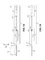
- FIG. 1Ashows an exemplary embodiment of a barrier application device according to the present invention
- FIG. 1Bshows an exemplary embodiment of a barrier application device according to the present invention
- FIG. 2shows an exemplary embodiment of an introducer assembly for a barrier application device according to the present invention
- FIG. 3shows an exemplary embodiment of a beam assembly and a flag for a barrier application device according to the present invention
- FIG. 4shows an exemplary embodiment of a barrier application device according to the present invention prior to use
- FIG. 5shows an exemplary embodiment of a barrier application device according to the present invention prior to use
- FIG. 6shows an exemplary embodiment of a barrier application device according to the present invention prior to use
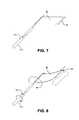
- FIG. 7shows an exemplary embodiment of a barrier application device according to the present invention during use
- FIG. 8shows an exemplary embodiment of a barrier application device according to the present invention during use.
- FIG. 9shows an exemplary embodiment of a barrier application device according to the present invention during use
- Exemplary embodiments of a barrier application devicemay be used to retain a barrier and deploy the barrier at a surgical site.
- the barriermay be adapted to adhere to the surgical site to prevent organs and/or tissue from adhering to the surgical site.
- a barriermay be Seprafilm® Adhesion Barrier made by Genzyme Corporation.
- a barriermay be Gynecare Interceed® made by Ethicon, Inc.
- FIGS. 1A and 1Bshow an exemplary embodiment of a barrier application device 10 according to the present invention.
- the application device 10comprises a handle 12 including a grip portion 12 . 1 and a shaft 12 . 2 extending therefrom.
- the grip portion 12 . 1is ergonomically shaped (e.g., cylindrical, conical, frusto-conical or any combination thereof) for being gripped and handled by a user.
- a gripping surface(not shown), such as a frictional material or an array of projections, may be disposed on the grip portion to enhance the grip of the user and preventing slipping during use.
- An orientation indicator 12 . 1 . 1may be disposed on the grip portion 12 . 1 .
- the orientation indicator 12 . 1 . 1may be a projection, recess, symbol or any other feature and may have a color different from a color of the grip portion 12 . 1 to provide visual feedback to the user.
- the shaft 12 . 2extends distally from a distal end of the grip portion 12 . 1 .
- the shaft 12 . 2is coaxially aligned with the grip portion 12 . 1 .
- the handle 12is made from acrylonitrile butadiene styrene.
- FIG. 2shows an exemplary embodiment of the introducer assembly 14 according to the present invention.
- the introducer assembly 14is slidably coupled to the shaft 12 . 2 and includes an introducer tube 14 . 1 and an introducer stop 14 . 2 .
- the introducer tube 14 . 1is a hollow cylinder that includes a distal end 14 . 1 . 1 that is beveled.
- the distal end 14 . 1 . 1includes a distal opening 14 . 1 . 1 . 1 which is contiguous with a slot 14 . 1 . 2 formed along at least a portion of a length of the introducer tube 14 . 1 .
- the introducer tube 14 . 1is made from stainless steel.
- the introducer stop 14 . 2has an outer diameter larger than an outer diameter of the introducer tube 14 . 1 .
- the introducer stop 14 . 2is adapted to abut an insertion device (e.g., a trocar) which provides access to a surgical site.
- the introducer stop 14 . 2may provide one or more features, such as ridges 14 . 2 . 1 , to enhance a grip and prevent slipping when the user is holding the introducer stop 14 . 2 .
- the introducer stop 14 . 2is overmolded on the introducer tube 14 . 1 and is made from acrylonite butadiene styrene.
- the introducer assembly 14is slidable relative to the shaft 12 . 2 between a retracted position (shown in FIGS. 1A-B ) and an extended position, and the introducer assembly 14 is freely rotatable relative to the shaft 12 . 2 .
- a sleeve 16is coupled to a distal end of the handle 12 .
- the sleeve 16may be disposed on a distal end of the shaft 12 . 2 to prevent the introducer 14 from sliding distally off the distal end of the shaft 12 . 2 .
- the sleeve 16may be made from polypropylene.
- a flex joint 18may be coupled to a distal end of the shaft 12 . 2 .
- the flex joint 18may be a cylindrical element having a proximal female end adapted to engage a distal end of the shaft 12 . 2 and a distal female end adapted to engage a proximal end of a beam assembly 20 .
- the distal end of the shaft 12 . 2 and/or the proximal end of the beam assembly 20may include one or more barbs adapted to engage the proximal and distal ends, respectively, of the flex joint 18 .
- the distal end of the shaft 12.
- the proximal end of the beam assembly 20may include one or more holes or recesses (radially or axially formed) to receive a corresponding projection(s) on the flex joint 18 (e.g., when the flex joint 18 is being molded).
- the flex joint 18may be inserted into an open distal end of the sleeve 16 .
- the flex joint 18may be biased in a non-deflected state (shown in FIGS. 1A-B ) in which the flex joint 18 is coaxially aligned with the shaft 12 . 2 .
- the flex joint 18When a force is applied, the flex joint 18 may be capable of bending 360° around the X-axis and approximately 180° around the Y-axis, and approximately 180° around the Z-axis. When the force is removed, the flex joint 18 may return to the non-deflected state.
- the flex joint 18is made from thermoplastic elastomer.
- a tensile strength of the flex joint 18is greater than approximately 9.1N.
- a beam assembly 20is coupled to the flex joint 18 and a flag 22 is coupled to the beam assembly 20 .
- FIG. 3shows an exemplary embodiment of the beam assembly 20 according to the present invention.
- the beam assembly 20comprises a first beam 20 . 1 and a second beam 20 . 2 .
- the first beam 20 . 1has a semi-circular cross-section
- the second bean 20 . 2has a complementary semi-circular cross-section.
- the first beam 20 . 1includes a first distal tip 20 . 1 . 2
- the second beam 20 . 2includes a second distal 20 . 2 . 2
- each of the first and second distal tips 20 . 1 . 2 , 20 . 2 . 2is substantially semi-spherical or a halved tear-drop.
- the first and second beams 20 . 1 , 20 . 2are made from acrylonite butadiene styrene.
- the orientation indicator 12 . 1 . 1may be disposed on the first beam 20 . 1 and/or the second beam 20 . 2 .
- one of the beamscould be a different color or include a symbol.
- FIG. 3shows an exemplary embodiment of a flag 22 according to the present invention.
- the flag 22is substantially rectangular and includes an inner tab 22 . 1 and at least one outer tab 22 . 2 spaced radially from the inner tab 22 . 1 .
- the flag 22is adapted to receive a barrier, and the tabs 22 . 1 , 22 . 2 are adapted to retain the barrier against the flag 22 until the barrier is deployed.
- the inner tab 22 . 1is adapted to fold about the X-axis and the at least one outer tab 22 . 2 is adapted to fold about the Z-axis.
- the tabs 22 . 1 , 22 . 2are flaps that are biased toward a folded position to engage a barrier when placed on a surface of the flag 22 .
- the tabs 22 . 1 , 22 . 2can be opened to an open position to receive the barrier.
- one or more slits 22 . 4may be formed (e.g., cut) between the inner tab 22 . 1 and the flag 22 .
- the inner tab 22 . 1may be folded along the at least one slit 22 . 3 toward the at least one outer tab 22 . 2 to create a pocket for receiving the barrier.
- the flag 22is made from a hydrophobic polyester mesh.
- the mesh and the hydrophobic materialmay prevent surface tension from adhering to the barrier B, and the hydrophobic material may further help shed water and blood from the flag 22 that may be encountered during the surgical procedure.
- the orientation indicator 12 . 1 . 1may be disposed on the flag 22 as, for example, text or a symbol.
- the handle 12is injection molded.
- the introducer tube 14 . 1is made and the introducer stop 14 . 2 is overmolded thereon to form the introducer assembly 14 .
- the introducer assembly 14is then coupled to the handle 12 by sliding the introducer assembly 14 onto the shaft 12 . 2 .
- the sleeve 16is then coupled to the distal end of the shaft 12 . 2 .
- the flag 22is made from a polyester mesh which is laser cut into a predetermined shape (e.g., including the tabs and slits).
- the first and second beams 20 . 1 and 20 . 2are overmolded on to portions of the flag 22 , as shown in FIG. 3 .
- the first beam 20 . 1may be molded on a first side of the slit 22 . 3
- the second beam 20 . 2may be molded on a second side of the slit 22 . 3
- the inner tab 22 . 1may be folded toward the outer tab 22 . 2 to create a pocket 22 . 3 (shown in FIG. 4 ), and the first and second beams 20 . 1 , 20 . 2 are coupled together (e.g., via a snap-fit, friction fit, latch, hook, etc.).
- the beam assembly 20 with the flag 22is placed with the handle/introducer/sleeve assembly into a mold for the flex joint 18 .
- the flex joint 18is then overmolded onto a distal portion of the sleeve 16 and a proximal portion of the beam assembly 20 .
- the fully assembled application device 10may then be placed in a sterile enclosure.
- FIGS. 4-9shows an exemplary embodiment of a use of a barrier application device 10 according to the present invention.
- the introducer assembly 10is in a retracted position relative to the beam assembly 20 so that the beam assembly 20 is exposed.
- a proximal end of the introducer tube 14 . 1may abut a distal end of the grip portion 12 . 1 of the handle 12 as a proximal stop.
- a barrier Bmay be placed on the flag 22 such that a first lateral edge of the barrier B is inserted into the pocket 22 . 3 under the inner tab 22 . 1 .
- the one or more slits 22 . 4may provide a visual feedback that the first lateral edge of the barrier B has been properly inserted through the first and second beams 20 . 1 , 20 . 2 and into the pocket 22 . 3 .
- the introducer assembly 14is moved from the retracted position to the extended position.
- the introducer assembly 14may be rotated so that the slot 14 . 1 . 2 aligns with the flag recess 20 . 3 in the beam assembly 20 .
- the slot 14 . 1 . 2may receive the flag 22 and the barrier B thereon.
- the beveled distal end 14 . 1 . 1 of the introducer tube 14 . 1may facilitate the alignment of the slot 14 . 1 . 2 and the flag recess 20 . 3 such that the flag 22 (and the barrier B thereon) will not be crimped or folded by an impact of the introducer tube 14 .
- a distal end of the introducer stop 14 . 2may abut a proximal end of the sleeve 16 to define the extended position of the introducer assembly 14 .
- the distal tip 20 . 4may have a larger cross-section than the distal end 14 . 1 . 1 of the introducer tube 14 , and the distal end 14 . 1 . 1 of the introducer tube 14 may abut the distal tip 20 .
- the distal tip 20 . 4may provide a bearing surface for rotation of the introducer tube 14 .
- a distal surface of the beveled portion of the distal end 14 . 1 . 1may be proximal of a distal surface of the distal tip 20 . 4 of the beam assembly 20 . This may prevent the beveled edge from damaging tissue/organ when inserted into the surgical site.
- the handle 12is rotated relative to the introducer assembly 14 which causes the flag 22 and the barrier B to roll around the beam assembly 20 .
- a second lateral edge of the barrier Bmay be inserted beneath the at least one outer tab 22 . 2 , and the flag 22 and barrier B may be rolled until they are no longer visible out of the slot 14 . 1 . 2 .
- the handle 12is rotated relative to the introducer assembly 14 , at least one of the beams 20 . 1 , 20 . 2 engage the barrier B, which prevents the barrier B from disengaging the flag 22 .
- an adhesivecould be disposed on the flag 22 and/or at least one of the beams 20 . 1 , 20 . 2 to engage the barrier B.
- at least one of the beams 20 . 1 , 20 . 2may include a barb adapted to engage the barrier B.
- the application device 10When the flag 22 and the barrier B are substantially retained in the introducer assembly 14 , the application device 10 may be deployed to the surgical site and the introducer assembly 14 may be moved from the extended position to the retracted position.
- the application device 10when the application device 10 is deployed to the surgical site, it is inserted into a trocar, and the introducer stop 14 . 2 . abuts a portion of the trocar which causes the introducer assembly 14 to retract as the handle 12 is inserted distally toward the surgical site.
- the introducer assembly 14is in the retracted position, and the flag 22 and the barrier B may at least partially unravel.
- the orientation indicator 12 . 1 . 1provides a visual feedback regarding the orientation of the flag 22 and the barrier B.
- the position of the orientation indicator 12 . 1 . 1 on the grip portion 12 . 1may indicate a position in which an exposed surface of the barrier B is oriented.
- the handle 12may be rotated to align the barrier B with the surgical site.
- the flag 22prevents a non-exposed surface of the barrier B from adhering to an organ or tissue as the handle 12 is rotated.
- the beam assembly 20may be deflected via the flex joint 18 to properly orient and position the harder B.
- a rounded distal surface of the distal tip 20 . 4may prevent trauma to organs and/or tissue during use of the application device 10 .
- a further surgical toolmay be used to manipulate the barrier B, e.g., to ensure that it adheres to the surgical site.
- the handle 20is pulled proximally relative to the introducer assembly 14 , and the handle 20 is rotated until the flag 22 is substantially within the introducer assembly 14 and can be removed from the surgical site.
- an unused barriermay be applied to the flag 22 and the application device 10 may be reused.
- the shaft 12 . 1may include one or more projections adapted to engage the introducer tube 14 . 1 .
- the projectionsmay prevent free sliding of the introducer assembly 14 relative to the shaft 12 . 1 and/or provide tactile feedback (e.g., resistance) when inserting the application device 10 into a trocar.
Landscapes
- Health & Medical Sciences (AREA)
- Life Sciences & Earth Sciences (AREA)
- Surgery (AREA)
- Heart & Thoracic Surgery (AREA)
- Engineering & Computer Science (AREA)
- Biomedical Technology (AREA)
- Nuclear Medicine, Radiotherapy & Molecular Imaging (AREA)
- Medical Informatics (AREA)
- Molecular Biology (AREA)
- Animal Behavior & Ethology (AREA)
- General Health & Medical Sciences (AREA)
- Public Health (AREA)
- Veterinary Medicine (AREA)
- Surgical Instruments (AREA)
Abstract
Description
Claims (24)
Priority Applications (7)
| Application Number | Priority Date | Filing Date | Title |
|---|---|---|---|
| US14/077,893US10028731B2 (en) | 2013-11-12 | 2013-11-12 | Barrier application device |
| TW103139059ATWI679962B (en) | 2013-11-12 | 2014-11-11 | Barrier application device and method of using barrier application device |
| PCT/US2014/064964WO2015073410A1 (en) | 2013-11-12 | 2014-11-11 | Barrier application device |
| JP2016554314AJP6806966B2 (en) | 2013-11-12 | 2014-11-11 | Barrier application device |
| EP14808762.0AEP3068310B1 (en) | 2013-11-12 | 2014-11-11 | Barrier application device |
| ES14808762TES2988529T3 (en) | 2013-11-12 | 2014-11-11 | Barrier application device |
| JP2020118891AJP2020179204A (en) | 2013-11-12 | 2020-07-10 | Barrier application device |
Applications Claiming Priority (1)
| Application Number | Priority Date | Filing Date | Title |
|---|---|---|---|
| US14/077,893US10028731B2 (en) | 2013-11-12 | 2013-11-12 | Barrier application device |
Publications (2)
| Publication Number | Publication Date |
|---|---|
| US20150128959A1 US20150128959A1 (en) | 2015-05-14 |
| US10028731B2true US10028731B2 (en) | 2018-07-24 |
Family
ID=52011302
Family Applications (1)
| Application Number | Title | Priority Date | Filing Date |
|---|---|---|---|
| US14/077,893Active2035-11-28US10028731B2 (en) | 2013-11-12 | 2013-11-12 | Barrier application device |
Country Status (6)
| Country | Link |
|---|---|
| US (1) | US10028731B2 (en) |
| EP (1) | EP3068310B1 (en) |
| JP (2) | JP6806966B2 (en) |
| ES (1) | ES2988529T3 (en) |
| TW (1) | TWI679962B (en) |
| WO (1) | WO2015073410A1 (en) |
Citations (101)
| Publication number | Priority date | Publication date | Assignee | Title |
|---|---|---|---|---|
| US4874375A (en)* | 1987-04-13 | 1989-10-17 | Ellison Arthur E | Tissue retractor |
| WO1992014513A1 (en) | 1991-02-13 | 1992-09-03 | Interface Biomedical Laboratories Corp. | Filler material for use in tissue welding |
| US5156613A (en) | 1991-02-13 | 1992-10-20 | Interface Biomedical Laboratories Corp. | Collagen welding rod material for use in tissue welding |
| US5195958A (en) | 1990-05-25 | 1993-03-23 | Phillips Edward H | Tool for laparoscopic surgery |
| EP0581036A1 (en) | 1992-06-30 | 1994-02-02 | United States Surgical Corporation | Surgical element deployment apparatus |
| US5370650A (en)* | 1992-02-24 | 1994-12-06 | United States Surgical Corporation | Articulating mesh deployment apparatus |
| US5464403A (en) | 1992-10-29 | 1995-11-07 | General Surgical Innovations, Inc. | Placement tool and method for laparoscopic hernia repair |
| WO1996007356A1 (en) | 1994-09-06 | 1996-03-14 | Fusion Medical Technologies, Inc. | Methods and articles for staple line reinforcement |
| WO1996007355A1 (en) | 1994-09-06 | 1996-03-14 | Fusion Medical Technologies, Inc. | Structure and method for bonding or fusion of biological materials |
| US5503623A (en) | 1995-03-17 | 1996-04-02 | Tilton, Jr.; Eugene B. | Instrumentation for laparoscopic insertion and application of sheet like surgical material |
| US5634931A (en) | 1994-09-29 | 1997-06-03 | Surgical Sense, Inc. | Hernia mesh patches and methods of their use |
| US5669934A (en) | 1991-02-13 | 1997-09-23 | Fusion Medical Technologies, Inc. | Methods for joining tissue by applying radiofrequency energy to performed collagen films and sheets |
| WO1997036622A1 (en) | 1996-04-01 | 1997-10-09 | SYNECHION/TILTON JOINT VENTURE (a joint venture of SYNECHION, INC. and TILTON, EUGENE, B., JR.) | Instrumentation for surgical endoscopic insertion and application of liquid, gel and like material |
| US5681342A (en) | 1995-08-17 | 1997-10-28 | Benchetrit; Salomon | Device and method for laparoscopic inguinal hernia repair |
| WO1998016165A1 (en) | 1996-10-16 | 1998-04-23 | Fusion Medical Technologies, Inc. | Films having improved characteristics and methods for their preparation and use |
| US5766157A (en) | 1995-03-17 | 1998-06-16 | Tilton, Jr.; Eugene B. | Instrumentation for surgical endoscopic insertion and application of liquid and gel material |
| US5785677A (en) | 1993-06-22 | 1998-07-28 | Auweiler; Udo | Laparoscopy bag |
| US5791352A (en) | 1996-06-19 | 1998-08-11 | Fusion Medical Technologies, Inc. | Methods and compositions for inhibiting tissue adhesion |
| US5919184A (en) | 1995-03-17 | 1999-07-06 | Tilton, Jr.; Eugene B. | Instrumentation for laparoscopic insertion and application of surgical sheet material |
| US5931165A (en) | 1994-09-06 | 1999-08-03 | Fusion Medical Technologies, Inc. | Films having improved characteristics and methods for their preparation and use |
| US5957939A (en) | 1997-07-31 | 1999-09-28 | Imagyn Medical Technologies, Inc. | Medical device for deploying surgical fabrics |
| US6010495A (en) | 1995-03-17 | 2000-01-04 | Tilton, Jr.; Eugene B. | Instrumentation for endoscopic surgical insertion and application of liquid, gel and like material |
| US6033426A (en) | 1997-07-29 | 2000-03-07 | Olympus Optical Co., Ltd. | Access device for surgical treatment |
| US6042592A (en) | 1997-08-04 | 2000-03-28 | Meadox Medicals, Inc. | Thin soft tissue support mesh |
| RU2150897C1 (en) | 1998-04-22 | 2000-06-20 | Плечев Владимир Вячеславович | Method for preventing visceroparietal abdominal commissures |
| US6110181A (en) | 1999-02-10 | 2000-08-29 | Veterans General Hospital-Taipei, Vacrs | Thread carrier plate device and method |
| US6183485B1 (en) | 1993-08-25 | 2001-02-06 | Inlet Medical, Inc. | Insertable suture passing grasping probe and methodology for using same |
| US6193731B1 (en) | 1998-10-27 | 2001-02-27 | Fziomed, Inc. | Laparoscopic insertion and deployment device |
| WO2001026563A1 (en) | 1999-10-08 | 2001-04-19 | Yale University | Method of administrating medicament to trocar adapted port site |
| RU2169528C2 (en) | 1997-03-18 | 2001-06-27 | Давлиев Марат Касимович | Method and device for preparing a patient to laparoscopic intervention |
| WO2001089390A1 (en) | 2000-05-19 | 2001-11-29 | Genzyme Corporation | Device for delivery of surgical materials |
| US20020049413A1 (en) | 2000-02-23 | 2002-04-25 | Moenning Stephen P. | Minimally invasive medical apparatus for dispensing a biologically active compound and an associated medical procedure for dispensing a biologically active compound |
| US6416506B1 (en)* | 1995-03-17 | 2002-07-09 | Eugene B. Tilton, Jr. | Instrumentation for endoscopic surgical insertion and application of liquid, gel and like material |
| JP2002360582A (en) | 2001-06-05 | 2002-12-17 | Hiroyoshi Morita | Internal organ exclusion tool |
| US20030149443A1 (en) | 2001-12-20 | 2003-08-07 | Gaskill Harold V. | Laparoscopic porting |
| US6641575B1 (en) | 1999-01-26 | 2003-11-04 | Neal M. Lonky | Surgical vacuum instrument for retracting, extracting, and manipulating tissue |
| US6676639B1 (en) | 1999-02-10 | 2004-01-13 | Safe Conduct Ab | Cannula |
| US20040034339A1 (en) | 2002-08-16 | 2004-02-19 | The Regents Of The University Of California | Device for improved visualization of operative sites during surgery |
| US20040092989A1 (en) | 2002-08-28 | 2004-05-13 | Heart Leaflet Technologies, Inc | Delivery device for leaflet valve |
| US20040093018A1 (en) | 2002-10-16 | 2004-05-13 | Applied Medical Resources Corporation | Access device maintenance apparatus and method |
| US20040092970A1 (en) | 2002-10-18 | 2004-05-13 | Xavier Alfredo F. | Prosthetic mesh anchor device |
| US20040106942A1 (en) | 2002-12-02 | 2004-06-03 | Applied Medical Resources Corporation | Universal access seal |
| US20040111061A1 (en) | 2002-11-12 | 2004-06-10 | Diana Curran | Trocar having an inflatable cuff for maintaining an insufflated abdominal cavity during an open laparaoscopy procedure |
| WO2004080348A1 (en) | 2003-03-13 | 2004-09-23 | Samuel Eldar | Device for deploying and placing a surgical prosthesis mesh |
| US20040249457A1 (en) | 2003-06-09 | 2004-12-09 | Smith Lane Fielding | Mastopexy stabilization apparatus and method |
| RU2241392C1 (en) | 2003-04-22 | 2004-12-10 | Дамбаев Георгий Цыренович | Surgical method for treating esophageal achalasia and device for creating compression-type valve anastomosis |
| US20050043746A1 (en) | 2003-08-21 | 2005-02-24 | Pollak Stanley B. | Methods and instruments for closing laparoscopic trocar puncture wounds |
| US20050165449A1 (en) | 2003-12-02 | 2005-07-28 | Board Of Regents, The University Of Texas System | Surgical anchor and system |
| US20050216028A1 (en) | 2004-03-24 | 2005-09-29 | Hart Charles C | Self-sealing cannula having integrated seals |
| US6966916B2 (en) | 2002-09-26 | 2005-11-22 | Kumar Sarbjeet S | Device and method for surgical repair of abdominal wall hernias |
| WO2006041474A1 (en) | 2004-10-07 | 2006-04-20 | Lexion Medical, Llc | Method and apparatus for delivering an agent to the abdomen |
| US20060129154A1 (en) | 2004-04-27 | 2006-06-15 | Shipp John I | Absorbable Anchor for Hernia Mesh Fixation |
| US20060149305A1 (en) | 2005-01-06 | 2006-07-06 | Brian Cuevas | Surgical seal for use in a surgical access apparatus |
| US20060200004A1 (en) | 2005-01-26 | 2006-09-07 | Wilk Patent, Llc | Intra-abdominal medical procedures and device |
| JP2006280848A (en) | 2005-04-05 | 2006-10-19 | Olympus Medical Systems Corp | Magnetic forceps |
| JP2006296666A (en) | 2005-04-19 | 2006-11-02 | Hakujuji Co Ltd | Disposable cloth inserter |
| US20060264991A1 (en) | 2005-04-29 | 2006-11-23 | Applied Medical Resources Corporation | Seal housing having anti-inversion features |
| US20070049860A1 (en) | 2005-09-01 | 2007-03-01 | Robert Seminara | Apparatus and method for using a surgical instrument with an expandable sponge |
| US20070073337A1 (en) | 2001-09-06 | 2007-03-29 | Ryan Abbott | Clip-Based Systems And Methods For Treating Septal Defects |
| WO2007044808A2 (en) | 2005-10-11 | 2007-04-19 | Black & Decker Inc. | Pto chuck spacer |
| US20070112361A1 (en)* | 2005-11-07 | 2007-05-17 | Schonholz Steven M | Surgical repair systems and methods of using the same |
| CN2910140Y (en) | 2005-10-25 | 2007-06-13 | 朱新生 | Manual aid for abdominoscope technique |
| US20070233606A1 (en) | 2006-04-04 | 2007-10-04 | Apple Computer, Inc. | Decoupling rights in a digital content unit from download |
| US20070255273A1 (en) | 2006-04-29 | 2007-11-01 | Board Of Regents, The University Of Texas System | Devices for use in Transluminal and Endoluminal Surgery |
| CN201026203Y (en) | 2007-04-07 | 2008-02-27 | 内蒙古自治区计划生育科学技术研究所 | Operation suspension device without pneumoperitoneum peritoneoscope |
| US20080058852A1 (en) | 2006-09-01 | 2008-03-06 | Ihde Glenn M | Fluid Absorbent Surgical Device for Trocars |
| US20080097468A1 (en) | 2006-10-18 | 2008-04-24 | Adams Ronald D | Systems for performing gynecological procedures with closed visualization lumen |
| US20080121553A1 (en) | 2006-08-28 | 2008-05-29 | Fred Gobel | Percutaneous gastrointestinal anchoring kit |
| WO2008068405A2 (en) | 2006-11-07 | 2008-06-12 | Corpataux, Jean-Marc | Laparoscopic spacer<0} |
| US20080146882A1 (en) | 2006-12-15 | 2008-06-19 | Cropper Michael S | Handoscopy Interwoven Layered Seal Laparoscopic Disk |
| US20080200934A1 (en) | 2007-02-15 | 2008-08-21 | Fox William D | Surgical devices and methods using magnetic force to form an anastomosis |
| RU2337636C2 (en) | 2006-11-29 | 2008-11-10 | Мадина Ирековна Мазитова | Method of laparolifting and retractor for its realisation |
| US20090005795A1 (en) | 2007-06-28 | 2009-01-01 | Brandon Giap | Surgical needle docking device and method |
| US20090043246A1 (en) | 2007-08-07 | 2009-02-12 | Dominguez Guillermo Manuel | Magnetic Surgical Device to Manipulate Tissue in Laparoscopic Surgeries Performed with a Single Trocar or Via Natural Orifices |
| US7501802B2 (en) | 2004-06-16 | 2009-03-10 | Ricoh Company, Ltd. | DC-DC converting method and apparatus |
| US20090069837A1 (en) | 2007-08-20 | 2009-03-12 | Atropos Limited | Hand and instrument access device |
| US20090137877A1 (en) | 2007-11-26 | 2009-05-28 | Ethicon Endo-Surgery, Inc. | Tissue retractors |
| US20090187079A1 (en) | 2008-01-22 | 2009-07-23 | Applied Medical Resources Corporation | Surgical instrument access device |
| US20090259185A1 (en) | 2008-04-15 | 2009-10-15 | Tyco Healthcare Group Lp | Self-conforming surgical seal |
| US20090270688A1 (en) | 2008-04-24 | 2009-10-29 | Searete Llc, A Limited Liability Corporation Of The State Of Delaware | Methods and systems for presenting a combination treatment |
| US7651478B2 (en) | 2002-01-24 | 2010-01-26 | Applied Medical Resources Corporation | Surgical access device with floating gel seal |
| US20100063452A1 (en) | 2008-09-05 | 2010-03-11 | Edelman David S | Flexible Disposable Surgical Port |
| US20100081881A1 (en) | 2008-09-30 | 2010-04-01 | Ethicon Endo-Surgery, Inc. | Surgical Access Device with Protective Element |
| WO2010045702A1 (en) | 2008-10-20 | 2010-04-29 | Imbros Administração E Participações Ltda | Improved trocar sealing |
| WO2010050243A1 (en) | 2008-10-31 | 2010-05-06 | 合同会社ジャパン・メディカル・クリエーティブ | Surgery device |
| CN101775982A (en) | 2009-09-01 | 2010-07-14 | 中国石油集团西部钻探工程有限公司测井公司 | Microsphere hydraulic sidewall contact device |
| WO2010087330A1 (en) | 2009-01-29 | 2010-08-05 | 国立大学法人大阪大学 | Retractor for flexible endoscope |
| US20100211000A1 (en) | 2008-08-26 | 2010-08-19 | Killion Douglas P | Method and system for sealing percutaneous punctures |
| US20100280437A1 (en) | 2007-12-27 | 2010-11-04 | University Of South Florida | Multichannel trocar |
| US20100305587A1 (en) | 2009-06-02 | 2010-12-02 | Jens-Peter Straehnz | Incision closure device and method |
| US7846171B2 (en) | 2004-05-27 | 2010-12-07 | C.R. Bard, Inc. | Method and apparatus for delivering a prosthetic fabric into a patient |
| EP2266476A1 (en) | 2005-10-13 | 2010-12-29 | Tyco Healthcare Group LP | Trocar anchor |
| US7867222B1 (en) | 1995-03-17 | 2011-01-11 | Tilton Jr Eugene B | Instrumentation for endoscopic surgical insertion and application of liquid, gel and like material |
| DE102009034251A1 (en) | 2009-07-22 | 2011-01-27 | Urotech Gmbh | Coating for a tubular or tubular part of a medical device to be introduced into cavities, in particular of individuals, and method for applying a coating to such a part |
| US20110029003A1 (en) | 2009-07-29 | 2011-02-03 | Confluent Surgical, Inc. | System and Method of Laparoscopic Use of Hemostatic Patch |
| US20110034935A1 (en) | 2009-08-06 | 2011-02-10 | Tyco Healthcare Group Lp | Surgical device having non-circular cross-section |
| US20110082343A1 (en) | 2009-10-01 | 2011-04-07 | Tyco Healthcare Group Lp | Seal anchor with non-parallel lumens |
| US20110079627A1 (en) | 2009-05-12 | 2011-04-07 | Ethicon, Inc. | Applicator instruments having curved and articulating shafts for deploying surgical fasteners and methods therefor |
| US20110105848A1 (en)* | 2007-10-07 | 2011-05-05 | Niv Sadovsky | Laparoscopic tissue retractor |
| US7947054B2 (en)* | 2007-02-14 | 2011-05-24 | EasyLab Ltd. | Mesh deployment apparatus |
| US20110124967A1 (en) | 2009-11-20 | 2011-05-26 | Ethicon Endo-Surgery, Inc. | Discrete flexion head for single port device |
Family Cites Families (3)
| Publication number | Priority date | Publication date | Assignee | Title |
|---|---|---|---|---|
| US6679886B2 (en)* | 2000-09-01 | 2004-01-20 | Synthes (Usa) | Tools and methods for creating cavities in bone |
| JP5689772B2 (en)* | 2011-09-26 | 2015-03-25 | ジェンザイム・ジャパン株式会社 | Medical instruments |
| JP5198680B1 (en)* | 2011-10-28 | 2013-05-15 | 富士システムズ株式会社 | Sheet insertion device |
- 2013
- 2013-11-12USUS14/077,893patent/US10028731B2/enactiveActive
- 2014
- 2014-11-11EPEP14808762.0Apatent/EP3068310B1/enactiveActive
- 2014-11-11WOPCT/US2014/064964patent/WO2015073410A1/enactiveApplication Filing
- 2014-11-11TWTW103139059Apatent/TWI679962B/ennot_activeIP Right Cessation
- 2014-11-11JPJP2016554314Apatent/JP6806966B2/enactiveActive
- 2014-11-11ESES14808762Tpatent/ES2988529T3/enactiveActive
- 2020
- 2020-07-10JPJP2020118891Apatent/JP2020179204A/enactivePending
Patent Citations (130)
| Publication number | Priority date | Publication date | Assignee | Title |
|---|---|---|---|---|
| US4874375A (en)* | 1987-04-13 | 1989-10-17 | Ellison Arthur E | Tissue retractor |
| US5304176A (en) | 1990-05-25 | 1994-04-19 | Phillips Edward H | Tool for laparoscopic surgery |
| US5195958A (en) | 1990-05-25 | 1993-03-23 | Phillips Edward H | Tool for laparoscopic surgery |
| US5324254A (en) | 1990-05-25 | 1994-06-28 | Phillips Edward H | Tool for laparoscopic surgery |
| US5334140A (en) | 1990-05-25 | 1994-08-02 | Phillips Edward H | Tool for laparoscopic surgery |
| US5380277A (en) | 1990-05-25 | 1995-01-10 | Phillips; Edward H. | Tool for laparoscopic surgery |
| US5156613A (en) | 1991-02-13 | 1992-10-20 | Interface Biomedical Laboratories Corp. | Collagen welding rod material for use in tissue welding |
| US5749895A (en) | 1991-02-13 | 1998-05-12 | Fusion Medical Technologies, Inc. | Method for bonding or fusion of biological tissue and material |
| US5824015A (en) | 1991-02-13 | 1998-10-20 | Fusion Medical Technologies, Inc. | Method for welding biological tissue |
| WO1992014513A1 (en) | 1991-02-13 | 1992-09-03 | Interface Biomedical Laboratories Corp. | Filler material for use in tissue welding |
| US5690675A (en) | 1991-02-13 | 1997-11-25 | Fusion Medical Technologies, Inc. | Methods for sealing of staples and other fasteners in tissue |
| US5669934A (en) | 1991-02-13 | 1997-09-23 | Fusion Medical Technologies, Inc. | Methods for joining tissue by applying radiofrequency energy to performed collagen films and sheets |
| US5370650A (en)* | 1992-02-24 | 1994-12-06 | United States Surgical Corporation | Articulating mesh deployment apparatus |
| US5304187A (en)* | 1992-06-30 | 1994-04-19 | United States Surgical Corporation | Surgical element deployment apparatus |
| EP0581036A1 (en) | 1992-06-30 | 1994-02-02 | United States Surgical Corporation | Surgical element deployment apparatus |
| US5464403A (en) | 1992-10-29 | 1995-11-07 | General Surgical Innovations, Inc. | Placement tool and method for laparoscopic hernia repair |
| US5785677A (en) | 1993-06-22 | 1998-07-28 | Auweiler; Udo | Laparoscopy bag |
| US6183485B1 (en) | 1993-08-25 | 2001-02-06 | Inlet Medical, Inc. | Insertable suture passing grasping probe and methodology for using same |
| WO1996007355A1 (en) | 1994-09-06 | 1996-03-14 | Fusion Medical Technologies, Inc. | Structure and method for bonding or fusion of biological materials |
| WO1996007356A1 (en) | 1994-09-06 | 1996-03-14 | Fusion Medical Technologies, Inc. | Methods and articles for staple line reinforcement |
| US5931165A (en) | 1994-09-06 | 1999-08-03 | Fusion Medical Technologies, Inc. | Films having improved characteristics and methods for their preparation and use |
| US5634931A (en) | 1994-09-29 | 1997-06-03 | Surgical Sense, Inc. | Hernia mesh patches and methods of their use |
| US6010495A (en) | 1995-03-17 | 2000-01-04 | Tilton, Jr.; Eugene B. | Instrumentation for endoscopic surgical insertion and application of liquid, gel and like material |
| US7867222B1 (en) | 1995-03-17 | 2011-01-11 | Tilton Jr Eugene B | Instrumentation for endoscopic surgical insertion and application of liquid, gel and like material |
| US6416506B1 (en)* | 1995-03-17 | 2002-07-09 | Eugene B. Tilton, Jr. | Instrumentation for endoscopic surgical insertion and application of liquid, gel and like material |
| US5797899A (en) | 1995-03-17 | 1998-08-25 | Tilton, Jr.; Eugene B. | Instrumentation for laparoscopic surgical endoscopic insertion and application of liquid, gel and like material |
| US5503623A (en) | 1995-03-17 | 1996-04-02 | Tilton, Jr.; Eugene B. | Instrumentation for laparoscopic insertion and application of sheet like surgical material |
| US5919184A (en) | 1995-03-17 | 1999-07-06 | Tilton, Jr.; Eugene B. | Instrumentation for laparoscopic insertion and application of surgical sheet material |
| US5766157A (en) | 1995-03-17 | 1998-06-16 | Tilton, Jr.; Eugene B. | Instrumentation for surgical endoscopic insertion and application of liquid and gel material |
| US5681342A (en) | 1995-08-17 | 1997-10-28 | Benchetrit; Salomon | Device and method for laparoscopic inguinal hernia repair |
| WO1997036622A1 (en) | 1996-04-01 | 1997-10-09 | SYNECHION/TILTON JOINT VENTURE (a joint venture of SYNECHION, INC. and TILTON, EUGENE, B., JR.) | Instrumentation for surgical endoscopic insertion and application of liquid, gel and like material |
| US5791352A (en) | 1996-06-19 | 1998-08-11 | Fusion Medical Technologies, Inc. | Methods and compositions for inhibiting tissue adhesion |
| WO1998016165A1 (en) | 1996-10-16 | 1998-04-23 | Fusion Medical Technologies, Inc. | Films having improved characteristics and methods for their preparation and use |
| RU2169528C2 (en) | 1997-03-18 | 2001-06-27 | Давлиев Марат Касимович | Method and device for preparing a patient to laparoscopic intervention |
| US6033426A (en) | 1997-07-29 | 2000-03-07 | Olympus Optical Co., Ltd. | Access device for surgical treatment |
| US5957939A (en) | 1997-07-31 | 1999-09-28 | Imagyn Medical Technologies, Inc. | Medical device for deploying surgical fabrics |
| US6042592A (en) | 1997-08-04 | 2000-03-28 | Meadox Medicals, Inc. | Thin soft tissue support mesh |
| US20020052612A1 (en) | 1997-08-04 | 2002-05-02 | Schmitt Peter J. | Thin soft tissue surgical support mesh |
| US6669706B2 (en) | 1997-08-04 | 2003-12-30 | Scimed Life Systems, Inc. | Thin soft tissue surgical support mesh |
| US6375662B1 (en) | 1997-08-04 | 2002-04-23 | Scimed Life Systems, Inc. | Thin soft tissue surgical support mesh |
| RU2150897C1 (en) | 1998-04-22 | 2000-06-20 | Плечев Владимир Вячеславович | Method for preventing visceroparietal abdominal commissures |
| US6193731B1 (en) | 1998-10-27 | 2001-02-27 | Fziomed, Inc. | Laparoscopic insertion and deployment device |
| US6641575B1 (en) | 1999-01-26 | 2003-11-04 | Neal M. Lonky | Surgical vacuum instrument for retracting, extracting, and manipulating tissue |
| US6676639B1 (en) | 1999-02-10 | 2004-01-13 | Safe Conduct Ab | Cannula |
| US6110181A (en) | 1999-02-10 | 2000-08-29 | Veterans General Hospital-Taipei, Vacrs | Thread carrier plate device and method |
| WO2001026563A1 (en) | 1999-10-08 | 2001-04-19 | Yale University | Method of administrating medicament to trocar adapted port site |
| US20020049413A1 (en) | 2000-02-23 | 2002-04-25 | Moenning Stephen P. | Minimally invasive medical apparatus for dispensing a biologically active compound and an associated medical procedure for dispensing a biologically active compound |
| US6695815B2 (en) | 2000-02-23 | 2004-02-24 | Stephen P. Moenning | Minimally invasive medical apparatus for dispensing a biologically active compound and an associated medical procedure for dispensing a biologically active compound |
| WO2001089390A1 (en) | 2000-05-19 | 2001-11-29 | Genzyme Corporation | Device for delivery of surgical materials |
| US6478803B1 (en)* | 2000-05-19 | 2002-11-12 | Genzyme Corporation | Device for delivery of surgical materials |
| JP2002360582A (en) | 2001-06-05 | 2002-12-17 | Hiroyoshi Morita | Internal organ exclusion tool |
| US20070073337A1 (en) | 2001-09-06 | 2007-03-29 | Ryan Abbott | Clip-Based Systems And Methods For Treating Septal Defects |
| US20030149443A1 (en) | 2001-12-20 | 2003-08-07 | Gaskill Harold V. | Laparoscopic porting |
| US6723088B2 (en) | 2001-12-20 | 2004-04-20 | Board Of Regents, The University Of Texas | Laparoscopic porting |
| US7651478B2 (en) | 2002-01-24 | 2010-01-26 | Applied Medical Resources Corporation | Surgical access device with floating gel seal |
| US20040034339A1 (en) | 2002-08-16 | 2004-02-19 | The Regents Of The University Of California | Device for improved visualization of operative sites during surgery |
| US20040092989A1 (en) | 2002-08-28 | 2004-05-13 | Heart Leaflet Technologies, Inc | Delivery device for leaflet valve |
| US6966916B2 (en) | 2002-09-26 | 2005-11-22 | Kumar Sarbjeet S | Device and method for surgical repair of abdominal wall hernias |
| US20060264998A1 (en) | 2002-10-16 | 2006-11-23 | Applied Medical Resources Corporation | Access device maintenance apparatus and method |
| US20040093018A1 (en) | 2002-10-16 | 2004-05-13 | Applied Medical Resources Corporation | Access device maintenance apparatus and method |
| US7105009B2 (en) | 2002-10-16 | 2006-09-12 | Applied Medical Resources Corporation | Access device maintenance apparatus and method |
| US20040092970A1 (en) | 2002-10-18 | 2004-05-13 | Xavier Alfredo F. | Prosthetic mesh anchor device |
| US20040111061A1 (en) | 2002-11-12 | 2004-06-10 | Diana Curran | Trocar having an inflatable cuff for maintaining an insufflated abdominal cavity during an open laparaoscopy procedure |
| US7390317B2 (en) | 2002-12-02 | 2008-06-24 | Applied Medical Resources Corporation | Universal access seal |
| US20040106942A1 (en) | 2002-12-02 | 2004-06-03 | Applied Medical Resources Corporation | Universal access seal |
| WO2004080348A1 (en) | 2003-03-13 | 2004-09-23 | Samuel Eldar | Device for deploying and placing a surgical prosthesis mesh |
| RU2241392C1 (en) | 2003-04-22 | 2004-12-10 | Дамбаев Георгий Цыренович | Surgical method for treating esophageal achalasia and device for creating compression-type valve anastomosis |
| US20040249457A1 (en) | 2003-06-09 | 2004-12-09 | Smith Lane Fielding | Mastopexy stabilization apparatus and method |
| US7081135B2 (en) | 2003-06-09 | 2006-07-25 | Lane Fielding Smith | Mastopexy stabilization apparatus and method |
| US7320693B2 (en) | 2003-08-21 | 2008-01-22 | Pollak Stanley B | Methods and instruments for closing laparoscopic trocar puncture wounds |
| US20050043746A1 (en) | 2003-08-21 | 2005-02-24 | Pollak Stanley B. | Methods and instruments for closing laparoscopic trocar puncture wounds |
| US20050165449A1 (en) | 2003-12-02 | 2005-07-28 | Board Of Regents, The University Of Texas System | Surgical anchor and system |
| US7429259B2 (en) | 2003-12-02 | 2008-09-30 | Cadeddu Jeffrey A | Surgical anchor and system |
| US20050216028A1 (en) | 2004-03-24 | 2005-09-29 | Hart Charles C | Self-sealing cannula having integrated seals |
| US20060129154A1 (en) | 2004-04-27 | 2006-06-15 | Shipp John I | Absorbable Anchor for Hernia Mesh Fixation |
| US20110022065A1 (en) | 2004-04-27 | 2011-01-27 | Shipp John I | Absorbable anchor for hernia mesh fixation |
| US7846171B2 (en) | 2004-05-27 | 2010-12-07 | C.R. Bard, Inc. | Method and apparatus for delivering a prosthetic fabric into a patient |
| US20110054485A1 (en) | 2004-05-27 | 2011-03-03 | C.R. Bard, Inc. | Method and apparatus for delivering a prosthetic fabric into a patient |
| US7501802B2 (en) | 2004-06-16 | 2009-03-10 | Ricoh Company, Ltd. | DC-DC converting method and apparatus |
| CA2681325C (en) | 2004-10-07 | 2013-09-03 | Lexion Medical, Llc | Method and apparatus for delivering an agent to the abdomen |
| WO2006041474A1 (en) | 2004-10-07 | 2006-04-20 | Lexion Medical, Llc | Method and apparatus for delivering an agent to the abdomen |
| CA2581783A1 (en) | 2004-10-07 | 2006-04-20 | Lexion Medical, Llc | Method and apparatus for delivering an agent to the abdomen |
| US20060149305A1 (en) | 2005-01-06 | 2006-07-06 | Brian Cuevas | Surgical seal for use in a surgical access apparatus |
| US7608082B2 (en) | 2005-01-06 | 2009-10-27 | Tyco Healthcare Group Lp | Surgical seal for use in a surgical access apparatus |
| US20060200004A1 (en) | 2005-01-26 | 2006-09-07 | Wilk Patent, Llc | Intra-abdominal medical procedures and device |
| JP2006280848A (en) | 2005-04-05 | 2006-10-19 | Olympus Medical Systems Corp | Magnetic forceps |
| JP2006296666A (en) | 2005-04-19 | 2006-11-02 | Hakujuji Co Ltd | Disposable cloth inserter |
| US20060264991A1 (en) | 2005-04-29 | 2006-11-23 | Applied Medical Resources Corporation | Seal housing having anti-inversion features |
| US20070049860A1 (en) | 2005-09-01 | 2007-03-01 | Robert Seminara | Apparatus and method for using a surgical instrument with an expandable sponge |
| WO2007044808A2 (en) | 2005-10-11 | 2007-04-19 | Black & Decker Inc. | Pto chuck spacer |
| EP2266476A1 (en) | 2005-10-13 | 2010-12-29 | Tyco Healthcare Group LP | Trocar anchor |
| CN2910140Y (en) | 2005-10-25 | 2007-06-13 | 朱新生 | Manual aid for abdominoscope technique |
| US20070112361A1 (en)* | 2005-11-07 | 2007-05-17 | Schonholz Steven M | Surgical repair systems and methods of using the same |
| US20070233606A1 (en) | 2006-04-04 | 2007-10-04 | Apple Computer, Inc. | Decoupling rights in a digital content unit from download |
| US7691103B2 (en) | 2006-04-29 | 2010-04-06 | Board Of Regents, The University Of Texas System | Devices for use in transluminal and endoluminal surgery |
| US20070255273A1 (en) | 2006-04-29 | 2007-11-01 | Board Of Regents, The University Of Texas System | Devices for use in Transluminal and Endoluminal Surgery |
| US7582098B2 (en) | 2006-08-28 | 2009-09-01 | Kimberly-Clark Wolrdwide, Inc. | Percutaneous gastrointestinal anchoring kit |
| US20080121553A1 (en) | 2006-08-28 | 2008-05-29 | Fred Gobel | Percutaneous gastrointestinal anchoring kit |
| US20080058852A1 (en) | 2006-09-01 | 2008-03-06 | Ihde Glenn M | Fluid Absorbent Surgical Device for Trocars |
| US20080097470A1 (en) | 2006-10-18 | 2008-04-24 | Gruber William H | Systems for performing gynecological procedures with mechanical distension |
| US20080097468A1 (en) | 2006-10-18 | 2008-04-24 | Adams Ronald D | Systems for performing gynecological procedures with closed visualization lumen |
| WO2008068405A2 (en) | 2006-11-07 | 2008-06-12 | Corpataux, Jean-Marc | Laparoscopic spacer<0} |
| RU2337636C2 (en) | 2006-11-29 | 2008-11-10 | Мадина Ирековна Мазитова | Method of laparolifting and retractor for its realisation |
| US20080146882A1 (en) | 2006-12-15 | 2008-06-19 | Cropper Michael S | Handoscopy Interwoven Layered Seal Laparoscopic Disk |
| US7947054B2 (en)* | 2007-02-14 | 2011-05-24 | EasyLab Ltd. | Mesh deployment apparatus |
| US20080200934A1 (en) | 2007-02-15 | 2008-08-21 | Fox William D | Surgical devices and methods using magnetic force to form an anastomosis |
| CN201026203Y (en) | 2007-04-07 | 2008-02-27 | 内蒙古自治区计划生育科学技术研究所 | Operation suspension device without pneumoperitoneum peritoneoscope |
| US20090005795A1 (en) | 2007-06-28 | 2009-01-01 | Brandon Giap | Surgical needle docking device and method |
| US20090043246A1 (en) | 2007-08-07 | 2009-02-12 | Dominguez Guillermo Manuel | Magnetic Surgical Device to Manipulate Tissue in Laparoscopic Surgeries Performed with a Single Trocar or Via Natural Orifices |
| US20090069837A1 (en) | 2007-08-20 | 2009-03-12 | Atropos Limited | Hand and instrument access device |
| US20110105848A1 (en)* | 2007-10-07 | 2011-05-05 | Niv Sadovsky | Laparoscopic tissue retractor |
| US20090137877A1 (en) | 2007-11-26 | 2009-05-28 | Ethicon Endo-Surgery, Inc. | Tissue retractors |
| US20100280437A1 (en) | 2007-12-27 | 2010-11-04 | University Of South Florida | Multichannel trocar |
| US20090187079A1 (en) | 2008-01-22 | 2009-07-23 | Applied Medical Resources Corporation | Surgical instrument access device |
| US20090259185A1 (en) | 2008-04-15 | 2009-10-15 | Tyco Healthcare Group Lp | Self-conforming surgical seal |
| US20090270688A1 (en) | 2008-04-24 | 2009-10-29 | Searete Llc, A Limited Liability Corporation Of The State Of Delaware | Methods and systems for presenting a combination treatment |
| US20100211000A1 (en) | 2008-08-26 | 2010-08-19 | Killion Douglas P | Method and system for sealing percutaneous punctures |
| US20100063452A1 (en) | 2008-09-05 | 2010-03-11 | Edelman David S | Flexible Disposable Surgical Port |
| US20100081881A1 (en) | 2008-09-30 | 2010-04-01 | Ethicon Endo-Surgery, Inc. | Surgical Access Device with Protective Element |
| WO2010045702A1 (en) | 2008-10-20 | 2010-04-29 | Imbros Administração E Participações Ltda | Improved trocar sealing |
| WO2010050243A1 (en) | 2008-10-31 | 2010-05-06 | 合同会社ジャパン・メディカル・クリエーティブ | Surgery device |
| WO2010087330A1 (en) | 2009-01-29 | 2010-08-05 | 国立大学法人大阪大学 | Retractor for flexible endoscope |
| US20110079627A1 (en) | 2009-05-12 | 2011-04-07 | Ethicon, Inc. | Applicator instruments having curved and articulating shafts for deploying surgical fasteners and methods therefor |
| US20100305587A1 (en) | 2009-06-02 | 2010-12-02 | Jens-Peter Straehnz | Incision closure device and method |
| DE102009034251A1 (en) | 2009-07-22 | 2011-01-27 | Urotech Gmbh | Coating for a tubular or tubular part of a medical device to be introduced into cavities, in particular of individuals, and method for applying a coating to such a part |
| US20110029003A1 (en) | 2009-07-29 | 2011-02-03 | Confluent Surgical, Inc. | System and Method of Laparoscopic Use of Hemostatic Patch |
| US20110034935A1 (en) | 2009-08-06 | 2011-02-10 | Tyco Healthcare Group Lp | Surgical device having non-circular cross-section |
| CN101775982A (en) | 2009-09-01 | 2010-07-14 | 中国石油集团西部钻探工程有限公司测井公司 | Microsphere hydraulic sidewall contact device |
| US20110082343A1 (en) | 2009-10-01 | 2011-04-07 | Tyco Healthcare Group Lp | Seal anchor with non-parallel lumens |
| US20110124967A1 (en) | 2009-11-20 | 2011-05-26 | Ethicon Endo-Surgery, Inc. | Discrete flexion head for single port device |
Non-Patent Citations (3)
| Title |
|---|
| Hakko Co. Ltd, Instructions for Use: A.P.S. Introducer, May 31, 2007, pp. 1-3, 3rd Edition, Tokyo, Japan. |
| International Search Report and Written Opinion for Application No. PCT/US2014/064964, dated Feb. 13, 2015, 13 pages. |
| US 5,263,989, 11/1993, Phillips (withdrawn) |
Also Published As
| Publication number | Publication date |
|---|---|
| JP6806966B2 (en) | 2021-01-06 |
| WO2015073410A1 (en) | 2015-05-21 |
| TW201536241A (en) | 2015-10-01 |
| EP3068310A1 (en) | 2016-09-21 |
| ES2988529T3 (en) | 2024-11-20 |
| JP2016540616A (en) | 2016-12-28 |
| TWI679962B (en) | 2019-12-21 |
| EP3068310B1 (en) | 2024-02-21 |
| JP2020179204A (en) | 2020-11-05 |
| US20150128959A1 (en) | 2015-05-14 |
Similar Documents
| Publication | Publication Date | Title |
|---|---|---|
| US6193731B1 (en) | Laparoscopic insertion and deployment device | |
| EP3116413B1 (en) | Apparatus for clipping tissue | |
| AU762195B2 (en) | Self-retaining surgical access instrument | |
| EP3745966B1 (en) | Hemostasis clip | |
| US6478803B1 (en) | Device for delivery of surgical materials | |
| EP1938761B1 (en) | Suturing device | |
| US8480686B2 (en) | Methods and devices for delivering and applying suture anchors | |
| EP2465450A1 (en) | Self Deploying Bodily Opening Protector | |
| US9610076B2 (en) | Wound closure device | |
| US8668642B2 (en) | Port device including retractable endoscope cleaner | |
| US20170281176A1 (en) | Medical clip device, method for producing medical clip device and method for operating thereof | |
| AU2024200441B2 (en) | System and device for treating tissue | |
| US20150119866A1 (en) | Surgical Marker and Cap | |
| US20150164628A1 (en) | Endoscopic system for winding and inserting a mesh | |
| US10028731B2 (en) | Barrier application device | |
| US10335196B2 (en) | Surgical instrument having a stop guard | |
| US10548580B2 (en) | Instrument to close fascia during laparoscopic surgery | |
| US20200046482A1 (en) | Intraperitoneal insertion member and housing body therefor | |
| WO2024158858A2 (en) | Surgical material delivery device | |
| JP6210506B2 (en) | Living implants | |
| JP2016202520A (en) | Film insertion assist tool |
Legal Events
| Date | Code | Title | Description |
|---|---|---|---|
| AS | Assignment | Owner name:GENZYME CORPORATION, MASSACHUSETTS Free format text:ASSIGNMENT OF ASSIGNORS INTEREST;ASSIGNORS:KAPEC, JEFFREY;TANAKA, KAZUNA;NAOI, YUKIKO;AND OTHERS;SIGNING DATES FROM 20140205 TO 20150302;REEL/FRAME:035081/0031 | |
| AS | Assignment | Owner name:GENZYME CORPORATION, MASSACHUSETTS Free format text:CORRECTIVE ASSIGNMENT TO CORRECT THE FOURTH INVENTOR'S LAST NAME PREVIOUSLY RECORDED AT REEL: 035081 FRAME: 0031. ASSIGNOR(S) HEREBY CONFIRMS THE ASSIGNMENT;ASSIGNORS:KAPEC, JEFFREY;TANAKA, KAZUNA;NAOI, YUKIKO;AND OTHERS;SIGNING DATES FROM 20140205 TO 20150302;REEL/FRAME:038475/0928 | |
| STCF | Information on status: patent grant | Free format text:PATENTED CASE | |
| AS | Assignment | Owner name:BAXTER INTERNATIONAL INC., ILLINOIS Free format text:ASSIGNMENT OF ASSIGNORS INTEREST;ASSIGNOR:GENZYME CORPORATION;REEL/FRAME:053201/0314 Effective date:20200709 Owner name:BAXTER HEALTHCARE SA, SWITZERLAND Free format text:ASSIGNMENT OF ASSIGNORS INTEREST;ASSIGNOR:GENZYME CORPORATION;REEL/FRAME:053201/0314 Effective date:20200709 | |
| MAFP | Maintenance fee payment | Free format text:PAYMENT OF MAINTENANCE FEE, 4TH YEAR, LARGE ENTITY (ORIGINAL EVENT CODE: M1551); ENTITY STATUS OF PATENT OWNER: LARGE ENTITY Year of fee payment:4 |