US10022263B2 - Sling-based treatment of obstructive sleep apnea - Google Patents
Sling-based treatment of obstructive sleep apneaDownload PDFInfo
- Publication number
- US10022263B2 US10022263B2US13/550,065US201213550065AUS10022263B2US 10022263 B2US10022263 B2US 10022263B2US 201213550065 AUS201213550065 AUS 201213550065AUS 10022263 B2US10022263 B2US 10022263B2
- Authority
- US
- United States
- Prior art keywords
- sling
- tongue
- main body
- width
- lengthwise axis
- Prior art date
- Legal status (The legal status is an assumption and is not a legal conclusion. Google has not performed a legal analysis and makes no representation as to the accuracy of the status listed.)
- Active, expires
Links
- 208000001797obstructive sleep apneaDiseases0.000titleabstractdescription31
- 239000000463materialSubstances0.000claimsdescription103
- 210000002744extracellular matrixAnatomy0.000claimsdescription43
- 108010037362Extracellular Matrix ProteinsProteins0.000claimsdescription34
- 102000010834Extracellular Matrix ProteinsHuman genes0.000claimsdescription34
- 210000004876tela submucosaAnatomy0.000claimsdescription22
- 239000011159matrix materialSubstances0.000claimsdescription6
- 239000003550markerSubstances0.000claimsdescription4
- 210000000813small intestineAnatomy0.000claims2
- 238000000034methodMethods0.000abstractdescription97
- 210000004373mandibleAnatomy0.000abstractdescription49
- 210000001519tissueAnatomy0.000abstractdescription47
- 238000002513implantationMethods0.000description14
- 241001465754MetazoaSpecies0.000description10
- 230000000975bioactive effectEffects0.000description10
- 108010035532CollagenProteins0.000description7
- 102000008186CollagenHuman genes0.000description7
- 229920001436collagenPolymers0.000description7
- 238000003384imaging methodMethods0.000description7
- 238000005553drillingMethods0.000description6
- 238000012800visualizationMethods0.000description6
- 238000007634remodelingMethods0.000description5
- 241000894007speciesSpecies0.000description5
- 208000024891symptomDiseases0.000description5
- 230000033115angiogenesisEffects0.000description4
- 230000002491angiogenic effectEffects0.000description4
- 210000000988bone and boneAnatomy0.000description4
- 239000002639bone cementSubstances0.000description4
- 239000000835fiberSubstances0.000description4
- BASFCYQUMIYNBI-UHFFFAOYSA-NplatinumChemical compound[Pt]BASFCYQUMIYNBI-UHFFFAOYSA-N0.000description4
- -1polyethylenePolymers0.000description4
- 108090000623proteins and genesProteins0.000description4
- 102000004169proteins and genesHuman genes0.000description4
- 230000005641tunnelingEffects0.000description4
- 102000003974Fibroblast growth factor 2Human genes0.000description3
- 108090000379Fibroblast growth factor 2Proteins0.000description3
- HTTJABKRGRZYRN-UHFFFAOYSA-NHeparinChemical compoundOC1C(NC(=O)C)C(O)OC(COS(O)(=O)=O)C1OC1C(OS(O)(=O)=O)C(O)C(OC2C(C(OS(O)(=O)=O)C(OC3C(C(O)C(O)C(O3)C(O)=O)OS(O)(=O)=O)C(CO)O2)NS(O)(=O)=O)C(C(O)=O)O1HTTJABKRGRZYRN-UHFFFAOYSA-N0.000description3
- 239000004743PolypropyleneSubstances0.000description3
- 230000006978adaptationEffects0.000description3
- 239000012867bioactive agentSubstances0.000description3
- 230000015572biosynthetic processEffects0.000description3
- 210000004027cellAnatomy0.000description3
- 230000001413cellular effectEffects0.000description3
- 238000002224dissectionMethods0.000description3
- 230000000968intestinal effectEffects0.000description3
- 230000003340mental effectEffects0.000description3
- 229910052751metalInorganic materials0.000description3
- 239000002184metalSubstances0.000description3
- 150000002739metalsChemical class0.000description3
- 229920001155polypropylenePolymers0.000description3
- 230000008569processEffects0.000description3
- 239000007787solidSubstances0.000description3
- 239000000126substanceSubstances0.000description3
- 238000001356surgical procedureMethods0.000description3
- 239000000725suspensionSubstances0.000description3
- 102000010780Platelet-Derived Growth FactorHuman genes0.000description2
- 108010038512Platelet-Derived Growth FactorProteins0.000description2
- 102000004887Transforming Growth Factor betaHuman genes0.000description2
- 108090001012Transforming Growth Factor betaProteins0.000description2
- 230000002730additional effectEffects0.000description2
- 238000004873anchoringMethods0.000description2
- 210000002469basement membraneAnatomy0.000description2
- 230000008901benefitEffects0.000description2
- 239000012620biological materialSubstances0.000description2
- 210000004204blood vesselAnatomy0.000description2
- 229940088679drug related substanceDrugs0.000description2
- 239000002158endotoxinSubstances0.000description2
- PCHJSUWPFVWCPO-UHFFFAOYSA-NgoldChemical compound[Au]PCHJSUWPFVWCPO-UHFFFAOYSA-N0.000description2
- 229910052737goldInorganic materials0.000description2
- 239000010931goldSubstances0.000description2
- 239000003102growth factorSubstances0.000description2
- 229920000669heparinPolymers0.000description2
- 229960002897heparinDrugs0.000description2
- 210000003823hyoid boneAnatomy0.000description2
- 239000007943implantSubstances0.000description2
- 230000001788irregularEffects0.000description2
- 229920001684low density polyethylenePolymers0.000description2
- 239000004702low-density polyethyleneSubstances0.000description2
- 239000000203mixtureSubstances0.000description2
- 238000012986modificationMethods0.000description2
- 230000004048modificationEffects0.000description2
- 229910052697platinumInorganic materials0.000description2
- 238000007789sealingMethods0.000description2
- 238000002791soakingMethods0.000description2
- ZRKFYGHZFMAOKI-QMGMOQQFSA-NtgfbetaChemical compoundC([C@H](NC(=O)[C@H](C(C)C)NC(=O)CNC(=O)[C@H](CCC(O)=O)NC(=O)[C@H](CCCNC(N)=N)NC(=O)[C@H](CC(N)=O)NC(=O)[C@H](CC(C)C)NC(=O)[C@H]([C@@H](C)O)NC(=O)[C@H](CCC(O)=O)NC(=O)[C@H]([C@@H](C)O)NC(=O)[C@H](CC(C)C)NC(=O)CNC(=O)[C@H](C)NC(=O)[C@H](CO)NC(=O)[C@H](CCC(N)=O)NC(=O)[C@@H](NC(=O)[C@H](C)NC(=O)[C@H](C)NC(=O)[C@@H](NC(=O)[C@H](CC(C)C)NC(=O)[C@@H](N)CCSC)C(C)C)[C@@H](C)CC)C(=O)N[C@@H]([C@@H](C)O)C(=O)N[C@@H](C(C)C)C(=O)N[C@@H](CC=1C=CC=CC=1)C(=O)N[C@@H](C)C(=O)N1[C@@H](CCC1)C(=O)N[C@@H]([C@@H](C)O)C(=O)N[C@@H](CC(N)=O)C(=O)N[C@@H](CCC(O)=O)C(=O)N[C@@H](C)C(=O)N[C@@H](CC=1C=CC=CC=1)C(=O)N[C@@H](CCCNC(N)=N)C(=O)N[C@@H](C)C(=O)N[C@@H](CC(C)C)C(=O)N1[C@@H](CCC1)C(=O)N1[C@@H](CCC1)C(=O)N[C@@H](CCCNC(N)=N)C(=O)N[C@@H](CCC(O)=O)C(=O)N[C@@H](CCCNC(N)=N)C(=O)N[C@@H](CO)C(=O)N[C@@H](CCCNC(N)=N)C(=O)N[C@@H](CC(C)C)C(=O)N[C@@H](CC(C)C)C(O)=O)C1=CC=C(O)C=C1ZRKFYGHZFMAOKI-QMGMOQQFSA-N0.000description2
- 238000007794visualization techniqueMethods0.000description2
- KIUKXJAPPMFGSW-DNGZLQJQSA-N(2S,3S,4S,5R,6R)-6-[(2S,3R,4R,5S,6R)-3-Acetamido-2-[(2S,3S,4R,5R,6R)-6-[(2R,3R,4R,5S,6R)-3-acetamido-2,5-dihydroxy-6-(hydroxymethyl)oxan-4-yl]oxy-2-carboxy-4,5-dihydroxyoxan-3-yl]oxy-5-hydroxy-6-(hydroxymethyl)oxan-4-yl]oxy-3,4,5-trihydroxyoxane-2-carboxylic acidChemical compoundCC(=O)N[C@H]1[C@H](O)O[C@H](CO)[C@@H](O)[C@@H]1O[C@H]1[C@H](O)[C@@H](O)[C@H](O[C@H]2[C@@H]([C@@H](O[C@H]3[C@@H]([C@@H](O)[C@H](O)[C@H](O3)C(O)=O)O)[C@H](O)[C@@H](CO)O2)NC(C)=O)[C@@H](C(O)=O)O1KIUKXJAPPMFGSW-DNGZLQJQSA-N0.000description1
- 102000004127CytokinesHuman genes0.000description1
- 108090000695CytokinesProteins0.000description1
- 108010049003FibrinogenProteins0.000description1
- 102000008946FibrinogenHuman genes0.000description1
- 102000018233Fibroblast Growth FactorHuman genes0.000description1
- 108050007372Fibroblast Growth FactorProteins0.000description1
- 102000016359FibronectinsHuman genes0.000description1
- 108010067306FibronectinsProteins0.000description1
- 241000233866FungiSpecies0.000description1
- 102000003886GlycoproteinsHuman genes0.000description1
- 108090000288GlycoproteinsProteins0.000description1
- 229920002683GlycosaminoglycanPolymers0.000description1
- 229920002971Heparan sulfatePolymers0.000description1
- 206010021143HypoxiaDiseases0.000description1
- 241000124008MammaliaSpecies0.000description1
- 208000008589ObesityDiseases0.000description1
- 229930012538PaclitaxelNatural products0.000description1
- 239000004698PolyethyleneSubstances0.000description1
- 229920000954PolyglycolidePolymers0.000description1
- 102000016611ProteoglycansHuman genes0.000description1
- 108010067787ProteoglycansProteins0.000description1
- 208000010340Sleep DeprivationDiseases0.000description1
- 206010041235SnoringDiseases0.000description1
- 208000002847Surgical WoundDiseases0.000description1
- 108090000190ThrombinProteins0.000description1
- 208000007536ThrombosisDiseases0.000description1
- 241000251539Vertebrata <Metazoa>Species0.000description1
- 241000700605VirusesSpecies0.000description1
- 230000001154acute effectEffects0.000description1
- 239000000853adhesiveSubstances0.000description1
- 230000001070adhesive effectEffects0.000description1
- 230000036626alertnessEffects0.000description1
- 239000003242anti bacterial agentSubstances0.000description1
- 229940121363anti-inflammatory agentDrugs0.000description1
- 239000002260anti-inflammatory agentSubstances0.000description1
- 230000001028anti-proliverative effectEffects0.000description1
- 229940088710antibiotic agentDrugs0.000description1
- 229940127090anticoagulant agentDrugs0.000description1
- 239000003146anticoagulant agentSubstances0.000description1
- 208000008784apneaDiseases0.000description1
- 238000013459approachMethods0.000description1
- 230000004323axial lengthEffects0.000description1
- 239000011324beadSubstances0.000description1
- 239000000227bioadhesiveSubstances0.000description1
- 230000003115biocidal effectEffects0.000description1
- 230000002201biotropic effectEffects0.000description1
- 239000003114blood coagulation factorSubstances0.000description1
- 230000036770blood supplyEffects0.000description1
- 239000002775capsuleSubstances0.000description1
- 229960001139cefazolinDrugs0.000description1
- MLYYVTUWGNIJIB-BXKDBHETSA-NcefazolinChemical compoundS1C(C)=NN=C1SCC1=C(C(O)=O)N2C(=O)[C@@H](NC(=O)CN3N=NN=C3)[C@H]2SC1MLYYVTUWGNIJIB-BXKDBHETSA-N0.000description1
- 230000036755cellular responseEffects0.000description1
- 230000008859changeEffects0.000description1
- 239000003795chemical substances by applicationSubstances0.000description1
- 230000001332colony forming effectEffects0.000description1
- 210000002808connective tissueAnatomy0.000description1
- 239000000470constituentSubstances0.000description1
- 206010012601diabetes mellitusDiseases0.000description1
- 208000037265diseases, disorders, signs and symptomsDiseases0.000description1
- 208000035475disorderDiseases0.000description1
- 229940079593drugDrugs0.000description1
- 239000003814drugSubstances0.000description1
- 210000001951dura materAnatomy0.000description1
- 230000002500effect on skinEffects0.000description1
- 238000005516engineering processMethods0.000description1
- 230000002708enhancing effectEffects0.000description1
- 210000000109fascia lataAnatomy0.000description1
- 229940012952fibrinogenDrugs0.000description1
- 229940126864fibroblast growth factorDrugs0.000description1
- 238000002594fluoroscopyMethods0.000description1
- 230000014509gene expressionEffects0.000description1
- 238000002695general anesthesiaMethods0.000description1
- 238000003306harvestingMethods0.000description1
- 229920002674hyaluronanPolymers0.000description1
- 229960003160hyaluronic acidDrugs0.000description1
- 208000018875hypoxemiaDiseases0.000description1
- 230000001771impaired effectEffects0.000description1
- 238000005470impregnationMethods0.000description1
- 238000001727in vivoMethods0.000description1
- 238000009434installationMethods0.000description1
- 230000009545invasionEffects0.000description1
- 238000012977invasive surgical procedureMethods0.000description1
- 238000002955isolationMethods0.000description1
- 210000001847jawAnatomy0.000description1
- 210000004185liverAnatomy0.000description1
- 230000007774longtermEffects0.000description1
- 210000004379membraneAnatomy0.000description1
- 239000012528membraneSubstances0.000description1
- 102000039446nucleic acidsHuman genes0.000description1
- 108020004707nucleic acidsProteins0.000description1
- 150000007523nucleic acidsChemical class0.000description1
- 235000020824obesityNutrition0.000description1
- 210000000056organAnatomy0.000description1
- 229960001592paclitaxelDrugs0.000description1
- 210000003516pericardiumAnatomy0.000description1
- 210000004303peritoneumAnatomy0.000description1
- 229920000573polyethylenePolymers0.000description1
- 239000004633polyglycolic acidSubstances0.000description1
- 229920000642polymerPolymers0.000description1
- 238000003825pressingMethods0.000description1
- 230000035755proliferationEffects0.000description1
- 230000009467reductionEffects0.000description1
- 238000011160researchMethods0.000description1
- 230000029058respiratory gaseous exchangeEffects0.000description1
- 230000004044responseEffects0.000description1
- 238000012552reviewMethods0.000description1
- 231100000241scarToxicity0.000description1
- 210000002460smooth muscleAnatomy0.000description1
- 210000004872soft tissueAnatomy0.000description1
- 238000005507sprayingMethods0.000description1
- 238000010186stainingMethods0.000description1
- 229910001220stainless steelInorganic materials0.000description1
- 239000010935stainless steelSubstances0.000description1
- 210000002784stomachAnatomy0.000description1
- 238000007920subcutaneous administrationMethods0.000description1
- 230000000153supplemental effectEffects0.000description1
- 238000004381surface treatmentMethods0.000description1
- 238000011477surgical interventionMethods0.000description1
- 108010070228surgisisProteins0.000description1
- 229920002994synthetic fiberPolymers0.000description1
- RCINICONZNJXQF-MZXODVADSA-NtaxolChemical compoundO([C@@H]1[C@@]2(C[C@@H](C(C)=C(C2(C)C)[C@H](C([C@]2(C)[C@@H](O)C[C@H]3OC[C@]3([C@H]21)OC(C)=O)=O)OC(=O)C)OC(=O)[C@H](O)[C@@H](NC(=O)C=1C=CC=CC=1)C=1C=CC=CC=1)O)C(=O)C1=CC=CC=C1RCINICONZNJXQF-MZXODVADSA-N0.000description1
- 150000004579taxol derivativesChemical class0.000description1
- 229960004072thrombinDrugs0.000description1
- 238000009966trimmingMethods0.000description1
- 238000002604ultrasonographyMethods0.000description1
- 210000003932urinary bladderAnatomy0.000description1
- VBEQCZHXXJYVRD-GACYYNSASA-NuroantheloneChemical compoundC([C@@H](C(=O)N[C@H](C(=O)N[C@@H](CS)C(=O)N[C@@H](CC(N)=O)C(=O)N[C@@H](CS)C(=O)N[C@H](C(=O)N[C@@H]([C@@H](C)CC)C(=O)NCC(=O)N[C@@H](CC=1C=CC(O)=CC=1)C(=O)N[C@@H](CO)C(=O)NCC(=O)N[C@@H](CC(O)=O)C(=O)N[C@@H](CCCNC(N)=N)C(=O)N[C@@H](CS)C(=O)N[C@@H](CCC(N)=O)C(=O)N[C@@H]([C@@H](C)O)C(=O)N[C@@H](CCCNC(N)=N)C(=O)N[C@@H](CC(O)=O)C(=O)N[C@@H](CC(C)C)C(=O)N[C@@H](CCCNC(N)=N)C(=O)N[C@@H](CC=1C2=CC=CC=C2NC=1)C(=O)N[C@@H](CC=1C2=CC=CC=C2NC=1)C(=O)N[C@@H](CCC(O)=O)C(=O)N[C@@H](CC(C)C)C(=O)N[C@@H](CCCNC(N)=N)C(O)=O)C(C)C)[C@@H](C)O)NC(=O)[C@H](CO)NC(=O)[C@H](CC(O)=O)NC(=O)[C@H](CC(C)C)NC(=O)[C@H](CO)NC(=O)[C@H](CCC(O)=O)NC(=O)[C@@H](NC(=O)[C@H](CC=1NC=NC=1)NC(=O)[C@H](CCSC)NC(=O)[C@H](CS)NC(=O)[C@@H](NC(=O)CNC(=O)CNC(=O)[C@H](CC(N)=O)NC(=O)[C@H](CC(C)C)NC(=O)[C@H](CS)NC(=O)[C@H](CC=1C=CC(O)=CC=1)NC(=O)CNC(=O)[C@H](CC(O)=O)NC(=O)[C@H](CC=1C=CC(O)=CC=1)NC(=O)[C@H](CO)NC(=O)[C@H](CO)NC(=O)[C@H]1N(CCC1)C(=O)[C@H](CS)NC(=O)CNC(=O)[C@H]1N(CCC1)C(=O)[C@H](CC=1C=CC(O)=CC=1)NC(=O)[C@H](CO)NC(=O)[C@@H](N)CC(N)=O)C(C)C)[C@@H](C)CC)C1=CC=C(O)C=C1VBEQCZHXXJYVRD-GACYYNSASA-N0.000description1
- 238000012795verificationMethods0.000description1
Images


Classifications
- A—HUMAN NECESSITIES
- A61—MEDICAL OR VETERINARY SCIENCE; HYGIENE
- A61F—FILTERS IMPLANTABLE INTO BLOOD VESSELS; PROSTHESES; DEVICES PROVIDING PATENCY TO, OR PREVENTING COLLAPSING OF, TUBULAR STRUCTURES OF THE BODY, e.g. STENTS; ORTHOPAEDIC, NURSING OR CONTRACEPTIVE DEVICES; FOMENTATION; TREATMENT OR PROTECTION OF EYES OR EARS; BANDAGES, DRESSINGS OR ABSORBENT PADS; FIRST-AID KITS
- A61F5/00—Orthopaedic methods or devices for non-surgical treatment of bones or joints; Nursing devices ; Anti-rape devices
- A61F5/56—Devices for preventing snoring
- A61F5/566—Intra-oral devices
Definitions
- the disclosurerelates generally to the field of implantable medical devices. More particularly, the disclosure relates to sling devices for securement of tissue within the body. The devices described herein are useful in the treatment of Obstructive Sleep Apnea. The disclosure also relates to kits that include a sling device, and methods of treatment in which a sling device is used.
- tissue or portion of a tissuewithin the body of an animal, such as a human.
- Sling devicesare known in the art and can be used to affect such a securement of tissue within the body.
- Obstructive Sleep Apneais a clinical disorder in which a partial or complete collapse of soft tissue occurs in the airway during sleep. This leads to a blockage of the airway and impaired breathing during sleep. Mild OSA can lead to fatigue, reduced alertness following sleep, and a general reduction in productivity for the affected individual. Severe OSA can lead to sleep deprivation, hypoxemia, and depression.
- OSAcan be the result of obesity and/or diabetes. It is believed that about 1 in every 15 Americans are affected by some form of OSA, leading to an estimated $3.4 billion in associated healthcare costs each year.
- CPAPContinuous Positive Airway Pressure
- Oral appliancesthat force the jaw forward to maintain an open airway can also be used. These devices are generally considered to be not as effective as CPAP machines, and can be uncomfortable to use. Furthermore, these devices are frequently ejected from the mouth during sleep, reducing their effectiveness over the entire course of a sleeping period.
- Invasive surgical procedurescan also be used to treat OSA.
- Various techniqueshave been described, including uvulopalatopharyngoplasty (UPP, maxillomandibular advancement (MMA), and even tracheostomy.
- UPPuvulopalatopharyngoplasty
- MMAmaxillomandibular advancement
- Surgical proceduresare generally considered to have limited and potentially short-lived effectiveness.
- many of the proceduresrequire hospitalization and the use of general anesthesia. As a result, these procedures are generally reserved for severe cases of OSA.
- the ReposeTM System from Medtronicprovides a surgical-based tongue suspension procedure that can be performed with or without an adjunct hyoid suspension procedure. These suspension procedures require a surgical incision and dissection of the neck below the mandible. Following implantation of one or more necessary bone screws, sutures are lashed around the tongue and/or hyoid bone and secured with surgical knots. While these procedures offer less complicated solutions than the surgical procedures above, they still require surgical intervention and suffer from the drawbacks associated with surgical procedures. Furthermore, over time, the sutures used to suspend the tongue and/or hyoid bone may weaken or even snap, which may limit the effectiveness of the treatment over time. Lastly, the use of sutures in these procedures necessitates the use of specialized knotting and securement techniques to complete the procedure, which adds an additional opportunity for error and failure in the device and the procedure.
- An exemplary sling devicecomprises a main body extending along a lengthwise axis and having first and second opposing ends, first and second opposing sides, and first and second opposing surfaces; a first ribbed portion extending along the lengthwise axis from a first point disposed on the lengthwise axis between a longitudinal midpoint and the first end to a second point disposed on the lengthwise axis between the longitudinal midpoint and the first end; a second ribbed portion extending along the lengthwise axis from a third point disposed on the lengthwise axis between the longitudinal midpoint and the second end to a second point disposed on the lengthwise axis between the longitudinal midpoint and the second end; and a non-ribbed middle portion extending along the lengthwise axis across the longitudinal midpoint from an end of the first ribbed portion to an end of the second ribbed portion.
- An exemplary kitcomprises a sling and one or more needles adapted to engage the sling.
- An exemplary methodcomprises creating two openings in the mandible of a patient; creating a transverse passageway in the tongue of the patient such that the passageway lies on a plane that is transverse to the longitudinal axis of the tongue; advancing a device through one of the two openings in the mandible and through the tongue of the patient; advancing a second device through the other of the two openings in the mandible and through the tongue of the patient; engaging a sling according to an embodiment with a device disposed through the transverse passageway in the tongue; pulling the device and attached sling through the transverse passageway in the tongue until the sling is disposed in the transverse passageway; engaging the sling with the first device such that a pulling force applied to the first device will result in a first end of the sling being pulled along with the first device through the tongue and through first opening in the mandible; engaging the sling with the second device such that a pulling force applied to the second device will result in a second end of the sling being pulled along with
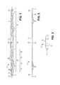
- FIG. 1is a perspective view of a first exemplary sling device.
- FIG. 2is an elevation view of the sling device illustrated in FIG. 1 .
- FIG. 3is an end view of the sling device illustrated in FIG. 1 .
- FIG. 4is a perspective view of a second exemplary sling device.
- FIG. 5is a perspective view of a third exemplary sling device.
- FIG. 5Ais a magnified view of area I in FIG. 5 .
- FIG. 6is a perspective view of a fourth exemplary sling device.
- FIG. 7Ais a perspective view of another exemplary sling device.
- FIG. 7Bis a perspective view of another exemplary sling device.
- FIG. 8is a perspective view of another exemplary sling device.
- FIG. 9is a perspective view of the sling device illustrated in FIG. 1 disposed within a sheath.
- FIG. 10is a perspective view of the sling device illustrated in FIG. 1 disposed within first and second sheaths.
- FIG. 11is a schematic illustration of an exemplary kit.
- FIG. 11Ais a magnified view of the distal end of a first needle of the kit illustrated in FIG. 11 .
- FIG. 11Bis a magnified view of the distal end of a second needle of the kit illustrated in FIG. 11 .
- FIG. 12is a flowchart illustration of a first exemplary method of treatment.
- FIG. 13is a flowchart illustration of a second exemplary method of treatment.
- FIG. 14is a flowchart illustration of a third exemplary method of treatment.
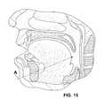
- FIG. 15is a schematic illustration showing a location for an incision made during performance of the method illustrated in FIG. 1 .
- FIG. 16is a flowchart illustration of a fourth exemplary method of treatment.
- FIG. 17is a flowchart illustration of a fifth exemplary method of treatment.
- FIGS. 1 through 3illustrate a first exemplary sling 10 .
- the sling 10has a main body 12 comprising a substantially flat member extending from a first end 14 to an opposing second end 16 and having first 18 and second 20 opposing sides.
- the main body 12has a first 22 or upper surface and an opposing second 24 or lower surface.
- the main body 12has a lengthwise axis 26 and a longitudinal midpoint 28 disposed on the lengthwise axis.
- a first ribbed portion 30extends along the lengthwise axis 26 of the main body 12 from a point on the lengthwise axis 26 between the longitudinal midpoint 28 and the first end 14 to another point on the lengthwise axis 26 between the longitudinal midpoint 28 and the first end 14 .
- a second ribbed portion 32extends along the lengthwise axis 26 of the main body 12 from a point on the lengthwise axis 26 between the longitudinal midpoint 28 and the second end 16 to another point on the lengthwise axis 26 between the longitudinal midpoint 28 and the second end 16 .
- a non-ribbed middle portion 34extends along the lengthwise axis 26 of the main body 12 across the longitudinal midpoint 28 from an end of the first ribbed portion 30 to an end of the second ribbed portion 32 .
- Each of the ribbed portions 32 , 34includes a series of ribs 36 that extend outwardly from the respective side 18 , 20 , away from the longitudinal axis 26 .
- each rib 36advantageously extends away from the respective side 18 , 20 at a non-orthogonal angle with respect to the lengthwise axis 26 .
- each rib 36advantageously extends away from the respective side 18 , 20 at an acute angle with respect to the longitudinal midpoint 28 on the lengthwise axis 26 .
- ribrefers to an outwardly-directed protrusion extending from a surface.
- An individual ribcan have any suitable shape, including regular and irregular shapes, symmetrical and asymmetrical shapes, and any other suitable shape.
- the term “series of ribs”refers to two or more individual ribs.
- a series of ribsincludes multiple ribs having the same shape, size and or/configurations, a series of ribs having different sizes, shapes and configurations, a series of ribs spaced at regular intervals, such as a toothed surface, a series of ribs spaced at different intervals, and a series of ribs spaced at irregular intervals. Examples of suitable configurations for ribs include one in which ribs extend toward an end of the sling and one in which ribs extend toward the center of the sling.
- ribs 36are considered advantageous at least because the outwardly-projecting structure of the rib provides additional surface area beyond that of the respective side 18 , 20 for contacting and/or engaging with tissue within the body. This additional surface area is expected to enhance the anchoring of the sling in the body as a result of the additional contact formed between the sling and tissue.
- the ribs 36are considered particularly advantageous in slings formed of remodellable material, as described more fully below.
- the main body 12defines a plurality of openings 38 that extend through the thickness of the main body 12 from the first surface 22 to the second surface 24 .
- each opening 38defines a passageway that extends through the main body.
- a first series 40 of openings 38is disposed on the first ribbed portion 30
- a second series 42 of openings 38is disposed on the second ribbed portion 32 .
- Each series 40 , 42 of openings 38advantageously includes multiple sets of openings 38 of identical dimensions.
- the openings 38 of one sethave different dimensions from the openings of all other sets in the series 40 , 42 . For example, as best illustrated in FIG.
- each series 40 , 42 of openings 38includes four sets 44 , 46 , 48 , 50 of openings 38 .
- the openings 38 of each sethave dimensions that are identical with those of the other openings 38 in the set, but that are different from those of the other sets.
- each opening of one setcan have one or more dimensions that differ from the same dimension or dimensions of openings of another set while also have one or more dimension that is the same or substantially similar to the same dimension or dimensions of the openings of the other set.
- each opening of one setmay have a rectangular shape having a length and width that differ from the length and width of a rectangular-shaped opening of another set, but the two openings may have the same overall area and/or perimeter length.
- the main bodyis advantageously formed of a bioremodellable material.
- a first end opening 52is disposed at the first end 14 of the main body 12 and extends through the thickness of the main body 12 from the first surface 22 to the second surface 24 .
- a second end opening 54is disposed at the second end 16 of the main body 12 and extends through the thickness of the main body 12 from the first surface 22 to the second surface 24 .
- each end opening 52 , 54defines a passageway that extends through the main body 12 .
- first 22 and second 24 surfaces of the main body 12are substantially flat. It is noted, though, that it may be advantages to include one or more bumps, projections or other surface modifications on one or both of the surfaces 22 , 24 . Inclusion of such modifications may improve the handling of the sling 10 during use.
- the sling 10can be formed of any suitable material, and a skilled artisan will be able to select an appropriate material for a sling according to a particular embodiment based on various considerations, including the tissue with which the sling is intended to be used, the technique by which the sling will be implanted, and other considerations. Both synthetic and natural materials are considered suitable. Examples of suitable synthetic materials include polymeric materials, such as polyethylene, polypropylene and other flexible polymeric materials. Examples of suitable natural materials include tissue and tissue-derived materials. The inventors have determined that slings formed of bioremodellable materials are particularly well-suited for securement of various tissues in human and other animals at least because of the ability of such materials to remodel and become incorporated into adjacent tissues over time. These materials can provide a scaffold onto which cellular in-growth can occur, eventually allowing the material to remodel into a structure of host cells, which aids in the effectiveness of the sling as a long-term support of the tissue being secured.
- remodelable collagenous materialscan be provided, for example, by collagenous materials isolated from a warm-blooded vertebrate, especially a mammal. Such isolated collagenous material can be processed so as to have remodelable, angiogenic properties and promote cellular invasion and ingrowth. Remodelable materials may be used in this context to stimulate ingrowth of adjacent tissues into an implanted construct such that the remodelable material gradually breaks down and becomes replaced by new patient tissue so as to generate a new, remodeled tissue structure.
- Suitable remodelable materialscan be provided by collagenous extracellular matrix (ECM) materials possessing biotropic properties.
- suitable collagenous materialsinclude ECM materials such as those comprising submucosa, renal capsule membrane, dermal collagen, dura mater, pericardium, fascia lata, serosa, peritoneum or basement membrane layers, including liver basement membrane.
- Suitable submucosa materials for these purposesinclude, for instance, intestinal submucosa including small intestinal submucosa, stomach submucosa, urinary bladder submucosa, and uterine submucosa.
- Collagenous matrices comprising submucosa (potentially along with other associated tissues) useful in the present inventioncan be obtained by harvesting such tissue sources and delaminating the submucosa-containing matrix from smooth muscle layers, mucosal layers, and/or other layers occurring in the tissue source.
- Remodelable ECM tissue materials harvested as intact sheets from a mammalian source and processed to remove cellular debrisadvantageously retain at least a portion of and potentially all of the native collagen microarchitecture of the source extracellular matrix.
- This matrix of collagen fibersprovides a scaffold to facilitate and support tissue ingrowth, particularly in bioactive ECM implant materials, such as porcine small intestinal submucosa or SIS (Surgisis® BiodesignTM, Cook Medical, Bloomington Ind.), that are processed to retain an effective level of growth factors and other bioactive constituents from the source tissue.
- bioactive ECM implant materialssuch as porcine small intestinal submucosa or SIS (Surgisis® BiodesignTM, Cook Medical, Bloomington Ind.)
- Submucosa-containing or other ECM tissue used in the slingsis preferably highly purified, for example, as described in U.S. Pat. No. 6,206,931 to Cook et al.
- preferred ECM materialwill exhibit an endotoxin level of less than about 12 endotoxin units (EU) per gram, more preferably less than about 5 EU per gram, and most preferably less than about 1 EU per gram.
- the submucosa or other ECM materialmay have a bioburden of less than about 1 colony forming units (CFU) per gram, more preferably less than about 0.5 CFU per gram.
- Fungus levelsare desirably similarly low, for example less than about 1 CFU per gram, more preferably less than about 0.5 CFU per gram.
- Nucleic acid levelsare preferably less than about 5 ⁇ g/mg, more preferably less than about 2 ⁇ g/mg, and virus levels are preferably less than about 50 plaque forming units (PFU) per gram, more preferably less than about 5 PFU per gram.
- PFUplaque forming units
- a typical layer thickness for an as-isolated submucosa or other ECM tissue layer used in the inventionranges from about 50 to about 250 microns when fully hydrated, more typically from about 50 to about 200 microns when fully hydrated, although isolated layers having other thicknesses may also be obtained and used. These layer thicknesses may vary with the type and age of the animal used as the tissue source. As well, these layer thicknesses may vary with the source of the tissue obtained from the animal source. In a dry state, a typical layer thickness for an as-isolated submucosa or other ECM tissue layer used in the invention ranges from about 30 to about 160 microns when fully dry, more typically from about 30 to about 130 microns when fully dry.
- Suitable bioactive agentsmay include one or more bioactive agents native to the source of the ECM tissue material.
- a submucosa or other remodelable ECM tissue materialmay retain one or more growth factors such as but not limited to basic fibroblast growth factor (FGF-2), transforming growth factor beta (TGF-beta), epidermal growth factor (EGF), cartilage derived growth factor (CDGF), and/or platelet derived growth factor (PDGF).
- FGF-2basic fibroblast growth factor
- TGF-betatransforming growth factor beta
- EGFepidermal growth factor
- CDGFcartilage derived growth factor
- PDGFplatelet derived growth factor
- submucosa or other ECM materials when used in the inventionmay retain other native bioactive agents such as but not limited to proteins, glycoproteins, proteoglycans, and glycosaminoglycans.
- ECM materialsmay include heparin, heparin sulfate, hyaluronic acid, fibronectin, cytokines, and the like.
- a submucosa or other ECM materialmay retain one or more bioactive components that induce, directly or indirectly, a cellular response such as a change in cell morphology, proliferation, growth, protein or gene expression.
- Submucosa-containing or other ECM materials used in a slingcan be derived from any suitable organ or other tissue source, usually sources containing connective tissues.
- the ECM materials processed for use in the inventive slingswill typically include abundant collagen, most commonly being constituted at least about 80% by weight collagen on a dry weight basis.
- Such naturally-derived ECM materialswill for the most part include collagen fibers that are non-randomly oriented, for instance occurring as generally uniaxial or multi-axial but regularly oriented fibers.
- the ECM materialcan retain these factors interspersed as solids between, upon and/or within the collagen fibers.
- Particularly desirable naturally-derived ECM materials for use in the inventionwill include significant amounts of such interspersed, non-collagenous solids that are readily ascertainable under light microscopic examination with appropriate staining.
- non-collagenous solidscan constitute a significant percentage of the dry weight of the ECM material in certain inventive embodiments, for example at least about 1%, at least about 3%, and at least about 5% by weight in various embodiments of the invention.
- the submucosa-containing or other ECM material used in the inventive slingsmay also exhibit an angiogenic character and thus be effective to induce angiogenesis in a host engrafted with the material.
- angiogenesisis the process through which the body makes new blood vessels to generate increased blood supply to tissues.
- angiogenic materialswhen contacted with host tissues, promote or encourage the formation of new blood vessels into the materials.
- Methods for measuring in vivo angiogenesis in response to biomaterial implantationhave recently been developed. For example, one such method uses a subcutaneous implant model to determine the angiogenic character of a material. See, C. Heeschen et al., Nature Medicine 7 (2001), No. 7, 833-839. When combined with a fluorescence microangiography technique, this model can provide both quantitative and qualitative measures of angiogenesis into biomaterials. C. Johnson et al., Circulation Research 94 (2004), No. 2, 262-268.
- non-native bioactive componentssuch as those synthetically produced by recombinant technology or other methods (e.g., genetic material such as DNA), may be incorporated into an ECM material used in an inventive sling.
- These non-native bioactive componentsmay be naturally-derived or recombinantly produced proteins that correspond to those natively occurring in an ECM tissue, but perhaps of a different species.
- These non-native bioactive componentsmay also be drug substances.
- Illustrative drug substances that may be added to materialsinclude, for example, anti-clotting agents, e.g.
- non-native bioactive componentscan be incorporated into and/or onto ECM material in any suitable manner, for example, by surface treatment (e.g., spraying) and/or impregnation (e.g., soaking), to name a few.
- these substancesmay be applied to the ECM material in a premanufacturing step, immediately prior to the procedure (e.g., by soaking the material in a solution containing a suitable antibiotic such as cefazolin), or during or after engraftment of the material in the patient.
- a suitable antibioticsuch as cefazolin
- Inventive devicescan incorporate xenograft material (i.e., cross-species material, such as tissue material from a non-human donor to a human recipient), allograft material (i.e., interspecies material, with tissue material from a donor of the same species as the recipient), and/or autograft material (i.e., where the donor and the recipient are the same individual).
- xenograft materiali.e., cross-species material, such as tissue material from a non-human donor to a human recipient
- allograft materiali.e., interspecies material, with tissue material from a donor of the same species as the recipient
- autograft materiali.e., where the donor and the recipient are the same individual.
- any exogenous bioactive substances incorporated into an ECM materialmay be from the same species of animal from which the ECM material was derived (e.g. autologous or allogenic relative to the ECM material) or may be from a different species from the ECM material source
- ECM materialwill be xenogenic relative to the patient receiving the graft, and any added exogenous material(s) will be from the same species (e.g. autologous or allogenic) as the patient receiving the graft.
- human patientsmay be treated with xenogenic ECM materials (e.g. porcine-, bovine- or ovine-derived) that have been modified with exogenous human material(s) as described herein, those exogenous materials being naturally derived and/or recombinantly produced.
- SISis particularly well-suited for use in the sling devices described herein at least because of its well-characterized nature and ready availability. Furthermore, the inventors have determined that vacuum-pressed SIS provides a particularly advantageous material from which to form sling devices that include one or more series of ribs, such as the sling 10 described above and illustrated in FIGS. 1 through 3 . Lyophilized SIS can also be used, and may be advantageous for slings in which a relatively quicker remodeling time is desired. Radiopaque SIS can also be used, and may be advantageous for slings for which enhanced visualization characteristics are desired.
- a sling having a main body formed of multiple layers laminated togetherprovides a particularly advantageous structure.
- the main bodycan comprise a multilaminate construct.
- any suitable number of layerscan be used, and a skilled artisan will be able to select an appropriate number of layers for a particular sling based on various considerations, including the intended use of the sling and nature of the tissue intended to be supported by the sling.
- the inventorshave determined that a sling having a main body formed of between 4 and 12 layers of an ECM material, such as SIS, provides a particularly advantageous structure for slings intended for use in supporting the tongue of a patient, such as in methods of treating OSA.
- the layerscan be assembled together in any suitable manner and using any suitable technique or process.
- the inventorshave determined that vacuum-pressing of multiple layers of SIS provides a suitable laminate structure for use as a sling as described herein.
- a hybrid structuremay provide a desirable balance between desired overall rigidity for the sling and relative remodeling time.
- a middle portion of the slingis formed of lyophilized SIS, which provides a relatively quicker remodeling time
- the perimeter sections, including the ribbed portionsare formed of vacuum-pressed SIS, which provides a relatively high degree of overall rigidity.
- the middle portion in this embodimentis expected to remodel relatively quickly following implantation, enhancing the securement of the sling.
- An opposite structureis also considered suitable and may be advantageous in certain circumstances.
- a hybrid structure in which a mesh is embedded inside an SIS or other composition or between layers of SIS or of other materialis also considered suitable.
- a polymeric meshsuch as a mesh formed of polypropylene, can be disposed between layers of SIS during formation of the sling.
- the polymeric meshwill remain in the body following completion of remodeling by the SIS, which may enhance the overall anchoring of the supported tissue over time.
- a bioabsorable meshsuch as a mesh formed of polyglycolic acid or other bioabsorbable material, can also be included in the sling in this manner and may be advantageous where supplemental support is desired that lasts beyond the remodeling time for the SIS, but that does not have the permanency associated with a polypropylene or other polymeric mesh.
- suitable structural arrangements of polymer and remodelable layerscan be found in United States Patent Application Publication No. 2011/0166673 to Patel et al., for QUILTED IMPLANTABLE GRAFT, the entire contents of which are hereby incorporated into this disclosure.
- FIG. 4illustrates another exemplary sling 110 .
- the sling 110 of this embodimentis similar to the embodiment described above and illustrated in FIGS. 1 through 3 , except as described below.
- the sling 110includes a main body 112 having first 114 and second 116 opposing ends, first 118 and second 120 opposing sides, and first 122 and second (not illustrated in FIG. 2 ) opposing surfaces.
- the slingincludes first 140 and second 142 series of openings 138 .
- the sides 118 , 120are substantially flat surfaces.
- the sling 110does not include any outwardly-projecting ribs.
- the sides 118 , 120are substantially parallel to each other along substantially the entire length of the sling 110 .
- each of the openings 138are substantially similar in all dimensions.
- FIGS. 5 and 5Aillustrate another exemplary sling 210 .
- the sling 210 of this embodimentis similar to the embodiment described above and illustrated in FIGS. 1 through 3 , except as described below.
- the sling 210includes a main body 212 having first 214 and second 216 opposing ends, first 218 and second 220 opposing sides, and first 222 and second (not illustrated in FIG. 5 or 5A ) opposing surfaces.
- the sling 210includes first 240 and second 242 series of openings 238 .
- each of the openings 238has an ovoid or substantially ovoid shape and all openings 238 are substantially similar in all dimensions.
- the first 214 enddefines a first end loop 252 and the second end 216 defines a second end loop 254 .
- the first end loop 252is disposed at the first end 214 of the main body 212 and extends through the thickness of the main body 212 from the first surface 222 to the second surface.
- the second end loop 254is disposed at the second end 216 of the main body 212 and extends through the thickness of the main body 212 from the first surface 222 to the second surface.
- each end loop 252 , 254defines a passageway that extends through the main body 212 .
- a slingcan include a single loop at one end and a closed end or differently-formed loop at the other end.
- a slingcan include an end loop at one end, such as first end loop 252 , and a structure similar to any end from any embodiment described herein at the opposite end.
- each of the first 252 and second 254 end loops of this embodimenthave a width 260 extending from a first lateral side 262 to an opposing second lateral side 264 of the sling 210 and along an axis orthogonal to a lengthwise axis of the sling 210 that is greater than a width 270 extending from a first lateral side 218 to an opposing second lateral side 220 of the sling 210 and along an axis that intersects a midpoint 272 of and is orthogonal to a lengthwise axis of the sling 210 .
- This structureis considered advantageous at least because it facilitates handling of the first 214 and second 216 ends of the sling 210 during use and also allows each of the first end loop 252 and second end loop 254 to define a larger opening, which facilitates engagement of the sling 210 with various tools that can be used during placement around or through the tissue to be secured, such as the tongue in the methods described in detail below.
- a sling according to a particular embodimentcan have any suitable dimensions and a skilled artisan will be able to select appropriate dimensions for a particular sling based on various considerations, including the nature, location of and route of access to the tissue to be secured by the sling.
- a sling intended to secure the tongue to the mandible in accordance with a method described hereinadvantageously has a length that is between about 25 cm and about 35 cm, a width at the longitudinal midpoint that is between about 4 mm and about 8 mm, widths at the ends that are between about 7 mm and about 11 mm—the two ends having the same or different widths, an opening length that is between about 2 mm and about 3 mm, and an end loop opening length that is between about 2 mm and about 6 mm.
- a sling according to an embodiment of the inventioncan include various additional properties, elements and/or associated devices that facilitate the use of a particular sling in a particular method, such as any of the exemplary methods of treatment described in detail below.
- a slingcan include a structure, such as an embedded wire or other stiffening member, to facilitate handling and/or securement of the sling; one or more radiopaque markers to facilitate visualization of the sling before, during or after placement; external or other indicia that aid in the use of the sling; and/or one or more sheaths to protect the sheath and/or to enhance the ability of the sling to pass through passages within tissue, such as a tongue, during use.
- a structuresuch as an embedded wire or other stiffening member, to facilitate handling and/or securement of the sling
- one or more radiopaque markersto facilitate visualization of the sling before, during or after placement
- external or other indiciathat aid in the use of the sling
- sheathsto protect the sheath and/or to enhance the ability of the sling to pass through passages within tissue, such as a tongue, during use.
- FIG. 6illustrates another exemplary sling 310 .
- the sling 310 of this embodimentis similar to the embodiment described above and illustrated in FIGS. 1 through 3 , except as described below.
- the sling 310includes a main body 312 having first 314 and second 316 opposing ends, first 318 and second 320 opposing sides, and first 322 and second (not illustrated in FIG. 2 ) opposing surfaces.
- the sides 318 , 320are substantially flat surfaces.
- the sling 310does not include any outwardly-projecting ribs. Also, the sling 310 does not include any openings extending through the thickness of the main body 312 .
- An elongate wire member 375is disposed within the main body 312 and extends substantially along the length of the main body 312 from the first end 314 to the second end 316 . Inclusion of the elongate wire member 375 confers radiopacity onto the sling, which facilitates imaging of the sling 310 following implantation using appropriate imaging equipment and techniques, such as fluoroscopy. Furthermore, the type, size and configuration of the elongate wire member can be selected to enhance the rigidity and/or pushability of the sling 310 and aid in the handling and implantation of the sling 310 , if desired.
- the elongate wire member 375can be formed of any suitable material, and a skilled artisan will be able to select an appropriate material based on various considerations, including the desired rigidity of the wire member and any visualization concerns and/or needs.
- Stainless steelis considered particularly well-suited for the wire member at least because of its well-characterized nature, ready availability, and its advantageous rigidity and imaging properties.
- Any other suitable materialcan be used, including other metals, polymeric materials, and any other material now known or hereinafter developed.
- Gold, platinum and other dense metalscan be used for the elongate wire member in slings for which imaging is critical or expected to be challenging.
- vacuum-pressed remodellable materialsuch as vacuum-pressed SIS
- SISvacuum-pressed remodellable material
- any suitable lengthcan be used, including a length that is between 25 and 100% of the entire length of the sling 310 , a length that is between 50 and 100% of the entire length of the sling 310 , a length that is between 75 and 100% of the entire length of the sling 310 , a length that is between 85 and 100% of the entire length of the sling 310 , and a length that is between 95 and 100% of the entire length of the sling 310 .
- elongate wire member 375is described and illustrated as having a substantially linear configuration, any suitable shape and/or configuration can be used. Also, while the elongate wire member 375 is described and illustrated as being entirely contained within the sling 310 , a portion or portions of the elongate wire member 375 can extend through and out of the sling 310 to facilitate removal from the sling 310 following implantation, as described below.
- a single elongate wire memberis described and illustrated, the inventors have determined that it may be desirable to include multiple wire members in slings according to particular embodiments. For example, two elongate wire members positioned side-by-side may be included if the ability to discern particular orientations of the sling under visualization is desired.
- a slingcan be modified to include appropriate structure and/or additional elements to enhance its imaging characteristics using alternative imaging techniques, if desired.
- a slingcan be rendered echogeneic by introducing dimples onto a surface of a sling, by including beads or other structures on the surface of a sling or embedded within the sling, by including bubbles in the material of the sling, or by using other appropriate structures and/or elements.
- a sling modified in this waycan be visualized using ultrasound equipment and techniques, which may be desirable in situations in which it is either not possible or undesirable to use x-rays.
- a sling 410can include a radiopaque marker 470 positioned at a longitudinal midpoint 480 of the sling 410 .
- This configurationis considered advantageous at least because it facilitates visualization of the midpoint 480 of the sling 410 during placement, which can aid in placing the sling across a midpoint of a targeted tissue, such as the tongue.
- a sling 410 ′can include two radiopaque markers 472 , 474 positioned on a longitudinal axis of the sling 410 ′ and separated by a predetermined distance.
- a cliniciancan use markers 472 , 474 positioned in this configuration to verify that the markers 472 , 474 lie in a straight or substantially straight line, which can be indicative of a placement in which the sling 410 ′ or portion of the sling 410 ′ has not rolled onto itself or adopted any other undesirable configuration prior to a final placement or securement.
- any suitable number, configuration and arrangement of radiopaque markerscan be included in a sling according to a particular embodiment and a skilled artisan will be able to construct a sling with an appropriate number, configuration and arrangement of such markers based on various considerations, including the nature of the material from which the sling is comprised, the intended use of the sling, and any desired visualization techniques, methods and/or equipment with which the sling is intended to be used.
- the marker or markerscan be formed of any suitable material, and a skilled artisan will be able to select an appropriate material based on various considerations, including any visualization concerns and/or needs. Gold, platinum and other dense metals are considered suitable for this purpose.
- a sling 510can include first 590 and second 592 series of indicia that mirror each other relative to a longitudinal midpoint 580 of the sling 510 . This configuration is considered advantageous at least because it facilitates centering of the sling 510 during placement.
- a cliniciancan adjust the sling 510 across the tongue following initial placement in performance of a method, such as any of the methods described herein, by pulling and/or advancing each end of the sling until indicia of the same color are disposed adjacent the respective opening in the mandible, or at the same distance from the respective opening in the mandible. Once such positioning is achieved, the clinician has assurance that the sling 510 is centered or substantially centered across the tongue and is able to proceed to further secure the sling without further adjustment.
- any suitable number, configuration and arrangement of indiciacan be included in a sling according to a particular embodiment and a skilled artisan will be able to construct a sling with an appropriate number, configuration and arrangement of such indicia based on various considerations, including the nature of the material from which the sling is comprised and the needs of the users expected to be placing the sling.
- Color-based indiciaare merely exemplary, and any other suitable indicia can be used, including indicia differentiated by structure such that tactile feedback can be used to achieve a desired positioning.
- FIG. 9illustrates the sling 10 of FIGS. 1 through 3 disposed within a sheath 602 .
- the sheath 602is an elongate, pouched-shaped member with an open end 604 and an opposing closed end 606 .
- the sheath 602defines and interior chamber 608 that is sized and configured to receive one end of the sling 10 .
- the sheath 602advantageously fits snuggly over one end of the sling 10 such that a gentle pulling force on the sheath 602 is required to remove it from its position over the sling 10 .
- the sheath 602advantageously has an axial length that allows the sheath 602 to extend over all ribs 36 on one longitudinal portion, such as a longitudinal half, of the sling 10 when that particular portion is diposed within the interior chamber 608 .
- any suitable materialcan be used for the sheath 602 , and a skilled artisan will be able to select an appropriate material for a sling according to a particular embodiment based on various considerations, including the material of the sling and the desired handling properties of the sheath during implantation of the sling.
- the inventorshave determined that flexible materials capable of sliding over the material of the main body of the sling provide advantageous handling characteristics. Examples of suitable flexible materials include low density polyethylene (LDPE) and other polymeric materials.
- LDPElow density polyethylene
- the flexible materialshould provide a degree of flexibility that will aid in tunneling of the device during implantation, but should not roll on itself.
- FIG. 10illustrates the sling 10 of FIGS. 1 through 3 disposed within first 602 and second 610 sheaths.
- the first sheath 602is the sheath illustrated in FIG. 9 and described above.
- the second sheath 610is similar to the first sheath 602 , and thus comprises an elongate, pouched-shaped member with an open end 612 and an opposing closed end 614 .
- the sheath 610defines and interior chamber 616 that is sized and configured to receive the end of the sling 610 opposite the end disposed within the first sheath 602 .
- the sheath 610is also advantageous sized and configured as described above for the first sheath 602 , and can have the same, substantially the same, or a different size and/or configurations than that of the first sheath 602 .
- sheaths 602 , 610are considered advantageous at least because the sheaths 602 , 604 can be used as a leading surface for blunt dissection and tunneling during implantation of the sling 10 .
- Using the sheaths in this mannerprotect the sling 10 from any contact with tissue during this process and is expected to reduce damage to the sling 10 that might otherwise occur if the sling 10 was used as a dissection and/or tunneling device during implantation.
- the inclusion of two sheaths 602 , 610 that are each capable of receiving and covering about a longitudinal half of the sling 10is considered advantageous. These two sheaths 602 , 610 can easily be removed following the initial placement of the sling 10 by pulling gently on the closed ends 606 , 614 with forceps, fingers, or another tool until the sheaths 602 , 610 slide over the covered portion of the sling 10 .
- FIG. 11is a schematic of an exemplary kit 700 .
- the kit 700includes a sling 710 and one or more needles 712 .
- the sling 710can be a sling according to any embodiment, including the sling illustrated in the Figure, which includes first and second sheaths as described above. Instructions for use 714 of the kit 700 and/or the components can also be included.
- the needle(s) 712can be any suitable needle.
- at least on of the needles 712defines a notch adapted to engage one of the openings defined by the main body of the sling 710 included in the kit 700 .
- the kit 700advantageously includes two needles 712 a , 712 b having notches that extend away from the respective longitudinal axis in opposite directions. The inclusion of such different needles 712 a , 712 b allows one to be used for a pushing technique during implantation of the sling 710 and the other to be used for a pulling technique during implantation. Inclusion of both needles 712 a , 712 b allows a user to select one according to personal preference.
- both needles 712 a , 712 bprovides a complete procedural toolkit 700 for implantations that may require use of both a pushing and a pulling technique, such as the methods of treating obstructive sleep apnea described below.
- FIG. 12is a flowchart illustration of an exemplary method 800 of treating obstructive sleep apnea (OSA).
- OSAobstructive sleep apnea
- Any suitable sling according an any embodiment of the inventioncan be used in the method. Performance of the method results in securement of the tongue of an animal, such as a human, via the sling being looped around the tongue and secured to the mandible. With the tongue secured in this manner, it is expected that the individual being treated will experience fewer and/or reduced symptoms associated with OSA.
- An initial step 802comprises creating an opening in the mandible, such as at the mental protuberance or chin. This step can be accomplished using any suitable technique, including standard drilling techniques.
- Another step 804comprises engaging a sling with a needle such that a pushing force applied on the needle will result in the sling being advanced along with the needle, such as through a tissue.
- This step 802can be accomplished using a needle having a notch directed toward the lengthwise axis of the needle and away from the distal end of the needle, such as the needle 712 b illustrated in FIG. 11B .
- Another step 806comprises advancing the needle and attached sling through the opening in the mandible.
- Another step 808comprises advancing the needle and attached sling into and through a lower portion of the tongue until the distal end of the needle and an end of the sling create an opening in the back of the tongue and exit through the opening.
- Another step 810comprises advancing a second needle into the opening in the mandible.
- This second needleadvantageously has a notch directed toward the lengthwise axis of the needle and toward the distal end of the needle, such as the needle 712 a illustrated in FIG. 11A .
- Another step 812comprises advancing the second needle through a lower portion of the tongue, laterally opposite the portion through which the first needle and sling were advanced, until the distal end of the second needle creates a second opening in the back of the tongue and exits through the second opening.
- Another step 814comprises engaging the sling with the second needle, such as by disposing a portion of the sling, such as an edge of the main body that partially defines an opening in the main body, in the notch of the second needle to facilitate the pulling of the second needle and the sling through the tongue as a unit.
- Another step 816comprises pulling the second needle and the sling through the tunnel created during the step 812 of advancing the second needle through the tongue until the end of the sling that has been advanced through both portions of the tongue has exited the tunnel and ultimately exited the opening in the mandible.
- Another step 818comprises pulling the tongue toward the front of the mouth or mandible, such as by pulling on both ends of the sling, which is now looped around the back of the tongue.
- Another step 820comprises securing the sling to a tissue to support the tongue in the new position.
- This stepcan be accomplished using any suitable structures and techniques for securing materials to tissues, including installation of one or more bone screws at one or more anchor points under the mandible gum line, the use of bioadhesives, sutures, or other suitable structures and/or techniques.
- An optional step 822comprises closing the opening in the mandible, such as by sealing the opening.
- This stepcan be conducted using any suitable structure and/or technique, including the placement of bone cement in the opening.
- Additional optional stepscan be included as appropriate. For example, if one or more sheaths are included with the sling, a step of removing the sheath or sheaths from the sling by gently pulling the sheath or sheaths away from the sling can be included, and should be performed prior to the step of securing the sling to a tissue to support the tongue in the new position. Also, to aid in verification of a desired placement, the sling and/or the position of the tongue can be visualized prior to securement using any suitable technique, method and/or equipment, such as an appropriate endoscope.
- an optional step of removing the elongate wire member from the slingcan be included, if desired. This step can be accomplished using any suitable technique, and the specific technique selected will depend on the nature of the structure of the sling. For example, if the elongate wire member contained entirely within the sling, a use can create a nick or small cut in the sling to expose a portion of the elongate wire member, and can then grasp the portion with forceps or other suitable tool and pull the portion until the elongate wire member is removed from the sling. Similarly, if a portion of the elongate wire member extends out of the sling, as described above, a user can simply grasp that portion and pull until the elongate wire member is removed from the sling.
- FIG. 13is a flowchart illustration of another exemplary method 900 of treating obstructive sleep apnea (OSA).
- OSAobstructive sleep apnea
- Any suitable sling according any embodiment of the inventioncan be used in the method. Performance of the method results in securement of the tongue of an animal, such as a human, via the sling being looped around the tongue and secured to the mandible. With the tongue secured in this manner, it is expected that the individual being treated will experience fewer and/or reduced symptoms associated with OSA.
- An initial step 902comprises pushing a first end of a sling into the tongue of a patient to create a first tunnel through the tongue of said patient until the first end of the sling has passed into, through and exited the tunnel at the back of the tongue relative to the chin of said patient and a second end of the sling remains outside the first tunnel.
- Another step 904comprises creating a second tunnel through the tongue of said patient.
- This stepcan be accomplished using any suitable technique, including passing a needle through the tongue of the patient.
- This stepis advantageously performed such that the second tunnel is laterally opposite the first tunnel with respect to the lengthwise axis of the tongue, and such that the second tunnel includes an opening toward the front of the tongue and an exit at the back of the tongue, similar to the first tunnel.
- any suitable device and/or techniquecan be used for this step, including a needle.
- Another step 906comprises pulling the first end of the sling through the second tunnel created in the tongue of said patient until the first end of the sling has passed through the entire length of the second tunnel and the second end of the sling remains outside the first tunnel.
- This stepcan be accomplished in any suitable manner, such as by engaging the first end of the sling with a needle used to form the second tunnel in step 904 .
- Another step 908comprises securing the sling to the mandible of said patient such that the tongue of said patient is pulled toward the chin of said patient by the sling.
- This stepcan be accomplished in any suitable manner, including by securing the first and second ends of the sling to the mandible at one or more anchor points along the mandible gum line.
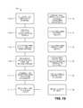
- FIG. 14is a flowchart illustration of another exemplary method 1000 of treating obstructive sleep apnea (OSA).
- OSAobstructive sleep apnea
- Any suitable sling according any embodiment of the inventioncan be used in the method. Performance of the method results in securement of the tongue of an animal, such as a human, via the sling being looped through the tongue and secured to the mandible. With the tongue secured in this manner, it is expected that the individual being treated will experience fewer and/or reduced symptoms associated with OSA.
- This exemplary method 1000is considered particularly advantageous at least because it causes minimal aesthetic scaring for the patient, and any resulting scar is positioned under the chin and not on the front of the face. Furthermore, this method causes relatively minor perforations at the back of the tongue to facilitate the exchange on the sling between the needles used in the procedure.
- An initial step 1002comprises making an incision under the chin of a patient.
- the incisioncan be made at any suitable location that allows for the drilling of holes, as described below.
- FIG. 15is a schematic illustration of a suitable location for the incision. Any suitable tool can be used to make the incision.
- Another step 1004comprises moving the skin located adjacent the incision made in step 1002 to expose the bone of the chin. Any suitable tool can be used to move the skin.
- Another step 1006comprises creating two separate holes through the chin of the mandible, such as by drilling through the mandible.
- the holescan be drilled using a suitable bone drilling tool, and each hole should be of a sufficient diameter to allow passage or a portion of the sling through the hole, as described below. Also, it is considered advantageous to drill the holes as close together as possible while retaining distinctness to facilitate tightening of the sling, as described below. Furthermore, to facilitate positioning of the sling relative to the tongue, the holes should be drilled with a slight upward angle.
- the holescan be made through the mental protuberance of the chin. Arrow A in FIG. 15 represents a suitable location and axis for the holes.
- a block with pre-drilled holes positioned at a desired angle and/or distance from each othercan be used to guide the drilling of the holes through the mandible.
- Use of such a block, while considered optional,is considered advantageous at least because it is expected to reduce risk of error in the positioning of the holes.
- a single hole with two sub-channels that exit the back of the mandible near the tonguecould also be formed. Furthermore, a single hole could be formed.
- the use of two separate and distinct holesis considered advantageous, though, at least because of the relative ease of formation and provision of separate passageways for the separate ends of the sling, as described more fully below.
- Another step 1008comprises inserting a pull needle through the first of the holes drilled in step 1006 and passing the needle through the tongue until the tip of the needle forms a perforation at the back of the tongue.
- the performance of this stepwill create a tunnel through the tongue. It is considered advantageous to conduct this step such that the tunnel is formed in a medial to lateral manner on the side of the tongue that corresponds to the hole through which the pull needle has been inserted.
- Another step 1010comprises inserting a second pull needle through the second of the holes drilled in step 1006 and passing the needle through the tongue until the tip of the needle forms a second perforation at the back of the tongue.
- the performance of this stepwill create a second tunnel through the tongue. Similar to step 1008 , it is considered advantageous to conduct this step such that the second tunnel is formed in a medial to lateral manner on the side of the tongue that corresponds to the second hole through which the second pull needle has been inserted.
- Another step 1012comprises inserting a push needle having a first end of a sling attached to it into the first perforation formed in the back of the tongue in step 1008 .
- the tip of the first pull needlecan be used to guide the push needle and attached sling into the first perforation.
- step 1014comprises forcing the tip of the push needle through the base of the tongue along an axis and to the second perforation formed in step 1010 .
- the performance of this stepcreates a third tunnel through the tongue that extends from the first perforation to the second perforation.
- another step 1016comprises passing a portion of the sling through the third tunnel. This step is advantageously performed until the sling is disposed through the third tunnel with approximately half of its length positioned on each side of the tongue.
- another step 1018comprises attaching a portion of the sling to the first pull needle at the back of the tongue.
- Any suitable attachment member and/or techniquecan be used to accomplish this step, and a skilled artisan will be able to select an appropriate attachment member and/or technique for a particular method based on various considerations, including the nature of the sling being used.
- a direct attachment between the sling and the pull needlecan be used (e.g., securing a notch of the pull needle to a portion of the sling, such as an edge adjacent an opening).
- a suture with a knotcan be looped around a portion of the sling and secured in a notch of the pull needle.
- step 1020comprises attaching a portion of the sling to the second pull needle at the back of the tongue. This step is similar to step 1018 and can be conducted in the same or different manner (e.g., using the same or different attachment member and/or technique).
- another step 1022comprises pulling the pull needles through the respective tunnels in the tongue and out of the respective hole in the mandible. It is considered advantageous to perform this step by pulling each of the needles simultaneously and at substantially the same rate with substantially the same force, but the needles can be pulled sequentially or with different rates and/or forces if considered desirable and/or necessary. Performance of this step results in each of the ends of the sling being pulled through one of the first and second tunnels in the tongue. At the end of performance of this step, the ends of the slings extend outward from the holes in the mandible and the central portion of the sling is looped around the base of the tongue.
- a step 1024 of tightening the sling by pulling on the ends of the slingcan be performed. This can be performed until a desired placement of the tongue relative to the front of the mouth and/or the mandible is achieved.
- Another step 1026comprises fixing the sling in position within each of the holes. This step can be accomplished using any suitable material, attachment member, and/or technique. An application of bone cement into each of the holes is considered suitable.
- Another step 1028 of trimming the slingcan be performed. If included, it is considered advantageous to include this step after completion of step 1026 . Furthermore, it is considered advantageous to perform this step after a desired positioning and/or tensioning is achieved, such as after completion of step 1024 .
- Another step 1030 of closing the incision under the chincan be included. This step can be performed using any suitable attachment member and or technique, such as sutures and clips.
- FIG. 16is a flowchart illustration of another exemplary method 1100 of treating obstructive sleep apnea (OSA).
- OSAobstructive sleep apnea
- Any suitable sling according any embodiment of the inventioncan be used in the method. Performance of the method results in securement of the tongue of an animal, such as a human, via the sling being looped through the tongue and secured to the mandible. With the tongue secured in this manner, it is expected that the individual being treated will experience fewer and/or reduced symptoms associated with OSA.
- An initial step 1102comprises creating two openings in the mandible of the patient, such as at the mental protuberance or chin.
- This stepcan be accomplished using any suitable technique, including standard drilling techniques. It is considered advantageous to drill the holes as close together as possible while retaining distinctness to facilitate tightening of the sling, as described below. Furthermore, to facilitate positioning of the sling relative to the tongue, the holes should be drilled with a slight upward angle and directed toward the back or base of the tongue.
- the arrow in FIG. 15represents a suitable location and axis for the holes.
- Another step 1104comprises creating a passageway in the tongue of a patient such that the passageway lies on a plane that is transverse to the longitudinal axis of the tongue. Any suitable technique and tool can be used to perform this step, including a needle or other tunneling instrument.
- Another step 1106comprises advancing a first device through the first of the two openings in the mandible such that the device extends through the entire opening, with a portion of the device outside of the opening and adjacent the chin and another portion of the device outside of the opening and adjacent the tongue.
- Any suitable devicecan be used and need only be able to fit in and movable through the opening.
- a device with structural adaptations, such as a hook or other suitable structure,can be used to facilitate engagement of the sling, as described below.
- Another step 1108comprises advancing a second device through the second of the two openings in the mandible such that the second device extends through the entire second opening, with a portion of the second device outside of the second opening and adjacent the chin and another portion of the second device outside of the second opening and adjacent the tongue.
- Any suitable devicecan be used and need only be able to fit in and movable through the second opening.
- a device with structural adaptations, such as a hook or other suitable structure,can be used to facilitate engagement of the sling, as described below.
- Another step 1110comprises passing a device through the passageway in the tongue such that a portion of the device extends beyond one end of the passageway and another portion of the device extends beyond another end of the passageway.
- Any suitable devicecan be used and need only be able to fit in and movable through the second opening.
- a device with structural adaptations, such as a hook or other suitable structure,can be used to facilitate engagement of the sling, as described below.
- Another step 1112comprises engaging a sling according to an embodiment with one end of the device disposed through the passageway in the tongue.
- Another step 1114comprises pulling the device disposed through the passageway in the tongue and the attached sling through the passageway in the tongue until the sling is disposed in the passageway with a portion of the sling extending beyond one end of the passageway and another portion of the sling extending beyond another end of the passageway.
- Another step 1116comprises engaging a first portion of the sling, such as the first end of the sling, with the tongue-adjacent end of the first device disposed in the first of the two openings in the mandible such that a pulling force applied to the first device will result in the first end of the sling being pulled along with the first device through the first opening in the mandible.
- Another step 1118comprises engaging a second portion of the sling, such as the second end of the sling, with the tongue-adjacent end of the second device disposed in the second of the two openings in the mandible such that a pulling force applied to the second device will result in the second end of the sling being pulled along with the second device through the second opening in the mandible.
- Another step 1120comprises pulling the first and second devices and the first and second ends of the sling through the respective openings in the mandible until each end of the sling has exited the respective opening.
- Another step 1122comprises pulling the tongue toward the front of the mouth or mandible by pulling on one or both of the first and second devices and/or one or both of the first and second ends of the sling.
- Another step 1124comprises securing the sling to a tissue, such as the mandible, to support the tongue in the new position.
- another stepcan comprise sealing the openings in the mandible, such as with bone cement or other suitable composition and/or technique.
- FIG. 17is a flowchart illustration of another exemplary method 1200 of treating obstructive sleep apnea (OSA).
- OSAobstructive sleep apnea
- Any suitable sling according any embodiment of the inventioncan be used in the method. Performance of the method results in securement of the tongue of an animal, such as a human, via the sling being looped through the tongue and secured to the mandible. With the tongue secured in this manner, it is expected that the individual being treated will experience fewer and/or reduced symptoms associated with OSA.
- An initial step 1202comprises creating a first longitudinal tunnel in the tongue.
- This stepcan be accomplished using any suitable technique and device, such as a needle.
- the stepis advantageously performed such that a tunnel is formed through the tongue that extends upward from a position on the lower surface of the anterior portion of the tongue to a position on the opposite surface on the posterior or base portion of the tongue.
- Arrow A in FIG. 15represents a suitable location and axis for the first longitudinal tunnel.
- Another step 1204comprises creating a second longitudinal tunnel in the tongue.
- This stepcan be accomplished using any suitable technique and device, such as a needle.
- the stepis advantageously performed such that a second tunnel is formed through the tongue that extends upward from a second position on the lower surface of the anterior portion of the tongue to a second position on the opposite surface on the posterior or base portion of the tongue.
- Arrow A in FIG. 15represents a suitable location and axis for the first longitudinal tunnel.
- the axis of the second tunneladvantageously lies on the same or substantially the same plane as the axis of the first tunnel, but it is not necessary that the tunnels have this structural arrangement.
- Another step 1206comprises creating a transverse tunnel in the tongue.
- This stepcan be accomplished using any suitable technique and device, such as a needle.
- the stepis advantageously performed such that the axis of the transverse tunnel is substantially orthogonal to an axis of one or both of the first and second longitudinal tunnels, although this structural arrangement of the tunnels is not necessary.
- the transverse tunnelcan be formed such that its axis extends at any angle to the longitudinal axis of the tongue.
- the transverse tunnelextends across the posterior surface of the tongue, opposite the mandible, in the mid-region or base of the tongue.
- Another step 1208comprises advancing a sling through the transverse tunnel such that a portion of the sling is disposed in the transverse tunnel and such that the first end of the sling extends outward from an end of the transverse tunnel and the second end of the sling extends outward from the other end of the transverse tunnel.
- This stepcan be accomplished using any suitable sling, such as any of the embodiments described and illustrated herein, and any suitable technique and device, such as a needle.
- This stepcan be accomplished by pushing the sling through the transverse tunnel or by pulling the sling through the transverse tunnel, and a skilled artisan will be able to select a suitable approach in the performance of a particular method based on various considerations, including the nature of the sling being used and the space available in the cavity within which the sling is being placed.
- Another step 1210comprises pulling the first end of the sling through the first longitudinal tunnel.
- This stepcan be accomplished using any suitable technique and device, such as a needle, clamp or other device adapted to engage a portion of the sling and hold the portion while pulling the portion through a tunnel.
- Another stepcomprises pulling the second end of the sling through the second longitudinal tunnel.
- This stepcan be accomplished using any suitable technique and device, such as a needle, clamp or other device adapted to engage a portion of the sling and hold the portion while pulling the portion through a tunnel.
- Another step 1214comprises securing the sling to a tissue, such as the mandible or tissue located in the mouth, to support the tongue in the new position.
- This stepadvantageously comprises securing a first portion of the sling to the tissue and securing a second portion of the sling to the same or different tissue.
- Any suitable technique, devices, and/or apparatusescan be used to accomplish the securing, including bone cement, adhesives, and sutures and other mechanical attachment members.
Landscapes
- Health & Medical Sciences (AREA)
- Otolaryngology (AREA)
- Pulmonology (AREA)
- Nursing (AREA)
- Orthopedic Medicine & Surgery (AREA)
- Engineering & Computer Science (AREA)
- Biomedical Technology (AREA)
- Heart & Thoracic Surgery (AREA)
- Vascular Medicine (AREA)
- Life Sciences & Earth Sciences (AREA)
- Animal Behavior & Ethology (AREA)
- General Health & Medical Sciences (AREA)
- Public Health (AREA)
- Veterinary Medicine (AREA)
- Prostheses (AREA)
Abstract
Description
Claims (12)
Priority Applications (1)
| Application Number | Priority Date | Filing Date | Title |
|---|---|---|---|
| US13/550,065US10022263B2 (en) | 2011-07-14 | 2012-07-16 | Sling-based treatment of obstructive sleep apnea |
Applications Claiming Priority (3)
| Application Number | Priority Date | Filing Date | Title |
|---|---|---|---|
| US201161507914P | 2011-07-14 | 2011-07-14 | |
| US201161533189P | 2011-09-10 | 2011-09-10 | |
| US13/550,065US10022263B2 (en) | 2011-07-14 | 2012-07-16 | Sling-based treatment of obstructive sleep apnea |
Publications (2)
| Publication Number | Publication Date |
|---|---|
| US20130056009A1 US20130056009A1 (en) | 2013-03-07 |
| US10022263B2true US10022263B2 (en) | 2018-07-17 |
Family
ID=46604059
Family Applications (1)
| Application Number | Title | Priority Date | Filing Date |
|---|---|---|---|
| US13/550,065Active2035-11-30US10022263B2 (en) | 2011-07-14 | 2012-07-16 | Sling-based treatment of obstructive sleep apnea |
Country Status (3)
| Country | Link |
|---|---|
| US (1) | US10022263B2 (en) |
| EP (2) | EP3028683B1 (en) |
| WO (1) | WO2013010169A1 (en) |
Families Citing this family (12)
| Publication number | Priority date | Publication date | Assignee | Title |
|---|---|---|---|---|
| US9439801B2 (en) | 2012-06-29 | 2016-09-13 | Revent Medical, Inc. | Systems and methods for treatment of sleep apnea |
| WO2012018545A2 (en) | 2010-07-26 | 2012-02-09 | Revent Medical, Inc. | Systems and methods for treatment of sleep apnea |
| US10022263B2 (en) | 2011-07-14 | 2018-07-17 | Cook Medical Technologies Llc | Sling-based treatment of obstructive sleep apnea |
| EP2908770B1 (en) | 2012-10-16 | 2019-04-24 | Cook Medical Technologies LLC | Apparatus for treating obstructive sleep apnea (osa) |
| US10123900B2 (en) | 2013-03-15 | 2018-11-13 | Cook Medical Technologies Llc | Devices, kits, and methods for the treatment of obstructive sleep apnea |
| WO2015017749A1 (en)* | 2013-08-01 | 2015-02-05 | Mohan P Arun | Tissue adjustment implant |
| AU2014306232B2 (en) | 2013-08-05 | 2018-12-06 | C2Dx, Inc. | Medical devices having a releasable tubular member and methods of using the same |
| EP2898920B1 (en) | 2014-01-24 | 2018-06-06 | Cook Medical Technologies LLC | Articulating balloon catheter |
| US9974563B2 (en) | 2014-05-28 | 2018-05-22 | Cook Medical Technologies Llc | Medical devices having a releasable member and methods of using the same |
| WO2016022454A1 (en) | 2014-08-04 | 2016-02-11 | Darin Schaeffer | Medical devices having a releasable tubular member and methods of using the same |
| US9238090B1 (en) | 2014-12-24 | 2016-01-19 | Fettech, Llc | Tissue-based compositions |
| WO2019006218A1 (en)* | 2017-06-29 | 2019-01-03 | Oconnor Peter | Implantable medical devices for tissue repositioning |
Citations (125)
| Publication number | Priority date | Publication date | Assignee | Title |
|---|---|---|---|---|
| US4024859A (en) | 1975-09-08 | 1977-05-24 | Nestor Engineering Associates, Inc. | Mouth gag having three dimensional alveolus retractor adjustability |
| US4064873A (en) | 1976-06-10 | 1977-12-27 | Swenson Rudolph E | Tongue blade for mouth gag |
| US4608972A (en) | 1985-02-19 | 1986-09-02 | Small Irwin A | Method of applying a chin implant, drill guide tool and implant |
| US4917604A (en) | 1988-04-20 | 1990-04-17 | Small Irwin A | Compression staple, method and apparatus for insertion of same |
| US5674191A (en) | 1994-05-09 | 1997-10-07 | Somnus Medical Technologies, Inc. | Ablation apparatus and system for removal of soft palate tissue |
| US5988171A (en) | 1997-06-26 | 1999-11-23 | Influence Medical Technologies, Ltd. | Methods and devices for the treatment of airway obstruction, sleep apnea and snoring |
| US6042534A (en)* | 1997-02-13 | 2000-03-28 | Scimed Life Systems, Inc. | Stabilization sling for use in minimally invasive pelvic surgery |
| US6159208A (en) | 1995-06-07 | 2000-12-12 | Arthocare Corporation | System and methods for electrosurgical treatment of obstructive sleep disorders |
| US20010050085A1 (en) | 1999-09-17 | 2001-12-13 | Knudson Mark B. | Contracting snoring treatment implant |
| US6397841B1 (en) | 1997-06-18 | 2002-06-04 | Resmed Limited | Apparatus for supplying breathable gas |
| US6408851B1 (en) | 1999-10-01 | 2002-06-25 | Manuel L. Karell | Method and device for holding a tongue in a forward position |
| WO2003002027A1 (en) | 2001-06-27 | 2003-01-09 | Promedon Do Brasil Produtos Medico-Hospitalares Ltda | Adjustable autofixing sling for treatment of urinary incontinence |
| US6513531B2 (en) | 1999-09-17 | 2003-02-04 | Pi Medical, Inc. | Proximal placement of snoring treatment implant |
| US6513530B2 (en) | 1999-09-17 | 2003-02-04 | Pi Medical, Inc. | Braided palatal implant for snoring treatment |
| US6523541B2 (en) | 1999-09-17 | 2003-02-25 | Pi Medical, Inc. | Delivery system for snoring treatment implant and method |
| US20030111079A1 (en) | 2001-10-12 | 2003-06-19 | Greg Matthews | Auto-titration pressure support system and method of using same |
| US20030140925A1 (en) | 2000-07-19 | 2003-07-31 | Sapienza Christine A. | System for conditioning expiratory muscles for an improved respiratory system |
| US20030168064A1 (en) | 2001-12-10 | 2003-09-11 | Daly Geoffrey D. | Double ended blower and volutes therefor |
| US20030176875A1 (en) | 2002-03-07 | 2003-09-18 | Anderson Kimberly A. | Transobturator surgical articles and methods |
| US20040006353A1 (en)* | 2002-04-30 | 2004-01-08 | Bosley Rodney W. | Sling for supporting tissue |
| US20040028676A1 (en) | 2002-08-06 | 2004-02-12 | Klein Dean A. | Swallowing system tissue modifier |
| US20040073272A1 (en) | 1999-09-29 | 2004-04-15 | Restore Medical, Inc. | Implantable stimulation device for snoring treatment |
| US20040112387A1 (en) | 2001-09-07 | 2004-06-17 | Lang Bernd Christoph | Forehead pad for respiratory mask |
| US20040144395A1 (en)* | 2002-08-02 | 2004-07-29 | Evans Douglas G | Self-anchoring sling and introducer system |
| US20040153127A1 (en) | 2003-01-15 | 2004-08-05 | Alfred E. Mann Institute For Biomedical Engineering At The University Of Southern Californ | Treatments for snoring using injectable neuromuscular stimulators |
| US20050005937A1 (en) | 2003-06-20 | 2005-01-13 | Farrugia Steven Paul | Method and apparatus for improving the comfort of CPAP |
| US20050098184A1 (en) | 1999-09-17 | 2005-05-12 | Restore Medical Inc. | Resorbable airway implant |
| US20050103339A1 (en) | 2001-12-10 | 2005-05-19 | Resmed Limited | Multiple stage blowers and volutes therefor |
| US6895963B1 (en) | 1999-06-16 | 2005-05-24 | Resmed Limited | Apparatus with automatic respiration monitoring and display |
| US20050126563A1 (en) | 2003-12-15 | 2005-06-16 | Van Der Burg Erik J. | System and method for hyoidplasty |
| US6911002B2 (en)* | 1999-12-22 | 2005-06-28 | Promedon S.A. | Sling with pad for treatment of urinary incontinence |
| US20050175665A1 (en)* | 2003-11-20 | 2005-08-11 | Angiotech International Ag | Polymer compositions and methods for their use |
| US6955172B2 (en) | 2002-09-06 | 2005-10-18 | Apneon, Inc. | Systems and methods for moving and/or restraining the tongue in the oral cavity |
| US6974419B1 (en) | 2002-08-01 | 2005-12-13 | Tensys Medical, Inc. | Method and apparatus for control of non-invasive parameter measurements |
| US20050279365A1 (en) | 2004-06-18 | 2005-12-22 | Armijo Dennis F | Anti-snoring apparatus and method |
| US20060000475A1 (en) | 2001-10-12 | 2006-01-05 | Ric Investments, Llc. | Auto-titration bi-level pressure support system and method of using same |
| US7004941B2 (en) | 2001-11-08 | 2006-02-28 | Arthrocare Corporation | Systems and methods for electrosurigical treatment of obstructive sleep disorders |
| US20060070626A1 (en) | 2004-10-04 | 2006-04-06 | Andrew Frazier | System and method for airway manipulation |
| US7063089B2 (en) | 1999-09-17 | 2006-06-20 | Restore Medical Inc. | Airway stiffening implant |
| US7073505B2 (en) | 2002-09-06 | 2006-07-11 | Apneon, Inc. | Systems and methods for moving and/or restraining tissue in the oral cavity |
| US20060150986A1 (en) | 2004-12-15 | 2006-07-13 | Aspire Medical, Inc. | System and method for hyoidplasty |
| US7090672B2 (en) | 1995-06-07 | 2006-08-15 | Arthrocare Corporation | Method for treating obstructive sleep disorder includes removing tissue from the base of tongue |
| US20060207612A1 (en) | 2005-02-08 | 2006-09-21 | Jasper Jackson | Tissue anchoring system for percutaneous glossoplasty |
| US20060235877A1 (en) | 2004-06-04 | 2006-10-19 | Ron Richard | Mask fititng system and method |
| US7188627B2 (en) | 2002-09-06 | 2007-03-13 | Apneon, Inc. | Magnetic force devices, systems, and methods for resisting tissue collapse within the pharyngeal conduit |
| US7213599B2 (en) | 2003-10-31 | 2007-05-08 | Restore Medical, Inc. | Airway implant |
| US20070132117A1 (en) | 2005-09-27 | 2007-06-14 | Ric Investments, Llc. | Humidifier with back-flow prevention valve |
| US20070144539A1 (en) | 2005-11-09 | 2007-06-28 | Van Der Burg Erik | Glossoplasty using tissue anchor glossopexy with volumetric tongue reduction |
| US20070157928A1 (en) | 2005-09-27 | 2007-07-12 | Ric Investments, Llc | Humidifier with back-flow prevention valve |
| US20070207994A1 (en) | 2004-11-19 | 2007-09-06 | Bradley Teegarden | 3-Phenyl-pyrazole derivatives as modulators of the 5-HT2a serotonin receptor useful for the treatment of disorders related thereto |
| US20070209665A1 (en) | 2002-09-06 | 2007-09-13 | Apneon, Inc. | Self-anchoring magnetic force implant devices, systems, and methods |
| US20070209664A1 (en) | 2002-09-06 | 2007-09-13 | Apneon, Inc. | Devices, systems and methods using magnetic force systems affecting both the tongue and the soft palate/uvula in the upper airway |
| US20070256693A1 (en) | 2002-09-06 | 2007-11-08 | Apneon, Inc. | Devices, systems, and methods using magnetic force systems in or on soft palate tissue |
| US20070287923A1 (en) | 2006-05-15 | 2007-12-13 | Charles Adkins | Wrist plethysmograph |
| WO2007149469A2 (en) | 2006-06-21 | 2007-12-27 | Aspire Medical, Inc. | System and method for temporary tongue suspension |
| US20080023012A1 (en) | 2005-02-08 | 2008-01-31 | Aspire Medical, Inc. | Glossopexy adjustment system and method |
| US20080027560A1 (en) | 2006-06-13 | 2008-01-31 | Aspire Medical, Inc. | Glossal engagement system and method |
| US20080045813A1 (en) | 2004-02-25 | 2008-02-21 | Chee Keong Phuah | Cardiac Monitoring And Therapy Using A Device For Providing Pressure Treatment Of Sleep Disordered Breathing |
| US7337781B2 (en) | 2005-04-15 | 2008-03-04 | Restore Medical, Inc. | Implant for tongue |
| US20080053461A1 (en) | 2005-02-08 | 2008-03-06 | Aspire Medical, Inc. | Methods and devices for the treatment of airway obstruction, sleep apnea and snoring |
| US20080066753A1 (en) | 2004-10-06 | 2008-03-20 | Resmed Limited | Method And Apparatus For Non-Invasive Monitoring Of Respiratory Parameters In Sleep Disordered Breathing |
| US20080066765A1 (en) | 2002-09-06 | 2008-03-20 | Apneon, Inc. | Implantable devices, systems, and methods for maintaining desired orientations in targeted tissue regions |
| US20080066769A1 (en) | 2005-02-08 | 2008-03-20 | Aspire Medical, Inc. | Airway implants and methods and devices for insertion and retrieval |
| US20080091058A1 (en)* | 2006-10-16 | 2008-04-17 | Bosley Rodney W | Urethral sling implantation using needle sheaths |
| US7360542B2 (en) | 2002-09-06 | 2008-04-22 | Apneon, Inc. | Devices, systems, and methods to fixate tissue within the regions of body, such as the pharyngeal conduit |
| US20080097380A1 (en) | 2006-09-21 | 2008-04-24 | Li Kasey K | Method and apparatus for creating variable stiffness and/or reduction of soft tissue |
| US7363926B2 (en) | 2002-12-30 | 2008-04-29 | Quiescence Medical, Inc. | Apparatus and methods for treating sleep apnea |
| US7387634B2 (en) | 1998-11-23 | 2008-06-17 | Benderev Theodore V | System for securing sutures, grafts and soft tissue to bone and periosteum |
| US20080194953A1 (en) | 2007-02-12 | 2008-08-14 | Med-El Elektromedizinische Geraete Gmbh | Implantable Microphone Noise Suppression |
| US20080208265A1 (en) | 2005-02-08 | 2008-08-28 | Andrew Frazier | System and method for percutaneous palate remodeling |
| US20080251071A1 (en) | 2007-04-13 | 2008-10-16 | Resmed Limited | Method and system for motor failure detection |
| US7491200B2 (en) | 2004-03-26 | 2009-02-17 | Arthrocare Corporation | Method for treating obstructive sleep disorder includes removing tissue from base of tongue |
| US20090044814A1 (en) | 2007-06-18 | 2009-02-19 | Koninklijke Philips Electronics N.V. | Implantable devices, systems, and methods for maintaining desired orientations in targeted tissue regions |
| US20090053306A1 (en) | 2005-09-29 | 2009-02-26 | Agarwal Rajesh K | Pharmaceutical Compositions of a 5-HT2A Serotonin Receptor Modulator Useful for the Treatment of Disorders Related Thereto |
| US20090060905A1 (en) | 2006-01-30 | 2009-03-05 | Genfit | Use of 15-Lipoxygenase Inhibitors for Treating Obesity |
| US20090099471A1 (en) | 2005-10-04 | 2009-04-16 | William H Broadley | Disordered Breathing Monitoring Device And Method Of Using Same Including A Study Status Indicator |
| US20090131923A1 (en) | 2005-01-07 | 2009-05-21 | Connors Kevin P | System and method for treatment of uvula and soft palate to reduce tissue laxity |
| US7607439B2 (en) | 2006-06-19 | 2009-10-27 | Li Kasey K | Tongue retention system |
| WO2009140197A1 (en) | 2008-05-12 | 2009-11-19 | Revent Medical, Inc. | Partially erodable systems for treatment of obstructive sleep apnea |
| US20100004264A1 (en) | 2006-10-03 | 2010-01-07 | Yifeng Xiong | Pyrazole derivatives as modulators of the 5-ht2a serotonin receptor useful for the treatment of disorders related thereto |
| US7644714B2 (en) | 2005-05-27 | 2010-01-12 | Apnex Medical, Inc. | Devices and methods for treating sleep disorders |
| US20100010061A1 (en) | 2006-12-18 | 2010-01-14 | Martin Cooper | Cb1 receptor modulators |
| US20100016694A1 (en) | 2006-11-13 | 2010-01-21 | Resmed Limited | Systems, Methods, and/or Apparatuses for Non-Invasive Monitoring of Respiratory Parameters in Sleep Disordered Breathing |
| US20100028026A1 (en) | 2008-07-31 | 2010-02-04 | Canon Kabushiki Kaisha | Image forming apparatus |
| US7658192B2 (en) | 2007-07-03 | 2010-02-09 | Douglas C. Harrington | Method and device for treatment of obstructive sleep apnea |
| US7669603B2 (en) | 2002-02-04 | 2010-03-02 | Medtronic Xomed, Inc. | Pharyngeal wall treatment |
| US7673635B2 (en) | 2003-10-31 | 2010-03-09 | Medtronix Xomed, Inc. | Soft palate implant |
| US7680538B2 (en) | 2005-03-31 | 2010-03-16 | Case Western Reserve University | Method of treating obstructive sleep apnea using electrical nerve stimulation |
| WO2010045546A1 (en) | 2008-10-16 | 2010-04-22 | Linguaflex, Llc | Methods and devices for treating sleep apnea |
| US20100106246A1 (en) | 2008-10-24 | 2010-04-29 | Ethicon, Inc. | Methods and devices for the indirect displacement of the hyoid bone for treating obstructive sleep apnea |
| WO2010051195A1 (en) | 2008-10-30 | 2010-05-06 | Ethicon, Inc. | Implant systems and methods for treating obstructive sleep apnea |
| US20100108066A1 (en) | 2008-04-15 | 2010-05-06 | Resmed Limited | Methods, systems and apparatus for paced breathing |
| US20100132719A1 (en) | 2008-12-01 | 2010-06-03 | Ethicon, Inc. | Implant systems and methods for treating obstructive sleep apnea |
| US20100234946A1 (en) | 2009-03-16 | 2010-09-16 | Ethicon, Inc. | Implant systems and methods for treating obstructive sleep apnea |
| US7813812B2 (en) | 2000-09-27 | 2010-10-12 | Cvrx, Inc. | Baroreflex stimulator with integrated pressure sensor |
| US20100300458A1 (en) | 2007-05-17 | 2010-12-02 | Michael Stubbs | Mandibular Advancement Device |
| US7845357B2 (en) | 2006-10-03 | 2010-12-07 | Medtronic Xomed, Inc. | Tongue implant for sleep apnea |
| US7874291B2 (en) | 2002-04-23 | 2011-01-25 | Resmed Limited | Ergonomic and adjustable respiratory mask assembly with frame |
| US7909038B2 (en) | 2006-04-20 | 2011-03-22 | Pavad Medical, Inc. | Tongue stabilization device and methods of using the same |
| US7909037B2 (en) | 2006-04-20 | 2011-03-22 | Pavad Medical | Tethered airway implants and methods of using the same |
| US7921850B2 (en) | 2002-09-06 | 2011-04-12 | Koninklijke Philips Electronics N.V. | Systems and methods for moving and/or restraining tissue in the upper respiratory system |
| US20110094520A1 (en) | 2004-10-27 | 2011-04-28 | Eugene Mikhailenok | System and method for treatment of snoring |
| US7935065B2 (en) | 2005-05-03 | 2011-05-03 | The University Of Western Ontario | Oral device |
| US20110100376A1 (en) | 2009-10-29 | 2011-05-05 | Ethicon, Inc. | Fluid filled implants for treating obstructive sleep apnea |
| US20110100378A1 (en) | 2009-10-30 | 2011-05-05 | Ethicon, Inc. | Flexible implants having internal volume shifting capabilities for treating obstructive sleep apnea |
| US7949400B2 (en) | 2000-09-27 | 2011-05-24 | Cvrx, Inc. | Devices and methods for cardiovascular reflex control via coupled electrodes |
| US20110130249A1 (en) | 2004-10-27 | 2011-06-02 | Eugene Mikhailenok | Device for strengthening soft palate muscles |
| US7954494B1 (en) | 2008-03-26 | 2011-06-07 | Connor Robert A | Device with actively-moving members that hold or move the tongue |
| WO2011068952A1 (en) | 2009-12-02 | 2011-06-09 | Entrigue Surgical, Inc. | Devices for tongue stabilization |
| US20110166673A1 (en)* | 2008-06-10 | 2011-07-07 | Patel Umesh H | Quilted implantable graft |
| US7976471B2 (en) | 2002-08-01 | 2011-07-12 | Tensys Medical, Inc. | Method and apparatus for control of non-invasive parameter measurements |
| US7980248B2 (en) | 2004-09-21 | 2011-07-19 | Hegde Anant V | Delivery tools for sleep disorders treatment implant and methods of implantation |
| US20110183928A1 (en) | 2008-06-25 | 2011-07-28 | Bayer Schering Pharma Aktiengesellschaft | 3-Cyanoalkyl- and 3-hydroxyalkylindoles and use thereof |
| US7992564B2 (en) | 2004-12-08 | 2011-08-09 | Ventus Medical, Inc. | Respiratory devices |
| US20110226264A1 (en) | 2008-11-25 | 2011-09-22 | Michael Friedman | Devices, systems and methods for the treatment of sleep apnea |
| US20110245850A1 (en) | 2010-03-31 | 2011-10-06 | Siesta Medical, Inc. | Suture passer systems and methods for tongue or other tissue suspension and compression |
| US8074655B2 (en) | 2004-02-26 | 2011-12-13 | Linguaflex, Inc. | Methods and devices for treating sleep apnea and snoring |
| US20110308530A1 (en) | 2010-05-21 | 2011-12-22 | Gillis Edward M | Systems and methods for treatment of sleep apnea |
| US8167787B2 (en) | 2008-01-03 | 2012-05-01 | Revent Medical, Inc. | Partially erodable systems for treatment of obstructive sleep apnea |
| US8220467B2 (en) | 2004-02-26 | 2012-07-17 | Linguaflex, Inc. | Method and device for the treatment of obstructive sleep apnea and snoring |
| US20130056009A1 (en) | 2011-07-14 | 2013-03-07 | Arun Mohan | Sling-Based Treatment of Obstructive Sleep Apnea |
| US20130085546A1 (en) | 2011-05-12 | 2013-04-04 | Stephen Bolea | Devices and methods for sleep apnea treatment |
| US20130180528A1 (en) | 2010-09-29 | 2013-07-18 | Xing Zhou | Implanted tongue pulling device, pull plate, pull line, retractor and method |
| US20130213409A1 (en) | 2007-11-13 | 2013-08-22 | Apnicure, Inc. | Airway device with tongue-engaging member |
| US8776799B2 (en)* | 2010-03-19 | 2014-07-15 | Revent Medical, Inc. | Systems and methods for treatment of sleep apnea |
Family Cites Families (5)
| Publication number | Priority date | Publication date | Assignee | Title |
|---|---|---|---|---|
| US4902508A (en) | 1988-07-11 | 1990-02-20 | Purdue Research Foundation | Tissue graft composition |
| US5554389A (en) | 1995-04-07 | 1996-09-10 | Purdue Research Foundation | Urinary bladder submucosa derived tissue graft |
| PL331765A1 (en) | 1996-08-23 | 1999-08-02 | Cook Biotech Inc | Trnsplant prosthesis, materials and methods |
| DE69734218T2 (en) | 1996-12-10 | 2006-07-06 | Purdue Research Foundation, West Lafayette | Tissue graft from the stomach submucosa |
| US5993844A (en) | 1997-05-08 | 1999-11-30 | Organogenesis, Inc. | Chemical treatment, without detergents or enzymes, of tissue to form an acellular, collagenous matrix |
- 2012
- 2012-07-16USUS13/550,065patent/US10022263B2/enactiveActive
- 2012-07-16EPEP16150647.2Apatent/EP3028683B1/ennot_activeNot-in-force
- 2012-07-16EPEP12742998.3Apatent/EP2731561B1/ennot_activeNot-in-force
- 2012-07-16WOPCT/US2012/046923patent/WO2013010169A1/enactiveApplication Filing
Patent Citations (167)
| Publication number | Priority date | Publication date | Assignee | Title |
|---|---|---|---|---|
| US4024859A (en) | 1975-09-08 | 1977-05-24 | Nestor Engineering Associates, Inc. | Mouth gag having three dimensional alveolus retractor adjustability |
| US4064873A (en) | 1976-06-10 | 1977-12-27 | Swenson Rudolph E | Tongue blade for mouth gag |
| US4608972A (en) | 1985-02-19 | 1986-09-02 | Small Irwin A | Method of applying a chin implant, drill guide tool and implant |
| US4917604A (en) | 1988-04-20 | 1990-04-17 | Small Irwin A | Compression staple, method and apparatus for insertion of same |
| US5674191A (en) | 1994-05-09 | 1997-10-07 | Somnus Medical Technologies, Inc. | Ablation apparatus and system for removal of soft palate tissue |
| US6159208A (en) | 1995-06-07 | 2000-12-12 | Arthocare Corporation | System and methods for electrosurgical treatment of obstructive sleep disorders |
| US7090672B2 (en) | 1995-06-07 | 2006-08-15 | Arthrocare Corporation | Method for treating obstructive sleep disorder includes removing tissue from the base of tongue |
| US6042534A (en)* | 1997-02-13 | 2000-03-28 | Scimed Life Systems, Inc. | Stabilization sling for use in minimally invasive pelvic surgery |
| US6397841B1 (en) | 1997-06-18 | 2002-06-04 | Resmed Limited | Apparatus for supplying breathable gas |
| US5988171A (en) | 1997-06-26 | 1999-11-23 | Influence Medical Technologies, Ltd. | Methods and devices for the treatment of airway obstruction, sleep apnea and snoring |
| US7387634B2 (en) | 1998-11-23 | 2008-06-17 | Benderev Theodore V | System for securing sutures, grafts and soft tissue to bone and periosteum |
| US7337778B2 (en) | 1999-06-16 | 2008-03-04 | Resmed Limited | Apparatus with automatic respiration monitoring and display |
| US20080099019A1 (en) | 1999-06-16 | 2008-05-01 | Martin Dion C C | Apparatus with automatic respiration monitoring and display |
| US20050178384A1 (en) | 1999-06-16 | 2005-08-18 | Martin Dion C.C. | Apparatus with automatic respiration monitoring and display |
| US6895963B1 (en) | 1999-06-16 | 2005-05-24 | Resmed Limited | Apparatus with automatic respiration monitoring and display |
| US6513530B2 (en) | 1999-09-17 | 2003-02-04 | Pi Medical, Inc. | Braided palatal implant for snoring treatment |
| US6513531B2 (en) | 1999-09-17 | 2003-02-04 | Pi Medical, Inc. | Proximal placement of snoring treatment implant |
| US7255109B2 (en) | 1999-09-17 | 2007-08-14 | Restore Medical, Inc. | Polymer palate implant |
| US20010050085A1 (en) | 1999-09-17 | 2001-12-13 | Knudson Mark B. | Contracting snoring treatment implant |
| US6523541B2 (en) | 1999-09-17 | 2003-02-25 | Pi Medical, Inc. | Delivery system for snoring treatment implant and method |
| US7063089B2 (en) | 1999-09-17 | 2006-06-20 | Restore Medical Inc. | Airway stiffening implant |
| US20050098184A1 (en) | 1999-09-17 | 2005-05-12 | Restore Medical Inc. | Resorbable airway implant |
| US7047979B2 (en) | 1999-09-17 | 2006-05-23 | Restore Medical Inc. | Soft palate implant with fiber construction |
| US20050267547A1 (en) | 1999-09-29 | 2005-12-01 | Restore Medical, Inc. | Microstimulator treatment for sleep apnea or snoring |
| US20040073272A1 (en) | 1999-09-29 | 2004-04-15 | Restore Medical, Inc. | Implantable stimulation device for snoring treatment |
| US6408851B1 (en) | 1999-10-01 | 2002-06-25 | Manuel L. Karell | Method and device for holding a tongue in a forward position |
| US6911002B2 (en)* | 1999-12-22 | 2005-06-28 | Promedon S.A. | Sling with pad for treatment of urinary incontinence |
| US20030140925A1 (en) | 2000-07-19 | 2003-07-31 | Sapienza Christine A. | System for conditioning expiratory muscles for an improved respiratory system |
| US7949400B2 (en) | 2000-09-27 | 2011-05-24 | Cvrx, Inc. | Devices and methods for cardiovascular reflex control via coupled electrodes |
| US7813812B2 (en) | 2000-09-27 | 2010-10-12 | Cvrx, Inc. | Baroreflex stimulator with integrated pressure sensor |
| WO2003002027A1 (en) | 2001-06-27 | 2003-01-09 | Promedon Do Brasil Produtos Medico-Hospitalares Ltda | Adjustable autofixing sling for treatment of urinary incontinence |
| US7216647B2 (en) | 2001-09-07 | 2007-05-15 | Resmed Limited | Forehead pad for respiratory mask |
| US20110056498A1 (en) | 2001-09-07 | 2011-03-10 | Resmed Limited | Forehead pad for respiratory mask |
| US20070157934A1 (en) | 2001-09-07 | 2007-07-12 | Resmed Limited | Forehead pad for respiratory mask |
| US20040112387A1 (en) | 2001-09-07 | 2004-06-17 | Lang Bernd Christoph | Forehead pad for respiratory mask |
| US7856980B2 (en) | 2001-09-07 | 2010-12-28 | Resmed Limited | Forehead pad for respiratory mask |
| US7938114B2 (en) | 2001-10-12 | 2011-05-10 | Ric Investments Llc | Auto-titration bi-level pressure support system and method of using same |
| US20080041383A1 (en) | 2001-10-12 | 2008-02-21 | Greg Matthews | Auto-Titration Bi-Level Pressure Support System and Method of Using Same |
| US20040187870A1 (en) | 2001-10-12 | 2004-09-30 | Greg Matthews | Auto-titration pressure support system and method of using same |
| US20030111079A1 (en) | 2001-10-12 | 2003-06-19 | Greg Matthews | Auto-titration pressure support system and method of using same |
| US20060000475A1 (en) | 2001-10-12 | 2006-01-05 | Ric Investments, Llc. | Auto-titration bi-level pressure support system and method of using same |
| US7168429B2 (en) | 2001-10-12 | 2007-01-30 | Ric Investments, Llc | Auto-titration pressure support system and method of using same |
| US7827988B2 (en) | 2001-10-12 | 2010-11-09 | Ric Investments, Llc | Auto-titration pressure support system and method of using same |
| US20080041382A1 (en) | 2001-10-12 | 2008-02-21 | Ric Investments, Llc. | Auto-Titration Bi-Level Pressure Support System and Method of Using Same |
| US7004941B2 (en) | 2001-11-08 | 2006-02-28 | Arthrocare Corporation | Systems and methods for electrosurigical treatment of obstructive sleep disorders |
| US20050103339A1 (en) | 2001-12-10 | 2005-05-19 | Resmed Limited | Multiple stage blowers and volutes therefor |
| US6910483B2 (en) | 2001-12-10 | 2005-06-28 | Resmed Limited | Double-ended blower and volutes therefor |
| US20030168064A1 (en) | 2001-12-10 | 2003-09-11 | Daly Geoffrey D. | Double ended blower and volutes therefor |
| US20050217673A1 (en) | 2001-12-10 | 2005-10-06 | Resmed Limited | Double-ended blower and volutes therefor |
| US20070134085A1 (en) | 2001-12-10 | 2007-06-14 | Resmed Limited | Double-ended blower and volutes therefor |
| US7669603B2 (en) | 2002-02-04 | 2010-03-02 | Medtronic Xomed, Inc. | Pharyngeal wall treatment |
| US20030176875A1 (en) | 2002-03-07 | 2003-09-18 | Anderson Kimberly A. | Transobturator surgical articles and methods |
| US7874291B2 (en) | 2002-04-23 | 2011-01-25 | Resmed Limited | Ergonomic and adjustable respiratory mask assembly with frame |
| US7997267B2 (en) | 2002-04-23 | 2011-08-16 | Resmed Limited | Ergonomic and adjustable respiratory mask assembly with elbow assembly |
| US20040006353A1 (en)* | 2002-04-30 | 2004-01-08 | Bosley Rodney W. | Sling for supporting tissue |
| US7955267B2 (en) | 2002-08-01 | 2011-06-07 | Voss Gregory I | Apparatus for control of non-invasive parameter measurements |
| US7976471B2 (en) | 2002-08-01 | 2011-07-12 | Tensys Medical, Inc. | Method and apparatus for control of non-invasive parameter measurements |
| US6974419B1 (en) | 2002-08-01 | 2005-12-13 | Tensys Medical, Inc. | Method and apparatus for control of non-invasive parameter measurements |
| US7291112B2 (en) | 2002-08-01 | 2007-11-06 | Tensys Medical, Inc. | Method and apparatus for control of non-invasive parameter measurements |
| US20040144395A1 (en)* | 2002-08-02 | 2004-07-29 | Evans Douglas G | Self-anchoring sling and introducer system |
| US20040028676A1 (en) | 2002-08-06 | 2004-02-12 | Klein Dean A. | Swallowing system tissue modifier |
| US20080066765A1 (en) | 2002-09-06 | 2008-03-20 | Apneon, Inc. | Implantable devices, systems, and methods for maintaining desired orientations in targeted tissue regions |
| US7921850B2 (en) | 2002-09-06 | 2011-04-12 | Koninklijke Philips Electronics N.V. | Systems and methods for moving and/or restraining tissue in the upper respiratory system |
| US20070209664A1 (en) | 2002-09-06 | 2007-09-13 | Apneon, Inc. | Devices, systems and methods using magnetic force systems affecting both the tongue and the soft palate/uvula in the upper airway |
| US7360542B2 (en) | 2002-09-06 | 2008-04-22 | Apneon, Inc. | Devices, systems, and methods to fixate tissue within the regions of body, such as the pharyngeal conduit |
| US20070209665A1 (en) | 2002-09-06 | 2007-09-13 | Apneon, Inc. | Self-anchoring magnetic force implant devices, systems, and methods |
| US20070256693A1 (en) | 2002-09-06 | 2007-11-08 | Apneon, Inc. | Devices, systems, and methods using magnetic force systems in or on soft palate tissue |
| US7188627B2 (en) | 2002-09-06 | 2007-03-13 | Apneon, Inc. | Magnetic force devices, systems, and methods for resisting tissue collapse within the pharyngeal conduit |
| US6955172B2 (en) | 2002-09-06 | 2005-10-18 | Apneon, Inc. | Systems and methods for moving and/or restraining the tongue in the oral cavity |
| US7073505B2 (en) | 2002-09-06 | 2006-07-11 | Apneon, Inc. | Systems and methods for moving and/or restraining tissue in the oral cavity |
| US7363926B2 (en) | 2002-12-30 | 2008-04-29 | Quiescence Medical, Inc. | Apparatus and methods for treating sleep apnea |
| US7992566B2 (en) | 2002-12-30 | 2011-08-09 | Quiescence Medical, Inc. | Apparatus and methods for treating sleep apnea |
| US20040153127A1 (en) | 2003-01-15 | 2004-08-05 | Alfred E. Mann Institute For Biomedical Engineering At The University Of Southern Californ | Treatments for snoring using injectable neuromuscular stimulators |
| US7128069B2 (en) | 2003-06-20 | 2006-10-31 | Resmed Limited | Method and apparatus for improving the comfort of CPAP |
| US20050005937A1 (en) | 2003-06-20 | 2005-01-13 | Farrugia Steven Paul | Method and apparatus for improving the comfort of CPAP |
| US7213599B2 (en) | 2003-10-31 | 2007-05-08 | Restore Medical, Inc. | Airway implant |
| US7703460B2 (en) | 2003-10-31 | 2010-04-27 | Medtronic Xomed, Inc. | Tongue implant |
| US7673635B2 (en) | 2003-10-31 | 2010-03-09 | Medtronix Xomed, Inc. | Soft palate implant |
| US7401611B2 (en) | 2003-10-31 | 2008-07-22 | Restore Medical, Inc. | Airway implant |
| US20050175665A1 (en)* | 2003-11-20 | 2005-08-11 | Angiotech International Ag | Polymer compositions and methods for their use |
| US20050126563A1 (en) | 2003-12-15 | 2005-06-16 | Van Der Burg Erik J. | System and method for hyoidplasty |
| US20080045813A1 (en) | 2004-02-25 | 2008-02-21 | Chee Keong Phuah | Cardiac Monitoring And Therapy Using A Device For Providing Pressure Treatment Of Sleep Disordered Breathing |
| US8074655B2 (en) | 2004-02-26 | 2011-12-13 | Linguaflex, Inc. | Methods and devices for treating sleep apnea and snoring |
| US8220467B2 (en) | 2004-02-26 | 2012-07-17 | Linguaflex, Inc. | Method and device for the treatment of obstructive sleep apnea and snoring |
| US7491200B2 (en) | 2004-03-26 | 2009-02-17 | Arthrocare Corporation | Method for treating obstructive sleep disorder includes removing tissue from base of tongue |
| US7827038B2 (en) | 2004-06-04 | 2010-11-02 | Resmed Limited | Mask fitting system and method |
| US20060235877A1 (en) | 2004-06-04 | 2006-10-19 | Ron Richard | Mask fititng system and method |
| US20050279365A1 (en) | 2004-06-18 | 2005-12-22 | Armijo Dennis F | Anti-snoring apparatus and method |
| US7980248B2 (en) | 2004-09-21 | 2011-07-19 | Hegde Anant V | Delivery tools for sleep disorders treatment implant and methods of implantation |
| US20060070626A1 (en) | 2004-10-04 | 2006-04-06 | Andrew Frazier | System and method for airway manipulation |
| US7997266B2 (en) | 2004-10-04 | 2011-08-16 | Koninklijke Philips Electronics N.V. | System and method for airway manipulation |
| US20080066753A1 (en) | 2004-10-06 | 2008-03-20 | Resmed Limited | Method And Apparatus For Non-Invasive Monitoring Of Respiratory Parameters In Sleep Disordered Breathing |
| US20110094520A1 (en) | 2004-10-27 | 2011-04-28 | Eugene Mikhailenok | System and method for treatment of snoring |
| US20110130249A1 (en) | 2004-10-27 | 2011-06-02 | Eugene Mikhailenok | Device for strengthening soft palate muscles |
| US7884101B2 (en) | 2004-11-19 | 2011-02-08 | Arena Pharmaceuticals, Inc. | 3-phenyl-pyrazole derivatives as modulators of the 5-HT2A serotonin receptor useful for the treatment of disorders related thereto |
| US20070244086A1 (en) | 2004-11-19 | 2007-10-18 | Arena Pharmaceuticals, Inc. | 3-Phenyl-Pyrazole Derivatives as Modulators of the 5-Ht2A Serotonin Receptor Useful for the Treatment of Disorders Related Thereto |
| US20070207994A1 (en) | 2004-11-19 | 2007-09-06 | Bradley Teegarden | 3-Phenyl-pyrazole derivatives as modulators of the 5-HT2a serotonin receptor useful for the treatment of disorders related thereto |
| US7992564B2 (en) | 2004-12-08 | 2011-08-09 | Ventus Medical, Inc. | Respiratory devices |
| US20060150986A1 (en) | 2004-12-15 | 2006-07-13 | Aspire Medical, Inc. | System and method for hyoidplasty |
| US20090131923A1 (en) | 2005-01-07 | 2009-05-21 | Connors Kevin P | System and method for treatment of uvula and soft palate to reduce tissue laxity |
| US20080066769A1 (en) | 2005-02-08 | 2008-03-20 | Aspire Medical, Inc. | Airway implants and methods and devices for insertion and retrieval |
| US7992567B2 (en) | 2005-02-08 | 2011-08-09 | Koninklijke Philips Electronics N.V. | System and method for percutaneous glossoplasty |
| US7975700B2 (en) | 2005-02-08 | 2011-07-12 | Koninklijke Philips Electronics N.V. | System for adjustable tissue anchors |
| US8220466B2 (en) | 2005-02-08 | 2012-07-17 | Koninklijke Philips Electronics N.V. | System and method for percutaneous palate remodeling |
| US8096303B2 (en) | 2005-02-08 | 2012-01-17 | Koninklijke Philips Electronics N.V | Airway implants and methods and devices for insertion and retrieval |
| US20080053461A1 (en) | 2005-02-08 | 2008-03-06 | Aspire Medical, Inc. | Methods and devices for the treatment of airway obstruction, sleep apnea and snoring |
| US20080023012A1 (en) | 2005-02-08 | 2008-01-31 | Aspire Medical, Inc. | Glossopexy adjustment system and method |
| US20080208265A1 (en) | 2005-02-08 | 2008-08-28 | Andrew Frazier | System and method for percutaneous palate remodeling |
| US20060207612A1 (en) | 2005-02-08 | 2006-09-21 | Jasper Jackson | Tissue anchoring system for percutaneous glossoplasty |
| US7680538B2 (en) | 2005-03-31 | 2010-03-16 | Case Western Reserve University | Method of treating obstructive sleep apnea using electrical nerve stimulation |
| US7337781B2 (en) | 2005-04-15 | 2008-03-04 | Restore Medical, Inc. | Implant for tongue |
| US7935065B2 (en) | 2005-05-03 | 2011-05-03 | The University Of Western Ontario | Oral device |
| US7644714B2 (en) | 2005-05-27 | 2010-01-12 | Apnex Medical, Inc. | Devices and methods for treating sleep disorders |
| US20070157928A1 (en) | 2005-09-27 | 2007-07-12 | Ric Investments, Llc | Humidifier with back-flow prevention valve |
| US20070132117A1 (en) | 2005-09-27 | 2007-06-14 | Ric Investments, Llc. | Humidifier with back-flow prevention valve |
| US20090053306A1 (en) | 2005-09-29 | 2009-02-26 | Agarwal Rajesh K | Pharmaceutical Compositions of a 5-HT2A Serotonin Receptor Modulator Useful for the Treatment of Disorders Related Thereto |
| US20090099471A1 (en) | 2005-10-04 | 2009-04-16 | William H Broadley | Disordered Breathing Monitoring Device And Method Of Using Same Including A Study Status Indicator |
| US20070144539A1 (en) | 2005-11-09 | 2007-06-28 | Van Der Burg Erik | Glossoplasty using tissue anchor glossopexy with volumetric tongue reduction |
| US20090060905A1 (en) | 2006-01-30 | 2009-03-05 | Genfit | Use of 15-Lipoxygenase Inhibitors for Treating Obesity |
| US7909037B2 (en) | 2006-04-20 | 2011-03-22 | Pavad Medical | Tethered airway implants and methods of using the same |
| US7909038B2 (en) | 2006-04-20 | 2011-03-22 | Pavad Medical, Inc. | Tongue stabilization device and methods of using the same |
| US20070287923A1 (en) | 2006-05-15 | 2007-12-13 | Charles Adkins | Wrist plethysmograph |
| US20080058584A1 (en) | 2006-06-13 | 2008-03-06 | Aspire Medical, Inc. | Glossopexy tension system and method |
| US20080027560A1 (en) | 2006-06-13 | 2008-01-31 | Aspire Medical, Inc. | Glossal engagement system and method |
| US7607439B2 (en) | 2006-06-19 | 2009-10-27 | Li Kasey K | Tongue retention system |
| WO2007149469A2 (en) | 2006-06-21 | 2007-12-27 | Aspire Medical, Inc. | System and method for temporary tongue suspension |
| US7934506B2 (en) | 2006-06-21 | 2011-05-03 | Koninklijke Philips Electronics N.V. | System and method for temporary tongue suspension |
| US20080097380A1 (en) | 2006-09-21 | 2008-04-24 | Li Kasey K | Method and apparatus for creating variable stiffness and/or reduction of soft tissue |
| US7845357B2 (en) | 2006-10-03 | 2010-12-07 | Medtronic Xomed, Inc. | Tongue implant for sleep apnea |
| US20100004264A1 (en) | 2006-10-03 | 2010-01-07 | Yifeng Xiong | Pyrazole derivatives as modulators of the 5-ht2a serotonin receptor useful for the treatment of disorders related thereto |
| US20080091058A1 (en)* | 2006-10-16 | 2008-04-17 | Bosley Rodney W | Urethral sling implantation using needle sheaths |
| US20100016694A1 (en) | 2006-11-13 | 2010-01-21 | Resmed Limited | Systems, Methods, and/or Apparatuses for Non-Invasive Monitoring of Respiratory Parameters in Sleep Disordered Breathing |
| US20100010061A1 (en) | 2006-12-18 | 2010-01-14 | Martin Cooper | Cb1 receptor modulators |
| US20100144701A1 (en) | 2006-12-18 | 2010-06-10 | 7Tm Pharma A/S | Modulators of CB1 Receptors |
| US20080194953A1 (en) | 2007-02-12 | 2008-08-14 | Med-El Elektromedizinische Geraete Gmbh | Implantable Microphone Noise Suppression |
| US20080251071A1 (en) | 2007-04-13 | 2008-10-16 | Resmed Limited | Method and system for motor failure detection |
| US20100300458A1 (en) | 2007-05-17 | 2010-12-02 | Michael Stubbs | Mandibular Advancement Device |
| US20090044814A1 (en) | 2007-06-18 | 2009-02-19 | Koninklijke Philips Electronics N.V. | Implantable devices, systems, and methods for maintaining desired orientations in targeted tissue regions |
| US7658192B2 (en) | 2007-07-03 | 2010-02-09 | Douglas C. Harrington | Method and device for treatment of obstructive sleep apnea |
| US20130213409A1 (en) | 2007-11-13 | 2013-08-22 | Apnicure, Inc. | Airway device with tongue-engaging member |
| US8167787B2 (en) | 2008-01-03 | 2012-05-01 | Revent Medical, Inc. | Partially erodable systems for treatment of obstructive sleep apnea |
| US7954494B1 (en) | 2008-03-26 | 2011-06-07 | Connor Robert A | Device with actively-moving members that hold or move the tongue |
| US20100108066A1 (en) | 2008-04-15 | 2010-05-06 | Resmed Limited | Methods, systems and apparatus for paced breathing |
| US20110144421A1 (en)* | 2008-05-12 | 2011-06-16 | Gillis Edward M | Partially erodable systems for treatment of obstructive sleep apnea |
| US8327854B2 (en) | 2008-05-12 | 2012-12-11 | Revent Medical, Inc. | Partially erodable systems for treatment of obstructive sleep apnea |
| WO2009140197A1 (en) | 2008-05-12 | 2009-11-19 | Revent Medical, Inc. | Partially erodable systems for treatment of obstructive sleep apnea |
| US20110166673A1 (en)* | 2008-06-10 | 2011-07-07 | Patel Umesh H | Quilted implantable graft |
| US20110183928A1 (en) | 2008-06-25 | 2011-07-28 | Bayer Schering Pharma Aktiengesellschaft | 3-Cyanoalkyl- and 3-hydroxyalkylindoles and use thereof |
| US20100028026A1 (en) | 2008-07-31 | 2010-02-04 | Canon Kabushiki Kaisha | Image forming apparatus |
| WO2010045546A1 (en) | 2008-10-16 | 2010-04-22 | Linguaflex, Llc | Methods and devices for treating sleep apnea |
| US20100106246A1 (en) | 2008-10-24 | 2010-04-29 | Ethicon, Inc. | Methods and devices for the indirect displacement of the hyoid bone for treating obstructive sleep apnea |
| WO2010051195A1 (en) | 2008-10-30 | 2010-05-06 | Ethicon, Inc. | Implant systems and methods for treating obstructive sleep apnea |
| US20100108077A1 (en) | 2008-10-30 | 2010-05-06 | Ethicon, Inc. | Implant systems and methods for treating obstructive sleep apnea |
| US20110226264A1 (en) | 2008-11-25 | 2011-09-22 | Michael Friedman | Devices, systems and methods for the treatment of sleep apnea |
| US20100132719A1 (en) | 2008-12-01 | 2010-06-03 | Ethicon, Inc. | Implant systems and methods for treating obstructive sleep apnea |
| US20100234946A1 (en) | 2009-03-16 | 2010-09-16 | Ethicon, Inc. | Implant systems and methods for treating obstructive sleep apnea |
| US20110100376A1 (en) | 2009-10-29 | 2011-05-05 | Ethicon, Inc. | Fluid filled implants for treating obstructive sleep apnea |
| US20110100378A1 (en) | 2009-10-30 | 2011-05-05 | Ethicon, Inc. | Flexible implants having internal volume shifting capabilities for treating obstructive sleep apnea |
| WO2011068952A1 (en) | 2009-12-02 | 2011-06-09 | Entrigue Surgical, Inc. | Devices for tongue stabilization |
| US8776799B2 (en)* | 2010-03-19 | 2014-07-15 | Revent Medical, Inc. | Systems and methods for treatment of sleep apnea |
| WO2011123714A1 (en) | 2010-03-31 | 2011-10-06 | Siesta Medical, Inc. | Suture passer systems and methods for tongue or other tissue suspension and compression |
| US8460322B2 (en) | 2010-03-31 | 2013-06-11 | Siesta Medical, Inc. | Suture passer systems and methods for tongue or other tissue suspension and compression |
| US20110245850A1 (en) | 2010-03-31 | 2011-10-06 | Siesta Medical, Inc. | Suture passer systems and methods for tongue or other tissue suspension and compression |
| US20110308530A1 (en) | 2010-05-21 | 2011-12-22 | Gillis Edward M | Systems and methods for treatment of sleep apnea |
| US20130180528A1 (en) | 2010-09-29 | 2013-07-18 | Xing Zhou | Implanted tongue pulling device, pull plate, pull line, retractor and method |
| US20130085546A1 (en) | 2011-05-12 | 2013-04-04 | Stephen Bolea | Devices and methods for sleep apnea treatment |
| US20130056009A1 (en) | 2011-07-14 | 2013-03-07 | Arun Mohan | Sling-Based Treatment of Obstructive Sleep Apnea |
Non-Patent Citations (19)
| Title |
|---|
| Aspire Medical, Inc. Aspire Medical announces first implant in US and start of clinical trial to treat sleep apnea [article]. Medical News Today. May 23, 2007. pp. 1-4. URL: <http://www.medicalnewstoday.com/releases/71787.php>. |
| European Patent Office, "Extended European Search Report," for Intl. App. No. 16150647.2, dated Apr. 12, 2016, pp. 1-7. |
| File history of U.S. Appl. No. 08/883,220, now U.S. Pat. No. 5,988,171, as of Nov. 21, 2013. Filing date, Jun. 26, 1997. First Named Inventor, Ze'ev Sohn. Title, Methods and Devices for the Treatment of Airway Obstruction, Sleep Apnea and Snoring. |
| File history of U.S. Appl. No. 10/877,003, now U.S. Pat. No. 7,213,599, as of Nov. 21, 2013. Filing date, Jun. 24, 2004. First Named Inventor, Timothy R. Conrad. Title, Airway Implant. |
| File history of U.S. Appl. No. 11/757,501, now U.S. Pat. No. 7,703,460, as of Nov. 21, 2013. Filing date, Jun. 4, 2007. First Named Inventor, Timothy R. Conrad. Title, Tongue Implant. |
| File history of U.S. Appl. No. 12/214,084 as of Nov. 21, 2013. Filing date, Jun. 17, 2008. First Named Inventor, Octavian Iancea. Title, Implantable devices, systems, and methods for maintaining desired orientations in targeted tissue regions. |
| Hamans et al. A novel tongue implant for tongue advancement for obstructive sleep apnea: feasibility, safety and histology in a canine model [article]. J Musculoskelet Neuronal Interact. vol. 10, No. 1, pp. 100-111. Dec. 29, 2009. Hylonome. |
| International Searching Authority, International Search Report and the Written Opinion, for Internation Application No. PCT/US2012/046923, Nov. 2, 2012, p. 1-18. |
| International Searching Authority, International Search Report and Written Opinion for International application No. PCT/US2014/049341, dated Nov. 19, 2014, pp. 1-11. |
| Knobbe, Martens, Olson & Bear, LLP. Amendment and response to non-Final Office Action dated Jan. 18, 2013, for U.S. Appl. No. 13/077,813, filed Mar. 31, 2011. First Named Inventor, van der Burg. Title, Suture Passer Systems and Methods for Tongue or Other Tissue Suspension and Compression. |
| Park. Aspire Medical Advance System for obstructive sleep apnea [blog]. Dr. Park: Breathe better, sleep better, live better. pp. 1-4. Oct. 6, 2010. URL: <http://doctorstevenpark.com/aspire-medical-advance-system-for-obstructive-sleep-apnea>. |
| PR Newswire. Asprie Medical appoints Roseanne Varner as president and CEO [press release]. pp. 1-2. May 1, 2011. URL: <http://www.prnewswire.com/news-releases/aspire-medical-appoints-roseanne-varner-as-president-and-ceo-57760852.html>. |
| Revent Medical. The Revent Solution: Implants [webpage]. 2014. pp. 1-2. Retrieved Aug. 12, 2014. URL: <www.reventmedical.com/solution/>. |
| Revent Medical. The Revent Solution: Tongue Implanter Kit [webpage]. 2014. pp. 1-2. Retrieved Aug. 12, 2014. URL: <http://www.reventmedical.com/solution/>. |
| Siesta Medical. Siesta Medical receives 510(k) clearance for Encore system to treat obstructive sleep apnea [press release]. Sep. 12, 2011. pp. 1-2. |
| Woodson et al. Multicenter study of a novel adjustable tongue-advacement device for obstructive sleep apnea [article]. Otolaryngology-head and neck surgery, vol. 143, No. 4, pp. 585-590. IP: 128.210.125.135. Jun. 10, 2010. SAGE. |
| Woodson et al. Multicenter study of a novel adjustable tongue-advacement device for obstructive sleep apnea [article]. Otolaryngology—head and neck surgery, vol. 143, No. 4, pp. 585-590. IP: 128.210.125.135. Jun. 10, 2010. SAGE. |
| Woodson et al. Response to: Multicenter study of a novel adjustable tongue-advacement device for obstructive sleep apnea [article]. Otolaryngology-head and neck surgery, vol. 144, No. 6, pp. 1009-1012. 2011. SAGE. |
| Woodson et al. Response to: Multicenter study of a novel adjustable tongue-advacement device for obstructive sleep apnea [article]. Otolaryngology—head and neck surgery, vol. 144, No. 6, pp. 1009-1012. 2011. SAGE. |
Also Published As
| Publication number | Publication date |
|---|---|
| EP2731561A1 (en) | 2014-05-21 |
| EP3028683B1 (en) | 2018-05-09 |
| EP2731561B1 (en) | 2016-03-23 |
| WO2013010169A1 (en) | 2013-01-17 |
| US20130056009A1 (en) | 2013-03-07 |
| EP3028683A1 (en) | 2016-06-08 |
Similar Documents
| Publication | Publication Date | Title |
|---|---|---|
| US10022263B2 (en) | Sling-based treatment of obstructive sleep apnea | |
| US11744726B2 (en) | Tissue adjustment implant | |
| US10470749B2 (en) | Fistula grafts and related methods and systems useful for treating gastrointestinal and other fistulae | |
| US8956390B2 (en) | Devices and methods for applying bolster materials to surgical fastening apparatuses | |
| US20110184439A1 (en) | Biological Matrix for Cardiac Repair | |
| TWI605842B (en) | An apparatus for inserting a medical thread and a surgical procedure kit for inserting a medical thread comprising the same | |
| JP2010540051A (en) | Self-fixing tissue lifting device and method of manufacturing the device | |
| US8821533B2 (en) | Device for minimally invasive plastic surgery lift procedure | |
| US8764799B2 (en) | Device and method for nasal surgery | |
| KR101532704B1 (en) | Cannula with barbed suture lifting | |
| KR101668663B1 (en) | The kit which using a stitching fiber and method thereof | |
| US20150051641A1 (en) | Percutaneous closure device | |
| US11357660B2 (en) | Implantable medical devices for tissue repositioning | |
| RU2440789C1 (en) | Method of replacing fenestrated tracheal and laryngeal defects | |
| CN219230087U (en) | Fracture fixing device | |
| Gruber | Malposition of the lower lateral crus: recognition and treatment |
Legal Events
| Date | Code | Title | Description |
|---|---|---|---|
| AS | Assignment | Owner name:COOK MEDICAL TECHNOLOGIES LLC, INDIANA Free format text:ASSIGNMENT OF ASSIGNORS INTEREST;ASSIGNOR:MELDER, PATRICK C.;REEL/FRAME:037197/0430 Effective date:20121109 Owner name:COOK INCORPORATED, INDIANA Free format text:ASSIGNMENT OF ASSIGNORS INTEREST;ASSIGNOR:SCHAEFFER, DARIN;REEL/FRAME:037197/0317 Effective date:20120808 Owner name:COOK MEDICAL TECHNOLOGIES LLC, INDIANA Free format text:ASSIGNMENT OF ASSIGNORS INTEREST;ASSIGNOR:COOK INCORPORATED;REEL/FRAME:037197/0383 Effective date:20120808 Owner name:COOK BIOTECH INCORPORATED, INDIANA Free format text:ASSIGNMENT OF ASSIGNORS INTEREST;ASSIGNOR:MOHAN, ARUN;REEL/FRAME:037197/0536 Effective date:20120730 | |
| AS | Assignment | Owner name:COOK MEDICAL TECHNOLOGIES LLC, INDIANA Free format text:ASSIGNMENT OF ASSIGNORS INTEREST;ASSIGNOR:COOK BIOTECH INCORPORATED;REEL/FRAME:037641/0693 Effective date:20160107 | |
| STCF | Information on status: patent grant | Free format text:PATENTED CASE | |
| MAFP | Maintenance fee payment | Free format text:PAYMENT OF MAINTENANCE FEE, 4TH YEAR, LARGE ENTITY (ORIGINAL EVENT CODE: M1551); ENTITY STATUS OF PATENT OWNER: LARGE ENTITY Year of fee payment:4 | |
| AS | Assignment | Owner name:WILMINGTON TRUST, NATIONAL ASSOCIATION, AS COLLATERAL AGENT, DELAWARE Free format text:SECURITY INTEREST;ASSIGNOR:COOK MEDICAL TECHNOLOGIES LLC;REEL/FRAME:066700/0277 Effective date:20240227 | |
| AS | Assignment | Owner name:C2DX, INC., MICHIGAN Free format text:ASSIGNMENT OF ASSIGNORS INTEREST;ASSIGNOR:COOK MEDICAL TECHNOLOGIES LLC;REEL/FRAME:066915/0180 Effective date:20240117 | |
| AS | Assignment | Owner name:FIDELITY DIRECT LENDING LLC, AS AGENT, ILLINOIS Free format text:SECURITY INTEREST;ASSIGNOR:C2DX, INC.;REEL/FRAME:067328/0410 Effective date:20240319 | |
| AS | Assignment | Owner name:COOK MEDICAL TECHNOLOGIES LLC, INDIANA Free format text:RELEASE BY SECURED PARTY;ASSIGNOR:WILMINGTON TRUST, NATIONAL ASSOCIATION, AS COLLATERAL AGENT;REEL/FRAME:070617/0717 Effective date:20250324 |