US10022210B2 - Pelvic floor treatments and related tools and implants - Google Patents
Pelvic floor treatments and related tools and implantsDownload PDFInfo
- Publication number
- US10022210B2 US10022210B2US14/081,728US201314081728AUS10022210B2US 10022210 B2US10022210 B2US 10022210B2US 201314081728 AUS201314081728 AUS 201314081728AUS 10022210 B2US10022210 B2US 10022210B2
- Authority
- US
- United States
- Prior art keywords
- tissue
- implant
- extension portion
- mesh
- distal end
- Prior art date
- Legal status (The legal status is an assumption and is not a legal conclusion. Google has not performed a legal analysis and makes no representation as to the accuracy of the status listed.)
- Expired - Fee Related, expires
Links
Images


Classifications
- A—HUMAN NECESSITIES
- A61—MEDICAL OR VETERINARY SCIENCE; HYGIENE
- A61F—FILTERS IMPLANTABLE INTO BLOOD VESSELS; PROSTHESES; DEVICES PROVIDING PATENCY TO, OR PREVENTING COLLAPSING OF, TUBULAR STRUCTURES OF THE BODY, e.g. STENTS; ORTHOPAEDIC, NURSING OR CONTRACEPTIVE DEVICES; FOMENTATION; TREATMENT OR PROTECTION OF EYES OR EARS; BANDAGES, DRESSINGS OR ABSORBENT PADS; FIRST-AID KITS
- A61F2/00—Filters implantable into blood vessels; Prostheses, i.e. artificial substitutes or replacements for parts of the body; Appliances for connecting them with the body; Devices providing patency to, or preventing collapsing of, tubular structures of the body, e.g. stents
- A61F2/0004—Closure means for urethra or rectum, i.e. anti-incontinence devices or support slings against pelvic prolapse
- A61F2/0031—Closure means for urethra or rectum, i.e. anti-incontinence devices or support slings against pelvic prolapse for constricting the lumen; Support slings for the urethra
- A61F2/0036—Closure means for urethra or rectum, i.e. anti-incontinence devices or support slings against pelvic prolapse for constricting the lumen; Support slings for the urethra implantable
- A61F2/0045—Support slings
- A—HUMAN NECESSITIES
- A61—MEDICAL OR VETERINARY SCIENCE; HYGIENE
- A61B—DIAGNOSIS; SURGERY; IDENTIFICATION
- A61B17/00—Surgical instruments, devices or methods
- A61B17/04—Surgical instruments, devices or methods for suturing wounds; Holders or packages for needles or suture materials
- A61B17/0401—Suture anchors, buttons or pledgets, i.e. means for attaching sutures to bone, cartilage or soft tissue; Instruments for applying or removing suture anchors
- A—HUMAN NECESSITIES
- A61—MEDICAL OR VETERINARY SCIENCE; HYGIENE
- A61B—DIAGNOSIS; SURGERY; IDENTIFICATION
- A61B17/00—Surgical instruments, devices or methods
- A61B17/04—Surgical instruments, devices or methods for suturing wounds; Holders or packages for needles or suture materials
- A61B17/0483—Hand-held instruments for holding sutures
- A—HUMAN NECESSITIES
- A61—MEDICAL OR VETERINARY SCIENCE; HYGIENE
- A61B—DIAGNOSIS; SURGERY; IDENTIFICATION
- A61B17/00—Surgical instruments, devices or methods
- A61B17/064—Surgical staples, i.e. penetrating the tissue
- A—HUMAN NECESSITIES
- A61—MEDICAL OR VETERINARY SCIENCE; HYGIENE
- A61F—FILTERS IMPLANTABLE INTO BLOOD VESSELS; PROSTHESES; DEVICES PROVIDING PATENCY TO, OR PREVENTING COLLAPSING OF, TUBULAR STRUCTURES OF THE BODY, e.g. STENTS; ORTHOPAEDIC, NURSING OR CONTRACEPTIVE DEVICES; FOMENTATION; TREATMENT OR PROTECTION OF EYES OR EARS; BANDAGES, DRESSINGS OR ABSORBENT PADS; FIRST-AID KITS
- A61F2/00—Filters implantable into blood vessels; Prostheses, i.e. artificial substitutes or replacements for parts of the body; Appliances for connecting them with the body; Devices providing patency to, or preventing collapsing of, tubular structures of the body, e.g. stents
- A61F2/0063—Implantable repair or support meshes, e.g. hernia meshes
- A—HUMAN NECESSITIES
- A61—MEDICAL OR VETERINARY SCIENCE; HYGIENE
- A61B—DIAGNOSIS; SURGERY; IDENTIFICATION
- A61B17/00—Surgical instruments, devices or methods
- A61B17/064—Surgical staples, i.e. penetrating the tissue
- A61B17/0644—Surgical staples, i.e. penetrating the tissue penetrating the tissue, deformable to closed position
- A—HUMAN NECESSITIES
- A61—MEDICAL OR VETERINARY SCIENCE; HYGIENE
- A61B—DIAGNOSIS; SURGERY; IDENTIFICATION
- A61B17/00—Surgical instruments, devices or methods
- A61B2017/00743—Type of operation; Specification of treatment sites
- A61B2017/00805—Treatment of female stress urinary incontinence
- A—HUMAN NECESSITIES
- A61—MEDICAL OR VETERINARY SCIENCE; HYGIENE
- A61B—DIAGNOSIS; SURGERY; IDENTIFICATION
- A61B17/00—Surgical instruments, devices or methods
- A61B17/04—Surgical instruments, devices or methods for suturing wounds; Holders or packages for needles or suture materials
- A61B17/0401—Suture anchors, buttons or pledgets, i.e. means for attaching sutures to bone, cartilage or soft tissue; Instruments for applying or removing suture anchors
- A61B2017/0409—Instruments for applying suture anchors
- A—HUMAN NECESSITIES
- A61—MEDICAL OR VETERINARY SCIENCE; HYGIENE
- A61B—DIAGNOSIS; SURGERY; IDENTIFICATION
- A61B17/00—Surgical instruments, devices or methods
- A61B17/04—Surgical instruments, devices or methods for suturing wounds; Holders or packages for needles or suture materials
- A61B17/0401—Suture anchors, buttons or pledgets, i.e. means for attaching sutures to bone, cartilage or soft tissue; Instruments for applying or removing suture anchors
- A61B2017/0412—Suture anchors, buttons or pledgets, i.e. means for attaching sutures to bone, cartilage or soft tissue; Instruments for applying or removing suture anchors having anchoring barbs or pins extending outwardly from suture anchor body
- A—HUMAN NECESSITIES
- A61—MEDICAL OR VETERINARY SCIENCE; HYGIENE
- A61B—DIAGNOSIS; SURGERY; IDENTIFICATION
- A61B17/00—Surgical instruments, devices or methods
- A61B17/04—Surgical instruments, devices or methods for suturing wounds; Holders or packages for needles or suture materials
- A61B17/0401—Suture anchors, buttons or pledgets, i.e. means for attaching sutures to bone, cartilage or soft tissue; Instruments for applying or removing suture anchors
- A61B2017/0427—Suture anchors, buttons or pledgets, i.e. means for attaching sutures to bone, cartilage or soft tissue; Instruments for applying or removing suture anchors having anchoring barbs or pins extending outwardly from the anchor body
- A—HUMAN NECESSITIES
- A61—MEDICAL OR VETERINARY SCIENCE; HYGIENE
- A61B—DIAGNOSIS; SURGERY; IDENTIFICATION
- A61B17/00—Surgical instruments, devices or methods
- A61B17/04—Surgical instruments, devices or methods for suturing wounds; Holders or packages for needles or suture materials
- A61B17/0401—Suture anchors, buttons or pledgets, i.e. means for attaching sutures to bone, cartilage or soft tissue; Instruments for applying or removing suture anchors
- A61B2017/0464—Suture anchors, buttons or pledgets, i.e. means for attaching sutures to bone, cartilage or soft tissue; Instruments for applying or removing suture anchors for soft tissue
- A—HUMAN NECESSITIES
- A61—MEDICAL OR VETERINARY SCIENCE; HYGIENE
- A61B—DIAGNOSIS; SURGERY; IDENTIFICATION
- A61B17/00—Surgical instruments, devices or methods
- A61B17/04—Surgical instruments, devices or methods for suturing wounds; Holders or packages for needles or suture materials
- A61B2017/0496—Surgical instruments, devices or methods for suturing wounds; Holders or packages for needles or suture materials for tensioning sutures
- A—HUMAN NECESSITIES
- A61—MEDICAL OR VETERINARY SCIENCE; HYGIENE
- A61B—DIAGNOSIS; SURGERY; IDENTIFICATION
- A61B17/00—Surgical instruments, devices or methods
- A61B17/064—Surgical staples, i.e. penetrating the tissue
- A61B2017/0641—Surgical staples, i.e. penetrating the tissue having at least three legs as part of one single body
- A—HUMAN NECESSITIES
- A61—MEDICAL OR VETERINARY SCIENCE; HYGIENE
- A61F—FILTERS IMPLANTABLE INTO BLOOD VESSELS; PROSTHESES; DEVICES PROVIDING PATENCY TO, OR PREVENTING COLLAPSING OF, TUBULAR STRUCTURES OF THE BODY, e.g. STENTS; ORTHOPAEDIC, NURSING OR CONTRACEPTIVE DEVICES; FOMENTATION; TREATMENT OR PROTECTION OF EYES OR EARS; BANDAGES, DRESSINGS OR ABSORBENT PADS; FIRST-AID KITS
- A61F2/00—Filters implantable into blood vessels; Prostheses, i.e. artificial substitutes or replacements for parts of the body; Appliances for connecting them with the body; Devices providing patency to, or preventing collapsing of, tubular structures of the body, e.g. stents
- A61F2/02—Prostheses implantable into the body
- A—HUMAN NECESSITIES
- A61—MEDICAL OR VETERINARY SCIENCE; HYGIENE
- A61F—FILTERS IMPLANTABLE INTO BLOOD VESSELS; PROSTHESES; DEVICES PROVIDING PATENCY TO, OR PREVENTING COLLAPSING OF, TUBULAR STRUCTURES OF THE BODY, e.g. STENTS; ORTHOPAEDIC, NURSING OR CONTRACEPTIVE DEVICES; FOMENTATION; TREATMENT OR PROTECTION OF EYES OR EARS; BANDAGES, DRESSINGS OR ABSORBENT PADS; FIRST-AID KITS
- A61F2/00—Filters implantable into blood vessels; Prostheses, i.e. artificial substitutes or replacements for parts of the body; Appliances for connecting them with the body; Devices providing patency to, or preventing collapsing of, tubular structures of the body, e.g. stents
- A61F2/0063—Implantable repair or support meshes, e.g. hernia meshes
- A61F2002/0068—Implantable repair or support meshes, e.g. hernia meshes having a special mesh pattern
- A—HUMAN NECESSITIES
- A61—MEDICAL OR VETERINARY SCIENCE; HYGIENE
- A61F—FILTERS IMPLANTABLE INTO BLOOD VESSELS; PROSTHESES; DEVICES PROVIDING PATENCY TO, OR PREVENTING COLLAPSING OF, TUBULAR STRUCTURES OF THE BODY, e.g. STENTS; ORTHOPAEDIC, NURSING OR CONTRACEPTIVE DEVICES; FOMENTATION; TREATMENT OR PROTECTION OF EYES OR EARS; BANDAGES, DRESSINGS OR ABSORBENT PADS; FIRST-AID KITS
- A61F2/00—Filters implantable into blood vessels; Prostheses, i.e. artificial substitutes or replacements for parts of the body; Appliances for connecting them with the body; Devices providing patency to, or preventing collapsing of, tubular structures of the body, e.g. stents
- A61F2/02—Prostheses implantable into the body
- A61F2/30—Joints
- A61F2002/30001—Additional features of subject-matter classified in A61F2/28, A61F2/30 and subgroups thereof
- A61F2002/30316—The prosthesis having different structural features at different locations within the same prosthesis; Connections between prosthetic parts; Special structural features of bone or joint prostheses not otherwise provided for
- A61F2002/30535—Special structural features of bone or joint prostheses not otherwise provided for
- A61F2002/30537—Special structural features of bone or joint prostheses not otherwise provided for adjustable
- A61F2002/3055—Special structural features of bone or joint prostheses not otherwise provided for adjustable for adjusting length
- A—HUMAN NECESSITIES
- A61—MEDICAL OR VETERINARY SCIENCE; HYGIENE
- A61F—FILTERS IMPLANTABLE INTO BLOOD VESSELS; PROSTHESES; DEVICES PROVIDING PATENCY TO, OR PREVENTING COLLAPSING OF, TUBULAR STRUCTURES OF THE BODY, e.g. STENTS; ORTHOPAEDIC, NURSING OR CONTRACEPTIVE DEVICES; FOMENTATION; TREATMENT OR PROTECTION OF EYES OR EARS; BANDAGES, DRESSINGS OR ABSORBENT PADS; FIRST-AID KITS
- A61F2220/00—Fixations or connections for prostheses classified in groups A61F2/00 - A61F2/26 or A61F2/82 or A61F9/00 or A61F11/00 or subgroups thereof
- A61F2220/0008—Fixation appliances for connecting prostheses to the body
- A61F2220/0016—Fixation appliances for connecting prostheses to the body with sharp anchoring protrusions, e.g. barbs, pins, spikes
- A—HUMAN NECESSITIES
- A61—MEDICAL OR VETERINARY SCIENCE; HYGIENE
- A61F—FILTERS IMPLANTABLE INTO BLOOD VESSELS; PROSTHESES; DEVICES PROVIDING PATENCY TO, OR PREVENTING COLLAPSING OF, TUBULAR STRUCTURES OF THE BODY, e.g. STENTS; ORTHOPAEDIC, NURSING OR CONTRACEPTIVE DEVICES; FOMENTATION; TREATMENT OR PROTECTION OF EYES OR EARS; BANDAGES, DRESSINGS OR ABSORBENT PADS; FIRST-AID KITS
- A61F2250/00—Special features of prostheses classified in groups A61F2/00 - A61F2/26 or A61F2/82 or A61F9/00 or A61F11/00 or subgroups thereof
- A61F2250/0004—Special features of prostheses classified in groups A61F2/00 - A61F2/26 or A61F2/82 or A61F9/00 or A61F11/00 or subgroups thereof adjustable
- A61F2250/0007—Special features of prostheses classified in groups A61F2/00 - A61F2/26 or A61F2/82 or A61F9/00 or A61F11/00 or subgroups thereof adjustable for adjusting length
Definitions
- the inventionrelates to apparatus and methods for treating pelvic conditions by use of a pelvic implant to support pelvic tissue.
- the pelvic conditionsinclude conditions of the female or male anatomy, and specifically include treatments of female or male urinary and fecal incontinence, and treatment of female vaginal prolapse conditions including enterocele, rectocele, cystocele, vault prolapse, conditions of the pelvic floor, and any of these conditions in combination.
- articles and tools described hereininclude: surgical implants that support pelvic tissue and that are adjustable in terms of their length or tension, during or after being implanted; implants having certain general and specific types of tissue fixation devices, adjusting engagements, or designs (e.g., shapes) that allow placement of extension portions a desired pelvic locations; and tools having various configurations.
- Pelvic prolapsecan be caused by the weakening or breakdown of various parts of the pelvic support system, such as the pelvic floor or tissue surrounding the vagina. Due to the lack of support, structures such as the uterus, rectum, bladder, urethra, small intestine, or vagina, may begin to fall out of their normal positions. Prolapse may cause pelvic discomfort and may affect bodily functions such as urination and defecation.
- Pelvic prolapse conditionscan be treated by various surgical and non-surgical methods.
- Non-surgical treatments for vaginal prolapseinclude pelvic muscle exercises, estrogen supplementation, and vaginal pessaries.
- the Perigee® systemdeveloped by American Medical Systems located in Minnetonka, Minn., is a surgical technique for the repair of anterior vaginal prolapse.
- the Apogee® systemdeveloped by American Medical Systems located in Minnetonka, Minn., is a surgical technique for the repair of vaginal vault prolapse and posterior prolapse.
- the present inventionincludes teachings to achieve ischial spine support, tools for soft tissue fixation, measures to minimize tissue accumulation in adjusting element s (e.g., grommets or “eyelets”), and concepts for the delivery of fixation elements.
- pelvic implantsidentifies pelvic implants, components of implants, related devices, systems and kits containing these, and methods of using these for treating pelvic conditions such as incontinence (various forms such as fecal incontinence, stress urinary incontinence, urge incontinence, mixed incontinence, etc.), vaginal prolapse (including various forms such as enterocele, cystocele, rectocele, apical or vault prolapse, uterine descent, etc.), conditions of the pelvic floor and result from weakness or trauma of pelvic floor muscles such as the levator (“levator ani”) or coccygeus muscle (collectively the pelvic floor), and other conditions caused by muscle and ligament weakness.
- incontinencevarious forms such as fecal incontinence, stress urinary incontinence, urge incontinence, mixed incontinence, etc.
- vaginal prolapseincluding various forms such as enterocele, cystocele, rectocele, apical or vault prolapse, uter
- Exemplary methodscan involve treatment of vaginal prolapse, including anterior prolapse, posterior prolapse, or vault prolapse.
- a methodcan be transvaginal, involving a single incision in the vaginal tissue, with no external incision.
- Level 1 vaginal tissue supportrelates to support of the top portion, or “apex” of the vagina. This section of tissue is naturally supported by the cardinal ligament that goes laterally to the ischial spine and crosses over medially to the sacrospinous ligament, and also by the uterosacral ligament that anchors into the sacrum.
- Level 2 support of vaginal tissueis support of tissue of the mid section of the vagina, below the bladder. This tissue is partially supported by the cardinal ligament but is predominantly supported by lateral fascial attachments to the arcus tendineus or white line.
- Level 3 supportis that of the front end (sometimes referred to as the “distal” section) of the vagina right under the urethra. Natural support includes lateral fascial attachments that anchor into the obturator internus muscle.
- One method that can provide a combination of Level 1 and Level 2 supportcan involve contacting vaginal sidewall tissue to an arcus tendineus, optionally by placing a segment (e.g., mesh) of implant between tissue of the arcus tendineus and tissue of the vaginal sidewalls.
- Alternate methodscan involve an implant that includes a scaffold portion that extends from a posterior location of the implant to a location at a mid-length or an anterior of the implant.
- the scaffoldconnects to the tissue support portion (optionally through an extension portion that extends from a side of the tissue support portion) and these structures support the mid-portion of the urethra, e.g., vaginal sidewalls.
- tissue fastenersthat are designed to secure an implant extension portion or an implant scaffold portion to soft tissue.
- Thesemay be in the form of a soft tissue anchor, a self-fixating tip, a spring-biased fastener that can insert into tissue or that may grasp and hold tissue, a fastener that includes a male component that engages a female component (e.g., within tissue, or may involve extensions (tines or teeth) that can be extended from a delivery tool to splay laterally into soft tissue.
- Implantscan include features such as adjusting engagement (one-way or two-way); combinations of a one-way and a two-way adjusting engagement present on a single implant segment (e.g., extension portion piece or segment or scaffold portion piece or segment); scaffold portions as described; multiple pieces.
- Other embodiments of implants and methodscan involve the use of an extension portion piece that includes a mesh portion and a non-mesh portion. These implants and methods may further involve a grommet management tool.
- Any implant as described, for use according to any pelvic treatment method,can be placed within a patient by a tool that includes a pore engagement at a length of the shaft, which allows control of a segment of implant that is being manipulated by the tool.
- the inventionrelates to a method for treating vaginal prolapse.
- the methodincludes: providing an implant that includes a tissue support portion and two or more extension portions; placing the tissue support portion in contact with vaginal tissue to support the vaginal tissue; extending a posterior extension portion to engage a sacrospinous ligament, and extending a lateral extension portion to engage tissue at a region of ischial spine.
- the inventionin another aspect, relates to a method for treating vaginal prolapse that includes: providing an implant comprising a tissue support portion and a two or more extension portions, placing the tissue support portion in contact with vaginal tissue to support the vaginal tissue, extending a posterior extension portion to engage a sacrospinous ligament, and extending an anterior extension portion to engage an obturator foramen.
- the inventionin another aspect relates to a method for treating vaginal prolapse with Level 1 and Level 2 support.
- the methodincludes: providing an implant that includes a tissue support portion and two or more extension portions, placing the tissue support portion in contact with vaginal tissue to support the vaginal tissue, extending an extension portion to engage a sacrospinous ligament to provide Level 1 support, and supporting vaginal tissue to provide Level 2 support.
- the pelvic implantincludes: a tissue support portion having an anterior end, a posterior end, and right and left sides extending between the anterior end and the posterior end; a first right-side extension portion extending from the right side of the tissue support portion and a first left-side extension portion extending from the left side of the tissue support portion; optionally, a second right-side extension portion extending from a right side of the tissue support portion and optionally a second left-side extension portion extending from the left side of the tissue support portion; a right-side scaffold portion having an anterior end, a posterior end, and a right-side scaffold length between the anterior end and the posterior end, the anterior end connected to the tissue support portion or second right-side extension portion, the right-side scaffold portion being connected to the first right-side extension portion along the right-side scaffold length, and the distal end includes a tissue fastener; a left-side scaffold portion having an anterior end, a posterior end, and a left-side scaffold length between the anterior end and
- the inventionin another aspect relates to a pelvic implant that includes a tissue fastener capable of engaging soft tissue of a pelvic region.
- the tissue fastenerincludes spring-biased extensions.
- the spring-biased extensionsinclude an open configuration and a closed configuration. The tissue fastener can be contacted with tissue when placed in an open configuration, and closed to the closed configuration to grasp the tissue.
- the inventionin another aspect relates to a pelvic implant that includes a tissue fastener capable of engaging soft tissue of a pelvic region.
- the tissue fastenerincludes extensions.
- the extensionsinclude an open configuration and a closed configuration.
- the tissue fastenercan be contacted with tissue when placed in the closed configuration, and inserted into tissue to achieve an open configuration within the tissue.
- the inventionin another aspect relates to a kit that includes a pelvic implant.
- the pelvic implantincludes a support portion piece and an extension portion piece.
- the extension portion pieceincludes a mesh portion and a non-mesh portion.
- the support portion pieceincludes an adjusting engagement capable of adjustably engaging the support portion piece.
- the inventionin another aspect, relates to an insertion tool that can be used to place a tissue fastener of a pelvic implant.
- the insertion toolincludes a shaft having a pore engagement located along a length of the shaft.
- the inventionin another aspect, relates to an adjusting tool that includes a shaft and a distal end.
- the distal endincludes a first set of opposing arms. Each set of arms extends laterally from the distal end of shaft to define a slot.
- the inventionin another aspect relates to a pelvic implant that includes a grommet.
- the grommetincludes an aperture and an aperture extension.
- the inventionin another aspect relates to a pelvic implant that includes a tissue support portion, a set of two anterior extension portions extending from the tissue support portion, a set of two lateral extension portions extending from the tissue support portion, and a set of two posterior extension portions extending from the tissue support portion.
- the anterior extension portionscan be connected to opposing obturator foramen
- the lateral extension portionscan be connected to opposing regions of ischial spine and optionally contacted to tissue of opposing arcus tendineus
- the posterior extension portionscan be connected to opposing sacrospinous ligaments.
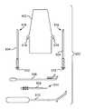
- FIGS. 1A and 1Billustrate embodiments of implants.
- FIGS. 2A and 2Billustrate embodiments of implants and adjusting engagements.
- FIGS. 3A and 3Billustrate embodiments of implants, tissue fasteners, and insertion tools.
- FIGS. 4A, 4B, and 4Cillustrate embodiments of implants, tissue fasteners, and insertion tools.
- FIGS. 5A, 5B, and 5Cillustrate embodiments of implants, tissue fasteners; and insertion tools.
- FIGS. 6A, 6B, 6C, and 6Dillustrate embodiments of extension portion pieces and grommet management tools.
- FIGS. 7A, 7B, and 7Cillustrate embodiments of insertion tools and implants.
- FIGS. 8A and 8Billustrate embodiments of adjusting tools.
- FIGS. 9A and 9Billustrate embodiments of adjusting tools.
- FIGS. 10A and 10Billustrate embodiments of adjusting tools, adjusting engagements, implants, and steps of related methods.
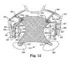
- FIG. 12illustrates embodiments of implants and related anatomy for placement of the implants.
- FIGS. 13A, 13B, and 13Cillustrate embodiments of implants.
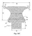
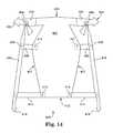
- FIGS. 14 and 15illustrate embodiments of implants.
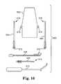
- FIG. 16illustrates embodiments of adjusting tools, adjusting engagements, implants, insertion tools, grommet management tools, and any embodiments of which can be assembled into a kit.
- the inventioninvolves surgical instruments, assemblies, and implantable articles for treating pelvic floor disorders such as fecal or urinary incontinence, including stress urinary incontinence (SUI), prolapse, etc.
- a surgical implantcan be used to treat a pelvic condition, including the specific examples of surgically placing a pelvic implant to treat a condition such as vaginal prolapse or incontinence (male or female). Described are various features of surgical implants, surgical tools, surgical systems, surgical kits, and surgical methods useful for installing implants.
- An implantcan be implanted in a male or a female patient to treat a condition such as urge incontinence; stress urinary incontinence; mixed incontinence; overflow incontinence; functional incontinence; fecal incontinence; prolapse (e.g. vaginal or uterine); enterocele (e.g. of the uterus); rectocele; cystocele; anatomic hypermobility; conditions of the pelvic floor caused by weakness or trauma of pelvic floor muscles such as the levator (“levator ani”) or coccygeus muscle (collectively the pelvic floor); other conditions caused by muscle and ligament weakness; and combinations of these.
- a conditionsuch as urge incontinence; stress urinary incontinence; mixed incontinence; overflow incontinence; functional incontinence; fecal incontinence; prolapse (e.g. vaginal or uterine); enterocele (e.g. of the uterus); rectocele; cysto
- An implantcan include a tissue support portion that can be used to support pelvic tissue such as the urethra (which includes the bladder neck), bladder, rectum, vaginal tissue (Level 1, Level 2, Level 3, or combinations of these), pelvic floor tissue, etc. During use, the tissue support portion is typically placed in contact with and attached to tissue to be supported, such as by attachment using one or more sutures.
- An implantcan additionally include one or more extension portion attached to the tissue support portion, or one or more scaffold portion attached to a tissue support portion or an extension portion.
- a tissue fastener or a connectorcan be included at an end of an extension or scaffold portion.
- the tissue support portionis designed to support a specific type of pelvic tissue such as the urethra, bladder, or vaginal tissue (anterior, posterior, apical, etc.), rectum, tissue of the pelvic floor such as levator muscle, etc.
- the tissue support portioncan be sized and shaped to contact the desired tissue when installed, e.g., as a “sling” or “hammock,” to contact and support pelvic tissue.
- Extension portionsare pieces of material, generally elongate or otherwise extended from a tissue support portion, and that are useful to optionally either pass through or attach to tissue of the pelvic region to thereby provide support for the tissue support portion and the supported tissue.
- One or multiple (e.g., one, two, four, or six) extension portionscan extend from a tissue support portion for attachment to tissue in the pelvic region, such as by extending to an internal anchoring point (for attachment by bone anchor, tissue fastener, etc.), or through a tissue path to an external incision.
- An implantcan optionally include a scaffold portion, (which can be considered a type of extension portion, such as if the scaffold portion extends from a tissue support portion) that can be extended internally within a patient and secured to tissue of a pelvic region or to a location of the implant, and is used to support a tissue support portion or extension portion attached to the scaffold portion along a length of the scaffold portion, between two ends of the scaffold portion.
- a scaffold portioncan have two ends. Either end can be attached internally to tissue of the pelvic region r to the implant, such as to a tissue support portion, another extension portion, or another scaffold portion.
- An end of a scaffold portioncan be securely (non-adjustably) attached to a tissue support portion or another extension portion, such as by a suture, rivet, staple, etc.; may be integrally formed with the tissue support portion or extension portion; or may be adjustably attached to a tissue support portion or an extension portion using an adjusting engagement.
- a scaffold portionmay also optionally include an adjusting engagement along the length of the scaffold portion.
- a scaffold portioncan be sized or adjusted in size to be sufficiently taut upon placement within a pelvic region to be able to support an extension portion or a tissue support portion of an implant attached along a length of the scaffold portion between the two ends of the scaffold portion.
- An extension portion of an implant, or a tissue support portion of an implantcan be connected to the scaffold portion either in a secure (non-adjustable) manner such as integrally, by a suture, adhesive, thermal bonding, polymeric rivets, or the like, or in an adjusting manner, using and adjusting engagement.
- a “multi-piece” implantrefers to an implant that includes a “support portion piece” and one or multiple “extension portion piece” or “scaffold portion piece,” as separate pieces of the implant.
- An extension portion piece or scaffold portion piececan be separate from a support portion piece, and can be connected through one or multiple an adjusting engagements.
- the support portion pieceincludes a tissue support portion.
- Exemplary implantscan be made of materials and may be generally shaped and sized with certain individual features that may be found in previous implants, but can be modified to include features as described herein such as a scaffold portion, an adjusting engagement, any of the various tissue fasteners described herein, multi-piece construction, etc., and can be adapted for use according to methods that are described herein.
- An implantcan have features described in the following exemplary documents: U.S. patent application Ser. No. 10/834,943, filed Apr. 30, 2004; U.S. patent application Ser. No. 10/306,179, filed Nov. 27, 2002; U.S. patent application Ser. No. 11/347,063, filed Feb. 3, 2006; U.S. patent application Ser. No. 11/347,596, filed Feb.
- PCT/US2007/004015entitled “SURGICAL ARTICLES AND METHODS FOR TREATING PELVIC CONDITIONS,” filed Feb. 16, 2007; International Application No. PCT/US2007/016760 entitled “SURGICAL ARTICLES AND METHODS FOR TREATING PELVIC CONDITIONS,” filed Jul. 25, 2007; and International Application No. PCT/US2008/000033 entitled “METHODS FOR INSTALLING SLING TO TREAT FECAL INCONTINENCE, AND RELATED DEVICES,” filed Jan. 3, 2008; the entireties of each of these disclosures being incorporated herein by reference.
- Examples of commercial implantsinclude those sold by American Medical Systems, Inc., of Minnetonka Minn., under the trade names Apogee®, Perigee®, and ElevateTM for use in treating pelvic prolapse (including vaginal vault prolapse, cystocele, enterocele, etc.), and Sparc®, Bioarc®, Monarc®, and MiniArcTM for treating urinary incontinence. Implants useful according to the present description can include one or more features of these commercial implants.
- An implantmay include portions, pieces, or segments, that are synthetic or of biological material (e.g., porcine, cadaveric, etc.).
- Extension portions and scaffold portions(made of a single piece or of more than one piece) may be, e.g., a synthetic mesh such as a polypropylene mesh.
- a tissue support portionmay be synthetic (e.g., a polypropylene mesh) or biologic.
- portion of implantor “implant portion” refers generally to any piece, segment, or portion (e.g., extension portion or scaffold portion) of an implant.
- segment of implant(or “implant segment”) refers to an elongate length of implant material, such as a length of an elongate section of an extension portion or a scaffold portion.)
- implants for treating vaginal prolapsecan include a central support portion and from two to four to six extension portions, and may take the form of an integral piece of mesh or other implant material, or multiple pieces of mesh or other implant material attached in a modular fashion. See, e.g., Assignee's copending U.S. patent application Ser. Nos. 11/398,369; 10/834,943; 11/243,802; 10/840,646; PCT/2006/028828; among others.
- implants for treating vaginal prolapseusing any one or a combination of devices or methods as described herein can be implants described in Assignee's copending International Patent Application No. PCT/US2007/014120, entitled “SURGICAL IMPLANTS, TOOLS, AND METHODS FOR TREATING PELVIC CONDITIONS,” filed Jun. 15, 2007, the entirety of which is incorporated herein by reference.
- an implantcan include pieces or portions that are adjustably connected together by an adjusting engagement, which may be either a one-way adjusting engagement or a two-way adjusting engagement, to allow a portion or a segment of an implant to be moved relative to another portion or segment, and adjusted as to length, tension, or positioning.
- an extension portion piececan be attached to a support portion piece at an adjusting engagement to allow adjustment of a length of extension portion.
- a scaffold portion or scaffold portion piececan be attached to a support portion piece or to an extension portion at an adjusting engagement to allow adjustment of length or tension of a scaffold portion.
- Some adjusting engagementscan allow free two-way movement of one piece relative to another piece (e.g., a “two-way” adjusting engagement).
- This type of adjusting engagementallows easy movement of a segment of implant in two directions through an adjusting engagement.
- the force needed to move the segment of implant in one directionis substantially equal to the force needed to move the segment in the opposite direction, and, preferably, the two-way adjusting engagement does not substantially hinder the movement of a segment of implant through the adjusting engagement with frictional surfaces such as extensions (e.g., “teeth”) extending into an aperture through which the segment of implant is moved.
- a two-way adjusting engagementmay include an open (smooth) aperture that may be circular, oval, elongate such as in the form of a slit or slot, etc.
- the aperturemay optionally be reinforced by a reinforcement of a shape that is similar to the aperture, such as by a fabric or a polymeric material such as a grommet (e.g., a “loose grommet” or “eyelet”), which may be circular, or may be of another shape.
- the reinforcemente.g., grommet
- the reinforcementdefines a reinforced aperture through which a segment of implant can pass relatively freely and with the same resistance two different directions.
- Still other embodiments of adjusting engagementsmay allow for two-way adjustment of a length of extension portion in one configuration (an “open” configuration), and further include a structure or mechanism that can be switched, activated, moved, removed, closed, or opened, to secure a frictional adjusting engagement at a selected location to prevent movement in either direction.
- FIGS. 1A, 1B, 2A, and 2Billustrate various embodiments of adjusting engagements in the form of grommets.
- FIGS. 1A and 1Bshow implant 20 that includes implant portion 24 (e.g., a tissue support portion or a support portion piece), and grommet 22 , which is a two-way, non-frictional adjusting engagement, sometimes referred to as an “eyelet” or a “loose eyelet.”
- Implant portion 24e.g., a tissue support portion or a support portion piece
- grommet 22which is a two-way, non-frictional adjusting engagement, sometimes referred to as an “eyelet” or a “loose eyelet.”
- Grommet 22includes aperture 28 , through which implant segment 26 can pass freely in two directions, to adjust lengths of implant portions extending from either side of grommet 22 .
- FIG. 2Ashows a perspective view of implant 30 with one-way frictional adjusting engagement 32 attached to portion of implant 34 .
- FIG. 2Bis a cross-sectional view.
- one-way, frictional, adjusting engagement 32includes central aperture 44 , first flange 40 , second flange 38 , and a plurality of extensions (flaps or “teeth”) 36 extending in the direction of aperture 44 or an longitudinal axis (“a”) extending through aperture 44 .
- the outside diameter of frictional adjusting engagement 32can be about 5 mm (e.g., from 3 to 10 millimeters) and the length of an extension 36 can be in the range from about 1 mm to about 2 mm.
- Aperture extension 46extends away from flange 40 in a direction (designated “A”) in which grommet 32 will be pushed along a length of an implant portion.
- Grommet 32a “one-way” adjusting engagement, is able to freely move along an implant portion in direction A, and extensions 36 prevent movement in the opposite direction.
- An aperture extension 46can also be useful on a two-way grommet.
- Aperture extension 46is an optional feature of a grommet that is designed to prevent tissue from entering aperture 44 and becoming lodged inside of grommet 32 during movement of grommet 32 along an implant portion. For instance, when implant portion 34 is moved within a patient, in direction A, relative to an implant portion (not shown) extending through aperture 44 , tissue may come into contact with the implant portion (which may be a mesh) and with grommet 32 . Absent aperture extension 46 , the tissue can tend to be forced into aperture 44 . This can be especially true if the implant portion extending through aperture 44 is made of mesh.
- Aperture extension 46deflects and blocks tissue from entering aperture 44 .
- An exemplary length of extension 46(the distance from flange 40 to the far tip of aperture extension 46 ) can be a length that is approximately the same as the thickness of grommet 32 from flange 38 to flange 40 (including opposing the width of the flanges).
- Exemplary thicknessescan be, e.g., from 1 to 5 millimeters, e.g., from 2 to 4 millimeters.
- an implant segmentmay engage a separate implant segment or portion of implant at an adjusting engagement, and another adjusting engagement can be used to secure final positioning of the two portions of implant.
- a segment of an extension portion piecemay extend through a two-way adjusting engagement located at a support portion piece.
- a segment of the extension portion piece(alternately a scaffold portion piece) extending from one side of the two-way adjusting engagement can be useful to form an extension portion (alternately scaffold portion) of adjustable length; an end of this segment away from the adjusting engagement can include a tissue fastener for fastening to soft tissue.
- a second segment of the piece extending from the adjusting engagement, on the opposite side of the two-way adjusting engagementcan be referred to as a loose end; this end may be cut as desired or attached to pelvic anatomy as desired.
- a second adjusting elementcan be used to fix the extension portion piece in place relative to the support portion piece.
- an adjusting engagement in the form of a one-way grommetcan be placed on the loose end of the extension portion piece. The one-way grommet be used to secure the positioning of the extension portion piece and support portion piece after adjustment.
- the tissue fastener at one end of the extension portionis placed at tissue as desired, and the second (loose) end of the extension portion piece is passed through the two-way adjusting engagement.
- the engagementis adjusted to place the support portion piece at a desired position (length) of the extension portion piece.
- a second adjusting engagemente.g., a one-way grommet, is slid onto the loose end of the extension portion piece and slid along the extension portion piece to a location at the two-way adjusting engagement.
- the one-way adjusting engagementmoves easily along the extension portion piece in the direction toward two-way adjusting engagement, and does not move easily in the opposite direction.
- Implants as describedcan include a tissue fastener at a distal end of an extension portion, which is the end not attached to a tissue support portion.
- tissueas used herein may refer to an end of a structure that is “away from” a different structure, such as a distal end of an extension portion that is the end away from a connection to a tissue support portion.
- the term “distal”may also (based on arbitrary selection) generally refer to a location that is relatively more posterior to a patient, and relatively farther away from a surgeon performing a method as described; “proximal” generally refers to a location that is relatively more anterior to a patient, and relatively closer to a surgeon performing a method as described. Any other convention, such as an opposite convention, could alternately be used to refer to features of devices and methods as described.)
- a tissue fastenercan be of various types, including, as examples, a self-fixating tip that is inserted into soft tissue and frictionally retained; soft tissue anchors; biologic adhesive; a soft tissue clamp that can generally include opposing, optionally biased, jaws that close to grab tissue; and opposing male and female connector elements that engage to secure an end of an extension portion to tissue.
- An implantmay also have extension portions that do not include a tissue fastener at a distal end, for example if the distal end is designed to be secured to tissue by other methods (e.g., suturing), or is intended to pass through an external incision, in which case the extension portion may include a connector, dilator, or dilating connector, which connects to an elongate tool that can be used to either push or pull the connector, dilator, or dilating connector through a tissue path to an external incision.
- a tissue fastenerat a distal end, for example if the distal end is designed to be secured to tissue by other methods (e.g., suturing), or is intended to pass through an external incision, in which case the extension portion may include a connector, dilator, or dilating connector, which connects to an elongate tool that can be used to either push or pull the connector, dilator, or dilating connector through a tissue path to an external incision.
- a tissue fastenercan be placed at and secured within internal tissue of the pelvic region to support the implant and pelvic tissue that is supported by the implant.
- a tissue fastenercan be placed at muscle tissue of an obturator foramen (e.g., obturator internus muscle), tissue of an arcus tendineus or surrounding an arcus tendineus, tissue of a sacrospinous ligament, tissue in a region of a sacrospinous ligament, tissue of a coccyx region, tissue of a region of an ischial spine, tissue of coccygeous muscle, tissue of iliococcygeous muscle, tissue of a uterosacral ligament, tissue of levator muscle, or at other tissue of the pelvic region.
- an obturator foramene.g., obturator internus muscle
- tissue of an arcus tendineus or surrounding an arcus tendineustissue of a sacrospinous ligament
- a tissue fasteneris a self-fixating tip.
- a “self-fixating tip” in generalcan be a structure (sometimes referred to as a soft tissue anchor) connected to an extension portion that can be implanted into tissue (e.g., muscle tissue, tendon tissue, or ligament tissue) in a manner that will maintain the position of the self-fixating tip and support the attached implant.
- Exemplary self-fixating tipscan also be designed to engage an end of an insertion tool (e.g., elongate needle, elongate tube, etc.) so the insertion tool can be used to push the self-fixating tip through and into tissue for implantation, preferably also through an incision to reach the interior of the pelvic region.
- the self-fixating tipmay engage the insertion tool at an internal channel of the self-fixating tip, at an external location such as at a base, or at a lateral extension, as desired.
- Exemplary self-fixating tipscan include one or more lateral extensions that allow the self-fixating tip to be inserted into soft tissue and to become effectively anchored in the tissue.
- a lateral extensionmay be moveable or fixed.
- the size of the self-fixating tip and optional lateral extensionscan be useful to penetrate and become anchored into the tissue.
- Exemplary self-fixating tipsare described in Assignee's copending international patent application PCTUS2007/004015, filed Feb. 16, 2007, titled Surgical Articles and Methods for Treating Pelvic Conditions, the entirety of which is incorporated herein by reference. Other structures may also be useful.
- a self-fixating tipcan have structure that includes a base having a proximal base end and a distal base end.
- the proximal base endcan be connected (directly or indirectly, such as by a connective suture) to a distal end of an extension portion (also meaning, as used herein, a scaffold portion).
- the baseextends from the proximal base end to the distal base end and can optionally include an internal channel extending from the proximal base end at least partially along a length of the base toward the distal base end.
- the optional internal channelcan be designed to interact with (i.e., engage) a distal end of an insertion tool to allow the insertion tool to be used to place the self-fixating tip at a location within pelvic tissue of the patient.
- Embodiments of self-fixating tipsalso include one or more lateral extension extending laterally (e.g., radially) from the base, such as from a location between the proximal end and the distal end, from a location at the distal base end, or from a location at the proximal base end.
- a self-fixating tipcan be made out of any useful material, generally including materials that can be molded or formed to a desired structure and connected to or attached to an end of an extension portion of an implant.
- Useful materialscan include plastics such as polyethylene, polypropylene, and other thermoplastic or thermoformable materials, as well as metals, ceramics, and other types of biocompatible and optionally bioabsorbable or bioresorbable materials.
- Exemplary bioabsorbable materialsinclude, e.g., polyglycolic acid (PGA), polylactide (PLA), copolymers of PGA and PLA.
- Pluralities (only one is required) of male connector elements 54 in the form of elongate barbed membersextend from each distal end of base portion 51 and branch 53 .
- Apertures of the material of the of Y-shaped distal end 52 base portion 51 and branch 53e.g., mesh) function as female connector elements into which the barbed ends of fingers 54 become engaged when the two opposing ends of the Y-shaped distal end are pushed to contact each other.
- Barbed fingers 54are sized and prepared from materials that allow the barbed ends of fingers 54 to penetrate tissue of the pelvic region, such as muscle, ligament, tendon, etc., and also to engage apertures of material of the Y-shaped distal end.
- FIG. 3Ashows fingers 54 located at both a distal end of base 51 and a distal end of branch 53 . In alternate embodiments, fingers may be present at only one of these distal ends, and not the other.
- FIG. 3Billustrates an installation tool, tool 56 , for installing implant 50 .
- Installation tool 56includes jaws 58 and 60 that pivot about pivot point 62 .
- Jaws 58 and 60include structure to engage each distal end of the base and branch of Y-shaped distal end 52 to hold male connector elements 54 for placement into tissue in a manner to engage tissue and to also engage the opposing mesh of Y-shaped distal end 52 .
- jaws 58 and 60are positioned at a desired tissue location, with a piece of tissue placed (or pinched”) between opposing male connector elements 54 .
- Tool 52is then used to drive opposing male connector elements 54 toward each other, through tissue, and into engagement within opposing mesh.
- FIG. 3Bshows fingers 54 located at both a distal end of base 51 and a distal end of branch 53 . In alternate embodiments, fingers may be present at only one of these distal ends, and not the other.
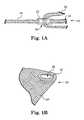
- FIGS. 4A, 4B, and 4Cillustrate another example of a tissue fastener.
- Tissue fastener 73is an integral, spring-biased tissue fastener that can exhibit an opened configuration and a closed configuration.
- tissue fastener 73is attached to a distal end of implant portion 72 , such as an extension portion or a scaffold portion.
- Cylindrical body 71includes aperture 74 on a proximal end, the proximal end being attached to a distal end of implant portion 72 .
- On a distal side of body 71are spring-biased, curved prongs (e.g., teeth, tines, extensions, etc.) that are shaped to penetrate tissue of a pelvic region.
- prongs 75may have sharpened edges or ends and dimensions to extend a desired depth into tissue. Prongs 75 are spring-biased toward the closed configuration illustrated at FIG. 4A .
- prongs 75can be opened or expanded as shown at FIG. 4B , to become spring-loaded, by inserting an end of an inserting tool 78 , into aperture 74 and pushing the end of the inserting tool against prongs 75 , causing prongs 75 to splay apart to the opened configuration.
- tissue fastener 73can be placed with ends of prongs against soft tissue of a pelvic region. Tissue fastener 73 can be pushed from the end of inserter tool 78 by any mechanism, such as by a pushing mechanism 77 . Pushing mechanism 77 moves in direction M, within slot.
- a surface of pushing mechanism 77engages a surface of tissue fastener 73 , to allow fastener 73 to be pushed from a distal end of inserter tool 78 .
- prongs 75When pushed from inserter tool 78 , with prongs 75 in contact with a surface of tissue, prongs 75 contact and sink into tissue, grabbing the tissue between prongs 75 and securing tissue fastener 73 to tissue 76 , as shown at FIG. 4C .
- FIGS. 5A, 5B, and 5Cillustrate another example of a tissue fastener.
- Tissue fastener 86is shown at FIG. 5A in a closed position, when loaded in a tube at a distal end of insertion tool 82 .
- Tissue fastener 86includes body 88 and projections (or “arms”) 90 , which can be inserted into tissue of a pelvic region.
- Tissue fastener 86is attached to a distal end of implant portion 84 (e.g., an extension portion or a scaffold portion), also located within a hollow body of a distal end of insertion tool 82 (illustrated in cross section).
- an extension portion piececan include a segment (referred to herein as a “mesh portion,” but not necessarily of mesh) having a tissue fastener at one end.
- the extension portion pieceis configured to engage a support portion piece in a manner that allows the mesh portion to provide a structure that includes an extension portion having an adjustable length.
- An end of the extension portion piececan be placed through an adjusting engagement of a support portion piece, and the end of the support portion piece that includes the tissue fastener forms an extension portion between tissue (with which the tissue fastener becomes engaged) and the support portion piece (to which the extension portion is engaged at the adjustable engagement).
- the end (segment) of the extension portion piece extending in the other directioni.e., the end (segment) that does not include the tissue fastener (sometimes referred to as a “loose” end), may be functional as shown at FIGS. 11A, 11B, 12, 13A, and 13B . Alternately, the loose end may be cut after a desired length of the extension portion is achieved.
- Embodiments of extension portion pieces used with methods and implants described hereinmay also include a non-mesh portion.
- a non-mesh portionmay be, for example a suture, a set of sutures, a tape, or processed (e.g., melted or compressed) mesh.
- a non-mesh portioncan facilitate placement or movement of an extension portion piece relative to a support portion piece, e.g., through an adjusting engagement.
- a mesh of an extension portion piecemay be unwieldy for placing into an adjusting engagement such as a small-diameter grommet, small-dimension slot, toothed-slot, etc.
- a non-mesh portioncan allow easier placement (threading) of an end of an extension portion piece through an aperture of an adjusting engagement by providing a less wieldy, integral (non-mesh), more easily managed end.
- a non-mesh tapefor example, may be more easily inserted into a slot or a toothed-slot of a one-way or a two-way adjusting engagement.
- a cylindrical non-mesh portionsuch as a flexible yet rigid plastic “rod” may be more easily inserted into a round aperture such as an aperture of a grommet, compared to a loose end of a mesh material.
- a non-mesh portionmay allow for easier adjustment of the extension portion piece within an adjusting element.
- a non-meshcan exhibit reduced cross section, and friction, relative to a mesh material. Additionally, an extension portion piece made of a full length of mesh material can undesirably engage tissue that can stick to mesh and become lodged in an adjusting element.
- a non-mesh portioncan be less prone to sticking to tissue during use.
- Mesh and non-mesh portions of an extension portion piececan be dimensioned to allow the mesh portion to engage an adjusting engagement, when adjusted to a desired length, and when a distal end tissue fastener is fastened to tissue as desired.
- a non-mesh portioncan be of a length to allow manipulation and adjustment of the extension portion piece. Exemplary lengths of a total extension portion piece can be in the range from 4 to 10 inches, including a mesh portion and a non-mesh portion (if present).
- a mesh portioncan be, for example, from 1 to 4 inches in length and a non-mesh portion (e.g., polymeric rod, suture, etc.) can be, for example, from 3.5 to 5.5 inches in length.
- a non-mesh portione.g., polymeric rod, suture, etc.
- FIG. 6Aillustrates an example of an extension portion piece that includes a mesh portion and a non-mesh portion.
- Extension portion piece 110includes mesh portion 114 and non-mesh portion 112 , in the form of two sutures 113 .
- Tissue fastenere.g., a self-fixating tip
- Sutures 113are attached to a proximal end of mesh portion 114 , such as by knots.
- Non-mesh portion 112is illustrated to be in the form of two sutures, but may alternately by more or fewer sutures, such as one suture, or three sutures, optionally tied or braided. Still alternate forms of non-mesh portion 112 may be a polymeric tape, a narrow fabric, or the like, any of which can be selected to be easily threaded through an aperture of a desired adjusting engagement.
- FIG. 6Billustrates another example of an extension portion piece that includes a mesh portion and a non-mesh portion.
- Extension portion piece 100includes mesh portion 104 and non-mesh portion 102 .
- Tissue fastener (e.g., self-fixating tip) 106is attached to a distal end of mesh portion 104 .
- Polymeric (e.g., polypropylene) rod 102is attached to (preferably integral to) a proximal end of mesh portion 104 .
- Polymeric rod 102can be formed by any method and may be integrally attached to mesh portion 104 , or attached by any technique. As an example, polymeric rod 102 may be prepared by starting with a length of mesh material that is integral to mesh portion 104 .
- the length of meshcan be heat treated at a desired melting temperature (according to the type of polymer of the mesh) to melt the mesh into a polymeric rod having stiff yet flexible mechanical properties.
- a desired heat-treating temperaturemay be in the range from 450 to 520 degrees Fahrenheit.
- Polymeric rod 102can be of useful dimensions, such as a length in the range of about 3.5 to 5.5 inches and a width dimension (e.g., diameter) useful to engage a dilator, e.g., about 1/16 of an inch, or from about 1 to 4 millimeters.
- proximal end 109 of polymeric rod 102can be shaped to accept or matingly engage an end of a grommet-management tool, such as a polymeric rod, that can facilitate placement of a grommet or other adjusting engagement onto a proximal end of a non-mesh portion of an extension portion piece.
- a grommet-management toolsuch as a polymeric rod
- a user of an extension portion piecesuch as extension portion piece 100 , may place a grommet (e.g., a one-way grommet) onto a proximal end of a non-mesh portion by hand, using fingers. This can be clumsy, especially in potentially confined or deep locations of a pelvic region.
- a grommet management toolholds one or multiple grommets.
- An end of the grommet management toolcan engage a proximal end of a non-mesh portion of an extension portion piece in a manner to allow the end of the grommet management tool to align and mate against the proximal end of the extension portion piece. Once the ends are engaged, a grommet can slide from the grommet management tool, directly onto the proximal end of the non-mesh portion of the extension portion piece.
- a grommet management toolmay contain a single grommet, or multiple grommets, and can be used to transfer the one or multiple grommets onto multiple different extension portion pieces of a single or multiple pelvic implants.
- a grommet management toolcan ensure that control of a grommet (or other adjusting engagement) and a location of a grommet are not lost during a surgical procedure, and a grommet can be prevented from becoming a free-standing, separate piece with the potential of becoming lost during a surgical procedure.
- FIG. 6Cillustrates grommet management tool 120 , which is a rod, such as a polymeric (e.g., polypropylene) rod with a diameter that matches a diameter of polymeric rod 102 .
- One-way (alternately two-way) grommets 124are aligned along a length of grommet management tool 120 .
- Distal end 124includes channel or bore 122 that is complementary to cylindrical extension 108 at proximal end 109 of extension portion piece 100 . These complementary surfaces can be engaged to allow transfer of a grommet from tool 120 to distal end 124 .
- non-mesh portion 102 of extension portion piece 100can be passed through an adjusting engagement of an implant.
- the implant and extension portion piececan be manipulated and placed as desired, such as at locations within a pelvic region.
- Channel 122 of grommet management tool 120can be placed over cylindrical extension 108 , and a grommet 124 can be slid in direction B (see FIG. 6C ) and transferred from grommet management tool 120 onto proximal end 109 of extension portion piece 100 .
- One-way grommets 124move easily along an extension portion piece in direction B, and are inhibited from moving in a direction opposite of direction B when placed on a mesh portion such as mesh portion 104 .
- grommet 124can slide to engage mesh portion 104 , and contact the adjusting engagement of the tissue support portion or support portion piece, to secure a relative position of mesh portion 104 to the tissue support portion or support portion piece, e.g., to fix a length of an extension portion of mesh portion 104 .
- a grommet management tool such as tool 120can be made of a plastic. metal, or other useful material.
- a grommet management toolcan be prepared in the same manner used to make a polymeric rod non-mesh portion 102 , such as by melting a length of mesh and molding to form a polymeric rod. Other methods can also be used, such as by extruding, injecting molding, etc.
- the engagement between distal end 124 of grommet management tool 120 , and proximal end 109 of non-mesh portion 102includes complementary cylindrical surfaces.
- Other engagementscan also be useful, such as complementary conical surfaces, square surfaces, etc.
- a feature of a non-mesh portion of an extension portion piece, or of a grommet management toolmay include a feature that allows a one-way grommet to pass, only if the one-way grommet is correctly oriented for movement in a desired direction.
- An example of this featurecan be a shoulder or notch located at a proximal end of a non-mesh portion of an extension portion piece (or, alternately, at a distal end of a grommet management tool).
- Teeth 139 of grommet 138would engage shoulder 142 and stop grommet 138 from moving past shoulder 142 in direction C.
- Notch 140 and shoulder 142are illustrated to be located on non-mesh portion 132 , but alternately could be included on grommet management tool 130 .
- insertion toolswhich generally are tools useful to engage and place a tissue fastener or a connector that is secured to an extension portion (or, as described herein, a scaffold portion) of an implant.
- insertion toolsVarious types of insertion tools are known, and these types of tools and modifications thereof can be used according to the present description to install an implant.
- useful insertion toolsinclude those types of tool that generally include a thin elongate shaft (e.g., needle); a handle attached to one end (a proximal end) of the shaft; and an optional distal end (or “tip”) of the shaft adapted to engage an end of an extension portion or scaffold portion, e.g., at a connector or a tissue fastener (e.g., a self-fixating tip).
- the needlecan facilitate placement of the distal end of the extension or scaffold portion at a desired anatomical location that may be internal or through a tissue path to an external incision.
- Exemplary insertion toolscan be similar to or can include features of tools described in the above-referenced patent documents.
- those insertion toolsmay be modified, such as to allow the insertion tool to be used to place a self-fixating tip through a vaginal or a medial incision, to engage tissue within the pelvic region.
- the insertion toolcan be designed, shaped, and sized, to include an elongate shaft that may be straight or that may be curved in two or three dimensions, that can be inserted through a vaginal incision (for female anatomy) or through a perineal incision (for male anatomy), and extend from that incision to or through pelvic tissue for placement of a distal end of an extension portion.
- An example of an insertion tool for use in implanting a pelvic implantcan include a handle, a shaft, a distal end of the shaft that engages a tissue fastener (e.g., self-fixating tip), and a pore engagement at a location along a length of the shaft.
- the pore engagementengages an aperture of a portion of implant, e.g., an aperture of mesh of an extension portion or a scaffold portion.
- the pore engagementengages a pore of the implant portion in a manner that temporarily fixes the portion of implant against the shaft.
- the pore engagementcan be a small extension, bump, hook, or tang, that extends from the shaft, and that is stationary or moveable (e.g., by movement of an actuator at a proximal end of the tool.
- the pore engagementcan be at any useful location along a length of the shaft, and can preferably be located at a surface of an outer major bend of a curved or angled shaft.
- a pore engagementcan be of a size that engages an aperture of a portion of implant, and can be located to allow the portion of implant to remain taut during insertion.
- tissue fastenerloosely engages a tip of the shaft by a relatively loose (non-frictional) engagement, such by complementary cylindrical engagement surfaces that do not include a snap-fit, detent, threads, or other frictional feature that maintains the engagement.
- a relatively loose engagementis an engagement between a cylindrical tip of an insertion tool and a cylindrical aperture or bore of a base of a self-fixating tip.
- the pore engagementcan be located along the shaft at any distance from the distal end (or tip) of the shaft, and may be located at a distance that is approximately equidistant from distal and proximal ends of the shaft, such as at the medial 1 ⁇ 3 of the length of the shaft, or at a location that is between 30 and 70 (e.g., between 40 and 60) percent of the distance between the proximal end to the distal end. Alternately, the pore engagement may be located at a distance that is approximately 2 to 10 inches from the tip, e.g., from 2 to 5 inches from the tip.
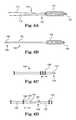
- FIG. 7Aillustrates an embodiment of an insertion tool that includes a pore engagement.
- Shaft 150includes distal end 158 that includes cylindrical tip 160 that engages a smooth interior cylindrical bore of self-fixating tip 156 (shown in cross section) (non-cylindrical engagement surfaces can alternately be useful).
- Implant portion 154extends from a proximal end of self-fixating tip 156 , along an outer major bend (comprising cornered sections, alternately curved) of shaft 150 .
- An aperture or pore of portion of implant 154engages pore engagement 152 , located on an outer major surface of the bend. Portion of implant 154 can be pulled taut to engage pore engagement 152 , to pull self-fixating tip 156 snug against cylindrical tip 160 .
- Shaft 150can be used to place self-fixating tip at a location internal to a patient, such as by inserting self-fixating tip into soft tissue.
- tip 156remains snug against cylindrical tip 160 , to hold self-fixating tip at distal end 158 .
- a distal end of portion of implant 154can be pulled, which can slightly stretch portion of implant 154 and allow portion of implant 154 to become disengaged from pore engagement 152 .
- FIGS. 7B and 7Cshow alternate embodiments of pore extension 152 , in the form of a rounded bump, or a straight extension, respectively.
- Rounded bump 152 of FIG. 7Bwas formed by removing (by machine) material from shaft 150 , resulting in depressions 155 .
- pore engagement 152can be a moveable engagement that can moved and disengaged from portion of implant 154 , by use of an actuator located at a proximal end of shaft 150 .
- An adjusting toolcan be an elongate tool that includes a distal end that engages an adjusting mechanism, to manipulate and optionally cause movement of the adjusting mechanism relative to a portion of implant.
- FIGS. 8A and 8Bshow side and top views of adjusting tool 170 , useful for moving an adjusting engagement such as a grommet along a length of a segment of an implant such as a segment of an extension portion or a scaffold portion.
- Tool 170includes elongate shaft 172 and distal end 174 .
- Slot 176 at distal end 174can be slid past a segment of implant to place a segment of implant at a location within aperture 179 .
- Aperture 179is defined in part by opposing arms 178 (illustrated to be curved, but optionally straight, angled, etc.) that extend laterally and optionally distally from a distal end of shaft 172 , to define aperture 179 and slot 176 .
- Bottom surfaces of arms 178can be used to apply pressure to an adjusting engagement (e.g., grommet) located on the segment of implant, and move the grommet, preferably in a direction along the segment of implant to adjust a length of an extension portion or scaffold portion.
- an adjusting engagemente.g., grommet
- a slotfor example, may define an opening that is in the range from 0.5 to 1.2 centimeters, e.g., from 0.5 to 1.0 centimeter.
- An aperturemay have the same or similar dimensions, or may be the same width or wider than the slot, such as having a diameter in the range from 0.5 to 1.2, e.g., 0.5 to 1.0 centimeter.
- Surfaces for engaging an adjusting engagementmay correspond to a size of surfaces of the adjusting engagement, such as having surfaces that match surfaces of a flange of a grommet.
- FIGS. 9A and 9BAnother embodiment of adjusting tool is shown at FIGS. 9A and 9B .
- This embodiment of adjusting tool 170includes features of tool 170 as illustrated at FIGS. 8A and 8B , and also includes an optional second set of arms around aperture 179 , located in alignment with arms 178 .
- FIGS. 9A and 9Bshow side and top views of this embodiment of adjusting tool 170 .
- this embodiment of tool 170includes a second set of arms, 184 , that are aligned with arms 178 and that define additional length of aperture 179 .
- optional arms 186are structured to prevent tissue from becoming lodged inside of an adjusting engagement (e.g. a grommet) during movement of grommet 32 in a direction N along a segment of implant.
- an adjusting engagemente.g. a grommet
- tissuemay come into contact with the mesh or the grommet and (absent arms 186 ) can tend to be forced into the aperture of the grommet.
- Arms 186become located on the side of the grommet that moves into tissue, and deflect and block tissue from entering an aperture of the grommet.
- second arms 186can be used to move a two-way grommet in a direction opposite of the direction of movement provided by arms 178 ; i.e., this embodiment of an adjusting tool allows for a two-way grommet to be moved in two different directions (distally, and proximally) along an implant segment.
- slots 176 and 184 at distal end 174can be slid over a segment of implant to place a segment of implant at a location within aperture 179 (defined by and between sets of arms 178 and 186 ).
- FIG. 10Ashows that bottom surfaces 182 of arms 186 can deflect and block tissue from entering an aperture of adjusting engagement 192 , which may be, e.g., a one-way or a two-way grommet used to adjust the location of implant portion 190 relative to implant segment 198 , which includes tissue fastener 196 placed within tissue 194 .
- FIG. 10Bshows an alternate use of adjusting tool 170 , by which a one-way adjusting engagement (grommet) 188 is manipulated to adjust toward a two-way grommet ( 192 ) attached to an implant portion ( 190 ), to secure a length of extension portion 197 between tissue 194 and two-way grommet 192 .
- a one-way adjusting engagement (grommet) 188is manipulated to adjust toward a two-way grommet ( 192 ) attached to an implant portion ( 190 ), to secure a length of extension portion 197 between tissue 194 and two-way grommet 192 .
- embodiments of implants as describedcan be implanted according to methods that include placement of a tissue support portion of an implant at a location to support pelvic tissue.
- One or more extension portions and optional scaffold portionsare then placed for use in supporting the tissue support portion.
- a tissue fastener at a distal end of an extension portioncan be placed at internal tissue of the pelvic region such as muscle, ligament, tendon, fascia, bone, etc.
- an extension portionmay include a connector, for connecting to a tool that pulls the connector and extension portion through a tissue path leading to an external incision (e.g., at an external perirectal region, or through an obturator foramen and to an external incision at an inner thigh).
- an extension portionmay not include a connector or a self-fixating tip but may be connected to tissue or led through a tissue path internal to the patient, or may be passed through a tissue path and an external incision.
- a tissue fastener at a distal end of a scaffold portioncan be connected to internal tissue of the pelvic region such as muscle, ligament, tendon, fascia, bone, etc.
- an end of a scaffold portioncan also be attached to a tissue support portion or an extension portion of an implant.
- An extension portion or a support portion piececan be attached to the scaffold portion at a location between the ends of the scaffold portion.
- Embodiments of methodscan be performed using a medial incision such as through a vaginal incision (for female anatomy) or perineal incision (for male anatomy), and by use of an insertion tool (e.g., any insertion tool described herein) that engages a distal end of the extension portion (such as by engaging a tissue fastener) and passes the distal end to a desired location within a pelvic region of a patient.
- a medial incisionsuch as through a vaginal incision (for female anatomy) or perineal incision (for male anatomy)
- an insertion toole.g., any insertion tool described herein
- An end of an extension portion or scaffold portioncan be attached to any desired tissue of the pelvic region, or passed through a desired tissue path to an external incision.
- a tissue fastenercan be attached at the end of the extension or scaffold portion.
- the tissue fastenercan be attached to any desired tissue, for example soft tissue such as a muscle (e.g., of the obturator foramen, obturator internus, obturator externus, levator ani, coccygeous, iliococcygeous); ligament such as the sacrospinous ligament or surrounding tissue; tendon such as the arcus tendineus or surrounding tissue (e.g., a region of the arcus tendineus, see WO 2007/016083, published Feb. 8, 2007, and entitled “Methods and Symptoms for Treatment of Prolapse,” the entirety of which is incorporated herein by reference); including tissue at or near an ischial spine, e.g., at a region of an ischial spine.
- soft tissuesuch as a muscle (e.g., of the obturator foramen, obturator internus, obturator externus, levator ani, coccygeous, iliococc
- Tissue in a “region” of an ischial spinecan be tissue that is within one centimeter from the ischial spine, including tissue of the levator ani muscle (e.g., iliococcygeous muscle) and arcus tendineus.
- a distal end of an extension portion or scaffold portioncan be attached to tissue in this region, such as by a soft tissue fastener, optionally as described herein.
- the tissue in this regioncan be relatively thin compared to other tissue in the pelvic region, meaning that a tissue fastener may be adapted to securely attach to that thinner tissue.
- a method as described herein for treating vaginal prolapsecan include placing a tissue support portion at tissue of the anterior or posterior vagina or vaginal vault, and placing an extension portion extending from the tissue support portion to region of an ischial spine, preferably on both sides of a patient.
- Such a methodcan include additional optional steps that can be useful to improve support of vaginal tissue and, preferably, to restore an anatomically correct curve to vaginal tissue.
- Such a methodcan include an optional step of attaching an extension portion at a region of ischial spine, slightly anterior of the ischial spine at or near an arcus tendineus.
- additional length of the extension portionmay be placed along and optionally attached to a length of arcus tendineus in an anterior direction from the ischial spine.
- Vaginal tissuemay be placed in contact with the same extension portion that is placed in contact with or attached to the arcus tendineus, e.g., in a manner to provide Level 2 support of the medial vaginal tissue (e.g., sidewall tissue), also preferably to provide a vagina bend that is anatomically correct.
- FIGS. 11A and 11Bshow anatomy and materials for achieving ischial spine support and optional Level 2 support for a posterior or an anterior vaginal implant, on a patient's left side.
- Support portion piece 350 of a vaginal implantwhich may be a posterior or an anterior vaginal implant, is attached to vaginal tissue, preferably in a placement to put adjusting engagement (e.g., grommet) 352 at an apical location (near a vaginal apex).
- Extension portion piece 353extends through adjusting engagement 352 in an adjustable fashion and defines posterior extension portion 354 between adjusting engagement 352 and sacrospinous ligament 360 .
- Extension portion piece 353also includes a “loose end” on the opposite side of adjusting engagement 352 , which defines lateral extension portion 356 between adjusting engagement 352 and a location of a region of ischial spine, such as slightly anterior to ischial spine 362 .
- a segment of lateral extension portion 356 that extends beyond the attachment at the region of ischial spinecan be optionally placed along arcus tendineus 366 , and optionally (and as illustrated at FIG. 11B ) can be attached to a length of arcus tendineus 366 anterior to ischial spine 362 .
- a tissue fastener(not shown), e.g., a self-fixating tip, is located at a distal end of posterior extension portion 354 , and is secured to sacrospinous ligament 360 .
- aperture 352from which posterior extension portion 354 and lateral extension portion 356 originate, can be located near a vaginal apex when support portion piece 350 is placed.
- the length of posterior extension portion 354is adjusted by movement of extension portion piece 353 through aperture 352 (in other words moving aperture 352 in a direction toward distal end of posterior extension portions 354 ), and held frictionally by one-way grommet 352 to place support portion piece 350 as desired.
- Lateral extension portion 356is extended to a location near and anterior to ischial spine 362 , and attached to a region of ischial spine, such as at tissue of the arcus tendineus. Lateral extension portion 56 can be cut as desired.
- lateral extension portion 356can be cut at a length that will allow a segment of lateral extension portion 356 to be further extended laterally (and anteriorly) past ischial spine 362 at arcus tendineus 360 , and along a length of arcus tendineus 362 , optionally being attached to arcus tendineus 362 along that length. See FIG. 11B .
- Anterior implant 351includes adjustable extension portion pieces 353 (left and right sides) extending through aperture 352 located on tissue support portion piece 350 .
- Each extension portion piece 353defines a posterior extension portion 354 of adjustable length and a lateral extension portion 356 , the length of which increases as the length of posterior extension portion ( 354 ) is decreased.
- the distal end of each posterior extension portion 354is secured to sacrospinous ligament 360 .
- Support portion piece 350is secured to vaginal tissue to support an anterior prolapse.
- aperture 352from which posterior extension portion 354 and lateral extension portion 356 extend, can be located near a vaginal apex.
- the lengths of posterior extension portions 354are adjusted as desired by movement of extension portion pieces 353 through apertures 352 (in other words moving aperture 352 in a direction toward distal end of posterior extension portions 354 ), and are held frictionally, to place support portion piece 350 as desired.
- Lateral extension portions 356can be cut to a length to allow extension to locations near and anterior to ischial spine 362 and placement of additional length of lateral extension portions 356 along each opposing arcus tendineus 366 .
- Each lateral extension portion 356can be optionally attached to the length of arcus tendineus 366 using sutures 367 (or any other useful attachment).
- Useful lengths of lateral extension portion 356measured from aperture 352 to a distal end, can be from about 3 to 5 centimeters, e.g., about 4 centimeters.
- opposing vaginal side wall tissues 366are contacted with or optionally connected (e.g., by absorbable sutures, 368 , or any other useful method) to opposing lateral extension portions 356 extending along opposing length of arcus tendineus 366 .
- Each of anterior extension portions 370is secured to opposing obturator foramen 364 .
- a preferred method of attachmentis by placing a tissue fastener such as a self-fixating tip (not shown), attached at ends of anterior extension portions 370 , into tissue of each obturator foramen, preferably obturator internus muscle, preferably without penetrating the obturator membrane.
- the physiciancan suture the vaginal side wall, from inside the vagina, to the mesh extension portion located along the arcus tendineus, alternately or optional also suturing to the arcus tendineus.
- the meshbecomes located in-between the lateral vaginal wall and arcus tendineus.
- the meshprovides a scaffold between the vaginal wall and arcus tendineus, for tissue in-growth.
- Suturesmay be placed using any technique or device, such as a curved pin end suture and any general medical instrument that allows manipulation of the suture, such as a hemostat.
- the optional suturecan provide support and strength between the vaginal tissue (Level 2) and the arcus tendineus while tissue becomes in-grown into the mesh. After the suture biodegrades, the mesh has become fully in-grown and provides Level 2 support.
- the methodscan optionally and preferably be performed transvaginally using a single vaginal incision and no external incisions, to optionally provide multi-level support of vaginal tissue by placement of extension portions at one or more of the sacrospinous ligament, a region of an ischial spine, an arcus tendineus, and obturator foramen, with additional optional support of vaginal sidewalls by attachment to lateral extension portion 356 attached at opposing arcus tendin trains 366 . Placement of a length of lateral extension portion 356 along arcus tendineus 366 can mitigate the possibility of a physician cutting the mesh arm too close to adjusting engagement 352 .
- extension portion piece 353(adjustable relative to support portion piece 350 ) provides dual functions of adjusting lengths of extension portions ( 354 and 356 ), and when extended along an arcus tendineus allowing optional Level 2 tissue support and tissue ingrowth.
- An implant used in these methodscan be any useful implant that includes a tissue support portion suitable to support vaginal tissue, and extension portions that can extend to a sacrospinous ligament, a region of an ischial spine, and along a length of arcus tendineus.
- Alternate methods and devices for providing a combination of Level 1 and Level 2 support for anterior prolapsecan involve a tissue support portion having an anterior end and a posterior end; two opposing anterior extension portions can extend from the anterior end to be placed at opposing obturator foramen; two opposing lateral extension portions can extend laterally from sides between the anterior and posterior ends.
- a scaffold portioncan extend from a location near the anterior end or at a mid-length position along the sides of the tissue support portion, such as by being connected (securely or adjustably) at an anterior extension portion, a lateral extension portion, or both.
- the scaffold portionextends from the anterior end or the mid-length location, along and distanced from sides of the implant, toward the posterior end, for connecting to a sacrospinous ligament. Additional extension portions may also make connections between the scaffold portion and sides of the tissue support portion, e.g., extending from locations at or near the posterior end of the tissue support portion to the scaffold portion.
- FIGS. 13A, 13B, and 13Cillustrate exemplary multi-piece pelvic implants 200 , 230 , and 231 .
- an extension portionextends through an opening of a support portion piece that includes an adjusting engagement.
- the adjusting engagementcan be a one-way adjusting engagement or a two-way adjusting engagement. If the adjusting engagement is a two-way adjusting engagement, a loose end of the extension portion piece can further include a second adjusting engagement that is a one-way adjusting engagement (see FIG. 13A ) that can be moved in an direction toward the support portion piece and the two-way adjusting engagement to fix the length of an extension portion on the opposite side of the two-way adjusting engagement.
- one-way adjusting engagements 214located at each of left lateral extension portion 222 and right lateral extension portion 224 , are optional.
- an extension portion piece ( 210 or 212 )can be adjusted as desired through an aperture ( 204 , 206 ), e.g., to produce a desired length or tension on each posterior extension portion ( 218 , 220 ).
- Support portion piece 202 and an extension portion piece ( 210 , 212 )can be placed internally as desired, and moved relative to each other by threading and sliding a support portion piece through either respective aperture on support portion piece 202 .
- each adjusting engagement 214can be slid to rest against an aperture ( 204 , 206 ), to fix a maximum length of a posterior extension portions ( 218 , 220 ), and also to adjust and fix lengths of corresponding lateral extension portions ( 222 and 224 ). Movement of a frictional adjustment element can be done by use of an adjustment tool as described herein.
- Extension portion pieces 210 and 212are illustrated as being a length entirely of mesh, with no non-mesh portion. Alternately, extension portion pieces may be used that include a non-mesh portion, such as illustrated at FIGS. 6A and 6B , or otherwise described herein.
- a grommet management toolsuch as illustrated at FIG. 6C or otherwise described herein can be used to place a grommet on each non-mesh portion of such extension portion pieces.
- FIG. 13Billustrates another example of an implant ( 230 ), having components similar to those of implant 200 , with the addition of two anterior extension portions ( 226 and 228 ) on an anterior end of support portion piece 203 .
- This implantcan be particularly useful for treating anterior prolapse.
- Support portion piece 203 of implant 230can be placed to treat anterior vaginal prolapse.
- Adjusting engagements 204 and 206are shown as one-way adjusting engagements that allow extension portion pieces 210 and 212 to move in a direction to extend loose ends (lateral extension portions) 222 and 224 , while shortening posterior extension portions 218 and 220 ; because these are one-way adjusting engagements, loose ends 222 and 224 do not include one-way adjusting engagements 214 as in implant 200 of FIG. 7A .
- Elements of implant 230 that are numbered similarly to features of implant 200can function in the manner described for implant 20 .
- implant 230right anterior extension portion 226 and left anterior extension portion 228 , can be extended to locate self-fixating tips 216 (at their respective distal ends) at opposing right and left obturator foramen, respectively, of the patient.
- FIG. 13Cillustrates another example of an implant ( 231 ), having components similar to those of implant 230 .
- Support portion piece 205 of implant 231can be placed to treat anterior vaginal prolapse.
- the elements of implant 231numbered similarly to features of implant 230 and can function in the manner described for implant 230 .
- An additional element of implant 231is posterior tissue support extension 226 .
- Adjusting engagements 204 and 206may be one-way adjusting engagements (e.g., grommets) or two-way adjusting engagements (e.g., grommets).
- Extension portion pieces(not shown) may include a length that is entirely mesh, or may include a mesh portion and a non-mesh portion, such as illustrated at FIGS. 6A and 6B or otherwise described herein.
- a grommet management tool as illustrated at FIG. 6C or as otherwise described hereincan be used to place a grommet on each non-mesh portion of such extension portion pieces.
- Exemplary dimensions of an implant as shown at FIG. 13Ccan be: length A, from 5 to 7 centimeters, e.g., from 5.5 to 6.5 centimeters; length B, from 10 to 12 centimeters, e.g., from 10.5 to 11.5 centimeters; length C, from 5.5 to 7.5 centimeters, e.g., from 6 to 7 centimeters; length D, from 3.5 to 5.5 centimeters, e.g., from 4 to 5 centimeters; length E, from 2 to 4 centimeters, e.g., from 2.5 to 3.5 centimeters; and length F, from 4 to 6 centimeters, e.g., from 4.5 to 5.5 centimeters.
- Implant 400can be useful to provide Level 1 and Level 2 support in treating anterior vaginal prolapse.
- Implant 400includes tissue support portion 402 , which may be synthetic (e.g., a mesh such as a large pore polypropylene (“LPP”) mesh, or an extra large pore (“ELPP”) mesh, or biologic (e.g., porcine, cadaveric, etc.).
- Anterior extension portions 404extend from anterior end 403 , to extension portion distal ends of that include tissue fasteners 405 .
- An opposite end of tissue support portion 402is posterior end 412 . Extending between the ends are sides 407 .
- Apertures 406which may be adjusting engagements such as one-way or two-way grommets, are located at each anterior extension portion 404 .
- Lateral extension portions 408extend from each of sides 407 approximately mid-way (mid-length) between ends 403 and 412 .
- Posterior extension portions 414extend from each of sides 407 , at posterior end 412 .
- Scaffold portions 414extend from apertures 406 (at anterior extension portions 404 ), along a length from end 403 to end 412 of tissue support portion 402 , and are connected to ends of lateral extension portions 408 and posterior extension portions 414 .
- Tissue fasteners (e.g., self-fixating tips) 418are located at ends of scaffold portions 414 , and can be secured to tissue of a sacrospinous ligament.
- implant 400can be used to treat anterior vaginal prolapse with Level 1 and Level 2 support.
- Tissue support portion 402is fastened to tissue of an anterior vagina, with anterior end 403 toward a patient's anterior to allow anterior extension portions 404 to extend to place tissue fixation devices 405 at opposing obturator foramen.
- Tissue support portion 102e.g., near sides 107 , is also attached to a mid-section of the vagina, optionally include sidewalls of the mid-section, and supported by extension portions to provide Level 2 support.
- Posterior end 412can be secured to tissue near a vaginal apex to provide apical support.
- Dimensions of implant 400can be as desired.
- a width between two opposing distal ends of extension portions 408can be, e.g., from 8 to 11 centimeters, or from about 8.5 to 10.5 centimeters.
- a width of a level 2 aspect of tissue support portion 402can be sufficient to engage vaginal tissue sidewalls; e.g., a length between rivets 411 can be from about 5 to 7 centimeters, e.g., from 5.5 to 6.5 centimeters.
- a distance from end 302 (providing Level 3 support) and a mid-length location of the implant (e.g., rivet 411 )can be, e.g., from abut 5 to 6 centimeters.
- a width of end 412 , between rivets 413can be, for example, from about 6 to 8 centimeters, e.g., from 6 to 7 centimeters.
- Implant 420can be useful to provide Level 1 and Level 2 support in treating anterior vaginal prolapse.
- Implant 420includes tissue support portion 422 , which may be synthetic (e.g., a mesh, an LPP mesh, or an ELPP mesh) or biologic (e.g., porcine, cadaveric, etc.).
- Anterior extension portions 424extend from anterior end 423 to distal ends that include tissue fixation elements 425 .
- An opposite end of tissue support portion 422is posterior end 432 . Extending between the ends are sides 427 .
- Apertures 426are located at each lateral extension portion 428 .
- Lateral extension portions 428extend from each of sides 427 approximately mid-way (mid-length) between ends 423 and 432 .
- Posterior extension portions 424extend from each of sides 427 at posterior end 432 .
- Scaffold portions 434(which can optionally be considered to include segment 435 ) extend from apertures 426 , along a length of tissue support portion 422 , and are connected to ends of posterior extension portions 424 .
- Tissue fasteners (e.g., self-fixating tips) 438are located at ends of scaffold extension portions 434 and can be secured to tissue of a sacrospinous ligament.
- the scaffold portionscan be considered to be portions of the implant that extend from posterior tissue fasteners 438 to adjusting engagements 426 and further to anterior extension portions 424 , connecting at secure engagements 421 .
- segment 435is considered to be a segment of each scaffold portion; the anterior end of the left-side scaffold portion is connected in a secure manner at location 421 to the anterior left-side extension portion, and the left-side scaffold portion includes an adjusting engagement ( 426 ) along the left-side scaffold portion length; and the anterior end of the right-side scaffold portion is connected in a secure manner at location 421 to the anterior right-side extension portion, and the right-side scaffold portion includes an adjusting engagement ( 426 ) along the right-side scaffold portion length.
- Each lateral extension portion 428is optional and the adjusting engagements 426 may be considered to be (or may actually be) located near respective left and right sides ( 427 ) tissue support portion 422 .
- implant 420can be used to treat anterior vaginal prolapse with Level 1 and Level 2 support.
- Tissue support portion 422is fastened to tissue of an anterior vagina, with anterior end 423 toward a patient's anterior to allow anterior extension portions 424 to extend to place tissue fixation devices 425 at opposing obturator foramen.
- Tissue support portion 422e.g., near sides 127 , is also attached to sidewalls of vaginal tissue, to provide Level 2 support.
- Posterior end 432can be secured to tissue near a vaginal apex to provide apical support.
- Tissue fasteners 438are secured to sacrospinous ligaments on each of a left and a right side of the patient.
- Each of scaffold portions 434can be adjusted as to length, to tension their engagement between the sacrospinous ligament and lateral extension portions 428 .
- Implant 420can be similar to those of implant 400 .
- Implants 200 , 230 , 231 , 400 , and 420are primarily described in relation to treating vaginal prolapse, but these implants, and various of the separate features of these implants, (e.g., adjusting engagements, scaffold portions, and the general use and general and specific anatomic placement of these) may be used for treating other pelvic conditions. Also, any of these implants, or features of these implants, can be used in combination with any separate or combined components of implants and kits as described herein, such as the various tissue fasteners, adjusting tools, grommet management tools, insertion tools, adjusting engagements (e.g., grommets), etc., and for methods that include any of the variety of techniques, incisions, locations of internal attachment, and treated conditions.
- Kit 500includes support portion piece 502 and two (optional) extension portion pieces 504 .
- Extension portion pieces 502include a mesh-portion and a non-mesh portion, but entirely mesh extension portion pieces could be used.
- extension portion piecescan be absent and extension portions can be attached integrally to a tissue support portion.
- Optional adjusting tool 506can be as described, e.g., as illustrated at FIGS. 8A and 8B , or 9 A and 9 B.
- Optional grommet management tool 508can be as described, e.g., as illustrated at FIG. 6C or 6D .
- Optional insertion tool 510can be as described, e.g., as illustrated at FIG. 7A, 7B , or 7 C, or may be an alternate or previously-known insertion tool.
- Optional insertion tool 510may engage tissue fasteners 512 .
- End 514 of grommet management tool 508can matingly engage ends 516 of non-mesh portions of extension portion pieces 504 , such as at cylindrical bores (shown in shadow).
- Support portion piece 502can be designed to support posterior vaginal tissue, anterior vaginal tissue, vaginal vault tissue, or another pelvic tissue, and can include optional features such as additional extension portions or scaffold portions or additional adjusting engagements (not shown).
- support portion piece 502can comprise a support portion piece or implant as described or illustrated herein.
- Apertures 518can be one-way adjusting engagements or two-way adjusting engagements.
- Various embodiments disclosed hereincan be combined with neuromuscular stimulation to treat pelvic prolapse and pain or discomfort associated with it or post-cancer or other reconstructive surgery.
Landscapes
- Health & Medical Sciences (AREA)
- Life Sciences & Earth Sciences (AREA)
- Surgery (AREA)
- General Health & Medical Sciences (AREA)
- Public Health (AREA)
- Biomedical Technology (AREA)
- Heart & Thoracic Surgery (AREA)
- Veterinary Medicine (AREA)
- Engineering & Computer Science (AREA)
- Animal Behavior & Ethology (AREA)
- Molecular Biology (AREA)
- Nuclear Medicine, Radiotherapy & Molecular Imaging (AREA)
- Medical Informatics (AREA)
- Urology & Nephrology (AREA)
- Cardiology (AREA)
- Oral & Maxillofacial Surgery (AREA)
- Transplantation (AREA)
- Vascular Medicine (AREA)
- Rheumatology (AREA)
- Prostheses (AREA)
- Surgical Instruments (AREA)
Abstract
Description
Claims (12)
Priority Applications (1)
| Application Number | Priority Date | Filing Date | Title |
|---|---|---|---|
| US14/081,728US10022210B2 (en) | 2007-07-27 | 2013-11-15 | Pelvic floor treatments and related tools and implants |
Applications Claiming Priority (5)
| Application Number | Priority Date | Filing Date | Title |
|---|---|---|---|
| US95241107P | 2007-07-27 | 2007-07-27 | |
| US1226007P | 2007-12-07 | 2007-12-07 | |
| PCT/US2008/009066WO2009017680A2 (en) | 2007-07-27 | 2008-07-25 | Pelvic floor treatments and related tools and implants |
| US66909910A | 2010-05-13 | 2010-05-13 | |
| US14/081,728US10022210B2 (en) | 2007-07-27 | 2013-11-15 | Pelvic floor treatments and related tools and implants |
Related Parent Applications (2)
| Application Number | Title | Priority Date | Filing Date |
|---|---|---|---|
| PCT/US2008/009066ContinuationWO2009017680A2 (en) | 2007-07-27 | 2008-07-25 | Pelvic floor treatments and related tools and implants |
| US12/669,099ContinuationUS8597173B2 (en) | 2007-07-27 | 2008-07-25 | Pelvic floor treatments and related tools and implants |
Publications (2)
| Publication Number | Publication Date |
|---|---|
| US20140073850A1 US20140073850A1 (en) | 2014-03-13 |
| US10022210B2true US10022210B2 (en) | 2018-07-17 |
Family
ID=39761109
Family Applications (2)
| Application Number | Title | Priority Date | Filing Date |
|---|---|---|---|
| US12/669,099Active2030-10-29US8597173B2 (en) | 2007-07-27 | 2008-07-25 | Pelvic floor treatments and related tools and implants |
| US14/081,728Expired - Fee RelatedUS10022210B2 (en) | 2007-07-27 | 2013-11-15 | Pelvic floor treatments and related tools and implants |
Family Applications Before (1)
| Application Number | Title | Priority Date | Filing Date |
|---|---|---|---|
| US12/669,099Active2030-10-29US8597173B2 (en) | 2007-07-27 | 2008-07-25 | Pelvic floor treatments and related tools and implants |
Country Status (9)
| Country | Link |
|---|---|
| US (2) | US8597173B2 (en) |
| EP (1) | EP2175783A2 (en) |
| JP (1) | JP5599707B2 (en) |
| KR (1) | KR101494190B1 (en) |
| CN (1) | CN101801281B (en) |
| AU (1) | AU2008282864B2 (en) |
| BR (1) | BRPI0814102A2 (en) |
| CA (1) | CA2693198C (en) |
| WO (1) | WO2009017680A2 (en) |
Families Citing this family (97)
| Publication number | Priority date | Publication date | Assignee | Title |
|---|---|---|---|---|
| US8109866B2 (en) | 2005-04-26 | 2012-02-07 | Ams Research Corporation | Method and apparatus for prolapse repair |
| US8864650B2 (en) | 2005-06-21 | 2014-10-21 | Ams Research Corporation | Methods and apparatus for securing a urethral sling to a pubic bone |
| WO2007002071A1 (en) | 2005-06-21 | 2007-01-04 | Ams Research Corporation | Apparatus for securing a urethral sling to pubic bone |
| WO2007008209A1 (en) | 2005-07-13 | 2007-01-18 | Boston Scientific Scimed Inc. | Snap fit sling anchor system and related methods |
| EP2974692B1 (en) | 2005-07-25 | 2019-03-13 | Boston Scientific Limited | Pelvic floor repair system |
| US8535217B2 (en) | 2005-07-26 | 2013-09-17 | Ams Research Corporation | Methods and systems for treatment of prolapse |
| CA2908132C (en) | 2006-02-16 | 2018-12-11 | Ams Research Corporation | Surgical articles and methods for treating pelvic conditions |
| WO2007137226A2 (en) | 2006-05-19 | 2007-11-29 | Ams Research Corporation | Method and articles for treatment of stress urinary incontinence |
| CN101500507B (en) | 2006-06-16 | 2013-09-25 | Ams研究公司 | Surgical implants, tools for the treatment of pelvic diseases |
| CA2654294C (en) | 2006-06-22 | 2016-09-20 | Ams Research Corporation | Adjustable tension incontinence sling assemblies |
| JP4718636B2 (en) | 2006-07-25 | 2011-07-06 | エーエムエス リサーチ コーポレイション | Surgical apparatus and method for treating pelvic disease |
| BRPI0718156A2 (en) | 2006-10-26 | 2013-11-26 | Ams Res Corp | INSERT TOOL AND METHOD FOR PREPARING A SURGICAL TREATMENT SET. |
| US8951185B2 (en) | 2007-10-26 | 2015-02-10 | Ams Research Corporation | Surgical articles and methods for treating pelvic conditions |
| WO2008057269A1 (en) | 2006-10-26 | 2008-05-15 | Ams Research Corporation | Surgical articles and methods for treating pelvic conditions |
| US9427573B2 (en) | 2007-07-10 | 2016-08-30 | Astora Women's Health, Llc | Deployable electrode lead anchor |
| EP2194913A1 (en) | 2007-09-21 | 2010-06-16 | AMS Research Corporation | Pelvic floor treatments and related tools and implants |
| WO2009075800A1 (en)* | 2007-12-07 | 2009-06-18 | Ams Research Corporation | Pelvic floor treatments and related tools and implants |
| US20090240102A1 (en) | 2008-03-14 | 2009-09-24 | Ajay Rane | Apparatus and method for repairing vaginal reconstruction |
| US9017382B2 (en) | 2008-05-19 | 2015-04-28 | Ams Research Corporation | Collapsible tissue anchor device and method |
| CA2724604C (en)* | 2008-05-29 | 2017-10-10 | Ams Research Corporation | Minimally invasive levator avulsion repair |
| US8727963B2 (en) | 2008-07-31 | 2014-05-20 | Ams Research Corporation | Methods and implants for treating urinary incontinence |
| KR101739304B1 (en) | 2008-08-25 | 2017-05-24 | 에이엠에스 리서치 코포레이션 | Minimally invasive implant system |
| US9017243B2 (en) | 2008-08-25 | 2015-04-28 | Ams Research Corporation | Minimally invasive implant and method |
| WO2010028242A1 (en)* | 2008-09-04 | 2010-03-11 | Enriquez Albert J | System for combined anterior and posterior prolapse repair |
| US8322341B2 (en) | 2008-09-09 | 2012-12-04 | Conceptus, Inc. | System and method for occluding a reproductive body lumen |
| US20110270284A1 (en)* | 2008-10-03 | 2011-11-03 | Mayo Foundation For Medical Education And Research | Musculo-skeletal mesh and fixation system |
| US8944990B2 (en) | 2008-10-27 | 2015-02-03 | Ams Research Corporation | Surgical needle and anchor system with retractable features |
| WO2010078591A1 (en) | 2009-01-05 | 2010-07-08 | Caldera Medical, Inc. | Implants and procedures for supporting anatomical structures for treating conditions such as incontinence |
| WO2010093421A2 (en)* | 2009-02-10 | 2010-08-19 | Ams Research Corporation | Surgical articles and methods for treating urinary incontinence |
| US8430826B2 (en) | 2009-03-04 | 2013-04-30 | Covidien Lp | Specimen retrieval apparatus |
| WO2011022515A1 (en)* | 2009-08-18 | 2011-02-24 | C.R. Bard, Inc. | Pelvic floor repair system |
| US9168119B2 (en) | 2009-10-07 | 2015-10-27 | Dionysios Veronikis | Surgical systems and methods for transvaginal apical suspension |
| US20110087067A1 (en)* | 2009-10-09 | 2011-04-14 | Tyco Healthcare Group Lp | Internal retractor systems |
| US9060837B2 (en)* | 2009-11-23 | 2015-06-23 | Ams Research Corporation | Patterned sling implant and method |
| AU2010321585B2 (en)* | 2009-11-23 | 2013-03-28 | Boston Scientific Scimed, Inc. | Patterned implant and method |
| AU2010328077B2 (en) | 2009-12-09 | 2013-07-11 | Boston Scientific Scimed, Inc. | Patterned sling implant |
| US9364308B2 (en) | 2009-12-30 | 2016-06-14 | Astora Women's Health, Llc | Implant systems with tensioning feedback |
| EP2519185A4 (en) | 2009-12-30 | 2018-01-24 | Boston Scientific Scimed, Inc. | Elongate implant system and method for treating pelvic conditions |
| US9345473B2 (en) | 2009-12-30 | 2016-05-24 | Astora Women's Health, Llc | Implantable sling systems and methods |
| AU2010339436B2 (en)* | 2009-12-30 | 2015-01-15 | Boston Scientific Scimed, Inc. | Systems, implants, tools, and methods for treatments of pelvic conditions |
| US9393091B2 (en) | 2009-12-31 | 2016-07-19 | Astora Women's Health, Llc | Suture-less tissue fixation for implantable device |
| EP2536445A1 (en) | 2010-02-16 | 2012-12-26 | AMS Research Corporation | Bioabsorbable mesh for surgical implants |
| WO2011106419A1 (en) | 2010-02-23 | 2011-09-01 | Ams Research Corporation | Surgical articles and methods |
| US9445881B2 (en) | 2010-02-23 | 2016-09-20 | Boston Scientific Scimed, Inc. | Surgical articles and methods |
| US9138305B2 (en) | 2010-06-24 | 2015-09-22 | Boston Scientific Scimed, Inc. | Implants and methods of securing the same |
| US10028813B2 (en) | 2010-07-22 | 2018-07-24 | Boston Scientific Scimed, Inc. | Coated pelvic implant device and method |
| BR112013008254A2 (en) | 2010-10-06 | 2017-12-12 | Ams Res Corp | implant configured for transvaginal insertion in a female patient to treat a pelvic disorder, and method for surgically implanting a mesh in a female patient |
| US9271754B2 (en) | 2010-12-16 | 2016-03-01 | Boston Scientific Scimed, Inc. | Movable curved needle for delivering implants and methods of delivering implants |
| US20140018610A1 (en)* | 2010-12-20 | 2014-01-16 | Walter von Pechmann | Endoscopic mesh delivery system with integral mesh stabilizer and vaginal probe |
| US9572648B2 (en) | 2010-12-21 | 2017-02-21 | Justin M. Crank | Implantable slings and anchor systems |
| CA2827330A1 (en) | 2011-02-23 | 2012-08-30 | Ams Research Corporation | Pelvic implant and therapeutic agent system and method |
| US9125717B2 (en) | 2011-02-23 | 2015-09-08 | Ams Research Corporation | Implant tension adjustment system and method |
| EP2683325A2 (en) | 2011-03-10 | 2014-01-15 | Boston Scientific Scimed, Inc. | A multi-arm inside-out tool for delivering implants and methods thereof |
| EP2691047B1 (en) | 2011-03-28 | 2017-08-02 | AMS Research Corporation | Implants, tools, and methods for treatments of pelvic conditions |
| US9089393B2 (en) | 2011-03-28 | 2015-07-28 | Ams Research Corporation | Implants, tools, and methods for treatment of pelvic conditions |
| US8808162B2 (en) | 2011-03-28 | 2014-08-19 | Ams Research Corporation | Implants, tools, and methods for treatment of pelvic conditions |
| US9492259B2 (en)* | 2011-03-30 | 2016-11-15 | Astora Women's Health, Llc | Expandable implant system |
| US9943392B2 (en)* | 2011-05-04 | 2018-04-17 | Boston Scientific Scimed, Inc. | Implants, tools, and methods for treatment of pelvic conditions |
| CA2834273A1 (en) | 2011-05-05 | 2012-11-08 | Ams Research Corporation | Tools and methods for treatment of pelvic conditions |
| US9636201B2 (en)* | 2011-05-12 | 2017-05-02 | Boston Scientific Scimed, Inc. | Delivery members for delivering an implant into a body of a patient |
| US10058240B2 (en) | 2011-06-29 | 2018-08-28 | Boston Scientific Scimed, Inc. | Systems, implants, tools, and methods for treatments of pelvic conditions |
| US20130006049A1 (en) | 2011-06-30 | 2013-01-03 | Alexander James A | Implants, tools, and methods for treatments of pelvic conditions |
| US9351723B2 (en) | 2011-06-30 | 2016-05-31 | Astora Women's Health, Llc | Implants, tools, and methods for treatments of pelvic conditions |
| US10667895B2 (en) | 2011-06-30 | 2020-06-02 | Boston Scientific Scimed, Inc. | Implants, tools, and methods for treatments of pelvic conditions |
| US10076396B2 (en) | 2011-07-11 | 2018-09-18 | James R. Mujwid | Implants, tools, and methods for treatments of pelvic conditions |
| US9414903B2 (en) | 2011-07-22 | 2016-08-16 | Astora Women's Health, Llc | Pelvic implant system and method |
| EP2734148B1 (en) | 2011-07-22 | 2019-06-05 | Boston Scientific Scimed, Inc. | Pelvic implant system |
| CA2842948A1 (en)* | 2011-07-26 | 2013-01-31 | Covidien Lp | System and methods for connecting tissue patches |
| US9492191B2 (en)* | 2011-08-04 | 2016-11-15 | Astora Women's Health, Llc | Tools and methods for treatment of pelvic conditions |
| US20130035555A1 (en) | 2011-08-05 | 2013-02-07 | Alexander James A | Systems, implants, tools, and methods for treatment of pelvic conditions |
| US8661614B2 (en)* | 2011-08-17 | 2014-03-04 | Symmetry Medical Manufacturing, Inc. | Grommet device with flexible bowed members and methods of using thereof |
| US10098721B2 (en) | 2011-09-01 | 2018-10-16 | Boston Scientific Scimed, Inc. | Pelvic implant needle system and method |
| US9345472B2 (en)* | 2011-09-02 | 2016-05-24 | Boston Scientific Scimed, Inc. | Multi-arm tool for delivering implants and methods thereof |
| USD721175S1 (en) | 2011-09-08 | 2015-01-13 | Ams Research Corporation | Backers for surgical indicators |
| USD736382S1 (en) | 2011-09-08 | 2015-08-11 | Ams Research Corporation | Surgical indicator with backers |
| USD721807S1 (en) | 2011-09-08 | 2015-01-27 | Ams Research Corporation | Surgical indicators |
| US9504547B2 (en)* | 2011-09-12 | 2016-11-29 | Boston Scientific Scimed, Inc. | Implantable medical device and methods of delivering the implantable medical device |
| US9277967B2 (en)* | 2011-09-14 | 2016-03-08 | Symmetry Medical Manufacturing, Inc. | Universally-sized grommet device and method thereof |
| US8556970B2 (en)* | 2011-09-28 | 2013-10-15 | Depuy Mitek, Llc | Graft introducer |
| US10265152B2 (en) | 2011-10-13 | 2019-04-23 | Boston Scientific Scimed, Inc. | Pelvic implant sizing systems and methods |
| US9192458B2 (en) | 2012-02-09 | 2015-11-24 | Ams Research Corporation | Implants, tools, and methods for treatments of pelvic conditions |
| WO2013123036A2 (en) | 2012-02-13 | 2013-08-22 | Ams Research Corporation | Releasably securable needle and handle system and method |
| AU2013239390B2 (en)* | 2012-03-28 | 2017-02-02 | Bradley JASEY | Vaginal vault suspension system and method |
| US9161829B2 (en)* | 2012-04-20 | 2015-10-20 | Boston Scientific Scimed, Inc. | Implantable medical device and methods of delivering the implantable medical device |
| US9554886B2 (en) | 2012-04-23 | 2017-01-31 | Boston Scientific Scimed, Inc. | Medical assembly with tactile feedback |
| US9320586B2 (en)* | 2012-07-02 | 2016-04-26 | Ethicon, Inc. | Surgical implant for treating pelvic organ prolapse conditions |
| US9855126B2 (en)* | 2013-01-04 | 2018-01-02 | Boston Scientific Scimed, Inc. | Implant tissue fixation system and method |
| US10736725B2 (en)* | 2013-03-14 | 2020-08-11 | Boston Scientific Scimed, Inc. | Implants, tools, and methods for treating pelvic conditions |
| CN105377154B (en) | 2013-07-09 | 2020-05-01 | Ams研究有限责任公司 | Biodegradable products comprising extracellular matrix material and methods for treating pelvic floor disorders |
| TWI520721B (en)* | 2014-04-18 | 2016-02-11 | 國立臺灣大學 | Implants for pelvic organ support |
| CA2985537A1 (en)* | 2015-05-15 | 2016-11-24 | Lifecell Corporation | Tissue matrices for plastic surgery |
| CN104921842B (en)* | 2015-06-29 | 2016-09-28 | 苏州大学 | The implant system repaired at the bottom of mesh sheet and basin is repaired at the bottom of a kind of basin |
| US11160647B2 (en) | 2016-04-20 | 2021-11-02 | Boston Scientific Scimed, Inc. | Implants and methods for treatments of pelvic conditions |
| WO2020072742A1 (en)* | 2018-10-04 | 2020-04-09 | Davol Inc. | Surgical prosthetic |
| WO2020227095A1 (en) | 2019-05-03 | 2020-11-12 | Lifecell Corporation | Breast treatment device |
| US20230065206A1 (en)* | 2021-08-25 | 2023-03-02 | Pedro Juan LOREDO | System and method for repairing a ligament |
| CA3239795A1 (en)* | 2021-12-05 | 2023-06-08 | David Staskin | Controlled absorbable sling system |
Citations (132)
| Publication number | Priority date | Publication date | Assignee | Title |
|---|---|---|---|---|
| US4172458A (en) | 1977-11-07 | 1979-10-30 | Pereyra Armand J | Surgical ligature carrier |
| EP0248544A1 (en) | 1986-05-07 | 1987-12-09 | National Research Development Corporation | Urinary incontinence prostheses |
| US4741330A (en) | 1983-05-19 | 1988-05-03 | Hayhurst John O | Method and apparatus for anchoring and manipulating cartilage |
| US4848341A (en) | 1986-11-25 | 1989-07-18 | Riyaz Ahmad | Suture cutter |
| US5163960A (en) | 1990-06-28 | 1992-11-17 | Bonutti Peter M | Surgical devices assembled using heat bondable materials |
| US5167665A (en) | 1991-12-31 | 1992-12-01 | Mckinney William W | Method of attaching objects to bone |
| EP0571686A1 (en) | 1992-05-27 | 1993-12-01 | William E. Anspach, Jr. | Rivet for attaching objects |
| US5368602A (en) | 1993-02-11 | 1994-11-29 | De La Torre; Roger A. | Surgical mesh with semi-rigid border members |
| US5464424A (en) | 1994-06-27 | 1995-11-07 | O'donnell, Jr.; Francis E. | Laser adjustable suture |
| US5591206A (en) | 1993-09-30 | 1997-01-07 | Moufarr+E,Gra E+Ee Ge; Richard | Method and device for closing wounds |
| DE19544162C1 (en) | 1995-11-17 | 1997-04-24 | Ethicon Gmbh | Implant for suspension of the bladder in urinary incontinence in women |
| US5647836A (en) | 1995-09-28 | 1997-07-15 | Blake, Iii; Joseph W. | Method and means for treating female urinary incontinence |
| WO1998035632A1 (en) | 1997-02-13 | 1998-08-20 | Boston Scientific Ireland Limited | Stabilization sling for use in minimally invasive pelvic surgery |
| WO1998035616A1 (en) | 1997-02-13 | 1998-08-20 | Boston Scientific Ireland Limited, Barbados Head Office | Percutaneous and hiatal devices and methods for use in minimally invasive pelvic surgery |
| WO1998040114A1 (en) | 1997-03-14 | 1998-09-17 | Medworks Corporation | Surgical template and surgical method employing same |
| WO1999016381A1 (en) | 1997-10-01 | 1999-04-08 | Boston Scientific Limited | Pelvic floor reconstruction |
| US5922026A (en) | 1997-05-01 | 1999-07-13 | Origin Medsystems, Inc. | Surgical method and prosthetic strip therefor |
| IT1299162B1 (en) | 1998-04-17 | 2000-02-29 | Mauro Cervigni | PROSTHETIC ASSEMBLY TO BE USED IN SURGICAL THERAPY OF UROGENITAL PROLAPSE |
| WO2000027304A1 (en) | 1998-11-10 | 2000-05-18 | Sofradim Production | Suspension device for treating prolapsus and urinary incontinence |
| WO2000057812A1 (en) | 1999-03-26 | 2000-10-05 | Ethicon, Inc. | Knitted surgical mesh |
| WO2000064370A1 (en) | 1999-04-27 | 2000-11-02 | Sofradim Production | Device for treating a prolapse by vaginal suspension |
| WO2000074633A2 (en) | 1999-06-09 | 2000-12-14 | Ethicon, Inc. | Method and apparatus for adjusting flexible areal polymer implants |
| EP1060714A2 (en) | 1999-06-08 | 2000-12-20 | Ethicon, Inc. | Knitted surgical mesh |
| WO2001006951A1 (en) | 1999-07-27 | 2001-02-01 | Angiologica B.M. S.R.L. | Corrective mesh for body tissues |
| US6221060B1 (en) | 1997-08-19 | 2001-04-24 | Abbeymoor Medical, Inc. | Urethral device with anchoring system |
| US6248118B1 (en) | 1997-06-30 | 2001-06-19 | Eva Corporation | Heat activated surgical fastener |
| US6306079B1 (en) | 1999-12-07 | 2001-10-23 | Arnaldo F. Trabucco | Mesh pubovaginal sling |
| US20020028980A1 (en) | 2000-09-07 | 2002-03-07 | American Medical Systems | Implantable article and method |
| US6354991B1 (en) | 1998-10-06 | 2002-03-12 | Bio Control Medical Ltd | Incontinence treatment device |
| US6443988B2 (en) | 1994-05-06 | 2002-09-03 | Disc Dynamics, Inc. | Mold apparatus and kit for in situ tissue repair |
| US20020147382A1 (en) | 2001-01-23 | 2002-10-10 | Neisz Johann J. | Surgical articles and methods |
| WO2002078552A1 (en) | 2001-03-28 | 2002-10-10 | George Kaladelfos | Treatment of vault prolapse |
| US20020151762A1 (en) | 2001-01-23 | 2002-10-17 | Rocheleau Gary A. | Sling assembly with secure and convenient attachment |
| US6502578B2 (en) | 1998-04-24 | 2003-01-07 | Ams Research Corporation | Method and apparatus for correction for gynecological pathologies including treatment of female cystocele |
| WO2003003778A1 (en) | 2001-06-29 | 2003-01-09 | Siemens Mobile Communications S.P.A. | Method to control the packet switching traffic in digital cellular communication systems |
| US20030023137A1 (en) | 2001-07-27 | 2003-01-30 | Gellman Barry N. | Medical slings |
| US6514194B2 (en) | 1997-01-02 | 2003-02-04 | Myocor, Inc. | Heart wall tension reduction apparatus and method |
| WO2003028585A2 (en) | 2001-10-04 | 2003-04-10 | Ethicon, Inc. | Mesh for pelvic floor repair |
| WO2003047476A1 (en) | 2001-11-15 | 2003-06-12 | Abraham Nissenkorn | Vaginal pessary |
| US6582443B2 (en) | 2000-12-27 | 2003-06-24 | Ams Research Corporation | Apparatus and methods for enhancing the functional longevity and for facilitating the implantation of medical devices |
| US20030130670A1 (en) | 2001-01-23 | 2003-07-10 | Anderson Kimberly A. | Pelvic floor implant system and method of assembly |
| US6592610B2 (en) | 1992-11-13 | 2003-07-15 | Ams Research Corporation | Medical sling procedures and anchor insertion methods and devices |
| WO2003068107A1 (en) | 2002-02-14 | 2003-08-21 | Ethicon, Inc. | Surgical instrument and method for treating organ prolapse conditions |
| US6612977B2 (en) | 2001-01-23 | 2003-09-02 | American Medical Systems Inc. | Sling delivery system and method of use |
| US20030171644A1 (en) | 2002-03-07 | 2003-09-11 | Anderson Kimberly A. | Transobturator surgical articles and methods |
| WO2003073960A1 (en) | 2002-03-01 | 2003-09-12 | Ethicon, Inc. | Method and apparatus for treating pelvic organ prolapses in female patients |
| WO2003077772A1 (en) | 2002-03-14 | 2003-09-25 | Yeung Jeffrey E | Suture anchor and approximating device |
| US20030181924A1 (en) | 2002-01-30 | 2003-09-25 | Olympus Optical Co., Ltd. | Endoscopic suturing system |
| US6641524B2 (en) | 1997-03-18 | 2003-11-04 | Ams Research Corporation | Sling system for treating incontinence |
| US20030212305A1 (en) | 2002-03-07 | 2003-11-13 | Anderson Kimberly A. | Transobturator surgical articles and methods |
| US6648921B2 (en) | 2001-10-03 | 2003-11-18 | Ams Research Corporation | Implantable article |
| US6652450B2 (en) | 2001-01-23 | 2003-11-25 | American Medical Systems, Inc. | Implantable article and method for treating urinary incontinence using means for repositioning the implantable article |
| WO2003096929A1 (en) | 2002-05-15 | 2003-11-27 | American Medical Systems, Inc. | Improved pelvic health implants and methods |
| US20030225424A1 (en) | 1998-11-23 | 2003-12-04 | Benderev Theodore V. | System for securing sutures, grafts and soft tissue to bone and periosteum |
| US6669735B1 (en) | 1998-07-31 | 2003-12-30 | Davol, Inc. | Prosthesis for surgical treatment of hernia |
| WO2004012626A1 (en) | 2002-08-01 | 2004-02-12 | Fin Med S.A.S. Di Grondelli & C. | Device for the surgical treatment of female prolapse |
| WO2004017845A1 (en) | 2002-08-23 | 2004-03-04 | Kvinno Centre Pty Ltd | Anchoring device and its implementation |
| US6712772B2 (en) | 2001-11-29 | 2004-03-30 | Biocontrol Medical Ltd. | Low power consumption implantable pressure sensor |
| WO2004045457A1 (en) | 2002-11-15 | 2004-06-03 | Carey Tasca Pty Ltd | Method of surgical repair of vagina damaged by pelvic organ prolapse and prosthetic materials and devices suitable for use therein |
| FR2852817A1 (en) | 2003-03-28 | 2004-10-01 | Emmanuel Delorme | Implant for treating rectocele and/or prolapse of vaginal cuff, has two upper and lower sling attachments extending from upper edge and side of support body, respectively, and arranged in sagittal plane |
| US6808486B1 (en) | 2002-12-03 | 2004-10-26 | Pat O'Donnell | Surgical instrument for treating female urinary stress incontinence |
| US20040220591A1 (en) | 2003-04-30 | 2004-11-04 | Bonutti Peter M. | Tissue fastener and methods for using same |
| US20040225181A1 (en) | 2003-04-25 | 2004-11-11 | Scimed Life Systems, Inc. | Systems and methods for sling delivery and placement |
| US20050004427A1 (en) | 2003-04-30 | 2005-01-06 | Mauro Cervigni | Prosthesis for use in the surgical treatment of urogenital prolapse and female urinary incontinence |
| US20050038452A1 (en)* | 2003-08-14 | 2005-02-17 | Scimed Life Systems, Inc. | Medical slings |
| US6862480B2 (en) | 2001-11-29 | 2005-03-01 | Biocontrol Medical Ltd. | Pelvic disorder treatment device |
| WO2005037132A2 (en) | 2003-10-14 | 2005-04-28 | Caldera Medical, Inc. | Implantable sling having bladder support |
| US6896651B2 (en) | 1998-10-06 | 2005-05-24 | Biocontrol Medical Ltd. | Mechanical and electrical sensing for incontinence treatment |
| US20050148815A1 (en) | 1998-07-29 | 2005-07-07 | Myocor, Inc. | Transventricular implant tools and devices |
| US20050199249A1 (en) | 2004-03-15 | 2005-09-15 | Karram Mickey M. | Apparatus and method for incision-free vaginal prolapse repair |
| WO2005087153A2 (en) | 2004-03-18 | 2005-09-22 | Contipi Ltd. | Apparatus for the treatment of feminine pelvic organ prolapse |
| WO2005094741A1 (en) | 2004-03-30 | 2005-10-13 | Proxy Biomedical Limited | Sling for treatment of urinary stress incontinence and/or pelvic floor prolapse |
| US20050245787A1 (en) | 2004-04-30 | 2005-11-03 | Ams Research Corporation | Method and apparatus for treating pelvic organ prolapse |
| US20050250977A1 (en) | 2004-05-07 | 2005-11-10 | Ams Research Corporation | Method and apparatus for cystocele repair |
| WO2005112842A1 (en) | 2004-05-21 | 2005-12-01 | Mpathy Medical Devices Limited | Implant for treatment of vaginal and/or uterine prolapse |
| US20050278037A1 (en) | 2004-06-11 | 2005-12-15 | Analytic Biosurgical Solutions-Abiss | Implant for the treatment of cystocele and rectocele |
| US20050283189A1 (en) | 1999-03-31 | 2005-12-22 | Rosenblatt Peter L | Systems and methods for soft tissue reconstruction |
| US20060069301A1 (en) | 2001-03-29 | 2006-03-30 | Ams Research Corporation | Implant inserted without bone anchors |
| US7025063B2 (en) | 2000-09-07 | 2006-04-11 | Ams Research Corporation | Coated sling material |
| US20060089525A1 (en)* | 2004-06-14 | 2006-04-27 | Boston Scientific Scimed, Inc. | Systems, methods and devices relating to implantable supportive slings |
| US20060122457A1 (en) | 2004-10-05 | 2006-06-08 | Kovac S R | Method for supporting vaginal cuff |
| WO2006069078A2 (en) | 2004-12-20 | 2006-06-29 | Rosenblatt Peter L | Treatment of anal incontinence |
| US7070558B2 (en) | 2001-07-27 | 2006-07-04 | Boston Scientific Scimed, Inc. | Medical slings |
| US20060195007A1 (en) | 2002-03-07 | 2006-08-31 | Anderson Kimberly A | Transobturator surgical articles and methods |
| US20060195011A1 (en) | 2005-02-04 | 2006-08-31 | Arnal Kevin R | Pelvic implants and related methods |
| US20060205995A1 (en) | 2000-10-12 | 2006-09-14 | Gyne Ideas Limited | Apparatus and method for treating female urinary incontinence |
| US20060224038A1 (en) | 2005-04-04 | 2006-10-05 | Boston Scientific Scimed, Inc. | Dissolvable protective treatment for an implantable supportive sling |
| WO2006108145A1 (en) | 2005-04-06 | 2006-10-12 | Boston Scientific Scimed, Inc. | Systems, devices, and methods for treating pelvic floor disorders |
| WO2007002071A1 (en) | 2005-06-21 | 2007-01-04 | Ams Research Corporation | Apparatus for securing a urethral sling to pubic bone |
| WO2007014241A1 (en) | 2005-07-25 | 2007-02-01 | Boston Scientific Scimed, Inc. | Pelvic floor repair system |
| WO2007016083A1 (en) | 2005-07-26 | 2007-02-08 | Ams Research Corporation | Methods and systems for treatment of prolapse |
| WO2007016698A2 (en) | 2005-08-04 | 2007-02-08 | C.R. Bard, Inc. | Pelvic implant systems and methods |
| US7189251B2 (en) | 1995-08-22 | 2007-03-13 | Orthohelix Surgical Designs, Inc. | Open helical organic tissue anchor having recessible head and method of making the organic tissue anchor |
| US20070062541A1 (en) | 2005-08-31 | 2007-03-22 | Zhou Huan S | Device for anatomical support and uses thereof |
| WO2007059199A2 (en) | 2005-11-14 | 2007-05-24 | C.R. Bard, Inc. | Sling anchor system |
| WO2007059368A1 (en) | 2005-11-11 | 2007-05-24 | Ams Research Corporation | Integral sling connection system and method |
| WO2007081954A1 (en) | 2006-01-10 | 2007-07-19 | Beyer Roger D | Apparatus for posterior pelvic floor repair |
| WO2007081955A1 (en) | 2006-01-10 | 2007-07-19 | American Medical Systems, Inc. | Levator for repair of perineal prolapse |
| US20070173864A1 (en) | 2006-01-13 | 2007-07-26 | Boston Scientific Scimed, Inc. | Placing fixation devices |
| WO2007097994A2 (en) | 2006-02-16 | 2007-08-30 | Ams Research Corporation | Surgical articles and methods for treating pelvic conditions |
| US7303525B2 (en) | 2003-08-22 | 2007-12-04 | Ams Research Corporation | Surgical article and methods for treating female urinary incontinence |
| WO2007146784A2 (en) | 2006-06-08 | 2007-12-21 | Ams Research Corporation | Method and apparatus for levator distension repair |
| WO2007149348A2 (en) | 2006-06-16 | 2007-12-27 | Ams Research Corporation | Surgical implants and tools for treating pelvic conditions |
| WO2007149555A2 (en) | 2006-06-22 | 2007-12-27 | Ams Research Corporation | Adjustable tension incontinence sling assemblies |
| US20080021265A1 (en) | 2006-05-31 | 2008-01-24 | Olivier Garbin | Prosthesis to be implanted in a human body for repairing or treating pelvic organ prolapses in a female patient and surgical method using such a prosthesis |
| US20080027271A1 (en) | 2006-06-07 | 2008-01-31 | Maccarone Joseph L | Methods for pelvic reconstruction and related implants |
| WO2008013867A1 (en) | 2006-07-25 | 2008-01-31 | Ams Research Corporation | Surgical articles and methods for treating pelvic conditions |
| WO2008015722A1 (en) | 2006-08-02 | 2008-02-07 | Mauro Cervigni | Prosthesis for use in the surgical treatment of rectal and pelvic prolapse and faecal incontinence and related surgical kit |
| US20080039678A1 (en) | 2004-05-07 | 2008-02-14 | Ams Research Corporation | Method and Apparatus for Treatment of Vaginal Anterior Repairs |
| US20080045782A1 (en) | 2006-06-26 | 2008-02-21 | Ams Research Corporation | Floating Sling for Treatment of Incontinence |
| US7347812B2 (en) | 2003-09-22 | 2008-03-25 | Ams Research Corporation | Prolapse repair |
| WO2008042438A2 (en) | 2006-10-03 | 2008-04-10 | Boston Scientific Scimed, Inc. | Systems and devices for treating pelvic floor disorders |
| WO2008057269A1 (en) | 2006-10-26 | 2008-05-15 | Ams Research Corporation | Surgical articles and methods for treating pelvic conditions |
| US7393320B2 (en) | 2005-04-29 | 2008-07-01 | Ams Research Corporation | Pelvic floor health articles and procedures |
| WO2008083394A2 (en) | 2007-01-02 | 2008-07-10 | Boston Scientific Scimed, Inc. | Reinforced mesh for retropubic implants |
| WO2008085825A1 (en) | 2007-01-03 | 2008-07-17 | Ams Research Corporation | Methods for installing sling to treat fecal incontinence, and related devices |
| US20080207988A1 (en) | 2007-02-28 | 2008-08-28 | Hanes Charles R | Apparatus and method for organ suspension |
| WO2008124056A1 (en) | 2007-04-04 | 2008-10-16 | Ams Research Corporation | Kit for levator avulsion repair |
| US20090005634A1 (en) | 2006-01-10 | 2009-01-01 | Ajay Rane | Multi-Leveled Transgluteal Tension-Free Levatorplasty For Treatment of Rectocele |
| WO2009005714A2 (en) | 2007-06-29 | 2009-01-08 | Ams Research Corporation | Surgical articles and methods for treating pelvic conditions |
| WO2009011852A1 (en) | 2007-07-16 | 2009-01-22 | Ams Research Corporation | Surgical devices and methods for treating pelvic conditions |
| US7494495B2 (en) | 2003-03-28 | 2009-02-24 | Coloplast A/S | Method and implant for curing cystocele |
| WO2009038781A1 (en) | 2007-09-21 | 2009-03-26 | Ams Research Corporation | Pelvic floor treatments and related tools and implants |
| WO2009075800A1 (en) | 2007-12-07 | 2009-06-18 | Ams Research Corporation | Pelvic floor treatments and related tools and implants |
| US7588598B2 (en) | 2003-03-28 | 2009-09-15 | Coloplast A/S | Implant for treating rectocele and a device for putting said implant into place |
| US20090240102A1 (en) | 2008-03-14 | 2009-09-24 | Ajay Rane | Apparatus and method for repairing vaginal reconstruction |
| WO2009145911A1 (en) | 2008-05-29 | 2009-12-03 | Ams Research Corporation | Minimally invasive levator avulsion repair |
| US20100105979A1 (en) | 2008-10-27 | 2010-04-29 | Ams Research Corporation | Surgical Needle and Anchor System with Retractable Features |
| US7740576B2 (en) | 2005-04-05 | 2010-06-22 | Ams Research Corporation | Articles, devices, and methods for pelvic surgery |
| US7794385B2 (en) | 2004-12-20 | 2010-09-14 | Ams Research Corporation | System and method for treatment of anal incontinence and pelvic organ prolapse |
| WO2010129331A2 (en) | 2009-04-28 | 2010-11-11 | Ams Research Corporation | Biologic treatment system and method |
| US7914437B2 (en) | 2005-02-04 | 2011-03-29 | Ams Research Corporation | Transobturator methods for installing sling to treat incontinence, and related devices |
Family Cites Families (3)
| Publication number | Priority date | Publication date | Assignee | Title |
|---|---|---|---|---|
| US657897A (en)* | 1900-07-28 | 1900-09-11 | Conrad E Smith | Guide-marker for planters. |
| DE10056169C2 (en)* | 2000-11-13 | 2003-07-03 | Ethicon Gmbh | Implant for holding the female bladder |
| FR2871365B1 (en)* | 2004-06-11 | 2006-09-22 | Analytic Biosurgical Solutions | IMPLANT FOR THE TREATMENT OF THE RECTOCELE OR CYSTOCELE |
- 2008
- 2008-07-25JPJP2010518236Apatent/JP5599707B2/ennot_activeExpired - Fee Related
- 2008-07-25CNCN2008801062120Apatent/CN101801281B/ennot_activeExpired - Fee Related
- 2008-07-25EPEP08794768Apatent/EP2175783A2/ennot_activeWithdrawn
- 2008-07-25AUAU2008282864Apatent/AU2008282864B2/ennot_activeCeased
- 2008-07-25CACA2693198Apatent/CA2693198C/ennot_activeExpired - Fee Related
- 2008-07-25USUS12/669,099patent/US8597173B2/enactiveActive
- 2008-07-25KRKR1020107002478Apatent/KR101494190B1/ennot_activeExpired - Fee Related
- 2008-07-25BRBRPI0814102-9A2Apatent/BRPI0814102A2/ennot_activeApplication Discontinuation
- 2008-07-25WOPCT/US2008/009066patent/WO2009017680A2/enactiveApplication Filing
- 2013
- 2013-11-15USUS14/081,728patent/US10022210B2/ennot_activeExpired - Fee Related
Patent Citations (175)
| Publication number | Priority date | Publication date | Assignee | Title |
|---|---|---|---|---|
| US4172458A (en) | 1977-11-07 | 1979-10-30 | Pereyra Armand J | Surgical ligature carrier |
| US4741330A (en) | 1983-05-19 | 1988-05-03 | Hayhurst John O | Method and apparatus for anchoring and manipulating cartilage |
| EP0248544A1 (en) | 1986-05-07 | 1987-12-09 | National Research Development Corporation | Urinary incontinence prostheses |
| US4848341A (en) | 1986-11-25 | 1989-07-18 | Riyaz Ahmad | Suture cutter |
| US5163960A (en) | 1990-06-28 | 1992-11-17 | Bonutti Peter M | Surgical devices assembled using heat bondable materials |
| US5167665A (en) | 1991-12-31 | 1992-12-01 | Mckinney William W | Method of attaching objects to bone |
| EP0571686A1 (en) | 1992-05-27 | 1993-12-01 | William E. Anspach, Jr. | Rivet for attaching objects |
| US5326205A (en) | 1992-05-27 | 1994-07-05 | Anspach Jr William E | Expandable rivet assembly |
| US6592610B2 (en) | 1992-11-13 | 2003-07-15 | Ams Research Corporation | Medical sling procedures and anchor insertion methods and devices |
| US5368602A (en) | 1993-02-11 | 1994-11-29 | De La Torre; Roger A. | Surgical mesh with semi-rigid border members |
| US5591206A (en) | 1993-09-30 | 1997-01-07 | Moufarr+E,Gra E+Ee Ge; Richard | Method and device for closing wounds |
| US6443988B2 (en) | 1994-05-06 | 2002-09-03 | Disc Dynamics, Inc. | Mold apparatus and kit for in situ tissue repair |
| US5464424A (en) | 1994-06-27 | 1995-11-07 | O'donnell, Jr.; Francis E. | Laser adjustable suture |
| US7189251B2 (en) | 1995-08-22 | 2007-03-13 | Orthohelix Surgical Designs, Inc. | Open helical organic tissue anchor having recessible head and method of making the organic tissue anchor |
| US5647836A (en) | 1995-09-28 | 1997-07-15 | Blake, Iii; Joseph W. | Method and means for treating female urinary incontinence |
| DE19544162C1 (en) | 1995-11-17 | 1997-04-24 | Ethicon Gmbh | Implant for suspension of the bladder in urinary incontinence in women |
| US6514194B2 (en) | 1997-01-02 | 2003-02-04 | Myocor, Inc. | Heart wall tension reduction apparatus and method |
| WO1998035632A1 (en) | 1997-02-13 | 1998-08-20 | Boston Scientific Ireland Limited | Stabilization sling for use in minimally invasive pelvic surgery |
| WO1998035616A1 (en) | 1997-02-13 | 1998-08-20 | Boston Scientific Ireland Limited, Barbados Head Office | Percutaneous and hiatal devices and methods for use in minimally invasive pelvic surgery |
| US6042534A (en)* | 1997-02-13 | 2000-03-28 | Scimed Life Systems, Inc. | Stabilization sling for use in minimally invasive pelvic surgery |
| WO1998040114A1 (en) | 1997-03-14 | 1998-09-17 | Medworks Corporation | Surgical template and surgical method employing same |
| US6641524B2 (en) | 1997-03-18 | 2003-11-04 | Ams Research Corporation | Sling system for treating incontinence |
| US5922026A (en) | 1997-05-01 | 1999-07-13 | Origin Medsystems, Inc. | Surgical method and prosthetic strip therefor |
| US6248118B1 (en) | 1997-06-30 | 2001-06-19 | Eva Corporation | Heat activated surgical fastener |
| US6221060B1 (en) | 1997-08-19 | 2001-04-24 | Abbeymoor Medical, Inc. | Urethral device with anchoring system |
| WO1999016381A1 (en) | 1997-10-01 | 1999-04-08 | Boston Scientific Limited | Pelvic floor reconstruction |
| IT1299162B1 (en) | 1998-04-17 | 2000-02-29 | Mauro Cervigni | PROSTHETIC ASSEMBLY TO BE USED IN SURGICAL THERAPY OF UROGENITAL PROLAPSE |
| US6502578B2 (en) | 1998-04-24 | 2003-01-07 | Ams Research Corporation | Method and apparatus for correction for gynecological pathologies including treatment of female cystocele |
| US20050004426A1 (en) | 1998-04-24 | 2005-01-06 | Shlomo Raz | Methods and apparatus for correction of urinary and gynecological pathologies, including treatment of male incontinence, and female cystocele |
| US6691711B2 (en) | 1998-04-24 | 2004-02-17 | Ams Research Corporation | Method for correction of urinary and gynecological pathologies including treatment of incontinence |
| US7608036B2 (en) | 1998-04-24 | 2009-10-27 | Ams Research Corporation | Methods and apparatus for correction of urinary and gynecological pathologies, including treatment of male incontinence, and female cystocele |
| US20050148815A1 (en) | 1998-07-29 | 2005-07-07 | Myocor, Inc. | Transventricular implant tools and devices |
| US6669735B1 (en) | 1998-07-31 | 2003-12-30 | Davol, Inc. | Prosthesis for surgical treatment of hernia |
| US6896651B2 (en) | 1998-10-06 | 2005-05-24 | Biocontrol Medical Ltd. | Mechanical and electrical sensing for incontinence treatment |
| US6354991B1 (en) | 1998-10-06 | 2002-03-12 | Bio Control Medical Ltd | Incontinence treatment device |
| US6652449B1 (en) | 1998-10-06 | 2003-11-25 | Bio Control Medical, Ltd. | Control of urge incontinence |
| US6575897B1 (en) | 1998-11-10 | 2003-06-10 | Sofradim Production | Suspension device for treating prolapse and urinary incontinence |
| WO2000027304A1 (en) | 1998-11-10 | 2000-05-18 | Sofradim Production | Suspension device for treating prolapsus and urinary incontinence |
| US20030225424A1 (en) | 1998-11-23 | 2003-12-04 | Benderev Theodore V. | System for securing sutures, grafts and soft tissue to bone and periosteum |
| WO2000057812A1 (en) | 1999-03-26 | 2000-10-05 | Ethicon, Inc. | Knitted surgical mesh |
| US20050283189A1 (en) | 1999-03-31 | 2005-12-22 | Rosenblatt Peter L | Systems and methods for soft tissue reconstruction |
| WO2000064370A1 (en) | 1999-04-27 | 2000-11-02 | Sofradim Production | Device for treating a prolapse by vaginal suspension |
| EP1060714A3 (en) | 1999-06-08 | 2002-10-09 | Ethicon, Inc. | Knitted surgical mesh |
| EP1060714A2 (en) | 1999-06-08 | 2000-12-20 | Ethicon, Inc. | Knitted surgical mesh |
| WO2000074633A2 (en) | 1999-06-09 | 2000-12-14 | Ethicon, Inc. | Method and apparatus for adjusting flexible areal polymer implants |
| WO2001006951A1 (en) | 1999-07-27 | 2001-02-01 | Angiologica B.M. S.R.L. | Corrective mesh for body tissues |
| US6306079B1 (en) | 1999-12-07 | 2001-10-23 | Arnaldo F. Trabucco | Mesh pubovaginal sling |
| US7131943B2 (en) | 2000-03-09 | 2006-11-07 | Ethicon, Inc. | Surgical instrument and method for treating organ prolapse conditions |
| US20040267088A1 (en) | 2000-03-09 | 2004-12-30 | Kammerer Gene W | Surgical instrument and method for treating organ prolapse conditions |
| US6592515B2 (en) | 2000-09-07 | 2003-07-15 | Ams Research Corporation | Implantable article and method |
| US6884212B2 (en) | 2000-09-07 | 2005-04-26 | Ams Research Corporation | Implantable article and method |
| US20020028980A1 (en) | 2000-09-07 | 2002-03-07 | American Medical Systems | Implantable article and method |
| US7517313B2 (en) | 2000-09-07 | 2009-04-14 | Ams Research Corporation | Implantable article and method |
| US7025063B2 (en) | 2000-09-07 | 2006-04-11 | Ams Research Corporation | Coated sling material |
| US20080132754A1 (en) | 2000-09-07 | 2008-06-05 | Ams Research Corporation | Implantable article and method |
| US20060205995A1 (en) | 2000-10-12 | 2006-09-14 | Gyne Ideas Limited | Apparatus and method for treating female urinary incontinence |
| US6582443B2 (en) | 2000-12-27 | 2003-06-24 | Ams Research Corporation | Apparatus and methods for enhancing the functional longevity and for facilitating the implantation of medical devices |
| US6641525B2 (en) | 2001-01-23 | 2003-11-04 | Ams Research Corporation | Sling assembly with secure and convenient attachment |
| US7048682B2 (en) | 2001-01-23 | 2006-05-23 | American Medical Systems, Inc. | Surgical articles and methods |
| US6652450B2 (en) | 2001-01-23 | 2003-11-25 | American Medical Systems, Inc. | Implantable article and method for treating urinary incontinence using means for repositioning the implantable article |
| US6612977B2 (en) | 2001-01-23 | 2003-09-02 | American Medical Systems Inc. | Sling delivery system and method of use |
| US20020147382A1 (en) | 2001-01-23 | 2002-10-10 | Neisz Johann J. | Surgical articles and methods |
| US20030130670A1 (en) | 2001-01-23 | 2003-07-10 | Anderson Kimberly A. | Pelvic floor implant system and method of assembly |
| US20040015057A1 (en) | 2001-01-23 | 2004-01-22 | Ams Research Corporation | Sling assembly with secure and convenient attachment |
| US20040068159A1 (en)* | 2001-01-23 | 2004-04-08 | Neisz Johann J. | Surgical articles and methods |
| US6802807B2 (en) | 2001-01-23 | 2004-10-12 | American Medical Systems, Inc. | Surgical instrument and method |
| US20020151762A1 (en) | 2001-01-23 | 2002-10-17 | Rocheleau Gary A. | Sling assembly with secure and convenient attachment |
| WO2002078552A1 (en) | 2001-03-28 | 2002-10-10 | George Kaladelfos | Treatment of vault prolapse |
| US7175591B2 (en) | 2001-03-28 | 2007-02-13 | George Kaladelfos | Treatment of vault prolapse |
| US20060069301A1 (en) | 2001-03-29 | 2006-03-30 | Ams Research Corporation | Implant inserted without bone anchors |
| WO2003003778A1 (en) | 2001-06-29 | 2003-01-09 | Siemens Mobile Communications S.P.A. | Method to control the packet switching traffic in digital cellular communication systems |
| US7407480B2 (en) | 2001-07-27 | 2008-08-05 | Ams Research Corporation | Method and apparatus for correction of urinary and gynecological pathologies, including treatment of incontinence cystocele |
| US7070558B2 (en) | 2001-07-27 | 2006-07-04 | Boston Scientific Scimed, Inc. | Medical slings |
| US20040039453A1 (en) | 2001-07-27 | 2004-02-26 | Anderson Kimberly A. | Pelvic health implants and methods |
| US20030023137A1 (en) | 2001-07-27 | 2003-01-30 | Gellman Barry N. | Medical slings |
| US6648921B2 (en) | 2001-10-03 | 2003-11-18 | Ams Research Corporation | Implantable article |
| US7087065B2 (en) | 2001-10-04 | 2006-08-08 | Ethicon, Inc. | Mesh for pelvic floor repair |
| WO2003028585A2 (en) | 2001-10-04 | 2003-04-10 | Ethicon, Inc. | Mesh for pelvic floor repair |
| WO2003047476A1 (en) | 2001-11-15 | 2003-06-12 | Abraham Nissenkorn | Vaginal pessary |
| US6712772B2 (en) | 2001-11-29 | 2004-03-30 | Biocontrol Medical Ltd. | Low power consumption implantable pressure sensor |
| US6862480B2 (en) | 2001-11-29 | 2005-03-01 | Biocontrol Medical Ltd. | Pelvic disorder treatment device |
| US20030181924A1 (en) | 2002-01-30 | 2003-09-25 | Olympus Optical Co., Ltd. | Endoscopic suturing system |
| WO2003068107A1 (en) | 2002-02-14 | 2003-08-21 | Ethicon, Inc. | Surgical instrument and method for treating organ prolapse conditions |
| US20060173237A1 (en) | 2002-03-01 | 2006-08-03 | Bernard Jacquetin | Method and apparatus for treating pelvic organ prolapses in female patients |
| US7131944B2 (en) | 2002-03-01 | 2006-11-07 | Ethicon, Inc. | Method and apparatus for treating pelvic organ prolapses in female patients |
| WO2003073960A1 (en) | 2002-03-01 | 2003-09-12 | Ethicon, Inc. | Method and apparatus for treating pelvic organ prolapses in female patients |
| US20030171644A1 (en) | 2002-03-07 | 2003-09-11 | Anderson Kimberly A. | Transobturator surgical articles and methods |
| US20030176875A1 (en) | 2002-03-07 | 2003-09-18 | Anderson Kimberly A. | Transobturator surgical articles and methods |
| US7070556B2 (en) | 2002-03-07 | 2006-07-04 | Ams Research Corporation | Transobturator surgical articles and methods |
| US20030212305A1 (en) | 2002-03-07 | 2003-11-13 | Anderson Kimberly A. | Transobturator surgical articles and methods |
| US6911003B2 (en) | 2002-03-07 | 2005-06-28 | Ams Research Corporation | Transobturator surgical articles and methods |
| US20060195007A1 (en) | 2002-03-07 | 2006-08-31 | Anderson Kimberly A | Transobturator surgical articles and methods |
| WO2003077772A1 (en) | 2002-03-14 | 2003-09-25 | Yeung Jeffrey E | Suture anchor and approximating device |
| WO2003096929A1 (en) | 2002-05-15 | 2003-11-27 | American Medical Systems, Inc. | Improved pelvic health implants and methods |
| WO2004012626A1 (en) | 2002-08-01 | 2004-02-12 | Fin Med S.A.S. Di Grondelli & C. | Device for the surgical treatment of female prolapse |
| WO2004017845A1 (en) | 2002-08-23 | 2004-03-04 | Kvinno Centre Pty Ltd | Anchoring device and its implementation |
| WO2004045457A1 (en) | 2002-11-15 | 2004-06-03 | Carey Tasca Pty Ltd | Method of surgical repair of vagina damaged by pelvic organ prolapse and prosthetic materials and devices suitable for use therein |
| US6808486B1 (en) | 2002-12-03 | 2004-10-26 | Pat O'Donnell | Surgical instrument for treating female urinary stress incontinence |
| US7494495B2 (en) | 2003-03-28 | 2009-02-24 | Coloplast A/S | Method and implant for curing cystocele |
| US7588598B2 (en) | 2003-03-28 | 2009-09-15 | Coloplast A/S | Implant for treating rectocele and a device for putting said implant into place |
| FR2852817A1 (en) | 2003-03-28 | 2004-10-01 | Emmanuel Delorme | Implant for treating rectocele and/or prolapse of vaginal cuff, has two upper and lower sling attachments extending from upper edge and side of support body, respectively, and arranged in sagittal plane |
| US20040225181A1 (en) | 2003-04-25 | 2004-11-11 | Scimed Life Systems, Inc. | Systems and methods for sling delivery and placement |
| US20050004427A1 (en) | 2003-04-30 | 2005-01-06 | Mauro Cervigni | Prosthesis for use in the surgical treatment of urogenital prolapse and female urinary incontinence |
| US20040220591A1 (en) | 2003-04-30 | 2004-11-04 | Bonutti Peter M. | Tissue fastener and methods for using same |
| US20050038452A1 (en)* | 2003-08-14 | 2005-02-17 | Scimed Life Systems, Inc. | Medical slings |
| US7303525B2 (en) | 2003-08-22 | 2007-12-04 | Ams Research Corporation | Surgical article and methods for treating female urinary incontinence |
| US7347812B2 (en) | 2003-09-22 | 2008-03-25 | Ams Research Corporation | Prolapse repair |
| WO2005037132A2 (en) | 2003-10-14 | 2005-04-28 | Caldera Medical, Inc. | Implantable sling having bladder support |
| US20050199249A1 (en) | 2004-03-15 | 2005-09-15 | Karram Mickey M. | Apparatus and method for incision-free vaginal prolapse repair |
| WO2005087153A2 (en) | 2004-03-18 | 2005-09-22 | Contipi Ltd. | Apparatus for the treatment of feminine pelvic organ prolapse |
| WO2005094741A1 (en) | 2004-03-30 | 2005-10-13 | Proxy Biomedical Limited | Sling for treatment of urinary stress incontinence and/or pelvic floor prolapse |
| US7500945B2 (en) | 2004-04-30 | 2009-03-10 | Ams Research Corporation | Method and apparatus for treating pelvic organ prolapse |
| US20050245787A1 (en) | 2004-04-30 | 2005-11-03 | Ams Research Corporation | Method and apparatus for treating pelvic organ prolapse |
| US20090137864A1 (en) | 2004-04-30 | 2009-05-28 | Cox James E | Method and apparatus for treating pelvic organ prolapse |
| US20050250977A1 (en) | 2004-05-07 | 2005-11-10 | Ams Research Corporation | Method and apparatus for cystocele repair |
| US7351197B2 (en) | 2004-05-07 | 2008-04-01 | Ams Research Corporation | Method and apparatus for cystocele repair |
| WO2005110274A2 (en) | 2004-05-07 | 2005-11-24 | Ams Research Corporation | Apparatus for cystocele repair |
| US20080039678A1 (en) | 2004-05-07 | 2008-02-14 | Ams Research Corporation | Method and Apparatus for Treatment of Vaginal Anterior Repairs |
| WO2005112842A1 (en) | 2004-05-21 | 2005-12-01 | Mpathy Medical Devices Limited | Implant for treatment of vaginal and/or uterine prolapse |
| US20050278037A1 (en) | 2004-06-11 | 2005-12-15 | Analytic Biosurgical Solutions-Abiss | Implant for the treatment of cystocele and rectocele |
| US20060089525A1 (en)* | 2004-06-14 | 2006-04-27 | Boston Scientific Scimed, Inc. | Systems, methods and devices relating to implantable supportive slings |
| US20060122457A1 (en) | 2004-10-05 | 2006-06-08 | Kovac S R | Method for supporting vaginal cuff |
| US7901346B2 (en) | 2004-10-05 | 2011-03-08 | Ams Research Corporation | Method for supporting vaginal cuff |
| US7794385B2 (en) | 2004-12-20 | 2010-09-14 | Ams Research Corporation | System and method for treatment of anal incontinence and pelvic organ prolapse |
| WO2006069078A2 (en) | 2004-12-20 | 2006-06-29 | Rosenblatt Peter L | Treatment of anal incontinence |
| US20060195011A1 (en) | 2005-02-04 | 2006-08-31 | Arnal Kevin R | Pelvic implants and related methods |
| US20060195010A1 (en) | 2005-02-04 | 2006-08-31 | Arnal Kevin R | Surgical implants and related methods and systems |
| US7422557B2 (en) | 2005-02-04 | 2008-09-09 | Ams Research Corporation | Needle design for male transobturator sling |
| US7914437B2 (en) | 2005-02-04 | 2011-03-29 | Ams Research Corporation | Transobturator methods for installing sling to treat incontinence, and related devices |
| US7905825B2 (en) | 2005-02-04 | 2011-03-15 | AMS Research Foundation | Pelvic implants and related methods |
| US7722528B2 (en) | 2005-02-04 | 2010-05-25 | Ams Research Corporation | Surgical implants and related methods and systems |
| US20060224038A1 (en) | 2005-04-04 | 2006-10-05 | Boston Scientific Scimed, Inc. | Dissolvable protective treatment for an implantable supportive sling |
| US7740576B2 (en) | 2005-04-05 | 2010-06-22 | Ams Research Corporation | Articles, devices, and methods for pelvic surgery |
| WO2006108145A1 (en) | 2005-04-06 | 2006-10-12 | Boston Scientific Scimed, Inc. | Systems, devices, and methods for treating pelvic floor disorders |
| US7393320B2 (en) | 2005-04-29 | 2008-07-01 | Ams Research Corporation | Pelvic floor health articles and procedures |
| WO2007002071A1 (en) | 2005-06-21 | 2007-01-04 | Ams Research Corporation | Apparatus for securing a urethral sling to pubic bone |
| WO2007014241A1 (en) | 2005-07-25 | 2007-02-01 | Boston Scientific Scimed, Inc. | Pelvic floor repair system |
| WO2007016083A1 (en) | 2005-07-26 | 2007-02-08 | Ams Research Corporation | Methods and systems for treatment of prolapse |
| WO2007016698A2 (en) | 2005-08-04 | 2007-02-08 | C.R. Bard, Inc. | Pelvic implant systems and methods |
| US20070062541A1 (en) | 2005-08-31 | 2007-03-22 | Zhou Huan S | Device for anatomical support and uses thereof |
| WO2007059368A1 (en) | 2005-11-11 | 2007-05-24 | Ams Research Corporation | Integral sling connection system and method |
| WO2007059199A2 (en) | 2005-11-14 | 2007-05-24 | C.R. Bard, Inc. | Sling anchor system |
| US20090005634A1 (en) | 2006-01-10 | 2009-01-01 | Ajay Rane | Multi-Leveled Transgluteal Tension-Free Levatorplasty For Treatment of Rectocele |
| WO2007081954A1 (en) | 2006-01-10 | 2007-07-19 | Beyer Roger D | Apparatus for posterior pelvic floor repair |
| WO2007081955A1 (en) | 2006-01-10 | 2007-07-19 | American Medical Systems, Inc. | Levator for repair of perineal prolapse |
| US20090012353A1 (en) | 2006-01-10 | 2009-01-08 | Beyer Roger D | Apparatus for Posterior Pelvic Floor Repair |
| US20070173864A1 (en) | 2006-01-13 | 2007-07-26 | Boston Scientific Scimed, Inc. | Placing fixation devices |
| WO2007097994A2 (en) | 2006-02-16 | 2007-08-30 | Ams Research Corporation | Surgical articles and methods for treating pelvic conditions |
| US20100256442A1 (en) | 2006-02-16 | 2010-10-07 | Ogdahl Jason W | Surgical Articles and Methods for Treating Pelvic Conditions |
| US20080021265A1 (en) | 2006-05-31 | 2008-01-24 | Olivier Garbin | Prosthesis to be implanted in a human body for repairing or treating pelvic organ prolapses in a female patient and surgical method using such a prosthesis |
| US20080027271A1 (en) | 2006-06-07 | 2008-01-31 | Maccarone Joseph L | Methods for pelvic reconstruction and related implants |
| US20100152528A1 (en) | 2006-06-08 | 2010-06-17 | Ams Research Corporation | Method and apparatus for levator distension repair |
| WO2007146784A2 (en) | 2006-06-08 | 2007-12-21 | Ams Research Corporation | Method and apparatus for levator distension repair |
| WO2007149348A2 (en) | 2006-06-16 | 2007-12-27 | Ams Research Corporation | Surgical implants and tools for treating pelvic conditions |
| WO2007149555A2 (en) | 2006-06-22 | 2007-12-27 | Ams Research Corporation | Adjustable tension incontinence sling assemblies |
| US20080045782A1 (en) | 2006-06-26 | 2008-02-21 | Ams Research Corporation | Floating Sling for Treatment of Incontinence |
| US20100261952A1 (en) | 2006-07-25 | 2010-10-14 | Karen Pilney Montpetit | Surgical articles and methods for treating pelvic conditions |
| WO2008013867A1 (en) | 2006-07-25 | 2008-01-31 | Ams Research Corporation | Surgical articles and methods for treating pelvic conditions |
| WO2008015722A1 (en) | 2006-08-02 | 2008-02-07 | Mauro Cervigni | Prosthesis for use in the surgical treatment of rectal and pelvic prolapse and faecal incontinence and related surgical kit |
| WO2008042438A2 (en) | 2006-10-03 | 2008-04-10 | Boston Scientific Scimed, Inc. | Systems and devices for treating pelvic floor disorders |
| US20100174134A1 (en) | 2006-10-26 | 2010-07-08 | Anderson Kimberly A | Surgical articles and methods for treating pelvic conditions |
| WO2008057269A1 (en) | 2006-10-26 | 2008-05-15 | Ams Research Corporation | Surgical articles and methods for treating pelvic conditions |
| WO2008083394A2 (en) | 2007-01-02 | 2008-07-10 | Boston Scientific Scimed, Inc. | Reinforced mesh for retropubic implants |
| WO2008085825A1 (en) | 2007-01-03 | 2008-07-17 | Ams Research Corporation | Methods for installing sling to treat fecal incontinence, and related devices |
| US20080207988A1 (en) | 2007-02-28 | 2008-08-28 | Hanes Charles R | Apparatus and method for organ suspension |
| WO2008124056A1 (en) | 2007-04-04 | 2008-10-16 | Ams Research Corporation | Kit for levator avulsion repair |
| WO2009005714A2 (en) | 2007-06-29 | 2009-01-08 | Ams Research Corporation | Surgical articles and methods for treating pelvic conditions |
| WO2009011852A1 (en) | 2007-07-16 | 2009-01-22 | Ams Research Corporation | Surgical devices and methods for treating pelvic conditions |
| WO2009038781A1 (en) | 2007-09-21 | 2009-03-26 | Ams Research Corporation | Pelvic floor treatments and related tools and implants |
| US20100298630A1 (en) | 2007-12-07 | 2010-11-25 | Shawn Michael Wignall | Pelvic floor treatments and related tools and implants |
| WO2009075800A1 (en) | 2007-12-07 | 2009-06-18 | Ams Research Corporation | Pelvic floor treatments and related tools and implants |
| US20090240102A1 (en) | 2008-03-14 | 2009-09-24 | Ajay Rane | Apparatus and method for repairing vaginal reconstruction |
| WO2009145911A1 (en) | 2008-05-29 | 2009-12-03 | Ams Research Corporation | Minimally invasive levator avulsion repair |
| US20100105979A1 (en) | 2008-10-27 | 2010-04-29 | Ams Research Corporation | Surgical Needle and Anchor System with Retractable Features |
| WO2010129331A2 (en) | 2009-04-28 | 2010-11-11 | Ams Research Corporation | Biologic treatment system and method |
Non-Patent Citations (43)
| Title |
|---|
| Amundsen, Cindy L. et al., Anatomical Correction of Vaginal Vault Prolapse by Uterosacral Ligament Fixation in Women Who Also Require a Pubovaginal Sling, The Journal of Urology, vol. 169, pp. 1770-1774, (May 2003). |
| Brochure, "GPS for Pelvic Floor Repair," Gynecare Prolift, 6 pages, 2005. |
| Buller, J.L. et al., Uterosacral Ligament: Description of Anatomic Relationships to Optimize Sergical Safety, Obstet. Gynecol. 97:873-79, 2001. |
| Burch, John C., Urethrovaginal Fixation to Cooper's Ligament for Correction of Stress Incontinence, Cystocele, and Prolapse, Am. J. Obst. & Gyn, vol. 31, pp. 281-290 (1961). |
| Cervigni, Mauro et al., The Use of Synthetics in the Treatment of Pelvic Organ Prolapse, Voiding Dysfunction and Female Urology, vol. 11, pp. 429-435 (2001). |
| Diana, et al., Treatment of Vaginal Vault Prolapse With Abdominal Sacral Colpopexy Using Prolene Mesh, American Journal of Surgery, vol. 179, pp. 126-128, (Feb. 2000). |
| Eglin et al., Transobturator Subvesical Mesh. Tolerance and short-term results of a 103 case continuous series, Gynecologie Obstetrique & Fertilite, vol. 31, Issue 1, pp. 14-19 (Jan. 2003). |
| Farnsworth, B.N., Posterior Intravaginal Slingplasty (Infracoccygeal Sacropexy) for Sever Posthysterectomy Vaginal Vault Prolapse—A Preliminary Report on Efficacy and Safety, Int Urogynecology J, vol. 13, pp. 4-8 (2002). |
| Fidela, Marie R. et al., Pelvic Support Defects and Visceral and Sexual Function in Women Treated With Sacrospinous Ligament Suspension and Pelvic Reconstruction, Am J Obstet Gynecol, vol. 175, n. 6 (Dec. 1996). |
| Flood, C.G. et al., Anterior Colporrhaphy Reinforce With Marlex Mesh for the Treatment of Cystoceles, International Urogynecology Journal, vol. 9, pp. 200-204 (1998). |
| Flynn, B.J. et al., Surgical Management of the Apical Vaginal Defect, Curr. Opin. Urol. 12(4):353-58, Jul. 2002. |
| Greene, Frederick, "Repair of Rectal Prolapse Using a Puborectal Sling Procedure," Arch Surg; vol. 118, pp. 398-401 (Apr. 1983). |
| Guner, et al., Transvaginal Sacrospinous Colpopexy for Marked Uterovaginal and Vault Prolapse, Inter J of Gynec & Obstetrics, vol. 74, pp. 165-170 (2001). |
| IVS Tunneller, Australian Medical Design Breakthrough for GSI, mixed incontinence and vault prolapse, AMA Medical Products, 4 pages (no date). |
| Julian, Thomas, The Efficacy of Marlex Mesh in the Repair of Sever, Recurrent Vaginal Prolapse of the Anterior Midvaginal Wall, Am J Obstet Gynecol, vol. 175, n. 6, pp. 1472-1475 (Dec. 1996). |
| Karram, Mickey M. et al., Chapter 19 Surgical Treatment of Vaginal Vault Prolapse, Urogynecology and Reconstructive Pelvic Surgery, (Walters & Karram eds.) pp. 235-256 (Mosby 1999). |
| Kettel, L. Michael et al., An Anatomical Evaluation of the Sacrospinous Ligament Colpopexy, Surg. Gynecol. Obstet., 168(4):318-22, Apr. 1989. |
| Kobashi, K.C. et al., "A New Technique for Cystocele Repair and Transvaginal Sling: The Cadaveric Prolapse Repair and Sling (CaPS)," Urology 56 (Supplement 6A), Dec. 2000. |
| Lichtenstein, Irving L. et al, The Tension Free Hernioplasty, The American Journal of Surgery, vol. 157 pp. 188-193 (Feb. 1989). |
| Marchionni, Mauro et al., True Incidence of Vaginal Vault Prolapse Thirteen Years of Experience, Journal of Reproductive Medicine, vol. 44, n. 8, pp. 679-684 (Aug. 199). |
| Marinkovic, Serge Peter et al., Triple Compartment Prolapse: Sacrocolpopexy With Anterior and Posterior Mesh Extensions, Br J Obstet Gynaecol, vol. 110, pp. 323-326 (Mar. 2003). |
| McMahan et al., Rectal prolapse. An update on the rectal sling procedure,: Am Surg., vol. 53, No. 1, pp. 37-40, 1987. |
| Migliari, Roberto et al., Tension-Free Vaginal Mesh Repair for Anterior Vaginal Wall Prolapse, Eur Urol, vol. 38, pp. 151-155 (Oct. 1999). |
| Migliari, Roberto et al., Treatment Results Using a Mixed Fiber Mesh in Patients With Grade IV Cystocele, Journal of Urology, vol. 161, pp. 1255-1258 (Apr. 1999). |
| Moir, J. Chassar et.al., The Gauze-Hammock Operation, The Journal of Obstetrics and Gynaecology of British Commonwealth, vol. 75 No. 1, pp. 1-9 (Jan. 1968). |
| Morley, George W. et al., Sacrospinous Ligament Fixations for Eversion of the Vagina, Am J Obstet Gyn, vol. 158, n. 4, pp. 872-881 (Apr. 1988). |
| Mouly, Patrick et al., Vaginal Reconstruction of a Complete Vaginal Prolapse: The Trans Obturator Repair, Journal of Urology, vol. 169, p. 183 (Apr. 2003). |
| Nicita, Giulio, A New Operation for Genitourinary Prolapse, Journal of Urology, vol. 160, pp. 741-745 (Sep. 1998). |
| Notice of Acceptance for Australian Application No. 2016201571, dated Oct. 4, 2017, 3 pages. |
| O'Rourke D, et al., "A puborectal sling in the management of anal incontinence and rectal prolapse," Aust N Z J Surg., vol. 55, No. 5, pp. 493-495, 1985. |
| O'Rourke D, et al., "An anorectal sling in the treatment of rectal prolapse and incontinence," Aust N Z J Surg., vol. 44, No. 2, pp. 144-146, 1974. |
| Paraiso et al., Laparoscopic Surgery for Enterocele, Vaginal Apex Prolapse and Rectocele, Int. Urogynecol J, vol. 10, pp. 223-229 (1999). |
| Petros, Peter E. Papa et al., Pelvic Floor Rehabilitation According to the Integrated Theory of Female Urinary Incontinence, Chapter 7, pp. 249-258 (book chapter). |
| Petros, Peter E. Papa et al., The Posterior Fornix Syndrome: A Multiple Symptom Complex of Pelvic Pain and Abnormal Urinary Symptoms Deriving From Laxity in the Posterior Fornix of Vagina, Scandinavian Journal of Neurourology and Urodynamics, Sup 153, pa. |
| Petros, Peter E. Papa, Vault Prolapse II; Restoration of Dynamic Vaginal Supports by Infracoccygeal Sacropexy, an Axial Day-Case Vaginal Procedure, Int Urogynecol J, vol. 12, pp. 296-303 (2001). |
| Richter, K., Massive Eversion of the Vagina: Pathogenesis, Diagnosis and Therapy of the "True" Prolapse of the Vaginal Stump, Clin obstet gynecol, vol. 25, pp. 897-912 (1982). |
| Shafik, Ahmed, "Puborectoplasty, New Technique for the Repair of Fecal Incontinence," Dig. Surg. 1991; 8: pp. 182-186. |
| Sullivan, Eugene S. et al., Total Pelvic Mesh Repair a Ten-Year Experience, Dis. Colon Rectum, vol. 44, No. 6, pp. 857-863 (Jun. 2001). |
| Swift, S.E., et al., Case-Control Study of Etiologic Factors in the Development of Sever Pelvic Organ Prolapse, Int Urogynecol J, vol. 12, pp. 187-192 (2001). |
| Visco, Anthony G. et al., Vaginal Mesh Erosion After Abdominal Sacral Colpopexy, Am J Obstet Gynecol, vol. 184, n. 3, pp. 297-302 (297-302). |
| Weber, Anne M. et al., Anterior Vaginal Prolapse: Review of Anatomy and Techniques of Surgical Repair, Obstetrics and Gynecology, vol. 89, n. 2, pp. 311-318 (Feb. 1997). |
| Winters et al., Abdominal Sacral Colpopexy and Abdominal Enterocele Repair in the Management of Vaginal Vault Prolapse, Urology, vol. 56, supp. 6A, pp. 55-63 (2000). |
| Zacharin, Robert et al., Pulsion Enterocele: Long-Term Results of an Abdominoperineal Technique, Obstetrics & Gynecology, vol. 55 No. 2, pp. 141-148 (Feb. 1980). |
Also Published As
| Publication number | Publication date |
|---|---|
| US8597173B2 (en) | 2013-12-03 |
| AU2008282864A1 (en) | 2009-02-05 |
| CN101801281B (en) | 2013-03-06 |
| WO2009017680A3 (en) | 2009-03-19 |
| KR20100051059A (en) | 2010-05-14 |
| EP2175783A2 (en) | 2010-04-21 |
| JP2010534512A (en) | 2010-11-11 |
| CN101801281A (en) | 2010-08-11 |
| KR101494190B1 (en) | 2015-02-17 |
| US20140073850A1 (en) | 2014-03-13 |
| WO2009017680A4 (en) | 2009-06-04 |
| JP5599707B2 (en) | 2014-10-01 |
| BRPI0814102A2 (en) | 2015-02-03 |
| AU2008282864B2 (en) | 2014-01-16 |
| CA2693198A1 (en) | 2009-02-05 |
| US20100261955A1 (en) | 2010-10-14 |
| WO2009017680A2 (en) | 2009-02-05 |
| CA2693198C (en) | 2014-10-14 |
Similar Documents
| Publication | Publication Date | Title |
|---|---|---|
| US10022210B2 (en) | Pelvic floor treatments and related tools and implants | |
| US10010394B2 (en) | Pelvic floor treatments and related tools and implants | |
| US10105160B2 (en) | Surgical articles and methods for treating pelvic conditions | |
| KR20090021367A (en) | Implants, Tools and Methods for Pelvic Disease Treatment | |
| US10667895B2 (en) | Implants, tools, and methods for treatments of pelvic conditions | |
| AU2014202096B2 (en) | Pelvic Floor Treatments and Related Tools and Implants | |
| AU2016201571B2 (en) | Pelvic floor treatments and related tools and implants | |
| AU2016200993B2 (en) | Surgical articles and methods for treating pelvic conditions | |
| AU2016203709B2 (en) | Pelvic floor treatments and related tools and implants | |
| AU2014202158B2 (en) | Pelvic floor treatments and related tools and implants | |
| AU2013200166B2 (en) | Surgical Articles and Methods for Treating Pelvic Conditions | |
| HK1189794A (en) | Surgical implants and tools for treating pelvic conditions |
Legal Events
| Date | Code | Title | Description |
|---|---|---|---|
| AS | Assignment | Owner name:DEUTSCHE BANK AG NEW YORK BRANCH, AS COLLATERAL AGENT, NEW YORK Free format text:GRANT OF SECURITY INTEREST IN PATENTS;ASSIGNORS:ENDO PHARMACEUTICALS SOLUTIONS, INC.;ENDO PHARMACEUTICALS, INC.;AMS RESEARCH CORPORATION;AND OTHERS;REEL/FRAME:032491/0440 Effective date:20140228 Owner name:DEUTSCHE BANK AG NEW YORK BRANCH, AS COLLATERAL AG Free format text:GRANT OF SECURITY INTEREST IN PATENTS;ASSIGNORS:ENDO PHARMACEUTICALS SOLUTIONS, INC.;ENDO PHARMACEUTICALS, INC.;AMS RESEARCH CORPORATION;AND OTHERS;REEL/FRAME:032491/0440 Effective date:20140228 | |
| AS | Assignment | Owner name:AMS RESEARCH, LLC, MINNESOTA Free format text:RELEASE BY SECURED PARTY;ASSIGNOR:DEUTSCHE BANK AG NEW YORK BRANCH;REEL/FRAME:036285/0146 Effective date:20150803 Owner name:AMERICAN MEDICAL SYSTEMS, LLC, MINNESOTA Free format text:RELEASE BY SECURED PARTY;ASSIGNOR:DEUTSCHE BANK AG NEW YORK BRANCH;REEL/FRAME:036285/0146 Effective date:20150803 Owner name:LASERSCOPE, CALIFORNIA Free format text:RELEASE BY SECURED PARTY;ASSIGNOR:DEUTSCHE BANK AG NEW YORK BRANCH;REEL/FRAME:036285/0146 Effective date:20150803 | |
| AS | Assignment | Owner name:AMS RESEARCH, LLC, MINNESOTA Free format text:CHANGE OF NAME;ASSIGNOR:AMS RESEARCH CORPATION;REEL/FRAME:037300/0728 Effective date:20141217 | |
| AS | Assignment | Owner name:ASTORA WOMEN'S HEALTH, LLC, MINNESOTA Free format text:CHANGE OF NAME;ASSIGNOR:APHRODITE WOMEN'S HEALTH, LLC;REEL/FRAME:037551/0749 Effective date:20150929 Owner name:APHRODITE WOMEN'S HEALTH, LLC, MINNESOTA Free format text:ASSIGNMENT OF ASSIGNORS INTEREST;ASSIGNOR:AMS RESEARCH, LLC;REEL/FRAME:037551/0626 Effective date:20150227 | |
| AS | Assignment | Owner name:AMS RESEARCH, LLC, MINNESOTA Free format text:CORRECTIVE ASSIGNMENT TO CORRECT THE CONVEYING PARTY DATA NAME PREVIOUSLY RECORDED AT REEL: 037300 FRAME: 0728. ASSIGNOR(S) HEREBY CONFIRMS THE CHANGE OF NAME;ASSIGNOR:AMS RESEARCH CORPORATION;REEL/FRAME:042308/0630 Effective date:20141217 | |
| AS | Assignment | Owner name:WILMINGTON TRUST, NATIONAL ASSOCIATION, AS COLLATERAL TRUSTEE, DELAWARE Free format text:SECURITY INTEREST;ASSIGNOR:ASTORA WOMEN'S HEALTH, LLC;REEL/FRAME:042743/0278 Effective date:20170427 Owner name:WILMINGTON TRUST, NATIONAL ASSOCIATION, AS COLLATE Free format text:SECURITY INTEREST;ASSIGNOR:ASTORA WOMEN'S HEALTH, LLC;REEL/FRAME:042743/0278 Effective date:20170427 | |
| AS | Assignment | Owner name:BOSTON SCIENTIFIC CORPORATION, MASSACHUSETTS Free format text:ASSIGNMENT OF ASSIGNORS INTEREST;ASSIGNORS:ASTORA WOMEN'S HEALTH, LLC;ENDO HEALTH SOLUTIONS INC.;ASTORA WOMEN'S HEALTH HOLDINGS, LLC;REEL/FRAME:043777/0895 Effective date:20161222 Owner name:BOSTON SCIENTIFIC SCIMED, INC., MINNESOTA Free format text:ASSIGNMENT OF ASSIGNORS INTEREST;ASSIGNOR:BOSTON SCIENTIFIC CORPORATION;REEL/FRAME:043778/0167 Effective date:20161222 | |
| AS | Assignment | Owner name:AMS RESEARCH CORPORATION, MINNESOTA Free format text:ASSIGNMENT OF ASSIGNORS INTEREST;ASSIGNORS:O'HERN, JEFFREY MICHAEL;KALETA, RICHARD;KHAMIS, CHAOUKI A.;AND OTHERS;SIGNING DATES FROM 20100126 TO 20100209;REEL/FRAME:044505/0540 | |
| STCF | Information on status: patent grant | Free format text:PATENTED CASE | |
| FEPP | Fee payment procedure | Free format text:MAINTENANCE FEE REMINDER MAILED (ORIGINAL EVENT CODE: REM.); ENTITY STATUS OF PATENT OWNER: LARGE ENTITY | |
| LAPS | Lapse for failure to pay maintenance fees | Free format text:PATENT EXPIRED FOR FAILURE TO PAY MAINTENANCE FEES (ORIGINAL EVENT CODE: EXP.); ENTITY STATUS OF PATENT OWNER: LARGE ENTITY | |
| STCH | Information on status: patent discontinuation | Free format text:PATENT EXPIRED DUE TO NONPAYMENT OF MAINTENANCE FEES UNDER 37 CFR 1.362 | |
| FP | Lapsed due to failure to pay maintenance fee | Effective date:20220717 | |
| AS | Assignment | Owner name:VINTAGE PHARMACEUTICALS, LLC, NEW YORK Free format text:RELEASE BY SECURED PARTY;ASSIGNOR:WILMINGTON TRUST, NATIONAL ASSOCIATION;REEL/FRAME:067240/0001 Effective date:20240423 Owner name:SLATE PHARMACEUTICALS, LLC, PENNSYLVANIA Free format text:RELEASE BY SECURED PARTY;ASSIGNOR:WILMINGTON TRUST, NATIONAL ASSOCIATION;REEL/FRAME:067240/0001 Effective date:20240423 Owner name:QUARTZ SPECIALTY PHARMACEUTICALS, LLC, NEW YORK Free format text:RELEASE BY SECURED PARTY;ASSIGNOR:WILMINGTON TRUST, NATIONAL ASSOCIATION;REEL/FRAME:067240/0001 Effective date:20240423 Owner name:PAR STERILE PRODUCTS, LLC (FORMERLY KNOWN AS JHP PHARMACEUTICALS, LLC), NEW YORK Free format text:RELEASE BY SECURED PARTY;ASSIGNOR:WILMINGTON TRUST, NATIONAL ASSOCIATION;REEL/FRAME:067240/0001 Effective date:20240423 Owner name:PAR PHARMACEUTICAL, INC., NEW YORK Free format text:RELEASE BY SECURED PARTY;ASSIGNOR:WILMINGTON TRUST, NATIONAL ASSOCIATION;REEL/FRAME:067240/0001 Effective date:20240423 Owner name:GENERICS BIDCO I, LLC, NEW YORK Free format text:RELEASE BY SECURED PARTY;ASSIGNOR:WILMINGTON TRUST, NATIONAL ASSOCIATION;REEL/FRAME:067240/0001 Effective date:20240423 Owner name:ENDO PHARMACEUTICALS SOLUTIONS INC. (FORMERLY KNOWN AS INDEVUS PHARMACEUTICALS, INC.), PENNSYLVANIA Free format text:RELEASE BY SECURED PARTY;ASSIGNOR:WILMINGTON TRUST, NATIONAL ASSOCIATION;REEL/FRAME:067240/0001 Effective date:20240423 Owner name:ENDO PHARMACEUTICALS INC., PENNSYLVANIA Free format text:RELEASE BY SECURED PARTY;ASSIGNOR:WILMINGTON TRUST, NATIONAL ASSOCIATION;REEL/FRAME:067240/0001 Effective date:20240423 Owner name:ENDO GENERIC HOLDINGS, INC. (FORMERLY KNOWN AS PAR PHARMACEUTICALS COMPANIES, INC.), PENNSYLVANIA Free format text:RELEASE BY SECURED PARTY;ASSIGNOR:WILMINGTON TRUST, NATIONAL ASSOCIATION;REEL/FRAME:067240/0001 Effective date:20240423 Owner name:DAVA PHARMACEUTICALS, LLC, NEW YORK Free format text:RELEASE BY SECURED PARTY;ASSIGNOR:WILMINGTON TRUST, NATIONAL ASSOCIATION;REEL/FRAME:067240/0001 Effective date:20240423 Owner name:DAVA INTERNATIONAL, LLC, PENNSYLVANIA Free format text:RELEASE BY SECURED PARTY;ASSIGNOR:WILMINGTON TRUST, NATIONAL ASSOCIATION;REEL/FRAME:067240/0001 Effective date:20240423 Owner name:BIOSPECIFICS TECHNOLOGIES LLC, PENNSYLVANIA Free format text:RELEASE BY SECURED PARTY;ASSIGNOR:WILMINGTON TRUST, NATIONAL ASSOCIATION;REEL/FRAME:067240/0001 Effective date:20240423 Owner name:BIOSPECIFICS TECHNOLOGIES CORP., PENNSYLVANIA Free format text:RELEASE BY SECURED PARTY;ASSIGNOR:WILMINGTON TRUST, NATIONAL ASSOCIATION;REEL/FRAME:067240/0001 Effective date:20240423 Owner name:AUXILIUM US HOLDINGS, LLC, PENNSYLVANIA Free format text:RELEASE BY SECURED PARTY;ASSIGNOR:WILMINGTON TRUST, NATIONAL ASSOCIATION;REEL/FRAME:067240/0001 Effective date:20240423 Owner name:AUXILIUM PHARMACEUTICALS, LLC, PENNSYLVANIA Free format text:RELEASE BY SECURED PARTY;ASSIGNOR:WILMINGTON TRUST, NATIONAL ASSOCIATION;REEL/FRAME:067240/0001 Effective date:20240423 Owner name:ASTORA WOMEN'S HEALTH LLC, PENNSYLVANIA Free format text:RELEASE BY SECURED PARTY;ASSIGNOR:WILMINGTON TRUST, NATIONAL ASSOCIATION;REEL/FRAME:067240/0001 Effective date:20240423 Owner name:ASTORA WOMEN'S HEALTH HOLDINGS, LLC, MINNESOTA Free format text:RELEASE BY SECURED PARTY;ASSIGNOR:WILMINGTON TRUST, NATIONAL ASSOCIATION;REEL/FRAME:067240/0001 Effective date:20240423 Owner name:ACTIENT PHARMACEUTICALS LLC, PENNSYLVANIA Free format text:RELEASE BY SECURED PARTY;ASSIGNOR:WILMINGTON TRUST, NATIONAL ASSOCIATION;REEL/FRAME:067240/0001 Effective date:20240423 Owner name:GENERICS INTERNATIONAL (US), INC., NEW YORK Free format text:RELEASE BY SECURED PARTY;ASSIGNOR:WILMINGTON TRUST, NATIONAL ASSOCIATION;REEL/FRAME:067240/0001 Effective date:20240423 |