US10022115B2 - Two suture anchor - Google Patents
Two suture anchorDownload PDFInfo
- Publication number
- US10022115B2 US10022115B2US14/526,938US201414526938AUS10022115B2US 10022115 B2US10022115 B2US 10022115B2US 201414526938 AUS201414526938 AUS 201414526938AUS 10022115 B2US10022115 B2US 10022115B2
- Authority
- US
- United States
- Prior art keywords
- suture
- channel
- pair
- openings
- tip
- Prior art date
- Legal status (The legal status is an assumption and is not a legal conclusion. Google has not performed a legal analysis and makes no representation as to the accuracy of the status listed.)
- Active, expires
Links
- 210000000988bone and boneAnatomy0.000claimsabstractdescription31
- 230000001054cortical effectEffects0.000claimsdescription4
- 210000004872soft tissueAnatomy0.000description8
- 238000003780insertionMethods0.000description2
- 230000037431insertionEffects0.000description2
- 210000003041ligamentAnatomy0.000description2
- 239000002184metalSubstances0.000description2
- 238000000034methodMethods0.000description2
- 210000001519tissueAnatomy0.000description2
- 229910000831SteelInorganic materials0.000description1
- 230000001419dependent effectEffects0.000description1
- 210000003127kneeAnatomy0.000description1
- 238000012986modificationMethods0.000description1
- 230000004048modificationEffects0.000description1
- 210000003205muscleAnatomy0.000description1
- 230000000717retained effectEffects0.000description1
- 229910001220stainless steelInorganic materials0.000description1
- 239000010935stainless steelSubstances0.000description1
- 239000010959steelSubstances0.000description1
- 238000001356surgical procedureMethods0.000description1
- 210000002435tendonAnatomy0.000description1
Images


Classifications
- A—HUMAN NECESSITIES
- A61—MEDICAL OR VETERINARY SCIENCE; HYGIENE
- A61B—DIAGNOSIS; SURGERY; IDENTIFICATION
- A61B17/00—Surgical instruments, devices or methods
- A61B17/04—Surgical instruments, devices or methods for suturing wounds; Holders or packages for needles or suture materials
- A61B17/0401—Suture anchors, buttons or pledgets, i.e. means for attaching sutures to bone, cartilage or soft tissue; Instruments for applying or removing suture anchors
- A61B2017/0403—Dowels
- A—HUMAN NECESSITIES
- A61—MEDICAL OR VETERINARY SCIENCE; HYGIENE
- A61B—DIAGNOSIS; SURGERY; IDENTIFICATION
- A61B17/00—Surgical instruments, devices or methods
- A61B17/04—Surgical instruments, devices or methods for suturing wounds; Holders or packages for needles or suture materials
- A61B17/0401—Suture anchors, buttons or pledgets, i.e. means for attaching sutures to bone, cartilage or soft tissue; Instruments for applying or removing suture anchors
- A61B2017/0406—Pledgets
- A—HUMAN NECESSITIES
- A61—MEDICAL OR VETERINARY SCIENCE; HYGIENE
- A61B—DIAGNOSIS; SURGERY; IDENTIFICATION
- A61B17/00—Surgical instruments, devices or methods
- A61B17/04—Surgical instruments, devices or methods for suturing wounds; Holders or packages for needles or suture materials
- A61B17/0401—Suture anchors, buttons or pledgets, i.e. means for attaching sutures to bone, cartilage or soft tissue; Instruments for applying or removing suture anchors
- A61B2017/0408—Rivets
- A—HUMAN NECESSITIES
- A61—MEDICAL OR VETERINARY SCIENCE; HYGIENE
- A61B—DIAGNOSIS; SURGERY; IDENTIFICATION
- A61B17/00—Surgical instruments, devices or methods
- A61B17/04—Surgical instruments, devices or methods for suturing wounds; Holders or packages for needles or suture materials
- A61B17/0401—Suture anchors, buttons or pledgets, i.e. means for attaching sutures to bone, cartilage or soft tissue; Instruments for applying or removing suture anchors
- A61B2017/0412—Suture anchors, buttons or pledgets, i.e. means for attaching sutures to bone, cartilage or soft tissue; Instruments for applying or removing suture anchors having anchoring barbs or pins extending outwardly from suture anchor body
- A—HUMAN NECESSITIES
- A61—MEDICAL OR VETERINARY SCIENCE; HYGIENE
- A61B—DIAGNOSIS; SURGERY; IDENTIFICATION
- A61B17/00—Surgical instruments, devices or methods
- A61B17/04—Surgical instruments, devices or methods for suturing wounds; Holders or packages for needles or suture materials
- A61B17/0401—Suture anchors, buttons or pledgets, i.e. means for attaching sutures to bone, cartilage or soft tissue; Instruments for applying or removing suture anchors
- A61B2017/0438—Suture anchors, buttons or pledgets, i.e. means for attaching sutures to bone, cartilage or soft tissue; Instruments for applying or removing suture anchors slotted, i.e. having a longitudinal slot for enhancing their elasticity
- A—HUMAN NECESSITIES
- A61—MEDICAL OR VETERINARY SCIENCE; HYGIENE
- A61B—DIAGNOSIS; SURGERY; IDENTIFICATION
- A61B17/00—Surgical instruments, devices or methods
- A61B17/04—Surgical instruments, devices or methods for suturing wounds; Holders or packages for needles or suture materials
- A61B17/0401—Suture anchors, buttons or pledgets, i.e. means for attaching sutures to bone, cartilage or soft tissue; Instruments for applying or removing suture anchors
- A61B2017/044—Suture anchors, buttons or pledgets, i.e. means for attaching sutures to bone, cartilage or soft tissue; Instruments for applying or removing suture anchors with a threaded shaft, e.g. screws
- A61B2017/0441—Suture anchors, buttons or pledgets, i.e. means for attaching sutures to bone, cartilage or soft tissue; Instruments for applying or removing suture anchors with a threaded shaft, e.g. screws the shaft being a rigid coil or spiral
- A—HUMAN NECESSITIES
- A61—MEDICAL OR VETERINARY SCIENCE; HYGIENE
- A61B—DIAGNOSIS; SURGERY; IDENTIFICATION
- A61B17/00—Surgical instruments, devices or methods
- A61B17/04—Surgical instruments, devices or methods for suturing wounds; Holders or packages for needles or suture materials
- A61B17/0401—Suture anchors, buttons or pledgets, i.e. means for attaching sutures to bone, cartilage or soft tissue; Instruments for applying or removing suture anchors
- A61B2017/0445—Suture anchors, buttons or pledgets, i.e. means for attaching sutures to bone, cartilage or soft tissue; Instruments for applying or removing suture anchors cannulated, e.g. with a longitudinal through-hole for passage of an instrument
- A—HUMAN NECESSITIES
- A61—MEDICAL OR VETERINARY SCIENCE; HYGIENE
- A61B—DIAGNOSIS; SURGERY; IDENTIFICATION
- A61B17/00—Surgical instruments, devices or methods
- A61B17/04—Surgical instruments, devices or methods for suturing wounds; Holders or packages for needles or suture materials
- A61B17/0401—Suture anchors, buttons or pledgets, i.e. means for attaching sutures to bone, cartilage or soft tissue; Instruments for applying or removing suture anchors
- A61B2017/0446—Means for attaching and blocking the suture in the suture anchor
- A61B2017/0458—Longitudinal through hole, e.g. suture blocked by a distal suture knot
- A—HUMAN NECESSITIES
- A61—MEDICAL OR VETERINARY SCIENCE; HYGIENE
- A61B—DIAGNOSIS; SURGERY; IDENTIFICATION
- A61B17/00—Surgical instruments, devices or methods
- A61B17/04—Surgical instruments, devices or methods for suturing wounds; Holders or packages for needles or suture materials
- A61B17/0401—Suture anchors, buttons or pledgets, i.e. means for attaching sutures to bone, cartilage or soft tissue; Instruments for applying or removing suture anchors
- A61B2017/0446—Means for attaching and blocking the suture in the suture anchor
- A61B2017/0459—Multiple holes in the anchor through which the suture extends and locking the suture when tension is applied
- A—HUMAN NECESSITIES
- A61—MEDICAL OR VETERINARY SCIENCE; HYGIENE
- A61B—DIAGNOSIS; SURGERY; IDENTIFICATION
- A61B17/00—Surgical instruments, devices or methods
- A61B17/04—Surgical instruments, devices or methods for suturing wounds; Holders or packages for needles or suture materials
- A61B17/0401—Suture anchors, buttons or pledgets, i.e. means for attaching sutures to bone, cartilage or soft tissue; Instruments for applying or removing suture anchors
- A61B2017/0464—Suture anchors, buttons or pledgets, i.e. means for attaching sutures to bone, cartilage or soft tissue; Instruments for applying or removing suture anchors for soft tissue
Definitions
- the present inventionrelates to bone anchor devices for securing soft tissue to a pair of sutures in the device.
- suture anchorsMore recently, various types of suture anchors have been developed.
- the suture anchorsare implanted in bone, and suture passed through the soft tissue is secured to the suture anchor.
- the techniqueusually requires the surgeon to tie knots in the suture, though various knotless techniques are also available.
- Older style bone anchorshad an external eyelet to allow the sutures to be fed through after the screw was driven into the bone. This left the eyelet exposed in the soft muscle tissue at a proximal end of the device.
- the anchorshould leave no metal remnants and ideally is able to provide a knotless fixation or hold of the suture on insertion into the bone.
- the present inventionachieves all the objectives and more and can achieve these features with a simple push in type anchor or alternatively a threaded anchor that is rotationally screwed into a bone without twisting or entangling the suture when driven into place.
- a suture anchorhas an entry tip and a hollow cylindrical body.
- the entry tipis integral to a hollow cylindrical body.
- the entry tipis at a distal end and the body has a proximal end and projections formed on an external surface of the body for retaining the anchor in a pre-drilled hole formed in bone.
- the projectionscan be ribs or threads.
- Four suture openingsare formed on the tip at the distal end. Each opening is connected to an internal cavity of the body.
- the four suture openingsare divided into two pairs, a first pair and a second pair. Each first or second pair of two suture openings are recessed in a respective first or second external channel formed in the entry tip. Each pair of two suture openings is configured to receive a suture.
- the first external channel and second external channelcan cross in an “X” configuration intersecting a central axis of the anchor body.
- the first external channelcan be parallel to the second external channel with both channels being offset a distance from a center axis of the anchor body.
- one of the first external channel or second external channelis deeper than the other so the received sutures are at or below the external surface of the tip adjacent the channels at an intersection.
- Each pair of two suture openingscan be threaded by a suture such that a suture end or ends of one suture pass and are pulled through the pair of openings holding a portion of the suture lying in one of the first or second external channels and a suture end or ends of another suture cross the other suture passing and pulled through the other pair of openings and a portion of the other suture being held and lying in the other channel, as the end or ends of both sutures pass through the body opening of the suture anchor past the proximal end.
- the channel depth at the intersectionis equal to the thickness of the crossing sutures and the first or second external channel depth adjacent the intersection is equal to the thickness of a suture being held.
- the first and second external channelseach extend to a depth so the received sutures are at or below the external surface of the tip.
- Each pair of two suture openingscan be threaded by a suture such that a suture end or ends of one suture pass are pulled through the pair of openings holding a portion of the suture lying in one of the first or second external channels and a suture end or ends of another suture pass and are pulled through the other pair of openings and a portion of the other suture being held and lying in the other channel parallel to the other suture portion, as the end or ends of both sutures pass through the body opening of the suture anchor past the proximal end.
- the first and second channeleach has a depth equal to the thickness of the suture being held.
- FIG. 1is a perspective view of a first embodiment of the present invention.
- FIG. 2is a side plan view of the first embodiment.
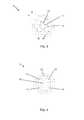
- FIG. 3is an end view showing the external surface of the tip or distal end of the first embodiment.
- FIG. 4is an opposite end view showing the internal surface of the tip or distal end and the central opening of the hollow cylindrical body of the first embodiment.
- FIG. 5is a second perspective view of the first embodiment showing the proximal end.
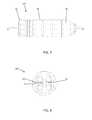
- FIG. 6is a perspective view of a second embodiment of the present invention.
- FIG. 7is a side plan view of the second embodiment.
- FIG. 8is an end view showing the external surface of the tip or distal end of the second embodiment.
- FIG. 9is an opposite end view showing the internal surface of the tip or distal end and the central opening of the hollow cylindrical body of the second embodiment.
- FIG. 10is a second perspective view of the second embodiment showing the proximal end.
- a first embodiment suture anchor 10is illustrated.
- the suture anchor 10is designed to hold at least two sutures in channels 21 and 22 .
- a single suturecan be retained in the channel 21 , 22 which is a recessed groove in the tip 20 as illustrated.
- the tip 20is an integral portion of the suture anchor body 30 .
- the suture anchor body 30has external ribs or threads 32 projecting outwardly therefrom. As illustrated, the ribs 32 are spaced from the surface in such a way that they engage the bone for attachment on insertion of the suture anchor 10 .
- the suture anchor 10can be placed in a pre-drilled hole then pressed into position as illustrated.
- FIG. 2a plan view of the suture anchor 10 is illustrated.
- the distal end or tip 20is illustrated and an axis A is shown extending through the longitudinal length of the body 30 .
- the external surface of the tip 20is illustrated for the suture anchor 10 .
- the recess channels 21 , 22are shown crossing in an “X” configuration and intersecting at the location 23 .
- the recess 21is cut into the tip 20 to a recess depth of approximately 2.5 mm.
- the other channel 22is recessed approximately 1.25 mm deep.
- the suture channels 21 , 22cross at offset depth levels such that the opening pairs 52 of channel 22 are deeper than the openings 54 of channel 21 .
- the sutureis then looped back through the complimentary pair of openings 52 , 54 depending on the channel in which it resides in such a way that it is securely positioned and a portion of the suture will lie in the recess preferably at a surface level such that it is at or below the external surface of the tip 20 .
- the openings 54are shown and the openings 52 extending into a central opening 50 of the longitudinal body 30 .
- the suturesOnce the sutures pass from the external surface to the inner opening 50 they can extend outward to the surface wherein soft tissue can be attached using the sutures to affix the suture to the bone anchor when the bone anchor is positioned to a certain depth within a pre-drilled hole.
- FIG. 5a second perspective view is shown showing the proximal end of the elongated body 30 with the opening 50 .
- the sutureswill extend as indicated when the bone anchor 10 is pushed to a desired depth into the bone opening with the sutures pre-attached they can be used to reattach soft tissue to the anatomically correct location.
- the rib 32 designcan be alternated such that they are widely spaced toward the distal tip or end 20 and then more compactly spaced at the proximal end.
- the proximal endwill engage the cortical bone at the surface and therefore can be designed with more ribs 32 so that a tight secure fit can be maintained.
- the suture anchor 10 Ahas channels 21 , 22 that are parallel and do not cross the axis A, but are offset a distance relative to the axis A.
- the channels 21 , 22do not intersect and as such the sutures can be extended through the tip end 20 through the openings 52 , 54 as previously discussed.
- the portion of the suture that loops through the ends 52 or 54 within each respective channel 21 , 22will lie in the tip preferably at the depth of approximately 1.25 mm in such a fashion that the suture lies at or slightly below the exterior surface of the tip 20 .
- the channels 21 , 22are of equal depth.
- both the first and second embodimentsare ideally suited to be placed into a pre-drilled opening through the bone in order to attach to the soft tissue. This can be done as mentioned either by pressing the bone anchor into position or by threading it depending on the configuration of the ribs or threads 32 on the anchor body.
Landscapes
- Health & Medical Sciences (AREA)
- Surgery (AREA)
- Life Sciences & Earth Sciences (AREA)
- Biomedical Technology (AREA)
- Nuclear Medicine, Radiotherapy & Molecular Imaging (AREA)
- Engineering & Computer Science (AREA)
- Rheumatology (AREA)
- Heart & Thoracic Surgery (AREA)
- Medical Informatics (AREA)
- Molecular Biology (AREA)
- Animal Behavior & Ethology (AREA)
- General Health & Medical Sciences (AREA)
- Public Health (AREA)
- Veterinary Medicine (AREA)
- Surgical Instruments (AREA)
Abstract
Description
Claims (4)
Priority Applications (2)
| Application Number | Priority Date | Filing Date | Title |
|---|---|---|---|
| US14/526,938US10022115B2 (en) | 2014-10-29 | 2014-10-29 | Two suture anchor |
| US14/676,429US9241704B1 (en) | 2014-10-29 | 2015-04-01 | Two suture anchor |
Applications Claiming Priority (1)
| Application Number | Priority Date | Filing Date | Title |
|---|---|---|---|
| US14/526,938US10022115B2 (en) | 2014-10-29 | 2014-10-29 | Two suture anchor |
Related Child Applications (1)
| Application Number | Title | Priority Date | Filing Date |
|---|---|---|---|
| US14/676,429ContinuationUS9241704B1 (en) | 2014-10-29 | 2015-04-01 | Two suture anchor |
Publications (2)
| Publication Number | Publication Date |
|---|---|
| US20160120533A1 US20160120533A1 (en) | 2016-05-05 |
| US10022115B2true US10022115B2 (en) | 2018-07-17 |
Family
ID=55085982
Family Applications (2)
| Application Number | Title | Priority Date | Filing Date |
|---|---|---|---|
| US14/526,938Active2035-05-25US10022115B2 (en) | 2014-10-29 | 2014-10-29 | Two suture anchor |
| US14/676,429ActiveUS9241704B1 (en) | 2014-10-29 | 2015-04-01 | Two suture anchor |
Family Applications After (1)
| Application Number | Title | Priority Date | Filing Date |
|---|---|---|---|
| US14/676,429ActiveUS9241704B1 (en) | 2014-10-29 | 2015-04-01 | Two suture anchor |
Country Status (1)
| Country | Link |
|---|---|
| US (2) | US10022115B2 (en) |
Cited By (2)
| Publication number | Priority date | Publication date | Assignee | Title |
|---|---|---|---|---|
| USD914213S1 (en)* | 2019-10-07 | 2021-03-23 | Maruho Medical, Inc. | Suture anchor |
| USD914212S1 (en)* | 2019-10-07 | 2021-03-23 | Maruho Medical, Inc. | Suture anchor |
Families Citing this family (2)
| Publication number | Priority date | Publication date | Assignee | Title |
|---|---|---|---|---|
| KR102241125B1 (en)* | 2019-01-21 | 2021-04-16 | 아주약품(주) | Orthopedic anchor and anchor fastening member, one-piece surgical tool |
| US12042139B2 (en)* | 2021-04-27 | 2024-07-23 | Medos International Sarl | Knotless suture anchors |
Citations (18)
| Publication number | Priority date | Publication date | Assignee | Title |
|---|---|---|---|---|
| US5037422A (en) | 1990-07-02 | 1991-08-06 | Acufex Microsurgical, Inc. | Bone anchor and method of anchoring a suture to a bone |
| US5480403A (en) | 1991-03-22 | 1996-01-02 | United States Surgical Corporation | Suture anchoring device and method |
| US5647874A (en) | 1982-05-20 | 1997-07-15 | John O. Hayhurst | Anchoring and manipulating tissue |
| US5720765A (en) | 1995-06-06 | 1998-02-24 | Thal; Raymond | Knotless suture anchor assembly |
| US5980558A (en) | 1997-09-30 | 1999-11-09 | Biomet Inc. | Suture anchor system |
| US6146406A (en) | 1998-02-12 | 2000-11-14 | Smith & Nephew, Inc. | Bone anchor |
| US6517542B1 (en) | 1999-08-04 | 2003-02-11 | The Cleveland Clinic Foundation | Bone anchoring system |
| US6641596B1 (en) | 2000-10-18 | 2003-11-04 | Ethicon, Inc. | Knotless bioabsorbable suture anchor system and method |
| US6641597B2 (en) | 2001-05-25 | 2003-11-04 | Arthrex, Inc. | Interference fit knotless suture anchor fixation |
| US20050222619A1 (en)* | 2004-04-06 | 2005-10-06 | Arthrex, Inc. | Suture anchor with apertures at tip |
| US20090076544A1 (en)* | 2007-09-14 | 2009-03-19 | Depuy Mitek, Inc. | Dual thread cannulated suture anchor |
| US20110313453A1 (en) | 2007-08-24 | 2011-12-22 | C2M Medical, Inc. | Bone anchor comprising a shape memory element and utilizing temperature transition to secure the bone anchor in bone |
| US8114128B2 (en) | 2006-11-01 | 2012-02-14 | Depuy Mitek, Inc. | Cannulated suture anchor |
| US20120053626A1 (en)* | 2010-02-17 | 2012-03-01 | Koepke Ryan D | Fully threaded suture anchor with internal, recessed eyelets |
| US20120078300A1 (en)* | 2010-09-24 | 2012-03-29 | Sportwelding Gmbh | Suture anchor and method for fixating a suture relative to hard tissue |
| US8613756B2 (en) | 2009-10-30 | 2013-12-24 | Depuy Mitek, Llc | Knotless suture anchor |
| US8663325B2 (en) | 2009-07-09 | 2014-03-04 | Smith & Nephew, Inc. | Tissue graft anchor assembly and instrumentation for use therewith |
| US20140277127A1 (en)* | 2013-03-13 | 2014-09-18 | Patrick Burki | Soft tissue fixation system |
- 2014
- 2014-10-29USUS14/526,938patent/US10022115B2/enactiveActive
- 2015
- 2015-04-01USUS14/676,429patent/US9241704B1/enactiveActive
Patent Citations (19)
| Publication number | Priority date | Publication date | Assignee | Title |
|---|---|---|---|---|
| US5647874A (en) | 1982-05-20 | 1997-07-15 | John O. Hayhurst | Anchoring and manipulating tissue |
| US5037422A (en) | 1990-07-02 | 1991-08-06 | Acufex Microsurgical, Inc. | Bone anchor and method of anchoring a suture to a bone |
| US5480403A (en) | 1991-03-22 | 1996-01-02 | United States Surgical Corporation | Suture anchoring device and method |
| US5720765A (en) | 1995-06-06 | 1998-02-24 | Thal; Raymond | Knotless suture anchor assembly |
| US5980558A (en) | 1997-09-30 | 1999-11-09 | Biomet Inc. | Suture anchor system |
| US6146406A (en) | 1998-02-12 | 2000-11-14 | Smith & Nephew, Inc. | Bone anchor |
| US6517542B1 (en) | 1999-08-04 | 2003-02-11 | The Cleveland Clinic Foundation | Bone anchoring system |
| US6641596B1 (en) | 2000-10-18 | 2003-11-04 | Ethicon, Inc. | Knotless bioabsorbable suture anchor system and method |
| US6641597B2 (en) | 2001-05-25 | 2003-11-04 | Arthrex, Inc. | Interference fit knotless suture anchor fixation |
| US20050222619A1 (en)* | 2004-04-06 | 2005-10-06 | Arthrex, Inc. | Suture anchor with apertures at tip |
| US8114128B2 (en) | 2006-11-01 | 2012-02-14 | Depuy Mitek, Inc. | Cannulated suture anchor |
| US8597328B2 (en) | 2006-11-01 | 2013-12-03 | Depuy Mitek, Llc | Cannulated suture anchor |
| US20110313453A1 (en) | 2007-08-24 | 2011-12-22 | C2M Medical, Inc. | Bone anchor comprising a shape memory element and utilizing temperature transition to secure the bone anchor in bone |
| US20090076544A1 (en)* | 2007-09-14 | 2009-03-19 | Depuy Mitek, Inc. | Dual thread cannulated suture anchor |
| US8663325B2 (en) | 2009-07-09 | 2014-03-04 | Smith & Nephew, Inc. | Tissue graft anchor assembly and instrumentation for use therewith |
| US8613756B2 (en) | 2009-10-30 | 2013-12-24 | Depuy Mitek, Llc | Knotless suture anchor |
| US20120053626A1 (en)* | 2010-02-17 | 2012-03-01 | Koepke Ryan D | Fully threaded suture anchor with internal, recessed eyelets |
| US20120078300A1 (en)* | 2010-09-24 | 2012-03-29 | Sportwelding Gmbh | Suture anchor and method for fixating a suture relative to hard tissue |
| US20140277127A1 (en)* | 2013-03-13 | 2014-09-18 | Patrick Burki | Soft tissue fixation system |
Non-Patent Citations (1)
| Title |
|---|
| American Journal of SPorts Medicine, vol. 33, No. 6, 2004; Suture Anchor Design, Bone Density and Pull out Strength.* |
Cited By (2)
| Publication number | Priority date | Publication date | Assignee | Title |
|---|---|---|---|---|
| USD914213S1 (en)* | 2019-10-07 | 2021-03-23 | Maruho Medical, Inc. | Suture anchor |
| USD914212S1 (en)* | 2019-10-07 | 2021-03-23 | Maruho Medical, Inc. | Suture anchor |
Also Published As
| Publication number | Publication date |
|---|---|
| US9241704B1 (en) | 2016-01-26 |
| US20160120533A1 (en) | 2016-05-05 |
Similar Documents
| Publication | Publication Date | Title |
|---|---|---|
| US9265600B2 (en) | Graft fixation | |
| US11576664B2 (en) | Methods for anchoring suture to bone | |
| CA2639507C (en) | Dual thread cannulated suture anchor | |
| US20210100545A1 (en) | Suture anchor | |
| EP2316379B1 (en) | Partial thickness rotator cuff repair system | |
| US20180235596A1 (en) | Threaded suture anchor | |
| ES2325612T3 (en) | SCREW SCREW. | |
| US9241704B1 (en) | Two suture anchor | |
| US8343152B2 (en) | Fixed angle dual prong pin fixation system | |
| US20230329698A1 (en) | Syndesmosis construct | |
| US9492157B2 (en) | Bone anchor apparatus and method | |
| AU6338498A (en) | System for anchoring tissue to bone | |
| US10987143B2 (en) | Flexible screw | |
| JP2018519890A (en) | Suture anchor system with threaded plug | |
| CA2863899C (en) | Suture distal locking for intramedullary nail | |
| JP2019506993A (en) | Implant device | |
| US9526494B1 (en) | Bone anchor delivery system device and method | |
| US20140288595A1 (en) | Soft tissue interference fit anchor system | |
| US20250134517A1 (en) | Suture transfer device | |
| US20130030479A1 (en) | Bone wedge | |
| KR102761914B1 (en) | Easy Start Cannulated Bone Screw | |
| US20160089130A1 (en) | Soft Tissue Attachment | |
| KR200482023Y1 (en) | Omega knot type sleeve anchor | |
| US20130325073A1 (en) | Bone Anchors, Kits, and Methods for Securing Portions of Bone | |
| KR101901516B1 (en) | Suture screw sheath and suturing device including the same |
Legal Events
| Date | Code | Title | Description |
|---|---|---|---|
| AS | Assignment | Owner name:VALERIS MEDICAL, LLC, GEORGIA Free format text:ASSIGNMENT OF ASSIGNORS INTEREST;ASSIGNORS:MACLEOD, WILLIAM ERIC;LANOIS, DANIEL BRIAN;REEL/FRAME:034060/0348 Effective date:20141023 | |
| STCF | Information on status: patent grant | Free format text:PATENTED CASE | |
| AS | Assignment | Owner name:VALERIS MEDICAL, INC., GEORGIA Free format text:CHANGE OF NAME;ASSIGNOR:VALERIS MEDICAL, LLC;REEL/FRAME:052094/0336 Effective date:20161216 | |
| AS | Assignment | Owner name:MARUHO MEDICAL, INC., MASSACHUSETTS Free format text:ASSIGNMENT OF ASSIGNORS INTEREST;ASSIGNOR:VALERIS MEDICAL, INC.;REEL/FRAME:052266/0302 Effective date:20200327 | |
| MAFP | Maintenance fee payment | Free format text:PAYMENT OF MAINTENANCE FEE, 4TH YR, SMALL ENTITY (ORIGINAL EVENT CODE: M2551); ENTITY STATUS OF PATENT OWNER: SMALL ENTITY Year of fee payment:4 | |
| AS | Assignment | Owner name:MEDLINE INDUSTRIES, LP, ILLINOIS Free format text:ASSIGNMENT OF ASSIGNORS INTEREST;ASSIGNOR:MARUHO MEDICAL, INC.;REEL/FRAME:067208/0682 Effective date:20240422 | |
| FEPP | Fee payment procedure | Free format text:ENTITY STATUS SET TO UNDISCOUNTED (ORIGINAL EVENT CODE: BIG.); ENTITY STATUS OF PATENT OWNER: LARGE ENTITY |