US10020850B2 - Master reference for base station network interface sourced from distributed antenna system - Google Patents
Master reference for base station network interface sourced from distributed antenna systemDownload PDFInfo
- Publication number
- US10020850B2 US10020850B2US14/187,115US201414187115AUS10020850B2US 10020850 B2US10020850 B2US 10020850B2US 201414187115 AUS201414187115 AUS 201414187115AUS 10020850 B2US10020850 B2US 10020850B2
- Authority
- US
- United States
- Prior art keywords
- data stream
- unit
- base station
- network interface
- downlink data
- Prior art date
- Legal status (The legal status is an assumption and is not a legal conclusion. Google has not performed a legal analysis and makes no representation as to the accuracy of the status listed.)
- Active
Links
Images


Classifications
- H—ELECTRICITY
- H04—ELECTRIC COMMUNICATION TECHNIQUE
- H04B—TRANSMISSION
- H04B7/00—Radio transmission systems, i.e. using radiation field
- H04B7/02—Diversity systems; Multi-antenna system, i.e. transmission or reception using multiple antennas
- H04B7/022—Site diversity; Macro-diversity
- H04B7/024—Co-operative use of antennas of several sites, e.g. in co-ordinated multipoint or co-operative multiple-input multiple-output [MIMO] systems
- H—ELECTRICITY
- H01—ELECTRIC ELEMENTS
- H01Q—ANTENNAS, i.e. RADIO AERIALS
- H01Q1/00—Details of, or arrangements associated with, antennas
- H01Q1/12—Supports; Mounting means
- H01Q1/22—Supports; Mounting means by structural association with other equipment or articles
- H01Q1/24—Supports; Mounting means by structural association with other equipment or articles with receiving set
- H01Q1/241—Supports; Mounting means by structural association with other equipment or articles with receiving set used in mobile communications, e.g. GSM
- H01Q1/246—Supports; Mounting means by structural association with other equipment or articles with receiving set used in mobile communications, e.g. GSM specially adapted for base stations
- H—ELECTRICITY
- H03—ELECTRONIC CIRCUITRY
- H03J—TUNING RESONANT CIRCUITS; SELECTING RESONANT CIRCUITS
- H03J7/00—Automatic frequency control; Automatic scanning over a band of frequencies
- H03J7/02—Automatic frequency control
- H03J7/04—Automatic frequency control where the frequency control is accomplished by varying the electrical characteristics of a non-mechanically adjustable element or where the nature of the frequency controlling element is not significant
- H—ELECTRICITY
- H04—ELECTRIC COMMUNICATION TECHNIQUE
- H04B—TRANSMISSION
- H04B7/00—Radio transmission systems, i.e. using radiation field
- H04B7/24—Radio transmission systems, i.e. using radiation field for communication between two or more posts
- H04B7/26—Radio transmission systems, i.e. using radiation field for communication between two or more posts at least one of which is mobile
- H—ELECTRICITY
- H04—ELECTRIC COMMUNICATION TECHNIQUE
- H04W—WIRELESS COMMUNICATION NETWORKS
- H04W16/00—Network planning, e.g. coverage or traffic planning tools; Network deployment, e.g. resource partitioning or cells structures
- H04W16/24—Cell structures
- H04W16/28—Cell structures using beam steering
- H—ELECTRICITY
- H04—ELECTRIC COMMUNICATION TECHNIQUE
- H04W—WIRELESS COMMUNICATION NETWORKS
- H04W24/00—Supervisory, monitoring or testing arrangements
- H—ELECTRICITY
- H04—ELECTRIC COMMUNICATION TECHNIQUE
- H04W—WIRELESS COMMUNICATION NETWORKS
- H04W88/00—Devices specially adapted for wireless communication networks, e.g. terminals, base stations or access point devices
- H04W88/08—Access point devices
- H—ELECTRICITY
- H04—ELECTRIC COMMUNICATION TECHNIQUE
- H04B—TRANSMISSION
- H04B1/00—Details of transmission systems, not covered by a single one of groups H04B3/00 - H04B13/00; Details of transmission systems not characterised by the medium used for transmission
- H04B1/38—Transceivers, i.e. devices in which transmitter and receiver form a structural unit and in which at least one part is used for functions of transmitting and receiving
- H04B1/40—Circuits
- H—ELECTRICITY
- H04—ELECTRIC COMMUNICATION TECHNIQUE
- H04W—WIRELESS COMMUNICATION NETWORKS
- H04W56/00—Synchronisation arrangements
Definitions
- DASDistributed Antenna Systems
- a DASmay distribute antennas within a building.
- the antennasare typically connected to a radio frequency (RF) signal source, such as a service provider.
- RFradio frequency
- Various methods of transporting the RF signal from the RF signal source to the antennahave been implemented in the art.
- a distributed antenna systemincludes a first base station network interface unit configured to receive first downlink signals from a first external device external to the distributed antenna system and to convert the first downlink signals into a first downlink data stream; a second base station network interface unit configured to receive second downlink signals from a second external device external to the distributed antenna system and to convert the second downlink signals into a second downlink data stream; and a first remote antenna unit communicatively coupled to the first base station network interface unit and configured to receive at least one of the first downlink data stream from the first base station network interface unit and a first downlink signal derived from the first downlink data stream.
- the first remote antenna unithas a first radio frequency converter configured to convert at least one of the first downlink data stream and the first downlink signal derived from the first downlink data stream into a first radio frequency band signal and a first radio frequency antenna configured to transmit the first radio frequency band signal to a first subscriber unit.
- the distributed antenna systemis configured to transmit a master reference clock to the first external device.
- FIGS. 1A-1Eare block diagrams of exemplary embodiments of distributed antenna systems
- FIGS. 2A-2Jare block diagrams of exemplary embodiments of base station network interfaces used in distributed antenna systems, such as the exemplary distributed antenna systems in FIGS. 1A-1E ;
- FIGS. 3A-3Care block diagrams of exemplary embodiments of distributed antenna switches used in distributed antenna systems, such as the exemplary distributed antenna systems in FIGS. 1A-1E ;
- FIG. 4is a block diagram of an exemplary embodiment of a master host unit used in distributed antenna systems, such as the exemplary distributed antenna systems in FIGS. 1A-1E ;
- FIG. 5is a block diagram of an exemplary embodiment of a remote antenna unit used in distributed antenna systems, such as the exemplary distributed antenna systems in FIGS. 1A-1E ;
- FIGS. 6A-6Care block diagrams of exemplary embodiments of RF conversion modules used in remote antenna units of distributed antenna systems, such as the exemplary remote antenna unit in FIG. 5 ;
- FIG. 7is a block diagram of an exemplary embodiment of a hybrid distributed antenna system
- FIG. 8is a block diagram of an exemplary embodiment of a hybrid expansion unit used in hybrid distributed antenna systems, such as the hybrid distributed antenna system in FIG. 7 ;
- FIG. 9is a block diagram of an exemplary embodiment of a remote antenna unit used in hybrid or analog distributed antenna systems, such as the exemplary hybrid distributed antenna system in FIG. 7 ;
- FIGS. 10A-10Care block diagrams of exemplary embodiments of RF conversion modules used in hybrid or analog remote antenna units of hybrid or analog distributed antenna systems, such as the exemplary remote antenna unit in FIG. 9 ;
- FIG. 11is a flow diagram illustrating one exemplary embodiment of a method of sourcing a master reference clock for a base station network interface from a distributed antenna system.
- the embodiments described belowdescribe a distributed antenna system and components within the distributed antenna system.
- the distributed antenna systemis connected to a plurality of external devices through a plurality of base station network interface units.
- at least one base station network interface unit of the distributed antenna systemprovides a master reference clock to at least one of the external devices.
- the master reference clockis generated within the distributed antenna system.
- the master reference clockis derived from another external device through another base station network interface unit.
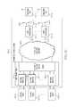
- FIGS. 1A-1Eare block diagrams of exemplary embodiments of distributed antenna systems 100 . Each of FIGS. 1A-1E illustrates a different embodiment of a distributed antenna system 100 , labeled 100 A- 100 E respectively.
- FIG. 1Ais a block diagram of an exemplary embodiment of a distributed antenna system 100 , distributed antenna system 100 A.
- Distributed antenna system 100 Aincludes a plurality of network interfaces 102 (including network interface 102 - 1 , network interface 102 - 2 , and any amount of optional network interfaces 102 through optional network interface 102 -A), at least one remote antenna unit 104 (including remote antenna unit 104 - 1 and any amount of optional remote antenna units 104 through optional remote antenna unit 104 -B), and a distributed switching network 106 .
- Each network interface 102is communicatively coupled to an external device 108 that is configured to provide signals to be transported through the distributed antenna system 100 A to the network interface 102 .
- each network interface 102is configured to receive signals from at least one external device 108 .
- network interface 102 - 1is communicatively coupled to external device 108 - 1
- network interface 102 - 2is communicatively coupled to external device 108 - 2
- optional network interface 102 -Ais communicatively coupled to optional external device 108 -A.
- Each network interface 102is also communicatively coupled to the distributed switching network 106 across a digital communication link 110 .
- network interface 102 - 1is communicatively coupled to the distributed switching network 106 across digital communication link 110 - 1
- network interface 102 - 2is communicatively coupled to the distributed switching network 106 across digital communication link 110 - 2
- optional network interface 102 -Ais communicatively coupled to the distributed switching network 106 across digital communication link 110 -A.
- each network interface 102is configured to convert signals from the external device 108 to which it is communicatively coupled into a downlink data stream and further configured to communicate the downlink data stream to the distributed switching network 106 (either directly or through other components of the distributed antenna system 100 ) across a respective digital communication link 110 .
- each network interface 102is configured to receive uplink data streams across a respective digital communication link 110 from distributed switching network 106 .
- Each network interface 102is further configured to convert the received uplink data stream to signals formatted for the associated external device 108 and further configured to communicate the signals formatted for the associated external device 108 to the associated external device 108 .
- Distributed switching network 106couples the plurality of network interfaces 102 with the at least one remote antenna unit 104 .
- Distributed switching network 106may include one or more distributed antenna switches or other components that functionally distribute downlink signals from the network interfaces 102 to the at least one remote antenna unit 104 .
- Distributed switching network 106also functionally distributes uplink signals from the at least one remote antenna unit 104 to the network interfaces 102 .
- the distributed switching network 106can be controlled by a separate controller or another component of the system.
- the switching elements of the distributed switching network 106are controlled either manually or automatically.
- the routescan be pre-determined and static. In other exemplary embodiments, the routes can dynamically change based on time of day, load, or other factors.
- Each remote antenna unit 104is communicatively coupled to the distributed switching network 106 across a digital communication link 112 .
- remote antenna unit 104 - 1is communicatively coupled to the distributed switching network 106 across digital communication link 112 - 1
- optional remote antenna unit 104 -Bis communicatively coupled to the distributed switching network 106 across digital communication link 112 -B.
- Each remote antenna unit 104includes components configured for extracting at least one downlink data stream from an aggregate downlink data stream and components configured for aggregating at least one uplink data stream into an aggregate uplink data stream as well as at least one radio frequency converter configured to convert between at least one data stream and at least one radio frequency band and at least one radio frequency antenna 114 configured to transmit and receive signals in the at least one radio frequency band to at least one subscriber unit 116 .
- each remote antenna unit 104is configured to extract at least one downlink data stream from the downlink aggregate data stream.
- Each remote antenna unit 104is further configured to convert the at least one downlink data stream into a downlink radio frequency (RF) signal in a radio frequency band. In exemplary embodiments, this may include digital to analog converters and oscillators.
- RFradio frequency
- Each remote antenna unit 104is further configured to transmit the downlink radio frequency signal in the radio frequency band to at least one subscriber unit using at least one radio frequency antenna 114 .
- remote antenna unit 104 - 1is configured to extract at least one downlink data stream from the downlink aggregate data stream received from the distributed antenna switch 102 and further configured to convert the at least one downlink data stream into a downlink radio frequency signal in a radio frequency band.
- Remote antenna unit 104 - 1is further configured to transmit the downlink radio frequency signal in a radio frequency band using a radio frequency band antenna 114 - 1 to at least one subscriber unit 116 - 1 .
- remote antenna unit 104 - 1is configured to extract a plurality of downlink data streams from the downlink aggregate data stream received from the distributed switching network 106 and configured to convert the plurality of downlink data streams to a plurality of downlink radio frequency signals.
- the remote antenna unit 104 - 1is further configured to transmit the downlink radio frequency signal in at least one radio frequency band to at least subscriber unit 116 - 1 using at least radio frequency antenna 114 - 1 .
- the remote antenna unit 104 - 1is configured to transmit one downlink radio frequency signal to one subscriber unit 116 - 1 using an antenna 114 - 1 and another radio frequency signal to another subscriber unit 116 -D using another antenna 114 -C.
- other combinations of radio frequency antennas 114 and other componentsare used to communicate other combinations of radio frequency signals in other various radio frequency bands to various subscriber units 116 .
- each remote antenna unit 104is configured to receive uplink radio frequency signals from at least one subscriber unit 116 using at least one radio frequency antenna 114 .
- Each remote antenna unit 104is further configured to convert the radio frequency signals to at least one uplink data stream.
- Each remote antenna unit 104is further configured to aggregate the at least one uplink data stream into an aggregate uplink data stream and further configured to communicate the aggregate uplink data stream across at least one digital communication link 112 to the distributed switching network 106 .
- a master reference clockis distributed between the various components of the distributed antenna system 100 A to keep the various components locked to the same clock.
- a master reference clockis provided to at least one external device 108 via at least one network interface 102 so that the external device can lock to the master reference clock as well.
- the master reference clockis provided from at least one external device to the distributed antenna system 100 A via at least one network interface 102 .
- the master reference clockis generated within a component of the distributed antenna system, such as a network interface 102 , a remote antenna unit 104 , or somewhere within the distributed switching network 106 .
- FIG. 1Bis a block diagram of an exemplary embodiment of a distributed antenna system 100 , distributed antenna system 100 B.
- Distributed antenna system 100 Bincludes a plurality of network interfaces 102 (including network interface 102 - 1 , network interface 102 - 2 , and any amount of optional network interfaces 102 through optional network interface 102 -A), at least one remote antenna unit 104 (including remote antenna unit 104 - 1 and any amount of optional remote antenna units 104 through optional remote antenna unit 104 -B), and a distributed switching network 106 .
- Distributed antenna system 100 Bincludes similar components to distributed antenna system 100 A and operates according to similar principles and methods as distributed antenna system 100 A described above. The difference between distributed antenna system 100 B and distributed antenna system 100 A is that both digital communication links 110 and digital communication links 112 are optical communication links.
- FIG. 1Cis a block diagram of an exemplary embodiment of a distributed antenna system 100 , distributed antenna system 100 C.
- Distributed antenna system 100 Cincludes a plurality of network interfaces 102 (including network interface 102 - 1 , network interface 102 - 2 , and any amount of optional network interfaces 102 through optional network interface 102 -A), at least one remote antenna unit 104 (including remote antenna unit 104 - 1 and any amount of optional remote antenna units 104 through optional remote antenna unit 104 -B), and a distributed antenna switch 118 A.
- Distributed antenna system 100 Cincludes similar components to distributed antenna system 100 A and operates according to similar principles and methods as distributed antenna system 100 A described above.
- the difference between distributed antenna system 100 B and distributed antenna system 100 Ais that both digital communication links 110 and digital communication links 112 are optical communication links and that a distributed antenna switch 118 A replaces the distributed switching network 106 .
- Each network interface 102is communicatively coupled to the distributed antenna switch 118 A across a digital communication medium 110 .
- Each antenna unit 104is also communicatively coupled to the distributed antenna switch 118 A across a digital communication medium 110 .
- the distributed antenna switch 118 Acan be controlled by a separate controller or another component of the system.
- the distributed antenna switch 118 Ais controlled either manually or automatically.
- the routescan be pre-determined and static. In other exemplary embodiments, the routes can dynamically change based on time of day, load, or other factors.
- the distributed antenna switch 118 Adistributes and/or routes downlink signals received from the network interfaces 102 to the at least one remote antenna unit 104 .
- downlink data streams from a plurality of network interfacesare aggregated by the distributed antenna switch into an aggregate downlink data stream that is communicated to the at least one remote antenna unit 104 .
- the distributed antenna switch 118 Adistributes and/or routes uplink signals received from the at least one remote antenna unit 104 to the plurality of network interfaces 102 .
- an aggregate uplink data stream from at least one remote antenna unit 104is split apart into a plurality of uplink data streams by the distributed antenna switch 118 A and communicated to the plurality of network interfaces 102 .
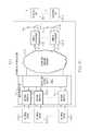
- FIG. 1Dis a block diagram of an exemplary embodiment of a distributed antenna system 100 , distributed antenna system 100 D.
- Distributed antenna system 100 Dincludes a master host unit 120 having a plurality of network interfaces 102 (including network interface 102 - 1 , network interface 102 - 2 , and any amount of optional network interfaces 102 through optional network interface 102 -A), a distributed antenna switch 118 B, at least one remote antenna unit 104 (including remote antenna unit 104 - 1 and any amount of optional remote antenna units 104 through optional remote antenna unit 104 -B), and a distributed switching network 106 .
- Distributed antenna system 100 Cincludes similar components to distributed antenna systems 100 A- 100 C and operates according to similar principles and methods as distributed antenna systems 100 A- 100 C described above.
- the difference between distributed antenna system 100 D and distributed antenna system 100 Cis that the network interfaces 102 and the distributed antenna switch 118 B are included within a master host unit that is communicatively coupled to the remote antenna units 104 by the distributed switching network 106 .
- the distributed antenna switch 118 Bcan be controlled by a separate controller or another component of the system.
- the distributed antenna switch 118 Bis controlled either manually or automatically.
- the routescan be pre-determined and static. In other exemplary embodiments, the routes can dynamically change based on time of day, load, or other factors.
- the distributed antenna switch 118 Bdistributes and/or routes downlink signals received from the network interfaces 102 to the at least one remote antenna unit 104 through the distributed switching network 106 .
- downlink data streams from a plurality of network interfacesare aggregated by the distributed antenna switch 118 B into an aggregate downlink data stream that is communicated to the at least one remote antenna unit 104 via the distributed switching network.
- the distributed antenna switch 118 Adistributes and/or routes uplink signals received from the at least one remote antenna unit 104 to the plurality of network interfaces 102 .
- an aggregate uplink data stream received from at least one remote antenna unit 104 via the distributed switching network 106is split apart into a plurality of uplink data streams by the distributed antenna switch 118 B and communicated to the plurality of network interfaces 102 .
- FIG. 1Eis a block diagram of an exemplary embodiment of a distributed antenna system 100 , distributed antenna system 100 E.
- Distributed antenna system 100 Eincludes a master host unit 120 having a plurality of network interfaces 102 (including network interface 102 - 1 , network interface 102 - 2 , and any amount of optional network interfaces 102 through optional network interface 102 -A), a distributed antenna switch 118 C, at least one remote antenna unit 104 (including remote antenna unit 104 - 1 and any amount of optional remote antenna units 104 through optional remote antenna unit 104 -B), and a distributed switching network 106 .
- Distributed antenna system 100 Eincludes similar components to distributed antenna systems 100 A- 100 D and operates according to similar principles and methods as distributed antenna systems 100 A- 100 D described above. The difference between distributed antenna system 100 E and distributed antenna system 100 D is that digital communication links 112 are optical communication links.
- FIGS. 2A-2Jare block diagrams of exemplary embodiments of base station network interfaces 102 used in distributed antenna systems, such as the exemplary distributed antenna systems 100 described above. Each of FIGS. 2A-2J illustrates a different embodiment of a type of base station network interface 102 , labeled 104 A- 104 D respectively.
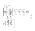
- FIG. 2Ais a block diagram of an exemplary embodiment of a base station network interface 102 , general base station network interface 102 A.
- General base station network interface 102 Aincludes signal to data stream conversion module 202 A, network interface clock unit 204 A, optional processor 206 , optional memory 208 , and optional power supply 210 .
- signal to data stream conversion module 202 Ais communicatively coupled to an external device output 212 A of an external device 108 A.
- Signal to data stream conversion module 202 Ais also communicatively coupled to at least one digital communication link 110 .
- the digital communication link 110is an optical communication link across a fiber optic cable, though it can also be other types of wired or wireless links in other embodiments.
- the signal to data stream conversion module 202 A and/or the network interface clock unit 204 Aare implemented using optional processor 206 and optional memory 208 .
- the optional power supply 210provides power to the various elements of the base station network interface 102 A.
- signal to data stream conversion module 202 Ais configured to receive downlink signals from the external device output 212 A of the external device 108 A.
- the signal to data stream conversion module 202 Ais further configured to convert the received downlink signals to a downlink data stream.
- the signal to data stream conversion module 202 Afurther converts the data stream from electrical signals to optical signals for output on digital communication link 110 .
- the data streamis transported using a conductive communication medium, such as coaxial cable or twisted pair, and the optical conversion is not necessary.
- signal to data stream conversion module 202 Ais configured to receive an uplink data stream from digital communication link 110 .
- digital communication link 110is an optical medium
- the radio frequency to optical data stream conversion module 202 Ais configured to convert the uplink data stream between received optical signals and electrical signals.
- the data streamis transported using a conductive communication medium, such as coaxial cable or twisted pair, and the optical conversion is not necessary.
- the signal to data stream conversion module 202 Ais further configured to convert the uplink data stream to uplink signals.
- Signal to data stream conversion module 202 Ais further configured to communicate the uplink signals to the external device output 212 A of the external device 108 A.
- the network interface clock unit 204 Ais communicatively coupled to an external device clock unit 214 A of the external device 108 A.
- a master reference clockis provided to the external device clock unit 214 A of the external device 108 A from the network interface clock unit 204 A of the base station network interface 102 A.
- a master reference clockis provided from the external device clock unit 214 A of the external device 108 A to the network interface clock unit 204 A of the base station network interface 102 A.
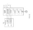
- FIG. 2Bis a block diagram of an exemplary embodiment of a type of base station interface 102 , general base station network interface 102 B.
- General base station network interface 102 Bincludes signal to data stream conversion module 202 B, network interface clock unit 204 B, optional processor 206 , optional memory 208 , and optional power supply 210 .
- signal to data stream conversion module 202 Bis communicatively coupled to an external device output 212 B of an external device 108 B.
- base station network interface clock unit 204 Bis not coupled directly to external device clock unit 214 B of external device 108 B to provide the master reference clock to the external device 108 B. Instead, network interface clock unit 204 B provides the master reference clock to the signal to data stream conversion module 202 B and the master reference clock is embedded in the upstream signal from the signal to data stream conversion module 202 B to the external device output 212 B of external device 108 B.
- uplink signalscan be clocked using the master clock, such that the master clock is embedded in the uplink signals.
- external device clock unit 214 Bextracts the master clock from uplink signals and distributes the master clock as appropriate in the external device 108 B to establish a common clock with the distributed antenna system in the external device 108 B.
- the master reference clockcan be embedded in the downlink signals by the external device clock unit 214 B so that the downlink signals communicated from the external device output 212 B of the external device 108 B to the signal to data stream conversion module 202 B can be extracted by the network interface clock unit 204 B and distributed as appropriate within the network interface 102 B and the distributed antenna system 100 generally.
- the signal to data stream conversion module 202 B and/or the network interface clock unit 204 Bare implemented using optional processor 206 and optional memory 208 .
- the optional power supply 210provides power to the various elements of the base station network interface 102 B.
- FIG. 2Cis a block diagram of an exemplary embodiment of a type of base station network interface 102 , radio frequency (RF) network interface 102 C.
- Radio frequency network interface 102 Cincludes a radio frequency (RF) to data stream conversion module 202 C, a radio frequency (RF) network interface clock unit 204 C, an optional processor 206 , optional memory 208 , and an optional power supply 210 .
- radio frequency (RF) to data stream conversion module 202 Cis communicatively coupled to a radio frequency (RF) base station output 212 C of an external device that is a radio frequency base station 108 C.
- Radio frequency to data stream conversion module 202 Cis also communicatively coupled to at least one digital communication link 110 .
- the radio frequency to data stream conversion module 202 C and/or the radio frequency network interface clock unit 204 Care implemented using optional processor 206 and optional memory 208 .
- the optional power supply 210provides power to the various elements of the radio frequency network interface 102 C.
- radio frequency to data stream conversion module 202 Cis configured to receive radio frequency signals from the radio frequency base station output 212 C of the radio frequency base station 108 C.
- the radio frequency to data stream conversion module 202 Cis further configured to convert the received radio frequency signals to a downlink data stream. In exemplary embodiments, this is done using oscillators and mixers.
- the radio frequency to data stream conversion module 202 Cfurther converts the data stream from electrical signals to optical signals for output on digital communication link 110 .
- the data streamis transported using a conductive communication medium, such as coaxial cable or twisted pair, and the optical conversion is not necessary.
- radio frequency to data stream conversion module 202 Cis configured to receive a data stream across digital communication link 110 .
- digital communication link 110is an optical medium
- the radio frequency to data stream conversion module 202 Cis configured to convert the uplink data streams between received optical signals and electrical signals.
- the data streamis transported using a conductive communication medium, such as coaxial cable or twisted pair, and the optical conversion is not necessary.
- the radio frequency to data stream conversion moduleis further configured to convert the uplink data stream to radio frequency signals. In exemplary embodiments, this is done using oscillators and mixers.
- Radio frequency to data stream conversion module 202 Cis further configured to communicate the uplink radio frequency signals to the radio frequency base station output 212 C of the radio frequency base station 108 C.
- the radio frequency network interface clock unit 204 Cis communicatively coupled to a radio frequency base station clock unit 214 C of the radio frequency base station 108 C.
- a master reference clockis provided to the radio frequency base station clock unit 214 C of the radio frequency base station 108 C from the radio frequency network interface clock unit 204 C of the base station network interface 102 C.
- a master reference clockis provided from the radio frequency base station clock unit 214 C of the radio frequency base station 108 C to the radio frequency network interface clock unit 204 C of the radio frequency network interface 102 C.
- FIG. 2Dis a block diagram of an exemplary embodiment of a type of base station interface 102 , radio frequency (RF) network interface 102 D.
- Radio frequency network interface 102 Dincludes a radio frequency (RF) to data stream conversion module 202 D, a radio frequency (RF) network interface clock unit 204 D, an optional processor 206 , optional memory 208 , and an optional power supply 210 .
- radio frequency (RF) to data stream conversion module 202 Dis communicatively coupled to a radio frequency (RF) base station output 212 D of an external device that is a radio frequency base station 108 D and to at least one digital communication link 110 .
- RFradio frequency
- radio frequency network interface clock unit 204 Dis not coupled directly to radio frequency base station clock unit 214 D of radio frequency base station 108 D to provide and/or receive the master reference clock to/from the radio frequency base station 108 D. Instead, radio frequency network interface clock unit 204 C provides the master reference clock to the radio frequency to data stream conversion module 202 D and the master reference clock is embedded in upstream signals from the radio frequency to data stream conversion module 202 D to the radio frequency base station output 212 D of radio frequency base station 108 D.
- uplink signalscan be clocked using the master clock, such that the master clock is embedded in the uplink signals.
- radio frequency base station clock unit 214 Dextracts the master clock from uplink signals and distributes the master clock as appropriate in the radio frequency base station 108 D to establish a common clock with the distributed antenna system 100 in the radio frequency base station 108 D.
- the master reference clockcan be embedded in the downlink signals by the radio frequency base station clock unit 214 D so that the downlink signals communicated from the radio frequency base station output 212 D of the radio frequency base station 108 D to the radio frequency to data stream conversion module 202 D can be extracted by the radio frequency network interface clock unit 204 D and distributed as appropriate within the radio frequency network interface 102 D and the distributed antenna system 100 generally.
- the radio frequency to data stream conversion module 202 D and/or the radio frequency network interface clock unit 204 Dare implemented using optional processor 206 and optional memory 208 .
- the optional power supply 210provides power to the various elements of the base station network interface 102 D.
- FIG. 2Eis a block diagram of an exemplary embodiments of a type of base station network interface 102 , baseband network interface 102 E.
- Baseband network interface 102 Eincludes a baseband to data stream conversion module 202 E, a baseband network interface clock unit 204 E, an optional processor 206 , optional memory 208 , and an optional power supply 210 .
- baseband to data stream conversion module 202 Eis communicatively coupled to a baseband base station output 212 E of an external device that is a baseband base station 108 E.
- Baseband to data stream conversion module 202 Eis also communicatively coupled to at least one digital communication link 110 .
- the baseband to data stream conversion module 202 E and/or the baseband network interface clock unit 204 Eare implemented using optional processor 206 and optional memory 208 .
- the optional power supply 210provides power to the various elements of the baseband network interface 102 E.
- baseband to data stream conversion module 202 Eis configured to receive baseband mobile wireless access signals (such as I/Q data) from a baseband base station output 212 E of a baseband base station 108 E.
- the baseband to data stream conversion module 202 Eis further configured to convert the received baseband mobile wireless access signals to a downlink data stream.
- the baseband to data stream conversion module 202 Efurther converts the data stream from electrical signals to optical signals for output on the digital communication link 110 .
- the data streamis transported using a conductive communication medium, such as coaxial cable or twisted pair, and the optical conversion is not necessary.
- baseband to data stream conversion module 202 Eis configured to receive a data stream across digital communication link 110 .
- digital communication link 110is an optical medium
- the baseband to data stream conversion module 202 Eis configured to convert the uplink data stream between received optical signals and electrical signals.
- the data streamis transported using a conductive communication medium, such as coaxial cable or twisted pair, and the optical conversion is not necessary.
- the baseband to data stream conversion module 202 Eis further configured to convert the uplink data stream to uplink baseband wireless access signals.
- Baseband to data stream conversion module 202 Eis further configured to communicate the uplink baseband wireless access signals to the baseband base station output 212 E.
- the baseband network interface clock unit 204 Eis communicatively coupled to a baseband base station clock unit 214 E of the baseband base station 108 E.
- a master reference clockis provided to the baseband base station clock unit 214 E of the baseband base station 108 E from the baseband network interface clock unit 204 E of the baseband network interface 102 E.
- a master reference clockis provided from the baseband base station clock unit 214 E of the baseband base station 108 E to the baseband network interface clock unit 204 E of the baseband network interface 102 E.
- FIG. 2Fis a block diagram of an exemplary embodiment of a type of base station interface 102 , baseband network interface 102 F.
- Baseband network interface 102 Fincludes a baseband to data stream conversion module 202 F, a baseband network interface clock unit 204 F, an optional processor 206 , optional memory 208 , and an optional power supply 210 .
- baseband to data stream conversion module 202 Fis communicatively coupled to a baseband base station output 212 F of an external device that is a baseband base station 108 F and to at least one digital communication link 110 .
- baseband network interface clock unit 204 Fis not coupled directly to baseband base station clock unit 214 F of baseband base station 108 F to provide and/or receive the master reference clock to/from the baseband base station 108 F. Instead, baseband network interface 102 F provides the master reference clock to the baseband to data stream conversion module 202 F and the master reference clock is embedded in upstream signals from the baseband to data stream conversion module 202 F to the baseband base station output 212 F of baseband base station 108 F.
- uplink signalscan be clocked using the master clock, such that the master clock is embedded in the uplink signals.
- baseband base station clock unit 214 Fextracts the master clock from uplink signals and distributes the master clock as appropriate in the baseband base station 108 F to establish a common clock with the distributed antenna system 100 in the baseband base station 108 F.
- the master reference clockcan be embedded in the downlink signals by the baseband base station clock unit 214 F so that the downlink signals communicated from the baseband base station output 212 F of the baseband base station 108 F to the baseband to data stream conversion module 202 F can be extracted by the baseband network interface clock unit 204 F and distributed as appropriate within the baseband network interface 102 F and the distributed antenna system generally.
- the baseband to data stream conversion module 202 F and/or the baseband network interface clock unit 204 Fare implemented using optional processor 206 and optional memory 208 .
- the optional power supply 210provides power to the various elements of the baseband network interface 102 F.
- FIG. 2Gis a block diagram of an exemplary embodiment of a type of base station network interface 102 , Common Public Radio Interface (CPRI) network interface 102 G.
- CPRI network interface 102 Gincludes a CPRI to data stream conversion module 202 G, a CPRI network interface clock unit 204 G, an optional processor 206 , optional memory 208 , and an optional power supply 210 .
- CPRI to data stream conversion module 202 Gis communicatively coupled to a CPRI base station output 212 G of an external device that is a CPRI base station 108 G.
- CPRI to data stream conversion module 202 Gis also communicatively coupled to at least one digital communication link 110 .
- the CPRI to data stream conversion module 202 G and/or the CPRI network interface clock unit 204 Gare implemented using optional processor 206 and optional memory 208 .
- the optional power supply 210provides power to the various elements of the CPRI network interface 102 G.
- CPRI to data stream conversion module 202 Gis configured to receive CPRI signals from the CPRI base station output 212 G.
- the CPRI to data stream conversion module 202 Gis further configured to convert the received CPRI signals to a downlink data stream.
- the CPRI to data stream conversion module 202 Gfurther converts the data stream from electrical signals to optical signals for output on the digital communication link 110 .
- the data streamis transported using a conductive communication medium, such as coaxial cable or twisted pair, and the optical conversion is not necessary.
- CPRI to data stream conversion module 202 Cis configured to receive a data stream across digital communication link 110 .
- digital communication link 110is an optical medium
- the CPRI to data stream conversion module 202 Gis configured to convert the uplink data stream between received optical signals and electrical signals.
- the data streamis transported using a conductive communication medium, such as coaxial cable or twisted pair, and the optical conversion is not necessary.
- the CPRI to data stream conversion module 202 Gis further configured to convert the uplink data stream to uplink CPRI signals.
- CPRI to data stream conversion module 202 Gis further configured to communicate the uplink CPRI signal to the CPRI base station output 212 G.
- the CPRI network interface clock unit 204 Gis communicatively coupled to a CPRI base station clock unit 214 G of the CPRI base station 108 G.
- a master reference clockis provided to the CPRI base station clock unit 214 G of the CPRI base station 108 G from the CPRI network interface clock unit 204 G of the CPRI network interface 102 G.
- a master reference clockis provided from the CPRI base station clock unit 214 G of the CPRI base station 108 G to the CPRI network interface clock unit 204 E of the CPRI network interface 102 G.
- FIG. 2His a block diagram of an exemplary embodiment of a type of base station interface 102 , CPRI network interface 102 H.
- CPRI network interface 102 Hincludes a CPRI to data stream conversion module 202 H, a CPRI network interface clock unit 204 H, an optional processor 206 , optional memory 208 , and an optional power supply 210 .
- CPRI to data stream conversion module 202 His communicatively coupled to a CPRI base station output 212 H of an external device that is a CPRI base station 108 H and to at least one digital communication link 110 .
- CPRI network interface clock unit 204 His not coupled directly to CPRI base station clock unit 214 G of CPRI base station 108 H to provide and/or receive the master reference clock to/from the CPRI base station 108 H. Instead, CPRI network interface 102 H provides the master reference clock to the CPRI to data stream conversion module 202 H and the master reference clock is embedded in upstream signals from the CPRI to data stream conversion module 202 H to the CPRI base station output 212 H of CPRI base station 108 H.
- uplink signalscan be clocked using the master clock, such that the master clock is embedded in the uplink signals.
- CPRI base station clock unit 214 Hextracts the master clock from uplink signals and distributes the master clock as appropriate in the CPRI base station 108 H to establish a common clock with the distributed antenna system 100 in the CPRI base station 108 H.
- the master reference clockcan be embedded in the downlink signals by the CPRI base station clock unit 214 H so that the downlink signals communicated from the CPRI base station output 212 H of the CPRI base station 108 H to the CPRI to data stream conversion module 202 H can be extracted by the CPRI network interface clock unit 204 H and distributed as appropriate within the CPRI network interface 102 H and the distributed antenna system 100 generally.
- the CPRI to data stream conversion module 202 H and/or the CPRI network interface clock unit 204 Hare implemented using optional processor 206 and optional memory 208 .
- the optional power supply 210provides power to the various elements of the CPRI network interface 102 H.
- FIG. 2Iis a block diagram of an exemplary embodiment of a type of base station network interface 102 , Ethernet network interface 102 I.
- Ethernet network interface 102 Iincludes an Ethernet to data stream conversion module 202 I, an Ethernet network interface clock unit 204 I, an optional processor 206 , optional memory 208 , and an optional power supply 210 .
- Ethernet to data stream conversion module 202 Iis communicatively coupled to an Ethernet output 212 I of an external device that is an Ethernet adapter 108 I to an internet protocol (IP) based network.
- IPinternet protocol
- Ethernet to data stream conversion module 202 Iis also communicatively coupled to at least one digital communication link 110 .
- the Ethernet to data stream conversion module 202 I and/or the Ethernet network interface clock unit 204 Iare implemented using optional processor 206 and optional memory 208 .
- the optional power supply 210provides power to the various elements of the Ethernet network interface 102 I.
- Ethernet to data stream conversion module 202 Iis configured to receive internet protocol packets from the Ethernet output 212 I.
- the Ethernet to data stream conversion module 202 Iis further configured to convert the internet protocol packets to a downlink data stream.
- the Ethernet to data stream conversion module 202 Ifurther converts the data stream from electrical signals to optical signals for output on the digital communication link 110 .
- the data streamis transported using a conductive communication medium, such as coaxial cable or twisted pair, and the optical conversion is not necessary.
- Ethernet to data stream conversion module 202 Iis configured to receive a data stream across digital communication link 110 .
- digital communication link 110is an optical medium
- the Ethernet to data stream conversion module 202 Iis configured to convert the uplink data stream between received optical signals and electrical signals.
- the data streamis transported using a conductive communication medium, such as coaxial cable or twisted pair, and the optical conversion is not necessary.
- the Ethernet to data stream conversion module 202 Iis further configured to convert the uplink data stream to uplink Ethernet frames.
- Ethernet to data stream conversion module 202 Iis further configured to communicate the uplink Ethernet frames to the Ethernet output 204 I.
- the Ethernet network interface clock unit 204 Iis communicatively coupled to an Ethernet adapter clock unit 214 I of the Ethernet adapter 108 I.
- a master reference clockis provided to the Ethernet adapter clock unit 214 I of the Ethernet adapter 108 I from the Ethernet network interface clock unit 204 I of the Ethernet network interface 102 I.
- a master reference clockis provided from the Ethernet adapter clock unit 214 I of the Ethernet adapter 108 I to the Ethernet network interface clock unit 204 I of the Ethernet network interface 102 I.
- FIG. 2Jis a block diagram of an exemplary embodiments of a type of base station interface 102 , an Ethernet network interface 102 J.
- Ethernet network interface 102 Jincludes an Ethernet to data stream conversion module 202 J, an Ethernet network interface clock unit 204 J, an optional processor 206 , optional memory 208 , and an optional power supply 210 .
- Ethernet to data stream conversion module 202 Jis communicatively coupled to an Ethernet output 212 J of an external device that is an Ethernet adapter 108 J and to at least one digital communication link 110 .
- Ethernet network interface clock unit 204 Jis not coupled directly to Ethernet adapter clock unit 214 J of Ethernet adapter 108 J to provide and/or receive the master reference clock to/from the Ethernet adapter 108 J. Instead, Ethernet network interface 102 J provides the master reference clock to the Ethernet to data stream conversion module 202 J and the master reference clock is embedded in upstream signals from the Ethernet to data stream conversion module 202 J to the Ethernet output 212 J of the Ethernet adapter 108 J.
- uplink signalscan be clocked using the master clock, such that the master clock is embedded in the uplink signals.
- Ethernet adapter clock unit 214 Jextracts the master clock from uplink signals and distributes the master clock as appropriate in the Ethernet adapter 108 J to establish a common clock with the distributed antenna system 100 in the Ethernet adapter 108 J.
- the master reference clockcan be embedded in the downlink signals by the Ethernet adapter clock unit 214 J so that the downlink signals communicated from the Ethernet output 212 J of the Ethernet adapter 108 J to the Ethernet to data stream conversion module 202 J can be extracted by the Ethernet network interface clock unit 204 J and distributed as appropriate within the Ethernet network interface 102 J and the distributed antenna system 100 generally.
- the Ethernet to data stream conversion module 202 J and/or the Ethernet network interface clock unit 204 Jare implemented using optional processor 206 and optional memory 208 .
- the optional power supply 210provides power to the various elements of the Ethernet network interface 102 J.
- FIGS. 3A-3Care block diagrams of exemplary embodiments of distributed antenna switches used in distributed antenna systems, such as the exemplary distributed antenna systems 100 described above. Each of FIGS. 3A-3C illustrates a different embodiment of distributed antenna switch 118 , labeled distributed antenna switch 118 A- 118 C respectively.
- FIG. 3Ais a block diagram of an exemplary distributed antenna switch 118 A including a data stream routing unit 302 , electro-optical conversion modules 304 (including electro-optical conversion module 304 - 1 , electro-optical conversion module 304 - 2 , and any amount of optional electro-optical conversion modules 304 through optional electro-optical conversion module 304 -A, and at least one electro-optical conversion module 306 - 1 (and any amount of optional electro-optical conversion modules 306 through optional electro-optical conversion module 306 -B).
- the data stream routing unit 302is implemented using optional processor 308 and optional memory 310 .
- the distributed antenna switch 118 Aincludes optional power supply 312 to power the various elements of the distributed antenna switch 118 A.
- the distributed antenna switch 118 Acan be controlled by a separate controller or another component of the system.
- the distributed antenna switch 118 Ais controlled either manually or automatically.
- the routescan be pre-determined and static. In other exemplary embodiments, the routes can dynamically change based on time of day, load, or other factors.
- Each electro-optical conversion module 304is communicatively coupled to a network interface 102 across a digital communication link 110 .
- each electro-optical conversion module 304is configured to receive a downlink digitized data stream from at least one network interface 102 across a digital communication link 110 .
- electro-optical conversion module 304 - 1is configured to receive a downlink digitized data stream from network interface 102 - 1 across digital communication link 110 - 1
- electro-optical conversion module 304 - 2is configured to receive a downlink digitized data stream from network interface 102 - 2 across digital communication link 110 - 2
- optional electro-optical conversion module 304 -Ais configured to receive a downlink digitized data stream from optional network interface 102 -A across optional digital communication link 110 -A.
- Each electro-optical conversion module 304is configured to convert the downlink digitized data streams from optical to electrical signals, which are then passed onto the data stream routing unit 302 .
- each electro-optical conversion module 304is configured to receive an uplink digitized data stream in an electrical format from the data stream routing unit 302 and to convert them to an optical format for communication across a digital communication link 110 to a network interface 102 .
- the data stream routing unit 302receives downlink data streams for a plurality of electro-optical conversion modules 304 and aggregates a plurality of these downlink data streams into at least one downlink aggregate data stream that is routed to at least one electro-optical conversion module 306 (such as electro-optical conversion module 306 - 1 ) for eventual transmission to a remote antenna unit 104 .
- the same or different downlink aggregate data streamsare routed to a plurality of electro-optical conversion modules 306 .
- the data stream routing unit 302is configured to aggregate and route data from a first subset of network interfaces 102 into a first downlink aggregate data stream that is transferred to at least a first remote antenna unit 104 and is further configured to aggregate and route data from a second subset of network interfaces 102 into a second downlink aggregate data stream that is transferred to at least a second remote antenna unit 104 .
- the first and second subsetsare mutually exclusive.
- the first and second subsetspartially overlap.
- the first and second subsetsare identical.
- data streams from greater numbers of subsets of network interfaces 102are aggregated and communicated to greater numbers of remote antenna units 104 .
- the data stream routing unit 302receives at least one uplink aggregate data stream from at least one electro-optical conversion module 306 (such as electro-optical conversion module 306 - 1 ) from a remote antenna unit 104 and splits it into a plurality of uplink data streams which are passed to electro-optical conversion modules 304 - 1 for eventual communication to a network interface 102 .
- the same or different uplink aggregate data streamsare received from a plurality of electro-optical conversion modules 306 .
- the data stream routing unit 302is configured to receive, split apart, and route data from a first uplink aggregate data stream from at least a first remote antenna unit 104 - 1 to a first subset of electro-optical conversion modules 304 destined for a first subset of network interfaces 102 and is further configured to receive, split apart, and route data from a second uplink aggregate data stream from at least a second remote antenna unit 104 - 2 to a second subset of electro-optical conversion modules 304 destined for a second subset of network interfaces 102 .
- the first and second subsetsare mutually exclusive.
- the first and second subsetspartially overlap.
- the first and second subsetsare identical.
- aggregate data streams from greater numbers of remote antenna units 104are split apart and communicated to greater numbers of subsets of network interfaces 102 .
- Electro-optical conversion module 306is communicatively coupled to a remote antenna unit 104 across a digital communication link 112 .
- each electro-optical conversion module 304is configured to receive an aggregate downlink data stream in an electrical format from the data stream routing unit 302 .
- electro-optical conversion module 306 - 1is configured to receive a first downlink aggregate data stream in an electrical format from the data stream routing unit 302
- optional electro-optical conversion module 306 -Bis configured to receive a second downlink aggregate data stream from data stream routing unit 302 .
- Each electro-optical conversion module 306is configured to convert the aggregate downlink data streams from electrical signals to optical signals, which are then communicated across a digital communication link 110 to a remote antenna unit 104 .
- each electro-optical conversion module 304is configured to receive an uplink aggregate digitized data stream from a remote antenna unit 104 across a digital communication link 110 in an optical format and to convert them to an electrical format for communication to the data stream routing unit 302 .
- FIG. 3Bis a block diagram of an exemplary distributed antenna switch 118 B including data stream routing unit 302 , optional processor 308 , optional memory 310 , and optional power supply 312 .
- Distributed antenna switch 118 Bincludes similar components to distributed antenna switch 118 A and operates according to similar principles and methods as distributed antenna switch 118 A described above. The difference between distributed antenna switch 118 B and distributed antenna switch 118 A is that distributed antenna switch 118 B does not include any electro-optical conversion modules 304 or any electro-optical conversion modules 306 . Accordingly, the distributed antenna switch 118 B communicates using electrical signals with upstream network interfaces 102 and downstream with remote units 104 through distributed switching network 106 .
- the distributed antenna switch 118 Bcan be controlled by a separate controller or another component of the system. In exemplary embodiments the distributed antenna switch 118 B is controlled either manually or automatically. In exemplary embodiments, the routes can be pre-determined and static. In other exemplary embodiments, the routes can dynamically change based on time of day, load, or other factors.
- FIG. 3Cis a block diagram of an exemplary distributed antenna switch 118 C including data stream routing unit 302 , at least one electro-optical conversion module 306 , optional processor 308 , optional memory 310 , and optional power supply 312 .
- Distributed antenna switch 118 Cincludes similar components to distributed antenna switch 118 A and operates according to similar principles and methods as distributed antenna switch 118 A described above. The difference between distributed antenna switch 118 C and distributed antenna switch 118 A is that distributed antenna switch 118 C does not include any electro-optical conversion modules 304 . Accordingly, the distributed antenna switch 118 C communicates using electrical signals with upstream network interfaces 102 and using optical signals with downstream remote antenna units 104 through distributed switching network 106 .
- Exemplary embodimentscombine electrical and optical communication in either the upstream and/or downstream at the distributed antenna switch 118 .
- the distributed antenna switch 118 Ccan be controlled by a separate controller or another component of the system.
- the distributed antenna switch 118 Cis controlled either manually or automatically.
- the routescan be pre-determined and static. In other exemplary embodiments, the routes can dynamically change based on time of day, load, or other factors.
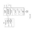
- FIG. 4is a block diagram of an exemplary embodiment of a master host unit 120 used in distributed antenna systems, such as the exemplary distributed antenna systems 100 described above.
- Exemplary master host unit 120includes at least two network interfaces 102 (including network interface 102 - 1 , network interface 102 - 2 , and any number of optional network interfaces 102 through optional network interface 102 -A), distributed antenna switch 118 B, at least one electro-optical conversion module 306 (including electro-optical conversion module 306 - 1 and any amount of optional electro-optical conversion modules 306 through electro-optical conversion module 306 -B), an optional master host clock unit 402 , an optional processor 404 , optional memory 406 , and an optional power supply 408 .
- the network interfaces 102 , distributed antenna switch 118 B, the at least one electro-optical conversion module 306 , and/or master host clock unit 402are implemented by optional processor 404 and memory 406 .
- power supply 408provides power for the various components of the master host unit 120 .
- the distributed antenna switch 118 Bcan be controlled by a separate controller or another component of the system. In exemplary embodiments the distributed antenna switch 118 B is controlled either manually or automatically.
- the routescan be pre-determined and static. In other exemplary embodiments, the routes can dynamically change based on time of day, load, or other factors.
- each network interface 102receives downlink signals from a respective external device 108 , converts the downlink signals into a downlink data stream, and communicates the downlink data stream to the distributed antenna switch 118 B.
- the distributed antenna switch 118 Baggregates the downlink data streams and outputs the aggregate downlink data stream to the at least one electro-optical conversion module 306 - 1 .
- the distributed antenna switch 118 Baggregates and routes downlink data streams received from respective network interfaces 102 in different ways.
- the electro-optical conversion module 306 - 1converts the aggregate downlink data stream output by the distributed antenna switch from electrical format to optical format and outputs it on optical communication medium 112 - 1 .
- electro-optical conversion modules 306convert various downlink data streams output by the distributed antenna switch from electrical format to optical format and outputs them on optical communication mediums 112 .
- the electro-optical conversion module 306 - 1receives optical formatted uplink data streams from the optical communication medium 112 - 1 , converts them to electrical signals and passes the electrically formatted uplink data streams to the distributed antenna switch 118 B.
- the distributed antenna switchsplits apart, aggregates, and routes uplink data streams received from respective network interfaces 102 in different ways to various network interfaces 102 .
- the network interfaces 102then convert the uplink data streams into uplink signals that are passed onto the respective external devices 108 .
- the master host clock unit 402extracts the master reference clock from signal supplied by at least one external device 108 and distributes this master clock with other external devices 108 through the corresponding network interfaces 102 . In exemplary embodiments, the master host clock unit 402 generates a master reference clock and distributes the generated master reference clock with external devices 108 through the corresponding network interfaces 102 . In exemplary embodiments, the master clock is also supplied to other components of the distributed antenna system 100 in the downlink.
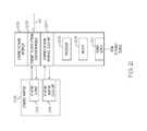
- FIG. 5is a block diagram of an exemplary embodiment of a remote antenna unit 104 used in distributed antenna systems, such as the exemplary distributed antenna systems 100 described above.
- the remote antenna unit 104includes a data stream multiplexing unit 502 , at least one radio frequency (RF) conversion module 504 (including RF conversion module 504 - 1 and any amount of optional RF conversion modules 504 through optional RF conversion module 504 -C), optional electro-optical conversion module 506 , optional Ethernet interface 508 , optional remote antenna unit clock unit 510 , optional processor 512 , optional memory 514 , and optional power supply 516 .
- RFradio frequency
- data stream multiplexing unit 502 , at least one RF conversion module 504 , and/or the optional electro-optical conversion module 506are implemented at least in part by optional processor 512 and memory 514 .
- optional power supply 516is used to power the various components of the remote antenna unit 104 .
- data stream multiplexing unit 502receives at least one downlink data stream from at least one network interface 102 through the distributed switching network 106 .
- the at least one downlink data streamis received through the optional electro-optical conversion module 506 that converts the downlink data stream from an optical format to an electrical format.
- more input lines and/or more electro-optical conversion modules 506are included in the remote antenna unit 104 .
- the data stream multiplexing unit 502splits apart an aggregate downlink data stream into at least one downlink data stream that is sent to RF conversion module 504 - 1 for eventual transmission as a radio frequency on antenna 114 - 1 .
- the data stream multiplexing unit 502splits apart the aggregate downlink data stream into a plurality of downlink data streams that are sent to a plurality of RF conversion modules 504 for eventual transmission as radio frequency signals at antennas 114 .
- data stream multiplexing unit 502receives at least one uplink data stream from at least one RF conversion module 504 . In exemplary embodiments, the data stream multiplexing unit 502 receives a plurality of uplink data streams from a plurality of RF conversion modules 504 . In exemplary embodiments, the data stream multiplexing unit aggregates at least one uplink data stream received from an RF conversion module 504 - 1 with another uplink data stream received from another RF conversion module 504 . In exemplary embodiments, the data stream multiplexing unit 502 aggregates a plurality of uplink data streams into a single aggregate uplink data stream.
- the aggregate uplink data streamis provided to optional electro-optical conversion module 506 which converts the aggregate uplink data stream from electrical signals to optical signals before communicating the aggregate uplink data stream to the distributed antenna switch 102 through the distributed switching network 106 .
- the aggregate uplink data streamis communicated as electrical signals toward the distributed antenna switch 102 through the distributed switching network 106 .
- the aggregate uplink signalis converted to optical signals at another place in the distributed antenna system 100 .
- the optional Ethernet interface 508receives a downlink data stream from the data stream multiplexing unit 502 and converts it to Ethernet packets and communicates the Ethernet packets with an internet protocol network device.
- the optional Ethernet interface 508also receives Ethernet packets from the internet protocol network device and converts them to an uplink data stream and communicates it to the data stream multiplexing unit 502 .
- the optional remote antenna unit clock unit 510extracts the master reference clock from the downlink data stream and uses this master clock within the remote antenna unit 104 to establish a common time base in the remote antenna unit 104 with the rest of the distributed antenna system 100 .
- the optional remote antenna unit clock unit 510generates a master reference clock and distributes the generated master reference clock to other components of the distributed antenna system 100 (and even the external devices 108 ) in the upstream using the uplink data stream.
- FIGS. 6A-6Care block diagrams of exemplary embodiments of RF conversion modules 504 used in remote antenna units of distributed antenna systems, such as the exemplary remote antenna unit 100 described above.
- FIGS. 6A-6Care block diagrams of exemplary embodiments of RF conversion module 504 , labeled RF conversion module 504 A- 504 C respectively.
- FIG. 6Ais a block diagram of an exemplary RF conversion module 504 A including an optional data stream conditioner 602 , an RF frequency converter 604 , an optional RF conditioner 606 , and an RF duplexer 608 coupled to a single antenna 114 .
- the optional data stream conditioner 602is communicatively coupled to a data stream multiplexing unit 502 and the radio frequency (RF) converter 604 .
- the optional data stream conditioner 602conditions the downlink data stream (for example, through amplification, attenuation, and filtering) received from the data stream multiplexing unit 502 and passes the downlink data stream to the RF converter 604 .
- the optional data stream conditioner 602conditions the uplink data stream (for example, through amplification, attenuation, and filtering) received from the RF converter 604 and passes the uplink data stream to the data stream multiplexing unit 502 .
- the RF converter 604is communicatively coupled to either the data stream multiplexing unit 502 or the optional data stream conditioner 602 on one side and to either RF duplexer 608 or the optional RF conditioner 606 on the other side.
- the RF converter 604converts a downlink data stream to downlink radio frequency (RF) signals and passes the downlink RF signals onto either the RF duplexer 608 or the optional RF conditioner 606 .
- the RF converter 604converts uplink radio frequency (RF) signals received from either the RF duplexer 608 or the optional RF conditioner 606 to an uplink data stream and passes the uplink data stream to either the data stream multiplexing unit 502 or the optional data stream conditioner 602 .
- RFradio frequency
- the RF duplexer 608is communicatively coupled to either the RF frequency converter 604 or the optional RF conditioner 606 on one side and the antenna 114 on the other side.
- the RF duplexer 608duplexes the downlink RF signals with the uplink RF signals for transmission/reception using the antenna 114 .
- FIG. 6Bis a block diagram of an exemplary RF conversion module 504 B including an optional data stream conditioner 602 , an RF frequency converter 604 , and an optional RF conditioner 606 coupled to a downlink antenna 114 A and an uplink antenna 114 B.
- RF conversion module 504 Bincludes similar components to RF conversion module 504 A and operates according to similar principles and methods as RF conversion module 504 A described above. The difference between RF conversion module 504 B and RF conversion module 504 A is that RF conversion module 504 B does not include RF duplexer 608 and instead includes separate downlink antenna 114 A used to transmit RF signals to at least one subscriber unit and uplink antenna 114 B used to receive RF signals from at least one subscriber unit.
- FIG. 6Cis a block diagram of an exemplary RF conversion module 504 C- 1 and exemplary RF conversion module 504 C- 2 that share a single antenna 114 through an RF diplexer 610 .
- the RF conversion module 504 C- 1includes an optional data stream conditioner 602 - 1 , an RF frequency converter 604 - 1 , an optional RF conditioner 606 - 1 , and an RF duplexer 608 - 1 communicatively coupled to RF diplexer 610 that is communicatively coupled to antenna 114 .
- the RF conversion module 504 C- 2includes an optional data stream conditioner 602 - 2 , an RF frequency converter 604 - 2 , an optional RF conditioner 606 - 2 , and an RF duplexer 608 - 2 communicatively coupled to RF diplexer 610 that is communicatively coupled to antenna 114 .
- Each of RF conversion module 504 C- 1 and 504 C- 2operate according to similar principles and methods as RF conversion module 504 A described above.
- the difference between RF conversion modules 504 C- 1 and 504 C- 2 and RF conversion module 504 Ais that RF conversion modules 504 C- 1 and 504 C- 2 are both coupled to a single antenna 114 through RF diplexer 610 .
- the RF diplexer 610diplexes the duplexed downlink and uplink signals for both RF conversion module 504 C- 1 and 504 C- 2 for transmission/reception using the single antenna 114 .
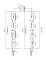
- FIG. 7is a block diagram of an exemplary embodiment of a hybrid distributed antenna system 700 .
- Hybrid distributed antenna system 700includes a master host unit 120 having a plurality of network interfaces 102 (including network interface 102 - 1 , network interface 102 - 2 , and any amount of optional network interfaces 102 through optional network interface 102 -A) and a distributed antenna switch 118 C, at least one hybrid expansion unit 702 (including hybrid expansion unit 702 - 1 , optional hybrid expansion unit 702 - 2 and any amount of additional optional hybrid expansion units 702 through optional hybrid expansion unit 702 -H), at least one analog remote antenna unit 704 (including analog remote antenna unit 704 - 1 and any amount of optional analog remote antenna units 704 through analog remote antenna unit 704 -L), and optional digital expansion unit 706 .
- a master host unit 120having a plurality of network interfaces 102 (including network interface 102 - 1 , network interface 102 - 2 , and any amount of optional network interfaces 102 through optional network
- Master host unit 120 including network interfaces 102 and distributed antenna switch 118 Coperate as described above.
- the main differences between the hybrid distributed antenna system 700 and the distributed antenna systems 100 described aboveis the inclusion of at least one hybrid expansion unit 702 that acts as the interface between the digital portion of the distributed antenna system 700 (between the master host unit 120 and the hybrid expansion unit 702 ) and the analog portion of the distributed antenna system 700 (between the hybrid expansion unit 702 and the at least one analog remote antenna unit 704 ).
- the distributed antenna switch 118 Ccan be controlled by a separate controller or another component of the system.
- the distributed antenna switch 118 Cis controlled either manually or automatically.
- the routescan be pre-determined and static. In other exemplary embodiments, the routes can dynamically change based on time of day, load, or other factors.
- the hybrid expansion unit 702converts between the digital downlink data stream provided by the distributed antenna switch 118 C across digital communication link 110 and analog downlink signals that are communicated to the at least one analog remote antenna unit 704 .
- the hybrid expansion unit 702aggregates, splits apart, and routes downlink data streams converted to downlink analog signals to various analog remote antenna units 704 .
- the analog downlink signalsare intermediate frequency analog signals communicated across an analog wired medium 710 , such as a coaxial cable or twisted pair cabling.
- the analog remote antenna unit 704then converts the analog signals to radio frequency signals and communicates them with a subscriber unit.
- the analog remote antenna unit 704receives radio frequency signals from a subscriber unit and converts the radio frequency signals to analog signals for transmission across the analog wired medium 710 .
- the hybrid expansion unit 702converts between analog uplink signals received from the analog remote antenna unit to an uplink data stream that is communicated to the distributed antenna switch 118 C across digital communication link 110 .
- the hybrid expansion unit 702aggregates, splits apart, and routes uplink analog signals converted to uplink data streams to various ports of the distributed antenna switch 118 C or different master host units 120 altogether.
- the analog uplink signalsare intermediate frequency analog signals communicated across the analog wired medium 710 .
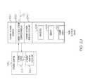
- FIG. 8is a block diagram of an exemplary embodiment of a hybrid expansion unit 702 used in hybrid distributed antenna systems, such as the hybrid distributed antenna system 700 .
- Hybrid expansion unit 702includes a data stream multiplexing unit 802 , a plurality of digital to analog conversion units 804 (including digital to analog conversion unit 804 - 1 and any number of optional digital to analog conversion units 804 through digital to analog conversion unit 804 -M), an analog multiplexing unit 806 , optional electro-optical conversion modules 808 (including optional electro-optical conversion module 808 - 1 though optional electro-optical conversion module 808 -N), an optional digital expansion clock unit 810 , an optional analog domain reference clock unit 812 , an optional processor 814 , optional memory 816 , and an optional power supply 818 .
- the data stream multiplexing unit 802 , the digital to analog conversion units 804 , the analog multiplexing unit 806 , the digital expansion clock unit 810 , and/or the analog domain reference clock unit 816are at least in part implemented using optional processor 814 and optional memory 816 .
- the optional power supply 818provides power to the various elements of the hybrid expansion unit 702 .
- the data stream multiplexing unit 802receives downlink data streams from distributed antenna switches 118 C.
- the downlink data streamsare converted from optical signals to electrical signals by optional electro-optical conversion modules 808 .
- the data stream multiplexing unit 802then routes the data streams to appropriate digital to analog conversion units 804 for conversion to analog signals from digital data streams.
- the digital to analog conversion units 804convert the downlink data streams into downlink intermediate frequency signals.
- the analog multiplexing unit 806receives the downlink analog signals and routes them to appropriate analog communication medium 710 .
- the analog multiplexing unit 806receives uplink analog signals from the analog communication media 710 and routes them to the appropriate digital to analog conversion unit 804 to be converted to uplink data streams and passed to the data stream multiplexing unit 802 for routing to the appropriate digital communication medium 110 destined to a particular port of a distributed antenna switch 118 C.
- the digital expansion clock unit 810extracts the master reference clock from a downlink data stream received from the distributed antenna switch 118 C and passes it to the analog domain reference clock unit 812 , which converts the master reference clock to an analog clock that is then embedded in the downlink analog signals at the analog multiplexing unit 806 .
- the reference clockcan be used within the hybrid expansion unit 702 and sent to the analog remote antenna units 704 for use by them.
- the master reference clockis received from one of the analog remote antenna units 704 or another downstream component of the distributed antenna system 700 and is extracted by the analog domain reference clock unit 812 and provided to the digital expansion clock unit 810 which embeds it into uplink digital data streams for communication to the distributed antenna switch 118 C.
- FIG. 9is a block diagram of an exemplary embodiment of an analog remote antenna unit 704 used in hybrid or analog distributed antenna systems, such as the exemplary hybrid distributed antenna system 700 .
- the analog remote antenna unitincludes an analog multiplexing unit 902 , at least one radio frequency (RF) conversion module 904 (including RF conversion module 904 - 1 and any amount of optional RF conversion modules 904 through optional RF conversion module 904 - 0 ), optional Ethernet interface 906 , optional remote antenna unit clock unit 908 , optional processor 910 , optional memory 912 , and optional power supply 914 .
- RFradio frequency
- analog multiplexing unit 902 , at least one RF conversion module 904 , and/or the remote antenna unit clock unit 908are implemented at least in part by optional processor 910 and optional memory 912 .
- optional power supply 914is used to power the various components of the analog remote antenna unit 704 .
- analog multiplexing unit 902receives at least one multiplexed analog signal from at least one hybrid expansion unit 702 . In exemplary embodiments more input lines are included in the analog remote antenna unit 704 . In exemplary embodiments, the analog multiplexing unit 904 splits apart an aggregate multiplexed downlink analog signal into at least one downlink analog signal that is sent to RF conversion module 904 - 1 for eventual transmission as a radio frequency on antenna 114 - 1 . In exemplary embodiments, the analog multiplexing unit 902 splits apart the aggregate downlink analog signals into a plurality of downlink analog signals that are sent to a plurality of RF conversion modules 904 for eventual transmission as radio frequency signals at antennas 114 .
- analog multiplexing unit 902receives at least one uplink analog signal from at least one RF conversion module 904 . In exemplary embodiments, the analog multiplexing unit 902 receives a plurality of uplink analog signals from a plurality of RF conversion modules 904 . In exemplary embodiments, the analog multiplexing unit 902 aggregates at least one uplink analog signal received from an RF conversion module 904 - 1 with another uplink analog signal received from another RF conversion module 904 . In exemplary embodiments, the analog multiplexing unit 902 aggregates a plurality of uplink analog signals into a single aggregate analog multiplexed signal. In exemplary embodiments, the aggregate uplink data stream is communicated as electrical signals to the hybrid expansion unit 702 .
- the optional remote antenna unit clock unit 908extracts the master reference clock from the downlink analog signal and uses this master clock within the analog remote antenna unit 704 to establish a common time base in the remote antenna unit 704 with the rest of the distributed antenna system 100 .
- the optional remote antenna unit clock unit 908generates a master reference clock and distributes the generated master reference clock to other components of the distributed antenna system 100 (and even the external devices 108 ) in the upstream using the uplink analog signal.
- the optional Ethernet interface 906receives a downlink analog signal from the analog multiplexing unit 902 and converts it to Ethernet packets and communicates the Ethernet packets with an internet protocol network device.
- the optional Ethernet interface 906also receives Ethernet packets from the internet protocol network device and converts them to an uplink analog signal and communicates it to the analog multiplexing unit 902 .
- FIGS. 10A-10Care block diagrams of exemplary embodiments of RF conversion modules 904 used in analog remote antenna units of hybrid or analog distributed antenna systems, such as the exemplary remote antenna unit 700 described above.
- FIGS. 10A-10Care block diagrams of exemplary embodiments of RF conversion module 904 , labeled RF conversion module 904 A- 904 C respectively.
- FIG. 10Ais a block diagram of an exemplary RF conversion module 904 A including an optional analog intermediate frequency conditioner 1002 , an RF frequency converter 1004 , an optional RF conditioner 1006 , and an RF duplexer 1008 coupled to a single antenna 114 .
- the optional analog intermediate frequency conditioner 1002is communicatively coupled to a data stream multiplexing unit 502 and the radio frequency (RF) converter 1004 .
- the optional analog intermediate frequency conditioner 1002conditions the downlink data stream (for example, through amplification, attenuation, and filtering) received from the data stream multiplexing unit 502 and passes the downlink data stream to the RF converter 1004 .
- the optional analog intermediate frequency conditioner 1002conditions the uplink data stream (for example, through amplification, attenuation, and filtering) received from the RF converter 1004 and passes the uplink data stream to the data stream multiplexing unit 502 .
- the RF converter 1004is communicatively coupled to either the data stream multiplexing unit 502 or the optional analog intermediate frequency conditioner 1002 on one side and to either RF duplexer 1008 or the optional RF conditioner 1006 on the other side.
- the RF converter 1004converts a downlink data stream to downlink radio frequency (RF) signals and passes the downlink RF signals onto either the RF duplexer 1008 or the optional RF conditioner 1006 .
- RF converter 1004converts uplink radio frequency (RF) signals received from either the RF duplexer 1008 or the optional RF conditioner 1006 to an uplink data stream and passes the uplink data stream to either the data stream multiplexing unit 502 or the optional analog intermediate frequency conditioner 1002 .
- RFradio frequency
- the RF duplexer 1008is communicatively coupled to either the RF frequency converter 1004 or the optional RF conditioner 1006 on one side and the antenna 114 on the other side.
- the RF duplexer 1008duplexes the downlink RF signals with the uplink RF signals for transmission/reception using the antenna 114 .
- FIG. 10Bis a block diagram of an exemplary RF conversion module 904 B including an optional analog intermediate frequency conditioner 1002 , an RF frequency converter 1004 , and an optional RF conditioner 1006 coupled to a downlink antenna 114 A and an uplink antenna 114 B.
- RF conversion module 904 Bincludes similar components to RF conversion module 904 A and operates according to similar principles and methods as RF conversion module 904 A described above. The difference between RF conversion module 904 B and RF conversion module 904 A is that RF conversion module 904 B does not include RF duplexer 1008 and instead includes separate downlink antenna 114 A used to transmit RF signals to at least one subscriber unit and uplink antenna 114 B used to receive RF signals from at least one subscriber unit.
- FIG. 10Cis a block diagram of an exemplary RF conversion module 904 C- 1 and exemplary RF conversion module 904 C- 2 that share a single antenna 114 through an RF diplexer 1010 .
- the RF conversion module 904 C- 1includes an optional analog intermediate frequency conditioner 1002 - 1 , an RF frequency converter 1004 - 1 , an optional RF conditioner 1006 - 1 , and an RF duplexer 1008 - 1 communicatively coupled to RF diplexer 1010 that is communicatively coupled to antenna 114 .
- the RF conversion module 904 C- 2includes an optional analog intermediate frequency conditioner 1002 - 2 , an RF frequency converter 1004 - 2 , an optional RF conditioner 1006 - 2 , and an RF duplexer 1008 - 2 communicatively coupled to RF diplexer 1010 that is communicatively coupled to antenna 114 .
- Each of RF conversion module 904 C- 1 and 904 C- 2operate according to similar principles and methods as RF conversion module 904 A described above.
- the difference between RF conversion modules 904 C- 1 and 904 C- 2 and RF conversion module 904 Ais that RF conversion modules 904 C- 1 and 904 C- 2 are both coupled to a single antenna 114 through RF diplexer 1010 .
- the RF diplexer 1010diplexes the duplexed downlink and uplink signals for both RF conversion module 904 C- 1 and 904 C- 2 for transmission/reception using the single antenna 114 .
- FIG. 11is a flow diagram illustrating one exemplary embodiment of a method 1100 of sourcing a master reference clock for a base station network interface from a distributed antenna system.
- Exemplary method 1100begins at block 1102 with receiving a first downlink signal from a first external device external to a distributed antenna system via a first network interface unit.
- Exemplary method 1100proceeds to block 1104 with converting the first downlink signal into a first downlink data stream at the first network interface unit.
- the first downlink data streamis a baseband data stream.
- the baseband data streamincludes quadrature samples of I/Q pairs.
- Exemplary method 1100proceeds to block 1106 with receiving a second downlink signal from a second external device external to the distributed antenna system via a second network interface unit. Exemplary method 1100 proceeds to block 1108 with converting the second downlink signal into a second downlink data stream at the second network interface unit.
- the second downlink data streamis a baseband data stream.
- the baseband data streamincludes quadrature samples of I/Q pairs.
- Exemplary method 1100proceeds to block 1110 with communicating the first downlink data stream from the first network interface unit to at least one of a first remote antenna unit and an intermediary device. Exemplary method 1100 proceeds to block 1112 with converting at least one of the first downlink data stream and a first downlink signal derived from the first downlink data stream at the intermediary device into a first radio frequency band signal at a first remote antenna unit. Exemplary method 1100 proceeds to block 1114 with transmitting the first radio frequency band signal to the first subscriber unit at the first remote antenna unit.
- Exemplary method 1100proceeds to block 1116 with transmitting a master reference clock to the first external device through the first network interface unit.
- thisincludes transmitting uplink signals to the first external device through the first base station network interface unit, wherein the uplink signals are clocked using the master reference clock such that the master reference clock is embedded in the uplink signals.
- Exemplary embodiments of method 1100further include locking a reference clock of the first device of the devices external to the distributed antenna system to the master reference clock embedded in the uplink signals.
- transmitting the master reference clock to the first device of the devices external to the distributed antenna systemincludes transmitting the master reference clock across a separate master reference clock channel.
- Exemplary embodiments of method 1100further include generating the master reference clock within the distributed antenna system. Exemplary embodiments of method 1100 further include deriving the master reference clock from the second external device through the second base station network interface. In exemplary embodiments, this includes locking the master reference clock to a clock embedded in the second downlink signals received from the second external device.
- Exemplary embodiments of method 1100further include communicating the first downlink data stream to a hybrid expansion unit communicatively coupled between the first base station network interface unit and the first downlink data stream at the hybrid expansion unit; converting the first downlink data stream to the first downlink signal derived from the first downlink data stream at the hybrid expansion unit; communicating the first downlink signal derived from the first downlink data stream from the hybrid expansion unit to the first remote antenna unit; and converting the first downlink signal derived from the first downlink data stream into a first radio frequency band signal at the first remote antenna unit.
- the first downlink signal derived from the first downlink data streamis a downlink analog intermediate frequency signal.
- Exemplary embodiments of method 1100further include communicating the second downlink data stream from the second base station network interface unit to the first remote antenna unit; converting the second downlink data stream into a second radio frequency band signal at the first remote antenna unit; and transmitting the second radio frequency band signal to a second subscriber unit at the first remote antenna unit.
- Exemplary embodiments of method 1100further include communicating the second downlink data stream from the second base station network interface unit to a hybrid expansion unit communicatively coupled between the second base station network interface unit and the first remote antenna unit; converting the second downlink data stream to a second downlink signal derived from the first downlink data stream at the hybrid expansion unit; communicating the second downlink signal derived from the second downlink data stream from the hybrid expansion unit to the first remote antenna unit; converting the second downlink signal derived from the second downlink data stream into a second radio frequency band signal at the first remote antenna unit; and transmitting the second radio frequency band signal to a second subscriber unit at the first remote antenna unit.
- Exemplary embodiments of method 1100further include communicating the second downlink data stream from the second base station network interface unit to a second remote antenna unit; converting the first downlink data stream into a second radio frequency band signal at the second remote antenna unit; and transmitting the second radio frequency band signal to a second subscriber unit at the second remote antenna unit.
- Exemplary embodiments of method 1100further include communicating the second downlink data stream from the second base station network interface unit to a hybrid expansion unit communicatively coupled between the second base station network interface unit and the first remote antenna unit; converting the second downlink data stream to a second downlink signal derived from the first downlink data stream at the hybrid expansion unit; communicating the second downlink signal derived from the second downlink data stream from the hybrid expansion unit to the first remote antenna unit; converting the second downlink signal derived from the second downlink data stream into a second radio frequency band signal at the second remote antenna unit; and transmitting the second radio frequency band signal to a second subscriber unit at the second remote antenna unit.
- Exemplary embodiments of method 1100further include communicating the first downlink data stream from the first base station network interface unit to a distributed antenna switch communicatively coupled between the first base station network interface unit and the first distributed antenna switch; communicating the second downlink data stream from the second base station network interface unit to the distributed antenna switch communicatively coupled between the second base station network interface unit and the second distributed antenna switch; aggregating the first downlink data stream with the second downlink data stream into an aggregate downlink data stream at the distributed antenna switch; communicating the aggregate downlink data stream to the first remote antenna unit; and extracting the first downlink data stream from the aggregate downlink data stream at the first remote antenna unit.
- Exemplary embodiments of method 1100further include receiving a first uplink radio frequency band signal from the first subscriber unit at the first remote antenna unit; converting the first uplink radio frequency band signal to a first uplink data stream at the first remote antenna unit; communicating the first uplink data stream from the first remote antenna unit to the first base station network interface unit; converting the first uplink data stream into first uplink signals at the first base station network interface; and communicating the first uplink signals to the first external device at the first base station network interface.
- Exemplary embodiments of method 1100further include receiving a first uplink radio frequency band signal from the first subscriber unit at the first remote antenna unit; converting the first uplink radio frequency band signal to a first uplink analog intermediate frequency signal at the first remote antenna unit; communicating the first analog intermediate frequency signal from the first remote antenna unit to a hybrid expansion unit communicatively coupled between the first base station network interface and the first remote antenna unit; converting the first uplink analog intermediate frequency signal to a first uplink data stream at the hybrid expansion unit; communicating the first uplink data stream from the hybrid expansion unit to the first base station network interface unit; converting the first uplink data stream into first uplink signals at the first base station network interface; and communicating the first uplink signals to the first external device at the first base station network interface.
- processors described abovemay include or function with software programs, firmware or other computer readable instructions for carrying out various methods, process tasks, calculations, and control functions, described herein. These instructions are typically stored on any appropriate computer readable medium used for storage of computer readable instructions or data structures.
- the computer readable mediumcan be implemented as any available media that can be accessed by a general purpose or special purpose computer or processor, or any programmable logic device.
- Suitable processor-readable mediamay include storage or memory media such as magnetic or optical media.
- storage or memory mediamay include conventional hard disks, Compact Disk-Read Only Memory (CD-ROM), volatile or non-volatile media such as Random Access Memory (RAM) (including, but not limited to, Synchronous Dynamic Random Access Memory (SDRAM), Double Data Rate (DDR) RAM, RAMBUS Dynamic RAM (RDRAM), Static RAM (SRAM), etc.), Read Only Memory (ROM), Electrically Erasable Programmable ROM (EEPROM), and flash memory, etc.
- RAMRandom Access Memory
- SDRAMSynchronous Dynamic Random Access Memory
- DDRDouble Data Rate
- RDRAMRAMBUS Dynamic RAM
- SRAMStatic RAM
- ROMRead Only Memory
- EEPROMElectrically Erasable Programmable ROM
- flash memoryetc.
- Suitable processor-readable mediamay also include transmission media such as electrical, electromagnetic, or digital signals, conveyed via a communication medium such as a network and/or a wireless link.
- Example 1includes a distributed antenna system comprising: a first base station network interface unit configured to receive first downlink signals from a first external device external to the distributed antenna system and to convert the first downlink signals into a first downlink data stream; a second base station network interface unit configured to receive second downlink signals from a second external device external to the distributed antenna system and to convert the second downlink signals into a second downlink data stream; a first remote antenna unit communicatively coupled to the first base station network interface unit and configured to receive at least one of the first downlink data stream from the first base station network interface unit and a first downlink signal derived from the first downlink data stream; the first remote antenna unit having a first radio frequency converter configured to convert at least one of the first downlink data stream and the first downlink signal derived from the first downlink data stream into a first radio frequency band signal and a first radio frequency antenna configured to transmit the first radio frequency band signal to a first subscriber unit; and wherein the distributed antenna system is configured to transmit a master reference clock to the first external device.
- Example 2includes the distributed antenna system of Example 1, wherein the distributed antenna system is configured to generate the master reference clock internally.
- Example 3includes the distributed antenna system of any of Examples 1-2, wherein the distributed antenna system is configured to derive the master reference clock from the second external device.
- Example 4includes the distributed antenna system of Example 3, wherein the distributed antenna system is configured to derive the master reference clock from the second external device by being configured to lock the master reference clock to a clock embedded in the second downlink signals received from the second external device.
- Example 5includes the distributed antenna system of any of Examples 1-4, wherein the distributed antenna system is configured to transmit the master reference clock to the first external device by being configured to transmit first uplink signals to the first external device through the first base station network interface unit, wherein the first uplink signals are clocked using the master reference clock such that the master reference clock is embedded in the uplink signals.
- Example 6includes the distributed antenna system of any of Examples 4-5, wherein the first external device is configured to lock its clock to the master reference clock embedded in the first uplink signals.
- Example 7includes the distributed antenna system of any of Examples 1-6, wherein the distributed antenna system is configured to transmit the master reference clock to the first external device by being configured to transmit the master reference clock across a separate master reference clock channel.
- Example 8includes the distributed antenna system of any of Examples 1-7, further comprising: a hybrid expansion unit communicatively coupled between the first base station network interface unit and the first remote antenna unit and configured to receive the first downlink data stream and convert the first downlink data stream to the first downlink signal derived from the first downlink data stream; wherein the first remote antenna unit is further configured to receive the first downlink signal derived from the first downlink data stream and to convert the first downlink signal derived from the first downlink data stream into the second radio frequency band signal.
- a hybrid expansion unitcommunicatively coupled between the first base station network interface unit and the first remote antenna unit and configured to receive the first downlink data stream and convert the first downlink data stream to the first downlink signal derived from the first downlink data stream
- the first remote antenna unitis further configured to receive the first downlink signal derived from the first downlink data stream and to convert the first downlink signal derived from the first downlink data stream into the second radio frequency band signal.
- Example 9includes the distributed antenna system of Example 8, wherein the first downlink signal derived from the first downlink data stream is a downlink analog intermediate frequency signal.
- Example 10includes the distributed antenna system of any of Examples 1-9, wherein the first remote antenna unit is further communicatively coupled to the second base station network interface unit and configured to receive at least one of the second downlink data stream from the second base station network interface unit and a second downlink signal derived from the second downlink data stream; the first remote antenna unit further having a second radio frequency converter configured to convert at least one of the second downlink data stream and the second downlink signal derived from the second downlink data stream into a second radio frequency band signal and a second radio frequency antenna configured to transmit the second radio frequency band signal to a second subscriber unit.
- the first remote antenna unitis further communicatively coupled to the second base station network interface unit and configured to receive at least one of the second downlink data stream from the second base station network interface unit and a second downlink signal derived from the second downlink data stream
- the first remote antenna unitfurther having a second radio frequency converter configured to convert at least one of the second downlink data stream and the second downlink signal derived from the second downlink data stream into a
- Example 11includes the distributed antenna system of any of Examples 1-10, wherein the first remote antenna unit is further communicatively coupled to the second base station network interface unit and configured to receive at least one of the second downlink data stream from the second base station network interface unit and a second downlink signal derived from the second downlink data stream; the first remote antenna unit further having a second radio frequency converter configured to convert at least one of the second downlink data stream and the second downlink signal derived from the second downlink data stream into a second radio frequency band signal; and wherein the first radio frequency antenna is further configured to transmit the second radio frequency band signal to a second subscriber unit.
- Example 12includes the distributed antenna system of any of Examples 1-11, further comprising a second remote antenna unit communicatively coupled to the second base station network interface unit and configured to receive at least one of the second downlink data stream from the second base station network interface unit and a second downlink signal derived from the second downlink data stream; and the second remote antenna unit further having a second radio frequency converter configured to convert at least one of the second downlink data stream and the second downlink signal derived from the second downlink data stream into a second radio frequency band signal and a second radio frequency antenna configured to transmit the second radio frequency band signal to a second subscriber unit.
- a second remote antenna unitcommunicatively coupled to the second base station network interface unit and configured to receive at least one of the second downlink data stream from the second base station network interface unit and a second downlink signal derived from the second downlink data stream
- the second remote antenna unitfurther having a second radio frequency converter configured to convert at least one of the second downlink data stream and the second downlink signal derived from the second downlink data stream into a
- Example 13includes the distributed antenna system of any of Examples 1-12, further comprising: a distributed antenna switch communicatively coupled between both the first base station network interface unit and the second base station network interface unit and the first remote antenna unit, the distributed antenna switch configured to receive the first downlink data stream from the first base station network interface unit and the second downlink data stream from the second base station network interface unit and to aggregate the first downlink data stream with the second downlink data stream into an aggregate downlink data stream; the distributed antenna switch further configured to transmit the aggregate downlink data stream to the first remote antenna unit; and the first remote antenna unit further configured to receive the aggregate downlink data stream and to extract the first downlink data stream from the aggregate downlink data stream.
- a distributed antenna switchcommunicatively coupled between both the first base station network interface unit and the second base station network interface unit and the first remote antenna unit, the distributed antenna switch configured to receive the first downlink data stream from the first base station network interface unit and the second downlink data stream from the second base station network interface unit and to aggregate the first downlink data stream with the second downlink data stream
- Example 14includes the distributed antenna system of Example 13, further comprising a second remote antenna unit communicatively coupled to the second base station network interface unit through the distributed antenna switch and configured to receive aggregate downlink data stream and to extract the second downlink data stream from the second aggregate downlink data stream; the second remote antenna unit further having a second radio frequency converter configured to convert the second downlink data stream into a second radio frequency band signal and a second radio frequency antenna configured to transmit the second radio frequency band signal to a second subscriber unit.
- a second remote antenna unitcommunicatively coupled to the second base station network interface unit through the distributed antenna switch and configured to receive aggregate downlink data stream and to extract the second downlink data stream from the second aggregate downlink data stream
- the second remote antenna unitfurther having a second radio frequency converter configured to convert the second downlink data stream into a second radio frequency band signal and a second radio frequency antenna configured to transmit the second radio frequency band signal to a second subscriber unit.
- Example 15includes the distributed antenna system of any of Examples 1-14, wherein the first radio frequency antenna is further configured to receive a first uplink radio frequency band signal from the first subscriber unit; wherein the first radio frequency converter is further configured to convert the first uplink radio frequency band signal to a first uplink data stream; wherein the first remote antenna unit is further configured to communicate the first uplink data stream to the first base station network interface unit; wherein the first base station network interface unit is configured to receive the first uplink data stream from the first remote antenna unit; wherein the first network interface is configured to convert the first uplink data stream into first uplink signals; and wherein the first base station network interface unit is configured to communicate the first uplink signals to the first external device.
- Example 16includes the distributed antenna system of any of Examples 1-15, wherein the first radio frequency antenna is further configured to receive a first uplink radio frequency band signal from the first subscriber unit; wherein the first radio frequency converter is further configured to convert the first uplink radio frequency band signal to a first uplink analog intermediate frequency signal; wherein the first remote antenna unit is further configured to communicate the first uplink analog intermediate frequency signals to a hybrid expansion unit; wherein the hybrid expansion unit is configured to receive the first uplink analog intermediate frequency signals from the first remote antenna unit; wherein the hybrid expansion unit is configured to convert the first uplink analog intermediate frequency signals to a first uplink data stream; wherein the hybrid expansion unit is configured to communicate the first uplink data stream to the first base station network interface unit; wherein the first base station network interface unit is configured to receive the first uplink data stream from the hybrid expansion unit; wherein the first network interface is configured to convert the first uplink data stream into first uplink signals; and wherein the first base station network interface unit is configured to communicate the first uplink signals to the first external device.
- Example 17includes the distributed antenna system of any of Examples 1-16, wherein the first external device is a base band unit of a wireless access base station.
- Example 18includes the distributed antenna system of any of Examples 1-17, wherein the first external device is a Common Public Radio Interface (CPRI) base station, wherein the first base station network interface unit is a CPRI converter interface communicatively coupled to a CPRI base station, the CPRI converter interface configured to receive CPRI data from the CPRI base station, the CPRI converter interface further configured to convert the CPRI data into a first downlink data stream of the plurality of downlink data streams.
- CPRICommon Public Radio Interface
- Example 19includes the distributed antenna system of any of Examples 1-18, wherein the first downlink data stream is a baseband data stream.
- Example 20includes the distributed antenna system of Example 19, wherein the baseband data stream includes quadrature samples of I/Q pairs.
- Example 21includes a method comprising: receiving a first downlink signal from a first external device external to a distributed antenna system via a first base station network interface unit; converting the first downlink signal into a first downlink data stream at the first base station network interface unit; receiving a second downlink signal from a second external device external to the distributed antenna system via a second base station network interface unit; converting the second downlink signal into a second downlink data stream at the second base station network interface unit; communicating the first downlink data stream from the first base station network interface unit to at least one of a first remote antenna unit and an intermediary device; converting at least one of the first downlink data stream and a first downlink signal derived from the first downlink data stream at the intermediary device into a first radio frequency band signal at the first remote antenna unit; transmitting the first radio frequency band signal to a first subscriber unit at the first remote antenna unit; transmitting a master reference clock to the first external device through the first base station network interface unit.
- Example 22includes the method of Example 21, further comprising: generating the master reference clock within the distributed antenna system.
- Example 23includes the method of any of Examples 21-22, further comprising: deriving the master reference clock from the second external device through the second base station network interface unit.
- Example 24includes the method of Example 23, wherein deriving the master reference clock from the second external device through the second base station network interface unit includes: locking the master reference clock to a clock embedded in the second downlink signals received from the second external device.
- Example 25includes the method of any of Examples 21-24, wherein transmitting the master reference clock to the first external device includes transmitting uplink signals to the first external device through the first base station network interface unit, wherein the uplink signals are clocked using the master reference clock such that the master reference clock is embedded in the uplink signals.
- Example 26includes the method of Example 25, further comprising: locking a reference clock of the first device of the devices external to the distributed antenna system to the master reference clock embedded in the uplink signals.
- Example 27includes the method of any of Examples 21-26, wherein transmitting the master reference clock to the first device of the devices external to the distributed antenna system includes transmitting the master reference clock across a separate master reference clock channel.
- Example 28includes the method of any of Examples 21-27, further comprising: communicating the first downlink data stream to a hybrid expansion unit communicatively coupled between the first base station network interface unit and the first remote antenna unit; converting the first downlink data stream to the first downlink signal derived from the first downlink data stream at the hybrid expansion unit; communicating the first downlink signal derived from the first downlink data stream from the hybrid expansion unit to the first remote antenna unit; and converting the first downlink signal derived from the first downlink data stream into a first radio frequency band signal at the first remote antenna unit.
- Example 29includes the method of Example 28, wherein the first downlink signal derived from the first downlink data stream is a downlink analog intermediate frequency signal.
- Example 30includes the method of any of Examples 21-29, further comprising: communicating the second downlink data stream from the second base station network interface unit to the first remote antenna unit; converting the second downlink data stream into a second radio frequency band signal at the first remote antenna unit; and transmitting the second radio frequency band signal to a second subscriber unit at the first remote antenna unit.
- Example 31includes the method of any of Examples 21-30, further comprising: communicating the second downlink data stream from the second base station network interface unit to a hybrid expansion unit communicatively coupled between the second base station network interface unit and the first remote antenna unit; converting the second downlink data stream to a second downlink signal derived from the first downlink data stream at the hybrid expansion unit; communicating the second downlink signal derived from the second downlink data stream from the hybrid expansion unit to the first remote antenna unit; converting the second downlink signal derived from the second downlink data stream into a second radio frequency band signal at the first remote antenna unit; and transmitting the second radio frequency band signal to a second subscriber unit at the first remote antenna unit.
- Example 32includes the method of any of Examples 21-31, further comprising: communicating the second downlink data stream from the second base station network interface unit to a second remote antenna unit; converting the first downlink data stream into a second radio frequency band signal at the second remote antenna unit; and transmitting the second radio frequency band signal to a second subscriber unit at the second remote antenna unit.
- Example 33includes the method of any of Examples 21-32, further comprising: communicating the second downlink data stream from the second base station network interface unit to a hybrid expansion unit communicatively coupled between the second base station network interface unit and the first remote antenna unit; converting the second downlink data stream to a second downlink signal derived from the first downlink data stream at the hybrid expansion unit; communicating the second downlink signal derived from the second downlink data stream from the hybrid expansion unit to the first remote antenna unit; and converting the second downlink signal derived from the second downlink data stream into a second radio frequency band signal at the second remote antenna unit; and transmitting the second radio frequency band signal to a second subscriber unit at the second remote antenna unit.
- Example 34includes the method of any of Examples 21-33, further comprising: communicating the first downlink data stream from the first base station network interface unit to a distributed antenna switch communicatively coupled between the first base station network interface unit and the first distributed antenna switch; communicating the second downlink data stream from the second base station network interface unit to the distributed antenna switch communicatively coupled between the second base station network interface unit and the second distributed antenna switch; aggregating the first downlink data stream with the second downlink data stream into an aggregate downlink data stream at the distributed antenna switch; communicating the aggregate downlink data stream to the first remote antenna unit; and extracting the first downlink data stream from the aggregate downlink data stream at the first remote antenna unit.
- Example 35includes the method of any of Examples 21-34, further comprising: receiving a first uplink radio frequency band signal from the first subscriber unit at the first remote antenna unit; converting the first uplink radio frequency band signal to a first uplink data stream at the first remote antenna unit; communicating the first uplink data stream from the first remote antenna unit to the first base station network interface unit; converting the first uplink data stream into first uplink signals at the first base station network interface; and communicating the first uplink signals to the first external device at the first base station network interface.
- Example 36includes the method of any of Examples 21-35, further comprising: receiving a first uplink radio frequency band signal from the first subscriber unit at the first remote antenna unit; converting the first uplink radio frequency band signal to a first uplink analog intermediate frequency signal at the first remote antenna unit; communicating the first analog intermediate frequency signal from the first remote antenna unit to a hybrid expansion unit communicatively coupled between the first base station network interface and the first remote antenna unit; converting the first uplink analog intermediate frequency signal to a first uplink data stream at the hybrid expansion unit; communicating the first uplink data stream from the hybrid expansion unit to the first base station network interface unit; converting the first uplink data stream into first uplink signals at the first base station network interface; and communicating the first uplink signals to the first external device at the first base station network interface.
- Example 37includes the method of any of Examples 21-36, wherein the first downlink data stream is a baseband data stream.
- Example 38includes the method of Example 37, wherein the baseband data stream includes quadrature samples of I/Q pairs.
- Example 39includes a base station comprising: a base station network interface configured to be communicatively coupled to a corresponding base station network interface of a distributed antenna system and configured to communicate signals with the distributed antenna system; a clocking unit configured to receive a master clock signal from the distributed antenna system; and wherein the base station is further configured to synchronize itself with the distributed antenna system using the master clock signal from the distributed antenna system.
- Example 40includes the base station of Example 39, wherein the clocking unit is configured to receive the master clock signal from the distributed antenna system by being configured to lock to the master clock embedded in an uplink signal received from the distributed antenna system.
- Example 41includes the base station of any of Examples 39-40, wherein the clocking unit is configured to receive the master clock signal from the first external device across a separate master reference clock channel.
- Example 42includes the base station of any of Examples 39-41, wherein the master reference clock is generated within the distributed antenna system.
- Example 43includes the base station of any of Examples 39-42, wherein the master reference clock is derived from an device external to the distributed antenna system.
Landscapes
- Engineering & Computer Science (AREA)
- Computer Networks & Wireless Communication (AREA)
- Signal Processing (AREA)
- Mobile Radio Communication Systems (AREA)
Abstract
Description
Claims (41)
Priority Applications (3)
| Application Number | Priority Date | Filing Date | Title |
|---|---|---|---|
| US14/187,115US10020850B2 (en) | 2013-02-22 | 2014-02-21 | Master reference for base station network interface sourced from distributed antenna system |
| US16/030,642US10855338B2 (en) | 2013-02-22 | 2018-07-09 | Master reference for base station network interface sourced from distributed antenna system |
| US17/107,531US11329701B2 (en) | 2013-02-22 | 2020-11-30 | Master reference for base station network interface sourced from distributed antenna system |
Applications Claiming Priority (2)
| Application Number | Priority Date | Filing Date | Title |
|---|---|---|---|
| US201361767968P | 2013-02-22 | 2013-02-22 | |
| US14/187,115US10020850B2 (en) | 2013-02-22 | 2014-02-21 | Master reference for base station network interface sourced from distributed antenna system |
Related Child Applications (1)
| Application Number | Title | Priority Date | Filing Date |
|---|---|---|---|
| US16/030,642ContinuationUS10855338B2 (en) | 2013-02-22 | 2018-07-09 | Master reference for base station network interface sourced from distributed antenna system |
Publications (2)
| Publication Number | Publication Date |
|---|---|
| US20140243033A1 US20140243033A1 (en) | 2014-08-28 |
| US10020850B2true US10020850B2 (en) | 2018-07-10 |
Family
ID=51388662
Family Applications (3)
| Application Number | Title | Priority Date | Filing Date |
|---|---|---|---|
| US14/187,115ActiveUS10020850B2 (en) | 2013-02-22 | 2014-02-21 | Master reference for base station network interface sourced from distributed antenna system |
| US16/030,642Expired - Fee RelatedUS10855338B2 (en) | 2013-02-22 | 2018-07-09 | Master reference for base station network interface sourced from distributed antenna system |
| US17/107,531ActiveUS11329701B2 (en) | 2013-02-22 | 2020-11-30 | Master reference for base station network interface sourced from distributed antenna system |
Family Applications After (2)
| Application Number | Title | Priority Date | Filing Date |
|---|---|---|---|
| US16/030,642Expired - Fee RelatedUS10855338B2 (en) | 2013-02-22 | 2018-07-09 | Master reference for base station network interface sourced from distributed antenna system |
| US17/107,531ActiveUS11329701B2 (en) | 2013-02-22 | 2020-11-30 | Master reference for base station network interface sourced from distributed antenna system |
Country Status (6)
| Country | Link |
|---|---|
| US (3) | US10020850B2 (en) |
| EP (3) | EP3843284B1 (en) |
| KR (1) | KR102161668B1 (en) |
| CN (2) | CN105144666B (en) |
| CA (1) | CA2914104C (en) |
| WO (1) | WO2014130794A1 (en) |
Cited By (7)
| Publication number | Priority date | Publication date | Assignee | Title |
|---|---|---|---|---|
| US20150303998A1 (en)* | 2013-12-23 | 2015-10-22 | Dali Systems Co. Ltd. | Digital multiplexer in a distributed antenna system |
| US10499269B2 (en) | 2015-11-12 | 2019-12-03 | Commscope Technologies Llc | Systems and methods for assigning controlled nodes to channel interfaces of a controller |
| US20200186250A1 (en)* | 2013-12-23 | 2020-06-11 | Dali Systems Co. Ltd. | Virtual radio access network using software-defined network of remotes and digital multiplexing switches |
| US10855338B2 (en) | 2013-02-22 | 2020-12-01 | Commscope Technologies Llc | Master reference for base station network interface sourced from distributed antenna system |
| USRE48342E1 (en) | 2010-07-28 | 2020-12-01 | Commscope Technologies Llc | Distributed digital reference clock |
| US11564110B2 (en) | 2011-11-07 | 2023-01-24 | Dali Wireless, Inc. | Soft hand-off and routing data in a virtualized distributed antenna system |
| US20230188193A1 (en)* | 2020-04-30 | 2023-06-15 | Telefonaktiebolaget Lm Ericsson (Publ) | Improved Interface in Series-Connected Radios |
Families Citing this family (53)
| Publication number | Priority date | Publication date | Assignee | Title |
|---|---|---|---|---|
| US9673904B2 (en) | 2009-02-03 | 2017-06-06 | Corning Optical Communications LLC | Optical fiber-based distributed antenna systems, components, and related methods for calibration thereof |
| CN102396171B (en) | 2009-02-03 | 2015-09-30 | 康宁光缆系统有限责任公司 | Based on the distributing antenna system of optical fiber, assembly and the correlation technique for monitoring and configure distributing antenna system based on optical fiber, assembly |
| US8280259B2 (en) | 2009-11-13 | 2012-10-02 | Corning Cable Systems Llc | Radio-over-fiber (RoF) system for protocol-independent wired and/or wireless communication |
| US20210063836A1 (en) | 2017-04-26 | 2021-03-04 | View, Inc. | Building network |
| US9525488B2 (en) | 2010-05-02 | 2016-12-20 | Corning Optical Communications LLC | Digital data services and/or power distribution in optical fiber-based distributed communications systems providing digital data and radio frequency (RF) communications services, and related components and methods |
| WO2012024247A1 (en) | 2010-08-16 | 2012-02-23 | Corning Cable Systems Llc | Remote antenna clusters and related systems, components, and methods supporting digital data signal propagation between remote antenna units |
| US9252874B2 (en) | 2010-10-13 | 2016-02-02 | Ccs Technology, Inc | Power management for remote antenna units in distributed antenna systems |
| US9160449B2 (en) | 2010-10-13 | 2015-10-13 | Ccs Technology, Inc. | Local power management for remote antenna units in distributed antenna systems |
| US11296504B2 (en) | 2010-11-24 | 2022-04-05 | Corning Optical Communications LLC | Power distribution module(s) capable of hot connection and/or disconnection for wireless communication systems, and related power units, components, and methods |
| EP2643947B1 (en) | 2010-11-24 | 2018-09-19 | Corning Optical Communications LLC | Power distribution module(s) capable of hot connection and/or disconnection for distributed antenna systems, and related power units, components, and methods |
| EP2678972B1 (en) | 2011-02-21 | 2018-09-05 | Corning Optical Communications LLC | Providing digital data services as electrical signals and radio-frequency (rf) communications over optical fiber in distributed communications systems, and related components and methods |
| US10989977B2 (en) | 2011-03-16 | 2021-04-27 | View, Inc. | Onboard controller for multistate windows |
| WO2015134789A1 (en) | 2014-03-05 | 2015-09-11 | View, Inc. | Monitoring sites containing switchable optical devices and controllers |
| WO2012148938A1 (en) | 2011-04-29 | 2012-11-01 | Corning Cable Systems Llc | Determining propagation delay of communications in distributed antenna systems, and related components, systems and methods |
| WO2012148940A1 (en) | 2011-04-29 | 2012-11-01 | Corning Cable Systems Llc | Systems, methods, and devices for increasing radio frequency (rf) power in distributed antenna systems |
| WO2013162988A1 (en) | 2012-04-25 | 2013-10-31 | Corning Cable Systems Llc | Distributed antenna system architectures |
| US9455784B2 (en) | 2012-10-31 | 2016-09-27 | Corning Optical Communications Wireless Ltd | Deployable wireless infrastructures and methods of deploying wireless infrastructures |
| US11868103B2 (en) | 2014-03-05 | 2024-01-09 | View, Inc. | Site monitoring system |
| AU2015274511B2 (en) | 2014-06-11 | 2019-08-15 | Outdoor Wireless Networks LLC | Bitrate efficient transport through distributed antenna systems |
| WO2016030880A2 (en)* | 2014-08-25 | 2016-03-03 | Corning Optical Communications Wireless Ltd. | Supporting an add-on remote unit (ru) in an optical fiber-based distributed antenna system (das) over an existing optical fiber communications medium using radio frequency (rf) multiplexing |
| US10659163B2 (en) | 2014-09-25 | 2020-05-19 | Corning Optical Communications LLC | Supporting analog remote antenna units (RAUs) in digital distributed antenna systems (DASs) using analog RAU digital adaptors |
| WO2016071902A1 (en) | 2014-11-03 | 2016-05-12 | Corning Optical Communications Wireless Ltd. | Multi-band monopole planar antennas configured to facilitate improved radio frequency (rf) isolation in multiple-input multiple-output (mimo) antenna arrangement |
| WO2016075696A1 (en) | 2014-11-13 | 2016-05-19 | Corning Optical Communications Wireless Ltd. | Analog distributed antenna systems (dass) supporting distribution of digital communications signals interfaced from a digital signal source and analog radio frequency (rf) communications signals |
| CN112615135B (en) | 2014-11-25 | 2024-12-10 | 唯景公司 | Method and device for personalizing the settings of a building area |
| US11114742B2 (en) | 2014-11-25 | 2021-09-07 | View, Inc. | Window antennas |
| US12235560B2 (en) | 2014-11-25 | 2025-02-25 | View, Inc. | Faster switching electrochromic devices |
| US11740948B2 (en) | 2014-12-08 | 2023-08-29 | View, Inc. | Multiple interacting systems at a site |
| WO2016098111A1 (en) | 2014-12-18 | 2016-06-23 | Corning Optical Communications Wireless Ltd. | Digital- analog interface modules (da!ms) for flexibly.distributing digital and/or analog communications signals in wide-area analog distributed antenna systems (dass) |
| WO2016098101A1 (en)* | 2014-12-18 | 2016-06-23 | Corning Optical Communications Wireless Ltd. | Distributing digital communications signals in analog distributed antenna systems (dass) using programmable head-end units |
| WO2016098109A1 (en) | 2014-12-18 | 2016-06-23 | Corning Optical Communications Wireless Ltd. | Digital interface modules (dims) for flexibly distributing digital and/or analog communications signals in wide-area analog distributed antenna systems (dass) |
| EP3076750B1 (en)* | 2015-03-30 | 2023-07-12 | JMA Wireless B.V. | System for the distribution of wireless signals in telecommunication networks |
| US9681313B2 (en) | 2015-04-15 | 2017-06-13 | Corning Optical Communications Wireless Ltd | Optimizing remote antenna unit performance using an alternative data channel |
| US9712343B2 (en) | 2015-06-19 | 2017-07-18 | Andrew Wireless Systems Gmbh | Scalable telecommunications system |
| US9948349B2 (en) | 2015-07-17 | 2018-04-17 | Corning Optical Communications Wireless Ltd | IOT automation and data collection system |
| US12366111B2 (en) | 2015-09-18 | 2025-07-22 | View Operating Corporation | Trunk line window controllers |
| DE102015012893A1 (en) | 2015-10-06 | 2017-04-06 | Audi Ag | Motor vehicle with several antennas and at least one communication device |
| WO2017190773A1 (en)* | 2016-05-03 | 2017-11-09 | Sonova Ag | Audio transmission system |
| KR102408468B1 (en)* | 2017-02-21 | 2022-06-14 | 메이븐 와이어리스 스웨덴 에이비 | Distributed Antenna Systems for Multi-Operator Networks |
| EP3602733B1 (en) | 2017-03-31 | 2024-01-03 | Corning Optical Communications Llc | Safety power disconnection for power distribution over power conductors to power consuming devices |
| US12147142B2 (en) | 2017-04-26 | 2024-11-19 | View, Inc. | Remote management of a facility |
| US10805811B2 (en)* | 2017-12-18 | 2020-10-13 | Commscope Technologies Llc | Synchronization and fault management in a distributed antenna system |
| WO2020086780A1 (en) | 2018-10-25 | 2020-04-30 | Corning Optical Communications LLC | Power distribution system |
| EP3966963A2 (en) | 2019-05-09 | 2022-03-16 | View, Inc. | Antenna systems for controlled coverage in buildings |
| US12176596B2 (en) | 2019-05-31 | 2024-12-24 | View, Inc. | Building antenna |
| CN112134712B (en)* | 2019-06-25 | 2021-12-31 | 华为技术有限公司 | A signal processing method and related equipment |
| US11973343B2 (en) | 2019-08-05 | 2024-04-30 | Corning Research & Development Corporation | Safety power disconnection for power distribution over power conductors to radio communications circuits |
| WO2022221651A1 (en)* | 2021-04-15 | 2022-10-20 | View, Inc. | Dynamic signal routing in a facility |
| KR20210067766A (en)* | 2019-11-29 | 2021-06-08 | 주식회사 쏠리드 | Method for clock synchronization of communication network, and the communication network using the same |
| TW202206925A (en) | 2020-03-26 | 2022-02-16 | 美商視野公司 | Access and messaging in a multi client network |
| US11855455B2 (en) | 2020-04-23 | 2023-12-26 | Corning Research & Development Corporation | Systems and methods for power start up in a multi-unit power distribution network |
| US11791656B2 (en) | 2020-04-23 | 2023-10-17 | Corning Research & Development Corporation | Systems and methods for synchronizing subunits in a multi-unit power distribution network |
| US11621776B2 (en) | 2020-07-29 | 2023-04-04 | Corning Research & Development Corporation | Systems for low power distribution in a power distribution network |
| US12126168B2 (en) | 2021-11-30 | 2024-10-22 | Corning Research & Development Corporation | Power distribution within a power source unit |
Citations (145)
| Publication number | Priority date | Publication date | Assignee | Title |
|---|---|---|---|---|
| US4183054A (en) | 1977-09-30 | 1980-01-08 | Harris Corporation | Digital, frequency-translated, plural-channel, vestigial sideband television communication system |
| US4451916A (en) | 1980-05-12 | 1984-05-29 | Harris Corporation | Repeatered, multi-channel fiber optic communication network having fault isolation system |
| US4611323A (en) | 1983-05-24 | 1986-09-09 | Ant Nachrichtentechnik Gmbh | Method for transmitting digitally coded analog signals |
| US4628501A (en) | 1983-12-29 | 1986-12-09 | The United States Of America As Represented By The Secretary Of The Army | Optical communications systems |
| US4654843A (en) | 1982-09-17 | 1987-03-31 | U.S. Philips Corporation | Signal distribution system |
| US4691292A (en) | 1983-04-13 | 1987-09-01 | Rca Corporation | System for digital multiband filtering |
| EP0391597A2 (en) | 1989-04-04 | 1990-10-10 | AT&T Corp. | Optical fiber microcellular mobile radio |
| US4999831A (en) | 1989-10-19 | 1991-03-12 | United Telecommunications, Inc. | Synchronous quantized subcarrier multiplexer for digital transport of video, voice and data |
| WO1991015927A1 (en) | 1990-04-10 | 1991-10-17 | British Telecommunications Public Limited Company | Signal distribution |
| GB2253770A (en) | 1991-01-15 | 1992-09-16 | Rogers Communications Inc | Multichannel radiotelephony system using bidirectional cable T.V. network |
| US5193109A (en) | 1989-02-06 | 1993-03-09 | Pactel Corporation | Zoned microcell with sector scanning for cellular telephone system |
| CA2058736A1 (en) | 1992-01-03 | 1993-07-04 | Andrew S. Beasley | Distributed rf repeater arrangement for wireless telephones |
| CA2058737A1 (en) | 1992-01-03 | 1993-07-04 | Andrew S. Beasley | Rf repeater arrangement with improved frequency reuse for wireless telephones |
| CA2069462A1 (en) | 1992-01-09 | 1993-07-10 | Andrew S. Beasley | Rf repeater arrangement with reduced noise for wireless telephones |
| US5243598A (en) | 1991-04-02 | 1993-09-07 | Pactel Corporation | Microcell system in digital cellular |
| CA2087285A1 (en) | 1992-07-14 | 1994-01-15 | Andrew Beasley | RF Repeaters for Time Division Duplex Cordless Telephone Systems |
| US5303287A (en) | 1992-08-13 | 1994-04-12 | Hughes Aircraft Company | Integrated personal/cellular communications system architecture |
| WO1994013067A1 (en) | 1992-11-23 | 1994-06-09 | Telefonaktiebolaget Lm Ericsson | Radio coverage in closed environments |
| US5321849A (en) | 1991-05-22 | 1994-06-14 | Southwestern Bell Technology Resources, Inc. | System for controlling signal level at both ends of a transmission link based on a detected valve |
| US5339184A (en) | 1992-06-15 | 1994-08-16 | Gte Laboratories Incorporated | Fiber optic antenna remoting for multi-sector cell sites |
| CA2156046A1 (en) | 1993-06-23 | 1995-01-05 | Andrew Beasley | Cordless telephone system and zone switching control method |
| US5381459A (en) | 1991-07-29 | 1995-01-10 | Cable Television Laboratories, Inc. | System for distributing radio telephone signals over a cable television network |
| US5400391A (en) | 1990-09-17 | 1995-03-21 | Nec Corporation | Mobile communication system |
| US5461627A (en) | 1991-12-24 | 1995-10-24 | Rypinski; Chandos A. | Access protocol for a common channel wireless network |
| WO1995033350A1 (en) | 1994-06-01 | 1995-12-07 | Airnet Communications Corp. | Wideband wireless basestation making use of time division multiple-access bus to effect switchable connections to modulator/demodulator resources |
| CA2128842A1 (en) | 1994-07-26 | 1996-01-27 | Andrew Beasley | Wireless telephone systememploying switchboard-controlled lines |
| CA2134365A1 (en) | 1994-10-26 | 1996-04-27 | Andrew Beasley | Self-Adjusting RF Repeater Arrangements for Wireless Telephone Systems |
| US5519691A (en) | 1994-06-03 | 1996-05-21 | At&T Corp. | Arrangement for and method of providing radio frequency access to a switching system |
| US5533011A (en) | 1990-12-07 | 1996-07-02 | Qualcomm Incorporated | Dual distributed antenna system |
| US5545397A (en) | 1991-10-23 | 1996-08-13 | Boron Biologicals, Inc. | Contrast agents and compositions for radiological imaging, and radiological imaging method utilizing same |
| WO1996028946A1 (en) | 1995-03-13 | 1996-09-19 | Airnet Communications Corporation | Wideband wireless basestation making use of time division multiple-access bus having selectable number of time slots and frame synchronization to support different modulation standards |
| US5566168A (en) | 1994-01-11 | 1996-10-15 | Ericsson Ge Mobile Communications Inc. | TDMA/FDMA/CDMA hybrid radio access methods |
| CA2158386A1 (en) | 1995-09-15 | 1997-03-16 | Andrew Beasley | Rf repeaters for tdma mobile telephone systems |
| US5621786A (en) | 1992-09-17 | 1997-04-15 | Adc Telecomminications, Inc. | Cellular communications system having passive handoff |
| WO1997016000A1 (en) | 1995-10-26 | 1997-05-01 | Omnipoint Corporation | Coexisting communication systems |
| US5634191A (en) | 1994-10-24 | 1997-05-27 | Pcs Microcell International, Inc. | Self-adjusting RF repeater arrangements for wireless telephone systems |
| CA2168681A1 (en) | 1996-02-02 | 1997-08-03 | Andrew Beasley | Rf repeaters for time division cordless telephone systems without timing signals |
| WO1997032442A1 (en) | 1996-02-27 | 1997-09-04 | Airnet Communications Corporation | Cellular system plan using in band-translators |
| US5682256A (en) | 1988-11-11 | 1997-10-28 | British Telecommunications Public Limited Company | Communications system |
| US5687195A (en) | 1994-12-16 | 1997-11-11 | Electronics And Telecommunications Research Institute | Digital automatic gain controller for satellite transponder |
| GB2315959A (en) | 1996-08-01 | 1998-02-11 | Motorola Inc | Communications network node with switched channelizer architecture |
| US5761619A (en) | 1995-03-23 | 1998-06-02 | Telefoanktiebolaget Lm Ericsson | Distributed telecommunications system |
| WO1998024256A2 (en) | 1996-11-25 | 1998-06-04 | Ericsson Inc. | A flexible wideband architecture for use in radio communications systems |
| US5765099A (en) | 1996-04-19 | 1998-06-09 | Georges; John B. | Distribution of radio-frequency signals through low bandwidth infrastructures |
| GB2320653A (en) | 1996-12-23 | 1998-06-24 | Northern Telecom Ltd | Mobile Communications Network Using Alternative Protocols |
| US5781541A (en) | 1995-05-03 | 1998-07-14 | Bell Atlantic Network Services, Inc. | CDMA system having time-distributed transmission paths for multipath reception |
| US5802173A (en) | 1991-01-15 | 1998-09-01 | Rogers Cable Systems Limited | Radiotelephony system |
| US5805983A (en) | 1996-07-18 | 1998-09-08 | Ericsson Inc. | System and method for equalizing the delay time for transmission paths in a distributed antenna network |
| US5809395A (en) | 1991-01-15 | 1998-09-15 | Rogers Cable Systems Limited | Remote antenna driver for a radio telephony system |
| US5822324A (en) | 1995-03-16 | 1998-10-13 | Bell Atlantic Network Services, Inc. | Simulcasting digital video programs for broadcast and interactive services |
| EP0876073A2 (en) | 1997-05-01 | 1998-11-04 | AT&T Corp. | Dual-mode telephone for cordless and cellular networks |
| US5845199A (en) | 1996-12-05 | 1998-12-01 | Ericsson Inc. | Simulcasting system with diversity reception |
| US5867485A (en) | 1996-06-14 | 1999-02-02 | Bellsouth Corporation | Low power microcellular wireless drop interactive network |
| US5870392A (en) | 1995-12-28 | 1999-02-09 | Lucent Technologies Inc. | Microcell architecture |
| CA2215079A1 (en) | 1997-09-09 | 1999-03-09 | Andrew S. Beasley | Wireless loop system with enhanced access |
| US5890055A (en) | 1995-07-28 | 1999-03-30 | Lucent Technologies Inc. | Method and system for connecting cells and microcells in a wireless communications network |
| US5907544A (en) | 1996-05-10 | 1999-05-25 | Rypinski; Chandos A. | Hub controller architecture and function for a multiple access-point wireless communication network |
| US5914963A (en) | 1996-06-21 | 1999-06-22 | Compaq Computer Corporation | Clock skew reduction |
| WO1999037035A1 (en) | 1998-01-15 | 1999-07-22 | Interwave Communications, Inc. | Wireless co-tenant base station |
| US5987014A (en) | 1994-07-14 | 1999-11-16 | Stanford Telecommunications, Inc. | Multipath resistant, orthogonal code-division multiple access system |
| US6023628A (en) | 1992-08-05 | 2000-02-08 | Pcs Wireless, Inc. | Base stations for TDD telephony and methods for operating the same |
| US6034950A (en) | 1996-12-27 | 2000-03-07 | Motorola Inc. | System packet-based centralized base station controller |
| US6108550A (en) | 1997-06-13 | 2000-08-22 | Telefonaktienbolaget Lm Ericsson | Reuse of a physical control channel in a distributed cellular radio communication system |
| US6108626A (en) | 1995-10-27 | 2000-08-22 | Cselt-Centro Studi E Laboratori Telecomunicazioni S.P.A. | Object oriented audio coding |
| US6108113A (en) | 1995-12-29 | 2000-08-22 | Mci Communications Corporation | Method and system for transporting ancillary network data |
| JP2000333240A (en) | 2000-03-24 | 2000-11-30 | Kokusai Electric Co Ltd | Optical transmission system for mobile communication |
| US6157810A (en) | 1996-04-19 | 2000-12-05 | Lgc Wireless, Inc | Distribution of radio-frequency signals through low bandwidth infrastructures |
| US6157659A (en) | 1997-12-19 | 2000-12-05 | Nortel Networks Corporation | Method of and apparatus for multiplexing and demultiplexing digital signal streams |
| US6188693B1 (en) | 1996-02-14 | 2001-02-13 | Hitachi, Ltd. | ATM multiplexing apparatus, ATM demultiplexing apparatus, and communication network with the apparatus |
| WO2001017156A1 (en) | 1999-08-31 | 2001-03-08 | Motorola, Inc. | Method and system for measuring and adjusting the quality of an orthogonal transmit diversity signal |
| US6222660B1 (en) | 1998-06-09 | 2001-04-24 | Tektronix, Inc. | Adaptive power supply for avalanche photodiode |
| US6226274B1 (en) | 1998-09-24 | 2001-05-01 | Omnipoint Corporation | Method and apparatus for multiple access communication |
| US6230021B1 (en)* | 1997-05-19 | 2001-05-08 | Matsushita Electric Industrial Co., Ltd. | Digital cordless communication system with frequency deviation correction capability |
| US6246675B1 (en) | 1995-11-14 | 2001-06-12 | Andrew Beasley | CDMA cordless telephone system and method of operation thereof |
| JP2001197012A (en) | 1999-10-27 | 2001-07-19 | Toyo Commun Equip Co Ltd | Optical transmission repeater and repeating system using same |
| WO2001074013A2 (en) | 2000-03-29 | 2001-10-04 | Transcept Opencell, Inc. | Operations and maintenance architecture for multiprotocol distributed system |
| WO2001074100A1 (en) | 2000-03-27 | 2001-10-04 | Transcept Opencell, Inc. | Multi-protocol distributed wireless system architecture |
| WO2001082642A1 (en) | 2000-04-25 | 2001-11-01 | Qualcomm Incorporated | Radio frequency coverage of enclosed regions |
| US20010044292A1 (en) | 1999-12-22 | 2001-11-22 | Hyundai Electronics Industries Co., Ltd. | RF block of mobile communication base station |
| US6373887B1 (en) | 1998-06-30 | 2002-04-16 | Cisco Technology, Inc. | HTU-C clocking from a single source |
| US6377640B2 (en) | 1997-07-31 | 2002-04-23 | Stanford Syncom, Inc. | Means and method for a synchronous network communications system |
| US20020142739A1 (en) | 2001-03-27 | 2002-10-03 | Smith Andrew D. | Multi-channel peak power smoothing |
| US20020167954A1 (en) | 2001-05-11 | 2002-11-14 | P-Com, Inc. | Point-to-multipoint access network integrated with a backbone network |
| US20020191565A1 (en) | 2001-06-08 | 2002-12-19 | Sanjay Mani | Methods and systems employing receive diversity in distributed cellular antenna applications |
| US6498936B1 (en) | 1999-01-22 | 2002-12-24 | Ericsson Inc. | Methods and systems for coding of broadcast messages |
| US20030015943A1 (en) | 2001-06-28 | 2003-01-23 | Jong-Sun Kim | Rosen type piezoelectric transformer with multiple output electrodes, and stabilizer for multiple light source using that |
| JP2003023396A (en) | 2001-07-06 | 2003-01-24 | Hitachi Kokusai Electric Inc | Optical transmission equipment for mobile communication |
| US20030043928A1 (en) | 2001-02-01 | 2003-03-06 | Fuyun Ling | Coding scheme for a wireless communication system |
| US6567473B1 (en) | 1999-03-12 | 2003-05-20 | Aware, Inc. | Method for seamlessly changing power modes in a ADSL system |
| WO2003079645A2 (en) | 2002-03-11 | 2003-09-25 | Adc Telecommunications, Inc. | Distribution of wireless telephony and data signals in a substantially closed environment |
| US20030203717A1 (en) | 1998-04-27 | 2003-10-30 | Chuprun Jeffery Scott | Satellite based data transfer and delivery system |
| CN1455993A (en) | 2000-07-19 | 2003-11-12 | Adc长途电讯有限公司 | Method for point-to-multipoint communication using digital radio frequency transmission |
| US6667973B1 (en) | 1998-04-29 | 2003-12-23 | Zhone Technologies, Inc. | Flexible SONET access and transmission systems |
| US6674966B1 (en) | 1998-10-15 | 2004-01-06 | Lucent Technologies Inc. | Re-configurable fibre wireless network |
| US20040010609A1 (en) | 2000-02-08 | 2004-01-15 | Vilander Harri Tapani | Using internet protocol (IP) in radio access network |
| US20040032354A1 (en) | 2002-08-16 | 2004-02-19 | Yaron Knobel | Multi-band ultra-wide band communication method and system |
| US20040037565A1 (en) | 2002-08-22 | 2004-02-26 | Robin Young | Transport of signals over an optical fiber using analog RF multiplexing |
| US20040053602A1 (en) | 2002-09-18 | 2004-03-18 | Wurzburg Francis L. | Low-cost interoperable wireless multi-application and messaging service |
| US6729929B1 (en) | 1999-03-17 | 2004-05-04 | Cisco Systems, Inc. | Method and apparatus for controlling wireless networks |
| US20040106387A1 (en) | 2002-12-03 | 2004-06-03 | Adc Telecommunications, Inc. | Small signal threshold and proportional gain distributed digital communications |
| US20040106435A1 (en) | 2002-12-03 | 2004-06-03 | Adc Telecommunications, Inc. | Distributed digital antenna system |
| JP2004180220A (en) | 2002-11-29 | 2004-06-24 | Hitachi Kokusai Electric Inc | Radio station system |
| JP2004194351A (en) | 1999-02-05 | 2004-07-08 | Interdigital Technol Corp | Base station equipped with automatic cable loss compensation means |
| US6768745B1 (en) | 1998-04-29 | 2004-07-27 | Zhone Technologies, Inc. | Flexible SONET access and transmission system |
| US6785558B1 (en)* | 2002-12-06 | 2004-08-31 | Lgc Wireless, Inc. | System and method for distributing wireless communication signals over metropolitan telecommunication networks |
| US20040198453A1 (en) | 2002-09-20 | 2004-10-07 | David Cutrer | Distributed wireless network employing utility poles and optical signal distribution |
| US20040203339A1 (en) | 2002-12-03 | 2004-10-14 | Bauman Donald R. | Distributed signal summation and gain control |
| US20040219950A1 (en) | 2003-05-02 | 2004-11-04 | Jorma Pallonen | Antenna arrangement and base transceiver station |
| US6826163B2 (en) | 2001-06-08 | 2004-11-30 | Nextg Networks | Method and apparatus for multiplexing in a wireless communication infrastructure |
| US6826164B2 (en) | 2001-06-08 | 2004-11-30 | Nextg Networks | Method and apparatus for multiplexing in a wireless communication infrastructure |
| US6831901B2 (en) | 2002-05-31 | 2004-12-14 | Opencell Corporation | System and method for retransmission of data |
| US6865390B2 (en) | 2001-06-25 | 2005-03-08 | Lucent Technologies Inc. | Cellular communications system featuring a central radio pool/traffic router |
| US6917614B1 (en) | 1999-09-17 | 2005-07-12 | Arris International, Inc. | Multi-channel support for virtual private networks in a packet to ATM cell cable system |
| US20050250503A1 (en) | 2004-05-05 | 2005-11-10 | Cutrer David M | Wireless networks frequency reuse distance reduction |
| US20060026017A1 (en) | 2003-10-28 | 2006-02-02 | Walker Richard C | National / international management and security system for responsible global resourcing through technical management to brige cultural and economic desparity |
| US20060066484A1 (en) | 2002-08-14 | 2006-03-30 | Skipper Wireless Inc. | Method and system for determining direction of transmission using multi-facet antenna |
| US20060094470A1 (en) | 2004-11-01 | 2006-05-04 | Microwave Photonics, Inc. | Communications system and method |
| US20060121944A1 (en) | 2002-12-24 | 2006-06-08 | Flavio Buscaglia | Radio base station receiver having digital filtering and reduced sampling frequency |
| US20060153070A1 (en) | 2004-04-05 | 2006-07-13 | Delregno Nick | System and method for monitoring, controlling and provisioning a telecommunications access network |
| US20060172775A1 (en) | 2005-02-01 | 2006-08-03 | Adc Telecommunications, Inc. | Scalable distributed radio network |
| US20060193295A1 (en) | 2004-11-19 | 2006-08-31 | White Patrick E | Multi-access terminal with capability for simultaneous connectivity to multiple communication channels |
| US7127175B2 (en) | 2001-06-08 | 2006-10-24 | Nextg Networks | Method and apparatus for multiplexing in a wireless communication infrastructure |
| US20070008939A1 (en) | 2005-06-10 | 2007-01-11 | Adc Telecommunications, Inc. | Providing wireless coverage into substantially closed environments |
| US7205864B2 (en) | 2004-11-02 | 2007-04-17 | Nextg Networks, Inc. | Distributed matrix switch |
| WO2007075579A2 (en) | 2005-12-19 | 2007-07-05 | Powerwave Technologies, Inc. | Distributed antenna system employing digital forward deployment of wireless transmit/receive locations |
| US7289972B2 (en) | 2004-06-25 | 2007-10-30 | Virginia Tech Intellectual Properties, Inc. | Cognitive radio engine based on genetic algorithms in a network |
| US20080181282A1 (en) | 2007-01-25 | 2008-07-31 | Adc Telecommunications, Inc. | Modular wireless communications platform |
| US20080192855A1 (en) | 2007-02-12 | 2008-08-14 | Mobileaccess Networks Ltd. | Mimo-adapted distributed antenna system |
| US20080240164A1 (en) | 2007-03-27 | 2008-10-02 | Adc Telecommunications, Inc. | Method for data converter sample clock distribution |
| US20080287153A1 (en)* | 2007-05-15 | 2008-11-20 | Scott Fullam | Clock synchronization for a wireless communications system |
| US7474852B1 (en)* | 2004-02-12 | 2009-01-06 | Multidyne Electronics Inc. | System for communication of video, audio, data, control or other signals over fiber |
| US20090061940A1 (en)* | 2007-08-31 | 2009-03-05 | Stefan Scheinert | System for and method of configuring distributed antenna communications system |
| US20090067363A1 (en)* | 2007-07-31 | 2009-03-12 | Johnson Controls Technology Company | System and method for communicating information from wireless sources to locations within a building |
| US20090180407A1 (en)* | 2007-12-21 | 2009-07-16 | John Sabat | Time division duplexed digital distributed antenna system |
| WO2009138876A2 (en) | 2008-05-13 | 2009-11-19 | Mobileaccess Networks Ltd. | Multiple data services over a distributed antenna system |
| WO2009155602A1 (en) | 2008-06-20 | 2009-12-23 | Mobileaccess Networks Ltd. | Method and system for real time control of an active antenna over a distributed antenna system |
| US20090316608A1 (en)* | 2008-06-24 | 2009-12-24 | Lgc Wireless, Inc. | System and method for configurable time-division duplex interface |
| US20090316611A1 (en) | 2008-06-24 | 2009-12-24 | Lgc Wireless, Inc. | Method and apparatus for frame detection in a communications system |
| US20100046494A1 (en) | 2008-08-22 | 2010-02-25 | Qualcomm Incorporated | Base station synchronization |
| US7733901B2 (en) | 1999-02-05 | 2010-06-08 | Tecore | Multi-protocol wireless communication apparatus and method |
| US8027270B1 (en)* | 2003-09-09 | 2011-09-27 | Marvell International Ltd. | Methods and apparatus for breaking and resynchronizing a data link |
| US20110243291A1 (en) | 2010-03-31 | 2011-10-06 | Andrew Llc | Synchronous transfer of streaming data in a distributed antenna system |
| US20110280209A1 (en) | 2008-05-21 | 2011-11-17 | Samplify Systems, Inc. | Compression of baseband signals in base transceiver systems |
| US20120027145A1 (en) | 2010-07-28 | 2012-02-02 | Adc Telecommunications, Inc. | Distributed digital reference clock |
| US20130017863A1 (en) | 2011-07-11 | 2013-01-17 | Andrew Llc | Base Station Router for Distributed Antenna Systems |
Family Cites Families (11)
| Publication number | Priority date | Publication date | Assignee | Title |
|---|---|---|---|---|
| KR970055364A (en) | 1995-12-15 | 1997-07-31 | 이형도 | Digitally Controlled Multi-Frequency Generator |
| KR100401199B1 (en) | 2001-09-27 | 2003-10-10 | 삼성전자주식회사 | Signal supply apparatus for public and private mobile communication system |
| CN100446453C (en) | 2005-07-19 | 2008-12-24 | 电子科技大学 | A communication method for a distributed multiple-input multiple-output orthogonal frequency division multiplexing communication system |
| CN1753329A (en)* | 2005-10-28 | 2006-03-29 | 芯通科技(成都)有限公司 | Method of timing and timing calibration of base station radio frequency remoter and its use |
| CN101351035B (en)* | 2007-07-19 | 2011-11-30 | 中兴通讯股份有限公司 | Up synchronization method and apparatus for TD-SCDMA system |
| DE102008017881B9 (en)* | 2008-04-09 | 2012-11-08 | Andrew Wireless Systems Gmbh | TDD repeater for a wireless network and method for operating such a repeater |
| CN101267251A (en)* | 2008-04-30 | 2008-09-17 | 中兴通讯股份有限公司 | Distributed base station clock synchronization method and system |
| US8165169B2 (en)* | 2008-12-02 | 2012-04-24 | Adc Telecommunications, Inc. | Clock priority chain level systems and methods |
| US8346278B2 (en) | 2009-01-13 | 2013-01-01 | Adc Telecommunications, Inc. | Systems and methods for mobile phone location with digital distributed antenna systems |
| US8462683B2 (en)* | 2011-01-12 | 2013-06-11 | Adc Telecommunications, Inc. | Distinct transport path for MIMO transmissions in distributed antenna systems |
| CA2914104C (en) | 2013-02-22 | 2022-12-13 | Adc Telecommunications, Inc. | Master reference for base station network interface sourced from distributed antenna system |
- 2014
- 2014-02-21CACA2914104Apatent/CA2914104C/enactiveActive
- 2014-02-21EPEP21157864.6Apatent/EP3843284B1/enactiveActive
- 2014-02-21CNCN201480022991.1Apatent/CN105144666B/ennot_activeExpired - Fee Related
- 2014-02-21USUS14/187,115patent/US10020850B2/enactiveActive
- 2014-02-21CNCN201910416637.1Apatent/CN110212974B/ennot_activeExpired - Fee Related
- 2014-02-21WOPCT/US2014/017643patent/WO2014130794A1/enactiveApplication Filing
- 2014-02-21EPEP18211421.5Apatent/EP3484060B1/enactiveActive
- 2014-02-21EPEP14754576.8Apatent/EP2959664B1/ennot_activeNot-in-force
- 2014-02-21KRKR1020157024364Apatent/KR102161668B1/enactiveActive
- 2018
- 2018-07-09USUS16/030,642patent/US10855338B2/ennot_activeExpired - Fee Related
- 2020
- 2020-11-30USUS17/107,531patent/US11329701B2/enactiveActive
Patent Citations (178)
| Publication number | Priority date | Publication date | Assignee | Title |
|---|---|---|---|---|
| US4183054A (en) | 1977-09-30 | 1980-01-08 | Harris Corporation | Digital, frequency-translated, plural-channel, vestigial sideband television communication system |
| US4451916A (en) | 1980-05-12 | 1984-05-29 | Harris Corporation | Repeatered, multi-channel fiber optic communication network having fault isolation system |
| US4654843A (en) | 1982-09-17 | 1987-03-31 | U.S. Philips Corporation | Signal distribution system |
| US4691292A (en) | 1983-04-13 | 1987-09-01 | Rca Corporation | System for digital multiband filtering |
| US4611323A (en) | 1983-05-24 | 1986-09-09 | Ant Nachrichtentechnik Gmbh | Method for transmitting digitally coded analog signals |
| US4628501A (en) | 1983-12-29 | 1986-12-09 | The United States Of America As Represented By The Secretary Of The Army | Optical communications systems |
| US5682256A (en) | 1988-11-11 | 1997-10-28 | British Telecommunications Public Limited Company | Communications system |
| US5193109A (en) | 1989-02-06 | 1993-03-09 | Pactel Corporation | Zoned microcell with sector scanning for cellular telephone system |
| EP0391597A2 (en) | 1989-04-04 | 1990-10-10 | AT&T Corp. | Optical fiber microcellular mobile radio |
| US4999831A (en) | 1989-10-19 | 1991-03-12 | United Telecommunications, Inc. | Synchronous quantized subcarrier multiplexer for digital transport of video, voice and data |
| WO1991015927A1 (en) | 1990-04-10 | 1991-10-17 | British Telecommunications Public Limited Company | Signal distribution |
| US5400391A (en) | 1990-09-17 | 1995-03-21 | Nec Corporation | Mobile communication system |
| US5533011A (en) | 1990-12-07 | 1996-07-02 | Qualcomm Incorporated | Dual distributed antenna system |
| US5802173A (en) | 1991-01-15 | 1998-09-01 | Rogers Cable Systems Limited | Radiotelephony system |
| GB2289198A (en) | 1991-01-15 | 1995-11-08 | Rogers Cantel Inc | Radiotelephony Interface |
| GB2253770A (en) | 1991-01-15 | 1992-09-16 | Rogers Communications Inc | Multichannel radiotelephony system using bidirectional cable T.V. network |
| US5809395A (en) | 1991-01-15 | 1998-09-15 | Rogers Cable Systems Limited | Remote antenna driver for a radio telephony system |
| US5243598A (en) | 1991-04-02 | 1993-09-07 | Pactel Corporation | Microcell system in digital cellular |
| US5321849A (en) | 1991-05-22 | 1994-06-14 | Southwestern Bell Technology Resources, Inc. | System for controlling signal level at both ends of a transmission link based on a detected valve |
| US5381459A (en) | 1991-07-29 | 1995-01-10 | Cable Television Laboratories, Inc. | System for distributing radio telephone signals over a cable television network |
| US5545397A (en) | 1991-10-23 | 1996-08-13 | Boron Biologicals, Inc. | Contrast agents and compositions for radiological imaging, and radiological imaging method utilizing same |
| US5461627A (en) | 1991-12-24 | 1995-10-24 | Rypinski; Chandos A. | Access protocol for a common channel wireless network |
| US5781859A (en) | 1992-01-03 | 1998-07-14 | Pcs Solutions, Llc | RF repeater arrangement with improved frequency reuse for wireless telephones |
| US5321736A (en) | 1992-01-03 | 1994-06-14 | Pcs Microcell International Inc. | Distributed RF repeater arrangement for cordless telephones |
| CA2058737A1 (en) | 1992-01-03 | 1993-07-04 | Andrew S. Beasley | Rf repeater arrangement with improved frequency reuse for wireless telephones |
| CA2058736A1 (en) | 1992-01-03 | 1993-07-04 | Andrew S. Beasley | Distributed rf repeater arrangement for wireless telephones |
| CA2125411C (en) | 1992-01-03 | 1995-05-30 | Pcs Microcell Int Inc | Distributed RF Repeater Arrangement and Method for Linking Wireless Handsets to Basestations |
| CA2069462A1 (en) | 1992-01-09 | 1993-07-10 | Andrew S. Beasley | Rf repeater arrangement with reduced noise for wireless telephones |
| US5339184A (en) | 1992-06-15 | 1994-08-16 | Gte Laboratories Incorporated | Fiber optic antenna remoting for multi-sector cell sites |
| CA2087285A1 (en) | 1992-07-14 | 1994-01-15 | Andrew Beasley | RF Repeaters for Time Division Duplex Cordless Telephone Systems |
| US5678177A (en) | 1992-07-14 | 1997-10-14 | 2777321 Canada Ltd. | RF repeaters for time division duplex cordless telephone system |
| CA2138763A1 (en) | 1992-07-14 | 1994-01-20 | Andrew Beasley | Rf repeaters for time division duplex cordless telephone system |
| US5377255A (en) | 1992-07-14 | 1994-12-27 | Pcs Microcell International Inc. | RF repeaters for time division duplex cordless telephone systems |
| US6023628A (en) | 1992-08-05 | 2000-02-08 | Pcs Wireless, Inc. | Base stations for TDD telephony and methods for operating the same |
| US5303287A (en) | 1992-08-13 | 1994-04-12 | Hughes Aircraft Company | Integrated personal/cellular communications system architecture |
| US5621786A (en) | 1992-09-17 | 1997-04-15 | Adc Telecomminications, Inc. | Cellular communications system having passive handoff |
| US5657374A (en) | 1992-09-17 | 1997-08-12 | Adc Telecommunications, Inc. | Cellular communications system with centralized base stations and distributed antenna units |
| US5644622A (en) | 1992-09-17 | 1997-07-01 | Adc Telecommunications, Inc. | Cellular communications system with centralized base stations and distributed antenna units |
| US5852651A (en) | 1992-09-17 | 1998-12-22 | Adc Telecommunications, Inc. | Cellular communications system with sectorization |
| US5642405A (en) | 1992-09-17 | 1997-06-24 | Adc Telecommunications, Inc. | Cellular communications system with centralized base stations and distributed antenna units |
| US5627879A (en) | 1992-09-17 | 1997-05-06 | Adc Telecommunications, Inc. | Cellular communications system with centralized base stations and distributed antenna units |
| WO1994013067A1 (en) | 1992-11-23 | 1994-06-09 | Telefonaktiebolaget Lm Ericsson | Radio coverage in closed environments |
| CA2156046A1 (en) | 1993-06-23 | 1995-01-05 | Andrew Beasley | Cordless telephone system and zone switching control method |
| US5566168A (en) | 1994-01-11 | 1996-10-15 | Ericsson Ge Mobile Communications Inc. | TDMA/FDMA/CDMA hybrid radio access methods |
| WO1995033350A1 (en) | 1994-06-01 | 1995-12-07 | Airnet Communications Corp. | Wideband wireless basestation making use of time division multiple-access bus to effect switchable connections to modulator/demodulator resources |
| US5519691A (en) | 1994-06-03 | 1996-05-21 | At&T Corp. | Arrangement for and method of providing radio frequency access to a switching system |
| US5987014A (en) | 1994-07-14 | 1999-11-16 | Stanford Telecommunications, Inc. | Multipath resistant, orthogonal code-division multiple access system |
| CA2128842A1 (en) | 1994-07-26 | 1996-01-27 | Andrew Beasley | Wireless telephone systememploying switchboard-controlled lines |
| US5634191A (en) | 1994-10-24 | 1997-05-27 | Pcs Microcell International, Inc. | Self-adjusting RF repeater arrangements for wireless telephone systems |
| CA2134365A1 (en) | 1994-10-26 | 1996-04-27 | Andrew Beasley | Self-Adjusting RF Repeater Arrangements for Wireless Telephone Systems |
| US5687195A (en) | 1994-12-16 | 1997-11-11 | Electronics And Telecommunications Research Institute | Digital automatic gain controller for satellite transponder |
| WO1996028946A1 (en) | 1995-03-13 | 1996-09-19 | Airnet Communications Corporation | Wideband wireless basestation making use of time division multiple-access bus having selectable number of time slots and frame synchronization to support different modulation standards |
| US5822324A (en) | 1995-03-16 | 1998-10-13 | Bell Atlantic Network Services, Inc. | Simulcasting digital video programs for broadcast and interactive services |
| US5761619A (en) | 1995-03-23 | 1998-06-02 | Telefoanktiebolaget Lm Ericsson | Distributed telecommunications system |
| US5781541A (en) | 1995-05-03 | 1998-07-14 | Bell Atlantic Network Services, Inc. | CDMA system having time-distributed transmission paths for multipath reception |
| US5890055A (en) | 1995-07-28 | 1999-03-30 | Lucent Technologies Inc. | Method and system for connecting cells and microcells in a wireless communications network |
| US5924022A (en) | 1995-09-15 | 1999-07-13 | Pcs Microcell International | RF repeater for TDMA mobile telephone systems |
| CA2158386A1 (en) | 1995-09-15 | 1997-03-16 | Andrew Beasley | Rf repeaters for tdma mobile telephone systems |
| US5732076A (en) | 1995-10-26 | 1998-03-24 | Omnipoint Corporation | Coexisting communication systems |
| WO1997016000A1 (en) | 1995-10-26 | 1997-05-01 | Omnipoint Corporation | Coexisting communication systems |
| US6108626A (en) | 1995-10-27 | 2000-08-22 | Cselt-Centro Studi E Laboratori Telecomunicazioni S.P.A. | Object oriented audio coding |
| US6246675B1 (en) | 1995-11-14 | 2001-06-12 | Andrew Beasley | CDMA cordless telephone system and method of operation thereof |
| US5870392A (en) | 1995-12-28 | 1999-02-09 | Lucent Technologies Inc. | Microcell architecture |
| US6108113A (en) | 1995-12-29 | 2000-08-22 | Mci Communications Corporation | Method and system for transporting ancillary network data |
| CA2168681A1 (en) | 1996-02-02 | 1997-08-03 | Andrew Beasley | Rf repeaters for time division cordless telephone systems without timing signals |
| US6188693B1 (en) | 1996-02-14 | 2001-02-13 | Hitachi, Ltd. | ATM multiplexing apparatus, ATM demultiplexing apparatus, and communication network with the apparatus |
| WO1997032442A1 (en) | 1996-02-27 | 1997-09-04 | Airnet Communications Corporation | Cellular system plan using in band-translators |
| US6157810A (en) | 1996-04-19 | 2000-12-05 | Lgc Wireless, Inc | Distribution of radio-frequency signals through low bandwidth infrastructures |
| US5765099A (en) | 1996-04-19 | 1998-06-09 | Georges; John B. | Distribution of radio-frequency signals through low bandwidth infrastructures |
| US5907544A (en) | 1996-05-10 | 1999-05-25 | Rypinski; Chandos A. | Hub controller architecture and function for a multiple access-point wireless communication network |
| US5867485A (en) | 1996-06-14 | 1999-02-02 | Bellsouth Corporation | Low power microcellular wireless drop interactive network |
| US5914963A (en) | 1996-06-21 | 1999-06-22 | Compaq Computer Corporation | Clock skew reduction |
| US5805983A (en) | 1996-07-18 | 1998-09-08 | Ericsson Inc. | System and method for equalizing the delay time for transmission paths in a distributed antenna network |
| GB2315959A (en) | 1996-08-01 | 1998-02-11 | Motorola Inc | Communications network node with switched channelizer architecture |
| WO1998024256A2 (en) | 1996-11-25 | 1998-06-04 | Ericsson Inc. | A flexible wideband architecture for use in radio communications systems |
| US5845199A (en) | 1996-12-05 | 1998-12-01 | Ericsson Inc. | Simulcasting system with diversity reception |
| GB2320653A (en) | 1996-12-23 | 1998-06-24 | Northern Telecom Ltd | Mobile Communications Network Using Alternative Protocols |
| US6034950A (en) | 1996-12-27 | 2000-03-07 | Motorola Inc. | System packet-based centralized base station controller |
| EP0876073A2 (en) | 1997-05-01 | 1998-11-04 | AT&T Corp. | Dual-mode telephone for cordless and cellular networks |
| US6230021B1 (en)* | 1997-05-19 | 2001-05-08 | Matsushita Electric Industrial Co., Ltd. | Digital cordless communication system with frequency deviation correction capability |
| US6108550A (en) | 1997-06-13 | 2000-08-22 | Telefonaktienbolaget Lm Ericsson | Reuse of a physical control channel in a distributed cellular radio communication system |
| US6377640B2 (en) | 1997-07-31 | 2002-04-23 | Stanford Syncom, Inc. | Means and method for a synchronous network communications system |
| CA2215079A1 (en) | 1997-09-09 | 1999-03-09 | Andrew S. Beasley | Wireless loop system with enhanced access |
| US6157659A (en) | 1997-12-19 | 2000-12-05 | Nortel Networks Corporation | Method of and apparatus for multiplexing and demultiplexing digital signal streams |
| WO1999037035A1 (en) | 1998-01-15 | 1999-07-22 | Interwave Communications, Inc. | Wireless co-tenant base station |
| US20030203717A1 (en) | 1998-04-27 | 2003-10-30 | Chuprun Jeffery Scott | Satellite based data transfer and delivery system |
| US6667973B1 (en) | 1998-04-29 | 2003-12-23 | Zhone Technologies, Inc. | Flexible SONET access and transmission systems |
| US6768745B1 (en) | 1998-04-29 | 2004-07-27 | Zhone Technologies, Inc. | Flexible SONET access and transmission system |
| US6222660B1 (en) | 1998-06-09 | 2001-04-24 | Tektronix, Inc. | Adaptive power supply for avalanche photodiode |
| US6373887B1 (en) | 1998-06-30 | 2002-04-16 | Cisco Technology, Inc. | HTU-C clocking from a single source |
| US6226274B1 (en) | 1998-09-24 | 2001-05-01 | Omnipoint Corporation | Method and apparatus for multiple access communication |
| US6674966B1 (en) | 1998-10-15 | 2004-01-06 | Lucent Technologies Inc. | Re-configurable fibre wireless network |
| US6498936B1 (en) | 1999-01-22 | 2002-12-24 | Ericsson Inc. | Methods and systems for coding of broadcast messages |
| US7733901B2 (en) | 1999-02-05 | 2010-06-08 | Tecore | Multi-protocol wireless communication apparatus and method |
| JP2004194351A (en) | 1999-02-05 | 2004-07-08 | Interdigital Technol Corp | Base station equipped with automatic cable loss compensation means |
| US6567473B1 (en) | 1999-03-12 | 2003-05-20 | Aware, Inc. | Method for seamlessly changing power modes in a ADSL system |
| US6729929B1 (en) | 1999-03-17 | 2004-05-04 | Cisco Systems, Inc. | Method and apparatus for controlling wireless networks |
| EP1214809B1 (en) | 1999-08-31 | 2006-03-01 | Motorola, Inc. | Method and system for measuring and adjusting the quality of an orthogonal transmit diversity signal |
| WO2001017156A1 (en) | 1999-08-31 | 2001-03-08 | Motorola, Inc. | Method and system for measuring and adjusting the quality of an orthogonal transmit diversity signal |
| US6917614B1 (en) | 1999-09-17 | 2005-07-12 | Arris International, Inc. | Multi-channel support for virtual private networks in a packet to ATM cell cable system |
| JP2001197012A (en) | 1999-10-27 | 2001-07-19 | Toyo Commun Equip Co Ltd | Optical transmission repeater and repeating system using same |
| US20010044292A1 (en) | 1999-12-22 | 2001-11-22 | Hyundai Electronics Industries Co., Ltd. | RF block of mobile communication base station |
| US20040010609A1 (en) | 2000-02-08 | 2004-01-15 | Vilander Harri Tapani | Using internet protocol (IP) in radio access network |
| JP2000333240A (en) | 2000-03-24 | 2000-11-30 | Kokusai Electric Co Ltd | Optical transmission system for mobile communication |
| WO2001074100A1 (en) | 2000-03-27 | 2001-10-04 | Transcept Opencell, Inc. | Multi-protocol distributed wireless system architecture |
| US20010036163A1 (en) | 2000-03-27 | 2001-11-01 | Transcept Opencell, Inc. | Multi-protocol distributed wireless system architecture |
| US6963552B2 (en) | 2000-03-27 | 2005-11-08 | Adc Telecommunications, Inc. | Multi-protocol distributed wireless system architecture |
| US7920858B2 (en) | 2000-03-27 | 2011-04-05 | Lgc Wireless, Inc. | Multiprotocol antenna system for multiple service provider-multiple air interface co-located base stations |
| US7761093B2 (en) | 2000-03-27 | 2010-07-20 | Adc Wireless Solutions Llc | Multi-protocol distributed antenna system for multiple service provider-multiple air interface co-located base stations |
| US20110143649A1 (en) | 2000-03-27 | 2011-06-16 | Lgc Wireless, Inc. | Multiprotocol antenna system for multiple service provider-multiple air interface co-located base stations |
| WO2001074013A2 (en) | 2000-03-29 | 2001-10-04 | Transcept Opencell, Inc. | Operations and maintenance architecture for multiprotocol distributed system |
| WO2001082642A1 (en) | 2000-04-25 | 2001-11-01 | Qualcomm Incorporated | Radio frequency coverage of enclosed regions |
| US6704545B1 (en) | 2000-07-19 | 2004-03-09 | Adc Telecommunications, Inc. | Point-to-multipoint digital radio frequency transport |
| CN1455993A (en) | 2000-07-19 | 2003-11-12 | Adc长途电讯有限公司 | Method for point-to-multipoint communication using digital radio frequency transmission |
| US20040132474A1 (en) | 2000-07-19 | 2004-07-08 | Adc Telecommunications, Inc. | Point-to-multipoint digital radio frequency transport |
| US20030043928A1 (en) | 2001-02-01 | 2003-03-06 | Fuyun Ling | Coding scheme for a wireless communication system |
| US20020142739A1 (en) | 2001-03-27 | 2002-10-03 | Smith Andrew D. | Multi-channel peak power smoothing |
| US20020167954A1 (en) | 2001-05-11 | 2002-11-14 | P-Com, Inc. | Point-to-multipoint access network integrated with a backbone network |
| US20050147067A1 (en) | 2001-06-08 | 2005-07-07 | Sanjay Mani | Method and apparatus for multiplexing in a wireless communication infrastructure |
| US20050201323A1 (en) | 2001-06-08 | 2005-09-15 | Sanjay Mani | Method and apparatus for multiplexing in a wireless communication infrastructure |
| US7127175B2 (en) | 2001-06-08 | 2006-10-24 | Nextg Networks | Method and apparatus for multiplexing in a wireless communication infrastructure |
| US20020191565A1 (en) | 2001-06-08 | 2002-12-19 | Sanjay Mani | Methods and systems employing receive diversity in distributed cellular antenna applications |
| US6826163B2 (en) | 2001-06-08 | 2004-11-30 | Nextg Networks | Method and apparatus for multiplexing in a wireless communication infrastructure |
| US6826164B2 (en) | 2001-06-08 | 2004-11-30 | Nextg Networks | Method and apparatus for multiplexing in a wireless communication infrastructure |
| US6865390B2 (en) | 2001-06-25 | 2005-03-08 | Lucent Technologies Inc. | Cellular communications system featuring a central radio pool/traffic router |
| US20030015943A1 (en) | 2001-06-28 | 2003-01-23 | Jong-Sun Kim | Rosen type piezoelectric transformer with multiple output electrodes, and stabilizer for multiple light source using that |
| JP2003023396A (en) | 2001-07-06 | 2003-01-24 | Hitachi Kokusai Electric Inc | Optical transmission equipment for mobile communication |
| US20040203703A1 (en) | 2002-03-11 | 2004-10-14 | Fischer Larry G. | Distribution of wireless telephony and data signals in a substantially closed environment |
| WO2003079645A2 (en) | 2002-03-11 | 2003-09-25 | Adc Telecommunications, Inc. | Distribution of wireless telephony and data signals in a substantially closed environment |
| US6831901B2 (en) | 2002-05-31 | 2004-12-14 | Opencell Corporation | System and method for retransmission of data |
| US20070147278A1 (en) | 2002-05-31 | 2007-06-28 | Adc Wireless Solutions Llc | System and method for retransmission of data |
| US7215651B2 (en) | 2002-05-31 | 2007-05-08 | Adc Wireless Solutions Llc | System and method for retransmission of data |
| US20060066484A1 (en) | 2002-08-14 | 2006-03-30 | Skipper Wireless Inc. | Method and system for determining direction of transmission using multi-facet antenna |
| US20040032354A1 (en) | 2002-08-16 | 2004-02-19 | Yaron Knobel | Multi-band ultra-wide band communication method and system |
| US20040037565A1 (en) | 2002-08-22 | 2004-02-26 | Robin Young | Transport of signals over an optical fiber using analog RF multiplexing |
| US20040053602A1 (en) | 2002-09-18 | 2004-03-18 | Wurzburg Francis L. | Low-cost interoperable wireless multi-application and messaging service |
| US20040198453A1 (en) | 2002-09-20 | 2004-10-07 | David Cutrer | Distributed wireless network employing utility poles and optical signal distribution |
| JP2004180220A (en) | 2002-11-29 | 2004-06-24 | Hitachi Kokusai Electric Inc | Radio station system |
| US20040203339A1 (en) | 2002-12-03 | 2004-10-14 | Bauman Donald R. | Distributed signal summation and gain control |
| US20040106435A1 (en) | 2002-12-03 | 2004-06-03 | Adc Telecommunications, Inc. | Distributed digital antenna system |
| US20040106387A1 (en) | 2002-12-03 | 2004-06-03 | Adc Telecommunications, Inc. | Small signal threshold and proportional gain distributed digital communications |
| US6785558B1 (en)* | 2002-12-06 | 2004-08-31 | Lgc Wireless, Inc. | System and method for distributing wireless communication signals over metropolitan telecommunication networks |
| US20060121944A1 (en) | 2002-12-24 | 2006-06-08 | Flavio Buscaglia | Radio base station receiver having digital filtering and reduced sampling frequency |
| US20040219950A1 (en) | 2003-05-02 | 2004-11-04 | Jorma Pallonen | Antenna arrangement and base transceiver station |
| US8027270B1 (en)* | 2003-09-09 | 2011-09-27 | Marvell International Ltd. | Methods and apparatus for breaking and resynchronizing a data link |
| US20060026017A1 (en) | 2003-10-28 | 2006-02-02 | Walker Richard C | National / international management and security system for responsible global resourcing through technical management to brige cultural and economic desparity |
| US7474852B1 (en)* | 2004-02-12 | 2009-01-06 | Multidyne Electronics Inc. | System for communication of video, audio, data, control or other signals over fiber |
| US20060153070A1 (en) | 2004-04-05 | 2006-07-13 | Delregno Nick | System and method for monitoring, controlling and provisioning a telecommunications access network |
| US20050250503A1 (en) | 2004-05-05 | 2005-11-10 | Cutrer David M | Wireless networks frequency reuse distance reduction |
| US7289972B2 (en) | 2004-06-25 | 2007-10-30 | Virginia Tech Intellectual Properties, Inc. | Cognitive radio engine based on genetic algorithms in a network |
| US7313415B2 (en)* | 2004-11-01 | 2007-12-25 | Nextg Networks, Inc. | Communications system and method |
| US20060094470A1 (en) | 2004-11-01 | 2006-05-04 | Microwave Photonics, Inc. | Communications system and method |
| US7205864B2 (en) | 2004-11-02 | 2007-04-17 | Nextg Networks, Inc. | Distributed matrix switch |
| US20060193295A1 (en) | 2004-11-19 | 2006-08-31 | White Patrick E | Multi-access terminal with capability for simultaneous connectivity to multiple communication channels |
| US20060172775A1 (en) | 2005-02-01 | 2006-08-03 | Adc Telecommunications, Inc. | Scalable distributed radio network |
| US7787854B2 (en) | 2005-02-01 | 2010-08-31 | Adc Telecommunications, Inc. | Scalable distributed radio network |
| US20070008939A1 (en) | 2005-06-10 | 2007-01-11 | Adc Telecommunications, Inc. | Providing wireless coverage into substantially closed environments |
| US20100215028A1 (en) | 2005-06-10 | 2010-08-26 | Adc Telecommunications, Inc. | Providing wireless coverage into substantially closed environments |
| WO2007075579A2 (en) | 2005-12-19 | 2007-07-05 | Powerwave Technologies, Inc. | Distributed antenna system employing digital forward deployment of wireless transmit/receive locations |
| US20080181282A1 (en) | 2007-01-25 | 2008-07-31 | Adc Telecommunications, Inc. | Modular wireless communications platform |
| US20080192855A1 (en) | 2007-02-12 | 2008-08-14 | Mobileaccess Networks Ltd. | Mimo-adapted distributed antenna system |
| US20080240164A1 (en) | 2007-03-27 | 2008-10-02 | Adc Telecommunications, Inc. | Method for data converter sample clock distribution |
| US20080287153A1 (en)* | 2007-05-15 | 2008-11-20 | Scott Fullam | Clock synchronization for a wireless communications system |
| US20090067363A1 (en)* | 2007-07-31 | 2009-03-12 | Johnson Controls Technology Company | System and method for communicating information from wireless sources to locations within a building |
| US20090061940A1 (en)* | 2007-08-31 | 2009-03-05 | Stefan Scheinert | System for and method of configuring distributed antenna communications system |
| US20120281622A1 (en) | 2007-12-17 | 2012-11-08 | Ofer Saban | Multiple data services over a distributed antenna system |
| US20090180407A1 (en)* | 2007-12-21 | 2009-07-16 | John Sabat | Time division duplexed digital distributed antenna system |
| US20100093391A1 (en)* | 2008-05-13 | 2010-04-15 | Ofer Saban | Multiple Data Services Over a Distributed Antenna System |
| WO2009138876A2 (en) | 2008-05-13 | 2009-11-19 | Mobileaccess Networks Ltd. | Multiple data services over a distributed antenna system |
| US20110280209A1 (en) | 2008-05-21 | 2011-11-17 | Samplify Systems, Inc. | Compression of baseband signals in base transceiver systems |
| WO2009155602A1 (en) | 2008-06-20 | 2009-12-23 | Mobileaccess Networks Ltd. | Method and system for real time control of an active antenna over a distributed antenna system |
| US20090316608A1 (en)* | 2008-06-24 | 2009-12-24 | Lgc Wireless, Inc. | System and method for configurable time-division duplex interface |
| US20090316611A1 (en) | 2008-06-24 | 2009-12-24 | Lgc Wireless, Inc. | Method and apparatus for frame detection in a communications system |
| US20100046494A1 (en) | 2008-08-22 | 2010-02-25 | Qualcomm Incorporated | Base station synchronization |
| US20110243291A1 (en) | 2010-03-31 | 2011-10-06 | Andrew Llc | Synchronous transfer of streaming data in a distributed antenna system |
| US20120027145A1 (en) | 2010-07-28 | 2012-02-02 | Adc Telecommunications, Inc. | Distributed digital reference clock |
| US20130272463A1 (en) | 2010-07-28 | 2013-10-17 | Adc Telecommunications, Inc. | Distributed digital reference clock |
| US20130017863A1 (en) | 2011-07-11 | 2013-01-17 | Andrew Llc | Base Station Router for Distributed Antenna Systems |
Non-Patent Citations (70)
Cited By (12)
| Publication number | Priority date | Publication date | Assignee | Title |
|---|---|---|---|---|
| USRE48342E1 (en) | 2010-07-28 | 2020-12-01 | Commscope Technologies Llc | Distributed digital reference clock |
| USRE48351E1 (en) | 2010-07-28 | 2020-12-08 | Commscope Technologies Llc | Distributed digital reference clock |
| US11564110B2 (en) | 2011-11-07 | 2023-01-24 | Dali Wireless, Inc. | Soft hand-off and routing data in a virtualized distributed antenna system |
| US10855338B2 (en) | 2013-02-22 | 2020-12-01 | Commscope Technologies Llc | Master reference for base station network interface sourced from distributed antenna system |
| US11329701B2 (en) | 2013-02-22 | 2022-05-10 | Commscope Technologies Llc | Master reference for base station network interface sourced from distributed antenna system |
| US20150303998A1 (en)* | 2013-12-23 | 2015-10-22 | Dali Systems Co. Ltd. | Digital multiplexer in a distributed antenna system |
| US10637537B2 (en)* | 2013-12-23 | 2020-04-28 | Dali Systems Co. Ltd. | Digital multiplexer in a distributed antenna system |
| US20200186250A1 (en)* | 2013-12-23 | 2020-06-11 | Dali Systems Co. Ltd. | Virtual radio access network using software-defined network of remotes and digital multiplexing switches |
| US11563492B2 (en)* | 2013-12-23 | 2023-01-24 | Dali Wireless, Inc. | Virtual radio access network using software-defined network of remotes and digital multiplexing switches |
| US10499269B2 (en) | 2015-11-12 | 2019-12-03 | Commscope Technologies Llc | Systems and methods for assigning controlled nodes to channel interfaces of a controller |
| US20230188193A1 (en)* | 2020-04-30 | 2023-06-15 | Telefonaktiebolaget Lm Ericsson (Publ) | Improved Interface in Series-Connected Radios |
| US12155443B2 (en)* | 2020-04-30 | 2024-11-26 | Telefonaktiebolaget Lm Ericsson (Publ) | Interface in series-connected radios |
Also Published As
| Publication number | Publication date |
|---|---|
| CA2914104C (en) | 2022-12-13 |
| KR102161668B1 (en) | 2020-10-05 |
| CN105144666B (en) | 2019-06-11 |
| US10855338B2 (en) | 2020-12-01 |
| US20210083726A1 (en) | 2021-03-18 |
| US11329701B2 (en) | 2022-05-10 |
| US20180323831A1 (en) | 2018-11-08 |
| CN110212974B (en) | 2022-10-04 |
| CA2914104A1 (en) | 2014-08-28 |
| EP3484060A1 (en) | 2019-05-15 |
| EP3843284A1 (en) | 2021-06-30 |
| CN105144666A (en) | 2015-12-09 |
| EP2959664A1 (en) | 2015-12-30 |
| US20140243033A1 (en) | 2014-08-28 |
| CN110212974A (en) | 2019-09-06 |
| EP3843284B1 (en) | 2023-07-26 |
| EP2959664B1 (en) | 2018-12-12 |
| KR20150118987A (en) | 2015-10-23 |
| EP2959664A4 (en) | 2016-10-19 |
| WO2014130794A1 (en) | 2014-08-28 |
| EP3484060B1 (en) | 2021-04-07 |
Similar Documents
| Publication | Publication Date | Title |
|---|---|---|
| US11329701B2 (en) | Master reference for base station network interface sourced from distributed antenna system | |
| US11689250B2 (en) | Systems and methods for noise floor optimization in distributed antenna system with direct digital interface to base station | |
| US10205584B2 (en) | Systems and methods for integrating asynchronous signals in distributed antenna system with direct digital interface to base station | |
| US10128918B2 (en) | Universal remote radio head | |
| US10333591B2 (en) | Bitrate efficient transport through distributed antenna systems | |
| US9367828B2 (en) | Forward-path digital summation in digital radio frequency transport | |
| US20140146905A1 (en) | Flexible, reconfigurable multipoint-to-multipoint digital radio frequency transport architecture |
Legal Events
| Date | Code | Title | Description |
|---|---|---|---|
| AS | Assignment | Owner name:ADC TELECOMMUNICATIONS, INC., MINNESOTA Free format text:ASSIGNMENT OF ASSIGNORS INTEREST;ASSIGNORS:WALA, PHILIP M.;ZAVADSKY, DEAN;FORLAND, JODY;AND OTHERS;SIGNING DATES FROM 20140219 TO 20140314;REEL/FRAME:032440/0707 | |
| AS | Assignment | Owner name:TYCO ELECTRONICS SERVICES GMBH, SWITZERLAND Free format text:ASSIGNMENT OF ASSIGNORS INTEREST;ASSIGNORS:ADC TELECOMMUNICATIONS, INC.;TE CONNECTIVITY SOLUTIONS GMBH;REEL/FRAME:036908/0443 Effective date:20150825 | |
| AS | Assignment | Owner name:COMMSCOPE EMEA LIMITED, IRELAND Free format text:ASSIGNMENT OF ASSIGNORS INTEREST;ASSIGNOR:TYCO ELECTRONICS SERVICES GMBH;REEL/FRAME:036956/0001 Effective date:20150828 | |
| AS | Assignment | Owner name:COMMSCOPE TECHNOLOGIES LLC, NORTH CAROLINA Free format text:ASSIGNMENT OF ASSIGNORS INTEREST;ASSIGNOR:COMMSCOPE EMEA LIMITED;REEL/FRAME:037012/0001 Effective date:20150828 | |
| AS | Assignment | Owner name:JPMORGAN CHASE BANK, N.A., AS COLLATERAL AGENT, ILLINOIS Free format text:PATENT SECURITY AGREEMENT (TERM);ASSIGNOR:COMMSCOPE TECHNOLOGIES LLC;REEL/FRAME:037513/0709 Effective date:20151220 Owner name:JPMORGAN CHASE BANK, N.A., AS COLLATERAL AGENT, ILLINOIS Free format text:PATENT SECURITY AGREEMENT (ABL);ASSIGNOR:COMMSCOPE TECHNOLOGIES LLC;REEL/FRAME:037514/0196 Effective date:20151220 Owner name:JPMORGAN CHASE BANK, N.A., AS COLLATERAL AGENT, IL Free format text:PATENT SECURITY AGREEMENT (ABL);ASSIGNOR:COMMSCOPE TECHNOLOGIES LLC;REEL/FRAME:037514/0196 Effective date:20151220 Owner name:JPMORGAN CHASE BANK, N.A., AS COLLATERAL AGENT, IL Free format text:PATENT SECURITY AGREEMENT (TERM);ASSIGNOR:COMMSCOPE TECHNOLOGIES LLC;REEL/FRAME:037513/0709 Effective date:20151220 | |
| STCF | Information on status: patent grant | Free format text:PATENTED CASE | |
| AS | Assignment | Owner name:REDWOOD SYSTEMS, INC., NORTH CAROLINA Free format text:RELEASE BY SECURED PARTY;ASSIGNOR:JPMORGAN CHASE BANK, N.A.;REEL/FRAME:048840/0001 Effective date:20190404 Owner name:COMMSCOPE, INC. OF NORTH CAROLINA, NORTH CAROLINA Free format text:RELEASE BY SECURED PARTY;ASSIGNOR:JPMORGAN CHASE BANK, N.A.;REEL/FRAME:048840/0001 Effective date:20190404 Owner name:COMMSCOPE TECHNOLOGIES LLC, NORTH CAROLINA Free format text:RELEASE BY SECURED PARTY;ASSIGNOR:JPMORGAN CHASE BANK, N.A.;REEL/FRAME:048840/0001 Effective date:20190404 Owner name:ALLEN TELECOM LLC, ILLINOIS Free format text:RELEASE BY SECURED PARTY;ASSIGNOR:JPMORGAN CHASE BANK, N.A.;REEL/FRAME:048840/0001 Effective date:20190404 Owner name:ANDREW LLC, NORTH CAROLINA Free format text:RELEASE BY SECURED PARTY;ASSIGNOR:JPMORGAN CHASE BANK, N.A.;REEL/FRAME:048840/0001 Effective date:20190404 Owner name:ANDREW LLC, NORTH CAROLINA Free format text:RELEASE BY SECURED PARTY;ASSIGNOR:JPMORGAN CHASE BANK, N.A.;REEL/FRAME:049260/0001 Effective date:20190404 Owner name:ALLEN TELECOM LLC, ILLINOIS Free format text:RELEASE BY SECURED PARTY;ASSIGNOR:JPMORGAN CHASE BANK, N.A.;REEL/FRAME:049260/0001 Effective date:20190404 Owner name:COMMSCOPE TECHNOLOGIES LLC, NORTH CAROLINA Free format text:RELEASE BY SECURED PARTY;ASSIGNOR:JPMORGAN CHASE BANK, N.A.;REEL/FRAME:049260/0001 Effective date:20190404 Owner name:COMMSCOPE, INC. OF NORTH CAROLINA, NORTH CAROLINA Free format text:RELEASE BY SECURED PARTY;ASSIGNOR:JPMORGAN CHASE BANK, N.A.;REEL/FRAME:049260/0001 Effective date:20190404 Owner name:REDWOOD SYSTEMS, INC., NORTH CAROLINA Free format text:RELEASE BY SECURED PARTY;ASSIGNOR:JPMORGAN CHASE BANK, N.A.;REEL/FRAME:049260/0001 Effective date:20190404 | |
| AS | Assignment | Owner name:JPMORGAN CHASE BANK, N.A., NEW YORK Free format text:ABL SECURITY AGREEMENT;ASSIGNORS:COMMSCOPE, INC. OF NORTH CAROLINA;COMMSCOPE TECHNOLOGIES LLC;ARRIS ENTERPRISES LLC;AND OTHERS;REEL/FRAME:049892/0396 Effective date:20190404 Owner name:WILMINGTON TRUST, NATIONAL ASSOCIATION, AS COLLATE Free format text:PATENT SECURITY AGREEMENT;ASSIGNOR:COMMSCOPE TECHNOLOGIES LLC;REEL/FRAME:049892/0051 Effective date:20190404 Owner name:JPMORGAN CHASE BANK, N.A., NEW YORK Free format text:TERM LOAN SECURITY AGREEMENT;ASSIGNORS:COMMSCOPE, INC. OF NORTH CAROLINA;COMMSCOPE TECHNOLOGIES LLC;ARRIS ENTERPRISES LLC;AND OTHERS;REEL/FRAME:049905/0504 Effective date:20190404 Owner name:WILMINGTON TRUST, NATIONAL ASSOCIATION, AS COLLATERAL AGENT, CONNECTICUT Free format text:PATENT SECURITY AGREEMENT;ASSIGNOR:COMMSCOPE TECHNOLOGIES LLC;REEL/FRAME:049892/0051 Effective date:20190404 | |
| AS | Assignment | Owner name:WILMINGTON TRUST, DELAWARE Free format text:SECURITY INTEREST;ASSIGNORS:ARRIS SOLUTIONS, INC.;ARRIS ENTERPRISES LLC;COMMSCOPE TECHNOLOGIES LLC;AND OTHERS;REEL/FRAME:060752/0001 Effective date:20211115 | |
| MAFP | Maintenance fee payment | Free format text:PAYMENT OF MAINTENANCE FEE, 4TH YEAR, LARGE ENTITY (ORIGINAL EVENT CODE: M1551); ENTITY STATUS OF PATENT OWNER: LARGE ENTITY Year of fee payment:4 | |
| AS | Assignment | Owner name:OUTDOOR WIRELESS NETWORKS LLC, NORTH CAROLINA Free format text:ASSIGNMENT OF ASSIGNORS INTEREST;ASSIGNOR:COMMSCOPE TECHNOLOGIES LLC;REEL/FRAME:068492/0826 Effective date:20240715 | |
| AS | Assignment | Owner name:JPMORGAN CHASE BANK, N.A., AS COLLATERAL AGENT, NEW YORK Free format text:PATENT SECURITY AGREEMENT (TERM);ASSIGNOR:OUTDOOR WIRELESS NETWORKS LLC;REEL/FRAME:068770/0632 Effective date:20240813 Owner name:JPMORGAN CHASE BANK, N.A., AS COLLATERAL AGENT, NEW YORK Free format text:PATENT SECURITY AGREEMENT (ABL);ASSIGNOR:OUTDOOR WIRELESS NETWORKS LLC;REEL/FRAME:068770/0460 Effective date:20240813 | |
| AS | Assignment | Owner name:APOLLO ADMINISTRATIVE AGENCY LLC, NEW YORK Free format text:SECURITY INTEREST;ASSIGNORS:ARRIS ENTERPRISES LLC;COMMSCOPE TECHNOLOGIES LLC;COMMSCOPE INC., OF NORTH CAROLINA;AND OTHERS;REEL/FRAME:069889/0114 Effective date:20241217 | |
| AS | Assignment | Owner name:OUTDOOR WIRELESS NETWORKS LLC, NORTH CAROLINA Free format text:RELEASE OF SECURITY INTEREST AT REEL/FRAME 068770/0632;ASSIGNOR:JPMORGAN CHASE BANK, N.A., AS COLLATERAL AGENT;REEL/FRAME:069743/0264 Effective date:20241217 Owner name:RUCKUS WIRELESS, LLC (F/K/A RUCKUS WIRELESS, INC.), NORTH CAROLINA Free format text:RELEASE OF SECURITY INTEREST AT REEL/FRAME 049905/0504;ASSIGNOR:JPMORGAN CHASE BANK, N.A., AS COLLATERAL AGENT;REEL/FRAME:071477/0255 Effective date:20241217 Owner name:COMMSCOPE TECHNOLOGIES LLC, NORTH CAROLINA Free format text:RELEASE OF SECURITY INTEREST AT REEL/FRAME 049905/0504;ASSIGNOR:JPMORGAN CHASE BANK, N.A., AS COLLATERAL AGENT;REEL/FRAME:071477/0255 Effective date:20241217 Owner name:COMMSCOPE, INC. OF NORTH CAROLINA, NORTH CAROLINA Free format text:RELEASE OF SECURITY INTEREST AT REEL/FRAME 049905/0504;ASSIGNOR:JPMORGAN CHASE BANK, N.A., AS COLLATERAL AGENT;REEL/FRAME:071477/0255 Effective date:20241217 Owner name:ARRIS SOLUTIONS, INC., NORTH CAROLINA Free format text:RELEASE OF SECURITY INTEREST AT REEL/FRAME 049905/0504;ASSIGNOR:JPMORGAN CHASE BANK, N.A., AS COLLATERAL AGENT;REEL/FRAME:071477/0255 Effective date:20241217 Owner name:ARRIS TECHNOLOGY, INC., NORTH CAROLINA Free format text:RELEASE OF SECURITY INTEREST AT REEL/FRAME 049905/0504;ASSIGNOR:JPMORGAN CHASE BANK, N.A., AS COLLATERAL AGENT;REEL/FRAME:071477/0255 Effective date:20241217 Owner name:ARRIS ENTERPRISES LLC (F/K/A ARRIS ENTERPRISES, INC.), NORTH CAROLINA Free format text:RELEASE OF SECURITY INTEREST AT REEL/FRAME 049905/0504;ASSIGNOR:JPMORGAN CHASE BANK, N.A., AS COLLATERAL AGENT;REEL/FRAME:071477/0255 Effective date:20241217 | |
| AS | Assignment | Owner name:OUTDOOR WIRELESS NETWORKS LLC, NORTH CAROLINA Free format text:PARTIAL TERMINATION AND RELEASE OF SECURITY INTEREST IN PATENTS RECORDED AT REEL 069889/FRAME 0114;ASSIGNOR:APOLLO ADMINISTRATIVE AGENCY LLC;REEL/FRAME:070154/0341 Effective date:20250131 Owner name:OUTDOOR WIRELESS NETWORKS LLC, NORTH CAROLINA Free format text:PARTIAL TERMINATION AND RELEASE OF SECURITY INTEREST IN PATENTS;ASSIGNOR:U.S. BANK TRUST COMPANY, NATIONAL ASSOCIATION;REEL/FRAME:070154/0183 Effective date:20250131 Owner name:OUTDOOR WIRELESS NETWORKS LLC, NORTH CAROLINA Free format text:RELEASE (REEL 068770 / FRAME 0460);ASSIGNOR:JPMORGAN CHASE BANK, N.A.;REEL/FRAME:070149/0432 Effective date:20250131 |