US10016777B2 - Methods and systems for creating aerosols - Google Patents
Methods and systems for creating aerosolsDownload PDFInfo
- Publication number
- US10016777B2 US10016777B2US14/066,435US201314066435AUS10016777B2US 10016777 B2US10016777 B2US 10016777B2US 201314066435 AUS201314066435 AUS 201314066435AUS 10016777 B2US10016777 B2US 10016777B2
- Authority
- US
- United States
- Prior art keywords
- fluid
- rollers
- roller
- nip
- creation system
- Prior art date
- Legal status (The legal status is an assumption and is not a legal conclusion. Google has not performed a legal analysis and makes no representation as to the accuracy of the status listed.)
- Active, expires
Links
Images


Classifications
- B—PERFORMING OPERATIONS; TRANSPORTING
- B05—SPRAYING OR ATOMISING IN GENERAL; APPLYING FLUENT MATERIALS TO SURFACES, IN GENERAL
- B05B—SPRAYING APPARATUS; ATOMISING APPARATUS; NOZZLES
- B05B13/00—Machines or plants for applying liquids or other fluent materials to surfaces of objects or other work by spraying, not covered by groups B05B1/00 - B05B11/00
- B—PERFORMING OPERATIONS; TRANSPORTING
- B05—SPRAYING OR ATOMISING IN GENERAL; APPLYING FLUENT MATERIALS TO SURFACES, IN GENERAL
- B05B—SPRAYING APPARATUS; ATOMISING APPARATUS; NOZZLES
- B05B17/00—Apparatus for spraying or atomising liquids or other fluent materials, not covered by the preceding groups
- B05B17/04—Apparatus for spraying or atomising liquids or other fluent materials, not covered by the preceding groups operating with special methods
- B—PERFORMING OPERATIONS; TRANSPORTING
- B01—PHYSICAL OR CHEMICAL PROCESSES OR APPARATUS IN GENERAL
- B01J—CHEMICAL OR PHYSICAL PROCESSES, e.g. CATALYSIS OR COLLOID CHEMISTRY; THEIR RELEVANT APPARATUS
- B01J13/00—Colloid chemistry, e.g. the production of colloidal materials or their solutions, not otherwise provided for; Making microcapsules or microballoons
- B01J13/0095—Preparation of aerosols
- B—PERFORMING OPERATIONS; TRANSPORTING
- B05—SPRAYING OR ATOMISING IN GENERAL; APPLYING FLUENT MATERIALS TO SURFACES, IN GENERAL
- B05B—SPRAYING APPARATUS; ATOMISING APPARATUS; NOZZLES
- B05B15/00—Details of spraying plant or spraying apparatus not otherwise provided for; Accessories
- B—PERFORMING OPERATIONS; TRANSPORTING
- B05—SPRAYING OR ATOMISING IN GENERAL; APPLYING FLUENT MATERIALS TO SURFACES, IN GENERAL
- B05B—SPRAYING APPARATUS; ATOMISING APPARATUS; NOZZLES
- B05B9/00—Spraying apparatus for discharge of liquids or other fluent material, without essentially mixing with gas or vapour
- B05B9/03—Spraying apparatus for discharge of liquids or other fluent material, without essentially mixing with gas or vapour characterised by means for supplying liquid or other fluent material
- B—PERFORMING OPERATIONS; TRANSPORTING
- B05—SPRAYING OR ATOMISING IN GENERAL; APPLYING FLUENT MATERIALS TO SURFACES, IN GENERAL
- B05B—SPRAYING APPARATUS; ATOMISING APPARATUS; NOZZLES
- B05B3/00—Spraying or sprinkling apparatus with moving outlet elements or moving deflecting elements
- B05B3/02—Spraying or sprinkling apparatus with moving outlet elements or moving deflecting elements with rotating elements
- B05B3/10—Spraying or sprinkling apparatus with moving outlet elements or moving deflecting elements with rotating elements discharging over substantially the whole periphery of the rotating member
- B—PERFORMING OPERATIONS; TRANSPORTING
- B05—SPRAYING OR ATOMISING IN GENERAL; APPLYING FLUENT MATERIALS TO SURFACES, IN GENERAL
- B05B—SPRAYING APPARATUS; ATOMISING APPARATUS; NOZZLES
- B05B5/00—Electrostatic spraying apparatus; Spraying apparatus with means for charging the spray electrically; Apparatus for spraying liquids or other fluent materials by other electric means
- B05B5/025—Discharge apparatus, e.g. electrostatic spray guns
- B05B5/057—Arrangements for discharging liquids or other fluent material without using a gun or nozzle
- B—PERFORMING OPERATIONS; TRANSPORTING
- B05—SPRAYING OR ATOMISING IN GENERAL; APPLYING FLUENT MATERIALS TO SURFACES, IN GENERAL
- B05B—SPRAYING APPARATUS; ATOMISING APPARATUS; NOZZLES
- B05B7/00—Spraying apparatus for discharge of liquids or other fluent materials from two or more sources, e.g. of liquid and air, of powder and gas
- B05B7/0075—Nozzle arrangements in gas streams
- B—PERFORMING OPERATIONS; TRANSPORTING
- B05—SPRAYING OR ATOMISING IN GENERAL; APPLYING FLUENT MATERIALS TO SURFACES, IN GENERAL
- B05C—APPARATUS FOR APPLYING FLUENT MATERIALS TO SURFACES, IN GENERAL
- B05C1/00—Apparatus in which liquid or other fluent material is applied to the surface of the work by contact with a member carrying the liquid or other fluent material, e.g. a porous member loaded with a liquid to be applied as a coating
- B05C1/04—Apparatus in which liquid or other fluent material is applied to the surface of the work by contact with a member carrying the liquid or other fluent material, e.g. a porous member loaded with a liquid to be applied as a coating for applying liquid or other fluent material to work of indefinite length
- B05C1/08—Apparatus in which liquid or other fluent material is applied to the surface of the work by contact with a member carrying the liquid or other fluent material, e.g. a porous member loaded with a liquid to be applied as a coating for applying liquid or other fluent material to work of indefinite length using a roller or other rotating member which contacts the work along a generating line
- B05C1/0813—Apparatus in which liquid or other fluent material is applied to the surface of the work by contact with a member carrying the liquid or other fluent material, e.g. a porous member loaded with a liquid to be applied as a coating for applying liquid or other fluent material to work of indefinite length using a roller or other rotating member which contacts the work along a generating line characterised by means for supplying liquid or other fluent material to the roller
- Y—GENERAL TAGGING OF NEW TECHNOLOGICAL DEVELOPMENTS; GENERAL TAGGING OF CROSS-SECTIONAL TECHNOLOGIES SPANNING OVER SEVERAL SECTIONS OF THE IPC; TECHNICAL SUBJECTS COVERED BY FORMER USPC CROSS-REFERENCE ART COLLECTIONS [XRACs] AND DIGESTS
- Y10—TECHNICAL SUBJECTS COVERED BY FORMER USPC
- Y10S—TECHNICAL SUBJECTS COVERED BY FORMER USPC CROSS-REFERENCE ART COLLECTIONS [XRACs] AND DIGESTS
- Y10S118/00—Coating apparatus
- Y10S118/14—Roller, conical
Definitions
- a typical atomizer or aerosolinvolves the coaxial flow of air and component solution at large Reynolds and Weber numbers, i.e., the inertial forces dominate the viscous and surface tension forces in the fluid.
- Such flowsare generally unstable and lead to fluid break-up by Kelvin-Helmholtz and Plateau-Rayleigh instabilities.
- the flowis turbulent and chaotic, which strips and stretches the fluid parcels at high strain and strain rates, which leads to the entrainment of large amounts of air with the fluid and results in a fine mist of drops suspended in the air.
- High velocity coaxial flowsare effective when the component solution has Newtonian properties and behaves like a Newtonian fluid.
- many component solutionscontain a variety of macromolecular and interacting solids components that lead to non-Newtonian properties, including shear-thinning and viscoelasticity.
- Conventional methods of atomization like high velocity coaxial flows and electrospraycan be ineffective for component solutions that have non-Newtonian properties.
- a component solutionis viscoelastic and strongly extensionally thickening, its extensional viscosity can increase by several orders of magnitude in the straining direction when the fluid is stretched, i.e., greater than 10 5 for some high molecular weight polymer component solutions.
- the extensional thickening of component solutions having non-Newtonian propertiescauses the viscous drag to overwhelm the inertial and surface tension forces, which allows the system to support large strain before breaking-up and preventing the formation of small drops.
- the jettingleads to the formation of long, sticky filaments, films, and tendrils that never break-up and become suspended in air. Essentially, the liquid stretches, but never breaks into droplets to form a mist or vapor.
- the principal problem with coaxial flow systems to create aerosolsis that the straining direction is coincident with the translation direction.
- the filamenteventually breaks up into droplets to form a mist, but to achieve the large strain the filaments issuing from the jet must necessarily travel long distances. As the filaments travel, the filaments lose momentum and can recoil to reform large droplets. Alternatively, attempts to continually impel the filament during its trajectory require impractically long jetting to break the filaments and form droplets.
- FIG. 1is a progressive illustration of fluid being drawn through a nip defined between two rollers and a fluid filament stretching, according to aspects of the disclosure.
- FIG. 2is an example of a pair of pistons between which fluid is stretched and breaks.
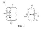
- FIG. 3shows a pair of counter-rotating rollers and a filament formed on a downstream side of the nip, in accordance with aspects of the disclosure.
- FIG. 4is a cross-sectional view of an exemplary pair of counter-rotating rollers with a fluid reservoir.
- FIG. 5is an example of an aerosol creation machine having a pair of counter-rotating rollers that create aerosol.
- FIGS. 6A and 6Bare two examples of fluid coating techniques for a pair of counter-rotating rollers.
- FIGS. 7A-7Eare additional examples of fluid coating techniques for a pair of counter-rotating rollers.
- FIG. 8is an example a system for creating aerosols that includes fans to create air flow upstream of the pair of counter-rotating rollers.
- FIG. 9is the system for creating aerosols shown in FIG. 8 with the addition of baffles that are positioned downstream of the pair of counter-rotating rollers.
- FIG. 10is the system for creating aerosols shown in FIG. 9 with the addition of a spray collector and a vacuum that are positioned downstream of the pair of counter-rotating rollers and the baffles.
- FIG. 11is an example system for creating aerosols that includes air flow that is positioned upstream of the pair of counter-rotating rollers and baffles, a spray collector, and a vacuum that are positioned downstream of the pair of counter-rotating rollers.
- FIG. 12is another example system for creating aerosols that includes a fan positioned below the pair of counter-rotating roller, a baffle positioned above the counter-rotating rollers, and a spray collector and vacuum positioned downstream of the counter-rotating rollers.
- FIG. 13is yet another example system for creating aerosols that includes an air stream that travels parallel to the counter-rotating rollers along the nip defined between the rollers.
- FIG. 14is an example roller of a counter-rotating roller showing various openings on the roller surface.
- FIGS. 15A-15Care example textures for one or both of the counter-rotating rollers.
- FIG. 16is one of the counter-rotating rollers having two regions of different textured surfaces.
- FIG. 17is yet another example textured surface for a counter-rotating roller in which ribs spaced apart at varying distances extend around the circumference of the roller.
- FIG. 18is still another type of textured roller surface in which a plurality of bristles extends away from the surface of the roller.
- FIG. 19is an example roller having two surface treatments applied to its surface in different regions.
- Aerosols, mists, and vaporsare interchangeable terms used to describe one or more droplets of fluid filaments that become suspended in air.
- the fluidsare often liquids, having either Newtonian or non-Newtonian properties.
- fluids having non-Newtonian propertiescan have strong extensional thickening, which cause their extensional viscosity to increase significantly, sometimes several orders of magnitude, in the straining direction when strained.
- the extensional thickening of non-Newtonian fluidscauses viscous drag that overwhelms the inertial and surface tension forces of the fluid and allows the system to support large strain before breaking-up and preventing the formation of small drops or droplets.
- all fluidsincluding fluids having Newtonian and non-Newtonian properties, eventually break-up into small droplets and form a mist or aerosol. All fluids can be continually stretched to form fluid filaments (stretched fluid) until the fluid filaments break into several droplets thus forming a mist or aerosol.
- the process of straining and stretching fluid filamentscan be repeated with excess fluid remaining after the first round of droplets have been formed or with new fluid. Further, multiple fluid filaments can be stretched in parallel with the first fluid filament stretching and straining process thus increasing the volume of the formed droplets.
- the amount of time between stretching the first fluid filament and any additional excess fluid filamentscan be defined by a time period that may be adjusted or controlled, as desired.
- the time periods between multiple stretching and breaking of fluid filamentscan be variable or can be constant.
- FIG. 1shows a progression of fluid that is stretched by a pair of counter-rotating rollers 100 , 102 .
- a nip 104is defined as the space between the two rollers 100 , 102 into which the fluid is drawn when the rollers 100 , 102 counter-rotate.
- the fluidpools at an upstream side 106 of the nip 104 and is drawn through the nip 104 .
- On a downstream side 108 of the nip 104the fluid is stretched between the surfaces of the two rollers 100 , 102 into a fluid filament 110 .
- the rollers 100 , 102 counter-rotatethe surfaces of the rollers 100 , 102 to which the fluid filament 110 adheres remains the same, but the space between such surface is greater.
- the fluid filament 112grows longer and thinner as the surfaces of the rollers 100 , 102 rotate away from each other.
- the fluid filament 112breaks up into several droplets 114 and leaves excess fluid 116 behind on each of the roller's surface.
- the excess fluid 116retracts to the surface of its respective roller and can be part of the fluid that pools and is drawn through the nip on the next rotation of the rollers. The process can be repeated to provide a continuous mist.
- FIG. 2shows a progression of fluid 204 that is stretched between a pair of pistons 200 , 202 to form a fluid filament 206 that eventually breaks up into a plurality of droplets 206 .
- Fluid 204is placed between the pistons 200 , 202 .
- the pistons 200 , 202are pulled apart and a continuous strain is applied to cause the fluid 204 to stretch between the pistons 200 , 202 and form a fluid filament 206 .
- the fluid filament 206grows longer and thinner, the fluid filament 206 eventually reaches its capillary break-up point at which it breaks into multiple droplets 208 and leaves excess fluid 210 behind on the surface of each piston 200 , 202 .
- FIG. 1shows a progression of fluid 204 that is stretched between a pair of pistons 200 , 202 to form a fluid filament 206 that eventually breaks up into a plurality of droplets 206 .
- Fluid 204is placed between the pistons 200 , 202 .
- the pistons 200 , 202are
- FIG. 2also shows a beads-on-a-string structure 212 , which is the precursor to fluid filament 206 reach its capillary break-up point at which time the droplets 208 form. Excess fluid 210 is pooled on the pistons 200 , 202 and the pistons 200 , 202 can be brought back together and the fluid stretched again, thereby repeating the process and forming additional mist droplets.
- FIG. 3shows an example pair of counter-rotating rollers 302 , 304 .
- the rollers 302 , 304define a nip 306 , which is the region between the rollers.
- the nipis defined by the space between rollers that are physically spaced apart.
- the nip 306is defined between the rollers physically touching each other.
- the rollershave a flexible surface material that compresses when the rollers contact each other at the nip.
- the nip 306has an upstream side 310 and a downstream side 312 . Fluid coating the roller(s) pools on the upstream side 310 of the nip 306 . The fluid is drawn through the nip 306 to the downstream side 312 and stretched to form a fluid filament 308 .
- the fluid filament 308has a continuous and increasing strain applied to it on the downstream side, which causes the fluid filament 308 to grow longer and thinner as the strain is increased and the surfaces of the rollers 302 , 304 are pulled farther apart. In the example shown in FIG.
- the strain applied to the fluid filament 308is increased because of the counter-rotation of the rollers 302 , 304 —the fluid remains attached to the same location on the surfaces of the rollers and the rollers counter-rotate, which causes a greater distance between the rollers' surfaces as the rotation occurs, thereby stretching the fluid filament until it breaks.
- FIG. 4shows a more detailed view of an aerosol creation system 400 having a pair of counter rotating rollers 402 , 404 . Similar to FIG. 3 , the pair of counter-rotating rollers 402 , 404 of FIG. 4 define a nip 406 therebetween and they counter-rotate with respect to each other.
- the rollers 402 , 404are both coated with a fluid 412 , 414 , respectively.
- the fluid 412 , 414extends around the entire circumference of each roller 402 , 404 .
- Some portion of the fluid 412 , 414 on one or both rollers 402 , 404could partially dry-off leaving areas of the roller surface(s) without a fluid coating.
- the fluidcan coat only one of the pair of rollers that could also experience some partial dry-off areas, in other examples.
- a portion of the lower roller 404is submerged in a coating pan 408 that contains the fluid 410 that coats the lower roller 404 .
- the lower roller 404also has a rubber layer 416 that enables a negative gap to be implemented between the lower roller 404 and the upper roller 402 .
- the negative gap between the two rollers 402 , 404causes the fluid to be reversibly compressed between the rollers 402 , 404 .
- the rubber layer 416also encourages the fluid 410 to adhere to the roller 404 surface.
- the rubber layer 416is rubber in this example, but can be any other suitable material that helps the fluid adhere to the roller in other examples.
- nip 406Between the pair of counter-rotating rollers 402 , 404 is a nip 406 .
- the nipsqueezes the fluid layers 412 , 414 between the two rollers 402 , 404 at a controlled fluid thickness.
- the controlled fluid thicknesscan be adjustable in some examples or can be fixed in other examples. Controlling the fluid thickness controls the volume of and manner in which the droplets 418 of the mist are formed on the downstream side of the nip 406 .
- the fluidcan pool at the upstream side of the nip 406 before it passes through the nip 406 .
- the pooling of fluid in the example shown in FIG. 4can be a combination of the fluid from both rollers 402 , 404 .
- FIG. 5shows an example of an aerosol creation system 500 having a pair of counter-rotating rollers 502 , 504 as a strain element that stretches the fluid.
- a driving elementsuch as the motors 506 shown in FIG. 5 , drive the pair of counter-rotating rollers 502 , 504 to rotate in counter-rotation with respect to each other, as indicated by the arrows 508 , 510 in FIG. 5 .
- a fluid source 511such as a reservoir with liquid in it, coats one or both of the rollers 502 , 504 with a fluid.
- a film of fluidforms on the surface(s) one or both of the rollers 502 , 504 .
- a metering blade 512 or other film thickness control mechanismmay be included in the filament creation system 500 to control the thickness of the film on the roller(s) 502 , 504 .
- the metering blade 512either contacts, as shown in FIG. 5 , or comes into near contact with one or both of the rollers 502 , 504 to control the thickness of the film of fluid on the roller(s) 502 , 504 .
- the fluid coating one or both of the rollersis drawn into a nip defined between the rollers.
- the fluid filamentstretches on a downstream side of the nip and breaks into droplets to form the mist on the downstream side of the nip.
- the fluid filament breaking into dropletsflows in a direction that is away from the rollers themselves.
- a harvesting elementcan be positioned to collect mist that is formed by the fluid coating being drawn through the nip of the rollers.
- the mistis a collection of the droplets that are formed by the fluid filaments breaking.
- FIGS. 6A and 6Bshow two different types of fluid coating techniques for aerosol creation systems having a pair of counter-rotating rollers that stretch the fluid.
- FIG. 6Aincludes a fluid feed 602 that is directed to cause the fluid to contact the top roller 604 of the pair of counter-rotating rollers.
- the fluid feed 602causes the fluid to contact the top roller 604 near where a metering blade 606 also contacts the top roller 602 , in this example.
- the metering blade 606controls the thickness of the fluid that adheres to the surface of the top roller 604 .
- the fluidforms a fluid film around the circumference of the surface of the top roller 604 as the top roller 604 rotates in a counter-clockwise motion and the metering blade 606 sets a maximum thickness for the fluid film based on how close it is positioned to the surface of the top roller 604 in this example or either or both rollers in alternative examples.
- the counter-rotation of the rollers 604 , 610draws fluid through a nip 608 formed between the top roller 604 and the bottom roller 610 .
- the bottom roller 610rotates in a clockwise motion, which thereby draws the fluid film through an upstream end of the nip 608 .
- Air flow pathways 612 , 614 on the downstream side of the nip 608have a pathway that is parallel to the rotating motion of each respective roller, e.g., for the top, counter-clockwise rotating roller 604 , the airflow pathway 612 is parallel to the counter-clockwise rotation of the top roller 604 and for the bottom, clockwise rotating roller 610 , the airflow pathway 614 is parallel to the clockwise rotation of the bottom roller 610 .
- FIG. 6Bshows another roller coating technique for the same pair of counter-rotating rollers 640 , 610 shown in FIG. 6A in which the fluid source is a pan or reservoir 616 with fluid in it.
- the reservoir 616is positioned so that a portion of the bottom roller 610 is submerged in and travels through the fluid in the pan 614 when it rotates, which encourages or causes fluid to adhere to the surface of the bottom roller 610 .
- the metering blade 618is positioned to contact or nearly contact the bottom roller 610 and control the thickness of the fluid film that adheres to the surface of the bottom roller 610 by defining a maximum thickness through which the fluid passes.
- the airflow pathways 612 , 614are the same or similar for the counter-rotating rollers for both coating techniques shown in FIGS. 6A and 6B .
- the nip 608 shown in the FIGS. 6A and 6B examplesincludes a gap or space between the two rollers 604 , 610 such that the rollers 604 , 610 are positioned adjacent to, but not in direct contact with each other.
- the narrow gap formed by the nip 608still causes the fluid filaments to stretch on the downstream end of the nip 608 and break into droplets to form a mist or aerosol.
- FIGS. 7A-7Eshow alternative coating techniques for applying fluid to the roller(s) of strain elements having a pair of counter-rotating rollers.
- a single roller 700is shown for clarity, although the rollers are part of a pair of counter-rotating rollers.
- FIG. 7Ashows a fluid source 702 that is applying a slot bead coating to the roller 700 .
- the fluid source 702is positioned to apply the fluid to the surface of the roller 700 on an upstream side of and approximately midway along the height of the roller 700 .
- the fluid source 702is in contact or near contact with the surface of the roller 700 in this example.
- the fluid 704coats the circumference of the roller 700 .
- FIG. 7Bhas a fluid source 706 having a first fluid 708 and a second fluid 710 that apply a multi-layer slot bead coating to the roller 700 .
- the fluid source 706is positioned to apply the fluid to the surface of the roller 700 on an upstream side of and approximately midway along the height of the roller 700 and is in contact or near contact with the surface of the roller 700 .
- the fluid source 706includes a first fluid 708 and a second fluid 710 that are overlaid on each other and are applied as a multi-layer fluid 712 to the surface of the roller 700 .
- the multi-layer fluid 712coats the circumference of the roller 700 .
- FIG. 7Cshows a slot curtain coating technique in which the fluid source 714 is positioned above and approximately midway along with width of the roller 700 .
- the fluid source 714is also spaced apart from the roller 700 and does not come into physical contact with the surface of the roller 700 in applying the fluid to the roller 700 , which causes the fluid to travel a distance through the air before contacting the roller 700 .
- the fluid pathway 716extends around the circumference of the roller in a similar fashion to the other alternative coating techniques discussed above in FIGS. 7A and 7B .
- FIG. 7Dshows a slide bead coating technique in which the fluid source 718 includes a first fluid 720 , a second fluid 722 , and a third fluid 724 that together create a multi-layer fluid 726 that adheres to the surface of the roller 700 .
- the fluid source 718is positioned on a side of and is tilted at an angle with respect to the roller 700 such that when each of the first fluid 720 , the second fluid 722 , and the third fluid 724 are dispensed, they run into each other and form the multi-layer fluid 726 .
- the fluid source 718 in this exampleis positioned to dispense the fluid 726 either in contact or in near contact with the roller 700 . Similar to the other examples discussed above, the fluid pathway of the fluid 726 extends around the circumference of the roller 700 .
- FIG. 7Eshows a slide curtain coating technique in which the fluid source 728 includes a first fluid 730 , a second fluid 732 , and a third fluid 734 that together create a multi-layer fluid 736 that adheres to the surface of the roller 700 .
- the fluid source 728is positioned to a side of and is tilted at an angle with respect to the roller 700 such that when each of the first fluid 730 , the second fluid 732 , and the third fluid 734 are dispensed, they run into each other and form the multi-layer fluid 736 .
- the fluid source 728is spaced apart from the surface of the roller 700 and does not come into physical contact with the surface of the roller 700 in applying the fluid 736 to the roller 700 , which causes the fluid 736 to travel a distance through the air before contacting the roller 700 .
- the fluid pathwayextends in the direction perpendicular to the point of contact between the fluid 736 and the roller 700 and coats the roller 700 around its circumference.
- any suitable coating technique(s)can be used to apply fluid to the surface of a roller and the above discussed coating techniques are not designed to limit the disclosure in any way.
- the fluidcan be applied at any suitable angle and in any suitable location with respect to the roller(s).
- the fluidcan be dripped on to one or both rollers or can be directly applied to the roller's surface.
- the fluidcan be applied on the upstream or downstream side of the nip, although in the above examples, the rollers are round and any application of fluid on the downstream side of the nip coats the roller on the downstream side and the roller's rotation causes the fluid to enter the nip on the upstream side of the nip.
- FIGS. 8-12are example configurations for aerosol harvesting systems, each having some aid in forming the droplets of the aerosol or in directing the mist of the aerosol.
- Each of FIGS. 8-12include a pair of counter-rotating rollers 800 , 802 , a fluid source 804 , and a metering blade 806 .
- an electric fieldcan be applied to or near the nip to encourage the formation of droplets from the fluid filaments.
- the aerosol creation systemalso includes three fans 808 with respective air flow pathways 810 that encourage the fluid filaments to stretch and break into droplets on the downstream side of the nip between the rollers and to encourage the formed mist or aerosol to travel in the direction of the air flow 810 .
- the fanscan be replaced with any suitable compressed air source or any pressure source that is able to encourage fluid filaments to stretch and break into droplets.
- FIG. 9shows the aerosol creation system shown in FIG. 8 with the addition of two baffles 812 positioned on the downstream side of the nip and are angled with respect to the rollers 800 , 802 .
- the baffles 812guide the formed aerosol into a pathway 814 that travels through an opening 816 formed between the two baffles 812 .
- FIG. 10is the aerosol creation system shown in FIG. 9 with the addition of an aerosol collector 818 and a vacuum 820 .
- the aerosol collector 818is an element that gathers the droplets of the aerosol into a container of any suitable type.
- the vacuum 820may be applied to help encourage the droplets of the aerosol to travel into the aerosol collector 818 or to otherwise guide the aerosol in a desired direction or along a desired pathway.
- FIG. 11is the same aerosol creation system shown in FIG. 10 , but with the fans removed.
- FIG. 12is yet another aerosol creation system having a pair of counter-rotating rollers 800 , 802 , a fluid source 804 , and a metering blade 806 .
- a fan 822is positioned on the downstream side and below the pair of rollers 800 , 802 and causes an air flow pathway 824 that is perpendicular to the direction in which the aerosol is directed away from the rollers 800 , 802 .
- the air flow pathway 824directs the aerosol toward a baffle 826 that in turn directs the aerosol into an aerosol collector 828 .
- a vacuum 830may be applied to the aerosol collector 828 to encourage the aerosol to travel into the aerosol collector 828 in one configuration.
- the air streamruns through one or both of the rollers and is expelled radially through one or both of the rollers or a portion thereof.
- FIG. 13shows still another aerosol creation system that includes a pair of counter-rotating rollers 1300 , 1302 .
- the bottom roller 1302is partially submerged in and positioned to rotate through liquid in a reservoir 1304 .
- An air stream 1308flows toward the droplets formed by the fluid break-up 1306 at the downstream side of the nip, approximately parallel with the length of the rollers 1300 , 1302 .
- FIG. 14shows a roller 1400 having a plurality of openings 1402 in its surface.
- the holesdraw the fluid into the openings 1402 and control the manner in which the fluid filaments are formed (i.e., the size of the fluid filaments, which also controls the size of the mist droplets), which regulates the manner in which the fluid filament break-up occurs and the resulting formation of the mist.
- the openings 1402can also improve the fluid adhering to the surface of the roller 1400 .
- the openings 1402can be either holes through the surface of the roller that extend into the interior of a hollow roller or can be openings with a floor, such as a cavity extending inward from the roller surface.
- the openings 1402increase the surface area to which the fluid adheres to the roller surface.
- the openings 1402can be in any suitable configuration and can be any suitable shape and size.
- FIGS. 15A-15Cshow various textures that can be applied to the surfaces of one or both rollers.
- the texturescan be formed integrally with the surface of the rollers or can be applied as a layer on top of the surface of the rollers.
- FIG. 15Ashows a textured roller surface having multiple dimples.
- FIGS. 15B and 15Cshow textured roller surfaces having patterned raised elements.
- the textured surface(s) of the roller(s)increase the surface area of the roller to which the fluid adheres and can shape or otherwise alter the thickness, shape, flow, angle of adhering, or the like between the fluid and the surface of the roller.
- FIG. 1600shows a roller 1600 with a textured surface in which a first portion 1602 of the textured surface has a first texture and a second portion 1604 of the textured surface has a second texture that is different from the first texture.
- FIG. 17shows yet another roller 1700 with a textured surface that includes a plurality of ribs 1702 that extend around the circumference of the roller and are spaced apart at various distances from each other.
- FIG. 18is still another example roller 1800 having multiple bristles 1802 that extend away from the surface of the roller 1800 .
- FIG. 19is yet another roller 1900 that has a first region 1902 that is treated with a first surface treatment to change the angle at which the fluid contacts the roller 1900 and a second region 1904 that is treated with a second surface treatment that changes the angle at which the fluid contacts the roller 1900 in a manner different from the first surface treatment.
- a single surface treatmentis applied to the roller that changes the angle at which the fluid contacts the roller.
- the texture and/or the treatment applied to the rollerscan be selected based on the characteristics of the fluid that is aerosolized to customize the aerosol creation process to each fluid and provide the most efficient manner for aerosolizing the fluid among other reasons.
- the textured surface of one or both of the rollersvaries the thickness of the fluid coating that adheres to the surface of the roller. Such a textured surface can help vary the thickness of the fluid film in a manner that increases the efficiency of the fluid filament breaking into droplets by varying the concentration of the fluid in target regions.
- the rollerscan include any suitable materials such as steel or other metal(s), plastics, rubbers, or the like.
- the rollers or any portions thereofalso can be a single material or may be any number of multiple materials.
- a rollercan have a core material that is coated with or includes a surface layer of a material that is softer than the core material.
- the surface layer materialencourages the fluid to adhere to the roller or may encourage the fluid to adhere to the roller at a different angle or in a different way than would occur without the surface layer material.
- the orientation of the fluid source with respect to the rollerscan be any desirable position.
- Some of the above examplesdiscuss an air flow source that directs the droplets forming the mist or aerosol in a particular direction.
- the air flow sourcecan be any gas source and is not limited to air.
- the gas sourcecan be positioned to cause gas to flow on either side of, above, or below the nip to encourage or cause the formation of droplets from breaking of the fluid filaments.
- the gas sourcecan be positioned to cause gas to run through one or both rollers so the gas is expelled radially from the roller(s).
- the formed mistcan be directed to form an aerosol of various geometries. Any desirable geometrical shape can be formed, depending on how the mist is directed.
- the geometrycan be any shape, such as a rectangle, cone, or conical shape and the size and contour of such shapes can be controlled by altering the volume and concentration of the aerosolized fluids.
Landscapes
- Chemical & Material Sciences (AREA)
- Organic Chemistry (AREA)
- Dispersion Chemistry (AREA)
- Chemical Kinetics & Catalysis (AREA)
- Nozzles (AREA)
- Application Of Or Painting With Fluid Materials (AREA)
- Colloid Chemistry (AREA)
- Treatment Of Fiber Materials (AREA)
Abstract
Description
Claims (17)
Priority Applications (7)
| Application Number | Priority Date | Filing Date | Title |
|---|---|---|---|
| US14/066,435US10016777B2 (en) | 2013-10-29 | 2013-10-29 | Methods and systems for creating aerosols |
| TW103134480ATWI639465B (en) | 2013-10-29 | 2014-10-02 | Methods and systems for creating aerosols |
| CN201410532187.XACN104549830B (en) | 2013-10-29 | 2014-10-10 | Method and system for generating an aerosol |
| EP14188704.2AEP2868390B1 (en) | 2013-10-29 | 2014-10-13 | Systems for creating aerosols |
| KR1020140139160AKR102071208B1 (en) | 2013-10-29 | 2014-10-15 | Methods and systems for creating aerosols |
| JP2014211062AJP6506939B2 (en) | 2013-10-29 | 2014-10-15 | Aerosol generation method and aerosol generation system |
| US16/014,402US11311900B2 (en) | 2013-10-29 | 2018-06-21 | Methods and systems for creating aerosols |
Applications Claiming Priority (1)
| Application Number | Priority Date | Filing Date | Title |
|---|---|---|---|
| US14/066,435US10016777B2 (en) | 2013-10-29 | 2013-10-29 | Methods and systems for creating aerosols |
Related Child Applications (1)
| Application Number | Title | Priority Date | Filing Date |
|---|---|---|---|
| US16/014,402DivisionUS11311900B2 (en) | 2013-10-29 | 2018-06-21 | Methods and systems for creating aerosols |
Publications (2)
| Publication Number | Publication Date |
|---|---|
| US20150115057A1 US20150115057A1 (en) | 2015-04-30 |
| US10016777B2true US10016777B2 (en) | 2018-07-10 |
Family
ID=51730374
Family Applications (2)
| Application Number | Title | Priority Date | Filing Date |
|---|---|---|---|
| US14/066,435Active2034-08-19US10016777B2 (en) | 2013-10-29 | 2013-10-29 | Methods and systems for creating aerosols |
| US16/014,402Active2034-05-13US11311900B2 (en) | 2013-10-29 | 2018-06-21 | Methods and systems for creating aerosols |
Family Applications After (1)
| Application Number | Title | Priority Date | Filing Date |
|---|---|---|---|
| US16/014,402Active2034-05-13US11311900B2 (en) | 2013-10-29 | 2018-06-21 | Methods and systems for creating aerosols |
Country Status (6)
| Country | Link |
|---|---|
| US (2) | US10016777B2 (en) |
| EP (1) | EP2868390B1 (en) |
| JP (1) | JP6506939B2 (en) |
| KR (1) | KR102071208B1 (en) |
| CN (1) | CN104549830B (en) |
| TW (1) | TWI639465B (en) |
Families Citing this family (16)
| Publication number | Priority date | Publication date | Assignee | Title |
|---|---|---|---|---|
| US10016777B2 (en)* | 2013-10-29 | 2018-07-10 | Palo Alto Research Center Incorporated | Methods and systems for creating aerosols |
| US9757747B2 (en) | 2014-05-27 | 2017-09-12 | Palo Alto Research Center Incorporated | Methods and systems for creating aerosols |
| US9527056B2 (en)* | 2014-05-27 | 2016-12-27 | Palo Alto Research Center Incorporated | Methods and systems for creating aerosols |
| US9707588B2 (en)* | 2014-05-27 | 2017-07-18 | Palo Alto Research Center Incorporated | Methods and systems for creating aerosols |
| US9782790B2 (en) | 2014-12-18 | 2017-10-10 | Palo Alto Research Center Incorporated | Devices and methods for the controlled formation and dispension of small drops of highly viscous and/or non-newtonian liquids |
| US9789499B2 (en)* | 2015-07-29 | 2017-10-17 | Palo Alto Research Center Incorporated | Filament extension atomizers |
| US9707577B2 (en)* | 2015-07-29 | 2017-07-18 | Palo Alto Research Center Incorporated | Filament extension atomizers |
| US9993839B2 (en)* | 2016-01-18 | 2018-06-12 | Palo Alto Research Center Incorporated | System and method for coating a substrate |
| US10500784B2 (en) | 2016-01-20 | 2019-12-10 | Palo Alto Research Center Incorporated | Additive deposition system and method |
| US10493483B2 (en)* | 2017-07-17 | 2019-12-03 | Palo Alto Research Center Incorporated | Central fed roller for filament extension atomizer |
| US10464094B2 (en) | 2017-07-31 | 2019-11-05 | Palo Alto Research Center Incorporated | Pressure induced surface wetting for enhanced spreading and controlled filament size |
| US10919215B2 (en) | 2017-08-22 | 2021-02-16 | Palo Alto Research Center Incorporated | Electrostatic polymer aerosol deposition and fusing of solid particles for three-dimensional printing |
| US10953425B2 (en)* | 2018-04-25 | 2021-03-23 | Palo Alto Research Center Incorporated | Methods and systems for collecting droplets of strain hardening viscoelastic fluids in a spray |
| US11246997B2 (en)* | 2018-09-25 | 2022-02-15 | Palo Alto Research Center Incorporated | Handheld filament extension atomizer for precision delivery of drugs and therapeutics |
| CN110963232B (en)* | 2019-12-14 | 2021-03-16 | 深圳市开步电子有限公司 | An automatic coating machine for resistance processing |
| US11909052B2 (en) | 2021-06-30 | 2024-02-20 | Xerox Corporation | Fabrication of membrane electrode assembly with filament extension atomizer spray |
Citations (63)
| Publication number | Priority date | Publication date | Assignee | Title |
|---|---|---|---|---|
| US2291046A (en)* | 1942-07-28 | Arrangement for burning liquid fuel | ||
| US3554815A (en) | 1963-04-30 | 1971-01-12 | Du Pont | Thin,flexible thermoelectric device |
| US3626833A (en)* | 1969-06-09 | 1971-12-14 | Addressograph Multigraph | Liquid developing apparatus |
| US3649829A (en) | 1970-10-06 | 1972-03-14 | Atomic Energy Commission | Laminar flow cell |
| US3702258A (en) | 1969-03-05 | 1972-11-07 | Eastman Kodak Co | Web treatment method |
| US3717875A (en)* | 1971-05-04 | 1973-02-20 | Little Inc A | Method and apparatus for directing the flow of liquid droplets in a stream and instruments incorporating the same |
| US3873025A (en)* | 1974-05-06 | 1975-03-25 | Stora Kopparbergs Bergslags Ab | Method and apparatus for atomizing a liquid medium and for spraying the atomized liquid medium in a predetermined direction |
| US3926114A (en)* | 1967-06-30 | 1975-12-16 | Walter E S Matuschke | Rotary lithographic printing press with ink and dampening fluid separator |
| US4011993A (en)* | 1975-03-26 | 1977-03-15 | Atom Chemical Paint Co., Ltd. | Apparatus for paint application |
| US4034670A (en)* | 1975-03-24 | 1977-07-12 | Rockwell International Corporation | Dampening device for lithographic printing press |
| US4222059A (en) | 1978-12-18 | 1980-09-09 | Xerox Corporation | Ink jet multiple field electrostatic lens |
| US4384296A (en) | 1981-04-24 | 1983-05-17 | Xerox Corporation | Linear ink jet deflection method and apparatus |
| US5270086A (en) | 1989-09-25 | 1993-12-14 | Schneider (Usa) Inc. | Multilayer extrusion of angioplasty balloons |
| US5314119A (en)* | 1992-04-20 | 1994-05-24 | Latanick Equipment, Inc. | Method and apparatus for applying thin coatings of fluid droplets |
| US5315119A (en)* | 1991-11-29 | 1994-05-24 | Kabushiki Kaisha Toshiba | Electron beam irradiating apparatus and electric signal detecting apparatus |
| US5633045A (en)* | 1995-08-31 | 1997-05-27 | Xerox Corporation | Apparatus and process for coating webs using a cylindrical applicator |
| US5641544A (en)* | 1995-02-02 | 1997-06-24 | Minnesota Mining And Manufacturing Company | Method and apparatus for applying thin fluid coatings |
| US5656313A (en)* | 1989-10-04 | 1997-08-12 | Micro-Blend, Inc. | Method of beverage blending and carbonation |
| US5720370A (en)* | 1995-05-10 | 1998-02-24 | Tok Bearing Co., Ltd. | Rotary damper |
| US5733608A (en)* | 1995-02-02 | 1998-03-31 | Minnesota Mining And Manufacturing Company | Method and apparatus for applying thin fluid coating stripes |
| US5861195A (en)* | 1997-01-21 | 1999-01-19 | Minnesota Mining And Manufacturing Company | Method for coating a plurality of fluid layers onto a substrate |
| US5934142A (en)* | 1997-11-17 | 1999-08-10 | Chrysler Corporation | Two piece continuous mesh synchronized reverse idler system |
| US6098691A (en)* | 1996-12-04 | 2000-08-08 | G D Societa Azioni | Gumming device for applying adhesive to sheet material |
| US6204644B1 (en)* | 1998-01-30 | 2001-03-20 | Toko, Inc. | Switching power supply for speeding up turn-off operation of a switching element |
| US6382524B1 (en)* | 1999-11-26 | 2002-05-07 | Diversey Lever, Inc. | Applicator for applying a fluid to a surface and method of applying a fluid to a surface |
| US20020053320A1 (en)* | 1998-12-15 | 2002-05-09 | Gregg M. Duthaler | Method for printing of transistor arrays on plastic substrates |
| US6514571B1 (en)* | 1998-05-21 | 2003-02-04 | Eastman Kodak Company | Method and apparatus for applying a solution to photosensitive material |
| US6554206B2 (en)* | 2001-01-04 | 2003-04-29 | Watt Fluid Applications, Llc | Apparatus and method for applying sprayed fluid to a moving web |
| US6576861B2 (en) | 2000-07-25 | 2003-06-10 | The Research Foundation Of State University Of New York | Method and apparatus for fine feature spray deposition |
| US6622335B1 (en)* | 2000-03-29 | 2003-09-23 | Lam Research Corporation | Drip manifold for uniform chemical delivery |
| US20030183099A1 (en)* | 2002-03-28 | 2003-10-02 | Clemens Johannes Maria De Vroome | Applicator roller having a roller jacket, applicator roller and rotating element assembly, dryer, cooling roller stand and printing press having the applicator roller and method for coating a material web |
| US6692570B2 (en)* | 2001-03-02 | 2004-02-17 | James Hardie Research Pty Limited | Spattering apparatus |
| US20050000231A1 (en) | 2003-07-02 | 2005-01-06 | Ju-Yeon Lee | Wearable cooler using thermoelectric module |
| US6934142B2 (en) | 2001-02-23 | 2005-08-23 | Robert Bosch Gmbh | Device and method for charge removal from dielectric surfaces |
| US20060035033A1 (en)* | 2004-08-10 | 2006-02-16 | Konica Minolta Photo Imaging, Inc. | Spray coating method, spray coating device and inkjet recording sheet |
| US7083830B2 (en) | 2003-10-02 | 2006-08-01 | E. I. Dupont De Nemours And Company | Electrostatically-assisted high-speed rotary application process for the production of special effect base coat/clear coat two-layer coatings |
| US20080233356A1 (en)* | 2005-09-12 | 2008-09-25 | Perlen Converting Ag | Method for the Application of a Structured Coating Upon a Smooth Surface |
| US20090014046A1 (en)* | 2007-07-12 | 2009-01-15 | Industrial Technology Research Institute | Flexible thermoelectric device and manufacturing method thereof |
| US7686987B2 (en)* | 2002-05-20 | 2010-03-30 | Eastman Kodak Company | Polycarbonate films prepared by coating methods |
| US20100154856A1 (en)* | 2007-03-13 | 2010-06-24 | Sumitomo Chemical Company, Limited | Substrate for Thermoelectric Conversion Module, and Thermoelectric Conversion Module |
| US20110017431A1 (en) | 2009-03-06 | 2011-01-27 | Y.C. Lee | Flexible thermal ground plane and manufacturing the same |
| US20110150036A1 (en) | 2009-12-21 | 2011-06-23 | Electronics And Telecommunications Research Institute | Flexible thermoelectric generator, wireless sensor node including the same and method of manufacturing the same |
| US20110154558A1 (en) | 2008-06-02 | 2011-06-30 | Nederlandse Organisatie Voor Toegepast- Natuurwetenschappelijk Onderzoek Tno | Method for Manufacturing a Thermoelectric Generator, a Wearable Thermoelectric Generator and a Garment Comprising the Same |
| EP2227834B1 (en) | 2007-12-28 | 2011-08-03 | Basf Se | Extrusion process for producing improved thermoelectric materials |
| US20110267740A1 (en)* | 2010-04-29 | 2011-11-03 | Shrisudersan Jayaraman | Packaging for electrochemically active materials, devices made therefrom, and methods of making the same |
| US20110290727A1 (en)* | 2009-01-19 | 2011-12-01 | Ronny Van Engelen | Process for Preparing Membranes |
| US8132744B2 (en) | 2004-12-13 | 2012-03-13 | Optomec, Inc. | Miniature aerosol jet and aerosol jet array |
| US20120103213A1 (en)* | 2010-10-29 | 2012-05-03 | Palo Alto Research Center Incorporated | Ink Rheology Control Subsystem for a Variable Data Lithography System |
| US20120227778A1 (en) | 2011-03-11 | 2012-09-13 | Imec | Thermoelectric Textile |
| US8272579B2 (en) | 2007-08-30 | 2012-09-25 | Optomec, Inc. | Mechanically integrated and closely coupled print head and mist source |
| US20130087180A1 (en) | 2011-10-10 | 2013-04-11 | Perpetua Power Source Technologies, Inc. | Wearable thermoelectric generator system |
| US8511251B2 (en)* | 2009-08-24 | 2013-08-20 | Fujitsu Limited | Film deposition device and method thereof |
| US8552299B2 (en) | 2008-03-05 | 2013-10-08 | The Board Of Trustees Of The University Of Illinois | Stretchable and foldable electronic devices |
| US8720370B2 (en)* | 2011-04-07 | 2014-05-13 | Dynamic Micro System Semiconductor Equipment GmbH | Methods and apparatuses for roll-on coating |
| US20140146116A1 (en) | 2012-11-29 | 2014-05-29 | Palo Alto Research Center Incorporated | Pulsating heat pipe spreader for ink jet printer |
| US8742246B2 (en) | 2011-04-22 | 2014-06-03 | Panasonic Corporation | Thermoelectric conversion module and method of manufacturing thereof |
| US20150115057A1 (en)* | 2013-10-29 | 2015-04-30 | Palo Alto Research Center Incorporated | Methods and systems for creating aerosols |
| US9021948B2 (en)* | 2011-04-27 | 2015-05-05 | Xerox Corporation | Environmental control subsystem for a variable data lithographic apparatus |
| US20150210009A1 (en)* | 2014-01-28 | 2015-07-30 | Palo Alto Research Center Incorporated | Polymer spray deposition methods and systems |
| US20150343477A1 (en)* | 2014-05-27 | 2015-12-03 | Palo Alto Research Center Incorporated | Methods and systems for creating aerosols |
| US20150343407A1 (en)* | 2014-05-27 | 2015-12-03 | Palo Alto Research Center Incorporated | Methods and systems for creating aerosols |
| US20150343468A1 (en)* | 2014-05-27 | 2015-12-03 | Palo Alto Research Center Incorporated | Methods and systems for creating aerosols |
| US20160175874A1 (en)* | 2014-12-18 | 2016-06-23 | Palo Alto Research Center Incorporated | Devices and methods for the controlled formation and dispension of small drops of highly viscous and/or non-newtonian liquids |
Family Cites Families (22)
| Publication number | Priority date | Publication date | Assignee | Title |
|---|---|---|---|---|
| US3326122A (en)* | 1965-01-18 | 1967-06-20 | Frederic C Wildeman | Dampening system for offset press |
| US4301859A (en) | 1979-05-14 | 1981-11-24 | Karl Hollemann | Hot water surface heating device |
| DE4003412A1 (en)* | 1990-02-05 | 1991-08-08 | Koenig & Bauer Ag | Offset printer - has additional rollers to carry water droplet dampener and increase ink emulsifying |
| USH976H (en) | 1990-03-16 | 1991-11-05 | The United States Of America As Represented By The Secretary Of The Army | Apparatus and method for measuring elongational viscosity of a polymeric solution |
| EP0463688B2 (en) | 1990-06-22 | 1998-01-21 | Unilever N.V. | Water-and-oil emulsion and process for preparing such emulsion |
| DE4224443A1 (en)* | 1992-07-24 | 1994-01-27 | Dox Maschinenbau Gmbh | Inking or damping device with at least one ink or colour application roller - working with further roller to form roller gap and application roller adjacent to electrode system is acted on with different voltage compared to application roller |
| JP3400764B2 (en)* | 2000-01-27 | 2003-04-28 | 株式会社東京機械製作所 | Inking device |
| US6711941B2 (en)* | 2000-08-14 | 2004-03-30 | Cambridge Polymer Group, Inc. | Apparatus and methods for measuring extensional rheological properties of a material |
| DE10131369A1 (en)* | 2001-06-28 | 2003-01-09 | Sms Demag Ag | Method and device for cooling and lubricating rolls of a roll stand |
| US7855711B2 (en)* | 2005-09-14 | 2010-12-21 | Palo Alto Research Center Incorporated | Conductive islands for printable electronic paper |
| US8469492B2 (en) | 2006-05-10 | 2013-06-25 | Samsung Electronics Co., Ltd. | Method of printing droplet using capillary electric charge concentration |
| KR100790903B1 (en) | 2007-01-23 | 2008-01-03 | 삼성전자주식회사 | Droplet discharging device using electric charge concentration and liquid column cutting and its method |
| GB0712861D0 (en)* | 2007-07-03 | 2007-08-08 | Eastman Kodak Co | Continuous ink jet printing of encapsulated droplets |
| EP2020261A1 (en)* | 2007-07-20 | 2009-02-04 | Nederlandse Organisatie voor toegepast- natuurwetenschappelijk onderzoek TNO | Multi component particle generating system |
| KR101460156B1 (en) | 2008-01-25 | 2014-11-10 | 삼성전자주식회사 | Droplet ejecting apparatus having a piezoelectric type voltage generator, and droplet ejecting method using the same |
| US9592699B2 (en)* | 2011-04-27 | 2017-03-14 | Xerox Corporation | Dampening fluid for digital lithographic printing |
| US8991310B2 (en)* | 2011-04-27 | 2015-03-31 | Palo Alto Research Center Incorporated | System for direct application of dampening fluid for a variable data lithographic apparatus |
| US20130033687A1 (en)* | 2011-08-05 | 2013-02-07 | Palo Alto Research Center Incorporated | Method for Direct Application of Dampening Fluid for a Variable Data Lithographic Apparatus |
| UA112883C2 (en)* | 2011-12-08 | 2016-11-10 | Філіп Морріс Продактс С.А. | DEVICE FOR THE FORMATION OF AEROSOL WITH A CAPILLARY BORDER LAYER |
| JP2015507525A (en)* | 2011-12-13 | 2015-03-12 | スリーエム イノベイティブ プロパティズ カンパニー | Contact coating using a manifold with capillary tubing |
| US9032874B2 (en)* | 2012-03-21 | 2015-05-19 | Xerox Corporation | Dampening fluid deposition by condensation in a digital lithographic system |
| US9962673B2 (en) | 2013-10-29 | 2018-05-08 | Palo Alto Research Center Incorporated | Methods and systems for creating aerosols |
- 2013
- 2013-10-29USUS14/066,435patent/US10016777B2/enactiveActive
- 2014
- 2014-10-02TWTW103134480Apatent/TWI639465B/ennot_activeIP Right Cessation
- 2014-10-10CNCN201410532187.XApatent/CN104549830B/ennot_activeExpired - Fee Related
- 2014-10-13EPEP14188704.2Apatent/EP2868390B1/enactiveActive
- 2014-10-15JPJP2014211062Apatent/JP6506939B2/enactiveActive
- 2014-10-15KRKR1020140139160Apatent/KR102071208B1/ennot_activeExpired - Fee Related
- 2018
- 2018-06-21USUS16/014,402patent/US11311900B2/enactiveActive
Patent Citations (64)
| Publication number | Priority date | Publication date | Assignee | Title |
|---|---|---|---|---|
| US2291046A (en)* | 1942-07-28 | Arrangement for burning liquid fuel | ||
| US3554815A (en) | 1963-04-30 | 1971-01-12 | Du Pont | Thin,flexible thermoelectric device |
| US3926114A (en)* | 1967-06-30 | 1975-12-16 | Walter E S Matuschke | Rotary lithographic printing press with ink and dampening fluid separator |
| US3702258A (en) | 1969-03-05 | 1972-11-07 | Eastman Kodak Co | Web treatment method |
| US3626833A (en)* | 1969-06-09 | 1971-12-14 | Addressograph Multigraph | Liquid developing apparatus |
| US3649829A (en) | 1970-10-06 | 1972-03-14 | Atomic Energy Commission | Laminar flow cell |
| US3717875A (en)* | 1971-05-04 | 1973-02-20 | Little Inc A | Method and apparatus for directing the flow of liquid droplets in a stream and instruments incorporating the same |
| US3873025A (en)* | 1974-05-06 | 1975-03-25 | Stora Kopparbergs Bergslags Ab | Method and apparatus for atomizing a liquid medium and for spraying the atomized liquid medium in a predetermined direction |
| US4034670A (en)* | 1975-03-24 | 1977-07-12 | Rockwell International Corporation | Dampening device for lithographic printing press |
| US4011993A (en)* | 1975-03-26 | 1977-03-15 | Atom Chemical Paint Co., Ltd. | Apparatus for paint application |
| US4222059A (en) | 1978-12-18 | 1980-09-09 | Xerox Corporation | Ink jet multiple field electrostatic lens |
| US4384296A (en) | 1981-04-24 | 1983-05-17 | Xerox Corporation | Linear ink jet deflection method and apparatus |
| US5270086A (en) | 1989-09-25 | 1993-12-14 | Schneider (Usa) Inc. | Multilayer extrusion of angioplasty balloons |
| US5656313A (en)* | 1989-10-04 | 1997-08-12 | Micro-Blend, Inc. | Method of beverage blending and carbonation |
| US5315119A (en)* | 1991-11-29 | 1994-05-24 | Kabushiki Kaisha Toshiba | Electron beam irradiating apparatus and electric signal detecting apparatus |
| US5314119A (en)* | 1992-04-20 | 1994-05-24 | Latanick Equipment, Inc. | Method and apparatus for applying thin coatings of fluid droplets |
| US5641544A (en)* | 1995-02-02 | 1997-06-24 | Minnesota Mining And Manufacturing Company | Method and apparatus for applying thin fluid coatings |
| US5733608A (en)* | 1995-02-02 | 1998-03-31 | Minnesota Mining And Manufacturing Company | Method and apparatus for applying thin fluid coating stripes |
| US5720370A (en)* | 1995-05-10 | 1998-02-24 | Tok Bearing Co., Ltd. | Rotary damper |
| US5633045A (en)* | 1995-08-31 | 1997-05-27 | Xerox Corporation | Apparatus and process for coating webs using a cylindrical applicator |
| US6098691A (en)* | 1996-12-04 | 2000-08-08 | G D Societa Azioni | Gumming device for applying adhesive to sheet material |
| US5861195A (en)* | 1997-01-21 | 1999-01-19 | Minnesota Mining And Manufacturing Company | Method for coating a plurality of fluid layers onto a substrate |
| US5934142A (en)* | 1997-11-17 | 1999-08-10 | Chrysler Corporation | Two piece continuous mesh synchronized reverse idler system |
| US6204644B1 (en)* | 1998-01-30 | 2001-03-20 | Toko, Inc. | Switching power supply for speeding up turn-off operation of a switching element |
| US6514571B1 (en)* | 1998-05-21 | 2003-02-04 | Eastman Kodak Company | Method and apparatus for applying a solution to photosensitive material |
| US20020053320A1 (en)* | 1998-12-15 | 2002-05-09 | Gregg M. Duthaler | Method for printing of transistor arrays on plastic substrates |
| US6382524B1 (en)* | 1999-11-26 | 2002-05-07 | Diversey Lever, Inc. | Applicator for applying a fluid to a surface and method of applying a fluid to a surface |
| US6622335B1 (en)* | 2000-03-29 | 2003-09-23 | Lam Research Corporation | Drip manifold for uniform chemical delivery |
| US6576861B2 (en) | 2000-07-25 | 2003-06-10 | The Research Foundation Of State University Of New York | Method and apparatus for fine feature spray deposition |
| US6554206B2 (en)* | 2001-01-04 | 2003-04-29 | Watt Fluid Applications, Llc | Apparatus and method for applying sprayed fluid to a moving web |
| US6934142B2 (en) | 2001-02-23 | 2005-08-23 | Robert Bosch Gmbh | Device and method for charge removal from dielectric surfaces |
| US6692570B2 (en)* | 2001-03-02 | 2004-02-17 | James Hardie Research Pty Limited | Spattering apparatus |
| US20030183099A1 (en)* | 2002-03-28 | 2003-10-02 | Clemens Johannes Maria De Vroome | Applicator roller having a roller jacket, applicator roller and rotating element assembly, dryer, cooling roller stand and printing press having the applicator roller and method for coating a material web |
| US7686987B2 (en)* | 2002-05-20 | 2010-03-30 | Eastman Kodak Company | Polycarbonate films prepared by coating methods |
| US20050000231A1 (en) | 2003-07-02 | 2005-01-06 | Ju-Yeon Lee | Wearable cooler using thermoelectric module |
| US7083830B2 (en) | 2003-10-02 | 2006-08-01 | E. I. Dupont De Nemours And Company | Electrostatically-assisted high-speed rotary application process for the production of special effect base coat/clear coat two-layer coatings |
| US20060035033A1 (en)* | 2004-08-10 | 2006-02-16 | Konica Minolta Photo Imaging, Inc. | Spray coating method, spray coating device and inkjet recording sheet |
| US8132744B2 (en) | 2004-12-13 | 2012-03-13 | Optomec, Inc. | Miniature aerosol jet and aerosol jet array |
| US20080233356A1 (en)* | 2005-09-12 | 2008-09-25 | Perlen Converting Ag | Method for the Application of a Structured Coating Upon a Smooth Surface |
| US20100154856A1 (en)* | 2007-03-13 | 2010-06-24 | Sumitomo Chemical Company, Limited | Substrate for Thermoelectric Conversion Module, and Thermoelectric Conversion Module |
| US20090014046A1 (en)* | 2007-07-12 | 2009-01-15 | Industrial Technology Research Institute | Flexible thermoelectric device and manufacturing method thereof |
| US9114409B2 (en)* | 2007-08-30 | 2015-08-25 | Optomec, Inc. | Mechanically integrated and closely coupled print head and mist source |
| US8272579B2 (en) | 2007-08-30 | 2012-09-25 | Optomec, Inc. | Mechanically integrated and closely coupled print head and mist source |
| EP2227834B1 (en) | 2007-12-28 | 2011-08-03 | Basf Se | Extrusion process for producing improved thermoelectric materials |
| US8552299B2 (en) | 2008-03-05 | 2013-10-08 | The Board Of Trustees Of The University Of Illinois | Stretchable and foldable electronic devices |
| US20110154558A1 (en) | 2008-06-02 | 2011-06-30 | Nederlandse Organisatie Voor Toegepast- Natuurwetenschappelijk Onderzoek Tno | Method for Manufacturing a Thermoelectric Generator, a Wearable Thermoelectric Generator and a Garment Comprising the Same |
| US20110290727A1 (en)* | 2009-01-19 | 2011-12-01 | Ronny Van Engelen | Process for Preparing Membranes |
| US20110017431A1 (en) | 2009-03-06 | 2011-01-27 | Y.C. Lee | Flexible thermal ground plane and manufacturing the same |
| US8511251B2 (en)* | 2009-08-24 | 2013-08-20 | Fujitsu Limited | Film deposition device and method thereof |
| US20110150036A1 (en) | 2009-12-21 | 2011-06-23 | Electronics And Telecommunications Research Institute | Flexible thermoelectric generator, wireless sensor node including the same and method of manufacturing the same |
| US20110267740A1 (en)* | 2010-04-29 | 2011-11-03 | Shrisudersan Jayaraman | Packaging for electrochemically active materials, devices made therefrom, and methods of making the same |
| US20120103213A1 (en)* | 2010-10-29 | 2012-05-03 | Palo Alto Research Center Incorporated | Ink Rheology Control Subsystem for a Variable Data Lithography System |
| US20120227778A1 (en) | 2011-03-11 | 2012-09-13 | Imec | Thermoelectric Textile |
| US8720370B2 (en)* | 2011-04-07 | 2014-05-13 | Dynamic Micro System Semiconductor Equipment GmbH | Methods and apparatuses for roll-on coating |
| US8742246B2 (en) | 2011-04-22 | 2014-06-03 | Panasonic Corporation | Thermoelectric conversion module and method of manufacturing thereof |
| US9021948B2 (en)* | 2011-04-27 | 2015-05-05 | Xerox Corporation | Environmental control subsystem for a variable data lithographic apparatus |
| US20130087180A1 (en) | 2011-10-10 | 2013-04-11 | Perpetua Power Source Technologies, Inc. | Wearable thermoelectric generator system |
| US20140146116A1 (en) | 2012-11-29 | 2014-05-29 | Palo Alto Research Center Incorporated | Pulsating heat pipe spreader for ink jet printer |
| US20150115057A1 (en)* | 2013-10-29 | 2015-04-30 | Palo Alto Research Center Incorporated | Methods and systems for creating aerosols |
| US20150210009A1 (en)* | 2014-01-28 | 2015-07-30 | Palo Alto Research Center Incorporated | Polymer spray deposition methods and systems |
| US20150343477A1 (en)* | 2014-05-27 | 2015-12-03 | Palo Alto Research Center Incorporated | Methods and systems for creating aerosols |
| US20150343407A1 (en)* | 2014-05-27 | 2015-12-03 | Palo Alto Research Center Incorporated | Methods and systems for creating aerosols |
| US20150343468A1 (en)* | 2014-05-27 | 2015-12-03 | Palo Alto Research Center Incorporated | Methods and systems for creating aerosols |
| US20160175874A1 (en)* | 2014-12-18 | 2016-06-23 | Palo Alto Research Center Incorporated | Devices and methods for the controlled formation and dispension of small drops of highly viscous and/or non-newtonian liquids |
Non-Patent Citations (34)
| Title |
|---|
| "Ortho-Planar Spring", BYI Mechanical Engineering Website, URL: http://compliantmechanisms.byu.edu/content/ortho-planar-spring, retrieved from the Internet on Dec. 23, 2014. |
| Arens, E., "Partial- and whole-body thermal sensation and comfort-Part I: Uniform environmental conditions," Journal of Thermal Biology, vol. 31, Issues 1-2, Jan. 2006, pp. 53-59. |
| Arens, E., "Partial- and whole-body thermal sensation and comfort-Part II: Non-uniform environmental conditions," Journal of Thermal Biology, vol. 31, Issues 1-2, Jan. 2006, pp. 60-66. |
| Arens, E., "Partial- and whole-body thermal sensation and comfort—Part I: Uniform environmental conditions," Journal of Thermal Biology, vol. 31, Issues 1-2, Jan. 2006, pp. 53-59. |
| Arens, E., "Partial- and whole-body thermal sensation and comfort—Part II: Non-uniform environmental conditions," Journal of Thermal Biology, vol. 31, Issues 1-2, Jan. 2006, pp. 60-66. |
| Bailey, Adrian G.: "The Science and technology of electrostatic powder spraying, transport and coating", Journal of Electrostatics, vol. 45, 1998, pp. 85-120. |
| Bhat, Pradeep P., "Formation of beads-on-a-string structures during break-up of viscoelastic filaments," Aug. 2010, vol. 6:625-631, Nature Physics, vol. 7 pages. |
| Bullis, Kevin, "Expandable Silicon", MIT Technology Review, Dec. 14, 2007, URL: http://www.technologyreview.com/news/409198/expandable-silicon/, retrieved from the Internet on Dec. 23, 2014. |
| C. Huizenga, H. Zhang, E. Arens, D. Wang: "Skin and core temperature response to partial-and whole-body heating and cooling," Journal of Thermal Biology, vol. 29, Issues 7-8, Oct.-Dec. 2004, pp. 549-558. |
| Chapter 15, "Ink Jet Printing", 14 pages, found at http://www.lintech.org/comp-per/15/15INK.pdf. |
| Chen, A., "Dispenser-printed planar thick-film thermoelectric energy generators," J. Micromech. Microeng., 21(10), 2011. |
| Crowe, Clayton et al.: "Multiphase Flows With Droplets and Particles", CRC Press, LLC, 1998. |
| Domnick, et al: "The Simulation of Electrostatic Spray Painting Process with High-Speed Rotary Bell Atomizers. Part II: External Charging", Part. Part. Syst. Charact. vol. 23, 2006, pp. 408-416, URL: http://www.ppsc-journal.com. |
| Francioso, L., "Flexible thermoelectric generator for ambient assisted living wearable biometric sensors", Journal of Power Sources, vol. 196, Issue 6, Mar. 15, 2011, pp. 3239-3243. |
| Hewitt, A.B., "Multilayered Carbon Nanotube/Polymer Composite Based Thermoelectric Fabrics," Nano Letters, 12(3), pp. 1307-1310, 2012. |
| http://glaciertek.com/, retrieved on Dec. 19, 2014. |
| http://veskimo.com/, retrieved on Dec. 19, 2014. |
| http://www.stacoolvest.com/, retrieved on Dec. 19, 2014. |
| http://www.steelevest.com/, retrieved on Dec. 19, 2014. |
| Kelly, Ryan T, et al..: "The ion funnel: theory, implementations, and applications", Mass Spectrometry Reviews,vol. 29, 2010, pp. 294-312. |
| L. Francioso, C. De Pascali, A. Taurino, P. Siciliano, A. De Risi: "Wearable and flexible thermoelectric generator with enhanced package," In Proc. SPIE 8763, Smart Sensors, Actuators, and MEMS VI, 876306, May 2013. |
| Le, Hue P., "Progress and Trends in Ink-jet Printing Technology," Jan./Feb. 1998, vol. 42:49-62, Journal of Imaging Science and Technology, 16 pages, found at: http://www.imaging.org/ist/resources/tutorials/inkjet.cfm. |
| Marple, A. and Liu, Y.H.: "Characteristics of Laminar Jet Impactors", Environmental Science & Technology, vol. 8, No. 7, Jul. 1974, pp. 648-654. |
| Matheson, Rob, "Cool Invention Wins First Place at MADMEC", MIT News Office, Oct. 17, 2013, 3 pages, retrieved from the Internet: http://newsoffice.mit.edu/2013/madmec-design-competition-1017, retrieved on Dec. 19, 2014. |
| McClure, Max, "Stanford Researchers' Cooling Glove Better than Steroids-and Helps Solve Physiological Mystery Too", Stanford Report, Aug. 29, 2012, 3 pages, retrieved from the Internet: http://news.stanford.edu/news/2012/ augusticooling-glove-research-082912.html, retrieved on Dec. 19, 2014. |
| McClure, Max, "Stanford Researchers' Cooling Glove Better than Steroids—and Helps Solve Physiological Mystery Too", Stanford Report, Aug. 29, 2012, 3 pages, retrieved from the Internet: http://news.stanford.edu/news/2012/ augusticooling-glove-research-082912.html, retrieved on Dec. 19, 2014. |
| Oliveira, Monica S., "Iterated Stretching, Extensional Rheology and Formation of Beads-on-a-String Structures in Polymer Solutions," Jan. 20, 2006, Special Issue of JNNFM on Extensional Flow, MIT, Cambridge, MA, 36 pages. |
| Owen, M., "Misting of non-Newtonian Liquids in Forward Roll Coating," Jul. 13, 2011, Journal of Non-Newtonian Fluid Mechanics, vol. 166:1123-1128, 6 pages. |
| Owens et al, Misting of non-Newtonian liquids in forward roll coating, Jul. 13, 2011, Journal of Non-Newtonian Fluid Mechanics, 166, pp. 1123-1128.* |
| S.-J. Kim, J.-H. Wea and B.-J. Cho: "A wearable thermoelectric generator fabricated on a glass fabric," Energy Environmental Science, 2014. |
| Shi, X.D., "A Cascade of Structure in a Drop Falling from a Faucet," Jul. 8, 2004, vol. 265:219-222, Science, 4 pages. |
| Sholin, V. et al.: "High Work Function Materials for Source/Drain Contacts in Printed Polymer Thin Transistors," Applied Physics Letters, vol. 92, 2008. |
| Vanhemert, Kyle, "MIT Wristband Could Make AC Obsolete", Wired.com, Oct. 30, 2013, retrieved from the Internet: http://www.wired.com/2013/10/an-ingenious-wristband-that-keeps-your-body-at-theperfect-temperature-no-ac-required/, retrieved on Dec. 19, 2014. |
| Zhou, Li, et al.: "Highly Conductive, Flexible, Polyurethane-Based Adhesives for Flexible and Printed Electronics," Advanced Functional Materials, vol. 23, p. 1459-1465, wileyonlinelibrary.com. |
Also Published As
| Publication number | Publication date |
|---|---|
| TWI639465B (en) | 2018-11-01 |
| EP2868390A1 (en) | 2015-05-06 |
| CN104549830B (en) | 2019-11-15 |
| JP6506939B2 (en) | 2019-04-24 |
| JP2015085324A (en) | 2015-05-07 |
| US20150115057A1 (en) | 2015-04-30 |
| KR20150050365A (en) | 2015-05-08 |
| US20180297052A1 (en) | 2018-10-18 |
| US11311900B2 (en) | 2022-04-26 |
| TW201515695A (en) | 2015-05-01 |
| EP2868390B1 (en) | 2017-03-01 |
| KR102071208B1 (en) | 2020-01-30 |
| CN104549830A (en) | 2015-04-29 |
Similar Documents
| Publication | Publication Date | Title |
|---|---|---|
| US11311900B2 (en) | Methods and systems for creating aerosols | |
| US9962673B2 (en) | Methods and systems for creating aerosols | |
| US12202001B2 (en) | Methods and systems for creating aerosols | |
| EP2949401B1 (en) | Methods and systems for creating aerosols | |
| EP2949402B1 (en) | Methods and systems for creating aerosols |
Legal Events
| Date | Code | Title | Description |
|---|---|---|---|
| AS | Assignment | Owner name:PALO ALTO RESEARCH CENTER INCORPORATED, CALIFORNIA Free format text:ASSIGNMENT OF ASSIGNORS INTEREST;ASSIGNORS:BECK, VICTOR;JOHNSON, DAVID MATHEW;REEL/FRAME:031504/0030 Effective date:20131029 | |
| STCF | Information on status: patent grant | Free format text:PATENTED CASE | |
| MAFP | Maintenance fee payment | Free format text:PAYMENT OF MAINTENANCE FEE, 4TH YEAR, LARGE ENTITY (ORIGINAL EVENT CODE: M1551); ENTITY STATUS OF PATENT OWNER: LARGE ENTITY Year of fee payment:4 | |
| AS | Assignment | Owner name:XEROX CORPORATION, CONNECTICUT Free format text:ASSIGNMENT OF ASSIGNORS INTEREST;ASSIGNOR:PALO ALTO RESEARCH CENTER INCORPORATED;REEL/FRAME:064038/0001 Effective date:20230416 | |
| AS | Assignment | Owner name:CITIBANK, N.A., AS COLLATERAL AGENT, NEW YORK Free format text:SECURITY INTEREST;ASSIGNOR:XEROX CORPORATION;REEL/FRAME:064760/0389 Effective date:20230621 | |
| AS | Assignment | Owner name:XEROX CORPORATION, CONNECTICUT Free format text:CORRECTIVE ASSIGNMENT TO CORRECT THE REMOVAL OF US PATENTS 9356603, 10026651, 10626048 AND INCLUSION OF US PATENT 7167871 PREVIOUSLY RECORDED ON REEL 064038 FRAME 0001. ASSIGNOR(S) HEREBY CONFIRMS THE ASSIGNMENT;ASSIGNOR:PALO ALTO RESEARCH CENTER INCORPORATED;REEL/FRAME:064161/0001 Effective date:20230416 | |
| AS | Assignment | Owner name:JEFFERIES FINANCE LLC, AS COLLATERAL AGENT, NEW YORK Free format text:SECURITY INTEREST;ASSIGNOR:XEROX CORPORATION;REEL/FRAME:065628/0019 Effective date:20231117 | |
| AS | Assignment | Owner name:XEROX CORPORATION, CONNECTICUT Free format text:TERMINATION AND RELEASE OF SECURITY INTEREST IN PATENTS RECORDED AT RF 064760/0389;ASSIGNOR:CITIBANK, N.A., AS COLLATERAL AGENT;REEL/FRAME:068261/0001 Effective date:20240206 Owner name:CITIBANK, N.A., AS COLLATERAL AGENT, NEW YORK Free format text:SECURITY INTEREST;ASSIGNOR:XEROX CORPORATION;REEL/FRAME:066741/0001 Effective date:20240206 | |
| AS | Assignment | Owner name:U.S. BANK TRUST COMPANY, NATIONAL ASSOCIATION, AS COLLATERAL AGENT, CONNECTICUT Free format text:FIRST LIEN NOTES PATENT SECURITY AGREEMENT;ASSIGNOR:XEROX CORPORATION;REEL/FRAME:070824/0001 Effective date:20250411 | |
| AS | Assignment | Owner name:U.S. BANK TRUST COMPANY, NATIONAL ASSOCIATION, AS COLLATERAL AGENT, CONNECTICUT Free format text:SECOND LIEN NOTES PATENT SECURITY AGREEMENT;ASSIGNOR:XEROX CORPORATION;REEL/FRAME:071785/0550 Effective date:20250701 |