US10016538B2 - System and method for managing reduced pressure at a tissue site - Google Patents
System and method for managing reduced pressure at a tissue siteDownload PDFInfo
- Publication number
- US10016538B2 US10016538B2US14/824,845US201514824845AUS10016538B2US 10016538 B2US10016538 B2US 10016538B2US 201514824845 AUS201514824845 AUS 201514824845AUS 10016538 B2US10016538 B2US 10016538B2
- Authority
- US
- United States
- Prior art keywords
- reduced pressure
- operating parameter
- sensor
- tissue site
- pressure
- Prior art date
- Legal status (The legal status is an assumption and is not a legal conclusion. Google has not performed a legal analysis and makes no representation as to the accuracy of the status listed.)
- Active, expires
Links
- 238000000034methodMethods0.000titleabstractdescription89
- 238000009530blood pressure measurementMethods0.000claimsdescription27
- 230000007423decreaseEffects0.000claimsdescription24
- 238000006243chemical reactionMethods0.000claimsdescription6
- 230000004043responsivenessEffects0.000abstractdescription5
- 210000001519tissueAnatomy0.000description156
- 230000008569processEffects0.000description80
- 238000007789sealingMethods0.000description29
- 239000012530fluidSubstances0.000description22
- 230000004044responseEffects0.000description17
- 239000000463materialSubstances0.000description14
- 238000007726management methodMethods0.000description12
- 206010052428WoundDiseases0.000description11
- 208000027418Wounds and injuryDiseases0.000description11
- 210000000416exudates and transudateAnatomy0.000description11
- 230000003247decreasing effectEffects0.000description7
- 230000010261cell growthEffects0.000description5
- 239000007789gasSubstances0.000description5
- 239000007788liquidSubstances0.000description5
- 239000006260foamSubstances0.000description4
- 230000012010growthEffects0.000description4
- 230000007246mechanismEffects0.000description4
- 229920000954PolyglycolidePolymers0.000description3
- 239000000853adhesiveSubstances0.000description3
- 230000001070adhesive effectEffects0.000description3
- 230000002950deficientEffects0.000description3
- 238000010586diagramMethods0.000description3
- 239000000203mixtureSubstances0.000description3
- 239000004633polyglycolic acidSubstances0.000description3
- 230000009467reductionEffects0.000description3
- 206010063560Excessive granulation tissueDiseases0.000description2
- 230000008901benefitEffects0.000description2
- 238000001311chemical methods and processMethods0.000description2
- 238000001514detection methodMethods0.000description2
- 230000000694effectsEffects0.000description2
- 210000001126granulation tissueAnatomy0.000description2
- 230000035876healingEffects0.000description2
- 239000000017hydrogelSubstances0.000description2
- 238000005259measurementMethods0.000description2
- 230000002093peripheral effectEffects0.000description2
- 239000004626polylactic acidSubstances0.000description2
- 239000011148porous materialSubstances0.000description2
- 238000012545processingMethods0.000description2
- 239000007921spraySubstances0.000description2
- 239000000126substanceSubstances0.000description2
- 238000002560therapeutic procedureMethods0.000description2
- 241000894006BacteriaSpecies0.000description1
- 235000014653Carica parvifloraNutrition0.000description1
- 241000243321CnidariaSpecies0.000description1
- 102000008186CollagenHuman genes0.000description1
- 108010035532CollagenProteins0.000description1
- 206010016717FistulaDiseases0.000description1
- 241001465754MetazoaSpecies0.000description1
- 229920001247Reticulated foamPolymers0.000description1
- XUIMIQQOPSSXEZ-UHFFFAOYSA-NSiliconChemical compound[Si]XUIMIQQOPSSXEZ-UHFFFAOYSA-N0.000description1
- 238000010521absorption reactionMethods0.000description1
- NIXOWILDQLNWCW-UHFFFAOYSA-Nacrylic acid groupChemical groupC(C=C)(=O)ONIXOWILDQLNWCW-UHFFFAOYSA-N0.000description1
- 239000013543active substanceSubstances0.000description1
- 210000000577adipose tissueAnatomy0.000description1
- 239000003570airSubstances0.000description1
- 230000002547anomalous effectEffects0.000description1
- 239000003242anti bacterial agentSubstances0.000description1
- 239000003443antiviral agentSubstances0.000description1
- 239000011324beadSubstances0.000description1
- 239000000560biocompatible materialSubstances0.000description1
- 230000005540biological transmissionEffects0.000description1
- 229960000074biopharmaceuticalDrugs0.000description1
- 229920001222biopolymerPolymers0.000description1
- 230000015572biosynthetic processEffects0.000description1
- 210000000988bone and boneAnatomy0.000description1
- 229910000389calcium phosphateInorganic materials0.000description1
- 239000001506calcium phosphateSubstances0.000description1
- 235000011010calcium phosphatesNutrition0.000description1
- 239000003990capacitorSubstances0.000description1
- 150000004649carbonic acid derivativesChemical class0.000description1
- 210000000845cartilageAnatomy0.000description1
- 239000000919ceramicSubstances0.000description1
- 239000003795chemical substances by applicationSubstances0.000description1
- 229920001436collagenPolymers0.000description1
- 238000002485combustion reactionMethods0.000description1
- 238000004891communicationMethods0.000description1
- 150000001875compoundsChemical class0.000description1
- 238000007906compressionMethods0.000description1
- 230000006835compressionEffects0.000description1
- 238000009833condensationMethods0.000description1
- 230000005494condensationEffects0.000description1
- 210000002808connective tissueAnatomy0.000description1
- 230000008878couplingEffects0.000description1
- 238000010168coupling processMethods0.000description1
- 238000005859coupling reactionMethods0.000description1
- 239000002274desiccantSubstances0.000description1
- 230000002500effect on skinEffects0.000description1
- 230000008030eliminationEffects0.000description1
- 238000003379elimination reactionMethods0.000description1
- 239000004744fabricSubstances0.000description1
- 230000003890fistulaEffects0.000description1
- 238000009472formulationMethods0.000description1
- 239000000499gelSubstances0.000description1
- 238000010438heat treatmentMethods0.000description1
- 230000002439hemostatic effectEffects0.000description1
- 230000002209hydrophobic effectEffects0.000description1
- 125000002887hydroxy groupChemical group[H]O*0.000description1
- 238000009434installationMethods0.000description1
- 230000002262irrigationEffects0.000description1
- 238000003973irrigationMethods0.000description1
- 210000003041ligamentAnatomy0.000description1
- 238000012423maintenanceMethods0.000description1
- 238000012544monitoring processMethods0.000description1
- 210000003205muscleAnatomy0.000description1
- -1open-cellPolymers0.000description1
- 230000003204osmotic effectEffects0.000description1
- 230000037361pathwayEffects0.000description1
- 230000002572peristaltic effectEffects0.000description1
- 230000035699permeabilityEffects0.000description1
- 229920000747poly(lactic acid)Polymers0.000description1
- 229920000515polycarbonatePolymers0.000description1
- 239000004417polycarbonateSubstances0.000description1
- 229920001296polysiloxanePolymers0.000description1
- 229920002635polyurethanePolymers0.000description1
- 239000004814polyurethaneSubstances0.000description1
- 230000036632reaction speedEffects0.000description1
- 239000000565sealantSubstances0.000description1
- 229910052710siliconInorganic materials0.000description1
- 239000010703siliconSubstances0.000description1
- 239000007787solidSubstances0.000description1
- 238000007920subcutaneous administrationMethods0.000description1
- 210000002435tendonAnatomy0.000description1
- 239000004753textileSubstances0.000description1
- QORWJWZARLRLPR-UHFFFAOYSA-Htricalcium bis(phosphate)Chemical compound[Ca+2].[Ca+2].[Ca+2].[O-]P([O-])([O-])=O.[O-]P([O-])([O-])=OQORWJWZARLRLPR-UHFFFAOYSA-H0.000description1
- 230000002792vascularEffects0.000description1
- XLYOFNOQVPJJNP-UHFFFAOYSA-NwaterSubstancesOXLYOFNOQVPJJNP-UHFFFAOYSA-N0.000description1
Images


Classifications
- A61M1/0031—
- A—HUMAN NECESSITIES
- A61—MEDICAL OR VETERINARY SCIENCE; HYGIENE
- A61M—DEVICES FOR INTRODUCING MEDIA INTO, OR ONTO, THE BODY; DEVICES FOR TRANSDUCING BODY MEDIA OR FOR TAKING MEDIA FROM THE BODY; DEVICES FOR PRODUCING OR ENDING SLEEP OR STUPOR
- A61M1/00—Suction or pumping devices for medical purposes; Devices for carrying-off, for treatment of, or for carrying-over, body-liquids; Drainage systems
- A61M1/71—Suction drainage systems
- A61M1/73—Suction drainage systems comprising sensors or indicators for physical values
- A61M1/732—Visual indicating means for vacuum pressure
- A61M1/0027—
- A61M1/0088—
- A—HUMAN NECESSITIES
- A61—MEDICAL OR VETERINARY SCIENCE; HYGIENE
- A61M—DEVICES FOR INTRODUCING MEDIA INTO, OR ONTO, THE BODY; DEVICES FOR TRANSDUCING BODY MEDIA OR FOR TAKING MEDIA FROM THE BODY; DEVICES FOR PRODUCING OR ENDING SLEEP OR STUPOR
- A61M1/00—Suction or pumping devices for medical purposes; Devices for carrying-off, for treatment of, or for carrying-over, body-liquids; Drainage systems
- A61M1/71—Suction drainage systems
- A61M1/74—Suction control
- A—HUMAN NECESSITIES
- A61—MEDICAL OR VETERINARY SCIENCE; HYGIENE
- A61M—DEVICES FOR INTRODUCING MEDIA INTO, OR ONTO, THE BODY; DEVICES FOR TRANSDUCING BODY MEDIA OR FOR TAKING MEDIA FROM THE BODY; DEVICES FOR PRODUCING OR ENDING SLEEP OR STUPOR
- A61M1/00—Suction or pumping devices for medical purposes; Devices for carrying-off, for treatment of, or for carrying-over, body-liquids; Drainage systems
- A61M1/90—Negative pressure wound therapy devices, i.e. devices for applying suction to a wound to promote healing, e.g. including a vacuum dressing
- A61M1/96—Suction control thereof
- A61M1/966—Suction control thereof having a pressure sensor on or near the dressing
- A—HUMAN NECESSITIES
- A61—MEDICAL OR VETERINARY SCIENCE; HYGIENE
- A61M—DEVICES FOR INTRODUCING MEDIA INTO, OR ONTO, THE BODY; DEVICES FOR TRANSDUCING BODY MEDIA OR FOR TAKING MEDIA FROM THE BODY; DEVICES FOR PRODUCING OR ENDING SLEEP OR STUPOR
- A61M1/00—Suction or pumping devices for medical purposes; Devices for carrying-off, for treatment of, or for carrying-over, body-liquids; Drainage systems
- A61M1/90—Negative pressure wound therapy devices, i.e. devices for applying suction to a wound to promote healing, e.g. including a vacuum dressing
- A61M1/91—Suction aspects of the dressing
- A61M1/912—Connectors between dressing and drainage tube
- A—HUMAN NECESSITIES
- A61—MEDICAL OR VETERINARY SCIENCE; HYGIENE
- A61M—DEVICES FOR INTRODUCING MEDIA INTO, OR ONTO, THE BODY; DEVICES FOR TRANSDUCING BODY MEDIA OR FOR TAKING MEDIA FROM THE BODY; DEVICES FOR PRODUCING OR ENDING SLEEP OR STUPOR
- A61M1/00—Suction or pumping devices for medical purposes; Devices for carrying-off, for treatment of, or for carrying-over, body-liquids; Drainage systems
- A61M1/90—Negative pressure wound therapy devices, i.e. devices for applying suction to a wound to promote healing, e.g. including a vacuum dressing
- A61M1/91—Suction aspects of the dressing
- A61M1/915—Constructional details of the pressure distribution manifold
- A—HUMAN NECESSITIES
- A61—MEDICAL OR VETERINARY SCIENCE; HYGIENE
- A61M—DEVICES FOR INTRODUCING MEDIA INTO, OR ONTO, THE BODY; DEVICES FOR TRANSDUCING BODY MEDIA OR FOR TAKING MEDIA FROM THE BODY; DEVICES FOR PRODUCING OR ENDING SLEEP OR STUPOR
- A61M1/00—Suction or pumping devices for medical purposes; Devices for carrying-off, for treatment of, or for carrying-over, body-liquids; Drainage systems
- A61M1/90—Negative pressure wound therapy devices, i.e. devices for applying suction to a wound to promote healing, e.g. including a vacuum dressing
- A61M1/98—Containers specifically adapted for negative pressure wound therapy
- A—HUMAN NECESSITIES
- A61—MEDICAL OR VETERINARY SCIENCE; HYGIENE
- A61M—DEVICES FOR INTRODUCING MEDIA INTO, OR ONTO, THE BODY; DEVICES FOR TRANSDUCING BODY MEDIA OR FOR TAKING MEDIA FROM THE BODY; DEVICES FOR PRODUCING OR ENDING SLEEP OR STUPOR
- A61M2205/00—General characteristics of the apparatus
- A61M2205/15—Detection of leaks
- A—HUMAN NECESSITIES
- A61—MEDICAL OR VETERINARY SCIENCE; HYGIENE
- A61M—DEVICES FOR INTRODUCING MEDIA INTO, OR ONTO, THE BODY; DEVICES FOR TRANSDUCING BODY MEDIA OR FOR TAKING MEDIA FROM THE BODY; DEVICES FOR PRODUCING OR ENDING SLEEP OR STUPOR
- A61M2205/00—General characteristics of the apparatus
- A61M2205/33—Controlling, regulating or measuring
- A61M2205/3331—Pressure; Flow
- A61M2205/3337—Controlling, regulating pressure or flow by means of a valve by-passing a pump
- A—HUMAN NECESSITIES
- A61—MEDICAL OR VETERINARY SCIENCE; HYGIENE
- A61M—DEVICES FOR INTRODUCING MEDIA INTO, OR ONTO, THE BODY; DEVICES FOR TRANSDUCING BODY MEDIA OR FOR TAKING MEDIA FROM THE BODY; DEVICES FOR PRODUCING OR ENDING SLEEP OR STUPOR
- A61M2205/00—General characteristics of the apparatus
- A61M2205/33—Controlling, regulating or measuring
- A61M2205/3331—Pressure; Flow
- A61M2205/3344—Measuring or controlling pressure at the body treatment site
- A—HUMAN NECESSITIES
- A61—MEDICAL OR VETERINARY SCIENCE; HYGIENE
- A61M—DEVICES FOR INTRODUCING MEDIA INTO, OR ONTO, THE BODY; DEVICES FOR TRANSDUCING BODY MEDIA OR FOR TAKING MEDIA FROM THE BODY; DEVICES FOR PRODUCING OR ENDING SLEEP OR STUPOR
- A61M2205/00—General characteristics of the apparatus
- A61M2205/58—Means for facilitating use, e.g. by people with impaired vision
- A61M2205/583—Means for facilitating use, e.g. by people with impaired vision by visual feedback
Definitions
- the reduced pressure at a tissue site caused by a reduced pressure treatment systemmay need to be properly managed to maintain or increase the effectiveness of the reduced pressure treatment.
- leaks and blockages in the components of the reduced pressure treatment systemmay need to be detected and corrected to maintain effective treatment.
- a leak or blockage in the tube that connects a reduced pressure source, such as a vacuum pump, to the tissue sitemay disrupt the reduced pressure treatment being administered to the tissue site.
- the management or control of reduced pressure treatment systemsmay be generally referred to as “pump pressure control” or “differential pressure control.”
- differential pressure control systemsemploy two sensors to measure pressure at both the pump outlet and at the tissue site. The pressures measured by the two sensors are compared so that the occurrence of leaks or blockages in reduced pressure treatment system may be identified.
- the two sensors used by current differential pressure control systemsincrease the systems' size, weight, cost, and complexity. For example, the use of two sensors increases the amount of electronic circuitry and power used by the reduced pressure treatment system.
- comparing measurements from two different sensorsrequires that the reduced pressure treatment system include circuitry and software for making the comparison.
- the additional components required by current differential pressure control systemsreduce those systems' ability to be used to treat low-severity wounds and wounds on ambulatory patients. In addition, the additional components increase the obtrusiveness and weight of the reduced pressure treatment system, thereby increasing the discomfort and limiting the mobility of the patient.
- the processincreases a generated reduced pressure using a reduced pressure source.
- the processdetermines an actual reduced pressure at the tissue site using a single pressure sensor.
- the processemits a signal using an indicator in response to the actual reduced pressure at the tissue site being nonresponsive to increasing the generated reduced pressure.
- FIG. 1is a block diagram of an apparatus for managing reduced pressure at a tissue site in accordance with an illustrative embodiment of the present invention
- FIG. 3is a perspective view of a multi-lumen tube in accordance with an illustrative embodiment of the present invention
- FIG. 6is a flowchart illustrating a process for managing reduced pressure at a tissue site in accordance with an illustrative embodiment of the present invention.
- FIG. 7is a flowchart illustrating a process for managing reduced pressure at a tissue site in accordance with an illustrative embodiment of the present invention.
- the apparatusincludes a reduced pressure source that generates reduced pressure.
- a reduced pressure sourceis any device capable of generating reduced pressure.
- the reduced pressureis delivered to the tissue site via a delivery tube.
- the apparatusincludes a single pressure sensor.
- a pressure sensoris any device capable of measuring or detecting a pressure.
- the single pressure sensordetects an actual reduced pressure at the tissue site. In one embodiment, the single pressure sensor is the only pressure sensor included in the apparatus.
- the apparatusalso includes a controller.
- a controlleris any device capable of processing data, such as data from the single pressure sensor.
- a controllermay also control the operation of one or more components of the apparatus.
- the controllerdetermines a responsiveness of the actual reduced pressure measured by the single pressure sensor to an increase in reduced pressure generated by the reduced pressure source.
- the reduced pressure sourcegenerates a decreased reduced pressure when the actual reduced pressure at the tissue site detected by the single pressure sensor exceeds a target reduced pressure. In another embodiment, the reduced pressure source generates an increased reduced pressure when a target reduced pressure exceeds the actual reduced pressure at the tissue site detected by the single pressure sensor.
- the apparatusmay also include a relief valve coupled to the delivery tube.
- a relief valveis any valve capable of decreasing the reduced pressure.
- the relief valvemay open to decrease the actual reduced pressure at the tissue site when the actual reduced pressure at the tissue site detected by the single pressure sensor exceeds a target reduced pressure by a predetermined threshold.
- the term “coupled”includes coupling via a separate object.
- the relief valvemay be coupled to the delivery tube if both the relief valve and the relief tube are coupled to a third object.
- the term “coupled”also includes “directly coupled,” in which case the two objects touch each other in some way.
- the term “coupled”also encompasses two or more components that are continuous with one another by virtue of each of the components being formed from the same piece of material.
- the apparatusincludes an indicator.
- An indicatoris any device capable of emitting a signal.
- the indicatormay emit a signal to a user of the apparatus.
- the indicatoremits a signal when the controller determines that the actual reduced pressure measured by the single pressure sensor is nonresponsive to the increase in reduced pressure generated by the reduced pressure source.
- “Nonresponsive”may refer to the lack of an effect on the actual reduced pressure, as measured by the single pressure sensor, from an increase in reduced pressure generated by the reduced pressure source. Additional details regarding the responsiveness of the actual reduced pressure measured by the single pressure sensor are provided in the illustrative embodiments described below.
- the illustrative embodimentsalso provide a method for managing reduced pressure at a tissue site.
- the processdetermines a target reduced pressure.
- the target reduced pressuremay be any reduced pressure that is set by a user or the apparatus, such as the controller.
- the processdetects an actual reduced pressure at the tissue site using a single pressure sensor.
- the processcompares the actual reduced pressure with the target reduced pressure to form a comparison.
- the processperforms a reduced pressure management function based on the comparison.
- a reduced pressure management functionis any operation, function, or activity of any or all of the components of the apparatus.
- a reduced pressure management functionmay be performed by one or more components of the apparatus.
- a reduced pressure management functionmay also be performed by a user.
- performing the reduced pressure management function based on the comparisonincludes decreasing a generated reduced pressure generated by a reduced pressure source in response to the actual reduced pressure exceeding the target reduced pressure.
- the processopens a relief valve that decreases the actual reduced pressure at the tissue site in response to the actual reduced pressure exceeding the target reduced pressure by a predetermined threshold.
- the processeliminates the generated reduced pressure by turning off the reduced pressure source in response to the actual reduced pressure exceeding the target reduced pressure by a predetermined threshold.
- performing the reduced pressure management function based on the comparisonincludes increasing a generated reduced pressure generated by a reduced pressure source in response to the target reduced pressure exceeding the actual reduced pressure.
- the processmay emit a signal using an indicator in response to the actual reduced pressure at the tissue site being nonresponsive to increasing the generated reduced pressure.
- the actual reduced pressure at the tissue siteis nonresponsive to increasing the generated reduced pressure when the actual reduced pressure at the tissue site fails to increase within a predefined time period in response to increasing the generated reduced pressure.
- the actual reduced pressure at the tissue siteis nonresponsive to increasing the generated reduced pressure when the actual reduced pressure at the tissue site fails to meet a target reduced pressure within a predefined time period in response to increasing the generated reduced pressure.
- the predefined time periodmay be in a range of 4 to 6 seconds.
- FIG. 1a block diagram of an apparatus for managing reduced pressure at a tissue site is depicted in accordance with an illustrative embodiment of the present invention. Specifically, FIG. 1 shows reduced pressure treatment system 100 for managing the reduced pressure to tissue site 105 .
- Reduced pressure treatment system 100may be used to apply reduced pressure treatment to tissue site 105 .
- Tissue site 105may be the bodily tissue of any human, animal, or other organism, including bone tissue, adipose tissue, muscle tissue, dermal tissue, vascular tissue, connective tissue, cartilage, tendons, ligaments, or any other tissue. While tissue site 105 may include a wound, diseased tissue, or defective tissue, the tissue site may further include healthy tissue that is not wounded, diseased, or defective.
- the application of reduced pressure to tissue site 105may be used to promote the drainage of exudate and other liquids from tissue site 105 , as well as promote the growth of additional tissue.
- tissue site 105is a wound site
- the growth of granulation tissue and removal of exudates and bacteriapromotes healing of the wound.
- the application of reduced pressure to non-wounded or non-defective tissue, including healthy tissue,may be used to promote the growth of tissue that may be harvested and transplanted to another tissue location.
- Reduced pressure source 110may be any type of manually, mechanically, or electrically operated pump.
- Non-limiting examples of reduced pressure source 110include devices that are driven by stored energy, and which are capable of producing a reduced pressure. Examples of these stored energy, reduced pressure sources include, without limitation, pumps driven by piezo electric energy, spring energy, solar energy, kinetic energy, energy stored in capacitors, combustion, and energy developed by Sterling or similar cycles.
- reduced pressure source 110examples include devices that are manually activated, such as bellows pumps, peristaltic pumps, diaphragm pumps, rotary vane pumps, linear piston pumps, pneumatic pumps, hydraulic pumps, hand pumps, foot pumps, and manual pumps such as those used with manually-activated spray bottles. Still other devices and processes that may be used or included in reduced pressure source 110 include syringes, lead screws, ratchets, clockwork-driven devices, pendulum-driven devices, manual generators, osmotic processes, thermal heating processes, and processes in which vacuum pressures are generated by condensation.
- reduced pressure source 110may include a pump that is driven by a chemical reaction.
- a tablet, solution, spray, or other delivery mechanismmay be delivered to the pump and used to initiate the chemical reaction.
- the heat generated by the chemical reactionmay be used to drive the pump to produce the reduced pressure.
- a pressurized gas cylindersuch as a CO2 cylinder is used to drive a pump to produce the reduced pressure.
- reduced pressure source 110may be a battery-driven pump.
- the pumpuses low amounts of power and is capable of operating for an extended period of time on a single charge of the battery.
- Reduced pressure source 110provides reduced pressure to tissue site 105 via dressing 115 .
- Dressing 115includes manifold 120 , which may be placed to adjacent to or in contact with tissue site 105 .
- Manifold 120may be a biocompatible, porous material that is capable of being placed in contact with tissue site 105 and distributing reduced pressure to the tissue site 105 .
- Manifold 120may be made from foam, gauze, felted mat, or any other material suited to a particular biological application.
- Manifold 120may include a plurality of flow channels or pathways to facilitate distribution of reduced pressure or fluids to or from tissue site 105 .
- manifold 120is a porous foam and includes a plurality of interconnected cells or pores that act as flow channels.
- the porous foammay be a polyurethane, open-cell, reticulated foam such as GranuFoam manufactured by Kinetic Concepts, Inc. of San Antonio, Tex. If an open-cell foam is used, the porosity may vary, but is preferably about 400 to 600 microns.
- the flow channelsallow fluid communication throughout the portion of manifold 120 having open cells.
- the cells and flow channelsmay be uniform in shape and size, or may include patterned or random variations in shape and size. Variations in shape and size of the cells of manifold result in variations in the flow channels, and such characteristics may be used to alter the flow characteristics of fluid through manifold 120 .
- manifold 120may further include portions that include “closed cells.” These closed-cell portions of manifold 120 contain a plurality of cells, the majority of which are not fluidly connected to adjacent cells. Closed-cell portions may be selectively disposed in manifold 120 to prevent transmission of fluids through perimeter surfaces of manifold 120 .
- Manifold 120may also be constructed from bioresorbable materials that do not have to be removed from a patient's body following use of reduced pressure treatment system 100 .
- Suitable bioresorbable materialsmay include, without limitation, a polymeric blend of polylactic acid (PLA) and polyglycolic acid (PGA).
- the polymeric blendmay also include without limitation polycarbonates, polyfumarates, and capralactones.
- Manifold 120may further serve as a scaffold for new cell-growth, or a scaffold material may be used in conjunction with manifold 120 to promote cell-growth.
- a scaffoldis a substance or structure used to enhance or promote the growth of cells or formation of tissue, such as a three-dimensional porous structure that provides a template for cell growth.
- scaffold materialsinclude calcium phosphate, collagen, PLA/PGA, coral hydroxy apatites, carbonates, or processed allograft materials.
- the scaffold materialhas a high void-fraction (i.e. a high content of air).
- the manifold 120may be formed from porous hydrogels or hyrogel-forming materials, textiles, such as fabrics, ceramics, laminates, biologics, biopolymers, corks, and hemostatic dressings.
- beadsmay be placed in contact with the tissue site 105 and used to distribute reduced pressure.
- Dressing 115also includes sealing member 125 .
- Manifold 120may be secured to tissue site 105 using sealing member 125 .
- Sealing member 125may be a cover that is used to secure manifold 120 at tissue site 105 . While sealing member 125 may be impermeable or semi-permeable, in one example sealing member 125 is capable of maintaining a reduced pressure at tissue site 105 after installation of the sealing member 125 over manifold 120 .
- Sealing member 125may be a flexible drape or film made from a silicone based compound, acrylic, hydrogel or hydrogel-forming material, or any other biocompatible material that includes the impermeability or permeability characteristics desired for tissue site 105 . Sealing member 125 may be formed of a hydrophobic material to prevent moisture absorption by the sealing member 125 .
- sealing member 125may be provided in a pourable or sprayable form that is applied over the manifold 120 after placement of manifold 120 in contact with the tissue site 105 .
- sealing member 125may include a device that is placed over manifold 120 and tissue site 105 to provide sealing functionality, including but not limited to a suction cup, a molded cast, and a bell jar.
- sealing member 125is configured to provide a sealed connection with the tissue surrounding manifold 120 and tissue site 105 .
- the sealed connectionmay be provided by an adhesive positioned along a perimeter of sealing member 125 or on any portion of sealing member 125 to secure sealing member 125 to manifold 120 or the tissue surrounding tissue site 105 .
- the adhesivemay be pre-positioned on sealing member 125 or may be sprayed or otherwise applied to sealing member 125 immediately prior to installing sealing member 125 .
- a sealed connectionmay be provided by circumferentially wrapping the area adjacent to tissue site 105 with sealing member 125 .
- tissue site 105is located on an extremity of a patient, an elongated drape or “drape tape” could be wrapped multiple times around manifold 120 and the area surrounding tissue site 105 to provide the sealed connection.
- the sealed connection between sealing member 125 and the tissue surrounding tissue site 105may be provided by reduced pressure applied by reduced pressure treatment system 100 .
- the perimeter of sealing member 125could be “vacuum” sealed to a patient's skin.
- sealing member 125may be sutured to the tissue surrounding tissue site 105 to provide a sealed connection.
- sealing member 125may not be required to seal tissue site 105 .
- tissue site 105may be capable of being “self-sealed” to maintain reduced pressure.
- maintenance of reduced pressure at tissue site 105may be possible without the use of sealing member 125 . Since tissue often encases or surrounds these types of tissue sites, the tissue surrounding the tissue site acts effectively as a sealing member.
- the reduced pressure generated by reduced pressure source 110may be applied to tissue site 105 using source tube 130 and delivery tube 135 .
- Source tube 130 and delivery tube 135may be any tube through which a gas, liquid, gel, or other fluid may flow.
- exudate from tissue site 105may flow through delivery tube 135 .
- source line 130couples reduced pressure source 110 to canister 140 and delivery tube 135 couples canister 140 to dressing 115 .
- reduced pressure source 135may be directly coupled to dressing 115 using delivery tube 135 .
- Source tube 130 and delivery tube 135may be made from any material.
- Source tube 130 and delivery tube 135may be either flexible or inflexible.
- source tube 130 and delivery tube 135may include one or more paths or lumens through which fluid may flow.
- delivery tube 135may include two lumens.
- one lumenmay be used for the passage of exudate from tissue site 105 to canister 140 .
- the other lumenmay be used to deliver fluids, such as air, antibacterial agents, antiviral agents, cell-growth promotion agents, irrigation fluids, or other chemically active agents, to tissue site 105 .
- the fluid source from which these fluids originateis not shown in FIG. 1 . Additional details regarding the inclusion of multi-lumen tubes in reduced pressure treatment system 100 are provided below.
- delivery tube 135is coupled to manifold 120 via connection member 145 .
- Connection member 145permits the passage of fluid from manifold 120 to delivery tube 135 , and vice versa.
- exudates collected from tissue site 105 using manifold 120may enter delivery tube 135 via connection member 145 .
- reduced pressure treatment system 100does not include connection member 145 .
- delivery tube 135may be inserted directly into sealing member 125 or manifold 120 such that an end of delivery tube 135 is adjacent to or in contact with manifold 120 .
- Reduced pressure treatment system 100includes canister 140 .
- Liquid, such as exudate, from tissue site 105may flow through delivery tube 135 into canister 140 .
- Canister 115may be any device or cavity capable of containing a fluid, such as gases and liquids, as well as fluids that contain solids.
- canister 115may contain exudates from tissue site 105 .
- Source tube 130 and delivery tube 135may be directly connected to canister 140 , or may be coupled to canister 140 via a connector, such as connector 150 .
- the canister 140may be a flexible or rigid canister, a bag, or pouch fluidly connected to manifold 120 by delivery tube 135 .
- Canister 140may be a separate container or may be operably combined with reduced pressure source 110 to collect exudate and fluids.
- the variable-volume chamber that generates the reduced pressuremay also serve as canister 140 , collecting fluid as the chamber expands.
- the canister 140may include a single chamber for collecting fluids, or alternatively may include multiple chambers.
- a desiccant or absorptive materialmay be disposed within canister 140 to trap or control fluid once the fluid has been collected.
- a method for controlling exudate and other fluidsmay be employed in which the fluids, especially those that are water soluble, are allowed to evaporate from manifold 120 .
- Reduced pressure treatment system 100includes pressure sensor 155 .
- Pressure sensor 155detects an actual reduced pressure at tissue site 105 .
- pressure sensor 155is a silicon piezoresistive gauge pressure sensor.
- pressure sensor 155is the only pressure sensor included in reduced pressure treatment system 100 .
- reduced pressure treatment system 100includes no other pressure sensor other than pressure sensor 155 .
- Control tube 160is any tube through which a gas may flow.
- Control tube 160may be made from any material.
- Control tube 160may be either flexible or inflexible.
- control tube 160may include one or more paths or lumens through which fluid may flow.
- control tube 160is shown as passing through connector 150 .
- control tube 160may be routed through canister 140 , along an outside surface of canister 140 , or may bypass canister 140 .
- the end of control tube 160 that is opposite of pressure sensor 155may be coupled to manifold 120 via connector 145 .
- control tube 160may be inserted directly into sealing member 125 or manifold 120 such that an end of control tube 160 is adjacent to or in contact with manifold 120 .
- delivery tube 135 and control tube 160are each lumens in a single multi-lumen tube.
- Source tube 130 and control tube 160may also each be lumens in a single multi-lumen tube.
- a single multi-lumen tubemay be used to couple both reduced pressure source 110 and pressure sensor 155 to manifold 120 . Additional details regarding the multi-lumen embodiments will be provided below in FIGS. 2 and 3 .
- Pressure sensor 155may be located anywhere on reduced pressure treatment system 100 .
- pressure sensor 155is shown to be remote from tissue site 105 .
- the reduced pressure at tissue site 105may be detected from remotely located pressure sensor 155 through control tube 160 , which permits the flow of gas.
- pressure sensormay be directly or indirectly coupled to other remotely located components of reduced pressure treatment system 100 , such as reduced pressure source 110 , canister 140 , or any other illustrated component of reduced pressure treatment system 100 .
- pressure sensor 155may be placed adjacent to tissue site 155 .
- pressure sensor 155may not require the use of control tube 160 to detect the pressure at tissue site 105 .
- pressure sensor 155is directly coupled to manifold 120 or placed between sealing member 125 and manifold 120 .
- Reduced pressure treatment system 100includes control tube valve 165 .
- Control tube valve 165may be coupled to control tube 160 .
- Control tube valve 165may be any valve capable of relieving the reduced pressure in control tube 160 .
- Non-limiting examples of control tube valve 165include a pneumatic solenoid valve, a proportional valve, or a mechanical valve.
- control tube valve 165may be manually controlled by a human being. In another example, control tube valve 165 may be controlled by controller 170 . In one embodiment, control tube valve 165 may be opened to relieve the reduced pressure in control tube 160 when a blockage is detected in control tube 160 . Such a blockage may occur, for example, when exudate or other fluid from tissue site 105 clogs control tube 160 . By relieving the reduced pressure in control tube 160 via control tube valve 165 , the blockage may be cleared from control tube 160 .
- Reduced pressure treatment system 100also includes relief valve 175 .
- Relief valve 175may be a valve that is coupled to any one of or any combination of source tube 130 , canister 140 , connector 150 , delivery tube 135 , connector 145 , reduced pressure source 110 , or dressing 115 .
- Relief valve 175may any type of valve capable of relieving the reduced pressure at tissue site 105 .
- Non-limiting examples of relief valve 175include a pneumatic solenoid valve, a proportional valve, or a mechanical valve.
- relief valve 175may be opened to relieve the reduced pressure at tissue site 105 .
- Relief valve 175may also be used to manage the reduced pressure at tissue site 105 . Additional details regarding the use of relief valve 175 and other components of the reduced pressure treatment system 100 to manage the reduced pressure at tissue site 105 are provided below.
- Reduced pressure treatment systemincludes controller 170 .
- Controller 170is any device capable of processing data, such as data from pressure sensor 155 .
- Controller 170may also control the operation of one or more components of reduced pressure treatment system 100 , such as reduced pressure source 110 , relief valve 175 , control tube valve 165 , pressure sensor 155 , or indicator 180 .
- controller 170receives and processes data, such as data from pressure sensor 155 , and controls the operation of one or more components of reduced pressure treatment system 100 to manage the reduced pressure at tissue site 105 .
- controller 170determines a target reduced pressure for tissue site 105 .
- the target reduced pressuremay be a user-definable reduced pressure for tissue site 105 .
- the target reduced pressuremay also be determined by controller 170 .
- the target reduced pressureis a reduced pressure that provides an effective treatment of tissue site 105 and takes into account safety issues associated with applying reduced pressure to tissue site 105 .
- pressure sensor 155detects the reduced pressure at tissue site 105 .
- the reduced pressure measurementmay be received by controller 170 from pressure sensor 155 .
- Controller 170may compare the reduced pressure received from pressure sensor 155 with the target reduced pressure to form a comparison.
- Controller 170may then perform or direct a component of reduced pressure treatment system 100 to perform a reduced pressure management function based on the comparison.
- controller 170in performing the reduced pressure management function based on the comparison, decreases a generated reduced pressure generated by reduced pressure source 110 in response to the actual reduced pressure exceeding the target reduced pressure. For example, if reduced pressure source 110 is a motorized or otherwise electrically operated reduced pressure source, the motor or electrical process may be slowed such that reduced pressure source 110 generates a decreased amount of reduced pressure. In another non-limiting example, if reduced pressure source 110 is a chemically driven reduced pressure source, the chemical process driving reduced pressure source 110 may be slowed or altered to decrease the amount of reduced pressure generated by reduced pressure source 110 .
- controller 170opens relief valve 175 to decrease the reduced pressure at tissue site 105 in response to the actual reduced pressure, as measured by pressure sensor 155 , exceeding the target reduced pressure by a predetermined threshold.
- the predetermined thresholdmay be determined by a user or by a component of reduced pressure treatment system 100 , such as controller 170 .
- the predetermined thresholdis a threshold that helps to ensure the safety of tissue at tissue site 105 .
- the predetermined thresholdmay be determined such that an actual reduced pressure at tissue site 105 that exceeds the target reduced pressure by the predetermined threshold may affect the safety of tissue at tissue site 105 .
- this embodimentmay be implemented as a safety mechanism using the single pressure sensor 155 .
- controller 170turns off or shuts down reduced pressure source 110 in response to the actual reduced pressure, as measured by pressure sensor 155 , exceeding the target reduced pressure by a predetermined threshold. Turning off or shutting down reduced pressure source 110 decreases the reduced pressure at tissue site 105 .
- the predetermined threshold beyond which reduced pressure source 110 is turned offis greater than or less than the predetermined threshold beyond which relief valve 175 is opened as described in the previous embodiment.
- a two-tiered safety mechanismis employed to ensure the safety of tissue at tissue site 105 .
- the predetermined threshold beyond which reduced pressure source 110 is turned offis the same as the predetermined threshold beyond which relief valve 175 is opened.
- controller 170in performing the reduced pressure management function based on the comparison, increases a generated reduced pressure generated by reduced pressure source 110 .
- reduced pressure source 110is a motorized or otherwise electrically operated reduced pressure source
- the pace of the motor or electrical processmay be increased such that reduced pressure source 110 generates an increased amount of reduced pressure.
- reduced pressure source 110is a chemically driven reduced pressure source
- the chemical process driving reduced pressure source 110may be hastened or altered to increase the amount of reduced pressure generated by reduced pressure source 110 .
- controller 170determines a responsiveness of the actual reduced pressure at tissue site 105 , as measured by pressure sensor 155 , to an increase in the generated reduced pressure from reduced pressure source 110 .
- controller 170may detect when the reduced pressure generated by reduced pressure source is increased or decreased.
- controller 170may be able to detect when the motor speed, chemical reaction speed, or compression speed of reduced pressure source 110 has increased or decreased.
- Other parameters that may be detected by controller 170 to determine such an increase or decreaseinclude the current draw of a motor, which may indicate the pump's duty.
- the level of power or pulse-width modulation required to be given to the motor to deliver the required reduced pressure to tissue site 105may also be detected.
- Controller 170may also be able to infer that the reduced pressure generated by reduced pressure source is increased or decreased based on the comparison between the actual reduced pressure measured by pressure sensor 155 and the target reduced pressure.
- controller 170directs indicator 180 to emit a signal in response to the actual reduced pressure at tissue site 105 , as measured by pressure sensor 155 , being nonresponsive to increasing the generated reduced pressure.
- indicator 180is a light emitting diode, or “LED.” In this embodiment, indicator 180 illuminates in response to the actual reduced pressure at tissue site 105 being nonresponsive to increasing the generated reduced pressure.
- indicator 180is a sound emitting device, such as a speaker. In this embodiment, indicator 180 emits a sound in response to the actual reduced pressure at tissue site 105 being nonresponsive to increasing the generated reduced pressure.
- the predefined time periodmay be any time period, and may be set by a user of reduced pressure treatment system 100 , or a component of reduced pressure treatment system 100 , such as controller 170 . In one example, the predefined time period in a range of one second to ten seconds or four seconds to six seconds. In one specific non-limiting example, the predefined time period is five seconds.
- the actual reduced pressure at tissue site 105is nonresponsive to increasing the generated reduced pressure when the actual reduced pressure at tissue site 105 fails to meet a target reduced pressure within a predefined time period in response to increasing the generated reduced pressure. Similar to the previously described embodiment, such nonresponsiveness may indicate that one or more components of reduced pressured treatment system 100 , such as delivery tube 135 or source tube 130 , are blocked or have a leak.
- reduced pressure source 110includes a motor having a speed.
- a sensormay detect the speed of the motor.
- Indicator 180may emit a signal when the speed of the motor changes by a threshold amount.
- the threshold amountmay be any amount, and may be set by a user of reduced pressure treatment system 100 , or a component of reduced pressure treatment system 100 , such as controller 170 .
- the threshold amountmay be expressed in terms of a finite quantity, a percentage, or any combination thereof.
- FIG. 2a perspective view of a multi-lumen tube is depicted in accordance with an illustrative embodiment of the present invention. Specifically, FIG. 2 depicts multi-lumen tube 200 , which may be implemented in a reduced pressure treatment system, such as reduced pressure treatment system 100 in FIG. 1 .
- Multi-lumen tube 200includes two lumens. Specifically, multi-lumen tube 200 includes lumens 235 and 260 . Although multi-lumen tube 200 includes two lumens 235 and 160 , multi-lumen tube may have any number of lumens, such as three, four, or ten.
- FIG. 3a perspective view of a multi-lumen tube is depicted in accordance with an illustrative embodiment of the present invention.
- FIG. 3depicts multi-lumen tube 300 , which may be implemented in a reduced pressure treatment system, such as reduced pressure treatment system 100 in FIG. 1 .
- Multi-lumen tube 300may be a non-limiting example of multi-lumen tube 200 in FIG. 2 .
- one of lumens 335 and 360is a delivery tube or source tube, such as delivery tube 135 and source tube 130 in FIG. 1 .
- one of lumens 335 and 360is a control tube, such as control tube 160 in FIG. 1 .
- the number of separate tubes included in the reduced pressure treatment systemmay be reduced to increase the usability of the reduced pressure treatment system in which the multi-lumen tube is included.
- FIG. 4a flowchart illustrating a process for managing reduced pressure at a tissue site is depicted in accordance with an illustrative embodiment of the present invention.
- the process illustrated in FIG. 4may be implemented by a controller, such as controller 170 in FIG. 1 , in conjunction with other components of a reduced pressure treatment system, such as components of reduced pressure treatment system 100 in FIG. 1 .
- the processbegins by determining a target reduced pressure (step 405 ).
- the processdetects an actual reduced pressure at a tissue site using a single pressure sensor (step 410 ).
- the processcompares the actual reduced pressure with the target reduced pressure to form a comparison (step 415 ).
- the processperforms a reduced pressure management function based on the comparison (step 420 ).
- FIG. 5a flowchart illustrating a process for managing reduced pressure at a tissue site is depicted in accordance with an illustrative embodiment of the present invention.
- the process illustrated in FIG. 5may be implemented by a controller, such as controller 170 in FIG. 1 , in conjunction with other components of a reduced pressure treatment system, such as components of reduced pressure treatment system 100 in FIG. 1 .
- the process illustrated in FIG. 5provides illustrative embodiments and additional detail with respect to steps 415 and 420 in FIG. 4 .
- the processbegins by determining whether the actual reduced pressure exceeds the target reduced pressure (step 505 ). If the process determines that the actual reduced pressure does not exceed the target reduced pressure, the process terminates. Returning to step 505 , if the process determines the actual reduced pressure exceeds the target reduced pressure, the process decreases the generated reduced pressure that is generated by the reduced pressure source (step 510 ).
- the processdetermines whether the actual reduced pressure exceeds the target reduced pressure by a predetermined threshold (step 515 ). If the process determines that the actual reduced pressure does not exceed the target reduced pressure by the predetermined threshold, the process terminates. Returning to step 515 , if the process determines that the actual reduced pressure exceeds the target reduced pressure by a predetermined threshold, the process determines whether to decrease the reduced pressure by opening a relief valve (step 520 ). If the process determines to decrease the reduced pressure by opening a relief valve, the process opens the relief valve to decrease the actual reduced pressure at the tissue site (step 525 ).
- step 520if the process determines not to decrease the reduced pressure by opening a relief valve, the process determines whether to decrease the reduced pressure by turning off the reduced pressure source (step 530 ). If the process determines to decrease the reduced pressure by turning off the reduced pressure source, the process turns off the reduced pressure source (step 535 ). The process then terminates. Returning to step 530 , if the process determines not to decrease the reduced pressure by turning off the reduced pressure source, the process terminates.
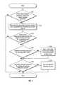
- FIG. 6a flowchart illustrating a process for managing reduced pressure at a tissue site is depicted in accordance with an illustrative embodiment of the present invention.
- the process illustrated in FIG. 6may be implemented by a controller, such as controller 170 in FIG. 1 , in conjunction with other components of a reduced pressure treatment system, such as components of reduced pressure treatment system 100 in FIG. 1 .
- the process illustrated in FIG. 5provides illustrative embodiments and additional detail with respect to steps 415 and 420 in FIG. 4 .
- the processbegins by determining whether the target reduced pressure exceeds the actual reduced pressure (step 605 ). If the process determines that the target reduced pressure does not exceed the actual reduced pressure, the process terminates. Returning to step 605 , if the process determines that the target reduced pressure exceeds the actual reduced pressure, the process increases the generated reduced pressure that is generated by the reduced pressure source (step 610 ).
- the processdetermines whether the actual reduced pressure measured by the single pressure sensor is responsive to the increased generated reduced pressure (step 615 ). If the process determines that the actual reduced pressure measured by the single pressure sensor is responsive to the increased generated reduced pressure, the process terminates. Returning to step 615 , if the process determines that the actual reduced pressure measured by the single pressure sensor is nonresponsive to the increased generated reduced pressure, the process emits a signal using an indicator (step 620 ). The process then terminates.
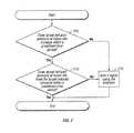
- FIG. 7a flowchart illustrating a process for managing reduced pressure at a tissue site is depicted in accordance with an illustrative embodiment of the present invention.
- the process illustrated in FIG. 7may be implemented by a controller, such as controller 170 in FIG. 1 , in conjunction with other components of a reduced pressure treatment system, such as components of reduced pressure treatment system 100 in FIG. 1 .
- the process illustrated in FIG. 7provides illustrative embodiments and additional detail with respect to steps 615 and 620 in FIG. 6 .
- the processbegins by determining whether the actual reduced pressure at the tissue site increases within a predefined time period (step 705 ). If the process determines that the actual reduced pressure at the tissue site does not increase within a predefined time period, the process emits a signal using an indicator (step 710 ). The process then terminates.
- step 715if the process determines that the actual reduced pressure at the tissue site increases within a predefined time period, the process determines whether the actual reduced pressure at the tissue site meets the target reduced pressure within a predefined time period (step 715 ). If the process determines that the actual reduced pressure at the tissue site does not meet the target reduced pressure within a predefined time period, the process emits a signal using the indicator (step 710 ). The process then terminates. Returning to step 715 , if the process determines that the actual reduced pressure at the tissue site meets the target reduced pressure within a predefined time period, the process then terminates.
- the illustrative embodimentsmay be configured to be a light weight and low cost system that consumes less power than currently used reduced pressure treatment systems.
- the reductions in size and weightare particularly important when the system is to be used to treat low-severity wounds and wounds on ambulatory patients. These wounds and patients require a system that is unobtrusive and lightweight so that discomfort to the patient and hindrance of movement are minimized.
- One way in which cost, weight, and power consumption are minimizedis through the use of only one sensor to measure pressure.
- traditional systemstypically use two pressure sensors, one to measure pressure at the tissue site and one to measure pressure at the reduced pressure source.
- the elimination of the pressure sensor measuring pressure at the reduced pressure sourceallows significant reductions in the amount of electronic circuitry required and also the amount of power consumed by the system. Additionally, any circuitry and software used to compare the two sensor readings is eliminated.
- the illustrative embodimentsenable the application of a predefined reduced pressure to tissue, while providing detection and notification of certain anomalous system conditions with fewer components than prior systems.
- the illustrative embodimentsalso eliminate the need to approximate the tissue site pressure using a measured value at the reduced pressure source. Further, determining the pressure directly at the tissue site, when included with the other features of the illustrative embodiments, allows the reduced pressure treatment system to detect leaks and blockages by observing pressure changes at the tissue site in response to operational changes made at the reduced pressure source.
Landscapes
- Health & Medical Sciences (AREA)
- Heart & Thoracic Surgery (AREA)
- Animal Behavior & Ethology (AREA)
- General Health & Medical Sciences (AREA)
- Anesthesiology (AREA)
- Biomedical Technology (AREA)
- Hematology (AREA)
- Life Sciences & Earth Sciences (AREA)
- Vascular Medicine (AREA)
- Engineering & Computer Science (AREA)
- Public Health (AREA)
- Veterinary Medicine (AREA)
- Media Introduction/Drainage Providing Device (AREA)
- Surgical Instruments (AREA)
- Measuring Fluid Pressure (AREA)
- External Artificial Organs (AREA)
Abstract
Description
Claims (31)
Priority Applications (1)
| Application Number | Priority Date | Filing Date | Title |
|---|---|---|---|
| US14/824,845US10016538B2 (en) | 2007-02-09 | 2015-08-12 | System and method for managing reduced pressure at a tissue site |
Applications Claiming Priority (4)
| Application Number | Priority Date | Filing Date | Title |
|---|---|---|---|
| US90055607P | 2007-02-09 | 2007-02-09 | |
| US12/069,364US8409170B2 (en) | 2007-02-09 | 2008-02-08 | System and method for managing reduced pressure at a tissue site |
| US13/780,438US9138515B2 (en) | 2007-02-09 | 2013-02-28 | System and method for managing reduced pressure at a tissue site |
| US14/824,845US10016538B2 (en) | 2007-02-09 | 2015-08-12 | System and method for managing reduced pressure at a tissue site |
Related Parent Applications (1)
| Application Number | Title | Priority Date | Filing Date |
|---|---|---|---|
| US13/780,438ContinuationUS9138515B2 (en) | 2007-02-09 | 2013-02-28 | System and method for managing reduced pressure at a tissue site |
Publications (2)
| Publication Number | Publication Date |
|---|---|
| US20150367045A1 US20150367045A1 (en) | 2015-12-24 |
| US10016538B2true US10016538B2 (en) | 2018-07-10 |
Family
ID=39690401
Family Applications (3)
| Application Number | Title | Priority Date | Filing Date |
|---|---|---|---|
| US12/069,364Active2029-12-01US8409170B2 (en) | 2007-02-09 | 2008-02-08 | System and method for managing reduced pressure at a tissue site |
| US13/780,438Active2028-07-19US9138515B2 (en) | 2007-02-09 | 2013-02-28 | System and method for managing reduced pressure at a tissue site |
| US14/824,845Active2029-03-07US10016538B2 (en) | 2007-02-09 | 2015-08-12 | System and method for managing reduced pressure at a tissue site |
Family Applications Before (2)
| Application Number | Title | Priority Date | Filing Date |
|---|---|---|---|
| US12/069,364Active2029-12-01US8409170B2 (en) | 2007-02-09 | 2008-02-08 | System and method for managing reduced pressure at a tissue site |
| US13/780,438Active2028-07-19US9138515B2 (en) | 2007-02-09 | 2013-02-28 | System and method for managing reduced pressure at a tissue site |
Country Status (14)
| Country | Link |
|---|---|
| US (3) | US8409170B2 (en) |
| EP (3) | EP2109472B2 (en) |
| JP (5) | JP5122586B2 (en) |
| KR (1) | KR101217918B1 (en) |
| CN (1) | CN101605568B (en) |
| AU (1) | AU2008216781B2 (en) |
| BR (1) | BRPI0806221A2 (en) |
| CA (1) | CA2673842C (en) |
| IL (1) | IL199778A0 (en) |
| MX (1) | MX2009008397A (en) |
| RU (1) | RU2428208C2 (en) |
| TW (2) | TW201219070A (en) |
| WO (1) | WO2008100440A1 (en) |
| ZA (1) | ZA200904308B (en) |
Cited By (41)
| Publication number | Priority date | Publication date | Assignee | Title |
|---|---|---|---|---|
| US10420865B2 (en) | 2014-03-06 | 2019-09-24 | Stryker Corporation | Medical/surgical waste collection unit with a light assembly separate from the primary display, the light assembly presenting information about the operation of the system by selectively outputting light |
| US11103225B2 (en) | 2016-08-31 | 2021-08-31 | B. Braun Surgical S.A. | Medical device, in particular for treating fistulas |
| USD959658S1 (en) | 2020-10-12 | 2022-08-02 | Stryker Corportation | Medical waste collection unit |
| US11819231B2 (en) | 2017-10-30 | 2023-11-21 | Cilag Gmbh International | Adaptive control programs for a surgical system comprising more than one type of cartridge |
| US11832899B2 (en) | 2017-12-28 | 2023-12-05 | Cilag Gmbh International | Surgical systems with autonomously adjustable control programs |
| US11844579B2 (en) | 2017-12-28 | 2023-12-19 | Cilag Gmbh International | Adjustments based on airborne particle properties |
| US11844545B2 (en) | 2018-03-08 | 2023-12-19 | Cilag Gmbh International | Calcified vessel identification |
| US11857152B2 (en) | 2017-12-28 | 2024-01-02 | Cilag Gmbh International | Surgical hub spatial awareness to determine devices in operating theater |
| US11864845B2 (en) | 2017-12-28 | 2024-01-09 | Cilag Gmbh International | Sterile field interactive control displays |
| US11864728B2 (en) | 2017-12-28 | 2024-01-09 | Cilag Gmbh International | Characterization of tissue irregularities through the use of mono-chromatic light refractivity |
| US11871901B2 (en) | 2012-05-20 | 2024-01-16 | Cilag Gmbh International | Method for situational awareness for surgical network or surgical network connected device capable of adjusting function based on a sensed situation or usage |
| US11890065B2 (en) | 2017-12-28 | 2024-02-06 | Cilag Gmbh International | Surgical system to limit displacement |
| US11896322B2 (en) | 2017-12-28 | 2024-02-13 | Cilag Gmbh International | Sensing the patient position and contact utilizing the mono-polar return pad electrode to provide situational awareness to the hub |
| US11896443B2 (en) | 2017-12-28 | 2024-02-13 | Cilag Gmbh International | Control of a surgical system through a surgical barrier |
| US11903587B2 (en) | 2017-12-28 | 2024-02-20 | Cilag Gmbh International | Adjustment to the surgical stapling control based on situational awareness |
| US11925350B2 (en) | 2019-02-19 | 2024-03-12 | Cilag Gmbh International | Method for providing an authentication lockout in a surgical stapler with a replaceable cartridge |
| US11931027B2 (en) | 2018-03-28 | 2024-03-19 | Cilag Gmbh Interntional | Surgical instrument comprising an adaptive control system |
| US11969216B2 (en) | 2017-12-28 | 2024-04-30 | Cilag Gmbh International | Surgical network recommendations from real time analysis of procedure variables against a baseline highlighting differences from the optimal solution |
| US11969142B2 (en) | 2017-12-28 | 2024-04-30 | Cilag Gmbh International | Method of compressing tissue within a stapling device and simultaneously displaying the location of the tissue within the jaws |
| US11986233B2 (en) | 2018-03-08 | 2024-05-21 | Cilag Gmbh International | Adjustment of complex impedance to compensate for lost power in an articulating ultrasonic device |
| US11998193B2 (en) | 2017-12-28 | 2024-06-04 | Cilag Gmbh International | Method for usage of the shroud as an aspect of sensing or controlling a powered surgical device, and a control algorithm to adjust its default operation |
| US12009095B2 (en) | 2017-12-28 | 2024-06-11 | Cilag Gmbh International | Real-time analysis of comprehensive cost of all instrumentation used in surgery utilizing data fluidity to track instruments through stocking and in-house processes |
| US12029506B2 (en) | 2017-12-28 | 2024-07-09 | Cilag Gmbh International | Method of cloud based data analytics for use with the hub |
| US12035890B2 (en) | 2017-12-28 | 2024-07-16 | Cilag Gmbh International | Method of sensing particulate from smoke evacuated from a patient, adjusting the pump speed based on the sensed information, and communicating the functional parameters of the system to the hub |
| US12035983B2 (en) | 2017-10-30 | 2024-07-16 | Cilag Gmbh International | Method for producing a surgical instrument comprising a smart electrical system |
| US12042207B2 (en) | 2017-12-28 | 2024-07-23 | Cilag Gmbh International | Estimating state of ultrasonic end effector and control system therefor |
| US12048496B2 (en) | 2017-12-28 | 2024-07-30 | Cilag Gmbh International | Adaptive control program updates for surgical hubs |
| US12062442B2 (en) | 2017-12-28 | 2024-08-13 | Cilag Gmbh International | Method for operating surgical instrument systems |
| US12059169B2 (en) | 2017-12-28 | 2024-08-13 | Cilag Gmbh International | Controlling an ultrasonic surgical instrument according to tissue location |
| US12121256B2 (en) | 2018-03-08 | 2024-10-22 | Cilag Gmbh International | Methods for controlling temperature in ultrasonic device |
| US12127729B2 (en) | 2017-12-28 | 2024-10-29 | Cilag Gmbh International | Method for smoke evacuation for surgical hub |
| US12133709B2 (en) | 2017-12-28 | 2024-11-05 | Cilag Gmbh International | Communication hub and storage device for storing parameters and status of a surgical device to be shared with cloud based analytics systems |
| US12133773B2 (en) | 2017-12-28 | 2024-11-05 | Cilag Gmbh International | Surgical hub and modular device response adjustment based on situational awareness |
| US12144518B2 (en) | 2017-12-28 | 2024-11-19 | Cilag Gmbh International | Surgical systems for detecting end effector tissue distribution irregularities |
| US12226151B2 (en) | 2017-12-28 | 2025-02-18 | Cilag Gmbh International | Capacitive coupled return path pad with separable array elements |
| US12226166B2 (en) | 2017-12-28 | 2025-02-18 | Cilag Gmbh International | Surgical instrument with a sensing array |
| US12295674B2 (en) | 2017-12-28 | 2025-05-13 | Cilag Gmbh International | Usage and technique analysis of surgeon / staff performance against a baseline to optimize device utilization and performance for both current and future procedures |
| US12310586B2 (en) | 2017-12-28 | 2025-05-27 | Cilag Gmbh International | Method for adaptive control schemes for surgical network control and interaction |
| US12318152B2 (en) | 2017-12-28 | 2025-06-03 | Cilag Gmbh International | Computer implemented interactive surgical systems |
| US12329467B2 (en) | 2017-10-30 | 2025-06-17 | Cilag Gmbh International | Method of hub communication with surgical instrument systems |
| US12396806B2 (en) | 2017-12-28 | 2025-08-26 | Cilag Gmbh International | Adjustment of a surgical device function based on situational awareness |
Families Citing this family (234)
| Publication number | Priority date | Publication date | Assignee | Title |
|---|---|---|---|---|
| GB0224986D0 (en) | 2002-10-28 | 2002-12-04 | Smith & Nephew | Apparatus |
| CN1822874B (en) | 2003-07-22 | 2010-10-13 | 凯希特许有限公司 | Negative pressure wound treatment dressing |
| GB0325129D0 (en) | 2003-10-28 | 2003-12-03 | Smith & Nephew | Apparatus in situ |
| US8062272B2 (en) | 2004-05-21 | 2011-11-22 | Bluesky Medical Group Incorporated | Flexible reduced pressure treatment appliance |
| US10058642B2 (en) | 2004-04-05 | 2018-08-28 | Bluesky Medical Group Incorporated | Reduced pressure treatment system |
| US7909805B2 (en) | 2004-04-05 | 2011-03-22 | Bluesky Medical Group Incorporated | Flexible reduced pressure treatment appliance |
| CA2949821C (en) | 2005-09-06 | 2021-05-18 | Smith & Nephew, Inc. | Self contained wound dressing with micropump |
| US8338402B2 (en)* | 2006-05-12 | 2012-12-25 | Smith & Nephew Plc | Scaffold |
| EP1905465B2 (en) | 2006-09-28 | 2013-11-27 | Smith & Nephew, Inc. | Portable wound therapy system |
| ES2564519T3 (en) | 2006-10-13 | 2016-03-23 | Bluesky Medical Group Inc. | Pressure control of a medical vacuum pump |
| AU2007311028B2 (en)* | 2006-10-17 | 2013-06-27 | Smith & Nephew Plc | Auxiliary powered negative pressure wound therapy apparatuses and methods |
| US7967810B2 (en) | 2006-10-20 | 2011-06-28 | Mary Beth Kelley | Sub-atmospheric wound-care system |
| RU2428208C2 (en) | 2007-02-09 | 2011-09-10 | КейСиАй Лайсензинг Инк. | System and method of low pressure control in tissue area |
| CA2674997C (en) | 2007-02-09 | 2012-08-14 | Kci Licensing, Inc. | A breathable interface system for topical reduced pressure |
| EP2129409B2 (en) | 2007-03-14 | 2021-11-24 | The Board of Trustees of the Leland Stanford Junior University | Devices for application of reduced pressure therapy |
| GB0712736D0 (en)* | 2007-07-02 | 2007-08-08 | Smith & Nephew | Apparatus |
| GB0712764D0 (en) | 2007-07-02 | 2007-08-08 | Smith & Nephew | Carrying Bag |
| GB0712763D0 (en) | 2007-07-02 | 2007-08-08 | Smith & Nephew | Apparatus |
| GB0715259D0 (en) | 2007-08-06 | 2007-09-12 | Smith & Nephew | Canister status determination |
| US9408954B2 (en) | 2007-07-02 | 2016-08-09 | Smith & Nephew Plc | Systems and methods for controlling operation of negative pressure wound therapy apparatus |
| GB0712739D0 (en) | 2007-07-02 | 2007-08-08 | Smith & Nephew | Apparatus |
| US12121648B2 (en) | 2007-08-06 | 2024-10-22 | Smith & Nephew Plc | Canister status determination |
| WO2009067711A2 (en)* | 2007-11-21 | 2009-05-28 | T.J. Smith & Nephew, Limited | Suction device and dressing |
| EP2214612B1 (en) | 2007-11-21 | 2019-05-01 | Smith & Nephew PLC | Wound dressing |
| GB0722820D0 (en) | 2007-11-21 | 2008-01-02 | Smith & Nephew | Vacuum assisted wound dressing |
| ES2715605T3 (en) | 2007-11-21 | 2019-06-05 | Smith & Nephew | Wound dressing |
| US11253399B2 (en) | 2007-12-06 | 2022-02-22 | Smith & Nephew Plc | Wound filling apparatuses and methods |
| GB0723855D0 (en) | 2007-12-06 | 2008-01-16 | Smith & Nephew | Apparatus and method for wound volume measurement |
| US20130096518A1 (en) | 2007-12-06 | 2013-04-18 | Smith & Nephew Plc | Wound filling apparatuses and methods |
| GB0723872D0 (en) | 2007-12-06 | 2008-01-16 | Smith & Nephew | Apparatus for topical negative pressure therapy |
| GB0723874D0 (en)* | 2007-12-06 | 2008-01-16 | Smith & Nephew | Dressing |
| GB2455962A (en) | 2007-12-24 | 2009-07-01 | Ethicon Inc | Reinforced adhesive backing sheet, for plaster |
| US8377017B2 (en) | 2008-01-03 | 2013-02-19 | Kci Licensing, Inc. | Low-profile reduced pressure treatment system |
| US8366692B2 (en) | 2008-01-08 | 2013-02-05 | Richard Scott Weston | Sustained variable negative pressure wound treatment and method of controlling same |
| AU2009214439B2 (en)* | 2008-02-14 | 2014-09-25 | Solventum Intellectual Properties Company | Devices and methods for treatment of damaged tissue |
| AU2009221772B2 (en) | 2008-03-05 | 2015-01-22 | Solventum Intellectual Properties Company | Dressing and method for applying reduced pressure to and collecting and storing fluid from a tissue site |
| US8021347B2 (en) | 2008-07-21 | 2011-09-20 | Tyco Healthcare Group Lp | Thin film wound dressing |
| US9033942B2 (en)* | 2008-03-07 | 2015-05-19 | Smith & Nephew, Inc. | Wound dressing port and associated wound dressing |
| US8298200B2 (en) | 2009-06-01 | 2012-10-30 | Tyco Healthcare Group Lp | System for providing continual drainage in negative pressure wound therapy |
| AU2009223037A1 (en) | 2008-03-12 | 2009-09-17 | Smith & Nephew Plc | Negative pressure dressing and method of using same |
| EP2977067B1 (en) | 2008-03-13 | 2020-12-09 | 3M Innovative Properties Company | Apparatus for applying reduced pressure to a tissue site on a foot |
| US8152785B2 (en) | 2008-03-13 | 2012-04-10 | Tyco Healthcare Group Lp | Vacuum port for vacuum wound therapy |
| US10912869B2 (en) | 2008-05-21 | 2021-02-09 | Smith & Nephew, Inc. | Wound therapy system with related methods therefor |
| US8414519B2 (en) | 2008-05-21 | 2013-04-09 | Covidien Lp | Wound therapy system with portable container apparatus |
| US8177763B2 (en) | 2008-09-05 | 2012-05-15 | Tyco Healthcare Group Lp | Canister membrane for wound therapy system |
| US8257326B2 (en) | 2008-06-30 | 2012-09-04 | Tyco Healthcare Group Lp | Apparatus for enhancing wound healing |
| WO2010005709A1 (en) | 2008-07-08 | 2010-01-14 | Tyco Healthcare Group Lp | Portable negative pressure wound therapy device |
| ES2658263T3 (en) | 2008-08-08 | 2018-03-09 | Smith & Nephew, Inc. | Continuous fiber wound dressing |
| US8366691B2 (en)* | 2008-08-08 | 2013-02-05 | Kci Licensing, Inc | Reduced-pressure treatment systems with reservoir control |
| US8216198B2 (en) | 2009-01-09 | 2012-07-10 | Tyco Healthcare Group Lp | Canister for receiving wound exudate in a negative pressure therapy system |
| US8251979B2 (en) | 2009-05-11 | 2012-08-28 | Tyco Healthcare Group Lp | Orientation independent canister for a negative pressure wound therapy device |
| US8827983B2 (en) | 2008-08-21 | 2014-09-09 | Smith & Nephew, Inc. | Sensor with electrical contact protection for use in fluid collection canister and negative pressure wound therapy systems including same |
| US9414968B2 (en) | 2008-09-05 | 2016-08-16 | Smith & Nephew, Inc. | Three-dimensional porous film contact layer with improved wound healing |
| US8425478B2 (en)* | 2008-09-18 | 2013-04-23 | Kci Licensing, Inc. | Multi-layer dressings, systems, and methods for applying reduced pressure at a tissue site |
| US8158844B2 (en) | 2008-10-08 | 2012-04-17 | Kci Licensing, Inc. | Limited-access, reduced-pressure systems and methods |
| CN102215799B (en) | 2008-11-14 | 2013-09-18 | 凯希特许有限公司 | Fluid bag, system and method for storing fluid from a tissue site |
| CA2744548C (en) | 2008-11-25 | 2017-06-13 | Spiracur Inc. | Device for delivery of reduced pressure to body surfaces |
| US8361043B2 (en) | 2009-01-07 | 2013-01-29 | Spiracur Inc. | Reduced pressure therapy of the sacral region |
| US8162907B2 (en) | 2009-01-20 | 2012-04-24 | Tyco Healthcare Group Lp | Method and apparatus for bridging from a dressing in negative pressure wound therapy |
| US8728045B2 (en)* | 2009-03-04 | 2014-05-20 | Spiracur Inc. | Devices and methods to apply alternating level of reduced pressure to tissue |
| SE533726C2 (en)* | 2009-04-30 | 2010-12-14 | Moelnlycke Health Care Ab | Apparatus with negative pressure for treatment of wounds |
| US9421309B2 (en) | 2009-06-02 | 2016-08-23 | Kci Licensing, Inc. | Reduced-pressure treatment systems and methods employing hydrogel reservoir members |
| US20110196321A1 (en) | 2009-06-10 | 2011-08-11 | Tyco Healthcare Group Lp | Fluid Collection Canister Including Canister Top with Filter Membrane and Negative Pressure Wound Therapy Systems Including Same |
| US20100324516A1 (en)* | 2009-06-18 | 2010-12-23 | Tyco Healthcare Group Lp | Apparatus for Vacuum Bridging and/or Exudate Collection |
| EP2461863B1 (en) | 2009-08-05 | 2016-07-27 | Covidien LP | Surgical wound dressing incorporating connected hydrogel beads having an embedded electrode therein |
| WO2011043863A2 (en) | 2009-08-13 | 2011-04-14 | Michael Simms Shuler | Methods and dressing systems for promoting healing of injured tissue |
| AU2010298770B2 (en)* | 2009-09-22 | 2015-05-28 | Molnlycke Health Care Ab | An apparatus and method for controlling the negative pressure in a wound |
| AU2010341491B2 (en) | 2009-12-22 | 2015-05-14 | Smith & Nephew, Inc. | Apparatuses and methods for negative pressure wound therapy |
| CA2784138C (en) | 2010-01-20 | 2018-04-24 | Kci Licensing, Inc. | Wound-connection pads for fluid instillation and negative pressure wound therapy, and systems and methods |
| US8430867B2 (en) | 2010-03-12 | 2013-04-30 | Kci Licensing, Inc. | Reduced-pressure dressing connection pads, systems, and methods |
| US8882730B2 (en)* | 2010-03-12 | 2014-11-11 | Kci Licensing, Inc. | Radio opaque, reduced-pressure manifolds, systems, and methods |
| US8454580B2 (en)* | 2010-03-12 | 2013-06-04 | Kci Licensing, Inc. | Adjustable reduced-pressure wound coverings |
| US8814842B2 (en) | 2010-03-16 | 2014-08-26 | Kci Licensing, Inc. | Delivery-and-fluid-storage bridges for use with reduced-pressure systems |
| US8604265B2 (en) | 2010-04-16 | 2013-12-10 | Kci Licensing, Inc. | Dressings and methods for treating a tissue site on a patient |
| US9061095B2 (en) | 2010-04-27 | 2015-06-23 | Smith & Nephew Plc | Wound dressing and method of use |
| USRE48117E1 (en) | 2010-05-07 | 2020-07-28 | Smith & Nephew, Inc. | Apparatuses and methods for negative pressure wound therapy |
| US8795246B2 (en) | 2010-08-10 | 2014-08-05 | Spiracur Inc. | Alarm system |
| US8753322B2 (en) | 2010-08-10 | 2014-06-17 | Spiracur Inc. | Controlled negative pressure apparatus and alarm mechanism |
| GB201015656D0 (en)* | 2010-09-20 | 2010-10-27 | Smith & Nephew | Pressure control apparatus |
| US9526920B2 (en) | 2010-10-12 | 2016-12-27 | Smith & Nephew, Inc. | Medical device |
| US8986269B2 (en)* | 2010-11-11 | 2015-03-24 | Ulcerx Medical Inc. | Wound leakage vacuum collection device |
| CA2814873C (en)* | 2010-11-17 | 2018-04-24 | Kci Licensing, Inc. | Systems and methods for managing reduced pressure at a plurality of wound sites |
| CN102058932B (en)* | 2010-12-20 | 2013-03-06 | 惠州市华阳医疗电子有限公司 | Negative pressure control device and control method of negative pressure treatment system |
| USD714433S1 (en) | 2010-12-22 | 2014-09-30 | Smith & Nephew, Inc. | Suction adapter |
| RU2016111981A (en) | 2010-12-22 | 2018-11-27 | Смит Энд Нефью, Инк. | DEVICE AND METHOD FOR TREATING RAS WITH NEGATIVE PRESSURE |
| GB2488749A (en) | 2011-01-31 | 2012-09-12 | Systagenix Wound Man Ip Co Bv | Laminated silicone coated wound dressing |
| AU2012228360B2 (en)* | 2011-03-11 | 2015-08-20 | Lohmann & Rauscher Gmbh & Co. Kg | Vacuum system and endoscopy arrangement for endoscopic vacuum therapy |
| US9302034B2 (en) | 2011-04-04 | 2016-04-05 | Smith & Nephew, Inc. | Negative pressure wound therapy dressing |
| GB201106491D0 (en) | 2011-04-15 | 2011-06-01 | Systagenix Wound Man Ip Co Bv | Patterened silicone coating |
| US9474838B2 (en)* | 2011-04-20 | 2016-10-25 | Kci Licensing, Inc. | System and method for managing reduced pressure delivered to a tissue site |
| US9067003B2 (en) | 2011-05-26 | 2015-06-30 | Kalypto Medical, Inc. | Method for providing negative pressure to a negative pressure wound therapy bandage |
| RU2611760C2 (en) | 2011-06-07 | 2017-02-28 | Смит Энд Нефью Плс | Wound contacting elements and methods of their use |
| CA2843133C (en)* | 2011-07-26 | 2020-08-25 | Smith & Nephew Plc | Systems and methods for controlling operation of a reduced pressure therapy system |
| JP6083762B2 (en)* | 2011-08-31 | 2017-02-22 | ケーシーアイ ライセンシング インコーポレイテッド | Inline storage pouch for use with body fluids |
| JP6050819B2 (en)* | 2011-09-14 | 2016-12-21 | ケーシーアイ ライセンシング インコーポレイテッド | Pressure reduction system and method using leak detection member |
| US9393354B2 (en) | 2011-11-01 | 2016-07-19 | J&M Shuler Medical, Inc. | Mechanical wound therapy for sub-atmospheric wound care system |
| US9084845B2 (en) | 2011-11-02 | 2015-07-21 | Smith & Nephew Plc | Reduced pressure therapy apparatuses and methods of using same |
| CN103987348B (en) | 2011-12-16 | 2016-05-11 | 凯希特许有限公司 | Releasable Medical Drapes |
| US10940047B2 (en) | 2011-12-16 | 2021-03-09 | Kci Licensing, Inc. | Sealing systems and methods employing a hybrid switchable drape |
| EP2626049B1 (en)* | 2012-02-11 | 2018-07-25 | Paul Hartmann AG | Wound treatment device |
| JP6250571B2 (en) | 2012-03-12 | 2017-12-20 | スミス アンド ネフュー ピーエルシーSmith & Nephew Public Limited Company | Pressure reducing apparatus and method |
| AU2013237095B2 (en) | 2012-03-20 | 2017-10-05 | Smith & Nephew Plc | Controlling operation of a reduced pressure therapy system based on dynamic duty cycle threshold determination |
| US9427505B2 (en) | 2012-05-15 | 2016-08-30 | Smith & Nephew Plc | Negative pressure wound therapy apparatus |
| EP2852333B1 (en) | 2012-05-22 | 2021-12-15 | Smith & Nephew plc | Apparatuses for wound therapy |
| JP6400570B2 (en) | 2012-05-23 | 2018-10-10 | スミス アンド ネフュー ピーエルシーSmith & Nephew Public Limited Company | Apparatus and method for local negative pressure closure therapy |
| CN108186200B (en) | 2012-08-01 | 2021-08-10 | 史密夫及内修公开有限公司 | Wound dressing |
| WO2014020440A1 (en) | 2012-08-01 | 2014-02-06 | Smith & Nephew Plc | Wound dressing |
| AU2013344686B2 (en) | 2012-11-16 | 2018-06-21 | Solventum Intellectual Properties Company | Medical drape with pattern adhesive layers and method of manufacturing same |
| GB201222770D0 (en) | 2012-12-18 | 2013-01-30 | Systagenix Wound Man Ip Co Bv | Wound dressing with adhesive margin |
| JP6259510B2 (en)* | 2013-03-14 | 2018-01-10 | ケーシーアイ ライセンシング インコーポレイテッド | Multi-porous conduit |
| US9737649B2 (en) | 2013-03-14 | 2017-08-22 | Smith & Nephew, Inc. | Systems and methods for applying reduced pressure therapy |
| EP2968012B1 (en) | 2013-03-14 | 2017-04-26 | KCI Licensing, Inc. | Absorbent dressing with hybrid drape |
| JP2016517318A (en) | 2013-03-14 | 2016-06-16 | スミス アンド ネフュー インコーポレーテッド | System and method for administering decompression therapy |
| AU2014228778B2 (en)* | 2013-03-15 | 2019-06-06 | Atrium Medical Corporation | Fluid analyzer and associated methods |
| WO2014168985A1 (en)* | 2013-04-08 | 2014-10-16 | Iogyn, Inc | Medical systems and methods |
| US10010658B2 (en) | 2013-05-10 | 2018-07-03 | Smith & Nephew Plc | Fluidic connector for irrigation and aspiration of wounds |
| CN103330992B (en)* | 2013-07-18 | 2016-03-30 | 苏州元禾医疗器械有限公司 | The Intelligent adjustment therapy system of auxiliary wound healing |
| WO2015023515A1 (en) | 2013-08-13 | 2015-02-19 | Smith & Nephew, Inc. | Systems and methods for applying reduced pressure therapy |
| EP3038667B1 (en) | 2013-08-26 | 2019-10-09 | KCI Licensing, Inc. | Dressing interface with moisture controlling feature and sealing function |
| US10946124B2 (en) | 2013-10-28 | 2021-03-16 | Kci Licensing, Inc. | Hybrid sealing tape |
| AU2014342903B2 (en) | 2013-10-30 | 2018-09-20 | Solventum Intellectual Properties Company | Dressing with differentially sized perforations |
| US9956120B2 (en) | 2013-10-30 | 2018-05-01 | Kci Licensing, Inc. | Dressing with sealing and retention interface |
| EP3062751B1 (en) | 2013-10-30 | 2017-08-09 | KCI Licensing, Inc. | Condensate absorbing and dissipating system |
| EP3527237B1 (en) | 2013-10-30 | 2020-09-09 | KCI Licensing, Inc. | Absorbent conduit and system |
| EP3110379B1 (en) | 2014-02-28 | 2019-04-03 | KCI Licensing, Inc. | Hybrid drape having a gel-coated perforated mesh |
| US11026844B2 (en) | 2014-03-03 | 2021-06-08 | Kci Licensing, Inc. | Low profile flexible pressure transmission conduit |
| US10531977B2 (en) | 2014-04-17 | 2020-01-14 | Coloplast A/S | Thermoresponsive skin barrier appliances |
| WO2015168681A1 (en) | 2014-05-02 | 2015-11-05 | Kci Licensing, Inc. | Fluid storage devices, systems, and methods |
| EP4424347A3 (en)* | 2014-05-15 | 2024-10-30 | Fisher & Paykel Healthcare Limited | Active smoke filtration for insufflation |
| JP6640748B2 (en) | 2014-06-05 | 2020-02-05 | ケーシーアイ ライセンシング インコーポレイテッド | Dressing with fluid acquisition and dispensing features |
| US12133789B2 (en) | 2014-07-31 | 2024-11-05 | Smith & Nephew, Inc. | Reduced pressure therapy apparatus construction and control |
| CA3179001A1 (en) | 2014-07-31 | 2016-02-04 | Smith & Nephew, Inc. | Systems and methods for applying reduced pressure therapy |
| WO2016100098A1 (en) | 2014-12-17 | 2016-06-23 | Kci Licensing, Inc. | Dressing with offloading capability |
| EP3237032B1 (en) | 2014-12-22 | 2024-08-07 | Smith & Nephew plc | Negative pressure wound therapy apparatus |
| CA2972701A1 (en)* | 2014-12-30 | 2016-07-07 | Smith & Nephew, Inc. | Systems and methods for applying reduced pressure therapy |
| EP3240587B1 (en) | 2014-12-30 | 2020-05-27 | Smith & Nephew, Inc | Systems for applying reduced pressure therapy |
| US9549851B2 (en) | 2015-01-28 | 2017-01-24 | Novartis Ag | Surgical hand piece with integrated pressure sensor |
| DK3288508T3 (en) | 2015-04-27 | 2020-03-09 | Smith & Nephew | REDUCED PRESSURE DEVICES |
| EP3574877B1 (en) | 2015-05-08 | 2022-08-17 | 3M Innovative Properties Company | Low-acuity dressing with integral pump |
| US10076594B2 (en) | 2015-05-18 | 2018-09-18 | Smith & Nephew Plc | Fluidic connector for negative pressure wound therapy |
| EP3297699B1 (en) | 2015-05-18 | 2020-04-29 | Smith & Nephew PLC | Heat-assisted pumping systems for use in negative pressure wound therapy |
| WO2016204028A1 (en)* | 2015-06-17 | 2016-12-22 | オリンパス株式会社 | Energy treatment tool |
| US10583228B2 (en) | 2015-07-28 | 2020-03-10 | J&M Shuler Medical, Inc. | Sub-atmospheric wound therapy systems and methods |
| AU2016305091B2 (en) | 2015-08-13 | 2021-06-10 | Smith & Nephew, Inc. | Systems and methods for applying reduced pressure therapy |
| EP3741335B1 (en) | 2015-09-01 | 2023-05-24 | KCI Licensing, Inc. | Dressing with increased apposition force |
| CN108289979A (en) | 2015-09-11 | 2018-07-17 | 史密夫和内修有限公司 | System and method for the negative pressure treatment that application reduces |
| EP3349807B1 (en) | 2015-09-17 | 2021-02-24 | 3M Innovative Properties Company | Hybrid silicone and acrylic adhesive cover for use with wound treatment |
| EP3187203B2 (en) | 2015-12-30 | 2022-08-24 | Paul Hartmann AG | Methods and devices for controlling negative pressure at a wound site |
| EP3187206B1 (en)* | 2015-12-30 | 2019-03-13 | Paul Hartmann AG | Methods and devices for negative pressure wound therapy |
| EP4393526A3 (en) | 2016-02-12 | 2024-08-14 | Smith & Nephew, Inc | Systems and methods for detecting operational conditions of reduced pressure therapy |
| EP3426206B1 (en) | 2016-03-07 | 2023-05-10 | Smith & Nephew plc | Wound treatment apparatuses and methods with negative pressure source integrated into wound dressing |
| CA3022184A1 (en) | 2016-04-26 | 2017-11-02 | Smith & Nephew Plc | Wound dressings and methods of use with integrated negative pressure source having a fluid ingress inhibition component |
| US11096831B2 (en) | 2016-05-03 | 2021-08-24 | Smith & Nephew Plc | Negative pressure wound therapy device activation and control |
| WO2017191158A1 (en) | 2016-05-03 | 2017-11-09 | Smith & Nephew Plc | Systems and methods for driving negative pressure sources in negative pressure therapy systems |
| CA3038206A1 (en) | 2016-05-03 | 2017-11-09 | Smith & Nephew Plc | Optimizing power transfer to negative pressure sources in negative pressure therapy systems |
| CN109069713A (en) | 2016-05-13 | 2018-12-21 | 史密夫和内修有限公司 | Automatic wound in negative pressure wound treating system couples detection |
| WO2018037075A1 (en) | 2016-08-25 | 2018-03-01 | Smith & Nephew Plc | Absorbent negative pressure wound therapy dressing |
| CN106806064A (en)* | 2016-08-27 | 2017-06-09 | 浙江保尔曼生物科技有限公司 | Wound healing and bone regeneration instrument and its application method |
| EP3519001B1 (en) | 2016-09-30 | 2025-05-21 | Smith & Nephew plc | Negative pressure wound treatment apparatuses and methods with integrated electronics |
| EP3551244A1 (en) | 2016-12-12 | 2019-10-16 | Smith & Nephew PLC | Pressure wound therapy status indication via external device |
| US11395870B2 (en) | 2017-02-15 | 2022-07-26 | Smith & Nephew Asia Pacific Pte. Limited | Negative pressure wound therapy apparatuses and methods for using the same |
| EP3592312B1 (en) | 2017-03-08 | 2024-01-10 | Smith & Nephew plc | Negative pressure wound therapy device control in presence of fault condition |
| EP3595736B1 (en)* | 2017-03-15 | 2025-07-23 | Smith & Nephew, Inc | Pressure control in negative pressure wound therapy systems |
| JP7121050B2 (en) | 2017-05-09 | 2022-08-17 | スミス アンド ネフュー ピーエルシー | Redundant control of negative pressure wound therapy systems |
| GB201718070D0 (en) | 2017-11-01 | 2017-12-13 | Smith & Nephew | Negative pressure wound treatment apparatuses and methods with integrated electronics |
| CA3074780A1 (en) | 2017-09-13 | 2019-03-21 | Smith & Nephew Plc | Negative pressure wound treatment apparatuses and methods with integrated electronics |
| US11497653B2 (en) | 2017-11-01 | 2022-11-15 | Smith & Nephew Plc | Negative pressure wound treatment apparatuses and methods with integrated electronics |
| GB201718014D0 (en) | 2017-11-01 | 2017-12-13 | Smith & Nephew | Dressing for negative pressure wound therapy with filter |
| GB201718072D0 (en) | 2017-11-01 | 2017-12-13 | Smith & Nephew | Negative pressure wound treatment apparatuses and methods with integrated electronics |
| GB201718054D0 (en) | 2017-11-01 | 2017-12-13 | Smith & Nephew | Sterilization of integrated negative pressure wound treatment apparatuses and sterilization methods |
| DE102017131018A1 (en) | 2017-12-21 | 2019-06-27 | Paul Hartmann Ag | Method for operating a negative pressure therapy system |
| US10500084B2 (en) | 2017-12-22 | 2019-12-10 | Coloplast A/S | Accessory devices of an ostomy system, and related methods for communicating leakage state |
| WO2019120441A1 (en) | 2017-12-22 | 2019-06-27 | Coloplast A/S | Sensor assembly part and a base plate for an ostomy appliance and a method for manufacturing a sensor assembly part and a base plate |
| EP4042987B1 (en) | 2017-12-22 | 2025-02-12 | Coloplast A/S | Monitor device of an ostomy system having a connector for coupling to both a base plate and an accessory device |
| LT4032510T (en) | 2017-12-22 | 2025-08-25 | Coloplast A/S | BASE BOARD WITH SELECTIVE SENSOR POINTS AND METHOD FOR MANUFACTURING THEREOF |
| US10849781B2 (en) | 2017-12-22 | 2020-12-01 | Coloplast A/S | Base plate for an ostomy appliance |
| EP4245273A3 (en) | 2017-12-22 | 2023-11-08 | Coloplast A/S | Base plate and sensor assembly of an ostomy system having a leakage sensor |
| US11607334B2 (en) | 2017-12-22 | 2023-03-21 | Coloplast A/S | Base plate for a medical appliance, a monitor device and a system for a medical appliance |
| US10799385B2 (en) | 2017-12-22 | 2020-10-13 | Coloplast A/S | Ostomy appliance with layered base plate |
| DK3729456T3 (en) | 2017-12-22 | 2022-03-07 | Coloplast As | MONITORING DEVICE FOR AN OSTOMY SYSTEM AND ASSOCIATED METHOD FOR OPERATING A MONITORING DEVICE |
| US11471318B2 (en) | 2017-12-22 | 2022-10-18 | Coloplast A/S | Data collection schemes for a medical appliance and related methods |
| US11654043B2 (en) | 2017-12-22 | 2023-05-23 | Coloplast A/S | Sensor assembly part and a base plate for a medical appliance and a method for manufacturing a base plate or a sensor assembly part |
| AU2018391313B2 (en) | 2017-12-22 | 2024-05-02 | Coloplast A/S | Accessory devices of an ostomy system, and related methods for communicating operating state |
| US11627891B2 (en) | 2017-12-22 | 2023-04-18 | Coloplast A/S | Calibration methods for medical appliance tools |
| LT3727228T (en) | 2017-12-22 | 2022-08-10 | Coloplast A/S | MAIN BOARD AND SENSOR STRUCTURE PART FOR OSTOMY DEVICE AND METHOD OF MANUFACTURING THE MAIN BOARD AND SENSOR STRUCTURE PART |
| EP3727222B1 (en) | 2017-12-22 | 2024-05-08 | Coloplast A/S | Sensor assembly part for an ostomy appliance and a method for manufacturing a sensor assembly part |
| EP3727245B1 (en) | 2017-12-22 | 2025-04-30 | Coloplast A/S | Data transmission schemes for an ostomy system, monitoring device for an ostomy device, and associated methods |
| JP7462558B2 (en) | 2017-12-22 | 2024-04-05 | コロプラスト アクティーゼルスカブ | Ostomy system and monitor device with angular leak detection - Patents.com |
| US11707377B2 (en) | 2017-12-22 | 2023-07-25 | Coloplast A/S | Coupling part with a hinge for a medical base plate and sensor assembly part |
| WO2019120442A1 (en) | 2017-12-22 | 2019-06-27 | Coloplast A/S | Sensor assembly part and a base plate for an ostomy appliance and a device for connecting to a base plate or a sensor assembly part |
| WO2019120438A1 (en) | 2017-12-22 | 2019-06-27 | Coloplast A/S | Tools and methods for placing an ostomy appliance on a user |
| EP4248920A3 (en) | 2017-12-22 | 2023-12-27 | Coloplast A/S | Ostomy appliance system, monitor device, and method of monitoring an ostomy appliance |
| EP3727219B1 (en) | 2017-12-22 | 2023-08-09 | Coloplast A/S | Moisture detecting base plate for an ostomy appliance and a system for determining moisture propagation in a base plate and/or a sensor assembly part |
| WO2019120431A1 (en) | 2017-12-22 | 2019-06-27 | Coloplast A/S | Tools and methods for cutting holes in an ostomy appliance |
| JP2021508269A (en) | 2017-12-22 | 2021-03-04 | コロプラスト アクティーゼルスカブ | A method for manufacturing a base plate for an ostomy orthosis and a sensor assembly part for the base plate, and a base plate and a sensor assembly part. |
| EP4032511A1 (en) | 2017-12-22 | 2022-07-27 | Coloplast A/S | Ostomy appliance with sensing zones |
| EP3727231B2 (en) | 2017-12-22 | 2025-03-12 | Coloplast A/S | Processing schemes for an ostomy system, monitor device for an ostomy appliance and related methods |
| GB201813282D0 (en) | 2018-08-15 | 2018-09-26 | Smith & Nephew | System for medical device activation and opertion |
| US10624794B2 (en) | 2018-02-12 | 2020-04-21 | Healyx Labs, Inc. | Negative pressure wound therapy systems, devices, and methods |
| WO2019161861A1 (en) | 2018-02-20 | 2019-08-29 | Coloplast A/S | Sensor assembly part and a base plate for an ostomy appliance and a device for connecting to a base plate and/or a sensor assembly part |
| US12208029B2 (en) | 2018-02-20 | 2025-01-28 | Coloplast A/S | Base plate having a mechanical and electrical connector |
| EP4631480A2 (en) | 2018-02-20 | 2025-10-15 | Coloplast A/S | Accessory devices of an ostomy system, and related methods for changing an ostomy appliance based on future operating state |
| US11903728B2 (en)* | 2018-03-15 | 2024-02-20 | Coloplast A/S | Methods of configuring medical notifications and related accessory devices |
| US11998474B2 (en) | 2018-03-15 | 2024-06-04 | Coloplast A/S | Apparatus and methods for navigating ostomy appliance user to changing room |
| GB201804347D0 (en) | 2018-03-19 | 2018-05-02 | Smith & Nephew Inc | Securing control of settings of negative pressure wound therapy apparatuses and methods for using the same |
| WO2019186501A1 (en)* | 2018-03-30 | 2019-10-03 | Ethicon Llc | Method of sensing particulate from smoke evacuated from a patient, adjusting the pump speed based on the sensed information, and communicating the functional parameters of the system to the hub |
| GB201806988D0 (en) | 2018-04-30 | 2018-06-13 | Quintanar Felix Clarence | Power source charging for negative pressure wound therapy apparatus |
| EP3773782A4 (en) | 2018-05-16 | 2022-03-02 | Midwest Training and Development Services, LLC | Negative pressure wound apposition dressing system |
| GB201808438D0 (en)* | 2018-05-23 | 2018-07-11 | Smith & Nephew | Systems and methods for determining blockages in a negative pressure wound therapy system |
| GB201811449D0 (en) | 2018-07-12 | 2018-08-29 | Smith & Nephew | Apparatuses and methods for negative pressure wound therapy |
| WO2020018328A1 (en)* | 2018-07-16 | 2020-01-23 | Kci Licensing, Inc. | Wound therapy system with conduit blockage detection |
| EP3837520B1 (en) | 2018-08-15 | 2025-10-08 | Coloplast A/S | Accessory device of an ostomy system and related methods for issue identification |
| CN112601573A (en)* | 2018-08-29 | 2021-04-02 | 埃埃特鲁医疗有限责任公司 | Negative pressure therapy including mechanical pump and chemical pump |
| USD898925S1 (en) | 2018-09-13 | 2020-10-13 | Smith & Nephew Plc | Medical dressing |
| EP3897481B1 (en) | 2018-12-20 | 2023-08-09 | Coloplast A/S | Ostomy condition classification with masking, devices and related methods |
| EP3897482B1 (en) | 2018-12-20 | 2025-07-16 | Coloplast A/S | Ostomy condition classification with image data transformation, devices and related methods |
| US11612512B2 (en) | 2019-01-31 | 2023-03-28 | Coloplast A/S | Moisture detecting base plate for an ostomy appliance and a system for determining moisture propagation in a base plate and/or a sensor assembly part |
| CN113365582B (en) | 2019-01-31 | 2024-12-31 | 科洛普拉斯特公司 | Stoma Sensor Patch |
| WO2020156624A1 (en) | 2019-01-31 | 2020-08-06 | Coloplast A/S | Application of a stomal sensor patch |
| KR102825171B1 (en) | 2019-01-31 | 2025-06-25 | 컬러플라스트 에이/에스 | Sensor patch for ostomy/urinary device |
| US12257172B2 (en) | 2019-02-28 | 2025-03-25 | Coloplast A/S | Sensor patch for attachment to a base plate |
| GB201903774D0 (en) | 2019-03-20 | 2019-05-01 | Smith & Nephew | Negative pressure wound treatment apparatuses and methods with integrated electronics |
| CN110025832A (en)* | 2019-03-25 | 2019-07-19 | 广东省医疗器械研究所 | A kind of drainage controller and its implementation of pressure adjustable |
| BR112021022115A2 (en)* | 2019-05-07 | 2022-01-04 | Aroa Biosurgery Ltd | negative pressure wound dressing |
| GB201907716D0 (en) | 2019-05-31 | 2019-07-17 | Smith & Nephew | Systems and methods for extending operational time of negative pressure wound treatment apparatuses |
| EP4010044B1 (en)* | 2019-08-06 | 2025-09-24 | Solventum Intellectual Properties Company | Electro-mechanical pump controller for negative-pressure treatment |
| GB201914283D0 (en) | 2019-10-03 | 2019-11-20 | Smith & Nephew | Apparatuses and methods for negative pressure wound therapy |
| GB202000574D0 (en) | 2020-01-15 | 2020-02-26 | Smith & Nephew | Fluidic connectors for negative pressure wound therapy |
| US11160917B2 (en) | 2020-01-22 | 2021-11-02 | J&M Shuler Medical Inc. | Negative pressure wound therapy barrier |
| US20210260272A1 (en)* | 2020-02-20 | 2021-08-26 | Convatec Limited | Method and control system for a wound therapy apparatus |
| GB202004181D0 (en)* | 2020-03-23 | 2020-05-06 | Smith & Nephew | Self-tesing for negative pressure wound therapy devices |
| EP4512377A3 (en) | 2020-04-14 | 2025-04-30 | Coloplast A/S | METHOD FOR A MONITORING DEVICE FOR A PERSONAL CARE SYSTEM |
| GB202005928D0 (en)* | 2020-04-23 | 2020-06-10 | Smith & Nephew | Dual mode negative pressure source operation for provision of negative pressure wound therapy |
| DK3915530T3 (en)* | 2020-05-25 | 2024-05-06 | Moelnlycke Health Care Ab | CONNECTION FOR NATIVE PRESSURE WOUND TREATMENT (NPWT) |
Citations (126)
| Publication number | Priority date | Publication date | Assignee | Title |
|---|---|---|---|---|
| US1355846A (en) | 1920-02-06 | 1920-10-19 | David A Rannells | Medical appliance |
| US2547758A (en) | 1949-01-05 | 1951-04-03 | Wilmer B Keeling | Instrument for treating the male urethra |
| US2632443A (en) | 1949-04-18 | 1953-03-24 | Eleanor P Lesher | Surgical dressing |
| GB692578A (en) | 1949-09-13 | 1953-06-10 | Minnesota Mining & Mfg | Improvements in or relating to drape sheets for surgical use |
| US2682873A (en) | 1952-07-30 | 1954-07-06 | Johnson & Johnson | General purpose protective dressing |
| US2910763A (en) | 1955-08-17 | 1959-11-03 | Du Pont | Felt-like products |
| US2969057A (en) | 1957-11-04 | 1961-01-24 | Brady Co W H | Nematodic swab |
| US3066672A (en) | 1960-09-27 | 1962-12-04 | Jr William H Crosby | Method and apparatus for serial sampling of intestinal juice |
| US3367332A (en) | 1965-08-27 | 1968-02-06 | Gen Electric | Product and process for establishing a sterile area of skin |
| US3520300A (en) | 1967-03-15 | 1970-07-14 | Amp Inc | Surgical sponge and suction device |
| US3568675A (en) | 1968-08-30 | 1971-03-09 | Clyde B Harvey | Fistula and penetrating wound dressing |
| US3648692A (en) | 1970-12-07 | 1972-03-14 | Parke Davis & Co | Medical-surgical dressing for burns and the like |
| US3682180A (en) | 1970-06-08 | 1972-08-08 | Coilform Co Inc | Drain clip for surgical drain |
| US3826254A (en) | 1973-02-26 | 1974-07-30 | Verco Ind | Needle or catheter retaining appliance |
| DE2640413A1 (en) | 1976-09-08 | 1978-03-09 | Wolf Gmbh Richard | CATHETER MONITORING DEVICE |
| US4080970A (en) | 1976-11-17 | 1978-03-28 | Miller Thomas J | Post-operative combination dressing and internal drain tube with external shield and tube connector |
| US4096853A (en) | 1975-06-21 | 1978-06-27 | Hoechst Aktiengesellschaft | Device for the introduction of contrast medium into an anus praeter |
| US4139004A (en) | 1977-02-17 | 1979-02-13 | Gonzalez Jr Harry | Bandage apparatus for treating burns |
| US4165748A (en) | 1977-11-07 | 1979-08-28 | Johnson Melissa C | Catheter tube holder |
| US4184510A (en) | 1977-03-15 | 1980-01-22 | Fibra-Sonics, Inc. | Valued device for controlling vacuum in surgery |
| WO1980002182A1 (en) | 1979-04-06 | 1980-10-16 | J Moss | Portable suction device for collecting fluids from a closed wound |
| US4233969A (en) | 1976-11-11 | 1980-11-18 | Lock Peter M | Wound dressing materials |
| US4245630A (en) | 1976-10-08 | 1981-01-20 | T. J. Smith & Nephew, Ltd. | Tearable composite strip of materials |
| US4256109A (en) | 1978-07-10 | 1981-03-17 | Nichols Robert L | Shut off valve for medical suction apparatus |
| US4261363A (en) | 1979-11-09 | 1981-04-14 | C. R. Bard, Inc. | Retention clips for body fluid drains |
| US4275721A (en) | 1978-11-28 | 1981-06-30 | Landstingens Inkopscentral Lic, Ekonomisk Forening | Vein catheter bandage |
| US4284079A (en) | 1979-06-28 | 1981-08-18 | Adair Edwin Lloyd | Method for applying a male incontinence device |
| US4297995A (en) | 1980-06-03 | 1981-11-03 | Key Pharmaceuticals, Inc. | Bandage containing attachment post |
| US4333468A (en) | 1980-08-18 | 1982-06-08 | Geist Robert W | Mesentery tube holder apparatus |
| US4373519A (en) | 1981-06-26 | 1983-02-15 | Minnesota Mining And Manufacturing Company | Composite wound dressing |
| US4382441A (en) | 1978-12-06 | 1983-05-10 | Svedman Paul | Device for treating tissues, for example skin |
| US4392853A (en) | 1981-03-16 | 1983-07-12 | Rudolph Muto | Sterile assembly for protecting and fastening an indwelling device |
| US4392858A (en) | 1981-07-16 | 1983-07-12 | Sherwood Medical Company | Wound drainage device |
| US4419097A (en) | 1981-07-31 | 1983-12-06 | Rexar Industries, Inc. | Attachment for catheter tube |
| EP0100148A1 (en) | 1982-07-06 | 1984-02-08 | Dow Corning Limited | Medical-surgical dressing and a process for the production thereof |
| US4465485A (en) | 1981-03-06 | 1984-08-14 | Becton, Dickinson And Company | Suction canister with unitary shut-off valve and filter features |
| EP0117632A2 (en) | 1983-01-27 | 1984-09-05 | Johnson & Johnson Products Inc. | Adhesive film dressing |
| US4475909A (en) | 1982-05-06 | 1984-10-09 | Eisenberg Melvin I | Male urinary device and method for applying the device |
| US4480638A (en) | 1980-03-11 | 1984-11-06 | Eduard Schmid | Cushion for holding an element of grafted skin |
| US4525166A (en) | 1981-11-21 | 1985-06-25 | Intermedicat Gmbh | Rolled flexible medical suction drainage device |
| US4525374A (en) | 1984-02-27 | 1985-06-25 | Manresa, Inc. | Treating hydrophobic filters to render them hydrophilic |
| US4540412A (en) | 1983-07-14 | 1985-09-10 | The Kendall Company | Device for moist heat therapy |
| US4543100A (en) | 1983-11-01 | 1985-09-24 | Brodsky Stuart A | Catheter and drain tube retainer |
| US4548202A (en) | 1983-06-20 | 1985-10-22 | Ethicon, Inc. | Mesh tissue fasteners |
| US4551139A (en) | 1982-02-08 | 1985-11-05 | Marion Laboratories, Inc. | Method and apparatus for burn wound treatment |
| EP0161865A2 (en) | 1984-05-03 | 1985-11-21 | Smith and Nephew Associated Companies p.l.c. | Adhesive wound dressing |
| US4569348A (en) | 1980-02-22 | 1986-02-11 | Velcro Usa Inc. | Catheter tube holder strap |
| AU550575B2 (en) | 1981-08-07 | 1986-03-27 | Richard Christian Wright | Wound drainage device |
| US4605399A (en) | 1984-12-04 | 1986-08-12 | Complex, Inc. | Transdermal infusion device |
| US4608041A (en) | 1981-10-14 | 1986-08-26 | Frese Nielsen | Device for treatment of wounds in body tissue of patients by exposure to jets of gas |
| US4640688A (en) | 1985-08-23 | 1987-02-03 | Mentor Corporation | Urine collection catheter |
| US4655754A (en) | 1984-11-09 | 1987-04-07 | Stryker Corporation | Vacuum wound drainage system and lipids baffle therefor |
| US4664662A (en) | 1984-08-02 | 1987-05-12 | Smith And Nephew Associated Companies Plc | Wound dressing |
| WO1987004626A1 (en) | 1986-01-31 | 1987-08-13 | Osmond, Roger, L., W. | Suction system for wound and gastro-intestinal drainage |
| US4710165A (en) | 1985-09-16 | 1987-12-01 | Mcneil Charles B | Wearable, variable rate suction/collection device |
| US4733659A (en) | 1986-01-17 | 1988-03-29 | Seton Company | Foam bandage |
| GB2195255A (en) | 1986-09-30 | 1988-04-07 | Vacutec Uk Limited | Method and apparatus for vacuum treatment of an epidermal surface |
| US4743232A (en) | 1986-10-06 | 1988-05-10 | The Clinipad Corporation | Package assembly for plastic film bandage |
| GB2197789A (en) | 1986-11-28 | 1988-06-02 | Smiths Industries Plc | Anti-foaming disinfectants used in surgical suction apparatus |
| US4758220A (en) | 1985-09-26 | 1988-07-19 | Alcon Laboratories, Inc. | Surgical cassette proximity sensing and latching apparatus |
| US4787888A (en) | 1987-06-01 | 1988-11-29 | University Of Connecticut | Disposable piezoelectric polymer bandage for percutaneous delivery of drugs and method for such percutaneous delivery (a) |
| US4826494A (en) | 1984-11-09 | 1989-05-02 | Stryker Corporation | Vacuum wound drainage system |
| US4838883A (en) | 1986-03-07 | 1989-06-13 | Nissho Corporation | Urine-collecting device |
| US4840187A (en) | 1986-09-11 | 1989-06-20 | Bard Limited | Sheath applicator |
| US4863449A (en) | 1987-07-06 | 1989-09-05 | Hollister Incorporated | Adhesive-lined elastic condom cathether |
| US4872450A (en) | 1984-08-17 | 1989-10-10 | Austad Eric D | Wound dressing and method of forming same |
| US4878901A (en) | 1986-10-10 | 1989-11-07 | Sachse Hans Ernst | Condom catheter, a urethral catheter for the prevention of ascending infections |
| GB2220357A (en) | 1988-05-28 | 1990-01-10 | Smiths Industries Plc | Medico-surgical containers |
| US4897081A (en) | 1984-05-25 | 1990-01-30 | Thermedics Inc. | Percutaneous access device |
| US4906240A (en) | 1988-02-01 | 1990-03-06 | Matrix Medica, Inc. | Adhesive-faced porous absorbent sheet and method of making same |
| US4906233A (en) | 1986-05-29 | 1990-03-06 | Terumo Kabushiki Kaisha | Method of securing a catheter body to a human skin surface |
| US4919654A (en) | 1988-08-03 | 1990-04-24 | Kalt Medical Corporation | IV clamp with membrane |
| CA2005436A1 (en) | 1988-12-13 | 1990-06-13 | Glenda G. Kalt | Transparent tracheostomy tube dressing |
| US4941882A (en) | 1987-03-14 | 1990-07-17 | Smith And Nephew Associated Companies, P.L.C. | Adhesive dressing for retaining a cannula on the skin |
| US4953565A (en) | 1986-11-26 | 1990-09-04 | Shunro Tachibana | Endermic application kits for external medicines |
| WO1990010424A1 (en) | 1989-03-16 | 1990-09-20 | Smith & Nephew Plc | Absorbent devices and precursors therefor |
| US4969880A (en) | 1989-04-03 | 1990-11-13 | Zamierowski David S | Wound dressing and treatment method |
| US4985019A (en) | 1988-03-11 | 1991-01-15 | Michelson Gary K | X-ray marker |
| GB2235877A (en) | 1989-09-18 | 1991-03-20 | Antonio Talluri | Closed wound suction apparatus |
| US5037397A (en) | 1985-05-03 | 1991-08-06 | Medical Distributors, Inc. | Universal clamp |
| US5086170A (en) | 1989-01-16 | 1992-02-04 | Roussel Uclaf | Process for the preparation of azabicyclo compounds |
| US5092858A (en) | 1990-03-20 | 1992-03-03 | Becton, Dickinson And Company | Liquid gelling agent distributor device |
| US5100396A (en) | 1989-04-03 | 1992-03-31 | Zamierowski David S | Fluidic connection system and method |
| US5134994A (en) | 1990-02-12 | 1992-08-04 | Say Sam L | Field aspirator in a soft pack with externally mounted container |
| US5149331A (en) | 1991-05-03 | 1992-09-22 | Ariel Ferdman | Method and device for wound closure |
| US5167613A (en) | 1992-03-23 | 1992-12-01 | The Kendall Company | Composite vented wound dressing |
| US5176663A (en) | 1987-12-02 | 1993-01-05 | Pal Svedman | Dressing having pad with compressibility limiting elements |
| WO1993009727A1 (en) | 1991-11-14 | 1993-05-27 | Wake Forest University | Method and apparatus for treating tissue damage |
| US5215522A (en) | 1984-07-23 | 1993-06-01 | Ballard Medical Products | Single use medical aspirating device and method |
| US5232453A (en) | 1989-07-14 | 1993-08-03 | E. R. Squibb & Sons, Inc. | Catheter holder |
| US5261893A (en) | 1989-04-03 | 1993-11-16 | Zamierowski David S | Fastening system and method |
| US5278100A (en) | 1991-11-08 | 1994-01-11 | Micron Technology, Inc. | Chemical vapor deposition technique for depositing titanium silicide on semiconductor wafers |
| US5279550A (en) | 1991-12-19 | 1994-01-18 | Gish Biomedical, Inc. | Orthopedic autotransfusion system |
| US5298015A (en) | 1989-07-11 | 1994-03-29 | Nippon Zeon Co., Ltd. | Wound dressing having a porous structure |
| US5342376A (en) | 1993-05-03 | 1994-08-30 | Dermagraphics, Inc. | Inserting device for a barbed tissue connector |
| US5344415A (en) | 1993-06-15 | 1994-09-06 | Deroyal Industries, Inc. | Sterile system for dressing vascular access site |
| DE4306478A1 (en) | 1993-03-02 | 1994-09-08 | Wolfgang Dr Wagner | Drainage device, in particular pleural drainage device, and drainage method |
| WO1994020041A1 (en) | 1993-03-09 | 1994-09-15 | Wake Forest University | Wound treatment employing reduced pressure |
| US5358494A (en) | 1989-07-11 | 1994-10-25 | Svedman Paul | Irrigation dressing |
| US5437622A (en) | 1992-04-29 | 1995-08-01 | Laboratoire Hydrex (Sa) | Transparent adhesive dressing with reinforced starter cuts |
| US5437651A (en) | 1993-09-01 | 1995-08-01 | Research Medical, Inc. | Medical suction apparatus |
| DE29504378U1 (en) | 1995-03-15 | 1995-09-14 | MTG Medizinisch, technische Gerätebau GmbH, 66299 Friedrichsthal | Electronically controlled low-vacuum pump for chest and wound drainage |
| WO1996005873A1 (en) | 1994-08-22 | 1996-02-29 | Kinetic Concepts Inc. | Wound drainage equipment |
| US5527293A (en) | 1989-04-03 | 1996-06-18 | Kinetic Concepts, Inc. | Fastening system and method |
| US5549584A (en) | 1994-02-14 | 1996-08-27 | The Kendall Company | Apparatus for removing fluid from a wound |
| US5556375A (en) | 1994-06-16 | 1996-09-17 | Hercules Incorporated | Wound dressing having a fenestrated base layer |
| US5607388A (en) | 1994-06-16 | 1997-03-04 | Hercules Incorporated | Multi-purpose wound dressing |
| WO1997018007A1 (en) | 1995-11-14 | 1997-05-22 | Kci Medical Limited | Portable wound treatment apparatus |
| GB2329127A (en) | 1997-09-12 | 1999-03-17 | Kci Medical Ltd | Suction head and drape wound treatment assembly |
| US6071267A (en) | 1998-02-06 | 2000-06-06 | Kinetic Concepts, Inc. | Medical patient fluid management interface system and method |
| US6135116A (en) | 1997-07-28 | 2000-10-24 | Kci Licensing, Inc. | Therapeutic method for treating ulcers |
| US6241747B1 (en) | 1993-05-03 | 2001-06-05 | Quill Medical, Inc. | Barbed Bodily tissue connector |
| US6287316B1 (en) | 1999-03-26 | 2001-09-11 | Ethicon, Inc. | Knitted surgical mesh |
| US20020077661A1 (en) | 2000-12-20 | 2002-06-20 | Vahid Saadat | Multi-barbed device for retaining tissue in apposition and methods of use |
| US20020115951A1 (en) | 2001-02-22 | 2002-08-22 | Core Products International, Inc. | Ankle brace providing upper and lower ankle adjustment |
| US20020120185A1 (en) | 2000-05-26 | 2002-08-29 | Kci Licensing, Inc. | System for combined transcutaneous blood gas monitoring and vacuum assisted wound closure |
| US20020143286A1 (en) | 2001-03-05 | 2002-10-03 | Kci Licensing, Inc. | Vacuum assisted wound treatment apparatus and infection identification system and method |
| US6488643B1 (en) | 1998-10-08 | 2002-12-03 | Kci Licensing, Inc. | Wound healing foot wrap |
| US6493568B1 (en) | 1994-07-19 | 2002-12-10 | Kci Licensing, Inc. | Patient interface system |
| AU755496B2 (en) | 1997-09-12 | 2002-12-12 | Kci Licensing, Inc. | Surgical drape and suction head for wound treatment |
| US20030040687A1 (en) | 2001-08-24 | 2003-02-27 | Kci Licensing, Inc | Vacuum assisted tissue treatment system |
| US20060025727A1 (en) | 2003-09-16 | 2006-02-02 | Boehringer Laboratories, Inc. | Apparatus and method for suction-assisted wound healing |
| US20070032763A1 (en) | 2005-08-08 | 2007-02-08 | Vogel Richard C | Wound irrigation device pressure monitoring and control system |
| US20070032762A1 (en)* | 2005-08-08 | 2007-02-08 | Vogel Richard C | Wound irrigation device |
| US20080033400A1 (en)* | 2005-08-02 | 2008-02-07 | Manfred Holper | Drainage system for cerebrospinal fluid |
| JP4129536B2 (en) | 2000-02-24 | 2008-08-06 | ヴェネテック インターナショナル,インコーポレイテッド | Highly compatible catheter anchoring system |
Family Cites Families (139)
| Publication number | Priority date | Publication date | Assignee | Title |
|---|---|---|---|---|
| US1885926A (en) | 1931-06-24 | 1932-11-01 | Harry T Lewis | Liquid measuring device |
| US2381821A (en) | 1940-10-25 | 1945-08-07 | Helleberg Tore | Device for determining the volume of gas or liquid in receptacles |
| US2378849A (en) | 1940-10-25 | 1945-06-19 | Helleberg Tore | Device for determining the volume of gas or liquid in a receptacle |
| DE1544868A1 (en)* | 1963-11-14 | 1969-06-26 | Bayer Ag | Dry pigment preparations for coloring plastics |
| GB1052614A (en) | 1964-06-04 | |||
| US3419006A (en) | 1966-08-08 | 1968-12-31 | Union Carbide Corp | Novel dressing and use thereof |
| US3585861A (en) | 1969-06-05 | 1971-06-22 | Georgia Tech Res Inst | Method for volume measurement |
| US4141361A (en) | 1970-02-09 | 1979-02-27 | Snyder Manufacturing Co., Incorporated | Evacuator |
| DE2108757C3 (en) | 1971-02-24 | 1974-01-17 | Egon Georg 8000 Muenchen Weishaar | Device for suctioning blood from a surgical wound and feeding it to a heart-lung machine |
| US3742952A (en) | 1971-04-28 | 1973-07-03 | Alpha Ind Inc | Surgical suction pump assembly |
| US3779243A (en) | 1971-10-15 | 1973-12-18 | J Tussey | Contamination free surgical evacuator |
| US3774611A (en) | 1972-06-08 | 1973-11-27 | J Tussey | Stabilized contamination free surgical evacuator |
| US3744306A (en) | 1972-06-30 | 1973-07-10 | R Krueger | Method and apparatus for measuring the ullage of a vessel |
| US3892229A (en) | 1973-12-06 | 1975-07-01 | Duane F Taylor | Apparatus for augmenting venous blood flow |
| US4091804A (en) | 1976-12-10 | 1978-05-30 | The Kendall Company | Compression sleeve |
| US4375217A (en) | 1980-06-04 | 1983-03-01 | The Kendall Company | Compression device with pressure determination |
| US4529402A (en) | 1980-07-08 | 1985-07-16 | Snyder Laboratories, Inc. | Closed wound suction evacuator with rotary valve |
| AU546785B2 (en)* | 1980-07-23 | 1985-09-19 | Commonwealth Of Australia, The | Open-loop controlled infusion of diabetics |
| US4600015A (en) | 1980-10-28 | 1986-07-15 | Antec Systems Limited | Patient monitoring apparatus and method |
| DE3206130C2 (en) | 1982-02-20 | 1986-07-03 | Walter 2000 Hamburg Nicolai | Device for determining and displaying the quantity of a liquid or solid storage item |
| US4569674A (en) | 1982-08-03 | 1986-02-11 | Stryker Corporation | Continuous vacuum wound drainage system |
| US4534756A (en) | 1983-04-11 | 1985-08-13 | Ivac Corporation | Fault detection apparatus and method for parenteral infusion system |
| US4509959A (en) | 1983-07-28 | 1985-04-09 | Greene & Kellogg, Inc. | Modular industrial oxygen concentrator |
| GB8402351D0 (en) | 1984-01-30 | 1984-02-29 | Saggers M J | Inflatable garment |
| US4698060A (en) | 1984-08-20 | 1987-10-06 | Antonio Nicholas F D | Pressure regulation system |
| DE3441893A1 (en)* | 1984-11-16 | 1986-05-28 | Walter Küsnacht Beck | METHOD AND DEVICE FOR SUCTIONING SECRETARY LIQUID FROM A Wound |
| US4798583A (en)* | 1984-11-16 | 1989-01-17 | Walter Beck | Method and apparatus for aspirating secreted fluids from a wound |
| US4664652A (en) | 1985-02-07 | 1987-05-12 | Snyder Laboratories, Inc. | Wound evacuator |
| US4650462A (en) | 1985-07-29 | 1987-03-17 | Minnesota Mining And Manufacturing Company | Irrigation system |
| US4981474A (en) | 1988-02-16 | 1991-01-01 | Baxter Travenol Laboratories, Inc. | Body fluid drainage device |
| US4917112A (en) | 1988-08-22 | 1990-04-17 | Kalt Medical Corp. | Universal bandage with transparent dressing |
| US5195995A (en) | 1989-05-09 | 1993-03-23 | Sherwood Medical Company | Control vacuum to measure gas flow |
| US5106629A (en) | 1989-10-20 | 1992-04-21 | Ndm Acquisition Corp. | Transparent hydrogel wound dressing |
| US5001924A (en) | 1989-12-28 | 1991-03-26 | The United States Of America As Represented By The Administrator Of The National Aeronautics And Space Administration | Volumetric measurement of tank volume |
| US5112323A (en) | 1990-02-08 | 1992-05-12 | Snyder Laboratories, Inc. | Wound evacuator |
| US5055198A (en)* | 1990-03-07 | 1991-10-08 | Shettigar U Ramakrishna | Autologous blood recovery membrane system and method |
| SE470052B (en) | 1991-01-25 | 1993-11-01 | Lic Hygien Ab | Venkateterförband |
| US5160315A (en) | 1991-04-05 | 1992-11-03 | Minnesota Mining And Manufacturing Company | Combined adhesive strip and transparent dressing delivery system |
| US5342329A (en) | 1991-10-11 | 1994-08-30 | Inmed Ltda. | Portable disposable device for post-surgical suction |
| US5242404A (en) | 1992-02-12 | 1993-09-07 | American Cyanamid Company | Aspiration control system |
| PL307164A1 (en) | 1992-07-13 | 1995-05-02 | Pall Corp | Automatic system for and method of processing biological fluids |
| US5526683A (en) | 1992-09-11 | 1996-06-18 | Maggio; Louis | Method and apparatus for determining the fullness and emptiness of silos |
| GB2271060B (en) | 1992-10-01 | 1996-04-03 | Huntleigh Technology Plc | An inflatable garment |
| USRE37651E1 (en) | 1993-03-19 | 2002-04-09 | Wallsten Medical S.A. | Apparatus for medical treatment |
| US5423737A (en) | 1993-05-27 | 1995-06-13 | New Dimensions In Medicine, Inc. | Transparent hydrogel wound dressing with release tab |
| US5497788A (en) | 1993-07-16 | 1996-03-12 | Tecnol Medical Products, Inc. | Wound closure device for viewing a wound and method |
| US5429593A (en) | 1993-12-23 | 1995-07-04 | Matory; Yvedt L. | Post-surgical, drainage accommodating, compression dressing |
| US5562615A (en) | 1994-02-28 | 1996-10-08 | Corpak, Inc. | Free flow detector for an enternal feeding pump |
| JP3679143B2 (en)* | 1994-06-30 | 2005-08-03 | 株式会社ニデック | Perfusion suction device |
| US5628230A (en) | 1994-11-01 | 1997-05-13 | Flam; Eric | Method and apparatus for testing the efficacy of patient support systems |
| US5645539A (en) | 1994-11-14 | 1997-07-08 | Innocare One, Ltd. | Elongated medical channel assembly and method of preventing dislodgement |
| US5538502A (en) | 1994-12-27 | 1996-07-23 | Golda, Inc. | Surgical chest dressing |
| DE19517699C2 (en) | 1995-05-13 | 1999-11-04 | Wilhelm Fleischmann | Device for vacuum sealing a wound |
| DE19534417A1 (en) | 1995-09-16 | 1997-03-20 | Fresenius Ag | Method for checking at least one filter arranged in the dialysis fluid system of a device for extracorporeal blood treatment |
| US5895869A (en) | 1995-11-17 | 1999-04-20 | Mwi, Inc. | Method and apparatus for analyzing particulate matter |
| US5843007A (en) | 1996-04-29 | 1998-12-01 | Mcewen; James Allen | Apparatus and method for periodically applying a pressure waveform to a limb |
| US5906206A (en) | 1996-06-04 | 1999-05-25 | Circaio Medical Products, Inc. | Therapeutic compression garment |
| US5653244A (en) | 1996-06-04 | 1997-08-05 | Circaid Medical Products, Inc. | Therapeutic compression garment |
| WO1998025122A1 (en) | 1996-12-05 | 1998-06-11 | Bell Avon, Inc. | System and method for leak detection |
| EP0791814A3 (en) | 1997-05-26 | 1997-11-26 | Martin Lehmann | Method for leak testing and leak testing apparatus |
| NL1006457C2 (en) | 1997-07-03 | 1999-01-05 | Polymedics N V | Drainage system to be used with an open wound, element used for applying a drainage pipe or hose and method for applying the drainage system. |
| US6420622B1 (en) | 1997-08-01 | 2002-07-16 | 3M Innovative Properties Company | Medical article having fluid control film |
| US6017493A (en) | 1997-09-26 | 2000-01-25 | Baxter International Inc. | Vacuum-assisted venous drainage reservoir for CPB systems |
| US5950238A (en) | 1998-01-29 | 1999-09-14 | Klein; Jeffrey A. | Post-liposuction breast compression garment and method for edema reduction |
| US6176822B1 (en) | 1998-03-31 | 2001-01-23 | Impella Cardiotechnik Gmbh | Intracardiac blood pump |
| US6086450A (en) | 1998-08-13 | 2000-07-11 | Mankovitz; Roy J. | Brassieres which facilitate the drainage of lymphatic fluid from the breast area of the human female |
| GB9822341D0 (en)* | 1998-10-13 | 1998-12-09 | Kci Medical Ltd | Negative pressure therapy using wall suction |
| US6162960A (en) | 1999-01-25 | 2000-12-19 | Klein; Jeffrey A. | Compression sponge for wound care |
| DE19904603A1 (en)* | 1999-02-05 | 2000-08-10 | Goldschmidt Ag Th | Maleic anhydride copolymers containing amine oxide groups and their use as dispersants for pigments or fillers |
| US7947033B2 (en) | 1999-04-06 | 2011-05-24 | Kci Licensing Inc. | Systems and methods for detection of wound fluid blood and application of phototherapy in conjunction with reduced pressure wound treatment system |
| EP2255837B2 (en)* | 1999-04-09 | 2020-07-29 | KCI Licensing, Inc. | Process for making a porous pad for use in a wound therapy device |
| US6695823B1 (en)* | 1999-04-09 | 2004-02-24 | Kci Licensing, Inc. | Wound therapy device |
| US6302653B1 (en) | 1999-07-20 | 2001-10-16 | Deka Products Limited Partnership | Methods and systems for detecting the presence of a gas in a pump and preventing a gas from being pumped from a pump |
| US6402714B1 (en) | 1999-11-12 | 2002-06-11 | Karl Storz Gmbh & Co., Kg | Apparatus and method for controlling high flow insufflation |
| US6764462B2 (en) | 2000-11-29 | 2004-07-20 | Hill-Rom Services Inc. | Wound treatment apparatus |
| US6824533B2 (en) | 2000-11-29 | 2004-11-30 | Hill-Rom Services, Inc. | Wound treatment apparatus |
| IT1308687B1 (en) | 1999-12-28 | 2002-01-09 | Gambro Dasco Spa | METHOD AND DEVICE FOR THE DETECTION OF ACCESS TO THE CARDIVASCULAR SYSTEM IN AN EXTRA-BODY BLOOD TREATMENT IN A |
| ES2252238T3 (en)* | 2000-04-20 | 2006-05-16 | Akzo Nobel Coatings International B.V. | FUNCTIONAL HYDROXYL RAMYED POLYESTER RESIN AND ITS USE IN RETICULAR BINDING WATER COMPOSITIONS. |
| DE10026466A1 (en)* | 2000-05-27 | 2001-11-29 | Basf Ag | Pigment preparations containing alkoxylated polyethyleneimine |
| US6585675B1 (en) | 2000-11-02 | 2003-07-01 | Chf Solutions, Inc. | Method and apparatus for blood withdrawal and infusion using a pressure controller |
| US6685681B2 (en) | 2000-11-29 | 2004-02-03 | Hill-Rom Services, Inc. | Vacuum therapy and cleansing dressing for wounds |
| US6855135B2 (en) | 2000-11-29 | 2005-02-15 | Hill-Rom Services, Inc. | Vacuum therapy and cleansing dressing for wounds |
| US7070584B2 (en) | 2001-02-20 | 2006-07-04 | Kci Licensing, Inc. | Biocompatible wound dressing |
| US6878799B2 (en)* | 2001-03-12 | 2005-04-12 | King Industries, Inc. | Acid functional polymer dispersants |
| CN2479979Y (en) | 2001-06-12 | 2002-03-06 | 刘贵真 | Pneumothorax Therapeutic Apparatus Automatically Assisting Decompression Through Thin Tube |
| JP2004534595A (en) | 2001-07-12 | 2004-11-18 | ヒル−ロム サービシズ,インコーポレイテッド | Control of vacuum rate of change |
| US7025739B2 (en) | 2001-08-09 | 2006-04-11 | Integra Lifesciences Corporation | System and method for treating elevated intracranial pressure |
| US6648862B2 (en) | 2001-11-20 | 2003-11-18 | Spheric Products, Ltd. | Personally portable vacuum desiccator |
| AU2002359828A1 (en) | 2001-12-26 | 2003-07-24 | Hill-Rom Services Inc. | Vented vacuum bandage and method |
| DE10204304A1 (en)* | 2002-02-01 | 2003-08-14 | Basf Ag | pigment granules |
| TWI224964B (en) | 2002-03-25 | 2004-12-11 | Molten Corp | Detecting device for cause of pressure sores |
| US8168848B2 (en) | 2002-04-10 | 2012-05-01 | KCI Medical Resources, Inc. | Access openings in vacuum bandage |
| USD503509S1 (en) | 2002-07-01 | 2005-04-05 | Lightning2 Llc | Compression garment |
| US6860789B2 (en) | 2002-07-01 | 2005-03-01 | Lightning2 Llc | Compression garment |
| US6767188B2 (en) | 2002-08-15 | 2004-07-27 | Becton, Dickinson And Company | Constant output fluidic system |
| US7846141B2 (en) | 2002-09-03 | 2010-12-07 | Bluesky Medical Group Incorporated | Reduced pressure treatment system |
| US7520872B2 (en) | 2002-09-13 | 2009-04-21 | Neogen Technologies, Inc. | Closed wound drainage system |
| US6979324B2 (en) | 2002-09-13 | 2005-12-27 | Neogen Technologies, Inc. | Closed wound drainage system |
| US7815616B2 (en) | 2002-09-16 | 2010-10-19 | Boehringer Technologies, L.P. | Device for treating a wound |
| DE10245623A1 (en)* | 2002-09-30 | 2004-04-08 | Clariant Gmbh | Esters and partial esters from polyhydric alcohols |
| CN2577848Y (en)* | 2002-10-22 | 2003-10-08 | 王钦尧 | Negative pressure suctor |
| GB0224986D0 (en)* | 2002-10-28 | 2002-12-04 | Smith & Nephew | Apparatus |
| US7361184B2 (en) | 2003-09-08 | 2008-04-22 | Joshi Ashok V | Device and method for wound therapy |
| JP4226425B2 (en) | 2003-09-25 | 2009-02-18 | 本田技研工業株式会社 | Viscous damper device |
| US7135007B2 (en) | 2003-11-21 | 2006-11-14 | Julius Zorn, Inc. | Compression garments and related methods |
| CN1859935B (en) | 2003-12-22 | 2011-07-20 | 美德乐控股公司 | Drainage devices and methods |
| US7128735B2 (en) | 2004-01-02 | 2006-10-31 | Richard Scott Weston | Reduced pressure wound treatment appliance |
| US20050197647A1 (en)* | 2004-03-02 | 2005-09-08 | Dolliver Phillip B. | Surgical wound drain tube with flow control safeguards |
| US8062272B2 (en) | 2004-05-21 | 2011-11-22 | Bluesky Medical Group Incorporated | Flexible reduced pressure treatment appliance |
| US8512219B2 (en)* | 2004-04-19 | 2013-08-20 | The Invention Science Fund I, Llc | Bioelectromagnetic interface system |
| WO2005105200A1 (en)* | 2004-04-22 | 2005-11-10 | Medtronic, Inc. | Branching catheter systems with diagnostic components |
| GB0508529D0 (en)* | 2005-04-27 | 2005-06-01 | Smith & Nephew | Sai with microstress |
| US9119907B2 (en) | 2004-09-21 | 2015-09-01 | Zoll Medical Corporation | Digitally controlled aspirator |
| US20060229531A1 (en) | 2005-02-01 | 2006-10-12 | Daniel Goldberger | Blood monitoring system |
| WO2006054720A1 (en)* | 2004-11-18 | 2006-05-26 | Jms Co., Ltd. | Automatic peritoneal dialyzer and method of drainage control therefor |
| US7909754B2 (en) | 2005-02-24 | 2011-03-22 | Ethicon Endo-Surgery, Inc. | Non-invasive measurement of fluid pressure in an adjustable gastric band |
| CN2805782Y (en)* | 2005-04-18 | 2006-08-16 | 杨克训 | Vacuum suction device |
| US7438705B2 (en) | 2005-07-14 | 2008-10-21 | Boehringer Technologies, L.P. | System for treating a wound with suction and method detecting loss of suction |
| JP4970445B2 (en)* | 2005-07-24 | 2012-07-04 | カーメリ・アダハン | Wound cover and drainage system |
| EP1919533A1 (en)* | 2005-07-24 | 2008-05-14 | Carmeli Adahan | Suctioning system, method and kit |
| US7503910B2 (en)† | 2006-02-01 | 2009-03-17 | Carmeli Adahan | Suctioning system, method and kit |
| CA3045572C (en)* | 2005-09-07 | 2023-01-31 | Smith & Nephew, Inc. | Self contained wound dressing apparatus |
| EP2010245B1 (en) | 2005-11-21 | 2015-10-14 | Joshua David Smith | Wound care system |
| US20070200121A1 (en) | 2006-02-24 | 2007-08-30 | Lumileds Lighting U.S., Llc | Multi-colored LED array with improved color uniformity |
| US20070219585A1 (en)* | 2006-03-14 | 2007-09-20 | Cornet Douglas A | System for administering reduced pressure treatment having a manifold with a primary flow passage and a blockage prevention member |
| US7252014B1 (en) | 2006-04-17 | 2007-08-07 | Mocon, Inc. | Instrument and method for measuring the volume of a hermetically sealed variable volume and pressure conforming container |
| US7779625B2 (en) | 2006-05-11 | 2010-08-24 | Kalypto Medical, Inc. | Device and method for wound therapy |
| US20080009815A1 (en)* | 2006-07-10 | 2008-01-10 | Grabenkort Richard W | Vacuum Control System For A Breast Pump |
| US8652086B2 (en)* | 2006-09-08 | 2014-02-18 | Abbott Medical Optics Inc. | Systems and methods for power and flow rate control |
| US8366690B2 (en) | 2006-09-19 | 2013-02-05 | Kci Licensing, Inc. | System and method for determining a fill status of a canister of fluid in a reduced pressure treatment system |
| WO2008036361A2 (en) | 2006-09-19 | 2008-03-27 | Kci Licensing Inc. | Reduced pressure treatment system having blockage clearing and dual-zone pressure protection capabilities |
| AU2007311028B2 (en)* | 2006-10-17 | 2013-06-27 | Smith & Nephew Plc | Auxiliary powered negative pressure wound therapy apparatuses and methods |
| RU2428208C2 (en) | 2007-02-09 | 2011-09-10 | КейСиАй Лайсензинг Инк. | System and method of low pressure control in tissue area |
| AU2008219034B2 (en) | 2007-02-20 | 2012-01-19 | Solventum Intellectual Properties Company | System and method for distinguishing leaks from a disengaged canister condition in a reduced pressure treatment system |
| GB0715210D0 (en) | 2007-08-06 | 2007-09-12 | Smith & Nephew | Apparatus |
| WO2009049235A2 (en) | 2007-10-12 | 2009-04-16 | Deka Products Limited Partnership | Systems, devices and methods for cardiopulmonary treatment and procedures |
| GB0723876D0 (en) | 2007-12-06 | 2008-01-16 | Smith & Nephew | Apparatus and method for topical negative pressure therapy |
| US8192388B2 (en) | 2008-07-25 | 2012-06-05 | Baxter International Inc. | System and method for detecting access disconnection |
| US9474838B2 (en)* | 2011-04-20 | 2016-10-25 | Kci Licensing, Inc. | System and method for managing reduced pressure delivered to a tissue site |
- 2008
- 2008-02-08RURU2009124101/14Apatent/RU2428208C2/ennot_activeIP Right Cessation
- 2008-02-08CNCN2008800044356Apatent/CN101605568B/enactiveActive
- 2008-02-08EPEP08725372.0Apatent/EP2109472B2/enactiveActive
- 2008-02-08CACA2673842Apatent/CA2673842C/enactiveActive
- 2008-02-08EPEP18207374.2Apatent/EP3527235A1/ennot_activeWithdrawn
- 2008-02-08AUAU2008216781Apatent/AU2008216781B2/enactiveActive
- 2008-02-08MXMX2009008397Apatent/MX2009008397A/ennot_activeApplication Discontinuation
- 2008-02-08KRKR1020097018797Apatent/KR101217918B1/ennot_activeExpired - Fee Related
- 2008-02-08USUS12/069,364patent/US8409170B2/enactiveActive
- 2008-02-08BRBRPI0806221-8Apatent/BRPI0806221A2/ennot_activeIP Right Cessation
- 2008-02-08JPJP2009549123Apatent/JP5122586B2/enactiveActive
- 2008-02-08EPEP15179753.7Apatent/EP2974754B1/ennot_activeRevoked
- 2008-02-08WOPCT/US2008/001730patent/WO2008100440A1/enactiveApplication Filing
- 2008-02-12TWTW101102361Apatent/TW201219070A/enunknown
- 2008-02-12TWTW097104861Apatent/TWI372638B/ennot_activeIP Right Cessation
- 2009
- 2009-06-19ZAZA200904308Apatent/ZA200904308B/enunknown
- 2009-07-09ILIL199778Apatent/IL199778A0/enunknown
- 2012
- 2012-03-19JPJP2012061520Apatent/JP5542165B2/enactiveActive
- 2012-10-24JPJP2012234432Apatent/JP5930466B2/enactiveActive
- 2013
- 2013-02-28USUS13/780,438patent/US9138515B2/enactiveActive
- 2015
- 2015-08-12USUS14/824,845patent/US10016538B2/enactiveActive
- 2016
- 2016-02-09JPJP2016022522Apatent/JP6249459B2/enactiveActive
- 2017
- 2017-11-15JPJP2017219586Apatent/JP6657165B2/enactiveActive
Patent Citations (136)
| Publication number | Priority date | Publication date | Assignee | Title |
|---|---|---|---|---|
| US1355846A (en) | 1920-02-06 | 1920-10-19 | David A Rannells | Medical appliance |
| US2547758A (en) | 1949-01-05 | 1951-04-03 | Wilmer B Keeling | Instrument for treating the male urethra |
| US2632443A (en) | 1949-04-18 | 1953-03-24 | Eleanor P Lesher | Surgical dressing |
| GB692578A (en) | 1949-09-13 | 1953-06-10 | Minnesota Mining & Mfg | Improvements in or relating to drape sheets for surgical use |
| US2682873A (en) | 1952-07-30 | 1954-07-06 | Johnson & Johnson | General purpose protective dressing |
| US2910763A (en) | 1955-08-17 | 1959-11-03 | Du Pont | Felt-like products |
| US2969057A (en) | 1957-11-04 | 1961-01-24 | Brady Co W H | Nematodic swab |
| US3066672A (en) | 1960-09-27 | 1962-12-04 | Jr William H Crosby | Method and apparatus for serial sampling of intestinal juice |
| US3367332A (en) | 1965-08-27 | 1968-02-06 | Gen Electric | Product and process for establishing a sterile area of skin |
| US3520300A (en) | 1967-03-15 | 1970-07-14 | Amp Inc | Surgical sponge and suction device |
| US3568675A (en) | 1968-08-30 | 1971-03-09 | Clyde B Harvey | Fistula and penetrating wound dressing |
| US3682180A (en) | 1970-06-08 | 1972-08-08 | Coilform Co Inc | Drain clip for surgical drain |
| US3648692A (en) | 1970-12-07 | 1972-03-14 | Parke Davis & Co | Medical-surgical dressing for burns and the like |
| US3826254A (en) | 1973-02-26 | 1974-07-30 | Verco Ind | Needle or catheter retaining appliance |
| US4096853A (en) | 1975-06-21 | 1978-06-27 | Hoechst Aktiengesellschaft | Device for the introduction of contrast medium into an anus praeter |
| DE2640413A1 (en) | 1976-09-08 | 1978-03-09 | Wolf Gmbh Richard | CATHETER MONITORING DEVICE |
| US4245630A (en) | 1976-10-08 | 1981-01-20 | T. J. Smith & Nephew, Ltd. | Tearable composite strip of materials |
| US4233969A (en) | 1976-11-11 | 1980-11-18 | Lock Peter M | Wound dressing materials |
| US4080970A (en) | 1976-11-17 | 1978-03-28 | Miller Thomas J | Post-operative combination dressing and internal drain tube with external shield and tube connector |
| US4139004A (en) | 1977-02-17 | 1979-02-13 | Gonzalez Jr Harry | Bandage apparatus for treating burns |
| US4184510A (en) | 1977-03-15 | 1980-01-22 | Fibra-Sonics, Inc. | Valued device for controlling vacuum in surgery |
| US4165748A (en) | 1977-11-07 | 1979-08-28 | Johnson Melissa C | Catheter tube holder |
| US4256109A (en) | 1978-07-10 | 1981-03-17 | Nichols Robert L | Shut off valve for medical suction apparatus |
| US4275721A (en) | 1978-11-28 | 1981-06-30 | Landstingens Inkopscentral Lic, Ekonomisk Forening | Vein catheter bandage |
| US4382441A (en) | 1978-12-06 | 1983-05-10 | Svedman Paul | Device for treating tissues, for example skin |
| WO1980002182A1 (en) | 1979-04-06 | 1980-10-16 | J Moss | Portable suction device for collecting fluids from a closed wound |
| US4284079A (en) | 1979-06-28 | 1981-08-18 | Adair Edwin Lloyd | Method for applying a male incontinence device |
| US4261363A (en) | 1979-11-09 | 1981-04-14 | C. R. Bard, Inc. | Retention clips for body fluid drains |
| US4569348A (en) | 1980-02-22 | 1986-02-11 | Velcro Usa Inc. | Catheter tube holder strap |
| US4480638A (en) | 1980-03-11 | 1984-11-06 | Eduard Schmid | Cushion for holding an element of grafted skin |
| US4297995A (en) | 1980-06-03 | 1981-11-03 | Key Pharmaceuticals, Inc. | Bandage containing attachment post |
| US4333468A (en) | 1980-08-18 | 1982-06-08 | Geist Robert W | Mesentery tube holder apparatus |
| US4465485A (en) | 1981-03-06 | 1984-08-14 | Becton, Dickinson And Company | Suction canister with unitary shut-off valve and filter features |
| US4392853A (en) | 1981-03-16 | 1983-07-12 | Rudolph Muto | Sterile assembly for protecting and fastening an indwelling device |
| US4373519A (en) | 1981-06-26 | 1983-02-15 | Minnesota Mining And Manufacturing Company | Composite wound dressing |
| US4392858A (en) | 1981-07-16 | 1983-07-12 | Sherwood Medical Company | Wound drainage device |
| US4419097A (en) | 1981-07-31 | 1983-12-06 | Rexar Industries, Inc. | Attachment for catheter tube |
| AU550575B2 (en) | 1981-08-07 | 1986-03-27 | Richard Christian Wright | Wound drainage device |
| US4608041A (en) | 1981-10-14 | 1986-08-26 | Frese Nielsen | Device for treatment of wounds in body tissue of patients by exposure to jets of gas |
| US4525166A (en) | 1981-11-21 | 1985-06-25 | Intermedicat Gmbh | Rolled flexible medical suction drainage device |
| US4551139A (en) | 1982-02-08 | 1985-11-05 | Marion Laboratories, Inc. | Method and apparatus for burn wound treatment |
| US4475909A (en) | 1982-05-06 | 1984-10-09 | Eisenberg Melvin I | Male urinary device and method for applying the device |
| EP0100148A1 (en) | 1982-07-06 | 1984-02-08 | Dow Corning Limited | Medical-surgical dressing and a process for the production thereof |
| EP0117632A2 (en) | 1983-01-27 | 1984-09-05 | Johnson & Johnson Products Inc. | Adhesive film dressing |
| US4548202A (en) | 1983-06-20 | 1985-10-22 | Ethicon, Inc. | Mesh tissue fasteners |
| US4540412A (en) | 1983-07-14 | 1985-09-10 | The Kendall Company | Device for moist heat therapy |
| US4543100A (en) | 1983-11-01 | 1985-09-24 | Brodsky Stuart A | Catheter and drain tube retainer |
| US4525374A (en) | 1984-02-27 | 1985-06-25 | Manresa, Inc. | Treating hydrophobic filters to render them hydrophilic |
| EP0161865A2 (en) | 1984-05-03 | 1985-11-21 | Smith and Nephew Associated Companies p.l.c. | Adhesive wound dressing |
| US4897081A (en) | 1984-05-25 | 1990-01-30 | Thermedics Inc. | Percutaneous access device |
| US5215522A (en) | 1984-07-23 | 1993-06-01 | Ballard Medical Products | Single use medical aspirating device and method |
| US4664662A (en) | 1984-08-02 | 1987-05-12 | Smith And Nephew Associated Companies Plc | Wound dressing |
| US4872450A (en) | 1984-08-17 | 1989-10-10 | Austad Eric D | Wound dressing and method of forming same |
| US4655754A (en) | 1984-11-09 | 1987-04-07 | Stryker Corporation | Vacuum wound drainage system and lipids baffle therefor |
| US4826494A (en) | 1984-11-09 | 1989-05-02 | Stryker Corporation | Vacuum wound drainage system |
| US4605399A (en) | 1984-12-04 | 1986-08-12 | Complex, Inc. | Transdermal infusion device |
| US5037397A (en) | 1985-05-03 | 1991-08-06 | Medical Distributors, Inc. | Universal clamp |
| US4640688A (en) | 1985-08-23 | 1987-02-03 | Mentor Corporation | Urine collection catheter |
| US4710165A (en) | 1985-09-16 | 1987-12-01 | Mcneil Charles B | Wearable, variable rate suction/collection device |
| US4758220A (en) | 1985-09-26 | 1988-07-19 | Alcon Laboratories, Inc. | Surgical cassette proximity sensing and latching apparatus |
| US4733659A (en) | 1986-01-17 | 1988-03-29 | Seton Company | Foam bandage |
| WO1987004626A1 (en) | 1986-01-31 | 1987-08-13 | Osmond, Roger, L., W. | Suction system for wound and gastro-intestinal drainage |
| US4838883A (en) | 1986-03-07 | 1989-06-13 | Nissho Corporation | Urine-collecting device |
| US4906233A (en) | 1986-05-29 | 1990-03-06 | Terumo Kabushiki Kaisha | Method of securing a catheter body to a human skin surface |
| US4840187A (en) | 1986-09-11 | 1989-06-20 | Bard Limited | Sheath applicator |
| GB2195255A (en) | 1986-09-30 | 1988-04-07 | Vacutec Uk Limited | Method and apparatus for vacuum treatment of an epidermal surface |
| US4743232A (en) | 1986-10-06 | 1988-05-10 | The Clinipad Corporation | Package assembly for plastic film bandage |
| US4878901A (en) | 1986-10-10 | 1989-11-07 | Sachse Hans Ernst | Condom catheter, a urethral catheter for the prevention of ascending infections |
| US4953565A (en) | 1986-11-26 | 1990-09-04 | Shunro Tachibana | Endermic application kits for external medicines |
| GB2197789A (en) | 1986-11-28 | 1988-06-02 | Smiths Industries Plc | Anti-foaming disinfectants used in surgical suction apparatus |
| US4941882A (en) | 1987-03-14 | 1990-07-17 | Smith And Nephew Associated Companies, P.L.C. | Adhesive dressing for retaining a cannula on the skin |
| US4787888A (en) | 1987-06-01 | 1988-11-29 | University Of Connecticut | Disposable piezoelectric polymer bandage for percutaneous delivery of drugs and method for such percutaneous delivery (a) |
| US4863449A (en) | 1987-07-06 | 1989-09-05 | Hollister Incorporated | Adhesive-lined elastic condom cathether |
| US5176663A (en) | 1987-12-02 | 1993-01-05 | Pal Svedman | Dressing having pad with compressibility limiting elements |
| US4906240A (en) | 1988-02-01 | 1990-03-06 | Matrix Medica, Inc. | Adhesive-faced porous absorbent sheet and method of making same |
| US4985019A (en) | 1988-03-11 | 1991-01-15 | Michelson Gary K | X-ray marker |
| GB2220357A (en) | 1988-05-28 | 1990-01-10 | Smiths Industries Plc | Medico-surgical containers |
| EP0358302A2 (en) | 1988-05-28 | 1990-03-14 | Smiths Industries Public Limited Company | Medico-surgical suction container |
| US4919654A (en) | 1988-08-03 | 1990-04-24 | Kalt Medical Corporation | IV clamp with membrane |
| CA2005436A1 (en) | 1988-12-13 | 1990-06-13 | Glenda G. Kalt | Transparent tracheostomy tube dressing |
| US5086170A (en) | 1989-01-16 | 1992-02-04 | Roussel Uclaf | Process for the preparation of azabicyclo compounds |
| WO1990010424A1 (en) | 1989-03-16 | 1990-09-20 | Smith & Nephew Plc | Absorbent devices and precursors therefor |
| US5100396A (en) | 1989-04-03 | 1992-03-31 | Zamierowski David S | Fluidic connection system and method |
| US5261893A (en) | 1989-04-03 | 1993-11-16 | Zamierowski David S | Fastening system and method |
| US5527293A (en) | 1989-04-03 | 1996-06-18 | Kinetic Concepts, Inc. | Fastening system and method |
| US4969880A (en) | 1989-04-03 | 1990-11-13 | Zamierowski David S | Wound dressing and treatment method |
| US5358494A (en) | 1989-07-11 | 1994-10-25 | Svedman Paul | Irrigation dressing |
| US5298015A (en) | 1989-07-11 | 1994-03-29 | Nippon Zeon Co., Ltd. | Wound dressing having a porous structure |
| US5232453A (en) | 1989-07-14 | 1993-08-03 | E. R. Squibb & Sons, Inc. | Catheter holder |
| GB2235877A (en) | 1989-09-18 | 1991-03-20 | Antonio Talluri | Closed wound suction apparatus |
| US5134994A (en) | 1990-02-12 | 1992-08-04 | Say Sam L | Field aspirator in a soft pack with externally mounted container |
| US5092858A (en) | 1990-03-20 | 1992-03-03 | Becton, Dickinson And Company | Liquid gelling agent distributor device |
| US5149331A (en) | 1991-05-03 | 1992-09-22 | Ariel Ferdman | Method and device for wound closure |
| US5278100A (en) | 1991-11-08 | 1994-01-11 | Micron Technology, Inc. | Chemical vapor deposition technique for depositing titanium silicide on semiconductor wafers |
| US5645081A (en) | 1991-11-14 | 1997-07-08 | Wake Forest University | Method of treating tissue damage and apparatus for same |
| WO1993009727A1 (en) | 1991-11-14 | 1993-05-27 | Wake Forest University | Method and apparatus for treating tissue damage |
| US5636643A (en) | 1991-11-14 | 1997-06-10 | Wake Forest University | Wound treatment employing reduced pressure |
| US5279550A (en) | 1991-12-19 | 1994-01-18 | Gish Biomedical, Inc. | Orthopedic autotransfusion system |
| US5167613A (en) | 1992-03-23 | 1992-12-01 | The Kendall Company | Composite vented wound dressing |
| US5437622A (en) | 1992-04-29 | 1995-08-01 | Laboratoire Hydrex (Sa) | Transparent adhesive dressing with reinforced starter cuts |
| DE4306478A1 (en) | 1993-03-02 | 1994-09-08 | Wolfgang Dr Wagner | Drainage device, in particular pleural drainage device, and drainage method |
| WO1994020041A1 (en) | 1993-03-09 | 1994-09-15 | Wake Forest University | Wound treatment employing reduced pressure |
| US5342376A (en) | 1993-05-03 | 1994-08-30 | Dermagraphics, Inc. | Inserting device for a barbed tissue connector |
| US6241747B1 (en) | 1993-05-03 | 2001-06-05 | Quill Medical, Inc. | Barbed Bodily tissue connector |
| US5344415A (en) | 1993-06-15 | 1994-09-06 | Deroyal Industries, Inc. | Sterile system for dressing vascular access site |
| US5437651A (en) | 1993-09-01 | 1995-08-01 | Research Medical, Inc. | Medical suction apparatus |
| US5549584A (en) | 1994-02-14 | 1996-08-27 | The Kendall Company | Apparatus for removing fluid from a wound |
| US5556375A (en) | 1994-06-16 | 1996-09-17 | Hercules Incorporated | Wound dressing having a fenestrated base layer |
| US5607388A (en) | 1994-06-16 | 1997-03-04 | Hercules Incorporated | Multi-purpose wound dressing |
| US6493568B1 (en) | 1994-07-19 | 2002-12-10 | Kci Licensing, Inc. | Patient interface system |
| WO1996005873A1 (en) | 1994-08-22 | 1996-02-29 | Kinetic Concepts Inc. | Wound drainage equipment |
| DE29504378U1 (en) | 1995-03-15 | 1995-09-14 | MTG Medizinisch, technische Gerätebau GmbH, 66299 Friedrichsthal | Electronically controlled low-vacuum pump for chest and wound drainage |
| WO1997018007A1 (en) | 1995-11-14 | 1997-05-22 | Kci Medical Limited | Portable wound treatment apparatus |
| US6135116A (en) | 1997-07-28 | 2000-10-24 | Kci Licensing, Inc. | Therapeutic method for treating ulcers |
| WO1999013793A1 (en) | 1997-09-12 | 1999-03-25 | Kci Medical Limited | Surgical drape and suction head for wound treatment |
| US6814079B2 (en) | 1997-09-12 | 2004-11-09 | Kci Licensing, Inc. | Surgical drape and suction head for wound treatment |
| AU755496B2 (en) | 1997-09-12 | 2002-12-12 | Kci Licensing, Inc. | Surgical drape and suction head for wound treatment |
| GB2333965A (en) | 1997-09-12 | 1999-08-11 | Kci Medical Ltd | Surgical drape |
| GB2329127A (en) | 1997-09-12 | 1999-03-17 | Kci Medical Ltd | Suction head and drape wound treatment assembly |
| US6345623B1 (en) | 1997-09-12 | 2002-02-12 | Keith Patrick Heaton | Surgical drape and suction head for wound treatment |
| AU745271B2 (en) | 1997-09-12 | 2002-03-14 | Kci Licensing, Inc. | Surgical drape and suction head for wound treatment |
| US6553998B2 (en) | 1997-09-12 | 2003-04-29 | Kci Licensing, Inc. | Surgical drape and suction head for wound treatment |
| EP1018967A1 (en) | 1997-09-12 | 2000-07-19 | KCI Medical Ltd. | Surgical drape and suction head for wound treatment |
| US6071267A (en) | 1998-02-06 | 2000-06-06 | Kinetic Concepts, Inc. | Medical patient fluid management interface system and method |
| US6488643B1 (en) | 1998-10-08 | 2002-12-03 | Kci Licensing, Inc. | Wound healing foot wrap |
| US6287316B1 (en) | 1999-03-26 | 2001-09-11 | Ethicon, Inc. | Knitted surgical mesh |
| JP4129536B2 (en) | 2000-02-24 | 2008-08-06 | ヴェネテック インターナショナル,インコーポレイテッド | Highly compatible catheter anchoring system |
| US20020120185A1 (en) | 2000-05-26 | 2002-08-29 | Kci Licensing, Inc. | System for combined transcutaneous blood gas monitoring and vacuum assisted wound closure |
| US20020077661A1 (en) | 2000-12-20 | 2002-06-20 | Vahid Saadat | Multi-barbed device for retaining tissue in apposition and methods of use |
| US20020115951A1 (en) | 2001-02-22 | 2002-08-22 | Core Products International, Inc. | Ankle brace providing upper and lower ankle adjustment |
| US20020143286A1 (en) | 2001-03-05 | 2002-10-03 | Kci Licensing, Inc. | Vacuum assisted wound treatment apparatus and infection identification system and method |
| US20030040687A1 (en) | 2001-08-24 | 2003-02-27 | Kci Licensing, Inc | Vacuum assisted tissue treatment system |
| US20060025727A1 (en) | 2003-09-16 | 2006-02-02 | Boehringer Laboratories, Inc. | Apparatus and method for suction-assisted wound healing |
| US20080033400A1 (en)* | 2005-08-02 | 2008-02-07 | Manfred Holper | Drainage system for cerebrospinal fluid |
| US20070032763A1 (en) | 2005-08-08 | 2007-02-08 | Vogel Richard C | Wound irrigation device pressure monitoring and control system |
| US20070032762A1 (en)* | 2005-08-08 | 2007-02-08 | Vogel Richard C | Wound irrigation device |
Non-Patent Citations (43)
| Title |
|---|
| A.A. Safronov, Dissertation Abstract, Vacuum Therapy of Trophic Ulcers of the Lower Leg with Simultaneous Autoplasty of the Skin (Central Scientific Research Institute of Traumatology and Orthopedics, Moscow, U.S.S.R. 1967) (copy and certified translation). |
| Arnljots, Björn et al.: "Irrigation Treatment in Split-Thickness Skin Grafting of Intractable Leg Ulcers", Scand J. Plast Reconstr. Surg., No. 19, 1985, pp. 211-213. |
| C.E. Tennants, "The Use of Hypermia in the Postoperative Treatment of Lesions of the Extremities and Thorax," Journal of the American Medical Association 64 (1915), pp. 1548-1549. |
| Chariker, Mark E., M.D., et al; "Effective Management of incisional and cutaneous fistulae with closed suction wound drainage"; Contemporary Surgery, vol. 34, Jun. 1989, pp. 59-63. |
| Chinn, Steven D. et al.: "Closed Wound Suction Drainage", The Journal of Foot Surgery, vol. 24, No. 1, 1985, pp. 76-81. |
| D.E. Tribble, An Improved Sump Drain-Irrigation Device of Simple Construction, Archives of Surgery 105 (1972) pp. 511-513. |
| Dattilo, Philip P., Jr., et al; "Medical Textiles: Application of an Absorbable Barbed Bi-directional Surgical Suture"; Journal of Textile and Apparel, Technology and Management, vol. 2, Issue 2, Spring 2002, pp. 1-5. |
| Davydov, Yu. A., et al; "Vacuum Therapy in the Treatment of Purulent Lactation Mastitis"; Vestnik Khirurgi, May 14, 1986, pp. 66-70, and 9 page English translation thereof. |
| Davydov, Yu.A., et al; "Bacteriological and Cytological Assessment of Vacuum Therapy for Purulent Wounds"; Vestnik Khirugi, Oct. 1988, pp. 48-52, and 8 page English translation thereof. |
| Davydov, Yu.A., et al; "Concepts for the Clinical-Biological Management of the Wound Process in the Treatment of Purulent Wounds by Means of Vacuum Therapy"; Vestnik Khirurgi, Jul. 7, 1980, pp. 132-136, and 8 page English translation thereof. |
| Egnell Minor, Instruction Book, First Edition, 300 7502, Feb. 1975, pp. 24. |
| Egnell Minor: Addition to the Users Manual Concerning Overflow Protection-Concerns all Egnell Pumps, Feb. 3, 1983, pp. 2. |
| Egnell Minor: Addition to the Users Manual Concerning Overflow Protection—Concerns all Egnell Pumps, Feb. 3, 1983, pp. 2. |
| EP Examination Report corresponding to EP15179753.7, dated Mar. 31, 2017. |
| F.E. Johnson, "An Improved Technique for Skin Graft Placement Using a Suction Drain," Surgery, Gynecology, and Obstetrics 159 (1984), pp. 584-585. |
| G. {hacek over (Z)}ivadinovi?, V. ?uki?, {hacek over (Z)}. Maksimovi?, ?. Radak, and P. Pe{hacek over (s)}ka, "Vacuum Therapy in the Treatment of Peripheral Blood Vessels," Timok Medical Journal 11 (1986), pp. 161-164 (copy and certified translation). |
| George V. Letsou, MD., et al; "Stimulation of Adenylate Cyclase Activity in Cultured Endothelial Cells Subjected to Cyclic Stretch"; Journal of Cardiovascular Surgery, 31, 1990, pp. 634-639. |
| International Search Report for PCT International Application PCT/GB95/01983; dated Nov. 23, 1995. |
| James H. Blackburn II, MD et al.: Negative-Pressure Dressings as a Bolster for Skin Grafts; Annals of Plastic Surgery, vol. 40, No. 5, May 1998, pp. 453-457; Lippincott Williams & Wilkins, Inc., Philidelphia, PA, USA. |
| John Masters; "Reliable, Inexpensive and Simple Suction Dressings"; Letter to the Editor, British Journal of Plastic Surgery, 198, vol. 51 (3), p. 267; Elsevier Science/The British Association of Plastic Surgeons, UK. |
| K.F. Jeter, T.E. Tintle, and M. Chariker, "Managing Draining Wounds and Fistulae: New and Established Methods," Chronic Wound Care, edited by D. Krasner (Health Management Publications, Inc., King of Prussia, PA 1990), pp. 240-246. |
| Kostyuchenok, B.M., et al; "Vacuum Treatment in the Surgical Management of Purulent Wounds"; Vestnik Khirurgi, Sep. 1986, pp. 18-21 and 6 page English translation thereof. |
| Louis C. Argenta, MD and Michael J. Morykwas, PhD; Vacuum-Assisted Closure: A New Method for Wound Control and Treatment: Clinical Experience; Annals of Plastic Surgery. |
| M. Schein, R. Saadia, J.R. Jamieson, and G.A.G. Decker, "The 'Sandwich Technique' in the Management of the Open Abdomen," British Journal of Surgery 73 (1986), pp. 369-370. |
| M. Schein, R. Saadia, J.R. Jamieson, and G.A.G. Decker, "The ‘Sandwich Technique’ in the Management of the Open Abdomen," British Journal of Surgery 73 (1986), pp. 369-370. |
| M.J. Morykwas, L.C. Argenta, E.I. Shelton-Brown, and W. McGuirt, "Vacuum-Assisted Closure: A New Method for Wound Control and Treatment: Animal Studies and Basic Foundation," Annals of Plastic Surgery 38 (1997), pp. 553-562 (Morykwas I). |
| N.A. Bagautdinov, "Variant of External Vacuum Aspiration in the Treatment of Purulent Diseases of Soft Tissues," Current Problems in Modern Clinical Surgery: Interdepartmental Collection, edited by V. Ye Volkov et al. (Chuvashia State University, Cheboksary, U.S.S.R. 1986); pp. 94-96 (copy and certified translation). |
| Orringer, Jay, et al; "Management of Wounds in Patients with Complex Enterocutaneous Fistulas"; Surgery, Gynecology & Obstetrics, Jul. 1987, vol. 165, pp. 79-80. |
| PCT International Examination and Search Report, PCT International Application PCT/GB96/02802; dated Jan. 15, 1998 & Apr. 29, 1997. |
| PCT International Search Report for PCT International Application PCT/GB98/02713; dated Jan. 8, 1999. |
| PCT Written Opinion, PCT International Application PCT/GB96/02802; dated Sep. 3, 1997. |
| PCT Written Opinion; PCT International Application PCT/GB98/02713; dated Jun. 8, 1999. |
| S.E. Greer, et al. "The Use of Subatmospheric Pressure Dressing Therapy to Close Lymphocutaneous Fistulas of the Groin" British Journal of Plastic Surgery (2000), 53, pp. 484-487. |
| Selections from W. Meyer and V. Schmieden, Bier's Hyperemic Treatment in Surgery, Medicine, and the Specialties: A Manual of Its Practical Application, (W.B. Saunders Co., Philadelphia, PA 1909), pp. 17-25, 44-64, 90-96, 167-170, and 210-211. |
| Susan Mendez-Eatmen, RN; "When wounds Won't Heal" RN Jan. 1998, vol. 61 (1); Medical Economics Company, Inc., Montvale, NJ, USA; pp. 20-24. |
| Svedman, P. et al: "A Dressing System Providing Fluid Supply and Suction Drainage Used for Continuous of Intermittent Irrigation", Annals of Plastic Surgery, vol. 17, No. 2, Aug. 1986, pp. 125-133. |
| Svedman, P.: "A Dressing Allowing Continuous Treatment of a Biosurface", IRCS Medical Science: Biomedical Technology, Clinical Medicine, Surgery and Transplantation, vol. 7, 1979, p. 221. |
| Svedman, P.: "Irrigation Treatment of Leg Ulcers", The Lancet, Sep. 3, 1983, pp. 532-534. |
| V.A. Kuznetsov & N.a. Bagautdinov, "Vacuum and Vacuum-Sorption Treatment of Open Septic Wounds," in II All-Union Conference on Wounds and Wound Infections: Presentation Abstracts, edited by B.M. Kostyuchenok et al. (Moscow, U.S.S.R. Oct. 28-29, 1986) pp. 91-92 ("Bagautdinov II"). |
| V.A. Solovev et al., Guidelines, The Method of Treatment of Immature External Fistulas in the Upper Gastrointestinal Tract, editor-in-chief Prov. V.I. Parahonyak (S.M. Kirov Gorky State Medical Institute, Gorky, U.S.S.R. 1987) ("Solovev Guidelines"). |
| V.A. Solovev, Dissertation Abstract, Treatment and Prevention of Suture Failures after Gastric Resection (S.M. Kirov Gorky State Medical Institute, Gorky, U.S.S.R. 1988) ("Solovev Abstract"). |
| V.A.C.® Therapy Clinical Guidelines: A Reference Source for Clinicians; Jul. 2007. |
| Yusupov. Yu.N., et al; "Active Wound Drainage", Vestnki Khirurgi, vol. 138, Issue 4, 1987, and 7 page English translation thereof. |
Cited By (54)
| Publication number | Priority date | Publication date | Assignee | Title |
|---|---|---|---|---|
| US11871901B2 (en) | 2012-05-20 | 2024-01-16 | Cilag Gmbh International | Method for situational awareness for surgical network or surgical network connected device capable of adjusting function based on a sensed situation or usage |
| US10420865B2 (en) | 2014-03-06 | 2019-09-24 | Stryker Corporation | Medical/surgical waste collection unit with a light assembly separate from the primary display, the light assembly presenting information about the operation of the system by selectively outputting light |
| US11452807B2 (en) | 2014-03-06 | 2022-09-27 | Stryker Corporation | Waste collection unit including a light assembly |
| US12280199B2 (en) | 2014-03-06 | 2025-04-22 | Stryker Corporation | Methods of operating a waste collection unit including a light assembly |
| US11103225B2 (en) | 2016-08-31 | 2021-08-31 | B. Braun Surgical S.A. | Medical device, in particular for treating fistulas |
| US11819231B2 (en) | 2017-10-30 | 2023-11-21 | Cilag Gmbh International | Adaptive control programs for a surgical system comprising more than one type of cartridge |
| US11925373B2 (en) | 2017-10-30 | 2024-03-12 | Cilag Gmbh International | Surgical suturing instrument comprising a non-circular needle |
| US12329467B2 (en) | 2017-10-30 | 2025-06-17 | Cilag Gmbh International | Method of hub communication with surgical instrument systems |
| US12121255B2 (en) | 2017-10-30 | 2024-10-22 | Cilag Gmbh International | Electrical power output control based on mechanical forces |
| US12035983B2 (en) | 2017-10-30 | 2024-07-16 | Cilag Gmbh International | Method for producing a surgical instrument comprising a smart electrical system |
| US12029506B2 (en) | 2017-12-28 | 2024-07-09 | Cilag Gmbh International | Method of cloud based data analytics for use with the hub |
| US12053159B2 (en) | 2017-12-28 | 2024-08-06 | Cilag Gmbh International | Method of sensing particulate from smoke evacuated from a patient, adjusting the pump speed based on the sensed information, and communicating the functional parameters of the system to the hub |
| US11896322B2 (en) | 2017-12-28 | 2024-02-13 | Cilag Gmbh International | Sensing the patient position and contact utilizing the mono-polar return pad electrode to provide situational awareness to the hub |
| US11896443B2 (en) | 2017-12-28 | 2024-02-13 | Cilag Gmbh International | Control of a surgical system through a surgical barrier |
| US11903587B2 (en) | 2017-12-28 | 2024-02-20 | Cilag Gmbh International | Adjustment to the surgical stapling control based on situational awareness |
| US11918302B2 (en) | 2017-12-28 | 2024-03-05 | Cilag Gmbh International | Sterile field interactive control displays |
| US12396806B2 (en) | 2017-12-28 | 2025-08-26 | Cilag Gmbh International | Adjustment of a surgical device function based on situational awareness |
| US11832899B2 (en) | 2017-12-28 | 2023-12-05 | Cilag Gmbh International | Surgical systems with autonomously adjustable control programs |
| US12318152B2 (en) | 2017-12-28 | 2025-06-03 | Cilag Gmbh International | Computer implemented interactive surgical systems |
| US12310586B2 (en) | 2017-12-28 | 2025-05-27 | Cilag Gmbh International | Method for adaptive control schemes for surgical network control and interaction |
| US12295674B2 (en) | 2017-12-28 | 2025-05-13 | Cilag Gmbh International | Usage and technique analysis of surgeon / staff performance against a baseline to optimize device utilization and performance for both current and future procedures |
| US11969216B2 (en) | 2017-12-28 | 2024-04-30 | Cilag Gmbh International | Surgical network recommendations from real time analysis of procedure variables against a baseline highlighting differences from the optimal solution |
| US11969142B2 (en) | 2017-12-28 | 2024-04-30 | Cilag Gmbh International | Method of compressing tissue within a stapling device and simultaneously displaying the location of the tissue within the jaws |
| US11844579B2 (en) | 2017-12-28 | 2023-12-19 | Cilag Gmbh International | Adjustments based on airborne particle properties |
| US11998193B2 (en) | 2017-12-28 | 2024-06-04 | Cilag Gmbh International | Method for usage of the shroud as an aspect of sensing or controlling a powered surgical device, and a control algorithm to adjust its default operation |
| US12009095B2 (en) | 2017-12-28 | 2024-06-11 | Cilag Gmbh International | Real-time analysis of comprehensive cost of all instrumentation used in surgery utilizing data fluidity to track instruments through stocking and in-house processes |
| US11864728B2 (en) | 2017-12-28 | 2024-01-09 | Cilag Gmbh International | Characterization of tissue irregularities through the use of mono-chromatic light refractivity |
| US12035890B2 (en) | 2017-12-28 | 2024-07-16 | Cilag Gmbh International | Method of sensing particulate from smoke evacuated from a patient, adjusting the pump speed based on the sensed information, and communicating the functional parameters of the system to the hub |
| US11864845B2 (en) | 2017-12-28 | 2024-01-09 | Cilag Gmbh International | Sterile field interactive control displays |
| US12042207B2 (en) | 2017-12-28 | 2024-07-23 | Cilag Gmbh International | Estimating state of ultrasonic end effector and control system therefor |
| US12048496B2 (en) | 2017-12-28 | 2024-07-30 | Cilag Gmbh International | Adaptive control program updates for surgical hubs |
| US11890065B2 (en) | 2017-12-28 | 2024-02-06 | Cilag Gmbh International | Surgical system to limit displacement |
| US12062442B2 (en) | 2017-12-28 | 2024-08-13 | Cilag Gmbh International | Method for operating surgical instrument systems |
| US12059124B2 (en) | 2017-12-28 | 2024-08-13 | Cilag Gmbh International | Surgical hub spatial awareness to determine devices in operating theater |
| US12059169B2 (en) | 2017-12-28 | 2024-08-13 | Cilag Gmbh International | Controlling an ultrasonic surgical instrument according to tissue location |
| US12096916B2 (en) | 2017-12-28 | 2024-09-24 | Cilag Gmbh International | Method of sensing particulate from smoke evacuated from a patient, adjusting the pump speed based on the sensed information, and communicating the functional parameters of the system to the hub |
| US12096985B2 (en) | 2017-12-28 | 2024-09-24 | Cilag Gmbh International | Surgical network recommendations from real time analysis of procedure variables against a baseline highlighting differences from the optimal solution |
| US12256995B2 (en) | 2017-12-28 | 2025-03-25 | Cilag Gmbh International | Surgical network recommendations from real time analysis of procedure variables against a baseline highlighting differences from the optimal solution |
| US11857152B2 (en) | 2017-12-28 | 2024-01-02 | Cilag Gmbh International | Surgical hub spatial awareness to determine devices in operating theater |
| US12127729B2 (en) | 2017-12-28 | 2024-10-29 | Cilag Gmbh International | Method for smoke evacuation for surgical hub |
| US12226166B2 (en) | 2017-12-28 | 2025-02-18 | Cilag Gmbh International | Surgical instrument with a sensing array |
| US12133709B2 (en) | 2017-12-28 | 2024-11-05 | Cilag Gmbh International | Communication hub and storage device for storing parameters and status of a surgical device to be shared with cloud based analytics systems |
| US12133773B2 (en) | 2017-12-28 | 2024-11-05 | Cilag Gmbh International | Surgical hub and modular device response adjustment based on situational awareness |
| US12144518B2 (en) | 2017-12-28 | 2024-11-19 | Cilag Gmbh International | Surgical systems for detecting end effector tissue distribution irregularities |
| US12193636B2 (en) | 2017-12-28 | 2025-01-14 | Cilag Gmbh International | Characterization of tissue irregularities through the use of mono-chromatic light refractivity |
| US12226151B2 (en) | 2017-12-28 | 2025-02-18 | Cilag Gmbh International | Capacitive coupled return path pad with separable array elements |
| US12121256B2 (en) | 2018-03-08 | 2024-10-22 | Cilag Gmbh International | Methods for controlling temperature in ultrasonic device |
| US11986233B2 (en) | 2018-03-08 | 2024-05-21 | Cilag Gmbh International | Adjustment of complex impedance to compensate for lost power in an articulating ultrasonic device |
| US11844545B2 (en) | 2018-03-08 | 2023-12-19 | Cilag Gmbh International | Calcified vessel identification |
| US11931027B2 (en) | 2018-03-28 | 2024-03-19 | Cilag Gmbh Interntional | Surgical instrument comprising an adaptive control system |
| US11925350B2 (en) | 2019-02-19 | 2024-03-12 | Cilag Gmbh International | Method for providing an authentication lockout in a surgical stapler with a replaceable cartridge |
| USD1050427S1 (en) | 2020-10-12 | 2024-11-05 | Stryker Corporation | Medical waste collection unit |
| USD1019941S1 (en) | 2020-10-12 | 2024-03-26 | Stryker Corporation | Medical waste collection unit |
| USD959658S1 (en) | 2020-10-12 | 2022-08-02 | Stryker Corportation | Medical waste collection unit |
Also Published As
Similar Documents
| Publication | Publication Date | Title |
|---|---|---|
| US10016538B2 (en) | System and method for managing reduced pressure at a tissue site | |
| US9925316B2 (en) | Apparatus and method for administering reduced pressure treatment to a tissue site | |
| AU2015201860B2 (en) | Apparatus and method for administering reduced pressure treatment to a tissue site | |
| HK1135053B (en) | System and method for managing reduced pressure at a tissue site | |
| AU2012202494B2 (en) | Apparatus and method for administering reduced pressure treatment to a tissue site |
Legal Events
| Date | Code | Title | Description |
|---|---|---|---|
| AS | Assignment | Owner name:KCI LICENSING, INC., TEXAS Free format text:ASSIGNMENT OF ASSIGNORS INTEREST;ASSIGNORS:LOCKE, CHRISTOPHER BRIAN;BEARD, MARK STEPHEN JAMES;SIGNING DATES FROM 20130606 TO 20130715;REEL/FRAME:036312/0200 | |
| AS | Assignment | Owner name:WILMINGTON TRUST, NATIONAL ASSOCIATION, AS COLLATERAL AGENT, MINNESOTA Free format text:SECOND LIEN SECURITY AGREEMENT;ASSIGNORS:KCI USA, INC.;LIFECELL CORPORATION;KCI LICENSING, INC.;REEL/FRAME:040098/0268 Effective date:20160920 Owner name:WILMINGTON TRUST, NATIONAL ASSOCIATION, AS COLLATE Free format text:SECOND LIEN SECURITY AGREEMENT;ASSIGNORS:KCI USA, INC.;LIFECELL CORPORATION;KCI LICENSING, INC.;REEL/FRAME:040098/0268 Effective date:20160920 | |
| AS | Assignment | Owner name:WILMINGTON TRUST, NATIONAL ASSOCIATION, AS COLLATERAL AGENT, MINNESOTA Free format text:LIMITED THIRD LIEN INTELLECTUAL PROPERTY SECURITY AGREEMENT;ASSIGNORS:KCI USA, INC.;LIFECELL CORPORATION;KCI LICENSING, INC.;REEL/FRAME:040291/0237 Effective date:20161006 Owner name:WILMINGTON TRUST, NATIONAL ASSOCIATION, AS COLLATE Free format text:LIMITED THIRD LIEN INTELLECTUAL PROPERTY SECURITY AGREEMENT;ASSIGNORS:KCI USA, INC.;LIFECELL CORPORATION;KCI LICENSING, INC.;REEL/FRAME:040291/0237 Effective date:20161006 | |
| AS | Assignment | Owner name:KCI USA, INC., TEXAS Free format text:RELEASE OF SECURITY INTEREST REEL/FRAME 040098/0268;ASSIGNOR:WILMINGTON TRUST;REEL/FRAME:041666/0320 Effective date:20170203 | |
| STCF | Information on status: patent grant | Free format text:PATENTED CASE | |
| AS | Assignment | Owner name:KCI LICENSING, INC., TEXAS Free format text:RELEASE OF SECURITY INTEREST IN PATENTS;ASSIGNOR:WILMINGTON TRUST, NATIONAL ASSOCIATION;REEL/FRAME:050966/0547 Effective date:20191011 Owner name:KCI USA, INC., TEXAS Free format text:RELEASE OF SECURITY INTEREST IN PATENTS;ASSIGNOR:WILMINGTON TRUST, NATIONAL ASSOCIATION;REEL/FRAME:050966/0547 Effective date:20191011 | |
| MAFP | Maintenance fee payment | Free format text:PAYMENT OF MAINTENANCE FEE, 4TH YEAR, LARGE ENTITY (ORIGINAL EVENT CODE: M1551); ENTITY STATUS OF PATENT OWNER: LARGE ENTITY Year of fee payment:4 | |
| AS | Assignment | Owner name:3M INNOVATIVE PROPERTIES COMPANY, MINNESOTA Free format text:ASSIGNMENT OF ASSIGNORS INTEREST;ASSIGNOR:KCI LICENSING, INC.;REEL/FRAME:064790/0085 Effective date:20230830 | |
| AS | Assignment | Owner name:SOLVENTUM INTELLECTUAL PROPERTIES COMPANY, MINNESOTA Free format text:ASSIGNMENT OF ASSIGNORS INTEREST;ASSIGNOR:3M INNOVATIVE PROPERTIES COMPANY;REEL/FRAME:066445/0336 Effective date:20240201 |